fire detection and alarm system - smstoolboxsmstoolbox.co.uk/downloads/obsoleted products... ·...
TRANSCRIPT

Fire detection and alarm system
Installation Instructions

2
Installation instructions
Table of Contents
Preface - - - - - - - - - - - - - - - - - - - - - - - 3
Associated Documents · · · · · · · · · · · · · · · · · 3
Conventions · · · · · · · · · · · · · · · · · · · · · · · 3
Abbreviations - - - - - - - - - - - - - - - - - - - - 3
Notes on system installation - - - - - - - - - - 4
Installation requirements - - - - - - - - - - - - - - - 4
Second fix installation - - - - - - - - - - - - - - - - 4
Fixture and fittings - - - - - - - - - - - - - - - - - 4
As fitted drawings - - - - - - - - - - - - - - - - - - 4
Cable type and routing - - - - - - - - - - - - - - - - 4
Fire sensor covers - - - - - - - - - - - - - - - - - - 4
Earth continuity - - - - - - - - - - - - - - - - - - - 4
Power supply - - - - - - - - - - - - - - - - - - - - 4
Mains supply - - - - - - - - - - - - - - - - - - - - 4
Local Manual Call Point - - - - - - - - - - - - - - - 4
System wiring- - - - - - - - - - - - - - - - - 5
Cable separation- - - - - - - - - - - - - - - - - - - 5
Lightning protection · · · · · · · · · · · · · · · · · · 5
Requirements of cables - - - - - - - - - - - - - - - 6
Loop Cable usage · · · · · · · · · · · · · · · · · · · · 6
Repeat indicator to Control panel cable - - - - - - - - 6
Loop cable - - - - - - - - - - - - - - - - - - - - - 6
Enhanced cables· · · · · · · · · · · · · · · · · · · · · 6
Standard cables · · · · · · · · · · · · · · · · · · · · · 6
Mains Supply cable - - - - - - - - - - - - - - - - - 6
Typical Senator Advance system architecture - - - - - 7
Devices (Outstations) per loop - - - - - - - - - - - - 8
Senator Advance panel - - - - - - - - - - - - 9
Features · · · · · · · · · · · · · · · · · · · · · · · · · 9
Technical specification - - - - - - - - - - - - - - - 9
Control panel · · · · · · · · · · · · · · · · · · · · · · 9
Power supply · · · · · · · · · · · · · · · · · · · · · · 10
Installation checks - - - - - - - - - - - - - - - - - - 11
Enclosure - - - - - - - - - - - - - - - - - - - - - - 11
Cable termination points on the enclosure - - - - - - - 12
Wiring test · · · · · · · · · · · · · · · · · · · · · · · 12
Mains supply - - - - - - - - - - - - - - - - - - - - 12
Mains and battery supply connections - - - - - - - - 12
How to flush mount the control panel - - - - - - - - - 13
Surface fixing · · · · · · · · · · · · · · · · · · · · · 13
Removable terminal block - - - - - - - - - - - - - - 14
Terminals for external circuits - - - - - - - - - - - - 14
Loop circuit - - - - - - - - - - - - - - - - - - - - - 15
Master alarm circuits - - - - - - - - - - - - - - - - 16
Auxiliary relay circuits - - - - - - - - - - - - - - - 16
Clean contacts- - - - - - - - - - - - - - - - - - - - 16
Repeat indicator panel - - - - - - - - - - - - - - - - 16
Monitored input circuit - - - - - - - - - - - - - - - 17
RS232 / RS485 Ports - - - - - - - - - - - - - - - - 17
USB Port - - - - - - - - - - - - - - - - - - - - - - 17
Connecting a thermal printer - - - - - - - - - - - - - 17
On completion of panel installation - - - - - - - - - - 18
Repeat indicator panel - - - - - - - - - - - - - 19
Technical Specification - - - - - - - - - - - - - - - 19
Installation - - - - - - - - - - - - - - - - - - - - - 19
Terminal plates, Trim ring and flush kit- - - - - 20
Terminal plate installation - - - - - - - - - - - - - - 21
Trim ring installation - - - - - - - - - - - - - - - - 22
Semi flush installation - - - - - - - - - - - - - - - - 22
Fire sensors - - - - - - - - - - - - - - - - - - 23
Exploded view of a sensor · · · · · · · · · · · · · · · 23
Optical Sensor - - - - - - - - - - - - - - - - - - - 24
Optical Heat Sensor - - - - - - - - - - - - - - - - - 24
Optical Heat Sounder - - - - - - - - - - - - - - - - 25
Optical Sounder - - - - - - - - - - - - - - - - - - - 25
Heat Sensor - - - - - - - - - - - - - - - - - - - - - 26
Heat Sounder - - - - - - - - - - - - - - - - - - - - 26
Fitting a Sensor head to the terminal plate- - - - - - - 27
Removal of Sensor head from terminal plate - - - - - 27
To assemble a sensor head - - - - - - - - - - - - - - 28
T' breaker and slave units - - - - - - - - - - - 29
Technical specification - - - - - - - - - - - - - - - 29
Installing a 'T' breaker or slave unit - - - - - - - - - - 30
Beam sensor - - - - - - - - - - - - - - - - - 31
Technical specification - - - - - - - - - - - - - - - 31
Installation - - - - - - - - - - - - - - - - - - - - - 32
Duct Sensor - - - - - - - - - - - - - - - - - - 33
Technical specification - - - - - - - - - - - - - - - 33
Installation - - - - - - - - - - - - - - - - - - - - - 34
Sounder Strobe - - - - - - - - - - - - - - - - 35
Technical specification - - - - - - - - - - - - - - - 35
Installation - - - - - - - - - - - - - - - - - - - - - 36
Terminal block for retrofit installation of
System Sounder · · · · · · · · · · · · · · · · · · · · · 36
Manual call points - - - - - - - - - - - - - - - 37
Technical specification - - - - - - - - - - - - - - - 37
Installation - - - - - - - - - - - - - - - - - - - - - 38
Zone module (loop powered)- - - - - - - - - - 39
Technical specification - - - - - - - - - - - - - - - 39
Installation - - - - - - - - - - - - - - - - - - - - - 40
Single channel interface (loop powered) - - - - 41
Technical specification - - - - - - - - - - - - - - - 41
Installation - - - - - - - - - - - - - - - - - - - - - 42
Four channel interface (loop powered) - - - - - 43
Technical specification - - - - - - - - - - - - - - - 43
Installation - - - - - - - - - - - - - - - - - - - - - 44
Keyswitch door · · · · · · · · · · · · · · · · · · · · · 44
Power supply unit
(for 4 channel loop powered interface) - - - - - 45
Installation - - - - - - - - - - - - - - - - - - - - - 45
Mains powered interface unit - - - - - - - - - 46
Technical specification - - - - - - - - - - - - - - - 46
Installation - - - - - - - - - - - - - - - - - - - - - 47
Senator Advance system parts - - - - - - - - - 49
Control Panels - - - - - - - - - - - - - - - - - - - 49
Printer - - - - - - - - - - - - - - - - - - - - - - - 49
Repeat panel - - - - - - - - - - - - - - - - - - - - 49
T Breaker and Slaves - - - - - - - - - - - - - - - - 49
Sensors - - - - - - - - - - - - - - - - - - - - - - - 50
Terminal Plate· · · · · · · · · · · · · · · · · · · · · · 50
Tools · · · · · · · · · · · · · · · · · · · · · · · · · · 50
Sounder and Strobe - - - - - - - - - - - - - - - - - 51
Manual call points (MCP) 2-way - - - - - - - - - - - 51
Interfaces - - - - - - - - - - - - - - - - - - - - - - 52
Surge protection- - - - - - - - - - - - - - - - - - - 52
Manuals - - - - - - - - - - - - - - - - - - - - - - 52

Preface
This is the second issue Installation instructions for the Senator
Advance system. The manual covers information on how to install the
panel and loop devices of the system, with information on cables types.
These instructions must be read in conjunction with the
recommendations in BS5839:Part 1, which is the code of practice for Fire
detection and alarm systems for buildings.
Associated Documents
Operating instructions
Log book
Conventions
� This is a note to highlight important text that is
normally hidden in the main text.
� This is either a caution to prevent damage to the
equipment or a warning to inform of dangerous conditions
that may result in injury or death.
The information in this manual is being supplied without liability for errors or
omissions. No part of the manual may be reproduced in any form whatsoever
without prior consent of the company. Due to the on going development
of products the information contained in this manual is subject to change without
notice.
Abbreviations
ac - alternating current
ADC - Analogue to Digital Converter
AS - Anti Surge
C - Common
CH - Channel
dc - direct current
DEV - Device
DIL - Dual in line
DKC - Display keyboard card
DPCO - Double pole change over (relay contacts)
EOL - End of line
EP - Environmentally protected
ESD - Electrostatic discharge
GND - Ground
HF - High frequency
HRC - High rupture capacity (fuse)
I/F - Interface
IO or I/O - Input Output
IP - Ingress protection
LED - Light emitting diode
LPC - Loop processor card
LPCB - Loss prevention council certification board
LVD - Low voltage directive
MCB - Master control board (Local controller CARD 0)
MCP - Manual call point
MRC - Master repeat card
NC - Normally closed
N/O - Normally open
NVM - Non Volatile Memory (NVM on MCB CARD14)
OC - Open circuit
OS - Outstation (Loop device)
PCB - Printed circuit board
PIN - Personal identification number (usercode, password, access code)
PSU - Power supply unit
PVC - Polyvinyl chloride
QB - Quick blow (fuse)
RAM -Random access memory
ROM - Read only memory
Rx - Receive or Receiver
SC - Short circuit
SPCO - Single pole change over (relay contacts)
T - Anti-surge (fuse)
Tx - Transmit or Transmitter
TBA - To be advised
USB - Universal Serial Bus
3
SENATOR ADVANCE
Notes on system
installation
The power-up of the control panel and
commissioning of the system is done by the
Servicing organisation.
Installation requirements
It is recommended that the installer follow the general requirements of
BS5839:Part 1:2002, which is the code of practice relating to fire
detection and alarm systems for buildings and BS5839:Part 8:1997,
which is the code of practice for the design installation and servicing of
voice alarm systems. The installer must follow the relevant parts of
BS7671 : 1992 Requirements for Electrical installations, IEE wiring
regulations 16th edition if installation is in the United Kingdom, UK.
Second fix installation
To prevent the possibility of damage or dirt degrading the performance or
appearance of the products, the installation of second fix items should be
delayed until all major building work in the area is complete.
� The installation of all outstanding parts are usually
carried out during commissioning of the system.
Fixture and fittings
It is the installers responsibility to provide adequate fixtures and fittings
for the type of construction surface onto which a product is to be
installed, whilst utilising the fixing points on the respective product. As an
aid to this decision, the weight and overall size of each full assembly
together with implications on cable entries and routing should be taken
into consideration.
� All these procedures assume that the cable, gland,
steel box (BESA box) and other related accessories are provided
by the installer.
As fitted drawings
The installer should acquire site specific information from the interested
parties, for details on the location of products for installation. The
acquired information together with this guide and the relevant standards
should be used to assist the work.
Each product assembly can be identified from its package label. The
contents of all packages should be checked for any discrepancies.
Cable type and routing
Appropriate attention must be given to ensure the correct cable type is
installed in accordance with as fitted drawings, site specific information
and recommendations of BS5839 Part 1 : 2002. The cables must be
installed using cable manufacturers recommended fixing and
accessories.
Fire sensor covers
Each fire sensor may be supplied with a plastic dust cover. If supplied,
the cover must be fitted to prevent dust and dirt from the building work
contaminating the fire sensor.
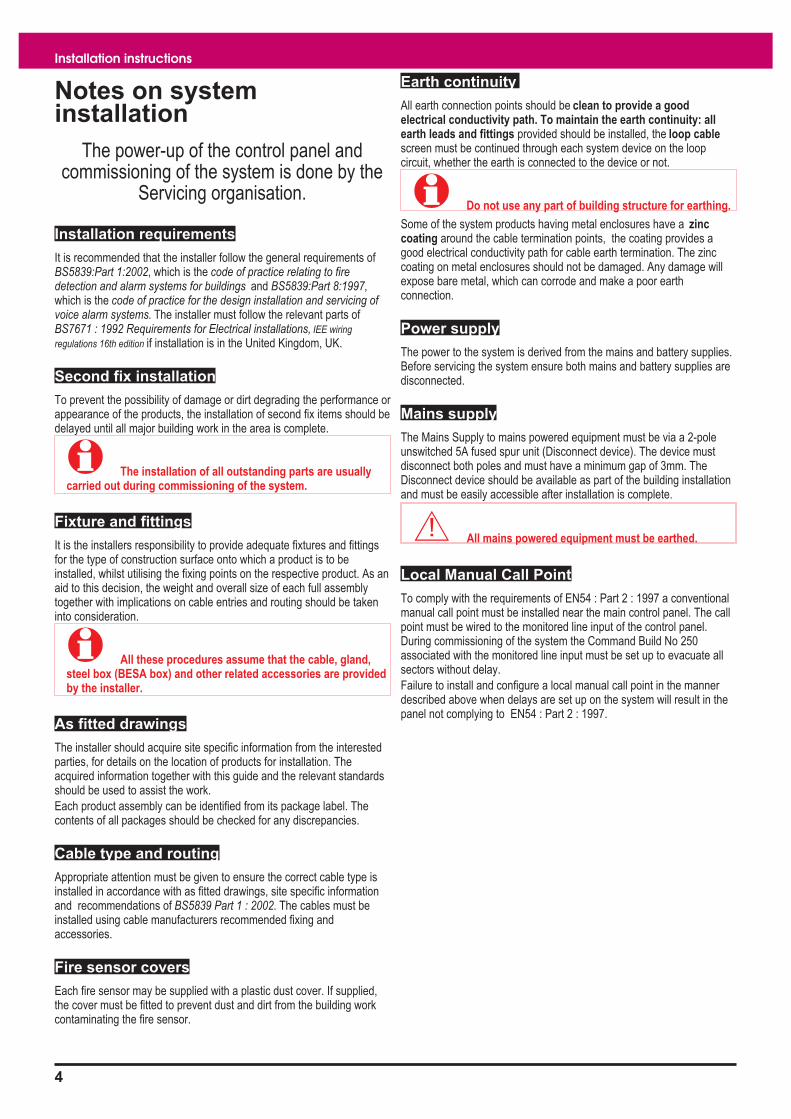
Earth continuity
All earth connection points should be clean to provide a good
electrical conductivity path. To maintain the earth continuity: all
earth leads and fittings provided should be installed, the loop cable
screen must be continued through each system device on the loop
circuit, whether the earth is connected to the device or not.
� Do not use any part of building structure for earthing.
Some of the system products having metal enclosures have a zinc
coating around the cable termination points, the coating provides a
good electrical conductivity path for cable earth termination. The zinc
coating on metal enclosures should not be damaged. Any damage will
expose bare metal, which can corrode and make a poor earth
connection.
Power supply
The power to the system is derived from the mains and battery supplies.
Before servicing the system ensure both mains and battery supplies are
disconnected.
Mains supply
The Mains Supply to mains powered equipment must be via a 2-pole
unswitched 5A fused spur unit (Disconnect device). The device must
disconnect both poles and must have a minimum gap of 3mm. The
Disconnect device should be available as part of the building installation
and must be easily accessible after installation is complete.
� All mains powered equipment must be earthed.
Local Manual Call Point
To comply with the requirements of EN54 : Part 2 : 1997 a conventional
manual call point must be installed near the main control panel. The call
point must be wired to the monitored line input of the control panel.
During commissioning of the system the Command Build No 250
associated with the monitored line input must be set up to evacuate all
sectors without delay.
Failure to install and configure a local manual call point in the manner
described above when delays are set up on the system will result in the
panel not complying to EN54 : Part 2 : 1997.
4
Installation instructions
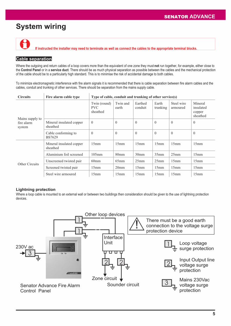
System wiring
� If instructed the installer may need to terminate as well as connect the cables to the appropriate terminal blocks.
Cable separation
Where the outgoing and return cables of a loop covers more than the equivalent of one zone they must not run together, for example, either close to
the Control Panel or in a service duct. There should be as much physical separation as possible between the cables and the mechanical protection
of the cable should be to a particularly high standard. This is to minimise the risk of accidental damage to both cables.
To minimize electromagnetic interference with fire alarm signals it is recommended that there is cable separation between fire alarm cables and the
cables, conduit and trunking of other services. There should be separation from the mains supply cable.
Circuits Fire alarm cable type Type of cable, conduit and trunking of other service(s)
Mains supply to
fire alarm
system
Twin (round)
PVC
sheathed
Twin and
earth
Earthed
conduit
Earth
trunking
Steel wire
armoured
Mineral
insulated
copper
sheathed
Mineral insulated copper
sheathed
0 0 0 0 0 0
Cable conforming to
BS7629
0 0 0 0 0 0
Other Circuits
Mineral insulated copper
sheathed
15mm 15mm 15mm 15mm 15mm 15mm
Aluminium foil screened 105mm 80mm 30mm 35mm 25mm 15mm
Unscreened twisted pair 60mm 65mm 25mm 25mm 15mm 15mm
Screened twisted pair 15mm 20mm 15mm 15mm 15mm 15mm
Steel wire armoured 15mm 15mm 15mm 15mm 15mm 15mm
Lightning protection
Where a loop cable is mounted to an external wall or between two buildings then consideration should be given to the use of lightning protection
devices.
5
SENATOR ADVANCE
Senator Advance Fire Alarm
Control Panel
1
1
2 2
Zone circuit
Sounder circuit
3
230V ac
Other loop devices
3
1
2
Loop voltage
surge protection
Mains 230Vac
voltage surge
protection
Input Output line
voltage surge
protection
There must be a good earth
connection to the voltage surge
protection device
Interface
Unit

Requirements of cables
The British Standard BS5839 Part 1 : 2002 Code of practice for system
design, installation, commissioning and maintenance states the
requirements for standard and fire resisting cables in Clause 26.2 section
d and e.
"d) Standard fire resisting cables should meet PH 30 classification
when tested in accordance with EN50200 and maintain circuit integrity if
exposed to the following test:
- a sample of the cable is simultaneously exposed to flame at a
temperature of 830ºC - 0 +40ºC and mechanical shock for 15min,
followed by simultaneous exposure to water spray and mechanical shock
for a further 15min.
e) Enhanced fire resisting cables should meet the PH120 classification
when tested in accordance with EN 50200 and maintain circuit integrity if
exposed to the following test:
- a single sample of the cable is simultaneously exposed to flame at a
temperature of 930ºC - 0 +40ºC and mechanical shock for a period of
60min, followed by simultaneous exposure to water spray and
mechanical shock for a further 60min."
� The cables listed in this manual are those that have
been tested for EMC compliance with the system products.
� All fire resisting cables for use in the system must
meet the requirements of BS5839 : Part 1 : 2002., refer to the
cable manufacturers data.
Loop Cable usage
� There is a maximum limit of 1Km loop cable usage
allowed per loop circuit. This maximum limit is the sum of the
cable used on main loop circuit, spurs off main loop circuit, plus
cable runs to all input / output lines off loop powered interface
units installed on the same loop.
There is a further maximum limit of 100m cable run allowed per
input / output line off loop powered interface unit.
Repeat indicator to Control panel cable
A maximum of 1Km cable distance is allowed between Control Panel and
Repeat indicator panel
� Belden No. 9842 EIA RS485 Applications, O/A Beldfoil®
Braid having two twisted pairs
Loop cable
Loop cable carries both data and power supply, therefore its selection is
important. Note the following:
� In countries where the European EMC directive is in force,
only EMC Compliant cables are to be used.
� The loop cable usage must not exceed 1Km. This includes the
cable usage on main loop, spur circuits and plus cable runs to
all line modules off interface inputs on the same loop.
� Single pair cable must be used. It is NOT permissible to run
mixed loops or outgoing and return pairs in a multi core cable,
due to inadequate separation and possible electrical
interference problems.
� Each core of the loop cable must not be less than 1.5mm2
cross section area.
� the cable screen must be capable of being earthed at each
system device (outstation).
� Red is the preferred cover sheath for fire applications.
� The specified loop circuit cables are also suitable for wiring
master alarm, auxiliary relay, input/output lines and mains
supply.
Enhanced cables
� TBA
Standard cables
EMC approved cables for loop wiring
� Mineral insulated cable (MICC) to BS6207:Part 1
� Draka Firetuf FTZ2E1.5 FIRETUF OHLS fire resistant data
cable
� Raydex CDT FG950 *
� Cavicel SpA FIRECEL SR 114H *
distributed by Cables Britain
� AEI Cables FIRETEC *
� BICC Pyrotenax FLAMESIL FRC *
� Datwyler LIFELINE *
� Alcatel cable PYROLON E *distributed by Winstonlead
� Huber & Suhner RADOX FR *
� Pirelli FP200 FLEX *
� Pirelli FP200 GOLD *
� The cables marked * utilise laminated aluminium tape
with a tinned drain wire for electrostatic screening. Under certain
environmental conditions galvanic action may take place
between the aluminium and the drain wire. This will severely
degrade EMC performance as the foil to drain wire impedance
will increase. Therefore these wires should be installed in line
with these instructions and in accordance with the
environmental conditions as specified by the manufacturer.
Mains Supply cable
The mains supply cable must be a standard fire resisting type and should
meet PH30 classification.
6
Installation instructions
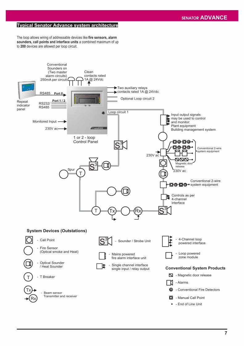
Typical Senator Advance system architecture
The loop allows wiring of addressable devices like fire sensors, alarm
sounders, call points and interface units a combined maximum of up
to 200 devices are allowed per loop circuit.
7
SENATOR ADVANCE
Zones 1 2 3 4 5 6 7 8 9 10 11 12 13 14 15 16
17 18 19 20 21 22 23 24 25 26 27 28 29 30 31 32
Test
Conventional 2-wire
system equipment
Conventional 2-wire
system equipment
230V ac
Magnetic door
release
230V ac
Controls as per
4-channel
interface
Spur
Optional Loop circuit 2
1 or 2 - loop
Control Panel
Input output signals
may be used to control
and monitor:
Plant equipment
Building management system
Conventional
Sounders on
(Two master
alarm circuits)
250mA per circuit
Two auxiliary relays
contacts rated 1A @ 24Vdc
Clean
contacts rated
1A @ 24Vdc
T
System Devices (Outstations)
- Call Point
- Fire Sensor
(Optical smoke and Heat)
- Optical Sounder
/ Heat Sounder
- T BreakerT
- End of Line Unit
- Magnetic door release
Conventional System Products
- Alarms
- Conventional Fire Detectors
- Manual Call Point
- Loop powered
zone module
- 4-Channel loop
powered interface
Loop circuit 1
T
- Single channel interface
single input / relay output
- Mains powered
fire alarm interface unit
S3
- Sounder / Strobe Unit
Repeat
indicator
panel
RS232/
RS485
Monitored Input
Port 0
Port 1 / 2
230V ac
S3
S3
S3
RS485
Tx Rx
Tx
Rx
- Beam sensor
Transmitter and receiver
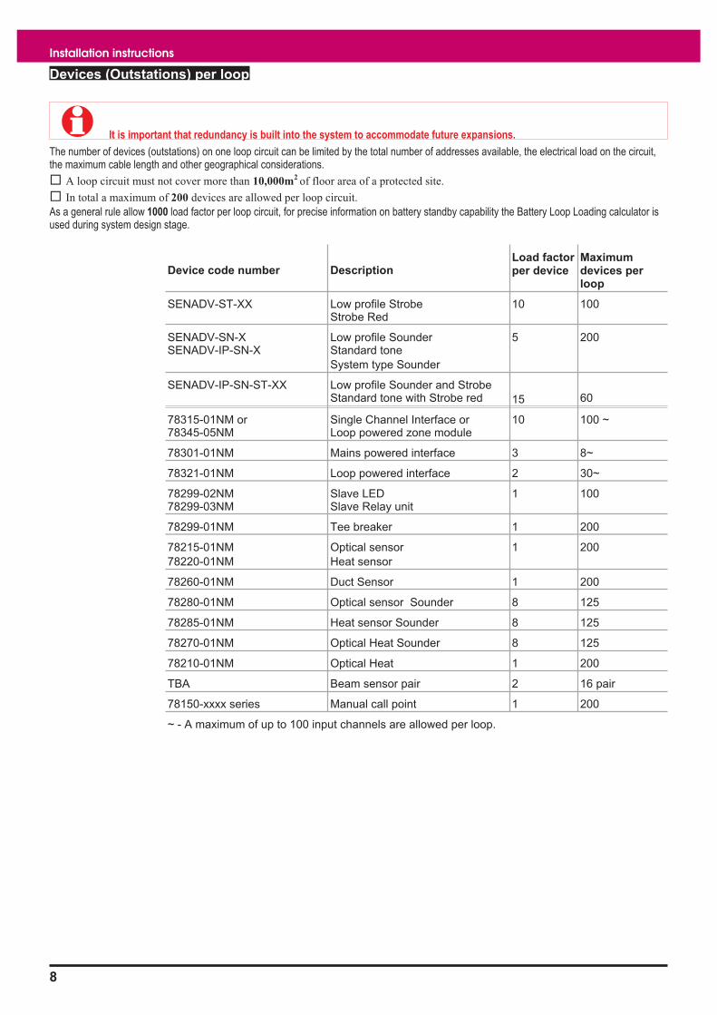
Devices (Outstations) per loop
� It is important that redundancy is built into the system to accommodate future expansions.
The number of devices (outstations) on one loop circuit can be limited by the total number of addresses available, the electrical load on the circuit,
the maximum cable length and other geographical considerations.
� A loop circuit must not cover more than 10,000m2of floor area of a protected site.
� In total a maximum of 200 devices are allowed per loop circuit.
As a general rule allow 1000 load factor per loop circuit, for precise information on battery standby capability the Battery Loop Loading calculator is
used during system design stage.
Device code number Description
Load factor
per device
Maximum
devices per
loop
SENADV-ST-XX Low profile Strobe
Strobe Red
10 100
SENADV-SN-X
SENADV-IP-SN-X
Low profile Sounder
Standard tone
System type Sounder
5 200
SENADV-IP-SN-ST-XX Low profile Sounder and Strobe
Standard tone with Strobe red 15 60
78315-01NM or
78345-05NM
Single Channel Interface or
Loop powered zone module
10 100 ~
78301-01NM Mains powered interface 3 8~
78321-01NM Loop powered interface 2 30~
78299-02NM
78299-03NM
Slave LED
Slave Relay unit
1 100
78299-01NM Tee breaker 1 200
78215-01NM
78220-01NM
Optical sensor
Heat sensor
1 200
78260-01NM Duct Sensor 1 200
78280-01NM Optical sensor Sounder 8 125
78285-01NM Heat sensor Sounder 8 125
78270-01NM Optical Heat Sounder 8 125
78210-01NM Optical Heat 1 200
TBA Beam sensor pair 2 16 pair
78150-xxxx series Manual call point 1 200
~ - A maximum of up to 100 input channels are allowed per loop.
8
Installation instructions

Senator Advance panel
The Senator Advance is an analogue addressable fire alarm panel
designed to the requirements of EN54 Parts 2 and 4. The panel can
accommodate up to 2 loop circuits of Senator Advance range of
analogue addressable devices. The panel provides local visual and
audible indications of system events, it has integral zone indicators for
fire events. It houses its own power supply with batteries to supply
standby power in the event of mains supply failure. The batteries provide
a standby supply for 24 hours. A lockable front door prevents
unauthorised access to fire alarm controls but allows all of the indicators
to be seen. The panel is designed for flush and surface mounting and
facilitates both rear and top cable entry points.
Features
� Analogue addressable fire alarm control panel
� Supports up to two loop circuits per panel
� Up to 200 addressable devices can be connected to a loop
circuit, devices like sensors, call point, interface units, repeat
and mimic panels.
� Two master alarm circuits
� Dedicated RS485 (Port 0) to connect to repeat indicator
panel(s)
� RS232 and RS485 (Ports 1 and 2) to connect to external
printer or commissioning tool
� Two sets of auxiliary relay change over contacts configurable
to operate with fire, fault or disablement
� One set of clean voltage-free change over contacts that
operate with master alarms.
� Monitored input that actions a command build 250
� Standby supply to power the system via batteries for 24 hours
� LCD alphanumeric type with back light to display event
information
� Integral 32 zone LEDs (with First fire flashing/steady options
and option to disable the integral zone indicators)
� LED lights for event indication
� Local audible buzzer to announce events
� Push buttons for essential controls and menu driven
commands
� Two programmable LED indications
� Two programmable control buttons
Technical specification
Control panel
Standard Designed to EN54 Part 2 : 1997
Panel dimensions in mm height 403 x width 338 x depth 101
Panel weight approximately 8.6Kg without batteries
1 - 12V 12Ah battery weight is 4Kg
2 batteries are required
Storage temperature -10ºC to 55ºC
Operating temperature 0ºC to 45ºC
Relative Humidity (Non
condensing)
Temperature 5ºC - 45°C
up to 90%
Emission BS EN50081-1:1992 Part 1 Residential,
Commercial & Light Industry
Class B limits
Immunity BS EN50130-4: 1996: Part 4
Alarm systems: Electromagnetic
compatibility
Product family standard: Immunity
requirements for components of fire,
intruder and social alarm systems
Ingress Protection IP31
Colour Eggshell white (Dupont 7EP21172S)
Backbox: Graphite Grey (RAL 7024)
Plug in Card Card 1
Card 2
Loop processor card (supplied) LPC
Optional loop card (This location is also for
future expansion)
Loops The panel supports up to 2 Loop circuits.
Second loop circuit is optional
Devices per loop A maximum of up to 200 addressable
devices (outstations) per loop
Device labels Each device can be given a 32 character
label for identification to locate events in
the system. Each MCP is restricted to 28
character label.
Auxiliary relays
Aux relay 1
Aux relay 2
Voltage-free contacts rated 1A @ 24Vdc
2 sets of change over contacts configured
to operate immediately with Fire event The
relay is normally de-energised
1 set of change over contacts configured
to operate immediately with Fault event
The relay is normally energised
The relays can be re-configured to
operate with Fire, Fault or Disablement
event, with a maximum delay of up to
10 minutes and can operate in a normally
energised or de-energised state.
Clean contacts 1 set of voltage free change over contacts
rated 1A @ 24Vdc active with master
alarms.
SENATOR ADVANCE
9
Zones 1 2 3 4 5 6 7 8 9 10 11 12 13 14 15 16
17 18 19 20 21 22 23 24 25 26 27 28 29 30 31 32
Test

Master alarm circuits 2 - (24 volt nominal)
250 mA max per circuit
MA1 - fuse 250mA (T) FS1
MA2 - fuse 250mA (T) FS2
Both fuses are 20mm x 5mm in size and
are located on the master control board
Monitored input Normally open input contacts, active when
contacts are closed, which triggers
command build 250. Circuit is monitored
for open and short circuit faults.
Ports Port 0
Port 1
Port 2
RS485 -Repeat indicator panel (P15)
(Mode: Repeat)
Includes a 24V supply protected by
FS3 Fuse 200mA TE5 on MCB
RS232 -Printer / Commissioning Tool (P5)
(Mode: Std, Printer, Universal or Ascom)
RS485 -Repeat indicator panel (P5)
(Mode: Std or Repeat)
USB - Future expansion (P16)
The baud rate is factory set for Port 0 it is
1200 and for Ports 1 & 2 it is 9600. Baud
rate can be software reconfigured to
another setting.
Indicators Fire (red)
32 - Zones (red) - hidden til lit
Verify (amber)
Sounder (amber)
CB253 (amber)
CB254 (amber)
Power (green)
Fault (amber)
Power Fault (amber)
System Fault (amber)
Delay (amber)
Test (amber)
Disablement (amber)
Display Alpha-numeric display - 8 lines by
40 character per line, back-lit, (Black
characters on green background, liquid
crystal display)
Internal sounder To announce Fire and Fault events, plus
give a key press confirmation beep.
Controls (with door
closed) Access level 1
Next and Previous buttons operable
during Fire condition only
Controls (with door open)
Access level 2
Sound Alarms, Silence Alarms, Reset,
Cancel Buzzer, Verify, F1-F4 keys, Menu
On/Off key, Numeric keys, U1-U2 keys
available if configured to perform site
specific actions by triggering CB251 and
CB252
Access level 2a Customer (Customer PIN)
Access level 3 Engineering (Engineers PIN)
Menus [Control], [Setup], [Information] and
[Test Engineering] menus.
Logs Active Logs: Fire, Fault and Disablement
logs
Historic log
Event logs: Fault, Disablement, Warning,
Supervisory, Exceptions and Historic
fires.(255 events)
Fire Log (100 events)
Power supply
Standard Designed to EN54 Part 4 : 1997
Mains operating voltage 230V 50Hz +10% -6%
Nominal supply voltage
for master alarm circuits
24V +/- 4V
Lithium Battery CR2032 3V cell (supplied) on MCB.
Replace only with the same or equivalent
type battery. Dispose of used batteries
according to the manufacturer’s
instructions.
Battery circuits BAT1 FS1 Fuse 3.15A (T) TE5 size on PSU
board
PSU Voltages and Fuses
43V supply
24V supply
24V supply
FS6 Fuse 1A TE5 on PSU board
FS4 Fuse 1A TE5 on PSU board
FS3 Fuse 200mA TE5 - on MCB
Battery 2- 12V 12Ah sealed lead acid batteries
that provide 24 hours standby and
30 minutes alarm, determined by loop
loading, reference should be made to the
loop loading calculator
Storage temperature -10ºC to 55ºC
Operating temperature 0ºC to 45ºC
Relative Humidity (Non
condensing)
Temperature 5ºC - 45°C
up to 90%
Indicators Left LED (yellow)
Indication off battery circuit 2 or
43V supply fault
Centre LED (yellow)
Indication off battery circuit 1, 24V supply
Right LED (green)
Indication of mains supply fault
� Hazardous voltages
may still be present even if this
indication is extinguished.
Installation instructions
10

Installation checks
A Senator Advance panel is supplied in two cartons, it is important to
check the contents of the packages:
� Inner box assembly of the control panel
� Outer door assembly (fits on to inner box assembly)
� Batteries 2 - 12V 12Ah (not supplied, order separately)
Parts in the Spares pack Quantity.
Fuse 3.15A 20mm x 5mm 1
Fuse 3.15A 2
Fuse 1A 2
Fuse 200mA 2
10K Ohms Resistor 4
Battery Link 1
Battery Lead 1
Open the inner door using the allen key supplied. The allen key is
located on the inside of the outer door assembly.
The Senator Advance panel with inner door open
Enclosure
� Unused knockouts that have been removed should
not be left open.
11
SENATOR ADVANCE
Allen Key
Fixing point
Inner door
Fixing point
Inner door
ESD Earth
Bonding point
Inner door
Plastic cover protecting
PCBs, the Master Control
Board and Loop Card
Metal cover
protecting PSU
REMOVAL OF COVER
EXPOSES HIGH VOLTAGE
WARNING
REMOVE ONLY
DURING COMMISSIONING
Earth lead from
back box - inner door
Cover to protect PCB
display and keyboard
Warning
removal
of cover
exposes
live parts
Battery
bracket
Back box
Ribbon cable
and clamp
Product No: SENATOR ADVANCE
Rated Voltage: 230 - 240V A.C.
Rated Frequency: 50 - 60Hz
Rated Current: 0.6A
Rated Fuse: T 3.15A H 250V
Manf. Date xx/xx/xx
REMOVE ONLY
DURING COMMISSIONING
Mains
cable
entry
All other cable entry
Repeat RS232/RS485 Mon I/P
Clean Cont.
Aux Relays Loop Master alarm
Floor
level
Cable
entry points
13 - Top
6 - back
7 Earth points
4 - Panel fixing
points
1.7m

Cable termination points on the enclosure
� Unused knockouts that have been removed must not
be left open.
The wire length between the cable termination and point of connection
must be as short as possible. Cable earth drain wire where applicable
must be connected to the nearest earth point.
Terminate each cable at the dedicated entry point on the enclosure,
using the cable manufacturers recommended techniques.
Where the cable is not required to be connected, leave 400mm (unless
otherwise specified) tail wire length and mark each core identifying its
final point of connection.
Where the cable is required to be connected, ensure it is secure to the
respective terminal.
Wiring test
� DO NOT undertake high voltage insulation tests
WITH THE CABLES CONNECTED to the panel and system
device terminals. Such a test may damage the electronics
circuitry in loop devices and at the panel.
Mains supply
� Ensure that the mains supply cable enters the
panel through a dedicated cable entry, located adjacent to
the mains terminal block and also segregated from loop
wiring.
� These fire alarm system products are not designed to
be powered from IT Power systems.
Mains supply to any fire alarm control and indicating equipment must be
via an unswitched fused spur unit (Disconnect device).
The fused spur isolator cover should be marked:
FIRE ALARM - DO NOT SWITCH OFFThe fire alarm equipment’s fused spur unit must be fed from adedicated switch or protective device at the local mains supplydistribution board.
Mains and battery supply connections
The mains and battery supply cables must be installed to the stage to
facilitate the power up for commissioning, which is carried out by the
Servicing organisation.
� Where mains cable is to remain disconnected, its
tail ends must be insulated to prevent dangerous
conditions arising in the event of accidental switching On
of the mains supply.
12
Installation instructions
P2N E L
DANGER
POWER SUPPLY
PANEL
FS3
3.15A(T)
mains fuse
Dedicated mains supply
from consumer unit
5A Unswitched fused
spur unit (Disconnect device)
MICC CABLE
GLAND
BRASS
LOCKNUT
ZINC PLATED
LOCK WASHERGLAND
BOARD
TERMINALS
EARTH
DRAIN
WIRE
Should not
be more than
50mm
MICC
CABLE TERMINATION
MICC CABLE
GLAND
BRASS
LOCKNUT
ZINC PLATED
LOCK WASHER
Soft skin cable
GLAND
BOARD
TERMINALS
EARTH
DRAIN
WIRE
Should not
be more than
50mm long
Soft skin (FireTuf)
CABLE TERMINATION
PANEL
enclosure
REMOVE ONLY
DURING COMMISSIONING
MAINS
SUPPLYLOOP 1
END 1LOOP 1
END 2
MASTER
ALARMSMASTER
ALARMS

How to flush mount the control panel
a. Cut out an aperture in the wall to allow the flush surround to be fitted, see diagram for dimensions of the aperture.
b. Using the fixing holes on the flush surround, secure it into the aperture side walls.
c. Knock out the appropriate top or rear cable points on the panel enclosure.
d. Route the cables through the cable entry points into the panel and at the same time insert the panel into the flush
surround.
e. Fit the panel back box to the flush surround using the 4-off 5mm screws supplied with the flush surround.
Surface fixing
13
SENATOR ADVANCE
Control Panel
Cross section of
the wall to which
the panel is to be
flush mounted
Aperture
Flush
Surround
5mm diameter
fixing holes
Aperture Height:
380mm
Aperture Width:
320mm
Aperture depth should not be less than:
93mm
REMOVE ONLY
DURING COMMISSIONING

Removable terminal block
To ease installation the terminal blocks on the Master Control Board can be unplugged from the board.
Terminals for external circuits
The Master Control Board (MCB) holds all the terminals for the connection of external circuits. The exception is the mains supply terminal block
which is located on the PSU board.
14
Installation instructions
removable
P15 P10 P11 P9 P8
P2 CARD 1
IC3
KE
YB
OA
RD
PR
INT
ER
IC16
POWER
SUPPLY
P12
MA1 - FS1 250mA
MA2 - FS2 250mA
P1 CARD 2
P16
P13SW1
24V B A0V NC C NO NC C NONC C NO MA1+ MA1- MA2+ MA2- 0V MIPNC C NO
CODE BCKUP
Loop Card
Master Control Board
P15
P10
P11
P9
P8
P14
P6
24V B A0V
NC C NO
NC C NO
0V TX A
NC C NO
RX B
L1 0V L2 0V L1 0V L2 0V
MA1+ MA1- MA2+ MA2-
0V MIPNC C NO
REPEAT
INDICATOR
AUXILIARY RELAY 1
AUXILIARY
RELAY 2
RS232
/RS485
LOOP CIRCUITS
MASTER ALARMS
MONITORED
INPUT
and
CLEAN
CONTACTS
LOOP 1LOOP 2
P7P6
0V TX A RX B L1 0V L2 0V L1 0V L2 0V
24V
FS3 200mA
P14
BATT1

Loop circuit
The two analogue loop circuits can each accept connection of addressable devices / outstations, up to 200 maximum per circuit. To maintain earth
continuity on a loop, the loop cable screen must be continued through each system device, whether the earth is connected to a device or not.
�A loop circuit must not cover more than 10,000m2 of floor area of a protected site.
A spur circuit must always be taken from the "line common" terminals of a 3 ways device.
A spur must not cover more than the equivalent of one zone as defined in BS5839 Part 1.
As every device has a loop isolator, the application of more than 32 devices does not require any special consideration.
15
SENATOR ADVANCE
L2
02
01
L1
L1
01
L2
02
02
L2
01
L1
++
+
+
L1
L2
0V
++
+
+
L1
L2
0V
++
+
+
L1
L2
0V
L1
0V
Manual call point
L2
0V
PANEL
2 - way device
2 - way device
2 - way device
Earth to
metal box
Master Control Board
P7
L1 0V L2 0V L1 0V L2 0V
LOOP CIRCUIT 1
Note: The 0V terminals
in the device- Terminal plate
are electrically
connected together.
LOOP 2 LOOP 1
P14
Sounder / Strobe
Sounder / Strobe

Master alarm circuits
The two master alarm circuits accept the connection of conventional
alarm sounders including the conventional Sounder and Strobe products.
Auxiliary relay circuits
The auxiliary relays 1 and 2 contacts can be used to control external
equipment, such as an automatic dialler that makes the call for fire
fighting action. The external equipment can be installed a maximum of
100m cable distance away from the main fire panel. The relays can be
individually re-configured to operate with either fire, fault or disablement
event in the system. The relay operation can also be delayed by up to
10 minutes and can be set up to operate in a normally energised or
de-energised state. The contacts should be powered from an
independent power supply, if required.
Clean contacts
The clean contacts can be used to signal plant equipment, such as a lift
control system. The plant equipment can be a maximum of 100m cable
distance away from the fire panel. The relay will always operate with the
master alarms. The contacts should be powered from an independent
power supply, if required.
Repeat indicator panel
Up to four repeat indicator panels can be connected directly to the fire
panel at Port 0. The furthest repeat indicator panel can be installed a
maximum of 1Km cable distance away from the fire panel. The Port 0 is
configured for Repeat mode and set up for RS485 communication and
the baud rate is selected during the commissioning stage.
16
Installation instructions
P9
MA2 - FS1 250mA
MA1 - FS2 250mA
MA1+ MA1- MA2+ MA2-
MASTER CONTROL BOARD
PANEL
10K Ohms -
End-of-line resistor
fitted in the last alarm sounder
Conventional
alarm sounders
MASTER ALARMS
PANEL
MASTER CONTROL
BOARD
Factory default:
Aux relay 1 is normally de-energised and operates with a
fire event without delay.
Aux relay 2 is normally energised and operates with
fault event without delay.
NC C NO NC C NONC C NO
P10 P11
AUXILIARY
RELAY 1
AUXILIARY
RELAY 2
Change over contacts
rated 1A @ 24Vdc, to control
external equipment
PANEL
MASTER CONTROL
BOARD
Terminals P15 is PORT 0 of
Master Control Board
(Card 0)
The factory default
setting of PORT 0 is
to allow connection to
repeat indicator panel
Repeat mode
REPEAT RS485
24V B A0V
P15
REPEAT INDICATOR PANEL 1
a
bRS485
earth
REPEAT INDICATOR PANEL 4
-
+24V
a
bRS485
earth
UP TO 4 REPEAT INDICATOR
PANELS MAXIMUM
24V
POWER
SUPPLY UNIT
+ -
If there is only
one repeat indicator
panel connected
then use the 24V
supply on the
Master control board.
-
+24V
24V
PANEL
MASTER
CONTROL BOARD
The clean contact relay is
normally de-energised
and operates with a fire
event without delay.
NC C NO
P8
CLEAN
CONTACTS
Change over contacts
rated 1A @ 24Vdc, to
control external equipment

Monitored input circuit
The monitored input at the fire panel is activated by an external switch
installed a maximum of up to 100m cable distance away from the fire
panel. The input is monitored for both short and open circuit fault. When
the input is active it triggers a command build number 250 of the fire
panel. The command build action is configured during the commissioning
of the system. For example the action can be to sound the alarms of the
system for the duration the push button is pressed.
RS232 / RS485 Ports
The ports 1 and 2 of the fire panel offer RS232 and RS485
communication, having configurable mode of operation and baud rate
which are set during the commissioning of the system. The ports are
used to connect an external printer or commissioning tool.
USB Port
The port 3 is an USB port for future expansion.
Connecting a thermal printer
An external serial printer can be connected to the RS232 Port. The port
is configured during commissioning for printer connection.
17
SENATOR ADVANCE
PANEL
MASTER CONTROL
BOARD
Terminal block
P6 is PORT 1
of Master Control Board
(Card 0)
PORT 1 is configured
for RS232 Communication.
Its mode and baud rate are
set up during commissioning
RS232
P6
0V TX A RX B
PANEL
MASTER CONTROL
BOARD
RS 485
P6
0V TX A RX B
Terminal block
P6 is also PORT 2
of Master Control Board
(Card 0)
PORT 2 is configured
for RS485 Communication.
Its mode and baud rate are
set up during commissioning
RS232
RS 485
P8
0V MIP
PANEL
2 - 10K Ohms -
resistors must be
fitted as shown.
MASTER CONTROL
BOARD
Normally open contacts
An active input will trigger
the command build No 250
The command build action
is configured
during commissioning
Monitored Input
These contacts can be a push button
switch, fire relay contacts from another
panel or contacts from a timer.
P16
PANEL
MASTER CONTROL
BOARDConnector P16 is PORT 3
of Master Control Board
(Card 0)
PORT 3 is an USB port.
PANEL
MASTER CONTROL
BOARD
RS232
P6
0V TX A RX B
Thermal printer9-way D-type connector
GN
DG
ND
Tx
Rx
Rx
Tx
Hand held version
shown (can be a
desktop version of
the thermal printer)
Terminals P6 is PORT 1
of Master Control Board
(Card 0)
PORT 1 is configured
for RS232 Communication.
The PORT 1 mode must
be set to and the
baud rate may be adjusted
if required during
commissioning
Printer

On completion of panel installation
After all the cable installation is complete:
a. Close the inner door using the allen key, which is
located on the inside of the outer door.
b. Fit the metal outer door on to the main enclosure.
c. Connect the earth lead on the back box and fit it to the
metal outer door.
� Ensure the earth lead from the backbox is
connected to the earth on the metal door
d. Store the allen key by inserting it back on the inside of
the metal outer door.
e. Close and lock the metal outer door.
18
Installation instructions
Earth lead to connect
to the metal door

Repeat indicator panel
The repeat indicator panel provides messages and indications of system
events and connects directly to the Senator Advance fire panel.
Technical Specification
Panel dimensions height 177 mm
width 206 mm
depth 48.5mm
Full assembly
weight
750g
Storage
temperature
0ºC to 60ºC
Operating
temperature
0ºC to 45ºC
Relative humidity
(Non condensing)
Temperature
5 - 45°C
up to 90%
Ingress protection IP30
estimated
Colour White
Indicators Fire, Fault, Disablement, Power On,
System fault, Sounder
2 lines 20 characters per line, back-lit
display
Controls
(with flap closed)
Test and Cancel buzzer
Controls
(with flap open)
Fire, Fault, Disablement, Warning,
Display Mode and Numeric keypad
� If only one repeat indicator panel is to be connected
to the control panel then make use of the 24V supply at the
panel, there is no need to use an external power supply.
Installation
a. Open the outer cover
b. Insert the external cable into the backbox assembly at
the required entry point.
c. Mark the fixing points and secure the backbox to the
wall.
d. Connect the cable to terminals.
e. Refit the front cover and flap.
19
SENATOR ADVANCE
1 2 3
4 5 6
7 8 9
0
+
RE
L
- 24
V
a
b
RS
48
5
ON
1 2 3 4 5 6 7 8
J6 J5 J7
Back cable entry pointThinned sections
on sides of enclosure for
cable entry 4 enclosure fixing points
PANEL
MASTER CONTROL
BOARD
Terminals P15 is PORT 0 of
Master Control Board
(Card 0)
The factory default
setting of PORT 0 is
to allow connection to
repeat indicator panel
Repeat mode
REPEAT RS485
24V B A0V
P15
REPEAT INDICATOR PANEL 1
a
bRS485
earth
REPEAT INDICATOR PANEL 4
-
+24V
a
bRS485
earth
UP TO 4 REPEAT INDICATOR
PANELS MAXIMUM
24V
POWER
SUPPLY UNIT
+ -
If there is only
one repeat indicator
panel connected
then use the 24V
supply on the
Master control board.
-
+24V
24V

Terminal plates, Trim ring
and flush kit
2-Way terminal plate
This terminal plate provides 2-way loop connection, the loop in from
previous device/panel and loop out to next device/panel.
Trim ring
The sensor trim ring is used to conceal rough edges of the hole made in
the ceiling tile for terminal plate installation. It is also suitable for use in
refurbished installation where the previous sensor diameter was larger
and a larger diameter hole in the ceiling tile needs to be concealed.
Technical Specification
Diameter 120mm
Compatibility BESA, MK switch and American type
Colour White
Semi Flush Mounting
The semi-flush mounting kit is used to flush the terminal plate into a
ceiling tile.
20
Installation instructions
Housing
Flush ring
Clamping ringClamps
Screws

Terminal plate installation
� Use the correct tool and technique to fit or remove any part of the fire sensor from terminal plate.
� To provide the right coverage, each fire sensor must be fitted to a terminal plate in the location as defined by the site
specific information.
21
SENATOR ADVANCE
Wires must be
6mm clear off
the side walls
Wires must not
project below
the plate rim
terminal plate
If the continuity spring has moved
from the location shown it may prevent
correct fitting of the sensor head.
L1
L2
0V
L1
L2
0V
++
+
+
L1
L2
OV
2 - way terminal plate
Earth to
metal box
++
+
+
L1
L2
OV
From previous
device on
the loop
Note: The 0V terminals
in the 2 - way device
terminal plate are electrically
connected together.
2 - way terminal plate
Do’s and Don’ts
Removal of transit card
Wiring
Wire correctly to avoid damage to the sensor head.
The transit card prevents movement of the
continuity spring that links L1 to L2. Only
remove the card after installation of the terminal plate.
Continuity
spring

Trim ring installation
The trim ring must be fitted prior to fitting the terminal plate. The loop
cable connections are then made to the terminal plate and then the plate
is clipped into position on the trim ring.
Semi flush installation
These procedures describe how to semi flush a fire sensor to a ceiling
tile. A terminal plate and semi flush mounting kit are required.
a. Identify the package SENSOR FLUSH MOUNTING
KIT 19279-01 and check the contents:
Component Quantity
Semi flush housing 1
Flush ring 1
Clamp 2
Clamping ring 1
Screws 2
b. Remove the ceiling tile to which the semi flush
mounting kit is to be fitted.
c. Cut a hole 93mm diameter in the tile and cut out to
allow for lugs on the semi flush housing.
d. Assemble the semi flush housing to the tile using the
clamp ring, clamps and locking screws.
e. Replace the tile loosely.
f. Feed the loop wires through the semi flush mounting
and terminal plate.
g. Secure the base to the steel box (BESA box).
h. Clip the flush ring to the semi flush housing.
� Follow the procedure for wiring the terminal
plate to prevent damage to the sensor head.
i. Connect the loop cables to the terminal plate terminals.
22
Installation instructions
LOOP CABLE
STANDARD 60mm STEEL BOX
GLAND
LOOP CABLE
TRIM RING
TERMINAL PLATE
MAKE CONNECTIONS TO
TERMINAL PLATE AND THEN
CLIP INTO PLACE ON TRIM
RING
CEILING TILE
2 SCREWS TO SECURE
TERMINAL PLATE TO STEEL BOX
CROSS SECTION OF
CEILING TILE
93mm diameter hole
Cut outs for lugs on
the semi flush housing
LOOP CABLE
STANDARD 60mm STEEL BOX
GLAND
CLAMPING RING
CEILING TILESEMI FLUSH
HOUSING
LOCKING SCREWS
TERMINAL PLATE
FLUSH RING
SCREWS TO SECURE
TERMINAL PLATE TO STEEL BOX
CLAMPS
LOOP CABLE
STANDARD 60mm STEEL BOX
GLAND
LOOP CABLE
TERMINAL PLATECEILING TILE
2 SCREWS TO SECURE
TERMINAL PLATE TO STEEL BOX
CROSS SECTION OF
CEILING TILE

Fire sensors
� To prevent dirt and dust in the environment
degrading the performance of the fire sensors, the sensor
head installation should be carried out by the installer just
prior to the commissioning of the system.
� To prevent damage to a fire sensor, the correct
tool and technique must be used when removing or fitting
sensor, or its sub assembly, to and from the terminal plate.
� Optical sensor - Blue ring
� Optical Heat sensor - tba
� Optical Heat Sounder - tba
� Heat sensor - Yellow ring
� Optical sensor sounder - Blue ring
� Heat sensor sounder - Yellow ring
� Damage will occur if undue force is used on
fitting or removal of any part of a sensor assembly.
Exploded view of a sensor
Dust Cover
Each sensor is supplied with a push-fit plastic dust cover to protect the
sensor from dirt and dust. After installation it is essential that the
protective dust cover is fitted to the sensors to prevent the sensor
becoming contaminated with dirt or dust during any subsequent building
work.
23
SENATOR ADVANCE
Semi flush mount
(if used)
Terminal plate
Electronic module
Sensor head
Dust cover

Optical Sensor
Standard
Smoke BS5445:Part 7 (EN54 : Part 7)
Dimensions diameter 86 mm
height 60 mm (with terminal plate)
Full assembly weight 580g with terminal plate
Storage temperature -30ºC to 70ºC
Operating
temperature
0ºC to 50°C
Relative Humidity
(Non condensing)
Temperature
5ºC - 45°C
up to 90%
Emission BS EN50081-1:1992 Part 1
Residential, Commercial & Light
Industry Class B limits
Immunity BS EN50130-4: 1996: Part 4
Alarm systems: Electromagnetic
compatibility
Product family standard: Immunity
requirements for components of
fire, intruder and social alarm
systems
Ingress Protection IP30 estimated - when mounted
on a flat ceiling
IP20 estimated when mounted on
a BESA box
Air flow in installed
environment
10m/s gusting for up to
30 minutes
5m/s continuous
Vibration 5 to 60Hz
Colour White
Operating voltage 20-45V
Indicators Red LED visible at 500LUX
ambient light levels 3m
Mounting Surface or Semi-flush, using
mounting kit (model no 19279-01)
Chamber format Sensing chamber is removable
Loop Maximum number per loop = 200
Load (1000 max) = 1
Optical Heat Sensor
Standard
Heat
Smoke
BS5445:Part 5 (EN54 : Part 5)
BS5445:Part 7 (EN54 : Part 7)
Dimensions diameter 86 mm
height 60 mm (with terminal
plate)
Full Assembly
weight
580g with terminal plate
Storage temperature -30ºC to 70ºC
Operating
temperature
0ºC to 50°C (If only heat is
used then 0 to 45°C)
Relative Humidity
(Non condensing)
Temperature
5ºC - 45°C
up to 90%
Emission BS EN 61000-6-3:2001
Residential, Commercial &
Light Industry Class B limits.
Immunity BS EN50130-4: 1996: Part 4
Alarm systems:
Electromagnetic compatibility
Product family standard:
Immunity requirements for
components of fire, intruder
and social alarm systems.
Ingress Protection IP30 estimated when mounted
on a flat ceiling
IP20 estimated when mounted
on a BESA box.
Air flow in installed
environment
10m/s gusting for up to
30 minutes
5m/s continuous.
Vibration 5 to 60Hz
Colour White
Operating voltage 20-50V
Indicators Red LED visible at 500LUX
ambient light levels 3m
Mounting Surface or Semi-flush, using
mounting kit (model no
19279-01)
Chamber format Sensing chamber is removable
Loop Maximum number per loop =
200
Load (1000 max) = 1
24
Installation instructions

Optical Heat Sounder
Standard
Heat detection
Smoke detection
Sounder
BS5445: Parts 5 (EN54 : Part
5)
BS5445 : Part 7 (EN54 : Part
7)
BS5839 : Part 1 Sound output
85dBA at 1m
Dimensions diameter 86 mm
height 60 mm (with terminal
plate)
Full Assembly
weight
600g with terminal plate.
Storage
temperature
-30 to 70ºC
Operating
temperature
0ºC to 50°C (If heat is used
then 0ºC to 45°C)
Relative Humidity
(Non condensing)
Temperature 5 -
45°C
up to 90%
Emission BS EN 61000-6-3:2001
Residential, Commercial &
Light Industry Class B limits.
Immunity BS EN50130-4: 1996: Part 4
Alarm systems:
Electromagnetic compatibility
Product family standard:
Immunity requirements for
components of fire, intruder
and social alarm systems.
Ingress Protection IP30 estimated when mounted
on a flat ceiling
IP20 estimated when mounted
on a BESA box
Air flow in installed
environment
10m/s gusting for up to
30 minutes
5m/s continuous
Vibration 5 to 60Hz
Colour White
Operating voltage 20-50V
Indicators Red LED visible at 500LUX
ambient light levels 3m
Mounting Surface or Semi-flush using
mounting kit (model no
19279-01)
Chamber format Sensing chamber is
removable.
Loop Maximum number per loop =
125
Load (1000 max) = 8.
Optical Sounder
Standard
Smoke detection
Sounder
BS5445 : Part 7 (EN54 : Part 7)
BS5839 : Part 1 Sound output
85dBA at 1m
Dimensions diameter 86 mm
height 60 mm (with terminal plate)
Full Assembly weight 600g with terminal plate
Storage temperature -30ºC to 70ºC
Operating
temperature
0ºC to 50°C
Relative Humidity
(Non condensing)
Temperature
5ºC - 45°C
up to 90%
Emission BS EN50081-1:1992 Part 1
Residential, Commercial & Light
Industry Class B limits
Immunity BS EN50130-4: 1996: Part 4
Alarm systems: Electromagnetic
compatibility
Product family standard: Immunity
requirements for components of
fire, intruder and social alarm
systems
Ingress Protection IP30 estimated when mounted on
a flat ceiling
IP20 estimated when mounted on
a BESA box
Air flow in installed
environment
10m/s gusting for up to 30
minutes
5m/s continuous
Vibration 5 to 60Hz
Colour White
Operating voltage 20-45V
Indicators Red LED visible at 500LUX
ambient light levels 3m
Mounting Surface or Semi-flush using
mounting kit (model no 19279-01)
Chamber format Sensing chamber is removable
Loop Maximum number per loop = 125
Load (1000 max) = 8
25
SENATOR ADVANCE

Heat Sensor
Standard
Heat BS5445:Part 5 (EN54 : Part 5)
BS5445:Part 8 (EN54 : Part 8)
Dimensions
standard
environmentally
protected
diameter 86 mm
height 60 mm (with terminal plate)
180 mm height (the probe
protrudes 100mm)
180 mm width
90 mm depth
Full Assembly weight 505g with terminal plate
(weight for non EP version)
Storage temperature -30ºC to 70ºC
Operating
temperature
0 to 45°C (Exception is when set
to operate at State 5 or 6, State
information is available in the
commissioning manual)
Relative Humidity
(Non condensing)
Temperature
5ºC - 45°C
up to 90%
Emission BS EN50081-1:1992 Part 1
Residential, Commercial & Light
Industry Class B limits
Immunity BS EN50130-4: 1996: Part 4
Alarm systems: Electromagnetic
compatibility
Product family standard: Immunity
requirements for components of
fire, intruder and social alarm
systems
Ingress Protection IP20 estimated - standard product
IP55 environmentally protected
version
Air flow in installed
environment
10m/s gusting for up to 30
minutes
5m/s continuous
Vibration 5 to 60Hz
Colour White
Operating voltage 20-45V
Indicators Red LED visible at 500LUX
ambient light levels 3m
Mounting Surface or Semi-flush using
mounting kit (model no 19279-01)
Chamber format Sensing chamber is removable
Loop Maximum number per loop = 200
Load (1000 max) = 1
Heat Sounder
Standard
Heat detection
Sounder
BS5445: Parts 5 (EN54 : Part 5)
BS5839 : Part 1 Sound output
85dBA at 1m
Dimensions diameter 86 mm
height 60 mm (with terminal plate)
Full Assembly weight 600g with terminal plate
Storage temperature -30 to 70ºC
Operating
temperature
0 to 50°C
Relative Humidity
(Non condensing)
Temperature
5 - 45°C
up to 90%
Emission BS EN50081-1:1992 Part 1
Residential, Commercial & Light
Industry Class B limits
Immunity BS EN50130-4: 1996: Part 4
Alarm systems: Electromagnetic
compatibility
Product family standard: Immunity
requirements for components of
fire, intruder and social alarm
systems
Ingress Protection IP30 estimated (mounted on a flat
ceiling)
IP20 estimated (mounted on a
BESA box)
Air flow in installed
environment
10m/s gusting for up to 30
minutes
5m/s continuous
Vibration 5 to 60Hz
Colour White
Operating voltage 20-45V
Indicators Red LED visible at 500LUX
ambient light levels 3m
Mounting Surface or Semi-flush using
mounting kit (model no 19279-01)
Chamber format Sensing chamber is removable
Loop Maximum number per loop = 125
Load (1000 max) = 8
26
Installation instructions

Fitting a Sensor head to the terminal plate
To fit a fire sensor head to a base, use the extractor cup supplied with
the sensor tool kit. For an easy-to-reach terminal plate, the sensor
head may be held in hand, see also information on terminal plate
page 21.
Removal of Sensor head from terminal plate
Use the extractor cup supplied with the tool kit, and the
correct electronics module removal tool:
Optical heat (sounder) sensor
Heat sensor
a. Using the extractor cup, remove the chamber module
from the electronics module of the sensor head.
b. Using the extractor cup and appropriate electronics
module removal tool, remove the electronic module
from the base.
27
SENATOR ADVANCE
Terminal plate
Sensor head:
Electronic module
Chamber module
Extractor cup
Ceiling tile
1. Place sensor head inside the cup.
2. Offer the sensor head/
cup to the terminal plate
and rotate clockwise to locate
and lock the head to the plate.
Ceiling tile Terminal plate
Sensor head:
Electronic module
Chamber module
Extractor cup
1. Offer the cup to the sensor head.
2. Rotate anticlockwise
to unlock and release
the chamber from the
electronic module.
T
Terminal plate
Electronic module
Optical heat
assembly shown.
Extractor cup
Ceiling tile
2. Offer the electronics
removal tool/cup to the
electronic module.
3. Rotate the cup
anti-clockwise until a stop
is felt and pull to release the
electronic module from the
terminal plate.
Screw
Chamber Removal
tool
Optical heat
chamber removal tool
shown.
1. Insert the correct
electronics module
removal tool into the cup.

To assemble a sensor head
Use the following technique when fitting together a chamber to its
electronic module.
28
Installation instructions
2. Offer the chamber to
the electronic module.
3. Whilst holding the
electronic module, rotate
the chamber clockwise
to locate and lock the two
assemblies together.
Chamber Module1. Ensure the vanes
are displaced
Optical heat chamber removal tool shown.
Vanes

T' breaker and slave units
A 'T' breaker provides 3 way connection at the point of installation on a
loop, to a spur circuit. It is an addressable device.
A Slave relay provides voltage free contacts that operates with the next
sensor device (master) on the loop. A slave does not take up a loop
address.
A Slave fire indicator operates with the next sensor device (master)
connected on the loop. A slave does not take up a loop address
Technical specification
Dimensions diameter 86 mm
height 48 mm
Full assembly weight
Slave T breaker
Slave LED indicator
Slave Relay
350g with fixing base
340g with fixing base
360g with fixing base
Storage temperature -30ºC to 70ºC
Operating temperature 0ºC to 50°C
Relative humidity
(Non condensing)
Temperature 5ºC - 45°C
Up to 90%
Emission BS EN50081-1:1992 Part 1 Residential,
Commercial & Light Industry Class B limits
Immunity BS EN50130-4: 1996: Part 4
Alarm systems: Electromagnetic
compatibility
Product family standard: Immunity
requirements for components of fire, intruder
and social alarm systems
Ingress protection IP40 estimated
Colour White
Operating voltage 20-50V
Indicator
T breaker
Slave LED indicator
Slave Relay
Green LED
Red LED
Red LED
Loop
T breaker
Slave LED indicator
Slave Relay
Maximum number per loop = 200
Maximum number per loop = 100
Maximum number per loop = 100
Load factor = 1
(load factor 1000 max per loop)
Relay
Slave Relay contacts Single pole change over rated 2A at 24Vdc
resistive
29
SENATOR ADVANCE

Installing a 'T' breaker or slave unit
a. Check the contents of the package:
Components Quantity
Main assembly 1
Base 1
Fixing screws 2
b. Remove the ceiling tile to which the base is to be
fitted.
c. Punch or drill the required cable entry and base fixing
holes in the tile.
d. Feed the loop wires through the tile and base, and then
secure the base to the steel box.
e. Re-fit the ceiling tile.
f. Connect the wires to the terminal block on the main
assembly and secure the main assembly to the base
using screws provided.
Connecting a T breaker and Slave units to a loop circuit
30
Installation instructions
50mm
50
mm
CABLE ENTRY
HOLE 30mm DIA
4 OFF
BASE FIXING
POINTS
2 OFF
FIXING POINTS
FOR MAIN
ASSEMBLY
BASE MAIN ASSEMBLY
L1 OV L2 OV LC OV
LINE 1 LINE 2 COMMON
LINE
T-BREAKER
L1 OV L2 OV
LINE 1 LINE 2 NOT
USED
SLAVE LED UNIT
L1 OV L2 OV
LINE 1 LINE 2 RELAY
CONTACTS
COM NC NO
SLAVE RELAY UNIT
BASE
CEILING TILESCREWS (NOT SUPPLIED)
TO SECURE BASE TO BESA BOX
MAIN ASSEMBLY
MAIN ASSEMBLY TO BASE
FIXING SCREWS
LOOP CABLESTANDARD 60mm STEEL BOX (BESA BOX)
Earth to
metal box
++
+
+
L1
L2
OV
END 1
of panel or
from
previous
device on
the loop
END 2
of panel or
to next device
on the loop
2 - way device
0V L1 0V L2 0V LC
++
+
+
L1
L2
OV
To next device
on the spur
2 - way device
Earth to
metal box
++
+
+
L1
L2
OV
2 - way
master device
0V L1 0V L2 C N/C NO
External
equipment
switched by
the contacts
Earth to
metal box
++
+
+
L1
L2
OV
Note: The 0V terminals
in the 2 - way device
terminal plate are electrically
connected together.
2 - way
master device
0V L1 0V L2
Slave to the device fitted to this terminal plate
T Breaker
Slave relay
Slave to the device
fitted to this terminal plate
Slave LED Unit

Beam sensor
The beam sensor allows detection of smoke over distances up to
100 metres. The sensor comprises 2 parts a transmitter and a receiver,
each must be mounted on a base and bracket.
Options
� Beam sensor pair, 2 to 100 metres
� Angle bracket with base
Technical specification
Standard - Smoke BS5839 : Part 5
Dimensions in mm Angle bracket and sensor: 145 (H) x
106 (W) x 130 (D)
Full Assembly
weight
Angle bracket and sensor: 660g
(800g with head)
Storage
temperature
-30°C to 70ºC
Operating
temperature
0°C to 50°C
Relative Humidity
(Non condensing)
Temperature
5°C - 45°C
up to 95%
Emission BS EN 61000-6-3:2001 Residential,
Commercial & Light Industry Class B
limits.
Immunity BS EN50130-4: 1996: Part 4
Alarm systems: Electromagnetic
compatibility
Product family standard: Immunity
requirements for components of fire,
intruder and social alarm systems.
Ingress Protection IP42 estimated (non IP version)
Colour White
Operating voltage 20-50V
Indicators Two Red LEDs visible at 500LUX
ambient light levels 3m
Loop Maximum number per loop = 16 pairs
Load factor = 2
(load factor 1000 max per loop).
31
SENATOR ADVANCE
Beam Receiver Beam Transmitter
Beam TxBeam Rx
Angle bracket
with base
Installation
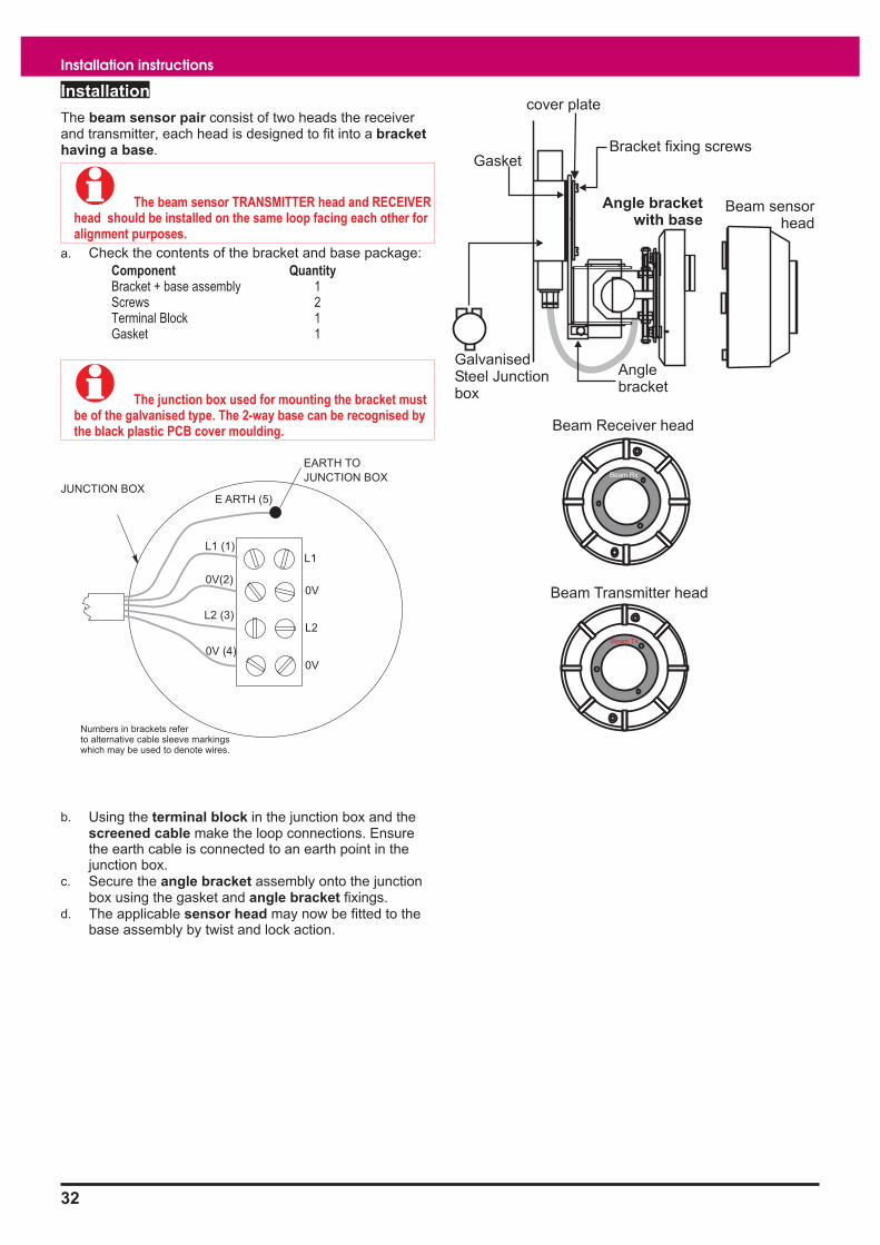
The beam sensor pair consist of two heads the receiver
and transmitter, each head is designed to fit into a bracket
having a base.
� The beam sensor TRANSMITTER head and RECEIVER
head should be installed on the same loop facing each other for
alignment purposes.
a. Check the contents of the bracket and base package:
Component Quantity
Bracket + base assembly 1
Screws 2
Terminal Block 1
Gasket 1
� The junction box used for mounting the bracket must
be of the galvanised type. The 2-way base can be recognised by
the black plastic PCB cover moulding.
b. Using the terminal block in the junction box and the
screened cable make the loop connections. Ensure
the earth cable is connected to an earth point in the
junction box.
c. Secure the angle bracket assembly onto the junction
box using the gasket and angle bracket fixings.
d. The applicable sensor head may now be fitted to the
base assembly by twist and lock action.
32
Installation instructions
JUNCTION BOX
EARTH TO
JUNCTION BOX
L1
0V
L2
0V
L1 (1)
0V (4)
0V(2)
L2 (3)
E ARTH (5)
Numbers in brackets refer
to alternative cable sleeve markings
which may be used to denote wires.
Beam Transmitter head
Beam Tx
Beam Receiver head
Beam Rx
Bracket fixing screws
cover plate
Galvanised
Steel Junction
box
Angle
bracket
Gasket
Beam sensor
head
Angle bracket
with base

Duct Sensor
The duct sensor uses probes to sample the air in ducts. If smoke is
detected in the duct then the system can action a shut-down of the
air-conditioning or ventilation system to prevent the spread of smoke.
Technical specification
Dimensions
Housing
Probes
height 160 mm
width 180mm
depth 170mm
length 0.92m supplied
Probes The probes are 0.92 metres long, but may
be cut down to suit. An extension kit allowing
probes to be extended by a further 0.92
metres is available (part no 17908-06)
Full Assembly weight 3.3Kg
Storage temperature -30 to 70ºC
Operating temperature 0 to 50°C
Relative Humidity
(Non condensing)
Temperature 5 - 45°C
up to 90%
Emission BS EN50081-1:1992 Part 1 Residential,
Commercial & Light Industry Class B limits
Immunity BS EN50130-4: 1996: Part 4
Alarm systems: Electromagnetic
compatibility
Product family standard: Immunity
requirements for components of fire, intruder
and social alarm systems
Ingress Protection IP55 estimated
Air flow in installed
environment
10m/s gusting for up to 30 minutes
5m/s continuous
Colour White
Operating voltage 20-50V
Indicators none, use the supplied slave LED (part no
78299-02NM)
Loop Maximum number per loop = 200
Load factor = 1
(load factor 1000 max per loop)
33
SENATOR ADVANCE

Installation
The duct sensor consists of a housing assembly and
probes for installation on to a ventilation duct.
a. Check contents of the DUCT SENSOR and PROBES
package:
Component Quantity
Duct Housing 1
Plastic Bungs 2
Lock Nuts 2
Inlet Probe 1
Exhaust Probe 1
Slave LED unit 1
b. Mark out the position of the two probe hole centres on
the duct.
� It is important to take into account the direction of the
air flow in the duct and probe orientations.
c. Drill or punch the two probe holes 35mm diameter in
the duct.
d. Fit the lock nut onto the threaded end of each probe
and fit the respective probe into its coupling on the
duct housing. Rotate each probe to face the required
direction in the duct and secure the lock nuts to prevent
probe from rotating.
e. Insert the probes into the duct until they reach the
opposite wall and measure the gap between the duct
housing flange and the duct wall.
f. Remove the probes from the duct and cut the probe
ends by the measured gap + 10mm.
g. Fit the plastic bungs into the probe ends.
h. Insert the probes into the duct and secure the duct
housing using the fixing holes on the flange.
i. Terminate each cable at the entry and connect the
appropriate cable ends to the terminal block.
34
Installation instructions
DUCT AIR
FLOW
AIR FLOW
TO SENSOR
AIR FLOW
FROM SENSOR
PLASTIC
BUNG
SECTION THROUGH A
DUCT
LOCK NUTS
FLANGE
TERMINAL BOX
CONDUIT HOLES
PROBE
1 ROW OF
HOLES
SMOKE INLET
SMOKE EXHAUST
PROBE
3-ROW OF
HOLES
DUCT
FLANGE
OUT IN
10mm
66mm
55mm
32mm
116mm
DUCT
2 - holes
35mm diameter
L1
0V
L2
0V
LINE
LINE
2
1
TERMINALSLOOP
DUCT AIR
FLOW
HOLES
HOLES

Sounder Strobe
The low power addressable Sounder and Strobe products provide
audible and visual alarm signals, and are designed for use in Senator
Advance analogue and addressable fire alarm systems.
The devices are configured during commissioning to operate to site
specific requirements. The devices are supplied with either a deep base
(40mm) or a shallow base (25mm), offering IP55C and IP31C ratings
respectively. The system range is available with deep base only.
These sounder strobe product range incorporates innovative
design features for which design Patents applications are pending.
The product design has also been registered.
Technical specification
Sound output for standard
tone
(levels given are typical
values with measurement
taken at 90� anechoic - fast
response)
Low profile - 100dBA
+/-3dBA
System - 103dBA
+/-3dBA
Standard (for sounder only) EN54 : Part 3
Tones and Strobe flash rate see instructions supplied with
the product
Strobe light output with red
lens
equivalent to 3W Xenon
flasher
Operating voltage range 35V - 45V
Terminal size 2.5mm2
maximum
IP rating
with deep base
with shallow base
IP55C
IP31C
Loop loading factors
Standard tone
per device
5
Standard tone with red Strobe
Standard tone with white
Strobe
15
28
Enclosure colour White and Red
(with red translucent lens
cover for the Strobe)
Enclosure material Flame retardant ABS
(Strobe cover is
polycarbonate)
Weight 0.3Kg (approximate)
Operating temperature -10�C to 50�C
Storage temperature -20�C to 70�C
Relative humidity
(non condensing)
up to 90%
35
SENATOR ADVANCE
Low profile type System type
40
112
90
60
25
75
75
112
with shallow base
35
with deep base
with deep base
120 DIA

Installation
a. Drill or knockout the required cable entry points on the
Base.
b. If using the deep base option and IP65C protection is
required, then stick the circular wall gasket on to the
centre back of the base.
c. Secure the Base to the wall whilst ensuring Top of the
base is in correct orientation.
d. Terminate the cable at the entry point leaving no more
than 10cm (4") tail wire length for connection.
e. Ensure the transparent cover is in place over the
PCB. Connect the wires to the terminal block.
f. Close the main assembly to the base.
Terminal block for retrofit installation of System
Sounder
36
Installation instructions
112
50
60
35
25mm depth
40mm depth
Shallow base
Deep base
Top
Top
Cable entry
1- Back112
Base
Gasket
Thinned section
for IR receiver
Thinned section
for IR receiver
Earth
continuity
Strap
Cable entry
2 - Top
1 - Bottom
1 - Back
Wall
Gasket
DO NOT FLUSH
MOUNT THE BASE.
TOP
02
L2
Infrared
receiver
Main assembly
# Locating pegs
for the transparent cover
#
#
PCB
Label
Transparent
cover
01
L1
Adhesive spot used
to secure the transparent cover
LC
0C
L1
01
L2
02
LC
0C
L1
01
main assembly
L2
02
base
System sounder
device (3-way)
red
black
red
black
red
black
Loop INLoop OUT
COMMON LINE
to Spur
Ensure the terminal block
is placed inside the back of the base

Manual call points
Options
The surface mountable Manual Call Point range includes:
� MCP - LPC certified
� MCP water resistant IP44
� MCP environmentally protected IP55
� MCP with lift-up cover
� MCP with lift-up cover, water resistant IP44
� Surface mounted MCP with key switch
� If the MCP is flush mounted the plastic backbox
supplied must be used. A flush fixing bezel is available.
Technical specification
Standard EN54 Part 11 (break glass type only)
Dimensions
Standard variant
Environmentally protected
height 88 mm x width 88 mm
depth 70 mm
height 180 mm x width 180 mm x
depth 130 mm
Full assembly weight 770g - approximate for standard MCP
3.5Kg - environmentally protected MCP
Storage temperature -30 to 70ºC
Operating temperature 0ºC to 50°C
Relative Humidity
(Non condensing)
Temperature 5ºC - 45°C
up to 90%
Emission BS EN50081-1:1992 Part 1 Residential,
Commercial & Light Industry Class B limits
Immunity BS EN50130-4: 1996: Part 4
Alarm systems: Electromagnetic
compatibility
Product family standard: Immunity
requirements for components of fire, intruder
and social alarm systems
Ingress Protection IP40 estimated standard type
IP44 estimated water resistant type
IP66 estimated environmentally protected
type
Colour Red
Case ABS engineering plastic
Indication Red LED that illuminates when the MCP is
operated
Testing The mechanism and operation of the MCP is
tested by using a test key
Operating voltage 20-50V
Loop Maximum number per loop = 200
Load factor = 1
(load factor 1000 max per loop)
2-way device
37
SENATOR ADVANCE
Environmentally
protected MCP
Keyswitch MCP
FIRE
88mm
88mm
surface flush
33mm70mm

Installation
Surface Fixing
a. Check the contents of the manual call point package:
Component Quantity
Call point Assembly 1
Back Box 1
Earth Link 1
Test Key 1
Long Screw 2
Small Screw 1
Gasket 1 (Only supplied
with weather resistant versions)
b. Cut the required holes on the back box for cable entry
and also on the square gasket if applicable.
c. Feed the cables through the entry holes and mount the
back box with the Square Gasket, if used, to an even
wall surface using suitable fixing.
d. Terminate each cable entry at the back box utilising the
earth link to maintain cable earth continuity.
e. Disassemble the call point assembly using the end of
the test key to open the socket head screw.
f. Feed the cable tails through the spacer/back box
gasket, if used and connect the cable ends to the loop
terminals provided in the spacer assembly.
� Ensure the spacer/back box gasket is fitted on and
around the back box profile.
g. Secure the spacer assembly to the back box using the
2 - long screws.
h. Re-assemble the cover assembly to the main
assembly with the socket head screw. To do this:
I) Fit the spacer/cover gasket, if used.
ii) Insert the glass in a sloping position.
iii) Hang the test key in its operating position.
iv) Place the cover/glass gasket, if used, over the glass
with its bevelled edge outwards.
v) Hook the cover onto the main assembly securing the
two parts with the allen screw, and remove the
test key to leave the call point in its normal
operating state.
� Check the cover/glass gasket is not trapped around
the circular rim of the cover.
vi) Fit the socket head screw to secure the cover onto
the main assembly. A weather resistant version is
supplied with a longer socket head screw.
� Semi-Flush Fixing: When flush fixing the call point,
the red plastic back box supplied must be flushed into the wall.
The procedure for installation is similar to the surface fixing
version except a MCP SEMI FLUSH KIT containing a flush plate
is required and must be installed between the back box and
spacer assembly.
The water resistant call points cannot be flush fixed.
Test
Push the test key through the hole on the underside of the call point to
engage the test cam mechanism. Push to operate the cam mechanism.
At this point the test key is retained in the call point. Pulling the test key
out will reset the glass.
38
Installation instructions
RECESSED CENTRES
FOR CABLE ENTRIES
3-TOP & 1-BOTTOM
(MAX OF 2 USABLE)SPACE FOR
BACK CABLE
ENTRY
FIXING SCREWS
2-OFF FOR PCB
ASSY MOULDING
EARTH POINT
THIS WAY UP
1.4m
FLOOR LEVEL
4-OFF DRILL OUTS FOR
CONDUIT BOX MOUNTING
NOTE : ITEMS MARKED * ARE SUPPLIED
WITH WATER RESISTANT VERSION ONLY
BACKBOX
36mm DEPTH
LOOP TERMINATIONS
LINE2
LOOP
OUT
L2 OV
LINE1
LOOP
IN
L1 OV
SQUARE GASKET
BLACK BOX
SPACER/BACK BOX GASKET
SPACER/COVER GASKET
LONG SCREWS
GLASS
COVER/GLASS GASKET
COVER
SOCKET HEAD SCREW
SPACER ASSEMBLY
10 9 8 7 6 5 4 3 2 1
1
2
3
4
5
6
7
8
9
10
88mm
88
mm
Depth: 70mm
without Gaskets
CA
LL2
CA
LL1
LED
-
LED
+
0V
LIN
E2
0v
LIN
E1
BRO
WN
BLU
E
WH
ITE
RED
0V
LIN
E1
0V
LIN
E2
CA
LL
PO
INT
CO
NTA
CTS
(ON
CO
VER)
LED
(ON
CO
VER)
LO
OP
OU
T
TON
EX
T
DEVIC
E
LO
OP
IN
FRO
MPREVIO
US
DEVIC
E
Centre mark
Cable entry points
167mm
16
5m
m
Earth terminals
EP Manual Call Point
4 - fixing points

Zone module (loop
powered)
This loop powered zone module is a single channel device, which can
accommodate up to 20 conventional detectors. The loop powered zone
module can also accommodate conventional manual call points fitted
with either a 3.9V Zener or 470 ohm resistor in series with its contacts.
� If using diode bases, the removal of more than
five detectors may prevent some MCPs from working.
� There is a maximum limit of 1Km loop cable usage
allowed per loop circuit. This maximum limit is the sum of the
cable used on main loop circuit, spurs off main loop circuit, plus
cable runs to all input / output lines off loop powered interface
units installed on the same loop.
There is a further maximum limit of 100m cable run allowed per
input / output line off loop powered interface unit.
Technical specification
Dimensions height 125mm
width 204mm
depth 50mm
Full Assembly weight 700g
Storage temperature -30ºC to 70ºC
Operating temperature 0ºC to 45ºC
Relative Humidity
(Non condensing)
Temperature 5 - 45°C
up to 90%
Emission BS EN50081-1:1992 Part 1 Residential,
Commercial & Light Industry
Class B limits
Immunity BS EN50130-4: 1996: Part 4
Alarm systems: Electromagnetic
compatibility
Product family standard: Immunity
requirements for components of fire,
intruder and social alarm systems
Ingress Protection IP40 estimated
Colour Grey/Brown and Black
Number of channels 1 channel
Input channels 2-wire input for conventional zone circuits.
Circuits are monitored for:
� Fire
� MCP fire
� Wiring open circuit fault
� Wiring short circuit fault
Monitoring conforms to BS5839 by still
detecting a MCP activation if a detector is
removed, when detector heads are fitted to
diode bases.
Maximum detector load: 20 conventional
detectors
End-of-line capacitor/diode (supplied) must
be used.
The input circuits will operate with various
manufacturers conventional detectors:
Menvier 700 series: Ionisation
Menvier 700 series: Optical
Apollo series 60: Ionisation
Apollo series 30: Ionisation
Apollo series 30: Rate of rise
Hochiki SLK-E Optical
Hochiki SIH-E Ionisation
Hochiki Comb Heat
Hochiki DFE-90E Fixed Temp
Nittan 2KC Optical Smoke
System Sensor 1151E
System Sensor 4451E
Notifier SD-651E
Thorn MR601/AFA1706 Optical
Thorn MR601T/AFA1705 High
Performance Optical
Thorn MD611/AFA 1704
Thorn MF601/AFA 1702
Thorn MS302 Ex Flame, provided;
1. The flame detector is the only device
connected to the zone.
2. The EOL is fitted directly to the flame
detector and is housed in the base.
Loop Maximum number per loop = 32
Load factor = 10
(load factor 1000 max per loop)
2 way device
39
SENATOR ADVANCE

Installation
a. Check the package contents.
b. Remove the lid to the module.
c. Check that an end-of-line capacitor is supplied with the Unit.
d. Remove the board from the unit and keep it in a safe place until required, together with the fixing screws.
e. Knockout the required cable entry points from the module sides.
f. Mark the four fixing positions on the wall to which the unit is to be mounted, secure the unit to the wall with suitable
fixings.
g. Terminate each cable at the entry point.
h. Fit the board into the module using the fixings.
i. Connect the appropriate cable ends to the terminals.
j. Secure the lid to the module.
k. Leave all outstanding installation work to the servicing organisation.
40
Installation instructions
Detection (zone) circuit
Conventional detector
with or without diode
base, if without then
MCPs must be intalled
before detectors.
Manual call point with
3.9V zener diode or 470R resistor
in series with contacts
NOTE: A maximum of up to
20 conventional devices can be
connected to the zone circuit
P3
C+
0V
Z+
End-of-line
Capacitor diode
unit
P1
D22 P3
PCB
M4 EARTHING
STUD
Shown with lid removed
140mm
79
mm
L1
0V
L2
0VC+
0V
Z+

Single channel interface
(loop powered)
This Single channel interface unit operates directly from the loop. It has
1 channel that can be configured as either an input or an output.
When the unit is set up as an output, the input channel can still be used
as a verification input of the output action.
When the unit is configured as a single input, a line module must be
installed and can be up to 100m cable distance away. The two position
switch on the module must be set to input.
When the unit is configured for multiple input, an end of line capacitor
unit must be fitted to the last input. If the multiple inputs are from manual
call points, there must be a 470 ohm resistor in series with the contacts.
As a relay output the unit provides voltage free change over contacts
rated 5A at 24Vdc / 5A at 250Vac. The relay output of the interface
operates with a system sector.
� There is a maximum limit of 1Km loop cable usage
allowed per loop circuit. This maximum limit is the sum of the
cable used on main loop circuit, spurs off main loop circuit, plus
cable runs to all input / output lines off loop powered interface
units installed on the same loop.
There is a further maximum limit of 100m cable run allowed per
input / output line off loop powered interface unit.
Technical specification
Dimensions height 125mm
width 204mm
depth 50mm
Full Assembly weight 702g
Storage temperature -30ºC to 70ºC
Operating temperature 0ºC to 45ºC
Relative Humidity
(Non condensing)
Temperature
5ºC - 45°C
up to 90%
Emission BS EN50081-1:1992 Part 1 Residential,
Commercial & Light Industry
Class B limits
Immunity BS EN50130-4: 1996: Part 4
Alarm systems: Electromagnetic compatibility
Product family standard: Immunity
requirements for components of fire, intruder
and social alarm systems
Ingress Protection IP40 estimated
Colour Grey/Brown and Black
Number of channels 1 channel, (configurable as input or output)
Input channels Single input (using optional line module):
monitors voltage free contacts,
normally open or normally closed,
inputs may be configured as:
fire,
fault,
supervisory
(with 0s or 30s delay before signal accepted)
Multiple input (with capacitor end of line unit):
monitors voltage free contacts
(in series with 470 ohm resistor for MCPs)
normally open or normally closed,
inputs may be configured as:
fire only
(with 0s or 30s delay before signal accepted)
Output channels Voltage free SPCO contacts rated at:
5 amps at 24 Vdc / 5A at 250Vac
Loop Maximum number per loop = 32
Load factor = 10
(load factor 1000 max per loop)
2-way device
41
SENATOR ADVANCE

Installation
a. Check the contents of the package.
b. Remove the lid to the module.
c. Check that an end-of-line capacitor is supplied with the Unit.
d. Remove the board from the unit and keep it in a safe place until required, together with the fixing screws.
e. Knockout the required cable entry points from the module sides.
f. Mark the four fixing positions on the wall to which the unit is to be mounted and secure the unit to the wall with
suitable fixings.
g. Terminate each cable at the entry point.
h. Refit the board into the module.
i. Connect the appropriate cable ends to the terminals.
j. Secure the lid to the module.
k. Leave all outstanding installation work to the servicing organisation.
42
Installation instructions
Line module
Single input using a line module
Multiple inputs
Switch inputP3
C+
0V
Z+
P3
C+
0V
Z+
N/C
CO
MN
/O
P2
12
S1
I/P
O/P
I/O CHAN
P1
470R
Resistor
Input 1 Input 2 Input 3 Input 4
End-of-line
Capacitor diode
unit470R
Resistor
470R
Resistor
470R
Resistor
P1
D22 P3
P2RL2SW1
Shown with lid removed
PCB
M4 EARTHING
STUD
140mm
79
mm
L1
0V
L2
0V
0V
C+
Z+
NC
COM
NO

Four channel interface
(loop powered)
This interface unit is a 4 channel device that operates directly from the
loop and does not need a separate power supply. The interface must be
used in conjunction with one or more of the following interface options:
� Line modules
Provides a single channel input or output, the output contacts
of which are rated at 24Vdc 2A. Up to 4 may be used in
conjunction with the interface. Line modules connect to the
interface with 2 wires. All four line modules may be housed
within the interface enclosure. Alternatively, any line module
may be housed in the host equipment; the limit of the 2-wire
interconnection is 100 metres with a maximum of 1km for
each loop.
� Key switches 4-position door
2-way key switch - max 4 per interface
3-way key switch - max 2 per interface
The 4-position door replaces the standard door of the
interface. The door may be assembled with up to 4 key
switches. Key switches are available in 2-way and 3-way
switch configurations and include LEDs to indicate status.
Key switches connect to the interface via push-on connectors.
Label plates are built-in to each key switch position. Unused
positions may be covered using a blanking plate (supplied).
� Power supply unit
The supply unit provides up to four 240 Vac, 5 amp rated
single pole changeover relay contacts in a separate enclosure.
Each relay is controlled by one channel of the interface. They
are interconnected by a 2-wire cable. The maximum length of
this cable is 100 metres. One relay is supplied with the supply
unit, additional relays up to 3 more can be installed and must
be ordered separately
� There is a maximum limit of 1Km loop cable usage
allowed per loop circuit. This maximum limit is the sum of the
cable used on main loop circuit, spurs off main loop circuit, plus
cable runs to all input / output lines off loop powered interface
units installed on the same loop.
There is a further maximum limit of 100m cable run allowed per
input / output line off loop powered interface unit.
Technical specification
Panel Dimensions height 270mm
width 261mm
depth 60mm
Full Assembly weight 2.4Kg
Storage temperature -30ºC to 70ºC
Operating temperature 0ºC to 45ºC
Relative Humidity
(Non condensing)
Temperature 5ºC - 45°C
up to 90%
Emission BS EN50081-1:1992 Part 1 Residential,
Commercial & Light Industry
Class B limits
Immunity BS EN50130-4: 1996: Part 4
Alarm systems: Electromagnetic
compatibility
Product family standard: Immunity
requirements for components of fire, intruder
and social alarm systems
Ingress Protection IP40 estimated
Colour Grey - Brown and Black
Number of channels 4 channels, (each configurable as input,
output or off)
Input channels (using line modules)
monitors voltage-free contacts,
normally open or normally closed.
inputs may be configured as:
� fire
� fault
� Supervisory (non-fire event)
(with 10 second sprinkler switch delay
option)
Output channels Using line modules there is voltage-free
SPCO contacts rated 2A at 24 Vdc
Using power supply unit and relays there is
voltage-free SPCO contacts rated 5A at
240 Vac
All ratings are for - resistive loads
Loop Maximum number per loop = 8
Load factor = 2
(load factor 1000 max per loop)
2-way device
43
SENATOR ADVANCE

Installation
Fuse Rating
FS1 to FS4 100mA 20mm x 5mm
a. Check the contents of the packages
Open the door using the key.
Component Quantity
Unit 1
Interface board# 1
Screws (for board)# 5
Key 1
#these components are packaged separately
b. Knockout the required cable entry points.
� Only mount the unit with cable entry points at the top.
c. Mark and drill the three hole fixing positions on the
surface to which the unit is to be mounted and secure
the unit to the surface with suitable fixings.
d. Terminate each cable at the entry point.
e. Fit the interface board using the screws provided.
f. Fit the line modules inside the backbox, if required.
g. Connect the appropriate cables ends to their respective
terminals.
� The connection of internally fitted line module should
be left for the Servicing organisation, unless otherwise
instructed.
A remotely installed line module should not be located more
than 100m cable distance away from the interface unit, assuming
1.5mm2 MICC is being used. An overall limit of 1Km loop cable
usage is allowed per loop.
h. Close the door on the unit using the key.
i. Leave all outstanding installation work to the servicing
organisation.
Keyswitch door
� Where interface unit inputs are keyswitch operated,
there is an optional replacement door. The door can
accommodate keyswitches 19245-03 (2 off 3-way keyswitch) or
19245-02 (4 off 2-way keyswitch).
.
� If a keyswitch is fitted to a channel, no line module
can be connected to that channel.
44
Installation instructions
P5 P6 P7 P8 P10 P11
P2
P1
P2
P1
P2
P1
P2
P1
EARTH LEAD
CABLE ENTRIES
6-BACK
6-TOP
INTERFACE
UNIT
UP TO 4-OFF
OPTIONAL
LINE
MODULES
BOARD
DOOR
85mm
3-off BACK and
1-off TOP
EARTH POINTS
for CABLES
CABLE ENTRIES
FOR LOOP
WIRING
14
9m
mP1
CH1
P2
CH2
P3
CH3
P4
CH4
FS1 FS2 FS3 FS4
85mm
P 5 P 6 P 7 P 8 P 1 0 P 11
P2
P1
N/C COM N/O
N/C COM N/ON/C COM N/ON/C COM N/O
I/O CHAIN
I/O CHAINI/O CHAINI/O CHAIN
CH4CH3CH2CH1
INTERFACE UNIT
(LOOP POWERED)
L1 0V L2 0V
P2
P1
P2
P1
P2
P1
OUTPUT
INPUT
Up to 100m
cable distance
Line modules can be fitted inside
the interface unit or externally.
LINE
MODULE
EXTERNAL
EQUIPMENT
1
2
3
4
P1 to P4
CONFIRMATION
LED
KEYSWITCH
KEYSWITCH DOOR
for interface unit
2-WAY KEYSWITCH
3-WAY KEYSWITCH
To -> P1, P2, P3 or P4
To -> P1 & P2
or
P3 & P4
INTERFACE BOARDKEYSWITCH ASSEMBLY
LABEL
DRESS NUT
LOCK NUT
DOOR (PART OF)
LABEL HOLDER
P1
CH1
P2
CH2
P3
CH3
P4
CH4

Power supply unit (for 4
channel loop powered
interface)
The power supply unit allows connection to external
equipment that requires switched mains voltages via
change over contacts. The change over contacts are
available at terminals P1 to P8.
Panel Dimensions height 208mm
width 222mm
depth 60mm
Full assembly weight 1.5Kg
Storage temperature -30ºC to 70ºC
Operating temperature 0ºC to 45ºC
Relative Humidity
(Non condensing)
Temperature 5ºC - 45°C
up to 90%
Emission BS EN50081-1:1992 Part 1 Residential,
Commercial & Light Industry
Class B limits
Immunity BS EN50130-4: 1996: Part 4
Alarm systems: Electromagnetic
compatibility
Product family standard: Immunity
requirements for components of fire, intruder
and social alarm systems
Ingress Protection IP40 estimated
Colour Grey - Brown and Black
Outputs 4 pairs of change over contacts rated 5A at
240Vac resistive load.
The change over of contacts occur on
operation of the respective interface output
channel.
Power indicator Green power on indicator is lit when power is
healthy
Installation
Fuse Rating Location
Mains 1A HRC 20mm x 5mm Mains terminal block
a. Check the contents of the package.
b. Using the key open the door.
c. Knockout the required cable entry points (6-off on top
of case).
� The unit must be mounted with the cable entry points
at the top of the unit.
d. Mark and drill the four fixing hole positions on the
surface to which the unit is to be mounted and secure
the unit to the surface with suitable fixings.
e. Terminate cables at the entry points and connect the
cables ends if instructed, otherwise leave tail wire
length of 400mm and mark the cores to identify the
connection point.
f. Close the door on the unit using the key.
� The unit is supplied complete with 1 PSU RELAY. The
unit is designed to operate a maximum of 4 relays. Individual
PSU RELAYs may be ordered using part code 19245-07.
g. Leave all outstanding installation work for the servicing
organisation.
45
SENATOR ADVANCE
P16
P12
P14
P15
I/O
_C
H4
I/O
_C
H3
I/O
_C
H2
I/O
_C
H1
CH4CH3CH2CH1
P5 P6 P7 P8
INTERFACE UNIT
POWER SUPPLY UNIT
100m maximum distance
RL4
P1&P2
RL3
P3&P4
RL2
P5&P6
RL1
P7&P8
POWER SUPPLY
UNIT
200mm
13
6m
m
6-OFF
TOP
CABLE
ENTRY
POINTS
DOOR
P1 P2 P3 P4 P5 P6 P7 P8 P9
P11
P12
P14
P15
P16
P18
P18
P10
RL4 RL3 RL2 RL1
P13
D10
N L
1A
Earth lead
MAINS
CABLE
ENTRY
POINT
N/O COM N/C
P1 to P8

Mains powered interface
unit
This interface unit operates from mains power and incorporates its own
battery-backed power supply. It has 4 channels, each may be configured
as input or output and are configured as conventional zone and sector
circuits respectively.
Technical specification
Dimensions height 305mm
width 504mm
depth 98mm
Full assembly weight 8.6Kg
Storage temperature -30ºC to 70ºC
Operating temperature 0ºC to 45ºC
Relative Humidity
(Non condensing)
Temperature
5ºC - 45°C
up to 90%
Mains Operating voltage 230V 50Hz +10% -6%
Input (zone) channels 2-wire inputs for conventional zone circuits.
Circuits are monitored for:
� Detector fire
� MCP fire
� Wiring open circuit fault
� Wiring short circuit fault
Monitoring conforms to BS5839 by detecting
a MCP activation if a detector is removed
providing detector heads are fitted to diode
bases
Maximum detector load: 2 mA.
End-of-line capacitor/diode (supplied) must be
used.
The input circuits may be configured to
operate with various manufacturers detectors
and MCP's: Gent, Apollo, Hochiki, Menvier,
Nittan, Notifier and Thorn
On certain sites where older type detectors
and MCPs are used that give a short circuit
fire, set rotary switch to position ‘F’.
Emission BS EN50081-1:1992 Part 1 Residential,
Commercial & Light Industry
Class B limits
Immunity BS EN50130-4: 1996: Part 4
Alarm systems: Electromagnetic compatibility
Product family standard: Immunity
requirements for components of fire, intruder
and social alarm systems
Ingress Protection IP40 estimated
Colour Grey/Brown and Black
Number of channels 4 channels, (each configurable as input or
output)
Output (sector)
channels
Output (sector) channel will operate
conventional equipment such as sounders /
bells and door holders.
A maximum current of 500mA is allowed and
can be shared between the output channels
(each fused at 800 mA).
Maximum output current per interface is
500mA
Sectors are monitored for:
� wiring open circuit fault
� wiring short circuit fault
End-of-line 22K resistor (supplied) must be
used.
Optional up to 4 Octal relays with diode packs
may be fitted within the enclosure. These
provide DPCO voltage-free contacts rated at
10 amps, 240 Vac, resistive load.
Batteries 2 - 12V 2.1Ah sealed lead acid batteries
Loop Maximum number per loop = 8
Load factor = 3
(load factor 1000 max per loop)
3-way device (terminals provided for spur
circuit)
46
Installation instructions

Installation
Fuse Rating Location
Mains 1.6A HRC - 20mm x 5mm Top left of the backbox
FS1 800mA - 20mm x 5mm Board
FS2 800mA - 20mm x 5mm Board
FS3 800mA - 20mm x 5mm Board
FS4 800mA - 20mm x 5mm Board
FS5 2.5A - 20mm x 5mm Board
FS6 250mA - 20mm x 5mm Board
a. Check the package contents, open the door using the
key and check all components.
Component Quantity
Unit 1
Interface Board# 1
Screws (for board)# 7
12V 2.1Ah Battery 2
Key 1
Battery Link 1
Battery lead assembly 1
250mA Aux Fuse (Spare) 1
1.6A Mains Fuse (Spare) 1
2.5A Battery Fuse (Spare) 1
800mA Quick Blow Fuse (Spare) 4
Capacitor Unit (EOL) 4
EOL Label 5
22k Resistor (EOL) 4
# these components are packaged separately.
b. If necessary, remove the door on the unit to ease
installation and remove the covers fitted over the
mains terminal.
c. Knockout the required cable entry points from the back
box.
d. Mark the 3 fixing positions on the wall to which the unit
is to be mounted and secure the unit to the wall with
suitable fixings.
� If the unit is to switch heavy non-mains loads, then
optional POWER RELAYS 19104-52 must be used. The relays
may be installed on the DIN rail inside the unit. The relay unit
must include a diode unit.
e. Terminate each cable at the entry point.
f. Fit the interface board inside the backbox using the
screws provided.
g. Connect the incoming cable ends to the appropriate
terminals.
h. Connect the transformer secondary wires to terminal
block P7 on the interface board.
i. Place the batteries inside the backbox, however do not
make the connection, this is done during
commissioning by the Servicing organisation.
j. Fit the cover over the mains terminal and battery
restraint bracket.
k. If removed, re-fit the door and earth lead.
� The capacitor unit and the 22k Resistor must be fitted
to the end-of-line (EOL) of each circuit. Also stick an EOL label
inside the last device on each circuit or where the EOL unit is
fitted.
l. Close the door on the Unit using the Key.
m. Leave all outstanding parts and installation work to the
Servicing organisation.
47
SENATOR ADVANCE
DIN RAIL FOR
OPTIONAL
OCTAL TYPE
RELAYS
CABLE
ENTRY
POINTS
16 - TOP
183mm
BACK BOX
NOTE: The battery
restraint brackets
are not shown.
BOARD
P3 P4 P5 P6 P2
AC AC
P7Aux
P9
Battery
P8+ - + -
CABLE
ENTRIES
FOR
LOOP
WIRING
1.6A
MAINS
FUSE
N E L
CABLE
ENTRIES
FOR
MAINS
WIRING
218mm 218mm
EARTH
LINK TO
DOOR
DOOR BATTERY
RESTRAINT
FIXING
POINT
2-OFF 12V
BATTERIES
2.1Ah
40mm
FS1 FS2 FS3 FS4
FS5
FS6
S5

External circuits Power relay
Up to 4 relays can be fitted inside the interface unit on the DIN rail.
� Octal relay operates from a 24V supply
� DIN rail mountable
� Relay coil resistance 470R
� Contacts rated 10A at 230Vac
48
Installation instructions
S1
-
S1
+
EA
RT
H Z1
ZC
1
End-of-line
22K Resistor
P3 to P6
OUTPUT USED
S1
-
S1
+
EA
RT
H Z1
ZC
1
End-of-line
Capacitor unit
P3 to P6
INPUT NOT USED
S1
-
S1
+
EA
RT
H Z1
ZC
1
P3 to P6
End-of-line
22K Resistor
Conventional
detector or MCP
S1
-
S1
+
EA
RT
H Z1
ZC
1
P3 to P6
End-of-line
Capacitor unit
INPUT USED
P2
00VV LLCC 00VV LL11 00VV LL22
COMMON
LINE
LOOP IN
LINE 1
LOOP OUT
LINE 2
LOOP WIRING
SPUR CIRCUIT
(WHERE USED)
LOOP CIRCUIT
OUTPUT NOT USED
DIODE UNIT
(TS35 DIN RAIL MOUNTABLE)
2S 3S
1S 4S
14 N/O 1
12 N/C 1
24 N/O 2
22 N/C 2
21 COM 2
COIL
A2
-ve
+ve
3S
1S4S
2S
Diode
Unit
A1
11 COM 1
2
7
3 4
1
6 5
8
6 5 4 3
24 22 12 14
A2 21 11 A1
7 8 1 2
HOLDER
TOP VIEW(TS35 DIN RAIL MOUNTABLE)

Senator Advance system parts
This section lists parts that can be used in the Senator Advance system. For further details on the availability of the parts, contact your supplier.
Control Panels
The panel is supplied as first and second fix assemblies in separate packages.
SENADV Control panel (EN54) c/w 1 - Loop card (requires 2-12V 12Ah batteries - not supplied)
Accessories
SENADV-FLUSH Control panel semi flushing bezel
SENADV-FLUSH-SS Stainless steel semi flush frame for control panel
SENADV-DR-SS Stainless steel outer door
SENADV-OUT-DR Senator advance replacement outer door
SENADV-INN-DR Senator Advance inner door assembly
4015-514 1 - 12V 12Ahr Battery
SENADV-LPC Loop Card (EN54)
2434t675 PSU
Printer
PRINTER-DESK Desktop serial thermal printer
PRINTER-HAND Handheld serial thermal printer
PRINTER-H-PAPER Thermal paper for handheld printer
PRINTER-D-PAPER Thermal paper for desktop printer
Repeat panel
SENADV-IND Repeat indicator panel (connects directly to the control panel)
T Breaker and Slaves
78299-01NM T breaker Unit
78299-02NM Slave LED unit
78299-03NM Slave Relay unit
49
SENATOR ADVANCE

Sensors
78215-01NM Optical sensor
78215-11NM Replacement chamber for Optical sensor
78280-01NM Optical sensor sounder
78215-11NM Replacement Optical chamber
78210-01NM Optical heat sensor
78215-11NM Replacement Optical chamber
78270-01NM Optical heat sounder
78215-11NM Replacement Optical chamber
78220-01NM Heat sensor
78220-11NM Replacement heat chamber
78285-01NM Heat sounder
78220-11NM Replacement heat sounder chamber
34740 Beam sensor pair
34741-01 Angle bracket with base
4334-035 Light shield for beams
78260-01NM Duct sensor (inc Probes
& 34702 Slave LED unit)
Terminal Plate
78200-01NM 2-way terminal plate
19279-01 Semi-flush sensor mounting kit
19279-10 Sensor trim ring (10 pack)
19270-50 Sensor dust cover (50 pack)
Tools
78290-01NM Sensor chamber extraction tool - removes chambers
78290-05NM Sensor electronic module extraction tool
50
Installation instructions

Sounder and Strobe
Sounder
SENADV-IP-SN-W Sounder (system type) white body IP55
SENADV-IP-SN-R Sounder (system type) red body IP55
78400-03NM Sounder (system type) white body IP55
The 78400-03NM product are suitable for retrofitting and is supplied with a 6-way terminal block to ease wiring.
SENADV-SN-W Sounder (low profile) white body IP31
SENADV-SN-R Sounder (low profile) red body IP31
Strobe
SENADV-IP-ST-RR Strobe (low profile) red body IP65 red lens
SENADV-IP-ST-WR Strobe (low profile) white body IP65 red lens
Sounder Strobe
SENADV-IP-SN-ST-RR Sounder Strobe (low profile) red body and red lens IP65
SENADV-IP-SN-ST-WR Sounder Strobe (low profile) white body and red lens IP65
Manual call points (MCP) 2-way
78150-52NM-EN Surface mounted MCP
78155-52NM Surface mounted keyswitch MCP
78150-55NM Surface mounted MCP with cover
78150-22NM Surface mounted water resistant MCP- IP44
78150-98NM MCP flush fixing plate
78150-25NM Surface mounted water resistant MCP with cover - IP44
SPK0457 Environmentally protected surface mounted MCP
71150-90NM-EN EN54 MCP glasses 10 pack
71150-95-EN BS to EN - MCP Conversion kit
51
SENATOR ADVANCE

Interfaces
4- Channel mains powered interface
78301-01NM Mains powered fire alarm interface
19104-52 Power relay (for mains powered interface)
(up to 4 maximum can be fitted inside the interface - supplied with base and diode unit)
4- Channel loop powered interface
78321-01NM 4 - Channel loop powered fire alarm interface
78345-05NM Interface line module
-up to 4 can be fitted in a 4 channel loop powered fire alarm interface
78345-04NM 4 way keyswitch door for 4-channel loop powered interface
78345-02 2 position keyswitch assembly (for use with optional interface doors)
78345-03 3-position keyswitch assembly (for use with optional interface doors)
Power supply unit
78345-06NM Power supply unit with 1 relay (for use with loop powered interface unit)
78345-88NM Mains relay (up to 4 for use with 19245-06 unit)
1- Channel loop powered interface
78310-01NM Loop powered zone module
78315-01NM Single Channel loop powered interface
78345-05NM Interface line module
Surge protection
5530440 1 x Mains, 1 x Loop & 1 x Zone/Sector suppression
(enclosure has space for 1 extra loop (2 x 2817958)
5530478 1 x Mains suppressor
2817958 1 x Additional Loop suppressor (module only)
Replacement Plug ins
2798844 Mains suppressor
2839648 Loop suppressor
2838351 Zone / Sector suppressor
Manuals
4188-766 Senator Advance Installation instructions
4188-765 Senator Advance Operating instructions
4188-749 Log book
52
Installation instructions

Notes
53
SENATOR ADVANCE

Notes
54
Installation instructions

Notes
55
SENATOR ADVANCE
