fire alarm control panel ms-4412b ms-4424b · pdf filefire alarm control panel ms-4412b...
TRANSCRIPT

Fire Alarm Control Panel
MS-4412BMS-4424B
Instruction Manual
Document 1512510/22/2002 Rev: G
PN 15125:G1 ECN 02-539
LimWarLg.p65 01/10/2000
An automatic fire alarm system–typically made up of smokedetectors, heat detectors, manual pull stations, audible warn-ing devices, and a fire alarm control with remote notificationcapability–can provide early warning of a developing fire.Such a system, however, does not assure protection againstproperty damage or loss of life resulting from a fire.
The Manufacturer recommends that smoke and/or heat detec-tors be located throughout a protected premise following therecommendations of the current edition of the National FireProtection Association Standard 72 (NFPA 72),manufacturer's recommendations, State and local codes, andthe recommendations contained in the Guide for Proper Useof System Smoke Detectors, which is made available at nocharge to all installing dealers. A study by the Federal Emer-gency Management Agency (an agency of the United Statesgovernment) indicated that smoke detectors may not go off inas many as 35% of all fires. While fire alarm systems are de-signed to provide early warning against fire, they do not guar-antee warning or protection against fire. A fire alarm systemmay not provide timely or adequate warning, or simply may notfunction, for a variety of reasons:
Smoke detectors may not sense fire where smoke cannotreach the detectors such as in chimneys, in or behind walls, onroofs, or on the other side of closed doors. Smoke detectorsalso may not sense a fire on another level or floor of a build-ing. A second-floor detector, for example, may not sense afirst-floor or basement fire.
Particles of combustion or "smoke" from a developing firemay not reach the sensing chambers of smoke detectors be-cause:
• Barriers such as closed or partially closed doors, walls, orchimneys may inhibit particle or smoke flow.
• Smoke particles may become "cold," stratify, and not reachthe ceiling or upper walls where detectors are located.
• Smoke particles may be blown away from detectors by airoutlets.
• Smoke particles may be drawn into air returns beforereaching the detector.
The amount of "smoke" present may be insufficient to alarmsmoke detectors. Smoke detectors are designed to alarm atvarious levels of smoke density. If such density levels are notcreated by a developing fire at the location of detectors, thedetectors will not go into alarm.
Smoke detectors, even when working properly, have sensinglimitations. Detectors that have photoelectronic sensingchambers tend to detect smoldering fires better than flamingfires, which have little visible smoke. Detectors that have ion-izing-type sensing chambers tend to detect fast-flaming firesbetter than smoldering fires. Because fires develop in differ-ent ways and are often unpredictable in their growth, neithertype of detector is necessarily best and a given type of detec-tor may not provide adequate warning of a fire.
Smoke detectors cannot be expected to provide adequatewarning of fires caused by arson, children playing withmatches (especially in bedrooms), smoking in bed, and violentexplosions (caused by escaping gas, improper storage offlammable materials, etc.).
Heat detectors do not sense particles of combustion andalarm only when heat on their sensors increases at a prede-termined rate or reaches a predetermined level. Rate-of-riseheat detectors may be subject to reduced sensitivity over time.For this reason, the rate-of-rise feature of each detectorshould be tested at least once per year by a qualified fire pro-tection specialist. Heat detectors are designed to protectproperty, not life.
IMPORTANT! Smoke detectors must be installed in thesame room as the control panel and in rooms used by the sys-tem for the connection of alarm transmission wiring, communi-cations, signaling, and/or power. If detectors are not so lo-cated, a developing fire may damage the alarm system, crip-pling its ability to report a fire.
Audible warning devices such as bells may not alert peopleif these devices are located on the other side of closed orpartly open doors or are located on another floor of a building.Any warning device may fail to alert people with a disability orthose who have recently consumed drugs, alcohol or medica-tion. Please note that:
• Strobes can, under certain circumstances, cause seizuresin people with conditions such as epilepsy.
• Studies have shown that certain people, even when theyhear a fire alarm signal, do not respond or comprehend themeaning of the signal. It is the property owner's responsibil-ity to conduct fire drills and other training exercise to makepeople aware of fire alarm signals and instruct them on theproper reaction to alarm signals.
• In rare instances, the sounding of a warning device cancause temporary or permanent hearing loss.
A fire alarm system will not operate without any electricalpower. If AC power fails, the system will operate from standbybatteries only for a specified time and only if the batterieshave been properly maintained and replaced regularly.
Equipment used in the system may not be technically com-patible with the control. It is essential to use only equipmentlisted for service with your control panel.
Telephone lines needed to transmit alarm signals from apremise to a central monitoring station may be out of serviceor temporarily disabled. For added protection against tele-phone line failure, backup radio transmission systems are rec-ommended.
The most common cause of fire alarm malfunction is inade-quate maintenance. To keep the entire fire alarm system inexcellent working order, ongoing maintenance is required perthe manufacturer's recommendations, and UL and NFPA stan-dards. At a minimum, the requirements of Chapter 7 of NFPA72 shall be followed. Environments with large amounts ofdust, dirt or high air velocity require more frequent mainte-nance. A maintenance agreement should be arrangedthrough the local manufacturer's representative. Maintenanceshould be scheduled monthly or as required by National and/or local fire codes and should be performed by authorized pro-fessional fire alarm installers only. Adequate written recordsof all inspections should be kept.
While a fire alarm system may lower insurancerates, it is not a substitute for fire insurance!Fire Alarm System Limitations
LimWarLg.p65 01/10/2000
WARNING - Several different sources of power can be con-nected to the fire alarm control panel. Disconnect all sourcesof power before servicing. Control unit and associated equip-ment may be damaged by removing and/or inserting cards,modules, or interconnecting cables while the unit is energized.Do not attempt to install, service, or operate this unit until thismanual is read and understood.
CAUTION - System Reacceptance Test after SoftwareChanges. To ensure proper system operation, this productmust be tested in accordance with NFPA 72 Chapter 7 afterany programming operation or change in site-specific soft-ware. Reacceptance testing is required after any change, ad-dition or deletion of system components, or after any modifica-tion, repair or adjustment to system hardware or wiring.
All components, circuits, system operations, or software func-tions known to be affected by a change must be 100% tested.In addition, to ensure that other operations are not inadvert-ently affected, at least 10% of initiating devices that are notdirectly affected by the change, up to a maximum of 50 de-vices, must also be tested and proper system operation veri-fied.
This system meets NFPA requirements for operation at0-49° C/32-120° F and at a relative humidity of 85% RH (non-condensing) at 30° C/86° F. However, the useful life of thesystem's standby batteries and the electronic componentsmay be adversely affected by extreme temperature rangesand humidity. Therefore, it is recommended that this systemand all peripherals be installed in an environment with a nomi-nal room temperature of 15-27° C/60-80° F.
Verify that wire sizes are adequate for all initiating andindicating device loops. Most devices cannot tolerate morethan a 10% I.R. drop from the specified device voltage.
Like all solid state electronic devices, this system mayoperate erratically or can be damaged when subjected to light-ning-induced transients. Although no system is completelyimmune from lightning transients and interferences, propergrounding will reduce susceptibility. Overhead or outsideaerial wiring is not recommended, due to an increased sus-ceptibility to nearby lightning strikes. Consult with the Techni-cal Services Department if any problems are anticipated orencountered.
Disconnect AC power and batteries prior to removing or in-serting circuit boards. Failure to do so can damage circuits.
Remove all electronic assemblies prior to any drilling, filing,reaming, or punching of the enclosure. When possible, makeall cable entries from the sides or rear. Before making modifi-cations, verify that they will not interfere with battery, trans-former, and printed circuit board location.
Do not tighten screw terminals more than 9 in-lbs.Over-tightening may damage threads, resulting in reducedterminal contact pressure and difficulty with screw terminalremoval.
Though designed to last many years, system componentscan fail at any time. This system contains static-sensitivecomponents. Always ground yourself with a proper wrist strapbefore handling any circuits so that static charges are re-moved from the body. Use static-suppressive packagingto protect electronic assemblies removed from the unit.
Follow the instructions in the installation, operating, andprogramming manuals. These instructions must be followedto avoid damage to the control panel and associatedequipment. FACP operation and reliability depend uponproper installation by authorized personnel.
Adherence to the following will aid in problem-freeinstallation with long-term reliability:
WARNING: This equipment generates, uses, and canradiate radio frequency energy and if not installed andused in accordance with the instruction manual, maycause interference to radio communications. It hasbeen tested and found to comply with the limits for classA computing device pursuant to Subpart B of Part 15 ofFCC Rules, which is designed to provide reasonableprotection against such interference when operated in acommercial environment. Operation of this equipment ina residential area is likely to cause interference, in whichcase the user will be required to correct the interferenceat his own expense.
Canadian RequirementsThis digital apparatus does not exceed the Class Alimits for radiation noise emissions from digitalapparatus set out in the Radio Interference Regulationsof the Canadian Department of Communications.
Le present appareil numerique n'emet pas de bruitsradioelectriques depassant les limites applicables auxappareils numeriques de la classe A prescrites dans leReglement sur le brouillage radioelectrique edicte par leministere des Communications du Canada.
FCC Warning
Installation Precautions
NFPA Standards
4 MS-4412B/MS-4424B Instruction Manual PN 15125:G1 10/22/02
NFPA StandardsThis control panel complies with the following NFPA standards:
• NFPA 72 - Central Station Signaling Systems (Automatic, Manual, and Waterflow) - Protected Premises UnitRequires NOTI-FIRE 911AC DACT or 411UDAC Universal Digital Alarm Communicator
• NFPA 72 - Local Fire Alarm Systems (Automatic, Manual, Waterflow and Sprinkler Supervisory)• NFPA 72 - Auxiliary Fire Alarm Systems (Automatic, Manual, and Waterflow)
Requires 4XTMF• NFPA 72 - Remote Station Fire Alarm Systems (Automatic, Manual, and Waterflow)
Requires 4XTMF or NOTI•FIRE 911AC DACT or 411UDAC• NFPA 72 - Proprietary Fire Alarm Systems (Automatic, Manual, and Waterflow)
Requires Potter EFT-C McCulloh Transmitter.Note: Applications which require the NOTI-FIRE 911AC, or the Potter EFT-C are not FM approved.
NFPA Standards • NFPA 72 - Installation, Maintenance, and Use of Central Station Signaling Systems• NFPA 72 - Local, Auxiliary, Remote Station and Proprietary Fire Alarm Systems• NFPA 72 - Automatic Fire Detectors• NFPA 72 - Installation, Maintenance, and Use of Notification Appliances for Protective Signaling
Systems• NFPA 72 - Testing Procedures for Signaling Systems
Underwriters Laboratories Documents • UL 38 - Manually Actuated Signaling Boxes• UL 217 - Smoke Detectors, Single and Multiple Station• UL 228 - Door Closers - Holders for Fire Alarm Systems• UL 268 - Smoke Detectors for Fire Alarm Systems• UL 268A - Smoke Detectors for Duct Applications• UL 346 - Waterflow Indicators for Fire Protective Signaling Systems• UL 464 - Audible Signaling Appliances• UL 521 - Heat Detectors for Fire Protective Signaling Systems• UL 864 - Standard for Control Units for Fire Alarm Systems• UL 1481 - Power Supplies for Fire Protective Signaling Systems• UL 1638 - Visual Signaling Appliances• UL 1971 - Signaling Devices for the Hearing Impaired• CAN/ULC-S524-M91 Standard for Installation of Fire Alarm Systems • CAN/ULC-S527-M87 Standard for Control Units for Fire Alarm System
Other• NEC Article 300 - Wiring Methods• NEC Article 760 - Fire Protective Signaling Systems• Applicable Local and State Building Codes• Requirements of the Local Authority Having Jurisdiction• Fire•Lite Device Compatibility Document, 15384.• ADA - Americans with Disabilities Act
Before proceeding, the installer should be familiar with the following documents.
Table of Contents
MS-4412B/MS-4424B Instruction Manual PN 15125:G1 10/22/02 5
Table of ContentsNFPA Standards.......................................................................................................... 4
NFPA Standards .................................................................................................... 4Underwriters Laboratories Documents ................................................................. 4Other....................................................................................................................... 4
1. Product DescriptionOverview ...................................................................................................................... 7Features ....................................................................................................................... 7Options ........................................................................................................................ 7Circuits ......................................................................................................................... 8
Input Circuits.......................................................................................................... 8Output circuits........................................................................................................ 8Front Panel Control Switches ................................................................................ 8
Suplemental Documentation ...................................................................................... 8Control Panel ............................................................................................................... 9DIP Switch Functions................................................................................................ 10Options ....................................................................................................................... 10
Transmitter Module - 4XTMF (12V: 4412TM) ................................................. 10Zone Relay Module - 4XZMF (12V: 4412ZM) .................................................. 11Remote Annunciator - RZA-4XF ....................................................................... 11LED Interface Module - 4XLMF (12V: 4412LM) ............................................. 11
Specifications ............................................................................................................. 12AC Power............................................................................................................. 12Battery (lead acid only)........................................................................................ 12Initiating Device Circuits ..................................................................................... 12Notification Appliance Circuits ........................................................................... 12Alarm and Trouble Relays ................................................................................... 12Resettable Power.................................................................................................. 12Nonresettable Power ............................................................................................ 12RMS Rregulated Power ....................................................................................... 12
2. InstallationCabinet Mounting ..................................................................................................... 13
Removal of Circuit Board .................................................................................... 13Mounting of Cabinet ............................................................................................ 13Attaching Conduit ................................................................................................ 13Reinstallation of Circuit Board ............................................................................ 14
Power Connections.................................................................................................... 15AC Connections ................................................................................................... 15Battery (DC) Connections.................................................................................... 15
24 Volt Connections ..................................................................................... 1612 Volt Connections ..................................................................................... 16
Power-limited Wiring Requirements ...................................................................... 16Initiating Device Circuits.......................................................................................... 17
Four-Wire Smoke Detector Connections ............................................................. 18
Output Circuits.......................................................................................................... 19Notification Appliance Circuits ........................................................................... 19Supervisory Configuration................................................................................... 20Alarm Relay ......................................................................................................... 20Trouble Relay....................................................................................................... 20
Powering External Devices....................................................................................... 21Optional Modules ...................................................................................................... 22
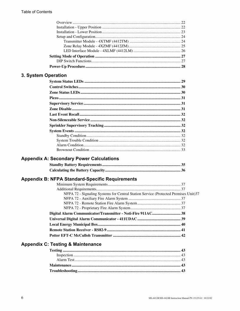
Table of Contents
6 MS-4412B/MS-4424B Instruction Manual PN 15125:G1 10/22/02
Overview .............................................................................................................. 22Installation - Upper Position ................................................................................ 22Installation - Lower Position ................................................................................ 23Setup and Configuration....................................................................................... 24
Transmitter Module - 4XTMF (4412TM) .................................................... 24Zone Relay Module - 4XZMF (4412ZM)..................................................... 25LED Interface Module - 4XLMF (4412LM) ................................................ 26
Setting Mode of Operation ....................................................................................... 27DIP Switch Functions........................................................................................... 27
Power-Up Procedure ................................................................................................. 28
3. System OperationSystem Status LEDs .................................................................................................. 29Control Switches........................................................................................................ 30Zone Status LEDs...................................................................................................... 30Piezo ............................................................................................................................ 31Supervisory Service ................................................................................................... 31Zone Disable............................................................................................................... 31Last Event Recall ....................................................................................................... 32Non-Silenceable Service ............................................................................................ 32Sprinkler Supervisory Tracking .............................................................................. 32System Events ............................................................................................................ 32
Standby Condition................................................................................................ 32System Trouble Condition ................................................................................... 32Alarm Condition................................................................................................... 32Brownout Condition............................................................................................. 33
Appendix A: Secondary Power CalculationsStandby Battery Requirements ................................................................................ 35Calculating the Battery Capacity............................................................................. 36
Appendix B: NFPA Standard-Specific RequirementsMinimum System Requirements.......................................................................... 37Additional Requirements...................................................................................... 37
NFPA 72 - Signaling Systems for Central Station Service (Protected Premises Unit)37NFPA 72 - Auxiliary Fire Alarm System ..................................................... 37NFPA 72 - Remote Station Fire Alarm System............................................ 37NFPA 72 - Proprietary Fire Alarm System................................................... 37
Digital Alarm Communicator/Transmitter - Noti-Fire 911AC............................. 38Universal Digital Alarm Communicator - 411UDAC ............................................ 39Local Energy Municipal Box.................................................................................... 40Remote Station Receiver - RS82-9 ........................................................................... 41Potter EFT-C McCulloh Transmitter ..................................................................... 42
Appendix C: Testing & MaintenanceTesting ........................................................................................................................ 43
Inspection ............................................................................................................. 43Alarm Test............................................................................................................ 43
Maintenance............................................................................................................... 43Troubleshooting......................................................................................................... 43
MS-4412B/MS-4424B Instruction Manual PN 15125:G1 10/22/02 7
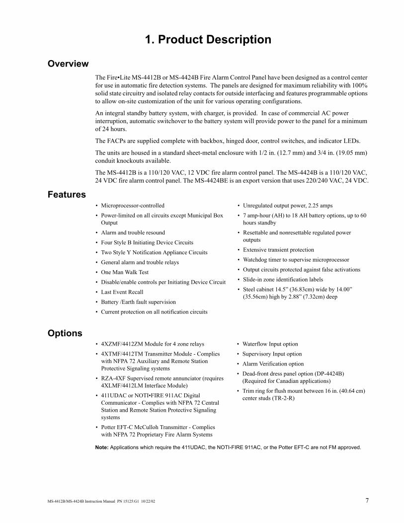
1. Product Description
Overview The Fire•Lite MS-4412B or MS-4424B Fire Alarm Control Panel have been designed as a control center for use in automatic fire detection systems. The panels are designed for maximum reliability with 100% solid state circuitry and isolated relay contacts for outside interfacing and features programmable options to allow on-site customization of the unit for various operating configurations.
An integral standby battery system, with charger, is provided. In case of commercial AC power interruption, automatic switchover to the battery system will provide power to the panel for a minimum of 24 hours.
The FACPs are supplied complete with backbox, hinged door, control switches, and indicator LEDs.
The units are housed in a standard sheet-metal enclosure with 1/2 in. (12.7 mm) and 3/4 in. (19.05 mm) conduit knockouts available.
The MS-4412B is a 110/120 VAC, 12 VDC fire alarm control panel. The MS-4424B is a 110/120 VAC, 24 VDC fire alarm control panel. The MS-4424BE is an export version that uses 220/240 VAC, 24 VDC.
Features
Options
Note: Applications which require the 411UDAC, the NOTI-FIRE 911AC, or the Potter EFT-C are not FM approved.
• Microprocessor-controlled
• Power-limited on all circuits except Municipal Box Output
• Alarm and trouble resound
• Four Style B Initiating Device Circuits
• Two Style Y Notification Appliance Circuits
• General alarm and trouble relays
• One Man Walk Test
• Disable/enable controls per Initiating Device Circuit
• Last Event Recall
• Battery /Earth fault supervision
• Current protection on all notification circuits
• Unregulated output power, 2.25 amps
• 7 amp-hour (AH) to 18 AH battery options, up to 60 hours standby
• Resettable and nonresettable regulated power outputs
• Extensive transient protection
• Watchdog timer to supervise microprocessor
• Output circuits protected against false activations
• Slide-in zone identification labels
• Steel cabinet 14.5” (36.83cm) wide by 14.00” (35.56cm) high by 2.88” (7.32cm) deep
• 4XZMF/4412ZM Module for 4 zone relays
• 4XTMF/4412TM Transmitter Module - Complies with NFPA 72 Auxiliary and Remote Station Protective Signaling systems
• RZA-4XF Supervised remote annunciator (requires 4XLMF/4412LM Interface Module)
• 411UDAC or NOTI•FIRE 911AC Digital Communicator - Complies with NFPA 72 Central Station and Remote Station Protective Signaling systems
• Potter EFT-C McCulloh Transmitter - Complies with NFPA 72 Proprietary Fire Alarm Systems
• Waterflow Input option
• Supervisory Input option
• Alarm Verification option
• Dead-front dress panel option (DP-4424B) (Required for Canadian applications)
• Trim ring for flush mount between 16 in. (40.64 cm) center studs (TR-2-R)
1. Product Description Circuits
8 MS-4412B/MS-4424B Instruction Manual PN 15125:G1 10/22/02
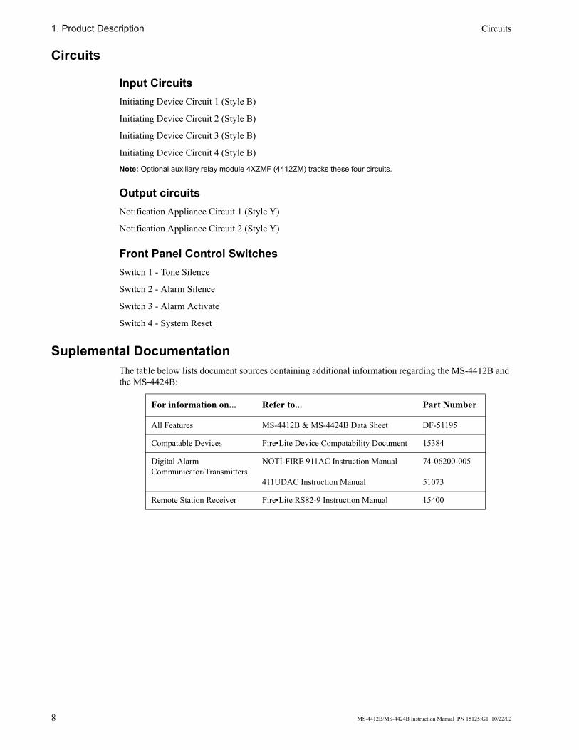
Circuits
Input Circuits Initiating Device Circuit 1 (Style B)
Initiating Device Circuit 2 (Style B)
Initiating Device Circuit 3 (Style B)
Initiating Device Circuit 4 (Style B)
Note: Optional auxiliary relay module 4XZMF (4412ZM) tracks these four circuits.
Output circuits Notification Appliance Circuit 1 (Style Y)
Notification Appliance Circuit 2 (Style Y)
Front Panel Control Switches Switch 1 - Tone Silence
Switch 2 - Alarm Silence
Switch 3 - Alarm Activate
Switch 4 - System Reset
Suplemental Documentation The table below lists document sources containing additional information regarding the MS-4412B and the MS-4424B:
For information on... Refer to... Part Number
All Features MS-4412B & MS-4424B Data Sheet DF-51195
Compatable Devices Fire•Lite Device Compatability Document 15384
Digital Alarm Communicator/Transmitters
NOTI-FIRE 911AC Instruction Manual
411UDAC Instruction Manual
74-06200-005
51073
Remote Station Receiver Fire•Lite RS82-9 Instruction Manual 15400
Control Panel 1. Product Description
MS-4412B/MS-4424B Instruction Manual PN 15125:G1 10/22/02 9
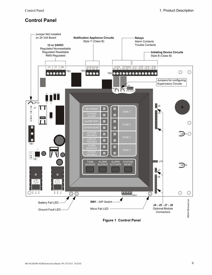
Control Panel
Figure 1 Control Panel
TONESILENCE
ALARMSILENCE
ALARMACTIVATE
SYSTEMRESET
AC POWER
SYSTEMALARM
ALARM TEST
SUPERVISORY
SYSTEMTROUBLE
CIRCUITTROUBLE
ALARMSILENCED
POWERTROUBLE
ZONE 1
ZONE 3
ZONE 4
SW1
TB2 TB3TB4
J4
J5
J7
J8
OPT1
OPT2J10
J9
J1
JP12
TB1
OUT#1B+ B–
OUT#2B+ B–
IN #2B+ B–
IN #3B+ B–
IN #4B+ B–
SUPV 1 SUPV 2JP1
MS4
412B
-boa
rd.c
dr
Battery Fail LED
Ground Fault LED
SW1 - DIP Switch
Micro Fail LEDJ4 - J5 - J7 - J8Optional Module
Connectors
Notification Appliance CircuitsStyle Y (Class B)
RelaysAlarm ContactsTrouble Contacts
Initiating Device CircuitsStyle B (Class B)
12 or 24VDCRegulated Nonresettable
Regulated ResettableRMS-Regulated
Jumpers for configuring Supervisory Circuits
Jumper Not Installed on 24 Volt Board

1. Product Description DIP Switch Functions
10 MS-4412B/MS-4424B Instruction Manual PN 15125:G1 10/22/02
DIP Switch Functions The table below describes the DIP switch functions. For a more detailed explaination see "Setting Mode of Operation" on page 27.
Options Three optional modules are available for use on the control panel. The control panel provides mounting slots for two of these optional module boards.
Transmitter Module - 4XTMF (12V: 4412TM) The Transmitter Module provides a supervised output for a Local Energy Municipal Box transmitter and alarm and trouble reverse polarity circuits for Remote Station Service. Also included is a DISABLE switch and disable trouble LED.
Note: As a jumper option, the alarm reverse polarity circuit will open on trouble if no alarm exists.
Specifications for Local Energy Municipal Box service (NFPA 72 Auxiliary Fire Alarm System)
Supervisory current: 5.0 mA.Trip current: 0.35 amps (subtracted from Notification Appliance power).Coil Voltage: 3.65 VDC.Coil resistance: 14.6 ohms.Maximum allowable wire resistance between panel and trip coil: 3 ohms.Municipal Box wiring can leave the building.
Specifications for Remote Station Service (NFPA 72 Remote Station Fire Alarm System)
Maximum load for each circuit: 10 mA.Reverse polarity output voltage: 12 or 24 VDC.Remote Alarm and Remote Trouble wiring can leave the building.
#1 Alarm Verification
ON Alarm Verification enabled (two-minute period).OFF No verification employed.
#2 Waterflow ON Zone 3 configured for Waterflow.OFF Zone 3 functions as a normal Initiating Device Circuit.
#3 Supervisory ON Zone 4 configured for Supervisory.OFF Zone 4 functions as a normal Initiating Device Circuit.
#4 Silence Inhibit
ON Alarm Silence will not function for 60 seconds after initiation of an alarm.OFF Alarm Silence is possible at any time after initiation of an alarm.
#5 Disable NACs
ON Two Notification Appliance Circuits and the Alarm Relay are disabled.OFF Two Notification Appliance Circuits and the Alarm Relay are enabled.
#6 Walk Test ON Places the panel into Walk Test Mode.OFF Normal Operating Mode.
Note: See “Setting Mode of Operation” on page 27 for a more detailed explanation of DIP switch functions.
TB1
TBL
J1
J2
4XTM
F.cd
r
Options 1. Product Description
MS-4412B/MS-4424B Instruction Manual PN 15125:G1 10/22/02 11
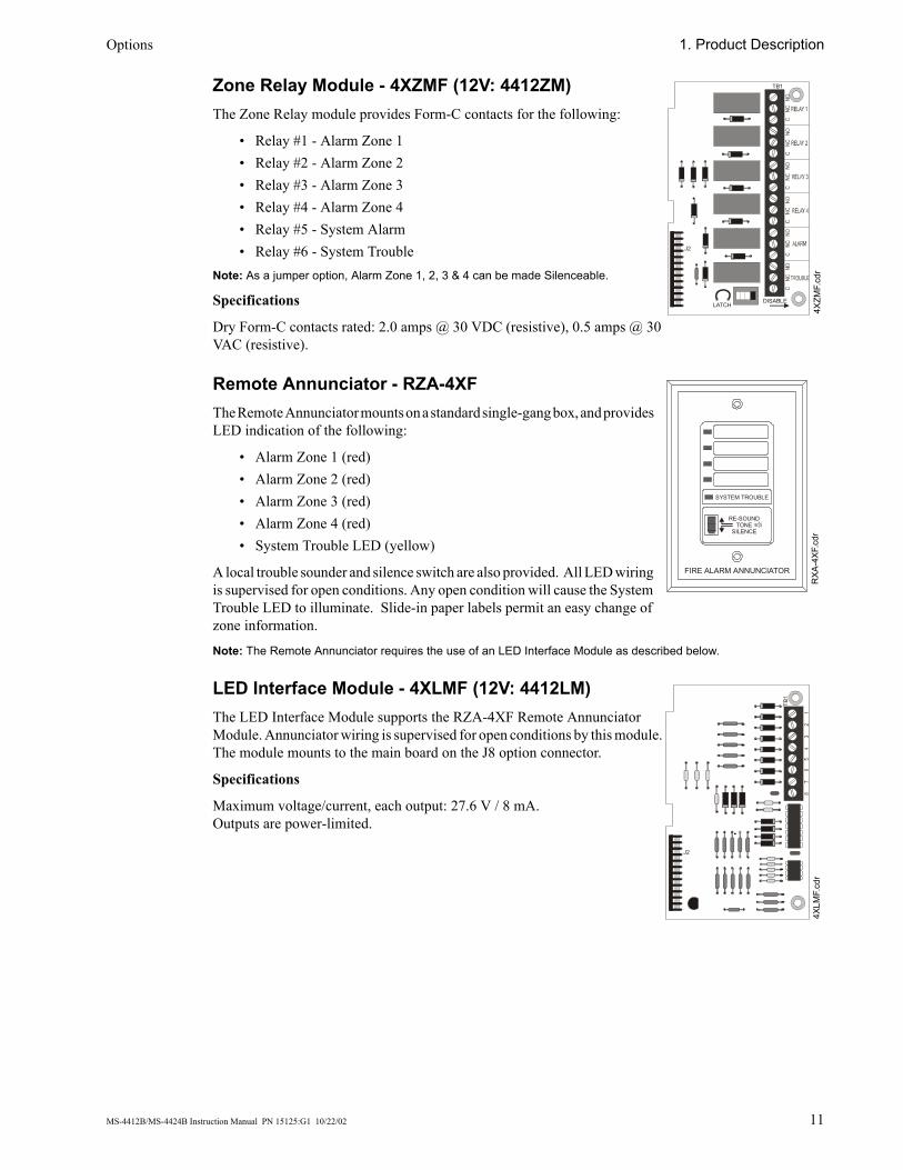
Zone Relay Module - 4XZMF (12V: 4412ZM) The Zone Relay module provides Form-C contacts for the following:
• Relay #1 - Alarm Zone 1• Relay #2 - Alarm Zone 2• Relay #3 - Alarm Zone 3• Relay #4 - Alarm Zone 4• Relay #5 - System Alarm• Relay #6 - System Trouble
Note: As a jumper option, Alarm Zone 1, 2, 3 & 4 can be made Silenceable.
Specifications
Dry Form-C contacts rated: 2.0 amps @ 30 VDC (resistive), 0.5 amps @ 30 VAC (resistive).
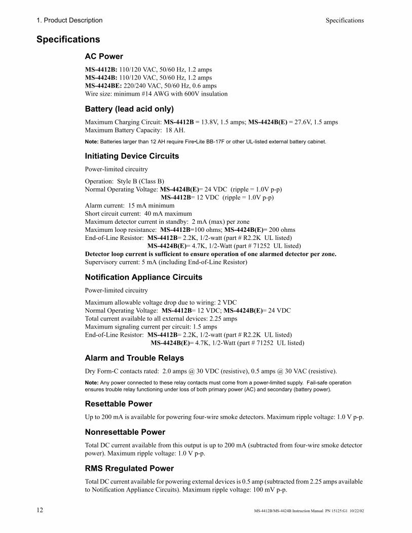
Remote Annunciator - RZA-4XF The Remote Annunciator mounts on a standard single-gang box, and provides LED indication of the following:
• Alarm Zone 1 (red)• Alarm Zone 2 (red)• Alarm Zone 3 (red)• Alarm Zone 4 (red)• System Trouble LED (yellow)
A local trouble sounder and silence switch are also provided. All LED wiring is supervised for open conditions. Any open condition will cause the System Trouble LED to illuminate. Slide-in paper labels permit an easy change of zone information.
Note: The Remote Annunciator requires the use of an LED Interface Module as described below.
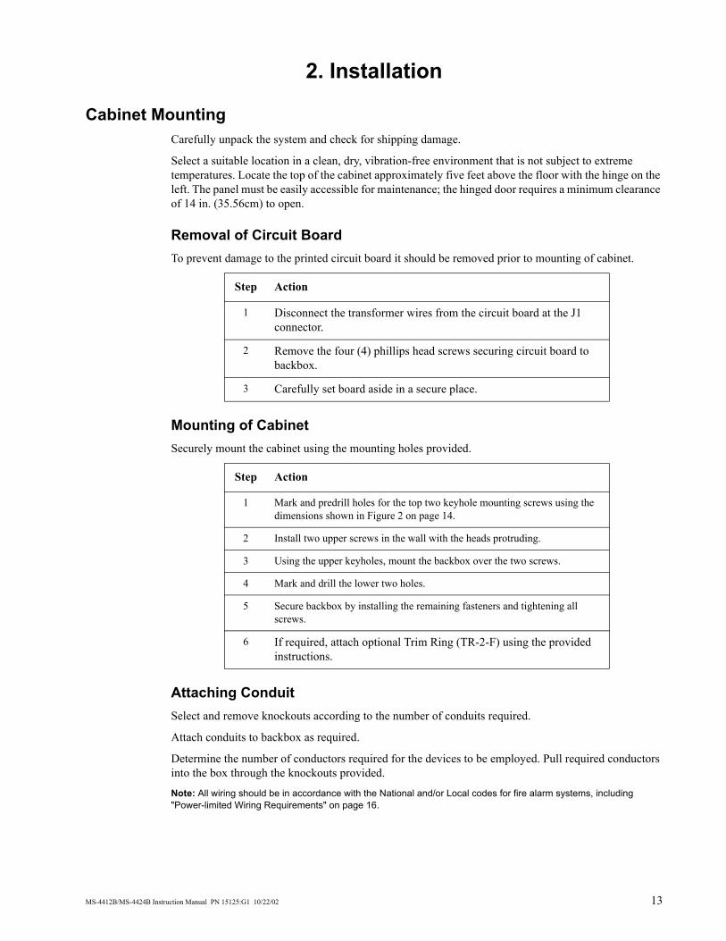
LED Interface Module - 4XLMF (12V: 4412LM) The LED Interface Module supports the RZA-4XF Remote Annunciator Module. Annunciator wiring is supervised for open conditions by this module. The module mounts to the main board on the J8 option connector.
Specifications
Maximum voltage/current, each output: 27.6 V / 8 mA.Outputs are power-limited.
TB1
LATCHDISABLE
J2
4XZM
F.cd
r
SYSTEM TROUBLE
RE-SOUNDTONE
SILENCE
FIRE ALARM ANNUNCIATOR
RXA
-4XF
.cdr
TB1
J2
4XLM
F.cd
r
1. Product Description Specifications
12 MS-4412B/MS-4424B Instruction Manual PN 15125:G1 10/22/02
Specifications AC Power MS-4412B: 110/120 VAC, 50/60 Hz, 1.2 ampsMS-4424B: 110/120 VAC, 50/60 Hz, 1.2 ampsMS-4424BE: 220/240 VAC, 50/60 Hz, 0.6 ampsWire size: minimum #14 AWG with 600V insulation
Battery (lead acid only) Maximum Charging Circuit: MS-4412B = 13.8V, 1.5 amps; MS-4424B(E) = 27.6V, 1.5 ampsMaximum Battery Capacity: 18 AH.
Note: Batteries larger than 12 AH require Fire•Lite BB-17F or other UL-listed external battery cabinet.
Initiating Device Circuits Power-limited circuitry
Operation: Style B (Class B)Normal Operating Voltage: MS-4424B(E)= 24 VDC (ripple = 1.0V p-p) MS-4412B= 12 VDC (ripple = 1.0V p-p)Alarm current: 15 mA minimumShort circuit current: 40 mA maximumMaximum detector current in standby: 2 mA (max) per zoneMaximum loop resistance: MS-4412B=100 ohms; MS-4424B(E)= 200 ohmsEnd-of-Line Resistor: MS-4412B= 2.2K, 1/2-watt (part # R2.2K UL listed) MS-4424B(E)= 4.7K, 1/2-Watt (part # 71252 UL listed)Detector loop current is sufficient to ensure operation of one alarmed detector per zone.Supervisory current: 5 mA (including End-of-Line Resistor)
Notification Appliance Circuits Power-limited circuitry
Maximum allowable voltage drop due to wiring: 2 VDCNormal Operating Voltage: MS-4412B= 12 VDC; MS-4424B(E)= 24 VDCTotal current available to all external devices: 2.25 ampsMaximum signaling current per circuit: 1.5 ampsEnd-of-Line Resistor: MS-4412B= 2.2K, 1/2-watt (part # R2.2K UL listed) MS-4424B(E)= 4.7K, 1/2-Watt (part # 71252 UL listed)
Alarm and Trouble Relays Dry Form-C contacts rated: 2.0 amps @ 30 VDC (resistive), 0.5 amps @ 30 VAC (resistive).
Note: Any power connected to these relay contacts must come from a power-limited supply. Fail-safe operation ensures trouble relay functioning under loss of both primary power (AC) and secondary (battery power).
Resettable Power Up to 200 mA is available for powering four-wire smoke detectors. Maximum ripple voltage: 1.0 V p-p.
Nonresettable Power Total DC current available from this output is up to 200 mA (subtracted from four-wire smoke detector power). Maximum ripple voltage: 1.0 V p-p.
RMS Rregulated Power Total DC current available for powering external devices is 0.5 amp (subtracted from 2.25 amps available to Notification Appliance Circuits). Maximum ripple voltage: 100 mV p-p.
MS-4412B/MS-4424B Instruction Manual PN 15125:G1 10/22/02 13
2. Installation
Cabinet Mounting Carefully unpack the system and check for shipping damage.
Select a suitable location in a clean, dry, vibration-free environment that is not subject to extreme temperatures. Locate the top of the cabinet approximately five feet above the floor with the hinge on the left. The panel must be easily accessible for maintenance; the hinged door requires a minimum clearance of 14 in. (35.56cm) to open.
Removal of Circuit Board To prevent damage to the printed circuit board it should be removed prior to mounting of cabinet.
Mounting of Cabinet Securely mount the cabinet using the mounting holes provided.
Attaching Conduit Select and remove knockouts according to the number of conduits required.
Attach conduits to backbox as required.
Determine the number of conductors required for the devices to be employed. Pull required conductors into the box through the knockouts provided.
Note: All wiring should be in accordance with the National and/or Local codes for fire alarm systems, including "Power-limited Wiring Requirements" on page 16.
Step Action
1 Disconnect the transformer wires from the circuit board at the J1 connector.
2 Remove the four (4) phillips head screws securing circuit board to backbox.
3 Carefully set board aside in a secure place.
Step Action
1 Mark and predrill holes for the top two keyhole mounting screws using the dimensions shown in Figure 2 on page 14.
2 Install two upper screws in the wall with the heads protruding.
3 Using the upper keyholes, mount the backbox over the two screws.
4 Mark and drill the lower two holes.
5 Secure backbox by installing the remaining fasteners and tightening all screws.
6 If required, attach optional Trim Ring (TR-2-F) using the provided instructions.
2. Installation Cabinet Mounting
14 MS-4412B/MS-4424B Instruction Manual PN 15125:G1 10/22/02
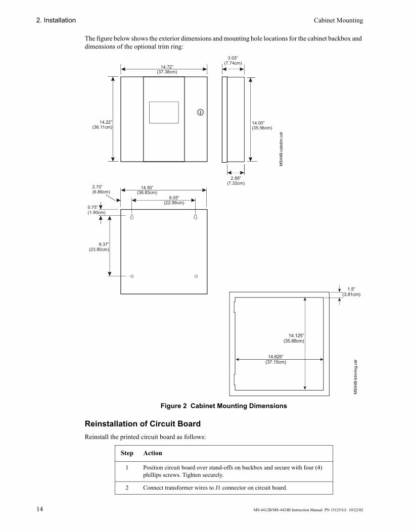
The figure below shows the exterior dimensions and mounting hole locations for the cabinet backbox and dimensions of the optional trim ring:
Figure 2 Cabinet Mounting Dimensions
Reinstallation of Circuit Board Reinstall the printed circuit board as follows:
Step Action
1 Position circuit board over stand-offs on backbox and secure with four (4) phillips screws. Tighten securely.
2 Connect transformer wires to J1 connector on circuit board.
14.72”(37.38cm)
14.22”(36.11cm)
3.05”(7.74cm)
14.00”(35.56cm)
2.88”(7.32cm)
14.50”(36.83cm)
9.05”(22.99cm)
9.37”(23.80cm)
2.70”(6.86cm)
0.75”(1.90cm)
1.5”(3.81cm)
14.125”(35.88cm)
14.625”(37.15cm)
MS4
4B-c
abdi
m.c
dr
MS4
4B-tr
imrin
g.cd
r
Power Connections 2. Installation
MS-4412B/MS-4424B Instruction Manual PN 15125:G1 10/22/02 15
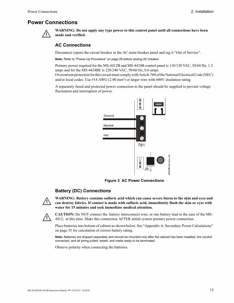
Power Connections WARNING: Do not apply any type power to this control panel until all connections have been made and verified.
AC Connections Disconnect (open) the circuit breaker in the AC main breaker panel and tag it “Out of Service”.
Note: Refer to "Power-Up Procedure" on page 28 before closing AC breaker.
Primary power required for the MS-4412B and MS-4424B control panel is 110/120 VAC, 50/60 Hz, 1.2 amps and for the MS-4424BE is 220/240 VAC, 50/60 Hz, 0.6 amps.Overcurrent protection for this circuit must comply with Article 760 of the National Electrical Code (NEC) and/or local codes. Use #14 AWG (2.00 mm2) or larger wire with 600V insulation rating.
A separately fused and protected power connection to the panel should be supplied to prevent voltage fluctuation and interruption of power.
Figure 3 AC Power Connections
Battery (DC) Connections WARNING: Battery contains sulfuric acid which can cause severe burns to the skin and eyes and can destroy fabrics. If contact is made with sulfuric acid, immediately flush the skin or eyes with water for 15 minutes and seek immediate medical attention.
CAUTION: Do NOT connect the battery interconnect wire, or one battery lead in the case of the MS-4412, at this time. Make this connection AFTER initial system primary power connection.
Place batteries into bottom of cabinet as shown below. See "Appendix A: Secondary Power Calculations" on page 35 for calculation of correct battery rating.
Note: Batteries are shipped separately and should be mounted only after the cabinet has been installed, the conduit connected, and all wiring pulled, tested, and made ready to be terminated.
Observe polarity when connecting the batteries.
!
J9
TB1
MS4
4B-A
Cco
nn.c
dr
Ground
Neutral
Hot
!
!
2. Installation Power-limited Wiring Requirements
16 MS-4412B/MS-4424B Instruction Manual PN 15125:G1 10/22/02
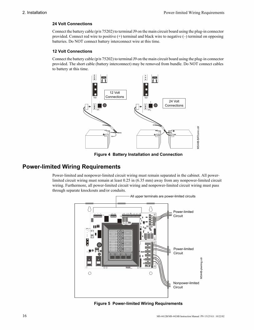
24 Volt Connections
Connect the battery cable (p/n 75202) to terminal J9 on the main circuit board using the plug-in connector provided. Connect red wire to positive (+) terminal and black wire to negative (–) terminal on opposing batteries. Do NOT connect battery interconnect wire at this time.
12 Volt Connections
Connect the battery cable (p/n 75202) to terminal J9 on the main circuit board using the plug-in connector provided. The short cable (battery interconnect) may be removed from bundle. Do NOT connect cables to battery at this time.
Figure 4 Battery Installation and Connection
Power-limited Wiring Requirements Power-limited and nonpower-limited circuit wiring must remain separated in the cabinet. All power-limited circuit wiring must remain at least 0.25 in (6.35 mm) away from any nonpower-limited circuit wiring. Furthermore, all power-limited circuit wiring and nonpower-limited circuit wiring must pass through separate knockouts and/or conduits.
Figure 5 Power-limited Wiring Requirements
J9
TB1
J9
TB1
MS4
4B-B
ATco
nn.c
dr
24 Volt Connections
12 Volt Connections
TONESILENCE
ALARMSILENCE
ALARMACTIVATE
SYSTEMRESET
AC POWER
SYSTEMALARM
ALARM TEST
SUPERVISORY
SYSTEMTROUBLE
CIRCUITTROUBLE
ALARMSILENCED
POWERTROUBLE
ZONE 1
ZONE 2
ZONE 3
ZONE 4
SW1
TB2 TB3TB4
OPT1
OPT2
J9
J1
JP12
TB1
OUT#1B+ B–
OUT#2B+ B–
ALARMNO NC C
IN #2B+ B–
IN #3B+ B–
IN #4B+ B–
SU PV 1 SU PV 2JP1
TB1
LATCH DISABLE
J2
Power-limited Circuit
Nonpower-limited Circuit
All upper terminals are power-limited circuits
Power-limited Circuit
MS4
4B-p
lwiri
ng.c
dr
Initiating Device Circuits 2. Installation
MS-4412B/MS-4424B Instruction Manual PN 15125:G1 10/22/02 17
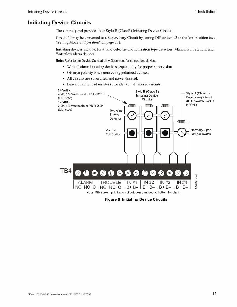
Initiating Device Circuits The control panel provides four Style B (ClassB) Initiating Device Circuits.
Circuit #4 may be converted to a Supervisory Circuit by setting DIP switch #3 to the ‘on’ position (see "Setting Mode of Operation" on page 27).
Initiating devices include: Heat, Photoelectric and Ionization type detectors, Manual Pull Stations and Waterflow alarm devices.
Note: Refer to the Device Compatibility Document for compatible devices.
• Wire all alarm initiating devices sequentially for proper supervision.• Observe polarity when connecting polarized devices.• All circuits are supervised and power-limited.• Leave dummy load resistor (provided) on all unused circuits.
Figure 6 Initiating Device Circuits
TB4
IN #2B+ B–
IN #3B+ B–
IN #4B+ B–
24 Volt -4.7K, 1/2-Watt resistor PN 71252 (UL listed)12 Volt -2.2K, 1/2-Watt resistor PN R-2.2K (UL listed)
Style B (Class B)Initiating Device
Circuits
Two-wire Smoke Detector
ManualPull Station
Style B (Class B) Supervisory Circuit(If DIP switch SW1-3 is “ON”)
Normally Open Tamper Switch
MS4
4B-id
c.cd
rNote: Silk screen printing on circuit board moved to bottom for clarity
2. Installation Initiating Device Circuits
18 MS-4412B/MS-4424B Instruction Manual PN 15125:G1 10/22/02
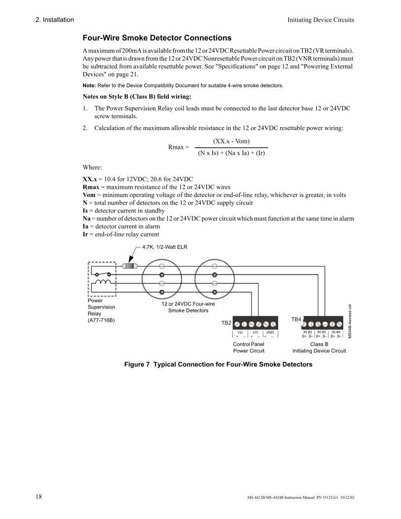
Four-Wire Smoke Detector Connections A maximum of 200mA is available from the 12 or 24VDC Resettable Power circuit on TB2 (VR terminals). Any power that is drawn from the 12 or 24VDC Nonresettable Power circuit on TB2 (VNR terminals) must be subtracted from available resettable power. See "Specifications" on page 12 and "Powering External Devices" on page 21.
Note: Refer to the Device Compatibility Document for suitable 4-wire smoke detectors.
Notes on Style B (Class B) field wiring:
1. The Power Supervision Relay coil leads must be connected to the last detector base 12 or 24VDC screw terminals.
2. Calculation of the maximum allowable resistance in the 12 or 24VDC resettable power wiring:
Where:
XX.x = 10.4 for 12VDC; 20.6 for 24VDCRmax = maximum resistance of the 12 or 24VDC wiresVom = minimum operating voltage of the detector or end-of-line relay, whichever is greater, in voltsN = total number of detectors on the 12 or 24VDC supply circuitIs = detector current in standbyNa = number of detectors on the 12 or 24VDC power circuit which must function at the same time in alarmIa = detector current in alarmIr = end-of-line relay current
Figure 7 Typical Connection for Four-Wire Smoke Detectors
Rmax =(XX.x - Vom)
(N x Is) + (Na x Ia) + (Ir)
–
–+
+
–
–+
+
TB2IN #4
B+ B–IN #3
B+ B–IN #2
B+ B–
TB4
MS4
4B-4
wire
sd.c
dr12 or 24VDC Four-wire Smoke Detectors
4.7K, 1/2-Watt ELR
Power Supervision Relay(A77-716B)
Class BInitiating Device Circuit
Control Panel Power Circuit
Output Circuits 2. Installation
MS-4412B/MS-4424B Instruction Manual PN 15125:G1 10/22/02 19
Output Circuits
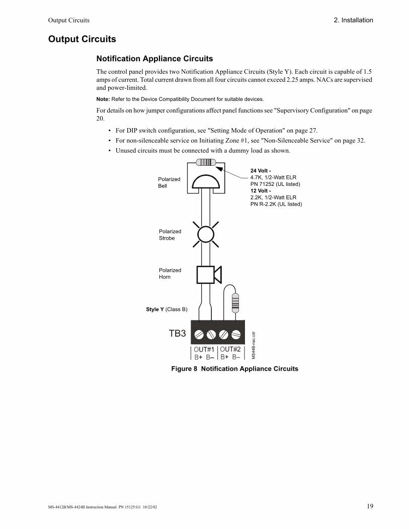
Notification Appliance Circuits The control panel provides two Notification Appliance Circuits (Style Y). Each circuit is capable of 1.5 amps of current. Total current drawn from all four circuits cannot exceed 2.25 amps. NACs are supervised and power-limited.
Note: Refer to the Device Compatibility Document for suitable devices.
For details on how jumper configurations affect panel functions see "Supervisory Configuration" on page 20.
• For DIP switch configuration, see "Setting Mode of Operation" on page 27.• For non-silenceable service on Initiating Zone #1, see "Non-Silenceable Service" on page 32.• Unused circuits must be connected with a dummy load as shown.
Figure 8 Notification Appliance Circuits
TB3
MS4
4B-n
ac.c
dr
Polarized Horn
Polarized Strobe
Polarized Bell
Style Y (Class B)
24 Volt -4.7K, 1/2-Watt ELRPN 71252 (UL listed)12 Volt -2.2K, 1/2-Watt ELRPN R-2.2K (UL listed)
2. Installation Output Circuits
20 MS-4412B/MS-4424B Instruction Manual PN 15125:G1 10/22/02
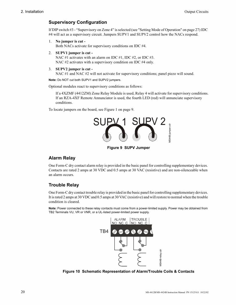
Supervisory Configuration If DIP switch #3 - “Supervisory on Zone 4” is selected (see "Setting Mode of Operation" on page 27) IDC #4 will act as a supervisory circuit. Jumpers SUPV1 and SUPV2 control how the NACs respond.
1. No jumper is cut - Both NACs activate for supervisory conditions on IDC #4.
2. SUPV1 jumper is cut - NAC #1 activates with an alarm on IDC #1, IDC #2, or IDC #3.NAC #2 activates with a supervisory condition on IDC #4 only.
3. SUPV2 jumper is cut - NAC #1 and NAC #2 will not activate for supervisory conditions; panel piezo will sound.
Note: Do NOT cut both SUPV1 and SUPV2 jumpers.
Optional modules react to supervisory conditions as follows:
If a 4XZMF (4412ZM) Zone Relay Module is used, Relay 4 will activate for supervisory conditions.If an RZA-4XF Remote Annunciator is used, the fourth LED (red) will annunciate supervisory conditions.
To locate jumpers on the board, see Figure 1 on page 9.
Figure 9 SUPV Jumper
Alarm Relay One Form-C dry contact alarm relay is provided in the basic panel for controlling supplementary devices. Contacts are rated 2 amps at 30 VDC and 0.5 amps at 30 VAC (resistive) and are non-silenceable when an alarm occurs.
Trouble Relay One Form-C dry contact trouble relay is provided in the basic panel for controlling supplementary devices. It is rated 2 amps at 30 VDC and 0.5 amps at 30 VAC (resistive) and will restore to normal when the trouble condition is cleared.
Note: Power connected to these relay contacts must come from a power-limited supply. Power may be obtained from TB2 Terminals VU, VR or VNR, or a UL-listed power-limited power supply.
Figure 10 Schematic Representation of Alarm/Trouble Coils & Contacts
SUPV 1 SUPV 2
MS4
4B-ju
mpe
r.cdr
TB4
MS4
4B-re
lay.
cdr
Powering External Devices 2. Installation
MS-4412B/MS-4424B Instruction Manual PN 15125:G1 10/22/02 21
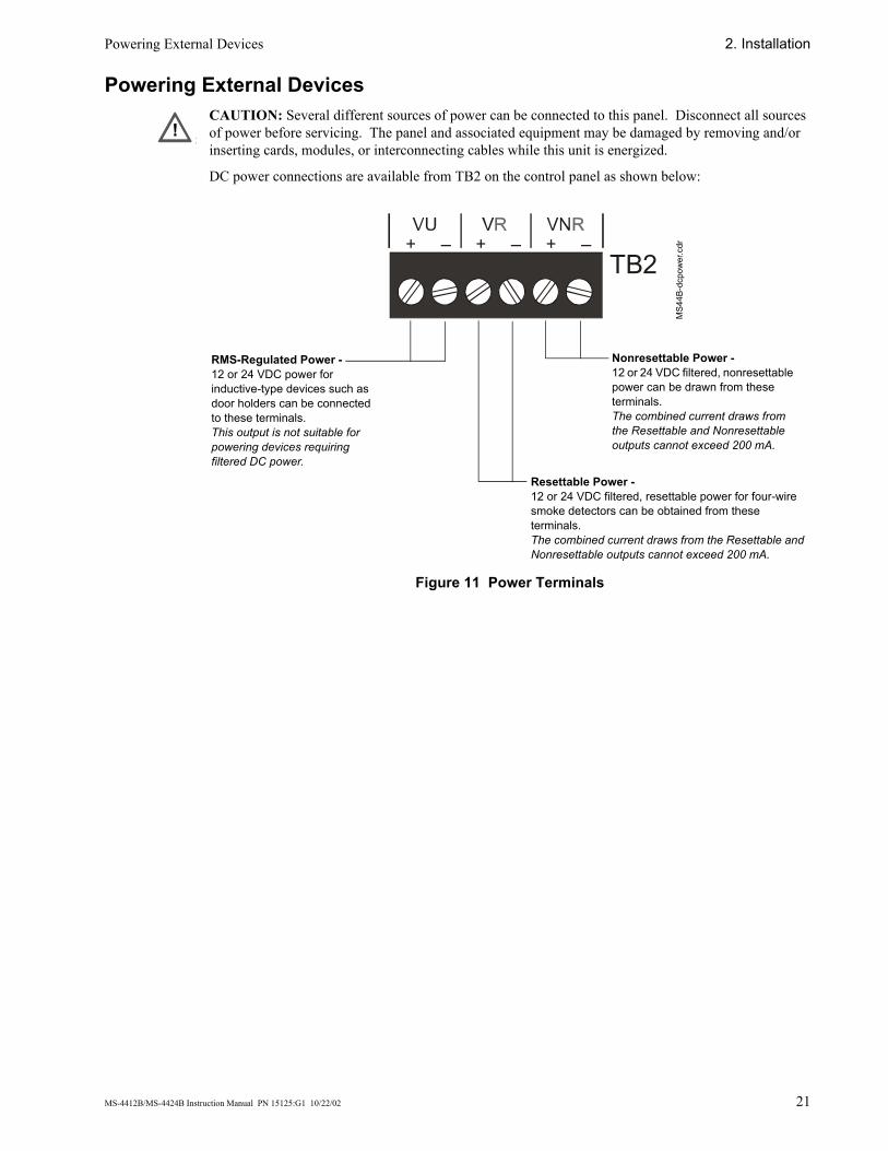
Powering External Devices CAUTION: Several different sources of power can be connected to this panel. Disconnect all sources of power before servicing. The panel and associated equipment may be damaged by removing and/or inserting cards, modules, or interconnecting cables while this unit is energized.
DC power connections are available from TB2 on the control panel as shown below:
Figure 11 Power Terminals
!!!
TB2
RMS-Regulated Power - 12 or 24 VDC power for inductive-type devices such as door holders can be connected to these terminals.This output is not suitable for powering devices requiring filtered DC power.
Resettable Power -12 or 24 VDC filtered, resettable power for four-wire smoke detectors can be obtained from these terminals.The combined current draws from the Resettable and Nonresettable outputs cannot exceed 200 mA.
Nonresettable Power -12 or 24 VDC filtered, nonresettable power can be drawn from these terminals.The combined current draws from the Resettable and Nonresettable outputs cannot exceed 200 mA.
MS4
4B-d
cpow
er.c
dr
2. Installation Optional Modules
22 MS-4412B/MS-4424B Instruction Manual PN 15125:G1 10/22/02
Optional Modules
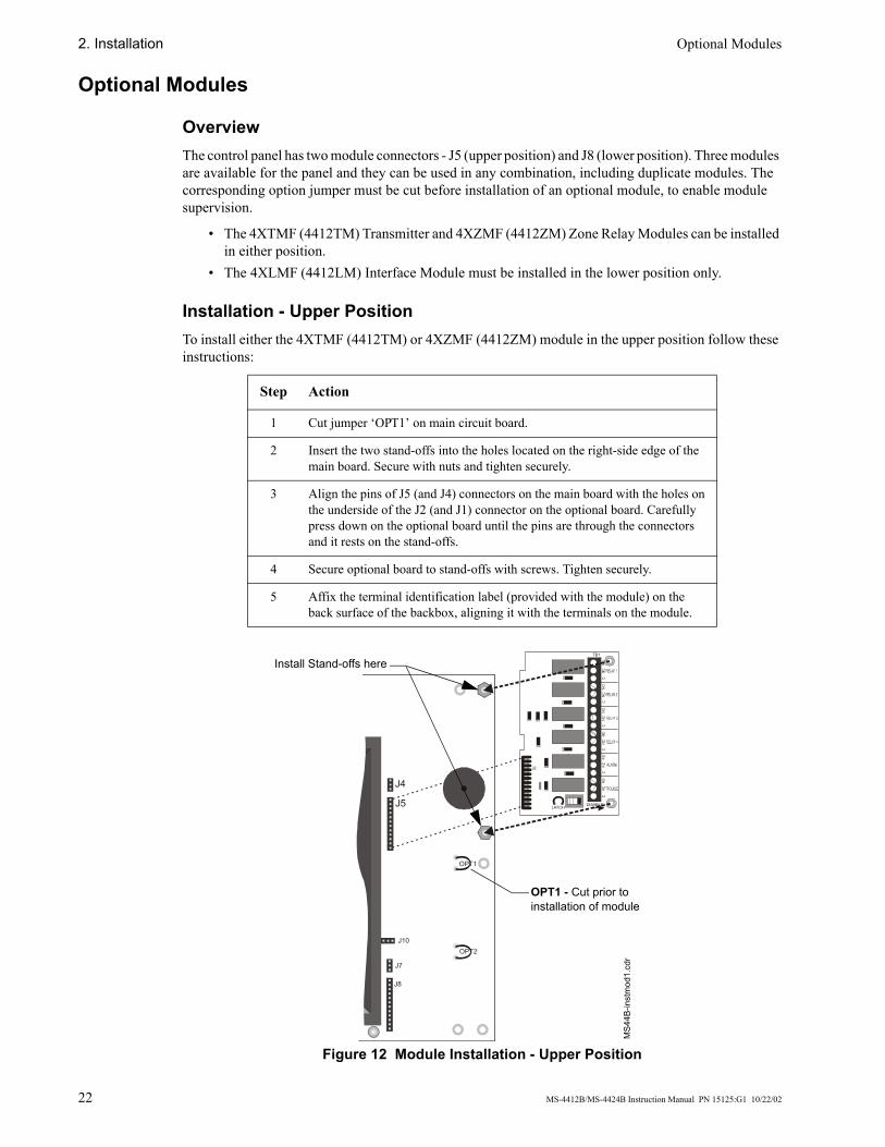
Overview The control panel has two module connectors - J5 (upper position) and J8 (lower position). Three modules are available for the panel and they can be used in any combination, including duplicate modules. The corresponding option jumper must be cut before installation of an optional module, to enable module supervision.
• The 4XTMF (4412TM) Transmitter and 4XZMF (4412ZM) Zone Relay Modules can be installed in either position.
• The 4XLMF (4412LM) Interface Module must be installed in the lower position only.
Installation - Upper Position To install either the 4XTMF (4412TM) or 4XZMF (4412ZM) module in the upper position follow these instructions:
Figure 12 Module Installation - Upper Position
Step Action
1 Cut jumper ‘OPT1’ on main circuit board.
2 Insert the two stand-offs into the holes located on the right-side edge of the main board. Secure with nuts and tighten securely.
3 Align the pins of J5 (and J4) connectors on the main board with the holes on the underside of the J2 (and J1) connector on the optional board. Carefully press down on the optional board until the pins are through the connectors and it rests on the stand-offs.
4 Secure optional board to stand-offs with screws. Tighten securely.
5 Affix the terminal identification label (provided with the module) on the back surface of the backbox, aligning it with the terminals on the module.
TB1
LATCHDISABLE
J2
J4
J5
J7
J8
OPT1
OPT2J10
MS4
4B-in
stm
od1.
cdr
OPT1 - Cut prior to installation of module
Install Stand-offs here
Optional Modules 2. Installation
MS-4412B/MS-4424B Instruction Manual PN 15125:G1 10/22/02 23
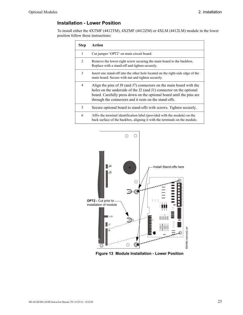
Installation - Lower Position To install either the 4XTMF (4412TM), 4XZMF (4412ZM) or 4XLM (4412LM) module in the lower position follow these instructions:
Figure 13 Module Installation - Lower Position
Step Action
1 Cut jumper ‘OPT2’ on main circuit board.
2 Remove the lower-right screw securing the main board to the backbox. Replace with a stand-off and tighten securely.
3 Insert one stand-off into the other hole located on the right-side edge of the main board. Secure with nut and tighten securely.
4 Align the pins of J8 (and J7) connectors on the main board with the holes on the underside of the J2 (and J1) connector on the optional board. Carefully press down on the optional board until the pins are through the connectors and it rests on the stand-offs.
5 Secure optional board to stand-offs with screws. Tighten securely.
6 Affix the terminal identification label (provided with the module) on the back surface of the backbox, aligning it with the terminals on the module.
TB1
J2
J4
J5
J7
J8
OPT1
OPT2J10
MS4
4B-in
stm
od2.
cdr
Install Stand-offs here
OPT2 - Cut prior to installation of module
2. Installation Optional Modules
24 MS-4412B/MS-4424B Instruction Manual PN 15125:G1 10/22/02
Setup and Configuration
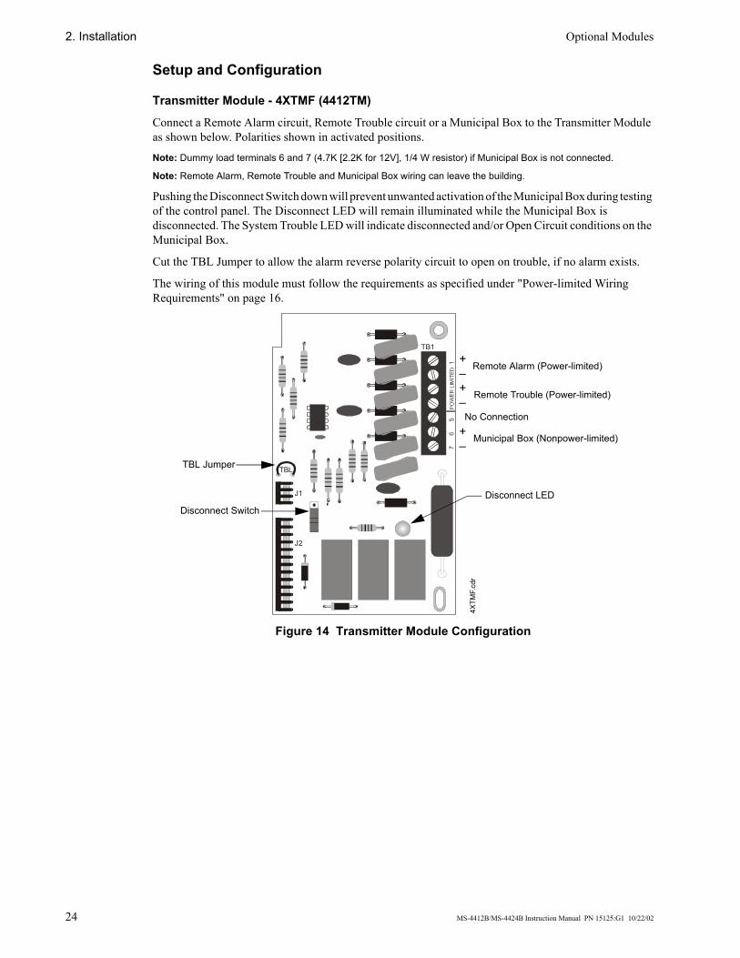
Transmitter Module - 4XTMF (4412TM)
Connect a Remote Alarm circuit, Remote Trouble circuit or a Municipal Box to the Transmitter Module as shown below. Polarities shown in activated positions.
Note: Dummy load terminals 6 and 7 (4.7K [2.2K for 12V], 1/4 W resistor) if Municipal Box is not connected.
Note: Remote Alarm, Remote Trouble and Municipal Box wiring can leave the building.
Pushing the Disconnect Switch down will prevent unwanted activation of the Municipal Box during testing of the control panel. The Disconnect LED will remain illuminated while the Municipal Box is disconnected. The System Trouble LED will indicate disconnected and/or Open Circuit conditions on the Municipal Box.
Cut the TBL Jumper to allow the alarm reverse polarity circuit to open on trouble, if no alarm exists.
The wiring of this module must follow the requirements as specified under "Power-limited Wiring Requirements" on page 16.
Figure 14 Transmitter Module Configuration
TB1
TBL
J1
J2
4XTM
F.cd
rTBL Jumper
Disconnect SwitchDisconnect LED
Remote Alarm (Power-limited)
Remote Trouble (Power-limited)
Municipal Box (Nonpower-limited)
No Connection
+–+–
+–
Optional Modules 2. Installation
MS-4412B/MS-4424B Instruction Manual PN 15125:G1 10/22/02 25
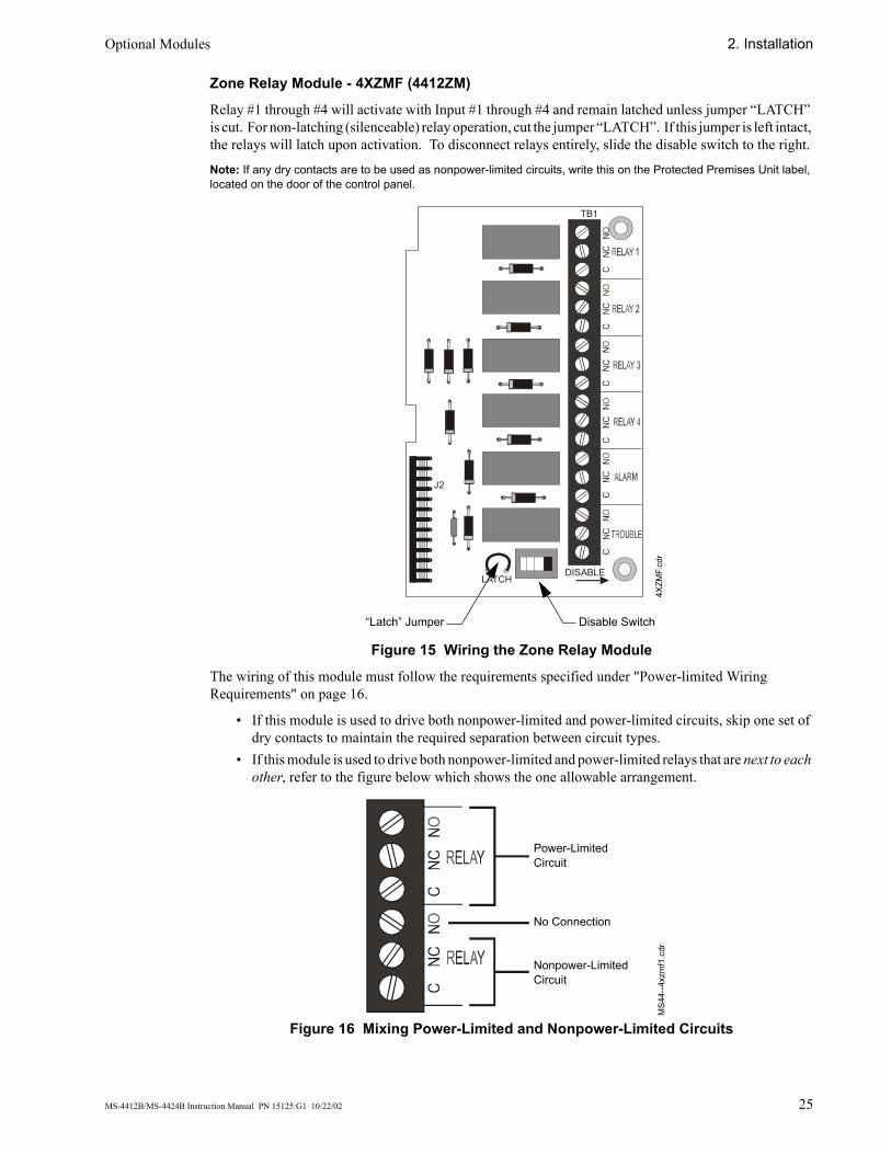
Zone Relay Module - 4XZMF (4412ZM)
Relay #1 through #4 will activate with Input #1 through #4 and remain latched unless jumper “LATCH” is cut. For non-latching (silenceable) relay operation, cut the jumper “LATCH”. If this jumper is left intact, the relays will latch upon activation. To disconnect relays entirely, slide the disable switch to the right.
Note: If any dry contacts are to be used as nonpower-limited circuits, write this on the Protected Premises Unit label, located on the door of the control panel.
Figure 15 Wiring the Zone Relay Module
The wiring of this module must follow the requirements specified under "Power-limited Wiring Requirements" on page 16.
• If this module is used to drive both nonpower-limited and power-limited circuits, skip one set of dry contacts to maintain the required separation between circuit types.
• If this module is used to drive both nonpower-limited and power-limited relays that are next to each other, refer to the figure below which shows the one allowable arrangement.
Figure 16 Mixing Power-Limited and Nonpower-Limited Circuits
TB1
LATCHDISABLE
J2
Disable Switch“Latch” Jumper
4XZM
F.cd
r
Power-Limited Circuit
Nonpower-Limited Circuit
MS4
4--4
xzm
f1.c
dr
No Connection
2. Installation Optional Modules
26 MS-4412B/MS-4424B Instruction Manual PN 15125:G1 10/22/02
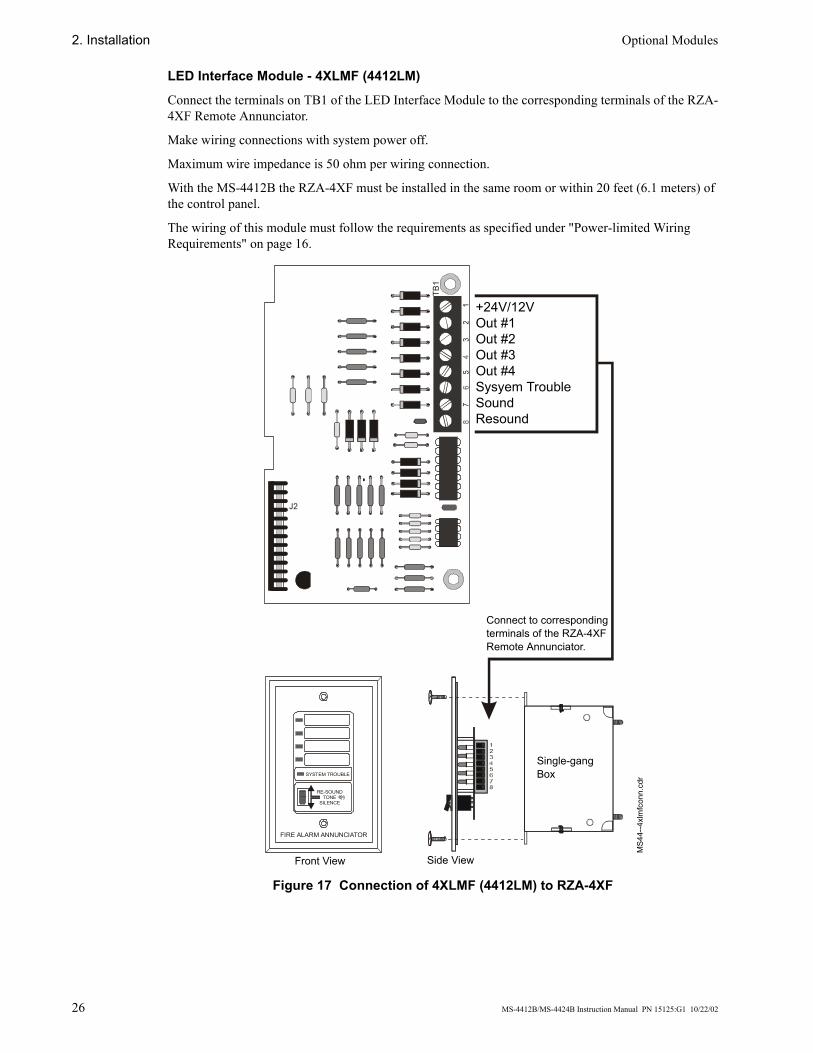
LED Interface Module - 4XLMF (4412LM)
Connect the terminals on TB1 of the LED Interface Module to the corresponding terminals of the RZA-4XF Remote Annunciator.
Make wiring connections with system power off.
Maximum wire impedance is 50 ohm per wiring connection.
With the MS-4412B the RZA-4XF must be installed in the same room or within 20 feet (6.1 meters) of the control panel.
The wiring of this module must follow the requirements as specified under "Power-limited Wiring Requirements" on page 16.
Figure 17 Connection of 4XLMF (4412LM) to RZA-4XF
SYSTEM TROUBLE
RE-SOUNDTONE
SILENCE
FIRE ALARM ANNUNCIATOR
TB1
J2
Connect to corresponding terminals of the RZA-4XF Remote Annunciator.
Front View Side View
MS4
4--4
xlm
fcon
n.cd
r
Single-gang Box
+24V/12VOut #1Out #2Out #3Out #4Sysyem TroubleSoundResound
Setting Mode of Operation 2. Installation
MS-4412B/MS-4424B Instruction Manual PN 15125:G1 10/22/02 27
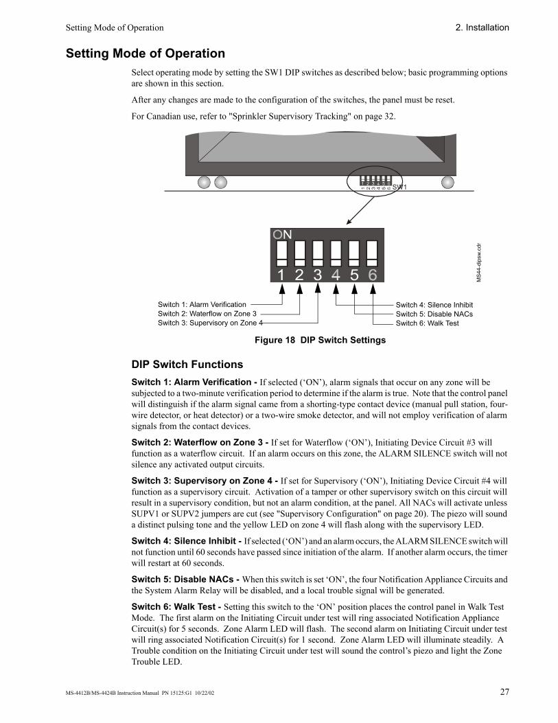
Setting Mode of Operation Select operating mode by setting the SW1 DIP switches as described below; basic programming options are shown in this section.
After any changes are made to the configuration of the switches, the panel must be reset.
For Canadian use, refer to "Sprinkler Supervisory Tracking" on page 32.
Figure 18 DIP Switch Settings
DIP Switch Functions Switch 1: Alarm Verification - If selected (‘ON’), alarm signals that occur on any zone will be subjected to a two-minute verification period to determine if the alarm is true. Note that the control panel will distinguish if the alarm signal came from a shorting-type contact device (manual pull station, four-wire detector, or heat detector) or a two-wire smoke detector, and will not employ verification of alarm signals from the contact devices.
Switch 2: Waterflow on Zone 3 - If set for Waterflow (‘ON’), Initiating Device Circuit #3 will function as a waterflow circuit. If an alarm occurs on this zone, the ALARM SILENCE switch will not silence any activated output circuits.
Switch 3: Supervisory on Zone 4 - If set for Supervisory (‘ON’), Initiating Device Circuit #4 will function as a supervisory circuit. Activation of a tamper or other supervisory switch on this circuit will result in a supervisory condition, but not an alarm condition, at the panel. All NACs will activate unless SUPV1 or SUPV2 jumpers are cut (see "Supervisory Configuration" on page 20). The piezo will sound a distinct pulsing tone and the yellow LED on zone 4 will flash along with the supervisory LED.
Switch 4: Silence Inhibit - If selected (‘ON’) and an alarm occurs, the ALARM SILENCE switch will not function until 60 seconds have passed since initiation of the alarm. If another alarm occurs, the timer will restart at 60 seconds.
Switch 5: Disable NACs - When this switch is set ‘ON’, the four Notification Appliance Circuits and the System Alarm Relay will be disabled, and a local trouble signal will be generated.
Switch 6: Walk Test - Setting this switch to the ‘ON’ position places the control panel in Walk Test Mode. The first alarm on the Initiating Circuit under test will ring associated Notification Appliance Circuit(s) for 5 seconds. Zone Alarm LED will flash. The second alarm on Initiating Circuit under test will ring associated Notification Circuit(s) for 1 second. Zone Alarm LED will illuminate steadily. A Trouble condition on the Initiating Circuit under test will sound the control’s piezo and light the Zone Trouble LED.
SW1
MS4
4-di
psw.
cdr
Switch 1: Alarm VerificationSwitch 2: Waterflow on Zone 3Switch 3: Supervisory on Zone 4
Switch 4: Silence InhibitSwitch 5: Disable NACsSwitch 6: Walk Test
2. Installation Power-Up Procedure
28 MS-4412B/MS-4424B Instruction Manual PN 15125:G1 10/22/02
Power-Up Procedure WARNING: Prior to energizing this panel, notify all personnel and authorities, including any personnel who may be working on, around, or near this unit.
WARNING: Battery contains sulfuric acid which can cause severe burns to the skin and eyes and can destroy fabrics. If contact is made with sulfuric acid, immediately flush the skin or eyes with water for 15 minutes and seek immediate medical attention.
CAUTION: Observe polarity of batteries. Improper connection will cause damage and VOID WARRANTY.
Follow these steps to power-up the FACP:
1. Conduct Visual Inspection. A careful visual inspection should be made before applying power to the system. See “Inspection” on page 43.
2. Notification. Notify personnel who may be working with the AC power circuits before removing the “Out of Service” tag.
3. Apply Primary Power. Switch the circuit breaker to the ‘closed’ position, providing power to the circuit.• The green AC power LED will illuminate.• The Trouble LED will illuminate until battery power is applied.
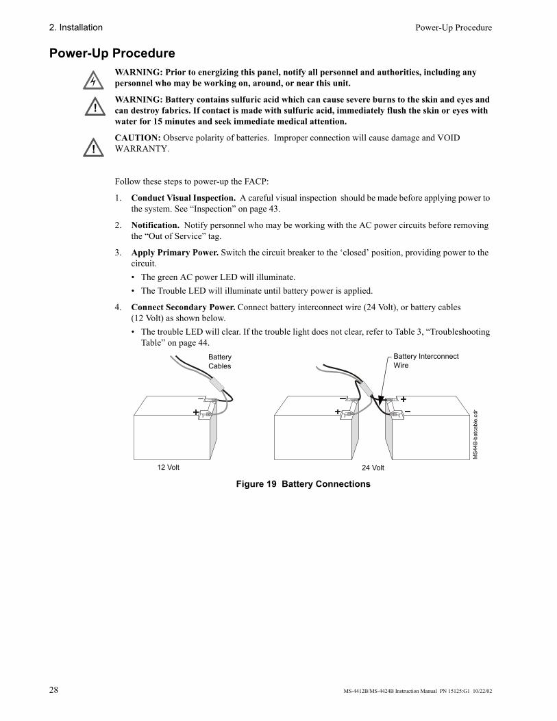
4. Connect Secondary Power. Connect battery interconnect wire (24 Volt), or battery cables (12 Volt) as shown below.• The trouble LED will clear. If the trouble light does not clear, refer to Table 3, “Troubleshooting
Table” on page 44.
Figure 19 Battery Connections
!
!
Battery Interconnect Wire
MS4
4B-b
atca
ble.
cdr
24 Volt12 Volt
Battery Cables
MS-4412B/MS-4424B Instruction Manual PN 15125:G1 10/22/02 29
3. System Operation
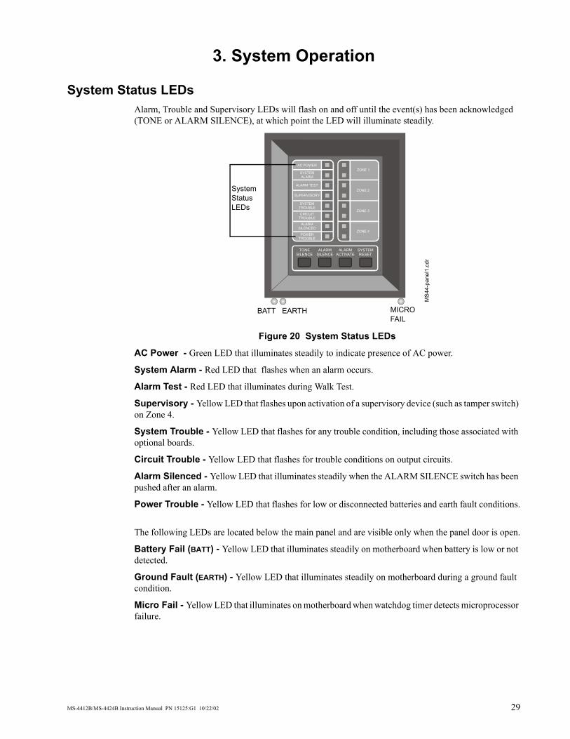
System Status LEDs Alarm, Trouble and Supervisory LEDs will flash on and off until the event(s) has been acknowledged (TONE or ALARM SILENCE), at which point the LED will illuminate steadily.
Figure 20 System Status LEDs
AC Power - Green LED that illuminates steadily to indicate presence of AC power.
System Alarm - Red LED that flashes when an alarm occurs.
Alarm Test - Red LED that illuminates during Walk Test.
Supervisory - Yellow LED that flashes upon activation of a supervisory device (such as tamper switch) on Zone 4.
System Trouble - Yellow LED that flashes for any trouble condition, including those associated with optional boards.
Circuit Trouble - Yellow LED that flashes for trouble conditions on output circuits.
Alarm Silenced - Yellow LED that illuminates steadily when the ALARM SILENCE switch has been pushed after an alarm.
Power Trouble - Yellow LED that flashes for low or disconnected batteries and earth fault conditions.
The following LEDs are located below the main panel and are visible only when the panel door is open.
Battery Fail (BATT) - Yellow LED that illuminates steadily on motherboard when battery is low or not detected.
Ground Fault (EARTH) - Yellow LED that illuminates steadily on motherboard during a ground fault condition.
Micro Fail - Yellow LED that illuminates on motherboard when watchdog timer detects microprocessor failure.
TONESILENCE
ALARMSILENCE
ALARMACTIVATE
SYSTEMRESET
AC POWER
SYSTEMALARM
ALARM TEST
SUPERVISORY
SYSTEMTROUBLE
CIRCUITTROUBLE
ALARMSILENCED
POWERTROUBLE
ZONE 1
ZONE 2
ZONE 3
ZONE 4
MS4
4-pa
nel1
.cdr
BATT EARTH MICRO FAIL
System Status LEDs
3. System Operation Control Switches
30 MS-4412B/MS-4424B Instruction Manual PN 15125:G1 10/22/02
Control Switches
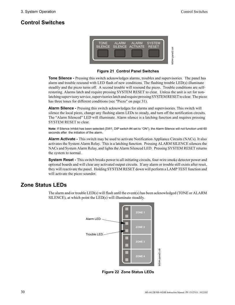
Figure 21 Control Panel Switches
Tone Silence - Pressing this switch acknowledges alarms, troubles and supervisories. The panel has alarm and trouble resound with LED flash of new conditions. The flashing trouble LED(s) illuminate steadily and the piezo turns off. A second trouble will resound the piezo. Trouble conditions are self-restoring. Alarms latch and require pressing SYSTEM RESET to clear. Unless the unit is set for non-latching supervisory service, supervisories latch and require pressing SYSTEM RESET to clear. The piezo has three tones for different conditions (see "Piezo" on page 31).
Alarm Silence - Pressing this switch acknowledges for alarms and supervisories. This switch will silence the local piezo, change any flashing alarm LEDs to steady, and turn off the notification circuits. The “Alarm Silenced” LED will illuminate. Alarm silence is a latching function and requires pressing SYSTEM RESET to clear.
Note: If Silence Inhibit has been selected (SW1, DIP switch #4 set to “ON”), the Alarm Silence will not function until 60 seconds after the initiation of the alarm.
Alarm Activate - This switch may be used to activate Notification Appliance Circuits (NACs). It also activates the System Alarm Relay. This is a latching function. Pressing ALARM SILENCE silences the NACs and System Alarm Relay, and lights the Alarm Silenced LED. Pressing SYSTEM RESET returns the system to normal.
System Reset - This switch breaks power to all initiating circuits, four-wire smoke detector power and optional boards and will clear any activated output circuits. If any alarm or trouble still exists after reset, they will reactivate the panel. Holding SYSTEM RESET down will perform a LAMP TEST function and will activate the piezo sounder.
Zone Status LEDs The alarm and/or trouble LED(s) will flash until the event(s) has been acknowledged (TONE or ALARM SILENCE), at which point the LED(s) will illuminate steadily.
Figure 22 Zone Status LEDs
TONESILENCE
ALARMSILENCE
ALARMACTIVATE
SYSTEMRESET
MS4
4-pa
nel2
.cdr
ZONE 1
ZONE 2
ZONE 3
ZONE 4
MS4
4-pa
nel3
.cdr
Alarm LED
Trouble LED
Piezo 3. System Operation
MS-4412B/MS-4424B Instruction Manual PN 15125:G1 10/22/02 31
Piezo The piezo (local buzzer) generates different tone patterns for different event conditions:
• Alarm - Generates a steady tone, no pulse.• Trouble - Pulses one second on, one second off. Repeats 30 pulses per minute.• Supervisory - Pulses one-half second on, one-half second off. Repeats 60 pulses per minute.
Supervisory Service Zone 4 is programmable for monitoring supervisory devices (such as valve tamper switches) by setting SW1 DIP switch 3 to “ON” (see "Setting Mode of Operation" on page 27). A short circuit on this zone (activation of a N.O. contact) will cause the supervisory LED and the zone 4 yellow LED to flash. The piezo sounder will generate a unique sound. Pressing TONE SILENCE will silence the piezo and cause the supervisory LED to illuminate steadily, but the Zone 4 Trouble LED will continue to flash. Supervisory signals latch and require SYSTEM RESET to clear. The ALARM SILENCE switch will silence the piezo, cause the supervisory LED to illuminate steadily and turn off the Supervisory Notification Circuit. An open circuit on Zone 4 will be reported as a zone trouble.
Note: The Initiating Device Circuit for sprinkler supervisory zone can be programmed for tracking operation; latching operation is the default setting. Canadian regulations require latching operation; for programming instructions, See “Sprinkler Supervisory Tracking” on page 32.
Zone Disable If a zone has been disabled, an alarm that occurs on that zone will flash the red zone LED, but not the piezo or any output circuit. If both power sources are removed from the system, all zones will be re-enabled upon restoration of power. Disable status will be lost.
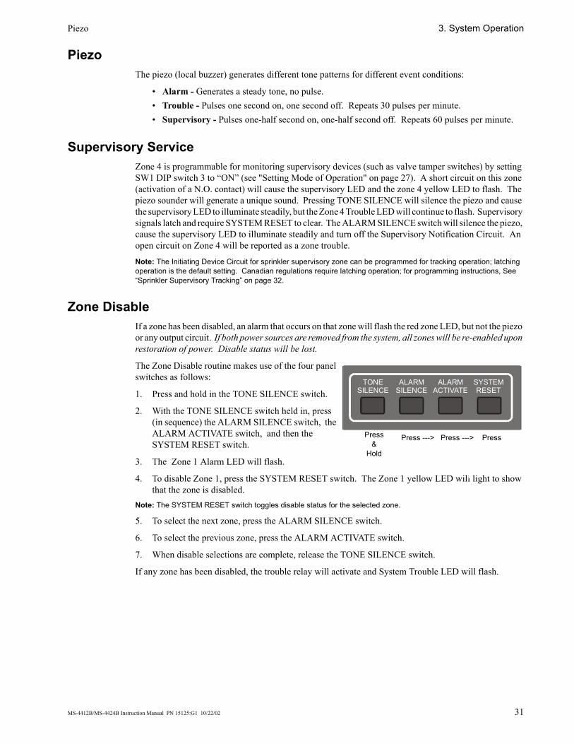
The Zone Disable routine makes use of the four panel switches as follows:
1. Press and hold in the TONE SILENCE switch.
2. With the TONE SILENCE switch held in, press (in sequence) the ALARM SILENCE switch, the ALARM ACTIVATE switch, and then the SYSTEM RESET switch.
3. The Zone 1 Alarm LED will flash.
4. To disable Zone 1, press the SYSTEM RESET switch. The Zone 1 yellow LED will light to show that the zone is disabled.
Note: The SYSTEM RESET switch toggles disable status for the selected zone.
5. To select the next zone, press the ALARM SILENCE switch.
6. To select the previous zone, press the ALARM ACTIVATE switch.
7. When disable selections are complete, release the TONE SILENCE switch.
If any zone has been disabled, the trouble relay will activate and System Trouble LED will flash.
TONESILENCE
ALARMSILENCE
ALARMACTIVATE
SYSTEMRESET
Press &
Hold
Press ---> Press ---> Press
3. System Operation Last Event Recall
32 MS-4412B/MS-4424B Instruction Manual PN 15125:G1 10/22/02
Last Event Recall Last Event Recall allows the user to display the previous panel status. The Last Event Recall makes use of the four panel switches as follows:
1. Press and hold in the TONE SILENCE switch.
2. With the TONE SILENCE switch held in, press (in sequence) the SYSTEM RESET switch, the ALARM ACTIVATE switch, and then the ALARM SILENCE switch.
3. LEDs will light to indicate the last event recorded in the panel’s buffer.
4. Release the TONE SILENCE switch to return to normal operation.
To clear the Last Event buffer, press SYSTEM RESET twice.
Non-Silenceable Service Initiating Zone #1 can be programmed as non-silenceable by following these steps:
1. Press and hold in the TONE SILENCE switch.
2. With the TONE SILENCE switch held in, press in sequence the ALARM SILENCE switch, then the ALARM ACTIVATE switch, and finally the ALARM SILENCE switch again.
3. Release the TONE SILENCE switch.Note: If both primary and secondary power sources are removed from the system, these settings will be lost. When power is restored, Initiating Zone #1 will default to silenceable operation.
Sprinkler Supervisory Tracking The Initiating Device Circuit for sprinkler supervisory zone can be programmed for tracking operation; latching operation is the default setting. Canadian regulations require latching operation.
1. Press and hold in the TONE SILENCE switch.
2. With the TONE SILENCE switch held in, press in sequence the ALARM SILENCE switch, then the ALARM ACTIVATE switch, and finally the ALARM ACTIVATE switch again.
3. Release the TONE SILENCE switch.Note: If both primary and secondary power sources are removed from the system, this setting will be lost. When power is restored, supervisory will default to latching operation.
System Events
Standby Condition Green LED (AC power on) will be illuminated. All other LEDs (trouble and alarm) are off.
System Trouble Condition Interruption of any of the electrically supervised circuits will illuminate the System Trouble LED. The Trouble RElay Contacts will transfer. The piezo (local buzzer) will sound one second on, one second off, and repeating until silenced. Silence the piezo by pressing the TONE SILENCE switch. The panel will remain in the trouble state until the trouble condition has been cleared and the panel reset.
Alarm Condition Upon activation of an initiating device, a red alarm LED will illuminate for that zone. In addition, the Alarm Relay will activate, the piezo will sound, and Notification Appliance Circuit(s) will activate. (See “Output Circuits” on page 19 for details).
System Events 3. System Operation
MS-4412B/MS-4424B Instruction Manual PN 15125:G1 10/22/02 33
Brownout Condition The total power being provided to the system’s power supply should not exceed the current draw during fully loaded panel operation. Brownout circuitry annunciates degradation of the incoming AC voltage supply. A brownout condition is annunciated when the AC power decreases. When the brownout threshold is reached, the system reacts as if AC power is totally lost:
• Battery backup begins supplying power to operate the control panel• General Trouble Relay contact transfers• Green AC Power LED turns off• Yellow System Trouble LED illuminates• The piezo will sound one second on, one second off, and repeat until the Trouble is cleared.
When the AC voltage returns or increases above the brownout threshold, the green AC Power LED will illuminate. The power supply circuitry will return to primary power functions and begin to recharge the backup battery supply.

3. System Operation System Events
34 MS-4412B/MS-4424B Instruction Manual PN 15125:G1 10/22/02
Notes
MS-4412B/MS-4424B Instruction Manual PN 15125:G1 10/22/02 35
Appendix A: Secondary Power Calculations
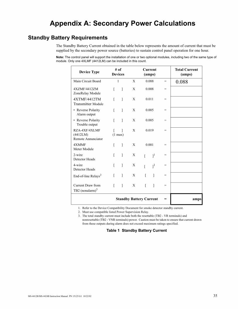
Standby Battery Requirements The Standby Battery Current obtained in the table below represents the amount of current that must be supplied by the secondary power source (batteries) to sustain control panel operation for one hour.
Note: The control panel will support the installation of one or two optional modules, including two of the same type of module. Only one 4XLMF (4412LM) can be included in this count.
Table 1 Standby Battery Current
Device Type # of Devices
Current(amps)
Total Current(amps)
Main Circuit Board 1 X 0.088 = 0.0884XZMF/4412ZMZoneRelay Module
[ ] X 0.008 =
4XTMF/4412TMTransmitter Module
[ ] X 0.011 =
• Reverse Polarity Alarm output
[ ] X 0.005 =
• Reverse Polarity Trouble output
[ ] X 0.005 =
RZA-4XF/4XLMF (4412LM)Remote Annunciator
[ ](1 max)
X 0.019 =
4XMMFMeter Module
[ ] X 0.001 =
2-wire Detector Heads
[ ] X [ ]1
1. Refer to the Device Compatibility Document for smoke detector standby current.
=
4-wire Detector Heads
[ ] X [ ]1 =
End-of-line Relays2
2. Must use compatible listed Power Supervision Relay.
[ ] X [ ] =
Current Draw from TB2 (nonalarm)3
3. The total standby current must include both the resettable (TB2 - VR terminals) and nonresettable (TB2 - VNR terminals) power. Caution must be taken to ensure that current drawn from these outputs during alarm does not exceed maximum ratings specified.
[ ] X [ ] =
Standby Battery Current = amps
Appendix A: Secondary Power Calculations Calculating the Battery Capacity
36 MS-4412B/MS-4424B Instruction Manual PN 15125:G1 10/22/02
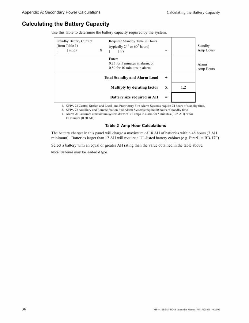
Calculating the Battery Capacity Use this table to determine the battery capacity required by the system.
Table 2 Amp Hour Calculations
The battery charger in this panel will charge a maximum of 18 AH of batteries within 48 hours (7 AH minimum). Batteries larger than 12 AH will require a UL-listed battery cabinet (e.g. Fire•Lite BB-17F).
Select a battery with an equal or greater AH rating than the value obtained in the table above.
Note: Batteries must be lead-acid type.
Standby Battery Current(from Table 1)[ ] amps X
Required Standby Time in Hours (typically 241 or 602 hours)[ ] hrs
1. NFPA 72 Central Station and Local and Proprietary Fire Alarm Systems require 24 hours of standby time.2. NFPA 72 Auxiliary and Remote Station Fire Alarm Systems require 60 hours of standby time.
=Standby Amp Hours
Enter:0.25 for 5 minutes in alarm, or0.50 for 10 minutes in alarm
Alarm3 Amp Hours
3. Alarm AH assumes a maximum system draw of 3.0 amps in alarm for 5 minutes (0.25 AH) or for10 minutes (0.50 AH).
Total Standby and Alarm Load +
Multiply by derating factor X 1.2
Battery size required in AH =
MS-4412B/MS-4424B Instruction Manual PN 15125:G1 10/22/02 37
Appendix B: NFPA Standard-Specific Requirements Minimum System Requirements The control panel has been designed for use in commercial, industrial, and institutional applications and meets the requirements for service under the National Fire Protection Association (NFPA) Standards outlined in this appendix. The minimum system components required for compliance with the appropriate NFPA standard are listed below.
• Fire Alarm Control Panel. Contains the main control board, cabinet (backbox and door), main supply transformer and power supply.
• Batteries. Refer to "Appendix A: Secondary Power Calculations" on page 35.• Initiating Devices. Connected to one of the control panel's Initiating Device Circuits.• Notification Appliances. Connected to one of the control panel's Notification Appliance Circuits.
Additional Requirements The following additional equipment is needed for compliance with the NFPA standards listed below. The relay contacts of this control panel may be used to trip any dialer that is UL listed for Central Station/Remote Station services. The illustrations in this appendix provide examples of possible system configurations.
Note: Applications which require the the NOTI-FIRE 911AC or the Potter EFT-C are not FM approved.
NFPA 72 - Signaling Systems for Central Station Service (Protected Premises Unit) • NOTI-FIRE 911AC Digital Alarm Communicator/Transmitter connected to a compatible
listed Central Station DACR or Protected Premises Receiving Unit. See "Digital Alarm Communicator/Transmitter - Noti-Fire 911AC" on page 38 for installation instructions for this unit.
• 411UDAC Universal Digital Alarm Communicator connected to a compatible listed Central Station DACR or Protected Premises Receiving Unit. See "Universal Digital Alarm Communicator - 411UDAC" on page 39 for installation instructions for this unit.
NFPA 72 - Auxiliary Fire Alarm System • 4XTMF (4412TM) Transmitter Module for connection to a compatible listed Local Energy
Municipal Box. See "Local Energy Municipal Box" on page 40 for installation instructions for this unit.
NFPA 72 - Remote Station Fire Alarm System • Fire•Lite RS82-9 Remote Station Receiver connected to a 4XTMF (4412TM) Transmitter
Module. See "Remote Station Receiver - RS82-9" on page 41 for installation instructions for this unit.
• NOTI-FIRE 911AC Digital Alarm Communicator/Transmitter connected to a compatible listed Central Station DACR. See "Digital Alarm Communicator/Transmitter - Noti-Fire 911AC" on page 38 for installation instructions for this unit.
• 411UDAC Universal Digital Alarm Communicator connected to a compatible listed Central Station DACR. See "Universal Digital Alarm Communicator - 411UDAC" on page 39 for installation instructions for this unit.
NFPA 72 - Proprietary Fire Alarm System • Potter EFT-C McCulloh Transmitter. See "Potter EFT-C McCulloh Transmitter" on page 42 for
installation instructions for this unit.
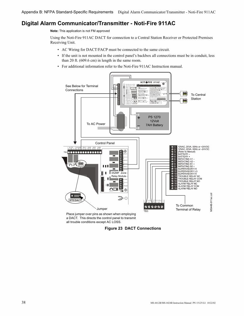
Appendix B: NFPA Standard-Specific Requirements Digital Alarm Communicator/Transmitter - Noti-Fire 911AC
38 MS-4412B/MS-4424B Instruction Manual PN 15125:G1 10/22/02
Digital Alarm Communicator/Transmitter - Noti-Fire 911AC Note: This application is not FM approved
Using the Noti-Fire 911AC DACT for connection to a Central Station Receiver or Protected Premises Receiving Unit.
• AC Wiring for DACT/FACP must be connected to the same circuit.• If the unit is not mounted in the control panel’s backbox all connections must be in conduit, less
than 20 ft. (609.6 cm) in length in the same room.• For additional information refer to the Noti-Fire 911AC Instruction manual.
Figure 23 DACT Connections
+–
TB3
TB4
OPT1
IN #2B+ B–
IN #3B+ B–
IN #4B+ B–
SUPV 1 SUPV 2JP1
TB1
LATCHDISABLE
J2
STD DACT
MS4
4B-9
11ac
.cdr
Place jumper over pins as shown when employing a DACT. This directs the control panel to transmit all trouble conditions except AC LOSS.
To Central Station
PS 127012Volt
7AH BatteryTo AC Power
See Below for Terminal Connections
Control Panel
To Common Terminal of RelayJumper
4XZMF ZoneRelay Module

Universal Digital Alarm Communicator - 411UDAC Appendix B: NFPA Standard-Specific Requirements
MS-4412B/MS-4424B Instruction Manual PN 15125:G1 10/22/02 39
Universal Digital Alarm Communicator - 411UDAC The following figure illustrates an example of Central Station/Remote Station Receiver or Protected Premises Receiving Unit reporting using a 411UDAC. The relay contacts of the MS-4412B/MS-4424B may be used to trip any dialer listed for Central Station/Remote Station services. For additional information refer to the Instruction Manual for the 411UDAC.
• All connections between the control panel and the 411UDAC must be in conduit, less than 20 feet (6.1 meters) in length in the same room.
• Any zone of the 411UDAC can be wired to function as alarm, trouble or supervisory; the unit must be programmed accordingly. In this example, Zone 1 is wired to the control panel’s alarm relay, Zone2 is wired to the control panel’s trouble relay, and Zone 3 is wired to the optional module’s supervisory relay.
• AC power is supplied directly to the 411UDAC, not through the control panel. AC wiring for both the 411UDAC and the control panel must be connected to the same AC branch circuit.
• End-of-line Resistors must terminate all circuits. In this example, Zone 4 is unused and is terminated at the board.
• When employing a DACT, place the JP1 jumper, on the control panel, as shown below. This directs the panel to transmit all trouble conditions except AC LOSS. The DACT must be configured to transmit AC power loss to the central station.
Figure 24 411UDAC Connections
TB4
OPT1
IN #2B+ B–
IN #3B+ B–
IN #4B+ B–
SUPV 1 SUPV 2JP1
TB1
LATCH DIS ABLE
J2
STD DACT
TB2TB4TB1
RELAY 1NO NC C
RELAY 2NO NC C
NACB+ B-
ZONE 1B+ B-
ZONE 4B+ B-
ZONE 2B+ B-
ZONE 3B+ A+ A- B-
+12V PWR + -
PH1 PH2
Trouble
Alarm
Secondary Phone LinePrimary Phone Line
Modular Cable P/N MCBL-6
Super-visory
Control Panel
4XZMF Zone Relay Module
MS4
4B-4
11.c
dr
Jumper
Zone 1 Zone 2 Zone 3
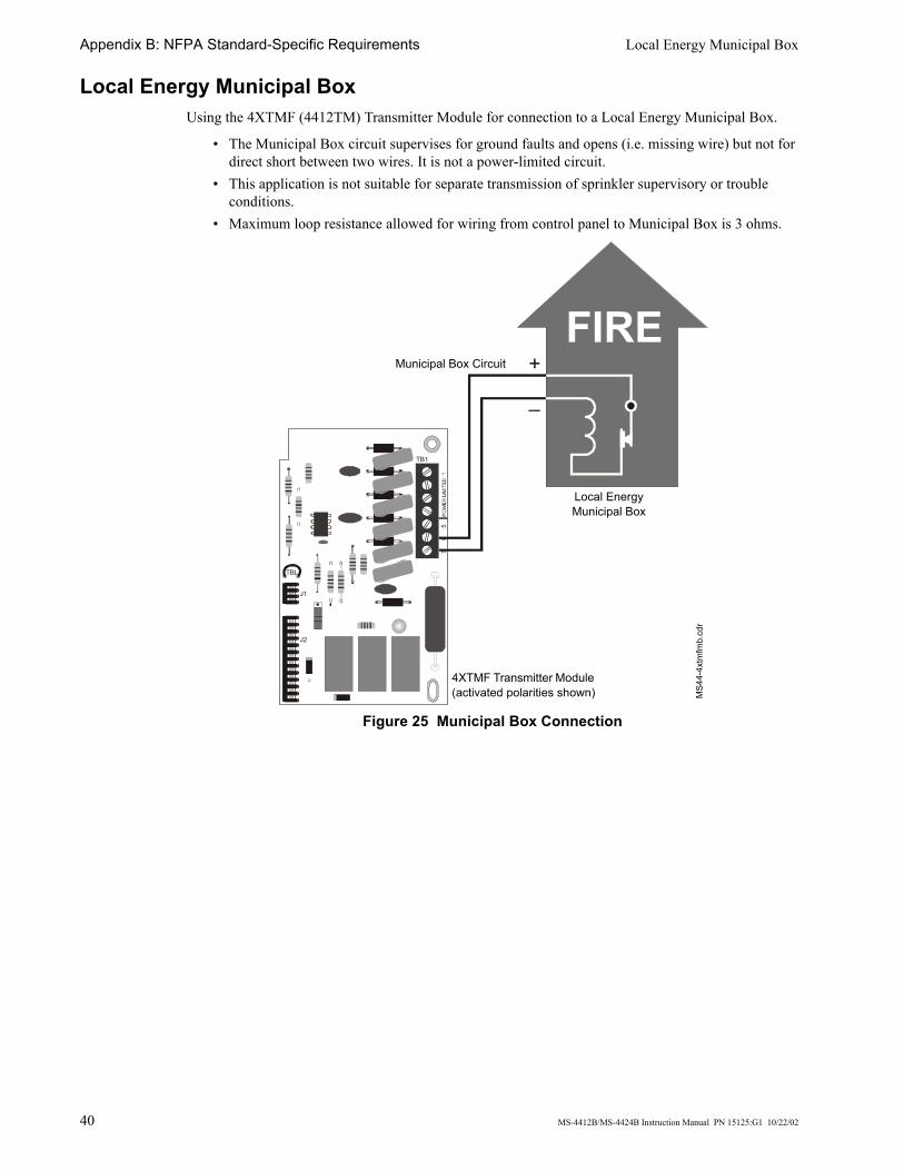
Appendix B: NFPA Standard-Specific Requirements Local Energy Municipal Box
40 MS-4412B/MS-4424B Instruction Manual PN 15125:G1 10/22/02
Local Energy Municipal Box Using the 4XTMF (4412TM) Transmitter Module for connection to a Local Energy Municipal Box.
• The Municipal Box circuit supervises for ground faults and opens (i.e. missing wire) but not for direct short between two wires. It is not a power-limited circuit.
• This application is not suitable for separate transmission of sprinkler supervisory or trouble conditions.
• Maximum loop resistance allowed for wiring from control panel to Municipal Box is 3 ohms.
Figure 25 Municipal Box Connection
TB1
TBL
J1
J2
FIRE+
–
Local Energy Municipal Box
Municipal Box Circuit
4XTMF Transmitter Module (activated polarities shown) M
S44-
4xtm
fmb.
cdr
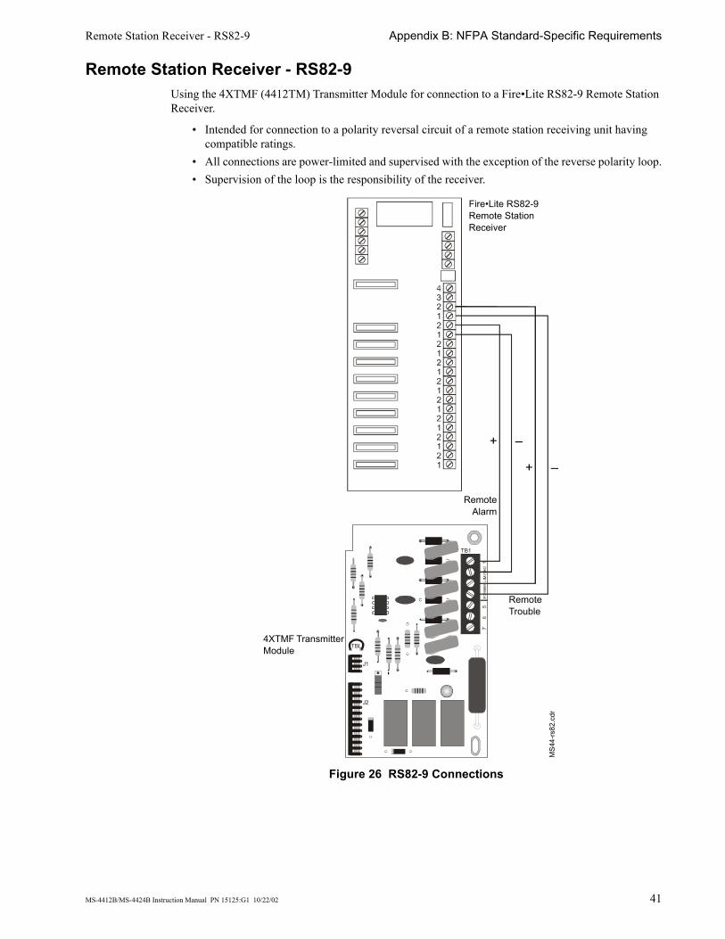
Remote Station Receiver - RS82-9 Appendix B: NFPA Standard-Specific Requirements
MS-4412B/MS-4424B Instruction Manual PN 15125:G1 10/22/02 41
Remote Station Receiver - RS82-9 Using the 4XTMF (4412TM) Transmitter Module for connection to a Fire•Lite RS82-9 Remote Station Receiver.
• Intended for connection to a polarity reversal circuit of a remote station receiving unit having compatible ratings.
• All connections are power-limited and supervised with the exception of the reverse polarity loop.• Supervision of the loop is the responsibility of the receiver.
Figure 26 RS82-9 Connections
TB1
TBL
J1
J2
Fire•Lite RS82-9 Remote Station Receiver
MS4
4-rs
82.c
dr
4XTMF Transmitter Module
+ –
+ –
Remote Trouble
RemoteAlarm
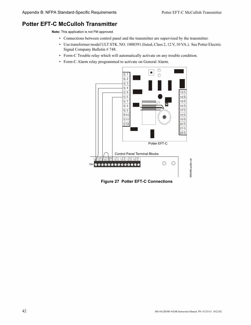
Appendix B: NFPA Standard-Specific Requirements Potter EFT-C McCulloh Transmitter
42 MS-4412B/MS-4424B Instruction Manual PN 15125:G1 10/22/02
Potter EFT-C McCulloh Transmitter Note: This application is not FM approved.
• Connections between control panel and the transmitter are supervised by the transmitter.• Use transformer model ULT STK. NO. 1000391 (listed, Class 2, 12 V, 10 VA.). See Potter Electric
Signal Company Bulletin # 748.• Form-C Trouble relay which will automatically activate on any trouble condition.• Form-C Alarm relay programmed to activate on General Alarm.
Figure 27 Potter EFT-C Connections
TB4
IN #2B+ B–
IN #3B+ B–
IN #4B+ B–
Potter EFT-C
Control Panel Terminal Blocks
MS4
4B-p
otte
r.cdr

MS-4412B/MS-4424B Instruction Manual PN 15125:G1 10/22/02 43
Appendix C: Testing & Maintenance
Testing
Inspection Perform the following prior to applying power to the system.
• Check the actual wiring hookup with the wiring diagrams.• Insure that no pieces of wire have fallen into the circuitry.• Check for missing or damaged parts.
Alarm Test An initial alarm test should be conducted following installation to determine that all parts of the system are functioning properly.
To perform an alarm test on the panel, initiate an alarm condition by blowing smoke into a smoke detector. This should cause the first zone alarm condition.
• The alarm relay will activate.• The red zone alarm LED will be illuminated.• Notification Appliance Circuits and the local piezo will start sounding.
Maintenance A regular schedule of inspection, testing, and maintenance is vital to insure proper and reliable operation of the control panel. The procedures should be performed as required by the local authority having jurisdiction. Refer to NFPA for further details.
Troubleshooting A troubleshooting table is included on the following page which provides for symptoms, problems and their solutions.

Appendix C: Testing & Maintenance Troubleshooting
44 MS-4412B/MS-4424B Instruction Manual PN 15125:G1 10/22/02
Table 3 Troubleshooting Table Symptom Problem Solution
AC Power LED ON
System trouble LED ON
Circuit trouble LED ON
Notification appliance circuit trouble
1. Check TB3 for proper connections.2. Remove all field wiring and install dummy ELR at output circuit. Check for supervisory voltage across it, (Normal -2.3 V), if problem persists, replace circuit board.3. Removed dummy ELR, reconnect field wiring and measure voltage across output; (trouble-5V, short 0V).4. Check for ELR at last device.5. Check field wiring.
Any of the right column yellow LEDs flashing
Initiating zone open circuit trouble
1. Check TB4 for proper connections.2. Remove field wiring for zone in trouble and install dummy ELR (4.7K for 24V; 2.2K for 12V). If problem persists, replace circuit board.3. Check for ELR at last device.4. Check field wiring.
Any of the right column yellow LEDs steady ON
Zone disable
1. Check installation manual.
Power trouble LED ON
Battery troubleBatt yellow LED ON
Missing or Disconnected
1. Check battery connections.
Low or damaged battery
1. Remove batteries, check voltage across charger output (17 to 19V for 24V; 8-10V for 12V), otherwise replace circuit board.2. Reconnect batteries, measure battery voltage at battery terminals. If voltage is less than 85% of rated voltage, allow them to charge for 48 hours.3. If problem persists, replace batteries.
Ground fault troubleEarth yellow LED ON
1. Remove field wiring from main panel and optional module(s) (if installed). Install dummy ELR (4.7K for 24V; 2.2K for 12V).2. Remove both battery leads.3. If trouble clears, connect one circuit at the time to pin point the problem.4. If trouble doesn’t clear, replace circuit board.
Yellow LED on 4XTMF ON 4XTMF (4412TM)
1. Move Municipal Box disconnect switch SW1 up.
OPT1, OPT2 jumper cut 1. Install optional module(s) or replace jumper if module(s) is not used.
Municipal Box open circuit1. Install dummy load if Municipal Box option isn’t used.2. Check Municipal Box wiring.
Any of the right column red LEDs ON Short on initiating circuit wiring
1. Remove field wiring and install ELR. If trouble clears, look for faulty or incorrectly wired devices.
Disconnecting Municipal Box switch ON 4XTMF (4412TM) does not create a trouble
Jumper for optional modules isn’t cut
1. Cut associated jumper OPT1 or OPT2.
4XZMF(4412ZM): associated LED doesn’t activate for alarm, trouble or supervisory conditions
Optional module trouble1. Make sure module is properly installed.2. Move disable switch SW1 on 4XZMF (4412ZM) to the left.
RZA-4XF piezo doesn’t sound for alarm, trouble or supervisory conditions
4XLMF (4412LM)1. Make sure that 4XLMF (4412LM) module is installed on J8.2. Check field wiring.
Micro Fail yellow LED ON Microprocessor damaged 1. Replace circuit board.
All RZA-4XF LEDs stay ON Power wasn’t removed prior to installation
1. Press system reset.
AC Power LED OFF
System trouble LED ON Loss of main power 1. Check incoming power (TB1).Damaged circuit breaker 1. Replace circuit board.
Micro Fail yellow LED ON Microprocessor damaged 1. Replace circuit board.
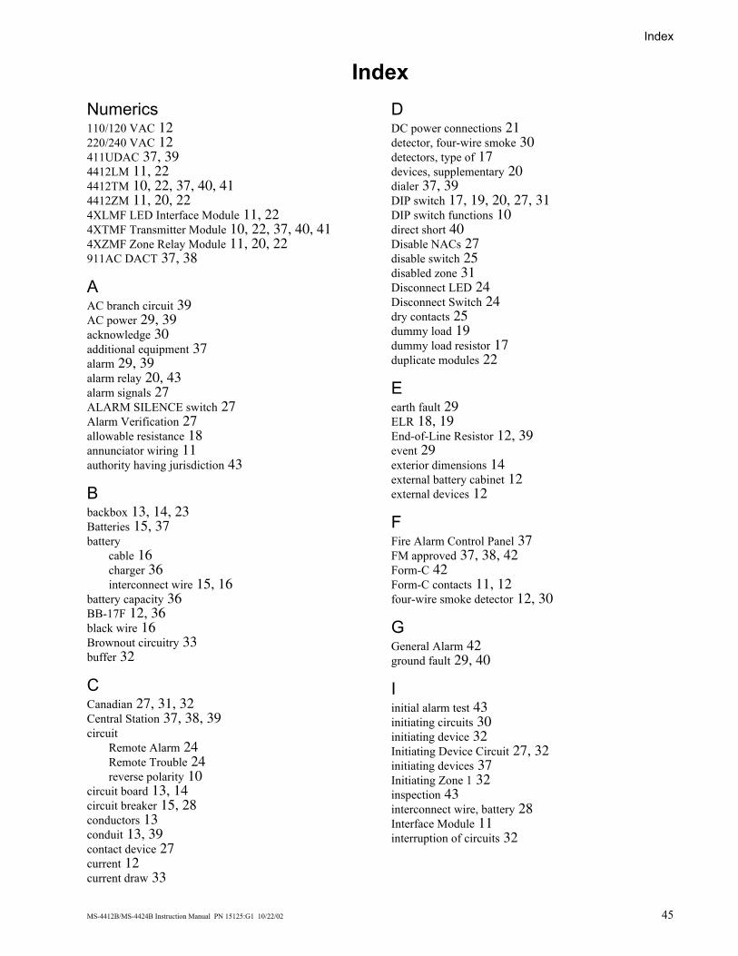
Index
MS-4412B/MS-4424B Instruction Manual PN 15125:G1 10/22/02 45
IndexNumerics110/120 VAC 12220/240 VAC 12411UDAC 37, 394412LM 11, 224412TM 10, 22, 37, 40, 414412ZM 11, 20, 224XLMF LED Interface Module 11, 224XTMF Transmitter Module 10, 22, 37, 40, 414XZMF Zone Relay Module 11, 20, 22911AC DACT 37, 38
AAC branch circuit 39AC power 29, 39acknowledge 30additional equipment 37alarm 29, 39alarm relay 20, 43alarm signals 27ALARM SILENCE switch 27Alarm Verification 27allowable resistance 18annunciator wiring 11authority having jurisdiction 43
Bbackbox 13, 14, 23Batteries 15, 37battery
cable 16charger 36interconnect wire 15, 16
battery capacity 36BB-17F 12, 36black wire 16Brownout circuitry 33buffer 32
CCanadian 27, 31, 32Central Station 37, 38, 39circuit
Remote Alarm 24Remote Trouble 24reverse polarity 10
circuit board 13, 14circuit breaker 15, 28conductors 13conduit 13, 39contact device 27current 12current draw 33
DDC power connections 21detector, four-wire smoke 30detectors, type of 17devices, supplementary 20dialer 37, 39DIP switch 17, 19, 20, 27, 31DIP switch functions 10direct short 40Disable NACs 27disable switch 25disabled zone 31Disconnect LED 24Disconnect Switch 24dry contacts 25dummy load 19dummy load resistor 17duplicate modules 22
Eearth fault 29ELR 18, 19End-of-Line Resistor 12, 39event 29exterior dimensions 14external battery cabinet 12external devices 12
FFire Alarm Control Panel 37FM approved 37, 38, 42Form-C 42Form-C contacts 11, 12four-wire smoke detector 12, 30
GGeneral Alarm 42ground fault 29, 40
Iinitial alarm test 43initiating circuits 30initiating device 32Initiating Device Circuit 27, 32initiating devices 37Initiating Zone 1 32inspection 43interconnect wire, battery 28Interface Module 11interruption of circuits 32
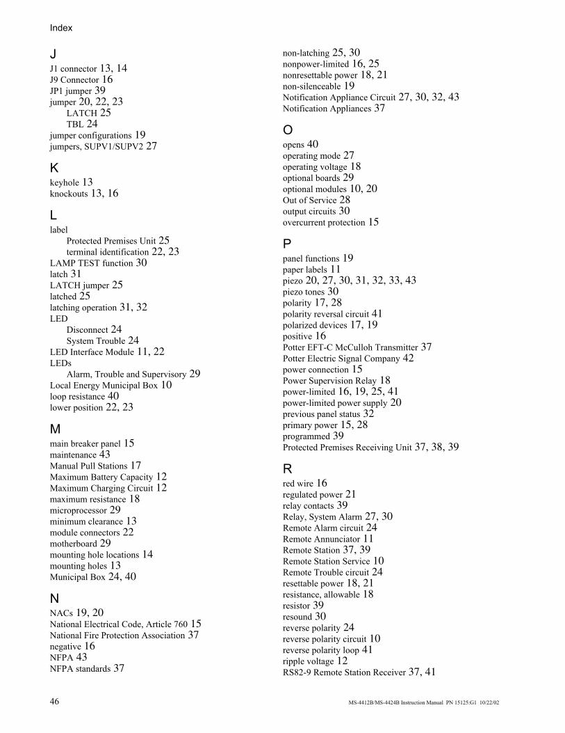
Index
46 MS-4412B/MS-4424B Instruction Manual PN 15125:G1 10/22/02
JJ1 connector 13, 14J9 Connector 16JP1 jumper 39jumper 20, 22, 23
LATCH 25TBL 24
jumper configurations 19jumpers, SUPV1/SUPV2 27
Kkeyhole 13knockouts 13, 16
Llabel
Protected Premises Unit 25terminal identification 22, 23
LAMP TEST function 30latch 31LATCH jumper 25latched 25latching operation 31, 32LED
Disconnect 24System Trouble 24
LED Interface Module 11, 22LEDs
Alarm, Trouble and Supervisory 29Local Energy Municipal Box 10loop resistance 40lower position 22, 23
Mmain breaker panel 15maintenance 43Manual Pull Stations 17Maximum Battery Capacity 12Maximum Charging Circuit 12maximum resistance 18microprocessor 29minimum clearance 13module connectors 22motherboard 29mounting hole locations 14mounting holes 13Municipal Box 24, 40
NNACs 19, 20National Electrical Code, Article 760 15National Fire Protection Association 37negative 16NFPA 43NFPA standards 37
non-latching 25, 30nonpower-limited 16, 25nonresettable power 18, 21non-silenceable 19Notification Appliance Circuit 27, 30, 32, 43Notification Appliances 37
Oopens 40operating mode 27operating voltage 18optional boards 29optional modules 10, 20Out of Service 28output circuits 30overcurrent protection 15
Ppanel functions 19paper labels 11piezo 20, 27, 30, 31, 32, 33, 43piezo tones 30polarity 17, 28polarity reversal circuit 41polarized devices 17, 19positive 16Potter EFT-C McCulloh Transmitter 37Potter Electric Signal Company 42power connection 15Power Supervision Relay 18power-limited 16, 19, 25, 41power-limited power supply 20previous panel status 32primary power 15, 28programmed 39Protected Premises Receiving Unit 37, 38, 39
Rred wire 16regulated power 21relay contacts 39Relay, System Alarm 27, 30Remote Alarm circuit 24Remote Annunciator 11Remote Station 37, 39Remote Station Service 10Remote Trouble circuit 24resettable power 18, 21resistance, allowable 18resistor 39resound 30reverse polarity 24reverse polarity circuit 10reverse polarity loop 41ripple voltage 12RS82-9 Remote Station Receiver 37, 41

Index
MS-4412B/MS-4424B Instruction Manual PN 15125:G1 10/22/02 47
RZA-4XF Remote Annunciator 11, 20
SSecondary Power 28secondary power source 35self-restoring 30separate transmission 40short circuit 31Silence Inhibit 27, 30silence switch 11Slide-in paper labels 11sprinkler 31, 32sprinkler supervisory 40Standby Battery Current 35stand-off 14, 22, 23Style B (ClassB) 17Style Y 19sulfuric acid 28supervised 19supervisory 39
circuit 17, 20, 27device 29, 31switch 27
Supervisory on Zone 4 27supplementary devices 20switch
ALARM SILENCE 27disable 25supervisory/tamper 27
System Alarm Relay 27, 30System Trouble LED 24
Ttag, “Out of Service” 28tamper switch 17, 27TBL Jumper 24terminal identification label 22, 23testing 43timer 27timer, watchdog 29tone patterns 31tones, piezo 30tracking operation 31, 32transformer 42transformer wires 13, 14transmitter 42Transmitter Module 10, 22, 37, 40, 41trim ring 14trouble 39
condition 29, 32, 40, 42relay 20sounder 11
troubleshooting 43
UUL listed 37
unused circuits 19upper position 22
Vverification period 27visual inspection 28voltage drop 12
WWalk Test 27, 29watchdog timer 29Waterflow 17Waterflow on Zone 3 27wire, primary power 15wires, transformer 13
Zzone 39Zone Relay Module 11, 22

48 MS-4412B/MS-4424B Instruction Manual PN 15125:G1 10/22/02

MS-4412B/MS-4424B Instruction Manual PN 15125:G1 10/22/02 49

50 MS-4412B/MS-4424B Instruction Manual PN 15125:G1 10/22/02

LimWarLg.p65 01/10/2000
The manufacturer warrants its products to be free from defects in materials and workmanshipfor eighteen (18) months from the date of manufacture, under normal use and service. Productsare date-stamped at time of manufacture. The sole and exclusive obligation of the manufactureris to repair or replace, at its option, free of charge for parts and labor, any part which isdefective in materials or workmanship under normal use and service. For products not underthe manufacturer's date-stamp control, the warranty is eighteen (18) months from date oforiginal purchase by the manufacturer's distributor unless the installation instructions or catalogsets forth a shorter period, in which case the shorter period shall apply. This warranty is voidif the product is altered, repaired, or serviced by anyone other than the manufacturer or itsauthorized distributors, or if there is a failure to maintain the products and systems in whichthey operate in a proper and workable manner. In case of defect, secure a Return MaterialAuthorization form from our customer service department. Return product, transportationprepaid, to the manufacturer.
This writing constitutes the only warranty made by this manufacturer with respect to itsproducts. The manufacturer does not represent that its products will prevent any loss by fireor otherwise, or that its products will in all cases provide the protection for which they areinstalled or intended. Buyer acknowledges that the manufacturer is not an insurer and assumesno risk for loss or damages or the cost of any inconvenience, transportation, damage, misuse,abuse, accident, or similar incident.
THE MANUFACTURER GIVES NO WARRANTY, EXPRESSED OR IMPLIED, OFMERCHANTABILITY, FITNESS FOR ANY PARTICULAR PURPOSE, OR OTHERWISEWHICH EXTEND BEYOND THE DESCRIPTION ON THE FACE HEREOF. UNDERNO CIRCUMSTANCES SHALL THE MANUFACTURER BE LIABLE FOR ANY LOSSOF OR DAMAGE TO PROPERTY, DIRECT, INCIDENTAL, OR CONSEQUENTIAL,ARISING OUT OF THE USE OF, OR INABILITY TO USE THE MANUFACTURER'SPRODUCTS. FURTHERMORE, THE MANUFACTURER SHALL NOT BE LIABLE FORANY PERSONAL INJURY OR DEATH WHICH MAY ARISE IN THE COURSE OF, ORAS A RESULT OF, PERSONAL, COMMERCIAL, OR INDUSTRIAL USE OF ITSPRODUCTS.
This warranty replaces all previous warranties and is the only warranty made by themanufacturer. No increase or alteration, written or verbal, of the obligation of this warrantyis authorized.
Limited Warranty

World HeadquartersOne Fire-Lite Place, Northford, CT 06472-1653 USA
203-484-7161 • Fax 203-484-7118www.firelite.com