fire control communicator ms-5024/ms-5024elimwarlg.p65 01/10/2000 an automatic fire alarm...
TRANSCRIPT

Fire Control Communicator
MS-5024/MS-5024E
PN: 50066:D2 ECN 02-606
DDocument #50066 12/03/02 Rev.
LimWarLg.p65 01/10/2000
An automatic fire alarm system–typically made up of smokedetectors, heat detectors, manual pull stations, audible warn-ing devices, and a fire alarm control with remote notificationcapability–can provide early warning of a developing fire.Such a system, however, does not assure protection againstproperty damage or loss of life resulting from a fire.
The Manufacturer recommends that smoke and/or heat detec-tors be located throughout a protected premise following therecommendations of the current edition of the National FireProtection Association Standard 72 (NFPA 72),manufacturer's recommendations, State and local codes, andthe recommendations contained in the Guide for Proper Useof System Smoke Detectors, which is made available at nocharge to all installing dealers. A study by the Federal Emer-gency Management Agency (an agency of the United Statesgovernment) indicated that smoke detectors may not go off inas many as 35% of all fires. While fire alarm systems are de-signed to provide early warning against fire, they do not guar-antee warning or protection against fire. A fire alarm systemmay not provide timely or adequate warning, or simply may notfunction, for a variety of reasons:
Smoke detectors may not sense fire where smoke cannotreach the detectors such as in chimneys, in or behind walls, onroofs, or on the other side of closed doors. Smoke detectorsalso may not sense a fire on another level or floor of a build-ing. A second-floor detector, for example, may not sense afirst-floor or basement fire.
Particles of combustion or "smoke" from a developing firemay not reach the sensing chambers of smoke detectors be-cause:
• Barriers such as closed or partially closed doors, walls, orchimneys may inhibit particle or smoke flow.
• Smoke particles may become "cold," stratify, and not reachthe ceiling or upper walls where detectors are located.
• Smoke particles may be blown away from detectors by airoutlets.
• Smoke particles may be drawn into air returns beforereaching the detector.
The amount of "smoke" present may be insufficient to alarmsmoke detectors. Smoke detectors are designed to alarm atvarious levels of smoke density. If such density levels are notcreated by a developing fire at the location of detectors, thedetectors will not go into alarm.
Smoke detectors, even when working properly, have sensinglimitations. Detectors that have photoelectronic sensingchambers tend to detect smoldering fires better than flamingfires, which have little visible smoke. Detectors that have ion-izing-type sensing chambers tend to detect fast-flaming firesbetter than smoldering fires. Because fires develop in differ-ent ways and are often unpredictable in their growth, neithertype of detector is necessarily best and a given type of detec-tor may not provide adequate warning of a fire.
Smoke detectors cannot be expected to provide adequatewarning of fires caused by arson, children playing withmatches (especially in bedrooms), smoking in bed, and violentexplosions (caused by escaping gas, improper storage offlammable materials, etc.).
Heat detectors do not sense particles of combustion andalarm only when heat on their sensors increases at a prede-termined rate or reaches a predetermined level. Rate-of-riseheat detectors may be subject to reduced sensitivity over time.For this reason, the rate-of-rise feature of each detectorshould be tested at least once per year by a qualified fire pro-tection specialist. Heat detectors are designed to protectproperty, not life.
IMPORTANT! Smoke detectors must be installed in thesame room as the control panel and in rooms used by the sys-tem for the connection of alarm transmission wiring, communi-cations, signaling, and/or power. If detectors are not so lo-cated, a developing fire may damage the alarm system, crip-pling its ability to report a fire.
Audible warning devices such as bells may not alert peopleif these devices are located on the other side of closed orpartly open doors or are located on another floor of a building.Any warning device may fail to alert people with a disability orthose who have recently consumed drugs, alcohol or medica-tion. Please note that:
• Strobes can, under certain circumstances, cause seizuresin people with conditions such as epilepsy.
• Studies have shown that certain people, even when theyhear a fire alarm signal, do not respond or comprehend themeaning of the signal. It is the property owner's responsibil-ity to conduct fire drills and other training exercise to makepeople aware of fire alarm signals and instruct them on theproper reaction to alarm signals.
• In rare instances, the sounding of a warning device cancause temporary or permanent hearing loss.
A fire alarm system will not operate without any electricalpower. If AC power fails, the system will operate from standbybatteries only for a specified time and only if the batterieshave been properly maintained and replaced regularly.
Equipment used in the system may not be technically com-patible with the control. It is essential to use only equipmentlisted for service with your control panel.
Telephone lines needed to transmit alarm signals from apremise to a central monitoring station may be out of serviceor temporarily disabled. For added protection against tele-phone line failure, backup radio transmission systems are rec-ommended.
The most common cause of fire alarm malfunction is inade-quate maintenance. To keep the entire fire alarm system inexcellent working order, ongoing maintenance is required perthe manufacturer's recommendations, and UL and NFPA stan-dards. At a minimum, the requirements of Chapter 7 of NFPA72 shall be followed. Environments with large amounts ofdust, dirt or high air velocity require more frequent mainte-nance. A maintenance agreement should be arrangedthrough the local manufacturer's representative. Maintenanceshould be scheduled monthly or as required by National and/or local fire codes and should be performed by authorized pro-fessional fire alarm installers only. Adequate written recordsof all inspections should be kept.
While a fire alarm system may lower insurancerates, it is not a substitute for fire insurance!Fire Alarm System Limitations

LimWarLg.p65 01/10/2000
WARNING - Several different sources of power can be con-nected to the fire alarm control panel. Disconnect all sourcesof power before servicing. Control unit and associated equip-ment may be damaged by removing and/or inserting cards,modules, or interconnecting cables while the unit is energized.Do not attempt to install, service, or operate this unit until thismanual is read and understood.
CAUTION - System Reacceptance Test after SoftwareChanges. To ensure proper system operation, this productmust be tested in accordance with NFPA 72 Chapter 7 afterany programming operation or change in site-specific soft-ware. Reacceptance testing is required after any change, ad-dition or deletion of system components, or after any modifica-tion, repair or adjustment to system hardware or wiring.
All components, circuits, system operations, or software func-tions known to be affected by a change must be 100% tested.In addition, to ensure that other operations are not inadvert-ently affected, at least 10% of initiating devices that are notdirectly affected by the change, up to a maximum of 50 de-vices, must also be tested and proper system operation veri-fied.
This system meets NFPA requirements for operation at0-49° C/32-120° F and at a relative humidity of 85% RH (non-condensing) at 30° C/86° F. However, the useful life of thesystem's standby batteries and the electronic componentsmay be adversely affected by extreme temperature rangesand humidity. Therefore, it is recommended that this systemand all peripherals be installed in an environment with a nomi-nal room temperature of 15-27° C/60-80° F.
Verify that wire sizes are adequate for all initiating andindicating device loops. Most devices cannot tolerate morethan a 10% I.R. drop from the specified device voltage.
Like all solid state electronic devices, this system mayoperate erratically or can be damaged when subjected to light-ning-induced transients. Although no system is completelyimmune from lightning transients and interferences, propergrounding will reduce susceptibility. Overhead or outsideaerial wiring is not recommended, due to an increased sus-ceptibility to nearby lightning strikes. Consult with the Techni-cal Services Department if any problems are anticipated orencountered.
Disconnect AC power and batteries prior to removing or in-serting circuit boards. Failure to do so can damage circuits.
Remove all electronic assemblies prior to any drilling, filing,reaming, or punching of the enclosure. When possible, makeall cable entries from the sides or rear. Before making modifi-cations, verify that they will not interfere with battery, trans-former, and printed circuit board location.
Do not tighten screw terminals more than 9 in-lbs.Over-tightening may damage threads, resulting in reducedterminal contact pressure and difficulty with screw terminalremoval.
Though designed to last many years, system componentscan fail at any time. This system contains static-sensitivecomponents. Always ground yourself with a proper wrist strapbefore handling any circuits so that static charges are re-moved from the body. Use static-suppressive packagingto protect electronic assemblies removed from the unit.
Follow the instructions in the installation, operating, andprogramming manuals. These instructions must be followedto avoid damage to the control panel and associatedequipment. FACP operation and reliability depend uponproper installation by authorized personnel.
Adherence to the following will aid in problem-freeinstallation with long-term reliability:
WARNING: This equipment generates, uses, and canradiate radio frequency energy and if not installed andused in accordance with the instruction manual, maycause interference to radio communications. It hasbeen tested and found to comply with the limits for classA computing device pursuant to Subpart B of Part 15 ofFCC Rules, which is designed to provide reasonableprotection against such interference when operated in acommercial environment. Operation of this equipment ina residential area is likely to cause interference, in whichcase the user will be required to correct the interferenceat his own expense.
Canadian RequirementsThis digital apparatus does not exceed the Class Alimits for radiation noise emissions from digitalapparatus set out in the Radio Interference Regulationsof the Canadian Department of Communications.
Le present appareil numerique n'emet pas de bruitsradioelectriques depassant les limites applicables auxappareils numeriques de la classe A prescrites dans leReglement sur le brouillage radioelectrique edicte par leministere des Communications du Canada.
FCC Warning
Installation Precautions

4 Document #50066 Rev.D2 12/03/02 P/N 50066:D2
Notes

Document 50066 Rev. D2 12/03/02 P/N: 50066:D2 5
CHAPTER 1: Product Description .........................................................................................................................111.1: Product Features ..........................................................................................................................................11
FIGURE 1-1: DP-5024 ........................................................................................................................12FIGURE 1-2: MS-5024 Control Panel.................................................................................................12
1.2: Controls and Indicators ...............................................................................................................................131.2.1: Front Panel Switches ........................................................................................................................13
FIGURE 1-3: Controls and Indicators .................................................................................................131.2.2: Display and Indicators ......................................................................................................................131.2.3: Local Sounder ...................................................................................................................................13
1.3: Circuits ........................................................................................................................................................131.3.1: Input Circuits.....................................................................................................................................131.3.2: Output Circuits ..................................................................................................................................131.3.3: Notification Appliance Circuits ........................................................................................................141.3.4: Relays................................................................................................................................................14
1.4: Digital Communicator.................................................................................................................................141.5: Components.................................................................................................................................................14
1.5.1: Main Circuit Board ...........................................................................................................................141.5.2: Cabinet ..............................................................................................................................................141.5.3: Transformer Assembly......................................................................................................................141.5.4: Batteries ............................................................................................................................................15
1.6: Optional Devices .........................................................................................................................................151.6.1: ADM-24 ............................................................................................................................................151.6.2: RZA-5F .............................................................................................................................................151.6.3: CAC-5F.............................................................................................................................................151.6.4: NACA-2F..........................................................................................................................................151.6.5: DP-5024 ............................................................................................................................................151.6.6: BB-17F..............................................................................................................................................16
1.7: Specifications ..............................................................................................................................................161.8: Telephone Requirements and Warnings ......................................................................................................17
1.8.1: Telephone Circuitry...........................................................................................................................171.8.2: Digital Communicator.......................................................................................................................171.8.3: Telephone Company Rights and Warnings .......................................................................................171.8.4: For Canadian Applications................................................................................................................18
CHAPTER 2: Installation.........................................................................................................................................192.1: Mounting Options .......................................................................................................................................192.2: Backbox Mounting......................................................................................................................................19
FIGURE 2-1: Cabinet Dimensions and Knockout Locations..............................................................20FIGURE 2-2: Backbox and Battery Box .............................................................................................21
2.3: Operating Power..........................................................................................................................................22FIGURE 2-3: Operating Power Connections.......................................................................................22
2.4: Input Circuits...............................................................................................................................................23FIGURE 2-4: Typical Initiating Device Circuit Connections .............................................................23
2.5: Output Circuits ............................................................................................................................................242.5.1: DC Power Output Connections.........................................................................................................24
FIGURE 2-5: Auxiliary Power Connections .......................................................................................242.5.2: Telephone Circuits ............................................................................................................................242.5.3: Notification Appliance Circuits (full-wave rectified) .......................................................................24
FIGURE 2-6: Typical NAC Connections ............................................................................................242.5.4: Programmable Relays .......................................................................................................................25
FIGURE 2-7: Programmable Relay Terminals....................................................................................252.6: UL Power-limited Wiring Requirements ....................................................................................................26
Table of Contents
Table of Contents
6 Document #50066 Rev. D2 12/03/02 P/N 50066:D2
FIGURE 2-8: Typical Wiring Diagram for UL Power-limited Requirements ....................................262.7: Digital Communicator .................................................................................................................................27
FIGURE 2-9: Wiring Phone Jacks .......................................................................................................272.8: Optional Boards...........................................................................................................................................28
2.8.1: ADM-24 Annunciator Driver Module ..............................................................................................28FIGURE 2-10: ADM-24 ......................................................................................................................28
2.8.2: RZA-5F Remote Annunciator ...........................................................................................................28FIGURE 2-11: RZA-5F .......................................................................................................................28FIGURE 2-12: Wiring the RZA-5F/ADM-24 .....................................................................................29FIGURE 2-13: Installing Annunciator in Single-Gang Box................................................................29
2.8.3: NACA-2F and CAC-5F Class A Converter Modules .......................................................................30FIGURE 2-14: NACA-2F Style Z Converter Module .........................................................................30FIGURE 2-15: CAC-5F Style D Converter Module............................................................................30
CHAPTER 3: Programming Instructions...............................................................................................................313.1: Entering Program Mode ..............................................................................................................................313.2: Switch (Key) Functions...............................................................................................................................32
FIGURE 3-1: Control Panel Keypad ...................................................................................................323.3: Programming Options .................................................................................................................................32
TABLE 3-1: 3+1, 4+1 Express, 4+1 Standard and Expanded, 4+2 Expanded - Primary....................33TABLE 3-2: 4+2 Standard and 4+2 Express Format - Primary..........................................................35TABLE 3-3: 3+1, 4+1 Express, 4+1 Standard and Expanded, 4+2 Expanded - Secondary................37TABLE 3-4: 4+2 Standard and 4+2 Express Format - Primary..........................................................39FIGURE 3-2: Verification Timing Diagram........................................................................................40TABLE 3-5: ........................................................................................................................................41
CHAPTER 4: Operating Instructions ....................................................................................................................464.1: Switches.......................................................................................................................................................46
4.1.1: Reset ..................................................................................................................................................464.1.2: Silence ...............................................................................................................................................464.1.3: Mode..................................................................................................................................................474.1.4: 1st Event ............................................................................................................................................474.1.5: Down Arrow......................................................................................................................................474.1.6: Up Arrow...........................................................................................................................................474.1.7: [ENTER/STORE]..............................................................................................................................47
4.2: Display and LEDs........................................................................................................................................47FIGURE 4-1: Phone Connectors and LEDs.........................................................................................48
4.3: Operation .....................................................................................................................................................494.3.1: Alarm Response ................................................................................................................................494.3.2: Alarm Restoral ..................................................................................................................................494.3.3: System Supervisory Condition Response .........................................................................................504.3.4: System Supervisory Restoral Response ............................................................................................504.3.5: Trouble Condition Response .............................................................................................................504.3.6: Trouble Conditions Restoral .............................................................................................................514.3.7: Off Normal Reporting .......................................................................................................................514.3.8: Zone Disable/Enable .........................................................................................................................514.3.9: Fire Drill ............................................................................................................................................524.3.10: No Battery/Low Battery ..................................................................................................................52
4.4: Central Station Communications.................................................................................................................52TABLE 4-1: Format Selection Addresses (16 & 42)...........................................................................53TABLE 4-2: Format Selection Address Explanation...........................................................................54
4.4.1: Transmittal Priorities .........................................................................................................................55TABLE 4-3: Compatible UL Listed Receivers....................................................................................56
Document 50066 Rev. D2 12/03/02 P/N: 50066:D2 7
Table of Contents
CHAPTER 5: Servicing ...........................................................................................................................................575.1: Walktest Mode.............................................................................................................................................575.2: History Mode...............................................................................................................................................585.3: Troubleshoot Mode .....................................................................................................................................59
5.3.1: Zones .................................................................................................................................................595.3.2: AC Line.............................................................................................................................................595.3.3: Battery ...............................................................................................................................................595.3.4: NAC 1 & 2 ........................................................................................................................................605.3.5: Resettable Power...............................................................................................................................605.3.6: Telephone Lines ................................................................................................................................60
FIGURE 5-1: Handset/Speaker Connection ........................................................................................605.4: Lamp Test ....................................................................................................................................................60
CHAPTER 6: Slave Communicator Configuration ...............................................................................................61FIGURE 6-1: Slave Communicator Connections................................................................................62
Appendix A: Battery Calculations .......................................................................................................................63
TABLE A-1: Battery Calculations ......................................................................................................63TABLE A-2: Regulated Load in Standby ...........................................................................................64TABLE A-3: Regulated Load in Alarm ..............................................................................................65
Appendix B: Programming Reference Sheet .....................................................................................................66
Appendix C: Wire Requirements .........................................................................................................................72
TABLE C-1: Wire Requirements .......................................................................................................72
Appendix D: Operation and Function Modes .....................................................................................................73
TABLE D-1: Operation Modes ...........................................................................................................73TABLE D-2: Function Modes ............................................................................................................73

8 Document #50066 Rev.D2 12/03/02 P/N 50066:D2
Notes
This control panel has been designed to comply with standards set forth by the following regulatory agencies:
• Underwriters Laboratories Standard UL 864
• NFPA 72 National Fire Alarm Code for Local, Remote Station and Central Station Fire Alarm Systems
• CAN/ULC - S527M Standard for Control Units for Fire Alarm Systems
NFPA Standards
NFPA 72 National Fire Alarm Code for Central Station Signaling Systems Protected Premises Unit (Automatic, Manual and Waterflow), Local Fire Alarm Systems and Remote Station Fire Alarm Systems.
Underwriters Laboratories Documents:
UL 38 Manually Actuated Signaling Boxes
UL 217 Smoke Detectors, Single and Multiple Station
UL 228 Door Closers–Holders for Fire Protective Signaling Systems
UL 268 Smoke Detectors for Fire Protective Signaling Systems
UL 268A Smoke Detectors for Duct Applications
UL 346 Waterflow Indicators for Fire Protective Signaling Systems
UL 464 Audible Signaling Appliances
UL 521 Heat Detectors for Fire Protective Signaling Systems
UL 864 Standard for Control Units for Fire Protective Signaling Systems
UL 1481 Power Supplies for Fire Protective Signaling Systems
UL 1638 Visual Signaling Appliances
UL 1971 Signaling Devices for Hearing Impaired
CAN/ULC - S524M Standard for Installation of Fire Alarm Systems
Other:
NEC Article 250 Grounding
NEC Article 300 Wiring Methods
NEC Article 760 Fire Protective Signaling Systems
Applicable Local and State Building Codes
C22.1, Canadian Electrical Code, Part I
C22.2 No. 0, General Requirements - Canadian Electrical Code, Part II
C22.2 No. 0.4, Bonding and Grounding of Electrical Equipment (Protective Grounding) - Canadian
C282, Emergency Electrical Power Supply for Buildings - Canadian
Requirements of the Local Authority Having Jurisdiction (LAHJ)
Fire•Lite Documents
Fire•Lite Device Compatibility Document Document #15384
Before proceeding, the installer should be familiar with the following documents.
Document #50066 Rev. D2 12/03/02 P/N 50066:D2 9
10 Document #50066 Rev.D2 12/03/02 P/N 50066:D2
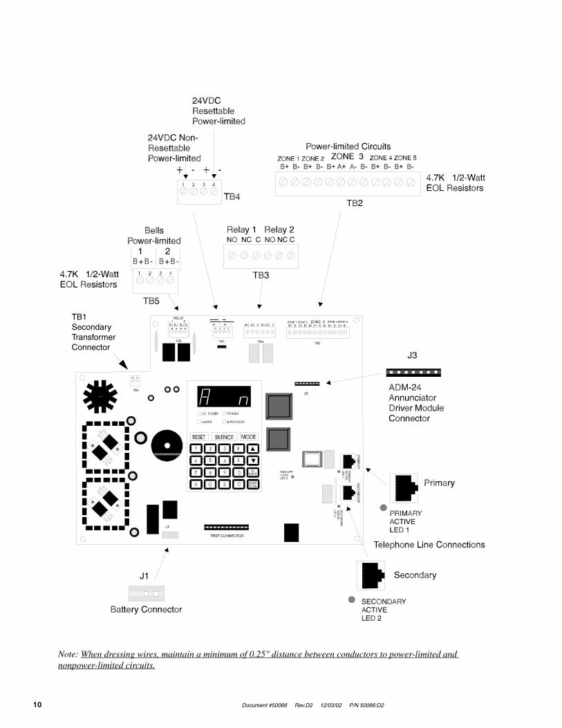
Note: When dressing wires, maintain a minimum of 0.25" distance between conductors to power-limited and nonpower-limited circuits.
TB1SecondaryTransformerConnector
Document #50066 Rev. D2 12/03/02 P/N 50066:D2 11
Product Description
CHAPTER 1 Product Description
The MS-5024 is a combination control panel and digital communicator all on one circuit board. It is a five-zone panel which uses conventional input devices. The panel accepts waterflow devices, two-wire smoke detectors, four-wire smoke detectors, pull stations and other normally open contact devices. Outputs include two NACs (Notifica-tion Appliance Circuits) and two programmable relays.
The integral communicator transmits system status (alarms, troubles, AC loss, etc.) to UL listed Central Stations via the public switched telephone network. The control panel has a built-in programmer and may also serve as a slave communicator to a host control panel. It also supervises all wiring, AC voltage, telephone line input voltage and battery level.
The MS-5024E offers the same features as the MS-5024 but allows connection to 220/240 VAC input. Note that unless otherwise specified, the term MS-5024 shall be used in this manual to refer to both the MS-5024 and MS-5024E Fire Control Communicators.
1.1 Product Features
• Selectable as Fire Panel, Fire Panel/Communicator or Slave Communicator
• Programmable Zone ID:
✓ 2-wire smoke
✓ Pull station
✓ Normally open contact
✓ Supervisory
✓ Supervisory auto-resettable
✓ Waterflow silenceable
✓ Waterflow nonsilenceable
• One Style D (Class A) Initiating Zone
• Four Style B (Class B) Initiating Zones
• 3.6 amps usable power
• Two NFPA Style Y (Class B) Notification Appliance Circuits
• Built-in programmer
• Built-in voltmeter
• Telephone Line Active LED indicators
• Communication confirmation (Kissoff) LED
• Disable report by event
• Programmable Event Codes
• 24 volt operation
• Real-Time clock
• Trouble reminder
• Alarm verification
• Alarm presignal
• RZA-5F Remote Annunciator (requires ADM-24 Annunciator Driver Module)
• Small size - 14.5" (36.83 cm) X 12.5" (31.75 cm) X 2.875" (7.303 cm)
• History file with 32 event storage
• Silence inhibit per NAC

Product Features
12 Document #50066 Rev.D2 12/03/02 P/N 50066:D2
• Auto-silence per NAC
• Touchtone/rotary dialing
• Programmable make/break ratio
• Fuseless design
• Number of dial attempts (5 minimum, 10 maximum)
• Programmable channel ID (slave)
• Programmable zone delay (waterflow only)
• Two Form-C programmable relays
• Low AC voltage sense
• One-man Walktest
• Optional Dead Front cover (DP-5024)
• CAC-5F Class A Converter module for Initiating Device Circuits
• NACA-2F Class A Converter module for Notification Appliance Cir-cuits
FIGURE 1-1:DP-5024
B+ B- B+ B- B+ A+ A- B- B+ B- B+ B-1 2 3 41
1
2
2
3 4
TEST CONNECTOR
J1
J3
BELLS1 2
TB5 TB4 TB3 TB2
TB1
NO NC C NO NC C ZONE 1 ZONE 2 ZONE 4 ZONE 5ZONE 3
PRIM
ARY SECON
DARY
KISS OFF/LOADLED 3
PRIM
ARYAC
TIVELED
1S
ECO
ND
ARYAC
TIVELED
2
2 4V NO N-RE SE TTA BLE
24V RE SE TTA BLE
FIGURE 1-2:MS-5024 Control Panel
Notification Appliance Circuits
Programmable Relays
5 Input Zones
Annunciator Driver Module Interface Connector
Primary & Secondary Phone Lines
Keypad
Holds up to 7 AH Batteries Up to 60 Hrs. of Standby
Piezo 85dB
Four Character 7-Segment LED Display

Document #50066 Rev. D2 12/03/02 P/N 50066:D2 13
Controls and Indicators
1.2 Controls and Indicators
1.2.1 Front Panel Switches
RESET Digits 0 - 9
SILENCE A
MODE B
Up Arrow C
Down Arrow D
1st EVENT E
ENTER/STORE F
1.2.2 Display and Indicators
• Four 7-Segment Displays - red
• Alarm - red LED
• Trouble - yellow LED
• Supervisory - yellow LED
• Silence - yellow LED
• AC Power - green LED
• Primary Phone Line Active - red LED
• Secondary Phone Line Active - red LED
• 'Kissoff' Signal from Central Station - green LED
1.2.3 Local Sounder
A piezo sounder provides separate and distinct sounds for alarm, trouble and supervisory conditions.
1.3 Circuits
1.3.1 Input Circuits
Five input circuits provide Style B configuration with one circuit also configurable for Style D. Input circuits may be used as standard fire control panel zones or slave communicator input channels.
• Initiating Device Circuit 1 (Style B) accepts Normally Open contact devices and 2-wire smoke detectors
• Initiating Device Circuit 2 (Style B) accepts Normally Open contact devices and 2-wire smoke detectors
• Initiating Device Circuit 3 (Style B/D) accepts Normally Open contact devices, 2-wire smoke detectors and waterflow devices
• Initiating Device Circuit 4 (Style B) accepts Normally Open contact devices and 2-wire smoke detectors
• Initiating Device Circuit 5 (Style B) accepts Normally Open contact devices and 2-wire smoke detectors
1.3.2 Output Circuits
• 24 Volt Resettable Power Output
• 24 Volt Nonresettable Power Output
• Primary Telephone Line
• Secondary Telephone Line
• 24 Volt Battery Charger
FIGURE 1-3:Controls and Indicators

Digital Communicator
14 Document #50066 Rev.D2 12/03/02 P/N 50066:D2
1.3.3 Notification Appliance Circuits
Two NACs (Notification Appliance Circuits) configurable for Style Y (Class B) with various programmable features.
1.3.4 Relays
Two dry Form-C relay contacts programmable for Alarm, Trouble, Supervisory and/or Communications Failure. Contacts are rated 2 amps @ 30 VDC (resistive) and 0.5 amps @ 30 VAC (resistive).
1.4 Digital Communicator
Two modular phone jacks allow easy connection to telephone lines. Modular jacks are labeled PH1 and PH2 for the Primary and Secondary phone lines. Telephone line active red LEDs are provided as well as a green 'Kissoff” LED. The integral digital communicator provides the following functions:
• Line Seizure - takes control of the phone lines, disconnecting any premises phones
• Off/On Hook - perform on and off-hook status to the phone lines
• Listen for dial tone - 440 hertz tone typical in most networks
• Dialing the Central Station(s) number - default is Touch-Tone®, programmable to rotary
• For tone burst or touchtone type formats: discern proper 'Ack' and 'Kissoff' tone(s) - the frequency and time duration of the tone(s) vary with the transmission format. The control panel will adjust accordingly
• Communicate in the following formats:
✓ 12 Tone Burst Types: 20 pps(3+1, 4+1 and 4+2 Standard, 3+1 Expanded, 4+1 Expanded, 4+2 Expanded)
✓ 2 Touchtone Types:4+1 Ademco Express and 4+2 Ademco ExpressRefer to Table 4-3, “Compatible UL Listed Receivers,” on page 56 for a list of compatible receivers.
1.5 Components
1.5.1 Main Circuit Board
The main circuit board contains the system’s CPU, power supply, other primary components and wiring interface connectors. Optional modules plug in and are mounted to the main circuit board. The main circuit board is delivered premounted in the cabinet.
1.5.2 Cabinet
The cabinet is red with an attractive navy blue front overlay. The backbox measures 14.5" (36.83 cm) X 12.5" (31.75 cm) X 2.875" (7.303 cm) and provides space for two batteries (up to 7 Amp Hour). Also available is an optional dress panel (DP-5024), which mounts inside the cabinet.
1.5.3 Transformer Assembly
One 100 VA transformer is provided standard with the panel.

Document #50066 Rev. D2 12/03/02 P/N 50066:D2 15
Optional Devices
1.5.4 Batteries
The cabinet provides space for 7 Amp Hour batteries (for 12 Amp Hour to 18 Amp Hour batteries use the UL listed BB-17F battery box). Batteries must be ordered separately.
1.6 Optional Devices
1.6.1 ADM-24
The ADM-24 Annunciator Driver Module supports the RZA-5F Remote Annunciator module. Annunciator wiring is supervised for open circuits by this module. The Annunciator Driver Module mounts to connector J3 in the upper right corner of the main board. Refer to Figure 1-2 on page 12 and Figure 2-10 on page 28.
1.6.2 RZA-5F
The RZA-5F Remote Annunciator mounts on a standard single-gang box and provides LED indications of the following:
✓ Alarm Zone 1 (red LED)
✓ Alarm Zone 2 (red LED)
✓ Alarm Zone 3 (red LED)
✓ Alarm Zone 4 (red LED)
✓ Alarm Zone 5 (red LED)
✓ System Trouble (yellow LED)
A Local Trouble Sounder and Tone Silence Switch are also provided. All LEDs and their wiring are supervised for open conditions. Any open condition will cause the System Trouble LED to illuminate. Slide in paper labels permit an easy change of zone information (refer to Figure 2-11 on page 28). Note that the RZA-5F Remote Annunciator requires the use of the ADM-24 Annunciator Driver Module. Only one ADM-24/RZA-5F combination is allowed per system.
1.6.3 CAC-5F
The CAC-5F Class A Converter module converts the Style B (Class B) Initiating Device Circuits to Style D (Class A). The CAC-5F mounts to terminal block TB2 located in the upper right corner of the main circuit board (refer to Figure 1-2 on page 12 and Figure 2-15 on page 30). The removable terminal block on the CAC-5F module provides for ease of wiring.
1.6.4 NACA-2F
The NACA-2F Notification Appliance Circuit Class A Converter module converts the two NAC circuits from Style Y (Class B) to Style Z (Class A). The converter module mounts to terminal block TB5 located in the upper left cor-ner of the main circuit board (refer to Figure 1-2 on page 12 and Figure 2-14 on page 30). The removable terminal block on the NACA-2F module provides for ease of wiring.
1.6.5 DP-5024
The DP-5024 Dress Panel is red and is available as an option (required for Canadian installations). The dress panel restricts access to the system wiring while allowing access to the membrane switch panel (refer to Figure 1-1 on page 12).

Specifications
16 Document #50066 Rev.D2 12/03/02 P/N 50066:D2
1.6.6 BB-17F
The BB-17F Battery Box may be used to house two 12 Amp Hour or 18 AMP Hour batteries. The battery box mounts directly below the control panel cabinet (refer to Figure 2-2 on page 21). The BB-17F is red and is provided with knockouts.
1.7 Specifications
AC Power - TB1
MS-5024: 120 VAC, 60 Hz, 1.2 ampsMS-5024E: 220/240 VAC, 50 Hz, 0.6 ampsSupervised for AC loss and brownoutWire size: minimum 14 AWG (2.00 mm2) with 600V insulation
Battery (lead acid only) - J1
Maximum charging circuit: Normal Flat Charge - 27.6V @ 0.8 ampMaximum charger capacity: 17 Amp Hour battery (MS-5024 cabinet holds maximum 7 Amp Hour battery. Larger batteries require Fire•Lite BB-17F or other UL listed battery cabinet).Supervised for low and no battery
Initiating Device Circuits - TB2
Detector zones 1, 2, 3, 4 and 5Power-limited circuitryOperation: All zones (NFPA Style B), Zone 3 (NFPA Style B or D). Use CAC-5F for Style D operationNormal operating voltage: 24 VDC (ripple = 100mV maximum)Alarm current: 26 mA Short circuit current: 42 mA maximumMaximum loop resistance: 100 ohmsEnd-of-Line Resistor: 4.7K, ½ watt (P/N 27072 UL listed)Detector loop current sufficient to ensure operation of one alarmed detector/zoneStandby current: 7.26 mA (includes ELR and 2 mA maximum detector current)Smoke Detector Identifier ARefer to Fire•Lite Device Compatibility Document for listed compatible devices
Notification Appliance Circuits - TB5
Nonregulated special purpose power, Style Y supported. Use NACA-2F for Style Z operationPower-limited circuitryOperating voltage nominal 24 voltsCurrent limit: PTC Maximum signaling current/circuit: 1.5 amps (3.0 amps max. for all external devicesEnd-of-Line Resistor: 4.7K, ½ watt (P/N 71252 UL listed) for Notification Appliance CircuitsRefer to Fire•Lite Device Compatibility Document for listed compatible devices
Programmable Relays - TB4
Contact rating: 2.0 amps @ 30 VDC (resistive), 0.5 amps @ 30 VAC (resistive)Programmable: Form-C
Four-Wire Smoke Detector Power - TB4, Terminals 3(+) & 4(-)
Maximum ripple voltage: 10 mVRMS Operating voltage: nominal 24 voltsUp to 300 mA is available for powering 4-wire smoke detectorsPower-limited circuitry Maximum standby current: 50 mARefer to Fire•Lite Device Compatibility Document for compatible listed devices
Document #50066 Rev. D2 12/03/02 P/N 50066:D2 17
Telephone Requirements and Warnings
Nonresettable 24 VDC Power - TB4, Terminals 1(+) & 2(-)
Maximum ripple voltage: 10 mVRMS Operating voltage: nominal 24 voltsTotal DC current available from this output is up to 300 mAPower-limited circuitry Maximum standby current is 150 mARefer to Fire•Lite Device Compatibility Document for compatible listed devices
Notes:
1. For power supply calculations, refer to “Battery Calculations” on page 63
2. Total current for nonresettable power, 4-wire smoke power and two NACs must not exceed 3.6 amps
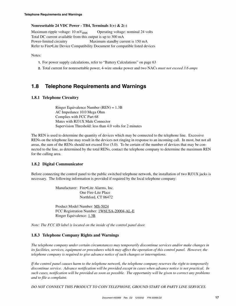
1.8 Telephone Requirements and Warnings
1.8.1 Telephone Circuitry
Ringer Equivalence Number (REN) = 1.3BAC Impedance 10.0 Mega OhmComplies with FCC Part 68Mates with RJ31X Male ConnectorSupervision Threshold: less than 4.0 volts for 2 minutes
The REN is used to determine the quantity of devices which may be connected to the telephone line. Excessive RENs on the telephone line may result in the devices not ringing in response to an incoming call. In most, but not all areas, the sum of the RENs should not exceed five (5.0). To be certain of the number of devices that may be con-nected to the line, as determined by the total RENs, contact the telephone company to determine the maximum REN for the calling area.
1.8.2 Digital Communicator
Before connecting the control panel to the public switched telephone network, the installation of two RJ31X jacks is necessary. The following information is provided if required by the local telephone company:
Manufacturer: Fire•Lite Alarms, Inc.One Fire-Lite PlaceNorthford, CT 06472
Product Model Number: MS-5024FCC Registration Number: 1W6USA-20004-AL-ERinger Equivalence: 1.3B
Note: The FCC ID label is located on the inside of the control panel door.
1.8.3 Telephone Company Rights and Warnings
The telephone company under certain circumstances may temporarily discontinue services and/or make changes in its facilities, services, equipment or procedures which may affect the operation of this control panel. However, the telephone company is required to give advance notice of such changes or interruptions.
If the control panel causes harm to the telephone network, the telephone company reserves the right to temporarily discontinue service. Advance notification will be provided except in cases when advance notice is not practical. In such cases, notification will be provided as soon as possible. The opportunity will be given to correct any problems and to file a complaint.
DO NOT CONNECT THIS PRODUCT TO COIN TELEPHONE, GROUND START OR PARTY LINE SERVICES.

Telephone Requirements and Warnings
18 Document #50066 Rev.D2 12/03/02 P/N 50066:D2
When the control panel activates, premises phones will be disconnected.
Two separate phone lines are required. Do not connect both telephone interfaces to the same telephone line.
The control panel must be connected to the public switched telephone network upstream of any private telephone system at the protected premises.
An FCC compliant telephone cord must be used with this equipment. This equipment is designed to be connected to the telephone network or premises wiring using a compatible RJ31X male modular plug which is Part 68 compliant.
1.8.4 For Canadian Applications
The following is excerpted from CP-01 Issue 5:
“NOTICE: The Industry Canada (IC) label identifies certified equipment. This certification means that the equip-ment meets certain telecommunications network protective, operational and safety requirements as prescribed in the appropriate Terminal Equipment Technical Requirements document(s). The Department does not guarantee the equipment will operate to the user’s satisfaction.”
Before installing this equipment, users should ensure that it is permissible to be connected to the facilities of the local telecommunications company. The equipment must also be installed using an acceptable method of connection. The customer should be aware that compliance with the above conditions may not prevent degradation of service in some situations.
Repairs to certified equipment should be made by an authorized Canadian maintenance facility designated by the supplier. Any repairs or alterations made by the user to this equipment, or equipment malfunctions, may give the telecommunications company cause to request the user to disconnect the equipment.
Users should ensure for their own protection that the electrical ground connections of the power utility, telephone lines and internal metallic water pipe system, if present, are connected together. This precaution may be particularly important in rural areas.
CAUTION
Users should not attempt to make such connections themselves, but should contact the appropriate electric inspection authority or electrician.
“The Ringer Equivalence Number (REN) assigned to each terminal device provides an indication of the maximum number of terminals allowed to be connected to a telephone interface. The termination of an interface may consist of any combination of devices subject only to the requirement that the sum of the REN of all devices does not exceed 5.”
Representative: NOTIFIER, CANADA24 Viceroy RoadConcord, Ontario L4K2L9
IC Certificate Number: 21325785ARinger Equivalence Number (REN): 1.3BLoad Number: 2
Document #50066 Rev. D2 12/03/02 P/N 50066:D2 19
Installation
CHAPTER 2 Installation
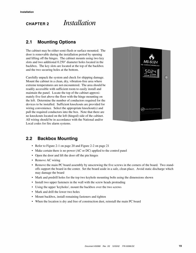
2.1 Mounting Options
The cabinet may be either semi-flush or surface mounted. The door is removable during the installation period by opening and lifting off the hinges. The cabinet mounts using two key slots and two additional 0.250" diameter holes located in the backbox. The key slots are located at the top of the backbox and the two securing holes at the bottom.
Carefully unpack the system and check for shipping damage. Mount the cabinet in a clean, dry, vibration-free area where extreme temperatures are not encountered. The area should be readily accessible with sufficient room to easily install and maintain the panel. Locate the top of the cabinet approxi-mately five feet above the floor with the hinge mounting on the left. Determine the number of conductors required for the devices to be installed. Sufficient knockouts are provided for wiring convenience. Select the appropriate knockout(s) and pull the required conductors into the box. Note that there are no knockouts located on the left (hinged) side of the cabinet. All wiring should be in accordance with the National and/or Local codes for fire alarm systems.
2.2 Backbox Mounting
• Refer to Figure 2-1 on page 20 and Figure 2-2 on page 21
• Make certain there is no power (AC or DC) applied to the control panel
• Open the door and lift the door off the pin hinges
• Remove AC wiring
• Remove the main PC board assembly by unscrewing the five screws in the corners of the board. Two stand-offs support the board in the center. Set the board aside in a safe, clean place. Avoid static discharge which may damage the board
• Mark and predrill holes for the top two keyhole mounting bolts using the dimensions shown
• Install two upper fasteners in the wall with the screw heads protruding
• Using the upper 'keyholes', mount the backbox over the two screws
• Mark and drill the lower two holes
• Mount backbox, install remaining fasteners and tighten
• When the location is dry and free of construction dust, reinstall the main PC board

Backbox Mounting
20 Document #50066 Rev.D2 12/03/02 P/N 50066:D2
Draw wires through the respective knockout locations.
12.625"(32.068 cm)
14.625“ (37.148 cm)
16.625" (42.228 cm)
17.625"(44.768 cm)
3.000“(7.620 cm)
3.000“(7.620 cm)
1.250“ (3.175 cm)
10.000“ (25.400 cm)1.250“ (3.175 cm)
1.25“(3.175 cm)
1.25“(3.175 cm)
1.125“(2.858 cm)
0.875“(2.223 cm)
14.5“(36.83 cm)
3.25“(8.255 cm)
1.75“(4.445 cm)
3.5“(8.89 cm)
12.5“ (31.75 cm)
4.125“ (10.478 cm)6.125“ (15.558 cm)
8.125“ (20.638 cm)10.125“ (25.718 cm)
1.000“ (2.540 cm)
6.5“ (16.51 cm)
9.500“ (24.130 cm)
(7.62 cm)3.0“
FIGURE 2-1:Cabinet Dimensions and Knockout Locations
Right Side
Top
Bottom
TR-3-R Trim Ring

Document #50066 Rev. D2 12/03/02 P/N 50066:D2 21
Backbox Mounting
Notes:
1. Mount the MS-5024 cabinet to the wall
2. Remove appropriate knockouts from the MS-5024 cabinet and BB-17F
3. Position the BB-17F near the MS-5024 cabinet and connect with conduit, making sure there is at least ½" of clearance between the two cabinets
4. Anchor the BB-17F to the wall
����������� ������� ���� ��������� ������ ��
����������� ������� ���� ���������� ������ ��
����� �!"
�"#�����$$$�����$ ��
�"#�������
����$�� ��
����"�%��������
��$���� ��
�&#���'�(��)��*�
����"�%�������������� ��
�&#���'�(��)��*�
+�#
������
+�#
����������� ��������������������

Operating Power
22 Document #50066 Rev.D2 12/03/02 P/N 50066:D2
2.3 Operating Power
CAUTION! Several different sources of power can be connected to this panel. Disconnect all sources of power before servicing. The panel and associated equipment may be damaged by removing and/or inserting cards, modules or interconnecting cables while this unit is energized.
Primary Power Source (AC) and Earth Ground Connections
AC power connections are made inside the control panel cabinet. Primary power source for the MS-5024 is 120VAC, 60 Hz, 1.2 amps and for the MS-5024E is 220/240VAC, 50 Hz, 0.6 amps. Run a pair of wires (with ground conductor) from the protected premises main breaker box to the orange and black primary leads of the MS-5024 transformer. As per the National Electric Code, use 14 AWG (2.00 mm2) or heavier gauge wire with 600 V insulation. No other equipment may be connected to this circuit. In addition, this circuit must be provided with overcurrent protection and may not contain any power disconnect devices. A separate Earth Ground connection must be made to ensure proper panel operation and lightning and transient protection. Connect the Earth Ground wire, minimum 14 AWG (2.00 mm2), to the grounding stud indicated by the ground symbol label. Note that conduit must not be used for an Earth Ground connection since this does not provide reliable protection.
Secondary Power Source (batteries)
Observe polarity when connecting the battery. Connect the battery cable to J1 on the main circuit board using the plug-in connector provided. The battery charger is current-limited and capable of recharging sealed lead acid type batteries. The charger shuts off when the system is in alarm or if the battery voltage drops too low (below 14.2VDC). See Appendix A for calculations of the correct battery rating. WARNING! Battery contains sulfuric acid which can cause severe burns to the skin and eyes and can destroy fabrics. If contact is made with sulfuric acid, immediately flush the skin or eyes with water for 15 minutes and seek immediate medical attention.
FIGURE 2-3:Operating Power Connections
Ground Stud
Connect Earth Ground Wire
Ground
HotAC Feed
Neutral
Orange
Red
Brown
Black
Document #50066 Rev. D2 12/03/02 P/N 50066:D2 23
Input Circuits
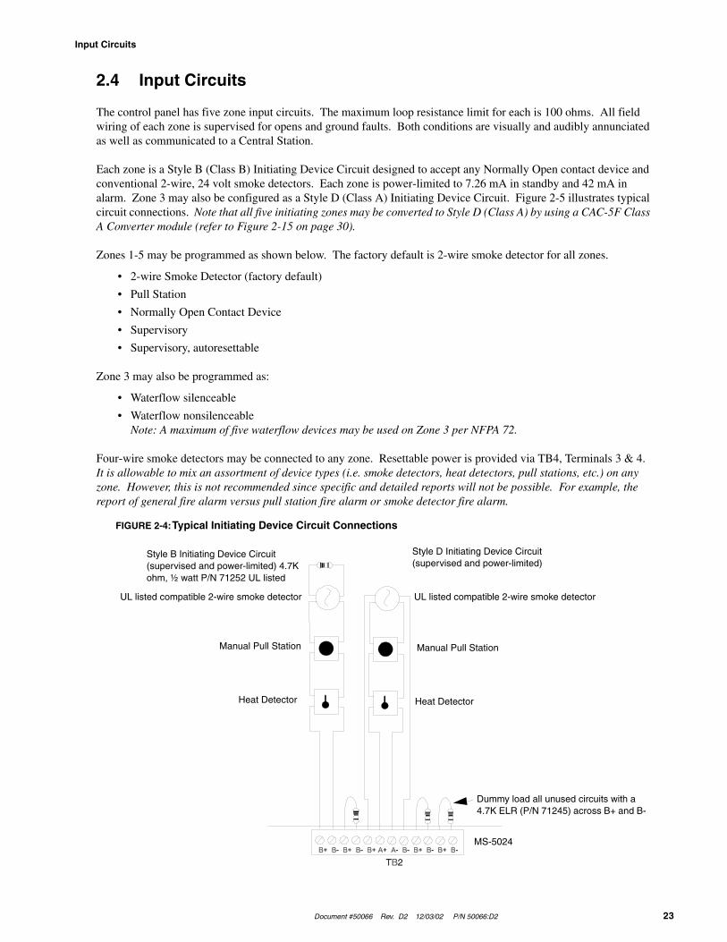
2.4 Input Circuits
The control panel has five zone input circuits. The maximum loop resistance limit for each is 100 ohms. All field wiring of each zone is supervised for opens and ground faults. Both conditions are visually and audibly annunciated as well as communicated to a Central Station.
Each zone is a Style B (Class B) Initiating Device Circuit designed to accept any Normally Open contact device and conventional 2-wire, 24 volt smoke detectors. Each zone is power-limited to 7.26 mA in standby and 42 mA in alarm. Zone 3 may also be configured as a Style D (Class A) Initiating Device Circuit. Figure 2-5 illustrates typical circuit connections. Note that all five initiating zones may be converted to Style D (Class A) by using a CAC-5F Class A Converter module (refer to Figure 2-15 on page 30).
Zones 1-5 may be programmed as shown below. The factory default is 2-wire smoke detector for all zones.
• 2-wire Smoke Detector (factory default)
• Pull Station
• Normally Open Contact Device
• Supervisory
• Supervisory, autoresettable
Zone 3 may also be programmed as:
• Waterflow silenceable
• Waterflow nonsilenceableNote: A maximum of five waterflow devices may be used on Zone 3 per NFPA 72.
Four-wire smoke detectors may be connected to any zone. Resettable power is provided via TB4, Terminals 3 & 4.It is allowable to mix an assortment of device types (i.e. smoke detectors, heat detectors, pull stations, etc.) on any zone. However, this is not recommended since specific and detailed reports will not be possible. For example, the report of general fire alarm versus pull station fire alarm or smoke detector fire alarm.
FIGURE 2-4:Typical Initiating Device Circuit Connections
Dummy load all unused circuits with a 4.7K ELR (P/N 71245) across B+ and B-
Heat DetectorHeat Detector
Manual Pull Station Manual Pull Station
UL listed compatible 2-wire smoke detectorUL listed compatible 2-wire smoke detector
Style B Initiating Device Circuit (supervised and power-limited) 4.7K ohm, ½ watt P/N 71252 UL listed
Style D Initiating Device Circuit (supervised and power-limited)
MS-5024

Output Circuits
24 Document #50066 Rev.D2 12/03/02 P/N 50066:D2
2.5 Output Circuits
2.5.1 DC Power Output Connections
All DC power outputs are power-limited.
2.5.2 Telephone Circuits
Provision to connect to two independent telephone lines is available via two telephone jacks labeled PH1 (Primary) and PH2 (Secondary). Telephone line control/command is possible via double line seizure as well as usage of an RJ31X style interconnection (refer to Figure 2-9 on page 27).
2.5.3 Notification Appliance Circuits (full-wave rectified)
The MS-5024 provides two Style Y NACs (Notification Appliance Circuits), each capable of 1.5 amps of current. Total current drawn from these as well as other DC power outputs cannot exceed 3.6 amps. Circuits are supervised and power-limited. Figure 2-6 illustrates a typical circuit connection. Refer to the Fire•Lite Device Compatibility Document for a listing of compatible notification appliances. Note that both NACs may be converted to Style Z (Class A) by using an NACA-2F Class A Converter module (refer to Figure 2-14 on page 30).
FIGURE 2-5:Auxiliary Power Connections
1 2 3 4+ - + -
*Nonresettable Power (300 mA)24 VDC filtered, nonresettable power can be obtained from TB4 Terminals 1(+) & 2(-)
*4-Wire Smoke Detector Power (300 mA)24 VDC filtered, resettable power for 4-wire smoke detectors can be obtained from TB4 Terminals 3(+) & 4(-)
* Refer to the Fire•Lite Device Compatibility Document for a list of compatible smoke detectors, notification appliances and auxiliary devices
FIGURE 2-6:Typical NAC Connections
Polarized Bell
Polarized Horn
Polarized Horn
Dummy Load all unused circuitsP/N 71245
Note: Notification Appliance Circuit polarity shown in alarm state.
Style Y Notification Appliance Circuit (supervised and power-limited). 4.7K ohm, ½ watt P/N 71252 UL listed

Document #50066 Rev. D2 12/03/02 P/N 50066:D2 25
Output Circuits
Note that both NACs may be programmed as follows:
• Silenceable
• Nonsilenceable
• Enabled/Disabled
• Silence Inhibited
• Autosilence, 5 to 30 minutes
• Coded (March Time, Temporal, California)
2.5.4 Programmable Relays
The control panel provides two sets of Form-C programmable relay contacts rated for 2.0 amps @ 30 VDC (resistive). Each relay may be programmed for alarm, trouble, supervisory, communications failure or any combina-tion of these. Refer to Figure 2-7 on page 25 for UL Power-limited wiring requirements.Note that all relay connections must be power-limited or nonpower-limited. No mixing is permitted.
FIGURE 2-7:Programmable Relay Terminals
Relay 1 Relay 2
Relay Connections
PowerLimited
PowerLimited
Note: If relays are used as power-limited circuits, paste supplied label to terminal block as indicated below.

UL Power-limited Wiring Requirements
26 Document #50066 Rev.D2 12/03/02 P/N 50066:D2
2.6 UL Power-limited Wiring Requirements
Power-limited and nonpower-limited circuit wiring must remain separated in the cabinet. All power-limited circuit wiring must remain at least 0.25" away from any nonpower-limited circuit wiring. Furthermore, all power-limited circuit wiring and nonpower-limited circuit wiring must enter and exit the cabinet through different knockouts and/or conduits. A typical wiring diagram for the MS-5024 is shown below.
B+ B- B+ B- B+ A+ A- B- B+ B- B+ B-1 2 3 41
1
2
2
3 4
TEST CONNECTOR
J1
J3
BELLS1 2
TB5 TB4 TB3 TB2
TB1
NO NC C NO NC C ZONE 1 ZONE 2 ZONE 4 ZONE 5ZONE 3
PR
IMAR
Y S
ECO
ND
AR
Y
KISS OFF/LOADLED 3
PRIMARY
ACTIVELED 1
SECONDARYACTIVELED 2
24V NON-RESETTABLE
24V RESETTABLE
- +
ADM-24
FIGURE 2-8:Typical Wiring Diagram for UL Power-limited Requirements
AC Power
Earth Ground
Power-limited Circuits
Nonpower-limited Circuits
Power-limited Circuits
Power-limitedCircuit

Document #50066 Rev. D2 12/03/02 P/N 50066:D2 27
Digital Communicator
2.7 Digital Communicator
Two independent telephone lines can be connected to the control panel. Telephone line control/command is made possible via double line seizure as well as usage of an RJ31X style interconnection. The control panel’s digital com-municator is built into the main circuit board. Connection and wiring of two phone lines is required as shown below.Note that it is critical that the digital communicator be located as the first device on the incoming telephone circuit to properly function.
FIGURE 2-9:Wiring Phone Jacks

Optional Boards
28 Document #50066 Rev.D2 12/03/02 P/N 50066:D2
2.8 Optional Boards
2.8.1 ADM-24 Annunciator Driver Module
The ADM-24 supports the RZA-5F Remote Annunciator. The wiring is supervised for open conditions by this mod-ule. The Annunciator Driver Module mounts to J3 in the upper right corner of the main circuit board.
2.8.2 RZA-5F Remote Annunciator
The RZA-5F mounts on a standard single-gang electri-cal box and provides LED indication of the following:
• Alarm Zone 1 (red LED)
• Alarm Zone 2 (red LED)
• Alarm Zone 3 (red LED)
• Alarm Zone 4 (red LED)
• Alarm Zone 5 (red LED)
• System Trouble (yellow LED)
The remote annunciator provides individual zone alarm LEDs, a system trouble LED, a piezo sounder and a remote sounder shut off switch. All LEDs and their wiring are supervised for open conditions. Any open condition will cause the System Trouble LED to illuminate.
Note that the RZA-5F requires the use of an ADM-24 Annunciator Drive Module. Only one RZA-5F/ADM-24 combination is allowed per system.
FIGURE 2-10:ADM-24
Main Board
ADM-24
Connector located on back of board
Standoff
FIGURE 2-11:RZA-5F

Document #50066 Rev. D2 12/03/02 P/N 50066:D2 29
Optional Boards
FIGURE 2-12:Wiring the RZA-5F/ADM-24
ADM-24
RZA-5F
Note: Make wiring connections with system power off. Maximum wire impedance is 100 ohms per wiring connection.
+24V
FIGURE 2-13:Installing Annunciator in Single-Gang Box
screw #6-32 x 1.00" LG
Optional Boards
30 Document #50066 Rev.D2 12/03/02 P/N 50066:D2
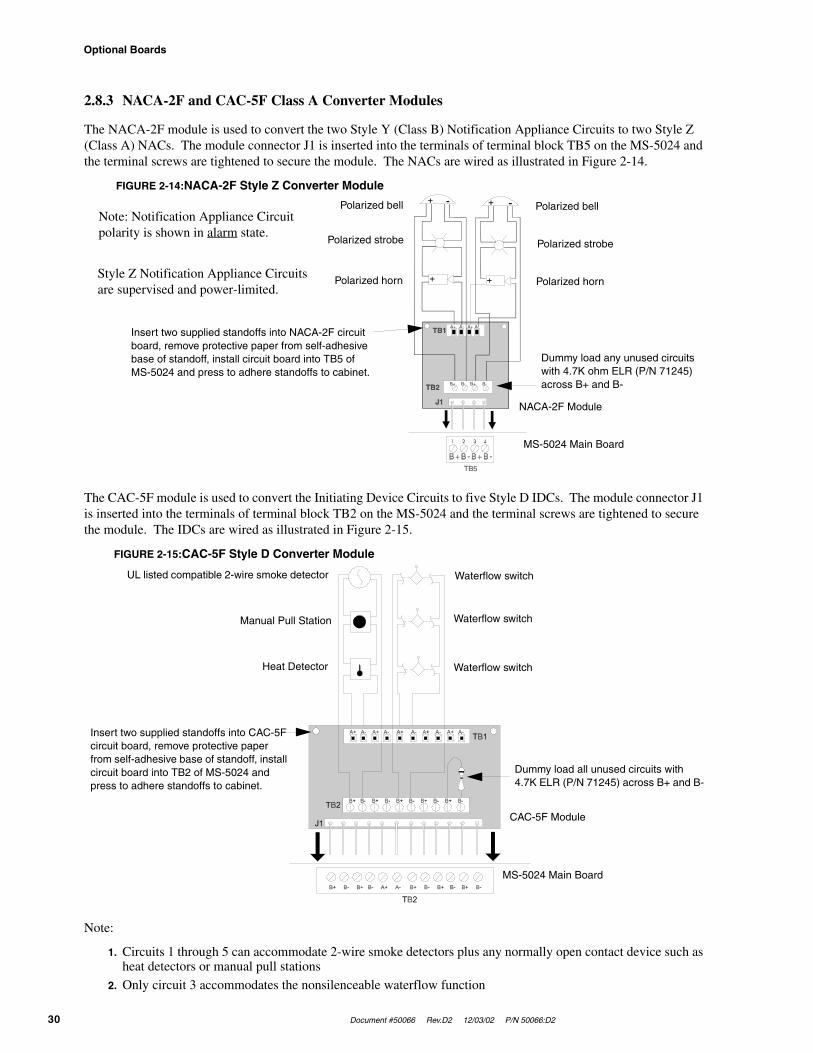
2.8.3 NACA-2F and CAC-5F Class A Converter Modules
The NACA-2F module is used to convert the two Style Y (Class B) Notification Appliance Circuits to two Style Z (Class A) NACs. The module connector J1 is inserted into the terminals of terminal block TB5 on the MS-5024 and the terminal screws are tightened to secure the module. The NACs are wired as illustrated in Figure 2-14.
The CAC-5F module is used to convert the Initiating Device Circuits to five Style D IDCs. The module connector J1 is inserted into the terminals of terminal block TB2 on the MS-5024 and the terminal screws are tightened to secure the module. The IDCs are wired as illustrated in Figure 2-15.
Note:
1. Circuits 1 through 5 can accommodate 2-wire smoke detectors plus any normally open contact device such as heat detectors or manual pull stations
2. Only circuit 3 accommodates the nonsilenceable waterflow function
FIGURE 2-14:NACA-2F Style Z Converter Module
Polarized bellPolarized bell
Polarized strobe
Polarized horn Polarized horn
Polarized strobe
Note: Notification Appliance Circuit polarity is shown in alarm state.
Style Z Notification Appliance Circuits are supervised and power-limited.
Dummy load any unused circuits with 4.7K ohm ELR (P/N 71245) across B+ and B-
Insert two supplied standoffs into NACA-2F circuit board, remove protective paper from self-adhesive base of standoff, install circuit board into TB5 of MS-5024 and press to adhere standoffs to cabinet.
MS-5024 Main Board
NACA-2F Module
FIGURE 2-15:CAC-5F Style D Converter Module
Waterflow switch
Waterflow switch
Waterflow switch
UL listed compatible 2-wire smoke detector
Manual Pull Station
Heat Detector
MS-5024 Main Board
CAC-5F Module
Dummy load all unused circuits with 4.7K ELR (P/N 71245) across B+ and B-
Insert two supplied standoffs into CAC-5F circuit board, remove protective paper from self-adhesive base of standoff, install circuit board into TB2 of MS-5024 and press to adhere standoffs to cabinet.

Document #50066 Rev. D2 12/03/02 P/N 50066:D2 31
Programming Instructions
CHAPTER 3 Programming Instructions
This chapter describes programming the panel from the onboard keypad. Programming of the control panel is possible at any time except when an alarm condition is present or during a fire drill.
The control panel has been designed for many different types of applications. After examining your specific application, review the programming options and choose the entries best suited for your system.
The control panel has a built-in intelligent programmer. All programming selections are stored in nonvolatile Electrically-Erasable Programmable Read-Only Memory (EEPROM). This ensures that the control panel will retain all entries made in programming mode even if both AC and battery power are removed. Invalid entries cause a 'beep' from the onboard piezo sounder.
The user must program the primary and secondary phone numbers, account numbers and 24 hour test report times for each Central Station account and the current time and date. The control panel comes with factory chosen options/features already programmed. Other options/features may be programmed if desired. If all factory default settings are acceptable, programming is complete.
Successful entry into Program Mode places the system into trouble. A 'system off-normal' message is transmitted to the Central Station.
3.1 Entering Program Mode
To enter Program Mode, press the MODE key once (the display will go blank). The user than has ten seconds to start entering the code 7764.
☛ 7764 spells PROG on a Touch-Tone® phone
If an incorrect key is entered, reenter the proper 4-digit code before pressing the [ENTER/STORE] key. Note that as the information is entered into the control panel, the digits will scroll across the display from right to left.
___7__77_7767764
The user is allowed a pause of up to 10 seconds between each number while entering the code. After pressing the [ENTER/STORE] key, the control panel will be in Program Mode and will display 00_F. A maximum of 10 min-utes of idle time is allowed at this point before starting the programming, otherwise the control panel will return to Normal Mode. A maximum of 10 minutes between key strokes is also allowed. All entries made prior to the 10 minute time-out are valid and are stored.
Once in Programming Mode, the control panel will:
• Blink the trouble LED
• Activate the relay(s) if programmed for trouble
• Disable the Notification Appliance Circuit(s)
• Disable the relay(s) if programmed for alarm
• Display 00_F
• Ignore all other keys other than those mentioned in this section
• Continue to communicate any events not previously acknowledged at a Central Station prior to entering Program Mode
Switch (Key) Functions
32 Document #50066 Rev.D2 12/03/02 P/N 50066:D2
Note that location 56 is factory defaulted to '0' for control panel only. This keeps the communicator off until location 56 is changed to '1' for slave communicator or '2' for panel/communicator. Once location 56 is set to '1' or '2' and a valid phone number is entered, entry into the Program Mode will cause transmission of the 'system off-normal' report.
Throughout Program Mode, the first three locations on the left of the display represent the memory address which can range from 000 to 313 (alpha characters are not used). The last location (farthest right) represents the contents of the memory address. The first address displayed is shown below:
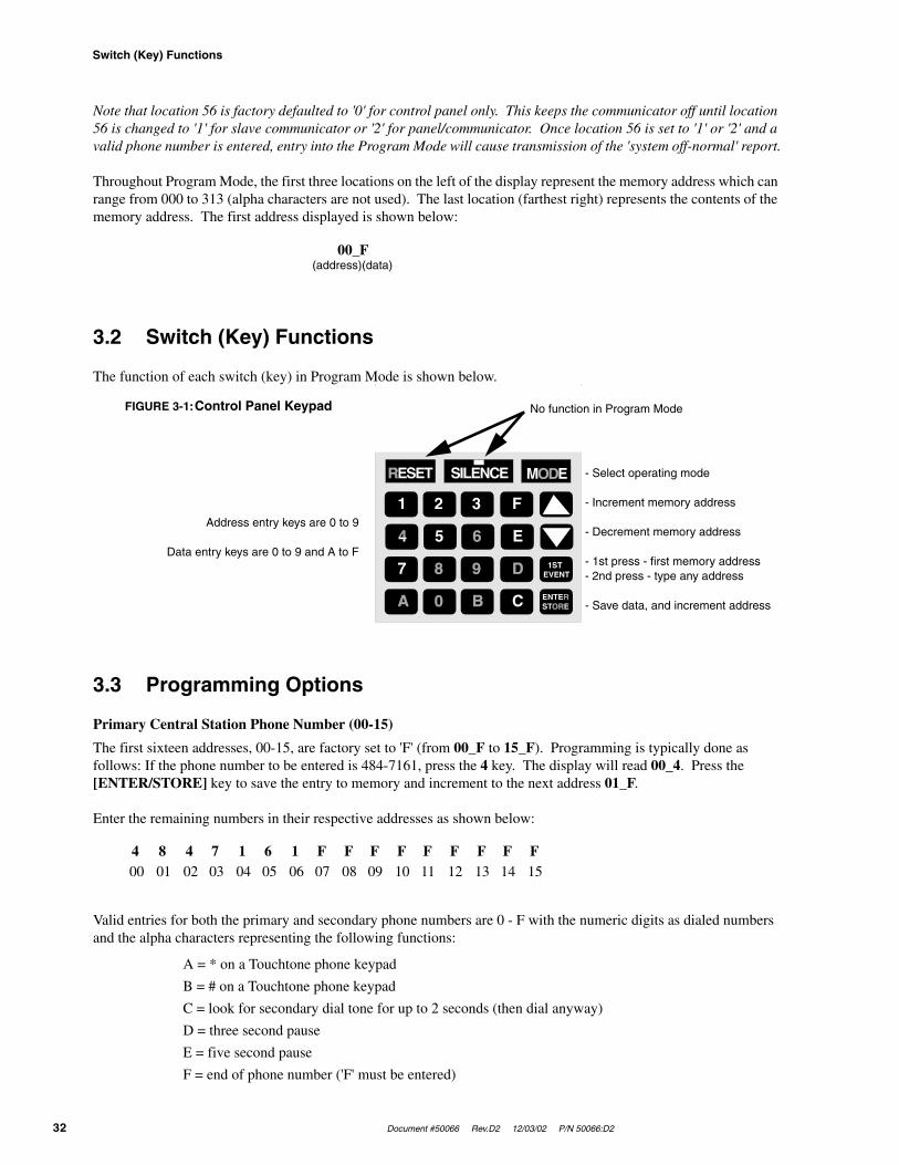
3.2 Switch (Key) Functions
The function of each switch (key) in Program Mode is shown below.
3.3 Programming Options
Primary Central Station Phone Number (00-15)
The first sixteen addresses, 00-15, are factory set to 'F' (from 00_F to 15_F). Programming is typically done as follows: If the phone number to be entered is 484-7161, press the 4 key. The display will read 00_4. Press the [ENTER/STORE] key to save the entry to memory and increment to the next address 01_F.
Enter the remaining numbers in their respective addresses as shown below:
Valid entries for both the primary and secondary phone numbers are 0 - F with the numeric digits as dialed numbers and the alpha characters representing the following functions:
A = * on a Touchtone phone keypad
B = # on a Touchtone phone keypad
C = look for secondary dial tone for up to 2 seconds (then dial anyway)
D = three second pause
E = five second pause
F = end of phone number ('F' must be entered)
00_F(address)(data)
FIGURE 3-1:Control Panel Keypad No function in Program Mode
Address entry keys are 0 to 9
Data entry keys are 0 to 9 and A to F
- Select operating mode
- Increment memory address
- Decrement memory address
- 1st press - first memory address- 2nd press - type any address
- Save data, and increment address
4 8 4 7 1 6 1 F F F F F F F F F00 01 02 03 04 05 06 07 08 09 10 11 12 13 14 15

Document #50066 Rev. D2 12/03/02 P/N 50066:D2 33
Programming Options
Primary Central Station Number Communication Format (16)
One location is needed to select the Communication Format for the primary phone number. Address 16 is used for this purpose. The default (factory setting) for this address is 'A' (16_A), which is 4+2 Standard, 1800 Hz 'Carrier', 2300 Hz 'ack'. You may enter 0 through D in place of the default, then press the [ENTER/STORE] key. Choose from the list of formats below:
0: 4+1 Ademco Express Standard, DTMF, 1400/2300 ACK
1: 4+2 Ademco Express Standard, DTMF, 1400/2300 ACK
2: 3+1 Standard 1800 Hz Carrier, 2300 Hz ACK
3: 3+1 Expanded 1800 Hz Carrier, 2300 Hz ACK
4: 3+1 Standard 1900 Hz Carrier, 1400 Hz ACK
5: 3+1 Expanded 1900 Hz Carrier, 1400 Hz ACK
6: 4+1 Standard 1800 Hz Carrier, 2300 Hz ACK
7: 4+1 Expanded 1800 Hz Carrier, 2300 Hz ACK
8: 4+1 Standard 1900 Hz Carrier, 1400 Hz ACK
9: 4+1 Expanded 1900 Hz Carrier, 1400 Hz ACK
A: 4+2 Standard 1800 Hz Carrier, 2300 Hz ACK
B: 4+2 Expanded 1800 Hz Carrier, 2300 Hz ACK
C: 4+2 Standard 1900 Hz Carrier, 1400 Hz ACK
D: 4+2 Expanded 1900 Hz Carrier, 1400 Hz ACK
E: Not used
F: Not used
Note: Consult your Central Station for proper selection or consult our factory representatives. For any format cho-sen, the control panel automatically programs all of the event codes. See Table 3-1 , Table 3-2 , Table 3-3 and Table 3-4 .
CAUTION! Default entries for event codes (as shown in Table 3-1 through Table 3-4 ) are programmed into memory each time address 16 is altered. Be certain to double check entries after programming the Zone Functions, addresses 57 - 61. Program the Format first then program the Zone(s) Function.
3+1, 4+1 Express, 4+1 Standard and Expanded, 4+2 Expanded Formats
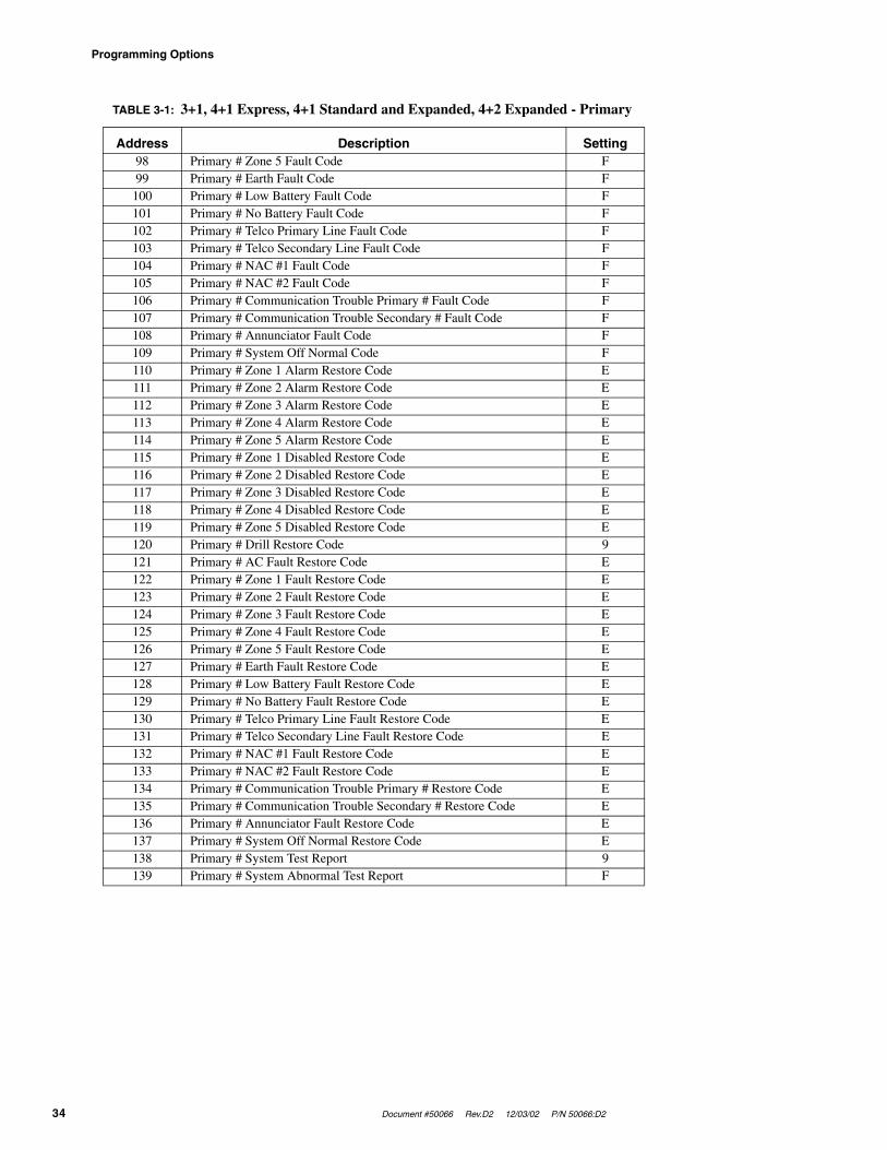
If '0, 2, 3, 4, 5, 6, 7, 8, 9, B or D' is entered for address 16, the data in Table 3-1 is automatically programmed for the Primary Central Station phone number event codes. Enter '0' for the setting to disable the report.
TABLE 3-1: 3+1, 4+1 Express, 4+1 Standard and Expanded, 4+2 Expanded - Primary
Address Description Setting82 Primary # Zone 1 Alarm Code 183 Primary # Zone 2 Alarm Code 184 Primary # Zone 3 Alarm Code 185 Primary # Zone 4 Alarm Code 186 Primary # Zone 5 Alarm Code 187 Primary # Zone 1 Disabled Code F88 Primary # Zone 2 Disabled Code F89 Primary # Zone 3 Disabled Code F90 Primary # Zone 4 Disabled Code F91 Primary # Zone 5 Disabled Code F92 Primary # Drill Code 993 Primary # AC Fault Code F94 Primary # Zone 1 Fault Code F95 Primary # Zone 2 Fault Code F96 Primary # Zone 3 Fault Code F97 Primary # Zone 4 Fault Code F
Programming Options
34 Document #50066 Rev.D2 12/03/02 P/N 50066:D2
98 Primary # Zone 5 Fault Code F99 Primary # Earth Fault Code F
100 Primary # Low Battery Fault Code F101 Primary # No Battery Fault Code F102 Primary # Telco Primary Line Fault Code F103 Primary # Telco Secondary Line Fault Code F104 Primary # NAC #1 Fault Code F105 Primary # NAC #2 Fault Code F106 Primary # Communication Trouble Primary # Fault Code F107 Primary # Communication Trouble Secondary # Fault Code F108 Primary # Annunciator Fault Code F109 Primary # System Off Normal Code F110 Primary # Zone 1 Alarm Restore Code E111 Primary # Zone 2 Alarm Restore Code E112 Primary # Zone 3 Alarm Restore Code E113 Primary # Zone 4 Alarm Restore Code E114 Primary # Zone 5 Alarm Restore Code E115 Primary # Zone 1 Disabled Restore Code E116 Primary # Zone 2 Disabled Restore Code E117 Primary # Zone 3 Disabled Restore Code E118 Primary # Zone 4 Disabled Restore Code E119 Primary # Zone 5 Disabled Restore Code E120 Primary # Drill Restore Code 9121 Primary # AC Fault Restore Code E122 Primary # Zone 1 Fault Restore Code E123 Primary # Zone 2 Fault Restore Code E124 Primary # Zone 3 Fault Restore Code E125 Primary # Zone 4 Fault Restore Code E126 Primary # Zone 5 Fault Restore Code E127 Primary # Earth Fault Restore Code E128 Primary # Low Battery Fault Restore Code E129 Primary # No Battery Fault Restore Code E130 Primary # Telco Primary Line Fault Restore Code E131 Primary # Telco Secondary Line Fault Restore Code E132 Primary # NAC #1 Fault Restore Code E133 Primary # NAC #2 Fault Restore Code E134 Primary # Communication Trouble Primary # Restore Code E135 Primary # Communication Trouble Secondary # Restore Code E136 Primary # Annunciator Fault Restore Code E137 Primary # System Off Normal Restore Code E138 Primary # System Test Report 9139 Primary # System Abnormal Test Report F
TABLE 3-1: 3+1, 4+1 Express, 4+1 Standard and Expanded, 4+2 Expanded - Primary
Address Description Setting

Document #50066 Rev. D2 12/03/02 P/N 50066:D2 35
Programming Options
4+2 Standard and 4+2 Express Format
If '1, A or C' is entered for address 16, the data in Table 3-2 is automatically programmed for the Primary Central Station phone number event codes. Enter '00' for the setting to disable the report.
TABLE 3-2: 4+2 Standard and 4+2 Express Format - Primary
Address Description Setting82 - 83 Primary # Zone 1 Alarm Code 1184 - 85 Primary # Zone 2 Alarm Code 1286 - 87 Primary # Zone 3 Alarm Code 1388 - 89 Primary # Zone 4 Alarm Code 1490 - 91 Primary # Zone 5 Alarm Code 1592 - 93 Primary # Zone 1 Disabled Code F194 - 95 Primary # Zone 2 Disabled Code F296 - 97 Primary # Zone 3 Disabled Code F398 - 99 Primary # Zone 4 Disabled Code F4
100 - 101 Primary # Zone 5 Disabled Code F5102 - 103 Primary # Drill Code 97104 - 105 Primary # AC Fault Code F6106 - 107 Primary # Zone 1 Fault Code F1108 - 109 Primary # Zone 2 Fault Code F2110 - 111 Primary # Zone 3 Fault Code F3112 - 113 Primary # Zone 4 Fault Code F4114 - 115 Primary # Zone 5 Fault Code F5116 - 117 Primary # Earth Fault Code F7118 - 119 Primary # Low Battery Fault Code F8120 - 121 Primary # No Battery Fault Code F9122 - 123 Primary # Telco Primary Line Fault Code FA124 - 125 Primary # Telco Secondary Line Fault Code FB126 - 127 Primary # NAC #1 Fault Code FC128 - 129 Primary # NAC #2 Fault Code FC130 - 131 Primary # Communication Trouble Primary # Fault Code FD132 - 133 Primary # Communication Trouble Secondary # Fault Code FE134 - 135 Primary # Annunciator Fault Code FC136 - 137 Primary # System Off Normal Code FF138 - 139 Primary # Zone 1 Alarm Restore Code E1140 - 141 Primary # Zone 2 Alarm Restore Code E2142 - 143 Primary # Zone 3 Alarm Restore Code E3144 - 145 Primary # Zone 4 Alarm Restore Code E4146 - 147 Primary # Zone 5 Alarm Restore Code E5148 - 149 Primary # Zone 1 Disabled Restore Code E1150 - 151 Primary # Zone 2 Disabled Restore Code E2152 - 153 Primary # Zone 3 Disabled Restore Code E3154 - 155 Primary # Zone 4 Disabled Restore Code E4156 - 157 Primary # Zone 5 Disabled Restore Code E5158 - 159 Primary # Drill Restore Code 98160 - 161 Primary # AC Fault Restore Code E6162 - 163 Primary # Zone 1 Fault Restore Code E1164 - 165 Primary # Zone 2 Fault Restore Code E2166 - 167 Primary # Zone 3 Fault Restore Code E3168 - 169 Primary # Zone 4 Fault Restore Code E4170 - 171 Primary # Zone 5 Fault Restore Code E5172 - 173 Primary # Earth Fault Restore Code E7174 - 175 Primary # Low Battery Fault Restore Code E8176 - 177 Primary # No Battery Fault Restore Code E9178 - 179 Primary # Telco Primary Line Fault Restore Code EA180 - 181 Primary # Telco Secondary Line Fault Restore Code EB182 - 183 Primary # NAC #1 Fault Restore Code EC184 - 185 Primary # NAC #2 Fault Restore Code EC186 - 187 Primary # Communication Trouble Primary # Restore Code ED188 - 189 Primary # Communication Trouble Secondary # Restore Code EE190 - 191 Primary # Annunciator Fault Restore Code EC192 - 193 Primary # System Off Normal Restore Code EF194 - 195 Primary # System Test Report 99196 - 197 Primary # System Abnormal Test Report 91
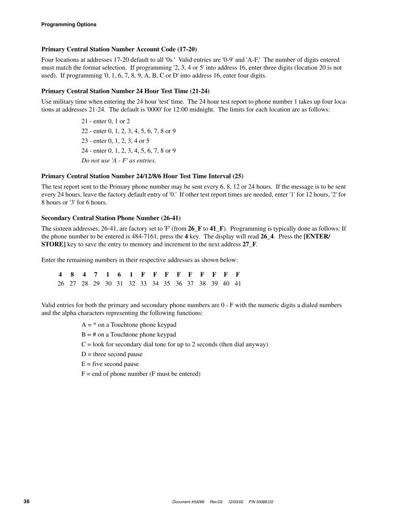
Programming Options
36 Document #50066 Rev.D2 12/03/02 P/N 50066:D2
Primary Central Station Number Account Code (17-20)
Four locations at addresses 17-20 default to all '0s.' Valid entries are '0-9' and 'A-F,' The number of digits entered must match the format selection. If programming '2, 3, 4 or 5' into address 16, enter three digits (location 20 is not used). If programming '0, 1, 6, 7, 8, 9, A, B, C or D' into address 16, enter four digits.
Primary Central Station Number 24 Hour Test Time (21-24)
Use military time when entering the 24 hour 'test' time. The 24 hour test report to phone number 1 takes up four loca-tions at addresses 21-24. The default is '0000' for 12:00 midnight. The limits for each location are as follows:
21 - enter 0, 1 or 2
22 - enter 0, 1, 2, 3, 4, 5, 6, 7, 8 or 9
23 - enter 0, 1, 2, 3, 4 or 5
24 - enter 0, 1, 2, 3, 4, 5, 6, 7, 8 or 9
Do not use 'A - F' as entries.
Primary Central Station Number 24/12/8/6 Hour Test Time Interval (25)
The test report sent to the Primary phone number may be sent every 6, 8, 12 or 24 hours. If the message is to be sent every 24 hours, leave the factory default entry of '0.' If other test report times are needed, enter '1' for 12 hours, '2' for 8 hours or '3' for 6 hours.
Secondary Central Station Phone Number (26-41)
The sixteen addresses, 26-41, are factory set to 'F' (from 26_F to 41_F). Programming is typically done as follows: If the phone number to be entered is 484-7161, press the 4 key. The display will read 26_4. Press the [ENTER/STORE] key to save the entry to memory and increment to the next address 27_F.
Enter the remaining numbers in their respective addresses as shown below:
Valid entries for both the primary and secondary phone numbers are 0 - F with the numeric digits a dialed numbers and the alpha characters representing the following functions:
A = * on a Touchtone phone keypad
B = # on a Touchtone phone keypad
C = look for secondary dial tone for up to 2 seconds (then dial anyway)
D = three second pause
E = five second pause
F = end of phone number (F must be entered)
4 8 4 7 1 6 1 F F F F F F F F F26 27 28 29 30 31 32 33 34 35 36 37 38 39 40 41

Document #50066 Rev. D2 12/03/02 P/N 50066:D2 37
Programming Options
Secondary Central Station Number Communication Format (42)
One location is needed to select the Communication Format for the secondary phone number. Address 42 is used for this purpose. The default (factory setting) for this address is 'A' (42_A), which is 4+2 Standard, 1800 Hz 'Carrier', 2300 Hz 'ack'. You may enter 0 through D in place of the default, then press the [ENTER/STORE] key. Choose from the list of formats below:
0: 4+1 Ademco Express Standard, DTMF, 1400/2300 ACK
1: 4+2 Ademco Express Standard, DTMF, 1400/2300 ACK
2: 3+1 Standard 1800 Hz Carrier, 2300 Hz ACK
3: 3+1 Expanded 1800 Hz Carrier, 2300 Hz ACK
4: 3+1 Standard 1900 Hz Carrier, 1400 Hz ACK
5: 3+1 Expanded 1900 Hz Carrier, 1400 Hz ACK
6: 4+1 Standard 1800 Hz Carrier, 2300 Hz ACK
7: 4+1 Expanded 1800 Hz Carrier, 2300 Hz ACK
8: 4+1 Standard 1900 Hz Carrier, 1400 Hz ACK
9: 4+1 Expanded 1900 Hz Carrier, 1400 Hz ACK
A: 4+2 Standard 1800 Hz Carrier, 2300 Hz ACK
B: 4+2 Expanded 1800 Hz Carrier, 2300 Hz ACK
C: 4+2 Standard 1900 Hz Carrier, 1400 Hz ACK
D: 4+2 Expanded 1900 Hz Carrier, 1400 Hz ACK
E: Not used
F: Not used
Note: Consult your Central Station for proper selection or consult our factory representatives. For any format cho-sen, the control panel automatically programs all of the event codes. See Table 3-1 , Table 3-2 , Table 3-3 and Table 3-4 .
CAUTION! Default entries for event codes (as shown in Table 3-1 through Table 3-4 ) are programmed into memory each time address 42 is altered. Be certain to double check entries after programming the Zone Functions, addresses 57 - 61. Program the Format first then program the Zone(s) Function.
3+1, 4+1 Express, 4+1 Standard and Expanded, 4+2 Expanded Formats
If '0, 2, 3, 4, 5, 6, 7, 8, 9, B or D' is entered for address 42, the data in Table 3-3 is automatically programmed for the Secondary Central Station phone number event codes. Enter '0' for the setting to disable the report.
TABLE 3-3: 3+1, 4+1 Express, 4+1 Standard and Expanded, 4+2 Expanded - Secondary
Address Description Setting198 Secondary # Zone 1 Alarm Code 1199 Secondary # Zone 2 Alarm Code 1200 Secondary # Zone 3 Alarm Code 1201 Secondary # Zone 4 Alarm Code 1202 Secondary # Zone 5 Alarm Code 1203 Secondary # Zone 1 Disabled Code F204 Secondary # Zone 2 Disabled Code F205 Secondary # Zone 3 Disabled Code F206 Secondary # Zone 4 Disabled Code F207 Secondary # Zone 5 Disabled Code F208 Secondary # Drill Code 9209 Secondary # AC Fault Code F210 Secondary # Zone 1 Fault Code F211 Secondary # Zone 2 Fault Code F212 Secondary # Zone 3 Fault Code F213 Secondary # Zone 4 Fault Code F

Programming Options
38 Document #50066 Rev.D2 12/03/02 P/N 50066:D2
214 Secondary # Zone 5 Fault Code F215 Secondary # Earth Fault Code F216 Secondary # Low Battery Fault Code F217 Secondary # No Battery Fault Code F218 Secondary # Telco Primary Line Fault Code F219 Secondary # Telco Secondary Line Fault Code F220 Secondary # NAC #1 Fault Code F221 Secondary # NAC #2 Fault Code F222 Secondary # Communication Trouble Primary # Fault Code F223 Secondary # Communication Trouble Secondary # Fault Code F224 Secondary # Annunciator Fault Code F225 Secondary # System Off Normal Code F226 Secondary # Zone 1 Alarm Restore Code E227 Secondary # Zone 2 Alarm Restore Code E228 Secondary # Zone 3 Alarm Restore Code E229 Secondary # Zone 4 Alarm Restore Code E230 Secondary # Zone 5 Alarm Restore Code E231 Secondary # Zone 1 Disabled Restore Code E232 Secondary # Zone 2 Disabled Restore Code E233 Secondary # Zone 3 Disabled Restore Code E234 Secondary # Zone 4 Disabled Restore Code E235 Secondary # Zone 5 Disabled Restore Code E236 Secondary # Drill Restore Code 9237 Secondary # AC Fault Restore Code E238 Secondary # Zone 1 Fault Restore Code E239 Secondary # Zone 2 Fault Restore Code E240 Secondary # Zone 3 Fault Restore Code E241 Secondary # Zone 4 Fault Restore Code E242 Secondary # Zone 5 Fault Restore Code E243 Secondary # Earth Fault Restore Code E244 Secondary # Low Battery Fault Restore Code E245 Secondary # No Battery Fault Restore Code E246 Secondary # Telco Primary Line Fault Restore Code E247 Secondary # Telco Secondary Line Fault Restore Code E248 Secondary # NAC #1 Fault Restore Code E249 Secondary # NAC #2 Fault Restore Code E250 Secondary # Communication Trouble Primary # Restore Code E251 Secondary # Communication Trouble Secondary # Restore Code E252 Secondary # Annunciator Fault Restore Code E253 Secondary # System Off Normal Restore Code E254 Secondary # System Test Report 9255 Secondary # System Abnormal Test Report F
TABLE 3-3: 3+1, 4+1 Express, 4+1 Standard and Expanded, 4+2 Expanded - Secondary
Address Description Setting

Document #50066 Rev. D2 12/03/02 P/N 50066:D2 39
Programming Options
4+2 Standard and 4+2 Express Format
If '1, A or C' is entered for address 42, the data in Table 3-4 is automatically programmed for the Secondary Central Station phone number event codes. Enter '00' for the setting to disable the report.
TABLE 3-4: 4+2 Standard and 4+2 Express Format - Primary
Address Description Setting198 - 199 Secondary # Zone 1 Alarm Code 11200 - 201 Secondary # Zone 2 Alarm Code 12202 - 203 Secondary # Zone 3 Alarm Code 13204 - 205 Secondary # Zone 4 Alarm Code 14206 - 207 Secondary # Zone 5 Alarm Code 15208 - 209 Secondary # Zone 1 Disabled Code F1210 - 211 Secondary # Zone 2 Disabled Code F2212 - 213 Secondary # Zone 3 Disabled Code F3214 - 215 Secondary # Zone 4 Disabled Code F4216 - 217 Secondary # Zone 5 Disabled Code F5218 - 219 Secondary # Drill Code 97220 - 221 Secondary # AC Fault Code F6222 - 223 Secondary # Zone 1 Fault Code F1224 - 225 Secondary # Zone 2 Fault Code F2226 - 227 Secondary # Zone 3 Fault Code F3228 - 229 Secondary # Zone 4 Fault Code F4230 - 231 Secondary # Zone 5 Fault Code F5232 - 233 Secondary # Earth Fault Code F7234 - 235 Secondary # Low Battery Fault Code F8236 - 237 Secondary # No Battery Fault Code F9238 - 239 Secondary # Telco Primary Line Fault Code FA240 - 241 Secondary # Telco Secondary Line Fault Code FB242 - 243 Secondary # NAC #1 Fault Code FC244 - 245 Secondary # NAC #2 Fault Code FC246 - 247 Secondary # Communication Trouble Primary # Fault Code FD248 - 249 Secondary # Communication Trouble Secondary # Fault Code FE250 - 251 Secondary # Annunciator Fault Code FC252 - 253 Secondary # System Off Normal Code FF254 - 255 Secondary # Zone 1 Alarm Restore Code E1256 - 257 Secondary # Zone 2 Alarm Restore Code E2258 - 259 Secondary # Zone 3 Alarm Restore Code E3260 - 261 Secondary # Zone 4 Alarm Restore Code E4262 - 263 Secondary # Zone 5 Alarm Restore Code E5264 - 265 Secondary # Zone 1 Disabled Restore Code E1266 - 267 Secondary # Zone 2 Disabled Restore Code E2268 - 269 Secondary # Zone 3 Disabled Restore Code E3270 - 271 Secondary # Zone 4 Disabled Restore Code E4272 - 273 Secondary # Zone 5 Disabled Restore Code E5274 - 275 Secondary # Drill Restore Code 98276 - 277 Secondary # AC Fault Restore Code E6278 - 279 Secondary # Zone 1 Fault Restore Code E1280 - 281 Secondary # Zone 2 Fault Restore Code E2282 - 283 Secondary # Zone 3 Fault Restore Code E3284 - 285 Secondary # Zone 4 Fault Restore Code E4286 - 287 Secondary # Zone 5 Fault Restore Code E5288 - 289 Secondary # Earth Fault Restore Code E7290 - 291 Secondary # Low Battery Fault Restore Code E8292 - 293 Secondary # No Battery Fault Restore Code E9294 - 295 Secondary # Telco Primary Line Fault Restore Code EA296 - 297 Secondary # Telco Secondary Line Fault Restore Code EB298 - 299 Secondary # NAC #1 Fault Restore Code EC300 - 301 Secondary # NAC #2 Fault Restore Code EC302 - 303 Secondary # Communication Trouble Primary # Restore Code ED304 - 305 Secondary # Communication Trouble Secondary # Restore Code EE306 - 307 Secondary # Annunciator Fault Restore Code EC308 - 309 Secondary # System Off Normal Restore Code EF310 - 311 Secondary # System Test Report 99312 - 313 Secondary # System Abnormal Test Report 91

Programming Options
40 Document #50066 Rev.D2 12/03/02 P/N 50066:D2
Secondary Central Station Number Account Code (43-46)
Four locations at addresses 43-46 default to all '0s.' Valid entries are '0-9' and 'A-F,' The number of digits entered must match the format selection. If programming '2, 3, 4 or 5' into address 42, enter three digits (location 46 is not used). If programming '0, 1, 6, 7, 8, 9, A, B, C or D' into address 42, enter four digits.
Secondary Central Station Number 24 Hour Test Time (47-50)
Use military time when entering the 24 hour 'test' time. The 24 hour test report to phone number 2 takes up four loca-tions at addresses 47-50. The default is '0000' for 12:00 midnight. The limits for each location are as follows:
47 - enter 0, 1 or 2
48 - enter 0, 1, 2, 3, 4, 5, 6, 7, 8 or 9
49 - enter 0, 1, 2, 3, 4 or 5
50 - enter 0, 1, 2, 3, 4, 5, 6, 7, 8 or 9
Do not use 'A - F' as entries.
Secondary Central Station Number 24/12/8/6 Hour Test Time Interval (51)
The test report sent to the Secondary phone number may be sent every 6, 8, 12 or 24 hours. If the message is to be sent every 24 hours, leave the factory default entry of '0.' If other test report times are needed, enter '1' for 12 hours, '2' for 8 hours or '3' for 6 hours.
Alarm Verification (52)
Alarm verification works only on zones programmed as 2-wire smoke detector zones. After detecting an alarm, the control panel removes power from all zones for 6 seconds, resetting all 2-wire smoke detectors. Power is reapplied and a 12 second retard period allows detectors to stabilize. During the retard/reset period of 18 seconds, subsequent alarms by the same initiating zone are ignored. An alarm detected on any other 2-wire detector zone during the retard period will cause immediate verified alarms. A subsequent alarm on the initiating zone occurring within the confir-mation time will cause a verified alarm. Note that mixing devices on zones designated as 2-wire smoke zones is not recommended.
During the alarm verification period, access to other modes of operation is prevented.
Factory default selection is '0' for no verification. Entering a '1' enables alarm verification. Consult the local Authority Having Jurisdiction (AHJ) prior to altering this address.
FIGURE 3-2:Verification Timing Diagram
Detector Zone Goes Into Alarm
Different Detector Zone Alarms
Detector Alarm Verification RESET RETARD
CONFIRMATION TIME
ALARM VERIFICATION PERIOD
Control Panel Immediately Processes Alarm
Control Panel Processes Alarm if Same Detector is Still in AlarmAlarm Ignored
0 Sec. 6 Sec. 18 Sec. 120 Sec.
1209060300
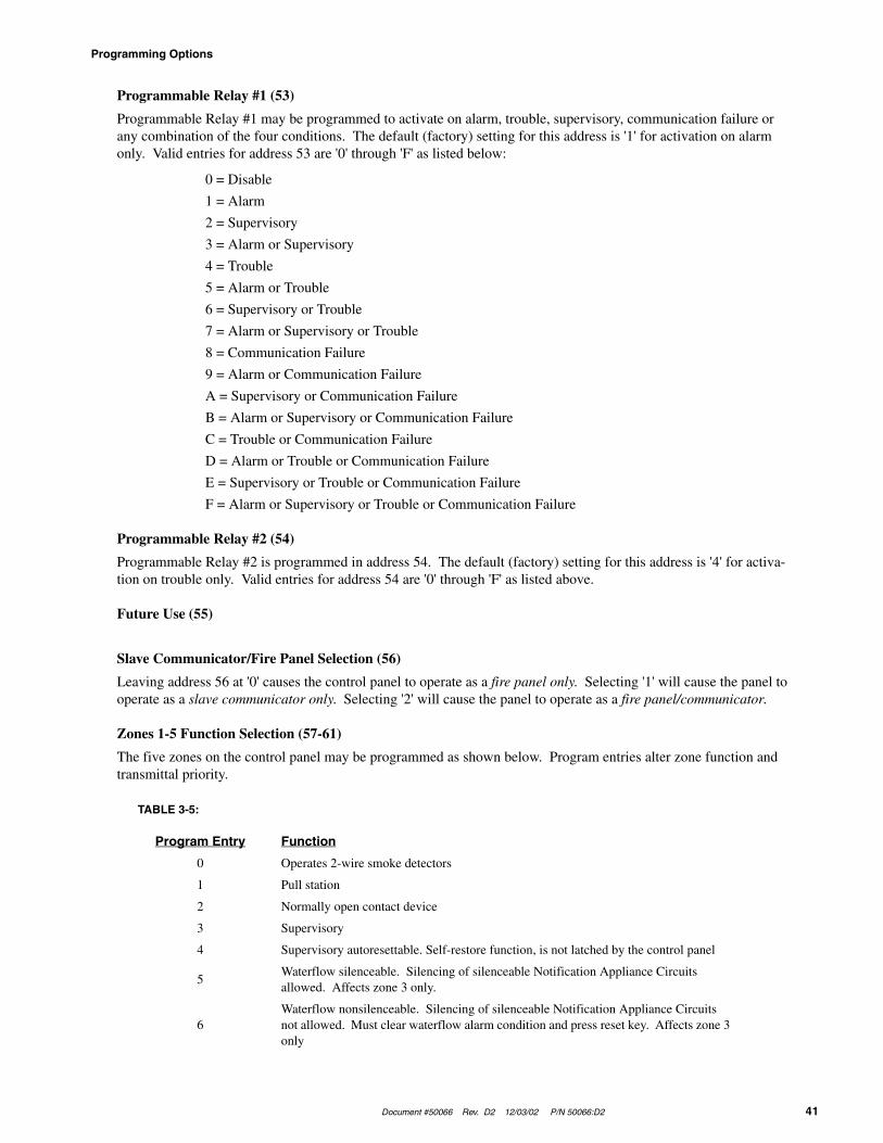
Document #50066 Rev. D2 12/03/02 P/N 50066:D2 41
Programming Options
Programmable Relay #1 (53)
Programmable Relay #1 may be programmed to activate on alarm, trouble, supervisory, communication failure or any combination of the four conditions. The default (factory) setting for this address is '1' for activation on alarm only. Valid entries for address 53 are '0' through 'F' as listed below:
0 = Disable
1 = Alarm
2 = Supervisory
3 = Alarm or Supervisory
4 = Trouble
5 = Alarm or Trouble
6 = Supervisory or Trouble
7 = Alarm or Supervisory or Trouble
8 = Communication Failure
9 = Alarm or Communication Failure
A = Supervisory or Communication Failure
B = Alarm or Supervisory or Communication Failure
C = Trouble or Communication Failure
D = Alarm or Trouble or Communication Failure
E = Supervisory or Trouble or Communication Failure
F = Alarm or Supervisory or Trouble or Communication Failure
Programmable Relay #2 (54)
Programmable Relay #2 is programmed in address 54. The default (factory) setting for this address is '4' for activa-tion on trouble only. Valid entries for address 54 are '0' through 'F' as listed above.
Future Use (55)
Slave Communicator/Fire Panel Selection (56)
Leaving address 56 at '0' causes the control panel to operate as a fire panel only. Selecting '1' will cause the panel to operate as a slave communicator only. Selecting '2' will cause the panel to operate as a fire panel/communicator.
Zones 1-5 Function Selection (57-61)
The five zones on the control panel may be programmed as shown below. Program entries alter zone function and transmittal priority.
TABLE 3-5:
Program Entry Function
0 Operates 2-wire smoke detectors
1 Pull station
2 Normally open contact device
3 Supervisory
4 Supervisory autoresettable. Self-restore function, is not latched by the control panel
5Waterflow silenceable. Silencing of silenceable Notification Appliance Circuits allowed. Affects zone 3 only.
6Waterflow nonsilenceable. Silencing of silenceable Notification Appliance Circuits not allowed. Must clear waterflow alarm condition and press reset key. Affects zone 3 only

Programming Options
42 Document #50066 Rev.D2 12/03/02 P/N 50066:D2
Zone 1 Function Selection (57)
Factory default for zone 1 is '0' for 2-wire smoke detector. Enter '1' for pull station, '2' for normally open contact device, '3' for supervisory or '4' for supervisory autoresettable.
Zone 2 Function Selection (58)
Factory default for zone 2 is '0' for 2-wire smoke detector. Enter '1' for pull station, '2' for normally open contact device, '3' for supervisory or '4' for supervisory autoresettable.
Zone 3 Function Selection (59)
Factory default for zone 3 is '0' for 2-wire smoke detector. Enter '1' for pull station, '2' for normally open contact device, '3' for supervisory, '4' for supervisory autoresettable, '5' for waterflow silenceable or '6' for waterflow nonsilenceable.
Zone 4 Function Selection (60)
Factory default for zone 4 is '0' for 2-wire smoke detector. Enter '1' for pull station, '2' for normally open contact device, '3' for supervisory or '4' for supervisory autoresettable.
Zone 5 Function Selection (61)
Factory default for zone 5 is '0' for 2-wire smoke detector. Enter '1' for pull station, '2' for normally open contact device, '3' for supervisory or '4' for supervisory autoresettable.
Note: Programming any zone to function as supervisory or supervisory autoresettable will cause the defaulted event codes (note in Table 3-1 through Table 3-4 ) to be automatically changed. The defaulted code of '1' is changed to '8' for Formats 3+1 and 4+1 Standard and Expanded, 4+2 Expanded and 4+1 Express. The defaulted codes of 11, 12, 13, 14 and 15 are changed to 81, 82, 83, 84 and 85 accordingly for Formats 4+2 Standard and 4+2 Express.
Waterflow Retard Timer (62-63)
A delay may be added prior to declaring a waterflow type of alarm. Delays up to 89 seconds are allowed. The default for addresses 62 and 63 are '00' for no additional delay. Valid entries for address 62 are '0' to '8' and for address 63 '0' to '9.' Program an entry into these addresses only if entering a '5' or '6' in address 59. Be careful to include any built-in delays of the waterflow device.
AC Loss Reporting Delay (64)
Enter a digit of '1' to '9' or 'A' to 'F' corresponding to the number of hours to be delayed in reporting the loss of AC power. The factory default setting is '0' for 6 hour delay. If 24 hour battery backup is being employed, select from choices '0' to '6'. If 60 hour battery backup is used, select from choices '7' to 'F'. Selections are:
0 = 6 hour delay1 = 7 hour delay2 = 8 hour delay3 = 9 hour delay4 = 10 hour delay5 = 11 hour delay6 = 12 hour delay7 = 15 hour delay8 = 16 hour delay9 = 17 hour delayA = 18 hour delayB = 19 hour delayC = 20 hour delayD = 21 hour delayE = 22 hour delayF = 23 hour delay

Document #50066 Rev. D2 12/03/02 P/N 50066:D2 43
Programming Options
Alarm Presignal (65)
Positive Alarm Sequence is used to delay Notification Appliance Circuit(s) activation while allowing for visual veri-fication by a person. Once a zone triggers an alarm, the mainboard piezo and the annunciator piezo turn on steady, the display indicates the activated zone, the alarm LED blinks and the Notification Appliance Circuits are held off for 15 seconds. During this time, if the silence switch is pressed, the notification appliances may be held off for up to three minutes (see Alarm Presignal Delay Timer Address 66-68). After the programmed delay period, the notifica-tion appliances will activate. Alarm Presignal does not function for zones defined as waterflow or supervisory. The factory default is '0' for no Alarm Presignal. Enter '1' to select Alarm Presignal. During Alarm Presignal, access to other modes is prevented and the communicator will not transmit a signal to the Central Station signifying that the Alarm Presignal has been initiated.
Alarm Presignal Delay Timer (66-68)
The Alarm Presignal timer is factory set to 120 seconds (two minutes), with address 66 set to '1', address 67 set to '2' and address 68 set to '0'. The timer may be programmed from 0 to 179 seconds. Location 65 must be set to '1' to enable Alarm Presignal.
Notification Appliance Circuit #1 Enable (69)
Notification Appliance Circuit #1 may be programmed to '0' for silenceable, '1' for nonsilenceable or '2' for disabled. The factory default setting is '0' for silenceable. Consult the local Authority Having Jurisdiction (AHJ) prior to altering this address.
Silence Inhibit Notification Appliance Circuit #1 (70)
Setting address 70 to '1' prevents silencing of Notification Appliance Circuit #1 and the on-board piezo sounder for one minute after an alarm. The factory default setting is '0' for no silence inhibit of Notification Appliance Circuit #1.
Autosilence Notification Appliance Circuit #1 (71)
Notification Appliance Circuit #1 may be autosilenced after a programmed time interval between 5 and 30 minutes. Enter '1' for 5 minute autosilence, '2' for 10 minute autosilence, '3' for 15 minute autosilence, '4' for 20 minute autosi-lence, '5' for 25 minute autosilence or '6' for 30 minute autosilence. The factory default setting is '0' for no autosilence.
Coding Notification Appliance Circuit #1 (72)
Coding of Notification Appliance Circuit #1 can be programmed by selecting '1' for March Time (120 ppm), '2' for California (10 seconds On, 5 seconds Off) or '3' for Temporal (½ second On, ½ second Off, ½ second On, ½ second Off, ½ second On, 1½ second Off). The factory default setting is '0' for steady (no coding).
Notification Appliance Circuit #2 Enable (73)
Notification Appliance Circuit #2 may be programmed to '0' for silenceable, '1' for nonsilenceable or '2' for disabled. The factory default setting is '0' for silenceable. Consult the local Authority Having Jurisdiction (AHJ) prior to altering this address.
Silence Inhibit Notification Appliance Circuit #2 (74)
Setting address 74 to '1' prevents silencing of Notification Appliance Circuit #2 and the on-board piezo sounder for one minute after an alarm. The factory default setting is '0' for no silence inhibit of Notification Appliance Circuit #2.
Autosilence Notification Appliance Circuit #2 (75)
Notification Appliance Circuit #2 may be autosilenced after a programmed time interval between 5 and 30 minutes. Enter '1' for 5 minute autosilence, '2' for 10 minute autosilence, '3' for 15 minute autosilence, '4' for 20 minute autosi-lence, '5' for 25 minute autosilence or '6' for 30 minute autosilence. The factory default setting is '0' for no autosilence.

Programming Options
44 Document #50066 Rev.D2 12/03/02 P/N 50066:D2
Coding Notification Appliance Circuit #2 (76)
Coding of Notification Appliance Circuit #2 can be programmed by selecting '1' for March Time (120 ppm), '2' for California (10 seconds On, 5 seconds Off) or '3' for Temporal (½ second On, ½ second Off, ½ second On, ½ second Off, ½ second On, 1½ second Off). The factory default setting is '0' for steady (no coding).
Trouble Reminder (77)
The factory default setting of '0' disables the trouble reminder feature. Selecting '1' will cause a reminding beep (after the Silence switch is pressed) every 15 seconds during an alarm and every two minutes during a trouble condition. The beeps from the on-board piezo sounder will occur until the alarm or fault is cleared.
Annunciator Supervision (78)
The factory default setting is '0' for no annunciator present. Set address 78 to '1' if an annunciator is present.
Backup Reporting (79)
Leaving address 79 at '0' means that reports will be transmitted to the secondary Central Station phone number only if attempts to communicate to the primary Central Station phone number are unsuccessful. Programming a '1' causes all reports to be transmitted to the secondary Central Station phone number.
Touchtone/Rotary Select (80)
A '0' programmed in this address by the factory triggers Touchtone dialing over both phone lines. Select '1' for rotary dialing.
Make/Break Ratio (81)
Use this address only if you have chosen '1' for address 80. The make/break ratio is factory set to '0' which is 67/33, but may be changed to '1' which is a 62/38 ratio.
Programming Event Codes (82-313)
The type of reports and 'event codes' that are sent to the Central Station are in the preceding Tables. The selections made for the Primary Central Station Number Communication Format (address 16) and the Secondary Central Sta-tion Number Communication Format (address 42) automatically program addresses 82-313 with factory default selections.
Any of the event codes may be changed. Consult your Central Station prior to altering the event codes. Entering an event code of '0' will cause the communicator to not transmit the report. For the 3+1, 4+1 and 4+2 Express formats or the 4+2 Expanded format, enter a single zero. For the 4+2 Standard or 4+2 Express formats enter two zeros. Trans-mission of reports to either or both Central Station phone numbers may be disabled.
Note the special 'system abnormal test report' event code. This report was added per new UL DACT requirements. This report is generated in place of the normal test report when an alarm and/or trouble condition exists at the time the test report is due to be sent.
Programming the Real-Time Clock
Entering an address greater than 313 will cause a display of the current time. On initial power-up, the clock will start running from the factory setting of 00:01 (military time). The far left digit will be flashing, indicating that this is the first digit to be programmed.
Hours/Minutes Setting
Select a digit then press the [ENTER/STORE] key. The digit 2nd from the left will start flashing. Select a digit then press the [ENTER/STORE] key. The hours setting is complete. With the digit 2nd from the right flashing, select a digit then press the [ENTER/STORE] key. The digit on the far right will start flashing. Select a digit then press the [ENTER/STORE] key. The minutes setting is complete. Once the last digit corresponding to the minutes is entered, the display will show the contents of address '00'. Note that if an invalid digit is selected (i.e. 3 or higher for the first digit) the FACP piezo will beep and the digit will continue to blink until a valid entry is made.

Document #50066 Rev. D2 12/03/02 P/N 50066:D2 45
Programming Options
Note that the software for the MS-5024 operates the internal clock based upon 60 Hz. The software for the MS-5024E operates the internal clock based upon 50 Hz.
End Programming
Exit Programming Mode by pressing the MODE key, followed by the 4-digit code corresponding to an alternate mode of operation, then press the [ENTER/STORE] key.
During Program Mode, if no key is pressed within 10 minutes, the control panel will revert to Normal Mode.

Operating Instructions
46 Document #50066 Rev.D2 12/03/02 P/N 50066:D2
CHAPTER 4 Operating Instructions
The MS-5024 has five modes of operation; Normal, Program, Walktest, Troubleshoot and History. Upon initial power-up, the system will be in Normal Mode. This chapter discusses operation of the control panel in the Normal Mode.
4.1 Switches
This section describes the function switches in Normal Mode.
4.1.1 Reset
The Reset Switch resets the system and any smoke detectors. If the Reset Switch is pressed, the control panel will:
• Clear the display and status LEDs
• Turn off the Notification Appliance Circuits
• Reset all zones by temporarily removing power
• Silence the on-board piezo sounder
• Store 'reset' message in the History file
• Restore the programmable relays to normal
• Temporarily remove power from the resettable power output TB4 Terminals 3 & 4
Upon release of the Reset Switch, the display will read rES_ for six seconds. Any alarm, supervisory or trouble con-dition that exists after system reset will resound the system, reactivating normal system activity.
4.1.2 Silence
If the Silence Switch is pressed:
• The silenceable Notification Appliance Circuits will be turned Off
• The silence LED will be turned On
• The piezo sounder will be shut Off
• 'System Silenced' message will be stored in the History file

Document #50066 Rev. D2 12/03/02 P/N 50066:D2 47
Display and LEDs
Upon the occurrence of a subsequent event (alarm or trouble), System Silence is overridden and the control panel will respond to the new event. The System Silence switch will be ignored for nonsilenceable waterflow type alarms.
4.1.3 Mode
Pressing the Mode Switch followed by a valid 4-digit numerical code and the [ENTER/STORE] key selects one of the five modes of operation. To enter Normal Mode from any other mode, press the MODE key then 6676 followed by the [ENTER/STORE] key.
☛ 6676 spells NORM on a Touch-Tone® phone.
4.1.4 1st Event
This switch, along with the Up Arrow and Down Arrow keys, is used to display any presently active alarm and/or fault conditions present in the system. Press the 1st Event switch at any time to display the first event (alarm and/or trouble) that occurred.
4.1.5 Down Arrow
Use the Down Arrow key to view other events (older) that have occurred and are active (not yet cleared).
4.1.6 Up Arrow
Use the Up Arrow key to view other events (newer) that have occurred and are active (not yet cleared).
4.1.7 [ENTER/STORE]
See individual mode descriptions in other sections of this manual.
4.2 Display and LEDs
Four 7-segment red LED characters provide visual annunciation of status, events and messages. A list of messages that may appear on the display in Normal Mode is shown below:
d__1 Zone 1 Disabledd__2 Zone 2 Disabledd__3 Zone 3 Disabledd__4 Zone 4 Disabledd__5 Zone 5 DisabledE__1 Zone 1 EnabledE__2 Zone 2 EnabledE__3 Zone 3 EnabledE__4 Zone 4 EnabledE__5 Zone 5 EnabledA__1 Alarm Zone 1A__2 Alarm Zone 2A__3 Alarm Zone 3A__4 Alarm Zone 4A__5 Alarm Zone 5F__1 Trouble Zone 1F__2 Trouble Zone 2F__3 Trouble Zone 3F__4 Trouble Zone 4
F__5 Trouble Zone 5rES_ System ResetF__A Annunciator FaultF__E Earth FaultLo_b Low Batteryno_b No BatteryPH_1 Primary Central Station Number Comm. FaultPH_2 Secondary Central Station Number Comm. FaultbEL1 Bell 1 FaultbEL2 Bell 2 Faultno_1 Primary Phone Line Faultno_2 Secondary Phone Line FaultSUP1 Supervisory Alarm Zone 1SUP2 Supervisory Alarm Zone 2SUP3 Supervisory Alarm Zone 3SUP4 Supervisory Alarm Zone 4SUP5 Supervisory Alarm Zone 5_AC_ AC Power Loss
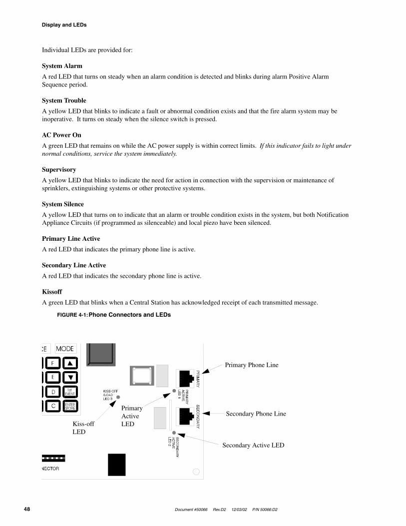
Display and LEDs
48 Document #50066 Rev.D2 12/03/02 P/N 50066:D2
Individual LEDs are provided for:
System Alarm
A red LED that turns on steady when an alarm condition is detected and blinks during alarm Positive Alarm Sequence period.
System Trouble
A yellow LED that blinks to indicate a fault or abnormal condition exists and that the fire alarm system may be inoperative. It turns on steady when the silence switch is pressed.
AC Power On
A green LED that remains on while the AC power supply is within correct limits. If this indicator fails to light under normal conditions, service the system immediately.
Supervisory
A yellow LED that blinks to indicate the need for action in connection with the supervision or maintenance of sprinklers, extinguishing systems or other protective systems.
System Silence
A yellow LED that turns on to indicate that an alarm or trouble condition exists in the system, but both Notification Appliance Circuits (if programmed as silenceable) and local piezo have been silenced.
Primary Line Active
A red LED that indicates the primary phone line is active.
Secondary Line Active
A red LED that indicates the secondary phone line is active.
Kissoff
A green LED that blinks when a Central Station has acknowledged receipt of each transmitted message.
FIGURE 4-1:Phone Connectors and LEDs
Primary Phone Line
Secondary Phone Line
Secondary Active LED
Primary Active LEDKiss-off
LED
Document #50066 Rev. D2 12/03/02 P/N 50066:D2 49
Operation
4.3 Operation
Normal Mode is the standard mode of operation. In this mode, the panel continuously monitors system status. When no alarm or trouble conditions exist, the display will be blank and all LEDs will be off (except the AC Power LED). The Notification Appliance Circuits will be off, all relays are normal and the onboard piezo sounder will be off. The communicator is not active, primary and secondary active LEDs are off.
All alarm and system trouble conditions are annunciated on the control panel’s display. The control panel will main-tain an 'active event list' which will consist of all alarms, supervisory alarms and system troubles currently active and not cleared, requiring immediate service. When the system is cleared and restored to normal, the display will be blank. All alarms and troubles are stored in a history file and may be recalled at any time.
Higher priority events take precedence over lower priority events. Display and reporting of system status is done on a priority basis. Priorities are, from highest to lowest:
1. Alarms
2. Supervisory Alarms
3. System Troubles
If the events to be displayed consist of alarms and disabled zones only (no troubles), the control panel will scroll them on the display. Pressing the 1st Event key will stop the scrolling and cause the display of the first alarm that occurred after the panel was last reset, cleared of all active events and placed into Normal Mode. Operation of the Up and Down arrow keys will display all remaining events in order of their occurrences.
4.3.1 Alarm Response
The control panel will, upon detection of an alarm condition:
• Turn on the alarm LED
• Activate relay(s) programmed for alarm
• Display the alarm message, for example A__1 for alarm on zone 1
• Communicate the alarm to the Central Station
• Store the alarm in the History file
• Turn on the Notification Appliance Circuits
• Turn on the piezo sounder
• Turn on the annunciator zone LED and annunciator piezo sounder
Note that when any zone is programmed as a supervisory zone, it will not be processed in the same manner as a con-ventional alarm zone. See “System Supervisory Condition Response” on page 50.
4.3.2 Alarm Restoral
The control panel returns to normal only after all alarms have been cleared and the Reset switch has been pressed (pull stations reset, smoke detectors reset and no smoke present, waterflow has stopped). The control panel will perform the following upon restoral of all active alarms:
• Turn off the alarm LED
• Deactivate the alarm relay(s) if programmed
• Clear the 4-character display
• Send all 'zone restoral' messages to the Central Station
• Turn off the Notification Appliance Circuits
• Turn off the piezo sounder
• Turn off the annunciator zone LED and annunciator piezo sounder
Operation
50 Document #50066 Rev.D2 12/03/02 P/N 50066:D2
4.3.3 System Supervisory Condition Response
Program zones for supervisory in applications where a waterflow sensing device has been employed and the wiring to the waterflow valve and/or tamper switch is to be monitored. If the wiring has been cut or the tamper switch has been activated, a supervisory alarm condition will occur.
When a supervisory condition occurs, the control panel will:
• Blink the supervisory LED (½ second On, ½ second Off)
• Activate the supervisory relay(s) if programmed
• Display the following message: SUPX where X is the zone number
• Communicate the supervisory condition to the Central Station
• Store the 'supervisory' message in the History file
• Pulse the piezo sounder at ½ second on and ½ second off rate
• Turn on the annunciator zone LED and pulse the annunciator piezo
4.3.4 System Supervisory Restoral Response
When the supervisory condition has been cleared (condition is restored and the reset switch has been pressed), the control panel will perform the following:
• Turn off the supervisory LED
• Deactivate the supervisory relay(s) if programmed
• Clear the display of the SUP message
• Communicate a supervisory restoral message to the Central Station
• Turn off the piezo sounder
• Turn off the annunciator zone LED and annunciator piezo sounder
Note that for any zone programmed for supervisory autoresettable, the Reset key does not need to be pressed to clear the zone supervisory condition.
4.3.5 Trouble Condition Response
The control panel will perform the following upon detection of one or more trouble conditions:
• Blink the trouble LED (1 second on, 1 second off)
• Activate the trouble relay(s) if programmed
• Display the appropriate trouble message(s) in priority fashion from the highest priority to the lowest. Note that the Up arrow, Down arrow or 1st Event key must be pressed to view the messages
• Communicate the trouble conditions to the Central Station
• Store the trouble conditions in the History file
• Sound the piezo sounder (1 second on, 1 second off)
• Blink the annunciator trouble LED and pulse the piezo sounder
Note that when AC brownout occurs, the AC LED is turned off and the trouble LED blinks. Should the brownout con-dition remain, it will be transmitted to the Central Station after a delay (see program address 64).

Document #50066 Rev. D2 12/03/02 P/N 50066:D2 51
Operation
Possible trouble messages that may appear on the display are as follows:
4.3.6 Trouble Conditions Restoral
The control panel performs the following upon restoral of all trouble conditions:
• Turn off the trouble LED
• Deactivate the trouble relay(s) if programmed
• Turn on the AC Power LED if the trouble was loss of AC power
• Clear the display of the trouble message(s)
• Communicate the restored trouble condition(s) to the Central Station
4.3.7 Off Normal Reporting
Removing the panel from Normal Mode and placing it into any other mode causes a transmission of an 'off normal' fault message. Returning the panel to Normal Mode causes a transmission of a 'return to normal' restoral message.
4.3.8 Zone Disable/Enable
The zone disable feature may be used to disable any zone in the system. Zones may be disabled if they are normal, in trouble or in alarm. Zones may be disabled only during the Normal Mode of operation when the fire protection is active. If the panel is in alarm, the silence switch must be pressed first before zone disable will function.
To disable a zone, press the MODE key once. The display will go blank. You then have 10 seconds to start entering the code 3472. Next, press the [ENTER/STORE] key.
☛ 3472 spells DISA on a Touch-Tone® phone
A flashing lower case d will appear on the far left of the display. Press the zone number to be disabled. The number will appear on the far right display character. Pressing the [ENTER/STORE] key will disable the selected zone. Note that the relay (if programmed for trouble) is activated and the trouble LED will blink.
The zone disable message will remain on the display until the zone is enabled. To enable a zone, press the MODE key once. The display will go blank. You then have 10 seconds to start entering the code 3622. Press the [ENTER/STORE] key.
☛ 3622 spells ENAB on a Touch-Tone® phone
A flashing upper case E will appear on the left of the display. Press the zone number to be enabled. The number will appear on the far right display character. Pressing the [ENTER/STORE] key will enable the selected zone. Note that the relay (if programmed for trouble) is restored to normal and the trouble LED will turn off if no other troubles exist on the system.
d__1 Zone 1 Disabledd__2 Zone 2 Disabledd__3 Zone 3 Disabledd__4 Zone 4 Disabledd__5 Zone 5 DisabledF__1 Trouble Zone 1F__2 Trouble Zone 2F__3 Trouble Zone 3F__4 Trouble Zone 4F__5 Trouble Zone 5
F__A Annunciator FaultF__E Earth FaultLo_b Low Batteryno_b No BatteryPH_1 Primary Central Station Number Comm. FaultPH_2 Secondary Central Station Number Comm. FaultbEL1 Bell 1 FaultbEL2 Bell 2 Faultno_1 Primary Phone Line Faultno_2 Secondary Phone Line Fault

Central Station Communications
52 Document #50066 Rev.D2 12/03/02 P/N 50066:D2
4.3.9 Fire Drill
The Drill (manual evacuate) feature turns on both Notification Appliance Circuits (if programmed as enabled) and turns off the silence LED. To perform a fire drill, press the MODE key followed by the code 3745 and then the [ENTER/STORE] key. The display will read dril. The relay (if programmed for alarm) is not activated. There is an option to transmit the fire drill report code to the Central Station.
☛ 3745 spells DRIL on a Touch-Tone® phone
During a fire drill, the Silence key will silence both Notification Appliance Circuits and the Reset key restores the panel to normal. All zones remain active during a fire drill.
4.3.10No Battery/Low Battery
This control panel detects two levels of battery fault conditions, low battery and no battery. The low battery condi-tion is 20.4 volts per NFPA and UL requirements. The no battery condition can occur if a battery is not installed or if the battery voltage drops below the 'no battery threshold' voltage limit. The no battery threshold voltage is the mini-mum voltage required to operate the system fully under loss of AC power. This voltage must be high enough to power initiating devices, power notification appliances and provide internal power to system components including the microprocessor. Both the no battery and low battery condition may be reported to the Central Station.
When AC power is lost and the system is running on battery, the panel will report 'loss of AC power' to the Central Station after a programmed delay period. The panel will report 'low battery' when the low battery threshold is reached. If AC power is not restored and the 'no battery' threshold is reached, the panel will power off. This prevents false alarms, nuisance reports and incorrect panel operation when the battery falls to dangerous levels. After the AC power is restored, the no battery (no_b) message will appear. The battery must be disconnected from the system and either replaced or allowed to restore itself before being reinstalled.
CAUTION! Be certain to clear the no battery condition since the battery will not recharge from this condition and the panel will not clear itself. The low battery condition will self-clear when the battery recharges, provided the battery is good.
4.4 Central Station Communications
The control panel transmits zone and system status reports to Central Station via the public switched telephone net-work. Two supervised telephone line connections are made to interface the control panel to the telephone lines. Two 7-foot telephone cables are required for this purpose and must be ordered separately.
The control panel supervises both telephone lines for proper voltage. A delay of two minutes will occur before a fault on either phone line connection is reported as a trouble. When a fault is detected, an audible trouble signal will sound, the yellow trouble LED will blink, the 4-character display will show either 'no_1' for Primary Line fault or 'no_2' for Secondary Line fault, and the trouble condition will be reported to the Central Station over the remaining good phone line.
The control panel comes with line seizure capability provided for both the primary and secondary telephone line interfaces. Any time that the control panel needs to make a call to a Central Station, line seizure will disconnect any local premises phones sharing the same telephone line.
All transmissions to the Central Stations will be sent over the Primary Central Station phone line. In the event of noisy phone lines, transmissions will be sent over the backup Secondary phone line.
Two phone numbers must be programmed, the Primary Central Station phone number and the Secondary Central Sta-tion phone number. All system reports will be transmitted to the Primary Central Station phone number. Reports will automatically be sent to the Secondary Central Station phone number if attempts to transmit to the Primary Central
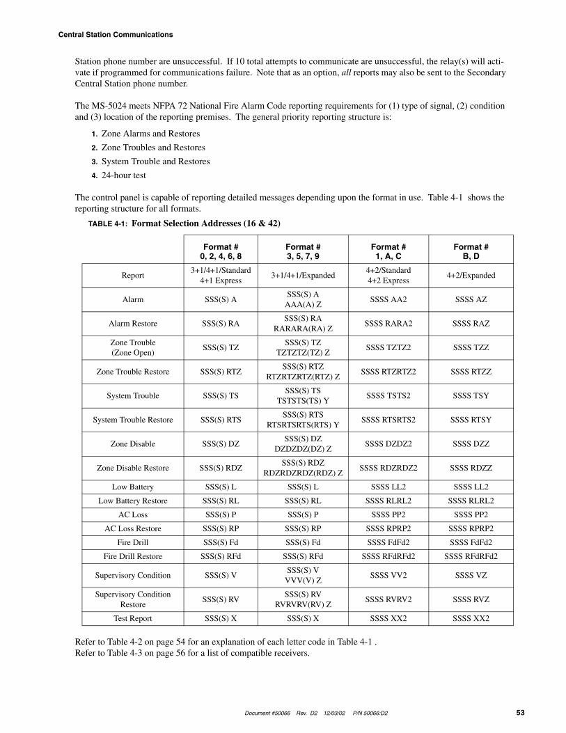
Document #50066 Rev. D2 12/03/02 P/N 50066:D2 53
Central Station Communications
Station phone number are unsuccessful. If 10 total attempts to communicate are unsuccessful, the relay(s) will acti-vate if programmed for communications failure. Note that as an option, all reports may also be sent to the Secondary Central Station phone number.
The MS-5024 meets NFPA 72 National Fire Alarm Code reporting requirements for (1) type of signal, (2) condition and (3) location of the reporting premises. The general priority reporting structure is:
1. Zone Alarms and Restores
2. Zone Troubles and Restores
3. System Trouble and Restores
4. 24-hour test
The control panel is capable of reporting detailed messages depending upon the format in use. Table 4-1 shows the reporting structure for all formats.
Refer to Table 4-2 on page 54 for an explanation of each letter code in Table 4-1 .Refer to Table 4-3 on page 56 for a list of compatible receivers.
TABLE 4-1: Format Selection Addresses (16 & 42)
Format #0, 2, 4, 6, 8
Format #3, 5, 7, 9
Format #1, A, C
Format #B, D
Report3+1/4+1/Standard
4+1 Express3+1/4+1/Expanded
4+2/Standard 4+2 Express
4+2/Expanded
Alarm SSS(S) ASSS(S) A
AAA(A) ZSSSS AA2 SSSS AZ
Alarm Restore SSS(S) RASSS(S) RA
RARARA(RA) ZSSSS RARA2 SSSS RAZ
Zone Trouble(Zone Open)
SSS(S) TZSSS(S) TZ
TZTZTZ(TZ) ZSSSS TZTZ2 SSSS TZZ
Zone Trouble Restore SSS(S) RTZSSS(S) RTZ
RTZRTZRTZ(RTZ) ZSSSS RTZRTZ2 SSSS RTZZ
System Trouble SSS(S) TSSSS(S) TS
TSTSTS(TS) YSSSS TSTS2 SSSS TSY
System Trouble Restore SSS(S) RTSSSS(S) RTS
RTSRTSRTS(RTS) YSSSS RTSRTS2 SSSS RTSY
Zone Disable SSS(S) DZSSS(S) DZ
DZDZDZ(DZ) ZSSSS DZDZ2 SSSS DZZ
Zone Disable Restore SSS(S) RDZSSS(S) RDZ
RDZRDZRDZ(RDZ) ZSSSS RDZRDZ2 SSSS RDZZ
Low Battery SSS(S) L SSS(S) L SSSS LL2 SSSS LL2
Low Battery Restore SSS(S) RL SSS(S) RL SSSS RLRL2 SSSS RLRL2
AC Loss SSS(S) P SSS(S) P SSSS PP2 SSSS PP2
AC Loss Restore SSS(S) RP SSS(S) RP SSSS RPRP2 SSSS RPRP2
Fire Drill SSS(S) Fd SSS(S) Fd SSSS FdFd2 SSSS FdFd2
Fire Drill Restore SSS(S) RFd SSS(S) RFd SSSS RFdRFd2 SSSS RFdRFd2
Supervisory Condition SSS(S) VSSS(S) V
VVV(V) ZSSSS VV2 SSSS VZ
Supervisory Condition Restore
SSS(S) RVSSS(S) RV
RVRVRV(RV) ZSSSS RVRV2 SSSS RVZ
Test Report SSS(S) X SSS(S) X SSSS XX2 SSSS XX2

Central Station Communications
54 Document #50066 Rev.D2 12/03/02 P/N 50066:D2
Note that for Expanded Reporting, the control panel automatically adds the digit corresponding to the zone number and the second digit corresponding to any system trouble condition. Only the first digit is programmable.
TABLE 4-2: Format Selection Address ExplanationSSS or SSSS
= Subscriber ID
A = Alarm (1dt digit)A2 = Alarm (2nd digit)Z = Zone NumberRA = Alarm Restore (1st digit)RA2 = Alarm Restore (2nd digit)TZ = Zone Trouble (1st digit)TZ2 = Zone Trouble (2nd digit)RTZ = Zone Trouble Restore (1st digit)RTZ2 = Zone Trouble Restore (2nd digit)TS = System Trouble (1st digit)TS2 = System Trouble (2nd digit)RTS = System Trouble Restore (1st digit)RTS2 = System Trouble Restore (2nd digit)DZ = Zone Disable (1st digit)DZ2 = Zone Disable (2nd digit)RDZ = Zone Disable Restore (1st digit)RDZ2 = Zone Disable Restore (2nd digit)L = Low Battery (1st digit)L2 = Low Battery (2nd digit)RL = Low Battery Restore (1st digit)RL2 = Low Battery Restore (2nd digit)P = AC Loss (1st digit)P2 = AC Loss (2nd digit)RP = AC Loss Restore (1st digit)RP2 = AC Loss Restore (2nd digit)FD = Fire Drill (1st digit)FD2 = Fire Drill (2nd digit)RFD = Fire Drill Restore (1st digit)RFD2 = Fire Drill Restore (2nd digit)V = Supervisory Condition (1st digit)V2 = Supervisory Condition (2nd digit)RV = Supervisory Condition Restore (1st digit)RV2 = Supervisory Condition Restore (2nd digit)X = Test Report (1st digit)X2 = Test Report (2nd digit)Y = Trouble corresponding to one of the following:
7 = Ground Fault8 = Low Battery9 = No BatteryA = Telco Primary Line FaultB = Telco Secondary Line FaultC = Main Bell Fault, Annunciator FaultD = Communication Fault to Primary NumberE = Communication Fault to Secondary NumberF = System Off Normal Fault/System Fault (Slave Operation, see “Slave Communicator
Configuration” on page 61)
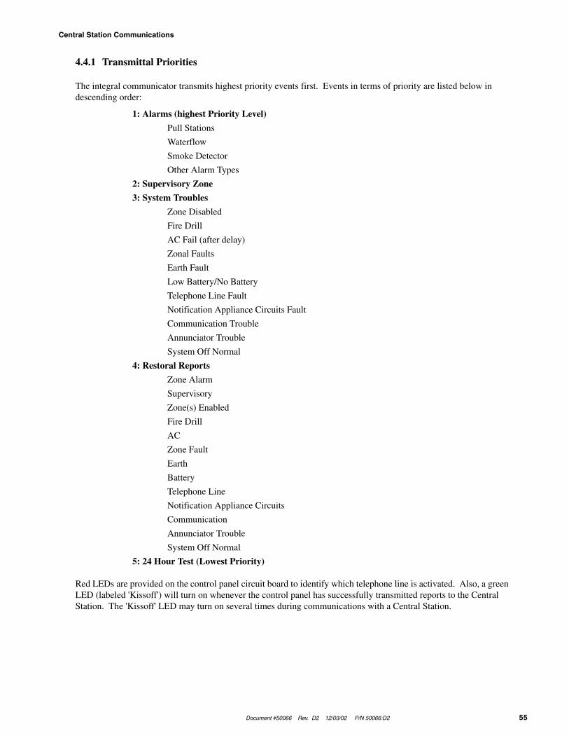
Document #50066 Rev. D2 12/03/02 P/N 50066:D2 55
Central Station Communications
4.4.1 Transmittal Priorities
The integral communicator transmits highest priority events first. Events in terms of priority are listed below in descending order:
1: Alarms (highest Priority Level)
Pull Stations
Waterflow
Smoke Detector
Other Alarm Types
2: Supervisory Zone
3: System Troubles
Zone Disabled
Fire Drill
AC Fail (after delay)
Zonal Faults
Earth Fault
Low Battery/No Battery
Telephone Line Fault
Notification Appliance Circuits Fault
Communication Trouble
Annunciator Trouble
System Off Normal
4: Restoral Reports
Zone Alarm
Supervisory
Zone(s) Enabled
Fire Drill
AC
Zone Fault
Earth
Battery
Telephone Line
Notification Appliance Circuits
Communication
Annunciator Trouble
System Off Normal
5: 24 Hour Test (Lowest Priority)
Red LEDs are provided on the control panel circuit board to identify which telephone line is activated. Also, a green LED (labeled 'Kissoff') will turn on whenever the control panel has successfully transmitted reports to the Central Station. The 'Kissoff' LED may turn on several times during communications with a Central Station.

Central Station Communications
56 Document #50066 Rev.D2 12/03/02 P/N 50066:D2
The following table shows UL listed receivers compatible with the MS-5024:
(1) With 685-8 Line Card with Rev 4.4d software
(2) With 9002 Line Card Rev 9035 software or 9032 Line Card with 9326A software
(3) Rev 4.0 software
(4) FBI CP220FB Rec-11 Line Card with Rev 2.6 software and a memory card with Rev 3.8 software
(5) Model 6500 with Rev 600 software
(6) Model 6000 with Rev 204 software
(7) With Rev B control card at Rev 1.4 software and Rev C line card at Rev 1.5 software
(8) Model 2 only
(9) Version 1.62 software
TABLE 4-3: Compatible UL Listed Receivers
Format #(Addresses 16 & 42) A
dem
co68
5 (1
)
Sile
nt
Kn
igh
t90
00 (
2)
ITI
CS
-400
0 (3
)
FB
IC
P22
0FB
Osb
orn
e H
off
man
Mo
del
s 1
& 2
Rad
ion
ics
6000
/650
0 (5
)
Ses
coa
3000
R (
7)
Su
rgu
ard
ML
R-2
(9)
0 4+1 Ademco Express ✔ ✔ ✔
1 4+2 Ademco Express ✔ ✔ ✔ (8) ✔
2 3+1/Standard/1800/2300 ✔ ✔ ✔ ✔ (4) ✔ ✔ (5, 6) ✔ ✔
3 3+1/Expanded/1800/2300 ✔ ✔ ✔ ✔ (4) ✔ ✔ ✔
4 3+1/Standard/1900/1400 ✔ ✔ ✔ (4) ✔ ✔ ✔
5 3+1/Expanded/1900/1400 ✔ ✔ ✔ (4) ✔ ✔ ✔
6 4+1/Standard/1800/2300 ✔ ✔ ✔ ✔ (4) ✔ ✔ (5) ✔ ✔
7 4+1/Expanded/1800/2300 ✔ ✔ ✔ (4) ✔ ✔ ✔
8 4+1/Standard/1900/1400 ✔ ✔ ✔ (4) ✔ ✔ ✔
9 4+1/Expanded/1900/1400 ✔ ✔ ✔ (4) ✔ ✔ ✔
A 4+2/Standard/1800/2300 ✔ ✔ ✔ ✔ (4) ✔ ✔ (5) ✔ ✔
B 4+2/Expanded/1800/2300 ✔ ✔ ✔ (4) ✔ ✔ ✔
C 4+2/Standard/1900/1400 ✔ ✔ ✔ (4) ✔ ✔ ✔
D 4+2/Expanded/1900/1400 ✔ ✔ ✔ (4) ✔ ✔ ✔
E Not Used
F Not Used
Document #50066 Rev. D2 12/03/02 P/N 50066:D2 57
Servicing
CHAPTER 5 Servicing
5.1 Walktest Mode
The MS-5024 provides the capability to perform a one-man walktest of the system without triggering the communi-cator or the alarm relay (if programmed). Walktest allows for testing of the five zones (initiating circuits). The first initiating device activated on a zone will cause the Notification Appliance Circuits to turn on for four seconds. Subsequent device activations on the same zone will cause the Notification Appliance Circuits to turn on for one second. Any smoke detectors that are activated will be reset. Zonal faults (open circuits) will cause the appliance circuit to remain on steadily. Prior to entering Walktest Mode, check to be certain that all system faults have been cleared. Note that the trouble relay will be activated (if programmed) while the control panel is in this mode. Placing the control panel into Walktest Mode will be possible only if the system has no active alarms.
Pressing the MODE key followed by the 4-digit code 9255 and then the [ENTER/STORE] key will place the con-trol panel into Walktest Mode.
☛ 9255 spells WALK on a Touch-Tone® phone.
Once in Walktest Mode, the control panel will immediately:
• Blink the trouble LED
• Activate the trouble relay(s) if programmed
• Turn on the Notification Appliance Circuits for four seconds for the first alarm on a zone. Subsequent alarms will sound for one second. Troubles cause the Notification Appliance Circuits to remain on
• Disable the alarm relay(s) if programmed
• Display all alarm conditions as they occur
• Display all zone troubles as they occur
• Display ground faults as they occur
• Transmit 'off normal' message to Central Station(s)
• Continue to communicate any events not acknowledged at a Central Station prior to entering Walktest Mode
During Walktest Mode, zonal activity is displayed in real time as it occurs. At the end of walktesting the system, the display will show the last event that occurred. To view all events stored during the walktest, use the Up arrow, Down arrow and 1st Event keys. The Down arrow key moves the walktest list to show older (previous) events. The Up arrow key moves the walktest list to show newer (most recent) events. Pressing the 1st Event key at any time will cause the display of the first event stored upon initial entry into Walktest Mode. While in Walktest Mode, the control panel will store up to 128 events in the walktest file for future recall and display.
To return the control panel to Normal Mode, press the MODE key followed by the code 6676 and then the [ENTER/STORE] key. Any delay between key entries greater than 10 seconds causes the control panel to remain in Walktest Mode.
The control panel will automatically revert back to Normal Mode if no system activity has occurred for 60 minutes. This would include pressing any keys or activity on any zone.

History Mode
58 Document #50066 Rev.D2 12/03/02 P/N 50066:D2
5.2 History Mode
All Normal Mode events are stored in a History file for future recall. Recall is possible via the 4-character display. See the following page for a list and description of each event displayed.
The History file list is a first-in, first-out (FIFO). In this manner, only the most recent events may be called up from memory. Old events will be overwritten (i.e. pushed out of the FIFO). The number of stored events is 32. This History file is kept in E2 memory. Complete power loss will not erase the list.
Pressing the MODE key followed by 4478 and then the [ENTER/STORE] key places the control panel into History Mode. This will not occur if there are any active alarm conditions present. The event displayed is the most recent event.
☛ 4478 spells HIST on a Touch-Tone® phone.
Once in History Mode, the control panel will:
• Blink the trouble LED
• Activate the trouble relay(s) if programmed
• Disable the Notification Appliance Circuit(s)
• Disable the alarm relay(s) if programmed
• Display all events as they occurred since the last time the History file list was cleared. The most recent event will be displayed first
• Ignore all other keys other than those mentioned in this section
• Transmit the 'off normal' message to the Central Station(s)
• Continue to communicate any events not previously acknowledged at the Central Station prior to entering His-tory Mode
The Down arrow key moves the History file to show older (previous) events. The Up arrow key moves the History file to show newer (most recent) events.
Shown below is the list of messages as they will appear on the display:
To erase the list from E2 memory, press the Silence key twice before exiting the History Mode. A lack of keyboard activity for a period of 10 minutes will cause the control panel to return to Normal Mode.
d__1 Zone 1 Disabledd__2 Zone 2 Disabledd__3 Zone 3 Disabledd__4 Zone 4 Disabledd__5 Zone 5 DisabledE__1 Zone 1 EnabledE__2 Zone 2 EnabledE__3 Zone 3 EnabledE__4 Zone 4 EnabledE__5 Zone 5 EnabledA__1 Alarm Zone 1A__2 Alarm Zone 2A__3 Alarm Zone 3A__4 Alarm Zone 4A__5 Alarm Zone 5F__1 Trouble Zone 1F__2 Trouble Zone 2F__3 Trouble Zone 3F__4 Trouble Zone 4
F__5 Trouble Zone 5rES_ System ResetF__A Annunciator FaultF__E Earth FaultLo_b Low Batteryno_b No BatteryPH_1 Primary Central Station Number Comm. FaultPH_2 Secondary Central Station Number Comm. FaultbEL1 Bell 1 FaultbEL2 Bell 2 Faultno_1 Primary Phone Line Faultno_2 Secondary Phone Line FaultSUP1 Supervisory Alarm Zone 1SUP2 Supervisory Alarm Zone 2SUP3 Supervisory Alarm Zone 3SUP4 Supervisory Alarm Zone 4SUP5 Supervisory Alarm Zone 5_AC_ AC Power Loss

Document #50066 Rev. D2 12/03/02 P/N 50066:D2 59
Troubleshoot Mode
5.3 Troubleshoot Mode
In this mode, system voltages may be displayed on the 4-character display. An internal voltmeter measures the voltage present at:
• zone inputs
• AC power input
• battery terminal leads
• NAC #1
• NAC #2
• resettable 24 volt power
A lack of keyboard activity for a period of 20 minutes will cause the control panel to return to Normal Mode. To enter Troubleshoot Mode, press the MODE key followed by the code 8768 and then the [ENTER/STORE] key.
☛ 8768 spells TROU on a Touch-Tone® phone.
Once in this mode, the control panel will:
• Blink the trouble LED
• Activate the trouble relay(s) if programmed
• Disable the Notification Appliance Circuits
• Disable the alarm relay(s) if programmed
• Transmit the 'off normal' message to the Central Station(s)
• Continue to communicate any events not yet acknowledged at the Central Station prior to entering Trouble-shoot Mode
The Up arrow key, Down arrow key and 1st Event key do not function in this mode.
5.3.1 Zones
Pressing 01 through 05 followed by the [ENTER/STORE] key displays the zone voltage of the selected zone. Listed below are the nominal threshold voltages for each zone:
Zone # Normal w/EOL Shorted Open Circuit
1 through 5 23.5V 00.0V 25.4V
5.3.2 AC Line
Pressing A followed by the [ENTER/STORE] key displays the AC input voltage as shown below. The following lists the AC line voltage range. The AC On indicator will turn off and the trouble LED will turn on when the AC line voltage drops below the Low Line threshold.
AC Line Voltage Low Line Normal High Line
MS-5024 102VAC 115VAC 132VAC
MS-5024E 204VAC 220VAC 264VAC
5.3.3 Battery
Pressing B followed by the [ENTER/STORE] key displays the Battery voltage. Shown below are the critical battery threshold conditions:
Battery Voltage Normal Low Battery No Battery
27.6 VDC 20.4 VDC <14.2 VDC
IMPORTANT The battery charger will turn off when the battery voltage drops to 14.2 VDC or less (No Battery condition). A battery with a higher voltage must be installed to turn the charger back on.
Note: Make measurements after allowing 48 hours to charge depleted batteries. If batteries do not show normal readings, replace them.
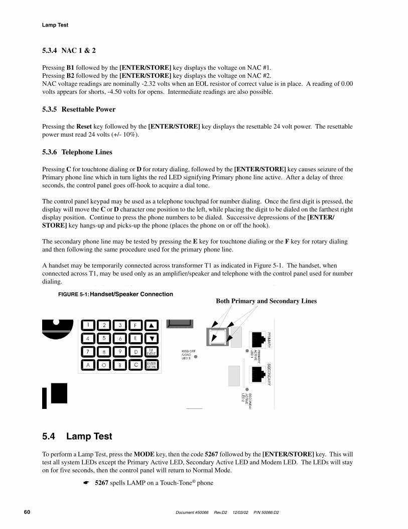
Lamp Test
60 Document #50066 Rev.D2 12/03/02 P/N 50066:D2
5.3.4 NAC 1 & 2
Pressing B1 followed by the [ENTER/STORE] key displays the voltage on NAC #1.Pressing B2 followed by the [ENTER/STORE] key displays the voltage on NAC #2.NAC voltage readings are nominally -2.32 volts when an EOL resistor of correct value is in place. A reading of 0.00 volts appears for shorts, -4.50 volts for opens. Intermediate readings are also possible.
5.3.5 Resettable Power
Pressing the Reset key followed by the [ENTER/STORE] key displays the resettable 24 volt power. The resettable power must read 24 volts (+/- 10%).
5.3.6 Telephone Lines
Pressing C for touchtone dialing or D for rotary dialing, followed by the [ENTER/STORE] key causes seizure of the Primary phone line which in turn lights the red LED signifying Primary phone line active. After a delay of three seconds, the control panel goes off-hook to acquire a dial tone.
The control panel keypad may be used as a telephone touchpad for number dialing. Once the first digit is pressed, the display will move the C or D character one position to the left, while placing the digit to be dialed on the farthest right display position. Continue to press the phone numbers to be dialed. Successive depressions of the [ENTER/STORE] key hangs-up and picks-up the phone (places the phone on or off the hook).
The secondary phone line may be tested by pressing the E key for touchtone dialing or the F key for rotary dialing and then following the same procedure used for the primary phone line.
A handset may be temporarily connected across transformer T1 as indicated in Figure 5-1. The handset, when connected across T1, may be used only as an amplifier/speaker and telephone with the control panel used for number dialing.
5.4 Lamp Test
To perform a Lamp Test, press the MODE key, then the code 5267 followed by the [ENTER/STORE] key. This will test all system LEDs except the Primary Active LED, Secondary Active LED and Modem LED. The LEDs will stay on for five seconds, then the control panel will return to Normal Mode.
☛ 5267 spells LAMP on a Touch-Tone® phone
FIGURE 5-1:Handset/Speaker ConnectionBoth Primary and Secondary Lines

Document #50066 Rev. D2 12/03/02 P/N 50066:D2 61
Slave Communicator Configuration
CHAPTER 6 Slave Communicator Configuration
The MS-5024 may be used as a slave communicator to a host or master FACP (fire alarm control panel). All wiring between the master and the slave communicator is supervised. 4.7K ohm End-of-Line resistors should be connected.
In slave configuration, the five zones become five channels that may be triggered by the relay outputs of any host FACP. The inputs have the following functions in the slave configuration:
• Zone 1/Channel 1 is used for general alarm
• Zone 2/Channel 2 is used for general trouble
• Zone 3/Channel 3 may be programmed to match the FACP relay function used as an input
• Zone 4/Channel 4 is used for supervisory
• Zone 5/Channel 5 may be programmed to match the FACP relay function used as an input
The factory settings for Zone 2/Channel 2 alarm and restoral are altered as follows:
❒ If 0, 2, 3, 4, 5, 6, 7, 8, 9, B or D is entered for address 16 or 42, the report code for Zone 2 Alarm Code (address 83, 199) is 'F', Zone 2 Restoral Code (address 111, 227) is 'E'
❒ If 1, A or C is entered for address 16 or 42, the report code for Zone 2 Alarm Code (addresses 84-85, 200-201) is 'FF', Zone 2 Restoral Code (addresses 140-141, 256-257) is 'EF.'
The factory settings for Zone 4/Channel 4 alarm and restoral are altered as follows:
❒ If 0, 2, 3, 4, 5, 6, 7, 8, 9, B or D is entered for address 16 or 42, report code for Zone 4/Channel 4 Alarm Code (address 85, 201) is '8', Zone 4 Restoral Code (address 113, 229) is 'E.'
❒ If 1, A or C is entered for addresses 16 or 42, the report code for Zone 4 Alarm Code (addresses 88-89, 204-205) is 84, Zone 4 Restoral Code (addresses 144-145, 260-261) is 'E4.'
Location 56 must be programmed to a '1' to enable the control panel as a slave communicator.
Be certain to connect the slave communicator’s primary AC power to the same branch circuit as the host FACP.
Note that Alarm Presignal and Alarm Verification do not function in Slave Communicator Mode.

Slave Communicator Configuration
62 Document #50066 Rev.D2 12/03/02 P/N 50066:D2
Relays in the master FACP activate various input circuits on the slave communicator. Messages (event codes) pro-grammed for a particular input circuit (channel) will be transmitted to the Central Station upon relay activation.
FIGURE 6-1:Slave Communicator Connections

Document #50066 Rev. D2 12/03/02 P/N 50066:D2 63
Battery Calculations
Appendix A Battery Calculations
Use the Total Standby and Alarm Load currents calculated in Table A-2 on page 64 and Table A-3 on page 65 for the following battery calculation.
Notes:
1. 7 Ampere Hour battery can be located in the backbox
2. 12 Ampere Hour and 17 Ampere Hour batteries require the BB-17F battery box
TABLE A-1: Battery Calculations
Standby LoadCurrent (amps)
[ ]X
Required Standby Time inHours (24 or 60 Hours)
[ ]= __________
Alarm LoadCurrent (amps)
[ ]X
Required Alarm Time in Hours(i.e. 5 minutes = 0.084)
[ ]= __________
Add Standby and Alarm Load for Required Ampere Hour Battery = __________
Multiply by the Derating Factor of 1.2 X 1.2 __________
Total Ampere Hours (AH) Required = __________

Battery Calculations
64 Document #50066 Rev.D2 12/03/02 P/N 50066:D2
Main Power Supply
The MS-5024 provides filtered power for operating the fire alarm control panel, operating external devices and oper-ating the standby battery. The power for operating external devices is limited. Use Table A-2 (standby or nonalarm) and Table A-3 on page 65 (alarm) to determine if external loading is within the capabilities of the power supply.
Concerning 4-wire smoke detectors: be sure to power detectors from TB4, Terminals 3 & 4.
Note that all external devices are connected to TB4 only.
Notes:
1. Refer to the Device Compatibility Document for 2-wire smoke detector standby current
2. Must use compatible listed Power Supervision Relay
TABLE A-2: Regulated Load in Standby
Device Type # of DevicesCurrent(amps)
Total Current(amps)
Main Circuit Board 1 X 0.123 = 0.123
ADM-24 (1 maximum) X 0.006 =
RZA-5F (1 maximum) X 0 = 0
CAC-5F (1 maximum) X 0 = 0
NACA-2F (1 maximum) X 0 = 0
2-wire Detector Heads [ ] X [ ]1 =
4-wire Detector Heads [ ] X [ ]1 =
Power Supervision Relays2 [ ] X 0.025 =
Additional Current Draw from TB4 (nonalarm)
X =
Sum Column for Standby Load = amps
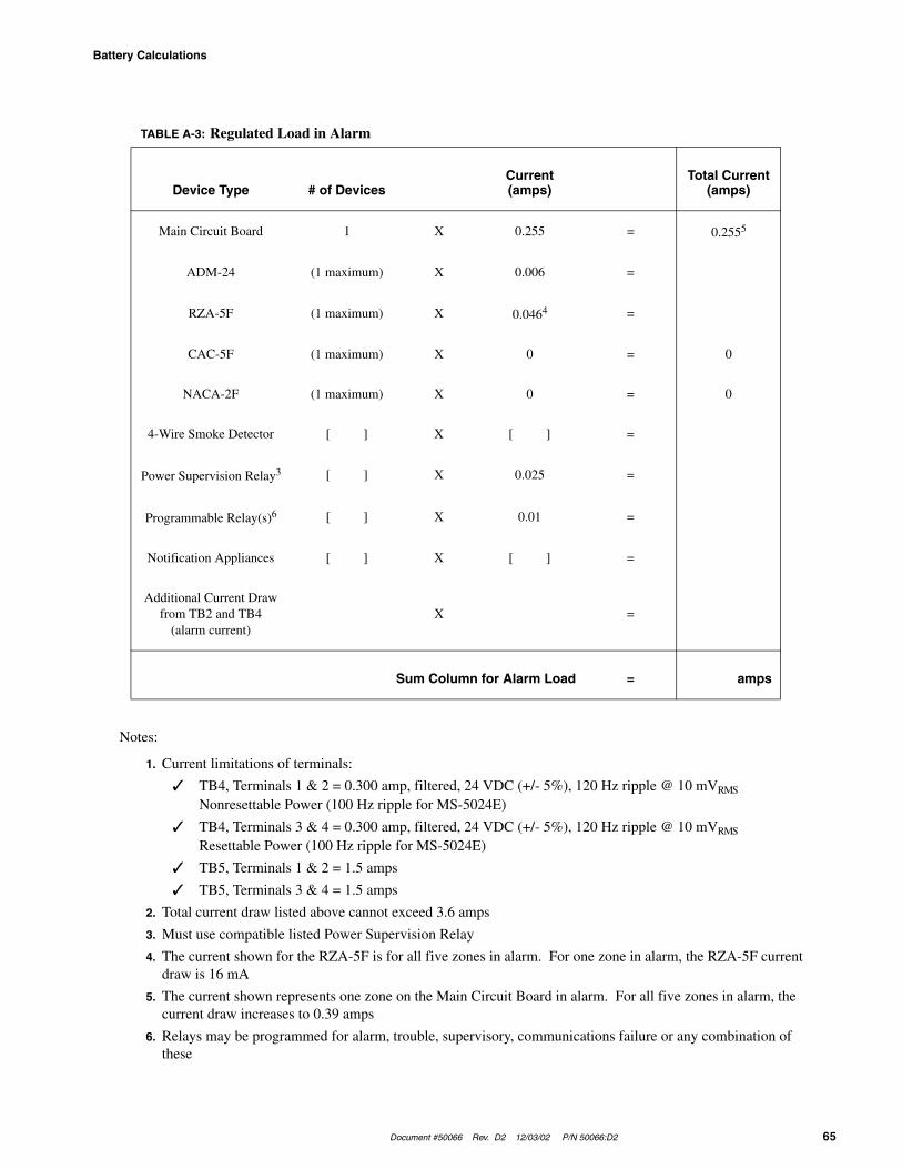
Document #50066 Rev. D2 12/03/02 P/N 50066:D2 65
Battery Calculations
Notes:
1. Current limitations of terminals:
✓ TB4, Terminals 1 & 2 = 0.300 amp, filtered, 24 VDC (+/- 5%), 120 Hz ripple @ 10 mVRMS
Nonresettable Power (100 Hz ripple for MS-5024E)
✓ TB4, Terminals 3 & 4 = 0.300 amp, filtered, 24 VDC (+/- 5%), 120 Hz ripple @ 10 mVRMS
Resettable Power (100 Hz ripple for MS-5024E)
✓ TB5, Terminals 1 & 2 = 1.5 amps
✓ TB5, Terminals 3 & 4 = 1.5 amps
2. Total current draw listed above cannot exceed 3.6 amps
3. Must use compatible listed Power Supervision Relay
4. The current shown for the RZA-5F is for all five zones in alarm. For one zone in alarm, the RZA-5F current draw is 16 mA
5. The current shown represents one zone on the Main Circuit Board in alarm. For all five zones in alarm, the current draw increases to 0.39 amps
6. Relays may be programmed for alarm, trouble, supervisory, communications failure or any combination of these
TABLE A-3: Regulated Load in Alarm
Device Type # of DevicesCurrent(amps)
Total Current(amps)
Main Circuit Board 1 X 0.255 = 0.2555
ADM-24 (1 maximum) X 0.006 =
RZA-5F (1 maximum) X 0.0464 =
CAC-5F (1 maximum) X 0 = 0
NACA-2F (1 maximum) X 0 = 0
4-Wire Smoke Detector [ ] X [ ] =
Power Supervision Relay3 [ ] X 0.025 =
Programmable Relay(s)6 [ ] X 0.01 =
Notification Appliances [ ] X [ ] =
Additional Current Draw from TB2 and TB4
(alarm current)X =
Sum Column for Alarm Load = amps

Programming Reference Sheet
66 Document #50066 Rev.D2 12/03/02 P/N 50066:D2
Appendix B Programming Reference Sheet
❐00 ❐01 ❐02 ❐03 ❐04 ❐05 ❐06 ❐07 ❐08 ❐09 ❐10 ❐11 ❐12 ❐13 ❐14 ❐15
Addresses 00 to 15 store the Primary Central Station Phone Number. Enter 'F' to represent the end of the number.
❐16 Primary Central Station Communication Format: Enter '0 - D'.
❐17 ❐18 ❐19 ❐20 Primary Central Station Account Code: Valid entries are '0 - F'.
❐21 ❐22 ❐23 ❐24 Primary Central Station 24-Hour Test Time. Enter military time (i.e. 1400 for 2 PM).
❐25 Primary Number Test Time Interval. Enter '0' for 24 hour; '1' for 12 hour; '2' for 8 hour; '3' for 6 hour.
❐26 ❐27 ❐28 ❐29 ❐30 ❐31 ❐32 ❐33 ❐34 ❐35 ❐36 ❐37 ❐38 ❐39 ❐40 ❐41
Addresses 26 to 41 store the Secondary Central Station Phone Number. Enter 'F' to represent the end of the number.
❐42 Secondary Central Station Communication Format: Enter '0 - D'.
❐43 ❐44 ❐45 ❐46 Secondary Central Station Account Code: Valid entries are '0 - F'.
❐47 ❐48 ❐49 ❐50 Secondary Central Station 24-Hour Test Time. Enter military time (i.e. 1400 for 2 PM).
❐51 Secondary Number Test Time Interval. Enter '0' for 24 hour; '1' for 12 hour; '2' for 8 hour; '3' for 6 hour.
❐52 Alarm Verification. Enter '0' for no verification; '1' for verification of all 2-wire smoke zones.
❐53 Programmable Relay 1: Enter '0' to Disable; '1' for Alarm; '2' for Supervisory; '3' for Alarm or Supervisory;
'4' for Trouble; '5' for Alarm or Trouble; '6' for Supervisory or Trouble; '7' for Alarm or Supervisory or Trouble; '8' for Communication Failure; '9' for Alarm or Communication Failure; 'A' for Supervisory or Communication Fail-ure; 'B' for Alarm or Supervisory or Communication Failure; 'C' for Trouble or Communication Failure; 'D' for Alarm or Trouble or Communication Failure; 'E' for Supervisory or Trouble or Communication Failure; 'F' for Alarm or Supervisory or Trouble or Communication Failure.
❐54 Programmable Relay 1: Enter '0' to Disable; '1' for Alarm; '2' for Supervisory; '3' for Alarm or Supervisory;
'4' for Trouble; '5' for Alarm or Trouble; '6' for Supervisory or Trouble; '7' for Alarm or Supervisory or Trouble; '8' for Communication Failure; '9' for Alarm or Communication Failure; 'A' for Supervisory or Communication Fail-ure; 'B' for Alarm or Supervisory or Communication Failure; 'C' for Trouble or Communication Failure; 'D' for Alarm or Trouble or Communication Failure; 'E' for Supervisory or Trouble or Communication Failure; 'F' for Alarm or Supervisory or Trouble or Communication Failure.
❐55 Future use.
❐56 Slave Communicator/Fire Panel Selection. Enter '0' for fire panel only; '1' for slave communicator only; '2'
for fire panel/communicator operation.
❐57 Zone 1 Function Select. Enter '0' for 2-wire smoke detectors; '1' for pull station; '2' for normally open contact
devices; '3' for supervisory devices; '4' for supervisory devices (autoresettable).
❐58 Zone 2 Function Select. Enter '0' for 2-wire smoke detectors; '1' for pull station; '2' for normally open contact
devices; '3' for supervisory devices; '4' for supervisory devices (autoresettable).
❐59 Zone 3 Function Select. Enter '0' for 2-wire smoke detectors; '1' for pull station; '2' for normally open contact
devices; '3' for supervisory devices; '4' for supervisory devices (autoresettable); '5' for waterflow (silenceable); '6' for waterflow (nonsilenceable).
...To enter Programming Mode, press the MODE key, the code 7764 and then the [ENTER/STORE] key...

Document #50066 Rev. D2 12/03/02 P/N 50066:D2 67
Programming Reference Sheet
❐60 Zone 4 Function Select. Enter '0' for 2-wire smoke detectors; '1' for pull station; '2' for normally open contact
devices; '3' for supervisory devices; '4' for supervisory devices (autoresettable).
❐61 Zone 5 Function Select. Enter '0' for 2-wire smoke detectors; '1' for pull station; '2' for normally open contact
devices; '3' for supervisory devices; '4' for supervisory devices (autoresettable).
❐62 ❐63 Waterflow Retard Timer. Enter 0 - 89 additional seconds.
❐64 AC Loss Reporting Delay. Enter '0' for 6 hour delay; '1' for 7 hours; '2' for 8 hours; '3' for 9 hours; '4' for 10
hours; '5' for 11 hours; '6' for 12 hours; '7' for 15 hours; '8' for 16 hours; '9' for 17 hours; 'A' for 18 hours; 'B' for 19 hours; 'C' for 20 hours; 'D' for 21 hours; 'E' for 22 hours; 'F' for 23 hours.
❐65 Alarm Presignal. Enter '0' to disable alarm presignal; '1' to enable.
❐66 ❐67 ❐68 Alarm Presignal Delay Time. Enter 0 - 179 additional seconds (default - 120 seconds).
❐69 Notification Appliance Circuit #1 Selection. Enter '0' for enabled (silenceable); '1' for enabled
(nonsilenceable); '2' for disabled.
❐70 Silence Inhibit NAC #1. Enter '0' for no silence inhibit; '1' to inhibit silencing of NAC #1 for one minute.
❐71 Autosilence NAC #1. Enter '0' for no autosilence; '1' for 5 minutes; '2' for 10 minutes; '3' for 15 minutes; '4'
for 20 minutes; '5' for 25 minutes; '6' for 30 minutes.
❐72 Coding NAC #1. Enter '0' for steady; '1' for March Time (120 ppm); '2' for California (10 seconds On, 5 sec-
onds Off); '3' for Temporal (½ second On, ½ second Off, ½ second On, ½ second Off, ½ second On, 1½ second Off).
❐73 Notification Appliance Circuit #2 Selection. Enter '0' for enabled (silenceable); '1' for enabled
(nonsilenceable); '2' for disabled.
❐74 Silence Inhibit NAC #2. Enter '0' for no silence inhibit; '1' to inhibit silencing of NAC #2 for one minute.
❐75 Autosilence NAC #2. Enter '0' for no autosilence; '1' for 5 minutes; '2' for 10 minutes; '3' for 15 minutes; '4'
for 20 minutes; '5' for 25 minutes; '6' for 30 minutes.
❐76 Coding NAC #2. Enter '0' for steady; '1' for March Time (120 ppm); '2' for California (10 seconds On, 5 sec-
onds Off); '3' for Temporal (½ second On, ½ second Off, ½ second On, ½ second Off, ½ second On, 1½ second Off)
❐77 Trouble Reminder. Enter '0' to disable trouble reminder; '1' to enable.
❐78 Annunciator Supervision. Enter '0' for annunciator not present; '1' for annunciator present.
❐79 Backup Reporting. Enter '0' to report to secondary phone number as backup only; '1' to report to secondary
phone number for all reports/messages.
❐80 Touchtone/Rotary Select. Enter '0' for touchtone dialing; '1' for rotary dialing.
❐81 Make/Break Ratio. Enter '0' for 67/33 ratio; '1' for 62/38 ratio.

Programming Reference Sheet
68 Document #50066 Rev.D2 12/03/02 P/N 50066:D2
Programming Reference Sheets
❐82 ❐83 ❐84 ❐85 ❐86 ❐87 ❐88 ❐89 ❐90 ❐91 ❐92 ❐93 ❐94
❐95 ❐96 ❐97 ❐98 ❐99 ❐100 ❐101 ❐102 ❐103 ❐104 ❐105 ❐106 ❐107
❐108 ❐109 ❐110 ❐111 ❐112 ❐113 ❐114 ❐115 ❐116 ❐117 ❐118 ❐119 ❐120
❐121 ❐122 ❐123 ❐124 ❐125 ❐126 ❐127 ❐128 ❐129 ❐130 ❐131 ❐132 ❐133
❐134 ❐135 ❐136 ❐137 ❐138 ❐139 ❐140 ❐141 ❐142 ❐143 ❐144 ❐145 ❐146
❐147 ❐148 ❐149 ❐150 ❐151 ❐152 ❐153 ❐154 ❐155 ❐156 ❐157 ❐158 ❐159
❐160 ❐161 ❐162 ❐163 ❐164 ❐165 ❐166 ❐167 ❐168 ❐169 ❐170 ❐171 ❐172
❐173 ❐174 ❐175 ❐176 ❐177 ❐178 ❐179 ❐180 ❐181 ❐182 ❐183 ❐184 ❐185
❐186 ❐187 ❐188 ❐189 ❐190 ❐191 ❐192 ❐193 ❐194 ❐195 ❐196 ❐197 ❐198
❐199 ❐200 ❐201 ❐202 ❐203 ❐204 ❐205 ❐206 ❐207 ❐208 ❐209 ❐210 ❐211
❐212 ❐213 ❐214 ❐215 ❐216 ❐217 ❐218 ❐219 ❐220 ❐221 ❐222 ❐223 ❐224
❐225 ❐226 ❐227 ❐228 ❐229 ❐230 ❐231 ❐232 ❐233 ❐234 ❐235 ❐236 ❐237
❐238 ❐239 ❐240 ❐241 ❐242 ❐243 ❐244 ❐245 ❐246 ❐247 ❐248 ❐249 ❐250
❐251 ❐252 ❐253 ❐254 ❐255 ❐256 ❐257 ❐258 ❐259 ❐260 ❐261 ❐262 ❐263
❐264 ❐265 ❐266 ❐267 ❐268 ❐269 ❐270 ❐271 ❐272 ❐273 ❐274 ❐275 ❐276
❐277 ❐278 ❐279 ❐280 ❐281 ❐282 ❐283 ❐284 ❐285 ❐286 ❐287 ❐288 ❐289
❐290 ❐291 ❐292 ❐293 ❐294 ❐295 ❐296 ❐297 ❐298 ❐299 ❐300 ❐301 ❐302
❐303 ❐304 ❐305 ❐306 ❐307 ❐308 ❐309 ❐310 ❐311 ❐312 ❐313

Document #50066 Rev. D2 12/03/02 P/N 50066:D2 69
Programming Reference Sheet
Programming Reference Sheets - Factory Default Settings
F F F F F F F F F F F F F F F F
A
0 0 0 0
0 0 0 0
0
F F F F F F F F F F F F F F F F
A
0 0 0 0
0 0 0 0
0
0
1
4
0
0
0
0
0
0
0
0 0
0
0
1 2 0
0
0
0
❐00 ❐01 ❐02 ❐03 ❐04 ❐05 ❐06 ❐07 ❐08 ❐09 ❐10 ❐11 ❐12 ❐13 ❐14 ❐15
Addresses 00 to 15 store the Primary Central Station Phone Number. Enter 'F' to represent the end of the number.
❐16 Primary Central Station Communication Format: 'A' for 4+2 Standard, 1800/2300.
❐17 ❐18 ❐19 ❐20 Primary Central Station Account Code.
❐21 ❐22 ❐23 ❐24 Primary Central Station 24-Hour Test Time. 0000 = 12:00 midnight.
❐25 Primary Number Test Time Interval. '0' for 24 hours.
❐26 ❐27 ❐28 ❐29 ❐30 ❐31 ❐32 ❐33 ❐34 ❐35 ❐36 ❐37 ❐38 ❐39 ❐40 ❐41
Addresses 26 to 41 store the Secondary Central Station Phone Number. Enter 'F' to represent the end of the number.
❐42 Secondary Central Station Communication Format: 'A' for 4+2 Standard, 1800/2300.
❐43 ❐44 ❐45 ❐46 Secondary Central Station Account Code.
❐47 ❐48 ❐49 ❐50 Secondary Central Station 24-Hour Test Time. 0000 = 12:00 midnight.
❐51 Secondary Number Test Time Interval. 0' for 24 hours.
❐52 Alarm Verification. '0' for no verification.
❐53 Programmable Relay #1. '1' for alarm only.
❐54 Programmable Relay #2. '4' for trouble only.
❐55 Future use.
❐56 Slave Communicator/Fire Panel Selection. 0' for fire panel only operation.
❐57 Zone 1 Function Select. '0' for 2-wire smoke detectors.
❐58 Zone 2 Function Select. '0' for 2-wire smoke detectors.
❐59 Zone 3 Function Select. '0' for 2-wire smoke detectors.
❐60 Zone 4 Function Select. '0' for 2-wire smoke detectors.
❐61 Zone 5 Function Select. '0' for 2-wire smoke detectors.
❐62 ❐63 Waterflow Retard Timer. '00' for no delay.
❐64 AC Loss Reporting Delay. '0' for 6 hour delay.
❐65 Alarm Presignal. '0' for no Positive Alarm Sequence.
❐66 ❐67 ❐68 Alarm Presignal Delay Time. 120 second Positive Alarm Sequence delay.
❐69 Notification Appliance Circuit #1 Selection. '0' for enabled (silenceable).
❐70 Silence Inhibit NAC #1. '0' for no silence inhibit.
❐71 Autosilence NAC #1. '0' for no autosilence.
...To enter Programming Mode, press the MODE key, the code 7764 and then the [ENTER/STORE] key...
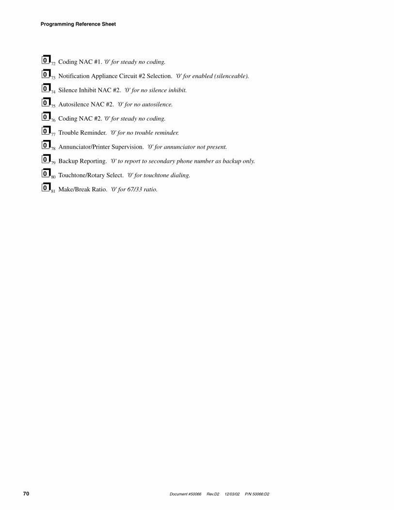
Programming Reference Sheet
70 Document #50066 Rev.D2 12/03/02 P/N 50066:D2
❐72 Coding NAC #1. '0' for steady no coding.
❐73 Notification Appliance Circuit #2 Selection. '0' for enabled (silenceable).
❐74 Silence Inhibit NAC #2. '0' for no silence inhibit.
❐75 Autosilence NAC #2. '0' for no autosilence.
❐76 Coding NAC #2. '0' for steady no coding.
❐77 Trouble Reminder. '0' for no trouble reminder.
❐78 Annunciator/Printer Supervision. '0' for annunciator not present.
❐79 Backup Reporting. '0' to report to secondary phone number as backup only.
❐80 Touchtone/Rotary Select. '0' for touchtone dialing.
❐81 Make/Break Ratio. '0' for 67/33 ratio.
0
0
0
0
0
0
0
0
0
0

Document #50066 Rev.D2 12/03/02 P/N 50066:D2 71
Programming Reference Sheets Factory Default
❐82 ❐83 ❐84 ❐85 ❐86 ❐87 ❐88 ❐89 ❐90 ❐91 ❐92 ❐93 ❐94
❐95 ❐96 ❐97 ❐98 ❐99 ❐100 ❐101 ❐102 ❐103 ❐104 ❐105 ❐106 ❐107
❐108 ❐109 ❐110 ❐111 ❐112 ❐113 ❐114 ❐115 ❐116 ❐117 ❐118 ❐119 ❐120
❐121 ❐122 ❐123 ❐124 ❐125 ❐126 ❐127 ❐128 ❐129 ❐130 ❐131 ❐132 ❐133
❐134 ❐135 ❐136 ❐137 ❐138 ❐139 ❐140 ❐141 ❐142 ❐143 ❐144 ❐145 ❐146
❐147 ❐148 ❐149 ❐150 ❐151 ❐152 ❐153 ❐154 ❐155 ❐156 ❐157 ❐158 ❐159
❐160 ❐161 ❐162 ❐163 ❐164 ❐165 ❐166 ❐167 ❐168 ❐169 ❐170 ❐171 ❐172
❐173 ❐174 ❐175 ❐176 ❐177 ❐178 ❐179 ❐180 ❐181 ❐182 ❐183 ❐184 ❐185
❐186 ❐187 ❐188 ❐189 ❐190 ❐191 ❐192 ❐193 ❐194 ❐195 ❐196 ❐197 ❐198
❐199 ❐200 ❐201 ❐202 ❐203 ❐204 ❐205 ❐206 ❐207 ❐208 ❐209 ❐210 ❐211
❐212 ❐213 ❐214 ❐215 ❐216 ❐217 ❐218 ❐219 ❐220 ❐221 ❐222 ❐223 ❐224
❐225 ❐226 ❐227 ❐228 ❐229 ❐230 ❐231 ❐232 ❐233 ❐234 ❐235 ❐236 ❐237
❐238 ❐239 ❐240 ❐241 ❐242 ❐243 ❐244 ❐245 ❐246 ❐247 ❐248 ❐249 ❐250
❐251 ❐252 ❐253 ❐254 ❐255 ❐256 ❐257 ❐258 ❐259 ❐260 ❐261 ❐262 ❐263
❐264 ❐265 ❐266 ❐267 ❐268 ❐269 ❐270 ❐271 ❐272 ❐273 ❐274 ❐275 ❐276
❐277 ❐278 ❐279 ❐280 ❐281 ❐282 ❐283 ❐284 ❐285 ❐286 ❐287 ❐288 ❐289
❐290 ❐291 ❐292 ❐293 ❐294 ❐295 ❐296 ❐297 ❐298 ❐299 ❐300 ❐301 ❐302
❐303 ❐304 ❐305 ❐306 ❐307 ❐308 ❐309 ❐310 ❐311 ❐312 ❐313
1 1 1 2 1 3 1 4 1 5 F 1 F
2 F 3 F 4 F 5 9 7 F 6 F 1
F 2 F 3 F 4 F 5 F 7 F 8 F
9 F A F B F C F C F D F E
F C F F E 1 E 2 E 3 E 4 E
5 E 1 E 2 E 3 E 4 E 5 9 8
E 6 E 1 E 2 E 3 E 4 E 5 E
7 E 8 E 9 E A E B E C E C
E D E E E C E F 9 9 9 1 1
1 1 2 1 3 1 4 1 5 F 1 F 2
F 3 F 4 F 5 9 7 F 6 F 1 F
2 F 3 F 4 F 5 F 7 F 8 F 9
F A F B F C F C F D F E F
C F F E 1 E 2 E 3 E 4 E 5
E 1 E 2 E 3 E 4 E 5 9 8 E
6 E 1 E 2 E 3 E 4 E 5 E 7
E 8 E 9 E A E B E C E C E
D E E E C E F 9 9 9 1

Wire Requirements
72 Document #50066 Rev.D2 12/03/02 P/N 50066:D2
Appendix C Wire Requirements
Connecting external system accessories to the MS-5024 main circuits must be carefully considered to ensure proper operation. It is important to use the correct type of wire, wire gauge and wire run length per each MS-5024 circuit. Reference the chart below to specify wire requirements and limitations for each MS-5024.
TABLE C-1: Wire Requirements
Circuit Connections Wire Requirements
Circuit Type Circuit Function Wire Type and Limitations
Recommended Maximum Distance(feet/m)
Wire Gauge
Initiating Device Circuit (power-
limited)
Connects to Initiating Devices
Untwisted, unshielded wire (Do not exceed 100 ohms)
10,000 (3,000 m)8,000 (2,400 m)4,875 (1,480 m)3,225 (980 m)
12AWG Belden 958214AWG Belden 958016AWG Belden 957218AWG Belden 9571
(0.75 mm2 - 3.25 mm2)
24 VDC Filtered,
Resettable, Nonresettable
(power-limited)
Connects to annunciators and other accessories
No more than 1.2 volt drop allowed from supply source
to end of any branch
Distance limitation set by
1.2 volt maximum line
drop
12 - 18 AWG
(0.75 mm2 - 3.25 mm2)

Document #50066 Rev. D2 12/03/02 P/N 50066:D2 73
Operation and Function Modes
Appendix D Operation and Function Modes
TABLE D-1: Operation Modes
Code Activity Notes
6676 (NORM) Return to normal operation Fire protection on.
7764 (PROG) Enters Program ModeFour levels of programming may be entered. Fire protection is off.
9255 (WALK) Enters Walktest Mode Audible walktest function. Fire protection is off.
4478 (HIST) View History FileUse display to view History File. Fire protection is off.
8768 (TROU)Activates internal system voltmeter for troubleshooting and diagnosing problems
Fire protection is off while voltmeter function is enabled.
5267 (LAMP) Turns on all LEDs on the main PCB for 5 seconds Fire protection is on.
TABLE D-2: Function Modes
Code Activity Notes
3472 (DISA) Allows disabling of any input zoneMay only disable one zone at a time. Places system into trouble.
3622 (ENAB) Allows enabling (return to normal) of any zone May only enable one zone at a time.
3745 (DRIL)Performs drill function by turning on both NAC outputs
Transmission of drill function to Central Station is defaulted to On.

74 Document #50066 Rev.D2 12/03/02 P/N 50066:D2
Notes

Document #50066 Rev.D2 12/03/02 P/N 50066:D2 75
Numerics1st Event 47220/240 VAC 11
AAC loss
reporting delay 42AC Power 16AC power 22AC Power On 48account code 36, 40ADM-24 15, 28, 29
see also annunciator driver module 11Alarm 48alarm presignal 43
delay timer 43Alarm Response 49Alarm Restoral 49alarm verification 40annunciator drive module 28annunciator driver module 11, 15annunciator supervision 44auto-silence 12autosilence
programming 43
Bbackbox mounting 19backup reporting 44batteries 15battery 22battery box 16battery calculations 63battery charger 13, 16BB-17F 16
Ccabinet 14cabinet dimensions 20CAC-5F 15, 30
see also Class A IDC converter module 12Central Station Communications 52central station phone 32, 36circuit board 14Class A converter modules 30Class A IDC module 15Class A NAC module 15clock
real-time 44coding
NAC 43communication format 33, 37communication formats 14communicator 11controls 13current 11
Ddescription 11dial tone 14dialing 14digital communicator 14, 17, 27display 47Down Arrow 47
EENTER/STORE 47event codes
programming 44exit
programming 45export version 11
FFire Drill 52fire panel 41fire panel/communicator 11format
communication 33, 37formats
communication 14function modes 73
Hhistory 58history file 11
IIDC 16, 23
see also Initiating Device Circuit 13indicators 13Initiating Device Circuit 16, 23initiating device circuit 13initiating zone 11input
zones 23input circuits 13, 23installation 19
Kkey functions 32keys 46Kissoff 48
Llamp test 60LEDs 47line seizure 14local sounder 13
Mmake/break ratio 44Mode 47mounting 19
NNAC 16, 24
programming 43see also Notification Appliance Circuit 11see also notification appliance circuit 14
NACA-2F 15, 30see also Class A NAC module 12
No Battery/Low Battery 52nonresettable power 13, 17, 24Notification Appliance Circuit 11, 16, 24
OOff Normal Reporting 51off/on hook 14operating instructions 46operation 49operations modes 73output circuits 13, 24
Ppiezo
Index

76 Document #50066 Rev.D2 12/03/02 P/N 50066:D2
see also local sounder 13power
operating 22power-limited wiring 26presignal
alarm 43Primary Line Active 48program mode 31programmer 11programming 31
options 32sheets 66
RReceivers 56relay 12relays 14, 16
alarm 14programming 25, 41supervisory 14trouble 14
remote annunciator 11, 15, 28Reset 46resettable power 13, 16, 24Ringer Equivalence Number (REN) 17RZA-5F 15, 28, 29
see also remote annunciator 11
SSecondary Line Active 48servicing 57Silence 46, 48silence inhibit 11
programming 43size 11slave communicator 11, 41, 61specifications 16Supervisory 48Supervisory Condition Response 50Supervisory Restoral Response 50switches 46System Alarm 48System Silence 48System Trouble 48
Ttelephone circuit 13, 17, 24telephone circuits
wiring 27test time 36, 40
interval 36, 40tone burst 14touchtone 14
programming 44transformer 14Transmittal Priorities 55Trouble 48Trouble Condition Response 50Trouble Conditions Restoral 51trouble reminder 44troubleshoot 59
UUp Arrow 47
Vverification
alarm 40
voltmeter 11
Wwalktest 12, 57waterflow
retard timer 42waterflow circuit 23wire
requirements 72
Zzone
functions 41, 42programming 23
Zone Disable/Enable 51zone ID 11

Document #50066 Rev. D2 12/03/02 P/N 50066:D2 77
Notes

78 Document #50066 Rev.D2 12/03/02 P/N 50066:D2
Notes

LimWarLg.p65 01/10/2000
The manufacturer warrants its products to be free from defects in materials and workmanshipfor eighteen (18) months from the date of manufacture, under normal use and service. Productsare date-stamped at time of manufacture. The sole and exclusive obligation of the manufactureris to repair or replace, at its option, free of charge for parts and labor, any part which isdefective in materials or workmanship under normal use and service. For products not underthe manufacturer's date-stamp control, the warranty is eighteen (18) months from date oforiginal purchase by the manufacturer's distributor unless the installation instructions or catalogsets forth a shorter period, in which case the shorter period shall apply. This warranty is voidif the product is altered, repaired, or serviced by anyone other than the manufacturer or itsauthorized distributors, or if there is a failure to maintain the products and systems in whichthey operate in a proper and workable manner. In case of defect, secure a Return MaterialAuthorization form from our customer service department. Return product, transportationprepaid, to the manufacturer.
This writing constitutes the only warranty made by this manufacturer with respect to itsproducts. The manufacturer does not represent that its products will prevent any loss by fireor otherwise, or that its products will in all cases provide the protection for which they areinstalled or intended. Buyer acknowledges that the manufacturer is not an insurer and assumesno risk for loss or damages or the cost of any inconvenience, transportation, damage, misuse,abuse, accident, or similar incident.
THE MANUFACTURER GIVES NO WARRANTY, EXPRESSED OR IMPLIED, OFMERCHANTABILITY, FITNESS FOR ANY PARTICULAR PURPOSE, OR OTHERWISEWHICH EXTEND BEYOND THE DESCRIPTION ON THE FACE HEREOF. UNDERNO CIRCUMSTANCES SHALL THE MANUFACTURER BE LIABLE FOR ANY LOSSOF OR DAMAGE TO PROPERTY, DIRECT, INCIDENTAL, OR CONSEQUENTIAL,ARISING OUT OF THE USE OF, OR INABILITY TO USE THE MANUFACTURER'SPRODUCTS. FURTHERMORE, THE MANUFACTURER SHALL NOT BE LIABLE FORANY PERSONAL INJURY OR DEATH WHICH MAY ARISE IN THE COURSE OF, ORAS A RESULT OF, PERSONAL, COMMERCIAL, OR INDUSTRIAL USE OF ITSPRODUCTS.
This warranty replaces all previous warranties and is the only warranty made by themanufacturer. No increase or alteration, written or verbal, of the obligation of this warrantyis authorized.
Limited Warranty

World HeadquartersOne Fire-Lite Place, Northford, CT 06472-1653 USA
203-484-7161 • Fax 203-484-7118www.firelite.com