finite state machines - harvard universitycscie287/fall2017/slides/vhdl.pdf · •look in the...
TRANSCRIPT
VHDLProf. James L. Frankel
Harvard University
Version of 10:22 PM 17-Oct-2017Copyright © 2017, 2016 James L. Frankel. All rights reserved.
Introduction
• VHDL is a Hardware Description Language• VHSIC HDL: Very High Speed Integrated Circuit Hardware Description Language• Used both for synthesis and simulation
• Synthesis is using the VHDL program to create a device such as the programming for an FPGA
• Simulation is using the VHDL program to run a model of how that program behaves – this can include timing simulation
• We will be using VHDL primarily for synthesis
• Not all VHDL language features are appropriate for both synthesis and simulation
VHDL Mindset
• When writing code in VHDL, do not think of the code as a traditional program that runs sequentially
• Think of the VHDL code as being a description of a circuit composed of Boolean gates
• The consequences of this mindset is that all circuits (i.e., all code) are active (or, if you prefer, running) in parallel

Entity Declaration
• Declares the interface to an entity
• Example:
entity buttonFunctions isport (pb1, pb2: in bit;
led1, led2: out bit);end entity buttonFunctions;
• Details• buttonFunctions is the entity’s name• pb1 and pb2 and inputs to the entity – specified by the keyword in• led1 and led2 are outputs from the entity – specified by the keyword out• bit is a built-in data type that can have values '0' and '1'
Entity Buffer Port
• In addition to in and out, buffer can be specified
• A buffer is an output that can also be read in your code
Notes about DE2 LEDs
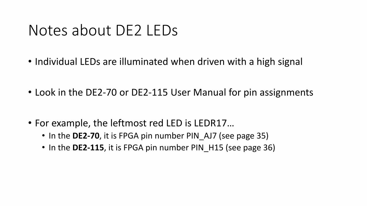
• Individual LEDs are illuminated when driven with a high signal
• Look in the DE2-70 or DE2-115 User Manual for pin assignments
• For example, the leftmost red LED is LEDR17…• In the DE2-70, it is FPGA pin number PIN_AJ7 (see page 35)
• In the DE2-115, it is FPGA pin number PIN_H15 (see page 36)
Notes about DE2 Pushbuttons
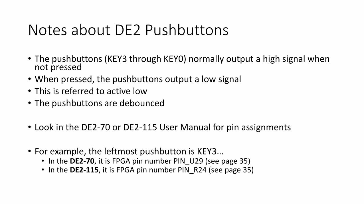
• The pushbuttons (KEY3 through KEY0) normally output a high signal when not pressed
• When pressed, the pushbuttons output a low signal• This is referred to active low• The pushbuttons are debounced
• Look in the DE2-70 or DE2-115 User Manual for pin assignments
• For example, the leftmost pushbutton is KEY3…• In the DE2-70, it is FPGA pin number PIN_U29 (see page 35)• In the DE2-115, it is FPGA pin number PIN_R24 (see page 35)
Architecture Description
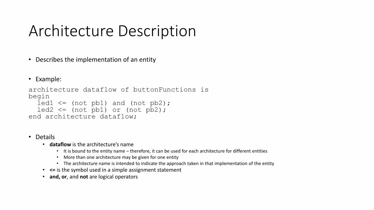
• Describes the implementation of an entity
• Example:
architecture dataflow of buttonFunctions isbeginled1 <= (not pb1) and (not pb2);led2 <= (not pb1) or (not pb2);
end architecture dataflow;
• Details• dataflow is the architecture’s name
• It is bound to the entity name – therefore, it can be used for each architecture for different entities• More than one architecture may be given for one entity• The architecture name is intended to indicate the approach taken in that implementation of the entity
• <= is the symbol used in a simple assignment statement• and, or, and not are logical operators
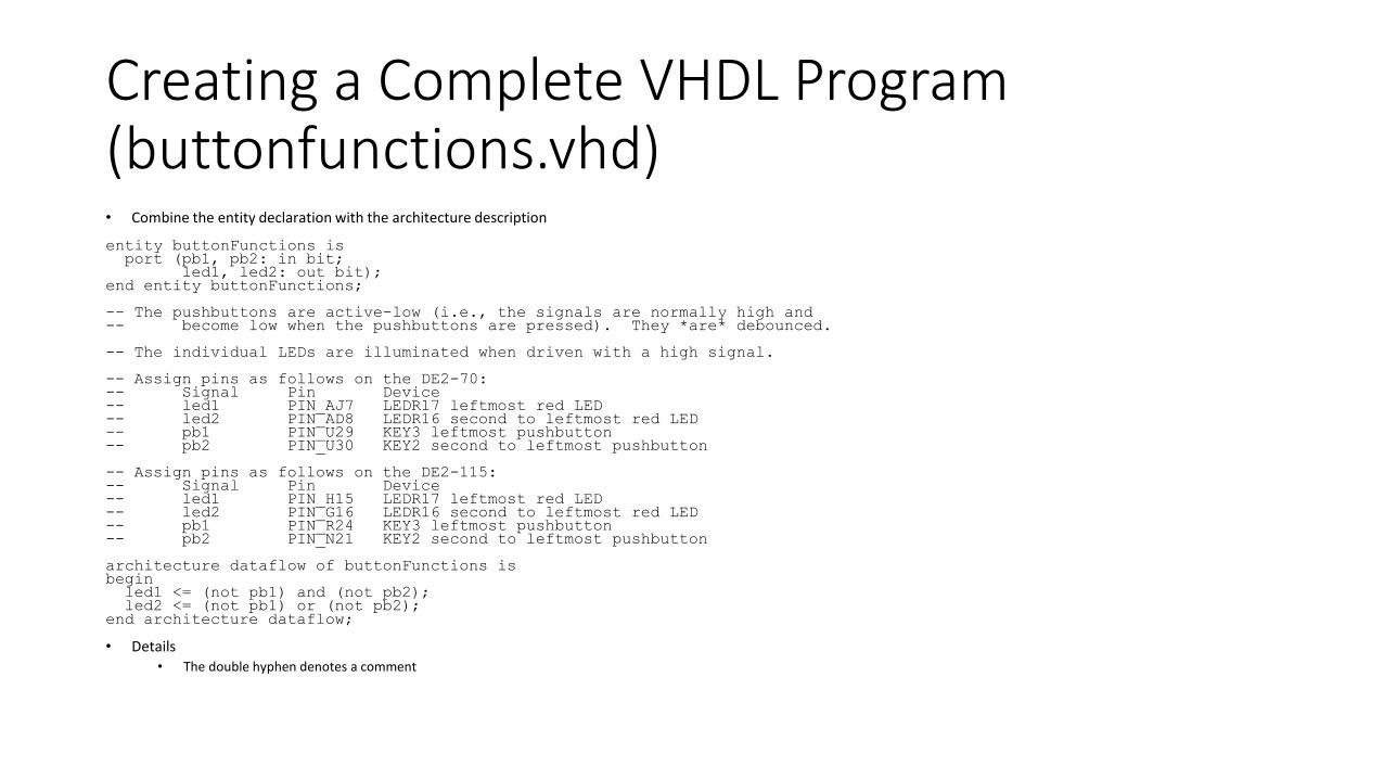
Creating a Complete VHDL Program (buttonfunctions.vhd)• Combine the entity declaration with the architecture description
entity buttonFunctions isport (pb1, pb2: in bit;
led1, led2: out bit);end entity buttonFunctions;
-- The pushbuttons are active-low (i.e., the signals are normally high and-- become low when the pushbuttons are pressed). They *are* debounced.
-- The individual LEDs are illuminated when driven with a high signal.
-- Assign pins as follows on the DE2-70:-- Signal Pin Device-- led1 PIN_AJ7 LEDR17 leftmost red LED-- led2 PIN_AD8 LEDR16 second to leftmost red LED-- pb1 PIN_U29 KEY3 leftmost pushbutton-- pb2 PIN_U30 KEY2 second to leftmost pushbutton
-- Assign pins as follows on the DE2-115:-- Signal Pin Device-- led1 PIN_H15 LEDR17 leftmost red LED-- led2 PIN_G16 LEDR16 second to leftmost red LED-- pb1 PIN_R24 KEY3 leftmost pushbutton-- pb2 PIN_N21 KEY2 second to leftmost pushbutton
architecture dataflow of buttonFunctions isbeginled1 <= (not pb1) and (not pb2);led2 <= (not pb1) or (not pb2);
end architecture dataflow;
• Details• The double hyphen denotes a comment

Using the Altera/Terasic Hardware
• Attach AC power cable to power supply
• Attach power supply to the Altera DE2 board at the DC 12V connector
• Attach USB cable from the Altera DE2 board BLASTER jack to your computer
• Power on the Altera DE2 board by pushing the red button labelled POWERor POWER/SW
• The Altera DE2 should start counting on all the seven-segment displays, flashing the red and green individual LEDs, and displaying a welcome message on the LCD display
• Pressing the rightmost pushbutton labelled KEY0 should display all 0s with decimal points on the seven-segment displays
Using Quartus II
• Ensure that you are using Version 13.0, SP 1 (either 32-bit or 64-bit)
• Create a new directory for each project• Name the directory with the same as the project name
• This will segregate all files being used for this project
• If you have already created a source VHDL file (with extension .vhd), copy it into the new directory• Name the VHDL source file with the same name as the project
• Launch Quartus II
Create a New Project (1 of 5)
• Select File → New...
• In the pop-up window, select New Quartus II Project
• In the New Project Wizard window, click on Next
• In the Directory, Name, Top-Level Entity [page 1 of 5] window…• Navigate to the working directory that you just created for this project and
select it
• Enter the name of the project
• The project name will default to be the top-level entity name
• Click on Next
Create a New Project (2 of 5)
• In the Add Files [page 2 of 5] window…• If you have already added VHDL source files into this directory, click on Add
All• Your VHDL files should now appear in the list
• Click on Next
Create a New Project (3 of 5)
• In the Family & Device Settings [page 3 of 5] window…• For the DE2-70…
• Under Family, select Cyclone II• In the Available Devices list, select EP2C70F896C6
• Verify that this is the FPGA part number installed in your DE2 board• EP2C70F896C6N should be entered as EP2C70F896C6
• For the DE2-115…• Under Family, select Cyclone IV E• In the Available Devices list, select EP4CE115F29C7
• Verify that this is the FPGA part number installed in your DE2 board• EP4CE115F29C7N should be entered as EP4CE115F29C7
• The appropriate device should be highlighted• Click on Next

Create a New Project (4 of 5)
• In the EDA Tool Settings [page 4 of 5] window…• Under Design Entry/Synthesis, enter Design Compiler, VHDL
• Under Simulation, enter ModelSim-Altera, VHDL
• Under Formal Verification, enter <None>
• Under Board-Level, Timing, enter STAMP
• Under Board-Level, Symbol, enter FPGA Xchange
• Under Board-Level, Signal Integrity,• Enter IBIS for the DE2-70
• Enter HSPICE for the DE2-115
• Under Board-Level, Boundary Scan, enter BSDL
• Click on Next
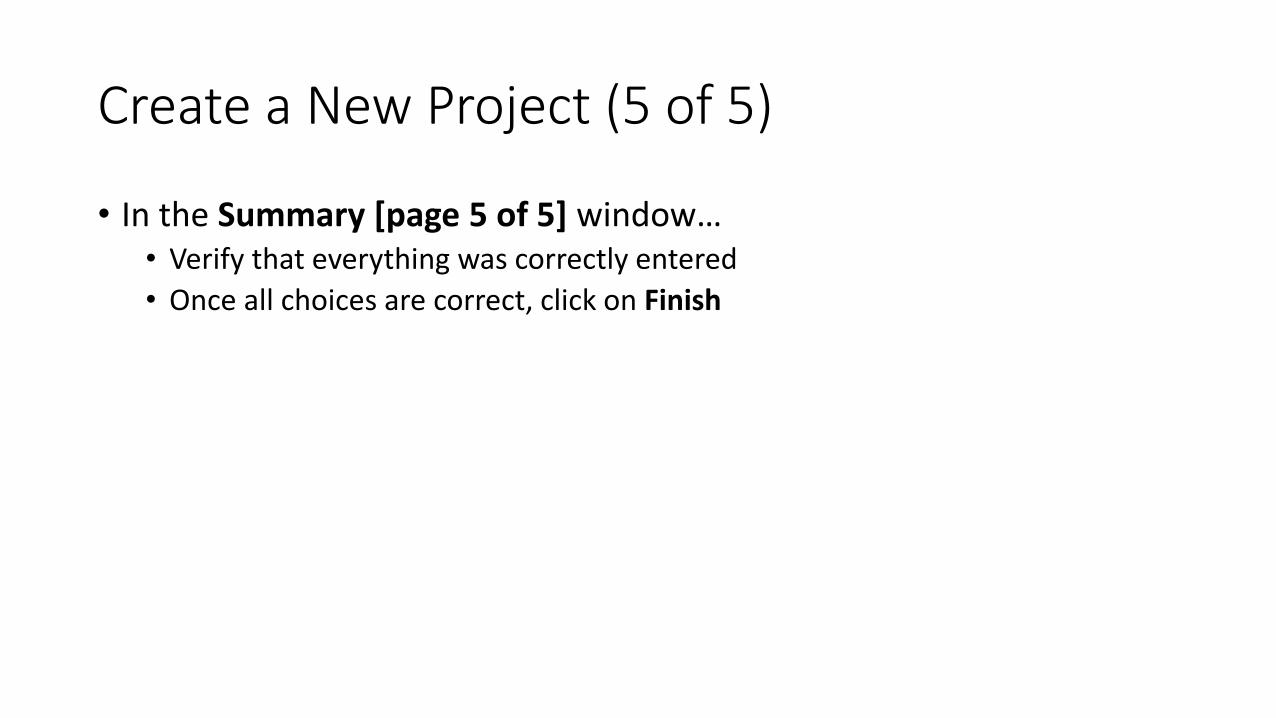
Create a New Project (5 of 5)
• In the Summary [page 5 of 5] window…• Verify that everything was correctly entered
• Once all choices are correct, click on Finish
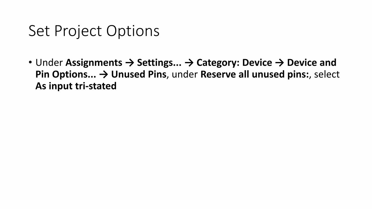
Set Project Options
• Under Assignments → Settings... → Category: Device → Device and Pin Options... → Unused Pins, under Reserve all unused pins:, select As input tri-stated

Build the Project
• Under Processing, select Start Compilation
• Wait until the entire compilation is complete• A pop-up windows will appear with text Full Compilation was successful (n
warnings)
• Before attempting to use the compiled project, pin assignments need to be made
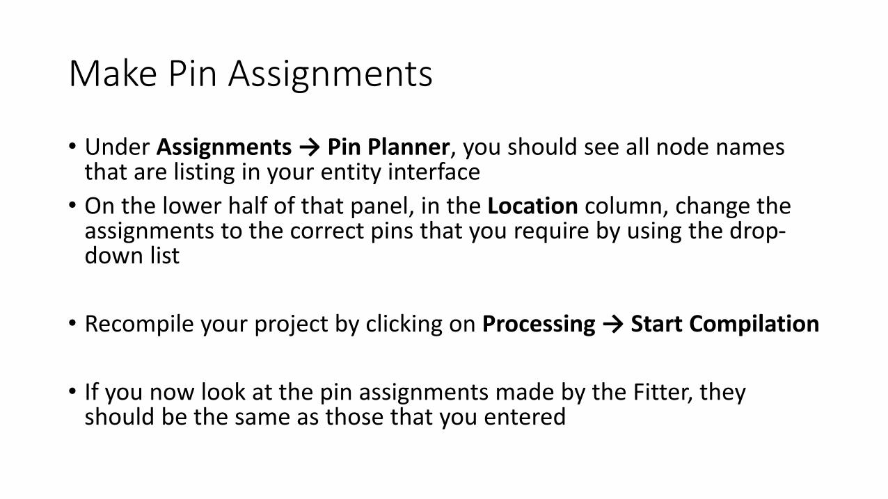
Make Pin Assignments
• Under Assignments → Pin Planner, you should see all node names that are listing in your entity interface
• On the lower half of that panel, in the Location column, change the assignments to the correct pins that you require by using the drop-down list
• Recompile your project by clicking on Processing → Start Compilation
• If you now look at the pin assignments made by the Fitter, they should be the same as those that you entered

Program the Hardware with your Design
• Ensure that the slide switch on the left side of the DE2 is in the RUN position (notin the PROG position)
• Select Tools → Programmer, to program the hardware
• In the Programmer window that opens, the Hardware Setup… should show USB-Blaster selected and the Mode should be JTAG
• Click on Add File… and in the Select Programming File, click on the output_filessubdirectory and select the appropriate .sof file and click on Open
• Back in the Programmer window, ensure that Program/Configure check box is checked
• Click on Start• The Progress bar should show the programming progress• Finally, the Progress bar should show 100% (Successful)
• Your design should be loaded into the FPGA and is currently active
Quick DE2 Kit Information
• Review: Individual LEDs are illuminated when driven by a high signal
• Segments of the seven-segment LEDs are illuminated when driven by a low signal
• Review: The four pushbutton switches are debounced and are active low (they output a low signal when depressed)
• The slide switches are not debounced

Alternate Way to Set Pin Assignments
• Instead of using the Pin Planner in Quartus II, it is possible to specify pin assignments in your VHDL file (see http://quartushelp.altera.com/15.0/mergedProjects/hdl/vhdl/vhdl_file_dir_chip.htm) using the chip_pin synthesis attribute
• The architecture specification should include code similar to the following (see buttonfunctionspinassign.vhd):
entity buttonFunctionsPinAssign isport (pb1, pb2: in bit;
led1, led2: out bit);end entity buttonFunctionsPinAssign;
-- Assign pins as follows on the DE2-70:-- Signal Pin Device-- led1 PIN_AJ7 LEDR17 leftmost red LED-- led2 PIN_AD8 LEDR16 second to leftmost red LED-- pb1 PIN_U29 KEY3 leftmost pushbutton-- pb2 PIN_U30 KEY2 second to leftmost pushbutton
architecture dataflow of buttonFunctionsPinAssign isattribute chip_pin: string;attribute chip_pin of led1: signal is "AJ7";attribute chip_pin of led2: signal is "AD8";attribute chip_pin of pb1: signal is "U29";attribute chip_pin of pb2: signal is "U30";
beginled1 <= (not pb1) and (not pb2);led2 <= (not pb1) or (not pb2);
end architecture dataflow;
• This technique can be used to assign pins for only the ports of the top-level entity• Of course, a signal can be assigned and thereby used by (“passed to”) a lower-level entity
• Additionally, this attribute can be used only with single bit or one-dimensional signals
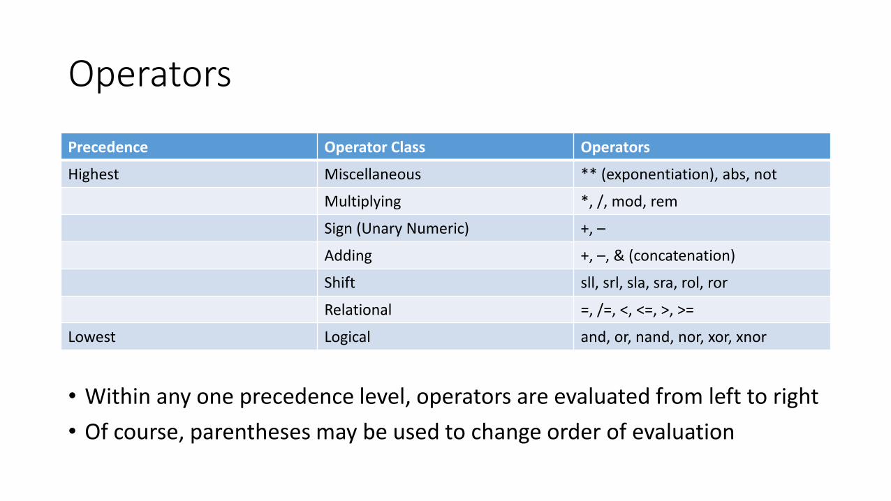
• Within any one precedence level, operators are evaluated from left to right
• Of course, parentheses may be used to change order of evaluation
Operators
Precedence Operator Class Operators
Highest Miscellaneous ** (exponentiation), abs, not
Multiplying *, /, mod, rem
Sign (Unary Numeric) +, –
Adding +, –, & (concatenation)
Shift sll, srl, sla, sra, rol, ror
Relational =, /=, <, <=, >, >=
Lowest Logical and, or, nand, nor, xor, xnor
More Specific Information of VHDL
• The IEEE Standard VHDL Language Reference Manual is IEEE Std 1076-2008, but is quite expensive
• Our textbook, The Designer’s Guide to VHDL, Third Edition by Peter J. Ashenden contains the same information in a more accessible form
• Refer to these documents for more specific information on VHDL
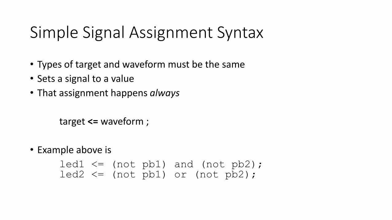
Simple Signal Assignment Syntax
• Types of target and waveform must be the same
• Sets a signal to a value
• That assignment happens always
target <= waveform ;
• Example above is
led1 <= (not pb1) and (not pb2);led2 <= (not pb1) or (not pb2);
Concurrent Assignment Operators
• Simple assignment• We’ve already seen this
• Selected signal assignment
• Conditional signal assignment
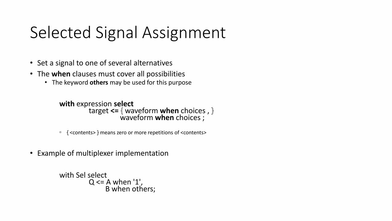
Selected Signal Assignment
• Set a signal to one of several alternatives
• The when clauses must cover all possibilities• The keyword others may be used for this purpose
with expression selecttarget <= waveform when choices ,
waveform when choices ;
<contents> means zero or more repetitions of <contents>
• Example of multiplexer implementation
with Sel selectQ <= A when '1',
B when others;
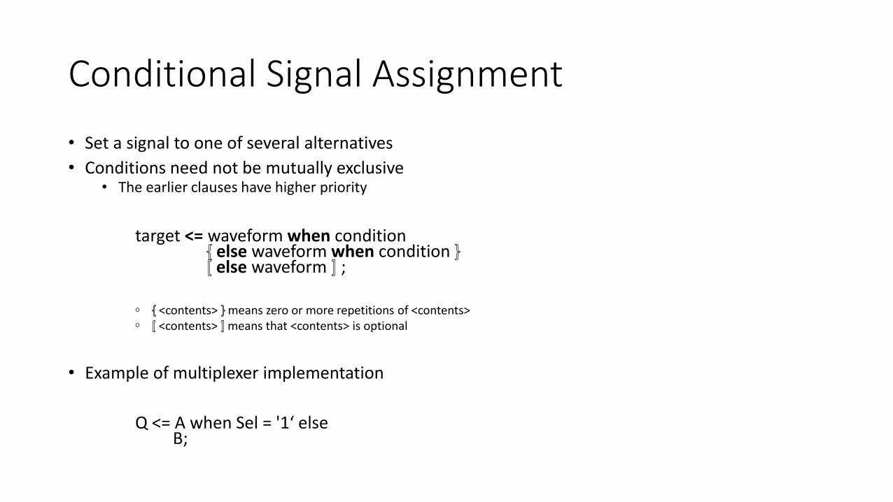
Conditional Signal Assignment
• Set a signal to one of several alternatives
• Conditions need not be mutually exclusive• The earlier clauses have higher priority
target <= waveform when conditionelse waveform when condition else waveform ;
<contents> means zero or more repetitions of <contents><contents> means that <contents> is optional
• Example of multiplexer implementation
Q <= A when Sel = '1‘ elseB;
Concurrent Assignment Ordering
• Ordering of concurrent assignment statements does not matter• Their operations are always taking place
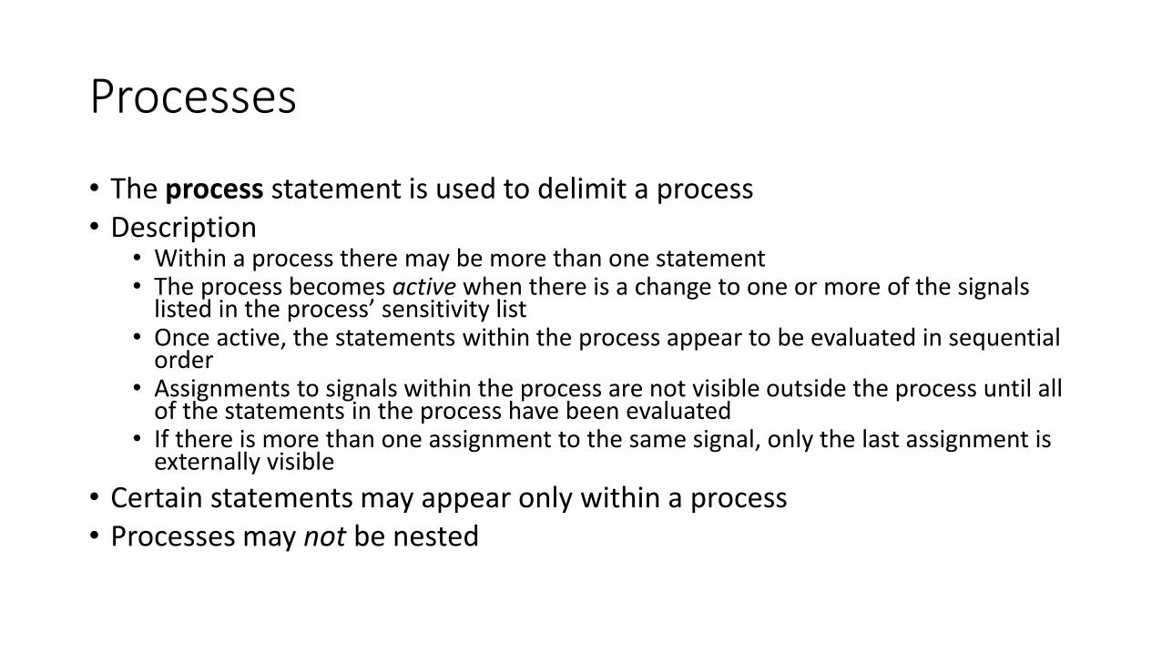
Processes
• The process statement is used to delimit a process• Description
• Within a process there may be more than one statement• The process becomes active when there is a change to one or more of the signals
listed in the process’ sensitivity list• Once active, the statements within the process appear to be evaluated in sequential
order• Assignments to signals within the process are not visible outside the process until all
of the statements in the process have been evaluated• If there is more than one assignment to the same signal, only the last assignment is
externally visible
• Certain statements may appear only within a process• Processes may not be nested

Process Syntax
• Use a process to introduce a block of sequential statements• Sequential statements are executed in the order they appear in the program• Sequential statements must appear within a process
process_label : process ( signal_name , … ) ( all ) is
process_declarative_itembegin
sequential_statementend process process_label ;
<contents> means zero or more repetitions of <contents><contents> means that <contents> is optionalmeans that the category immediately preceding the left brace may be repeated separated by the
specified delimeteris used to separate alternatives
• all means that the process is sensitive to all of the signals that it reads as inputs

Processes
• A process must be used to create a component with memory• For example, latches or registers are components with memory
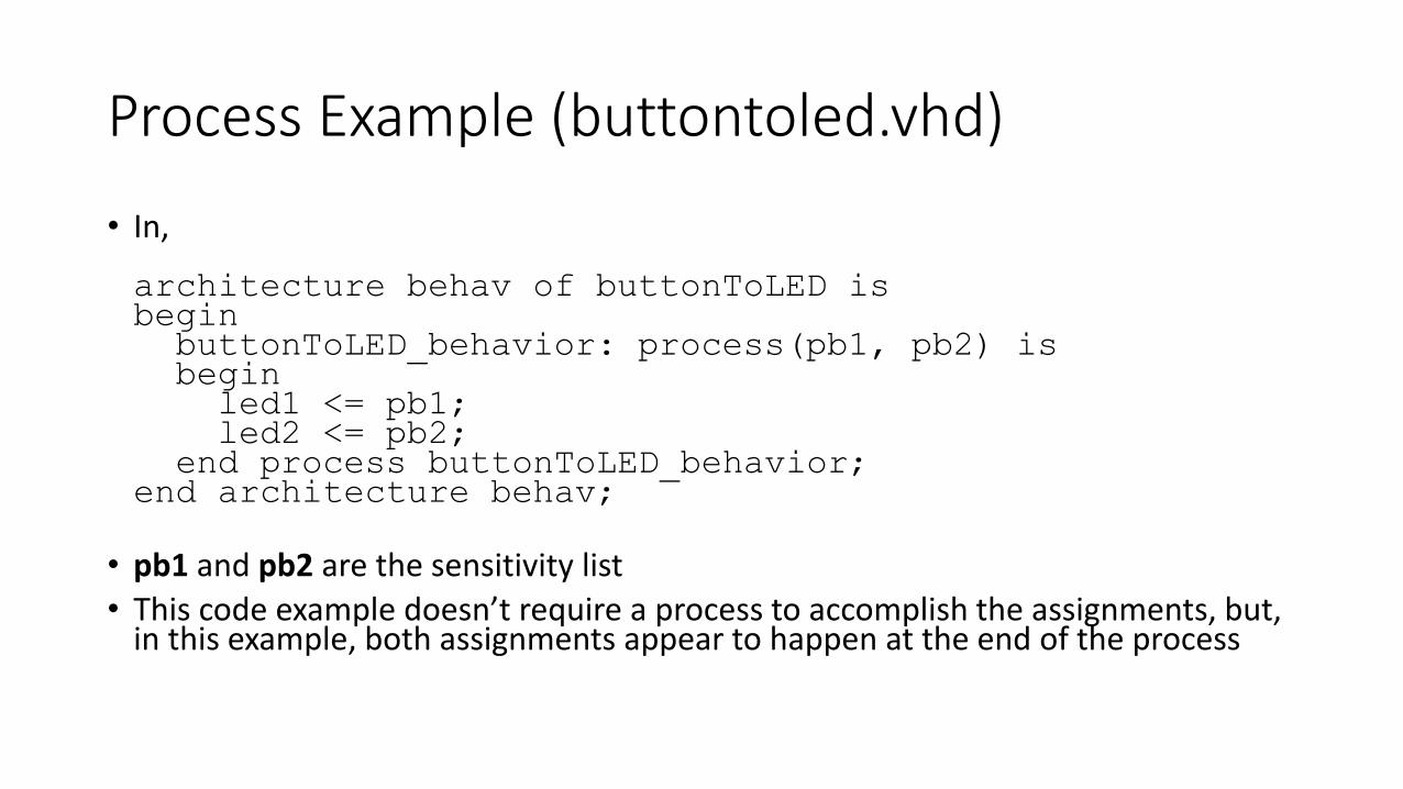
Process Example (buttontoled.vhd)
• In,
architecture behav of buttonToLED isbegin
buttonToLED_behavior: process(pb1, pb2) isbegin
led1 <= pb1;led2 <= pb2;
end process buttonToLED_behavior;end architecture behav;
• pb1 and pb2 are the sensitivity list
• This code example doesn’t require a process to accomplish the assignments, but, in this example, both assignments appear to happen at the end of the process
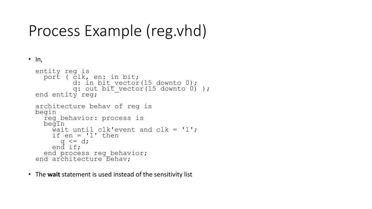
Process Example (reg.vhd)
• In,
entity reg isport ( clk, en: in bit;
d: in bit_vector(15 downto 0);q: out bit_vector(15 downto 0) );
end entity reg;
architecture behav of reg isbegin
reg_behavior: process isbeginwait until clk'event and clk = '1';if en = '1' thenq <= d;
end if;end process reg_behavior;
end architecture behav;
• The wait statement is used instead of the sensitivity list
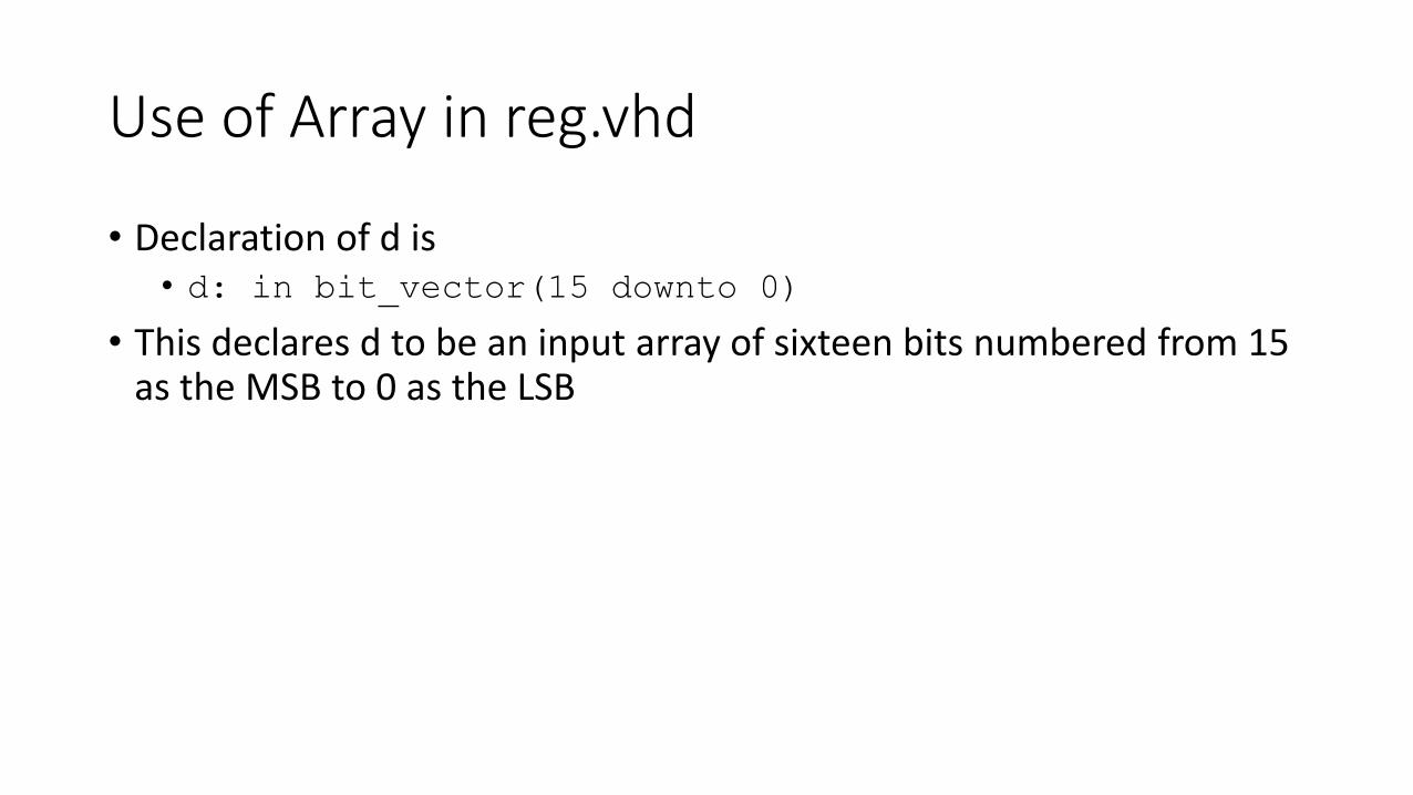
Use of Array in reg.vhd
• Declaration of d is• d: in bit_vector(15 downto 0)
• This declares d to be an input array of sixteen bits numbered from 15 as the MSB to 0 as the LSB

If Statement
• Our first example of a sequential statement• Sequential statements are executed in the order they appear in the program• Sequential statements must appear within a process
if_label : if condition then
sequential_statementelsif condition then
sequential_statementelse
sequential_statementend if if_label ;
<contents> means zero or more repetitions of <contents>
<contents> means that <contents> is optional
• Example of multiplexer implementation
if Sel = '1' thenQ <= A;
elseQ <= B;
end if;
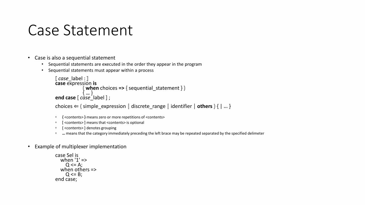
Case Statement
• Case is also a sequential statement• Sequential statements are executed in the order they appear in the program• Sequential statements must appear within a process
case_label : case expression is
when choices => sequential_statement
end case case_label ;
choices ⇐ simple_expression discrete_range identifier others |
<contents> means zero or more repetitions of <contents>
<contents> means that <contents> is optional
<contents> denotes grouping
means that the category immediately preceding the left brace may be repeated separated by the specified delimeter
• Example of multiplexer implementation
case Sel iswhen '1' =>
Q <= A;when others =>
Q <= B;end case;
Wait Statement
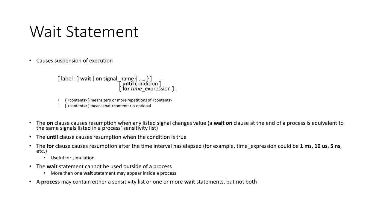
• Causes suspension of execution
label : wait on signal_name , until conditionfor time_expression ;
<contents> means zero or more repetitions of <contents>
<contents> means that <contents> is optional
• The on clause causes resumption when any listed signal changes value (a wait on clause at the end of a process is equivalent to the same signals listed in a process’ sensitivity list)
• The until clause causes resumption when the condition is true
• The for clause causes resumption after the time interval has elapsed (for example, time_expression could be 1 ms, 10 us, 5 ns, etc.)
• Useful for simulation
• The wait statement cannot be used outside of a process• More than one wait statement may appear inside a process
• A process may contain either a sensitivity list or one or more wait statements, but not both
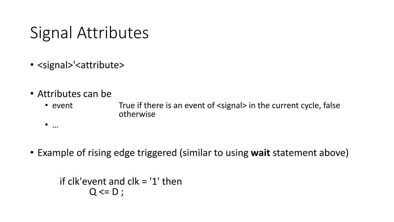
Signal Attributes
• <signal>'<attribute>
• Attributes can be• event True if there is an event of <signal> in the current cycle, false
otherwise• …
• Example of rising edge triggered (similar to using wait statement above)
if clk'event and clk = '1' thenQ <= D ;
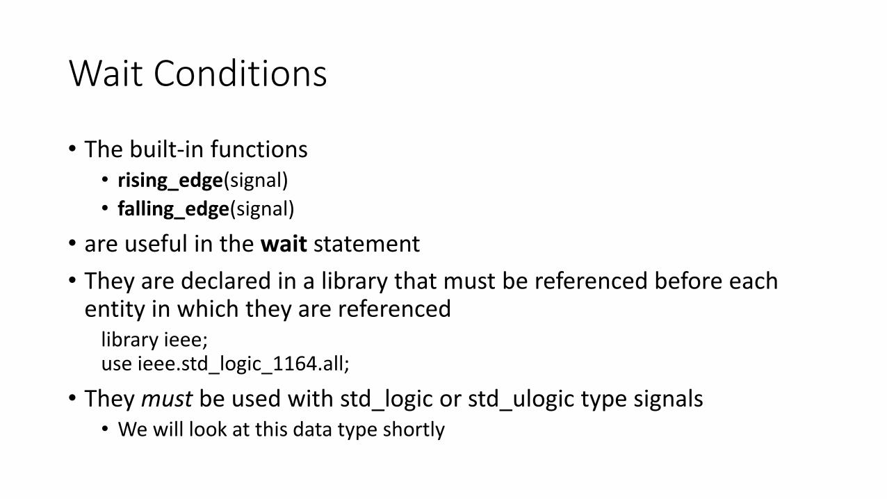
Wait Conditions
• The built-in functions• rising_edge(signal)
• falling_edge(signal)
• are useful in the wait statement
• They are declared in a library that must be referenced before each entity in which they are referenced
library ieee;use ieee.std_logic_1164.all;
• They must be used with std_logic or std_ulogic type signals• We will look at this data type shortly
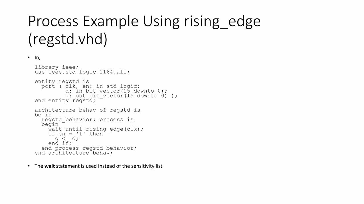
Process Example Using rising_edge(regstd.vhd)• In,
library ieee;use ieee.std_logic_1164.all;
entity regstd isport ( clk, en: in std_logic;
d: in bit_vector(15 downto 0);q: out bit_vector(15 downto 0) );
end entity regstd;
architecture behav of regstd isbegin
regstd_behavior: process isbeginwait until rising_edge(clk);if en = '1' thenq <= d;
end if;end process regstd_behavior;
end architecture behav;
• The wait statement is used instead of the sensitivity list
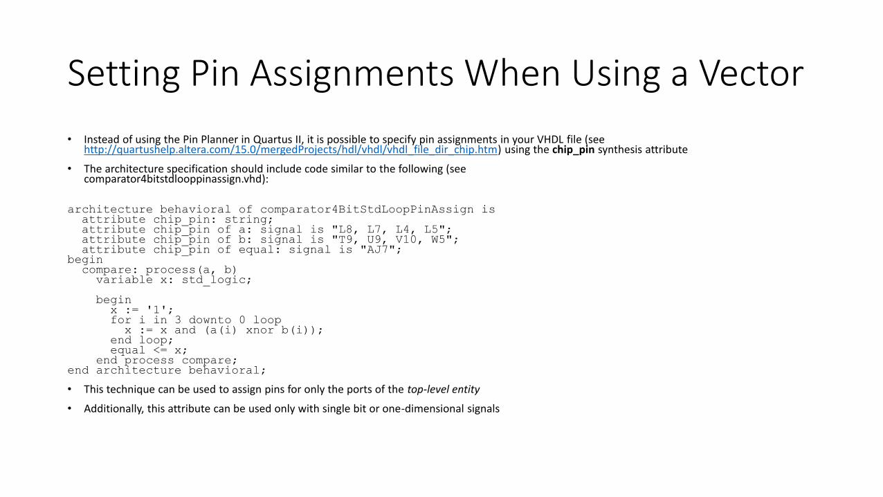
Setting Pin Assignments When Using a Vector
• Instead of using the Pin Planner in Quartus II, it is possible to specify pin assignments in your VHDL file (see http://quartushelp.altera.com/15.0/mergedProjects/hdl/vhdl/vhdl_file_dir_chip.htm) using the chip_pin synthesis attribute
• The architecture specification should include code similar to the following (seecomparator4bitstdlooppinassign.vhd):
architecture behavioral of comparator4BitStdLoopPinAssign isattribute chip_pin: string;attribute chip_pin of a: signal is "L8, L7, L4, L5";attribute chip_pin of b: signal is "T9, U9, V10, W5";attribute chip_pin of equal: signal is "AJ7";
begincompare: process(a, b)variable x: std_logic;
beginx := '1';for i in 3 downto 0 loopx := x and (a(i) xnor b(i));
end loop;equal <= x;
end process compare;end architecture behavioral;
• This technique can be used to assign pins for only the ports of the top-level entity
• Additionally, this attribute can be used only with single bit or one-dimensional signals
Logical and Arithmetic
• Assignment operators act on both logical and arithmetic data types
• We’ll cover data types later
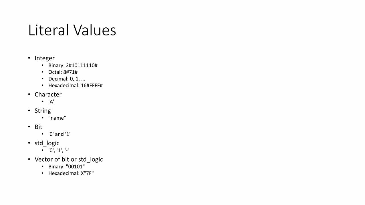
Literal Values
• Integer• Binary: 2#10111110#• Octal: 8#71#• Decimal: 0, 1, …• Hexadecimal: 16#FFFF#
• Character• 'A'
• String• "name"
• Bit• '0' and '1'
• std_logic• '0', '1', '-'
• Vector of bit or std_logic• Binary: "00101"• Hexadecimal: X"7F"
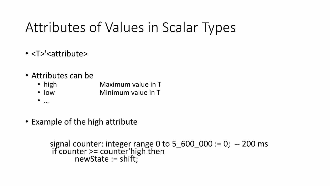
Attributes of Values in Scalar Types
• <T>'<attribute>
• Attributes can be• high Maximum value in T• low Minimum value in T• …
• Example of the high attribute
signal counter: integer range 0 to 5_600_000 := 0; -- 200 msif counter >= counter'high then
newState := shift;
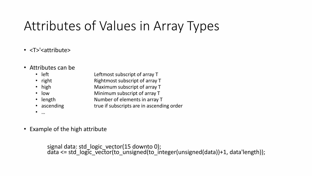
Attributes of Values in Array Types
• <T>'<attribute>
• Attributes can be• left Leftmost subscript of array T• right Rightmost subscript of array T• high Maximum subscript of array T• low Minimum subscript of array T• length Number of elements in array T• ascending true if subscripts are in ascending order• …
• Example of the high attribute
signal data: std_logic_vector(15 downto 0);data <= std_logic_vector(to_unsigned(to_integer(unsigned(data))+1, data'length));

Instantiation of Components
• A common paradigm in VHDL is creating entities that can be used throughout a design
• First, the entities are created
• Next, the entities are grouped into a package
• Finally, the package is invoked and the entities are used to create new entities

Create Components for Instantiation
• For each entity, create a file that contains the entity declaration and the architecture description
• For example, my file xnor02.vhd contains
library ieee;use ieee.std_logic_1164.all;
entity xnor02 isport (a, b : in std_logic;q : out std_logic);
end entity xnor02;
architecture dataflow of xnor02 isbeginq <= '1' when a = b else '0';
end architecture dataflow;
Write All Components That Are Part of a Package• In my case, in addition to xnor02.vhd, I have also created and04.vhd
and not01.vhd
• Each of these files contains an entity and the corresponding architecture
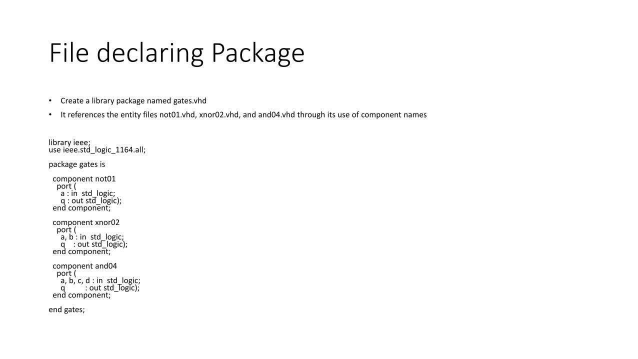
File declaring Package
• Create a library package named gates.vhd
• It references the entity files not01.vhd, xnor02.vhd, and and04.vhd through its use of component names
library ieee;use ieee.std_logic_1164.all;
package gates is
component not01port (
a : in std_logic;q : out std_logic);
end component;
component xnor02port (
a, b : in std_logic;q : out std_logic);
end component;
component and04port (
a, b, c, d : in std_logic;q : out std_logic);
end component;
end gates;
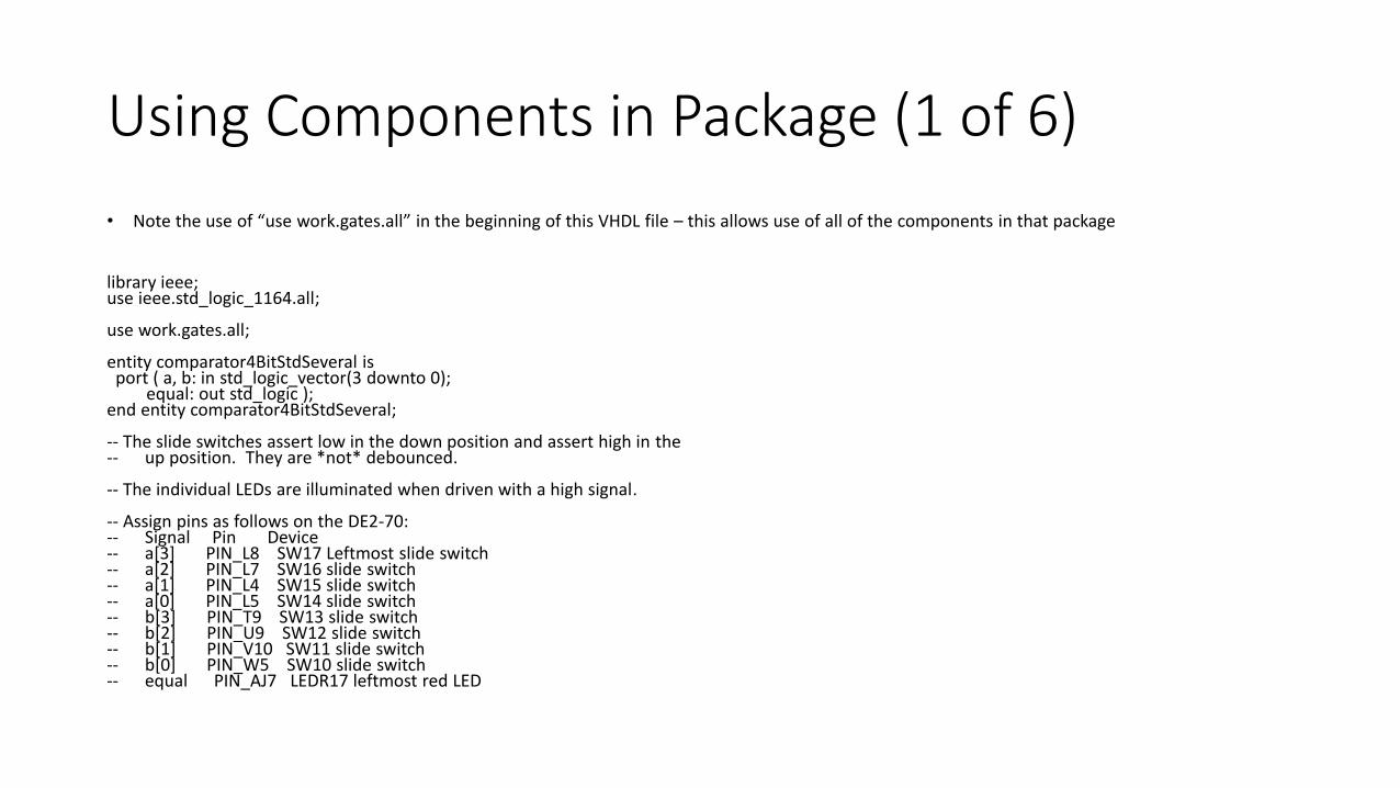
Using Components in Package (1 of 6)
• Note the use of “use work.gates.all” in the beginning of this VHDL file – this allows use of all of the components in that package
library ieee;use ieee.std_logic_1164.all;
use work.gates.all;
entity comparator4BitStdSeveral isport ( a, b: in std_logic_vector(3 downto 0);
equal: out std_logic );end entity comparator4BitStdSeveral;
-- The slide switches assert low in the down position and assert high in the-- up position. They are *not* debounced.
-- The individual LEDs are illuminated when driven with a high signal.
-- Assign pins as follows on the DE2-70:-- Signal Pin Device-- a[3] PIN_L8 SW17 Leftmost slide switch-- a[2] PIN_L7 SW16 slide switch-- a[1] PIN_L4 SW15 slide switch-- a[0] PIN_L5 SW14 slide switch-- b[3] PIN_T9 SW13 slide switch-- b[2] PIN_U9 SW12 slide switch-- b[1] PIN_V10 SW11 slide switch-- b[0] PIN_W5 SW10 slide switch-- equal PIN_AJ7 LEDR17 leftmost red LED

Using Components in Package (2 of 6)
• The first architecture is a dataflow implementation of the comparator4BitStdSeveral entity
• The second architecture is a dataflow implementation of the same entity using low-level Boolean operators
architecture dataflow of comparator4BitStdSeveral isbeginequal <= '1' when a = b else '0';
end architecture dataflow;
architecture dataflow_boolean of comparator4BitStdSeveral isbeginequal <= not(a(0) xor b(0))
and not(a(1) xor b(1))and not(a(2) xor b(2))and not(a(3) xor b(3));
end architecture dataflow_boolean;
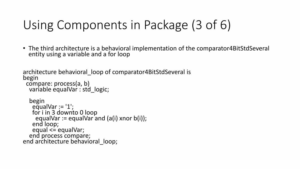
Using Components in Package (3 of 6)
• The third architecture is a behavioral implementation of the comparator4BitStdSeveralentity using a variable and a for loop
architecture behavioral_loop of comparator4BitStdSeveral isbegin
compare: process(a, b)variable equalVar : std_logic;
beginequalVar := '1';for i in 3 downto 0 loop
equalVar := equalVar and (a(i) xnor b(i));end loop;equal <= equalVar;
end process compare;end architecture behavioral_loop;
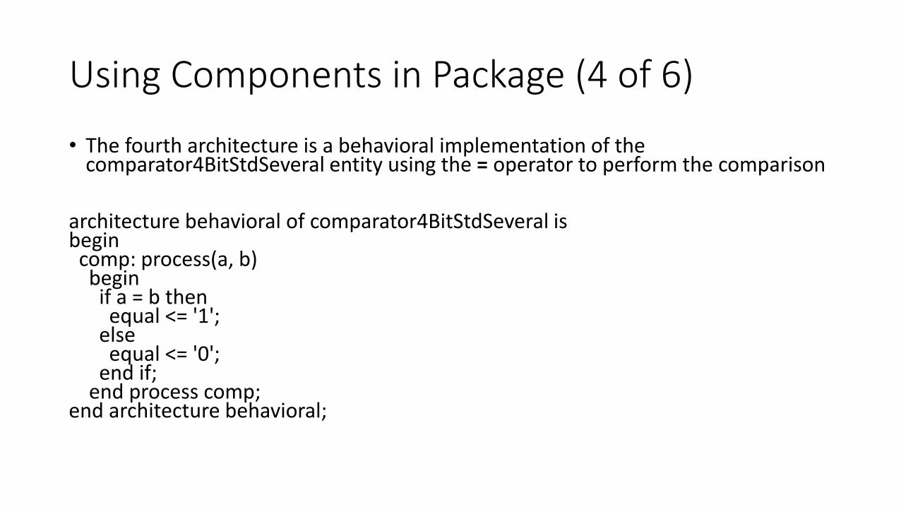
Using Components in Package (4 of 6)
• The fourth architecture is a behavioral implementation of the comparator4BitStdSeveral entity using the = operator to perform the comparison
architecture behavioral of comparator4BitStdSeveral isbegincomp: process(a, b)beginif a = b thenequal <= '1';
elseequal <= '0';
end if;end process comp;
end architecture behavioral;
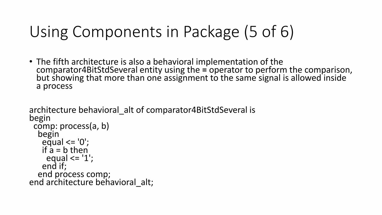
Using Components in Package (5 of 6)
• The fifth architecture is also a behavioral implementation of the comparator4BitStdSeveral entity using the = operator to perform the comparison, but showing that more than one assignment to the same signal is allowed inside a process
architecture behavioral_alt of comparator4BitStdSeveral isbegincomp: process(a, b)beginequal <= '0';if a = b thenequal <= '1';
end if;end process comp;
end architecture behavioral_alt;
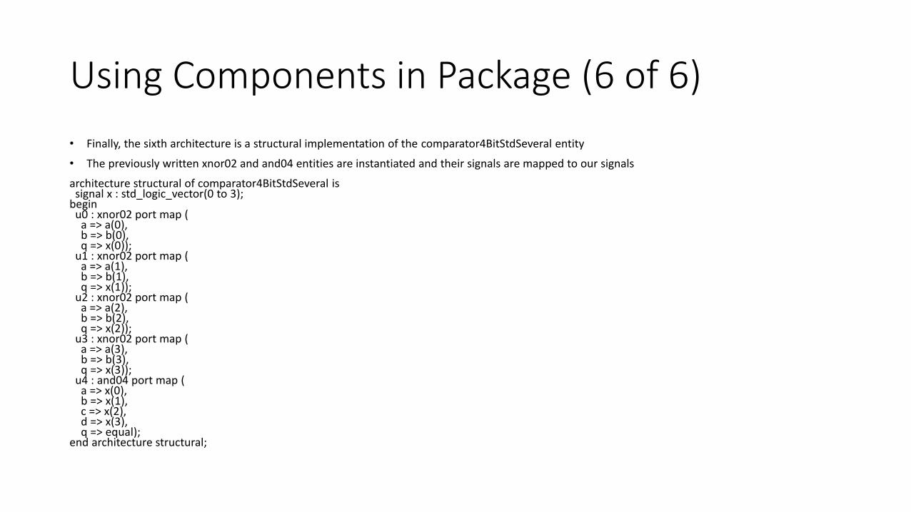
Using Components in Package (6 of 6)
• Finally, the sixth architecture is a structural implementation of the comparator4BitStdSeveral entity
• The previously written xnor02 and and04 entities are instantiated and their signals are mapped to our signals
architecture structural of comparator4BitStdSeveral issignal x : std_logic_vector(0 to 3);
beginu0 : xnor02 port map (
a => a(0),b => b(0),q => x(0));
u1 : xnor02 port map (a => a(1),b => b(1),q => x(1));
u2 : xnor02 port map (a => a(2),b => b(2),q => x(2));
u3 : xnor02 port map (a => a(3),b => b(3),q => x(3));
u4 : and04 port map (a => x(0),b => x(1),c => x(2),d => x(3),q => equal);
end architecture structural;
Instantiation of Components
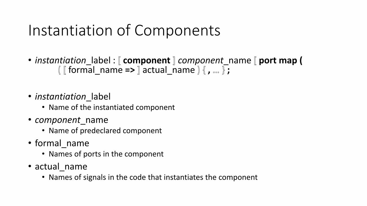
• instantiation_label : component component_name port map (formal_name => actual_name , ;
• instantiation_label• Name of the instantiated component
• component_name• Name of predeclared component
• formal_name• Names of ports in the component
• actual_name• Names of signals in the code that instantiates the component

Observations about Component Instantiation
• Components cannot be instantiated inside a process
• However, components can be instantiated inside the same architecture that contains a process• That is, after the begin for the architecture and before the process

Vector Data Type
• An array of bits is furnished as a built-in type• bit_vector
• Allows the declaration of a vector of signals
• For example,bit_vector(3 downto 0)
is the declaration of a vector of four bits numbered zero-origin from LSB to MSB
• And,bit_vector(1 to 7)
is the declaration of a vector of seven bits numbered one-origin from MSB to LSB
• Operators are defined to work on vectors/arrays
• Elements can be accessed using parentheses for subscripts
Vector Example (comparator4bit.vhd)
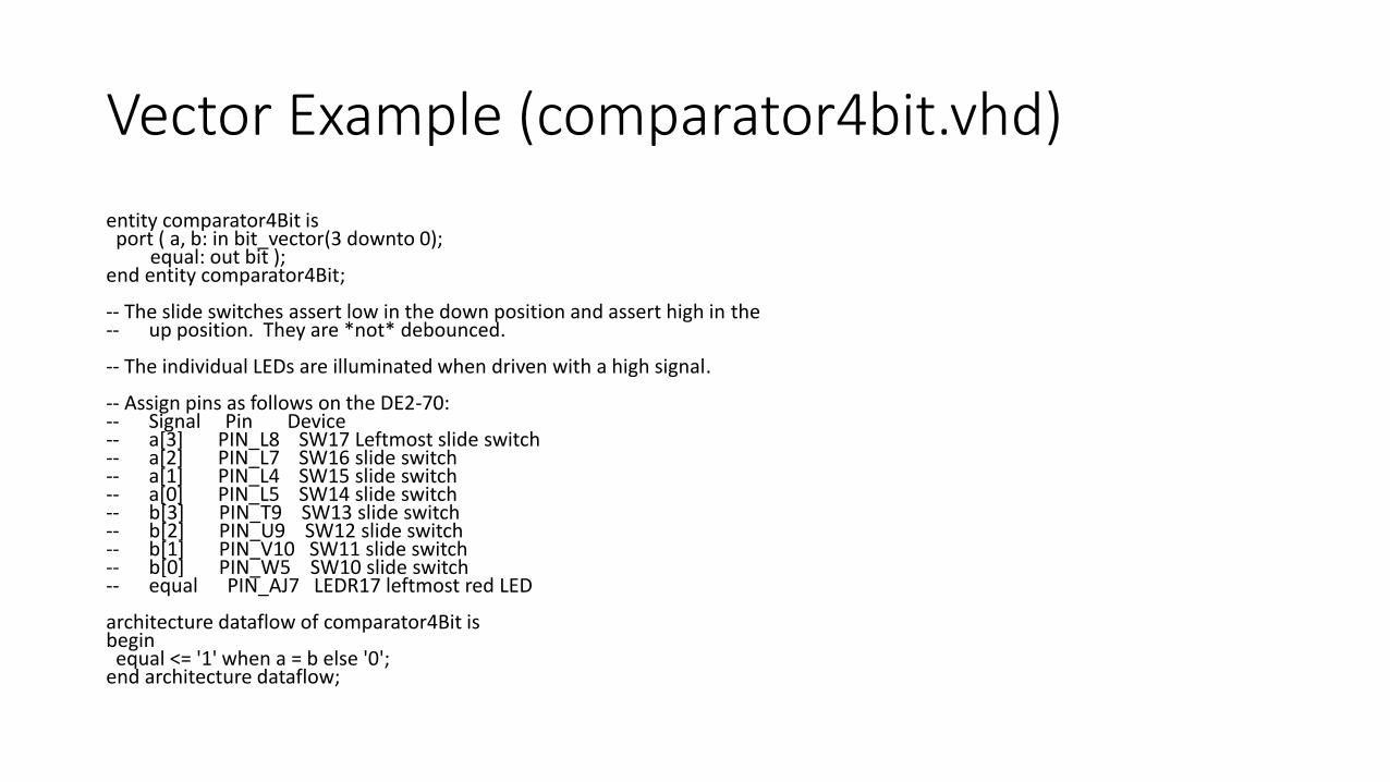
entity comparator4Bit isport ( a, b: in bit_vector(3 downto 0);
equal: out bit );end entity comparator4Bit;
-- The slide switches assert low in the down position and assert high in the-- up position. They are *not* debounced.
-- The individual LEDs are illuminated when driven with a high signal.
-- Assign pins as follows on the DE2-70:-- Signal Pin Device-- a[3] PIN_L8 SW17 Leftmost slide switch-- a[2] PIN_L7 SW16 slide switch-- a[1] PIN_L4 SW15 slide switch-- a[0] PIN_L5 SW14 slide switch-- b[3] PIN_T9 SW13 slide switch-- b[2] PIN_U9 SW12 slide switch-- b[1] PIN_V10 SW11 slide switch-- b[0] PIN_W5 SW10 slide switch-- equal PIN_AJ7 LEDR17 leftmost red LED
architecture dataflow of comparator4Bit isbeginequal <= '1' when a = b else '0';
end architecture dataflow;
Extended Bit Data Type
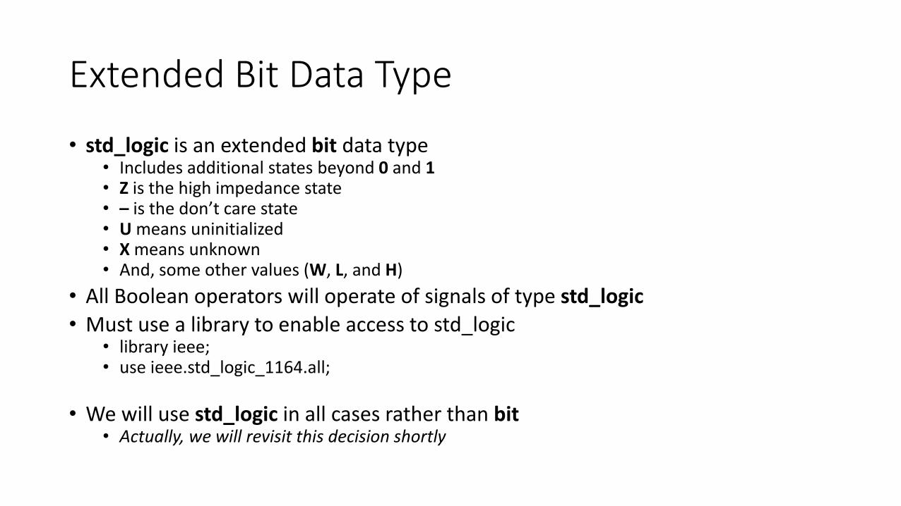
• std_logic is an extended bit data type• Includes additional states beyond 0 and 1• Z is the high impedance state• – is the don’t care state• U means uninitialized• X means unknown• And, some other values (W, L, and H)
• All Boolean operators will operate of signals of type std_logic
• Must use a library to enable access to std_logic• library ieee;• use ieee.std_logic_1164.all;
• We will use std_logic in all cases rather than bit• Actually, we will revisit this decision shortly
Declaring New Data Types
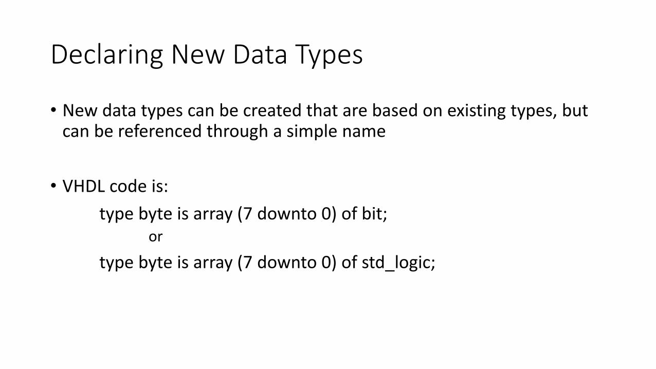
• New data types can be created that are based on existing types, but can be referenced through a simple name
• VHDL code is:
type byte is array (7 downto 0) of bit;or
type byte is array (7 downto 0) of std_logic;
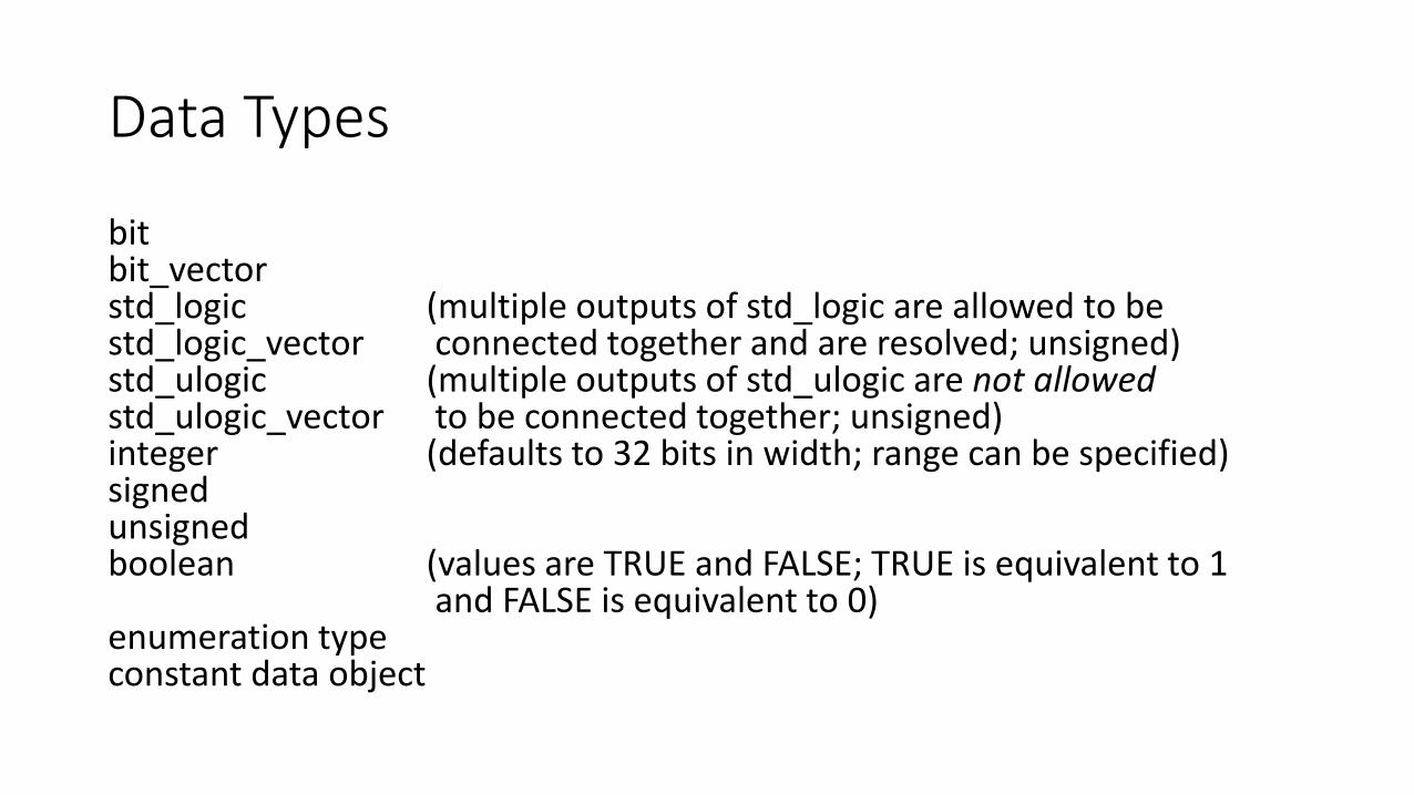
Data Types
bitbit_vectorstd_logic (multiple outputs of std_logic are allowed to bestd_logic_vector connected together and are resolved; unsigned)std_ulogic (multiple outputs of std_ulogic are not allowedstd_ulogic_vector to be connected together; unsigned)integer (defaults to 32 bits in width; range can be specified)signedunsignedboolean (values are TRUE and FALSE; TRUE is equivalent to 1
and FALSE is equivalent to 0)enumeration typeconstant data object
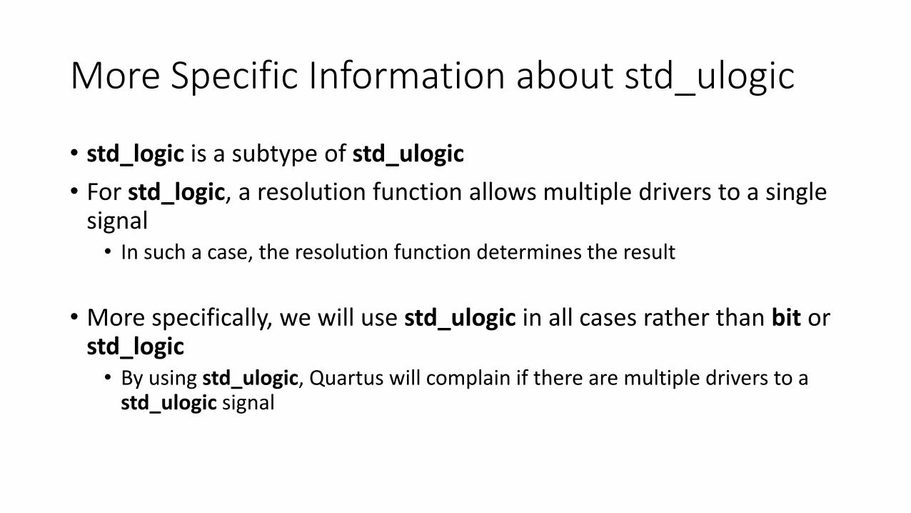
More Specific Information about std_ulogic
• std_logic is a subtype of std_ulogic
• For std_logic, a resolution function allows multiple drivers to a single signal• In such a case, the resolution function determines the result
• More specifically, we will use std_ulogic in all cases rather than bit or std_logic• By using std_ulogic, Quartus will complain if there are multiple drivers to a
std_ulogic signal
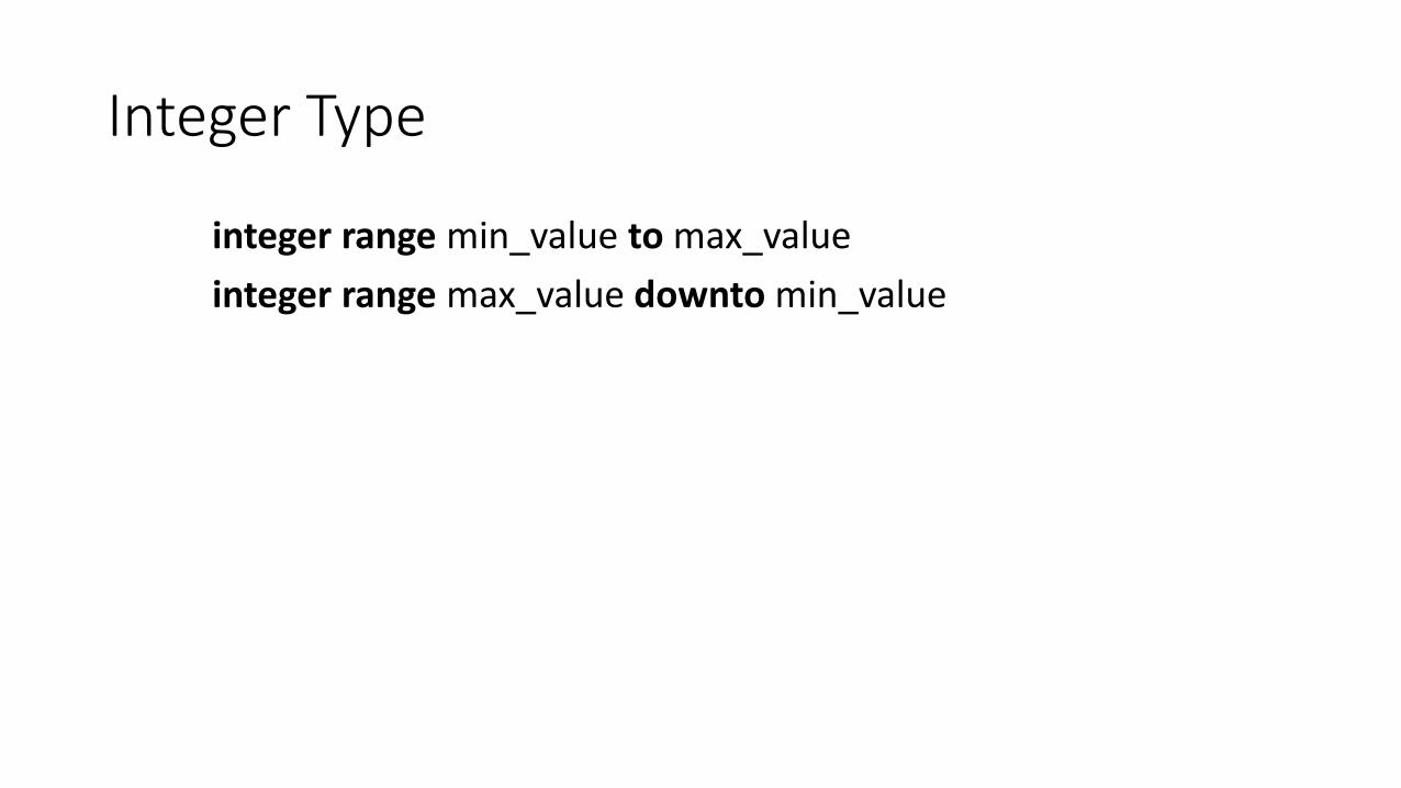
Integer Type
integer range min_value to max_value
integer range max_value downto min_value
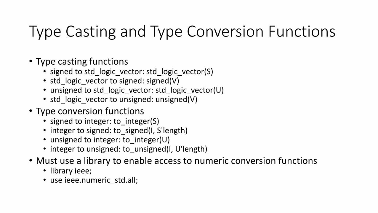
Type Casting and Type Conversion Functions
• Type casting functions• signed to std_logic_vector: std_logic_vector(S)• std_logic_vector to signed: signed(V)• unsigned to std_logic_vector: std_logic_vector(U)• std_logic_vector to unsigned: unsigned(V)
• Type conversion functions• signed to integer: to_integer(S)• integer to signed: to_signed(I, S'length)• unsigned to integer: to_integer(U)• integer to unsigned: to_unsigned(I, U'length)
• Must use a library to enable access to numeric conversion functions• library ieee;• use ieee.numeric_std.all;

Enumeration Data Type
• User can specify the possible values for a type
type enumeration_type_name is ( name1 , name2 )
Constant Data Object
• A constant has a fixed value that cannot be changed
• It is not mapped to a wire in a circuit
constant constant_name : type_name := constant_value ;
Signals
• Signals that are not used in an interface to an entity can be declared at the beginning of an architecture and then used within that architecture
• An initial value can be given in the declaration
Example of Declaring Signals
• An example of declaring a signal (that isn’t a port of an entity) is shown above in the structural architecture of the comparator4BitStdSeveral entity

Variables
• Assignment to a variable immediately overwrites the variable with a new value• In comparison, assignment to a signal schedules a new value to be applied to the signal at
some later time
• In general, unlike signals, variables do not correspond to wires in a synthesized circuit• Use variables to describe connections in a circuit that cannot be described using signals and
VHDL operators
• We will reserve the use of variables to (1) describing how signals are connected together in for loops and (2) wiring values to be assigned in different FSM cases
• An initial value can be given when the variable is declared
Variable Assignment Statement
• Replace the current value of a variable with a new value specified by an expression
<target> := <expr> ;
• Note that variable assignment uses the := operator rather than the <=operator used for signals

Example of Using Variables with Instantiation
• An example of declaring and using a variable is shown above in the behavioral_loop architecture of the comparator4BitStdSeveral entity
Using VHDL to Implement an FSM (1 of 5)
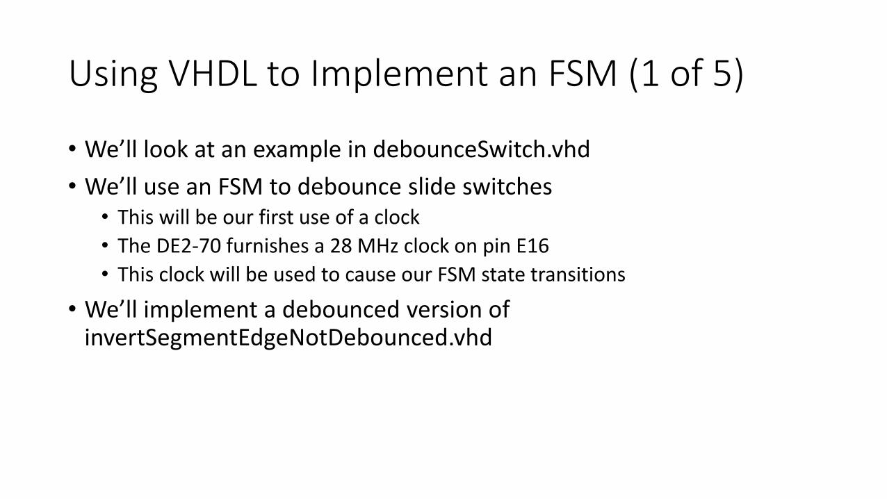
• We’ll look at an example in debounceSwitch.vhd
• We’ll use an FSM to debounce slide switches• This will be our first use of a clock
• The DE2-70 furnishes a 28 MHz clock on pin E16
• This clock will be used to cause our FSM state transitions
• We’ll implement a debounced version of invertSegmentEdgeNotDebounced.vhd

Using VHDL to Implement an FSM (2 of 5)
• Entity declaration is
library ieee;use ieee.std_logic_1164.all;
entity debounceSwitch isport (reset, invert: in std_logic;
segment: buffer std_logic;clock: in std_logic);
end entity debounceSwitch;
Using VHDL to Implement an FSM (3 of 5)
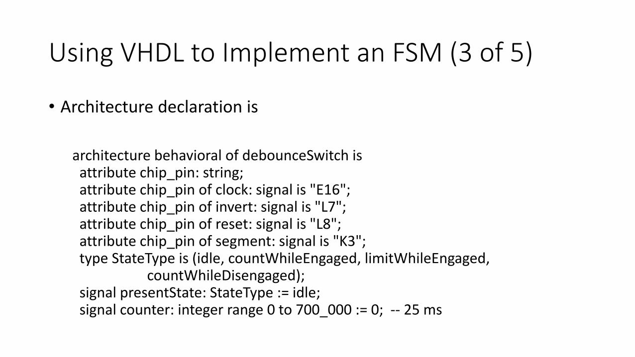
• Architecture declaration is
architecture behavioral of debounceSwitch isattribute chip_pin: string;attribute chip_pin of clock: signal is "E16";attribute chip_pin of invert: signal is "L7";attribute chip_pin of reset: signal is "L8";attribute chip_pin of segment: signal is "K3";type StateType is (idle, countWhileEngaged, limitWhileEngaged,
countWhileDisengaged);signal presentState: StateType := idle;signal counter: integer range 0 to 700_000 := 0; -- 25 ms
Using VHDL to Implement an FSM (4 of 5)
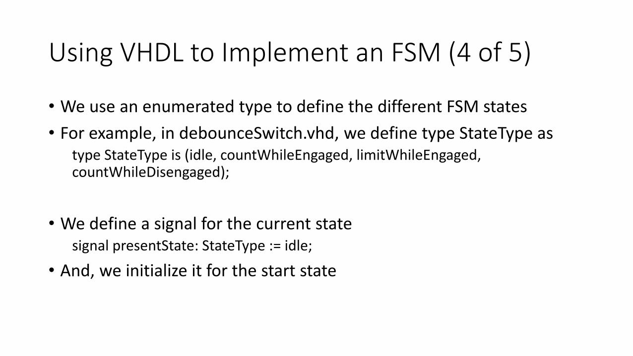
• We use an enumerated type to define the different FSM states
• For example, in debounceSwitch.vhd, we define type StateType astype StateType is (idle, countWhileEngaged, limitWhileEngaged, countWhileDisengaged);
• We define a signal for the current statesignal presentState: StateType := idle;
• And, we initialize it for the start state
Using VHDL to Implement an FSM (5 of 5)
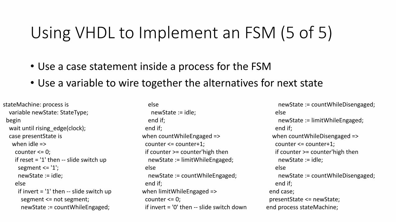
• Use a case statement inside a process for the FSM
• Use a variable to wire together the alternatives for next state
stateMachine: process isvariable newState: StateType;
beginwait until rising_edge(clock);case presentState iswhen idle =>
counter <= 0;if reset = '1' then -- slide switch upsegment <= '1';newState := idle;
elseif invert = '1' then -- slide switch upsegment <= not segment;newState := countWhileEngaged;
elsenewState := idle;
end if;end if;
when countWhileEngaged =>counter <= counter+1;if counter >= counter'high thennewState := limitWhileEngaged;
elsenewState := countWhileEngaged;
end if;when limitWhileEngaged =>
counter <= 0;if invert = '0' then -- slide switch down
newState := countWhileDisengaged;elsenewState := limitWhileEngaged;
end if;when countWhileDisengaged =>
counter <= counter+1;if counter >= counter'high thennewState := idle;
elsenewState := countWhileDisengaged;
end if;end case;presentState <= newState;
end process stateMachine;

Using Configuration to Select One of Several Architectures• By default, the last architecture found that matches the entity
specification will be selected
• To select a different architecture, use the configuration statement as follows
configuration config_name of x_entity isfor x_archend for;
end config_name;
• In general, having multiple architectures for an entity is unnecessary
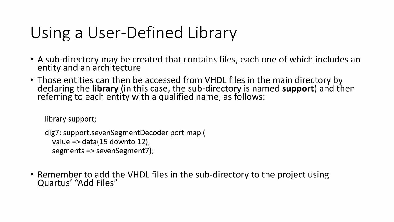
Using a User-Defined Library
• A sub-directory may be created that contains files, each one of which includes an entity and an architecture
• Those entities can then be accessed from VHDL files in the main directory by declaring the library (in this case, the sub-directory is named support) and then referring to each entity with a qualified name, as follows:
library support;
dig7: support.sevenSegmentDecoder port map (value => data(15 downto 12),segments => sevenSegment7);
• Remember to add the VHDL files in the sub-directory to the project using Quartus’ “Add Files”