finite element simulation on shot peen forming the wing ... · finite element simulation on shot...
TRANSCRIPT
Finite element simulation on shot peen forming the wing panel of commercial aircraft C919
Y.J. Wang1, X.D. Xiao 1, J.B. Wang1, W. Zhang2 , M.J. Qiao2
1 School of Mechanical Engineering, Northwestern Polytechnical University, China 2 Xi'an Aircraft International Corporation, China
Abstract A wing panel is usually shaped from a machined flat panel by using a shot peen forming process to meet its aerodynamic contour. It is essential to validate the formability of the wing panel and to develop the peen forming parameters as well as to compensate the machined flat panel. Many iterations are usually required to achieve the works. Reliable numerical simulations could reduce the time and the cost. In this paper, the ideal induced stress field is calculated directly from the desired panel shape in association with the shot peen forming processes. The calculated induced stresses are validated on a rectangular plate. The maximum deviation of the simulated curvatures of the plate is 4.12%. A FE simulation technique is proposed to simulate the deformation of aircraft wing panel and is performed on a wing panel of the commercial aircraft C919. The simulated contour is in good agreement with desired panel shape. The maximum contour deviation of the simulation without applying gravity load is 10 mm. The maximum contour deviation of the simulation with applying gravity load is 3.5 mm which is consistent with the experimentally measured values
Keywords Finite element simulation, shot peen forming, induced stress, wing panel, C919.
Introduction Shot peen forming is a well-established method for shaping large wing panels. By imposing compressive stresses, shot peening treatments produce stretching and bending loads across the peened component [1, 2] resulting in the desired shape. Homer and Vanluchene [1] presented a finite element-based geometric method to obtain an accurate geometric shape and to predict peening intensity patterns. Grasty and Andrew [3] proposed an equivalent finite element analysis method to simulate the impacting effect of a large number of shots in which the surface layers of the plates were subjected to a squeeze pressure to produce a small plastic deformation similar to shot impacting. Levers and Prior [4] proposed a static analysis method to simulate the peening deformation by introducing the material coefficient of thermal expansion and temperature profiles into the elements. Wang et al. [5] developed a thermal loading model by applying a loading unit to induce an equivalent plastic layer in a plate. Gariepy [6] simulated the practical peening process by sequentially applying stress profiles on the peening strip areas of a wing panel. In this paper, an algorithm is proposed to directly calculate the ideal induced stress of shot peen forming. A FE method has been developed to simulate the deformation of a large wing panel.
Ideal induced stress of shot peen forming The aim of the shot peen forming is to shape a plate by introducing compressive stresses in the surface layer. The peening effect on the deformation of plate is equivalent to applying bending moments and stretching forces on the plate. The equivalent bending moments per unit width are related to the resulting shape as
(1)
where, Px and Py are curvatures in the x and y direction of the formed plate. V is the
Poisson's ratio. o = Et 3 1 (12(1 - v 2 )) , tis the thickness of the plate.
342
The ideal induced stress field is equilibrated with the bending moments as
f ~ ~nd ( t I 2-z)dz + Mx = 0, f ~ ~nd ( t I 2-z)dz + MY = 0 (2)
The shot peen forming process of a wing panel is usually implemented on the both surfaces of the panel to obtain saddleback shape. The bending moments are the results of compressive residual stresses in both surface layers induced by the peening treatments. The peening treat-
ments on the top surface produce a moment Mx,top along the x direction and a moment My.top
along they direction. On the bottom surface layer, it is same. For equilibrium of the bending moment on plate sections, the sum of the top moment and the bottom moment is equal to the corresponding moment as
The deformation energy of a peen-formed plate consists of bending energy and elongation energy. For a plate with a certain shape represented by curvatures, the bending deformation energy is a constant. The elongating deformation energy depends on the peening intensity. The elastic deformation energy on the element cube can be expressed as
(4)
The optimized induced stress field can be obtained by minimizing the deformation energy subject to the constraints corresponding to the peening parameters and boundary conditions.
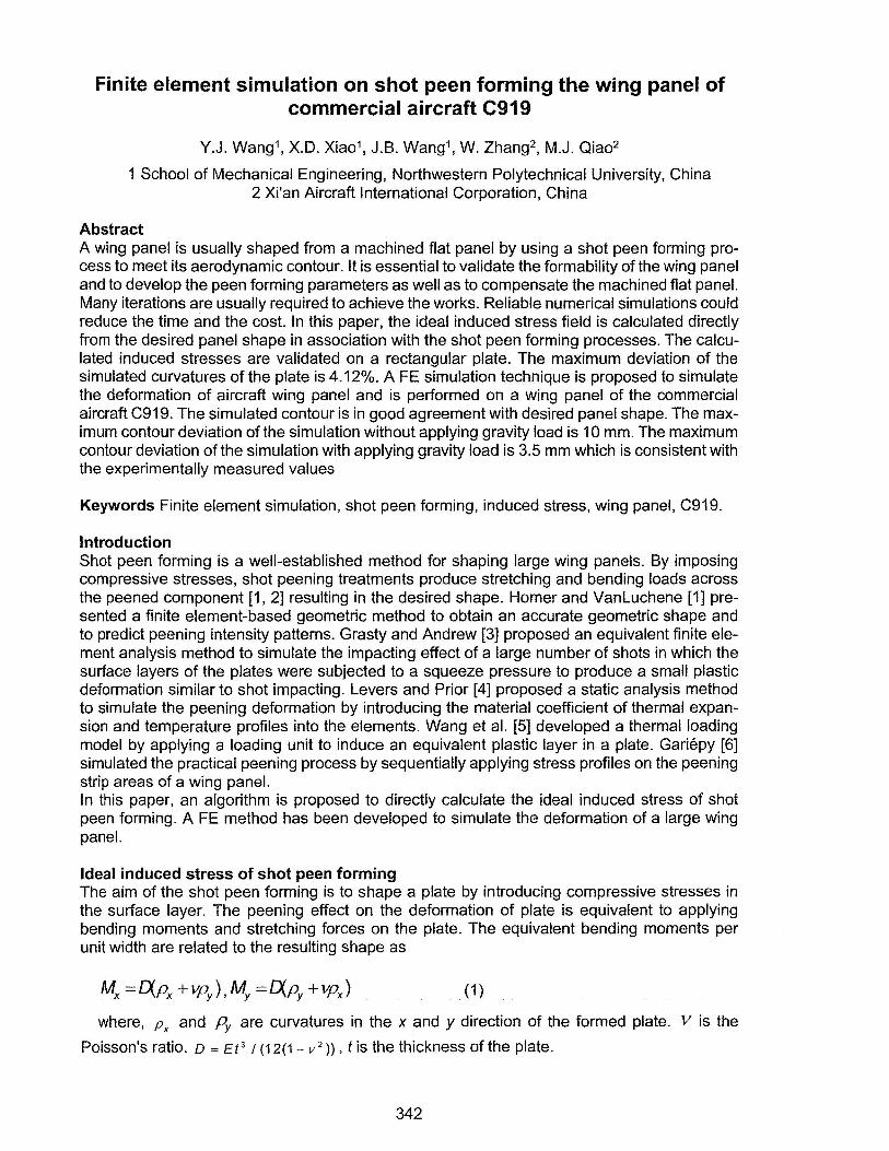
FE simulation on test plate To simulate the stress layers produced by shot peening, the composite element with three layers is used in the FE model, as shown in Fig. 2(a). Both outside layers, named the top layer and the bottom layer, are peening layers. The middle layer is the core material of the plate. A saddle shape is intended to form from a rectangle plate as shown in Fig. 2(b). The length of the plate is 1200 mm and the width 200 mm. The various thicknesses and curvatures of the tests are listed in Table 1. The thicknesses of both outer layers are assumed to be the same here and are proportional to the thickness of the plate. The thickness ratios (k) of the outer layer to the plate of the tests are listed in Table1. The deformation of the material of the plate is considered in the elastic range with elastic modulus 73 GPa and Poisson's ratio 0.33.
Bottom layer
(a) (b) Fig. 1. Schematic of (a) FE for shot peen forming and (b) test plate.
In the simulation processes, an optimized induced stress field is calculated from the desired shape. For convenient treatment, identical induced stresses are assumed in the outer layers. Then the induced stresses are given to the section points of the outer layers as the initial stresses of the FE model. The simulated contour is compared with the design shape along the x axis.
343
NO.
1 2
3-1 3-2 3-3
Table 1. Geometric parameters of test plate.
Px [x 1 Q-5] Py [x 10-5] t[mm]
-x/120+11 -5 10 5 x/60-25 10 5 -5 -x/120+15 5 -5 -x/120+15 5 -5 -x/120+15
12 ....---------------- 1.20E-04
10
8
E E6
4
2
Simulation shap >----Target shape ------- Fitting shape --- Target curvature
1.00E-04
8.00E-OScu ... :::,
6.00E-05~ :::,
4.00E-OSu
2.00E-05
------- Fitting curvature 0 ------------------"'- O.OOE+OO
0 400 800 1200 x,mm
(a) (b)
k [%]
5 5 3 5 7
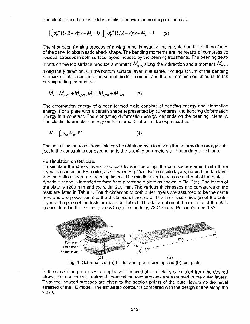
Fig. 2. Comparison of the simulated contour and the curvature along the x axis with the target contour and the curvature when the Px is changing along the x axis.
10
9 8
7
E6 ES N' 4
3
2
1
0
...---------------....... 5.0SE-05
.,. .. .,. .. , .. "'*,,,.,""-·• ,.,
...... ,; ... "' Simulation shape ........ .., Target shape
............... ------- Fitting shape ---Target curvature ------- Fitting curvature
4.95E-05 ! :::,
4.90E-05 ~ :I
4.8SE-05 u
4.80E-05
.;J:.-----....------.------+ 4.75E-05
0 400 800 1200 x,mm
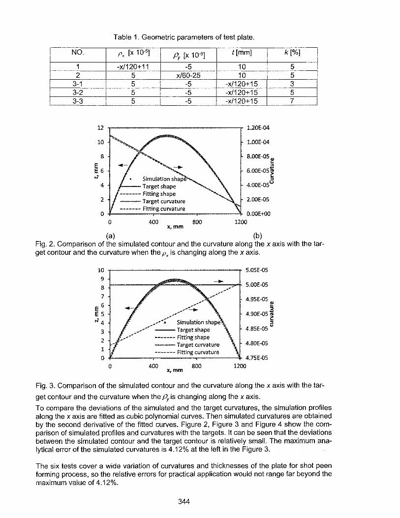
Fig. 3. Comparison of the simulated contour and the curvature along the x axis with the tar
get contour and the curvature when the Py is changing along the x axis.
To compare the deviations of the simulated and the target curvatures, the simulation profiles along the x axis are fitted as cubic polynomial curves. Then simulated curvatures are obtained by the second derivative of the fitted curves. Figure 2, Figure 3 and Figure 4 show the comparison of simulated profiles and curvatures with the targets. It can be seen that the deviations between the simulated contour and the target contour is relatively small. The maximum analytical error of the simulated curvatures is 4.12% at the left in the Figure 3.
The six tests cover a wide variation of curvatures and thicknesses of the plate for shot peen forming process, so the relative errors for practical application would not range far beyond the maximum value of 4.12%.
344
10
8
eG E N' 4
2
0
0 400 x,mm
---Target shape ------- Fitting shape 2 --Target curvature ------- Fitting curvature 2
S.OSE·OS
-.,... S.OOE-05
QJ
4.9SE·OS 5 ... "' ~ 4.90E-05:,
4.85E·OS
4.80E-OS
800 1200
- - - Fitting shape 1 · - · - Fitting shape 3
- - - Fitting curvature 1 - · - · - Fitting curvature 3
v
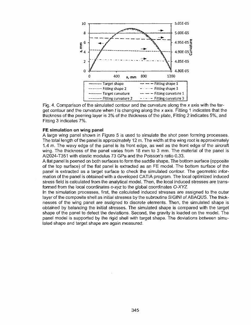
Fig. 4. Comparison of the simulated contour and the curvature along the x axis with the target contour and the curvature when tis changing along the x axis. Fitting 1 indicates that the thickness of the peening layer is 3% of the thickness of the plate, Fitting 2 indicates 5%, and Fitting 3 indicates 7%.
FE simulation on wing panel A large wing panel shown in Figure 5 is used to simulate the shot peen forming processes. The total length of the panel is approximately 12 m. The width at the wing root is approximately 1.4 m. The wavy edge of the panel is its front edge, as well as the front edge of the aircraft wing. The thickness of the panel varies from 18 mm to 3 mm. The material of the panel is Al2024-T351 with elastic modulus 73 GPa and the Poisson's ratio 0.33. A flat panel is peened on both surfaces to form the saddle shape. The bottom surface (opposite of the top surface) of the flat panel is extracted as an FE model. The bottom surface of the panel is extracted as a target surface to check the simulated contour. The geometric information of the panel is obtained with a developed CATIA program. The local optimized induced stress field is calculated from the analytical model. Then, the local induced stresses are transformed from the local coordinates o-xyz to the global coordinates 0-XYZ. In the simulation processes, first, the calculated induced stresses are assigned to the outer layer of the composite shell as initial stresses by the subroutine SIGINI of ABAQUS. The thicknesses of the wing panel are assigned to discrete elements. Then, the simulated shape is obtained by balancing the initial stresses. The simulated shape is compared with the target shape of the panel to detect the deviations. Second, the gravity is loaded on the model. The panel model is supported by the rigid shell with target shape. The deviations between simulated shape and target shape are again measured.
345
""4
y 1---·,--! (.... 1.4m i } ----------...; ' 1
Back edge
FE model
Target surface
Front edge
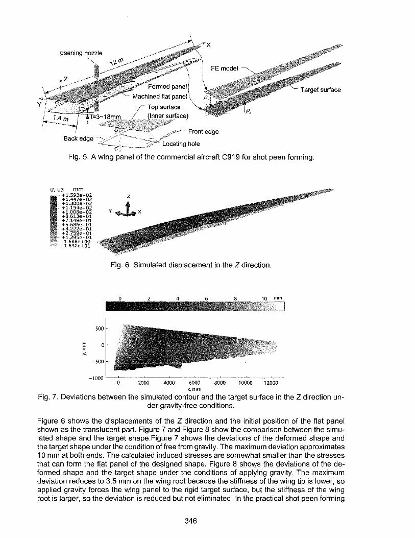
Fig. 5. A wing panel of the commercial aircraft C919 for shot peen forming.
u, u3 mm +1.593e+02 +1.447e+02 +l.300e+02 +l.154e+02 +l.008e+02 +8.613e+01 +7.149e+Ol +5.686e+Ol +4.222e+01 +2.759e+Ol +1.295e+Ol ·1.688e+OO -1.632e+Ol
500
E O E >.
-500
Fig. 6. Simulated displacement in the Z direction.
0 2 4 6 mm -0 2000 4000 6000 8000 10000 12000
x,mm
Fig. 7. Deviations between the simulated contour and the target surface in the Z direction un-der gravity-free conditions.
Figure 6 shows the displacements of the Z direction and the initial position of the flat panel shown as the translucent part. Figure 7 and Figure 8 show the comparison between the simulated shape and the target shape.Figure 7 shows the deviations of the deformed shape and the target shape under the condition of free from gravity. The maximum deviation approximates 10 mm at both ends. The calculated induced stresses are somewhat smaller than the stresses that can form the flat panel of the designed shape. Figure 8 shows the deviations of the deformed shape and the target shape under the conditions of applying gravity. The maximum deviation reduces to 3.5 mm on the wing root because the stiffness of the wing tip is lower, so applied gravity forces the wing panel to the rigid target surface, but the stiffness of the wing root is larger, so the deviation is reduced but not eliminated. In the practical shot peen forming
346
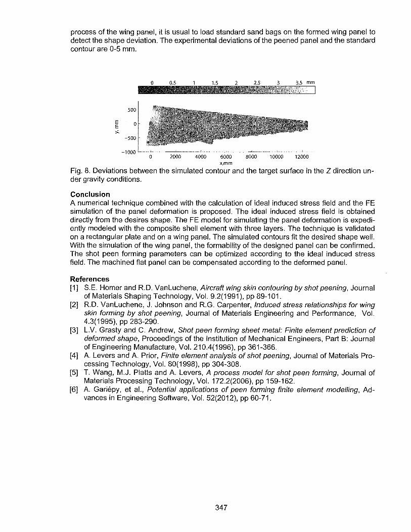
process of the wing panel, it is usual to load standard sand bags on the formed wing panel to detect the shape deviation. The experimental deviations of the peened panel and the standard contour are 0-5 mm.
mm
500
E 0 E >.
-500
-1000 0 2000 4000 6000 8000 10000 12000
x,mm
Fig. 8. Deviations between the simulated contour and the target surface in the Z direction under gravity conditions.
Conclusion A numerical technique combined with the calculation of ideal induced stress field and the FE simulation of the panel deformation is proposed. The ideal induced stress field is obtained directly from the desires shape. The FE model for simulating the panel deformation is expediently modeled with the composite shell element with three layers. The technique is validated on a rectangular plate and on a wing panel. The simulated contours fit the desired shape well. With the simulation of the wing panel, the formability of the designed panel can be confirmed. The shot peen forming parameters can be optimized according to the ideal induced stress field. The machined flat panel can be compensated according to the deformed panel.
References [1] S.E. Homer and R.D. VanLuchene, Aircraft wing skin contouring by shot peening, Journal
of Materials Shaping Technology, Vol. 9.2(1991 ), pp 89-101. [2] R.D. VanLuchene, J. Johnson and R.G. Carpenter, Induced stress relationships for wing
skin forming by shot peening, Journal of Materials Engineering and Performance, Vol. 4.3(1995), pp 283-290.
[3] L.V. Grasty and C. Andrew, Shot peen forming sheet metal: Finite element prediction of deformed shape, Proceedings of the Institution of Mechanical Engineers, Part B: Journal of Engineering Manufacture, Vol. 210.4(1996), pp 361-366.
[4] A. Levers and A. Prior, Finite element analysis of shot peening, Journal of Materials Processing Technology, Vol. 80(1998), pp 304-308.
[5] T. Wang, M.J. Platts and A. Levers, A process model for shot peen forming, Journal of Materials Processing Technology, Vol. 172.2(2006), pp 159-162.
[6] A. Gariepy, et al., Potential applications of peen forming finite element modelling, Advances in Engineering Software, Vol. 52(2012), pp 60-71.
347