finite element modeling of failure in steel moment ... · finite element modeling of failure in...
TRANSCRIPT

Finite element modeling of failure in steel moment connection subjected to ultra-low cycle fatigue loading
Milad Afzalan1) and *Mehdi Ghassemieh2)
1), 2) School of Civil Engineering, University of Tehran, Tehran, Iran 2) [email protected]
ABSTRACT Following the Northridge earthquake in 1994, widespread damage including brittle cracking was observed in steel structural components; and by that time, the attention of researchers has been shifted towards development of improved connection details to make them less prone to brittle fracture. However, studies have shown that these post-Northridge connections with higher toughness weld and base metal and reduced fracture toughness can still have the tendency to fracture but in a ductile manner. This paper aims to simulate ductile fracture in a steel moment connection subjected to large amplitude cyclic loading with limited number of cycles (less than 20). Location of crack initiation is predicted by a micromechanical model called cyclic void growth model, and crack propagation is simulated in a step-by-step procedure. The aforementioned model was firstly developed for predicting crack initiation under cyclic loading based on the concept of nucleation, growth and coalescence of voids in the metal matrix. The method has been conducted within the framework of nonlinear finite element analysis on many cyclic loadings for a beam-to-column connection, and the number of cycles which leads to final fracture is presented. Results obtained from numerical analysis successfully determine the cracking location in the steel moment connection and its propagation path. 1. INTRODUCTION In 1994, Northridge earthquake caused severe damage to steel moment-frame, and much of the damage was appeared in a brittle manner and concentrated in the beam-column moment-resisting connections at the face of the column (Kaufmann et al. 1997). Shortly after the earthquake, a joint venture known as SAC began their studies to develop new design approaches to minimize the damage to steel moment-frame buildings in
1)
Graduate Student 2)
Professor
ensuing earthquakes. These investigations led to the development of improved connection details which were less prone to brittle fracture. In these post-Northridge connections, although a more ductile behavior is provided, they can still fracture when they experience ultra-low cycle fatigue, ULCF, during an earthquake which typically involves less than 20 cycles of large plastic strain (Kim et al. 2000). As the post-Northridge connections experience ultra-low cycle fatigue, failure occurs in the form of initiation and propagation of crack with large deformations in the connection zone. In ULCF, since large scale yielding occurs in structural components, traditional fracture mechanics methods such as stress intensity factor (K) and J-integral are not practical for evaluating the fracture anymore. Hence, in order to study the behavior of structural steel under such phenomenon, several methods for predicting the initiation of cracks have been proposed. Among them, cyclic void growth model (Kanvinde et al. 2007), CVGM, predicts the initiation of fracture based on the mechanism of nucleation, growth, and coalescence of voids. According to CVGM, when a specific criterion is met over the characteristic length of an element, the fracture initiates. Huang (2010), and Amiri et al. (2013) were among the recent researchers who investigated the crack propagation during cyclic loading in steel structures within the framework of continuum damage mechanics. Amiri et al. (2013) took advantage of underlying principle of CVGM to propose a method for propagation of crack in ULCF. Based on their approach, a macro-crack can be discretized to micro-cracks formed in consecutive steps when the CVGM criterion is satisfied over each element. In this paper, the applicability of this numerical method for predicting the fracture of steel moment connection subjected to cyclic loading has been demonstrated in a beam-column analysis whose results compares well with the experimental test.
2. CYCLIC VOID GROWTH MODEL This section provides an overview of cyclic void growth model, CVGM, introduced by Kanvinde et al. (2007). This micromechanical model is employed to simulate ductile cracking in the ultra-low cycle fatigue regime. The ultra-low cycle fatigue requires extremely large plastic strains and few number of cycles which results in ductile cracking in structural steel. The process of ductile fracture in steel is caused by nucleation, growth, and coalescence of voids in the metal matrix. According to CVGM, ductile cracking is predicted to initiate when the equation below is satisfied over the characteristic length of
*l .
cyclic cyclic
criticalVGI VGI (1)
Here, CyclicVGI is the cyclic void growth index and is as follows:
2 2
1 1
exp( 1.5 ). exp( 1.5 ).cyclic
p p
tensile cycles compressive cycles
VGI T d T d
(2)

where pd is the differential increment of the equivalent plastic strain, 1 and 2 are the limits of the integration corresponding to the beginning and end of each cycle, and T , stress triaxiality ratio, is as follows:
m
e
T (3)
in which m is the mean stress and e is the von Mises stress. Cyclic
CriticalVGI , the right side of Eq. (1), is the critical cyclic void growth index and is defined as follows:
exp( ) critical critical
cyclic monotonic pVGI VGI (4)
In the above equation, critical
monotonicVGI and are material dependent parameter calibrated by tests. critical
monotonicVGI is determined by tension tests of notched bar specimens in monotonic loading and is calibrated through cyclic tests of notched bar specimens. The value of
demonstrates the sensitivity of the material to cyclic loading; therefore, the term
pexp( ) takes the effect of capacity degradation in cyclic loading into account. Using the Eq. (1), the fracture index, FI, can be defined at any arbitrary point of the model during the loading history
cyclic
cyclic
critical
VGIFI
VGI (5)
When the value of Eq. (5) reaches the unity, the damage initiates at the corresponding integration point. 3. FINITE ELEMENT MODELING OF FRACTURE As discussed earlier, based on CVGM, during ULCF in steel material, damage initiates when Eq. (1) is met over an element with the characteristic length of *l . Thereafter, when cracking occurs in an element, adjacent elements become more vulnerable to damage initiation and the process of cracking expedites for them as a redistribution in stress and strain happens in the vicinity of cracking zone. Amiri et al. (2013) adopted this approach to model cracking in consecutive steps. They assumed that a macro-crack can be formed to smaller cracks if the length of element is equal to l . It must be noted that an element is considered fully cracked after two steps: 1. the fracture index reaches unity, i.e. damage initiation occurs. 2. Hereafter, the material degrades until it loses its bearing capacity (damage evolution). In order to implement this method, ABAQUS general purpose finite element software is employed. A USDFLD Fortran subroutine, based on UVARM subroutine written by

Myers (2009), is developed to calculate CVGM fracture index at each integration point. When this criteria is satisfied, damage evolves at the corresponding point based on displacement till it reaches a predefined critical value. Finally, the element containing that integration point is considered fully cracked and removed from the model. The following procedure can be summarized in the algorithm demonstrated in Fig. 1.
Fig. 1 Algorithm of numerical approach
4. NUMERICAL MODELING OF THE SPECIMEN A three dimensional finite element model of the RC03 connection tested in Pacific Earthquake Engineering Research Center (Kim et al. 2000) has been considered to assess the applicability of the numerical approach in this paper. The connection considered was a cover plate connection made of a w30x99 (A36 steel) beam connected to a w14x176 (Grade 50) column. Continuity plates were located on both sides of the column web, and 10 mm doubler plates were added to strengthen the panel zone. Fig. 2 illustrates the connection test setup and its details. For all materials, Young’s modulus is set equal to 200GPa, and Poisson’s ratio is set equal to 0.3. A tri-linear stress-strain relationship was used for all the structural components, and their material properties are presented in Table1. Material parameters of CVGM, critical
monotonicVGI and , are taken as 2.6 and 1 respectively (Myers 2009). Finally, the critical equivalent plastic displacement for damage evolution has been set to the value suggested by Lequesne (2009).

Fig. 2 Test setup (Kim et al. 2000) (a) Connection configuration (b) Connection details
The finite element model consists of linear elements that utilize reduced integration (C3D8R) with enhanced hourglass control. All welds including groove and fillet welds are modelled by imposing tie constraints between nodes. Since it is extremely time-consuming to consider the characteristic length for elements in the entire model, only the critical zone in which the crack is observed in experimental test is modeled with fine mesh. Fig. 3 represents the finite element model of this study and the mesh refinement at the critical region.
Fig. 3 Finite element mesh
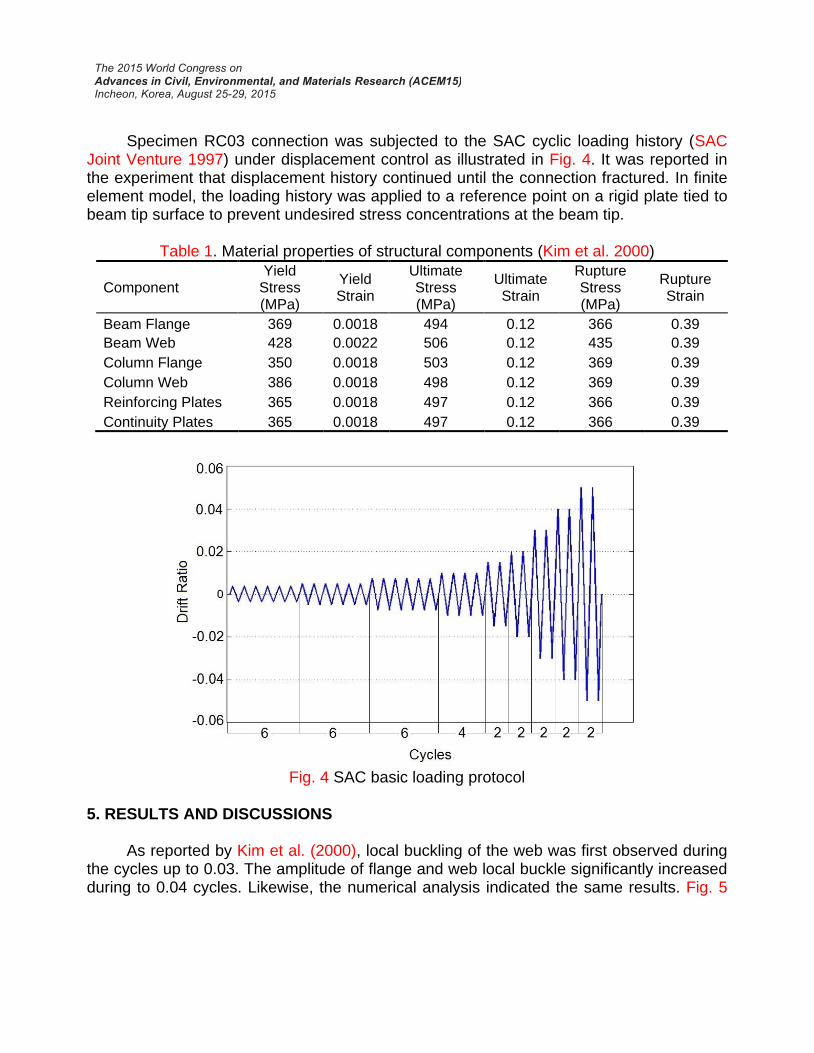
Specimen RC03 connection was subjected to the SAC cyclic loading history (SAC Joint Venture 1997) under displacement control as illustrated in Fig. 4. It was reported in the experiment that displacement history continued until the connection fractured. In finite element model, the loading history was applied to a reference point on a rigid plate tied to beam tip surface to prevent undesired stress concentrations at the beam tip.
Table 1. Material properties of structural components (Kim et al. 2000)
Component Yield
Stress (MPa)
Yield Strain
Ultimate Stress (MPa)
Ultimate Strain
Rupture Stress (MPa)
Rupture Strain
Beam Flange 369 0.0018 494 0.12 366 0.39
Beam Web 428 0.0022 506 0.12 435 0.39
Column Flange 350 0.0018 503 0.12 369 0.39
Column Web 386 0.0018 498 0.12 369 0.39
Reinforcing Plates 365 0.0018 497 0.12 366 0.39
Continuity Plates 365 0.0018 497 0.12 366 0.39
Fig. 4 SAC basic loading protocol
5. RESULTS AND DISCUSSIONS As reported by Kim et al. (2000), local buckling of the web was first observed during the cycles up to 0.03. The amplitude of flange and web local buckle significantly increased during to 0.04 cycles. Likewise, the numerical analysis indicated the same results. Fig. 5

compares the experimental and numerically calculated load-drift ratio hysteretic curve of the specimen.
Fig. 5 Hysteretic curve (a) FEM (b) Test (Kim et al. 2000)
As mentioned before, CVGM is applied to evaluate fracture in the connection zone. Based on the test (Kim et al. 2000), the crack initiates during the cycles up to 0.04 (However, the exact cycle number was not reported in the experiment). Numerical analysis has shown that a crack initiates at the bottom flange k-line during the first negative cycle of 0.04. Therefore, CVGM successfully determines the cracking instance and its site formation. FEM analysis showed that the crack continued to grow along bottom flange k-line for a few millimeters and then propagated in a direction perpendicular to the longitudinal axis of the beam. It is noteworthy to mention that FEM result demonstrates that the cracking in the bottom flange expedites during tensile cycles due to void growth. According to the experiment, final fracture of the beam bottom flange happened during second negative displacement excursion to 0.05 which was a result of severe flange and web local buckling. The FEM analysis, however, was carried out to the second negative cycle of 0.04 since severe convergence problems occurred due to crack closure. Although the analysis was terminated two cycles before the actual failure reported by the experiment, the fracture index contour suggests that fracture was likely to happen at the experimentally reported time if the analysis was continued. Fig. 6 compares the numerical and experimental fracture of RC03 connection.

Fig. 6 Fracture path (a) FEM (b) Test (Kim et al. 2000)
In order to evaluate the CVGM fracture index at the crack path till eventual failure, another analysis was conducted without including the fracture phenomenon. This analysis was performed solely for the purpose of detecting potential cracking locations, the accuracy of determining failure instance, and effectively reducing the computational costs. Therefore, neither element removal nor material degradation was considered. Our observations imply that fracture index in elements near the end of bottom flange exceeds the unity at the second negative cycle of 0.05h as depicted in Fig.7 (c), and this, is in agreement with the empirical result. Fig. 7 demonstrates the damage status at three different stages of SAC loading history. Elements whose fracture index in their corresponding integration points has surpassed unity are shown with red color.
Fig. 7 Comparison of fracture index (a) 2nd cycle of 0.04 (b) 1st cycle of 0.05 (c) 2nd cycle of
0.05
To find a better understanding of failure criterion, plots of cyclicVGI and critical
cyclicVGI for the points that relate to crack initiation and final failure are illustrated in Fig. 8. The value of

cyclicVGI increases and decreases based upon the sign of triaxiality, and the quantity of critical
cyclicVGI decreases based on the accumulation of plastic strain at the beginning of each tensile excursion of loading. In Fig. 8, the intersection of two plots predicts the failure point.
Fig. 8 Evolution of CVGM demand and capacity (a) Crack initiation (b) Final failure
6. CONCLUSIONS In this paper, cyclic void growth model has been applied to predict the crack initiation and subsequent fracture in a steel moment connection subjected to high amplitude loading with few number of cycles. To assess the applicability of this micromechanical model, a finite element model of a connection previously tested is simulated with ABAQUS. A FE code is utilized to simulate the behavior of cracking within the context of continuum damage mechanics during ultra-low cycle fatigue. It has been observed that CVGM successfully determines the crack initiation. Hereafter, crack propagation is modeled halfway through beam bottom flange by removing totally damaged elements. The result is reasonably consistent with experimental test. Furthermore, another analysis was conducted to evaluate fracture index at different points without taking the effect of material degradation into account. The numerical results were then compared with those of the test, and they were acceptable in terms of fracture path and instance of failure. As the final remark, cyclic void growth model acts as a strong numerical tool for predicting fracture in the specimen considered in this study. REFERENCES Amiri, H.R., Aghakouchak, A.A., Shahbeyk, S. and Engelhardt, M.D. (2013), “Finite
element simulation of ultra low cycle fatigue cracking in steel structures” Journal of Constructional Steel Research 89, 175-184.
Huang, H. (2009), “Simulating the inelastic seismic behavior of steel braced frame of including the effect of low-cycle fatigue” PhD thesis. University of California, Berkeley.

Kanvinde, A.M. and Deierlein,G.G. (2007),“Cyclic void growth model to assess ductile fracture initiation in structural steels due to ultra low cycle fatigue” J. Eng. Mech., ASCE, 133(6),701–712.
Kaufmann, E. J., Fisher, J. W., Di Julio Jr., R.M. and Gross, J. L. (1997), “Failure analysis of welded steel moment frames damaged in the Northridge earthquake,” NISTIR 5944, National Institute of Standards and Technology, Gaithersburg, Maryland.
Kim, T., Whittaker, A.S., Gilani, A.S.J., Bertero, V.V. and Takhirov, S.M. (2000), “Cover-plate and flange-plate reinforced steel moment-resisting connections” Pacific Earthquake Engineering Research Center, California.
Lequesne, C. (2009). “Modeling of fracture in heavy steel welded beam-to-column connection submitted to cyclic loading by finite elements” PhD thesis. University of Liege
Myers, A., Deierlein, GG. and Kanvinde, A.M. (2009), “Testing and probabilistic simulation of ductile fracture initiation in structural steel components and weldments”, Technical report No.170, Stanford University.
Peter Clark. (1997), “Protocol for fabrication, inspection, testing, and documentation of beam-column connection tests and other experimental specimens” Report No. SAC/BD-97/02. SAC Joint Venture.