finite-element computer program
TRANSCRIPT

NASA TECHNICAL NOTE
Z
Z
NASA TN D-8483
FINITE-ELEMENT COMPUTER PROGRAM
FOR AXISYMMETRIC LOADING SITUATIONS
WHERE COMPONENTS MAY HAVE
A RELATIVE INTERFERENCE FIT
Christopher M. Taylor
Lewis Research Center
Cleveland, Ohio 44135
NATIONAL AERONAUTICS AND SPACE ADMINISTRATION - WASHINGTON, D. C. • MAY 1977


1. Report No. 2. Government Accession No.
NASATN D-84834.
12.
Title and Subtitle
FINITE-ELEMENT C(_PUTER PROGRAM FOR AXIS"IM-
METRIC LOADING SITUATIONS WHERE COMPONENTS
MAY HAVE A RELATIVE INTERFERENCE FIT
Author(s)
Christopher M. Taylor
Performing Organization Name and Address
Lewis Research Center
National Aeronautics and Space Administration
Cleveland, Ohio 44135
Sponsoring Agency Name and Address
National Aeronautics and Space Administration
Washington, D.C. 20546
8,
10.
11.
13.
14.
3. Recipient's Catalog No.
5. Report Date
May 1977
6. Performing Organization Code-
Performing Organization Report No.
E-9018
Work Unit No.
505-04
Contract or Grant No,
Type of Report and Period Covered
Technical Note
Sponsoring Agency Code
5. Supplementary Notes
16. Abstract
A finite-element computer program which enables the analysis of distortions and stresses
occurring in components having a relative interference is presented. The program is limited
to situations in which the loading is axisymmetric. As well as loads arising from the inter-
ference fit(s), external, inertial, and thermal loadings can be accommodated. The components
may comprise several different homogeneous isotropic materials whose properties may be a
function of temperature. An example illustrating the data input and program output is given.
17. Key Words (Suggested by Author(s)}
Interference, finite-element, computer
programs, axisymmetric bodies
18. Distribution Statement
Unclassified - unlimited
STAR Category 37
19. Security Classif. (of this report)
Unclassified
20. Security Ctassif, (of this page} 21. No. of Pages
Unclassified 48
22. Price"
A03
i " Forsale by the NationalTechnical InformationService,Springfield,Vi[ginia 22161


FINITE-ELEMENTCOMPUTER PROGRAM FOR AXISYMMETRIC LOADING
SITUATIONS WHERECOMPONENTSMAY HAVE A
RELATIVE INTERFERENCEFIT
by Christopher M. Taylor*
Lewis Research Center
SUMMARY
This finite-element computer program permits the analysis of axisymmetrically
loaded components having a relative interference fit. External, inertial, and thermal
-_ loads may be applied in addition to forces arising from an interference condition. The
components under investigation may comprise different homogeneous lsotropic materials
whose properties may be temperature dependent. The theoretical background to the anal-
ysis of the interference condition is described, and the computer program structure out-
lined briefly. Particular attention is paid to the program input requirements and the out-
put. The output comprises the input information, nodal distortions, element stresses,
! and details of the interference contact conditions. The running of multiple cases, with
i one or a number of different geometries, is possible. An example to illustrate the data
input and program output is presented.
INTRODUCTION
The ability of the engineer to undertake the analysis of deformations and stresses
occurring in the structures and components with which he deals has changed remarkably
in the last 15 years. The development of finite-element approximation techniques, cou-
pled with the widespread availability of digital computers, has paved the way for detailed
examination of the behavior of loaded structures and machine parts of quite complex
geometry. Numerous computer programs have been developed by workers in industry,
*Lecturer in Mechanical Engineering, University of Leeds, Leeds, England;
National Research Council -National Aeronautics and Space Administration Senior
Research Associate at the Lewis Research Center in 1976-1977.

research organizations, andinstitutions of higher education using the finite-element
technique. Some of the more recently developed programs enable the study of situations
in which three-dimensional loading pertains. Work to improve the accuracy of predic-
tion in such situations, whilst most efficiently employing the facilities of the digital com-
puter, progresses currently.
The program described here restricts itself to simple elements and axisymmetric
loading situations. Unlike most finite-element programs, however, it can undertake a
direct analysis of components that have relative interference. It is a frequent engineer-
ing practice to mate or prestress parts using shrink or press-fitting techniques. The
analysis of such situations has, in general, been limited to axially invariant axisymmet-
tic situations using, for example, the solution for a cylinder subjected to uniform inter-
nal or external pressure due to Lam6 (ref. 1).
Wilson and Parsons (ref. 1) have described the approach adopted here to enable the so-
lution of problems in which statically indeterminate conditions occur as a result of inter-
ference fits. They term the technique "differential displacements. " It enables one node
in a finite-element mesh to be displaced by a specified amount relative to another without
having to know how the two nodes move in relation to some fixed coordinate system.
Since the finite elementry used in the computer program developed is quite conven-
tional, the details are not dwelt upon. A number of texts (e. g., ref. 2) may be consulted
for background information. The differential displacements approach and its incorpora-
tion into solution schemes for systems of equations is described. The computer program
is presented as an appendix. As with many finite-element programs, it is long and its
details are not discussed; its broad structure is, however, described. Fuller attention
• is paid to the input data for the program and the output to enable its easy use. An ex-
ample of the inner ring of a roller bearing shrunk or press fitted onto a shaft is pre-
sented. The purpose of this example is not to highlight the technical aspects of the sit-
uation, but rather to give examples of the input and output.
The computer program presented uses some coding developed by Dr. B. Parsons,
Reader in Mechanical Engineering, University of Leeds, England, whose encouragement
and support are gratefully acknowledged.
SOME ASPECTS OF THE ANALYSIS
The finite-element types, designated 1, 2, and 0, that have been incorporated into
the program are shown in figure 1. The geometrical restrictions of each elemen£ form
are indicated. A linear displacement model within the elements was assumed, enabling
the stiffness characteristics in matrix form to be determined by analytic integration of
the strain energy integrals. The unknowns are normally node displacements in the

radial and axial directions. Where a node displacement or a coordinate direction is pre-
scribed, an unknown force results. The general equation enabling nodal distortions to be
determined is
[K]{U} = {F}(1)
where [K] is the overall stiffness matrix of the structure, { U} is the vector of nodal
displacements, and { F } is the vector of nodal forces. The solution of the system of
equations (1) may be achieved by many schemes. Direct methods of solution are now al-
most universally employed for solid mechanics problems, the method used here being
that of Crout (ref. 3).
If it is known that two nodes in a finite-element structure have an effective pre-
scribed movement relative to each other (obviously an interference), it is cumbersome
with conventional finite elementry to analyze the situation. An influence coefficient ap-
proach can be adopted (e.g., ref. 4), but to use the differential displacement approach is
more direct and less specific.
For example, consider, for convenience, consecutively numbered nodes 1, 2, 3,
and 4 where it is known that nodes 2 and 3 have an interference { 6}. With due regard
for sign we may write,
{U3} = {U2} + {5}(2)
and
{F2} = {F_} - {F 6}
{F3} = {F_} + {F 6}
(3)
where { F 2 } and { F_ } are node forces due to external, inertial, and thermal loadings
and { F6} is the interference force due to the differential displacement { 6 } and is
unknown.
Thus the equation of the form of :(1) for the nodes may be adapted to
[K].
U 1
U2
U 2 + 6!
U 4
" F1 "
F_ - F 6
F_ +F 6
<. F4 J
(4)

Equation (4) can be reduced to give
FKA] 2 = +F' -
L.u4) F 4 J
(5)
Having made this reduction, the set of equations (5) can now be solved for the unknown
displacements, all other quantities being calculable. After the determination of the dis-
placements, the set of equations (4) may be used to calculate the nodal forces due to in-
terference {F6}.
The differential displacements technique, already described in terms of four con-
secutively numbered nodes, two of wMch have relative interference, is amenable to pro-
gramming on a digital computer for large systems of equations. Nodes having inter-
ference need not be numbered consecutively. The example presented in the report shows
how the geometry of interferring nodes is described.
THE COMPUTER PROGRAM
The program listing is presented in appendix A. The program is written in Fortran
and has been developed on a Univac 1100 machine with a Fortran V compiler. In appen-
dix B the structure of the program is briefly described. To facilitate the use of the pro-
gram, detailed attention will now be given to the required input and output.
Input Data
The required card input will be listed in sequence with comments on limitations.
Some general remarks will first be made. Where detailed elucidation on some aspect of
the input data is needed, this appears in appendix C.
The coordinate system adopted is shown in figure 2. For elements of types 1 and 0
the axial node positions (which are relative to node i) should be in accord with the sign
convention of figure 2 (i. e., values to the left of node i being negative).
Any consistent set of units may be employed. The program output does not detail
any units, but those actually employed could be indicated in the title.
The program arrangement permits multiple cases on one run with the same geom-
etry but varying operating conditions, for example, loading or speed. In addition
4

different geometries maybe examinedon the samerun, though this is a less likely
requirement.
The input requirements of finite-element computer programs are usually demanding
in terms of punching of data. To simplify this aspect with the present program, it has
been assumed that the most likely situation is that a single material (termed the 'q_ase"
material) will be involved or will dominate. Other materials (termed "special"), un-
limited in number, may be used in addition to the base material. However, when many
special materials are used, the preparation of data cards will be disproportionately
more time consuming than for a single material case.
The program includes a consideration of external, inertial, and thermal loadings.
Material properties may be a function of temperature. The temperature distribution is
an input requirement.
The limitations on the magnitude of certain variables indicated in the required input
relate to the dimensioning of arrays. Alterations may be made as indicated in appen-
dix C, where the storage requirement needed for operation on a Univac ll00 computer
is also given.
It should also be noted that axisymmetric loading problems in which no interference
fit occurs can also be treated with the program. The program variable for a parameter,
on read-in, is indicated in brackets after its verbal description.
CARD A format (I2)
I2 number of geometries considered
The remaining cards are repeated for each geometry.
gc)
CARD B A title of up to 80 characters, commencing with a blank
CARD C for mat (I2)
I2 number of different cases for geometry under consideration (NOC)
CARD D
I4
I4
14
I4
I4
I4
format (614)
number of elements
number of nodes (_200)
maximum nodal number difference in any element (:_19)
(See appendix C. )
number of special material elements
number of nodes constrained (_50)
number of nodes with external forces applied
(N)
(NW)
(NE)
(NCON)
(NFOR)

CARD E format (5E12.4)
E12.4 Poisson's ratio for base material (PROP (I))
El2.4 Young's modulus for base material (PROP (2))
E12.4 coefficientof expansion for base material (PROP (3))
E12.4 density of base material (PROP (4))
El2.4 reference temperature (<_0) (PROP (5))
If any of the first four properties read in on this card are to be functions of the fifth,
temperature, then any negative number should be placed in the appropriate format posi-
tion. The reference temperature is that temperature the elements will be assured to
take if the element temperature of CARD H is left blank. This reference temperature
may be zero, which implies no relative thermal expansion for the element; that is, if the
geometry read in is to suffer no thermal distortions, the reference temperature should
be zero and apply to every element.
CARD F format (F10.0)
F10.0 rotational speed (rpm)
CARDS G,H
CARD G format (614)
I4 element number
I4 type of element
I4 number of node i
I4 number of node j
I4 number of node k
I4 number of node L (0 for a triangle)
(w)
(L)
(NTYPE)
(NTRI (L,I))
(h'rRI (L,2))
(NTPJ (L,3))
(NTPJ (L,4))

CARD H format (6F10.0)
Element type
1 2 0
FIO. 0 ri r i r i (TRI (L, 1))
• (TRI (L, 2))FIO. 0 rj -rj r]
FI0.0 bj r k bj (TRI (L, 3))
FI0.0 b k r L b k (TRI (L, 4))
F10.0 b L b 0 (TRI (L, 5))
F10.0 Element temperature (40) (TRI (L, 6))
Figure 1 may be referred to for the meaning of symbols on cards G and H. If the ele-
ment temperature is to equal the reference temperature of card E, a blank space may be
left, otherwise the temperature of all elements must be indicated here. Note that if any
temperatures are to be zero then the reference temperature must also be zero.
Cards G and H are repeated, consecutively, for each element. For type 1 rectan-
gular elements only, element numbering need not be consecutive. In this case inter-
mediate elements will be generated automatically. The automatic generation defines
node numbers of elements by increasing the previous element values by unity; linear
interpolation is used to determine ri, rj, and element temperature; and bj, bk, and b Lremain fixed. The automatic generation may be applied in either coordinate direction.
CARD I format (I4, 4E12.4) Only read if number of special material elements (NE)
of card D is greater than zero
I4 number of special material element
E12.4 Poisson's ratio for special material
El2.4 Young's modulus for special material
El2.4 coefficient of expansion for special material
El2.4 density of special element
The properties should have a value appropriate to the element temperature of card E or
card H. Card I should be repeated "NE times" corresponding to the number of special
material elements.
(L)
(TRI (L, 7))
(TRI (L, 8))
(TRI (L, 9))
(TRI (L, 10))
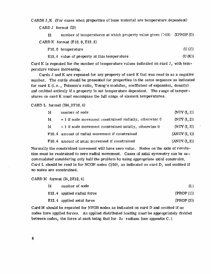
CARDSJ,K (For caseswhenproperties of base material are temperature dependent5
CARDJ format (I25
I2 number of temperatures at which property value given (_10) flPROP(I55
CARDK format (F10.0, E12.4)
F10.0 temperature
El2.4 value of property at this temperature
(u (JS)
(g (KS)
Card K is repeated for the number of temperature values indicated on card J, with tem-
perature values increasing.
Cards J and K are repeated for any property of card E that was read in as a negative
number. The cards should be presented for properties in the same sequence as indicated
for card E (i. e., Poisson's ratio, Young's modulus, coefficient of expansion, density5
and omitted entirely if a property is not temperature dependent. The range of temper-
atures on card K must encompass the full range of element temperatures.
CARD L format (314,2F 10.45
I4 number of node (NUV (I, 1))
I4 = 1 if node movement constrained radially, otherwise 0 (NUV (I, 2))
I4 = 1 if node movement constrained axially, otherwise 0 (NUV (I, 3))
F10.4 amount of radial movement if constrained (ANUV (I, 1)5
F10.4 amount of axial movement if constrained (ANUV (I, 2))
Normally the constrained movement will have zero value. Nodes on the axis of revolu-
tion must be restrained to zero radial movement. Cases of axial symmetry can be ac-
commodated considering only half the problem by using appropriate axial constraint.
Card L should be read in for NCON nodes (_50), as indicated on card D, and omitted if
no nodes are constrained.
CARD M format (I4, 2E12.4)
I4 number of node (L)
E12.4 applied radial force (PROP (155
El2.4 applied axial force (PROP (255
Card M should be repeated for NFOR nodes as indicated on card D and omitted if no
nodes have applied forces. An applied distributed loading must be appropriately divided
between nodes, the force at each being that for 2rr radians (see appendix C. )

CARDN format (I2)
I2 = 1 if there is any interference, otherwise 0 (IDD)
If card N reads in the value 0, the following course is adopted: if the number of
cases for the geometry under consideration is 1 (NOC of card C), then the data ter-
minate, unless another geometry is to be considered, in which case the card sequence
returns to card B and begins again. If there are (NOC - 1) cases for the same geometry
still to be dealt with, then the following cards should be read for each of these cases:
CARD F, CARD M, and CARD N. This sequence allows applied speed and load to be
varied. If card N should now take the value 1, then the case should proceed as below.
If card N reads in the value 1 (an interference fit), the following card sequence
should be adopted:
CARD O format (I5)
I5 number of node pairs with relative interference (NODD)
CARD P format (IX, I6, 5X, I6,5X, I6, Eli. 4, 5X,I6, Eli. 4)
I6 lower numbered node of a pair in interference (J)
I6 higher numbered node of a pair in interference (K)
I6 = 1 if radial interference, otherwise 0 (IR)
Eli. 4 amount of any radial interference (DR)
I6 = I if any axial interference, otherwise 0 (12)
Eli. 4 amount of any axial interference (D2)
Card P should be repeated for the NODD pairs of nodes indicated on card 0. The
sign of interference, radial or axial, should be in accord with the sign convention of fig-
ure 2, working from the lower to the higher numbered node. (See the example of ap-
pendix D. ) It will be convenient in interpreting the output to have all the higher num-
bered nodes of pairs in radial interference "nearer" the axis of revolution. This
scheme has been adopted in the development of the program and is recommended.
CARD Q format (I4)
I4 = 1 if radial interference pressures are to be calculated (IND)
If card Q reads in 1, then the pressure distribution at a fixed radial location where
interference occurs will be determined. Card Q may only be read in with a value of 1 if
all the nodes having interference are at the same radius and are axially adjacent. If
this card reads in 0, go to card T.

CARDR format (I4, E12.4)
I4 number of node pairs in interference (_50)
El2.4 constant radius of interference fit
CARD S format (I4, E12.4)
I4 number of the node in pair nearer the axis of revolution
El2.4 axial distance to next node in sequence
(NP)
(RAD)
Read in the node numbers nearer the axis of revolution in sequence, moving axially in
either direction. The axial distance between nodes should be kept positive. The pres-
sure distribution is the same for both components involved in the interference. The
value of axial distance to the next node for the last node is immaterial.
Card S should be repeated for the number of node pairs (NP) indicated in card R.
CARD T format (I2)
I2 = 0 if no axial slip to be allowed automatically at nodes with radial
interference, otherwise 1 (ISLP)
This card may only read in a value of 1 if it is permissible to do so with card Q. If card
T reads in a value of 0, the following card sequence should be adopted for remaining
cases with the same geometry: CARD F, CARDS L,M,N, et seq. Alternatively, if
there are no more cases for the particular geometry, the data sequence terminates or
returns to card B for a new geometry.
If card T reads in a value of 1, the following card should be inputted:
CARD U format (FS. 0)
FS. 0 coefficient of friction (COF)
See appendix C for an explanation of the slip calculations. After this card, the data
sequence should be the same as if card T had read in 0 (see above).
Although it is very convenient and saving in time to run multiple cases, particularly
with the same geometry, it will be seen that the data is accordingly complicated. It is
therefore recommended that new users of the program adopt single case runs initially.
The data card series will then be as in table I.
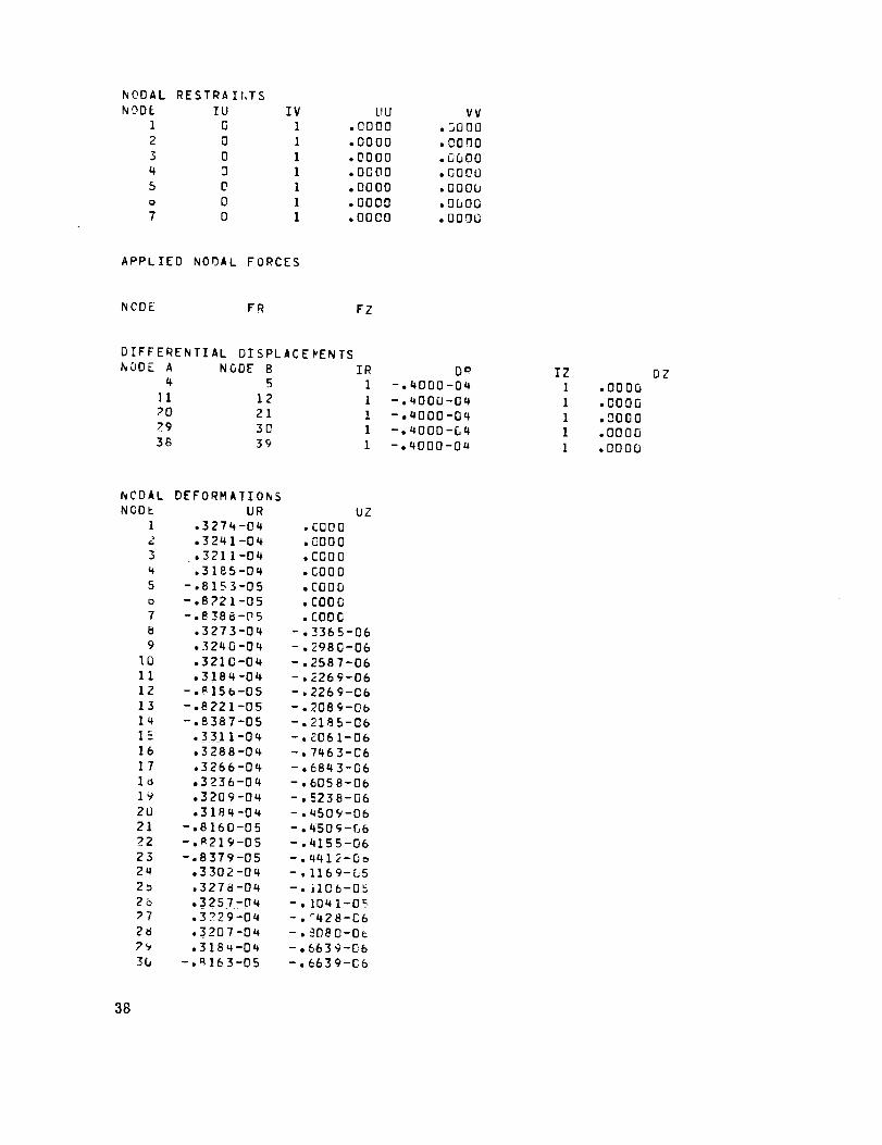
Output
The program output is virtually self-explanatory. An example is to be found in ap-
pendix D. As well as outputting calculated information, all the input data are also pre-
sented. Thus, the first part of the output gives the data fed to the program on cards B,
10

D throughM, and P, as appropriate. Calculations to set element temperatures andphysical properties are carried out on the basis of the aboveinput but details are not out-putted. In the caseof multiple runs with the samegeometry only the parameters whichcanbe changedare re-presented.
Results calculated by the program andpresented in the output are
(a) Nodal deformations
(b) Element stresses at the midpoint of the element. Stresses given are radial, tan-
gential, axial, and shear together with the coordinates of the element midpoint with re-
spect to node i. Positive stresses are tensile.
(c) If there is an interference fit, the forces due to this fit radially and axially acting
on the higher numbered of each node in the pairs involved. The sign of these forces is
opposite to the sign convention of figure 2. Thus in the example of appendix D, where all
the higher numbered nodes are nearer the axis of revolution, the positive radial forces
indicate that the two components are still entirely in interference. These forces are per
radian unlike the input forces, which are for an extent of 2n radians.
(d) If the option is so chosen, the pressure distribution at the position of radial in-
terference. Note that although the interference force output may indicate that all nodes
of an interference remain in contact, small negative interference pressures may some-
times occur. This is because of the assumption that the pressure varies linearly be-
tween nodes.
(e) If slip between nodes in radial interference is to be accommodated automatically,
the coefficient of friction and details of which nodes are allowed to slip on each cycle.
On completion of slip the final nodal deformations and element stresses are given.
C ONC LUDING R EM ARKS
A finite-element computer program that can directly analyze the behavior of axisym-
metrically loaded components having an interference fit has been described. External,
inertial, and thermal loads can be accommodated as well as loading due to the interfer-
ence fit. In addition components constructed of a number of materials, the physical
properties of which may be temperature dependent, can be dealt with. The program code
is presented together with an example data input and program output.
Lewis Research Center,
National Aeronautics and Space Administration,
Cleveland, Ohio, February 15, 1977,
505 -04
11

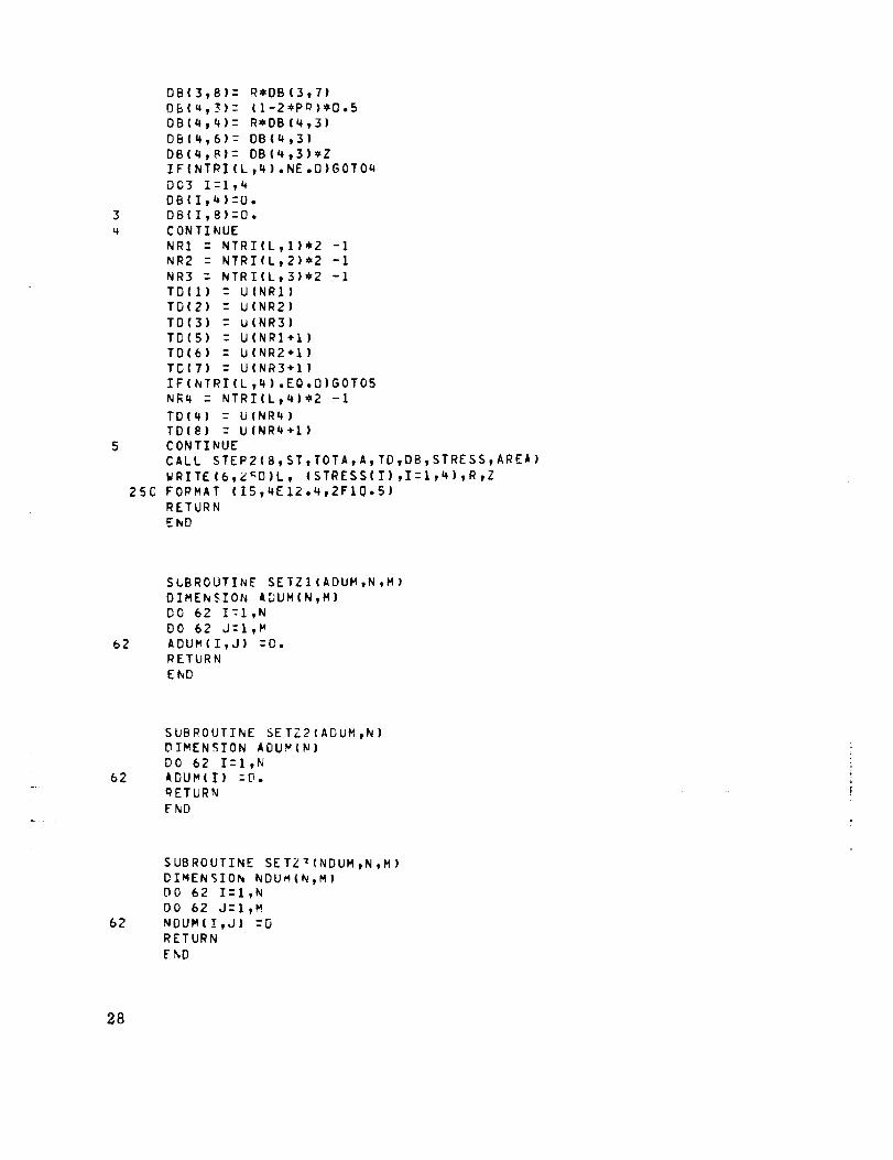
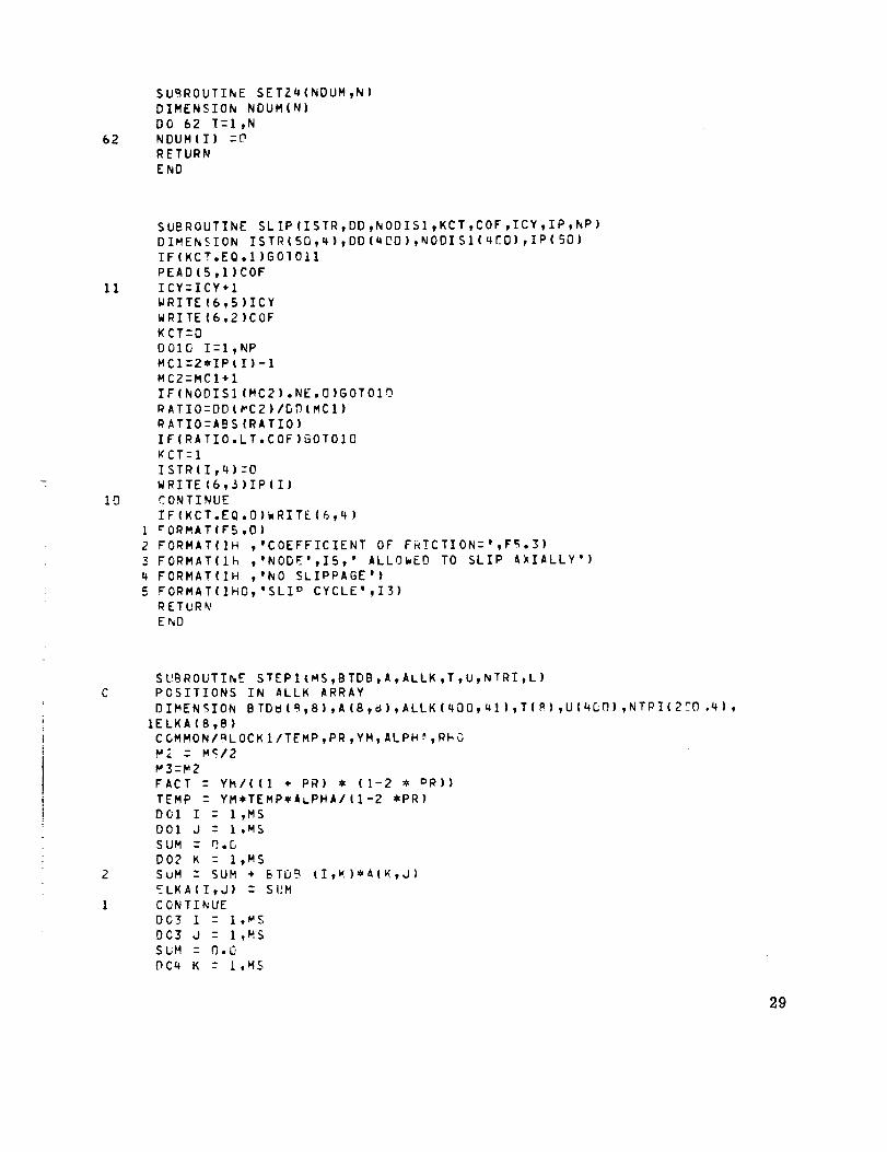
APPENDIX A
THE COMPUTER PROGRAIVI LISTING
AXISYMMETRIC FINITE ELEMENT PROGRAM WITH VARIABLE MATEOlALS ,TEMPERATbPE EFFECTS AND INERTIAL LGAOING (CPT)DIFFEPF.NTIAL DISPLACEMENTS I_.CLUDED
DIMENSION ALLK(4001,41)I, TRI(200,10) tNTPI(2OO,Q),NGDIS(qLO),FW(2Cq),IPROPI5), U(4OO), NUV(5C,3), A_IUVI50,2),TU(_DU)
2,DFL(aDD),DD(400),NDD(4DO},MOVE(40D),_.LLK1(450,41)
3, ISTR (50,4) ,STR (50,2) ,NODIS1 (400) , IP (_[J) ,AL (5.C_)4, IP&OP (5)
INTEGER REPT
COMMON/BLOCK 1/TEMP, PR yYMt ALPHA ,PHO
C OMKON/eL OCK2/MORD., NV221, N422, NWI C"0
PEAD(_,IGD)ICAS_.IC-IC+I
WRITE (6,1._O)
PEAD(S,I01)
WRITE (6,101)
WRITE(6,152)
P,EAD (5.,]CO)NCCIC1-1
READ (5.,,102) M, N, Nw ,NE, NCON,NFOP
WRITE (6,154) M yN,N_V, NF. ,NCON, NFORWRITE (6,1_2)
MOPD - 7_K
N&22 , 2x_L'IW+2
NW_21 - N422+1
PEADIr',IO.X-) (PRODII},I:I,_)
PEAD(':., IU_)W
WRITE(6,155) (PROP(I)I.I-!,5),_,
WRITE (6.,I_2}
W -" WW'{].I0471976
CALL S_-TZI(TRI, 2CjO, 1D)
CALL SETZ3(NTRI,2DO,4)
WRITE(6,156)
WRITE (6_152)LST-O
DO 2 I:l ,:'
READ(S,IO2)L,KTYPE_. (NTRI(L,J),J-'I,4)READ(5,1D5) (TRI(L,J),JZl,6)
L1-LST÷I
IF(L1 ,F'O.L)GOTO 3U
L2-L-I
L3:L-LST
_Z--(TQI(L,1)-TRI(LST, 1))/L3
YY- (TPl (L,6)-TRI (LST,b} }/L3
D031 JIZL1,L2
NTPI(JI,1)zNTRI(LST,I)+I
NTPlIJI,2)zNTRI(LST,2}+I
NIRI(JI,3)zNTRI(LST,3)+I
NTRI(JI,4)zNTRI(LST,4)+I
TRI(JI,3)zTRI(LST,3)
12

................... _ll_nll,la|/mmlullllllllUUUlUlIIIIIImUliilnNIIIIIIINIIIII IIIIII II NIIINLmLIJLIlU_JUUlIINlU,II.II IIIIIIPlIImNIIIIIIIIIJIINJUI,,I,I,JLJ.,,.,,_ , I
"1"1
(_
_E
_'vl Z _
U1 I I I
o __ _ _ v
H O 0 0
0 "!1 0
Z
+
_-. 0 _ "T1 ;no "_ 0 ;0 -rl 0 ;no 0 _0 m 0 N o.-, "I"1 -_ -rl -V'l _u ;_0 rm -rl 0 0 _T1 0II II II _ H _ II _) H _ 0_ H Z H _" II (J_ II _ _ _ _ I-'1H }_ _ ._ Z I--I Z
::0 I _ _10"_ I-'q ÷ L_ I--IH--Z--_Jrl ÷ II I _ rfll'Vl 7rl rip--!nO II Z_._
"_ Q I--I ,-_ H H "1:9"-=1
_,-_ )--O ÷ r'rl rrl I'_rl I_ ¢)
(.__ v 0 I
H
0
0'1
0
-.q
0
m
r r
A
--I --I
H H
r--r-
f... (_
II II
M '..,4
_ v
N
0 _0 _0 mm ':0 0 cn -n
L._IHH ^ H Z 4--
Hm rq m r_ H i--.
0.-' (7_ 0_ r- (_ E: 0
0
0
_1 _.M LM
IE F" IE
mr-rq
v (I! U1
G')'M
O v
-ir- _._
o,m i_i
J= --I z
"o ,.<
•e rrl
z
_ Hr-
2 i_
r" H
2 i_
t,,4 _1
1"-( H "1H H _ --'l H H
•I ,! _ _1 r" -I ,o
_ v v _e v_
II +1 II I1 ,3 II II
-'1--1 _1 --I _ --I--I
H H H H 0 H H
F r r ro rl--
÷ ÷
N t,4
_ H H H
(,._ ¢.,- C- (_.
_ p,-_ I-,' 0-=n
II II II
• --4"1---I
0-1 ;n0 _0, ';El
_,- r- f- g-
i-v-1 --i ._1 ,=.¢
o o_ Ln ,1_.
--I
O
t_

9
85
36
11
12
13
80
14
15
81
IF (ABS (Q) .LT. I. E-05 )GOT08
IF(C.GT.U.O)GOTn 9
MI - NI + 39
M2 - _I + i
M3 : N1 - 1
TR..-"(I,K)ZU(MI) +(U(F;2) -U(MI))*(TRI(I,6)GOT08
CONTINU[
CONTINUE
-U(M _))I(U(N! )
CONTINUE
CONTINUE
CALL <ETZI (ALLK,4GO,41)
CALL SETZ?(FW,2D8}
CALL SET22 (U, 4[.,r])
CALL SETZJ' (NODISt4OD)
DO II LZl,M
TEMP : TRI(L,6)
PR : TRI(L,7)
YM : TRI(L,8)
ALPHA : TRI(L,9)
PHO -- TPI(L,ICJ)
CALL RECT (L,FW, NTRI ,ALLK,U, TRT)CONTINUE
REPT-- I
DO 12 I-1,N
j _- 2,_i-1
J1 - J +1
ALLK(J,NW221) z U(J) + FW(I),_W,W,W2
_LLK(JI,NW221) - U(JI)Tb(J)zU(J)
TU(JI )-U (J1)
IJ(d} : C.C
U(JI) - 0.0
WRITE (6,176)
WRITE (6,165)IF(NCON.EQ.D)COT080
D013 Izl,_'CON
PEAD(5,1OS) (NUV(I,J),J-II "),(ANUV(I,J),Jzl,2)
WEITE(6,166) (NUV(I,J),J-I,7},(ANUV(I ,J),JZI,2)NOD - 2X,NUV(I,I) -i
U(NOD) : ANUV(i,1}
IF(NUV(I,P}.GT.NODIS(NOD) )NOOIS(NOD)-NUV(I,?)NOD - NOD + 1
U(NOD} - ANUV(I,2)
NODIS(NOD) - NUV(I,3}
CONTINUE
WRITE (6,152)
WRITE (6,177)
WRITE (6,167)
IF(NFOP.EO.O)GOTO%I
D015 I-!,NF'OR
READ(5,106)L, (PROP(J},J--I,2)
WRITE (6,168)L,(PROP(J),J-I,2)K - 2*L - I
KK : K +1
ALLK (K t NW221) :ALLK (K,NW?21) +PROP (I) _0. 15015_r._3
ALLK (KK,NW221} : ALLK(KK,NW2?I) + PROP(2)* D.159154943CONTINUE
IDD:8
-U(M3))
14

20
37
39
40
41
38
42
16
17
19
22
READI5,1OO)IDD
DO20 I:I,MORD
De20 JzI,NWZZl
ALLKI(I,J)zALLK(i,J)
D037 I:I,4_0
NC_ISI(I)zNODIS(1)
KTzMO_D
_CTzG
TCyzcIWPzO
CCTO3P
DC4C Izl,_O0
NODISII)zNODISIII)
U(I)zP
DO41 IzI,MORD
DC41 JZl,_W221
ALLKII,J):ALLKI(i,J)
CALL DIFSISIKTyALLKtNODIS,MOVFt_DDtDD,DEL_ISTR,STO_NORD_KCI)
GOTO_?
IF(IDD.GI.O)
ICALL DIFDISIKT,ALLK,NODIS,MOVE,NDD,DDtDEL,ISTP,ST_tNO_O,KCT)
CALL BCROUTIALLR,U,MORD,REPT,_:W,NOUIS)
IF(IDD.GT.O) GOT022
WRITE(6,150)
WRITE(6,178)
WRITE(6,169)
D016 I:ly_'MIz2_T-I
MZzMI+I
WRITE(6t168)I,U(M1),UIM?)
WRITE(6,1_2)
WRITEI6,17Q)
WRITE(6,1?O)
TOTAz9.O
STzO.P
DOt7 LzI,M
TEMPzTRIIL,6)
PRzTRT(LtT)
YMzTRI(L,9)
ALPHAzTRIIL,9)
CALL PECTST(LyST,TOTA,U,TRI,NTRI)
STzST/TOTA
WRITE(6,171} ST
IF(ICI.E&.NOC)GOTO 1B
ICI z ICl + I
PEAD(5,104IW
WRITE(6,172)W
WzW_O. I0_ 71976
D019 I:l ,_
J:2_I-1
Jl:J+l
aLLK(J,Nw221)zFW(I)_W_2+TUIJ)
ALLK(JI,NWZZl)zTUIJ1)
RERT: -1
WRITE(6,1S2)
GOTO 1_
KTzMO_D
DOZ3IIzltKT
IzKT-II+I
15

24
2346
25
29
45
27
26
28
IF (NDDII).GE.g) GOT024
I1---NDD(I)
II-MOVE(II)
DEL(I)--DEL(I)+U(11)
$0T027
I 1-MOVE (I )
DEL (I)zU( I! )
CONTINUE
CONTINUE
IF(ICY.NE .O)GOT045
WRITE (6t150}WPITE {6,178 }
wR_TE (6,169}
D625 I:l,N
NOD:2_I-I
WRITEI6,16@) I,DEL (NC D) ,DEL (NnD+I)
WRITE(6,152)
WRITE (6,179}
WRITE (6,170)
TCTAzO.O
ST--O.O
D029 L--1 ,M
TEMP- TRI ¢ L ,6 )
PRzT_I(L,7)
Y_.-TRI(L,_}
ALPHAzTRI (Ltg)
CALL _ECTST (L, ST, TOTA,DEL,T_I,NTPl )
SI-ST/TOT_
WRITE(6,171) ST
CONTINUE
IF(IV;P.NE.O)GOTO43
CALL SETL?IDD,WOU)
D026 I-ItKTMC1zI+1-NW22
N,C2--I ÷NW22-I
IF (MCI.GT.I)JI-MC1
IF (MC].LE.I)JI-1
IF {MCT.LT.MORD }J2-MC2
IF (MC ?.GE .MOR U )J2zMORD
DC27 d--J1,J2
IF(I .LT.J)DD(I)-DD(I) +ALLKI (i,J-I+I)_DSL (J)
_F( I .GE.J)DD(I }-_D(I) +ALLKI (_,I-J+I)_DEL(J)
CONTINUE
WRITE(6,152)
WRITE(6,173)
WRITE (6,152)
D026 T-I ,NWCl--2_I-1
MC2--MCI+I
IF (NmD (MCI) .GE .O.AND .NDD (MC2) .GE .O)GOT028
IF (NDD (MCI). LT .O)DD( MC I)--ALLK 1|MC1,N_221)-DD(_.Ci)
IF (NDD(MC1) .GE .U)DD |MC 1)-0.
IF (NDD(MC2).LT.O)DD(MC2)-ALLKl(MC2,NW221)-DD(MC2)
IF(NDD(MC2) .GE.O)DD(MC2)zO,
IF(NOCISI (MCl).NE.O)DD(MCI)-D
IF(NODI$1 (MC2).NE.O)DD(MC2)-O
WRITE(6,168)I,DD(MC1},DD(MC2)
CONTINUE
CALL PmE$S(DD,I°,AL,NP,RAD,_C T)
16

44
47
43
1PC
1C1
IF (KCT.FQ.O)READ (5, i00) ISLP
IF( ISLP •E 0. L])GOTOW3
KCK-G
D844 I-I,NP
_CI:2_IP(I)-I
IF(DD(_'CI).LT.O)KCK:I
IF (KCK.EQ.O)GOTOLI?
WRITE (6,175)
IF (KCT.EQ. n) READ (5, ID4 )COF
GOTO_
CALL _LIP (ISTR t DO tNODIS I,KCTyCOFt ICY, IP,NP)
IF(_(CT.EQ.1 )GCT030
TF(ICV.EQ.I )GOTO_3
I_R-1
ICY--O
GC.TO#6
IF(ICI .EQ .NOC )GOTOIB
ICI - ICl + 1
REAG(=,IO_}w
W_ITE (6,174 }W
W -W_'O • iOq 71976
W&ITE (6,152)
GCT036
IFIIC.LT. TCASE)GOTO 1
FORMAT(12)
cOPMAT(RCN
1
I_2 FORMAT 6:_)
I0_ FCRMAT 5E12._ )IPq fORMAT FI_.O)
IDE FORMAT 6F10.0)
I_E FORMAT 14,_E12.4)
I07 _ORMAT FI_.D,EI2.4)
1C_ FORMAT 314,2F10._)
I_C FOR_AT(IMI)
151FOPMAT(IH )
I_2 FOP_AT(IHC)
IF3 FOmKAT(lh+)
15_ FCDMAT(IX,'Mz'tI4_5X,'Nz',I4tSX_'N_z',I_,5X''NEZ''I4'SX'
I,KCONz',I4,5X,'NFORz',Itl)
155 FGRMAT(IX,'p_z',EI2.Q,SXt'YMz',E12.4,SXt'COEXz',E12.4,5X,
1'PHOz',EI2._,5X,'TEMPZ',E12.q,SX,'SPEED(RPM)z'tF10.2'
15_ FOPMAT(IX,'ELEMFNT',4X,'TYPE',TX,'i',TX,'J',TX,'K',?X,'L''K',BX,'BOBL',BX,'TEmP')
,'ELEMENT',IOX,'PR',IDX,'YM',
IIOX,'RI',IOX,'RJ',TX,'RKOBJ',TX,'RLO
157 FORMAT(6IB,6E12.4)
15@ _ORMAT(]X,'SPECIAL ELEMENTS '/IH
18X,'COEX',_X,'RMO')
IES FORMAT(IB,QE12._)
16[ FORMAT(IX,'6ASE MATERIAL PROPERTY
I_I FORMAT(6X,'TEMP',IOX,'PR')
I_Z FORMAT(6X,'TEMP',10X,'Y u')
I_ FORMAT(6X,'TEMP',SX,'COEX')
164 FO_MAT(AX,'TEMP',9X,'RHO')165 FORMAT(IX,'NODE' ,GX,'IU',6X,'IV',SX,'UU',BX,'VV')
16E FORMAT(15,2I_,2FIO._)
167 FORMAT(IX, 'NODE', IOX_'FR', ]OX, '_Z')
I_ FORMAT(15,2E12.4)
169 FORMAT(IH ,'NODE',IDX,'UR',IGXt'UZ')
17C FOPMAT(IX,'ELMT',_X,'R STRFSS' ,4X,'T STRESS',3X,'AX
VARIATIONS V_ITH TEMPERATLRE')
_TRESS',3X,
17

I'SH STRESS'_X,'R',gx
I71FORMAT(IH ,'AVERAGE
172 cORMLT(1H1, 'NEW SPE
1"3 FOPMAT(1HC,'INTrRFERE
I?X,IAXIAL ')
IT4 RORMAT(IHI_'SAM_ GEOM
175 FORMAT(IHO,'LOSS OF R
I76 FORMAT(IX,'NODAL REST
1_7 _ORMAT(IX,'APPLIED NO
176 FORMAT(IX,'NOOAL DEFO
17_ RORMAT(1X_'ELEM_NT ST
STOP
EnD
,'Z')
TANGENTIAL STRESSz',EIZ._)
ED AND/09 FORCES.Wz',F10o2)
NCE FORC r VECTORS'/IH ,'h_DE',6X,'RADIAL'
ETRY.Wz',FIO.2)
ADIAL INTERFERENCE')
RAI_TS')
DAL FORCES'}
RMATIONS')
RESSES')
SUBROUTINE
INVERTS THE
DIMEN¢ION
CALL SFTZ]IA,_,B)
IF(T_I(L,2)°GE.O.O)GOTO
PIzTRI(L,I)
Pj: -TRI{Lt2)
RK:TRI (L, _)
RLzTR T (L, _)
BzTPl (L,E)_J=O.
AIz O.5*(PI+RK)
AJz O.F*(_J+RL)
A
A
A
A
A
A
a
A
8
A
A
A
J
A
A
A
A
A
A
A
A
A
A
(2,1)- 1/(RI-RJ)
(6,5)- A(2,1)
(2,2)- -_(2,1)
(6,6)-- A(2,2)
(1,1)- R,-'*A(2t _ )
(5,5)- A(1,1)
(1,2)-- _I*A(2,l)
(5,b)- A(I,2)
(4,1)- A(2,2)/8
(8,5)z A(4,1|
14,2): -A(4,1)
(8,6): A(4,2)
(3,1): RJ*A(4,?)(7,5)z A(3,1)
(3,2)-- RI'_A(4,1)
(7,6)- A(3,2)
(4,3)- 1/(B*(RK-RL))
(B,7)- A(4,3)
(4,4): -A(4,3)
(8,8)- A(4,_)
(3,3)z RL*A(4,_)
(?,7)- A(3,3)
(3,4.)-- RK'_A (4, 3)
A(7,B): A(_x,4)
DET: AI-AJ
PETUR_
AI--TRI(L,I)
AJzTRI(L,P)DETzAT-AJ
BJzTRI (L, X)
B_zTKT(L,'_)
AINV(RI,RJ,RK,RL,B,AI,AJ,BJ,BK,BL,DET,L,TR!,A)
ARRAY A
A(8,8),TRI(2OD,1D)
18

RL--TRI (L, _ )B" (BK+:L-BJ)/Z
Ol- AJ-AID2- DI*(E J-SL)
ill,l): AJ/D1
-_ (5,5)= A(1_1)A(I,2): k I,WBL ID?
_(5to)- A{1,2)
A(1,4): -aI_BJlr)2
A(5tB): A(I_h)
a (2,1)-- -I/D1
A(6,5): A(2,1)
A (2,2): -BL/D2
A(6y6): A(2,2)
A(2,4): BJ/D2A (6,_): A(2,#)
A(4,1): 1/(B_,WD])
_(8,5): A(4,1)
A (4,3): -A(,_I)
A(8_7)- -A(4_1)
A(3,1)- -AJ'_A (4,1)
A(7,5): A(_.,1)
A (3,3)-- -A(3,1)
A (7_7)- -A(3, 1)
J(#_2): I/D2
A(B,6): A(4,2)
A (4,4): -AI#,2)
A (8t8): -_'(#,2)
A{3_#): AS/D2
A (?,8)z AIX,4)
A (3_2): -A(3_4)A (7y6)-- -_(3_4)RETURNEND
C
C
C
C
C
C
C
C
91
92
Sb_ROUTINE BCROUT(D,X,N,REPT_NW,N001S)
AFROCEDURE TO APPLY CROUT REDUCTION TO A BANDED MATRIY
D WHICH HOLDS THE UPPER TPIANGLE OF THE SYMMETRICAL
BANDED MATRIX A SO THAT D(I,J-I÷I)zA(I,J).THE LAST cOLUM_
(D(I,J-I+I) HOLDS THE VECTOF. B FOR THE SET OF E_LATIONS ". zB.
OK EXIT THE VECTOR X HOLDS THE SOLUTION (X) TO THESE E_U_TIOND.
TFE REDUCTION IS ARRANGED SO THAT IF CERTATN SETS OF EQUATIONS
_LST NOT BE SOLVED.(I.E. NODIS(I):I) THE_J TH_ ApPRoPRIAT_ ROwS
A_D COLUMNS ARE NEGLECTED
DIMENSION D(4OG,#I),XI4OD),NOnISI4GO)
INTEGEP REPT,CT,CI
Nw2:2mNW+I
CT:O
CT:CT+I
IF ((NODIS(CT)-C.I).GT.D) GO TO _I
IF (REPT.LT.I) GuTO 25
DO 92 I:I_NW2
IF((NODIS(CT÷I)-O.1).GT.O) GO_O 92
O(CT_T+I) : D(CT_I÷I)/D(CT,1)CONTINUE
ClzCT÷I
nO _3 J:CI,_
19

94
96
9593
2S
98
97
26
9O
99
20
IF ((NODIS(J )-'_.I}.GT.O) GO TO 93
SUM=D.
LI --d-1
K 1 :J-NW2
IF (KI.LT.CT} III-CT
DG94 K:KI_L1IF ((NODISIK )-O.1}.GT.O) GO TO 94
SUM :SUM+ (D (K tJ-K+II_2)_D(Kt ] )CONTINUE
DIJtl} -D IJ 71)-SUM
TF (J.EO.N) GOTO 25
L2-J+I
_2 "J+NW2
_TF (_2.GE.N) N2:N
DO 95 I-L2tN2
IF ((NODIS(I )-n.I).GT.D} 60TO 95
SUM -0.
K1 :I-NW2-1
IF (KI.LT.CT) KIzCT
DO 96 K:KI_LI
IF |(I-K-n.I).GT.NW2) GOTO 96
IF ((NODIS(K)-D.1)oGT.O) GOTO 96
SbM -SUM+ (D(K _I-K+I )_D( K _J-K+I) WWD(K _ I) )CONTINUE
DlJtI-J+l) - (DIJ_I-J+I)-SUM)/DIJ_I)CONTINUE
CONTINUE
NW3 z2_,NW ÷3
D ICT_NW3)zD(CTtNw3)/D (CT_ i)
CI:CT+I
DO 97 I:CItN
IF I(NOr'ISII) -0.1).GToD) GCTn q7
SUM -O.
LlzI-1
KIZI-NW2
IF (K1.LT.CT) KI-CT
DO 98 KZKI_L1IF ((NODIS( K)-D.I).GT.D) GOTO 98
SUM :SUM+ (D (K _I-K+I )X.DIK_ I)_DIK tNW3} )CONTINUE
DII_NW3) :ID (I _NW3)-SUM)/._( I _ ] )CONTINUE
IF( (NODIS(N)-D.1).BT.D)GOTO26
X(N):D(NtNW3)LlZN-I
00 99 I:I,LIL2z(N-I)+I
SUM--O.(I
L3:N-I
IF ((NODIS(L3)-D.I).GT.D) GOTO 99
N2-L3+NW2
IF (N2.GT.N) N2 ZN
DO 90 KZL2_N2IF ((NODIS (K)-P..1).GT.O) GOTO 90
SUM -SUM+ (D (L 3_ K-L3÷I)*X (K) )
CONTINUE
X (L3):D(L3,NW3)-$UMCONTINUE
RETURH
FkD

20
21
90
g2
91
70
23
SUBROUTINE DIFDES
I ( KT ,D,NODIS ,MOVE,NOD,DD ,DEL ,ISTR_ STR, NOr)D,KCT )DIMENSION D(QCD_al), NODIS(400), MOVE(qDO)t NC.D(40_)_
1DD(400), DEL(40D)
2, ISTR (50,4) tSTR I50 t2)C OMMON/BLOCK 2/MORD tNW 22 1 _ NW22 _NW
CALL SETZ2(DEL_GO)
CALL SE TZ ? lDD tu_O,.l)
CALL SETZ4(NDDt400)
CALL SETZq(MOVE,4DD}
NW2 - NW22-1
D020 ! - I_KT
DDII) - D (I,NW_2+I)
IF (KCT.NE .D )GOTOgO
qEAD(5,1) NOE. D
WRITE I6,2 )
WRITE (6,2_1)
{_021 I -- I,NO_D
READ(5,252)J,K _ IR,DR_ IZ ,DZ
WRITE (6,252)J _K fir 9DR tIZ,DZ
ISTR(I_I):J
ISTR(!_ZI:K
ISTR(I,3):IR
ISTR(I,4):IZ
STR(Itl)zDR
STR (I ,2) :DZ
NDDI2_K-I) : (-2_J+I)_IR
_IDD(2*K) : (-2xzJ}_IZ
DEL(2=K-I) : OR
DEL(2*K) : DZ
GGTOQI
0092 Tz]_NODD
J:ISTR(I,I)
KzISTR(II?}
DR--STR(I, I)
DZ--STP(I,?)
IR--ISTRII ,3)
I Z: ISTR ( I ,4 )
NDD(21K-1)-I-2_J+I)_IR
NOD (2_K ) --(-2_J) _I Z
DEL (2_K-1 )-DR
DEL(2_HI-DZ
II:O
0022 ! - 1,KT
MOVE(1) : I
TF (NDD(1).LT.G) GOTO 70
II : II+l
MOVE(I) -- II
MCI -- I-_W2
MC2zI+NW2
IF (MCI.GT.1) J1 - MC1
IF (MC1.LE.I) J1 z I
IF (MC2.LT.KT) J2 -- MC2
IF (MCZ.GE,KT) J2 - KTD023 J : Jl_J2
IF(NDD (J).GE.O) GOT023
IF (J.GE.I) OOII) : ODII)-OELIJ)W_DIItJ-I+I)
IF IJ.LT.!) DDII) - DDII)-DEL(J)_OIJ,I-J+I)
CONTINUE
21

22
71
72
74
73
25
26
75
CONTINUE
D024 I = I,KT
IF(ND[;(I) .LT.O)
IK : MOVE(I)
_iFI : gGCT07?
IK : -NDD(I)
NFI:I
IK : _OVE (IK)
dl = I
MC2 = I+_W2
IF (MC2.LT.KT)
IF (MC2.GE.KT)
DG 25 d - Jl_d2
IF(NDD(J) .LT.O)
JK--MOVE (J}
JJ - JK
_JFIJ :
NFJ : r)
5CT073
JK - -NDD(J)
JK : MOVE (JK}
NFJ : 1
_FIJ - NFI*NFJ
GOTO71
J2 : PC?
J2 : KT
GOT074
wC] z NFj+NFI-NFIJ
IF (IK.GT.JK)D(JK_IK-JK+I}=D(_,J-I+I)÷MCI*D(JKtIK-JK+])
IFIIK.LT.JK)DIiK,JK-iK+I)zO(I,J-I÷I)+MCI*O(IKtJK-IK+I)CONTINUF
J1:JJ+]
J2zlK+NW2
IF(JI.GT.J2)GOT075
D026 J=J1,J2
DIIK,J-IK+I) zO
CONTI_UE
DD(I_)=DDII)+NF_DDIIK)
NODIS(IK)zNODIS(I)+KFI*NODIS(TK)
_' y5X,'NOCET E_',9X
24 CONTI_'UE
I zMOVE (KT)+i
DG27 JzI,KTD_(J)-O.
NODIS (J)-q
DO2
28 D(J
27 CON
DO2
29 [?(IKT-
WRI
25 I FOR
l,'I25_" top
I FOR
2 FOP
RET
E._D
8 dJ-I tNW22,Jdl=O.
TINUE
c !:ItKT
,N_'??I):DOII)
MOVE(_T)
TE(5,Z)
MAT( !X, ' DI FFE_E'_TI _L 5'ISPLACEMENTS'/I.. ,'N_DE
R',oX,'DR',gYt'!Z',9X,'OZ')
MAT(IX,Ic,SX,iS,5X,I6,_11._,5X_I6,E11.4)MAT(_IE)
MAT(]Hn)
URN
22

_'1 -q G'_ I_ _-I :C O H 3: G'_ _-4 H _ (-) t--I _--I O w,I J--4 G1 "O
O O O :ID O _ O -V'l _1¢ O, "q -rl _.._ j.., -q -rl _ "ri -rl O _
,e
Z
-..4
1,1,1
PO
,-qel-1
0
Z
r"n
nO
.rq
C
PO
rq
_r,
i.-i
l'-
r--
I|
O
Z
!/3
--4
a
J_" _ C 0 0
M _-_
_ 0 0 r:: t'-I IJ _ w
_t-_ I _t--* "_
Z I H
H nD _,. I
)>_ I
Z v
"O -_- t-4
"_ +
"_ r,_
_ H I-" "--i II _ r-" II "-_ z z H H --i t'_ H _ --i 'I--I H H _ I'_ I-, t--' _I_, l-m _:, _ :]_ _ *-d It" r-" r" _ _ :I
HvOn II OI--4 II _-_ l| -,.I --I.e _e O_ ..m HO-e _ -m $-I_ II t%)O_--_ OH O _--ir- r-" r-i--i-v'] ::_1
II II II Jl_ "i_" l'-i II _ 11"4 • ',_ • (7_ r_l _rl l"fl r'rl H ,-.i
C')_e
• L"_ C::: _" II II II II
G') C:) 'l"rll"q ,_.,,Il=, 1_, _1 •
UII--_ I--'H H I--" _
C_l H _-.." NO
I _ _ ---I
G-, _
• II I-4
4_) _ II .-,I
• I.-.I _ ÷
O nO
H
n'l
G_
O
"--4
O
_o
;O
t_ [.rl L_ (3 "_ JD" i'Y1
t-4r-
r-
(-1
t_

IC
FOPMAT(TS,14X _E12,_)
FORMAT(IHO_'NON CONVERGENCE')
CONTINUE
RETURI_
FTP_D
SbBROUTINE RECT{L,FWyNTqIyALLK_UtTRI)
DIMENSION NTRI¢_OO,4}_T(,g),FW(200)tU(400),_LLK(400_41)_EI_B)_
IA(B,8),TRI(200,10)
COMMONIRLOCKI/TEMP,PR,YM,ALPHA,RHO
IF(NTPI(L,q).EQ.O)GOTO8
CALL AINV(RI,RJ,RK,RL,B,AI,AJ,BJ,BK,BL,DET,LvTPI,A)OOTO_
CALL TAINV(RI,RJ,AI,AJ,BJ,BK,BL,DET,L,TPI,A)CONTINUE
CALL SETZIIE,8,A)
IF (TPI(L,2).LT.U.O) GOTO I
IF (AI.LE.O,C) GOTO 2
ELF z ALOG (AjIAl)
GCTO 3
ELF :
Pl : ((4_ • A_) - (_L • AI) • (RJ _ AT))
P2 : _L-bK-_J
P3 : (RL-PK)/(AJ-AI)
_4 : RL-6K
P5 : AJ-AI
B5 : (3_B_PS_2-3_AI_B2)
El : PT+PI*ELF/O5
E7 z (o2_0.25_(AJ_4-AI*_4)+PI_(AJ_3-AI_3)/3)/F5
T$ : (P3_ELF+_4_PS+BS_(AJ_2-AI_2)/2
I÷_5_(AJ_4-AI_4)/4+B2_(AJ_5-AI_$)/S)/3
_11 : (P2_(AJ_5-AI_5)/5+PI_(AJ_4-AI_4)/4)/P5
El2 : (P6_{AJ_3-AI_3)I3+2_BK_Pk_(AJ_4-AI_)/(q_PS)
1+EI_(_.2_P5_5+n.5vAI_PS_4+AZ_2_P5_*3/3))/Z
2-O.25_A!_(Ad_4-AI=_4)|/3))/_
A_lz(AJ-AII_BK
!F(AJ1.GT.D.C)GOTO_
24

EI:-E1
E2:-E2
E3:-E3
Eqz-E4
E5:-E5
£6=-E6
E7=-E7
E8:-E8
E9:-E9
E I0:-£10
E11:-E11
E 12:-t'12
EI3:-E13
GOTO
_JRI : P.J-RI
PLRK : RL-RK
RLLN : _LOGIRL)
r_JLN : ALOG(RJ)
R_RI : oK-Pl
RLRJ -- RL-RJ
RKLN - ALOG(R
PILN - ALOG(R
E2 - 8._(RJRI+
E5 : _.5_._.(R
Fb : F_x.X.2#((R
K)
(RLRK-RJRI)I2)
RK÷d.5_RJRI)/3
J_2-RI_2)/2÷2_(RJ_RLRJ-RI_;_KRI)/3
I+(PLRJ_2-PKRI_2}/_)/2
E7 : _(RJ_3-RI_3÷I.5_(RJ_RLRo-_2_pK;._)
I+_J_RLPJ_2-_I_KPI_2+IPLRJ_3-R_RI_3)/w)/3
_9 : B_*3_(RJRI÷3_RLRK)/12
E12 = B_2_IIRJ_3-RI_3112+RJ_2_ALFJ-RI_2_RK_I
l+O.75_(Rd_PLRJ_2-RI_RKRl_2)+O.2_I_L_J_3-pKeI_))/ "
IF |APS(_LRJ).LT.1.E-OS) GOTu 5
FI z (-QLRJ+RL_RLLN-RJ_RJLN)/PLRJ
E3:RLL_-_.5+(RjIffLRJ)_II-RJ_I_LLN-_JLN)/RLPJ)
ES=PLLN-I./3o÷(RJ/_LRJ)_(DoS-IRJ/RLRJ}_II-_J_(RLLN-_JLK)/_LPJ)}EIOz#J_2/6+RJ$_LRJ_O.25+RLRJ*_2_O.1
F11 = (PL#_5-_J_5)_O.DS/_LRJ
E13:RJ_4_D.5÷4_,J_3_RLRJI3+I.5_RJ_PLRJ_2+C.O_RJ_LRJ_I+_LRJ_41_
GOTO 6
El z PJLN
E3ZRJLN
E_:RJL_
ElOzPJ_*2/6
Ell z 0.25_RJ_4
El3 z _.5_RJ_4
IF (ABSIRKRI).LT.I.E-03) GOTO 7
El : B_(EI-(-RKPI+RK*RKLN-RI_PILN)IRKRI)
E3zB_(E3-RKL_+O.5-(RI/RKRI)_(I-RI_IRKLh-RILN}/PwRI))/Z
E_:B_3_(EB-RKLN-!./3.-(RI/RK_I)_(O.5-(_I/RKRI}
I*{I-RI*(_KLN-RILN)/RKRI)))/3
EIC:B_*3*lEIO-RI_*2/6-_I*RKRI*O.25-RKRI*_2JO.I)
Ell : B_(E11-{RK_5-_I_$)_D.D5/RK_I)
E13:B_2_(EI3-RI_4_O.5-4_RI_3_R_RII3-1.5_RI_2_K.I_2
I-0.8_PI_RKRI_#3-RKRI_4/b)_O._5
GOTO 4
25

I,,.LLJd'IJJ la.' i.i-' i._J iJ._ Iz.r laJ L_ t._J t._l IzJ-L_ L_ UJ. L_ IzJ m.r b._ L_F t, ' L_L_ I._ L,_ L,,J L_ bJ I,_ b3 b,.t bJ L,.J m,. t_ I._I.L_ L,,J'L,J bJ L_J b, IJ.I bJ b.I b_ IJ.lLi.i,I-- I-- I-- I.--I-_ I'-- I-- I-- l--i

E'--
U
25C
DB(3_B): R*DB(3tT)
OB(_,3): (1-Z*PQ)*O.5
DBI4,h): R*DB(4,3)
DB(_v6): DB(4,3)
IF(NTRI(L,4).NE.O)GOTO_
DO3 I:I_4
DB(Iy4):O.
DB(IvB):O.
CONTINUE
NRI : NTRI(Lwl)*Z -I
NR2 : NTRI(L,2)*Z -i
NR3 : NTRI(Lt3)*2 -I
TD(1) : U(NR1)
TD(2} : U(NR2)
TD(3) z u(NR3)
TD(5) : U(NRI+I)
TD(6) = U(NR2+I)
TG(7) = U(NR3+I)
IF(NTRI(L_q).EQ.O)GOT05
NE4 : NTRI(Lt4)_2 -1
TD(4) : U(NR4)TD(8) : U(NR4+I)
CONTINUE
CALL STEP2(8_STtTOTAtAtTDvDBtSTRESS_AREA)
WRITE(6_Z_D)L, (STRESS(1)tIzl,4)tRtZ
FOPMAT (15,4EI2.4t2FlO.5)
RETURN
END
62
SbBROUTINE SETZI(ADUM,N,M9
DIMENSION A_UM(NtM)
DO 62 I:I_N
DO 62 JZI,M
ADUM(I_J) :0.RETURN
EhD
62
SUBROUTINE SETZ2IADUM_N)
DIMENSION ADUM(N)
DO 62 I:I ,N
ADUM(1) :[_.
QETURN
FND
6Z
SUBROUTINE SETZ_(NDUM,N_M)
DIMENSION NDUM(NvM)DO 62 I:I ,N
DO 62 JZI,M
NDUMI!,J) :0
RETURN
E)wD
28
62
SUBROUTINE SETZ4(NDUM_N)
DIMENSION NDUM(N)
DO 62 IzI_N
NDUMII) zO
RETURN
END
11
i0
SUBROUTINE SLIP(ISTRtDD_NODISltKCT_COFtlCY_IPtNP)
DIMENSION ISTR(50_)_DO(_CD}_NODISI(4CO)_IP(50)
IF(KCT.EQ.1)G01011
PEAD(5_I)COF
ICYzICY÷I
WRITE(6_5)ICY
WRITE(6_2)COF
KCTzD
DOIG I:I_NP
MCIz2_IP¢I)-I
MC2zMCI÷I
IF (NODIS I (MC2) .NE.O )GOT01O
RATIOzDD teC2)/DD IMCl)
PATIOzABS (RATIO)
IF(RATIO.LT.COF)GOTOID
KCTzl
ISTR(It_)zD
WRITE(6_3)IP(1)
CONTINUE
IF(KCT.EQ.OiWRITE(6_4)
I _ORMAT(FS.O)
2 FORMAT(IH _'COEFFICIENT OF F_TCTIONz'_F_o3)
FORMAT(lh t'NODE'_I5t' ALLOWED TO SLIP AXIALLY')
4 FORMAT(IH _'NO SLIPPAGE')
5 FORMAT(IHOT'SLI D CYCLE'_I3)
RETURN
END
SUBROUTINE STEPI(MSyBTDB,AtALLK_TtU_NTRI,L)POSITIONS IN ALLK ARRAY
DIMENSION BTD_(_tB)_A(8tB)tALLK(400_41)_T(P)IU(4_n)_NTRI(2_0.4).
1ELKA(Bt8)
COMMONImLOCK1/TEMP_PR_YM_ALPH_vRhG
M2 : MSI2
P3--M2
FACT - YM/((I ÷ PR) • (I-2 • DR))
TEMP -- YMW, TEMP_.ALPHA/ll-2 _.PR)
DO1 I : I_MS
DO1 J : 1,MS
SUM z _._
DO2 K - I_MS
SUM -- SUM + BTDB (I,K).WA(Ktj)
C__LKA(I_J) : SI'M
CONTINU_
DC3 1 : 1 .MS
003 J : 1.M_
SUM : (_.0
DC4 K -- I,MS
29

SUM -- SUM + A(Ktl)W'ELKA(K,J)
BT[)B(ItJ} - SbM'_FACTCONTINUE
IF (NTRI (L ,a) ,EQ,O) M3z3
DO5 I-I,M3
I I : I + _'-M2
MFI , NTDI{L,II)_'2-1
KK = MM ÷ i
II : I + M2
U(MM) -- T(I)_TEMP ÷ U|MM)
U(KK) : T(II),_TEMP + U(Kk)
DO6 JzI_M3
Jd : J + W-M2
NN - NTRI(L,JJ)W=2-1LL - NN+I
JJ : J + M2
IF (MW,LE,NN)ALLK(MM_NN-W,M+I) : ALLK(WM,NN-MM+I) + BTDB(I,,_)
IF(MM,LE,LL)ALLK(MM_LL-MM+I} - ALLKfMM,LL-MM+]) + BTDP(I_JJ)
TF (KK,LE,NN}ALLK(KKtNN-KK+I) " ALLK(KK_NN-KK+I) + BTt_B(iI,J)
IF (MK,LE,LL)ALLK(KK,LL-KK+I) : ALLK(KK_LL-KK+I) + BTDB(II,JJ)
CONTINUE
CONTINUE
RETURN
END
SbBROUTINE STEP2 (MS,ST,TOTA,AtTD_DB,STRESS_AREA)
DIMENSION A(8_8)tTD(8),D_(4,8),STRESS(4),ATO(8)
CCMMON/_LOCKI/TEMPtPR,YM_ALPH_tRHO
FACT : YM/((I+PR)_(I-2_PR))
DO1 IZl,MS
SUMzO,Q
DO2 J:l _MS
SUW: SUM+_(ItJ)_TD(J)
A_D(I): SUM
D03 I:I,4
SbM: C,O
DO4 J:ltMS
SUM: SUM + DB(I,J)_ATO(J)
STRESS(1): FACT_SUM-TEMP_ALPHA*YM/(I-2_PR)
STRESSIq): FACT_SUM
ST: ST+ $TRESS(2)_APEA
TOTAz TOT_ + AREA
RETURN
END
30

e_
_fq
Z
II II PI II Jl || II I| i_
_, I.,.-. _ tjl (_ r_ i'ro i,.,,-
II II II I| _r ii
_ID _.4 (_ P,J _ t-.,
--I !11
r_ --_
--if
(-3
1-4 --4 II II II II II II II I=" "I' < CD
II -_ rtl I--If_ --I
_ I" r-- r- r" .-i o _._
_ 2_ _ "*, _ "*' NZ'_
_ _r_z
:0:1_
7_
r-

APP ENDIX B
A BRIEF CONSIDERATION OF THE STRUCTURE OF THE PROGRAI_
A flow chart of the computer program for a single case run is shown in figure 3.
The functions of the program elements listed in appendix A will now be briefly described:
AXIFE the main program element, which acts as executor, reading in data,
AINV
BCROUT
DIFDIS
PRESS
RECT
RECTST
SETZ1, SETZ2,
JSETZ3, SETZ4
SLIP
STEP1
STEP2
TAINV
calling appropriate subroutines, and routing according to options
and multiple case processing requirements
inverts the shape function matrix (A} for trapezoidal elements
applies matrix reduction solution scheme to solve for deformations
reduces system of equations according to interference (differential
displacement) conditions
calculates pressure distribution at interference location
prepares data for calculating element stiffness characteristics and
thermal and inertial force effects
prepares data for calculating element stresses
sets elements of arrays of various dimensions and types to zero
allows axial slip of interfering nodes if appropriate
determines element stiffness characteristics and organizes them
into the main stiffness matrix
calculates element stresses
inverts the shape function matrix (A) for triangular elements
32

APPENDIX C
SC_ E PROGRAM DETAILS
Array dimensioning. - The following arrays would need redimensioning if the num-
ber of nodes required exceeds 200: ALLK, TRI, NTRI, NODIS, FW, U, TU, DEL, DD,
NDD, MOVE, ALLK1, NODIS1, and D.
The following arrays would need redimensioning if the maximum nodal difference in
an element (NW) were to exceed 19: ALLK and ALLK1 (see section Maximum nodal
number difference).
The following arrays would need redimensioning if the number of constrained nodes
were to exceed 50: NUV, ANUV, l'P, AL, P, Z, B, and A.
The appropriate modifications, should redimensioning be required, are apparent
without further detailing. Other dimensioning limitations are unlikely to be significant.
The storage requirement of the program, as listed, on a Univac 1100 machine is 53 004
words. Note also that if redimensioning of arrays whose elements are set to zero is
undertaken (through SETZ1 etc. ), then the call of the subroutines SETZ should be
amended accordingly.
Maximum nodal number difference. - The matrix reduction solution scheme after
Crout (ref. 3) has been amended to a banded form for the purposes of the present pro-
gram. The bandwidth of the solution is (2NW + 2), where NW is the maximum nodal num-
ber difference in any element. In fact, the width of the main stiffness matrix ALLK, and
its copy ALLK1, has been dimensioned as (2NW + 3), the nodal force vector being added
on in the last column.
Whilst it is apparent what the maximum nodal number difference is in an element
where none of the nodes is "involved" in an interference, it is not so clear if this is not
the case. If an interference is effected between components, then for elements involved
in the interference the value of NW should be assessed as the maximum nodal number
difference between nodes in the element and associated nodes in interference with the
element. (Examples are shown in fig. 4. )
Equivalent loading. - If a continuously distributed load is applied to a structure, the
loading must be reduced to an equivalent nodal distribution. An example is shown in
figure 5.
Frictional condition at interference surfaces. - If two nodes have an imposed radial
interference, they may also be constrained axially or, alternatively, allowed to move
freely axially (to slip). If no slip is permitted between two radially constrained nodes,
then equal and opposite forces will be set up on the nodes, there being an axial compo-
nent. The reality of whether or not axial slip occurs between the nodes might be thought
of as whether the ratio of axial to radial force exceeds some assumed coefficient of
33

friction. An arrangement for automatically allowing slip has been incorporated into the
program (cards T and U).
The option to allow slip to occur should only be chosen when all nodes in interference
are located at the same radius and are axially adjacent, With the sllp option effective,
all the node pairs should initially be constrained axially. If slip of any node pair actually
occurs, then a recalculation of distortions, etc., is carried out. Several cycles may be
required until either no slip occurs in the remaining nodes constrained axially or all
nodes have been freed to slip axially.
The process of slip can be investigated by manual intervention and, although this is
more time consuming, it may be more appropriate in some circumstances.
34

APPENDIX D
AN EXAMPLE
To demonstrate the use of the program, an example will now be presented. This is
the inner ring of a roller bearing having an interference fit with its hollow shaft. An ex-
tremely course mesh of elemenfs has been chosen (see fig. 6) to avoid too much detail.
Figure 6 shows node and element numbering chosen together with dimensions given in
meters. A symmetrical situation is considered and therefore only half the geometry has
been considered. The following data were chosen for the example:
Rotational speed, rpm ................................. 5000
Ring and shaft material ................................ steel
Poisson's ratio .............. . ....................... 0.3
Young's modulus, N/m 2 ............................... 2×10¹¹
Coefficient of expansion, °C-I ............................. 10 -5
Density, kg/m 3 ..................................... 7800
Ring temperature (relative to the shaft), °C ...................... 20
Shaft temperature (no thermal expansion), °C ...................... 0
Radial interference, m ............................... 4×10 -5
Coefficient of friction (for axial slip) ......................... 0.5
Note that nodes 1 to 7 are restrained axially to fulfill symmetry requirements and that
the nodes in radial interference 4/5, 11/12, 20/21, 29/30, and 38/39 are at the same
radial location; that is, there are two nodes at the same spatial position.
It should be noted that the technical aspects of this example are not the concern of
this report. The example is solely to demonstrate a typical data input and the form of
the output. The example used 13 seconds of central processing unit time on a Univac
1100 computer. The data input and program output are now presented.
35

I
ROLLEP BEAPING INNER RING/SI bNITS1
2_ 47 11 7
• 3000E GP ,2000E 125000 •
1 1 o 8 2 1
•064 ,067
I 11 10 4 3
.C5_ .061
a I 13 12 6 5
• 053 .058
5 1 la 13 7 6
• 548 ,053
1 I_ 17 9 8
,064 ,067
1 2_ 1 c 11 10
• C58 .061
Q 1 22 21 13 12
• 053 .058
10 1 23 22 14 13
• 048 .053
11 1 25 24 16 15
•06_ .071
12 1 26 25 17 16
•067 ,069
17 1 27 26 18 17
.C64 ,067
15 1 29 28 20 19
•05_ ,061
16 1 3! 30 22 21
•053 .058
17 1 37 31 23 22
•04_ ,053
la I 3_ 33 25 24
•669 .071
IQ I 35 34 2b 25•G67 .060
20 i 36 35 27 26
• 064 ,067
22 I 3R 37 29 28
• 05_ .061
23 1 40 39 31 39
• 053 ,058
24 1 _i 40 32 31
•046 ,053
25 i 43 42 40 39
• 053 ,058
26 I 44 43 41 40
• 04_ ,053
27 i 46 45 43 42
•053 ,058
28 I 47 46 44 43
•C4E ,053
,IO00E-O_
,003
,003
,003
.003
,003
,003
,003
.003
,003
.003
.003
,003
.003
.003
,003
,003
,003
.003
.003
.OC_
.003
,003
.003
.003
36
,7800E 04
.003
.003
,003
.003
,003
,003
.003
,gO3
,003
,003
.003
,003
,003
,003
.003
,003
.003
,OO_
.003
,003
,003
,003
.003
,003
23.
20.
20.
?C,
29,
20.
20.
20.
20.
20,
20.
20.
CJPO A
CAQO B
CAqO C
CAPO 0
capn E
Ca#D F
Card G
C_0 U

5
6
7
i
G 1
C 1
0 I
0 I
0 1
0 1
C 1
C4PD L
CA_n h
E CaPD 0
q 5 I -._O00E-Oq i CAoD P
II 12 i -.4COOE-Oq I
20 21 i -,qO00E-04 I
2 ° 30 I -.qO00E-O4 I
3_ _9 i -.4OBOE-D4 1
I CARD 0
5 .58OnE-Of CaqD P
5 .300DE-G2 CAmD S
12 .3000E-02
21 .3DONE-02
3_ .3GOOE-02
39 .3COOE-O2
1 CARO T
• 5 CARD U
NCON'- 7 NFOR-" 0
ROLLER BEADING INNER RING/SI UNITS
M: _8 N= 47 NW: 11 NE: C
PRz .3000+00 Y_: .2000+12 COEX: .IO00-Oq RHO= .7800+0_ TE_P z .0000 SP_ED{_PM)= 5COC.OG
cLEMENT TYPF I J K l RI RJ RKO_J _LO_K BCBL TEMF
6
7
80
lo11
12131415
1617
18192o
2122
232_
25262728
1 9 8 7 1 .a40O-Ol .6700-01 .CO00 .3000-02 .3000-02 .2000_D2
1 10 9 3 2 .6100-01 .6_OO-Ol .0000 .3000-02 .30C0-G2 .2C00+02
1 11 IO 4 3 .5800-01 .61OO-Ol .oOOO .3o0c-C2 .3000-02 .2C00+02
I 13 1_ 6 5 .5300-01 .5800-01 .O00O .3000-02 .3C00-02 .COCO
I 14 13 7 6 ._800-01 .5300-01 .O00O .30C0-02 .3000-02 .GO00
1 ]8 17 g 8 ._wO0-Ol .6700-01 .oOOO .30_0-c2 .3000-02 .2000_02
I 19 18 I0 g .6100-01 .6400-01 .oooo .30c0-02 .3000-02 .2C00_02
I 20 19 II i0 .C80O-OI .6100-01 .O00O .3000-02 .3000-02 .2000+02
l 22 21 13 12 .5300-01 .5800-01 .0000 .3000-02 .30_0-02 .CO00
1 23 22 14 13 .4800-01 .5300-01 .0000 .30C0-02 .3000-02 .COO0
I 25 24 16 15 .6900-01 .7100-01 .0000 .3000-02 .3000-02 .2C00_02
I 26 25 17 16 .6700-01 .6900-01 .O00O .3000-02 .3000-02 ,2C00.02
1 27 26 18 17 .6400-01 .6700-01 .CO00 .3000-02 .3000-02 .2000_02
I 28 27 ig 18 .&lOO-Ol .6qO0-Ol .mOO0 .30_0-02 .3000,02 .2000402
1 29 28 20 19 .5800-01 ,6100-01 .0000 .30_0-02 .3000-02 ,2CC0.02
I 31 30 22 21 ._300-01 .5800-01 .CO00 .3000-02 .3G00-02 .CGOO
I 32 31 23 22 .4800-01 .5300-01 .nO00 .3000-02 .3000-02 .CO00
1 3_ 33 25 2_ .6gO0-Ol .710_-01 .0000 .3000-02 .3000-02 .2G00402
1 35 3_ 26 25 .6700-01 .6900-01 .0000 .3000-02 .3000-02 .2000402
I 36 35 27 26 .6WOO-Ol .6TOO-Ol .0000 .3000-02 .3000-02 .2000.02
I 37 36 28 27 .6100-01 .6@00-01 .O00O .3000-02 .3000-u2 .2000402
I 38 37 29 28 .F800-OI .6100-01 ,0000 .3000-02 .3000-02 .2000.02
I _O 39 31 30 ._300-01 .5800-Ol .OOOO .3000-02 .3000-02 .CCO0
I _I qo 32 31 ._800-01 .5300-01 ._OO0 ,3000-02 .3ODD-D2 .COOO
1 43 42 40 39 .¢300-01 .5800-01 .0000 .3000-02 ,3000-02 .CO00
I 44 _3 41 SO .4800-01 .5300-01 .0000 .3000-02 .3000-02 .CO00
1 46 W5 q3 4P ._300-01 .5@00-01 .OOO0 .3000-02 .300b-02 ._000
1 _7 _6 _4 43 ._800-01 .5300-01 .0000 .3000-02 .300G-02 .tO00
37
NODAL RESTRAIhTS
NODE IU IV UU VV
I O I .CO00 .5000
2 0 1 .ODD0 .OOO0
3 O I .OOOO .OOOO
4 O I .OOOO .GO00
5 0 1 .OOOO .O00O
o 0 1 .OOOO .ObO0
7 0 i .0000 .0000
APPLIED NOOAL FORCES
NODE FR FZ
DIFFERENTIAL DISPLACEMENTS
NODE A NODE B IR
4 5 i
11 12 1
20 21 I
29 30 i
3G 39 I
D D
-.4OOO-O4
-.4000-04
-.4000-04
-.40OO-C4
-.4OOO-O_
IZ
I
I
I
I
i
.0000
.0000
.OOOO
.0000
.0000
DZ
NODAL DEFORMAIIONS
NODF. UR UZ
I .3274-04 .C000
g .3241-04 .COO0
3 .3211-04 .COO(]
4 .3185-04 •COOO
5 -.8153-05 .COOO
o -.8721-05 .CO00
7 -.8388-05 .COOO
8 .3273-D4 -.3365-06
9 .3240-04 -.2980-D6
10 .3210-04 -.2587-06
II .3184-04 -.2269-06
12 -.RISb-05 -.2269-06
13 -.8221-05 -.2089-0b
14 -.8387-05 -.2185-0615 .3311-04 -._061-D6
16 .3288-04 -.7463-06
17 .3266-04 -.E843-06
10 .3_36-D4 -.6058-0b
19 .3209-04 -.5238-06
20 .3184-04 -.4509-D6
21 -.8160-05 -.4509-66
-72 -.R219-D5 -.q155-06
23 -.8379-D5 -.4412-0o
24 .3302-04 -. i169-{;5
2_ .327_-04 -. 1106-05
2o .3257-04 -. 1041-0527 • 3.'729-04 - • '-428-C6
28 .3207-04 -. _OBO-Ot
2'J .3184-D4 -.6639-06
3b -.B163-05 -.6639-C6
38

31 -.P19_-0532 -,8350-05
33 ,32O2-D_
35 .3247-043(> o3219-0437 .3197-0_3b .3189-0439 -,8113-054_ -.8134-05_1 -._291-0542 -.7822-05q3 -,8029-05
44 -,8220-05
45 -,771_,-05q6 -,792b-0547 -,8161-05
-.6215-0b- •(:669-06
-. 1533-05- •1466-05
- • 1402-05-. 1295-05
-,1166-05-. E572-06-._572-06- • _265-G6-, _833-06-.9279-06- • 1019-05-, i073-05
-,1036-05-, 1159-05-. 12W6-05
_LEMENT STRESSESELMT R STRESS T SThESS AX STRESS
1 -.9436"06 .E87C+C8 -o1521÷072 -,3029+07 .(:110+08 -.4024÷073 -,5279+07 . (:404+08 -.6183÷07
4 -.5069÷07 -.29_I+08 .4065÷075 -.18t"3+07 -,3222+08 ,4039÷076 -.1 724+÷07 ,5850+08 -,II13+077 -.3869+07 • (:0_6+08 -.3805÷078 -.5967÷07 .6376+08 -.6361÷079 -,5_09÷07 -. 3001÷08 ,3726÷07
10 -.1941+07 -._224+08 ,q058+07ii -.6136+06 ,5398+08 .9208÷0512 - • 1971"07 ,5566+08 -.3603+0413 -,3296*07 .E803+08 -.41+l+ 7+06I_ -,6111+07 .6030+08 -.3037÷0715 -.7209+07 °(:327+08 -.6606÷0716 -,6_14÷07 -.30S6+08 ,2876+0717 -.2253*07 -.3228+08 .4029÷0718 -.6178÷06 ,5370+08 ,7989+05
19 -,1928+07 ,5542+08 .9309÷0520 -.3920*07 .$766÷08 -,I192÷0b?1 -.7082+07 ,(:061+08 -,2661+0622 -,1355÷08 ,6109+08 -.73q5÷0723 -.7756÷07 -,3123+08 .1577+_7
2L+ -.2q_0÷07 -.3229+08 .3626+0725 -*.5qS8+07 -,3122+08 -.2213+0726 -.1945+07 -,3218+08 _2520+0727 -,3067÷06 -.2858+08 ",3939+0626 -.9778-06 -.3216+08 .48&'8÷Oh
AVERAGE TANGENTIAL STRESS= .?186+07
SH STRESS-,2004÷06-,287_+06-.3000÷06
-.1027÷0b.6720÷05
-.2380+06- .e573+06-,1067÷07-,3891+06
,1360+06,1390+05
-.2875+05-.1742+06-,1631÷07-.2492+07-.8247÷06-,g68i+u5-,1152+05
,3017÷05-,4837+05-,7896+0b-.5204+C7-,2016+07-,7835+06-.q622÷07-,1415÷07
-.I048+07-,9920÷06
R.06550.06250,05950
,&5550.05050.06550.062S0.0S_50.05550.0_050
,07000.06_00,06550,062$0,05950,G55SG,b_050.070_0
.068_0
.06550
.06250
.05_0,055_0
,05050,OSSSO.050SO,OSS_O.O_OSO
Z
.¢olSo
.00150
,00150
,0015C.00150,00150
,O01SO,00150,00150
,O01SO
,00150,0015_,OOISO
.OOlSO,0015C.00150
,00150,oOzSo.0015u,00150,00150
.00150,00150
,00150,0015u.001SO
,OOlSC,00150
39

INTERFERENCE FORCE VECTORS
N(_DE RADIAL A XIAL
5 .5674+03 • EOOO
12 .1175+0, .9051+02
21 •1296 +04 •2456+03
30 .163_+04 .h642+03
39 •2036".'C4 . 134 9+0L+
NODEb
12213U
39
INTERFERENCE PRESSURE (_ADIALLY.R:CONST)
.6484+0?
.6634+07
.7755+D7
.641g+07
.2907+08
SLIP CYCLE 1
COEFFICIENT OF FRICTION: .500
NODE 39 ALLOWED TO SLIP AXIALLY
INTERFERENCE FORCE VECTORS
NO.DE n_DlJ L AXIAL
5 .5590+03 .COOO
12 • 116D',-Dq • 1254+03
71 .1304+04 .3115+03
3i3 .1794+04 • 1671+0_
39 .lqlO+Oq .COOO
NODE
E
12
21
30
39
INTERFERENCF PRESSURE (R ADIA LLY .RzCONS T)
.6379+07
.6564+07
.7560+07
.8053+07
.2659+P8
SLIP CYCLE 2
COEFFICIENT OF FPlCTICN- .500
NODL 30 ALLOWED TO SLIP AXIALLY
INTERFERENCE FORCE VECTORS
NODE RADIAL AXIAL
5 ..... .5514+03 .[000
12 .I14_+04 .2261+03
21 .I 36 7+04 • 1740+04
71O .I059+04 .COOO
39 .1820+D4 .COOC
40

NODE
5
12
21
30
39
INTERFERENCE PRESSURE(RADIALLY.RzCONST)
.6312+07
.641B+07
,7943+07
.B756+07
.2497+08
SLIP CYCLE 3
COEFFICIENT OF FRICTION: ,500
NODE 21 ALLOWED TO SLIP AXIALLY
INTEPFERENCE FORCE VECTORS
NODE PADIAL AXIAL
5 ,5436+03 ,COOO
12 ,I198+04 .1624+04
21 .1411+04 .COOO
30 ,1831+04 ,C000
3_ ,1776÷04 .C000
NODE
b
12
21
30
39
INTERFERENCE PRESSUREIRADIALLY.R:CONST)
.6066+07
.6793÷D7
,8249+07,8593+07,2436+0B
SLIP CYCLE 4
C_EFFICIENT OF FRICTICN:
NGDE 12 ALLOWED TO SLIP
.500
AXIALLY
INTERFEPENCE FORCE VECTORS
N_OE RADIAL AXIAL
5 ,5921 +03 • ZOO0
12 .IP29+D4 .C000
21 ,1385+04 .CODD
30 .1811+04 ,CO00
39 ,1754+04 .COO0
NODE
b
12
21
3U
39
INTERFERENCE PRESSURE(RSDIALLYoRZCONST)
,6756+07
.6955+07
.8030+07
,853b+07
,2403+DR
SLIP CYCLE 5
COEFFICIENT OF
NO SLIPPAGE
FRICTICNz .500
41
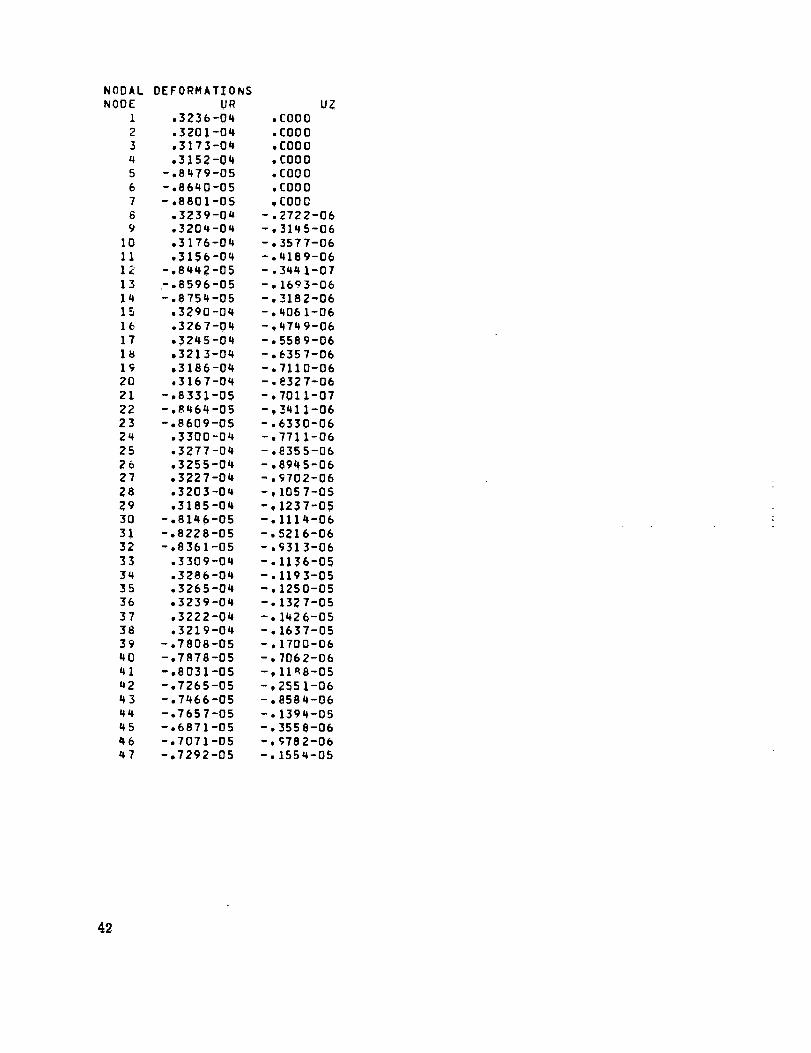
NODALNODE
1
234
56
769
101112
13
1415
1617
ls1920
Zl2223
2425
262728293031
3233
343536
373839
4O41
u2
434445
4647
DEFORMATIONS
UR
,3236-04
,3201-04
,3173-04
,3152-04
-,8479-05-.8640-05
-,8801-05
,3239-04,3204-04
,3176-04
,3156-04-,8442-05-,8596-05
-,8754-05
,3290-04
,3267-04
,3245-04
•3213-04
.3186-04,3167-04
-,8331-05
-,8464-05
-,8609-05.3300-04
,3277-04,3255-04,3227-04,3203-04
,3185-04-,8146-05
-,8228-05-,8361-05
,3309-04,3286-04,3265-04,3239-04
,3222-04,3219-04
-,78D8-05
-,7878-05
-,8031-05-,7265-05-,7466-05
-,7657-05
-,6871-05-,7071-05-,7292-05
UZ
,COO0
,COOD
,COOO
• CO00
,CO00
,COOO
,C000
- •2722-06
-,3145-06
-, 3577-06
-,4189-06- .3441-07-, 1693-06
-, _182-06
-,4061-06- , 4749-06
-,5589-06-°6357-06
-,7!10-06- • e32 7-06- • 701 1-07
-,3411-06- • 6330-06-,7711-06
-, 8355-06
-,8945-06-,9702-06- • 105 7-05
- • !237-05-,1114-06
-,5216-06-,_3!3-06
-. I136-05
-,1193-05
- • 1250-05
- • 132 7-05
-, 1426-05- • 1637-05-, 1700-06
- , 7062-06-, 11_8-05
- • 255 1-06-,8584-06-, 1394-05
- • 3558-06-, 978 2-06-, 1554-05
42

ELEMENT STRESSES
ELMT R STRESS T STRESS AX STRESS
I -,8323+06 ,_70C+06 -,3595+07
2 -,2811+07 .6117+08 -,8954+05
3 -,5270+07 ,6601+08 .4106+07
4 -,5352+07 -,3387+08 -.4976*075 -,1917+07 -,._332+08 ,5679+07
6 -,1602+07 ,5708+08 -,3089+_7
7 -,3335+07 ,6120+08 -,1539+06
b -,5822+07 .6593+08 .3608+_7
-,5866÷07 -,3373+08 -,4963+07
10 -,2162+07 -,3303+08 ,5662+07
11 -.5979+06 ,5367+08 ,1085+06
12 -,1992+07 ,5506+08 -,8765+06
13 -,2902+07 ,5753+08 -,1278+07
14 -,5091+07 ,609_+08 -,5590+0o
15 -,708b+07 ,6573+08 ,2596+07
16 -,7185+07 -, _348+08 -,4803÷07
17 -,2525-07 -, 3245+08 ,5469+07
16 -,6332+06 ,53_I+08 ,3459+05
19 -,1903+07 ,5559+08 -,1542+06
20 -,q396+07 ,5773+08 -,2527+06
21 -,8618+07 ,6046+08 -,2579+06
22 -,1374+08 ,6389+08 .6537+0b
23 -,7913+07 -,3246+0d -,4009+07
24 -,2350+07 -,3152+08 ,q554+07
25 -,3973+07 -,2921+08 -,2042+07
25 -,1557+07 - .3049+08 ,233q+07
27 ,13-_3÷06 -,2590708 -,3783+06
2_ -,3622+06 -,2917+08 ,q595÷nb
AVERAGE T,_NGENTI AL STRESS: ,7186+07
SH STPESS
-,2358+06
-,2859+06
-,1301+06
,1540+05
-°6740+04
-,4264+06-,9331+06
-,3761+06
,3477+04
-,1655+06
-,1777+05
,1610+06
-,1042+07
-,1778+07
-,6713+06
-,1672+06
-,8044+06
,1969+05
-,1607+06
-,8113+0b
-,1600+07
-,1744+07
-,1535+07
-,1868+07
-.3472+07-,2233+07
-,7005÷06
-,1197+07
R
,06550
,06250
,05950
.05550
.Off050
,06550
,06250
,05950
,05550
,05050
.07000
,06800
,06550
.06250
,05950
,05550
,05050
,07000
,068C0
,06550
,06250
,05950
,05550
,05050
,05550
,05050
,05550
,05050
Z
,00150
,00150
,00150
,00160
,00150
,00150
,00150
,0015G
,00150
,00150
,00150
,00150
,00150
,00150
,00150
,0OlSG
,00150
,00150
,00150
,00150
,00150
,00150
,00150
,00150
,00150
,00150
,00150
,00150
43

REF ER ENC ES
1. Wilson, E. A. ; and Parsons, B. : Finite Element Analysis of Elastic Contact Prob-
lems Using Differential Displacements. Int. J. Num. Methods Eng., vol. 2, no. 3,July-Sept. 1970, pp. 387-395.
2. Zienkiewicz, O. C. : The Finite Element Method in Structural and Continuum
Mechanics. McGraw-Hill Book Co., Inc., 1967.
3. Crout, P. D. : A Short Method for Evaluating Determinants and Solving Systems of
Linear Equations with Real or Complex Coefficients. Trans. Am. Inst. Electr.
Eng., vol. 60, 1941, pp. 1235-1240.
t. Harris, T. A. ; and Broschard, J. L. : Analysis of an Improved Planetary Gear
Transmission Bearing. J. Basic Eng., vol. 86, Sept. 1964, pp. 457-462.
44

Card(s)
A
B
C
D
E
F
G,H
I
J,K
L
M
N
0
P
Q
R
S
T
U
TABLE I. - DATA CARD SEQUENCE FOR A SINGLE CASE RUN
Comment
= 1 (number of geometries)
= I (number of cases for the geometry)
repeat as appropriate
ifthere are "special" material elements, repeat as appropriate
ifbase material properties are temperature dependent, repeat as appropriate
ifnodes are constrained, repeat as appropriate
if nodal forces are applied, repeat as appropriate
if = O, terminate data; if = 1, continue for an interference case
.r
repeat as appropriate
if = O, go to card T
repeat as appropriate
if = O, terminate data; if = 1, continue for slip analysis
..... .......----.--....___.._....._..._......._..__........_.............
Typel
bL
ri_>O,rj> rp bk>l_, bL>bj
Type2
bL, bk(=b)
ri i
Lri_>O, rk_>O, rj > ri, rL> rk, bL> 0
Trapezoidalaxisymmetricelements
Type0
__r_rJ
ri20, rj20, r i + rj, bk ÷ 0
Triangular axlsymmetric element
Figure 1. - The three types of element incorporated into the computerprogram.
45

Radial (r)
Axial (z)
Figure 2. - 1he coordinatesystem.
1Readin cardsA to K, generatinggeometry andelement materialpropert es. Pr nt out
I Calculate element stiffness Icharacteristics and assemblemain stiffness matrix
Readin cards L and M and /generate force vector and 1node restriction conditions
No interference
_0
Interference
No interference
Solve the system Lof equations I
II Calculate and print out I
Ideformations andstresses I -"
I
-I
]i,
II Readin cards Oand P, and t
i
reduce equations appropriateito the interference
Interference
ICalculate and print out forcesIat interference positions due I
to nterference only J
• II_addpio_n_ar_Rnten_eSrenacndpCraeIsCsUlra_e ]
• I
I Readin card Uand allownodes
to slip asappropriate. Print outinterference forces during slipcycles anddeformations andstresses on completion
Figure3. - Flowchart for a single caserun.
,t6

Element not involved in an
interference. NW =16 - 1 = 15
15 I
10 2
17 3 R
181 ....O. 4
Elements having interference at
nodes 2-3and 16-17. Element (_
NW • 17 - 1 = 16;, element (_)NW • 18 - 2 - 16
Figure 4. - Determination of nodal number difference (NW) in element.
ICylinder with uniformly distributed compressive loading of Q/unit
length on its outer surface
Equivalent forces at -
Nodes 1 and 4:- O._R- _, _- -
<½),,,,,oNodes 2 and _.- + O'2"trR ' i ' • -T
Figure 5. - Determination of node applied forces due to distributed load.
33 15
® ®25 16
)5 @ 26 @ 17
37
®38
45 42 )9
,®,3 ® ,o®
i,,@,,®,,@
® _o®
21G
@ ®)2 23
s I]
O9 2
®I0 3
®)) 4
12 @ 5
13 6
14 _0
t'I
!
0,012 m
_-._0.006m-i_ 1
..........
Inner race
,/r Interferencei
G 071rn tad.
Figure6. - Theexample: the Inner ring andshaft of roller bearing. (Not to scale.)
NASA-Langley, 19/7 E-9018 47
