finite element analysis of the seismic behavior of …
TRANSCRIPT

Article no. 51
THE CIVIL ENGINEERING JOURNAL 4-2019
---------------------------------------------------------------------------------------------------------------
DOI 10.14311/CEJ.2019.04.0051 606
FINITE ELEMENT ANALYSIS OF THE SEISMIC BEHAVIOR OF
THE ASSEMBLED LIGHT STEEL FRAME- LIGHT WALL
STRUCTURES
Liu Wenchao 1,2*, Chen Zheng 3, Wang Cheng 1, Dong Hongying 3, Wang Ruwei 3
1. Technology Research and Development Center , CCCC Fourth Highway
Engineering CO.,LTD., Beijing 100022, China;[email protected]
2. Office of Postdoctoral Research, Beijing University of Technology, Beijing
100124, China; [email protected]
3. Key Laboratory of Urban Security and Disaster Engineering, Beijing University
of Technology, Beijing 100124, China; [email protected]
ABSTRACT
In order to meet the needs of the development of low-rise assembly structure in rural areas,
a fabricated light-weight steel frame-composite light wall structure is proposed in this paper. The
light-weight steel frames are used to bear the vertical loads. The single-row-reinforced recycled
concrete wall-boards are used as lateral members to resist most of the horizontal earthquake
loads. The wall-board, EPS (Expanded Polystyrene) insulation modules, and fly ash blocks form
the thermally insulated wall. Four fabricated lightweight steel frame-composite light wall structures
and one light-weight steel frame (FRA) structure were tested under the low cyclic loads. The
influence of wall reinforcement spacing and structural form (be it fly ash block or not) on the
seismic performance of this new structure was analysed and the damage process of the specimen
was simulated using the ABAQUS® software. The results show that the light steel frames and the
single-row-reinforced recycled concrete wall-board can work well together. Furthermore, the
structure has two clear seismic lines. Due to the use of EPS insulation modules and fly ash blocks,
the structure has good anti-seismic and thermal insulation abilities. Reducing the spacing of bars
or compositing fly ash blocks can significantly improve the seismic performance of the structure.
The finite element method (FEM) calculations agreed well with the experimental results, which
validates the proposed model.
KEYWORDS
Pre-fabricated construction, Rural residence, Fabricated light-weight steel frame- composite
light wall structure, Seismic performance, Experimental study

Article no. 51
THE CIVIL ENGINEERING JOURNAL 4-2019
---------------------------------------------------------------------------------------------------------------
DOI 10.14311/CEJ.2019.04.0051 607
INTRODUCTION
Due to rapid growth in the sector of construction and low production costs, pre-fabricated
construction has attracted the attention of many scholars in the early 20th century. By the 1960s,
pre-fabricated construction had preliminarily been established in developed countries, such as
Great Britain, France and the former Soviet Union. China began to vigorously develop pre-
fabricated construction in 2015, and introduced a series of related measures. In November 2015,
the Ministry of Housing and Urban-rural Development issued the “Outline for the modernization
and development of the construction industry“, and in February 2016, the state council issued the
"Guidelines on the vigorous development of prefabricated construction“, both of which clearly
pointed out the development of pre-fabricated construction. According to some statistics, at
present, the construction of villages and towns accounts for more than 50% of the total buildings in
China. There is only a handful of research on the structural technology suitable for pre-fabricated
construction in villages and towns. Villages and towns are in urgent need of developing new
assembly-type structural systems.
Domestic and foreign scholars have conducted a lot of research on the assembled
residential systems. Serrette et al. studied the thin-walled light steel structure, and carried out a
series of tests and theoretical analyses on the lateral resistance of light steel keel composite wall
[1-4]. Based on the frame of the concrete light wall structure, Tsinghua University developed SW
structure [5]. Hao et al. (2010) developed the CL building system based on the welded steel grid
technology [6]. Beijing University of Civil Engineering and Architecture developed the LI+T
composite concrete building system (2007), in which the connection between different types of
wall-boards is unified, whereas the number of structural nodes is also reduced [7]. Xi'an University
of Architecture and Technology and Beijing Jiaotong University jointly developed the energy saving
system having multi-ribbed composite plate and light frame structure (2010), which is suitable for
high-rise earthquake-resistant structures consisting of pre-fabricated components and integral
pouring of external frames [8].
Mochizuki tested the seismic performance of vertical joints of pre-cast concrete shear wall,
and found that the ultimate bearing capacity of the wall was related to the constraint conditions of
horizontal joints (including pin action). Chen et al. (2012) carried out low-cycle repeated load test
on the one-half reduced scale four-storey space model of the full-prefabricated shear wall
structure, and showed that the yield load is much higher than the seismic shear force, whereas the
test piece maintained elasticity under medium earthquake and therefore, can meet the fortification
target of large earthquakes [10]. Cao et al. (2017) carried out an experimental study on the seismic
performance of semi-assembled low-rise recycled concrete shear wall, and the results showed
that, under horizontal load, horizontal crack and a small slip appear in the joint connection between
the pre-cast shear wall and the foundation wall, whereas the structure had good seismic
performance [11].
Many studies have been conducted on the seismic performance and connection
performance of light steel shear wall. Most of them have focused on industrial and high-rise

Article no. 51
THE CIVIL ENGINEERING JOURNAL 4-2019
---------------------------------------------------------------------------------------------------------------
DOI 10.14311/CEJ.2019.04.0051 608
buildings. However, research on the seismic performance of pre-fabricated light steel frame-
composite light wall structure, suitable for rural residential buildings, has not been reported in
literature. To this end, the low-cycle cyclic load tests of four assembled light-weight steel-light wall
structure and one light-steel hollow frame were designed. This paper studies the influence of
construction measures (be it the composite fly ash block layer or not) and spacing of distributed
bars on the bearing capacity, hysteretic characteristics, ductility, stiffness and failure mode of the
wall structure, and provides a reference for the design of assembled structure of rural buildings.
EXPERIMENTAL
Material Properties
The specimen was made of 42.5 grade ordinary Portland cement, in which the replacement
of recycled coarse aggregate(RCA) was 100% (particle size of 5-10 mm). The recycled coarse
aggregate was made up of crushed concrete of a demolished building in Beijing, China. Fine
aggregate used natural sand (aggregate size 0-5 mm). All aggregates were mixed with tap water.
The mixing ratio and cubic compressive strength (fcu) of recycled aggregate concrete is presented
in Table 1.
The measured concrete strength is presented in Table 1. The mechanical properties of the
steel used in the test piece are given in Table 2. The EPS modules were used as the insulation
layer. The compressive strength of fly ash blocks, used in the specimen, was 2.35 MPa. The M10
mixed mortar (The strength representative value is 11.5MPa~16.0MPa) was used for building the
specimen.
Tab. 1 - Mixing proportion and cubic compressive strength of the specimen (kg/m3)
RCA/% Cement Fly
ash
Mineral
powder Sand
Recycled
pebble
Water
reducer Water fcu/MPa
100 369 78 78 841 841 3.5 181 43.6

Article no. 51
THE CIVIL ENGINEERING JOURNAL 4-2019
---------------------------------------------------------------------------------------------------------------
DOI 10.14311/CEJ.2019.04.0051 609
Tab. 2 - Mechanical properties of steel bar and steel tube
Steel type Steel size
/mm
Yield
strength fy
/MPa
Ultimate
strength fu
/MPa
Elongation
/ %
Modulus of
elasticity
E/MPa
Thickness
/mm
Steel bar D5 680 786 5.5 2.09×10⁵ —
Steel plate — 309 467 25.27 2.11×10⁵ 4
Steel tube 100×100 375 477 23.23 2.18×10⁵ 4
Details of the Test Specimens
Four fabricated light-weight steel frame-composite light wall structures and one light-weight
steel frame structure were designed. The main parameters of the specimens are presented in
Table 3. The light-weight steel frames were constructed of square steel tubes having the thickness
of 4 mm and which were filled with recycled concrete. In order to facilitate the bolt connection with
the single-row-reinforced recycled concrete wall-boards, steel plate with the thickness of 4 mm was
welded. The frame joint was enhanced, and the column foot was provided with 8 bolt holes to
facilitate the connection with the I-foundation. The column foot bolt adopted M20 high-strength bolt.
The recycled concrete wallboard was composed of frame steel plate with the thickness of 4 mm
and distributed reinforcement with a diameter of 5 mm. The connecting bolt of the wall-board was
M10. The single-row distributed reinforcement of wall-board was placed in two directions. The
reinforcement ratio of the distributed rebar was 0.33%~0.49%. The size and reinforcement details
of the specimens are shown in Figure 1.

Article no. 51
THE CIVIL ENGINEERING JOURNAL 4-2019
---------------------------------------------------------------------------------------------------------------
DOI 10.14311/CEJ.2019.04.0051 610
Tab. 3 - Main parameters of the specimens
Serial No. Wallboard
thickness/mm
Reinforcement
spacing/mm
EPS module
thickness /mm
Fly ash block
thickness /mm
PFS40-S1-1 40 100 70 -
PFS40-S1-2 40 100 70 60
PFS40-S2-1 40 150 70 -
PFS40-S2-2 40 150 70 60
FRA - - - -
(a) Details of the specimen
(b) Construction of the specimen
Fig. 1 - Size and reinforcement details of specimens

Article no. 51
THE CIVIL ENGINEERING JOURNAL 4-2019
---------------------------------------------------------------------------------------------------------------
DOI 10.14311/CEJ.2019.04.0051 611
Test Set-Up and Loading Programme
In this work, low cyclic load method was adopted for the tests. In this regard, 600 kN
vertical load was applied at the top center of the distribution beam, which remained constant during
the loading process. The loading field is shown in Figure 2(a). The horizontal load was applied at
the center of the frame beam. The loading point was 1480 mm from the top of the foundation, and
the axial compression ratio was 0.35. In order to prevent the out-of-plane instability of specimens
during loading, lateral restraint braces were set in the vertical direction of horizontal loading. The
column base of the specimen was fixed to the steel beam of the foundation using high-strength
bolts, and the steel beam of the foundation was fixed to the ground using ground anchor bolts.
The measured horizontal displacement of the loading point was used as the control
displacement. When the displacement angle was less than 1/500, the displacement loading
increment was 1/2500. When the displacement angle was less than 1/50, the displacement loading
increment was 1/500. When the displacement angle was greater than 1/50, the displacement
loading increment became 3/500, which was twice per stage. During the whole testing process, the
displacement loading rate was consistent. It is stipulated that the force was positive when the
horizontal jack was pushed out. The magnitude of the displacement loading is shown in Figure
2(b).
Force sensors are arranged at the ends of vertical and horizontal jacks. At the loading
height, the horizontal displacement meter is arranged at the end of the loading beam.
(a) Loading field (b) Loading history
Fig. 2 - Loading device and the loading history
RESULTS AND DISCUSSION
Failure Characteristics
The obvious shear failure took place in the wall, which indicated that the wall undertook a
lot of horizontal shear force. With the wall cracked, the light steel frame became the main force-
bearing member at the later stage of loading. It finally underwent bending failure, while no obvious
-60
-40
-20
0
20
40
60
0 1 2 3 4 5 6 7 8 9 10 11 12 13 14 15 16 17 18 19
Δ/m
m
Δ≤ 2.96mm Δ>29.6mm

Article no. 51
THE CIVIL ENGINEERING JOURNAL 4-2019
---------------------------------------------------------------------------------------------------------------
DOI 10.14311/CEJ.2019.04.0051 612
damage was found in the joint. The structure had two clear seismic lines. In the later stage, the
connecting members between the wall and the frame were not obviously damaged, which
indicated that the two components worked well together. With the increase of reinforcement ratio,
the width of diagonal crack in the wall obviously decreased. The damage of the wall with fly ash
layer was not obvious, which indicated that fly ash block could effectively withstand the horizontal
force of the wall. Figures 3(a) - 3(h) show the ultimate failure models and crack distribution of
specimens.
(a) Broken of the bar (b) Steel plate tearing (c) Separation of EPS (d) Bulging of steel tube
(e) PFS40-S1-1 (f) PFS40-S2-1 (g) PFS40-S1-2 (h) PFS40-S2-2
Fig. 3 - Failure models and crack distribution of specimens
Load-Displacement Response
The measured characteristic results of specimens on the skeleton curve are presented in
Table 4. In Table 4, Fy is the yield load, Fu is the peak load, and Fd is the failure load. Furthermroe,
Δc, Δy, Δu and Δd are the displacement values corresponding to Fc, Fy, Fu and Fd, respectively.
Addtiionally, θc, θy, θu and θd are the corresponding interlayer displacement angles. The yield load
is determined by energy equivalence method. The failure load is the corresponding load value
when the peak load drops to 85%. The skeleton curves of specimens are shown in Figure 4.

Article no. 51
THE CIVIL ENGINEERING JOURNAL 4-2019
---------------------------------------------------------------------------------------------------------------
DOI 10.14311/CEJ.2019.04.0051 613
Tab. 4 - Measured characteristic results of the specimens
Serial No. Fy/kN Δy/mm Fu/kN Δu/mm Fd/kN Δd/mm µ
PFS40-S1-1 784.10 7.35 920.63 10.12 800.95 13.63 1.85
PFS40-S1-2 966.71 7.18 1141.11 11.44 969.95 14.88 2.07
PFS40-S2-1 623.27 7.87 731.89 11.10 622.10 13.71 1.74
PFS40-S2-2 797.68 7.20 936.34 9.82 795.89 14.85 2.06
FRA 120.74 26.83 143.56 47.54 122.03 64.89 2.42
Fig.4 - Skeleton curves of specimens Fig. 5 - “Ki-Δ” curves of specimens
Compared with the specimens without filled fly ash block, the bearing capacity of the
specimens filled with fly ash block was significantly increased. The yield loads of PFS40-S1-2 and
PFS40-S2-2 increased by 18.9% and 21.9%, respectively, indicating that the bearing capacity of
the structure significantly increased due to the filling by fly ash block. The wall reinforcement
spacing had a relatively large impact on the bearing capacity of the structure. Compared with
PFS40-S2-1 and PFS40-S2-2, the peak loads of PFS40-S1-1 and PFS40-S1-2 increased by
20.5% and 17.9%, respectively. The ultimate bearing capacity of light-weight steel frame was
139.61 kN. The ultimate bearing capacity of light-weight steel frame-composite light wall structures
was 424.24% - 825.33% higher than that of light-weight steel frame.
The proposed structure meets the requirements of the Chinese Code for seismic design of
buildings [12], which states that the elastic-plastic displacement angle of steel structure is limited to
1/50 and the failure displacement angle of specimen FRA is 1/23. The results show that the
recycled concrete light-weight steel frame has good collapse resistance. Meanwhile, the elastic-
plastic ultimate displacement angle of specimens PFS-S1-2 and PFS-S2-2 with fly ash filled layer
meet the requirement, which states that the elastic-plastic displacement angle of reinforced
concrete frame - seismic wall should not be higher than 1/100.
It is assumed that the weight of low-rise buildings is about 1.5T per square meter. For a 150
m2 house, the total mass is about 225t. In the case of 8 degree seismic fortification intensity, the
maximum value of the basic seismic acceleration is 0.3g, whereas the horizontal load is calculated

Article no. 51
THE CIVIL ENGINEERING JOURNAL 4-2019
---------------------------------------------------------------------------------------------------------------
DOI 10.14311/CEJ.2019.04.0051 614
to be 675 kN. Furthermore, the average yield load of the wall specimen is 792.94 kN, while the
overall structure is controlled within the elastic working range.
(1)
The displacement ductility coefficient μ is the ratio of Δd (failure displacement) to Δy (yield
displacement). Since the hysteresis curve is not completely symmetrical, the displacement ductility
coefficient is calculated according to Equation (1).
1) The recycled concrete light steel frame has good ductility, whereas the maximum failure
displacement can reach the value of 64.89 mm. Compared with the light-weight steel frame, the
ductility of the structure is reduced after the wall-board is assembled.
2) The specimens PFS40-S1-2 and PFS40-S2-2 filled with fly ash block have larger peak and
failure displacements. Meanwhile, the ductility coefficient is also higher, which indicates that fly ash
block can effectively improve the ductility of the structure.
3) Reducing the spacing of distributed reinforcement or increasing the reinforcement ratio of
distributed reinforcement can effectively improve the ductility coefficient of the structure.
Stiffness and Degradation
The stiffness-displacement Ki-Δ curves of specimens as shown in Figure 5. In this study, K
is the secant stiffness of peak points at different time intervals. As shown by the results presented
in Table 5, K0, Ky, Ku and Kd represent the average values of secant stiffness of hysteresis curve in
the initial stage, yield load, peak load and failure load, respectively. The Ki-Δ curves of specimens
are obtained using Equation (2).
(2)
where i is the number of cycles, Ki is the tangential stiffness of the i-th cycle, Fi is the peak
load corresponding to the i-th cycle, and +, - represent the positive and negative directions of the
horizontal force.
d d
y y
+ + −
=+ + −
i i
i
i i
F FK
+ + −=+ + −

Article no. 51
THE CIVIL ENGINEERING JOURNAL 4-2019
---------------------------------------------------------------------------------------------------------------
DOI 10.14311/CEJ.2019.04.0051 615
Tab. 5 - Experimental results of stiffness and degeneration coefficient
Serial No. K0/(kN∙mm-1) Ky /(kN∙mm-1) θy Ku /(kN∙mm-1) θu Kd/(kN∙mm-1) θd
PFS40-S1-1 265.48 106.68 1/201 90.97 1/146 58.76 1/108
PFS40-S1-2 304.88 134.73 1/206 99.75 1/129 65.18 1/99
PFS40-S2-1 248.24 79.20 1/188 65.97 1/133 45.38 1/107
PFS40-S2-2 283.41 110.87 1/206 95.35 1/151 53.60 1/100
FRA 15.88 4.50 1/55 3.02 1/31 1.88 1/23
The degradation of stiffness of light-weight steel frame-composite light wall structure can be
divided into five stages, namely the Initial stage, the cracking stage, the yield stage, the limit stage,
and the failure stage. The specimens have the character of higher initial stiffness, while the
stiffness decreases rapidly with the cracking of the wall. When the wall is seriously damaged, the
frame beam and the column are severely deformed. Then, the stiffness of the test piece continues to
decrease, though the rate of decrease drops down significantly.
In the case of same reinforcement spacing, the structure with fly ash block layer had higher
yielding stiffness, peak stiffness and failure stiffness. Compared with PFS40-S1-1 and PFS40-S2-1, the
average initial lateral stiffness of PFS40-S1-2 and PFS40-S2-2 increased by 12.92% and 12.41%,
respectively. In addition, the average yield stiffness increased by 20.82% and 28.56%, and the average
peak stiffness increased by 8.75% and 30.81%, respectively. Fly ash block significantly delayed the
structural damage during the process of loading.
In the case of same structural form, the spacing of distributed reinforcement bars has a great
influence on the characteristic stiffness of the specimen. Smaller the spacing of reinforcement bars,
higher was the characteristic stiffness of the specimen. The initial stiffness of the light steel frame
structure was 15.88 kN∙mm-1. Compared with the light-weight steel frame structure, the initial stiffness of
the new structure increases by 1463.22 - 2002.20.
Energy Dissipation Capacity
The area of intersection of characteristic point load skeleton curve and coordinate axis is
taken as the energy dissipation value. Furthermore, Ey is the yield energy dissipation, Eu is the
peak energy dissipation and Ed is the destruction energy dissipation. Additionally, Ep is the
cumulative total energy consumption, which is the cumulative area of the cyclic hysteresis loop
when the specimen is destroyed. The experimental results of energy dissipation are presented in
Table 6.
Article no. 51
THE CIVIL ENGINEERING JOURNAL 4-2019
---------------------------------------------------------------------------------------------------------------
DOI 10.14311/CEJ.2019.04.0051 616
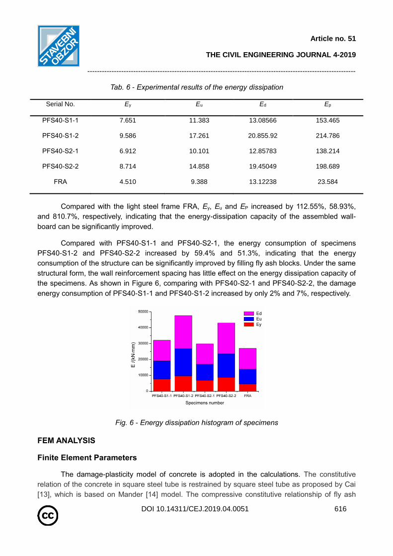
Tab. 6 - Experimental results of the energy dissipation
Serial No. Ey Eu Ed Ep
PFS40-S1-1 7.651 11.383 13.08566 153.465
PFS40-S1-2 9.586 17.261 20.855.92 214.786
PFS40-S2-1 6.912 10.101 12.85783 138.214
PFS40-S2-2 8.714 14.858 19.45049 198.689
FRA 4.510 9.388 13.12238 23.584
Compared with the light steel frame FRA, Ey, Eu and EP increased by 112.55%, 58.93%,
and 810.7%, respectively, indicating that the energy-dissipation capacity of the assembled wall-
board can be significantly improved.
Compared with PFS40-S1-1 and PFS40-S2-1, the energy consumption of specimens
PFS40-S1-2 and PFS40-S2-2 increased by 59.4% and 51.3%, indicating that the energy
consumption of the structure can be significantly improved by filling fly ash blocks. Under the same
structural form, the wall reinforcement spacing has little effect on the energy dissipation capacity of
the specimens. As shown in Figure 6, comparing with PFS40-S2-1 and PFS40-S2-2, the damage
energy consumption of PFS40-S1-1 and PFS40-S1-2 increased by only 2% and 7%, respectively.
Fig. 6 - Energy dissipation histogram of specimens
FEM ANALYSIS
Finite Element Parameters
The damage-plasticity model of concrete is adopted in the calculations. The constitutive
relation of the concrete in square steel tube is restrained by square steel tube as proposed by Cai
[13], which is based on Mander [14] model. The compressive constitutive relationship of fly ash

Article no. 51
THE CIVIL ENGINEERING JOURNAL 4-2019
---------------------------------------------------------------------------------------------------------------
DOI 10.14311/CEJ.2019.04.0051 617
block wall was adopted, as proposed by Wang [15]. The constitutive relation of steel adopted the
double broken line model. The contribution of EPS module to shear capacity was ignored.
Finite Element Model
The solid element C3D8R was used to simulate the steel tube, concrete and fly ash. The
truss element T3D2 was adopted for reinforcement of the wall-board, while the shell element S4R
was adopted for the steel plate of the wall-board. The steel bars are modelled separately without
considering the bond slip between the steel bars and the concrete. The model is divided using
hexahedral structured mesh, and the shell element is divided using the tetrahedron-main unit free
mesh, as shown in Figure 7.
(a) Constructional detail (b) Boundary condition (c) Steel skeleton (d)Wall structure
Fig.7 - Calculation models and meshing
Analysis of the Calculated Results - The Skeleton Curve
The comparison between the calculated and measured curves of force-displacement F–Δ is
shown in Figure 8.
(a)PFS40-S1-1 (b)PFS40-S1-2
Fig. 8 - Comparison between the calculated and measured curves of F–Δ

Article no. 51
THE CIVIL ENGINEERING JOURNAL 4-2019
---------------------------------------------------------------------------------------------------------------
DOI 10.14311/CEJ.2019.04.0051 618
(c)PFS40-S2-1 (d)PFS40-S2-2
Fig. 8 - Comparison between the calculated and measured curves of F–Δ
Figure 8 shows that, at the early stage of load, the calculated curve is in good agreement
with the measured curve. While in the middle and late stages, the calculated results lie below the
measured ones, whereas the error between the calculated and measured values of ultimate load is
less than 15%.
CONCLUSIONS
(1) The fabricated lightweight steel frame-composite light wall structure has two anti-seismic
lines of composite light wall and light steel frame. The structure has good seismic performance.
The EPS module and the fly ash filling layer can effectively slow down the structural damage
process.
(2) The structural form has a significant impact on the seismic performance of the structure.
Filling the fly ash block can effectively improve the seismic performance of the structure. The
spacing of reinforcing bars has a relatively small impact on the energy consumption performance.
It is suggested that the reinforcement ratio of reinforcing bars, distributed on the wall-board, should
be controlled within 0.25 - 0.33%.
(3) The stiffness of FEM calculated curve is in good agreement with the measured curve at the
early stage of loading. The calculated curve deviates from the measured curve during the middle
and late stages. The calculated values are less than the measured ones. The error between the
calculated and measured values is less than 15%.
(4) According to the estimation, the structure is still in the elastic working range and has a high
strength safety reserve under the circumstance of 8° seismic fortification intensity.

Article no. 51
THE CIVIL ENGINEERING JOURNAL 4-2019
---------------------------------------------------------------------------------------------------------------
DOI 10.14311/CEJ.2019.04.0051 619
REFERENCES [1] Serrette R. L., José, Encalada, et al., 1997. Static racking behavior of plywood, OSB, gypsum, and fiber
bond walls with metal framing. Journal of Structural Engineering, 123, 1079-1086.
[2] Goggins J. M., Broderick B. M., Elghazouli A Y, et al.,2005. Experimental cyclic response of cold-formed
hollow steel bracing members. Engineering Structures, 27, 977-989.
[3] Landolfo R., Fiorino L., Corte G. D., 2006. Seismic behavior of sheathed cold-formed structures:
numerical study. Journal of Structural Engineering, 132, 558-569.
[4] Pourabdollah O., Farahbod F., Rofooei F. R., 2017. The seismic performance of K-braced cold-formed
steel shear panels with improved connections. Journal of Constructional Steel Research, 135, 56-68.
[5] Qian J. R., Song X. L., Feng B.C., et al., 2013. Experimental study and finite element analysis of seismic
behavior of sprayed concrete sandwich shear walls. Journal of Building Structures, 34, 12-23. (in Chinese)
[6] Hao Y. H., Mu L. H., WANG Y.Q., et al., 2013. Application study on CL building structure system in the
construction of affordable housing. Building Structure, 43, 40-43. (in Chinese)
[7] Zhou Q., 2006. The study of LIT composite concrete light-duty house system. Beijing University Of Civil
Engineering And Architecture. (in Chinese)
[8] Jia S, Cao W, Zhang Y., 2017. Damage index calibration of frame-supported concealed multi-ribbed wall
panels with energy-efficient blocks. Applied Sciences, 7,453.
[9] Mochizuki S., Kobayashi T., 1996. Experiment on slip strength of horizontal joint of precast concrete multi-
story shear walls. Journal of Structural & Construction Engineering, 61, 63-73.
[10] Chen J. S., Guo Z.X., 2012. Seismic Performance Study on Space Model of the New Precast Concrete
Shear Wall Structure. Construction Technology, 41,87-89. (in Chinese)
[11] Liu C.W., Cao W.L, Dong H.Y., et al., 2017. Test on seismic behavior of semi-assembled low-rise
recycled concrete shear walls. Journal of Harbin Institute of Technology, 49,35-39. (in Chinese)
[12] China Standards Publication, GB50011-2010, 2010. Code for seismic of design buildings; Standard
Press of China: Beijing: China (in Chinese)
[13] Cai J., Sun G., 2008. Constitutive relationship of concrete core confined by square steel tube. Journal of
South China University of Technology, 36, 105-109.
[14] Mander J. B., Priestley M. J. N., Park R, 1988 . Theoretical stress‐strain model for confined concrete.
Journal of Structural Engineering, 114,1804-1826.
[15] Wang X., Li G., Shen Q.Z, 2005. Finite element analysis of the fly ash block walls strengthened by glass
fiber reinforced plastics. Industrial Construction, 35, 96-98.