find the click here
TRANSCRIPT

(217) 352-9330 | [email protected] | artisantg.com
-~ ARTISAN® ~I TECHNOLOGY GROUP
Your definitive source for quality pre-owned equipment.
Artisan Technology Group
Full-service, independent repair center with experienced engineers and technicians on staff.
We buy your excess, underutilized, and idle equipment along with credit for buybacks and trade-ins.
Custom engineering so your equipment works exactly as you specify.
• Critical and expedited services • Leasing / Rentals/ Demos
• In stock/ Ready-to-ship • !TAR-certified secure asset solutions
Expert team I Trust guarantee I 100% satisfaction
All trademarks, brand names, and brands appearing herein are the property of their respective owners.
Find the Mettler Toledo MiniMapper at our website: Click HERE
MiniMapper V1.1 User Guide 13602089 Version 2 06-03
Artisan Technology Group - Quality Instrumentation ... Guaranteed | (888) 88-SOURCE | www.artisantg.com

MiniMapper User Guide:
13602089 VERSION 2 06-03 2
The software described in this manual and all printed materials associated with the software, including this manual, is furnished under a license agreement and may be used only in accordance with the terms of this agreement.
MiniMapper V1.1
13602089 Version 2 06-03
Artisan Technology Group - Quality Instrumentation ... Guaranteed | (888) 88-SOURCE | www.artisantg.com

MiniMapper User Guide: Table Of Contents
13602089 VERSION 2 06-03 3
Table of Contents
1. Introduction 6 1.1. Safety 6
1.1.1. Avoiding Injury 6 1.1.2. General 6 1.1.3. Solvent Safety 7 1.1.4. Using the Emergency Stop 8
1.2. The MiniMapper Workstation 9 1.3. Installing the MiniMapper 10
1.3.1. Getting Started 10 1.3.2. Setting Up the System 11 1.3.3. Calibrating the Deck 12 1.3.4. Adjusting the Vent and Gas Pressure 14 1.3.5. Starting the System 15
1.4. Help and Further Information 16 1.5. Document Conventions 16
1.5.1. Formatting Conventions 16 1.5.2. Glossary of MiniMapper Terms 16
2. Information Server 18 2.1. Introduction 18 2.2. Adding Racks and Carriers 19
3. Preparing the Deck 20 3.1. Loading Racks and Carriers 20 3.2. Loading Reagents 21
4. Writing a Job 22 4.1. Creating a Layout 23
4.1.1. Using the My Racks Tab 24 4.1.2. Using the Advanced Tab 24 4.1.3. Adding a New Rack to the Layout 25 4.1.4. Adding a Rack / Carrier to My Racks 25 4.1.5. Renaming a Rack 27 4.1.6. Moving a Rack in the Layout 28 4.1.7. Removing a Rack from the Layout 28 4.1.8. Viewing Rack Layout Properties 28
4.2. Specifying Solvents for the Job 29 4.3. Managing Liquid Handling Parameters 30
4.3.1. Viewing the Liquid Manager 30 4.3.2. Liquid Handling Parameter Descriptions 31 4.3.3. Liquid Manager Toolbar 34 4.3.4. Editing Pipette Parameters 34 4.3.5. Adding Liquids 35 4.3.6. Adding Pipette Parameters 35 4.3.7. Creating a New Liquid Database 36
4.4. Mapper 37 4.4.1. Creating a Mapping 38 4.4.2. Volume Tracking 41
4.5. The Process 44 4.5.1. Steps 45 4.5.2. Adding Steps to a Process 46 4.5.3. Specifying Step Details 46
Artisan Technology Group - Quality Instrumentation ... Guaranteed | (888) 88-SOURCE | www.artisantg.com

MiniMapper User Guide: Table Of Contents
13602089 VERSION 2 06-03 4
4.5.4. Validating the Process 57 4.5.5. Saving the Process 58
4.6. Running the Job 58
5. Best Practices 59 5.1. Best Practices for MiniMapper Use 59
5.1.1. Dripping Solvents 59 5.1.2. Saturated Solutions 59 5.1.3. Precipitates 59
6. Maintenance 60 6.1. Manual Operations 60 6.2. Changing a Solvent Bottle 60 6.3. Emptying the Waste 61 6.4. Syringe Maintenance 61
6.4.1. Removing the Syringe 61 6.4.2. Replacing the Syringe 62 6.4.3. Changing the Sample Loop 63
6.5. Cannula Maintenance 64 6.5.1. Removing the Cannula 64 6.5.2. Replacing the Cannula 65
7. Troubleshooting 66 7.1. Hardware 66 7.2. Software 66 7.3. Liquid Handling Performance 67 7.4. Arm and Cannula 68 7.5. Contacting Customer Support 68
Appendix A: Accessories 69
Appendix B: Mapper Controls 70 B.1. Toolbar 70
B.1.1. Available Tools 70 B.1.2. Customizing the Toolbar 72
B.2. View and Selection Tools 73 B.3. Changing Preferences 74
B.3.1. Display Tab 74 B.3.2. General Tab 75
B.4. Menus 75 B.4.1. File Menu 76 B.4.2. Edit Menu 78 B.4.3. View Menu 79 B.4.4. Workstation Menu 80 B.4.5. Tools Menu 81 B.4.6. Help Menu 82
Artisan Technology Group - Quality Instrumentation ... Guaranteed | (888) 88-SOURCE | www.artisantg.com
MiniMapper User Guide: Table Of Contents
13602089 VERSION 2 06-03 5
Figures Figure 1-1: MiniMapper Workstation with Enclosure 9 Figure 1-2: Utility Panel Close Up 10 Figure 1-3: Electrical Connection Panel 11 Figure 1-4: Deck Calibration Tool and Robot Arm Foot 13 Figure 2-1: Information Server 18 Figure 3-1: Loaded Deck 20 Figure 4-1: Layout Window 23 Figure 4-2: Advanced Liquid Handling Parameters 33 Figure 4-3: Mapper Window 37 Figure 4-4: Vessel History Pop-up 41 Figure 4-5: Process Window 44 Figure 4-6: Add Solvent Edit Parameters Dialog Box 47 Figure 4-7: Aspirate Edit Parameters Dialog Box 48 Figure 4-8: Dispense Edit Parameters Dialog Box 49 Figure 4-9: Transfer Edit Parameters Dialog Box 50 Figure 4-10: Multi-Mapping Transfer 51 Figure 4-11: Mix Vial Contents Edit Parameters Dialog Box 53 Figure 4-12: Wash Cannula Edit Parameters Dialog Box 54 Figure 4-13: Prime Edit Parameters Dialog Box 54 Figure 4-14: Wait Edit Parameters Dialog Box 55 Figure 4-15: Pause Edit Parameters Dialog Box 55 Figure 4-16: Launch Executable Edit Parameters Dialog Box 55 Figure 4-17: Group Edit Parameters Dialog box 56
Tables Table 4-1: Writing a Job 22 Table 4-2: Pipette Parameters 32 Table 4-3: Liquid Manager Tools 34 Table 4-4 Step Buttons 45 Table 6-1: Manual Operations 60
Artisan Technology Group - Quality Instrumentation ... Guaranteed | (888) 88-SOURCE | www.artisantg.com
MiniMapper User Guide: Introduction
13602089 VERSION 2 06-03 6
1. Introduction
MiniMapper automates parallel synthesis. It provides:
– Accurate liquid handling – Variable solvent availability – 3-channel cannula that facilitates septum piercing, venting and inert gas dispersing, and
prevents cross contamination – Easy-to-use equipment and interface in a compact workstation – This manual describes how to use the MiniMapper.
1.1. Safety
1.1.1. Avoiding Injury
– Do not place your head or arms between the deck and top gantry of the machine while a job is running, while running manual steps, or when moving the robot head to the maintenance or home positions.
– Do not place your hand or any other object below the cannula at any time. The cannula is sharp and could pierce through the object when the arm moves up and down. Use caution when handling cannula.
– Do not place your head or arms above the machine while it is running. – A stationary robot head does not necessarily mean that the job is complete. Always check the
State field in the Execution window to confirm that the job has finished. – Do not touch the syringe pump while it is moving. Keep your hands clear when the syringe pump
is moving to syringe change position – Do not remove the front or back cover of the MiniMapper
1.1.2. General
– Only use consumables supplied by Mettler-Toledo AutoChem on MiniMapper. – Do not change MiniMapper software files. – Complete training through Mettler-Toledo AutoChem before operating MiniMapper. – Check with Mettler-Toledo AutoChem before running a machine affected by chemical corrosion
or mechanical damage.
Artisan Technology Group - Quality Instrumentation ... Guaranteed | (888) 88-SOURCE | www.artisantg.com
MiniMapper User Guide: Introduction
13602089 VERSION 2 06-03 7
1.1.3. Solvent Safety
When working with solvents always follow these guidelines.
– Do not use concentrated mineral acids such as sulfuric acid, nitric acid, and hydrochloric acid. – Do not use solutions of concentrated bases such as hydroxide and potassium hydroxide. – Do not expose the workstation to corrosive gases such as hydrogen chloride and hydrogen
fluoride. – Only run MiniMapper in a well ventilated fume-hood. – Do not leave open solvent vessels on the deck unless MiniMapper is on and the fume-hood is
operating. – Disconnect and seal or empty the waste bottle and online solvent bottles when the fume hood is
not running. – Always leave a minimum of 1inch of clearance behind the machine to allow good ventilation. – In the event of a large spill of volatile solvent (>500ml) on the deck of MiniMapper, vacate the
area and allow machine to dry off with the fume-hood running. – In the event of a large spill of non-volatile solvent (>500ml) on the deck of MiniMapper, clean up
the solvent from the deck and underneath the machine and ensure that the area is well ventilated.
– When using corrosive reagents such as TFA: – Do not pump corrosive reagents using the syringe and valve, instead, pipette them from the
deck. – Do not leave corrosive reagents on the deck after use or leave them open on the deck for long
periods of time. – Use Clean steps after each operation using a corrosive reagent – Clean the workstation thoroughly after using corrosive reagents including the lines, cannula,
deck to remove all traces of the reagent.
Artisan Technology Group - Quality Instrumentation ... Guaranteed | (888) 88-SOURCE | www.artisantg.com

MiniMapper User Guide: Introduction
13602089 VERSION 2 06-03 8
1.1.4. Using the Emergency Stop
In the event of an emergency, MiniMapper can be stopped without losing the contents of the vessels. Follow the instructions below to stop a job in an emergency.
1. Click the Halt button or push the red Emergency Stop button on the front of the workstation. The MiniMapper immediately stops whatever it is doing and goes into Error mode.
2. Click the Recover button to reset the workstation. The robot head moves to the home position.
3. Click the Manual Operations button and select Empty Syringe from the drop down menu. The Empty Syringe dialog box displays.
4. Specify which vial to dispense the sample to, by selecting it in the Deck Layout frame and dragging it into the Empty Syringe dialog box.
5. Click the OK button. MiniMapper dispenses the sample into the selected vial.
6. Select Manual Wash from the Manual Operations drop down menu and specify the parameters in the dialog box that displays. MiniMapper washes the cannula and syringe.
7. Click the Execution Tools button to resume the job. The Execution Tools dialog box displays.
8. Select the Step and Sample where the job was halted to begin the job again from that point. The Runmarker moves to the specified step and sample.
9. Click the Run button to restart the Job.
Artisan Technology Group - Quality Instrumentation ... Guaranteed | (888) 88-SOURCE | www.artisantg.com
MiniMapper User Guide: Introduction
13602089 VERSION 2 06-03 9
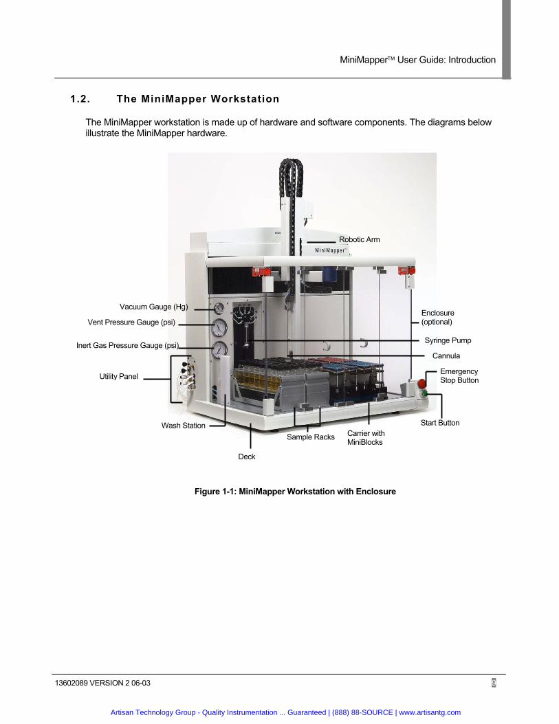
1.2. The MiniMapper Workstation
The MiniMapper workstation is made up of hardware and software components. The diagrams below illustrate the MiniMapper hardware.
Figure 1-1: MiniMapper Workstation with Enclosure
Emergency Stop Button
Enclosure (optional)
Robotic Arm
Syringe Pump
Cannula
Utility Panel
Vacuum Gauge (Hg)
Vent Pressure Gauge (psi)
Inert Gas Pressure Gauge (psi)
Start Button
Sample Racks Carrier with MiniBlocks
Deck
Wash Station
Artisan Technology Group - Quality Instrumentation ... Guaranteed | (888) 88-SOURCE | www.artisantg.com

MiniMapper User Guide: Introduction
13602089 VERSION 2 06-03 10
Online Solvent Bottle Connections
Vacuum In Vacuum Out
Waste
Vent Back Pressure Adjustment
Inert Gas
Figure 1-2: Utility Panel Close Up
1.3. Installing the MiniMapper
1.3.1. Getting Started
Unpack the system and verify that all parts are present and undamaged.
– Inspect the outside of the crate and any boxes for indications of damage. – Inspect the Tilt and Shock indicators on the outside of the MiniMapper crate. – Check all items on shipping list are present and in good condition – Visually inspect the MiniMapper for any signs of damage – Inspect for any loose/broken components, such as wiring and connections.
Artisan Technology Group - Quality Instrumentation ... Guaranteed | (888) 88-SOURCE | www.artisantg.com
MiniMapper User Guide: Introduction
13602089 VERSION 2 06-03 11
Monitor
Mouse and Keyboard
Reboot Button
Main Power Switch
Power
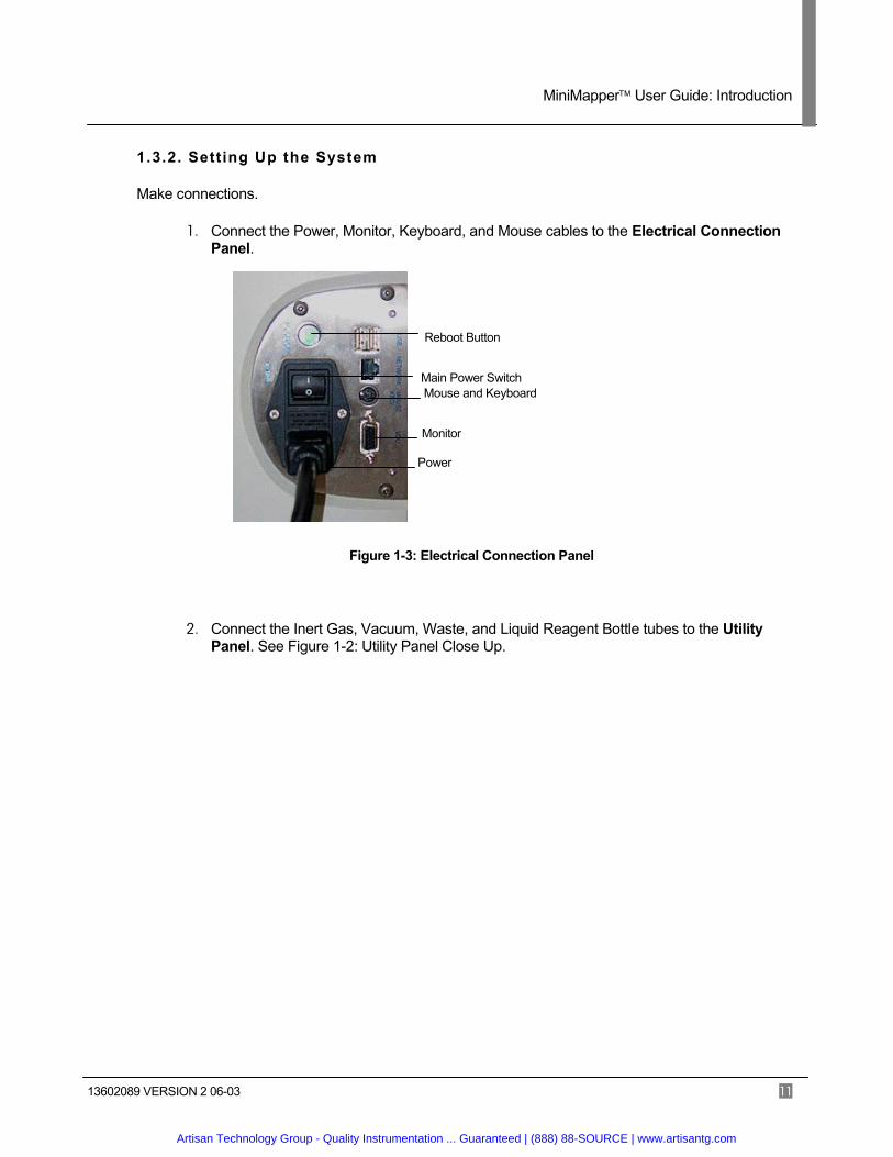
1.3.2. Setting Up the System
Make connections.
1. Connect the Power, Monitor, Keyboard, and Mouse cables to the Electrical Connection Panel.
Figure 1-3: Electrical Connection Panel
2. Connect the Inert Gas, Vacuum, Waste, and Liquid Reagent Bottle tubes to the Utility Panel. See Figure 1-2: Utility Panel Close Up.
Artisan Technology Group - Quality Instrumentation ... Guaranteed | (888) 88-SOURCE | www.artisantg.com
MiniMapper User Guide: Introduction
13602089 VERSION 2 06-03 12
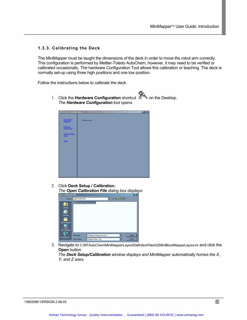
1.3.3. Calibrating the Deck
The MiniMapper must be taught the dimensions of the deck in order to move the robot arm correctly. This configuration is performed by Mettler-Toledo AutoChem, however, it may need to be verified or calibrated occasionally. The hardware Configuration Tool allows this calibration or teaching. The deck is normally set-up using three high positions and one low position.
Follow the instructions below to calibrate the deck.
1. Click the Hardware Configuration shortcut on the Desktop. The Hardware Configuration tool opens.
2. Click Deck Setup / Calibration. The Open Calibration File dialog box displays:
3. Navigate to C:\MTAutoChem\MiniMapper\Layout\DefinitionFiles\G2MiniBlockMapperLayout.ini and click the
Open button. The Deck Setup/Calibration window displays and MiniMapper automatically homes the X, Y, and Z axes.
Artisan Technology Group - Quality Instrumentation ... Guaranteed | (888) 88-SOURCE | www.artisantg.com
MiniMapper User Guide: Introduction
13602089 VERSION 2 06-03 13
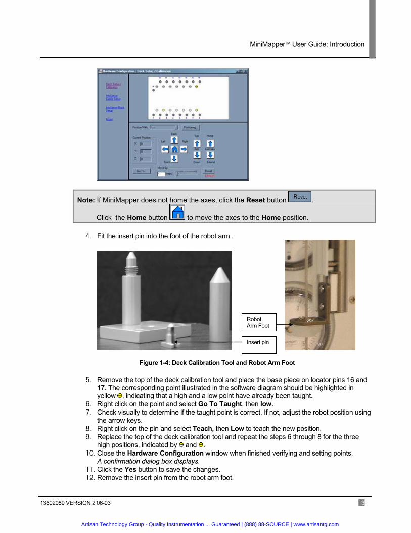
Note: If MiniMapper does not home the axes, click the Reset button .
Click the Home button to move the axes to the Home position.
4. Fit the insert pin into the foot of the robot arm .
Figure 1-4: Deck Calibration Tool and Robot Arm Foot
5. Remove the top of the deck calibration tool and place the base piece on locator pins 16 and 17. The corresponding point illustrated in the software diagram should be highlighted in yellow , indicating that a high and a low point have already been taught.
6. Right click on the point and select Go To Taught, then low. 7. Check visually to determine if the taught point is correct. If not, adjust the robot position using
the arrow keys. 8. Right click on the pin and select Teach, then Low to teach the new position. 9. Replace the top of the deck calibration tool and repeat the steps 6 through 8 for the three
high positions, indicated by and . 10. Close the Hardware Configuration window when finished verifying and setting points.
A confirmation dialog box displays. 11. Click the Yes button to save the changes. 12. Remove the insert pin from the robot arm foot.
Insert pin
Robot Arm Foot
Artisan Technology Group - Quality Instrumentation ... Guaranteed | (888) 88-SOURCE | www.artisantg.com
MiniMapper User Guide: Introduction
13602089 VERSION 2 06-03 14
1.3.4. Adjusting the Vent and Gas Pressure
Occasionally the Vent Pressure or the Argon Gas Pressure will need to be adjusted.
Use the following guidelines for setting the pressures.
– Typically the Argon gas setting should be slightly higher than the vent pressure. – Use higher pressure for large vessels and lower pressure for smaller vessels. – Settings of 2 psi for the vent and 2.5 psi for the Argon gas work well for most vessels.
Follow the steps below to adjust the vent or gas pressure. See 1.2 The MiniMapper Workstation to see the locations of the pressure gauges and the adjustment knobs.
1. Loosen the locking nut. 2. Turn the adjustment knob until the dial reads the desired value. 3. Tighten the locking nut to lock the adjustment knob into place.
Artisan Technology Group - Quality Instrumentation ... Guaranteed | (888) 88-SOURCE | www.artisantg.com
MiniMapper User Guide: Introduction
13602089 VERSION 2 06-03 15
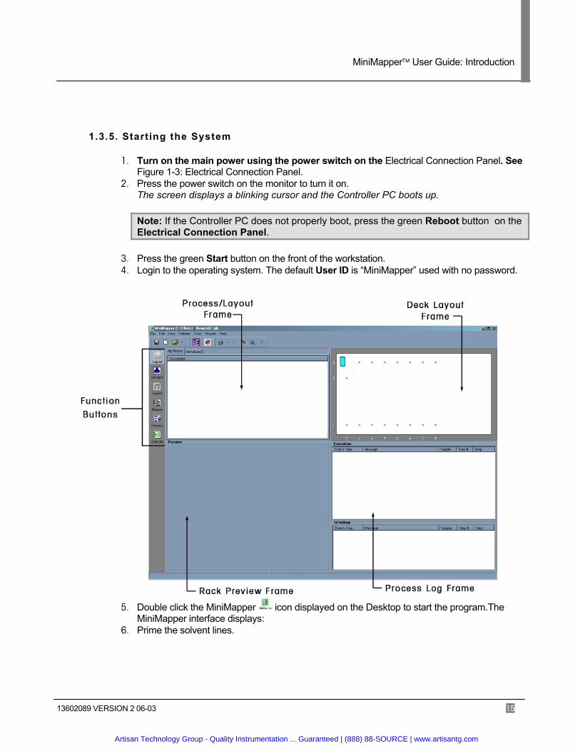
1.3.5. Starting the System
1. Turn on the main power using the power switch on the Electrical Connection Panel. See Figure 1-3: Electrical Connection Panel.
2. Press the power switch on the monitor to turn it on. The screen displays a blinking cursor and the Controller PC boots up.
Note: If the Controller PC does not properly boot, press the green Reboot button on the Electrical Connection Panel.
3. Press the green Start button on the front of the workstation. 4. Login to the operating system. The default User ID is “MiniMapper” used with no password.
5. Double click the MiniMapper icon displayed on the Desktop to start the program.The MiniMapper interface displays:
6. Prime the solvent lines.
Artisan Technology Group - Quality Instrumentation ... Guaranteed | (888) 88-SOURCE | www.artisantg.com

MiniMapper User Guide: Introduction
13602089 VERSION 2 06-03 16
1.4. Help and Further Information
If you have queries or comments that are not addressed in this user guide, please contact your local Mettler-Toledo office or visit our web site at www.mtautochem.com.
For technical support issues, please see section 7.5 Contacting Customer Support.
1.5. Document Conventions
1.5.1. Formatting Conventions
The following conventions are used in this document. 1. Notes designate alternate instructions or caveats.
2. Tips designate extra information that may be useful.
3. Bold font designates step, window, frame, field, and button names and other terms that appear in the MiniMapper software user interface.
4. Courier font indicates text typed into the interface. Specific keys appear in brackets. Example: <enter>
1.5.2. Glossary of MiniMapper Terms
AJB file The MiniMapper Job file. MiniMapper creates this file when the save option is selected.
Aspirate: The process of removing reagent from a vessel through suction. Aspiration is effected through the cannula.
Bulk Solvent: A solvent located in one of the six online bottles.
Cannula: The tube used to aspirate and dispense liquids. The cannula is located on the robotic arm. Many types of cannulas may be used, including cannulas for piercing septa.
Carrier: A device that holds small racks in order to place them on the deck.
Chemistry: Used in this document to refer to the chemical processes executed and supported by MiniMapper.
Deck: The physical workspace of the workstation where racks and carriers are placed. The deck features locator pins for securing the racks and carriers. The term deck also refers to graphical representation of the physical deck in the software.
Dispense: The process of putting reagent into a vessel through the cannula using pressure. Typically, some amount of liquid is first aspirated from one vessel or a bottle solvent and then dispensed into one or more other vessels.
Job: A complete set of instructions for the MiniMapper procedure including solvents, layout, and a process. Jobs can be saved or run once and discarded. Jobs can also be converted to templates for use in the MiniMapper Wizard software.
Artisan Technology Group - Quality Instrumentation ... Guaranteed | (888) 88-SOURCE | www.artisantg.com
MiniMapper User Guide: Introduction
13602089 VERSION 2 06-03 17
Layout: The configuration of racks and carriers on the MiniMapper deck, both physically and as specified in the software.
Mapper: Software utility used to create a graphical representation of the job called a Mapping.
Mapping: A graphical representation of the job. Mappings are created using the Mapper software.
MMA file: The Mapper Process Specification file. The Mapper creates this file and then the primary software uses it to add the appropriate steps to the process. The file may be reopened and edited using the mapper utility.
Process: A series of steps making up a procedure performed by MiniMapper.
Rack: A device that contains vessels. Racks come in many colors, sizes, orientation, and capacities including MiniBlock and XT.
RVL file: The Reagent Volume Level file specifies the initial volumes of all vessels in the process. The Mapper or an external program such as Microsoft Excel or Notepad can create this file.
Sample Loop:
The tubing that carries online solvents from the syringe to the cannula.
System Solvent:
Any solvent that has been defined in the Liquid Manager utility.
Step: Refers to any of a set of pre-defined actions performed by MiniMapper. Processes: are made up of steps.
Artisan Technology Group - Quality Instrumentation ... Guaranteed | (888) 88-SOURCE | www.artisantg.com
MiniMapper User Guide: Information Server
13602089 VERSION 2 06-03 18
Status Frame
Lists of data located in the current file
Location of the currently loaded file
Racks and Carriers tabs
Add
Load Save
Reload
Synchronize
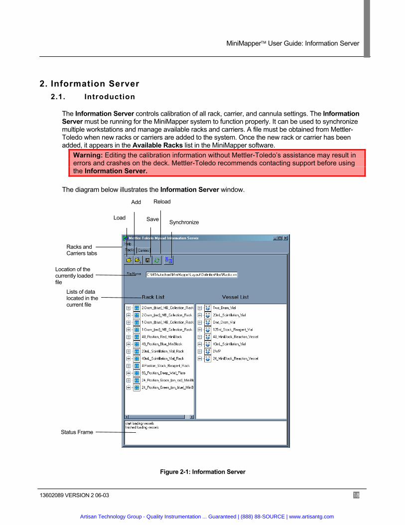
2. Information Server 2.1. Introduction
The Information Server controls calibration of all rack, carrier, and cannula settings. The Information Server must be running for the MiniMapper system to function properly. It can be used to synchronize multiple workstations and manage available racks and carriers. A file must be obtained from Mettler-Toledo when new racks or carriers are added to the system. Once the new rack or carrier has been added, it appears in the Available Racks list in the MiniMapper software.
Warning: Editing the calibration information without Mettler-Toledo’s assistance may result in errors and crashes on the deck. Mettler-Toledo recommends contacting support before using the Information Server.
The diagram below illustrates the Information Server window.
Figure 2-1: Information Server
Artisan Technology Group - Quality Instrumentation ... Guaranteed | (888) 88-SOURCE | www.artisantg.com
MiniMapper User Guide: Information Server
13602089 VERSION 2 06-03 19
2.2. Adding Racks and Carriers
Follow the instructions below to add new racks or carriers to the Information Server.
1. Save the rack or carrier XML file to the MiniMapper computer. 2. Double click the Information Server icon or click the icon and select Show from the menu that
displays. The Information Server window displays.
3. Click the Load button. The Open dialog box displays.
4. Navigate to the new XML file location and click the Open button. 5. Click the Add button.
The Open dialog box displays. 6. Navigate to C:\MTAutochem\MiniMapper\Layout\DefinitionFiles\Racks.xml to add racks or
C:\MTAutochem\MiniMapper\Layout\DefinitionFiles\Carriers.xml to add carriers and click the Open button.
7. Click the Save button.
Artisan Technology Group - Quality Instrumentation ... Guaranteed | (888) 88-SOURCE | www.artisantg.com
MiniMapper User Guide: Preparing The Deck
13602089 VERSION 2 06-03 20
3. Preparing the Deck
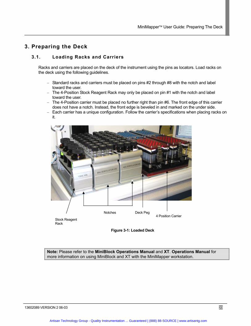
3.1. Loading Racks and Carriers
Racks and carriers are placed on the deck of the instrument using the pins as locators. Load racks on the deck using the following guidelines.
– Standard racks and carriers must be placed on pins #2 through #8 with the notch and label toward the user.
– The 4-Position Stock Reagent Rack may only be placed on pin #1 with the notch and label toward the user.
– The 4-Position carrier must be placed no further right than pin #6. The front edge of this carrier does not have a notch. Instead, the front edge is beveled in and marked on the under side.
– Each carrier has a unique configuration. Follow the carrier’s specifications when placing racks on it.
Figure 3-1: Loaded Deck
Note: Please refer to the MiniBlock Operations Manual and XT. Operations Manual for more information on using MiniBlock and XT with the MiniMapper workstation.
4 Position Carrier Deck Peg Notches
Stock Reagent Rack
Artisan Technology Group - Quality Instrumentation ... Guaranteed | (888) 88-SOURCE | www.artisantg.com
MiniMapper User Guide: Preparing The Deck
13602089 VERSION 2 06-03 21
3.2. Loading Reagents
Place the appropriate vials of reagents in the racks using the following guidelines.
– Cap with septum may be used. – Use caution when filling reagents so as not to exceed minimum and maximum volumes. These
volumes are critical for proper operation of the cannula and vent system. – Use caution when handling reagents that are sensitive to atmospheric exposure. – Carefully document where reagents and reactants have been placed. This information will be
needed when writing a job. – If using the Mapping software, a file may be generated in text, tab delimited format that contains
reagent and reactant information. See 4.4.2.2 Specifying Initial Volumes.
Note: Understanding of MiniBlock and XT materials is important when selecting MiniBlock and XT components for a given chemistry. Please refer to the MiniBlock Operations Manual and XT Operations Manual for more information.
Artisan Technology Group - Quality Instrumentation ... Guaranteed | (888) 88-SOURCE | www.artisantg.com

MiniMapper User Guide: Writing A Job
13602089 VERSION 2 06-03 22
4. Writing a Job
A MiniMapper job is made up of a Layout, a Map, and a Process.
– The Layout specifies the racks and their location on the deck. – The Mapping specifies the source and destination containers for liquids used in the job. – The Process lists the Steps that MiniMapper will perform.
The table below summarizes how to create a new job. Start the MiniMapper software (See Section 1.3.4 Error! Reference source not found.)
Load the Deck (See Section3 Preparing the Deck)
Specify the Layout (See Section 4.1 Creating a Layout)
Specify the Solvents for the Job (See Section 4.2 Specifying Solvents for the Job)
Adjust Liquid Handling Parameters (See Section 4.3 Managing Liquid Handling Parameters)
Create a Mapping (See Section 4.4 Mapper)
Create the Process (See Section 4.5 The Process)
Table 4-1: Writing a Job
Artisan Technology Group - Quality Instrumentation ... Guaranteed | (888) 88-SOURCE | www.artisantg.com
MiniMapper User Guide: Writing A Job
13602089 VERSION 2 06-03 23
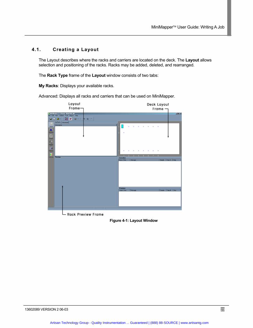
4.1. Creating a Layout
The Layout describes where the racks and carriers are located on the deck. The Layout allows selection and positioning of the racks. Racks may be added, deleted, and rearranged.
The Rack Type frame of the Layout window consists of two tabs:
My Racks: Displays your available racks.
Advanced: Displays all racks and carriers that can be used on MiniMapper.
Figure 4-1: Layout Window
Artisan Technology Group - Quality Instrumentation ... Guaranteed | (888) 88-SOURCE | www.artisantg.com
MiniMapper User Guide: Writing A Job
13602089 VERSION 2 06-03 24
4.1.1. Using the My Racks Tab
The My Racks tab displays in the Layout frame when the Layout window opens. The tab consists of the Description list box.
The Description list box contains the names of your commonly used racks. Clicking on a rack in this list displays a diagram of it in the Preview frame, at the bottom left of the window. Right-clicking on a rack in My Racks displays the following options:
– Add to deck – Rename – Delete – Properties
4.1.2. Using the Advanced Tab
The Advanced tab displays in the Layout frame when clicked in the Layout window. The tab consists of the following two tabs.
Racks: Displays the full range of racks that can be used on MiniMapper. Clicking the rack name in this list displays a diagram of it in the Preview frame, at the bottom left of the window. Double clicking the rack name adds it to the deck and displays it in the Deck Preview frame at the top right.
Carriers: Displays the full range of carriers or locators that can be used on MiniMapper. Clicking the carrier name in this list displays a diagram of it in the Preview frame, at the bottom left of the window. Double clicking the carrier name adds it to the deck and displays it in the Deck Preview frame at the top right.
Right-clicking on a rack or carrier in the Description frame displays the following option:
– Add to Deck
Artisan Technology Group - Quality Instrumentation ... Guaranteed | (888) 88-SOURCE | www.artisantg.com
MiniMapper User Guide: Writing A Job
13602089 VERSION 2 06-03 25
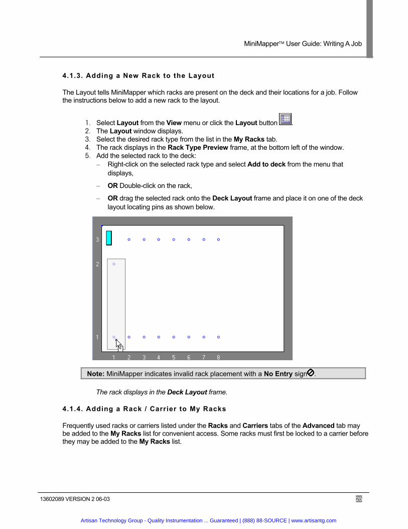
4.1.3. Adding a New Rack to the Layout
The Layout tells MiniMapper which racks are present on the deck and their locations for a job. Follow the instructions below to add a new rack to the layout.
1. Select Layout from the View menu or click the Layout button . 2. The Layout window displays. 3. Select the desired rack type from the list in the My Racks tab. 4. The rack displays in the Rack Type Preview frame, at the bottom left of the window. 5. Add the selected rack to the deck:
– Right-click on the selected rack type and select Add to deck from the menu that displays,
– OR Double-click on the rack,
– OR drag the selected rack onto the Deck Layout frame and place it on one of the deck layout locating pins as shown below.
Note: MiniMapper indicates invalid rack placement with a No Entry sign .
The rack displays in the Deck Layout frame.
4.1.4. Adding a Rack / Carrier to My Racks
Frequently used racks or carriers listed under the Racks and Carriers tabs of the Advanced tab may be added to the My Racks list for convenient access. Some racks must first be locked to a carrier before they may be added to the My Racks list.
Artisan Technology Group - Quality Instrumentation ... Guaranteed | (888) 88-SOURCE | www.artisantg.com

MiniMapper User Guide: Writing A Job
13602089 VERSION 2 06-03 26
4.1.4.1. Adding a Rack to My Racks
Follow the instructions below to add a rack to My Racks.
1. Add the rack to the Layout as described in 4.1.3 Adding a New Rack to the Layout. 2. Right click on the rack in the Deck Preview frame.
A drop down menu displays:
3. Select Add to My Racks The Enter Rack Name dialog box displays:
4. Type a name for the rack in the Rack Name text field. 5. Click the OK button.
The rack is added to the My Racks list.
Artisan Technology Group - Quality Instrumentation ... Guaranteed | (888) 88-SOURCE | www.artisantg.com

MiniMapper User Guide: Writing A Job
13602089 VERSION 2 06-03 27
4.1.4.2. Adding a Carrier to My Racks
Follow the instructions below to add a carrier to My Racks.
1. Add the carrier to the Layout in the manner described for racks in 4.1.4.1 Adding a Rack to My Racks.
2. Add a rack to the carrier, in the manner a rack is added to the Layout, if desired. 3. Right click on the carrier in the Deck Preview frame.
A drop down menu displays.
4. Select Lock to Carrier if a rack has been added to the carrier. 5. Right click on the carrier in the Deck Preview frame and select Add to My Racks from the
drop down menu. The Enter Rack Name dialog box displays:
6. Type a name for the carrier in the Rack Name text field. 7. Click the OK button.
The carrier is added to the My Racks list.
4.1.5. Renaming a Rack
Racks can be renamed for either the current job or the My Racks list.
Follow the instructions below to rename a rack for the current job.
1. Right-click on the rack in the Deck Preview frame to change the name for the job
OR
Right-click on the rack name in the My Racks tab to change the name in My Racks. A drop down menu displays.
2. Select Rename. The Object Name dialog box displays.
3. In the Name text box, type a new name for the rack. 4. Click the OK button to close the dialog box.
Artisan Technology Group - Quality Instrumentation ... Guaranteed | (888) 88-SOURCE | www.artisantg.com
MiniMapper User Guide: Writing A Job
13602089 VERSION 2 06-03 28
4.1.6. Moving a Rack in the Layout
Racks can be rearranged in the layout if necessary.
Follow the instructions below to move a rack on the Layout. 1. Click the rack you want to move in the Deck Preview frame.
2. Drag the rack to its new position.
Note: The drag cursor snaps to the locator pin positions on the deck layout.
4.1.7. Removing a Rack from the Layout
Follow the instructions below to remove a rack from the Layout. 1. In the Deck Preview frame, right-click on the rack.
A drop down menu displays.
2. Select Delete.
MiniMapper removes the rack from the deck.
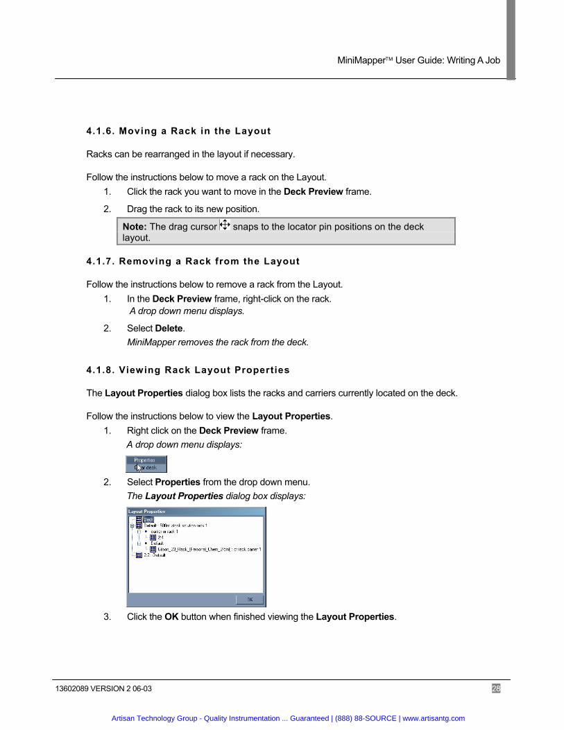
4.1.8. Viewing Rack Layout Properties
The Layout Properties dialog box lists the racks and carriers currently located on the deck.
Follow the instructions below to view the Layout Properties. 1. Right click on the Deck Preview frame.
A drop down menu displays:
2. Select Properties from the drop down menu.
The Layout Properties dialog box displays:
3. Click the OK button when finished viewing the Layout Properties.
Artisan Technology Group - Quality Instrumentation ... Guaranteed | (888) 88-SOURCE | www.artisantg.com
MiniMapper User Guide: Writing A Job
13602089 VERSION 2 06-03 29
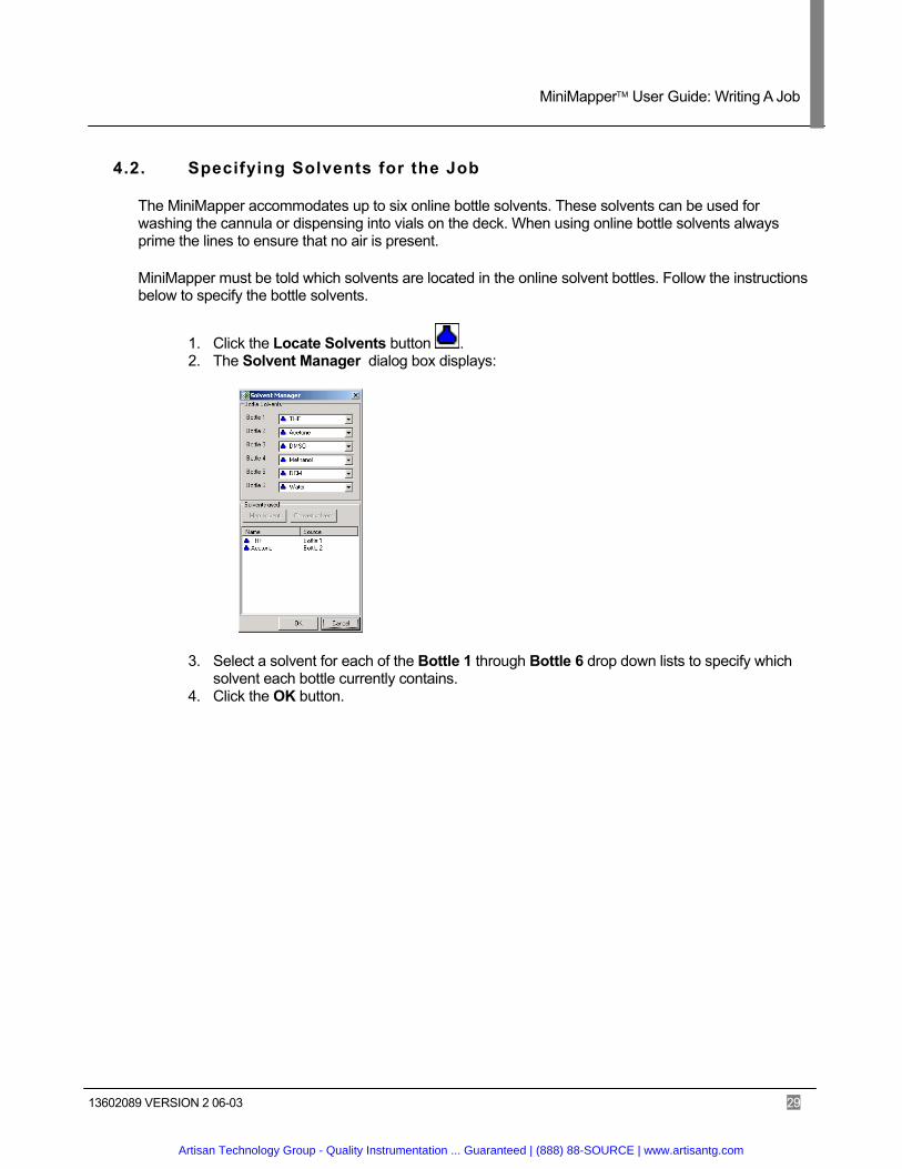
4.2. Specifying Solvents for the Job
The MiniMapper accommodates up to six online bottle solvents. These solvents can be used for washing the cannula or dispensing into vials on the deck. When using online bottle solvents always prime the lines to ensure that no air is present.
MiniMapper must be told which solvents are located in the online solvent bottles. Follow the instructions below to specify the bottle solvents.
1. Click the Locate Solvents button . 2. The Solvent Manager dialog box displays:
3. Select a solvent for each of the Bottle 1 through Bottle 6 drop down lists to specify which solvent each bottle currently contains.
4. Click the OK button.
Artisan Technology Group - Quality Instrumentation ... Guaranteed | (888) 88-SOURCE | www.artisantg.com

MiniMapper User Guide: Writing A Job
13602089 VERSION 2 06-03 30
4.3. Managing Liquid Handling Parameters
The Liquid Manager keeps track of all liquids used with the MiniMapper workstation along with information about the liquids. Each liquid may have several pipette parameters defined for handling the liquid in different scenarios. A default set of liquids and pipette parameters, called a liquid database, exists and other liquids and pipette parameters can be added, modified, and deleted from this database. New databases may also be created. The following sections describe how to manage liquids using the Liquid Manager.
4.3.1. Viewing the Liquid Manager
1. Click the Liquids button to open the Liquid Manager.
2. Click the next to the liquids icon to show all defined liquids.
3. Click the next to the desired liquid to show all available pipette parameter sets. 4. Click on a pipette parameter name to display the parameters. See Table 4-2: Pipette
Parameters for more information.
Artisan Technology Group - Quality Instrumentation ... Guaranteed | (888) 88-SOURCE | www.artisantg.com
MiniMapper User Guide: Writing A Job
13602089 VERSION 2 06-03 31
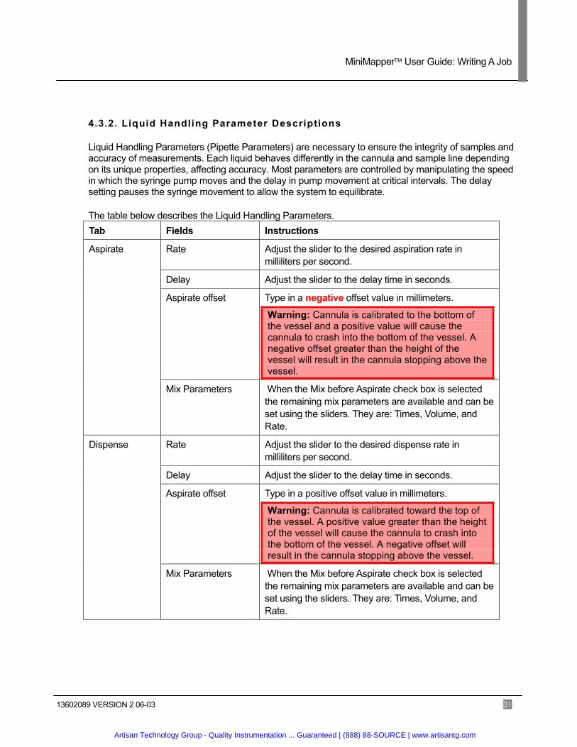
4.3.2. Liquid Handling Parameter Descriptions
Liquid Handling Parameters (Pipette Parameters) are necessary to ensure the integrity of samples and accuracy of measurements. Each liquid behaves differently in the cannula and sample line depending on its unique properties, affecting accuracy. Most parameters are controlled by manipulating the speed in which the syringe pump moves and the delay in pump movement at critical intervals. The delay setting pauses the syringe movement to allow the system to equilibrate.
The table below describes the Liquid Handling Parameters. Tab Fields Instructions
Rate Adjust the slider to the desired aspiration rate in milliliters per second.
Delay Adjust the slider to the delay time in seconds.
Aspirate offset Type in a negative offset value in millimeters.
Warning: Cannula is calibrated to the bottom of the vessel and a positive value will cause the cannula to crash into the bottom of the vessel. A negative offset greater than the height of the vessel will result in the cannula stopping above the vessel.
Aspirate
Mix Parameters When the Mix before Aspirate check box is selected the remaining mix parameters are available and can be set using the sliders. They are: Times, Volume, and Rate.
Rate Adjust the slider to the desired dispense rate in milliliters per second.
Delay Adjust the slider to the delay time in seconds.
Aspirate offset Type in a positive offset value in millimeters.
Warning: Cannula is calibrated toward the top of the vessel. A positive value greater than the height of the vessel will cause the cannula to crash into the bottom of the vessel. A negative offset will result in the cannula stopping above the vessel.
Dispense
Mix Parameters When the Mix before Aspirate check box is selected the remaining mix parameters are available and can be set using the sliders. They are: Times, Volume, and Rate.
Artisan Technology Group - Quality Instrumentation ... Guaranteed | (888) 88-SOURCE | www.artisantg.com
MiniMapper User Guide: Writing A Job
13602089 VERSION 2 06-03 32
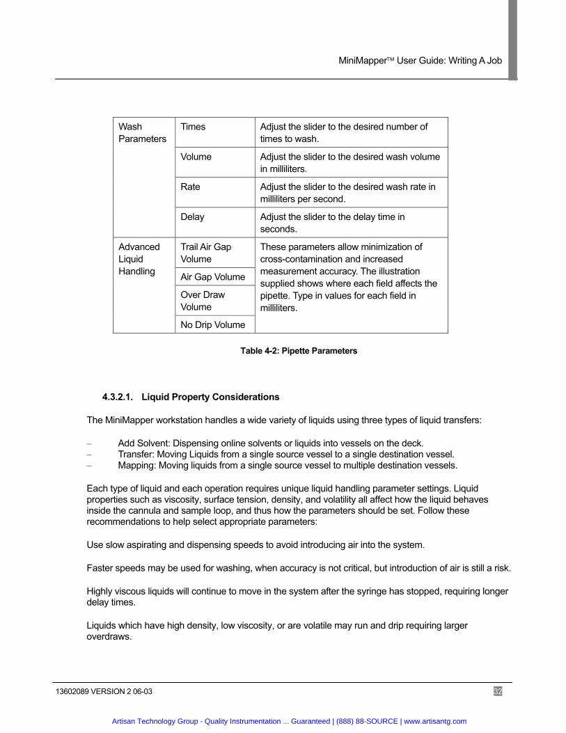
Times Adjust the slider to the desired number of
times to wash.
Volume Adjust the slider to the desired wash volume in milliliters.
Rate Adjust the slider to the desired wash rate in milliliters per second.
Wash Parameters
Delay Adjust the slider to the delay time in seconds.
Trail Air Gap Volume
Air Gap Volume
Over Draw Volume
Advanced Liquid Handling
No Drip Volume
These parameters allow minimization of cross-contamination and increased measurement accuracy. The illustration supplied shows where each field affects the pipette. Type in values for each field in milliliters.
Table 4-2: Pipette Parameters
4.3.2.1. Liquid Property Considerations
The MiniMapper workstation handles a wide variety of liquids using three types of liquid transfers:
– Add Solvent: Dispensing online solvents or liquids into vessels on the deck. – Transfer: Moving Liquids from a single source vessel to a single destination vessel. – Mapping: Moving liquids from a single source vessel to multiple destination vessels.
Each type of liquid and each operation requires unique liquid handling parameter settings. Liquid properties such as viscosity, surface tension, density, and volatility all affect how the liquid behaves inside the cannula and sample loop, and thus how the parameters should be set. Follow these recommendations to help select appropriate parameters:
Use slow aspirating and dispensing speeds to avoid introducing air into the system.
Faster speeds may be used for washing, when accuracy is not critical, but introduction of air is still a risk.
Highly viscous liquids will continue to move in the system after the syringe has stopped, requiring longer delay times.
Liquids which have high density, low viscosity, or are volatile may run and drip requiring larger overdraws.
Artisan Technology Group - Quality Instrumentation ... Guaranteed | (888) 88-SOURCE | www.artisantg.com
MiniMapper User Guide: Writing A Job
13602089 VERSION 2 06-03 33
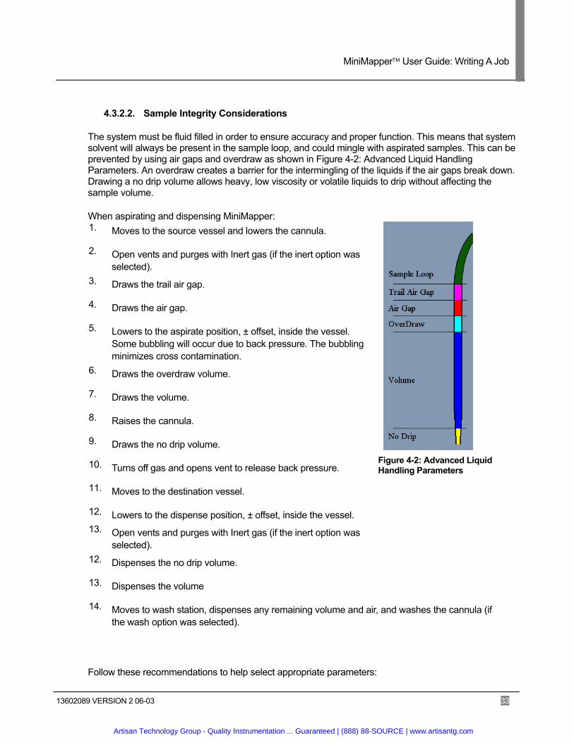
4.3.2.2. Sample Integrity Considerations
The system must be fluid filled in order to ensure accuracy and proper function. This means that system solvent will always be present in the sample loop, and could mingle with aspirated samples. This can be prevented by using air gaps and overdraw as shown in Figure 4-2: Advanced Liquid Handling Parameters. An overdraw creates a barrier for the intermingling of the liquids if the air gaps break down. Drawing a no drip volume allows heavy, low viscosity or volatile liquids to drip without affecting the sample volume.
When aspirating and dispensing MiniMapper: 1. Moves to the source vessel and lowers the cannula.
2. Open vents and purges with Inert gas (if the inert option was selected).
3. Draws the trail air gap.
4. Draws the air gap.
5. Lowers to the aspirate position, ± offset, inside the vessel. Some bubbling will occur due to back pressure. The bubbling minimizes cross contamination.
6. Draws the overdraw volume.
7. Draws the volume.
8. Raises the cannula.
9. Draws the no drip volume.
10. Turns off gas and opens vent to release back pressure.
11. Moves to the destination vessel.
12. Lowers to the dispense position, ± offset, inside the vessel.
Figure 4-2: Advanced Liquid Handling Parameters
13. Open vents and purges with Inert gas (if the inert option was selected).
12. Dispenses the no drip volume.
13. Dispenses the volume
14. Moves to wash station, dispenses any remaining volume and air, and washes the cannula (if the wash option was selected).
Follow these recommendations to help select appropriate parameters:
Artisan Technology Group - Quality Instrumentation ... Guaranteed | (888) 88-SOURCE | www.artisantg.com
MiniMapper User Guide: Writing A Job
13602089 VERSION 2 06-03 34
When using a valuable liquid, use large air gaps and no overdraw. Accuracy will be lower, but the liquid will not be wasted.
Total air gap volumes should be 0.01 ml to 0.05 ml
No drip volumes should be 0.01 ml to 0.05 ml
When using the standard three channel cannula, a no drip volume is only needed for liquids that are highly moisture and air sensitive. Most Dripping is caused by the surface tension of the liquid and the outside surface of the cannula. Longer delays, to allow the drip to form, and wiping off the cannula should be effective in most situations.
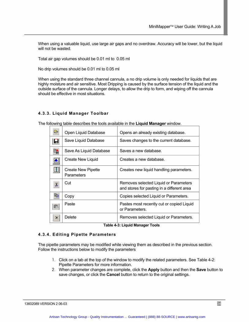
4.3.3. Liquid Manager Toolbar
The following table describes the tools available in the Liquid Manager window.
Table 4-3: Liquid Manager Tools
4.3.4. Editing Pipette Parameters
The pipette parameters may be modified while viewing them as described in the previous section. Follow the instructions below to modify the parameters
1. Click on a tab at the top of the window to modify the related parameters. See Table 4-2: Pipette Parameters for more information.
2. When parameter changes are complete, click the Apply button and then the Save button to save changes, or click the Cancel button to return to the original settings.
Open Liquid Database Opens an already existing database.
Save Liquid Database Saves changes to the current database.
Save As Liquid Database Saves a new database.
Create New Liquid Creates a new database.
Create New Pipette Parameters
Creates new liquid handling parameters.
Cut Removes selected Liquid or Parameters and stores for pasting in a different area
Copy Copies selected Liquid or Parameters.
Paste Pastes most recently cut or copied Liquid or Parameters.
Delete Removes selected Liquid or Parameters.
Artisan Technology Group - Quality Instrumentation ... Guaranteed | (888) 88-SOURCE | www.artisantg.com
MiniMapper User Guide: Writing A Job
13602089 VERSION 2 06-03 35
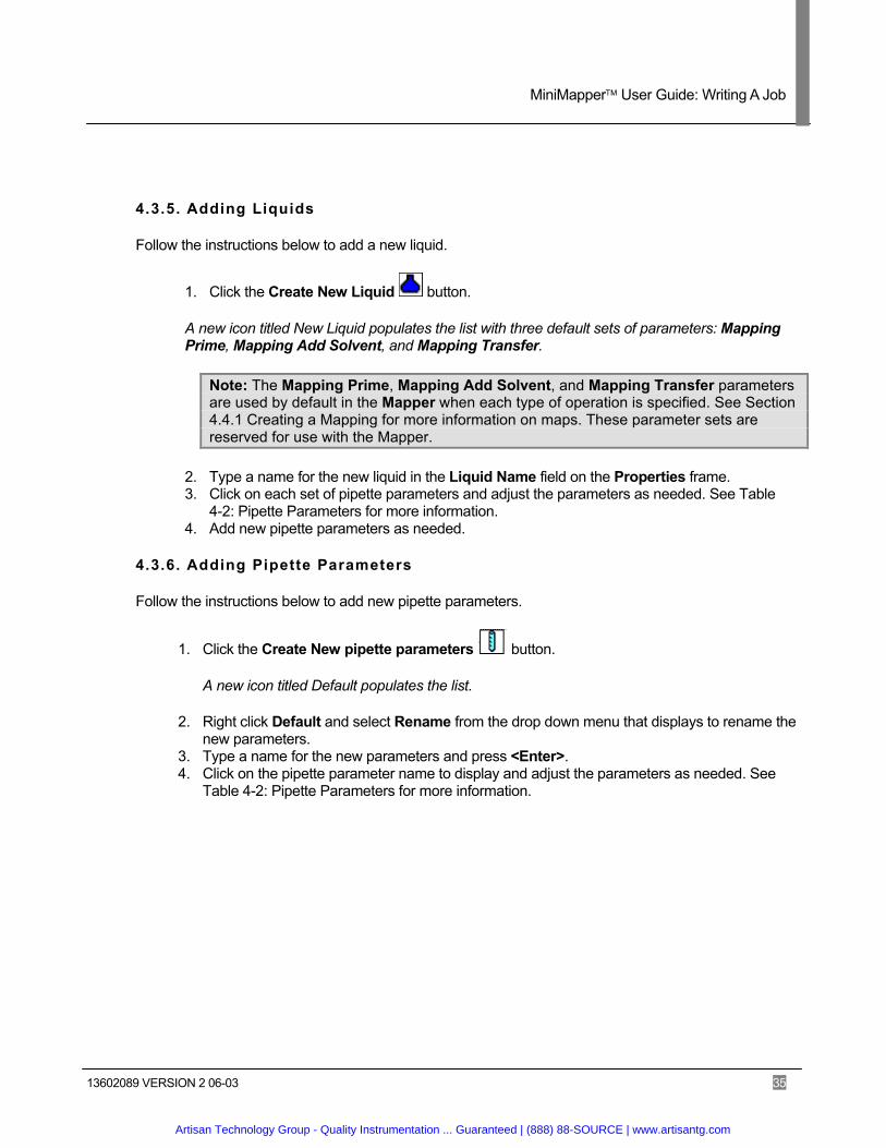
4.3.5. Adding Liquids
Follow the instructions below to add a new liquid.
1. Click the Create New Liquid button.
A new icon titled New Liquid populates the list with three default sets of parameters: Mapping Prime, Mapping Add Solvent, and Mapping Transfer.
Note: The Mapping Prime, Mapping Add Solvent, and Mapping Transfer parameters are used by default in the Mapper when each type of operation is specified. See Section 4.4.1 Creating a Mapping for more information on maps. These parameter sets are reserved for use with the Mapper.
2. Type a name for the new liquid in the Liquid Name field on the Properties frame. 3. Click on each set of pipette parameters and adjust the parameters as needed. See Table
4-2: Pipette Parameters for more information. 4. Add new pipette parameters as needed.
4.3.6. Adding Pipette Parameters
Follow the instructions below to add new pipette parameters.
1. Click the Create New pipette parameters button.
A new icon titled Default populates the list.
2. Right click Default and select Rename from the drop down menu that displays to rename the new parameters.
3. Type a name for the new parameters and press <Enter>. 4. Click on the pipette parameter name to display and adjust the parameters as needed. See
Table 4-2: Pipette Parameters for more information.
Artisan Technology Group - Quality Instrumentation ... Guaranteed | (888) 88-SOURCE | www.artisantg.com
MiniMapper User Guide: Writing A Job
13602089 VERSION 2 06-03 36
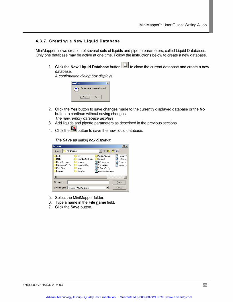
4.3.7. Creating a New Liquid Database
MiniMapper allows creation of several sets of liquids and pipette parameters, called Liquid Databases. Only one database may be active at one time. Follow the instructions below to create a new database.
1. Click the New Liquid Database button to close the current database and create a new database. A confirmation dialog box displays:
2. Click the Yes button to save changes made to the currently displayed database or the No button to continue without saving changes. The new, empty database displays.
3. Add liquids and pipette parameters as described in the previous sections.
4. Click the button to save the new liquid database.
The Save as dialog box displays:
5. Select the MiniMapper folder. 6. Type a name in the File name field. 7. Click the Save button.
Artisan Technology Group - Quality Instrumentation ... Guaranteed | (888) 88-SOURCE | www.artisantg.com
MiniMapper User Guide: Writing A Job
13602089 VERSION 2 06-03 37
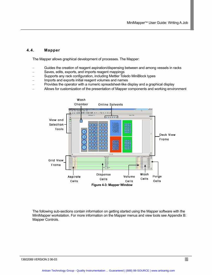
4.4. Mapper
The Mapper allows graphical development of processes. The Mapper:
– Guides the creation of reagent aspiration/dispensing between and among vessels in racks – Saves, edits, exports, and imports reagent mappings – Supports any rack configuration, including Mettler Toledo MiniBlock types – Imports and exports initial reagent volumes and names – Provides the operator with a numeric spreadsheet-like display and a graphical display – Allows for customization of the presentation of Mapper components and working environment
Figure 4-3: Mapper Window
The following sub-sections contain information on getting started using the Mapper software with the MiniMapper workstation. For more information on the Mapper menus and view tools see Appendix B: Mapper Controls.
Artisan Technology Group - Quality Instrumentation ... Guaranteed | (888) 88-SOURCE | www.artisantg.com
MiniMapper User Guide: Writing A Job
13602089 VERSION 2 06-03 38
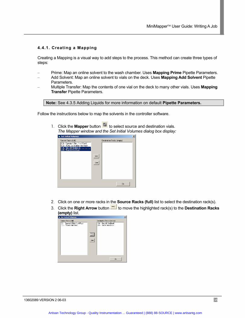
4.4.1. Creating a Mapping
Creating a Mapping is a visual way to add steps to the process. This method can create three types of steps:
– Prime: Map an online solvent to the wash chamber. Uses Mapping Prime Pipette Parameters. – Add Solvent: Map an online solvent to vials on the deck. Uses Mapping Add Solvent Pipette
Parameters. – Multiple Transfer: Map the contents of one vial on the deck to many other vials. Uses Mapping
Transfer Pipette Parameters.
Note: See 4.3.5 Adding Liquids for more information on default Pipette Parameters.
Follow the instructions below to map the solvents in the controller software.
1. Click the Mapper button to select source and destination vials. The Mapper window and the Set Initial Volumes dialog box display:
2. Click on one or more racks in the Source Racks (full) list to select the destination rack(s). 3. Click the Right Arrow button to move the highlighted rack(s) to the Destination Racks
(empty) list.
Artisan Technology Group - Quality Instrumentation ... Guaranteed | (888) 88-SOURCE | www.artisantg.com
MiniMapper User Guide: Writing A Job
13602089 VERSION 2 06-03 39
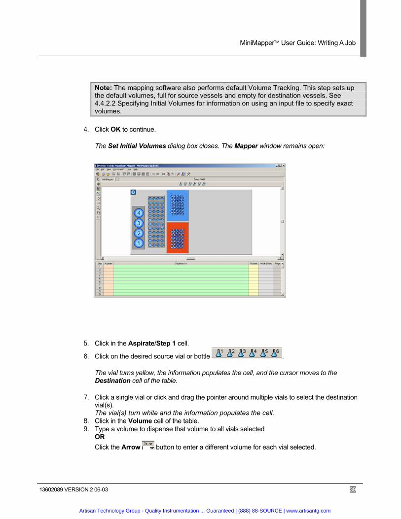
Note: The mapping software also performs default Volume Tracking. This step sets up the default volumes, full for source vessels and empty for destination vessels. See 4.4.2.2 Specifying Initial Volumes for information on using an input file to specify exact volumes.
4. Click OK to continue.
The Set Initial Volumes dialog box closes. The Mapper window remains open:
5. Click in the Aspirate/Step 1 cell.
6. Click on the desired source vial or bottle .
The vial turns yellow, the information populates the cell, and the cursor moves to the Destination cell of the table.
7. Click a single vial or click and drag the pointer around multiple vials to select the destination vial(s). The vial(s) turn white and the information populates the cell.
8. Click in the Volume cell of the table. 9. Type a volume to dispense that volume to all vials selected
OR Click the Arrow button to enter a different volume for each vial selected.
Artisan Technology Group - Quality Instrumentation ... Guaranteed | (888) 88-SOURCE | www.artisantg.com
MiniMapper User Guide: Writing A Job
13602089 VERSION 2 06-03 40
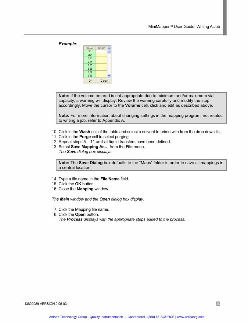
Example:
Note: If the volume entered is not appropriate due to minimum and/or maximum vial capacity, a warning will display. Review the warning carefully and modify the step accordingly. Move the cursor to the Volume cell, click and edit as described above.
Note: For more information about changing settings in the mapping program, not related to writing a job, refer to Appendix A.
10. Click in the Wash cell of the table and select a solvent to prime with from the drop down list. 11. Click in the Purge cell to select purging. 12. Repeat steps 5 – 11 until all liquid transfers have been defined. 13. Select Save Mapping As… from the File menu.
The Save dialog box displays.
Note: The Save Dialog box defaults to the “Maps” folder in order to save all mappings in a central location.
14. Type a file name in the File Name field. 15. Click the OK button. 16. Close the Mapping window.
The Main window and the Open dialog box display.
17. Click the Mapping file name. 18. Click the Open button.
The Process displays with the appropriate steps added to the process.
Artisan Technology Group - Quality Instrumentation ... Guaranteed | (888) 88-SOURCE | www.artisantg.com
MiniMapper User Guide: Writing A Job
13602089 VERSION 2 06-03 41
4.4.2. Volume Tracking
4.4.2.1. Vessel History
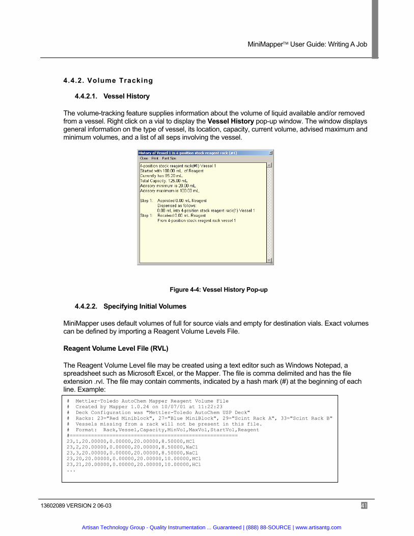
The volume-tracking feature supplies information about the volume of liquid available and/or removed from a vessel. Right click on a vial to display the Vessel History pop-up window. The window displays general information on the type of vessel, its location, capacity, current volume, advised maximum and minimum volumes, and a list of all seps involving the vessel.
Figure 4-4: Vessel History Pop-up
4.4.2.2. Specifying Initial Volumes
MiniMapper uses default volumes of full for source vials and empty for destination vials. Exact volumes can be defined by importing a Reagent Volume Levels File.
Reagent Volume Level File (RVL)
The Reagent Volume Level file may be created using a text editor such as Windows Notepad, a spreadsheet such as Microsoft Excel, or the Mapper. The file is comma delimited and has the file extension .rvl. The file may contain comments, indicated by a hash mark (#) at the beginning of each line. Example: # Mettler-Toledo AutoChem Mapper Reagent Volume File # Created by Mapper 1.0.24 on 10/07/01 at 11:22:23 # Deck Configuration was "Mettler-Toledo AutoChem USP Deck" # Racks: 23="Red Miniblock", 27="Blue MiniBlock", 29="Scint Rack A", 33="Scint Rack B" # Vessels missing from a rack will not be present in this file. # Format: Rack,Vessel,Capacity,MinVol,MaxVol,StartVol,Reagent #======================================================= 23,1,20.00000,0.00000,20.00000,8.50000,HCl 23,2,20.00000,0.00000,20.00000,8.50000,NaCl 23,3,20.00000,0.00000,20.00000,8.50000,NaCl 23,20,20.00000,0.00000,20.00000,10.00000,HCl 23,21,20.00000,0.00000,20.00000,10.00000,HCl ...
Artisan Technology Group - Quality Instrumentation ... Guaranteed | (888) 88-SOURCE | www.artisantg.com

MiniMapper User Guide: Writing A Job
13602089 VERSION 2 06-03 42
The Format comment line describes the exact format expected by the Mapper when it reads and uses the RVL.
– Rack: the internal rack index number from the workstation. In the example above, we show data for rack #23.
– Vessel: the numerical vessel number within that rack. – Capacity: the rated capacity of the vessel. This number must be the same for all vessels in the
same rack. – MinVol and MaxVol: the minimum and maximum advisory volumes above or below which a
warning is issued by Mapper. – StartVol: the initial volume of the reagent in the vessel. If empty, this value is specified as zero. – Reagent: the name of the reagent in the vessel (optional).
To create the file in Excel, type each value in its own cell, separating vessels by rows. Save the spreadsheet in “CSV” (comma delimited) format. Then, rename the file with the extension .rvl.
To create the file in a simple text editor, type out the values as shown in the example and save with the .rvl extension.
The Mapper generates the file when the Export Volumes option is selected. The values are based on the current values used in the mapping.
Import Reagent Volumes
Follow the instructions below to import exact volumes.
1. Click the Import Volumes button or select Import Volumes from the File menu.
The Import Vessel Volumes dialog box displays.
Artisan Technology Group - Quality Instrumentation ... Guaranteed | (888) 88-SOURCE | www.artisantg.com
MiniMapper User Guide: Writing A Job
13602089 VERSION 2 06-03 43
2. Select the desired parameters and click the Open File button.
Parameter Description
Set initial vessel volumes to imported volumes.
Replaces the default volume values of full and empty. Selected by default.
Add imported volumes to default values.
Adds the volumes in the file to the default values of full and empty.
Warn if volume exists for missing vessel.
Produces a warning dialog box if extra values exist in the file. Selected by default.
Warn if missing volumes for any vessel.
Produces a warning dialog box if any values are missing. Selected by default.
The Open Reagent File window opens.
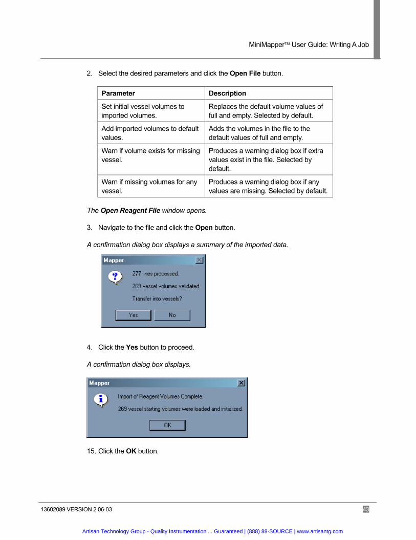
3. Navigate to the file and click the Open button.
A confirmation dialog box displays a summary of the imported data.
4. Click the Yes button to proceed.
A confirmation dialog box displays.
15. Click the OK button.
Artisan Technology Group - Quality Instrumentation ... Guaranteed | (888) 88-SOURCE | www.artisantg.com
MiniMapper User Guide: Writing A Job
13602089 VERSION 2 06-03 44
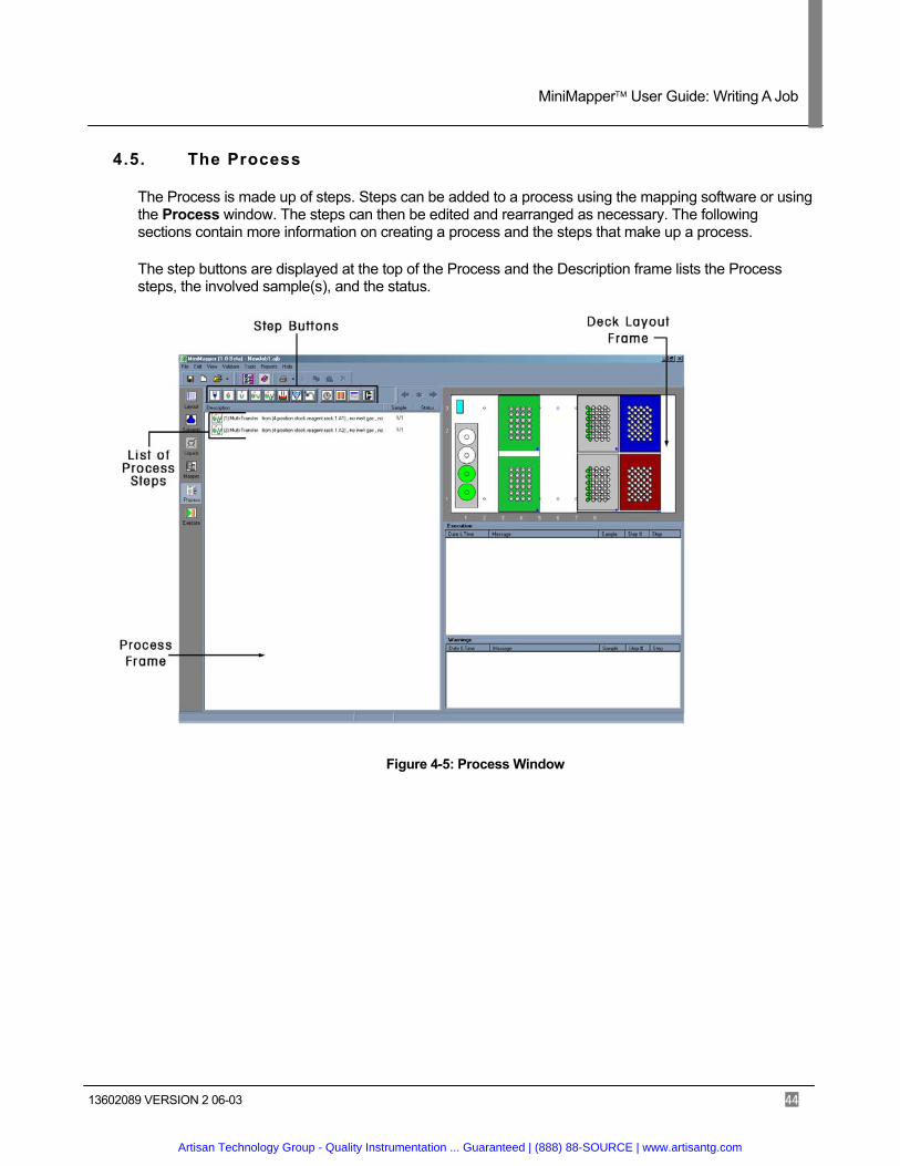
4.5. The Process
The Process is made up of steps. Steps can be added to a process using the mapping software or using the Process window. The steps can then be edited and rearranged as necessary. The following sections contain more information on creating a process and the steps that make up a process.
The step buttons are displayed at the top of the Process and the Description frame lists the Process steps, the involved sample(s), and the status.
Figure 4-5: Process Window
Artisan Technology Group - Quality Instrumentation ... Guaranteed | (888) 88-SOURCE | www.artisantg.com
MiniMapper User Guide: Writing A Job
13602089 VERSION 2 06-03 45
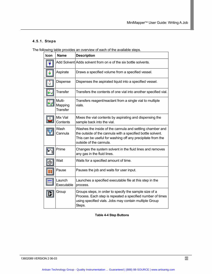
4.5.1. Steps
The following table provides an overview of each of the available steps. Icon Name Description
Add Solvent Adds solvent from on e of the six bottle solvents.
Aspirate Draws a specified volume from a specified vessel.
Dispense Dispenses the aspirated liquid into a specified vessel.
Transfer Transfers the contents of one vial into another specified vial.
Multi-Mapping Transfer
Transfers reagent/reactant from a single vial to multiple vials.
Mix Vial Contents
Mixes the vial contents by aspirating and dispensing the sample back into the vial.
Wash Cannula
Washes the inside of the cannula and settling chamber and the outside of the cannula with a specified bottle solvent. This can be useful for washing off any precipitate from the outside of the cannula.
Prime Changes the system solvent in the fluid lines and removes any gas in the fluid lines.
Wait Waits for a specified amount of time.
Pause Pauses the job and waits for user input.
Launch Executable
Launches a specified executable file at this step in the process.
Group Groups steps, in order to specify the sample size of a Process. Each step is repeated a specified number of times using specified vials. Jobs may contain multiple Group Steps.
Table 4-4 Step Buttons
Artisan Technology Group - Quality Instrumentation ... Guaranteed | (888) 88-SOURCE | www.artisantg.com

MiniMapper User Guide: Writing A Job
13602089 VERSION 2 06-03 46
4.5.2. Adding Steps to a Process
Follow the instructions below to add Steps to a Process. 1. Click the Process button or select Process from the View menu.
The Process displays.
2. Add steps to the Process by clicking and dragging Step buttons onto the Process window.
3. Double-click on each step to display the Edit Parameters dialog box and complete the step parameters.
4.5.3. Specifying Step Details
Each type of step requires input parameters. The following sections describe how to complete each step’s parameters.
4.5.3.1. Selecting Vials
Many steps require the selection of one or more vials. Follow the instructions below to select vials.
1. Click on the desired destination or source rack in Rack Preview frame.
The Rack Preview pop-up window displays:
2. Click and drag the destination vial into the Dispense to or Aspirate from list as shown below.
3. Click the OK button to close the Rack Preview pop-up window or click on a new rack to display it in the window.
Artisan Technology Group - Quality Instrumentation ... Guaranteed | (888) 88-SOURCE | www.artisantg.com
MiniMapper User Guide: Writing A Job
13602089 VERSION 2 06-03 47
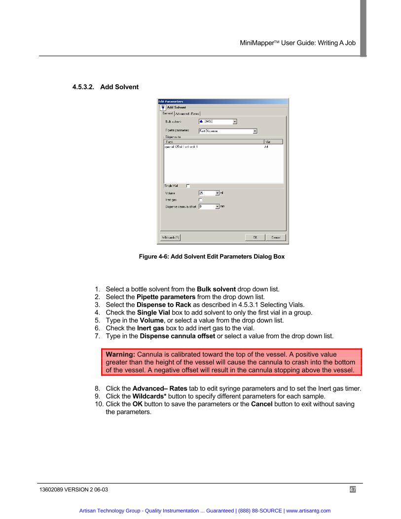
4.5.3.2. Add Solvent
Figure 4-6: Add Solvent Edit Parameters Dialog Box
1. Select a bottle solvent from the Bulk solvent drop down list. 2. Select the Pipette parameters from the drop down list. 3. Select the Dispense to Rack as described in 4.5.3.1 Selecting Vials. 4. Check the Single Vial box to add solvent to only the first vial in a group. 5. Type in the Volume, or select a value from the drop down list. 6. Check the Inert gas box to add inert gas to the vial. 7. Type in the Dispense cannula offset or select a value from the drop down list.
Warning: Cannula is calibrated toward the top of the vessel. A positive value greater than the height of the vessel will cause the cannula to crash into the bottom of the vessel. A negative offset will result in the cannula stopping above the vessel.
8. Click the Advanced– Rates tab to edit syringe parameters and to set the Inert gas timer. 9. Click the Wildcards* button to specify different parameters for each sample. 10. Click the OK button to save the parameters or the Cancel button to exit without saving
the parameters.
Artisan Technology Group - Quality Instrumentation ... Guaranteed | (888) 88-SOURCE | www.artisantg.com
MiniMapper User Guide: Writing A Job
13602089 VERSION 2 06-03 48
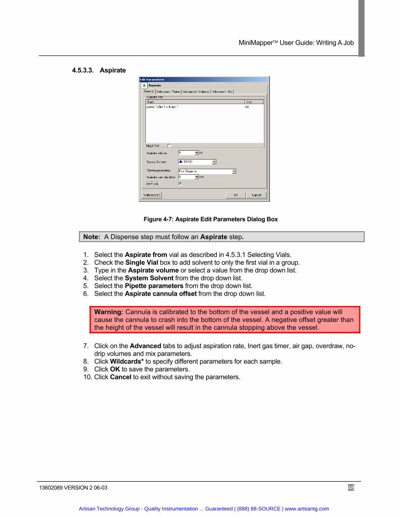
4.5.3.3. Aspirate
Figure 4-7: Aspirate Edit Parameters Dialog Box
Note: A Dispense step must follow an Aspirate step.
1. Select the Aspirate from vial as described in 4.5.3.1 Selecting Vials. 2. Check the Single Vial box to add solvent to only the first vial in a group. 3. Type in the Aspirate volume or select a value from the drop down list. 4. Select the System Solvent from the drop down list. 5. Select the Pipette parameters from the drop down list. 6. Select the Aspirate cannula offset from the drop down list.
Warning: Cannula is calibrated to the bottom of the vessel and a positive value will cause the cannula to crash into the bottom of the vessel. A negative offset greater than the height of the vessel will result in the cannula stopping above the vessel.
7. Click on the Advanced tabs to adjust aspiration rate, Inert gas timer, air gap, overdraw, no-drip volumes and mix parameters.
8. Click Wildcards* to specify different parameters for each sample. 9. Click OK to save the parameters. 10. Click Cancel to exit without saving the parameters.
Artisan Technology Group - Quality Instrumentation ... Guaranteed | (888) 88-SOURCE | www.artisantg.com

MiniMapper User Guide: Writing A Job
13602089 VERSION 2 06-03 49
4.5.3.4. Dispense
Figure 4-8: Dispense Edit Parameters Dialog Box
Note: An Aspirate step must precede a Dispense step.
1. Select the Dispense to vial as described in 4.5.3.1 Selecting Vials. 2. Check the Single Vial box to add solvent to only the first vial in a group. 3. Type in the Dispense Volume or select a value from the drop down list. 4. Select the System Solvent from the drop down list. 5. Select Pipette parameters from the drop down list. 6. Check the Wash box, if desired.If selected, the Advanced Parameters window displays.
Edit parameters and select the General tab to continue. 7. Check the Inert gas box to add inert gas to the vial. 8. Type in the Dispense cannula offset or select a value from the drop down list.
Warning: Cannula is calibrated toward the top of the vessel. A positive value greater than the height of the vessel will cause the cannula to crash into the bottom of the vessel. A negative offset will result in the cannula stopping above the vessel.
9. Click on the Advanced tabs to adjust aspiration rate, Inert gas timer, air gap, overdraw, no-drip volumes and mix parameters.
10. Click the Wildcards* button to specify different parameters for each sample. 11. Click the OK button to save the parameters or click the Cancel button to exit without saving
the parameters.
Artisan Technology Group - Quality Instrumentation ... Guaranteed | (888) 88-SOURCE | www.artisantg.com

MiniMapper User Guide: Writing A Job
13602089 VERSION 2 06-03 50
4.5.3.5. Transfer
Figure 4-9: Transfer Edit Parameters Dialog Box
1. Select the Aspirate from vial as described in 4.5.3.1Selecting Vials. 2. Select the Dispense to vial as described in 4.5.3.1Selecting Vials. 3. Check the Single Vial box(es) to add solvent to only the first vial in a group. 4. Type in the Aspirate Volume or select a value from the drop down list. 5. Select the System Solvent from the drop down list. 6. Select Pipette parameters from the drop down list. 7. Type in the Aspirate cannula offset or select a value from the drop down list.
Warning: The cannula is calibrated aspirating and dispensing. Typing positive value in steps 7 or 8 may cause the cannula to crash into the bottom of the vessel. Typing a negative value may result in the cannula stopping above the vessel.
8. Type in the Dispense cannula offset or select a value from the drop down list. 9. Check the Wash box, if desired.
If selected, the Advanced Parameters window displays. Edit parameters and select the General tab to continue.
10. Check the Inert gas box to add inert gas to the vial. 11. Click on the Advanced tabs to adjust aspiration rate, Inert gas timer, air gap, overdraw, no-
drip volumes and mix parameters. 12. Click Wildcards* to specify different parameters for each sample. 13. Click the OK button to save the parameters or click the Cancel button to exit without saving
the parameters.
Artisan Technology Group - Quality Instrumentation ... Guaranteed | (888) 88-SOURCE | www.artisantg.com

MiniMapper User Guide: Writing A Job
13602089 VERSION 2 06-03 51
4.5.3.6. Multi-Mapping Transfer
Figure 4-10: Multi-Mapping Transfer
Note: Mettler-Toledo AutoChem suggests using the Mapper to create a Multi-Mapping Transfer. See 4.4 Mapper and Appendix B: Mapper Controls for more information.
1. Select the Aspirate from vial as described in 4.5.3.1 Selecting Vials. 2. Select the Dispense to vials as described in 4.5.3.1 Selecting Vials. 3. Check the Single Vial box(es) to add solvent to only the first vial in a group. 4. Click the Dispense Volumes >> button.
The Wildcard table window displays:
Artisan Technology Group - Quality Instrumentation ... Guaranteed | (888) 88-SOURCE | www.artisantg.com
MiniMapper User Guide: Writing A Job
13602089 VERSION 2 06-03 52
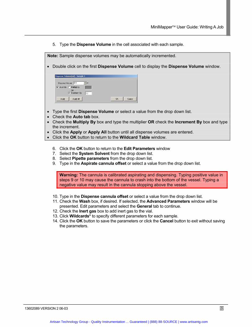
5. Type the Dispense Volume in the cell associated with each sample.
Note: Sample dispense volumes may be automatically incremented.
• Double click on the first Dispense Volume cell to display the Dispense Volume window.
• Type the first Dispense Volume or select a value from the drop down list. • Check the Auto tab box. • Check the Multiply By box and type the multiplier OR check the Increment By box and type
the increment. • Click the Apply or Apply All button until all dispense volumes are entered. • Click the OK button to return to the Wildcard Table window.
6. Click the OK button to return to the Edit Parameters window 7. Select the System Solvent from the drop down list. 8. Select Pipette parameters from the drop down list. 9. Type in the Aspirate cannula offset or select a value from the drop down list.
Warning: The cannula is calibrated aspirating and dispensing. Typing positive value in steps 9 or 10 may cause the cannula to crash into the bottom of the vessel. Typing a negative value may result in the cannula stopping above the vessel.
10. Type in the Dispense cannula offset or select a value from the drop down list. 11. Check the Wash box, if desired. If selected, the Advanced Parameters window will be
presented. Edit parameters and select the General tab to continue. 12. Check the Inert gas box to add inert gas to the vial. 13. Click Wildcards* to specify different parameters for each sample. 14. Click the OK button to save the parameters or click the Cancel button to exit without saving
the parameters.
Artisan Technology Group - Quality Instrumentation ... Guaranteed | (888) 88-SOURCE | www.artisantg.com

MiniMapper User Guide: Writing A Job
13602089 VERSION 2 06-03 53
4.5.3.7. Mix Vial Contents
Figure 4-11: Mix Vial Contents Edit Parameters Dialog Box
1. Select the Vials to mix vials as described in 4.5.3.1 Selecting Vials. 2. Check the Single Vial box to add solvent to only the first vial in a group. 3. Select the System solvent from the drop down list. 4. Select the Pipette parameters from the drop down list. 5. Move the slider to the desired Number of mixes. 6. Type in the Mix volume or select a value from the drop down list. 7. Type in the Aspirate cannula offset or select a value from the drop down list.
Warning: Cannula is calibrated to the bottom of the vessel and a positive value will cause the cannula to crash into the bottom of the vessel. A negative offset greater than the height of the vessel will result in the cannula stopping above the vessel.
8. Check the Wash box, if desired.
If selected, the Advanced Parameters window displays. Edit parameters and select the General tab to continue.
9. Check the Inert gas box to add inert gas to the vial. 10. Click the Wildcard* button to specify different parameters for each sample. 11. Click the Advanced tab to set syringe parameters and set the inert gas timer. 12. Click the OK button to save the parameters or click the Cancel button to exit without saving
the parameters.
Artisan Technology Group - Quality Instrumentation ... Guaranteed | (888) 88-SOURCE | www.artisantg.com

MiniMapper User Guide: Writing A Job
13602089 VERSION 2 06-03 54
4.5.3.8. Wash Cannula
Figure 4-12: Wash Cannula Edit Parameters Dialog Box
1. Select a bottle solvent from the Bulk solvent drop down list. 2. Select the Washing Pipette parameters from the drop down list. 3. Move the slider to select the Number of Washes. 4. Type in the Washing volume or select a value from the drop down list. 5. Click the Advanced tab to set Washing rate, Wash delay and Additional evacuation time. 6. Click the OK button to save the parameters or click the Cancel button to exit without saving
the parameters.
4.5.3.9. Prime
Figure 4-13: Prime Edit Parameters Dialog Box
1. Select a bottle solvent from the Bulk solvent drop down list. 2. Select the Prime Pipette parameters from the drop down list. 3. Type in the Prime volume or select a value from the drop down list. 4. Click the Advanced – Rates tab to change the Aspirate rate, Aspirate delay, Dispense rate,
and/or Dispense delay. 5. Click the OK button to save the parameters or click the Cancel button to exit without saving
the parameters.
Artisan Technology Group - Quality Instrumentation ... Guaranteed | (888) 88-SOURCE | www.artisantg.com
MiniMapper User Guide: Writing A Job
13602089 VERSION 2 06-03 55
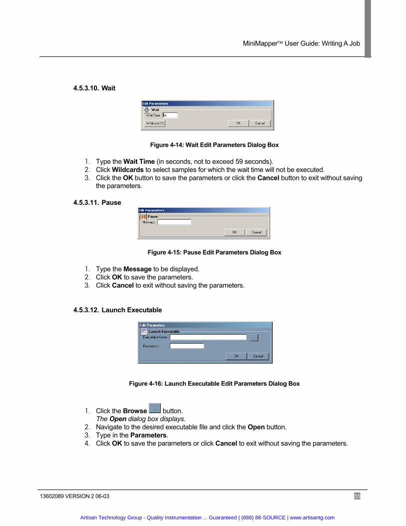
4.5.3.10. Wait
Figure 4-14: Wait Edit Parameters Dialog Box
1. Type the Wait Time (in seconds, not to exceed 59 seconds). 2. Click Wildcards to select samples for which the wait time will not be executed. 3. Click the OK button to save the parameters or click the Cancel button to exit without saving
the parameters.
4.5.3.11. Pause
Figure 4-15: Pause Edit Parameters Dialog Box
1. Type the Message to be displayed. 2. Click OK to save the parameters. 3. Click Cancel to exit without saving the parameters.
4.5.3.12. Launch Executable
Figure 4-16: Launch Executable Edit Parameters Dialog Box
1. Click the Browse button. The Open dialog box displays.
2. Navigate to the desired executable file and click the Open button. 3. Type in the Parameters. 4. Click OK to save the parameters or click Cancel to exit without saving the parameters.
Artisan Technology Group - Quality Instrumentation ... Guaranteed | (888) 88-SOURCE | www.artisantg.com

MiniMapper User Guide: Writing A Job
13602089 VERSION 2 06-03 56
4.5.3.13. Group
Figure 4-17: Group Edit Parameters Dialog box
1. Type in Group description. 2. Type in Sample size. 3. Click the OK button to save the parameters or click the Cancel button to exit without saving
the parameters. 4. Click and drag desired steps into the Group.
The vials included in the group change color in the Deck Layout and Rack Preview frames.
Artisan Technology Group - Quality Instrumentation ... Guaranteed | (888) 88-SOURCE | www.artisantg.com
MiniMapper User Guide: Writing A Job
13602089 VERSION 2 06-03 57
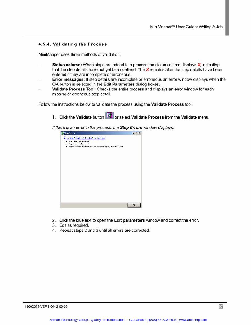
4.5.4. Validating the Process
MiniMapper uses three methods of validation.
– Status column: When steps are added to a process the status column displays X, indicating that the step details have not yet been defined. The X remains after the step details have been entered if they are incomplete or erroneous.
– Error messages: If step details are incomplete or erroneous an error window displays when the OK button is selected in the Edit Parameters dialog boxes.
– Validate Process Tool: Checks the entire process and displays an error window for each missing or erroneous step detail.
Follow the instructions below to validate the process using the Validate Process tool.
1. Click the Validate button or select Validate Process from the Validate menu.
If there is an error in the process, the Step Errors window displays:
2. Click the blue text to open the Edit parameters window and correct the error. 3. Edit as required. 4. Repeat steps 2 and 3 until all errors are corrected.
Artisan Technology Group - Quality Instrumentation ... Guaranteed | (888) 88-SOURCE | www.artisantg.com

MiniMapper User Guide: Writing A Job
13602089 VERSION 2 06-03 58
4.5.5. Saving the Process
Follow the instructions below to save the job.
1. Click the Save as button to save the job.
The Save dialog box displays.
2. Navigate to the destination folder.
Tip: Create a folder on the hard drive titled “Jobs” to save all jobs in a central location.
3. Type a name for the job in the File Name field. 4. Click the Save button.
4.6. Running the Job
1. Click the Execute button . The Execute window displays:
2. Click the Recover button to reset the workstation.
3. Click the Run button to start the job. The job begins execution. Progress messages display in the Progress Log frame throughout the duration of the job.
Artisan Technology Group - Quality Instrumentation ... Guaranteed | (888) 88-SOURCE | www.artisantg.com

MiniMapper User Guide: Best Practices
13602089 VERSION 2 06-03 59
5. Best Practices
5.1. Best Practices for MiniMapper Use
5.1.1. Dripping Solvents
When using highly volatile solvents such as dichloromethane in a warm environment, the solvent may drip from the cannula. Selecting the proper Pipette Parameters can minimize this effect. See Section 4.3.2 Liquid Handling Parameter Descriptions for more information.
5.1.2. Saturated Solutions
The cannula may become blocked when using saturated solutions. To avoid blockage include a Wash Cannula step using water after each step using the saturated solution. If necessary, the cannula may be removed for offline cleaning.
5.1.3. Precipitates
Use of precipitates is not supported. Precipitates of any size may cause clogging of the cannula. Non-soluble precipitates are very difficult to clean if clogging occurs.
Artisan Technology Group - Quality Instrumentation ... Guaranteed | (888) 88-SOURCE | www.artisantg.com
MiniMapper User Guide: Maintenance
13602089 VERSION 2 06-03 60
6. Maintenance
This section describes how to look after and maintain the MiniMapper workstation.
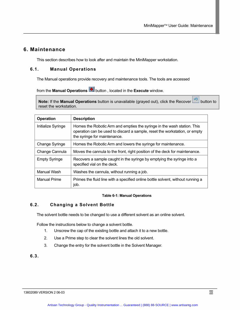
6.1. Manual Operations
The Manual operations provide recovery and maintenance tools. The tools are accessed
from the Manual Operations button , located in the Execute window.
Note: If the Manual Operations button is unavailable (grayed out), click the Recover button to reset the workstation.
Operation Description
Initialize Syringe Homes the Robotic Arm and empties the syringe in the wash station. This operation can be used to discard a sample, reset the workstation, or empty the syringe for maintenance.
Change Syringe Homes the Robotic Arm and lowers the syringe for maintenance.
Change Cannula Moves the cannula to the front, right position of the deck for maintenance.
Empty Syringe Recovers a sample caught in the syringe by emptying the syringe into a specified vial on the deck.
Manual Wash Washes the cannula, without running a job.
Manual Prime Primes the fluid line with a specified online bottle solvent, without running a job.
Table 6-1: Manual Operations
6.2. Changing a Solvent Bottle
The solvent bottle needs to be changed to use a different solvent as an online solvent.
Follow the instructions below to change a solvent bottle. 1. Unscrew the cap of the existing bottle and attach it to a new bottle.
2. Use a Prime step to clear the solvent lines the old solvent.
3. Change the entry for the solvent bottle in the Solvent Manager.
6.3.
Artisan Technology Group - Quality Instrumentation ... Guaranteed | (888) 88-SOURCE | www.artisantg.com
MiniMapper User Guide: Maintenance
13602089 VERSION 2 06-03 61
6.4. Emptying the Waste
The waste container must be emptied regularly to avoid overflow or backups into the system. Check the waste container before running each job to ensure that there is enough space for the job's waste.
Follow the instructions below to empty the waste container. 1. Remove the stopper from the waste container.
Note: The waste container may be under vacuum. 2. Empty the waste into the appropriate solvent waste container.
3. Recap the waste container.
6.5. Syringe Maintenance
The syringe at the back of MiniMapper pumps solvent through the MiniMapper system. The glass syringe should be replaced once a year. It may be necessary to replace it more often if it breaks or leakage occurs near the top of the syringe. Syringes also come in multiple sizes.
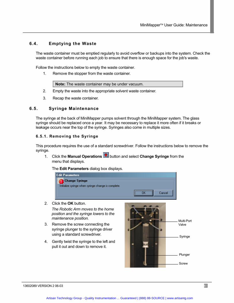
6.5.1. Removing the Syringe
This procedure requires the use of a standard screwdriver. Follow the instructions below to remove the syringe.
1. Click the Manual Operations button and select Change Syringe from the menu that displays.
The Edit Parameters dialog box displays.
2. Click the OK button.
The Robotic Arm moves to the home position and the syringe lowers to the maintenance position.
3. Remove the screw connecting the syringe plunger to the syringe driver using a standard screwdriver.
4. Gently twist the syringe to the left and pull it out and down to remove it.
Screw
Multi-Port Valve
Plunger
Syringe
Artisan Technology Group - Quality Instrumentation ... Guaranteed | (888) 88-SOURCE | www.artisantg.com
MiniMapper User Guide: Maintenance
13602089 VERSION 2 06-03 62
Driver
Screw
Plunger
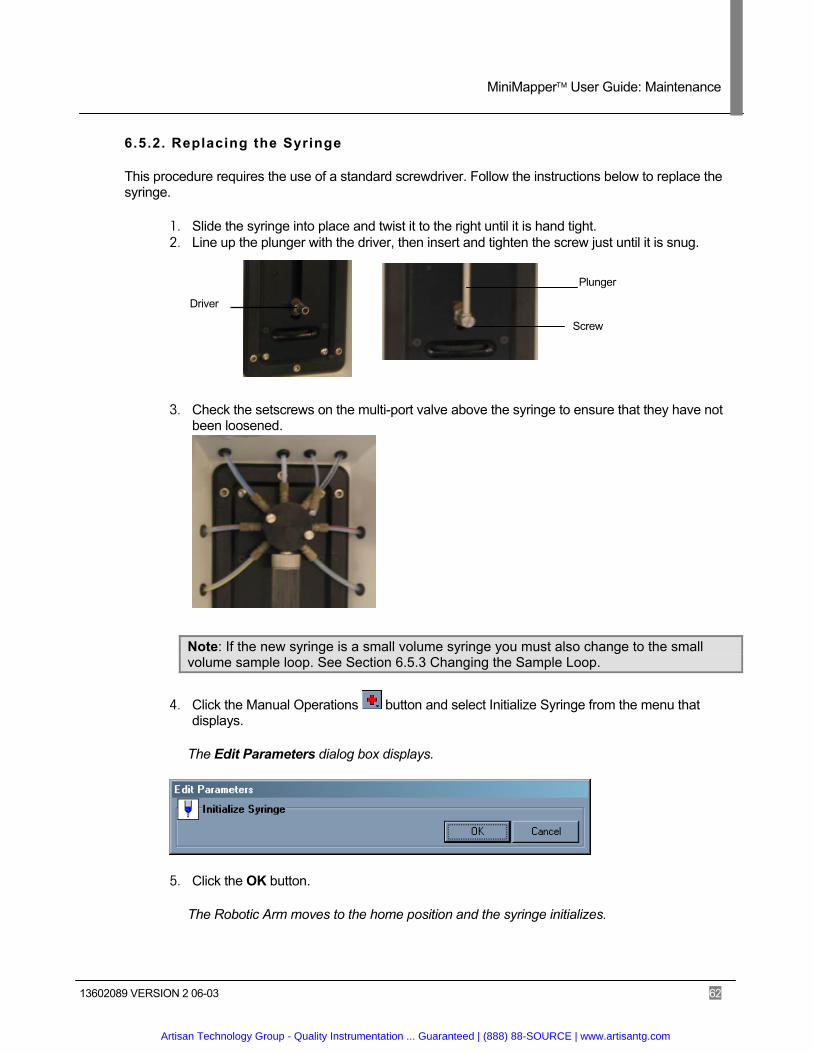
6.5.2. Replacing the Syringe
This procedure requires the use of a standard screwdriver. Follow the instructions below to replace the syringe.
1. Slide the syringe into place and twist it to the right until it is hand tight. 2. Line up the plunger with the driver, then insert and tighten the screw just until it is snug.
3. Check the setscrews on the multi-port valve above the syringe to ensure that they have not been loosened.
Note: If the new syringe is a small volume syringe you must also change to the small volume sample loop. See Section 6.5.3 Changing the Sample Loop.
4. Click the Manual Operations button and select Initialize Syringe from the menu that displays.
The Edit Parameters dialog box displays.
5. Click the OK button.
The Robotic Arm moves to the home position and the syringe initializes.
Artisan Technology Group - Quality Instrumentation ... Guaranteed | (888) 88-SOURCE | www.artisantg.com

MiniMapper User Guide: Maintenance
13602089 VERSION 2 06-03 63
6.5.3. Changing the Sample Loop
The sample loop is the tubing that carries fluid from the syringe to the cannula. Two sample loops are provide, one for large volumes and one for small volumes. Always use the appropriate sample loop for the current syringe size.
Follow the instructions below to change the sample loop.
1. Disconnect the current sample loop fitting from the multi-port valve at Position A.
2. Attach the desired sample loop fitting to the multi-port valve at Position A. 3. Disconnect the current sample loop fitting from the cannula fitting.
4. Attach the desired sample loop fitting to the cannula fitting.
Large Volume Sample Loop at Position A
Small Volume Sample Loop
Large Volume Sample Loop connected to Cannula Fitting Small Volume Sample Loop
Artisan Technology Group - Quality Instrumentation ... Guaranteed | (888) 88-SOURCE | www.artisantg.com
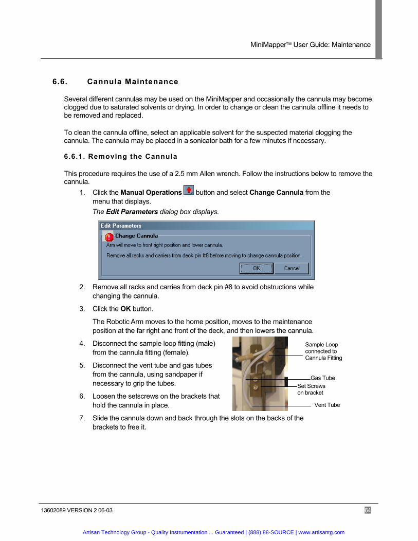
MiniMapper User Guide: Maintenance
13602089 VERSION 2 06-03 64
6.6. Cannula Maintenance
Several different cannulas may be used on the MiniMapper and occasionally the cannula may become clogged due to saturated solvents or drying. In order to change or clean the cannula offline it needs to be removed and replaced.
To clean the cannula offline, select an applicable solvent for the suspected material clogging the cannula. The cannula may be placed in a sonicator bath for a few minutes if necessary.
6.6.1. Removing the Cannula
This procedure requires the use of a 2.5 mm Allen wrench. Follow the instructions below to remove the cannula.
1. Click the Manual Operations button and select Change Cannula from the menu that displays.
The Edit Parameters dialog box displays.
2. Remove all racks and carries from deck pin #8 to avoid obstructions while changing the cannula.
3. Click the OK button.
The Robotic Arm moves to the home position, moves to the maintenance position at the far right and front of the deck, and then lowers the cannula.
4. Disconnect the sample loop fitting (male) from the cannula fitting (female).
5. Disconnect the vent tube and gas tubes from the cannula, using sandpaper if necessary to grip the tubes.
6. Loosen the setscrews on the brackets that hold the cannula in place.
7. Slide the cannula down and back through the slots on the backs of the brackets to free it.
Vent Tube
Gas Tube Set Screws on bracket
Sample Loop connected to Cannula Fitting
Artisan Technology Group - Quality Instrumentation ... Guaranteed | (888) 88-SOURCE | www.artisantg.com
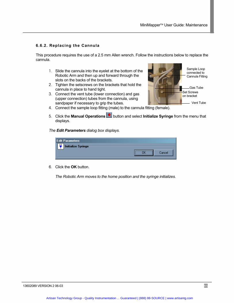
MiniMapper User Guide: Maintenance
13602089 VERSION 2 06-03 65
Vent Tube
Gas Tube Set Screws on bracket
Sample Loop connected to Cannula Fitting
6.6.2. Replacing the Cannula
This procedure requires the use of a 2.5 mm Allen wrench. Follow the instructions below to replace the cannula.
1. Slide the cannula into the eyelet at the bottom of the Robotic Arm and then up and forward through the slots on the backs of the brackets.
2. Tighten the setscrews on the brackets that hold the cannula in place to hand tight.
3. Connect the vent tube (lower connection) and gas (upper connection) tubes from the cannula, using sandpaper if necessary to grip the tubes.
4. Connect the sample loop fitting (male) to the cannula fitting (female).
5. Click the Manual Operations button and select Initialize Syringe from the menu that displays.
The Edit Parameters dialog box displays.
6. Click the OK button.
The Robotic Arm moves to the home position and the syringe initializes.
Artisan Technology Group - Quality Instrumentation ... Guaranteed | (888) 88-SOURCE | www.artisantg.com

MiniMapper User Guide: Troubleshooting
13602089 VERSION 2 06-03 66
7. Troubleshooting 7.1. Hardware
Issue Check Corrective Action
You cannot turn the system power on
– If the emergency stop button is depressed
– If the power cable is not plugged in
– Twist and pull out the emergency stop button
– Plug in the power cable – Contact Mettler-Toledo
AutoChem for support. The system stops during a run
– The workstation deck and run time screen for cause of failure
– For power outages during the run
– Use recovery tools to recover in the desired manner. Clear the workstation of obstacles, reboot computer, and check software job for cause of failure.
– See “You cannot turn the system power on”
– Contact Mettler-Toledo AutoChem for support.
The wash station is not emptying completely
– Wash Parameters – For blockage of wash
valves and lines – Valve Failure
– Increase wash drain time – Clear blockage from lines – Contact Mettler-Toledo
AutoChem for support. The cannula drips – For air in the fluid filled lines
– For loose fittings around the valve and cannula
– Prime system to purge air
– Tighten all fittings in the system around the syringe, valves, and cannula.
The syringe has large air gaps, fills suddenly, and doesn’t fill completely
– For solvent filter blockage – Syringe speed
– Replaces solvent filters – Reduce syringe speed
7.2. Software
Issue Check Corrective Action
Start-up initialization does not complete properly
– If the emergency stop button is depressed
– Twist and pull out the emergency stop button
– Contact Mettler-Toledo AutoChem for support.
“Main vacuum sensor detecting failed” message displays
– Vacuum source, vacuum connections at the waste flask, and at the workstation vacuum inlet and outlet.
– Turn on vacuum pump – Insert stopper into waste flask – Fix connections
Inert gas not detected – Inert gas source for pressure of at least 40psi or 3 bar.
– Contact Mettler-Toledo AutoChem for support.
Artisan Technology Group - Quality Instrumentation ... Guaranteed | (888) 88-SOURCE | www.artisantg.com

MiniMapper User Guide: Troubleshooting
13602089 VERSION 2 06-03 67
7.3. Liquid Handling Performance
Issue Check Corrective Action
Cannula drips after dispensing into sealed vials
– Syringe Parameters (Aspirate and dispense delay)
– Syringe Parameters Syringe speed
– 2 second delay time
– Slow down syringe speed to 20-25
Cannula drips without dispensing operation
– Connector at syringe outlet and or solvent valve.
– Syringe barrel loose or nut loose
– Tubing connection at cannula
– Tighten by hand until finger tight.
– Tighten by hand until finger tight.
– Reconnect if necessary
Solvent dispensing does not complete
– Liquid lines and solvent reservoirs
– Syringe barrel loose
– Fill solvent reservoirs and prime lines before run
– Finger tighten barrel and plunger nut.
Air present in lines when aspirating from reservoir
– Solvent bottle empty – Solvent lines out or above
solvents – fitting on 6-way valve not
tight – Fitting on Cavro 3-way
inlet not tight
– Refill solvent – Place lines in solvent – Tighten all fittings
Air present in lines when aspirating from vials or reaction blocks
– Aspirate teach position to high
– Teflon tubing to cannula collar is loose
– Syringe barrel loose – Omni fit on Cavro 3-way
outlet is loose – Vent clogged
– Re-teach position, remove cannula and check Teflon tube to collar connection
– tighten fittings – remove vent tube – check for clog
Air present in syringe barrel when aspirating and dispensing
– Syringe barrel is tight – Both Omni fittings on
Cavro 3-way
– Tighten syringe barrel – Omni fittings on Cavro 3-
way The syringe has large air gaps, fills suddenly, and doesn’t fill completely
– For solvent filter blockage – Syringe speed
– Replaces solvent filters
– Reduce syringe speed
Air in lines Wash Station Overflow line in use
– Syringe Parameters – Syringe speed
– Slow down aspirate speed to 20-25.
Artisan Technology Group - Quality Instrumentation ... Guaranteed | (888) 88-SOURCE | www.artisantg.com
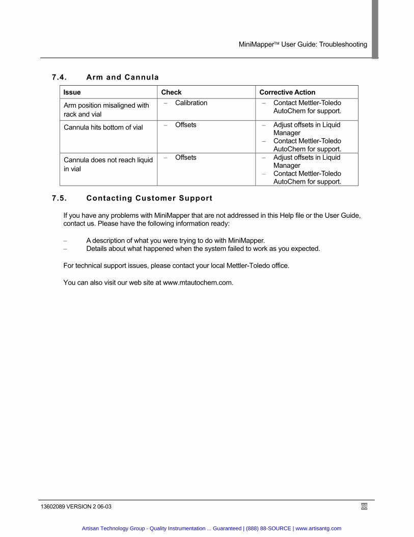
MiniMapper User Guide: Troubleshooting
13602089 VERSION 2 06-03 68
7.4. Arm and Cannula
Issue Check Corrective Action
Arm position misaligned with rack and vial
– Calibration – Contact Mettler-Toledo AutoChem for support.
Cannula hits bottom of vial – Offsets – Adjust offsets in Liquid Manager
– Contact Mettler-Toledo AutoChem for support.
Cannula does not reach liquid in vial
– Offsets – Adjust offsets in Liquid Manager
– Contact Mettler-Toledo AutoChem for support.
7.5. Contacting Customer Support
If you have any problems with MiniMapper that are not addressed in this Help file or the User Guide, contact us. Please have the following information ready:
– A description of what you were trying to do with MiniMapper. – Details about what happened when the system failed to work as you expected.
For technical support issues, please contact your local Mettler-Toledo office.
You can also visit our web site at www.mtautochem.com.
Artisan Technology Group - Quality Instrumentation ... Guaranteed | (888) 88-SOURCE | www.artisantg.com

MiniMapper User Guide: Accessories
13602089 VERSION 1 04-03 69
Appendix A: Accessories Syringe Options:
1.0 mL Replacement Syringe (15803089)
2.5 mL Replacement Syringe (15803090)
5.0 mL Replacement Syringe (13505033)
10.0 mL Replacement Syringe (15803068)
Replacement Cannulas:
2-Channel Septum Piercing Grooved Cannula (13559293): Solventchannel and groove acting as a passive vent.
3-Channel Septum Piercing Cannula (13559292): Vent Channel, Inert Gas Channel, and Solvent Channel.
Vials 40 mL Scintillation Vial (13520029): High quality scintillation vial with durable cap and septum. Works with MT part number 13530911.
125 mL Stock Vial (13520027): High quality stock reagent vial with durable cap and septum. Works with MT part number 13530005 and 13530012.
Artisan Technology Group - Quality Instrumentation ... Guaranteed | (888) 88-SOURCE | www.artisantg.com

MiniMapper User Guide: Mapper Controls
13602089 VERSION 1 04-03 70
Appendix B: Mapper Controls
The Mapper offers many tools accessed by menus and buttons. There are many options for changing the view and customizing the window.
Note: In the Grid View frame normal Windows short cuts and editing tools are available for editing the mapped steps. For example, hold <Ctrl> while clicking on rows in the grid to select all of the rows at once.
The following sections describe the menus and tools available.
B.1. Toolbar
The toolbar buttons, located along the top of the Mapping Window, provide short cuts to operations available in the menus (see Figure 4-3: Mapper ). Tools that are not available are grayed out. The toolbar is customizable.
B.1.1. Available Tools
The following table lists all available tools and their descriptions. Tool Description
Exit: Closes Mapper.
Open Configuration: Opens a different configuration file.
Open Mapping: Opens an existing Mapping file.
Import Mapping: Imports an existing Mapping file.
Import Volumes: Imports a RVL file.
Export Mapping: Exports mapping data in comma-delimited format for use in a different program.
Export Volumes: Exports the current volume levels to generate a RVL for future use or a comma delimited file for use in a different program.
Save Configuration: Not Available.
Save Mapping: Save the current Mapping.
Save Configuration As: Not Available.
Save Mapping As: Save the current mapping with a different name.
Artisan Technology Group - Quality Instrumentation ... Guaranteed | (888) 88-SOURCE | www.artisantg.com
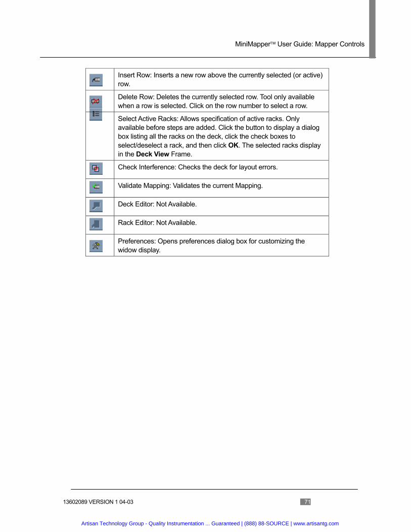
MiniMapper User Guide: Mapper Controls
13602089 VERSION 1 04-03 71
Insert Row: Inserts a new row above the currently selected (or active) row.
Delete Row: Deletes the currently selected row. Tool only available when a row is selected. Click on the row number to select a row.
Select Active Racks: Allows specification of active racks. Only available before steps are added. Click the button to display a dialog box listing all the racks on the deck, click the check boxes to select/deselect a rack, and then click OK. The selected racks display in the Deck View Frame.
Check Interference: Checks the deck for layout errors.
Validate Mapping: Validates the current Mapping.
Deck Editor: Not Available.
Rack Editor: Not Available.
Preferences: Opens preferences dialog box for customizing the widow display.
Artisan Technology Group - Quality Instrumentation ... Guaranteed | (888) 88-SOURCE | www.artisantg.com
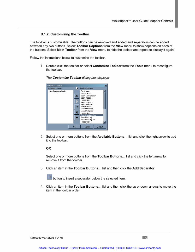
MiniMapper User Guide: Mapper Controls
13602089 VERSION 1 04-03 72
B.1.2. Customizing the Toolbar
The toolbar is customizable. The buttons can be removed and added and separators can be added between any two buttons. Select Toolbar Captions from the View menu to show captions on each of the buttons. Select Main Toolbar from the View menu to hide the toolbar and repeat to display it again.
Follow the instructions below to customize the toolbar.
1. Double-click the toolbar or select Customize Toolbar from the Tools menu to reconfigure the toolbar.
The Customize Toolbar dialog box displays:
2. Select one or more buttons from the Available Buttons… list and click the right arrow to add it to the toolbar.
OR
Select one or more buttons from the Toolbar Buttons… list and click the left arrow to remove it from the toolbar.
3. Click an item in the Toolbar Buttons… list and then click the Add Separator
button to insert a separator below the selected item.
4. Click an item in the Toolbar Buttons… list and then click the up or down arrows to move the item in the toolbar order.
Artisan Technology Group - Quality Instrumentation ... Guaranteed | (888) 88-SOURCE | www.artisantg.com

MiniMapper User Guide: Mapper Controls
13602089 VERSION 1 04-03 73
B.2. View and Selection Tools
The View and Selection tools are located along the left hand side of the Mapper Window (See Figure 4-3: Mapper ).
Tool Description
Selection mode: used for normal, default, operations such as selecting vessels for mapping. The cursor displays as the standard arrow .
Full Deck view: re-centers and zooms out to display the entire deck in the Deck View Frame. The selection tool is automatically selected after the view change is complete.
Active Rack view: Re-centers and zooms to display the active rack in the Deck View Frame. The selection tool is automatically selected after the view change is complete.
Zoom to Selected Area tool: Zooms in on the next selected area. The selection tool is automatically selected after the view change is complete.
Zoom In tool: Zooms in on the center point of the current display in the Deck View Frame. The selection tool is automatically selected after the view change is complete.
Zoom Out tool: Zooms out on the center point of the current display in the Deck View Frame. The selection tool is automatically selected after the view change is complete.
Zoom mode: used to zoom in and out. The cursor displays as a magnifying glass . Left click ( ) to zoom in and right click ( ) to zoom out.
Pan mode: used re-center the view. The cursor displays as a hand . Left click and drag (the mouse “grabs” ) to move a different area of the deck into view.
Deselect tool: Deselects the current destination vessels. This tool is only active when the cursor in the Grid View Frame is in a Dispense To cell.
Artisan Technology Group - Quality Instrumentation ... Guaranteed | (888) 88-SOURCE | www.artisantg.com
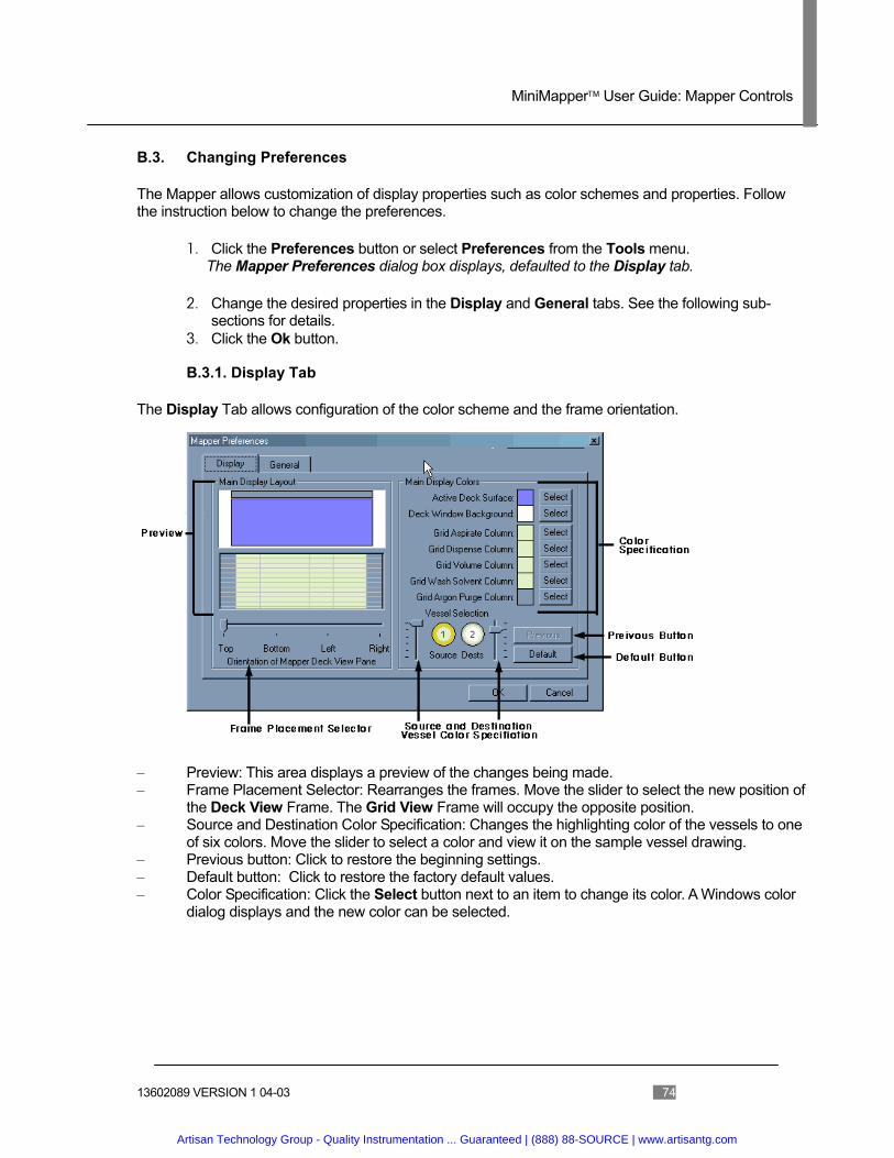
MiniMapper User Guide: Mapper Controls
13602089 VERSION 1 04-03 74
B.3. Changing Preferences
The Mapper allows customization of display properties such as color schemes and properties. Follow the instruction below to change the preferences.
1. Click the Preferences button or select Preferences from the Tools menu. The Mapper Preferences dialog box displays, defaulted to the Display tab.
2. Change the desired properties in the Display and General tabs. See the following sub-sections for details.
3. Click the Ok button.
B.3.1. Display Tab
The Display Tab allows configuration of the color scheme and the frame orientation.
– Preview: This area displays a preview of the changes being made. – Frame Placement Selector: Rearranges the frames. Move the slider to select the new position of
the Deck View Frame. The Grid View Frame will occupy the opposite position. – Source and Destination Color Specification: Changes the highlighting color of the vessels to one
of six colors. Move the slider to select a color and view it on the sample vessel drawing. – Previous button: Click to restore the beginning settings. – Default button: Click to restore the factory default values. – Color Specification: Click the Select button next to an item to change its color. A Windows color
dialog displays and the new color can be selected.
Artisan Technology Group - Quality Instrumentation ... Guaranteed | (888) 88-SOURCE | www.artisantg.com

MiniMapper User Guide: Mapper Controls
13602089 VERSION 1 04-03 75
B.3.2. General Tab
The General Tab allows configuration of operating modes and the default file directory.
– Erase all saved settings on next exit: Resets all default settings when the program exits. – Reset all “do not display again” dialogs: Resets dialog boxes where the Do not display
again check box has been selected. – Validate each row during data entry: Validates each step before allowing another step to be
added. Validation checks the existence of racks and vessels and the amount of reagent aspirated or dispensed, to ensure that vessels are neither exhausted nor overflowed.
– Display file operation status when done: Displays a dialog box that provides the status of the action attempted after every file operation.
– Auto-hide clipboard after each paste: Hides the clipboard when a paste operation is completed. Otherwise, once the clipboard is made visible, it remains on the screen in front of other objects unless explicitly hidden.
– Maximum Process Steps in the Grid: Limits the number of steps that may be specified according to the value typed in the field.
– Mapper Working Directory: Specifies the default directory for saving and opening files.
B.4. Menus
Mapper follows the standard Windows convention for menus. Most menu items have a keyboard accelerator key. Press the Alt key to activate accelerators and then the letter that is underlined on the item to invoke it. For example, type ALT F N to access New Mapping on the File menu. Some items also have shortcut keys, which are listed in parenthesis next to the items. The following sections describe each menu item in detail and list the shortcut when applicable. Menus shown with an ellipsis (…) at the end have submenus or activate dialog boxes.
Artisan Technology Group - Quality Instrumentation ... Guaranteed | (888) 88-SOURCE | www.artisantg.com
MiniMapper User Guide: Mapper Controls
13602089 VERSION 1 04-03 76
B.4.1. File Menu
The file menu controls file operations such as opening files and importing or exporting data.
New Mapping
Abandons the current mapping, empties the grid, and clears the racks from the deck. The current workstation configuration remains loaded. Proceed by selecting new racks to be loaded on the deck. A warning dialog will be displayed if the current mapping has not been saved. This option is only available when racks are loaded on the deck.
Open Configuration…
Loads a new workstation (deck) configuration from a Mapper Workstation Configuration file (MWC file). Such files specify the geometry and characteristics of the workstation deck, including what racks are available to be loaded on the deck, what reservoirs are available, and what standard deck equipment is available.
Open Mapping … (Ctrl+O)
Loads the workstation configuration file and the mapping file that was selected. Every mapping file has an associated workstation configuration file. When the mapping file is opened, the file name of the workstation configuration file is retrieved, and that file is then opened before any other mapping file processing is performed.
Import Mapping …
Reads and loads externally generated mapping files in a comma delimited format. Such files may be created with applications like Microsoft Excel. Before loading the file, you are prompted to decide how the mapping data is placed into the current mapping by making a selection from a dialog box.
Import Volumes…
Reads and loads an RVL file to set the initial volumes of all the vessels on the deck, overwriting default volumes.
Export Mapping …
Saves mapping file for access by an external application in either comma delimited (CSV) or plain text format. The former is suitable for use in other applications such as Microsoft Excel, or to be imported back into another Mapper process: using the Import Mapping feature.
Export Volumes…
Saves Vessel volumes file for access by an external application in either comma delimited or plain text format. When exporting in CSV format, the file is considered to be the “final volume table” and it contains the volumes of all vessels in all racks In RVL format, the operator selects which racks on the deck are to be considered, and only those vessel volumes are exported.
Artisan Technology Group - Quality Instrumentation ... Guaranteed | (888) 88-SOURCE | www.artisantg.com

MiniMapper User Guide: Mapper Controls
13602089 VERSION 1 04-03 77
Save Configuration
Saves workstation configuration after using the Mapper Deck Editor to create a new workstation configuration (deck) or to modify the one that is loaded. The deck editor and rack editor (see below) are used to manipulate the geometry and attributes of the deck and to create, modify, or delete racks that are used with that deck, respectively.
Save Mapping (Ctrl+S)
Saves the mapping file. This selection is available when at least one mapping step has been entered into the grid. If a mapping file is already opened or a new one has already been saved, this selection quietly saves the current data, replacing the same file. If no mapping file is already opened or if this is the first save from a new mapping, a file name will be requested. Mapping files use the extension MMA.
Save Configuration As…
Saves the configuration after prompting for a file name. This allows the operator to create multiple workstation configuration files, or to change which file is being edited. For example, a baseline deck with two racks could be created and saved, then four more racks added, and that configuration saved under a different name.
Save Mapping As…
Saves the Mapping file after prompting for a file name. This allows the operator to create multiple mapping files, or to save a mapping in different process: stages. For example, a mapping could be saved after 10 steps were entered, then again after 30 steps, 50 steps, etc., each time using a different mapping file name.
Save Workspace As… (Ctrl+W)
Creates an empty mapping file that can be used as a template for future mapping. Regardless of how many mapping steps are present in the grid, none are written to a workspace file. This way, the operator can open this file just like any other mapping file and have the racks loaded on the deck with no mapping steps present.
1 Mapping File name
Displays up to five of the last used mapping files near the end of the file menu, numbered 1 through 5. This is a shortcut to using the “Open Mapping” menu described above. The file opens when selected.
Exit
Use this selection to conclude the mapping session and terminate the Mapper application. If the configuration or mapping has not been saved, a confirmation dialog box displays.
Artisan Technology Group - Quality Instrumentation ... Guaranteed | (888) 88-SOURCE | www.artisantg.com

MiniMapper User Guide: Mapper Controls
13602089 VERSION 1 04-03 78
B.4.2. Edit Menu
The edit menu operations apply to the rows of the mapping grid. In general, rows (steps) must be selected for most of these functions. To select a row, click on its step number. To select a range, click on the first step, hold <shift>, and click on the last step of the range, or click and drag from the first step to the last step in the range. To select non-contiguous steps, hold <CTRL> and click the desired steps.
Cut Selected Steps to Clipboard (CTRL+X)
Deletes the selected steps from the mapping and copies them to the current page in the clipboard. This operation also renumbers subsequent steps as needed.
Copy Selected Steps to Clipboard (CTRL+C)
Copies the selected steps to the clipboard. Nothing changes in the mapping grid.
Paste Clipboard Contents (CTRL+V)
Inserts all of the steps on the current page in the clipboard above the selected location in the grid. Appends the contents of the clipboard to the end of the current mapping if no location is selected.
Insert Step(s)
Inserts empty steps, as specified, above the lowest selected step.
Delete Step(s)
Deletes all of the selected steps from the mapping grid. This operation also renumbers subsequent steps as needed.
Clear Step(s)
Clears all of the selected step data, without deleting the whole step.
Undo (CTRL+Z)
Reverses the last single action that changed the contents of the grid. Only one (1) undo step is available in Mapper.
Artisan Technology Group - Quality Instrumentation ... Guaranteed | (888) 88-SOURCE | www.artisantg.com
MiniMapper User Guide: Mapper Controls
13602089 VERSION 1 04-03 79
B.4.3. View Menu
The View menu controls the visibility of several features in Mapper.
Main Toolbar
Enables or disables display of the main Mapper toolbar along the top of the application. Hiding the toolbar increases the amount of space for other elements of the display without any loss of functionality.
Toolbar Captions
Enables and disables captions on the toolbar. Captions remove the ambiguity of the function of each tool, and can be useful in situations where a number of similar looking buttons are configured. Enabling captions automatically makes all the buttons larger.
Vessel RVID Format
Numeric Only: references all vessels in all racks by their vessel number, regardless if the rack is capable of displaying alpha-numeric vessel numbers or not. Independent of this setting, you may always type either full numeric or alphanumeric values for the vessels in the grid.
Alphanumeric: displays vessels in a matrix format, typically with row letters and column numbers. When this selection is checked on, all such vessels are displayed in the grid in this manner. Independent of this setting, you may always type either full numeric or alphanumeric values for the vessels in the grid.
Deck Equipment
N/A
Grid Clipboard
Enables and disables the clipboard (displayed automatically when you cut or copy steps). Depending on the setting in the preferences dialog, the clipboard will automatically hide itself when you paste. The grid clipboard must be visible to select from among its eight different pages for cutting/copying/pasting.
History Narrative
Enables and disables the availability of the History Narrative. The narrative displays information on vessels on the deck when right-clicked.
Mapping Narrative
Enables and disables the availability of the Mapping Narrative. When enabled, the mapping narrative will automatically attach itself to the left or right edge of the main Mapper application window, wherever there is the most room. At the same time, the main Mapper application window is pushed to the extreme edge of the display to provide the most room for the narrative window. The narrative window matches the size of the main window.
Artisan Technology Group - Quality Instrumentation ... Guaranteed | (888) 88-SOURCE | www.artisantg.com
MiniMapper User Guide: Mapper Controls
13602089 VERSION 1 04-03 80
B.4.4. Workstation Menu
Items on this menu are related to the operation of the workstation configuration.
Select Racks for Mapping
Allows specification of which racks are displayed from the racks available in the current configuration. This option is available when there are no mapping steps in the grid. When a rack is on deck, its vessels are available to Mapper. Once you have begun mapping, you will not be permitted to add or remove racks.
Check Deck for Interference
Ensures that no object, rack or equipment, interferes with another object. This function is performed automatically whenever racks are added to the deck. The workstation configuration file specifies what margin must be maintained around each object before interference is flagged.
Validate Mapping Steps
Validates all of the mapping steps in the grid.
Edit Deck Configuration
Creates a new deck when there is no deck (workstation configuration) loaded or allows editing of the properties of the deck if a deck is loaded but has no racks.
Edit Rack Configuration
Allow s creating or editing racks that are bound to the deck.
Artisan Technology Group - Quality Instrumentation ... Guaranteed | (888) 88-SOURCE | www.artisantg.com
MiniMapper User Guide: Mapper Controls
13602089 VERSION 1 04-03 81
B.4.5. Tools Menu
The tools menu provides a number of unrelated features and functions for Mapper.
Grid Settings
Destination Auto-Tab: Enables (and disables) the mapping grid cursor to move over to the destination cell as if TAB has been pressed after clicking a vessel as a source.
Fixed Width Columns: Enables and disables the automatic sizing of the columns in the mapping grid. Default value is ON. If you prefer to set those columns that are normally fixed to different widths, check this OFF, and set the widths manually. The destination columns will still auto-size even when you have set the widths of the other columns.
Note: You can also right-click on the heading of the “Step” column on the grid to access these options.
Preferences
See B.3 Changing Preferences.
Customize Toolbar
See B.1 Toolbar.
Artisan Technology Group - Quality Instrumentation ... Guaranteed | (888) 88-SOURCE | www.artisantg.com

MiniMapper User Guide: Mapper Controls
13602089 VERSION 1 04-03 82
B.4.6. Help Menu
This menu provides operational information about Mapper.
Memory
Displays a dialog box that depicts the amount of system memory presently in use. This feature is used mainly as a diagnostic tool to help technical support diagnose issues with the operation of Mapper. Frequently on Windows, memory use by all programs running on a computer will have an impact on the operation of one application.
About / Register
The About dialog is another diagnostic tool that provides version information and other details about Mapper. It is also the place where Mapper can be re-registered with an alternate key. This dialog automatically appears every time Mapper starts and it has not been registered.
Artisan Technology Group - Quality Instrumentation ... Guaranteed | (888) 88-SOURCE | www.artisantg.com
MiniMapper User Guide: Index
13602089 VERSION 1 04-03 83
Index
Acid.......................................................................... 7
Advanced (Step) Parameters..............49, 50, 52, 53
Advanced Tab Layout Frame.........................................23 Layout Window................................24, 25 Liquid Handling......................................32 Step Parameters........... 48, 49, 50, 53, 54
Advanced-Rate Tab ........................................ 47, 54
Bases....................................................................... 7
Cannula Maintenance ....................................64, 65 Parameters ............. 47, 48, 49, 50, 52, 53 Types .....................................................69 Wash................................................54, 59
Carrier........................................................ 16, 24, 25 Adding to My Racks.........................25, 27 Physically Loading.................................20 Specifying in Layout ..............................23 Tab...................................................24, 25
Deck Layout Frame..................................... 8, 25, 56
Electrical Connection Panel ............................ 11, 15
Emergency Stop...................................................... 8
Execution Tools ........................................................8 Window....................................................6
Gas Corrosive..................................................7 Inerting tube...........................................11
Inerting...........................................47, 49, 50, 52, 53
Job State ................................................................. 6
Keyboard ............................................................... 11
Layout..........................17, 22, 23, 25, 26, 27, 28, 71 Frame ..............................................23, 24 Properties ..............................................28 Window......................................23, 24, 25
Liquid Database ........................................ 30, 34, 36
Liquid Handling.................................... 22, 30, 31, 59 Advanced Tab .......................................32
Manual Operations.......................................... 60, 62 Button...............................8, 60, 61, 64, 65 Change Cannula .............................60, 64 Change Syringe...............................60, 61 Empty Syringe ...................................8, 60 Initialize Syringe.........................60, 62, 65 Manual Prime ........................................60 Manual Wash.....................................8, 60
Mapper ....................................17, 37, 39, 51, 70, 73
Mapping.................17, 22, 38, 40, 75, 76, 77, 79, 80 Initial Volumes ...........................21, 39, 41
MiniBlock ............................................. 17, 20, 21, 37
Monitor............................................................. 11, 15
Mouse.............................................................. 11, 73
My Racks Tab ............................... 23, 24, 25, 26, 27
Parallel Synthesis.....................................................6
Password............................................................... 15
Process....................................16, 17, 22, 44, 76, 77 Building ................... 37, 38, 45, 46, 57, 75 Button.....................................................46 Saving....................................................58 Validating ...............................................57 Window..................................................44
Rack ......................17, 20, 25, 27, 28, 37, 38, 42, 46 Advanced Tab ...........................23, 24, 25 Lock to Carrier .................................25, 27
Artisan Technology Group - Quality Instrumentation ... Guaranteed | (888) 88-SOURCE | www.artisantg.com

MiniMapper User Guide: Index
13602089 VERSION 1 04-03 84
Mapper Operations71, 73, 75, 76, 77, 79, 80 My Racks Tab..................... 23, 24, 25, 26 Preview Frame ................................46, 56 Specifying in Layout ..................23, 25, 28 Tab...................................................24, 25
Reagents ............................................................... 21
Reboot Button ....................................................... 15
RVL file ....................................17, 37, 41, 42, 70, 76
Sample Loop Changing .........................................62, 63 Large Volume ........................................63 Small Volume.........................................63
Solvents.........................................40, 45, 61, 64, 69 Add Step ..........................................45, 47 Dripping..................................................59 Guidelines................................................7 Locate Button.........................................29 Manager...........................................29, 60 Online/Bottle29, 38, 47, 48, 49, 50, 52, 53, 54, 60 Specifying ..................................16, 22, 29
Start Button.....................................................15
Preparation ............................................10 Software...........................................15, 22 System.......................................11, 15, 22
Steps Details....................................................46
Syringe Maintenance....................8, 60, 61, 62, 65 Types .....................................................69
User ID .................................................................. 15
Utility Panel...................................................... 10, 11
Vacuum ........................................................... 10, 11
Volume Parameter31, 32, 39, 45, 47, 48, 49, 50, 51, 52,
53, 54 Specify Initial17, 21, 37, 38, 39, 41, 42, 43, 70, 76 Tracking ...........................................39, 41 Vessel ........................................21, 40, 42
Waste .............................................................. 11, 61
XT .............................................................. 17, 20, 21
Artisan Technology Group - Quality Instrumentation ... Guaranteed | (888) 88-SOURCE | www.artisantg.com

Artisan Technology Group is an independent supplier of quality pre-owned equipment
Gold-standard solutions Extend the life of your critical industrial,
commercial, and military systems with our
superior service and support.
We buy equipment Planning to upgrade your current
equipment? Have surplus equipment taking
up shelf space? We'll give it a new home.
Learn more! Visit us at artisantg.com for more info
on price quotes, drivers, technical
specifications, manuals, and documentation.
Artisan Scientific Corporation dba Artisan Technology Group is not an affiliate, representative, or authorized distributor for any manufacturer listed herein.
We're here to make your life easier. How can we help you today? (217) 352-9330 I [email protected] I artisantg.com