final draft - city of colorado springs - home
TRANSCRIPT

Final Draft
Revised 07/01/2005
Manual on Uniform Traffic Control DevicesSupplement For
The City of Colorado Springs

Final Draft
Revised 10/6/2005 2
TABLE OF CONTENTS
Table of Contents 2
Executive Summary 3
Introduction 4
Goals 5
Objectives 6
General Requirements 8
Specific Requirements 11
Appendix “A” (Fee Schedules & Penalty Assessment) 15
Appendix “B” (Area Map) 16
Appendix “C” (General Guide to Work Zone Traffic Control) 17
Appendix “D” (Letter Codes & Formulas) 18
Appendix “E” (Typical Applications) 19
Appendix “F” (Important Phone Numbers) 21

Final Draft
Revised 10/6/2005 3
TRAFFIC CONTROLS FOR STREET CONSTRUCTION,UTILITY WORK AND MAINTENANCE OPERATIONS
CITY OF COLORADO SPRINGS
Executive Summary
This field guide is a supplement to the Manual on Uniform Traffic Control Devices(M.U.T.C.D.) and is provided as a guide for any contractor, utility, or agency working inthe public right-of-way. This document identifies the needs for traffic controls at worksites, establishes responsibility for traffic controls, defines the permit process, and givestypical urban traffic control applications. This manual also provides contact informationfor necessary agencies and establishes the need for public notification. The primary goalof this supplement is to increase awareness of the need for proper traffic control in workzones, ensuring efficient and safe completion of construction and maintenanceoperations.

Final Draft
Revised 10/6/2005 4
TRAFFIC CONTROLS FOR STREET CONSTRUCTION,UTILITY WORK AND MAINTENANCE OPERATIONS
CITY OF COLORADO SPRINGS
Introduction
Construction and maintenance areas have significantly higher than average accident rates.As a result, special care should be taken in applying traffic control techniques in theseareas. Traffic safety in construction zones should be an integral part of every project fromplanning, through design and construction. The City of Colorado Springs is veryconcerned with traffic control in work zones and has prepared this manual to aidconstruction and maintenance personnel in implementing safe and efficient methods forhandling traffic.
The Manual of Uniform Traffic Control Devices (M.U.T.C.D.) and the Traffic ControlDevices Handbook, distributed by the Institute of Transportation Engineers, are therecognized standard for all traffic control devices. This supplement is not meant toreplace these publications, but to address the standard practices in the City of ColoradoSprings. In all cases, the traffic control plan should conform to, or be of higher standardsthan, the methods outlined in the above mentioned publications.
Section 10.1.309 of the city traffic code establishes the authority of the Traffic Engineerto determine the installation of traffic control devices and provide for street closures.Additionally, the City Council of Colorado Springs established a resolution authorizingthe Traffic Engineer to impose traffic control fees. This supplement is created under thatauthority, and describes the objectives, goals and requirements of the City of ColoradoSprings for traffic control at work sites.

Final Draft
Revised 10/6/2005 5
TRAFFIC CONTROLS FOR STREET CONSTRUCTION,UTILITY WORK AND MAINTENANCE OPERATIONS
CITY OF COLORADO SPRINGS
GOALS
Safety is the primary goal of any traffic control plan. Traffic control devices at work sitesare necessary to protect motorists, bicyclists and pedestrians from encounteringunexpected requirements or difficult maneuvers that could result in an accident. Trafficcontrols should route traffic through the work area in a manner that is as similar aspossible to normal roadway conditions. Any unusual, unrecognized, or unclear trafficcontrol device can have negative results such as drivers choosing an incorrect route orblocking the flow of traffic. Though work site hazards cannot be completely eliminated,they can be reduced through the following methods:
• Schedule work during off-peak traffic volume hours.• Coordinate work with other agencies to provide fewer traffic interruptions.• Investigate alternate locations for utility installations.
Consistency in device appearance and use throughout the city will lead to betterunderstanding by the driver and result in fewer accidents. All traffic control devices mustmeet or exceed the standards in the latest edition of the MUTCD. Traffic control devicesmust be laid out according to the approved Traffic Control Plan and associated WorkZone Traffic Control Permit.
Maintenance of traffic control devices is very important to their effectiveness. All trafficcontrol devices must be maintained throughout the construction period to provide correctplacement and legible faces both day and night. Maintenance includes cleaning orreplacing dirty, missing or damaged devices. Routine day and night inspections arenecessary; however, no standard schedule can be used for all conditions. Frequencyshould be based on common sense, with heavy traffic arterials requiring more frequentinspections. If inclement weather, vandalism, or other difficulties occur, more frequentinspections will be required. Follow-up action is required to make sure that anydeficiencies have been corrected. The permit holder is responsible for the inspections andthe corrective action.

Final Draft
Revised 10/6/2005 6
TRAFFIC CONTROLS FOR STREET CONSTRUCTION,UTILITY WORK AND MAINTENANCE OPERATIONS
CITY OF COLORADO SPRINGS
OBJECTIVES
With the passage of resolution 39-02 the Colorado Springs City Council has authorizedthe City Traffic Engineer to impose traffic control fees. That resolution as well as cityordinance 01-42, states: “all work site traffic controls shall be approved by the city trafficengineer prior to commencement of work”, provided the need to implement an approvaland inspection process. This is an outline of the objectives of the Traffic ControlProgram.
I. TRAFFIC CONTROL PERMIT APPROVAL
A. Any contractor that is in the city’s right-of-way, whether on the sidewalk or inthe street, must obtain a Traffic Control Permit. Permits are issued at thePikes Peak Regional Development Center, 2880 International Circle, 2nd floor.If you are a licensed contractor and have a valid pin number, you can applyonline at www.springsgov.com. To set up a pin number, contact EngineeringInspections at (719) 385-5977.
B. All Permits must have a method of handling traffic or a Traffic Control Planattached to them. Traffic Engineering will accept custom plans if they aredone neatly and with recognized drawing methods. Refer to the latest editionof the Manual on Uniform Traffic Control Devices (MUTCD) and the TrafficControl Devices Handbook for assistance in making custom drawings. TrafficControl Plans for larger more complicated construction projects should beengineered drawings. Custom or engineered plans that need to be reviewedmay be delivered to Traffic Engineering’s office at, 30 S. Nevada Ave., Suite405, Colorado Springs, CO 80903, or faxed to (719) 385-5497. For standardtraffic control situations, a contractor may use the figures offered later in thissection. This Traffic Controls Supplement is available as part of the TrafficEngineering Section of the Subdivision Policy, Public Works Design Manualor as a stand alone document. The stand alone document is available at theTraffic Engineering office or at Pikes Peak Regional Development Center forpurchase. You can also view the document online at www.springsgov.comand select “Transportation & Transit”, “Traffic Engineering”, “TrafficControls for Street Construction, Utility Work & Maintenance”.

Final Draft
Revised 10/6/2005 7
C. For improved tracking and auditing purposes, permits applied for at the PikesPeak Regional Development Center will be entered into the online system forreview and approval. Online permits are reviewed and approved twice daily.Permits should be applied for at least five working days prior tocommencement of work to ensure enough time for review and advance notice.Work Zone Traffic Technicians are available Monday through Friday from6:30 A.M. to 5:00 P.M. to assist with any questions or problems you mayhave. Refer to the list below for days and phone numbers of the techniciansassigned to the Work Zone Traffic Control Program:
North Area Mon.-Thurs. Wk #385-5908 South Area Tues-Fri. Wk #385-5908
II INSPECTION
A. All temporary traffic control is subject to inspection by Traffic Engineeringstaff. Inspectors monitor city streets on a daily basis. Inspections are usuallyrandom except for larger or more complicated jobs which are inspecteddaily or as needed. Currently there are two full time inspectors involvedwith traffic control. Attached to this document, is a map showing whichinspector to contact for a certain area of the city.
B. Due to the increasing volume of night and weekend work, inspection afternormal business hours will be at the discretion of Traffic Engineering staff.Under certain circumstances, random inspections will be done during non-business hours.
III FEES AND PENALTIES
A. Permit fees vary depending on traffic volumes where work is being done,and whether the contract work is telecommunication or non-telecommunication (see attached Appendix A).
B. Fines are also outlined on this same schedule. Fines can be assessed forreasons ranging from no permit on site to safety issues; refer to your permitgeneral requirements for additional reasons for fines.
C. All permit fees and fines must be paid through City EngineeringInspections at Pikes Peak Regional Development Center. It is theresponsibility of the contractor or project supervisor to have an approvedTraffic Control Permit on site with a copy of the traffic control diagram.

Final Draft
Revised 10/6/2005 8
TRAFFIC CONTROL FOR STREET CONSTRUCTION,UTILITY WORK AND MAINTENANCE OPERATIONS
CITY OF COLORADO SPRINGS
General Requirements
1. Contractors are required to submit the Traffic Control application at least fiveworking days prior to commencement of work to ensure enough time for reviewand advance notice. Activity requiring unique traffic control setups may requireadditional time for review and permit issuance, Traffic Engineering is notresponsible for delays to a project due to this extended review time.
2. Traffic control permits are required for all operations that have a direct or indirectimpact on public traffic (including motor vehicles (parked or moving), cyclists,and pedestrians) within the City Right-of-Way. Bicyclists and pedestrians shouldbe provided with access and reasonably safe passage through the temporary trafficcontrol work zone.
3. City policy does allow an exception for moving operations. Moving operations,defined as “activities in place less than thirty (30) minutes including time to setupand remove traffic control”, shall be exempt from the permit process. However,moving operations are not exempt from having a complete and appropriate setupper the latest edition of the MUTCD and the City of Colorado Springs supplementto the MUTCD. Improper setup does not exclude anyone from assessed fines forimproper traffic control.
4. All traffic control devices shall meet or exceed MUTCD minimum requirementsand comply with the NCHRP 350 criteria requirements.
5. Engineered drawings may be required for all minor arterial streets and above. Anywaiver of this requirement will be at Traffic Engineering discretion.
6. Contractor generated traffic control plans will require a certified Traffic ControlSupervisor to do work zone setups on all streets classified as Major ResidentialCollector and above.
7. Proof of Traffic Control Supervisor Certification by either the American TrafficSafety Service Association (ATSSA) or Colorado Contractors Association (CCA)with Flagger endorsement must be provided at time of submittal or be on recordwith the city.
8. Traffic control plan/permit shall be onsite at all times.9. Permit fees are based on the number of traffic setups required to complete the
project. Permit fees shall be paid in full prior to the permit being issued and priorto start of actual work.
10. Permits will be valid for the time period approved by City Traffic Engineering onthe permit. Extensions may be granted if the contractor can justify the need.
11. Flagging personnel must be trained, certified and dressed appropriately.12. Any changes to the Traffic Control Plan must have approval by City Traffic
Engineering prior to implementation.

Final Draft
Revised 10/6/2005 9
13. Any city signs removed or damaged must be replaced. Temporary signs shall beinstalled until permanent signs are replaced. All temporary and replacement signsshall meet the city’s installation and materials standards. All signs conflictingwith approved traffic control plan shall be covered or removed. All expensesincurred to remove, cover and/or replace signs will be the contractor’sresponsibility.
14. The repair or replacement of any damaged roadway pavement markings shall bethe responsibility of the contractor per City Code 3.3.203. All stop lines,crosswalks, legends and arrows shall be 90 mil thickness, thermoplastic orpreform plastic tape. All longitudinal lines shall be 15 mil thickness epoxy.Temporary pavement markings shall not be in place for more than two weeksunless approved by City Traffic Engineering. All pavement markings shallconform to the most recent adopted editions of the MUTCD and City of ColoradoSprings Signs & Pavement Marking Guidelines.
15. An all weather surface must be in place before opening the roadway. Specificconditions may require the use of traffic plates. If used, they shall be properlyanchored and maintained according to work zone time restrictions andconstruction schedule.
16. Traffic control must meet or exceed contractual specifications.17. Contractors shall comply with the City Noise Ordinance # 3.3.2111.18. City Traffic Engineering reserves the right to inspect all traffic control plans in
operation and make changes as field conditions warrant.19. Traffic Engineering shall be notified when an emergency occurs. All emergency
work shall require that a permit application be filed and associated fees paidwithin 24 hours of the emergency or fines will be assessed accordingly.
20. Work involving state or county roadways within the Colorado Springs city limitsmust have permits from each of these agencies in addition to the required permitfrom the city. All permits must be on site at all times.
21. Vehicles and materials not related to the work in progress shall not be stored inthe work area.
22. All temporary traffic control devices shall be removed once they are no longerneeded. When work is suspended for short periods of time, temporary trafficcontrol devices that are no longer appropriate shall be removed or covered.
23. When the construction zone involves metered parking, the contractor shall obtainparking meter bags or make other arrangements with Parking Administration forthe allotted time.
24. A Uniformed Traffic Control Police Officer shall be required when traffic isshifted to run against a traffic signal unless the traffic signal can be modified tocontrol the new roadway alignment.
25. Arrow boards are required for lane closures on all roadways that are 60 feet orwider with 4 or more lanes and, an average daily volume of 10,000 or morevehicles. They are also required where horizontal and/or vertical alignment limitssight distance.
26. All traffic lanes shall be open to vehicular traffic between the hours of 06:00 A.M.to 09:00 A.M. and between the hours of 04:00 P.M. to 07:00 P.M. unlessauthorized by City Traffic Engineering.

Final Draft
Revised 10/6/2005 10
27. If a Special Event and Work Zone Traffic Control Permit are scheduled at thesame time, coordination shall be required between the contractor, event holderand City Traffic Engineering to resolve any potential conflicts that may occur.
28. All school districts within the city limits shall obtain an approved traffic controlpermit for the placement of traffic control devices within the City Right-of-Way.
29. All trenching will require adequate shoring or slope and any trench 5 feet ordeeper requires notification of the Colorado Springs Fire Department.
30. To determine if the segment of roadway is on a City Transit Route, go towww.springsgov.com and select “Transportation & Transit”, “Springs Transit”,“Springs Transit”, Route & Schedule Information” to view maps of currentroutes.
31. To determine if the segment of roadway is on a City Snow Plow Route, go towww.springsgov.com and select “Public Works”, “Street Division”, and “Snow &Ice Control” to view current plow routes.
32. To determine if the segment of roadway is on a City Truck Route, go towww.springsgov.com and select “Planning & Community Development”,“Transportation Planning”, “Inter-Modal Transportation Plan”, and “Chapter 7.Freight” to view current truck routes.

Final Draft
Revised 10/6/2005 11
TRAFFIC CONTROL FOR STREET CONSTRUCTION,UTILITY WORK AND MAINTENANCE OPERATIONS
CITY OF COLORADO SPRINGS
Specific Requirements
Temporary Traffic Barrier:
The Contractor shall install Pre-cast Type 7F concrete, Type IV concrete, or PlasticWater Filled barrier between any lanes carrying public traffic and any excavation,obstacle, or storage area when the following conditions exist:
• When an excavation is 12 inches or greater in depth a minimum clear zone (CZ)in feet shall be required for the following design speeds:
30 MPH 35 MPH 40 MPH 45 MPH 50 MPH 55 MPH 60 MPH12’ CZ 14’ CZ 16’ CZ 20’ CZ 22’ CZ 24’ CZ 30’ CZ
• If the minimum Clear Zone can not be maintained, then a temporary traffic barriershall be required for work site protection. The barrier must be pinned together,and a two foot shy line should be provided between vehicular traffic and thebarrier.
• A temporary traffic barrier shall be supplemented with standard delineation(reflectors), pavement markings, or channelizing devices to provide nighttimevisibility for vehicle traffic. The delineation or pavement marking color shallconform to the latest edition of the MUTCD.
• Temporary traffic barrier ends shall be installed in accordance with AASHTO’s“Roadside Design Guide” by flaring until the end is outside the acceptable clearzone (clear zone is based on 85th percentile speed) or by providing crashworthyend treatments that meet or exceed NCHRP Report 350.
• A temporary traffic barrier is required when the contractor has installed apermanent obstacle and the protective system, such as guardrail has not beeninstalled or when a portion of an existing protective guardrail has been removed.
• A temporary traffic barrier is required when materials or equipment are storedwithin the clear zone of the work site.
• The two accepted forms of anchoring steel pins are either with a cotter pin andwasher at the bottom of each steel pin, or by driving the steel pin 4 inches into thesurface to prevent the pin from jumping out of place during vehicle impact.
• The use of a 12 ft. transition section is allowed at the downstream end of theinstallation pointing away from approaching traffic out of the clear zone, or atlocations outside the clear zone, generally more than 30 ft. from the high speedtravel lane edge.
• Glare Screens may be required, if used the blade height shall be 24”.

Final Draft
Revised 10/6/2005 12
Temporary Traffic Signals:
Temporary traffic signals must meet the physical display and operationalrequirements of conventional traffic signals. A minimum of two signal faces shall beprovided for each approach, and each signal face shall consist of three 12 inchsections. The traffic signal controller must be capable of two-phase operations unlessotherwise specified, and have all-red timing intervals.
Pedestrian Requirements:
• All pedestrian access must meet the American Disabilities Act (ADA)standards. All temporary walk surfaces shall be cold patched, asphalt orconcrete and must not exceed 8.3% grade per ADA standards.
• When doing work involving a sidewalk or pedestrian walkway, the trafficcontrol plan must contain appropriate protection for pedestrians (fencing,barriers, or covered walkways) and must be approved by Traffic Engineering.
Scaffolds & Overhead Work:
• The contractor shall provide protection to the pedestrian when doing overheadwork. All heights 6 ft. and greater are considered overhead.
• An overhead, lighted canopy shall be constructed for pedestrians adjacent toany erected scaffolding. Pedestrian clearance shall be eight feet in height andfive feet in width. ADA ramps, with an 8.3% grade or flatter shall beconstructed if the pedestrian canopy walk is constructed in the roadway.
• All canopy construction within the city right-of-way shall comply with therequirements of the applicable local agency or the latest edition of theUniform Building Code whichever contains the higher standard.
• To prevent objects from falling off, scaffolds shall provide guardrail systems,safety nets or personal fall arrest systems. Scaffolds shall have toe boards,screens, or guardrail systems to prevent objects from falling from a higherlevel.
• Materials shall not be stored on scaffolds. All material placed on scaffoldsshall be removed at the end of the work shift.

Final Draft
Revised 10/6/2005 13
Excavation and Trenches:
Excavations and/or trenches, which cannot be properly back-filled and patched prior tothe end of the work day, shall be bridged to permit unobstructed traffic flow. Trenchwalls and adjacent soils shall be sufficiently stabilized prior to the use of steel plates forbridging.
Where traffic must cross trenches:• The use of steel plates shall be approved by City Traffic Engineering prior to
installation.• The Colorado Springs Fire Department – Heavy Rescue Response Group shall be
notified when the excavation or trench is 5 feet or greater in depth.• Steel Trench Plate width and thickness requirements:
18” or less in width Minimum thickness of ¾”> 18” in width to 72” in width Minimum thickness of 1”
• The thickness of Steel Plates for trench widths exceeding 72” a structural designshall be prepared by a Licensed Professional Engineer Registered in Colorado.
• Steel Plates can be installed in two ways. First, the Steel Plates can be installedflush with the existing pavement, milling out the pavement surface to ensure thatthe top of plate elevation matches the existing elevations of adjacent pavementsurface. Second, the Steel Plates can be installed on top of the asphalt withtransitional ramps (cold mix) on all four sides of the plates, with feathered edgesto match the existing asphalt (8% or a lesser slope).
• Steel Plates shall be attached to the roadway by a minimum of 4 dowels pre-drilled into the corners of the plates and drilled 2 inches into the pavement.
• The Steel Plates shall extend beyond the edge of the trench a minimum of 18” butno more than 30”on both sides.
• A non-skid surface treatment shall be applied to the entire surface area of the platein the direction of traffic flow.
• The contractor should avoid using a long series of plates that run parallel to trafficwheel paths. If allowed, the length of a series of plates running parallel to trafficwheel paths shall not exceed 30’.
• The trench shall be adequately shored to support the steel plates and traffic loads.• Steel Plates shall be installed to operate with minimum noise.• All Steel Plates within the right-of-way, whether used in or out of the traveled
way, shall be without deformation (free from any clips, chains, attachments,weldments, or surface irregularities).
• No one is allowed in the trench while covered by the Steel Plate.• The use of Steel Plates shall not exceed four weeks and Rough Road or Bump
signs shall be required during this period of time.

Final Draft
Revised 10/6/2005 14
Arrow Boards:
Arrow Boards shall be furnished as required by project conditions and shall meet thefollowing requirements:Type Minimum Size Min. # of Panel Lamps Min. Legibility DistanceA 48” x 24” 12 ½ mileB 60” x 30” 13 ¾ mileC 96” x 48” 15 1 mile(Example: length of arrow equals 48”; width of arrowhead equals 24”)
An arrow panel is a sign with a matrix of elements capable of flashing or showingsequential displays. This sign shall provide additional warning and directionalinformation to assist in merging and channeling road users through or around a temporarytraffic control zone. The panel face shall be rectangle in shape, solid construction andfinished in non-reflective black. The arrow panel shall have the capability of thefollowing mode selection: left arrow, right arrow, left and right arrow and caution. Thecaution mode consists of four or more flashing lamps arranged in a pattern which doesnot indicate a direction. Arrow panels shall include an automatic photocell sensor typesignal lamp dimmer with manual override and shall be capable of a minimum of 50percent dimming from rated lamp voltage.
Portable Variable Message Signs:
Variable Message Signs (VMS) are temporary traffic control devices with the flexibilityto display a variety of messages. Each message shall consist of one or two phases. Aphase consists of up to three lines of eight characters per line. Each character moduleshall use at least five wide and seven high pixel matrixes.
• VMS’s shall be used on all major residential collector streets and higherclassification of roadways, including roadway closures and detour routes. Also,VMS’s shall be used when lane reductions can not handle the normal volume oftraffic (no greater than 1,000 vehicles per lane per hour).
• VMS’s shall be used to advise vehicular traffic of alternate routes and expecteddelays due to construction activity.
• VMS’s shall be used to notify the general public of upcoming constructionactivities up to two weeks prior to start of construction.
• VMS’s shall be solar powered or a non-internal combustion device.• VMS’s shall have their own separate power source with an independent battery
backup and shall operate continuously for ten days without sun light.• VMS’s shall be capable of 360 degree rotation and elevated so the bottom of the
sign is 5 feet above the ground.• The sign shall be visible from one-half mile during both daytime and nighttime
conditions.• The message shall be legible from a minimum of 650 feet.• The sign shall automatically adjust its light source to meet nighttime legibility
requirements.

Final Draft
Revised 10/6/2005 15
Appendix “A”
Fee Schedules and Penalty Assessment Chart
Traffic Control PermitNon-Telecommunication Provider/Non-Cable Operator
Rate(per permit, per setup)
> 5,000 Average Daily Traffic on affected street $180.00< 5,000 Average Daily Traffic on affected street $50.00
Traffic Control PermitTelecommunication Provider/Cable Operator
Rate(per permit, per setup)
> 5,000 Average Daily Traffic on affected street $164.00< 5,000 Average Daily Traffic on affected street $45.00
Penalty for No Traffic Control PermitNon-Telecommunication Provider/Non-Cable Operator
& Telecommunication Provider/Cable Operator(not including permit fee, penalty only)
Penalty
> 5,000 ADT
Penalty
< 5,000 ADTFirst Penalty for No Permit for Activity $ 360.00 $100.00
Second Penalty for No Permit for Activity $ 540.00 $150.00
Penalty for Non-Compliance of Traffic Control Permit
Non-Telecommunication Provider/Non-Cable Operator& Telecommunication Provider/Cable Operator
(not including permit fee, penalty only)
Penalty
> 5,000 ADT
Penalty
< 5,000 ADT
First Penalty for Non-Compliance Permit $ 360.00 $100.00Second Penalty for Non-Compliance Permit $ 540.00 $150.00

Final Draft
Revised 10/6/2005 16
Appendix “B”

Final Draft
Revised 10/6/2005 17
Appendix “C”

Final Draft
Revised 10/6/2005 18
Appendix “D”
LETTER CODES
Distance between Signs in Ft (metric)ROAD TYPEA B C
Urban (low speed) 100 (30) 100 (30) 100 (30)
Urban (high speed) 350 (100) 350 (100) 350 (100)
Rural 500 (150) 500 (150) 500 (150)
Expressway / Freeway 1000 (300) 1500 (450) 2640 (800)
Type of Taper Taper Length (L)*
Merging Taper At least LShifting Taper At least 0.5 LShoulder Taper At least 0.33 LOne-Lane, Two-Way Traffic Taper 100 ft (30m) maximumDownstream Taper 100 ft (30m) per lane
FORMULAS
Speed Limits of 40 mph (60 km/h) or less / Speed Limits of 45 mph (70 km/h) or >:
2 2 L= WS (L=WS ) L=WS (L=WS) 60 155 1.6
LaneWidth
Speed inMPH
25MPH
30MPH
35MPH
40MPH
45MPH
50MPH
55MPH
60MPH
65MPH
10 ft. Merging Taper 105’ 150’ 205’ 270’ 450’ 500’ 550’ 600’ 650’11 ft. Merging Taper 115’ 165’ 225’ 294’ 495’ 550’ 605’ 660’ 715’12 ft. Merging Taper 125’ 180’ 245’ 320’ 540’ 600’ 660’ 720’ 780’
Where:L = Taper length in feet (meters).W = Width of offset in feet (meters).S = Posted speed limit, or off-peak 85th-percentile speed prior to work starting, or the anticipated operating speed in mph (km/h)
* Distances are shown in feet (meters).

Final Draft
Revised 10/6/2005 19
Appendix “E”
TYPICAL APPLICATIONS
Typical Application Description Typical ApplicationNo.
Sidewalk Detour T.A. # 1Sidewalk Diversion T.A. # 2Sidewalk Diversion within Parkway T.A. # 3Ramp Closure Pedestrian Detour T.A. # 4Work Beyond the Shoulder T.A. # 5Work on the Shoulder T.A. # 6Shoulder Work with Minor Encroachment T.A. # 7Lane Shift with Parking Restrictions T.A. # 8Lane Closure on Two-Lane Road with Flaggers T.A. # 9Work in Center of Road with Low Traffic Volume T.A. # 10Outside Single Lane Closure on Four Lane Road T.A. # 11Inside Single Lane Closure on Four Lane Road T.A. # 12Interior Lane Closure on Multi-Lane Road T.A. # 13Half Road Closure on Multi-Lane Road T.A. # 14Outside Lane Closure on Five Lane Road T.A. # 15Continuous & Inside Lane Closure on Five Lane Road T.A. # 16Work in the Continuous Lane on Five Lane Road T.A. # 17Multi-Lane Closure on Five Lane Road T.A. # 18Inside Lane Closure on Multi-Lane Road - Raised Median T.A. # 19Outside Lane Closure on Multi-Lane Road - Raised Median T.A. # 20Outside Lane Closure on Far Side of the Intersection withSidewalk Closure
T.A. # 21
Outside Lane Closure on Far Side of the Intersection with NoSidewalk Closure
T.A. # 22
Inside Lane Closure on Far Side of the Intersection T.A. # 23Half Road Closure on Far Side of the Intersection T.A. # 24Multiple Lane Closure on Far Side of the Intersection T.A. # 25Closure in Center of the Intersection T.A. # 26Closure in Corner of the Intersection T.A. # 27Overlapping Routes with Detour T.A. # 28Alley Closure T.A. # 29Local Road Closure T.A. # 30Multi-Lane Closure on Six Lane Road T.A. # 31Outside Lane Closure on Far Side of the Intersection T.A. # 32Left Turn Bay Closure T.A. # 33Right Turn Bay Closure T. A. # 34

Final Draft
Revised 10/6/2005 20
Typical Application Description Typical ApplicationNo.
Center Lane Closure on Six Lane Road T.A. # 35Lane Closure Shifting Traffic into the Continuous T.A. # 36Lane Closure on Low Volume Road T.A. # 37Work Inside of a Roundabout T.A. # 38Work Outside of a Roundabout T.A. # 39Work Inside of a Multi-Lane Roundabout T.A. # 40Inside Lane Closure Multi-Lane Roundabout T.A. # 41Outside Lane Closure Multi-Lane Roundabout T.A. # 42One Lane Road with Temporary Traffic Signals T.A. # 43Outside Lane Closure with Sidewalk Closure T.A. # 44Half Road Closure on Multi-Lane Road T.A. # 45

Final Draft
Revised 10/6/2005 21
Appendix “F”
Important Phone Numbers
Traffic Engineering Division30 S. Nevada Ave., Suite 405Colorado Springs, CO 80901-1575Office (719) 385-5908Fax (719) 385-5497
Traffic Engineering Signals404 W. Fontanero St.Colorado Springs, CO 80907Office (719) 385-6721Fax (719) 385-6727
Traffic Management Center234 W. Colorado Ave.Colorado Springs, CO 80901Office (719) 385-5966Fax (719) 385-7630
Traffic Engineering Signs/Markings404 W. Fontanero St.Colorado Springs, CO 80907Office (719) 385-6720Fax (719) 385-6727
City Engineering Inspections2880 International Cir., 2nd floorColorado Springs, CO 80910Office (719) 385-5977Fax (719) 385-5050
Colorado Springs Police DepartmentGold Hill – 705 S. Nevada Ave.Colorado Springs, CO 80903Office (719) 444-7000Fax (719) 632-1663
Colorado Springs Fire Department375 Printers ParkwayColorado Springs, CO 80910Office (719) 444-7000Fax (719) 632-1663
Questions Concerning Work ZoneTraffic Control
Questions Concerning Traffic Signalsand Work at Signalized Intersections
Questions Concerning Signal Timingand Video Vehicle Detection
Questions Concerning Signs andMarkings on Public Streets
Questions Concerning Excavation,Concrete and Traffic Control Permits
Notification of Street Closures and Workon Major Arterials
Notification of Street Closures andtrench excavation depths 5 feet orgreater in-depth

Final Draft
Revised 10/6/2005 22
Important Phone Numbers
Colorado Springs Parking System30 S. Nevada Ave., Suite 504Colorado Springs, CO 80901Office (719)385-5681Fax (719)385-5683
Questions regarding the renting ofParking Meter Hoods

Final Draft
Revised 10/6/2005 23
Other Agencies
Colorado Department of Transportation
Pueblo Office:P.O.Box 536905 Erie St.Pueblo, CO 81002Office (719) 546-5743Fax (719) 546-5414
Springs Office:1480 Quail Lake Loop - Suite AColorado Springs, CO 80906Office (719) 634-2323Fax (719) 227-3298
El Paso County Dept. of Public Works3640 Marksheffel Rd.Colorado Springs, CO 80922Office (719) 520-6460Fax (719) 520-6879
School District Phone Numbers
District 49District 20District 12District 11District 2
Utility Locating
UNCCTraffic SignalsQwestCablevision
Metro Traffic
Main NumberFax
Springs TransitMain NumberFax
Questions Concerning Permits and WorkZone Traffic Control on Federal andState Highways
Questions Concerning Permits and WorkZone Traffic Control on Federal andState Highways
Questions Concerning Permits and WorkZone Traffic Control on CountyRoadways
(719) 495-3601(719) 598-2566(719) 475-6100(719) 520-2000(719) 579-2000
(800) 922-1987(719) 385-6721(719) 290-0901(719) 633-3444
(719) 527-9799(719) 527-1850
(719) 385-7429 or (719) 385-7408(719) 385-7428

CITY OF COLORADO SPRINGS T.A. #1- SIDEWALK DETOUR
AND MAINTENANCE OPERATIONS
STREET CONSTRUCTION, UTILITY WORK,TRAFFIC ENGINEERING
TRAFFIC CONTROLS
FOR
MUTCD FIG. #6H-28
* FOR SIGN SPACING AND TAPER LENGTH REFER TO
APPENDIX "D".
WORK AREA
SIGN STAND
TYPE I OR II BARRICADE
CHANNELIZING DEVICE
LEGEND
SIDEWALK
CLOSED
USE OTHER
SIDE
USE OTHER
SIDE
SIDEWALK
CLOSED
INDICATE
NORTH
DIRECTION OF TRAVEL
STREET NAME
STREET NAME
STREET NAME
REVISED 2/03/05

CITY OF COLORADO SPRINGS
AND MAINTENANCE OPERATIONS
STREET CONSTRUCTION, UTILITY WORK,TRAFFIC ENGINEERING
TRAFFIC CONTROLS
FOR
* FOR SIGN SPACING AND TAPER LENGTH REFER TO
APPENDIX "D".
WORK AREA
SIGN STAND
TYPE I OR II BARRICADE
IMPACT ATTENUATOR
LEGEND
INDICATE
NORTH
DIRECTION OF TRAVEL
RAMP
(SLOPE 1:12)
SHOULDER
WORK
TRAFFIC BARRIER
FENCING OR PED BARRIER
* FOR PROPER TRAFFIC BARRIER AND END
TREATMENT USE REFER TO SPECIFIC REQUIRMENTS
T.A. #2- SIDEWALK DIVERSION
MUTCD FIG. #6H-28
STREET NAME
STREET NAME
STREET NAME
REVISED 2/03/05

CITY OF COLORADO SPRINGS
AND MAINTENANCE OPERATIONS
STREET CONSTRUCTION, UTILITY WORK,TRAFFIC ENGINEERING
TRAFFIC CONTROLS
FOR
* FOR SIGN SPACING AND TAPER LENGTH REFER TO
APPENDIX "D".
WORK AREA
SIGN STAND
TYPE I OR II BARRICADE
CHANNELIZING DEVICE
LEGEND
INDICATE
NORTH
DIRECTION OF TRAVEL
T.A. #3- SIDEWALK DIVERSION
STREET NAME
STREET NAME
STREET NAME
WITHIN PARKWAY
REVISED 2/04/05

CITY OF COLORADO SPRINGS T.A. #4- RAMP CLOSURE
AND MAINTENANCE OPERATIONS
STREET CONSTRUCTION, UTILITY WORK,TRAFFIC ENGINEERING
TRAFFIC CONTROLS
FOR
PEDESTRIAN DETOUR
* FOR SIGN SPACING AND TAPER LENGTH REFER TO
APPENDIX "D".
WORK AREA
SIGN STAND
TYPE I OR II BARRICADE
CHANNELIZING DEVICE
LEGEND
INDICATE
NORTH
DIRECTION OF TRAVEL
SIDEWALK
USE OTHER
CLOSED
SIDE
CLOSED
SIDEWALK
USE OTHER
SIDE
STREET NAME
STREET NAME
REVISED 2/04/05

CITY OF COLORADO SPRINGS T.A. #5- WORK BEYOND
AND MAINTENANCE OPERATIONS
STREET CONSTRUCTION, UTILITY WORK,TRAFFIC ENGINEERING
TRAFFIC CONTROLS
FOR THE SHOULDER
* FOR SIGN SPACING AND TAPER LENGTH REFER TO
APPENDIX "D".
A
WORK AREA
SIGN STAND
LEGEND
DIRECTION OF TRAVEL
MUTCD FIG. #6H-1
STREET NAME
INDICATE
NORTH
REVISED 2/04/05

CITY OF COLORADO SPRINGS T.A. #6- WORK ON THE
AND MAINTENANCE OPERATIONS
STREET CONSTRUCTION, UTILITY WORK,TRAFFIC ENGINEERING
TRAFFIC CONTROLS
FOR
SHOULDER
* FOR SIGN SPACING AND TAPER LENGTH REFER TO
APPENDIX "D".
A
WORK AREA
SIGN STAND
LEGEND
DIRECTION OF TRAVEL
SHOULDER
WORK
1/3 L
TRUCK MOUNTED IMPACT ATTENUATOR
CHANNELIZING DEVICE
WORK VEHICLE
USE SAFETY FLASHERS OR
ARROW PANEL IN CAUTION MODE.
INDICATE
STREET NAME
NORTH
REVISED 2/04/05

CITY OF COLORADO SPRINGS T.A. #7- SHOULDER WORK WITH
AND MAINTENANCE OPERATIONS
STREET CONSTRUCTION, UTILITY WORK,TRAFFIC ENGINEERING
TRAFFIC CONTROLS
FOR MINOR ENCROACHMENT
* FOR SIGN SPACING AND TAPER LENGTH REFER TO
APPENDIX "D".
A
WORK AREA
SIGN STAND
LEGEND
DIRECTION OF TRAVEL
MUTCD FIG. #6H-6
LANE
NARROWS
1/3 L
TRUCK MOUNTED IMPACT ATTENUATOR
CHANNELIZING DEVICE
WORK VEHICLE
USE SAFETY FLASHERS OR
ARROW PANEL IN CAUTION MODE.
A
XX
MPH
STREET NAME
NORTH
INDICATE
REVISED 2/04/05

CITY OF COLORADO SPRINGS T.A. #8- LANE SHIFT WITH
AND MAINTENANCE OPERATIONS
STREET CONSTRUCTION, UTILITY WORK,TRAFFIC ENGINEERING
TRAFFIC CONTROLS
FOR
PARKING RESTRICTIONS
* FOR SIGN SPACING AND TAPER LENGTH REFER TO
APPENDIX "D".
A
WORK AREA
SIGN STAND
LEGEND
DIRECTION OF TRAVEL
CHANNELIZING DEVICE
A
NO
PARKING
ANY
TIME
TIME
PARKING
NO
ANY
TIME
PARKING
NO
ANY
RIGHT
KEEP
L
100 FT MAX.L
100 FT MAX.
STREET NAME
NORTH
INDICATE
OR
OR
RIGHT
KEEP
REVISED 2/04/05

CITY OF COLORADO SPRINGST.A. #9- LANE CLOSURE ON
AND MAINTENANCE OPERATIONS
STREET CONSTRUCTION, UTILITY WORK,TRAFFIC ENGINEERING
TRAFFIC CONTROLS
FOR TWO-LANE ROAD WITH FLAGGERS
* FOR SIGN SPACING AND TAPER LENGTH REFER TO
APPENDIX "D".
WORK AREA
SIGN STAND
LEGEND
DIRECTION OF TRAVEL
MUTCD FIG. #6H-10
CHANNELIZING DEVICE
BE
PREPARED
TO STOP
BE
PREPARED
TO STOP
A
B
C
100FT MAX.
C
B
100FT MAX.
A
FLAGMAN
STREET NAME
INDICATE
NORTH
100FT MAX.(AS REQUIRED)
(AS REQUIRED)
100FT MAX.
OR
RIGHT
KEEP
RIGHT
OR
KEEP
REVISED 2/08/05

CITY OF COLORADO SPRINGS T.A. #10- WORK IN CENTER OF
AND MAINTENANCE OPERATIONS
STREET CONSTRUCTION, UTILITY WORK,TRAFFIC ENGINEERING
TRAFFIC CONTROLS
FOR ROAD WITH LOW TRAFFIC VOLUMES
* FOR SIGN SPACING AND TAPER LENGTH REFER TO
APPENDIX "C".
A
WORK AREA
SIGN STAND
LEGEND
DIRECTION OF TRAVEL
MUTCD FIG. #6H-15
CHANNELIZING DEVICE
A NO
PARKING
ANY
TIME
TIME
PARKING
NO
ANY
TIME
PARKING
NO
ANY
1/2 L
1/2 L
PARKING
TIME
ANY
NO
NO
ANY
PARKING
TIME
ANY
PARKING
TIME
NO
STREET NAME
INDICATE
NORTH
KEEP
RIGHT
OR
OR
RIGHT
KEEP
REVISED 2/08/05
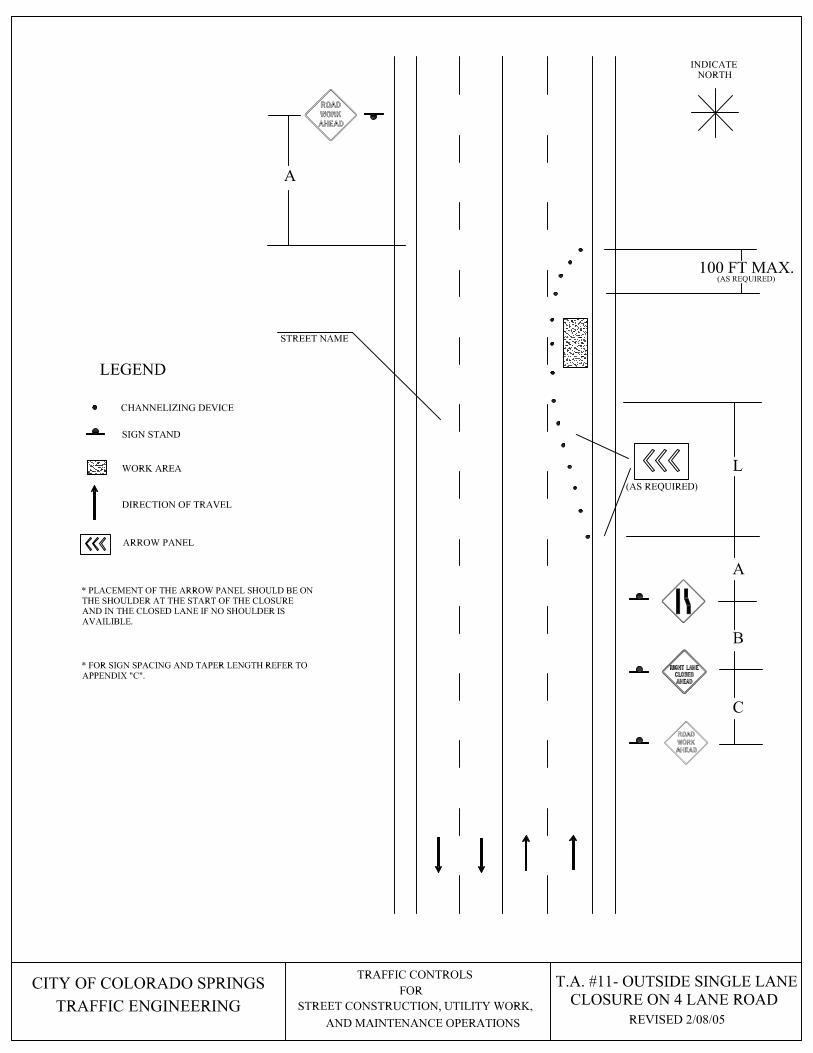
CITY OF COLORADO SPRINGS T.A. #11- OUTSIDE SINGLE LANE
AND MAINTENANCE OPERATIONS
STREET CONSTRUCTION, UTILITY WORK,TRAFFIC ENGINEERING
TRAFFIC CONTROLS
FORCLOSURE ON 4 LANE ROAD
* FOR SIGN SPACING AND TAPER LENGTH REFER TO
APPENDIX "C".
WORK AREA
SIGN STAND
LEGEND
DIRECTION OF TRAVEL
CHANNELIZING DEVICE
(AS REQUIRED)
A
B
C
L
100 FT MAX.
A
ARROW PANEL
* PLACEMENT OF THE ARROW PANEL SHOULD BE ON
THE SHOULDER AT THE START OF THE CLOSURE
AND IN THE CLOSED LANE IF NO SHOULDER IS
AVAILIBLE.
STREET NAME
NORTH
INDICATE
(AS REQUIRED)
REVISED 2/08/05

CITY OF COLORADO SPRINGS T.A. #12- INSIDE SINGLE LANE
AND MAINTENANCE OPERATIONS
STREET CONSTRUCTION, UTILITY WORK,TRAFFIC ENGINEERING
TRAFFIC CONTROLS
FORCLOSURE ON 4 LANE ROAD
* FOR SIGN SPACING AND TAPER LENGTH REFER TO
APPENDIX "C".
WORK AREA
SIGN STAND
LEGEND
DIRECTION OF TRAVEL
CHANNELIZING DEVICE
(AS REQUIRED)
A
B
C
L
100 FT. MAX.
A
ARROW PANEL
STREET NAME
INDICATE
NORTH
REVISED 2/08/05

CITY OF COLORADO SPRINGST.A. #13- INTERIOR LANE CLOSURE
AND MAINTENANCE OPERATIONS
STREET CONSTRUCTION, UTILITY WORK,TRAFFIC ENGINEERING
TRAFFIC CONTROLS
FOR ON MULTI-LANE ROAD
* FOR SIGN SPACING AND TAPER LENGTH REFER TO
APPENDIX "C".
WORK AREA
SIGN STAND
LEGEND
DIRECTION OF TRAVEL
MUTCD FIG. #6H-30
CHANNELIZING DEVICE
ARROW PANEL
C
B
A
(AS REQUIRED)
L
100 FT. MAX.
C
A
B
L
100 FT. MAX.
STREET NAME
INDICATE
NORTH
(AS REQUIRED)
REVISED 2/08/05

CITY OF COLORADO SPRINGS T.A. #14- HALF ROAD CLOSURE
AND MAINTENANCE OPERATIONS
STREET CONSTRUCTION, UTILITY WORK,TRAFFIC ENGINEERING
TRAFFIC CONTROLS
FOR ON MULTI-LANE ROAD
* FOR SIGN SPACING AND TAPER LENGTH REFER TO
APPENDIX "C".
WORK AREA
SIGN STAND
LEGEND
DIRECTION OF TRAVEL
MUTCD FIG. #6H-32
CHANNELIZING DEVICE
ARROW PANEL
C
B
A
(AS REQUIRED)
C
A
B
L
1/2 L
L
L
STREET NAME
NORTH
INDICATE
100 FT. PER LANE MAX.
(AS REQUIRED)
OR
RIGHT
KEEP
KEEP
RIGHT
OR
OR
UNDER
30
MPH
OVER
30
MPH
UNDER
30
MPH
OVER
30
MPH
OR
REVISED 2/09/05
* PLACEMENT OF THE ARROW PANEL SHOULD BE ON
THE SHOULDER AT THE START OF THE CLOSURE
AND IN THE CLOSED LANE IF NO SHOULDER IS
AVAILIBLE.

CITY OF COLORADO SPRINGS T.A. #15- OUTSIDE LANE
AND MAINTENANCE OPERATIONS
STREET CONSTRUCTION, UTILITY WORK,TRAFFIC ENGINEERING
TRAFFIC CONTROLS
FORCLOSURE ON 5-LANE ROAD
* FOR SIGN SPACING AND TAPER LENGTH REFER TO
APPENDIX "C".
WORK AREA
SIGN STAND
LEGEND
DIRECTION OF TRAVEL
CHANNELIZING DEVICE
ARROW PANEL
A
C
B
L
A
100 FT. MAX.
* PLACEMENT OF THE ARROW PANEL SHOULD BE ON
THE SHOULDER AT THE START OF THE CLOSURE
AND IN THE CLOSED LANE IF NO SHOULDER IS
AVAILIBLE.
STREET NAME
NORTH
INDICATE
(AS REQUIRED)
(AS REQUIRED)
REVISED 2/09/05

CITY OF COLORADO SPRINGS T.A. #16- CONTINUOUS AND INSIDE
AND MAINTENANCE OPERATIONS
STREET CONSTRUCTION, UTILITY WORK,TRAFFIC ENGINEERING
TRAFFIC CONTROLS
FORLANE CLOSURE ON 5-LANE ROAD
* FOR SIGN SPACING AND TAPER LENGTH REFER TO
APPENDIX "C".
WORK AREA
SIGN STAND
LEGEND
DIRECTION OF TRAVEL
CHANNELIZING DEVICE
ARROW PANEL
A
C
B
L
A
LEFT TURN
LANE
CLOSED
B
STREET NAME
INDICATE
NORTH
(AS REQUIRED)
1/2 L
100 FT. MAX.
100 FT. MAX.
(AS REQUIRED)
REVISED 2/10/05

CITY OF COLORADO SPRINGS T.A. #17- WORK IN THE
AND MAINTENANCE OPERATIONS
STREET CONSTRUCTION, UTILITY WORK,TRAFFIC ENGINEERING
TRAFFIC CONTROLS
FORCONTINUOUS LANE ON 5-LANE ROAD
* FOR SIGN SPACING AND TAPER LENGTH REFER TO
APPENDIX "C".
WORK AREA
SIGN STAND
LEGEND
DIRECTION OF TRAVEL
CHANNELIZING DEVICE
A
1/2 L
LEFT TURN
LANE
CLOSED
B
1/2 L
CLOSED
LEFT TURN
LANE
A
B
STREET NAME
INDICATE
NORTH
(AS REQUIRED)
REVISED 2/10/05

CITY OF COLORADO SPRINGS T.A. #18- MULTI-LANE CLOSURE
AND MAINTENANCE OPERATIONS
STREET CONSTRUCTION, UTILITY WORK,TRAFFIC ENGINEERING
TRAFFIC CONTROLS
FOR
ON 5-LANE ROAD
WORK AREA
SIGN STAND
LEGEND
DIRECTION OF TRAVEL
CHANNELIZING DEVICE
ARROW PANEL
A
LEFT TURN
LANE
CLOSED
B
A
C
B
L
1/2 L
L
1/2 L
* PLACEMENT OF THE ARROW PANEL SHOULD BE ON
THE SHOULDER AT THE START OF THE CLOSURE
AND IN THE CLOSED LANE IF NO SHOULDER IS
AVAILIBLE.
STREET NAME
INDICATE
NORTH
REVISED 2/10/05
* FOR SIGN SPACING AND TAPER LENGTH REFER TO
APPENDIX "C".
OVER
30
MPH
100 FT. PER LANE MAX.
(AS REQUIRED)
UNDER
30
MPH
OVER
30
MPH
OR
UNDER
30
MPH
OR
(AS REQUIRED)

CITY OF COLORADO SPRINGST.A. #19- INSIDE LANE CLOSURE
AND MAINTENANCE OPERATIONS
STREET CONSTRUCTION, UTILITY WORK,TRAFFIC ENGINEERING
TRAFFIC CONTROLS
FOR ON MULTI-LANE ROAD WITH
* FOR SIGN SPACING AND TAPER LENGTH REFER TO
APPENDIX "C'.
WORK AREA
SIGN STAND
LEGEND
DIRECTION OF TRAVEL
RAISED MEDIAN
CHANNELIZING DEVICE
ARROW PANEL
A
C
B
(AS REQUIRED)
L
100 FT. MAX.
STREET NAME
INDICATE
NORTH
RAISED MEDIAN
REVISED 2/10/05

CITY OF COLORADO SPRINGS
AND MAINTENANCE OPERATIONS
STREET CONSTRUCTION, UTILITY WORK,TRAFFIC ENGINEERING
TRAFFIC CONTROLS
FOR
* FOR SIGN SPACING AND TAPER LENGTH REFER TO
APPENDIX "D".
WORK AREA
SIGN STAND
LEGEND
DIRECTION OF TRAVEL
CHANNELIZING DEVICE
ARROW PANEL
A
C
B
(AS REQUIRED)
L
100 FT. MAX.
* PLACEMENT OF THE ARROW PANEL SHOULD BE ON
THE SHOULDER AT THE START OF THE CLOSURE
AND IN THE CLOSED LANE IF NO SHOULDER IS
AVAILIBLE.
STREET NAME
RAISED MEDIAN
ON MULTI-LANE ROAD WITH
T.A. #20- OUTSIDE LANE CLOSURE
RAISED MEDIAN
INDICATE
NORTH
REVISED 2/10/05

CITY OF COLORADO SPRINGST.A. #21- OUTSIDE LANE CLOSURE
AND MAINTENANCE OPERATIONS
STREET CONSTRUCTION, UTILITY WORK,TRAFFIC ENGINEERING
TRAFFIC CONTROLS
FOR ON FAR SIDE OF THE INTERSECTION
* FOR SIGN SPACING AND TAPER LENGTH REFER TO
APPENDIX "D".
WORK AREA
SIGN STAND
LEGEND
DIRECTION OF TRAVEL
CHANNELIZING DEVICE
(AS REQUIRED)
A
B
C
L
ARROW PANEL
* PLACEMENT OF THE ARROW PANEL SHOULD BE ON
THE SHOULDER AT THE START OF THE CLOSURE
AND IN THE CLOSED LANE IF NO SHOULDER IS
AVAILIBLE.
USE OTHER
CLOSED
SIDEWALK
SIDEWALK
USE OTHER
CLOSED
SIDE
SIDE
A
A
A
WORK VEHICLE
STREET NAME
INDICATE
NORTH
STREET NAME
MUTCD FIG #6H-22
WITH SIDEWALK CLOSURE
100 FT. MAX.(AS REQUIRED)
REVISED 2/10/05

CITY OF COLORADO SPRINGS
AND MAINTENANCE OPERATIONS
STREET CONSTRUCTION, UTILITY WORK,TRAFFIC ENGINEERING
TRAFFIC CONTROLS
FOR
* FOR SIGN SPACING AND TAPER LENGTH REFER TO
APPENDIX "D".
WORK AREA
SIGN STAND
LEGEND
DIRECTION OF TRAVEL
CHANNELIZING DEVICE
(AS REQUIRED)
A
B
C
L
ARROW PANEL
* PLACEMENT OF THE ARROW PANEL SHOULD BE ON
THE SHOULDER AT THE START OF THE CLOSURE
AND IN THE CLOSED LANE IF NO SHOULDER IS
AVAILIBLE.
A
A
A
WORK VEHICLE
STREET NAME
WITH NO SIDEWALK CLOSUREON FAR SIDE OF THE INTERSECTION
T.A. #22- OUTSIDE LANE CLOSURE
MUTCD FIG #6H-22
STREET NAME
INDICATE
NORTH
100 FT. MAX.(AS REQUIRED)
REVISED 2/10/05

CITY OF COLORADO SPRINGS
AND MAINTENANCE OPERATIONS
STREET CONSTRUCTION, UTILITY WORK,TRAFFIC ENGINEERING
TRAFFIC CONTROLS
FOR
* FOR SIGN SPACING AND TAPER LENGTH REFER TO
APPENDIX "D".
WORK AREA
SIGN STAND
LEGEND
DIRECTION OF TRAVEL
CHANNELIZING DEVICE
A
B
C
L
ARROW PANEL
A
A
A
LEFT LANE
MUST
TURN LEFT
ONLY
(AS REQUIRED)
STREET NAME
T.A. #23- INSIDE LANE CLOSURE
ON FAR SIDE OF THE INTERSECTION
MUTCD FIG #6H-23
STREET NAME
NORTH
INDICATE
100 FT. MAX.
(AS REQUIRED)
OR
RIGHT
KEEP
* THE LENGTH OF THE TURN BAY IS DEPENDANT ON
THE SPEED AND AMOUNT OF TURNING VEHICLES
AND WILL BE DETERMINED ON A PROJECT BY
PROJECT BASIS.
REVISED 2/10/05
CITY OF COLORADO SPRINGS
AND MAINTENANCE OPERATIONS
STREET CONSTRUCTION, UTILITY WORK,TRAFFIC ENGINEERING
TRAFFIC CONTROLS
FOR
* FOR SIGN SPACING AND TAPER LENGTH REFER TO
APPENDIX "D".
WORK AREA
SIGN STAND
LEGEND
DIRECTION OF TRAVEL
CHANNELIZING DEVICE
(AS REQUIRED)
A
B
C
L
ARROW PANEL
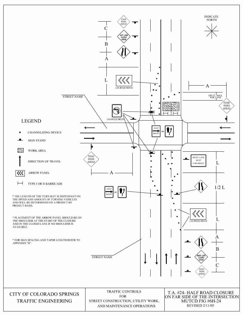
* PLACEMENT OF THE ARROW PANEL SHOULD BE ON
THE SHOULDER AT THE START OF THE CLOSURE
AND IN THE CLOSED LANE IF NO SHOULDER IS
AVAILIBLE.
A
A
1/2 L
L
A
B
C
L
TYPE I OR II BARRICADE
STREET NAME
T.A. #24- HALF ROAD CLOSURE
ON FAR SIDE OF THE INTERSECTION
MUTCD FIG #6H-24
STREET NAME
TURN RIGHT
MUST
RIGHT LANE
INDICATE
NORTH
(AS REQUIRED)
(AS REQUIRED)
100 FT. MAX.
* THE LENGTH OF THE TURN BAY IS DEPENDANT ON
THE SPEED AND AMOUNT OF TURNING VEHICLES
AND WILL BE DETERMINED ON A PROJECT BY
PROJECT BASIS.
REVISED 2/11/05
RIGHT
KEEP
OR
RIGHT
KEEP
OR
PER LANE

CITY OF COLORADO SPRINGS
AND MAINTENANCE OPERATIONS
STREET CONSTRUCTION, UTILITY WORK,TRAFFIC ENGINEERING
TRAFFIC CONTROLS
FOR
* FOR SIGN SPACING AND TAPER LENGTH REFER TO
APPENDIX "D".
WORK AREA
SIGN STAND
LEGEND
DIRECTION OF TRAVEL
CHANNELIZING DEVICE
A
B
C
L
ARROW PANEL
A
A
LEFT LANE
MUST
TURN LEFT
CLOSED
LEFT TURN
LANE
A
B
TYPE I OR II BARRICADE
STREET NAME
ON FAR SIDE OF THE INTERSECTION
T.A. #25- MULTIPLE LANE CLOSURE
MUTCD FIG #6H-25
STREET NAME
NORTH
INDICATE
(AS REQUIRED)
(AS REQUIRED)
100 FT. MAX.
REVISED 2/11/05
RIGHT
KEEP
OR

CITY OF COLORADO SPRINGS
AND MAINTENANCE OPERATIONS
STREET CONSTRUCTION, UTILITY WORK,TRAFFIC ENGINEERING
TRAFFIC CONTROLS
FOR
* FOR SIGN SPACING AND TAPER LENGTH REFER TO
APPENDIX "D".
WORK AREA
SIGN STAND
LEGEND
DIRECTION OF TRAVEL
CHANNELIZING DEVICE
BE
PREPARED
TO STOP
BE
PREPARED
TO STOP
A
B
C
1/2 L
C
B
1/2 L
A
C
TO STOP
BE
PREPARED
BA
PREPARED
TO STOP
BE
1/2 L
1/2 LABC
10 FT MIN.
STREET NAME
T.A. #26- CLOSURE IN CENTER
OF THE INTERSECTION
MUTCD FIG #6H-26
STREET NAME
INDICATE
NORTH
(AS REQUIRED)
(AS REQUIRED)
(AS
REQUIRED)
(AS
REQUIRED)
RIGHT
KEEP
OR
KEEP
RIGHT
OR
(AS REQUIRED)
(AS REQUIRED)
(AS REQUIRED)
(AS REQUIRED)
FLAGMAN
REVISED 2/11/05

CITY OF COLORADO SPRINGS
AND MAINTENANCE OPERATIONS
STREET CONSTRUCTION, UTILITY WORK,TRAFFIC ENGINEERING
TRAFFIC CONTROLS
FOR
* FOR SIGN SPACING AND TAPER LENGTH REFER TO
APPENDIX "D".
WORK AREA
SIGN STAND
LEGEND
DIRECTION OF TRAVEL
CHANNELIZING DEVICE
BE
PREPARED
TO STOP
BE
PREPARED
TO STOP
A
B
C
100 FT MAX.
C
B
100 FT MAX.
A
C
TO STOP
BE
PREPARED
BA
PREPARED
TO STOP
BE
100FTABC
MAX.
FLAGMAN
STREET NAME
T.A. #27- CLOSURE IN CORNER
OF THE INTERSECTION
MUTCD FIG #6H-27
STREET NAME
NORTH
INDICATE
100 FT.
MAX.
100FT
MAX.
100 FT MAX.
100 FT MAX.
REVISED 2/11/05
OR
RIGHT
KEEP
OR
KEEP
RIGHT
RIGHT
KEEP
OR
RIGHT
KEEP
OR

CITY OF COLORADO SPRINGST.A. #28- OVERLAPPING
AND MAINTENANCE OPERATIONS
STREET CONSTRUCTION, UTILITY WORK,TRAFFIC ENGINEERING
TRAFFIC CONTROLS
FOR
MUTCD FIG.#6H-9
ROUTES WITH DETOUR
* FOR SIGN SPACING AND TAPER LENGTH REFER TO
APPENDIX "D".
WORK AREA
SIGN STAND
TYPE I OR II BARRICADE
LEGEND
TO
THRU TRAFFIC
STREET CLOSED
INDICATE
NORTH
DETOUR
ROAD
CLOSED
DETOUR
DETOUR
DETOUR
DETOUR
DETOUR
DETOUR
DETOUR
AHEAD
ROAD
CLOSED
AHEAD
AHEAD
DETOUR
CLOSED
AHEAD
ROAD
TYPE III BARRICADE
STREET NAME
STREET NAME
STREET NAME
STREET NAME
STREET NAME
STREET NAMESTREET NAME
REVISED 2/11/05

CITY OF COLORADO SPRINGST.A. #29- ALLEY CLOSURE
AND MAINTENANCE OPERATIONS
STREET CONSTRUCTION, UTILITY WORK,TRAFFIC ENGINEERING
TRAFFIC CONTROLS
FOR
* FOR SIGN SPACING AND TAPER LENGTH REFER TO
APPENDIX "D".
WORK AREA
TYPE I OR II BARRICADE
LEGEND
TO
THRU TRAFFIC
STREET CLOSED
INDICATE
NORTH
ROAD
CLOSED
ALLEY
STREET NAME
STREET NAME
STREET NAME
STREET NAME
REVISED 2/11/05

CITY OF COLORADO SPRINGS
AND MAINTENANCE OPERATIONS
STREET CONSTRUCTION, UTILITY WORK,TRAFFIC ENGINEERING
TRAFFIC CONTROLS
FOR
* FOR SIGN SPACING AND TAPER LENGTH REFER TO
APPENDIX "D".
WORK AREA
SIGN STAND
TYPE I OR II BARRICADE
LEGEND
TO
THRU TRAFFIC
STREET CLOSED
INDICATE
NORTH
ROAD
CLOSED
AHEAD
CLOSED
TYPE III BARRICADE
ROAD
CLOSED
AHEAD
ROAD
T.A. #30- LOCAL ROAD
STREET NAME
STREET NAME
STREET NAME
CLOSURE
REVISED 2/15/05
* THIS TRAFFIC PLAN SHALL BE USED ONLY FOR
LOW-SPEED STREETS HAVING LOW TRAFFIC
VOLUMES.

CITY OF COLORADO SPRINGS
AND MAINTENANCE OPERATIONS
STREET CONSTRUCTION, UTILITY WORK,TRAFFIC ENGINEERING
TRAFFIC CONTROLS
FOR
* FOR SIGN SPACING AND TAPER LENGTH REFER TO
APPENDIX "D".
WORK AREA
SIGN STAND
LEGEND
DIRECTION OF TRAVEL
CHANNELIZING DEVICE
ARROW PANEL
A
C
B
L
2L
(AS REQUIRED)
L
A
100 FT. PER LANE MAX.
* PLACEMENT OF THE ARROW PANEL SHOULD BE ON
THE SHOULDER AT THE START OF THE CLOSURE
AND IN THE CLOSED LANE IF NO SHOULDER IS
AVAILIBLE.
T.A. #31- MULTI- LANE
CLOSURE ON 6-LANE ROAD
RAISED MEDIAN
STREET NAME
NORTH
INDICATE
(AS REQUIRED)
REVISED 2/15/05

CITY OF COLORADO SPRINGS
AND MAINTENANCE OPERATIONS
STREET CONSTRUCTION, UTILITY WORK,TRAFFIC ENGINEERING
TRAFFIC CONTROLS
FOR
* FOR SIGN SPACING AND TAPER LENGTH REFER TO
APPENDIX "D".
WORK AREA
SIGN STAND
LEGEND
DIRECTION OF TRAVEL
CHANNELIZING DEVICE
ARROW PANEL
A
C
B
(AS REQUIRED)
L
CLOSED
LEFT TURN
LANE
KEEP
LEFT
* PLACEMENT OF THE ARROW PANEL SHOULD BE ON
THE SHOULDER AT THE START OF THE CLOSURE
AND IN THE CLOSED LANE IF NO SHOULDER IS
AVAILIBLE.
STREET NAME
ON FAR SIDE OF THE INTERSECTION
T.A. #32- OUTSIDE LANE CLOSURE
NORTH
INDICATE
A
STREET NAME
AB
A
SIDEWALK
SIDE
CLOSED
USE OTHER
SIDEWALK
USE OTHER
SIDE
CLOSED
RAISED MEDIAN
REVISED 2/15/05

CITY OF COLORADO SPRINGS
AND MAINTENANCE OPERATIONS
STREET CONSTRUCTION, UTILITY WORK,TRAFFIC ENGINEERING
TRAFFIC CONTROLS
FOR
* FOR SIGN SPACING AND TAPER LENGTH REFER TO
APPENDIX "D".
WORK AREA
SIGN STAND
LEGEND
DIRECTION OF TRAVEL
CHANNELIZING DEVICE
CLOSED
LEFT TURN
LANE
B
RAISED MEDIAN
T.A. #33- LEFT TURN BAY
CLOSURE
STREET NAME
STREET NAME
INDICATE
NORTH
(AS REQUIRED)
A
REVISED 2/15/05
RIGHT
KEEP
OR

CITY OF COLORADO SPRINGS
AND MAINTENANCE OPERATIONS
STREET CONSTRUCTION, UTILITY WORK,TRAFFIC ENGINEERING
TRAFFIC CONTROLS
FOR
* FOR SIGN SPACING AND TAPER LENGTH REFER TO
APPENDIX "D".
WORK AREA
SIGN STAND
LEGEND
DIRECTION OF TRAVEL
CHANNELIZING DEVICE
CLOSED
RIGHT TURN
LANE
KEEP
LEFT
STREET NAME
CLOSURE
T.A. #34- RIGHT TURN BAY
RAISED MEDIAN
STREET NAME
B
A
(AS REQUIRED)
NORTH
INDICATE
REVISED 2/15/05

CITY OF COLORADO SPRINGS
AND MAINTENANCE OPERATIONS
STREET CONSTRUCTION, UTILITY WORK,TRAFFIC ENGINEERING
TRAFFIC CONTROLS
FOR
* FOR SIGN SPACING AND TAPER LENGTH REFER TO
APPENDIX "D".
WORK AREA
SIGN STAND
LEGEND
DIRECTION OF TRAVEL
CHANNELIZING DEVICE
ARROW PANEL
A
B
(AS REQUIRED)
L
A
CENTER LANE
CLOSED
AHEAD
RAISED MEDIAN
T.A. #35- CENTER LANE CLOSURE
ON 6 LANE ROAD
STREET NAME
INDICATE
NORTH
KEEP
LEFT
100 FT. MAX.
REVISED 2/16/05

CITY OF COLORADO SPRINGS
AND MAINTENANCE OPERATIONS
STREET CONSTRUCTION, UTILITY WORK,TRAFFIC ENGINEERING
TRAFFIC CONTROLS
FOR
* FOR SIGN SPACING AND TAPER LENGTH REFER TO
APPENDIX "D".
WORK AREA
SIGN STAND
LEGEND
DIRECTION OF TRAVEL
CHANNELIZING DEVICE
A
LEFT TURN
LANE
CLOSED
B
A
C
B
L
1/2 L
TRAFFIC INTO THE CONTINUOUS
T.A. #36- LANE CLOSURE SHIFTING
STREET NAME
(AS REQUIRED)
INDICATE
NORTH
100 FT. MAX.
REVISED 2/16/05
OR
RIGHT
KEEP
RIGHT
KEEP
OR

CITY OF COLORADO SPRINGS
AND MAINTENANCE OPERATIONS
STREET CONSTRUCTION, UTILITY WORK,TRAFFIC ENGINEERING
TRAFFIC CONTROLS
FOR
* FOR SIGN SPACING AND TAPER LENGTH REFER TO
APPENDIX "D".
WORK AREA
SIGN STAND
LEGEND
DIRECTION OF TRAVEL
CHANNELIZING DEVICE
ONE LANE
ROAD
AHEAD
A
B
C
B
100FT MAX.
A
AHEAD
ONE LANE
ROAD
YIELD
TO
ONCOMING
TRAFFIC
A
A
* THIS TRAFFIC PLAN SHALL BE USED ONLY FOR
LOW-SPEED STREETS HAVING LOW TRAFFIC
VOLUMES.
T.A. #37- LANE CLOSURE
ON LOW VOLUME ROAD
STREET NAME
NORTH
INDICATE
STREET NAME
TRAFFIC
ONCOMING
TO
YIELD
C
REVISED 2/16/05
CITY OF COLORADO SPRINGS
AND MAINTENANCE OPERATIONS
STREET CONSTRUCTION, UTILITY WORK,TRAFFIC ENGINEERING
TRAFFIC CONTROLS
FOR
* FOR SIGN SPACING AND TAPER LENGTH REFER TO
APPENDIX "D".
WORK AREA
SIGN STAND
LEGEND
DIRECTION OF TRAVEL
CHANNELIZING DEVICE
BE
PREPARED
TO STOP
BE
PREPARED
TO STOP
A
B
C
C
B
A
C
TO STOP
BE
PREPARED
B
PREPARED
TO STOP
BE
ABC
FLAGMAN
A
100 FT. MAX.
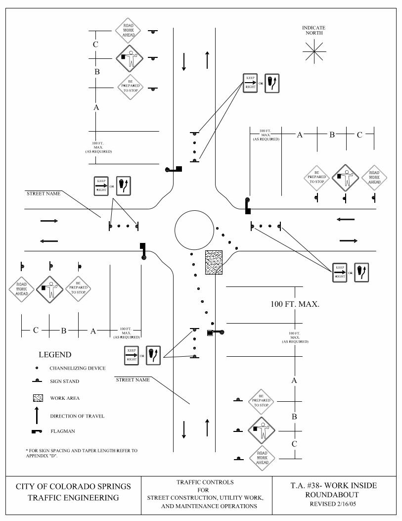
T.A. #38- WORK INSIDE
ROUNDABOUT
STREET NAME
STREET NAME
INDICATE
NORTH
OR
RIGHT
KEEP
100 FT.
MAX.
(AS REQUIRED)
RIGHT
OR
KEEP
100 FT.
MAX.
(AS REQUIRED)
KEEP
RIGHT
OR
100 FT.
MAX.
(AS REQUIRED)
100 FT.
MAX.
(AS REQUIRED)
KEEP
RIGHT
OR
REVISED 2/16/05

CITY OF COLORADO SPRINGS
AND MAINTENANCE OPERATIONS
STREET CONSTRUCTION, UTILITY WORK,TRAFFIC ENGINEERING
TRAFFIC CONTROLS
FOR
* FOR SIGN SPACING AND TAPER LENGTH REFER TO
APPENDIX "D".
WORK AREA
SIGN STAND
LEGEND
DIRECTION OF TRAVEL
CHANNELIZING DEVICE
BE
PREPARED
TO STOP
BE
PREPARED
TO STOP
A
B
C
C
B
AC
TO STOP
BE
PREPARED
B
PREPARED
TO STOP
BE
ABC
FLAGMAN
A
100 FT. MAX.
* FOUR FLAGGERS MUST BE USED WHEN WORKING
CLOSE TO A ROUNDABOUT UNTIL SUFFICIENT SPACE
IS PROVIDED TO STORE TRAFFIC WITHOUT BACKING
UP INTO THE ROUNDABOUT.
STREET NAME
T.A. #39- WORK OUTSIDE
ROUNDABOUT
STREET NAME
INDICATE
NORTH
KEEP
RIGHT
OR
100 FT.
MAX.
(AS REQUIRED)
RIGHT
KEEP
OR
100 FT.
MAX.
(AS REQUIRED)
100 FT.
MAX.
(AS REQUIRED)
100 FT.
MAX.
(AS REQUIRED)
RIGHT
KEEP
OR
RIGHT
KEEP
OR
REVISED 2/18/05

CITY OF COLORADO SPRINGS
AND MAINTENANCE OPERATIONS
STREET CONSTRUCTION, UTILITY WORK,TRAFFIC ENGINEERING
TRAFFIC CONTROLS
FOR
* FOR SIGN SPACING AND TAPER LENGTH REFER TO
APPENDIX "D".
WORK AREA
SIGN STAND
LEGEND
DIRECTION OF TRAVEL
CHANNELIZING DEVICE
(AS REQUIRED)
A
B
C
L
ARROW PANEL
* PLACEMENT OF THE ARROW PANEL SHOULD BE ON
THE SHOULDER AT THE START OF THE CLOSURE
AND IN THE CLOSED LANE IF NO SHOULDER IS
AVAILIBLE.
T.A. #40- WORK INSIDE
MULTI-LANE ROUNDABOUT
NORTH
INDICATE
STREET NAME
100 FT.
MAX.
(AS REQUIRED)
BE
PREPARED
TO STOP
C
A
B
RIGHT
KEEP
OR
KEEP
OR
RIGHT
B
BE
TO STOP
PREPARED
A C
AC B 100 FT.
MAX.
(AS REQUIRED)
(AS REQUIRED)
L
KEEP
RIGHT
OR
FLAGMAN
REVISED 2/18/05
STREET NAME

CITY OF COLORADO SPRINGS
AND MAINTENANCE OPERATIONS
STREET CONSTRUCTION, UTILITY WORK,TRAFFIC ENGINEERING
TRAFFIC CONTROLS
FOR
* FOR SIGN SPACING AND TAPER LENGTH REFER TO
APPENDIX "D".
WORK AREA
SIGN STAND
LEGEND
DIRECTION OF TRAVEL
CHANNELIZING DEVICE
(AS REQUIRED)
A
B
C
L
ARROW PANEL
* PLACEMENT OF THE ARROW PANEL SHOULD BE ON
THE SHOULDER AT THE START OF THE CLOSURE
AND IN THE CLOSED LANE IF NO SHOULDER IS
AVAILIBLE.
T.A. #41- INSIDE LANE CLOSURE
MULTI-LANE ROUNDABOUT
NORTH
INDICATE
STREET NAME
C
A
B
RIGHT
KEEP
OR
KEEP
OR
RIGHT
BA C
AC B
(AS REQUIRED)
L
REVISED 3/18/05
STREET NAME
(AS REQUIRED)
(AS REQUIRED)
L
L

STREET NAMEWORK AREA
STREET CONSTRUCTION, UTILITY WORK,
AND MAINTENANCE OPERATIONS
* PLACEMENT OF THE ARROW PANEL SHOULD BE ON
THE SHOULDER AT THE START OF THE CLOSURE
AND IN THE CLOSED LANE IF NO SHOULDER IS
AVAILIBLE.
* FOR SIGN SPACING AND TAPER LENGTH REFER TO
APPENDIX "D".
CITY OF COLORADO SPRINGS
TRAFFIC ENGINEERING
ARROW PANEL
DIRECTION OF TRAVEL
TRAFFIC CONTROLS
FOR
MULTI-LANE ROUNDABOUT
T.A. #42- OUTSIDE LANE CLOSURE
REVISED 3/18/05
C
B
L
(AS REQUIRED)
CHANNELIZING DEVICE
LEGEND
SIGN STAND
C B A
STREET NAME
(AS REQUIRED)
C
L
A
B
A
(AS REQUIRED)L
(AS REQUIRED)
INDICATE
AL B C
NORTH

CITY OF COLORADO SPRINGS
AND MAINTENANCE OPERATIONS
STREET CONSTRUCTION, UTILITY WORK,TRAFFIC ENGINEERING
TRAFFIC CONTROLS
FOR
* FOR SIGN SPACING AND TAPER LENGTH REFER TO
APPENDIX "D".
WORK AREA
SIGN STAND
LEGEND
DIRECTION OF TRAVEL
CHANNELIZING DEVICE
BE
PREPARED
TO STOP
A
B
C
TEMP. SIGNALS
100 FT. MAX.
STREET NAME
T.A. #43- ONE LANE ROAD
WITH TEMP. SIGNALS
INDICATE
NORTH
PREPARED
A
B
C
TO STOP
BE
STOP
RED
100 FT. MAX.
RIGHT
OR
KEEP
RIGHT
OR
KEEP
HERE ON
STOP
HERE ON
RED
100 FT. MAX.
100 FT. MAX.
REVISED 2/23/05

CITY OF COLORADO SPRINGS
AND MAINTENANCE OPERATIONS
STREET CONSTRUCTION, UTILITY WORK,TRAFFIC ENGINEERING
TRAFFIC CONTROLS
FOR
* FOR SIGN SPACING AND TAPER LENGTH REFER TO
APPENDIX "D".
WORK AREA
SIGN STAND
LEGEND
DIRECTION OF TRAVEL
CHANNELIZING DEVICE
(AS REQUIRED)
A
B
C
L
ARROW PANEL
* PLACEMENT OF THE ARROW PANEL SHOULD BE ON
THE SHOULDER AT THE START OF THE CLOSURE
AND IN THE CLOSED LANE IF NO SHOULDER IS
AVAILIBLE.
WORK VEHICLE
T.A. #44- OUTSIDE LANE CLOSURE
WITH SIDEWALK CLOSURE
STREET NAME
NORTH
INDICATE
USE OTHER
CLOSED
SIDEWALK
SIDEWALK
USE OTHER
CLOSED
SIDE
SIDE
100 FT. MAX.
(AS REQUIRED)
(AS REQUIRED)
REVISED 3/18/05

CITY OF COLORADO SPRINGS
AND MAINTENANCE OPERATIONS
STREET CONSTRUCTION, UTILITY WORK,TRAFFIC ENGINEERING
TRAFFIC CONTROLS
FOR
* FOR SIGN SPACING AND TAPER LENGTH REFER TO
APPENDIX "D".
WORK AREA
SIGN STAND
LEGEND
DIRECTION OF TRAVEL
CHANNELIZING DEVICE
(AS REQUIRED)
A
B
C
L
ARROW PANEL
* PLACEMENT OF THE ARROW PANEL SHOULD BE ON
THE SHOULDER AT THE START OF THE CLOSURE
AND IN THE CLOSED LANE IF NO SHOULDER IS
AVAILIBLE.
A
A
A
B
C
L
TYPE III BARRICADE
A
A
* Uniformed police shall be used when shifting traffic thru a
signalized intersection.
ON MULTI-LANE ROAD
T.A. #45- HALF ROAD CLOSURE
STREET NAME
INDICATE
NORTH
STREET NAME
STREET NAME
RAISED MEDIAN
OR
RIGHT
KEEP
OR
UNDER
30
MPH
OVER
30
MPH
OVER
30
MPH
UNDER
30
MPH
OR
(AS REQUIRED)
REVISED 3/18/05