
TecumsehQuick ReferenceService InformationCovers Engine and Transmission Product
Form No.695933 R 7/00 Not For Resale www.SmallEngineDiscount.com
1
IntroductionThis booklet contains the quick reference and basic trouble-shooting information previously found on Tecumseh wall chartsand in the Technician's Handbooks.This booklet is designed to be used as a work bench quickreference guide when servicing Tecumseh engines and motiondrive systems.
Technician's Note:Tecumseh engines are manufactured to meet EPA and CARBstandards. As a technician, it is unlawful to re-calibrate or replacea fuel nozzle or jet (bowl nut) with a part from any other carburetorthat was not originally designed for that engine. All speed adjust-ments must remain within the limits that are specified for eachengine and are not to exceed the maximum. This can only bedeviated from if specifically approved by Tecumseh Products,EPA and CARB.
Not For Resale www.SmallEngineDiscount.com
2
TV
S
TV
XL
HS
K
HX
L
TC
200
TC
300
AV
520/
600
TV
S60
0
AH
/HS
K60
0
AH
520
TC
H20
0/30
0
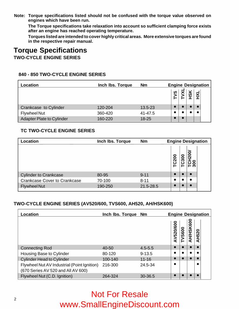
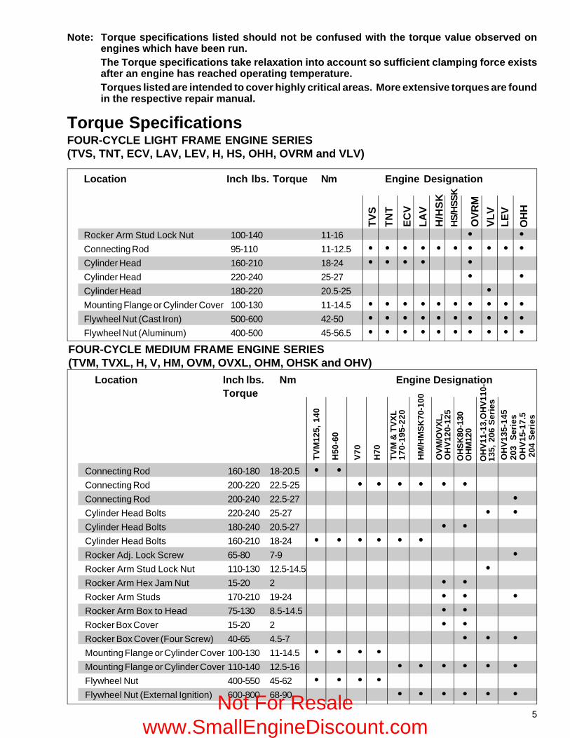
Note: Torque specifications listed should not be confused with the torque value observed onengines which have been run.The Torque specifications take relaxation into account so sufficient clamping force existsafter an engine has reached operating temperature.Torques listed are intended to cover highly critical areas. More extensive torques are foundin the respective repair manual.
Torque SpecificationsTWO-CYCLE ENGINE SERIES
840 - 850 TWO-CYCLE ENGINE SERIES
Location Inch lbs. Torque Nm Engine Designation
Crankcase to Cylinder 120-204 13.5-23 • • • •Flywheel Nut 360-420 41-47.5 • • • •Adapter Plate to Cylinder 160-220 18-25 • •
TC TWO-CYCLE ENGINE SERIES
Location Inch lbs. Torque Nm Engine Designation
Cylinder to Crankcase 80-95 9-11 • • •Crankcase Cover to Crankcase 70-100 8-11 • • •Flywheel Nut 190-250 21.5-28.5 • • •
TWO-CYCLE ENGINE SERIES (AV520/600, TVS600, AH520, AH/HSK600)
Location Inch lbs. Torque Nm Engine Designation
Connecting Rod 40-50 4.5-5.5 • • • •Housing Base to Cylinder 80-120 9-13.5 • • • •Cylinder Head to Cylinder 100-140 11-16 • • • •Flywheel Nut AV Industrial (Point Ignition) 216-300 24.5-34 • •(670 Series AV 520 and All AV 600)Flywheel Nut (C.D. Ignition) 264-324 30-36.5 • • • •
Not For Resale www.SmallEngineDiscount.com
3
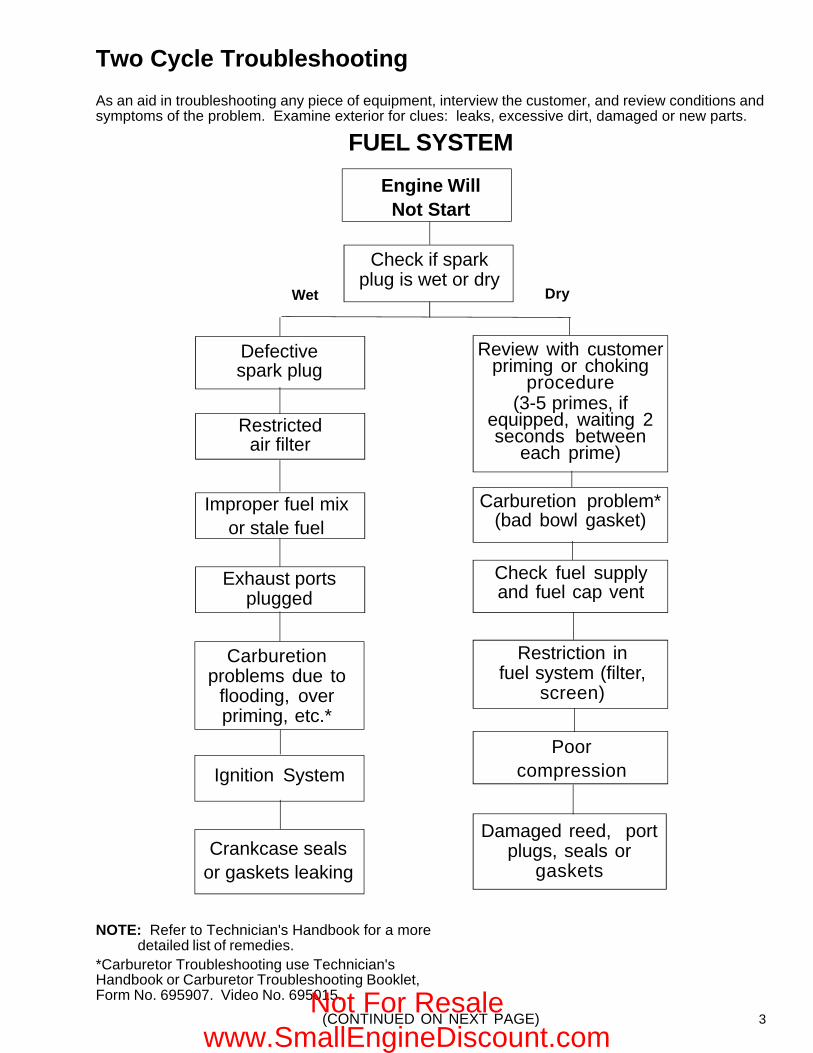
NOTE: Refer to Technician's Handbook for a moredetailed list of remedies.
*Carburetor Troubleshooting use Technician'sHandbook or Carburetor Troubleshooting Booklet,Form No. 695907. Video No. 695015.
Two Cycle Troubleshooting
As an aid in troubleshooting any piece of equipment, interview the customer, and review conditions andsymptoms of the problem. Examine exterior for clues: leaks, excessive dirt, damaged or new parts.
(CONTINUED ON NEXT PAGE)
Check fuel supplyand fuel cap vent
Wet Dry
Defectivespark plug
Improper fuel mixor stale fuel
Carburetionproblems due to
flooding, overpriming, etc.*
Restrictedair filter
Exhaust portsplugged
Crankcase sealsor gaskets leaking
Ignition System
Damaged reed, portplugs, seals or
gaskets
Poorcompression
Restriction infuel system (filter,
screen)
FUEL SYSTEM
Engine WillNot Start
Check if sparkplug is wet or dry
Review with customerpriming or choking
procedure(3-5 primes, if
equipped, waiting 2seconds between
each prime)
Carburetion problem*(bad bowl gasket)
Not For Resale www.SmallEngineDiscount.com
4
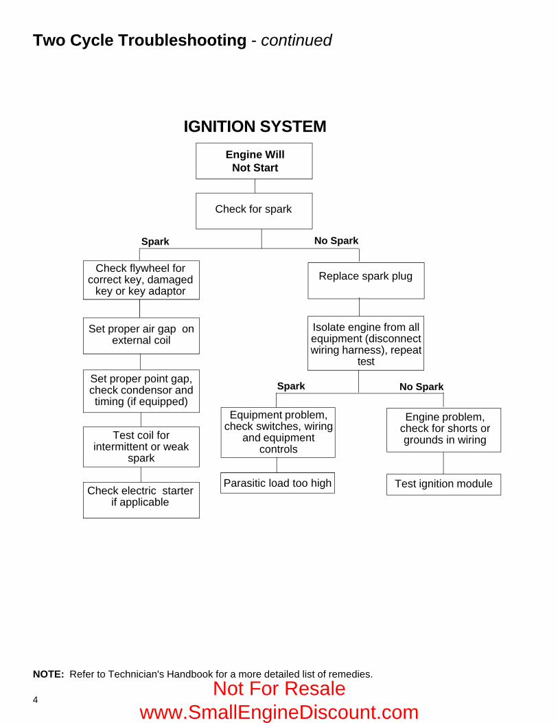
NOTE: Refer to Technician's Handbook for a more detailed list of remedies.
Two Cycle Troubleshooting - continued
IGNITION SYSTEM
Engine WillNot Start
Replace spark plug
Isolate engine from allequipment (disconnectwiring harness), repeat
test
No Spark
Check for spark
Set proper point gap,check condensor andtiming (if equipped)
Check electric starterif applicable
Set proper air gap onexternal coil
Check flywheel forcorrect key, damaged
key or key adaptor
Test coil forintermittent or weak
spark
Equipment problem,check switches, wiring
and equipmentcontrols
Spark
Parasitic load too high Test ignition module
Engine problem,check for shorts orgrounds in wiring
No Spark
Spark
Not For Resale www.SmallEngineDiscount.com
5
TV
M &
TV
XL
170-
195-
220
Torque SpecificationsFOUR-CYCLE LIGHT FRAME ENGINE SERIES(TVS, TNT, ECV, LAV, LEV, H, HS, OHH, OVRM and VLV)
Location Inch lbs. Torque Nm Engine Designation
Rocker Arm Stud Lock Nut 100-140 11-16 • •Connecting Rod 95-110 11-12.5 • • • • • • • • • •Cylinder Head 160-210 18-24 • • • • •Cylinder Head 220-240 25-27 • •Cylinder Head 180-220 20.5-25 •Mounting Flange or Cylinder Cover 100-130 11-14.5 • • • • • • • • • •Flywheel Nut (Cast Iron) 500-600 42-50 • • • • • • • • • •Flywheel Nut (Aluminum) 400-500 45-56.5 • • • • • • • • • •
TV
S
TN
T
EC
V
LAV
H/H
SK
HS
/HS
SK
OV
RM
VL
VL
EV
OH
H
Note: Torque specifications listed should not be confused with the torque value observed onengines which have been run.The Torque specifications take relaxation into account so sufficient clamping force existsafter an engine has reached operating temperature.Torques listed are intended to cover highly critical areas. More extensive torques are foundin the respective repair manual.
Location Inch lbs. Nm Engine DesignationTorque
HM
/HM
SK
70-1
00
OV
M/O
VX
L,O
HV
120-
125
OH
SK
80-1
30O
HM
120
TV
M12
5, 1
40
H50
-60
V70
H70
OH
V13
5-14
520
3 S
erie
sO
HV
15-1
7.5
204
Ser
ies
OH
V11
-13,
OH
V11
0-13
5, 2
06 S
erie
s
FOUR-CYCLE MEDIUM FRAME ENGINE SERIES(TVM, TVXL, H, V, HM, OVM, OVXL, OHM, OHSK and OHV)
Connecting Rod 160-180 18-20.5 • •Connecting Rod 200-220 22.5-25 • • • • • •Connecting Rod 200-240 22.5-27 •Cylinder Head Bolts 220-240 25-27 • •Cylinder Head Bolts 180-240 20.5-27 • •Cylinder Head Bolts 160-210 18-24 • • • • • •Rocker Adj. Lock Screw 65-80 7-9 •Rocker Arm Stud Lock Nut 110-130 12.5-14.5 •Rocker Arm Hex Jam Nut 15-20 2 • •Rocker Arm Studs 170-210 19-24 • • •Rocker Arm Box to Head 75-130 8.5-14.5 • •Rocker Box Cover 15-20 2 • •Rocker Box Cover (Four Screw) 40-65 4.5-7 • • •Mounting Flange or Cylinder Cover 100-130 11-14.5 • • • •Mounting Flange or Cylinder Cover 110-140 12.5-16 • • • • • •Flywheel Nut 400-550 45-62 • • • •Flywheel Nut (External Ignition) 600-800 68-90 • • • • • •Not For Resale
www.SmallEngineDiscount.com
6
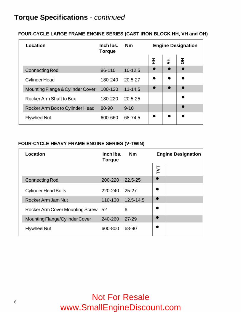
Torque Specifications - continued
HH
VH
OH
Location Inch lbs. Nm Engine DesignationTorque
TV
T
FOUR-CYCLE LARGE FRAME ENGINE SERIES (CAST IRON BLOCK HH, VH and OH)
Connecting Rod 86-110 10-12.5 • • •Cylinder Head 180-240 20.5-27 • • •Mounting Flange & Cylinder Cover 100-130 11-14.5 • • •Rocker Arm Shaft to Box 180-220 20.5-25 •Rocker Arm Box to Cylinder Head 80-90 9-10 •Flywheel Nut 600-660 68-74.5 • • •
FOUR-CYCLE HEAVY FRAME ENGINE SERIES (V-TWIN)
Location Inch lbs. Nm Engine DesignationTorque
Connecting Rod 200-220 22.5-25 •Cylinder Head Bolts 220-240 25-27 •Rocker Arm Jam Nut 110-130 12.5-14.5 •Rocker Arm Cover Mounting Screw 52 6 •Mounting Flange/Cylinder Cover 240-260 27-29 •Flywheel Nut 600-800 68-90 •
Not For Resale www.SmallEngineDiscount.com
7
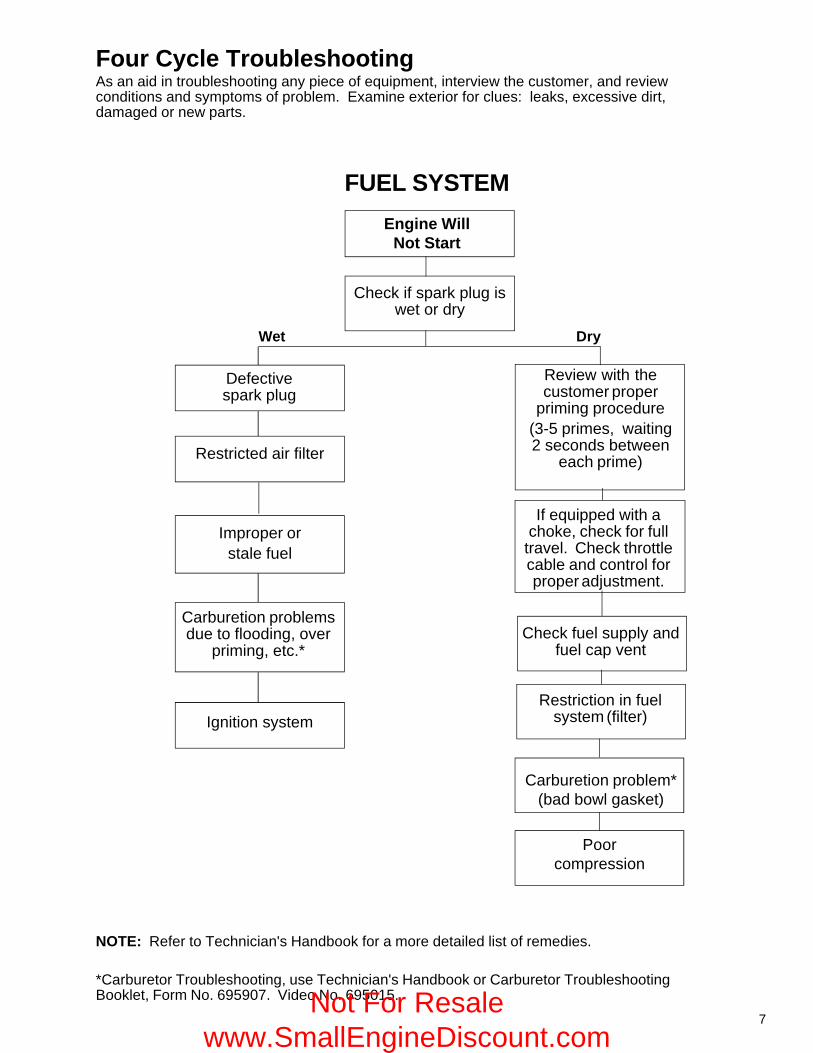
Four Cycle TroubleshootingAs an aid in troubleshooting any piece of equipment, interview the customer, and reviewconditions and symptoms of problem. Examine exterior for clues: leaks, excessive dirt,damaged or new parts.
NOTE: Refer to Technician's Handbook for a more detailed list of remedies.
*Carburetor Troubleshooting, use Technician's Handbook or Carburetor TroubleshootingBooklet, Form No. 695907. Video No. 695015.
Improper orstale fuel
Check if spark plug iswet or dry
FUEL SYSTEM
Engine WillNot Start
Defectivespark plug
Wet
Restricted air filter
Carburetion problemsdue to flooding, over
priming, etc.*
Ignition system
Review with thecustomer proper
priming procedure(3-5 primes, waiting2 seconds between
each prime)
Dry
Poorcompression
Check fuel supply andfuel cap vent
Restriction in fuelsystem (filter)
Carburetion problem*(bad bowl gasket)
If equipped with achoke, check for full
travel. Check throttlecable and control forproper adjustment.
Not For Resale www.SmallEngineDiscount.com
8
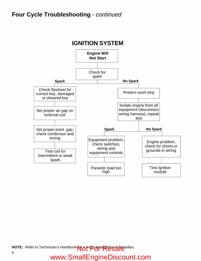
Four Cycle Troubleshooting - continued
NOTE: Refer to Technician's Handbook for a more detailed list of remedies.
IGNITION SYSTEM
Engine WillNot Start
No SparkSpark
Check forspark
Spark
Set proper point gap,check condensor and
timing
No Spark
Replace spark plug
Isolate engine from allequipment (disconnectwiring harness), repeat
test
Parasitic load toohigh
Test coil forintermittent or weak
spark
Set proper air gap onexternal coil
Check flywheel forcorrect key, damaged
or sheared key
Test ignitionmodule
Engine problem,check for shorts orgrounds in wiring
Equipment problem,check switches,
wiring andequipment controls
Not For Resale www.SmallEngineDiscount.com
9
1
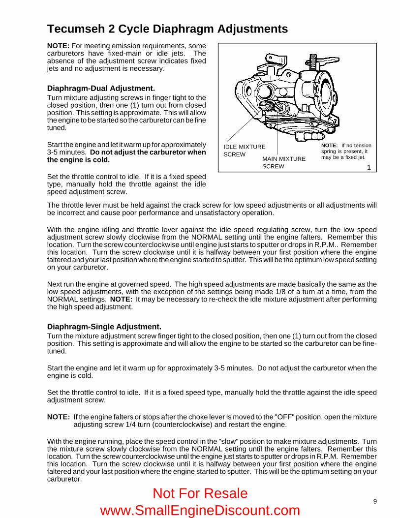
Tecumseh 2 Cycle Diaphragm AdjustmentsNOTE: For meeting emission requirements, somecarburetors have fixed-main or idle jets. Theabsence of the adjustment screw indicates fixedjets and no adjustment is necessary.
Diaphragm-Dual Adjustment.Turn mixture adjusting screws in finger tight to theclosed position, then one (1) turn out from closedposition. This setting is approximate. This will allowthe engine to be started so the carburetor can be finetuned.
Start the engine and let it warm up for approximately3-5 minutes. Do not adjust the carburetor whenthe engine is cold.
Set the throttle control to idle. If it is a fixed speedtype, manually hold the throttle against the idlespeed adjustment screw.
The throttle lever must be held against the crack screw for low speed adjustments or all adjustments willbe incorrect and cause poor performance and unsatisfactory operation.
With the engine idling and throttle lever against the idle speed regulating screw, turn the low speedadjustment screw slowly clockwise from the NORMAL setting until the engine falters. Remember thislocation. Turn the screw counterclockwise until engine just starts to sputter or drops in R.P.M.. Rememberthis location. Turn the screw clockwise until it is halfway between your first position where the enginefaltered and your last position where the engine started to sputter. This will be the optimum low speed settingon your carburetor.
Next run the engine at governed speed. The high speed adjustments are made basically the same as thelow speed adjustments, with the exception of the settings being made 1/8 of a turn at a time, from theNORMAL settings. NOTE: It may be necessary to re-check the idle mixture adjustment after performingthe high speed adjustment.
Diaphragm-Single Adjustment.Turn the mixture adjustment screw finger tight to the closed position, then one (1) turn out from the closedposition. This setting is approximate and will allow the engine to be started so the carburetor can be fine-tuned.
Start the engine and let it warm up for approximately 3-5 minutes. Do not adjust the carburetor when theengine is cold.
Set the throttle control to idle. If it is a fixed speed type, manually hold the throttle against the idle speedadjustment screw.
NOTE: If the engine falters or stops after the choke lever is moved to the "OFF" position, open the mixtureadjusting screw 1/4 turn (counterclockwise) and restart the engine.
With the engine running, place the speed control in the "slow" position to make mixture adjustments. Turnthe mixture screw slowly clockwise from the NORMAL setting until the engine falters. Remember thislocation. Turn the screw counterclockwise until the engine just starts to sputter or drops in R.P.M. Rememberthis location. Turn the screw clockwise until it is halfway between your first position where the enginefaltered and your last position where the engine started to sputter. This will be the optimum setting on yourcarburetor.
IDLE MIXTURESCREW
MAIN MIXTURESCREW
NOTE: If no tensionspring is present, itmay be a fixed jet.
Not For Resale www.SmallEngineDiscount.com
10
TC Series Governor Adjustment
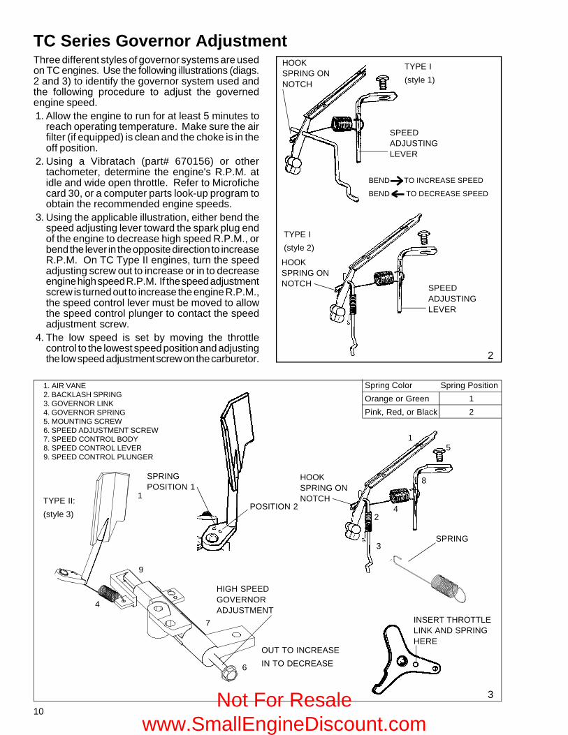
1. AIR VANE2. BACKLASH SPRING3. GOVERNOR LINK4. GOVERNOR SPRING5. MOUNTING SCREW6. SPEED ADJUSTMENT SCREW7. SPEED CONTROL BODY8. SPEED CONTROL LEVER9. SPEED CONTROL PLUNGER
1
4
9
7
6
HIGH SPEEDGOVERNORADJUSTMENT
INSERT THROTTLELINK AND SPRINGHERE
OUT TO INCREASEIN TO DECREASE
TYPE I(style 1)
TYPE I(style 2)
SPEEDADJUSTINGLEVER
2
3
SPEEDADJUSTINGLEVER
TYPE II:(style 3)
Three different styles of governor systems are usedon TC engines. Use the following illustrations (diags.2 and 3) to identify the governor system used andthe following procedure to adjust the governedengine speed.1. Allow the engine to run for at least 5 minutes to
reach operating temperature. Make sure the airfilter (if equipped) is clean and the choke is in theoff position.
2. Using a Vibratach (part# 670156) or othertachometer, determine the engine's R.P.M. atidle and wide open throttle. Refer to Microfichecard 30, or a computer parts look-up program toobtain the recommended engine speeds.
3. Using the applicable illustration, either bend thespeed adjusting lever toward the spark plug endof the engine to decrease high speed R.P.M., orbend the lever in the opposite direction to increaseR.P.M. On TC Type II engines, turn the speedadjusting screw out to increase or in to decreaseengine high speed R.P.M. If the speed adjustmentscrew is turned out to increase the engine R.P.M.,the speed control lever must be moved to allowthe speed control plunger to contact the speedadjustment screw.
4. The low speed is set by moving the throttlecontrol to the lowest speed position and adjustingthe low speed adjustment screw on the carburetor.
BEND TO INCREASE SPEED
BEND TO DECREASE SPEED
Spring Color Spring PositionOrange or Green 1Pink, Red, or Black 2
SPRING
SPRINGPOSITION 1
POSITION 2
3
24
15
8
HOOKSPRING ONNOTCH
HOOKSPRING ONNOTCH
HOOKSPRING ONNOTCH
Not For Resale www.SmallEngineDiscount.com
11
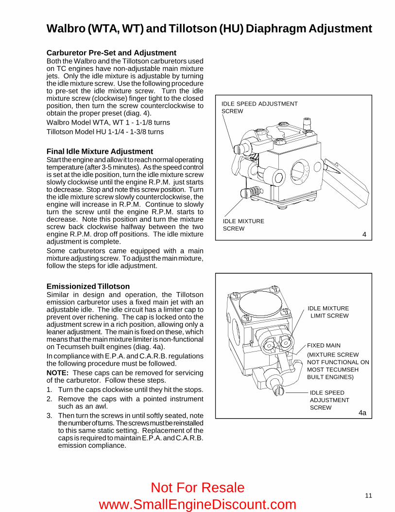
IDLE MIXTURESCREW
IDLE SPEED ADJUSTMENTSCREW
4
Carburetor Pre-Set and AdjustmentBoth the Walbro and the Tillotson carburetors usedon TC engines have non-adjustable main mixturejets. Only the idle mixture is adjustable by turningthe idle mixture screw. Use the following procedureto pre-set the idle mixture screw. Turn the idlemixture screw (clockwise) finger tight to the closedposition, then turn the screw counterclockwise toobtain the proper preset (diag. 4).Walbro Model WTA, WT 1 - 1-1/8 turnsTillotson Model HU 1-1/4 - 1-3/8 turns
Final Idle Mixture AdjustmentStart the engine and allow it to reach normal operatingtemperature (after 3-5 minutes). As the speed controlis set at the idle position, turn the idle mixture screwslowly clockwise until the engine R.P.M. just startsto decrease. Stop and note this screw position. Turnthe idle mixture screw slowly counterclockwise, theengine will increase in R.P.M. Continue to slowlyturn the screw until the engine R.P.M. starts todecrease. Note this position and turn the mixturescrew back clockwise halfway between the twoengine R.P.M. drop off positions. The idle mixtureadjustment is complete.Some carburetors came equipped with a mainmixture adjusting screw. To adjust the main mixture,follow the steps for idle adjustment.
Walbro (WTA, WT) and Tillotson (HU) Diaphragm Adjustment
4a
Emissionized TillotsonSimilar in design and operation, the Tillotsonemission carburetor uses a fixed main jet with anadjustable idle. The idle circuit has a limiter cap toprevent over richening. The cap is locked onto theadjustment screw in a rich position, allowing only aleaner adjustment. The main is fixed on these, whichmeans that the main mixture limiter is non-functionalon Tecumseh built engines (diag. 4a).In compliance with E.P.A. and C.A.R.B. regulationsthe following procedure must be followed.NOTE: These caps can be removed for servicingof the carburetor. Follow these steps.1. Turn the caps clockwise until they hit the stops.2. Remove the caps with a pointed instrument
such as an awl.3. Then turn the screws in until softly seated, note
the number of turns. The screws must be reinstalledto this same static setting. Replacement of thecaps is required to maintain E.P.A. and C.A.R.B.emission compliance.
FIXED MAIN(MIXTURE SCREWNOT FUNCTIONAL ONMOST TECUMSEHBUILT ENGINES)
IDLE SPEEDADJUSTMENTSCREW
IDLE MIXTURELIMIT SCREW
Not For Resale www.SmallEngineDiscount.com
12
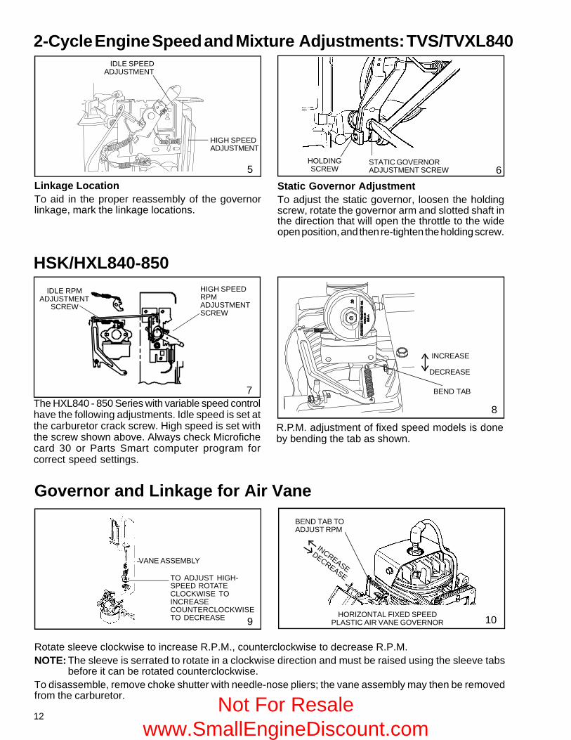
2-Cycle Engine Speed and Mixture Adjustments: TVS/TVXL840
Rotate sleeve clockwise to increase R.P.M., counterclockwise to decrease R.P.M.NOTE: The sleeve is serrated to rotate in a clockwise direction and must be raised using the sleeve tabs
before it can be rotated counterclockwise.To disassemble, remove choke shutter with needle-nose pliers; the vane assembly may then be removedfrom the carburetor.
9HORIZONTAL FIXED SPEED
PLASTIC AIR VANE GOVERNOR 10
BEND TAB TOADJUST RPM
INCREASE
DECREASE
Governor and Linkage for Air Vane
IDLE RPMADJUSTMENT
SCREW
HIGH SPEEDRPMADJUSTMENTSCREW
The HXL840 - 850 Series with variable speed controlhave the following adjustments. Idle speed is set atthe carburetor crack screw. High speed is set withthe screw shown above. Always check Microfichecard 30 or Parts Smart computer program forcorrect speed settings.
R.P.M. adjustment of fixed speed models is doneby bending the tab as shown.
HSK/HXL840-850
IDLE SPEEDADJUSTMENT
HIGH SPEEDADJUSTMENT
5HOLDINGSCREW
Linkage LocationTo aid in the proper reassembly of the governorlinkage, mark the linkage locations.
6Static Governor AdjustmentTo adjust the static governor, loosen the holdingscrew, rotate the governor arm and slotted shaft inthe direction that will open the throttle to the wideopen position, and then re-tighten the holding screw.
VANE ASSEMBLY
STATIC GOVERNORADJUSTMENT SCREW
7
8
BEND TAB
TO ADJUST HIGH-SPEED ROTATECLOCKWISE TOINCREASECOUNTERCLOCKWISETO DECREASE
DECREASE
INCREASE
Not For Resale www.SmallEngineDiscount.com
13
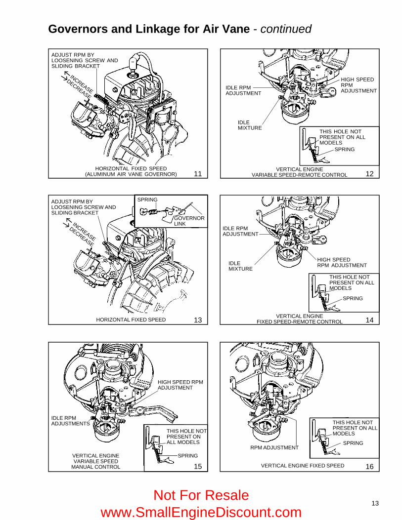
HORIZONTAL FIXED SPEED
15
VERTICAL ENGINEFIXED SPEED-REMOTE CONTROL
VERTICAL ENGINEVARIABLE SPEED-REMOTE CONTROL
HORIZONTAL FIXED SPEED(ALUMINUM AIR VANE GOVERNOR)
Governors and Linkage for Air Vane - continued
13
ADJUST RPM BYLOOSENING SCREW ANDSLIDING BRACKET
ADJUST RPM BYLOOSENING SCREW ANDSLIDING BRACKET
SPRING
IDLE RPMADJUSTMENTS
HIGH SPEED RPMADJUSTMENT
THIS HOLE NOTPRESENT ONALL MODELS
SPRINGVERTICAL ENGINEVARIABLE SPEED
MANUAL CONTROL
11
IDLE RPMADJUSTMENT
THIS HOLE NOTPRESENT ON ALLMODELS
SPRING
12
GOVERNORLINK
14
RPM ADJUSTMENT
THIS HOLE NOTPRESENT ON ALLMODELS
SPRING
VERTICAL ENGINE FIXED SPEED 16
THIS HOLE NOTPRESENT ON ALLMODELS
SPRING
HIGH SPEEDRPMADJUSTMENT
IDLEMIXTURE
HIGH SPEEDRPM ADJUSTMENTIDLE
MIXTURE
IDLE RPMADJUSTMENT
INCREASE
DECREASE
INCREASE
DECREASE
Not For Resale www.SmallEngineDiscount.com
14
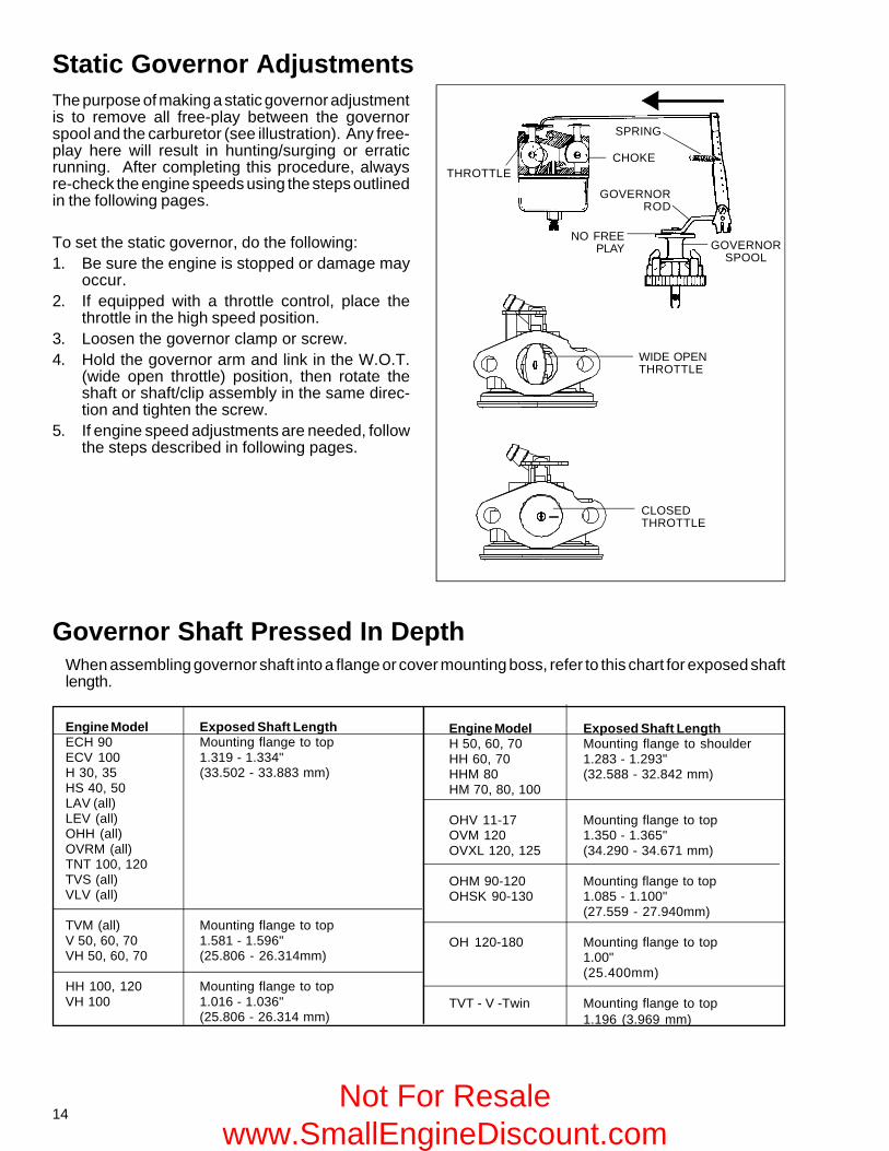
Static Governor AdjustmentsThe purpose of making a static governor adjustmentis to remove all free-play between the governorspool and the carburetor (see illustration). Any free-play here will result in hunting/surging or erraticrunning. After completing this procedure, alwaysre-check the engine speeds using the steps outlinedin the following pages.
To set the static governor, do the following:1. Be sure the engine is stopped or damage may
occur.2. If equipped with a throttle control, place the
throttle in the high speed position.3. Loosen the governor clamp or screw.4. Hold the governor arm and link in the W.O.T.
(wide open throttle) position, then rotate theshaft or shaft/clip assembly in the same direc-tion and tighten the screw.
5. If engine speed adjustments are needed, followthe steps described in following pages.
When assembling governor shaft into a flange or cover mounting boss, refer to this chart for exposed shaftlength.
Governor Shaft Pressed In Depth
Engine Model Exposed Shaft LengthECH 90 Mounting flange to topECV 100 1.319 - 1.334"H 30, 35 (33.502 - 33.883 mm)HS 40, 50LAV (all)LEV (all)OHH (all)OVRM (all)TNT 100, 120TVS (all)VLV (all)
TVM (all) Mounting flange to topV 50, 60, 70 1.581 - 1.596"VH 50, 60, 70 (25.806 - 26.314mm)
HH 100, 120 Mounting flange to topVH 100 1.016 - 1.036"
(25.806 - 26.314 mm)
Engine Model Exposed Shaft LengthH 50, 60, 70 Mounting flange to shoulderHH 60, 70 1.283 - 1.293"HHM 80 (32.588 - 32.842 mm)HM 70, 80, 100
OHV 11-17 Mounting flange to topOVM 120 1.350 - 1.365"OVXL 120, 125 (34.290 - 34.671 mm)
OHM 90-120 Mounting flange to topOHSK 90-130 1.085 - 1.100"
(27.559 - 27.940mm)
OH 120-180 Mounting flange to top1.00"(25.400mm)
TVT - V -Twin Mounting flange to top1.196 (3.969 mm)
SPRING
GOVERNORSPOOL
NO FREEPLAY
THROTTLECHOKE
WIDE OPENTHROTTLE
CLOSEDTHROTTLE
GOVERNORROD
Not For Resale www.SmallEngineDiscount.com
15
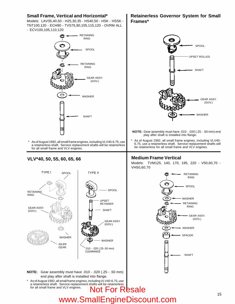
* As of August 1992, all small frame engines, including VLV40-6.75, usea retainerless shaft. Service replacement shafts will be retainerlessfor all small frame and VLV engines.
Medium Frame VerticalModels: TVM125, 140, 170, 195, 220 - V50,60,70 -VH50,60,70
VLV*40, 50, 55, 60, 65, 66
Small Frame, Vertical and Horizontal*Models: LAV35,40,50 - H25,30,35 - HS40,50 - HSK - HSSK -TNT100,120 - ECH90 - TVS75,90,105,115,120 - OVRM ALL- ECV100,105,110,120
Retainerless Governor System for SmallFrames*
RETAININGRING
SPOOL
RETAININGRING
GEAR ASSY.(GOV.)
WASHER
SHAFT
SPOOL
SHAFT
WASHER
GEAR ASSY.(GOV.)
TYPE I SPOOL
IDLERGEAR
WASHER
GEAR ASSY.(GOV.)
RETAININGRING
TYPE II
WASHER
GEAR ASSY.(GOV.)
SHAFT
SPOOL
UPSETRETAINER
SHAFT
SPACER
WASHER
RETAININGRING
WASHER
SPOOL
RETAININGRING
GEAR ASSY.(GOV.)
* As of August 1992, all small frame engines, including VLV40-6.75, use a retainerless shaft. Service replacement shafts willbe retainerless for all small frame and VLV engines.
NOTE: Gear assembly must have .010 - .020 (.25 - .50 mm) endplay after shaft is installed into flange.
* As of August 1992, all small frame engines, including VLV40-6.75, usea retainerless shaft. Service replacement shafts will be retainerlessfor all small frame and VLV engines.
NOTE: Gear assembly must have .010 - .020 (.25 - .50 mm)end play after shaft is installed into flange.
UPSET ROLLED
.010 - .020 (.25-.50 mm)CLEARANCE
Not For Resale www.SmallEngineDiscount.com
16
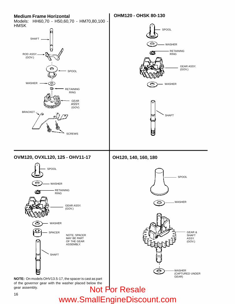
SHAFT
WASHER
BRACKET
SPOOL
RETAININGRING
GEARASSY.(GOV)
SCREWS
ROD ASSY.(GOV.)
SPOOL
WASHER
RETAININGRING
GEAR ASSY.(GOV.)
WASHER
SPACER
SHAFT
SPOOL
WASHER
RETAININGRING
GEAR ASSY.(GOV.)
WASHER
SPACER
SHAFT
NOTE; SPACERMAY BE PARTOF THE GEARASSEMBLY.
SPOOL
WASHER
GEAR &SHAFTASSY.(GOV.)
WASHER(CAPTURED UNDERGEAR)
Medium Frame HorizontalModels: HH60,70 - H50,60,70 - HM70,80,100 -HMSK
OVM120, OVXL120, 125 - OHV11-17
OHM120 - OHSK 80-130
OH120, 140, 160, 180
NOTE: On models OHV13.5-17, the spacer is cast as partof the governor gear with the washer placed below thegear assembly. Not For Resale
www.SmallEngineDiscount.com
17
MAIN MIXTURESCREW
17
18
** NON-ADJUSTABLENO CHOKEPRIMER
* ADJUSTABLEMIXTURES, CHOKE
SMALL WIRE (DRILL BIT)
HOLE IN BRACKET
HOLE IN SPEEDCONTROL CHOKEACTUATING LEVER
HOLE IN CHOKELEVER
LOW SPEEDADJUSTMENT SCREW
IDLE MIXTURESCREW
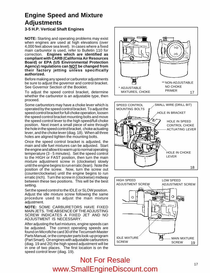
Engine Speed and MixtureAdjustments3-5 H.P. Vertical Shaft Engines
NOTE: Starting and operating problems may existwhen engines are used at high elevations (over4,000 feet above sea level). In cases where a fixedmain carburetor is used, refer to Bulletin 110 forcorrection. Engines which are identified ascompliant with CARB (California Air ResourcesBoard) or EPA (US Environmental ProtectionAgency) regulations can NOT be changed fromtheir factory jetting unless specificallyauthorized.Before making any speed or carburetor adjustmentsbe sure to adjust the governor and control bracket.See Governor Section of the Booklet.To adjust the speed control bracket, determinewhether the carburetor is an adjustable type, thenproceed.Some carburetors may have a choke lever which isoperated by the speed control bracket. To adjust thespeed control bracket for full choke operation, loosenthe speed control bracket mounting bolts and movethe speed control lever to the high speed/full chokeposition. Next insert a small piece of wire throughthe hole in the speed control bracket, choke actuatinglever, and the choke lever (diag. 18). When all threeholes are aligned tighten the mounting bolts.Once the speed control bracket is adjusted, themain and idle fuel mixtures can be adjusted. Startthe engine and allow it to warm up to normal operatingtemperature (3 - 5 minutes). Set the speed controlto the HIGH or FAST position, then turn the mainmixture adjustment screw in (clockwise) slowlyuntil the engine begins to run erratic (lean). Note theposition of the screw. Now, turn the screw out(counterclockwise) until the engine begins to runerratic (rich). Turn the screw in (clockwise) midwaybetween these two positions. This will be the bestsetting.Set the speed control to the IDLE or SLOW position.Adjust the idle mixture screw following the sameprocedure used to adjust the main mixtureadjustment.NOTE: SOME CARBURETORS HAVE FIXEDMAIN JETS. THE ABSENCE OF THE ADJUSTINGSCREW INDICATES A FIXED JET AND NOADJUSTMENT IS NECESSARY.After adjusting the fuel mixtures, engine speeds canbe adjusted. The correct operating speeds arefound on Microfiche card 30 of the Tecumseh MasterParts Manual, or the computer parts look-up program(Part Smart). On engines with adjustable carburetors(diag. 19 and 20) the high speed adjustment will bein one of two places. The first location is on thespeed control lever (diag. 19).
SPEED CONTROLMOUNTING BOLTS
HIGH SPEEDADJUSTMENT SCREW
19
Not For Resale www.SmallEngineDiscount.com
18
HIGH SPEEDADJUSTMENTSCREW
LOW SPEEDADJUSTMENT SCREW
IDLEMIXTURESCREW
MAIN MIXTURE SCREW
COUNTERCLOCKWISETO INCREASE SPEEDCLOCKWISE TODECREASE SPEED
SPEED CONTROLMOUNTING BOLTS
20
Engine Speed and Mixture Adjustments - continued3-5 H.P. Vertical Shaft Engines
21
HIGH SPEEDADJUSTMENTSCREW
LOW SPEEDADJUSTMENT SCREW
22
SPEED ADJUSTMENT TABBEND TO INCREASE SPEED
BEND TO DECREASE SPEED
23
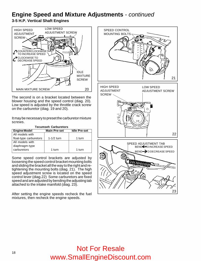
The second is on a bracket located between theblower housing and the speed control (diag. 20).Low speed is adjusted by the throttle crack screwon the carburetor (diag. 19 and 20).
It may be necessary to preset the carburetor mixturescrews.
Tecumseh CarburetorsEngine Model Main Pre-set Idle Pre-setAll models withfloat-type carburetors 1-1/2 turn 1 turnAll models withdiaphragm-typecarburetors 1 turn 1 turn
Some speed control brackets are adjusted byloosening the speed control bracket mounting boltsand sliding the bracket all the way to the right and re-tightening the mounting bolts (diag. 21). The highspeed adjustment screw is located on the speedcontrol lever (diag.22) Some carburetors are fixedspeed and are adjusted by bending the adjusting tabattached to the intake manifold (diag. 23).
After setting the engine speeds recheck the fuelmixtures, then recheck the engine speeds.
Not For Resale www.SmallEngineDiscount.com
19
TNT 100 VERTICAL ENGINES
25
26
BEND CONTROLBRACKET TO SET
RPM
VERTICAL ENGINES
TVS 115 ENGINE WITH DUALSYSTEM CARBURETOR
BEND TO INCREASE SPEED
BEND TO DECREASE SPEED
HIGH SPEED RPMADJUSTMENTSCREW
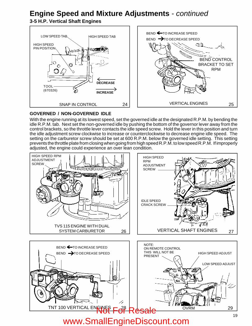
GOVERNED / NON-GOVERNED IDLEWith the engine running at its lowest speed, set the governed idle at the designated R.P.M. by bending theidle R.P.M. tab. Next set the non-governed idle by pushing the bottom of the governor lever away from thecontrol brackets, so the throttle lever contacts the idle speed screw. Hold the lever in this position and turnthe idle adjustment screw clockwise to increase or counterclockwise to decrease engine idle speed. Thesetting on the carburetor screw should be set at 600 R.P.M. below the governed idle setting. This settingprevents the throttle plate from closing when going from high speed R.P.M. to low speed R.P.M. If improperlyadjusted, the engine could experience an over lean condition.
VERTICAL SHAFT ENGINES
28
BEND TO INCREASE SPEED
BEND TO DECREASE SPEED
27
HIGH SPEEDRPMADJUSTMENTSCREW
IDLE SPEEDCRACK SCREW
NOTE:ON REMOTE CONTROLTHIS WILL NOT BEPRESENT
LOW SPEED ADJUST
HIGH SPEED ADJUST
OVRM 29
Engine Speed and Mixture Adjustments - continued3-5 H.P. Vertical Shaft Engines
LOW SPEED TAB HIGH SPEED TAB
DECREASE
INCREASE
HIGH SPEEDPIN POSITION
TOOL(670326)
SNAP IN CONTROL 24
Not For Resale www.SmallEngineDiscount.com
20
BEND TO INCREASE SPEED
BEND TO DECREASE SPEED
LONG BENDSHORT BEND
GOVERNOR SPRING
TWIST COUNTERCLOCKWISETO DISCONNECT
30
VLV Governor and Linkage
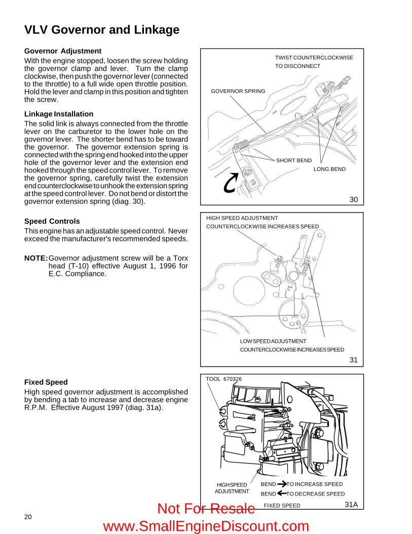
Governor AdjustmentWith the engine stopped, loosen the screw holdingthe governor clamp and lever. Turn the clampclockwise, then push the governor lever (connectedto the throttle) to a full wide open throttle position.Hold the lever and clamp in this position and tightenthe screw.
Speed ControlsThis engine has an adjustable speed control. Neverexceed the manufacturer's recommended speeds.
NOTE:Governor adjustment screw will be a Torxhead (T-10) effective August 1, 1996 forE.C. Compliance.
Linkage InstallationThe solid link is always connected from the throttlelever on the carburetor to the lower hole on thegovernor lever. The shorter bend has to be towardthe governor. The governor extension spring isconnected with the spring end hooked into the upperhole of the governor lever and the extension endhooked through the speed control lever. To removethe governor spring, carefully twist the extensionend counterclockwise to unhook the extension springat the speed control lever. Do not bend or distort thegovernor extension spring (diag. 30).
HIGH SPEED ADJUSTMENTCOUNTERCLOCKWISE INCREASES SPEED
LOW SPEED ADJUSTMENTCOUNTERCLOCKWISE INCREASES SPEED
31
FIXED SPEED
Fixed SpeedHigh speed governor adjustment is accomplishedby bending a tab to increase and decrease engineR.P.M. Effective August 1997 (diag. 31a).
31A
TOOL 670326
HIGH SPEEDADJUSTMENT
Not For Resale www.SmallEngineDiscount.com
21
MAIN MIXTURESCREW
MAIN MIXTURESCREW
32
33
34
SMALL PIECE OF WIRE
HOLE IN CONTROL BRACKET
MOUNTINGBOLTS
HOLE INCHOKEACTUATINGLEVER
HOLE IN CHOKE LEVER
HIGH SPEEDADJUSTMENT SCREW
THROTTLECRACKSCREW
IDLE MIXTURESCREW
GOVERNORADJUSTINGLEVER
HIGH SPEEDADJUSTMENTSCREW
LOW SPEEDADJUSTMENT SCREW
MOVE THE CONTROLLEVER IN THE HIGHSPEED POSITION
THROTTLE CRACK SCREW
IDLEMIXTURESCREW
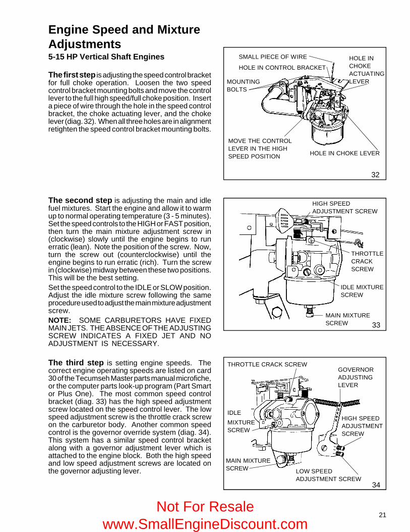
Engine Speed and MixtureAdjustments5-15 HP Vertical Shaft Engines
The first step is adjusting the speed control bracketfor full choke operation. Loosen the two speedcontrol bracket mounting bolts and move the controllever to the full high speed/full choke position. Inserta piece of wire through the hole in the speed controlbracket, the choke actuating lever, and the chokelever (diag. 32). When all three holes are in alignmentretighten the speed control bracket mounting bolts.
The second step is adjusting the main and idlefuel mixtures. Start the engine and allow it to warmup to normal operating temperature (3 - 5 minutes).Set the speed controls to the HIGH or FAST position,then turn the main mixture adjustment screw in(clockwise) slowly until the engine begins to runerratic (lean). Note the position of the screw. Now,turn the screw out (counterclockwise) until theengine begins to run erratic (rich). Turn the screwin (clockwise) midway between these two positions.This will be the best setting.Set the speed control to the IDLE or SLOW position.Adjust the idle mixture screw following the sameprocedure used to adjust the main mixture adjustmentscrew.NOTE: SOME CARBURETORS HAVE FIXEDMAIN JETS. THE ABSENCE OF THE ADJUSTINGSCREW INDICATES A FIXED JET AND NOADJUSTMENT IS NECESSARY.
The third step is setting engine speeds. Thecorrect engine operating speeds are listed on card30 of the Tecumseh Master parts manual microfiche,or the computer parts look-up program (Part Smartor Plus One). The most common speed controlbracket (diag. 33) has the high speed adjustmentscrew located on the speed control lever. The lowspeed adjustment screw is the throttle crack screwon the carburetor body. Another common speedcontrol is the governor override system (diag. 34).This system has a similar speed control bracketalong with a governor adjustment lever which isattached to the engine block. Both the high speedand low speed adjustment screws are located onthe governor adjusting lever.
Not For Resale www.SmallEngineDiscount.com
22
BEND TO INCREASE SPEED
BEND TO DECREASE SPEED
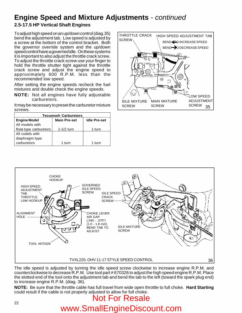
To adjust high speed on an up/down control (diag.35)bend the adjustment tab. Low speed is adjusted bya screw at the bottom of the control bracket. Boththe governor override system and the up/downspeed control have a governed idle. On these systemsit is important to also adjust the throttle crack screw.To adjust the throttle crack screw use your finger tohold the throttle shutter tight against the throttlecrack screw and adjust the engine speed toapproximately 600 R.P.M. less than therecommended low speed.After setting the engine speeds recheck the fuelmixtures and double check the engine speeds.NOTE: Not all engines have fully adjustable
carburetors.It may be necessary to preset the carburetor mixturescrews.
Tecumseh CarburetorsEngine Model Main Pre-set Idle Pre-setAll models withfloat-type carburetors 1-1/2 turn 1 turnAll codels withdiaphragm-typecarburetors 1 turn 1 turn
IDLE MIXTURESCREW
THROTTLE CRACKSCREW
MAIN MIXTURESCREW
Engine Speed and Mixture Adjustments - continued2.5-17.5 HP Vertical Shaft Engines
35
HIGH SPEED ADJUSTMENT TAB
LOW SPEEDADJUSTMENTSCREW
CHOKEHOOKUP
TOOL #670326
ALIGNMENTHOLE
HIGH SPEEDADJUSTMENTTABTHROTTLELINK HOOKUP
GOVERNEDIDLE SPEEDSCREW
CHOKE LEVERAIR GAP(.040 - .070")(1.0 - 1.8 mm)BEND TAB TOADJUST
The idle speed is adjusted by turning the idle speed screw clockwise to increase engine R.P.M. andcounterclockwise to decrease R.P.M. Use tool part # 670326 to adjust the high speed engine R.P.M. Placethe slotted end of the tool onto the adjustment tab and bend the tab to the left (toward the spark plug end)to increase engine R.P.M. (diag. 36).NOTE: Be sure that the throttle cable has full travel from wide open throttle to full choke. Hard Startingcould result if the cable is not properly adjusted to allow for full choke.
TVXL220, OHV 11-17 STYLE SPEED CONTROL 36
IDLE SPEEDCRACKSCREW
IDLE MIXTURESCREW
Not For Resale www.SmallEngineDiscount.com
23
Engine Speed and Mixture Adjustments - continued
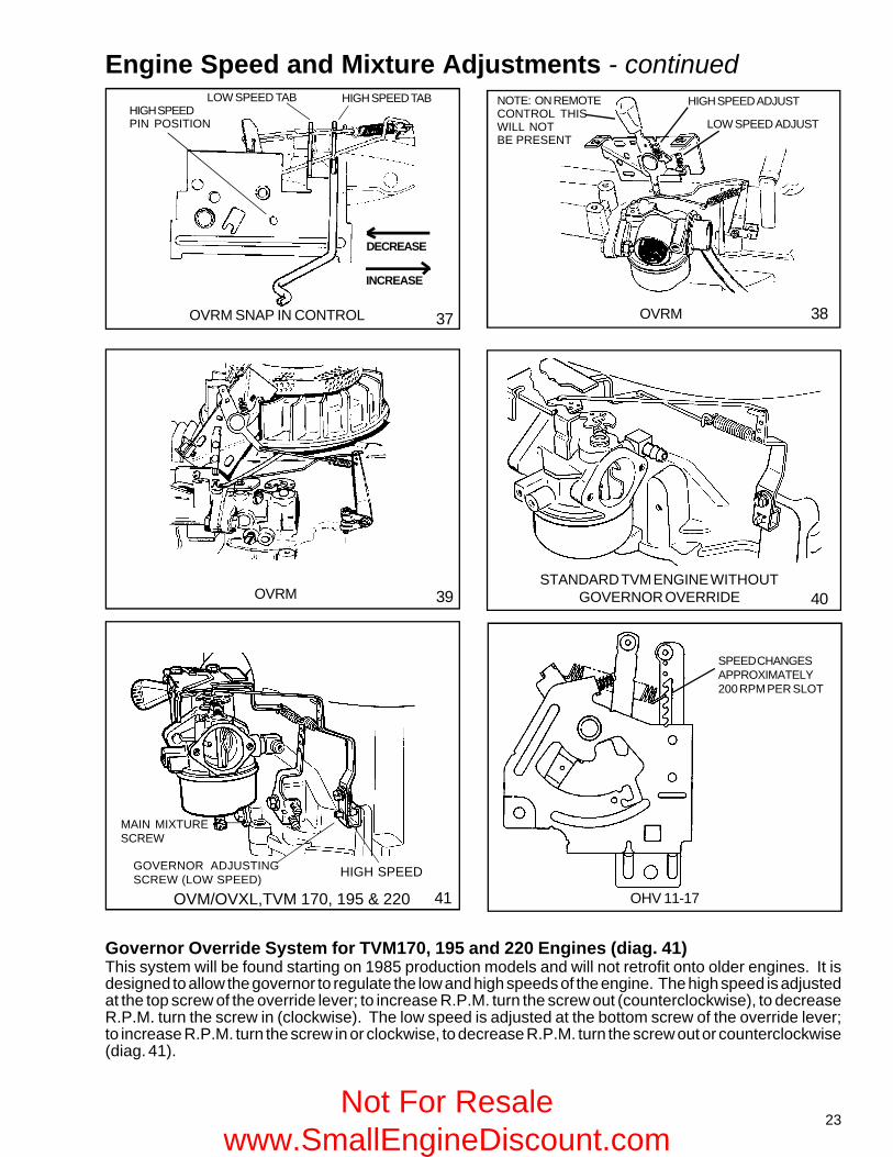
OVM/OVXL,TVM 170, 195 & 220
Governor Override System for TVM170, 195 and 220 Engines (diag. 41)This system will be found starting on 1985 production models and will not retrofit onto older engines. It isdesigned to allow the governor to regulate the low and high speeds of the engine. The high speed is adjustedat the top screw of the override lever; to increase R.P.M. turn the screw out (counterclockwise), to decreaseR.P.M. turn the screw in (clockwise). The low speed is adjusted at the bottom screw of the override lever;to increase R.P.M. turn the screw in or clockwise, to decrease R.P.M. turn the screw out or counterclockwise(diag. 41).
STANDARD TVM ENGINE WITHOUTGOVERNOR OVERRIDE 40
MAIN MIXTURESCREW
GOVERNOR ADJUSTINGSCREW (LOW SPEED) HIGH SPEED
41
LOW SPEED ADJUST
HIGH SPEED ADJUST
OVRM 3837OVRM SNAP IN CONTROL
LOW SPEED TAB HIGH SPEED TABHIGH SPEEDPIN POSITION
DECREASE
INCREASE
NOTE: ON REMOTECONTROL THISWILL NOTBE PRESENT
OVRM 39
SPEED CHANGESAPPROXIMATELY200 RPM PER SLOT
OHV 11-17
Not For Resale www.SmallEngineDiscount.com
24
SMALL FRAME GOVERNED IDLE HORIZONTAL MEDIUM FRAME
CONSTANT SPEED APPLICATIONS
LIGHTWEIGHT R.V. TYPE
44 45
46 47HORIZONTAL MEDIUM FRAME
IDLE SPEEDCRACK SCREW
IDLE SPEEDCRACK SCREW
HIGH SPEED RPM ADJUSTMENT SCREWIDLE SPEED CRACK SCREW
HIGH SPEED RPMADJUSTMENTSCREW
IDLE MIXTURESCREW
MAINMIXTURE SCREW
IDLE SPEED CRACK SCREW
HIGH SPEED RPMADJUSTMENT SCREW
IDLE SPEEDCRACK SCREW
HIGH SPEED RPM ADJUSTMENT SCREW
IDLE MIXTURE SCREW
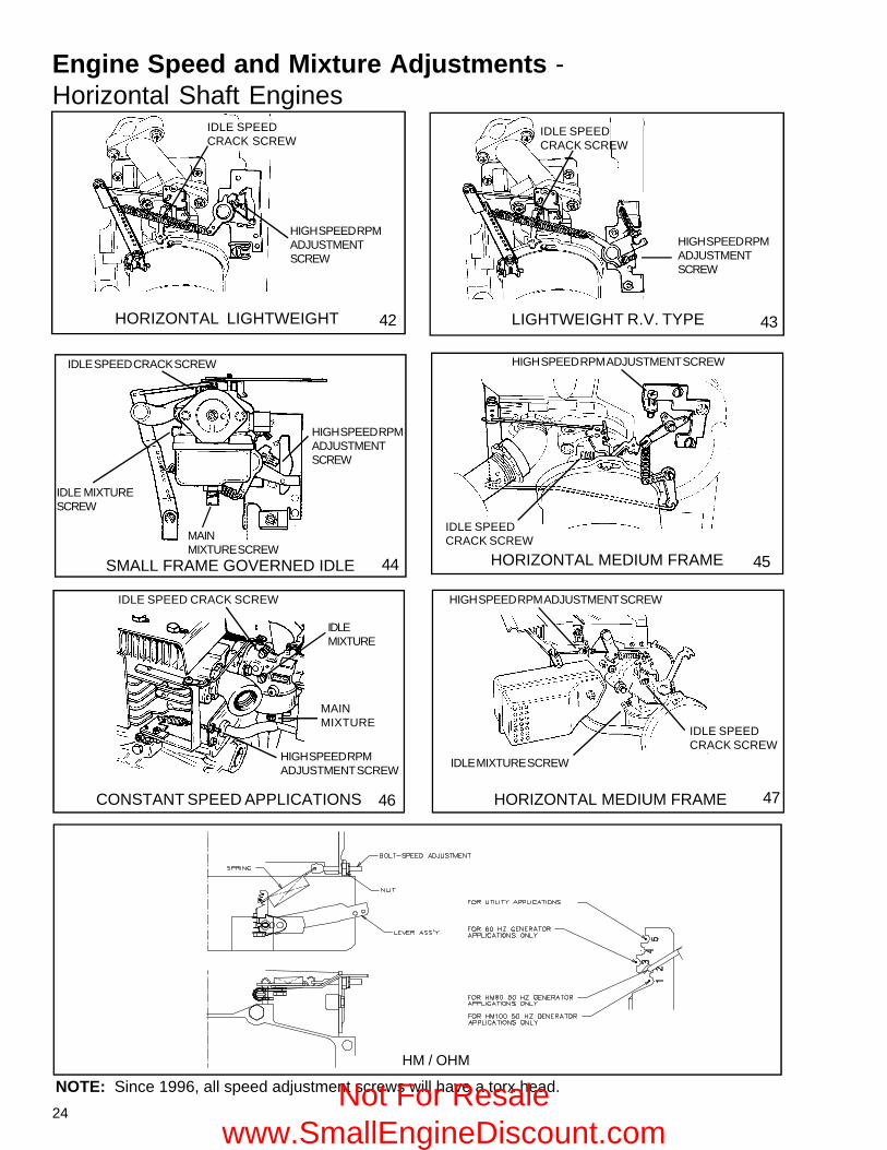
NOTE: Since 1996, all speed adjustment screws will have a torx head.
HIGH SPEED RPMADJUSTMENTSCREW
43
IDLEMIXTURE
MAINMIXTURE
Engine Speed and Mixture Adjustments -Horizontal Shaft Engines
42
IDLE SPEEDCRACK SCREW
HIGH SPEED RPMADJUSTMENTSCREW
HORIZONTAL LIGHTWEIGHT
HM / OHM
Not For Resale www.SmallEngineDiscount.com
25
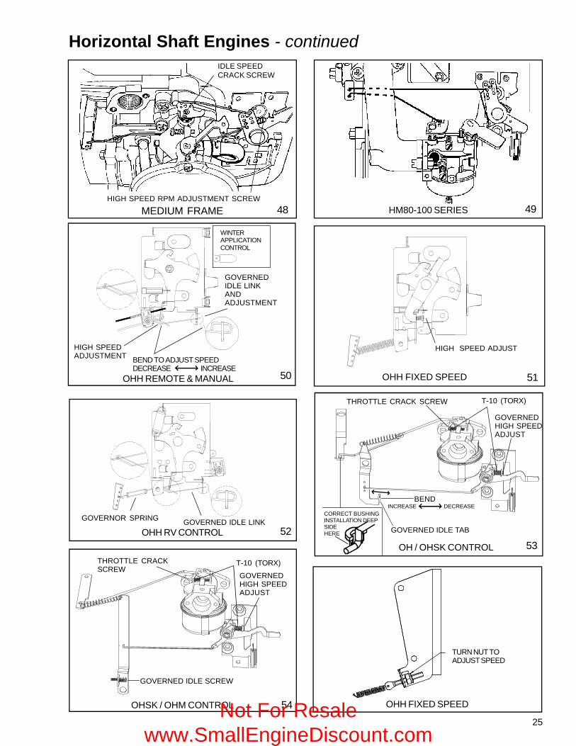
INCREASE DECREASE
Horizontal Shaft Engines - continued
53OHH RV CONTROL
GOVERNOR SPRING GOVERNED IDLE LINK
51OHH REMOTE & MANUAL
49
OHH FIXED SPEED50
WINTERAPPLICATIONCONTROL
HIGH SPEEDADJUSTMENT BEND TO ADJUST SPEED
DECREASE INCREASE
GOVERNEDIDLE LINKANDADJUSTMENT
HIGH SPEED ADJUST
OH / OHSK CONTROL
OHSK / OHM CONTROL
GOVERNEDHIGH SPEEDADJUST
BEND
GOVERNEDHIGH SPEEDADJUST
GOVERNED IDLE TAB
GOVERNED IDLE SCREW
T-10 (TORX)THROTTLE CRACK SCREW
T-10 (TORX)THROTTLE CRACKSCREW
CORRECT BUSHINGINSTALLATION DEEPSIDEHERE52
48MEDIUM FRAME
IDLE SPEEDCRACK SCREW
HIGH SPEED RPM ADJUSTMENT SCREW
54
HM80-100 SERIES
OHH FIXED SPEED
TURN NUT TOADJUST SPEED
Not For Resale www.SmallEngineDiscount.com
26
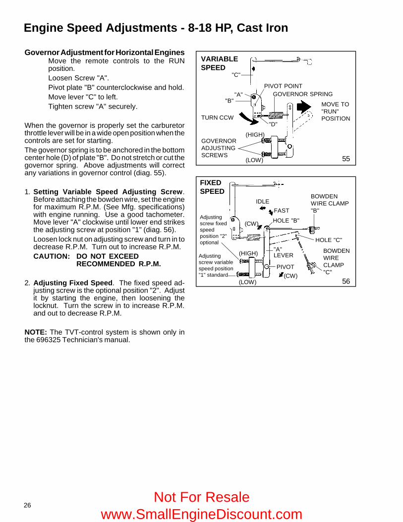
55
56
Governor Adjustment for Horizontal EnginesMove the remote controls to the RUNposition.Loosen Screw "A".Pivot plate "B" counterclockwise and hold.Move lever "C" to left.Tighten screw "A" securely.
When the governor is properly set the carburetorthrottle lever will be in a wide open position when thecontrols are set for starting.The governor spring is to be anchored in the bottomcenter hole (D) of plate "B". Do not stretch or cut thegovernor spring. Above adjustments will correctany variations in governor control (diag. 55).
1. Setting Variable Speed Adjusting Screw.Before attaching the bowden wire, set the enginefor maximum R.P.M. (See Mfg. specifications)with engine running. Use a good tachometer.Move lever "A" clockwise until lower end strikesthe adjusting screw at position "1" (diag. 56).Loosen lock nut on adjusting screw and turn in todecrease R.P.M. Turn out to increase R.P.M.CAUTION: DO NOT EXCEED
RECOMMENDED R.P.M.
2. Adjusting Fixed Speed. The fixed speed ad-justing screw is the optional position "2". Adjustit by starting the engine, then loosening thelocknut. Turn the screw in to increase R.P.M.and out to decrease R.P.M.
NOTE: The TVT-control system is shown only inthe 696325 Technician's manual.
IDLEFAST
(CW) HOLE "B"
BOWDENWIRE CLAMP"B"
HOLE "C"
BOWDENWIRECLAMP"C"(CW)
PIVOT
"A"LEVER
Engine Speed Adjustments - 8-18 HP, Cast Iron
VARIABLESPEED
GOVERNOR SPRING
MOVE TO"RUN"POSITION
GOVERNORADJUSTINGSCREWS
PIVOT POINT
TURN CCW
"C"
"A""B"
"D"
FIXEDSPEED
Adjustingscrew fixedspeedposition "2"optional
Adjustingscrew variablespeed position"1" standard
(LOW)
(HIGH)
(HIGH)
(LOW)
Not For Resale www.SmallEngineDiscount.com
27
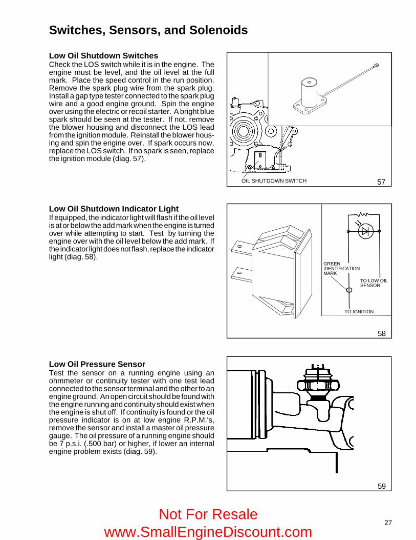
Low Oil Shutdown SwitchesCheck the LOS switch while it is in the engine. Theengine must be level, and the oil level at the fullmark. Place the speed control in the run position.Remove the spark plug wire from the spark plug.Install a gap type tester connected to the spark plugwire and a good engine ground. Spin the engineover using the electric or recoil starter. A bright bluespark should be seen at the tester. If not, removethe blower housing and disconnect the LOS leadfrom the ignition module. Reinstall the blower hous-ing and spin the engine over. If spark occurs now,replace the LOS switch. If no spark is seen, replacethe ignition module (diag. 57).
57
58
59
Switches, Sensors, and Solenoids
Low Oil Shutdown Indicator LightIf equipped, the indicator light will flash if the oil levelis at or below the add mark when the engine is turnedover while attempting to start. Test by turning theengine over with the oil level below the add mark. Ifthe indicator light does not flash, replace the indicatorlight (diag. 58).
Low Oil Pressure SensorTest the sensor on a running engine using anohmmeter or continuity tester with one test leadconnected to the sensor terminal and the other to anengine ground. An open circuit should be found withthe engine running and continuity should exist whenthe engine is shut off. If continuity is found or the oilpressure indicator is on at low engine R.P.M.'s,remove the sensor and install a master oil pressuregauge. The oil pressure of a running engine shouldbe 7 p.s.i. (.500 bar) or higher, if lower an internalengine problem exists (diag. 59).
OIL SHUTDOWN SWITCH
TO IGNITION
TO LOW OILSENSOR
GREENIDENTIFICATIONMARK
Not For Resale www.SmallEngineDiscount.com
28
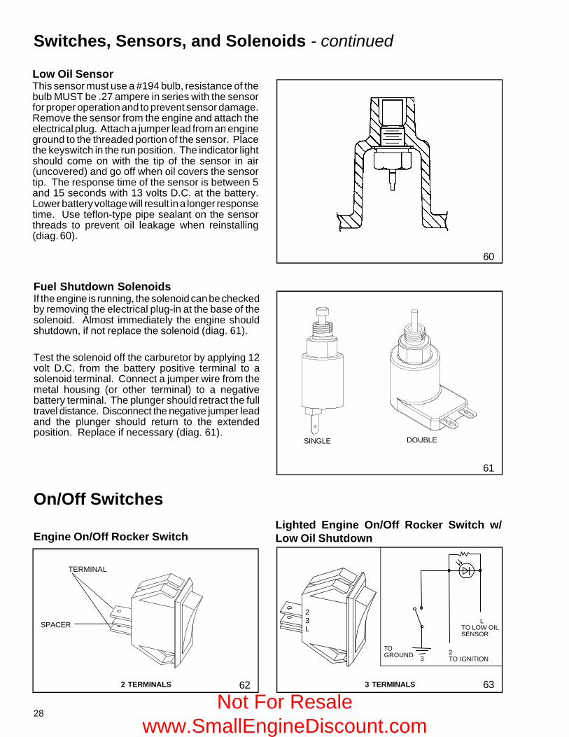
Low Oil SensorThis sensor must use a #194 bulb, resistance of thebulb MUST be .27 ampere in series with the sensorfor proper operation and to prevent sensor damage.Remove the sensor from the engine and attach theelectrical plug. Attach a jumper lead from an engineground to the threaded portion of the sensor. Placethe keyswitch in the run position. The indicator lightshould come on with the tip of the sensor in air(uncovered) and go off when oil covers the sensortip. The response time of the sensor is between 5and 15 seconds with 13 volts D.C. at the battery.Lower battery voltage will result in a longer responsetime. Use teflon-type pipe sealant on the sensorthreads to prevent oil leakage when reinstalling(diag. 60).
60
61
DOUBLESINGLE
Fuel Shutdown SolenoidsIf the engine is running, the solenoid can be checkedby removing the electrical plug-in at the base of thesolenoid. Almost immediately the engine shouldshutdown, if not replace the solenoid (diag. 61).
Test the solenoid off the carburetor by applying 12volt D.C. from the battery positive terminal to asolenoid terminal. Connect a jumper wire from themetal housing (or other terminal) to a negativebattery terminal. The plunger should retract the fulltravel distance. Disconnect the negative jumper leadand the plunger should return to the extendedposition. Replace if necessary (diag. 61).
Switches, Sensors, and Solenoids - continued
62
On/Off Switches
Engine On/Off Rocker Switch
63
Lighted Engine On/Off Rocker Switch w/Low Oil Shutdown
TERMINAL
SPACER
2 TERMINALS 3 TERMINALS
23L
2TO IGNITION
LTO LOW OILSENSOR
TOGROUND 3
Not For Resale www.SmallEngineDiscount.com
29
Wiring
CONDITION. All wiring must be fully insulated between connection points, securely fastened and free offoreign material (such as rust and corrosion) at the connection points. This is especially important in theuse of batteries where much of the potential may be lost due to loose connections or corrosion. Rememberto check the insulation on the wire. All it takes is a pin hole for a wire to "ground out" on the engine or frame.This is of special concern when moisture or water is present. This may cause the engine to run erraticallyor be impossible to start.
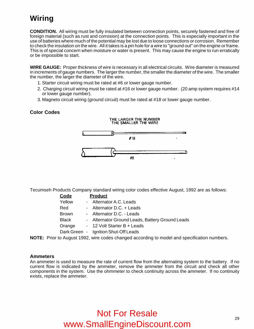
WIRE GAUGE: Proper thickness of wire is necessary in all electrical circuits. Wire diameter is measuredin increments of gauge numbers. The larger the number, the smaller the diameter of the wire. The smallerthe number, the larger the diameter of the wire.
1. Starter circuit wiring must be rated at #6 or lower gauge number.2. Charging circuit wiring must be rated at #16 or lower gauge number. (20 amp system requires #14
or lower gauge number).3. Magneto circuit wiring (ground circuit) must be rated at #18 or lower gauge number.
Color Codes
Tecumseh Products Company standard wiring color codes effective August, 1992 are as follows:Code ProductYellow - Alternator A.C. LeadsRed - Alternator D.C. + LeadsBrown - Alternator D.C. - LeadsBlack - Alternator Ground Leads, Battery Ground LeadsOrange - 12 Volt Starter B + LeadsDark Green - Ignition Shut-Off Leads
NOTE: Prior to August 1992, wire codes changed according to model and specification numbers.
AmmetersAn ammeter is used to measure the rate of current flow from the alternating system to the battery. If nocurrent flow is indicated by the ammeter, remove the ammeter from the circuit and check all othercomponents in the system. Use the ohmmeter to check continuity across the ammeter. If no continuityexists, replace the ammeter.
Not For Resale www.SmallEngineDiscount.com
30
64
65
GROUNDED SOLENOID
START POSITIONCIRCUIT CLOSED
RUNNING ANDSTOP POSITION
INSULATED SOLENOID
START POSITIONCIRCUIT CLOSED
RUNNING AND STOPPOSITION CIRCUIT
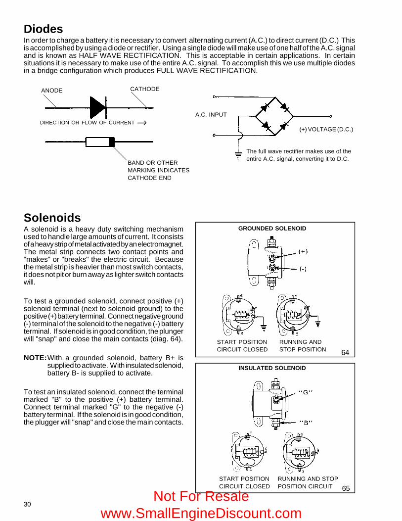
DiodesIn order to charge a battery it is necessary to convert alternating current (A.C.) to direct current (D.C.) Thisis accomplished by using a diode or rectifier. Using a single diode will make use of one half of the A.C. signaland is known as HALF WAVE RECTIFICATION. This is acceptable in certain applications. In certainsituations it is necessary to make use of the entire A.C. signal. To accomplish this we use multiple diodesin a bridge configuration which produces FULL WAVE RECTIFICATION.
SolenoidsA solenoid is a heavy duty switching mechanismused to handle large amounts of current. It consistsof a heavy strip of metal activated by an electromagnet.The metal strip connects two contact points and"makes" or "breaks" the electric circuit. Becausethe metal strip is heavier than most switch contacts,it does not pit or burn away as lighter switch contactswill.
To test a grounded solenoid, connect positive (+)solenoid terminal (next to solenoid ground) to thepositive (+) battery terminal. Connect negative ground(-) terminal of the solenoid to the negative (-) batteryterminal. If solenoid is in good condition, the plungerwill "snap" and close the main contacts (diag. 64).
NOTE:With a grounded solenoid, battery B+ issupplied to activate. With insulated solenoid,battery B- is supplied to activate.
To test an insulated solenoid, connect the terminalmarked "B" to the positive (+) battery terminal.Connect terminal marked "G" to the negative (-)battery terminal. If the solenoid is in good condition,the plugger will "snap" and close the main contacts.
ANODE CATHODE
BAND OR OTHERMARKING INDICATESCATHODE END
A.C. INPUT
(+) VOLTAGE (D.C.)
The full wave rectifier makes use of theentire A.C. signal, converting it to D.C.
DIRECTION OR FLOW OF CURRENT
Not For Resale www.SmallEngineDiscount.com
31
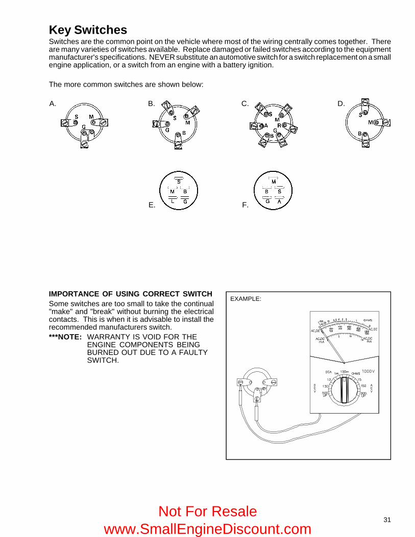
Key SwitchesSwitches are the common point on the vehicle where most of the wiring centrally comes together. Thereare many varieties of switches available. Replace damaged or failed switches according to the equipmentmanufacturer's specifications. NEVER substitute an automotive switch for a switch replacement on a smallengine application, or a switch from an engine with a battery ignition.
The more common switches are shown below:
IMPORTANCE OF USING CORRECT SWITCHSome switches are too small to take the continual"make" and "break" without burning the electricalcontacts. This is when it is advisable to install therecommended manufacturers switch.***NOTE: WARRANTY IS VOID FOR THE
ENGINE COMPONENTS BEINGBURNED OUT DUE TO A FAULTYSWITCH.
EXAMPLE:
E. F.
A. B. C. D.
Not For Resale www.SmallEngineDiscount.com
32
Con
tinui
ty w
/ ke
yin
sta
rt po
sitio
nC
ontin
uity
w /
key
in o
ff po
sitio
nN
O C
ontin
uity
inan
y ke
y po
sitio
nC
ontin
uity
w /
key
in ru
n po
sitio
n
Con
tinui
ty w
/ ke
yin
sta
rt po
sitio
nC
ontin
uity
w /
key
in o
ff po
sitio
nN
O C
ontin
uity
inan
y ke
y po
sitio
nC
ontin
uity
w /
key
in ru
n po
sitio
n
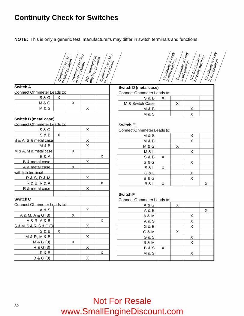
Continuity Check for Switches
NOTE: This is only a generic test, manufacturer's may differ in switch terminals and functions.
Switch D (metal case)Connect Ohmmeter Leads to:
S & B XM & Switch Case X
M & B XM & S X
Switch EConnect Ohmmeter Leads to:
M & S XM & B XM & G XM & L XS & B XS & G XS & L XG & L XB & G XB & L X X
Switch FConnect Ohmmeter Leads to:
A & G XA & B XA & M XA & S XG & B XG & M XG & S XB & M XB & S XM & S X
Switch AConnect Ohmmeter Leads to:
S & G XM & G XM & S X
Switch B (metal case)Connect Ohmmeter Leads to:
S & G XS & B X
S & A, S & metal case XM & B X
M & A, M & metal case XB & A X
B & metal case XA & metal case X
with 5th terminalR & S, R & M XR & B, R & A X
R & metal case X
Switch CConnect Ohmmeter Leads to:
A & S XA & M, A & G (3) X
A & R, A & B XS & M, S & R, S & G (3) X
S & B XM & R, M & B X
M & G (3) XR & G (3) X
R & B XB & G (3) X
Not For Resale www.SmallEngineDiscount.com
33
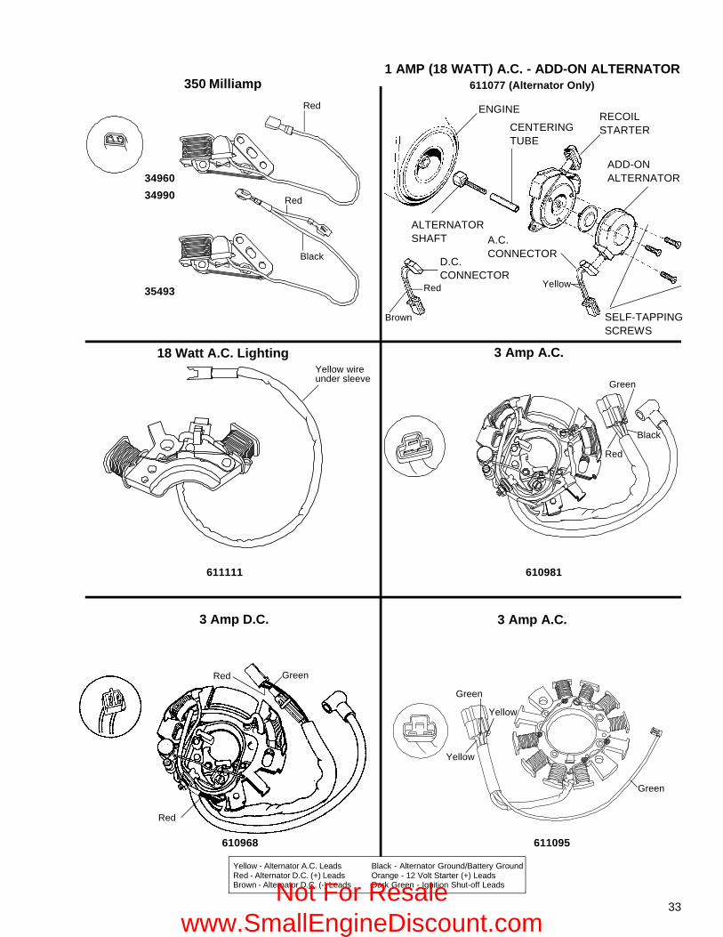
35493
611111
34960
34990
3 Amp A.C.
610981
3 Amp A.C.
611095
ENGINE
ALTERNATORSHAFT
CENTERINGTUBE
RECOILSTARTER
ADD-ONALTERNATOR
SELF-TAPPINGSCREWS
A.C.CONNECTOR
D.C.CONNECTOR
1 AMP (18 WATT) A.C. - ADD-ON ALTERNATOR611077 (Alternator Only)350 Milliamp
18 Watt A.C. Lighting
Red
Red
Black
Red
Brown
Yellow
Red
Green
Black
Yellow
Green
Green
610968
Red Green
3 Amp D.C.
Yellow wireunder sleeve
Red
Yellow
Yellow - Alternator A.C. LeadsRed - Alternator D.C. (+) LeadsBrown - Alternator D.C. (-) Leads
Black - Alternator Ground/Battery GroundOrange - 12 Volt Starter (+) LeadsDark Green - Ignition Shut-off LeadsNot For Resale
www.SmallEngineDiscount.com
34
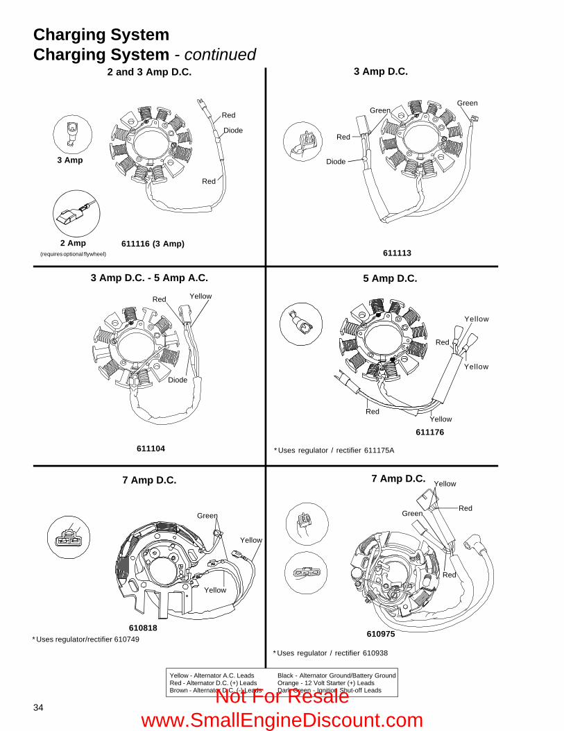
2 and 3 Amp D.C.
611116 (3 Amp)
3 Amp D.C. - 5 Amp A.C.
7 Amp D.C.
610818* Uses regulator/rectifier 610749
7 Amp D.C.
3 Amp D.C.
611113
5 Amp D.C.
* Uses regulator / rectifier 611175A
610975
* Uses regulator / rectifier 610938
Red
Diode
Red
Red
Diode
GreenGreen
Red
Yellow
RedYellow
611176
Yellow
Yellow
Green
Red
Green
Yellow
Red
Red Yellow
Diode
611104
Yellow
3 Amp
2 Amp(requires optional flywheel)
Yellow - Alternator A.C. LeadsRed - Alternator D.C. (+) LeadsBrown - Alternator D.C. (-) Leads
Black - Alternator Ground/Battery GroundOrange - 12 Volt Starter (+) LeadsDark Green - Ignition Shut-off Leads
Charging SystemCharging System - continued
Not For Resale www.SmallEngineDiscount.com
35
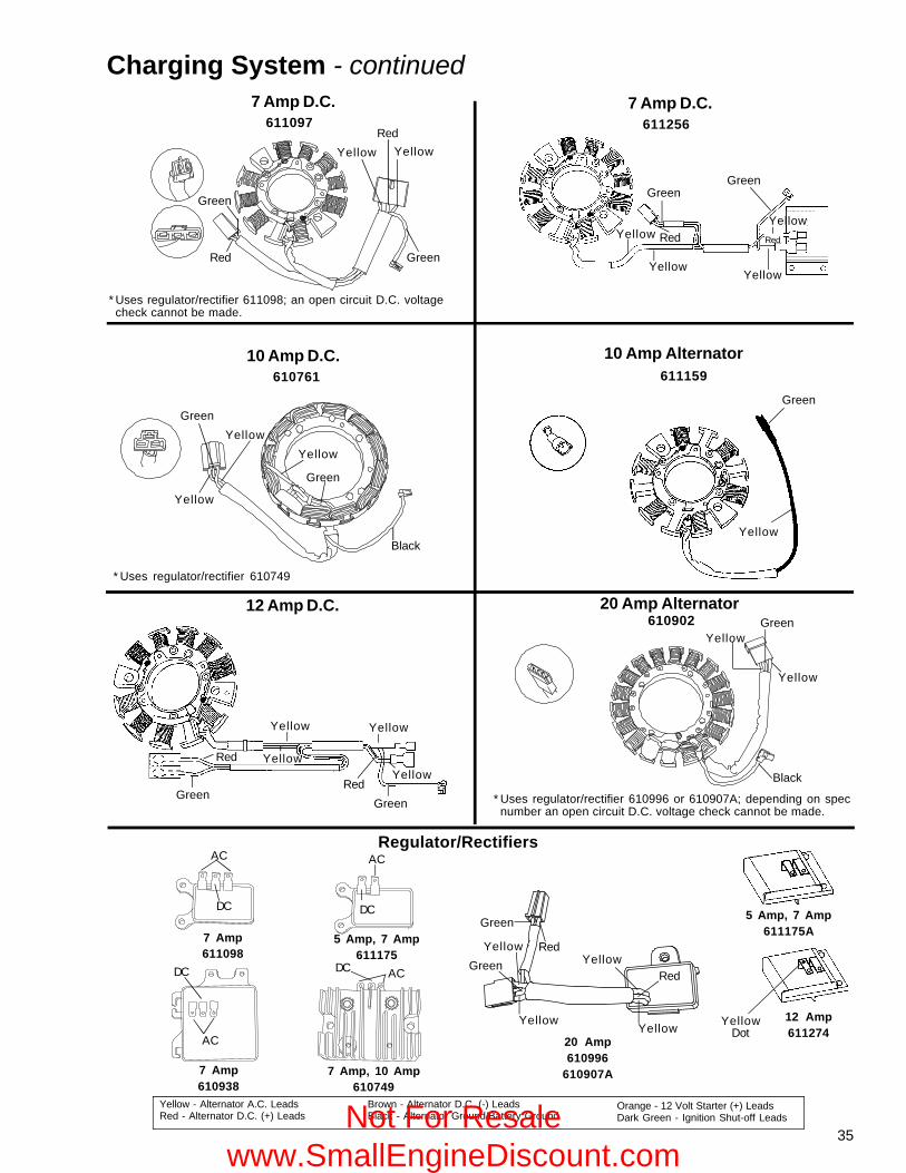
* Uses regulator/rectifier 610749
10 Amp Alternator
20 Amp Alternator
* Uses regulator/rectifier 610996 or 610907A; depending on specnumber an open circuit D.C. voltage check cannot be made.
610902
611097
* Uses regulator/rectifier 611098; an open circuit D.C. voltagecheck cannot be made.
7 Amp D.C.
Charging System - continued
Red
Green
YellowRed
Yellow
Green
YellowGreen
Yellow
Black
611159
Yellow
Green
10 Amp D.C.610761
Yellow
GreenYellow
Black
Yellow
Green
611256
7 Amp D.C.
Red
Green
YellowRedYellow
Green
YellowYellow
Regulator/Rectifiers
7 Amp610938
YellowRed
YellowYellow
GreenYellow
Green
Red
AC
DC DC
AC
DC
AC
DC AC
Yellow - Alternator A.C. LeadsRed - Alternator D.C. (+) Leads
Brown - Alternator D.C. (-) LeadsBlack - Alternator Ground/Battery Ground
Orange - 12 Volt Starter (+) LeadsDark Green - Ignition Shut-off Leads
7 Amp611098
5 Amp, 7 Amp611175
7 Amp, 10 Amp610749
20 Amp610996
610907A
12 Amp D.C.
12 Amp611274
5 Amp, 7 Amp611175A
Green
Yellow
Green
Yellow
Red
Red Yellow
Yellow
YellowDot
Not For Resale www.SmallEngineDiscount.com
36
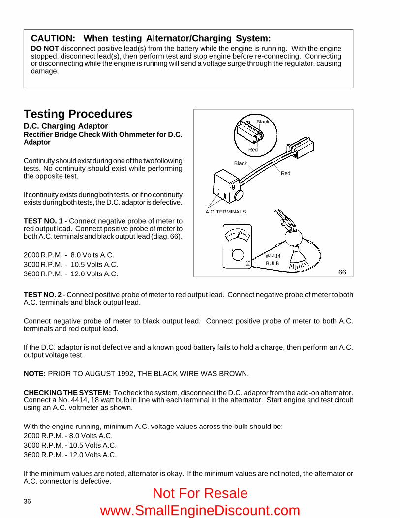
Testing ProceduresD.C. Charging AdaptorRectifier Bridge Check With Ohmmeter for D.C.Adaptor
Continuity should exist during one of the two followingtests. No continuity should exist while performingthe opposite test.
If continuity exists during both tests, or if no continuityexists during both tests, the D.C. adaptor is defective.
TEST NO. 1 - Connect negative probe of meter tored output lead. Connect positive probe of meter toboth A.C. terminals and black output lead (diag. 66).
2000 R.P.M. - 8.0 Volts A.C.3000 R.P.M. - 10.5 Volts A.C.3600 R.P.M. - 12.0 Volts A.C.
CAUTION: When testing Alternator/Charging System:DO NOT disconnect positive lead(s) from the battery while the engine is running. With the enginestopped, disconnect lead(s), then perform test and stop engine before re-connecting. Connectingor disconnecting while the engine is running will send a voltage surge through the regulator, causingdamage.
TEST NO. 2 - Connect positive probe of meter to red output lead. Connect negative probe of meter to bothA.C. terminals and black output lead.
Connect negative probe of meter to black output lead. Connect positive probe of meter to both A.C.terminals and red output lead.
If the D.C. adaptor is not defective and a known good battery fails to hold a charge, then perform an A.C.output voltage test.
NOTE: PRIOR TO AUGUST 1992, THE BLACK WIRE WAS BROWN.
CHECKING THE SYSTEM: To check the system, disconnect the D.C. adaptor from the add-on alternator.Connect a No. 4414, 18 watt bulb in line with each terminal in the alternator. Start engine and test circuitusing an A.C. voltmeter as shown.
With the engine running, minimum A.C. voltage values across the bulb should be:2000 R.P.M. - 8.0 Volts A.C.3000 R.P.M. - 10.5 Volts A.C.3600 R.P.M. - 12.0 Volts A.C.
If the minimum values are noted, alternator is okay. If the minimum values are not noted, the alternator orA.C. connector is defective.
66
Red
Black
A.C. TERMINALS
Red
Black
#4414BULB
Not For Resale www.SmallEngineDiscount.com
37
BATTERY GROUND (BLACK) ELECTRIC STARTERLEAD (ORANGE)
BLACKRED
(-) ENGINE GROUND
(+) POSITIVE LEAD
MAGNETO GROUND(GREEN) D.C. OUTPUT
LEAD (RED)
67
YELLOW
#4414 BULB
ENGINE
68
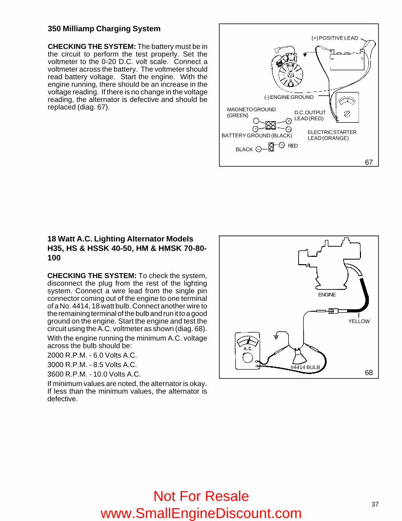
350 Milliamp Charging System
CHECKING THE SYSTEM: The battery must be inthe circuit to perform the test properly. Set thevoltmeter to the 0-20 D.C. volt scale. Connect avoltmeter across the battery. The voltmeter shouldread battery voltage. Start the engine. With theengine running, there should be an increase in thevoltage reading. If there is no change in the voltagereading, the alternator is defective and should bereplaced (diag. 67).
18 Watt A.C. Lighting Alternator ModelsH35, HS & HSSK 40-50, HM & HMSK 70-80-100
CHECKING THE SYSTEM: To check the system,disconnect the plug from the rest of the lightingsystem. Connect a wire lead from the single pinconnector coming out of the engine to one terminalof a No. 4414, 18 watt bulb. Connect another wire tothe remaining terminal of the bulb and run it to a goodground on the engine. Start the engine and test thecircuit using the A.C. voltmeter as shown (diag. 68).With the engine running the minimum A.C. voltageacross the bulb should be:2000 R.P.M. - 6.0 Volts A.C.3000 R.P.M. - 8.5 Volts A.C.3600 R.P.M. - 10.0 Volts A.C.If minimum values are noted, the alternator is okay.If less than the minimum values, the alternator isdefective.
Not For Resale www.SmallEngineDiscount.com
38
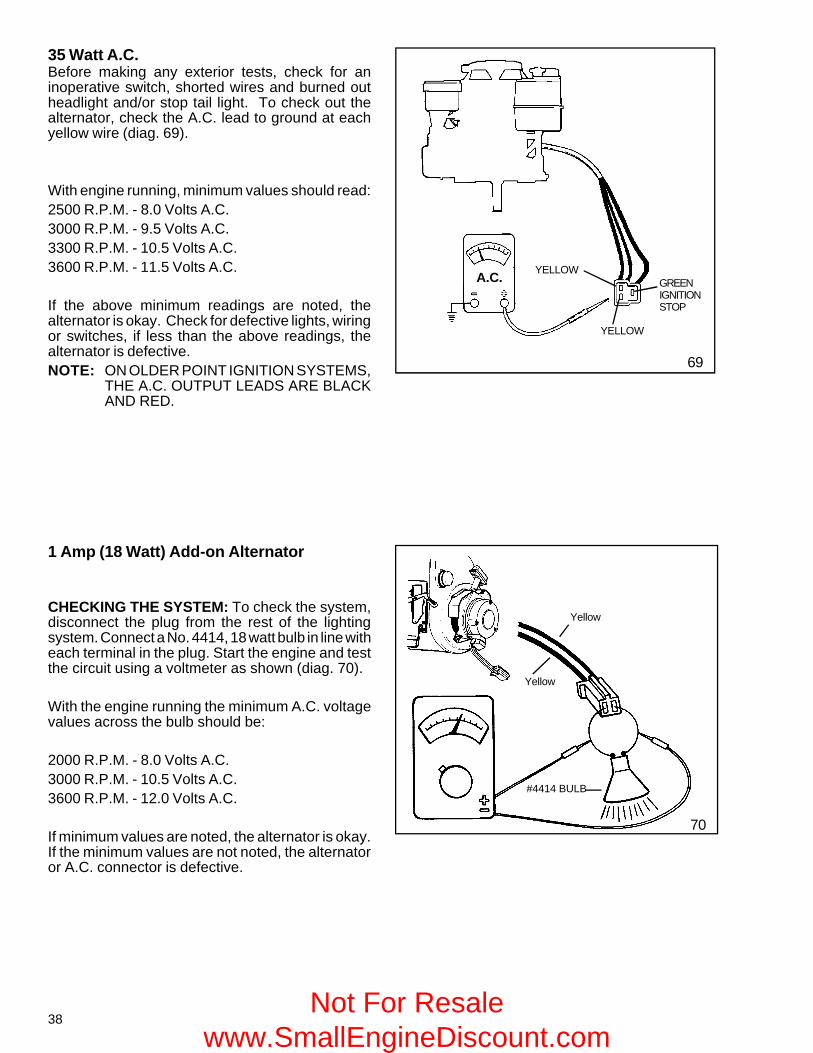
35 Watt A.C.Before making any exterior tests, check for aninoperative switch, shorted wires and burned outheadlight and/or stop tail light. To check out thealternator, check the A.C. lead to ground at eachyellow wire (diag. 69).
With engine running, minimum values should read:2500 R.P.M. - 8.0 Volts A.C.3000 R.P.M. - 9.5 Volts A.C.3300 R.P.M. - 10.5 Volts A.C.3600 R.P.M. - 11.5 Volts A.C.
If the above minimum readings are noted, thealternator is okay. Check for defective lights, wiringor switches, if less than the above readings, thealternator is defective.NOTE: ON OLDER POINT IGNITION SYSTEMS,
THE A.C. OUTPUT LEADS ARE BLACKAND RED.
YELLOW
YELLOWA.C. GREEN
IGNITIONSTOP
69
#4414 BULB
Yellow
Yellow
1 Amp (18 Watt) Add-on Alternator
CHECKING THE SYSTEM: To check the system,disconnect the plug from the rest of the lightingsystem. Connect a No. 4414, 18 watt bulb in line witheach terminal in the plug. Start the engine and testthe circuit using a voltmeter as shown (diag. 70).
With the engine running the minimum A.C. voltagevalues across the bulb should be:
2000 R.P.M. - 8.0 Volts A.C.3000 R.P.M. - 10.5 Volts A.C.3600 R.P.M. - 12.0 Volts A.C.
If minimum values are noted, the alternator is okay.If the minimum values are not noted, the alternatoror A.C. connector is defective.
70
Not For Resale www.SmallEngineDiscount.com
39
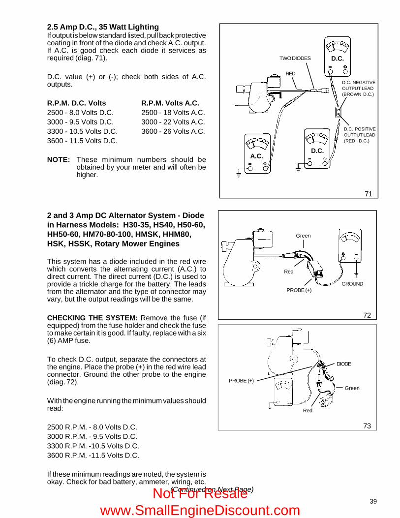
2.5 Amp D.C., 35 Watt LightingIf output is below standard listed, pull back protectivecoating in front of the diode and check A.C. output.If A.C. is good check each diode it services asrequired (diag. 71).
D.C. value (+) or (-); check both sides of A.C.outputs.
R.P.M. D.C. Volts R.P.M. Volts A.C.2500 - 8.0 Volts D.C. 2500 - 18 Volts A.C.3000 - 9.5 Volts D.C. 3000 - 22 Volts A.C.3300 - 10.5 Volts D.C. 3600 - 26 Volts A.C.3600 - 11.5 Volts D.C.
NOTE: These minimum numbers should beobtained by your meter and will often behigher.
D.C.TWO DIODES
REDD.C. NEGATIVEOUTPUT LEAD(BROWN D.C.)
D.C. POSITIVEOUTPUT LEAD(RED D.C.)
A.C.D.C.
71
2 and 3 Amp DC Alternator System - Diodein Harness Models: H30-35, HS40, H50-60,HH50-60, HM70-80-100, HMSK, HHM80,HSK, HSSK, Rotary Mower Engines
This system has a diode included in the red wirewhich converts the alternating current (A.C.) todirect current. The direct current (D.C.) is used toprovide a trickle charge for the battery. The leadsfrom the alternator and the type of connector mayvary, but the output readings will be the same.
CHECKING THE SYSTEM: Remove the fuse (ifequipped) from the fuse holder and check the fuseto make certain it is good. If faulty, replace with a six(6) AMP fuse.
To check D.C. output, separate the connectors atthe engine. Place the probe (+) in the red wire leadconnector. Ground the other probe to the engine(diag. 72).
With the engine running the minimum values shouldread:
2500 R.P.M. - 8.0 Volts D.C.3000 R.P.M. - 9.5 Volts D.C.3300 R.P.M. -10.5 Volts D.C.3600 R.P.M. -11.5 Volts D.C.
If these minimum readings are noted, the system isokay. Check for bad battery, ammeter, wiring, etc.
73
Red
Green
GROUNDPROBE (+)
Red
Green
DIODE
PROBE (+)
72
(Continued on Next Page)Not For Resale www.SmallEngineDiscount.com
40
If less than the above readings, proceed in making an A.C. output check by pulling back the protectivecoating from the fuse holder and diode. Using an A.C. voltmeter, check voltage from a point between theengine and the diode as shown in the diagram (diag. 73).With the engine running the minimum values should read:
2500 R.P.M. - 18.0 Volts A.C.3000 R.P.M. - 22.0 Volts A.C.3300 R.P.M. - 24.0 Volts A.C.3600 R.P.M. - 26.0 Volts A.C.
If low or no voltage is experienced, replace the alternator. If the alternator puts out the minimum A.C. voltage,replace the diode.
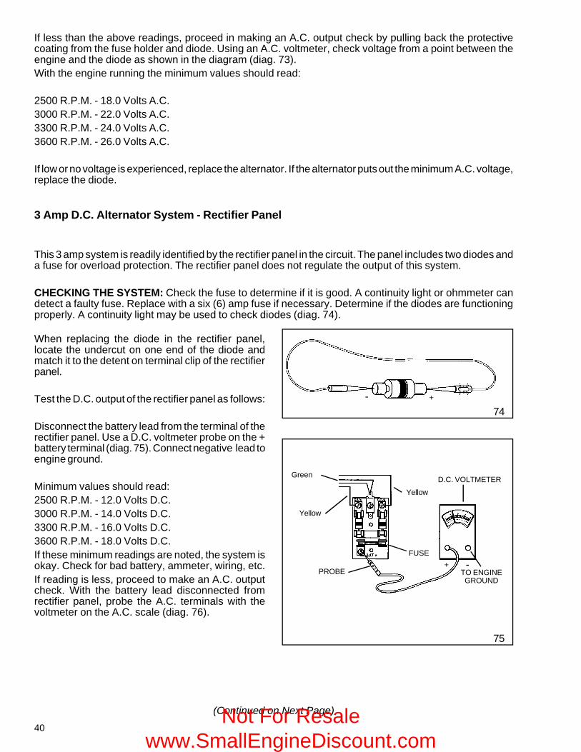
When replacing the diode in the rectifier panel,locate the undercut on one end of the diode andmatch it to the detent on terminal clip of the rectifierpanel.
Test the D.C. output of the rectifier panel as follows:
Disconnect the battery lead from the terminal of therectifier panel. Use a D.C. voltmeter probe on the +battery terminal (diag. 75). Connect negative lead toengine ground.
Minimum values should read:2500 R.P.M. - 12.0 Volts D.C.3000 R.P.M. - 14.0 Volts D.C.3300 R.P.M. - 16.0 Volts D.C.3600 R.P.M. - 18.0 Volts D.C.If these minimum readings are noted, the system isokay. Check for bad battery, ammeter, wiring, etc.If reading is less, proceed to make an A.C. outputcheck. With the battery lead disconnected fromrectifier panel, probe the A.C. terminals with thevoltmeter on the A.C. scale (diag. 76).
74
75
+-
+ -TO ENGINEGROUND
FUSE
PROBE
D.C. VOLTMETERGreen
Yellow
Yellow
3 Amp D.C. Alternator System - Rectifier Panel
This 3 amp system is readily identified by the rectifier panel in the circuit. The panel includes two diodes anda fuse for overload protection. The rectifier panel does not regulate the output of this system.
CHECKING THE SYSTEM: Check the fuse to determine if it is good. A continuity light or ohmmeter candetect a faulty fuse. Replace with a six (6) amp fuse if necessary. Determine if the diodes are functioningproperly. A continuity light may be used to check diodes (diag. 74).
(Continued on Next Page)Not For Resale www.SmallEngineDiscount.com
41
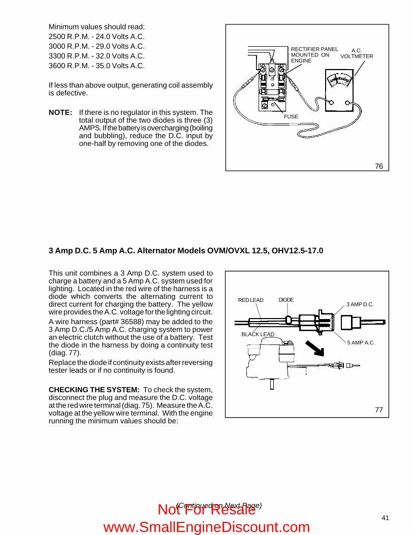
Minimum values should read:2500 R.P.M. - 24.0 Volts A.C.3000 R.P.M. - 29.0 Volts A.C.3300 R.P.M. - 32.0 Volts A.C.3600 R.P.M. - 35.0 Volts A.C.
If less than above output, generating coil assemblyis defective.
NOTE: If there is no regulator in this system. Thetotal output of the two diodes is three (3)AMPS. If the battery is overcharging (boilingand bubbling), reduce the D.C. input byone-half by removing one of the diodes.
76
RECTIFIER PANELMOUNTED ONENGINE
A.C.VOLTMETER
FUSE
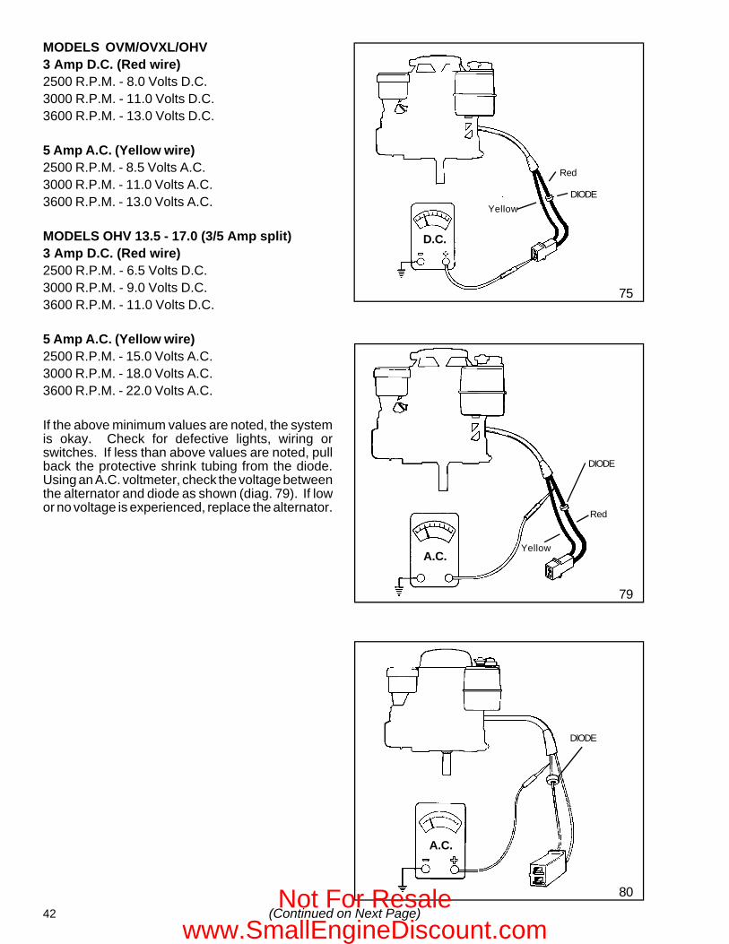
3 Amp D.C. 5 Amp A.C. Alternator Models OVM/OVXL 12.5, OHV12.5-17.0
This unit combines a 3 Amp D.C. system used tocharge a battery and a 5 Amp A.C. system used forlighting. Located in the red wire of the harness is adiode which converts the alternating current todirect current for charging the battery. The yellowwire provides the A.C. voltage for the lighting circuit.A wire harness (part# 36588) may be added to the3 Amp D.C./5 Amp A.C. charging system to poweran electric clutch without the use of a battery. Testthe diode in the harness by doing a continuity test(diag. 77).Replace the diode if continuity exists after reversingtester leads or if no continuity is found.
CHECKING THE SYSTEM: To check the system,disconnect the plug and measure the D.C. voltageat the red wire terminal (diag. 75). Measure the A.C.voltage at the yellow wire terminal. With the enginerunning the minimum values should be:
77
5 AMP A.C.
3 AMP D.C.RED LEAD DIODE
BLACK LEAD
(Continued on Next Page)Not For Resale www.SmallEngineDiscount.com
42
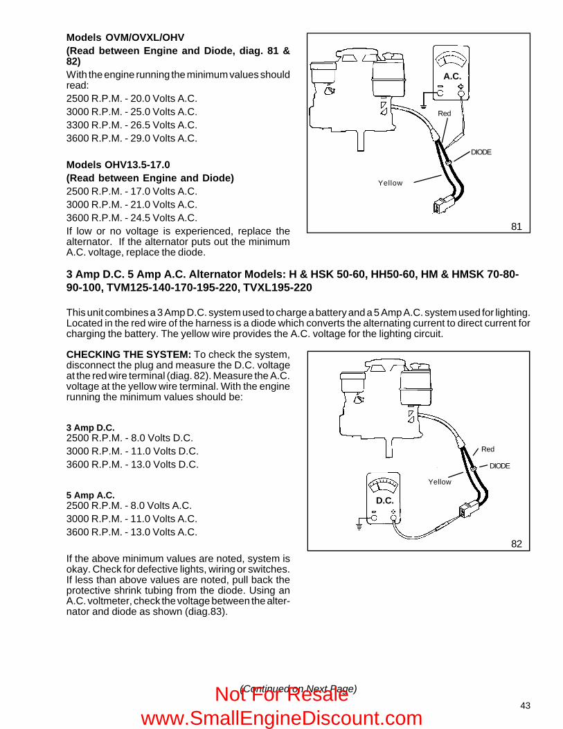
MODELS OVM/OVXL/OHV3 Amp D.C. (Red wire)2500 R.P.M. - 8.0 Volts D.C.3000 R.P.M. - 11.0 Volts D.C.3600 R.P.M. - 13.0 Volts D.C.
5 Amp A.C. (Yellow wire)2500 R.P.M. - 8.5 Volts A.C.3000 R.P.M. - 11.0 Volts A.C.3600 R.P.M. - 13.0 Volts A.C.
MODELS OHV 13.5 - 17.0 (3/5 Amp split)3 Amp D.C. (Red wire)2500 R.P.M. - 6.5 Volts D.C.3000 R.P.M. - 9.0 Volts D.C.3600 R.P.M. - 11.0 Volts D.C.
5 Amp A.C. (Yellow wire)2500 R.P.M. - 15.0 Volts A.C.3000 R.P.M. - 18.0 Volts A.C.3600 R.P.M. - 22.0 Volts A.C.
If the above minimum values are noted, the systemis okay. Check for defective lights, wiring orswitches. If less than above values are noted, pullback the protective shrink tubing from the diode.Using an A.C. voltmeter, check the voltage betweenthe alternator and diode as shown (diag. 79). If lowor no voltage is experienced, replace the alternator.
75
80
79
DIODE
Red
D.C.D.C.
Yellow
Red
A.C.A.C.
DIODE
A.C.
DIODE
Yellow
(Continued on Next Page)Not For Resale
www.SmallEngineDiscount.com
43
81
Yellow
Red
DIODE
A.C.
DIODE
Red
D.C.D.C.
82
Yellow
Models OVM/OVXL/OHV(Read between Engine and Diode, diag. 81 &82)With the engine running the minimum values shouldread:2500 R.P.M. - 20.0 Volts A.C.3000 R.P.M. - 25.0 Volts A.C.3300 R.P.M. - 26.5 Volts A.C.3600 R.P.M. - 29.0 Volts A.C.
Models OHV13.5-17.0(Read between Engine and Diode)2500 R.P.M. - 17.0 Volts A.C.3000 R.P.M. - 21.0 Volts A.C.3600 R.P.M. - 24.5 Volts A.C.If low or no voltage is experienced, replace thealternator. If the alternator puts out the minimumA.C. voltage, replace the diode.
3 Amp D.C. 5 Amp A.C. Alternator Models: H & HSK 50-60, HH50-60, HM & HMSK 70-80-90-100, TVM125-140-170-195-220, TVXL195-220
This unit combines a 3 Amp D.C. system used to charge a battery and a 5 Amp A.C. system used for lighting.Located in the red wire of the harness is a diode which converts the alternating current to direct current forcharging the battery. The yellow wire provides the A.C. voltage for the lighting circuit.
CHECKING THE SYSTEM: To check the system,disconnect the plug and measure the D.C. voltageat the red wire terminal (diag. 82). Measure the A.C.voltage at the yellow wire terminal. With the enginerunning the minimum values should be:
3 Amp D.C.2500 R.P.M. - 8.0 Volts D.C.3000 R.P.M. - 11.0 Volts D.C.3600 R.P.M. - 13.0 Volts D.C.
5 Amp A.C.2500 R.P.M. - 8.0 Volts A.C.3000 R.P.M. - 11.0 Volts A.C.3600 R.P.M. - 13.0 Volts A.C.
If the above minimum values are noted, system isokay. Check for defective lights, wiring or switches.If less than above values are noted, pull back theprotective shrink tubing from the diode. Using anA.C. voltmeter, check the voltage between the alter-nator and diode as shown (diag.83).
(Continued on Next Page)Not For Resale www.SmallEngineDiscount.com
44
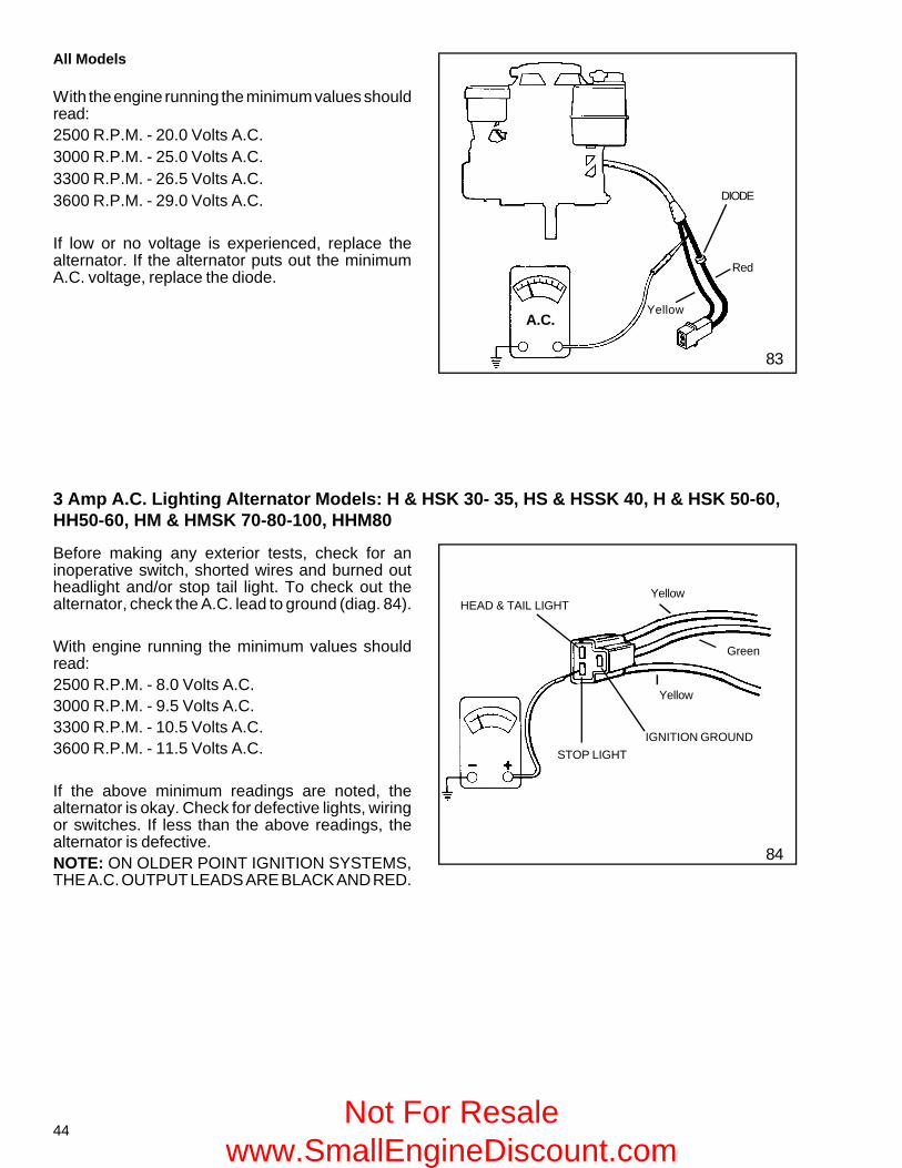
All Models
With the engine running the minimum values shouldread:2500 R.P.M. - 20.0 Volts A.C.3000 R.P.M. - 25.0 Volts A.C.3300 R.P.M. - 26.5 Volts A.C.3600 R.P.M. - 29.0 Volts A.C.
If low or no voltage is experienced, replace thealternator. If the alternator puts out the minimumA.C. voltage, replace the diode.
Yellow
Red
A.C.
DIODE
A.C.
83
3 Amp A.C. Lighting Alternator Models: H & HSK 30- 35, HS & HSSK 40, H & HSK 50-60,HH50-60, HM & HMSK 70-80-100, HHM80
84
Yellow
Green
YellowHEAD & TAIL LIGHT
IGNITION GROUND
STOP LIGHT
Before making any exterior tests, check for aninoperative switch, shorted wires and burned outheadlight and/or stop tail light. To check out thealternator, check the A.C. lead to ground (diag. 84).
With engine running the minimum values shouldread:2500 R.P.M. - 8.0 Volts A.C.3000 R.P.M. - 9.5 Volts A.C.3300 R.P.M. - 10.5 Volts A.C.3600 R.P.M. - 11.5 Volts A.C.
If the above minimum readings are noted, thealternator is okay. Check for defective lights, wiringor switches. If less than the above readings, thealternator is defective.NOTE: ON OLDER POINT IGNITION SYSTEMS,THE A.C. OUTPUT LEADS ARE BLACK AND RED.
Not For Resale www.SmallEngineDiscount.com
45
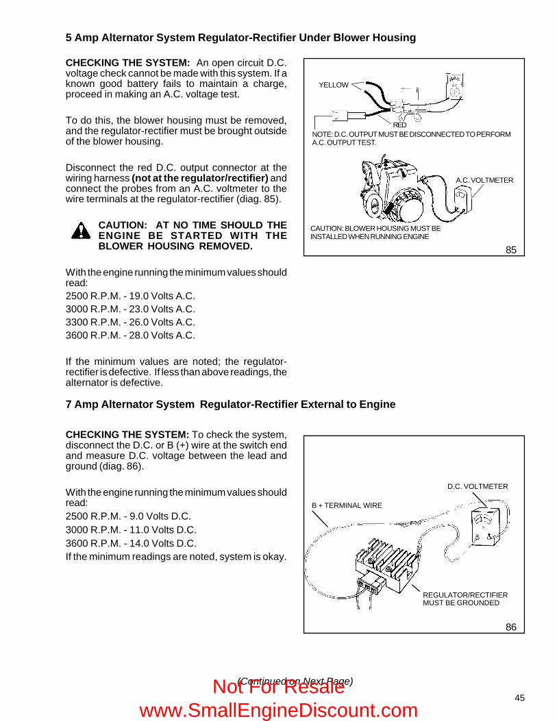
5 Amp Alternator System Regulator-Rectifier Under Blower Housing
CHECKING THE SYSTEM: An open circuit D.C.voltage check cannot be made with this system. If aknown good battery fails to maintain a charge,proceed in making an A.C. voltage test.
To do this, the blower housing must be removed,and the regulator-rectifier must be brought outsideof the blower housing.
Disconnect the red D.C. output connector at thewiring harness (not at the regulator/rectifier) andconnect the probes from an A.C. voltmeter to thewire terminals at the regulator-rectifier (diag. 85).
CAUTION: AT NO TIME SHOULD THEENGINE BE STARTED WITH THEBLOWER HOUSING REMOVED.
With the engine running the minimum values shouldread:2500 R.P.M. - 19.0 Volts A.C.3000 R.P.M. - 23.0 Volts A.C.3300 R.P.M. - 26.0 Volts A.C.3600 R.P.M. - 28.0 Volts A.C.
If the minimum values are noted; the regulator-rectifier is defective. If less than above readings, thealternator is defective.
85
CHECKING THE SYSTEM: To check the system,disconnect the D.C. or B (+) wire at the switch endand measure D.C. voltage between the lead andground (diag. 86).
With the engine running the minimum values shouldread:2500 R.P.M. - 9.0 Volts D.C.3000 R.P.M. - 11.0 Volts D.C.3600 R.P.M. - 14.0 Volts D.C.If the minimum readings are noted, system is okay.
7 Amp Alternator System Regulator-Rectifier External to Engine
86
REGULATOR/RECTIFIERMUST BE GROUNDED
D.C. VOLTMETER
B + TERMINAL WIRE
(Continued on Next Page)
CAUTION: BLOWER HOUSING MUST BEINSTALLED WHEN RUNNING ENGINE
A.C. VOLTMETER
YELLOW
REDNOTE: D.C. OUTPUT MUST BE DISCONNECTED TO PERFORMA.C. OUTPUT TEST.
Not For Resale www.SmallEngineDiscount.com
46
Check for a defective ammeter, wiring, etc. If lessthan the above readings, disconnect the plug fromthe regulator-rectifier, and insert the A.C. voltmeterprobes in the two outside terminals (diag. 87).
With the engine running the minimum values shouldread:2500 R.P.M. - 12.0 Volts A.C.3000 R.P.M. - 14.0 Volts A.C.3600 R.P.M. - 18.0 Volts A.C.
If the minimum readings are noted, the regulator-rectifier is defective. If less than the above readings,the alternator is defective.
A.C.
87
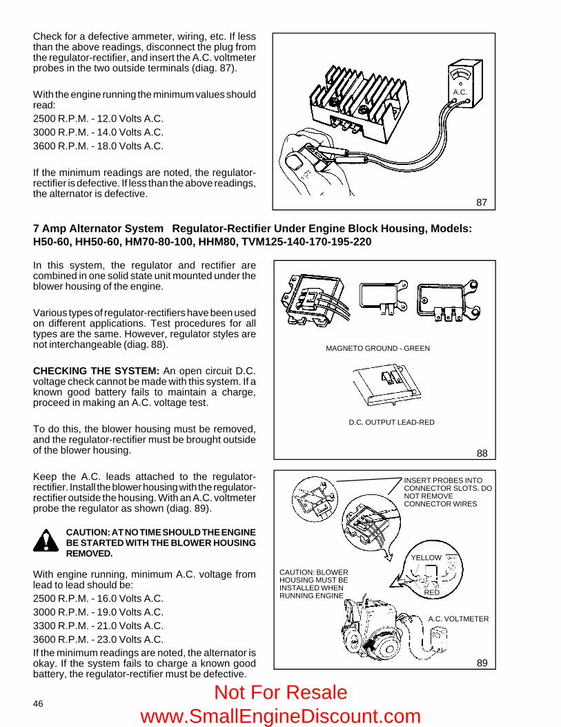
In this system, the regulator and rectifier arecombined in one solid state unit mounted under theblower housing of the engine.
Various types of regulator-rectifiers have been usedon different applications. Test procedures for alltypes are the same. However, regulator styles arenot interchangeable (diag. 88).
CHECKING THE SYSTEM: An open circuit D.C.voltage check cannot be made with this system. If aknown good battery fails to maintain a charge,proceed in making an A.C. voltage test.
To do this, the blower housing must be removed,and the regulator-rectifier must be brought outsideof the blower housing.
Keep the A.C. leads attached to the regulator-rectifier. Install the blower housing with the regulator-rectifier outside the housing. With an A.C. voltmeterprobe the regulator as shown (diag. 89).
CAUTION: AT NO TIME SHOULD THE ENGINEBE STARTED WITH THE BLOWER HOUSINGREMOVED.
With engine running, minimum A.C. voltage fromlead to lead should be:2500 R.P.M. - 16.0 Volts A.C.3000 R.P.M. - 19.0 Volts A.C.3300 R.P.M. - 21.0 Volts A.C.3600 R.P.M. - 23.0 Volts A.C.If the minimum readings are noted, the alternator isokay. If the system fails to charge a known goodbattery, the regulator-rectifier must be defective.
88
89
D.C. OUTPUT LEAD-RED
MAGNETO GROUND - GREEN
A.C. VOLTMETER
YELLOW
RED
INSERT PROBES INTOCONNECTOR SLOTS. DONOT REMOVECONNECTOR WIRES
CAUTION: BLOWERHOUSING MUST BEINSTALLED WHENRUNNING ENGINE
7 Amp Alternator System Regulator-Rectifier Under Engine Block Housing, Models:H50-60, HH50-60, HM70-80-100, HHM80, TVM125-140-170-195-220
Not For Resale www.SmallEngineDiscount.com
47
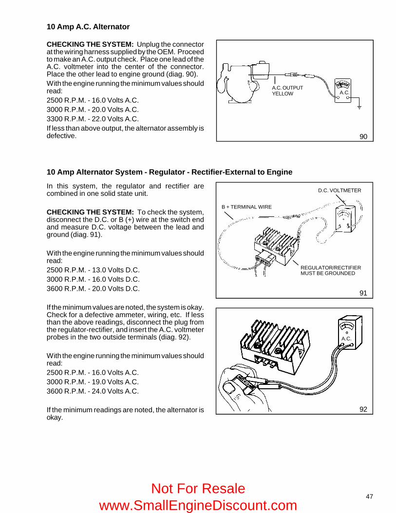
10 Amp A.C. Alternator
CHECKING THE SYSTEM: Unplug the connectorat the wiring harness supplied by the OEM. Proceedto make an A.C. output check. Place one lead of theA.C. voltmeter into the center of the connector.Place the other lead to engine ground (diag. 90).With the engine running the minimum values shouldread:2500 R.P.M. - 16.0 Volts A.C.3000 R.P.M. - 20.0 Volts A.C.3300 R.P.M. - 22.0 Volts A.C.If less than above output, the alternator assembly isdefective. 90
A.C. OUTPUTYELLOW A.C.
10 Amp Alternator System - Regulator - Rectifier-External to Engine
In this system, the regulator and rectifier arecombined in one solid state unit.
CHECKING THE SYSTEM: To check the system,disconnect the D.C. or B (+) wire at the switch endand measure D.C. voltage between the lead andground (diag. 91).
With the engine running the minimum values shouldread:2500 R.P.M. - 13.0 Volts D.C.3000 R.P.M. - 16.0 Volts D.C.3600 R.P.M. - 20.0 Volts D.C.
If the minimum values are noted, the system is okay.Check for a defective ammeter, wiring, etc. If lessthan the above readings, disconnect the plug fromthe regulator-rectifier, and insert the A.C. voltmeterprobes in the two outside terminals (diag. 92).
With the engine running the minimum values shouldread:2500 R.P.M. - 16.0 Volts A.C.3000 R.P.M. - 19.0 Volts A.C.3600 R.P.M. - 24.0 Volts A.C.
If the minimum readings are noted, the alternator isokay.
92
REGULATOR/RECTIFIERMUST BE GROUNDED
D.C. VOLTMETER
A.C.
B + TERMINAL WIRE
91
Not For Resale www.SmallEngineDiscount.com
48
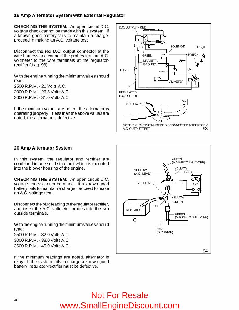
16 Amp Alternator System with External Regulator
D.C. OUTPUT - RED
SOLENOID
GREEN
LIGHT
SWITCH
AMMETER
MAGNETOGROUND
BATTERY
REGULATEDD.C. OUTPUT
FUSE
YELLOW
REDNOTE: D.C. OUTPUT MUST BE DISCONNECTED TO PERFORMA.C. OUTPUT TEST.
CHECKING THE SYSTEM: An open circuit D.C.voltage check cannot be made with this system. Ifa known good battery fails to maintain a charge,proceed in making an A.C. voltage test.
Disconnect the red D.C. output connector at thewire harness and connect the probes from an A.C.voltmeter to the wire terminals at the regulator-rectifier (diag. 93).
With the engine running the minimum values shouldread:2500 R.P.M. - 21 Volts A.C.3000 R.P.M. - 26.5 Volts A.C.3600 R.P.M. - 31.0 Volts A.C.
If the minimum values are noted, the alternator isoperating properly. If less than the above values arenoted, the alternator is defective.
93
20 Amp Alternator System
In this system, the regulator and rectifier arecombined in one solid state unit which is mountedinto the blower housing of the engine.
CHECKING THE SYSTEM: An open circuit D.C.voltage check cannot be made. If a known goodbattery fails to maintain a charge, proceed to makean A.C. voltage test.
Disconnect the plug leading to the regulator rectifier,and insert the A.C. voltmeter probes into the twooutside terminals.
With the engine running the minimum values shouldread:2500 R.P.M. - 32.0 Volts A.C.3000 R.P.M. - 38.0 Volts A.C.3600 R.P.M. - 45.0 Volts A.C.
If the minimum readings are noted, alternator isokay. If the system fails to charge a known goodbattery, regulator-rectifier must be defective.
94
YELLOW(A.C. LEAD)
GREEN(MAGNETO SHUT-OFF)
YELLOW(A.C. LEAD)
A.C.YELLOW
YELLOWGREEN
RED
GREEN(MAGNETO SHUT-OFF)
RED(D.C. WIRE)
RECT./REG.
Not For Resale www.SmallEngineDiscount.com
49
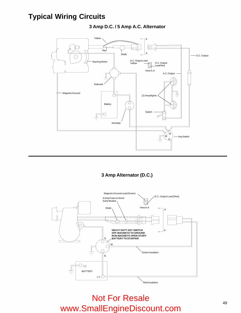
D.C. Output
(2) Headlights
Switch
A.C. Output LeadYellow D.C. Output
Lead Red
A.C. OutputView A-A
Key Switch
Ammeter
Battery
Magneto Ground
Starting Motor
Solenoid
Yellow
RedDiode
A
A
BM
S
Typical Wiring Circuits3 Amp D.C. / 5 Amp A.C. Alternator
3 Amp Alternator (D.C.)
Diode View A-A
Magneto Ground Lead (Green)D.C. Output Lead (Red)
A
AHEAVY DUTY KEY SWITCHOFF-MAGNETO TO GROUNDRUN-MAGNETO OPEN START-BATTERY TO STARTER
Green Insulation
Red Insulation
BATTERY
(+)
(-)
B.
M.
S.
6 Amp Fuse on SomeEarly Models
Not For Resale www.SmallEngineDiscount.com
50
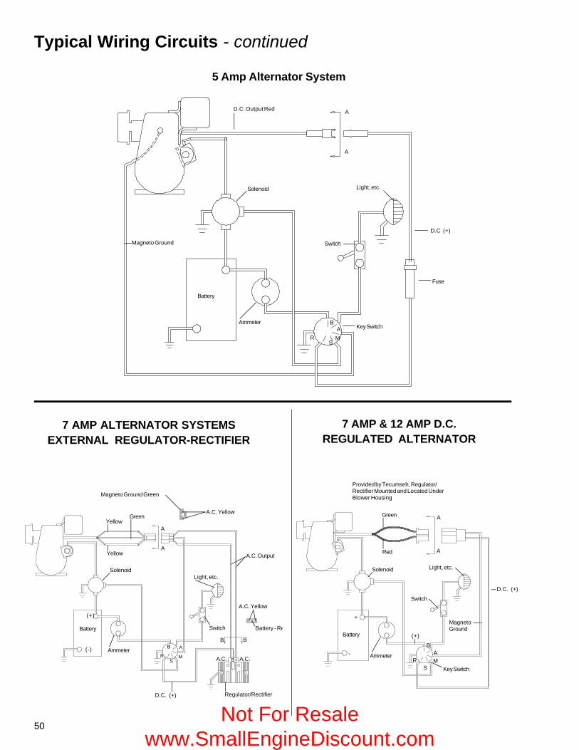
Typical Wiring Circuits - continued
7 AMP ALTERNATOR SYSTEMSEXTERNAL REGULATOR-RECTIFIER
5 Amp Alternator System
A
A
Switch
Light, etc.
D.C (+)
Fuse
MS
B
RA Key Switch
Ammeter
Battery
Magneto Ground
D.C. Output Red
Solenoid
Magneto Ground Green
A.C. Yellow
View A-A
A
AA.C. Output
Light, etc.
Switch
A.C. Yellow
B B
Battery - RedView B-B
A.C. A.C.B+
Regulator/RectifierD.C. (+)
B A
MS
RAmmeter
Battery
(-)
(+)
Solenoid
Yellow
YellowGreen
Provided by Tecumseh, Regulator/Rectifier Mounted and Located UnderBlower Housing
Green
Red
A
A
D.C. (+)
Light, etc.
Switch
MagnetoGround
Key Switch
A
SMR
B(+)
Ammeter
Battery
-
+
Solenoid
7 AMP & 12 AMP D.C.REGULATED ALTERNATOR
Not For Resale www.SmallEngineDiscount.com
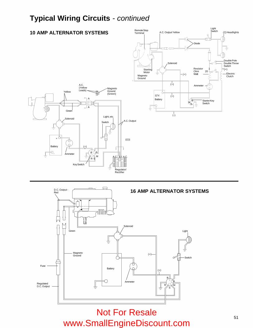
51
Typical Wiring Circuits - continued
D.C. Output -Red
Green
Fuse
RegulatedD.C. Output
MagnetoGround
Battery
AmmeterB
RS
MA
(+)
Switch
Light
(+)
Solenoid
16 AMP ALTERNATOR SYSTEMS
A.C. Output YellowRemote StopTerminal
Diode
LightSwitch (2) Headlights
Double PoleDouble ThrowSwitch(+)
ElectricClutch
Resistor 1Ohm 20Watt
Ammeter
Starter KeySwitch
BS
M
12 V.Battery
(-)
(+)
(+)
(+)
Solenoid
MagnetoGround
StartingMotor
Yellow
GreenA
A
MagnetoGround(Green)
A.C.(YellowLeads)
A.C. Output
Light, etc.
Switch
A.C. A.C.B+
Regulator/Rectifier
Key Switch
A
R SM
B
(+)
Ammeter
Battery
-
+
Solenoid
10 AMP ALTERNATOR SYSTEMS
Not For Resale www.SmallEngineDiscount.com
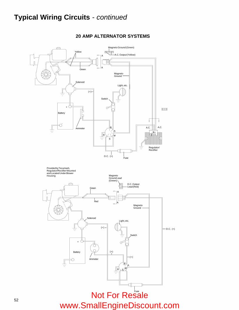
52
Typical Wiring Circuits - continued
20 AMP ALTERNATOR SYSTEMS
Yellow
Green
Magneto Ground (Green)
A.C. Output (Yellow)A
A
MagnetoGround
Light, etc.Solenoid
(+)
Switch
Battery
+
-
Ammeter
D.C. (+)Fuse
Regulator/Rectifier
B+
A.C. A.C.
RS
M
AB
View A-A
-
Provided by Tecumseh,Regulator/Rectifier Mountedand Located Under BlowerHousing
Green
Red
MagnetoGround Lead(Green)
D.C. OutputLead (Red)
A
A
Solenoid
MagnetoGround
Light, etc.
D.C. (+)(+)
+
Battery (+)
(+)
B
S
AMR
Fuse
Switch
Ammeter
Not For Resale www.SmallEngineDiscount.com
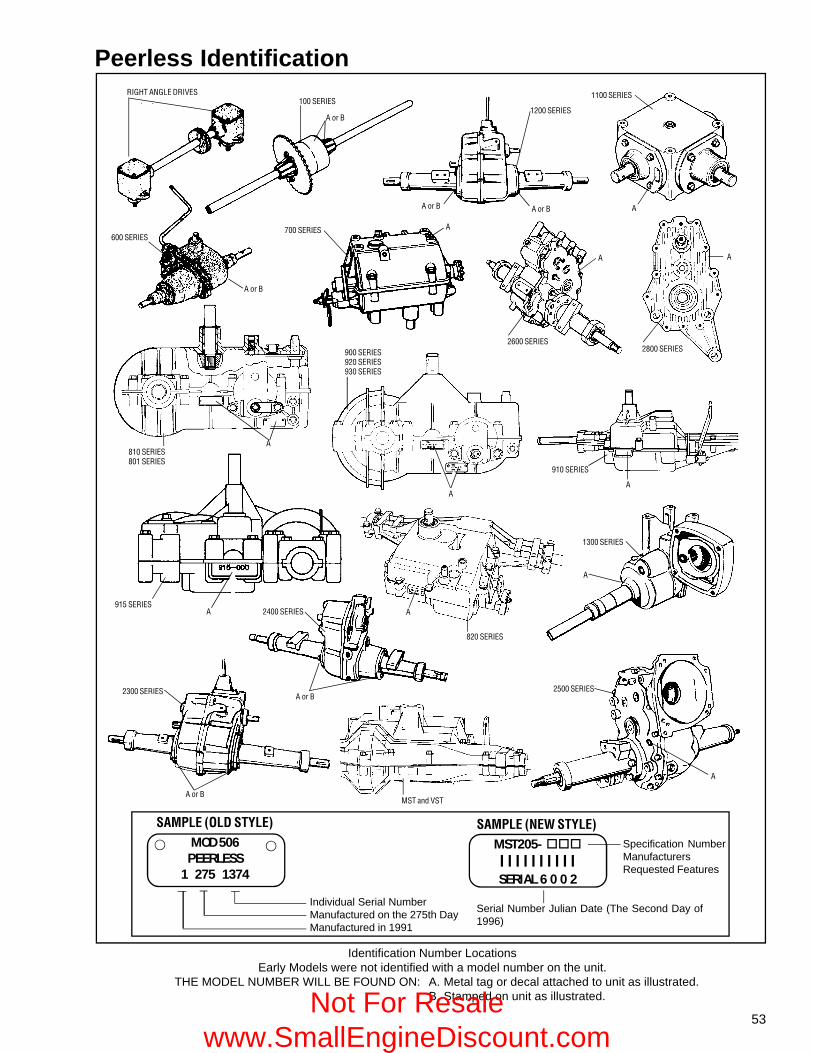
53
Identification Number LocationsEarly Models were not identified with a model number on the unit.
THE MODEL NUMBER WILL BE FOUND ON: A. Metal tag or decal attached to unit as illustrated.B. Stamped on unit as illustrated.
Peerless Identification
SAMPLE (OLD STYLE)MOD 506
PEERLESS1 275 1374
Individual Serial NumberManufactured on the 275th DayManufactured in 1991
SAMPLE (NEW STYLE)MST205- l l l l l l l l l lSERIAL 6 0 0 2
Serial Number Julian Date (The Second Day of1996)
Specification NumberManufacturersRequested Features
RIGHT ANGLE DRIVES100 SERIES
A or B
A or B A or B
1200 SERIES
1100 SERIES
600 SERIES
A or B
700 SERIES A
2600 SERIES
A
2800 SERIES
A
A
810 SERIES801 SERIES
900 SERIES920 SERIES930 SERIES
A
A
910 SERIES
A
1300 SERIES
A
820 SERIES
A915 SERIES
A 2400 SERIES
A or B2300 SERIES
A or BMST and VST
2500 SERIES
A
Not For Resale www.SmallEngineDiscount.com
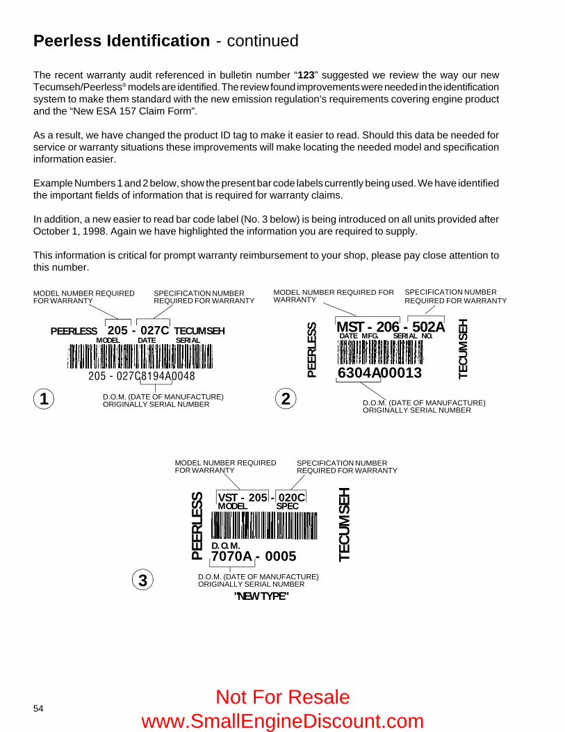
54
205 - 027C8194A0048
The recent warranty audit referenced in bulletin number “123” suggested we review the way our newTecumseh/Peerless® models are identified. The review found improvements were needed in the identificationsystem to make them standard with the new emission regulation’s requirements covering engine productand the “New ESA 157 Claim Form”.
As a result, we have changed the product ID tag to make it easier to read. Should this data be needed forservice or warranty situations these improvements will make locating the needed model and specificationinformation easier.
Example Numbers 1 and 2 below, show the present bar code labels currently being used. We have identifiedthe important fields of information that is required for warranty claims.
In addition, a new easier to read bar code label (No. 3 below) is being introduced on all units provided afterOctober 1, 1998. Again we have highlighted the information you are required to supply.
This information is critical for prompt warranty reimbursement to your shop, please pay close attention tothis number.
SPECIFICATION NUMBERREQUIRED FOR WARRANTY
SPECIFICATION NUMBERREQUIRED FOR WARRANTY
SPECIFICATION NUMBERREQUIRED FOR WARRANTY
MODEL NUMBER REQUIREDFOR WARRANTY
MODEL NUMBER REQUIREDFOR WARRANTY
MODEL NUMBER REQUIRED FORWARRANTY
D.O.M. (DATE OF MANUFACTURE)ORIGINALLY SERIAL NUMBER
D.O.M. (DATE OF MANUFACTURE)ORIGINALLY SERIAL NUMBER
D.O.M. (DATE OF MANUFACTURE)ORIGINALLY SERIAL NUMBER
"NEW TYPE"
1 2
3
PEERLESS
PEE
RLE
SSTECUMSEH
TEC
UM
SEH205 - 027C
MODEL DATE SERIALMST - 206 - 502ADATE MFG. SERIAL NO.
6304A00013
PEE
RLE
SS
TEC
UM
SEH
7070A - 0005
MODEL SPEC
D.O.M.
VST - 205 - 020C
Peerless Identification - continued
Not For Resale www.SmallEngineDiscount.com
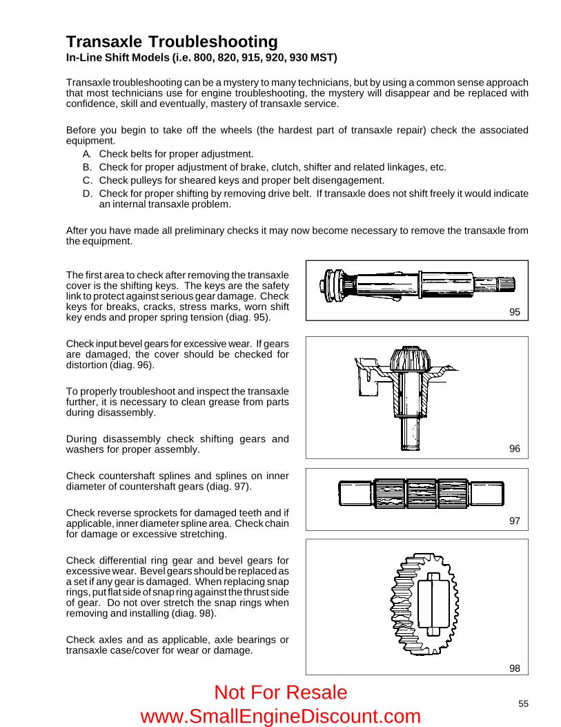
55
Transaxle Troubleshooting
95
96
97
98
In-Line Shift Models (i.e. 800, 820, 915, 920, 930 MST)
Transaxle troubleshooting can be a mystery to many technicians, but by using a common sense approachthat most technicians use for engine troubleshooting, the mystery will disappear and be replaced withconfidence, skill and eventually, mastery of transaxle service.
Before you begin to take off the wheels (the hardest part of transaxle repair) check the associatedequipment.
A. Check belts for proper adjustment.B. Check for proper adjustment of brake, clutch, shifter and related linkages, etc.C. Check pulleys for sheared keys and proper belt disengagement.D. Check for proper shifting by removing drive belt. If transaxle does not shift freely it would indicate
an internal transaxle problem.
After you have made all preliminary checks it may now become necessary to remove the transaxle fromthe equipment.
The first area to check after removing the transaxlecover is the shifting keys. The keys are the safetylink to protect against serious gear damage. Checkkeys for breaks, cracks, stress marks, worn shiftkey ends and proper spring tension (diag. 95).
Check input bevel gears for excessive wear. If gearsare damaged, the cover should be checked fordistortion (diag. 96).
To properly troubleshoot and inspect the transaxlefurther, it is necessary to clean grease from partsduring disassembly.
During disassembly check shifting gears andwashers for proper assembly.
Check countershaft splines and splines on innerdiameter of countershaft gears (diag. 97).
Check reverse sprockets for damaged teeth and ifapplicable, inner diameter spline area. Check chainfor damage or excessive stretching.
Check differential ring gear and bevel gears forexcessive wear. Bevel gears should be replaced asa set if any gear is damaged. When replacing snaprings, put flat side of snap ring against the thrust sideof gear. Do not over stretch the snap rings whenremoving and installing (diag. 98).
Check axles and as applicable, axle bearings ortransaxle case/cover for wear or damage.
Not For Resale www.SmallEngineDiscount.com
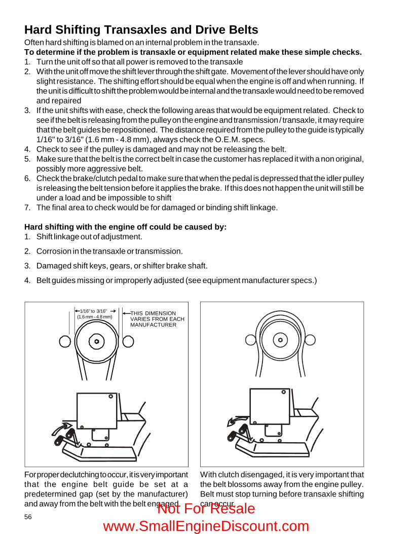
56
Hard Shifting Transaxles and Drive BeltsOften hard shifting is blamed on an internal problem in the transaxle.To determine if the problem is transaxle or equipment related make these simple checks.1. Turn the unit off so that all power is removed to the transaxle2. With the unit off move the shift lever through the shift gate. Movement of the lever should have only
slight resistance. The shifting effort should be equal when the engine is off and when running. Ifthe unit is difficult to shift the problem would be internal and the transaxle would need to be removedand repaired
3. If the unit shifts with ease, check the following areas that would be equipment related. Check tosee if the belt is releasing from the pulley on the engine and transmission / transaxle, it may requirethat the belt guides be repositioned. The distance required from the pulley to the guide is typically1/16" to 3/16" (1.6 mm - 4.8 mm), always check the O.E.M. specs.
4. Check to see if the pulley is damaged and may not be releasing the belt.5. Make sure that the belt is the correct belt in case the customer has replaced it with a non original,
possibly more aggressive belt.6. Check the brake/clutch pedal to make sure that when the pedal is depressed that the idler pulley
is releasing the belt tension before it applies the brake. If this does not happen the unit will still beunder a load and be impossible to shift
7. The final area to check would be for damaged or binding shift linkage.
Hard shifting with the engine off could be caused by:1. Shift linkage out of adjustment.
2. Corrosion in the transaxle or transmission.
3. Damaged shift keys, gears, or shifter brake shaft.
4. Belt guides missing or improperly adjusted (see equipment manufacturer specs.)
For proper declutching to occur, it is very importantthat the engine belt guide be set at apredetermined gap (set by the manufacturer)and away from the belt with the belt engaged.
With clutch disengaged, it is very important thatthe belt blossoms away from the engine pulley.Belt must stop turning before transaxle shiftingcan occur.
1/16" to 3/16" (1.6 mm - 4.8 mm)
THIS DIMENSIONVARIES FROM EACHMANUFACTURER
Not For Resale www.SmallEngineDiscount.com
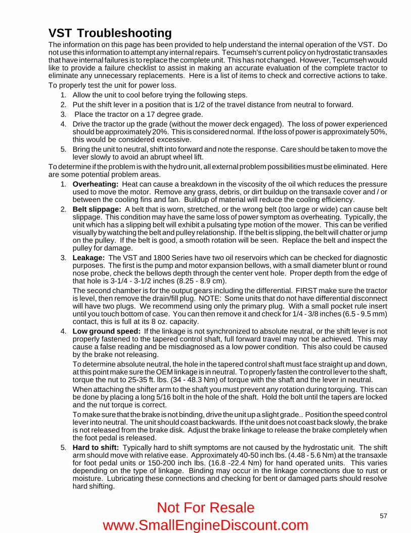
57
VST TroubleshootingThe information on this page has been provided to help understand the internal operation of the VST. Donot use this information to attempt any internal repairs. Tecumseh's current policy on hydrostatic transaxlesthat have internal failures is to replace the complete unit. This has not changed. However, Tecumseh wouldlike to provide a failure checklist to assist in making an accurate evaluation of the complete tractor toeliminate any unnecessary replacements. Here is a list of items to check and corrective actions to take.To properly test the unit for power loss.
1. Allow the unit to cool before trying the following steps.2. Put the shift lever in a position that is 1/2 of the travel distance from neutral to forward.3. Place the tractor on a 17 degree grade.4. Drive the tractor up the grade (without the mower deck engaged). The loss of power experienced
should be approximately 20%. This is considered normal. If the loss of power is approximately 50%,this would be considered excessive.
5. Bring the unit to neutral, shift into forward and note the response. Care should be taken to move thelever slowly to avoid an abrupt wheel lift.
To determine if the problem is with the hydro unit, all external problem possibilities must be eliminated. Hereare some potential problem areas.
1. Overheating: Heat can cause a breakdown in the viscosity of the oil which reduces the pressureused to move the motor. Remove any grass, debris, or dirt buildup on the transaxle cover and / orbetween the cooling fins and fan. Buildup of material will reduce the cooling efficiency.
2. Belt slippage: A belt that is worn, stretched, or the wrong belt (too large or wide) can cause beltslippage. This condition may have the same loss of power symptom as overheating. Typically, theunit which has a slipping belt will exhibit a pulsating type motion of the mower. This can be verifiedvisually by watching the belt and pulley relationship. If the belt is slipping, the belt will chatter or jumpon the pulley. If the belt is good, a smooth rotation will be seen. Replace the belt and inspect thepulley for damage.
3. Leakage: The VST and 1800 Series have two oil reservoirs which can be checked for diagnosticpurposes. The first is the pump and motor expansion bellows, with a small diameter blunt or roundnose probe, check the bellows depth through the center vent hole. Proper depth from the edge ofthat hole is 3-1/4 - 3-1/2 inches (8.25 - 8.9 cm).The second chamber is for the output gears including the differential. FIRST make sure the tractoris level, then remove the drain/fill plug. NOTE: Some units that do not have differential disconnectwill have two plugs. We recommend using only the primary plug. With a small pocket rule insertuntil you touch bottom of case. You can then remove it and check for 1/4 - 3/8 inches (6.5 - 9.5 mm)contact, this is full at its 8 oz. capacity.
4. Low ground speed: If the linkage is not synchronized to absolute neutral, or the shift lever is notproperly fastened to the tapered control shaft, full forward travel may not be achieved. This maycause a false reading and be misdiagnosed as a low power condition. This also could be causedby the brake not releasing.To determine absolute neutral, the hole in the tapered control shaft must face straight up and down,at this point make sure the OEM linkage is in neutral. To properly fasten the control lever to the shaft,torque the nut to 25-35 ft. lbs. (34 - 48.3 Nm) of torque with the shaft and the lever in neutral.When attaching the shifter arm to the shaft you must prevent any rotation during torquing. This canbe done by placing a long 5/16 bolt in the hole of the shaft. Hold the bolt until the tapers are lockedand the nut torque is correct.To make sure that the brake is not binding, drive the unit up a slight grade.. Position the speed controllever into neutral. The unit should coast backwards. If the unit does not coast back slowly, the brakeis not released from the brake disk. Adjust the brake linkage to release the brake completely whenthe foot pedal is released.
5. Hard to shift: Typically hard to shift symptoms are not caused by the hydrostatic unit. The shiftarm should move with relative ease. Approximately 40-50 inch lbs. (4.48 - 5.6 Nm) at the transaxlefor foot pedal units or 150-200 inch lbs. (16.8 -22.4 Nm) for hand operated units. This variesdepending on the type of linkage. Binding may occur in the linkage connections due to rust ormoisture. Lubricating these connections and checking for bent or damaged parts should resolvehard shifting.
Not For Resale www.SmallEngineDiscount.com
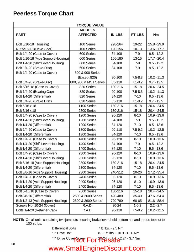
58
TORQUE VALUEMODELS
PART AFFECTED IN-LBS FT-LBS Nm
Bolt 5/16-18 (Housing) 100 Series 228-264 19-22 25.8 - 29.9Nut 5/16-18 (Drive Gear) 100 Series 120-156 10-13 13.6 - 17.7Bolt 1/4-20 (Case to Cover) 600 Series 84-108 7-9 9.5 - 12.2Bolt 5/16-18 (Axle Support Housing) 600 Series 156-180 13-15 17.7 - 20.4Bolt 1/4-20 (Shift Lever Housing) 600 Series 84-108 7-9 9.5 - 12.2Bolt 1/4-20 (Brake-Disc) 600 Series 84-108 7-9 9.5 - 12.2Bolt 1/4-20 (Case to Cover) 800 & 900 Series
(Except 820) 90-100 7.5-8.3 10.2 - 11.3Bolt 1/4-20 (Brake-Disc) 800, 900 & MST Series 85-110 7.1-9.2 9.7 - 12.5Bolt 5/16-18 (Case to Cover) 820 Series 180-216 15-18 20.4 - 24.5Bolt 1/4-20 (Bearing Cap) 820 Series 90-100 7.5-8.3 10.2 - 11.3Bolt 1/4-20 (Differential) 820 Series 84-120 7-10 9.5 - 13.6Bolt 1/4-20 (Brake Disc) 820 Series 85-110 7.1-9.2 9.7 - 12.5Bolt 5/16 x 18 1100 Series 180-216 15-18 20.4 - 24.5Bolt 5/16 x 18 2800 Series 180-216 15-18 20.4 - 24.5Bolt 1/4-20 (Case to Cover) 1200 Series 96-120 8-10 10.9 - 13.6Bolt 1/4-20 (Shift Lever Housing) 1200 Series 84-108 7-9 9.5 - 12.2Bolt 1/4-20 (Differential) 1200 Series 84-120 7-10 9.5 - 13.6Bolt 1/4-20 (Case to Cover) 1300 Series 90-110 7.5-9.2 10.2 - 12.5Bolt 1/4-20 (Differential) 1300 Series 84-120 7-10 9.5 - 13.6Bolt 1/4-20 (Case to Cover) 1400 Series 96-120 8-10 10.9 - 13.6Bolt 1/4-20 (Shift Lever Housing) 1400 Series 84-108 7-9 9.5 - 12.2Bolt 1/4-20 (Differential) 1400 Series 84-120 7-10 9.5 - 13.6Bolt 1/4-20 (Case to Cover) 2300 Series 96-120 8-10 10.9 - 13.6Bolt 1/4-20 (Shift Lever Housing) 2300 Series 96-120 8-10 10.9 - 13.6Bolt 5/16-18 (Axle Support Housing) 2300 Series 180-216 15-18 20.4 - 24.5Bolt 1/4-20 (Differential) 2300 Series 84-120 7-10 9.5 - 13.6Bolt 3/8-16 (Axle Support Housing) 2300 Series 240-312 20-26 27.2 - 35.4Bolt 1/4-20 (Case to Cover) 2400 Series 96-120 8-10 10.9 - 13.6Bolt 1/4-20 (Axle Support Housing) 2400 Series 96-120 8-10 10.9 - 13.6Bolt 1/4-20 (Differential) 2400 Series 84-120 7-10 9.5 - 13.6Bolt 5-16/18 (Case to Cover) 2500 Series 180-216 15-18 20.4 - 24.5Bolt 3/8-16 (Differential) 2500 & 2600 Series 420-480 35-40 47.6 - 54.4Bolt 1/2-13 (Axle Support Housing) 2500 & 2600 Series 720-780 60-65 81.6 - 88.4Screws No. 10-24 (Cover) R.A.D. 20-24 1.6-2 2.2 - 2.7Bolts 1/4-20 (Retainer Cap) R.A.D. 90-110 7.5-9.2 10.2 - 12.5
NOTE: On all units containing two jam nuts securing brake lever, hold bottom nut and torque top nut to100 in. lbs.
Differential Bolts 7 ft. lbs. - 9.5 Nm“T” Drive Bolt 8-11 ft. lbs. - 10.9 - 15.0 Nm“T” Drive Cover Screw 20-24 in. lbs. - 2.24 - 3.7 Nm
Peerless Torque Chart
Not For Resale www.SmallEngineDiscount.com
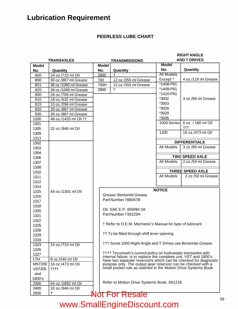
59
RIGHT ANGLEAND T DRIVES
ModelNo. Quantity
All ModelsExcept * 4 oz./118 ml Grease*1408-P91*1409-P91*1410-P91*3002 3 oz./89 ml Grease*3003*3028*3029*30351000 Series 6 oz. / 180 ml Oil
†††1100 16 oz./473 ml Oil
DIFFERENTIALSAll Models 3 oz./89 ml Grease
TWO SPEED AXLEAll Models 2 oz./59 ml Grease
THREE SPEED AXLEAll Models 2 oz./59 ml Grease
TRANSMISSIONSModelNo. Quantity2600 †700 12 oz./355 ml Grease700H 12 oz./355 ml Grease2800 †
TRANSAXLESModelNo. Quantity 600 24 oz./710 ml Oil 800 30 oz./887 ml Grease 801 36 oz./1065 ml Grease 820 36 oz./1065 ml Grease 900 26 oz./769 ml Grease 910 18 oz./532 ml Grease 915 10 oz./296 ml Grease 920 30 oz./887 ml Grease 930 30 oz./887 ml Grease1200 48 oz./1420 ml Oil ††13011305 32 oz./946 ml Oil1309131313021303130413061307130813101311131213141315 44 oz./1301 ml Oil13161317131813201321132213251328132913191323 24 oz./710 ml Oil13261327LTH 8 oz./240 ml OilMST200 16 oz./473 ml Oil
VST205 †††† and 1800's
2300 64 oz./1892 ml Oil2400 32 oz./946 ml Oil2500 †
NOTICEGrease: Bentonite GreasePart Number 788067B
Oil: SAE E.P. 80W90 OilPart Number 730229A
† Refer to O.E.M. Mechanic’s Manual for type of lubricant
†† To be filled through shift lever opening
††† Some 1000 Right Angle and T-Drives use Bentonite Grease.
†††† Tecumseh's current policy on hydrostatic transaxles withinternal failure, is to replace the complete unit. VST and 1800'shave two separate reservoirs which can be checked for diagnosticpurpose only. The output gear reservoir can be checked with asmall pocket rule as outlined in the Motion Drive Systems Book.
Refer to Motion Drive Systems Book, 691218.
PEERLESS LUBE CHART
Lubrication Requirement
Not For Resale www.SmallEngineDiscount.com
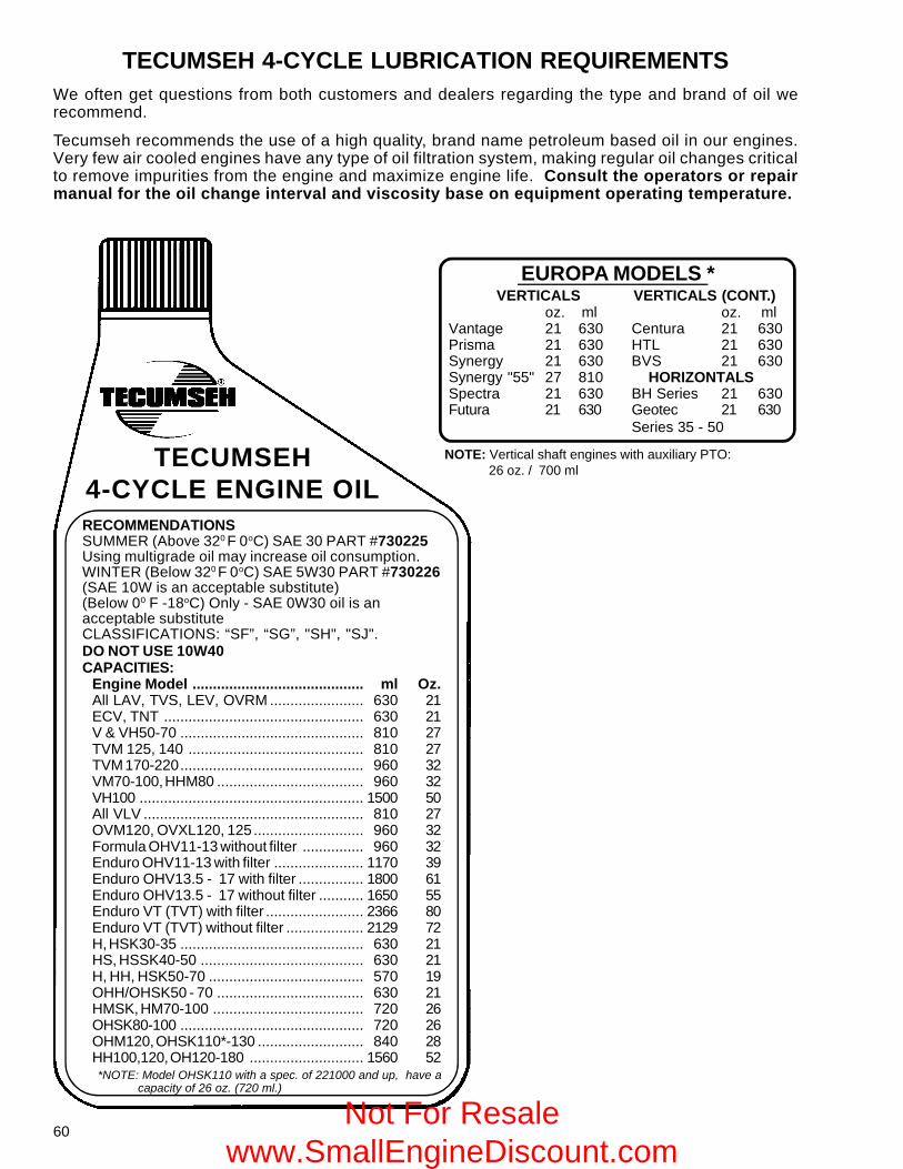
60
EUROPA MODELS *VERTICALS VERTICALS (CONT.)
oz. ml oz. mlVantage 21 630 Centura 21 630Prisma 21 630 HTL 21 630Synergy 21 630 BVS 21 630Synergy "55" 27 810 HORIZONTALSSpectra 21 630 BH Series 21 630Futura 21 630 Geotec 21 630
Series 35 - 50
TECUMSEH4-CYCLE ENGINE OIL
NOTE: Vertical shaft engines with auxiliary PTO: 26 oz. / 700 ml
TECUMSEH 4-CYCLE LUBRICATION REQUIREMENTSWe often get questions from both customers and dealers regarding the type and brand of oil werecommend.
Tecumseh recommends the use of a high quality, brand name petroleum based oil in our engines.Very few air cooled engines have any type of oil filtration system, making regular oil changes criticalto remove impurities from the engine and maximize engine life. Consult the operators or repairmanual for the oil change interval and viscosity base on equipment operating temperature.
RECOMMENDATIONSSUMMER (Above 320 F 0oC) SAE 30 PART #730225Using multigrade oil may increase oil consumption.WINTER (Below 320 F 0oC) SAE 5W30 PART #730226(SAE 10W is an acceptable substitute)(Below 00 F -18oC) Only - SAE 0W30 oil is anacceptable substituteCLASSIFICATIONS: “SF”, “SG”, "SH", "SJ".DO NOT USE 10W40CAPACITIES:
Engine Model .......................................... ml Oz.All LAV, TVS, LEV, OVRM ....................... 630 21ECV, TNT ................................................. 630 21V & VH50-70 ............................................. 810 27TVM 125, 140 ........................................... 810 27TVM 170-220............................................. 960 32VM70-100, HHM80 .................................... 960 32VH100 ....................................................... 1500 50All VLV ...................................................... 810 27OVM120, OVXL120, 125........................... 960 32Formula OHV11-13 without filter ............... 960 32Enduro OHV11-13 with filter ...................... 1170 39Enduro OHV13.5 - 17 with filter ................ 1800 61Enduro OHV13.5 - 17 without filter ........... 1650 55Enduro VT (TVT) with filter ........................ 2366 80Enduro VT (TVT) without filter ................... 2129 72H, HSK30-35 ............................................. 630 21HS, HSSK40-50 ........................................ 630 21H, HH, HSK50-70 ...................................... 570 19OHH/OHSK50 - 70 .................................... 630 21HMSK, HM70-100 ..................................... 720 26OHSK80-100 ............................................. 720 26OHM120, OHSK110*-130 .......................... 840 28HH100,120, OH120-180 ............................ 1560 52
*NOTE: Model OHSK110 with a spec. of 221000 and up, have a capacity of 26 oz. (720 ml.)
Not For Resale www.SmallEngineDiscount.com
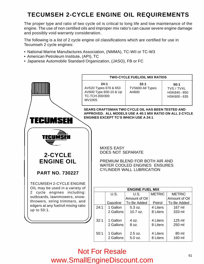
61
TECUMSEH 2-CYCLE ENGINE OIL REQUIREMENTS
2-CYCLEENGINE OIL
PART NO. 730227
TECUMSEH 2-CYCLE ENGINEOIL may be used in a variety of2 cycle engines including:outboards, lawnmowers, snow-throwers, string trimmers, andedgers at any fuel/oil mixing ratioup to 50:1.
MIXES EASYDOES NOT SEPARATE
PREMIUM BLEND FOR BOTH AIR ANDWATER COOLED ENGINES ENSURESCYLINDER WALL LUBRICATION
The proper type and ratio of two cycle oil is critical to long life and low maintenance of theengine. The use of non certified oils and improper mix ratio’s can cause severe engine damageand possibly void warranty consideration.
The following is a list of 2 cycle engine oil classifications which are certified for use inTecumseh 2 cycle engines:
• National Marine Manufactures Association, (NMMA), TC-WII or TC-W3• American Petroleum Institute, (API), TC• Japanese Automobile Standard Organization, (JASO), FB or FC
ENGINE FUEL MIXU.S. U.S. METRIC METRIC
Amount of Oil Amount of OilGasoline To Be Added Petrol To Be Added
24:1 1 Gallon 5.3 oz. 4 Liters 167 ml2 Gallons 10.7 oz. 8 Liters 333 ml
32:1 1 Gallon 4 oz. 4 Liters 125 ml2 Gallons 8 oz. 8 Liters 250 ml
50:1 1 Gallon 2.5 oz. 4 Liters 80 ml2 Gallons 5.0 oz. 8 Liters 160 ml
SEARS CRAFTSMAN TWO CYCLE OIL HAS BEEN TESTED ANDAPPROVED. ALL MODELS USE A 40:1 MIX RATIO ON ALL 2-CYCLEENGINES EXCEPT TC'S WHICH USE A 24:1
TWO-CYCLE FUEL/OIL MIX RATIOS
32:1TVS600 All TypesAH600
24:1AV520 Types 670 & 653AV600 Type 600-10 & UpTC-TCH 200/300MV100S
50:1TVS / TVXLHSK840 - 850HSK600 - 635
Not For Resale www.SmallEngineDiscount.com
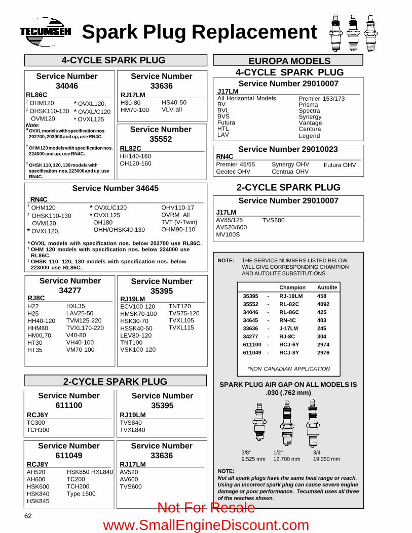
62
J17LMAV85/125AV520/600MV100S
Service Number34046
RL86C† OHM120‡ OHSK110-130 OVM120Note:*OVXL models with specification nos.
202700, 203000 and up, use RN4C.
† OHM 120 models with specification nos.224000 and up, use RN4C.
‡ OHSK 110, 120, 130 models withspecification nos. 223000 and up, useRN4C.
Spark Plug Replacement4-CYCLE SPARK PLUG
Service Number611100
RCJ6YTC300TCH300
2-CYCLE SPARK PLUG
Service Number611049
RCJ8YAH520AH600HSK600HSK840HSK845
Service Number35395
RJ19LMTVS840TVXL840
Service Number33636
RJ17LMAV520AV600TVS600
EUROPA MODELS4-CYCLE SPARK PLUGService Number 29010007
J17LMAll Horizontal ModelsBVBVLBVSFuturaHTLLAV
Service Number 29010023RN4CPremier 45/55Geotec OHV
2-CYCLE SPARK PLUGService Number 29010007
* OVXL120,* OVXL/C120* OVXL125
Service Number33636
RJ17LMH30-80HM70-100
Service Number35552
RL82CHH140-160OH120-160
HSK850 HXL840TC200TCH200Type 1500
Premier 153/173PrismaSpectraSynergyVantageCenturaLegend
Champion Autolite
35395 - RJ-19LM 458
35552 - RL-82C 4092
34046 - RL-86C 425
34645 - RN-4C 403
33636 - J-17LM 245
34277 - RJ-8C 304
611100 - RCJ-6Y 2974
611049 - RCJ-8Y 2976
*NON CANADIAN APPLICATION
NOTE: THE SERVICE NUMBERS LISTED BELOWWILL GIVE CORRESPONDING CHAMPIONAND AUTOLITE SUBSTITUTIONS.
NOTE:Not all spark plugs have the same heat range or reach.Using an incorrect spark plug can cause severe enginedamage or poor performance. Tecumseh uses all threeof the reaches shown.
SPARK PLUG AIR GAP ON ALL MODELS IS.030 (.762 mm)
1/2"12.700 mm
3/4"19.050 mm
3/8"9.525 mm
Service Number 34645RN4C
† OHM120‡ OHSK110-130 OVM120* OVXL120,
* OVXL/C120* OVXL125 OH180 OHH/OHSK40-130
OHV110-17OVRM AllTVT (V-Twin)OHM90-110
RJ8CH22H25HH40-120HHM80HMXL70HT30HT35
Service Number34277
HXL35LAV25-50TVM125-220TVXL170-220V40-80VH40-100VM70-100
Service Number35395
RJ19LMECV100-120HMSK70-100HSK30-70HSSK40-50LEV80-120TNT100VSK100-120
TNT120TVS75-120TVXL105TVXL115
* OVXL models with specification nos. below 202700 use RL86C.† OHM 120 models with specification nos. below 224000 use
RL86C.‡ OHSK 110, 120, 130 models with specification nos. below
223000 use RL86C.
Synergy OHVCentrua OHV
Futura OHV
HS40-50VLV-all
TVS600
Not For Resale www.SmallEngineDiscount.com
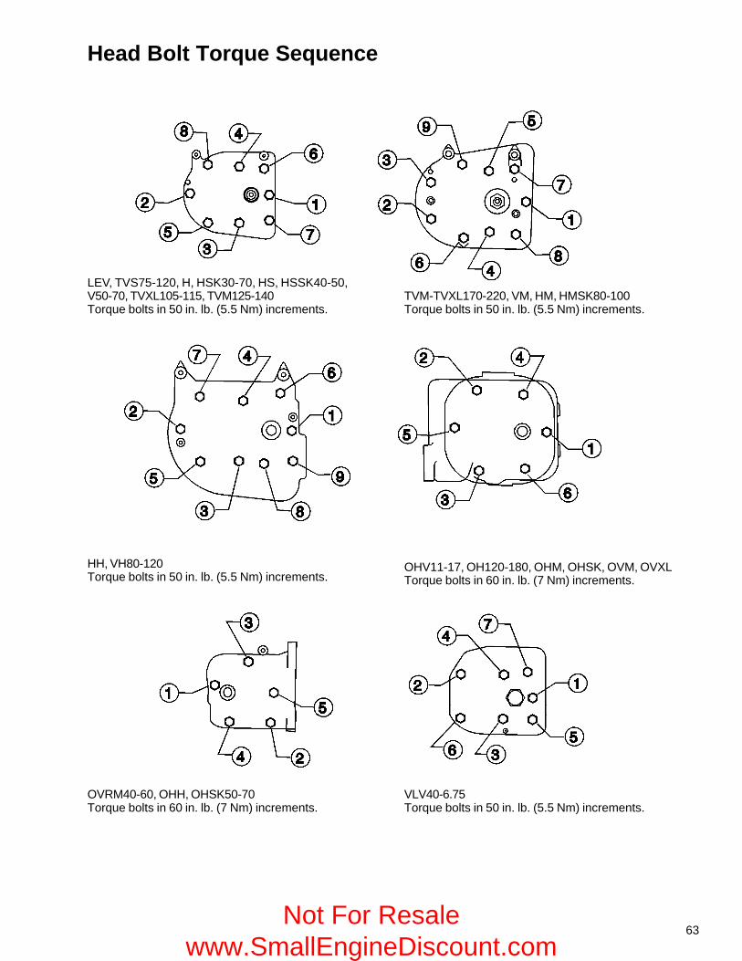
63
Head Bolt Torque Sequence
LEV, TVS75-120, H, HSK30-70, HS, HSSK40-50,V50-70, TVXL105-115, TVM125-140Torque bolts in 50 in. lb. (5.5 Nm) increments.
TVM-TVXL170-220, VM, HM, HMSK80-100Torque bolts in 50 in. lb. (5.5 Nm) increments.
HH, VH80-120Torque bolts in 50 in. lb. (5.5 Nm) increments.
OHV11-17, OH120-180, OHM, OHSK, OVM, OVXLTorque bolts in 60 in. lb. (7 Nm) increments.
OVRM40-60, OHH, OHSK50-70Torque bolts in 60 in. lb. (7 Nm) increments.
VLV40-6.75Torque bolts in 50 in. lb. (5.5 Nm) increments.
Not For Resale www.SmallEngineDiscount.com
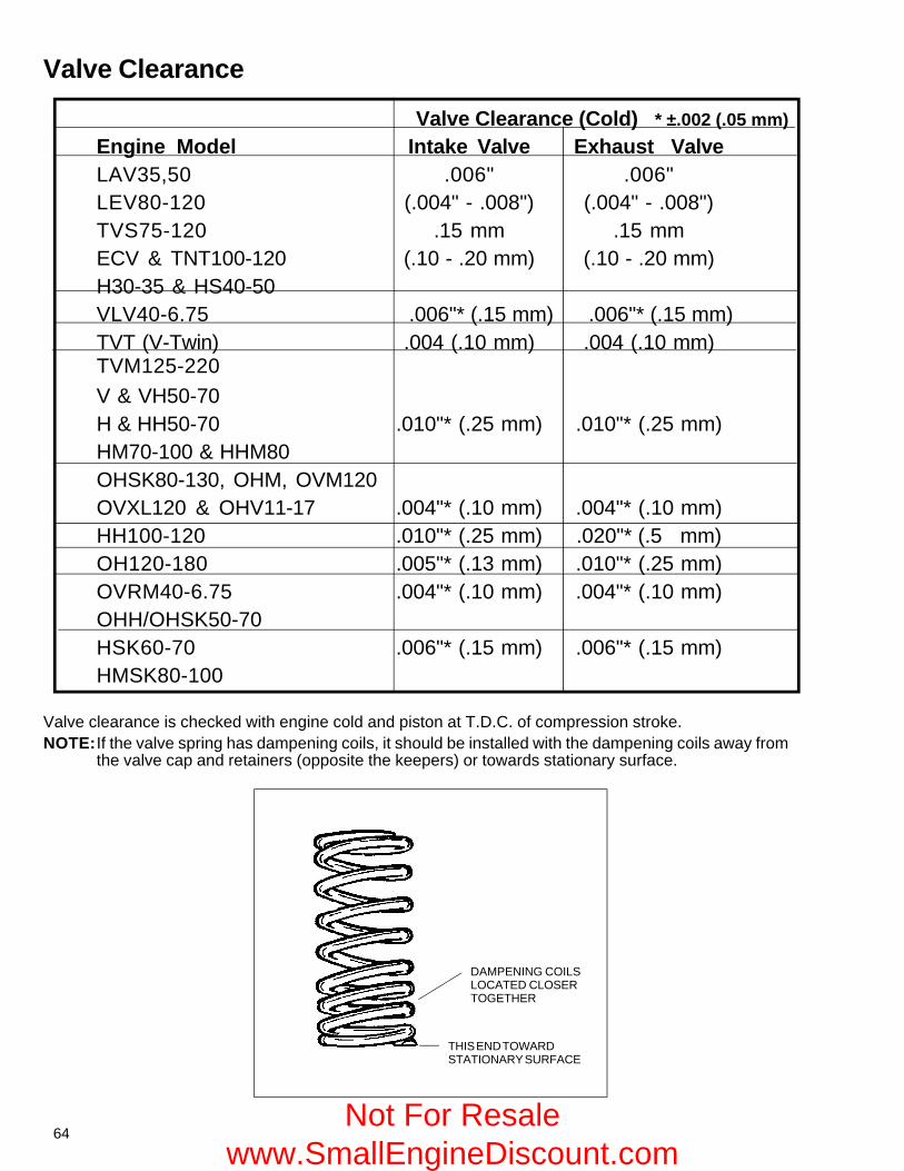
64
Valve Clearance
Valve Clearance (Cold) * ±.002 (.05 mm)
Engine Model Intake Valve Exhaust ValveLAV35,50 .006" .006"LEV80-120 (.004" - .008") (.004" - .008")TVS75-120 .15 mm .15 mmECV & TNT100-120 (.10 - .20 mm) (.10 - .20 mm)H30-35 & HS40-50VLV40-6.75 .006"* (.15 mm) .006"* (.15 mm)TVT (V-Twin) .004 (.10 mm) .004 (.10 mm)TVM125-220V & VH50-70H & HH50-70 .010"* (.25 mm) .010"* (.25 mm)HM70-100 & HHM80OHSK80-130, OHM, OVM120OVXL120 & OHV11-17 .004"* (.10 mm) .004"* (.10 mm)HH100-120 .010"* (.25 mm) .020"* (.5 mm)OH120-180 .005"* (.13 mm) .010"* (.25 mm)OVRM40-6.75 .004"* (.10 mm) .004"* (.10 mm)OHH/OHSK50-70HSK60-70 .006"* (.15 mm) .006"* (.15 mm)HMSK80-100
Valve clearance is checked with engine cold and piston at T.D.C. of compression stroke.NOTE:If the valve spring has dampening coils, it should be installed with the dampening coils away from
the valve cap and retainers (opposite the keepers) or towards stationary surface.
DAMPENING COILSLOCATED CLOSERTOGETHER
THIS END TOWARDSTATIONARY SURFACE
Not For Resale www.SmallEngineDiscount.com
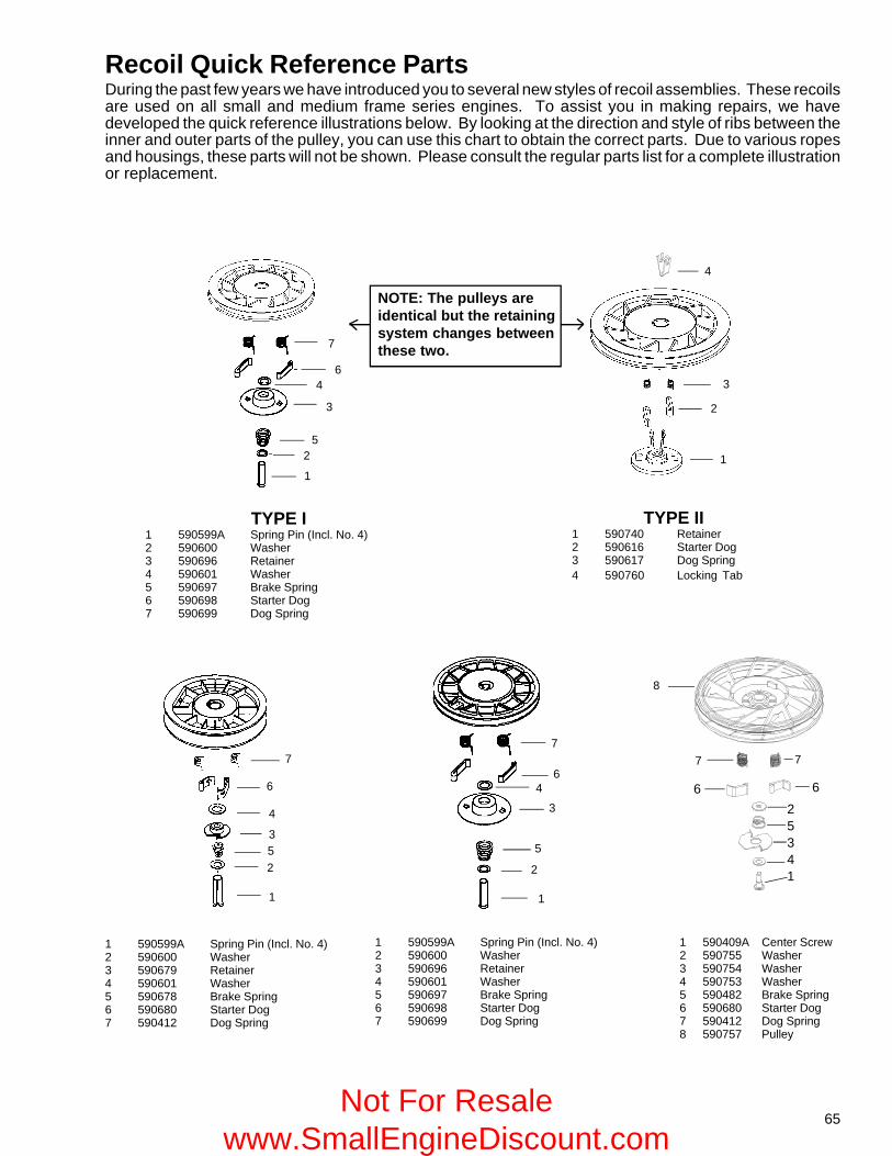
65
Recoil Quick Reference PartsDuring the past few years we have introduced you to several new styles of recoil assemblies. These recoilsare used on all small and medium frame series engines. To assist you in making repairs, we havedeveloped the quick reference illustrations below. By looking at the direction and style of ribs between theinner and outer parts of the pulley, you can use this chart to obtain the correct parts. Due to various ropesand housings, these parts will not be shown. Please consult the regular parts list for a complete illustrationor replacement.
1
25
3
46
7
TYPE I1 590599A Spring Pin (Incl. No. 4)2 590600 Washer3 590696 Retainer4 590601 Washer5 590697 Brake Spring6 590698 Starter Dog7 590699 Dog Spring
1
2
3
4
TYPE II1 590740 Retainer2 590616 Starter Dog3 590617 Dog Spring4 590760 Locking Tab
7
6
4
352
1
1 590599A Spring Pin (Incl. No. 4)2 590600 Washer3 590679 Retainer4 590601 Washer5 590678 Brake Spring6 590680 Starter Dog7 590412 Dog Spring
7
64
3
5
2
1
1 590599A Spring Pin (Incl. No. 4)2 590600 Washer3 590696 Retainer4 590601 Washer5 590697 Brake Spring6 590698 Starter Dog7 590699 Dog Spring
NOTE: The pulleys areidentical but the retainingsystem changes betweenthese two.
1 590409A Center Screw2 590755 Washer3 590754 Washer4 590753 Washer5 590482 Brake Spring6 590680 Starter Dog7 590412 Dog Spring8 590757 Pulley
8
7 7
6 625341
Not For Resale www.SmallEngineDiscount.com
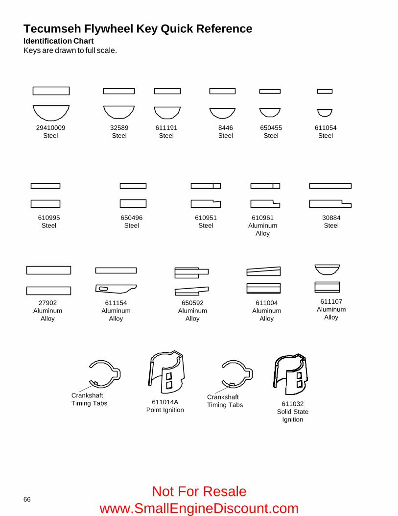
66
Tecumseh Flywheel Key Quick ReferenceIdentification ChartKeys are drawn to full scale.
29410009Steel
32589Steel
611191Steel
8446Steel
650455Steel
611054Steel
610995Steel
650496Steel
610951Steel
610961Aluminum
Alloy
30884Steel
27902Aluminum
Alloy
611154Aluminum
Alloy
650592Aluminum
Alloy
611004Aluminum
Alloy
611107Aluminum
Alloy
611014APoint Ignition
CrankshaftTiming Tabs
CrankshaftTiming Tabs 611032
Solid StateIgnition
Not For Resale www.SmallEngineDiscount.com
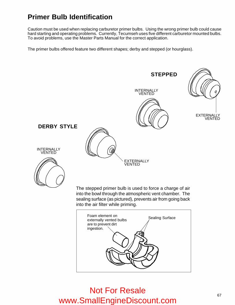
67
Primer Bulb Identification
Caution must be used when replacing carburetor primer bulbs. Using the wrong primer bulb could causehard starting and operating problems. Currently, Tecumseh uses five different carburetor mounted bulbs.To avoid problems, use the Master Parts Manual for the correct application.
The primer bulbs offered feature two different shapes; derby and stepped (or hourglass).
Sealing Surface
INTERNALLYVENTED
INTERNALLYVENTED
The stepped primer bulb is used to force a charge of airinto the bowl through the atmospheric vent chamber. Thesealing surface (as pictured), prevents air from going backinto the air filter while priming.
EXTERNALLYVENTED
EXTERNALLYVENTED
Foam element onexternally vented bulbsare to prevent dirtingestion.
DERBY STYLE
STEPPED
Not For Resale www.SmallEngineDiscount.com
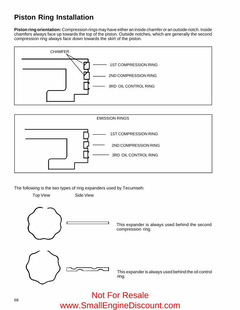
68
Piston Ring Installation
Piston ring orientation: Compression rings may have either an inside chamfer or an outside notch. Insidechamfers always face up towards the top of the piston. Outside notches, which are generally the secondcompression ring always face down towards the skirt of the piston.
Top View Side View
The following is the two types of ring expanders used by Tecumseh:
This expander is always used behind the secondcompression ring.
This expander is always used behind the oil controlring.
EMISSION RINGS
2ND COMPRESSION RING
1ST COMPRESSION RING
3RD OIL CONTROL RING
CHAMFER
3RD OIL CONTROL RING
1ST COMPRESSION RING
2ND COMPRESSION RING
Not For Resale www.SmallEngineDiscount.com
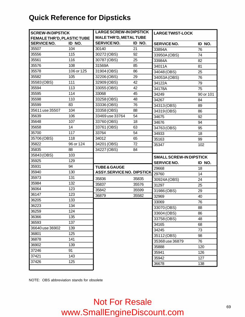
69
Quick Reference for Dipsticks
NOTE: OBS abbreviation stands for obsolete
SCREW-IN DIPSTICKFEMALE THR’D, PLASTIC TUBESERVICE NO. ID NO.35507 10435556 11535561 11635576 10835578 106 or 12535582 10535583 (OBS) 11135594 11335595 11435598 11035599 8335611 use 35507 10435639 10635648 10735658 1435700 11735706 (OBS) 11835822 96 or 12435835 8835843 (OBS) 10335925 12935931 9435940 13035973 13135984 13236064 12336147 12336205 13336223 13436259 12436366 13536593 13736640 use 36902 13936801 12536878 14136902 13937246 9137421 14337426 125
LARGE SCREW-IN DIPSTICKMALE THR’D, METAL TUBESERVICE NO. ID NO.30140 2130272 (OBS) 9230787 (OBS) 2531569A 8531904 (OBS) 8632206 (OBS) 2932909 (OBS) 4233055 (OBS) 4233068 4533258 (OBS) 4833336 (OBS) 7633358 (OBS) 8833469 use 33764 5433760 (OBS) 1833761 (OBS) 6333764 5434012 6534201 (OBS) 7234227 (OBS) 84
TUBE & GAUGEASSY.SERVICE NO. DIPSTICK
35836 3583535837 3557635842 3559936879 35582
LARGE TWIST-LOCK
SERVICE NO. ID NO.33894A 7633950A (OBS) 7433984A 8234011A 8134048 (OBS) 2534053A (OBS) 7634122A 7934178A 7534249 90 or 10134267 8434313 (OBS) 8934319 (OBS) 8634675 9234676 9434763 (OBS) 9534933 1835163 9935347 102
SMALL SCREW-IN DIPSTICKSERVICE NO. ID NO.29668 1829760 1430924A (OBS) 2431297 2531986 (OBS) 2932969 4033069 7633070 (OBS) 8833604 (OBS) 8633758 (OBS) 4834165 6834245 7335112 (OBS) 9835368 use 36879 7635888 12035941 12635942 12736678 138
Not For Resale www.SmallEngineDiscount.com
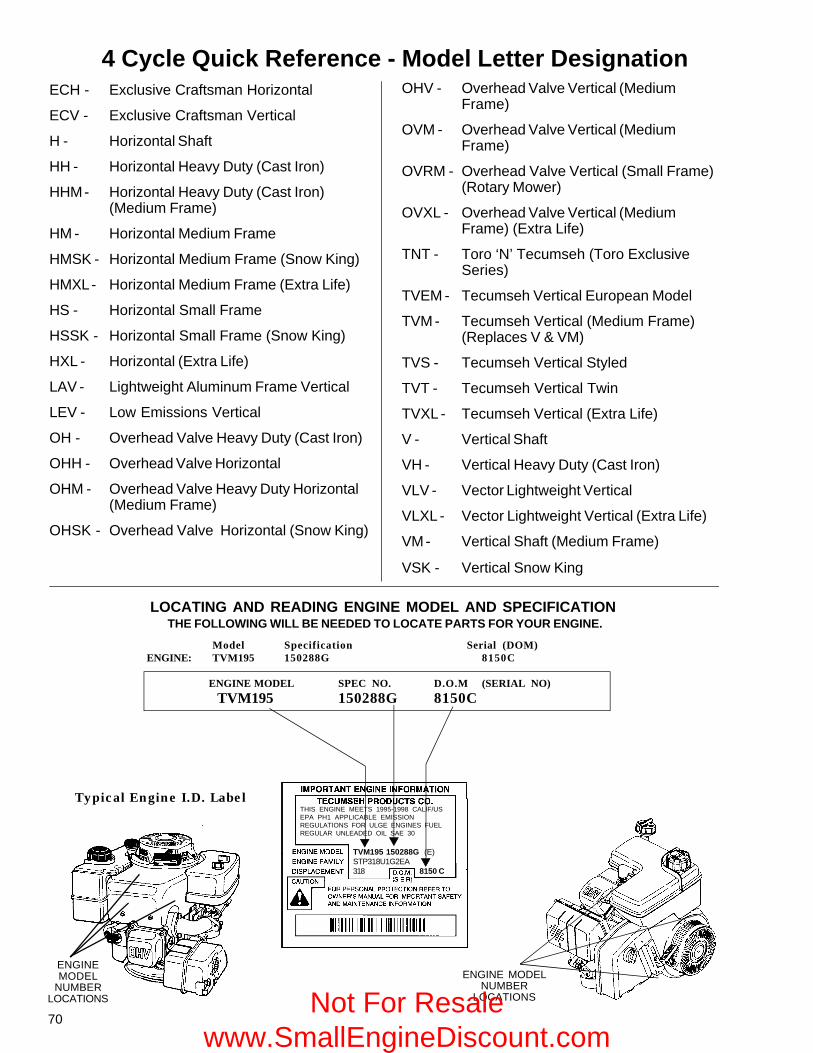
70
4 Cycle Quick Reference - Model Letter DesignationECH - Exclusive Craftsman Horizontal
ECV - Exclusive Craftsman Vertical
H - Horizontal Shaft
HH - Horizontal Heavy Duty (Cast Iron)
HHM - Horizontal Heavy Duty (Cast Iron)(Medium Frame)
HM - Horizontal Medium Frame
HMSK - Horizontal Medium Frame (Snow King)
HMXL - Horizontal Medium Frame (Extra Life)
HS - Horizontal Small Frame
HSSK - Horizontal Small Frame (Snow King)
HXL - Horizontal (Extra Life)
LAV - Lightweight Aluminum Frame Vertical
LEV - Low Emissions Vertical
OH - Overhead Valve Heavy Duty (Cast Iron)
OHH - Overhead Valve Horizontal
OHM - Overhead Valve Heavy Duty Horizontal(Medium Frame)
OHSK - Overhead Valve Horizontal (Snow King)
OHV - Overhead Valve Vertical (MediumFrame)
OVM - Overhead Valve Vertical (MediumFrame)
OVRM - Overhead Valve Vertical (Small Frame)(Rotary Mower)
OVXL - Overhead Valve Vertical (MediumFrame) (Extra Life)
TNT - Toro ‘N’ Tecumseh (Toro ExclusiveSeries)
TVEM - Tecumseh Vertical European Model
TVM - Tecumseh Vertical (Medium Frame)(Replaces V & VM)
TVS - Tecumseh Vertical Styled
TVT - Tecumseh Vertical Twin
TVXL - Tecumseh Vertical (Extra Life)
V - Vertical Shaft
VH - Vertical Heavy Duty (Cast Iron)
VLV - Vector Lightweight Vertical
VLXL - Vector Lightweight Vertical (Extra Life)
VM - Vertical Shaft (Medium Frame)
VSK - Vertical Snow King
ENGINE MODELNUMBER
LOCATIONS
ENGINEMODEL
NUMBERLOCATIONS
Model Specification Serial (DOM)ENGINE: TVM195 150288G 8150C
ENGINE MODEL SPEC NO. D.O.M (SERIAL NO)
TVM195 150288G 8150C
Typical Engine I.D. Label
TVM195 150288G (E)STP318U1G2EA318 8150 C
THIS ENGINE MEETS 1995-1998 CALIF/USEPA PH1 APPLICABLE EMISSIONREGULATIONS FOR ULGE ENGINES FUELREGULAR UNLEADED OIL SAE 30
THE FOLLOWING WILL BE NEEDED TO LOCATE PARTS FOR YOUR ENGINE.LOCATING AND READING ENGINE MODEL AND SPECIFICATION
Not For Resale www.SmallEngineDiscount.com
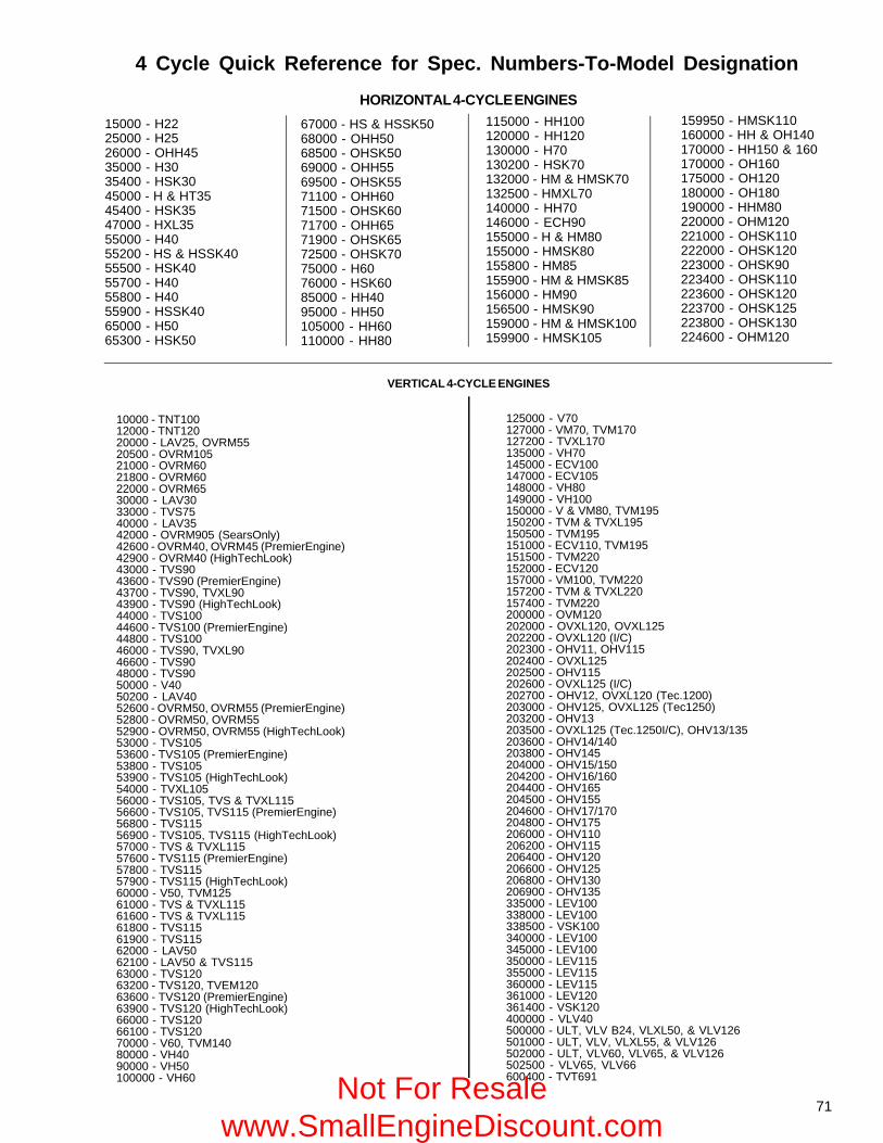
71
VERTICAL 4-CYCLE ENGINES
10000 - TNT10012000 - TNT12020000 - LAV25, OVRM5520500 - OVRM10521000 - OVRM6021800 - OVRM6022000 - OVRM6530000 - LAV3033000 - TVS7540000 - LAV3542000 - OVRM905 (SearsOnly)42600 - OVRM40, OVRM45 (PremierEngine)42900 - OVRM40 (HighTechLook)43000 - TVS9043600 - TVS90 (PremierEngine)43700 - TVS90, TVXL9043900 - TVS90 (HighTechLook)44000 - TVS10044600 - TVS100 (PremierEngine)44800 - TVS10046000 - TVS90, TVXL9046600 - TVS9048000 - TVS9050000 - V4050200 - LAV4052600 - OVRM50, OVRM55 (PremierEngine)52800 - OVRM50, OVRM5552900 - OVRM50, OVRM55 (HighTechLook)53000 - TVS10553600 - TVS105 (PremierEngine)53800 - TVS10553900 - TVS105 (HighTechLook)54000 - TVXL10556000 - TVS105, TVS & TVXL11556600 - TVS105, TVS115 (PremierEngine)56800 - TVS11556900 - TVS105, TVS115 (HighTechLook)57000 - TVS & TVXL11557600 - TVS115 (PremierEngine)57800 - TVS11557900 - TVS115 (HighTechLook)60000 - V50, TVM12561000 - TVS & TVXL11561600 - TVS & TVXL11561800 - TVS11561900 - TVS11562000 - LAV5062100 - LAV50 & TVS11563000 - TVS12063200 - TVS120, TVEM12063600 - TVS120 (PremierEngine)63900 - TVS120 (HighTechLook)66000 - TVS12066100 - TVS12070000 - V60, TVM14080000 - VH4090000 - VH50100000 - VH60
125000 - V70127000 - VM70, TVM170127200 - TVXL170135000 - VH70145000 - ECV100147000 - ECV105148000 - VH80149000 - VH100150000 - V & VM80, TVM195150200 - TVM & TVXL195150500 - TVM195151000 - ECV110, TVM195151500 - TVM220152000 - ECV120157000 - VM100, TVM220157200 - TVM & TVXL220157400 - TVM220200000 - OVM120202000 - OVXL120, OVXL125202200 - OVXL120 (I/C)202300 - OHV11, OHV115202400 - OVXL125202500 - OHV115202600 - OVXL125 (I/C)202700 - OHV12, OVXL120 (Tec.1200)203000 - OHV125, OVXL125 (Tec1250)203200 - OHV13203500 - OVXL125 (Tec.1250I/C), OHV13/135203600 - OHV14/140203800 - OHV145204000 - OHV15/150204200 - OHV16/160204400 - OHV165204500 - OHV155204600 - OHV17/170204800 - OHV175206000 - OHV110206200 - OHV115206400 - OHV120206600 - OHV125206800 - OHV130206900 - OHV135335000 - LEV100338000 - LEV100338500 - VSK100340000 - LEV100345000 - LEV100350000 - LEV115355000 - LEV115360000 - LEV115361000 - LEV120361400 - VSK120400000 - VLV40500000 - ULT, VLV B24, VLXL50, & VLV126501000 - ULT, VLV, VLXL55, & VLV126502000 - ULT, VLV60, VLV65, & VLV126502500 - VLV65, VLV66600400 - TVT691
HORIZONTAL 4-CYCLE ENGINES
4 Cycle Quick Reference for Spec. Numbers-To-Model Designation
15000 - H2225000 - H2526000 - OHH4535000 - H3035400 - HSK3045000 - H & HT3545400 - HSK3547000 - HXL3555000 - H4055200 - HS & HSSK4055500 - HSK4055700 - H4055800 - H4055900 - HSSK4065000 - H5065300 - HSK50
67000 - HS & HSSK5068000 - OHH5068500 - OHSK5069000 - OHH5569500 - OHSK5571100 - OHH6071500 - OHSK6071700 - OHH6571900 - OHSK6572500 - OHSK7075000 - H6076000 - HSK6085000 - HH4095000 - HH50105000 - HH60110000 - HH80
115000 - HH100120000 - HH120130000 - H70130200 - HSK70132000 - HM & HMSK70132500 - HMXL70140000 - HH70146000 - ECH90155000 - H & HM80155000 - HMSK80155800 - HM85155900 - HM & HMSK85156000 - HM90156500 - HMSK90159000 - HM & HMSK100159900 - HMSK105
159950 - HMSK110160000 - HH & OH140170000 - HH150 & 160170000 - OH160175000 - OH120180000 - OH180190000 - HHM80220000 - OHM120221000 - OHSK110222000 - OHSK120223000 - OHSK90223400 - OHSK110223600 - OHSK120223700 - OHSK125223800 - OHSK130224600 - OHM120
Not For Resale www.SmallEngineDiscount.com
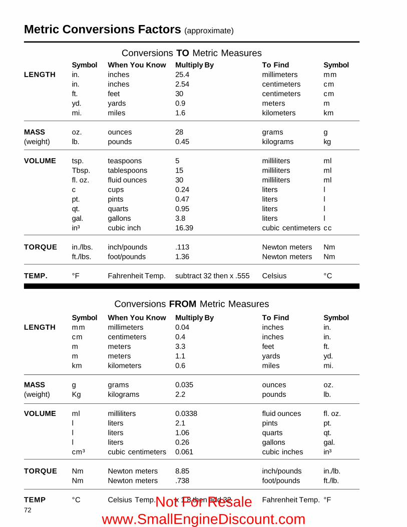
72
Symbol When You Know Multiply By To Find SymbolLENGTH mm millimeters 0.04 inches in.
cm centimeters 0.4 inches in.m meters 3.3 feet ft.m meters 1.1 yards yd.km kilometers 0.6 miles mi.
MASS g grams 0.035 ounces oz.(weight) Kg kilograms 2.2 pounds lb.
VOLUME ml milliliters 0.0338 fluid ounces fl. oz.l liters 2.1 pints pt.l liters 1.06 quarts qt.l liters 0.26 gallons gal.cm³ cubic centimeters 0.061 cubic inches in³
TORQUE Nm Newton meters 8.85 inch/pounds in./lb.Nm Newton meters .738 foot/pounds ft./lb.
TEMP °C Celsius Temp. x 1.8 then add 32 Fahrenheit Temp. °F
Metric Conversions Factors (approximate)
Conversions TO Metric MeasuresSymbol When You Know Multiply By To Find Symbol
LENGTH in. inches 25.4 millimeters mmin. inches 2.54 centimeters cmft. feet 30 centimeters cmyd. yards 0.9 meters mmi. miles 1.6 kilometers km
MASS oz. ounces 28 grams g(weight) lb. pounds 0.45 kilograms kg
VOLUME tsp. teaspoons 5 milliliters mlTbsp. tablespoons 15 milliliters mlfl. oz. fluid ounces 30 milliliters mlc cups 0.24 liters lpt. pints 0.47 liters lqt. quarts 0.95 liters lgal. gallons 3.8 liters lin³ cubic inch 16.39 cubic centimeters cc
TORQUE in./lbs. inch/pounds .113 Newton meters Nmft./lbs. foot/pounds 1.36 Newton meters Nm
TEMP. °F Fahrenheit Temp. subtract 32 then x .555 Celsius °C
Conversions FROM Metric Measures
Not For Resale www.SmallEngineDiscount.com


