QUALITY ASSURANCE PROJECT PLANREMEDIAL INVESTIGATION/FEASIBILITY STUDY
KENTUCKY AVENUE WELLFIELD SITEOPERABLE UNIT NO. 3
HORSEHEADS, CHEMUNG COUNTY, NEW YORK
VOLUME ma
October 1993Revision 1.0
Prepared for:
Westinghouse Electric CorporationPittsburgh, Pennsylvania
Project 427100
BURLINGTON ENVIRONMENTAL INC.East Park One Building
701 Rodi Road, Suite 101Pittsburgh, Pennsylvania 15235-4559
(412) 824-0200
300670
QUALITY ASSURANCE PROJECT PLAN BURLINGTON ENVIRONMENTAL INC.REMEDIAL INVESTIGATION/FEASIBILITY STUDY Project: 427100KENTUCKY AVENUE WELLFffiLD SITE Date: 10/25/93OPERABLE UNIT NO. 3 Page: 1 of 2
Revision: 1SECTION 1: APPROVAL OF QUALITY ASSURANCE PROJECT PLAN
FOR SAMPLING AND ANALYTICAL SUPPORT
1 APPROVAL OF QUALITY ASSURANCE PROJECT PLAN FORSAMPLING AND ANALYTICAL SUPPORT
Project Title:
Document Control Number:
Westinghouse Electric CorporationProject Coordinator
Burlington Project Manager:
Performing Organization:
Duration:
Type of Project:
Supporting Organization:
Remedial Investigation/Feasibility StudyKentucky Avenue Wellfield SiteOperable Unit No. 3
10/93/ 1046C82(427100)2
Timothy R. Basilone
James Pinta, Jr., Ph.D.
Burlington Environmental Inc.701 Rodi Road, Suite 101Pittsburgh, Pennsylvania 15235
30 days
Ambient Air Sampling DuringSubsurface Investigations
Optimal Technologies, Inc.4550 McKnight Road, Suite 210Pittsburgh, Pennsylvania 15237
APPROVAL:
Name: James Pinta. Jr.Title: Burlington Project ManagerSignature: _____________Date: ___________
Name: Timothy R. BasiloneTitle: Westinghouse Project ManagerSignature: ________________Date: __________________
10/9311046 W82 A(427100)2300671
QUALITY ASSURANCE PROJECT PLAN BURLINGTON ENVIRONMENTAL INC.REMEDIAL INVESTIGATION/FEASIBILITY STUDY Project: 427100KENTUCKY AVENUE WELLFIELD SITE Date: 10/25/93OPERABLE UNIT NO. 3 Page: 2 of 2
Revision: 1SECTION 1: APPROVAL OF QUALITY ASSURANCE PROJECT PLAN
FOR SAMPLING AND ANALYTICAL SUPPORT
Name: Kathleen A. BlaineTitle: OA/OC CoordinatorSignature: ____________Date: ______________
Name: Daniel DavenportTitle: Field OC Coord./Site SupervisorSignature: ________________Date: __________________
Name: J. Jeff JoseohsonTitle: USEPA Project CoordinatorSignature: ______________Date: ________________
Name:Title:
Marsha CulieOA/OC Manager
Signature:Date: __
30067;10/93/1046W82A(427100)2

QUALITY ASSURANCE PROJECT PLANREMEDIAL INVESTIGATION/FEASIBILITY STUDYKENTUCKY AVENUE WELLFIELD SITEOPERABLE UNIT NO. 3
SECTION 2: TABLE OF CONTENTS
BURLINGTON ENVIRONMENTAL INC.Project: 427100Date: 10/25/93Page: 2 of 4Revision: 1
Figures
3-1
3-2
3-3
4-1
7-1
LIST OF FIGURES AND TABLES
Site Area Location Map
Detail of Study Area
Previously Identified Potential Source Areas and Additional Source Areas inthe Vicinity of the Facility -
Organization Chart, RI/FS Project Team
Sample Custody Seal
Tables
4-1
5-1
5-2
5-3
5-4
5-5
6-1
6-2
9-1
9-2
9-3
Assignments for Key Project Personnel
Accuracy and Precision Objectives for Measurement Data
Matrix Spike Recovery and Relative Percent Difference Limits - VOCs
Matrix Spike Recovery and Relative Percent Difference Limits - SVOCs
Accuracy and Precision Objectives for Measurement Data, Metals, andInorganics (CLP)
Matrix Spike Recovery and Relative Percent Difference Limits - Pesticides andPCBs
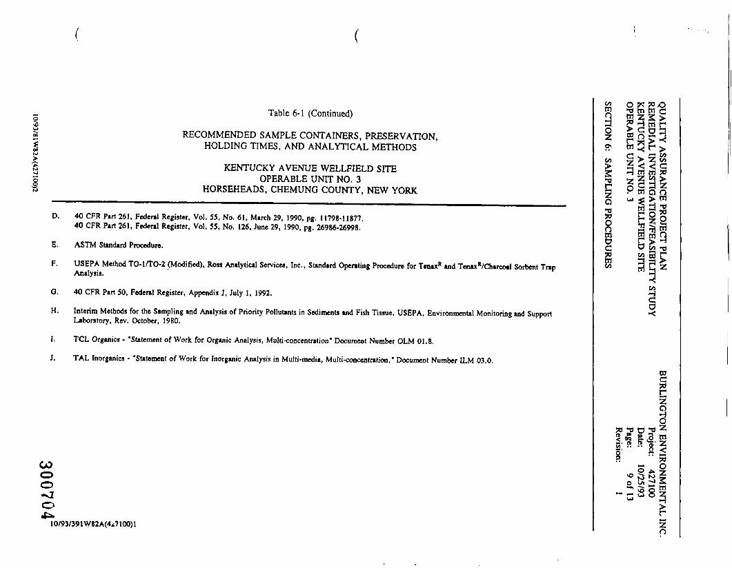
Recommended Sample Containers, Preservation, Holding Times, andAnalytical Methods
IFI Laboratory Analytical Data Requirements
Analytical Procedures
Target Compound List Volatiles and Contract Required Quantitation Limits(CRQL)
Target Compound List Semivolatiles and Contract Required Quantitation Limits(CRQL)
30067310/93/1047W82A(427100)2
QUALITY ASSURANCE PROJECT PLANREMEDIAL INVESTIGATION/FEASIBILITY STUDYKENTUCKY AVENUE WELLFIELD SITEOPERABLE UNIT NO. 3
SECTION 2: TABLE OF CONTENTS
BURLINGTON ENVIRONMENTAL INC.Project: 427100Date: 10/25/93Page: 3 of 4Revision: 1
Tables
9-4
9-5
LIST OF FIGURES AND TABLES (Continued)
Target Compound List Inorganics and Contract Required Quantitation Limits(CRQL)
Target Compound List Pesticides and PCBs and Contract Required QuantitationLimits (CRQL)
30067410/93/1047W82A(427100)2
QUALITY ASSURANCE PROJECT PLANREMEDIAL INVESTIGATION/FEASIBILITY STUDYKENTUCKY AVENUE WELLFIELD SITEOPERABLE UNIT NO. 3
SECTION 2: TABLE OF CONTENTS
BURLINGTON ENVIRONMENTAL INC.Project: 427100Date: 10/25/93Page: 4 of 4Revision: 1
LIST OF APPENDICES
APPENDIX A Standard Operating Procedures for Well Development and Water Sampling
APPENDIX B Standard Operating Procedures for Decontamination Procedures
APPENDK C Field Forms
APPENDIX D Analytical Laboratory, Quality Assurance Plan '-
APPENDIX E Health and Safety Standard Operating Procedures for the PhotoionizationDetectors
APPENDIX F Standard Operating Procedures for the pH Meter
APPENDIX G Standard Operating Procedures for YSI-Specific Conductivity Meter Model 33
APPENDIX H Standard Operating Procedures for RECON*
30Gu7510/93/1047W82A(427100)2
QUALITY ASSURANCE PROJECT PLANREMEDIAL INVESTIGATION/FEASIBILITY STUDYKENTUCKY AVENUE WELLFIELD SITEOPERABLE UNIT NO. 3
SECTION 3: PROJECT DESCRIPTION
BURLINGTON ENVIRONMENTAL INC.Project: 427100Date: 10/25/93Page: 1 of 8Revision: 1
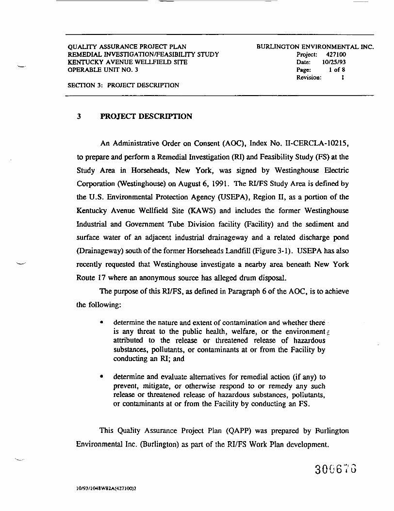
3 PROJECT DESCRIPTION
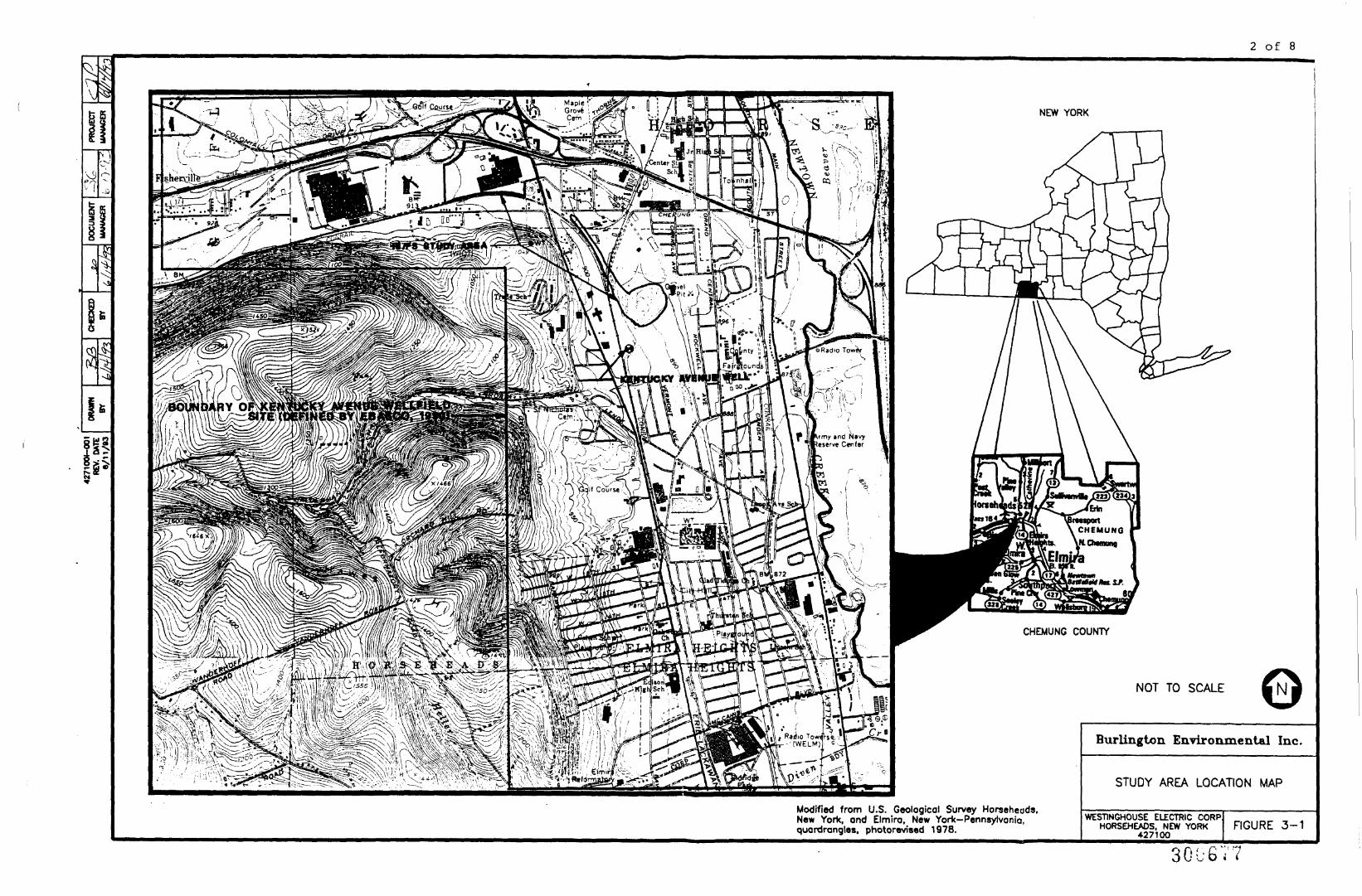
An Administrative Order on Consent (AOC), Index No. II-CERCLA-10215,to prepare and perform a Remedial Investigation (RI) and Feasibility Study (FS) at theStudy Area in Horseheads, New York, was signed by Westinghouse ElectricCorporation (Westinghouse) on August 6, 1991. The RI/FS Study Area is defined bythe U.S. Environmental Protection Agency (USEPA), Region II, as a portion of theKentucky Avenue Wellfield Site (KAWS) and includes the former WestinghouseIndustrial and Government Tube Division facility (Facility) and the sediment andsurface water of an adjacent industrial drainageway and a related discharge pond(Drainageway) south of the former Horseheads Landfill (Figure 3-1). USEPA has alsorecently requested that Westinghouse investigate a nearby area beneath New YorkRoute 17 where an anonymous source has alleged drum disposal.
The purpose of this RI/FS, as defined in Paragraph 6 of the AOC, is to achievethe following:
• determine the nature and extent of contamination and whether thereis any threat to the public health, welfare, or the environment £attributed to the release or threatened release of hazardoussubstances, pollutants, or contaminants at or from the Facility byconducting an RI; and
• determine and evaluate alternatives for remedial action (if any) toprevent, mitigate, or otherwise respond to or remedy any suchrelease or threatened release of hazardous substances, pollutants,or contaminants at or from the Facility by conducting an FS.
This Quality Assurance Project Plan (QAPP) was prepared by BurlingtonEnvironmental Inc. (Burlington) as part of the RI/FS Work Plan development.
30G67G10/93 /1048 W82A(427100)2
2 of 8
3§
NEW YORK
NOT TO SCALE
Modified from U.S. Geological Survey Horseheads.New Yorfc. and Elmira, New York-Pennsylvoniaquardrangles. photorevised 1978.
Burlington Environmental Inc.
STUDY AREA LOCATION MAP
WEST1NGHOUSE ELECTRIC CORP,HORSEHEADS. NEW YORK
427100FIGURE 3-1
301-677
QUALITY ASSURANCE PROJECT PLANREMEDIAL INVESTIGATION/FEASIBILITY STUDYKENTUCKY AVENUE WELLFIELD SITEOPERABLE UNIT NO. 3
SECTION 3: PROJECT DESCRIPTION
BURLINGTON ENVIRONMENTAL INC.Project: 427100Date: 10/25/93Page: 3 of 8Revision: 1
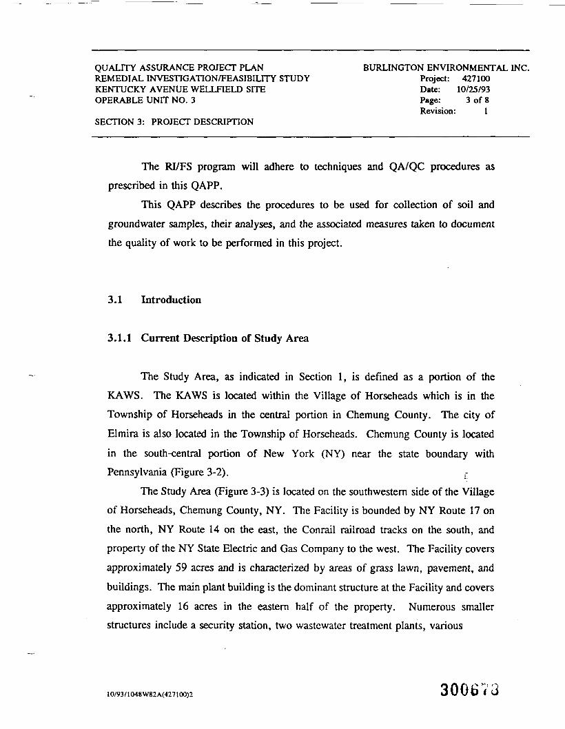
The RI/FS program will adhere to techniques and QA/QC procedures asprescribed in this QAPP.
This QAPP describes the procedures to be used for collection of soil andgroundwater samples, their analyses, and the associated measures taken to documentthe quality of work to be performed in this project.
3.1 Introduction
3.1.1 Current Description of Study Area
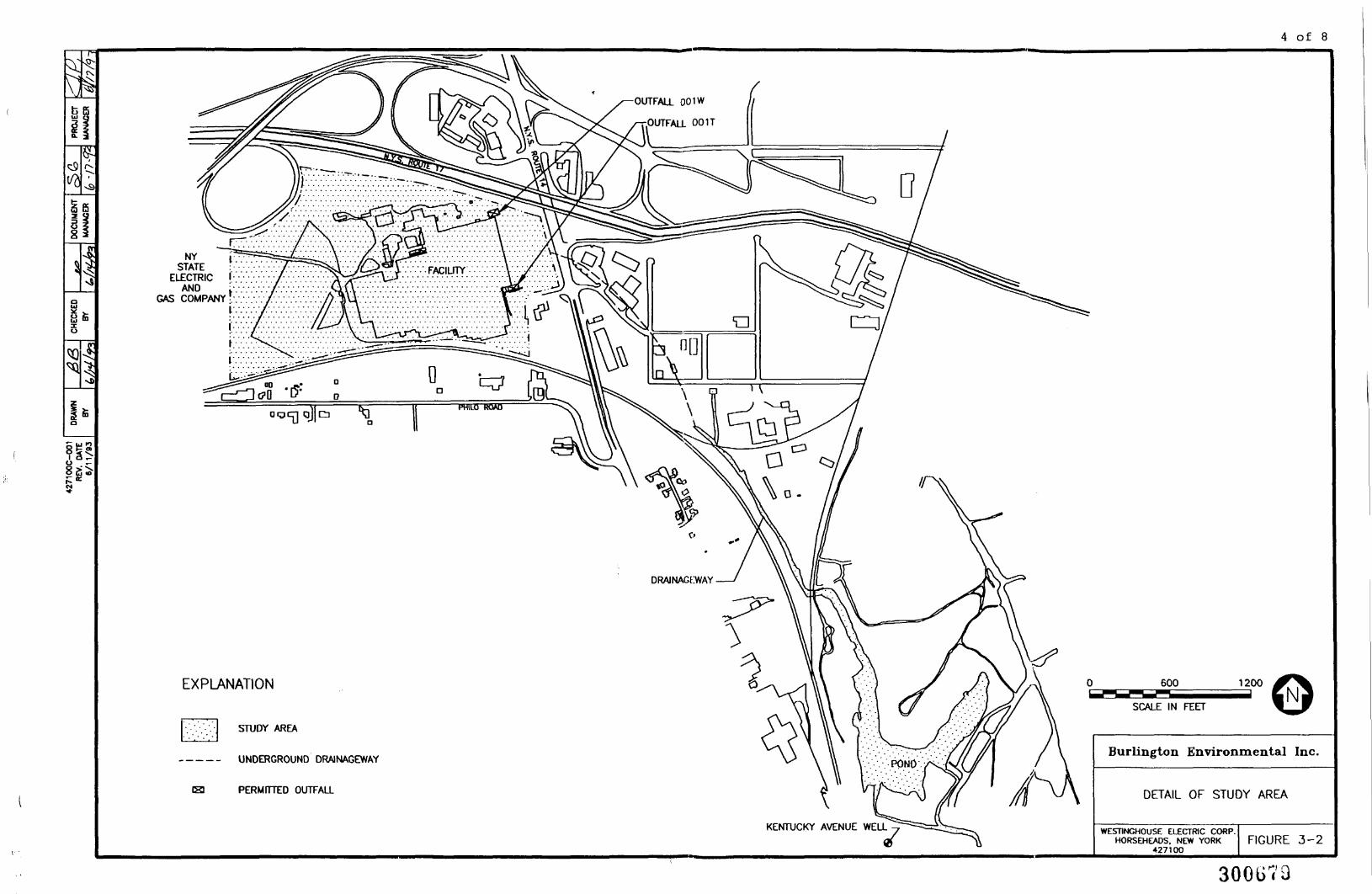
The Study Area, as indicated in Section 1, is defined as a portion of theKAWS. The KAWS is located within the Village of Horseheads which is in theTownship of Horseheads in the central portion in Chemung County. The city ofElmira is also located in the Township of Horseheads. Chemung County is locatedin the south-central portion of New York (NY) near the state boundary withPennsylvania (Figure 3-2).
The Study Area (Figure 3-3) is located on the southwestern side of the Villageof Horseheads, Chemung County, NY. The Facility is bounded by NY Route 17 on
the north, NY Route 14 on the east, the Conrail railroad tracks on the south, and
property of the NY State Electric and Gas Company to the west. The Facility coversapproximately 59 acres and is characterized by areas of grass lawn, pavement, andbuildings. The main plant building is the dominant structure at the Facility and coversapproximately 16 acres in the eastern half of the property. Numerous smallerstructures include a security station, two wastewater treatment plants, various
10/93/1048W82A(427100)2 300673
4 of 8
E5
Is
NYSTATE
ELECTRIC !AND i
GAS COMPANY VI
EXPLANATION
STUDY AREA
UNDERGROUND DRAINAGEWAY
PERMITTED OUTFALL
KENTUCKY AVENUE WELL
600
SCALE IN FEET
1200
Burlington Environmental Inc.
DETAIL OF STUDY AREA
WESTINGHOUSE ELECTRIC CORP.HORSEHEADS. NEW YORK
427100FIGURE 3-2
300673
5 of 8
a
\
B
FORMER COAL PILE AREABARREL STORAGE PAD
MAGNESIUM CHIP BURIAL AREA
/ . *MW-3D OQ/ MW-^A,
MW-12.S.D.R MW"i4NEST
.'-trfW-2
OUTFALL 001W
OUTFALL 001T
SOIL PILE
.FORMER RUNOFFIN AREA
HAZARDOUS WASTESTORAGE P
FLUORIDEDISPOSAL AREAS
MW-14.S.D.RNEST
Modified from Waitinghousa Ooctric Corporatkxi. Property Plan, 4/91.
EXPLANATION
•o.MW-1S
FENCEPROPERTY BOUNDARYDRAIN LINEOPEN GRATING MANHOLE LOCATIONMANHOLE LOCATIONSURFACE WATER RUNOFF DRAIN LOCATIONMONITORING WELL LOCATION AND NUMBERAREASPREVIOUSLY IDENTIFIED POTENTIAL SOURCEAREASOTHER SUSPECT POTENTIAL SOURCE AREAS
« pERMrrrEo OUTFALLLS.T.JC. IMAGING AND SENSING TECHNOLOGY CORPORATION
TDJX TOSHIBA DISPLAY DEVICES
3OO
SCALE IN FEET
600
Burlington Environmental Inc.
PREVIOUSLY IDENTIFIED POTENTIALSOURCE AREAS AND ADDITIONAL
POTENTIAL SOURCE AREAS IN THEVICINITY OF THE FACILITY
WESTWGHOUSE ELECTRIC CORP.HORSEHEAOS. NEW YORK
427tOOFIGURE 3-3
300G30
QUALITY ASSURANCE PROJECT PLANREMEDIAL INVESTIGATION/FEASIBILITY STUDYKENTUCKY AVENUE WELLFIELD SITEOPERABLE UNIT NO. 3
SECTIONS: PROJECT DESCRIPTION
BURLINGTON ENVIRONMENTAL INC.Project: 427100Date: 10/25/93Page: 6 of 8Revision: 1
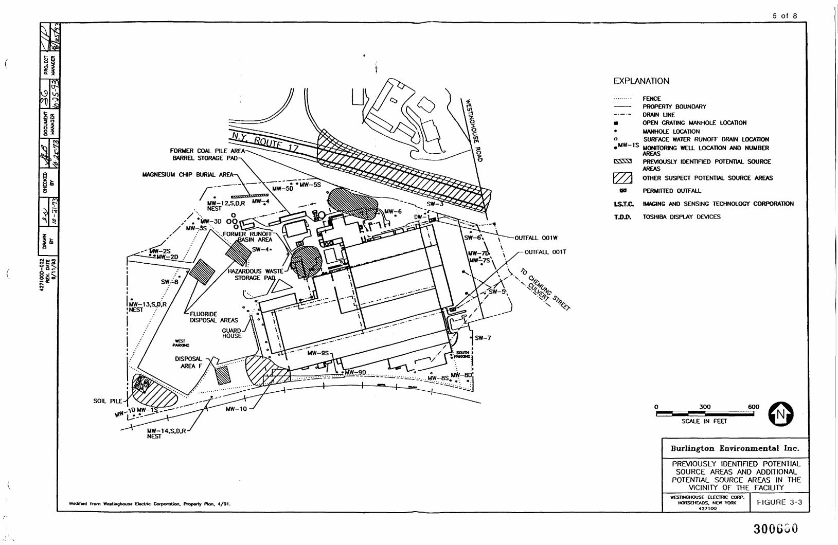
aboveground storage tanks and buildings, gas and groundwater pumping buildings, andan electric power substation. Large asphalt-paved parking lots cover approximately14 acres on the western, eastern, and southeastern parts of the property. Additionalpaved areas include a perimeter road around most of the main plant building androughly half the area between the main plant building and the West Parking Lot.Wide areas of lawn lie adjacent to the northern, western, and eastern boundaries ofthe main plant building with additional sections of lawn centrally located between themain plant building and the West Parking Lot.
The ground surface in the vicinity of the Facility has little relief and slopesvery gently to the east and northeast. Surface runoff from precipitation flowsgenerally in these directions across the property. Runoff is routed by shallow swalesand/or captured by surface water runoff (storm) drains at various locations around themain plant building. A large portion of the runoff (the portion originating from theroof of the main plant building) is routed through the two plant outfall flumes (001Tand 001W) to an off-site discharge point southeast of the main building(Drainageway). The surficial soil of the Facility appears to be well drained."
The Drainageway of the Study Area extends from an underground pipeapproximately 1,200 ft southeast of the main plant building and meanders 2,600 ft tothe southeast until discharging into a 7-acre pond. Surface water from this ponddischarges to the south. The Drainageway is approximately 7 to 10 ft wide and isbounded on the west by Conrail tracks and by industrial and municipal buildings onthe east. Soundings conducted by Weiler Mapping (Horseheads, NY) indicate that thedepth of the pond is about 3 to 6 ft over most of the area. The pond is bounded bythe former Horseheads Landfill on the north and northeast, the Conrail tracks on the
30068110/93/1048W82A(427100)2

QUALITY ASSURANCE PROJECT PLANREMEDIAL INVESTIGATION/FEASIBILITY STUDYKENTUCKY AVENUE WELLFIELD SITEOPERABLE UNIT NO. 3
SECTIONS: PROJECT DESCRIPTION
BURLINGTON ENVIRONMENTAL INC.Project: 427100Date: 10/25/93Page: 7 of 8Revision: 1
west, and area of the Kentucky Avenue Wellfield (KAW) on the south. Overflowfrom the pond discharges to the south into a small unnamed tributary to NewtownCreek.
The area surrounding the Drainageway can be characterized as having littlerelief and is poorly drained. Numerous areas adjacent to the Drainageway containstanding water and marsh-features. Other adjacent areas are indicative of the previouslandfill operations with paint cans, household refuse, and other debris evident at thesurface. Reconnaissance of the Drainageway in February 1992 located otherdischarges from unknown sources into the Drainageway.
The Westinghouse cathode-ray and power tube operations facility wasconstructed in 1951 on farm land in Horseheads, New York. Manufacturing beganin 1952. This facility was expanded in 1953, 1956, 1967, and 1973. The Cathode-Ray Tube Division operations were closed in 1976. After 1976, the operation wasknown as the Industrial and Government Tube Division. The name was changed toImaging and Sensing Technology Division (ISTD) in 1987. During this time, ISTDmade a diverse line of power, storage, and camera tubes; spectral light sources, sensorand control products, such as neutron detectors, thermocouples, and nuclearpenetrations; and low-voltage switches and vacuum interrupters. All of the productlines except the vacuum interrupter operation were sold to a new company calledImaging and Sensing Technology Corporation (ISTC) in May 1988.
The Facility was expanded in 1985 when Westinghouse and Toshiba formeda joint venture (Toshiba Westinghouse Electronics) to manufacture cathode-ray tubes.The building was expanded again in 1988. Westinghouse sold its interest in the jointventure on January 1, 1989, to Toshiba America.
Today the building is occupied by the Westinghouse Horseheads Operations,Toshiba Display Devices, and the ISTC. The Westinghouse Horseheads Operations
10/93/1048W82 A(427100)2 300682

QUALITY ASSURANCE PROJECT PLANREMEDIAL INVESTIGATION/FEASIBILITY STUDYKENTUCKY AVENUE WELLFIELD SITEOPERABLE UNIT NO. 3
SECTIONS: PROJECT DESCRIPTION
BURLINGTON ENVIRONMENTAL INC.Project: 427100Date: 10/25/93Page: 8 of 8Revision: 1
manufactures vacuum tube interrupters and is the landlord for most of the Facility.Part of the building is owned by the Urban Development Corporation which leasesspace to Westinghouse. Westinghouse sub-leases space to Toshiba Display Devicesand ISTC.
Each of the three companies (Toshiba Display Devices, ISTC, andWestinghouse) generate industrial wastewater discharges, solid wastes, and airemissions which are permitted by the New York State Department of EnvironmentalConservation. Toshiba and Westinghouse have five-year State Pollution DischargeElimination System (SPDES) permits. Toshiba's permit expires in 1996.Westinghouse has had a permit since the inception of the SPDES program; this permitexpires in 1993. ISTC discharges wastewater to Westinghouse and Toshiba permittedoutfalls which join downstream. Each of the three companies has been issued stateair emission permits for their individual sources. Each company generates hazardoussolid wastes, but none receives wastes generated off-site. Although the Facility iscurrently an interim-status treatment, storage, and disposal (TSD) facility underResource Conservation and Recovery Act (RCRA) regulations, Westinghouse hasrequested closure in lieu of filing a RCRA Part B application. =:
The history of the Drainageway and surrounding areas has not been welldocumented and will be investigated as part of the initial records review.
30068310/93/1048W82A(427100)2
QUALITY ASSURANCE PROJECT PLAN BURLINGTON ENVIRONMENTAL INC.REMEDIAL INVESTIGATION/FEASIBILITY STUDY Project: 427100KENTUCKY AVENUE WELLFIELD SITE Date: 10/25/93OPERABLE UNIT NO. 3 Page: 1 of 4
Revision: 1SECTION 4: PROJECT ORGANIZATION AND RESPONSIBILITY
4 PROJECT ORGANIZATION AND RESPONSIBILITY
The following organizations and individuals have key roles in controlling thequality of this project. These individuals will manage the project in accordance withthisQAPP.
• U. S. Environmental Protection Agency
Project Coordinator, J. Jeff Josephson
• Westinghouse Electric Corporation
Project Manager, Timothy R. Basilone
• Burlington Environmental Inc.
Program Director, Jeffrey D. YoungProject Manager, James Pinta, Jr.Site Supervisor, Daniel DavenportQA/QC Coordinator, Kathleen A. Blaine --
The organization chart for the project team assembled to conduct the RI/FS atthe Study Area is presented in Figure 4-1. Table 4-1 indicates designated roles forkey individuals for this project.
30068410/93/5W82A(427lOO)2

QUALITY ASSURANCE PROJECT PLANREMEDIAL INVESTIGATION/FEASIBILITY STUDYKENTUCKY AVENUE WELLFIELD SITEOPERABLE UNIT NO. 3
SECTION 4: PROJECT ORGANIZATION AND RESPONSIBILITY
BURLINGTON ENVIRONMENTAL INC.Project: 427100Date: 10/25/93Page: 2 of 4Revision: 1
UESTIHGHOUSE ELECTRICCORPORATION
PROJECT COORDINATOR
TIMOTHY R. BASILONE
PROJECT ENGINEER
LEO N. BRAUSCH
UESTINGHOUSE TECHNICALCONSULTANT ON
TREATABILITY ISSUES
JEFFREY FORSCHNER
HEALTH AND SAFETY
CORPORATE HEALTH ANDSAFETY OFFICER
BURLINGTON PROGRAMDIRECTOR
JEFFREY D. YOUNGGeneral Manager
PROJECT MANAGER
JAKES PIHTA, JR.Senior Geochealst
DOCUMENT MANAGEMENT
SUZANNA GARREAUTechnical Editor
RISK ASSESSMENT
BARR1E C. SELCOEGroup Leader
Risk Assessment
DATA MANAGEMENT
JEFFREY D. CHRIS THANGroup Leader
SITE CHARACTERIZATION
JAMES PINTA, JR.Task Manager
QUALITY ASSURANCE/QUALITY CONTROL
KATHLEEN A. BLAINEAnalytical Laboratory
Coordinator
FEASIBILITY STUDY
VAL J. KELHECKISManager
Environmental Engineering
DARRIEL DAVENPORTSite Supervisor
OPTIMAL TECHNOLOGIESBill Stanziana
John Frye
TERRESTRIAL ENVIRONMENTALSPECIALISTSEdward Reed
Cathie Baumgartner
Burlington Environmental Inc.
ORGANIZATION CHART
RI/FS PROJECT TEAM
427100 FIGURE 4-1
10/93/SW82A(427100)2 300GS5
QUALITY ASSURANCE PROJECT PLANREMEDIAL INVESTIGATION/FEASIBILITY STUDYKENTUCKY AVENUE WELLFIELD SITEOPERABLE UNIT NO. 3
SECTION 4: PROJECT ORGANIZATION AND RESPONSIBILITY
BURLINGTON ENVIRONMENTAL INC.Project: 427100Date: 10/25/93Page: 3 of 4Revision: 1
Table 4-1
ASSIGNMENTS FOR KEY PROJECT PERSONNEL
REMEDIAL INVESTIGATION AND FEASIBILITY STUDYWESTINGHOUSE ELECTRIC CORPORATION
HORSEHEADS, NEW YORK
Program DirectorJeffrey D. Young
Project ManagerJames Pinta, Jr., Ph.D.
Field SupervisorDaniel Davenport
Corporate Health and Safety OfficerScott Wilson
QA/QC CoordinatorKathleen A. Blaine
Risk AssessmentBarrie C. SelcoeElizabeth Ubinger
EngineeringVal J. Kelmeckis
Provides corporate oversight of the Burlington project team,as needed. Assists Westinghouse in agency communications andnegotiations.
Focal point for Westinghouse and Burlington interaction.Responsible for technical and administrative work on Work Planand execution, project progress reports, communication, budgetcontrol, adherence to schedules, staffing assignments, and day-to-day direction of the project including Burlington'ssubcontractors.
Coordinates field operations including geophysical investigationRECON surveys, monitoring well installation, trenchingactivities, and drilling and sample collection. Responsible forsupervising Burlington field operations personnel as well assubcontractors.
Establishes and enforces procedures to protect health andsafety of on-site workers and nearby residents. Preparation ofHealth and Safety Plan.
Establishes data quality objectives for analytical work.Preparation and review of QA/QC Plan. Monitors overallQA/QC for project. Supplies reports to management.
Advises project team during preparation of work plans. Performsall required Westinghouse risk assessment activities and generatesthe "shadow" risk assessment.
Evaluates reports to identify data needs to select the most cost-effective remedial alternative. Assists in preparation of workplans.
300GS610/93/5 W82A(427100)2
QUALITY ASSURANCE PROJECT PLAN BURLINGTON ENVIRONMENTAL INC.REMEDIAL INVESTIGATION/FEASIBILITY STUDY Project: 427100KENTUCKY AVENUE WELLFIELD SITE Date: 10/25/93OPERABLE UNIT NO. 3 Page: 4 of 4
Revision: 1SECTION 4: PROJECT ORGANIZATION AND RESPONSIBILITY
Table 4-1 (Continued)
ASSIGNMENTS FOR KEY PROJECT PERSONNEL
REMEDIAL INVESTIGATION AND FEASIBILITY STUDYWESTINGHOUSE ELECTRIC CORPORATION
HORSEHEADS, NEW YORK
Data Management/Statistics Establishes data management requirements for inclusion intoJeffrey D. Christman Work Plan. Provides oversight of data management and
statistics team. Responsible for overall reliability of datapresentations and statistical significance.
Document Management Edits and coordinates production of all project-relatedSuzanna Garreau documents.
300687!0/93/5W82A(427100)2
QUALITY ASSURANCE PROJECT PLANREMEDIAL INVESTIGATION/FEASIBILITY STUDYKENTUCKY AVENUE WELLFIELD SITEOPERABLE UNIT NO. 3
SECTION 5: QUALITY ASSURANCE OBJECTIVES
BURLINGTON ENVIRONMENTAL INC,Project: 427100Date: 10/25/93Page: 1 of 8Revision: 1
5 QUALITY ASSURANCE OBJECTIVES
The quality assurance goals for this project are the collection of samples andfield information that are technically sound and properly documented, and thegeneration of data that are statistically valid and of known precision and accuracy.The following discussions of accuracy, precision, completeness, representativeness,and comparability include and represent the objectives set by Burlington for thisproject.
5.1 Accuracy
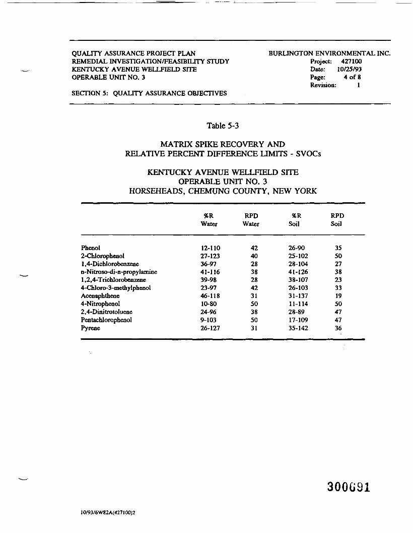
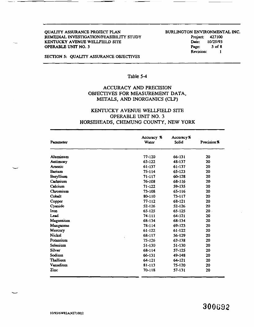
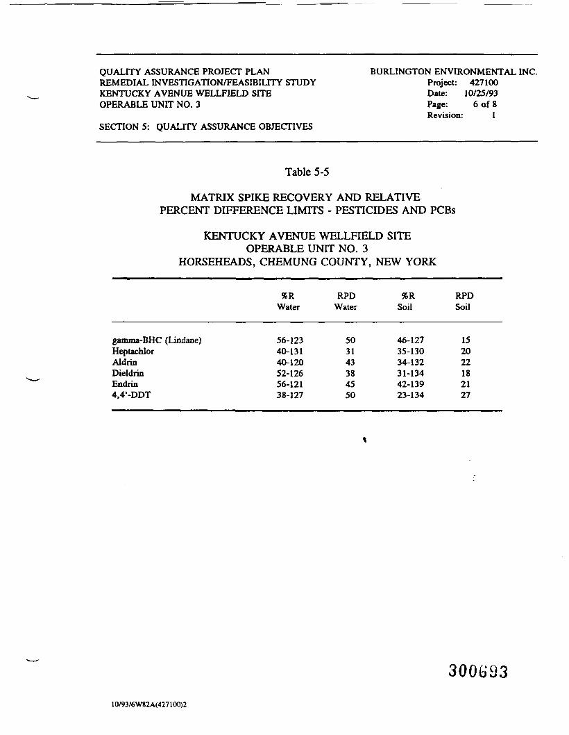
Accuracy is defined as the degree of agreement (nearness) of a measurementor the mean (X) of a set of results with an accepted reference or true value. Accuracyis assessed by means of reference samples (spike and spike duplicates) and percentrecoveries of these materials. The project objectives for accuracy are to provide datafor percent recovery within the guidelines presented in Tables 5-1 through Table 5-5.
5.2 Precision
Precision is the measure of mutual agreement of a set of replicate resultsamong themselves without assumption of any prior information as to the true result.Precision is assessed by means of duplicate/replicate sample analysis and is best
300G8810/93/6 W82 A(427100)2

QUALITY ASSURANCE PROJECT PLANREMEDIAL INVESTIGATION/FEASIBILITY STUDYKENTUCKY AVENUE WELLFIELD SITEOPERABLE UNIT NO. 3
SECTION 5: QUALITY ASSURANCE OBJECTIVES
BURLINGTON ENVIRONMENTAL INC.Project: 427100Date: 10/25/93Page: 2 of 8Revision: 1
expressed in terms of the standard deviation derived under prescribed similarconditions. The project objectives for precision are to generate data for percentvariance within the guidelines presented in Tables 5-1 through Table 5-5.
Table 5-1
ACCURACY AND PRECISION OBJECTIVES FOR MEASUREMENT DATA
KENTUCKY AVENUE WELLFIELD SITEOPERABLE UNIT NO. 3
HORSEHEADS, CHEMUNG COUNTY, NEW YORK
ParameterAccuracy Precision
VOCs1
SVOCs2
Metals3
Pesticices and PCBS4
Depth to groundwaterFluorideRECONGround Penetrating Radar
±0.01 ft.9580NA
909780NA
1 See Table 5-2.2 See Table 5-3.3 See Table 5-4.4 See Table 5-5.
10/93/6W82A(427IOO)2300G89
QUALITY ASSURANCE PROJECT PLANREMEDIAL INVESTIGATION/FEASIBILITY STUDYKENTUCKY AVENUE WELLFIELD SITEOPERABLE UNIT NO. 3
SECTIONS: QUALITY ASSURANCE OBJECTIVES
BURLINGTON ENVIRONMENTAL INC.Project: 427100Date: 10/25/93Page: 3 of 8Revision: 1
Table 5-2
MATRIX SPIKE RECOVERY ANDRELATIVE PERCENT DIFFERENCE LIMITS - VOCs
KENTUCKY AVENUE WELLFIELD SITEOPERABLE UNIT NO. 3
HORSEHEADS, CHEMUNG COUNTY, NEW YORK
%RWater
RPDWater Soil
RPDSoil
1 , 1-DichloroethaneTrichloroetheneBenzeneTolueneChlorobenzene
61-14571-12076-12776-12575-130
1414111313
59-17262-13766-14266-13960-133
2224212121
300G3010/93/6W82 A(427100)2
QUALITY ASSURANCE PROJECT PLANREMEDIAL INVESTIGATION/FEASIBILITY STUDYKENTUCKY AVENUE WELLFIELD SITEOPERABLE UNIT NO. 3
SECTION 5: QUALITY ASSURANCE OBJECTIVES
BURLINGTON ENVIRONMENTAL INC.Project: 427100Date: 10/25/93Page: 4 of 8Revision: 1
Table 5-3
MATRIX SPIKE RECOVERY ANDRELATIVE PERCENT DIFFERENCE LIMITS - SVOCs
KENTUCKY AVENUE WELLFIELD SITEOPERABLE UNIT NO. 3
HORSEHEADS, CHEMUNG COUNTY, NEW YORK
Phenol2-Chlorophenol1 ,4-Dichlorobenzenen-Nitroso-di-n-propylamine1 ,2,4-Trichlorobenzene4-Chloro-3-methylphenolAcenaphthene4-Nitrophenol2,4-DinitrotoluenePentachlorophenolPyrene
%RWater
12-11027-12336-9741-11639-9823-9746-11810-8024-969-10326-127
RPDWater
4240283828423150385031
%RSoil
26-9025-10228-10441-12638-10726-10331-13711-11428-8917-10935-142
RPDSoil
3550273823331950474736
300G9110/93/6W82A(427100)2
QUALITY ASSURANCE PROJECT PLANREMEDIAL INVESTIGATION/FEASIBILITY STUDYKENTUCKY AVENUE WELLFIELD SITEOPERABLE UNIT NO. 3
SECTION 5: QUALITY ASSURANCE OBJECTIVES
BURLINGTON ENVIRONMENTAL INC.Project: 427100Date: 10/25/93Page: 5 of 8Revision: 1
Table 5-4
ACCURACY AND PRECISIONOBJECTIVES FOR MEASUREMENT DATA,
METALS, AND INORGANICS (CLP)
KENTUCKY AVENUE WELLFIELD SITEOPERABLE UNIT NO. 3
HORSEHEADS, CHEMUNG COUNTY, NEW YORK
Parameter
AluminumAntimonyArsenicBariumBerylliumCadmuiinCalciumChromiumCobaltCopperCyanideIronLeadMagnesiumManganeseMercuryNickelPotassiumSeleniumSilverSodiumThalliumVanadiumZinc
Accuracy %Water
77-12063-12261-13775-11471-11776-10871-12273-10880-11077-11252-12665-12574-11168-13478-11461-12268-11775-12651-13068-11466-13164-12181-11370-118
Accuracy %Solid
66-13148-13761-13765-12360-12868-11659-13565-11673-11768-12152-12665-12564-12168-13469-12361-12256-12963-13851-13057-12549-14864-12175-12057-131
Precision %
202020202020202020202020202020202020202020202020
10/93/6W82A(427100)2300G92
QUALITY ASSURANCE PROJECT PLANREMEDIAL INVESTIGATION/FEASIBILITY STUDYKENTUCKY AVENUE WELLFIELD SITEOPERABLE UNIT NO. 3
SECTION 5: QUALITY ASSURANCE OBJECTIVES
BURLINGTON ENVIRONMENTAL INC.Project: 427100Date: 10/25/93Page: 6 of 8Revision: 1
Table 5-5
MATRIX SPIKE RECOVERY AND RELATIVEPERCENT DIFFERENCE LIMITS - PESTICIDES AND PCBs
KENTUCKY AVENUE WELLFIELD SITEOPERABLE UNIT NO. 3
HORSEHEADS, CHEMUNG COUNTY, NEW YORK
gamma-BHC (Lindane)HeptachlorAldrinDieldrinEndrin4,4'-DDT
%RWater
56-12340-13140-12052-12656-12138-127
RPDWater
503143384550
%RSoil
46-12735-13034-13231-13442-13923-134
RPDSoil
152022182127
30069310/93/6W82A(427100)2
QUALITY ASSURANCE PROJECT PLANREMEDIAL INVESTIGATION/FEASIBILITY STUDYKENTUCKY AVENUE WELLFIELD SITEOPERABLE UNIT NO. 3
SECTIONS: QUALITY ASSURANCE OBJECTIVES
BURLINGTON ENVIRONMENTAL INC.Project: 427100Date: 10/25/93Page: 7 of 8Revision: 1
5.3 Completeness
Completeness is a measure of the amount of valid data obtained compared tothe amount that was expected to be collected under normal operating conditions. Twocompleteness objectives will be calculated, one based on the total number of samplescollected and the second based on those samples reaching the laboratories intact. Thegoal of this QA/QC program is to generate valid data for at least 90 percent of thesamples collected and 95 percent of the samples analyzed by the laboratories.
5.4 Representativeness
Representativeness expresses the degree to which data accurately and preciselyrepresent a characteristic of a population, a process condition, an environmentalcondition, or parameter variations at a sampling point.
The field QA/QC procedures for sample handling, including chain-of-custody,
will provide for sample integrity until the time of analysis. To make certain that theanalytical results of this assessment are representative of the true field conditions,appropriate laboratory QA/QC procedures are prescribed.
5.5 Comparability
Comparability expresses the confidence with which one data set can becompared to another. To achieve comparability in this project, the data generated will
300G9410/93/6W82 A(427100)2
QUALITY ASSURANCE PROJECT PLANREMEDIAL INVESTIGATION/FEASIBILITY STUDYKENTUCKY AVENUE WELLFIELD SITEOPERABLE UNIT NO. 3
SECTION 5: QUALITY ASSURANCE OBJECTIVES
BURLINGTON ENVIRONMENTAL INC.Project: 427100Date: 10/25/93Page: 8 of 8Revision: 1
be reported using units of micrograms per liter (ug/L) and micrograms per kilogram(ug/kg) for water and soil samples, respectively, having low levels of contaminantsand milligrams per kilogram (mg/kg) and milligrams per liter (mg/L) for solids andliquid samples, respectively, having high levels of contaminants.
5.6 References
Guidelines and Specifications for Preparing Quality Assurance Program Plans,December 29, 1980, Office of Monitoring Systems and Quality Assurance,ORD, USEPA, QAMS-055/80, Washington, D.C. 20460.
Test Methods for Evaluating Solid Waste. Volumes I and II. November 1986, Officeof Solid Waste and Emergency Response, USEPA, SW-846, Washington, D.C.20460.
30069510/93/6W82A(427100)2
QUALITY ASSURANCE PROJECT PLANREMEDIAL INVESTIGATION/FEASIBILITY STUDYKENTUCKY AVENUE WELLFIELD SITEOPERABLE UNIT NO. 3
SECTION 6: SAMPLING PROCEDURES
BURLINGTON ENVIRONMENTAL INC.Project: 427100Date: 10/25/93Page: 1 of 13Revision: 1
6 SAMPLING PROCEDURES
Appropriate methods for obtaining acceptable samples from each sampledmedium have been selected for the RI/FS and are described in the Field Sampling Plan(Volume II). The following criteria have been considered in selecting the samplingmethods:
• representativeness;• compatibility with analytical considerations;• practicality;• simplicity and ease of operation; and• safety.
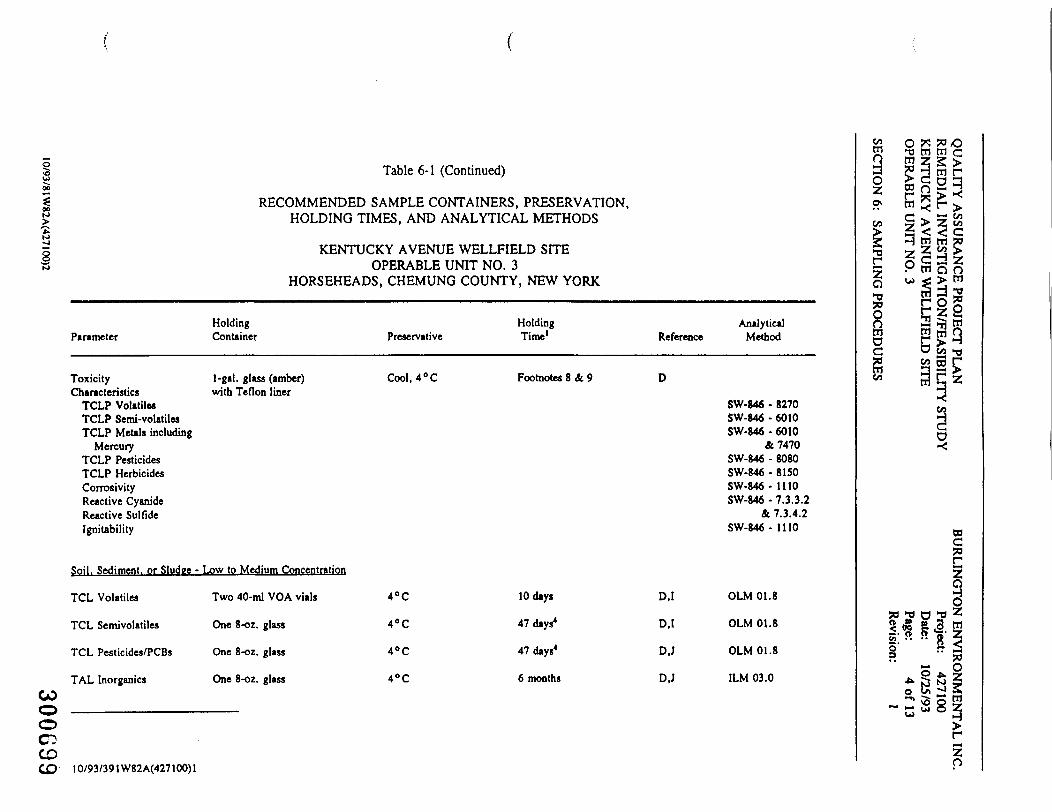
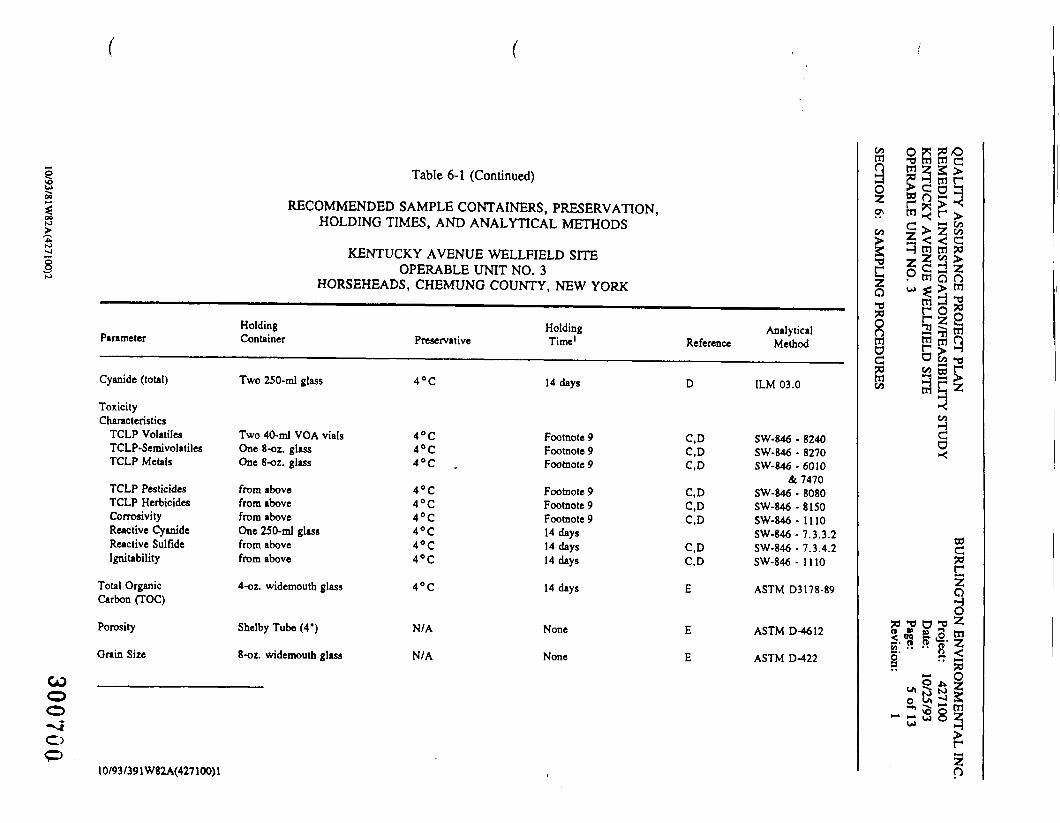
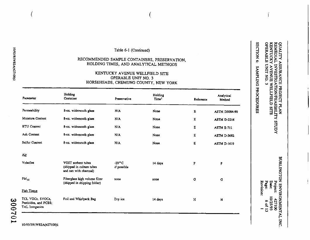
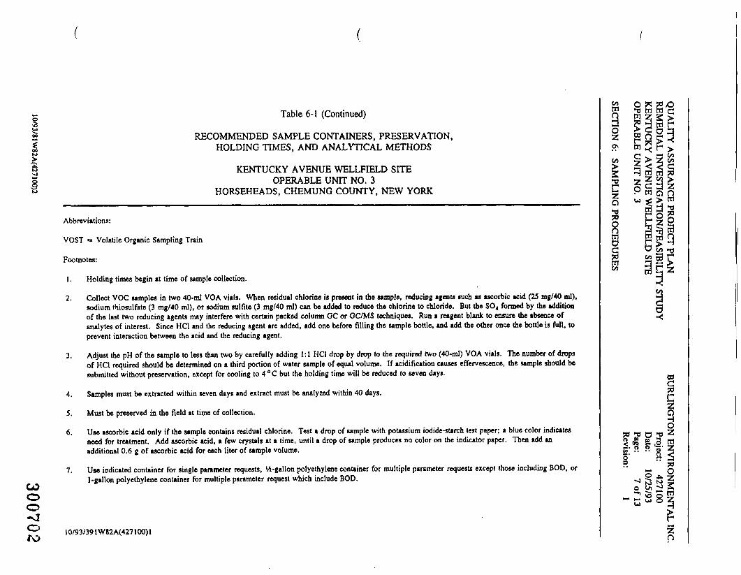
Table 6-1 is a listing of sample containers, preservatives, and volumerequirements.
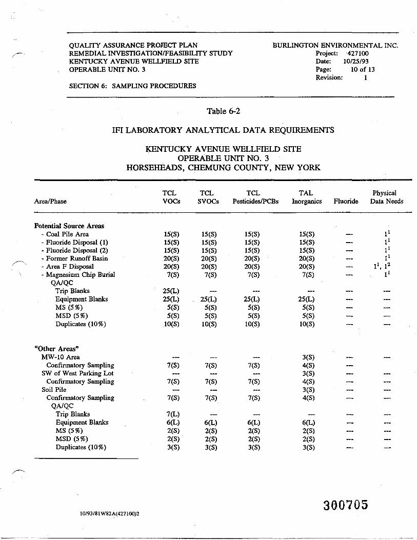
Table 6-2 provides a summary of total number of analyses (includng QA/QCsamples) currently planned for IFI activities in the Study Area.
30069610/93/81W82 A(427100)2
5u
to>1I10
Parameter
Aqueous
TCL Volatiles
TCL Semi-volatiles
TCL Pesticides/PBCs
TAL Inorganics
MercuryCOo0CD 'CD•*>!
10/93/391W82A(427100)
RECOMMENDED
Table 6-1
SAMPLE CONTAINERS. PRESERVATION.HOLDING TIMES. AND ANALYTICAL METHODS
KENTUCKY AVENUE WELLFIELD SITEOPERABLE UNIT NO. 3
HORSEHEADS, CHEMUNG COUNTY, NEW YORK
HoldingContainer
Two 40-ml vials withTeflon-lined septumcaps
1-gal. amber glassor two '/4-gal. amberglass with Teflon-lined closure
1-gal. amber glassor two 1 -liter amberglass with Teflon-lined closure
500-ml or 1 -liter polyethylenewith polyethylene-lined closure
500-ml or l-liter polethylenewith polyethylene-lined closure
1
Holding AnalyticalPreservative Time1 Reference Method
Acidify2-3 14 days A.I OLM O1.8Cool. 4° C
4°C 47 days4 A.I OLM 01.8
4°C 47 days4 A,I OLM 01.8
Concentrated 6 months B,J ILM 03.0Nitric Acid3,pH <2Cool, 4° C
Concentrated 28 days B.J ILM 03.0Nitric Acid5,pH >2Cool, 4° C
coWaoo\CO
*a
O*e5SQnmo2S3
t?1'5'a
fc-
o p* S*0" UJ Ul CH
r n £ 3m H; r >c -^ a <*Z ^ * e
P w o nuj < > tnw d 3p o 2S § sS w QC > -iO CO ^,co 53 rS § 23
ds><
»?o£^|
•fl D ** ^<ra 6 .3 W
& 255*1
KJ *> |Ti ^*N tj sra. ^ s^ S o E^^ ui o Zw ij
rzo
1 •00
to>1gs>
Parameter
TAL Cyanide (total)
Fluoride
TOC
00 ••—o0
CDCO
RECOMMENDED
Table 6-1 (Continued)-./.
SAMPLE CONTAINERS/PRESERVATION,HOLDING TIMES, AND ANALYTICAL METHODS
KENTUCKY AVENUE WELLFIELD SITEOPERABLE UNIT NO. 3
HORSEHEADS. CHEMUNG COUNTY. NEW YORK
HoldingContainer
1-literpolyethylene withpolyethylene orpolyethylene-linedclosure
500-ml or 1-liter polyethylenewith polyethylene orpolyethylene-linedclosure7
250-ml polyethlene
Holding AnalyticalPreservative Time1 Reference Method
Ascorbic 14 days A,J ILM O3.0Acid5-6
SodiumHydroxidepH>12CadmiumCarbonateif sulfideis presentCool,4°C
Cool, 4° C 28 days A EPA 340.2
H2S04 14 days C SW-846-9060pH<2
00W
9O55o*GO
•TJC25O
1o150
s
tf W W Clw 2 g; g
p Q5 3S 5 ^ >|>2|^ i i iP a § ou) ^ > W
|8|
§ g Qi, ^^O w ^oo B rI P ^
3cogoHj
WG2393
?0 *13 O *0 ^
|llf|o rr 2" 5
o^§w g S g
- ^ ^ i ^^ G 1 - ^ ^rNH
O10/93/391 W82A(427100) 1
QU
ALITY
ASSU
RAN
CE PROJECT PLA
NREM
EDIA
L INV
ESTIGA
TION
/FEASIBILITY
STUD
YK
ENTU
CKY
AV
ENU
E WELLFIELD
SITEO
PERABLE U
NIT N
O. 3
SECTION
6: SA
MPLIN
G PRO
CEDU
RES
BURLIN
GTO
N EN
VIR
ON
MEN
TAL IN
C.
Project: 427100
Date:
10/25/93Page:
4 of 13R
evision: 1
1coy,i_4J
H
zoH oo
< Q
> O
w i* <!
IE)ED SAMPLE CONTAIG TIMES, AND ANAL'
t; ZZ
HW
Q
i °
o
o05
^>06Ow
>•S |
Q
SJlilJTUCKY AVENUE WE
OPERABLE UNITEADS, CHEMUNG CO
i sf6
c/3
0ac
H "8f J^
1eo_
X
|sa.u
00 c
11
£(5
Parameter
«rj
C°
jr
f °°
°°
S S
S
SS
SS
S
5
o
in </> co
en c/i w> en v>
O
O
Q
Q
Q
o\^JOOs . %
,o
>» >,
1
* -3
o
o
r»U
. —
t
uo•5 0
<J
a ^
^
ge_
1
ll
|a|
100 U
2
"3 ja
S
"'^ i*
CO
O
c a
8^
""—
3
_a"5
"o
_
•! o
<°
si-s
|l ^-S
s
S
> J
5
•§ .0
g C
•§!"§
3 £•'?•§ £<u 3> >? g
.I^«sg
l5:s s ss
.1>>«>o,ft.o,S
oueuS-=-S
1S "S
.S
oJ
JJ
sJ
jp
uu
.^
^.
HC
CJ
tJ
UO
Oo
SS
pg
.H
HH
H
HO
«:^
&H
O
<rt
CO
° i
1 ?
s •?
^
OO
1 18
TCL Volatile*
TCL Semivolal
10/93/81W82A(427100)2
005
g
1 I*^
*^
Q
Q
* **
* 1
e^•* «0
U
U0
0
•v •v
M
VI
VI W
>
*oo "eo
9 9
OO
O
O
5 S
mOa.•"3;
tQ
8 .».
3 9
•- S?
1 1J
J(-
H
__^-v
8CMs00
O
300G99
QU
ALITY
ASSU
RAN
CE PROJECT PLA
NR
EMED
IAL IN
VESTIG
ATIO
N/FEA
SIBILITY STU
DY
KEN
TUCK
Y A
VEN
UE W
ELLFIELD SITE
OPERA
BLE UN
IT NO
. 3
SECTION
6: SA
MPLIN
G PRO
CEDU
RES
BURLIN
GTO
N EN
VIR
ON
MEN
TAL IN
C.
Project: 427100
Date:
10/25/93Page:
5 of 13R
evision: 1
c1Ui——
1
VO1
z~0PC
*<
Q>
0
a'S<? _45
"**
P <
1 "
Q H
Q O
RECOMMEN1HOLDIh
X20
LLFIELD SITENO. 3UNTY, NEW Y
W (-1 O
^ C
O
i«l
w W
S*C pj £c*w W
C_)
B <
g w
i sac
coaO
3-8>» *51
S•*
8|"oOC
ll?|o.
00 c
1 1
ac oseOu
CJ
CM
(f,
ooo
f:>ooo'^
'fc>
°?
c-t
CM
IN
OtjO
—
— '?
'?—
r^
S
Sw
oo
S^
Mo
o —
r-r-—
—
^
^i
°
lfl«
H
olio
loo
ol
2
S
S^
3*^st
^^
^^
st5
t ">
to to
—
(O(/1
<O
C
OM
IOC
OIO
CO
<
<
<
QO
Q
Q Q
Q
QO
Q
Oo
'o
UU
UU
CJ
oi
oi
01
O\
Ov
O\
O\
Ov
ON
<J O
O
O
4)
4>
>• 111
a g 1 >> s> >. >>
•3 III
l||-
3-3
^
-3
| S
^r o o
o
o 6
o
-rt- -rt-
rr °
°^^
(LiU
^tL
i (L
iU^
lJM
^-^
^i
^
2
Z
*
<J U
UU
U
CJ
UO
UU
O
<
<
**
> M
M
|
a
14
|aa i
! £ I
1
5M
M
S5
S1
5 ? §
|l
§
&$
$ £
22%
22 |
H|
c4 -»
oo
oo
« •
« *Q
« •
* >
,>
1 III !!!<
§!! Ill8
si ii
i-s^-
~ > " •§
5 S
«=a
I1"§
2 '«
li>6
>§&
-a
g1
s, -£
>^
S
laS:> «
«S
|2
a
5 .f? 3
3 3
5j S
3 1
« 'S
I <5 «
.£>
K1 -|§yyy
^^a
lll || i |
U
H U
H
0
(£
O
|t-Iooo\so
10/93/81W82A
(427100)2300700
QU
ALITY
ASSURANCE PROJECT PLA
NREM
EDIA
L INV
ESTIGA
TION
/FEASIBILITY
STUDYK
ENTU
CKY
AV
ENU
E WELLFIELD
SITEO
PERABLE U
NIT N
O. 3
SECTION
6: SA
MPLIN
G PRO
CEDU
RES
BURLIN
GTO
N EN
VIRO
NM
ENTA
L INC
.Project:
427100D
ate: 10/25/93
Page: 6 of 13
Revision:
1
?3CI,
\OIS£-
OH o
o
«<
Q
a:>
O
O
sjS |
£•->
j6^
<
W <
*> >-
m p
J O
£^r ^
^
i 2 |~
i^
^2
[T
) r
Q
M ||g
u P
2
j D
W 2
W
S 2
«-l <
> <
WS
oo
< m
K
< «
>2 ™
°-Q
H
p
Q§
0 |
WZ
S
U
SW
C |
M
glo
g
IK g
Us
"3 -a'f, J
I2o2
^"s2 .§-itga.
00 c
ll11weOu
S —
_
So 2
g
<S
P
m
-•
Q
Q
W
Q
D^
^g
^^
«
*• o
ac
S q
S S
5
UI
UI
WU
W
U.
O
X
•0
M>x
>.S
S*
10
* -3
« -3
ZT
'y
T
°y
^
&
**"
1C*
f-, **
1L
* ~
* Q
«-t
_<tt
°l -S
<<
<<
<
06
. S
£
.2
Z2
22
<^
S:
g
Q
it1 1 1
1 1
Jf
l! f
1 I 1 1
1
III 1:1 1
lilii
J
a
g•
§•
§*
§•
§•
§ o
^5
"^
"S *£?
*ff "ST
"S ** ^5
*• *• T!
"ON
Nf
^N
N
CO
Cl, "
fa
O,
__
99
99
9 9 "•§ *§
- - '-i "S
OO
O
O
OO
O
O
OO
>"
-sS
- o3 (J
Li v2-
tUa"8s
S "^ «—
e
V
i "O °
-^ a 1 g i « -V!
1 i M 1
i s 1 !^
«J
n^
3
-^
|!°
s
" !
2u
8<
0,
2
CQ
<
o
o
<l>
0
. U
.H
O.I-
1|<<s10/93/39IW8
10/93/81W82A
(427100)2300701
QU
ALITY
ASSU
RAN
CE PROJECT PLA
NREM
EDIA
L INV
ESTIGA
TION
/FEASIBILITY
STUDYK
ENTU
CKY
AV
ENU
E WELLFIELD
SITEO
PERABLE U
NIT N
O. 3
SECTION
6: SA
MPLIN
G PRO
CEDU
RES
BURLIN
GTO
N EN
VIR
ON
MEN
TAL IN
C.
Project: 427100
Date:
10/25/93Page:
7 of 13Revision:
1e 6-1 (Continued)
I
20llQ/ Mwp
CO mLE CONTAINERS, PREAND ANALYTICAL Ml
RECOMMENDED SAMPHOLDING TIMES,
VENUE WELLFIELD SKENTUCKY A mi3§a,O
£O>«*
EMUNG COUNTY, NFHORSEHEADS, CH
f §
2
3 =
i "° 3"Si's
8 ,,J
£»•• ^. ft S
li^j0
i 8"•e ^ 1 g§82
fe• *
| |12 «
e -aa « l-a8?
jf-2*• ••• ** 9«••§
a u
•i « .
^•cl-E.
« o §• B1"!
a
ijS
J« §s-s•!1§*
IIP.2 1
3 "
«
« •>
§ o
•s «ls5
S o «
-f'l« c ^ 2^
o S
^
.-s S; °- « pS >
.s s |
c 6 S
c "S »*» « S «•^ "^ ° Sf- s>
£ J
5 *
"
§"— --
""-S•a
J= g * •§ 1
1 *J«
«o
ri "5 ii « "S
£ 5 s .s 1 a
1 ! I5H
1»
o ^"Ssii«
8 li&
«S
o- .t;
TI. * o ce
- .s c «.s i
V) "
«! •-
*° V
1 f fills
! I I! H
Ir=
- >
'S -K o a
*i oo
*
»
I 1 1 lli|!
i i i
s al-oiitl
og
.-
< >
£
- M
P•i •§°-S•S-S.Q 9-3
2
0 3^ -9
•a 8
•rf* O
o |/•^ •>2 3^" 3 S,I.I-
3
•all•5* 8I?
2
° 8 "iII 1|l|U
J2 .1°
.S <» ~
•5 J 3
r? S °
S|*
«) U
^
lit23 §•Ji
"0 -S
p
-2
fc••
J\
Ii|
<*
ol
rn
'. analyzed within 40 days.
£to1B1fs1e3"8Ii8Tf
U time of collection.
2-.j3Must be preserved in 1^
3••5 a
.a 9•S s° 83"
clS- 8-ll
** "O•g .s? -Si
c:s o
'is.5 o
fl
1 s.«> JS
"E. g-E g^
•2
e s^g ^3
8 1.mple contains residual chlorine.)ic acid, a few crystals at a time,d for each liter of sample volume
ll 0d „
^.«
«*
-•
Use ascorbic acid onlyneed for treatment. Aadditional 0.6 g of asc
•o
gQOoq.£?•oao.a|Vsr£s|wD.
Uo.polyethylene container for mulhich include BOD.
5le parameter requests, Vi-gallon ]for multiple parameter request w
•- £IK
.C
(M
C
Use indicated containe1 -gallon polyethylene i
r^
/391W82A(427100)1«CJ
o
10/93/81W82 A
(427100)2300702

QU
ALITY
ASSU
RAN
CE PROJECT PLA
NREM
EDIA
L INV
ESTIGA
TION
/FEASIBILITY
STUD
YK
ENTU
CKY
AV
ENU
E WELLFIELD
SITEO
PERABLE U
NIT N
O. 3
SECTION
6: SAM
PLING PRO
CEDU
RES
BU
RLIN
GTO
N EN
VIR
ON
MEN
TAL IN
C.
Project: 427100
Date:
10/25/93Page:
8 of 13Revision:
1
O5s> oII2 2n
JC/3^ ^
"8 W
H
Table 6-1 (Continu
[ENDED SAMPLE CONTAINDING TIMES, AND ANALY
o§
UU)
a:
%O
1 *
Q
2, iW
« >-E xW
H*•? O
z
KENTUCKY AVENUE WELOPERABLE UNIT h
SEHEADS, CHEMUNG COU
05OX
jr the TCLP parameters:
«*-T? o
£
5"3
P-S
o§
|0o
! lil2
5? !k *°
•a •?
%$£$
- £ « °? £ «°
1 &
8> ™
- •• ~ ™
« 8•z jfuJi1 iisii£
>^
s£:5
00
2M.3•si1y50J«•scft.d0•>II8fi1•oiuop ^
^ o >
»
s |f
OO .rf*
^^
1
li t§l t
I 2
22
2 Js
•811 iu|L
tc
« x -S js a Hg* |°||||
•— ?• w
A. J-. -i
^;j^>
o. a. o. a. a. ft.
n^«
J-J
JJ
Jj
Hi
OO
UU
OO
^ "
H
HH
HH
H
o\
So\a12s§51*•£b^4)
•8a.vo"
ca.at,Ut.
« <->
1
5JJ«
«!•
so11S1>>I0
USEPA, Region I]
l-rt
•o9O1•o1U-O8£oa.01vtD.1i•so"tooO
vV-846 November 1986 and Decembe:
^~VI
^ Q
11
OT 00
00
Bc ^
'-a —
II
§
•S >
? S
s § 3
•* oo
oo8 |
^t" u
°^^
fnm
r! 0
10/93/81W82A
(427100)2
300703
QU
ALITY
ASSU
RAN
CE PROJECT PLA
NREM
EDIA
L INV
ESTIGA
TION
/FEASIBILITY
STUD
YK
ENTU
CKY
AV
ENU
E WELLFEELD
SITEO
PERABLE U
NIT N
O. 3
SECTION
6: SA
MPLIN
G PRO
CEDU
RES
BURLIN
GTO
N EN
VIR
ON
MEN
TAL INC.
Project: 427100
Date:
10/25/93Page:
9 of 13R
evision: 1
fo^^VOu•8H
z'0|s§w CS
w
§c«
<:ONTAINERANALYTIC
u pRECOMMENDED SAMPLE
HOLDING TIMES, AN
P
SF"700
yQ
S
W n
>T
i ^5 *^
gz|
W D
O5 w
5Z
. i P
KENTUCKY AVEOPERAB1
HORSEHEADS, CHEM
«-: ^oo 5E
1
H|a8*5Is• 3
II£ **
Is I^"8
1U
- U.
g_: _:
*•^
^3
^3
CM M
jj
II
1a. CL
S*>
* "
u, u. 5
O O
H
°°
^
Q
ui
D.
•g81«S5£3i**|H1a*5«IM£^D|a.ea.SMJ(Modified), Ross Analytical Services, In
I1
g1<4Cu >,
Ss
3<
uu
"3KIa.°M<£«5u.oIaiu.CJ5CJ
io.3V)
1ea-gS3_P2aEe1CL,
V]
DVMPwUUSediments and
_cipling and Analysis of Priority Pollutants980.
& sfU
-0
•S Sw
.y
<s **terim Methods,boratory, Rev
£ J
ac
oooOua818|uu31O1O.£1«oc«aV)
kE?O^
o<5oS~ia"%•^3
1IS1"3S?"3Sc-S2'531E?J1ou*S1J^
8N
10/93/81 W82A
(427100)2300704
QUALITY ASSURANCE PROJECT PLANREMEDIAL INVESTIGATION/FEASIBILITY STUDYKENTUCKY AVENUE WELLFIELD SITEOPERABLE UNIT NO. 3
SECTION 6: SAMPLING PROCEDURES
BURLINGTON ENVIRONMENTAL INC.Project: 427100Date: 10/25/93Page: 10 of 13Revision: 1
Table 6-2
IFI LABORATORY ANALYTICAL DATA REQUIREMENTS
KENTUCKY AVENUE WELLFIELD SITEOPERABLE UNIT NO. 3
HORSEHEADS, CHEMUNG COUNTY, NEW YORK
Area/PhaseTCLVOCs
TCLSVOCs
TCLPesticides/PCBs
TALInorganics Fluoride
PhysicalData Needs
Potential Source Areas- Coal Pile Area- Fluoride Disposal (1)- Fluoride Disposal (2)- Former Runoff Basin- Area F Disposal- Magnesium Chip Burial
QA/QCTrip BlanksEquipment BlanksMS (5%)MSD (5%)Duplicates (10%)
15(S)15(S)15(S)20(S)20(S)
7(S)
25(L)25(L)
5(S)5(S)
10(S)
15(S)15(S)
20(S)20(S)
7(8)
25(L)5(S)5(S)
10(S)
15(S)15(S)15(S)20(S)20(S)
7(S)
25(L)5(S)5(S)
10(S)
15(S)15(S)15(S)20(S)20(S)
7(S)
25(L)5(S)5(S)
10(S)
I1
I1
I1
I1
I1, I2
I1
"Other Areas"MW-10 Area
Confirmatory SamplingSW of West Parking Lot
Confirmatory SamplingSoil Pile
Confirmatory SamplingQA/QC
Trip BlanksEquipment BlanksMS (5%)MSD (5%)Duplicates (10%)
7(S)
7(S)
7(S)
7(L)6(L)2(S)2(S)3(S)
7(S)
7(S)
7(S)
6(L)2(S)2(S)3(8)
7(S)
7(S)
7(S)
6(L)2(S)2(S)3(S)
3(S)4(S)3(S)4(S)3(S)4(S)
6(L)2(S)2(S)3(S)
10/93/81W82 A(427100)2300705
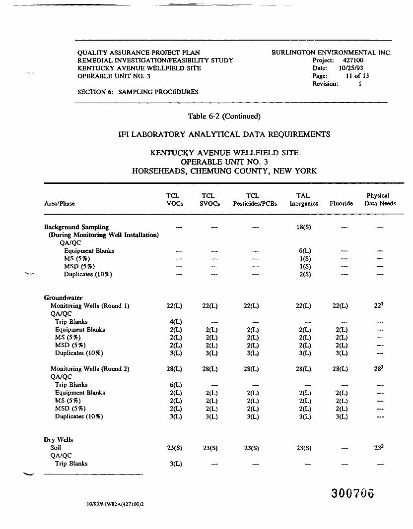
QUALITY ASSURANCE PROJECT PLANREMEDIAL INVESTIGATION/FEASIBILITY STUDYKENTUCKY AVENUE WELLFIELD SITEOPERABLE UNIT NO. 3
SECTION 6: SAMPLING PROCEDURES
BURLINGTON ENVIRONMENTAL INC.Project: 427100Date: 10/25/93Page: 11 of 13Revision: 1
Table 6-2 (Continued)
IFI LABORATORY ANALYTICAL DATA REQUIREMENTS
KENTUCKY AVENUE WELLFIELD SITEOPERABLE UNIT NO. 3
HORSEHEADS, CHEMUNG COUNTY, NEW YORK
Area/PhaseTCLVOCs
TCLSVOCs
TCLPesticides/PCBs
TALInorganics Fluoride
PhysicalData Needs
Background Sampling(During Monitoring Well Installation)
QA/QCEquipment BlanksMS (5%)MSD (5%)Duplicates (10%)
18(S)
6(L)
2(S)
GroundwaterMonitoring Wells (Round 1)QA/QC
Trip BlanksEquipment BlanksMS (5%)MSD (5%)Duplicates (10%)
Monitoring Wells (Round 2)QA/QC
Trip BlanksEquipment BlanksMS (5%)MSD (5%)Duplicates (10%)
22(L)
4(L)2(L)2(L)2(L)3(L)
28(L)
6(L)2(L)2(L)2(L)3(L)
22(L)
2(L)2(L)2(L)3(L)
28(L)
2(L)2(L)2(L)3(L)
22(L)
2(L)2(L)2(L)3(L)
28(L)
2(L)2(L)2(L)3(L)
22(L)
2(L)2(L)2(L)3(L)
28(L)
2(L)2(L)2(L)3(L)
22(L)
2(L)2(L)2(L)3(L)
28(L)
2(L)2(L)2(L)3(L)
223
283
Dry WellsSoilQA/QC
Trip Blanks
23(S)
3(L)
23(S) 23(S) 23(S) 232
10/93/81 W82A(427100)2300706
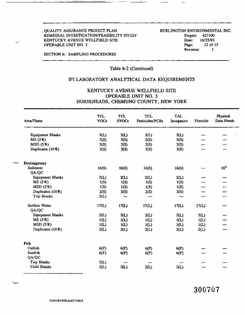
QUALITY ASSURANCE PROJECT PLANREMEDIAL INVESTIGATION/FEASIBILITY STUDYKENTUCKY AVENUE WELLFIELD SITEOPERABLE UNIT NO. 3
SECTION 6: SAMPLING PROCEDURES
BURLINGTON ENVIRONMENTAL INC.Project: 427100Date: 10/25/93Page: 12 of 13Revision: 1
Table 6-2 (Continued)
IFI LABORATORY ANALYTICAL DATA REQUIREMENTS
KENTUCKY AVENUE WELLFIELD SITEOPERABLE UNIT NO. 3
HORSEHEADS, CHEMUNG COUNTY, NEW YORK
Area/Phase
Equipment BlanksMS (5%)MSD (5%)Duplicates (10%)
DrainagewaySediment
QA/QCEquipment BlanksMS (5%)MSD (5%)Duplicates (10%)Trip Blanks
Surface WaterQA/QC
Equipment BlanksMS (5%)MSD (5%)Duplicates (10%)
FishCatfishSunfishQA/QC
Trip BlanksField Blanks
TCLVOCs
3(L)2(S)2(S)3(S)
16(S)
2(L)1(S)1(S)2(S)2(L)
17(L)
2(L)1(L)1(L)2(L)
6(F)6(F)
2(L)2(L)
TCL TCLSVOCs Pesticides/PCBs
3(L) 3(L)2(S) 2(S)2(S) 2(S)3(S) 3(S)
16(S) 16(S)
2(L) 2(L)1(S) 1(S)1(S) 1(S)2(S) 2(S)
— —
17(L) 17(L)
2(L) 2(L)1(L) 1(L)1(L) 1(L)2(L) 2(L)
6(F) 6(F)6(F) 6(F)
— —2(L) 2(L)
TALInorganics
3(L)2(S)2(S)3(S)
16(S)
2(L)1(S)1(S)2(S)
—
17(L)
2(L)1(L)1(L)2(L)
6(F)6(F)
—2(L)
PhysicalFluoride Data Needs
•— —— —•" ~*"~
- 164
— —— —
—— —— —
17(L) -
2(L) -1(L) —1(L) —2(L) —
— —— —
— ——
30070710/93/81W82 A(427100)2

QUALITY ASSURANCE PROJECT PLANREMEDIAL INVESTIGATION/FEASIBILITY STUDYKENTUCKY AVENUE WELLFIELD SITEOPERABLE UNIT NO. 3
SECTION 6: SAMPLING PROCEDURES
BURLINGTON ENVIRONMENTAL INC.Project: 427100Date: 10/25/93Page: 13 of 13Revision: 1
Table 6-2 (Continued)
IFI LABORATORY ANALYTICAL DATA REQUIREMENTS
KENTUCKY AVENUE WELLFIELD SITEOPERABLE UNIT NO. 3
HORSEHEADS, CHEMUNG COUNTY, NEW YORK
Area/PhaseTCLVOCs
TCLSVOCs
TCLPesticides/PCBs
TALInorganics Fluoride
PhysicalData Needs
Ambient AirAir
QA/QC 36(A)Trip Blanks 12(A)MS (5%) 3(A)MSD (5%) 3(A)Duplicates 12(A)Performance Eval. 1(A)
Investigation-derived WasteLiquid —Solids —
TOTALS (Including all QA/QC Samples)
36s
102
102
LiquidSolidFishAir
Notes:1 Physical data needs to evaluate for:
1781901267
129190
12—
129190
12—
151196
12—
91 —— —— —— —
• soil vapor extraction technology application are estimated to include: soil moisture, grain-size analysis, total organic carbon, bulk density, hydraulicconductivity, porosity; and
• thermal treatment to include: Btu content, ash content, and sulfur content.2 If any inherently waste-like material U encountered, RCRA characterization (as required) will be conducted including: TCLP toxicity (VOCs, SVOCs, metals,
pesticides, and herbicides); ignitability; reactivity; and corrosivity.3 Interface probe evaluation for LNAPLs and DNAPLs.4 Physical data needs include: 1) total organic carbon, 2) grain-size analysis, and 3) % moisture.5 Air sample evaluated for PM)0.(A) Air sample.(F) - Fish sample.(L) - Liquid Sample.(S) - Solid sample (soil or sediment).— Not applicable.
30070810/93/81 W82A(427100)2
QUALITY ASSURANCE PROJECT PLAN BURLINGTON ENVIRONMENTAL INC.REMEDIAL INVESTIGATION/FEASIBILITY STUDY Project: 427100KENTUCKY AVENUE WELLFIELD SITE Date: 10/25/93OPERABLE UNIT NO. 3 Page: 1 of 11
Revision: 1SECTION 7: SAMPLE CUSTODY AND DOCUMENTATION
7 SAMPLE CUSTODY AND DOCUMENTATION
Procedures for documentation concerning the collection of samples, fieldQA/QC, and sample custody are described in this section.
7.1 Identification of Samples for Chemical Analysis
Each sample will have a unique sample number based on the test boreholelocation and depth for soil samples and monitoring well designation for groundwatersamples.
All sample containers will be affixed with a label to prevent misidentificationof samples. The label will include, at a minimum, the following:
• initials of collector;• date and time of collection; and• sample number.
7.2 Field Documentation
Information pertinent to the work performed will be recorded in field logbooksand on field forms for sampling events and daily activities. Documentation byBurlington will be stored in the Burlington project file at the Pittsburgh, Pennsylvania,office upon completion of field work. Field forms to be used are included inAppendix C and are listed below:
30070910/93/60W82 A(427100)2
QUALITY ASSURANCE PROJECT PLAN BURLINGTON ENVIRONMENTAL INC.REMEDIAL INVESTIGATION/FEASIBILITY STUDY Project: 427100KENTUCKY AVENUE WELLFIELD SITE Date: 10/25/93OPERABLE UNIT NO. 3 Page: 2 of 11
Revision: 1SECTION 7: SAMPLE CUSTODY AND DOCUMENTATION
• field office sample tracking log;• soil/sediment sampling;• lagoon liquid/sludge log;• geologic log;• test pit log;• monitoring well installation;• water sampling data;• well development and purging general data;• water level data;• daily activities log;• site visitor log;• photograph log;• site supervisor's daily report;• chain-of-custody record; and• field logbook (not included in Appendix C).
Only those forms that are used during field activities will be completed andfiled in the project file.
All information pertinent to the sampling event will be recorded in the fieldlogbook (or series of logbooks) during performance of that activity. The field logbookwill be a bound book that has consecutively numbered pages and that will be suitablefor submission as evidence in legal proceedings. Field logbooks will be completed sothat later modifications or additions should not be necessary and all entries will bedescribed in as much detail as possible so that persons going to the Facility couldreconstruct a particular situation. These will become a part of the project file for thesite investigation. Logbooks will be assigned to field personnel, but will be stored inthe document center when not in use. Each logbook will be identified by the project-specific document number.
The title page of each notebook will contain the following:
• person to whom the book is assigned;• project name;
30071010/93/60W82A(427100)2
QUALITY ASSURANCE PROJECT PLAN BURLINGTON ENVIRONMENTAL INC.REMEDIAL INVESTIGATION/FEASIBIUTY STUDY Project: 427100KENTUCKY AVENUE WELLFIELD SITE Date: 10/25/93OPERABLE UNIT NO. 3 Page: 3 of 11
Revision: 1SECTION 7: SAMPLE CUSTODY AND DOCUMENTATION
• logbook number;• project start date; and• end date.
Entries in the Meld logbook(s) will contain three basic categories of informationincluding, but not limited to:
• site activities;• photo/survey data; and• sampling data.
Information to be entered in the field logbooks during soil sampling includesbut is not limited to:
• date/time/weather conditions;• sample number;• sampling location (based on site grid);• name(s) of sampler(s) and any observers;• estimated elevation;• total depth of borehole;• visual description;• OVA/HNu reading;• type of sample;• recovery;• resistance;• photograph number;• comments on deviation from the sampling plan; and• other information as required.
Groundwat^r sampling information to be entered in the field logbooks includes,but is not limited to the following:
30071110/93/60W82A(427100)2

QUALITY ASSURANCE PROJECT PLAN BURLINGTON ENVIRONMENTAL INC.REMEDIAL INVESTIGATION/FEASIBILITY STUDY Project: 427100KENTUCKY AVENUE WELLFIELD SITE Date: 10/25/93OPERABLE UNIT NO. 3 Page: 4 of 11
Revision: 1SECTION 7: SAMPLE CUSTODY AND DOCUMENTATION
date/time/weather conditions;well number;well location;names of samplers and any observers;any visible well damage;water level before purging;total depth of casing;calculated and actual water volume evacuated from well;time purge begins;color or sediment load and notation of any changes;time purge ends;water level after purging;presence or absence of a free product layer, both before andafter purging;time sample is taken;method or procedure used to obtain samples;temperature of water (°C);specific conductivity (umhos/cm);pH;pH meter check;sample preservation and/or filtering information;comments on deviation from the sampling plan; andother information as required.
Site activity entries will be completed daily to record all relevant siteinvestigation information and signed by the person making the entry. Thephotograph/survey and daily logs will be completed on an "as-performed" basis.
All entries will be made in ink and no erasures will be made. If an incorrectentry is made, the information will be crossed out with a single strike and thecorrection dated and initialed.
The field logbook will be kept throughout the field sampling operations todocument relevant information concerning sample generation, preparation, and fielddata. All well development/purging data, as well as sampling activities and data, will
30071210/93/60W82A(427100)2
QUALITY ASSURANCE PROJECT PLAN BURLINGTON ENVIRONMENTAL INC.REMEDIAL INVESTIGATION/FEASIBILITY STUDY Project: 427100KENTUCKY AVENUE WELLFIELD SITE Date: 10/25/93OPERABLE UNIT NO. 3 Page: 5 of 11
Revision: 1SECTION 7: SAMPLE CUSTODY AND DOCUMENTATION
be recorded on specified forms (provided weather conditions are dry) and filed in athree-ring binder. If precipitation occurs, information will be recorded in the fieldlogbook and then transferred to the forms at the end of the day.
One field audit will be performed by corporate QC personnel to audit the fielddocumentation. The audit will be unscheduled and unannounced to field personnel.Corrective action will be implemented if necessary.
7.3 Sample Chain-of-Custody Procedures
This section provides information about the procedures to be used to documentchain-of-custody for this project.
7.3.1 Field Chain-of-Custody Procedures
The field supervisor is responsible for the care and security of samples fromthe time the samples are taken until they have been turned over to the shipper orlaboratory. A sample is considered to be in one's custody if it is in plain view at alltimes, in the physical possession of the sampler, or stored in a locked place wheretampering is prevented.
To establish the documentation necessary to trace sample possession from thetime of collection, a serially numbered chain-of-custody record will be filled out toaccompany each sample. The chain-of-custody record will contain, at a minimum, thefollowing:
30071310/93/60W82A(427100)2
QUALITY ASSURANCE PROJECT PLAN BURLINGTON ENVIRONMENTAL INC.REMEDIAL INVESnOATION/FEASIBILITY STUDY Project: 427100KENTUCKY AVENUE WELLFIELD SITE Date: 10/25/93OPERABLE UNIT NO. 3 Page: 6 of 11
Revision: 1SECTION 7: SAMPLE CUSTODY AND DOCUMENTATION
sample number(s);signature of sampler(s);date and time of collection;sample location;sample type and class (if known);preservative;signature of persons involved in the chain-of-custody possession;inclusive dates of possession;shipping destination, carrier, and shipping bill number;analyses to be performed; andsample allocation.
An original chain-of-custody form will be completed at the time of sampling.A copy of the chain-of-custody form will be retained in the project file. The originalchain-of-custody form will accompany the samples during transportation to the shipperand, ultimately, the laboratory. An example of the chain-of-custody to be used isincluded in Appendix C.
The chain-of-custody record will be signed by appropriate Burlingtonpersonnel, sealed in a plastic bag, and taped to the inside lid of the shipping containerprior to sealing for shipment. This procedure typically occurs in view of the personabout to receive custody of the sample.
Any person accepting responsibility for the sample(s) will sign and date thechain-of-custody form.
7.3.2 Laboratory Chain-of-Custody Procedures
The laboratory will provide all glassware, preservation materials, shippingcontainers, and coolant for maintenance of protocol sample preservation requirementsfor the field sampling event(s). All sample containers provided by the laboratory will
IO/93/60W82A(427100)2 O\J\J 1X4
QUALITY ASSURANCE PROJECT PLAN BURLINGTON ENVIRONMENTAL INC.REMEDIAL INVESTIGATION/FEASIBILITY STUDY Project: 427100KENTUCKY AVENUE WELLFIELD SITE Date: 10/25/93OPERABLE UNIT NO. 3 Page: 7 of 11
Revision: 1SECTION 7: SAMPLE CUSTODY AND DOCUMENTATION
be obtained and prepared according to OSWER Directive #9240.0-05A entitled,"Specifications and Guidance for Contaminant-Free Sample Containers," December1992. The laboratory will coordinate shipment of samples with Burlington fieldpersonnel. Burlington field personnel will be responsible for preserving the chain-of-custody during all field activities. Field personnel will also be responsible forshipping samples via an express service. Sample container types and preservatives tobe supplied by the laboratory are described in Section 6. The laboratory will beresponsible, once a shipment of samples has been accepted, for completing the chain-of-custody program using appropriate laboratory chronicles. Documentation of allappropriate, internal chain-of-custody information will be included in the laboratory'sfinal analytical report.
A complete chain-of-custody record will be maintained to document thepossession of samples from the time the field sampling team is issued bottlewarethrough completion of analysis.
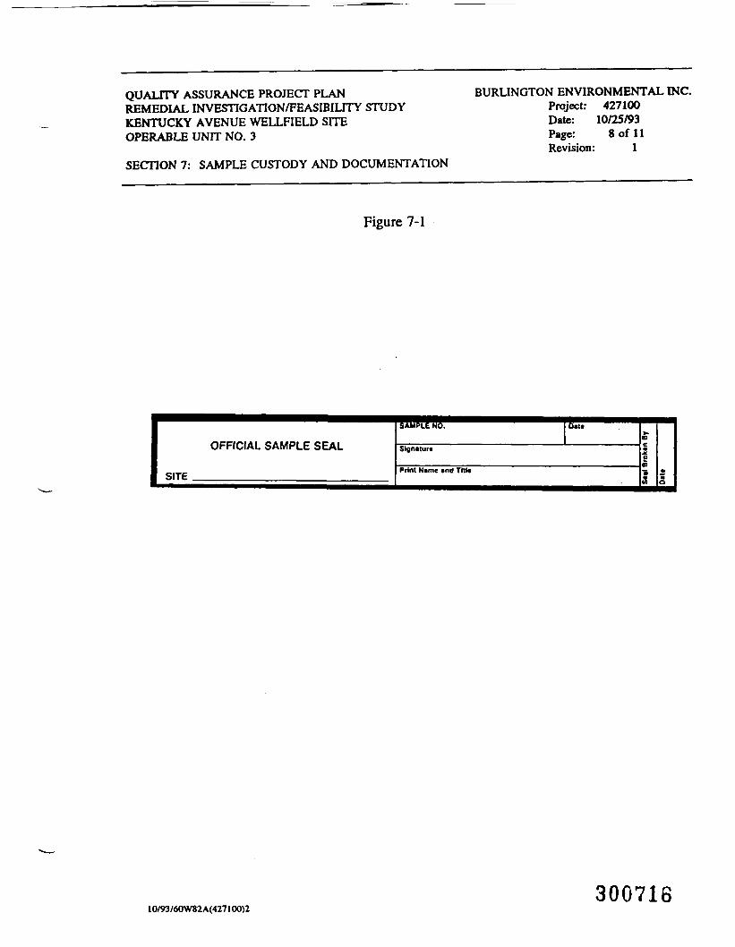
7.4 Custody Seals
Custody seals will be used to seal each sample container prior to samplepackaging in ice chests or coolers. Coolers containing samples must be sealed witha custody seal when not in the immediate possession of field personnel or secured inlocked storage. A sample custody seal is shown in Figure 7-1. Signed custody sealsshould be affixed to both ends of the cooler in such a manner that they must beremoved or broken to open the cooler. This can be accomplished by affixing onecustody seal to the front of the cooler, covering the space between the cooler's body
30071510/93/60W82A(427100)2
QUALITY ASSURANCE PROJECT PLANREMEDIAL INVESTIGATION/FEASIBILITY STUDYKENTUCKY AVENUE WELLFIELD SITEOPERABLE UNIT NO. 3
SECTION 7: SAMPLE CUSTODY AND DOCUMENTATION
BURLINGTON ENVIRONMENTAL INC.Project: 427100Date: 10/25/93Page: 8 of 11Revision: 1
Figure 7-1
OFFICIAL SAMPLE SEAL
SITE
SAMPLE NO.
Signature
0«U
Print Name «nd Till*
30071610/93/60W82A(427100)2
QUALITY ASSURANCE PROJECT PLAN BURLINGTON ENVIRONMENTAL INC.REMEDIAL INVESTIGATION/FEASIBILITY STUDY Project: 427100KENTUCKY AVENUE WELLFIELD SITE Date: 10/25/93OPERABLE UNIT NO. 3 Page: 9 of 11
Revision: 1SECTION 7: SAMPLE CUSTODY AND DOCUMENTATION
and the lid. Another seal is affixed to the other side of the cooler, diagonally oppositethe first seal. Fiberglass-reinforced tape should then be wrapped around both ends ofthe cooler. Tape should be wrapped sufficiently to afford secure closing, but not sothat the seal cannot be read through the tape. The chain-of-custody form must besigned and dated by both the relinquisher and the receiver each time the sampleschange hands (as in turning samples over to the possession of the laboratory). Thefirst entry should be signed by the sampler and subsequent entries must be signed bythe person who signed the most recent "received by" entry. The original custody andanalytical request forms will be kept in the laboratory files.
If the samples are sent by common carrier, a bill of lading should be used.Receipts of bills of lading will be retained as part of the permanent documentation.Commercial carriers are not required to sign off on the custody forms as long as thecustody forms are sealed inside the sample cooler and the custody seal remains intact.
7.5 Sample Packing and Shipping
Packing and shipping of samples will conform to the following protocol.
1. Sample container lids are to be secured with packing tape.
2. When packing liquids, volume levels will be marked on the bottle using anindelible marker.
3. Approximately 3 inches of inert cushioning material will be placed in thebottom of the cooler.
4. Containers will be placed in the cooler so that they do not touch each other.
5. VOA vials will be placed in a Ziploc bag or a container and will be positionedin the center of the cooler.
10/93/60W82A(427100)2 30071 7
QUALITY ASSURANCE PROJECT PLAN BURLINGTON ENVIRONMENTAL INC.REMEDIAL INVESTIGATION/FEASIBILITY STUDY Project: 427100KENTUCKY AVENUE WELLFIELD SITE Date: 10/25/93OPERABLE UNIT NO. 3 Page: 10 of 11
Revision: 1SECTION 7: SAMPLE CUSTODY AND DOCUMENTATION
6. Samples will be packed in ice enclosed in plastic bags. Sufficient ice will beused so as to maintain the samples at a temperature of 4°C during shipment.
7. The cooler will be filled with cushioning material.
8. Paperwork will be placed in plastic bags and securely taped to the inside lid ofthe cooler.
9. The cooler drain, if one is present, will be taped shut.
10. The cooler will be wrapped completely with strapping tape at two points.Labels will not be covered.
11. The laboratory address will be affixed to the top of the cooler.
12. "This Side Up" labels with directional arrows will be affixed on the sides ofthe box and "Fragile" labels will be affixed on at least two sides.
13. Samples will be shipped to the analytical laboratory via an express service.
7.6 Laboratory Quality Control
Upon receipt of the shipping container, the laboratory will inspect the custodyseal for its integrity. The ice chest or cooler will be opened and the shipment checkedversus the chain-of-custody.
Any inconsistencies or problems with a sample shipment (such as breakage)will be reported to the QA/QC Coordinator for immediate resolution.
When any/all problems are resolved, the corrective action will be documented.The official custody of the samples will be accepted by the laboratory by signing thechain-of-custody. The samples will then be tracked through the laboratory by internalcustody procedures.
30071310/93/60W82A(427100)2
QUALITY ASSURANCE PROJECT PLAN BURLINGTON ENVIRONMENTAL INC.REMEDIAL INVESTIGATION/FEASIBILITY STUDY Project: 427100KENTUCKY AVENUE WELLFDELD SITE Date: 10/25/93OPERABLE UNIT NO. 3 Page: 11 of 11
Revision: 1SECTION 7: SAMPLE CUSTODY AND DOCUMENTATION
QA/QC procedures to be followed by the analytical laboratory during samplehandling, analysis, and reporting will follow Contract Laboratory Program (CLP)protocol. Upon selection of the laboratory (or laboratories) that will conduct theanalytical portion of this work, QA/QC procedures will become part of this documentas Appendix D.
30071910/93/60W82A(427100)2
QUALITY ASSURANCE PROJECT PLAN BURLINGTON ENVIRONMENTAL INC.REMEDIAL INVESTIGATION/FEASIBILITY STUDY Project: 427100KENTUCKY AVENUE WELLFIELD SITE Date: 10/25/93OPERABLE UNIT NO. 3 Page: 1 of 4
Revision: 1SECTION 8: CALIBRATION PROCEDURES AND FREQUENCY
8 CALIBRATION PROCEDURES AND FREQUENCY
Burlington's field instruments are maintained with a formal calibrationprogram. The program assures that equipment is of the proper type, range, accuracy,and precision to provide data compatible with the specified requirements and desiredresults. Calibration of measuring and test equipment may be performed internallyusing reference standards or externally by agencies or manufacturers. Calibration ofin-house reference standards is, in general, performed externally. The field teamleaders and field personnel are responsible for the calibration of equipment when inthe field. Field equipment is checked and calibrated in-house by a maintenance orother personnel selected by the quality assurance manager prior to the start of eachfield project.
Measuring and test equipment and reference standards are calibrated atprescribed intervals and/or prior to each use. Calibration frequency is based on thetype of equipment, inherent stability, manufacturer's recommendations, values givenin national standards, intended use, and experience.
In some cases, particularly for field equipment, scheduled periodic calibrationis not performed when the equipment is not continuously in use. Such equipment iscalibrated on an as-needed basis prior to use, then, at the required frequencies duringuse.
Field equipment is uniquely identified by either the manufacturer's serialnumber, identification number, or other internal tracking system. This identification,and a label indicating when the equipment was last calibrated and when the nextcalibration is required, is attached to the equipment. When this is not possible,records traceable to the equipment will be made available for reference.
30072010/93/61W82A(427100)2
QUALITY ASSURANCE PROJECT PLAN BURLINGTON ENVIRONMENTAL INC.REMEDIAL INVESTIGATION/FEASIBILrTY STUDY Project: 427100KENTUCKY AVENUE WELLFIELD SITE Date: 10/25/93OPERABLE UNIT NO. 3 Page: 2 of 4
Revision: 1SECTION 8: CALIBRATION PROCEDURES AND FREQUENCY
Equipment users are responsible for checking the equipment calibration priorto use.
8.1 Photoionization Detectors
The calibration procedures and frequency are described in Appendix E,Burlington's Standard Operating Procedures (SOPs) No. H&S 442.
8.2 pH Meter
The calibration procedures and frequency are described in Appendix F,Burlington's SOPs for the pH meter.
8.3 Specific Conductivity Meter
The calibration procedures and frequency are described in Appendix G,Burlington's SOPs for the specific conductivity meter.
30072110/93/61W82 A(427100)2
QUALITY ASSURANCE PROJECT PLAN BURLINGTON ENVIRONMENTAL INC.REMEDIAL INVESTIGATION/FEASffilLrrY STUDY Project: 427100KENTUCKY AVENUE WELLFIELD SITE Date: 10/25/93OPERABLE UNIT NO. 3 Page: 3 of 4
Revision: 1SECTION 8: CALIBRATION PROCEDURES AND FREQUENCY
8.4 Gas Chromatograph
The GC on the RECON System will be calibrated in the following manner.Concentration measurements will be performed using an external standard calibration.Known concentrations of compounds of concern [TCE; trans-l,2-dichloroethene(trans-1,2-DCE); cis-l,2-dichloroethene (cis-l,2-DCE); tetrachloroethene (PERC); andbenzene, toluene, ethylbenzene, and xylenes (BTEX)] in a calibration gas mixture willbe injected into the GC. The GC will be calibrated initially upon arrival on-site usingthree external standards of known concentration of the eight compounds of concern.Calibration curves indicating compound peak area versus standard concentration willbe used to calculate compound concentration in the sample. Subsequent to this initialthree-point calibration, calibration checks will be conducted twice daily (beforesampling in the morning and after lunch in the afternoon) using a single standard.This standard will be prepared at a known concentration of the eight compounds ofconcern equivalent to the midpoint of the initial three-point calibration. A devianceof greater than 30 percent from the initial calibration for any of the compounds willsignify the need to recalibrate the instrument using the three-point calibration method.
8.5 Radar System
The radar system selected for use at the site is the GSSI SIR-3 using a500 MHz monostable antenna. The system is manufactured by Geophysical SurveySystems, Inc., of North Salem, New Hampshire. The radar system includes aninternal calibration circuit and no additional calibration is specified by themanufacturer.
30072210/93/61W82 A(427100)2
QUALITY ASSURANCE PROJECT PLAN BURLINGTON ENVIRONMENTAL INC.REMEDIAL INVESTIGATION/FEASIBILITY STUDY Project: 427100KENTUCKY AVENUE WELLFIELD SITE Date: 10/25/93OPERABLE UNIT NO. 3 Page: 4 of 4
Revision: 1SECTIONS: CALIBRATION PROCEDURES AND FREQUENCY
The equipment will be rented from Fett Instruments, Inc., (Fett) of Austin,Texas. Fett has developed an additional calibration procedure at their facility whichis applied to every radar instrument prior to rental. This procedure consists essentiallyof transmitting the radar pulse in air over a precisely measured distanced to a metallicreflector and back to the receiver antenna. The observed travel time is compared andadjusted to match the travel time calculated using the known radar propagation velocityin air.
8.6 Laboratory Equipment
The laboratory or laboratories that will perform the analyses of the samplescollected from the Study Area has not been selected at this time. Laboratory qualitycontrol procedures, which include instrument calibration, will follow the most currentrevisions to the USEPA Statement of Work (SOWs):
• Statement of Work for Organics Analysis, OLM 01.8; and
• Statement of Work for Inorganic Analyses, ILM 03.0.
Upon selection of the laboratory or laboratories that will conduct the analyticalportion of this work, QA/QC procedures will become part of this document asAppendix D.
30072310/93/61W82A(427lOO)2
QUALITY ASSURANCE PROJECT PLANREMEDIAL INVESTIGATION/FEASIBILITY STUDYKENTUCKY AVENUE WELLFIELD SITEOPERABLE UNIT NO. 3
SECTION 9: ANALYTICAL PROCEDURES
BURLINGTON ENVIRONMENTAL INC.Project: 427100Date: 10/25/93Page: 1 of 10Revision: 1
9 ANALYTICAL PROCEDURES
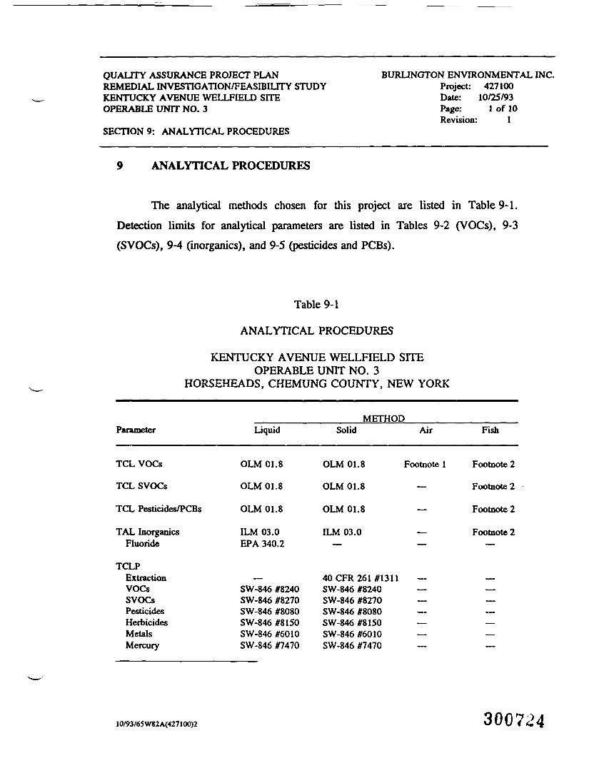
The analytical methods chosen for this project are listed in Table 9-1.Detection limits for analytical parameters are listed in Tables 9-2 (VOCs), 9-3(SVOCs), 9-4 (inorganics), and 9-5 (pesticides and PCBs).
Table 9-1
ANALYTICAL PROCEDURES
KENTUCKY AVENUE WELLFIELD SITEOPERABLE UNIT NO. 3
HORSEHEADS, CHEMUNG COUNTY, NEW YORK
Parameter
TCL VOCs
TCL SVOCs
TCL Pesticides/PCBs
TAL InorganicsFluoride
TCLPExtractionVOCsSVOCsPesticidesHerbicidesMetalsMercury
Liquid
OLM 01.8
OLM 01.8
OLM 01.8
ILM 03.0EPA 340.2
—SW-846 #8240SW-846 #8270SW-846 #8080SW-846 #8150SW-846 #6010SW-846 #7470
METHODSolid Air
OLM 01.8 Footnote 1
OLM 01.8 —
OLM 01.8 —
ILM 03.0 —— —
40 CFR 261 #13 11 —SW-846 #8240 —SW-846 #8270 —SW-846 #8080SW-846 #8150 —SW-846 #6010SW-846 #7470 —
Fish
Footnote 2
Footnote 2
Footnote 2
Footnote 2—
———————
10/93/65W82A(427100)2 300724
QUALITY ASSURANCE PROJECT PLANREMEDIAL INVESTIGATION/FEASIBILITY STUDYKENTUCKY AVENUE WELLFIELD SITEOPERABLE UNIT NO. 3
SECTION 9: ANALYTICAL PROCEDURES
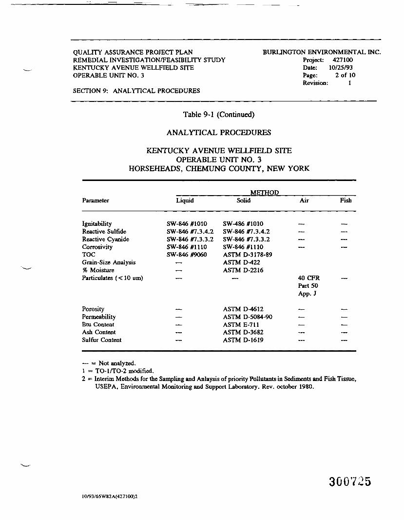
BURLINGTON ENVIRONMENTAL INC.Project: 427100Date: 10/25/93Page: 2 of 10Revision: 1
Table 9-1 (Continued)
ANALYTICAL PROCEDURES
KENTUCKY AVENUE WELLFIELD SITEOPERABLE UNIT NO. 3
HORSEHEADS, CHEMUNG COUNTY, NEW YORK
ParameterMETHOD
Liquid Solid Air Fish
Igni labilityReactive SulfideReactive CyanideCorrosivityTOCGrain-Size Analysis% MoistureParticulates (< 10 um)
PorosityPermeabilityBtu ContentAsh ContentSulfur Content
SW-846 #1010SW-846 #7.3.4.2SW-846 #7.3.3.2SW-846 #1110SW-846 #9060
SW-486 #1010SW-846 #7.3.4.2SW-846 #7.3.3.2SW-846 #1110ASTM D-3178-89ASTM D-422ASTM D-2216
ASTM D-4612ASTM D-5084-90ASTME-711ASTM D-3682ASTM D-1619
40CFRPart 50App. J
— = Not analyzed.1 = TO-l/TO-2 modified.2 = Interim Methods for the Sampling and Anlaysis of priority Pollutants in Sediments and Fish Tissue,
USEPA, Environmental Monitoring and Support Laboratory. Rev. October 1980.
30072510/93/65 W82 A(427100)2
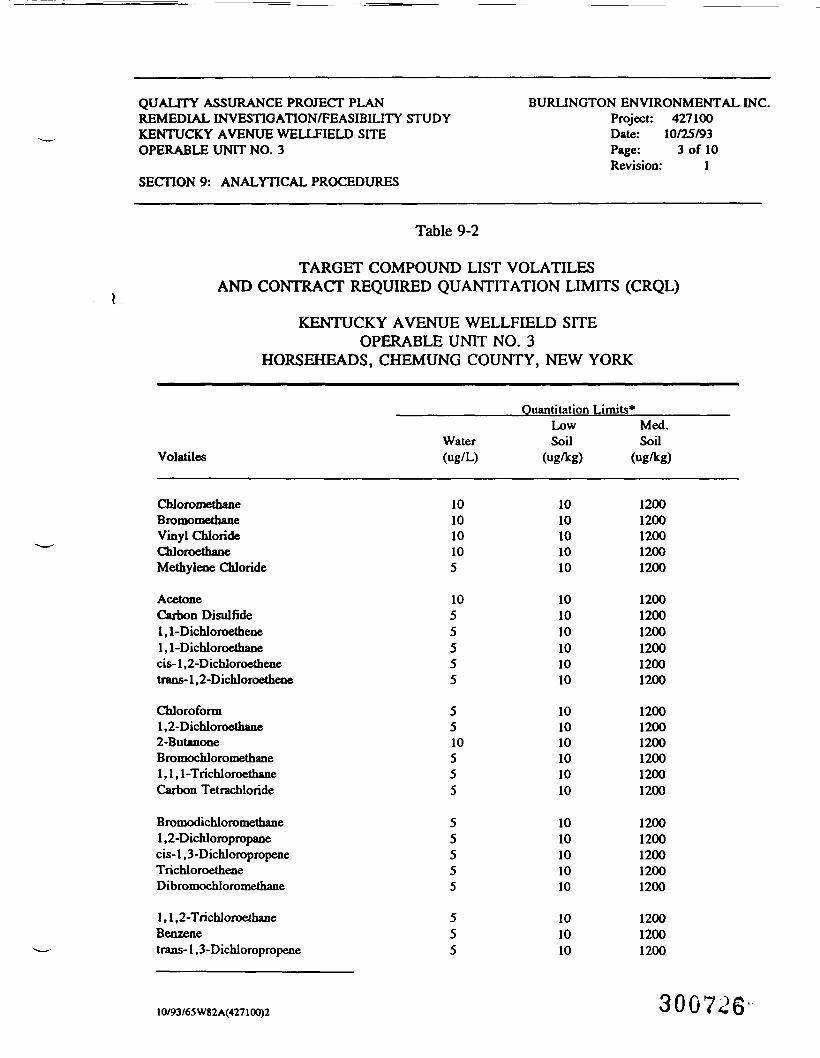
QUALITY ASSURANCE PROJECT PLANREMEDIAL INVESTIGATION/FEASIBILITY STUDYKENTUCKY AVENUE WELLFIELD SITEOPERABLE UNIT NO. 3
SECTION 9: ANALYTICAL PROCEDURES
BURLINGTON ENVIRONMENTAL INC.Project: 427100Date: 10/25/93Page: 3 of 10Revision: 1
Table 9-2
TARGET COMPOUND LIST VOLATILESAND CONTRACT REQUIRED QUANTITATION LIMITS (CRQL)
KENTUCKY AVENUE WELLFIELD SITEOPERABLE UNIT NO. 3
HORSEHEADS, CHEMUNG COUNTY, NEW YORK
VolatilesWater(ug/L)
Ouantitation Limits*LowSoil
(ug/kg)
Med.Soil
ChloromethaneBro mo methaneVinyl ChlorideChloroethaneMethylene Chloride
AcetoneCarbon Disulfide1,1 -Dichloroethene1.1-Dichloroetbanecis-1,2-Dichloroethenetrans-1,2-Dichloroethene
Chloroform1.2-Dichloroethane2-ButanoneBromochloromethane1,1,1 -TrichloroethaneCarbon Tetrachloride
Bromodichloromethane1,2-Dichloropropanecis-1,3-DichloropropeneTrichloroetheneDibromochloromethane
1,1,2-TrichloroethaneBenzenetrans-1,3-Dichloropropene
101010105
1055555
5510555
55555
555
1010101010
101010101010
101010101010
1010101010
101010
12001200120012001200
120012001200120012001200
120012001200120012001200
12001200120012001200
120012001200
10/93/65W82A(427100)2 300726'
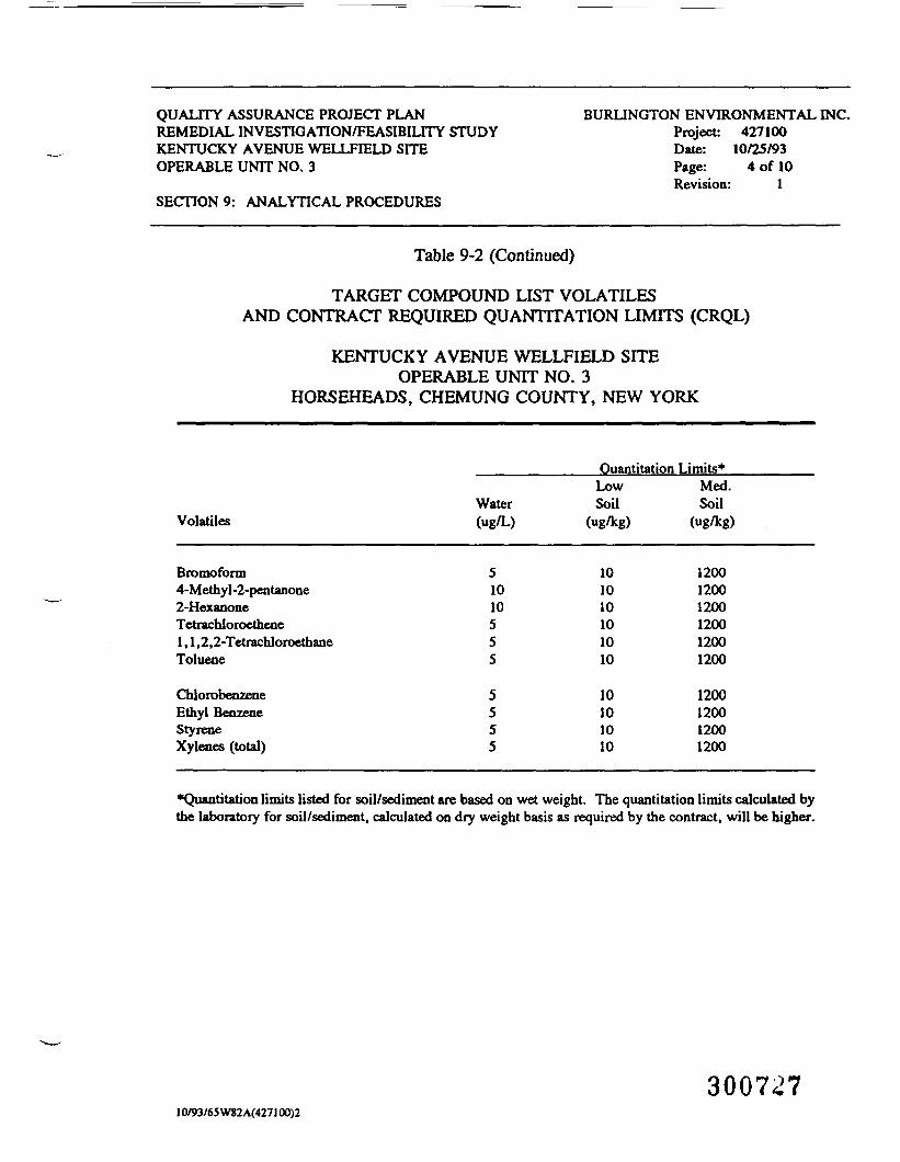
QUALITY ASSURANCE PROJECT PLANREMEDIAL INVESTIGATION/FEASIBILITY STUDYKENTUCKY AVENUE WELLFIELD SITEOPERABLE UNIT NO. 3
SECTION 9: ANALYTICAL PROCEDURES
BURLINGTON ENVIRONMENTAL INC.Project: 427100Date: 10/25/93Page: 4 of 10Revision: 1
Table 9-2 (Continued)
TARGET COMPOUND LIST VOLATILESAND CONTRACT REQUIRED QUANTITATION LIMITS (CRQL)
KENTUCKY AVENUE WELLFIELD SITEOPERABLE UNIT NO. 3
HORSEHEADS, CHEMUNG COUNTY, NEW YORK
Ouantitation Limits*
Volatiles
Bromofonn4-Methyl-2-pentanone2-HexanoneTetrachloroethene1 , 1 ,2,2-TetrachloroethaneToluene
ChlorobenzeneEthyl BenzeneStyreneXylenes (total)
Water(ug/L)
51010555
5555
LowSoil
(ug/kg)
101010101010
10101010
Med.Soil
(ug/kg)
120012001200120012001200
1200120012001200
"Quantitation limits listed for soil/sediment are based on wet weight. The quantitation limits calculated bythe laboratory for soil/sediment, calculated on dry weight basis as required by the contract, will be higher.
3007^710/93/65 W82 A(427100)2

QUALITY ASSURANCE PROJECT PLANREMEDIAL INVESTIGATION/FEASIBILITY STUDYKENTUCKY AVENUE WELLFffiLD SITEOPERABLE UNIT NO. 3
SECTION 9: ANALYTICAL PROCEDURES
BURLINGTON ENVIRONMENTAL INC.Project: 427100Date: 10/25/93Page: 5 of 10Revision: 1
Table 9-3
TARGET COMPOUND LIST SEMTVOLATILESAND CONTRACT REQUIRED QUANTTTATION LIMITS (CRQL)*
KENTUCKY AVENUE WELLFIELD SITEOPERABLE UNIT NO. 3
HORSEHEADS, CHEMUNG COUNTY, NEW YORK
SemivolatilesWater(ug/L)
Ouantitation Limits**LowSoil
(ug/kg)
Med.Soil*
(ug/kg)
Phenolbis(2-Chloroethyl) ether2-Chlorophenol1.3-DicbJorobenzene1.4-Dichlorobenzene
Benzyl alcohol1,2-Dichlorobenzene2-Methylphenolbis(2-Chloroisopropyl) ether4-Methylphenol
N-Nitroso-di-n-propylamineHexachloroethaneNitrobenzeneIsophorone2-Nitrophenol
2,4-DimethylphenolBenzole acidbis(2-Chloroethoxy) methane2,4-Dichlorophenol1,2,4-Trichlorobenzene
Naphthalene4-Chloroaniline
1010101010
1010101010
1010101010
1050101010
1010
330330330330330
330330330330330
330330330330330
3301600330330330
130330
1000010000100001000010000
1000010000100001000010000
1000010000100001000010000
1000010000100001000010000
1000010000
30072810/93/65W82A(427100)2
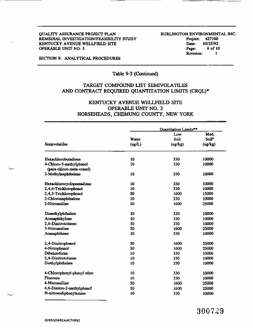
QUALITY ASSURANCE PROJECT PLANREMEDIAL INVESTIGATION/FEASIBILITY STUDYKENTUCKY AVENUE WELLFffiLD SITEOPERABLE UNIT NO. 3
SECTION 9: ANALYTICAL PROCEDURES
BURLINGTON ENVIRONMENTAL INC.Project 427100Date: 10/25/93Page: 6 of 10Revision: 1
Table 9-3 (Continued)
TARGET COMPOUND LIST SEMIVOLATILESAND CONTRACT REQUIRED QUANTITATION LIMITS (CRQL)*
KENTUCKY AVENUE WELLFffiLD SITEOPERABLE UNIT NO. 3
HORSEHEADS, CHEMUNG COUNTY, NEW YORK
SemivolatilesWater(ug/L)
Ouantitation Limits**LowSoil
(ug/kg)
Mod.Soil'
Hexachlorobutadiene4-Chloro-3-methylphenol
(para-chloro-meta-cresol)2-Methylnaphthalene
Hexachlorocyclopentadiene2,4,6-Trichlorophenol2,4,5-Trichlorophenol2-Chloronaphthaleoe2-Nitroaniline
DimethylphthalateAceoaphthylene2,6-Dinitrotoluene3-NitroanilineAcenaphthene
2,4-Dinitrophenol4-NitrophenolDibenzofuran2,4-DinitrotolueneDiethylphthalate
4-Chlorophenyl-pheoyI etherFluorene4-Nitroaniline4,6-Dinitro-2-methylphenolN-nitrosodipheoylamine
1010
10
1010501050
1010105010
5050101010
1010505010
330330
330
33033016003301600
3303303301600330
16001600330330330
33033016001600330
1000010000
10000
1000010000150001000025000
1000010000100002500010000
2500025000100001000010000
1000010000250002500010000
30072910/93/65W82A(427100)2
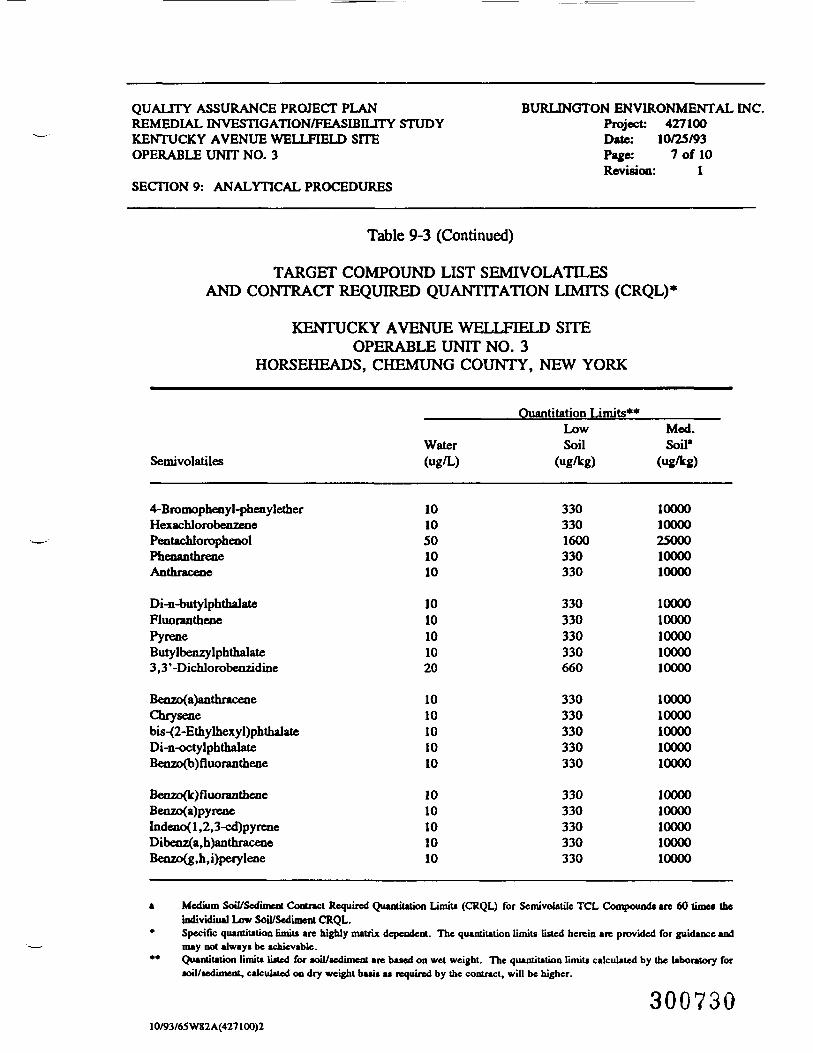
QUALITY ASSURANCE PROJECT PLANREMEDIAL INVESTIGATION/FEASIBILITY STUDYKENTUCKY AVENUE WELLFffiLD SITEOPERABLE UNIT NO. 3
SECTION 9: ANALYTICAL PROCEDURES
BURLINGTON ENVIRONMENTAL INC.Project: 427100Date: 10/25/93Page: 7 of 10Revision: 1
Table 9-3 (Continued)
TARGET COMPOUND LIST SEMTVOLATILESAND CONTRACT REQUIRED QUANTTTATION LIMITS (CRQL)*
KENTUCKY AVENUE WELLFffiLD SITEOPERABLE UNIT NO. 3
HORSEHEADS, CHEMUNG COUNTY, NEW YORK
Ouantitation Limits**
Semivolatiles
4-Bromophenyl-phenyletherHexachlorobenzenePentachlorophenolPhenanthreneAnthracene
Di-n-butylphthalateFluoranthenePyreneButylbenzylphthalate3,3'-Dichlorobeazidine
Benzo(a)anthraceneChrysenebis-{2-EthylhexyI)phthalateDi-n-octylphthalateBenzo(b)fluoranthene
Benzo(k)fluorantheneBenzo(a)pyreneIndeno{ 1 ,2,3-cd)pyreneDibenz(a,h)anthraceneBenzo(g,h,i)perylene
Water(ug/L)
1010501010
1010101020
1010101010
1010101010
LowSoil
(ug/kg)
3303301600330330
330330330330660
330330330330330
330330330330330
Med.Soil1
(ug/kg)
1000010000250001000010000
1000010000100001000010000
1000010000100001000010000
1000010000100001000010000
Medium Soil/Sediment Contract Required Quantitation Limits (CRQL) for Semivoiatile TCL Compound* are 60 times thebdividiual Low Soil/Sediment CRQL.Specific quantiiation limiu are highly matrix dependent. The quantiutioa limits listed herein are provided for guidance andmay not always be achievable.Quantitation limiu listed for soil/sediment are based on wet weight. The quantiution limiu calculated by the laboratory forsoil/sediment, calculated on dry weight basis as required by the contract, will be higher.
30073010/93/65 W82A(427100)2
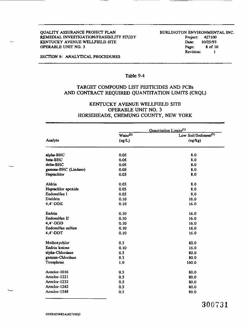
QUALITY ASSURANCE PROJECT PLANREMEDIAL INVESTIGATION/FEASIBILITY STUDYKENTUCKY AVENUE WELLFIELD SITEOPERABLE UNIT NO. 3
SECTION 9: ANALYTICAL PROCEDURES
BURLINGTON ENVIRONMENTAL INC.Project: 427100Date: 10/25/93Page: 8 of 10Revision: 1
Table 9-4
TARGET COMPOUND LIST PESTICIDES AND PCBsAND CONTRACT REQUIRED QUANTITATION LIMITS (CRQL)
KENTUCKY AVENUE WELLFIELD SITEOPERABLE UNIT NO. 3
HORSEHEADS, CHEMUNG COUNTY, NEW YORK
AnalyteWater^(ug/L)
Ouantitation Limits(>)
Low Soil/Sediment"3'(ug/kg)
alpha-BHCbeta-BHCdelU-BHCgamma-BHC (Lindane)Heptachlor
AldrinHeptachlor epoxideEndosulfan IDieldrin4,4'-DDE
EndrinEndosulfan II4,4'-DDDEndosulfan sulfate4,4'-DDT
MethoxychlorEndrin ketoneaJpha-ChJordanegamma-ChlordaneToxaphene
Aroclor-1016Aroclor-1221Aroclor-1232Aroclor-1242Aroclor-1248
0.050.050.050.050.05
0.050.050.050.100.10
0.100.100.100.100.10
0.50.100.50.51.0
0.50.50.50.50.5
8.08.08.08.08.0
8.08.08.0
16.016.0
16.016.016.016.016.0
80.016.080.080.0
160.0
80.080.080.080.080.0
30073110/93/65 W82A(427100)2
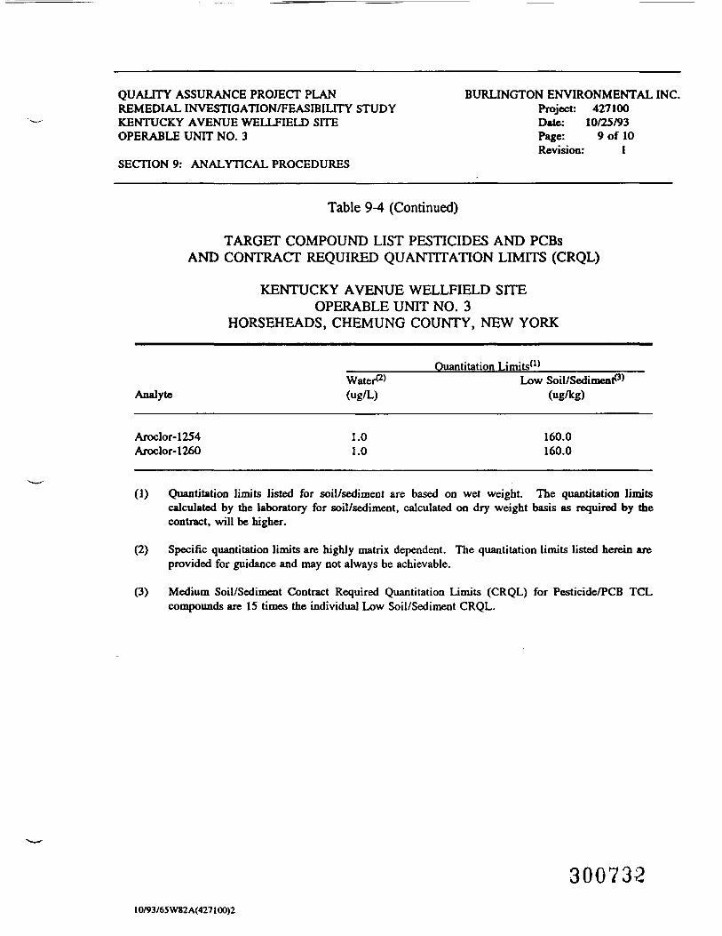
QUALITY ASSURANCE PROJECT PLANREMEDIAL INVESTIGATION/FEASIBILITY STUDYKENTUCKY AVENUE WELLFIELD SITEOPERABLE UNIT NO. 3
SECTION 9: ANALYTICAL PROCEDURES
BURLINGTON ENVIRONMENTAL INC.Project: 427100Date: 10/25/93Page: 9 of 10Revision: 1
Table 9-4 (Continued)
TARGET COMPOUND LIST PESTICIDES AND PCBsAND CONTRACT REQUIRED QUANTITATION LIMITS (CRQL)
KENTUCKY AVENUE WELLFIELD SITEOPERABLE UNIT NO. 3
HORSEHEADS, CHEMUNG COUNTY, NEW YORK
Analyte
Ouantitation Limits(1)
Water*2'("g/L)
Low Soil/Sediment^3'(ug/kg)
Aroclor-1254Aroclor-1260
1.01.0
160.0160.0
(1)
(2)
(3)
Quantitation limits listed for soil/sediment are based on wet weight. The quantitation limitscalculated by the laboratory for soil/sediment, calculated on dry weight basis as required by thecontract, will be higher.
Specific quantitation limits are highly matrix dependent. The quantitation limits listed herein areprovided for guidance and may not always be achievable.
Medium Soil/Sediment Contract Required Quantitation Limits (CRQL) for Pesticide/PCB TCLcompounds are IS times the individual Low Soil/Sediment CRQL.
30073210/93/65W82A(427100)2
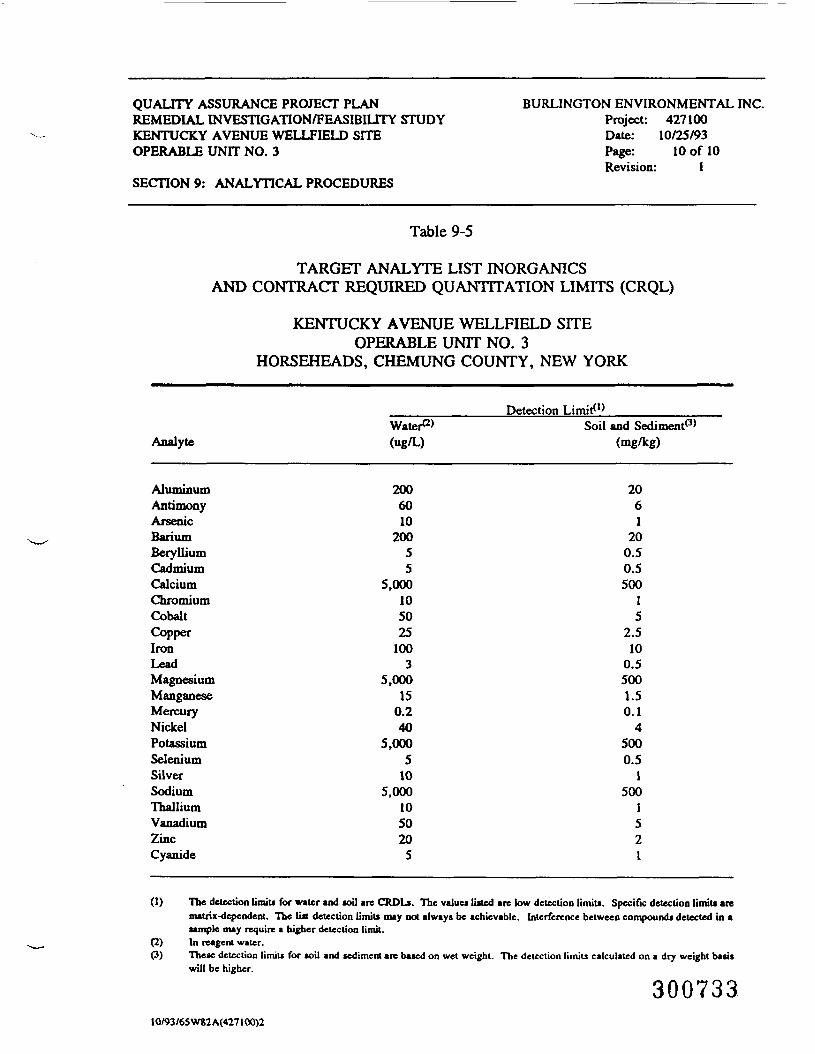
QUALITY ASSURANCE PROJECT PLANREMEDIAL INVESTIGATION/FEASIBILITY STUDYKENTUCKY AVENUE WELLFIELD SITEOPERABLE UNIT NO. 3
SECTION 9: ANALYTICAL PROCEDURES
BURLINGTON ENVIRONMENTAL INC.Project: 427100Date: 10/25/93Page: 10 of 10Revision: 1
Table 9-5
TARGET ANALYTE LIST INORGANICSAND CONTRACT REQUIRED QUANTITATION LIMITS (CRQL)
KENTUCKY AVENUE WELLFIELD SITEOPERABLE UNIT NO. 3
HORSEHEADS, CHEMUNG COUNTY, NEW YORK
Analyte
AluminumAntimonyArsenicBariumBerylliumCadmiumCalciumChromiumCobaltCopperIronLeadMagnesiumManganeseMercuryNickelPotassiumSeleniumSilverSodiumThalliumVanadiumZincCyanide
Water*2*(ug/L)
2006010
20055
5,000105025
1003
5,00015
0.240
5,0005
105,000
1050205
Detection Limit*1)Soil and Sediment*3*
(mg/kg)
2061
200.50.5500
15
2.510
0.55001.50.1
45000.5
1500
1521
(1) The detection limits for water and soil are CRDLi. The values listed are low detection limits. Specific detection limits arematrix-dependent. The list detection limits may not always be achievable. Interference between compounds detected in asample may require a higher detection limit.
(2) In reagent water.(3) These detection limiu for soil and sediment are based on wet weight. The detection limits calculated on a dry weight basis
will be higher.
30073310/93/65 W82A(427100)2
QUALITY ASSURANCE PROJECT PLAN BURLINGTON ENVIRONMENTAL INC.REMEDIAL INVESTIGATION/FEASIBILITY STUDY Project: 427100KENTUCKY AVENUE WELLFffiLD SITE Date: 10/25/93OPERABLE UNIT NO. 3 Page: 1 of 6
Revision: 1SECTION 10: DATA REDUCTION, TRANSFER, VALIDATION, AND REPORTING
10 DATA REDUCTION, TRANSFER, VALIDATION, AND REPORTING
To aid the data management activities so that they produce accurate andcontrolled flow of data, it is imperative that data handling and reporting steps beclearly defined and followed. Data management procedures will be applicable to field-and laboratory-generated data. Data reduction and transfer, validation, and reportingprocedures for this project are discussed briefly below.
10.1 Data Reduction and Transfer
Data reduction and transfer refers to all calculations and methods employed tosummarize and check data and information gathered to support conclusions. Dataobtained through the analytical laboratory will be subject to a multi-step reviewprocess to check data quality. This process starts with the laboratory analyst whoreviews all of the instrument output and prepares the draft version of the analyticalreport. Data reduction will be performed on personal computers reducing the amountof errors occurring during this process, the time to perform this process, and the timeto review finished calculations.
Data will then be transferred for peer review of the analytical report. In thisprocess, calculations and interpretations of data will be checked, and the data reportreviewed for completeness. After this, the data report is returned to the DataManagement Group Leader for final review and a final check for completeness.Reports are spot-checked by the work assignment manager for data quality. Thereport is then given to the Project or Task Manager for final approval.
30073410/93/62W82A(427100)2
QUALITY ASSURANCE PROJECT PLAN BURLINGTON ENVIRONMENTAL INC.REMEDIAL INVESTIGATION/FEASIBILITY STUDY Project: 427100KENTUCKY AVENUE WELLFIELD SITE Date: 10/25/93OPERABLE UNIT NO. 3 Page: 2 of 6
Revision: 1SECTION 10: DATA REDUCTION, TRANSFER, VALIDATION, AND REPORTING
Each laboratory will provide full CLP deliverables, using Region n datareporting forms as provided in SOWs OLM 01.8 and ILM 03.0. Full CLPdeliverables include all raw data (chromatograms, spectra, quant reports, data systemprintouts, sample analysis, and extraction logs, etc.), traffic reports, and chain-of-custody forms.
Field-generated data will also be subject to a multi-step review process to checkdata quality. All field-generated data will be recorded on standardized data sheets orwithin a bound field notebook. The field team leader will review the collected datafor legibility and completeness.
10.2 Data Validation
Data validation refers to the process whereby collected data is screened andeither accepted, approximated, or rejected (and subsequently investigated for correctiveaction) based on an established set of criteria. Data validation must be performedshortly after the time of data production (early screening), independent of itsproduction, and objective in its approach.
Data validation will be performed using approved Region II SOPs. The currentSOPs for data validation are as follows: SOP HW-6, Revision #8 (1/92) for OrganicData Review and SOP HW-2, Revision #XI (1/92) for Inorganic Data Review andSOP HW-7, Revision #1 for TCLP.
Specific items considered during the data validation process include thefollowing:
• comparing data to QA/QC objectives;
• collecting and reporting field blanks and duplicates;
300735IO/93/62W82A(427100)2
QUALITY ASSURANCE PROJECT PLAN BURLINGTON ENVIRONMENTAL INC.REMEDIAL INVESTIGATION/FEASIBILITY STUDY Project: 427100KENTUCKY AVENUE WELLFffiLD SITE Date: 10/25/93OPERABLE UNIT NO. 3 Page: 3 of 6
Revision: 1SECTION 10: DATA REDUCTION, TRANSFER, VALIDATION, AND REPORTING
• performance results of all necessary field and laboratory instrumentcalibrations;
• checking for data outliers;
• checking for transcription errors;
• maintenance of sample custody;
• maintenance of document control;
• proper preservation of all samples; and
• sample holding times were observed whenever possible.
The principal criteria that will be used to validate the data integrity duringcollection and reporting of the data are:
• verification by the QA/QC Coordinator that all raw data generatedhave been properly stored and documented in hard copy and thatstorage locations in the laboratory are coincident with chain-of-custody records;
• examination of the raw data by the QA/QC Coordinator to verifyadequacy of documentation and check the accuracy of calculations;
• confirmation that calibration standards are within the expectedvalues;
• reporting of all associated blank, duplicate, spike, standard, andQC data compared with results for analyses of each batch ofsamples;
• reporting of all analytical data for samples with no values rejectedas outliers because of the completeness goal of 95 percent for theanalytical support of this project;
30073610/93/62W82A(427100)2
QUALITY ASSURANCE PROJECT PLAN BURLINGTON ENVIRONMENTAL INC.REMEDIAL INVESTIGATION/FEASIBILITY STUDY Project: 427100KENTUCKY AVENUE WELLFIELD SITE Date: 10/25/93OPERABLE UNIT NO. 3 Page: 4 of 6
Revision: 1SECTION 10: DATA REDUCTION, TRANSFER, VALIDATION, AND REPORTING
• data identification checks - general consistency checks, checks foroutliers;
• unusual event review - check for catastrophic events of significantperturbations that may affect accuracy of measurements;
• deterministic relationship checks - in situ measurements are inagreement with other related data (e.g., benzene or toluene levelsare less than TOC levels); and
• data handling checks - checks for transcription errors.
Data validation of field data will be performed by peers that are nonteammembers. Any inconsistencies or errors will be brought to the attention of the WorkAssignment Manager for correction. Upon validation, the data sheets or fieldnotebook will be signed by the Work Assignment Manager.
10.3 Data Management
The field and analytical data gathered during this project is managed using acomputer-based data management system. This system provides efficiency in datahandling, tabulation, and analysis. The system also provides an integral portion of thequality assurance/quality control developed for the project.
All measurements taken during this project will be identified by source andtype to avoid ambiguity. Field and analytical data are input to the computerized datamanagement system and maintained under the supervision of the data system manager.
All data input is checked for accuracy and completeness and have undergonereview and approval by the field and analytical QC coordinator prior to addition to the
30073710/93/62W82 A(427100)2
QUALITY ASSURANCE PROJECT PLAN BURLINGTON ENVIRONMENTAL INC.REMEDIAL INVESTIGATION/FEASIBILITY STUDY Project: 427100KENTUCKY AVENUE WELUFIELD SITE Date: 10/25/93OPERABLE UNIT NO. 3 Page: 5 of 6
Revision: 1SECTION 10: DATA REDUCTION, TRANSFER, VALIDATION, AND REPORTING
master data base. The system manager is responsible for maintaining the integrity ofthe data and fulfilling requests for data access.
Standard computer software will be used for data management, analysis, and
tabulation. These products include Lotus 1-2-3, SAS (SAS Institute), and CIS/Key.The extensive statistical analysis and data tabulation capability of the SAS softwarepackage are used for conducting appropriate statistical analyses and data tabulations.
30073810/93/62W82A(427100)2
QUALITY ASSURANCE PROJECT PLAN BURLINGTON ENVIRONMENTAL INC.REMEDIAL INVESTIGATION/FEASIBILITY STUDY Project: 427100KENTUCKY AVENUE WELLFffiLD SITE Date: 10/25/93OPERABLE UNIT NO. 3 Page: 6 of 6
Revision: 1SECTION 10: DATA REDUCTION, TRANSFER, VALIDATION, AND REPORTING
10.4 Reporting
Analytical results will be tabulated and submitted to project management on aregular basis after completion of the necessary QA/QC steps and document reviewgiven in this QAPP.
At the completion of the project, a final report will be issued. The report willbe a compilation of data-substantiating procedures and documentation of projectperformance.
The final report will include, but not be limited to, the following:
• introduction, purpose, and scope of the project;• QAPP, including any revisions;• evaluation of QAPP compliance;• sampling plan, design;• logistical procedures;• sampling and analytical methods employed;• sample location maps;• copies of sample collection documentation;• tabulation of sampling results;• evaluation of sampling results; and• conclusions and recommendations.
30073910/93/62W82A(427100)2
QUALITY ASSURANCE PROJECT PLAN BURLINGTON ENVIRONMENTAL INC.REMEDIAL INVESTIGATION/FEASIBILITY STUDY Project: 427100KENTUCKY AVENUE WELLFIELD SITE Date: 10/25/93OPERABLE UNIT NO. 3 Page: 1 of 6
Revision: 1SECTION 11: INTERNAL QUALITY CONTROL PROGRAM
11 INTERNAL QUALITY CONTROL PROGRAM
The overall effectiveness of the quality control program is dependent upon theperformance of field sampling activities and laboratory operations in accordance witha plan that systematically evaluates the precision and accuracy of the analysis.
11.1 Field Quality Control Checks
The internal field sampling quality control program includes the use ofequipment-cleaning procedure blanks, sample container blanks, trip blanks, and"blind" quality control check samples including both duplicate and split samples. Thefield team leader will determine the number, type, and location of field QC samplesthat will actually be analyzed.
11.1.1 Field QA/QC Sample Collection Procedures
Additional samples will be taken to maintain quality control of soil, sediment,groundwater, and surface water sampling and analytical laboratory procedures. Theadditional samples will include field/equipment blanks, duplicates, and trip blanks.
The field/equipment blank is used to evaluate decontamination practices.Following standard decontamination procedures, each sampler used during the day will
30074010/93/63W82A(427100)2
QUALITY ASSURANCE PROJECT PLAN BURLINGTON ENVIRONMENTAL INC.REMEDIAL INVESTIGATION/FEASIBILITY STUDY Project: 427100KENTUCKY AVENUE WELLFIELD SITE Date: 10/25/93OPERABLE UNIT NO. 3 Page: 2 of 6
Revision: 1SECTION 11: INTERNAL QUALITY CONTROL PROGRAM
be filled with deionized water and poured into the appropriate sample container. Onefield/equipment blank for each type of sampling equipment will be prepared at the siteand returned to the lab for analysis for each day sampling is conducted. Equipmentblanks will be preserved and handled in the same manner as field samples.
A blind duplicate sample will be taken for every ten samples collected. Atmonitoring wells selected for quality control evaluation, samples will either be takenin duplicate (to check sampling precision) or split (to check analytical precision). Forsites selected by the Team Leader for duplicate samples, the normal samplingprocedure will be followed with the exception that two of each of the samplecontainers will be filled. This second set of containers is treated the same as all of theother samples.
To obtain a duplicate groundwater sample, a second sample will be collectedin an identical manner as the original sample was collected (bailer or pump). Allduplicate samples are treated identically to other samples. No attempt will be madeto collect duplicate soil or sediment samples.
Split samples will be taken as a check on laboratory precision. To split a
groundwater sample, a sample splitter will be used to split the stream of groundwaterinto two identical samples. To split a soil sample, the material recovered in the splitspoon sampler will be cut in half using a stainless steel spatula. One-half of therecovered material will become the sample of the specified interval; the other half willbecome the duplicate.
Since the laboratory will only be given coded sample numbers, the laboratorywill be unaware of which samples are duplicates and splits. It is imperative that thecode number selected for duplicate and split samples be recorded in the field log booksince it will be the only record of which sample has been split. All duplicate and splitsamples are treated identically to other samples.
30074110/93/63W82A(427100)2
QUALITY ASSURANCE PROJECT PLAN BURLINGTON ENVIRONMENTAL INC.REMEDIAL INVESTIGATION/FEASIBILITY STUDY Project: 427100KENTUCKY AVENUE WELLFIELD SITE Date: 10/25/93OPERABLE UNIT NO. 3 Page: 3 of 6
Revision: 1SECTION 11: INTERNAL QUALITY CONTROL PROGRAM
One trip blank will be made with analyte-free water to evaluate any outsideenvironmental impacts on the sample bottles for every shipment of bottles sent fromthe laboratory and every shipment of samples sent to the laboratory.
11.1.2 Field QA/QC Procedures for Activities That Do Not InvolveSampling
The objectives for activities that do not involve sampling (such as measuringpH, temperature, and specific conductance) are to obtain reproducible measurementsto a degree of accuracy consistent with the intended use of the measurements and todocument the procedures used.
Measurements of temperature, pH, conductivity, and soil screening are to meetthe following objectives.
1. Temperature - A thermometer with a range of 0°C to 50°C and divisions of1.0 °C will be used. Accuracy of measurement will be ±1.00C with aprecision expressed as a standard deviation of ±1.0° C.
2. pH - The meter will be read to the nearest 0.01 pH unit and will range from0 to 14 units. Accuracy of measurement will be ±0.1 pH unit. Precision willbe a standard deviation of +0.1 pH unit.
3. Conductivity - The specific conductance meter will be read to the nearest 10micromhos per centimeter (umhos/cm) and range from 0 to 20,000 umhos/cm.Accuracy of measurement will be ±5 percent of a standard. Precision shallbe a standard deviation of _+15 percent.
4. Air monitoring - The photoionization detector (HNu) will measure theconcentration of trace gases to tiu nearest 0.1 part per million (ppm) on the 0to 20 ppm scale and to the nearest 1 ppm on the 0 to 200 ppm scale, with arange of 0.1 to 2,000 ppm. Accuracy will be within ±_l percent of the meterscale.
30074210/93/63 W82A(427100)2
QUALITY ASSURANCE PROJECT PLAN BURLINGTON ENVIRONMENTAL INC.REMEDIAL INVESTIGATION/FEASIBILrrY STUDY Project: 427100KENTUCKY AVENUE WELLFffiLD SITE Date: 10/25/93OPERABLE UNIT NO. 3 Page: 4 of 6
Revision: 1SECTION 11: INTERNAL QUALITY CONTROL PROGRAM
11.2 Laboratory QA/QC Procedures
The analytical laboratory used will be audited by Burlington's QA/QCCoordinator and Laboratory Auditor, Ms. Kathy Blaine, who is an Auditor for theAmerican Association of Laboratory Accreditation.
Samples will be processed according to the most recent protocols of theUSEPA CLP. The CLP SOWs to be followed are OLM 01.8 for organics andILM 03.0 for inorganics. This QAPP is designed to comply with the CLP-protocolrequirements.
Laboratory responsibilities for this project are as follows:• receipt and preparation of site samples;
• measurement and recording of cooler temperature at the time ofsample receipt;
• extraction and analysis to identify specific organic and inorganiccompounds;
• qualitative verification of the identified compounds;
• adherence to CLP protocol; and
• reporting of all analytical data, including a summary of laboratoryquality assurance that will note any procedural variancesencountered that may influence the validity of results.
To meet the requirements for this project, the selected laboratory will berequired to provide the following:
• execution of the above-listed tasks;
30074310/93/63 W82A(427100)2
QUALITY ASSURANCE PROJECT PLAN BURLINGTON ENVIRONMENTAL INC.REMEDIAL INVESTIGATION/FEASIBILITY STUDY Project: 427100KENTUCKY AVENUE WELLFIELD SITE Date: 10/25/93OPERABLE UNIT NO. 3 Page: 5 of 6
Revision: 1SECTION 11: INTERNAL QUALITY CONTROL PROGRAM
• information necessary to satisfy CLP-protocol. reportingrequirements;
• analytical equipment and technical expertise necessary for thisproject;
• qualified personnel to fulfill key analytical, quality assurance, datamanagement, and reporting functions;
• preservation of all sample extracts after analysis in bottles/vialswith Teflon-lined septa and maintained at 4 ° C for a period of timespecified by the project coordinator;
• adherence to standard chain-of-custody procedures; and
• scheduling sample shipments to the laboratory's facility.
The analytical program detection limits will be the CLP-specified contract-required detection limits (CRDL). Although detection limits are matrix dependent,every reasonable effort will be made to achieve these limits. Detection limits forwater and soils will be on a best-effort basis using currently accepted USEPAmethodologies.
The analytical laboratory will use CLP methods for the approved projectanalytical program. The CLP protocols specify specific objective criteria (surrogaterecoveries, matrix spike recoveries, calibration checks) that are used as measures ofprecision and accuracy. Matrix spike samples will be flagged if the recovery criteriais not met.
The routine internal quality control program used by the analytical laboratoryincludes daily calibration of instruments using certified standards when possible.Glassware is checked for cleanliness and for detergent removal prior to each analysisrun. Nanograde quality solvents are used for trace organic applications. Each lot of
30074410/93/63 W82A(427100)2
QUALITY ASSURANCE PROJECT PLAN BURLINGTON ENVIRONMENTAL INC.REMEDIAL INVESTIGATION/FEASIBILITY STUDY Project: 427100KENTUCKY AVENUE WELLFIELD SITE Date: 10/25/93OPERABLE UNIT NO. 3 Page: 6 of 6
Revision: 1SECTION 11: INTERNAL QUALITY CONTROL PROGRAM
solvent is checked to demonstrate its suitability for the intended analysis. The highestpurity standards commercially available, usually 98 percent, are used for calibration.
To demonstrate that all analytical materials, for example, reagents, glassware,and solvents, are free of interferences, a method blank will be run at a minimum ofone for every 20 samples (or analysis batch). Accuracy will be assessed using matrixspikes and matrix spike duplicates of field samples at a minimum frequency of one pertwenty samples of each matrix. Duplicates of field samples will be randomly selectedand analyzed at a minimum of one for every 20 samples (or analysis batch) todocument the precision of the analysis. A laboratory quality control check sample willbe analyzed with each analysis batch with a minimum of one per 20 samples. Overalllaboratory quality control checks will exceed 20 percent of all samples analyzed forthe project.
The detailed laboratory quality control procedures are documented in thelaboratory QA/QC Program description (Appendix D).
30074510/93/63 W82A(427100)2
QUALITY ASSURANCE PROJECT PLAN BURLINGTON ENVIRONMENTAL INC.REMEDIAL INVESTIGATION/FEASIBILITY STUDY Project: 427100KENTUCKY AVENUE WELLFIELD SITE Date: 10/25/93OPERABLE UNIT NO. 3 Page: 1 of 1
Revision: 1SECTION 12: PERFORMANCE AND SYSTEM AUDITS
12 PERFORMANCE AND SYSTEM AUDITS
Two types of audit procedures will be used to assess and document the projectproceedings: system audits and performance audits. These audits form one of thebases for corrective action requirements and constitute a permanent record of theconformance of the measurement systems to QA requirements.
The system audit consists of a qualitative evaluation of all components of themeasurement systems to evaluate their proper selection and use. This audit includesan evaluation of both field and laboratory quality control procedures. The analyticallaboratory will be audited prior to initiation of field work. A minimum of one systemaudit to evaluate adherence to approved field procedures will be conducted duringsampling. An auditor will accompany the field sampling team to evaluate the samplecollection, document control, and chain-of-custody procedures based on the QAPP.Any inconsistencies and/or omissions will be taken into corrective action.
After project systems are operational and data are being generated, aquantitative performance audit will be conducted to evaluate the accuracy and precisionof the total measurement systems and component parts. Performance audits willconsist largely of continual reviews of data and documentation. These audits willconsist of checks of sampling equipment and analysis of analytical data from duplicatesand splits of samples, field, trip, and method blanks, and spikes.
Peer review of all deliverable reports and data supporting this project will beperformed by technically qualified individuals.
30074610/93/66 W82A(427100)2
QUALITY ASSURANCE PROJECT PLANREMEDIAL INVESTIGATION/FEASIBILITY STUDYKENTUCKY AVENUE WELLFIELD SITEOPERABLE UNIT NO. 3
SECTION 13: PREVENTIVE MAINTENANCE
BURLINGTON ENVIRONMENTAL INC.Project: 427100Date: 10/25/93Page: 1 of 3Revision: 1
13 PREVENTIVE MAINTENANCE
To prevent any cross contamination, all sampling equipment will bedecontaminated in the staging laboratory upon receipt from field activities and beforereuse in the field. All equipment will be individually wrapped.
The field crew will generally adhere to the following decontaminationprocedures:
• drilling equipment (drill rods, bits, augers, dredges, and any otherlarge pieces of equipment that contact the soil) and trenchingequipment are to be steam cleaned prior to use and betweenboreholes or trenches;
• all pumps, bailer cords, and dedicated tubing that are to be placedinto the borehole will be cleaned with soapy water rinsed withdemonstrated analyte-free water; and
• well screens and casings must be steam cleaned prior to use in thewell. Decontaminated equipment will be placed on polyethylenesheeting to avoid contact with surrounding soil.
Split-spoon samplers will be decontaminated after the collection of each sample.The rear portion of the drilling rig will be steam cleaned between areas. If the rearportion of the drilling rig becomes heavily contaminated at a given borehole andcontinued use may cause cross contamination of samples, the rear portion of thedrilling rig will be decontaminated between boreholes.
All other sampling devices or bailers used to develop or purge monitoring wellswill be decontaminated between sampling events using the following procedure:
• wash and scrub with low phosphate detergent;• rinse with tap water;• rinse with 10 percent HNO3, ultra-pure;
30074710/93/72W82 A(427100)2
QUALITY ASSURANCE PROJECT PLANREMEDIAL INVESTIGATION/FEASIBILITY STUDYKENTUCKY AVENUE WELLFIELD SITEOPERABLE UNIT NO. 3
SECTION 13: PREVENTIVE MAINTENANCE
BURLINGTON ENVIRONMENTAL INC.Project: 427100Date: 10/25/93Page: 2 of 3Revision: 1
• rinse with tap water;• rinse with methanol followed by hexane (solvents must be pesticide
grade or better);• thorough rinse with demonstrated analyte-free water*;• air dry; and• wrap in aluminum foil for transport.
The volume of water used during this rinse must be at least five times thevolume of solvent used in the previous step.
When performing the sampling equipment decontamination steps that involvethe use of organic solvents, phthalate-free gloves will be worn so as to avoidinteraction and possible phthalate contamination of the sampling equipment. The tapwater will be from a potable water supply from the municipal water treatment system.
All meters, probes, and other monitoring equipment are checked in the staginglaboratory before use. If any battery-operated equipment is not showing full charge,the batteries are replaced or recharged. If any of the units are found to be defective,they are red tagged and repaired or decommissioned. Any preventive or remedialmaintenance will be described and documented quarterly on standardized maintenancerecords.
All maintenance for the field equipment is outlined in the SOPs for therespective pieces of equipment. Preventive maintenance procedures for laboratoryoperations should be clearly defined and written for each measurement system andrequired support equipment. When maintenance activity is necessary, it should bedocumented on standard forms maintained in logbooks. A history of the maintenancerecord of each system serves as an indication of the adequacy of maintenanceschedules and parts inventory.
10/93/72W82 A(427100)2300748
QUALITY ASSURANCE PROJECT PLANREMEDIAL INVESTIGATION/FEASIBILITY STUDYKENTUCKY AVENUE WELLFIELD SITEOPERABLE UNIT NO. 3
SECTION 13: PREVENTIVE MAINTENANCE
BURLINGTON ENVIRONMENTAL INC.Project: 427100Date: 10/25/93Page: 3 of 3Revision: 1
The laboratory quality control plan, Appendix D contains a summary of allmaintenance procedures for the laboratory instrumentation.
30074910/93/72W82 A(427100)2
QUALITY ASSURANCE PROJECT PLAN BURLINGTON ENVIRONMENTAL INC.REMEDIAL INVESTIGATION/FEASIBILITY STUDY Project: 427100KENTUCKY AVENUE WELLFIELD SITE Date: 10/25/93OPERABLE UNIT NO. 3 Page: 1 of 4
Revision: 1SECTION 14: SPECIFIC ROUTINE PROCEDURES USED TO ASSESS
DATA PRECISION, ACCURACY, AND COMPLETENESS
14 SPECIFIC ROUTINE PROCEDURES USED TO ASSESS DATAPRECISION, ACCURACY, AND COMPLETENESS
The procedures in this section will be used by Burlington to assess QC data.Field or laboratory duplicate samples and laboratory replicate analyses will be usedto assess precision. Field or laboratory spike and blank samples will be used toevaluate accuracy. Check samples will be used to evaluate comparability of theanalytical results. These techniques are described in the following USEPA documents:QAMS - 005/80 (USEPA, 1980), SW846 third edition (USEPA, 1986), and theContract Laboratory Program SOW for:
• Organics Analysis: Multimedia, Multiconcentration(USEPA, 2/90); and
• Inorganics Analysis: Multimedia, Multiconcentration(USEPA, 3/90).
14.1 Procedures for the Assessment of Split, Duplicate, orReplicate Measurements
Replicate analysis of the same sample and analysis of duplicate or split sampleswill be evaluated using a paired t-test. The null hypothesis of interest is that there isno statistically significant difference between the originals and their replicates orduplicates, or that there is no statistically significant difference between laboratories.
Given a set of original analyses and their replicates, X0 and Xr, let Dj = Xoi -
Xri be the difference for each pair. Calculate the average difference, D using:
30075010/93/73 W82A(427100)2
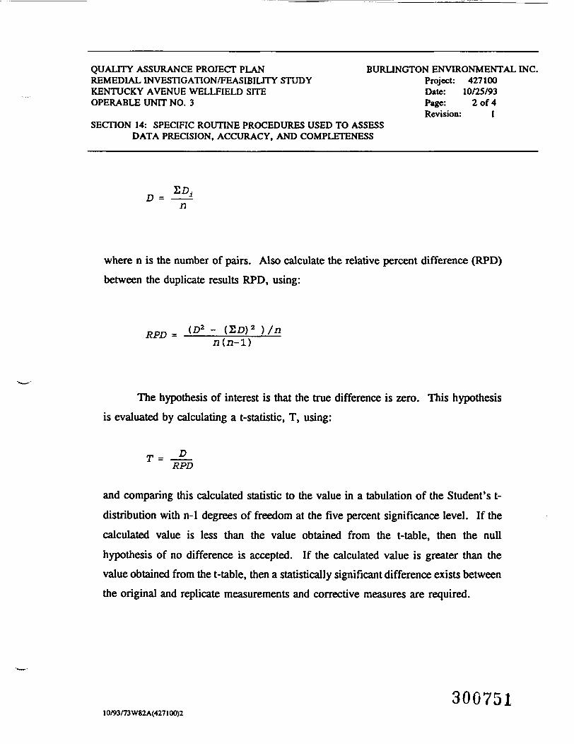
QUALITY ASSURANCE PROJECT PLAN BURLINGTON ENVIRONMENTAL INC.REMEDIAL INVESTIGATION/FEASIBILITY STUDY Project: 427100KENTUCKY AVENUE WELLFIELD SITE Date: 10/25/93OPERABLE UNIT NO. 3 Page: 2 of 4
Revision: 1SECTION 14: SPECIFIC ROUTINE PROCEDURES USED TO ASSESS
DATA PRECISION, ACCURACY, AND COMPLETENESS
n
where n is the number of pairs. Also calculate the relative percent difference (RPD)between the duplicate results RPD, using:
RPD = n(n-l)
The hypothesis of interest is that the true difference is zero. This hypothesisis evaluated by calculating a t-statistic, T, using:
T= D
RPD
and comparing this calculated statistic to the value in a tabulation of the Student's t-distribution with n-1 degrees of freedom at the five percent significance level. If thecalculated value is less than the value obtained from the t-table, then the nullhypothesis of no difference is accepted. If the calculated value is greater than thevalue obtained from the t-table, then a statistically significant difference exists betweenthe original and replicate measurements and corrective measures are required.
30075110/93/73 W82A(427100)2
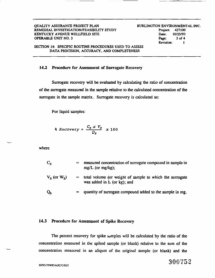
QUALITY ASSURANCE PROJECT PLAN BURLINGTON ENVIRONMENTAL INC.REMEDIAL INVESTIGATION/FEASIBILITY STUDY Project: 427100KENTUCKY AVENUE WELLFIELD SITE Date: 10/25/93OPERABLE UNIT NO. 3 Page: 3 of 4
Revision: 1SECTION 14: SPECIFIC ROUTINE PROCEDURES USED TO ASSESS
DATA PRECISION, ACCURACY, AND COMPLETENESS
14.2 Procedure for Assessment of Surrogate Recovery
Surrogate recovery will be evaluated by calculating the ratio of concentrationof the surrogate measured in the sample relative to the calculated concentration of thesurrogate in the sample matrix. Surrogate recovery is calculated as:
For liquid samples:
C X V% Recovery = ————- x 100
where
= measured concentration of surrogate compound in sample inmg/L (or mg/kg);
Vs (or Ws) = total volume (or weight of sample to which the surrogatewas added in L (or kg); and
Qs = quantity of surrogate compound added to the sample in mg.
14.3 Procedure for Assessment of Spike Recovery
The percent recovery for spike samples will be calculated by the ratio of theconcentration measured in the spiked sample (or blank) relative to the sum of theconcentration measured in an aliquot of the original sample (or blank) and the
30075210/93/73 W82A(427IOO)2
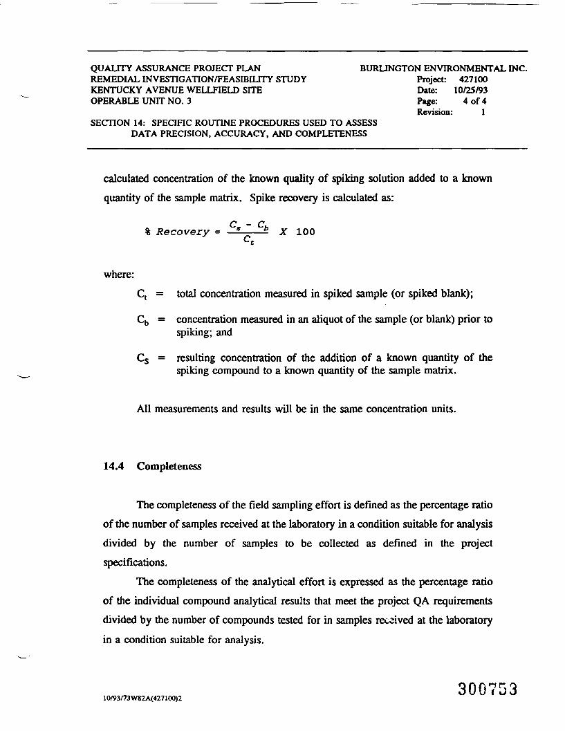
QUALITY ASSURANCE PROJECT PLAN BURLINGTON ENVIRONMENTAL INC.REMEDIAL INVESTIGATION/FEASIBILITY STUDY Project: 427100KENTUCKY AVENUE WELLFIELD SITE Date: 10/25/93OPERABLE UNIT NO. 3 Page: 4 of 4
Revision: 1SECTION 14: SPECIFIC ROUTINE PROCEDURES USED TO ASSESS
DATA PRECISION, ACCURACY, AND COMPLETENESS
calculated concentration of the known quality of spiking solution added to a knownquantity of the sample matrix. Spike recovery is calculated as:
% Recovery = °s " °b X 100
:Ct = total concentration measured in spiked sample (or spiked blank);
Cb = concentration measured in an aliquot of the sample (or blank) prior tospiking; and
Cs = resulting concentration of the addition of a known quantity of thespiking compound to a known quantity of the sample matrix.
All measurements and results will be in the same concentration units.
14.4 Completeness
The completeness of the field sampling effort is defined as the percentage ratioof the number of samples received at the laboratory in a condition suitable for analysisdivided by the number of samples to be collected as defined in the projectspecifications.
The completeness of the analytical effort is expressed as the percentage ratioof the individual compound analytical results that meet the project QA requirementsdivided by the number of compounds tested for in samples received at the laboratoryin a condition suitable for analysis.
30075310/93/73 W82A(427100)2

QUALITY ASSURANCE PROJECT PLANREMEDIAL INVESTIGATION/FEASIBILITY STUDYKENTUCKY AVENUE WELLFIELD SITEOPERABLE UNIT NO. 3
SECTION 15: CORRECTIVE ACTION
BURLINGTON ENVIRONMENTAL INC.Project: 427100Date: 10/25/93Page: 1 of 2Revision: 1
15 CORRECTIVE ACTION
For each analytical method employed in this program, the precision andaccuracy will be tracked. Calculations for spike recoveries will also be made, and thestandard deviation of the replicate set will be computed. When either the relativestandard deviation of replicate results or the spike recoveries of either set are out ofcompliance according to CLP guidelines, corrective action will be taken to improveperformance prior to analysis of the next group of samples.
If weaknesses or problems are uncovered during system or performance audits,corrective action will be initiated immediately.
Laboratory corrective action will include, but will not necessarily be limitedto, the following: recalibration of instruments using freshly prepared calibrationstandards; replacements of lots of solvent or other reagents that gave unacceptableblank values; additional training of laboratory personnel in correct implementation ofsample preparation and analysis methods; and reassignment of personnel, whennecessary.
When a corrective action is necessary to eliminate the cause of nonconformancein the field or the laboratory, the following closed-loop corrective action system willbe used. This procedure is taken from the "Quality Assurance Handbook for AirPollution Measurement System. Volume 1, Principles." EPA-600/4-7-005.January 1967. As appropriate, each of the following steps will be taken:
1. The problem is defined.
2. Responsibility for investigating the problem is assigned.
3. The cause of the problem is investigated and defined.
30075410/93/74W82A(427IOO)2
QUALITY ASSURANCE PROJECT PLANREMEDIAL INVESTIGATION/FEASIBILITY STUDYKENTUCKY AVENUE WELLFIELD SITEOPERABLE UNIT NO. 3
SECTION 15: CORRECTIVE ACTION
BURLINGTON ENVIRONMENTAL INC.Project: 427100Date: 10/25/93Page: 2 of 2Revision: 1
4. A corrective action to eliminate the problem is defined.
5. Responsibility for implementing the corrective action is assigned and accepted.
6.
7.
The effectiveness of the corrective action is established and the correctionimplemented.
The fact that the corrective action has eliminated the problem is verified anddocumented.
8. The impact on the quality of the project is assessed.
9. A report on the corrective action is issued.
30075510/93/74W82A(427100)2

QUALITY ASSURANCE PROJECT PLAN BURLINGTON ENVIRONMENTAL INC.REMEDIAL INVESTIGATION/FEASIBILITY STUDY Project: 427100KENTUCKY AVENUE WELLFffiLD SITE Date: 10/25/93OPERABLE UNIT NO. 3 Page: 1 of 2
Revision: 1SECTION 16: QUALITY ASSURANCE REPORTS TO MANAGEMENT
16 QUALITY ASSURANCE REPORTS TO MANAGEMENT
The project team will communicate on a regular basis to ascertain if QA/QCpractices are being carried out and to address potential problem areas. Any dataanomalies will be investigated to evaluate if they are a result of personnel orinstrument deviation, or are a true reflection of the methodology or task.
16.1 Quality Assurance Reports
Periodic reports will be made to the project manager by the QA officer on theperformance of the measurement system and the data quality. Minimally, thesereports will include:
• periodic assessment of measurement quality indicators such as dataaccuracy, precision, and completeness;
• results of system audits;
• results of performance audits; and
• significant QA/QC problems and recommended solutions.
The final project report will contain a separate section reviewing quality of thedata. At a minimum, the following information will be covered:
• assessment of measurement data precision, accuracy, andcompleteness;
30075610/93/75 W82 A(427100)2
QUALITY ASSURANCE PROJECT PLAN BURLINGTON ENVIRONMENTAL INC.REMEDIAL INVESTIGATION/FEASIBILITY STUDY Project: 427100KENTUCKY AVENUE WELLFffiLD SITE Date: 10/25/93OPERABLE UNIT NO. 3 Page: 2 of 2
Revision: 1SECTION 16: QUALITY ASSURANCE REPORTS TO MANAGEMENT
• system and performance audit results;
• significant QA/QC problems and implemented solutions; and
• impact on the quality of the project.
30075710/93/75 W82A(427100)2
QUALITY ASSURANCE PROJECT PLANREMEDIAL INVESTIGATION/FEASIBILITY STUDYKENTUCKY AVENUE WELLFIELD SITEOPERABLE UNIT NO. 3
APPENDIX A
BURLINGTON ENVIRONMENTAL INC.Project: 427100Date: 10/25/93Revision: 1
APPENDIX A
STANDARD OPERATING PROCEDURESFOR WELL DEVELOPMENT AND WATER SAMPLING
30075310/93/76 W82 A(427100)2
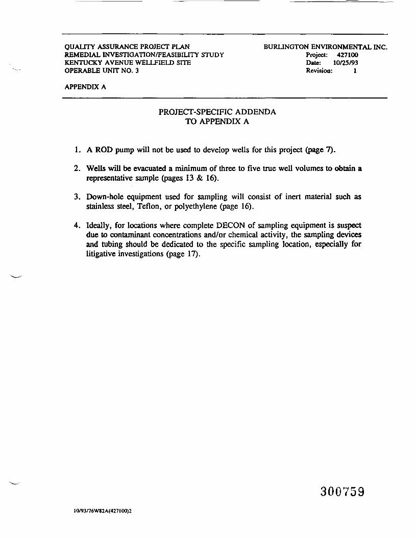
QUALITY ASSURANCE PROJECT PLANREMEDIAL INVESTIGATION/FEASIBILITY STUDYKENTUCKY AVENUE WELLFIELD SITEOPERABLE UNIT NO. 3
APPENDIX A
BURLINGTON ENVIRONMENTAL INC.Project: 427100Date: 10/25/93Revision: 1
PROJECT-SPECIFIC ADDENDATO APPENDIX A
1. A ROD pump will not be used to develop wells for this project (page 7).
2. Wells will be evacuated a minimum of three to five true well volumes to obtain arepresentative sample (pages 13 & 16).
3. Down-hole equipment used for sampling will consist of inert material such asstainless steel, Teflon, or polyethylene (page 16).
4. Ideally, for locations where complete DECON of sampling equipment is suspectdue to contaminant concentrations and/or chemical activity, the sampling devicesand tubing should be dedicated to the specific sampling location, especially forlitigative investigations (page 17).
30075910/93/76W82A(427IOO)2
i-
4.1.3.1.11 STANDARD OPERATING PROCEDURES
FOR
WELL DEVELOPMENT & WATER SAMPLING
October 16, 1986
1 INTRODUCTION
The following standard operating procedure (SOP) has been
prepared to provide basic information about the theory, and
practical application of field methods used for ground water
characterization activities. The methods described are basic
techniques for ground water field work and are presented as a
guideline for field operation technicians. The text is based
on practical experience and currently accepted practices
standard to the ground water industry, and is by no means
intended as a complete treatise on the subject. This document
is intended solely for in-house use by Burlington
Environmental personnel.
OCT/86/136e3007GO
WELL DEVELOPMENT & WATER SAMPLING Page 2
MONITORING NEWWQRK/WELL DEVELOPMENT
-': 2.1 Purpose
The purpose of well development is to remove unnatural
and prohibitive materials from the well screen and gravel pack
that have been introduced by drilling and well installation
procedures, and would, therefore/ affect sample and test
quality.
During the drilling process the side of the bore hole may
become smeared with clays or other fine sediments. This
plugging action substantially reduces the permeability of the
aquifer in the zone of the boring and retards the movement of
water into the well. In addition, sediment may enter the
filter pack or clog the well screen slots during installation
of the well materials.
Well development is the process of flushing the aquifer
interface with the well and cleaning the filter pack and the
well or piezometer screen slots to permit ground water to flow
into the monitoring well. Development is required:
o to restore the natural permeability of theformation adjacent to the bore hole;
o to remove clay, silt and other fines from thefilter pack and well screen so that subsequentwater samples will not be abnormally turbid orcontain undue suspended matter; and
OCT/86/136e300vGi
WELL DEVELOPMENT & WATER SAMPLING Page 3
o to remove remnant drilling fluids from the well,filter pack and aquifer, and contaminantsintroduced during drilling and well installation.
2.2 Methods
The development process is best accomplished by causing the
natural formation water collected inside the well screen to be
moved vigorously in and out through the screen in order to
agitate the clay and silt and move these fines into the well
where they can be removed. Use of water other than the natural
formation water is not recommended due to the possibility of
contributing contaminant or atypical water quality to the
ground water. Equipment used for well development must be
thoroughly cleaned before use to prevent possible contamination
of the well.
Development of monitoring wells will generally be
accomplished by bailing, pumping, or a combination of these two
methods. Where practical, the use of bailers for surge
development within the screened section of the well is
preferable. Approximately 100 feet is the practical depth
limitation for use with bailers if ther is any significant
quantity oc water column in the well.
OCT/86/136e
300762
WELL DEVELOPMENT & WATER SAMPLING Page 4
2.2.1 Bailers
A bailer can be used to develop the well screen/pack by a
surging action in the screen area. The bailer is raised
forcefully and lowered through the water column to produce an
agitating action that causes the water to surge in and out
through the screen accomplishing the desired cleaning action.
The bailer/ however, has the added capability of removing
turbid water and fines each time it is brought to the surface.
One drawback to the use of bailers for well development
arises from the basic design, operation, and efficiency of the
bailer in its surging function. Due to specific well
construction/installation configurations and/or sub-surface
geological conditions, the highly effective suction generated
during bailer surging of the well may draw gravel pack and/or
natural formation sand into the well through the well screen.
The bailer is capable of holding water inside its body by the
seating of a round "ball" in the tapered seat of the check
valve at the bottom end of the bailer. The weight of the
overlying water column inside the bailer body holds the ball
firmly down in the valve seat. Any sand particles that may
lodge between the check valve ball and seat will allow the
bailer to leak, decreasing bailing efficiency greatly.
The problem of sand in a well cannot be avoided altogether,
although specific techniques can minimize the adverse affects
to bailing performance. Sand that is drawn into the well
OCT/86/136e 3007C3
WELL DEVELOPMENT & WATER SAMPLING Page 5
rbottom during surging ideally should be removed, if possible.
rInitial sand influx/ especially gravel pack "fine" sand from a
j- graded filter pack, will decrease and stop altogether as the
_^. filter pack develops its final configuration during surging and
I"~ bailing.
A good faith attempt should be made during removal of the
first half well volume to withdraw as much influxed sand as
,- possible from the well bottom to ensure full screen length (
as installed). Unfortunately/ a portion of this sand will
F usually remain "trapped", in the well. A maximum allowable
amount of sand equivalent to no more than 5% of the screen:f length can be tolerated. However, this material should be
surged each time the well is developed (or later, purged) to
"•" remove silt and clay particles that will settle into the sand
r void space. This material may degrade and/or adsorb chemical
contaminants if allowed to remain in the well. Silt material
that has settled from previous well work should be purged from
-.- any trapped sand each time the well is flushed.
Common sense and the application of the following methods
i should minimize field difficulties in bailing wells with
trapped sand:
o Sand in the well bottom will agitate up into thebailer as water enters through the check valve.
— The check ball will seat initially and the water in1 the bailer will remain for removal if the bailer is
carefully withdrawn from the well. However, sandin the bailer will settle down around the ball and
T any sharp jolt to the bailer (i.e. striking acasing coupling, accidental momentary slip of thebailer rope, etc.) will unseat the ball. This
^ OCT/86/136e
l 3007G4
WELL DEVELOPMENT & WATER SAMPLING Page 6
allows sand to wedge between the ball and seal, and(— causes a leak. The best approach is to let the
bailer settle to the well bottom at its own speed,then immediately begin your retrieval. continue as
_ smoothly any continuously as possible. Do not' bounce the bailer on the well bottom prior to
retrieval or sand will unseat your "seal".
j~" o . If a leak does occur, which you can hear if windconditions allow, you can quite often re-seat thecheck valve by a quick jerk on the bailer rope.
— You may need to do this several times to re-achievean effective seal. It is also possible to detect aleak by bailer "weight loss".
1 o Certain "sand" wells bail more successfully if thebailer is weakly "surged" as the initial retrieval
J_ motion when pulling up the bailer.r ' ' • '' ''.'''o Sand will accumulate ;in the bailer with repeated
. bailer removals. It is advantageous to frequentlyj— shake as much sand from the bailer as possible.
rf Often, dependent upon the specific bailerconstruction (especially with some teflon bailers
1_ or check valve assemblies), it is not onlyI beneficial but may be necessary to periodically
rinse the bailer interior and check valve withi_ spray rinse water (appropriate to the well activityj being performed).
. o As a last resort, only if sand purging requirementsr~ have been met or extreme difficulty is experienced
-* due to sand, the bailer can be kept above the; trapped sand during bailing. The bailer can bel_ stopped (and no more than one foot) short of theJ sand bottom approximately six inches for bottom
bailing requirements. If the bailer is carefullylowered to this position, most sand problems will
(~ be., avoided. This method is recommended for thesecond half well volume removal if the water columnis short.
..r_r
Bailers that may be used for developing of wells can be
constructed of PVC, stainless steel, or teflon. Thorough
decontamination between well locations should be adequate to
r! OCT/86/136e
3007G5J

WELL DEVELOPMENT & WATER SAMPLING Page 7
prevent cross-contamination of sampling locations, but
dedicated bailers are often used to avoid any potential
cross-contamination.
2.2.2 Pumping
Pumping of wells for development can in certain cases be
accomplished using a 1.7 inch diameter PVC rod lift pump,I
j~ either hand or mechanically (electrically or pneumatically)
• driven. Dependent on well specifics (depth to water and the
well bottom), the rod pump may be used to surge the well
i_ screen. The relatively high pump rate volumes (estimated thcee
— to six gallons/minute) that are attainable with this pumping
I " method will adequately achieve a well screen/pack flushing
• function provided the well/aquifer recharge rate is high enoughJ to provide a strong inflow of formation water through the
I_ gravel pack and screen.
The use of a bailer either in conjunction with or
i~ prerequisite to pumping with a rod pump may be necessary. If a
, well has insufficient recharge to:I-1 o Prevent well drawdown into the screened area; or
L_ o Provide strong groundwater flow into the well: andi
the well will require some development with a bailer. The
\ bailer can be used to surge the well and remove well bottom
sediments prior to rod pump use. Specific well-*~— -
OCT/86/136e
r 300766
I-
I-
WELL DEVELOPMENT & WATER SAMPLING Page 8
development/flushing requirements may require final well
flushing with a bailer after rod pump use.
2.3 Development objective
The primary objective of well development is to produce a
|_ well that is:
: o free of unnatural, foreign or prohibitiveI materials, and therefore, is ready to be sampled orf~ flushed when sampled in the future;
i o capable of yielding "truly" representative groundj- water samples; and
o capable of exhibiting "true" aquifer_ characteristics when subjected to testing.
2.4 Development criterion
rIn order to ensure that the basic development objectives
-1~ have been met, two requirements of acceptable water quality
must be observable in order to accept a new monitoring well asr
being "developed".
P o The well should yield ground water that isrelatively free of "excessive" silt and clay. Thisis a judgment call, but should occur after removalof from two to three well volumes (total range
J~ could be as little as 1.5 and as many as four wellvolumes). Geological conditions of the screenedinterval will influence development difficulty and
T often a well screened in very silty materials,especially unconsolidated silts, may never "clearup".
T
OCT/86/136e 30G767
r-
WELL DEVELOPMENT & WATER SAMPLING Page 9
o Selected watec physicochemical parameters (i.e.,pH, temperature, salinity and conductivity) of thewell water, as measured with field analyticalinstrumentation, should stabilize (after a minimumof approximately 1.5 to 2.5 volumes). Readingsshould be taken at least one well volume apart.
NOTE: Well developers should be warned that pH readingsduring early development may agree before siltness"clears up". Therefore, water clarity is a better"call" factor, and pH should not be relied uponsolely until either:
o the water clarity has improved markedly; or
o at least 2.5 well volumes have been removed.
The addition of drilling water to a well will strongly
influence the .amount of ground water that must be removed prior
to considering a well to be developed. All water introduced to
the well during drilling and/or monitoring well installation
activities must be removed by up to a factor of three(3) as
conditions require. This volume removal requirement is a
prerequisites of any additional well volumes that may need to
be removed additionally for well development. Again, water
clarity and pH (after all water introduced, plus minimum, have
been removed) are indicator parameters to be relied upon.
OCT/86/.l36e
3007G8
J-
I-
WELL DEVELOPMENT & WATER SAMPLING Page 10
2.4.1 Requirements - basic development of wells
The following general requirements should be met in order
to consider the well to be sufficiently developed:
o An equivalent or greater amount of water, up tothree times that introduced to the well duringdrilling/well installation operations, must beremoved. (Only applicable if water was added to orlost in the boring),
o The well must exhibit markedly improved waterclarity after meeting the proceeding requirement orhaving removed a minimum of 1.5 well volumes.
NOTE: A well volume is defined herein as the sum totalof water in the well pipe and the saturated(submerged) portion of the well gravel pack(assuming a 45% void volume per volume of thegravel pack).
o The water parameters roust prove to be stablized byrepeating measurement as per the followingmethodology:
In order to consider the water parameter to bestablized, they must all agree (+ or - 5% between
t whole numbers) per paired parameter readings.j Reading shall not be taken more frequently than:
- After each three gallons or one well volume(whichever is less), if bailed.
- After each five gallons or one well volume(whichever) is less), if pumped.
NOTE: In order to determine acceptability of any well basedon minimum well volumes, water quality parametersneed to be measured prior to that volume perspecifications. Also, most wells should be able toacceptably developed within removal of four wellvolumes, maximum, as defined, but each well must beevaluated individually.
J-hhJ-h" OCT/86/136e
"s - 3007C9_T
WELL DEVELOPMENT & WATER SAMPLING Page 11
2.4.2 Sequential guidelines for well development adequacy
The following sequential guideline should be followed to
aid in quick definition and recognition of well development
adequacy.
o remove minimum volume requirement, noting waterclarity changes and monitoring water qualityparameters as convenient;
o if water clarity appears ..markedly improved andparameters are stablized, well development isadequate. If parameters not stable, continue;
o if water clarity not improved, continue removal to2.5 volumes;
o upon removal of 2.5 well volumes- water qualityparameter stabilization may be considered thepredominant acceptance factor. Frequent parameteranalysis should be begun at this point despitecontinued poor water clarity;
o if parameters still not stable, continue to monitorand develop; and
o if water quality stabilization still doubtful afterremoval of four well volumes, calculate stand pipevolume times 15. Use the larger of this value orfour well volumes as the maximum amount ofdevelopment water to be removed to meet USEPArecommendations.
A special situation arises when developing wells that have
a slow recharge rate relative to the rate of development water
removal. Multiple well volumes are ordinarily removed from
more rapidly recharging wells to ensure that fresh formation
watec is drawn into the well. However, when a well can be
OCT/86/136e
300770
I-
WELL DEVELOPMENT & WATER SAMPLING Page 12
essentially "emptied", there is no doubt that fresh groundwater
is being generated. When the condition exist, three
development criteria should be met.
o the well must be 'emptied* of the full well volumewithin practical limits, at least 90-95%;
o the well should be thoroughly surged with a bailer] . prior to withdrawal of well water that will dropJ~ the water level into the screened section of the
well. Some development water should be removedfrom the well bottom immediately following
i|- surging. This is done to eliminate gross silt/claypulled in during surging from settling to the
: bottota of the well; and! . . . . ' • •
F o the well should be emptied a minimum of two, andpreferably three times. The well should be surgedduring two of the well volume removals, and as much
.f~ of these well volumes should be withdrawn from thewell bottom/screened section as is practically
; possible. A minimum of 50% of each well volumer- should be removed from the well screened zone. The1 final/ additional well volume can be removed from
the top of the water column as it drops.
ri| 3 WELL FLUSHING (OR FORGING)
' Exclusive of well development requirements and procedures
are those requirements for well flushing. well developmentrshould be an initial, one-time necessity although extremely
p silty-formation wells may require periodic re-development.
This would be done to remove excessive accumulation of siltT—
-^ that may "silt in" a well, and influence certain water quality
parameter analyses, especially metals. However, most ground
water monitoring wells rarely require more than pre-sampling
j- OCT/86/136e
300771J"
WELL DEVELOPMENT & WATER SAMPLING Page 13
flushing (often called purging) prior to actual sample
collection. Also, during initial well development, the
development procedure supercedes well flushing except with
./ regards to special sampling/flushing requirements or procedures
!~ (to be discussed shortly).
3.1 Purpose
~ To remove stagnant water, stratified fluids/ or residual
j drilling contaminants in or near the filter 2one; all
monitoring wells will, as a general rule, be pumped or bailed
[_ prior to withdrawing a sample. Persons sampling should realize
•-—- that stagnant water may contain:i~ o foreign material inadvertently or deliberately
introduced from the surface; and/or
'— o physicochemically altered groundwater contaminants;and
L_ either resulting in unrepresentative data and misleading
interpretacion of the same.
3.2 Method
Evacuation of a min imum of one well volume (of water in the
well casing) and preferably 1.5 true well volumes is
recommended foe a representative sample. In a high-yielding
OCT/86/136e
300772
WELL DEVELOPMENT £. WATER SAMPLING Page 14Li
, groundwater formation and whete there is no stagnant water in
the well above the screened section, evacuation prior to sample
I— withdrawal is not as critical. However, in all cases where the
../. monitoring data is to be used for enforcement actions/
evacuation is recommended.
I For wells that can be pumped or bailed to dryness with the
sampling equipment being used, the well should be evacuated andI
j— allowed to recover prior to sample withdrawal. If the recovery
rate is fairly rapid and time allows, evacuation of more than
' one volume of water is preferred. If recharge to the well is
I sufficiently fast, samples may be obtained immediately afterr
flushing.
3.3 Flushing requirementsi1
ri- 3.3.1 General requirements
^~ In general, flushing requirements for ground water sampling
are essentially the same as for well development. The same
concerns about equipment/ground water chemistry compatibility
,- and well water quality integrity are fully applicable. The
primary difference between development and flushing is that
T" development is much more concerned with high volume removal
requirements (and cost effectiveness of various methods tor~
OCT/86/1366 300773
WELL DEVELOPMENT (. WATER SAMPLING Page 15
accomplish this) whereas flushing is predominantly concerned
with low volume removal with assurance of true ground water
representativeness for subsequent sampling.
Because of this basic difference in concerns and
objectives, methodology for flushing may deviate from
development technique at a specific location. The most cost
effective method should be used for development which may or
may not be the same method used for the flushing.
Flushing may, in itself, be accomplished by a combination
of pumping and bailing methods, again based on time economics
of the actual well volume and conditions involved. However,
the final product of well flushing - "truly representative"
ground water in the well immediately prior to sampling - is the
primary concern. The general requirements for well flushing
are to:
o remove stagnant non-representative groundwater fromthe well/gravel pack; and
o prevent the introduction of foreign,cross-contaminants to the well.
3.3.2 Special flushing requirements
Specific ground water/contaminant/well construction
conditions necessitate special consideration for selection of
optimum well flushing methodology. A major concern for
analytical accuracy of samples collected from monitoring wells
OCT/86/136e
300774
v WELL DEVELOPMENT & WATER SAMPLING Page 16
is chemical compatibility/incompatibility of the well itself
and/or sampling/flushing equipment with respect to water-borne
_ chemical contaminants. The selection of materials for the
.'. specific well and all equipment used down hole should address
the chemical environment anticipated within the ground water.
Special flushing methods can be utilized to ensure samplei
integrity.
P Chemical incompatibility or reactivity within monitoring
wells is a concern where either:
f~ o concentrations-of potential contaminants are highas in leachate wells; or
J~ o the specific contaminant(s) known or anticipatedare known to be specifically reactive, to commondown hole flushing/sampling equipment {e.g./
T- organic solvents).
When one or both of these conditions are suspected, the
I~ following methodologies should be employed:
o ideally, flushing/sampling should be done withf equipment (contacting sample material) that is
chemically unresponsive to the suspectedcontaminant;
-" o a degree of reactivity may be allowed if theresulting influence to chemical parameters in theground water does not alter (detract or add)
F concentrations measured for analytical parametersof interest:
Y o the final one to 1.5 well volumes removed from awell should be with a device relativelynon-reactive with suspected chemical contaminants;
-* o the final well volume removed from a well duringflushing should be done with the specific device tobe used for actual sample collection;
OCT/86/136e
30GY75
-i-j
WELL DEVELOPMENT & WATER SAMPLING Page 17
o ideally, for locations where complete decon ofsampling equipment is suspect due to contaminantconcentrations and/or chemical activity, thesampling device should be dedicated to the specificsampling location, especially for litigativeinvestigations; and
o bailer ropes should always be dedicated to samplinglocations, even if the bailer is reused at variouswells. It is impossible to decon braided ropeunder field conditions.
NOTE: When in doubt as to rope cleanliness/dedicatedstatus, replace rope with new.
o If bailers are used for more than one well samplinglocation, the bailer must be thoroughlydecontaminated between sampling locations. It willprobably be necessary to run a field blank on adecontaminated bailer after use in a well stronglysuspected of being contaminated. This should bedone to provide QA/QC for the use of bailers inthis manner.
~l 3.3.3 Flushing requirements/methods - private, residential andcommercial supply wells
~!JFlushing of private residential/commercial supply wells can
' be- achieved by running the water supply outlet, usually a tap
provided access to by the owner, for a minimal period of time.i_!I Based on the usage history of the water supply and outlet, the
following guidelines should provide acceptable flushing for
water sampling purposes, assuming near maximum outlet flow
rate:
o five minutes for an actively used water supply;
~~j o ten-fifteen minutes (dependent on water pressure atthe tap) for a seasonally used outlet or source
i that is currently inactive;
-j OCT/86/136e
300776
I.WELL DEVELOPMENT & WATER SAMPLING Page 18
L, o twenty-thirty minutes (dependent on water pressure:_ at the tap) for water supply or source that has
been turned off for six months to one year;
j also, under no circumstances should water be'~ sampled or collected for analysis from a point in a
private water supply system that would yield water"~ : . that has been heated or treated {e.g. a water
— softener); and
L'fc
o if a well has been known to have been out ofoperation for more than one year, especially forseveral years, it will be necessary to obtain (orestimate based on local standards and conditions)adequate ground water and well system installationdata to compute well volumes. The well should thenbe re-developed (per earlier discussion) based on
'j flow rate at the tap.I*1"""1
NOTE: Caution must be used to avoid sampling water from ai "holding" tank for the private water supply' system. Inquire and verify that any such tanks
within a system are known prior to flushingactivities. The volume of water flushed must
I include the holding tank volume, minimum, inr~ addition to the above listed requirements.
Therefore, the tank volume need be known.
t 4 SAMPLE COLLECTION
4.1 General requirements
In order to ensure representative samples for water quali ty
laboratory analysis, and provide additional f ie ld data relevant
OCT/86/136e
300777
W E L L DEVELOPMENT & WATER SAMPLING Page 19
to ground water characterization, the following requirements
should be met:
o all preparation requirements during welldevelopment and flushing have been followed;
o the water level should be measured and recordedprior to sampling a well. Measurement shall be bya method which will not influence water quality;
o wells must be sampled within 24 hours of welldevelopment/flushing;
o samples shall be shipped or transported so as to bein the specified sub-contract laboratory within 24hours of sampling;
o a field analysis shall be performed on arepresentative portion of the ground water sampledimmediately upon that portion's withdrawal from thesampling location; the intent is to measure thesample flush from certain physicochemicalparameters that cannot be reproduced in thelaboratory before those parameters start to degradewhen exposed to land surface, atmosphericconditions. Common field analysis parametersinclude pH, conductivity/ temperature, salinity,dissolved oxygen content, oxidation/reduction(redox) potential, odor and appearance; and
o all sample containers (excluding 40 ml "VolatileOrganics Analysis" Fraction fVOA's]) must be rinsedwith sample water prior to filling sample.
NOTE: This will not apply if the samplecontainer(s), as provided by the analyticallaboratory, already contain any samplepreservative chemical(s).
o wells that exhibit any of the followingpre-sampling conditions, having either:
o water tables that intersect the screenedportion of the well;
OCT/86/136e
300778
WELL DEVELOPMENT & WATER SAMPLING Page 20
o recovery rates (from development) that aresufficiently . slow, thereby disallowingsampling immediately afterdevelopment/flushing and requiring delayedsampling; or . *
o having not been sampled within 15 minutes ofcompletion of well development/flushingwhether for reasons of convenience, etc.;
those well should be sampled by special method to ensure
against contaminant/ground water stratification.
o All samples must be stored with ice in protectivecoolers as soon as possible. Field filteringand/or addition of chemical preservatives tospecific sample containers should be performed assoon as practically possible.
4.2 Method(s)
-r
The most common, method of sample collection is with a hand
bailer. Two basic sub-methods of providing a representative
sample suite are used, based on sampling time in relationship
to completion time of development/flushing. To be a truly
representative sample suite, each container within the sample
suite must have an equivalent proportion of potential
contaminants as all others.
SUB-METHOD A when sampled immediately after flushingin a well that recharges sufficientlyfast so as to not require recovery time,the samples may be poured directly intothe container(s) until each container (inturn) is filled.
OCT/86/136e
300779
WELL DEVELOPMENT &. WATER SAMPLING page 21
SUB-METHOD B When sampling is delayed with respect toflushing or the water table intersectsthe well screen, the sample suite must becollected and containerized by one of thefollowing.
SPECIAL METHODS: Partial Bottle Filling Method - Eachcontainer (excluding VGA's) should befilled by pouring a small, approximatelyequivalent percentage-wise, portion ofwater into each container from eachbailer of sample alternatively until allcontainers are full.
Common Vessel Collection Method - All thesample fluid collected for a sample suite(excluding the VGA's) can be collectedinto a common vessel and transferred tothe individual containers upon collectionof sufficient volume to fill all samplecontainers. However, the followingshould be considered when utilizing thismethod:
o The common vessel need be sterile whenused for this purpose.
o You need devise a sterile transfermethod, usually a small bottledecontaminated inside and out.
o Size of the vessel (and procurement) canprove prohibitive especially where largesample volume is needed..
o Increased duration of sample exposure tothe atmosphere may have detrimentaleffects on sample quality for specificanalytical parameters - especially thosethat are sensitive to oxidation ofcontaminants.
OCT/86/136e
3007
WELL DEVELOPMENT & WATER SAMPLING Page 22
4.3 Procedures
o Make sure that all pre-sampling conditions andrequirements are net;
- o have all necessary equipment and supplies preparedand available;
o plan the days activities to ensure adequate timefor sample preparation, documentation andtransport;
o verify adequate respiratory safety protection (iflocation is suspect as a potentially higher hazardlevel than originally planned for). It's oftenbest to do this prior to entering field to actuallysample. Usually the protection level used for wellflushing is adequate. However, where influx ofleachate is suspect, verification of adequaterespiratory protection is justifiable andpreferred;
o measure and record water level (if possible); and
o collect sample.
o use first bailer of sample to fill the 40 mlVGA's. Make sure bailer enters the top of thewater column in the well with minimalagitation to the well water and collect thetop-most water for the VOA's. Pill the VOA'swith minimal agitation of the water whilepouring and be sure no air is trapped in thebottle when capped;
NOTE: A VOA collected with any visible air bubblesis worthless.
o collect the rest of the sample volume requiredto complete the sample suite of containers bythe most preferred and/or applicable method.Be sure to rinse sample containers with samplewater prior to filling containers.
o collect the sample necessary for fieldanalysis into a disposable plastic container.(A cut open jug from distillcd/deionized waterworks well). Be sure you have sufficientvolume to cover analytical probes adequatelywithin the collection container.
OCT/86/136e
, WELL DEVELOPMENT & WATER SAMPLING Page 23
r
o p e r f o r m t i e l d analysis promptly;r
o ice samples promptly;
o perform special preservative methods promptly^ (i.e., field filtering, adding chemical
._;'. preservatives, removing '- all air from samplecontainer, etc.);
ro complete required sample documentation; and
j- o transfer, transport or ship samples as required byproject and laboratory specifications.
, NOTE: Figure 1 has been provided as a checklist of theJ~" basic procedures to be followed in ground water
I sampling procedures.
r
j- 4.4 Sample f i l t ra t ion
Because suspended particles are not generally transported
i by ground water, it is important to f i l ter ground water samplesr
designated for metals analyses so that an accurate
r- determination of dissolved metal concentrations may be
obtained. Surface water samples typically are not filtered
i prior to analysis.
Prior to sample filtration, all equipment used in ther
procedure should be cleaned to a sterile state by acceptable
r~ decontamination procedures. An ef f ic ient a l t e rna t ive is to use
pre-packaged, -sterile disposable f i l t e r ing un i t s available from
I laboratory suppliers. Filters for metals analysis f i l t ra t ion
are 0.45 micron pore-sized.r~- OCT/86/136e
300782
WELL DEVELOPMENT & WATER SAMPLING Page 24
FIGURE 1
CHECKLIST FOR GROUND WATER SAMPLING PROCEDURES
___ 1. Select locations for sampling (daily logistics)
___ monitoring well, off-site
___ monitoring wells, on-site
___ existing wells, off-site (includes privatewells)
___ other (i.e./ seeps)
___ 2. Determine field and laboratory analyses to beperformed ( f r o m project manager) .
___ 3. obtain sample bottles with correct preservativesand shipping containers.
___ 4. Pre-complete sample labels, chain of custody forms/and other documentation as possible.
___ 5. Prepare (clean and package) appropriate flushingand sampling equipment for transport to fieldlocation.
___ bailer
___ suction l i f t pump
___ submersible pump
___ a i r - l i f t sampler
6. Prepare sampling support equipment( ins t rumentat ion, decon materials, safety supplies,e t c . ) .
7. Package sample bottles sets.
8. Measure and record ground water elevation/level.
9. Flush well prior to sampling.
10. Measure and record ground wacer level (formonitoring wells).
11. Collect sample.
OCT/86/136e
300VS3
I-
i-rrr
WELL DEVELOPMENT & WATER SAMPLING Page 25
12. Conduct field tests, (i.e., pH, conductivity,temperature, etc.) as required. Record data.
13. Filter metals fraction (from ground watersamples). Add chemical preservatives (as required)to appropriate sample fractions.
14. Label and package sample containers for shipmentper D.O.T. specifications (as required) per projectmanager.
15. Sign and date chain of custody form, seal shippingcontainer and relinquish to transporter.
16. Transport samples to shipper or laboratory orarrange same.
OCT/8G/i36e
300Y84
WELL DEVELOPMENT £, WATER SAMPLING Page 26
Foe excessively silty samples, pre-filters ace also
available. These pre-filters greatly extend the filtering
capability/life of the filter units and decrease sample
filtration time greatly. Pre-filters also reduce the
consumption rate of the disposable filter units ... once
clogged, they must be replaced.
Sample fractions for filtration should be collected in
sterile pre-filtration sample bottles which should be included
in the set of bottles for each sampling station. A temporary
sample label should be affixed to each pre-filtration bottle.
Following sample collection the pre-filtration sample
containers are placed on ice in a protective cooler and
transported to the location where the filtration will be
performed.
Groundwater sample fractions that will require field
filtration prior to being submitted for laboratory analysis
should be filtered as soon after field collection as
practically possible. The sample should be iced during this
interim period. Field filtration should be performed
expediously and efficiently to minimize warming of the sample
fraction(s), and the time duration the sample is not on ice.
Avoid processing samples in direct sunlight, or near heating
vents indoors. The samples must be filtered as soon as
possible to allow required chemical preservation. Ideally, the
sample should be filtered and preserved within an hour of
collection but field conditions and scheduling may necessitate
OCT/86/13Ge 300YO5
I—WELL DEVELOPMENT & WATER SAMPLING Page 27
up to a four hour delay. The time of completion of fieldr
filtering should be recorded, especially if more than one hour
,- after sample collection completion.
.'. The term field filtration is used herein to differentiate
r~ pre-analysis filtering from filtration of samples in the
analytical laboratory. "Field" refers to any location utilizedr
to filter samples prior to shipment/transport to the prescribedi
Ij- laboratory. Field locations could include a field vehicle or
j trailer/ an allocated local facility on or near the subject
I~ site (i.e. site building, off-site storage locker, etc.), or
• the Mathes office laboratory, if practical.
•-_- 4.5 Chemical preservatives
rThe purpose of chemical preservatives for groundwaterr
samples is to minimize the post-sampling physicochemical
y- degradations that all samples undergo when removed from their
natural environment. An attempt is made to stablize the pH of
r the sample fraction in order to retard biological and chemical
changes that would influence the accuracy and validity of
specific parameter analytical results.. Icing of samples also
-,- aids in sample preservation in this respect, and the ideal
temperature for sample preservation, storage and transport is
1 4 C. All preserved fractions should be re-iced immediately
after addition of the chemical(s).
OCT/86/136e
7 3007S6
WELL DEVELOPMENT & WATER SAMPLING Page 28
Chemical preservatives for groundwater samples can be
provided for selected sample fractions by several methods. The
preservatives can generally be added to sample containers
either before or after sample collection with the exception of
those fractions requiring field filtering. The contract
analytical laboratory quite often provides the chemical
preservatives required either pre-measured into the appropriate
final sample containers or as" designated, pre-measured vials to
be added to the sample containers by the field technicians at
their convenience. Numerous preservative measuring (metering)
devices are used to add chemicals to sample containers, but
care must be taken to add the required preservative in the
proper volume amount to the appropriate sample container. As
with the pre-measured vials, any field addition of chemical
preservatives to sample containers is crucial. Addition of the
wrong preservatives and/oc in the wrong quantity will render
the samples fraction invalid for analytical purposes.
Specific laboratory analytical parameters will require
addition of chemical preservatives to their alloted portions.
Common parameters preserved for include:
o chemical hardness;
o dissolved and/or total metals;
o cyanide;
o nitrogen compounds i.e. ammonia, nitrate, totalKjeldahl, Nitrite;
OCT/86/136e
300787
, WELL DEVELOPMENT & WATER SAMPLING Page 29ir
O SUlfidG;r
o COD (Chemical Oxygen Demand);
r o TOC (Total Organic Carbon) ,-
.'. o oil and grease;
l~ o phenolics;: o certain bacteria;r
and for certain specific analytical techniques:i
it- o certain extractable organics;
i o dioxin (extractable, water soluble) ;
I o chlorinated organic compounds;
o certain pesticides;r
o certain purgeable (volatile organic) compounds; and
o radiation: alpha, beta and radium.
"~^ The specific sample fractions that will require chemical
t~ preservatives will be determined fully by the analytical
I techniques and requirements of the contract laboratory. Theser requirements will be provided for by the laboratory or the
P project Manager of the sampling program. Any uncertainty as to
proper procedures in the field should be addressed directly to
T the Project Manager or his on-site representative.
One additional concern should be considered when working
with chemical preservatives ... SAFETY. The chemicals used are
._ selected to either rapidly raise or lower the pH of the sample
fraction. The compounds that achieve this function are usually
f^ strong acids and alkaline compounds. Extreme caution should be
^ OCT/86/136e
300783
WELL DEVELOPMENT & WATER SAMPLING Page 30
r
exercised because these compounds are generally very caustic to|—
skin and mucous membranes. An added note of caution is offered
r for handling Nitric Acid, HNO3. This chemical preservative,
._'. used for metals, hardness, and certain radiation fraction
1~" preservation, produces caustic fumes, particularity when water
is first added to the concentrated chemical. Adequate workr
space ventilation should be considered.
r
r 5 DOCUMENTATION
,rr- 5.1 Rationale
i The purpose for the following well development and water
sampling documentation is to maintain accurate and precise,rfield data which is accountable and trackable. In addition to
v- chain-of-custody, lab analysis request and sample control
forms, well development and water sampling forms will also be
i filled out for each boring number. Examples of these forms are
shown in Figures 1, 2, 3, and 4.
These forms will be serialized and maintained in the
— Subsurface Investigation logbook, and filed according co well_4
number. Specific instructions for recording data on each form
3 is as follows.
J- OCT/86/136e
300789
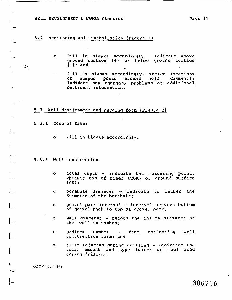
WELL DEVELOPMENT & WATER SAMPLING Page 31
5.2 Monitoring well installation (Figure 1)
o Fill in blanks accordingly. indicate aboveground surface (+) or below ground surface(-): and
o fill in blanks accordingly; sketch locationsof bumper posts around well; Comments:Indicate any changes, problems or additionalpertinent information.
5.3 Well development and purging form (Figure 2)
5.3.1 General Data:
o Fill in blanks accordingly,
i
! 5.3,2 well Construction
i o total depth - indicate the measuring point,' - whether top of riser (TOR) or ground surface
(GS) ;
|_ o borehole diameter - indicate in inches thediameter of the borehole;
I o gravel pack interval - interval between bottom~~ of gravel pack to top of gravel pack;
i well diameter - record the inside diameter ofthe well in inches;
o padlock number - f rom moni tor ing well|_ construction fo rm; and
o f l u i d injected during d r i l l i ng - indicated theI total amount and type (water or m u d ) used' dur ing drilling,
OCT/86/136e
i- 300VDO
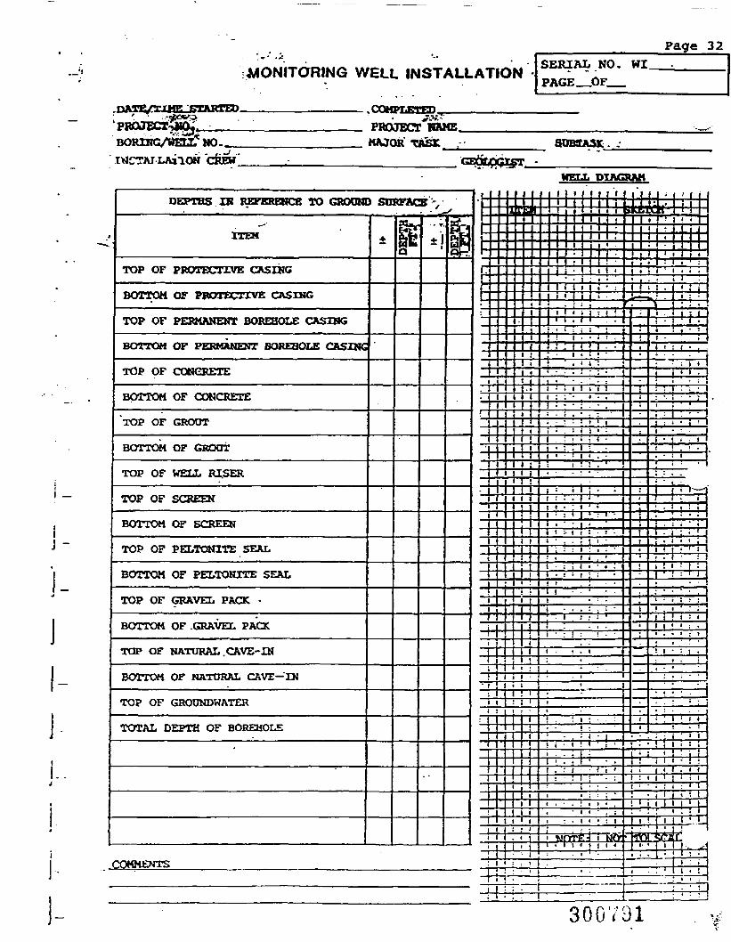
I _
J -
!MONITORING WELL INSTALLATION
———————————————.COMPLETED___________
Page 32SERIAL NO. wi.PAGE_OF__
BORING/WELL* NO.._I^CtTAJ LAilON CREW"
MAJOR TASK 80B9ASK
HELL DIAGRAM
DEPTHS IN REFERENCE TO GROQNX
ITEM
TOP OF PROTECTIVE CASING
BOTTOM OF PROTECTIVE CASING
TOP OF PERMANENT BOREHOLE CASING.
BOTTOM OF PERMANENT BOREHOLE CASING
TOP OF CONCRETE
BOTTOM OF CONCRETEt
TOP OF GROOT
BOTTOM OF GROUT
TOP OF WELL RISER-
TOP OF SCREEN
BOTTOM OF SCREEN
TOP OF PELTONITE SEAL
BOTTOM OF PELTONITE SEAL
TOP OF GRAVEL PACK •.
BOTTOM OF .GRAVEL PACK
TOP OF NATURAL CAVE-IN
BOTTOM OF NATORAL CAVE— IN
TOP OF GRODNDWATER
TOTAL DEPTH OF BOREHOLE
•
COMMENTS
> sn
4.•*
<KACT"5?rkjjpl3
8 '. '. - _j.
i
saS*Q- iPtF4Hi^i~*
i*
. . . ]
r
•:
i. i."T
! -1
•__--11 1t 1
'
;
_Lii1 1
i
i 1! 1 i
"• 1 1 i! 1i i -' i i
1 1
!1 1 1i l l :
1 i .
: i i1 1
! -•• :
r u [| ~^
_.
i1 <i :! :i •i i
ti1
1i :1
}1
i :
i :i i
t i •i ,1 1
i 1 J '^ It ,
t 1 •1 1 •
1 1 • !
! • I I1 !
t
i •i1 it ;
t •i;! i; ' i: ' *
! • •
1
1 .-4---T—
1 I1 1 •I .t I' i• i !
[
1
j
\
;
.
!
t
•
-i
K|
J
"i•i
.:i.
i
i.
i-i
ii
.
i
•
•
I
T
1it;
1•1!!
••ii|1:<
-I1iJ1iiiili
.:
.
.•
i«
i
4~y•!1
1>—
*
..
5
i
1
H
I
1
i
I
*-i
i:
i
f
i
,f
— :
<1
i
i
1
i
t
•,
t
i
1i1•
1
4
1
,
j
1
;
•
i
•
i
tit
_
> j
ii—
-:i
i-7-
iwi
iti
•
^
M ;ill f ,W '
1 • 1 i•1
-- ' ': :i .
: . : jk. : . : •^ " ' '
i 1 ' 1 * !• i f - 'i • iI .:..,.i . . . "
• : 1 «i ) .
i * • >: : I : . • 1..;.., I
-i — ! • ' ' 1* : " ' 'i : i • i ' \t • • •1 • > 1 t• . 1 •. • 1 1• < •! : . .• ' » •i i:'T< - '• t ! i* ; • • •
. ; i : •• ' j ' *;•'•',
I < • < : I' « 5 Ji l l ' :1 • ! :_ t
; ' • • .i : i ; .• :! . « ' . ;1 i ! < : <i i < ' i •i . • » : i; i ' : '1 1 • '• 1: » • '•. • •: . : • •• •
• • • • • .: • ' ' • i! • '
. i ' ' 1
j i • ! '.i i i . i i• : i : i1 1 * •1 1 1 1 _
1 1 *
1 * 4 - 1
1 - '"- f^• ' : •I : i
. ' 1 • !
• : ' : ' !
300701
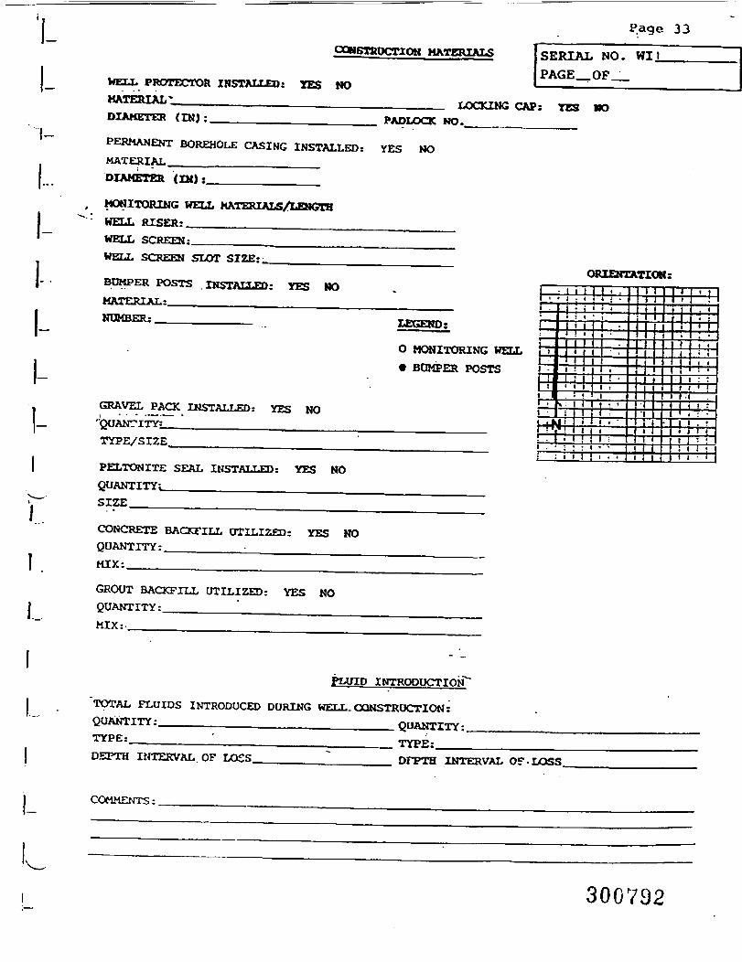
33
COHSTSOCTION HATERIALS
WELL PROTECTOR INSTALLED: YES NOMATERIAL-_______________
SERIAL NO. WitPAGE__OF__
DIAMETER (INJ:.LOCKING CAP: TES KO
PADLOCK N0._
PERMANENT BOREHOLE CASING INSTALLEDi YES NOMATERIAL ________________ __DIAMETER (IN):______________
, MONITORING WELL MATERIALS/LENGTHWELL RISER:______________WELL SCREEN:______WELL SCREEN SLOT SIZE:_BUMPER POSTS INSTALLED: YES HOMATERIAL:______________________NUMBER;____________
GRAVEL PACK INSTALLED t YES NO"QUANTITY;..______________TYPE/SIZE,_______________
PELTONITE SEAL INSTALLED: YES NOQUANTITY!_______________________SIZE_______
CONCRETE BACKFILL UTILIZED: YES NOQUANTITY :._________:_______________MIX:
GROUT BACKFILL UTILIZED: YES NOQUANTITY:_______MIX:______
LEGEND;
O MONITORING WELL• BUMPER POSTS
ORIENTATION:
FLUID INTRODUCTION""TOTAL FLUIDS INTRODUCED DURING WELL.CONSTRUCTION:QUANTITY:______________________ QUANTITY:.TYPEi__
DEPTH INTERVAL OF LOSS.__ TYPE:.
DFPTH INTERVAL OF-LOSS.
I- COMMENTS:
300792
•@£>- BURLINGTON"gj ? ENVIRONMENTAL
WEI
Project Name
Project No.
Date
Burlington Environmental Inc. Page 3 4
707 Rod! Road. Suite 101Pittsburgh. PA 15235-4559
SanWAto. WO
_L DEVELOPMENT & PURGING "" —— °' —— -f|GENERAL DATA
Well No.
Major Task Subtask
Form Completed by:
WELL CONSTRUCTION
Total Depth (Feet)
Gravel Pack Interval (Feet)
Well Protector: YES NO
Borehole Diameter (Inch)
Wen Diameter Inside (Inch)
Padlock No.
Quantity of Fluid Injected during Drilling (gallons)
WATER VOLUME CALCULATION Item fl Water Volume1 FT* Gal
Date of Measurement Measuring Point FJev. Well Casing
Water Level Instrument Used '
Initial Water Level (Feet)
Linear Feet Saturated Gravel Pack
Gravel Pack
Linear Feet of Water Drilling Fluids
TOTAL
NOTE: Quantities are to be calculated prior to development.
DEVELOPMENT CRITERIA
Method of Development
Water Quality Measurements YES NO
Well Volume (Annulus) (Gallon)
Water Volume to be Removed (Gallon)
Well Casing Volume (Pipe) (Gallon)
Minimum Maximum
NOTE: Development is to be performed in accordance with project-specific well development plan.
WATER QUALITY INSTRUMENTS
Date Instrument SeriaJ No. Calibration Performed (/) Tech Comments
Comments
_^.
JUO(Over)
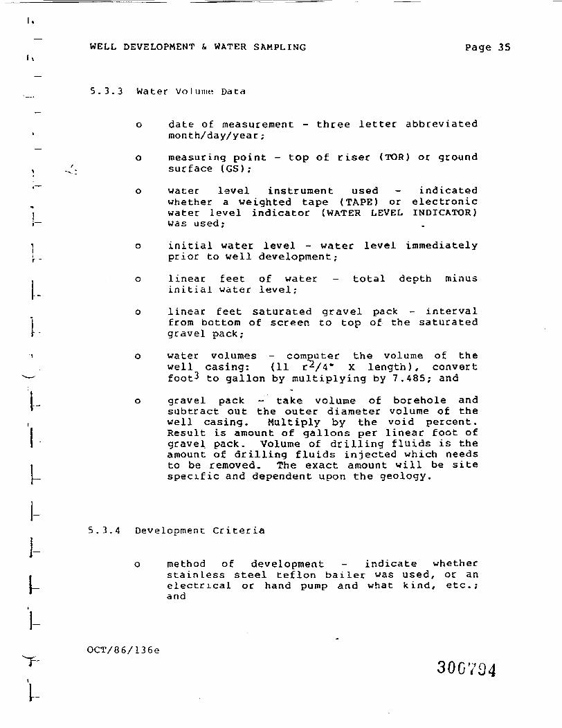
WELL DEVELOPMENT & WATER SAMPLING Page 35
5.3,3 Water volume Data
o date of measurement - three letter abbreviatedmonth/day/year;
o measuring point - top of riser (TOR) or ground, -„'- surface (GS);
'~ o water level instrument used - indicatedwhether a weighted tape (TAPE) or electronic
'] water level indicator (WATER LEVEL INDICATOR)•— was used;
i o initial water level - water level immediately•. . prior to well development;
. o linear feet of water - total depth minusinitial water level;
o linear feet saturated gravel pack - intervalfrom bottomgravel pack;
I from bottom of screen to top of the saturated
I-
1-I-
o water volumes - computer the volume of thewell casing: (11 r /4" x length), convertfoot^ to gallon by multiplying by 7.485; and
o gravel pack - take volume of borehole andsubtract out the outer diameter volume of thewell casing. Multiply by the void percent.Result is amount of gallons per linear foot ofgravel pack. Volume of drilling fluids is theamount of drilling fluids injected which needsto be removed. The exact amount will be sitespecific and dependent upon the geology.
5.3.4 Development Criteria
o method of development - indicate whetherstainless steel teflon bailer was used, or anelectrical or hand pump and what kind, etc.;and
OCT/86/136e
300704
WELL DEVELOPMENT & WATER SAMPLING Page 36
o water quality measurements: Yes ___ No ___;indicate whether or not water qualitymeasurements need to be taken; site specific.
o Water volume to be removed (gals)Minimum ___ Maximum ____. Indicate sum oTthe water volumes data table. Minimum andmaximum would be site specific
5.4 Water quality/water removal (Figure 3)
5.4.1 Water Quality Instruments
o date - three letter abbreviation ofmonth/day/year;
o instrument - indicate type of instrument used;
o serial number - indicate serial number ofinstrument used;
o calibration performed - check ( ) whether ornot the instrument was calibrated prior touse; and
o technician - signature of person operating theinstrument and recording the data.
5.4.2 Water Quality Readings
o date - as above;
o time - four digit military.time;
o total gallons removed - sum total of all fluidremoved from initial development; runningtotal;
OCT/86/136e300V95
Data Well No.
Data
DEVELOPMENT
Development Methodj^=======
Material or Serial No.
TECHNIQUES
Development Technician
— -
WATER QUALITY/WATER REMOVALWater Quality Readings
Data Time
TOTA
L IN
CREM
ENT
GALL
ONS
REM
OVED Q
K
WZ5ZWW
SOW!zo
o
2faQ, CO
NDUC
TIVI
TV(u
mho
a/qm
)
-
APPEARANCE/COMMENTS
DEVE
LOPM
ENT
STAR
T TI
ME
.Volumes Removed/Type
Water Removal Data
DEVE
LOPM
ENT
STO
P TI
ME
REM
OVAL
RAT
E(G
PM)
PUM
P IN
TAKE
LEVE
L
WAT
ER L
EVEL
BEFO
RE .
DEVE
LOPM
ENT
-
WAT
ER L
EVEL
AFTE
RDE
VELO
PMEN
TComments
NOTES:
1. Comments should delineate final sample and replicate measurements.2. Any instrumentation calibration or use anomalies should be noted.3. Appeoroncc should be notod before, during, and after development.
1
300736
Page 38PUMPING TECHNIQUES
DATE PUMP TYPE SERIAL NO. PUMP TECHNICIAN
WATER REMOVAL DATA
DATE
20cus
b,tMo
PUM
PIN
G
RATE
(GPM
)
S3(zlCOO
§ w14
.cuw
(9
8gs
COMMENTS
300797
WELL DEVELOPMENT £. WATER SAMPLING Page 39
o total well volumes removed - after initialdevelopment, running total of required wellvolumes removed prior to water sampling;
o temperature. (°C) - temperature of water in°C
o dissolved 02 - direct reading frominstrument;
o pH - direct reading from instrument?
o redox - direct reading from instrument;
o conductivity - direct reading from instrument;
o appearance - describe general appearance ofthe water (clear, cloudy, silty, etc);
o pumping techniques;
o date - as above;
5.4.3 Pumping techniques
o date - as above;
o pump type - indicate whether centrifugal,submersible, rod, etc.;
o serial number - record serial number of pump;
o pump technician -signature of person operatingpump;
5.4.4 Water removal data
o date - as above;
o pump on - time pump turned on;
o pump off - time pump turned off
OCT/86/136e
300798
I-
l
\-
WELL DEVELOPMENT & WATER SAMPLING Page 40
pumping rate - gallons per minute asdetermined by recording the time it takes tofill a certain known volume container;
incremental gallons removed - gallons removedduring one pump on/pump off period;
incremental well volumes removed - afterinitial development, will volumes removed bypumping during one pump on/pump off period;
total well volumes removed - running total ofall well volumes removed by pumping afterinitial development;
pump intake level - depth from which pumpingoccurs in foot;
water level before pumping - depth is feet ofwater level before one pumping period; and
I o water level after pumping - depth is feet of_j~* water level summed after one pumping period.
5.5 water sampling data (Figure 4)
5.5.1 Sampling data
weather - short description of general weatherconditions, including wind direction;
level of protection A, B, C, D - circle levelof protection;
measuring point - point from which waterlevel, sampling point, and total depth of wellmeasurements will be taken;
method of measurement - electric water levelirdicator or weighted taped;
OCT/86/136e
300739T
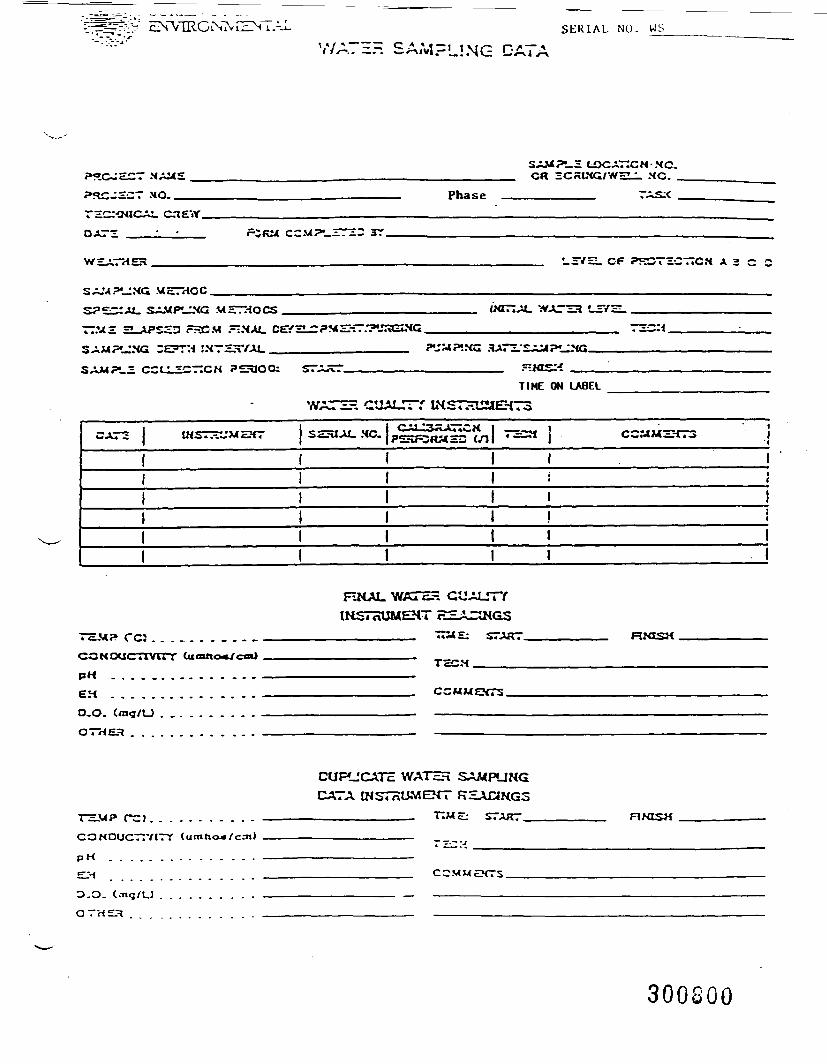
'i=^=v-:V ENVIRONS CEN i.-J SERIAL NO. WS
V/A7EH SAMPLING CATA
SA.UPU.E LOCATICN-MC.OR •=r:aiNC/w=« • NC. _
PftCJECT MO. Phase TASX
OAT3
•_3V=i. CP PKOTiCTICM A 3 C 2
TIMS 2^U»S2D FHCM .~.XAL
TIME ON LABEL
WATS QUALITY IHSTHUMEHT3
CAT- i fmj" ^ »v* trv"Uiv* ,-»*-** c^t 4 SSUJU. HC. CAU3^A77CHPSHFCHME3 (.T I"=H 1
1i
(IJ1
CCMMZKT3 I'1
1II
1i11
rc;
PH
EMO.O.OTHEH
FZHAL. WATEH GUIMSTHUMEH
START.
TcCM.
CCMMEXTS.
TEMP rCJ . . . . . . . . . . .CONOUCTtVtTY (umho«/c.-nl
p M . . . . . . . . . . . . . . .
D.O. (
QTHES
CUFUCATE WATEH SAMPUNGCATA INSTTOJMEHT RHAaKGS
____________. TMZ: START _
COMMEXTS.
RfOSH
300800
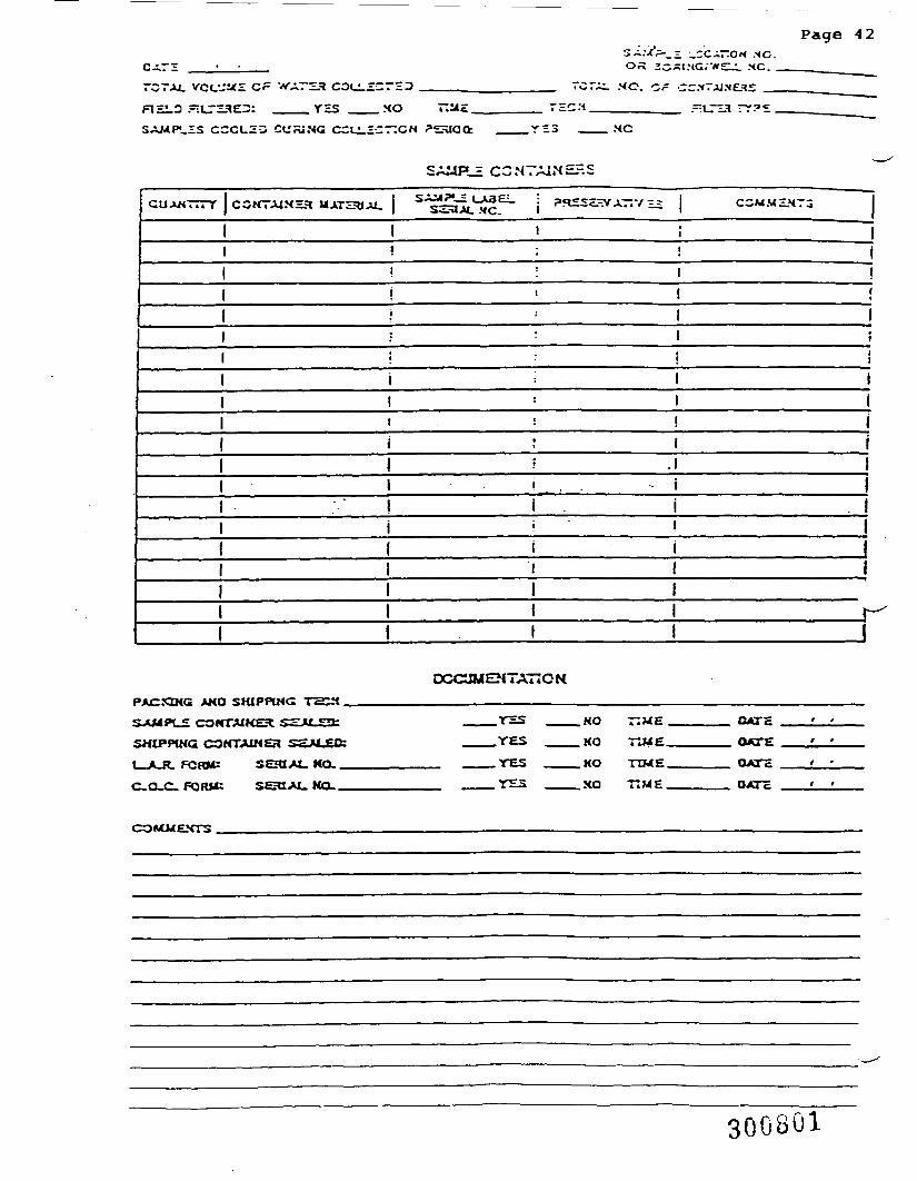
Page 42
RE1_3 =U_T3HE3: ____YESSAMPLES CCCLZ3 CURING CCU.
.HO
CU.=CT:CN ?2aoot
SAMP_£ CONTAINERS
GUAM... T | CCMTAIXH* «ATSa;U. i ^l^ j ««=* A^.V « COM.MZ.MT3
i i ;i : ! |! : 1i i i' : 1 1• : i ;* * i ii i I 1! ' 1l . : ! 1i I 1 jI i .1 11 i . . i 1I i . i !i • - ! 11 i i1 i I1 1 1I I I r -I I 1 I
PACJOHC, AND SHIPPING T2CH
COKTAIHEl <g='M «-T:
SHIPPING COMTAU4EH SS*L£FCRIUU SEHI AI_ KO.
OCOJMEMTATIGN
C.O-C.50RM: SCHIJU.KO
.YES
-YES.YS3
.NO —ME.
.MO TU4E.
.KO TIME.
.XO TIME.
DATEDATEOATH
OATc
COMMEXTS.
300S01
WELL DEVELOPMENT & WATER SAMPLING Page 43
measuring point elevation - to be filled fromsite survey;
initial water level elevation - figuredin-house from survey information;
sampling method - record type of device usingto sample;
initial water level - record water levelbefore sampling;
special sampling methods - partial bottlefilling method or common vessel collectionmethod;
time elapsed/final development/purging - timeelapsed from previous development performed totime begin water sampling;
technician - signature of person performingfinal development task;
sampling depth interval - interval from wherewater sample obtained within water column;
pumping rate/sampling - if sampling method iswith a pump/ record pumping rate surgingsampling; and -'
water quality instruments used - record allinstruments, then serial numbers, and whatlogbook to reference for calibrationinformation.
5.5.2 Final water quality instrument readings/duplicateT instrument readings
r o technician - signature of person performingwater quality instrument readings;
P o time start/time finish - record in four digitmilitary time the start and finish of waterquality test for specified sample;
FT
_ OCT/86/136e
r 300802
WELL DEVELOPMENT & WATER SAMPLING Page 44
o temperature °C - record of direct instrumentreading;
o conductivity - record of direct instrumentreading ,-
o pH - record of direct instrument reading;
o EH - record of direct instrument reading;
o DO - record of direct instrument reading;
o other - any other instrumentation used and thereading;
o total volume water collected - volume of waterobtained to fill designated sample bottle;
o total number of containers - sum of thecontainers included in sample suite;
o field filtered - check yes or no;
o time - time sample filtered;
o technician - signature of person filtering;
o filter type - record filter size; and
o samples cooled during collection periodcheck yes or no.
r- 5.4.3 Sample containers
o quantity - record how many same size andI" material bottles;
o container material/ volume - glass or plasticj~ plus volume;
o sample label serial number - record sampleT- label serial number;
o preservatives - record chemical preservativesadded to bottle, if applicable; and
o comments - indicate if preservatives wereadded in field or had been added by lab prior
j~' to sampling and if bottles were rinsed.
OCT/86/136e
QUALITY ASSURANCE PROJECT PLANREMEDIAL INVESTIGATION/FEASIBILITY STUDYKENTUCKY AVENUE WELLFIELD SITEOPERABLE UNIT NO. 3
APPENDIX B
BURLINGTON ENVIRONMENTAL INC.Project: 427100Date: 10/25/93Revision: 1
APPENDIX B
STANDARD OPERATING PROCEDURESFOR DECONTAMINATION PROCEDURES
10/93/76W82A(427100)2
SOP: DECON-1 DECONTAMINATION OF SAMPLING EQUIPMENT
1 SCOPE AND PURPOSE
This Standard Operating Procedure (SOP) is concerned with thedecontamination of sampling equipment used to collect samples to be analyzed forchemical constituents. Decontamination is necessary to:
1. prevent the cross contamination of samples collected at hazardous waste sitesor suspected hazardous waste sites, and
2. prevent the spread of hazardous substances from a site contaminated byhazardous waste or hazardous materials.
2 RESPONSIBILITIES
The Project Manager or Project Health and Safety Officer will have the.responsibility to develop decontamination procedures required in the site specificSampling and Analysis Plan that will detail the site specific sampling equipmentdecontamination procedure.
The Project Manager or Project Health and Safety Officer will have theresponsibility to develop decontamination procedures required for obtaining bids frompotential drilling subcontractors for each job.
The Project Manager or Project Health and Safety Officer will have theresponsibility to oversee and ensure that sampling equipment decontamination is per-formed in accordance with the project-specific Sampling and Analysis Plan, and thisSOP.
3 EQUIPMENT AND MATERIALS
The following list of equipment will be required to decontaminate samplingequipment:
• washing baths;
• brushes;
• supply of potable and/or distilled water;
• supply of alconox (or other nonphosphate) detergent;
• supply of pesticide quality hexane; n ~ ^,3UU t)
STANDARD OPERATING PROCEDURES MANUAL DECON-1-110/93/308W82A
• supply of pesticide-grade methanol;
• clean paper towels;
• polyethylene sheets; and
• polyethylene bags of sufficient size to hold sampling equipmentbeing decontaminated.
4 PROCEDURE
Decontamination procedures for field sampling and peripheral equipmentshould be implemented before use, at the end of each work day, between samples, orwhen leaving the work area. All sampling equipment must be cleaned anddecontaminated prior to removal from the site. The method of equipmentdecontamination will depend on the type of sample being collected and the parameterschosen for analysis. The project-specific Sampling and Analysis Plan would beconsulted to address project-specific procedures of sampling equipment decontamina-tion. General guidelines are as follows:
1. After the required samples are taken from the sampling device, remove allremaining soil or liquid from the device. Soil or water shall be placed in theproper receptacle for disposal if it is being handled as a hazardous or specialwaste. Soil and liquid shall be removed from both the inside and outside ofthe sampling device.
2. Immerse the individual sampler and/or components in a bath filled with potablewater and detergent. The individual components shall be scrubbed with abrush to remove all residual contaminated soil or liquid.
3. Remove the components from the first bath and allow excess water to drip intobath. Immerse the components in a second bath containing potable or distilledrinse water.
4. Unless made of carbon steel, rinse the sampling device in a solution of10 percent nitric acid, followed by a rinse with deionized analyte-free water(for carbon steel, use a 1 percent nitric acid solution).
5. Remove components and rinse in a similar manner in either acetone only, ormethanol followed by pesticide quality hexane. Collect any acetone,methanol,and/or hexane that drips off of the equipment in a separate bucket.
300^06
STANDARD OPERATING PROCEDURES MANUAL DECON-1-210/93/308W82A
6. Triple rinse the components of the sampling device with potable or distilledrinse water. The volume of potable water used for rinsing should be at leastfive time the volume of solvent used in the previous step. Place the samplingdevice on a clean polyethylene sheet during and after drying to preventcontamination from the soil.
7. Allow the sampler to air dry if conditions permit. If significant airbornecontamination is present, the sampling device should be assembled immediatelyafter decontamination and placed in a polyethylene bag until used.
8. Dispose of the rinse water and solvent wash in an appropriate manner.
5 DOCUMENTATION
Decontamination procedures shall be detailed in daily log sheets and field logbooks.
6 REFERENCES
U.S. Environmental Protection Agency, September, 1986, RCRA GroundwaterMonitoring Technical Enforcement Guidance Documenty.
300307STANDARD OPERATING PROCEDURES MANUAL DECON-1-310/93/308W82A
QUALITY ASSURANCE PROJECT PLANREMEDIAL INVESTIGATION/FEASIBILITY STUDYKENTUCKY AVENUE WELLFIELD SITEOPERABLE UNIT NO. 3
BURLINGTON ENVIRONMENTAL INC.Project: 427100Date: 10/25/93Revision: 1
APPENDIX C
APPENDIX C
FIELD FORMS
300SOS10/93/76 W82A(427100)2

jSg^A BURLINGTON H&S FORM 214-2* Sir ENVIRONMENTAL" '•" SITE SAFETY ORIENTATION MEETING RECORD
Document Serial Number H&S A
Project:
Location:
Project Number:
I acknowledge that I have received a verbal site safety
orientation briefing for authorized on-site activities. I have
been informed of site hazards and safety protocols applicable
to my responsibilities. A copy of the Site Safety Plan has
also been made available for ray review. I agree to comply with
site safety protocols as presented by Burlington Environmental
Inc., health and safety representatives.
Signature Company Date
This orientation was presented bySignature
on _________________________Date
01/89/8269S 300809
DOCUMENT SERIALIZATIONTRACKING FORM
Job Name Job No.
Project Mgr Project Sup.
LogBook#
Forms OrLog Book
AssignedTo
Initials
Serialized Outer Inner InteriorLabel Label Signed
(If YES/ Check Appropriate Column)
.
JAN/88/8491S 300810
The following record summarizes the project activities of(employee name)_________________________ for the(project name) Remedial Design Activities associated with KentuckyAvenue Wellfield in Horseheads, New York as performed byBurlington Environmental Inc. Project activities began(date)___________ under direct contract withWestinghouse Electric Corp. This document is a permanent part ofthe project record, and is the exclusive property of the (client)Westinghouse Electric Corp. and Burlington Environmental Inc., asthe prime contractor to the (client) Westinghouse Electric Corp.In accordance with contractual confidentiality agreements, thecontents of this record are confidential and shall be treated assuch by the custodian of this document. Information entered hereinshall be available only for in-house use by designated projectpersonnel. This document may not be viewed, or reproduced anddistributed to parties other than designated BurlingtonEnvironmental Inc. and (client) Westinghouse Electric Corp.personnel without the express written consent of (client)Westinghouse Electric Corp. The aforementioned conditions of thisdisclosure are agreed to and shall be fully complied with aswitnessed by the signature of (employee name)____________ onthis date, ________________ for receipt of record book,Serial No.
The following record summarizes the project activities of(employee name)________________________ for the(project name) Remedial Design Activities associated with KentuckyAvenue Wellfield in Horseheads, New York as performed byBurlington Environmental Inc. Project activities began(date)___________ under direct contract withWestinghouse Electric Corp. This document is a permanent part ofthe project record, and is the exclusive property of the (client)Westinghouse Electric Corp. and Burlington Environmental Inc., asthe prime contractor to the (client) Westinghouse Electric Corp.In accordance with contractual confidentiality agreements, thecontents of this record are confidential and shall be treated assuch by the custodian of this document. Information entered hereinshall be available only for in-house use by designated projectpersonnel. This document may not be viewed, or reproduced anddistributed to parties other than designated BurlingtonEnvironmental Inc. and (client) Westinghouse Electric Corp.personnel without the express written consent of (client)Westinghouse Electric Corp. The aforementioned conditions of thisdisclosure are agreed to and shall be fully complied with aswitnessed by the signature of (employee name)____________ onthis date, ________________ for receipt of record book,Serial No.
300811
j&* BURLINGTONENVIRONMENTAL S1TE V I S I T O R LOG SHEET
SEHIAL NO. SV
FffB o , »n«n
mr*~
NAME
(PRINT)/(SIG>
t.iit «v>v>\_S. / C->*s> ——— ?& ——
1
OfTODCCCM T"t fcl^*
Cot^\>x»^rs4V
I
_
(24 HOU
ARRIVE
0600
•
R CLOCK)DEPART
»«-.T»o
1
C\FT-H
mCDOCO
r.r_: rr FIELD ACTIVITY DAILY LOGBURLINGTON ENVIRONMENTAL INC.
East Park One Building701 Rodi Road, Suite 101
Pittsburgh, PA 15235-4559(412) 824-0200
F«x: (412)824-0480
Date
Control No.
P.gc of
Project Name:
Project Number: Phase Task
Personnel On-Site:
Contractors On-Site:
Visitors On-Site:
Major Field Activities:
Weather Conditions Temperature
TIME:
I91D3B-3/92
300813
.*££&•. BURLINGTONENVIRONMENTAL SAMPLE CONTROL LOG
Project NameTask DescriptionSample Type(s)
Serial No. SCLPage
Project No.PhaseTask
COooCO
BurlmgtonSampleNumber
Deptn(feet)
Date TimeSampled Sampled Shipped
Date COGLog
Number
LaboratoryName
Bill ofLading
Number
DateAnalysis
Performed
DateResults
Received
§^ BURLINGTONS&BgF ENVIRONMENTAL
SITE SUPERVISORS DAILY REPORTss-
Project No._ Date
Site Supervisor
WEATHER (fill in appropriate blank)(if blank, information not obtained or unobtainable)
TEMPERATTTPy:(Circle appropriate scale "F. *C)
Conunents
•F. *C'F. «C•F. *C;F. -c•F. «c•F, -C <3L
hr.hr.nr.hr.
HUMIDITY rnismirpoMcTime: ____
% Humidity_______Barometnc Pressure ______ (inches of Hg)
_Low .High
Comments
Time:VelocityDirection
Ooninients
.Constant
.Intermittent
General Comments
b36:daily.rpt
ATMOSPHERIC CONDITIONS
.Sunny/dear
.Ptly Cloudy
.Cloudy
-Hazy_Dosty.Other
Comments
300^15
Page 2SITE SUPERVISORS DAILY REPORT, Continued
PERSONNEL ON SITE
Project_______________________ No._____________ Date_____________
Burlington PersonnelName Time On Time Off Comments
(L)
SITE VISITOR'S ACTIVITY LOG(Refer to Site Visitor's Log for Names of Personnel and Employers)
TIME______ACTIVITY
300316
Page 3SITE SUPERVISORS DAILY REPORT, Continued
ss-_Project____________________________ Project No._______________
If the task is performed during the work period date__________, check appropriate column.
NOTE: • If Yes, refer to appropriate documentation, manual, and/or forms.
• If N/A, documentation not applicable.
• If initialed, reviewer has reviewed and verified documentation.
REVIEWER'SYES N/A INITIALS TASK/MANUAL___________________________________
___ __ _____ Site Supervisor Daily Report Documentation - Daily Work Tasks Accounted forSite Visitor's DocumentationHealth & Safety DocumentationInstrument Calibration &. Maintenance Documentation
. Record of Conversation Documentation and Forms. Photodocumentation it. Photos Logged . ''Site R<^ronna'gC3nr'r DocumentationTest Drilling &. Wetl Installation Documentation- Drilling Logs Accounted for- Well Diagram Logs Accounted forSoil -Samnlinar Documentation- Samples Accounted for- Sample Labels Accounted for- Sample COCTs Accounted for- Sample Assignment Sheets Accounted for- Samples Shipped &. Accounted forWell Development Documentation & Forms- Groundwater Sampling FormsEM Survey Documentation &. FormsRiver Sampling Documentation &. FormsBiota Sampling Documentation & FormsLiracfaatr &. Pood Water Documentation FormsAir Quality Documentation &. FormsDrum or Tank Sampling Documentation &. FormsWaste Characterization Documentation &. FormsHydrogeologic Study Documentation &. FormsWipe Sample Tests Documentation & FormsPhysical Survey Documentation &. Forms(Other)_______________________(Other)_______________________(Other) _______________________
300817
Page 4SITE SUPERVISORS DAILY REPORT, Continued
Project____________________ Project No._______ Date_
Accomplish men is___________________________________________
PROBLEMS ENCOUNTERED WITH: (if N/A, indicate)
Health &. Safety
Work (fade) items
Site Management
Weather
Other
300318
ss -DATE:
P*ge5SITE SUPERVISORS DAILY REPORT, Continued
T I M E -. ACTIVITY
300319
Itt BURLINGTON M & s -°RM 2 1^-1iS £• ENVIRONMENTAL'5S..' SITE SAFETY ORIENTATION MEETING RECORD
Document Serial Number H&S B
Project:____ ___________________
Location:
Project Number:
Each individual signed below acknowledges that they have
received a verbal site safety orientation briefing for
authorized on-site activities. They have been informed of site
hazards and safety protocols applicable to their
responsibilities. A copy of the Site Safety Plan has also been
made available for their review. Each individual signed below
agrees to comply with site safety protocols as presented by
Burlington Environmental Inc. health and safety
representatives.
NAME SIGNATURE COMPANY
i. ___________ __________ ____________2. ___________________ __________________ _______________
3. __________________ _________________ _______________
4. ___________________ __________________ _________________
5. __________________ _________________ ______________
6. _______________ _____
This class was presented bySignature
on ________________________.Date
01/89/8269S
300J20
& BURLINGTONfc>J ENVIRONMENTAL
DAILY SITE SAFETY MEETING RECORD
Document Serial Numbe r DSM-P reject NumberPhase Task
Project :
Location:
Site Safety Officer/Meeting Leader:
Work Areas:
Work Tasks:
Hazards:
Personnel Protective Equipment:
Aii Monitoring Koquirements:
i) : - ;on t :<n ; i i r..- L ion i ' rocc 'du t'e:; :
(Signature)Attendees (Signatures^:
1)________________ 2)_________________ 3).
4)___________• 5)_________________ 6).
7)______;__________ 8) _____________ 9).
300821
.•;V- BURLINGTON
- ENVIRONMENTAL'N.'.W
Project:
SITE SAFETY ACTIVITY MEETING RECORD
Document Serial NumberH&S C
Location:
Project Number: Work Activity:
Date: Time:
Presented Bv:
Attendees:
Name/Signature
1.
Company Position
3.
4.
5.
6.
NOV/87/8L59S/1
300S22
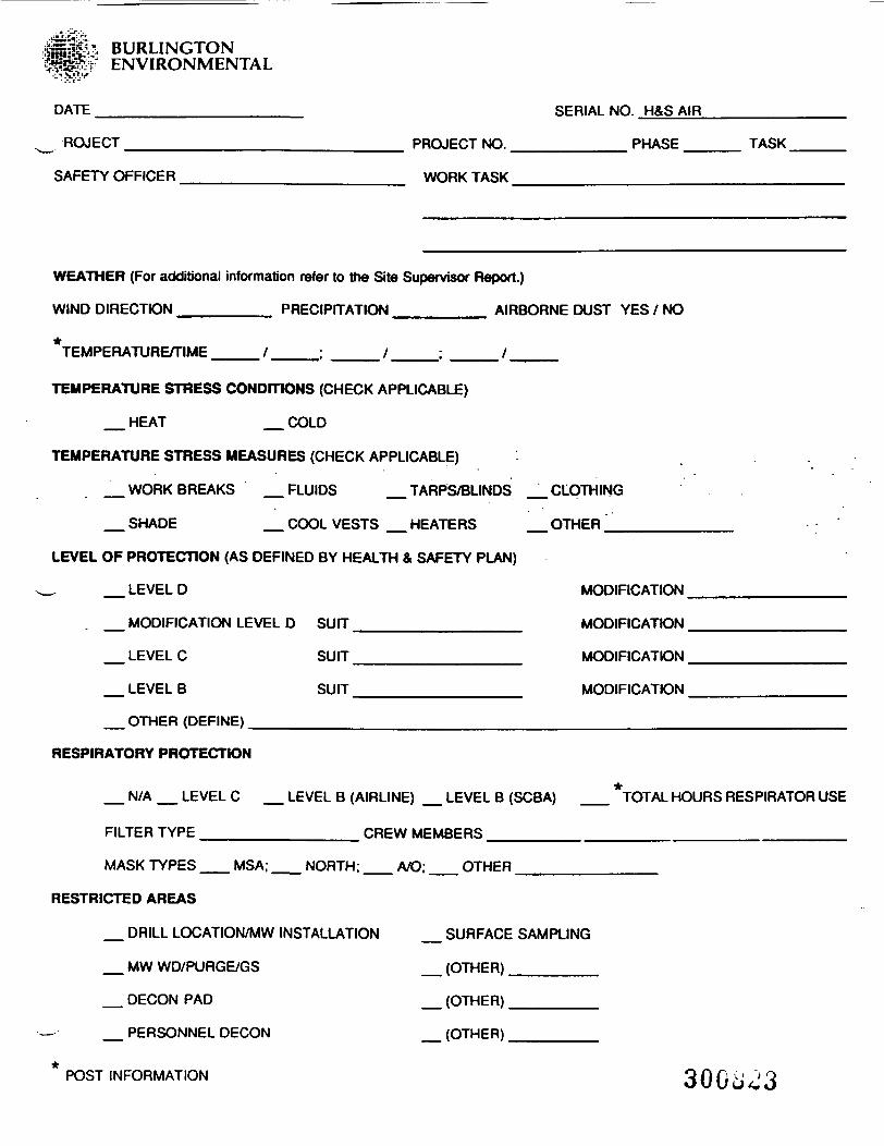
= a * BURLINGTONENVIRONMENTAL
DATE ___________________ SERIAL NO. H&S AIR
ROJECT _________________________ PROJECT NO. __________ PHASE _____ TASK.
SAFETY OFFICER ____________________ WORK TASK ________________
WEATHER (For additional information refer to the Site Supervisor Report.)
WIND DIRECTION ________ PRECIPITATION ________ AIRBORNE DUST YES / NO
*TEMPERATURE/TIME ____ /____; ____ /____; ____/ ______
TEMPERATURE STRESS CONDfTlONS (CHECK APPLICABLE)
_ HEAT _ COLD
TEMPERATURE STRESS MEASURES (CHECK APPLICABLE)
_ WORK BREAKS _ FLUIDS _ TARPS/BLINDS _ CLOTHING
_ SHADE _ COOL VESTS _ HEATERS _ OTHER ',_______
LEVEL OF PROTECTION (AS DEFINED BY HEALTH & SAFETY PLAN)
_ LEVEL D MODIFICATION
_ MODIFICATION LEVEL D SUIT _______________ MODIFICATION
_ LEVEL C SUIT _______________ MODIFICATION
_ LEVEL B SUIT _______________ MODIFICATION
__ OTHER (DEFINE) __________________________________________
RESPIRATORY PROTECTION
_ N/A _ LEVEL C _ LEVEL B (AIRLINE) _ LEVEL B (SCBA) __ *TOTAL HOURS RESPIRATOR USE
FILTER TYPE ______________ CREW MEMBERS _____________________________________________
MASK TYPES __ MSA; __ NORTH; __ A/O; __ OTHER _______
RESTRICTED AREAS
_ DRILL LOCATION/MW INSTALLATION _ SURFACE SAMPLING
_ MW WD/PURGE/GS _ (OTHER) ________
_ DECON PAD _ (OTHER) ________
_ PERSONNEL DECON _ (OTHER) ________
*POST INFORMATION 3 0 0 tj '3
AIR INSTRUMENTATION (REFER TO INSTRUMENT CALIBRATION BOOKS)
_ OVA SERIAL NO.
_ HNU SERIAL NO.
_ CGI (LEL ONLY) SERIAL NO.
_ CGI (COMBO) _ H2S _ CO SERIAL NO.
_ HCN SERIAL NO.
OTHER _________ SERIAL NO.
AIR MONITORING (LOCATION/INSTRUMENT)NR - No readings taken. All readings are in applicable instrument measurement units.
BREATHING ZONE READING SOURCE READING SAMPLE READING(OVA/HNU/CGI/OTHER) (OVA/HNU/CGI/OTHER) (OVA/HNU/CGI/OTHER)
SAMPLES: HEADSPACE LABORATORY
UPGRADE/DOWNGRADE (COMMENTS)
ACCIDENT (COMMENTS)
VIOLATION (COMMENTS)
11/92/CHARLENE/FORMS/HSFORM.FOR300824
BURLINGTONENVIRONMENTAL
Document: Ser ia l Number H&S F
BURLINGTONON-SITE RESPIRATOR FIT TEST RECORD
Project:
Location:
Project Number:
Date: ________
Work Act ivi ty:
__ Time: ___
Administrator:(Name)
Method/Testing Agent:
____ Hood With Irritant Smoke
1..
(Signature)
Isoamyl Acetate (BananaOil) Ampule
Product: _____;_______,_____:____._____«______________Descriptor (Brand) . (Mfg./Part Number) (Batch/Lot Number)
• f
Employees: ." '
____Name/Signature___ Company/Position Mask Fitted
4.
5.
6.
02/88/8596S Form HS-1. Pg. 1
300^5

& BURLINGTONENVIRONMENTAL Document Serial Number H&S G
1
BURLINGTONRESPIRATOR FIT TEST RECORD
Employee: ________._______________________ Date:
Location: _^____________________________________
Administrator:(Name) (Signature)
Reason for Test: ____ New Mask ____ Mask Repaired____ QA/QC Inspection ____ Re-Certification ____ Project Start
MASK FITTED:(Manufacturer) (Style Name) (Model Number)
(Material) (Size) (Configuration)
(Comments)" • . Organic
Cartridge(s) Used: _____;____,_______________/ ____ Vapor (OV). (Quantity) (Mfg. Number)
High EfficiencyParticulate/
'____ Aerosol Filter (HEPA) ____ OVHEPA _____ OVHEPA With Acid Gas
METHOD: ____ Quantitative ____ QualitativeClosed
____ Ambient Air ____ Head Hood ____ Full Hood ____ Chamber
EQUIPMENT USED: ____ Portacount ____ Portacount With Recorder____ Aspirator Bulb With Smoke Tube____ Chemical Ampule____ Chemical-Saturated Swab
TESTING AGENT: ____ Ambient Air (Dust) ____ Visible Smoke____ Irritant Smoke ____ Isoamyl Acetate (Banana Oil)
Product _______________,______________,_____________Descriptor (Brand) (Mfg. Number) (Batch/Lot No.
If Applicable)
FIT TEST RESULT: ____ Pass ____ Fail ____ Pass Re-TestPortacount Fit Factor Setting __________Strip Chart Run: ____ Yes ____ No
Administrator Comments: _____
I. _____________________, acknowledge that I have beer, fit tested,(Employee Signature)
as documented above, on ________________________(Date) " 3008^6
.-a r.r_: rr
A BURLINGTON SERIAL N0-f ENVIRONMENTAL
SUPERVISOR'S ACCIDENT/INJURY INVESTIGATION REPORT
ACCIDENT TYPE: INJURY CH VEHICLE CZ1 PROPERTY CH NEAR MISS CD
NAME OF INJURED PERSON:__________________________________________
DEPARTMENT TO WHICH INJURED PERSON IS ASSIGNED: ______________________
LENGTH OF EMPLOYMENT: _________________:__________ AGE
LENGTH OF TIME ON JOB ON WHICH PERSON WAS INJURED:____________
LOST TIME: YES_____ NO_____
DATE OF ACCIDENT: _____________ DATE INJURY REPORTED: '
TIME OF ACCIDENT: ______________ AM or PM DAY OF WEEK:
DOCTOR TREATED: ________________ FIRST AID ONLY: ____
OF HOSPITAL OR CLINIC: _________________________
EXACT LOCATION AT WHICH ACCIDENT OCCURRED:
SUPERVISOR OF INJURY EMPLOYEE: _________
WITNESS: ___________________________
WAS THE SCENE OF THE ACCIDENT INVESTIGATED BEFORE COMPLETING THIS REPORT?
YES______ NO _____
EMPLOYEE'S DESCRIPTION OF ACCIDENT AND SUPERVISOR'S COMMENTS: _________
(OVER)
300i>27
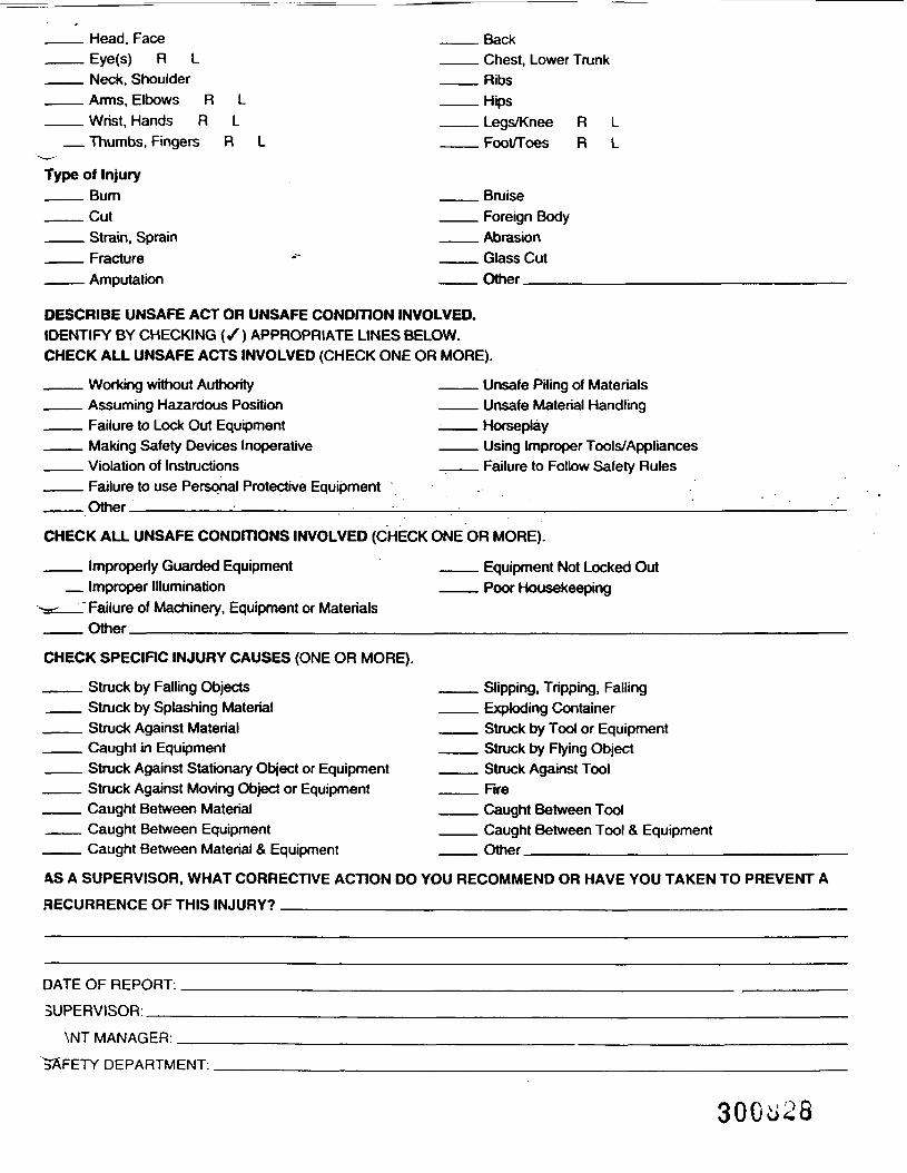
Head, FaceEye(s) R LNeck, ShoulderArms, Elbows RWrist, Hands R
_ Thumbs, Fingers R L
Type of Injury___ Bum___Cut___ Strain, Sprain——— Fracture___ Amputation
BackChest, Lower TrunkRibsHipsLegs/Knee R LFoot/Toes R L
BruiseForeign BodyAbrasionGlass CutOther________
DESCRIBE UNSAFE ACT OR UNSAFE CONDITION INVOLVED.IDENTIFY BY CHECKING (/) APPROPRIATE LINES BELOW.CHECK ALL UNSAFE ACTS INVOLVED (CHECK ONE OR MORE).
Working without AuthorityAssuming Hazardous PositionFailure to Lock Out EquipmentMaking Safety Devices InoperativeViolation of InstructionsFailure to use Personal Protective EquipmentOther.________:_________•
Unsafe Piling of MaterialsUnsafe Material HandlingHorseplayUsing Improper Tools/AppliancesFailure to Follow Safety Rules
CHECK ALL UNSAFE CONDITIONS INVOLVED (CHECK ONE OR MORE).
_ Improperly Guarded Equipment_ Improper Illumination
__" Failure of Machinery, Equipment or Materials_Other_____________________
Equipment Not Locked OutPoor Housekeeping
CHECK SPECIRC INJURY CAUSES (ONE OR MORE).
___ Struck by Falling Objects___ Struck by Splashing Material___ Struck Against Material_____ Caught in Equipment___ Struck Against Stationary Object or Equipment___ Struck Against Moving Object or Equipment___ Caught Between Material___ Caught Between Equipment___ Caught Between Material & Equipment
Slipping, Tripping, FallingExploding ContainerStruck by Tool or EquipmentStruck by Rying ObjectStruck Against ToolRreCaught Between ToolCaught Between Tool & EquipmentOther________________
AS A SUPERVISOR, WHAT CORRECTIVE ACTION DO YOU RECOMMEND OR HAVE YOU TAKEN TO PREVENT A
RECURRENCE OF THIS INJURY? __________________________________________________
DATE OF REPORT:
SUPERVISOR:__
\NT MANAGER.
"SAFETY DEPARTMENT:
RECORD OF CONVERSATIONBURLINGTON Route To —————ENVIRONMENTAL ———————————
. Telephone Call (to/from)Meeting
Organization____________________________Date _________Time.
Contact_____________________________Title ____________Address ______________________________Telephone Number
City, State. Zip____________________________________Project Name __________________________Project Number.REFERENCE _____ _ _
Discussion Summary
By.K-21 (IJK) 300^9
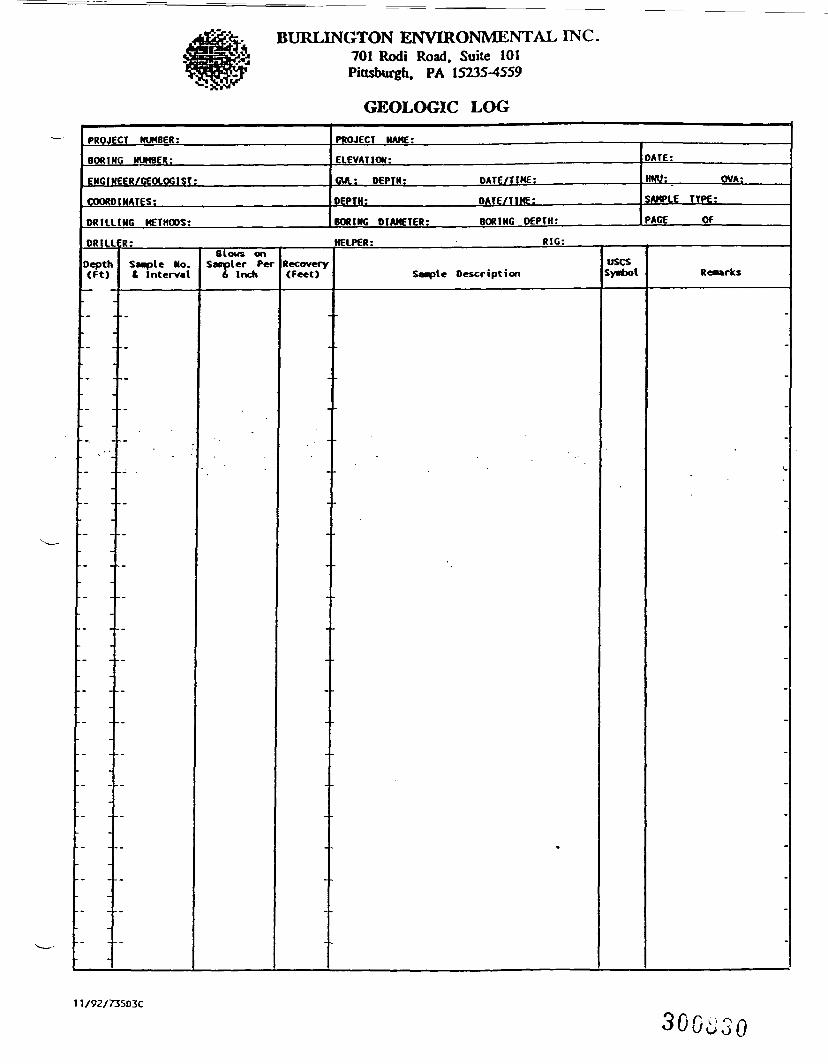
BURLINGTON ENVIRONMENTAL INC.701 Rodi Road. Suite 101Pittsbui h, PA 15235-4559
GEOLOGIC LOG
PROJECT NUMBER:
BORING NUMBER:
ENGINEER/GEOLOGIST:
COORDINATES:
DRILLING METHODS:
ORIL
Depth(Ft)
•
PROJECT NAME: ——————————— f
ELEVATION:
OWL: DEPTH: DATE/TIME:
DEPTH: DATE/TIKE:
BORING DIAMETER: BORING DEPTH:
ER: HELPER: RIG:
Sanple No.t Interval
--
Slows onSampler Per
6 InchRecovery<Feet> Sample Description
»
usesSynbol
DATE:
HNU: OVA:
SAMPLE TYPE:
PAGE OF
Remarks
*_
11/92/73503C
300^30
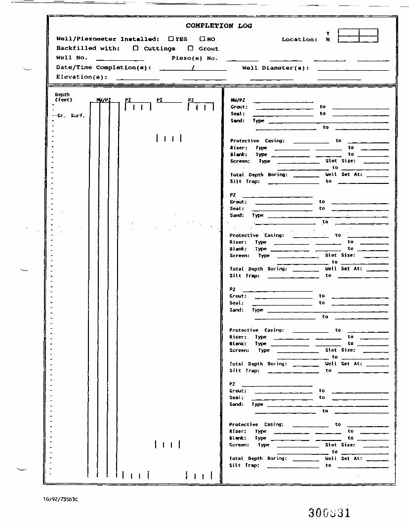
COMPLETION LOG
Well/Piezometer Installed: DYES DNOBackfilled with: D Cuttings D GroutWell No. ___________ Piezo(s) No.Date/Time Completions): _______i_____Elevation(s):
Depth(feet)
--Or. Surf.
HU/P PZM i l
PZ
I I l I
PZrrn
Location: N
Hell Diameter(s):
HU/PZ ___Grout: __Seal: ___Sand: Type
Protective Casing:Riser: Type ___Blank: Type ___Screen: Type __
Total Depth Boring:Silt Trap: _____
PZ _____Grout: __Seal: ___Sand: Type
Protective Casing:Riser: Type ___Blank: Type ___Screen: Type __
Total Depth Boring:Silt Trap: _____
PZ _____Grout: __Seal: ___Sand: Type
Protective Casing:Riser: Type ___Blank: Type ___Screen: Type __
Total Depth Boring:Silt Trap: _____
PZ ______Grout: __Seal: ___Sand: Type
Protective Casing:Riser: Type ___Blank: Type ___Screen: Type __
Total Depth Boring:Silt Trap: _____
toto
to
to____ to____ toSlot Size:
to ____Uell Set At:to ______
toto
to
to____ to____ toSlot Size:
to ____Well Set At:to ______
toto
to
to____ to____ to _Slot Size:_ to _____Uell Set At:to
toto
to
to____ to____ toSlot Size:
to ____Uell Set At:to ______
10/9Z/735D3C
30Go31
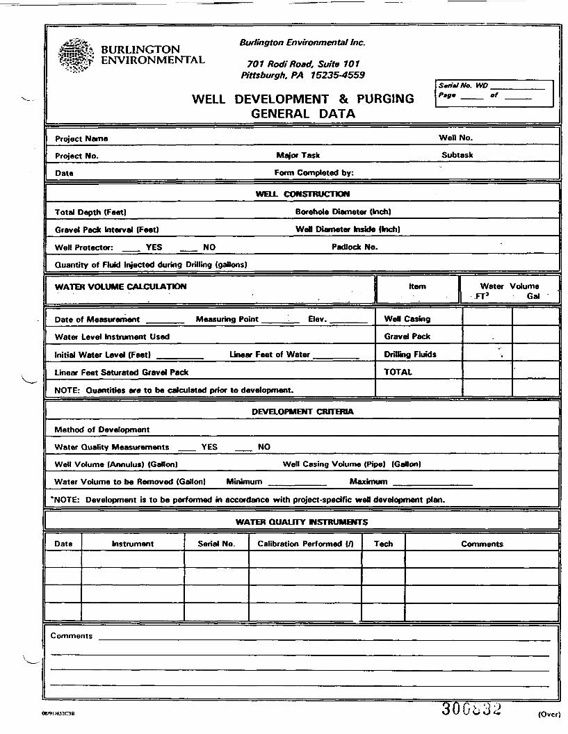
BURLINGTONIjpt ENVIRONMENTAL
•?-fS>?.v'
WEL
—Project Name
Project No.
Date
Burlington Environmental Inc.
701 Rod! Road. Suite 101Pittsburgh. PA 15235-4559
SarimlNo. WO
.L DEVELOPMENT & PURGING Pfi" —— °' ——GENERAL DATA
Well No.
Major Task Subtask
Form Completed by:
WELL CONSTRUCTION
Total Depth (Feet)
Gravel Pack Interval (Feet)
Well Protector: YES NO
Borehole Diameter (Inch)
Wen Diameter Inside (Inch)
Padlock No.
Quantity of Fluid Injected during Drilling (gallons)
WATER VOLUME CALCULATION Kern Water Volume. . II ^3 Gal
Date of Measurement Measurina Point - Elev. Wefl Casing
Water Level Instrument Used
Initial Water Level (Feet)
Linear Feet Saturated Gravel Pack
Gravel Pack
Linear Feet of Water Drilling Fluids
TOTAL
NOTE: Quantities are to be calculated prior to development.
DEVELOPMENT CRITERIA
Method of Development
Water Quality Measurements YES NO
Well Volume (Annulus) (Gallon)
Water Volume to be Removed (Gallon)
Well Casing Volume (Pipe) (Gallon)
Minimum Maximum
"NOTE: Development is to be performed in accordance with project-specific wen development plan.
Date Instrument Seria
= == == === -
WATER QUALITY INSTRUMENTS•- •• _ _ ""_n._V - - ___ - . '^' ' _*_ " ' _ _.._ ' " ..!. " ' '
1 No. Calibration Performed {/) Tech Comments
Comments
(Over)
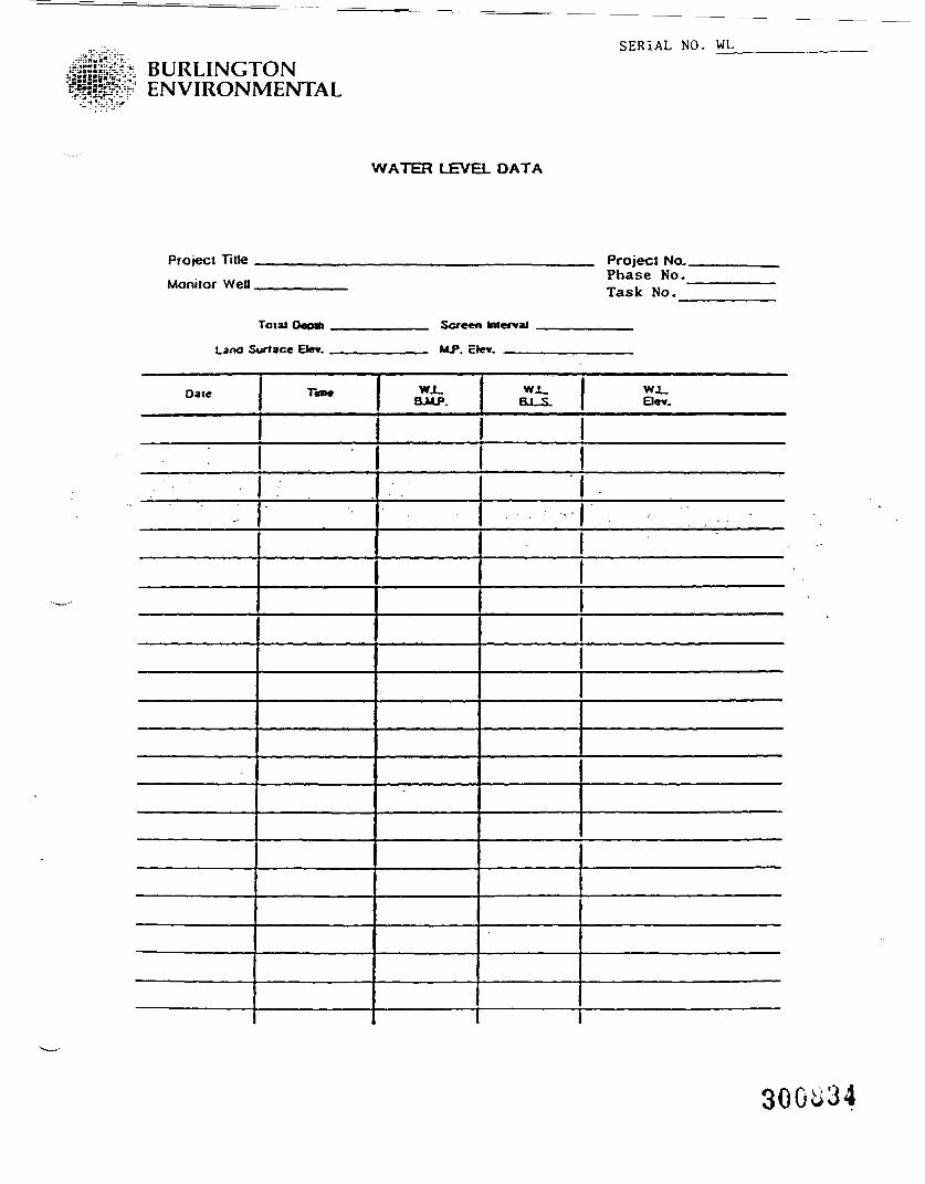
BURLINGTONENVIRONMENTAL
SERIAL NO. WL
WATER LEVEL DATA
Project Title .
Monitor Well.
Land S
Date
_.
Total O«fnti .. _ _
urtaee El*» . .. ...
Tim*
SCTB*<1
MJ> ?1
WJ_BJjLP.
i mi al
HI. S.
Projecl No.Phase Mo.Task No.
WJ_Bev.
. . . "
300834
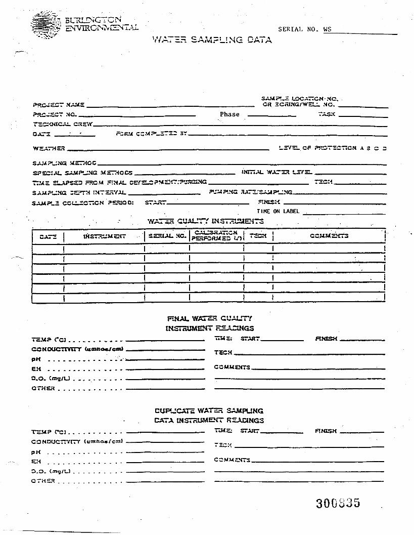
fo BUKJNGTCNSERIAL NO. WS
*—— -~~ C * * » — * S f Vf/^ P".-.. :zn. CJ.HUVI.—LINO: L.
<*C^£CT XAMS!_= UOCA—CN-.HO.
GR 3CSI.XG/WHU. NO. _Phase
WSATHSK L3VHI. Cl1 P5^CTiCT7C« A 3 C 3
SPZZXM. SAMPUNG MHTHOCS^——.————————TIMS 2.APS2D FSOM .~MAl. CEY3LC?«SHT:?«JKGIXG.SAM?«_:XG CETT:H SXTSSYAI..——————————
WAT23 L2VS1..T2CM.
LE CCULSOTtCN ?SHlOOi
^H GUALTTY UMST^TIME ON UBEL
CATS »IST*yj4SHT ' SSUAU XC.
CCJ . . . . . . . . . . . .COHOUCTTVirr Cumftoe/eaUPH . . . . . . . . . . . . . . .
EH . . . . . . . . . . . . . . .O.O. C«ng/U . _ . . . . . . . . .OTHEH . . . . . . . . . . . . .
WATSH QUALITYINSTHUMEHT *^HAONGS
__________ TI5*Hj START.
TcCH.
COMUEKTS.
RXtSX.
TSMP CCJ ...CONDUCTr/lTY
p H . . . . . . .
0.0- <mq/UOTHEH . . .
DUPLICATE WATHH SAMFUNGDATA INSTnUMEKT RSACIKGS
STAirr_
CCMMEJfTS.
30€835
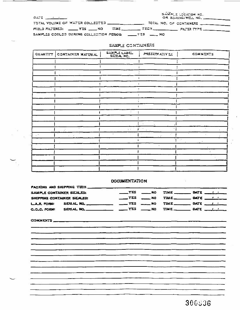
LZS CCCC23 CVJSiNG CCLL£CTT
HOTTCN ?S
I V r f 4
•£CH.
Orv
MC. CCN7AIME3S _
SAMP_= CCNTA1NEKS
GUAN777T CCHTAIM33 MATZ?BA1.
OCOIUEHTATtONPACXXHQ AND SHIPPING T2CH
SAMPLE CONTAIKER *??•«.«WSHIPPING C9NTAINEH Sg-M.EOT
FORM: SEHIAi. NO.FORK: SEUAL. NO.
.YES
.YES
.YES
.YES
.NO TIME.
. NO TIME.
.NO TIME.
..HO TIME.
OXTS,
OMTEOATS
DATE
COMMENTS.
300^36
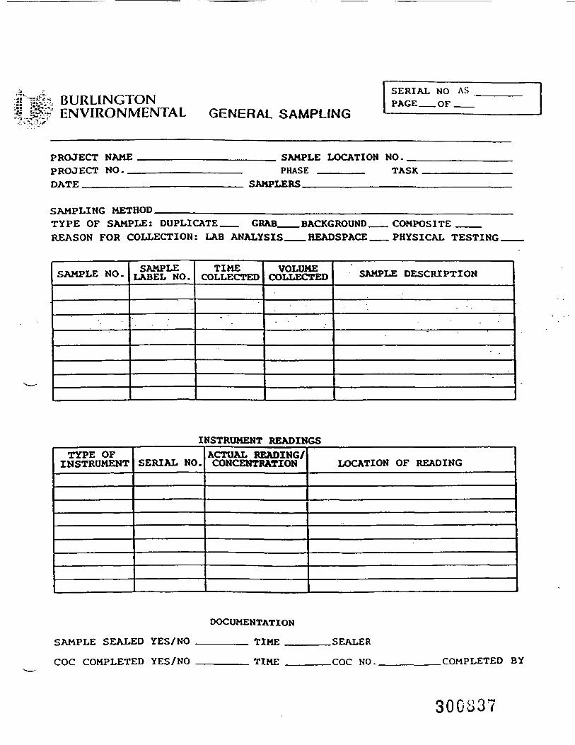
BURLINGTONENVIRONMENTAL GENERAL SAMPLING
SERIAL NO ASPAGE__OF
PROJECT NAMEPROJECT NO._DATE________
SAMPLE LOCATION NO.PHASE _______ TASK
SAMPLERS.
SAMPLING METHOD _____ _TYPE OF SAMPLE: DUPLICATE __ GRAB_REASON FOR COLLECTION: LAB ANALYSIS
BACKGROUND .HEADSPACE.
COMPOSITE ___PHYSICAL TESTING.
SAMPLE NO. SAMPLELABEL NO.
TIMECOLLECTED
"
VOLUMECOLLECTED SAMPLE DESCRIPTION
INSTRUMENT READINGSTYPE OFINSTRUMENT SERIAL NO.
ACTUAL READING/CONCENTRATION LOCATION OF READING
SAMPLE SEALED YES/NO
COC COMPLETED YES/NO
DOCUMENTATION
______ TIME __
______ TIME _
.SEALER
_COC NO. .COMPLETED BY
300837
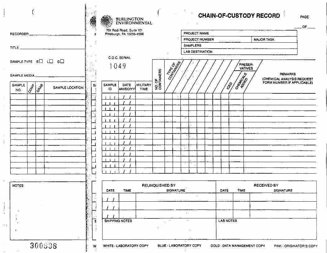
RECORDER.
TITLE.
SAMPLE TYPE sD LD
SAMPLE MEDIA.
SAMPLENO.
SAMPLE LOCATION
NOTES
30GS38
BURLINGTONENVIRONMENTAL
701 Rodi Road, Suite 101f Pittsburgh, PA 15235-4586
CHAIN-OF-CUSTODY RECORD PAGE
.OF.
PROJECT NAME
PROJECT NUMBER MAJOR TASK
SAMPLERS
LAB DESTINATION
C.O.C. SERIAL
1 0 4 9
SAMPLEID
1
DATEMM/DD/YY
/ /
/ /
/ /
/ /
/ /
/ // /
/ /
/ /
/ /
/ /
/ /
/ /
/ /
MILITARYTIME N
O. O
FC
ON
TAIN
ERS f//////
'
/ /PRESER- // VATIVES /
/ / $ / REMARKS' / &£> / (CHEMICAL ANALYSIS REQUESTO / /£« / FORM NUMBER IF APPLICABLE)
y&*/
RELINQUISHED BYDATE TIME SIGNATURE
/ /
/ /
/ /•
SHIPPING NOTES
RECEIVED BYDATE TIME SIGNATURE
LAB NOTES
W WHITE • LABORATORY COPY BLUE - LABORATORY COPY GOLD - DATA MANAGEMENT COPY PINK • ORIGINATOR'S COPY
Project Name_
Project No. Phase Task
BURLINGTONENVIRONMENTAL
PHOTOGRAPHSTim«:
Direction:
Photographer:_
Description: _
Roll No.
Date
Negative No.
Control No.
Time:Direction:
Photographer:.
Description: _
Roll No.
Date
Negative No.
Control No.
fORM EE 7O1 ISrylt II IHEV. 1/92)
SERIAL NO. FDR-
i%&+ BURLINGTONENVIRONMENTAL
BURLINGTOH nmamu. INC._
Field Project Debriefing Form
Project Name: ____________________ Project Manager:
Project No.: _____________________ Field Supervisor:
Phase/Task No.: _____________________ Completed By:
Date: __________________________ Discussed With:Copies To: __
Rate the level of work performed in each category listed belowas AA (above adequate), A (adequate)/ or BA (below adequate).In addition, briefly discuss the positive and negative aspectsof work performed in each category. If extra space is needed,use the back side of the forms.
1. Budget: Rating
2. Schedule: Rating
3. Project Management: Rating
•4. Technical Details: Rating
300u40
Project No.:
BURLINGTON ENVIRONMENTAL INC.
Field Project Debriefing Form
____________ Task No.(s): _
5. Scope of Work: Rating
6. Health and Safety: Rating
7. Documentation: Rating |___|
8. Mathes Personnel: Rating 1___|
9. Subcontractor Personnel: Rating
AUG/87/OL361 300841
Project No.:
BURLINGTON ENVIRONMENTAL INC.
Field Project Debriefing Form
____________ Task No.(s):
10. Site Conditions: Rating
11. Equipment: Rating
12. Client Relations: Rating
13. Public Relations: Rating
14. Quality Assurance/Quality Control: Rating
AUG/87/0136L 300842
BURLINGTON ENVIRONMENTAL INC.
Field Project Debriefing Form
Project No,: ______________ Task No.(s):
15, Suggestions and Additional Comments: _.
AUG/87/01361 "300843
FORM SERIAL NO. SEC
SITE EXIT CHECKLIST
Project No.: ___________Date:
Project Name: ___________________________ Form Serial No.: SEC
YES NO N/A
Have bumper posts been set?.......................-••-•-••
Have concrete pads been installed around the veils?....
Have bumper posts and wells been painted?..............Are wells locked?......................................Have wells been labeled?...............................Have wells been photographed?..........................
Have wells been measured?..............................
Have a final round of water levels been taken?.........Has a final round of well air quality been taken?.
Have drill sites been cleaned up?......................Have drums been moved?.................................
Have drums been staged?................................Are drums labeled?.....................................Are drums sealed?......................................Has drum disposal been arranged?.......................Has all equipment been decontaminated?.................Has all "hot" equipment been disposed of?..............Has all equipment been loaded?.........................Has all rental equipment been returned?................
Is all equipment ready for travel?.....................Have all subcontractors been notified at end of job?...Have utilities been shut off?..........................Have wells been surveyed?..............................
Have well caps been notched (not on flush mount)?......
Have weep holes been drilled in well protectors?.......
Other: ________________________________________.....
Signature: __________________________
30084401/88/18651 Form FM-4
BURLINGTONENVIRONMEN
SERIAL NO. DL
ENVIRONMENTAL; : BURLINGTON ENVIRONMENTAL INC.
DRUM LOG
Date: Time: Job No:
Drum No:DL-
DRUM SIZE:
Unknown__55 gal.__30 gal.__OtherSpecify_
Sample No:
17E 17HPlastic_FiberSpecify
Phase: Task:
DRUM TYPE:Unknown__Metal
Sample Control No:
DRUM CONDITION;Unknown_______Good__________FairPoor
DRUM COLOR:
Unknown;____Primary___Secondary
Drum Marking Key Word 1
Drum Marking Key Word 2
Drum Marking. Key Word 3
DRUM CONTENTS:
Unknown______Liquid_______Sludge_______
TrashDi r t
GtnerBH Cuttings
Well WaterDecon Fluids
Decon Water
Technician
Drum Contents Color:
DRUM AMOUNT:
Unknown_______Full_Part ,InchesEmpty
SKETCH i
300845 (Unless F u l l l
""ON'"NT/•'HYDROGEOLtf C PuMP 'i tbT UM i"A
PROJECT NAME:PROJECT NO: PHASE: TASK
DATE TIME PUMP WELL # LOG# MWJ
BASELINE
MW. * MW.# MW.#
OBSERVED READINQS
COC?CDCOȣ>.cn
DATE TIME PUMP WELL # LOG* MW.# MW. # MWJ MWJ
COMMENTS
START TIME :STOP TIME :
COMMENTS
..(BURLINGTONENVIRONMENTAL
TOTALIZER COUNTGALLONS REMOVED
PG. OF
PROJECT NAME: DATE:PROJECT NO. PHASE: TASK
INITIAL TOTALIZER CT :
COOO
£*
DATE TIME TOTALIZER CT. FLOW G.P.M
'
START TIME:STOP TIME :
COMMENTS

BURLINGTONffiSStf ENVIRONMENTAL Page of
RECON* SYSTEM PROBE SAMPLING WORK SHEETPROJECT NAME: _________ DATE:
PROJECT NO.: ________
FIELD CREW:
PHASE: TASK:
NAME POSITION/DUTIES
CLIENT/SITE REPRESENTATIVE:
Probe HoleNumber
SampleNumber
SampleDepth
OOP VAC Comments
. . . .
••.
'>
30084801/92/CHARLENE/FORMS/SAMPWORK.TAB
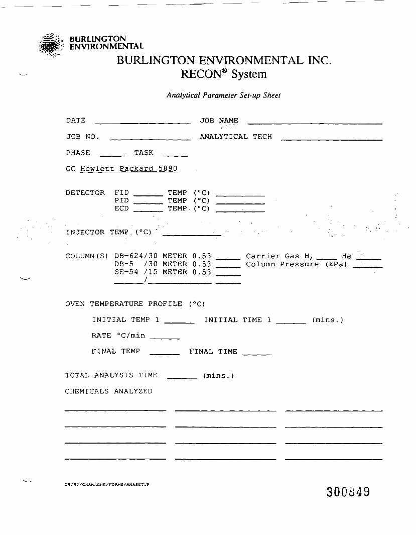
BURLINGTONENVIRONMENTAL
BURLINGTON ENVIRONMENTAL INC.RECON® System
Analytical Parameter Set-up Sheet
DATE ___________________ JOB NAME
JOB NO. ________________ ANALYTICAL TECH
PHASE _____ TASK _____
GC Hewlett Packard 5890
DETECTOR FID _____ TEMP (°C)PID ______ TEMP (°C)ECD ______ TEMP (°C)
INJECTOR TEMP . (°C). '
COLUMN (S) DB-624/30 METER 0.53 ____ Carrier Gas H2 ___ HeDB-5 /30 METER 0.53 ____ Column Pressure (kPa)SE-54 715 METER 0.53
OVEN TEMPERATURE PROFILE (°C)
INITIAL TEMP 1 ______ INITIAL TIME 1 ______ (mins.)
RATE °C/min _____
FINAL TEMP ______ FINAL TIME
TOTAL ANALYSIS TIME ______ (mins. )
CHEMICALS ANALYZED
;9/92/CHAHL£NE/FORMS/ANASETi;p
300849
BURLINGTONENVIRONMENTAL
MlRECON® SAIWLE ANALYSIS
Work Sheet
COoCDccClo
J r\ JL H» *. » * v w *— >^ » » - , _ . . ._PROJECT NO. JOB NAME
PHASE TASK
Sample I . D . Probe BoleNumber
Depth( f t . )
AnalysisTime
Inj. Vol.(Hi)
Multiplier VACin. Hg
Comments
D = duplicate analysisQC = quality control
tfURLINGTONENVIRONMENTAL
ofRECON® SAMPLE ANALYSIS
Data Summary Table
COCDO<J-CJ1
Date
Project No. Phase Task
S*npl« 1.0. ProbtHO*Nunbtr
O ift(Fit!) <^ WA4 tt*U ' IM
>
(WU
D dupicjl* (mrftiiOC quality controlM9A rriooyimi of cocnpourd dtMctod p«r h*r t> huthpioi MOOT injlyttd
Convntntt
Data QA:
Date:
(W.'92'CMAnLFNE/ronMS/CinOUNDWA TAB

FISH ANALYSIS — FORM PROTOCOL
Activity Form
Capture
Organ Removal
Assemble Tissue Samples
"B"
"C"
"D"
Complete organism number and designation form(completed forms to master file and copy).
Complete organism information form(s) (one foreach tissue) (completed forms to master file andcopy).
Freeze each tissue sample with a tissue tag.
Complete tissue information form for each tissuesample (completed forms to master file andcopy).
Remove tissue tag and add to master file andcopy (staple Form C's to Form D).
Form
A - Organism Number Designation
B - Organism Information
C - Tissue Tag
D - Tissue Information
MasterFile
Original
Original
(Attach to tissue)
Original
CopyFilel
X
X
X
06/93/393E82A(427100) 1
300852

Sequence No.
TERRESTRIAL ENVIRONMENTAL SPECIALISTS, INC.
FORMAORGANISM NUMBER DESIGNATIONS
PROJECT NAME _________________________
OrganismNo. Species Date Sampling Area
CollectedBy
101
102
103
104
105
106
107
108
109
110
111
112
113
114
115
116
30085306/93/393E82A(427100) 1
Sequence No.
TERRESTRIAL ENVIRONMENTAL SPECIALISTS, INC.
FORMSORGANISM INFORMATION
PROJECT NAME
ORGANISM NO.
DESCRIPTIONSpecies __
Sex ________ Length ________ Weight ________ Age
CAPTURE DESCRIPTIONDate ___________ Sampling Area
Specific Location _______________
Cover Type _________________ Capture Technique
Collected By: ________________________
TISSUE SAMPLESOrgan/Body Part Total Weight Sample Weight
GROSS ABNORMALITIES/PARASITES
COMMENTS
LAB SAMPLE NUMBER
Composite Sample Identifier No.
Individual Sample Identifier No.Laboratory Analyses: ______
Initials
06/93/393E82A(427100)1 °
Sequence No.
TERRESTRIAL ENVIRONMENTAL SPECIALISTS, INC.
FORMCTISSUE TAG
PROJECT NAME ______________________
Organism Number
Species _____
Body Part
Sampling Area
Collected by:
Initials
300M506/93/393E82A(427100) 1
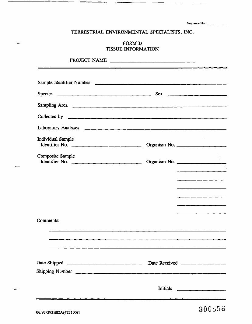
Sequence No.
TERRESTRIAL ENVIRONMENTAL SPECIALISTS, INC.
FORMDTISSUE INFORMATION
PROJECT NAME _________________________
Sample Identifier Number
Species _________
Sampling Area
Collected by
Laboratory Analyses
Individual SampleIdentifier No. __
Composite SampleIdentifier No.
Comments:
Sex
Organism No.
Organism No.
Date Shipped _Shipping Number
Date Received
Initials
06/93/393E82A(427100) 1 300656
QUALITY ASSURANCE PROJECT PLANREMEDIAL INVESTIGATION/FEASIBILITY STUDYKENTUCKY AVENUE WELLFIELD SITEOPERABLE UNIT NO. 3
APPENDIX D
BURLINGTON ENVIRONMENTAL INC.Project: 427100Date: 10/25/93Revision: 1
APPENDIX D
ANALYTICAL LABORATORYQUALITY ASSURANCE PLAN
10/93/76W82A(427100)2 300^57
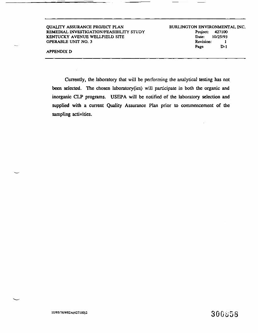
QUALITY ASSURANCE PROJECT PLANREMEDIAL INVESTIGATION/FEASIBILITY STUDYKENTUCKY AVENUE WELLFIELD SITEOPERABLE UNIT NO. 3
APPENDIX D
BURLINGTON ENVIRONMENTAL INC.Project: 427100Date: 10/25/93Revision: 1Page D-l
Currently, the laboratory that will be performing the analytical testing has notbeen selected. The chosen laboratory(ies) will participate in both the organic andinorganic CLP programs. USEPA will be notified of the laboratory selection andsupplied with a current Quality Assurance Plan prior to commencement of thesampling activities.
10/93f76W82A<427100)2 300^58
an environmental testing company200 Monro* Turnpik*Monro*. Connecticut OA468(2O3) 2O1-44MFAX (203) 268-S346
1991 QUALITY ASSURANCE PROGRAM PLAN
FOR
IEA. INC.-CONNECTICUT
MONROE, CONNECTICUT 06468
Minmar.Fhmd*
305-96 9-082* 7D«-70»-0?40
H.IKM*•17-272-8212 20t-«2«-t1ll •1*477.0000
1991 QUALITY ASSURANCE PROGRAM PLAN (QAPraP)
FOR
IEA, INC.-CONNECTICUT
HONROE, CONNECTICUT 06468
1.0 INTRODUCTION
This Quality Assurance. Program Plan (QAPmP) covers laboratory operation atIndustrial and Environmental Analysts, Inc.-Connecticut (IEA, Inc.-CT) locatedat 200 Monroe Turnpike, Monroe, Connecticut. The purpose of this general QAPmPis to provide information on laboratory operations as required for specificQuality Assurance Project Plans (QAPjPs), and to provide the basis for the Qual-ity Assurance Program at IEA, Inc.-CT.
This QAPmP is based upon USEPA guidelines as are specified in the following EPAdocuments:
1) NPO and ORD QAPP Guidance. Quality Assurance Management Staff (QAMS),USEPA, September, 1987.
2) QAMS-004/80, Guidelines and Specifications for Preparing QualityAssurance Program Plans. Quality Assurance Management Staff (QAMS),USEPA, 1979.
The second document is also available as EPA publication, EPA-600/8-83-024.Regulatory guidance for preparing QAPmPs is given in CFR part 30, 130.503, para-graph (e).
2.0 QUALITY ASSURANCE (QA) POLICY STATEMENT
It is the policy of IEA, Inc.-CT that the Quality Assurance (QA) Program will beappropriate to assure that all data collected and reported will be of known anddocumented value.
The objective of the QA Program (QAPmP) is to ensure, assess and document thatall data collected, stored and reported are scientifically valid, defensible andof the precision and accuracy required to meet the objectives of our clients.
It is the goal of IEA, Inc.-CT to provide the best laboratory services to ourclients. To accomplish this, the product which we produce, analytical measure-ment data, must be of defined quality and at the same time conform to governmentregulations and requirements.
All laboratory activities, from sample receipt to analysis to final report gen-eration, must adhere to the laboratory Standard Operating Procedures (SOPs)which have been developed to provide quality environmental data with adequatedocumentation to be legally defensible and hence of maximum use by our custom-ers.
30G6GO
J
Laboratory SOPs form the framework of the Quality Assurance Program Plan (QAPmP)at IEA, Inc.-CT. The purposes of the QAPmP are basically to ensure that ourSOPs fulfill all government and/or private client requirements, that properdocumentation of all quality control (QC) activities is accomplished, and thatthe SOPs are followed by the laboratory staff.
It is the policy of the laboratory, therefore, to build the quality controlrequirements into our SOPs. By adhering to the SOPs, laboratory management isthereby assured that the quality of the data produced will provide the basis forlong term relationships with our clients through customer satisfaction.3.0 MAJOR MISSION ELEMENTS REQUIRING QUALITY ASSURANCE
The primary focus of the laboratory is measurement of specific analytes in envi-ronmental samples (air, soil and water). All elements of laboratory measure-ments are subject to the requirements of the laboratory's QAPmP. The majortypes of laboratory operations affected are as follows:
Characterization of waste samples per the Resource Conservation andRecovery Act (RCRA) for either disposal or delisting purposes.
Analysis of drinking water samples in support of the Safe DrinkingWater Act.
Analysis of environmental samples in accordance with contracts withthe USEPA CLP program and various state agencies.Analysis of environmental samples for contaminants such as thosecompounds found on the EPA priority pollutant list, target compoundlist, etc. for site assessment purposes.
4.0 PLANNING FOR ENVIRONMENTAL DATA COLLECTION ACTIVITIES (EDCAs)
According to EPA's QAMS1, IEA, Inc.-CT is defined as an "Analytical SupportGroup". EPA's QAMS defines an "Analytical Support Group" as "any group -- sec-tion, branch, or entire laboratory -- that provides physical, chemical or bio-logical sampling or analysis on a service basis". According to QAMS, such ana-lytical support groups do not manage the EDCA projects but only provide servi-ces. IEA, Inc.-CT, as an analytical support group, does not determine or writeData Quality Objectives (DQOs) or Quality Assurance Project Plans (QAPjPs).
4.1 Adherence to Data Quality Objectives (DQOs)Data Quality Objectives (DQOs) have been specified by EPA as the processof-defining that type of data will be required by the client for a site orproject. The following two steps of defining DQOs must be taken before aproject begins:
1) "...the user (of data) must first specify the quality of data heneeds, then..."
2) "...the degree of quality control necessary to assure that the resul-tant data satisfy his specifications must be determined."
30G8C1
The laboratory is in the business of measuring environmental samples inorder to generate data which is to be used by our customers to make sounddecisions in relation to site contamination (or lack of), water/air/soilquality, public health concerns and the environment in general. Some ofthe sites have formal QAPjPs with specified OQOs, however, most sites donot have a formal QAPjP.
Each sample analyzed from a given site can present a set of unique analy-tical problems which potentially fall outside the realm "of establishedmethodologies and protocols. It is the goal of the laboratory to producedata which is 100 percent usable to the client but in the real world thisis not always possible. For some projects or sites, achieving 50 percentusable data may be considered an excellent achievement by the laboratorywhile at another site, achieving 90 percent usable data may be consideredbarely adequate.It is the policy of IEA, Inc.-CT to meet the requirements of DQOs inQAPjPs when the laboratory has contracted to provide measurement data insupport of an on-going client contract. These DQOs must be clearly de-fined by the client to the laboratory.4.2 Guidance for the Preparation of Standard Operating Procedures (SOPs)
Routine analytical work will be performed according to standard operatingprocedures (SOP's must satisfy the requirements of the regulations forwhich they were developed). All measurements will be made using methodsdeveloped in the laboratory or methods mandated by regulatory or legal/contractual requirements. No method will be used to obtain data until itis known to be applicable and competence has been gained in its use. Ifit appears that available techniques are not sufficient to obtain reliablemeasurements, the user will be informed and advised of any research re-quired and the estimated cost. The attainment of statistical control isa prerequisite for reporting any data. Any deviations from SOPs must besupportable and documented in the case narrative in the final report tothe client.Existing SOPs must be reviewed and updated as required but at a minimum ofonce per year.The QAO will maintain an index of all SOPs in use.
RCRA has proposed in SW846, 3rd Edition, 1st Update, a standardized 10element format for all revised RCRA methods. In light of RCRA's new re-quirements, the following SOP format should be employed when new measure-ment" SOPs are written or when major rewrites are made to SOPs.
All SOPs should provide complete documentation as to how each sample wasmeasured for each parameter. This formal documentation in the form ofsample preparation logs, standard preparation logs, instrument logs, cor-rective action reports/case narrative reports (CAR/CNRs), Quality ControlApproval Reports (QCARs), and similar logs must provide an immediate,complete and long-term description of how samples were measured and whatproblems were encountered. It is the laboratory policy to retain labora-tory measurement records for a minimum period of five years. It is very
300^62

important that all measurement records be well organized and that theyprovide a complete description of how each sample was measured.
Of special importance in writing good SOPs is that each SOP meet the regu-latory requirements of both the method and of any governing contract(s).It is important that IEA, Inc.-CT have SOPs prepared and ready to use foreach of the environmental regulations which we support. This means thatsome groups may have four or five SOPs to cover one type of-measurement(all five SOPs could be printed separately or compiled into one SOP).New SOPs are developed by line supervisors and/or their designated staffwhen any sampling, or analytical procedure is recognized to be repetitiveand routine. The Quality Assurance (QA) Officer will be available toassist in the development of SOPs.Newly developed SOPs shall be reviewed by the analytical group, the groupleader and by laboratory management and contain a sign off page.
The following outline lists some of the necessary elements that should becovered in most measurement SOPs. SOPs should cover each element. If alisted element in the outline does not apply, then the element shouldstill be listed with the additional descriptor, "Not Applicable".
1) Introduction
IEA. Inc. Policy on Business Ethics and Conduct
State in the beginning of each SOP that "It is the intent of this proce-dure to comply with the IEA business ethics policy". Each member of thegroup/section should read and understand this ethics policy statement. Itis the responsibility of all division managers to communicate and trainemployees about the requirements of the IEA, Inc. Policy on Business Eth-ics and Conduct to ensure compliance with this policy. A copy of the IEAEthics Policy is in Appendix A of this QAPmP.2) Scope and Application - Generally describe the SOP and its general
application.
a) Other related SOPs and analytical methodsb) Water samplesc) Soil/sediment samples
3) Summary of Method - Summarize the method in one paragraph.
4)—Interferences - Describe any interferences to the method.
5) Apparatus and Materials - List in detail.
6) Reagents
a) Inventory of Reagents, Standards and Solvents
It is laboratory policy that each measurement group set up and main-tain a system to inventory all standards, reagents and solvents used
30GuC3
in measurements. The inventory system should record the date theitem was received and the lot/batch number. A unique IEA inventorynumber should be given to each item in the inventory. A set of indexcards or a computer spread sheet (with hard copy and magnetic backup)may be used to maintain inventory records and updates. Each inven-toried item should be marked with the date of receipt and an inven-tory record number. Self-sticking sample seals may be used as la-bels. The inventory system should also provide for documentation ofthe date the material was opened and used up. It Is the section/group leader's responsibility to maintain an inventory system ofreagents, standards and solvents.
b) Quality of Solvents, Reagents and Standards
Traceabi1ity ,of Calibration Standards - It is laboratory policy topurchase standards for organics and inorganics measurements whichhave been previously traced to reference standards.
If traceable standards are not available, then the measurement grouptraces the non-certified standard to EPA or NBS reference standardsor other certified standards.
Assay of Purity - The chemical purity of the reagents and chemicalsshould be specified in the SOP. Any assays of materials should bekept in a central file.
Recordkeeping Requirements - Strict control of reagents used in labo-ratory operations shall be maintained to minimize contamination ordegradation. Dilutions and solutions prepared from them will beinitialed, dated and clearly labeled as to content. All reagentswill be appropriate to the operation performed. A record will bemaintained of all reagents used. Laboratory records should be keptorganized and accessible for five years (minimum).
7) Sample Collection, Preservation and Handling
a) Preservation Requirements and Procedures - Each measurement SOPshould clearly specify the preservation and holding time re-quirements of the regulatory method. Specify a system in theSOP to ensure that preservation and holding time requirementsare met and documented. Corrective action reports should beused to document all preservation blank problems, contamina-tion, etc.
— b) Regulatory Holding Times - Clearly list all holding times forenvironmental samples and extracts.
For samples:
. water samples
. soil/sediment samples
. other matrixes
For extracts and concentrates
30GoC4
8) Procedure
a) Safety - General safety rules as outlined in the IEA Health andSafety Manual shall be followed. Use of gloves, eye protectionand lab coats is required for work with dangerous chemicals.Hazardous materials with high vapor pressures should only beopened under hoods.
The responsibility of following good safety practices is every-one's. No employees should be using hazardous chemicals with-out proper training and safety equipment.
b) Sample and Data Chain of Custody Procedures - Upon receipt ofthe samples in the laboratory the sample custodian and the sam-ple control group are responsible for obtaining all necessaryshipping documentation and verification of all data entered inthe laboratory sample custody records.
The specific procedures and requirements for receiving samplesare specified in the SOP for sample control. In general thegroup signs and dates all shipping records, verifies the sam-ples are in good condition and properly preserved, verifies thefield chain of custody documents (if present) are in order, andassigns laboratory sample numbers to the incoming samples andstores the samples according to the requirements of the analy-tical protocols (refrigeration).
Each measurement SOP should specify procedures for maintainingsample and data chain of custody records. It is the responsi-bility of the group leader to ensure that chain of custodyrecords are signed and maintained.
Any and all deviations from established laboratory chain ofcustody procedures must be noted on the CAR/CNRs and also docu-mented in the case narrative for the job.
c) Sample Preparation - Each and every sample received by the lab-oratory will be handled in a conscientious manner. All aspectsof sample preparation will be performed according to anapproved SOP. The integrity of each sample shall be maintainedthrough appropriate chain of custody procedures. Any limita-tions on analytical results due to the sample will be specifiedin the case narrative. All preparation methods shall include aQCAR which states the minimum quality control requirements of
— the SOP.
d) Sample Screening
e) Standards Preparation Log - It Is the laboratory policy to pro-vide full and complete documentation on the use and compositionof all standards used for preservation or measurement or spik-ing of all environmental samples. This includes lot numbers ofsolvents, reagents, and standards used and the date and ini-tials of the analyst who prepared the standard.

Specify instructions in the SOP (or a separate SOP) on themaintenance of a standards preparation log notebook. Lot num-bers, weights, volumes and the initials of the analyst shouldbe recorded. Assign an IEA preparation code number to each andevery standard prepared including dilutions of standards. Usethe following labeling convention: group:date:page number (ofstandards prep book).
f) Calibration - Each analytical method has its own set of cali-bration procedures and verification. Each measurement SOP mustspecify calibration requirements of the method. For specificprocedures, each SOP must be consulted.
If the measurement requires the use of RCRA procedures, thenthe following general guidelines apply:
Volatile Organics (VOA) GC/MS - Instrument tuned to BFB.5-point initial calibration verified every 12 hours perSW846/CLP protocols.
Semi-Volatile Organics (GC/MS): Instrument tuned to DFTPP.5-point initial calibration verified every 12 hours perSW846/CLP protocols.
Oroanochlorine Pesticides/PCB's (GC/ECD): Calibration perSW846/CLP protocols. Verification every 10 samples. Dualcolumn confirmation.
Metals (ICP. GFAAS and FAAS): Calibration per SW846/CLPprotocols. Verification every 10 samples.
Miscellaneous: Calibration and verification per method.
g) Measurement of Samples - It is laboratory policy that allmeasurements be made using appropriate SOPs. All SOPs shall bein writing and available for review. Any significant changesto or deviations from a SOP shall be documented in case narra-tives and include the reasons for any changes.
Laboratory measurement SOPs are based upon the following regu-latory methods:
Test Methods for Evaluating Solid Wastes. RCRA SW846 Meth-ods (both 2nd and 3rd editions).
Methods for Chemical Analysis of Water and Wastes. EPA600/4-79-020. Revised March. 1983.
USEPA "Contract Laboratory Program Statement of Work forInorganic Analysis, Multi-Media, Multi-Concentration," SOW7/88, Revisions 2/89 ai.d 6/89.
30GJG6
J
!
USEPA "Contract Laboratory Program Statement of Work forOrganic Analysis, Multi-Media, Multi-Concentration," SOW2/88.
Methods for the Determination of Organic Compound in Fin-ished Drinking Water and Raw Source Water, EPA EMSL/CI,September, 1986.
h) Quantitation of Results - The SOP should clearly state the re-quirements of the method concerning the calculation of results.Provide examples as to how results are determined.
i) Qualitative Decisions (if any) - SOPs that require the identi-fication of Tentatively Identified Compounds (TICs) must speci-fy the EPA CLP procedures that must be followed in order toproperly identify non-target compounds. CLP SOW guidelines forthe identification of TICs are currently being evaluated byEPA. SOPs must require that the current CLP guidelines be fol-lowed. The QAO will audit TIC data for conformance to thesewritten guidelines.
9) Quality Control
a) Quality Control Approval Reports (QCARs) - The laboratory groupand section leaders are responsible for the data their groupsgenerate. As such, all data must be reviewed and approved pri-or to release. This Is documented in Quality Control ApprovalReports (QCARs) which must accompany each data package as it issubmitted to the data management group.
The laboratory Quality Assurance Officers will periodicallyexamine data packages at random to ensure that all QCARs arepresent and to ascertain that the data package meets the re-quirements as stated in the SOP. These findings are transmit-ted to laboratory management via Monthly QA Progress Reports(MQAPRs).
b) Required Method QC Limits - Each SOP explains the type and fre-quency of quality control checks. This includes such items asanalysis of EPA reference standards, matrix spikes, laboratoryduplicates, blanks, the use of internal standards and surrogatespikes, etc. In general all calibration are checked before ananalysis can begin. If the analytical system does not pass the
_ initial QC limits, then the system is determined to be out ofcontrol, and cause of the problem is determined before measure-ments can continue. Once the problem is corrected, QC measure-ments are repeated to verify the calibration. If the system isstill out of control, the instrument is re-examined until theproblem is corrected. The following are examples of typicalmethod QC items.
Tuning and/or Calibration of InstrumentOther Types of Calibration
300J67
Laboratory Reagent Blank (LRB) - The laboratory measures areagent blank sample at the frequency required by the meth-od. These LRBs must be within required QC limits beforesample analysis can begin.Internal Standard PrecisionSurrogate Spike Analysis - Surrogate spikes are added toall organics samples prior to extractions or analysis.Results of these are checked to verify the recoveries meetthe requirements of the SOP. If the recoveries are out,the sample is reanalyzed to prove that the system is incontrol.Laboratory Fortified Blank (LFB)Laboratory Fortified Matrix Sample (LFM) - In general thelaboratory performs a matrix spike/matrix spike duplicatefor organic QC and a duplicate/matrix spike for inorganicQC. The results of these analyses are used to generatecontrol charts to monitor the precision and accuracy ofeach parameter analyzed.Quality Control Sample (QCS)Laboratory Duplicates (LD1 and LD2)
c) Preventive Maintenance of Equipment - The policy of the labora-tory is to have service contracts for all of its major instru-ments. These contracts provide routine preventive maintenanceaccording to the manufacturer's requirements. Additionally thelaboratory maintains an inventory of expendable parts and sup-plies to minimize downtime and to allow laboratory personnel tomake minor repairs if necessary.Each measurement SOP must list the preventive maintenanceschedule for each instrument which is to be followed by in-house and extramural repair contractors. In addition, eachmeasurement group must maintain a log of all in-house and ex-tramural preventive maintenance activities.
10) Method Performance
a) Regulatory Requirements - Each regulatory method requires dif-ferent approaches in determining method performance. SQPs muststate the basis for the measurement and documentation of methodperformance for each method of analysis.
The laboratory is constantly assessing the changing Method Per-formance requirements of EPA regulations. For example, pro-
— posed drinking water organics methods may require a newapproach to mandatory quality control. These new method per-formance requirements may require new software and computerhardware to meet the mandatory QC requirements of the regula-tory methods.
b) Method Detection Limits (MDLs) - It is labo.atory policy todetermine MDLs for all methods prior to implementation of SOPs.Requirements for the determination of MDLs are specified ineach regulatory method.
30GJG8
c) Accuracy of the Method - In order to routinely assess the pre-cision and accuracy of the data generated, the laboratory per-forms monthly statistical analysis of the spike and spike du-plicate data as part of our QA program. These results are usedto generate control charts based upon the EPA Handbook of Ana-lytical Quality Control for.Environmental Laboratories. Thesecharts allow for trend analysis to identify potential problemsprior to their occurrence.
d) Precision of the Method
11) Data Reduction and Data Handling
a) Recordkeeping Procedures - It is the responsibility of all mem-bers of the laboratory to maintain complete records of all op-erations performed. All records shall be neat and organized.All laboratory records are the property of the laboratory andshall not be removed from the premises without permission fromsupervisors. All records are considered confidential and shallbe safeguarded. Unauthorized changes, loss or destruction ofrecords can be grounds for dismissal from the laboratory. Con-sult the IEA. Inc. Ethics Policy regarding integrity of dataand employee conduct.All measurement data will be recorded in logbooks or on pre-printed log sheets in permanent ink. Transcriptions will beavoided whenever possible. The record will reflect themeasurement performed and all appropriate details for conclu-sions related to the measurement. The record shall be signedand dated by the individual performing the measurement of theday the measurement is performed. Corrections shall be made bydrawing a single line through the error, and initialing anddating the error.
As described above, all SOPs should provide complete documenta-tion as to how each sample was measured for each parameter.SOPs should not permit measurement data or QC results to beroutinely recorded in personal lab notebooks. Measurement re-cords must be recorded in preprinted record logs or preprintedmeasurement logs. This policy will facilitate the organizationand archiving of all laboratory data for future reference.
All injection forms, instrumentation forms, sample prep formsand QC forms which are used to process samples and measurement
— results should be described and attached to the SOP. The SOPshould specify where these records and forms are cataloged andstored.
b) Data Validation - At a minimum, all data will be subject tosupervisory review. Sensitive data requires higher level re-view and release. All releases must be in writing. Oral pre-liminary releases are prohibited unless prior permission of the
appropriate supervisor(s) is granted and provided that they aresubsequently followed by written confirmation of reviewresults.
c) Delivery Times for Reporting Results
d) Preparation of Final Report - Each analytical group in the lab-oratory is responsible for generating the data for all analysesthe group performs. In general the data must first meet allthe specific QA/QC associated with the SOP that was used forthe analysis prior to any release of the data. The analyticalgroup leader (supervisor) is responsible for the final verifi-cation of the data from the analysis.
The laboratory eaploys a system of QA sign-off sheets calledQuality Control Approval Reports (QCARs), where each analystmust sign off that their respective part of the analysis iscomplete and meets the QA/QC requirements of the governing SOP.QCARs are signed and placed in each job folder along with anyCAR/CNRs which detail any problems which were encountered inthe measurement of samples. Any deviations in SOPs are notedon CAR/CNRs and explained in the case narrative which is incor-porated into the final report. The group leader has finalsign-off responsibility on the QCAR and is responsible for as-suring the overall quality of the data.
12) Special Procedures
13) Use of Other Required SOPs
14) Documentation of Problems
a) Corrective Action Reports - Include and attach to each measure-ment SOP a copy of the most recent revision of the IEA, Inc./CTCorrective Actions Report/Case Narrative Report (CAR/CNR)attached). Provide instructions as to when a CAR/CNR should becompleted. The CAR/CNR provides a routine written communica-tion vehicle to describe most types of problems which may occurthroughout the laboratory. In many cases, CAR/CNRs should beused instead of memos or notes. Host problems described incase narratives should be supported by a CAR/CNR. Eachgroup/section may also have additional unique CARs which arespecific for the group/section.
— The CAR/CNR system requires that the provider of the correctiveaction (solution to the problem) sign and date the CAR/CNR andsend secondary copies of the solution to the problem back tothe originator of the CAR/CNR and to the QAO.
The system requires that the originator of the CAR/CNR be theperson who is responsible to see that a solution is found tothe documented problem. Each originator of CAR/CNRs will re-port to the QAO if corrective actions have not been taken bythe designated provider of solutions.
SOGcjTO
Under the CAR/CNR system, the QAO will monitor and log theprogress of CAR/CNRs and will report in his/her Monthly QAProgress Report the status of major corrective actions taken inthe past month. It is the QAO's responsibility to see thatlaboratory problems are documented and solved in a timely man-ner.
b) Case Narratives - It is laboratory policy that any and allproblems related to client samples and the measurement of cli-ent samples be documented in the case narrative of the finallaboratory report which goes to the client. The mechanism fordocumenting problems which should be included in the case nar-rative are described above in Section a (above). It is theresponsibility of the data management group to see that infor-mation on CAR/CNRs be included in the final case narrative.
15) References for SOP
5.0 THE AUDIT/REVIEW PROGRAM
5.1 Categories of Audits and Reviews - EPA has classified audits of aQAPmP into four categories. According to NPO and ORD QAPP Guidance.Quality Assurance Management Staff, USEPA, September 1987, audits areclassified into the following areas:
\ . Management System Reviews (MSRs)A . Audits of Data Quality (ADQs)s . Technical Systems Audits (TSAs)
Performance Evaluations (PEs)
5.2 Management System Reviews (MSRs) - Management System Reviews (MSRs)"assess the effectiveness of the implementation of the approvedQAPmP(s). MSRs evaluate a specific group's QA program associatedwith environmental data collection activities to either affirm or toidentify areas where additional attention would bring significantbenefits". MSRs have been historically a review of one's organiza-tions QA management system. This type of review of IEA, Inc.-CT's QAmanagement system by IEA, Inc.-CT will continue, however, the labora-tory will may have MSRs conducted by outside organizations and con-tractors.
5.3 Audits of Data Quality (ADQs) - ADQs are normally conducted by theend user of the data to determine if specific data of QAPjP meets therequirements of the data quality objectives (DQOs).
At IEA, Inc.-CT, ADQs are conducted by both external auditors andinternal auditors. The results from external ADQs is usually a re-port submitted to the laboratory with a request for corrective ac-tions. The QAO reviews the external ADQs and issue requests forcorrective actions of deficier.-.ies. The QAO will look for both tech-nical and managerial causes of QA deficiencies and will make recom-mendations to the Laboratory Operations Manager (LOM) for correctiveactions. It is the responsibility of the LOM to implement thesecorrective actions.
30Gc,71
Internal ADQs are normally initiated by a QAO. The results of theaudit are reviewed by the QAO and corrective actions similar to thosedescribed above are submitted by the QAO to the LOM for implementa-tion.
5.4 Technical Systems Audits (TSAs) - According to ERA QAMS2 "TechnicalSystems Audits (TSAs) focus on the actual quality control and envi-ronmental measurement data collection systems. A TSA. entails anexamination of calibration records, sampling and measurement proce-dures, general laboratory cleanliness, support systems, equipment andfacilities, maintenance and repair records, control charts, etc. TSAauditors must be competent scientists who are familiar with the par-ticular data collection technology and quality control procedures".
At IEA, Inc.-CT, TSAs are performed by both external and internalauditors. Externally auditors are from ERA, state and private clientorganizations.
The QAO may conduct a TSA on any project or group in the laboratoryat any time. Internal TSAs by the QAO are essential to the QA pro-gram of the laboratory. The results of any deficiencies noted in allTSAs must be addressed by the LOM and his staff.
5.5 Performance Evaluation Audits (PEs) - According to ERA QAMS2, "A Per-formance Evaluation (PE) is the means of evaluating the performanceof laboratory technicians and the instrumentation or analytical sys-tems on which they work. A PE is accomplished by providing PE sam-ples containing specific pollutants (in appropriate matrices) unknownto the technician in their concentration and/or identity. PEs areimplemented by the QAOs, project officers (POs) or laboratory manage-ment".1
At IEA, Inc.-CT, PEs are conducted routinely by a number of externalorganizations. The QAO may submit internal PEs to any group in thelaboratory at any time. The QAO routinely submits double-blind PE.samples to each measurement group during each quarter of the year.Internal PEs by the QAO are essential to the QA program of the labo-ratory. The results of any deficiencies noted in all PEs must beaddressed by the LOM and his staff. QAOs routinely submit additionalPE samples to groups who show deficiencies in measurement accuracy orquality of data.
5.6 Management System Reviews (MSRs)
—External Audit Program - On an annual basis, IEA, Inc. will conductaudits of all groups at IEA, Inc.-CT. The results of this comprehen-sive QA audit will be reported as an External Management SystemsAudit Report (EMSAR) to corporate and laboratory management.
The above audit will review the entire, current QAPmP at IEA, Inc.-CTand make recommendations to corporate and laboratory management inthe following areas:
The quality of the existing QAPmP.
30Go72
Current procedures for developing, revising and approving SOPs.Overall data quality and technical capability.Procedures and criteria for designing and conducting audits.Recommendations for changes to the IEA, Inc.-CT QAPmP.
5.7 Audits Program - The results of all external audits will be reportedby the QAO in their monthly QAPR. These would include all state,federal and private client on-site inspections.
5.8 Internal Audits of Data Quality - On a regular basis the QAO willreview data to check for compliance to SOPs. Additionally the QAOwill review SOPs to ensure they meet the requirements o.f the method-ologies and applicable regulations.
5.9 Internal Technical System Audits - On a periodic basis the QAO willperform unannounced TSAs. The purpose of this will be to determineif the laboratory staff is following the SOPs, if the SOPs need revi-sion, proper documentation through corrective action reports, casenarratives, etc. and conformance to identified critical controlpoints.
5.10 Internal Performance Evaluation Audits - On a quarterly basis the QAOwill submit double blind QC samples to the laboratory. The purposeof this will be to check the accuracy of results, assess data quali-ty, assess documentation and completeness of data reporting.
5.11 Audit Reports
Monthly Quality Assurance Progress Report - By the 15th of each monththe QAO will issue a report to corporate and laboratory managementsummarizing all QA/QC activities from the previous month.
6.0 QUALITY ASSURANCE AUTHORITIES AND RESPONSIBILITIES
6.1 Organization Chart - The IEA, Inc.-CT Functional Organizational Chartis also attached. This chart indicates the chain of command for eachof the managers and groups at IEA, Inc.-CT.
6.2 Facilities and Equipment - A list of facilities and equipment isattached in Appendix A.
7.0 TRAINING
7.1 Technical Training - All laboratory personnel must have adequate—education, training, and experience to carry out their responsibili-
ties at IEA, Inc.-CT. To ensure that each laboratory member hasacquired both sufficient and applicable knowledge to carry out theirtasks, the QAOs and the Laboratory Management will periodically re-view the training needs of the staff and make recommendations for anyadditional training needs.
8.0 REFERENCES
1) NPO and QRD OAPP Guidance. Quality Assurance Management Staff (QAMS),USEPA, September, 1987.
2) QAMS-004/80, Guidelines and Specifications for Preparing QualityAssurance Program Plans. Quality Assurance Management Staff (QAMS),USEPA, 1979.
300674
ATTACHMENTS
J300^75

APPENDIX A
IEA, Inc. Policy Statement on Business Ethics and Conduct
IEA, Inc.-CT Organization Chart
IEA, Inc.-CT Floor Plan
IEA, Inc.-CT Capital Equipment Inventory
IEA, Inc.-CT Corrective Action Report/Case Narrative Report (CAR/CNR)
APPENDIX B
Laboratory Detection Limits
30Go76
Industrial & Environmental Analysts, Inc.-P.O. BoxRMMICT Trianglo Pa»H. Nonx Cjyofcna 277O9(919)877-0090FAX(9I9)677-0«?7
INDUSTRIAL & ENVIRONMENTAL ANALYST'S, INC.
ETHICS POLICY
The management of Industrial & Environmental Analyst's, Inc. (IEA) recognizes ourresponsibility to clients and fellow employees to ensure that fair and ethical business practicesare followed at all facilities.
Management is fully aware that any ethical violations severly damage the reputation of the entireorganization as well as individual employees at all levels. Therefore, it is imperative that highethical standards be maintained at all times by all employees.
The management and staff are committed to maintaining a carefully controlled analyticalenvironment which assures the consistent generation of accurate data which meets the dataquality objectives of our clientele.
The following represents the IEA ethics policy which has been adopted to clearly identify thecorporate position on ethical practices. Failure to comply with this policy cannot and will not betolerated.
The Company and All its Employees will:
o Fully comply with all applicable federal, state, and local laws and regulations.
o Produce analytical products that are accurate, defensible and which represent soundprofessional judgement at all times.
o Provide employees with guidance and an understanding of the ethical and qualitystandards required in the environmental industry. In this regard, all employees should feelfree to identify any ethical misconduct without fear of retribution. Any employee involvedin any form of ethical misconduct will be subject to immediate disciplinary actionincluding potential termination of employment.
o Present services to clients in a confidential, honest and forth-right manner and strive todeliver quality products at a fair price.
300877
APPENDIX A
IEA, Inc.-Connecticut
300678

INDUSTRIAL & ENVIRONMENTAL ANALYST'S, INC.
ETHICS POLICY -Continued...
Treat employees equitably by compensating them fairly, acknowledging their scientificcontributions, and providing them opportunities for professional growth and development.
Offer employment opportunities to qualified candidates regardless of their race, creed,color, sex or age.
Be a responsible corporate citizen of the community by operating in an environmentallysound manner at all times.
Maintain all facilities in a safe amd professional manner through maintenance of a safetyawareness program and providing the necessary safety equipment and training to protectall employees from preventable injury and chemical exposure.
30GST.9
IEA/CT, INC.ORGANIZATION (BY FUNCTION) 1/91
CORPORATE QA/QC
1
IOATA/SAHPLE MANAGEMENT
Supervisor
Section Leader
5
Section Leader
Sample Control
3
COOOCOCOo
CLIENT SERVICES
Manager
2
LABORATORY QA/QC
1
ORGANIC MANAGER
1
1CLASSICAL CHEMISTRY
Group Leader
11
ATOMIC SPECTROSCOPY
Group Leader
8
1GC/MS
Group Leader
Asst. Group Leader
7
1GC GROUP
Group Leader
4
1EXTRACTIONS GROUP
Group Leader
4
.»/-»»'J_JLi7 U
eo 0. <u . \ I
GC/MS Lab
HazardousWasteArea
-OrganicExtractions Lab
InorganicsPreparation Lab
\ f
— v —Storage
w o
5-
A Jl t
IK
S
fVTV VI00«0Vl II >-l OO || -H O
«-•«
L£
IEA,_XMC.-CONNECTICUT200 UOHROE TURNPIKE TDONROK. CONNBCnCUl
FLOOR PULH
300881
IEA, INC. - CONNECTICUT
EQUIPMENT LIST
"Equipment Name
Spectrophotometer, UV-VISTR-Spectrophotometerrurbidimeterroc AnalyzerTOX Analyzer?luorometerj)H/ISE MeterConductivity MeterTlash Point ApparatusDvenIncubatorBio RefrigeratorCentrifuge.Vater BathD.O. Meter\utoclave5as ChromatographGel Permeation Chromato-tographRefrigeratorOvenOvenJonicatorJonicatorMercury AnalyzerTCP-SequentialCCP-SemiultaneousFlame AAFurnace AArurnace AAfurnace AAComputer5as ChromatographJas ChromatographAuto Sampler\uto Samplerlass Selective—DetectorMass Selective DetectorComputer TerminalComputer TerminalComputer TerminalComputer Terminal
Manufacturer
Perkin-ElmerPerkin-ElmerHach Company
Xertex-DohrmannXertex-Dohrmann
Sequoia-Turner Corp.Orion
Cole-Parmer InstrumentPrecision ScientificFisher ScientificBlue M Electric
Frost QueenCarver ManufacturingBlue M Electric
YSIMarket ForgePerkin-Elmer
ABC
WWASPASP
Sonics & MaterialsTekmer
S pectro-ProductsPerkin-ElmerJarrell-AshPerkin-ElmerPerkin-ElmerPerkin-ElmerPerkin-Elmer
NECHewlett PackardHewlett PackardHewlett PackardHewlett PackardHewlett PackardHewlett PackardHewlett PackardHewlett PackardHewlett PackardHewlett Packard
ModelNumber
Hitachi 2001310 ~2100ADC-80
MC3 A,B112-003SA 7201484-20
Pensky-Martin556100 AR20/L549
MW-122051ASTM-E83201002B
4EFD 1142D 1162SM500TM500HG46500JA612380Z3030Z5100
Z5100 PCPower Mate2
589058907673A76732A59705970150 II2623A150 II150 II
1/91
SerialNumber
522-5134423
851017142HF2029
MF 2106D 01491
SR45A1421
10 Au-12291
IN1-13620002910883
MX-25200241
03420083N546501
7323
F397
149010689272644708128238677821264433131130911135141
77000690B7518A05422728A14612607A024382441A034602513A00922716A1063o2528A05525
2720Y05792720Y03266
301^82
J> Equipment: Name
Scanning InterfaceScanning InterfaceTape Drive"Disc Drive3 Track Magnetic Tape9 Track Magnetic TapeComputerComputerJisc DriveDisc DriveP&T?&TP&T?&T?&TP&TP&T?&T
GC/MS5C/MS3C/MSTerminalTerminal:RTPrinters (partial list)PrintersPrintersPrintersTerminal-RTlagnetic Tape UnitScanning interfaceScanning Interface-art. Tape Unit5010 Auto DesorberCart. Tape UnitJC AnalyzerJC data SystemAuto SamplerSatellite IntegratorSatellite IntegratorIntegrator/PlotterIntegrator/Plotter
Manufacturer
Hewlett PackardHewlett PackardHewlett PackardHewlett PackardHewlett PackardHewlett PackardHewlett PackardHewlett PackardHewlett PackardHewlett Packard
TekmarTekmarTekmarTekmarTekmarTekmarTekmarTekmarTekmar
Hewlett PackardHewlett PackardHewlett PackardHewlett PackardHewlett PackardHewlett PackardHewlett PackardHewlett PackardHewlett PackardHewlett PackardHewlett PackardHewlett PackardHewlett PackardHewlett PackardHewlett PackardHewlett Packard
TekmarHewlett PackardPerkin-ElmerPerkin-ElmerPerkin-ElmerPerkin-ElmerPerkin-ElmerPerkin-ElmerPerkin-Elmer
ModelNumber
59824A59824A914479587970E7970E
HP1000AHP100079147914LSC-240004000
14-2000-000LSC-2ALS
14-2962-200ALSALS5995B5995C5995C45849A3575135731A2934A2934A2225A2225A3575135731A7970E59824A59824A7914
14-2150-0007914
Sigma 1Sigma 1-data system
AS10OSI316SI316LCI-100LCI-100
SerialNumber
227192398
88068001324679
88061014941068
2217A0032413A0062413A0042530A1352643A0768633K2682635A3292715A4392512S3032510S323263OA0668610K205
N/AN/AN/AN/A
133-GTN/A
08151500081515001
94975N439707316N6715N431931P549010
•300S83
gguipment Name
.lutoSamplerData Station~>rinter>lotter
GCGC;c,011 ©samplerAutosamplerIntegratorIntegratorIntegratorAuto Analyzer
Manufacturer
Perkin-ElmerPerkin-ElmerPerkin-ElmerPerkin-ElmerPerkin-Elmer
Hewlett-PackardHewlett-PackardHewlett-PackardHewlett-PackardHewlett-PackardHewlett-PackardHewlett-PackardHewlett-Packard
LaChatVarian Hall/PID
ModelNumber
Sigma 3AS100 B7500P-132GP100589O58905730A
7673A-Dual Tower7 67 3 A3396A3393A3392A
Quikchem Ion Analyzer3300
Serii
09331700218u95234901732052597062005
2541A063012750A148401609A004592546A007092718A0653A2804A011062332AOOD802736A11930
30GSC4

QA: UK
IEA, INC.-CONNECTICUT
Reported By:___________C r o u p
Date : ____________Time:
CORRECTIVE ACTION REPORT / CASE NARRATIVE REPORTClient:________Job Number:___________ Sample Number(s):_____________
Problem Reported By:____________________________________________________
Category of Problem:________________________________________________Poor C o m m u n i c a t i o n W i t h _ _ _ . S a m p l e M a t r i x ; I n a t r u a
Description of Problem: ______________________________________________
Use back of CAR/CMR or attach*- -b-.t if more -pace le r e q u i r e d
Recommended Corrective Action(s):.
Person Who Is Requested To Provide Corrective Actions:
Deadline For CAR: _______________ Reply to Originator Required?
Actual Corrective Action(a) Taken:Document Actual Corrective Action* On 1
F o r m and Send a Copy of Completed CAR/CNR to QA Officer and Job f o l c
denature and DateIs this a recurring Problem?_____Should SOP be Modified or Opdated?__
Initial Lab manager. Marketing Manager, Branch Manager, QA Off itDistribution: Client Services, Job Folder. Other: ________________SECONDARY DISTRIBUTION: ORIGINATOR. QA OFFICER. OTHER: ______________
Document Problem and Corrective Action(s) In Case Narrative: [ ]Attachments: Telephone Log, Services Change Request. Memo, Other:
APPENDIX B
IEA, Inc.-Connecticut
S O G b o S
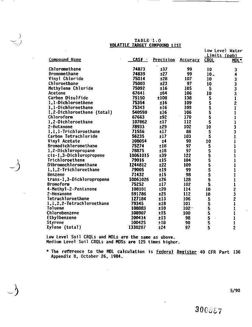
TABLE 1.0VOLATILE TARGET COMPOUND LIST
Compound Name CAS* -
748737483975014750037509267641751507535475343
) 5405906766310706278933715565623510805475274788751006101579016124481279005714321006102675252108101591786127184793451088831089071004141004251330207
Precision
±37±27±28±23±16±64±108±16±16±16±92±17±29±17±17±4±18±18±39±15±22±19±15±26±17±20±25±13±18±10±15±13±18±24
Accuracy
999910797105106138109109106170112102861039097971221041099998128102114112106101102100989097
Low Level WaterLimits fppbl
ChloromethaneBromomethaneVinyl ChlorideChloroethaneMethylene ChlorideAcetoneCarbon Disulfide1,1-Dlchloroethene1.1-Dichloroethane1.2-Dichloroethene (total)Chloroforml,2-D1chloroethane2-Butanone1,1,1-TrichloroethaneCarbon TetrachlorideVinyl AcetateBromodi chloromethane1,2-Dichloropropanecis-l,3-DichloropropeneTrichloroethene01bromochloromethane1,1,2-TrichloroethaneBenzenetrans-l,3-DichloropropeneBromoform4-Methyl-2-Pentanone2-HexanoneTetrachloroethene1,1,2,2-TetrachloroethaneTolueneChlorobenzeneEthyl benzeneStyreneXylene (total)
Low Level Soil CRQLs and MDLs are the same as above.Medium Level Soil CRQLs and MDSs are 125 times higher.
* The reference to the MOL calculation is Federal Register 40 CFR Part 136Appendix B, October 26, 1984.
CROJL
1010.10105
10555555
1055
10555555555
10105555555
HDL*
3433331211113311111111111232111112
5/90
300m
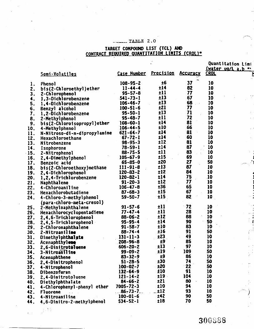
____TABLE 2.0TARGET COMPOUND LIST (TCL) AND
1.2.3.4.5.6.7.8.9.10.11.12.13.14.15.16.17.18.19.20.21.22.23.24.
25.26.27.28.29.30.31.32.33.34.35.36.37.38.39.40.41.42.43.44.
Semi-Volatnes
Phenolbis(2-Chloroethy1)ether2-Chlorophenol1.3-Dichlorobenzene1.4-DichlorobenzeneBenzyl alcohol1,2-Dichlorobenzene2-Methylphenolb1s{2-Chloro1soprc4-MethylphenolN-Nitroso-di-n-dipHexachloroethaneNitrobenzeneIsophorone2-N1tropheno12,4-OimethylphenolBenzole acidbis(2-Chloroethoxy2,4-Dichlorophenol1,2,4-Tri chlorobenzeneNaphthalene4-ChloroanilineHexachlorobutad i ene4-Chloro-3-roethylphenol(para-chloro-meta-c2-MethylnaphthaleneHexachlorocyclopent2,4,6-Trichlorophenol2,4,5-Trichlorophenol2-Chloronaphthalene2-NitroaniltMD1methylphthaUt«Acenaphthyltof2,6-Dinitrotottten«3-NitroahTllneAcenaphthene2,4-Dinitrophenol4-NitrophenolOlbenzofuran2,4-DinitrotolueneD1ethylphthalate4-Chlorophenyl-pheFluorene4-Nitroaniline4,6-Dinitro-2-methylphenol
Case Number
108-95-2}ether 11-44-4
95-57-8ie 541-73-1ie 106-46-7
100-51-6ie 95-50-1
95-48-7>pyl)ether 108-60-1
106-44-5>ropyl amine 621-64-7
67-72-198-95-378-59-188-75-5
1 105-67-965-85-0
0 me thane 111-91-81 120-83-2izene 120-82-1
91-20-3106-47-8
ie 87-68-3thenol 59-50-7•cresol )ie 91-57-6itadiene 77-47-4snol 88-06-2mol 95-95-4ie 91-58-7
88-74-4131-11-3208-96-8
i 606-20-299-09-283-32-951-28-5100-02-7132-64-9121-14-284-66-2
nyl ether 7005-72-386r73-7..100-01-6
lyl phenol 534-52-1
Precision
±6±14±11±13±13±21±13±11±14±10±14±14±12±14±11±15±20±13±12±14±12±36±15±15
±11±11±12±14±10±16±23±9±13 .±19±9±30±20ilO±19±21±10
_ ±12±42±18
Accuracy
378277676877717281668160818783692787847577656782
722888908391498597109867422911048094939070
Quantitation Liroi(water uo/L a.b **CJ01 H
101010101010101010101010101010105010101010101010
1010105010501010105010505010101010105050
300888
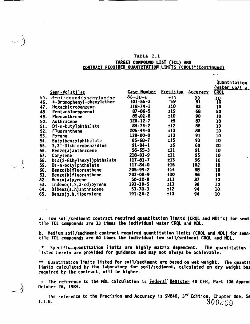
TABLE 2.1TARGET COMPOUND LIST (TCL) AND
COKTRACT REQUIRED QUAKTITATION LIMITS fCRQLWContinued)
45.46.47.48.49.50.51.52.53.54.55.56.57.56.59.60.61.62.63.64.65.
Semi-VolatilesN-nitrosodiphenylamine4-Broroophenyf-phenyl etherHexachl orobenzenePentachl orophenolPhenanthreneAnthracene01 -n-butyl phthal ateFluoranthenePyreneButyl benzyl phthal ate3,3'-D1chlorobenz1d1neBenzo(a) anthraceneChryseneb1s(2-Ethy1hexyl)phthalate01 -n-octyl phthal ateBenzo(b) f 1 uorantheneBenzo ( k) f 1 uorantheneBenzo(a)pyreneIndeno(l,2,3-cd)pyreneDibenz(a,h) anthraceneBenzo(g,h,1)perylene
Case Number86-30-6101-55-3118-74-187-86-585-01-8120-12-784-74-2206-44-0129-00-085-68-791-94-156-55-3218-01-9117-81-7117-84-0205-99-2207-08-950-32-8193-39-553-70-3191-24-2
Precision+ 15~±9tio±19tlO±9±12±13±13±15±6±11±11±13±16±14±30±11±13±12±13
Quant Uatlon 1Iwater ua/L a.l
Accuracy CRQL
Vl936890878888919368919596102888687989494
101010501010101010102010101010101010101010
a. Low soil/sediment contract required quantIt at Ion limits (CRQL and MOL's) for semitile TCL compounds are 33 times the individual water CRQL and MOL.b. Medium soil/sediment contract required quant Uatlon limits (CRQL and MOL) for semi-tile TCL compounds are 60 times the individual low soil/sediment CRQL and MOL.* Specific—quant1tat1on limits are highly matrix dependent. The quantitation
listed herein are provided for guidance and may not always be achievable.** Quantitation limits listed for soil/sediment are based on wet weight. The quant 11limits calculated by the laboratory for so11/sediment, calculated on dry weight baarequired by the contract, will be higher.
+ The reference to the MOL calculation 1s Federal' Register 40 CFR, Part 136 AppendOctober 26, 1984.
The reference to the Precision and Accuracy is SV846, 3rt Edition, Chapter One, S«
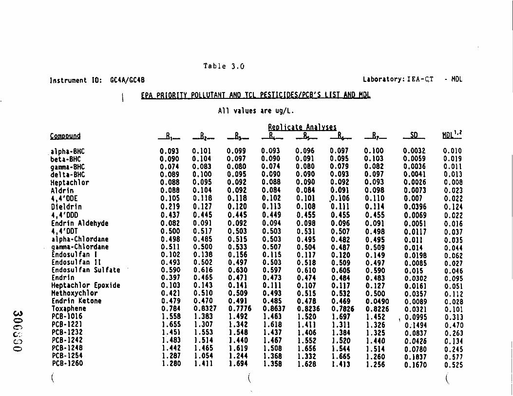
T a b l e 3.0Instrument ID: GC4A/GC4B Laboratory: IEA-QT HOL
COCDO
I EPA PRIORITY POLLUTANT AND TCL PESTICIDES/PCB'S LIST AND HDL
All values are ug/L.
Replicate AnalysesCompound
alpha-BHCbeta-BHCgamma-BHCdelta-BHCHeptachlorAldrln4,4'DDEOieldrln4,4'DDDEndrln Aldehyde4,4'ODTalpha-Chlordanegamma-ChlordaneEndosulfan IEndosulfan IIEndosulfan SulfateEndrlnHeptachlor EpoxldeHethoxychlorEndrln KetoneToxaphenePCB-1016PCB-1221PCB-1232PCB-1242PCB-1248PCB-1254PCB-1260
-Bi-0.0930.0900.0740.0890.0880.0880.1050.2190.4370.0820.5000.4980.5110.1020.4930.5900.3970.1030.4210.4790.7841.5581.6551.4511.4831.4421.2871.280
-Ba-0.1010.1040.0830.1000.0950.1040.1180.1270.4450.0910.5170.4850.5000.1380.5020.6160.4650.1430.5100.4700.83271.3831.307
.553
.514
.465
.054
.411
-JU0.0990.0970.0800.0950.0920.0920.1180.1200.4450.0920.5030.5150.5330.1560.4970.6300.4710.1410.5090.4910.77761.4921.3421.5481.4401.6191.2441.694
-X-0.0930.0900.0740.0900.0880.0840.1020.1130.4490.0940.5030.5030.5070.1150.5030.5970.4730.1110.4930.4850.8637
.463
.618
.437
.467
.508
.368
.358
-JU0.0960.0910.0800.0900.0900.0840.1010.1080.4550.0980.5310.4950.5040.1170.5180.6100.4740.1070.5150.4780.8236
.520
.411
.406
.552
.656
.3321.628
-Jfr-0.0970.0950.0790.0930.0920.091.0.1060.1110.4550.0960.5070.4820.4870.1200.5090.6050.4840.1170.5320.4690.7826
.697
.311
.384
.520
.544
.665
.413
-B7-
0.1000.1030.0820.0970.0930.0980.1100.1140.4550.0910.4980.4950.5090.1490.4970.5900.4830.1270.5000.04900.8226
.452
.326
.325
.440
.514
.260
.256
so0.00320.00590.00360.00410.00260.00730.0070.03960.00690.00510.01170.0110.0140.01980.00850.0150.03020.01610.03570.00890.0321
, 0.09950.14940.08370.04260.07800.18370.1670
HDL1'2
0.0100.0190.0110.0130.0080.0230.0220.1240.0220.0160.0370.0350.0440.0620.0270.0460.0950.0510.1120.0280.1010.3130.4700.2630.1340.2450.5770.525
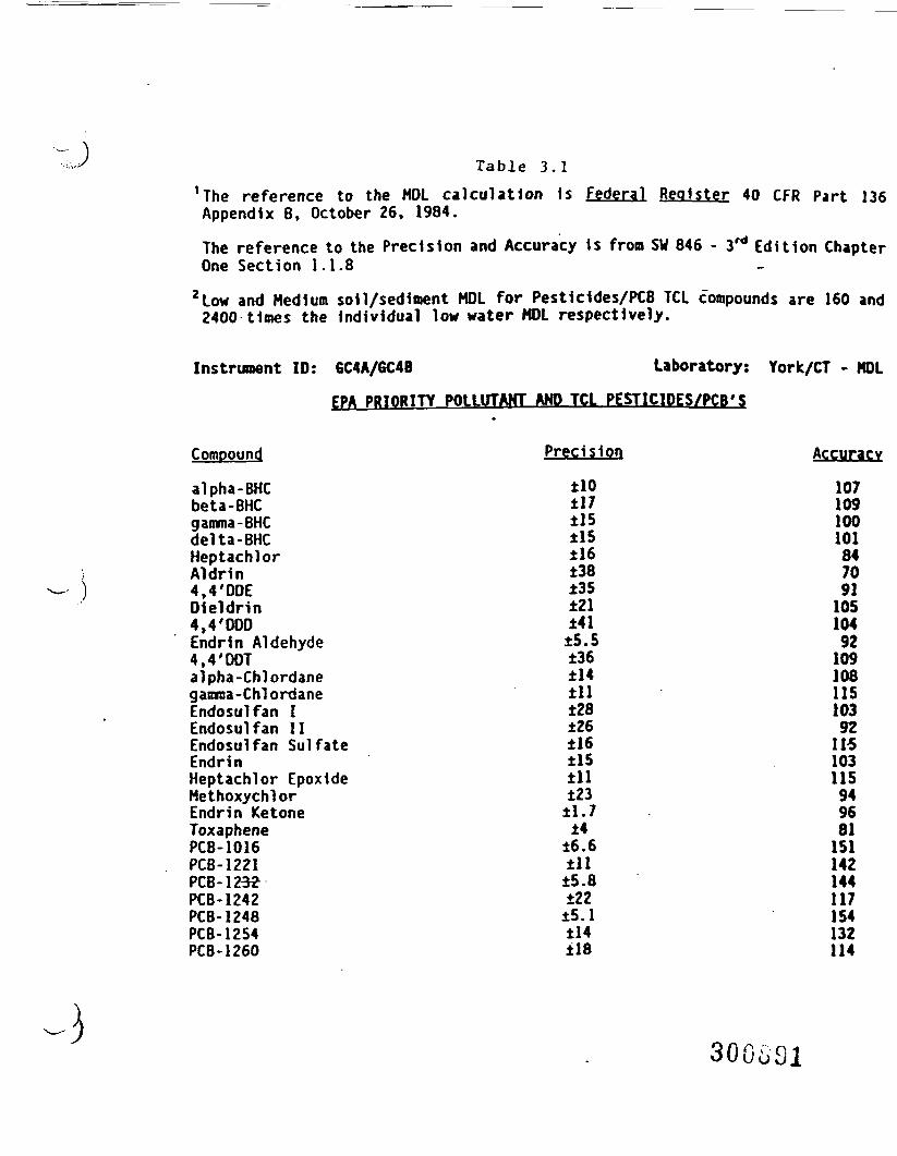
-J Table 3.1
'The reference to the MOL calculation is Federal Register 40 CFR Part 136Appendix 8, October 26, 1984.
The reference to the Precision and Accuracy is from SW 846 - 3rd Edition ChapterOne Section 1.1.8
2 Low and Medium soil/sediment MOL for Pesticides/PCB TCL compounds are 160 and2400 times the individual low water MOL respectively.
Instrument ID: GC4A/GC4B
PPTOR1TY POLLUTANT
Laboratory:TCL PESTICIDES/PCB*S
York/CT - MDL
Compound
alpha-BHCbeta-BHCgamma-BHCdelta-BHCHeptachlorAldrin4,4'DDEDleldrin4,4'DDDEndrin Aldehyde4,4'OOTalpha-Chlordanegamma-ChlordaneEndosulfan IEndosulfan IIEndosulfan SulfateEndrinHeptachlor EpoxideMethoxychlorEndrin KetoneToxaphenePCB-1016PCB-1221PCB-123?PCB-1242PCB-1248PCB-1254PCB-1260
Precision
±10±17±15±15±16±38±35±21±41±5.5±36±14±11±28±26±16±15±11±23±1.7±4
±6.6±11±5.8±22±5.1±14±18
Accuracy
1071091001018470911051049210910811510392
103115949681151142144117154132114
300SS1
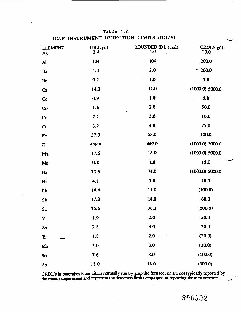
Table 4 .0ICAP INSTRUMENT DETECTION LIMITS (IDL'S)
ELEMENTAg
Al
Ba
Be
Ca
Cd
Co
Cr
Cu
Fe
K
Mg
Mn
Na
Ni
Pb
Sb
Se
V
Zn
Ti __
Mo
Sn
As
CRDL's in parenthesis_• _ _ • _ _i _ _ _ _ _ _ _ • .
IDL(ug/l)3.4
104
1.3
0.2
14.0
0.9
1.6
2.2
3.2
57.3
449.0
17.6
0.8
73.5
4.1
14.4
17.8
35.6
1.9
2.8
1.8
3.0
7.6
18.0
ROUNDED IDL (ug/1)4.0
104
2.0
1.0
14.0
1.0
2.0•
3.0
4.0
58.0
449.0
18.0
1.0
74.0
5.0
15.0
18.0
36.0
2.0
3.0
2.0
3.0
8.0
18.0
CRDL(ug/l)10.0
200.0
- 200.0
5.0
(1000.0) 5000.0
5.0
50.0
10.0
25.0
100.0
(1000.0) 5000.0
(1000.0) 5000.0
15.0
(1000.0) 5000.0
40.0
(100.0)
60.0
(500.0)
50.0
20.0
(20.0)
(20.0)
(100.0)
(300.0)
are either nonnally ran by graphite furnace, or are not typically reported bj_^^J i • m* mim f mr»f +V*A «"l^*^ *-»••** •% 1 1 ••* • •<• • mmt nl <~i • mm f\ *r» m^ f* l»m+ • •• •• +1*^**^ ft ft m it tut ml m r»
300c>92
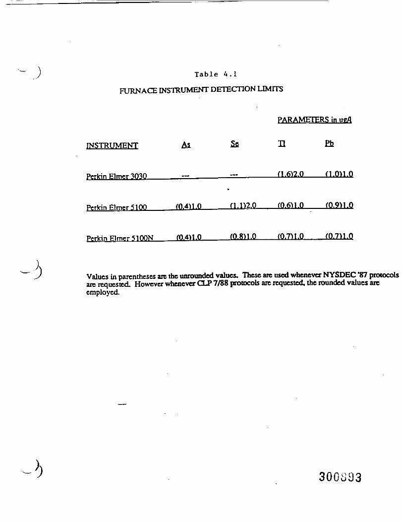
) Table 4.1
FURNACE INSTRUMENT DETECTION LIMITS
PARAMETERS in ugfl
INSTRUMENT As Sfi U P_b
(1.6)2.0 fl .011.0
PerkinElmer5100 (0.4
to
u 0 f 1.112.0 f0.6M.O ro.9ii.o
Perkin Elmer S100N m.«1.0 fO.811.0 ffl.Tll.O ——— (0.7)1,0
Values in parentheses are the unrounded values. These arc used whenever NYSDEC "87 protocolsarc requested. However whenever CLP 7/88 protocols arc requested, the rounded values areemployed.
300S93
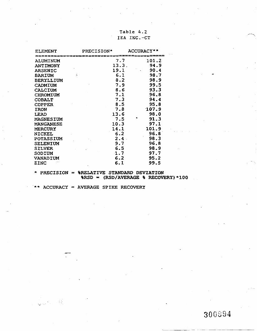
Table 4.2IEA INC.-CT
ELEMENT PRECISION* ACCURACY**
ALUMINUM 7.7 101.2ANTIMONY 13.3. 94.9ARSENIC 19.1 90.4BARIUM 6.1 98.7BERYLLIUM 8.2 98.9CADMIUM 7.9 99.5CALCIUM 8.6 93.3CHROMIUM 7.1 96.8COBALT 7.3 94.4COPPER 8.5 95.8IRON 7.8 107.9LEAD 13.6 98.0MAGNESIUM 7.5 * 91.3MANGANESE 10.3 97.1MERCURY 14.1 101.9NICKEL 6.2 96.8POTASSIUM 2.4 98.3SELENIUM 9.7 96.8SILVER . 6.5 98.9SODIUM 1.7 97.7VANADIUM 6.2 95.2ZINC 6.1 99.5
* PRECISION = %RELATIVE STANDARD DEVIATION%RSD - (RSD/AVERAGE % RECOVERY)*100
** ACCURACY - AVERAGE SPIKE RECOVERY
300894
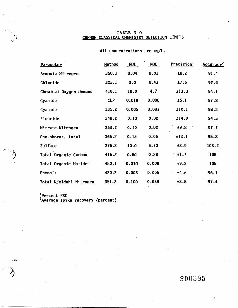
TABLE 5.0COMMON CLASSICAL CHEMISTRY DETECTION LIMITS
All concentrations are mg/L.
Parameter
Ammonia-Nitrogen
Chloride
Chemical Oxygen Demand
Cyanide
Cyanide
Fluoride
Nitrate-Nitrogen
Phosphorus, total
Sulfate
Total Organic Carbon
Total Organic Hal ides
Phenol s
Total Kjeldahl Nitrogen
Method
350.1
325.1
410.1
CLP
335.2
340.2
353.2
365.2
375.3
415.2
450.1
420.2
351.2
RDL
0.04
3.0
10.0
0.010
0.005
0.10
0.10
0.15
10.0
0.50
0.010
0.005
0.100
MDL
0.01
0.43
4.7
0.008
0.001
0.02
0.02
0.06
6.70
0.28
0.008
0.005
0.058
Precision1
±8.2
±7.6
±13.3
±5.1
±10.1
±14.0
±9.8
±13.1
±3.9
±1.7
±9.2
±4.6
±3.8
Accuracy2
91.4
92.6
94.1
97.8
98.3
94.5
97.7
95.8
103.2
105
105
96.1
97.4
1Percent RSD2Average spike recovery (percent)
300S95

QUALITY ASSURANCE PROJECT PLANREMEDIAL INVESTIGATION/FEASIBILITY STUDYKENTUCKY AVENUE WELLFIELD SITEOPERABLE UNIT NO. 3
APPENDDC E
BURLINGTON ENVIRONMENTAL INC.Project: 427100Date: 10/25/93Revision: 1
APPENDIX E
HEALTH AND STANDARD OPERATING PROCEDURESFOR THE PHOTOIONIZATION DETECTORS
30GS9610/93/76 W82 A(427100)2
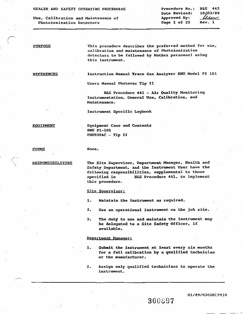
HEALTH AND SAFETY OPERATING PROCEDURES
Use, Calibration and Maintenance ofPhotoionization Detectors
Procedure No.:Date Revised:Approved By:Page 1 of 25
H&S 44210^03/89
Rev. 1
PURPOSE This procedure describes the preferred method for use,calibration and maintenance of Photoionizationdetectors to be followed by Mathes personnel usingthis instrument.
REFERENCES Instruction Manual Trace Gas Analyzer HNU Model PI 101
Users Manual Photovac Tip II
H&S Procedure 441 - Air Quality MonitoringInstrumentation, General Use, Calibration, andMaintenance.
Instrument Specific Logbook
EQUIPMENT Equipment Case and ContentsHNU PI-101PHOTOVAC - Tip II
None.
RESPONSIBILITIES The Site Supervisor, Department Manager, Health andSafety Department, and the Instrument User have thefollowing responsibilities, supplemental to thosespecified in H&S Procedure 441, to implementthis procedure.
Site Supervisor:
1. Maintain the instrument as required.
2. Use an operational instrument on the job site.
3. The duty to use and maintain the instrument maybe delegated to a Site Safety Officer, ifavailable.
Department Manager;
1. Submit the instrument at least every six monthsfor a full calibration by a qualified technicianor the manufacturer.
2. Assign only qualified technicians to operate theinstrument.
30GS9701/89/0302H(99)0
HEALTH AMD SAFETY OPERATING PROCEDURES Procedure No.: HS.S 442Use, Calibration, and Maintenance of Date.' Revised: • 10/03'/89!Photoionization Detectors Page 2 of 25 Rev.: 1
H&S Department;
1. Review instrument use on field projects todetermine appropriate action levels.
2. Audit selected field projects to determine themanner in which the"instrument is used.
3. Provide training, upon request, for fieldtechnicians.
4. Inspect instruments as judged appropriate ornecessary.
Instrument User;
1. Use the instrument in accordance with H&SDepartment manufacturers recommendation.
2. Attend a-training class on the proper use,limitations, calibration and maintenance of theinstrument.
3. Use, calibrate and maintain the instrument inaccordance with this procedure and H&S Procedure441.
4. Follow the site-specific instrument usespecifications and protocols provided by the H&SDepartment.
5. If an instrument malfunction is detected,promptly report the problem to your DepartmentManager or, if in the field, your Site Supervisor.
DISCUSSIOW The Photoionization detector is one of the mostextensively used instruments on hazardous wastesites. It is imperative that the instrument be used,calibrated and maintained in the proper manner. Thefollowing procedure should be closely followed bythose individuals using, calibrating, and maintainingPhotoionization detectors in the field in order toensure that the instrument functions correctly. Also,persons using the instrument should have been trainedand have read the Instruction Manual prior to usingthe instrument.
01/89/0302H(99)0 300 U 08
Procedure No.: H£S 442Date Revised: 10/03/89 Use, Calibration, and Maintenance ofPage 3 of 25 Rev.: 1 Photoionization Detectors
APPENDICES Appendix A - Operating Instructions for the HNU PI-101Appendix B - HNU Detector Cleaning ProcedureAppendix C - HNU Troubleshooting and Minor Repair
ProcedureAppendix D - Operating Instructions for the Photovac
Tip IIAppendix E - TIP Detector Cleaning ProcedureAppendix F - TIP Troubleshooting and Minor Repair
Procedure
PROCEDURE Perform the items listed below.
1. Equipment Checkout - (Done prior to removing thePID from the equipment room).
1.1 Inspect the PID equipment case to see if thenecessary equipment is available. Theequipment which is to accompany theinstrument is specified in section one ofthe Appendix for the respective instrument(Appendix A or D).
1.2 Perform the assembly and functional checksoutlined in Section 2.0 of the Appendix forthe respective instrument (Appendix A or D).
2. Calibration - (to be done prior to using theinstrument).
2.1 This instrument must be calibrated daily.Perform the calibration described in Section3 of the appendix describing the instrumentbeing used (Appendix A or D).
3. Operation — Operate the instrument only after allof the above steps have been taken.
3.1 Operate the instrument in accordance withthe instructions given in Section 5 of theAppendix (Appendix A or D) describing theinstrument being used.
4. Maintenance
4.1 Instruments must be maintained in a cleanand undamaged condition. Wipe any dirt ordebris from the instrument after use, andperform or obtain repairs, when needed.
30 Coo 9 01/89/0302H(99)0
HEALTH AND SAFETY OPERATING PROCEDURES Procedure No.: H&S 442Use, Calibration, and Maintenance of Date Revised: 10/03/89Photoionization Detectors Page 4 of 25 Rev.: 1
4.2 All other maintenance shall be performed inaccordance with the specific instructionswhich can be found in the- -manufacturersinstruction manual.
5. Rental Equipment
5.1 Refer to the instruction manual of thespecific instrument used to determine thecalibration, use, and maintenance proceduresto be followed.
EXCEPTIONS None.
END OF H&S PROCEDURE 442
Ol/89/0302H(99)O 3003 UU
Procedure No.: H&S 442Date Revised: 10/03/89 Use, Calibration, and Maintenance ofPage 5 of 25 Rev.: 1 Photoionization Detectors
APPENDIX AOPERATING INSTRUCTIONS FOR THE HNU PI-101
Perform the items listed below.
1. Equipment Checkout - (Done prior to removing the HNU from the equipmentroom).
1.1 Inspect the HNU Equipment Case to see if the necessary equipment isavailable. The case should include the following:
o One readout assemblyo One probe assemblyo One probe extensiono One calibration cylinder (HNU Part Number 101-350)o One cylinder regulator (HNU part number 101-351) with tubingo One instrument log booko One hair dryero Cleaning supplies:
- HNU Light Source Cleaning Compound,- Ethyl Alcohol (for 10.2 eV lamp),- 1,1,1 Trichlo roe thane (for 3.1.7 eV lamp), and- Cotton balls, cotton swabs and pipe cleaners
o Regular Screwdrivero Phillips Screwdriver "o 9 Volt Battery (rectangular)o Latex Surgical Gloves
2. Assembly and Functional Check
2.1 Prior to taking the instrument from the storage area, check thebatteries to see if they are adequately charged.
2.2 Connect probe assembly to readout assembly and screw the probeextension onto the end of the probe.
2.3 Turn the function switch to the "BATT" (battery check position.
2.4 If the batteries are properly charged the needle will fall withinthe upper end of the green area on the meter scale. Otherwise, theinstrument needs to be connected to the battery charger.
2.5 Turn the function switch on the instrument to standby.
HOTE; The high voltage interlock (small red button) switch must befully depressed to check or operate the instrument.
01/89/0302H(99)0
HEALTH AND SAFETY OPERATING PROCEDURES Procedure No.: H&S 442Use, Calibration, and Maintenance of Date Revised: 1O/O3/89Photoionization Detectors Page 6 of 25 Rev.: 1
APPENDIX A, ContinuedOPERATING INSTRUCTIONS FOR THE HNU PI-101
3. Field Calibration
3.1 Attach the regulator to the cylinder of calibration gas.
3.2 Check the cylinder pressure reading on the regulator. The cylindermust have a pressure of at least 30 psi to be used for a calibrationcheck.
3.3 Turn the instrument's function switch to the 0-200 range.
3.4 Fit the loose end of the tygon tubing attached to the regulator overthe end of the probe extension. . '
3.5 Open the regulator valve and check to see if the reading on theinstrument corresponds to the ideal response listed on thecalibration gas cylinder. The response should occur in about 12seconds.
3.6 If the HNU reading does not correspond to the ideal response, adjustthe span setting and perform subsequent checks until the HNUreadings do correspond. Cleaning may be necessary if span settingadjustments do not achieve the ideal response reading. SeeAttachment 1.
KOTE; When the span setting is decreased the meter response on theHNU should increase. When the span setting is increased the meterreadings should decrease.
3.7 Record the following data in the dedicated logbook for theinstrument.
o Date and Time of Calibrationo Calibration Gas Usedo Ideal Response Reading Printed on the Calibration Gas Cylindero Lot Number of Calibration Gaso Three successive readings (within one NDU of the ideal response)o Final Span Setting after Calibrationo Signature
4. Bi-annual Calibration
4.1 A calibration performed every six months is not required. Thisinstrument is calibrated dally. • . .
01/89/0302H(99)O 300302
Procedure No.: H&S 442Date Revised: 10/03/89 Use, Calibration, and Maintenance ofPage 7 of 25 Rev.: 1 Pbotoionization Detectors
APPEHDIX A, ContinuedOPERATING INSTRUCTIONS FOR THE HNU PI-101
5. Routine Use
5.1 Connect, the probe assembly to the readout assembly.
NOTE; Make sure that cable connector "snaps" into place so thatinterlock switch is properly depressed. If this is not done theinstrument will not work.
5.2 Attach the probe extension to the end of the probe. (The probe maybe used without the extension if desired).
5.3 Check the battery by turning the function switch to the positionlabeled, "BAIT". If the needle on the meter is in the upper—portionof the green area the battery is sufficiently charged. Otherwisethe instrument should not be used as it will give erroneous readings.
5.4 Turn the function switch to standby.
5.5 Allow the instrument to warm up for two to three minutes.
5.6 Recheck the calibration of the instrument at least once daily byfollowing the procedure described in Section 2 of this procedure.
5.7 Turn the function switch to the 0-20 range. If the needle on themeter falls below zero, re-adjust the zero knob until the instrumentreads zero. Set function switch to desired meter range if otherthan 0-20.
NOTE; Do not re-adjust the zero on the O-200 or 0-2000 rangesettings. - -•
5.8 Record instrument readings as desired, taking into consideration thefollowing limitations.
o The HNU is very sensitive to moisture. The probe tip should bekept away from water and should not come into direct contact withchemicals.
o Hater vapor (i.e. humidity above 90\, fog, dew, rain, etc.)strongly affects instrument accuracy by lowering responsereadings.
o Any foreign materials which accumulate on the lamp will adverselyeffect instrument readings.
01/89/0302H(99)0
300903
HEALTH AND SAFETY OPERATING PROCEDURES Procedure No.: HtS 442Use, Calibration, and Maintenance of Date Revised: 1O/03/89Photoionization Detectors Page 8 of 25 Rev.: 1
APPENDIX A, ContinuedOPERATING INSTRUCTIONS FOR THE HNU PI-101
o The instrument is adversely influenced by temperatures below 14degrees or above 104 degrees F.
o Readings that are apparently low, erratic, unstable, non-repeatable,or drifting may indicate erroneous readings and should prompt acalibration check and, possibly, further maintenance on theinstrument.
5.8 Turn the function switch to the standby position when not takingreadings with the instrument. This conserves the battery life.
o Check the battery periodically during use. It the low batteryindicator light comes on, turn the analyzer off and recharge.
o Recharge battery after each field day of instrument use.
5.9 Turn the unit off when done taking readings and replace all equipmentin the field case dedicated to the instrument.
5.10 Transport and store instrument and its support equipment in the fieldcase.
5.11 Report faulty, damaged or inoperable instruments as soon as practicalto your Manager.
6. Maintenance
6.1 Maintenance is to be performed when meter readings are apparentlylow, erratic, unstable, non-repeatable or drifting.
6.2 Maintenance should also be performed when several consecutivecalibration checks require lowering of the span setting toachieve the ideal response reading.
6.3 At a minimum, instruments must be maintained once every 40 hoursof operation. The Department: (or on-site) Manager shall reviewthe frequency of use and determine when the instrument requiresmaintenance.
6.4 The lamp should bo cleaned before field calibrations and must, becleaned before a full calibration. X cleaning procedure isprovided in Appendix B. Do not cleg" flffcer calibrating aainstrument resonse will
NOTE; 1,1, 1-Trichlorethane or freon should be the ONLY solventsused to clean the 11.7eV lamp.
01/69/0302H(">0 300904

Procedure No.: H&S 442Date Revised: 10/03/89 Use, Calibration, and Maintenance ofPage 9 of 25 Rev.: 1 Photoionization Detectors
APPENDIX A, ContinuedOPERATING INSTRUCTIONS FOR THE HNU PI-101
7. Troubleshooting Problems
7.1 Visually inspect the instrnment for obvious problems orconditions (i.e. loose cable connections, cracked cable,excessive dirtiness, damage, etc.) that could cause theinstrument malfunction.
7.2 A troubleshooting and minor repairs procedure is provided inAppendix C.
01/89/0302H(99)0
300905
HEALTH AND SAFETY OPERATING PROCEDURES Procedure No.: H&S 442Use, Calibration, and Maintenance of Date Revised: 10/03/89Photoionization Detectors Page 10 of 25 Rev.: 1
APPENDIX BHNU Detector Cleaning Procedure
NOTE: Turn the instrument to the OFF position before any disassembly.Otherwise, high voltage of 1,200 volts DC will be present and couldcause electric shock.
1. Clean the exterior of the instrument being careful not to let water intothe electronics of the probe or readout unit.
2. Remove the probe extension from the probe assembly.
3. Disassemble the probe and remove the lamp and ion chamber.o Disconnect the probe cable connector at the readout assembly.o Remove the exhaust screw at the base of the probe adjacent to the
handle.o Grasp the end cap in one hand and the probe shell in the other-,o Gently separate the end cap and the lamp housing from the shell,o Hold the lamp housing with the black end cap upright and loosen the
screws on the top of the end cap.o Carefully separate the ion chamber in the end cap from the light
source. Make sure that neither the light source nor the ion chamberfall,
o Carefully remove the lamp from the lamp assembly and the ion chamberfrom the end cap and place both on a clean, dry surface.
4. Don latex surgical gloves to ensure that your hands do not come incontact with the lamp window.
5. Hold the lamp up and inspect the lamp window for soiling deposits (i.e.dust, films, or discoloration) by viewing the lamp window at an incidentangle.
6. If the lamp window is fouled, clean the window..as follows: (Take careto prevent foreign materials from touching the lamp window, as thatwould influence subsequent readings.)o For 9.5 or 10.2 eV lamps, dab a drop of HNU light source cleaning
compound on a cotton swab and clean the window by rubbing the swab onthe window. For an 11.7 eV lamp, use 1,1,1-trichlo roe thane or freon.
NOTE; Do not clean an 11.7 eV lamp with HNU light source cleaningcompound.
o Wipe off excess cleaning compound with a clean cotton swab or cottonball.
o Rinse the lamp window (of 9.5 eV or 10.2 eV lamps) with a cotton swabdipped in methanol or ethanol. Do not rinse an 11.7 eV lamp.
NOTE: NEVER USE WATER to rinse the lamp window.
01/89/0302H(99)0 O Q P, 1 (j g
Procedure No.: H&S 442Date Revised: 10/03/89 Use, Calibration, and Maintenance ofPage 11 of 25 Rev.: 1 Photoionization Detectors
APPENDIX B, ContinuedHNU Detector Cleaning Procedure
o Dry with a clean cotton swab or ball.
7. Replace lamp in the lamp housing.
8. Inspect the ion chamber for particulate deposits. Review recentinstrument usage log entries and instrument response for indications ofmoisture fouling.
9. If such deposits are present, the ionization chamber should be cleanedas follows:o Remove outer Teflon ring.o Remove the four screws holding the retaining ring,o Carefully rotate the retaining ring aside and remove the screen.
(Note: This ring is soldered and cannot be totally removed withoutbreaking the ionization chamber.)
o To clean the ion chamber and screen, use a cotton swab wetted withthe same solvent as used to clean the lamp. DO NOT use HNU lightsource cleaning compound to clean the ion chamber,
o Particulates or moisture shall not be present in the ion chamber uponreassembly, as this would affect the performance of the instrument.Moisture can be anticipated if the instrument was used in a highhumidity (or rain) environment prior to cleaning,
o If moisture is suspected, either bake the chamber in an oven at 120*Fto 140'F for 1/2 hour or dry carefully with a hair dryer,
o Re-assemble the ion chamber and replace it in the end cap.
10. Re-assemble the instrument by reversing the sequence for disassembly.
11. Record the following maintenance information into the instrument logbook,o Date and timeo Description of problem (if other than symptoms of instrument
dirtiness or moisture fouling)o Maintenance performedo Signature
12. Check the operation of the instrument by performing a calibration checkas outlined in Section 2.
13. If the instrument is not functioning properly, check to make sure thatyou have performed this procedure correctly and make sure that the probeassembly has been properly re—assembled.
14. In the event that the cause of instrument malfunction cannot bedetermined in the field, notify your Department Manager as specified inH&S Procedure 441.
01/89/0302H(99)0
30G307
HEALTH AND SAFETY OPERATING PROCEDURESUse, Calibration, and Maintenance ofPhotoionization Detectors
Procedure No.: H&S 442Date Revised: 10/03/89Page 12 of 25 Rev.: 1
APPENDIX CHNU TROUBLESHOOTING AND MINOR REPAIRS PROCEDURE
NOTE; Turn the instrument OFF before any disassembly, as electric shock mayresult.
1. Use Table 1 to determine the probable cause of instrument failure, aswell as possible corrective action measures.
TABLE 1
TROUBLESHOOTING INDEX
Symptom Probable Cause Corrective Action
1. Instrument shows nosign of power (i.e.,meter does notrespond, fan notrunning, etc.) orinstrument meterindicates lowbattery
2. Fan not running
a. Blown fuse
b. Battery is low
a. Low battery
b. Fan is stuck
a. Perform items inSection 2.
b. Recharge battery.
a. Recharge battery.
b. Perform items inSection 3.
3. Meter erratic,unstable, or non-repeatable
a. Loose cable con-nections
b. Contamination inion chamber
a. Check cable con-nections at meterassembly. Tight-en if necessary.
b. Perform routinemaintenance, in-cluding cleaningof ion chamberand lamp.
01/89/0302H(99)0 300908
Procedure No.: H&S 442Date Revised: 10/03/89 Use, Calibration, and Maintenance ofPage 13 of 25 Rev.: 1 Photoionization Detectors
APPENDIX C, ContinuedHNU TROUBLESHOOTING AND MINOR REPAIRS PROCEDURE
2. Blown Fuse
o Check the fuse as follows:o Turn the screw on the bottom of the readout assembly 1/4 turn
counter- clockwise.o Carefully remove the housing on the readout assembly,o Inspect the fuse for charring or a broken or burnt filament.
The fuse is located near the circuit panel on the bottom of thereadout assembly,
o If the fuse is charred or has a broken or burnt filament,replace the fuse with a two-amp fuse.
(NOTE; A new two-amp fuse should be taped on the inside of the.readout assembly housing.)
o Replace the readout assembly in the housing.
3. Stuck Fan Blade
To free the fan blade, perform the following steps:
o Disassemble the probe as described in cleaning procedure,Attachment 1.
o Locate the red and black wires which lead to the coppercylinder. (Note: This cylinder contains the fan motor andblade. The red and black wires go to the fan motor.)
o Place the positive terminal of a 9 volt battery on the pogo pincontact which is connected to the black wire,
o To turn on the fan, touch th.e negative terminal on the 9 voltbattery to the pogo pin contact connected to the. red wire. Thisshould dislodge any debris that may have lodged between the fanand the fan housing.
NOTE; The fan should not be allowed to run for more than one ortwo seconds, as a longer period of operation could damage themotor.
o Reverse the polarity on the battery and briefly run the fanagain. This should blow dislodged debris clear of the fan.
o If the fan does not come unstuck, repeat this procedure again.o If after several attempts the fan does still not function
properly, notify your department manager.o Re-assemble the probe assembly.
300909Q f i Q 01/89/0302H(99)0
HEALTH AND SAFETY OPERATING PROCEDURES Procedure No.: H&S 442Use, Calibration, and Maintenance of Date Revised: 10/03/89Photoionization Detectors Page 14 of 25 Rev.: 1
APPENDIX C, ContinuedHNU TROUBLESHOOTING AND MINOR REPAIRS PROCEDURE
4. If trouble cannot be corrected, tag-out instrument and remove fromservice. Notify your Department Manager and do not use theinstrument until the problem is resolved.
5. Record the following information in the instrument log book. .
o Dateo Symptoms of problemo Corrective measures takeno Whether instrument was repaired in field or had to be taken out
of service for repairso Signature
oi/../.3oa.(M)o 300310
Procedure No.: H&S 442Date Revised: 10/03/89 Use, Calibration, and Maintenance ofPage 15 of 25 Rev.: 1 Photoionization Detectors
APPENDIX DINSTRUMENT SPECIFIC INSTRUCTIONS FOR THE
PHOTOVAC TIP II
1. Equipment
The following equipment should be included in the equipment case:
o one readout assembly;o one probe extension;o one calibration cylinder;o one cylinder regulator with tubing;o one instrument log book;o 1-3 liter Tedlar bag;o one hair dryer;o cleaning supplies:
- HNU Light Source Cleaning CompoundEthyl Alcohol (for 10.6 eV lamp),1,1,1 Trichloroethane (for 11.7 eV lamp), and
- cotton balls, cotton swabs and pipe cleaners;o regular screwdriver;o phillips screwdriver;o 9 volt battery (rectangular); ando latex surgical gloves.
•
2. Assembly and Functional Check
Prior to taking the instrument from the storage area, confirm thatthe batteries are charged and the instrument is functional.
2.1 Press POWER switch to turn on TIP II.
2.2 Unlock ZERO and SPAN controls by turning locking ringsclockwise.
2.3 Set SPAN control to 5. Higher or lower SPAN settings may besuitable.
2.4 Lock SPAN control by turning locking ring counterclockwise.
2.5 Allow TIP II to sample clean air.
2.6 Adjust ZERO control until liquid crystal display reads zero.
2.7 Lock ZERO control by turning locking ring counterclockwise -confirm that LCD still displays zero.
2.8 The instrument is ready for field ~alibration.
01/89/0302H(99)0
HEALTH AND SAFETY OPERATING PROCEDURES Procedure Ho. : HS.S 442Use, Calibration, and Maintenance of Date Revised: 10/O3/89Photoionization Detectors Page 16 of 25 Rev.: 1
APPENDIX D, ContinuedINSTRUMEKT SPECIFIC INSTRUCTIONS FOR THE
PHOTOVAC TIP II
3. Field Calibration
3.1 Press POKER switch to turn on TIP II. When you press thePOWER switch, the LCD of TIP II will turn on and the pumpand yellow LEDs will come on briefly. Wait for them to comeon continuously, indicating the ultraviolet lamp has started.
3.2 Unlock ZERO and SPAN controls by turning locking ringsclockwise. Turn the locking rings down to release the ZEROand SPAN controls.
3.3 Set SPAN control to 5. A mid-range sensitivity (Spansetting of 5) is a good place to start.
3.4 Allow TIP II to sample clean air. The cleanliness of yourreference Zero air should match your application. Outdoorair away from chemical sources is usually suitable.Although background chemicals will not be cancelled out asthey are when TIP II is used qualitatively, the error theycause is usually insignificant. If the zero reference aircontains 1 ppm equivalent of total ionizables, the TIP II isadjusted to read 100 when Span Gas is introduced, then infact TIP II will read, 1 when air with no ionizables issampled. The error will decrease as concentrationincreases. If your outdoor air is too heavily contaminated,bottled Zero Air should be used.
3.5 Adjust ZERO control until LCD reads zero (see operation).Turning the ZERO control will raise the LCD reading, turningit counterclockwise will lower it. Adjust the COARSE ZEROcontrol with a small slotted screwdriver if TIP II alwaysreads above or below zero with the ZERO control alone.
3.6 Connect bag to Span Gas to TIP II inlet. Fill the gas bag.
3.7 Adjust SPAN control until LCD indicates the Span Gasconcentration (nominally 100 ppm isobutylene). Disconnectgas bag. Hand tighten the gas bag adapter nut to TIP IIinlet, and open the gas bag valve.
3.8 Sample clean air again and readjust ZERO control ifnecessary. A clockwise turn of the SPAN control will raidethe LCD reading, a counterclockwise turn will lower it.
01/89/0302H(99)0300^12
Procedure No.: H&S 442Date Revised: 10/03/89 Use, Calibration, and Maintenance ofPage 17 of 25 Rev.: 1 Photoionization Detectors
APPENDIX D, ContinuedINSTRUMEHT SPECIFIC INSTRUCTIONS FOR THE
PHOTOVAC TIP II
3.9 Lock ZERO control by turning locking ring counterclockwise.You should check the zero setting by sampling clean airagain. Reset the ZERO control, if needed.
3.10 Sample Span Gas again and readjust SPAN control ifnecessary. Turn the locking ring against the SPAN control.
3.11 Lock SPAN control by turning locking ring counterclockwise.Disconnect gas bag. Check the SPAN setting by sampling SpanGas. Setting ZERO and SPAN controls is an iterativeprocedure. With experience, your initial settings will beclose to your final settings.
3.12 Observe readings on LCD. Concentration of total ionizablesis displayed in Span Gas equivalent units. Sample clean airwhile locking the ZERO control and sample Span Gas whilelocking the SPAN control, and hold the controls so that theydon't shift when their locking rings are turned against them.
3.13 Do not allow TIP II to draw in any liquid. The LCD will nowshow concentrations of* total ionizables in the sample inSpan Gas equivalent units. Naturally, part per millionreadings taken with TIP II only have meaning when there is asingle compound present-in the sample. A mixture of two ormore compounds will give a composite reading which, due todifferences in response, will obviously NOT be the simplesura of the concentrations of each component. Nevertheless,there can often be a benefit to such a reading, for example,in studying the distribution of an accidental spill ofgasoline.
3.14 Press POWER switch after use to turn off TIP II. Switch offTIP II when you are finished taking readings or if the"LOBAT" sign appears at the top left of the LCD. Readingstaken while "LOBAT** is on may not be reliable.
3.15 If the TIP reading does not correspond to the idealresponse, adjust the span setting and perform subsequentchecks until the TIP readings do correspond. Cleaning maybe necessary if span setting adjustments do not achieve theideal response reading. See Appendix E.
NOTE; When the span setting is decreased the meter responseon the TIP should increase. When the spam setting i-~increased the meter readings should decrease.
01/89/0302B(99)O
30GJ13
HEALTH AND SAFETY OPERATING PROCEDURES Procedure No.: H&S 442Use, Calibration, and Maintenance of Date Revised: 10/03/89Photoionization Detectors Page 18 of 25 Rev.: 1
APPENDIX D, ContinuedINSTRUMENT SPECIFIC INSTRUCTIONS FOR THE
PHOTOVAC TIP II
3.16 Record the following data in the dedicated logbook for theinstrument:
o date and time of collection;o calibrated gas used;o ideal response reading printed on the calibrated gas
cylinder;o lot number of calibration gas;o three successive readings (within one TIP of the ideal
response);o final span setting .after calibration; ando signature.
4. Bi-Annual Calibration
A calibration performed every six months is not required. Thisinstrument is calibrated daily.
4.1 Maintenance is to be performed when meter readings areapparently low, erratic, unstable, non-repeatable ordrifting.
4.2 Maintenance should also be performed - when severalconsecutive calibration checks, reg^iire lowering of the spansetting to achieve the ideal response reading.
4.3 At a minimum, instruments must be maintained once every 40hours of operation. The Department (or on-site) Managershall review the frequency of use and determine when theinstrument requires maintenance. •
4.4 The lamp should be cleaned before field calibrations andmust be cleaned before a full calibration. A cleaning'procedure is provided in Appendix E. Do not clean aftercalibrating as instrument response will change.
NOTEt 1,1,1-Trichlorethane or freon should be the ONLYsolvents used to clean the 11.7 eV lamp.
5. Routine Operation
5.1. Press POWER switch to turn on TIP II.
14
Procedure No.: H&S 442Date Revised: 1O/03/S9 Use, Calibration, and Maintenance ofPage 19 of 25 Rev.: 1 Photoionization Detectors
APPENDIX D, ContinuedINSTRUMENT SPECIFIC INSTRUCTIONS FOR THE
PHOTOVAC TIP II
Upon pressing the POWER switch, you will see numerals on theliquid crystal display (LCD), the pump wil run for half asecond, and the yellow light-emitting diodes (LEDs) in thedisplay compartment will flash on for half a second. Withinthree minutes, the pump and LEDs will come on continuouslyindicating that the ultraviolet lamp of TIP II has started.
5.2. Unlock ZERO and SPAN controls by turning locking ringsclockwise.
The locking rings on the ZERO and SPAN controls are designedto operate by pressing against the underside of the controlknobs. Turn the locking rings clockwise -to release theknobs.
5.3 Confirm that the instrument was calibrated within the last24 hours. If not, perform the field calibration defined inSection 3 of this Attachment.
5.4 Confirm that the span setting selected on the instrumentmatches the span setting documented in the calibrationlogbook.
5.5 Allow TIP II to sample clean air.
Clean air is, of course, a relative term. Outdoor air isoften a suitable zero reference. Zero TIP II upwind from aspill site or a waste site. For indoor leak detection work,zero TIP II on indoor air away from the suspected leak.
5.6 Turn the ZERO control clockwise to increase the reading orcounter—clockwise to decrease it. By adjusting the LCD toread zero, any background chemicals in the air are cancelledout. If the reading fluctuates too much you may have to usea lower span setting. Sampling in a windy location willcause the reading to jump, so keep the inlet sheltered. Ifthe chemical concentration in the air is fluctuating, thenso will the output of TIP II.
5.7 Lock ZERO control by turning ring counterclockwise - confirmthat LCD still displays zero.
01/89/0302H<99}0
300915
HEALTH AND SAFETY OPERATING PROCEDURES Procedure No.: H&S 442Use, Calibration, and Maintenance of Date Revised: 10/03/89Photoionization Detectors Page 20 of 25 Rev.: 1
APPENDIX D, ContinuedINSTRUMENT SPECIFIC INSTRUCTIONS FOR THE
PHOTOVAC TIP II
5.8 Now you are ready to being your investigation. As you woveclose to chemical sources, the LCD will register higherconcentrations, allowing rapid source determination. Anegative LCD reading indicates the sample has fewer totalionizables than the zero reference air. With a headsetconnected to TIP II you can hear concentration changes asfrequency changes, and you need not 'look at the LCD. Thisis especially useful in extended periods of work, where youreyes may become tired.
5.9 Do not allow TIP II to draw in any fluid.
5.10 Turn TIP II off when you are finished, or when the "LOBAT"sign appears at the top left of the LCD.
01/89/0302H(99)0 300916

Procedure No.: H&S 442Date Revised: 10/O3/89 Use, Calibration, and Maintenance ofPage 21 of 25 Rev.: 1 Photoionization Detectors
APPENDIX D, ContinuedINSTRUMENT SPECIFIC INSTRUCTIONS FOR THE
PHOTOVAC TIP II
6. Troubleshooting Problems
6.1 Visually inspect the instrument for obvious problems orconditions (i.e. loose cable connections, cracked cable,excessive dirtiness, damage, etc.) that could cause theinstrument malfunction.
6.2 A troubleshooting and minor repairs procedure is provided inAppendix F.
01/89/0302H(99)0
300317
HEALTH AND SAFETY OPERATING PROCEDURES Procedure No.: H&S 442Use, Calibration, and Maintenance of Date Revised: 10/03/89Photoionization Detectors Page 22 of 25 Rev.: 1
APPENDIX ETIP DETECTOR CLEANING PROCEDURE
As TIP II is used, a film of deposit will build up on the window of theultraviolet lamp. The rate of film build-up depends on the chemicalsand concentrations being sampled, and results from the action ofultraviolet light on the chemicals. Clean the lamp window when a spansetting of 2 is insufficient to give a high enough LCD reading.
1. Switch off TIP II.
2. Grasp the black detector cover and unscrew it from TIP II. Thedetector cell, lamp holder and lamp UHF driver circuit board arenow exposed. Be careful of the PID seal o-ring on top of thedetector cell.
3. Unplug red and yellow wires from OHF driver circuit board.
4. Grasp lamp holder so it will not rotate, and unscrew detector cell(with red and yellow wires attached) from lamp holder. Lamp willpop up.
5. Withdraw lamp from lampholder. Leave spring in lamp holder.
6. Moisten a lint-free tissue with methanol.
7. Rub lamp window with methanol-moistened tissue to remove film.
8. Dry lamp window with clean lint-free tissue.
9. Without touching window, slip lamp into lamp holder, window-end out.
10. Install detector cell onto lamp holder and tighten nn«;il justsnug. Avoid cross threading.
11. Plug yellow wire onto gold pin and red wire onto tinned pin on UHFdriver circuit board.
12. Install detector cover hand-tight.
When the detector cell is removed, be careful not to touch the finewire mesh inside it. Any dirt in the detector cell may be blown outwith a gentle jet of dry compressed air.
01/89/0302H(99)0 r . r* • 1( ) U U I
Procedure No.: H£S 442Date Revised: 10/03/89 Use, Calibration, and Maintenance ofPage 23 of 25 Rev.: 1 Photoionization Detectors
APPENDIX E, ContinuedTIP DETECTOR CLEANING PROCEDURE
TIP II is equipped vith a dust filter to reduce detectorcontamination. As the filter becomes clogged, TIP II inletflowrate and sensitivity will drop. If TIP II sensitivityincreases by more than 10% when the filter is removed then installa new filter. Don't run TIP II without a filter for more than aminute or so.
1. Switch off TIP II.
2. Hold'filter housing near detector cap with 9/16-inch wrench.
3. Unscrew top of housing with another 9/16-inch wrench. Becareful of the metal sealing washer.
4. Remove spring and filter.
5. Install new filter open end first.
6. Slip spring into top of housing and 'assemble housing. Tightenwith two wrenches.
Water drawn into TIP II will not cause permanent damage if theinstrument is promptly disassembled and cleaned. The mostimportant parts to clean are the lamp and the detector cell. Toclean the pump, allow TIP to run until no more water comes out ofvent hole located in the front bulkhead.
1. Refer to the procedure, "Cleaning the Lamp Window**, to removethe detector cell and lamp.
01/89/0302H(99)0
300319

HEALTU AND SAFETY OPERATING PROCEDUEES Procedure No.: H&S 442Use, Calibration, and Maintenance of Date Revised: 10/03/89Photoionization Detectors Page 24 of 25 Rev.: 1
APPENDIX FTIP TROUBLESHOOTING AND MINOR REPAIR PROCEDURE
Troubleshooting
1.1 Nothing happens when POWER Switch pressed:
o battery discharged (connect charger. Charge for 16 hours,o battery disconnected. Reconnect battery.
1.2 Numerals appear on LCD, but pump and LEDs never stay oncontinuously. TIP II front bulkhead warms up quickly:
o lamp driver circuit needs tuning. Instrument should not beused in field,
o lamp needs replacing. Install new lamp.
1.3 LCD always reads "I" except at span setting 0:
o instrument should not be in use in the field.
1.4 LCD reading fluctuates randomly:
o span setting too high. Reduce span setting.o loose detector cover. Hand tighten detector cover.
1.5 Reconnect Battery:
o remove two hex socket screws securing handle to controlhousing,
o remove handle from control housing by gently rockinghandle. Be careful of 2,1/4-inch plastic sealing washers,
o inspect and secure battery connector on control circuitboard.
o replace two hex socket screws in handle bulkhead,o slip plastic sealing washers over screws,o tighten screws to secure handle to control housing.
1.6 Install New Lamp
o follow maintenance instructions (Appendix E) to remove lamp,o clean new lamp window with a lint-free tissue moistened with
methanol.o dry lamp window with a clean tissue,o assemble TIP II according to Appendix E.
01/89/0302H(99)0
Procedure No.: HtS 442Date Revised: 10/03/89 Use, Calibration, and Maintenance ofPage 25 of 25 Rev.: 1 Photoionization Detectors
APPENDIX F, ContinuedTIP THOUBLESHOOTING AND MINOR REPAIR PROCEDURE
1.7 Repair or Replace Detector Cell
o follow maintenance instructions (Appendix F) to removedetector cell,
o measure resistance between red and yellow wires. Resistanceshould be above 10 Megohms,
o if resistance is below 10 Megohms, look for a short at wireconnections or between fine wire mesh and stainless steelplate (with small inlet hole).
o clean detector cell in methanol in ultrasonic cleaner,o dry detector cell overnight at 50 degrees C (125 degrees F) .o install detector cell according to Appendix F.o install detector cover.
01/89/0302H(99)0
30032J
QUALITY ASSURANCE PROJECT PLANREMEDIAL INVESTIGATION/FEASIBILITY STUDYKENTUCKY AVENUE WELLFIELD SITEOPERABLE UNIT NO. 3
APPENDIX F
BURLINGTON ENVIRONMENTAL INC.Project: 427100Date: 10/25/93Revision: 1
APPENDIX F
STANDARD OPERATING PROCEDURESFOR THE pH METER
IO/93/76W82A(427100)2
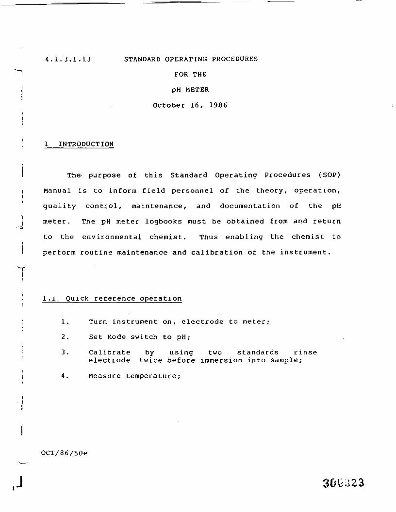
4.1.3.1.13 STANDARD OPERATING PROCEDURES
FOR THE
pH METER
October 16, 1986
• 1 INTRODUCTION
The purpose of this Standard Operating Procedures (SOP)
Manual is to inform field personnel of the theory, operation,
quality control, maintenance, and documentation of the pH
meter. The pH meter logbooks must be obtained from and return
to the environmental chemist. Thus enabling the chemist to
perform routine maintenance and calibration of the instrument.
7'! 1.1 Quick reference operation
• 1. Turn instrument on, electrode to meter;
2. Set Mode switch to pH;
3. Calibrate by using two standards rinseelectrode twice before immersion into sample;
4. Measure temperature;
OCT/86/50e
pH METER Page 2
5. Set temperature adjustment to sample temperature;
6. Place eletrode in sample and let stablize for45-60 seconds;
7. Record results; and
8. Rinse twice with distilled water and placeelectrode in distilled water betweenmeasurements.
2 THEORY OF OPERATION
The pH of a solution may be defined as the negative log of
the hydrogen ion concentration. Thus
pH = log 1 = -log [H+],
or
Where: [H ] (can be done by hand if needed) is the
hydrogen ion concentration,
for a neutral solution,
(H+] = 1.0 X 10~7
pH = -log (10-7) = -(-7)
pH = 7
It should be kept in mind that pH relates to a power of
10. Hence, a solution of pH = 1 has a hydronium ion
concentration 100 times that of a solution of pH = 3 (not three
times). Furthermore, since the pH is related to a negative
exponent, the lower the pH value, the larger the concentration
OCT/86/50e
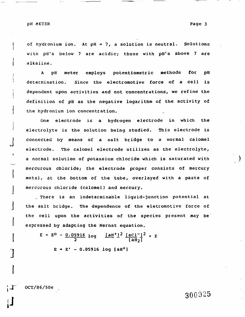
pH METER Page 3
j of hydronium ion. At pH = 7, a solution is neutral. Solutions
with pH's below 7 are acidic; those with pH's above 7 arei| alkaline.
. A pH meter employs potentiometric methods for pH
determination. Since the electromotive force of a cell is
• dependent upon activities and not concentrations, we refine theii
definition of pH as the negative logarithm of the activity of
j the hydronium ion concentration.
One electrode is a hydrogen electrode in which the
' electrolyte is the solution being studied. This electrode is
} connected by means of a salt bridge to a normal calomel
electrode. The calomel electrode utilizes as the electrolyte,i
a normal solution of potassium chloride which is saturated with
mercurous chloride; the electrode proper consists of mercury
' metal, at the bottom of the tube, overlayed with a paste of
j mercurous chloride (calomel) and mercury.
There is an indeterminable liquid-junction potential at
I the salt bridge. The dependence of the eletromotive force of
the cell upon the activities of the species present may be
' expressed by adapting the Nernst equation.
I E = E° - 0.05916 ioq laM'j' laci j «• + Ej ——2—— y —— ~ -^ ~2 UH2]
E - E' - 0.05916 log laH+)
' f~" OCT/86/50e
300925

pH METER Page 4
For the normal calomel electrode in air at 25 C, E' is
0.2825 V. Therefore
E = 0.2825 + 0.05916 (pH)
pH = E - 0.28250.05916
This expression may be regarded as an operational
definition of pH.
In place of the hydrogen electrode, a glass electrode is
usually . employed for the determination of pH's. A glass
electrode consists of a reference electrode containing a
solution of known pH sealed in a membrane of special glass. In
the determination of the pH of a solution, the glass electrode
and calomel electrode are immersed in the solution being
studied. This is made into a single electrode called a
combination electrode. The combination electrode is the
electrode used out in the field. The combination electrode is
the electrode used in the field.
The electromotive force of the complete cell depends upon
the difference in potential across the glass membrane that
separates solutions of different pH's and is found to respond
to changes in pH in the same way that an assembly using a
hydrogen electrode does. The value of E' for a cell using a
glass electrode depends upon the electrode used in the
construction of the combination electrode as well as the other
°CT/86/50e 300926
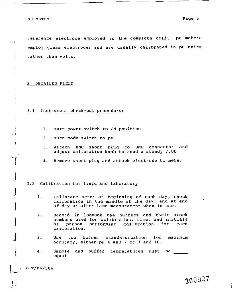
pH METER Page 5
reference electrode employed in the complete cell. pH meters-f
employ, glass electrodes and are usually calibrated in pH units
! rather than volts.
j
j
3 DETAILED FIELD
3.1 Instrument check-out procedures
1. Turn power switch to ON position
2. Turn mode switch to pH
3. Attach BNC short plug to BNC connector andadjust calibration knob to read a steady 7.00
4. Remove short plug and attach electrode to meter
3.2 Calibration for field and laboratory
1. Calibrate meter at beginning of each day, checkcalibration in the middle of the day, and at endof day or after last measurement when in use.
2. Record in logbook the buffers and their stocknumbers used for calibration, time, and initialsof person performing calibration for eachcalibration.
3. Use two buffer standardization for maximumaccuracy, either pH 4 and 7 or 7 and 10.
4. Sample and buffer temperatures must be ____equal
OCT/86/50e
300327
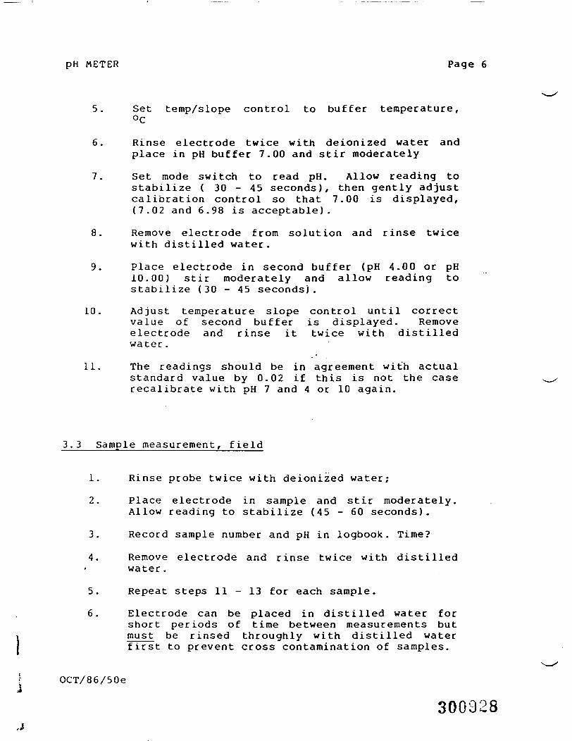
pH METER Page 6
5. Set temp/slope control to buffer temperature,°C
6. Rinse electrode twice with deionized water andplace in pH buffer 7.00 and stir moderately
7. Set mode switch to read pH. Allow reading tostabilize ( 3 0 - 4 5 seconds), then gently adjustcalibration control so that 7.00 is displayed,(7.02 and 6.98 is acceptable).
8. Remove electrode from solution and rinse twicewith distilled water.
9. Place electrode in second buffer (pH 4.00 or pH10.00) stir moderately and allow reading tostabilize (30 - 45 seconds).
10. Adjust temperature slope control until correctvalue of second buffer is displayed. Removeelectrode and rinse it twice with distilledwater.
11. The readings should be in agreement with actualstandard value by 0.02 if this is not the caserecalibrate with pH 7 and 4 or 10 again.
3.3 Sample measurement, field
1. Rinse probe twice with deionized water;
2. Place electrode in sample and stir moderately.Allow reading to stabilize (45 - 60 seconds).
3. Record sample number and pH in logbook. Time?
4. Remove electrode and rinse twice with distilledwater.
5. Repeat steps 11 - 13 for each sample.
6. Electrode can be placed in distilled water forshort periods of time between measurements butmust be rinsed throughly with distilled waterfirst to prevent cross contamination of samples.
OCT/86/50e
300928
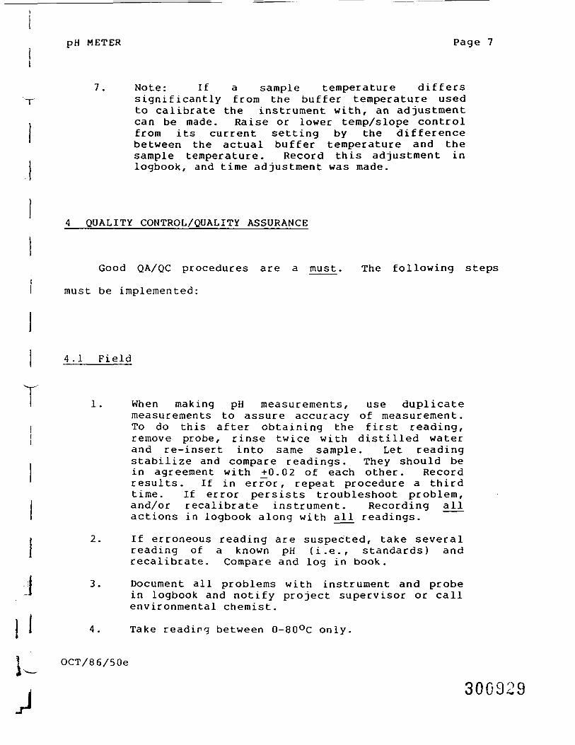
pH METER Page 7
7. Note: If a sample temperature differssignificantly from the buffer temperature usedto calibrate the instrument with, an adjustmentcan be made. Raise or lower temp/slope controlfrom its current setting by the differencebetween the actual buffer temperature and thesample temperature. Record this adjustment inlogbook, and time adjustment was made.
4 QUALITY CONTROL/QUALITY ASSURANCE
Good QA/QC procedures are a must. The following stepsiI must be implemented:
4.1 Field
VI 1. When making pH measurements, use duplicate
measurements to assure accuracy of measurement.I To do this after obtaining the first reading,{ remove probe, rinse twice with distilled water
and re-insert into same sample. Let readingstabilize and compare readings. They should bein agreement with _+0.02 of each other. Recordresults. If in error, repeat procedure a thirdtime. If error persists troubleshoot problem,and/or recalibrate instrument. Recording allactions in logbook along with all readings.
2. If erroneous reading are suspected, take severalreading of a known pH (i.e., standards) andrecalibrate. Compare and log in book.
3. Document all problems with instrument and probein logbook and notify project supervisor or callenvironmental chemist.
4. Take reading between 0-80°C only.
OCT/86/50e
300929
pH METER Page 8
5. Check pH standards by taking reading from twoseparate previous calibrated pH meters andcomparing results this should be done at leastonce a month.
4.2 Laboratory QA/QC
MAINTENANCE
5.1 Field maintenance
Air bubbles may occur in the electrode in transit. To
remove hold the probe vertically and gently tap sides to
release trapped air. If instrument is in field for an extended
time, the operator needs to check the electrode solution. When
low, add filling solution per directions under laboratory
maintenance in this manual. Record date and initials in
appropriate places if electrode splution is added.
5.2 Laboratory Maintenance
Check the electrode filling solution after each field uses
the electrode solution will discharge into the sample and will
run low damaging the electrode. When 1/3 low, add appropriate
I*OCT/86/50e
j

\
pH METER Page 9
solution by sliding rubber ring down pass fill hole. Then,
pour solution into fill hole until full. Replace ring over
fill hole. Tap sides gently to loosen air bubbles while
holding the electrode vertical. Recalibrate using standards
after letting electrodes stabilize (approximately 15 minutes)
Check battery in instrument once a month and replace as
needed. Check the battery if you suspect erroneous reading and
when the machine will not calibrate properly.
6 STORAGE
Disconnect electrode connector, replace short plug andf^s &*&£?*•^ turn machine off. I, N-|(
t3»lo-uoi^-*Tl * v
6.1 Field
Place a few drops of water in rubber cap and place over
the electrode to increase the life of the probe when not in
use.
OCT/86/50e
300931
J
pH METER Page 10
6.2 Laboratory
For periods of long storage, remove batteries to prevent
leakage and corrosion to the instrument. Place in storage case
and keep in cool, dry place.
6.3 Cleaning - laboratory
Soak electrode in 0.1M HCl or HNO- for 15 minutes
followed by soaking in pH 7 buffer for 30 minutes.
Removal of Deposits
Protein - digest with 1% pepsin in 0.1M HCl
Inorganic - rinse with O.lM tetrasodium EDTA solution
Grease & Oil - rinse with mild detergent or methanolsolution
After each of these methods, soak the electrode in pH 7
buffed for 30 minutes.
OCT/86/50e
300932
ORIONLaboratory Products GroupOrion Research Incorporated
MODEL 210INSTRUCTION MANUAL
J 300933
INSTRUCTION SHEETgel-filled combination pH electrodemodels 91-05. 91-06, 91-07, 91-08
91-15, 91-16- 91-25, 91-26
91-35, 91-36
introductionThe ORION gel-filled combination electrode is designed for routine pH measurements under ruggedconditions. The unbreakable body extends beyond the pH sensing glass bulb for protection, allow-ing the electrode to be used as a stirring rod. The sealed reference section, permanently filled with aKCI gel. never needs refilling. The electrodes are:• conventional electrode (91-05, 91-06, 91-07, 91-08) for general purpose pH measurement.• semi-micro electrode (91-15. 91-16) for pH measurement in test tubes. Provided with each elec-
trode is an adapter which allows the use of the ORION universal electrode holder (cat. no. 910002).• flask electrode (91-25, 91-26) for pH measurement in a tall-necked flask.• flat-surface electrode (91-35, 91-36) for pH measurement on solids or semi-solid substances.
required equipment and solutionsbuffers—two buffers: one near pH 7; and, one near sample pH.pH meter—any ORION or other meter with appropriate input jacks can be used. The following con-nector configurations are available:- 91-05, 91-15, 91-25, and 91-35 have standard U.S. Connectors.- 91-06, 91-16, 91-26, and 91-36 have a BNC connector for use with hand-held digital pH meters.- 91-07 has a miniature phone plug for use with the Coming model 5 and 610A pH meters.- 91-08 has a DIN connector.
preliminary to operation1. The electrode tip is covered by a cap which protects the electrode and keeps it from drying. Pull
the cap off and save for storage. There is normally no need to soak the electrode before use as thecap contains soaking solution.
2. If bubbles are seen in the bulb area of the electrode, shake the electrode downward. This actionwill help eliminate bubbles that may have been generated during shipment.
3. Connect electrode to meter.
single-buffer calibrationThis procedure is for routine measurements. Electrode slope should be checked periodically with atwo-buffer calibration.1. Choose a buffer which is near the expected sample pH.2. Buffer should be at room temperature. If samples are at varying temperatures, temperature com-
pensation is recommended. (See meter instruction manual.)3. Turn the meter slope indicator dial to 100% and the temperature knob to the temperature of the
buffer. (Some meters may use other controls for this procedure.)4. Rinse electrode with distilled water and place in the buffer.5. Wait for a stable display. Using the calibration control, set the meter to the pH value of the buffer
at its measured temperature. (A table of pH values at various temperatures is supplied with thebuffer.)
6. Rinse electrode with distilled water and place in sample. '7. When display is stable, record pH. 3 0 G 3 3 4
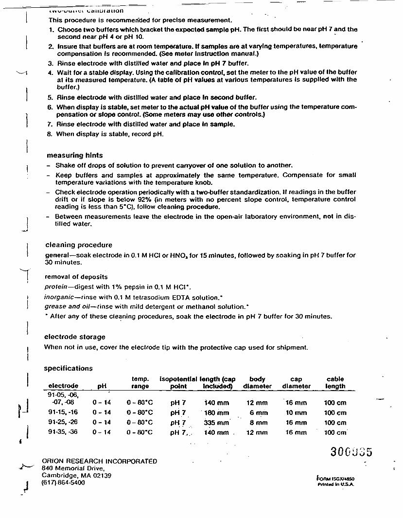
tnu-uunci cauurauonThis procedure is recommended for precise measurement.1. Choose two buffers which bracket the expected sample pH. The first should be near pH 7 and the
second near pH 4 or pH 10.2. Insure that buffers are at room temperature. If samples are at varying temperatures, temperature
compensation is recommended. (See meter Instruction manual.)3. Rinse electrode with distilled water and place In pH 7 buffer.
— I 4. Wait for a stable display. Using the calibration control, set the meter to the pH value of the bufferat its measured temperature. (A table of pH values at various temperatures is supplied with the
, buffer.)I 5. Rinse electrode with distilled water and place in second buffer.
6. When display is stable, set meter to the actual pH value of the buffer using the temperature com-
I pensation or slope control. (Some meters may use other controls.)7. Rinse electrode with distilled water and place in sample.8. When display is stable, record pH.
measuring hintsI - Shake off drops of solution to prevent carryover of one solution to another.
- Keep buffers and samples at approximately the same temperature. Compensate for smalltemperature variations with the temperature knob.
- Check electrode operation periodically with a two-buffer standardization. If readings in the bufferdrift or if slope is below 92% (in meters with no percent slope control, temperature controlreading is less than 5*C), follow cleaning procedure.
- Between measurements leave the electrode in the open-air laboratory environment, not in dis-tilled water.
.~.j
cleaning proceduregeneral—soak electrode in 0.1 M HCI or HNO, for 15 minutes, followed by soaking in pH 7 buffer for30 minutes.
I removal of depositsj
protein—digest with 1% pepsin in 0.1 M HCI*.i inorganic—rinse with 0.1 M tetrasodium EDTA solution.*j grease and oil—rinse with mild detergent or methanol solution.*
- After any of these cleaning procedures, soak the electrode in pH 7 buffer for 30 minutes.
electrode storageI When not in use, cover the electrode tip with the protective cap used for shipment.
»J
specifications
electrode91-05, -06,
-07, -0891-15, -1691-25, -2691-35. -36
pH
0-0-0-0-
14141414
0000
temp. isopotentlal length (caprange point Included)
-80'C-80*C-80'C-80*C
pH7pH 7pH 7pH 7.
140 mm180 mm335 mm140 mm -
bodydiameter
12 mm6 mm8 mm
12 mm
capdiameter
16 mm10 mm16 mm16 mm
cablelength
100cm100cm100cm100cm
ORION RESEARCH INCORPORATED840 Memorial Drive.Cambridge, MA 02139(617)864-5400
30GU35
£ORM ISGX/48SOPrinted In U.S.A.
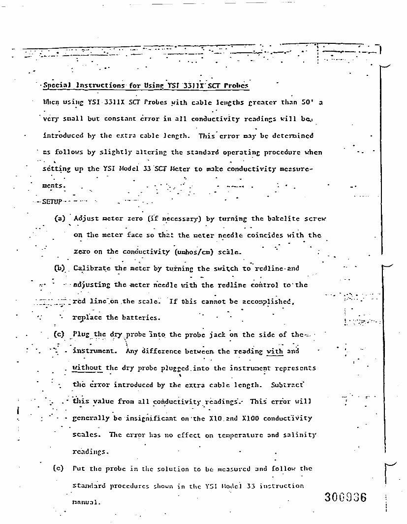
•Special Instructions for Using YSI 351II'SCT Probes
Mien using YSI 3311X SCT Trobcs with cable lengths greater than 50' a
very snail but constant error in all conductivity readings will bc.«
introduced by the extra cable length. This error nay be dctcmincd
cs follows by slightly altering the standard operating procedure when* . "
setting up the YSI Model 33 SCT Meter to make conductivity measure-
ments. . - - • "... •'" . - -—« . "- • .
-SETUP-- --- - —" - . - " •
(a) Adjust nctcr zero (if necessary) by turning the bakclite screw. *
on the nctcr face so that the ncter needle coincides with the• " ^ •
zero on the conductivity (uohos/cm) scale." •- • *
(b) Calibrate the nctcr by turning the switch to rcdline and
.-.- ' - -adjusting the -wctcr needle \d.th the rcdline control to'the
.„... ..„^rc{j iine".6n .the scale. If this cannot be accomplished,-.-•-'- _
"• replace the batteries. • _
(c) Plug the dry probe into the probe jack on the side of thc--„ • "• - • • '"*".•'\ • xnstrunicnt. Any difference between, the reading with and
. without the dry probe plugged.into the instrument represents*
the error introduced by the extra cable length. Subtract"
1- .' this value from all conductivity readings".- This error will
; " - - generally be insignificant on the XlO.znd X100 conductivity
scales. The error has no effect on temperature and salinity
readings.
(c) Put the probe in the solution to be measured and follow the
Standard procedures shown in the YSI ModcJ 33 instruction
nnnual.
r300936 ;
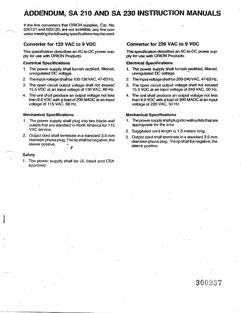
ADDENDUM, SA 210 AND SA 230 INSTRUCTION MANUALSIf the line converters that ORION supplies. Cat. No.020121 and 020120. are not available, any line con-verter meeting the following specifications may be used.
Converter for 120 VAC to 9 VDCThis specification describes an AC-to-DC power sup-ply for use with ORION Products.
Electrical Specifications1. The power supply shall furnish rectified, filtered,
unregulated DC voltage.2. The input voltage shall be 100-130 VAC. 47-63 Hz.3. The open circuit output voltage shall not exceed
15.5 VDC at an input voltage of 130 VAC. 60 Hz.4. The unit shall produce an output voltage not less
than 9.0 VDC with a load of 200 MADC at an inputvoltage of 115 VAC. 60 Hz.
Converter for 220 VAC to 9 VDCThis specification describes an AC-to-DC power sup-ply for use with ORION Products.
Electrical Specifications1. The power supply shall furnish jectified. filtered,
unregulated DC voltage.2. The input voltage shall be 200-240 VAC. 47-63 Hz.3. The open circuit output voltage shall not exceed
15.5 VDC at an input voltage of 240 VAC. 50 Hz.4. The unit shall produce an output voltage not less
than 9.0 VDC with a load of 200 MADC at an inputvoltage of 220 VAC. 50 Hz.
Mechanical Specifications1. The power supply shall plug into two blade wall
outlets that are standard in North America for 115VAC service.
2. Output cord shall terminate in a standard 3.5 mmdiameter phone plug. The tip shall be negative, thesleeve positive.
/Safety1. The power supply shall be UL listed and CSA
approved.
Mechanical Specifications1. The power supply shall plug into wall outlets that are
appropriate for the area.2. Suggested cord length is 1.5 meters long.3. Output cord shall terminate in a standard 3.5 mm
diameter phone plug. The tip shall be negative, thesleeve positive.
300937
ADDENDUM, ;SA 230 INSTRUCTION MANUAL
1 On page 5 under Single Buffer Standardization! (With ATC) steps 1 and 2 should read as follows:
1. Plug ATC probe into input jacks and adjust] °C/slope control knob to 25°C. Slide mode switchi to temperature. Verify that ambient temperature is
displayed.i 2. If incorrect, adjust °C/slope control knob until ac-I tual temperature is displayed.
J
O7IONOrion Research IncorporatedLaboratory Products Group840 MEMORIAL DRIVECAMBRIDGE. MA 02139 U.S.A.TEL 617-864-5400 / TLX 921466IN EUROPE: ORION RESEARCH AGFAHNLIBRUNNENSTRASSE 3CH-8700 /USNACHT. SWITZERLANDTEL 01-910-7858 / TLX 4430019
JI
o 1985 Orion Research Incorporated.ORION is a trademark registered in the US. Palent & Trademark Office. ' Primed in US ASpecifications subtect lo change vMhoU notice. Fo«m 230-21CMMA/564O.
J
I,1
J1
CONTENTS _General Information 2Introduction • 2Instrument Description 2
Instrument Set-up 3Support Rod 3Power Source 3Battery Installation 3Electrode Connections 4Meter Check-out Procedure 4
Measurement Procedures 5pH Measurement 5
Single Buffer Standardization 5Two Buffer Standardization 5
Potentiometric Measurements 6Dissolved Oxygen Measurement 6
Troubleshooting Guide 7Warranty Information 7Repair and Service 7Accessories 7Specifications 8Notice of Compliance 8
<300ij39
GENERAL INFORMATIONIntroductionThe ORION Model SA 210 is a portable battery-operateddigital pH meter for field, plant or laboratory use. It isdesigned for versatile, easy operation, and can be usedin or out of the accompanying carrying case. The instru-ment is lightweight and designed to Tit comfortably intothe hand. Al controls are on the meter face which affordsone hand calibration.The instrument measuring range is -1999 to +1999 mV.and pH is displayed to two decimal places. The meterhas a large easy to read LCD display.
tInstrument Description See Figure 11 On/Off switch: Slide switch controls power to
meter.2 LCD display: Model SA 210 automatically displays
data in large numerals with negative polarity signand decimal point. pH values are displayed from.0 to 14 with 0.01 pH unit resolution. Millivolt rangeis -1999 to +1999. Dissolved oxygen is measuredfrom 0 to 14 ppm when meter is used with 97-08Oxygen Probe.
3 Mode Control: Provides operator with choice ofmeasuring sample in either pH or mV mode.
4 Calibration Control: Used to standardize themeter/electrode system in Buffers of known pH.
5 Temperature/slope Control: Compensates forvariation in electrode slope or solution tem-perature.
6 Electrode Connection: Accepts BNC connectorfrom combination electrodes and pin tip jack availa-ble for use with separate half-cell reference elec-trodes.
a
Orion Researchmodel SA 210
Rgure 1Face of the SA 210
30GU40
INSTRUMENT SET-UP SeeFigure2.
r
Support Rod1. Attach support rod base to side ol meter carrying
case and tighten damp screw.2. Insert support rod into base. Tighten by turning rod
clockwise.3. Attach electrode holder to top of support rod.
Figure 2Model SA 210 and accessories
electrodeholder
support rodbase
Power SourceORION Mode) SA 210 operates on one non-recharge-able 9-vott alkaline battery. Optional AC line adaptersare available (or both 110 and 220 volt mains. Referto ACCESSORIES, page 7.
Battery Installation See Figure 4.1. Remove access panel on back of meter. No tools
are required, simply slide cover towards bottom ofmeter.
2. Attach battery connector dip of meter to battery ter-minals, install battery and replace access panel.
Figure 4Rear access panel removed
Rgure 3Support rod and clamp 30GB4I
Electrode Connections1
2.
Attach electrodes with BNC connectors directly tothe top of the meter. Refer to Rgure 5.Electrodes without BNC connectors may be usedwith a commercially available BNC adapter (ORIONCat. No. 090033). See Figure 6.If using a combination electrode, electrode connec-tion 3 is not used.
Figure 5Electrode connections
Legend1 AC line adapter2 BNC connector3 reference pin-tip connector
Figure 6U.S. Standard connector to BNC adapter
Meter Check-Out Procedure1. Slide power switch to ON position.2. If using optional AC fine adapter, connect it to meter
and appropriate power source. Proceed to step 4.3. Slide mode switch to pH. If LO BATT indicator on
LCD remains on. battery must be replaced.4. Attach BNC shorting plug (ORION Cat. No. 090045)
to BNC connector on top of meter. Slide modeswitch to pH. Adjust calib knob to read a steady7.00. If this cannot be done, refer to TROUBLE-SHOOTING, page 6.
5. Removetheshortingplug.Aftersuccessfulcomple-tion of steps 1 -4. the meter is ready for use with anelectrode.
300942
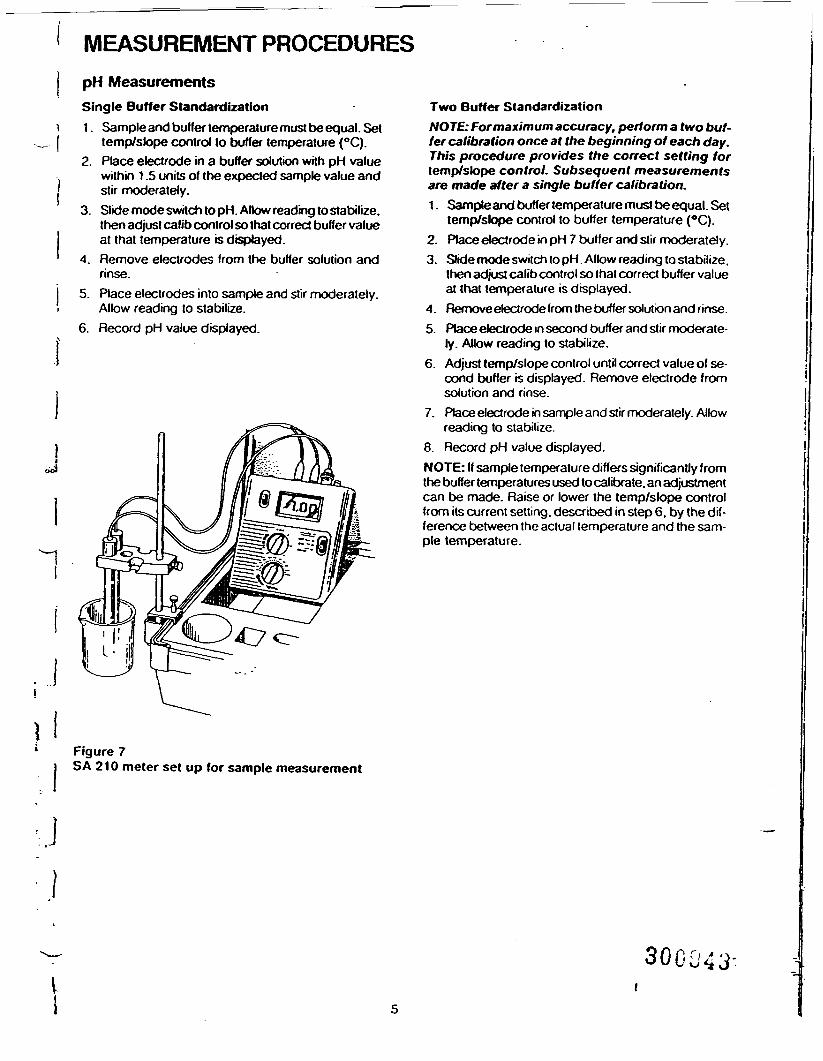
MEASUREMENT PROCEDURESpH MeasurementsSingle Buffer Standardization1. Sample and buffer temperature must be equal. Set
temp/slope control to buffer temperature (°C).2. Place electrode in a buffer solution with pH value
within 1.5 units of the expected sample value andstir moderately.
3. Slide mode switch to pH. Aflow reading to stabilize,then adjust calib control so that correct buffer valueat that temperature is displayed.
4. Remove electrodes from the buffer solution andrinse.
5. Place electrodes into sample and stir moderately.Allow reading to stabilize.
6. Record pH value displayed.
Two Buffer StandardizationNOTE: For maximum accuracy, perform a two buf-fer calibration once at the beginning of each day.This procedure provides the correct setting fortemp/slope control. Subsequent measurementsare made after a single buffer calibration.1. Sample and buffer temperature must be equal. Set
temp/slope control to buffer temperature (°C).2. Place electrode in pH 7 buffer and stir moderately.3. Slide mode switch to pH. Allow reading to stabilize,
then adjust calib control so that correct buffer valueat that temperature is displayed.
4. Remove electrode from the buffer solution and rinse.5. Place electrode in second buffer and slir moderate-
ly. Allow reading to stabilize.6. Adjust temp/slope control until correct value of se-
cond buffer is displayed. Remove electrode fromsolution and rinse.
7. Place electrode in sample and stir moderately. Allowreading to stabilize.
8. Record pH value displayed.NOTE: If sample temperature differs significantly fromthe buffer temperatures used to calibrate, an adjustmentcan be made. Raise or lower the temp/slope controlfrom its current setting, described in step 6. by the dif-ference between the actual temperature and the sam-ple temperature.
Figure 7SA 210 meter set up for sample measurement
:J
30C043-
Potentiometric MeasurementsPotentiomelric titratkxis are performed in mV modeusing either ion selective or redox electrodes with BNCconnectors. Detailed instructions lor any ORION elec-trode are given in the electrode instruction manual. Tilra-tion instructions are included in ORION Redox Elec-trode (Model 96-78) Instruction Manual, or in standardanalytical chemistry texts. U.S. Standard to BNCadaptersareavailabte from ORION (Cat.No. 090033).
Dissolved Oxygen MeasurementDissolved oxygen measurements are displayed in ppmwhen ORION Model 97-08-99 Dissolved Oxygen Elec-trode is used with Model SA 210. Follow the instructionsin the electrode manual. Be sure to set meter modeswitch to pH.
TROUBLESHOOTING GUIDE
The following section covers troubleshooting that canbe performed without special tools or skills. The ORIONTechnical Service Personnel can be consulted fortroubleshooting advice by calling 1-800-225-1480 or617-864-5400. Outside North America contact yourlocal authorized ORION Representative.
Malfunction Possible Cause RemedyNo Display
More than one decimaldisplayedErratic readings or drift.Readings out of range.
No power to meter
mode switch is betweenpositionsElectrode failure
Check that switch is in ON position.Replace battery.Check that adapter is receiving power andis plugged in securely.Adjust switch to proper position.
Follow meter checkout procedure. If meterokay, check electrode.
30GU44
INSTRUMENT WARRANTY OPTIONAL ACCESSORIES
OHION RESEARCH INCORPORATED warrants thisinstrument will operate (or one year from the date of pur-chase when used under normal laboratory conditions.
T and in accordance with the operating limitations andmaintenance procedures given in the instruction
. manual. In the event of failure within the warrant period.1 ORION, or its Authorized Dealer, will, at ORION'S op-' tion. repair or replace the non-conforming instrument
at no charge to the customer.j THE WARRANTY DESCRIBED ABOVE IS EXCLUSIVE| AND IN LIEU OF ANY OTHER WARRANTY.
WHETHER STATUTORY. EXPRESS OR IMPLIED. IN-. CLUDING BUT NOT LIMITED TO. ANY IMPLIED] WARRANTY OF MERCHANTABILITY OH FITNESS1 FOR A PARTICULAR PURPOSE AND ALL WARRAN-
TIES ARISING FROM COURSE OF DEALING OR) USAGE OF TRADE, EXCEPT TITLE. THE BUYER'S
SOLE AND EXCLUSIVE REMEDY IS FOR REPAIR. ORREPLACEMENTOFTHE DEFECTIVE INSTRUMENTOR PART. OR REFUND OF THE PURCHASE PRICE;
j BUT IN NO EVENT SHALL ORION (ITS CONTRAC-j TORS AND SUPPLIERS OF ANYTIER) BE LIABLE TO
THE BUYER OR ANY PERSON. IN CONTRACT ORIN TORT (INCLUDING NEGLIGENCE) FOR ANYSPECIAL. INDIRECT. INCIDENTAL OR CONSE-
J QUENTIAL DAMAGES.
Representations and warranties made by any person.including dealers, representatives and employees ofORION, which are inconsistent or in conflict with the
rms of this warranty shall not be binding upon ORIONin writing and signed by one of its officers.^Tunless
REPAIR AND SERVICE
A Return Authorization Number must be obtained frompRION Laboratory Products Customer Service beforereturning any product for in-warranty repair, replace-ment or credit. Contact ORION by calling
E" °00-225-1480 (USA outside Mass.) or 617-864-5400.side the USA and Canada consult your local in-ntry. authorized ORION sales agent/distributor for
product service information.
Cat. No. Description815600 Ross*epoxy body, bulb guard combina
tion pH electrode9104 BN Laboratory grade combination pH elec-
trode (BNC connector)910600 GX-series epoxy body, gel-filled com-
bination pH electrode (BNC connector)912600 GX-series epoxy body, gel-filled flask
combination pH electrode (BNCconnector)
913600 GX-series epoxy body, gel-filled flaskcombination pH electrode (BNCconnector)
915600 RX-series refillable. epoxy body com-bination pH electrode (BNC connector)
9162BN Combination pH electrode with ruggedbulb (BNC connector)
9163BN Combination pH electrode with needleshape (BNC connector)
910004 pH 4 buffer packets, box of 25 packets,each packet making 200 ml of buffer
910007 pH 7 buffer packets, box of 25 packets,each packet making 200 ml of buffer
910009 pH 9 buffer packets, box of 25 packets,each packet making 200 ml of buffer
910104 pH 4.01 buffer. 475 ml bottle910107 pH 7.00 buffer. 475 ml bottle910110 pH 10.01 buffer. 475 ml bottle970899 Dissolved oxygen electrode910002 Electrode holder090033 U.S.StandardtoBNCconnectoradapter090045 Shorting plug020120 110V AC line adapter020121 220V AC line adapter020041 Shoulder strap and meter holder for
hands free operation020042 Carrying case with foam insert, without
meter or accessories020043 Support rod and guide020044 Accessory pack includes two 60 ml bot-
tles and one 150 ml beaker020045 Electrode rod stand for bench-top meter
use outside carrying case
VI 300
SPECIFICATIONS NOTICE OF COMPLIANCE
Model SA 210. ORION Cat. No. 021000 portable pH/mVmeter kx hand held and bench top use. Digital LCD metercomes in carrying case with combination pH electrodeand accessories, ready lor immediate use. 110 and 220volt adapters) available kx AC line use.
ModespH. mV. O2 (with O2 probe)pH rangepHOto14pH resolution0.01mV range-1999 to +1999 mV showing negative polarity signmV resolution1 mVTemperature compensationManualSample temperature range-5 to 105°CInput impedance> 100.000 megohmsInstrument drift •<50microvolts/0CInput bias current< ± 1 pkx>ampat25°Cand < + 4 pico amps over fulloperating rangeEnvironmental requirements5 to 45°C and 5 to 80% relative humidity,non-condensingIsopotential pointpH 7 (fixed)Power requirementOne 9 volt battery. Optional 110 or 220 vott line adapter®available for AC line use.InputsBNC combination and separate pin tip reference jackMeter dimensions14cmX 14cmX4cmMeter weight0.5 kgMeter case .Splash-proof, chemical resistant' 7.,;Carrying case dimensions38.1 cm x 27.9 cm x 11.4 cm r' "
••'*• •' ..^ 5-. •Carrying case weight1.8kg
This meter may generate radio frequency energy andif not installed and used property, that is. in strict accor-dance with the manufacturer's instructions, may causeinterference to radio and television reception. It hasbeen type-tested and found to comply with the limitsfor a Class B computing device in accordance withspecifications in Subpart J of Part IS of FCC Rules,which are designed to provide reasonable protectionagainst such interference in a residential installation.However, there is no guarantee that interference wtflnot occur in a particular installation. If the meter doescause interference to radio or television reception,which can be determined by turning the unit off andon. the user is encouraged to try to correct the in-terference by one or more of the following measures:— Reorient the receiving antenna.— Relocate the meter with respect to the receiver— Move the meter away from the receiver.— Plug the meter into a different outlet so that the meter
and receiver are on different branch circuits.If necessary, the user should consult the manufactureror an experienced radio/television technician for addi-tional suggestions. The user may find the followingbooklet prepared by the Federal CommunicationsCommission helpful:"How to Identify and Resolve Radio-TV Interference Pro-blems."This booklet is available from the U.S. Government Prin-ting Office. Washington. D.C. 20402. Stock No.004-00(HX)345-4.
30GJ468
T
JORIONLaboratory Products GroupOrion Research Incorporated •840 Memorial Drive. Cambridge. MA 02139Call toll-free 800-225-1480. In MA can 617-864-5400. ' •In Europe: Orion Research AG :::' . . . .Fahnlibruriner rasse3.CH-87C)OKusnacrTt,Swtoefland-:: :, .. ;': • r- 'Telephone 01-910 7858. Tetex 57829. ^ . v. • - , ; • .,"-': - -•: "•:•• • 300 J47SpeoTcations are subjecl lo change <M*UU nolba. _" :...''ORION is 3 trademark registered in me U-S. Paten) and Trademark OAca.01964 Orion Research txxxporaied Part No. 2O5374O01.Form No ZIOrM/481 t(A) Pfrted n USA.
ADDENDUMSA 210/230 INSTRUCTION MANUALSTo further clarify the use of the ORION Model 97-08 Dis-solved Oxygen Electrode (Cat. No. 970899 with BNCconnector) with your new meter the following instruc-tions are included:1. Connect electrode to the meter.2. With the electrode modeswitch in the OFF position,
switch the meter to the pH mode.3. Turn the calib control until a 7.00 is displayed.4. Turn the temp/slope control (°C/stope) to the 25°C
position.The meter is now ready to caBtxate the 97-08 DissolvedOxygen Electrode. Refer to the instruction manual foradditional information and for Table 1 and Appendices.1. Turn the mode switch on the electrode to BT CK.
Good battery operation is indicated by a readingof 13.00 or greater on the meter.
2. Turn the mode switch on the electrode to ZERO. Usethe zero calibration control to set the meter to read0.00.
3. Insert the funnel into a BOD sample bottle contain-ing enough water to just cover the bottom. Insertthe electrode, making sure that the electrode tip isnot immersed in the water and does not have waterdroplets clinging to the outside of the membrane.Let stand approximately 30 minutes to ensure watersaturation of air in BOD bottle. Also use this bottlefor storage between measurements.
4. Turn the electrode mode switch to the AIR position.If measurements are being made at sea level, usethe AIR calibration control to set the pH meter read-ing to the prevailing barometric pressure (dividedby 100). If the barometric pressure is unknown, ifthe elevation is above sea level or if the sample hasa salinity greater than 2 parts per thousand, con-sult Table 1 found in the 97-O8 instruction manualto obtain the correct AIR setting.
5. Turn electrode mode switch to H2O for sampleanalysis.
Orion Research Incorporated840 Memorial Drive. Cambridge. MA 02139Telephone 617-864-5400 / Telex 921466o1985 Of ion Research Incorporated Printed in U.S.A.
Form 210/230Add/S810
300048
QUALITY ASSURANCE PROJECT PLANREMEDIAL INVESTIGATION/FEASIBILITY STUDYKENTUCKY AVENUE WELLFIELD SITEOPERABLE UNIT NO. 3
APPENDIX G
BURLINGTON ENVIRONMENTAL INC.Project: 427100Date: 10/25/93Revision: 1
APPENDIX G
STANDARD OPERATING PROCEDURESFOR YSI-SPECIFIC CONDUCTIVITY METER MODEL 33
30094910/93/76W82A(427100)2
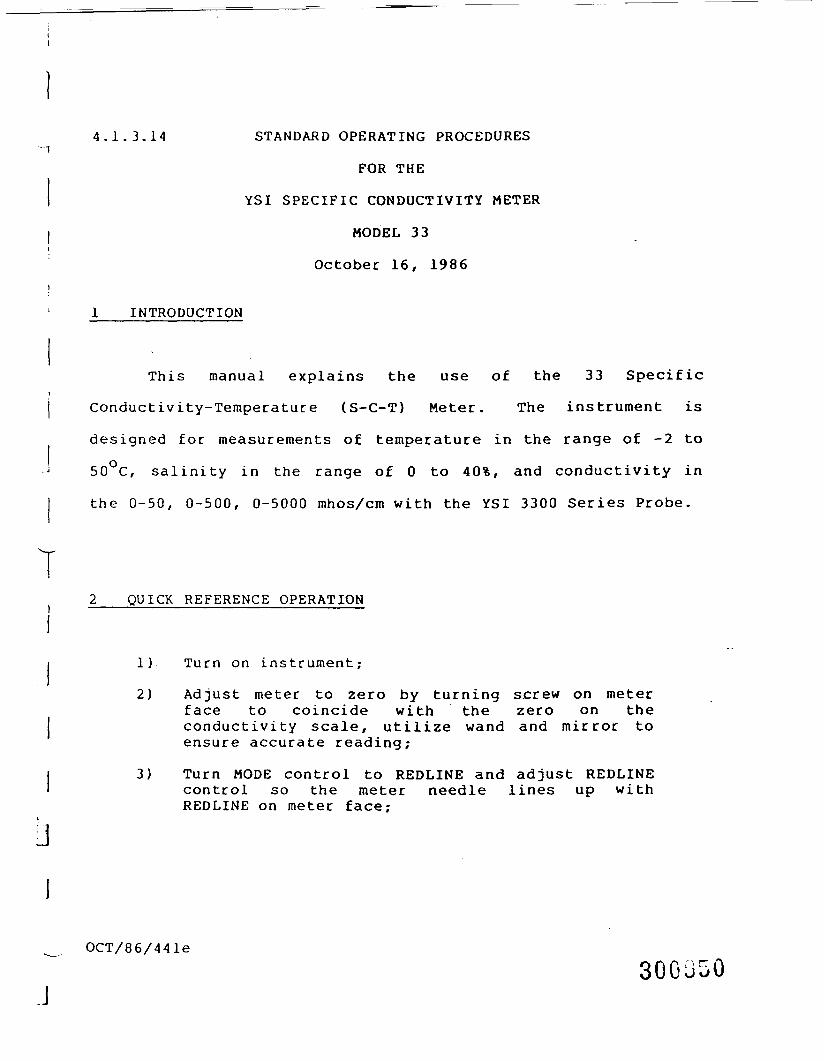
4.1.3.14 STANDARD OPERATING PROCEDURES
FOR THE
YSI SPECIFIC CONDUCTIVITY METER
MODEL 33
October 16, 1986
1 INTRODUCTION
This manual explains the use of the 33 Specific
Conductivity-Temperature (S-C-T) Meter. The instrument is
designed for measurements of temperature in the range of -2 to
50°C, salinity in the range of 0 to 40%, and conductivity in
the 0-50, 0-500, 0-5000 mhos/cm with the YSI 3300 Series Probe.
QUICK REFERENCE OPERATION
1) Turn on instrument;
2) Adjust meter to zero by turning screw on meterface to coincide with the zero on theconductivity scale, utilize wand and mirror toensure accurate reading;
3) Turn MODE control to REDLINE and adjust REDLINEcontrol so the meter needle lines up withREDLINE on meter face;
OCT/86/441e300050
YSI SPECIFIC CONDUCTIVITY METER Page 2
: 4) Plub probe into probe jack on the side of theinstrument;
5) Place probe into sample;
6) Set MODE switch to TEMPERATURE;
'. 7) Allow 1 minute for probe temperature to come toequilibrium;
8) Read temperature on bottom of scale in degreescelsius;
•'•] 9) Set MODE switch to appropriate setting startingi at the X100 scale and working down to the XI
scale;l
j 10} Allow 30 to 40 seconds for needle to stabilize;and
11} Take reading and multiply by the correct scale.--" The answer is expressed in mhos/cm.
Example: Meter Reading 238
Scale X10!i Answer 2380 mhos/cm
12) Reset made to REDLINE
3 THEORY OF OPERATION
Conductivity is a numerical expression of the ability of
I an aqueous solution to carry an electric current. This ability
depends on the presence of ions, their total concentrations,1J mobility, valence, and relative concentrations, and on the
» temperature of measurement. Electrolytic conductivity
increases with temperature at •a rate of approximately
" OCT/86/441e
J 30GJ51
YSI SPECIFIC CONDUCTIVITY METER Page 3
1.9%/°C. Significant errors can result from inaccurate
temperature measurement.
The conductivity of potable waters in the United States
ranges generally from 50 to 1500 mhos/cm. The conductivity of
domestic waste waters may be near that of the local water
supply, although some industrial wastes have conductivity above
10,000 mhos/cm.
The physical measurement made in a laboratory
determination of conductivity is usually of resistance,
measured in ohms or megaohms. The resistance of a conductor is
inversely proportional to its cross-sectional area and directly
proportional to its length. The magnitude of the resistance
measured in an aqueous solution therefore depends on the
characteristics of the conductivity cell used, and is not
meaningful without knowledge of these characteristics.
Specific resistance is the resistance of a cube 1 cm on an
edge. Practical electrodes measure a given fraction of the
specific resistance, the fraction being the cell constant, C:
Measured resistance, RmC =
Specific resistance, Ro
The reciprocal of resistance is conductance. It measures that
ability to conduct a current and is expressed in reciprocal
ohms or mhos. A more convenient unit in water analysis is
micromhos. When the cell constant is known and applied, the
measured conductance is converted to the specific conductance
I OCT/86/441e30GJ52
jJ
YSI SPECIFIC CONDUCTIVITY METER Page 4
or conductivity, R , the reciprocal of the specificsresistance:
1 C
Rs RmiThe term "conductivity" is preferred and customarily is
, reported in micromhos per centimeter (mhos/era). A conductanceI1 measurement requires a source of electrical power, a cell to
] contain the solution, and a suitable bridge to measure thei
resistance of the solution. The YSI utilizes two D-size}\ alkaline batteries providing approximately 200 hours of
'.««
operation. The cell itself is a rugged plastic conductivityi' cell and a precision thermometer temperature sensor combined in
a single unit with the bridge being transistorized. The bridge
used is similar to the Wheatstone Bridge.
CALIBRATION
4.1 Calibration for field
1) Turn instrument on and connect probe;
2) Set ZERO by aligning needle to the ZERO mark andadjusting the screw on meter face. Do thisgently so instrument is not damaged; and
OCT/86/441e300953
YSI SPECIFIC CONDUCTIVITY METER Page 5
3) Switch MODE to REDLINE the needle should line upwith the REDLINE that is approximately 2/3across the meter. Adjust if needed by usingREDLINE knob.
4.2 In-house calibration
1) Read the temperature and conductivity of A 0.01normal KC1 solution; Determine the salinity ofthe solution by running a line vertically on thegraph 9see Graph 1 below) from this conductancevalue until it intersects the appropriate °Cline (interpolate as required for temperaturebetween the given °C lines). From thisintersection extend a line horizontally to theedge of the graph. This determines the salinityfor this sample.
Example: 25,000 mhos/cm and 20°C gives a salinity of 17
Example: 2,500 mS/m and 20°C gives a salinity of 17.
J 2) Remove the °C knob, switch to SALINITY, andturn the control shaft until the meter needleindicates the salinity value determined in Step(1). In the example given, the value is 17.
_ OCT/86/441e
J 300354
J
YSI SPECIFIC CONDUCTIVITY METER Page 6
3) Switch to TEMPERATURE. (Note: This temperaturereading must be the same as Step (1); if not,begin again at Step (1).) Place the knob on thecontrol shaft (without turning the controlshaft) with the knob pointer at the sametemperature as the meter reading and tightenboth set screws securely. The temperature knobmay become loose or slip from its normalposition. In an emergency the dial can bere-positioned. It must be emphasized that thisis an emergency procedure only, and that theinstrument should be returned to the factory forproper recalibration at the earliest opportunity.
4.3 Cell calibration in-house
The YSI 13300 Series Cells are calibrated to absolute
accuracy of _+ 1.5% based on a standard solution. Since the
literature on conductivity does not indicate a consistently
accepted standardization method, Mathes has chosen the 0.01
normal KCl solution method as determined by Jones and Bradshaw
in 1937 as the standard. Recent textbooks, as well as the ASTM
standards, concur with this choice. The solution is prepared
by diluting 0.745 grams of pure dry KCl with distilled water
until the solution widths 1.00 kilogram. The table below shows
the values of conductivity this solution would have if the
distilled water were non-conductive. However, since eve high
purity distilled water is slightly conductive, the measured
JOCT/86/441e
300055
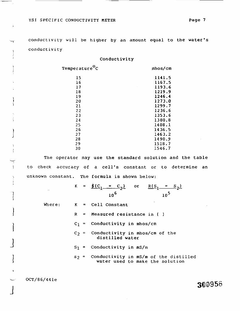
YSI SPECIFIC CONDUCTIVITY METER Page 7
conductivity will be higher by an amount equal to the water's
conductivity
Conductivity
TeraperatureC
15161718192021222324252627282930
mhos/cm
1141.51167.51193.61219.91246.41273.01299.71236.61353.61380.81408.11436.51463.21490.91518.71546.7
The operator may use the standard solution and the table
to check accuracy of a cell's constant or to determine an
unknown constant. The formula is shown below:
K = $(c = C) or
J
10 10
Where: K = Cell Constant
R = Measured resistance in ( )
GI = Conductivity in mhos/cm
C2 = Conductivity in mhos/cm of thedistilled water
S^ = Conductivity in mS/m
S2 = Conductivity in mS/m of the distilledwater used to make the solution
OCT/86/441e
J
YSI SPECIFIC CONDUCTIVITY METER Page 8
\ R, C, , and C_, or S, and S , must either be
^ determined at the sample temperature or corrected to the same
temperature to make the equation valid.
1 NOTE: For further information on conductivity and the
above standard information, refer to ASTM Standards Part 23 -
i Standard Methods of Test for Electrical Conductivity, or Water
, and Industrial Waste Water - ASTM Designation D1125-64.
JDETAILED FIELD OPERATION AND SET-UP PROCEDURES
Set-Up
1) Adjust meter zero by turning bakeli'te screw onmeter face to coincide with zero on conductivityscale.
2) Calibrate meter by turning on MODE switch toREDLINE and adjusting the REDLINE control so themeter needle lines up with REDLINE on meter face.
3) Plug probe into probe jack into side of matching.
4) Rinse probe twice with distilled water.
5) Place probe in sample making sure probe iscompletely submerged, 1 to 2 inches at least.
6) Switch MODE control to TEMPERATURE.
7) Let stabilize (approximately 30 sec - 1 min) andtake reading on bottom scale.
-' OCT/86/441e300357
.1d
YSI SPECIFIC CONDUCTIVITY METER Page 9
8) Switch the MODE control to conductivity on theX100 scale. If the reading falls below 50 onthe 0-500 scale switch to X10 scale. Letstabilize (30 - 60 sec), take reading andmultiply by the meter scale used. Answer isexpressed in mhos/cm.
Example meter Reading: 137
Scale: XlOO
Answer: 13,700 mhos/cm
9) Reset MODE to REDLINE.
10) Remove probe from sample and rinse twicethoroughly with distilled water.
11) Keep probe in a container filled with distilledwater between samples. This is extremelyimportant since the probe may overheat on hotdays or cause heating of the sample when atemperature measurement is being made.
FIELD QA/QC
There are certain criteria to follow for accurate QA/QC
work. This entails replicate measurements, time for
equilibrium, collection to measurement time, redline, zero, and.
temperature check, and conductivity QA/QC controls.
Measurement of temperature and conductivity should be
made as soon after collection of sample as possible. The
recommended method is to use a 4 liter container (properly
cleaned plastic will do) filled 3/4 full after rinsing twice
with solution to be sampled. Rinse probe twice with distilled
water and insert in sample submersing probe at least 1 to 2
OCT/86/441e
YSI SPECIFIC CONDUCTIVITY METER Page 10
inches, swirl gently. When taking measurements, allow the
instrument to stabilize. The time required for equilibrium is
usually 45-60 seconds. Conductivity should be taken
immediately after the temperature reading. The results are to
be recorded in the field logbook in tabular form on a Field
Data Record.
Standard Field Practice
1) A check on redline measurements must be madebefore probe is put in sample. This should beeasy to do since it should be in the redlinemode between samples.
2) A check on the temperature should be made atleast once an hour of use. This could be doneby using a mercury thermometer and comparing thetwo readings. They should agree to within
3) Duplicate measurements must be made once everyten samples. To do this, follow instructionsfor sample measurements. After recordingresults, remove probe, rinse twice, immerseprobe into same sample and take reading again.The results should be in agreement by 1% ofprevious measurement. Log all results on properform or logbook.
4) Split sample measurements can be substituted forduplicate measurements. For split measurementsdivide the sample in half and take reading foreach half. Agreement should be within 1%. Logresults in field book.
J
1
J
YSI SPECIFIC CONDUCTIVITY METER Page 11
MAINTENANCE
7.1 Field maintenance
The only field maintenance required is battery
replacement. Two "D" size alkaline flashlight cells, such as
Eveready D95 or equivalent, will provide approximately 200
hours of operation. Accuracy will not be maintained if
zinc-carbon "D" cells are used. Battery replacement is
indicated when the redline adjustment cannot be accomplished.
Replace batteries as needed. To replace batteries,
remove the six screws from the rear plate. The battery holders
are color coded. The positive (+ button) end must go on red.
Every six months or when the probe indicates low readings the
probable cause is dirty electrodes. Wash in soapy lukewarm
water and rinse with distilled water; then soak overnight in
distilled water. Be careful not to touch electrodes on the
inside or damage to the probe can result.
J
7.2 In-house maintenance
(A) Cleaning
When the cell test indicates low readings theprobable cause is dirty electrodes. Hard waterdeposits, oils and organic matter are the mostlikely contaminants.
OCT/86/441e
30GUGO
YSI SPECIFIC CONDUCTIVITY METER Page 12
For convenient normal cleaning soak thelectrodes for 5 minutes with a locally availablebathroom tile cleaning preparation such as DowChemical "Bathroom Cleaner", Horizon Industries"Rally, Tile, Porcelain, and Chrome Cleaner",Johnson Wax "Envy, Instant Cleaner", or Lysol Brand"Basin, Tub Tile Cleaner".
For stronger cleaning, a 5 minute soak in asolution made of 10 parts distilled water, 10 partsisopropyl alcohol and 1 part HC1 can be used.Always rinse the probe after cleaning and beforestorage.
CAUTION: Do not touch the electrodes inside the probe.Platinum black is soft and can be scraped off.If cleaning does not restore the probeperformance, re-latinizing is required.
(B) Re-Platinizing
Equipment required -
1) YSI 13140 Platinizing Solution, 2 fl. oz.(3% platinum chloride dissolved in 0.025%lead acetate solution).
2) YSI Model 33 or 33M S-C-T Meter
3) 50 ml glass breaker or equivalent bottle
4) Distilled water
Procedure -
1) Clean the probe as in Section (A), useeither method.
2) Place the cell in the beaker and addsufficient YSI 13140 solution to cover theelectrides. Do not cover the top of theprobe.
]j
.1J
OCT/86/441e
.I
"J
YSI SPECIFIC CONDUCTIVITY METER Page 13
3) Plub the probe into the Model 33 or 33M,switch to the X100 scale to platinize theelectrode. Move the probe slightly toobtain the highest meter reading andcontinue platinizing for the approximatelytime shown below.
Meter Reading Timemhos/cm (minutes)
30,000 525,000 620,000 815,000 1110,000 16
4) After the elapsed time remove the probe andrinse in fresh water.
5) Return the solution to its container. 2 oz.of solution should be sufficient for 50treatments.
) Probe Use
.1Ij[
A) Obstructions near the probe can disturbreadings. At least two inches of clearance mustbe allowed from non-metallic underwaterobjects. Metallic objects such as pliers orweights should be kept at least 6 inches fromthe probe.
B) Weights are attached to the cable of the YSI3310 and 3311 Probes. The YSI 3327 Weights aresupplied in pairs with a total weight of 4ounces per pair. Should it become necessary toadd more weight to overcome water currents,Mathes suggests limiting the total weight to twopounds (8 pairs). For weights in excess of two.pounds use an independent suspension cable. Ineither case, weights must be kept at least 6inches away from the probe.
C) Gentle agitation by raising and lowering theprobe several times during an in situmeasurement insures flow of specimen solutionthrough the probe and improves the time responseof the temperature sensor.
OCT/86/441e
300962
12
YSI SPECIFIC CONDUCTIVITY METER Page 14
STORAGE
1 In the field, as well as in-house, it is best to store
1 conductivity probes in deionized water between measurement. At
probe stored in water require less frequent platinization.
i Store the instrument in its carrying case making sure the
straps are in place and th probe is locked down. If the
^ instrument and probe are packed separately, store the probe in
1 a plastic bag. Ensure that the probe is securely packed in
order to avoid accidental knocks and possible damage.
) Each day in use, wipe down instrument and clean with
water before bringing back to be stored.
i
"* OCT/86/441ej . 300U63
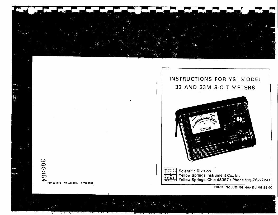
COOOCCO
ITIM02U70 P/NA03309L APRIL 198 J
INSTRUCTIONS FOR YSI MODEL33 AND 33M S-C-T METERS
Scientific DivisionYellow Springs Instrument Co., Inc.Yellow Springs, Ohio 45387 • Phone 513-767-7241
PRICE INCLUDING HANDLING $5.00
COoo
en
TABLE OF CONTENTSPage
GENERAL DESCRIPTION . . . . . . . . . . . . . . . . . . 2
SPECIFICATIONS . . . . . . . . . . . . . . . . . . . . . . . . . . 2
OPERATION PROCEDURE . . . . . . . . . . . . . . . . . . . . . . . . . . 4
1. Setup . . . . . . . . . . . . . . . . . . . . . . . . . . . . . . . . . . . . . . . . . . 4
2. Temperature . . . . . . . . . . . . . . . . . . . . . . . . . . . . . . . . . . . 53. Salinity . . . . . . . . . . . . . . . . . . . . . . . . . . . . . . . . . . . 54. Conductance . . . . . . . . . . . . . . . . . . . . . . . . . . . . 55. Error . . . . . . . . . . . . . . . . . . . . . . . . . . . . . . . . . . . . . . . . . . 6
CIRCUIT DESCRIPTION. MAINTENANCEAND CALIBRATION . . . . . . . . . . . . . . . . . . . . . . . . . . . . . . . . . 9
1 D e s c r i p t i o n . . . . . . . . . . . . . . . . . . . . . . . . . . . . . 92. Maintenance . . . . . . . . . . . . . . . . . . . . . . . . . . . . . . . . 93. Calibration . . . . . . . . . . . . . . . . . . . . . . . . . . . . . . . . 9
PROBE . . . . . . . . . . . . . . . . . . . . . . . . . . . . . . . . . . . . . . . 121. Description of YSI 3300 Conductivity/Temperature Probe 122 . Maintenance . . . . . . . . . . . . . . . . . . . 1 23 . Probe U s e . . . . . . . . . . . . - 1 44. Cell Calibration & Standard Solutions . . . . . . . 14
YSI MODEL 33 AND 33M USED WITH YSI S1A. 54 AND 57OXYGEN METERS . . . . . . . . . . . . . . . . . . . . . . . . . . 16
WARRANTY . . . . . . . . . . . . . . . . . . . . . . . . . . . . . . . . . . . . . . . . . 21
1
Ojcxxxxx3 WM/lr(i
_JWA>niT I.SV NOT! J
I- a » 5 I1 .s n<r ntf oS r>« In! o«
YSI MODEL 33 AND 33M B-03321-F
1. TM MhiM iM«m M «w MMmilU <"«Tkwii •>»«« In «M HMMmwn: » M, MUMI nkM
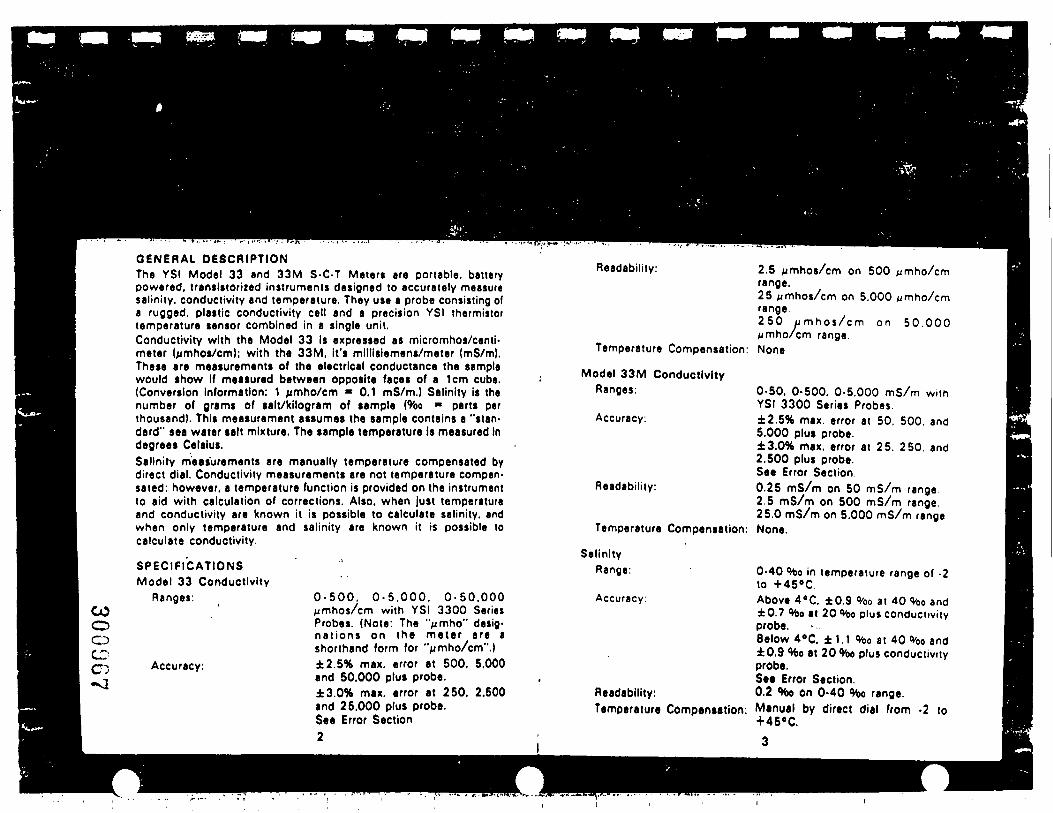
COoCDCDc:
GENERAL DESCRIPTIONThe YSI Model 33 and 33M S-C-T Meters are portable, batterypowered, transistorized instruments designed to accurately measuresalinity, conductivity and temperature. They use a probe consisting ofa rugged, plastic conductivity cell and a precision YSI thermistortemperature sensor combined in a single unit.Conductivity with the Model 33 Is expressed as micromhos/centi-meter (pmhos/cm); with the 33M, it's millisiemens/meter (mS/m).These are measurements of the electrical conductance the samplewould show If measured between opposite faces of a 1cm cube.(Conversion Information: 1 ^mho/cm « 0.1 mS/m.) Salinity is thenumber of grams of salt/kilogram of sample (%o m parts perthousand). This measurement assumes the sample contains a "stan-dard" sea water salt mixture. The sample temperature Is measured indegrees Celsius.Salinity measurements are manually temperature compensated bydirect dial. Conductivity measurements are not temperature compen-sated: however, a temperature function is provided on the instrumentto aid with calculation of corrections. Also, when just temperatureand conductivity are known it is possible to calculate salinity, andwhen only temperature and salinity are known it is possible tocalculate conductivity.
SPECIFICATIONSModel 33 Conductivity
Ranges:
Accuracy:
0-500 . 0-5.000. 0-50.000^mhos/cm with YSI 3300 SeriesProbes. (Note: The '>mho" desig-nat ions on the meter are ashorthand form for "^mho/cm".)±2.5% max. error at 500. 5,000and 50.000 plus probe.±3.0% max. error at 250. 2.500and 25.000 plus probe.See Error Section2
Readability: 2.5 /jmhos/cm on 500 nmho/cmrange.25 ^mhos/cm on 5.000 ^mho/cmrange250 umhos /cm on 50.000pmho/cm range.
Temperature Compensation: None
Model 33M ConductivityRanges:
Accuracy:
Readability:
Temperature Compensation:
SalinityRange:
0-50. 0-500. 0-5,000 mS/m withYSI 3300 Series Probes±2.5% max. error at 50, 500. and5.000 plus probe.±3.0% max. error at 25. 250. and2.500 plus probe.See Error Section0.25 mS/m on 50 mS/m range2.5 mS/m on 500 mS/m range25.0 mS/m on 5.000 mS/m rangeNone.
0-40 %o in temperature range of -2to +456C.
Accuracy: Above 4'C. ±0.9 %o at 40 %o and±0.7 %o at 20 %o plus conductivityprobe.Below 4«C. ±1.1 %o at 40 %o and±0.9 %o at 20 %o plus conductivityprobe.See Error Section.
Readability: 0.2 %o on 0-40 %o range.Temperature Compensation: Manual by direct dial from -2 to
+45«C.
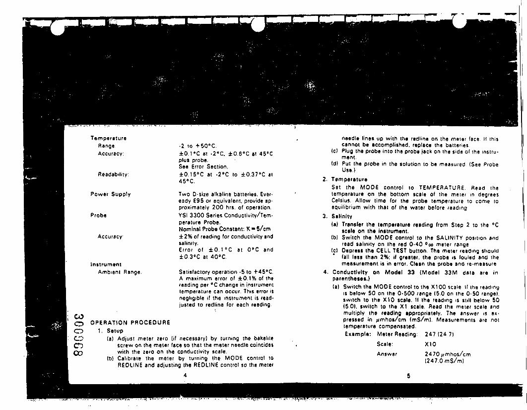
TemperatureRange:Accuracy:
Readability:
Power Supply
Probe
Accuracy:
InstrumentAmbient Range
COCDoCOCDCO
•2 to +50°C.±0.1 "C at -2°C. ±0.6°C at 45°Cplus probe.See Error Section.±0.15°C at -2°C to ±0.378C at45°C.
Two 0-size alkaline batteries. Ever-eady £95 or equivalent, provide ap-proximately 200 hrs. of operation.YSI 3300 Series Conductivity/Tem-perature Probe.Nominal Probe Constant: K « 5/cm±2% of reading for conductivity andsalinity.Error of ±0.1°C at 0°C and±0.3°C at 40°C.
Satisfactory operation -5 to +45°C.A maximum error of ±0.1% of thereading per °C change in instrumenttemperature can occur. This error isnegligible if the instrument is read-justed to redline for each reading.
OPERATION PROCEDURE1. Setup
(a) Adjust meter zero (if necessary) by turning the bakelilescrew on the meter face so that the meter needle coincideswith the zero on the conductivity scale.
(b) Calibrate the meter by turning the MODE control toREOLINE and adjusting the REDLINE control so the meter
4
needle lines up with the redline on the meter face If thiscannot be accomplished, replace the batteries
(c) Plug the probe into the probe jack on the side of the instru-ment.
(d) Put the probe in the solution to be measured (See ProbeUse.)
2. TemperatureSet the MODE control to TEMPERATURE. Read thetemperature on the bottom scale of the meter in degreesCelsius. Allow time for the probe temperature to come toequilibrium with that of the water before reading
3. Salinity(a) Transfer the temperature reading from Step 2 to the °C
scale on the instrument.(b) Switch the MODE control to the SALINITY position and
read salinity on the red 0-40 °oo meter range(c) Depress the CELL TEST button. The meter reading should
fall less than 2%: if greater, the probe is fouled and themeasurement is in error. Clean the probe and re-measure
4. Conductivity on Model 33 (Model 33M data are inparentheses.)(a) Switch the MODE control to the X100 scale K the reading
is below 50 on the 0-500 range (5.0 on the 0-50 range),switch to the X10 scale. If the reading is still below 50(5.0). switch to the XI scale. Read the meter scale andmultiply the reading appropriately. The answer is ex-pressed in //mhos/cm (mS/m). Measurements are nottemperature compensated.Example: Meter Reading: 2 4 7 ( 2 4 7 )
Scale: X10Answer 2470//mhos/cm
(247.0mS/m)
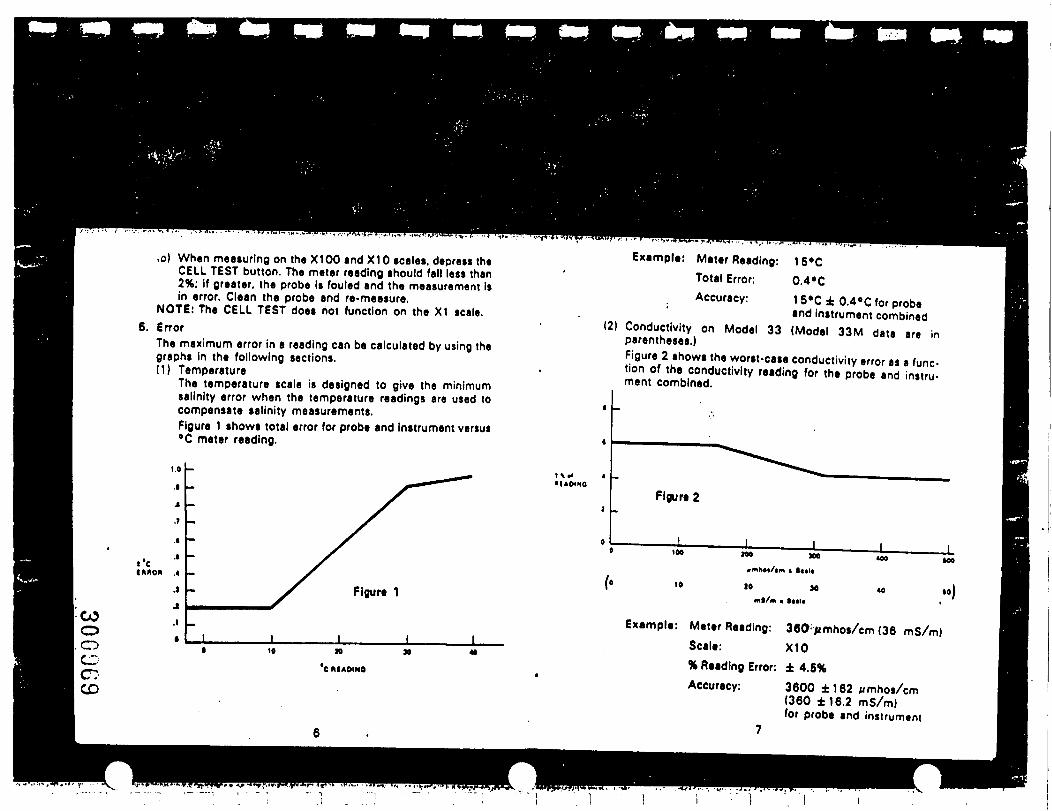
,o) When measuring on the X100 and X10 scales, depress theCELL TEST button. The meter reading should fall less than2%; if greater, the probe Is fouled and the measurement Isin error. Clean the probe and re-measure.
NOTE: The CELL TEST does not function on the XI scale.6. Error
The maximum error in a reading can be calculated by using thegraphs in the following sections.(1) Temperature
The temperature scale is designed to give the minimumsalinity error when the temperature readings are used tocompensate salinity measurements.Figure 1 shows total error for probe and instrument versus°C meter reading.
Example: Meter Reading: 1 5°CTotal Error: 0.4»C
Accuracy: 15eC ± 0.4»C for probe1 and instrument combined
(2) Conductivity on Model 33 (Model 33M data are inparentheses.)Figure 2 shows the worst-case conductivity error as a func-tion of the conductivity reading for the probe and instru-ment combined.
i'CfMOft
COo.oCDc:CD
• I ACM NOFlgure 2
Example: Meter Reading: 360 fimhos/cm (36 mS/m)Scale: X10% Reading Error: ± 4.5%Accuracy: 3600 ±162 M mhos/cm
(360 ±16.2 mS/m)for probe and instrument
7
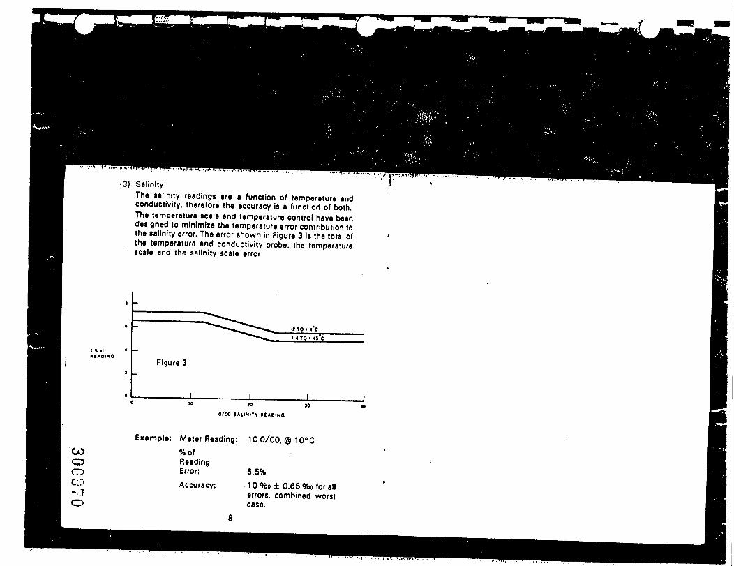
(3) SalinityThe salinity readings are a function of temperature andconductivity, therefore the accuracy is a function of both.The temperature scale and temperature control have beendesigned to minimize the temperature error contribution tothe salinity error. The error shown in Figure 3 Is the total ofthe temperature and conductivity probe, the temperaturescale and the salinity scale error.
KIAOINO
»< TO • «s'e
Figure 3
JO
0/00 I A U N I T V M A O I N O
COCDOCO
Example: Meter Reading: 100/00, © 10eC%ofReadingError:Accuracy:
6.5%• 10%o± 0.65 %o for allerrors, combined worstcase.
COooCO
CIRCUIT DESCRIPTION. MAINTENANCE AND CALIBRATION1. QescrlptlonThe circuit is composed of two parts; a multivibrator and switchingtransistors. The multivibrator produces a square waveform voltage.The square weve Is applied to two switching transistors They a l ter -nately apply two batteries of opposite polarity to the probe thusproviding AC power which minimizes polarization effects. The meteris in series with one battery and measures the current from it. Thecurrent from the battery is proportional to the conductance of the cell,Salinity is measured in a special range conductivity circuit which in-cludes a user-adjusted temperature compensator. In the temperature,redline and X1 positions the multivibrator operates at 100 Hz. In thesalinity. X100 and XI0 positions the multivibrator operates at 600 Hzand in these ranges pushing the CELL TEST button drops the frequen-cy to 100 Hz allowing the operator to judge the degree of probepolarization.2. MaintenanceThe only maintenance required is battery replacement. Two "D" sizealkaline flashlight cells, such a* Eveready E95 or equivalent, willprovide 200 hrs. of operation. Accuracy will not be maintained if zinc-carbon "D" cells are used. Battery replacement is indicated when theredline adjustment cannot be accomplished.Replace batteries every six months to reduce the danger of corrosiondue to leaky batteries. To replace batteries, remove the six screwsfrom the rear plate. The battery holders are color coded. The Positive( + button) end mutt go on red.3. Calibration of Model 33 (Model 33M data are In parentheses.)It is possible for the temperature knob to become loose or slip fromits normal position. In an emergency the dial can be re-positioned. Itmust be emphasized that this is an emergency procedure only, andthat the instrument should be returned to the factory for properrecalibration at the earliest opportunity.
9
(a) Read the temperature and conductivity of the solution. Deter-mine the salinity of the solution by running a line vertically onthe graph from this conductance value until it intersects theappropriate °C line (interpolate as required for temperaturebetween the given °C lines). From this intersection extend a
CAUIAATION CHAKT
, 10'C
(b)
(0
line horizontally to the edge of the graph. This determines thesalinity for this sample.Example: 2 5.000 j* mhos/cm and 20°C gives a salinity of 17.(Example: 2.500 mS/m and 20°C gives a salinity of 17.)Remove the °C knob, switch to SALINITY, and turn the controlshaft until the meter needle indicates the salinity value deter-mined in Step (a). In the example given, the value is 17.Switch to TEMPERATURE. (Note: This temperature readingmust be the same as Step (a); if not, begin again at Step (a).)Place the knob on the control shaft (without turning the controlshaft) with the knob pointer at the same temperature as themeter reading and tighten both set screws securely.
At earliest opportunity recalibrate using the following procedure orreturn the instrument to factory for service.
(a) Set the instrument for a salinity measurement as normal.(b) Substitute a 1000 pf capacitor and 112.7 ohm 0.1 % tolerance
resistor for the probe.Connect the resistor and capacitor between the green wire and redwire on the jack connections inside the instrument.
GREEN WIRE
RED WIREo—
112.70.1% 1000 Mf
11
COoo
CO
Ic) Turn the temperature dial until the meter reads redline.Now install the temperature knob with the arrow at 25°C This is atemporary calibration only Return the instrument to the factory lorproper recalibration
PROBE1. Description of YSI 3300 Series Conductivity/Temperature
ProbeThe YSI 3300 Series Conductivity Probes are designed for field use.embodying construction and design for rugged, accurate serviceEach probe features a built-in cell constant of 5.0 (500.0/M) ±2%. aprecision YSI thermistor temperature sensor-of ±0.1°C accuracy at0°C and ±0.3eC at 40°C and a low capacitance cable assembly ter-minating in a three therminal 0.25" dia. phone type connector.The 3310 has a 10 ft cable and the 3311 is a 50 ft. version. Otherlengths are available on special orderThe probe has a rigid P.V C body, platinized pure nickel electrodes,and a durable cable, providing resistance to a wide range of water-borne substances2. Maintenance
(»i CleaningWhen the cell test indicates low readings the probable cause is dirtyelectrodes Hard water deposits, oils and organic matter are the mostlikely contaminants.For convenient normal cleaning soak the electrodes for 5 minuteswith a locally available bathroom tile cleaning preparation such as:Dow Chemical "Bathroom Cleaner". Horizon Industries "Rally. Tile.Porcelain, and Chrome Cleaner": Johnson Wax "Envy. InstantCleaner", or Lysol Brand "Basin. Tub. Tile Cleaner."
For stronger cleaning a S minute soak in a solution made of 10 partsdistilled water. 10 parts Isopropyl alcohol and 1 part HCl can be usedAlways rinse the probe after cleaning and before storageCAUTION: Do not touch the electrodes inside the probe
Platinum black is soft and can be scraped off.If cleaning does not restore the probe performance, re-platinizing isrequired.
(b) Re-PlatinizingEquipment Required —(1) YSI #3140 Platinizing Solution. 2 ft. oz (3% platinumchloride dissolved in 0.025% lead acetate solution)(2) YSI Model 33 or 33M S-C-T Meter.(3) 50 ml glass breaker or equivalent bottle(4) Distilled water.Procedure —(1) Clean the. probe as in Section (a) — either method(2) Place the •cell in the beaker and add sufficient YSI #3140
solution to cover the electrodes. Do not cover the top ofthe probe.
(3) Plug the probe into the Model 33 or 33M. switch to theX100 scale to platinize the electrode Move the probeslightly to obtain the highest meter reading and continueplatinizing for the approximate time shown below
Mater Readingp mhos/cm mS/m
30.000 3.00025.000 2.50020.000 2.00016.000. 1.50010.000. 1.000
Time(minutes).
568
1116
12 13
! co: <=>I o
(.0
(4) Af ter the elapsed time remove the probe and rinse in freshwater.
(5) Return the solution to its container. 2 oz. of solutionshould be sufficient for 50 treatments,
(c) Storage:It is best to store conductivity cells in deionlzed water. Cellsstored in water require less frequent platinization. Any cell thathas been stored dry should be soaked in deionlzed water for24 hours before use.
3. Probe Use(a) Obstructions near the probe can disturb readings. At least two
inches of clearance must be allowed from non-metallic un-derwater objects. Metallic objects such as piers or weightsshould be kept at least 6 inches from the probe.
(b) Weights are attached to the cable of the YSI 3310 and 3311Probes. The YSI 3327 Weights are supplied in pairs with atotal weight of 4 ounces per pair. Should it become necessaryto add more weight to overcome water currents, we suggestlimiting the total weight to two pounds (8 pairs). For weightsin excess of two pounds use an independent suspensioncable. In either case, weights must be kept at least 6 inchesaway from the probe.
(c) Gentle agitation by raising and lowering the probe severaltimes during a measurement insures flow of specimen solu-tion through the probe and improves the time response of thetemperature sensor.
4. Cell Calibration & Standard SolutionsThe YSI #3300 Series Cells are calibrated to absolute accuracy of±1.5% based on a standard solution. Since the literature on conduc-tivity does not indicate a consistently accepted standardizationmethod, we have chosen the 0.01 demal KCI solution method asdetermined by Jones and Bradshaw in 1937 as our standard. Recenttextbooks, as well as the ASTM standards, concur with this choice.
14
The solution is prepared by diluting 0.745 grams of pure dry KCI withdistilled water until the solution is 1 kilogram. The table below showsthe values of conductivity this solution would have if the distilledwater were non-conductive. However, since even high purity distilledwater is slightly conductive, the measured conductivity will be higherby an amount equal to the water's conductivity.
ConductivityTemperature °C
15161718192021222324252627282930
j« mhos/cm1141.51167.5119361219.91246.41273.01299.71326.613536138081408.11436.51463.214909151871546.7
mS/m1 1421 1 6 81 194122.0124.6127.31300132 71354138 11408143.71463149 1151 9154 7
The operator may use the standard solution and the table to check ac-curacy of a cell's constant or to determine an unknown constant. Theformula is shown below:
R(C. + Ci) or R(S i
where: KR
10*Cell constantMeasured resistance in U
15
COooCO
Ci • Conductivity in ^mhos/cmCj » Conductivity in /jmhos/cm of the distilled water
used to make solution.Si * Conductivity in mS/mSi " Conductivity in mS/m of the distilled water used
to make the solution.
R. Ci and C;, or Si and Si. must either be determined at the sametemperature or corrected to the same temperature to make the equa-tion valid.Note: For further information on conductivity and the above stan-dard information, refer to ASTM Standards Part 23 — StandardMethods of Test for Electrical Conductivity, or Water and IndustrialWaste Water — ASTM Designation D1125-64.
YSI MODEL 33 AND 33M USED WITH YSI 51A. 64 and 57OXYGEN METERSIf the salinity measurement is to be used for salinity correction on the51 A. the reading should be converted to Chlorosity. The formula is:
Salinity °'oo -0.03PPM Chlorosity - ——————
1.8•x 103
For these instruments the 0.03 can be neglected so (he equationsimplifies to:
PPM ct
18 27 36 S%0
0 5.000 10.000 15,000 20,000 PPM CL
16
For salinity correction when using the Model 57 use the salinityreading direct from the Model 33 or 33M. No conversion isnecessary.Model 33 and 33M salinity readings taken in conjunction with Model54 dissolved oxygen readings can be used to correct the Model 54 forsalinity and to make post-measurement salinity corrections to dis-solved oxygen data. Correction tables are available from the factory.
WARRANTYAll YSI products carry a one-year warranty on workmanship andparts, exclusive of batteries. Damage through accident, misuse, ortampering will be repaired at a nominal charge.If you are experiencing difficulty with any YSI product, it may bereturned to an authorized YSI dealer for repair, even if the warrantyhas expired. If you need factory assistance for any reason, contact:
Service DepartmentYellow Springs Instrument Co., Inc.P.O. Box 279Yellow Springs, OhioJJ.S.A.Phone: (513) 767-7291
QUALITY ASSURANCE PROJECT PLANREMEDIAL INVESTIGATION/FEASIBILITY STUDYKENTUCKY AVENUE WELLFIELD SITEOPERABLE UNIT NO. 3
APPENDIX H
BURLINGTON ENVIRONMENTAL INC.Project: 427100Date: 10/25/93Revision: 1
APPENDIX H
STANDARD OPERATING PROCEDURESFOR RECON®
10/93/76W82A(427100)23000'

QUALITY ASSURANCE PROJECT PLANREMEDIAL INVESTIGATION/FEASIBILITY STUDYKENTUCKY AVENUE WELLFIELD SITEOPERABLE UNIT NO. 3
APPENDIX H
BURLINGTON ENVIRONMENTAL INC,Project: 427100Date: 10/25/93Revision: 1Page H-l
1.
PROJECT-SPECIFIC ADDENDATO APPENDIX H
Page 4, 8 - The syringe used is a glass syringe.
2. Page 6 - Teflon tubing will be used in the sampling train up to the sample bulb.
3. Page 10 - QA/QC procedures for this project will include the following:
• Concentrations measurements will be performed using an external standardcalibration. Known concentrations of compounds of concern [TCE; trans-1,2-dichloroethene (trans-l,2-DCE); cis-l,2-dichloroethene (cis-l,2-DCE);tetrachloroethene (PERC); and benzene, toluene, ethylbenzene, and xylenes(BTEX) ] in a calibration gas mixture will be injected into the GC. The GCwill be calibrated initially upon arrival on-site using three external standardsof known concentration of the eight compounds of concern. Calibration curvesindicating compound peak area versus standard concentration will be used tocalculate compound concentration in the sample. Subsequent to this initialthree-point calibration, calibration checks will be conducted twice daily (beforesampling in the morning and after lunch in the afternoon) using a singlestandard. This standard will be prepared at a known concentration of the eightcompounds of concern equivalent to the midpoint of the initial three-pointcalibration. A deviance of greater than 30 percent from the initial calibrationof any of the compounds will signify the need to recalibrate the instrumentusing the three-point calibration method.
• Because this is a reconnaissance technique, calibration is performed using amodified version of USEPA Method TO-1. Modifications include: 1) use ofa single point calibration curve of peak area response versus totalconcentration; and 2) glass beads are not used in the fixed-volume vial.
• For the RECON System survey, the detection limits for the compounds ofconcern are anticipated to be on the order of 1 micrograms per liter (ug/L).The detection limit is the lowest concentration of a compound that can bepracticably measured relative to the calibration standard and must bedetermined under actual analytical conditions in the field. Detection limits are
10/93/76W82A(427100)2 30GUV7
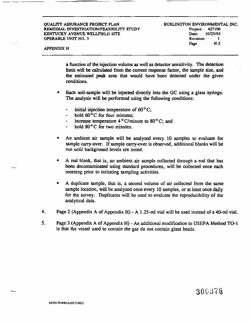
QUALITY ASSURANCE PROJECT PLANREMEDIAL INVESnOATION/FEASEBILITY STUDYKENTUCKY AVENUE WELLFIELD SITEOPERABLE UNIT NO. 3
APPENDIX H
BURLINGTON ENVIRONMENTAL INC.Project: 427100Date: 10/25/93Revision: 1Page H-2
a function of the injection volume as well as detector sensitivity. The detectionlimit will be calculated from the current response factor, the sample size, andthe estimated peak area that would have been detected under the givenconditions.
• Each soil-sample will be injected directly into the GC using a glass syringe.The analysis will be performed using the following conditions:
initial injection temperature of 60°C;hold 60 °C for four minutes;increase temperature 4 ° C/minute to 80 ° C; and
- hold 80 °C for two minutes.
• An ambient air sample will be analyzed every 10 samples to evaluate forsample carry-over. If sample carry-over is observed, additional blanks will berun until background levels are noted.
• A rod blank, that is, an ambient air sample collected through a rod that hasbeen decontaminated using standard procedures, will be collected once eachmorning prior to initiating sampling activities.
• A duplicate sample, that is, a second volume of air collected from the samesample location, will be analyzed once every 10 samples, or at least once dailyfor the survey. Duplicates will be used to evaluate the reproducibility of theanalytical data.
4. Page 2 (Appendix A of Appendix H) - A 1.25-ml vial will be used instead of a 40-ml vial.
5. Page 3 (Appendix A of Appendix H) - An additional modification to USEPA Method TO-1is that the vessel used to contain the gas do not contain glass beads.
10/93/76W82A(427100)2
Statement of Procedures
RECON® Multimedia Sampling and Testing System
February 1993
BURLINGTON ENVIRONMENTAL INC210 West Sand Bank Road
Post Office Box 330Columbia, Illinois 62236-0330
300979
STATEMENT OF PROCEDURESRECON* MULTIMEDIA SAMPLING AND TESTING SYSTEM
Burlington Environmental Inc. (Burlington) is pleased toprovide this statement of procedures describing its RECONMultimedia Sampling and Testing System.
The analysis of soil-gas, the mixture of gases within the soilabove the water table, has emerged as one of the most effectivetechniques for investigation of subsurface environmental problems.This technique is especially useful for detection of volatileorganic compounds (VOCs) in a timely and cost-effective manner.Many sampling and testing procedures require weeks and costthousands of dollars for the evaluation of a potentialcontamination problem.
With the Burlington RECON System, various media can be sampledand tested for an array of VOCs and semivolatile organic compounds(SVOCs). The analyses are performed using U.S. EnvironmentalProtection Agency (USEPA) Level II Field Screening Methods toestablish the identity and relative concentration of compoundsdetected. These tests are designed to detect the presence,potential magnitude, and extent of contaminants in the subsurface.
HOW THE BURLINGTON SYSTEM WORKS
The Burlington system is a fully self-contained mobile unit,which allows Burlington to work in remote areas far from sources ofelectricity. From the outside, the Burlington van appears veryordinary, which allows us to maintain a low profile in sensitiveareas.
After a careful evaluation of site conditions, Burlingtontechnicians select a sample location and hydraulically drive aprobe to the desired sampling depth. By delivering more than15,000 pounds of downward force, the hydraulic unit can drive aprobe up to 35 feet deep and can drill through as much as 30 inchesof concrete or asphalt at the surface.
02/93/995411/RECOKEPO.KEP/2
3GGUSO
Burlington technicians collect soil-gas, groundwater, freeproduct, or soil samples and use a laboratory-grade gaschromatograph (GC) mounted in the RECON van for analysis. With theappropriate detectors and columns, the GC can measure and analyzeVOCs and SVOCs, including:
volatile priority pollutants, includingtrichloroethylene, dichloroethylene, andtetrachloroethylene;
• petroleum hydrocarbons, including benzene, toluene,ethylbenzene, and xylenes (BTEX);
industrial solvents, including acetone, methylethyl ketone, and tetrahydrofuran;
• polychlorinated biphenyls, including Aroclor 1016and Aroclor 1260; and
pesticides and herbicides, including DOT, dieldrin,and atrazine.
: Within minutes, the RECON System's computing integrator plotsa chromatogram showing the concentration of calibrated compoundsdetected in the sample. The Burlington analytical technicianreviews the chromatogram and verifies the compounds detected.
The intermediate Level II analysis methods introduced by theUSEPA are used to reduce on-site analysis time, reduce the highcost of laboratory analysis, and provide more efficient use ofpersonnel and equipment. Level II methods, with appropriatequality control, and confirmatory laboratory results for improvingdata validation can, in some cases, replace the laboratoryanalytical methods, depending on how the data is to be used.
Because the RECON System provides analytical results inminutes, timely decisions can be made in the field regarding thenumber of samples to collect and the locations of these samples.In many cases, better technical information about a site oftenresults in fewer sample analyses than originally anticipated. Thissaves time and money without compromising technical quality.
02/93/9944 1 l/RF.COREI'O.KCP/2
300081
Depending on the complexity of the site and the media tested,the RECON System can be used to sample and analyze compounds at 10to 25 locations per day.
Operators of the RECON System are fully trained in theoperation of this equipment and instrumentation and have extensivebackgrounds in the environmental field investigations using avariety of techniques.
RECON SYSTEM APPLICATIONS
The Burlington RECON System is sophisticated and versatile.The system can be used for a variety of investigative purposes,including:
identifying contaminant sources;
• defining contaminant plumes;
• measuring product thickness in groundwater;
• preparing vertical profiles of contamination insoil;
monitoring landfills for accumulations of soil-gas;
testing for leaks from underground storage tanks(USTs);
identifying potential hazards during siteassessments and environmental audits; and
screening for contamination prior to drilling andwell installation.
The following sections describe various sampling and analysisprocedures.
SOIL-GAS SAMPLING AND ANALYSIS PROCEDURES
If soil-gas sampling is desired, Burlington will perform thesubsurface investigation of areas of contamination by collecting
02/93/995411/RECORCHO.REP/2
30GJS2
and analyzing soil-gas samples with Burlington's RECON MultimediaSampling System.
Soil-gas samples will be obtained by inserting a 1.0-inch O.D.steel probe to a predetermined depth. The in situ vapor samplewill be withdrawn through the probe, and captured in an air-tightgas sampling bulb. Costs can be included for backfilling orgrouting the probe holes and for patching concrete or asphaltholes.
For a standard soil-gas investigation, a vertical profile ata single probe hole location will be performed to identify theappropriate depth where samples can be collected to obtain optimumresults. Additional vertical profiling, increases project costs andduration because of the increased number of sample analysesperformed in the field.
After sample collection using the probe, the sampling bulbwill be marked for identification and removed from the samplingsystem. A portion of the soil-gas sample will be-' withdrawn fromthe sampling bulb with a gas-tight syringe and injected into the GCfor analysis. All of the soil-gas samples collected will beanalyzed with a GC fitted with a flame-ionization detector (FID)and a VOC capillary column. In addition, samples will be analyzedusing USEPA Level II Field Screening Methods for dynamic soil-gastesting. The intermediate Level II Methods provide screening datato establish the identity and relative concentration of compoundsdetected. The results of the analysis will be automaticallyrecorded in the computer, which is directly linked to the GC. Theanalytical data will be stored and available for on-site recall.
Quality assurance/quality control (QA/QC) guidelines will bemaintained so the data collected from this survey are accurate andreliable. Field QC samples will be collected during each day offield activity. These QC samples will consist of duplicate samplesof in situ soil-gas, chromatographic equipment blank samples,equipment blanks obtained from regularly decontaminated sampleprobes and bulbs, ambient air samples, and calibration standards.
02/93/99S411/RCCOHEPO.MKP/?
300983
Prior to use in sample collection, all sampling equipment,probe rods, and sample bulbs will be decontaminated by pressurewashing and purging. Pressure cleaning and detergent washing willbe used to decontaminate all tools and equipment. If thisdecontamination procedure is unsuccessful, alternativedecontamination methods or equipment replacement costs can beestimated.
The soil-gas survey data will be presented in a final reportsummarizing the sampling and analysis of target compound vapors inthe vadose zone. The presence of detectable levels of targetcompounds is dependent upon several factors, including thepermeability of soils, the depth to groundwater, and whethersufficient concentrations of target compounds are present in theaqueous phase to facilitate volatilization into the vadose zone.If for any reason a soil—gas survey is deemed unfeasible, theclient will be advised immediately and will be billed only forservices and expenses actually incurred.
GROUNDWATER SAMPLING AND ANALYSIS PROCEDURES
If groundwater sampling is desired, Burlington will performthe subsurface investigation of areas of contamination bycollecting and analyzing groundwater samples with Burlington'sRECON Multimedia Sampling System.
Groundwater sampling using the Burlington RECON System is amethod for rapidly screening an area for approximate levels ofcontamination. Data collected by this method should not beconsidered a replacement for more accurate measurements that can beobtained using monitoring wells.
Groundwater grab samples will be obtained by inserting a1.0-inch O.D. steel probe to a depth that will intercept thegroundwater table. Samples will be collected by one of two methodsfor groundwater grab sampling with the hydraulic probe unit. Themethod used will depend on several factors, including
02/93/99S4 1 l/RECOREPO.Hr.P/2
300984
decontamination requirements, efficient use of time and materials,analytical requirements, and the depth to groundwater. Samples canbe collected by pump or ball-check valve tubing bailer. If a pumpis used, either a peristaltic or vacuum pump will be used to drawthe sample to the surface through polyethylene tubing. Samplesrequired to be collected by the ball-check valve method will bedrawn to the surface through polyethylene tubing. Costs can beincluded for backfilling or grouting the probe holes and forpatching concrete or asphalt holes.
The groundwater samples will be collected in glass vials andanalyzed on site by Burlington. Samples will be analyzed with alaboratory-grade GC using a FID and field modifications to USEPASW-846 Method 8010/8020. The modifications include the use of anFID in the GC, a VOC capillary column, static headspace analysis,and a single-point calibration standard. The field modificationsprovide for intermediate USEPA Level II screening data, decreasedsample analysis times, and greater on'-site efficiency.
The sample will be placed into a glass vial fitted with, aseptum cap. An inorganic salt will be added to the vial, the vialshaken, and then heated. This procedure partitions the VOCsbetween the sample and headspace.in the vial. A sample aliquotwill be removed from the vial with a gas-tight syringe and injecteddirectly into the GC.
QA/QC guidelines will be maintained so the data collected fromthis survey are accurate and reliable. Field QC samples will becollected during each day of field activity. These QC samples willconsist of duplicate samples of in situ groundwater,chromatographic equipment blank samples, reagent blanks, andcalibration standards.
Prior to use in sample collection, all sampling equipment andprobe rods will be decontaminated by pressure washing and purging.Pressure cleaning and detergent washing will be used todecontaminate all tools and equipment. If this decontamination
OZ/93/99S«I1/RECOREPO.HEP/2
300935

procedure is unsuccessful, alternative decontamination methods orequipment replacement costs can be estimated.
The groundwater survey data will be presented in a finalreport summarizing the sampling and analysis of target compoundvapors in theigroundwater. The presence of detectable levels oftarget compounds is dependent upon several factors, including thepermeability of soils, the depth to groundwater, and whethersufficient concentrations of target compounds are present in theaqueous phase to facilitate volatilization. If for any reason asurvey is deemed unfeasible, the client will be advised immediatelyand will be billed only for services and expenses actuallyincurred.
SUBSURFACE SOIL SAMPLING AND ANALYSIS PROCEDURES
If soil sampling is" desired, Burlington will perform thesubsurface investigation of areas of contamination by collectingand analyzing soil samples with Burlington's RECON MultimediaSampling System.
Subsurface soil samples will be obtained by inserting a1.0-inch O.D. steel probe equipped with a retractable drive-pointsampler to the desired sampling depth. The sampling depth will bedetermined on site. The sampler will be advanced a minimum of24 inches beyond the desired initial sampling depth to push soilinto the sampling tube containing a single-use acetate liner. Fordense clays and tills, a retractable drive-point split-spoonsampler can be used. Costs can be included for backfilling orgrouting the test locations and for patching concrete or asphaltholes.
Samples will be collected in jars and analyzed on site byBurlington. Samples will be analyzed with a laboratory-grade GCusing a FID and field modifications to USEPA SW-846 Method8010/8020. The field modifications include the use of a FID, avolatile organic capillary column, static headspace analysis, and
02/93/99541 I/RECOREPO.REP/2
8
a single-point calibration standard. The field modificationsprovide for intermediate USEPA Level II screening data, decreasedsample analysis times, and greater on-site efficiency.
The sample will be placed into a headspace vial fitted with aseptum cap. An inorganic salt saturated solution will be added tothe vial, and the vial shaken to disperse the soil. This procedurepartitions the volatile compounds between the saturated solutionand headspace in the vial. A sample aliquot will be removed fromthe vial with a gas-tight syringe and injected directly into theGC.
QA/QC guidelines will be maintained so the data collected fromthis survey are accurate and reliable. Field QC samples will becollected during each day of field activity. These QC samples willconsist of duplicate samples of soil, chromatographic equipmentblank samples, reagent blanks, and calibration standards.
Prior to use in sample collection, all sampling equipment andprobe rods will be decontaminated by pressure washing and purging.Pressure cleaning and detergent washing will be used todecontaminate all tools and equipment. If this decontaminationprocedure is unsuccessful, alternative decontamination methods orequipment replacement costs can be estimated.
The data will be presented in a final report summarizingsampling and analysis of target compounds in the soil. Thepresence of detectable concentrations of target compounds isdependent upon several factors, including the permeability ofsoils, the depth to groundwater, and whether sufficientconcentrations of target compounds are present in the aqueous phaseto facilitate volatilization. If for any reason a survey is deemedunfeasible, the client will be advised immediately and will bebilled only for services and expenses actually incurred.
•: s ''• 702/93/99S«ll/RECOKEPO.REP/2 '-* I I \ ! «J *
PIEZOMETER INSTALLATION PROCEDURES
If piezometers are required, Burlington will installpiezometers with Burlington's RECON Multimedia Sampling System.
Piezometers will consist of threaded one-inch-diameter polyvinyl chloride (PVC) 0.01-inch slotted screen and riser pipe.
A hydraulic probe driving unit will be used to drivepiezometer assemblies consisting of three-foot lengths of 1.0-inch-diameter threaded steel inner rods and the PVC piezometer sections.The hydraulic probe unit will also be used to withdraw the innerrods. A hydraulic hammer will be used to assist .in driving theassemblies through unusually hard soil. Piezometers will beinstalled by pushing piezometer sections simultaneously with theinner rods. The inner rods will be withdrawn after the piezometershave been set to the desired depth.
Piezometers should not be considered a replacement formonitoring wells. The use of piezometers is a rapid method toevaluate product thickness and groundwater gradients. Groundwatersampling with piezometers is a method to rapidly screen an area forapproximate levels of contamination. Data collected by this methodshould not be considered a replacement for more accuratemeasurements that can be obtained using monitoring wells.
PROJECT SITE
Site conditions are expected to permit the work to beperformed utilizing a two-wheel-drive van. Provisions for roadbuilding or towing the van normally are not included in proposals.
Sampling can be scheduled in concrete-paved areas. If testlocations in driveways, sidewalks, and buildings are necessary, anattempt will be made to advance the hole a maximum of 30 inchesthrough the concrete at no extra charge.
Our personnel will comply with Burlington and the client'shealth and safety requirements on site. Air-purifying respirators
02/93/99S411/RECOREPO.REP/2 30GUG8

10
will be used if personnel exposures could exceed the OccupationalSafety and Health Administration (OSHA) permissible exposure limitsspecified in 29 CFR 1910.1000 (revised January 19, 1989). AllBurlington employees assigned to the project will have been trainedto use air-purifying respirators in accordance with OSHAregulations, will have passed a respirator fit test, and will beparticipating in a medical monitoring program. Respirators anddisposable personal protective clothing (Level C or B) will beavailable, if necessary.
At the project location, the client will provide all utilityclearances prior to investigation efforts. Availability of anon-site water source (10 gallons per minute) and an on-sitelocation for decontamination of RECON equipment will be theresponsibility of the client.
QUALITY CONTROL
QC is an essential part of an analytical test methodology. QCprocedures increase the confidence in the analytical results andare used to evaluate the reproducibility of the data.
The GC used to analyze samples will be calibrated using aknown concentration of each of the target compounds of interest atthe beginning of the day before analysis of any samples. The USEPArecommends instrument calibration be performed at least once every12 hours. The calibration helps to evaluate the operatingconditions of the GC. In addition, a calibration check standardwill be analyzed after every 10 samples analyzed. The checkstandard ensures accurate quantitation.
A chromatographic system blank will be analyzed at thebeginning of the survey day, prior to calibration and every 10samples as a means of indicating that sample carryover has notoccurred. If sample carryover has occurred, the concentrationdetected in the system blank can be subtracted from any of thesubsequent samples containing that compound. A probe rod blank
O?/93/99S411/RECOHtPO.RCP/2
11will be analyzed prior to soil-gas sample collection to ensure thatrods are free of contamination. In addition, a reagent blank ofinorganic salt, used with groundwater and soil analysispreparation, will be analyzed to ensure that the reagent is free ofcontamination.
A duplicate sample, which is a second volume of soil-gas,groundwater, or soil collected from the same sample location, willbe analyzed once every 10 samples, or at least once daily for eachsurvey. Burlington's standard operating procedure (SOP) foranalyzing samples using a USEPA Level II Field Screening method forVOC's is in Appendix A.
HEALTH AND SAFETY GUIDELINES
Burlington's general Health and Safety SOP for RECONinvestigations is in Appendix B. Procedures for working in othersite conditions, employee requirements, and chemical safetyprotocol are outlined in additional site-specific SOPs.
02/93/99S« 1 1 /RECOREPO. «El'/2
30GUSO
APPENDIX A
RECON* System
Volatile Organic Compound AnalysisUSEPA Level II Field Screening Method
(Static Headspace)
OZ/93/995411/RECOREPO. REP/2 300
BURLINGTON ENVIRONMENTAL
RECON* SYSTEM
VOLATILE ORGANIC COMPOUND ANALYSISDSEPA LEVEL II FIELD SCREENING METHOD
(STATIC HEADSPACE)
Scope and Application
This method is for the evaluation of volatile organiccompounds in soil-gas, groundwater, and soil.
Method
Headspace-gas chromatography using megabore capillary columns,flame-ionization detection (FID), and photo-ionization detection(PID).
Reference
"EPA Test Methods for Evaluating Solid Waste," SW-846 Methods3810, 8010, and 8020 with modifications
"Field Screening Methods Catalog User's Guide", EPA/540/2-88/005, FM-9, FM-14, FM-16, September 1988
Lower Quantifiable Limits (LQL)
Headspace 1.0-10.0 micrograms per liter (p.g/L) or less(compound specific)
Sample Handling
Water and soil samples are to be collected in 40-milliliter(mL) vials with open screw-caps and Teflon-faced silicon septa.Water samples should be collected so that no headspace remains inthe bottle. Soil-gas samples are to be collected in 250-mL glassbulbs. Sample should be collected in a manner to ensure thecomplete purging of the bulb. All samples should be protected fromsunlight and transported to the field laboratory as soon aspossible. Water samples will be held on ice prior to analysis.
12/92/CHARLENE/GENERIC/VOCMET.PRO
Reagents and Apparatus
1. Open screw cap 40-mL vial (I-CHEM). Detergent washed,distilled water rinsed and dried at 105°C before use.
2. Septum - Teflon-faced silicon (I-CHEM). Detergent washed,distilled water rinsed and dried at 105°C before use.
3. 250-mL gas sampling bulbs (Teflon stop-cocks and septuminlet).
4. Gas chromatograph - Hewlett-Packard (HP) Model 5890A equippedwith an FID.
5. Computing integrator HP Model 3396 A/B and dual-disk drivestorage device.
6. Column 1 - J&W DB-624/0.53mm i.d. capillary column, 30 meter,3.0-micron phase - volatile organic compounds.
7. Syringes - Assorted glass gas-tight microliter syringes andliquid syringes (10-1000 uL.volumes).
8. Balance - ± 0.0001 grams (g) - Sartorious Analytical Balance(not on board RECON System Van) .
9. Reagent water - organic free water -or distilled-deionizedwater that has been shown to be organic-free at the methoddetection limit.
10. Constant temperature heat block - 70°C (capable of ± 0.5°Ctemperature control).
11. Volumetric flasks - assorted.
12. Pipettes - assorted.
13. GC operating materials and supplies as described below under"Chroraatographic Conditions".
Calibration Standard Preparation
1. Stock standard solutions: Prepare a VOC standard at 2,500micrograms per milliliter (ng/mL) in methanol.
a. Add about 30 mL of methanol to a 50-mL volumetric flask.Allow the flask to stand unstoppered until the methanolon the neck of the flask has dried.
12/92/CHARLENE/GENERIC/VOCMET.PRO
30GU93
b. Tare the flask on the analytical balance.
c. Using a lOO-jlL syringe, add 0.125 g (correct for percentpurity) of the reference material to the flask. Makesure the drops fall directly into the methanol withoutcontacting the neck of the flask.
d. Determine the mass of reference material added. Rinsethe syringe with methanol, tare the flask, and add thenext standard.
e. After all the reference materials are added, fill tovolume with methanol, cap, and invert to mix.
f. Transfer stock standard solution to 40-mL VGA vials, cap,and store in a cool, -dark location.
Calibration - Vapor Standard - Single Point Calibration Procedure
1. Prepare a vapor standard using a nonapproved modification toUSEPA Method TO—1, calibration standard preparation using astatic dilution bottle technique. Add appropriate amount ofstock - standard, to a known volume vessel, fitted with aMininert® valve and heat to 70°C (at ± 0.5°C) . Inject aliquotdirectly into the gas chromatograph.
2. Use a single-point standard curve of peak area response versustotal concentration injected for each of the compounds ofinterest.
3. A continuing calibration check is performed after each set of10 samples. If the response for any of the compounds variesfrom the expected response by more than ±20 percent, a newstandard curve should be prepared to account for changes inanalytical conditions.
Sample Analysis
Soil-Gas Samples:
1. Soil gas samples are received in 250-mL glass bulbs. Whenreceived, they are allowed to equilibrate to the ambient airtemperature.
2. Remove an aliquot of the sample and inject directly into thegas chromatograph.
12/92/CHARLENE/GENERIC/VOCMET.PRO
30GU94
3. If any compound of interest is outside the calibration curveand an accurate concentration is required, a smaller aliquotis taken from the same sample bulb.
Water Samples:
1. Water samples are received in 40-mL VOA vials. Uncap andremove a 10-mL aliquot of the sample from the vial. Dispensethe sample into a headspace vial.
2. The vials are placed in a 70°C aluminum heat block and heatedfor 10 minutes.
3. Remove an aliquot of headspace and inject directly into thegas chroraatograph.
4. If any compound of interest is outside the calibration curveand an accurate concentration is required, a smaller samplevolume is injected into the instrument and the analysisrepeated.
Soil Samples:
1. Soil samples are received in 40-mL VOA vials. A 10-gramquantity of soil is placed in a clean VOA vial. •
2. Add 10-mL of a inorganic salt saturated solution to the vial.
3. Shake the vial vigorously to disperse the soil.
4. Place the vial in a 70°C heat block and heat for ten minutes.
5. Remove an aliquot of headspace and inject directly into thegas chromatograph.
6. If any compound of interest is outside the calibration curveand an accurate concentration is required, a smaller samplevolume is injected into the instrument and the analysisrepeated.
Chromatographic Conditions:
Column: 30-meter J&W DB-624 Volatile Organic CompoundColumn, 0.53 mm i.d./3.0-micron phase
Carrier Gas: Hydrogen - Ultra High Purity Grade 8 raL/min
12/92/CHARLENE/GENERIC/VOCMET.PRO
300D35
Detector: Flame-ionization detector (FID)Photo-ionization detector (PID Optional)Detector Temperature:Hydrogen Flow:Zero Air Flow:Nitrogen Make-up Gas:Hydrogen Carrier flow:
Injector Temperature:
Oven TemperatureProfile: Initial:
Rate:Final
300°C35 mL/min450 mL/min20-25 mL/min8 mL/min
200°C
45°C - 3.5 min.5°C/min.110°C - 0.5 min.
Conditions listed can be varied as needed for changingapplications.
Analytical Calculations
All calculations will be automatically performed by thecomputerized integrator.
1. Review the chromatograms and data reports for analysis. Checkfor gross errors such as incomplete data reports because offaulty integration.
2. Prepare external standard calibration curves for each compoundusing a single point calibration curve. Calculate the lowerquantifiable limit (LQL) for each target compound.
3. Calculate the concentration found in the samples from thecalibration curves using the following equation:
ug/L •= Area Comp x RF Target x DF
in which:
DFRFArea Comp
Dilution FactorResponse Factor (Target Compound)Area of compound in sample.
12/92/CHARLENE/GENERIC/VOCMET.PRO
300U36
Data Reporting
1. All results, chromatographic parameters, analytical results,sampling locations, and notes" will be recorded in daily GCfield worksheets.
2. All data generated by the field GC will be considered astentatively identified, with concentrations being estimated.
3. All raw field data will be forwarded to the Burlington officefor final review and QA/QC prior to final reporting.
Quality Control
1. Each daily analytical run should begin with a GC system blankand a headspace standard calibration. Calibration checkstandards should be analyzed every 10 samples. Continuingcalibration standards should be within 20 percent of theoriginal standards or a new standard curve should be.preparedand samples analyzed since the last check standard reanalyzed.
2. A minimum of 10 percent duplicate samples should be analyzedor a. minimum of one per day. Duplicates should be within±25 percent.
3. Gas chromatograph sample blanks will be analyzed at least oneevery 10 samples, or a minimum of one per day.
4. New stock standards should be prepared monthly in thelaboratory. New working standards should be prepared daily.
Quality Assurance
Quality assurance (QA) is performed by the QA coordinator toevaluate and verify field chromatographic measurements. Thisverification includes, but is not limited to, data precision,accuracy, detectability,and other miscellaneous quantitative andqualitative parameters.
QA is performed by implementing the following procedures.
1. Review all raw data sheets, chromatograms, and field samplingand analysis worksheets.
2. Note chrcmatographic abnormalities.
12/92/CHAKLENE/GENERIC/VOCMET.PRO
3. Correlate sample identification, injection volumes,anddilution multipliers on worksheets and chromatograms.
4. Tentatively identified target compounds are reviewed andreverse response factor evaluation performed to detectquantitation errors due to the computing integrator, manualcalculations, or incorrect calibration parameters.
5. Raw data, including worksheets, chromatograms, and reports arearchived.
6. A QA review sheet is completed and utilized in-house to assistin improving future analytical data quality.
Corrective action by the QA coordinator will include notingmissing or inconsistent data on respective data summary sheets andchromatograms, documenting changes and corrections to data, andproviding brief written documentation regarding changes andcorrections.
12/92/CHARLENE/GENERIC/VOCMET.PRO
30GJ38
APPENDIX B
Health and Safety Standard Operating Procedure
02/93/9954 11/RCCOREPO. REP/2 300DS9

HEALTH AND SAFETY OPERATING PROCEDURES
General Safety Rules for Environmental SamplingWith the RECON* Multimedia Sampling System "
Procedure No.:Date Issued:Approved By:Page 1 of 20
HtS 50802/05/91
Rev . :0
PURPOSE This procedure describes general precautions to be takenand good practices to be followed when performingenvironmental sampling using the RECON* MultimediaSampling System of the soil—gas van. This procedurealso specifies the minimum chemical hazard protectionprotocols required for field activities if site-specificchemical hazards have not been addressed in a morespecific project health and safety (HtS) guidancedocument.
REFERENCES Occupational Safety and Health Guidance Manual forHazardous Haste Site Activities
Department of ..-Transportation (DOT) driver safetyregulations
HtS Procedure 121 - Health and Safety Review of NewProjects
HtS Procedure 131 — Incident Reporting
HtS Procedure 301 - Minimum Health and SafetyRequirements
HtS Procedure 341 — Electrical Safety Practices/BuriedUtilities
HtS Procedure. SOS — General Safety Rules for- Work * on.Hazardous Haste Sites Documents
Geoprobe System's 8-M Operations Manual-
EQOIPMSKT Hard Bat (for OverheadHazards)
Hearing ProtectionSafety Belt (Vehicle)
Safety GlassesSteel-Toe Shoes.Work GlovesCPC (as needed)
FORMS Completed hazardous materials shipping manifest fortransport of GC supply compressed gases.
RESPONSIBILITIES Department Manager, Project Managers, Site Supervisors,the HtS Department, and Sampling Technicians haveresponsibilities to implement this procedure as listedbelow.
Department Manager:
1. Assign only technically qualified personnel toperfoxr* a task.
2. Provide training and supervision such that theemployee demonstrates adequate qualifications.
1O/9Z/»»OH/DMH/SO8.SOP/I
301000
Procedure No.: HiS 508 BURLINGTON ENVIRONMENTAL INC.Date Issued: 02/05/91Page 2 of 20 Rev.: 0 General Safety Rules for Environmental Sampling
Hith the RECON® Multimedia Sampling System
3. Where applicable, provide adequate personalprotective and safety backup equipment foremployee activities.
4. Conduct periodic audits to determine if theapplicable HiS procedures are being followed.
5. Refer technical questions concerning HiS issuesto the HtS Department.
Project Manager:
1. Consult the HtS- Department for project-specificguidance on safety matters for activities on yourjob sites.
2.-. Provide appropriate HiS precautions for projectuse in accordance with the project—specific HiSguidance documents that apply.
3. ' Contact the HfiS Department in the event. thatfield conditions change such that additionalrequirements may be necessary.
4. . Provide JEor -subsurface - utility clearances' forproject sites.
Site Supervisor/Senior- Sampling- Technician;
1. Implement: project H&S requirements in accordancewith 1-*"? procedure- and -other applicable
• ' procedures including, but not limited to, -a site-specific HiS plan and the client's facilitysafety program, if provided.
2. Provide and document project-specific trainingsessions. These training sessions should includea review- of the requirements of this procedurewith all field employees involved.
3. Verify subsurface utility clearances prior tosubsurface penetration with the Geoprobe drivepoints.
4. Provide for appropriate environmental hazardmonitoring and emergency response support foryour site activities.
5. Consult the H&S Department, as needed, forsupport for your field operations.
€. Strictly enforce on-site compliance with thisprocedure and other applicable site-specific HiSguidelines by persons in your charge.
10/92/S90H/OMH/SCW.SQP/2
301001
HEALTH AND SAFETY OPERATING PROCEDURES Procedure No.: HtS 508Date Issued: 02/05/91
General Safety Rules for Environmental Sampling Page 3 of 20 Rev.; 0With the RECON* Multimedia Sampling System
HAS Department:
1. Upon request, perform a project-specific hazardevaluation. Prepare a site—specific HCS plan toincorporate the elements of this procedure, ifnecessary.
2. Provide technical assistance to project personnelimplement ing this procedure.
3. Update this• procedure periodically to includecurrent industry practices to minimize thepotential for exposure to hazardous environments.
Samplino; Technicians;
1. Perform sampling operations in a safe manner,using- good judgment at all times. Refrain fromany activity, that Blight endanger yourself, fellowworkers, or the general public.
2. • Report any observed unsafe condition or act in atimely manner.
3. Report changed or unanticipated field conditionsbefore continuing the field operation.
4. Report safety incidents and injuries inaccordance - with HCS Procedure 131 — Incident
- • • Reporting.
5. Report roadway accidents -on- your field vehicles •to your Department Manager.
6. Abide by the HCS requirements set forth in thisprocedure and other applicable HCS procedures.
7.- Consult with your Department Manager when HCSquestions arise.
DISCUSSION Field activities involving the Burlington EnvironmentalInc. (Burlington) REOOM Multimedia g»«pHnj Systeminvolve a wide range of site conditions and safetyhazards. REOON activities are commonly conducted onchemically, impacted sites, some of which are coveredunder Occupational Safety and Health Administration(OSH&) Hazardous Haste Site Regulations 29 CFRPart 1910.120.
Numerous hazards are associated with field investigationof chemically contaminated sites. Chemical hazardsinclude toxic effects to workers, as well as hazardsfrom encounter of flammable liquids or vapors. Hazardsfrom sampling eqaipnent, personnel protection practices.
1O/92/9SOH/DMH/S08.SOP/1
301002
Procedure No.: HIS 508 BURLINGTON ENVIRONMENTAL INC.Date Issued: 02/05/91Page 4 of 20 Rev.: 0 General Safety Rules for Environmental Sampling
With the RECOJ*» Multimedia Sampling System
extreme weather conditions, and industrial operations ona client's active facility can cause physical injuriesand thermal stress to workers.
Exposure of workers to chemical products are likely tobe from direct dermal contact with free products orinhalation of organic vapors released during handling ofgrossly contaminated sampled materials . In general, thechemical contaminants -present relatively low inhalationand limited dermal exposure hazards. Samplingtechnicians are likely to be at greater risk fromexposure to ambient levels of contaminants on certainsites than from the chemical hazards generated by theirown activities.
Physical hazards to workers include physical injuriesfrom operating RECON sampling equipment, possibly.thermal stress from wearing chemically protectiveclothing or being exposed to inclement weather, or both.Physical injuries can occur from operation or failure ofRECON system equipment . hydraulics, handling . ofpressurized gas supply cylinders • for . the on-boardanalytical GC, and .any manual .labor needed to supportthe field operation. However,- the greatest potentialphysical hazard will .be accidental 'penetration intopressurized 'chemical- process piping or other "JJLve*1buried utilities with the hydraulic-driven • samplingprobes.
In general, the nature of the RECON equipment andsampling procedures tends to limit • most potentialhazards for sampling/analytical technicians because:
1. The equipment is relatively ««»n andlightweight.
2. . Quantities of chemically contaminated materialshandled is small.
3. Subsequent chemical exposure of personnel is
However, site-specific chemical hazards and project-specific HtS requirements must be evaluated on a case—by-case basis.
PROCEDURE Implement the following procedure:
Sampling technicians operating the RECON Systemequipment must be adequately trained for theprojects they are assigned to.
lO/*?/**M/n«/SM. sop/2
301003
HEALTH AND SAFET* OPERATING PROCEDURES Procedure No.: HtS 508Date Issued: 02/05/91
General Safety Rules for Environmental Sampling Page 5 of 20 Rev.: 0With the RECON* Multimedia Sampling System
1.1 Sampling personnel must meet the minimumtraining prequalif ication requirements forproject field personnel performingactivities on the subject job site.
1.2 Sampling personnel must be provided thesite-specific training required for theirtasks on site. This training will beperformed and documented by Burlingtonsafety management representative assignedthis responsibility for the project. Thistraining may be provided by:
the Project Safety Officer;
the Site Safety Officer (if alarge Burlington operation);
the Site Supervisor, if alsoacting .as the Site SafetyOfficer; or
• the senior technician of theRECON sampling team.
MOTE: The senior sampling technician is the taskleader 'and on-site -safety representativefor the RECON sampling field team. If- noother on-site Burlington Manager has directline authority over the .RECON samplingactivities, the senior sampling technicianmost also assume roles and responsibilitiesof the Site Supervisor/Acting Site SafetyOfficer for the RECON field operation.
-1*3 As a minimum, the y»y*i<«ij «-<w*n< ft »««« willbe provided a site- safety orientation todiscuss project safety organization,applicable guidance documents, site-specific harards, topical safety protocols,and emergency preparedness measures.
1.4 The Project Manager must specify theproject-specific training requirements forSampling
2. Sampling t-«»rf»n-f <•»< »ny must be medically qualifiedfor the projects they are assigned to.
2.1 Sampling personnel must meet the medicalcertification requirements for projectfield personnel performing activities onthe subject job site.
1O/92/990H/DMH/S08.SOP/1
301004
Procedure No.: HtS 508 BURLINGTON ENVIRONMENTAL INC.Date Issued: 02/05/91Page 6 of 20 Rev.: 0 General Safety Rules for Environmental Sampling
With the RECONO Multimedia Sampling System
2.2 Medical certification requirements mayinclude :
fitness to wear a respirator;
• active participation inB u r l i n g t o n ' s m e d i c a lsurveillance program forhazardous waste site work; and
site-specific medical screeningor monitoring.
2.3 The Project Manager must specify theproject— specific medical qualification/monitoring requirements for sampling
3 . Access to the work zone should be restricted toauthorized personnel only.
3.1 Access to the immediate vicinity .of RECONsystem sampling activities will be limited.
• to only those project personnel, including-subcontractors, who have reason to-be inthe area. Burlington will not attempt toenforce access restrictions, but willsummon facility security personnel, ifavailable, or local law enforcementofficers Immediately. Burlington will notassume any responsibility -for theactivities or safety of intruders into ourwork zone.
3.2 Access into known (or suspected) • chemical.hazard areas by Burlington personnel willbe limited to personnel meeting OSHArequirements for training,•onitoring, and respirator fit test
3.3 Non-Burlington personnel shall be cautionedagainst entry into a Burlington work zonejudged to be a chemical hazard area. Ifthey intrude despite the caution, shut downthe operation and summon security.
4 . The following minimum safety equipment shall beprovided in the RECON System vehicle:
five-pound, ABC-rated fireextinguisher;
urgency eyewash (potablewater, minimum);
10/92/990M/OMH/S08 . SOP/2
301005
HEALTH AND SAFETY OPERATING PROCEDURES Procedure No. : HtS 508Date Issued: 02/05/91
General Safety Rules for Environmental Sampling Page 7 of 20 Rev.: 0With the RECON® Multimedia Sampling System
Note: Hay use existing eyewash of client'sfacility.
first aid kit; and
prepackaged, moistenedsanitizing "wet" wipes, such asbaby wipes (minimum on— sitewash capacity, for usefollowing removal of splashprotection clothing, or foremergency use for dermalexposure to free chemicalproduct) .
5. Chemically protective clothing (CPC) shall beselected and worn according to the nature ofphysical and chemical hazards of the work beingperformed and the -requirements specified inproject— specific safety guidance .documents.
5.1 Sampling technicians shall wear the CPCspecified in the site-specific HCS plan (orthe client's written facility plan) ifprovided.
5.2 If no site-specific HCS plan is- provided,n^*^***? shall wear* the CPC
specified in the Burlington HCS operatingprocedure for tt»mtHntj the • projectcontaminant .of concern. If such an SOPexists.
5.3 If no site or contaminant-specific HCSprotocols are provided, the CPC listedbelow will be worn during work activities.
hard hats (for overheadhazards);
• hearing protection;
• safety glasses;
• steel-toed safety footwear;
• • field clothes or work uniform;and
work gloves with surgicalgloves (mini mm») for somechemical exposure protection.
10/92/99OH/OKM/SO8.SOP/1
301006
Procedure No.: HtS 508 BURLINGTON ENVIRONMENTAL INC.Date Issued: 02/05/91Page 8 of 20 Rev.: 0 General Safety Rules for Environmental Sampling
With the RECOUP Multimedia Sampling System
NOTE: Additional dermal protection will be requiredwhen chemical hazards are present from sitecontaminants and direct dermal contact is likelyor unavoidable. Specific CPC required is basedon the extent of site contamination and fieldconditions of the site or sample material handled(dry or wet).
When handling contaminated sample material orsampling equipment, also wear:
impermeable (neoprene or nitrile)outer gloves.
When .working in a location known to be (orvisibly) surface—contaminated and conditions aredry, also wear:
• • dust goggles (if windy and dusty);
•• Tyvek coveralls; and
v. rubber-outer-boots.
Splash protection is required .when activitiesinvolve handling of visibly ' contaminatedgroundwater or soil -saturated with free chemical-product. Splash . protection is also -requiredduring decontamination of equipment contaminatedby these same materials. When splash protectionis appropriate, also -wear:
• chemical splash-proof goggles; and
• polyethylene (poly)-coated Tyvekcoveralls.
5.4 Protective and personal clothing shall bechanged daily. - --
6. Respiratory protection will be worn by samplingtechnicians when required by project-specificsafety guidance documents or when a respiratoryhazard is detected or suspected.
€.1 Respirators will be worn as specified insite-specific safety protocols, in priorityof:
• the site BCS plan;
• interim guidelines developed bythe H£S Department for theproject;
10/M/990H/OWI/SO8. SOP/2
301UU

HEALTH AND SAFETY OPERATING PROCEDURES Procedure No.: HAS 508Date Issued: 02/05/91
General Safety Rules for Environmental Sampling Page 9 of 20 Rev.: 0With the RECON® Multimedia Sampling System
Burlington's HtS operatingp r o c e d u r e f o r t h econtaminant(s) of concern; or
the client's facility-specificIUS plan.
6.2 If no guidelines are provided and samplingtechnicians observe or suspect that sitecontaminants are present that may requireworker chemical protection, includingpossibly a respirator, further HtS reviewand guidance is required. When sitecontaminants are suspected or known toexceed one-half the threshold limit value(TLV), consult the HtS Department forfurther assistance.
6.3 The Project Manager must consult the HtSDepartment for a project-specific review ofsite hazards in order to establishappropriate protocols for protection offield personnel from respiratory hazards.The results -of the review- and project-required respiratory protection shall beconBonicated to Burlington site management-personnel.-
6.4 -The* results of the HCS review should alsobe communicated to field personnel when arespiratory hazards is not anticipated. '
6.5 If site conditions warrant wearing arespirator, sampling *•"****»"$ t*t »n<y most beiiM'dlit -"iiy prequalified for f4 trained '"the use of the respiratory to be worn.They must also successfully demonstrate adocumented fit test for the respiratory tobe worn "?<«j stannic chloride irritantsmoke <MSA Part Number 5645 or equivalent)as the challenging'agent.
6.6 Sampling personal shall contact the ProjectManager or HCS Department if siteconditions are perceived to be changed ordifferent than that anticipated so as topose a potential respiratory hazard.
6.7 Field personnel may. temporarily halt workactivities for H4S re evaluation if theybelieve that they are at undue risk due tochanged or unknown conditions.
10/92/990H/DMH/S08.SOP/1
301008
Procedure No.: HtS 508 BURLINGTON ENVIRONMENTAL INC.Date Issued: 02/05/91Page 10 of 20 Rev.: 0 General Safety Rules for Environmental Sampling
With the RECON* Multimedia Sampling System
7. Air monitoring shall be performed, as required orprudent, to verify that worker exposures to siterespiratory hazards are within TLV (or otheracceptable occupational exposure) guidelines.
7.1 Air Monitoring of sampling technicians willbe in accordance with project-specifiedprotocols as established by the HtSDepartment during the site hazard reviewprocess.
7.2 Ose of air monitoring instrumentation forHIS purposes is limited to personneltrained and qualified in the use of theequipment.
7.3 Ose, calibration, and maintenance of -air. monitoring - -instruments • shall .be in
accordance with Burlington HtS OperatingProcedures 441, 442, and 445 and themanufacturer's • manual for .the specialinstrument.
• 7 . 4 In general, sampling activities with theREOON - system are not . anticipated togenerate sufficient contaminant emissionsto pose a significant • i"ti*3*f $f>" hazard tosampling personnel.- For this reason, most:REOON sampling tasks will not require airmonitoring, . However, if. unanticipatedambient odors should become unexpectedlystrong or irritating, halt operations andcontact the Project Manager or HtSDepartment for directions on how toproceed.
7.5 "Rotten egg** odor detection of hydrogensiil fide (H,S) gas during sampling willrequire suspension of further samplingactivities at that location until either H»Semission monitoring is implemented orsupplied-air protection is provided.Detection of 10 parts per million orgreater R^S monitor will require supplied-air respiratory protection.
7.6 If a pressurized release of vapor (from theRECON System-installed probe) is detected,irrespective of the response of on-site airmonitoring instruments, shut down theequipment and evacuate the work zoneimmediately. Unless encounter'with methane~as was anticipated and a combustible gasindicator (OGI) haa been provided for oucha situation. Do not re-enter the work zone
10/97/990N/OMI/XM.SOF/2
301009
HEALTH AND SAFETY OPERATING PROCEDURES Procedure No.: HiS 508Date Issued: 02/05/91
General Safety Rules for Environmental Sampling Page 11 of 20 Rev.: 0With the RECON* Multimedia Sampling System
until you have contacted the ProjectManager or H£S Department.
Sampling personnel shall perform field operationswith the RECON System equipment in a prudent andsafety—conscious manner. Sampling techniciansmust pay special attention to potential hazardsfrom buried utilities, site chemicalcontaminants, and the sampling equipment itself.
8.1 Buried Utility Hazards
Each sampling location shall be inspected• and approved as safe for subsurfacepenetration with the sampling probe. Theinspection will be for buried utilitypipes, wires, conduits, tanks or otherpotentially dangerous .structures, overheadpower lines, stability of soil, and otherobstructions.
It is always best to obtain clearance forunderground utilities and otherobstructions from site owners or publicutility representatives. In Illinois, callJ.U.I..I.E., (800) 894-0123. In Missouri,«*n Dig-Rite, (800) 344-7483. Some otherstates -and. major cities have similar
• underground utility location clearance hotlines.
Call then or the local utility companies toget drilling locations cleared. Refer toH*S Procedure 341 - Electrical SafetyPractices/Buried Utilities for someguidelines on locating buried utilities andhow to proceed with intrusive work.
Mben driving sampling probes near suspectedelectrical hazards, the rig should begrounded with a ground wire attached to aground rod.
8.2 Site Contaminants
Site contaminants and potential safetyhazards associated with encounter withthese contaminants during samplingactivities have been addressed by theproject H£S review. The results of thisreview are the basis for the personalprotective measures specified in project-.-oecific safety guidance documents orprovided, by default, in this SOP.
1O/92/S90M/OMH/SO8. SOP/1
301010
Procedure No.: HSS 508 BURLINGTON ENVIRONMENTAL INC.Date Issued: 02/05/91Page 12 of 20 Rev.: 0 General Safety-Rules for Environmental Sampling
With the RECON« Multimedia Sampling System
In addition, refer to Attachment 1 to thisprocedure for some recommended safetyprocedures specific to sampling activities.Also, refer to HtS Procedure 505 - GeneralSafety Rules for Work on Hazardous WasteSites.
8.3 REOON Multimedia Sampling System EquipmentHazards
Use of' mechanized, highly technicalequipment such as the RECON System posesnumerous predominantly physical hazards tosampling personnel. Sampling techniciansmust follow. the specific operation and
• . maintenance procedures provided in the.equipment manufacturer's manual. . Inaddition, the specific safety precautionsfrom the manufacturer's manual are providedfor xeady reference in Attachment 2 .to thisprocedure.
9. Exposure to extreme temperatures could pose ahealth hazard to sampling personnel. Althoughnot usually a significant hazard .-unless manuallabor is involved, <n effects and injury canresult from improper worker protection .forthermal stress.. Beat and cold stress are best•addressed by preventative measure, in particular,worker monitoring for signs and symptoms ofphysical stress.
9.1 Specific procedures for monitoring andminimi ring the effects heat stress and coldstress are provided in HtS Procedures 431and 433, respectively.
9.2 The most effective way to minimize heat• stress is to be in good physical condition,take "cool down" rest breaks when needed toprevent severe overheating, and replacelost body fluids and electrolytes withplenty of chilled (not ice cold) water orpreferably a commercial "Body ThirstQuencher" such as Gatorade", Quik Kick*, orSquencher*.
9.3 The most effective way to minimize coldstress is to wear adequate clothing andtake "warm up" breaks in a heatedenclosure.
10. Employees shall remove personal protectiveequipment and remove residual contaminationbefore leaving the job site. Decontamination
10/92/990H/ONH/S08 .SOP/2
301011
HEALTH AND SAFETY OPERATING PROCEDURES Procedure No.: H£S 508Date Issued: 02/05/91
General Safety Rules for Environmental Sampling Page 13 of 20 Rev.: 0With the RECON& Multimedia Sampling System
protocols specified in project—specific safetyguidance documents must be followed.
10.1 If personal protective equipment was worn,worker decontamination will consist of thefollowing:
• removal, bagging, and on—sitedisposal of spent protectiveclothing, including respiratorcartridges;
• washing exposed skin on sitefollowing the removal ofprotective clothing worn forsplash protection; and
• standard worker hygiene,including a recommended showerfollowing the completion of theday's activities, especially Ifprotective clothing was worn
. for splash protection.
10.2 In general, decontamination of REOON Systemsampling equipment should be minimal unlessspecifically required by the project workplan, flowever, equipment dgoon***"1 n**-trmis required prior to demobilization fromthe work site for any equipment visiblycontaminated by chemical product/wastes.Detergent and water should remove mostcontaminants encountered.
11. Employees responding to an emergency situationshould use the following guidelines.
11.1 Burlington's senior on-site""" Manager willact as the Site Safety Officer tocoordinate responses "to on-site physicaland chemical injuries or exposures. Thisresponsibility may fall to the seniorsampling technician if no other Burlingtonpersonnel are on site.
11.2 Sampling personnel should review the siteemergency plan and be prepared to. respondto an emergency situation by using basicfirst aid techniques and initiating, asnecessary, the local emergency medicalservices (EMS) system. An EMS ambulancewill be summoned, if needed.
11.3 111 effects or injuries resulting fromthermal stress to workers will be handled
1O/92/990H/OMH/SO8.SOP/1
301012
Procedure No.: HtS 508 BURLINGTON ENVIRONMENTAL INC.Date Issued: 02/05/91Page 14 of 20 Rev.: 0 General Safety Rules for Environmental Sampling
With the RECON* Multimedia Sampling System
as a physical injury. Refer to H&S— Procedures 431 and 433 for first aid
procedures for heat and cold stress,respectively.
11.4 In the event of an overexposure or injuryinvolving chemicals, move the victim fromthe immediate vicinity of the accident/exposure. Affected area(s) will be flushedwith water, as needed. An EMS ambulancewill be summoned.
11.5 The nearest working phone must be locatedto provide an emergency communication linkto local medical emergency responders andproject management. The exact location andspecific directions to that phone will becommunicated to. on-site personnel in theirsite safety orientation.
11.6 Local emergency response contacts must beidentified by the acting Site SafetyOfficer prior to on—site activities andshall be communicated to on-site personnel.
11.7 This same information shall be posted insite facilities and/or vehicles, asappropriate.
• Posted emergency contacts should includethe local:
• ambulance service;
• hospital;
• poison control center;
• fire department; and
• police department.
11.8 Specific directions (preferably a detailedmap) to the hospital should be provided.It is advisable to travel the route to thehospital prior to an emergency to verifythe accuracy of the route.
11.9 Should an emergency or near—emergencyincident occur on site, report the incidentin accordance with H«S Procedure 131.
EXCEPTIONS None
END OF H&S PROCEDURE 508
10/»2/»«OH/OMH/S08 .SOP/2
3010.13
HEALTH AND SAFETY OPERATING PROCEDURES Procedure No.: HIS 508Date Issued: 02/05/91
General Safety Rules for Environmental Sampling Page 15 of 20 Rev.: 0With the RECON® Multimedia Sampling System
ATTACHMENT 1
SAMPLING SAFETY PROCEDURES
Safety practices for sampling activities, in general, provide worker protectionfrom chemical hazards associated with the sample materials and preservatives andsample decontamination chemicals. Required chemical protection will be specifiedin the Site Specific Health and Safety Plan or the applicable HfiS operatingprocedure. In addition, the following points of good field practice should beimplemented :
1. Use specified sampling techniques.
2. Exercise judgment in collecting and handling samples. (If the samplingsite is not accessible or your method is unfeasible, do not attempt totake a sample. Confer with project management about an alternate samplingsite.)
3. Wipe off spills, dirt, and residue immediately.
4. Immediately repair or replace any damaged gear or equipment.
5 . If you experience any physical discomfort, abnormalities, or light—headedness, stop work, tell the Site Safety Of ficer/Manager, and move fromthe immediate work area.
. 6. Avoid unnecessary physical contact with sample material.
7. Perform exposure/environmental monitoring required by safety plan.
8. -Avoid contact with chemicals -used for sample preservation ordecontamination of sampling equipment.
9. Follow safety plan requirements when hatirfUwtg^ processing, or packaginghazardous samples.
10 . Follow packaging, labeling, and shipping requirements of the Department ofTransportation and others.
10/ 92/990H/DMH/SO8 . SOP/1
301UI4
Procedure No.:Date Issued:Page 16 of 20
H&S 50802/05/91Rev.: 0
BURLINGTON ENVIRONMENTAL INC.
General Safety Rules for Environmental SamplingWith the RECON® Multimedia Sampling System
ATTACHMENT 2
GEOPROBE MODEL 8-M
OPERATION SAFETY PRECAUTIONS(EXCERPTED FROM THE MANUFACTURER'S OPERATIONS MANUAL)
General Precautions
1. Always take vehicle oat .of gear and set emergency brake beforeengaging remote ignition.
CAUTION: 2. If vehicle is parked on a loose or soft surface, do not fully.raise rear of vehicle with probe foot, as vehicle may fall ormove, causing injury.
3. Always. EXTEND the probe unit out from the vehicle and deploythe FOOT, to -clear vehicle roof line before foldiing the probeunit out.
4. Operators should wear OSBA—approved steel—toed shoes' and keepfeet clear of. probe FOOT.
CAUTION: . 5. One person only • should operate the probe machine and theassembly/disassembly "of probe rods and accessories.
6. Never place • hands on top of a rod while it is' under themachine.
7* Turn off .the hydraulic system while changing rods, insertingthe hammer anvil or attaching accessories.
8. Operator must stand to the control side of the probe machine,clear of .probe foot and mast, while operating controls.
9. Hear safety glasses at all times during the operation of thismachine.
10. Never exert down pressure on the probe rod so as to lift themachine base over six inches off the ground.
CAUTION: 11. Never exert down pressure on a probe rod so as to lift therear tires of the vehicle off the ground.
12. Always remove the banner anvil or other tool from the machinebefore folding the machine to the horizontal position.
CAUTION: 13. The vehicle catalytic converter is hot and may present a firehazard when operating over dry grass or combustibles.
10/92/990H/DMH/S08 . SOP/2
301015

HEALTH AND SAFETY OPERATING PROCEDURES
General Safety Rules for Environmental SamplingWith the RECON* Multimedia Sampling System
Procedure No.: IUS 508Date Issued: 02/05/91Page 17 of 20 Rev.: o
ATTACHMENT 2, Continued
GEOPROBE MODEL 8-M
OPERATION SAFETY PRECAUTIONS(EXCERPTED FROM THE MANUFACTURER'S OPERATIONS MANUAL)
CAUTION:
14. Geoprobe operators oust wear ear protection. OSHA-approvedear protection for sound levels exceeding 85 dba isrecommended.
15. The location of buried or underground utilities and servicesmust be known before starting to Hi-ill or probe.
16. Shut down the hydraulic system and stop the vehicle enginebefore attempting to clean or service the equipment.
17. Accidental engagement of this machine may cause injury.
Precautions for Operation of Electrical and Hydraulic Controls
1.
CAUTION:
CAUTION:
CAUTION:
CAUTION:
CAUTION:
CAOTION:
CAUTION:
2.
3.
4.
5.
8.
10.
It is necessary to be familiar with the Geoprobe machine'scontrols before operating the machine.
Never operate controls without proper training.
Be sure vehicle is in park before using the' remote ignition.
Periodically, check the hydraulic hoses for leaks.
Check the hydraulic fluid reservoir level at the beginning ofeach operating day.
Check the oil cooling fan each day and make sure that it isoperating properly.
This machine vibrates.monthly..
Tighten hydraulic fittings at least
The hydraulic oil should be changed after the first 250 hoursof service and after every 1,000 hours of operation orone year of service thereafter.
It is a good habit to keep the electrical switch (3 position)in the off position when starting the engine using the remoteignition:.
IMPORTANT: ALMAXS SHOT OFF ELECTRICAL SWITCH (DEACTIVATEHYDRAULICS) WHEN NOT USING THE HYDRAULIC CONTROLS.
1O/92/990H/OMH/SO8.SOP/1
301016
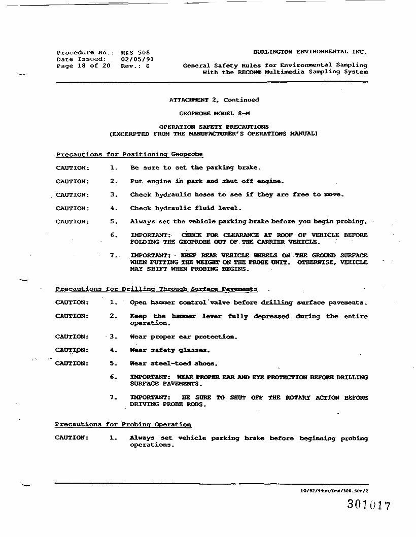
Procedure No.: HtS 508Date Issued: 02/05/91Page 18 of 20 Rev.: 0
BURLINGTON ENVIRONMENTAL INC.
General Safety Rules for Environmental SamplingWith the RECON* Multimedia Sampling System
ATTACHMENT 2, Continued
GEOPROBE MODEL 8-M
OPERATION SAFETY PRECAUTIONS(EXCERPTED FROM THE MANUFACTURER'S OPERATIONS MANUAL)
Precautions for Positioning Geoprobe
CAUTION: 1. Be sure to set the parking brake.
CAUTION: 2. Put engine in park and shut off engine.
CAUTION: 3. Check hydraulic hoses to see if they are free to move.
CAUTION: 4. Check hydraulic fluid level.
CAUTION: 5. Always set the vehicle parking brake before you begin probing.
6. IMPORTANT: CHECK FOR CLEARANCE AT ROOF OF VEHICLE BEFOREFOLDING THE GEOPROBE OUT OF THE CARRIER VEHICLE.
7. IMPORTANT: KEEP REAR VEHICLE HHEELS ON THE GROUND SURFACEWHEN PUTTING THE HEIGHT ON THE PROBE UNIT. OTHERWISE, VEHICLEMAY SHIFT WHEN PROBING BEGINS.
Precautions for Drilling Through Surface Pavements
CAUTION: 1. Open hammer control valve before drilling surface pavements.
CAUTION: 2. Keep the hammer lever fully depressed during the entireoperation.
CAUTION: 3. Wear proper ear protection.
CAUTION: 4. Hear safety glasses.
CAUTION: 5. Hear steel-toed shoes.
6. IMPORTANT: HEAR PROPER EAR AND EYE PROTECTION BEFORE DRILLINGSURFACE PAVEMENTS.
7. IMPORTANT: BE SURE TO SHUT OFF THE ROTARY ACTION BEFOREDRIVING PROBE RODS.
Precautions for Probing Operation
CAUTION: 1. Always set vehicle parking brake before beginning probingoperations.
10/9Z/»»0«/OMH/S08 .SOf/1
301017
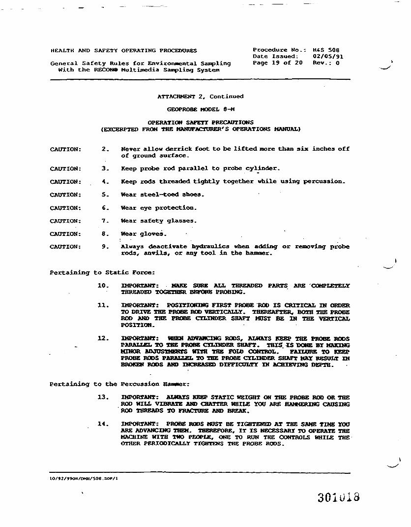
HEALTH AND SAFETY OPERATING PROCEDURES
General Safety Rules for Environmental SamplingWith the RECON* Multimedia Sampling System
Procedure No.: HAS SOSDate Issued: 02/05/91Page 19 of 20 Rev.; 0
ATTACHMENT 2, Continued
GEOPROBE MODEL 8-M
OPERATION SAFETY PRECAUTIONS(EXCERPTED FROM THE MANUFACTURER'S OPERATIONS MANUAL)
CAUTION: 2.
CAUTION:
CAUTION:
CAUTION:
CAUTION:
CAUTION:
CAUTION:
CAUTION:
3
4
5
6
7
8
9
Never allow derrick foot to be lifted more than six inches offof ground surface.
Keep probe rod parallel to probe cylinder.
Keep rods threaded tightly together while using percussion.
Wear steel—toed shoes.
Hear eye protection.
Hear safety glasses.
Hear gloves.
Always deactivate hydraulics when adding or removing proberods, anvils, or any tool in the hammer.
Pertaining to Static Force:
10. IMPORTANT: MAKE SORE ALL THREADED PARTS ARE 'COMPLETELYTHREADED TOGETHER BEFORE PROBING.
11. IMPORTANT: POSITIONING FIRST PROBE ROD IS CRITICAL IN ORDERTO DRIVE THE PROBE ROD VERTICALLY. THEREAFTER, BOTH THE PROBEROD AND THE PROBE CYLINDER SHAFT MUST BE IN THE VERTICALPOSITION.
12. IMPORTANT: WHEN ADVANCING RODS, ALWAYS KEEP THE PROBE RODSPARALLEL TO THE PROBE CYLINDER SHAFT. THIS iS DONE BY MAKINGMINOR ADJUSTMENTS WITH THE FOLD CONTROL. * FAILURE TO KEEPPROBE RODS PARALLEL TO THE PROBE CYLINDER SHAFT MAY RESULT XNBROKEN RODS AND INCREASED DIFFICULTY IN ACHIEVING DEPTH.
Pertaining to the Percussion Hammer:
13. IMPORTANT: ALWAYS KEEP STATIC HEIGHT ON THE PROBE ROD OR THEROD HILL VIBRATE AND CHATTER HHILE YOU ARE HAMMERING CAUSINGROD THREADS TO FRACTURE AND BREAK.
14. IMPORTANT: PROBE RODS MUST BE TIGHTENED AT THE SAME TIME YOUARE ADVANCING THEM. THEREFORE, IT IS NECESSARY TO OPERATE THEMACHINE WITH TWO PEOPLE, ONE TO RUN THE CONTROLS HHILE THEOTHER PERIODICALLY TIGHTENS THE PROBE RODS.
1O/92/990H/OMH/SO8.SOP/1
301U1S
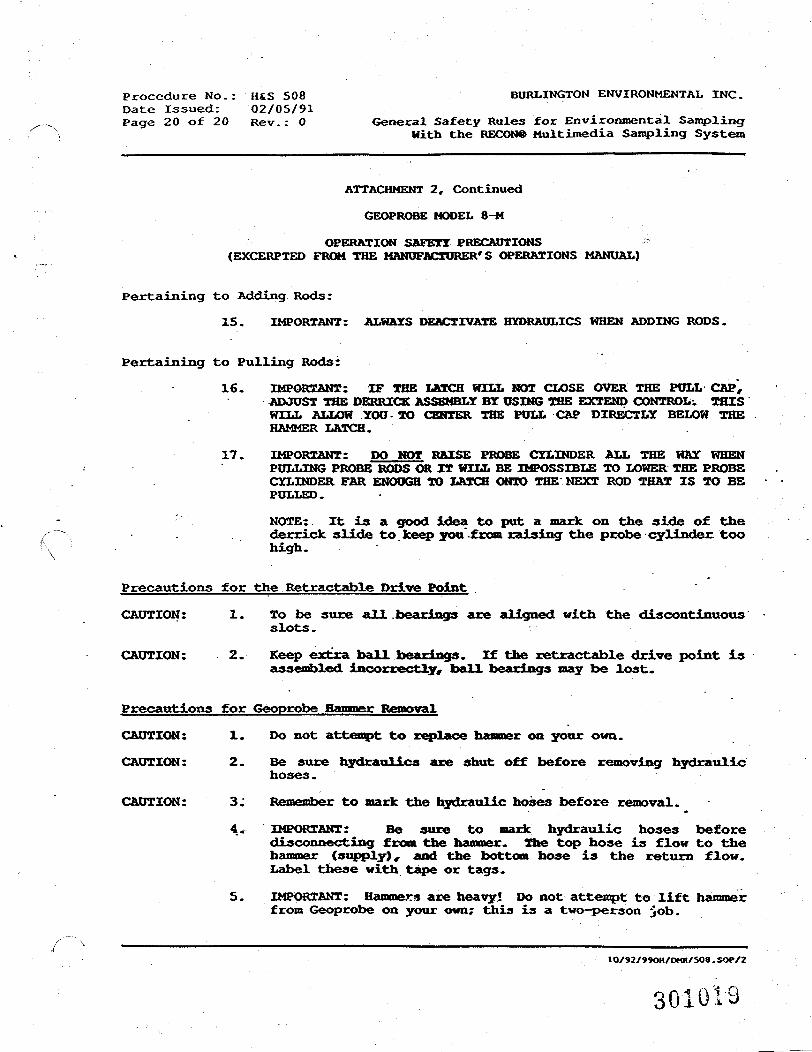
Procedure No.: HiS 508 BURLINGTON ENVIRONMENTAL INC.Date Issued: 02/05/91Page 20 of 20 Rev.: 0 General Safety Rules for Environmental Sampling
With the RECON® Multimedia Sampling System
ATTACHMENT 2, Continued
GEOPROBE MODEL 8-M
OPERATION SAFETY PRECAUTIONS(EXCERPTED FROM THE MANUFACTURER'S OPERATIONS MANUAL)
Pertaining to Adding Rods:
15. IMPORTANT: ALWAYS DEACTIVATE HYDRAULICS WHEN ADDING RODS.
Pertaining to Pulling Rods:
16. IMPORTANT: IF THE LATCH WILL NOT CLOSE OVER THE POLL CAP,ADJUST THE DERRICK ASSEMBLY BY USING THE EXTEND CONTROL-. THISWILL ALLOW YOU-TO CENTER THE PULL CAP DIRECTLY BELOW THEHAMMER LATCH.
17. IMPORTANT: DO HOT RAISE PROBE CYLINDER ALL THE WAY WHENPULLING PROBE RODS OR XT WILL BE IMPOSSIBLE TO LOWER THE PROBECYLINDER FAR ENOUGH TO LATCH ONTO THE NEXT ROD THAT IS TO BEPULLED.
NOTE:. It is a good idea to put a mark on the side of thederrick slide to keep you'-from raising the probe-cylinder, toohigh.
Precautions for the Retractable Drive Point .
CAUTION: 1. To be sure all .bearings are aligned with the discontinuousslots.
CAUTION: 2. Keep extra ball bearings. If the retractable drive point isassembled incorrectly, ball bearings nay be lost.
Precautions for Geoprobe Hammer Removal
CAUTION: 1. Do not attempt to replace hammer on your own.
CAUTION: 2. Be sure hydraulics are shut off before removing hydraulichoses.
CAUTION: 3; Remember to mark the hydraulic hoses before removal.
4. IMPORTANT: Be sure to mark hydraulic hoses beforedisconnecting from the hammer. The top hose is flow to thehammer (supply), and the bottom hose is the return flow.Label these with tape or tags.
5. IMPORTANT: Hammers are heavy* Do not attempt to lift hammerfrom Geoprobe on your own; this is a two-person -job.
IO/92/990H/OHH/SO8.SOP/2
301019


