Optics Communications 281 (2008) 4589–4597
Contents lists available at ScienceDirect
Optics Communications
journal homepage: www.elsevier .com/locate /optcom
Occlusion removal technique for improved recognition of partially occluded3D objects in computational integral imaging
Dong-Hak Shin a, Hoon Yoo a,*, Chun-Wei Tan a, Byung-Gook Lee a, Joon-Jae Lee b
a Department of Visual Contents, Dongseo University, San69-1, Jurye2-Dong, Sasang-Gu, Busan 617-716, Republic of Koreab Department of Game Mobile Contents, Keimyung University, 2139 Daemyung3-Dong, Nam-Gu, Daegu 705-701, Republic of Korea
a r t i c l e i n f o
Article history:Received 5 December 2007Received in revised form 11 April 2008Accepted 4 June 2008
Keywords:3D imagingIntegral imagingComputational reconstructionOcclusion removal
0030-4018/$ - see front matter � 2008 Elsevier B.V. Adoi:10.1016/j.optcom.2008.06.026
* Corresponding author. Tel.: +82 51 320 1734.E-mail address: [email protected] (H. Yoo).
a b s t r a c t
In this paper, we propose an occlusion removal technique for improved recognition of 3D objects that arepartially occluded in computational integral imaging (CII). In the reconstruction process of a 3D objectwhich is partially occluded by other objects, occlusion degrades the resolution of reconstructed 3Dimages and thus this affects negatively the recognition of a 3D object in CII. To overcome this problem,we introduce a method to eliminate occluding objects in elemental image array (EIA) and the proposedmethod is applied to 3D object recognition by use of CII. To our best knowledge, this is the first time toremove occlusion in CII. In our method, we apply the elemental image to sub-image (ES) transform to EIAobtained by a pickup process and those sub-images are employed for occlusion removal. After the trans-formation, we correlate those sub-images with a reference sub-image to locate occluding objects andthen we eliminate the objects. The inverse ES transform provides a modified EIA. Actually, the modifiedEIA is considered to be an EIA without the object that occludes the object to be reconstructed. This canprovide a substantial gain in terms of the image quality of 3D objects and in terms of recognition perfor-mance. To verify the usefulness of the proposed technique, some experimental results are carried out andthe results are presented.
� 2008 Elsevier B.V. All rights reserved.
1. Introduction
Integral imaging is a promising technique for three-dimensional(3D) imaging. Integral imaging is able to work with the incoherentlight and does not require the help of special viewing glasses [1–7].From the proposal of integral imaging in 1908, it has raised a greatattention to researchers because integral imaging is considered tobe a promising technology to provide the observing images withthe full parallax and the continuous viewing points. A general inte-gral imaging system consists of two processes: pickup and recon-struction. In the pickup process, light rays emanating from 3Dobjects are captured by a lenslet array. The light rays passingthrough each lenslet are recorded by using a 2D image sensor suchas the charged-coupled device (CCD). The captured images are con-sidered to be a set (or array) of demagnified 2D images becauseeach of them contains the different perspective information aboutthe 3D objects. These demagnified 2D images are known as the ele-mental image array (EIA). Reconstruction of 3D objects is a reverseprocess of pickup by propagating the rays coming from EIAthrough the same lenslet array. The reconstruction of 3D objectscan be done in two ways, either an optical way or a computationalway.
ll rights reserved.
For 3D visualization and recognition using InIm, computationalintegral imaging (CII) systems have been introduced [8–18]. A CIIsystem is shown in Fig. 1a. It is composed of the optical pickupand the volumetric computational reconstruction (VCR) based onthe pinhole-array model [10]. In optical pickup, 3D object is re-corded as the EIA through a lenslet array. In the VCR process, theEIA is digitally processed by use of a computer where 3D imagescan be easily reconstructed at any reconstruction output planewithout optical devices.
Even though VCR provides the simple reconstruction of 3D ob-jects using only a computer, there are some problems to be solvedincluding a poor visual quality by artifacts, high computation loads.In order to improve the visual quality in VCR, several methods aresuggested. One is to use the moving array lenslet technique [12], inwhich the sampling rate of the EIA can be increased by the rapidmoving of a lenslet array and the fast pickup of the EIA via time-multiplexing. However, this method has some difficulties. It mayhave a mismatch between the pickup lenslet array and the 2D im-age sensor caused by fast mechanical movement of the lenslet ar-ray. Also it requires the long multi-step pickup time to capture anEIA. Another method is to reconstruct resolution-enhanced 3Dimages using the intermediate-view reconstruction technique[15]. With this technique, intermediate elemental images can bedigitally synthesized as many as required by using only a limitednumber of picked-up EIA and from which resolution-enhanced
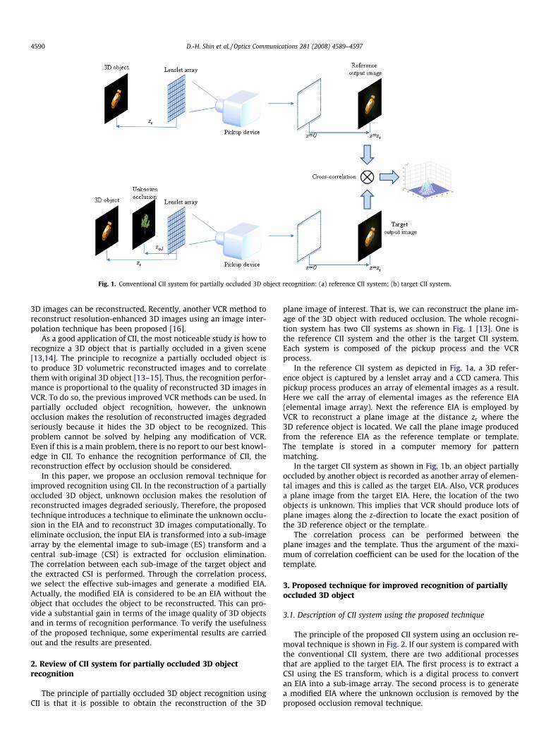
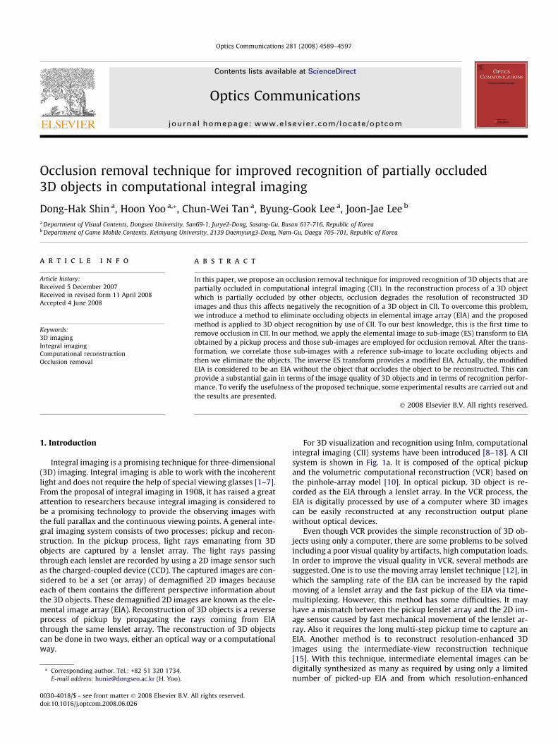
Fig. 1. Conventional CII system for partially occluded 3D object recognition: (a) reference CII system; (b) target CII system.
4590 D.-H. Shin et al. / Optics Communications 281 (2008) 4589–4597
3D images can be reconstructed. Recently, another VCR method toreconstruct resolution-enhanced 3D images using an image inter-polation technique has been proposed [16].
As a good application of CII, the most noticeable study is how torecognize a 3D object that is partially occluded in a given scene[13,14]. The principle to recognize a partially occluded object isto produce 3D volumetric reconstructed images and to correlatethem with original 3D object [13–15]. Thus, the recognition perfor-mance is proportional to the quality of reconstructed 3D images inVCR. To do so, the previous improved VCR methods can be used. Inpartially occluded object recognition, however, the unknownocclusion makes the resolution of reconstructed images degradedseriously because it hides the 3D object to be recognized. Thisproblem cannot be solved by helping any modification of VCR.Even if this is a main problem, there is no report to our best knowl-edge in CII. To enhance the recognition performance of CII, thereconstruction effect by occlusion should be considered.
In this paper, we propose an occlusion removal technique forimproved recognition using CII. In the reconstruction of a partiallyoccluded 3D object, unknown occlusion makes the resolution ofreconstructed images degraded seriously. Therefore, the proposedtechnique introduces a technique to eliminate the unknown occlu-sion in the EIA and to reconstruct 3D images computationally. Toeliminate occlusion, the input EIA is transformed into a sub-imagearray by the elemental image to sub-image (ES) transform and acentral sub-image (CSI) is extracted for occlusion elimination.The correlation between each sub-image of the target object andthe extracted CSI is performed. Through the correlation process,we select the effective sub-images and generate a modified EIA.Actually, the modified EIA is considered to be an EIA without theobject that occludes the object to be reconstructed. This can pro-vide a substantial gain in terms of the image quality of 3D objectsand in terms of recognition performance. To verify the usefulnessof the proposed technique, some experimental results are carriedout and the results are presented.
2. Review of CII system for partially occluded 3D objectrecognition
The principle of partially occluded 3D object recognition usingCII is that it is possible to obtain the reconstruction of the 3D
plane image of interest. That is, we can reconstruct the plane im-age of the 3D object with reduced occlusion. The whole recogni-tion system has two CII systems as shown in Fig. 1 [13]. One isthe reference CII system and the other is the target CII system.Each system is composed of the pickup process and the VCRprocess.
In the reference CII system as depicted in Fig. 1a, a 3D refer-ence object is captured by a lenslet array and a CCD camera. Thispickup process produces an array of elemental images as a result.Here we call the array of elemental images as the reference EIA(elemental image array). Next the reference EIA is employed byVCR to reconstruct a plane image at the distance zr where the3D reference object is located. We call the plane image producedfrom the reference EIA as the reference template or template.The template is stored in a computer memory for patternmatching.
In the target CII system as shown in Fig. 1b, an object partiallyoccluded by another object is recorded as another array of elemen-tal images and this is called as the target EIA. Also, VCR producesa plane image from the target EIA. Here, the location of the twoobjects is unknown. This implies that VCR should produce lots ofplane images along the z-direction to locate the exact position ofthe 3D reference object or the template.
The correlation process can be performed between theplane images and the template. Thus the argument of the maxi-mum of correlation coefficient can be used for the location of thetemplate.
3. Proposed technique for improved recognition of partiallyoccluded 3D object
3.1. Description of CII system using the proposed technique
The principle of the proposed CII system using an occlusion re-moval technique is shown in Fig. 2. If our system is compared withthe conventional CII system, there are two additional processesthat are applied to the target EIA. The first process is to extract aCSI using the ES transform, which is a digital process to convertan EIA into a sub-image array. The second process is to generatea modified EIA where the unknown occlusion is removed by theproposed occlusion removal technique.
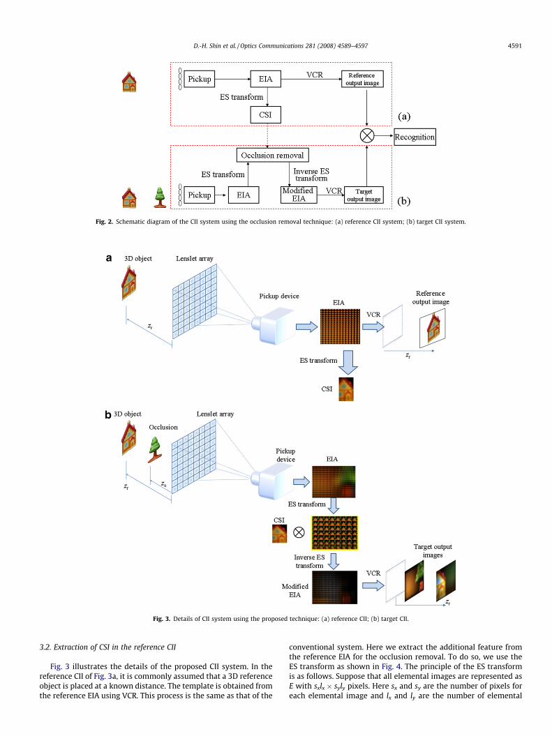
Fig. 2. Schematic diagram of the CII system using the occlusion removal technique: (a) reference CII system; (b) target CII system.
Fig. 3. Details of CII system using the proposed technique: (a) reference CII; (b) target CII.
D.-H. Shin et al. / Optics Communications 281 (2008) 4589–4597 4591
3.2. Extraction of CSI in the reference CII
Fig. 3 illustrates the details of the proposed CII system. In thereference CII of Fig. 3a, it is commonly assumed that a 3D referenceobject is placed at a known distance. The template is obtained fromthe reference EIA using VCR. This process is the same as that of the
conventional system. Here we extract the additional feature fromthe reference EIA for the occlusion removal. To do so, we use theES transform as shown in Fig. 4. The principle of the ES transformis as follows. Suppose that all elemental images are represented asE with sxlx � syly pixels. Here sx and sy are the number of pixels foreach elemental image and lx and ly are the number of elemental
Fig. 4. Conceptual model of ES transform: (a) EIA; (b) sub-image array.
4592 D.-H. Shin et al. / Optics Communications 281 (2008) 4589–4597
images in the x- and y-axis, respectively. Then a sub-image array iscalculated by
Si;jðm;nÞ ¼ Em;nði; jÞ ð1Þ
where i = 1, . . . ,sx, j = 1, . . . ,sy, m = 1, . . . , lx and n = 1, . . . , ly. This meansthat a sub-image is a set of pixels that are located at same positionin each elemental image. For example, let us consider a 3 � 2 EIAand each elemental image consists of 6 � 4 pixels. After the EStransform using Eq. (1), the sub-image array becomes to be 6 � 4sub-images whose size is 3 � 2, as shown in Fig. 4. This ES trans-form has been used in some applications [18,19].
After the ES transform, we have the sub-image array and candefine the CSI (central sub-image) as
CSI ¼ Si¼sx=2;j¼sy=2 ð2Þ
And the CSI is used for a reference template for the proposed sys-tem. The CSI is a portion of the sub-image in the center of a sub-im-age array and its shape information is available because we alreadyknow the reference EIA exactly. In other words, it is possible to sit-uate a 3D reference object at a known background. The proposedreference CII system uses a black background. This means that thepixel value of the background is zero whereas that of the 3D refer-ence object is nonzero. Consequently, we can easily define theshape information of the CSI as
aði� i0; j� j0Þ ¼1; CSIði; jÞ 6¼ 0;0; CSIði; jÞ ¼ 0:
�ð3Þ
Here, i ¼ i0; . . . ; i0 þ N � 1 and j ¼ j0; . . . ; j0 þM � 1, where the loca-tion (i0, j0) is the coordinate of the upper-left corner of the smallestbox that has the target object in the CSI and the size of box is (N, M).Also, we can extract the smallest box from the CSI and we can up-date the CSI with the smallest box. This updating process of the CSIis easily presented in the form
CSIði� i0; j� j0Þ ¼ CSIði; jÞ ð4Þ
Here, i ¼ i0; . . . ; i0 þ N � 1 and j ¼ j0; . . . ; j0 þM � 1. Largely, theupdated CSI is smaller than the CSI of Eq. (2) and this improvesthe computation speed. Note that the CSI has a good feature thatprovides the robustness on the shifting effect of an object becauseit represents the center view of a 3D object. There are some exam-ples in Fig. 5. According to the distance, the EIA is largely changedbut the associated sub-image array is not changed. This robustnessis very helpful for the recognition of objects.
3.3. Recognition in the target CII system
Now let us consider the proposed target CII system as shown inFig. 3b. Let us assume that the unknown occluding object O(xo, yo,zo) and a target object are located at arbitrary distances zo and zr,respectively. Then these objects are picked-up by using a CCD cam-era as shown in Fig. 4b. This pickup process provides us a targetEIA. And then the target EIA is transformed into a sub-image array.Each sub-image in the sub-image array is correlated with the CSIfrom the proposed reference CII system. This correlation processgives a set of correlation coefficients C(r,c) and it can be written as
Cðr; cÞ ¼XN�1
i¼0
XM�1
j¼0
aði; jÞCSIði; jÞSðr þ i; c þ jÞ; ð5Þ
where a(i,j) is the shape information of the CSI, which is discussedin previous chapter. The value M and N denote the row and columnsize of the CSI, respectively. S denotes each sub-image. After corre-lation process of (5), we have a set of correlation coefficients. Andthen the arguments rm and cm of the maximum correlation coeffi-cient Cmax is chosen as the position information of the target objectin each sub-image. Before moving on the next step, the value of Cmax
is compared with a threshold hth. If Cmax is greater than the
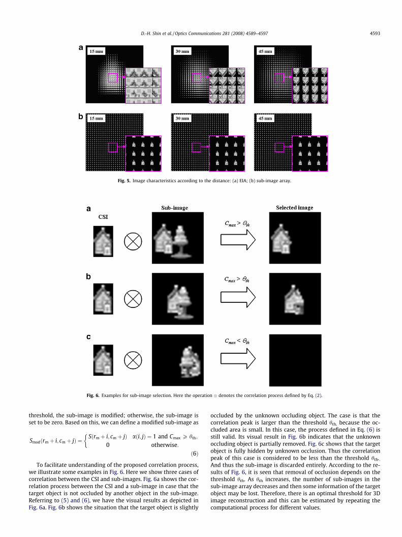
Fig. 5. Image characteristics according to the distance: (a) EIA; (b) sub-image array.
Fig. 6. Examples for sub-image selection. Here the operation � denotes the correlation process defined by Eq. (2).
D.-H. Shin et al. / Optics Communications 281 (2008) 4589–4597 4593
threshold, the sub-image is modified; otherwise, the sub-image isset to be zero. Based on this, we can define a modified sub-image as
Smodðrm þ i; cm þ jÞ ¼Sðrm þ i; cm þ jÞ aði; jÞ ¼ 1 and Cmax P hth;
0 otherwise:
�ð6Þ
To facilitate understanding of the proposed correlation process,we illustrate some examples in Fig. 6. Here we show three cases ofcorrelation between the CSI and sub-images. Fig. 6a shows the cor-relation process between the CSI and a sub-image in case that thetarget object is not occluded by another object in the sub-image.Referring to (5) and (6), we have the visual results as depicted inFig. 6a. Fig. 6b shows the situation that the target object is slightly
occluded by the unknown occluding object. The case is that thecorrelation peak is larger than the threshold hth, because the oc-cluded area is small. In this case, the process defined in Eq. (6) isstill valid. Its visual result in Fig. 6b indicates that the unknownoccluding object is partially removed. Fig. 6c shows that the targetobject is fully hidden by unknown occlusion. Thus the correlationpeak of this case is considered to be less than the threshold hth..And thus the sub-image is discarded entirely. According to the re-sults of Fig. 6, it is seen that removal of occlusion depends on thethreshold hth. As hth increases, the number of sub-images in thesub-image array decreases and then some information of the targetobject may be lost. Therefore, there is an optimal threshold for 3Dimage reconstruction and this can be estimated by repeating thecomputational process for different values.
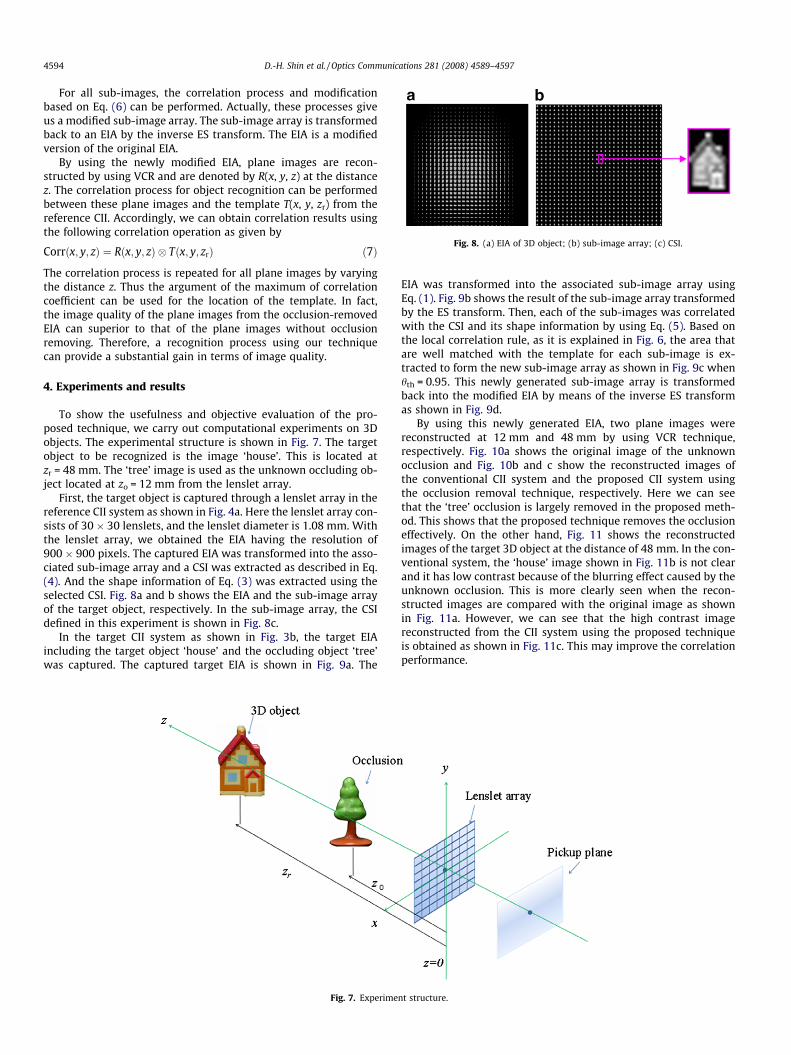
Fig. 8. (a) EIA of 3D object; (b) sub-image array; (c) CSI.
4594 D.-H. Shin et al. / Optics Communications 281 (2008) 4589–4597
For all sub-images, the correlation process and modificationbased on Eq. (6) can be performed. Actually, these processes giveus a modified sub-image array. The sub-image array is transformedback to an EIA by the inverse ES transform. The EIA is a modifiedversion of the original EIA.
By using the newly modified EIA, plane images are recon-structed by using VCR and are denoted by R(x, y, z) at the distancez. The correlation process for object recognition can be performedbetween these plane images and the template T(x, y, zr) from thereference CII. Accordingly, we can obtain correlation results usingthe following correlation operation as given by
Corrðx; y; zÞ ¼ Rðx; y; zÞ � Tðx; y; zrÞ ð7Þ
The correlation process is repeated for all plane images by varyingthe distance z. Thus the argument of the maximum of correlationcoefficient can be used for the location of the template. In fact,the image quality of the plane images from the occlusion-removedEIA can superior to that of the plane images without occlusionremoving. Therefore, a recognition process using our techniquecan provide a substantial gain in terms of image quality.
4. Experiments and results
To show the usefulness and objective evaluation of the pro-posed technique, we carry out computational experiments on 3Dobjects. The experimental structure is shown in Fig. 7. The targetobject to be recognized is the image ‘house’. This is located atzr = 48 mm. The ‘tree’ image is used as the unknown occluding ob-ject located at zo = 12 mm from the lenslet array.
First, the target object is captured through a lenslet array in thereference CII system as shown in Fig. 4a. Here the lenslet array con-sists of 30 � 30 lenslets, and the lenslet diameter is 1.08 mm. Withthe lenslet array, we obtained the EIA having the resolution of900 � 900 pixels. The captured EIA was transformed into the asso-ciated sub-image array and a CSI was extracted as described in Eq.(4). And the shape information of Eq. (3) was extracted using theselected CSI. Fig. 8a and b shows the EIA and the sub-image arrayof the target object, respectively. In the sub-image array, the CSIdefined in this experiment is shown in Fig. 8c.
In the target CII system as shown in Fig. 3b, the target EIAincluding the target object ‘house’ and the occluding object ‘tree’was captured. The captured target EIA is shown in Fig. 9a. The
Fig. 7. Experime
EIA was transformed into the associated sub-image array usingEq. (1). Fig. 9b shows the result of the sub-image array transformedby the ES transform. Then, each of the sub-images was correlatedwith the CSI and its shape information by using Eq. (5). Based onthe local correlation rule, as it is explained in Fig. 6, the area thatare well matched with the template for each sub-image is ex-tracted to form the new sub-image array as shown in Fig. 9c whenhth = 0.95. This newly generated sub-image array is transformedback into the modified EIA by means of the inverse ES transformas shown in Fig. 9d.
By using this newly generated EIA, two plane images werereconstructed at 12 mm and 48 mm by using VCR technique,respectively. Fig. 10a shows the original image of the unknownocclusion and Fig. 10b and c show the reconstructed images ofthe conventional CII system and the proposed CII system usingthe occlusion removal technique, respectively. Here we can seethat the ‘tree’ occlusion is largely removed in the proposed meth-od. This shows that the proposed technique removes the occlusioneffectively. On the other hand, Fig. 11 shows the reconstructedimages of the target 3D object at the distance of 48 mm. In the con-ventional system, the ‘house’ image shown in Fig. 11b is not clearand it has low contrast because of the blurring effect caused by theunknown occlusion. This is more clearly seen when the recon-structed images are compared with the original image as shownin Fig. 11a. However, we can see that the high contrast imagereconstructed from the CII system using the proposed techniqueis obtained as shown in Fig. 11c. This may improve the correlationperformance.
nt structure.
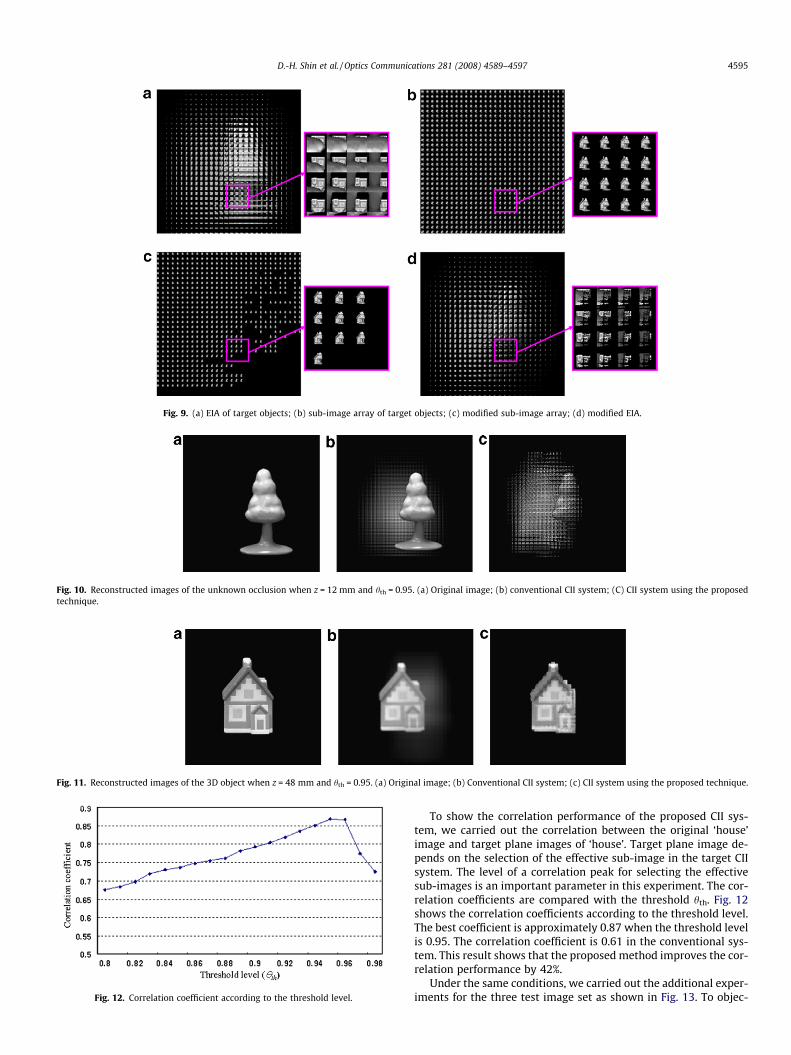
Fig. 9. (a) EIA of target objects; (b) sub-image array of target objects; (c) modified sub-image array; (d) modified EIA.
Fig. 10. Reconstructed images of the unknown occlusion when z = 12 mm and hth = 0.95. (a) Original image; (b) conventional CII system; (C) CII system using the proposedtechnique.
Fig. 11. Reconstructed images of the 3D object when z = 48 mm and hth = 0.95. (a) Original image; (b) Conventional CII system; (c) CII system using the proposed technique.
Fig. 12. Correlation coefficient according to the threshold level.
D.-H. Shin et al. / Optics Communications 281 (2008) 4589–4597 4595
To show the correlation performance of the proposed CII sys-tem, we carried out the correlation between the original ‘house’image and target plane images of ‘house’. Target plane image de-pends on the selection of the effective sub-image in the target CIIsystem. The level of a correlation peak for selecting the effectivesub-images is an important parameter in this experiment. The cor-relation coefficients are compared with the threshold hth. Fig. 12shows the correlation coefficients according to the threshold level.The best coefficient is approximately 0.87 when the threshold levelis 0.95. The correlation coefficient is 0.61 in the conventional sys-tem. This result shows that the proposed method improves the cor-relation performance by 42%.
Under the same conditions, we carried out the additional exper-iments for the three test image set as shown in Fig. 13. To objec-
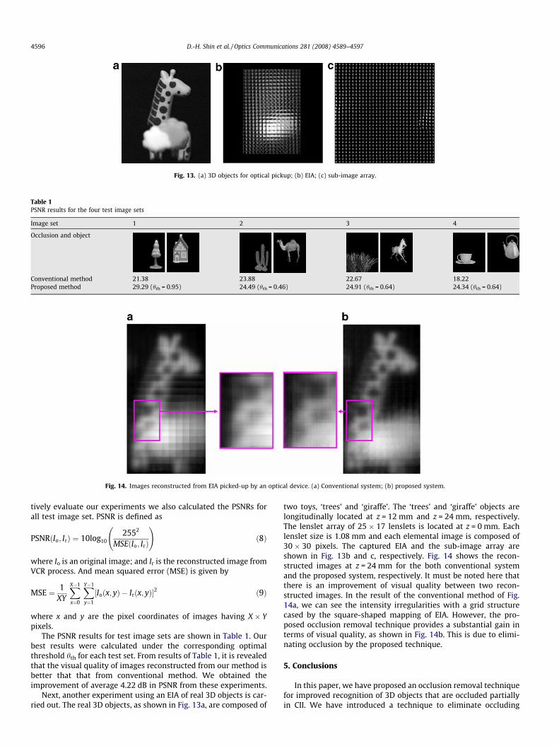
Fig. 13. (a) 3D objects for optical pickup; (b) EIA; (c) sub-image array.
Table 1PSNR results for the four test image sets
Image set 1 2 3 4
Occlusion and object
Conventional method 21.38 23.88 22.67 18.22Proposed method 29.29 (hth = 0.95) 24.49 (hth = 0.46) 24.91 (hth = 0.64) 24.34 (hth = 0.64)
Fig. 14. Images reconstructed from EIA picked-up by an optical device. (a) Conventional system; (b) proposed system.
4596 D.-H. Shin et al. / Optics Communications 281 (2008) 4589–4597
tively evaluate our experiments we also calculated the PSNRs forall test image set. PSNR is defined as
PSNRðIo; IrÞ ¼ 10log102552
MSEðIo; IrÞ
!ð8Þ
where Io is an original image; and Ir is the reconstructed image fromVCR process. And mean squared error (MSE) is given by
MSE ¼ 1XY
XX�1
x¼0
XY�1
y¼1
½Ioðx; yÞ � Irðx; yÞ�2 ð9Þ
where x and y are the pixel coordinates of images having X � Ypixels.
The PSNR results for test image sets are shown in Table 1. Ourbest results were calculated under the corresponding optimalthreshold hth for each test set. From results of Table 1, it is revealedthat the visual quality of images reconstructed from our method isbetter that that from conventional method. We obtained theimprovement of average 4.22 dB in PSNR from these experiments.
Next, another experiment using an EIA of real 3D objects is car-ried out. The real 3D objects, as shown in Fig. 13a, are composed of
two toys, ‘trees’ and ‘giraffe’. The ‘trees’ and ‘giraffe’ objects arelongitudinally located at z = 12 mm and z = 24 mm, respectively.The lenslet array of 25 � 17 lenslets is located at z = 0 mm. Eachlenslet size is 1.08 mm and each elemental image is composed of30 � 30 pixels. The captured EIA and the sub-image array areshown in Fig. 13b and c, respectively. Fig. 14 shows the recon-structed images at z = 24 mm for the both conventional systemand the proposed system, respectively. It must be noted here thatthere is an improvement of visual quality between two recon-structed images. In the result of the conventional method of Fig.14a, we can see the intensity irregularities with a grid structurecased by the square-shaped mapping of EIA. However, the pro-posed occlusion removal technique provides a substantial gain interms of visual quality, as shown in Fig. 14b. This is due to elimi-nating occlusion by the proposed technique.
5. Conclusions
In this paper, we have proposed an occlusion removal techniquefor improved recognition of 3D objects that are occluded partiallyin CII. We have introduced a technique to eliminate occluding
D.-H. Shin et al. / Optics Communications 281 (2008) 4589–4597 4597
objects in elemental image array and the proposed technique is ap-plied to 3D object recognition by use of CII. To our best knowledge,this is the first time to remove occlusion in CII. In our proposedtechnique, we employed the ES transform to obtain an efficientocclusion removal. And then we proposed a correlate process todetermine occluding pixels. This produces a modified EIA and itis considered to be an EIA without occluding objects that occludethe object to be reconstructed. This can provide a substantial gainin terms of the image quality of 3D objects and in terms of recog-nition performance. To obtain more improvement, we can combinethe proposed technique with the previous improved VCR method.To show the usefulness of the proposed technique, we representedsome experiments and demonstrated the improvement of recogni-tion performance. Therefore, we expect that the proposed tech-nique will aid to improve the performance of recognitionsystems using CII.
References
[1] G. Lippmann, C.R. Acad. Sci. 146 (1908) 446.
[2] F. Okano, H. Hoshino, J. Arai, M. Yamada, I. Yuyama, in: B. Javidi, F. Okano(Eds.), Three-Dimensional, Television, Video and Display Technology, SpringerVerlag, Berlin, Heidelberg, NY, 2002, p. 101.
[3] A. Stern, B. Javidi, Proc. IEEE 94 (2006) 591.[4] B. Lee, S.Y. Jung, S.-W. Min, J.-H. Park, Opt. Lett. 26 (2001) 1481.[5] J.-S. Jang, B. Javidi, Opt. Lett. 27 (2002) 324.[6] M. Martínez-Corral, B. Javidi, R. Martínez-Cuenca, G. Saavedra, J. Opt. Soc. Am.
A 22 (2005) 597.[7] D.-H. Shin, B. Lee, E.-S. Kim, Appl. Opt. 45 (2006) 7375.[8] H. Arimoto, B. Javidi, Opt. Lett. 26 (2001) 157.[9] Y. Frauel, B. Javidi, Appl. Opt. 41 (2002) 5488.
[10] S.-H. Hong, J.-S. Jang, B. Javidi, Opt. Express 12 (2004) 483.[11] D.-H. Shin, E.-S. Kim, B. Lee, Jpn. J. Appl. Phys. 44 (2005) 8016.[12] S.-H. Hong, B. Javidi, Opt. Express 12 (2004) 4579.[13] B. Javidi, R. Ponce-Díaz, S.-H. Hong, Opt. Lett. 31 (2006) 1106.[14] S.-H. Hong, B. Javidi, Opt. Express 14 (2006) 12085.[15] J.S. Park, D.C. Hwang, D.H. Shin, E.S. Kim, Opt. Comm. 26 (2007) 72.[16] D.-H. Shin, H. Yoo, Opt. Express 15 (2007) 12039.[17] H. Yoo, D.-H. Shin, Opt. Express 15 (2007) 14107.[18] J.-H. Park, J. Kim, B. Lee, Opt. Express 13 (2005) 5116.[19] C. Wu, A. Aggoun, M. McCormick, S.Y. Kung, in: A.J. Woods, J.O. Merritt, S.A.
Benton and M.T. Bolas (Eds.), Stereoscopic Displays and Virtual RealitySystems IX, Proc. SPIE 4660, 2002, 135.


![[The influence of occlusion on sporting performance]](https://cdn.vdocuments.mx/doc/165x107/6350ed90ae531ce86203c02c/the-influence-of-occlusion-on-sporting-performance.jpg)


