rotation, rescaling and occlusion invariant object retrieval
TRANSCRIPT

Rotation, Rescaling and Occlusion InvariantObject Retrieval
Michela Lecca and Stefano MesselodiFondazione Bruno Kessler - IRST
via Sommarive 18, 38050 Povo, Trento, Italy{lecca, messelod}@itc.it
Abstract
This paper presents a new approach for rotation, rescaling and occlusion in-variant retrieval of the objects of a given database D. The objects are repre-sented by means of many 2D views and each of them is occluded by severalhalf-planes. The remaining visible parts (linear cuts) as well as the wholeviews are stored in a new database D’ and described by low-level features.Given a portion R of an image, the retrieval of the most similar object is doneby generating some linear cuts of R, and by comparing their descriptors withthose of the elements of D’. Some heuristic rules regarding visual similarityand geometric properties of the objects in the database drive this process. Inthe case R is recognized as an object partially occluded, a strategy for thereconstruction of the whole shape of R is also presented.The tests carried out on synthetic and real-world datasets showed good per-formances both in recognition and in reconstruction accuracy.
1 Introduction
The diffusion of the digital photo- and video- cameras in the daily life, the rapid increaseof the visual materials, their simple and cheap availability, the development of efficientstorage devices, make the use of automatic image retrieval systems necessary to manage,index and organize the visual documents in easy and fast way [5].
A content-based image retrieval (CBIR) system is a tool for browsing and searchingimages from a large database. The system input is a digital image (query) and the outputis the database elements or a subset of them ranked by similarity with respect to the query.The similarity is defined as distance between some features describing the database im-ages and the query. Examples of CBIR systems are COMPASS [3], Virage [11], QBIC[7], VisualSEEk [17].The object retrieval systems are CBIR systems for browsing and searching for objects ina large database of digital images. In this case, the query is a region of a digital imageand the output is the database objects or a subset of them ordered by similarity respect tothe query. Due to their many applications in the e-commerce and in the automatic index-ing of digital images, the development of such systems is an attractive topic in ComputerVision and especially in Image Understanding. An example of commercial applicationis the search for web catalog products visually similar to a given input. Moreover, theseretrieval engines can be inserted in systems for the recognition of objects in digital images
to provide an automatic indexing and a high-level description of images [10]. Since theobjects can appear in various accidental circumstances that modify their appearance (likeperspective transformations, affinities, occlusions or changes of illuminant), the main bot-tleneck is to find a description of the objects, able to permit a stable recognition under alarge number of conditions.
The most popular approaches describe the objects and the image portion by means oflocal features, like pixel intensity, corners, high curvature points, edge fragments [13],[9], [16], [6]. Other methods describe the objects and the image region by some subsetsof pixels [12], or by dividing the object image into many regular parts, for example rect-angles, and by describing each of them by global features, [8], [4]. For objects consistingof distinguishable parts arranged in a fixed spatial configuration, models composed by adescription of the parts along with information about their spatial relationships or evenwith a label about their functionality are proposed [14]. Generally, in all these models,the local features are organized in hierarchical structures, for instance trees or graphs, andrecognition is reduced to their matching [16], [18].
The choice of the local features for the object description, their extraction from theimage, and the matching algorithm for the recognition are often computationally expen-sive, requiring generally an analysis pixel by pixel or in windows centered in each pixel,and even more for finding the feature correspondences, also when a priori knowledge orheuristic rules are introduced [2].
In this work we propose a method for the retrieval of objects invariant with respectto rotation and/or rescaling and/or occlusions. Differently from the most common ap-proaches, our approach does not use local features for the description of the objects andof the image region to be classified, and the computation of the descriptors as well asthe features matching are very fast. The objects are modeled by a set of 2D views andby some occlusions of them by half-planes; given an input region R, the retrieval of themost similar object is done by generating some occlusions of R by half-planes and bycomparing them with those of the objects. An algorithm for the reconstruction of thewhole shape of occluded objects is also proposed. The main advantages in the use of ourmethod are the simplicity of the object model, the invariance by rescaling, rotating and/orocclusions, and the restricted user interaction. The main disadvantage is due to the factthat the method needs a large amount of memory space to store the database containingthe objects and their cuts, but a distributed architecture can easily solve this problem.
2 Overview on the Method
Our method consists of three parts detailed in the next Sections: (1) object model con-struction, (2) recognition algorithm, (3) reconstruction of recognized occluded objects.In our approach, the objects to be recognized are represented by many 2D views and theyare stored in a database D. Moreover each view is occluded by several half-planes havingdifferent slope and masking different percentage of the view. A new database D’ contain-ing the remaining visible parts (linear cuts) and D is then built.To establish if a region R of an input image is a view possibly occluded of an object of D,a set of linear cuts of R is generated and then compared them with the items of D’. Eachelement of D’, R, and each linear cut of it are described by means of a vector of low-levelfeatures, encoding information about color, shape and texture. The pairs (CR,COv), where
x
y
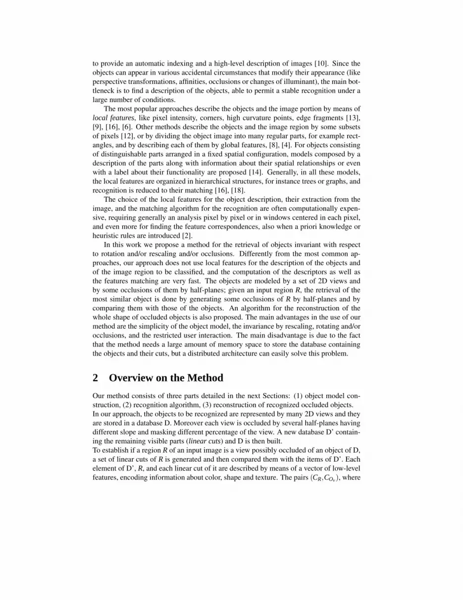
Figure 1: Rectangles for the generation of the linear cuts of a view of an object of thewell-known database COIL-100 (http://www.cs.columbia.edu/CAVE/).
CR is a linear cut of R and COv is the element of D’ having the smallest distance from it(recognition distance), are stored in a candidate list. R is recognized as an instance of anobject O in D if the majority of the linear cuts of R is associated to a linear cut of views ofO. Since the descriptors are invariant by rescaling, rotation, and composition of thereof,the system is able to recognize also rotated and/or rescaled partially occluded views. Thescale factor of R and its orientation in the image plane with respect to the associated ob-ject view are determined and in case of occlusions, they are used for the reconstructionof the whole shape of R. The recognition algorithm is guided by parametric heuristicrules related to geometric properties (area, scale factor) and visual similarity (recognitiondistance). If R corresponds to an occluded object view, its whole shape is reconstructedand its scale factor and orientation with respect the recognized view are returned. Somethresholds used in the recognition and reconstruction procedures are estimated automati-cally, while others are user inputs.Visual similarity between a portion of R and an element of D’ is defined as the L1-distancebetween their correspondent feature vectors. We call recognition distance the minimumdistance between R and the items of D’. The image description and the feature match-ing are performed by the extended version [1] of the content-base image retrieval systemCOMPASS [3] employed as object classifier. An image portion is described by meansof histograms representing intensity, hue, saturation, edge distribution, while the Fouriercoefficients and the Li Moments are used to describe its shape. The distributions of hueand saturation are represented also by two dimensional coocurrence matrices. The searchprocess is very efficient, for example retrieving the closest items in a database of 1 millionelements takes less than a second on a standard Pentium4 2GHz CPU.The key point of the recognition algorithm is the computation of the linear cuts of a regionQ in R2 (where Q is an object view in D or the region R). They are generated by occludingQ by 2n sheaves of parallel half-planes {Σi}i=1,...,m with slopes in [0, 2π], where n andm are integer numbers called generation cut parameters (briefly GCPs). In particular, foreach slope θk (k = 1, . . . , n), the minimum bounding rectangle of Q with vertices P0, P1,P2, P3 is built (see Figure 1); a set {t1, . . . , tm} of real numbers in (0, 1) is fixed and foreach i in {1, . . . ,m} the rectangle with vertices P0 + ti(P3 −P0), P1 + ti(P3 −P1), P2 and P3is computed. The Σi-linear cuts of Q are then Q∩P′
0P′1P2P3 and Q− (Q∩P′
0P′1P2P3).
In this work, the slopes are equally spaced in [0, 2π], whereas the elements t1, . . . , tmare computed by taking in account the size of the database objects, as explained in Section7.

The GCPs used in the object model construction can be different from those employed inthe recognition algorithm and they are set by the user.
3 Object Model Construction
The user inputs are an object database D, the GCPs n and m for the linear cut generation,and two real values paand pb in (0,1), pa < pb, related to the percentage of the minimumvisible area of the linear cuts. We describe each object view Ov of D by low-level features,compute its area A(Ov), occlude Ov by nm half-planes, and then insert Ov and its linearcuts having area in [paA(Ov), pbA(Ov)] in a new database D’. The linear cuts of Ov witharea greater than pbA(Ov) are described and compared with the items of D, and they areput in D’ only if the object classifier does not recognize them as instances of O, i.e. themost similar item of D’ returned by the object classifier is not a view of O.The parameters pa and pb are used to avoid the generation of too small linear cuts (notsignificant for recognition) and the insertion in D’ of linear cuts very similar to the wholeobject view. Typically pa ranges in (0, 0.6], while pb is close to 1.
4 Heuristic Parameters
The algorithms for the recognition and reconstruction proposed in this work request athreshold Γ on the similarity measure and some heuristic geometric parameters (α1,α2,Am, AM for the recognition and 〈EA
scale〉, 〈Eangle〉, a, b, y for the reconstruction).The values α1 and α2 are user inputs and they define the range of variability of the
scale factor for the database objects. Denoted by Amin and Amax the minimum and maxi-mum areas of the elements of D’, Am is given by α2
1 Amin and AM is given by α22 Amax.
The values of Γ and 〈EAscale〉 are estimated as follows: for each view Ov of an object O
of D, s rescaled and rotated versions of Ov are computed. The scale factors and the rotationangles are randomly chosen in [α1,α2] and [0, 2π] respectively. For each transformedversion T of (Ov), a linear cut is randomly generated and classified. If it is recognizedas a cut K of a view of O, its scale factor α∗ with respect to K is computed as squareroot between its area and the area of K. The error on scale is defined as the difference|α∗−αT |, where αT is the scale factor of the transformation T . The distributions of therecognition distances and of the errors on scale factor are computed. Γ is fixed as the99th percentile of the distribution of the recognition distance, while 〈EA
scale〉 is the meanvalue of the scale factors of the recognized objects. In this work, we consider 10 randomtransformations for each Ov (i.e. s = 10).
The value of 〈Eangle〉 measures the error on the angle in the reconstruction and it is de-fined as function of the GCP n (number of slopes) used for the object model construction,given by
〈Eangle〉 =12
πn
. (1)
The values a, b and y are related to the accuracy of the reconstruction and they are setby the user with the constraints a,b,y > 0 (see Sections 6 and 7).

5 Recognition Algorithm
The user inputs of this step are a region R of a color image, the GCPs (nR,mR) for thegeneration of the linear cuts of R, and the range [α1,α2]. The first step is the generationof the set {CR} of linear cuts of R. The cut CR is a solution only if its area is in the range[Am,AM], its scale factor αR with respect to the most similar item KR of D’ belongs to[α1,α2], and its recognition distance d(CR) is smaller than a threshold Γ. The scale factorαR is computed by the formula
αR =
√
A(CR)
A(KR)(2)
where A(·) indicates the area. The pairs (CR,KR) satisfying the conditions enumeratedabove are stored in the candidate list L and the most frequent object (if any) is returned assolution.The complexity of the recognition algorithm is proportional to the feature extraction com-plexity (i.e. O(A(CR))) multiplied the number of elements of the database D’ and thenumber of linear cuts of R compared with the items of D’.
6 Reconstruction Algorithm
The reconstruction algorithm is based on a method of alignment between minimum bound-ing rectangles. Let (CR,KR) be a pair of the candidate list L with scale factor αR. Let Ov
be the object view whose KR is a cut. The first step to reconstruct the whole shape of R isthe determination of the function η : KR 7→CR given by
η(x) =1α
Rψ x+B(CR)−B(1α
Rψ KR) (3)
where x belongs to KR, R is the matrix of the rotation of the angle ψ , and B(·) denotesthe barycenter. The reconstruction of R is then given by η(Ov) where η : Ov → R2 is theextension of η on Ov.
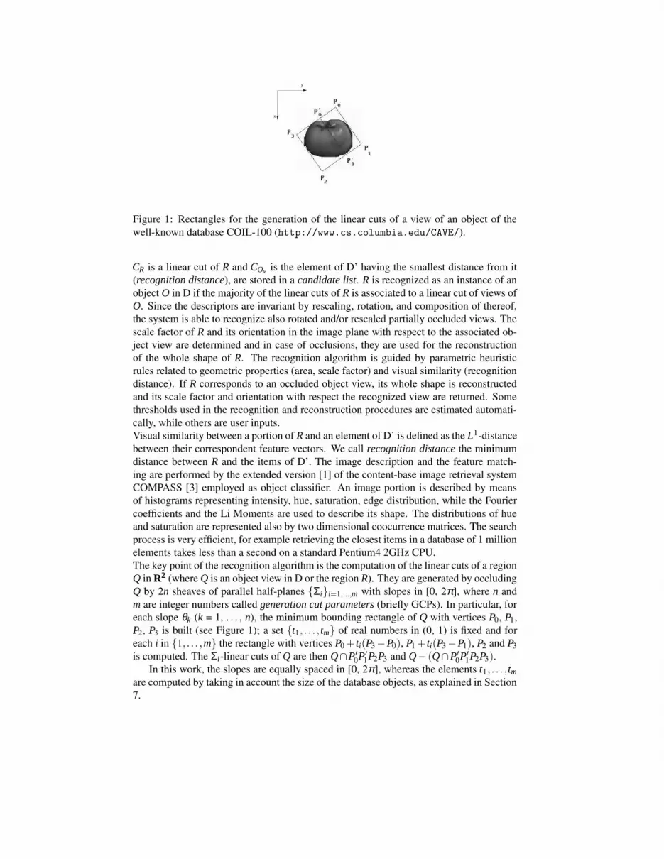
The value of α is given by αR. Let us determine the rotation angle ψ . Let a coordinatesystem be fixed. Let A, B, C, D and A′, B′, C′, D′ be the vertices (in clockwise or anti-clockwise order) of the minimum bounding rectangles of CR and α−1
R KR respectively (seeFigure 2). Two cases are distinguished:
1. length(AB) 6= length(AD) and length(A′B′) 6= length(A′D′). Without loss of general-ity, we can suppose that length(AB) < length(AD) and length(A′B′) < length(A′D′).Since we do not consider the case of flipped objects, the possible transformationsof the form (3) that align the rectangles A′B′C′D′ and ABCD are two:
(A′B′′,A′D′) 7→ (AB,AD) or (A′B′,A′D′) 7→ (DC,BC) (4)
Thus the angle ψ to be determined can assume the values θA′B′−θAB or 2π +θA′B′−θAB, where θAB and θA′B′ are the directions of the edges AB and A′B′ respectively.
2. length(AB) = length(AD) and length(A′B′) = length(A′D′), i.e. the minimum bound-ing rectangles are squares. In this case there are four possible transformations andthe angle ψ can assume the values θA′B′ −θAB + kπ with k = 0, 1/2, 1, 3/2.
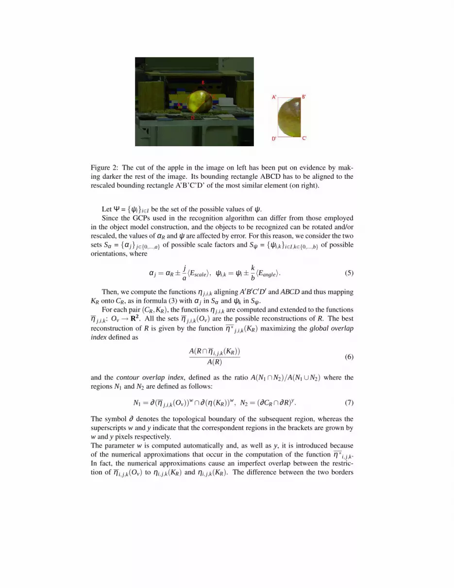
Figure 2: The cut of the apple in the image on left has been put on evidence by mak-ing darker the rest of the image. Its bounding rectangle ABCD has to be aligned to therescaled bounding rectangle A’B’C’D’ of the most similar element (on right).
Let Ψ = {ψi}i∈I be the set of the possible values of ψ .Since the GCPs used in the recognition algorithm can differ from those employed
in the object model construction, and the objects to be recognized can be rotated and/orrescaled, the values of αR and ψ are affected by error. For this reason, we consider the twosets Sα = {α j} j∈{0,...,a} of possible scale factors and Sψ = {ψi,k}i∈I,k∈{0,...,b} of possibleorientations, where
α j = αR ±ja〈Escale〉, ψi,k = ψi ±
kb〈Eangle〉. (5)
Then, we compute the functions η j,i,k aligning A′B′C′D′ and ABCD and thus mappingKR onto CR, as in formula (3) with α j in Sα and ψk in Sψ .
For each pair (CR,KR), the functions η j,i,k are computed and extended to the functionsη j,i,k: Ov → R2. All the sets η j,i,k(Ov) are the possible reconstructions of R. The bestreconstruction of R is given by the function η∗
j,i,k(KR) maximizing the global overlapindex defined as
A(R∩η i, j,k(KR))
A(R)(6)
and the contour overlap index, defined as the ratio A(N1 ∩N2)/A(N1 ∪N2) where theregions N1 and N2 are defined as follows:
N1 = ∂ (η j,i,k(Ov))w ∩∂ (η(KR))w, N2 = (∂CR ∩∂R)y. (7)
The symbol ∂ denotes the topological boundary of the subsequent region, whereas thesuperscripts w and y indicate that the correspondent regions in the brackets are grown byw and y pixels respectively.The parameter w is computed automatically and, as well as y, it is introduced becauseof the numerical approximations that occur in the computation of the function η ∗
i, j,k.In fact, the numerical approximations cause an imperfect overlap between the restric-tion of η i, j,k(Ov) to ηi, j,k(KR) and ηi, j,k(KR). The difference between the two borders

∂ (η j,i,k(Ov))∩ ∂ (η(KR)) and ∂ (CR)∩ ∂ (R) is generally very small, but it could be sig-nificant in the computation of the contour overlap index. For this reason, w is estimatedby rounding up the tolerance
2
√
A(ηi, j,k(KR)∩η i, j,k(Ov))
A(ηi, j,k(KR))(8)
to the nearest integer.On the contrary, the parameter y is set by the user and it is related to the accuracy on thereconstruction, that is measured by the overlap index ν = A(R∩η∗
j,i,k(Ov))/A(R). In ourtests, we set y = 2 pixels.The complexity of the reconstruction algorithm for a cut CR is proportional to the product4|I|abA(CR), where |I| is the cardinality of the set I.
7 Experiments and Conclusions
The section presents the experiments about the recognition and reconstruction perfor-mances obtained by running our method on 4 sets of synthetic images and on a set ofreal-world pictures. The tests on the synthetic data include some studies about the depen-dency of (i) the recognition rate on the GCPs used in model construction and in recogni-tion algorithm, and (ii) the reconstruction accuracy on the parameters a and b.Experiments on the Synthetic Data - Database IKEA-400 consists of 400 images offurniture (400 objects) of IKEA SpA downloaded from the internet cataloghttp://www.ikea.com/ms/it IT/our products.html.The recognition and reconstruction performances have been tested on 4 datasets S15, S25,S35, S45 containing rescaled and/or rotated versions of the objects of IKEA-400 partiallyoccluded by synthetic patches (Figure 3). The subscript in the set names indicates thepercentage of occluded area. The scale factor and the rotation angle range in [0.3; 1.5]and [0; 2π] respectively.For the object model construction, we considered 10 sheaves of half-planes, i.e. 10 slopesequally spaced in [0, 2π]. Since the objects in the database have different size, the numberof cuts having the same slope are different for each object and has been fixed by requiringthat the minimum distance between two half-plane of the same sheaf is ∆ = 50 pixels.Moreover, pa = 0.40 and pb = 0.90. The resulting database IKEA-400’ contains 10660images. In particular, we obtained the following values: Γ = 0.03574, 〈Escale〉 = 0.20044,〈Eangle〉 = 0.15708, Am = 675.75, and AM = 438898.5 pixels. For the reconstruction wefixed a = b = 2.We submit each visible part of the objects in the 4 test sets to the recognition algorithmwith GCPs nR = 2, mR = 2 (case a.) and n′R = 5, m′
R = 5 (case b.). Tables 1-a and 1-b showthe recognition rate ρ and the reconstruction accuracy, measured by the mean overlap in-dex ν obtained by setting a = b = 2. In case a., the computational time for the recognitionis less than 1 second, in case b. it is about 2.6 seconds, but the results are better. Therecognition rate ρ is in case b. very satisfactory. For a = b = 2, the reconstruction requestsabout 6 seconds. For case b. we repeated the tests by fixing a = b = 4 and we obtained themean overlap index ν ′. There is not a significant difference between the values of ν andν ′, but for a = b = 4, the computational time is longer (about 20 seconds). The times havebeen measured by running the algorithm on a standard Pentium4 2.80GHz.
a. b. c. c.
Figure 3: Examples of synthetic test images. Each of them contains a rescaled and/orrotated object view of D partially occluded (occluded area percentages of a. 15%, b.25%, c. 35 %, and d. 45%).
Table aTest Set ρ ν
S15 0.865 0.756S25 0.748 0.725S35 0.798 0.666S45 0.668 0.626
Table bTest Set ρ ν ν ′
S15 0.983 0.882 0.892S25 0.885 0.848 0.852S35 0.965 0.815 0.821S45 0.955 0.796 0.821
Table cTest Set ρ ν
S15 0.980 0.876S25 0.876 0.814S35 0.945 0.799S45 0.918 0.762
Table 1: Recognition rate and mean overlap index for the test sets with objects of IKEA-400. The overlap indices ν and ν ′ have been obtained by setting (a = 2, b = 2) and (a = 4,b = 4) respectively. Tables a. and b. are referred to the database IKEA-400’, whereas theresults of Table c. have been obtained by using the database IKEA-400”.
To test the results dependency on the GCPs used for the object model construction, webuilt an other extension of IKEA-400 by generating cuts with 5 sheaves of half-planeswith ∆ = 100 pixels. The resulting database (IKEA-400”) contains 5573 images. Table1-c shows the recognition rate and the mean overlap index obtained by using in the recog-nition algorithm the GCPs n′R = m′
R = 5 and the parameters a = b = 2 for the reconstruction.Also in this case satisfactory results have been obtained.Experiments on the Real-World Data - The tests on the recognition and reconstruction
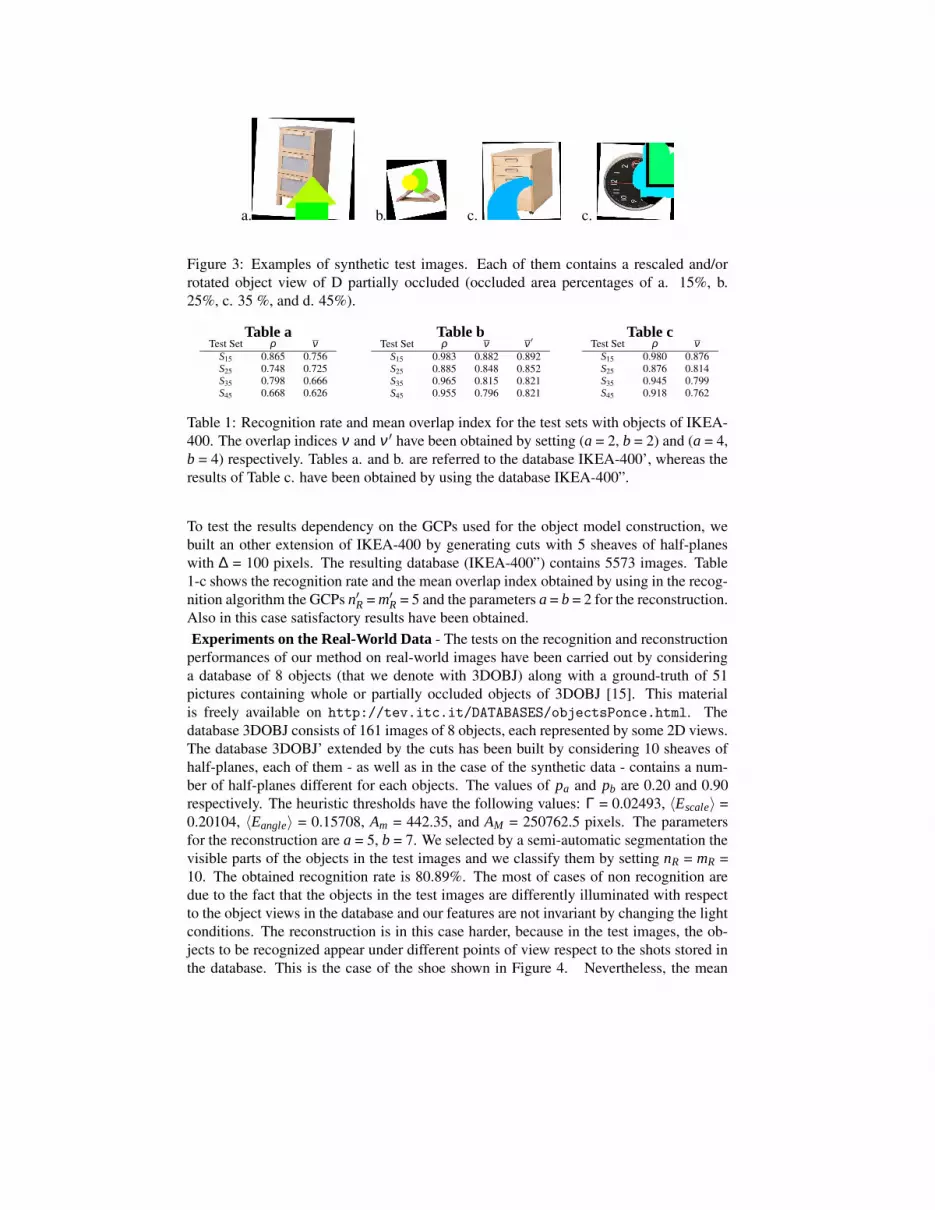
performances of our method on real-world images have been carried out by consideringa database of 8 objects (that we denote with 3DOBJ) along with a ground-truth of 51pictures containing whole or partially occluded objects of 3DOBJ [15]. This materialis freely available on http://tev.itc.it/DATABASES/objectsPonce.html. Thedatabase 3DOBJ consists of 161 images of 8 objects, each represented by some 2D views.The database 3DOBJ’ extended by the cuts has been built by considering 10 sheaves ofhalf-planes, each of them - as well as in the case of the synthetic data - contains a num-ber of half-planes different for each objects. The values of pa and pb are 0.20 and 0.90respectively. The heuristic thresholds have the following values: Γ = 0.02493, 〈Escale〉 =0.20104, 〈Eangle〉 = 0.15708, Am = 442.35, and AM = 250762.5 pixels. The parametersfor the reconstruction are a = 5, b = 7. We selected by a semi-automatic segmentation thevisible parts of the objects in the test images and we classify them by setting nR = mR =10. The obtained recognition rate is 80.89%. The most of cases of non recognition aredue to the fact that the objects in the test images are differently illuminated with respectto the object views in the database and our features are not invariant by changing the lightconditions. The reconstruction is in this case harder, because in the test images, the ob-jects to be recognized appear under different points of view respect to the shots stored inthe database. This is the case of the shoe shown in Figure 4. Nevertheless, the mean

Figure 4: The set of views of the shoe in the database D (left) does not contain the poseof the test image on right. In this case, the object is recognized, but a good reconstructionis not possible.
Figure 5: Examples of Reconstruction in Real-World Images.
overlap index is 0.9280. Some results are shown in Figure 5.Conclusions - The tests illustrated in this Section show that our method performs goodboth in term of recognition and reconstruction. Therefore our future work includes its usein an object recognition system like [10]. Since the computational times are quite long,our planes comprehend also a parallelization and optimization of the code and the com-parison of our approach with other on common databases. Moreover, we will develop astrategy for the automatic estimation of the thresholds that are currently to be fixed by theuser, like the GCPs parameters.Acknowledgments - The authors would like to acknowledge IKEA SpA for having madeavailable its catalogs for scientific research purposes. This work has been partially sup-ported by the EU Project VIKEF (Virtual Information and Knowledge Environment Frame-work).
References
[1] C. Andreatta. CBIR techniques for object recognition. Technical Report, ITC-irstT04-12-01, December 2004.
[2] S. Berretti, A. Del Bimbo, and E. Vicario. Efficient matching and indexing of graphmodels in content-based retrieval. IEEE Transaction on Pattern Analysis and Ma-chine Intelligence, 23(10), 2001.

[3] R. Brunelli and O. Mich. Image retrieval by examples. IEEE Transactions on Mul-timedia, 2(3), 2000.
[4] T. Deselaers, D. Keysers, R. Paredes, E. Vidal, and H. Ney. Local representation formulti-object recognition. In Deutsche Arbeitsgemeinschaft fur Mustererkennung:DAGM 2003, 2003.
[5] H. Eidenberger. A new perspective on visual information retrieval. In SPIE Elec-tronic Imaging Symposium, SPIE vol. 5304, San Jose, 2004.
[6] V. Ferrari, T. Tuytelaars, and L. Van Gool. Simultaneous object recognition and seg-mentation by image exploration. International Journal of Computer Vision (IJCV),(4), 2006.
[7] M. Flickner, H. Sawhney, W. Niblack, J. Ashley, H. Qian, and other. Query by imageand video content: the QBIC system. Computer, 28(9), 1995.
[8] G. Fritz, L. Paletta, and H. Bischof. Object representation and recognition frominformative local appearances. In Digital Imaging in Media and Education, 2004.
[9] F. Krolupper. Recognition of occluded objects using curvature. In Proc. of The 12thInternational Conference in Central Europe on Computer Graphics, Visualizationand Computer Vision, 2004.
[10] M. Lecca. Object recognition in color images by the self configuring system MEM-ORI. International Journal of Signal Processing, 3(3), 2006.
[11] Philippe Mulhem and Joo Hwee Lim. Symbolic photograph content-based retrieval.In CIKM ’02: Proceedings of the eleventh international conference on Informationand knowledge management, New York, NY, USA, 2002. ACM Press.
[12] S. Obdrzlek and J. Matas. Object recognition using local affine frames on distin-guished regions. In British Machine Vision Conference, 2002.
[13] M. Reinhold, M. Grzegorzek, and H. Niemann J. Denzler. Appearance-based recog-nition of 3-d objects by cluttered background and occlusions. Pattern Recognition,38(5), 2005.
[14] E. Rivlin, S. J. Dickinson, and A. Rosenfeld. Recognition by functional parts. Com-puter Vision and Image Understanding: CVIU, 82(2), 1995.
[15] F. Rothganger, S. Lazebnik, C. Schmid, and J. Ponce. 3D object modeling andrecognition using local affine-invariant image descriptors and multi-view spatialconstraints. IJCV, 66(3), 2006.
[16] A. Shokoufandeh, I. Marsic, and S. J. Dickinson. View-based object recognitionusing saliency maps. Image and Computing, 17, 1999.
[17] J. R. Smith and S.F. Chang. VisualSEEk: A fully automated content-based imagequery system. In ACM Multimedia, 1996.
[18] V. Vilaplana, X. Giro, P. Salembier, and F. Marques. Region-based extraction andanalysis of visual object information. In Proc. of Int. Workshop on Content-BasedMultimedia Indexing CBMI 2005, 2005.