kennametal.com
INNOVATIONS 2020 | 02 | INCH
Distributed by:
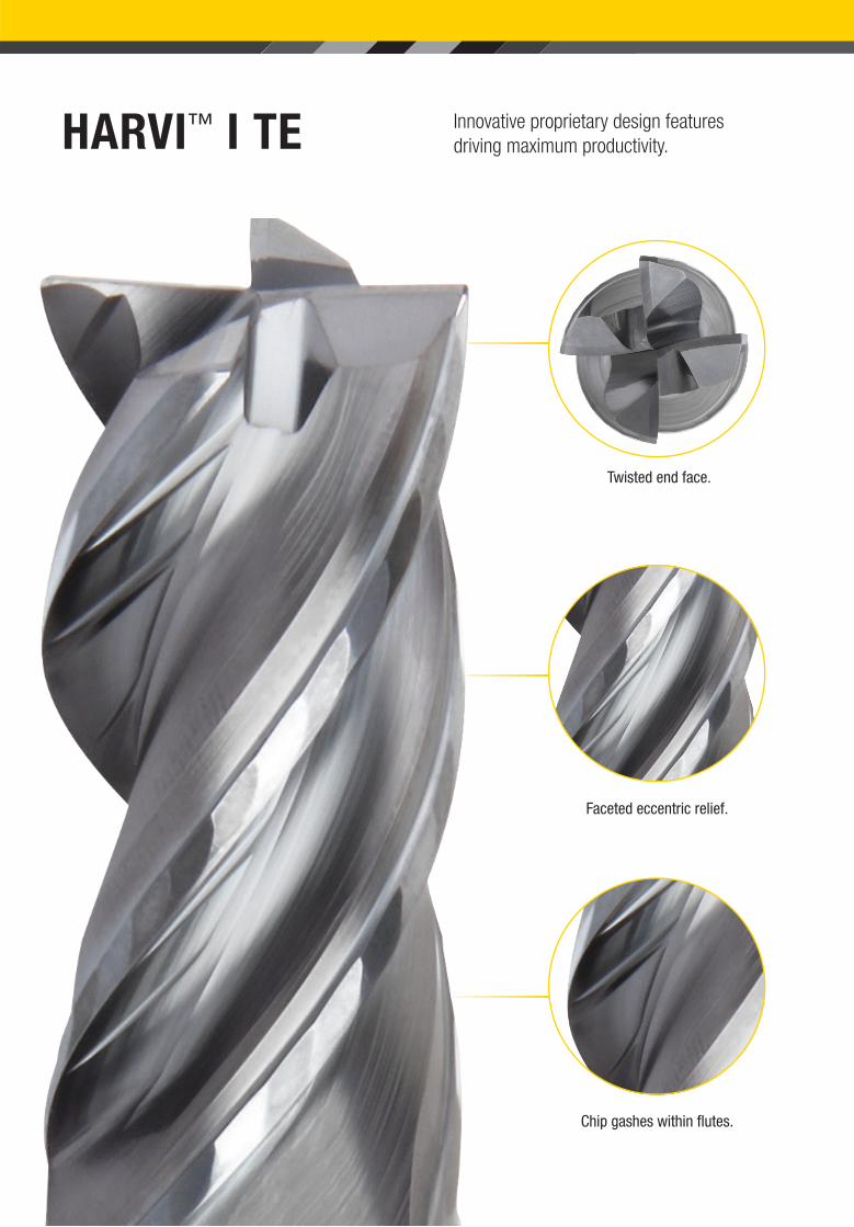
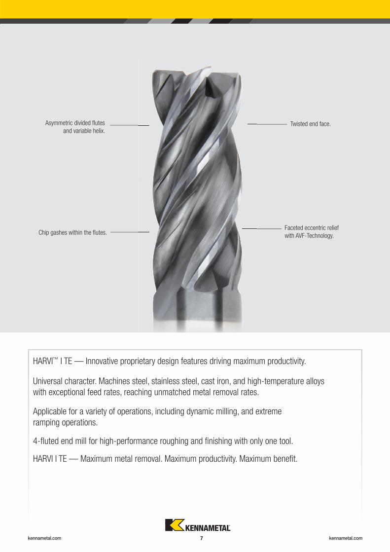
HARVI™ I TE Innovative proprietary design features
driving maximum productivity.
Faceted eccentric relief.
Twisted end face.
Chip gashes within fl utes.
kennametal.com kennametal.com 1
INNOVATIONS
Services & Support .........................................................................................................................................................................2–5
Contact Information ...................................................................................................................................................... 2–3
Spare Parts & Accessories Information • Online Catalog ............................................................................................. 4–5
Solid End Milling ...........................................................................................................................................................................6–41
HARVI I TE ................................................................................................................................................................... 6–25
KOR 5 ........................................................................................................................................................................ 26–30
Duo-Lock .................................................................................................................................................................. 32–41
Holemaking .................................................................................................................................................................................42–53
KSEM PLUS • HPF Inserts ....................................................................................................................................... 42–45
KenTIP FS • Bodies with SCF Shank........................................................................................................................ 46–53
Turning ........................................................................................................................................................................................54–66
KBH10B & KBH20B • Hard Turning PcBN Grades .................................................................................................. 54–61
Beyond Evolution ...................................................................................................................................................... 62–66
Tooling Systems .........................................................................................................................................................................68–86
ER Collet Chucks ...................................................................................................................................................... 68–86
General Information ....................................................................................................................................................................88–92
Grade Descriptions ................................................................................................................................................... 88–89
Key to Column Headings ................................................................................................................................................ 90
Material Cross Reference .......................................................................................................................................... 91–92
kennametal.com kennametal.com 2
Region Originating Country Language CAS Hotline Email
North America USA English 800 835 3668 [email protected] Spanish 1800 253 0758 [email protected]
Africa South Africa English 0800 981643 [email protected]
Europe Austria German 0800 202873 [email protected] English/French 0800 80850 [email protected] English 808 89298 [email protected] English 0800 919412 [email protected] French 080 5540 367 [email protected] German 0800 0006651 [email protected] English 1809 449889 [email protected] Italian 800 916561 [email protected] English 0800 0201 130 [email protected] English 800 10080 [email protected] Polish 0080 04411887 [email protected] (landline) Russian 8800 5556394 [email protected] (cell phone) Russian +7 800 5556394 [email protected] English 0207 99246 [email protected] English 0800 032 8339 [email protected] Russian 800 502664 [email protected]
Asia Pacifi c Australia English 1800 666 667 [email protected] English 1 800 103 5227 [email protected] English 03 3820 2855 [email protected] (South) English +82 2 2100 6100 [email protected] English 1800 812 990 [email protected] Zealand English 0800 450 941 [email protected] English 1800 6221031 [email protected] English 0800 666 197 [email protected] English 1800 4417820 [email protected]
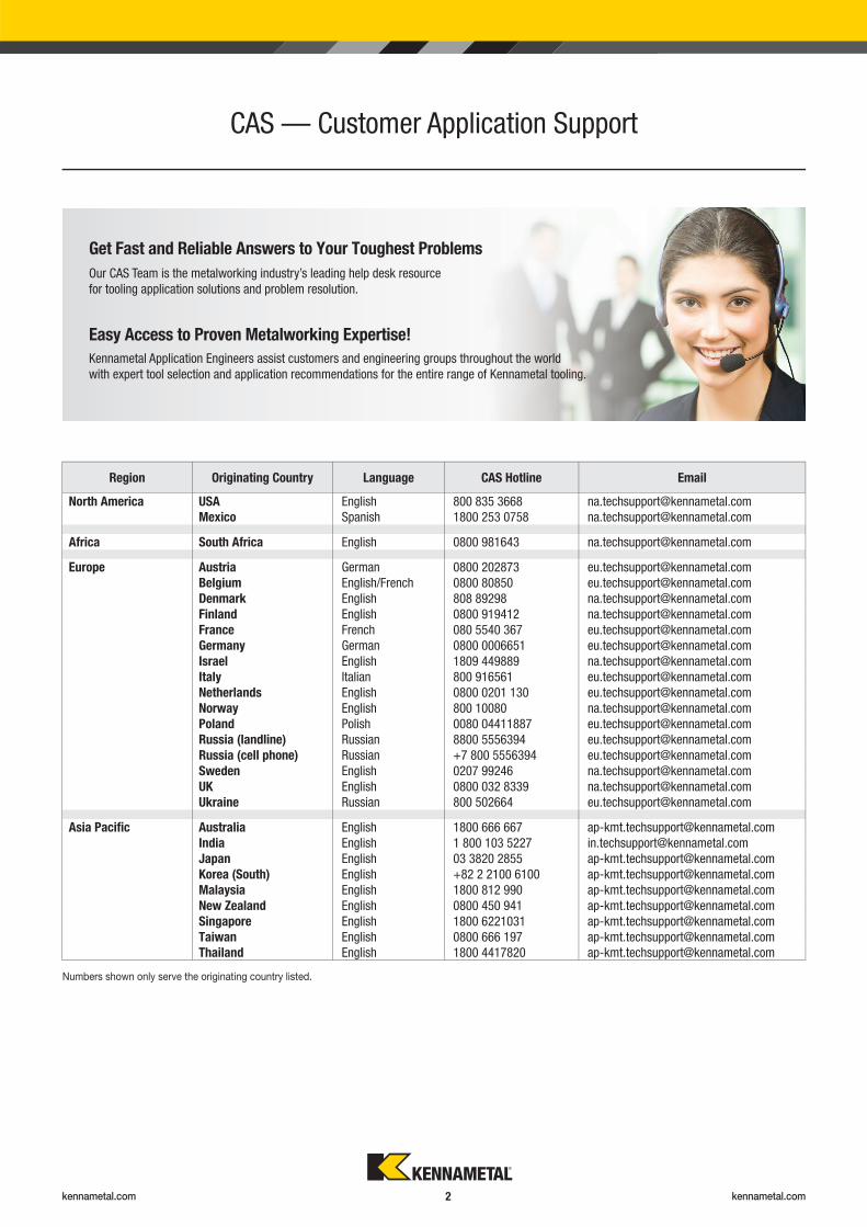
CAS — Customer Application Support
Numbers shown only serve the originating country listed.
Get Fast and Reliable Answers to Your Toughest Problems
Our CAS Team is the metalworking industry’s leading help desk resource
for tooling application solutions and problem resolution.
Easy Access to Proven Metalworking Expertise!
Kennametal Application Engineers assist customers and engineering groups throughout the world
with expert tool selection and application recommendations for the entire range of Kennametal tooling.
kennametal.com kennametal.com 3
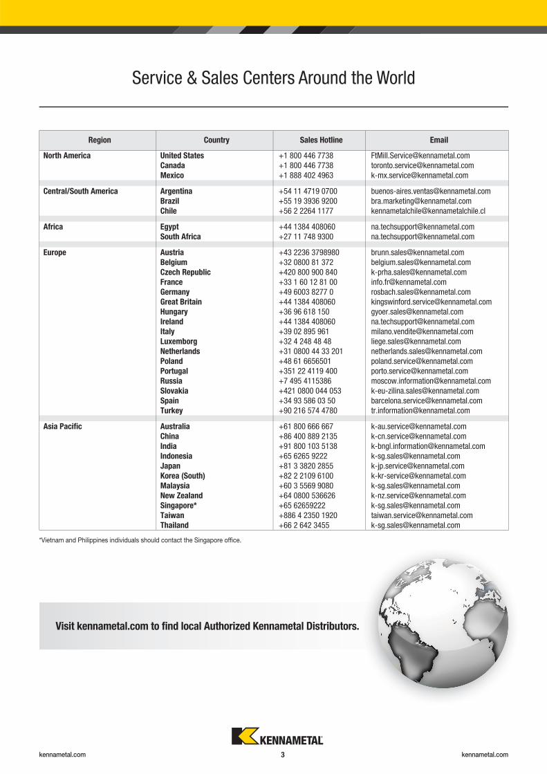
*Vietnam and Philippines individuals should contact the Singapore offi ce.
Region Country Sales Hotline Email
North America United States +1 800 446 7738 [email protected] +1 800 446 7738 [email protected] +1 888 402 4963 [email protected]
Central/South America Argentina +54 11 4719 0700 [email protected] +55 19 3936 9200 [email protected] +56 2 2264 1177 [email protected]
Africa Egypt +44 1384 408060 [email protected] Africa +27 11 748 9300 [email protected]
Europe Austria +43 2236 3798980 [email protected] +32 0800 81 372 [email protected] Republic +420 800 900 840 [email protected] +33 1 60 12 81 00 [email protected] +49 6003 8277 0 [email protected] Britain +44 1384 408060 [email protected] +36 96 618 150 [email protected] +44 1384 408060 [email protected] +39 02 895 961 [email protected] +32 4 248 48 48 [email protected] +31 0800 44 33 201 [email protected] +48 61 6656501 [email protected] +351 22 4119 400 [email protected] +7 495 4115386 [email protected] +421 0800 044 053 [email protected] +34 93 586 03 50 [email protected] +90 216 574 4780 [email protected]
Asia Pacifi c Australia +61 800 666 667 [email protected] +86 400 889 2135 [email protected] +91 800 103 5138 [email protected] +65 6265 9222 [email protected] +81 3 3820 2855 [email protected] (South) +82 2 2109 6100 [email protected] +60 3 5569 9080 [email protected] Zealand +64 0800 536626 [email protected]* +65 62659222 [email protected] +886 4 2350 1920 [email protected] +66 2 642 3455 [email protected]
Visit kennametal.com to fi nd local Authorized Kennametal Distributors.
Service & Sales Centers Around the World
kennametal.com kennametal.com 4
Digitally access spare parts and accessories information
to ensure you keep your operation running.
Visit kennametal.com/novo and download today. It’s Free!
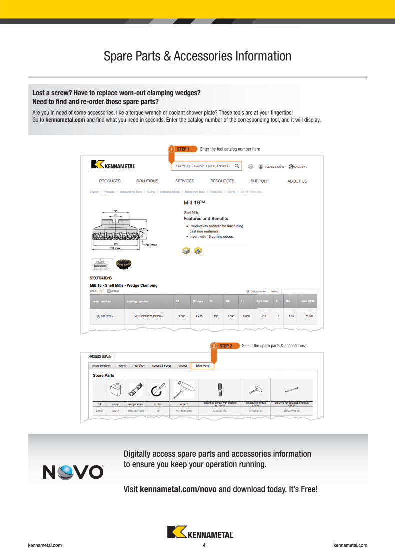
Spare Parts & Accessories Information
Lost a screw? Have to replace worn-out clamping wedges?
Need to fi nd and re-order those spare parts?
Are you in need of some accessories, like a torque wrench or coolant shower plate? These tools are at your fi ngertips!
Go to kennametal.com and fi nd what you need in seconds. Enter the catalog number of the corresponding tool, and it will display.
Enter the tool catalog number here
Select the spare parts & accessories
STEP 1
STEP 2
1
2
kennametal.com kennametal.com 5
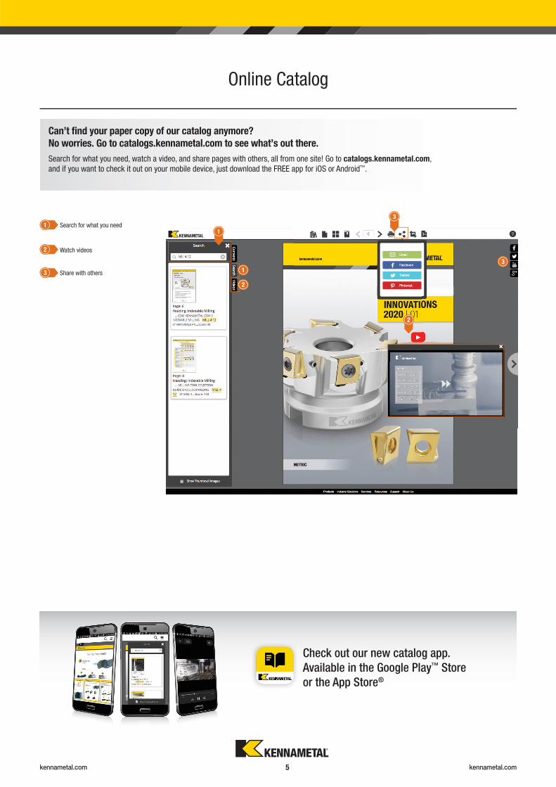
Online Catalog
3
1
2
Check out our new catalog app.
Available in the Google Play™ Store
or the App Store®
Can’t fi nd your paper copy of our catalog anymore?
No worries. Go to catalogs.kennametal.com to see what’s out there.
Search for what you need, watch a video, and share pages with others, all from one site! Go to catalogs.kennametal.com,
and if you want to check it out on your mobile device, just download the FREE app for iOS or Android™.
1
2
3
1
2
3
Search for what you need
Watch videos
Share with others
kennametal.com kennametal.com 6
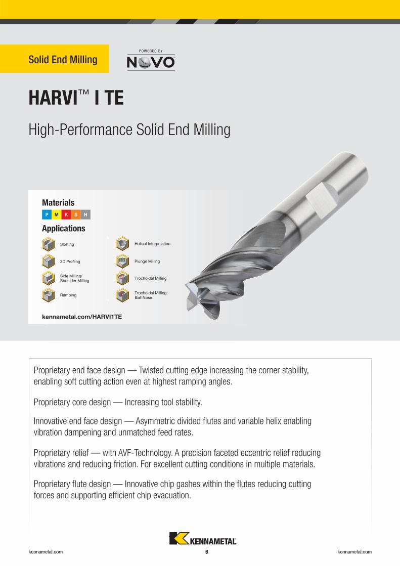
Solid End Milling
HARVI™ I TE
Proprietary end face design — Twisted cutting edge increasing the corner stability,
enabling soft cutting action even at highest ramping angles.
Materials
P M K S H
Helical Interpolation
Plunge Milling
Ramping
Applications
Trochoidal Milling
Trochoidal Milling:Ball Nose
kennametal.com/HARVI1TE
Slotting
3D Profi ing
Side Milling/Shoulder Milling
High-Performance Solid End Milling
Proprietary relief — with AVF-Technology. A precision faceted eccentric relief reducing
vibrations and reducing friction. For excellent cutting conditions in multiple materials.
Proprietary fl ute design — Innovative chip gashes within the fl utes reducing cutting
forces and supporting effi cient chip evacuation.
Proprietary core design — Increasing tool stability.
Innovative end face design — Asymmetric divided fl utes and variable helix enabling
vibration dampening and unmatched feed rates.
kennametal.com kennametal.com 7
Faceted eccentric relief
with AVF-Technology.
Applicable for a variety of operations, including dynamic milling, and extreme
ramping operations.
4-fl uted end mill for high-performance roughing and fi nishing with only one tool.
HARVI I TE — Maximum metal removal. Maximum productivity. Maximum benefi t.
HARVI™ I TE — Innovative proprietary design features driving maximum productivity.
Universal character. Machines steel, stainless steel, cast iron, and high-temperature alloys
with exceptional feed rates, reaching unmatched metal removal rates.
Twisted end face.
Chip gashes within the fl utes.
Asymmetric divided fl utes
and variable helix.
kennametal.com kennametal.com 8
Solid Carbide End Mills Solid Carbide End Mills
HARVI™ • TOOL SELECTION GUIDE
� Primary
� Secondary
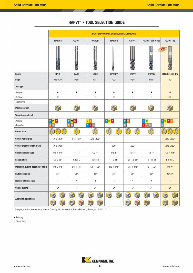
HIGH-PERFORMANCE (HP) ROUGHING & FINISHING
HARVI I HARVI I HARVI I HARVI I HARVI I HARVI I Ball Nose HARVI I TE
Series HPHV UADE UBDE HPRSHV HPHVT HPHVBN H1TE4SE-4CH-4RA
Page P16–P20* P21* P21* P22* P24* P23* 13
Tool type
Rougher � � � � � � �
Finisher � � � � � � �
Chamfering
Main operation
Workpiece material
Primary P M K P M K M S P M K P S P M P M K S
Secondary S H S H P K H H K S H H
Corner style
Corner radius [R�] .015–.250" .015–.120" .015–.120" — — — .010–.250"
Corner chamfer width [BCH] .015–.020" — — .020" .020" — .015–.020"
Cutter diameter [D1] 1/8–1-1/4" 1/4–1" 1/2–1" 1/2–1" 1/2–1" 1/8–1" 1/8–1-1/4"
Length of cut 1.8–2 x D1 1.25 x D 1.25 x D 1–1.2 x D1 1.25–1.8 x D1 1.5–4 x D1 1.2–4 x D
Maximum cutting depth [Ap1 max] 1/4–2-1/2" 3/8–1-1/8" 5/8–1-1/8" 5/8–1-1/8" 5/8 –1-1/2" 1/2–1-1/2" 1/4–4"
Flute helix angle 38° 38° 38° 38° 38° 38° 36°/39°
Number of flutes [ZU] 4 4 4 4 4 4 4
Center cutting � � � � � � �
Additional operations
NEW!
* See page in the Kennametal Master Catalog 2018 • Volume Two • Rotating Tools, A-16-05217.
kennametal.com kennametal.com 9
Solid Carbide End Mills Solid Carbide End Mills
HARVI™ • TOOL SELECTION GUIDE
� Primary
� Secondary
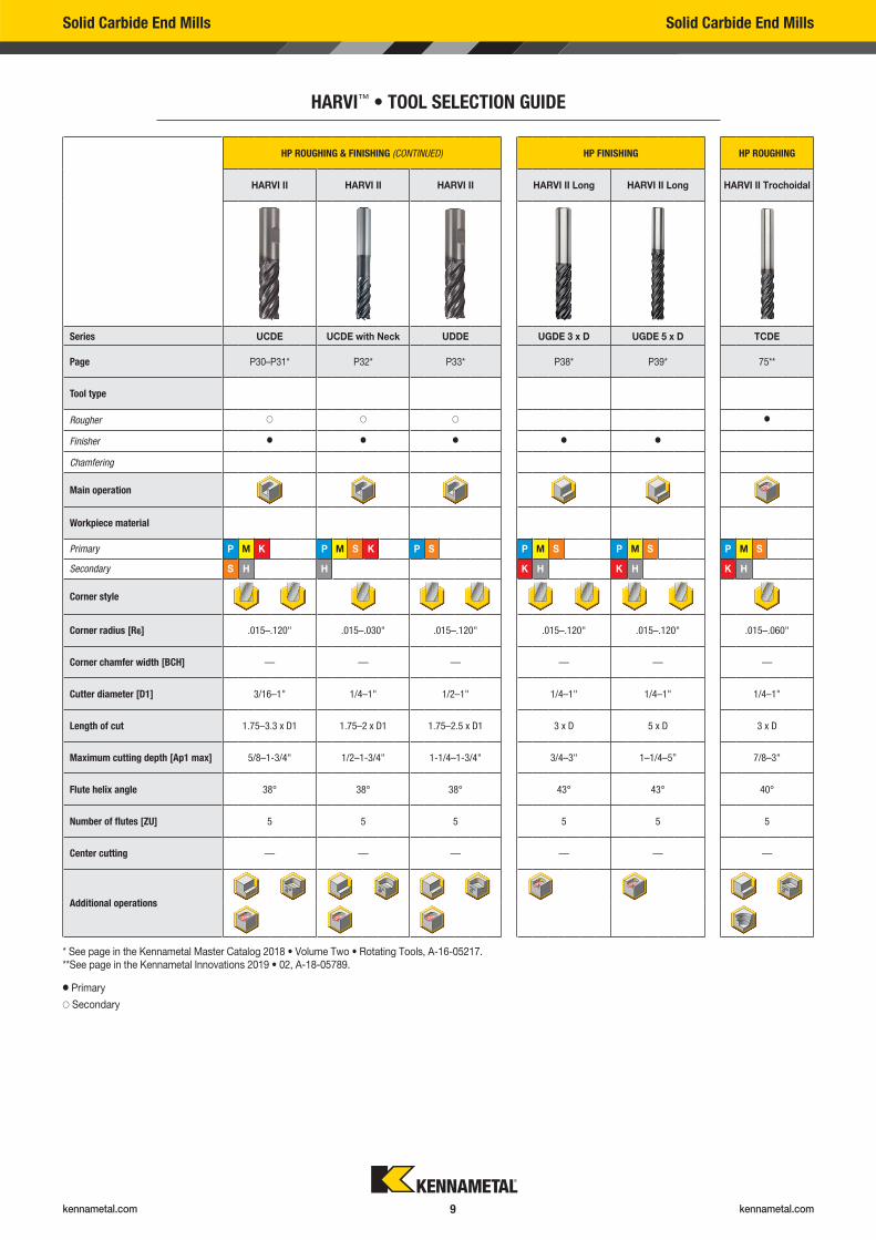
HP ROUGHING & FINISHING (CONTINUED) HP FINISHING HP ROUGHING
HARVI II HARVI II HARVI II HARVI II Long HARVI II Long HARVI II Trochoidal
Series UCDE UCDE with Neck UDDE UGDE 3 x D UGDE 5 x D TCDE
Page P30–P31* P32* P33* P38* P39* 75**
Tool type
Rougher � � � �
Finisher � � � � �
Chamfering
Main operation
Workpiece material
Primary P M K P M S K P S P M S P M S P M S
Secondary S H H K H K H K H
Corner style
Corner radius [R�] .015–.120" .015–.030" .015–.120" .015–.120" .015–.120" .015–.060"
Corner chamfer width [BCH] — — — — — —
Cutter diameter [D1] 3/16–1" 1/4–1" 1/2–1" 1/4–1" 1/4–1" 1/4–1"
Length of cut 1.75–3.3 x D1 1.75–2 x D1 1.75–2.5 x D1 3 x D 5 x D 3 x D
Maximum cutting depth [Ap1 max] 5/8–1-3/4" 1/2–1-3/4" 1-1/4–1-3/4" 3/4–3" 1–1/4–5” 7/8–3"
Flute helix angle 38° 38° 38° 43° 43° 40°
Number of flutes [ZU] 5 5 5 5 5 5
Center cutting — — — — — —
Additional operations
* See page in the Kennametal Master Catalog 2018 • Volume Two • Rotating Tools, A-16-05217.** See page in the Kennametal Innovations 2019 • 02, A-18-05789.
kennametal.com kennametal.com 10
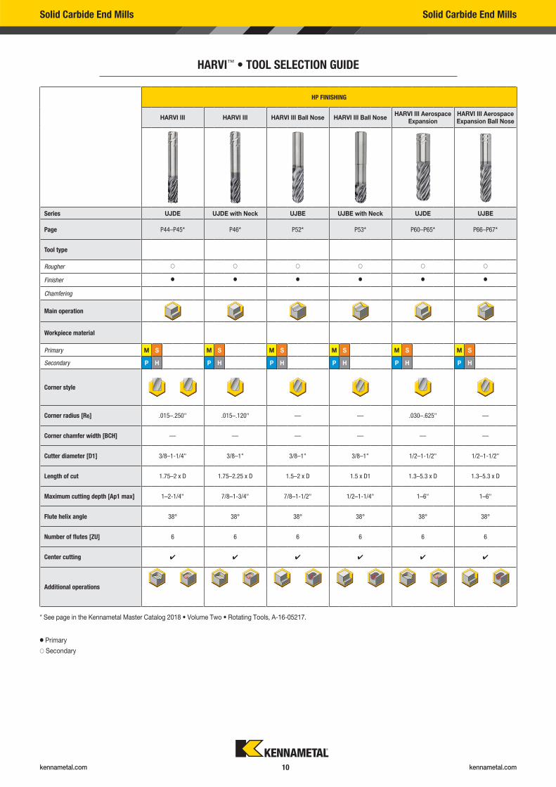
HP FINISHING
HARVI III HARVI III HARVI III Ball Nose HARVI III Ball NoseHARVI III Aerospace
ExpansionHARVI III Aerospace Expansion Ball Nose
Series UJDE UJDE with Neck UJBE UJBE with Neck UJDE UJBE
Page P44–P45* P46* P52* P53* P60–P65* P66–P67*
Tool type
Rougher � � � � � �
Finisher � � � � � �
Chamfering
Main operation
Workpiece material
Primary M S M S M S M S M S M S
Secondary P H P H P H P H P H P H
Corner style
Corner radius [R�] .015–.250" .015–.120" — — .030–.625" —
Corner chamfer width [BCH] — — — — — —
Cutter diameter [D1] 3/8–1-1/4" 3/8–1" 3/8–1" 3/8–1" 1/2–1-1/2" 1/2–1-1/2"
Length of cut 1.75–2 x D 1.75–2.25 x D 1.5–2 x D 1.5 x D1 1.3–5.3 x D 1.3–5.3 x D
Maximum cutting depth [Ap1 max] 1–2-1/4" 7/8–1-3/4" 7/8–1-1/2" 1/2–1-1/4" 1–6" 1–6"
Flute helix angle 38° 38° 38° 38° 38° 38°
Number of flutes [ZU] 6 6 6 6 6 6
Center cutting � � � � � �
Additional operations
Solid Carbide End Mills Solid Carbide End Mills
HARVI™ • TOOL SELECTION GUIDE
� Primary
� Secondary
* See page in the Kennametal Master Catalog 2018 • Volume Two • Rotating Tools, A-16-05217.
kennametal.com kennametal.com 11
Solid Carbide End Mills Solid Carbide End Mills
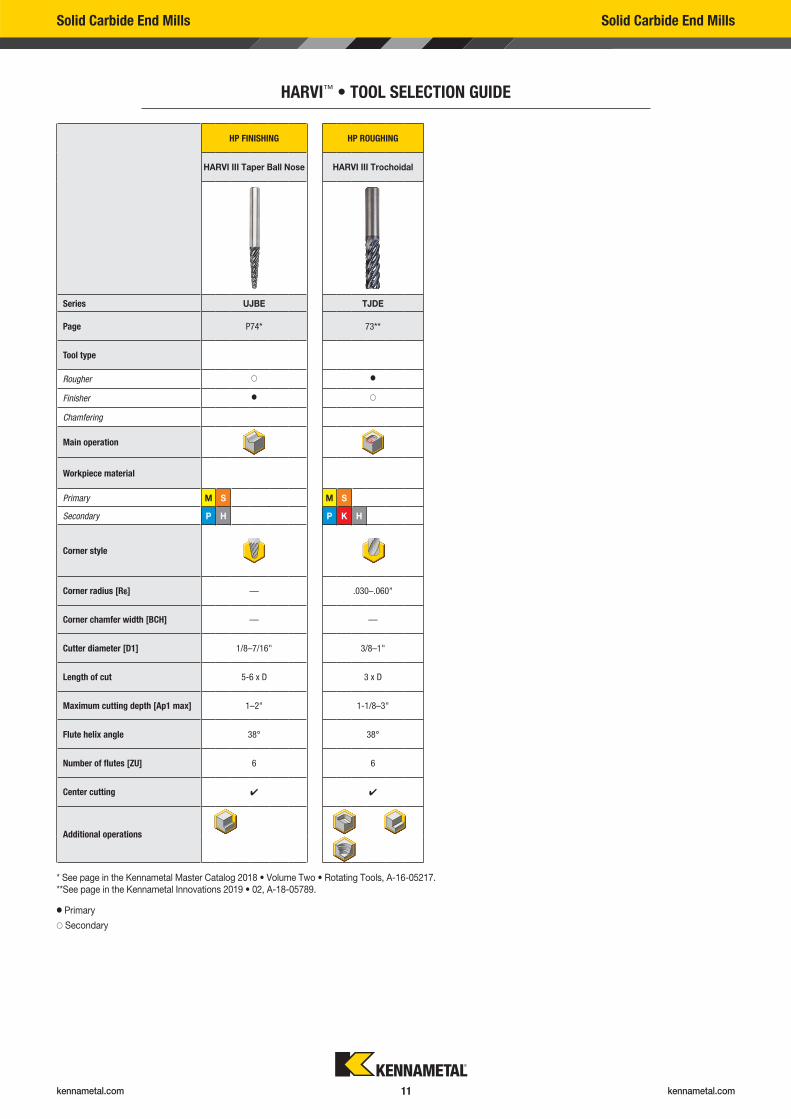
HARVI™ • TOOL SELECTION GUIDE
� Primary
� Secondary
* See page in the Kennametal Master Catalog 2018 • Volume Two • Rotating Tools, A-16-05217.** See page in the Kennametal Innovations 2019 • 02, A-18-05789.
HP FINISHING HP ROUGHING
HARVI III Taper Ball Nose HARVI III Trochoidal
Series UJBE TJDE
Page P74* 73**
Tool type
Rougher � �
Finisher � �
Chamfering
Main operation
Workpiece material
Primary M S M S
Secondary P H P K H
Corner style
Corner radius [R�] — .030–.060"
Corner chamfer width [BCH] — —
Cutter diameter [D1] 1/8–7/16" 3/8–1"
Length of cut 5-6 x D 3 x D
Maximum cutting depth [Ap1 max] 1–2" 1-1/8–3"
Flute helix angle 38° 38°
Number of flutes [ZU] 6 6
Center cutting � �
Additional operations
kennametal.com kennametal.com 12
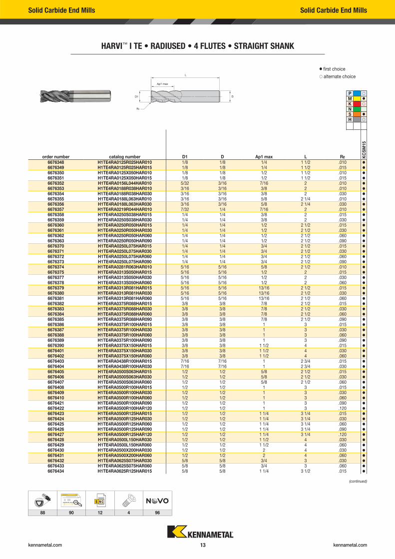
Solid Carbide End Mills Solid Carbide End Mills
HARVI™ I TE • RADIUSED • 4 FLUTES • STRAIGHT SHANK
order number catalog number D1 D Ap1 max L R� KC
SM
15
6676348 H1TE4RA0125R025HAR010 1/8 1/8 1/4 1 1/2 .010 �
6676349 H1TE4RA0125R025HAR015 1/8 1/8 1/4 1 1/2 .015 �
6676350 H1TE4RA0125X050HAR010 1/8 1/8 1/2 1 1/2 .010 �
6676351 H1TE4RA0125X050HAR015 1/8 1/8 1/2 1 1/2 .015 �
6676352 H1TE4RA0156L044HAR010 5/32 3/16 7/16 2 010 �
� first choice
� alternate choice
P �
M �
K �
NS �
H �
Solid Carbide End Mills Solid Carbide End Mills
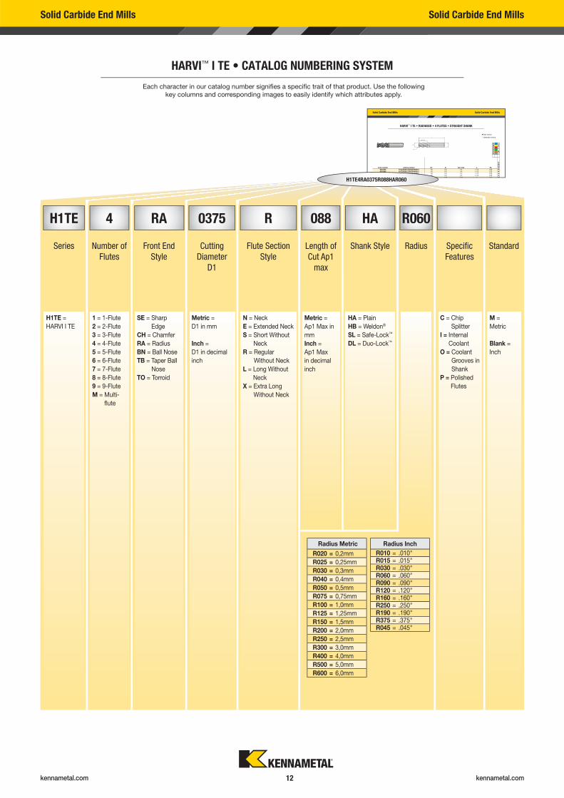
HARVI™ I TE • CATALOG NUMBERING SYSTEM
Each character in our catalog number signifi es a specifi c trait of that product. Use the following
key columns and corresponding images to easily identify which attributes apply.
H1TE4RA0375R088HAR060
Radius Metric
R020 = 0,2mm
R025 = 0,25mm
R030 = 0,3mm
R040 = 0,4mm
R050 = 0,5mm
R075 = 0,75mm
R100 = 1,0mm
R125 = 1,25mm
R150 = 1,5mm
R200 = 2,0mm
R250 = 2,5mm
R300 = 3,0mm
R400 = 4,0mm
R500 = 5,0mm
R600 = 6,0mm
Radius Inch
R010 = .010"R015 = .015"R030 = .030"R060 = .060"R090 = .090"R120 = .120"R160 = .160"R250 = .250"R190 = .190"R375 = .375"R045 = .045"
H1TE 4 RA 0375 R 088 HA R060
Series Number of
Flutes
Front End
Style
Cutting
Diameter
D1
Flute Section
Style
Length of
Cut Ap1
max
Shank Style Radius Specifi c
Features
Standard
H1TE =
HARVI I TE
1 = 1-Flute
2 = 2-Flute
3 = 3-Flute
4 = 4-Flute
5 = 5-Flute
6 = 6-Flute
7 = 7-Flute
8 = 8-Flute
9 = 9-Flute
M = Multi-
fl ute
SE = Sharp
Edge
CH = Chamfer
RA = Radius
BN = Ball Nose
TB = Taper Ball
Nose
TO = Torroid
Metric =
D1 in mm
Inch =
D1 in decimal
inch
N = Neck
E = Extended Neck
S = Short Without
Neck
R = Regular
Without Neck
L = Long Without
Neck
X = Extra Long
Without Neck
Metric =
Ap1 Max in
mm
Inch =
Ap1 Max
in decimal
inch
HA = Plain
HB = Weldon®
SL = Safe-Lock™
DL = Duo-Lock™
C = Chip
Splitter
I = Internal
Coolant
O = Coolant
Grooves in
Shank
P = Polished
Flutes
M =
Metric
Blank =
Inch
kennametal.com kennametal.com 13
AB
88 90 12 4 96
Solid Carbide End Mills Solid Carbide End Mills
HARVI™ I TE • RADIUSED • 4 FLUTES • STRAIGHT SHANK
order number catalog number D1 D Ap1 max L R� KC
SM
15
6676348 H1TE4RA0125R025HAR010 1/8 1/8 1/4 1 1/2 .010 �
6676349 H1TE4RA0125R025HAR015 1/8 1/8 1/4 1 1/2 .015 �
6676350 H1TE4RA0125X050HAR010 1/8 1/8 1/2 1 1/2 .010 �
6676351 H1TE4RA0125X050HAR015 1/8 1/8 1/2 1 1/2 .015 �
6676352 H1TE4RA0156L044HAR010 5/32 3/16 7/16 2 .010 �
6676353 H1TE4RA0188R038HAR010 3/16 3/16 3/8 2 .010 �
6676354 H1TE4RA0188R038HAR030 3/16 3/16 3/8 2 .030 �
6676355 H1TE4RA0188L063HAR010 3/16 3/16 5/8 2 1/4 .010 �
6676356 H1TE4RA0188L063HAR030 3/16 3/16 5/8 2 1/4 .030 �
6676357 H1TE4RA0219R044HAR010 7/32 1/4 7/16 2 .010 �
6676358 H1TE4RA0250S038HAR015 1/4 1/4 3/8 2 .015 �
6676359 H1TE4RA0250S038HAR030 1/4 1/4 3/8 2 .030 �
6676360 H1TE4RA0250R050HAR015 1/4 1/4 1/2 2 1/2 .015 �
6676361 H1TE4RA0250R050HAR030 1/4 1/4 1/2 2 1/2 .030 �
6676362 H1TE4RA0250R050HAR060 1/4 1/4 1/2 2 1/2 .060 �
6676363 H1TE4RA0250R050HAR090 1/4 1/4 1/2 2 1/2 .090 �
6676370 H1TE4RA0250L075HAR015 1/4 1/4 3/4 2 1/2 .015 �
6676371 H1TE4RA0250L075HAR030 1/4 1/4 3/4 2 1/2 .030 �
6676372 H1TE4RA0250L075HAR060 1/4 1/4 3/4 2 1/2 .060 �
6676373 H1TE4RA0250L075HAR090 1/4 1/4 3/4 2 1/2 .090 �
6676374 H1TE4RA0281R063HAR010 5/16 5/16 5/8 2 1/2 .010 �
6676375 H1TE4RA0313S050HAR015 5/16 5/16 1/2 2 .015 �
6676377 H1TE4RA0313S050HAR030 5/16 5/16 1/2 2 .030 �
6676378 H1TE4RA0313S050HAR060 5/16 5/16 1/2 2 .060 �
6676379 H1TE4RA0313R081HAR015 5/16 5/16 13/16 2 1/2 .015 �
6676380 H1TE4RA0313R081HAR030 5/16 5/16 13/16 2 1/2 .030 �
6676381 H1TE4RA0313R081HAR060 5/16 5/16 13/16 2 1/2 .060 �
6676382 H1TE4RA0375R088HAR015 3/8 3/8 7/8 2 1/2 .015 �
6676383 H1TE4RA0375R088HAR030 3/8 3/8 7/8 2 1/2 .030 �
6676384 H1TE4RA0375R088HAR060 3/8 3/8 7/8 2 1/2 .060 �
6676385 H1TE4RA0375R088HAR090 3/8 3/8 7/8 2 1/2 .090 �
6676386 H1TE4RA0375R100HAR015 3/8 3/8 1 3 .015 �
6676387 H1TE4RA0375R100HAR030 3/8 3/8 1 3 .030 �
6676388 H1TE4RA0375R100HAR060 3/8 3/8 1 3 .060 �
6676389 H1TE4RA0375R100HAR090 3/8 3/8 1 3 .090 �
6676390 H1TE4RA0375X150HAR015 3/8 3/8 1 1/2 4 .015 �
6676401 H1TE4RA0375X150HAR030 3/8 3/8 1 1/2 4 .030 �
6676402 H1TE4RA0375X150HAR060 3/8 3/8 1 1/2 4 .060 �
6676403 H1TE4RA0438R100HAR015 7/16 7/16 1 2 3/4 .015 �
6676404 H1TE4RA0438R100HAR030 7/16 7/16 1 2 3/4 .030 �
6676405 H1TE4RA0500S063HAR015 1/2 1/2 5/8 2 1/2 .015 �
6676406 H1TE4RA0500S063HAR030 1/2 1/2 5/8 2 1/2 .030 �
6676407 H1TE4RA0500S063HAR060 1/2 1/2 5/8 2 1/2 .060 �
6676408 H1TE4RA0500R100HAR015 1/2 1/2 1 3 .015 �
6676409 H1TE4RA0500R100HAR030 1/2 1/2 1 3 .030 �
6676410 H1TE4RA0500R100HAR060 1/2 1/2 1 3 .060 �
6676421 H1TE4RA0500R100HAR090 1/2 1/2 1 3 .090 �
6676422 H1TE4RA0500R100HAR120 1/2 1/2 1 3 .120 �
6676423 H1TE4RA0500R125HAR015 1/2 1/2 1 1/4 3 1/4 .015 �
6676424 H1TE4RA0500R125HAR030 1/2 1/2 1 1/4 3 1/4 .030 �
6676425 H1TE4RA0500R125HAR060 1/2 1/2 1 1/4 3 1/4 .060 �
6676426 H1TE4RA0500R125HAR090 1/2 1/2 1 1/4 3 1/4 .090 �
6676427 H1TE4RA0500R125HAR120 1/2 1/2 1 1/4 3 1/4 .120 �
6676428 H1TE4RA0500L150HAR030 1/2 1/2 1 1/2 4 .030 �
6676429 H1TE4RA0500L150HAR060 1/2 1/2 1 1/2 4 .060 �
6676430 H1TE4RA0500X200HAR030 1/2 1/2 2 4 .030 �
6676431 H1TE4RA0500X200HAR060 1/2 1/2 2 4 .060 �
6676432 H1TE4RA0625S075HAR030 5/8 5/8 3/4 3 .030 �
6676433 H1TE4RA0625S075HAR060 5/8 5/8 3/4 3 .060 �
6676434 H1TE4RA0625R125HAR015 5/8 5/8 1 1/4 3 1/2 .015 �
� first choice
� alternate choice
P �
M �
K �
NS �
H �
(continued)
kennametal.com kennametal.com 14
AB
88 90 12 4 96
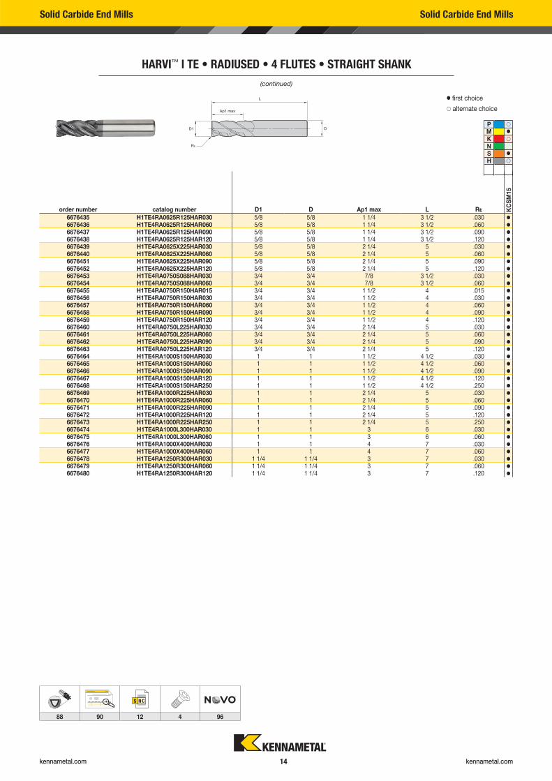
Solid Carbide End Mills Solid Carbide End Mills
HARVI™ I TE • RADIUSED • 4 FLUTES • STRAIGHT SHANK
� first choice
� alternate choice
P �
M �
K �
NS �
H �
order number catalog number D1 D Ap1 max L R� KC
SM
15
6676435 H1TE4RA0625R125HAR030 5/8 5/8 1 1/4 3 1/2 .030 �
6676436 H1TE4RA0625R125HAR060 5/8 5/8 1 1/4 3 1/2 .060 �
6676437 H1TE4RA0625R125HAR090 5/8 5/8 1 1/4 3 1/2 .090 �
6676438 H1TE4RA0625R125HAR120 5/8 5/8 1 1/4 3 1/2 .120 �
6676439 H1TE4RA0625X225HAR030 5/8 5/8 2 1/4 5 .030 �
6676440 H1TE4RA0625X225HAR060 5/8 5/8 2 1/4 5 .060 �
6676451 H1TE4RA0625X225HAR090 5/8 5/8 2 1/4 5 .090 �
6676452 H1TE4RA0625X225HAR120 5/8 5/8 2 1/4 5 .120 �
6676453 H1TE4RA0750S088HAR030 3/4 3/4 7/8 3 1/2 .030 �
6676454 H1TE4RA0750S088HAR060 3/4 3/4 7/8 3 1/2 .060 �
6676455 H1TE4RA0750R150HAR015 3/4 3/4 1 1/2 4 .015 �
6676456 H1TE4RA0750R150HAR030 3/4 3/4 1 1/2 4 .030 �
6676457 H1TE4RA0750R150HAR060 3/4 3/4 1 1/2 4 .060 �
6676458 H1TE4RA0750R150HAR090 3/4 3/4 1 1/2 4 .090 �
6676459 H1TE4RA0750R150HAR120 3/4 3/4 1 1/2 4 .120 �
6676460 H1TE4RA0750L225HAR030 3/4 3/4 2 1/4 5 .030 �
6676461 H1TE4RA0750L225HAR060 3/4 3/4 2 1/4 5 .060 �
6676462 H1TE4RA0750L225HAR090 3/4 3/4 2 1/4 5 .090 �
6676463 H1TE4RA0750L225HAR120 3/4 3/4 2 1/4 5 .120 �
6676464 H1TE4RA1000S150HAR030 1 1 1 1/2 4 1/2 .030 �
6676465 H1TE4RA1000S150HAR060 1 1 1 1/2 4 1/2 .060 �
6676466 H1TE4RA1000S150HAR090 1 1 1 1/2 4 1/2 .090 �
6676467 H1TE4RA1000S150HAR120 1 1 1 1/2 4 1/2 .120 �
6676468 H1TE4RA1000S150HAR250 1 1 1 1/2 4 1/2 .250 �
6676469 H1TE4RA1000R225HAR030 1 1 2 1/4 5 .030 �
6676470 H1TE4RA1000R225HAR060 1 1 2 1/4 5 .060 �
6676471 H1TE4RA1000R225HAR090 1 1 2 1/4 5 .090 �
6676472 H1TE4RA1000R225HAR120 1 1 2 1/4 5 .120 �
6676473 H1TE4RA1000R225HAR250 1 1 2 1/4 5 .250 �
6676474 H1TE4RA1000L300HAR030 1 1 3 6 .030 �
6676475 H1TE4RA1000L300HAR060 1 1 3 6 .060 �
6676476 H1TE4RA1000X400HAR030 1 1 4 7 .030 �
6676477 H1TE4RA1000X400HAR060 1 1 4 7 .060 �
6676478 H1TE4RA1250R300HAR030 1 1/4 1 1/4 3 7 .030 �
6676479 H1TE4RA1250R300HAR060 1 1/4 1 1/4 3 7 .060 �
6676480 H1TE4RA1250R300HAR120 1 1/4 1 1/4 3 7 .120 �
(continued)

kennametal.com kennametal.com 15
Solid Carbide End Mills Solid Carbide End Mills
HARVI™ I TE • RADIUSED • 4 FLUTES • WELDON® SHANK
� first choice
� alternate choice
P �
M �
K �
NS �
H �
order number catalog number D1 D Ap1 max L R� KC
SM
15
6676481 H1TE4RA0375R088HBR015 3/8 3/8 7/8 2 1/2 .015 �
6676482 H1TE4RA0375R088HBR030 3/8 3/8 7/8 2 1/2 .030 �
6676483 H1TE4RA0375R088HBR060 3/8 3/8 7/8 2 1/2 .060 �
6676484 H1TE4RA0375R088HBR090 3/8 3/8 7/8 2 1/2 .090 �
6676485 H1TE4RA0375R100HBR015 3/8 3/8 1 3 .015 �
6676486 H1TE4RA0375R100HBR030 3/8 3/8 1 3 .030 �
6676487 H1TE4RA0375R100HBR060 3/8 3/8 1 3 .060 �
6676488 H1TE4RA0375R100HBR090 3/8 3/8 1 3 .090 �
6676489 H1TE4RA0375X150HBR015 3/8 3/8 1 1/2 4 .015 �
6676490 H1TE4RA0375X150HBR030 3/8 3/8 1 1/2 4 .030 �
6676491 H1TE4RA0375X150HBR060 3/8 3/8 1 1/2 4 .060 �
6676492 H1TE4RA0438R100HBR015 7/8 7/16 1 2 3/4 .015 �
6676493 H1TE4RA0438R100HBR030 7/8 7/16 1 2 3/4 .030 �
6676494 H1TE4RA0500S063HBR015 1/2 1/2 5/8 2 1/2 .015 �
6676495 H1TE4RA0500S063HBR030 1/2 1/2 5/8 2 1/2 .030 �
6676496 H1TE4RA0500S063HBR060 1/2 1/2 5/8 2 1/2 .060 �
6676497 H1TE4RA0500R100HBR015 1/2 1/2 1 3 .015 �
6676498 H1TE4RA0500R100HBR030 1/2 1/2 1 3 .030 �
6676499 H1TE4RA0500R100HBR060 1/2 1/2 1 3 .060 �
6676500 H1TE4RA0500R100HBR090 1/2 1/2 1 3 .090 �
6676501 H1TE4RA0500R100HBR120 1/2 1/2 1 3 .120 �
6676502 H1TE4RA0500R125HBR015 1/2 1/2 1 1/4 3 1/4 .015 �
6676503 H1TE4RA0500R125HBR030 1/2 1/2 1 1/4 3 1/4 .030 �
6676504 H1TE4RA0500R125HBR060 1/2 1/2 1 1/4 3 1/4 .060 �
6676505 H1TE4RA0500R125HBR090 1/2 1/2 1 1/4 3 1/4 .090 �
6676506 H1TE4RA0500R125HBR120 1/2 1/2 1 1/4 3 1/4 .120 �
6676507 H1TE4RA0500L150HBR030 1/2 1/2 1 1/2 4 .030 �
6676508 H1TE4RA0500L150HBR060 1/2 1/2 1 1/2 4 .060 �
6676509 H1TE4RA0500X200HBR030 1/2 1/2 2 4 .030 �
6676510 H1TE4RA0500X200HBR060 1/2 1/2 2 4 .060 �
6676511 H1TE4RA0625S075HBR030 5/8 5/8 1/4 3 .030 �
6676512 H1TE4RA0625S075HBR060 5/8 5/8 1/4 3 .060 �
6676513 H1TE4RA0625R125HBR015 5/8 5/8 1 1/4 3 1/2 .015 �
6676514 H1TE4RA0625R125HBR030 5/8 5/8 1 1/4 3 1/2 .030 �
6676515 H1TE4RA0625R125HBR060 5/8 5/8 1 1/4 3 1/2 .060 �
6676516 H1TE4RA0625R125HBR090 5/8 5/8 1 1/4 3 1/2 .090 �
6676517 H1TE4RA0625R125HBR120 5/8 5/8 1 1/4 3 1/2 .120 �
6676518 H1TE4RA0625X225HBR030 5/8 5/8 2 1/4 5 .030 �
6676519 H1TE4RA0625X225HBR060 5/8 5/8 2 1/4 5 .060 �
6676520 H1TE4RA0625X225HBR090 5/8 5/8 2 1/4 5 .090 �
6676521 H1TE4RA0625X225HBR120 5/8 5/8 2 1/4 5 .120 �
6676522 H1TE4RA0750S088HBR030 3/4 3/4 7/8 3 1/2 .030 �
6676523 H1TE4RA0750S088HBR060 3/4 3/4 7/8 3 1/2 .060 �
6676524 H1TE4RA0750R150HBR015 3/4 3/4 1 1/2 4 .015 �
6676525 H1TE4RA0750R150HBR030 3/4 3/4 1 1/2 4 .030 �
6676526 H1TE4RA0750R150HBR060 3/4 3/4 1 1/2 4 .060 �
6676527 H1TE4RA0750R150HBR090 3/4 3/4 1 1/2 4 .090 �
6676528 H1TE4RA0750R150HBR120 3/4 3/4 1 1/2 4 .120 �
6676529 H1TE4RA0750L225HBR030 3/4 3/4 2 1/4 5 .030 �
6676530 H1TE4RA0750L225HBR060 3/4 3/4 2 1/4 5 .060 �
6676551 H1TE4RA0750L225HBR090 3/4 3/4 2 1/4 5 .090 �
6676552 H1TE4RA0750L225HBR120 3/4 3/4 2 1/4 5 .120 �
6676553 H1TE4RA1000S150HBR030 1 1 1 1/2 4 1/2 .030 �
6676554 H1TE4RA1000S150HBR060 1 1 1 1/2 4 1/2 .060 �
6676555 H1TE4RA1000S150HBR090 1 1 1 1/2 4 1/2 .090 �
6676556 H1TE4RA1000S150HBR120 1 1 1 1/2 4 1/2 .120 �
6676557 H1TE4RA1000S150HBR250 1 1 1 1/2 4 1/2 .250 �
6676558 H1TE4RA1000R225HBR030 1 1 2 1/4 5 .030 �
6676560 H1TE4RA1000R225HBR060 1 1 2 1/4 5 .060 �
6676561 H1TE4RA1000R225HBR090 1 1 2 1/4 5 .090 �
6676562 H1TE4RA1000R225HBR120 1 1 2 1/4 5 .120 �
6676563 H1TE4RA1000R225HBR250 1 1 2 1/4 5 .250 �
6676564 H1TE4RA1000L300HBR030 1 1 3 6 .030 �
6676565 H1TE4RA1000L300HBR060 1 1 3 6 .060 �
6676566 H1TE4RA1000X400HBR030 1 1 4 7 .030 �
6676567 H1TE4RA1000X400HBR060 1 1 4 7 .060 �
6676568 H1TE4RA1250R300HBR030 1 1/4 1 1/4 3 7 .030 �
6676569 H1TE4RA1250R300HBR060 1 1/4 1 1/4 3 7 .060 �
6676570 H1TE4RA1250R300HBR120 1 1/4 1 1/4 3 7 .120 �
kennametal.com kennametal.com 16
AB
88 90 12 4 96
Solid Carbide End Mills Solid Carbide End Mills
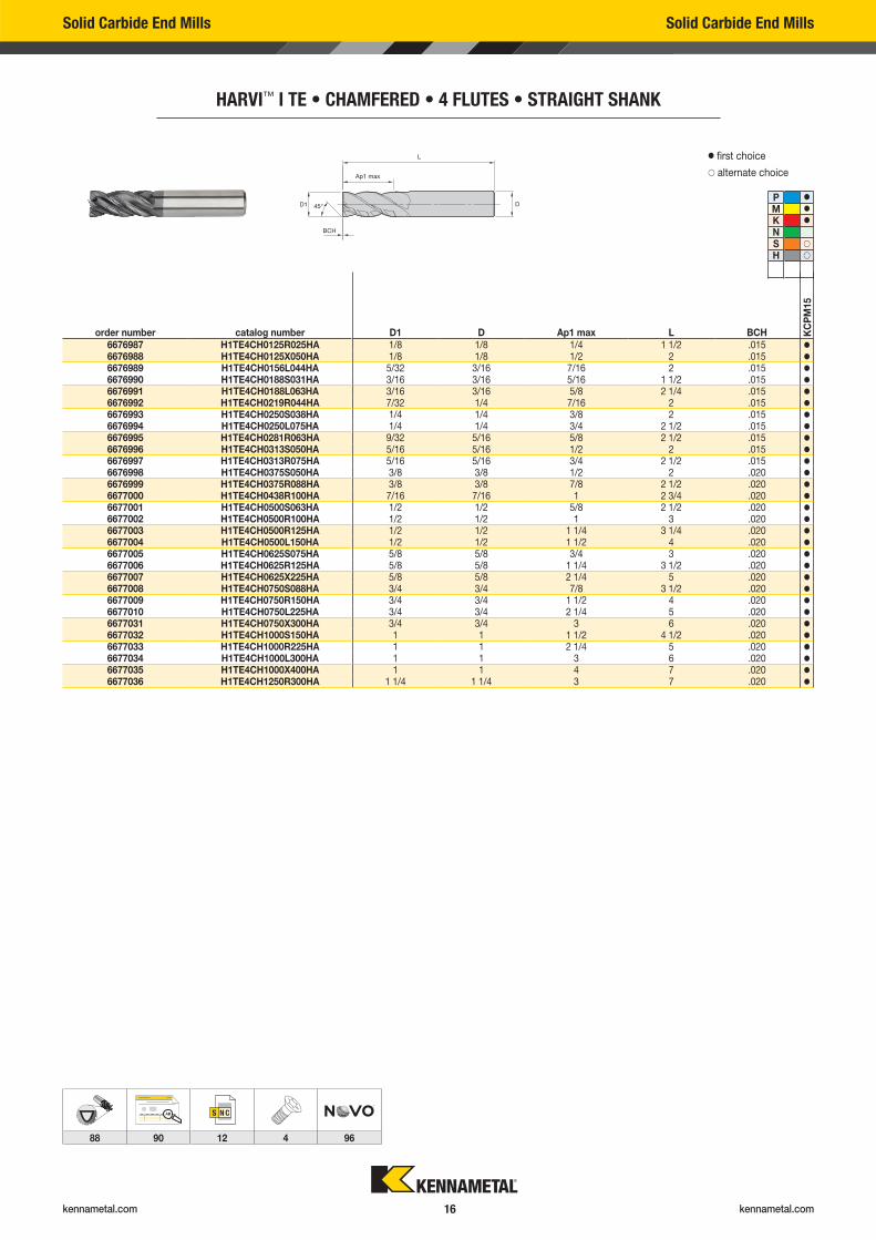
HARVI™ I TE • CHAMFERED • 4 FLUTES • STRAIGHT SHANK
order number catalog number D1 D Ap1 max L BCH KC
PM
15
6676987 H1TE4CH0125R025HA 1/8 1/8 1/4 1 1/2 .015 �
6676988 H1TE4CH0125X050HA 1/8 1/8 1/2 2 .015 �
6676989 H1TE4CH0156L044HA 5/32 3/16 7/16 2 .015 �
6676990 H1TE4CH0188S031HA 3/16 3/16 5/16 1 1/2 .015 �
6676991 H1TE4CH0188L063HA 3/16 3/16 5/8 2 1/4 .015 �
6676992 H1TE4CH0219R044HA 7/32 1/4 7/16 2 .015 �
6676993 H1TE4CH0250S038HA 1/4 1/4 3/8 2 .015 �
6676994 H1TE4CH0250L075HA 1/4 1/4 3/4 2 1/2 .015 �
6676995 H1TE4CH0281R063HA 9/32 5/16 5/8 2 1/2 .015 �
6676996 H1TE4CH0313S050HA 5/16 5/16 1/2 2 .015 �
6676997 H1TE4CH0313R075HA 5/16 5/16 3/4 2 1/2 .015 �
6676998 H1TE4CH0375S050HA 3/8 3/8 1/2 2 .020 �
6676999 H1TE4CH0375R088HA 3/8 3/8 7/8 2 1/2 .020 �
6677000 H1TE4CH0438R100HA 7/16 7/16 1 2 3/4 .020 �
6677001 H1TE4CH0500S063HA 1/2 1/2 5/8 2 1/2 .020 �
6677002 H1TE4CH0500R100HA 1/2 1/2 1 3 .020 �
6677003 H1TE4CH0500R125HA 1/2 1/2 1 1/4 3 1/4 .020 �
6677004 H1TE4CH0500L150HA 1/2 1/2 1 1/2 4 .020 �
6677005 H1TE4CH0625S075HA 5/8 5/8 3/4 3 .020 �
6677006 H1TE4CH0625R125HA 5/8 5/8 1 1/4 3 1/2 .020 �
6677007 H1TE4CH0625X225HA 5/8 5/8 2 1/4 5 .020 �
6677008 H1TE4CH0750S088HA 3/4 3/4 7/8 3 1/2 .020 �
6677009 H1TE4CH0750R150HA 3/4 3/4 1 1/2 4 .020 �
6677010 H1TE4CH0750L225HA 3/4 3/4 2 1/4 5 .020 �
6677031 H1TE4CH0750X300HA 3/4 3/4 3 6 .020 �
6677032 H1TE4CH1000S150HA 1 1 1 1/2 4 1/2 .020 �
6677033 H1TE4CH1000R225HA 1 1 2 1/4 5 .020 �
6677034 H1TE4CH1000L300HA 1 1 3 6 .020 �
6677035 H1TE4CH1000X400HA 1 1 4 7 .020 �
6677036 H1TE4CH1250R300HA 1 1/4 1 1/4 3 7 .020 �
� first choice
� alternate choice
P �
M �
K �
NS �
H �
kennametal.com kennametal.com 17
AB
88 90 12 4 96
Solid Carbide End Mills Solid Carbide End Mills
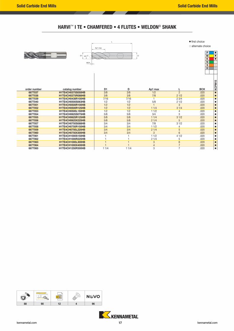
HARVI™ I TE • CHAMFERED • 4 FLUTES • WELDON® SHANK
� first choice
� alternate choice
P �
M �
K �
NS �
H �
order number catalog number D1 D Ap1 max L BCH KC
PM
15
6677037 H1TE4CH0375S050HB 3/8 3/8 1/2 2 .020 �
6677038 H1TE4CH0375R088HB 3/8 3/8 7/8 2 1/2 .020 �
6677039 H1TE4CH0438R100HB 7/16 7/16 1 2 3/4 .020 �
6677040 H1TE4CH0500S063HB 1/2 1/2 5/8 2 1/2 .020 �
6677051 H1TE4CH0500R100HB 1/2 1/2 1 3 .020 �
6677052 H1TE4CH0500R125HB 1/2 1/2 1 1/4 3 1/4 .020 �
6677053 H1TE4CH0500L150HB 1/2 1/2 1 1/2 4 .020 �
6677054 H1TE4CH0625S075HB 5/8 5/8 3/4 3 .020 �
6677055 H1TE4CH0625R125HB 5/8 5/8 1 1/4 3 1/2 .020 �
6677056 H1TE4CH0625X225HB 5/8 5/8 2 1/4 5 .020 �
6677057 H1TE4CH0750S088HB 3/4 3/4 7/8 3 1/2 .020 �
6677058 H1TE4CH0750R150HB 3/4 3/4 1 1/2 4 .020 �
6677059 H1TE4CH0750L225HB 3/4 3/4 2 1/4 5 .020 �
6677060 H1TE4CH0750X300HB 3/4 3/4 3 6 .020 �
6677061 H1TE4CH1000S150HB 1 1 1 1/2 4 1/2 .020 �
6677062 H1TE4CH1000R225HB 1 1 2 1/4 5 .020 �
6677063 H1TE4CH1000L300HB 1 1 3 6 .020 �
6677064 H1TE4CH1000X400HB 1 1 4 7 .020 �
6677065 H1TE4CH1250R300HB 1 1/4 1 1/4 3 7 .020 �
kennametal.com kennametal.com 18
Solid Carbide End Mills Solid Carbide End Mills
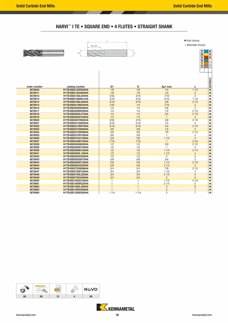
HARVI™ I TE • SQUARE END • 4 FLUTES • STRAIGHT SHANK
order number catalog number D1 D Ap1 max L KC
PM
15
6676840 H1TE4SE0125R025HA 1/8 1/8 1/4 1 1/2 �
6676911 H1TE4SE0125X050HA 1/8 1/8 1/2 2 �
6676912 H1TE4SE0156L044HA 5/32 3/16 7/16 2 �
6676913 H1TE4SE0188S031HA 3/16 3/16 5/16 1 1/2 �
6676914 H1TE4SE0188L063HA 3/16 3/16 5/8 2 1/4 �
6676915 H1TE4SE0219R044HA 7/32 1/4 7/16 2 �
6676916 H1TE4SE0250S038HA 1/4 1/4 3/8 2 �
6676917 H1TE4SE0250R050HA 1/4 1/4 1/2 2 1/2 �
6676918 H1TE4SE0250L075HA 1/4 1/4 3/4 2 1/2 �
6676919 H1TE4SE0250X100HA 1/4 1/4 1 3 �
6676920 H1TE4SE0281R063HA 9/32 5/16 5/8 2 1/2 �
6676921 H1TE4SE0313S050HA 5/16 5/16 1/2 2 �
6676922 H1TE4SE0313R075HA 5/16 5/16 3/4 2 1/2 �
6676923 H1TE4SE0375S050HA 3/8 3/8 1/2 2 �
6676924 H1TE4SE0375R088HA 3/8 3/8 7/8 2 1/2 �
6676925 H1TE4SE0375R100HA 3/8 3/8 1 3 �
6676926 H1TE4SE0375X150HA 3/8 3/8 1 1/2 4 �
6676927 H1TE4SE0438R100HA 7/16 7/16 1 2 3/4 �
6676928 H1TE4SE0500S063HA 1/2 1/2 5/8 2 1/2 �
6676929 H1TE4SE0500R100HA 1/2 1/2 1 3 �
6676930 H1TE4SE0500R125HA 1/2 1/2 1 1/4 3 1/4 �
6676941 H1TE4SE0500L150HA 1/2 1/2 1 1/2 4 �
6676942 H1TE4SE0500X200HA 1/2 1/2 2 4 �
6676943 H1TE4SE0625S075HA 5/8 5/8 3/4 3 �
6676944 H1TE4SE0625R125HA 5/8 5/8 1 1/4 3 1/2 �
6676945 H1TE4SE0625X225HA 5/8 5/8 2 1/4 5 �
6676946 H1TE4SE0750S088HA 3/4 3/4 7/8 3 1/2 �
6676947 H1TE4SE0750R150HA 3/4 3/4 1 1/2 4 �
6676948 H1TE4SE0750L225HA 3/4 3/4 2 1/4 5 �
6676949 H1TE4SE0750X300HA 3/4 3/4 3 6 �
6676950 H1TE4SE1000S150HA 1 1 1 1/2 4 1/2 �
6676961 H1TE4SE1000R225HA 1 1 2 1/4 5 �
6676962 H1TE4SE1000L300HA 1 1 3 6 �
6676963 H1TE4SE1000X400HA 1 1 4 7 �
6676964 H1TE4SE1250R300HA 1 1/4 1 1/4 3 7 �
� first choice
� alternate choice
P �
M �
K �
NS �
H �
AB
88 90 12 4 96
kennametal.com kennametal.com 19
AB
88 90 12 4 96
Solid Carbide End Mills Solid Carbide End Mills
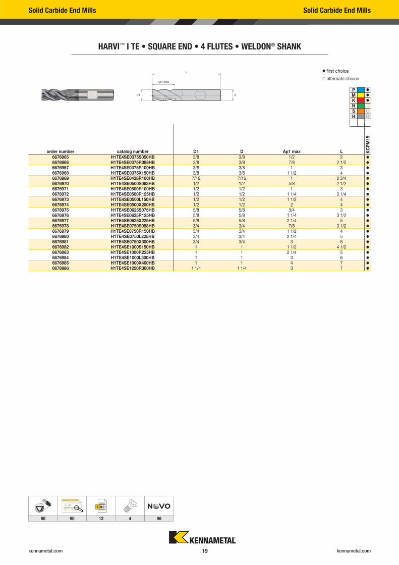
HARVI™ I TE • SQUARE END • 4 FLUTES • WELDON® SHANK
order number catalog number D1 D Ap1 max L KC
PM
15
6676965 H1TE4SE0375S050HB 3/8 3/8 1/2 2 �
6676966 H1TE4SE0375R088HB 3/8 3/8 7/8 2 1/2 �
6676967 H1TE4SE0375R100HB 3/8 3/8 1 3 �
6676968 H1TE4SE0375X150HB 3/8 3/8 1 1/2 4 �
6676969 H1TE4SE0438R100HB 7/16 7/16 1 2 3/4 �
6676970 H1TE4SE0500S063HB 1/2 1/2 5/8 2 1/2 �
6676971 H1TE4SE0500R100HB 1/2 1/2 1 3 �
6676972 H1TE4SE0500R125HB 1/2 1/2 1 1/4 3 1/4 �
6676973 H1TE4SE0500L150HB 1/2 1/2 1 1/2 4 �
6676974 H1TE4SE0500X200HB 1/2 1/2 2 4 �
6676975 H1TE4SE0625S075HB 5/8 5/8 3/4 3 �
6676976 H1TE4SE0625R125HB 5/8 5/8 1 1/4 3 1/2 �
6676977 H1TE4SE0625X225HB 5/8 5/8 2 1/4 5 �
6676978 H1TE4SE0750S088HB 3/4 3/4 7/8 3 1/2 �
6676979 H1TE4SE0750R150HB 3/4 3/4 1 1/2 4 �
6676980 H1TE4SE0750L225HB 3/4 3/4 2 1/4 5 �
6676981 H1TE4SE0750X300HB 3/4 3/4 3 6 �
6676982 H1TE4SE1000S150HB 1 1 1 1/2 4 1/2 �
6676983 H1TE4SE1000R225HB 1 1 2 1/4 5 �
6676984 H1TE4SE1000L300HB 1 1 3 6 �
6676985 H1TE4SE1000X400HB 1 1 4 7 �
6676986 H1TE4SE1250R300HB 1 1/4 1 1/4 3 7 �
� first choice
� alternate choice
P �
M �
K �
NS �
H �
kennametal.com kennametal.com 20
Solid Carbide End Mills Solid Carbide End Mills
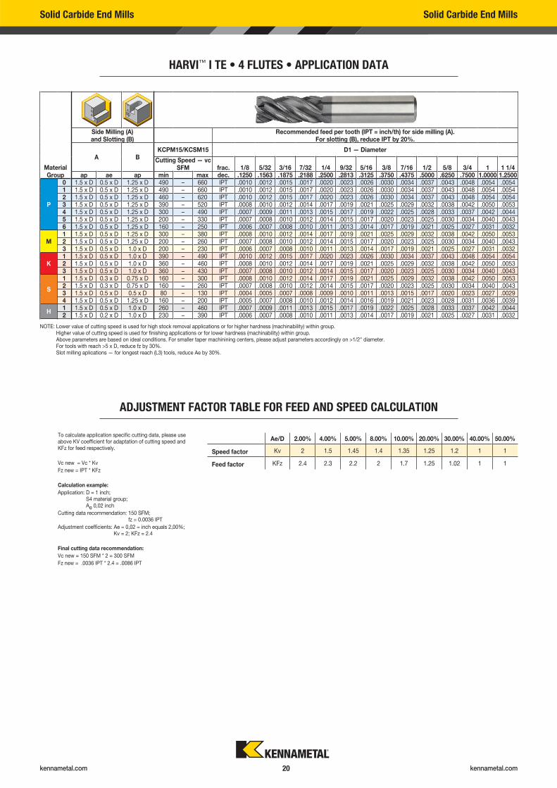
HARVI™ I TE • 4 FLUTES • APPLICATION DATA
ADJUSTMENT FACTOR TABLE FOR FEED AND SPEED CALCULATION
Ae/D 2.00% 4.00% 5.00% 8.00% 10.00% 20.00% 30.00% 40.00% 50.00%
Speed factor Kv 2 1.5 1.45 1.4 1.35 1.25 1.2 1 1
Feed factor KFz 2.4 2.3 2.2 2 1.7 1.25 1.02 1 1
To calculate application specific cutting data, please use above KV coefficient for adaptation of cutting speed and KFz for feed respectively.
Vc new = Vc * Kv
Fz new = IPT * KFz
Calculation example:
Application: D = 1 inch; S4 material group; Ae 0,02 inch
Cutting data recommendation: 150 SFM; fz = 0.0036 IPT
Adjustment coefficients: Ae = 0,02 = inch equals 2,00%; Kv = 2; KFz = 2.4
Final cutting data recommendation:
Vc new = 150 SFM * 2 = 300 SFM
Fz new = .0036 IPT * 2.4 = .0086 IPT
Material Group
Side Milling (A) and Slotting (B)
Recommended feed per tooth (IPT = inch/th) for side milling (A). For slotting (B), reduce IPT by 20%.
A BKCPM15/KCSM15 D1 — Diameter
Cutting Speed — vc SFM frac. 1/8 5/32 3/16 7/32 1/4 9/32 5/16 3/8 7/16 1/2 5/8 3/4 1 1 1/4
ap ae ap min max dec. .1250 .1563 .1875 .2188 .2500 .2813 .3125 .3750 .4375 .5000 .6250 .7500 1.0000 1.2500
P
0 1.5 x D 0.5 x D 1.25 x D 490 – 660 IPT .0010 .0012 .0015 .0017 .0020 .0023 .0026 .0030 .0034 .0037 .0043 .0048 .0054 .00541 1.5 x D 0.5 x D 1.25 x D 490 – 660 IPT .0010 .0012 .0015 .0017 .0020 .0023 .0026 .0030 .0034 .0037 .0043 .0048 .0054 .00542 1.5 x D 0.5 x D 1.25 x D 460 – 620 IPT .0010 .0012 .0015 .0017 .0020 .0023 .0026 .0030 .0034 .0037 .0043 .0048 .0054 .00543 1.5 x D 0.5 x D 1.25 x D 390 – 520 IPT .0008 .0010 .0012 .0014 .0017 .0019 .0021 .0025 .0029 .0032 .0038 .0042 .0050 .00534 1.5 x D 0.5 x D 1.25 x D 300 – 490 IPT .0007 .0009 .0011 .0013 .0015 .0017 .0019 .0022 .0025 .0028 .0033 .0037 .0042 .00445 1.5 x D 0.5 x D 1.25 x D 200 – 330 IPT .0007 .0008 .0010 .0012 .0014 .0015 .0017 .0020 .0023 .0025 .0030 .0034 .0040 .00436 1.5 x D 0.5 x D 1.25 x D 160 – 250 IPT .0006 .0007 .0008 .0010 .0011 .0013 .0014 .0017 .0019 .0021 .0025 .0027 .0031 .0032
M1 1.5 x D 0.5 x D 1.25 x D 300 – 380 IPT .0008 .0010 .0012 .0014 .0017 .0019 .0021 .0025 .0029 .0032 .0038 .0042 .0050 .00532 1.5 x D 0.5 x D 1.25 x D 200 – 260 IPT .0007 .0008 .0010 .0012 .0014 .0015 .0017 .0020 .0023 .0025 .0030 .0034 .0040 .00433 1.5 x D 0.5 x D 1.0 x D 200 – 230 IPT .0006 .0007 .0008 .0010 .0011 .0013 .0014 .0017 .0019 .0021 .0025 .0027 .0031 .0032
K1 1.5 x D 0.5 x D 1.0 x D 390 – 490 IPT .0010 .0012 .0015 .0017 .0020 .0023 .0026 .0030 .0034 .0037 .0043 .0048 .0054 .00542 1.5 x D 0.5 x D 1.0 x D 360 – 460 IPT .0008 .0010 .0012 .0014 .0017 .0019 .0021 .0025 .0029 .0032 .0038 .0042 .0050 .00533 1.5 x D 0.5 x D 1.0 x D 360 – 430 IPT .0007 .0008 .0010 .0012 .0014 .0015 .0017 .0020 .0023 .0025 .0030 .0034 .0040 .0043
S
1 1.5 x D 0.3 x D 0.75 x D 160 – 300 IPT .0008 .0010 .0012 .0014 .0017 .0019 .0021 .0025 .0029 .0032 .0038 .0042 .0050 .00532 1.5 x D 0.3 x D 0.75 x D 160 – 260 IPT .0007 .0008 .0010 .0012 .0014 .0015 .0017 .0020 .0023 .0025 .0030 .0034 .0040 .00433 1.5 x D 0.5 x D 0.5 x D 80 – 130 IPT .0004 .0005 .0007 .0008 .0009 .0010 .0011 .0013 .0015 .0017 .0020 .0023 .0027 .00294 1.5 x D 0.5 x D 1.25 x D 160 – 200 IPT .0005 .0007 .0008 .0010 .0012 .0014 .0016 .0019 .0021 .0023 .0028 .0031 .0036 .0039
H1 1.5 x D 0.5 x D 1.0 x D 260 – 460 IPT .0007 .0009 .0011 .0013 .0015 .0017 .0019 .0022 .0025 .0028 .0033 .0037 .0042 .00442 1.5 x D 0.2 x D 1.0 x D 230 – 390 IPT .0006 .0007 .0008 .0010 .0011 .0013 .0014 .0017 .0019 .0021 .0025 .0027 .0031 .0032
NOTE: Lower value of cutting speed is used for high stock removal applications or for higher hardness (machinability) within group. Higher value of cutting speed is used for finishing applications or for lower hardness (machinability) within group. Above parameters are based on ideal conditions. For smaller taper machinining centers, please adjust parameters accordingly on >1/2" diameter. For tools with reach >5 x D, reduce fz by 30%. Slot milling aplications — for longest reach (L3) tools, reduce Ae by 30%.

Catalog App
kennametal.com
Check out our new catalog app.
Available in the Google Play™ Store
or the App Store®
OR VISIT CATALOGS.KENNAMETAL.COM TODAY.
Search Products Watch a Video Browse Pages
kennametal.com kennametal.com 22
Solid Carbide End Mills Solid Carbide End Mills
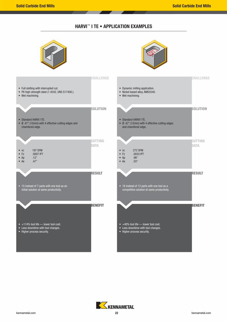
HARVI™ I TE • APPLICATION EXAMPLES
• Full slotting with interrupted cut.
• P6 high-strength steel (1.4542, UNS S17400.).
• Wet machining.
• Dynamic milling application.
• Nickel based alloy, AMS5540.
• Wet machining.
• Standard HARVI I TE.
• Ø .47" (12mm) with 4 effective cutting edges and
chamfered edge.
• Standard HARVI I TE.
• Ø .47" (12mm) with 4 effective cutting edges
and chamfered edge.
• vc 197 SFM
• Fz .0007 IPT
• Ap .12"
• Ae .47"
• vc 272 SFM
• Fz .0033 IPT
• Ap .98"
• Ae .03"
• 15 instead of 7 parts with one tool as an
initial solution at same productivity.
• 18 instead of 12 parts with one tool as a
competitive solution at same productivity.
• +114% tool life — lower tool cost.
• Less downtime with tool changes.
• Higher process security.
• +40% tool life — lower tool cost.
• Less downtime with tool changes.
• Higher process security.
CHALLENGE CHALLENGE
SOLUTION SOLUTION
CUTTINGDATA
CUTTINGDATA
RESULT RESULT
BENEFIT BENEFIT
kennametal.com kennametal.com 23
Solid Carbide End Mills Solid Carbide End Mills
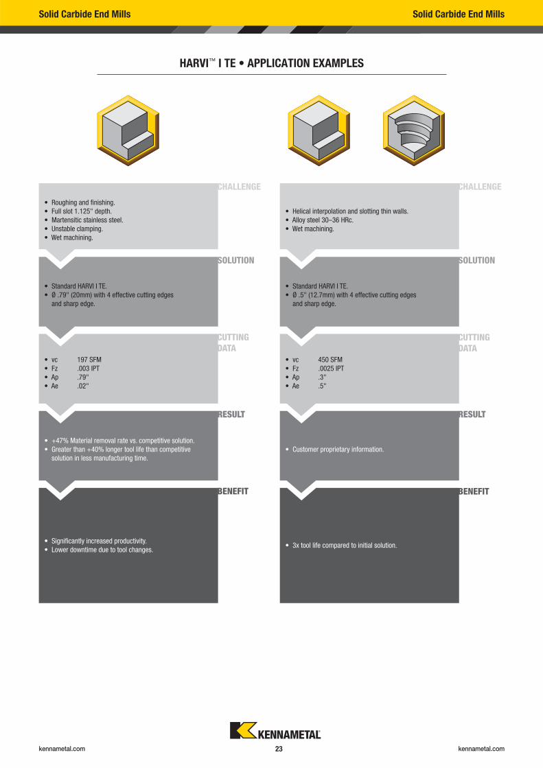
HARVI™ I TE • APPLICATION EXAMPLES
• Roughing and finishing.
• Full slot 1.125" depth.
• Martensitic stainless steel.
• Unstable clamping.
• Wet machining.
• Helical interpolation and slotting thin walls.
• Alloy steel 30–36 HRc.
• Wet machining.
• Standard HARVI I TE.
• Ø .79" (20mm) with 4 effective cutting edges
and sharp edge.
• Standard HARVI I TE.
• Ø .5" (12.7mm) with 4 effective cutting edges
and sharp edge.
• vc 197 SFM
• Fz .003 IPT
• Ap .79"
• Ae .02"
• vc 450 SFM
• Fz .0025 IPT
• Ap .3"
• Ae .5"
• +47% Material removal rate vs. competitive solution.
• Greater than +40% longer tool life than competitive
solution in less manufacturing time.
• Customer proprietary information.
• Significantly increased productivity.
• Lower downtime due to tool changes. • 3x tool life compared to initial solution.
CHALLENGE CHALLENGE
SOLUTION SOLUTION
CUTTINGDATA
CUTTINGDATA
RESULT RESULT
BENEFIT BENEFIT
kennametal.com kennametal.com 24
Solid Carbide End Mills Solid Carbide End Mills
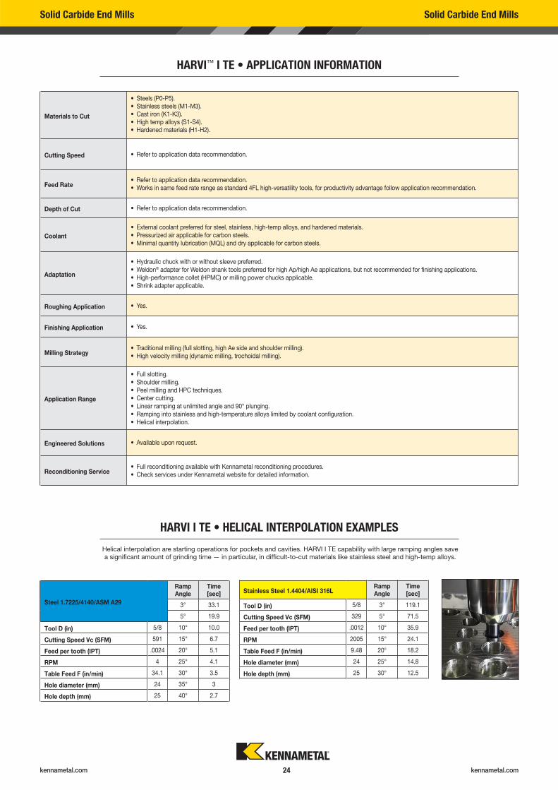
HARVI™ I TE • APPLICATION INFORMATION
Materials to Cut
• Steels (P0-P5).
• Stainless steels (M1-M3).
• Cast iron (K1-K3).
• High temp alloys (S1-S4).
• Hardened materials (H1-H2).
Cutting Speed • Refer to application data recommendation.
Feed Rate• Refer to application data recommendation.
• Works in same feed rate range as standard 4FL high-versatility tools, for productivity advantage follow application recommendation.
Depth of Cut • Refer to application data recommendation.
Coolant
• External coolant preferred for steel, stainless, high-temp alloys, and hardened materials.
• Pressurized air applicable for carbon steels.
• Minimal quantity lubrication (MQL) and dry applicable for carbon steels.
Adaptation
• Hydraulic chuck with or without sleeve preferred.
• Weldon® adapter for Weldon shank tools preferred for high Ap/high Ae applications, but not recommended for finishing applications.
• High-performance collet (HPMC) or milling power chucks applicable.
• Shrink adapter applicable.
Roughing Application • Yes.
Finishing Application • Yes.
Milling Strategy• Traditional milling (full slotting, high Ae side and shoulder milling).
• High velocity milling (dynamic milling, trochoidal milling).
Application Range
• Full slotting.
• Shoulder milling.
• Peel milling and HPC techniques.
• Center cutting.
• Linear ramping at unlimited angle and 90° plunging.
• Ramping into stainless and high-temperature alloys limited by coolant configuration.
• Helical interpolation.
Engineered Solutions • Available upon request.
Reconditioning Service• Full reconditioning available with Kennametal reconditioning procedures.
• Check services under Kennametal website for detailed information.
Helical interpolation are starting operations for pockets and cavities. HARVI I TE capability with large ramping angles save
a significant amount of grinding time — in particular, in difficult-to-cut materials like stainless steel and high-temp alloys.
HARVI I TE • HELICAL INTERPOLATION EXAMPLES
Steel 1.7225/4140/ASM A29
Ramp Angle
Time [sec]
3° 33.1
5° 19.9
Tool D (in) 5/8 10° 10.0
Cutting Speed Vc (SFM) 591 15° 6.7
Feed per tooth (IPT) .0024 20° 5.1
RPM 4 25° 4.1
Table Feed F (in/min) 34.1 30° 3.5
Hole diameter (mm) 24 35° 3
Hole depth (mm) 25 40° 2.7
Stainless Steel 1.4404/AISI 316LRamp Angle
Time [sec]
Tool D (in) 5/8 3° 119.1
Cutting Speed Vc (SFM) 329 5° 71.5
Feed per tooth (IPT) .0012 10° 35.9
RPM 2005 15° 24.1
Table Feed F (in/min) 9.48 20° 18.2
Hole diameter (mm) 24 25° 14.8
Hole depth (mm) 25 30° 12.5

kennametal.com kennametal.com 25
PROBLEM CAUSE REMEDIES
• Tool pullout. • High axial forces.
• Wrong adapter.
• Unadapted application data.
• Use Weldon® chuck if applicable or adapter
with higher clamping force.
• Reduce feed per tooth.
• Unevenly colored chips when slotting deep
(>1.25 x D).
• Not enough coolant in cutting zone. • Adjust coolant method to improve coolant
in cutting zone.
• Sudden breakage when milling dry in
Shrink Fit or hydraulic adapter.
• Tool is too hot and loses fit in adapter. • Check temperature on adapter/spindle.
• Improve coolant provision or reduce cutting
speed; eventually change to HPMC or Weldon,
if applicable.
• Material build-up on cutting edge. • Cold welding of material at cutting edge. • Increase coolant in cutting zone.
• Decrease cutting speed.
• High flank wear. • Unadapted application data.
• High tool runout.
• Decrease feed rate.
• Check tool runout.
• Chipping on tool. • Unadapted application data.
• Insufficient coolant.
• High tool runout.
• Unstable adapter.
• Clamping on coating area.
• Adjust to recommended speeds and feeds.
• Adjust coolant method to improve coolant
in cutting zone.
• Check runout; eventually change to more
stable adapter.
• Adjust clamping to clamp on uncoated area only.
• Minimize overhang length.
Solid Carbide End Mills Solid Carbide End Mills
HARVI™ I TE • CAUSES AND REMEDIES FOR MILLING PROBLEMS
kennametal.com kennametal.com 26
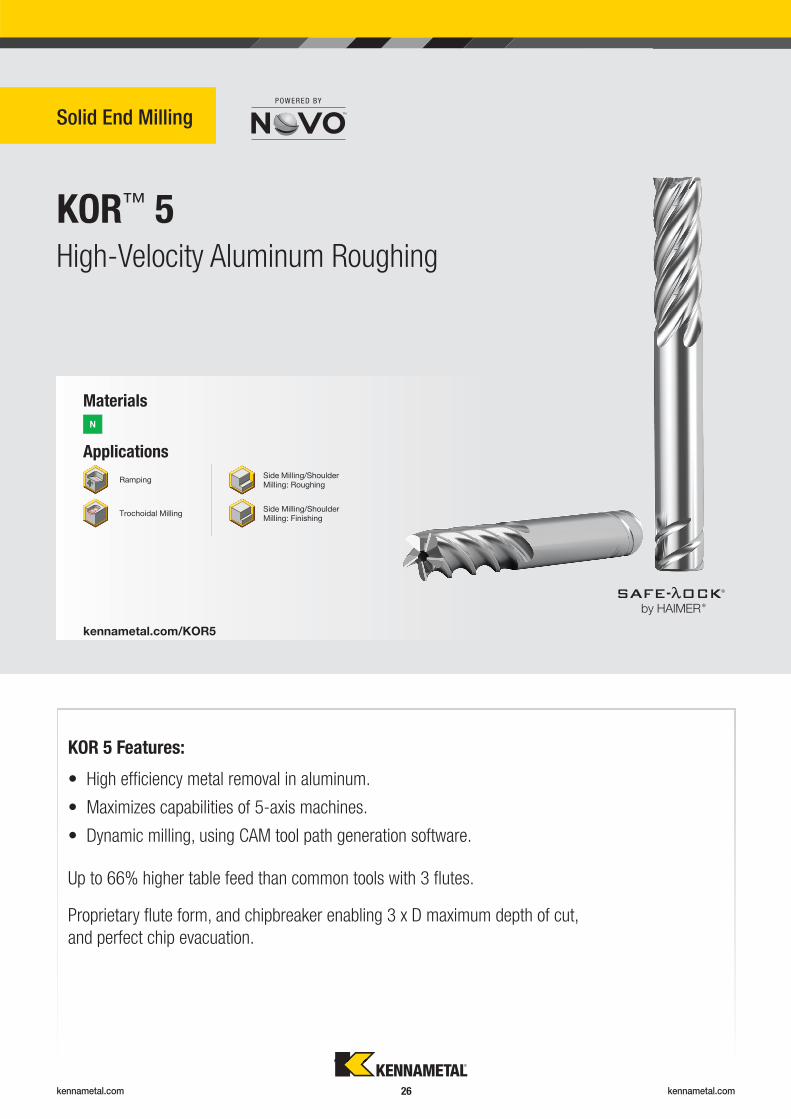
KOR™ 5
Solid End Milling
High-Velocity Aluminum Roughing
Applications
Materials
N
kennametal.com/KOR5
Ramping
Trochoidal Milling
Side Milling/Shoulder Milling: Roughing
Side Milling/Shoulder Milling: Finishing
Up to 66% higher table feed than common tools with 3 fl utes.
KOR 5 Features:
Proprietary fl ute form, and chipbreaker enabling 3 x D maximum depth of cut,
and perfect chip evacuation.
• High effi ciency metal removal in aluminum.
• Maximizes capabilities of 5-axis machines.
• Dynamic milling, using CAM tool path generation software.
®
®
kennametal.com kennametal.com 27
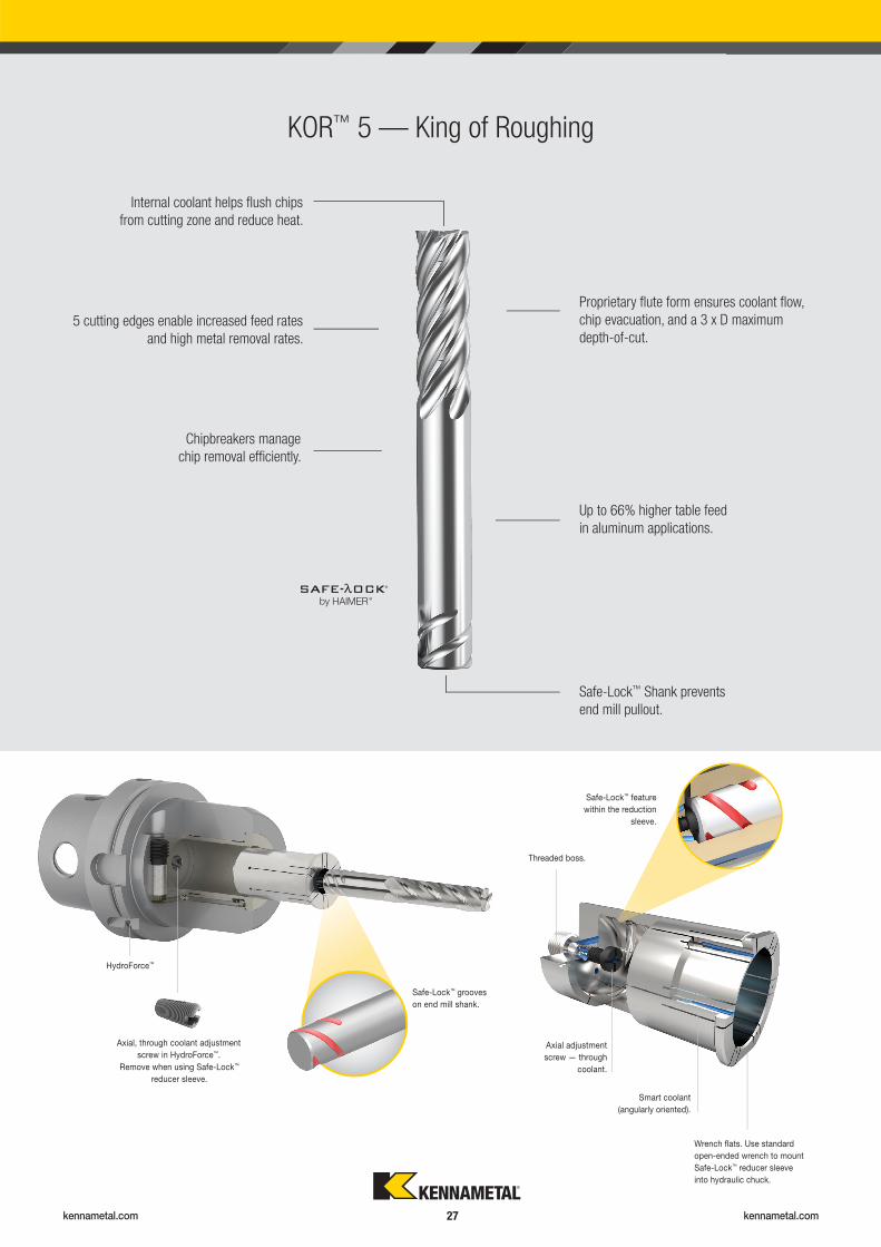
KOR™ 5 — King of Roughing
Proprietary fl ute form ensures coolant fl ow,
chip evacuation, and a 3 x D maximum
depth-of-cut.
Internal coolant helps fl ush chips
from cutting zone and reduce heat.
Up to 66% higher table feed
in aluminum applications.
Chipbreakers manage
chip removal effi ciently.
Safe-Lock™ Shank prevents
end mill pullout.
5 cutting edges enable increased feed rates
and high metal removal rates.
Remove when using Safe-Lock™
reducer sleeve.
Axial, through coolant adjustment
screw in HydroForce™.
HydroForce™
Safe-Lock™ grooves
on end mill shank.
Safe-Lock™ feature
within the reduction
sleeve.
Threaded boss.
Wrench fl ats. Use standard
open-ended wrench to mount
Safe-Lock™ reducer sleeve
into hydraulic chuck.
Smart coolant
(angularly oriented).
Axial adjustment
screw — through
coolant.
®
®
kennametal.com kennametal.com 28
High-Performance Solid Carbide End Mills High-Performance Solid Carbide End Mills
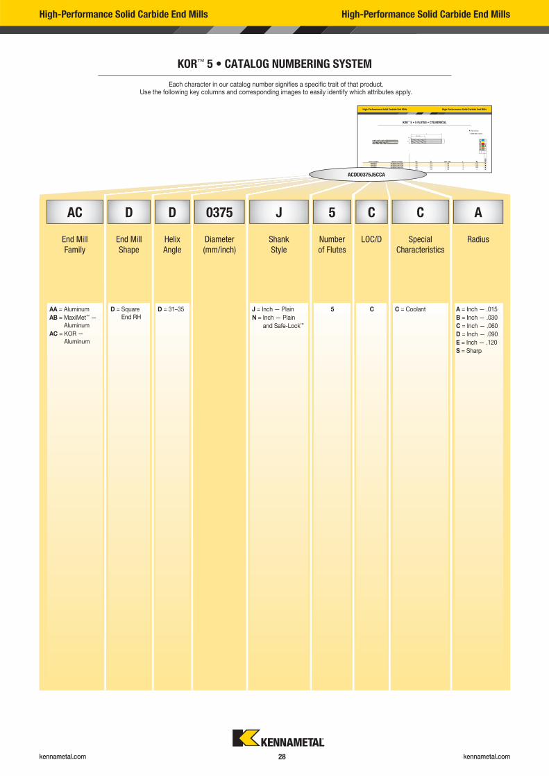
KOR™ 5 • CATALOG NUMBERING SYSTEM
Each character in our catalog number signifi es a specifi c trait of that product. Use the following key columns and corresponding images to easily identify which attributes apply.
High-Performance Solid Carbide End Mills High-Performance Solid Carbide End Mills
KOR™ 5 • 5 FLUTES • CYLINDRICAL
order number catalog number D1 D Ap1 max L R� K600
6665554 ACDD0375J5CCA 3/8 .375 1 1/8 3 .015 �
6665555 ACDD0375J5CCB 3/8 .375 1 1/8 3 .030 �
6665556 ACDD0375J5CCC 3/8 .375 1 1/8 3 .060 �
6665553 ACDD0375J5CCS 3/8 .375 1 1/8 3 — �
� first choice
� alternate choice
PMKN �
SH
AC D D 0375 J 5 C C A
End Mill
Family
End Mill
Shape
Helix
Angle
Diameter
(mm/inch)
Shank
Style
Number
of Flutes
LOC/D Special
Characteristics
Radius
AA = Aluminum
AB = MaxiMet™ —
Aluminum
AC = KOR —
Aluminum
D = Square
End RH
D = 31–35 J = Inch — Plain
N = Inch — Plain
and Safe-Lock™
5 C C = Coolant A = Inch — .015
B = Inch — .030
C = Inch — .060
D = Inch — .090
E = Inch — .120
S = Sharp
ACDD0375J5CCA
kennametal.com kennametal.com 29
AB
88 90 28 4 96
High-Performance Solid Carbide End Mills High-Performance Solid Carbide End Mills
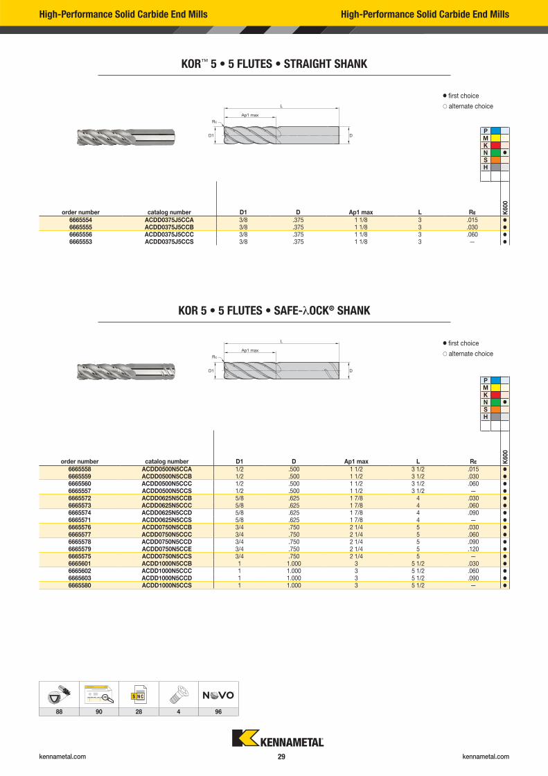
KOR™ 5 • 5 FLUTES • STRAIGHT SHANK
order number catalog number D1 D Ap1 max L R� K600
6665554 ACDD0375J5CCA 3/8 .375 1 1/8 3 .015 �
6665555 ACDD0375J5CCB 3/8 .375 1 1/8 3 .030 �
6665556 ACDD0375J5CCC 3/8 .375 1 1/8 3 .060 �
6665553 ACDD0375J5CCS 3/8 .375 1 1/8 3 — �
� first choice
� alternate choice
PMKN �
SH
KOR 5 • 5 FLUTES • SAFE-�OCK® SHANK
order number catalog number D1 D Ap1 max L R� K600
6665558 ACDD0500N5CCA 1/2 .500 1 1/2 3 1/2 .015 �
6665559 ACDD0500N5CCB 1/2 .500 1 1/2 3 1/2 .030 �
6665560 ACDD0500N5CCC 1/2 .500 1 1/2 3 1/2 .060 �
6665557 ACDD0500N5CCS 1/2 .500 1 1/2 3 1/2 — �
6665572 ACDD0625N5CCB 5/8 .625 1 7/8 4 .030 �
6665573 ACDD0625N5CCC 5/8 .625 1 7/8 4 .060 �
6665574 ACDD0625N5CCD 5/8 .625 1 7/8 4 .090 �
6665571 ACDD0625N5CCS 5/8 .625 1 7/8 4 — �
6665576 ACDD0750N5CCB 3/4 .750 2 1/4 5 .030 �
6665577 ACDD0750N5CCC 3/4 .750 2 1/4 5 .060 �
6665578 ACDD0750N5CCD 3/4 .750 2 1/4 5 .090 �
6665579 ACDD0750N5CCE 3/4 .750 2 1/4 5 .120 �
6665575 ACDD0750N5CCS 3/4 .750 2 1/4 5 — �
6665601 ACDD1000N5CCB 1 1.000 3 5 1/2 .030 �
6665602 ACDD1000N5CCC 1 1.000 3 5 1/2 .060 �
6665603 ACDD1000N5CCD 1 1.000 3 5 1/2 .090 �
6665580 ACDD1000N5CCS 1 1.000 3 5 1/2 — �
� first choice
� alternate choice
PMKN �
SH
kennametal.com kennametal.com 30
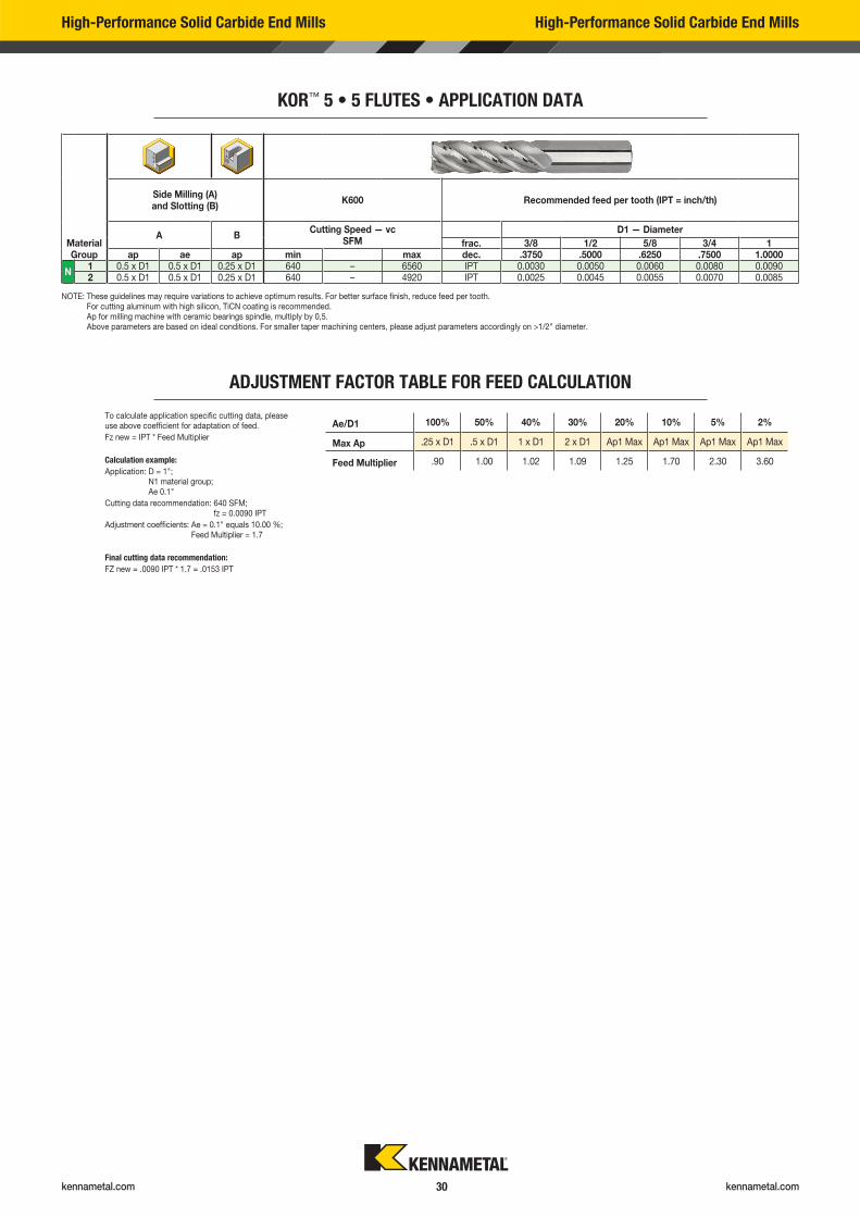
KOR™ 5 • 5 FLUTES • APPLICATION DATA
Ae/D1 100% 50% 40% 30% 20% 10% 5% 2%
Max Ap .25 x D1 .5 x D1 1 x D1 2 x D1 Ap1 Max Ap1 Max Ap1 Max Ap1 Max
Feed Multiplier .90 1.00 1.02 1.09 1.25 1.70 2.30 3.60
To calculate application specific cutting data, please use above coefficient for adaptation of feed.
Fz new = IPT * Feed Multiplier
Calculation example:
Application: D = 1"; N1 material group; Ae 0.1"
Cutting data recommendation: 640 SFM; fz = 0.0090 IPT
Adjustment coefficients: Ae = 0.1" equals 10.00 %; Feed Multiplier = 1.7
Final cutting data recommendation:
FZ new = .0090 IPT * 1.7 = .0153 IPT
Material Group
Side Milling (A) and Slotting (B)
K600 Recommended feed per tooth (IPT = inch/th)
A BCutting Speed — vc
SFMD1 — Diameter
frac. 3/8 1/2 5/8 3/4 1ap ae ap min max dec. .3750 .5000 .6250 .7500 1.0000
N1 0.5 x D1 0.5 x D1 0.25 x D1 640 – 6560 IPT 0.0030 0.0050 0.0060 0.0080 0.00902 0.5 x D1 0.5 x D1 0.25 x D1 640 – 4920 IPT 0.0025 0.0045 0.0055 0.0070 0.0085
NOTE: These guidelines may require variations to achieve optimum results. For better surface finish, reduce feed per tooth. For cutting aluminum with high silicon, TiCN coating is recommended. Ap for milling machine with ceramic bearings spindle, multiply by 0,5. Above parameters are based on ideal conditions. For smaller taper machining centers, please adjust parameters accordingly on >1/2" diameter.
ADJUSTMENT FACTOR TABLE FOR FEED CALCULATION
High-Performance Solid Carbide End Mills High-Performance Solid Carbide End Mills

kennametal.com
Lost a screw? Have to replace worn-out clamping wedges?
Need to fi nd and re-order those spare parts?
GO TO KENNAMETAL.COM AND FIND WHAT YOU NEED IN SECONDS.
1
2
Enter the tool catalog number here
Select the spare parts & accessories
STEP 1
STEP 2
Spare Parts & Accessories Information
kennametal.com kennametal.com 32
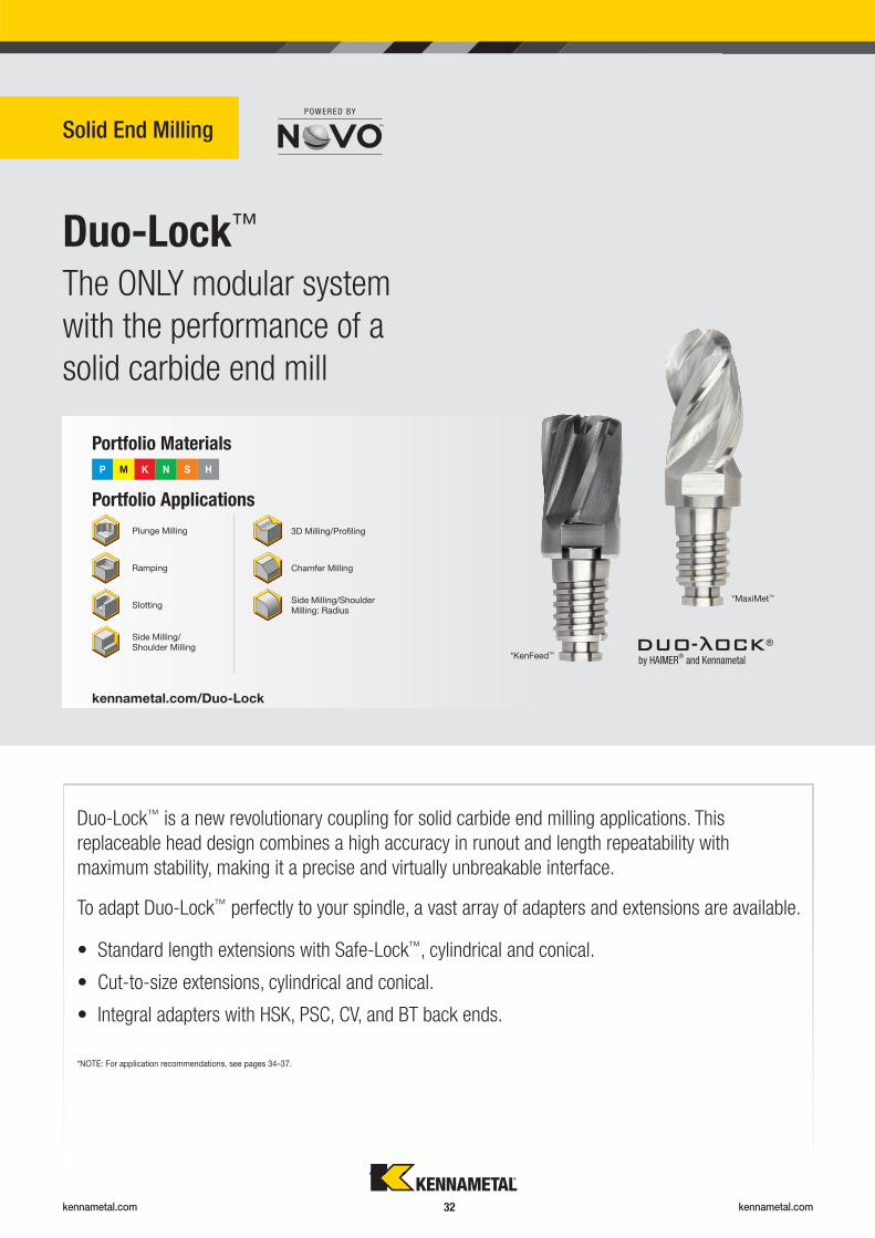
Duo-Lock™
Solid End Milling
The ONLY modular system
with the performance of a
solid carbide end mill
Portfolio Applications
Portfolio Materials
P M K N S H
kennametal.com/Duo-Lock
Plunge Milling
Ramping
Slotting
3D Milling/Profi ling
Side Milling/Shoulder Milling
Side Milling/Shoulder Milling: Radius
Chamfer Milling
Duo-Lock™ is a new revolutionary coupling for solid carbide end milling applications. This
replaceable head design combines a high accuracy in runout and length repeatability with
maximum stability, making it a precise and virtually unbreakable interface.
• Standard length extensions with Safe-Lock™, cylindrical and conical.
• Cut-to-size extensions, cylindrical and conical.
• Integral adapters with HSK, PSC, CV, and BT back ends.
To adapt Duo-Lock™ perfectly to your spindle, a vast array of adapters and extensions are available.
by HAIMER®
and Kennametal
®
*KenFeed™
*NOTE: For application recommendations, see pages 34–37.
*MaxiMet™
kennametal.com kennametal.com 33
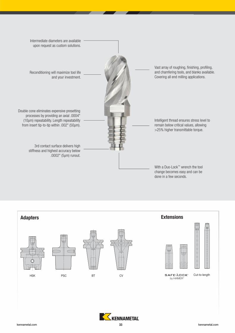
HSK PSC CV BT Cut-to-length
Adapters Extensions
®
®
Reconditioning will maximize tool life
and your investment.
Vast array of roughing, fi nishing, profi ling,
and chamfering tools, and blanks available.
Covering all end milling applications.
Intermediate diameters are available
upon request as custom solutions.
Double cone eliminates expensive presetting
processes by providing an axial .0004"
(10μm) repeatability. Length repeatability
from insert tip-to-tip within .002" (50μm).
Intelligent thread ensures stress level to
remain below critical values, allowing
>25% higher transmittable torque.
3rd contact surface delivers high
stiffness and highest accuracy below
.0002" (5μm) runout.
With a Duo-Lock™ wrench the tool
change becomes easy and can be
done in a few seconds.
kennametal.com kennametal.com 34
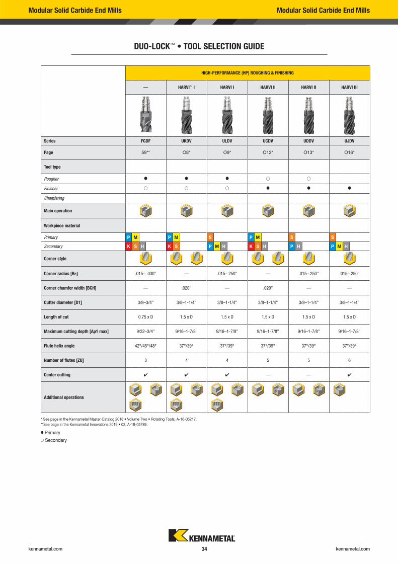
Modular Solid Carbide End Mills Modular Solid Carbide End Mills
DUO-LOCK™ • TOOL SELECTION GUIDE
HIGH-PERFORMANCE (HP) ROUGHING & FINISHING
— HARVI™ I HARVI I HARVI II HARVI II HARVI III
Series FGDF UKDV ULDV UCDV UDDV UJDV
Page 59** O8* O9* O12* O13* O16*
Tool type
Rougher � � � � �
Finisher � � � � � �
Chamfering
Main operation
Workpiece material
Primary P M P M S P M S S
Secondary K S H K S P M H K S H P H P M H
Corner style
Corner radius [R�] .015– .030" — .015–.250" — .015–.250" .015–.250"
Corner chamfer width [BCH] — .020" — .020" — —
Cutter diameter [D1] 3/8–3/4" 3/8–1-1/4" 3/8–1-1/4" 3/8–1-1/4" 3/8–1-1/4" 3/8–1-1/4"
Length of cut 0.75 x D 1.5 x D 1.5 x D 1.5 x D 1.5 x D 1.5 x D
Maximum cutting depth [Ap1 max] 9/32–3/4" 9/16–1-7/8" 9/16–1-7/8" 9/16–1-7/8" 9/16–1-7/8" 9/16–1-7/8"
Flute helix angle 42°/45°/48° 37°/39° 37°/39° 37°/39° 37°/39° 37°/39°
Number of flutes [ZU] 3 4 4 5 5 6
Center cutting � � � — — �
Additional operations
* See page in the Kennametal Master Catalog 2018 • Volume Two • Rotating Tools, A-16-05217.
** See page in the Kennametal Innovations 2019 • 02, A-18-05789.
� Primary
� Secondary
kennametal.com kennametal.com 35
* See page in the Kennametal Master Catalog 2018 • Volume Two • Rotating Tools, A-16-05217.
** See page in the Kennametal Innovations 2019 • 02, A-18-05789.
� Primary
� Secondary
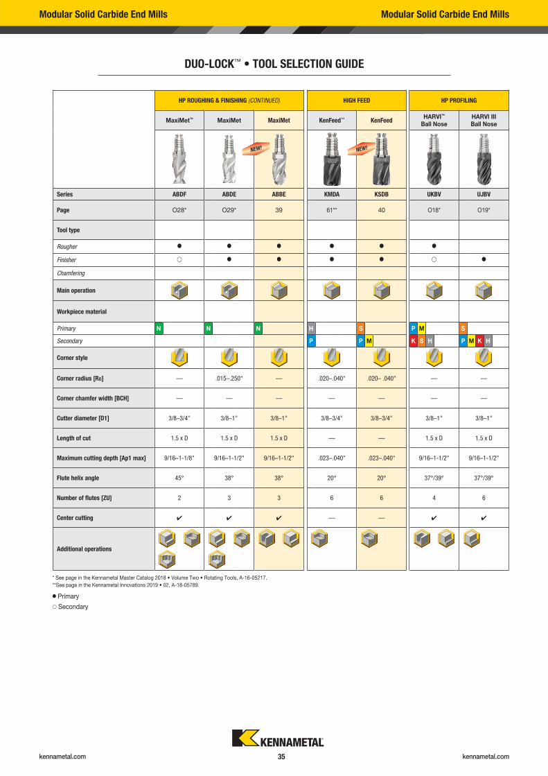
Modular Solid Carbide End Mills Modular Solid Carbide End Mills
DUO-LOCK™ • TOOL SELECTION GUIDE
HP ROUGHING & FINISHING (CONTINUED) HIGH FEED HP PROFILING
MaxiMet™ MaxiMet MaxiMet KenFeed™ KenFeedHARVI™
Ball NoseHARVI III Ball Nose
Series ABDF ABDE ABBE KMDA KSDB UKBV UJBV
Page O28* O29* 39 61** 40 O18* O19*
Tool type
Rougher � � � � � �
Finisher � � � � � � �
Chamfering
Main operation
Workpiece material
Primary N N N H S P M S
Secondary P P M K S H P M K H
Corner style
Corner radius [R�] — .015–.250" — .020–.040" .020– .040" — —
Corner chamfer width [BCH] — — — — — — —
Cutter diameter [D1] 3/8–3/4" 3/8–1" 3/8–1" 3/8–3/4" 3/8–3/4" 3/8–1" 3/8–1"
Length of cut 1.5 x D 1.5 x D 1.5 x D — — 1.5 x D 1.5 x D
Maximum cutting depth [Ap1 max] 9/16–1-1/8" 9/16–1-1/2" 9/16–1-1/2" .023–.040" .023–.040" 9/16–1-1/2" 9/16–1-1/2"
Flute helix angle 45° 38° 38° 20° 20° 37°/39° 37°/39°
Number of flutes [ZU] 2 3 3 6 6 4 6
Center cutting � � � — — � �
Additional operations
NEW! NEW!
kennametal.com kennametal.com 36
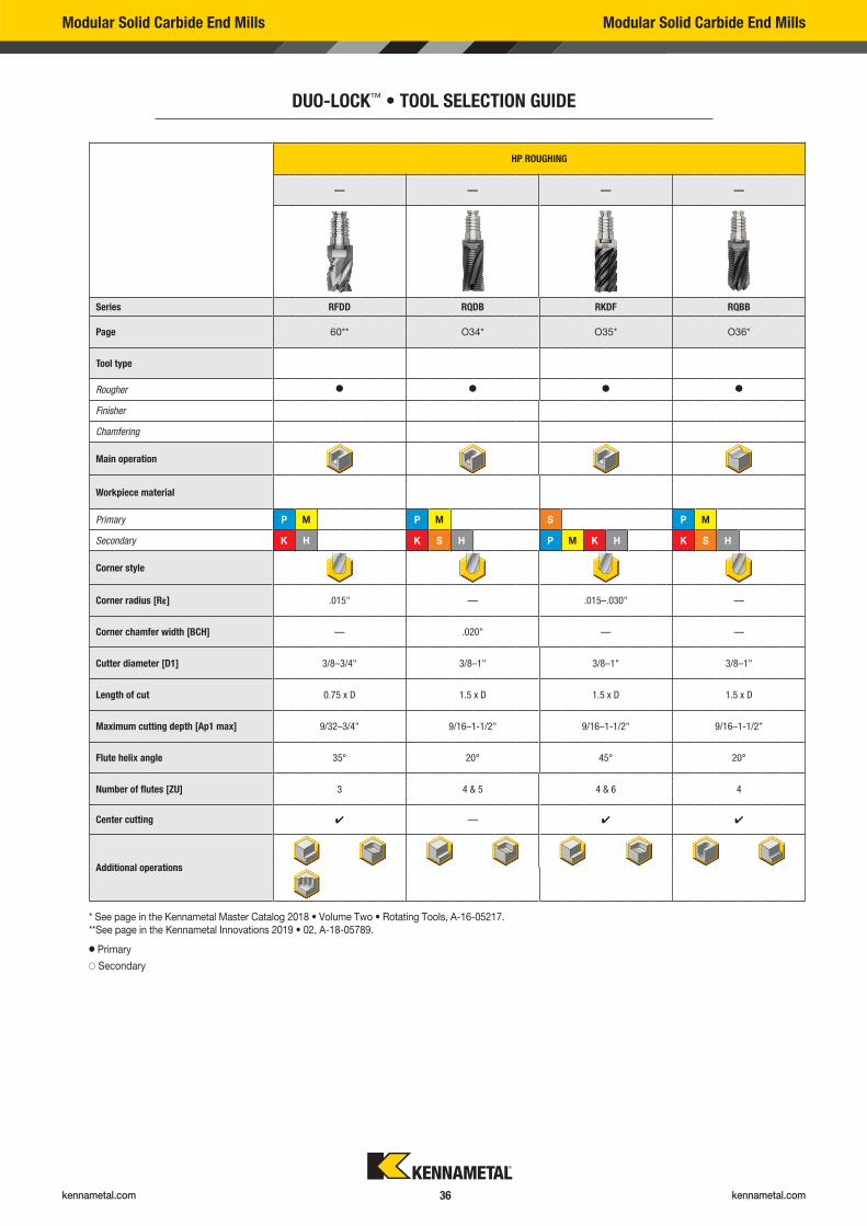
HP ROUGHING
— — — —
Series RFDD RQDB RKDF RQBB
Page 60** O34* O35* O36*
Tool type
Rougher � � � �
Finisher
Chamfering
Main operation
Workpiece material
Primary P M P M S P M
Secondary K H K S H P M K H K S H
Corner style
Corner radius [R�] .015" — .015–.030" —
Corner chamfer width [BCH] — .020" — —
Cutter diameter [D1] 3/8–3/4" 3/8–1" 3/8–1" 3/8–1"
Length of cut 0.75 x D 1.5 x D 1.5 x D 1.5 x D
Maximum cutting depth [Ap1 max] 9/32–3/4" 9/16–1-1/2" 9/16–1-1/2" 9/16–1-1/2"
Flute helix angle 35° 20° 45° 20°
Number of flutes [ZU] 3 4 & 5 4 & 6 4
Center cutting � — � �
Additional operations
* See page in the Kennametal Master Catalog 2018 • Volume Two • Rotating Tools, A-16-05217.** See page in the Kennametal Innovations 2019 • 02, A-18-05789.
� Primary
� Secondary
Modular Solid Carbide End Mills Modular Solid Carbide End Mills
DUO-LOCK™ • TOOL SELECTION GUIDE
kennametal.com kennametal.com 37
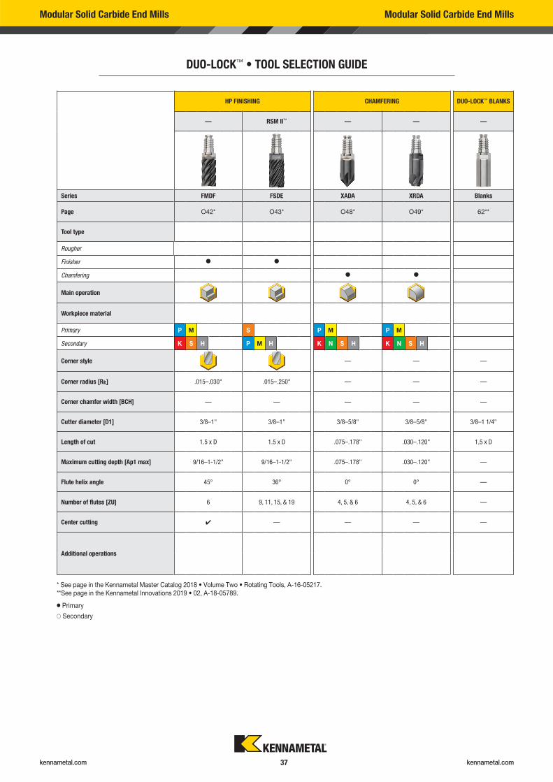
HP FINISHING CHAMFERING DUO-LOCK™ BLANKS
— RSM II™ — — —
Series FMDF FSDE XADA XRDA Blanks
Page O42* O43* O48* O49* 62**
Tool type
Rougher
Finisher � �
Chamfering � �
Main operation
Workpiece material
Primary P M S P M P M
Secondary K S H P M H K N S H K N S H
Corner style — — —
Corner radius [R�] .015–.030" .015–.250" — — —
Corner chamfer width [BCH] — — — — —
Cutter diameter [D1] 3/8–1" 3/8–1" 3/8–5/8" 3/8–5/8" 3/8–1 1/4"
Length of cut 1.5 x D 1.5 x D .075–.178" .030–.120" 1,5 x D
Maximum cutting depth [Ap1 max] 9/16–1-1/2" 9/16–1-1/2" .075–.178" .030–.120" —
Flute helix angle 45° 36° 0° 0° —
Number of flutes [ZU] 6 9, 11, 15, & 19 4, 5, & 6 4, 5, & 6 —
Center cutting � — — — —
Additional operations
* See page in the Kennametal Master Catalog 2018 • Volume Two • Rotating Tools, A-16-05217.** See page in the Kennametal Innovations 2019 • 02, A-18-05789.
� Primary
� Secondary
Modular Solid Carbide End Mills Modular Solid Carbide End Mills
DUO-LOCK™ • TOOL SELECTION GUIDE
kennametal.com kennametal.com 38
Modular Solid Carbide End Mills Modular Solid Carbide End Mills
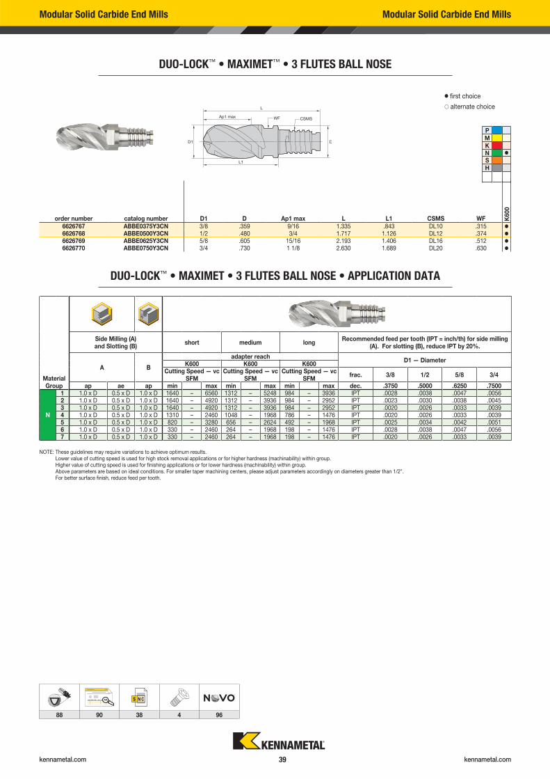
DUO-LOCK™ • MAXIMET™ • 3 FLUTES BALL NOSE
order number catalog number D1 D Ap1 max L L1 CSMS WF K6
00
6626767 ABBE0375Y3CN 3/8 .359 9/16 1.335 .843 DL10 .315 �
6626768 ABBE0500Y3CN 1/2 .480 3/4 1.717 1.126 DL12 .374 �
6626769 ABBE0625Y3CN 5/8 .605 15/16 2.193 1.406 DL16 .512 �
6626770 ABBE0750Y3CN 3/4 .730 1 1/8 2.630 1.689 DL20 .630 �
� first choice
� alternate choice
PMKN �
SH
Modular Solid Carbide End Mills Modular Solid Carbide End Mills
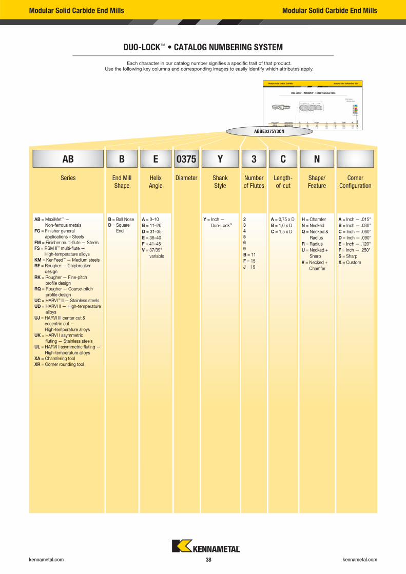
DUO-LOCK™ • CATALOG NUMBERING SYSTEM
ABBE0375Y3CN
AB B E 0375 Y 3 C N
Series End Mill
Shape
Helix
Angle
Diameter Shank
Style
Number
of Flutes
Length-
of-cut
Shape/
Feature
Corner
Confi guration
AB = MaxiMet™ —
Non-ferrous metals
FG = Finisher general
applications – Steels
FM = Finisher multi-fl ute — Steels
FS = RSM II™ multi-fl ute —
High-temperature alloys
KM = KenFeed™ — Medium steels
RF = Rougher — Chipbreaker
design
RK = Rougher — Fine-pitch
profi le design
RQ = Rougher — Coarse-pitch
profi le design
UC = HARVI™ II — Stainless steels
UD = HARVI lI — High-temperature
alloys
UJ = HARVI III center cut &
eccentric cut —
High-temperature alloys
UK = HARVI I asymmetric
fl uting — Stainless steels
UL = HARVI I asymmetric fl uting —
High-temperature alloys
XA = Chamfering tool
XR = Corner rounding tool
B = Ball Nose
D = Square
End
A = 0–10
B = 11–20
D = 31–35
E = 36–40
F = 41–45
V = 37/39°
variable
Y = Inch —
Duo-Lock™
2
3
4
5
6
9
B = 11
F = 15
J = 19
A = 0,75 x D
B = 1,0 x D
C = 1,5 x D
H = Chamfer
N = Necked
Q = Necked &
Radius
R = Radius
U = Necked +
Sharp
V = Necked +
Chamfer
A = Inch — .015"
B = Inch — .030"
C = Inch — .060"
D = Inch — .090"
E = Inch — .120"
F = Inch — .250"
S = Sharp
X = Custom
Each character in our catalog number signifi es a specifi c trait of that product.
Use the following key columns and corresponding images to easily identify which attributes apply.
kennametal.com kennametal.com 39
Modular Solid Carbide End Mills Modular Solid Carbide End Mills
DUO-LOCK™ • MAXIMET™ • 3 FLUTES BALL NOSE
order number catalog number D1 D Ap1 max L L1 CSMS WF K600
6626767 ABBE0375Y3CN 3/8 .359 9/16 1.335 .843 DL10 .315 �
6626768 ABBE0500Y3CN 1/2 .480 3/4 1.717 1.126 DL12 .374 �
6626769 ABBE0625Y3CN 5/8 .605 15/16 2.193 1.406 DL16 .512 �
6626770 ABBE0750Y3CN 3/4 .730 1 1/8 2.630 1.689 DL20 .630 �
� first choice
� alternate choice
PMKN �
SH
DUO-LOCK™ • MAXIMET • 3 FLUTES BALL NOSE • APPLICATION DATA
Material Group
Side Milling (A) and Slotting (B)
short medium longRecommended feed per tooth (IPT = inch/th) for side milling
(A). For slotting (B), reduce IPT by 20%.
A B
adapter reachD1 — Diameter
K600 K600 K600Cutting Speed — vc
SFMCutting Speed — vc
SFMCutting Speed — vc
SFMfrac. 3/8 1/2 5/8 3/4
ap ae ap min max min max min max dec. .3750 .5000 .6250 .7500
N
1 1.0 x D 0.5 x D 1.0 x D 1640 – 6560 1312 – 5248 984 – 3936 IPT .0028 .0038 .0047 .00562 1.0 x D 0.5 x D 1.0 x D 1640 – 4920 1312 – 3936 984 – 2952 IPT .0023 .0030 .0038 .00453 1.0 x D 0.5 x D 1.0 x D 1640 – 4920 1312 – 3936 984 – 2952 IPT .0020 .0026 .0033 .00394 1.0 x D 0.5 x D 1.0 x D 1310 – 2460 1048 – 1968 786 – 1476 IPT .0020 .0026 .0033 .00395 1.0 x D 0.5 x D 1.0 x D 820 – 3280 656 – 2624 492 – 1968 IPT .0025 .0034 .0042 .00516 1.0 x D 0.5 x D 1.0 x D 330 – 2460 264 – 1968 198 – 1476 IPT .0028 .0038 .0047 .00567 1.0 x D 0.5 x D 1.0 x D 330 – 2460 264 – 1968 198 – 1476 IPT .0020 .0026 .0033 .0039
NOTE: These guidelines may require variations to achieve optimum results. Lower value of cutting speed is used for high stock removal applications or for higher hardness (machinability) within group. Higher value of cutting speed is used for finishing applications or for lower hardness (machinability) within group. Above parameters are based on ideal conditions. For smaller taper machining centers, please adjust parameters accordingly on diameters greater than 1/2". For better surface finish, reduce feed per tooth.
AB
88 90 38 4 96
kennametal.com kennametal.com 40
Modular Solid Carbide End Mills Modular Solid Carbide End Mills
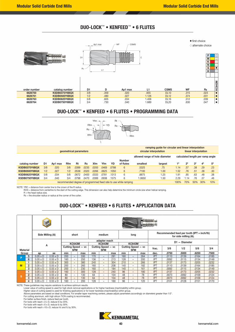
DUO-LOCK™ • KENFEED™ • 6 FLUTES
NOTE: YRC = distance from center line to the crown of the R radius. RCN = distance from centerline to the start of the cutting edge. This dimension can also help determine the minimum circle size when helical ramping. R = the head radius size. Rc = the shoulder radius or radius at the corner of the cutter.
order number catalog number D1 D Ap1 max L1 CSMS WF R� KC
643M
6626700 KSDB0375Y6BQX 3/8 .359 .020 .655 DL10 .315 .023 �
6626761 KSDB0500Y6BQX 1/2 .480 .027 1.126 DL12 .374 .031 �
6626763 KSDB0625Y6BQX 5/8 .605 .034 1.406 DL16 .512 .039 �
6626764 KSDB0750Y6BQX 3/4 .730 .040 1.689 DL20 .630 .047 �
DUO-LOCK™ • KENFEED • 6 FLUTES • PROGRAMMING DATA
geometrical parameters
ramping guide for circular and linear interpolation
circular interpolation linear interpolation
allowed range of hole diameter calculated length per ramp angle
catalog number D1 Ap1 max Rfm Rt Rc Xfm Yfm YDNumber of flutes smallest largest 1º 2º 3º 4º 5º
KSDB0375Y6BQX 3/8 .020 3/8 .0399 .0235 .0200 .0469 .0788 6 .5325 .75 1.14 .57 .38 .29 .23
KSDB0500Y6BQX 1/2 .027 1/2 .0538 .0320 .0266 .0625 .1050 6 .7100 1.00 1.52 .76 .51 .38 .30
KSDB0625Y6BQX 5/8 .034 5/8 .0672 .0400 .0333 .0781 .1313 6 .8875 1.25 1.91 .95 .63 .48 .38
KSDB0750Y6BQX 3/4 .040 3/4 .0798 .0470 .0399 .0938 .1575 6 1.0650 1.50 2.29 1.14 .76 .57 .46
recommended degree of programmed feed rate to use while ramping 100% 70% 50% 30% 10%
� first choice
� alternate choice
P �
M �
KNS �
H
DUO-LOCK™ • KENFEED • 6 FLUTES • APPLICATION DATA
Material Group
Side Milling (A) short medium longRecommended feed per tooth (IPT = inch/th)
for side milling (A).
A
adapter reachD1 — Diameter
KC643M KC643M KC643MCutting Speed — vc
SFMCutting Speed — vc
SFMCutting Speed — vc
SFMfrac. 3/8 1/2 5/8 3/4
ap ae min max min max min max dec. .3750 .5000 .6250 .7500
P5 0.05 x D 0.55 x D 200 – 330 170 – 281 160 – 264 IPT .0110 .0139 .0164 .01856 0.05 x D 0.55 x D 160 – 250 136 – 213 128 – 200 IPT .0092 .0115 .0134 .0149
M1 0.05 x D 0.55 x D 300 – 380 240 – 304 210 – 266 IPT .0137 .0173 .0205 .02322 0.05 x D 0.55 x D 200 – 260 160 – 208 140 – 182 IPT .0110 .0139 .0164 .01853 0.05 x D 0.55 x D 200 – 230 160 – 184 140 – 161 IPT .0092 .0115 .0134 .0149
S
1 0.05 x D 0.55 x D 160 – 300 128 – 240 96 – 180 IPT .0137 .0173 .0205 .02322 0.05 x D 0.55 x D 80 – 130 64 – 104 48 – 78 IPT .0073 .0092 .0109 .01243 0.05 x D 0.55 x D 80 – 130 64 – 104 48 – 78 IPT .0073 .0092 .0109 .01244 0.05 x D 0.55 x D 160 – 200 128 – 160 96 – 120 IPT .0101 .0128 .0151 .0170
NOTE: These guidelines may require variations to achieve optimum results. Lower value of cutting speed is used for high stock removal applications or for higher hardness (machinability) within group. Higher value of cutting speed is used for finishing applications or for lower hardness (machinability) within group. Above parameters are based on ideal conditions. For smaller taper machining centers, please adjust parameters accordingly on diameters greater than 1/2". For cutting aluminum, with high silicon TiCN coating is recommended. For better surface finish, reduce feed per tooth. For tools with reach >3 x D, reduce fz by 20%. For tools with reach >5 x D, reduce fz by 30%. For tools with reach >10 x D, reduce Vc and fz by 30%.
kennametal.com kennametal.com 41
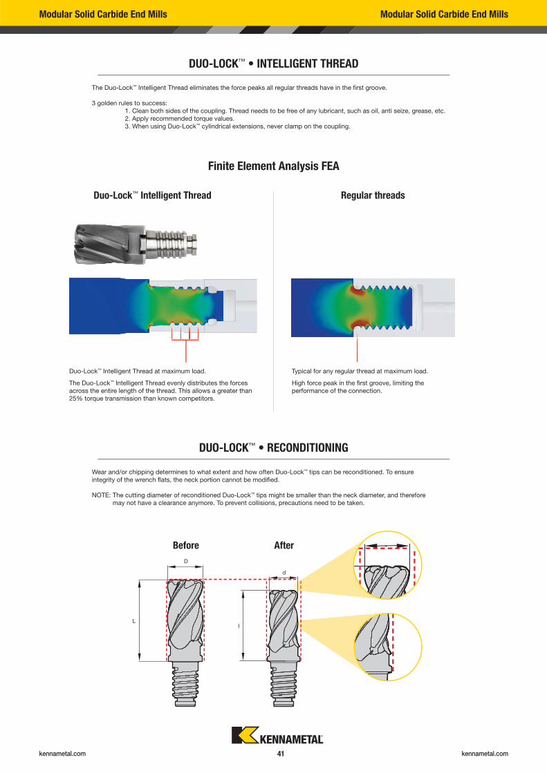
The Duo-Lock™ Intelligent Thread eliminates the force peaks all regular threads have in the fi rst groove.
3 golden rules to success:
1. Clean both sides of the coupling. Thread needs to be free of any lubricant, such as oil, anti seize, grease, etc.
2. Apply recommended torque values.
3. When using Duo-Lock™ cylindrical extensions, never clamp on the coupling.
Modular Solid Carbide End Mills Modular Solid Carbide End Mills
DUO-LOCK™ • INTELLIGENT THREAD
Finite Element Analysis FEA
Duo-Lock™ Intelligent Thread Regular threads
Duo-Lock™ Intelligent Thread at maximum load.
The Duo-Lock™ Intelligent Thread evenly distributes the forces
across the entire length of the thread. This allows a greater than
25% torque transmission than known competitors.
Typical for any regular thread at maximum load.
High force peak in the fi rst groove, limiting the
performance of the connection.
DUO-LOCK™ • RECONDITIONING
Wear and/or chipping determines to what extent and how often Duo-Lock™ tips can be reconditioned. To ensure
integrity of the wrench fl ats, the neck portion cannot be modifi ed.
NOTE: The cutting diameter of reconditioned Duo-Lock™ tips might be smaller than the neck diameter, and therefore
may not have a clearance anymore. To prevent collisions, precautions need to be taken.
D
d
L l
Before After
kennametal.com kennametal.com 42
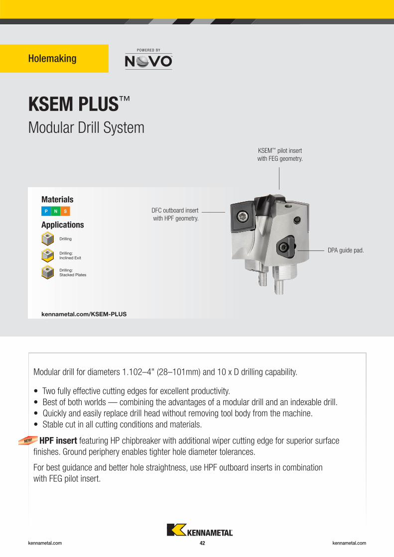
KSEM PLUS™
Holemaking
Modular Drill System
Applications
Materials
P N S
kennametal.com/KSEM-PLUS
Drilling
Drilling: Inclined Exit
Drilling: Stacked Plates
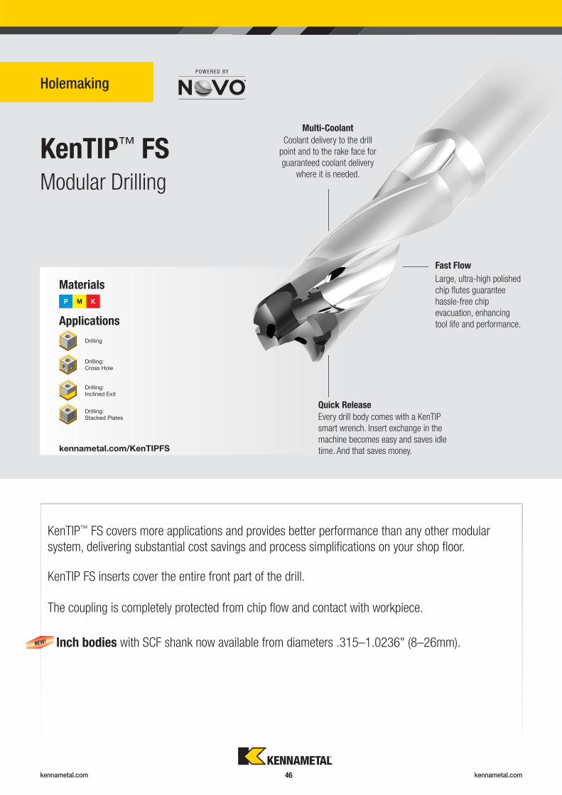
Modular drill for diameters 1.102–4" (28–101mm) and 10 x D drilling capability.
• Two fully effective cutting edges for excellent productivity.
• Best of both worlds — combining the advantages of a modular drill and an indexable drill.
• Quickly and easily replace drill head without removing tool body from the machine.
• Stable cut in all cutting conditions and materials.
HPF insert featuring HP chipbreaker with additional wiper cutting edge for superior surface
fi nishes. Ground periphery enables tighter hole diameter tolerances.
For best guidance and better hole straightness, use HPF outboard inserts in combination
with FEG pilot insert.
NEW!
DFC outboard insert
with HPF geometry.
KSEM™ pilot insert
with FEG geometry.
DPA guide pad.
kennametal.com kennametal.com 43
Modular Drills Modular Drills
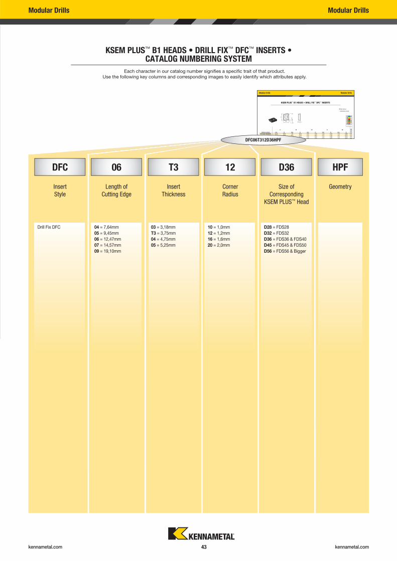
KSEM PLUS™ B1 HEADS • DRILL FIX™ DFC™ INSERTS • CATALOG NUMBERING SYSTEM
Modular Drills Modular Drills
KSEM PLUS™ B1 HEADS • DRILL FIX™ DFC™ INSERTS
LI W D1 S R�
catalog number mm in mm in mm in mm in mm in KC
U4
0
DFC040310D28HPF 10,00 .3940 7,64 .3010 2,85 .1120 3,18 .1250 1,00 .0390 �
DFC05T312D32HPF 12,00 .4720 9,45 .3720 3,40 .1340 3,75 .1480 1,20 .0470 �
DFC06T312D36HPF 16,00 .6300 12,47 .4910 4,40 .1730 3,75 .1480 1,20 .0470 �
DFC070416D45HPF 18,00 .7090 14,57 .5740 4,40 .1730 4,75 .1870 1,60 .0630 �
� first choice
� alternate choice
P �
M �
K �
N �
S �
H
DFC06T312D36HPF
Each character in our catalog number signifi es a specifi c trait of that product.
Use the following key columns and corresponding images to easily identify which attributes apply.
DFC 06 T3 12 D36 HPF
Insert
Style
Length of
Cutting Edge
Insert
Thickness
Corner
Radius
Size of
Corresponding
KSEM PLUS™ Head
Geometry
Drill Fix DFC 04 = 7,64mm
05 = 9,45mm
06 = 12,47mm
07 = 14,57mm
09 = 19,10mm
03 = 3,18mm
T3 = 3,75mm
04 = 4,75mm
05 = 5,25mm
10 = 1,0mm
12 = 1,2mm
16 = 1,6mm
20 = 2,0mm
D28 = FDS28
D32 = FDS32
D36 = FDS36 & FDS40
D45 = FDS45 & FDS50
D56 = FDS56 & Bigger
kennametal.com kennametal.com 44
Modular Drills Modular Drills
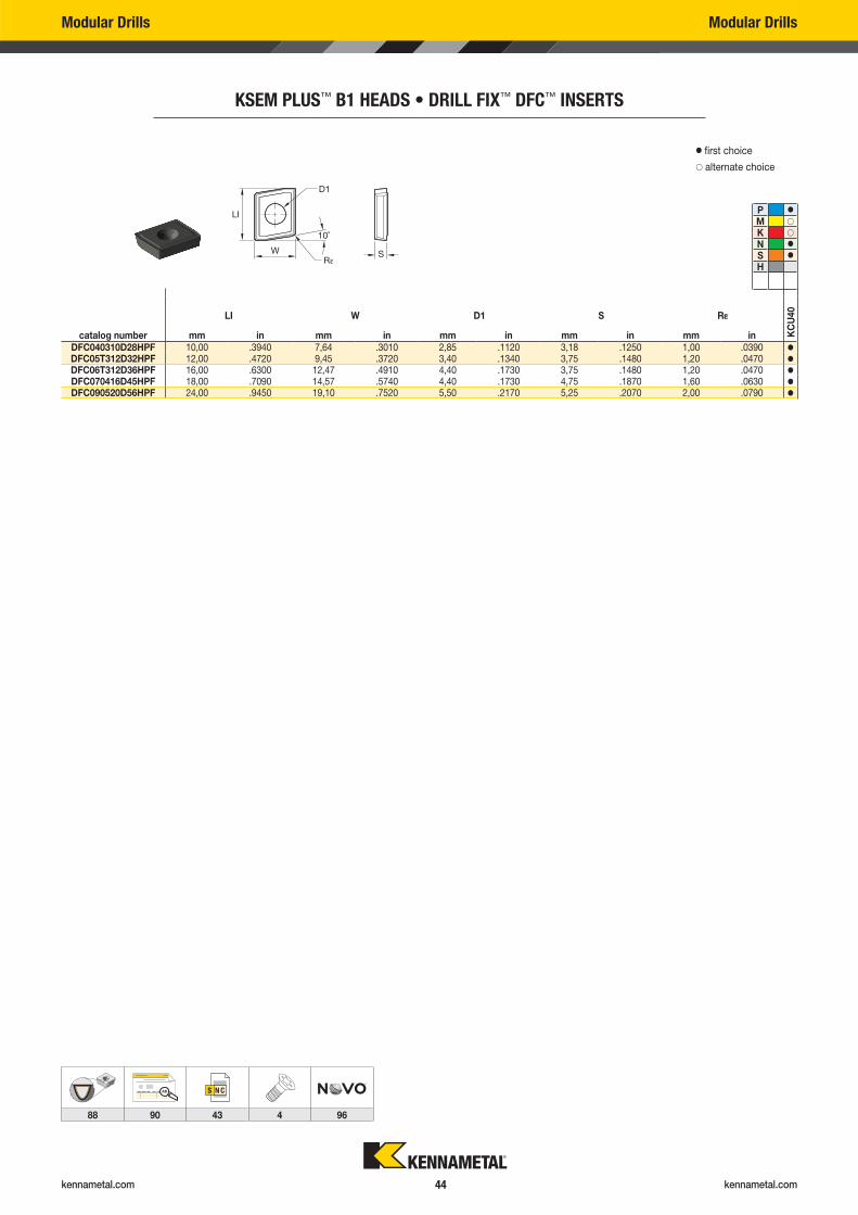
KSEM PLUS™ B1 HEADS • DRILL FIX™ DFC™ INSERTS
LI W D1 S R�
catalog number mm in mm in mm in mm in mm in KC
U40
DFC040310D28HPF 10,00 .3940 7,64 .3010 2,85 .1120 3,18 .1250 1,00 .0390 �
DFC05T312D32HPF 12,00 .4720 9,45 .3720 3,40 .1340 3,75 .1480 1,20 .0470 �
DFC06T312D36HPF 16,00 .6300 12,47 .4910 4,40 .1730 3,75 .1480 1,20 .0470 �
DFC070416D45HPF 18,00 .7090 14,57 .5740 4,40 .1730 4,75 .1870 1,60 .0630 �
DFC090520D56HPF 24,00 .9450 19,10 .7520 5,50 .2170 5,25 .2070 2,00 .0790 �
� first choice
� alternate choice
P �
M �
K �
N �
S �
H
AB
88 90 43 4 96
kennametal.com kennametal.com 45
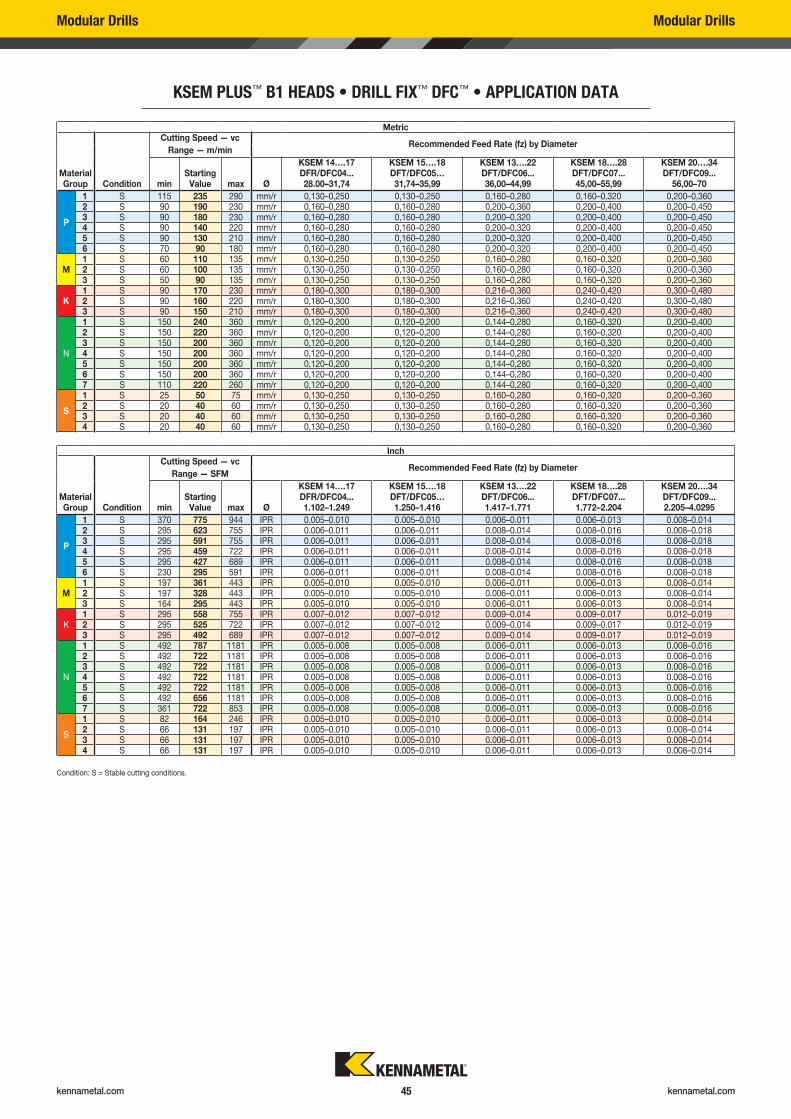
Condition: S = Stable cutting conditions.
Modular Drills Modular Drills
KSEM PLUS™ B1 HEADS • DRILL FIX™ DFC™ • APPLICATION DATA
Inch
Material Group Condition
Cutting Speed — vcRecommended Feed Rate (fz) by Diameter
Range — SFM
minStarting
Value max Ø
KSEM 14….17DFR/DFC04...1.102–1.249
KSEM 15….18DFT/DFC05…1.250–1.416
KSEM 13….22DFT/DFC06...1.417–1.771
KSEM 18….28DFT/DFC07...1.772–2.204
KSEM 20….34DFT/DFC09...2.205–4.0295
P
1 S 370 775 944 IPR 0.005–0.010 0.005–0.010 0.006–0.011 0.006–0.013 0.008–0.0142 S 295 623 755 IPR 0.006–0.011 0.006–0.011 0.008–0.014 0.008–0.016 0.008–0.0183 S 295 591 755 IPR 0.006–0.011 0.006–0.011 0.008–0.014 0.008–0.016 0.008–0.0184 S 295 459 722 IPR 0.006–0.011 0.006–0.011 0.008–0.014 0.008–0.016 0.008–0.0185 S 295 427 689 IPR 0.006–0.011 0.006–0.011 0.008–0.014 0.008–0.016 0.008–0.0186 S 230 295 591 IPR 0.006–0.011 0.006–0.011 0.008–0.014 0.008–0.016 0.008–0.018
M1 S 197 361 443 IPR 0.005–0.010 0.005–0.010 0.006–0.011 0.006–0.013 0.008–0.0142 S 197 328 443 IPR 0.005–0.010 0.005–0.010 0.006–0.011 0.006–0.013 0.008–0.0143 S 164 295 443 IPR 0.005–0.010 0.005–0.010 0.006–0.011 0.006–0.013 0.008–0.014
K1 S 295 558 755 IPR 0.007–0.012 0.007–0.012 0.009–0.014 0.009–0.017 0.012–0.0192 S 295 525 722 IPR 0.007–0.012 0.007–0.012 0.009–0.014 0.009–0.017 0.012–0.0193 S 295 492 689 IPR 0.007–0.012 0.007–0.012 0.009–0.014 0.009–0.017 0.012–0.019
N
1 S 492 787 1181 IPR 0.005–0.008 0.005–0.008 0.006–0.011 0.006–0.013 0.008–0.0162 S 492 722 1181 IPR 0.005–0.008 0.005–0.008 0.006–0.011 0.006–0.013 0.008–0.0163 S 492 722 1181 IPR 0.005–0.008 0.005–0.008 0.006–0.011 0.006–0.013 0.008–0.0164 S 492 722 1181 IPR 0.005–0.008 0.005–0.008 0.006–0.011 0.006–0.013 0.008–0.0165 S 492 722 1181 IPR 0.005–0.008 0.005–0.008 0.006–0.011 0.006–0.013 0.008–0.0166 S 492 656 1181 IPR 0.005–0.008 0.005–0.008 0.006–0.011 0.006–0.013 0.008–0.0167 S 361 722 853 IPR 0.005–0.008 0.005–0.008 0.006–0.011 0.006–0.013 0.008–0.016
S
1 S 82 164 246 IPR 0.005–0.010 0.005–0.010 0.006–0.011 0.006–0.013 0.008–0.0142 S 66 131 197 IPR 0.005–0.010 0.005–0.010 0.006–0.011 0.006–0.013 0.008–0.0143 S 66 131 197 IPR 0.005–0.010 0.005–0.010 0.006–0.011 0.006–0.013 0.008–0.0144 S 66 131 197 IPR 0.005–0.010 0.005–0.010 0.006–0.011 0.006–0.013 0.008–0.014
Metric
Material Group Condition
Cutting Speed — vcRecommended Feed Rate (fz) by Diameter
Range — m/min
minStarting
Value max Ø
KSEM 14….17DFR/DFC04...28.00–31,74
KSEM 15….18DFT/DFC05…31,74–35,99
KSEM 13….22DFT/DFC06...36,00–44,99
KSEM 18….28DFT/DFC07...45,00–55,99
KSEM 20….34DFT/DFC09...
56,00–70
P
1 S 115 235 290 mm/r 0,130–0,250 0,130–0,250 0,160–0,280 0,160–0,320 0,200–0,3602 S 90 190 230 mm/r 0,160–0,280 0,160–0,280 0,200–0,360 0,200–0,400 0,200–0,4503 S 90 180 230 mm/r 0,160–0,280 0,160–0,280 0,200–0,320 0,200–0,400 0,200–0,4504 S 90 140 220 mm/r 0,160–0,280 0,160–0,280 0,200–0,320 0,200–0,400 0,200–0,4505 S 90 130 210 mm/r 0,160–0,280 0,160–0,280 0,200–0,320 0,200–0,400 0,200–0,4506 S 70 90 180 mm/r 0,160–0,280 0,160–0,280 0,200–0,320 0,200–0,400 0,200–0,450
M1 S 60 110 135 mm/r 0,130–0,250 0,130–0,250 0,160–0,280 0,160–0,320 0,200–0,3602 S 60 100 135 mm/r 0,130–0,250 0,130–0,250 0,160–0,280 0,160–0,320 0,200–0,3603 S 50 90 135 mm/r 0,130–0,250 0,130–0,250 0,160–0,280 0,160–0,320 0,200–0,360
K1 S 90 170 230 mm/r 0,180–0,300 0,180–0,300 0,216–0,360 0,240–0,420 0,300–0,4802 S 90 160 220 mm/r 0,180–0,300 0,180–0,300 0,216–0,360 0,240–0,420 0,300–0,4803 S 90 150 210 mm/r 0,180–0,300 0,180–0,300 0,216–0,360 0,240–0,420 0,300–0,480
N
1 S 150 240 360 mm/r 0,120–0,200 0,120–0,200 0,144–0,280 0,160–0,320 0,200–0,4002 S 150 220 360 mm/r 0,120–0,200 0,120–0,200 0,144–0,280 0,160–0,320 0,200–0,4003 S 150 200 360 mm/r 0,120–0,200 0,120–0,200 0,144–0,280 0,160–0,320 0,200–0,4004 S 150 200 360 mm/r 0,120–0,200 0,120–0,200 0,144–0,280 0,160–0,320 0,200–0,4005 S 150 200 360 mm/r 0,120–0,200 0,120–0,200 0,144–0,280 0,160–0,320 0,200–0,4006 S 150 200 360 mm/r 0,120–0,200 0,120–0,200 0,144–0,280 0,160–0,320 0,200–0,4007 S 110 220 260 mm/r 0,120–0,200 0,120–0,200 0,144–0,280 0,160–0,320 0,200–0,400
S
1 S 25 50 75 mm/r 0,130–0,250 0,130–0,250 0,160–0,280 0,160–0,320 0,200–0,3602 S 20 40 60 mm/r 0,130–0,250 0,130–0,250 0,160–0,280 0,160–0,320 0,200–0,3603 S 20 40 60 mm/r 0,130–0,250 0,130–0,250 0,160–0,280 0,160–0,320 0,200–0,3604 S 20 40 60 mm/r 0,130–0,250 0,130–0,250 0,160–0,280 0,160–0,320 0,200–0,360
kennametal.com kennametal.com 46
KenTIP™ FS
Holemaking
Modular Drilling
Applications
Materials
P M K
kennametal.com/KenTIPFS
Drilling
Drilling: Cross Hole
Drilling: Inclined Exit
Drilling: Stacked Plates
KenTIP™ FS covers more applications and provides better performance than any other modular
system, delivering substantial cost savings and process simplifi cations on your shop fl oor.
KenTIP FS inserts cover the entire front part of the drill.
Inch bodies with SCF shank now available from diameters .315–1.0236" (8–26mm).
The coupling is completely protected from chip fl ow and contact with workpiece.
NEW!
Fast Flow
Large, ultra-high polished
chip fl utes guarantee
hassle-free chip
evacuation, enhancing
tool life and performance.
Multi-Coolant
Coolant delivery to the drill
point and to the rake face for
guaranteed coolant delivery
where it is needed.
Every drill body comes with a KenTIP
smart wrench. Insert exchange in the
machine becomes easy and saves idle
time. And that saves money.
Quick Release
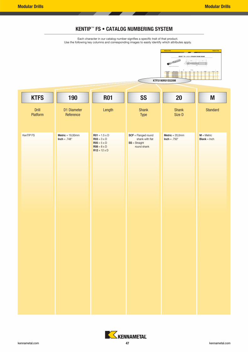
kennametal.com kennametal.com 47
Modular Drills Modular Drills
Modular Drills Modular Drills
KENTIP™ FS • 3 X D • STRAIGHT ROUND SHANK
D1 D1 max
order number catalog number mm in mm in LS D LATTH L L4 max SSC6389398 KTFS0237R03SS031 6,000 .2363 6,299 .2480 1.52 .313 2.58 2.72 .75 A6389399 KTFS0249R03SS031 6,300 .2481 6,599 .2598 1.52 .313 2.61 2.76 .79 B6389400 KTFS0260R03SS031 6,600 .2599 6,999 .2755 1.52 .313 2.65 2.80 .83 C6389401 KTFS0276R03SS031 7,000 .2756 7,499 .2952 1.52 .313 2.71 2.87 .91 D6389402 KTFS0296R03SS031 7,500 .2953 7,999 .3149 1.52 .313 2.83 3.00 .95 E6389403 KTFS0315R03SS038 8,000 .3150 8,499 .3346 1.59 .375 2.97 3.15 1.02 F6389404 KTFS0335R03SS038 8,500 .3347 8,999 .3543 1.59 .375 3.00 3.19 1.06 G6389405 KTFS0355R03SS038 9,000 .3544 9,499 .3739 1.59 .375 3.06 3.27 1.14 H6389406 KTFS0375R03SS038 9,500 .3740 9,999 .3936 1.59 .375 3.09 3.31 1.18 I6372000 KTFS0394R03SS044 10 000 3937 10 499 4133 1 67 438 3 32 3 54 1 26 J
Straight Round Shank (SS Shank)
KENTIP™ FS • CATALOG NUMBERING SYSTEM
KTFS190R01SS20M
Each character in our catalog number signifi es a specifi c trait of that product.
Use the following key columns and corresponding images to easily identify which attributes apply.
KTFS 190 R01 SS 20 M
Drill
Platform
D1 Diameter
Reference
Length Shank
Type
Shank
Size D
Standard
KenTIP FS Metric = 19,00mm
Inch = .748"
R01 = 1.5 x D
R03 = 3 x D
R05 = 5 x D
R08 = 8 x D
R12 = 12 x D
SCF = Flanged round
shank with fl at
SS = Straight
round shank
Metric = 20,0mm
Inch = .750"
M = Metric
Blank = Inch
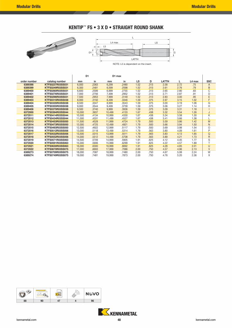
kennametal.com kennametal.com 48
Modular Drills Modular Drills
KENTIP™ FS • 3 X D • STRAIGHT ROUND SHANK
D1 D1 max
order number catalog number mm in mm in LS D LATTH L L4 max SSC6389398 KTFS0237R03SS031 6,000 .2363 6,299 .2480 1.52 .313 2.58 2.72 .75 A6389399 KTFS0249R03SS031 6,300 .2481 6,599 .2598 1.52 .313 2.61 2.76 .79 B6389400 KTFS0260R03SS031 6,600 .2599 6,999 .2755 1.52 .313 2.65 2.80 .83 C6389401 KTFS0276R03SS031 7,000 .2756 7,499 .2952 1.52 .313 2.71 2.87 .91 D6389402 KTFS0296R03SS031 7,500 .2953 7,999 .3149 1.52 .313 2.83 3.00 .95 E6389403 KTFS0315R03SS038 8,000 .3150 8,499 .3346 1.59 .375 2.97 3.15 1.02 F6389404 KTFS0335R03SS038 8,500 .3347 8,999 .3543 1.59 .375 3.00 3.19 1.06 G6389405 KTFS0355R03SS038 9,000 .3544 9,499 .3739 1.59 .375 3.06 3.27 1.14 H6389406 KTFS0375R03SS038 9,500 .3740 9,999 .3936 1.59 .375 3.09 3.31 1.18 I6372000 KTFS0394R03SS044 10,000 .3937 10,499 .4133 1.67 .438 3.32 3.54 1.26 J6372011 KTFS0414R03SS044 10,500 .4134 10,999 .4330 1.67 .438 3.34 3.58 1.30 K6372012 KTFS0434R03SS044 11,000 .4331 11,499 .4527 1.67 .438 3.41 3.66 1.38 L6372013 KTFS0453R03SS050 11,500 .4528 11,999 .4724 1.79 .500 3.59 3.86 1.42 M6372014 KTFS0473R03SS050 12,000 .4725 12,499 .4921 1.79 .500 3.66 3.94 1.50 N6372015 KTFS0493R03SS050 12,500 .4922 12,999 .5117 1.79 .500 3.69 3.98 1.54 O6372016 KTFS0512R03SS056 13,000 .5118 13,499 .5314 1.79 .563 3.80 4.09 1.61 P6372017 KTFS0532R03SS056 13,500 .5315 13,999 .5511 1.79 .563 3.83 4.13 1.65 Q6372018 KTFS0552R03SS056 14,000 .5512 14,499 .5708 1.79 .563 3.89 4.21 1.73 R6372019 KTFS0571R03SS063 14,500 .5709 14,999 .5905 1.91 .625 4.12 4.45 1.77 S6372020 KTFS0591R03SS063 15,000 .5906 15,999 .6299 1.91 .625 4.22 4.57 1.89 T6372021 KTFS0630R03SS063 16,000 .6300 16,999 .6692 1.91 .625 4.28 4.65 2.01 U6372022 KTFS0670R03SS075 17,000 .6693 17,999 .7086 2.00 .750 4.57 4.96 2.13 V6389273 KTFS0709R03SS075 18,000 .7087 18,999 .7480 2.00 .750 4.67 5.08 2.24 W6389274 KTFS0749R03SS075 19,000 .7481 19,999 .7873 2.00 .750 4.76 5.20 2.36 X
NOTE: L5 is dependent on the insert.
AB
88 90 47 4 96
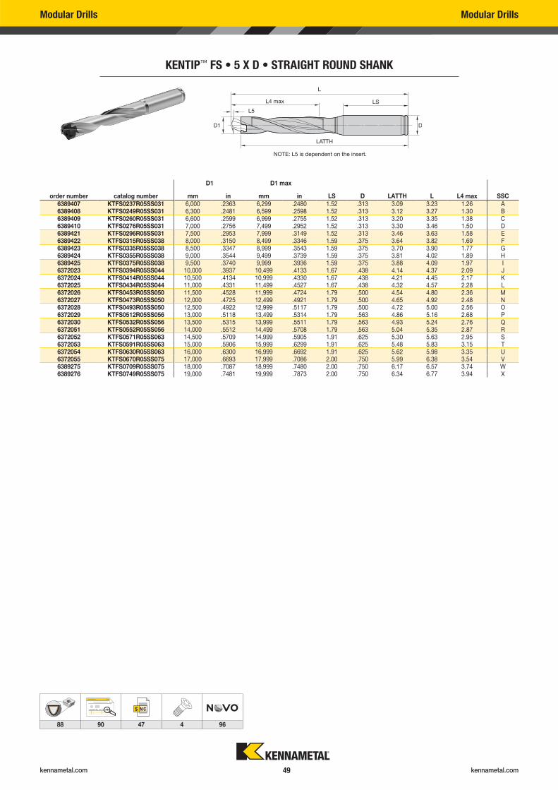
kennametal.com kennametal.com 49
NOTE: L5 is dependent on the insert.
Modular Drills Modular Drills
KENTIP™ FS • 5 X D • STRAIGHT ROUND SHANK
D1 D1 max
order number catalog number mm in mm in LS D LATTH L L4 max SSC6389407 KTFS0237R05SS031 6,000 .2363 6,299 .2480 1.52 .313 3.09 3.23 1.26 A6389408 KTFS0249R05SS031 6,300 .2481 6,599 .2598 1.52 .313 3.12 3.27 1.30 B6389409 KTFS0260R05SS031 6,600 .2599 6,999 .2755 1.52 .313 3.20 3.35 1.38 C6389410 KTFS0276R05SS031 7,000 .2756 7,499 .2952 1.52 .313 3.30 3.46 1.50 D6389421 KTFS0296R05SS031 7,500 .2953 7,999 .3149 1.52 .313 3.46 3.63 1.58 E6389422 KTFS0315R05SS038 8,000 .3150 8,499 .3346 1.59 .375 3.64 3.82 1.69 F6389423 KTFS0335R05SS038 8,500 .3347 8,999 .3543 1.59 .375 3.70 3.90 1.77 G6389424 KTFS0355R05SS038 9,000 .3544 9,499 .3739 1.59 .375 3.81 4.02 1.89 H6389425 KTFS0375R05SS038 9,500 .3740 9,999 .3936 1.59 .375 3.88 4.09 1.97 I6372023 KTFS0394R05SS044 10,000 .3937 10,499 .4133 1.67 .438 4.14 4.37 2.09 J6372024 KTFS0414R05SS044 10,500 .4134 10,999 .4330 1.67 .438 4.21 4.45 2.17 K6372025 KTFS0434R05SS044 11,000 .4331 11,499 .4527 1.67 .438 4.32 4.57 2.28 L6372026 KTFS0453R05SS050 11,500 .4528 11,999 .4724 1.79 .500 4.54 4.80 2.36 M6372027 KTFS0473R05SS050 12,000 .4725 12,499 .4921 1.79 .500 4.65 4.92 2.48 N6372028 KTFS0493R05SS050 12,500 .4922 12,999 .5117 1.79 .500 4.72 5.00 2.56 O6372029 KTFS0512R05SS056 13,000 .5118 13,499 .5314 1.79 .563 4.86 5.16 2.68 P6372030 KTFS0532R05SS056 13,500 .5315 13,999 .5511 1.79 .563 4.93 5.24 2.76 Q6372051 KTFS0552R05SS056 14,000 .5512 14,499 .5708 1.79 .563 5.04 5.35 2.87 R6372052 KTFS0571R05SS063 14,500 .5709 14,999 .5905 1.91 .625 5.30 5.63 2.95 S6372053 KTFS0591R05SS063 15,000 .5906 15,999 .6299 1.91 .625 5.48 5.83 3.15 T6372054 KTFS0630R05SS063 16,000 .6300 16,999 .6692 1.91 .625 5.62 5.98 3.35 U6372055 KTFS0670R05SS075 17,000 .6693 17,999 .7086 2.00 .750 5.99 6.38 3.54 V6389275 KTFS0709R05SS075 18,000 .7087 18,999 .7480 2.00 .750 6.17 6.57 3.74 W6389276 KTFS0749R05SS075 19,000 .7481 19,999 .7873 2.00 .750 6.34 6.77 3.94 X
AB
88 90 47 4 96
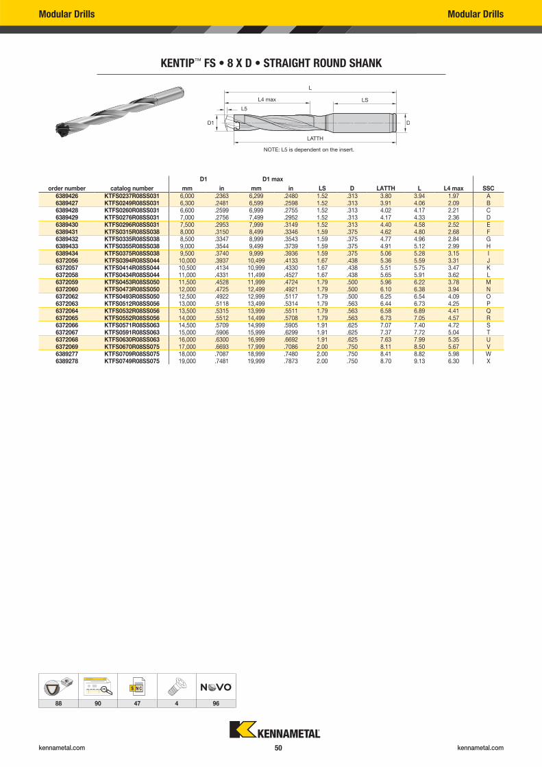
kennametal.com kennametal.com 50
Modular Drills Modular Drills
KENTIP™ FS • 8 X D • STRAIGHT ROUND SHANK
D1 D1 max
order number catalog number mm in mm in LS D LATTH L L4 max SSC6389426 KTFS0237R08SS031 6,000 .2363 6,299 .2480 1.52 .313 3.80 3.94 1.97 A6389427 KTFS0249R08SS031 6,300 .2481 6,599 .2598 1.52 .313 3.91 4.06 2.09 B6389428 KTFS0260R08SS031 6,600 .2599 6,999 .2755 1.52 .313 4.02 4.17 2.21 C6389429 KTFS0276R08SS031 7,000 .2756 7,499 .2952 1.52 .313 4.17 4.33 2.36 D6389430 KTFS0296R08SS031 7,500 .2953 7,999 .3149 1.52 .313 4.40 4.58 2.52 E6389431 KTFS0315R08SS038 8,000 .3150 8,499 .3346 1.59 .375 4.62 4.80 2.68 F6389432 KTFS0335R08SS038 8,500 .3347 8,999 .3543 1.59 .375 4.77 4.96 2.84 G6389433 KTFS0355R08SS038 9,000 .3544 9,499 .3739 1.59 .375 4.91 5.12 2.99 H6389434 KTFS0375R08SS038 9,500 .3740 9,999 .3936 1.59 .375 5.06 5.28 3.15 I6372056 KTFS0394R08SS044 10,000 .3937 10,499 .4133 1.67 .438 5.36 5.59 3.31 J6372057 KTFS0414R08SS044 10,500 .4134 10,999 .4330 1.67 .438 5.51 5.75 3.47 K6372058 KTFS0434R08SS044 11,000 .4331 11,499 .4527 1.67 .438 5.65 5.91 3.62 L6372059 KTFS0453R08SS050 11,500 .4528 11,999 .4724 1.79 .500 5.96 6.22 3.78 M6372060 KTFS0473R08SS050 12,000 .4725 12,499 .4921 1.79 .500 6.10 6.38 3.94 N6372062 KTFS0493R08SS050 12,500 .4922 12,999 .5117 1.79 .500 6.25 6.54 4.09 O6372063 KTFS0512R08SS056 13,000 .5118 13,499 .5314 1.79 .563 6.44 6.73 4.25 P6372064 KTFS0532R08SS056 13,500 .5315 13,999 .5511 1.79 .563 6.58 6.89 4.41 Q6372065 KTFS0552R08SS056 14,000 .5512 14,499 .5708 1.79 .563 6.73 7.05 4.57 R6372066 KTFS0571R08SS063 14,500 .5709 14,999 .5905 1.91 .625 7.07 7.40 4.72 S6372067 KTFS0591R08SS063 15,000 .5906 15,999 .6299 1.91 .625 7.37 7.72 5.04 T6372068 KTFS0630R08SS063 16,000 .6300 16,999 .6692 1.91 .625 7.63 7.99 5.35 U6372069 KTFS0670R08SS075 17,000 .6693 17,999 .7086 2.00 .750 8.11 8.50 5.67 V6389277 KTFS0709R08SS075 18,000 .7087 18,999 .7480 2.00 .750 8.41 8.82 5.98 W6389278 KTFS0749R08SS075 19,000 .7481 19,999 .7873 2.00 .750 8.70 9.13 6.30 X
AB
88 90 47 4 96
NOTE: L5 is dependent on the insert.
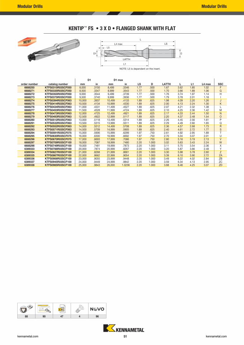
kennametal.com kennametal.com 51
Modular Drills Modular Drills
KENTIP™ FS • 3 X D • FLANGED SHANK WITH FLAT
D1 D1 max
order number catalog number mm in mm in LS D LATTH L L1 L4 max SSC6688250 KTFS0315R03SCF050 8,000 .3150 8,499 .3346 1.77 .500 1.67 3.62 1.85 1.02 F6688271 KTFS0335R03SCF050 8,500 .3347 8,999 .3543 1.77 .500 1.70 3.66 1.89 1.06 G6688272 KTFS0355R03SCF050 9,000 .3544 9,499 .3739 1.77 .500 1.76 3.74 1.97 1.14 H6688273 KTFS0375R03SCF050 9,500 .3740 9,999 .3936 1.77 .500 1.79 3.78 2.01 1.18 I6688274 KTFS0394R03SCF063 10,000 .3937 10,499 .4133 1.89 .625 1.98 4.09 2.20 1.26 J6688275 KTFS0414R03SCF063 10,500 .4134 10,999 .4330 1.89 .625 2.00 4.13 2.24 1.30 K6688276 KTFS0434R03SCF063 11,000 .4331 11,499 .4527 1.89 .625 2.07 4.21 2.32 1.38 L6688277 KTFS0453R03SCF063 11,500 .4528 11,999 .4724 1.89 .625 2.10 4.25 2.36 1.42 M6688278 KTFS0473R03SCF063 12,000 .4725 12,499 .4921 1.89 .625 2.17 4.33 2.44 1.50 N6688279 KTFS0493R03SCF063 12,500 .4922 12,999 .5117 1.89 .625 2.20 4.37 2.48 1.54 O6688280 KTFS0512R03SCF063 13,000 .5118 13,499 .5314 1.89 .625 2.26 4.45 2.56 1.61 P6688291 KTFS0532R03SCF063 13,500 .5315 13,999 .5511 1.89 .625 2.29 4.49 2.60 1.65 Q6688292 KTFS0552R03SCF063 14,000 .5512 14,499 .5708 1.89 .625 2.36 4.57 2.68 1.73 R6688293 KTFS0571R03SCF063 14,500 .5709 14,999 .5905 1.89 .625 2.40 4.61 2.72 1.77 S6688294 KTFS0591R03SCF075 15,000 .5906 15,999 .6299 1.97 .750 2.61 4.92 2.95 1.89 T6688295 KTFS0630R03SCF075 16,000 .6300 16,999 .6692 1.97 .750 2.70 5.04 3.07 2.01 U6688296 KTFS0670R03SCF075 17,000 .6693 17,999 .7086 1.97 .750 2.80 5.16 3.19 2.13 V6688297 KTFS0709R03SCF100 18,000 .7087 18,999 .7480 2.20 1.000 3.02 5.63 3.43 2.24 W6688298 KTFS0749R03SCF100 19,000 .7481 19,999 .7873 2.20 1.000 3.11 5.75 3.54 2.36 X6389333 KTFS0788R03SCF100 20,000 .7874 20,999 .8267 2.20 1.000 3.20 5.87 3.66 2.48 Y6389334 KTFS0827R03SCF100 21,000 .8268 21,999 .8661 2.20 1.000 3.30 5.98 3.78 2.60 Z6389335 KTFS0867R03SCF100 22,000 .8662 22,999 .9054 2.20 1.000 3.39 6.10 3.90 2.72 ZA6389336 KTFS0906R03SCF100 23,000 .9055 23,999 .9448 2.20 1.000 3.49 6.22 4.02 2.84 ZB6389337 KTFS0945R03SCF100 24,000 .9449 24,999 .9842 2.20 1.000 3.59 6.34 4.13 2.95 ZC6389338 KTFS0985R03SCF100 25,000 .9843 26,000 1.0236 2.20 1.000 3.68 6.46 4.25 3.07 ZD
AB
88 90 47 4 96
NOTE: L5 is dependent on the insert.
NEW!
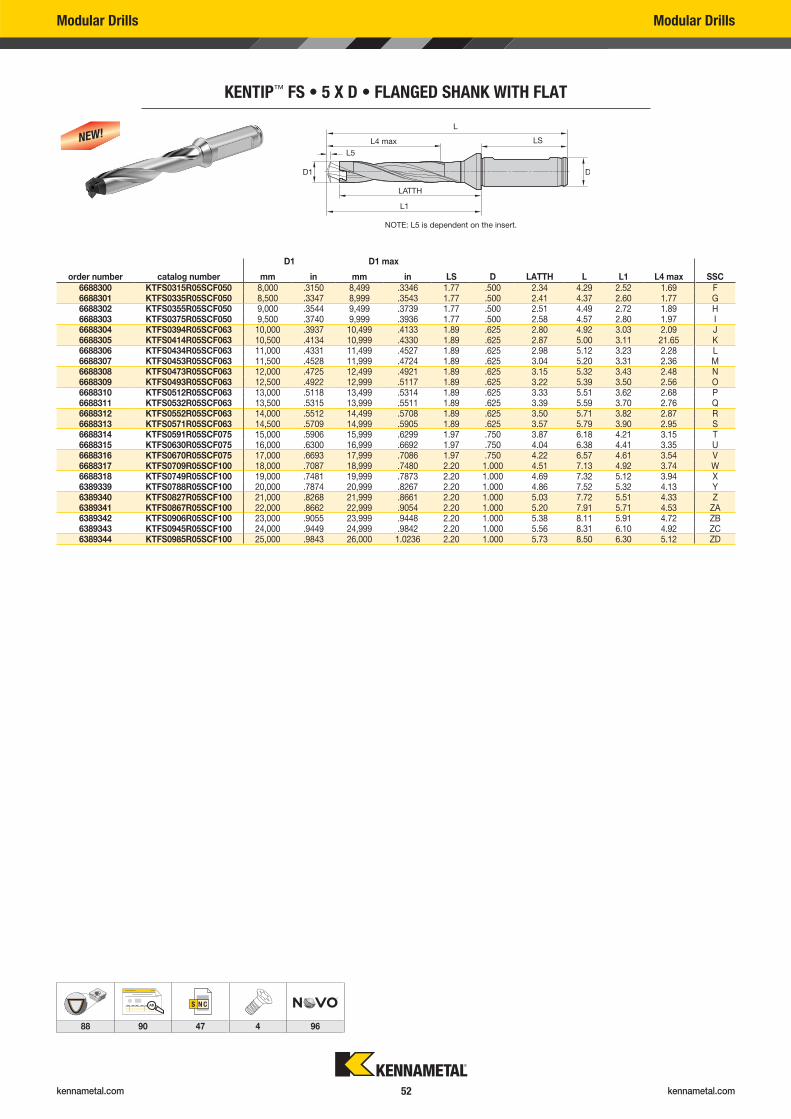
kennametal.com kennametal.com 52
Modular Drills Modular Drills
KENTIP™ FS • 5 X D • FLANGED SHANK WITH FLAT
D1 D1 max
order number catalog number mm in mm in LS D LATTH L L1 L4 max SSC6688300 KTFS0315R05SCF050 8,000 .3150 8,499 .3346 1.77 .500 2.34 4.29 2.52 1.69 F6688301 KTFS0335R05SCF050 8,500 .3347 8,999 .3543 1.77 .500 2.41 4.37 2.60 1.77 G6688302 KTFS0355R05SCF050 9,000 .3544 9,499 .3739 1.77 .500 2.51 4.49 2.72 1.89 H6688303 KTFS0375R05SCF050 9,500 .3740 9,999 .3936 1.77 .500 2.58 4.57 2.80 1.97 I6688304 KTFS0394R05SCF063 10,000 .3937 10,499 .4133 1.89 .625 2.80 4.92 3.03 2.09 J6688305 KTFS0414R05SCF063 10,500 .4134 10,999 .4330 1.89 .625 2.87 5.00 3.11 21.65 K6688306 KTFS0434R05SCF063 11,000 .4331 11,499 .4527 1.89 .625 2.98 5.12 3.23 2.28 L6688307 KTFS0453R05SCF063 11,500 .4528 11,999 .4724 1.89 .625 3.04 5.20 3.31 2.36 M6688308 KTFS0473R05SCF063 12,000 .4725 12,499 .4921 1.89 .625 3.15 5.32 3.43 2.48 N6688309 KTFS0493R05SCF063 12,500 .4922 12,999 .5117 1.89 .625 3.22 5.39 3.50 2.56 O6688310 KTFS0512R05SCF063 13,000 .5118 13,499 .5314 1.89 .625 3.33 5.51 3.62 2.68 P6688311 KTFS0532R05SCF063 13,500 .5315 13,999 .5511 1.89 .625 3.39 5.59 3.70 2.76 Q6688312 KTFS0552R05SCF063 14,000 .5512 14,499 .5708 1.89 .625 3.50 5.71 3.82 2.87 R6688313 KTFS0571R05SCF063 14,500 .5709 14,999 .5905 1.89 .625 3.57 5.79 3.90 2.95 S6688314 KTFS0591R05SCF075 15,000 .5906 15,999 .6299 1.97 .750 3.87 6.18 4.21 3.15 T6688315 KTFS0630R05SCF075 16,000 .6300 16,999 .6692 1.97 .750 4.04 6.38 4.41 3.35 U6688316 KTFS0670R05SCF075 17,000 .6693 17,999 .7086 1.97 .750 4.22 6.57 4.61 3.54 V6688317 KTFS0709R05SCF100 18,000 .7087 18,999 .7480 2.20 1.000 4.51 7.13 4.92 3.74 W6688318 KTFS0749R05SCF100 19,000 .7481 19,999 .7873 2.20 1.000 4.69 7.32 5.12 3.94 X6389339 KTFS0788R05SCF100 20,000 .7874 20,999 .8267 2.20 1.000 4.86 7.52 5.32 4.13 Y6389340 KTFS0827R05SCF100 21,000 .8268 21,999 .8661 2.20 1.000 5.03 7.72 5.51 4.33 Z6389341 KTFS0867R05SCF100 22,000 .8662 22,999 .9054 2.20 1.000 5.20 7.91 5.71 4.53 ZA6389342 KTFS0906R05SCF100 23,000 .9055 23,999 .9448 2.20 1.000 5.38 8.11 5.91 4.72 ZB6389343 KTFS0945R05SCF100 24,000 .9449 24,999 .9842 2.20 1.000 5.56 8.31 6.10 4.92 ZC6389344 KTFS0985R05SCF100 25,000 .9843 26,000 1.0236 2.20 1.000 5.73 8.50 6.30 5.12 ZD
AB
88 90 47 4 96
NOTE: L5 is dependent on the insert.
NEW!
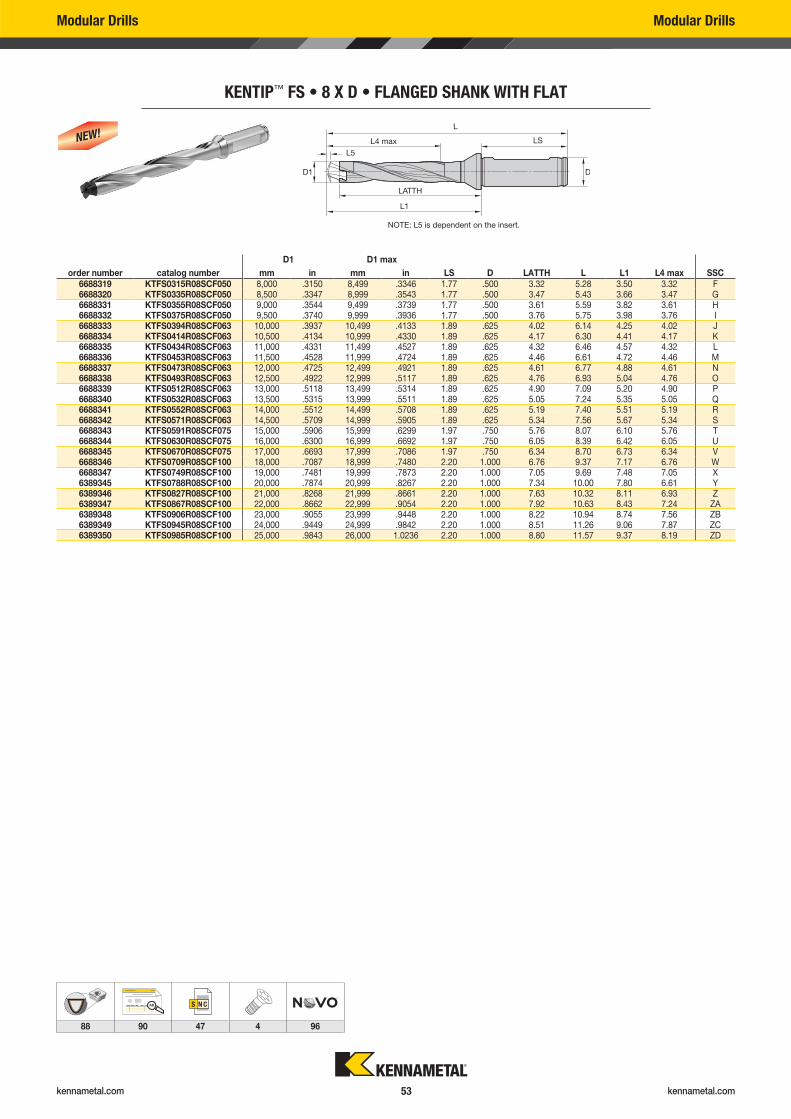
kennametal.com kennametal.com 53
Modular Drills Modular Drills
KENTIP™ FS • 8 X D • FLANGED SHANK WITH FLAT
D1 D1 max
order number catalog number mm in mm in LS D LATTH L L1 L4 max SSC6688319 KTFS0315R08SCF050 8,000 .3150 8,499 .3346 1.77 .500 3.32 5.28 3.50 3.32 F6688320 KTFS0335R08SCF050 8,500 .3347 8,999 .3543 1.77 .500 3.47 5.43 3.66 3.47 G6688331 KTFS0355R08SCF050 9,000 .3544 9,499 .3739 1.77 .500 3.61 5.59 3.82 3.61 H6688332 KTFS0375R08SCF050 9,500 .3740 9,999 .3936 1.77 .500 3.76 5.75 3.98 3.76 I6688333 KTFS0394R08SCF063 10,000 .3937 10,499 .4133 1.89 .625 4.02 6.14 4.25 4.02 J6688334 KTFS0414R08SCF063 10,500 .4134 10,999 .4330 1.89 .625 4.17 6.30 4.41 4.17 K6688335 KTFS0434R08SCF063 11,000 .4331 11,499 .4527 1.89 .625 4.32 6.46 4.57 4.32 L6688336 KTFS0453R08SCF063 11,500 .4528 11,999 .4724 1.89 .625 4.46 6.61 4.72 4.46 M6688337 KTFS0473R08SCF063 12,000 .4725 12,499 .4921 1.89 .625 4.61 6.77 4.88 4.61 N6688338 KTFS0493R08SCF063 12,500 .4922 12,999 .5117 1.89 .625 4.76 6.93 5.04 4.76 O6688339 KTFS0512R08SCF063 13,000 .5118 13,499 .5314 1.89 .625 4.90 7.09 5.20 4.90 P6688340 KTFS0532R08SCF063 13,500 .5315 13,999 .5511 1.89 .625 5.05 7.24 5.35 5.05 Q6688341 KTFS0552R08SCF063 14,000 .5512 14,499 .5708 1.89 .625 5.19 7.40 5.51 5.19 R6688342 KTFS0571R08SCF063 14,500 .5709 14,999 .5905 1.89 .625 5.34 7.56 5.67 5.34 S6688343 KTFS0591R08SCF075 15,000 .5906 15,999 .6299 1.97 .750 5.76 8.07 6.10 5.76 T6688344 KTFS0630R08SCF075 16,000 .6300 16,999 .6692 1.97 .750 6.05 8.39 6.42 6.05 U6688345 KTFS0670R08SCF075 17,000 .6693 17,999 .7086 1.97 .750 6.34 8.70 6.73 6.34 V6688346 KTFS0709R08SCF100 18,000 .7087 18,999 .7480 2.20 1.000 6.76 9.37 7.17 6.76 W6688347 KTFS0749R08SCF100 19,000 .7481 19,999 .7873 2.20 1.000 7.05 9.69 7.48 7.05 X6389345 KTFS0788R08SCF100 20,000 .7874 20,999 .8267 2.20 1.000 7.34 10.00 7.80 6.61 Y6389346 KTFS0827R08SCF100 21,000 .8268 21,999 .8661 2.20 1.000 7.63 10.32 8.11 6.93 Z6389347 KTFS0867R08SCF100 22,000 .8662 22,999 .9054 2.20 1.000 7.92 10.63 8.43 7.24 ZA6389348 KTFS0906R08SCF100 23,000 .9055 23,999 .9448 2.20 1.000 8.22 10.94 8.74 7.56 ZB6389349 KTFS0945R08SCF100 24,000 .9449 24,999 .9842 2.20 1.000 8.51 11.26 9.06 7.87 ZC6389350 KTFS0985R08SCF100 25,000 .9843 26,000 1.0236 2.20 1.000 8.80 11.57 9.37 8.19 ZD
AB
88 90 47 4 96
NOTE: L5 is dependent on the insert.
NEW!
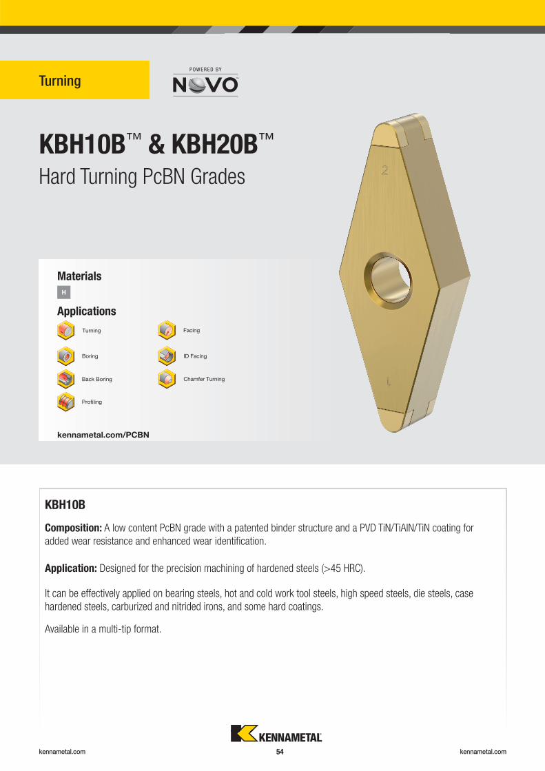
kennametal.com kennametal.com 54
KBH10B™ & KBH20B™
Turning
Hard Turning PcBN Grades
Applications
Materials
H
kennametal.com/PCBN
Turning
KBH10B
Composition: A low content PcBN grade with a patented binder structure and a PVD TiN/TiAlN/TiN coating for
added wear resistance and enhanced wear identifi cation.
Application: Designed for the precision machining of hardened steels (>45 HRC).
It can be effectively applied on bearing steels, hot and cold work tool steels, high speed steels, die steels, case
hardened steels, carburized and nitrided irons, and some hard coatings.
Available in a multi-tip format.
Boring
Back Boring
Profi ling
Facing
ID Facing
Chamfer Turning
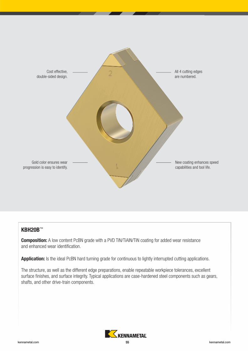
kennametal.com kennametal.com 55
KBH20B™
Composition: A low content PcBN grade with a PVD TiN/TiAlN/TiN coating for added wear resistance
and enhanced wear identifi cation.
Application: Is the ideal PcBN hard turning grade for continuous to lightly interrupted cutting applications.
The structure, as well as the different edge preparations, enable repeatable workpiece tolerances, excellent
surface fi nishes, and surface integrity. Typical applications are case-hardened steel components such as gears,
shafts, and other drive-train components.
Cost effective,
double-sided design.
Gold color ensures wear
progression is easy to identify.
New coating enhances speed
capabilities and tool life.
All 4 cutting edges
are numbered.
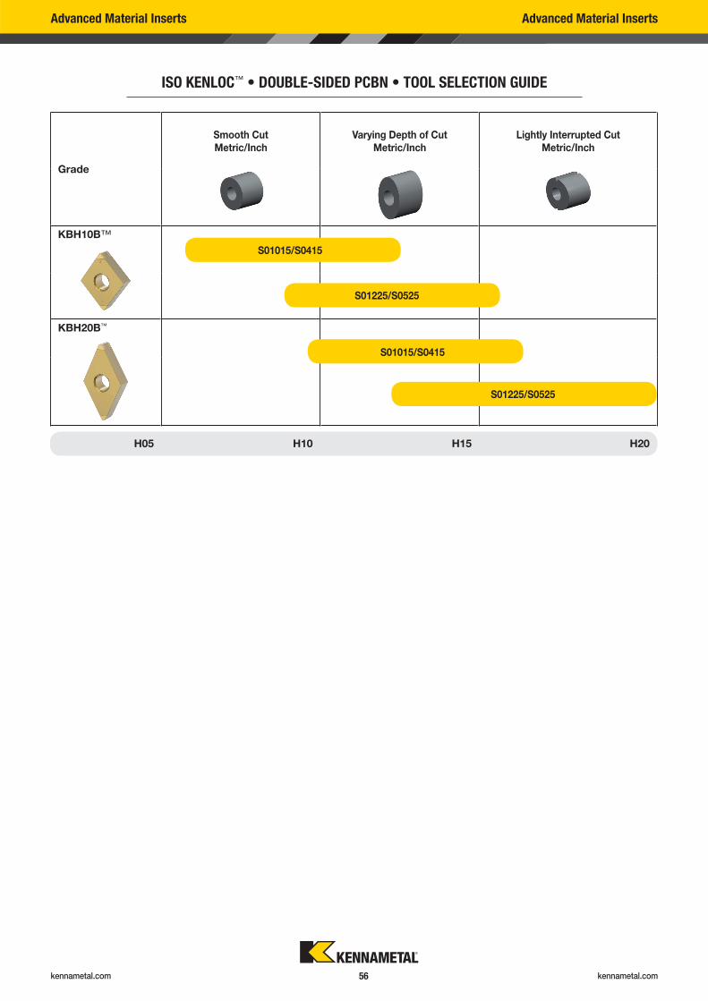
kennametal.com kennametal.com 56
Advanced Material Inserts Advanced Material Inserts
ISO KENLOC™ • DOUBLE-SIDED PCBN • TOOL SELECTION GUIDE
Grade
Smooth Cut
Metric/Inch
Varying Depth of Cut
Metric/Inch
Lightly Interrupted Cut
Metric/Inch
KBH10B™
KBH20B™
H05 H10 H15 H20
S01015/S0415
S01225/S0525
S01015/S0415
S01225/S0525
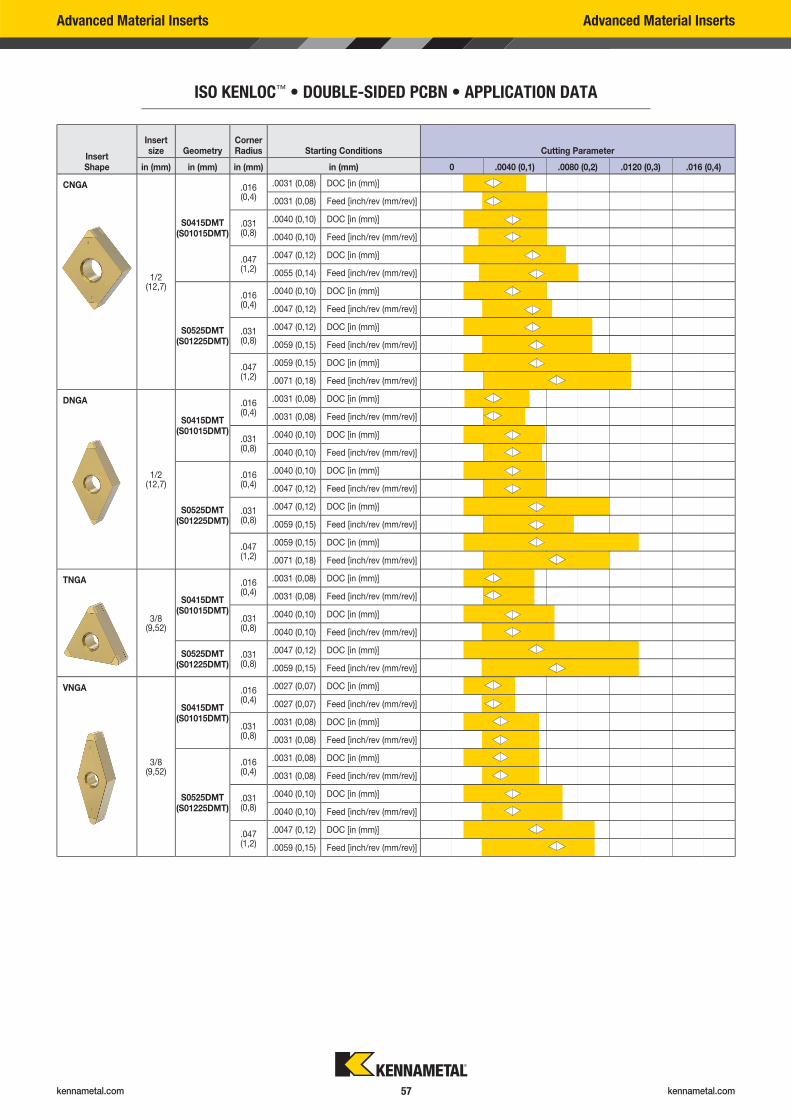
kennametal.com kennametal.com 57
Advanced Material Inserts Advanced Material Inserts
ISO KENLOC™ • DOUBLE-SIDED PCBN • APPLICATION DATA
Insert Shape
Insert size Geometry
Corner Radius Starting Conditions Cutting Parameter
in (mm) in (mm) in (mm) in (mm) 0 .0040 (0,1) .0080 (0,2) .0120 (0,3) .016 (0,4)
CNGA
1/2(12,7)
S0415DMT(S01015DMT)
.016 (0,4)
.0031 (0,08) DOC [in (mm)]
.0031 (0,08) Feed [inch/rev (mm/rev)]
.031(0,8)
.0040 (0,10) DOC [in (mm)]
.0040 (0,10) Feed [inch/rev (mm/rev)]
.047 (1,2)
.0047 (0,12) DOC [in (mm)]
.0055 (0,14) Feed [inch/rev (mm/rev)]
S0525DMT(S01225DMT)
.016 (0,4)
.0040 (0,10) DOC [in (mm)]
.0047 (0,12) Feed [inch/rev (mm/rev)]
.031 (0,8)
.0047 (0,12) DOC [in (mm)]
.0059 (0,15) Feed [inch/rev (mm/rev)]
.047 (1,2)
.0059 (0,15) DOC [in (mm)]
.0071 (0,18) Feed [inch/rev (mm/rev)]
DNGA
1/2(12,7)
S0415DMT(S01015DMT)
.016 (0,4)
.0031 (0,08) DOC [in (mm)]
.0031 (0,08) Feed [inch/rev (mm/rev)]
.031 (0,8)
.0040 (0,10) DOC [in (mm)]
.0040 (0,10) Feed [inch/rev (mm/rev)]
S0525DMT(S01225DMT)
.016 (0,4)
.0040 (0,10) DOC [in (mm)]
.0047 (0,12) Feed [inch/rev (mm/rev)]
.031 (0,8)
.0047 (0,12) DOC [in (mm)]
.0059 (0,15) Feed [inch/rev (mm/rev)]
.047 (1,2)
.0059 (0,15) DOC [in (mm)]
.0071 (0,18) Feed [inch/rev (mm/rev)]
TNGA
3/8(9,52)
S0415DMT(S01015DMT)
.016 (0,4)
.0031 (0,08) DOC [in (mm)]
.0031 (0,08) Feed [inch/rev (mm/rev)]
.031 (0,8)
.0040 (0,10) DOC [in (mm)]
.0040 (0,10) Feed [inch/rev (mm/rev)]
S0525DMT(S01225DMT)
.031 (0,8)
.0047 (0,12) DOC [in (mm)]
.0059 (0,15) Feed [inch/rev (mm/rev)]
VNGA
3/8(9,52)
S0415DMT(S01015DMT)
.016 (0,4)
.0027 (0,07) DOC [in (mm)]
.0027 (0,07) Feed [inch/rev (mm/rev)]
.031 (0,8)
.0031 (0,08) DOC [in (mm)]
.0031 (0,08) Feed [inch/rev (mm/rev)]
S0525DMT(S01225DMT)
.016 (0,4)
.0031 (0,08) DOC [in (mm)]
.0031 (0,08) Feed [inch/rev (mm/rev)]
.031 (0,8)
.0040 (0,10) DOC [in (mm)]
.0040 (0,10) Feed [inch/rev (mm/rev)]
.047 (1,2)
.0047 (0,12) DOC [in (mm)]
.0059 (0,15) Feed [inch/rev (mm/rev)]
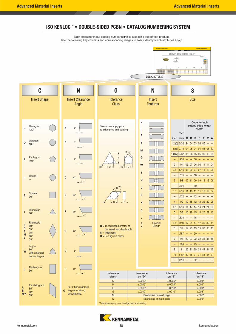
kennametal.com kennametal.com 58
C N G N 3
Insert Shape Insert Clearance
Angle
Tolerance
Class
Insert
Features
Size
HHexagon
120°A
Tolerances apply prior
to edge prep and coating
N
R
F
A
M
G
W
T
Q
U
B
H
C
J
Rε Rε
OOctagon
135°B
PPentagon
108°C
RRound
—D
Rε
SSquare
90°E
TTriangular
60°F
CDEMV
Rhomboid
80°
55°
75°
86°
35°
G
D = Theoretical diameter of
the insert inscribed circle
S = Thickness
B = See fi gures below
XV
SpecialDesign
W
Trigon
80°
with enlarged
corner angles
N
LRectangular
90°P
ABN/K
Parallelogram
85°
82°
55°
O
For other clearance
angles requiring
descriptions.
Code for inchcutting edge length
“L10”
“D”
inch inch C D R S T V W
1.2 (5) 5/32 S4 04 03 03 06 — —
1.5 (6) 3/16 04 05 04 04 08 08 S3
1.8 (7) 7/32 05 06 05 05 09 09 03
— .236 — — 06 — — — —
2 1/4 06 07 06 06 11 11 04
2.5 5/16 08 09 07 07 13 13 05
— .315 — — 08 — — — —
3 3/8 09 11 09 09 16 16 06
— .394 — — 10 — — — —
3.5 7/16 11 13 11 11 19 19 07
— .472 — — 12 — — — —
4 1/2 12 15 12 12 22 22 08
4.5 9/16 14 17 14 14 24 24 09
5 5/8 16 19 15 15 27 27 10
— .630 — — 16 — — — —
5.5 11/16 17 21 17 17 30 30 11
6 3/4 19 23 19 19 33 33 13
— .787 — — 20 — — — —
7 7/8 22 27 22 22 38 38 15
— .984 — — 25 — — — —
8 1 25 31 25 25 44 44 17
10 1-1/4 32 38 31 31 54 54 21
— 1.260 — — 32 — — — —
Advanced Material Inserts Advanced Material Inserts
ISO KENLOC™ • DOUBLE-SIDED PCBN • CATALOG NUMBERING SYSTEM
Advanced Material Inserts Advanced Material Inserts
ISO KENLOC™ • DOUBLE-SIDED PCBN • CNGA-MT
D L10 LEFF R�ISO
catalog numberANSI
catalog number mm in mm in mm in mm in KB
H10B
KB
H20B
CNGA120404S01015DMT CNGA431S0415DMT 12,70 1/2 12,90 .508 2,47 .097 0,4 1/64 � �
CNGA120404S01225DMT CNGA431S0525DMT 12,70 1/2 12,90 .508 2,47 .097 0,4 1/64 � �
CNGA120408S01015DMT CNGA432S0415DMT 12,70 1/2 12,90 .508 2,39 .094 0,8 1/32 � �
CNGA120408S01225DMT CNGA432S0525DMT 12,70 1/2 12,90 .508 2,39 .094 0,8 1/32 � �
CNGA120412S01015DMT CNGA433S0415DMT 12,70 1/2 12,90 .508 2,41 .095 1,2 3/64 – �
CNGA120412S01225DMT CNGA433S0525DMT 12,70 1/2 12,90 .508 2,41 .095 1,2 3/64 – �
� first choice
� alternate choice
PMKNSH � �
Each character in our catalog number signifi es a specifi c trait of that product.
Use the following key columns and corresponding images to easily identify which attributes apply.
CNGN332T0820
toleranceclass*
toleranceon “D”
toleranceon “B”
toleranceon “S”
C ±.0010" ±.0005" ±.001"
H ±.0005" ±.0005" ±.001"
E ±.0010" ±.0010" ±.001"
G ±.0010" ±.0010" ±.005"
M See tables on next page ±.005"
U See tables on next page ±.005"
*Tolerances apply prior to edge prep and coating.
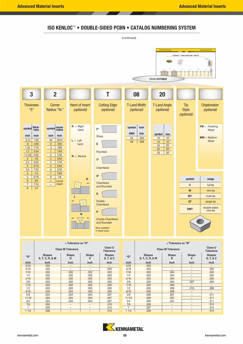
kennametal.com kennametal.com 59
3 2 T 08 20
Thickness
“S”
Corner
Radius “R�”
Hand of Insert
(optional)
Cutting Edge
(optional)
T-Land Width
(optional)
T-Land Angle
(optional)
Tip
Style
(optional)
Chipbreaker
(optional)
R = Right
hand F*
Sharp
L = Left
hand E
Rounded
N = Neutral
T*
Chamfered
S*
Chamfered
and Rounded
K
Double-
Chamfered
P
Double-Chamfered
and Rounded
symbol thick-ness
inch inch
.5 (1) 1/32
.6 .040
1 (2) 1/16
1.2 5.64
1.5 (3) 3/32
2 1/8
2.5 5/32
3 3/16
3.5 7/32
4 1/4
5 5/16
6 3/8
7 7/16
8 1/2
symbol corner radius
inch inch
X0 .0015
0 .004
.5 .008
1 1/64
2 1/32
3 3/64
4 1/16
5 5/64
6 3/32
7 7/64
8 1/8
— roundinsert—
symbol usage
C full tip
M mini tip
MT multi-tip
ST single tip
DMTdouble-sided
mini-tip
symbol inch
symbol sizeANSI size
04 .004 10 10°
08 .008 15 15°
20 20°
25 25°
30 30°
* Also available in wiper style.
± Tolerance on “D” ± Tolerance on “B”
Class M ToleranceClass U
ToleranceClass M Tolerance
Class U Tolerance
“D”Shapes
S, T, C, R, & WShape
DShape
VShapes S, T, & C
“D”Shapes
S, T, C, R, & WShape
DShape
VShapes S, T, & C
inch inch inch inch inch inch inch inch inch inch5/32 .002 – – – 5/32 .003 – – –3/16 .002 – – .003 3/16 .003 – – .0057/32 .002 .002 .002 .003 7/32 .003 .004 – .0051/4 .002 .002 .002 .003 1/4 .003 .004 – .0055/16 .002 .002 .002 .003 5/16 .003 .004 – .0053/8 .002 .002 .002 .003 3/8 .003 .004 .007 .0057/16 .003 .003 .003 .005 7/16 .005 .006 – –1/2 .003 .003 .003 .005 1/2 .005 .006 .010 .0089/16 .003 .003 .003 .005 9/16 .005 .006 – –5/8 .004 .004 .004 .007 5/8 .006 .007 – .011
11/16 .004 .004 .004 .007 11/16 .006 .007 – .0113/4 .004 .004 .004 .007 3/4 .006 .007 – .0117/8 .005 – – .010 7/8 .006 – – .0151 .005 – – .010 1 .007 – – .015
1 1/4 .006 – – .010 1 1/4 .008 – – .015
FW = Finishing
Wiper
MW = Medium
Wiper
R
L
N
Advanced Material Inserts Advanced Material Inserts
ISO KENLOC™ • DOUBLE-SIDED PCBN • CATALOG NUMBERING SYSTEM
Advanced Material Inserts Advanced Material Inserts
ISO KENLOC™ • DOUBLE-SIDED PCBN • CNGA-MT
D L10 LEFF R�ISO
catalog numberANSI
catalog number mm in mm in mm in mm in KB
H10B
KB
H20B
CNGA120404S01015DMT CNGA431S0415DMT 12,70 1/2 12,90 .508 2,47 .097 0,4 1/64 � �
CNGA120404S01225DMT CNGA431S0525DMT 12,70 1/2 12,90 .508 2,47 .097 0,4 1/64 � �
CNGA120408S01015DMT CNGA432S0415DMT 12,70 1/2 12,90 .508 2,39 .094 0,8 1/32 � �
CNGA120408S01225DMT CNGA432S0525DMT 12,70 1/2 12,90 .508 2,39 .094 0,8 1/32 � �
CNGA120412S01015DMT CNGA433S0415DMT 12,70 1/2 12,90 .508 2,41 .095 1,2 3/64 – �
CNGA120412S01225DMT CNGA433S0525DMT 12,70 1/2 12,90 .508 2,41 .095 1,2 3/64 – �
� first choice
� alternate choice
PMKNSH � �
(continued)
CNGN332T0820
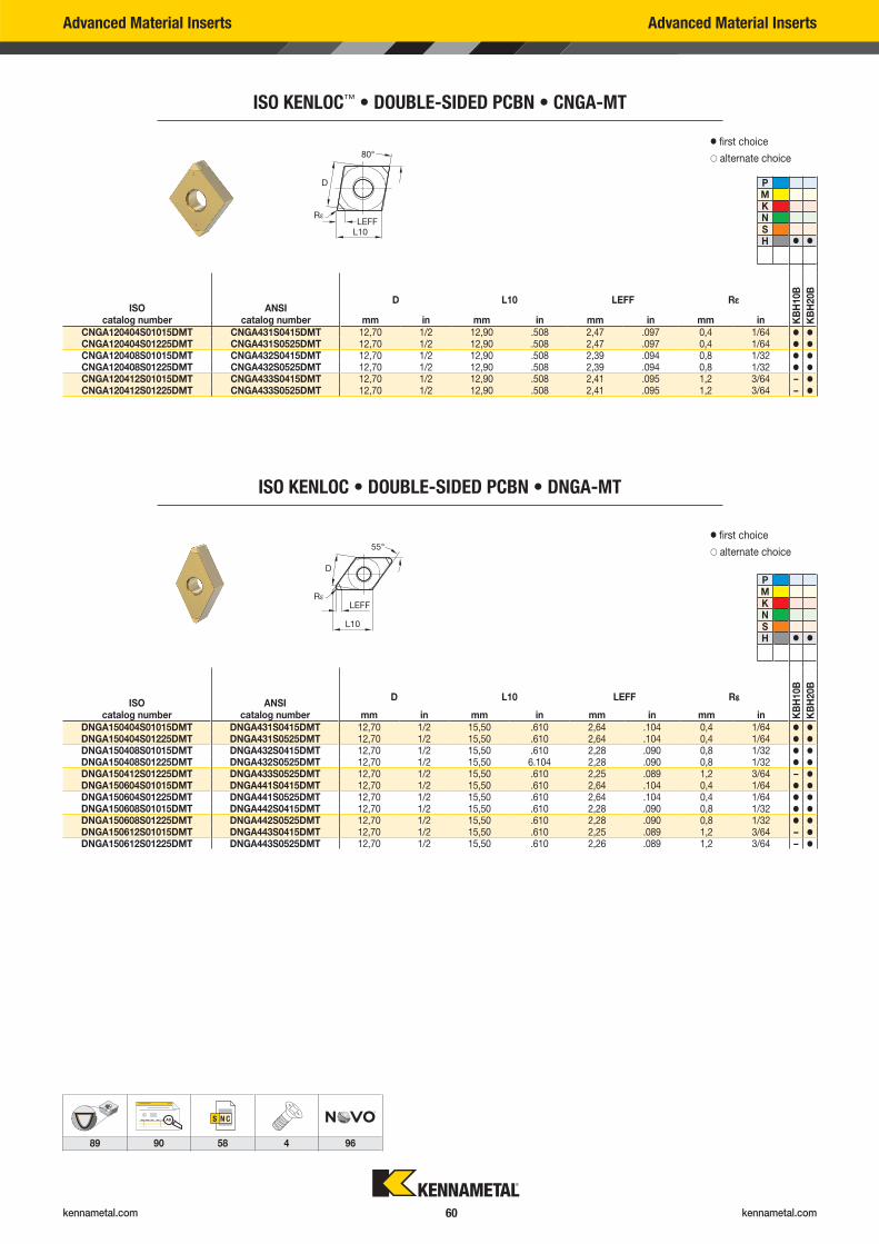
kennametal.com kennametal.com 60
AB
89 90 58 4 96
Advanced Material Inserts Advanced Material Inserts
ISO KENLOC™ • DOUBLE-SIDED PCBN • CNGA-MT
D L10 LEFF R�ISO
catalog numberANSI
catalog number mm in mm in mm in mm in KB
H10B
KB
H20B
CNGA120404S01015DMT CNGA431S0415DMT 12,70 1/2 12,90 .508 2,47 .097 0,4 1/64 � �
CNGA120404S01225DMT CNGA431S0525DMT 12,70 1/2 12,90 .508 2,47 .097 0,4 1/64 � �
CNGA120408S01015DMT CNGA432S0415DMT 12,70 1/2 12,90 .508 2,39 .094 0,8 1/32 � �
CNGA120408S01225DMT CNGA432S0525DMT 12,70 1/2 12,90 .508 2,39 .094 0,8 1/32 � �
CNGA120412S01015DMT CNGA433S0415DMT 12,70 1/2 12,90 .508 2,41 .095 1,2 3/64 – �
CNGA120412S01225DMT CNGA433S0525DMT 12,70 1/2 12,90 .508 2,41 .095 1,2 3/64 – �
� first choice
� alternate choice
PMKNSH � �
ISO KENLOC • DOUBLE-SIDED PCBN • DNGA-MT
D L10 LEFF R�ISO
catalog numberANSI
catalog number mm in mm in mm in mm in KB
H10B
KB
H20B
DNGA150404S01015DMT DNGA431S0415DMT 12,70 1/2 15,50 .610 2,64 .104 0,4 1/64 � �
DNGA150404S01225DMT DNGA431S0525DMT 12,70 1/2 15,50 .610 2,64 .104 0,4 1/64 � �
DNGA150408S01015DMT DNGA432S0415DMT 12,70 1/2 15,50 .610 2,28 .090 0,8 1/32 � �
DNGA150408S01225DMT DNGA432S0525DMT 12,70 1/2 15,50 6.104 2,28 .090 0,8 1/32 � �
DNGA150412S01225DMT DNGA433S0525DMT 12,70 1/2 15,50 .610 2,25 .089 1,2 3/64 – �
DNGA150604S01015DMT DNGA441S0415DMT 12,70 1/2 15,50 .610 2,64 .104 0,4 1/64 � �
DNGA150604S01225DMT DNGA441S0525DMT 12,70 1/2 15,50 .610 2,64 .104 0,4 1/64 � �
DNGA150608S01015DMT DNGA442S0415DMT 12,70 1/2 15,50 .610 2,28 .090 0,8 1/32 � �
DNGA150608S01225DMT DNGA442S0525DMT 12,70 1/2 15,50 .610 2,28 .090 0,8 1/32 � �
DNGA150612S01015DMT DNGA443S0415DMT 12,70 1/2 15,50 .610 2,25 .089 1,2 3/64 – �
DNGA150612S01225DMT DNGA443S0525DMT 12,70 1/2 15,50 .610 2,26 .089 1,2 3/64 – �
� first choice
� alternate choice
PMKNSH � �
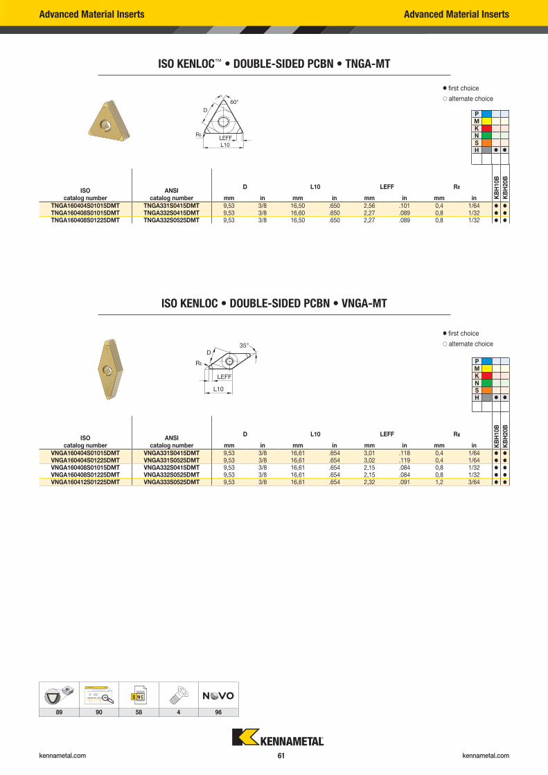
kennametal.com kennametal.com 61
AB
89 90 58 4 96
Advanced Material Inserts Advanced Material Inserts
ISO KENLOC™ • DOUBLE-SIDED PCBN • TNGA-MT
D L10 LEFF R�ISO
catalog numberANSI
catalog number mm in mm in mm in mm in KB
H10B
KB
H20B
TNGA160404S01015DMT TNGA331S0415DMT 9,53 3/8 16,50 .650 2,56 .101 0,4 1/64 � �
TNGA160408S01015DMT TNGA332S0415DMT 9,53 3/8 16,60 .650 2,27 .089 0,8 1/32 � �
TNGA160408S01225DMT TNGA332S0525DMT 9,53 3/8 16,50 .650 2,27 .089 0,8 1/32 � �
� first choice
� alternate choice
PMKNSH � �
ISO KENLOC • DOUBLE-SIDED PCBN • VNGA-MT
D L10 LEFF R�ISO
catalog numberANSI
catalog number mm in mm in mm in mm in KB
H10B
KB
H20B
VNGA160404S01015DMT VNGA331S0415DMT 9,53 3/8 16,61 .654 3,01 .118 0,4 1/64 � �
VNGA160404S01225DMT VNGA331S0525DMT 9,53 3/8 16,61 .654 3,02 .119 0,4 1/64 � �
VNGA160408S01015DMT VNGA332S0415DMT 9,53 3/8 16,61 .654 2,15 .084 0,8 1/32 � �
VNGA160408S01225DMT VNGA332S0525DMT 9,53 3/8 16,61 .654 2,15 .084 0,8 1/32 � �
VNGA160412S01225DMT VNGA333S0525DMT 9,53 3/8 16,61 .654 2,32 .091 1,2 3/64 � �
� first choice
� alternate choice
PMKNSH � �
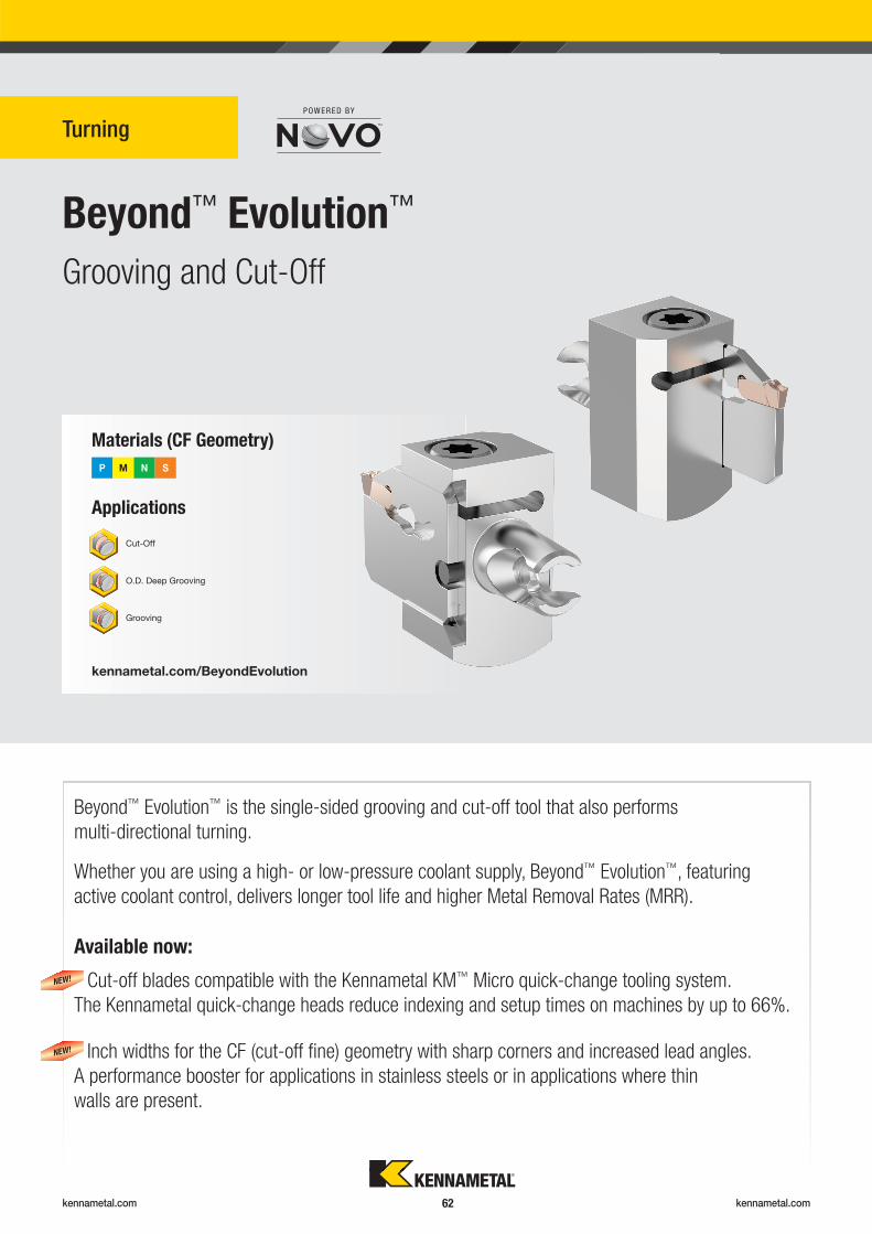
kennametal.com kennametal.com 62
Turning
Applications
Materials
P M N S
Beyond™ Evolution™
Grooving and Cut-Off
kennametal.com/BeyondEvolution
O.D. Deep Grooving
(CF Geometry)
Cut-Off
Grooving
Beyond™ Evolution™ is the single-sided grooving and cut-off tool that also performs
multi-directional turning.
Whether you are using a high- or low-pressure coolant supply, Beyond™ Evolution™, featuring
active coolant control, delivers longer tool life and higher Metal Removal Rates (MRR).
Cut-off blades compatible with the Kennametal KM™ Micro quick-change tooling system.
The Kennametal quick-change heads reduce indexing and setup times on machines by up to 66%.
Inch widths for the CF (cut-off fi ne) geometry with sharp corners and increased lead angles.
A performance booster for applications in stainless steels or in applications where thin
walls are present.
Available now:
NEW!
NEW!
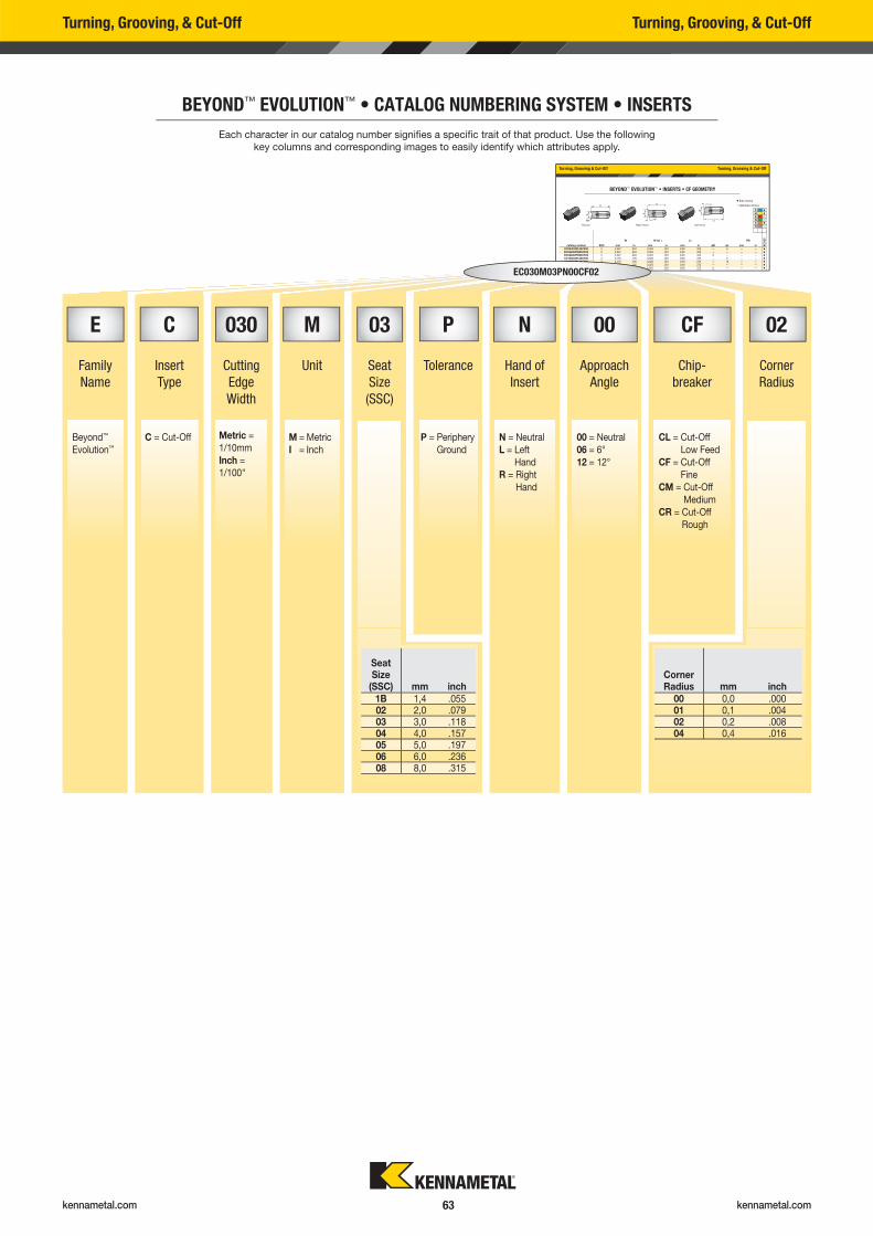
kennametal.com kennametal.com 63
Turning, Grooving & Cut-Off Turning, Grooving & Cut-Off
BEYOND™ EVOLUTION™ • INSERTS • CF GEOMETRY
W W tol ± LI RR
catalog number SSC mm in mm in mm in �R �L mm in KC
U25
EC094I02PL06CF00 2 2,387 .094 0,025 .001 8,95 .352 — 6 — — �
EC094I02PN00CF00 2 2,387 .094 0,025 .001 8,95 .352 — — — — �
EC094I02PR06CF00 2 2,387 .094 0,025 .001 8,95 .352 6 — — — �
EC125I03PL06CF00 3 3,175 .125 0,025 .001 9,48 .373 — 6 — — �
EC125I03PL12CF00 3 3,175 .125 0,025 .001 9,48 .373 — 12 — — �
EC125I03PN00CF00 3 3,175 .125 0,025 .001 9,48 .373 — — — — �
EC125I03PR06CF00 3 3,175 .125 0,025 .001 9,48 .373 6 — — — �
EC125I03PR12CF00 3 3 175 125 0 025 001 9 48 373 12 �
� first choice
� alternate choice
P �
M �
K �
N �
S �
HLeft HandRight HandNeutral
Turning, Grooving, & Cut-Off Turning, Grooving, & Cut-Off
BEYOND™ EVOLUTION™ • CATALOG NUMBERING SYSTEM • INSERTS
Each character in our catalog number signifi es a specifi c trait of that product. Use the following
key columns and corresponding images to easily identify which attributes apply.
EC030M03PN00CF02
E C 030 M 03 P N 00 CF 02
Family
Name
Insert
Type
Cutting
Edge
Width
Unit Seat
Size
(SSC)
Tolerance Hand of
Insert
Approach
Angle
Chip-
breaker
Corner
Radius
Beyond™
Evolution™
C = Cut-Off M = Metric
I = Inch
P = Periphery
Ground
N = Neutral
L = Left
Hand
R = Right
Hand
00 = Neutral
06 = 6°
12 = 12°
CL = Cut-Off
Low Feed
CF = Cut-Off
Fine
CM = Cut-Off
Medium
CR = Cut-Off
Rough
Corner Radius mm inch
00 0,0 .00001 0,1 .00402 0,2 .00804 0,4 .016
SeatSize
(SSC) mm inch1B 1,4 .05502 2,0 .07903 3,0 .11804 4,0 .15705 5,0 .19706 6,0 .23608 8,0 .315
Metric =
1/10mm
Inch =
1/100"
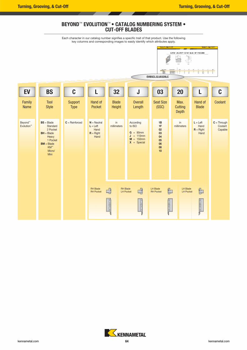
kennametal.com kennametal.com 64
Turning, Grooving, & Cut-Off Turning, Grooving, & Cut-Off
BEYOND™ EVOLUTION™ • CATALOG NUMBERING SYSTEM • CUT-OFF BLADES
EV BS C L 32 J 03 20 L C
Family
Name
Tool
Style
Support
Type
Hand of
Blade
Height
Overall
Length
Seat Size
(SSC)
Max.
Cutting
Depth
Hand of
Blade
Coolant
Beyond™
Evolution™
BS = Blade
Standard
2 Pocket
BH = Blade
Heavy
1 Pocket
BM = Blade
KM™
Micro/
Mini
C = Reinforced N = Neutral
L = Left
Hand
R = Right
Hand
in
millimeters
According
to ISO
1B
1F
02
03
04
05
06
08
10
in
millimeters
L = Left
Hand
R = Right
Hand
C = Through
Coolant
CapableG = 90mmJ = 110mmM = 150mmX = Special
EVBSCL32J0320LC
Each character in our catalog number signifi es a specifi c trait of that product. Use the following
key columns and corresponding images to easily identify which attributes apply.
RH BladeRH Pocket
RH BladeLH Pocket
LH BladeRH Pocket
LH BladeLH Pocket
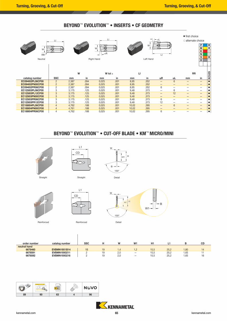
kennametal.com kennametal.com 65
Turning, Grooving, & Cut-Off Turning, Grooving, & Cut-Off
BEYOND™ EVOLUTION™ • CUT-OFF BLADE • KM™ MICRO/MINI
order number catalog number SSC H W W1 H1 L1 B CDneutral hand
6678460 EVBMN19X1B14 1B 19 1,4 1,2 15,5 25,2 1,80 146678591 EVBMN19X0211 2 19 2,0 — 15,5 20,2 1,65 116678592 EVBMN19X0216 2 19 2,0 — 15,5 25,2 1,65 16
Straight Straight
Reinforced Reinforced
Detail
Detail
AB
89 90 63 4 96
BEYOND™ EVOLUTION™ • INSERTS • CF GEOMETRY
W W tol ± LI RR
catalog number SSC mm in mm in mm in �R �L mm in KC
U25
EC094I02PL06CF00 2 2,387 .094 0,025 .001 8,95 .352 — 6 — — �
EC094I02PN00CF00 2 2,387 .094 0,025 .001 8,95 .352 — — — — �
EC094I02PR06CF00 2 2,387 .094 0,025 .001 8,95 .352 6 — — — �
EC125I03PL06CF00 3 3,175 .125 0,025 .001 9,48 .373 — 6 — — �
EC125I03PL12CF00 3 3,175 .125 0,025 .001 9,48 .373 — 12 — — �
EC125I03PN00CF00 3 3,175 .125 0,025 .001 9,48 .373 — — — — �
EC125I03PR06CF00 3 3,175 .125 0,025 .001 9,48 .373 6 — — — �
EC125I03PR12CF00 3 3,175 .125 0,025 .001 9,48 .373 12 — — — �
EC188I04PL06CF00 4 4,762 .188 0,025 .001 10,02 .395 — 6 — — �
EC188I04PN00CF00 4 4,761 .188 0,025 .001 10,02 .395 — — — — �
EC188I04PR06CF00 4 4,762 .188 0,025 .001 10,02 .395 6 — — — �
� fi rst choice
� alternate choice
P �
M �
K �
N �
S �
H Left Hand Right Hand Neutral
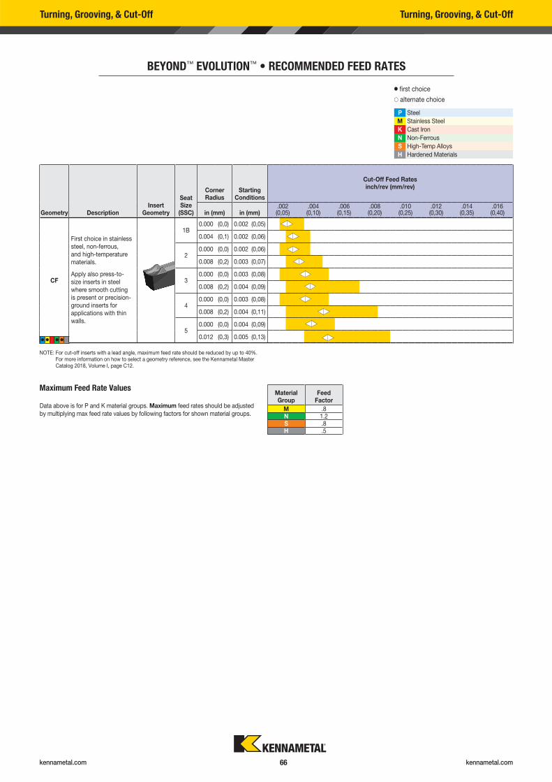
kennametal.com kennametal.com 66
Geometry DescriptionInsert
Geometry
SeatSize
(SSC)
Corner Radius
Starting Conditions
Cut-Off Feed Rates inch/rev (mm/rev)
in (mm) in (mm).002 (0,05)
.004 (0,10)
.006 (0,15)
.008 (0,20)
.010 (0,25)
.012 (0,30)
.014 (0,35)
.016 (0,40)
CF
1B0.000 (0,0) 0.002 (0,05)
0.004 (0,1) 0.002 (0,06)
20.000 (0,0) 0.002 (0,06)
0.008 (0,2) 0.003 (0,07)
30.000 (0,0) 0.003 (0,08)
0.008 (0,2) 0.004 (0,09)
40.000 (0,0) 0.003 (0,08)
0.008 (0,2) 0.004 (0,11)
50.000 (0,0) 0.004 (0,09)
0.012 (0,3) 0.005 (0,13)
� � � �
First choice in stainless
steel, non-ferrous,
and high-temperature
materials.
Apply also press-to-
size inserts in steel
where smooth cutting
is present or precision-
ground inserts for
applications with thin
walls.
NOTE: For cut-off inserts with a lead angle, maximum feed rate should be reduced by up to 40%. For more information on how to select a geometry reference, see the Kennametal Master Catalog 2018, Volume I, page C12.
Turning, Grooving, & Cut-Off Turning, Grooving, & Cut-Off
BEYOND™ EVOLUTION™ • RECOMMENDED FEED RATES
� first choice
� alternate choice
P Steel
M Stainless Steel
K Cast Iron
N Non-Ferrous
S High-Temp Alloys
H Hardened Materials
Data above is for P and K material groups. Maximum feed rates should be adjusted
by multiplying max feed rate values by following factors for shown material groups.
Material Group
Feed Factor
M .8N 1.2S .8H .5
Maximum Feed Rate Values

kennametal.com
Lost a screw? Have to replace worn-out clamping wedges?
Need to fi nd and re-order those spare parts?
GO TO KENNAMETAL.COM AND FIND WHAT YOU NEED IN SECONDS.
1
2
Enter the tool catalog number here
Select the spare parts & accessories
STEP 1
STEP 2
Spare Parts & Accessories Information
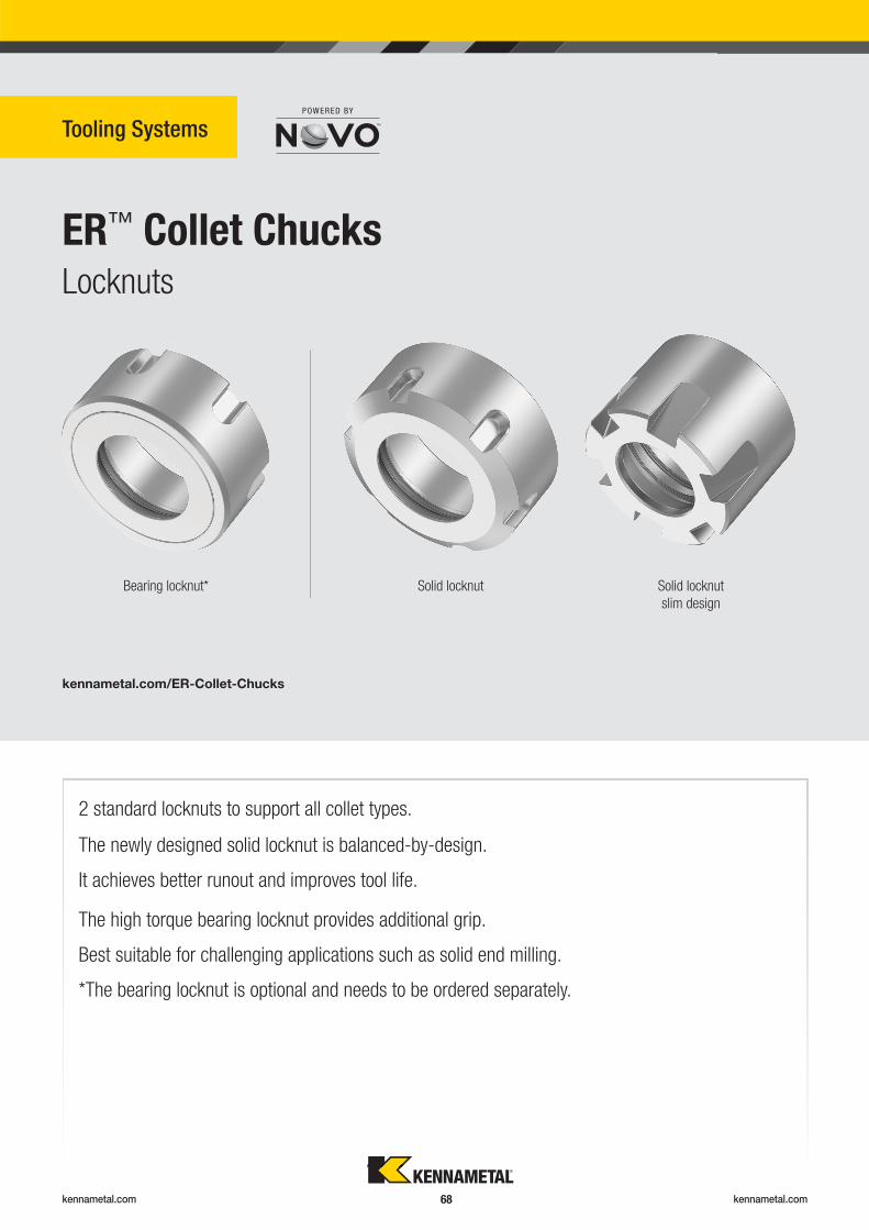
kennametal.com kennametal.com 68
ER™ Collet Chucks
Tooling Systems
Locknuts
kennametal.com/ER-Collet-Chucks
2 standard locknuts to support all collet types.
The high torque bearing locknut provides additional grip.
Best suitable for challenging applications such as solid end milling.
*The bearing locknut is optional and needs to be ordered separately.
The newly designed solid locknut is balanced-by-design.
It achieves better runout and improves tool life.
Bearing locknut* Solid locknut Solid locknut
slim design
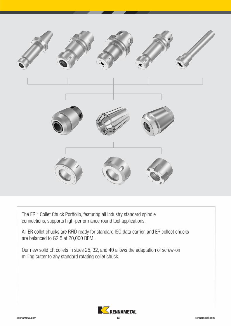
kennametal.com kennametal.com 69
The ER™ Collet Chuck Portfolio, featuring all industry standard spindle
connections, supports high-performance round tool applications.
Our new solid ER collets in sizes 25, 32, and 40 allows the adaptation of screw-on
milling cutter to any standard rotating collet chuck.
All ER collet chucks are RFID ready for standard ISO data carrier, and ER collect chucks
are balanced to G2.5 at 20,000 RPM.
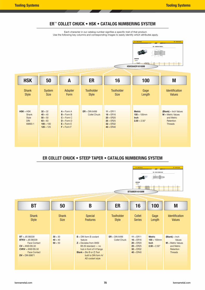
kennametal.com kennametal.com 70
Tooling Systems Tooling Systems
ER™ COLLET CHUCK • HSK • CATALOG NUMBERING SYSTEM
ER COLLET CHUCK • STEEP TAPER • CATALOG NUMBERING SYSTEM
ER™ Collet Chucks ER™ Collet Chucks
ER • HSK50A FORM A
order number catalog number CST D11 L1 L9 V kg1307789 HSK50AER16100M ER16 32 100 32 27 0,661307790 HSK50AER16160M ER16 32 160 32 51 1,071307791 HSK50AER20100M ER20 35 100 36 21 0,761307792 HSK50AER25100M ER25 42 100 40 16 0 95
��Metric
ER™ Collet Chucks ER™ Collet Chucks
ER • BT50 FORM B/AD
order number catalog number CST D11 L1 L9 V kg6694884 BT50BER16070M ER16 32 70 32 23 3,631586520 BT50BER16100M ER16 32 100 32 48 3,781871539 BT50BER16150M ER16 32 150 32 48 3,956694886 BT50BER20070M ER20 35 70 37 15 3,633847515 BT50BER20100M ER20 35 100 37 43 3,823847516 BT50BER20150M ER20 35 150 37 63 4,081871540 BT50BER25070M ER25 42 70 40 60 3,67
��Metric
HSK50AER16100M
BT50BER16100M
Each character in our catalog number signifi es a specifi c trait of that product.
Use the following key columns and corresponding images to easily identify which attributes apply.
HSK 50 A ER 16 100 M
Shank
Style
System
Size
Adapter
Form
Toolholder
Style
Toolholder
Size
Gage
Length
Identifi cation
Values
HSK = HSK
Shank
Style
DIN
69893-1
32 = 32
40 = 40
50 = 50
63 = 63
100 = 100
125 = 125
A = Form A
B = Form B
C = Form C
D = Form D
E = Form E
F = Form F
ER = DIN 6499
Collet Chuck
11 = ER11
16 = ER16
20 = ER20
25 = ER25
32 = ER32
40 = ER40
Metric
100 = 100mm
Inch
2.50 = 2.50"
(Blank) = Inch Values
M = Metric Values
and Metric
Retention
Threads
BT 50 B ER 16 100 M
Shank
Style
Shank
Size
Special
Features
Toolholder
Style
Collet
Series
Gage
Length
Identifi cation
Values
BT = JIS B6339
BTKV = JIS B6339
Face Contact
CV = ANSI B5.50
CVKV = ANSI B5.50
Face Contact
DV = DIN 69871
30 = 30
40 = 40
50 = 50
B = DIN form B coolant
feature
Z = Deviates from ANSI
B5.50 standard — no
hub in front of V-Flange
Blank = (No B or Z) Tool
built to DIN form A/
AD coolant style
ER = DIN 6499
Collet Chuck
11 = ER11
16 = ER16
20 = ER20
25 = ER25
32 = ER32
40 = ER40
Metric
100 = 100mm
Inch
2.50 = 2.50"
(Blank) = Inch
Values
M = Metric Values
and Metric
Retention
Threads
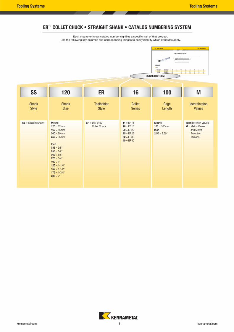
kennametal.com kennametal.com 71
ER™ COLLET CHUCK • STRAIGHT SHANK • CATALOG NUMBERING SYSTEM
ER™ Collet Chucks ER™ Collet Chucks
ER • STRAIGHT SHANK
order number catalog number CST D D11 L LS L9 V lbs1021460 SS038ER08500 ER8 3/8 .47 5.00 4.15 .71 1.42 .101021462 SS050ER11700 ER11 1/2 .63 7.00 5.96 .95 3.23 .261021494 SS075ER16700 ER16 3/4 .87 7.00 5.47 1.30 2.24 .561021496 SS100ER20700 ER20 1 1.34 7.00 5.70 1.30 2.20 1.071021498 SS100ER25750 ER25 1 1.65 7.50 5.69 1.58 1.97 1.13
�� Inch
SS120ER16100M
Each character in our catalog number signifi es a specifi c trait of that product.
Use the following key columns and corresponding images to easily identify which attributes apply.
Tooling Systems Tooling Systems
SS 120 ER 16 100 M
Shank
Style
Shank
Size
Toolholder
Style
Collet
Series
Gage
Length
Identifi cation
Values
SS = Straight Shank Metric
120 = 12mm
160 = 16mm
200 = 20mm
250 = 25mm
Inch
038 = 3/8"
050 = 1/2"
062 = 5/8"
075 = 3/4"
100 = 1"
125 = 1-1/4"
150 = 1-1/2"
175 = 1-3/4"
200 = 2"
ER = DIN 6499
Collet Chuck
11 = ER11
16 = ER16
20 = ER20
25 = ER25
32 = ER32
40 = ER40
Metric
100 = 100mm
Inch
2.50 = 2.50"
(Blank) = Inch Values
M = Metric Values
and Metric
Retention
Threads
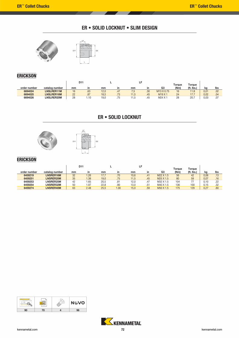
kennametal.com kennametal.com 72
ER™ Collet Chucks ER™ Collet Chucks
ER • SOLID LOCKNUT • SLIM DESIGN
D11 L LF
order number catalog number mm in mm in mm in G3Torque (Nm)
Torque (ft. lbs.) kg lbs
6694024 LNSLRER11M 16 .63 12,0 .47 7,5 .30 M13 X 0.75 16 11.8 0,01 .026694025 LNSLRER16M 22 .87 18,5 .73 11,5 .45 M19 X 1 24 17.7 0,02 .046694026 LNSLRER20M 28 1.10 19,0 .75 11,5 .45 M24 X 1 28 20.7 0,03 .07
ER • SOLID LOCKNUT
D11 L LF
order number catalog number mm in mm in mm in G3Torque
(Nm)Torque (ft. lbs.) kg lbs
6459219 LNSRER16M 32 1.26 17,7 .70 10,6 .41 M22 X 1.5 56 42 0,06 .136459251 LNSRER20M 35 1.38 19,0 .75 11,5 .45 M25 X 1.5 80 59 0,07 .166459253 LNSRER25M 42 1.65 20,5 .81 12,0 .47 M32 X 1.5 104 77 0,10 .226459254 LNSRER32M 50 1.97 22,8 .90 13,0 .51 M40 X 1.5 136 100 0,15 .326459274 LNSRER40M 63 2.48 25,5 1.00 15,0 .59 M50 X 1.5 175 129 0,27 .60
AB
90 70 4 96
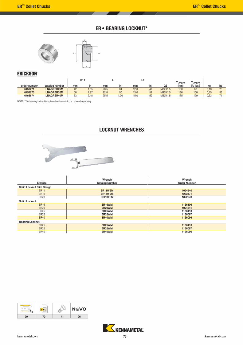
kennametal.com kennametal.com 73
ER™ Collet Chucks ER™ Collet Chucks
ER • BEARING LOCKNUT*
D11 L LF
order number catalog number mm in mm in mm in G3Torque
(Nm)Torque (ft. lbs.) kg lbs
6459271 LNAGRER25M 42 1.65 20,5 .81 12,0 .47 M32X1,5 108 80 0,10 .236459273 LNAGRER32M 50 1.97 22,8 .90 13,0 .51 M40X1,5 136 100 0,15 .336465674 LNAGRER40M 63 2.48 25,5 1.00 15,0 .59 M50X1,5 175 129 0,32 .71
AB
90 70 4 96
NOTE: *The bearing locknut is optional and needs to be ordered separately.
LOCKNUT WRENCHES
ER SizeWrench
Catalog NumberWrench
Order Number
Solid Locknut Slim DesignER11 ER11WEM 1024640ER16 ER16WEM 1232471ER20 ER20WEM 1322073
Solid LocknutER16 ER16WM 1136106ER20 ER20WM 1024641ER25 ER25WM 1136113ER32 ER32WM 1136087ER40 ER40WM 1136096
Bearing LocknutER25 ER25WM 1136113ER32 ER32WM 1136087ER40 ER40WM 1136096
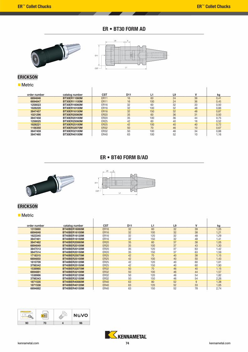
kennametal.com kennametal.com 74
ER™ Collet Chucks ER™ Collet Chucks
ER • BT30 FORM AD
order number catalog number CST D11 L1 L9 V kg6694846 BT30ER11060M ER11 16 60 24 36 0,416694847 BT30ER11100M ER11 16 100 24 36 0,451258023 BT30ER16060M ER16 32 60 32 33 0,501826220 BT30ER16100M ER16 32 100 32 48 0,663847457 BT30ER16150M ER16 32 150 32 48 0,871021296 BT30ER20060M ER20 35 60 36 31 0,503847458 BT30ER20100M ER20 35 100 36 44 0,751258025 BT30ER25060M ER25 42 60 40 16 0,521826221 BT30ER25100M ER25 42 100 40 40 0,721156350 BT30ER32070M ER32 50 70 46 10 0,673847459 BT30ER32100M ER32 50 100 46 34 0,883847460 BT30ER40100M ER40 63 100 52 10 1,16
ER • BT40 FORM B/AD
order number catalog number CST D11 L1 L9 V kg1315660 BT40BER16060M ER16 32 60 32 39 1,056694848 BT40BER16100M ER16 32 100 32 38 1,211623345 BT40BER16120M ER16 32 120 32 48 1,293847461 BT40BER16150M ER16 32 150 32 48 1,413847462 BT40BER20060M ER20 35 60 37 38 1,056694849 BT40BER20100M ER20 35 100 37 43 1,303847513 BT40BER20120M ER20 35 120 37 63 1,423847514 BT40BER20150M ER20 35 150 37 63 1,591718315 BT40BER25070M ER25 42 70 40 38 1,156694850 BT40BER25100M ER25 42 100 40 50 1,431610709 BT40BER25120M ER25 42 120 40 60 1,613798342 BT40BER25150M ER25 42 150 40 60 1,901538985 BT40BER32070M ER32 50 70 46 40 1,156694881 BT40BER32100M ER32 50 100 46 44 1,571538986 BT40BER32120M ER32 50 120 46 54 1,823798343 BT40BER32150M ER32 50 150 46 54 2,261871535 BT40BER40080M ER40 63 80 52 9 1,381871538 BT40BER40120M ER40 63 120 52 33 1,056694882 BT40BER40150M ER40 63 150 52 78 2,74
��Metric
��Metric
AB
90 70 4 96
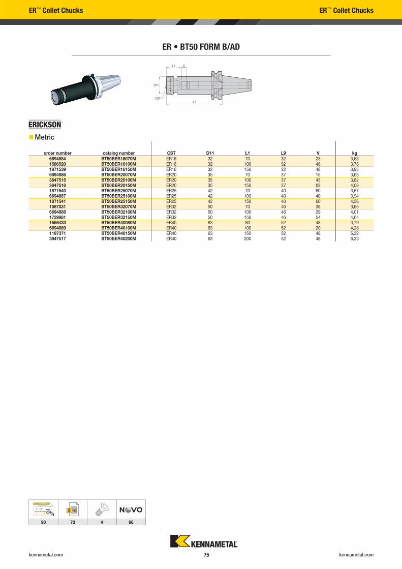
kennametal.com kennametal.com 75
ER™ Collet Chucks ER™ Collet Chucks
ER • BT50 FORM B/AD
order number catalog number CST D11 L1 L9 V kg6694884 BT50BER16070M ER16 32 70 32 23 3,631586520 BT50BER16100M ER16 32 100 32 48 3,781871539 BT50BER16150M ER16 32 150 32 48 3,956694886 BT50BER20070M ER20 35 70 37 15 3,633847515 BT50BER20100M ER20 35 100 37 43 3,823847516 BT50BER20150M ER20 35 150 37 63 4,081871540 BT50BER25070M ER25 42 70 40 60 3,676694887 BT50BER25100M ER25 42 100 40 40 3,941871541 BT50BER25150M ER25 42 150 40 60 4,361587031 BT50BER32070M ER32 50 70 46 38 3,656694888 BT50BER32100M ER32 50 100 46 29 4,011729881 BT50BER32150M ER32 50 150 46 54 4,641556433 BT50BER40080M ER40 63 80 52 48 3,796694889 BT50BER40100M ER40 63 100 52 20 4,281187371 BT50BER40150M ER40 63 150 52 48 5,323847517 BT50BER40200M ER40 63 200 52 48 6,33
��Metric
AB
90 70 4 96
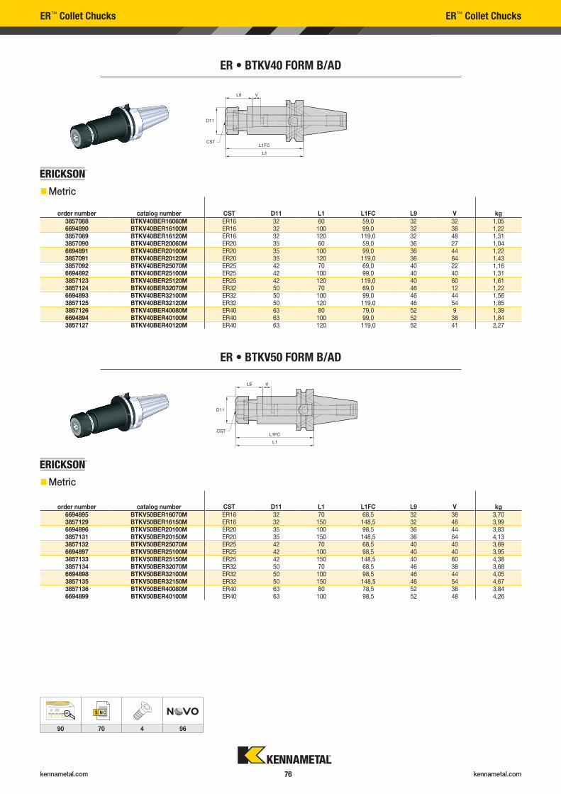
kennametal.com kennametal.com 76
ER • BTKV40 FORM B/AD
order number catalog number CST D11 L1 L1FC L9 V kg3857088 BTKV40BER16060M ER16 32 60 59,0 32 32 1,056694890 BTKV40BER16100M ER16 32 100 99,0 32 38 1,223857089 BTKV40BER16120M ER16 32 120 119,0 32 48 1,313857090 BTKV40BER20060M ER20 35 60 59,0 36 27 1,046694891 BTKV40BER20100M ER20 35 100 99,0 36 44 1,223857091 BTKV40BER20120M ER20 35 120 119,0 36 64 1,433857092 BTKV40BER25070M ER25 42 70 69,0 40 22 1,166694892 BTKV40BER25100M ER25 42 100 99,0 40 40 1,313857123 BTKV40BER25120M ER25 42 120 119,0 40 60 1,613857124 BTKV40BER32070M ER32 50 70 69,0 46 12 1,226694893 BTKV40BER32100M ER32 50 100 99,0 46 44 1,563857125 BTKV40BER32120M ER32 50 120 119,0 46 54 1,853857126 BTKV40BER40080M ER40 63 80 79,0 52 9 1,396694894 BTKV40BER40100M ER40 63 100 99,0 52 38 1,843857127 BTKV40BER40120M ER40 63 120 119,0 52 41 2,27
ER™ Collet Chucks ER™ Collet Chucks
ER • BTKV50 FORM B/AD
order number catalog number CST D11 L1 L1FC L9 V kg6694895 BTKV50BER16070M ER16 32 70 68,5 32 38 3,703857129 BTKV50BER16150M ER16 32 150 148,5 32 48 3,996694896 BTKV50BER20100M ER20 35 100 98,5 36 44 3,833857131 BTKV50BER20150M ER20 35 150 148,5 36 64 4,133857132 BTKV50BER25070M ER25 42 70 68,5 40 40 3,696694897 BTKV50BER25100M ER25 42 100 98,5 40 40 3,953857133 BTKV50BER25150M ER25 42 150 148,5 40 60 4,383857134 BTKV50BER32070M ER32 50 70 68,5 46 38 3,686694898 BTKV50BER32100M ER32 50 100 98,5 46 44 4,053857135 BTKV50BER32150M ER32 50 150 148,5 46 54 4,673857136 BTKV50BER40080M ER40 63 80 78,5 52 38 3,846694899 BTKV50BER40100M ER40 63 100 98,5 52 48 4,26
��Metric
��Metric
AB
90 70 4 96
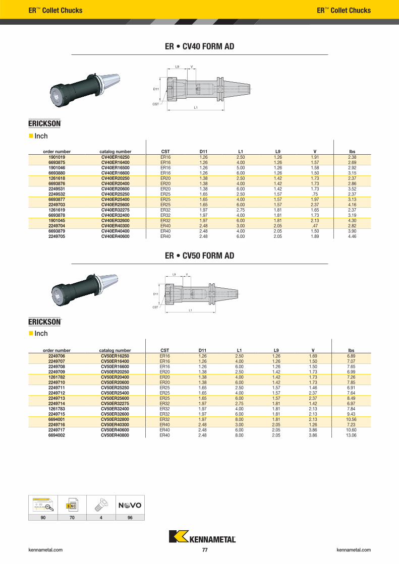
kennametal.com kennametal.com 77
ER™ Collet Chucks ER™ Collet Chucks
ER • CV50 FORM AD
order number catalog number CST D11 L1 L9 V lbs2249706 CV50ER16250 ER16 1.26 2.50 1.26 1.69 6.892249707 CV50ER16400 ER16 1.26 4.00 1.26 1.50 7.072249708 CV50ER16600 ER16 1.26 6.00 1.26 1.50 7.652249709 CV50ER20250 ER20 1.38 2.50 1.42 1.73 6.991261782 CV50ER20400 ER20 1.38 4.00 1.42 1.73 7.262249710 CV50ER20600 ER20 1.38 6.00 1.42 1.73 7.852249711 CV50ER25250 ER25 1.65 2.50 1.57 1.46 6.912249712 CV50ER25400 ER25 1.65 4.00 1.57 2.37 7.642249713 CV50ER25600 ER25 1.65 6.00 1.57 2.37 8.492249714 CV50ER32275 ER32 1.97 2.75 1.81 1.42 6.971261783 CV50ER32400 ER32 1.97 4.00 1.81 2.13 7.842249715 CV50ER32600 ER32 1.97 6.00 1.81 2.13 9.436694001 CV50ER32800 ER32 1.97 8.00 1.81 2.13 10.562249716 CV50ER40300 ER40 2.48 3.00 2.05 1.26 7.232249717 CV50ER40600 ER40 2.48 6.00 2.05 3.86 10.606694002 CV50ER40800 ER40 2.48 8.00 2.05 3.86 13.06
ER • CV40 FORM AD
order number catalog number CST D11 L1 L9 V lbs1901019 CV40ER16250 ER16 1.26 2.50 1.26 1.91 2.386693875 CV40ER16400 ER16 1.26 4.00 1.26 1.57 2.691901046 CV40ER16500 ER16 1.26 5.00 1.26 1.58 2.926693880 CV40ER16600 ER16 1.26 6.00 1.26 1.50 3.151261618 CV40ER20250 ER20 1.38 2.50 1.42 1.73 2.376693876 CV40ER20400 ER20 1.38 4.00 1.42 1.73 2.862249531 CV40ER20600 ER20 1.38 6.00 1.42 1.73 3.522249532 CV40ER25250 ER25 1.65 2.50 1.57 .75 2.376693877 CV40ER25400 ER25 1.65 4.00 1.57 1.97 3.132249703 CV40ER25600 ER25 1.65 6.00 1.57 2.37 4.161261619 CV40ER32275 ER32 1.97 2.75 1.81 1.65 2.376693878 CV40ER32400 ER32 1.97 4.00 1.81 1.73 3.191901045 CV40ER32600 ER32 1.97 6.00 1.81 2.13 4.302249704 CV40ER40300 ER40 2.48 3.00 2.05 .47 2.826693879 CV40ER40400 ER40 2.48 4.00 2.05 1.50 3.902249705 CV40ER40600 ER40 2.48 6.00 2.05 1.89 4.46
�� Inch
�� Inch
AB
90 70 4 96
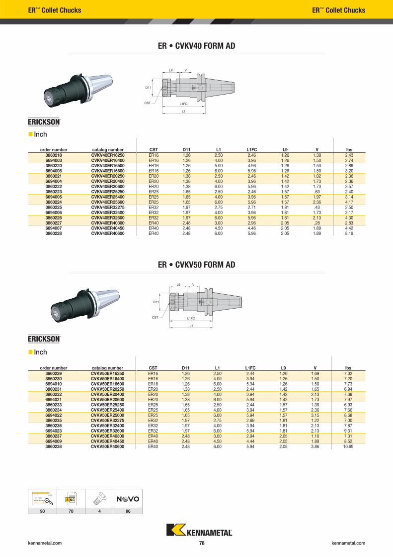
kennametal.com kennametal.com 78
ER • CVKV40 FORM AD
order number catalog number CST D11 L1 L1FC L9 V lbs3860218 CVKV40ER16250 ER16 1.26 2.50 2.46 1.26 1.30 2.436694003 CVKV40ER16400 ER16 1.26 4.00 3.96 1.26 1.50 2.743860220 CVKV40ER16500 ER16 1.26 5.00 4.96 1.26 1.50 2.896694008 CVKV40ER16600 ER16 1.26 6.00 5.96 1.26 1.50 3.203860221 CVKV40ER20250 ER20 1.38 2.50 2.46 1.42 1.02 2.366694004 CVKV40ER20400 ER20 1.38 4.00 3.96 1.42 1.73 2.363860222 CVKV40ER20600 ER20 1.38 6.00 5.96 1.42 1.73 3.573860223 CVKV40ER25250 ER25 1.65 2.50 2.46 1.57 .63 2.406694005 CVKV40ER25400 ER25 1.65 4.00 3.96 1.57 1.97 3.143860224 CVKV40ER25600 ER25 1.65 6.00 5.96 1.57 2.36 4.173860225 CVKV40ER32275 ER32 1.97 2.75 2.71 1.81 .43 2.506694006 CVKV40ER32400 ER32 1.97 4.00 3.96 1.81 1.73 3.173860226 CVKV40ER32600 ER32 1.97 6.00 5.96 1.81 2.13 4.303860227 CVKV40ER40300 ER40 2.48 3.00 2.96 2.05 .28 2.836694007 CVKV40ER40450 ER40 2.48 4.50 4.46 2.05 1.89 4.423860228 CVKV40ER40600 ER40 2.48 6.00 5.96 2.05 1.89 8.19
ER™ Collet Chucks ER™ Collet Chucks
ER • CVKV50 FORM AD
order number catalog number CST D11 L1 L1FC L9 V lbs3860229 CVKV50ER16250 ER16 1.26 2.50 2.44 1.26 1.69 7.023860230 CVKV50ER16400 ER16 1.26 4.00 3.94 1.26 1.50 7.206694010 CVKV50ER16600 ER16 1.26 6.00 5.94 1.26 1.50 7.733860231 CVKV50ER20250 ER20 1.38 2.50 2.44 1.42 1.65 6.943860232 CVKV50ER20400 ER20 1.38 4.00 3.94 1.42 2.13 7.386694021 CVKV50ER20600 ER20 1.38 6.00 5.94 1.42 1.73 7.973860233 CVKV50ER25250 ER25 1.65 2.50 2.44 1.57 1.38 6.933860234 CVKV50ER25400 ER25 1.65 4.00 3.94 1.57 2.36 7.666694022 CVKV50ER25600 ER25 1.65 6.00 5.94 1.57 3.15 8.683860235 CVKV50ER32275 ER32 1.97 2.75 2.69 1.81 1.22 7.003860236 CVKV50ER32400 ER32 1.97 4.00 3.94 1.81 2.13 7.876694023 CVKV50ER32600 ER32 1.97 6.00 5.94 1.81 2.13 9.313860237 CVKV50ER40300 ER40 2.48 3.00 2.94 2.05 1.10 7.316694009 CVKV50ER40450 ER40 2.48 4.50 4.44 2.05 1.89 8.523860238 CVKV50ER40600 ER40 2.48 6.00 5.94 2.05 3.86 10.69
�� Inch
�� Inch
AB
90 70 4 96
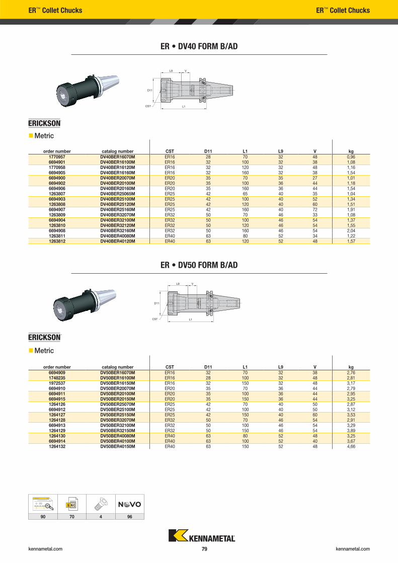
kennametal.com kennametal.com 79
ER™ Collet Chucks ER™ Collet Chucks
ER • DV50 FORM B/AD
order number catalog number CST D11 L1 L9 V kg6694909 DV50BER16070M ER16 32 70 32 38 2,761748235 DV50BER16100M ER16 28 100 32 48 2,811972537 DV50BER16150M ER16 32 150 32 48 3,176694910 DV50BER20070M ER20 35 70 36 44 2,796694911 DV50BER20100M ER20 35 100 36 44 2,956694915 DV50BER20150M ER20 35 150 36 44 3,251264126 DV50BER25070M ER25 42 70 40 50 2,876694912 DV50BER25100M ER25 42 100 40 50 3,121264127 DV50BER25150M ER25 42 150 40 60 3,531264128 DV50BER32070M ER32 50 70 46 54 2,916694913 DV50BER32100M ER32 50 100 46 54 3,291264129 DV50BER32150M ER32 50 150 46 54 3,891264130 DV50BER40080M ER40 63 80 52 48 3,256694914 DV50BER40100M ER40 63 100 52 40 3,671264132 DV50BER40150M ER40 63 150 52 48 4,66
ER • DV40 FORM B/AD
order number catalog number CST D11 L1 L9 V kg1770957 DV40BER16070M ER16 28 70 32 48 0,966694901 DV40BER16100M ER16 32 100 32 38 1,081770958 DV40BER16120M ER16 32 120 32 48 1,166694905 DV40BER16160M ER16 32 160 32 38 1,546694900 DV40BER20070M ER20 35 70 35 27 1,016694902 DV40BER20100M ER20 35 100 36 44 1,186694906 DV40BER20160M ER20 35 160 36 44 1,541263807 DV40BER25065M ER25 42 65 40 35 1,046694903 DV40BER25100M ER25 42 100 40 52 1,341263808 DV40BER25120M ER25 42 120 40 60 1,516694907 DV40BER25160M ER25 42 160 40 72 1,911263809 DV40BER32070M ER32 50 70 46 33 1,086694904 DV40BER32100M ER32 50 100 46 54 1,371263810 DV40BER32120M ER32 50 120 46 54 1,556694908 DV40BER32160M ER32 50 160 46 54 2,041263811 DV40BER40080M ER40 63 80 52 34 1,221263812 DV40BER40120M ER40 63 120 52 48 1,57
��Metric
��Metric
AB
90 70 4 96
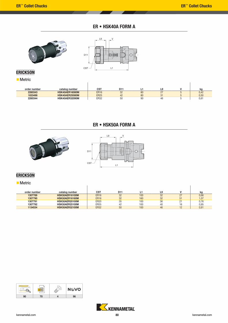
kennametal.com kennametal.com 80
ER™ Collet Chucks ER™ Collet Chucks
ER • HSK50A FORM A
order number catalog number CST D11 L1 L9 V kg1307789 HSK50AER16100M ER16 32 100 32 27 0,661307790 HSK50AER16160M ER16 32 160 32 51 1,071307791 HSK50AER20100M ER20 35 100 36 21 0,761307792 HSK50AER25100M ER25 42 100 40 16 0,951134534 HSK50AER32100M ER32 50 100 46 12 0,91
ER • HSK40A FORM A
order number catalog number CST D11 L1 L9 V kg2260343 HSK40AER16080M ER16 32 80 27 5 0,421833498 HSK40AER25080M ER25 42 80 31 5 0,502260344 HSK40AER32090M ER32 50 90 46 5 0,61
��Metric
��Metric
AB
90 70 4 96
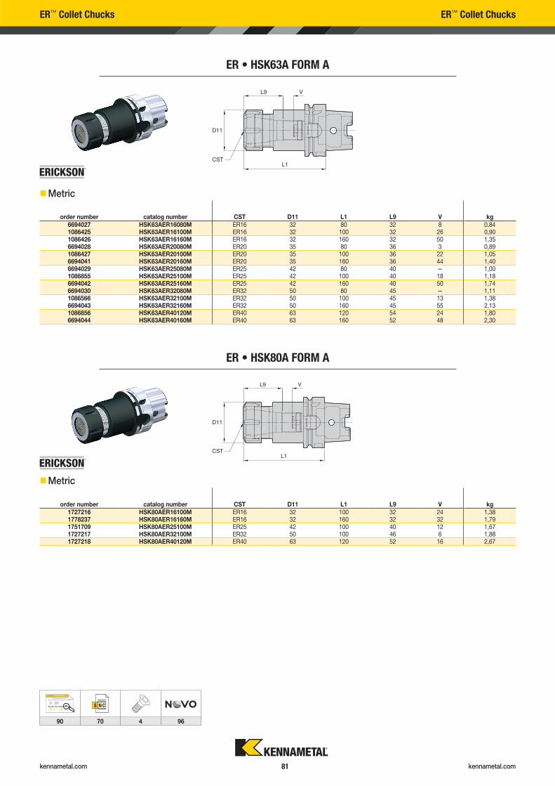
kennametal.com kennametal.com 81
ER™ Collet Chucks ER™ Collet Chucks
ER • HSK63A FORM A
order number catalog number CST D11 L1 L9 V kg6694027 HSK63AER16080M ER16 32 80 32 8 0,841086425 HSK63AER16100M ER16 32 100 32 26 0,901086426 HSK63AER16160M ER16 32 160 32 50 1,356694028 HSK63AER20080M ER20 35 80 36 3 0,891086427 HSK63AER20100M ER20 35 100 36 22 1,056694041 HSK63AER20160M ER20 35 160 36 44 1,406694029 HSK63AER25080M ER25 42 80 40 — 1,001086855 HSK63AER25100M ER25 42 100 40 18 1,186694042 HSK63AER25160M ER25 42 160 40 50 1,746694030 HSK63AER32080M ER32 50 80 45 — 1,111086566 HSK63AER32100M ER32 50 100 45 13 1,386694043 HSK63AER32160M ER32 50 160 45 55 2,131086856 HSK63AER40120M ER40 63 120 54 24 1,806694044 HSK63AER40160M ER40 63 160 52 48 2,30
��Metric
��Metric
ER • HSK80A FORM A
order number catalog number CST D11 L1 L9 V kg1727216 HSK80AER16100M ER16 32 100 32 24 1,381778237 HSK80AER16160M ER16 32 160 32 32 1,791751709 HSK80AER25100M ER25 42 100 40 12 1,671727217 HSK80AER32100M ER32 50 100 46 6 1,881727218 HSK80AER40120M ER40 63 120 52 16 2,67
AB
90 70 4 96
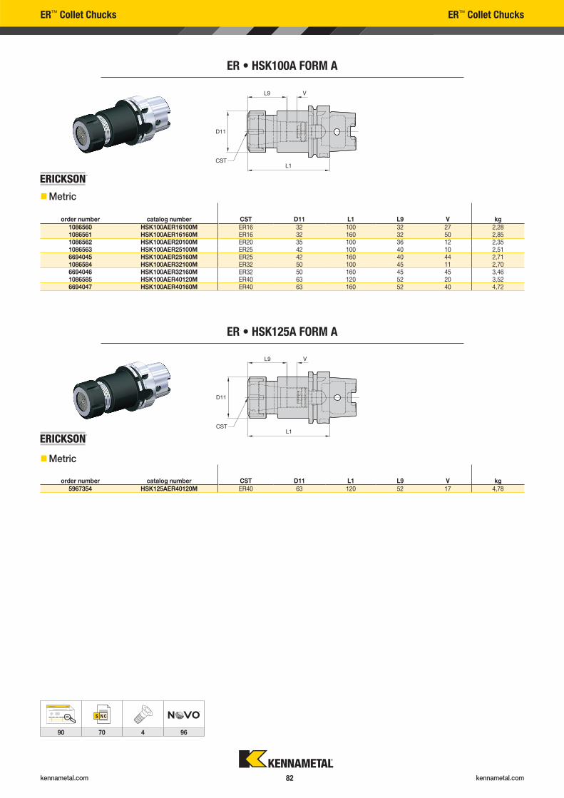
kennametal.com kennametal.com 82
ER™ Collet Chucks ER™ Collet Chucks
ER • HSK100A FORM A
order number catalog number CST D11 L1 L9 V kg1086560 HSK100AER16100M ER16 32 100 32 27 2,281086561 HSK100AER16160M ER16 32 160 32 50 2,851086562 HSK100AER20100M ER20 35 100 36 12 2,351086563 HSK100AER25100M ER25 42 100 40 10 2,516694045 HSK100AER25160M ER25 42 160 40 44 2,711086584 HSK100AER32100M ER32 50 100 45 11 2,706694046 HSK100AER32160M ER32 50 160 45 45 3,461086585 HSK100AER40120M ER40 63 120 52 20 3,526694047 HSK100AER40160M ER40 63 160 52 40 4,72
ER • HSK125A FORM A
order number catalog number CST D11 L1 L9 V kg5967354 HSK125AER40120M ER40 63 120 52 17 4,78
��Metric
��Metric
AB
90 70 4 96
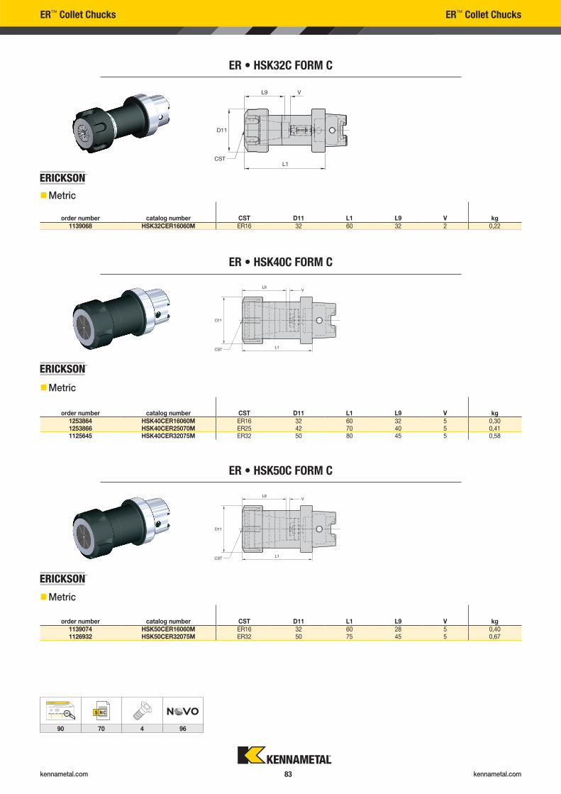
kennametal.com kennametal.com 83
ER™ Collet Chucks ER™ Collet Chucks
ER • HSK32C FORM C
order number catalog number CST D11 L1 L9 V kg1139068 HSK32CER16060M ER16 32 60 32 2 0,22
ER • HSK40C FORM C
order number catalog number CST D11 L1 L9 V kg1253864 HSK40CER16060M ER16 32 60 32 5 0,301253866 HSK40CER25070M ER25 42 70 40 5 0,411125645 HSK40CER32075M ER32 50 80 45 5 0,58
ER • HSK50C FORM C
order number catalog number CST D11 L1 L9 V kg1139074 HSK50CER16060M ER16 32 60 28 5 0,401126932 HSK50CER32075M ER32 50 75 45 5 0,67
��Metric
��Metric
��Metric
AB
90 70 4 96
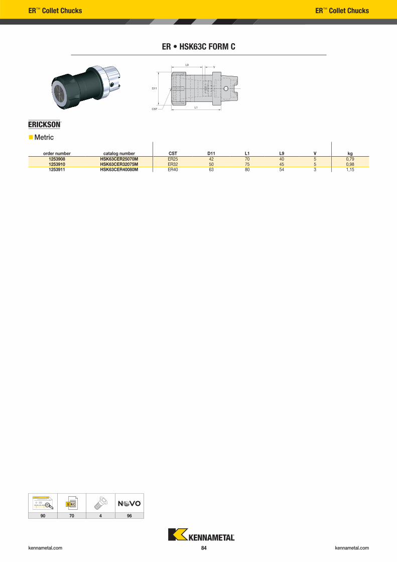
kennametal.com kennametal.com 84
ER™ Collet Chucks ER™ Collet Chucks
ER • HSK63C FORM C
order number catalog number CST D11 L1 L9 V kg1253908 HSK63CER25070M ER25 42 70 40 5 0,791253910 HSK63CER32075M ER32 50 75 45 5 0,981253911 HSK63CER40080M ER40 63 80 54 3 1,15
��Metric
AB
90 70 4 96
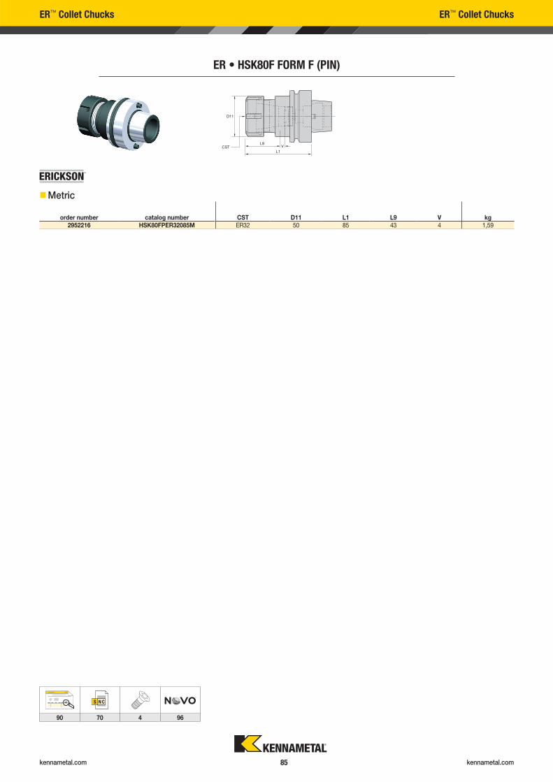
kennametal.com kennametal.com 85
ER™ Collet Chucks ER™ Collet Chucks
ER • HSK80F FORM F (PIN)
order number catalog number CST D11 L1 L9 V kg2952216 HSK80FPER32085M ER32 50 85 43 4 1,59
��Metric
AB
90 70 4 96
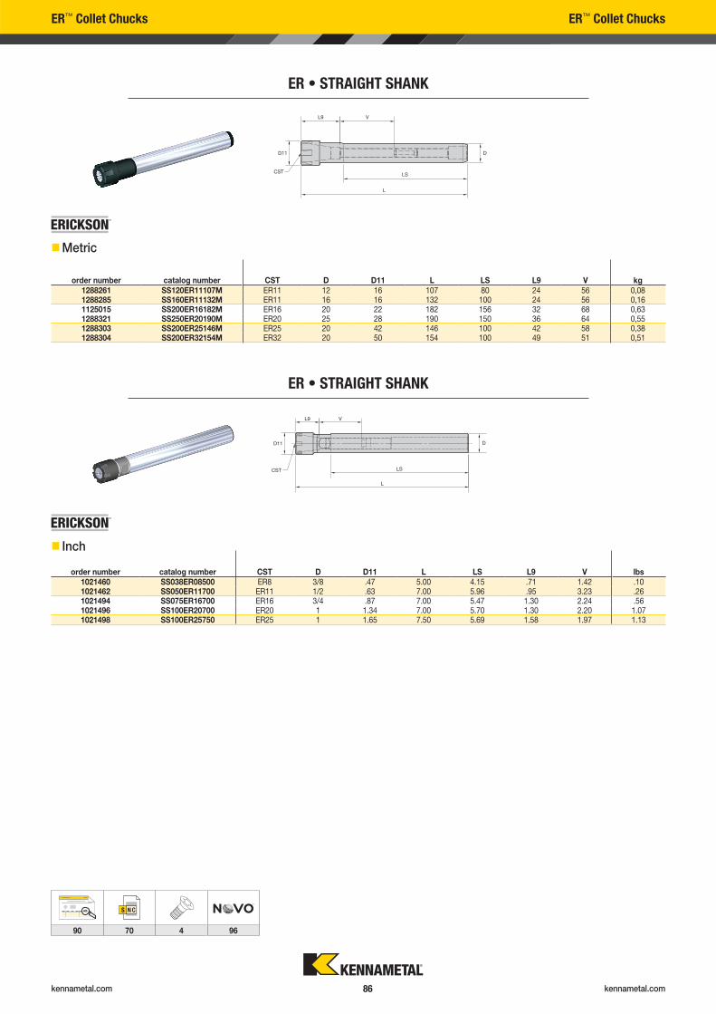
kennametal.com kennametal.com 86
ER™ Collet Chucks ER™ Collet Chucks
ER • STRAIGHT SHANK
order number catalog number CST D D11 L LS L9 V kg1288261 SS120ER11107M ER11 12 16 107 80 24 56 0,081288285 SS160ER11132M ER11 16 16 132 100 24 56 0,161125015 SS200ER16182M ER16 20 22 182 156 32 68 0,631288321 SS250ER20190M ER20 25 28 190 150 36 64 0,551288303 SS200ER25146M ER25 20 42 146 100 42 58 0,381288304 SS200ER32154M ER32 20 50 154 100 49 51 0,51
ER • STRAIGHT SHANK
order number catalog number CST D D11 L LS L9 V lbs1021460 SS038ER08500 ER8 3/8 .47 5.00 4.15 .71 1.42 .101021462 SS050ER11700 ER11 1/2 .63 7.00 5.96 .95 3.23 .261021494 SS075ER16700 ER16 3/4 .87 7.00 5.47 1.30 2.24 .561021496 SS100ER20700 ER20 1 1.34 7.00 5.70 1.30 2.20 1.071021498 SS100ER25750 ER25 1 1.65 7.50 5.69 1.58 1.97 1.13
��Metric
�� Inch
AB
90 70 4 96

kennametal.com
Lost a screw? Have to replace worn-out clamping wedges?
Need to fi nd and re-order those spare parts?
GO TO KENNAMETAL.COM AND FIND WHAT YOU NEED IN SECONDS.
1
2
Enter the tool catalog number here
Select the spare parts & accessories
STEP 1
STEP 2
Spare Parts & Accessories Information

kennametal.com kennametal.com 88
Grade Descriptions Grade Descriptions
SOLID END MILLING
HOLEMAKING
wear
resistancetoughness
Coating Grade Description 05 10 15 20 25 30 35 40 45
KC
PM
15
Coated carbide grade with thick PVD coating and optimized chemistry and process
for increased wear resistance. Outstanding protection in milling stainless steel to
mitigate crater, DOCN (depth-of-cut notching), and flank wear. Excellent performance
up to 52 HRC.
P
M
K
KC
SM
15
Coated carbide grade with thick PVD coating and optimized chemistry
and process for increased wear resistance. Outstanding protection in milling
stainless steel to mitigate crater, DOCN (depth-of-cut notching), and flank wear.
Excellent performance up to 52 HRC.
M
S
H
K600
Carbide grade made from high-quality, micrograin materials for cutting all types
of workpiece materials. Very high toughness ensures a controlled wear rate. The
micrograin structure enables extremely sharp cutting edges.
N
KC
643M
Coated fine-grain grade with PVD multilayer (AlTiN). KC643M™ is a very thin and hard
PVD coating particularly suited for cutting steel, cast iron, stainless steel (wet), and
titanium (wet). This grade can be used for materials with hardness up to 52 HRC.
P
M
K
S
wear
resistancetoughness
Coating Grade Description 05 10 15 20 25 30 35 40 45
KC
U40
Multilayered PVD TiN-TiAlN-coated fine-grain carbide, offering
highest wear resistance in steel, stainless steel, cast iron, and high-temp alloys.
P
M
K

kennametal.com kennametal.com 89
Grade Descriptions Grade Descriptions
TURNING
wear
resistancetoughness
Coating Grade Description 05 10 15 20 25 30 35 40 45
KB
H10B
A low content PcBN grade with a patented binder structure and a PVD TiN/TiAlN/
TiN coating for added wear resistance and enhanced wear identification. Designed
for the precision machining of hardened steels (>45 HRC). It can be effectively applied
on bearing steels, hot and cold work tool steels, high speed steels, die steels, case
hardened steels, carburized and nitrided irons, and some hard coatings. Available in a
multi-tip format with a wide range of edge preps, insert styles, and wiper geometries.
H
KB
H20B
A low content PcBN grade with a PVD TiN/TiAlN/TiN coating for added wear resistance
and enhanced wear identification. KBH20B™ is the ideal PcBN hard turning grade
for continuous to lightly interrupted cutting applications. The structure, as well as the
different edge preparations, enable repeatable workpiece tolerances, excellent surface
finishes, and surface integrity. Typical applications are case-hardened steel components
such as gears, shafts, and other drive-train components.
H
KC
U25
An advanced PVD grade with hard AlTiN coating and fine-grain unalloyed substrate.
The new and improved coating improves edge stability with wide range speed and feed
capabilities. The KCU25™ grade is ideal for general machining of most steels, stainless
steels, high-temp alloys, titanium, irons, and non-ferrous materials in a wide range of
speeds and feeds with improved edge toughness for interrupted cut and high feed rates.
P
M
K
N
S
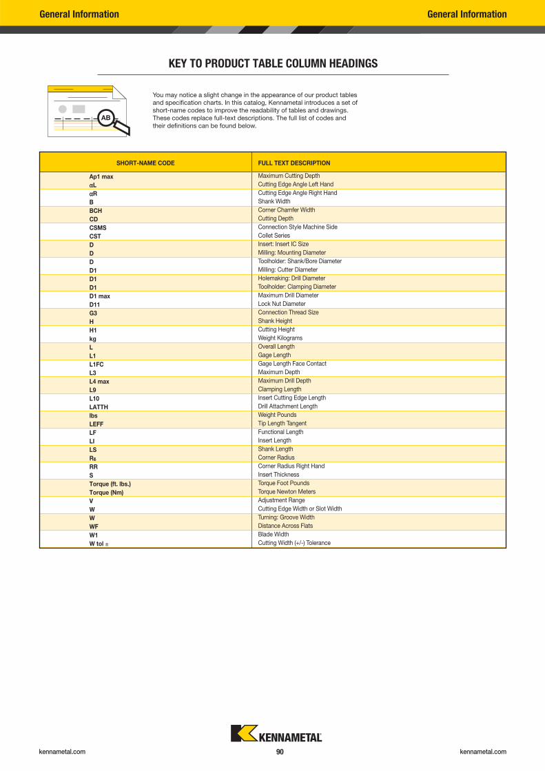
kennametal.com kennametal.com 90
SHORT-NAME CODE FULL TEXT DESCRIPTION
Ap1 max Maximum Cutting Depth
�L Cutting Edge Angle Left Hand
�R Cutting Edge Angle Right Hand
B Shank Width
BCH Corner Chamfer Width
CD Cutting Depth
CSMS Connection Style Machine Side
CST Collet Series
D Insert: Insert IC Size
D Milling: Mounting Diameter
D Toolholder: Shank/Bore Diameter
D1 Milling: Cutter Diameter
D1 Holemaking: Drill Diameter
D1 Toolholder: Clamping Diameter
D1 max Maximum Drill Diameter
D11 Lock Nut Diameter
G3 Connection Thread Size
H Shank Height
H1 Cutting Height
kg Weight Kilograms
L Overall Length
L1 Gage Length
L1FC Gage Length Face Contact
L3 Maximum Depth
L4 max Maximum Drill Depth
L9 Clamping Length
L10 Insert Cutting Edge Length
LATTH Drill Attachment Length
lbs Weight Pounds
LEFF Tip Length Tangent
LF Functional Length
LI Insert Length
LS Shank Length
R� Corner Radius
RR Corner Radius Right Hand
S Insert Thickness
Torque (ft. lbs.) Torque Foot Pounds
Torque (Nm) Torque Newton Meters
V Adjustment Range
W Cutting Edge Width or Slot Width
W Turning: Groove Width
WF Distance Across Flats
W1 Blade Width
W tol ± Cutting Width (+/-) Tolerance
General Information General Information
KEY TO PRODUCT TABLE COLUMN HEADINGS
You may notice a slight change in the appearance of our product tables
and specification charts. In this catalog, Kennametal introduces a set of
short-name codes to improve the readability of tables and drawings.
These codes replace full-text descriptions. The full list of codes and
their definitions can be found below.
AB
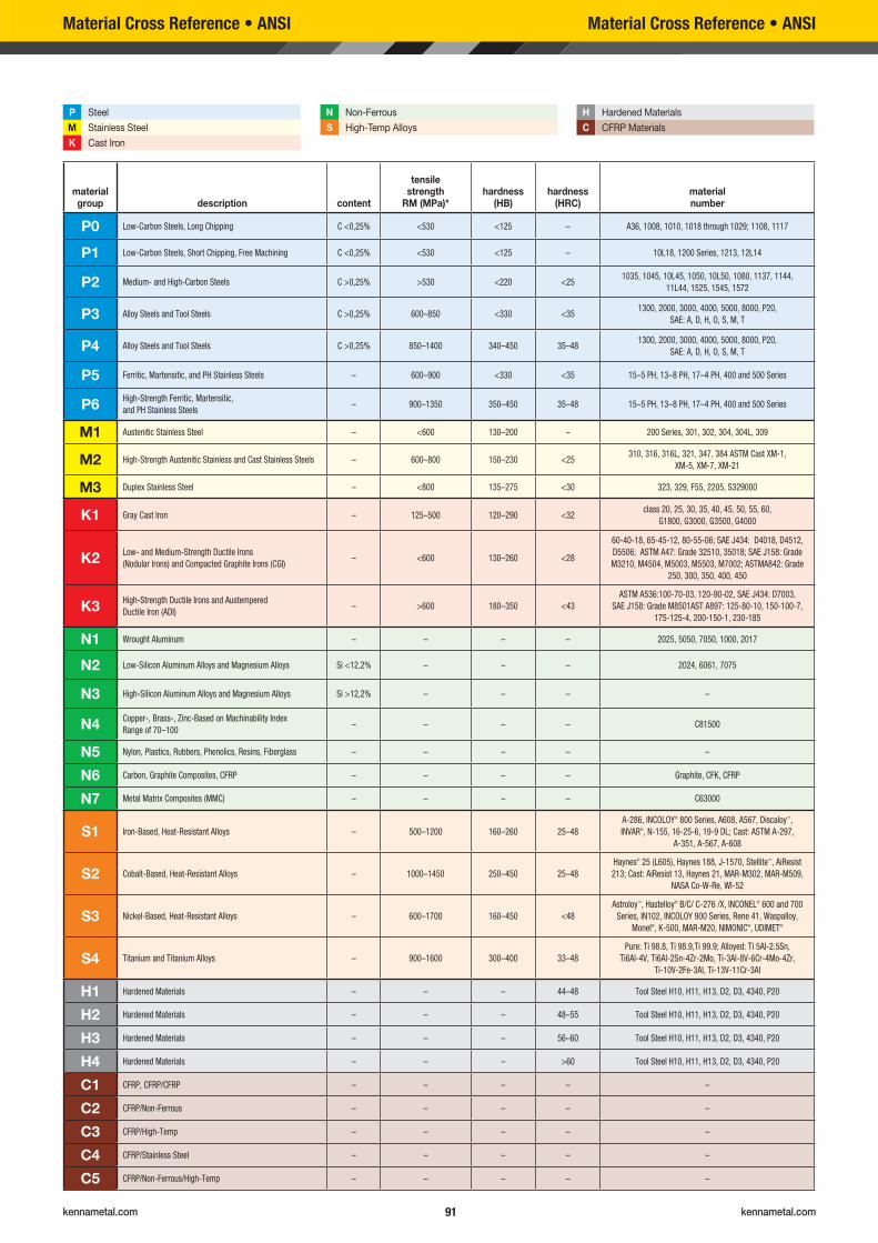
kennametal.com kennametal.com 91
material group description content
tensile strength
RM (MPa)*hardness
(HB)hardness
(HRC)material number
P0 Low-Carbon Steels, Long Chipping C <0,25% <530 <125 – A36, 1008, 1010, 1018 through 1029; 1108, 1117
P1 Low-Carbon Steels, Short Chipping, Free Machining C <0,25% <530 <125 – 10L18, 1200 Series, 1213, 12L14
P2 Medium- and High-Carbon Steels C >0,25% >530 <220 <251035, 1045, 10L45, 1050, 10L50, 1080, 1137, 1144,
11L44, 1525, 1545, 1572
P3 Alloy Steels and Tool Steels C >0,25% 600–850 <330 <351300, 2000, 3000, 4000, 5000, 8000, P20,
SAE: A, D, H, O, S, M, T
P4 Alloy Steels and Tool Steels C >0,25% 850–1400 340–450 35–481300, 2000, 3000, 4000, 5000, 8000, P20,
SAE: A, D, H, O, S, M, T
P5 Ferritic, Martensitic, and PH Stainless Steels – 600–900 <330 <35 15–5 PH, 13–8 PH, 17–4 PH, 400 and 500 Series
P6High-Strength Ferritic, Martensitic,
and PH Stainless Steels– 900–1350 350–450 35–48 15–5 PH, 13–8 PH, 17–4 PH, 400 and 500 Series
M1 Austenitic Stainless Steel – <600 130–200 – 200 Series, 301, 302, 304, 304L, 309
M2 High-Strength Austenitic Stainless and Cast Stainless Steels – 600–800 150–230 <25310, 316, 316L, 321, 347, 384 ASTM Cast XM-1,
XM-5, XM-7, XM-21
M3 Duplex Stainless Steel – <800 135–275 <30 323, 329, F55, 2205, S329000
K1 Gray Cast Iron – 125–500 120–290 <32class 20, 25, 30, 35, 40, 45, 50, 55, 60,
G1800, G3000, G3500, G4000
K2Low- and Medium-Strength Ductile Irons
(Nodular Irons) and Compacted Graphite Irons (CGI)– <600 130–260 <28
60-40-18, 65-45-12, 80-55-06; SAE J434: D4018, D4512,
D5506; ASTM A47: Grade 32510, 35018; SAE J158: Grade
M3210, M4504, M5003, M5503, M7002; ASTMA842: Grade
250, 300, 350, 400, 450
K3High-Strength Ductile Irons and Austempered
Ductile Iron (ADI)– >600 180–350 <43
ASTM A536:100-70-03, 120-90-02, SAE J434: D7003,
SAE J158: Grade M8501AST A897: 125-80-10, 150-100-7,
175-125-4, 200-150-1, 230-185
N1 Wrought Aluminum – – – – 2025, 5050, 7050, 1000, 2017
N2 Low-Silicon Aluminum Alloys and Magnesium Alloys Si <12,2% – – – 2024, 6061, 7075
N3 High-Silicon Aluminum Alloys and Magnesium Alloys Si >12,2% – – – –
N4Copper-, Brass-, Zinc-Based on Machinability Index
Range of 70–100– – – – C81500
N5 Nylon, Plastics, Rubbers, Phenolics, Resins, Fiberglass – – – – –
N6 Carbon, Graphite Composites, CFRP – – – – Graphite, CFK, CFRP
N7 Metal Matrix Composites (MMC) – – – – C63000
S1 Iron-Based, Heat-Resistant Alloys – 500–1200 160–260 25–48
A-286, INCOLOY® 800 Series, A608, A567, Discaloy™,
INVAR®, N-155, 16-25-6, 19-9 DL; Cast: ASTM A-297,
A-351, A-567, A-608
S2 Cobalt-Based, Heat-Resistant Alloys – 1000–1450 250–450 25–48
Haynes® 25 (L605), Haynes 188, J-1570, Stellite™, AiResist
213; Cast: AiResist 13, Haynes 21, MAR-M302, MAR-M509,
NASA Co-W-Re, WI-52
S3 Nickel-Based, Heat-Resistant Alloys – 600–1700 160–450 <48
Astroloy™, Hastelloy® B/C/ C-276 /X, INCONEL® 600 and 700
Series, IN102, INCOLOY 900 Series, Rene 41, Waspalloy,
Monel®, K-500, MAR-M20, NIMONIC®, UDIMET®
S4 Titanium and Titanium Alloys – 900–1600 300–400 33–48
Pure: Ti 98.8, Ti 98.9,Ti 99.9; Alloyed: Ti 5Al-2.5Sn,
Ti6Al-4V, Ti6Al-2Sn-4Zr-2Mo, Ti-3Al-8V-6Cr-4Mo-4Zr,
Ti-10V-2Fe-3Al, Ti-13V-11Cr-3Al
H1 Hardened Materials – – – 44–48 Tool Steel H10, H11, H13, D2, D3, 4340, P20
H2 Hardened Materials – – – 48–55 Tool Steel H10, H11, H13, D2, D3, 4340, P20
H3 Hardened Materials – – – 56–60 Tool Steel H10, H11, H13, D2, D3, 4340, P20
H4 Hardened Materials – – – >60 Tool Steel H10, H11, H13, D2, D3, 4340, P20
C1 CFRP, CFRP/CFRP – – – – –
C2 CFRP/Non-Ferrous – – – – –
C3 CFRP/High-Temp – – – – –
C4 CFRP/Stainless Steel – – – – –
C5 CFRP/Non-Ferrous/High-Temp – – – – –
P Steel
M Stainless Steel
K Cast Iron
Material Cross Reference • ANSI
N Non-Ferrous
S High-Temp Alloys
H Hardened Materials
C CFRP Materials
Material Cross Reference • ANSI
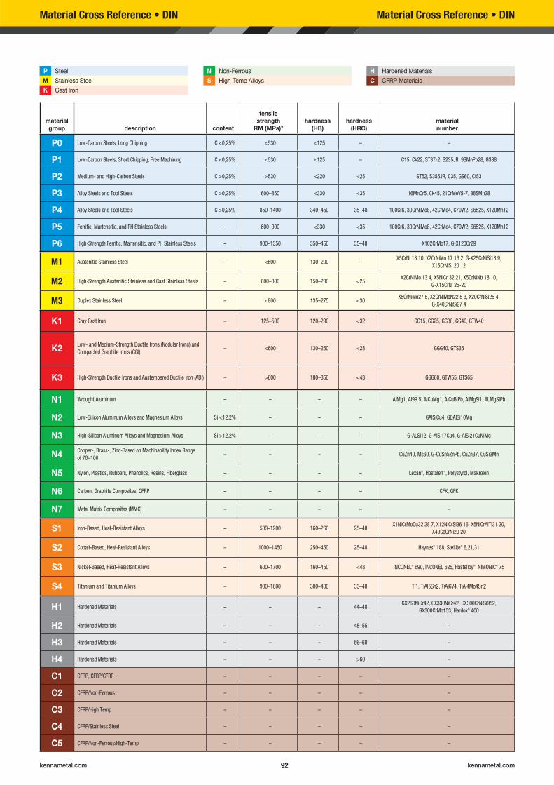
kennametal.com kennametal.com 92
material group description content
tensile strength
RM (MPa)*hardness
(HB)hardness
(HRC)material number
P0 Low-Carbon Steels, Long Chipping C <0,25% <530 <125 – –
P1 Low-Carbon Steels, Short Chipping, Free Machining C <0,25% <530 <125 – C15, Ck22, ST37-2, S235JR, 9SMnPb28, GS38
P2 Medium- and High-Carbon Steels C >0,25% >530 <220 <25 ST52, S355JR, C35, GS60, Cf53
P3 Alloy Steels and Tool Steels C >0,25% 600–850 <330 <35 16MnCr5, Ck45, 21CrMoV5-7, 38SMn28
P4 Alloy Steels and Tool Steels C >0,25% 850–1400 340–450 35–48 100Cr6, 30CrNiMo8, 42CrMo4, C70W2, S6525, X120Mn12
P5 Ferritic, Martensitic, and PH Stainless Steels – 600–900 <330 <35 100Cr6, 30CrNiMo8, 42CrMo4, C70W2, S6525, X120Mn12
P6 High-Strength Ferritic, Martensitic, and PH Stainless Steels – 900–1350 350–450 35–48 X102CrMo17, G-X120Cr29
M1 Austenitic Stainless Steel – <600 130–200 –X5CrNi 18 10, X2CrNiMo 17 13 2, G-X25CrNiSi18 9,
X15CrNiSi 20 12
M2 High-Strength Austenitic Stainless and Cast Stainless Steels – 600–800 150–230 <25X2CrNiMo 13 4, X5NiCr 32 21, X5CrNiNb 18 10,
G-X15CrNi 25-20
M3 Duplex Stainless Steel – <800 135–275 <30X8CrNiMo27 5, X2CrNiMoN22 5 3, X20CrNiSi25 4,
G-X40CrNiSi27 4
K1 Gray Cast Iron – 125–500 120–290 <32 GG15, GG25, GG30, GG40, GTW40
K2Low- and Medium-Strength Ductile Irons (Nodular Irons) and
Compacted Graphite Irons (CGI)– <600 130–260 <28 GGG40, GTS35
K3 High-Strength Ductile Irons and Austempered Ductile Iron (ADI) – >600 180–350 <43 GGG60, GTW55, GTS65
N1 Wrought Aluminum – – – – AIMg1, AI99.5, AICuMg1, AICuBiPb, AIMgSi1, ALMgSiPb
N2 Low-Silicon Aluminum Alloys and Magnesium Alloys Si <12,2% – – – GAISiCu4, GDAISi10Mg
N3 High-Silicon Aluminum Alloys and Magnesium Alloys Si >12,2% – – – G-ALSi12, G-AlSi17Cu4, G-AISi21CuNiMg
N4Copper-, Brass-, Zinc-Based on Machinability Index Range
of 70–100– – – – CuZn40, Ms60, G-CuSn5ZnPb, CuZn37, CuSi3Mn
N5 Nylon, Plastics, Rubbers, Phenolics, Resins, Fiberglass – – – – Lexan®, Hostalen™, Polystyrol, Makrolon
N6 Carbon, Graphite Composites, CFRP – – – – CFK, GFK
N7 Metal Matrix Composites (MMC) – – – – –
S1 Iron-Based, Heat-Resistant Alloys – 500–1200 160–260 25–48X1NiCrMoCu32 28 7, X12NiCrSi36 16, X5NiCrAITi31 20,
X40CoCrNi20 20
S2 Cobalt-Based, Heat-Resistant Alloys – 1000–1450 250–450 25–48 Haynes® 188, Stellite® 6,21,31
S3 Nickel-Based, Heat-Resistant Alloys – 600–1700 160–450 <48 INCONEL® 690, INCONEL 625, Hastelloy®, NIMONIC® 75
S4 Titanium and Titanium Alloys – 900–1600 300–400 33–48 Ti1, TiAI5Sn2, TiAI6V4, TiAI4Mo4Sn2
H1 Hardened Materials – – – 44–48GX260NiCr42, GX330NiCr42, GX300CrNiSi952,
GX300CrMo153, Hardox® 400
H2 Hardened Materials – – – 48–55 –
H3 Hardened Materials – – – 56–60 –
H4 Hardened Materials – – – >60 –
C1 CFRP, CFRP/CFRP – – – – –
C2 CFRP/Non-Ferrous – – – – –
C3 CFRP/High Temp – – – – –
C4 CFRP/Stainless Steel – – – – –
C5 CFRP/Non-Ferrous/High-Temp – – – – –
P Steel
M Stainless Steel
K Cast Iron
N Non-Ferrous
S High-Temp Alloys
H Hardened Materials
C CFRP Materials
Material Cross Reference • DINMaterial Cross Reference • DIN


kennametal.com kennametal.com 96
Digitally access and leverage product data and knowledge
to connect systems and processes throughout
the entire manufacturing lifecycle.
kennametal.com
VISIT KENNAMETAL.COM/NOVO AND DOWNLOAD TODAY.

kennametal.comkennametal.com
METALCUTTING SAFETYIMPORTANT SAFETY INSTRUCTIONSRead before using the tools in this catalog!
Projectile and Fragmentation Hazards: Breathing and Skin Contact Hazards:
Modern metalcutting operations involve high spindle and cutter speeds and high temperatures and cutting forces. Hot metal chips may fly off the workpiece during metalcutting. Although cutting tools are designed and manufactured to withstand high cutting forces and temperatures, they can sometimes fragment, particularly if they are subjected to over-stress, severe impact, or other abuse.
Grinding carbide or other advanced cutting tool materials produces dust or mist containing metallic particles. Breathing this dust or mist — especially over an extended period — can cause temporary or permanent lung disease or make existing medical conditions worse. Contact with this dust or mist can irritate eyes, skin, and mucous membranes and may make existing skin conditions worse.
To avoid injury: To avoid injury:
• Always wear appropriate personal protective equipment, including safety goggles, when operating metalcutting machines or working nearby.
• Always make sure all machine guards are in place.
• Always wear breathing protection and safety goggles when grinding.
• Provide ventilation control and collect and properly dispose of dust, mist, or sludge from grinding.
• Avoid skin contact with dust or mist.
For more information, read the applicable Material Safety Data Sheet provided by Kennametal and consult General Industry Safety and Health Regulations, Part 1910, Title 29 of the Code of Federal Regulations.
These safety instructions are general guidelines. Many variables affect machining operations. It is impossible to cover every specific situation. The technical information included in this catalog and recommendations on machining practices may not apply to your particular operation. For more information, consult the Kennametal Metalcutting Safety booklet, available free from Kennametal at 724 539 5747 or fax 724 539 5439. For specific product safety and environmental questions, contact our Corporate Environmental Health and Safety Office at 724 539 5066 or fax 724 539 5372.
Kennametal, the stylized K, Beyond Evolution, DFC, Drill Fix, ERICKSON, HARVI, HydroForce, KBH20B, KC643M, KCU25, KenFeed, KenTIP, KM, KOR 5, KSEM, KSEM PLUS, MaxiMet, NOVO, RSM II, and Stellite are trademarks of Kennametal, Inc. and are used as such herein. The absence of a product, service name, or logo from this list does not constitute a waiver of the Kennametal trademark or other intellectual property rights concerning that name or logo.
Android ™ is a trademark of Google Inc.App Store ® is a registered trademark of Apple Inc., registered in the U.S. and other countries.Astroloy ™ is a trademark of Svedala Industries, Inc. Corporation.Discaloy ™ is a trademark of Westinghouse Electric Corporation.DUO-�OCK ® is a registered trademark and Duo-Lock ™ is a trademark of Haimer GmbH.Google Play ™ is a trademark of Google Inc.Hardox ® is a registered trademark of SSAB Technology AB Corporation.Hastelloy ® and Haynes ® are registered trademarks of Haynes International, Inc. Corporation.Hostalen™ is a trademark of Hoechst GmbH Corporation.INCONEL®
, Monel ®, NIMONIC ®, and Udimet ® are registered trademarks of Special Metals Corporation.INCOLOY ® is a registered trademark of Inco Alloys International, Inc.INVAR ® is a registered trademark of Imphy Alloys Joint Stock Company.Lexan ® is a registered trademark of Sabic Innovative Plastics IP B.V. Company.SAFE-�OCK ® is a registered trademark and Safe-Lock ™ is a trademark of Haimer GmbH.Weldon ® is a registered trademark of Weldon Tool Company.
©2019 Kennametal Inc. All rights reserved.

©2019 Kennametal Inc. l All rights reserved. l A-19-06096EN_in
kennametal.com
WORLD HEADQUARTERS
Kennametal Inc.600 Grant Street l Suite 5100
Pittsburgh, PA 15219 USATel: 1 800 446 [email protected]
EUROPEAN HEADQUARTERS
Kennametal Europe GmbHRheingoldstrasse 50
CH 8212 Neuhausen am Rheinfall
Switzerland
Tel: +41 52 6750 100
ASIA-PACIFIC HEADQUARTERS
Kennametal Singapore Pte. Ltd.
3A International Business Park
Unit #01-02/03/05, ICON@IBPSingapore 609935Tel: +65 6265 9222
INDIA HEADQUARTERS
Kennametal India Limited
CIN: L27109KA1964PLC001546
8/9th Mile, Tumkur RoadBangalore - 560 073
Tel: +91 080 22198444 or +91 080 [email protected]
INNOVATIONS


