Download - Katalog Export GB 25
Exp
ort 2
5
B-GB-EXP 4 011377 049963
ALBRECHT JUNG GMBH & CO. KGP.O. Box 1320D-58569 SchalksmühleGermany
Tel.: +49 2355 806-553Fax: +49 2355 806-254E-mail: [email protected]: www.jung.de/en
For sales contacts in your country see: www.jung-salescontact.com
Certified proof of origine
„Made in Germany“ by TÜV Nord.
Export 25November 2012
We assume/accept no liability for these catalogue being complete, correct or up-to-date.
At a glance: All manuals, brochures in PDF format and the latest complete KNX database combined on a DVD - comfortable to download on your computer!
The presentation concept with removable displays. The new sample case MK 5 is available on request. The design ranges with original covers are presen-ted on seven displays with eleven presentation areas.
Sample case MK 5
Export 25
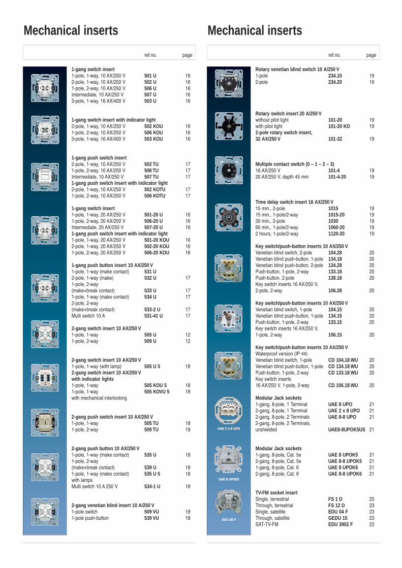
1-gang switch insert 1-pole, 1-way, 10 AX/250 V 501 U 162-pole, 1-way, 10 AX/250 V 502 U 161-pole, 2-way, 10 AX/250 V 506 U 16Intermediate, 10 AX/250 V 507 U 163-pole, 1-way, 16 AX/400 V 503 U 16
1-gang switch insert with indicator light2-pole, 1-way, 10 AX/250 V 502 KOU 161-pole, 2-way, 10 AX/250 V 506 KOU 163-pole, 1-way, 16 AX/400 V 503 KOU 16
1-gang push switch insert2-pole, 1-way, 10 AX/250 V 502 TU 171-pole, 2-way, 10 AX/250 V 506 TU 17Intermediate, 10 AX/250 V 507 TU 171-gang push switch insert with indicator light2-pole, 1-way, 10 AX/250 V 502 KOTU 171-pole, 2-way, 10 AX/250 V 506 KOTU 17
1-gang switch insert1-pole, 1-way, 20 AX/250 V 501-20 U 161-pole, 2-way, 20 AX/250 V 506-20 U 16Intermediate, 20 AX/250 V 507-20 U 161-gang push switch insert with indicator light1-pole, 1-way, 20 AX/250 V 501-20 KOU 162-pole, 1-way, 20 AX/250 V 502-20 KOU 161-pole, 2-way, 20 AX/250 V 506-20 KOU 16
1-gang push button insert 10 AX/250 V1-pole, 1-way (make contact) 531 U2-pole, 1-way (make) 532 U 171-pole, 2-way(make+break contact) 533 U 171-pole, 1-way (make contact) 534 U 172-pole, 2-way (make+break contact) 533-2 U 17Multi switch 10 A 531-41 U 17
2-gang switch insert 10 AX/250 V1-pole, 1-way 505 U 121-pole, 2-way 509 U 12
2-gang switch insert 10 AX/250 V1-pole, 1-way (with lamp) 505 U 5 182-gang switch insert 10 AX/250 Vwith indicator lights1-pole, 1-way 505 KOU 5 181-pole, 1-way 505 KOVU 5 18with mechanical interlocking
2-gang push switch insert 10 AX/250 V1-pole, 1-way 505 TU 181-pole, 2-way 509 TU 18
2-gang push button 10 AX/250 V1-pole, 1-way (make contact) 535 U 181-pole, 2-way (make+break contact) 539 U 181-pole, 1-way (make contact) 535 U 5 18with lampsMulti switch 10 A 250 V 534-1 U 18
2-gang venetian blind insert 10 A/250 V1-pole switch 509 VU 181-pole push-button 539 VU 18
Rotary venetian blind switch 10 A/250 V1-pole 234.10 192-pole 234.20 19
Rotary switch insert 20 A/250 Vwithout pilot light 101-20 19with pilot light 101-20 KO 192-pole rotary switch insert, 32 AX/250 V 101-32 19
Multiple contact switch (0 – 1 – 2 – 3)16 AX/250 V 101-4 1920 AX/250 V, depth 45 mm 101-4-20 19
Time delay switch insert 16 AX/250 V 15 min., 2-pole 1015 1915 min., 1-pole/2-way 1015-20 1930 min., 2-pole 1030 1960 min., 1-pole/2-way 1060-20 192 hours, 1-pole/2-way 1120-20 19
Key switch/push-button inserts 10 AX/250 VVenetian blind switch, 2-pole 104.28 20Venetian blind push-button, 1-pole 134.18 20Venetian blind push-button, 2-pole 134.28 20Push-button, 1-pole, 2-way 133.18 20Push-button, 2-pole 138.18 20Key switch inserts 16 AX/250 V, 2-pole, 2-way 106.28 20
Key switch/push-button inserts 10 AX/250 VVenetian blind switch, 1-pole 104.15 20Venetian blind push-button, 1-pole 134.15 20Push-button, 1-pole, 2-way 133.15 20Key switch inserts 16 AX/250 V, 1-pole, 2-way 106.15 20
Key switch/push-button inserts 10 AX/250 VWaterproof version (IP 44)Venetian blind switch, 1-pole CD 104.18 WU 20Venetian blind push-button, 1-pole CD 134.18 WU 20Push-button, 1-pole, 2-way CD 133.18 WU 20Key switch inserts 16 AX/250 V, 1-pole, 2-way CD 106.18 WU 20
Modular Jack sockets1-gang, 8-pole, 1 Terminal UAE 8 UPO 212-gang, 8-pole, 1 Terminal UAE 2 x 8 UPO 212-gang, 8-pole, 2 Terminals UAE 8-8 UPO 212-gang, 8-pole, 2 Terminals, unshielded UAE8-8UPOK5US 21
Modular Jack sockets1-gang, 8-pole, Cat. 5e UAE 8 UPOK5 212-gang, 8-pole, Cat. 5e UAE 8-8 UPOK5 211-gang, 8-pole, Cat. 6 UAE 8 UPOK6 212-gang, 8-pole, Cat. 6 UAE 8-8 UPOK6 21
TV-FM socket insertSingle, terrestrial FS 1 D 23Through, terrestrial FS 12 D 23Single, satellite EDU 04 F 23Through, satellite GEDU 15 23SAT-TV-FM EDU 3902 F 23
Mechanical inserts Mechanical inserts
ref.no. page ref.no. page
UAE 2 x 8 UPO
UAE 8 UPOK5
EDU 04 F
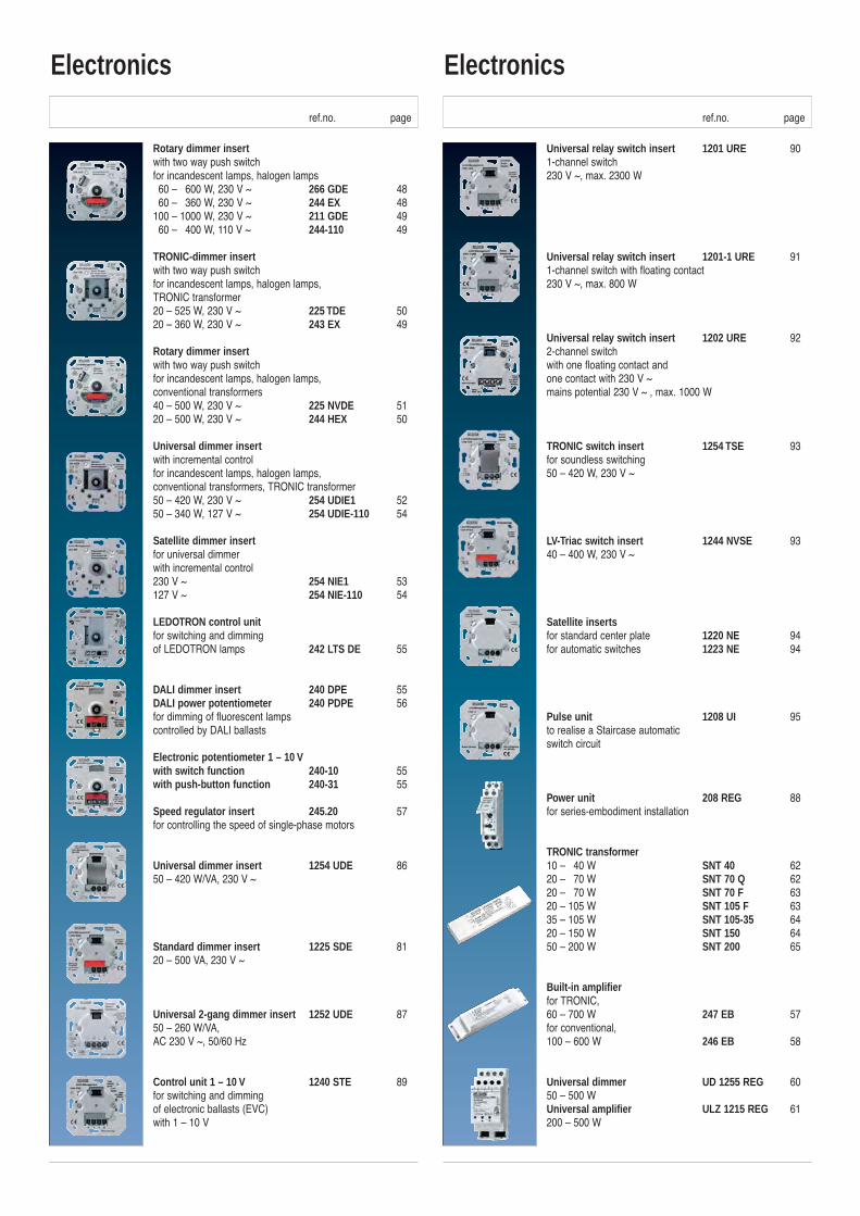
Rotary dimmer insertwith two way push switchfor incandescent lamps, halogen lamps060 – 0600 W, 230 V ~ 266 GDE 48060 – 0360 W, 230 V ~ 244 EX 48100 – 1000 W, 230 V ~ 211 GDE 49060 – 0400 W, 110 V ~ 244-110 49
TRONIC-dimmer insertwith two way push switchfor incandescent lamps, halogen lamps,TRONIC transformer20 – 525 W, 230 V ~ 225 TDE 5020 – 360 W, 230 V ~ 243 EX 49
Rotary dimmer insertwith two way push switchfor incandescent lamps, halogen lamps, conventional transformers40 – 500 W, 230 V ~ 225 NVDE 5120 – 500 W, 230 V ~ 244 HEX 50
Universal dimmer insertwith incremental control for incandescent lamps, halogen lamps, conventional transformers, TRONIC transformer50 – 420 W, 230 V ~ 254 UDIE1 5250 – 340 W, 127 V ~ 254 UDIE-110 54
Satellite dimmer insertfor universal dimmer with incremental control230 V ~ 254 NIE1 53127 V ~ 254 NIE-110 54
LEDOTRON control unitfor switching and dimmingof LEDOTRON lamps 242 LTS DE 55
DALI dimmer insert 240 DPE 55DALI power potentiometer 240 PDPE 56for dimming of fluorescent lampscontrolled by DALI ballasts
Electronic potentiometer 1 – 10 Vwith switch function 240-10 55with push-button function 240-31 55
Speed regulator insert 245.20 57for controlling the speed of single-phase motors
Universal dimmer insert 1254 UDE 8650 – 420 W/VA, 230 V ~
Standard dimmer insert 1225 SDE 8120 – 500 VA, 230 V ~
Universal 2-gang dimmer insert 1252 UDE 8750 – 260 W/VA, AC 230 V ~, 50/60 Hz
Control unit 1 – 10 V 1240 STE 89for switching and dimming of electronic ballasts (EVC) with 1 – 10 V
Universal relay switch insert 1201 URE 901-channel switch230 V ~, max. 2300 W
Universal relay switch insert 1201-1 URE 911-channel switch with floating contact230 V ~, max. 800 W
Universal relay switch insert 1202 URE 922-channel switch with one floating contact and one contact with 230 V ~ mains potential 230 V ~ , max. 1000 W
TRONIC switch insert 1254 TSE 93for soundless switching50 – 420 W, 230 V ~
LV-Triac switch insert 1244 NVSE 9340 – 400 W, 230 V ~
Satellite insertsfor standard center plate 1220 NE 94for automatic switches 1223 NE 94
Pulse unit 1208 UI 95to realise a Staircase automatic switch circuit
Power unit 208 REG 88for series-embodiment installation
TRONIC transformer10 – 040 W SNT 40 6220 – 070 W SNT 70 Q 6220 – 070 W SNT 70 F 6320 – 105 W SNT 105 F 6335 – 105 W SNT 105-35 6420 – 150 W SNT 150 6450 – 200 W SNT 200 65
Built-in amplifierfor TRONIC, 60 – 700 W 247 EB 57for conventional, 100 – 600 W 246 EB 58
Universal dimmer UD 1255 REG 6050 – 500 WUniversal amplifier ULZ 1215 REG 61200 – 500 W
Electronics Electronics
ref.no. page ref.no. page
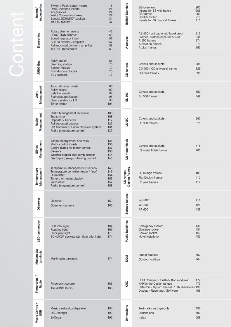
Inse
rts/
A
cces
sori
es Switch / Push-button inserts 16Data / Antenna inserts, 21Accessories 24Wall / Connection boxes 27Special SCHUKO® sockets 3450 x 50 system 37
Bri
tish
Sta
ndar
d
BS overview 200Inserts for BS wall boxes 206BS frames 209Cooker switch 210Inserts for 60 mm wall boxes 215
Ele
ctro
nics
Rotary dimmer inserts 46LEDOTRON dimmer 55Speed regulator insert 57Built-in dimmer / amplifier 57Rail mounted dimmer / amplifier 58TRONIC transformer 62 A
ran
ges
AS 500 / antibacterial / breakproof 216Frames, surface caps for AS 500 244A 500 frames 274A creation frames 279A plus frames 283
JUN
G B
us
Relay station 66Dimming station 70Sensor module 72Push-button module 7324 V sensors 73 C
D r
ange
s Covers and sockets 286
CD 500 / CD universal frames 329
CD plus frames 336
Ligh
t M
anag
emen
t Touch dimmer inserts 86Relay inserts 90Satellite inserts 94Staircase application 95Centre plates for LM 96Timer switch 104
SL
500 Covers and sockets 350
SL 500 frames 349
Rad
io
Man
agem
ent Radio Management Overview 106
Transmitter 108 Repeater / Receiver 117Rail mounted devices 127RM Controller / Radio observer system 131Radio temperature control 132
LS 9
90 Covers and sockets 350
LS 990 frames 375
Blin
ds
Man
agem
ent Blinds Management Overview 134
Motor control inserts 136Centre plates for motor control 137Sensors 138Weather station and combi sensor 144Decoupling relays / Awning control 146 LS
met
al f
inis
h
Covers and sockets 378
LS metal finish frames 405
Tem
pera
ture
M
anag
emen
t Temperature Management Overview 148Temperature controller (room / floor) 149Humidistat 154Timer thermostat display 155Valve drive 157Radio temperature control 158
LS r
ange
sD
esig
n fr
ames
LS Design frames 409
Flat Design frames 412
LS plus frames 414
Obs
erve
r
Observer 159
Observer systems 160
Sur
face
ran
ges
WG 800 416
WG 600 428
AP 600 439
LED
tec
hnol
ogy
LED info signs 164Reading light 167Floor pilot light 170SCHUKO® sockets with floor pilot light 171
Pub
lic b
uild
ings
Emergency system 446Oversize rocker 451Shaver socket 453Hotel installation 453
Mul
timed
ia
term
inal
s
Multimedia terminals 174
DC
M
Indoor stations 460
Outdoor stations 464
Fing
erpr
int
/
Rad
io
Fingerprint system 186
The JUNG Radio 188
KN
X
RCD Compact / Push-button modules 472KNX in the Design ranges 473Detectors / System devices / DIN rail devices 490Display / Reporting / Software 496
Mus
ic C
entr
e /
US
B
Music centre /Loudspeaker 190
USB charger 193
EnOcean 196
Dim
ensi
ons
Testmarks and symbols 498
Dimensions 500
Index 508
Con
tent
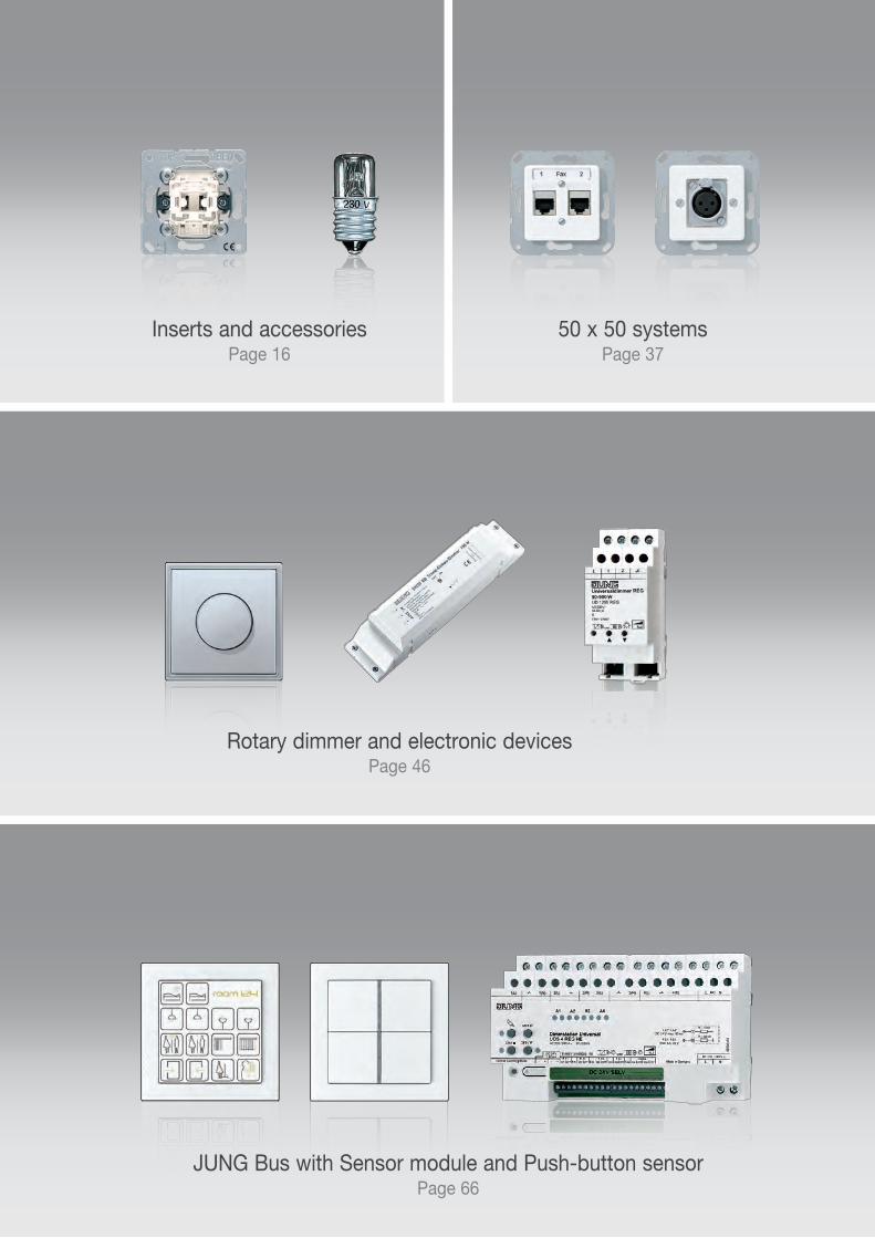
Inserts and accessoriesPage 16
50 x 50 systems Page 37
Rotary dimmer and electronic devicesPage 46
JUNG Bus with Sensor module and Push-button sensorPage 66
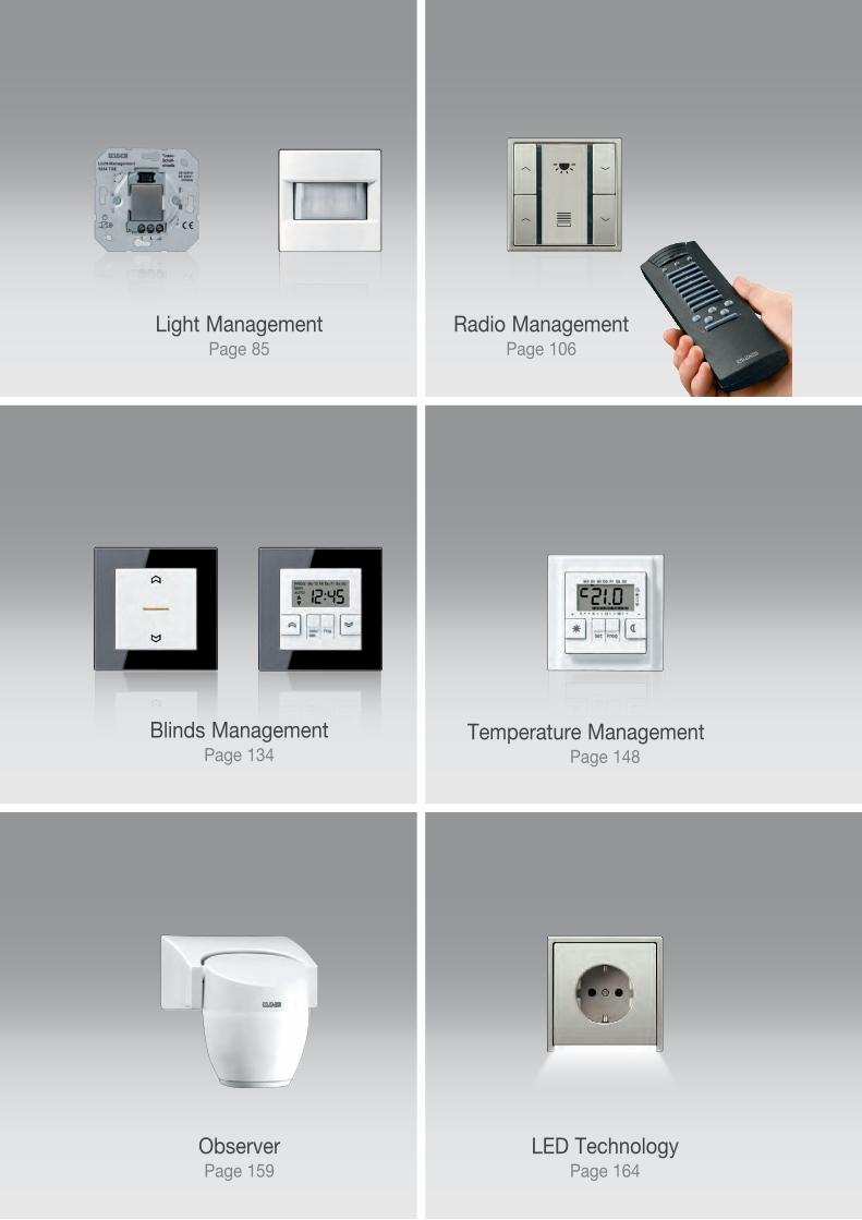
Radio ManagementPage 106
Light ManagementPage 85
Blinds ManagementPage 134
Temperature ManagementPage 148
Observer Page 159
LED Technology Page 164
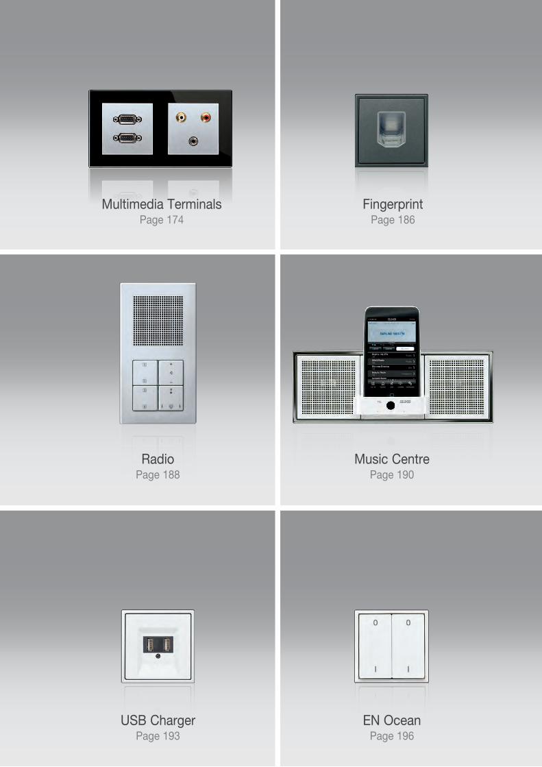
Fingerprint Page 186
Multimedia TerminalsPage 174
Music Centre Page 190
RadioPage 188
USB ChargerPage 193
EN OceanPage 196
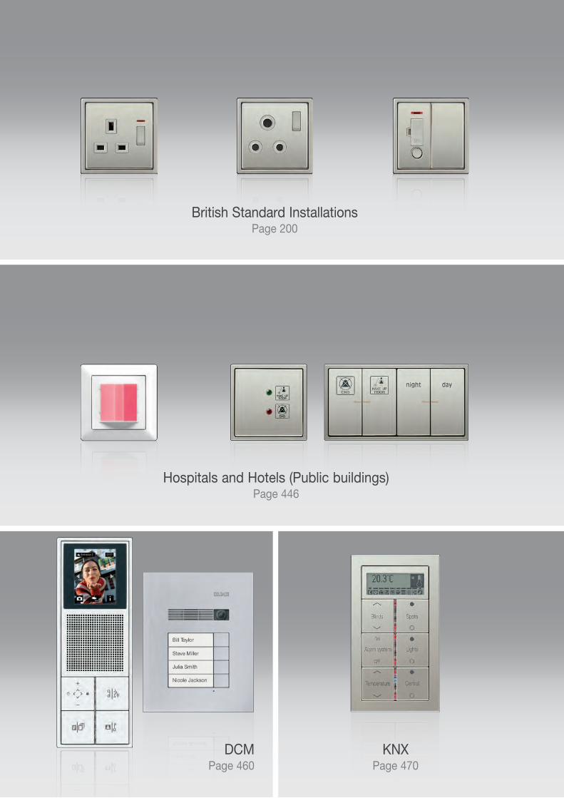
British Standard InstallationsPage 200
Hospitals and Hotels (Public buildings)Page 446
KNXPage 470
DCMPage 460
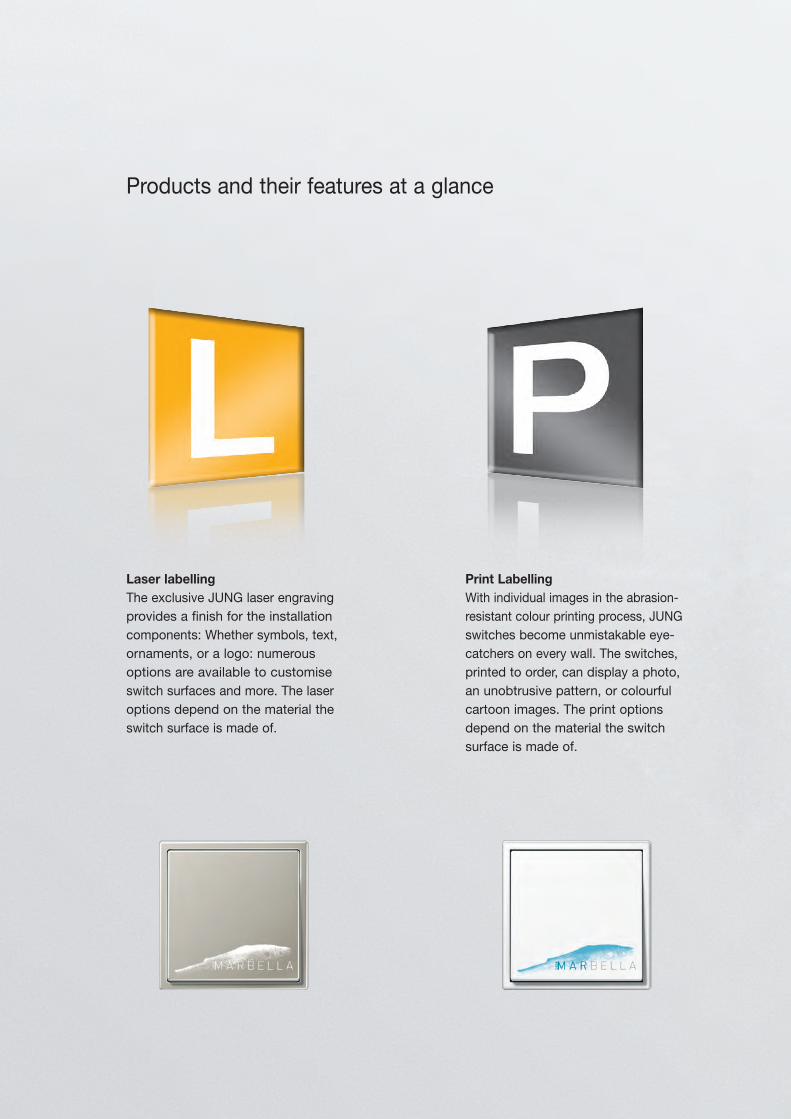
Products and their features at a glance
Laser labellingThe exclusive JUNG laser engraving provides a finish for the installation components: Whether symbols, text, ornaments, or a logo: numerous options are available to customise switch surfaces and more. The laser options depend on the material the switch surface is made of.
Print LabellingWith individual images in the abrasion-resistant colour printing process, JUNG switches become unmistakable eye-catchers on every wall. The switches, printed to order, can display a photo, an unobtrusive pattern, or colourful cartoon images. The print options depend on the material the switch surface is made of.
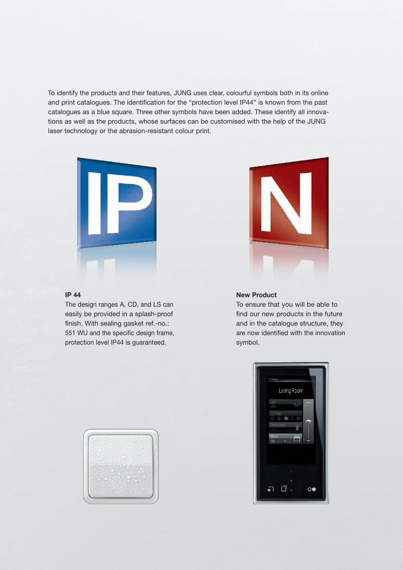
New ProductTo ensure that you will be able to find our new products in the future and in the catalogue structure, they are now identified with the innovation symbol.
IP 44The design ranges A, CD, and LS can easily be provided in a splash-proof finish. With sealing gasket ref.-no.: 551 WU and the specific design frame, protection level IP44 is guaranteed.
To identify the products and their features, JUNG uses clear, colourful symbols both in its online and print catalogues. The identification for the “protection level IP44” is known from the past catalogues as a blue square. Three other symbols have been added. These identify all innova-tions as well as the products, whose surfaces can be customised with the help of the JUNG laser technology or the abrasion-resistant colour print.
AS 500
A 500
A plus
CD 500
CD plus
SL 500
A creation
AS universal
AS 500 antibacterial
CD universal
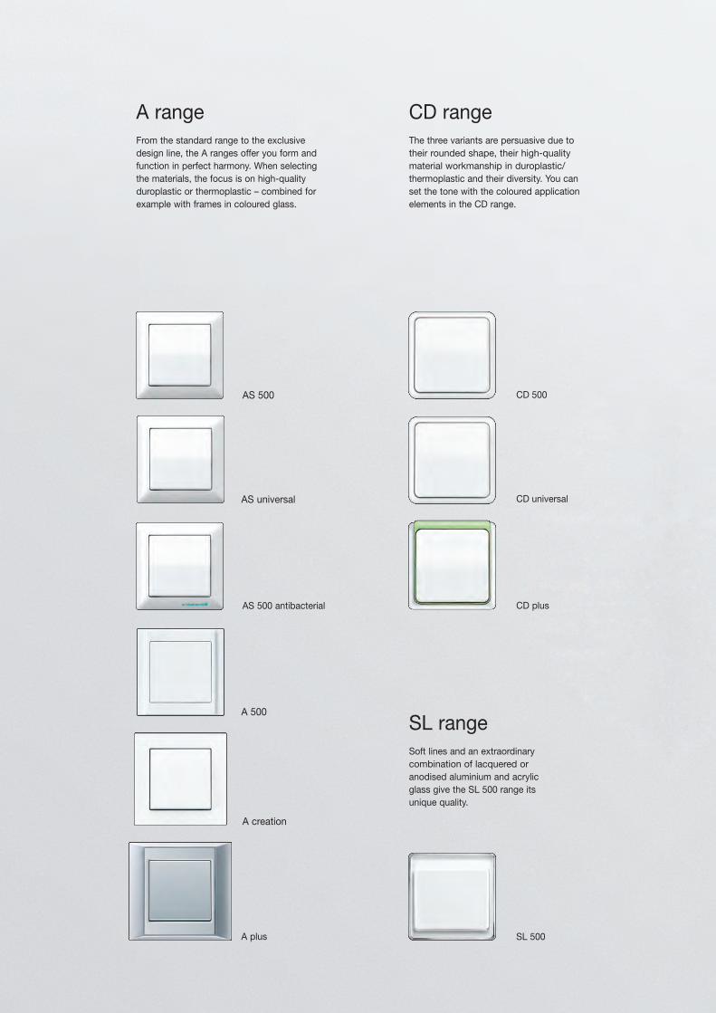
A rangeFrom the standard range to the exclusive design line, the A ranges offer you form and function in perfect harmony. When selecting the materials, the focus is on high-quality duroplastic or thermoplastic – combined for example with frames in coloured glass.
CD rangeThe three variants are persuasive due to their rounded shape, their high-quality material workmanship in duroplastic/thermoplastic and their diversity. You can set the tone with the coloured application elements in the CD range.
SL rangeSoft lines and an extraordinary combination of lacquered or anodised aluminium and acrylic glass give the SL 500 range its unique quality.
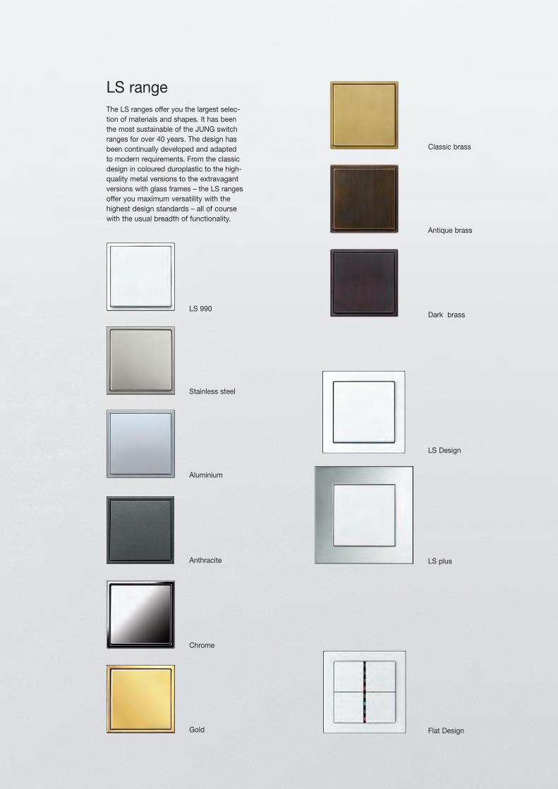
Flat Design
LS 990
Aluminium
Stainless steel
Anthracite
Gold
Chrome
LS Design
LS plus
LS rangeThe LS ranges offer you the largest selec-tion of materials and shapes. It has been the most sustainable of the JUNG switch ranges for over 40 years. The design has been continually developed and adapted to modern requirements. From the classic design in coloured duroplastic to the high-quality metal versions to the extravagant versions with glass frames – the LS ranges offer you maximum versatility with the highest design standards – all of course with the usual breadth of functionality.
Classic brass
Antique brass
Dark brass
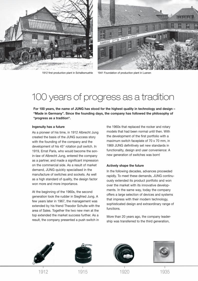
1912 1915 1920 1935
100 years of progress as a tradition For 100 years, the name of JUNG has stood for the highest quality in technology and design – “Made in Germany”. Since the founding days, the company has followed the philosophy of “progress as a tradition“.
1912 first production plant in Schalksmuehle 1941 Foundation of production plant in Luenen
Ingenuity has a future
As a pioneer of his time, in 1912 Albrecht Jung created the basis of the JUNG success story with the founding of the company and the development of his 45° rotation pull switch. In 1919, Ernst Paris, who would become the son-in-law of Albrecht Jung, entered the company as a partner, and made a significant impression on the commercial side. As a result of market demand, JUNG quickly specialised in the manufacture of switches and sockets. As well as a high standard of quality, the design factor won more and more importance.
At the beginning of the 1960s, the second generation took the rudder in Siegfried Jung. A few years later in 1967, the management was extended by his friend Theodor Schulte with the area of Sales. Together the two new men at the top extended the market success further. As a result, the company presented a push switch in
the 1960s that replaced the rocker and rotary models that had been normal until then. With the development of the first portfolio with a maximum switch faceplate of 70 x 70 mm, in 1969 JUNG definitively set new standards in functionality, design and user convenience: A new generation of switches was born!
Actively shape the future
In the following decades, advances proceeded rapidly. To meet these demands, JUNG continu-ously extended its product portfolio and won over the market with its innovative develop-ments. In the same way, today the company offers a large selection of devices and systems that impress with their modern technology, sophisticated design and extraordinary range of functions.
More than 20 years ago, the company leader-ship was transferred to the third generation,
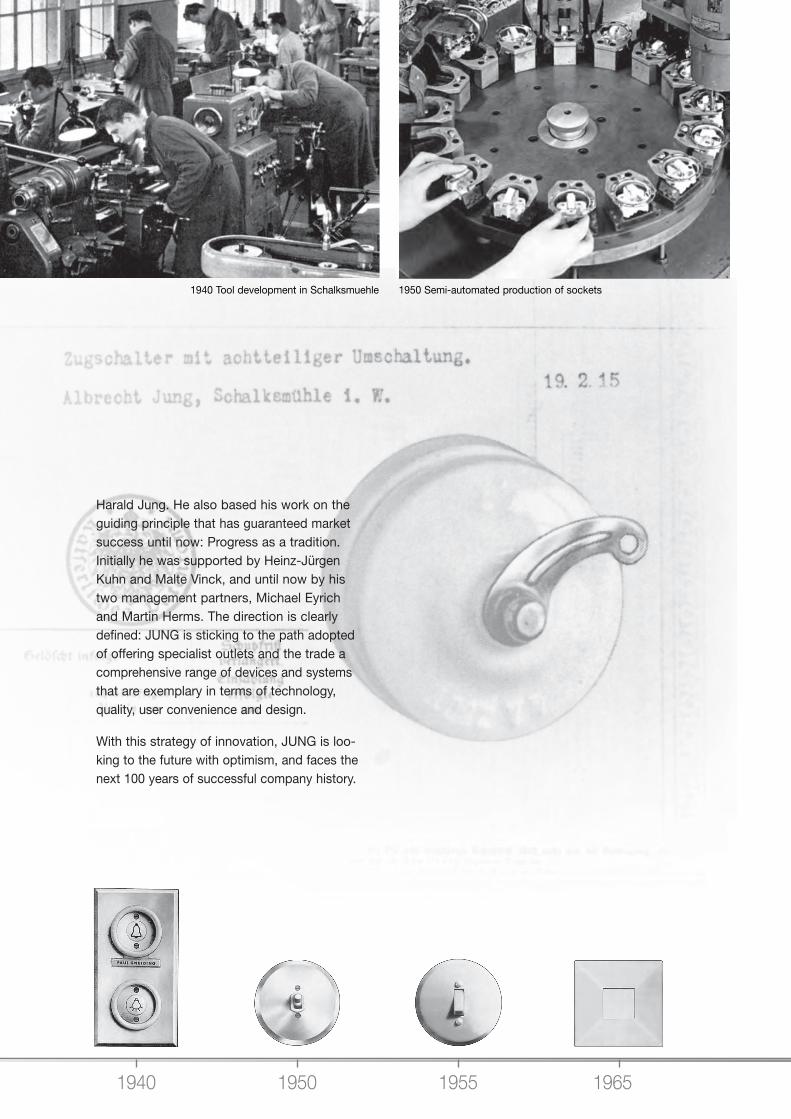
1940 1950 1955 1965
Harald Jung. He also based his work on the guiding principle that has guaranteed market success until now: Progress as a tradition. Initially he was supported by Heinz-Jürgen Kuhn and Malte Vinck, and until now by his two management partners, Michael Eyrich and Martin Herms. The direction is clearly defined: JUNG is sticking to the path adopted of offering specialist outlets and the trade a comprehensive range of devices and systems that are exemplary in terms of technology, quality, user convenience and design.
With this strategy of innovation, JUNG is loo-king to the future with optimism, and faces the next 100 years of successful company history.
1940 Tool development in Schalksmuehle 1950 Semi-automated production of sockets
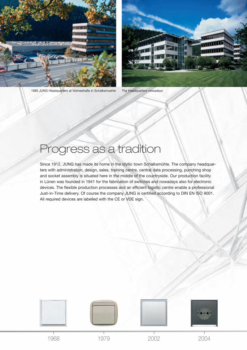
1968 1979 2002 2004
1985 JUNG Headquarters at Volmestraße in Schalksmuehle The Headquarters nowadays
Progress as a traditionSince 1912, JUNG has made its home in the idyllic town Schalksmühle. The company headquar-ters with administration, design, sales, training centre, central data processing, punching shop and socket assembly is situated here in the middle of the countryside. Our production facility in Lünen was founded in 1941 for the fabrication of switches and nowadays also for electronic devices. The flexible production processes and an efficient logistic centre enable a professional Just-in-Time delivery. Of course the company JUNG is certified according to DIN EN ISO 9001. All required devices are labelled with the CE or VDE sign.
2006 2007 20122009
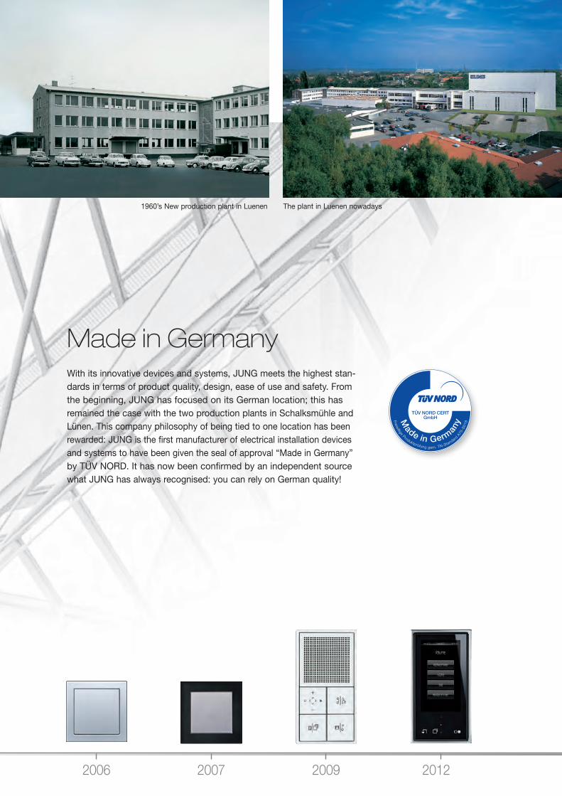
1960’s New production plant in Luenen The plant in Luenen nowadays
Made in Germany With its innovative devices and systems, JUNG meets the highest stan-dards in terms of product quality, design, ease of use and safety. From the beginning, JUNG has focused on its German location; this has remained the case with the two production plants in Schalksmühle and Lünen. This company philosophy of being tied to one location has been rewarded: JUNG is the first manufacturer of electrical installation devices and systems to have been given the seal of approval “Made in Germany” by TÜV NORD. It has now been confirmed by an independent source what JUNG has always recognised: you can rely on German quality!
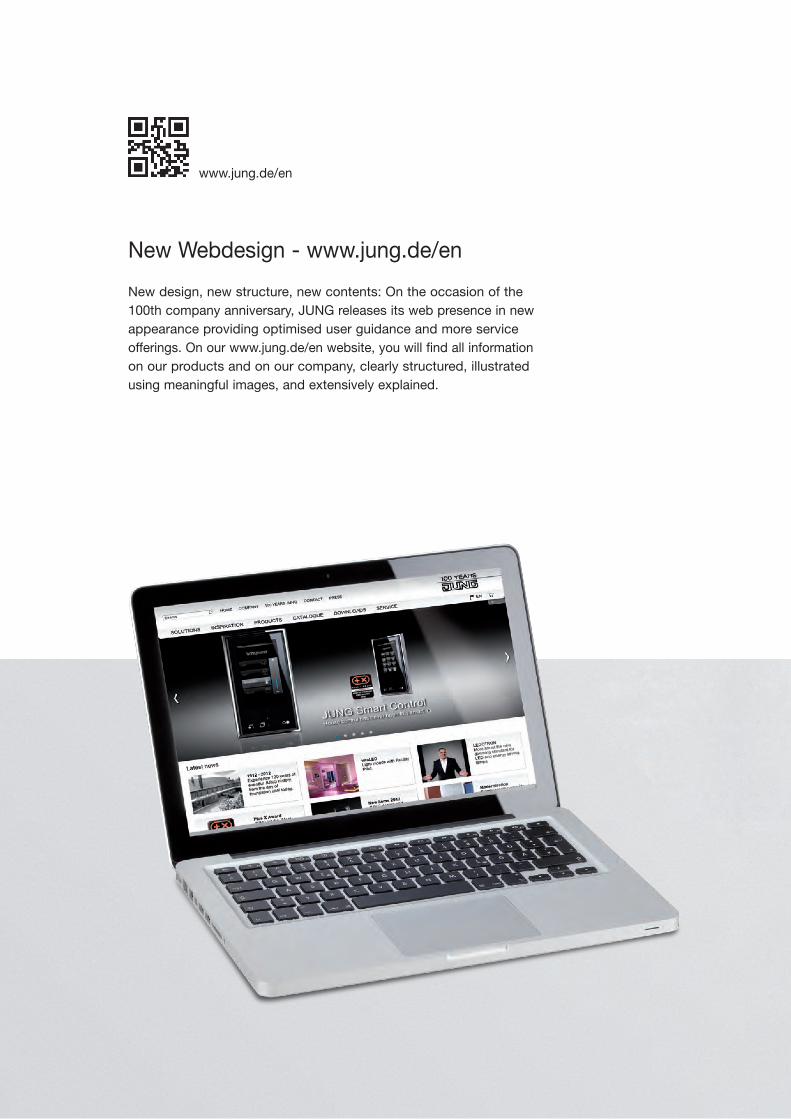
New design, new structure, new contents: On the occasion of the 100th company anniversary, JUNG releases its web presence in new appearance providing optimised user guidance and more service offerings. On our www.jung.de/en website, you will find all information on our products and on our company, clearly structured, illustrated using meaningful images, and extensively explained.
New Webdesign - www.jung.de/en
www.jung.de/en
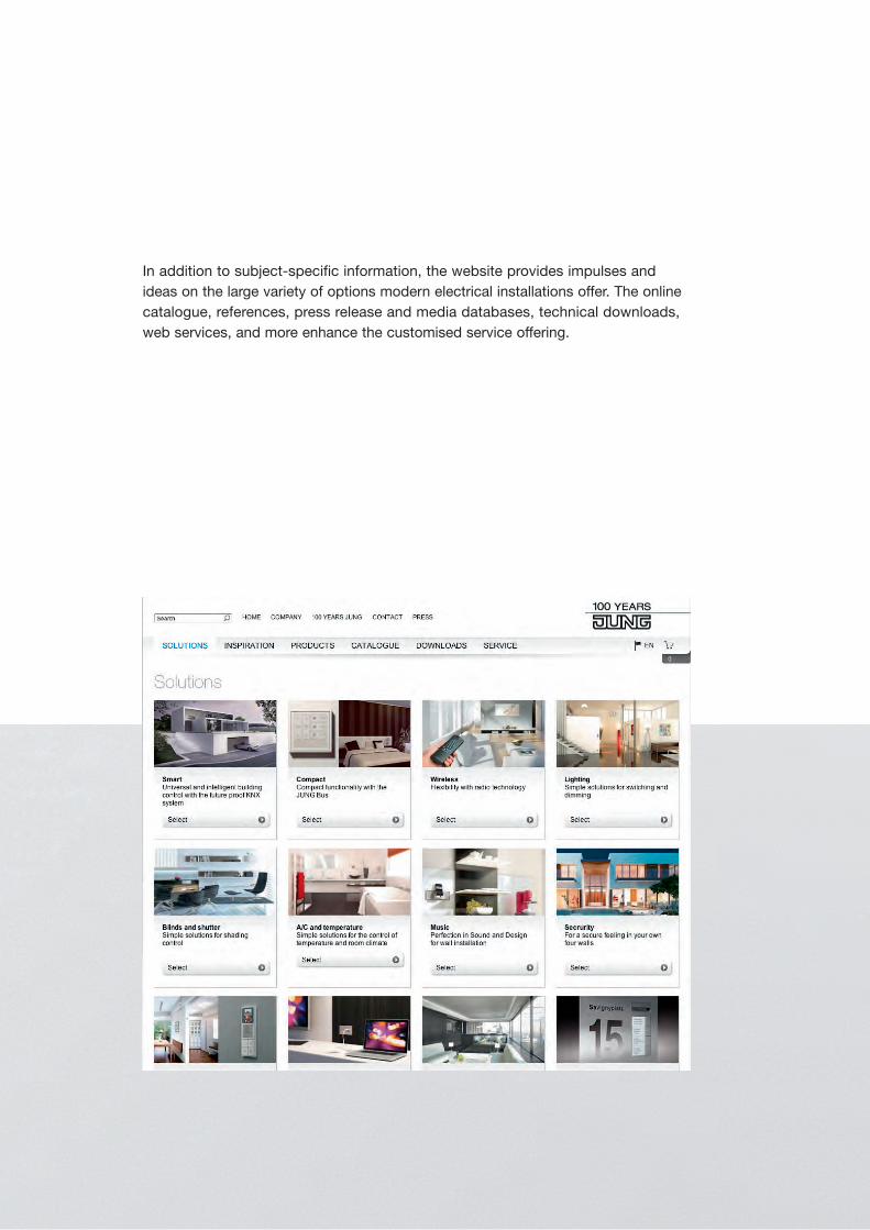
In addition to subject-specific information, the website provides impulses and ideas on the large variety of options modern electrical installations offer. The online catalogue, references, press release and media databases, technical downloads, web services, and more enhance the customised service offering.
16
1-gang
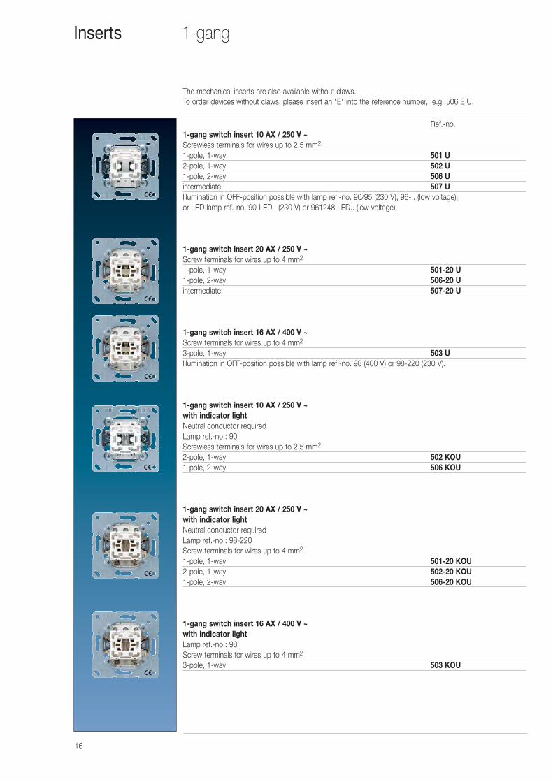
Ref.-no.1-gang switch insert 10 AX / 250 V ~Screwless terminals for wires up to 2.5 mm2
1-pole, 1-way 501 U2-pole, 1-way 502 U1-pole, 2-way 506 Uintermediate 507 UIllumination in OFF-position possible with lamp ref.-no. 90/95 (230 V), 96-.. (low voltage), or LED lamp ref.-no. 90-LED.. (230 V) or 961248 LED.. (low voltage).
1-gang switch insert 20 AX / 250 V ~Screw terminals for wires up to 4 mm2
1-pole, 1-way 501-20 U1-pole, 2-way 506-20 Uintermediate 507-20 U
1-gang switch insert 16 AX / 400 V ~Screw terminals for wires up to 4 mm2
3-pole, 1-way 503 UIllumination in OFF-position possible with lamp ref.-no. 98 (400 V) or 98-220 (230 V).
1-gang switch insert 10 AX / 250 V ~with indicator lightNeutral conductor requiredLamp ref.-no.: 90Screwless terminals for wires up to 2.5 mm2
2-pole, 1-way 502 KOU1-pole, 2-way 506 KOU
1-gang switch insert 20 AX / 250 V ~with indicator lightNeutral conductor requiredLamp ref.-no.: 98-220Screw terminals for wires up to 4 mm2
1-pole, 1-way 501-20 KOU2-pole, 1-way 502-20 KOU1-pole, 2-way 506-20 KOU
1-gang switch insert 16 AX / 400 V ~with indicator lightLamp ref.-no.: 98Screw terminals for wires up to 4 mm2
3-pole, 1-way 503 KOU
Inserts
The mechanical inserts are also available without claws. To order devices without claws, please insert an "E" into the reference number, e.g. 506 E U.
17
1-gang
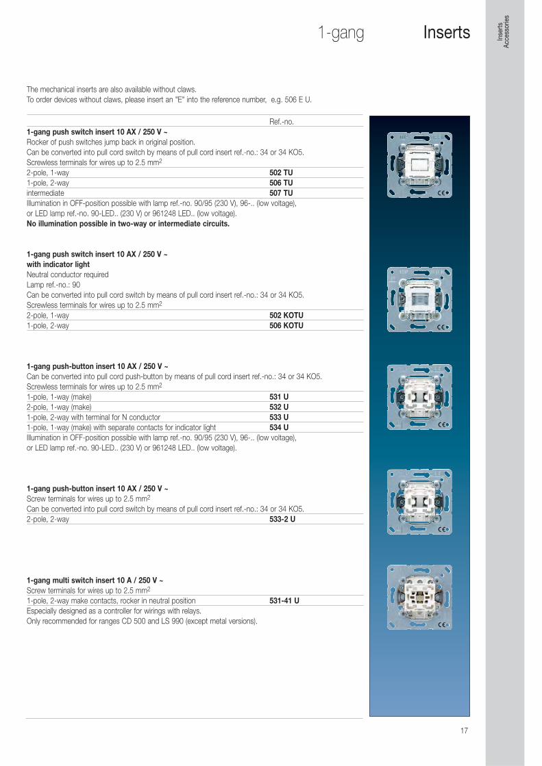
Ref.-no.1-gang push switch insert 10 AX / 250 V ~Rocker of push switches jump back in original position.Can be converted into pull cord switch by means of pull cord insert ref.-no.: 34 or 34 KO5.Screwless terminals for wires up to 2.5 mm2
2-pole, 1-way 502 TU1-pole, 2-way 506 TUintermediate 507 TUIllumination in OFF-position possible with lamp ref.-no. 90/95 (230 V), 96-.. (low voltage), or LED lamp ref.-no. 90-LED.. (230 V) or 961248 LED.. (low voltage).No illumination possible in two-way or intermediate circuits.
1-gang push switch insert 10 AX / 250 V ~with indicator lightNeutral conductor requiredLamp ref.-no.: 90Can be converted into pull cord switch by means of pull cord insert ref.-no.: 34 or 34 KO5.Screwless terminals for wires up to 2.5 mm2
2-pole, 1-way 502 KOTU1-pole, 2-way 506 KOTU
1-gang push-button insert 10 AX / 250 V ~Can be converted into pull cord push-button by means of pull cord insert ref.-no.: 34 or 34 KO5.Screwless terminals for wires up to 2.5 mm2
1-pole, 1-way (make) 531 U2-pole, 1-way (make) 532 U1-pole, 2-way with terminal for N conductor 533 U1-pole, 1-way (make) with separate contacts for indicator light 534 UIllumination in OFF-position possible with lamp ref.-no. 90/95 (230 V), 96-.. (low voltage), or LED lamp ref.-no. 90-LED.. (230 V) or 961248 LED.. (low voltage).
1-gang push-button insert 10 AX / 250 V ~Screw terminals for wires up to 2.5 mm2
Can be converted into pull cord switch by means of pull cord insert ref.-no.: 34 or 34 KO5.2-pole, 2-way 533-2 U
1-gang multi switch insert 10 A / 250 V ~Screw terminals for wires up to 2.5 mm2
1-pole, 2-way make contacts, rocker in neutral position 531-41 UEspecially designed as a controller for wirings with relays.Only recommended for ranges CD 500 and LS 990 (except metal versions).
Inserts
The mechanical inserts are also available without claws. To order devices without claws, please insert an "E" into the reference number, e.g. 506 E U.
Inse
rts
Acce
ssor
ies
18
2-gang
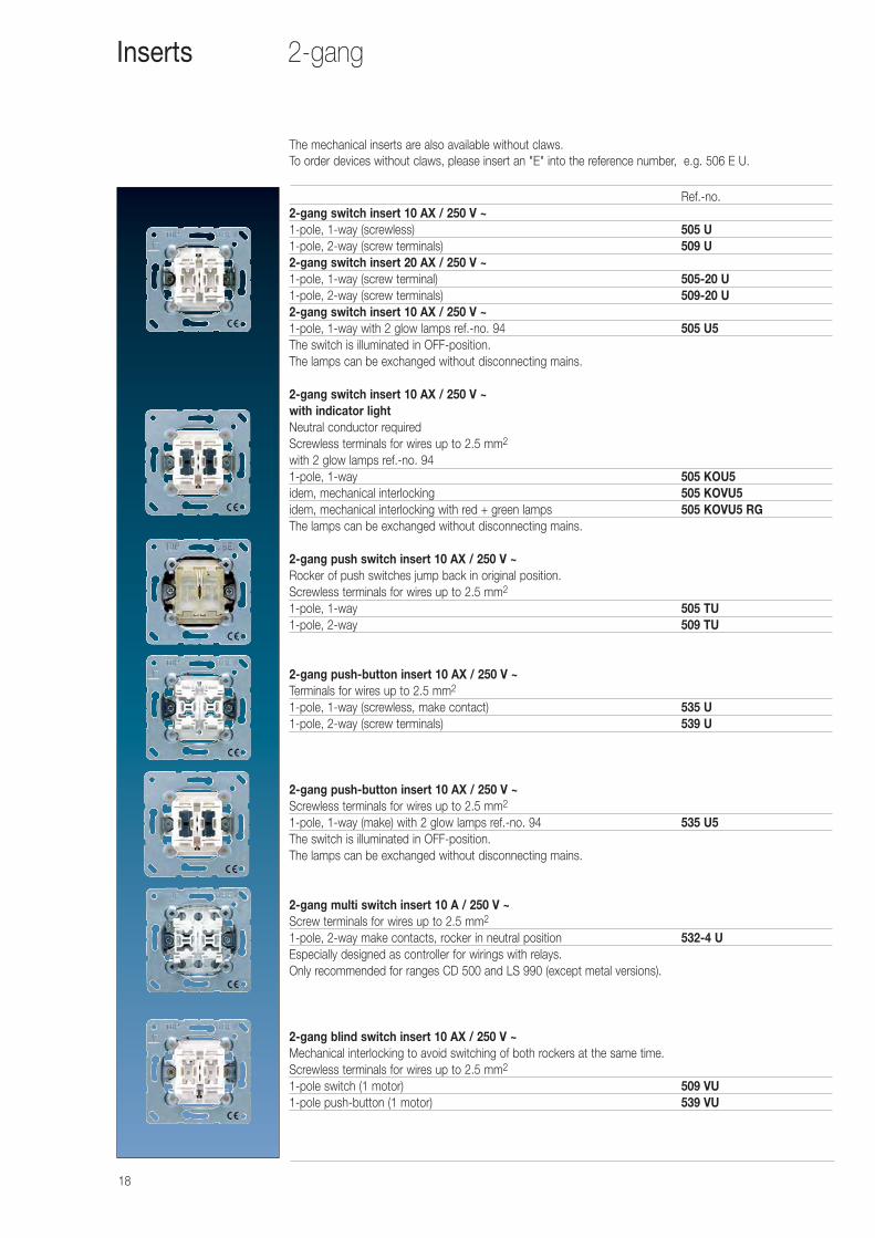
Ref.-no.2-gang switch insert 10 AX / 250 V ~1-pole, 1-way (screwless) 505 U1-pole, 2-way (screw terminals) 509 U2-gang switch insert 20 AX / 250 V ~1-pole, 1-way (screw terminal) 505-20 U1-pole, 2-way (screw terminals) 509-20 U2-gang switch insert 10 AX / 250 V ~1-pole, 1-way with 2 glow lamps ref.-no. 94 505 U5The switch is illuminated in OFF-position.The lamps can be exchanged without disconnecting mains.
2-gang switch insert 10 AX / 250 V ~with indicator lightNeutral conductor requiredScrewless terminals for wires up to 2.5 mm2
with 2 glow lamps ref.-no. 941-pole, 1-way 505 KOU5idem, mechanical interlocking 505 KOVU5idem, mechanical interlocking with red + green lamps 505 KOVU5 RGThe lamps can be exchanged without disconnecting mains.
2-gang push switch insert 10 AX / 250 V ~Rocker of push switches jump back in original position.Screwless terminals for wires up to 2.5 mm2
1-pole, 1-way 505 TU1-pole, 2-way 509 TU
2-gang push-button insert 10 AX / 250 V ~Terminals for wires up to 2.5 mm2
1-pole, 1-way (screwless, make contact) 535 U1-pole, 2-way (screw terminals) 539 U
2-gang push-button insert 10 AX / 250 V ~Screwless terminals for wires up to 2.5 mm2
1-pole, 1-way (make) with 2 glow lamps ref.-no. 94 535 U5The switch is illuminated in OFF-position.The lamps can be exchanged without disconnecting mains.
2-gang multi switch insert 10 A / 250 V ~Screw terminals for wires up to 2.5 mm2
1-pole, 2-way make contacts, rocker in neutral position 532-4 UEspecially designed as controller for wirings with relays.Only recommended for ranges CD 500 and LS 990 (except metal versions).
2-gang blind switch insert 10 AX / 250 V ~Mechanical interlocking to avoid switching of both rockers at the same time.Screwless terminals for wires up to 2.5 mm2
1-pole switch (1 motor) 509 VU1-pole push-button (1 motor) 539 VU
Inserts
The mechanical inserts are also available without claws. To order devices without claws, please insert an "E" into the reference number, e.g. 506 E U.
19
Rotary switch inserts
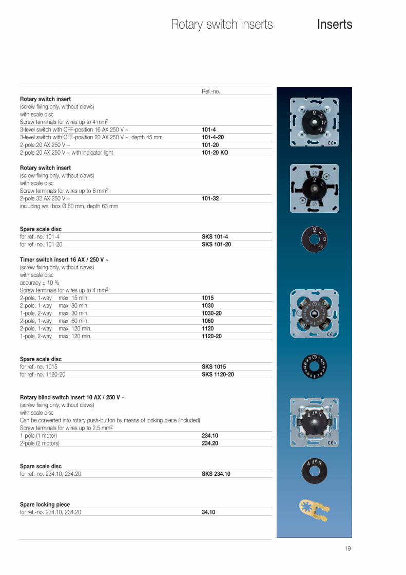
Ref.-no.Rotary switch insert(screw fixing only, without claws)with scale discScrew terminals for wires up to 4 mm2
3-level switch with OFF-position 16 AX 250 V ~ 101-43-level switch with OFF-position 20 AX 250 V ~, depth 45 mm 101-4-202-pole 20 AX 250 V ~ 101-202-pole 20 AX 250 V ~ with indicator light 101-20 KO
Rotary switch insert(screw fixing only, without claws)with scale discScrew terminals for wires up to 6 mm2
2-pole 32 AX 250 V ~ 101-32including wall box Ø 60 mm, depth 63 mm
Spare scale discfor ref.-no. 101-4 SKS 101-4for ref.-no. 101-20 SKS 101-20
Timer switch insert 16 AX / 250 V ~(screw fixing only, without claws)with scale discaccuracy ± 10 %Screw terminals for wires up to 4 mm2
2-pole, 1-way max. 15 min. 10152-pole, 1-way max. 30 min. 10301-pole, 2-way max. 30 min. 1030-202-pole, 1-way max. 60 min. 10602-pole, 1-way max. 120 min. 11201-pole, 2-way max. 120 min. 1120-20
Spare scale discfor ref.-no. 1015 SKS 1015for ref.-no. 1120-20 SKS 1120-20
Rotary blind switch insert 10 AX / 250 V ~(screw fixing only, without claws)with scale discCan be converted into rotary push-button by means of locking piece (included).Screw terminals for wires up to 2.5 mm2
1-pole (1 motor) 234.102-pole (2 motors) 234.20
Spare scale discfor ref.-no. 234.10, 234.20 SKS 234.10
Spare locking piecefor ref.-no. 234.10, 234.20 34.10
Inserts
20
Key switch inserts
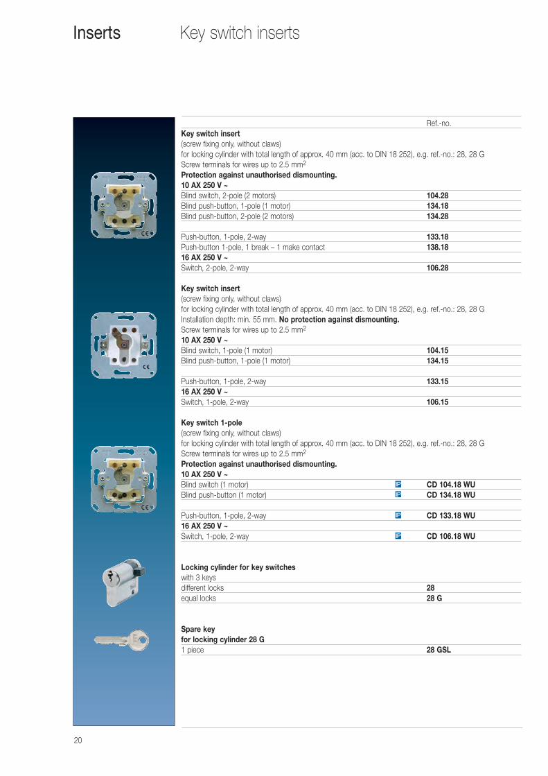
Ref.-no.Key switch insert(screw fixing only, without claws)for locking cylinder with total length of approx. 40 mm (acc. to DIN 18 252), e.g. ref.-no.: 28, 28 GScrew terminals for wires up to 2.5 mm2
Protection against unauthorised dismounting.10 AX 250 V ~Blind switch, 2-pole (2 motors) 104.28Blind push-button, 1-pole (1 motor) 134.18Blind push-button, 2-pole (2 motors) 134.28
Push-button, 1-pole, 2-way 133.18Push-button 1-pole, 1 break – 1 make contact 138.1816 AX 250 V ~Switch, 2-pole, 2-way 106.28
Key switch insert(screw fixing only, without claws)for locking cylinder with total length of approx. 40 mm (acc. to DIN 18 252), e.g. ref.-no.: 28, 28 GInstallation depth: min. 55 mm. No protection against dismounting.Screw terminals for wires up to 2.5 mm2
10 AX 250 V ~Blind switch, 1-pole (1 motor) 104.15Blind push-button, 1-pole (1 motor) 134.15
Push-button, 1-pole, 2-way 133.1516 AX 250 V ~Switch, 1-pole, 2-way 106.15
Key switch 1-pole(screw fixing only, without claws)for locking cylinder with total length of approx. 40 mm (acc. to DIN 18 252), e.g. ref.-no.: 28, 28 GScrew terminals for wires up to 2.5 mm2
Protection against unauthorised dismounting.10 AX 250 V ~Blind switch (1 motor) CD 104.18 WUBlind push-button (1 motor) CD 134.18 WU
Push-button, 1-pole, 2-way CD 133.18 WU16 AX 250 V ~Switch, 1-pole, 2-way CD 106.18 WU
Locking cylinder for key switcheswith 3 keysdifferent locks 28equal locks 28 G
Spare keyfor locking cylinder 28 G1 piece 28 GSL
IP
IP
IP
IP
Inserts
21
Modular jack sockets
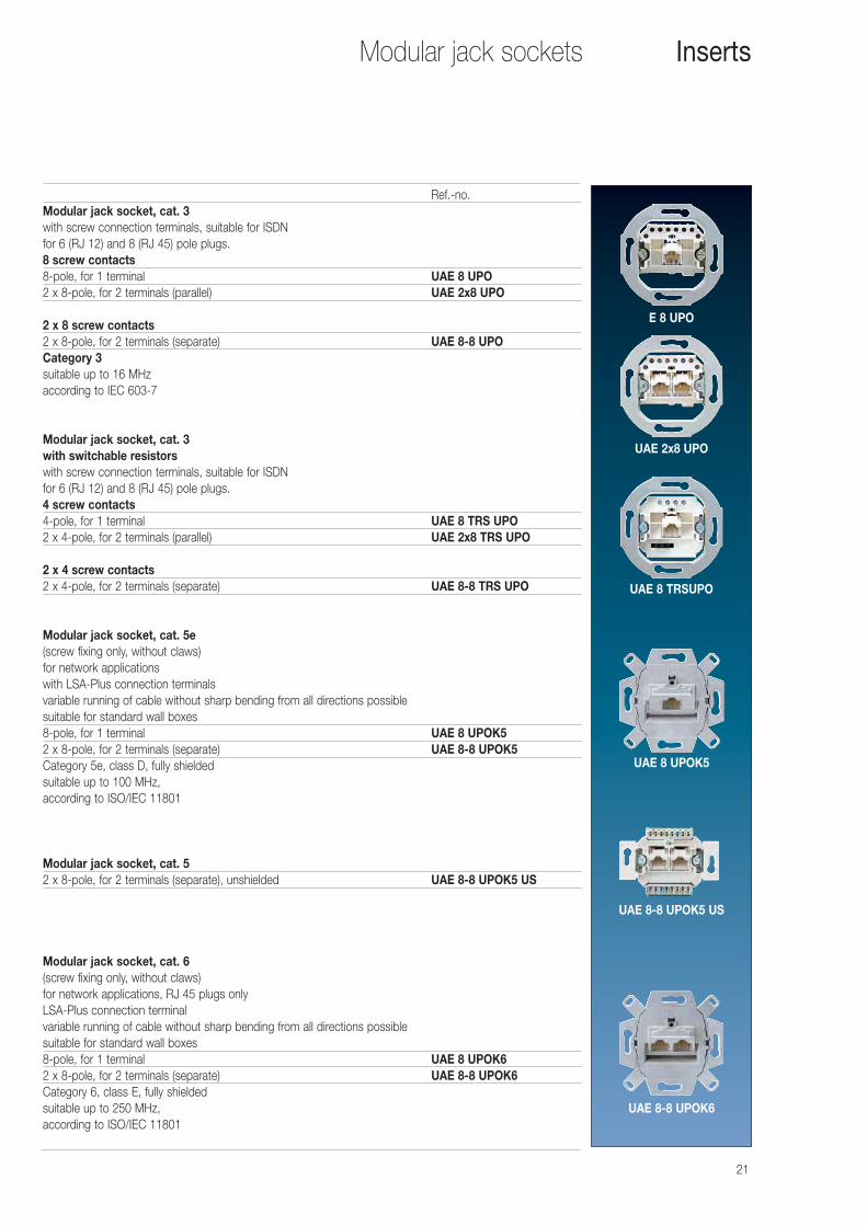
Ref.-no.Modular jack socket, cat. 3with screw connection terminals, suitable for ISDNfor 6 (RJ 12) and 8 (RJ 45) pole plugs.8 screw contacts8-pole, for 1 terminal UAE 8 UPO2 x 8-pole, for 2 terminals (parallel) UAE 2x8 UPO
2 x 8 screw contacts2 x 8-pole, for 2 terminals (separate) UAE 8-8 UPOCategory 3suitable up to 16 MHzaccording to IEC 603-7
Modular jack socket, cat. 3with switchable resistorswith screw connection terminals, suitable for ISDNfor 6 (RJ 12) and 8 (RJ 45) pole plugs.4 screw contacts4-pole, for 1 terminal UAE 8 TRS UPO2 x 4-pole, for 2 terminals (parallel) UAE 2x8 TRS UPO
2 x 4 screw contacts2 x 4-pole, for 2 terminals (separate) UAE 8-8 TRS UPO
Modular jack socket, cat. 5e(screw fixing only, without claws)for network applicationswith LSA-Plus connection terminalsvariable running of cable without sharp bending from all directions possiblesuitable for standard wall boxes8-pole, for 1 terminal UAE 8 UPOK52 x 8-pole, for 2 terminals (separate) UAE 8-8 UPOK5Category 5e, class D, fully shieldedsuitable up to 100 MHz,according to ISO/IEC 11801
Modular jack socket, cat. 52 x 8-pole, for 2 terminals (separate), unshielded UAE 8-8 UPOK5 US
Modular jack socket, cat. 6(screw fixing only, without claws)for network applications, RJ 45 plugs onlyLSA-Plus connection terminalvariable running of cable without sharp bending from all directions possiblesuitable for standard wall boxes8-pole, for 1 terminal UAE 8 UPOK62 x 8-pole, for 2 terminals (separate) UAE 8-8 UPOK6Category 6, class E, fully shieldedsuitable up to 250 MHz,according to ISO/IEC 11801
Inserts
E 8 UPO
UAE 2x8 UPO
UAE 8 TRSUPO
UAE 8 UPOK5
UAE 8-8 UPOK5 US
UAE 8-8 UPOK6
22
Modular jack sockets
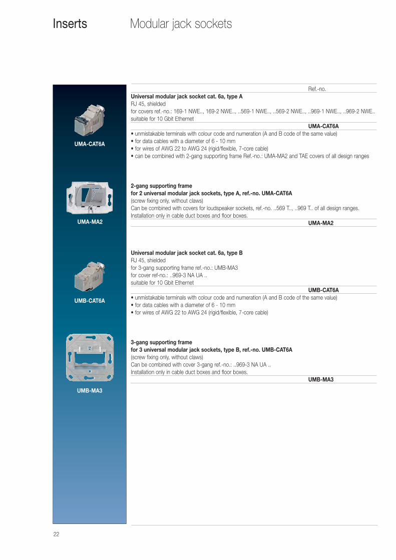
Ref.-no.Universal modular jack socket cat. 6a, type ARJ 45, shieldedfor covers ref.-no.: 169-1 NWE.., 169-2 NWE.., ..569-1 NWE.., ..569-2 NWE.., ..969-1 NWE.., ..969-2 NWE..suitable for 10 Gbit Ethernet
UMA-CAT6A• unmistakable terminals with colour code and numeration (A and B code of the same value)• for data cables with a diameter of 6 - 10 mm• for wires of AWG 22 to AWG 24 (rigid/flexible, 7-core cable)• can be combined with 2-gang supporting frame Ref.-no.: UMA-MA2 and TAE covers of all design ranges
2-gang supporting framefor 2 universal modular jack sockets, type A, ref.-no. UMA-CAT6A(screw fixing only, without claws)Can be combined with covers for loudspeaker sockets, ref.-no. ..569 T.., ..969 T.. of all design ranges.Installation only in cable duct boxes and floor boxes.
UMA-MA2
Universal modular jack socket cat. 6a, type BRJ 45, shieldedfor 3-gang supporting frame ref.-no.: UMB-MA3for cover ref-no.: ..969-3 NA UA ..suitable for 10 Gbit Ethernet
UMB-CAT6A• unmistakable terminals with colour code and numeration (A and B code of the same value)• for data cables with a diameter of 6 - 10 mm• for wires of AWG 22 to AWG 24 (rigid/flexible, 7-core cable)
3-gang supporting framefor 3 universal modular jack sockets, type B, ref.-no. UMB-CAT6A(screw fixing only, without claws)Can be combined with cover 3-gang ref.-no.: ..969-3 NA UA ..Installation only in cable duct boxes and floor boxes.
UMB-MA3
Inserts
UMA-CAT6A
UMB-CAT6A
UMB-MA3
UMA-MA2
23
SAT-TV-FM-sockets
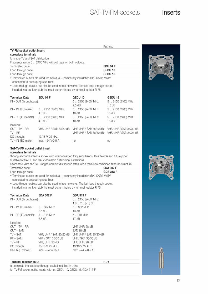
Ref.-no.TV-FM socket outlet insert screwless terminalsfor cable TV and SAT distributionFrequency range 5 ... 2400 MHz without gaps on both outputs.Terminated outlet EDU 04 FLoop through outlet GEDU 10Loop through outlet GEDU 15• Terminated outlets are used for individual + community installation (BK, CATV, MATV)
connected to decoupling stub lines• Loop through outlets can also be used in tree networks. The last loop through socket
installed in a trunk or stub line must be terminated by terminal resistor R 75.
Technical Data EDU 04 F GEDU 10 GEDU 15IN – OUT (throughpass): 5 ... 2150 (2400) MHz 5 ... 2150 (2400) MHz
2.5 dB 1.0 dBIN – TV (IEC male): 5 ... 2150 (2400) MHz 5 ... 2150 (2400) MHz 5 ... 2150 (2400) MHz
4.0 dB 10 dB 15 dBIN – RF (IEC female): 5 ... 2150 (2400) MHz 5 ... 2150 (2400) MHz 5 ... 2150 (2400) MHz
4.0 dB 10 dB 15 dBIsolation:OUT – TV – RF: VHF, UHF / SAT: 20/20 dB VHF, UHF / SAT: 35/20 dB VHF, UHF / SAT: 38/30 dBTV – RF: VHF, UHF / SAT: 38/30 dB VHF, UHF / SAT: 24/24 dBDC through: 13/18 V, 22 kHzTV – IN (IEC male): max. +24 V/0.5 A no no
SAT-TV-FM socket outlet insertscrewless terminals3-gang all-round antenna socket with interconnected frequency bands, thus flexible and future proof.Suitable for SAT IF and CATV domestic distribution installations.Seamless CATV and SAT ranges and low distribution attenuation thanks to combined filter-tap structure.Terminated outlet EDA 302 FLoop through outlet GDA 313 F• Terminated outlets are used for individual + community installation (BK, CATV, MATV)
connected to decoupling stub lines• Loop through outlets can also be used in tree networks. The last loop through socket
installed in a trunk or stub line must be terminated by terminal resistor R 75.
Technical Data EDA 302 F GDA 313 FIN – OUT (throughpass): 5 ... 2150 (2400) MHz
1.0 ... 2.0 (2.8) dBIN – TV (IEC male): 5 ... 862 MHz 5 ... 862 MHz
2.5 dB 13 dBIN – RF (IEC female): 5 ... 118 MHz 5 ...118 MHz
6.5 dB 17 dBIsolation:OUT – TV – RF: VHF, UHF: 28 dBOUT – SAT: SAT: 18 dBTV – SAT: VHF, UHF / SAT: 20/20 dB VHF, UHF / SAT: 20/20 dBRF – SAT: VHF / SAT: 35/30 dB VHF / SAT: 35/30 dBTV – RF: VHF, UHF: 20 dB VHF, UHF: 20 dBDC through: 13/18 V, 22 kHz 13/18 V, 22 kHzSAT-IN (F female): max. +24 V/0.5 A max. +24 V/0.5 A
Terminal resistor 75 Ω R 75to terminate the last loop through socket installed in a linefor TV-FM socket outlet inserts ref.-no.: GEDU 10, GEDU 15, GDA 313 F
Inserts
24
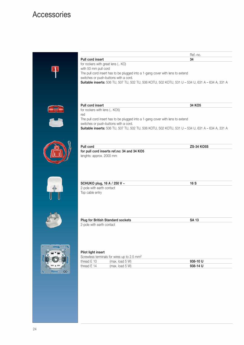
Ref.-no.Pull cord insert 34for rockers with great lens (.. KO)with 50 mm pull cordThe pull cord insert has to be plugged into a 1-gang cover with lens to extend switches or push-buttons with a cord.Suitable inserts: 506 TU, 507 TU, 502 TU, 506 KOTU, 502 KOTU, 531 U – 534 U, 631 A – 634 A, 331 A
Pull cord insert 34 KO5for rockers with lens (.. KO5)redThe pull cord insert has to be plugged into a 1-gang cover with lens to extend switches or push-buttons with a cord.Suitable inserts: 506 TU, 507 TU, 502 TU, 506 KOTU, 502 KOTU, 531 U – 534 U, 631 A – 634 A, 331 A
Pull cord ZS-34 KO5Sfor pull cord inserts ref.no: 34 and 34 KO5lenghts: approx. 2000 mm
SCHUKO plug, 16 A / 250 V ~ 16 S2-pole with earth contactTop cable entry
Plug for British Standard sockets SA 132-pole with earth contact
Pilot light insertScrewless terminals for wires up to 2.5 mm2
thread E 10 (max. load 5 W) 938-10 Uthread E 14 (max. load 5 W) 938-14 U
Accessories
25
Lamps
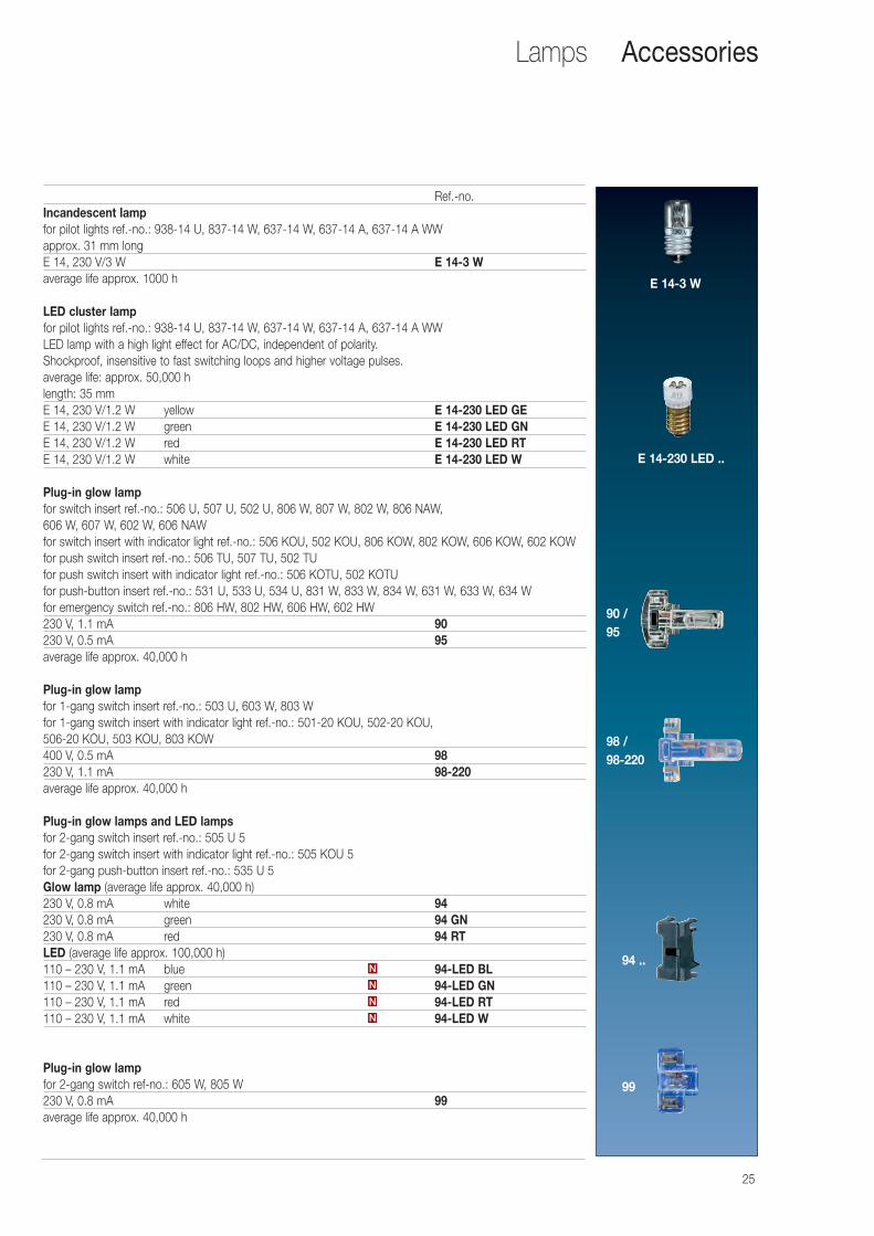
Ref.-no.Incandescent lampfor pilot lights ref.-no.: 938-14 U, 837-14 W, 637-14 W, 637-14 A, 637-14 A WWapprox. 31 mm longE 14, 230 V/3 W E 14-3 Waverage life approx. 1000 h
LED cluster lampfor pilot lights ref.-no.: 938-14 U, 837-14 W, 637-14 W, 637-14 A, 637-14 A WWLED lamp with a high light effect for AC/DC, independent of polarity.Shockproof, insensitive to fast switching loops and higher voltage pulses.average life: approx. 50,000 hlength: 35 mmE 14, 230 V/1.2 W yellow E 14-230 LED GEE 14, 230 V/1.2 W green E 14-230 LED GNE 14, 230 V/1.2 W red E 14-230 LED RTE 14, 230 V/1.2 W white E 14-230 LED W
Plug-in glow lampfor switch insert ref.-no.: 506 U, 507 U, 502 U, 806 W, 807 W, 802 W, 806 NAW, 606 W, 607 W, 602 W, 606 NAWfor switch insert with indicator light ref.-no.: 506 KOU, 502 KOU, 806 KOW, 802 KOW, 606 KOW, 602 KOWfor push switch insert ref.-no.: 506 TU, 507 TU, 502 TUfor push switch insert with indicator light ref.-no.: 506 KOTU, 502 KOTUfor push-button insert ref.-no.: 531 U, 533 U, 534 U, 831 W, 833 W, 834 W, 631 W, 633 W, 634 Wfor emergency switch ref.-no.: 806 HW, 802 HW, 606 HW, 602 HW230 V, 1.1 mA 90230 V, 0.5 mA 95average life approx. 40,000 h
Plug-in glow lampfor 1-gang switch insert ref.-no.: 503 U, 603 W, 803 Wfor 1-gang switch insert with indicator light ref.-no.: 501-20 KOU, 502-20 KOU, 506-20 KOU, 503 KOU, 803 KOW400 V, 0.5 mA 98230 V, 1.1 mA 98-220average life approx. 40,000 h
Plug-in glow lamps and LED lampsfor 2-gang switch insert ref.-no.: 505 U 5for 2-gang switch insert with indicator light ref.-no.: 505 KOU 5for 2-gang push-button insert ref.-no.: 535 U 5Glow lamp (average life approx. 40,000 h)230 V, 0.8 mA white 94 230 V, 0.8 mA green 94 GN230 V, 0.8 mA red 94 RTLED (average life approx. 100,000 h)110 – 230 V, 1.1 mA blue 94-LED BL110 – 230 V, 1.1 mA green 94-LED GN110 – 230 V, 1.1 mA red 94-LED RT110 – 230 V, 1.1 mA white 94-LED W
Plug-in glow lampfor 2-gang switch ref-no.: 605 W, 805 W230 V, 0.8 mA 99average life approx. 40,000 h
N
N
N
N
Accessories
E 14-3 W
E 14-230 LED ..
90 /95
99
98 /98-220
94 ..
26
Lamps
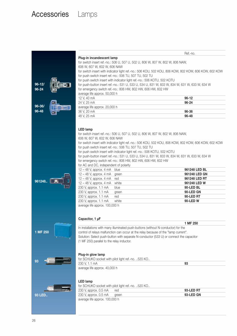
Ref.-no.Plug-in incandescent lampfor switch insert ref.-no.: 506 U, 507 U, 502 U, 806 W, 807 W, 802 W, 806 NAW, 606 W, 607 W, 602 W, 606 NAWfor switch insert with indicator light ref.-no.: 506 KOU, 502 KOU, 806 KOW, 802 KOW, 606 KOW, 602 KOWfor push switch insert ref.-no.: 506 TU, 507 TU, 502 TUfor push switch insert with indicator light ref.-no.: 506 KOTU, 502 KOTUfor push-button insert ref.-no.: 531 U, 533 U, 534 U, 831 W, 833 W, 834 W, 631 W, 633 W, 634 Wfor emergency switch ref.-no.: 806 HW, 802 HW, 606 HW, 602 HWaverage life approx. 50,000 h12 V, 40 mA 96-1224 V, 25 mA 96-24average life approx. 20,000 h36 V, 20 mA 96-3648 V, 25 mA 96-48
LED lampfor switch insert ref.-no.: 506 U, 507 U, 502 U, 806 W, 807 W, 802 W, 806 NAW, 606 W, 607 W, 602 W, 606 NAWfor switch insert with indicator light ref.-no.: 506 KOU, 502 KOU, 806 KOW, 802 KOW, 606 KOW, 602 KOWfor push switch insert ref.-no.: 506 TU, 507 TU, 502 TUfor push switch insert with indicator light ref.-no.: 506 KOTU, 502 KOTUfor push-button insert ref.-no.: 531 U, 533 U, 534 U, 831 W, 833 W, 834 W, 631 W, 633 W, 634 Wfor emergency switch ref.-no.: 806 HW, 802 HW, 606 HW, 602 HWfor AC and DC, independent of polarity12 – 48 V, approx. 4 mA blue 961248 LED BL12 – 48 V, approx. 4 mA green 961248 LED GN12 – 48 V, approx. 4 mA red 961248 LED RT12 – 48 V, approx. 4 mA white 961248 LED W230 V, approx. 1.1 mA blue 90-LED BL230 V, approx. 1.1 mA green 90-LED GN230 V, approx. 1.1 mA red 90-LED RT230 V, approx. 1.1 mA white 90-LED Waverage life approx. 100,000 h
Capacitor, 1 μF1 MF 250
In installations with many illuminated push-buttons (without N-conductor) for the control of relays malfunction can occur at the relay because of the "lamp current".Solution: Select push-button with separate N-conductor (533 U) or connect the capacitor (1 MF 250) parallel to the relay inductor.
Plug-in glow lampfor SCHUKO socket with pilot light ref.-no. ..520 KO..230 V, 1.1 mA 93average life approx. 40,000 h
LED lampfor SCHUKO socket with pilot light ref.-no. ..520 KO..230 V, approx. 0.5 mA red 93-LED RT230 V, approx. 0.5 mA green 93-LED GNaverage life approx. 100,000 h
Accessories
93
96-12/96-24
961248..
1 MF 250
93 LED..
96-36/96-48
27
Wall boxes
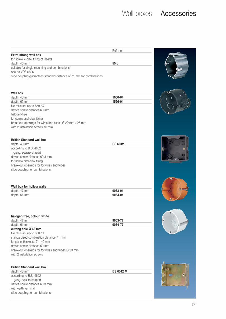
Ref.-no.Extra strong wall boxfor screw + claw fixing of insertsdepth: 40 mm 55 Lsuitable for single mounting and combinationsacc. to VDE 0606slide coupling guarantees standard distance of 71 mm for combinations
Wall boxdepth: 46 mm 1056-04depth: 63 mm 1556-04fire resistant up to 650 °Cdevice screw distance 60 mmhalogen-free for screw and claw fixingbreak-out openings for wires and tubes Ø 20 mm / 25 mmwith 2 installation screws 15 mm
British Standard wall boxdepth: 40 mm BS 6042according to B.S. 46621-gang, square shapeddevice screw distance 60.3 mm for screw and claw fixingbreak-out openings for for wires and tubesslide coupling for combinations
Wall box for hollow wallsdepth: 47 mm 9063-01depth: 61 mm 9064-01
halogen-free, colour: whitedepth: 47 mm 9063-77depth: 61 mm 9064-77cutting hole Ø 68 mmfire resistant up to 850 °Cstandardised combination distance 71 mmfor panel thickness 7 – 40 mmdevice screw distance 60 mmbreak-out openings for for wires and tubes Ø 20 mm with 2 installation screws
British Standard wall boxdepth: 48 mm BS 6042 Maccording to B.S. 46621-gang, square shapeddevice screw distance 60.3 mm with earth terminalslide coupling for combinations
Accessories
28
Audio devicesAccessories
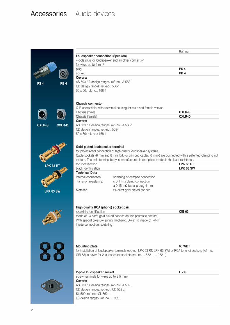
Ref.-no.Loudspeaker connection (Speakon)4-pole plug for loudspeaker and amplifier connectionfor wires up to 4 mm2
plug PS 4socket PB 4Covers:AS 500 / A design ranges: ref.-no.: A 568-1CD design ranges: ref.-no.: 568-150 x 50: ref.-no.: 168-1
Chassis connectorXLR compatible, with universal housing for male and female versionChassis (male) CXLR-SChassis (female) CXLR-DCovers:AS 500 / A design ranges: ref.-no.: A 568-1CD design ranges: ref.-no.: 568-150 x 50: ref.-no.: 168-1
Gold-plated loudspeaker terminalfor professional connection of high quality loudspeaker systems.Cable sockets (6 mm and 8 mm fork) or crimped cables (6 mm2) are connected with a patented clamping nutsystem. The pole terminal body is manufactured in one piece to obtain the least resistance.red identification LPK 63 RTblack identification LPK 63 SWTechnical Data Internal connection: soldering or crimped connectionTransition resistance: ≤ 0.1 mΩ clamp connection
≤ 0.15 mΩ banana plug 4 mmMaterial: 24 carat gold-plated copper
High quality RCA (phono) socket pairred/white identification CIB 63made of 24 carat gold plated copper, double prismatic contact.With special pressure spring mechanic. Dielectric made of Teflon.Inside connection: soldering
Mounting plate 63 WBTfor installation of loudspeaker terminals (ref.-no. LPK 63 RT, LPK 63 SW) or RCA (phono) sockets (ref.-no.CIB 63) in cover for 2 loudspeaker sockets (ref.-no. .. 562 .., .. 962 ..)
2-pole loudspeaker socket L 2 Sscrew terminals for wires up to 2,5 mm2
Covers:AS 500 / A design ranges: ref.-no.: A 562 ..CD design ranges: ref.-no.: CD 562 ..SL 500: ref.-no.: SL 562 ..LS design ranges: ref.-no.: .. 962 ..
PS 4 PB 4
CXLR-S CXLR-D
LPK 63 RT
LPK 63 SW
29
Audio devices
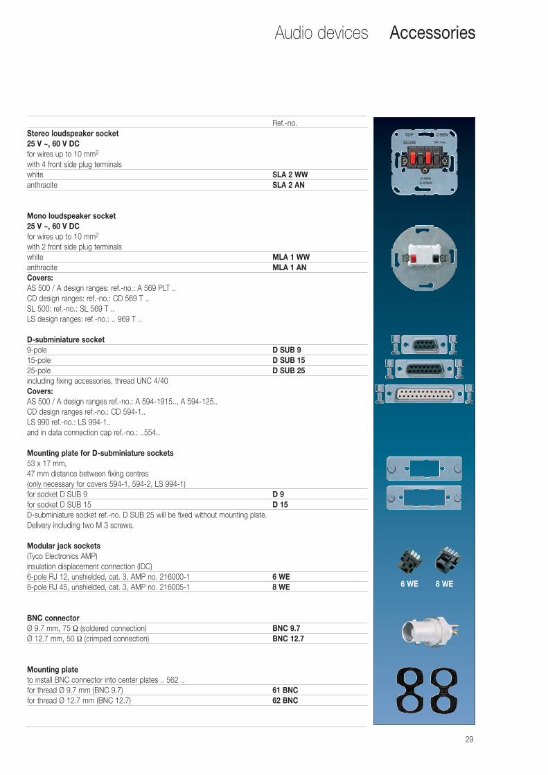
Ref.-no.Stereo loudspeaker socket25 V ~, 60 V DCfor wires up to 10 mm2
with 4 front side plug terminalswhite SLA 2 WWanthracite SLA 2 AN
Mono loudspeaker socket25 V ~, 60 V DCfor wires up to 10 mm2
with 2 front side plug terminalswhite MLA 1 WWanthracite MLA 1 ANCovers:AS 500 / A design ranges: ref.-no.: A 569 PLT ..CD design ranges: ref.-no.: CD 569 T ..SL 500: ref.-no.: SL 569 T ..LS design ranges: ref.-no.: .. 969 T ..
D-subminiature socket9-pole D SUB 915-pole D SUB 1525-pole D SUB 25including fixing accessories, thread UNC 4/40Covers:AS 500 / A design ranges ref.-no.: A 594-1915.., A 594-125..CD design ranges ref.-no.: CD 594-1..LS 990 ref.-no.: LS 994-1..and in data connection cap ref.-no.: ..554..
Mounting plate for D-subminiature sockets53 x 17 mm,47 mm distance between fixing centres(only necessary for covers 594-1, 594-2, LS 994-1)for socket D SUB 9 D 9for socket D SUB 15 D 15D-subminiature socket ref.-no. D SUB 25 will be fixed without mounting plate.Delivery including two M 3 screws.
Modular jack sockets(Tyco Electronics AMP)insulation displacement connection (IDC)6-pole RJ 12, unshielded, cat. 3, AMP no. 216000-1 6 WE8-pole RJ 45, unshielded, cat. 3, AMP no. 216005-1 8 WE
BNC connectorØ 9.7 mm, 75 Ω (soldered connection) BNC 9.7Ø 12.7 mm, 50 Ω (crimped connection) BNC 12.7
Mounting plateto install BNC connector into center plates .. 562 ..for thread Ø 9.7 mm (BNC 9.7) 61 BNCfor thread Ø 12.7 mm (BNC 12.7) 62 BNC
Accessories
6 WE 8 WE
30
Data connection housing
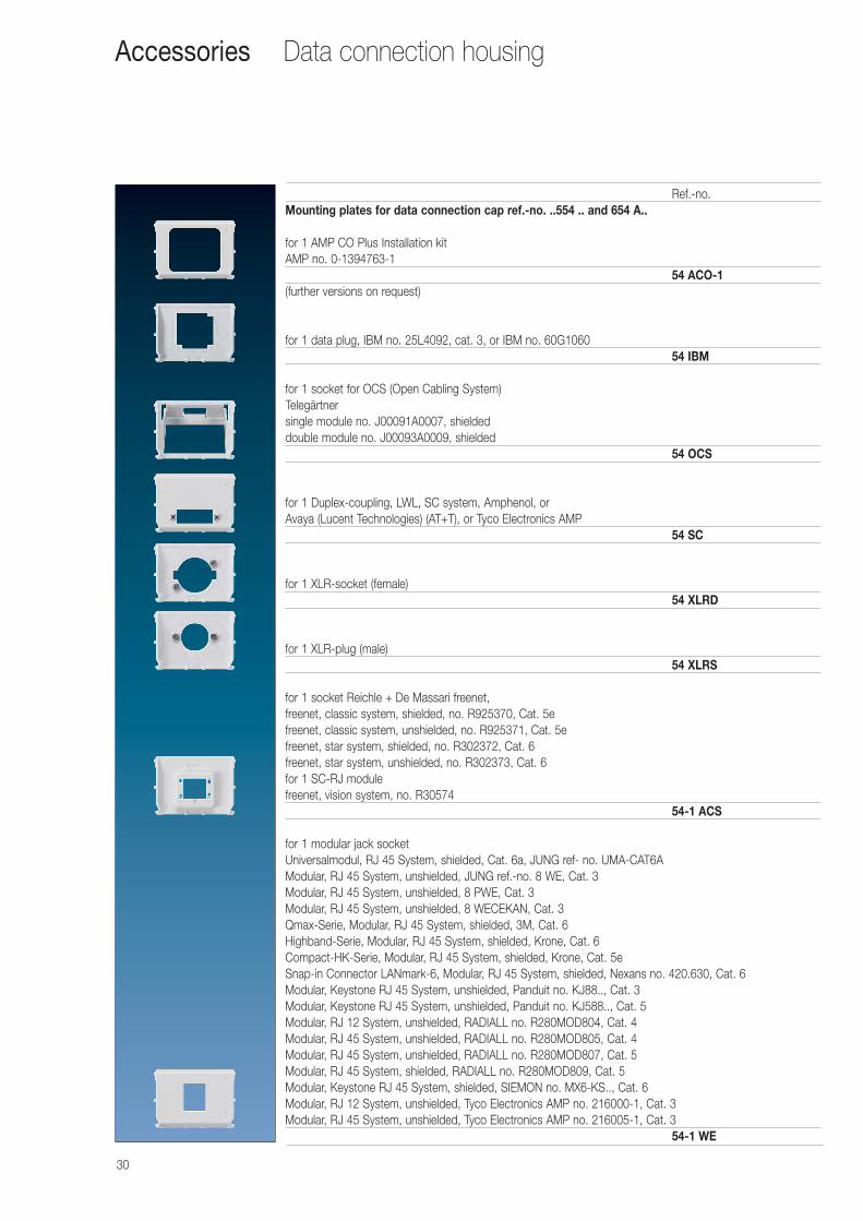
Ref.-no.Mounting plates for data connection cap ref.-no. ..554 .. and 654 A..
for 1 AMP CO Plus Installation kit AMP no. 0-1394763-1
54 ACO-1(further versions on request)
for 1 data plug, IBM no. 25L4092, cat. 3, or IBM no. 60G106054 IBM
for 1 socket for OCS (Open Cabling System)Telegärtnersingle module no. J00091A0007, shieldeddouble module no. J00093A0009, shielded
54 OCS
for 1 Duplex-coupling, LWL, SC system, Amphenol, orAvaya (Lucent Technologies) (AT+T), or Tyco Electronics AMP
54 SC
for 1 XLR-socket (female)54 XLRD
for 1 XLR-plug (male)54 XLRS
for 1 socket Reichle + De Massari freenet,freenet, classic system, shielded, no. R925370, Cat. 5efreenet, classic system, unshielded, no. R925371, Cat. 5efreenet, star system, shielded, no. R302372, Cat. 6freenet, star system, unshielded, no. R302373, Cat. 6for 1 SC-RJ modulefreenet, vision system, no. R30574
54-1 ACS
for 1 modular jack socketUniversalmodul, RJ 45 System, shielded, Cat. 6a, JUNG ref- no. UMA-CAT6AModular, RJ 45 System, unshielded, JUNG ref.-no. 8 WE, Cat. 3Modular, RJ 45 System, unshielded, 8 PWE, Cat. 3Modular, RJ 45 System, unshielded, 8 WECEKAN, Cat. 3Qmax-Serie, Modular, RJ 45 System, shielded, 3M, Cat. 6Highband-Serie, Modular, RJ 45 System, shielded, Krone, Cat. 6Compact-HK-Serie, Modular, RJ 45 System, shielded, Krone, Cat. 5eSnap-in Connector LANmark-6, Modular, RJ 45 System, shielded, Nexans no. 420.630, Cat. 6Modular, Keystone RJ 45 System, unshielded, Panduit no. KJ88.., Cat. 3Modular, Keystone RJ 45 System, unshielded, Panduit no. KJ588.., Cat. 5Modular, RJ 12 System, unshielded, RADIALL no. R280MOD804, Cat. 4Modular, RJ 45 System, unshielded, RADIALL no. R280MOD805, Cat. 4Modular, RJ 45 System, unshielded, RADIALL no. R280MOD807, Cat. 5Modular, RJ 45 System, shielded, RADIALL no. R280MOD809, Cat. 5Modular, Keystone RJ 45 System, shielded, SIEMON no. MX6-KS.., Cat. 6Modular, RJ 12 System, unshielded, Tyco Electronics AMP no. 216000-1, Cat. 3Modular, RJ 45 System, unshielded, Tyco Electronics AMP no. 216005-1, Cat. 3
54-1 WE
Accessories
31
Data connection housing
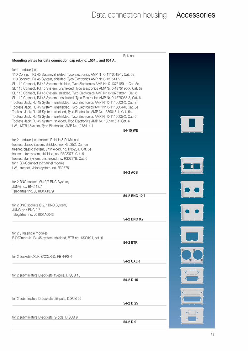
Ref.-no.Mounting plates for data connection cap ref.-no. ..554 .. and 654 A..
for 1 modular jack110 Connect, RJ 45 System, shielded, Tyco Electronics AMP Nr. 0-1116515-1, Cat. 5e110 Connect, RJ 45 System, shielded, Tyco Electronics AMP Nr. 0-1375117-1 SL 110 Connect, RJ 45 System, shielded, Tyco Electronics AMP Nr. 0-1375189-1, Cat. 5eSL 110 Connect, RJ 45 System, unshielded, Tyco Electronics AMP Nr. 0-1375190-X, Cat. 5eSL 110 Connect, RJ 45 System, shielded, Tyco Electronics AMP Nr. 0-1375188-1, Cat. 6 SL 110 Connect, RJ 45 System, unshielded, Tyco Electronics AMP Nr. 0-1375055-3, Cat. 6 Toolless Jack, RJ 45 System, unshielded, Tyco Electronics AMP Nr. 0-1116603-X, Cat. 3Toolless Jack, RJ 45 System, unshielded, Tyco Electronics AMP Nr. 0-1116604-X, Cat. 5e Toolless Jack, RJ 45 System, shielded, Tyco Electronics AMP Nr. 1339015-1, Cat. 5eToolless Jack, RJ 45 System, unshielded, Tyco Electronics AMP Nr. 0-1116605-X, Cat. 6 Toolless Jack, RJ 45 System, shielded, Tyco Electronics AMP Nr. 1339016-1, Cat. 6LWL, MTRJ System, Tyco Electronics AMP Nr. 1278414-1
54-15 WE
for 2 modular jack sockets Reichle & DeMassarifreenet, classic system, shielded, no. R35252, Cat. 5efreenet, classic system, unshielded, no. R35251, Cat. 5efreenet, star system, shielded, no. R302377, Cat. 6freenet, star system, unshielded, no. R302378, Cat. 6for 1 SC-Compact 2-channel moduleLWL, freenet, vision system, no. R30575
54-2 ACS
for 2 BNC-sockets Ø 12,7 BNC System,JUNG no.: BNC 12.7Telegärtner no. J01001A1379
54-2 BNC 12.7
for 2 BNC sockets Ø 9,7 BNC System,JUNG no.: BNC 9.7Telegärtner no. J01001A0043
54-2 BNC 9.7
for 2 8 (8) single modulesE-DATmodule, RJ 45 system, shielded, BTR no. 130910-i, cat. 6
54-2 BTR
for 2 sockets CXLR-S/CXLR-D; PB 4/PS 454-2 CXLR
for 2 subminiature D-sockets,15-pole, D SUB 1554-2 D 15
for 2 subminiature D-sockets, 25-pole, D SUB 2554-2 D 25
for 2 subminiature D-sockets, 9-pole, D SUB 954-2 D 9
Accessories

32
Data connection housing
Ref.-no.Mounting plates for data connection cap ref.-no. ..554 .. and 654 A..
for 2 modular jack sockets 8 FWE,semi-shielded, cat. 3Tyco Electronics AMP 569013-1
54-2 FWE
for 2 modular jack sockets 8-pole (RJ 45)Kannegieter type TP-Connectand type MOD-TAP system 100 (MODO746)
54 TPC
for 2 TWINAX sockets, Tyco Electronics AMP 135019-154-2 TWINAX
for 2 AMP CHAMP sockets (centronics 24-pole)54-2 CHAMP
for 2 modular jack sockets Avaya (Lucent / AT&T)M1 series, type M1BH.., MPS100BH.., MGS200BH..
54-2 AT
safety cap for 54-2 WE and 54-2 AT(protection against plug-off)
54 WEV
for 2 modular jack sockets type LAN Connect 808MK2, cat. 5, shielded,or LAN Connect 808MK3, cat. 6, shielded
54-2 ITT
for 2 modular jack sockets IBM Advanced Connectivity System (ACS)or Generic Footprint (GFP) types 11K9586, cat. 5e;11K9439, cat. 5e; 11K9587, cat. 6; 29P5118, cat. 6; 11K9663, cat. 5e;11K9661, cat. 5e; 11K9667, cat. 6; 11K9665, cat. 6
54-2 GFP
for 2 couplings, LWL (optic fibre), ST, 2,5 mm bayonet nut connector (BNC)54-2 LWL
for 2 Duplex couplings (optic fibre)LWL, SC system, AmphenolLWL, SC system, Avaya (Lucent Technologies) (AT+T)LWL, SC system, Tyco Electronics AMP
54-2 SC
Accessories
33
Data connection housing
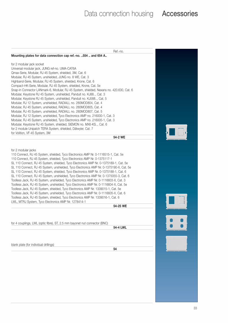
Ref.-no.Mounting plates for data connection cap ref.-no. ..554 .. and 654 A..
for 2 modular jack socketUniversal modular jack, JUNG ref-no. UMA-CAT6AQmax-Serie, Modular, RJ 45 System, shielded, 3M, Cat. 6Modular, RJ 45 System, unshielded, JUNG no. 8 WE, Cat. 3Highband-Serie, Modular, RJ 45 System, shielded, Krone, Cat. 6Compact-HK-Serie, Modular, RJ 45 System, shielded, Krone, Cat. 5eSnap-in Connector LANmark-6, Modular, RJ 45 System, shielded, Nexans no. 420.630, Cat. 6Modular, Keystone RJ 45 System, unshielded, Panduit no. KJ88.., Cat. 3Modular, Keystone RJ 45 System, unshielded, Panduit no. KJ588.., Cat. 5Modular, RJ 12 System, unshielded, RADIALL no. 280MOD804, Cat. 4Modular, RJ 45 System, unshielded, RADIALL no. 280MOD805, Cat. 4Modular, RJ 45 System, unshielded, RADIALL no. 280MOD807, Cat. 5Modular, RJ 12 System, unshielded, Tyco Electronics AMP no. 216000-1, Cat. 3Modular, RJ 45 System, unshielded, Tyco Electronics AMP no. 216005-1, Cat. 3Modular, Keystone RJ 45 System, shielded, SIEMON no. MX6-KS.., Cat. 6for 2 module Unipatch TERA System, shielded, Dätwyler, Cat. 7for Volition, VF-45 System, 3M
54-2 WE
for 2 modular jacks110 Connect, RJ 45 System, shielded, Tyco Electronics AMP Nr. 0-1116515-1, Cat. 5e110 Connect, RJ 45 System, shielded, Tyco Electronics AMP Nr. 0-1375117-1 SL 110 Connect, RJ 45 System, shielded, Tyco Electronics AMP Nr. 0-1375189-1, Cat. 5eSL 110 Connect, RJ 45 System, unshielded, Tyco Electronics AMP Nr. 0-1375190-X, Cat. 5eSL 110 Connect, RJ 45 System, shielded, Tyco Electronics AMP Nr. 0-1375188-1, Cat. 6 SL 110 Connect, RJ 45 System, unshielded, Tyco Electronics AMP Nr. 0-1375055-3, Cat. 6 Toolless Jack, RJ 45 System, unshielded, Tyco Electronics AMP Nr. 0-1116603-X, Cat. 3Toolless Jack, RJ 45 System, unshielded, Tyco Electronics AMP Nr. 0-1116604-X, Cat. 5e Toolless Jack, RJ 45 System, shielded, Tyco Electronics AMP Nr. 1339015-1, Cat. 5eToolless Jack, RJ 45 System, unshielded, Tyco Electronics AMP Nr. 0-1116605-X, Cat. 6 Toolless Jack, RJ 45 System, shielded, Tyco Electronics AMP Nr. 1339016-1, Cat. 6LWL, MTRJ System, Tyco Electronics AMP Nr. 1278414-1
54-25 WE
for 4 couplings, LWL (optic fibre), ST, 2.5 mm bayonet nut connector (BNC)54-4 LWL
blank plate (for individual drillings)54
Accessories
34
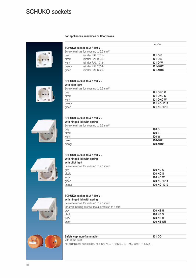
Ref.-no.SCHUKO socket 16 A / 250 V ~Screw terminals for wires up to 2.5 mm2
grey (similar RAL 7035) 121 O Gblack (similar RAL 9005) 121 O Sivory (similar RAL 1013) 121 O Worange (similar RAL 2004) 121-1017green (similar RAL 6029) 121-1018
SCHUKO socket 16 A / 250 V ~with pilot lightScrew terminals for wires up to 2.5 mm2
grey 121 OKO Gblack 121 OKO Sivory 121 OKO Worange 121 KO-1017green 121 KO-1018
SCHUKO socket 16 A / 250 V ~with hinged lid (with spring)Screw terminals for wires up to 2.5 mm2
grey 120 Gblack 120 Sivory 120 Wgreen 120-1011orange 120-1012
SCHUKO socket 16 A / 250 V ~with hinged lid (with spring)with pilot lightScrew terminals for wires up to 2.5 mm2
grey 120 KO Gblack 120 KO Sivory 120 KO Wgreen 120 KO-1011orange 120 KO-1012
SCHUKO socket 16 A / 250 V ~with hinged lid (with spring)Screw terminals for wires up to 2.5 mm2
for snap-in fixing in sheet metal plates up to 1 mmgrey 120 KB Gblack 120 KB Sivory 120 KB Wgreen 120 KB GN
Safety cap, non-flammable 121 DOwith strain reliefnot suitable for sockets ref.-no.: 120 KO.., 120 KB.., 121 KO.. and 121 OKO..
SCHUKO sockets
For appliances, machines or floor boxes
35
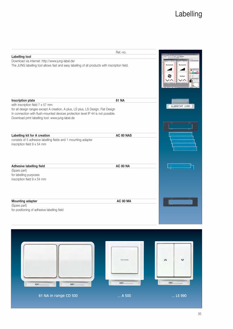
Ref.-no.Labelling toolDownload via internet: http://www.jung-label.de/The JUNG labelling tool allows fast and easy labelling of all products with inscription field.
Inscription plate 61 NAwith inscription field 7 x 57 mmfor all design ranges except A creation, A plus, LS plus, LS Design, Flat DesignIn connection with flush-mounted devices protection level IP 44 is not possible.Download print labelling tool: www.jung-label.de
Labelling kit for A creation AC 80 NASconsists of 5 adhesive labelling fields and 1 mounting adapterinscription field 9 x 54 mm
Adhesive labelling field AC 80 NA(Spare part)for labelling purposesinscription field 9 x 54 mm
Mounting adapter AC 80 MA(Spare part)for positioning of adhesive labelling field
Labelling
61 NA in range CD 500 ... A 500 ... LS 990
36
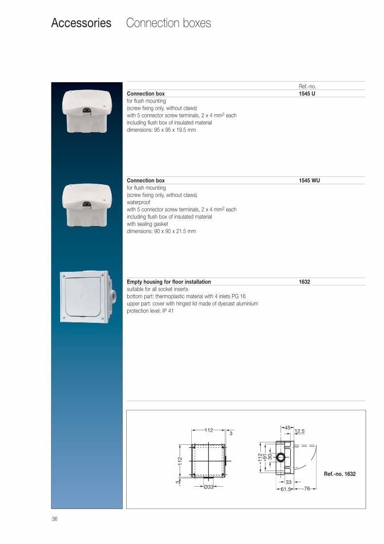
Ref.-no.Connection box 1545 Ufor flush mounting(screw fixing only, without claws)with 5 connector screw terminals, 2 x 4 mm2 eachincluding flush box of insulated materialdimensions: 95 x 95 x 19.5 mm
Connection box 1545 WUfor flush mounting(screw fixing only, without claws)waterproofwith 5 connector screw terminals, 2 x 4 mm2 eachincluding flush box of insulated materialwith sealing gasketdimensions: 90 x 90 x 21.5 mm
Empty housing for floor installation 1632suitable for all socket insertsbottom part: thermoplastic material with 4 inlets PG 16upper part: cover with hinged lid made of dyecast aluminiumprotection level: IP 41
3
3
Ø33
112
112
4512.5
33
30
~7661.5
ˇ̌ 112
ˇ̌ 91
Connection boxesAccessories
Ref.-no. 1632
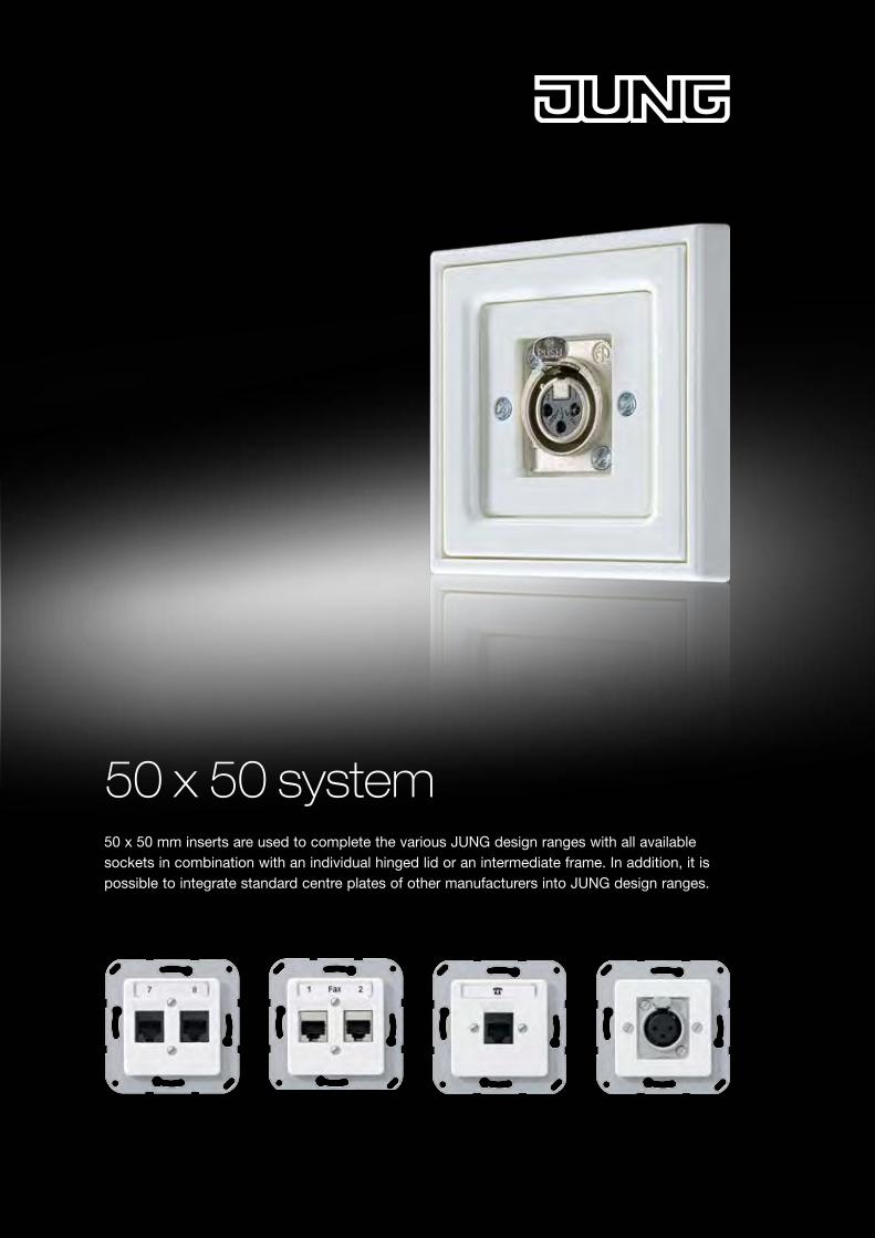
50 x 50 system50 x 50 mm inserts are used to complete the various JUNG design ranges with all available sockets in combination with an individual hinged lid or an intermediate frame. In addition, it is possible to integrate standard centre plates of other manufacturers into JUNG design ranges.
38
50 x 50 mm system
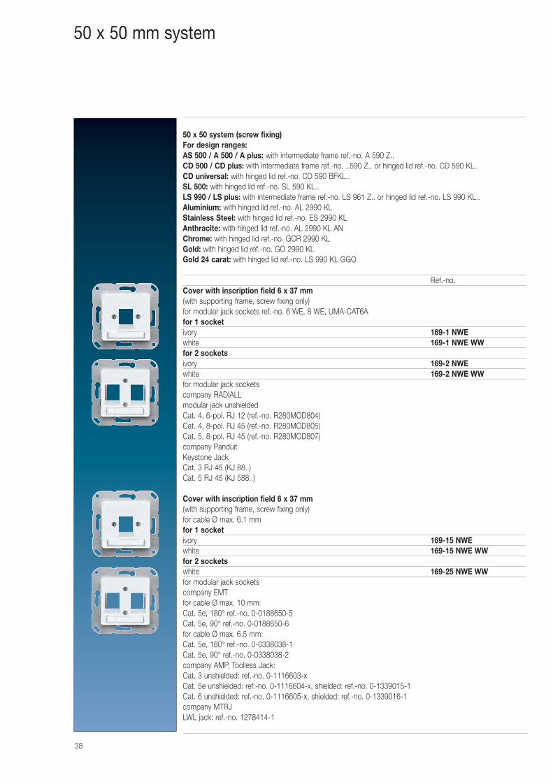
50 x 50 system (screw fixing)For design ranges:AS 500 / A 500 / A plus: with intermediate frame ref.-no. A 590 Z..CD 500 / CD plus: with intermediate frame ref.-no. ..590 Z.. or hinged lid ref.-no. CD 590 KL..CD universal: with hinged lid ref.-no. CD 590 BFKL..SL 500: with hinged lid ref.-no. SL 590 KL..LS 990 / LS plus: with intermediate frame ref.-no. LS 961 Z.. or hinged lid ref.-no. LS 990 KL..Aluminium: with hinged lid ref.-no. AL 2990 KLStainless Steel: with hinged lid ref.-no. ES 2990 KLAnthracite: with hinged lid ref.-no. AL 2990 KL ANChrome: with hinged lid ref.-no. GCR 2990 KLGold: with hinged lid ref.-no. GO 2990 KLGold 24 carat: with hinged lid ref.-no. LS 990 KL GGO
Ref.-no.Cover with inscription field 6 x 37 mm(with supporting frame, screw fixing only)for modular jack sockets ref.-no. 6 WE, 8 WE, UMA-CAT6Afor 1 socketivory 169-1 NWEwhite 169-1 NWE WWfor 2 socketsivory 169-2 NWEwhite 169-2 NWE WWfor modular jack socketscompany RADIALL modular jack unshieldedCat. 4, 6-pol. RJ 12 (ref.-no. R280MOD804)Cat. 4, 8-pol. RJ 45 (ref.-no. R280MOD805)Cat. 5, 8-pol. RJ 45 (ref.-no. R280MOD807)company Panduit Keystone JackCat. 3 RJ 45 (KJ 88..)Cat. 5 RJ 45 (KJ 588..)
Cover with inscription field 6 x 37 mm(with supporting frame, screw fixing only)for cable Ø max. 6.1 mmfor 1 socketivory 169-15 NWEwhite 169-15 NWE WWfor 2 socketswhite 169-25 NWE WWfor modular jack socketscompany EMTfor cable Ø max. 10 mm:Cat. 5e, 180° ref.-no. 0-0188650-5Cat. 5e, 90° ref.-no. 0-0188650-6for cable Ø max. 6.5 mm:Cat. 5e, 180° ref.-no. 0-0338038-1Cat. 5e, 90° ref.-no. 0-0338038-2company AMP, Toolless Jack:Cat. 3 unshielded: ref.-no. 0-1116603-xCat. 5e unshielded: ref.-no. 0-1116604-x, shielded: ref.-no. 0-1339015-1Cat. 6 unshielded: ref.-no. 0-1116605-x, shielded: ref.-no. 0-1339016-1company MTRJLWL jack: ref.-no. 1278414-1
39
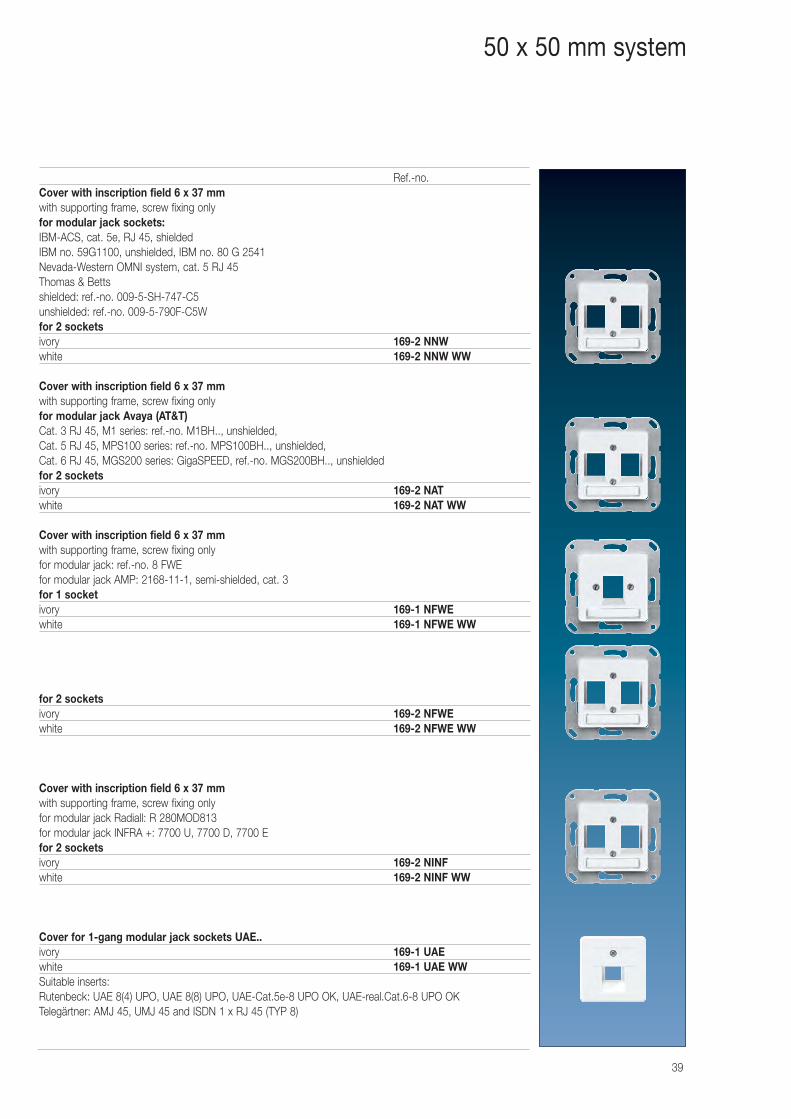
Ref.-no.Cover with inscription field 6 x 37 mmwith supporting frame, screw fixing onlyfor modular jack sockets:IBM-ACS, cat. 5e, RJ 45, shieldedIBM no. 59G1100, unshielded, IBM no. 80 G 2541Nevada-Western OMNI system, cat. 5 RJ 45Thomas & Bettsshielded: ref.-no. 009-5-SH-747-C5unshielded: ref.-no. 009-5-790F-C5Wfor 2 socketsivory 169-2 NNWwhite 169-2 NNW WW
Cover with inscription field 6 x 37 mmwith supporting frame, screw fixing onlyfor modular jack Avaya (AT&T)Cat. 3 RJ 45, M1 series: ref.-no. M1BH.., unshielded,Cat. 5 RJ 45, MPS100 series: ref.-no. MPS100BH.., unshielded,Cat. 6 RJ 45, MGS200 series: GigaSPEED, ref.-no. MGS200BH.., unshieldedfor 2 socketsivory 169-2 NATwhite 169-2 NAT WW
Cover with inscription field 6 x 37 mmwith supporting frame, screw fixing onlyfor modular jack: ref.-no. 8 FWEfor modular jack AMP: 2168-11-1, semi-shielded, cat. 3for 1 socketivory 169-1 NFWEwhite 169-1 NFWE WW
for 2 socketsivory 169-2 NFWEwhite 169-2 NFWE WW
Cover with inscription field 6 x 37 mmwith supporting frame, screw fixing onlyfor modular jack Radiall: R 280MOD813for modular jack INFRA +: 7700 U, 7700 D, 7700 Efor 2 socketsivory 169-2 NINFwhite 169-2 NINF WW
Cover for 1-gang modular jack sockets UAE..ivory 169-1 UAEwhite 169-1 UAE WWSuitable inserts:Rutenbeck: UAE 8(4) UPO, UAE 8(8) UPO, UAE-Cat.5e-8 UPO OK, UAE-real.Cat.6-8 UPO OKTelegärtner: AMJ 45, UMJ 45 and ISDN 1 x RJ 45 (TYP 8)
50 x 50 mm system
40
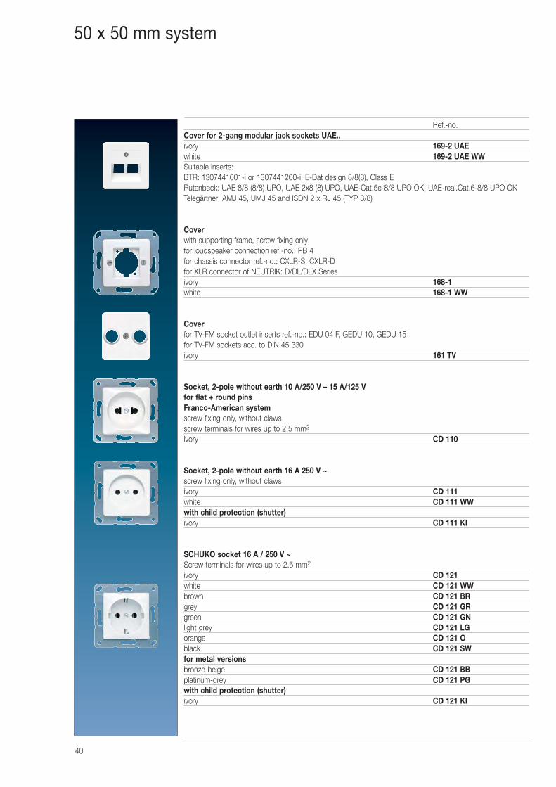
Ref.-no.Cover for 2-gang modular jack sockets UAE..ivory 169-2 UAEwhite 169-2 UAE WWSuitable inserts:BTR: 1307441001-i or 1307441200-i; E-Dat design 8/8(8), Class ERutenbeck: UAE 8/8 (8/8) UPO, UAE 2x8 (8) UPO, UAE-Cat.5e-8/8 UPO OK, UAE-real.Cat.6-8/8 UPO OKTelegärtner: AMJ 45, UMJ 45 and ISDN 2 x RJ 45 (TYP 8/8)
Coverwith supporting frame, screw fixing onlyfor loudspeaker connection ref.-no.: PB 4for chassis connector ref.-no.: CXLR-S, CXLR-Dfor XLR connector of NEUTRIK: D/DL/DLX Seriesivory 168-1white 168-1 WW
Coverfor TV-FM socket outlet inserts ref.-no.: EDU 04 F, GEDU 10, GEDU 15for TV-FM sockets acc. to DIN 45 330ivory 161 TV
Socket, 2-pole without earth 10 A/250 V – 15 A/125 Vfor flat + round pinsFranco-American systemscrew fixing only, without clawsscrew terminals for wires up to 2.5 mm2
ivory CD 110
Socket, 2-pole without earth 16 A 250 V ~screw fixing only, without clawsivory CD 111white CD 111 WWwith child protection (shutter)ivory CD 111 KI
SCHUKO socket 16 A / 250 V ~Screw terminals for wires up to 2.5 mm2
ivory CD 121white CD 121 WWbrown CD 121 BRgrey CD 121 GRgreen CD 121 GNlight grey CD 121 LGorange CD 121 Oblack CD 121 SWfor metal versionsbronze-beige CD 121 BBplatinum-grey CD 121 PGwith child protection (shutter)ivory CD 121 KI
50 x 50 mm system
41
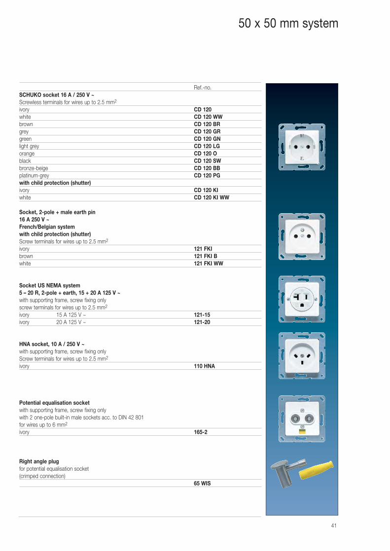
Ref.-no.SCHUKO socket 16 A / 250 V ~Screwless terminals for wires up to 2.5 mm2
ivory CD 120white CD 120 WWbrown CD 120 BRgrey CD 120 GRgreen CD 120 GNlight grey CD 120 LGorange CD 120 Oblack CD 120 SWbronze-beige CD 120 BBplatinum-grey CD 120 PGwith child protection (shutter)ivory CD 120 KIwhite CD 120 KI WW
Socket, 2-pole + male earth pin16 A 250 V ~French/Belgian systemwith child protection (shutter)Screw terminals for wires up to 2.5 mm2
ivory 121 FKIbrown 121 FKI Bwhite 121 FKI WW
Socket US NEMA system5 – 20 R, 2-pole + earth, 15 + 20 A 125 V ~with supporting frame, screw fixing onlyscrew terminals for wires up to 2.5 mm2
ivory 15 A 125 V ~ 121-15ivory 20 A 125 V ~ 121-20
HNA socket, 10 A / 250 V ~with supporting frame, screw fixing onlyScrew terminals for wires up to 2.5 mm2
ivory 110 HNA
Potential equalisation socketwith supporting frame, screw fixing onlywith 2 one-pole built-in male sockets acc. to DIN 42 801for wires up to 6 mm2
ivory 165-2
Right angle plugfor potential equalisation socket(crimped connection)
65 WIS
50 x 50 mm system
42
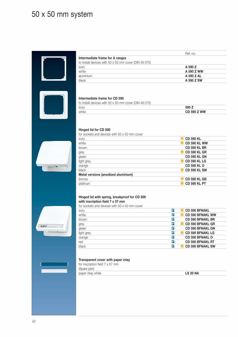
Ref.-no.Intermediate frame for A rangesto install devices with 50 x 50 mm cover (DIN 49 075)ivory A 590 Zwhite A 590 Z WWaluminium A 590 Z ALblack A 590 Z SW
Intermediate frame for CD 500to install devices with 50 x 50 mm cover (DIN 49 075)ivory 590 Zwhite CD 590 Z WW
Hinged lid for CD 500for sockets and devices with 50 x 50 mm coverivory CD 590 KLwhite CD 590 KL WWbrown CD 590 KL BRgrey CD 590 KL GRgreen CD 590 KL GNlight grey CD 590 KL LGorange CD 590 KL Oblack CD 590 KL SWMetal versions (anodized aluminium)bronze CD 590 KL GBplatinum CD 590 KL PT
Hinged lid with spring, breakproof for CD 500with inscription field 7 x 57 mmfor sockets and devices with 50 x 50 mm coverivory CD 590 BFNAKLwhite CD 590 BFNAKL WWbrown CD 590 BFNAKL BRgrey CD 590 BFNAKL GRgreen CD 590 BFNAKL GNlight grey CD 590 BFNAKL LGorange CD 590 BFNAKL Ored CD 590 BFNAKL RTblack CD 590 BFNAKL SW
Transparent cover with paper inlayfor inscription field 7 x 57 mm(Spare part)paper inlay white LS 20 NA
LIP
IP
IP
LIP
IP
LIP
IP
LIP
LIP
L
L
L
L
L
L
L
50 x 50 mm system
43
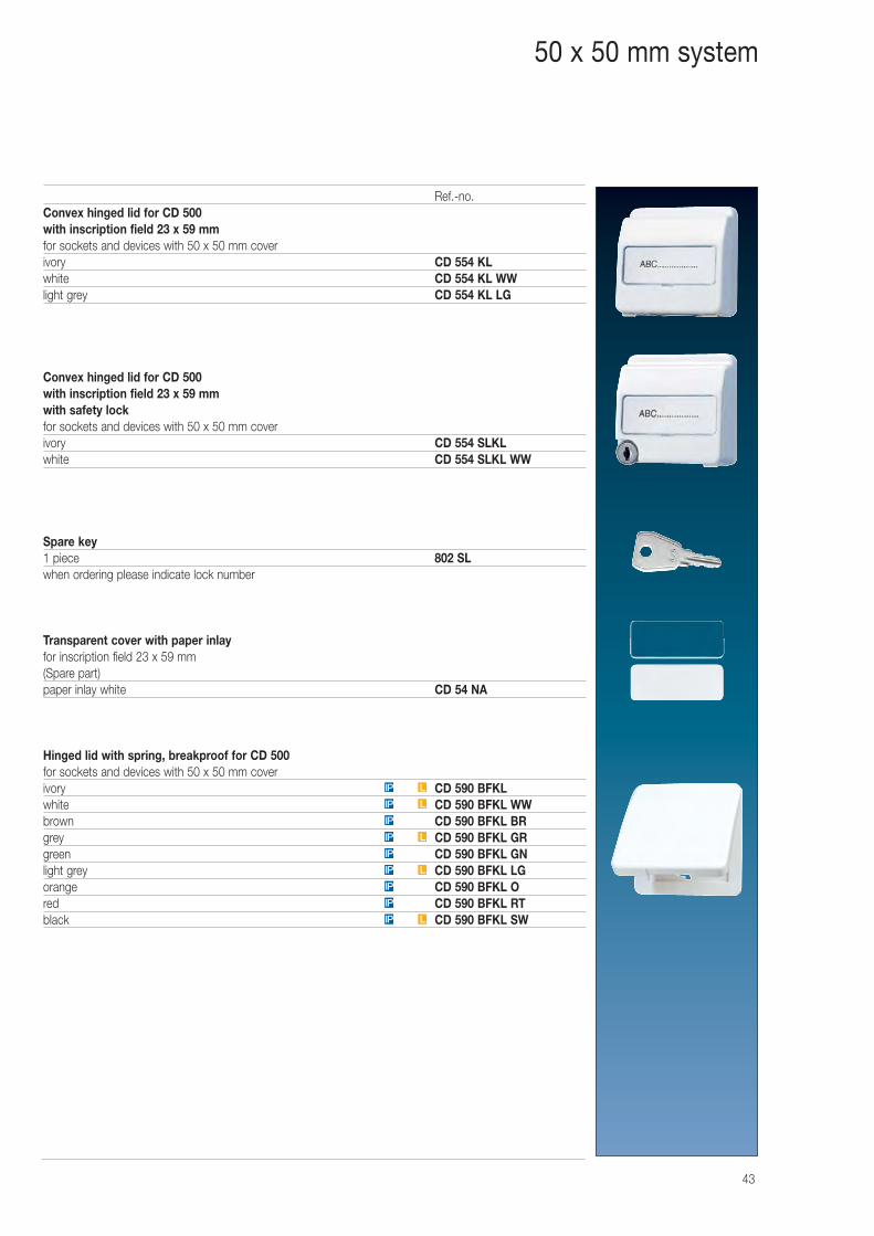
Ref.-no.Convex hinged lid for CD 500with inscription field 23 x 59 mmfor sockets and devices with 50 x 50 mm coverivory CD 554 KLwhite CD 554 KL WWlight grey CD 554 KL LG
Convex hinged lid for CD 500with inscription field 23 x 59 mmwith safety lockfor sockets and devices with 50 x 50 mm coverivory CD 554 SLKLwhite CD 554 SLKL WW
Spare key1 piece 802 SLwhen ordering please indicate lock number
Transparent cover with paper inlayfor inscription field 23 x 59 mm(Spare part)paper inlay white CD 54 NA
Hinged lid with spring, breakproof for CD 500for sockets and devices with 50 x 50 mm coverivory CD 590 BFKLwhite CD 590 BFKL WWbrown CD 590 BFKL BRgrey CD 590 BFKL GRgreen CD 590 BFKL GNlight grey CD 590 BFKL LGorange CD 590 BFKL Ored CD 590 BFKL RTblack CD 590 BFKL SWLIP
IP
IP
LIP
IP
LIP
IP
LIP
LIP
50 x 50 mm system
44
50 x 50 mm system
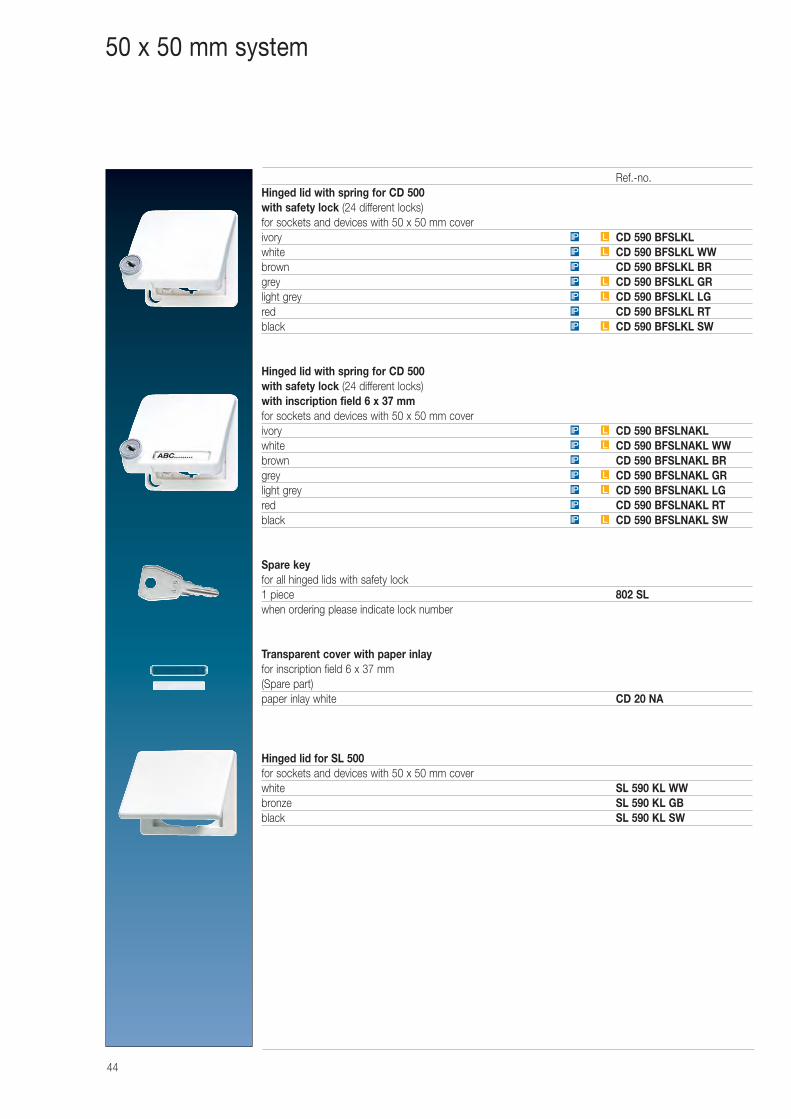
Ref.-no.Hinged lid with spring for CD 500with safety lock (24 different locks)for sockets and devices with 50 x 50 mm coverivory CD 590 BFSLKLwhite CD 590 BFSLKL WWbrown CD 590 BFSLKL BRgrey CD 590 BFSLKL GRlight grey CD 590 BFSLKL LGred CD 590 BFSLKL RTblack CD 590 BFSLKL SW
Hinged lid with spring for CD 500with safety lock (24 different locks)with inscription field 6 x 37 mmfor sockets and devices with 50 x 50 mm coverivory CD 590 BFSLNAKLwhite CD 590 BFSLNAKL WWbrown CD 590 BFSLNAKL BRgrey CD 590 BFSLNAKL GRlight grey CD 590 BFSLNAKL LGred CD 590 BFSLNAKL RTblack CD 590 BFSLNAKL SW
Spare keyfor all hinged lids with safety lock1 piece 802 SLwhen ordering please indicate lock number
Transparent cover with paper inlayfor inscription field 6 x 37 mm(Spare part)paper inlay white CD 20 NA
Hinged lid for SL 500for sockets and devices with 50 x 50 mm coverwhite SL 590 KL WWbronze SL 590 KL GBblack SL 590 KL SW
LIP
IP
LIP
LIP
IP
LIP
LIP
LIP
IP
LIP
LIP
IP
LIP
LIP
45
50 x 50 mm system
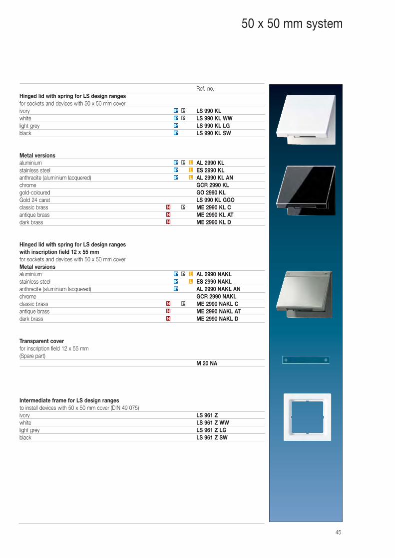
Ref.-no.Hinged lid with spring for LS design rangesfor sockets and devices with 50 x 50 mm coverivory LS 990 KLwhite LS 990 KL WWlight grey LS 990 KL LGblack LS 990 KL SW
Metal versionsaluminium AL 2990 KLstainless steel ES 2990 KLanthracite (aluminium lacquered) AL 2990 KL ANchrome GCR 2990 KLgold-coloured GO 2990 KLGold 24 carat LS 990 KL GGOclassic brass ME 2990 KL Cantique brass ME 2990 KL ATdark brass ME 2990 KL D
Hinged lid with spring for LS design rangeswith inscription field 12 x 55 mmfor sockets and devices with 50 x 50 mm coverMetal versionsaluminium AL 2990 NAKLstainless steel ES 2990 NAKLanthracite (aluminium lacquered) AL 2990 NAKL ANchrome GCR 2990 NAKLclassic brass ME 2990 NAKL Cantique brass ME 2990 NAKL ATdark brass ME 2990 NAKL D
Transparent coverfor inscription field 12 x 55 mm(Spare part)
M 20 NA
Intermediate frame for LS design rangesto install devices with 50 x 50 mm cover (DIN 49 075)ivory LS 961 Zwhite LS 961 Z WWlight grey LS 961 Z LGblack LS 961 Z SW
LIP
LPIP
PN
N
N
N
N
PN
LIP
LIP
LPIP
IP
IP
IP
PIP
PIP
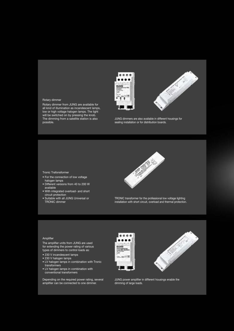
JUNG dimmers are also available in different housings for sealing installation or for distribution boards.
Rotary dimmer
Rotary dimmer from JUNG are available for all kind of illumination as incandescent lamps, low or high voltage halogen lamps. The light will be switched on by pressing the knob. The dimming from a satellite station is also possible.
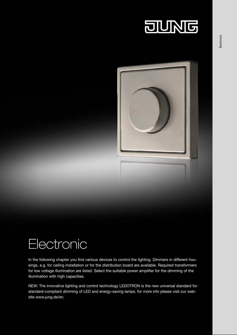
In the following chapter you find various devices to control the lighting. Dimmers in different hou-sings, e.g. for ceiling installation or for the distribution board are available. Required transformers for low voltage illumination are listed. Select the suitable power amplifier for the dimming of the illumination with high capacities.
NEW: The innovative lighting and control technology LEDOTRON is the new universal standard for standard-compliant dimming of LED and energy-saving lamps. for more info please visit our web-site www.jung.de/en.
Electronic
Tronic Trafonsformer
• For the connection of low voltage halogen lamps
• Different versions from 40 to 200 W available
• With integrated overload- and short circuit protection
• Suitable with all JUNG Universal or TRONIC dimmer
TRONIC transformer for the professional low voltage lighting installation with short circuit, overload and thermal protection.
Amplifier
The amplifier units from JUNG are used for extending the power rating of various types of dimmers to control loads as:
• 230 V incandescent lamps • 230 V halogen lamps• LV halogen lamps in combination with Tronic transformers• LV halogen lamps in combination with
conventional transformers
Depending on the required power rating, several amplifier can be connected to one dimmer.
JUNG power amplifier in different housings enable the dimming of large loads.
Elec
troni
cs
JUNG dimmers are also available in different housings for sealing installation or for distribution boards.
Rotary dimmer
Rotary dimmer from JUNG are available for all kind of illumination as incandescent lamps, low or high voltage halogen lamps. The light will be switched on by pressing the knob. The dimming from a satellite station is also possible.
In the following chapter you find various devices to control the lighting. Dimmers in different hou-sings, e.g. for ceiling installation or for the distribution board are available. Required transformers for low voltage illumination are listed. Select the suitable power amplifier for the dimming of the illumination with high capacities.
NEW: The innovative lighting and control technology LEDOTRON is the new universal standard for standard-compliant dimming of LED and energy-saving lamps. for more info please visit our web-site www.jung.de/en.
Electronic
Tronic Trafonsformer
• For the connection of low voltage halogen lamps
• Different versions from 40 to 200 W available
• With integrated overload- and short circuit protection
• Suitable with all JUNG Universal or TRONIC dimmer
TRONIC transformer for the professional low voltage lighting installation with short circuit, overload and thermal protection.
Amplifier
The amplifier units from JUNG are used for extending the power rating of various types of dimmers to control loads as:
• 230 V incandescent lamps • 230 V halogen lamps• LV halogen lamps in combination with Tronic transformers• LV halogen lamps in combination with
conventional transformers
Depending on the required power rating, several amplifier can be connected to one dimmer.
JUNG power amplifier in different housings enable the dimming of large loads.
Elec
troni
cs
48
Rotary dimmerElectronics
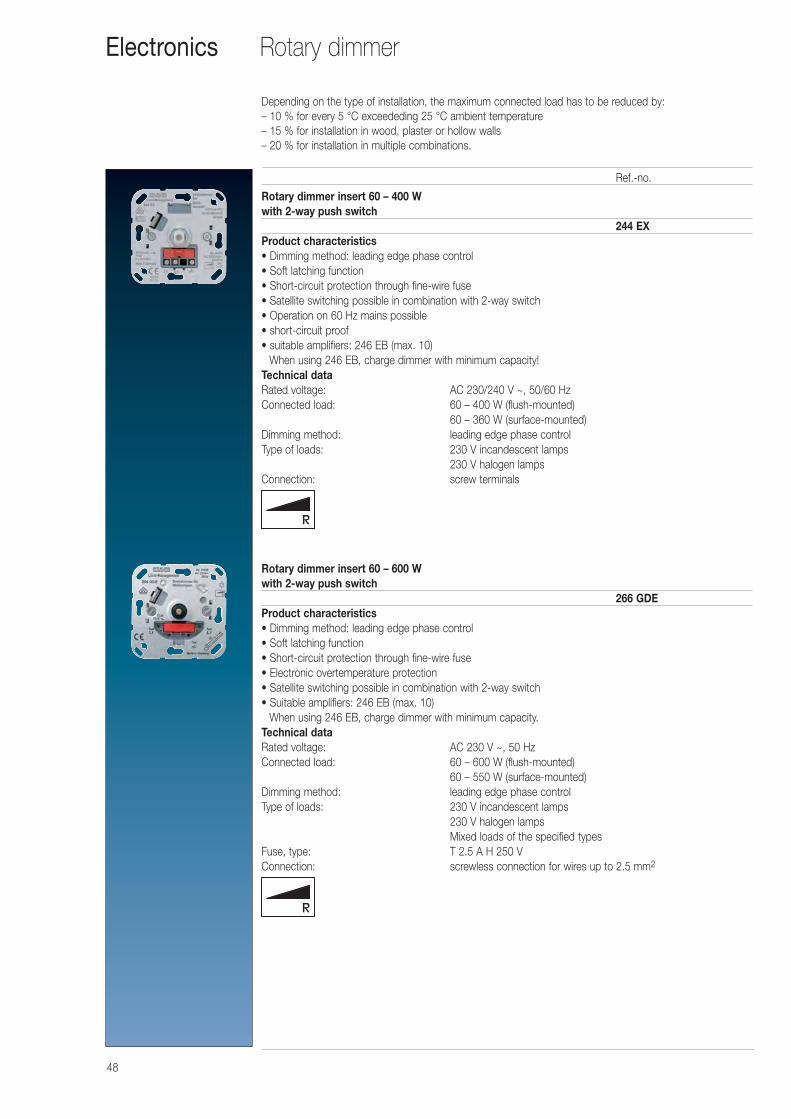
Rotary dimmer insert 60 – 400 Wwith 2-way push switch
244 EXProduct characteristics• Dimming method: leading edge phase control• Soft latching function• Short-circuit protection through fine-wire fuse• Satellite switching possible in combination with 2-way switch• Operation on 60 Hz mains possible• short-circuit proof• suitable amplifiers: 246 EB (max. 10)
When using 246 EB, charge dimmer with minimum capacity!Technical dataRated voltage: AC 230/240 V ~, 50/60 HzConnected load: 60 – 400 W (flush-mounted)
60 – 360 W (surface-mounted)Dimming method: leading edge phase controlType of loads: 230 V incandescent lamps
230 V halogen lampsConnection: screw terminals
Rotary dimmer insert 60 – 600 Wwith 2-way push switch
266 GDEProduct characteristics• Dimming method: leading edge phase control• Soft latching function• Short-circuit protection through fine-wire fuse• Electronic overtemperature protection• Satellite switching possible in combination with 2-way switch• Suitable amplifiers: 246 EB (max. 10)
When using 246 EB, charge dimmer with minimum capacity.Technical dataRated voltage: AC 230 V ~, 50 HzConnected load: 60 – 600 W (flush-mounted)
60 – 550 W (surface-mounted)Dimming method: leading edge phase controlType of loads: 230 V incandescent lamps
230 V halogen lampsMixed loads of the specified types
Fuse, type: T 2.5 A H 250 VConnection: screwless connection for wires up to 2.5 mm2
Ref.-no.
Depending on the type of installation, the maximum connected load has to be reduced by:– 10 % for every 5 °C exceededing 25 °C ambient temperature– 15 % for installation in wood, plaster or hollow walls– 20 % for installation in multiple combinations.
49
Rotary dimmer Electronics
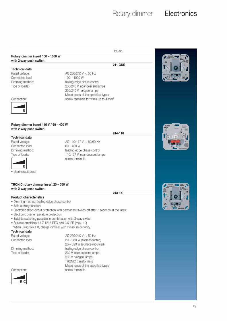
Rotary dimmer insert 100 – 1000 Wwith 2-way push switch
211 GDETechnical dataRated voltage: AC 230/240 V ~, 50 HzConnected load: 100 – 1000 WDimming method: trailing edge phase controlType of loads: 230/240 V incandescent lamps
230/240 V halogen lampsMixed loads of the specified types
Connection: screw terminals for wires up to 4 mm2
Rotary dimmer insert 110 V / 60 – 400 Wwith 2-way push switch
244-110Technical dataRated voltage: AC 110/127 V ~, 50/60 HzConnected load: 60 – 400 WDimming method: leading edge phase controlType of loads: 110/127 V incandescent lampsConnection: screw terminals
• short-circuit proof
TRONIC rotary dimmer insert 20 – 360 Wwith 2-way push switch
243 EXProduct characteristics• Dimming method: trailing edge phase control• Soft latching function• Electronic short-circuit protection with permanent switch-off after 7 seconds at the latest• Electronic overtemperature protection• Satellite switching possible in combination with 2-way switch• Suitable amplifiers: ULZ 1215 REG and 247 EB (max. 10)
When using 247 EB, charge dimmer with minimum capacity.Technical dataRated voltage: AC 230/240 V ~, 50 HzConnected load: 20 – 360 W (flush-mounted)
20 – 320 W (surface-mounted)Dimming method: trailing edge phase controlType of loads: 230 V incandescent lamps
230 V halogen lampsTRONIC transformersMixed loads of the specified types
Connection: screw terminals
Ref.-no.
50
Rotary dimmerElectronics
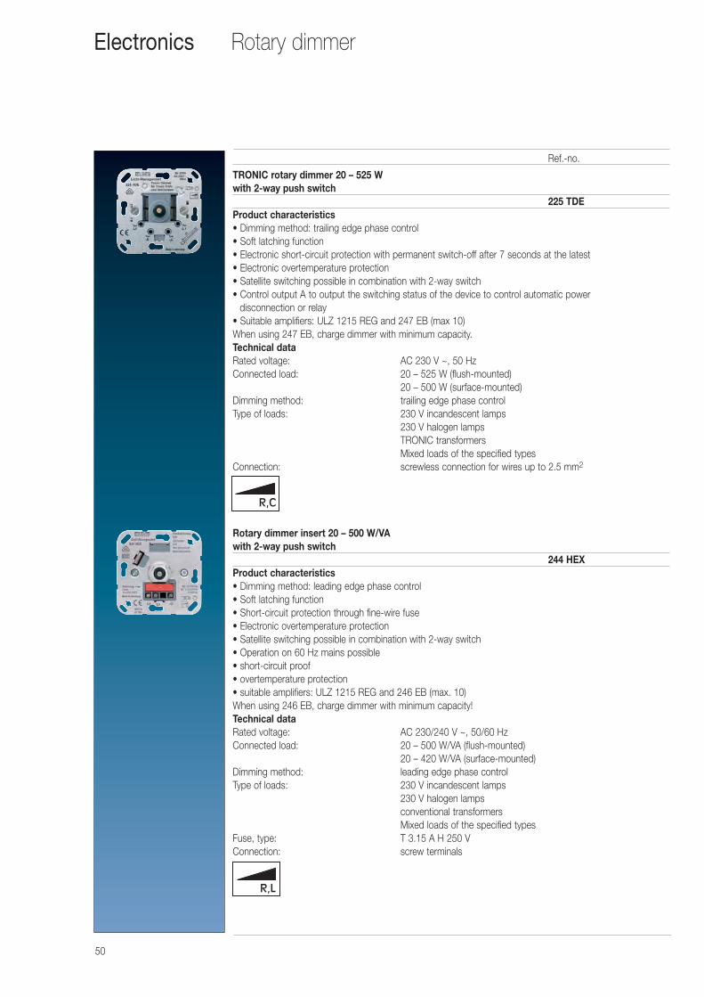
TRONIC rotary dimmer 20 – 525 Wwith 2-way push switch
225 TDEProduct characteristics• Dimming method: trailing edge phase control • Soft latching function • Electronic short-circuit protection with permanent switch-off after 7 seconds at the latest • Electronic overtemperature protection • Satellite switching possible in combination with 2-way switch • Control output A to output the switching status of the device to control automatic power
disconnection or relay • Suitable amplifiers: ULZ 1215 REG and 247 EB (max 10) When using 247 EB, charge dimmer with minimum capacity.Technical dataRated voltage: AC 230 V ~, 50 HzConnected load: 20 – 525 W (flush-mounted)
20 – 500 W (surface-mounted)Dimming method: trailing edge phase controlType of loads: 230 V incandescent lamps
230 V halogen lampsTRONIC transformersMixed loads of the specified types
Connection: screwless connection for wires up to 2.5 mm2
Rotary dimmer insert 20 – 500 W/VAwith 2-way push switch
244 HEXProduct characteristics• Dimming method: leading edge phase control • Soft latching function • Short-circuit protection through fine-wire fuse • Electronic overtemperature protection • Satellite switching possible in combination with 2-way switch • Operation on 60 Hz mains possible• short-circuit proof • overtemperature protection • suitable amplifiers: ULZ 1215 REG and 246 EB (max. 10) When using 246 EB, charge dimmer with minimum capacity!Technical dataRated voltage: AC 230/240 V ~, 50/60 HzConnected load: 20 – 500 W/VA (flush-mounted)
20 – 420 W/VA (surface-mounted)Dimming method: leading edge phase controlType of loads: 230 V incandescent lamps
230 V halogen lampsconventional transformersMixed loads of the specified types
Fuse, type: T 3.15 A H 250 VConnection: screw terminals
Ref.-no.
51
Rotary dimmer Electronics
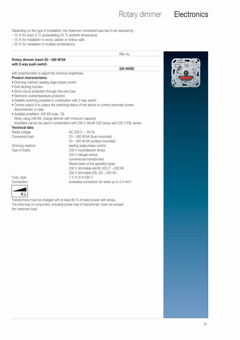
Rotary dimmer insert 20 – 500 W/VAwith 2-way push switch
225 NVDEwith potentiometer to adjust the minimum brightnessProduct characteristics• Dimming method: leading edge phase control• Soft latching function• Short-circuit protection through fine-wire fuse• Electronic overtemperature protection• Satellite switching possible in combination with 2-way switch• Control output A to output the switching status of the device to control automatic power
disconnection or relay• Suitable amplifiers: 246 EB (max. 10)
When using 246 EB, charge dimmer with minimum capacity!Amplifiers cannot be used in combination with 230 V retrofit LED lamps and 230 V ESL lamps.
Technical dataRated voltage: AC 230 V ~, 50 HzConnected load: 20 – 500 W/VA (flush-mounted)
20 – 450 W/VA (surface-mounted)Dimming method: leading edge phase controlType of loads: 230 V incandescent lamps
230 V halogen lampsconventional transformersMixed loads of the specified types230 V dimmable retrofit LED (7 – 200 W)230 V dimmable ESL (20 – 200 W)
Fuse, type: T 3.15 A H 250 VConnection: screwless connection for wires up to 2.5 mm2
Transformers must be charged with at least 85 % of rated power with lamps.The total load of consumers, including power loss of transformer, must not exceed the maximum load.
Ref.-no.
Depending on the type of installation, the maximum connected load has to be reduced by:– 10 % for every 5 °C exceededing 25 °C ambient temperature– 15 % for installation in wood, plaster or hollow walls– 20 % for installation in multiple combinations.
52
Rotary dimmerElectronics
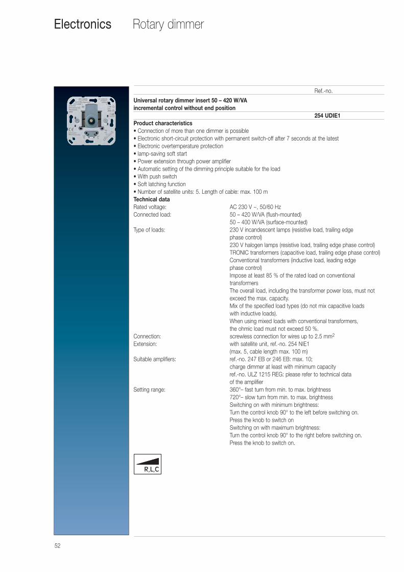
Universal rotary dimmer insert 50 – 420 W/VAincremental control without end position
254 UDIE1Product characteristics• Connection of more than one dimmer is possible• Electronic short-circuit protection with permanent switch-off after 7 seconds at the latest• Electronic overtemperature protection• lamp-saving soft start• Power extension through power amplifier• Automatic setting of the dimming principle suitable for the load• With push switch• Soft latching function• Number of satellite units: 5. Length of cable: max. 100 mTechnical dataRated voltage: AC 230 V ~, 50/60 HzConnected load: 50 – 420 W/VA (flush-mounted)
50 – 400 W/VA (surface-mounted)Type of loads: 230 V incandescent lamps (resistive load, trailing edge
phase control)230 V halogen lamps (resistive load, trailing edge phase control)TRONIC transformers (capacitive load, trailing edge phase control)Conventional transformers (inductive load, leading edge phase control)Impose at least 85 % of the rated load on conventional transformersThe overall load, including the transformer power loss, must notexceed the max. capacity.Mix of the specified load types (do not mix capacitive loads with inductive loads).When using mixed loads with conventional transformers, the ohmic load must not exceed 50 %.
Connection: screwless connection for wires up to 2.5 mm2
Extension: with satellite unit, ref.-no. 254 NIE1(max. 5, cable length max. 100 m)
Suitable amplifiers: ref.-no. 247 EB or 246 EB: max. 10; charge dimmer at least with minimum capacityref.-no. ULZ 1215 REG: please refer to technical data of the amplifier
Setting range: 360°– fast turn from min. to max. brightness720°– slow turn from min. to max. brightnessSwitching on with minimum brightness: Turn the control knob 90° to the left before switching on. Press the knob to switch onSwitching on with maximum brightness:Turn the control knob 90° to the right before switching on. Press the knob to switch on.
Ref.-no.
53
Rotary dimmer Electronics
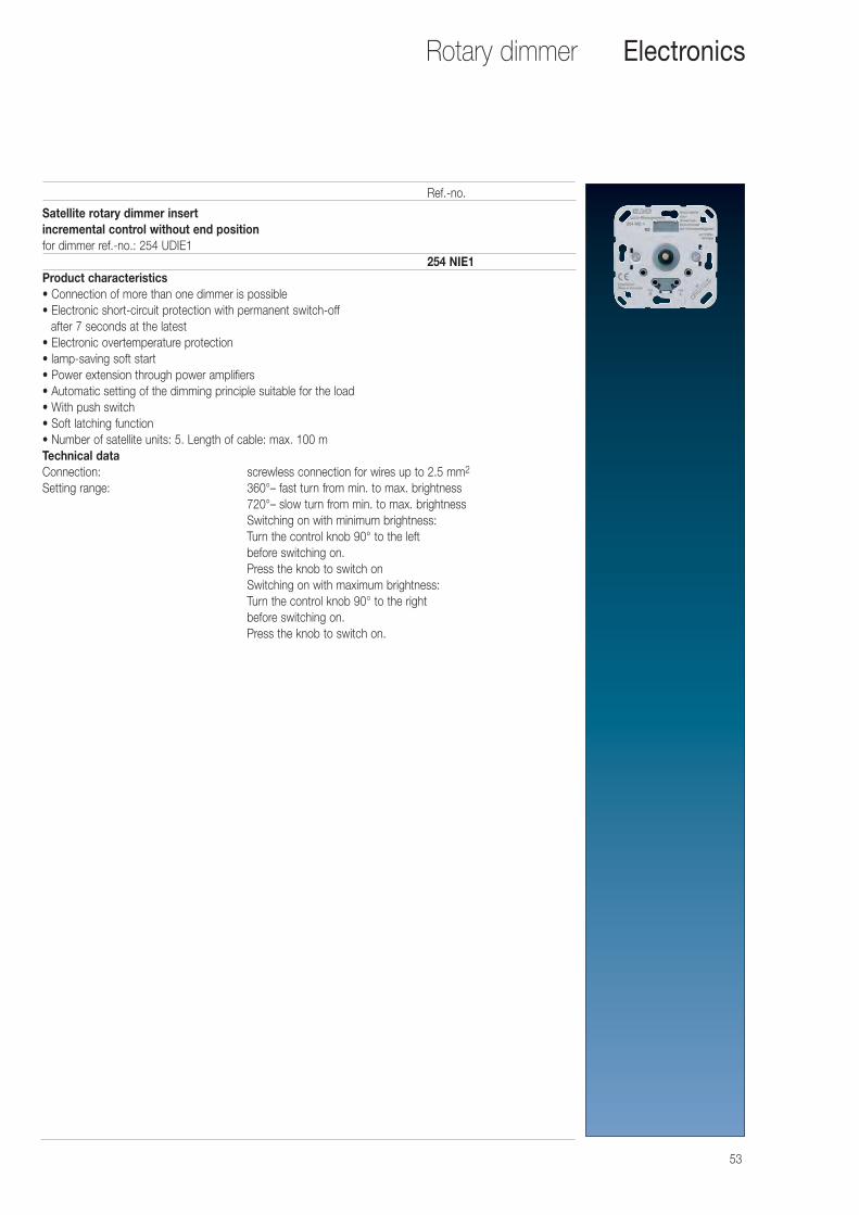
Satellite rotary dimmer insertincremental control without end positionfor dimmer ref.-no.: 254 UDIE1
254 NIE1Product characteristics• Connection of more than one dimmer is possible• Electronic short-circuit protection with permanent switch-off
after 7 seconds at the latest• Electronic overtemperature protection• lamp-saving soft start• Power extension through power amplifiers• Automatic setting of the dimming principle suitable for the load• With push switch• Soft latching function• Number of satellite units: 5. Length of cable: max. 100 mTechnical dataConnection: screwless connection for wires up to 2.5 mm2
Setting range: 360°– fast turn from min. to max. brightness720°– slow turn from min. to max. brightnessSwitching on with minimum brightness: Turn the control knob 90° to the left before switching on. Press the knob to switch onSwitching on with maximum brightness:Turn the control knob 90° to the right before switching on. Press the knob to switch on.
Ref.-no.
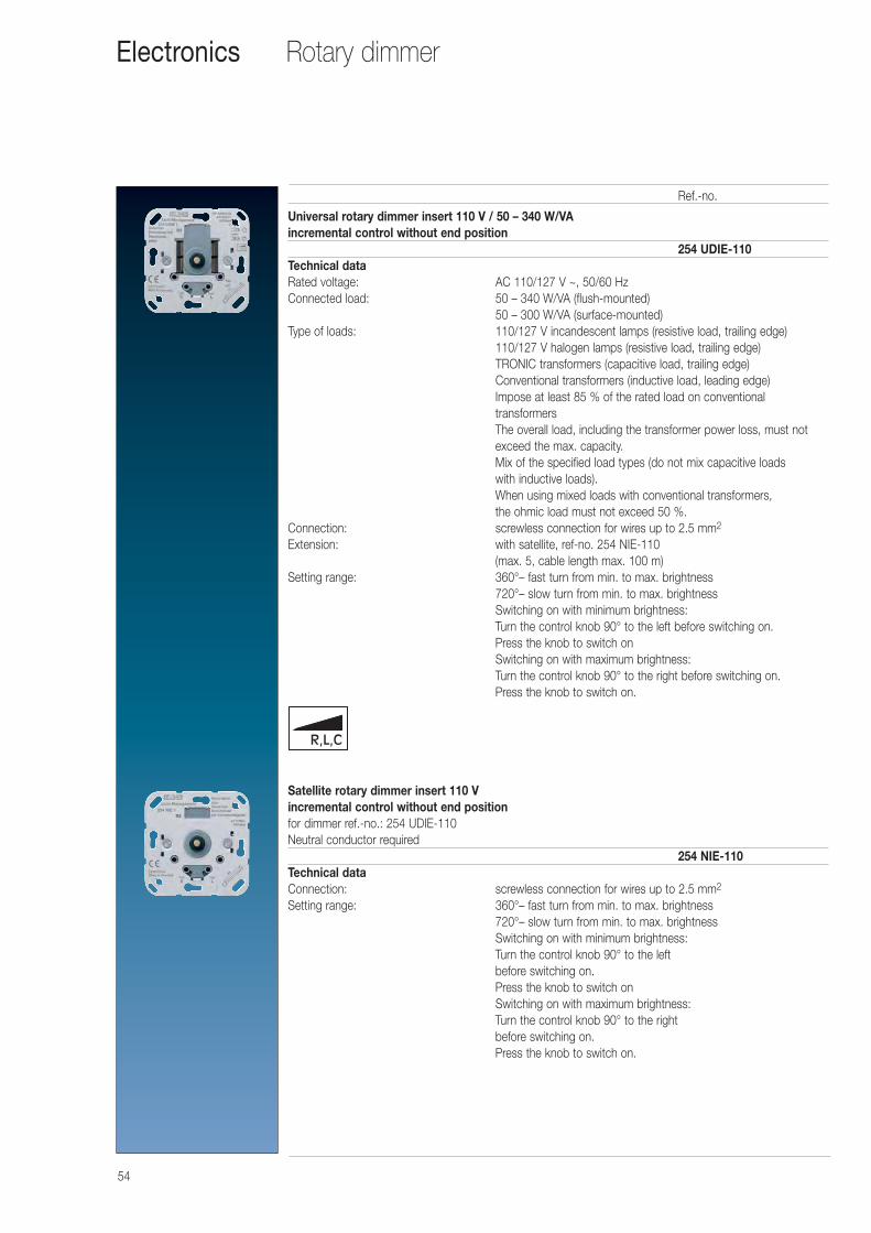
54
Rotary dimmerElectronics
Universal rotary dimmer insert 110 V / 50 – 340 W/VAincremental control without end position
254 UDIE-110Technical dataRated voltage: AC 110/127 V ~, 50/60 HzConnected load: 50 – 340 W/VA (flush-mounted)
50 – 300 W/VA (surface-mounted)Type of loads: 110/127 V incandescent lamps (resistive load, trailing edge)
110/127 V halogen lamps (resistive load, trailing edge)TRONIC transformers (capacitive load, trailing edge)Conventional transformers (inductive load, leading edge)Impose at least 85 % of the rated load on conventional transformersThe overall load, including the transformer power loss, must notexceed the max. capacity.Mix of the specified load types (do not mix capacitive loads with inductive loads).When using mixed loads with conventional transformers, the ohmic load must not exceed 50 %.
Connection: screwless connection for wires up to 2.5 mm2
Extension: with satellite, ref-no. 254 NIE-110 (max. 5, cable length max. 100 m)
Setting range: 360°– fast turn from min. to max. brightness720°– slow turn from min. to max. brightnessSwitching on with minimum brightness: Turn the control knob 90° to the left before switching on. Press the knob to switch onSwitching on with maximum brightness:Turn the control knob 90° to the right before switching on. Press the knob to switch on.
Satellite rotary dimmer insert 110 Vincremental control without end positionfor dimmer ref.-no.: 254 UDIE-110Neutral conductor required
254 NIE-110Technical dataConnection: screwless connection for wires up to 2.5 mm2
Setting range: 360°– fast turn from min. to max. brightness720°– slow turn from min. to max. brightnessSwitching on with minimum brightness: Turn the control knob 90° to the left before switching on. Press the knob to switch onSwitching on with maximum brightness:Turn the control knob 90° to the right before switching on. Press the knob to switch on.
Ref.-no.
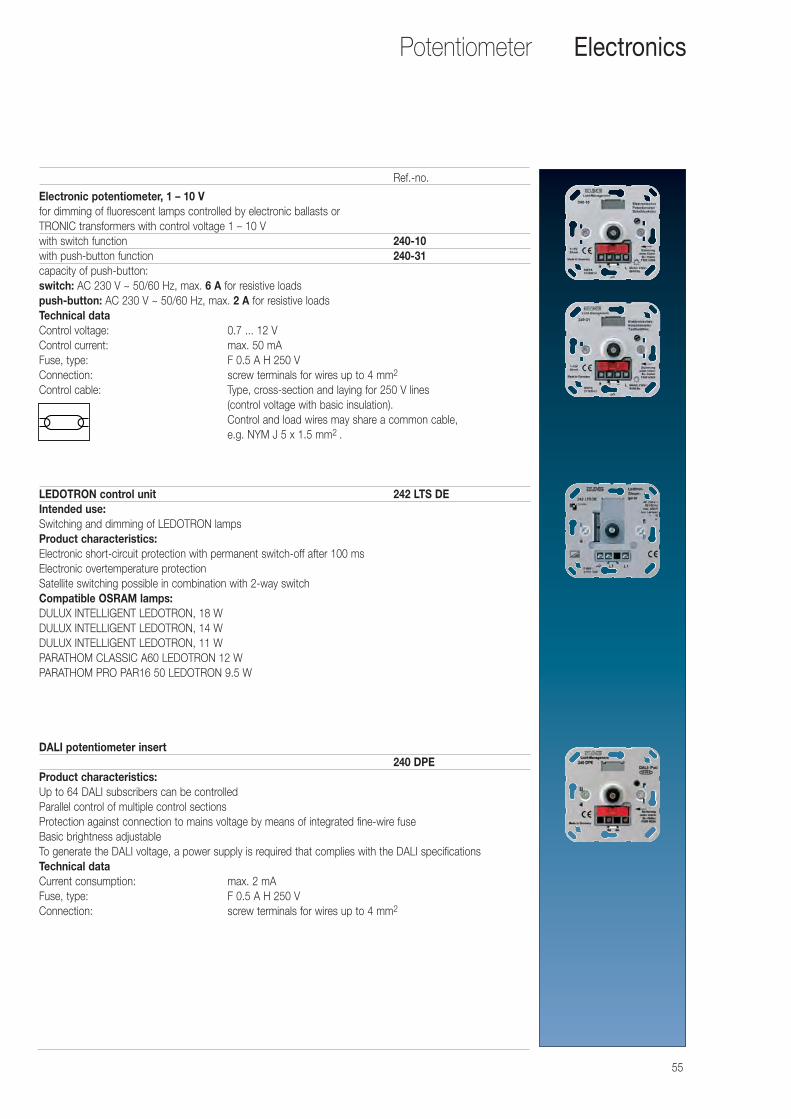
55
Potentiometer Electronics
Electronic potentiometer, 1 – 10 Vfor dimming of fluorescent lamps controlled by electronic ballasts orTRONIC transformers with control voltage 1 – 10 Vwith switch function 240-10with push-button function 240-31capacity of push-button:switch: AC 230 V ~ 50/60 Hz, max. 6 A for resistive loadspush-button: AC 230 V ~ 50/60 Hz, max. 2 A for resistive loadsTechnical dataControl voltage: 0.7 ... 12 VControl current: max. 50 mAFuse, type: F 0.5 A H 250 VConnection: screw terminals for wires up to 4 mm2
Control cable: Type, cross-section and laying for 250 V lines (control voltage with basic insulation). Control and load wires may share a common cable, e.g. NYM J 5 x 1.5 mm2 .
LEDOTRON control unit 242 LTS DEIntended use:Switching and dimming of LEDOTRON lampsProduct characteristics:Electronic short-circuit protection with permanent switch-off after 100 msElectronic overtemperature protectionSatellite switching possible in combination with 2-way switchCompatible OSRAM lamps: DULUX INTELLIGENT LEDOTRON, 18 W DULUX INTELLIGENT LEDOTRON, 14 WDULUX INTELLIGENT LEDOTRON, 11 WPARATHOM CLASSIC A60 LEDOTRON 12 WPARATHOM PRO PAR16 50 LEDOTRON 9.5 W
DALI potentiometer insert240 DPE
Product characteristics:Up to 64 DALI subscribers can be controlledParallel control of multiple control sectionsProtection against connection to mains voltage by means of integrated fine-wire fuseBasic brightness adjustableTo generate the DALI voltage, a power supply is required that complies with the DALI specifications Technical dataCurrent consumption: max. 2 mAFuse, type: F 0.5 A H 250 VConnection: screw terminals for wires up to 4 mm2
Ref.-no.
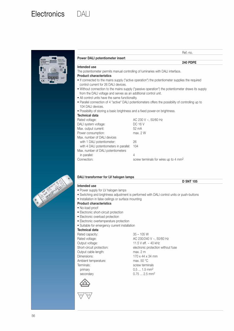
56
DALIElectronics
Power DALI potentiometer insert240 PDPE
Intended useThe potentiometer permits manual controlling of luminaries with DALI interface.Product characteristics• If connected to the mains supply ("active operation") the potentiometer supplies the required
control current for 26 DALI devices.• Without connection to the mains supply ("passive operation") the potentiometer draws its supply
from the DALI voltage and serves as an additional control unit.• All control units have the same functionality.• Parallel connection of 4 "active" DALI potentiometers offers the possibility of controlling up to
104 DALI devices.• Possibility of storing a basic brightness and a fixed power-on brightness.Technical dataRated voltage: AC 230 V ~, 50/60 HzDALI system voltage: DC 16 VMax. output current: 52 mAPower consumption: max. 2 WMax. number of DALI devices
with 1 DALI potentiometer: 26with 4 DALI potentiometers in parallel: 104
Max. number of DALI potentiometers in parallel: 4
Connection: screw terminals for wires up to 4 mm2
DALI transformer for LV halogen lampsD SNT 105
Intended use• Power supply for LV halogen lamps• Switching and brightness adjustment is performed with DALI control units or push-buttons• Installation in false ceilings or surface mountingProduct characteristics• No-load proof• Electronic short-circuit protection• Electronic overload protection• Electronic overtemperature protection• Suitable for emergency current installationTechnical dataRated capacity: 35 – 105 WRated voltage: AC 230/240 V ~, 50/60 HzOutput voltage: 11.5 V eff. ~ 40 kHz Short-circuit protection: electronic protection without fuseOutput cable length: max. 2 mDimensions: 170 x 44 x 34 mmAmbient temperature: max. 50 °CTerminals: screw terminals
primary 0.5 ... 1.5 mm2
secondary 0.75 ... 2.5 mm2
Ref.-no.
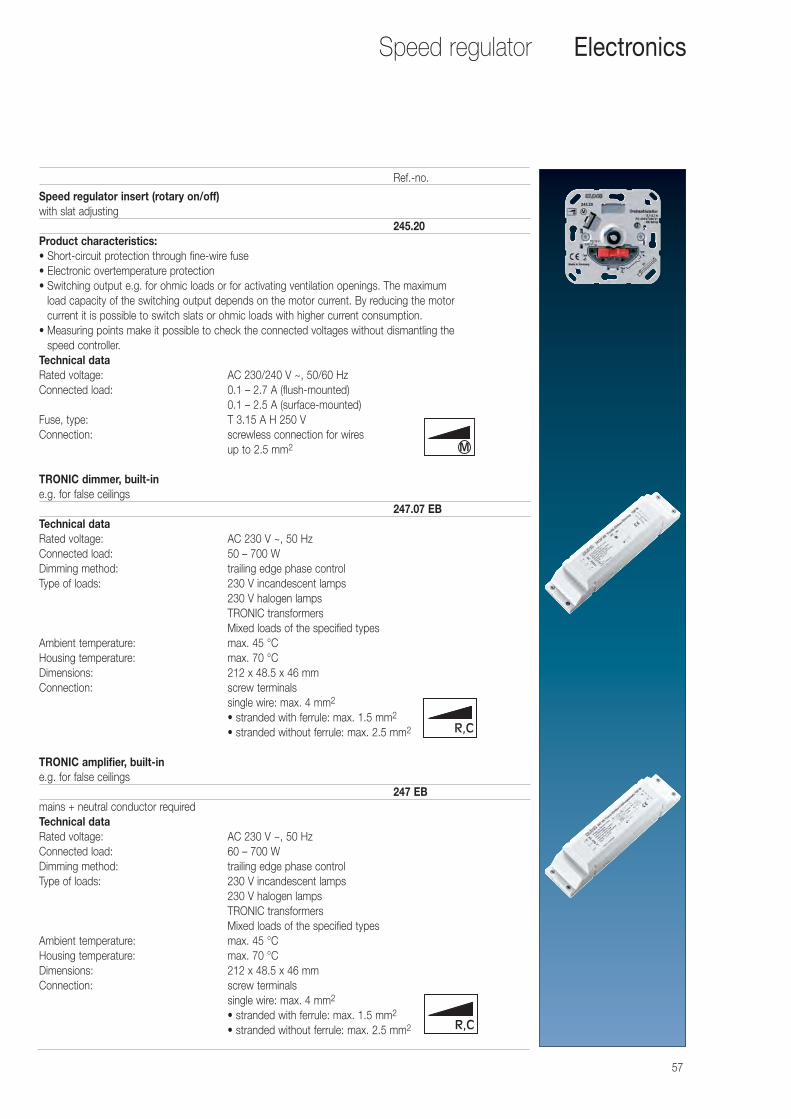
57
Speed regulator Electronics
Speed regulator insert (rotary on/off)with slat adjusting
245.20Product characteristics:• Short-circuit protection through fine-wire fuse• Electronic overtemperature protection• Switching output e.g. for ohmic loads or for activating ventilation openings. The maximum
load capacity of the switching output depends on the motor current. By reducing the motor current it is possible to switch slats or ohmic loads with higher current consumption.
• Measuring points make it possible to check the connected voltages without dismantling the speed controller.
Technical dataRated voltage: AC 230/240 V ~, 50/60 HzConnected load: 0.1 – 2.7 A (flush-mounted)
0.1 – 2.5 A (surface-mounted)Fuse, type: T 3.15 A H 250 VConnection: screwless connection for wires
up to 2.5 mm2
TRONIC dimmer, built-ine.g. for false ceilings
247.07 EBTechnical dataRated voltage: AC 230 V ~, 50 HzConnected load: 50 – 700 WDimming method: trailing edge phase controlType of loads: 230 V incandescent lamps
230 V halogen lampsTRONIC transformersMixed loads of the specified types
Ambient temperature: max. 45 °CHousing temperature: max. 70 °CDimensions: 212 x 48.5 x 46 mmConnection: screw terminals
single wire: max. 4 mm2
• stranded with ferrule: max. 1.5 mm2
• stranded without ferrule: max. 2.5 mm2
TRONIC amplifier, built-ine.g. for false ceilings
247 EBmains + neutral conductor requiredTechnical dataRated voltage: AC 230 V ~, 50 HzConnected load: 60 – 700 WDimming method: trailing edge phase controlType of loads: 230 V incandescent lamps
230 V halogen lampsTRONIC transformersMixed loads of the specified types
Ambient temperature: max. 45 °CHousing temperature: max. 70 °CDimensions: 212 x 48.5 x 46 mmConnection: screw terminals
single wire: max. 4 mm2
• stranded with ferrule: max. 1.5 mm2
• stranded without ferrule: max. 2.5 mm2
Ref.-no.
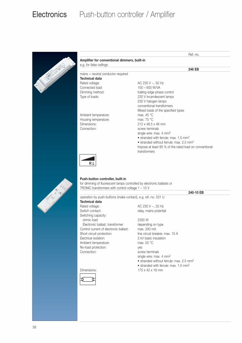
58
Push-button controller / AmplifierElectronics
Amplifier for conventional dimmers, built-ine.g. for false ceilings
246 EBmains + neutral conductor requiredTechnical dataRated voltage: AC 230 V ~, 50 HzConnected load: 100 – 600 W/VADimming method: trailing edge phase controlType of loads: 230 V incandescent lamps
230 V halogen lampsconventional transformersMixed loads of the specified types
Ambient temperature: max. 45 °CHousing temperature: max. 70 °CDimensions: 212 x 48.5 x 46 mmConnection: screw terminals
single wire: max. 4 mm2
• stranded with ferrule: max. 1.5 mm2
• stranded without ferrule: max. 2.5 mm2
Impose at least 85 % of the rated load on conventional transformers
Push-button controller, built-infor dimming of fluorescent lamps controlled by electronic ballasts orTRONIC transformers with control voltage 1 – 10 V
240-10 EBoperation by push-buttons (make contact), e.g. ref.-no. 531 UTechnical dataRated voltage: AC 230 V ~, 50 HzSwitch contact: relay, mains potentialSwitching capacity:
ohmic load 2300 WElectronic ballast, transformer depending on type
Control current of electronic ballast: max. 200 mAShort-circuit protection: line circuit breaker, max. 10 AElectrical isolation: 2 kV basic insulationAmbient temperature: max. 50 °CNo-load protection: yesConnection: screw terminals
single wire: max. 4 mm2
• stranded without ferrule: max. 2.5 mm2
• stranded with ferrule: max. 1.5 mm2
Dimensions: 175 x 42 x 18 mm
Ref.-no.
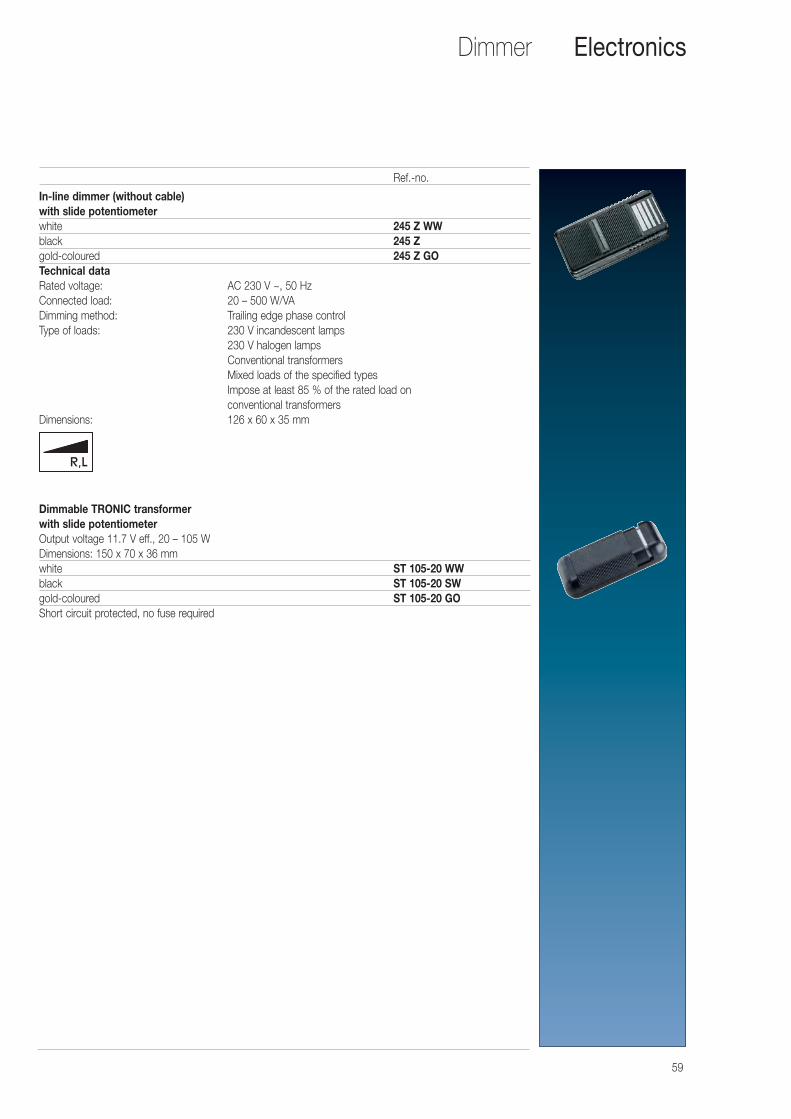
59
Dimmer Electronics
In-line dimmer (without cable)with slide potentiometerwhite 245 Z WWblack 245 Z gold-coloured 245 Z GOTechnical dataRated voltage: AC 230 V ~, 50 HzConnected load: 20 – 500 W/VADimming method: Trailing edge phase controlType of loads: 230 V incandescent lamps
230 V halogen lampsConventional transformersMixed loads of the specified typesImpose at least 85 % of the rated load on conventional transformers
Dimensions: 126 x 60 x 35 mm
Dimmable TRONIC transformer with slide potentiometerOutput voltage 11.7 V eff., 20 – 105 WDimensions: 150 x 70 x 36 mmwhite ST 105-20 WWblack ST 105-20 SWgold-coloured ST 105-20 GOShort circuit protected, no fuse required
Ref.-no.
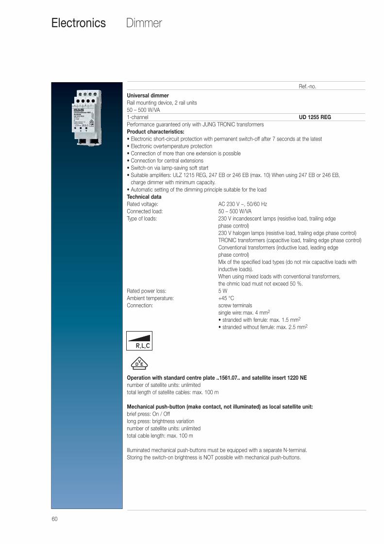
60
DimmerElectronics
Universal dimmerRail mounting device, 2 rail units50 – 500 W/VA1-channel UD 1255 REGPerformance guaranteed only with JUNG TRONIC transformersProduct characteristics:• Electronic short-circuit protection with permanent switch-off after 7 seconds at the latest• Electronic overtemperature protection• Connection of more than one extension is possible• Connection for central extensions• Switch-on via lamp-saving soft start• Suitable amplifiers: ULZ 1215 REG, 247 EB or 246 EB (max. 10) When using 247 EB or 246 EB,
charge dimmer with minimum capacity.• Automatic setting of the dimming principle suitable for the loadTechnical dataRated voltage: AC 230 V ~, 50/60 HzConnected load: 50 – 500 W/VAType of loads: 230 V incandescent lamps (resistive load, trailing edge
phase control)230 V halogen lamps (resistive load, trailing edge phase control)TRONIC transformers (capacitive load, trailing edge phase control)Conventional transformers (inductive load, leading edge phase control)Mix of the specified load types (do not mix capacitive loads withinductive loads).When using mixed loads with conventional transformers, the ohmic load must not exceed 50 %.
Rated power loss: 5 WAmbient temperature: +45 °CConnection: screw terminals
single wire: max. 4 mm2
• stranded with ferrule: max. 1.5 mm2
• stranded without ferrule: max. 2.5 mm2
Operation with standard centre plate ..1561.07.. and satellite insert 1220 NEnumber of satellite units: unlimitedtotal length of satellite cables: max. 100 m
Mechanical push-button (make contact, not illuminated) as local satellite unit:brief press: On / Offlong press: brightness variationnumber of satellite units: unlimitedtotal cable length: max. 100 m
Illuminated mechanical push-buttons must be equipped with a separate N-terminal.Storing the switch-on brightness is NOT possible with mechanical push-buttons.
Ref.-no.
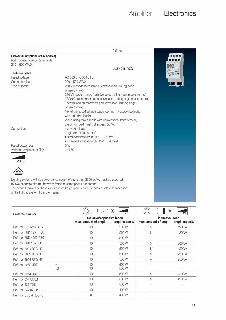
61
Amplifier Electronics
Universal amplifier (cascadable)Rail mounting device, 2 rail units200 – 500 W/VA
ULZ 1215 REGTechnical dataRated voltage: AC 230 V ~, 50/60 HzConnected load: 200 – 500 W/VAType of loads: 230 V incandescent lamps (resistive load, trailing edge
phase control)230 V halogen lamps (resistive load, trailing edge phase control)TRONIC transformers (capacitive load, trailing edge phase control)Conventional transformers (inductive load, leading edge phase control)Mix of the specified load types (do not mix capacitive loads with inductive loads).When using mixed loads with conventional transformers, the ohmic load must not exceed 50 %.
Connection: screw terminalssingle wire: max. 4 mm2
• stranded with ferrule: 0.5 ... 2.5 mm2
• stranded without ferrule: 0.75 ... 4 mm2
Rated power loss: 5 WAmbient temperature (Ta): +45 °C
Lighting systems with a power consumption of more than 3500 W/VA must be supplied by two separate circuits, however from the same phase conductor. The circuit breakers of these circuits must be ganged in order to ensure safe disconnection of the lighting system from the mains.
Ref.-no.
Suitable dimmerresistive/capacitive loads inductive loads
max. amount of ampl. ampl. capacity max. amount of ampl. ampl. capacity
Ref.-no. UD 1255 REG
Ref.-no. FUD 1254 REG
Ref.-no. FUD 4252 REG
Ref.-no. FUD 1253 EB
Ref.-no. 3901 REG HE
Ref.-no. 3902 REG HE
Ref.-no. 3904 REG HE
Ref.-no. 1252 UDE a1a2
Ref.-no. 1254 UDE
Ref.-no. 254 UDIE1
Ref.-no. 225 TDE
Ref.-no. 247.07 EB
Ref.-no. UDS 4 REGHE
10
10
10
10
10
10
10
1010
10
10
10
10
3
500 W
500 W
500 W
500 W
500 W
500 W
500 W
500 W500 W
500 W
500 W
500 W
400 W
400 W
5
5
–
5
5
5
–
––
5
5
–
–
–
420 VA
420 VA
–
300 VA
420 VA
250 VA
250 VA
––
420 VA
420 VA
–
–
–
R,C R,L
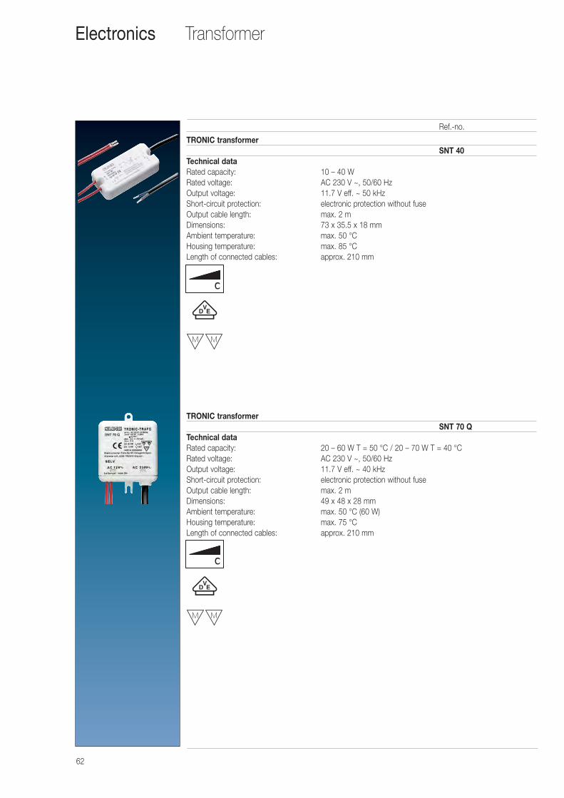
62
TransformerElectronics
TRONIC transformerSNT 40
Technical dataRated capacity: 10 – 40 WRated voltage: AC 230 V ~, 50/60 HzOutput voltage: 11.7 V eff. ~ 50 kHzShort-circuit protection: electronic protection without fuseOutput cable length: max. 2 mDimensions: 73 x 35.5 x 18 mmAmbient temperature: max. 50 °CHousing temperature: max. 85 °CLength of connected cables: approx. 210 mm
TRONIC transformerSNT 70 Q
Technical dataRated capacity: 20 – 60 W T = 50 °C / 20 – 70 W T = 40 °CRated voltage: AC 230 V ~, 50/60 HzOutput voltage: 11.7 V eff. ~ 40 kHzShort-circuit protection: electronic protection without fuseOutput cable length: max. 2 mDimensions: 49 x 48 x 28 mmAmbient temperature: max. 50 °C (60 W)Housing temperature: max. 75 °CLength of connected cables: approx. 210 mm
Ref.-no.
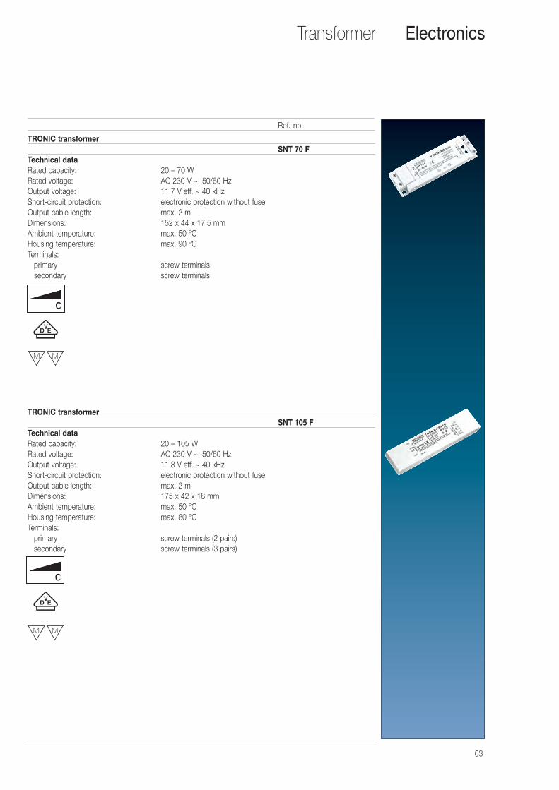
TRONIC transformerSNT 70 F
Technical dataRated capacity: 20 – 70 WRated voltage: AC 230 V ~, 50/60 HzOutput voltage: 11.7 V eff. ~ 40 kHzShort-circuit protection: electronic protection without fuseOutput cable length: max. 2 mDimensions: 152 x 44 x 17.5 mmAmbient temperature: max. 50 °CHousing temperature: max. 90 °CTerminals:
primary screw terminalssecondary screw terminals
TRONIC transformerSNT 105 F
Technical dataRated capacity: 20 – 105 WRated voltage: AC 230 V ~, 50/60 HzOutput voltage: 11.8 V eff. ~ 40 kHz Short-circuit protection: electronic protection without fuseOutput cable length: max. 2 mDimensions: 175 x 42 x 18 mmAmbient temperature: max. 50 °CHousing temperature: max. 80 °CTerminals:
primary screw terminals (2 pairs)secondary screw terminals (3 pairs)
63
Transformer Electronics
Ref.-no.
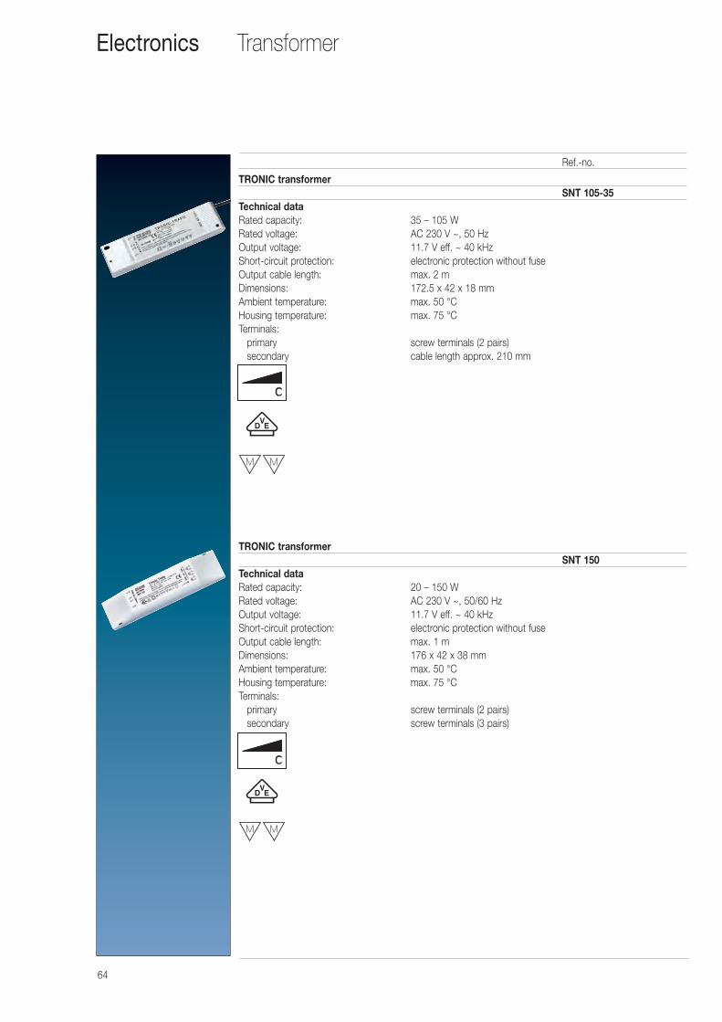
64
TransformerElectronics
TRONIC transformerSNT 105-35
Technical dataRated capacity: 35 – 105 WRated voltage: AC 230 V ~, 50 HzOutput voltage: 11.7 V eff. ~ 40 kHzShort-circuit protection: electronic protection without fuseOutput cable length: max. 2 mDimensions: 172.5 x 42 x 18 mm Ambient temperature: max. 50 °CHousing temperature: max. 75 °CTerminals:
primary screw terminals (2 pairs)secondary cable length approx. 210 mm
TRONIC transformerSNT 150
Technical dataRated capacity: 20 – 150 WRated voltage: AC 230 V ~, 50/60 HzOutput voltage: 11.7 V eff. ~ 40 kHzShort-circuit protection: electronic protection without fuseOutput cable length: max. 1 mDimensions: 176 x 42 x 38 mmAmbient temperature: max. 50 °CHousing temperature: max. 75 °CTerminals:
primary screw terminals (2 pairs)secondary screw terminals (3 pairs)
Ref.-no.
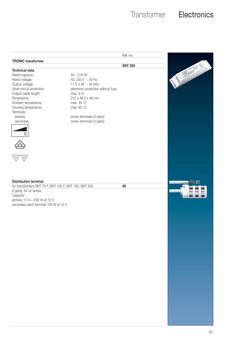
65
Transformer Electronics
TRONIC transformerSNT 200
Technical dataRated capacity: 50 – 210 WRated voltage: AC 230 V ~, 50 HzOutput voltage: 11.5 V eff. ~ 40 kHz Short-circuit protection: electronic protection without fuseOutput cable length: max. 2 mDimensions: 212 x 48.5 x 46 mmAmbient temperature: max. 45 °CHousing temperature: max. 65 °CTerminals:
primary screw terminals (2 pairs)secondary screw terminals (2 pairs)
Distribution terminalfor transformers SNT 70 F, SNT 105 F, SNT 150, SNT 200 266-gang, for LV lampsCapacity:primary 17 A = 200 W at 12 Vsecondary each terminal 100 W at 12 V
Ref.-no.
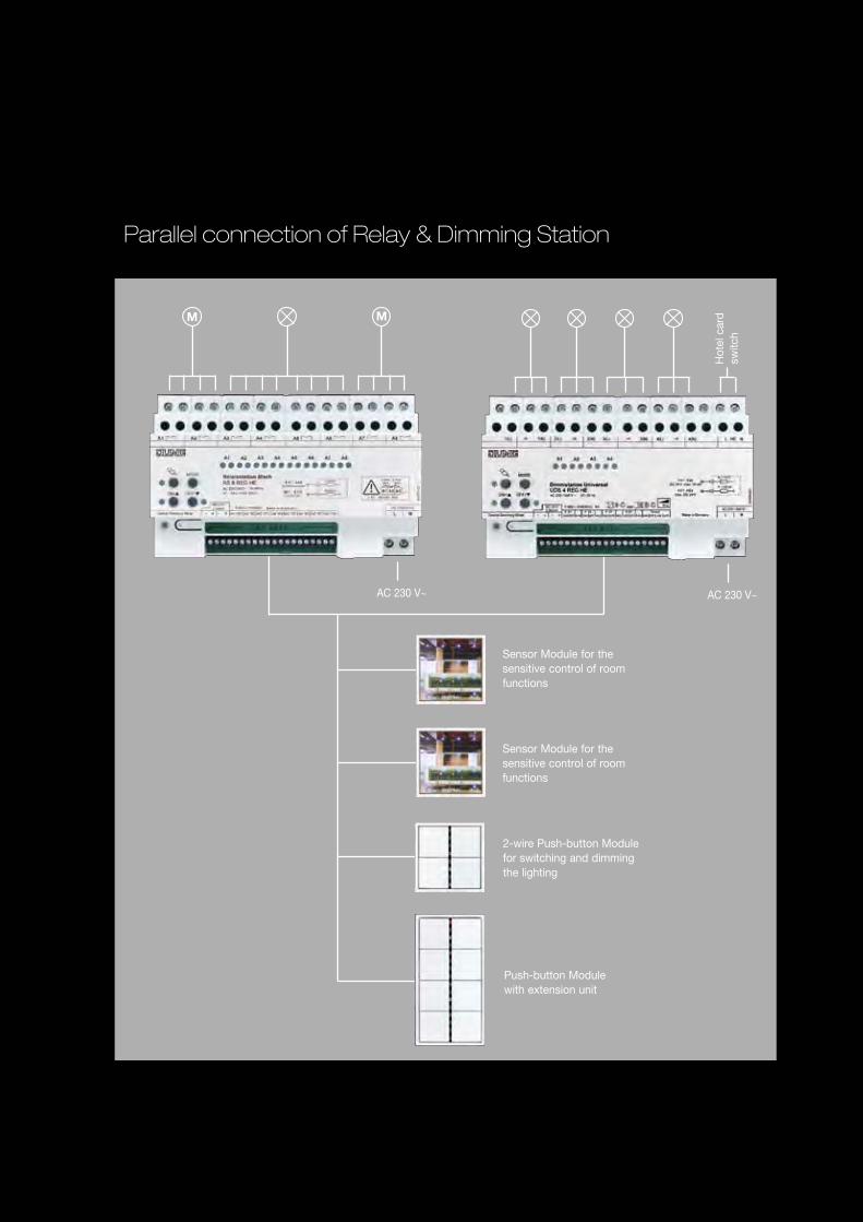
Sensor Module for the sensitive control of room functions
Sensor Module for the sensitive control of room functions
2-wire Push-button Module for switching and dimming the lighting
Push-button Module with extension unit
Connection of 4 control units to the Universal Relay Station
AC 230 V~
M M
Sensor Module for the sensitive control of room functions
Sensor Module for the sensitive control of room functions
2-wire Push-button Module for switching and dimming the lighting
Push-button Module with extension unit
AC 230 V~
M M
AC 230 V~
Hot
el c
ard
sw
itch
Parallel connection of Relay & Dimming Station
Wiring example of two Universal Dimming Stations with two sensor modules, a push-button module and a push-button module with extension unit. Simply connected via two wires.
JUN
G B
us
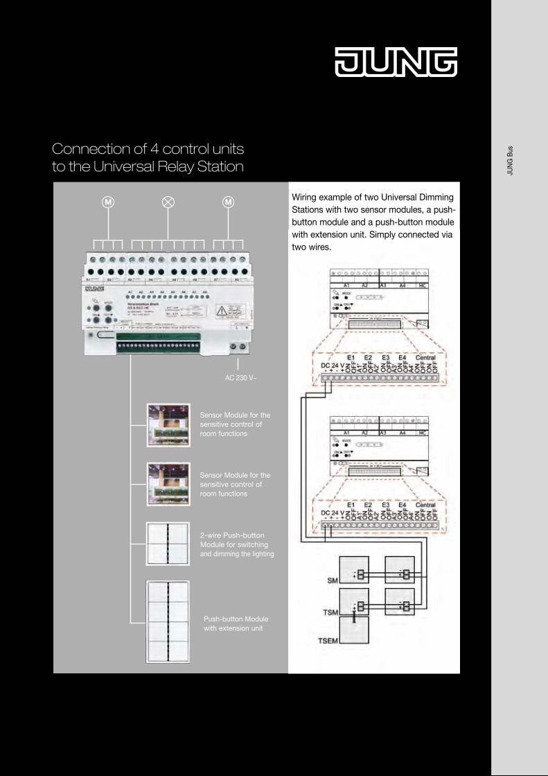
Sensor Module for the sensitive control of room functions
Sensor Module for the sensitive control of room functions
2-wire Push-button Module for switching and dimming the lighting
Push-button Module with extension unit
Connection of 4 control units to the Universal Relay Station
AC 230 V~
M M
Sensor Module for the sensitive control of room functions
Sensor Module for the sensitive control of room functions
2-wire Push-button Module for switching and dimming the lighting
Push-button Module with extension unit
AC 230 V~
M M
AC 230 V~
Hot
el c
ard
sw
itch
Parallel connection of Relay & Dimming Station
Wiring example of two Universal Dimming Stations with two sensor modules, a push-button module and a push-button module with extension unit. Simply connected via two wires.
JUN
G B
us
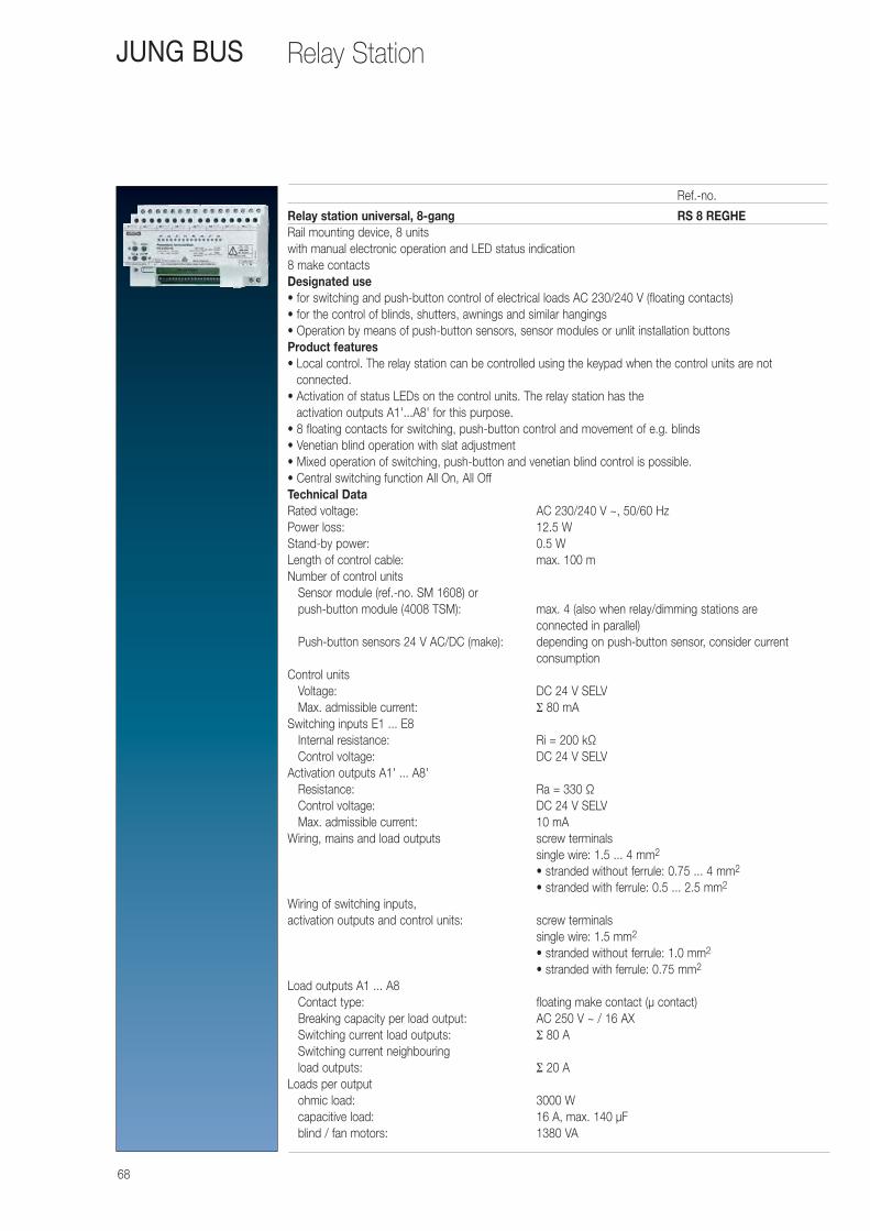
68
JUNG BUS
Relay station universal, 8-gang RS 8 REGHERail mounting device, 8 unitswith manual electronic operation and LED status indication8 make contactsDesignated use • for switching and push-button control of electrical loads AC 230/240 V (floating contacts) • for the control of blinds, shutters, awnings and similar hangings• Operation by means of push-button sensors, sensor modules or unlit installation buttonsProduct features • Local control. The relay station can be controlled using the keypad when the control units are not
connected. • Activation of status LEDs on the control units. The relay station has the
activation outputs A1'...A8' for this purpose. • 8 floating contacts for switching, push-button control and movement of e.g. blinds • Venetian blind operation with slat adjustment • Mixed operation of switching, push-button and venetian blind control is possible. • Central switching function All On, All OffTechnical Data Rated voltage: AC 230/240 V ~, 50/60 HzPower loss: 12.5 WStand-by power: 0.5 WLength of control cable: max. 100 mNumber of control units
Sensor module (ref.-no. SM 1608) or push-button module (4008 TSM): max. 4 (also when relay/dimming stations are
connected in parallel)Push-button sensors 24 V AC/DC (make): depending on push-button sensor, consider current
consumptionControl units
Voltage: DC 24 V SELVMax. admissible current: Σ 80 mA
Switching inputs E1 ... E8Internal resistance: Ri = 200 kΩControl voltage: DC 24 V SELV
Activation outputs A1' ... A8'Resistance: Ra = 330 ΩControl voltage: DC 24 V SELVMax. admissible current: 10 mA
Wiring, mains and load outputs screw terminalssingle wire: 1.5 ... 4 mm2
• stranded without ferrule: 0.75 ... 4 mm2
• stranded with ferrule: 0.5 ... 2.5 mm2
Wiring of switching inputs, activation outputs and control units: screw terminals
single wire: 1.5 mm2
• stranded without ferrule: 1.0 mm2
• stranded with ferrule: 0.75 mm2
Load outputs A1 ... A8Contact type: floating make contact (μ contact)Breaking capacity per load output: AC 250 V ~ / 16 AXSwitching current load outputs: Σ 80 ASwitching current neighbouring load outputs: Σ 20 A
Loads per outputohmic load: 3000 Wcapacitive load: 16 A, max. 140 μFblind / fan motors: 1380 VA
Ref.-no.
Relay Station
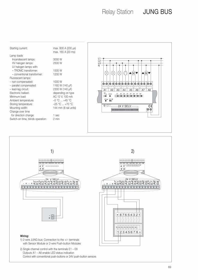
69
Relay Station JUNG BUS
Starting current: max. 800 A (200 μs)max. 165 A (20 ms)
Lamp loadsIncandescent lamps: 3000 WHV halogen lamps: 2500 WLV halogen lamps with:– TRONIC transformer: 1500 W– conventional transformer: 1200 W
Fluorescent lamps:– non-compensated: 1000 W– parallel compensated: 1160 W (140 μF)– lead-lag circuit: 2300 W (140 μF)Electronic ballast: depending on typeMinimum load: AC 12 V, 100 mAAmbient temperature: –5 °C ... +45 °CStoring temperature: –25 °C ... +70 °CMounting width: 144 mm (8 rail units)Change-over time
for direction change: 1 secSwitch-on time, blinds operation: 2 min
L1L2L3N
A1 A2 A3 A4 A5 A6 A7 A8
A1 A2 A3 A4 A5 A6 A7 A8
24 V SELV
M M
ON/ OFF/
MODE
- -+ +
A5 A6 A7 A8A1 A2 A3 A4
NL
MODE
OFF/oON/n
A1'
E1
A2'
E2
A3'
E3
A4'
E4
A5'
E5
A6'
E6
A7'
E7
A8'
E8
24 V SELV
24 V SELV
Wiring:1) 2-wire JUNG bus: Connection to the +/– terminals
with Sensor Module or 2-wire Push-button Modules
2) Single channel control with the terminals E1 – E8Outputs A1 – A8 enable LED status indication Control with conventional push-buttons or 24V push-button sensors
1) 2)
70
Dimming Station
Universal Dimming Station 4-gangRail mounting device,8 units
UDS 4 REGHEIntended use• Switching and dimming of incandescent lamps, 230 V halogen lamps, TRONIC and
conventional transformers• Mixed loads of the specified types (do not mix C and L loads)• Operation by means of push-button sensors, sensor modules, push-button modules or unlit
installation buttons• It is not possible to operate the device with universal amplifiers in conjunction with electronic transformers!
Please use Tronic amplifiers for power extension when operating electronic transformers.Product features• Local control. The dimming station can be controlled using the keypad when the control sections
are not connected.• Activation of status LEDs on the control sections. The relay station has the activation outputs
A1´...A4´ for this purpose.• Electronic short circuit protection with permanent cut-off after 7 seconds• Electronic overtemperature protection• Integrated memory function for each channel (storing of brightness value)• Lamp-saving soft start• Switching off with dim-down function• Increasing the capacity by means of parallel wiring of outputs possible• Connection of amplifier possible• Special connection for hotel card switch• Central switching function All On, All Off• Parallel connection of two dimming stations (or dimming + relay station) possibleFunction hotel card switchA hotel card switch is connected to the dimming station. When plugging in the hotel card the light will be switched on with the stored brightness level. After removing the hotel card the light remains on and can be controlled for 1 more minute. After the time has elapsed the light starts dimming down to minimum brightness and switches off within 3 minutes. The dimming station can be controlled again after plugging in the hotel card.
Technical Data Rated voltage: AC 230/240 V ~, 50/60 HzPower loss: max. 20 WStand-by power: max. 2 WTerminals –, +Control voltage: DC 24 V SELVMax. admissible current: Σ 80 mALength of control cable: max. 100 mNumber of control units
Sensor module (ref.-no. SM 1608): max. 4 (also when relay/dimming stations are connected in parallel)
Push-button module (ref.-no. 4008 TSM): max. 4 (also when relay/dimming stations are connected in parallel)
Push-button sensors 24 V AC/DC (make): depending on push-button sensor, consider current consumption
Switching inputs E1ON/OFF ... E4ON/OFFControl voltage: DC 24 V SELVResistance Ri: 200 kΩActivation outputs A1' ... A4'Control voltage: DC 24 V SELVMax. admissible current: 10 mAResistance Ra: 330 Ω
JUNG BUS
Ref.-no.
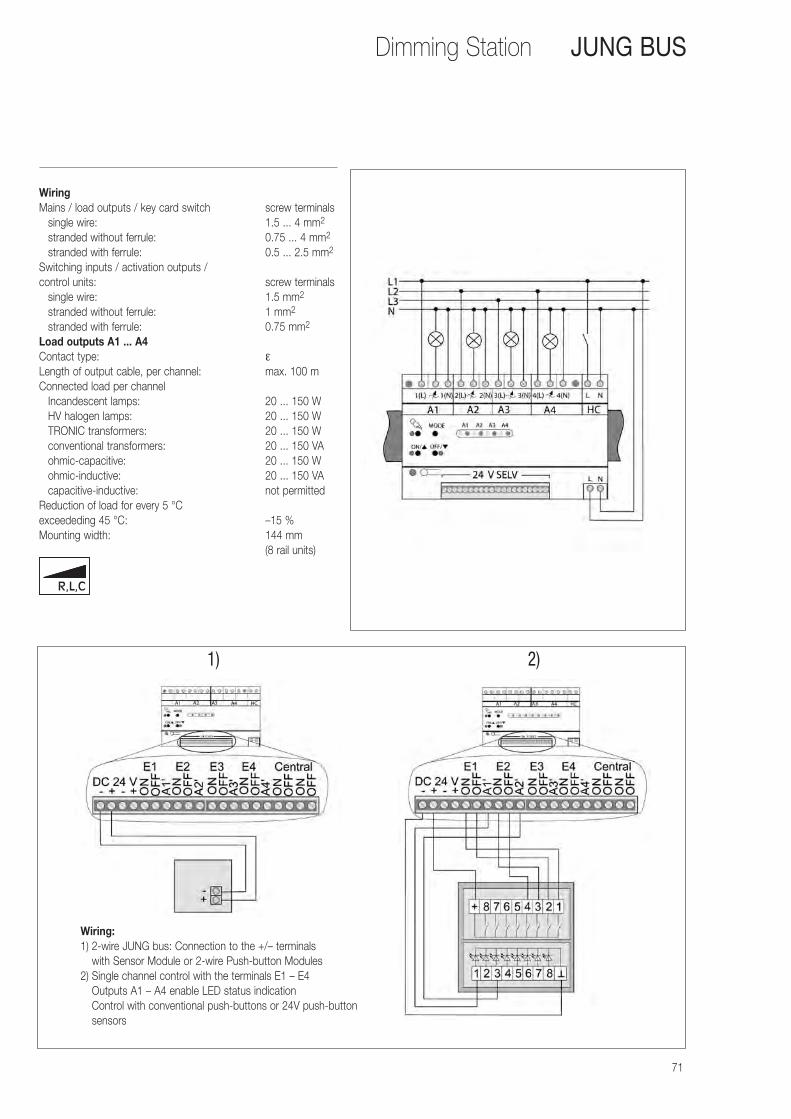
71
WiringMains / load outputs / key card switch screw terminals
single wire: 1.5 ... 4 mm2
stranded without ferrule: 0.75 ... 4 mm2
stranded with ferrule: 0.5 ... 2.5 mm2
Switching inputs / activation outputs / control units: screw terminals
single wire: 1.5 mm2
stranded without ferrule: 1 mm2
stranded with ferrule: 0.75 mm2
Load outputs A1 ... A4Contact type: ε Length of output cable, per channel: max. 100 mConnected load per channel
Incandescent lamps: 20 ... 150 WHV halogen lamps: 20 ... 150 WTRONIC transformers: 20 ... 150 Wconventional transformers: 20 ... 150 VAohmic-capacitive: 20 ... 150 Wohmic-inductive: 20 ... 150 VAcapacitive-inductive: not permitted
Reduction of load for every 5 °C exceededing 45 °C: –15 %Mounting width: 144 mm
(8 rail units)
Dimming Station JUNG BUS
Wiring:1) 2-wire JUNG bus: Connection to the +/– terminals
with Sensor Module or 2-wire Push-button Modules2) Single channel control with the terminals E1 – E4
Outputs A1 – A4 enable LED status indicationControl with conventional push-buttons or 24V push-button sensors
1) 2)
R,L,C
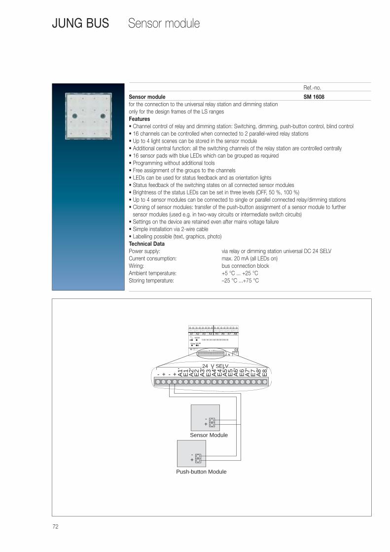
72
Sensor moduleJUNG BUS
Sensor module SM 1608for the connection to the universal relay station and dimming stationonly for the design frames of the LS rangesFeatures• Channel control of relay and dimming station: Switching, dimming, push-button control, blind control• 16 channels can be controlled when connected to 2 parallel-wired relay stations• Up to 4 light scenes can be stored in the sensor module• Additional central function: all the switching channels of the relay station are controlled centrally• 16 sensor pads with blue LEDs which can be grouped as required• Programming without additional tools• Free assignment of the groups to the channels• LEDs can be used for status feedback and as orientation lights• Status feedback of the switching states on all connected sensor modules• Brightness of the status LEDs can be set in three levels (OFF, 50 %, 100 %)• Up to 4 sensor modules can be connected to single or parallel connected relay/dimming stations• Cloning of sensor modules: transfer of the push-button assignment of a sensor module to further
sensor modules (used e.g. in two-way circuits or intermediate switch circuits)• Settings on the device are retained even after mains voltage failure• Simple installation via 2-wire cable• Labelling possible (text, graphics, photo)Technical Data Power supply: via relay or dimming station universal DC 24 SELVCurrent consumption: max. 20 mA (all LEDs on)Wiring: bus connection blockAmbient temperature: +5 °C ... +25 °CStoring temperature: –25 °C ...+75 °C
Ref.-no.
- -+ + A1'
E1
A2'
E2
A3'
E3
A4'
E4
A5'
E5
A6'
E6
A7'
E7
A8'
E8
24 V SELV
-+
Push-button Module
-+
Sensor Module

73
Push-button module JUNG BUS
Push-button module 4008 TSMfor the connection to the universal relay station and dimming stationAdapter frames ref.-no. LS 4 AR for LS design ranges is premounted
Features• Channel control of relay and dimming station: Switching, dimming, push-button control, blind control• 16 channels of 2 parallel-wired relay/dimming stations can be controlled in combination with push-button
extension module ref.-no.: 4094 TSEM• Up to 4 light scenes can be stored in the push-button module• Additional central function: all assigned channels of the relay station are controlled centrally • Push-buttons can be assigned according to cover kit• Programming without additional tools• Free assignment of the groups to the channels• 8 red status LED• 1 blue operation LED• Status feedback of the switching states to connected push-button modules and sensor modules• Up to 4 push-button modules with max. 4 extension modules can be connected to a relay station• Cloning of modules: transfer the assignment of one module to further modules• (Cloning of push-button modules with extension module is possible)• Simple installation via 2-wire cableTechnical Data Power supply: via relay station universal DC 24 V SELVCurrent consumption: max. 20 mA (all LEDs on)Wiring: bus connection blockAmbient temperature: +5 ... +25 °CStoring temperature: –25 ... +75 °C
Universal push-button extension module 4094 TSEMfor the extension of up to 8 additional push-buttons for the push-button module ref.-no. 4008 TSMpreferred installation: vertical8 red LED: status indication
Ref.-no.
metal supporting framepush-button module
extension module
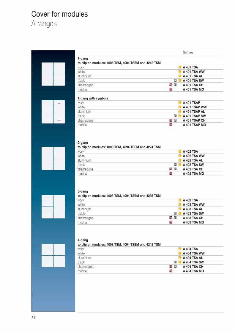
74
Cover for modulesA ranges
1-gang to clip on modules: 4008 TSM, 4094 TSEM and 4212 TSMivory A 401 TSAwhite A 401 TSA WWaluminium A 401 TSA ALblack A 401 TSA SWchamapgne A 401 TSA CHmocha A 401 TSA MO
1-gang with symbolsivory A 401 TSAPwhite A 401 TSAP WWaluminium A 401 TSAP ALblack A 401 TSAP SWchamapgne A 401 TSAP CHmocha A 401 TSAP MO
2-gang to clip on modules: 4008 TSM, 4094 TSEM and 4224 TSMivory A 402 TSAwhite A 402 TSA WWaluminium A 402 TSA ALblack A 402 TSA SWchamapgne A 402 TSA CHmocha A 402 TSA MO
3-gang to clip on modules: 4008 TSM, 4094 TSEM and 4236 TSMivory A 403 TSAwhite A 403 TSA WWaluminium A 403 TSA ALblack A 403 TSA SWchamapgne A 403 TSA CHmocha A 403 TSA MO
4-gang to clip on modules: 4008 TSM, 4094 TSEM and 4248 TSMivory A 404 TSAwhite A 404 TSA WWaluminium A 404 TSA ALblack A 404 TSA SWchamapgne A 404 TSA CHmocha A 404 TSA MON
PN
N
PN
N
PN
N
PN
N
PN
L
L
L
L
L
L
L
L
L
L
L
L
LP
LP
LP
LP
LP
L
L
L
Ref.-no.

75
Cover for modulesA ranges
Covers for 2-gang and 3-gang2-gang: to exchange both covers3-gang: to exchange right coverivory A 402 TSANwhite A 402 TSAN WWaluminium A 402 TSAN ALblack A 402 TSAN SWchamapgne A 402 TSAN CHmocha A 402 TSAN MO
Covers with symbols for 2-gang and 3-gangivory A 402 TSAPwhite A 402 TSAP WWaluminium A 402 TSAP ALblack A 402 TSAP SWchamapgne A 402 TSAP CHmocha A 402 TSAP MO
Covers for 3-gang and 4-gang3-gang: to exchange upper left cover4-gang: to exchange upper left or lower right coverivory A 404 TSAN 14white A 404 TSAN WW 14aluminium A 404 TSAN AL 14black A 404 TSAN SW 14chamapgne A 404 TSAN CH 14mocha A 404 TSAN MO 14
Covers with symbols for 3-gang and 4-gangivory A 404 TSAP 14white A 404 TSAP WW 14aluminium A 404 TSAP AL 14black A 404 TSAP SW 14chamapgne A 404 TSAP CH 14mocha A 404 TSAP MO 14
Covers for 3-gang and 4-gang3-gang: to exchange lower left cover4-gang: to exchange lower left or upper right coverivory A 404 TSAN 23white A 404 TSAN WW 23aluminium A 404 TSAN AL 23black A 404 TSAN SW 23chamapgne A 404 TSAN CH 23mocha A 404 TSAN MO 23
Covers with symbols for 3-gang and 4-gangivory A 404 TSAP 23white A 404 TSAP WW 23aluminium A 404 TSAP AL 23black A 404 TSAP SW 23chamapgne A 404 TSAP CH 23mocha A 404 TSAP MO 23
Important: There are different covers with symbol for each position on the push-button module. E.g. for the 4-gang module 2 different types of covers have to be selected. One for the upper left and lower right position, one for the upper right and the lower left position.
N
PN
N
PN
N
PN
N
PN
N
PN
N
PN
L
L
L
L
L
L
L
L
L
L
L
L
L
L
L
L
L
L
LP
LP
LP
LP
LP
LP
Ref.-no.
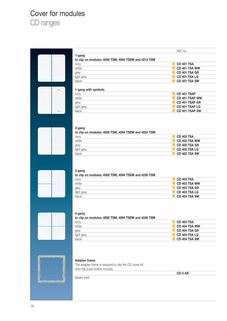
76
Cover for modulesCD ranges
1-gang to clip on modules: 4008 TSM, 4094 TSEM and 4212 TSMivory CD 401 TSAwhite CD 401 TSA WWgrey CD 401 TSA GRlight grey CD 401 TSA LGblack CD 401 TSA SW
1-gang with symbolsivory CD 401 TSAPwhite CD 401 TSAP WWgrey CD 401 TSAP GRlight grey CD 401 TSAP LGblack CD 401 TSAP SW
2-gang to clip on modules: 4008 TSM, 4094 TSEM and 4224 TSMivory CD 402 TSAwhite CD 402 TSA WWgrey CD 402 TSA GRlight grey CD 402 TSA LGblack CD 402 TSA SW
3-gang to clip on modules: 4008 TSM, 4094 TSEM and 4236 TSMivory CD 403 TSAwhite CD 403 TSA WWgrey CD 403 TSA GRlight grey CD 403 TSA LGblack CD 403 TSA SW
4-gang to clip on modules: 4008 TSM, 4094 TSEM and 4248 TSMivory CD 404 TSAwhite CD 404 TSA WWgrey CD 404 TSA GRlight grey CD 404 TSA LGblack CD 404 TSA SW
Adapter frameThe adapter frame is required to clip the CD cover kit onto the push-button module.
CD 4 AR(spare part)
L
L
L
L
L
L
L
L
L
L
L
L
L
L
L
L
L
L
L
L
L
L
L
L
L
Ref.-no.
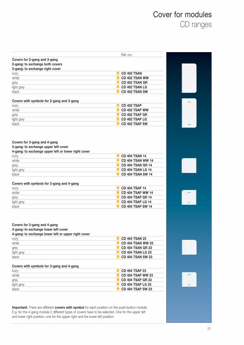
77
Cover for modulesCD ranges
Covers for 2-gang and 3-gang2-gang: to exchange both covers3-gang: to exchange right coverivory CD 402 TSANwhite CD 402 TSAN WWgrey CD 402 TSAN GRlight grey CD 402 TSAN LGblack CD 402 TSAN SW
Covers with symbols for 2-gang and 3-gangivory CD 402 TSAPwhite CD 402 TSAP WWgrey CD 402 TSAP GRlight grey CD 402 TSAP LGblack CD 402 TSAP SW
Covers for 3-gang and 4-gang3-gang: to exchange upper left cover4-gang: to exchange upper left or lower right coverivory CD 404 TSAN 14white CD 404 TSAN WW 14grey CD 404 TSAN GR 14light grey CD 404 TSAN LG 14black CD 404 TSAN SW 14
Covers with symbols for 3-gang and 4-gangivory CD 404 TSAP 14white CD 404 TSAP WW 14grey CD 404 TSAP GR 14light grey CD 404 TSAP LG 14black CD 404 TSAP SW 14
Covers for 3-gang and 4-gang3-gang: to exchange lower left cover4-gang: to exchange lower left or upper right coverivory CD 404 TSAN 23white CD 404 TSAN WW 23grey CD 404 TSAN GR 23light grey CD 404 TSAN LG 23black CD 404 TSAN SW 23
Covers with symbols for 3-gang and 4-gangivory CD 404 TSAP 23white CD 404 TSAP WW 23grey CD 404 TSAP GR 23light grey CD 404 TSAP LG 23black CD 404 TSAP SW 23
Important: There are different covers with symbol for each position on the push-button module. E.g. for the 4-gang module 2 different types of covers have to be selected. One for the upper left and lower right position, one for the upper right and the lower left position.
L
L
L
L
L
L
L
L
L
L
L
L
L
L
L
L
L
L
L
L
L
L
L
L
L
L
L
L
L
L
Ref.-no.

78
Cover for modulesLS 990
1-gang to clip on modules: 4008 TSM, 4094 TSEM and 4212 TSMiivory LS 401 TSAwhite LS 401 TSA WWlight grey LS 401 TSA LGblack LS 401 TSA SW
1-gang with symbolsivory LS 401 TSAPwhite LS 401 TSAP WWlight grey LS 401 TSAP LGblack LS 401 TSAP SW
2-gang to clip on modules: 4008 TSM, 4094 TSEM and 4224 TSMivory LS 402 TSAwhite LS 402 TSA WWlight grey LS 402 TSA LGblack LS 402 TSA SW
3-gang to clip on modules: 4008 TSM, 4094 TSEM and 4236 TSMivory LS 403 TSAwhite LS 403 TSA WWlight grey LS 403 TSA LGblack LS 403 TSA SW
4-gang to clip on modules: 4008 TSM, 4094 TSEM and 4248 TSMivory LS 404 TSAwhite LS 404 TSA WWlight grey LS 404 TSA LGblack LS 404 TSA SW
Adapter frameThe adapter frame is required to clip the LS cover kit onto the push-button module.
LS 4 AR(spare part)
L
L
L
L
L
L
L
L
L
L
L
L
L
L
L
L
L
L
L
L
Ref.-no.
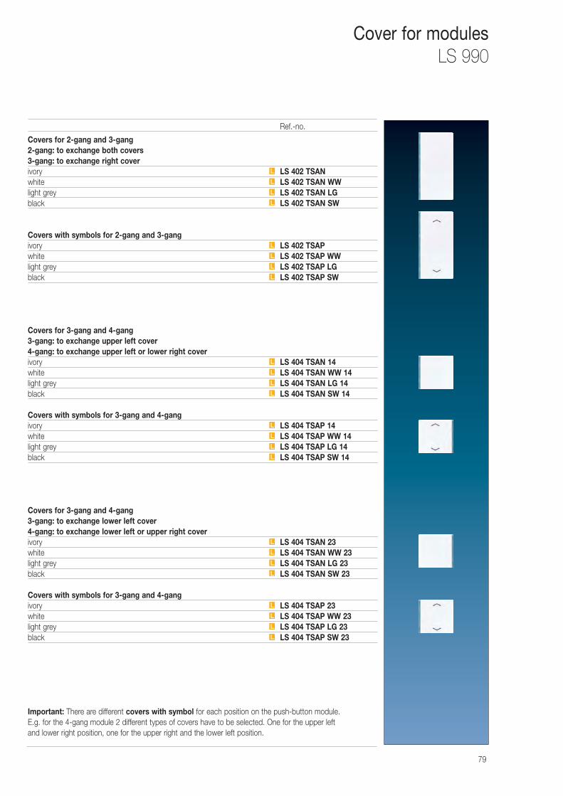
79
Cover for modulesLS 990
Covers for 2-gang and 3-gang2-gang: to exchange both covers3-gang: to exchange right coverivory LS 402 TSANwhite LS 402 TSAN WWlight grey LS 402 TSAN LGblack LS 402 TSAN SW
Covers with symbols for 2-gang and 3-gangivory LS 402 TSAPwhite LS 402 TSAP WWlight grey LS 402 TSAP LGblack LS 402 TSAP SW
Covers for 3-gang and 4-gang3-gang: to exchange upper left cover4-gang: to exchange upper left or lower right coverivory LS 404 TSAN 14white LS 404 TSAN WW 14light grey LS 404 TSAN LG 14black LS 404 TSAN SW 14
Covers with symbols for 3-gang and 4-gangivory LS 404 TSAP 14white LS 404 TSAP WW 14light grey LS 404 TSAP LG 14black LS 404 TSAP SW 14
Covers for 3-gang and 4-gang3-gang: to exchange lower left cover4-gang: to exchange lower left or upper right coverivory LS 404 TSAN 23white LS 404 TSAN WW 23light grey LS 404 TSAN LG 23black LS 404 TSAN SW 23
Covers with symbols for 3-gang and 4-gangivory LS 404 TSAP 23white LS 404 TSAP WW 23light grey LS 404 TSAP LG 23black LS 404 TSAP SW 23
Important: There are different covers with symbol for each position on the push-button module. E.g. for the 4-gang module 2 different types of covers have to be selected. One for the upper left and lower right position, one for the upper right and the lower left position.
L
L
L
L
L
L
L
L
L
L
L
L
L
L
L
L
L
L
L
L
L
L
L
L
Ref.-no.
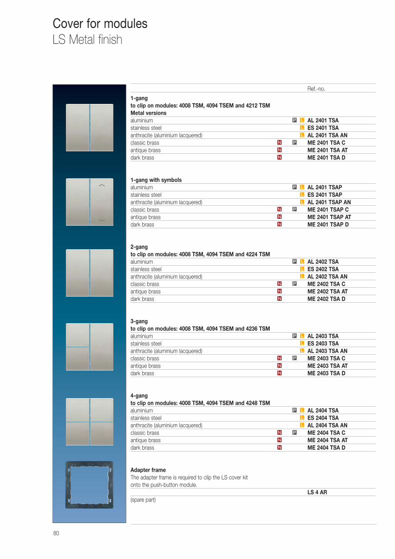
80
Cover for modulesLS Metal finish
1-gang to clip on modules: 4008 TSM, 4094 TSEM and 4212 TSMMetal versionsaluminium AL 2401 TSAstainless steel ES 2401 TSAanthracite (aluminium lacquered) AL 2401 TSA ANclassic brass ME 2401 TSA Cantique brass ME 2401 TSA ATdark brass ME 2401 TSA D
1-gang with symbolsaluminium AL 2401 TSAPstainless steel ES 2401 TSAPanthracite (aluminium lacquered) AL 2401 TSAP ANclassic brass ME 2401 TSAP Cantique brass ME 2401 TSAP ATdark brass ME 2401 TSAP D
2-gang to clip on modules: 4008 TSM, 4094 TSEM and 4224 TSMaluminium AL 2402 TSAstainless steel ES 2402 TSAanthracite (aluminium lacquered) AL 2402 TSA ANclassic brass ME 2402 TSA Cantique brass ME 2402 TSA ATdark brass ME 2402 TSA D
3-gang to clip on modules: 4008 TSM, 4094 TSEM and 4236 TSMaluminium AL 2403 TSAstainless steel ES 2403 TSAanthracite (aluminium lacquered) AL 2403 TSA ANclassic brass ME 2403 TSA Cantique brass ME 2403 TSA ATdark brass ME 2403 TSA D
4-gang to clip on modules: 4008 TSM, 4094 TSEM and 4248 TSMaluminium AL 2404 TSAstainless steel ES 2404 TSAanthracite (aluminium lacquered) AL 2404 TSA ANclassic brass ME 2404 TSA Cantique brass ME 2404 TSA ATdark brass ME 2404 TSA D
Adapter frameThe adapter frame is required to clip the LS cover kit onto the push-button module.
LS 4 AR(spare part)
PN
PN
PN
PN
L
L
L
L
L
L
L
L
LP
LP
LP
LP
N
N
N
N
N
N
N
N
N
N
PN
L
L
LP
Ref.-no.
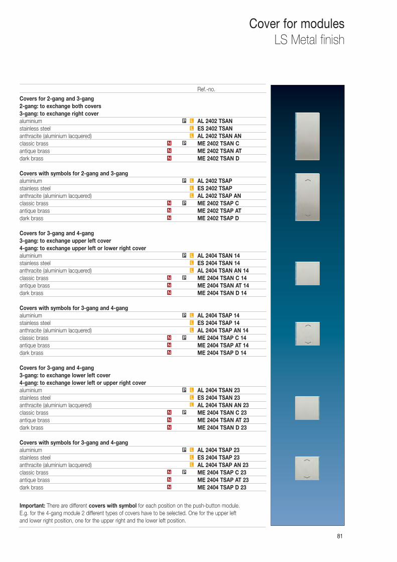
8181
Cover for modulesLS Metal finish
Covers for 2-gang and 3-gang2-gang: to exchange both covers3-gang: to exchange right coveraluminium AL 2402 TSANstainless steel ES 2402 TSANanthracite (aluminium lacquered) AL 2402 TSAN ANclassic brass ME 2402 TSAN Cantique brass ME 2402 TSAN ATdark brass ME 2402 TSAN D
Covers with symbols for 2-gang and 3-gangaluminium AL 2402 TSAPstainless steel ES 2402 TSAPanthracite (aluminium lacquered) AL 2402 TSAP ANclassic brass ME 2402 TSAP Cantique brass ME 2402 TSAP ATdark brass ME 2402 TSAP D
Covers for 3-gang and 4-gang3-gang: to exchange upper left cover4-gang: to exchange upper left or lower right coveraluminium AL 2404 TSAN 14stainless steel ES 2404 TSAN 14anthracite (aluminium lacquered) AL 2404 TSAN AN 14classic brass ME 2404 TSAN C 14antique brass ME 2404 TSAN AT 14dark brass ME 2404 TSAN D 14
Covers with symbols for 3-gang and 4-gangaluminium AL 2404 TSAP 14stainless steel ES 2404 TSAP 14anthracite (aluminium lacquered) AL 2404 TSAP AN 14classic brass ME 2404 TSAP C 14antique brass ME 2404 TSAP AT 14dark brass ME 2404 TSAP D 14
Covers for 3-gang and 4-gang3-gang: to exchange lower left cover4-gang: to exchange lower left or upper right coveraluminium AL 2404 TSAN 23stainless steel ES 2404 TSAN 23anthracite (aluminium lacquered) AL 2404 TSAN AN 23classic brass ME 2404 TSAN C 23antique brass ME 2404 TSAN AT 23dark brass ME 2404 TSAN D 23
Covers with symbols for 3-gang and 4-gangaluminium AL 2404 TSAP 23stainless steel ES 2404 TSAP 23anthracite (aluminium lacquered) AL 2404 TSAP AN 23classic brass ME 2404 TSAP C 23antique brass ME 2404 TSAP AT 23dark brass ME 2404 TSAP D 23
Important: There are different covers with symbol for each position on the push-button module. E.g. for the 4-gang module 2 different types of covers have to be selected. One for the upper left and lower right position, one for the upper right and the lower left position.
L
L
LP
L
L
LP
L
L
LP
L
L
LP
L
L
LP
L
L
LP
N
N
PN
N
N
PN
N
N
PN
N
N
PN
N
N
PN
N
N
PN
Ref.-no.
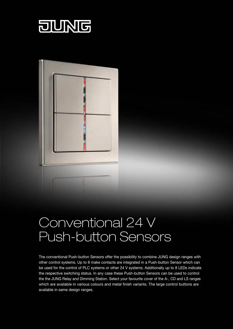
The conventional Push-button Sensors offer the possibility to combine JUNG design ranges with other control systems. Up to 8 make contacts are integrated in a Push-button Sensor which can be used for the control of PLC systems or other 24 V systems. Additionally up to 8 LEDs indicate the respective switching status. In any case these Push-button Sensors can be used to control the the JUNG Relay and Dimming Station. Select your favourite cover of the A-, CD and LS ranges which are available in various colours and metal finish variants. The large control buttons are available in same design ranges.
Conventional 24 V Push-button Sensors
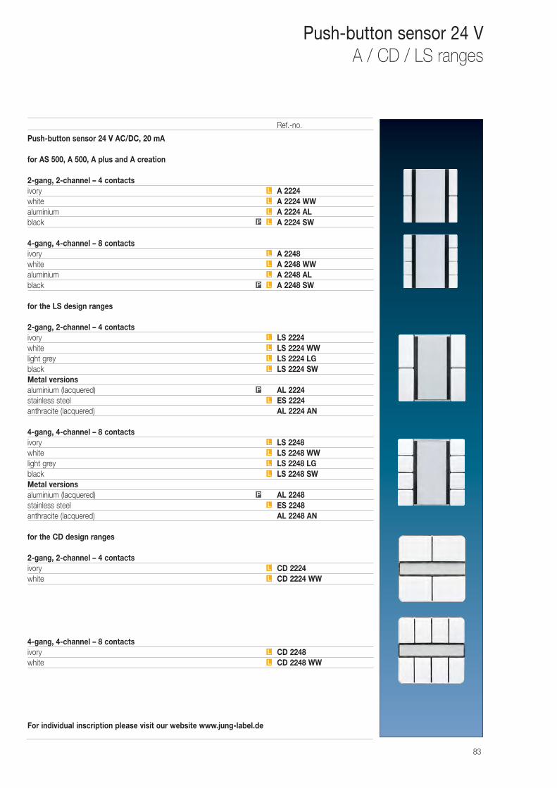
Push-button sensor 24 V AC/DC, 20 mA
for AS 500, A 500, A plus and A creation
2-gang, 2-channel – 4 contactsivory A 2224white A 2224 WWaluminium A 2224 ALblack A 2224 SW
4-gang, 4-channel – 8 contactsivory A 2248white A 2248 WWaluminium A 2248 ALblack A 2248 SW
for the LS design ranges
2-gang, 2-channel – 4 contactsivory LS 2224white LS 2224 WWlight grey LS 2224 LGblack LS 2224 SWMetal versionsaluminium (lacquered) AL 2224stainless steel ES 2224anthracite (lacquered) AL 2224 AN
4-gang, 4-channel – 8 contactsivory LS 2248white LS 2248 WWlight grey LS 2248 LGblack LS 2248 SWMetal versionsaluminium (lacquered) AL 2248stainless steel ES 2248anthracite (lacquered) AL 2248 AN
for the CD design ranges
2-gang, 2-channel – 4 contactsivory CD 2224white CD 2224 WW
4-gang, 4-channel – 8 contactsivory CD 2248white CD 2248 WW
For individual inscription please visit our website www.jung-label.de
L
L
L
L
L
P
L
L
L
L
L
P
L
L
L
L
LP
L
L
L
LP
L
L
L
83
Push-button sensor 24 VA / CD / LS ranges
Ref.-no.
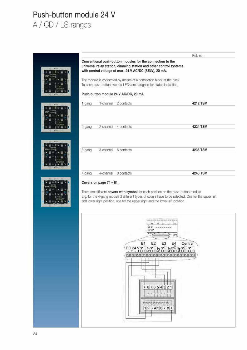
84
Push-button module 24 VA / CD / LS ranges
Conventional push-button modules for the connection to the universal relay station, dimming station and other control systems with control voltage of max. 24 V AC/DC (SELV), 20 mA.
The module is connected by means of a connection block at the back.To each push-button two red LEDs are assigned for status indication.
Push-button module 24 V AC/DC, 20 mA
1-gang 1-channel 2 contacts 4212 TSM
2-gang 2-channel 4 contacts 4224 TSM
3-gang 3-channel 6 contacts 4236 TSM
4-gang 4-channel 8 contacts 4248 TSM
Covers on page 74 – 81.
There are different covers with symbol for each position on the push-button module.E.g. for the 4-gang module 2 different types of covers have to be selected. One for the upper leftand lower right position, one for the upper right and the lower left position.
Ref.-no.
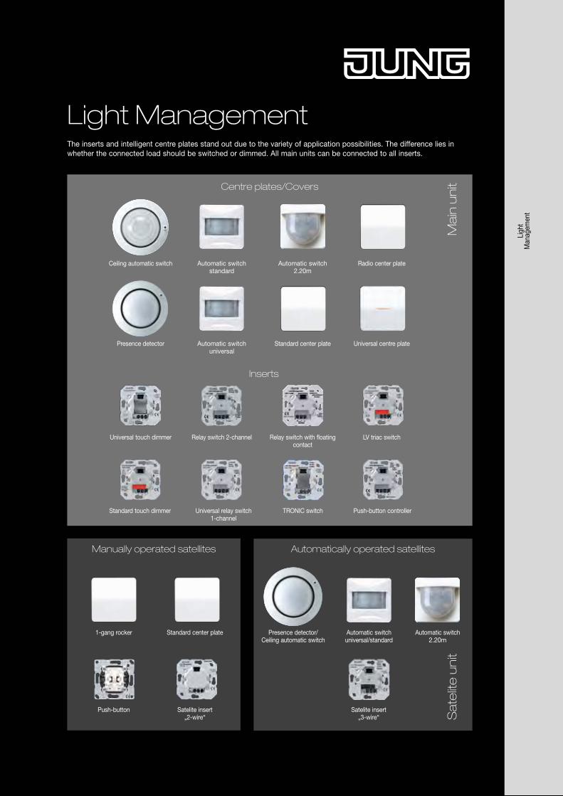
Light ManagementThe inserts and intelligent centre plates stand out due to the variety of application possibilities. The difference lies in whether the connected load should be switched or dimmed. All main units can be connected to all inserts.
Radio center plate
Automatic switchuniversal/standard
Automatically operated satellites
Automatic switch standard
Standard center plate
Satelite insert „2-wire“
1-gang rocker
Ceiling automatic switch
Push-button
Manually operated satellites
Sa
telit
e u
nit
LV triac switchRelay switch 2-channelUniversal touch dimmer Relay switch with floating contact
Push-button controllerUniversal relay switch 1-channel
Standard touch dimmer TRONIC switch
Presence detector/Ceiling automatic switch
Satelite insert „3-wire“
Universal centre plateAutomatic switch universal
Presence detector Standard center plate
Automatic switch 2.20m
Ma
in u
nitCentre plates/Covers
Inserts
Automatic switch 2.20m
Ligh
t M
anag
emen
t
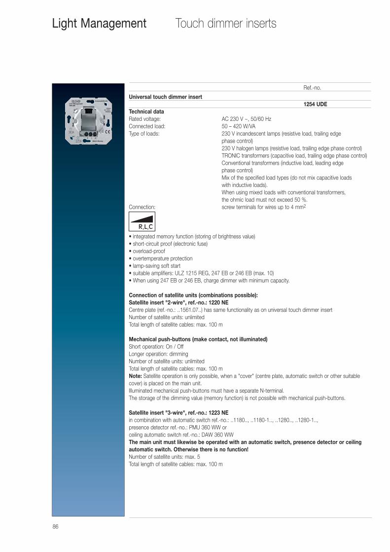
86
Touch dimmer insertsLight Management
Universal touch dimmer insert1254 UDE
Technical dataRated voltage: AC 230 V ~, 50/60 HzConnected load: 50 – 420 W/VAType of loads: 230 V incandescent lamps (resistive load, trailing edge
phase control)230 V halogen lamps (resistive load, trailing edge phase control)TRONIC transformers (capacitive load, trailing edge phase control)Conventional transformers (inductive load, leading edge phase control)Mix of the specified load types (do not mix capacitive loads with inductive loads).When using mixed loads with conventional transformers, the ohmic load must not exceed 50 %.
Connection: screw terminals for wires up to 4 mm2
• integrated memory function (storing of brightness value)• short-circuit proof (electronic fuse)• overload-proof• overtemperature protection• lamp-saving soft start• suitable amplifiers: ULZ 1215 REG, 247 EB or 246 EB (max. 10) • When using 247 EB or 246 EB, charge dimmer with minimum capacity.
Connection of satellite units (combinations possible):Satellite insert "2-wire", ref.-no.: 1220 NECentre plate (ref.-no.: ..1561.07..) has same functionality as on universal touch dimmer insertNumber of satellite units: unlimitedTotal length of satellite cables: max. 100 m
Mechanical push-buttons (make contact, not illuminated)Short operation: On / OffLonger operation: dimmingNumber of satellite units: unlimitedTotal length of satellite cables: max. 100 mNote: Satellite operation is only possible, when a "cover" (centre plate, automatic switch or other suitablecover) is placed on the main unit.Illuminated mechanical push-buttons must have a separate N-terminal.The storage of the dimming value (memory function) is not possible with mechanical push-buttons.
Satellite insert "3-wire", ref.-no.: 1223 NEin combination with automatic switch ref.-no.: ..1180.., ..1180-1.., ..1280.., ..1280-1..,presence detector ref.-no.: PMU 360 WW or ceiling automatic switch ref.-no.: DAW 360 WWThe main unit must likewise be operated with an automatic switch, presence detector or ceilingautomatic switch. Otherwise there is no function!Number of satellite units: max. 5Total length of satellite cables: max. 100 m
Ref.-no.
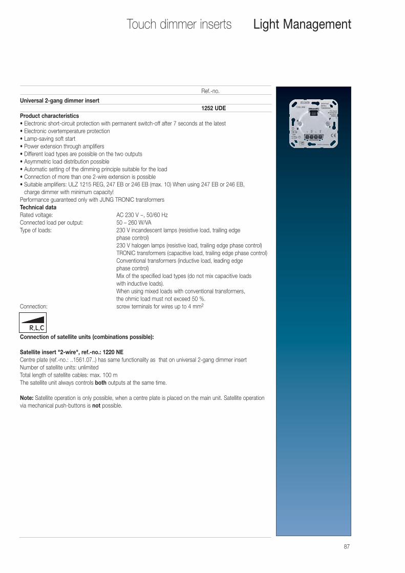
87
Touch dimmer inserts Light Management
Universal 2-gang dimmer insert1252 UDE
Product characteristics• Electronic short-circuit protection with permanent switch-off after 7 seconds at the latest• Electronic overtemperature protection• Lamp-saving soft start• Power extension through amplifiers• Different load types are possible on the two outputs• Asymmetric load distribution possible• Automatic setting of the dimming principle suitable for the load• Connection of more than one 2-wire extension is possible• Suitable amplifiers: ULZ 1215 REG, 247 EB or 246 EB (max. 10) When using 247 EB or 246 EB,
charge dimmer with minimum capacity! Performance guaranteed only with JUNG TRONIC transformersTechnical dataRated voltage: AC 230 V ~, 50/60 HzConnected load per output: 50 – 260 W/VAType of loads: 230 V incandescent lamps (resistive load, trailing edge
phase control)230 V halogen lamps (resistive load, trailing edge phase control)TRONIC transformers (capacitive load, trailing edge phase control)Conventional transformers (inductive load, leading edge phase control)Mix of the specified load types (do not mix capacitive loads with inductive loads).When using mixed loads with conventional transformers, the ohmic load must not exceed 50 %.
Connection: screw terminals for wires up to 4 mm2
Connection of satellite units (combinations possible):
Satellite insert "2-wire", ref.-no.: 1220 NECentre plate (ref.-no.: ..1561.07..) has same functionality as that on universal 2-gang dimmer insertNumber of satellite units: unlimitedTotal length of satellite cables: max. 100 mThe satellite unit always controls both outputs at the same time.
Note: Satellite operation is only possible, when a centre plate is placed on the main unit. Satellite operationvia mechanical push-buttons is not possible.
Ref.-no.
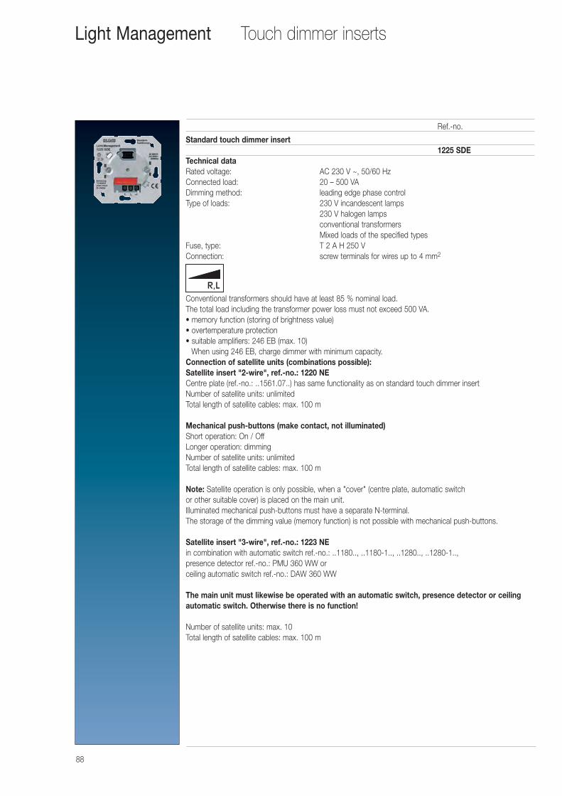
88
Touch dimmer insertsLight Management
Standard touch dimmer insert1225 SDE
Technical dataRated voltage: AC 230 V ~, 50/60 HzConnected load: 20 – 500 VADimming method: leading edge phase controlType of loads: 230 V incandescent lamps
230 V halogen lampsconventional transformersMixed loads of the specified types
Fuse, type: T 2 A H 250 VConnection: screw terminals for wires up to 4 mm2
Conventional transformers should have at least 85 % nominal load. The total load including the transformer power loss must not exceed 500 VA.• memory function (storing of brightness value)• overtemperature protection• suitable amplifiers: 246 EB (max. 10)
When using 246 EB, charge dimmer with minimum capacity.Connection of satellite units (combinations possible):Satellite insert "2-wire", ref.-no.: 1220 NECentre plate (ref.-no.: ..1561.07..) has same functionality as on standard touch dimmer insertNumber of satellite units: unlimitedTotal length of satellite cables: max. 100 m
Mechanical push-buttons (make contact, not illuminated)Short operation: On / OffLonger operation: dimmingNumber of satellite units: unlimitedTotal length of satellite cables: max. 100 m
Note: Satellite operation is only possible, when a "cover" (centre plate, automatic switch or other suitable cover) is placed on the main unit.Illuminated mechanical push-buttons must have a separate N-terminal.The storage of the dimming value (memory function) is not possible with mechanical push-buttons.
Satellite insert "3-wire", ref.-no.: 1223 NEin combination with automatic switch ref.-no.: ..1180.., ..1180-1.., ..1280.., ..1280-1..,presence detector ref.-no.: PMU 360 WW or ceiling automatic switch ref.-no.: DAW 360 WW
The main unit must likewise be operated with an automatic switch, presence detector or ceilingautomatic switch. Otherwise there is no function!
Number of satellite units: max. 10Total length of satellite cables: max. 100 m
Ref.-no.
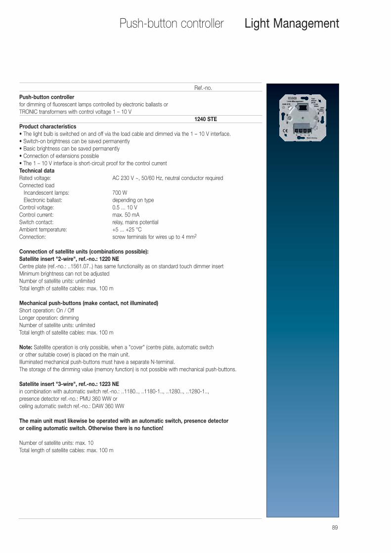
89
Push-button controllerfor dimming of fluorescent lamps controlled by electronic ballasts orTRONIC transformers with control voltage 1 – 10 V
1240 STEProduct characteristics• The light bulb is switched on and off via the load cable and dimmed via the 1 – 10 V interface.• Switch-on brightness can be saved permanently• Basic brightness can be saved permanently• Connection of extensions possible• The 1 – 10 V interface is short-circuit proof for the control currentTechnical dataRated voltage: AC 230 V ~, 50/60 Hz, neutral conductor requiredConnected load
Incandescent lamps: 700 WElectronic ballast: depending on type
Control voltage: 0.5 ... 10 VControl current: max. 50 mASwitch contact: relay, mains potentialAmbient temperature: +5 ... +25 °CConnection: screw terminals for wires up to 4 mm2
Connection of satellite units (combinations possible):Satellite insert "2-wire", ref.-no.: 1220 NECentre plate (ref.-no.: ..1561.07..) has same functionality as on standard touch dimmer insertMinimum brightness can not be adjustedNumber of satellite units: unlimitedTotal length of satellite cables: max. 100 m
Mechanical push-buttons (make contact, not illuminated)Short operation: On / OffLonger operation: dimmingNumber of satellite units: unlimitedTotal length of satellite cables: max. 100 m
Note: Satellite operation is only possible, when a "cover" (centre plate, automatic switch or other suitable cover) is placed on the main unit.Illuminated mechanical push-buttons must have a separate N-terminal.The storage of the dimming value (memory function) is not possible with mechanical push-buttons.
Satellite insert "3-wire", ref.-no.: 1223 NEin combination with automatic switch ref.-no.: ..1180.., ..1180-1.., ..1280.., ..1280-1..,presence detector ref.-no.: PMU 360 WW or ceiling automatic switch ref.-no.: DAW 360 WW
The main unit must likewise be operated with an automatic switch, presence detector or ceiling automatic switch. Otherwise there is no function!
Number of satellite units: max. 10Total length of satellite cables: max. 100 m
Ref.-no.
Push-button controller Light Management
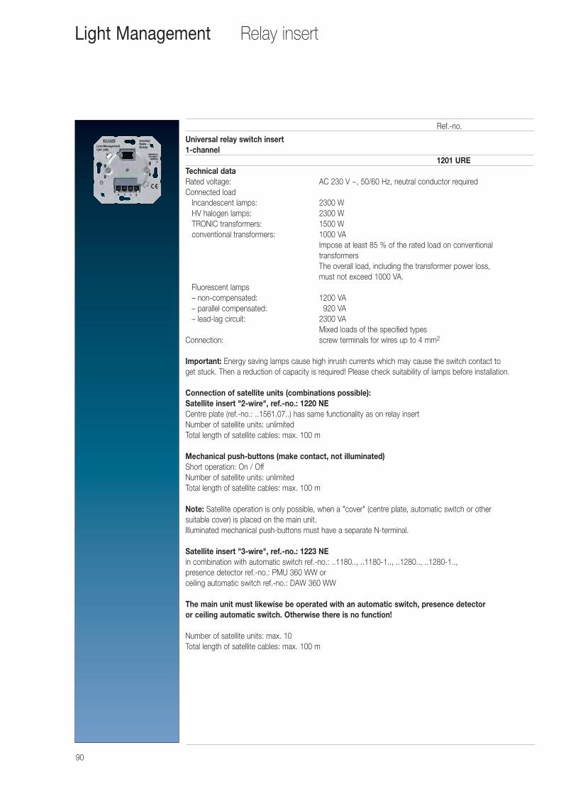
90
Universal relay switch insert 1-channel
1201 URETechnical dataRated voltage: AC 230 V ~, 50/60 Hz, neutral conductor requiredConnected load
Incandescent lamps: 2300 WHV halogen lamps: 2300 WTRONIC transformers: 1500 Wconventional transformers: 1000 VA
Impose at least 85 % of the rated load on conventional transformersThe overall load, including the transformer power loss, must not exceed 1000 VA.
Fluorescent lamps– non-compensated: 1200 VA– parallel compensated: 0920 VA– lead-lag circuit: 2300 VA
Mixed loads of the specified typesConnection: screw terminals for wires up to 4 mm2
Important: Energy saving lamps cause high inrush currents which may cause the switch contact to get stuck. Then a reduction of capacity is required! Please check suitability of lamps before installation.
Connection of satellite units (combinations possible):Satellite insert "2-wire", ref.-no.: 1220 NECentre plate (ref.-no.: ..1561.07..) has same functionality as on relay insertNumber of satellite units: unlimitedTotal length of satellite cables: max. 100 m
Mechanical push-buttons (make contact, not illuminated)Short operation: On / OffNumber of satellite units: unlimitedTotal length of satellite cables: max. 100 m
Note: Satellite operation is only possible, when a "cover" (centre plate, automatic switch or other suitable cover) is placed on the main unit.Illuminated mechanical push-buttons must have a separate N-terminal.
Satellite insert "3-wire", ref.-no.: 1223 NEin combination with automatic switch ref.-no.: ..1180.., ..1180-1.., ..1280.., ..1280-1..,presence detector ref.-no.: PMU 360 WW or ceiling automatic switch ref.-no.: DAW 360 WW
The main unit must likewise be operated with an automatic switch, presence detector or ceiling automatic switch. Otherwise there is no function!
Number of satellite units: max. 10Total length of satellite cables: max. 100 m
Ref.-no.
Relay insertLight Management
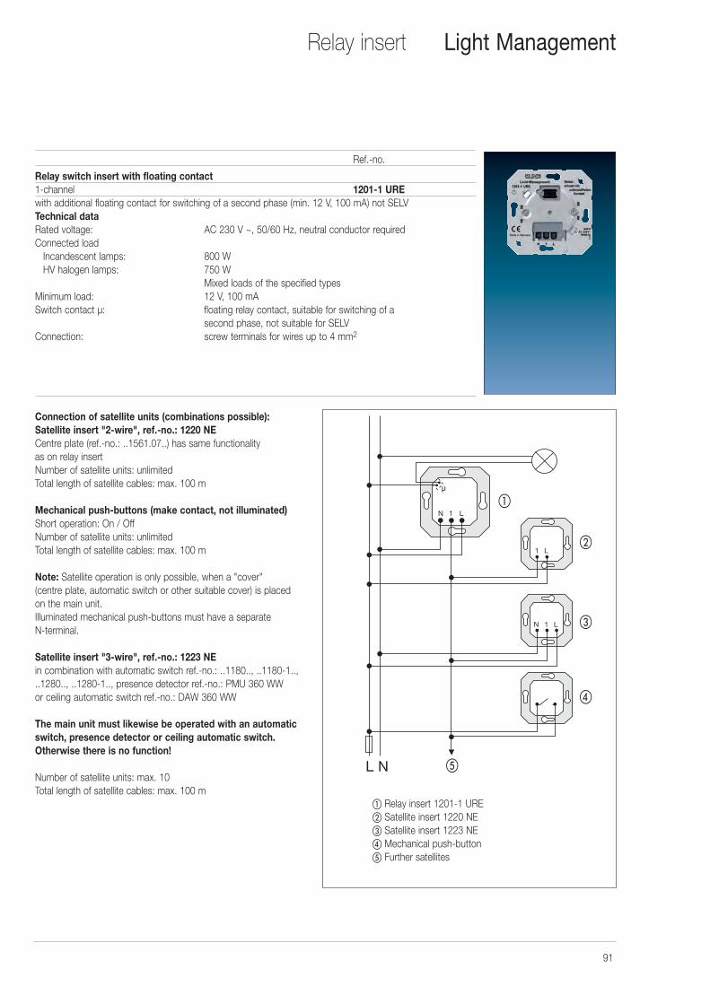
91
Relay switch insert with floating contact1-channel 1201-1 UREwith additional floating contact for switching of a second phase (min. 12 V, 100 mA) not SELVTechnical dataRated voltage: AC 230 V ~, 50/60 Hz, neutral conductor requiredConnected load
Incandescent lamps: 800 WHV halogen lamps: 750 W
Mixed loads of the specified typesMinimum load: 12 V, 100 mASwitch contact μ: floating relay contact, suitable for switching of a
second phase, not suitable for SELVConnection: screw terminals for wires up to 4 mm2
Connection of satellite units (combinations possible):Satellite insert "2-wire", ref.-no.: 1220 NECentre plate (ref.-no.: ..1561.07..) has same functionality as on relay insertNumber of satellite units: unlimitedTotal length of satellite cables: max. 100 m
Mechanical push-buttons (make contact, not illuminated)Short operation: On / OffNumber of satellite units: unlimitedTotal length of satellite cables: max. 100 m
Note: Satellite operation is only possible, when a "cover" (centre plate, automatic switch or other suitable cover) is placed on the main unit.Illuminated mechanical push-buttons must have a separate N-terminal.
Satellite insert "3-wire", ref.-no.: 1223 NEin combination with automatic switch ref.-no.: ..1180.., ..1180-1.., ..1280.., ..1280-1.., presence detector ref.-no.: PMU 360 WW or ceiling automatic switch ref.-no.: DAW 360 WW
The main unit must likewise be operated with an automatic switch, presence detector or ceiling automatic switch. Otherwise there is no function!
Number of satellite units: max. 10Total length of satellite cables: max. 100 m
Ref.-no.
Relay insert Light Management
� Relay insert 1201-1 URE� Satellite insert 1220 NE� Satellite insert 1223 NE � Mechanical push-button� Further satellites
�
�
�
�
�
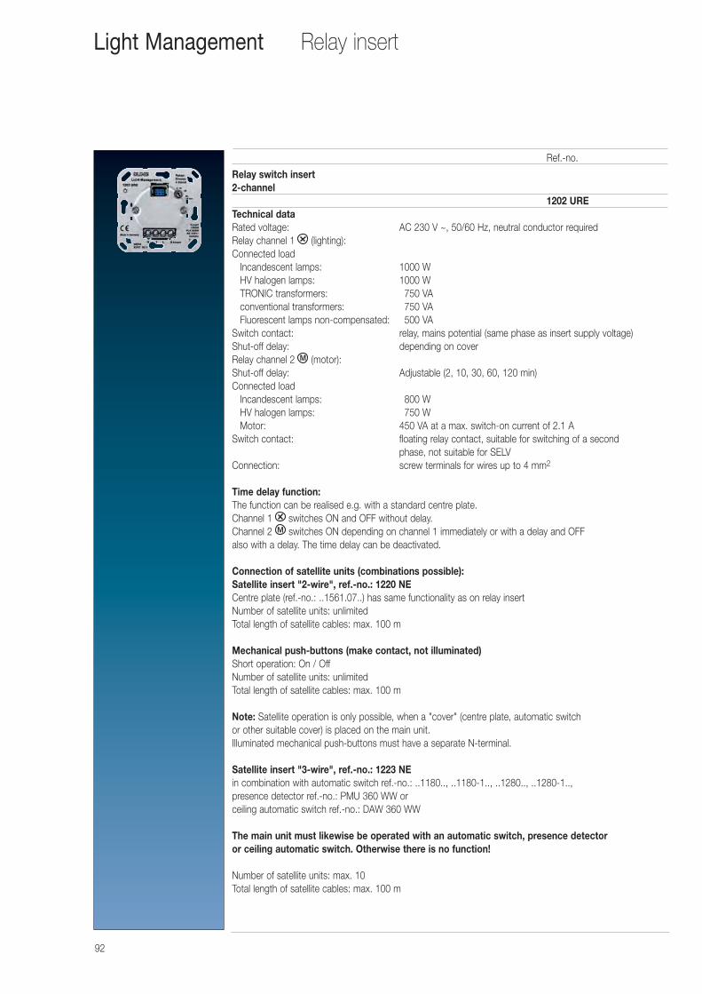
92
Relay switch insert 2-channel
1202 URETechnical dataRated voltage: AC 230 V ~, 50/60 Hz, neutral conductor requiredRelay channel 1 (lighting):Connected load
Incandescent lamps: 1000 WHV halogen lamps: 1000 WTRONIC transformers: 0750 VAconventional transformers: 0750 VAFluorescent lamps non-compensated: 0500 VA
Switch contact: relay, mains potential (same phase as insert supply voltage)Shut-off delay: depending on coverRelay channel 2 (motor):Shut-off delay: Adjustable (2, 10, 30, 60, 120 min)Connected load
Incandescent lamps: 0800 WHV halogen lamps: 0750 WMotor: 450 VA at a max. switch-on current of 2.1 A
Switch contact: floating relay contact, suitable for switching of a second phase, not suitable for SELV
Connection: screw terminals for wires up to 4 mm2
Time delay function:The function can be realised e.g. with a standard centre plate.Channel 1 switches ON and OFF without delay.Channel 2 switches ON depending on channel 1 immediately or with a delay and OFF also with a delay. The time delay can be deactivated.
Connection of satellite units (combinations possible):Satellite insert "2-wire", ref.-no.: 1220 NECentre plate (ref.-no.: ..1561.07..) has same functionality as on relay insertNumber of satellite units: unlimitedTotal length of satellite cables: max. 100 m
Mechanical push-buttons (make contact, not illuminated)Short operation: On / OffNumber of satellite units: unlimitedTotal length of satellite cables: max. 100 m
Note: Satellite operation is only possible, when a "cover" (centre plate, automatic switch or other suitable cover) is placed on the main unit.Illuminated mechanical push-buttons must have a separate N-terminal.
Satellite insert "3-wire", ref.-no.: 1223 NEin combination with automatic switch ref.-no.: ..1180.., ..1180-1.., ..1280.., ..1280-1..,presence detector ref.-no.: PMU 360 WW or ceiling automatic switch ref.-no.: DAW 360 WW
The main unit must likewise be operated with an automatic switch, presence detector or ceiling automatic switch. Otherwise there is no function!
Number of satellite units: max. 10Total length of satellite cables: max. 100 m
Ref.-no.
Relay insertLight Management
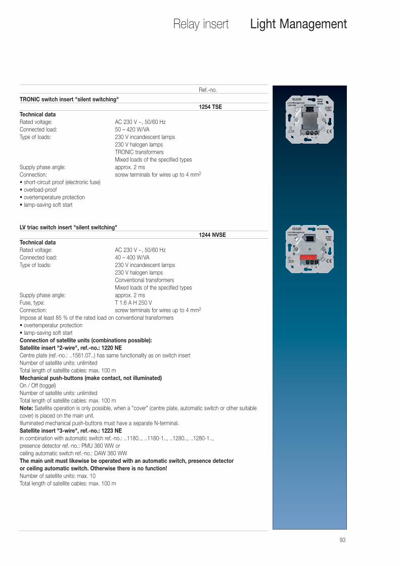
93
TRONIC switch insert "silent switching"1254 TSE
Technical dataRated voltage: AC 230 V ~, 50/60 HzConnected load: 50 – 420 W/VAType of loads: 230 V incandescent lamps
230 V halogen lampsTRONIC transformersMixed loads of the specified types
Supply phase angle: approx. 2 msConnection: screw terminals for wires up to 4 mm2
• short-circuit proof (electronic fuse)• overload-proof• overtemperature protection• lamp-saving soft start
LV triac switch insert "silent switching"1244 NVSE
Technical dataRated voltage: AC 230 V ~, 50/60 HzConnected load: 40 – 400 W/VAType of loads: 230 V incandescent lamps
230 V halogen lampsConventional transformersMixed loads of the specified types
Supply phase angle: approx. 2 msFuse, type: T 1.6 A H 250 VConnection: screw terminals for wires up to 4 mm2
Impose at least 85 % of the rated load on conventional transformers• overtemperatur protection• lamp-saving soft startConnection of satellite units (combinations possible):Satellite insert "2-wire", ref.-no.: 1220 NECentre plate (ref.-no.: ..1561.07..) has same functionality as on switch insertNumber of satellite units: unlimitedTotal length of satellite cables: max. 100 mMechanical push-buttons (make contact, not illuminated)On / Off (toggel)Number of satellite units: unlimitedTotal length of satellite cables: max. 100 mNote: Satellite operation is only possible, when a "cover" (centre plate, automatic switch or other suitablecover) is placed on the main unit.Illuminated mechanical push-buttons must have a separate N-terminal.Satellite insert "3-wire", ref.-no.: 1223 NEin combination with automatic switch ref.-no.: ..1180.., ..1180-1.., ..1280.., ..1280-1..,presence detector ref.-no.: PMU 360 WW or ceiling automatic switch ref.-no.: DAW 360 WWThe main unit must likewise be operated with an automatic switch, presence detector or ceiling automatic switch. Otherwise there is no function!Number of satellite units: max. 10Total length of satellite cables: max. 100 m
Ref.-no.
Relay insert Light Management
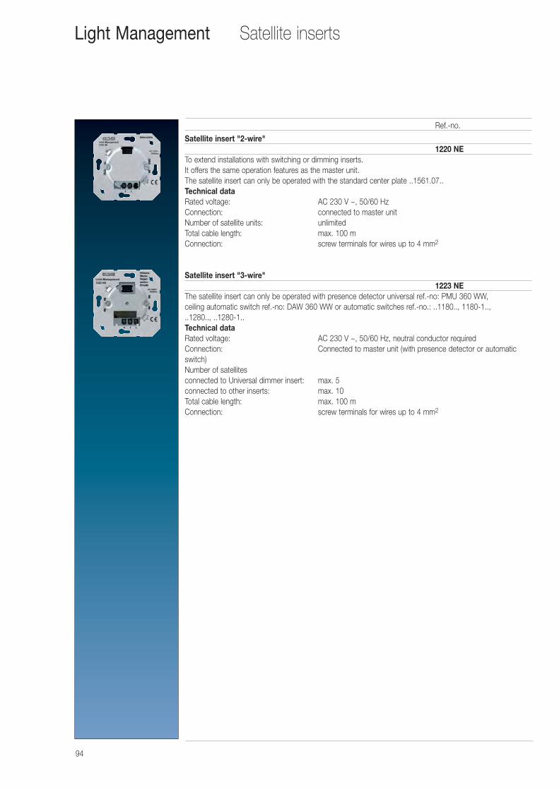
94
Satellite insert "2-wire"1220 NE
To extend installations with switching or dimming inserts.It offers the same operation features as the master unit.The satellite insert can only be operated with the standard center plate ..1561.07..Technical dataRated voltage: AC 230 V ~, 50/60 HzConnection: connected to master unitNumber of satellite units: unlimitedTotal cable length: max. 100 mConnection: screw terminals for wires up to 4 mm2
Satellite insert "3-wire"1223 NE
The satellite insert can only be operated with presence detector universal ref.-no: PMU 360 WW, ceiling automatic switch ref.-no: DAW 360 WW or automatic switches ref.-no.: ..1180.., 1180-1.., ..1280.., ..1280-1..Technical dataRated voltage: AC 230 V ~, 50/60 Hz, neutral conductor requiredConnection: Connected to master unit (with presence detector or automaticswitch)Number of satellitesconnected to Universal dimmer insert: max. 5connected to other inserts: max. 10Total cable length: max. 100 mConnection: screw terminals for wires up to 4 mm2
Ref.-no.
Satellite insertsLight Management
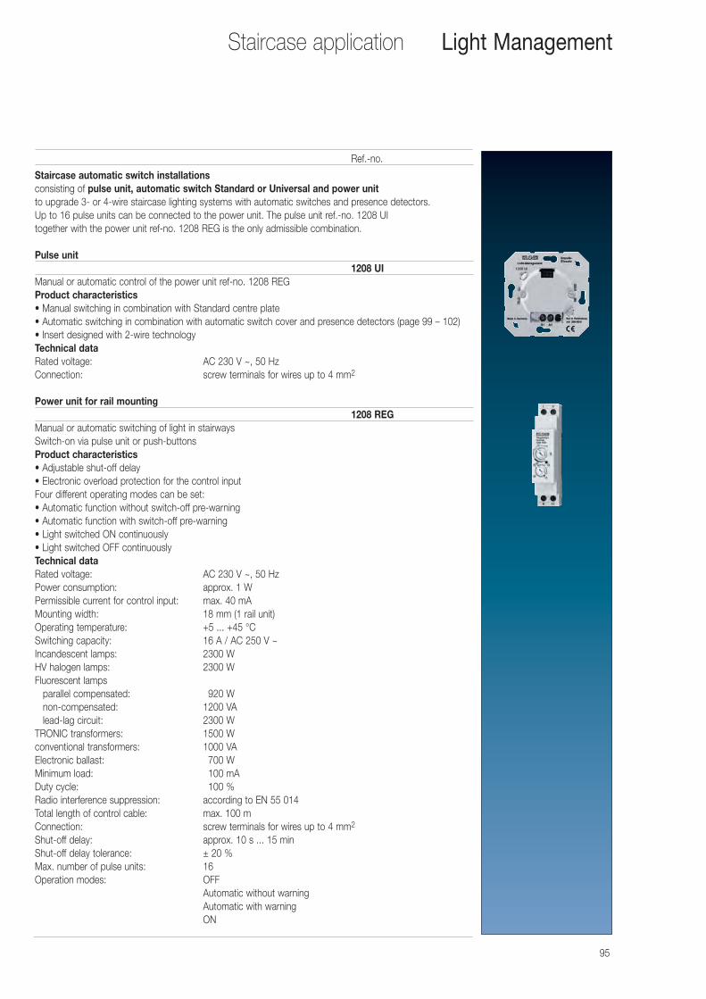
95
Staircase automatic switch installationsconsisting of pulse unit, automatic switch Standard or Universal and power unit to upgrade 3- or 4-wire staircase lighting systems with automatic switches and presence detectors.Up to 16 pulse units can be connected to the power unit. The pulse unit ref.-no. 1208 UI together with the power unit ref-no. 1208 REG is the only admissible combination.
Pulse unit1208 UI
Manual or automatic control of the power unit ref-no. 1208 REGProduct characteristics• Manual switching in combination with Standard centre plate• Automatic switching in combination with automatic switch cover and presence detectors (page 99 – 102)• Insert designed with 2-wire technologyTechnical dataRated voltage: AC 230 V ~, 50 HzConnection: screw terminals for wires up to 4 mm2
Power unit for rail mounting1208 REG
Manual or automatic switching of light in stairways Switch-on via pulse unit or push-buttonsProduct characteristics• Adjustable shut-off delay • Electronic overload protection for the control input Four different operating modes can be set: • Automatic function without switch-off pre-warning • Automatic function with switch-off pre-warning • Light switched ON continuously • Light switched OFF continuouslyTechnical dataRated voltage: AC 230 V ~, 50 HzPower consumption: approx. 1 WPermissible current for control input: max. 40 mAMounting width: 18 mm (1 rail unit)Operating temperature: +5 ... +45 °CSwitching capacity: 16 A / AC 250 V ~Incandescent lamps: 2300 WHV halogen lamps: 2300 WFluorescent lamps
parallel compensated: 0920 Wnon-compensated: 1200 VAlead-lag circuit: 2300 W
TRONIC transformers: 1500 Wconventional transformers: 1000 VAElectronic ballast: 0700 WMinimum load: 0100 mADuty cycle: 0100 %Radio interference suppression: according to EN 55 014Total length of control cable: max. 100 mConnection: screw terminals for wires up to 4 mm2
Shut-off delay: approx. 10 s ... 15 minShut-off delay tolerance: ± 20 %Max. number of pulse units: 16Operation modes: OFF
Automatic without warningAutomatic with warningON
Ref.-no.
Staircase application Light Management
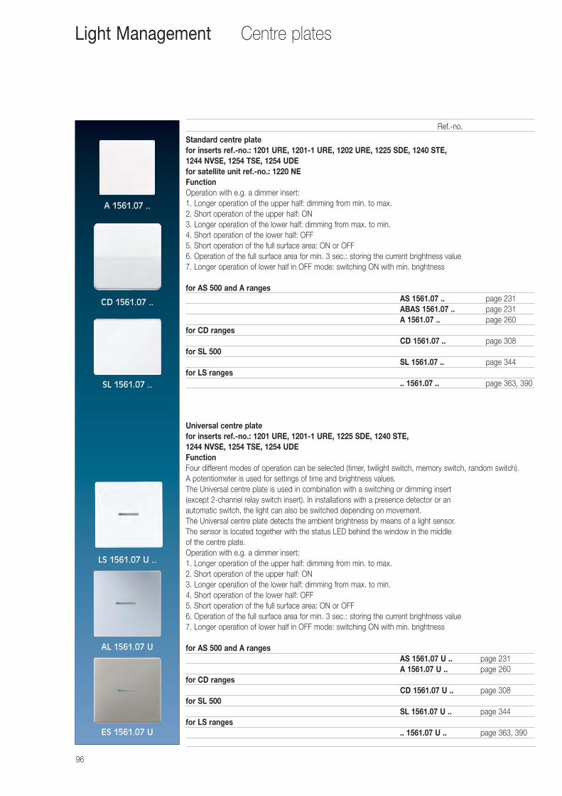
96
Standard centre platefor inserts ref.-no.: 1201 URE, 1201-1 URE, 1202 URE, 1225 SDE, 1240 STE, 1244 NVSE, 1254 TSE, 1254 UDEfor satellite unit ref.-no.: 1220 NEFunctionOperation with e.g. a dimmer insert:1. Longer operation of the upper half: dimming from min. to max.2. Short operation of the upper half: ON3. Longer operation of the lower half: dimming from max. to min.4. Short operation of the lower half: OFF5. Short operation of the full surface area: ON or OFF6. Operation of the full surface area for min. 3 sec.: storing the current brightness value7. Longer operation of lower half in OFF mode: switching ON with min. brightness
for AS 500 and A rangesAS 1561.07 .. page 231ABAS 1561.07 .. page 231A 1561.07 .. page 260
for CD rangesCD 1561.07 .. page 308
for SL 500SL 1561.07 .. page 344
for LS ranges.. 1561.07 .. page 363, 390
Universal centre platefor inserts ref.-no.: 1201 URE, 1201-1 URE, 1225 SDE, 1240 STE, 1244 NVSE, 1254 TSE, 1254 UDEFunctionFour different modes of operation can be selected (timer, twilight switch, memory switch, random switch).A potentiometer is used for settings of time and brightness values. The Universal centre plate is used in combination with a switching or dimming insert (except 2-channel relay switch insert). In installations with a presence detector or an automatic switch, the light can also be switched depending on movement. The Universal centre plate detects the ambient brightness by means of a light sensor. The sensor is located together with the status LED behind the window in the middle of the centre plate.Operation with e.g. a dimmer insert:1. Longer operation of the upper half: dimming from min. to max.2. Short operation of the upper half: ON3. Longer operation of the lower half: dimming from max. to min.4. Short operation of the lower half: OFF5. Short operation of the full surface area: ON or OFF6. Operation of the full surface area for min. 3 sec.: storing the current brightness value7. Longer operation of lower half in OFF mode: switching ON with min. brightness
for AS 500 and A rangesAS 1561.07 U .. page 231A 1561.07 U .. page 260
for CD rangesCD 1561.07 U .. page 308
for SL 500SL 1561.07 U .. page 344
for LS ranges.. 1561.07 U .. page 363, 390
Ref.-no.
Centre platesLight Management
A 1561.07 ..
CD 1561.07 ..
SL 1561.07 ..
LS 1561.07 U ..
AL 1561.07 U
ES 1561.07 U
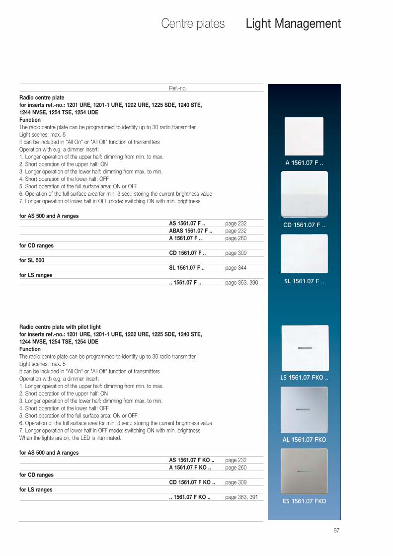
97
Radio centre platefor inserts ref.-no.: 1201 URE, 1201-1 URE, 1202 URE, 1225 SDE, 1240 STE, 1244 NVSE, 1254 TSE, 1254 UDEFunctionThe radio centre plate can be programmed to identify up to 30 radio transmitter.Light scenes: max. 5It can be included in "All On" or "All Off" function of transmittersOperation with e.g. a dimmer insert:1. Longer operation of the upper half: dimming from min. to max.2. Short operation of the upper half: ON3. Longer operation of the lower half: dimming from max. to min.4. Short operation of the lower half: OFF5. Short operation of the full surface area: ON or OFF6. Operation of the full surface area for min. 3 sec.: storing the current brightness value7. Longer operation of lower half in OFF mode: switching ON with min. brightness
for AS 500 and A rangesAS 1561.07 F .. page 232ABAS 1561.07 F .. page 232A 1561.07 F .. page 260
for CD rangesCD 1561.07 F .. page 309
for SL 500SL 1561.07 F .. page 344
for LS ranges.. 1561.07 F .. page 363, 390
Radio centre plate with pilot lightfor inserts ref.-no.: 1201 URE, 1201-1 URE, 1202 URE, 1225 SDE, 1240 STE, 1244 NVSE, 1254 TSE, 1254 UDEFunctionThe radio centre plate can be programmed to identify up to 30 radio transmitter.Light scenes: max. 5It can be included in "All On" or "All Off" function of transmittersOperation with e.g. a dimmer insert:1. Longer operation of the upper half: dimming from min. to max.2. Short operation of the upper half: ON3. Longer operation of the lower half: dimming from max. to min.4. Short operation of the lower half: OFF5. Short operation of the full surface area: ON or OFF6. Operation of the full surface area for min. 3 sec.: storing the current brightness value7. Longer operation of lower half in OFF mode: switching ON with min. brightnessWhen the lights are on, the LED is illuminated.
for AS 500 and A rangesAS 1561.07 F KO .. page 232A 1561.07 F KO .. page 260
for CD rangesCD 1561.07 F KO .. page 309
for LS ranges.. 1561.07 F KO .. page 363, 391
Ref.-no.
Centre plates Light Management
A 1561.07 F ..
CD 1561.07 F ..
SL 1561.07 F ..
LS 1561.07 FKO ..
AL 1561.07 FKO
ES 1561.07 FKO
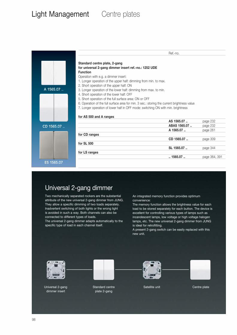
98
Standard centre plate, 2-gangfor universal 2-gang dimmer insert ref.-no.: 1252 UDEFunctionOperation with e.g. a dimmer insert:1. Longer operation of the upper half: dimming from min. to max.2. Short operation of the upper half: ON3. Longer operation of the lower half: dimming from max. to min.4. Short operation of the lower half: OFF5. Short operation of the full surface area: ON or OFF6. Operation of the full surface area for min. 3 sec.: storing the current brightness value7. Longer operation of lower half in OFF mode: switching ON with min. brightness
for AS 500 and A rangesAS 1565.07 .. page 232ABAS 1565.07 .. page 232A 1565.07 .. page 261
for CD rangesCD 1565.07 .. page 309
for SL 500SL 1565.07 .. page 344
for LS ranges.. 1565.07 .. page 364, 391
Ref.-no.
Centre platesLight Management
A 1565.07 ..
CD 1565.07 ..
ES 1565.07
Centre plateSatellite unitStandard centreplate 2-gang
Universal 2-gangdimmer insert
Universal 2-gang dimmerTwo mechanically separated rockers are the substantialattribute of the new universal 2-gang dimmer from JUNG.They allow a specific dimming of two loads separately.Inadvertent switching of both lights or the wrong light is avoided in such a way. Both channels can also be connected to different types of loads. The universal 2-gang dimmer adapts automatically to thespecific type of load in each channel itself.
An integrated memory function provides optimum convenience:The memory function allows the brightness value for eachload to be stored separately for each button. The device isexcellent for controlling various types of lamps such asincandescent lamps, low voltage or high voltage halogenlamps, etc. The new universal 2-gang dimmer from JUNG is ideal for retrofitting. A present 2-gang switch can be easily replaced with thisnew unit.

99
Automatic switch 180° for 1.1 m mounting heightfor inserts ref.-no.: 1201 URE, 1201-1 URE, 1202 URE, 1225 SDE, 1240 STE, 1244 NVSE, 1254 TSE, 1254 UDE, 1208 UIfor satellite unit ref.-no.: 1223 NE
Product characteristics of the "standard" version• Sensitivity and brightness threshold settable• Manual switch-on possible via extension insert, 2-wire, or installation button• 18 lens segments in 2 detection levels• Extension of the detection area in combination with the 3-wire extension insert• Detection area can be limited using cover plate
Additional characteristics of the "universal" version• Shut-off delay, sensitivity and brightness threshold settable• Teach function to save the current brightness as the new brightness threshold.• Operating mode switch for automatic operation, continuous on or off• Short-time operation, e.g. to control acoustic signal encoders• With the dimmer insert, it is possible to change the brightness using a 2-wire extension insert• Switch-on brightness can be saved with the dimmer insert• With the dimmer insert, the dim-down function is possible at the end of the shut-off delay• High protection against ambient light
for AS 500 and A ranges1.1 m – Standard A 1180 .. page 2321.1 m – Universal A 1180-1 .. page 2321.1 m – IP 44 – Standard A 1180 WU .. page 2321.1 m – IP 44 – Universal A 1180-1 WU .. page 233
for CD ranges1.1 m – Standard CD 1180 .. page 3091.1 m – Universal CD 1180-1 .. page 3101.1 m – IP 44 – Standard CD 1180 WU .. page 3101.1 m – IP 44 – Universal CD 1180-1 WU .. page 310
for SL 5001.1 m – Universal SL 1180-1 .. page 344
for LS ranges1.1 m – Standard .. 1180 .. page 3641.1 m – Universal .. 1180-1 .. page 3641.1 m – IP 44 – Standard ES 1180 WU page 3911.1 m – IP 44 – Universal ES 1180-1 WU page 391
Ref.-no.
Automatic switch Light Management
A 1180 ..
CD 1180 ..
SL 1180 ..
LS 1180 ..
1.10
m
~ 1
2 m
~ 10 m
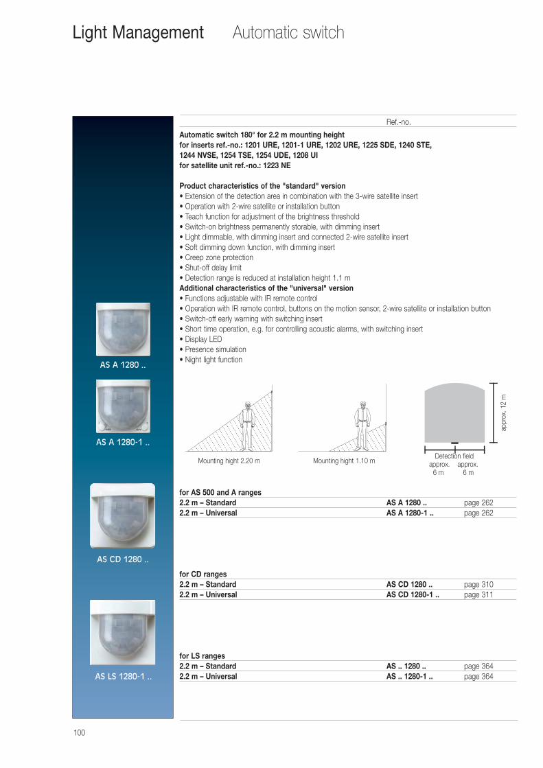
100
Automatic switch 180° for 2.2 m mounting heightfor inserts ref.-no.: 1201 URE, 1201-1 URE, 1202 URE, 1225 SDE, 1240 STE, 1244 NVSE, 1254 TSE, 1254 UDE, 1208 UIfor satellite unit ref.-no.: 1223 NE
Product characteristics of the "standard" version• Extension of the detection area in combination with the 3-wire satellite insert• Operation with 2-wire satellite or installation button• Teach function for adjustment of the brightness threshold• Switch-on brightness permanently storable, with dimming insert• Light dimmable, with dimming insert and connected 2-wire satellite insert• Soft dimming down function, with dimming insert• Creep zone protection• Shut-off delay limit• Detection range is reduced at installation height 1.1 mAdditional characteristics of the "universal" version• Functions adjustable with IR remote control• Operation with IR remote control, buttons on the motion sensor, 2-wire satellite or installation button• Switch-off early warning with switching insert• Short time operation, e.g. for controlling acoustic alarms, with switching insert• Display LED• Presence simulation• Night light function
for AS 500 and A ranges2.2 m – Standard AS A 1280 .. page 2622.2 m – Universal AS A 1280-1 .. page 262
for CD ranges2.2 m – Standard AS CD 1280 .. page 3102.2 m – Universal AS CD 1280-1 .. page 311
for LS ranges2.2 m – Standard AS .. 1280 .. page 3642.2 m – Universal AS .. 1280-1 .. page 364
Ref.-no.
Automatic switchLight Management
Mounting hight 2.20 mDetection field
approx. approx. 6 m 6 m
appr
ox. 1
2 m
Mounting hight 1.10 m
AS A 1280 ..
AS A 1280-1 ..
AS CD 1280 ..
AS LS 1280-1 ..
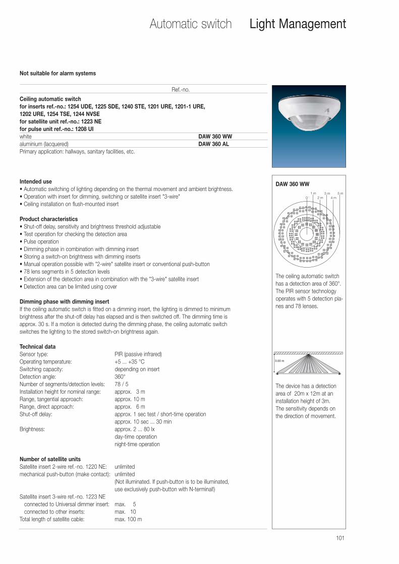
101
Ceiling automatic switchfor inserts ref.-no.: 1254 UDE, 1225 SDE, 1240 STE, 1201 URE, 1201-1 URE, 1202 URE, 1254 TSE, 1244 NVSEfor satellite unit ref.-no.: 1223 NEfor pulse unit ref.-no.: 1208 UIwhite DAW 360 WWaluminium (lacquered) DAW 360 ALPrimary application: hallways, sanitary facilities, etc.
Intended use• Automatic switching of lighting depending on the thermal movement and ambient brightness.• Operation with insert for dimming, switching or satellite insert "3-wire"• Ceiling installation on flush-mounted insert
Product characteristics• Shut-off delay, sensitivity and brightness threshold adjustable• Test operation for checking the detection area• Pulse operation• Dimming phase in combination with dimming insert• Storing a switch-on brightness with dimming inserts• Manual operation possible with "2-wire" satellite insert or conventional push-button• 78 lens segments in 5 detection levels• Extension of the detection area in combination with the "3-wire" satellite insert• Detection area can be limited using cover
Dimming phase with dimming insertIf the ceiling automatic switch is fitted on a dimming insert, the lighting is dimmed to minimum brightness after the shut-off delay has elapsed and is then switched off. The dimming time is approx. 30 s. If a motion is detected during the dimming phase, the ceiling automatic switch switches the lighting to the stored switch-on brightness again.
Technical dataSensor type: PIR (passive infrared)Operating temperature: +5 ... +35 °CSwitching capacity: depending on insertDetection angle: 360°Number of segments/detection levels: 78 / 5Installation height for nominal range: approx. 03 mRange, tangential approach: approx. 10 mRange, direct approach: approx. 06 mShut-off delay: approx. 1 sec test / short-time operation
approx. 10 sec ... 30 minBrightness: approx. 2 ... 80 lx
day-time operationnight-time operation
Number of satellite unitsSatellite insert 2-wire ref.-no. 1220 NE: unlimitedmechanical push-button (make contact): unlimited
(Not illuminated. If push-button is to be illuminated, use exclusively push-button with N-terminal!)
Satellite insert 3-wire ref.-no. 1223 NEconnected to Universal dimmer insert: max.0 05connected to other inserts: max.0 10
Total length of satellite cable: max. 100 m
Ref.-no.
Not suitable for alarm systems
Automatic switch Light Management
3.00 m
The device has a detectionarea of 20m x 12m at aninstallation height of 3m. The sensitivity depends onthe direction of movement.
1 m0� 2 m
3 m4 m
5 m
The ceiling automatic switchhas a detection area of 360°.The PIR sensor technology operates with 5 detection pla-nes and 78 lenses.
DAW 360 WW
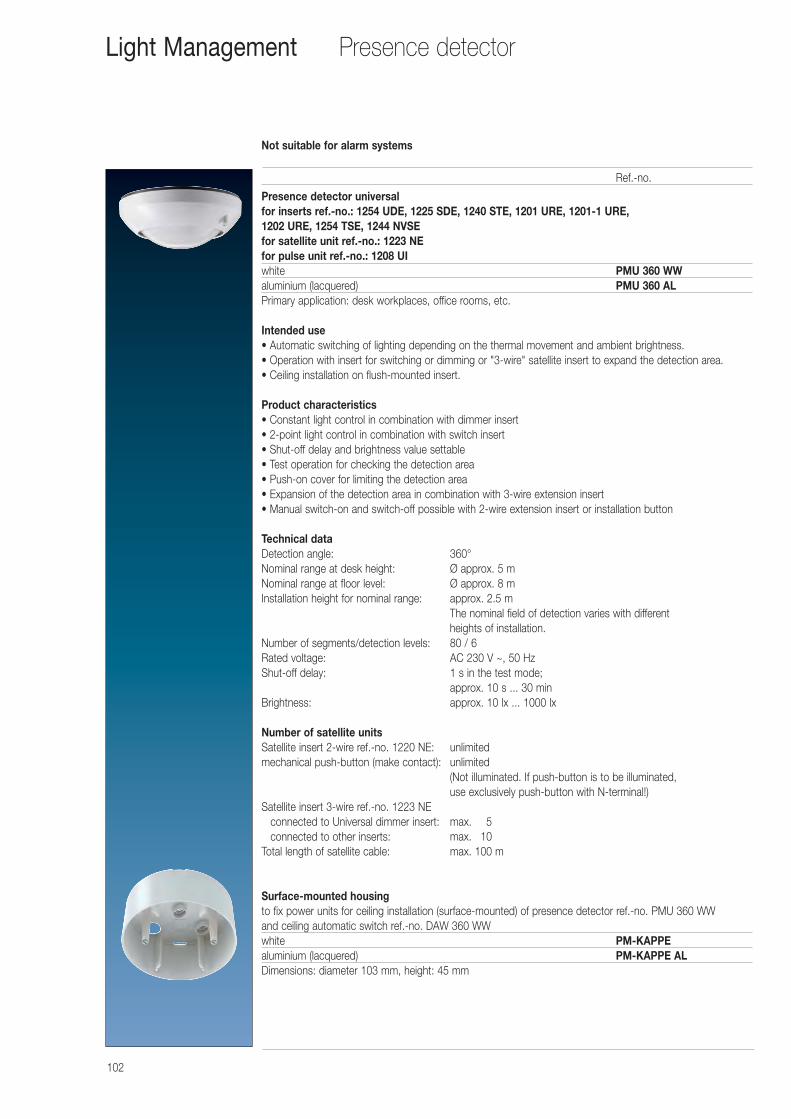
102
Presence detector universalfor inserts ref.-no.: 1254 UDE, 1225 SDE, 1240 STE, 1201 URE, 1201-1 URE, 1202 URE, 1254 TSE, 1244 NVSEfor satellite unit ref.-no.: 1223 NEfor pulse unit ref.-no.: 1208 UIwhite PMU 360 WWaluminium (lacquered) PMU 360 ALPrimary application: desk workplaces, office rooms, etc.
Intended use• Automatic switching of lighting depending on the thermal movement and ambient brightness.• Operation with insert for switching or dimming or "3-wire" satellite insert to expand the detection area.• Ceiling installation on flush-mounted insert.
Product characteristics• Constant light control in combination with dimmer insert• 2-point light control in combination with switch insert• Shut-off delay and brightness value settable• Test operation for checking the detection area• Push-on cover for limiting the detection area• Expansion of the detection area in combination with 3-wire extension insert• Manual switch-on and switch-off possible with 2-wire extension insert or installation button
Technical dataDetection angle: 360°Nominal range at desk height: Ø approx. 5 mNominal range at floor level: Ø approx. 8 mInstallation height for nominal range: approx. 2.5 m
The nominal field of detection varies with different heights of installation.
Number of segments/detection levels: 80 / 6Rated voltage: AC 230 V ~, 50 HzShut-off delay: 1 s in the test mode;
approx. 10 s ... 30 minBrightness: approx. 10 lx ... 1000 lx
Number of satellite unitsSatellite insert 2-wire ref.-no. 1220 NE: unlimitedmechanical push-button (make contact): unlimited
(Not illuminated. If push-button is to be illuminated, use exclusively push-button with N-terminal!)
Satellite insert 3-wire ref.-no. 1223 NEconnected to Universal dimmer insert: max.0 05connected to other inserts: max.0 10
Total length of satellite cable: max. 100 m
Surface-mounted housingto fix power units for ceiling installation (surface-mounted) of presence detector ref.-no. PMU 360 WW and ceiling automatic switch ref.-no. DAW 360 WWwhite PM-KAPPEaluminium (lacquered) PM-KAPPE ALDimensions: diameter 103 mm, height: 45 mm
Ref.-no.
Not suitable for alarm systems
Presence detectorLight Management
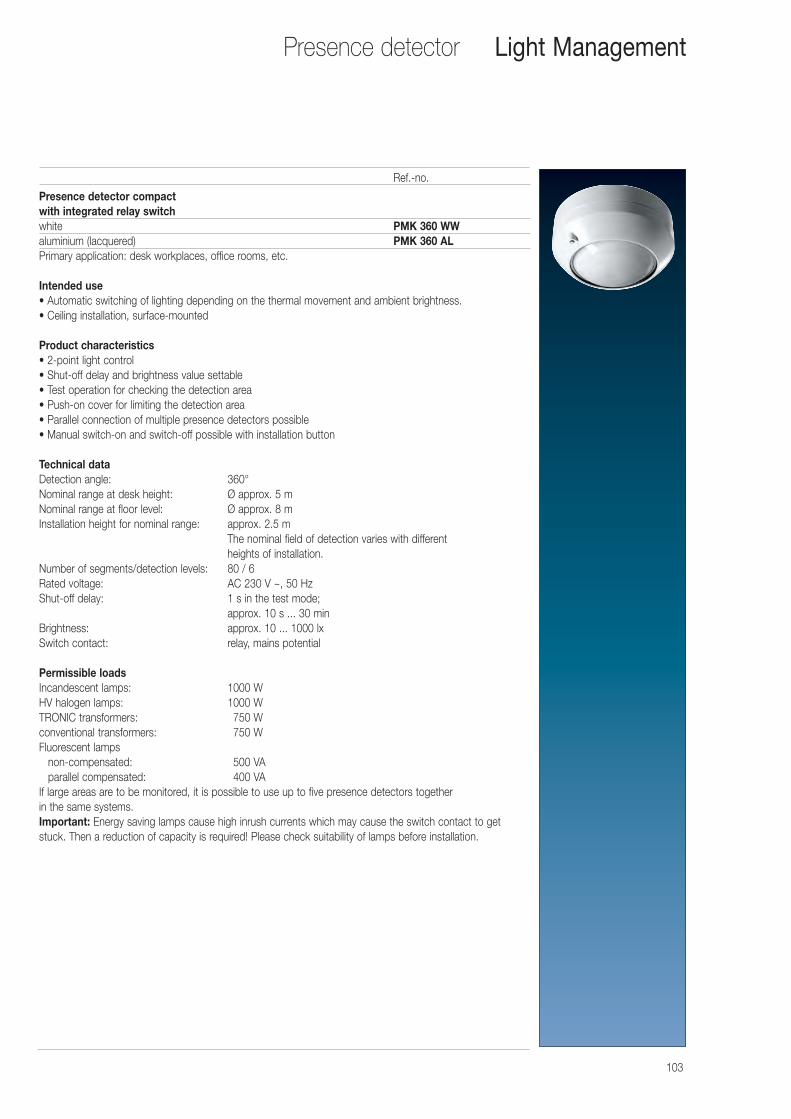
103
Presence detector Light Management
Presence detector compactwith integrated relay switchwhite PMK 360 WWaluminium (lacquered) PMK 360 ALPrimary application: desk workplaces, office rooms, etc.
Intended use• Automatic switching of lighting depending on the thermal movement and ambient brightness.• Ceiling installation, surface-mounted
Product characteristics• 2-point light control• Shut-off delay and brightness value settable• Test operation for checking the detection area• Push-on cover for limiting the detection area• Parallel connection of multiple presence detectors possible• Manual switch-on and switch-off possible with installation button
Technical dataDetection angle: 360°Nominal range at desk height: Ø approx. 5 mNominal range at floor level: Ø approx. 8 mInstallation height for nominal range: approx. 2.5 m
The nominal field of detection varies with different heights of installation.
Number of segments/detection levels: 80 / 6Rated voltage: AC 230 V ~, 50 HzShut-off delay: 1 s in the test mode;
approx. 10 s ... 30 minBrightness: approx. 10 ... 1000 lxSwitch contact: relay, mains potential
Permissible loadsIncandescent lamps: 1000 WHV halogen lamps: 1000 WTRONIC transformers: 0750 Wconventional transformers: 0750 WFluorescent lamps
non-compensated: 0500 VAparallel compensated: 0400 VA
If large areas are to be monitored, it is possible to use up to five presence detectors together in the same systems.Important: Energy saving lamps cause high inrush currents which may cause the switch contact to getstuck. Then a reduction of capacity is required! Please check suitability of lamps before installation.
Ref.-no.
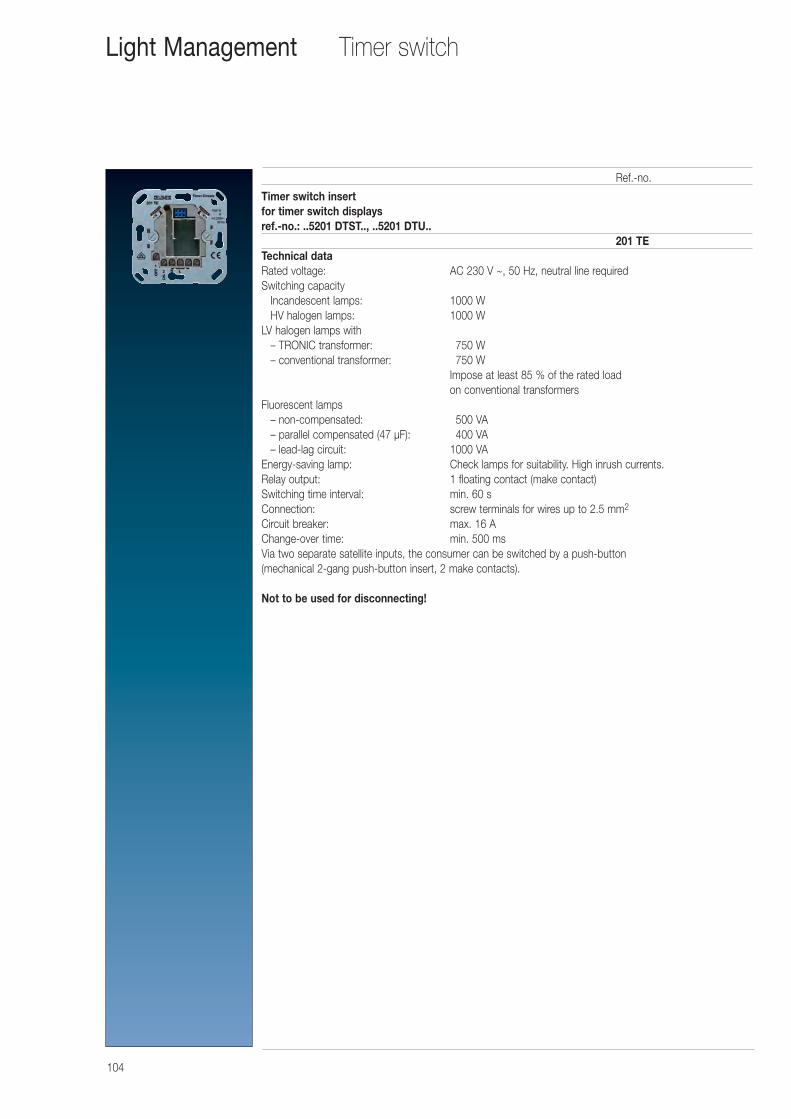
104
Timer switch insertfor timer switch displaysref.-no.: ..5201 DTST.., ..5201 DTU..
201 TETechnical dataRated voltage: AC 230 V ~, 50 Hz, neutral line requiredSwitching capacity
Incandescent lamps: 1000 WHV halogen lamps: 1000 W
LV halogen lamps with– TRONIC transformer: 0750 W– conventional transformer: 0750 W
Impose at least 85 % of the rated load on conventional transformers
Fluorescent lamps– non-compensated: 0500 VA0– parallel compensated (47 μF): 0400 VA– lead-lag circuit: 1000 VA
Energy-saving lamp: Check lamps for suitability. High inrush currents.Relay output: 1 floating contact (make contact)Switching time interval: min. 60 sConnection: screw terminals for wires up to 2.5 mm2
Circuit breaker: max. 16 AChange-over time: min. 500 msVia two separate satellite inputs, the consumer can be switched by a push-button (mechanical 2-gang push-button insert, 2 make contacts).
Not to be used for disconnecting!
Ref.-no.
Timer switchLight Management
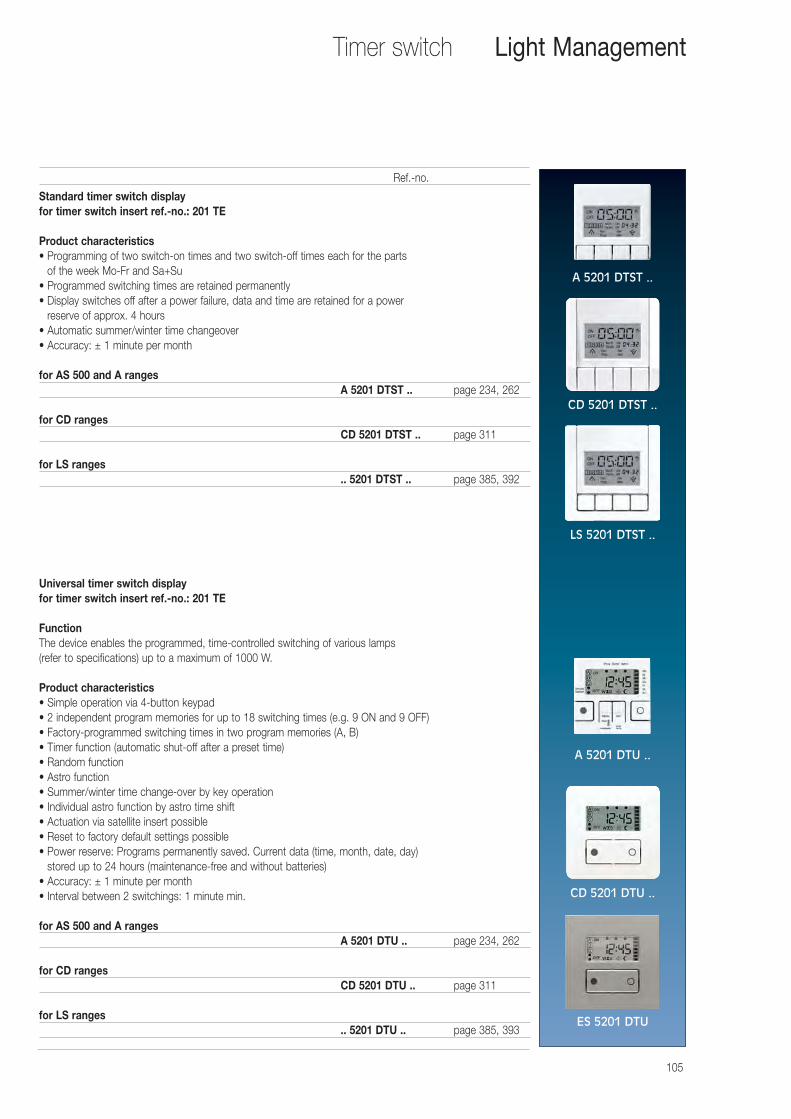
105
Standard timer switch displayfor timer switch insert ref.-no.: 201 TE
Product characteristics• Programming of two switch-on times and two switch-off times each for the parts
of the week Mo-Fr and Sa+Su• Programmed switching times are retained permanently• Display switches off after a power failure, data and time are retained for a power
reserve of approx. 4 hours• Automatic summer/winter time changeover• Accuracy: ± 1 minute per month
for AS 500 and A rangesA 5201 DTST .. page 234, 262
for CD rangesCD 5201 DTST .. page 311
for LS ranges.. 5201 DTST .. page 385, 392
Universal timer switch displayfor timer switch insert ref.-no.: 201 TE
FunctionThe device enables the programmed, time-controlled switching of various lamps (refer to specifications) up to a maximum of 1000 W.
Product characteristics• Simple operation via 4-button keypad• 2 independent program memories for up to 18 switching times (e.g. 9 ON and 9 OFF)• Factory-programmed switching times in two program memories (A, B)• Timer function (automatic shut-off after a preset time)• Random function• Astro function• Summer/winter time change-over by key operation• Individual astro function by astro time shift• Actuation via satellite insert possible• Reset to factory default settings possible• Power reserve: Programs permanently saved. Current data (time, month, date, day)
stored up to 24 hours (maintenance-free and without batteries)• Accuracy: ± 1 minute per month• Interval between 2 switchings: 1 minute min.
for AS 500 and A rangesA 5201 DTU .. page 234, 262
for CD rangesCD 5201 DTU .. page 311
for LS ranges.. 5201 DTU .. page 385, 393
Ref.-no.
Timer switch Light Management
A 5201 DTST ..
CD 5201 DTST ..
LS 5201 DTST ..
A 5201 DTU ..
CD 5201 DTU ..
ES 5201 DTU
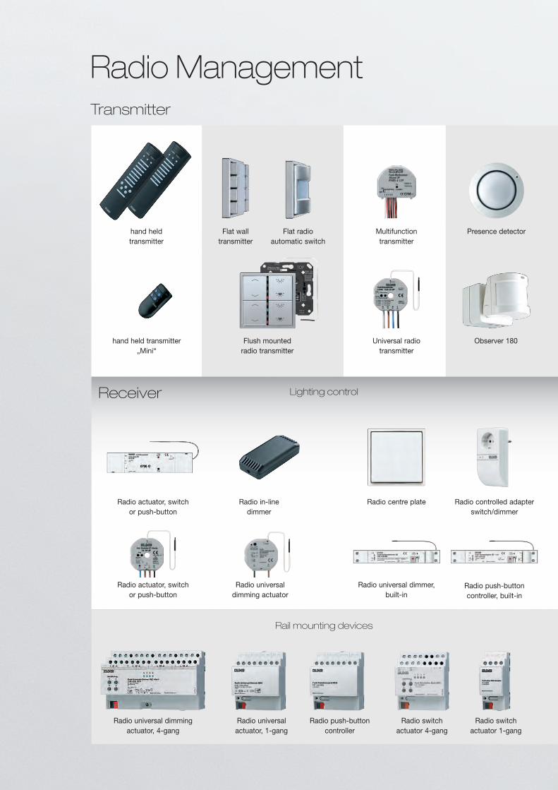
Radio ManagementTransmitter
Receiver
Radio push-button controller
Radio switch actuator 4-gang
Radio universal dimming actuator, 4-gang
Radio universal actuator, 1-gang
Rail mounting devices
Radio centre plate
Radio universal dimmer, built-in
Radio actuator, switch or push-button
Radio actuator, switch or push-button
Radio in-linedimmer
Radio controlled adapter switch/dimmer
Radio universal dimming actuator
Lighting control
Radio push-button controller, built-in
Radio switch actuator 1-gang
hand held transmitter
hand held transmitter„Mini“
Flush mounted radio transmitter
Flat wall transmitter
Flat radio automatic switch
Multifunctiontransmitter
Observer 180
Presence detector
Universal radio transmitter
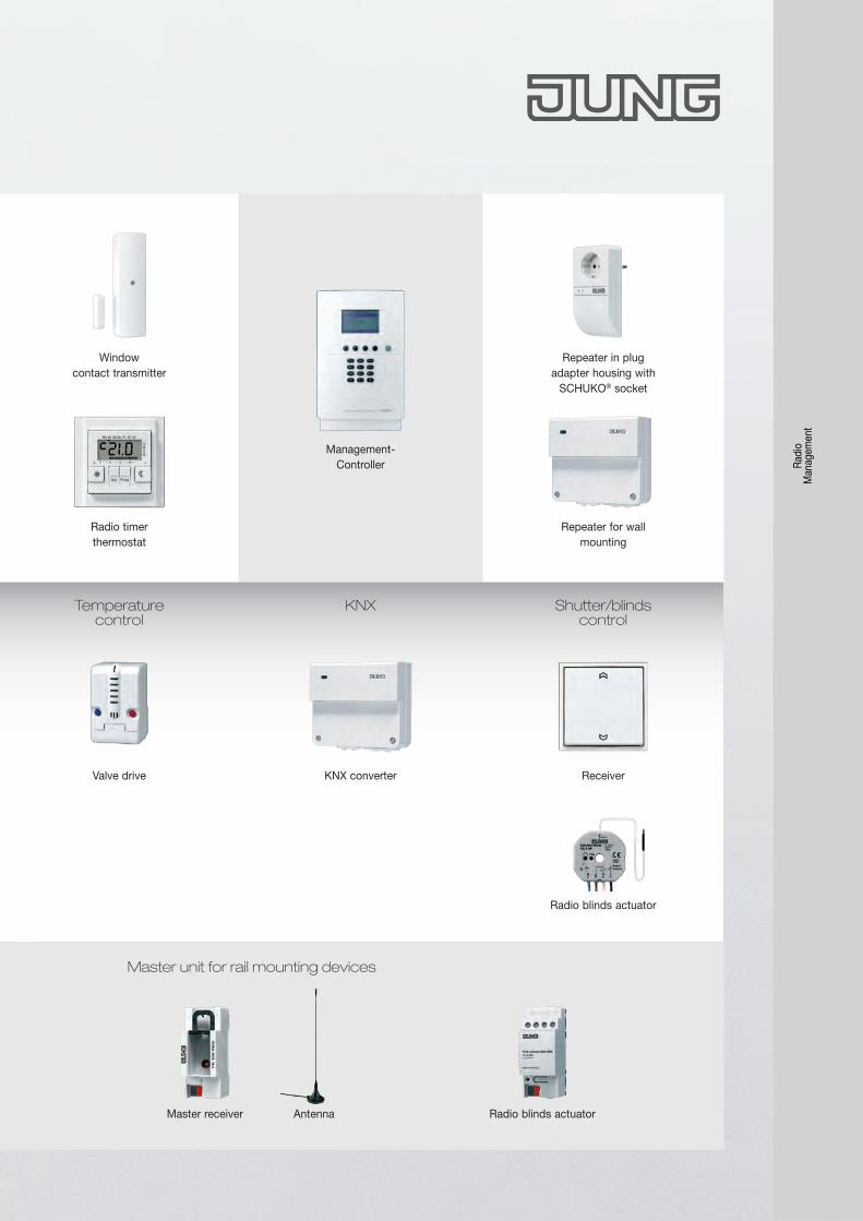
Valve drive
Temperature control
KNX converter
KNX Shutter/blindscontrol
Radio blinds actuator
Receiver
Master unit for rail mounting devices
Master receiver Antenna Radio blinds actuator
Management-Controller
Repeater for wall mounting
Repeater in plugadapter housing with
SCHUKO® socket
Radio timer thermostat
Windowcontact transmitter
Radi
o
Man
agem
ent
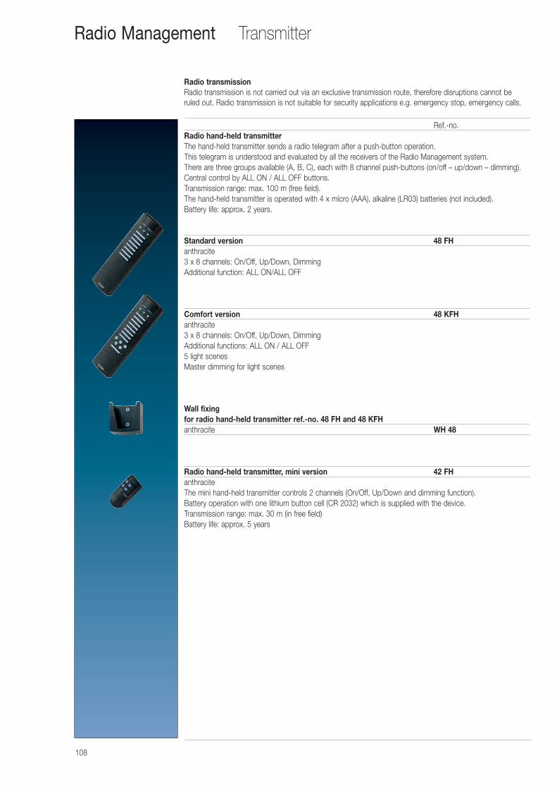
108
Transmitter
Ref.-no.Radio hand-held transmitterThe hand-held transmitter sends a radio telegram after a push-button operation.This telegram is understood and evaluated by all the receivers of the Radio Management system. There are three groups available (A, B, C), each with 8 channel push-buttons (on/off – up/down – dimming). Central control by ALL ON / ALL OFF buttons. Transmission range: max. 100 m (free field).The hand-held transmitter is operated with 4 x micro (AAA), alkaline (LR03) batteries (not included). Battery life: approx. 2 years.
Standard version 48 FHanthracite3 x 8 channels: On/Off, Up/Down, DimmingAdditional function: ALL ON/ALL OFF
Comfort version 48 KFHanthracite3 x 8 channels: On/Off, Up/Down, DimmingAdditional functions: ALL ON / ALL OFF5 light scenesMaster dimming for light scenes
Wall fixingfor radio hand-held transmitter ref.-no. 48 FH and 48 KFHanthracite WH 48
Radio hand-held transmitter, mini version 42 FHanthraciteThe mini hand-held transmitter controls 2 channels (On/Off, Up/Down and dimming function). Battery operation with one lithium button cell (CR 2032) which is supplied with the device.Transmission range: max. 30 m (in free field)Battery life: approx. 5 years
Radio Management
Radio transmissionRadio transmission is not carried out via an exclusive transmission route, therefore disruptions cannot be ruled out. Radio transmission is not suitable for security applications e.g. emergency stop, emergency calls.
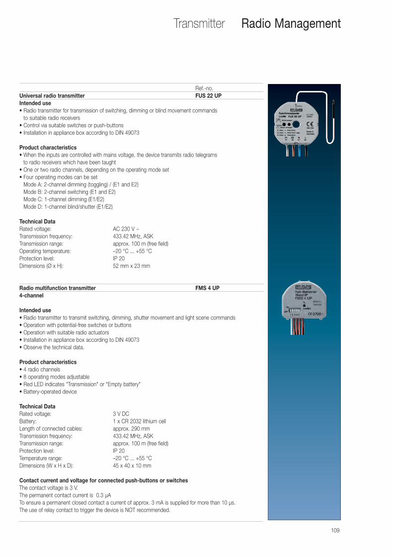
109
Transmitter
Ref.-no.Universal radio transmitter FUS 22 UPIntended use• Radio transmitter for transmission of switching, dimming or blind movement commands
to suitable radio receivers• Control via suitable switches or push-buttons• Installation in appliance box according to DIN 49073
Product characteristics• When the inputs are controlled with mains voltage, the device transmits radio telegrams
to radio receivers which have been taught• One or two radio channels, depending on the operating mode set• Four operating modes can be set
Mode A: 2-channel dimming (toggling) / (E1 and E2)Mode B: 2-channel switching (E1 and E2)Mode C: 1-channel dimming (E1/E2)Mode D: 1-channel blind/shutter (E1/E2)
Technical Data Rated voltage: AC 230 V ~Transmission frequency: 433.42 MHz, ASKTransmission range: approx. 100 m (free field)Operating temperature: –20 °C ... +55 °CProtection level: IP 20Dimensions (Ø x H): 52 mm x 23 mm
Radio multifunction transmitter FMS 4 UP4-channel
Intended use• Radio transmitter to transmit switching, dimming, shutter movement and light scene commands• Operation with potential-free switches or buttons• Operation with suitable radio actuators• Installation in appliance box according to DIN 49073• Observe the technical data.
Product characteristics• 4 radio channels• 8 operating modes adjustable• Red LED indicates "Transmission" or "Empty battery"• Battery-operated device
Technical Data Rated voltage: 3 V DCBattery: 1 x CR 2032 lithium cellLength of connected cables: approx. 290 mmTransmission frequency: 433.42 MHz, ASKTransmission range: approx. 100 m (free field)Protection level: IP 20Temperature range: –20 °C ... +55 °CDimensions (W x H x D): 45 x 40 x 10 mm
Contact current and voltage for connected push-buttons or switchesThe contact voltage is 3 V.The permanent contact current is 0.3 μATo ensure a permanent closed contact a current of approx. 3 mA is supplied for more than 10 μs.The use of relay contact to trigger the device is NOT recommended.
Radio Management
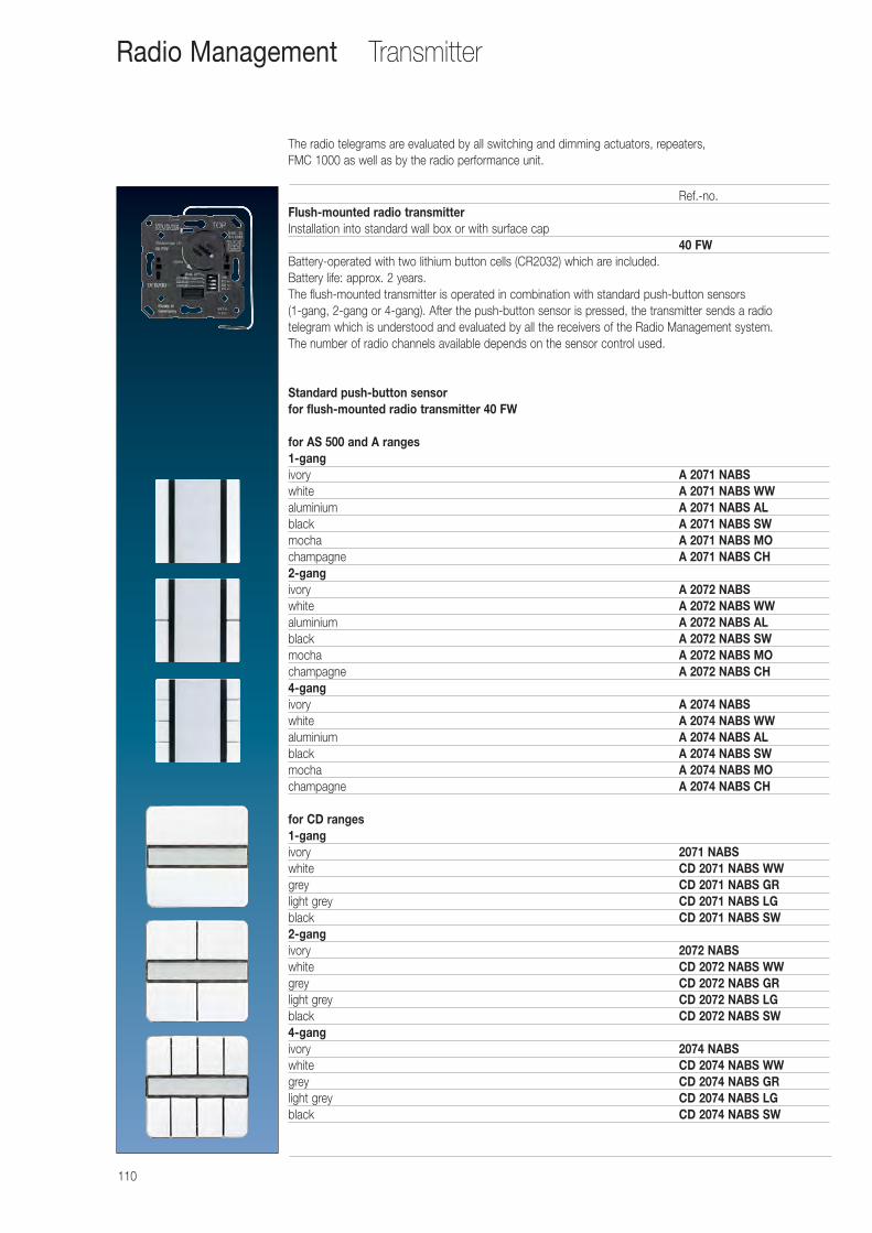
The radio telegrams are evaluated by all switching and dimming actuators, repeaters, FMC 1000 as well as by the radio performance unit.
110
TransmitterRadio Management
Ref.-no.Flush-mounted radio transmitterInstallation into standard wall box or with surface cap
40 FWBattery-operated with two lithium button cells (CR2032) which are included.Battery life: approx. 2 years.The flush-mounted transmitter is operated in combination with standard push-button sensors (1-gang, 2-gang or 4-gang). After the push-button sensor is pressed, the transmitter sends a radio telegram which is understood and evaluated by all the receivers of the Radio Management system. The number of radio channels available depends on the sensor control used.
Standard push-button sensorfor flush-mounted radio transmitter 40 FW
for AS 500 and A ranges1-gangivory A 2071 NABSwhite A 2071 NABS WWaluminium A 2071 NABS ALblack A 2071 NABS SWmocha A 2071 NABS MOchampagne A 2071 NABS CH2-gangivory A 2072 NABSwhite A 2072 NABS WWaluminium A 2072 NABS ALblack A 2072 NABS SWmocha A 2072 NABS MOchampagne A 2072 NABS CH4-gangivory A 2074 NABSwhite A 2074 NABS WWaluminium A 2074 NABS ALblack A 2074 NABS SWmocha A 2074 NABS MOchampagne A 2074 NABS CH
for CD ranges1-gangivory 2071 NABSwhite CD 2071 NABS WWgrey CD 2071 NABS GRlight grey CD 2071 NABS LGblack CD 2071 NABS SW2-gangivory 2072 NABSwhite CD 2072 NABS WWgrey CD 2072 NABS GRlight grey CD 2072 NABS LGblack CD 2072 NABS SW4-gangivory 2074 NABSwhite CD 2074 NABS WWgrey CD 2074 NABS GRlight grey CD 2074 NABS LGblack CD 2074 NABS SW
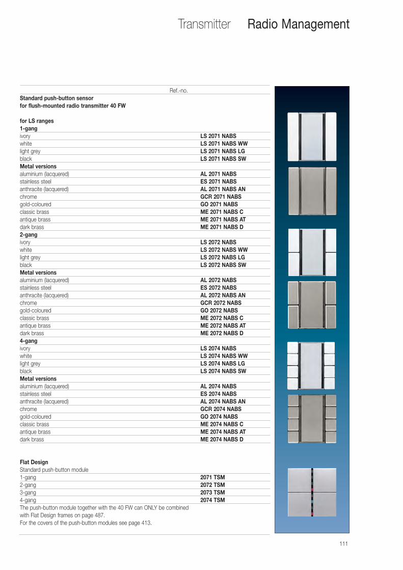
111
Transmitter
Ref.-no.Standard push-button sensor for flush-mounted radio transmitter 40 FW
for LS ranges1-gangivory LS 2071 NABSwhite LS 2071 NABS WWlight grey LS 2071 NABS LGblack LS 2071 NABS SWMetal versionsaluminium (lacquered) AL 2071 NABSstainless steel ES 2071 NABSanthracite (lacquered) AL 2071 NABS ANchrome GCR 2071 NABSgold-coloured GO 2071 NABSclassic brass ME 2071 NABS Cantique brass ME 2071 NABS ATdark brass ME 2071 NABS D2-gangivory LS 2072 NABSwhite LS 2072 NABS WWlight grey LS 2072 NABS LGblack LS 2072 NABS SWMetal versionsaluminium (lacquered) AL 2072 NABSstainless steel ES 2072 NABSanthracite (lacquered) AL 2072 NABS ANchrome GCR 2072 NABSgold-coloured GO 2072 NABSclassic brass ME 2072 NABS Cantique brass ME 2072 NABS ATdark brass ME 2072 NABS D4-gangivory LS 2074 NABSwhite LS 2074 NABS WWlight grey LS 2074 NABS LGblack LS 2074 NABS SWMetal versionsaluminium (lacquered) AL 2074 NABSstainless steel ES 2074 NABSanthracite (lacquered) AL 2074 NABS ANchrome GCR 2074 NABSgold-coloured GO 2074 NABSclassic brass ME 2074 NABS Cantique brass ME 2074 NABS ATdark brass ME 2074 NABS D
Flat DesignStandard push-button module1-gang 2071 TSM2-gang 2072 TSM3-gang 2073 TSM4-gang 2074 TSMThe push-button module together with the 40 FW can ONLY be combined with Flat Design frames on page 487.For the covers of the push-button modules see page 413.
Radio Management
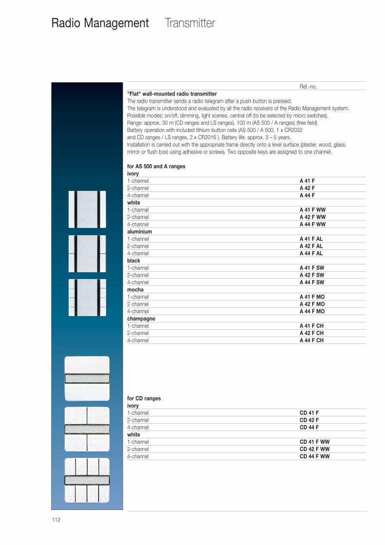
112
Transmitter
Ref.-no."Flat" wall-mounted radio transmitterThe radio transmitter sends a radio telegram after a push-button is pressed. The telegram is understood and evaluated by all the radio receivers of the Radio Management system.Possible modes: on/off, dimming, light scenes, central off (to be selected by micro switches). Range: approx. 30 m (CD ranges and LS ranges), 100 m (AS 500 / A ranges) (free field)Battery operation with included lithium button cells (AS 500 / A 500, 1 x CR2032 and CD ranges / LS ranges, 2 x CR2016 ). Battery life: approx. 3 – 5 years. Installation is carried out with the appropriate frame directly onto a level surface (plaster, wood, glass, mirror or flush box) using adhesive or screws. Two opposite keys are assigned to one channel.
for AS 500 and A rangesivory1-channel A 41 F2-channel A 42 F4-channel A 44 Fwhite1-channel A 41 F WW2-channel A 42 F WW4-channel A 44 F WWaluminium1-channel A 41 F AL2-channel A 42 F AL4-channel A 44 F ALblack1-channel A 41 F SW2-channel A 42 F SW4-channel A 44 F SWmocha1-channel A 41 F MO2-channel A 42 F MO4-channel A 44 F MOchampagne1-channel A 41 F CH2-channel A 42 F CH4-channel A 44 F CH
for CD rangesivory1-channel CD 41 F2-channel CD 42 F4-channel CD 44 Fwhite1-channel CD 41 F WW2-channel CD 42 F WW4-channel CD 44 F WW
Radio Management
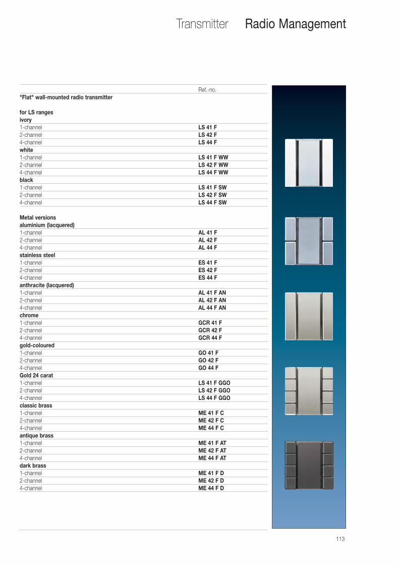
113
Transmitter
Ref.-no."Flat" wall-mounted radio transmitter
for LS rangesivory1-channel LS 41 F2-channel LS 42 F4-channel LS 44 Fwhite1-channel LS 41 F WW2-channel LS 42 F WW4-channel LS 44 F WWblack1-channel LS 41 F SW2-channel LS 42 F SW4-channel LS 44 F SW
Metal versionsaluminium (lacquered)1-channel AL 41 F2-channel AL 42 F4-channel AL 44 Fstainless steel1-channel ES 41 F2-channel ES 42 F4-channel ES 44 Fanthracite (lacquered)1-channel AL 41 F AN2-channel AL 42 F AN4-channel AL 44 F ANchrome1-channel GCR 41 F2-channel GCR 42 F4-channel GCR 44 Fgold-coloured1-channel GO 41 F2-channel GO 42 F4-channel GO 44 FGold 24 carat1-channel LS 41 F GGO2-channel LS 42 F GGO4-channel LS 44 F GGOclassic brass1-channel ME 41 F C2-channel ME 42 F C4-channel ME 44 F Cantique brass1-channel ME 41 F AT2-channel ME 42 F AT4-channel ME 44 F ATdark brass1-channel ME 41 F D2-channel ME 42 F D4-channel ME 44 F D
Radio Management
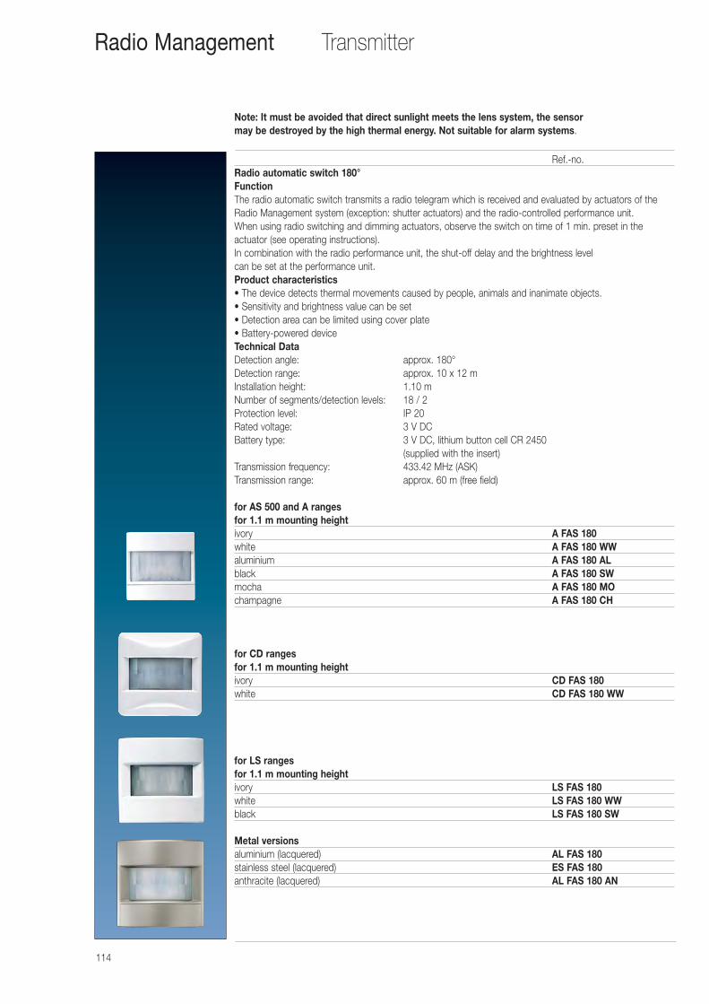
Note: It must be avoided that direct sunlight meets the lens system, the sensor may be destroyed by the high thermal energy. Not suitable for alarm systems.
114
TransmitterRadio Management
Ref.-no.Radio automatic switch 180°FunctionThe radio automatic switch transmits a radio telegram which is received and evaluated by actuators of theRadio Management system (exception: shutter actuators) and the radio-controlled performance unit. When using radio switching and dimming actuators, observe the switch on time of 1 min. preset in the actuator (see operating instructions).In combination with the radio performance unit, the shut-off delay and the brightness level can be set at the performance unit.Product characteristics• The device detects thermal movements caused by people, animals and inanimate objects.• Sensitivity and brightness value can be set• Detection area can be limited using cover plate• Battery-powered deviceTechnical Data Detection angle: approx. 180°Detection range: approx. 10 x 12 mInstallation height: 1.10 mNumber of segments/detection levels: 18 / 2Protection level: IP 20Rated voltage: 3 V DCBattery type: 3 V DC, lithium button cell CR 2450
(supplied with the insert)Transmission frequency: 433.42 MHz (ASK)Transmission range: approx. 60 m (free field)
for AS 500 and A rangesfor 1.1 m mounting heightivory A FAS 180white A FAS 180 WWaluminium A FAS 180 ALblack A FAS 180 SWmocha A FAS 180 MOchampagne A FAS 180 CH
for CD rangesfor 1.1 m mounting heightivory CD FAS 180white CD FAS 180 WW
for LS rangesfor 1.1 m mounting heightivory LS FAS 180white LS FAS 180 WWblack LS FAS 180 SW
Metal versionsaluminium (lacquered) AL FAS 180stainless steel (lacquered) ES FAS 180anthracite (lacquered) AL FAS 180 AN
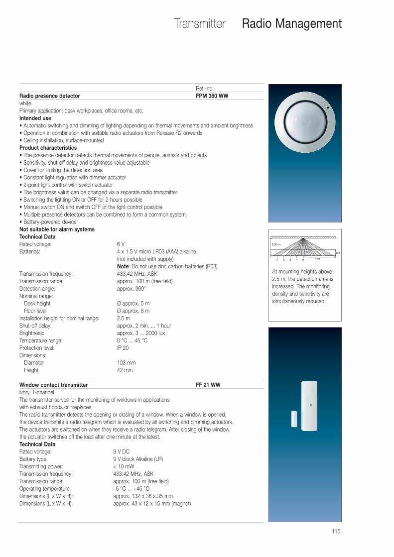
115
Ref.-no.Radio presence detector FPM 360 WWwhitePrimary application: desk workplaces, office rooms, etc.Intended use• Automatic switching and dimming of lighting depending on thermal movements and ambient brightness• Operation in combination with suitable radio actuators from Release R2 onwards• Ceiling installation, surface-mountedProduct characteristics• The presence detector detects thermal movements of people, animals and objects• Sensitivity, shut-off delay and brightness value adjustable• Cover for limiting the detection area• Constant light regulation with dimmer actuator• 2-point light control with switch actuator• The brightness value can be changed via a separate radio transmitter• Switching the lighting ON or OFF for 2 hours possible• Manual switch ON and switch OFF of the light control possible• Multiple presence detectors can be combined to form a common system.• Battery-powered deviceNot suitable for alarm systemsTechnical Data Rated voltage: 6 VBatteries: 4 x 1.5 V micro LR03 (AAA) alkaline
(not included with supply)Note: Do not use zinc carbon batteries (R03).
Transmission frequency: 433.42 MHz, ASKTransmission range: approx. 100 m (free field)Detection angle: approx. 360°Nominal range:
Desk height Ø approx. 5 mFloor level Ø approx. 8 m
Installation height for nominal range: 2.5 mShut-off delay: approx. 2 min. ... 1 hourBrightness: approx. 3 ... 2000 luxTemperature range: 0 °C ... 45 °CProtection level: IP 20Dimensions:
Diameter 103 mmHeight 42 mm
Window contact transmitter FF 21 WWivory, 1-channelThe transmitter serves for the monitoring of windows in applications with exhaust hoods or fireplaces.The radio transmitter detects the opening or closing of a window. When a window is opened, the device transmits a radio telegram which is evaluated by all switching and dimming actuators. The actuators are switched on when they receive a radio telegram. After closing of the window, the actuator switches off the load after one minute at the latest.Technical Data Rated voltage: 9 V DCBattery type: 9 V block Alkaline (LR)Transmitting power: < 10 mWTransmission frequency: 433.42 MHz, ASKTransmission range: approx. 100 m (free field)Operating temperature: –5 °C ... +45 °CDimensions (L x W x H): approx. 132 x 36 x 35 mmDimensions (L x W x H): approx. 43 x 12 x 15 mm (magnet)
Transmitter Radio Management
2,50 m
4 m
0,8
4 3 2 1 0
At mounting heights above2.5 m, the detection area isincreased. The monitoringdensity and sensitivity aresimultaneously reduced.
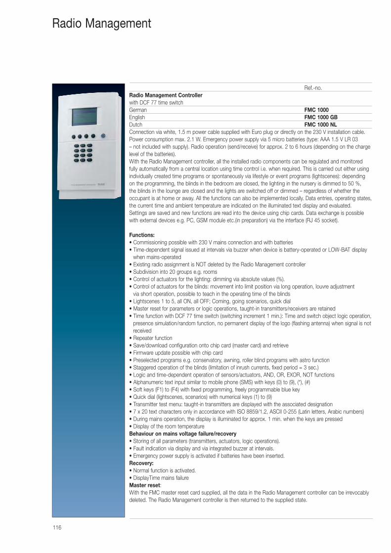
116
Ref.-no.Radio Management Controllerwith DCF 77 time switchGerman FMC 1000English FMC 1000 GBDutch FMC 1000 NLConnection via white, 1.5 m power cable supplied with Euro plug or directly on the 230 V installation cable.Power consumption max. 2.1 W. Emergency power supply via 5 micro batteries (type: AAA 1.5 V LR 03 – not included with supply). Radio operation (send/receive) for approx. 2 to 6 hours (depending on the chargelevel of the batteries).With the Radio Management controller, all the installed radio components can be regulated and monitoredfully automatically from a central location using time control i.e. when required. This is carried out either usingindividually created time programs or spontaneously via lifestyle or event programs (lightscenes): dependingon the programming, the blinds in the bedroom are closed, the lighting in the nursery is dimmed to 50 %, the blinds in the lounge are closed and the lights are switched off or dimmed – regardless of whether theoccupant is at home or away. All the functions can also be implemented locally. Data entries, operating states,the current time and ambient temperature are indicated on the illuminated text display and evaluated.Settings are saved and new functions are read into the device using chip cards. Data exchange is possiblewith external devices e.g. PC, GSM module etc.(in preparation) via the interface (RJ 45 socket).
Functions:• Commissioning possible with 230 V mains connection and with batteries• Time-dependent signal issued at intervals via buzzer when device is battery-operated or LOW-BAT display
when mains-operated• Existing radio assignment is NOT deleted by the Radio Management controller• Subdivision into 20 groups e.g. rooms• Control of actuators for the lighting: dimming via absolute values (%).• Control of actuators for the blinds: movement into limit position via long operation, louvre adjustment
via short operation, possible to teach in the operating time of the blinds• Lightscenes 1 to 5, all ON, all OFF; Coming, going scenarios, quick dial• Master reset for parameters or logic operations, taught-in transmitters/receivers are retained• Time function with DCF 77 time switch (switching increment 1 min.): Time and switch object logic operation,
presence simulation/random function, no permanent display of the logo (flashing antenna) when signal is notreceived
• Repeater function• Save/download configuration onto chip card (master card) and retrieve• Firmware update possible with chip card• Preselected programs e.g. conservatory, awning, roller blind programs with astro function• Staggered operation of the blinds (limitation of inrush currents, fixed period = 3 sec.)• Logic and time-dependent operation of sensors/actuators, AND, OR, EXOR, NOT functions• Alphanumeric text input similar to mobile phone (SMS) with keys (0) to (9), (*), (#)• Soft keys (F1) to (F4) with fixed programming, freely programmable blue key• Quick dial (lightscenes, scenarios) with numerical keys (1) to (9)• Transmitter test menu: taught-in transmitters are displayed with the associated designation• 7 x 20 text characters only in accordance with ISO 8859/1.2, ASCII 0-255 (Latin letters, Arabic numbers)• During mains operation, the display is illuminated for approx. 1 min. when the keys are pressed• Display of the room temperatureBehaviour on mains voltage failure/recovery• Storing of all parameters (transmitters, actuators, logic operations). • Fault indication via display and via integrated buzzer at intervals. • Emergency power supply is activated if batteries have been inserted.Recovery:• Normal function is activated. • DisplayTime mains failureMaster reset: With the FMC master reset card supplied, all the data in the Radio Management controller can be irrevocablydeleted. The Radio Management controller is then returned to the supplied state.
Radio Management
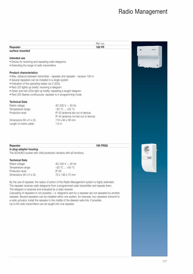
117
Radio Management
Ref.-no.Repeater 100 FRsurface mounted
Intended use• Device for receiving and repeating radio telegrams• Extending the range of radio transmitters
Product characteristics• Max. distance between transmitter - repeater and repeater - receiver 100 m• Several repeaters can be installed in a single system• Indication of the operating states via 2 LEDs: • Red LED lights up briefly: receiving a telegram • Green and red LEDs light up briefly: repeating a taught telegram• Red LED flashes continuously: repeater is in programming mode
Technical Data Rated voltage: AC 230 V ~, 50 HzTemperature range: –20 °C ... +55 °CProtection level: IP 20 (antenna led out of device)
IP 44 (antenna not led out of device)Dimensions (W x H x D): 110 x 94 x 38 mmLength of mains cable: 1.5 m
Repeater 100 FRSGin plug adapter housingThe SCHUKO-socket with child protection remains with all functions.
Technical Data Rated voltage: AC 230 V ~, 50 HzTemperature range: –20 °C ... +55 °CProtection level: IP 20Dimensions (W x H x D): 70 x 136 x 72 mm
By the use of repeater, the radius of action of the Radio Management system is highly extended. The repeater receives radio telegrams from a programmed radio transmitter and repeats them. The telegram is received and evaluated by a radio receiver.Cascading of repeaters is not possible, i. e. telegrams sent by a repeater are not repeated by another repeater. Several repeaters can be installed within one system, for example, two repeaters transmit to a radio actuator. Install the repeater in the middle of the desired radio link, if possible.Up to 60 radio transmitters can be taught into one repeater.
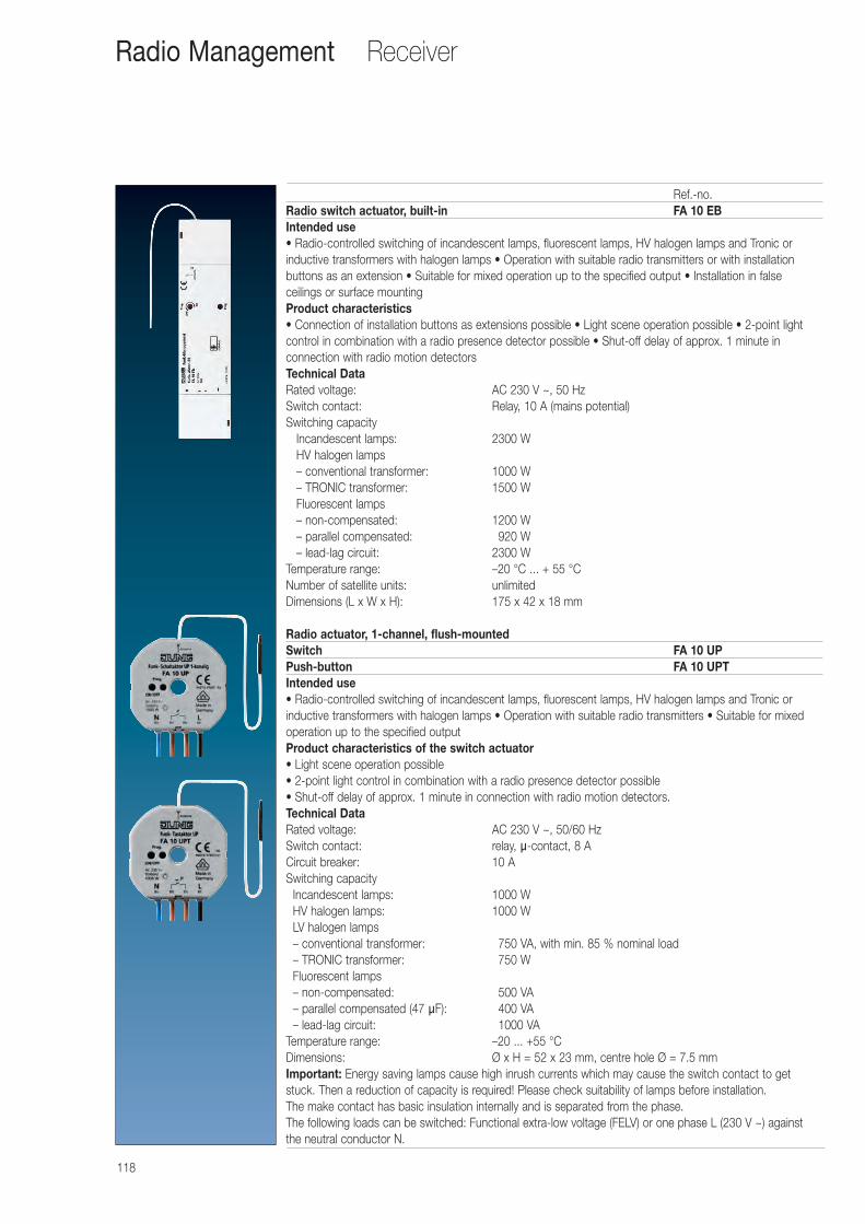
118
Receiver
Ref.-no.Radio switch actuator, built-in FA 10 EBIntended use• Radio-controlled switching of incandescent lamps, fluorescent lamps, HV halogen lamps and Tronic or inductive transformers with halogen lamps • Operation with suitable radio transmitters or with installation buttons as an extension • Suitable for mixed operation up to the specified output • Installation in false ceilings or surface mountingProduct characteristics• Connection of installation buttons as extensions possible • Light scene operation possible • 2-point light control in combination with a radio presence detector possible • Shut-off delay of approx. 1 minute in connection with radio motion detectorsTechnical Data Rated voltage: AC 230 V ~, 50 HzSwitch contact: Relay, 10 A (mains potential)Switching capacity
Incandescent lamps: 2300 WHV halogen lamps– conventional transformer: 1000 W– TRONIC transformer: 1500 WFluorescent lamps– non-compensated: 1200 W– parallel compensated: 0920 W– lead-lag circuit: 2300 W
Temperature range: –20 °C ... + 55 °CNumber of satellite units: unlimitedDimensions (L x W x H): 175 x 42 x 18 mm
Radio actuator, 1-channel, flush-mountedSwitch FA 10 UPPush-button FA 10 UPTIntended use• Radio-controlled switching of incandescent lamps, fluorescent lamps, HV halogen lamps and Tronic or inductive transformers with halogen lamps • Operation with suitable radio transmitters • Suitable for mixed operation up to the specified outputProduct characteristics of the switch actuator• Light scene operation possible• 2-point light control in combination with a radio presence detector possible• Shut-off delay of approx. 1 minute in connection with radio motion detectors.Technical Data Rated voltage: AC 230 V ~, 50/60 Hz Switch contact: relay, µ-contact, 8 A Circuit breaker: 10 A Switching capacity
Incandescent lamps: 1000 W HV halogen lamps: 1000 W LV halogen lamps – conventional transformer: 0750 VA, with min. 85 % nominal load – TRONIC transformer: 0750 W Fluorescent lamps – non-compensated: 0500 VA – parallel compensated (47 µF): 0400 VA – lead-lag circuit: 01000 VA
Temperature range: –20 ... +55 °C Dimensions: Ø x H = 52 x 23 mm, centre hole Ø = 7.5 mmImportant: Energy saving lamps cause high inrush currents which may cause the switch contact to getstuck. Then a reduction of capacity is required! Please check suitability of lamps before installation.The make contact has basic insulation internally and is separated from the phase.The following loads can be switched: Functional extra-low voltage (FELV) or one phase L (230 V ~) against the neutral conductor N.
Radio Management
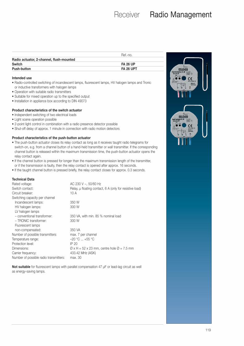
119
Receiver
Ref.-no.Radio actuator, 2-channel, flush-mountedSwitch FA 26 UPPush-button FA 26 UPT
Intended use• Radio-controlled switching of incandescent lamps, fluorescent lamps, HV halogen lamps and Tronic
or inductive transformers with halogen lamps• Operation with suitable radio transmitters• Suitable for mixed operation up to the specified output• Installation in appliance box according to DIN 49073
Product characteristics of the switch actuator• Independent switching of two electrical loads• Light scene operation possible• 2-point light control in combination with a radio presence detector possible• Shut-off delay of approx. 1 minute in connection with radio motion detectors
Product characteristics of the push-button actuator• The push-button actuator closes its relay contact as long as it receives taught radio telegrams for
switch-on, e.g. from a channel button of a hand-held transmitter or wall transmitter. If the correspondingchannel button is released within the maximum transmission time, the push-button actuator opens the relay contact again.
• If the channel button is pressed for longer than the maximum transmission length of the transmitter, or if the transmission is faulty, then the relay contact is opened after approx. 16 seconds.
• If the taught channel button is pressed briefly, the relay contact closes for approx. 0.3 seconds.
Technical Data Rated voltage: AC 230 V ~, 50/60 HzSwitch contact: Relay, μ floating contact, 6 A (only for resistive load)Circuit breaker: 10 ASwitching capacity per channel
Incandescent lamps: 350 WHV halogen lamps: 300 WLV halogen lamps– conventional transformer: 350 VA, with min. 85 % nominal load– TRONIC transformer: 300 WFluorescent lampsnon-compensated: 350 VA
Number of possible transmitters: max. 7 per channelTemperature range: –20 °C ... +55 °CProtection level: IP 20Dimensions: Ø x H = 52 x 23 mm, centre hole Ø = 7.5 mmCarrier frequency: 433.42 MHz (ASK) Number of possible radio transmitters: max. 30
Not suitable for fluorescent lamps with parallel compensation 47 μF or lead-lag circuit as well as energy-saving lamps.
Radio Management
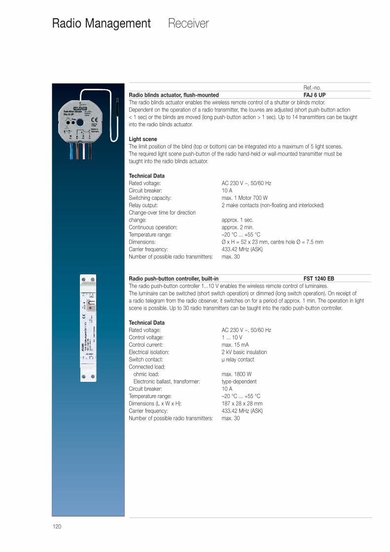
120
Receiver
Ref.-no.Radio blinds actuator, flush-mounted FAJ 6 UPThe radio blinds actuator enables the wireless remote control of a shutter or blinds motor. Dependent on the operation of a radio transmitter, the louvres are adjusted (short push-button action < 1 sec) or the blinds are moved (long push-button action > 1 sec). Up to 14 transmitters can be taught into the radio blinds actuator.
Light sceneThe limit position of the blind (top or bottom) can be integrated into a maximum of 5 light scenes. The required light scene push-button of the radio hand-held or wall-mounted transmitter must be taught into the radio blinds actuator.
Technical Data Rated voltage: AC 230 V ~, 50/60 HzCircuit breaker: 10 ASwitching capacity: max. 1 Motor 700 WRelay output: 2 make contacts (non-floating and interlocked)Change-over time for direction change: approx. 1 sec.Continuous operation: approx. 2 min.Temperature range: –20 °C ... +55 °CDimensions: Ø x H = 52 x 23 mm, centre hole Ø = 7.5 mmCarrier frequency: 433.42 MHz (ASK) Number of possible radio transmitters: max. 30
Radio push-button controller, built-in FST 1240 EBThe radio push-button controller 1...10 V enables the wireless remote control of luminaires. The luminaire can be switched (short switch operation) or dimmed (long switch operation). On receipt of a radio telegram from the radio observer, it switches on for a period of approx. 1 min. The operation in lightscene is possible. Up to 30 radio transmitters can be taught into the radio push-button controller.
Technical Data Rated voltage: AC 230 V ~, 50/60 HzControl voltage: 1 ... 10 VControl current: max. 15 mAElectrical isolation: 2 kV basic insulationSwitch contact: μ relay contactConnected load:
ohmic load: max. 1800 WElectronic ballast, transformer: type-dependent
Circuit breaker: 10 ATemperature range: –20 °C ... +55 °CDimensions (L x W x H): 187 x 28 x 28 mmCarrier frequency: 433.42 MHz (ASK) Number of possible radio transmitters: max. 30
Radio Management
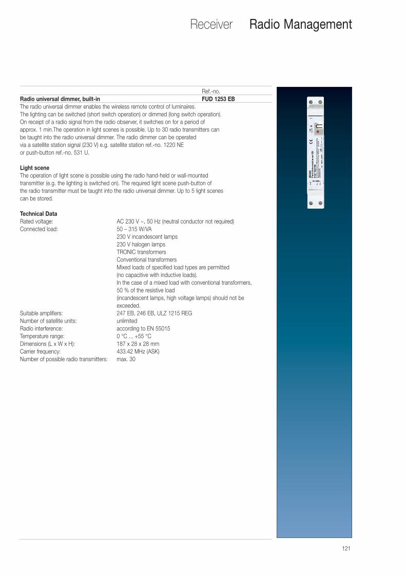
121
Receiver
Ref.-no.Radio universal dimmer, built-in FUD 1253 EBThe radio universal dimmer enables the wireless remote control of luminaires. The lighting can be switched (short switch operation) or dimmed (long switch operation). On receipt of a radio signal from the radio observer, it switches on for a period of approx. 1 min.The operation in light scenes is possible. Up to 30 radio transmitters can be taught into the radio universal dimmer. The radio dimmer can be operated via a satellite station signal (230 V) e.g. satellite station ref.-no. 1220 NE or push-button ref.-no. 531 U.
Light sceneThe operation of light scene is possible using the radio hand-held or wall-mounted transmitter (e.g. the lighting is switched on). The required light scene push-button of the radio transmitter must be taught into the radio universal dimmer. Up to 5 light scenes can be stored.
Technical Data Rated voltage: AC 230 V ~, 50 Hz (neutral conductor not required)Connected load: 50 – 315 W/VA
230 V incandescent lamps230 V halogen lampsTRONIC transformersConventional transformersMixed loads of specified load types are permitted (no capacitive with inductive loads).In the case of a mixed load with conventional transformers, 50 % of the resistive load(incandescent lamps, high voltage lamps) should not be exceeded.
Suitable amplifiers: 247 EB, 246 EB, ULZ 1215 REGNumber of satellite units: unlimitedRadio interference: according to EN 55015Temperature range: 0 °C ... +55 °CDimensions (L x W x H): 187 x 28 x 28 mmCarrier frequency: 433.42 MHz (ASK) Number of possible radio transmitters: max. 30
Radio Management
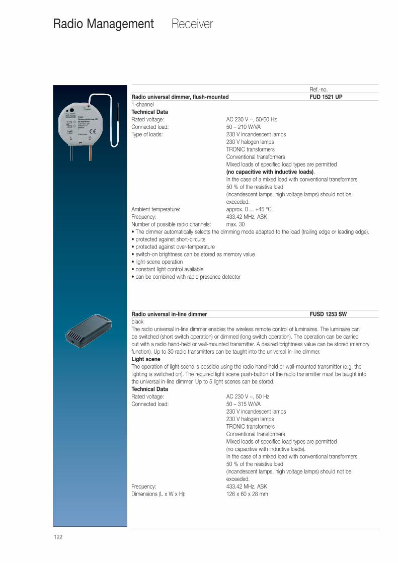
122
Receiver
Ref.-no.Radio universal dimmer, flush-mounted FUD 1521 UP1-channelTechnical Data Rated voltage: AC 230 V ~, 50/60 HzConnected load: 50 – 210 W/VAType of loads: 230 V incandescent lamps
230 V halogen lampsTRONIC transformersConventional transformers Mixed loads of specified load types are permitted (no capacitive with inductive loads).In the case of a mixed load with conventional transformers, 50 % of the resistive load(incandescent lamps, high voltage lamps) should not be exceeded.
Ambient temperature: approx. 0 ... +45 °CFrequency: 433.42 MHz, ASKNumber of possible radio channels: max. 30• The dimmer automatically selects the dimming mode adapted to the load (trailing edge or leading edge).• protected against short-circuits• protected against over-temperature• switch-on brightness can be stored as memory value• light-scene operation• constant light control available• can be combined with radio presence detector
Radio universal in-line dimmer FUSD 1253 SWblackThe radio universal in-line dimmer enables the wireless remote control of luminaires. The luminaire can be switched (short switch operation) or dimmed (long switch operation). The operation can be carried out with a radio hand-held or wall-mounted transmitter. A desired brightness value can be stored (memoryfunction). Up to 30 radio transmitters can be taught into the universal in-line dimmer.Light sceneThe operation of light scene is possible using the radio hand-held or wall-mounted transmitter (e.g. the lighting is switched on). The required light scene push-button of the radio transmitter must be taught into the universal in-line dimmer. Up to 5 light scenes can be stored.Technical Data Rated voltage: AC 230 V ~, 50 HzConnected load: 50 – 315 W/VA
230 V incandescent lamps230 V halogen lampsTRONIC transformersConventional transformersMixed loads of specified load types are permitted (no capacitive with inductive loads).In the case of a mixed load with conventional transformers, 50 % of the resistive load(incandescent lamps, high voltage lamps) should not be exceeded.
Frequency: 433.42 MHz, ASKDimensions (L x W x H): 126 x 60 x 28 mm
Radio Management
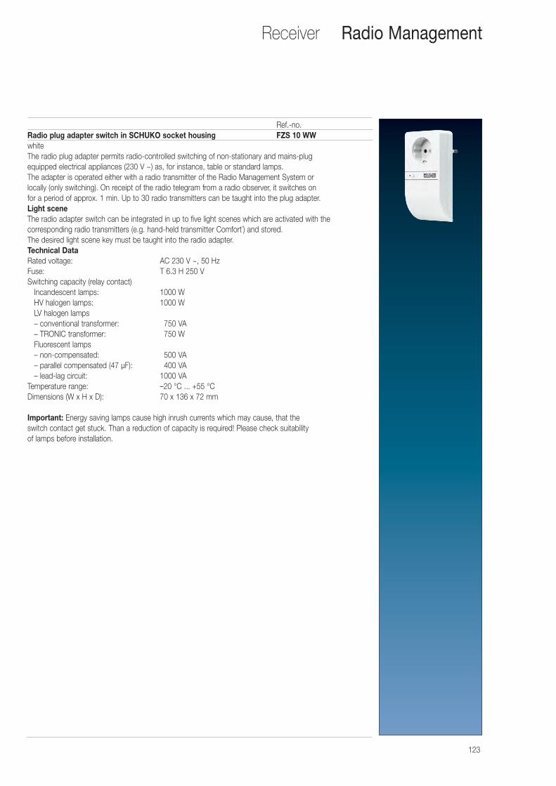
123
Receiver
Ref.-no.Radio plug adapter switch in SCHUKO socket housing FZS 10 WWwhiteThe radio plug adapter permits radio-controlled switching of non-stationary and mains-plug equipped electrical appliances (230 V ~) as, for instance, table or standard lamps.The adapter is operated either with a radio transmitter of the Radio Management System or locally (only switching). On receipt of the radio telegram from a radio observer, it switches on for a period of approx. 1 min. Up to 30 radio transmitters can be taught into the plug adapter.Light sceneThe radio adapter switch can be integrated in up to five light scenes which are activated with the corresponding radio transmitters (e.g. hand-held transmitter Comfort´) and stored. The desired light scene key must be taught into the radio adapter.Technical Data Rated voltage: AC 230 V ~, 50 HzFuse: T 6.3 H 250 VSwitching capacity (relay contact)
Incandescent lamps: 1000 WHV halogen lamps: 1000 WLV halogen lamps– conventional transformer: 0750 VA– TRONIC transformer: 0750 WFluorescent lamps– non-compensated: 0500 VA– parallel compensated (47 μF): 0400 VA– lead-lag circuit: 1000 VA
Temperature range: –20 °C ... +55 °CDimensions (W x H x D): 70 x 136 x 72 mm
Important: Energy saving lamps cause high inrush currents which may cause, that theswitch contact get stuck. Than a reduction of capacity is required! Please check suitability of lamps before installation.
Radio Management
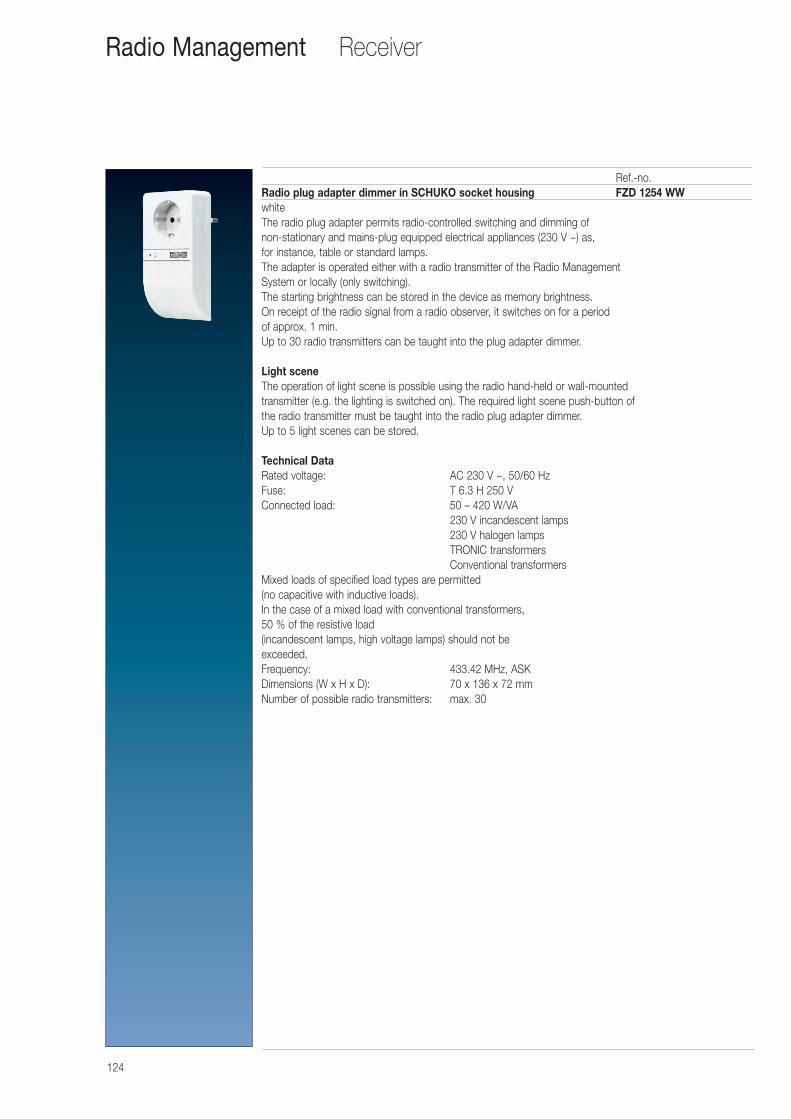
124
ReceiverRadio Management
Ref.-no.Radio plug adapter dimmer in SCHUKO socket housing FZD 1254 WWwhiteThe radio plug adapter permits radio-controlled switching and dimming of non-stationary and mains-plug equipped electrical appliances (230 V ~) as, for instance, table or standard lamps.The adapter is operated either with a radio transmitter of the Radio Management System or locally (only switching).The starting brightness can be stored in the device as memory brightness. On receipt of the radio signal from a radio observer, it switches on for a period of approx. 1 min.Up to 30 radio transmitters can be taught into the plug adapter dimmer.
Light sceneThe operation of light scene is possible using the radio hand-held or wall-mounted transmitter (e.g. the lighting is switched on). The required light scene push-button of the radio transmitter must be taught into the radio plug adapter dimmer. Up to 5 light scenes can be stored.
Technical Data Rated voltage: AC 230 V ~, 50/60 HzFuse: T 6.3 H 250 VConnected load: 50 – 420 W/VA
230 V incandescent lamps230 V halogen lampsTRONIC transformersConventional transformers
Mixed loads of specified load types are permitted (no capacitive with inductive loads).In the case of a mixed load with conventional transformers, 50 % of the resistive load(incandescent lamps, high voltage lamps) should not be exceeded. Frequency: 433.42 MHz, ASKDimensions (W x H x D): 70 x 136 x 72 mmNumber of possible radio transmitters: max. 30
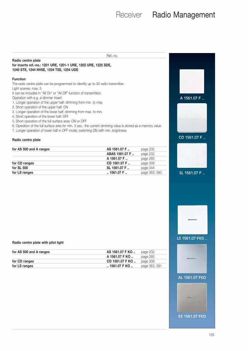
125
Receiver Radio Management
Ref.-no.Radio centre platefor inserts ref.-no.: 1201 URE, 1201-1 URE, 1202 URE, 1225 SDE, 1240 STE, 1244 NVSE, 1254 TSE, 1254 UDE
FunctionThe radio centre plate can be programmed to identify up to 30 radio transmitter.Light scenes: max. 5It can be included in "All On" or "All Off" function of transmittersOperation with e.g. a dimmer insert:1. Longer operation of the upper half: dimming from min. to max.2. Short operation of the upper half: ON3. Longer operation of the lower half: dimming from max. to min.4. Short operation of the lower half: OFF5. Short operation of the full surface area: ON or OFF6. Operation of the full surface area for min. 3 sec.: the current dimming value is stored as a memory value7. Longer operation of lower half in OFF mode: switching ON with min. brightness
Radio centre plate
for AS 500 and A ranges AS 1561.07 F .. page 232ABAS 1561.07 F .. page 232A 1561.07 F .. page 260
for CD ranges CD 1561.07 F .. page 309for SL 500 SL 1561.07 F .. page 344for LS ranges .. 1561.07 F .. page 363, 390
Radio centre plate with pilot light
for AS 500 and A ranges AS 1561.07 F KO .. page 232A 1561.07 F KO .. page 260
for CD ranges CD 1561.07 F KO .. page 309for LS ranges .. 1561.07 F KO .. page 363, 391
A 1561.07 F ..
CD 1561.07 F ..
SL 1561.07 F ..
LS 1561.07 FKO ..
AL 1561.07 FKO
ES 1561.07 FKO
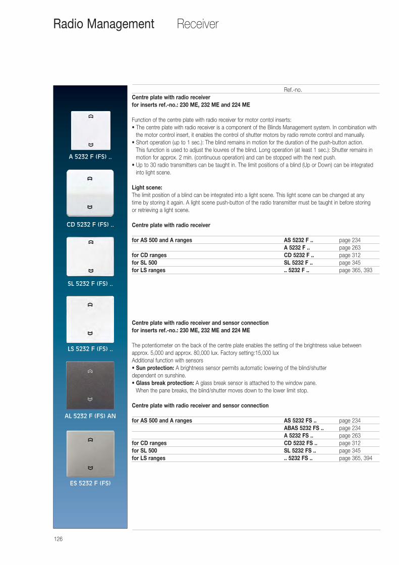
126
Receiver Radio Management
Ref.-no.Centre plate with radio receiverfor inserts ref.-no.: 230 ME, 232 ME and 224 ME
Function of the centre plate with radio receiver for motor contol inserts:• The centre plate with radio receiver is a component of the Blinds Management system. In combination with
the motor control insert, it enables the control of shutter motors by radio remote control and manually.• Short operation (up to 1 sec.): The blind remains in motion for the duration of the push-button action.
This function is used to adjust the louvres of the blind. Long operation (at least 1 sec.): Shutter remains inmotion for approx. 2 min. (continuous operation) and can be stopped with the next push.
• Up to 30 radio transmitters can be taught in. The limit positions of a blind (Up or Down) can be integratedinto light scene.
Light scene:The limit position of a blind can be integrated into a light scene. This light scene can be changed at any time by storing it again. A light scene push-button of the radio transmitter must be taught in before storing or retrieving a light scene.
Centre plate with radio receiver
for AS 500 and A ranges AS 5232 F .. page 234A 5232 F .. page 263
for CD ranges CD 5232 F .. page 312for SL 500 SL 5232 F .. page 345for LS ranges .. 5232 F .. page 365, 393
Centre plate with radio receiver and sensor connectionfor inserts ref.-no.: 230 ME, 232 ME and 224 ME
The potentiometer on the back of the centre plate enables the setting of the brightness value betweenapprox. 5,000 and approx. 80,000 lux. Factory setting:15,000 luxAdditional function with sensors• Sun protection: A brightness sensor permits automatic lowering of the blind/shutterdependent on sunshine.• Glass break protection: A glass break sensor is attached to the window pane.
When the pane breaks, the blind/shutter moves down to the lower limit stop.
Centre plate with radio receiver and sensor connection
for AS 500 and A ranges AS 5232 FS .. page 234ABAS 5232 FS .. page 234A 5232 FS .. page 263
for CD ranges CD 5232 FS .. page 312for SL 500 SL 5232 FS .. page 345for LS ranges .. 5232 FS .. page 365, 394
A 5232 F (FS) ..
CD 5232 F (FS) ..
SL 5232 F (FS) ..
LS 5232 F (FS) ..
AL 5232 F (FS) AN
ES 5232 F (FS)
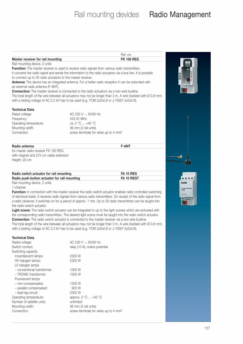
127
Rail mounting devides Radio Management
Ref.-no.Master receiver for rail mounting FK 100 REGRail mounting device, 2 unitsFunction: The master receiver is used to receive radio signals from various radio transmitters. It converts the radio signal and sends the information to the radio actuators via a bus line. It is possible to connect up to 30 radio actuators to the master receiver.Antenna: The device has an integrated antenna. For a better radio reception it can be extended with an external radio antenna (F-ANT).Connection: The master receiver is connected to the radio actuators via a two-wire busline. The total length of the wire between all actuators may not be longer than 3 m. A wire (twisted with Ø 0.8 mm)with a testing voltage of AC 2.5 kV has to be used (e.g. YCM 2x2x0.8 or J-Y(St)Y 2x2x0.8).
Technical Data Rated voltage: AC 230 V ~, 50/60 HzFrequency: 433.42 MHzOperating temperature: ca. 0 °C ... +45 °CMounting width: 36 mm (2 rail units)Connection: screw terminals for wires up to 4 mm2
Radio antenna F-ANTfor master radio receiver FK 100 REGwith magnet and 275 cm cable extensionHeight: 20 cm
Radio switch actuator for rail mounting FA 10 REGRadio push-button actuator for rail mounting FA 10 REGTRail mounting device, 2 units1-channelFunction: In connection with the master receiver the radio switch actuator enables radio controlled switchingof electrical loads. It receives radio signals from various radio transmitters. On receipt of the radio signal froma radio observer, it switches on for a period of approx. 1 min. Up to 30 radio transmitters can be taught intothe radio switch actuator.Light scene: The radio switch actuator can be integrated in up to five light scenes which are activated withthe corresponding radio transmitters. The desired light scene must be taught into the radio switch actuator.Connection: The radio switch actuator is connected to the master receiver via a two-wire busline. The total length of the wire between all actuators may not be longer than 3 m. A wire (twisted with Ø 0.8 mm)with a testing voltage of AC 2.5 kV has to be used (e.g. YCM 2x2x0.8 or J-Y(St)Y 2x2x0.8).
Technical Data Rated voltage: AC 230 V ~, 50/60 HzSwitch contact: relay (10 A), mains potentialSwitching capacity
Incandescent lamps: 2300 WHV halogen lamps: 2300 WLV halogen lamps– conventional transformer: 1000 W– TRONIC transformer: 1500 WFluorescent lamps– non-compensated: 1200 W– parallel compensated: 0920 W– lead-lag circuit: 2300 W
Operating temperature: approx. 0 °C ... +45 °CNumber of satellite units: unlimitedMounting width: 36 mm (2 rail units)Connection: screw terminals for wires up to 4 mm2
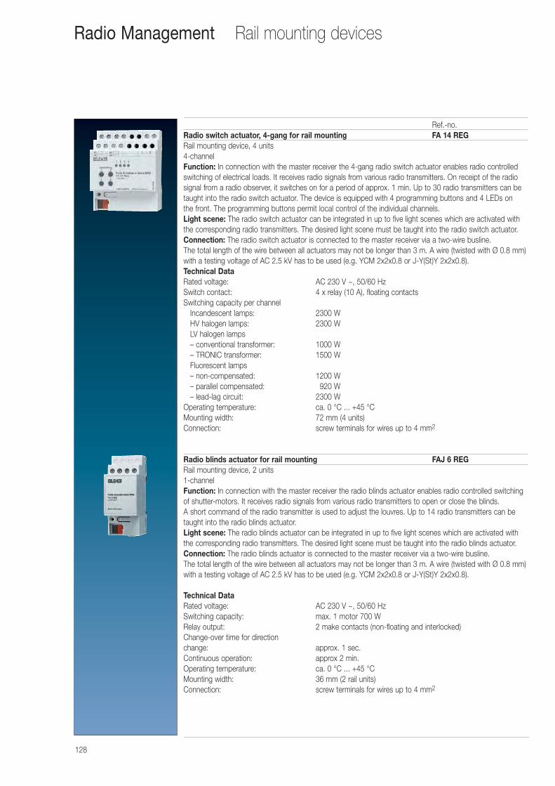
128
Rail mounting devicesRadio Management
Ref.-no.Radio switch actuator, 4-gang for rail mounting FA 14 REGRail mounting device, 4 units4-channelFunction: In connection with the master receiver the 4-gang radio switch actuator enables radio controlledswitching of electrical loads. It receives radio signals from various radio transmitters. On receipt of the radiosignal from a radio observer, it switches on for a period of approx. 1 min. Up to 30 radio transmitters can betaught into the radio switch actuator. The device is equipped with 4 programming buttons and 4 LEDs on the front. The programming buttons permit local control of the individual channels.Light scene: The radio switch actuator can be integrated in up to five light scenes which are activated withthe corresponding radio transmitters. The desired light scene must be taught into the radio switch actuator.Connection: The radio switch actuator is connected to the master receiver via a two-wire busline. The total length of the wire between all actuators may not be longer than 3 m. A wire (twisted with Ø 0.8 mm)with a testing voltage of AC 2.5 kV has to be used (e.g. YCM 2x2x0.8 or J-Y(St)Y 2x2x0.8).Technical Data Rated voltage: AC 230 V ~, 50/60 HzSwitch contact: 4 x relay (10 A), floating contactsSwitching capacity per channel
Incandescent lamps: 2300 WHV halogen lamps: 2300 WLV halogen lamps– conventional transformer: 1000 W– TRONIC transformer: 1500 WFluorescent lamps– non-compensated: 1200 W– parallel compensated: 0920 W– lead-lag circuit: 2300 W
Operating temperature: ca. 0 °C ... +45 °CMounting width: 72 mm (4 units)Connection: screw terminals for wires up to 4 mm2
Radio blinds actuator for rail mounting FAJ 6 REGRail mounting device, 2 units1-channelFunction: In connection with the master receiver the radio blinds actuator enables radio controlled switchingof shutter-motors. It receives radio signals from various radio transmitters to open or close the blinds. A short command of the radio transmitter is used to adjust the louvres. Up to 14 radio transmitters can betaught into the radio blinds actuator.Light scene: The radio blinds actuator can be integrated in up to five light scenes which are activated withthe corresponding radio transmitters. The desired light scene must be taught into the radio blinds actuator.Connection: The radio blinds actuator is connected to the master receiver via a two-wire busline. The total length of the wire between all actuators may not be longer than 3 m. A wire (twisted with Ø 0.8 mm)with a testing voltage of AC 2.5 kV has to be used (e.g. YCM 2x2x0.8 or J-Y(St)Y 2x2x0.8).
Technical Data Rated voltage: AC 230 V ~, 50/60 HzSwitching capacity: max. 1 motor 700 WRelay output: 2 make contacts (non-floating and interlocked)Change-over time for direction change: approx. 1 sec.Continuous operation: approx 2 min.Operating temperature: ca. 0 °C ... +45 °CMounting width: 36 mm (2 rail units)Connection: screw terminals for wires up to 4 mm2
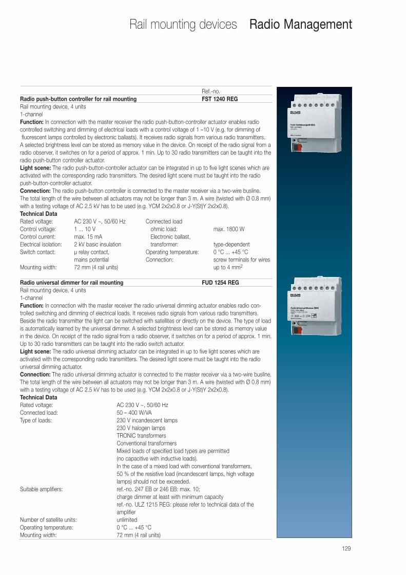
129
Rail mounting devices Radio Management
Ref.-no.Radio push-button controller for rail mounting FST 1240 REGRail mounting device, 4 units1-channelFunction: In connection with the master receiver the radio push-button-controller actuator enables radio controlled switching and dimming of electrical loads with a control voltage of 1 –10 V (e.g. for dimming offluorescent lamps controlled by electronic ballasts). It receives radio signals from various radio transmitters.
A selected brightness level can be stored as memory value in the device. On receipt of the radio signal from aradio observer, it switches on for a period of approx. 1 min. Up to 30 radio transmitters can be taught into theradio push-button controller actuator.Light scene: The radio push-button-controller actuator can be integrated in up to five light scenes which areactivated with the corresponding radio transmitters. The desired light scene must be taught into the radiopush-button-controller actuator.Connection: The radio push-button controller is connected to the master receiver via a two-wire busline. The total length of the wire between all actuators may not be longer than 3 m. A wire (twisted with Ø 0.8 mm)with a testing voltage of AC 2.5 kV has to be used (e.g. YCM 2x2x0.8 or J-Y(St)Y 2x2x0.8).Technical Data Rated voltage: AC 230 V ~, 50/60 Hz Connected loadControl voltage: 1 ... 10 V ohmic load: max. 1800 WControl current: max. 15 mA Electronic ballast, Electrical isolation: 2 kV basic insulation transformer: type-dependentSwitch contact: μ relay contact, Operating temperature: 0 °C ... +45 °C
mains potential Connection: screw terminals for wires Mounting width: 72 mm (4 rail units) up to 4 mm2
Radio universal dimmer for rail mounting FUD 1254 REGRail mounting device, 4 units1-channelFunction: In connection with the master receiver the radio universal dimming actuator enables radio con-trolled switching and dimming of electrical loads. It receives radio signals from various radio transmitters.Beside the radio transmitter the light can be switched with satellites or directly on the device. The type of loadis automatically learned by the universal dimmer. A selected brightness level can be stored as memory valuein the device. On receipt of the radio signal from a radio observer, it switches on for a period of approx. 1 min.Up to 30 radio transmitters can be taught into the radio switch actuator.Light scene: The radio universal dimming actuator can be integrated in up to five light scenes which are activated with the corresponding radio transmitters. The desired light scene must be taught into the radio universal dimming actuator.Connection: The radio universal dimming actuator is connected to the master receiver via a two-wire busline.The total length of the wire between all actuators may not be longer than 3 m. A wire (twisted with Ø 0.8 mm)with a testing voltage of AC 2.5 kV has to be used (e.g. YCM 2x2x0.8 or J-Y(St)Y 2x2x0.8).Technical Data Rated voltage: AC 230 V ~, 50/60 HzConnected load: 50 – 400 W/VAType of loads: 230 V incandescent lamps
230 V halogen lampsTRONIC transformersConventional transformersMixed loads of specified load types are permitted (no capacitive with inductive loads).In the case of a mixed load with conventional transformers, 50 % of the resistive load (incandescent lamps, high voltage lamps) should not be exceeded.
Suitable amplifiers: ref.-no. 247 EB or 246 EB: max. 10; charge dimmer at least with minimum capacityref.-no. ULZ 1215 REG: please refer to technical data of the amplifier
Number of satellite units: unlimitedOperating temperature: 0 °C ... +45 °CMounting width: 72 mm (4 rail units)
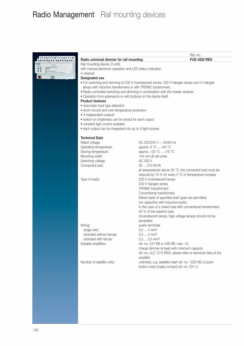
130
Rail mounting devicesRadio Management
Ref.-no.Radio universal dimmer for rail mounting FUD 4252 REGRail mounting device, 8 unitswith manual electronic operation and LED status indication4-channelDesignated use• For switching and dimming of 230 V incandescent lamps, 230 V halogen lamps and LV halogen
lamps with inductive transformers or with TRONIC transformers.• Radio-controlled switching and dimming in combination with the master receiver.• Operation from extensions or with buttons on the device itself.Product features• Automatic load type detection• short-circuits and over-temperature protection• 4 independent outputs• switch-on brightness can be stored for each output• constant light control available• each output can be integrated into up to 5 light-scenes
Technical Data Rated voltage: AC 230/240 V ~, 50/60 HzOperating temperature: approx. 0 °C ... +45 °CStoring temperature: approx. –25 °C ... +70 °CMounting width: 144 mm (8 rail units)Switching voltage: AC 250 VConnected load: 50 ... 210 W/VA
at temperatures above 35 °C, the connected load must be reduced by 10 % for every 5 °C of temperature increase
Type of loads: 230 V incandescent lamps230 V halogen lampsTRONIC transformersConventional transformersMixed loads of specified load types are permitted (no capacitive with inductive loads).In the case of a mixed load with conventional transformers, 50 % of the resistive load(incandescent lamps, high voltage lamps) should not be exceeded.
Wiring: screw terminalssingle wire: 0.5 ... 4 mm2
stranded without ferrule: 0.5 ... 4 mm2
stranded with ferrule: 0.5 ... 2.5 mm2
Suitable amplifiers: ref.-no. 247 EB or 246 EB: max. 10; charge dimmer at least with minimum capacityref.-no. ULZ 1215 REG: please refer to technical data of the amplifier
Number of satellite units: unlimited, e.g. satellite insert ref.-no. 1220 NE or push-button insert (make contact) ref.-no. 531 U
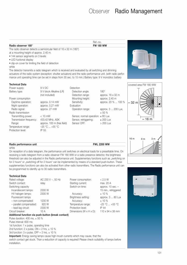
131
Observer Radio Management
Ref.-no.Radio observer 180° FW 180 WWThe radio observer detects a semicircular field of 16 x 32 m (180°) at a mounting height of approx. 2.40 m.• 144 sensor segments on 3 levels• LED fuctional display• clip-on cover for limiting the field of detectionwhiteThe detector transmits a radio telegram which is received and evaluated by all switching and dimming actuators of the radio system (exception: shutter actuators) and the radio performance unit. (with radio perfor-mance unit operating time can be set in steps from 30 sec. to 15 min.) Battery type: 9 V monobloc battery
Technical Data Power supply: 9 V DC DetectionBattery type: 9 V block Alkaline (LR) Detection angle: 180°
(not included) Detection range: approx. 16 x 32 mPower consumption Mounting height: approx. 2.40 m
Daytime operation: approx. 0.14 mW Sensitivity: approx. 20 % ... 100 %Night operation: approx. 0.27 mW EvaluationRadio signal: approx. 27 mW Operation range: approx. 3 ... 200 Lux,
Radio transmission ± 50 %Transmitting power: < 10 mW Sensor, normal operation: ≤ 80 LuxTransmission frequency: 433.42 MHz, ASK Sensor, retriggering: ≤ 200 LuxRange: approx. 100 m (free field) Sensor OFF: > 200 Lux
Temperature range: –25 °C ... +55 °CProtection level: IP 55
Radio performance unit FWL 2200 WWwhiteOn reception of a data telegram, the performance unit switches on electrical loads for a presettable time. Onreceiving a radio telegram from a radio observer FW 180 WW or a radio presence detector, the brightnessthreshold can also be adjusted in the Radio performance unit. Supplementary functions such as „switching onfor 2 hours“ or „switching off for 2 hours“ can be implemented by means of a standard push-button. Thesesupplementary functions can also be activated from other radio transmitters. The Radio performance unit canbe programmed to identify up to 30 radio transmitters.
Technical Data Rated voltage: AC 230 V ~, 50 Hz Power consumption: < 2.5 WSwitch contact: relay Starting current: max. 20 ASwitching capacity Switch-on time: approx. 10 sec. –
Incandescent lamps: 2300 W 15 min., retriggeredHV halogen lamps: 2300 W Accuracy: ± 10 %Fluorescent lamps Brightness setting: approx. 3 ... 80 Lux– non-compensated: 1200 W Accuracy: ± 10 %– parallel compensated: 0920 W Temperature range: –25 °C ... +55 °C– lead-lag circuit: 2300 W Protection level: IP 44
Circuit breaker: 10 A Dimensions (W x H x D): 110 x 94 x 38 mmAdditional function via push-button (break contact)Pulse duration: 400 ms, ± 50 %Pulse interval: 600 ms1st function: 1 x pulse, operating time2nd function: 2 x pulse, ON = 2 hrs, ± 10 %3rd function: 3 x pulse, OFF = 2 hrs, ± 10 %Important: Energy saving lamps cause high inrush currents which may cause, that theswitch contact get stuck. Than a reduction of capacity is required! Please check suitability of lamps beforeinstallation.
~ 16 m
~ 32 m
16 m
2,4
m
9 m 3 m
covered area FW 180 WW
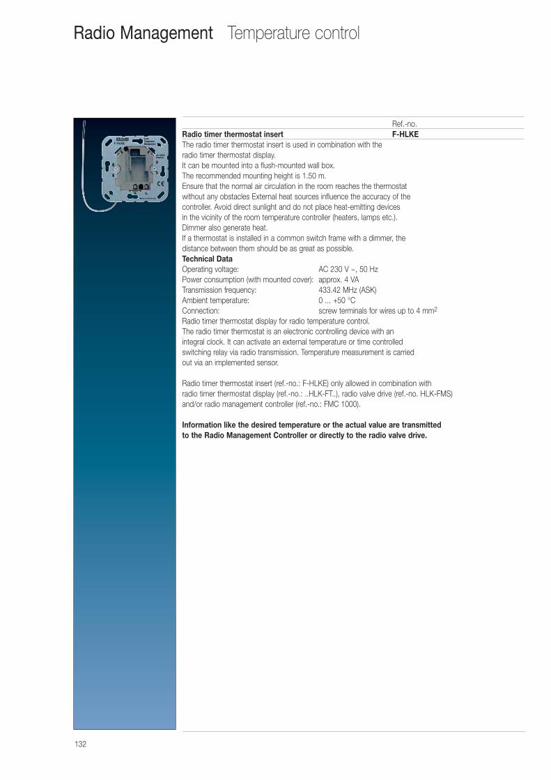
132
Ref.-no.Radio timer thermostat insert F-HLKEThe radio timer thermostat insert is used in combination with the radio timer thermostat display. It can be mounted into a flush-mounted wall box. The recommended mounting height is 1.50 m. Ensure that the normal air circulation in the room reaches the thermostat without any obstacles External heat sources influence the accuracy of the controller. Avoid direct sunlight and do not place heat-emitting devices in the vicinity of the room temperature controller (heaters, lamps etc.). Dimmer also generate heat. If a thermostat is installed in a common switch frame with a dimmer, the distance between them should be as great as possible.Technical Data Operating voltage: AC 230 V ~, 50 HzPower consumption (with mounted cover): approx. 4 VATransmission frequency: 433.42 MHz (ASK)Ambient temperature: 0 ... +50 °CConnection: screw terminals for wires up to 4 mm2
Radio timer thermostat display for radio temperature control.The radio timer thermostat is an electronic controlling device with an integral clock. It can activate an external temperature or time controlled switching relay via radio transmission. Temperature measurement is carried out via an implemented sensor.
Radio timer thermostat insert (ref.-no.: F-HLKE) only allowed in combination with radio timer thermostat display (ref.-no.: ..HLK-FT..), radio valve drive (ref.-no. HLK-FMS) and/or radio management controller (ref.-no.: FMC 1000).
Information like the desired temperature or the actual value are transmitted to the Radio Management Controller or directly to the radio valve drive.
Temperature controlRadio Management
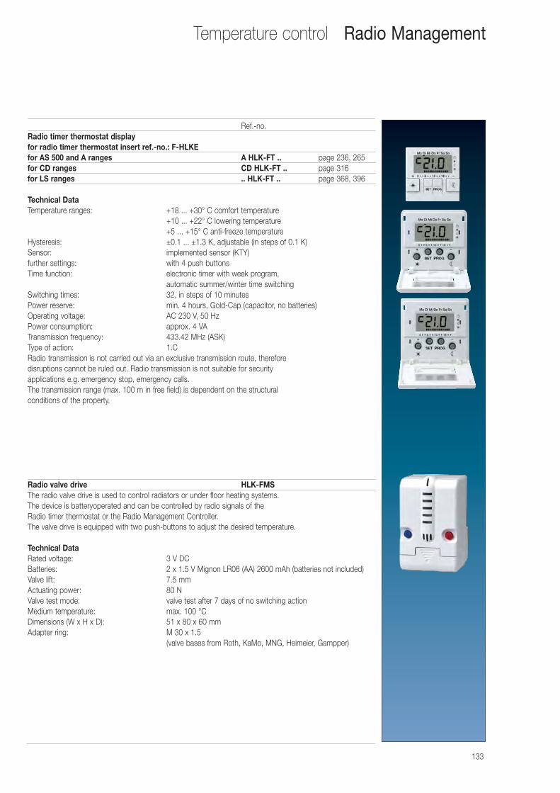
133
Ref.-no.Radio timer thermostat displayfor radio timer thermostat insert ref.-no.: F-HLKEfor AS 500 and A ranges A HLK-FT .. page 236, 265for CD ranges CD HLK-FT .. page 316for LS ranges .. HLK-FT .. page 368, 396
Technical Data Temperature ranges: +18 ... +30° C comfort temperature
+10 ... +22° C lowering temperature+5 ... +15° C anti-freeze temperature
Hysteresis: ±0.1 ... ±1.3 K, adjustable (in steps of 0.1 K)Sensor: implemented sensor (KTY)further settings: with 4 push buttonsTime function: electronic timer with week program,
automatic summer/winter time switchingSwitching times: 32, in steps of 10 minutesPower reserve: min. 4 hours, Gold-Cap (capacitor, no batteries)Operating voltage: AC 230 V, 50 HzPower consumption: approx. 4 VATransmission frequency: 433.42 MHz (ASK)Type of action: 1.CRadio transmission is not carried out via an exclusive transmission route, therefore disruptions cannot be ruled out. Radio transmission is not suitable for security applications e.g. emergency stop, emergency calls.The transmission range (max. 100 m in free field) is dependent on the structural conditions of the property.
Radio valve drive HLK-FMSThe radio valve drive is used to control radiators or under floor heating systems. The device is batteryoperated and can be controlled by radio signals of the Radio timer thermostat or the Radio Management Controller. The valve drive is equipped with two push-buttons to adjust the desired temperature.
Technical Data Rated voltage: 3 V DCBatteries: 2 x 1.5 V Mignon LR06 (AA) 2600 mAh (batteries not included)Valve lift: 7.5 mmActuating power: 80 NValve test mode: valve test after 7 days of no switching actionMedium temperature: max. 100 °CDimensions (W x H x D): 51 x 80 x 60 mmAdapter ring: M 30 x 1.5
(valve bases from Roth, KaMo, MNG, Heimeier, Gampper)
Temperature control Radio Management
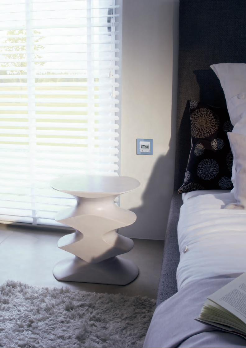
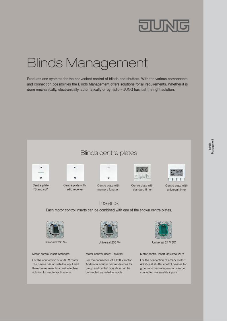
Products and systems for the convenient control of blinds and shutters. With the various components and connection possibilities the Blinds Management offers solutions for all requirements. Whether it is done mechanically, electronically, automatically or by radio – JUNG has just the right solution.
Blin
ds
Man
agem
ent
Blinds Management
Motor control insert Standard
For the connection of a 230 V motor. The device has no satellite input and therefore represents a cost effective solution for single applications.
Motor control insert Universal
For the connection of a 230 V motor. Additional shutter control devices for group and central operation can be connected via satellite inputs.
Motor control insert Universal 24 V
For the connection of a 24 V motor. Additional shutter control devices for group and central operation can be connected via satellite inputs.
InsertsEach motor control inserts can be combined with one of the shown centre plates.
Universal 24 V DCStandard 230 V~ Universal 230 V~
Centre plate “Standard”
Centre plate with radio receiver
Centre plate with memory function
Centre plate with universal timer
Blinds centre plates
Centre plate with standard timer
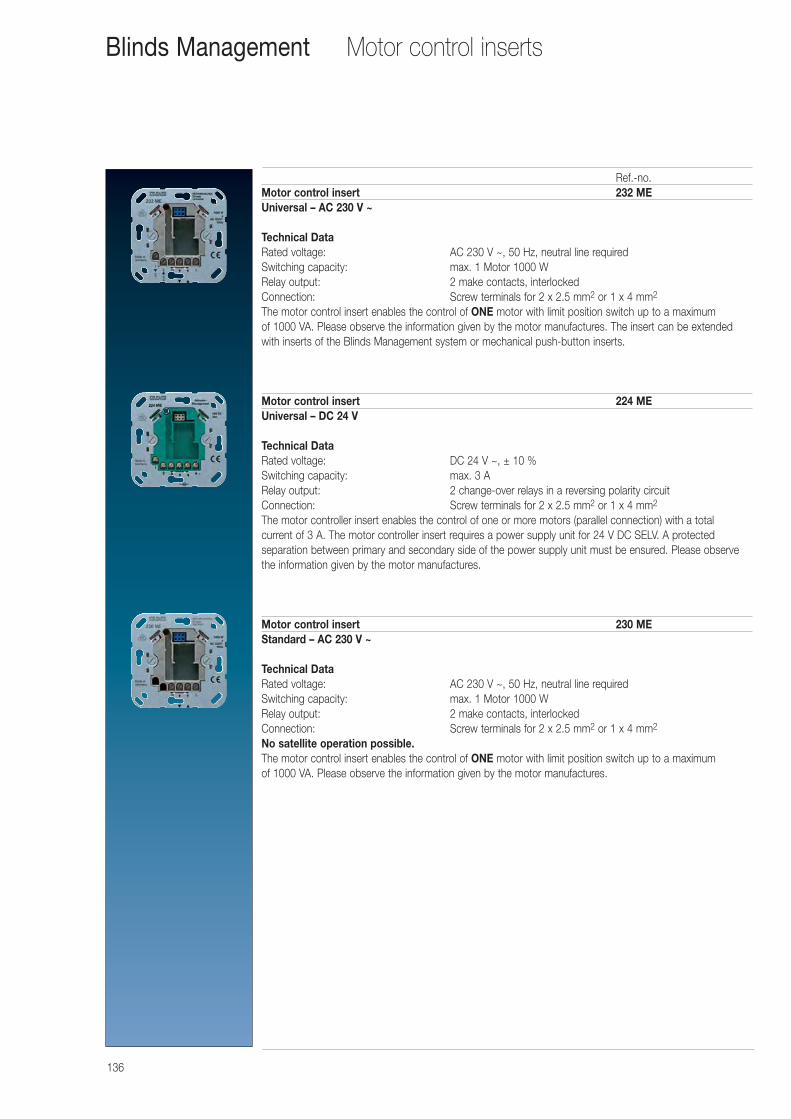
136
Motor control inserts
Ref.-no.Motor control insert 232 MEUniversal – AC 230 V ~
Technical Data Rated voltage: AC 230 V ~, 50 Hz, neutral line requiredSwitching capacity: max. 1 Motor 1000 WRelay output: 2 make contacts, interlockedConnection: Screw terminals for 2 x 2.5 mm2 or 1 x 4 mm2
The motor control insert enables the control of ONE motor with limit position switch up to a maximum of 1000 VA. Please observe the information given by the motor manufactures. The insert can be extendedwith inserts of the Blinds Management system or mechanical push-button inserts.
Motor control insert 224 MEUniversal – DC 24 V
Technical Data Rated voltage: DC 24 V ~, ± 10 %Switching capacity: max. 3 ARelay output: 2 change-over relays in a reversing polarity circuitConnection: Screw terminals for 2 x 2.5 mm2 or 1 x 4 mm2
The motor controller insert enables the control of one or more motors (parallel connection) with a total current of 3 A. The motor controller insert requires a power supply unit for 24 V DC SELV. A protected separation between primary and secondary side of the power supply unit must be ensured. Please observethe information given by the motor manufactures.
Motor control insert 230 MEStandard – AC 230 V ~
Technical Data Rated voltage: AC 230 V ~, 50 Hz, neutral line requiredSwitching capacity: max. 1 Motor 1000 WRelay output: 2 make contacts, interlockedConnection: Screw terminals for 2 x 2.5 mm2 or 1 x 4 mm2
No satellite operation possible.The motor control insert enables the control of ONE motor with limit position switch up to a maximum of 1000 VA. Please observe the information given by the motor manufactures.
Blinds Management
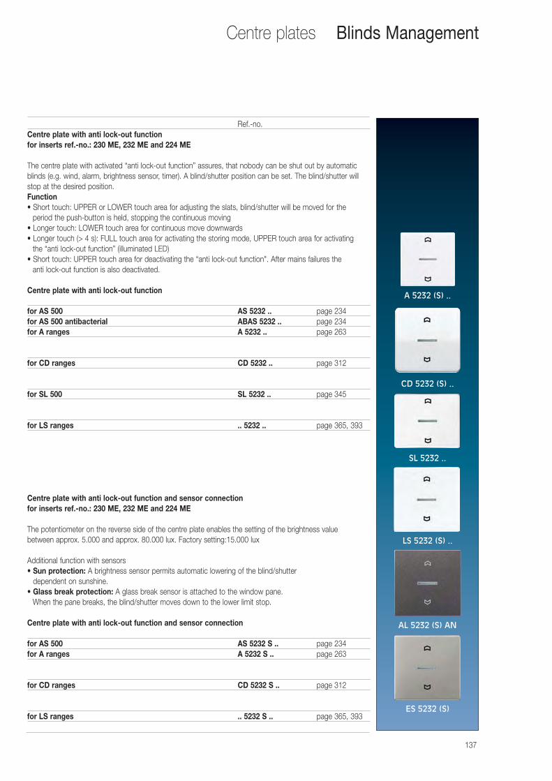
137
Centre plates
Ref.-no.Centre plate with anti lock-out functionfor inserts ref.-no.: 230 ME, 232 ME and 224 ME
The centre plate with activated “anti lock-out function” assures, that nobody can be shut out by automaticblinds (e.g. wind, alarm, brightness sensor, timer). A blind/shutter position can be set. The blind/shutter willstop at the desired position.Function• Short touch: UPPER or LOWER touch area for adjusting the slats, blind/shutter will be moved for the
period the push-button is held, stopping the continuous moving• Longer touch: LOWER touch area for continuous move downwards• Longer touch (> 4 s): FULL touch area for activating the storing mode, UPPER touch area for activating
the “anti lock-out function” (illuminated LED)• Short touch: UPPER touch area for deactivating the “anti lock-out function". After mains failures the
anti lock-out function is also deactivated.
Centre plate with anti lock-out function
for AS 500 AS 5232 .. page 234for AS 500 antibacterial ABAS 5232 .. page 234for A ranges A 5232 .. page 263
for CD ranges CD 5232 .. page 312
for SL 500 SL 5232 .. page 345
for LS ranges .. 5232 .. page 365, 393
Centre plate with anti lock-out function and sensor connectionfor inserts ref.-no.: 230 ME, 232 ME and 224 ME
The potentiometer on the reverse side of the centre plate enables the setting of the brightness value between approx. 5.000 and approx. 80.000 lux. Factory setting:15.000 lux
Additional function with sensors• Sun protection: A brightness sensor permits automatic lowering of the blind/shutter
dependent on sunshine.• Glass break protection: A glass break sensor is attached to the window pane.
When the pane breaks, the blind/shutter moves down to the lower limit stop.
Centre plate with anti lock-out function and sensor connection
for AS 500 AS 5232 S .. page 234for A ranges A 5232 S .. page 263
for CD ranges CD 5232 S .. page 312
for LS ranges .. 5232 S .. page 365, 393
Blinds Management
A 5232 (S) ..
CD 5232 (S) ..
SL 5232 ..
LS 5232 (S) ..
AL 5232 (S) AN
ES 5232 (S)
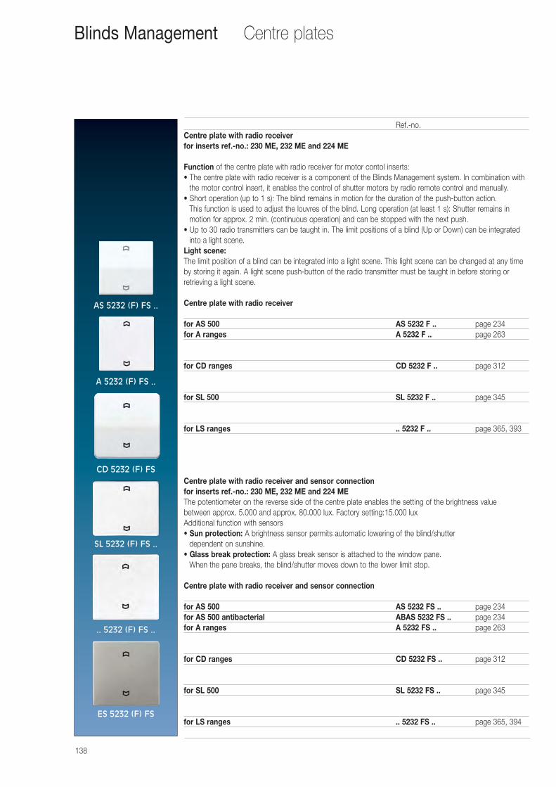
138
Centre plates
Ref.-no.Centre plate with radio receiverfor inserts ref.-no.: 230 ME, 232 ME and 224 ME
Function of the centre plate with radio receiver for motor contol inserts:• The centre plate with radio receiver is a component of the Blinds Management system. In combination with
the motor control insert, it enables the control of shutter motors by radio remote control and manually.• Short operation (up to 1 s): The blind remains in motion for the duration of the push-button action.
This function is used to adjust the louvres of the blind. Long operation (at least 1 s): Shutter remains inmotion for approx. 2 min. (continuous operation) and can be stopped with the next push.
• Up to 30 radio transmitters can be taught in. The limit positions of a blind (Up or Down) can be integratedinto a light scene.
Light scene:The limit position of a blind can be integrated into a light scene. This light scene can be changed at any timeby storing it again. A light scene push-button of the radio transmitter must be taught in before storing orretrieving a light scene.
Centre plate with radio receiver
for AS 500 AS 5232 F .. page 234for A ranges A 5232 F .. page 263
for CD ranges CD 5232 F .. page 312
for SL 500 SL 5232 F .. page 345
for LS ranges .. 5232 F .. page 365, 393
Centre plate with radio receiver and sensor connectionfor inserts ref.-no.: 230 ME, 232 ME and 224 METhe potentiometer on the reverse side of the centre plate enables the setting of the brightness value between approx. 5.000 and approx. 80.000 lux. Factory setting:15.000 luxAdditional function with sensors• Sun protection: A brightness sensor permits automatic lowering of the blind/shutter
dependent on sunshine.• Glass break protection: A glass break sensor is attached to the window pane.
When the pane breaks, the blind/shutter moves down to the lower limit stop.
Centre plate with radio receiver and sensor connection
for AS 500 AS 5232 FS .. page 234for AS 500 antibacterial ABAS 5232 FS .. page 234for A ranges A 5232 FS .. page 263
for CD ranges CD 5232 FS .. page 312
for SL 500 SL 5232 FS .. page 345
for LS ranges .. 5232 FS .. page 365, 394
Blinds Management
AS 5232 (F) FS ..
A 5232 (F) FS ..
CD 5232 (F) FS
.. 5232 (F) FS ..
ES 5232 (F) FS
SL 5232 (F) FS ..

139
Centre plates
Ref.-no.Centre plate with memory function and sensor connectionfor inserts ref.-no.: 230 ME, 232 ME and 224 ME
FunctionThe centre plate with memory function enables the individual storing of one up and one down operation time. These two blind operation times are repeated every 24 hour. This provides comfortable, automatic blinds control which can, for example, be used for presence simulation.• Short touch (< 1 s): UPPER or LOWER touch area for adjusting the slats, blind/shutter will
be moved for the period the push button is held, stopping the continuous moving• Longer touch (> 1 s): LOWER touch area for continuous moving downwards UPPER
touch area for continuous moving upwards• Longer touch (> 3.5 s): Storing of the up or down operation time.• Longer touch (> 8 s): Switching between manual and memory mode
Additional function with sensors• Sun protection: A brightness sensor permits automatic lowering of the blind/shutter
dependent on sunshine.
• Glass break protection: A glass break sensor is attached to the window pane. When the pane breaks, the blind/shutter moves down to the lower limit stop.
Centre plate with memory function and sensor connection
for AS 500 AS 5232 MS .. page 234for A ranges A 5232 MS .. page 263
for CD ranges CD 5232 MS .. page 313
for SL 500 SL 5232 MS .. page 345
for LS ranges .. 5232 MS .. page 366, 394
Blinds Management
AS 5232 MS ..
A 5232 MS ..
CD 5232 MS ..
.. 5232 MS ..
ES 5232 MS
SL 5232 MS ..
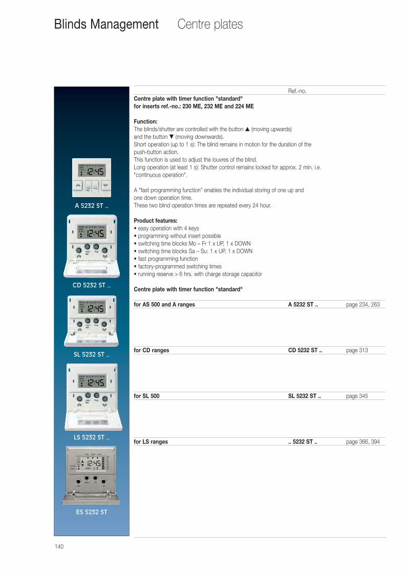
140
Centre plates
Ref.-no.Centre plate with timer function "standard"for inserts ref.-no.: 230 ME, 232 ME and 224 ME
Function:The blinds/shutter are controlled with the button ▲ (moving upwards) and the button ▼ (moving downwards).Short operation (up to 1 s): The blind remains in motion for the duration of the push-button action. This function is used to adjust the louvres of the blind.Long operation (at least 1 s): Shutter control remains locked for approx. 2 min. i.e. "continuous operation".
A "fast programming function" enables the individual storing of one up and one down operation time.These two blind operation times are repeated every 24 hour.
Product features:• easy operation with 4 keys• programming without insert possible• switching time blocks Mo – Fr 1 x UP, 1 x DOWN• switching time blocks Sa – Su: 1 x UP, 1 x DOWN• fast programming function• factory-programmed switching times• running reserve > 6 hrs. with charge storage capacitor
Centre plate with timer function "standard"
for AS 500 and A ranges A 5232 ST .. page 234, 263
for CD ranges CD 5232 ST .. page 313
for SL 500 SL 5232 ST .. page 345
for LS ranges .. 5232 ST .. page 366, 394
Blinds Management
A 5232 ST ..
CD 5232 ST ..
SL 5232 ST ..
LS 5232 ST ..
ES 5232 ST
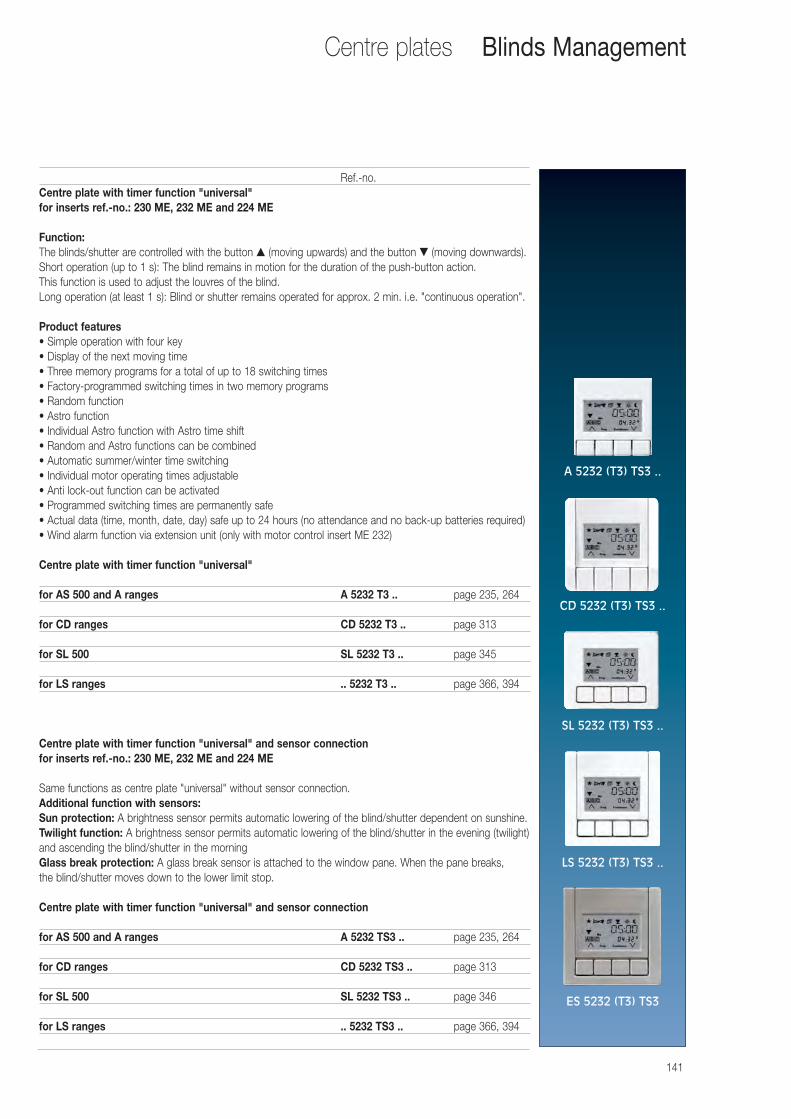
141
Centre plates
Ref.-no.Centre plate with timer function "universal"for inserts ref.-no.: 230 ME, 232 ME and 224 ME
Function:The blinds/shutter are controlled with the button ▲ (moving upwards) and the button ▼ (moving downwards).Short operation (up to 1 s): The blind remains in motion for the duration of the push-button action. This function is used to adjust the louvres of the blind.Long operation (at least 1 s): Blind or shutter remains operated for approx. 2 min. i.e. "continuous operation".
Product features• Simple operation with four key • Display of the next moving time • Three memory programs for a total of up to 18 switching times • Factory-programmed switching times in two memory programs • Random function• Astro function • Individual Astro function with Astro time shift • Random and Astro functions can be combined • Automatic summer/winter time switching • Individual motor operating times adjustable• Anti lock-out function can be activated• Programmed switching times are permanently safe • Actual data (time, month, date, day) safe up to 24 hours (no attendance and no back-up batteries required) • Wind alarm function via extension unit (only with motor control insert ME 232)
Centre plate with timer function "universal"
for AS 500 and A ranges A 5232 T3 .. page 235, 264
for CD ranges CD 5232 T3 .. page 313
for SL 500 SL 5232 T3 .. page 345
for LS ranges .. 5232 T3 .. page 366, 394
Centre plate with timer function "universal" and sensor connectionfor inserts ref.-no.: 230 ME, 232 ME and 224 ME
Same functions as centre plate "universal" without sensor connection.Additional function with sensors:Sun protection: A brightness sensor permits automatic lowering of the blind/shutter dependent on sunshine.Twilight function: A brightness sensor permits automatic lowering of the blind/shutter in the evening (twilight)and ascending the blind/shutter in the morningGlass break protection: A glass break sensor is attached to the window pane. When the pane breaks, the blind/shutter moves down to the lower limit stop.
Centre plate with timer function "universal" and sensor connection
for AS 500 and A ranges A 5232 TS3 .. page 235, 264
for CD ranges CD 5232 TS3 .. page 313
for SL 500 SL 5232 TS3 .. page 346
for LS ranges .. 5232 TS3 .. page 366, 394
Blinds Management
A 5232 (T3) TS3 ..
CD 5232 (T3) TS3 ..
SL 5232 (T3) TS3 ..
LS 5232 (T3) TS3 ..
ES 5232 (T3) TS3
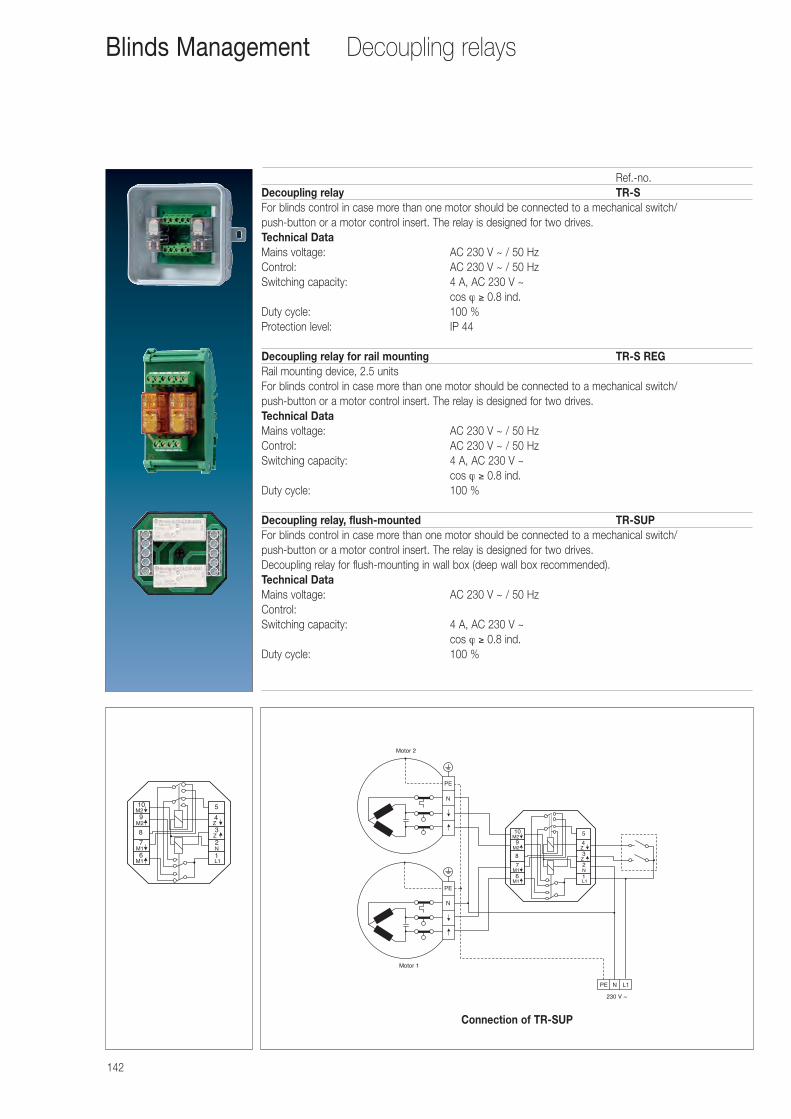
142
Decoupling relays
Ref.-no.Decoupling relay TR-SFor blinds control in case more than one motor should be connected to a mechanical switch/push-button or a motor control insert. The relay is designed for two drives.Technical Data Mains voltage: AC 230 V ~ / 50 HzControl: AC 230 V ~ / 50 HzSwitching capacity: 4 A, AC 230 V ~
cos ϕ ≥ 0.8 ind.Duty cycle: 100 %Protection level: IP 44
Decoupling relay for rail mounting TR-S REGRail mounting device, 2.5 unitsFor blinds control in case more than one motor should be connected to a mechanical switch/push-button or a motor control insert. The relay is designed for two drives.Technical Data Mains voltage: AC 230 V ~ / 50 HzControl: AC 230 V ~ / 50 HzSwitching capacity: 4 A, AC 230 V ~
cos ϕ ≥ 0.8 ind.Duty cycle: 100 %
Decoupling relay, flush-mounted TR-SUPFor blinds control in case more than one motor should be connected to a mechanical switch/push-button or a motor control insert. The relay is designed for two drives.Decoupling relay for flush-mounting in wall box (deep wall box recommended).Technical Data Mains voltage: AC 230 V ~ / 50 HzControl:Switching capacity: 4 A, AC 230 V ~
cos ϕ ≥ 0.8 ind.Duty cycle: 100 %
Blinds Management
M1
M1
M2
M2
N
L11
2
3
4
5
6
7
8
9
10
Z
Z
M1
M1
M2
M2
N
L11
2
3
4
5
6
7
8
9
10
Z
Z
PE N L1
230 V ~
Motor 1
Motor 2
PE
N
PE
N
Connection of TR-SUP
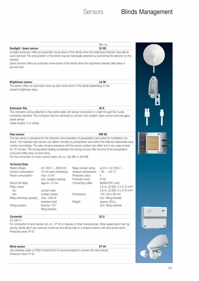
143
Sensors
Ref.-no.Sunlight / dawn sensor 32 SDSunlight protection offers an automatic move-down of the blinds when the brightness intensity rises above a pre-set level. The end-position of the blinds may be individually selected by positioning the detector on thewindow.Dawn function offers an automatic move-down of the blinds when the brightness intensity falls below a pre-set level.
Brightness sensor LA 90The sensor offers an automatic move-up and move-down of the blinds depending on the present brightness value.
Extension flex 32 KThe connector will be attached to the center plate with sensor connection or insert through the 3-pole connection terminal. The connector has two terminals to connect one sunlight /dawn sensor and one glass-break sensor.Cable lenghts: 5 m (white)
Rain sensor RW 95The rain sensor is designed for the detection and evaluation of precipitation and suited for installation out-doors. The meander-type sensor can detect humidity by precipitation and switch the internal make/break relaycontact accordingly. The relay remains energized until the sensor surface has dried, but in any case at leastfor 10 minutes. The incorporated heating accelerates the drying process after the end of the precipitationcycle and melts away ice and snow.For the connection to motor control insert, ref.-no. 232 ME or 224 ME.
Technical Data Rated voltage: AC 230 V ~, 50/60 Hz Relay contact rating: (μ) 6 A / AC 250 V ~Current consumption: 15 mA (with preheating) Ambient temperature: –30 ... +50 °CPower consumption: max. 4.5 W Protection class: II
(incl. auxiliary heating) Protection level: IP 65Switch-off delay: approx. 10 min. Connecting cable: flexible PVC cord,Relay output 2.9 m, JZ-600, 3 x 0.75 mm2
dry: contact open 2.9 m, JZ-600, 2 x 0.75 mm2
rain: contact closed Dimensions: 130 x 90 x 90 mm Relay switching capacity: max. 1500 W (incl. fitting bracket)
(resistive load) Weight: approx. 600 gFitting position: fixed by 110° (incl. fitting bracket)
fitting bracket
Converter 32 UAC 230 V ~For connection of wind sensor ref.-no.: VT 04 or devices of other manufactures. Wind speed alarm has toppriority, blinds will in any case be moved-up and will be kept in a locked position until wind slows down.Protection level: IP 43
Wind sensor VT 04Use shielded cable (J-Y(St)Y 2x2x0.6mm2 is recommended) to connect the wind sensor.Protection level: IP 43
Blinds Management
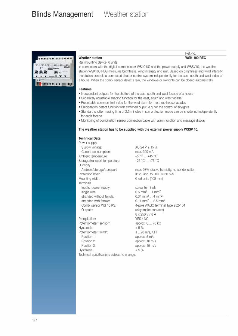
144
Weather stationBlinds Management
Ref.-no.Weather station WSK 100 REGRail mounting device, 6 unitsIn connection with the digital combi sensor WS10 KS and the power supply unit WSSV10, the weather station WSK100 REG measures brightness, wind intensity and rain. Based on brightness and wind intensity,the station controls a connected shutter control system independently for the east, south and west sides of a house. When the combi sensor detects rain, the windows or skylights can be closed automatically.
Features• Independent outputs for the shutters of the east, south and west facade of a house• Separately adjustable shading function for the east, south and west facade• Presettable common limit value for the wind alarm for the three house facades• Precipitation detect function with switched ouput, e.g. for the control of skylights• Standard shutter moving time of 2.5 minutes in sun protection mode can be shortened independently
for each facade• Monitoring of combination sensor connection cable with alarm function and message display
The weather station has to be supplied with the external power supply WSSV 10.
Technical Data Power supply
Supply voltage: AC 24 V ± 15 %Current consumption: max. 300 mA
Ambient temperature: –5 °C ... +45 °CStorage/transport temperature: –25 °C ... +75 °CHumidity
Ambient/storage/transport: max. 93% relative humidity, no condensationProtection level: IP 20 acc. to DIN EN 60 529Mounting width: 6 rail units (108 mm)Terminals
Inputs, power supply: screw terminalssingle wire: 0.5 mm2 ... 4 mm2
stranded without ferrule: 0.34 mm2 ... 4 mm2
stranded with ferrule: 0.14 mm2 ... 2.5 mm2
Combi sensor WS 10 KS: 4-pole WAGO terminal Type 252-104Outputs: relay (make contacts)
8 x 250 V / 8 APrecipitation: YES / NOPotentiometer "sensor": approx. 0 ... 76 klxHysteresis: ± 5 %Potentiometer "wind": 1 ...20 m/s, OFF
Position 1: approx. 5 m/sPosition 2: approx. 10 m/sPosition 3: approx. 15 m/s
Hysteresis: ± 5 %Technical specifications subject to change.
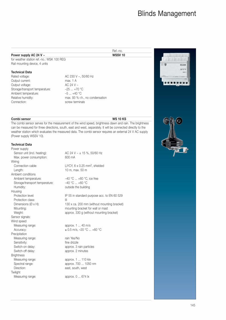
145
Blinds Management
Ref.-no.Power supply AC 24 V ~ WSSV 10for weather station ref.-no.: WSK 100 REGRail mounting device, 4 units
Technical Data Rated voltage: AC 230 V ~, 50/60 Hz Output current: max. 1 A Output voltage: AC 24 V ~ Storage/transport temperature: –25 ... +70 °C Ambient temperature: –5 ... +40 °C Relative humidity: max. 93 % r.h., no condensation Connection: screw terminals
Combi sensor WS 10 KSThe combi sensor serves for the measurement of the wind speed, brightness dawn and rain. The brightnesscan be measured for three directions, south, east and west, separately. It will be connected directly to theweather station which evaluates the measured data. The combi sensor requires an external 24 V AC supply(Power supply WSSV 10).
Technical Data Power supply
Sensor unit (incl. heating): AC 24 V ~ ± 15 %, 50/60 HzMax. power consumption: 600 mA
Wiring Connection cable: LiYCY, 6 x 0.25 mm2, shieldedLength: 10 m, max. 50 m
Ambient conditions Ambient temperature: –40 °C ... +60 °C, ice freeStorage/transport temperature: –40 °C ... +60 °CHumidity: outside the building
Housing Protection level: IP 55 in standard purpose acc. to EN 60 529Protection class: IIIDimensions (Ø x H): 130 x ca. 200 mm (without mounting bracket)Mounting: mounting bracket for wall or mastWeight: approx. 330 g (without mounting bracket)
Sensor signals: Wind speed
Measuring range: approx. 1 ... 40 m/sAccuracy: ≤ 0.5 m/s, –20 °C ... +60 °C
Precipitation Measuring range: rain Yes/NoSensitivity: fine drizzleSwitch-on delay: approx. 3 rain particlesSwitch-off delay: approx. 2 minutes
Brightness Measuring range: approx. 1 ... 110 klxSpectral range: approx. 700 ... 1050 nmDirection: east, south, west
Twilight Measuring range: approx. 0 ... 674 lx
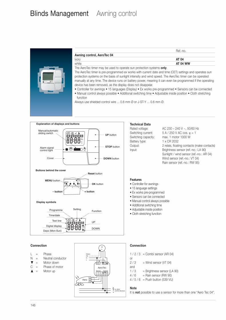
146
Awning controlBlinds Management
Ref.-no.Awning control, AeroTec 04ivory AT 04white AT 04 WWThe AeroTec timer may be used to operate sun protection systems only.The AeroTec timer is pre-programmed ex works with current date and time (CET) settings and operates sunprotection systems on the basis of sunlight intensity and wind speed. The AeroTec timer can be operatedmanually at any time. The device runs on battery power, meaning it can even be programmed if the operatingdevice has been removed, as the display does not disappear.• Controller for awnings • 15 languages (Display) • Ex works pre-programmed • Sensors can be connected• Manual control always possible • Additional switching time • Adjustable inside position • Cloth stretching
functionAlways use shielded control wire ... 0.8 mm Ø or J-ST-Y ... 0.6 mm Ø.
Connection
L = PhaseN = Neutral conductor� = Motor downC = Phase of motor� = Motor up
31
Programme Setting
Time/date
Text line
Digital display
Days (Mon-Sun)
Function
UP
DOWN
Display symbols
UP button
STOP button
31
Explanation of displays and buttons
Manual/automaticsliding switch
Alarm signalcontrol light
Cover DOWN button
– button
Reset button
OK button
+ button
Buttons behind the cover
MENU buttonMENUE – + OK
AeroTec
Reset
AeroTec
N L C
1 2 3 4 5 6
Sensor Central
Aero
MainsPENL
to othercontrol devices
123
M
1~
Connection
1 / 2 / 3 = Combi sensor (AR 04) or2 / 3 = Wind sensor (VT 04) and1 / 3 = Brightness sensor (LA 90)4 / 6 = Rain sensor (RW 90)4 / 5 / 6 = Push button (539 VU)
NoteIt is not possible to use a sensor for more than one “Aero Tec 04”.
Technical Data Rated voltage: AC 230 – 240 V ~, 50/60 HzSwitching current: 5 A / 250 V AC cos. ϕ = 1Switching capacity: max. 1 motor 1000 WBattery type: 1 x CR 2032Output: 2 relais, floating contacts (make contacts)Input: Brightness sensor (ref.-no.: LA 90)
Sunlight / wind sensor (ref.-no.: AR 04)Wind sensor (ref.-no.: VT 04)Rain sensor (ref.-no.: RW 95)
Features• Controller for awnings• 15 language settings• Ex works pre-programmed• Sensors can be connected• Manual control always possible• Additional switching time• Adjustable inside position• Cloth stretching function
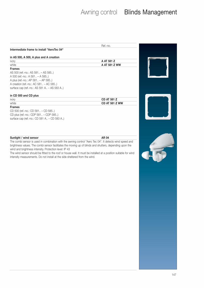
147
Awning control Blinds Management
Ref.-no.Intermediate frame to install "AeroTec 04"
in AS 500, A 500, A plus and A creationivory A AT 581 Zwhite A AT 581 Z WWFramesAS 500 (ref.-no.: AS 581.. – AS 585..) A 500 (ref.-no.: A 581.. – A 585..) A plus (ref.-no.: AP 581.. – AP 585..) A creation (ref.-no.: AC 581.. – AC 585..) surface cap (ref.-no.: AS 581 A.. – AS 583 A..)
in CD 500 and CD plusivory CD AT 581 Zwhite CD AT 581 Z WWFramesCD 500 (ref.-no.: CD 581.. – CD 585..) CD plus (ref.-no.: CDP 581.. – CDP 585..) surface cap (ref.-no.: CD 581 A.. – CD 583 A..)
Sunlight / wind sensor AR 04The combi sensor is used in combination with the awning control "Aero Tec 04". It detects wind speed andbrightness values. The combi sensor facilitates the moving up of blinds and shutters, depending upon thewind and brightness intensity. Protection level: IP 43The wind sensor should be fitted to the roof or house wall. It must be installed at a position suitable for windintensity measurements. Do not install at the side sheltered from the wind.
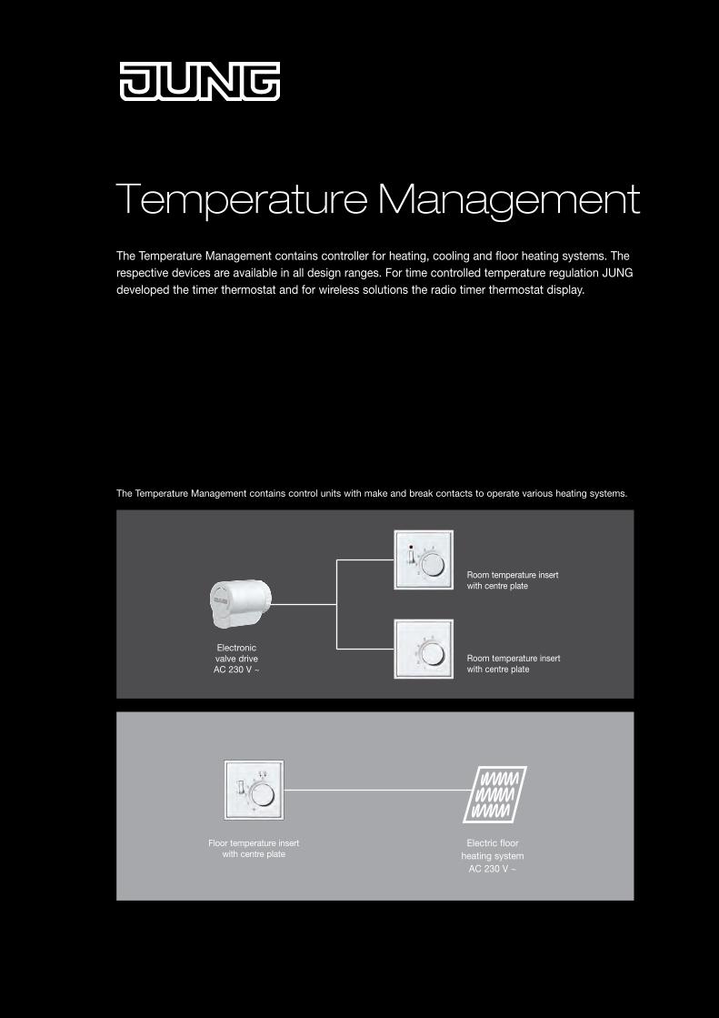
Temperature ManagementThe Temperature Management contains controller for heating, cooling and floor heating systems. The respective devices are available in all design ranges. For time controlled temperature regulation JUNG developed the timer thermostat and for wireless solutions the radio timer thermostat display.
Floor temperature insert with centre plate
Electric floor heating system
AC 230 V ~
The Temperature Management contains control units with make and break contacts to operate various heating systems.
Electronic valve drive AC 230 V ~
Room temperature insert with centre plate
Room temperature insert with centre plate
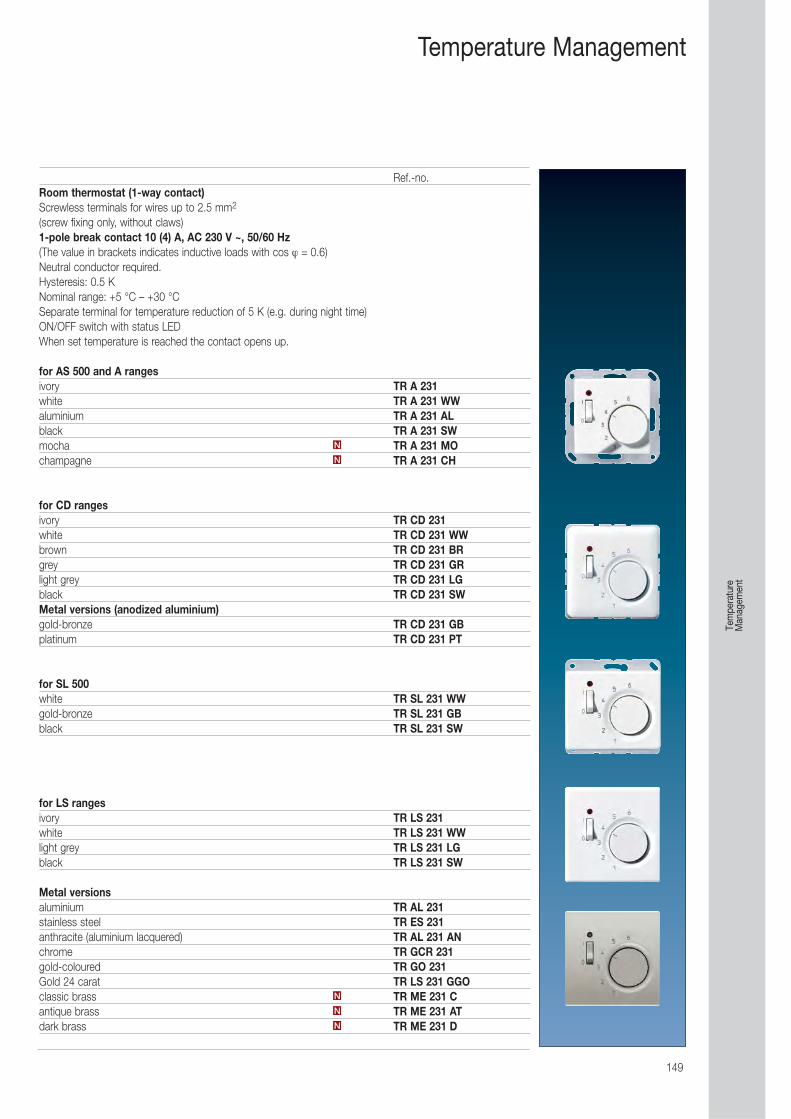
149
Temperature Management
Ref.-no.Room thermostat (1-way contact)Screwless terminals for wires up to 2.5 mm2
(screw fixing only, without claws)1-pole break contact 10 (4) A, AC 230 V ~, 50/60 Hz(The value in brackets indicates inductive loads with cos ϕ = 0.6)Neutral conductor required.Hysteresis: 0.5 KNominal range: +5 °C – +30 °CSeparate terminal for temperature reduction of 5 K (e.g. during night time)ON/OFF switch with status LEDWhen set temperature is reached the contact opens up.
for AS 500 and A rangesivory TR A 231white TR A 231 WWaluminium TR A 231 ALblack TR A 231 SWmocha TR A 231 MOchampagne TR A 231 CH
for CD rangesivory TR CD 231white TR CD 231 WWbrown TR CD 231 BRgrey TR CD 231 GRlight grey TR CD 231 LGblack TR CD 231 SWMetal versions (anodized aluminium)gold-bronze TR CD 231 GBplatinum TR CD 231 PT
for SL 500white TR SL 231 WWgold-bronze TR SL 231 GBblack TR SL 231 SW
for LS rangesivory TR LS 231white TR LS 231 WWlight grey TR LS 231 LGblack TR LS 231 SW
Metal versionsaluminium TR AL 231stainless steel TR ES 231anthracite (aluminium lacquered) TR AL 231 ANchrome TR GCR 231gold-coloured TR GO 231Gold 24 carat TR LS 231 GGOclassic brass TR ME 231 Cantique brass TR ME 231 ATdark brass TR ME 231 DN
N
N
N
N
Tem
pera
ture
M
anag
emen
t
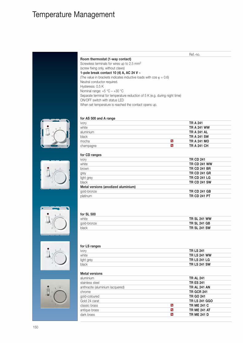
150
Ref.-no.Room thermostat (1-way contact)Screwless terminals for wires up to 2.5 mm2
(screw fixing only, without claws)1-pole break contact 10 (4) A, AC 24 V ~(The value in brackets indicates inductive loads with cos ϕ = 0.6)Neutral conductor required.Hysteresis: 0.5 KNominal range: +5 °C – +30 °CSeparate terminal for temperature reduction of 5 K (e.g. during night time)ON/OFF switch with status LEDWhen set temperature is reached the contact opens up.
for AS 500 and A rangeivory TR A 241white TR A 241 WWaluminium TR A 241 ALblack TR A 241 SWmocha TR A 241 MOchampagne TR A 241 CH
for CD rangesivory TR CD 241white TR CD 241 WWbrown TR CD 241 BRgrey TR CD 241 GRlight grey TR CD 241 LGblack TR CD 241 SWMetal versions (anodized aluminium)gold-bronze TR CD 241 GBplatinum TR CD 241 PT
for SL 500white TR SL 241 WWgold-bronze TR SL 241 GBblack TR SL 241 SW
for LS rangesivory TR LS 241white TR LS 241 WWlight grey TR LS 241 LGblack TR LS 241 SW
Metal versionsaluminium TR AL 241stainless steel TR ES 241anthracite (aluminium lacquered) TR AL 241 ANchrome TR GCR 241gold-coloured TR GO 241Gold 24 carat TR LS 241 GGOclassic brass TR ME 241 Cantique brass TR ME 241 ATdark brass TR ME 241 DN
N
N
N
N
Temperature Management

151
Ref.-no.Room thermostat (make/break contact)Screwless terminals for wires up to 2.5 mm2
(screw fixing only, without claws)1-pole, 2-way, heating 10 (4) A, AC 230 V ~, 50/60 Hz1-pole, 2-way, cooling 5 (2) A, AC 230 V ~, 50/60 Hz(The value in brackets indicates inductive loads with cos ϕ = 0.6)Neutral conductor required.Hysteresis: 0.5 KNominal range: +5 °C – +30 °CWhen set temperature is reached the make/break contact switches over.
for AS 500 and A rangesivory TR A 236white TR A 236 WWaluminium TR A 236 ALblack TR A 236 SWmocha TR A 236 MOchampagne TR A 236 CH
for CD rangesivory TR CD 236white TR CD 236 WWbrown TR CD 236 BRgrey TR CD 236 GRlight grey TR CD 236 LGblack TR CD 236 SWMetal versions (anodized aluminium)gold-bronze TR CD 236 GBplatinum TR CD 236 PT
for SL 500white TR SL 236 WWgold-bronze TR SL 236 GBblack TR SL 236 SW
for LS rangesivory TR LS 236white TR LS 236 WWlight grey TR LS 236 LGblack TR LS 236 SW
Metal versionsaluminium TR AL 236stainless steel TR ES 236anthracite (aluminium lacquered) TR AL 236 ANchrome TR GCR 236gold-coloured TR GO 236Gold 24 carat TR LS 236 GGOclassic brass TR ME 236 Cantique brass TR ME 236 ATdark brass TR ME 236 DN
N
N
N
N
Temperature Management
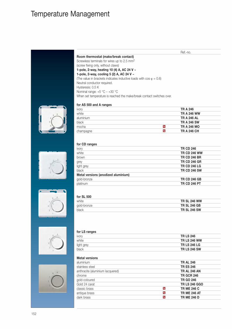
152
Ref.-no.Room thermostat (make/break contact)Screwless terminals for wires up to 2.5 mm2
(screw fixing only, without claws)1-pole, 2-way, heating 10 (4) A, AC 24 V ~1-pole, 2-way, cooling 5 (2) A, AC 24 V ~(The value in brackets indicates inductive loads with cos ϕ = 0.6)Neutral conductor required.Hysteresis: 0.5 KNominal range: +5 °C – +30 °CWhen set temperature is reached the make/break contact switches over.
for AS 500 and A rangesivory TR A 246white TR A 246 WWaluminium TR A 246 ALblack TR A 246 SWmocha TR A 246 MOchampagne TR A 246 CH
for CD rangesivory TR CD 246white TR CD 246 WWbrown TR CD 246 BRgrey TR CD 246 GRlight grey TR CD 246 LGblack TR CD 246 SWMetal versions (anodized aluminium)gold-bronze TR CD 246 GBplatinum TR CD 246 PT
for SL 500white TR SL 246 WWgold-bronze TR SL 246 GBblack TR SL 246 SW
for LS rangesivory TR LS 246white TR LS 246 WWlight grey TR LS 246 LGblack TR LS 246 SW
Metal versionsaluminium TR AL 246stainless steel TR ES 246anthracite (aluminium lacquered) TR AL 246 ANchrome TR GCR 246gold-coloured TR GO 246Gold 24 carat TR LS 246 GGOclassic brass TR ME 246 Cantique brass TR ME 246 ATdark brass TR ME 246 DN
N
N
N
N
Temperature Management
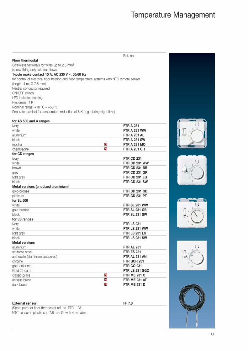
153
Ref.-no.Floor thermostatScrewless terminals for wires up to 2.5 mm2
(screw fixing only, without claws)1-pole make contact 10 A, AC 230 V ~, 50/60 Hzfor control of electrical floor heating and floor temperature systems with NTC remote sensor (length: 4 m, Ø 7.8 mm)Neutral conductor requiredON/OFF switchLED indicates heatingHysteresis: 1 KNominal range: +10 °C – +50 °CSeparate terminal for temperature reduction of 5 K (e.g. during night time)
for AS 500 and A rangesivory FTR A 231white FTR A 231 WWaluminium FTR A 231 ALblack FTR A 231 SWmocha FTR A 231 MOchampagne FTR A 231 CHfor CD rangesivory FTR CD 231white FTR CD 231 WWbrown FTR CD 231 BRgrey FTR CD 231 GRlight grey FTR CD 231 LGblack FTR CD 231 SWMetal versions (anodized aluminium)gold-bronze FTR CD 231 GBplatinum FTR CD 231 PTfor SL 500white FTR SL 231 WWgold-bronze FTR SL 231 GBblack FTR SL 231 SWfor LS rangesivory FTR LS 231white FTR LS 231 WWlight grey FTR LS 231 LGblack FTR LS 231 SWMetal versionsaluminium FTR AL 231stainless steel FTR ES 231anthracite (aluminium lacquered) FTR AL 231 ANchrome FTR GCR 231gold-coloured FTR GO 231Gold 24 carat FTR LS 231 GGOclassic brass FTR ME 231 Cantique brass FTR ME 231 ATdark brass FTR ME 231 D
External sensor FF 7.8(Spare part) for floor thermostat ref. no. FTR .. 231 ..NTC sensor in plastic cap 7.8 mm Ø, with 4 m cable
N
N
N
N
N
Temperature Management
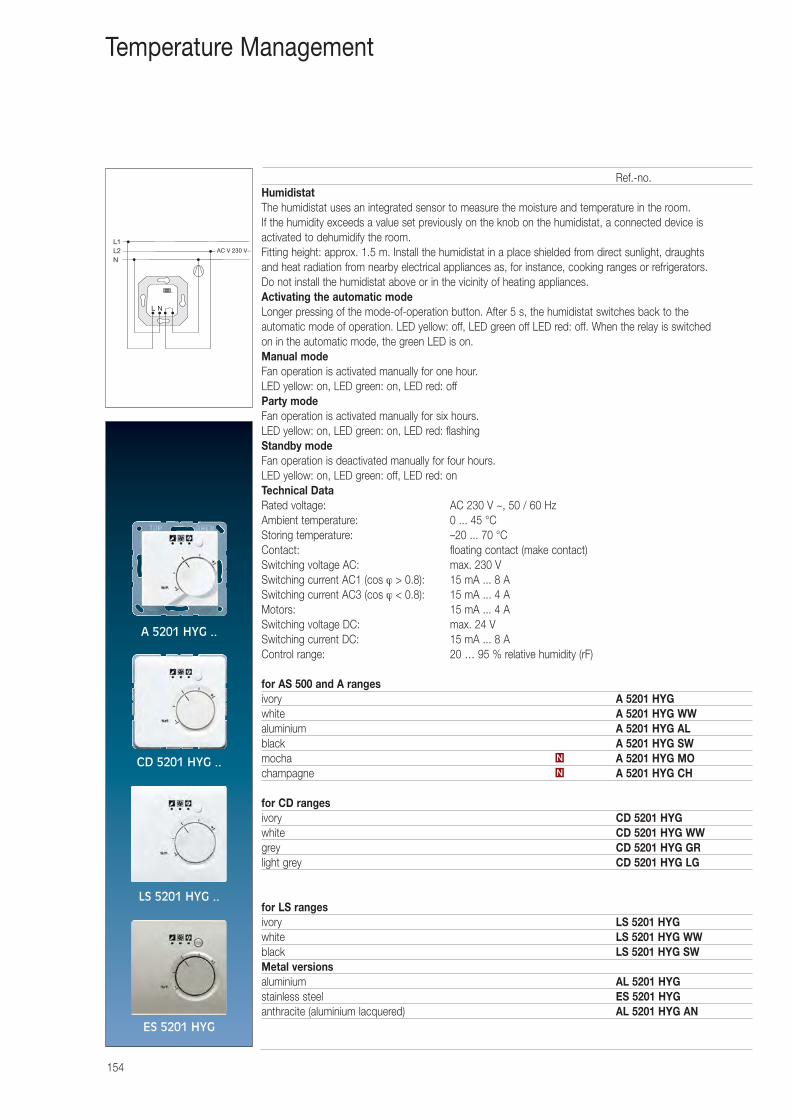
154
Temperature Management
Ref.-no.HumidistatThe humidistat uses an integrated sensor to measure the moisture and temperature in the room. If the humidity exceeds a value set previously on the knob on the humidistat, a connected device is activated to dehumidify the room.Fitting height: approx. 1.5 m. Install the humidistat in a place shielded from direct sunlight, draughts and heat radiation from nearby electrical appliances as, for instance, cooking ranges or refrigerators. Do not install the humidistat above or in the vicinity of heating appliances.Activating the automatic modeLonger pressing of the mode-of-operation button. After 5 s, the humidistat switches back to the automatic mode of operation. LED yellow: off, LED green off LED red: off. When the relay is switched on in the automatic mode, the green LED is on.Manual modeFan operation is activated manually for one hour.LED yellow: on, LED green: on, LED red: offParty modeFan operation is activated manually for six hours.LED yellow: on, LED green: on, LED red: flashingStandby modeFan operation is deactivated manually for four hours.LED yellow: on, LED green: off, LED red: onTechnical Data Rated voltage: AC 230 V ~, 50 / 60 HzAmbient temperature: 0 ... 45 °CStoring temperature: –20 ... 70 °CContact: floating contact (make contact)Switching voltage AC: max. 230 VSwitching current AC1 (cos ϕ > 0.8): 15 mA ... 8 ASwitching current AC3 (cos ϕ < 0.8): 15 mA ... 4 AMotors: 15 mA ... 4 ASwitching voltage DC: max. 24 VSwitching current DC: 15 mA ... 8 AControl range: 20 … 95 % relative humidity (rF)
for AS 500 and A rangesivory A 5201 HYGwhite A 5201 HYG WWaluminium A 5201 HYG ALblack A 5201 HYG SWmocha A 5201 HYG MOchampagne A 5201 HYG CH
for CD rangesivory CD 5201 HYGwhite CD 5201 HYG WWgrey CD 5201 HYG GRlight grey CD 5201 HYG LG
for LS rangesivory LS 5201 HYGwhite LS 5201 HYG WWblack LS 5201 HYG SWMetal versionsaluminium AL 5201 HYGstainless steel ES 5201 HYGanthracite (aluminium lacquered) AL 5201 HYG AN
N
N
A 5201 HYG ..
CD 5201 HYG ..
LS 5201 HYG ..
ES 5201 HYG
L1L2N
L N
AC V 230 V~
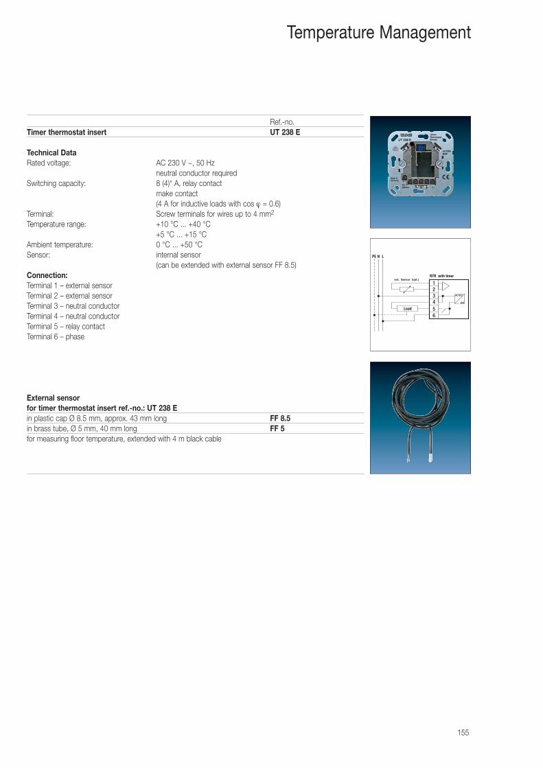
155
Temperature Management
Ref.-no.Timer thermostat insert UT 238 E
Technical Data Rated voltage: AC 230 V ~, 50 Hz
neutral conductor requiredSwitching capacity: 8 (4)* A, relay contact
make contact(4 A for inductive loads with cos ϕ = 0.6)
Terminal: Screw terminals for wires up to 4 mm2
Temperature range: +10 °C ... +40 °C +5 °C ... +15 °C
Ambient temperature: 0 °C ... +50 °CSensor: internal sensor
(can be extended with external sensor FF 8.5)Connection: Terminal 1 – external sensorTerminal 2 – external sensorTerminal 3 – neutral conductorTerminal 4 – neutral conductorTerminal 5 – relay contactTerminal 6 – phase
External sensorfor timer thermostat insert ref.-no.: UT 238 Ein plastic cap Ø 8.5 mm, approx. 43 mm long FF 8.5in brass tube, Ø 5 mm, 40 mm long FF 5for measuring floor temperature, extended with 4 m black cable
PE N L
DC
AC/DC
123456
Load
RTR with timerext. Sensor (opt.)
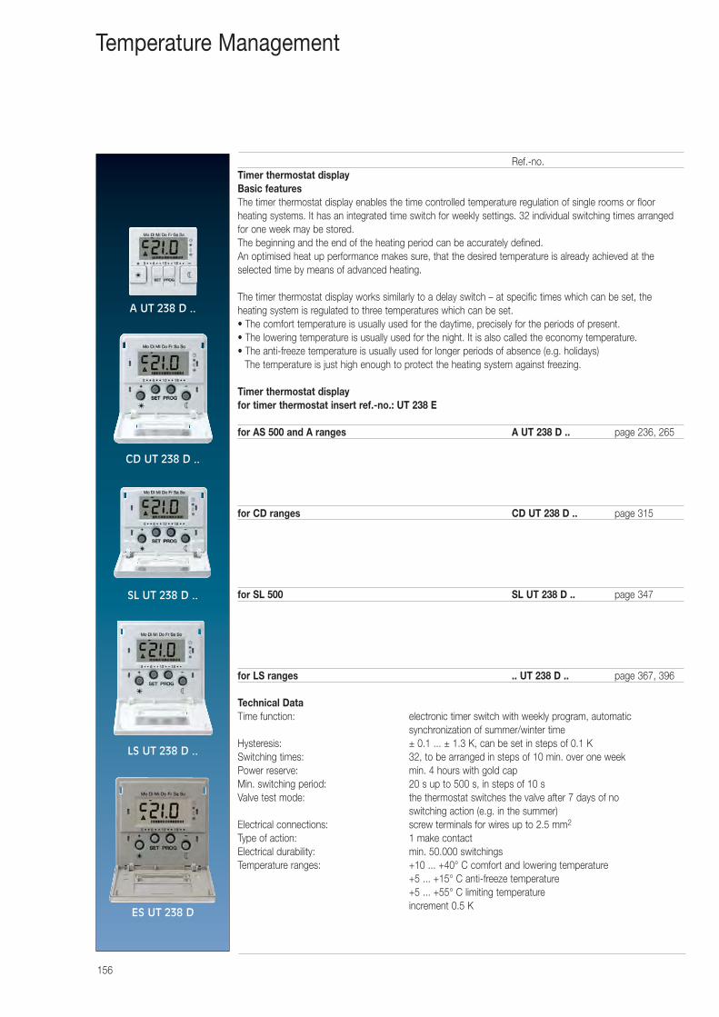
156
Temperature Management
Ref.-no.Timer thermostat displayBasic featuresThe timer thermostat display enables the time controlled temperature regulation of single rooms or floor heating systems. It has an integrated time switch for weekly settings. 32 individual switching times arrangedfor one week may be stored.The beginning and the end of the heating period can be accurately defined.An optimised heat up performance makes sure, that the desired temperature is already achieved at the selected time by means of advanced heating.
The timer thermostat display works similarly to a delay switch – at specific times which can be set, the heating system is regulated to three temperatures which can be set.• The comfort temperature is usually used for the daytime, precisely for the periods of present.• The lowering temperature is usually used for the night. It is also called the economy temperature.• The anti-freeze temperature is usually used for longer periods of absence (e.g. holidays)
The temperature is just high enough to protect the heating system against freezing.
Timer thermostat displayfor timer thermostat insert ref.-no.: UT 238 E
for AS 500 and A ranges A UT 238 D .. page 236, 265
for CD ranges CD UT 238 D .. page 315
for SL 500 SL UT 238 D .. page 347
for LS ranges .. UT 238 D .. page 367, 396
Technical Data Time function: electronic timer switch with weekly program, automatic
synchronization of summer/winter timeHysteresis: ± 0.1 ... ± 1.3 K, can be set in steps of 0.1 KSwitching times: 32, to be arranged in steps of 10 min. over one weekPower reserve: min. 4 hours with gold capMin. switching period: 20 s up to 500 s, in steps of 10 sValve test mode: the thermostat switches the valve after 7 days of no
switching action (e.g. in the summer)Electrical connections: screw terminals for wires up to 2.5 mm2
Type of action: 1 make contact Electrical durability: min. 50.000 switchingsTemperature ranges: +10 ... +40° C comfort and lowering temperature
+5 ... +15° C anti-freeze temperature+5 ... +55° C limiting temperatureincrement 0.5 K
A UT 238 D ..
CD UT 238 D ..
SL UT 238 D ..
LS UT 238 D ..
ES UT 238 D
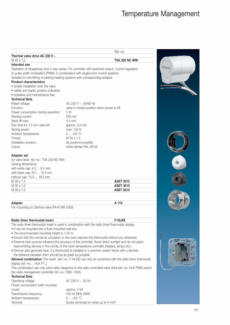
157
Temperature Management
Ref.-no.Thermal valve drive AC 230 V ~M 30 x 1,5 TVA 230 NC WWIntended useOperation of straightway and 3-way valves. For controller with switched output, 2-point regulation or pulse width modulation (PWM), in combination with single room control systems. Suitable for retrofitting of existing heating systems with corresponding adapter.Product characteristics• simple installation onto the valve • visible and haptic position indication • noiseless and maintenance-freeTechnical Data Rated voltage: AC 230 V ~, 50/60 Hz Function: valve in closed position when power is offPower consumption during operation: 2 W Starting current: 250 mA Valve lift max. 4.5 mm Run time for 4.5 mm valve lift: approx. 3.5 min Spring power: max. 125 N Ambient temperature: 0 ... +50 °C Thread: M 30 x 1.5 Installation position: all positions possibleColour: white (similar RAL 9010)
Adapter setfor valve drive ref.-no.: TVA 230 NC WWClosing dimensionswith white cap: 4.5 ... 9.5 mmwith black cap: 8.5 ... 13.5 mmwithout cap: 13.5 ... 18.5 mmM 30 x 1.5 ASET 3015M 30 x 1.0 ASET 3010M 28 x 1.5 ASET 2815
Adapter A 110For mounting on Danfoss valve RA-N (RA 2000)
Radio timer thermostat insert F-HLKEThe radio timer thermostat insert is used in combination with the radio timer thermostat display. • It can be mounted into a flush-mounted wall box.• The recommended mounting height is 1.50 m.• Ensure that the normal air circulation in the room reaches the thermostat without any obstacles• External heat sources influence the accuracy of the controller. Avoid direct sunlight and do not place
heat-emitting devices in the vicinity of the room temperature controller (heaters, lamps etc.).• Dimmer also generate heat. If a thermostat is installed in a common switch frame with a dimmer,
the distance between them should be as great as possible.Allowed combination: The insert (ref.-no.: F-HLKE) can only be combined with the radio timer thermostatdisplay (ref.-no.: ..HLK-FT..)This combination can only send radio telegrams to the radio-controlled valve drive (ref.-no. HLK-FMS) and/orthe radio management controller (ref.-no.: FMC 1000).Technical Data Operating voltage: AC 230 V ~, 50 HzPower consumption (with mounted cover): approx. 4 VATransmission frequency: 433.42 MHz (ASK)Ambient temperature: 0 ... +50 °CTerminal: Screw terminals for wires up to 4 mm2
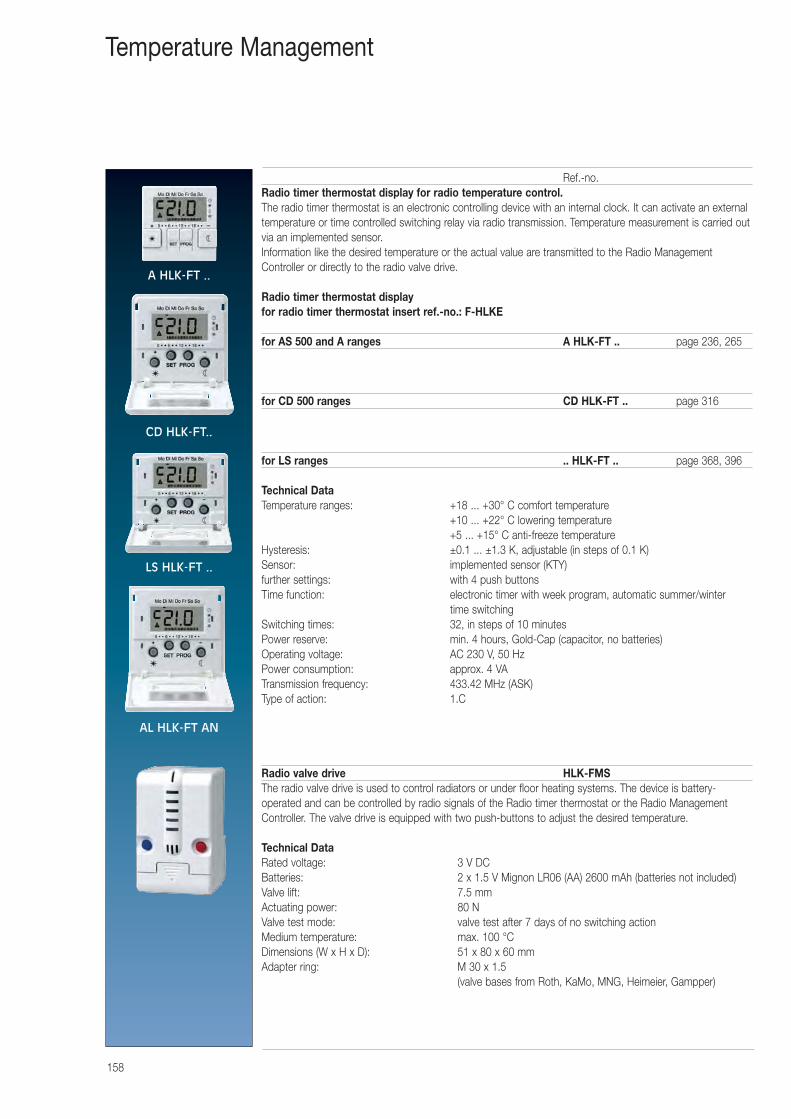
158
Temperature Management
Ref.-no.Radio timer thermostat display for radio temperature control.The radio timer thermostat is an electronic controlling device with an internal clock. It can activate an externaltemperature or time controlled switching relay via radio transmission. Temperature measurement is carried outvia an implemented sensor.Information like the desired temperature or the actual value are transmitted to the Radio ManagementController or directly to the radio valve drive.
Radio timer thermostat displayfor radio timer thermostat insert ref.-no.: F-HLKE
for AS 500 and A ranges A HLK-FT .. page 236, 265
for CD 500 ranges CD HLK-FT .. page 316
for LS ranges .. HLK-FT .. page 368, 396
Technical Data Temperature ranges: +18 ... +30° C comfort temperature
+10 ... +22° C lowering temperature+5 ... +15° C anti-freeze temperature
Hysteresis: ±0.1 ... ±1.3 K, adjustable (in steps of 0.1 K)Sensor: implemented sensor (KTY)further settings: with 4 push buttonsTime function: electronic timer with week program, automatic summer/winter
time switchingSwitching times: 32, in steps of 10 minutesPower reserve: min. 4 hours, Gold-Cap (capacitor, no batteries)Operating voltage: AC 230 V, 50 HzPower consumption: approx. 4 VATransmission frequency: 433.42 MHz (ASK)Type of action: 1.C
Radio valve drive HLK-FMSThe radio valve drive is used to control radiators or under floor heating systems. The device is battery-operated and can be controlled by radio signals of the Radio timer thermostat or the Radio ManagementController. The valve drive is equipped with two push-buttons to adjust the desired temperature.
Technical Data Rated voltage: 3 V DCBatteries: 2 x 1.5 V Mignon LR06 (AA) 2600 mAh (batteries not included)Valve lift: 7.5 mmActuating power: 80 NValve test mode: valve test after 7 days of no switching actionMedium temperature: max. 100 °CDimensions (W x H x D): 51 x 80 x 60 mmAdapter ring: M 30 x 1.5
(valve bases from Roth, KaMo, MNG, Heimeier, Gampper)
A HLK-FT ..
CD HLK-FT..
LS HLK-FT ..
AL HLK-FT AN
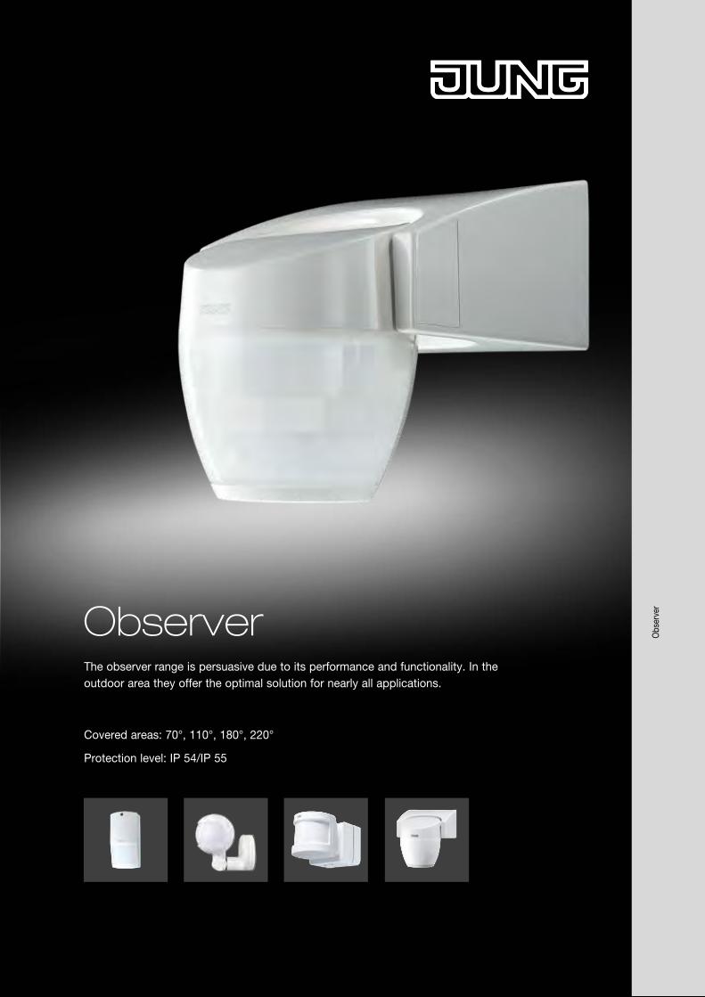
Obs
erve
r
ObserverThe observer range is persuasive due to its performance and functionality. In the outdoor area they offer the optimal solution for nearly all applications.
Covered areas: 70°, 110°, 180°, 220°
Protection level: IP 54/IP 55
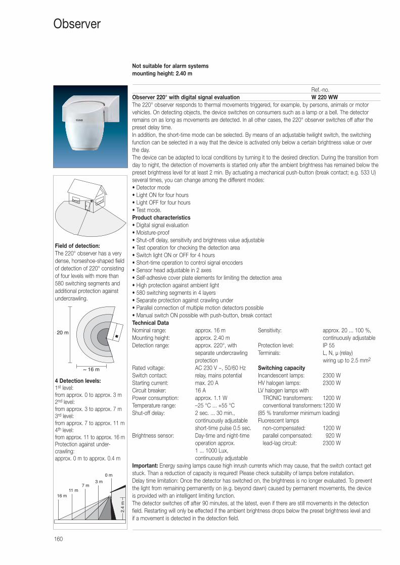
16 m
2.4
m
7 m
0 m
11 m
3 m
4 Detection levels:1st level:from approx. 0 to approx. 3 m2nd level:from approx. 3 to approx. 7 m3rd level:from approx. 7 to approx. 11 m4th level:from approx. 11 to approx. 16 mProtection against under-crawling:approx. 0 m to approx. 0.4 m
~ 16 m
~ 20 m
Field of detection: The 220° observer has a verydense, horseshoe-shaped fieldof detection of 220° consistingof four levels with more than580 switching segments andadditional protection againstundercrawling.
Not suitable for alarm systemsmounting height: 2.40 m
160
Observer
Ref.-no.Observer 220° with digital signal evaluation W 220 WWThe 220° observer responds to thermal movements triggered, for example, by persons, animals or motorvehicles. On detecting objects, the device switches on consumers such as a lamp or a bell. The detectorremains on as long as movements are detected. In all other cases, the 220° observer switches off after thepreset delay time.In addition, the short-time mode can be selected. By means of an adjustable twilight switch, the switchingfunction can be selected in a way that the device is activated only below a certain brightness value or over the day. The device can be adapted to local conditions by turning it to the desired direction. During the transition fromday to night, the detection of movements is started only after the ambient brightness has remained below thepreset brightness level for at least 2 min. By actuating a mechanical push-button (break contact; e.g. 533 U)several times, you can change among the different modes:• Detector mode • Light ON for four hours • Light OFF for four hours • Test mode.Product characteristics• Digital signal evaluation• Moisture-proof• Shut-off delay, sensitivity and brightness value adjustable• Test operation for checking the detection area• Switch light ON or OFF for 4 hours• Short-time operation to control signal encoders• Sensor head adjustable in 2 axes• Self-adhesive cover plate elements for limiting the detection area• High protection against ambient light• 580 switching segments in 4 layers• Separate protection against crawling under• Parallel connection of multiple motion detectors possible• Manual switch ON possible with push-button, break contactTechnical Data Nominal range: approx. 16 m Sensitivity: approx. 20 ... 100 %, Mounting height: approx. 2.40 m continuously adjustableDetection range: approx. 220°, with Protection level: IP 55
separate undercrawling Terminals: L, N, μ (relay) protection wiring up to 2.5 mm2
Rated voltage: AC 230 V ~, 50/60 Hz Switching capacitySwitch contact: relay, mains potential Incandescent lamps: 2300 WStarting current: max. 20 A HV halogen lamps: 2300 WCircuit breaker: 16 A LV halogen lamps withPower consumption: approx. 1.1 W TRONIC transformers: 1200 WTemperature range: –25 °C ... +55 °C conventional transformers:1200 WShut-off delay: 2 sec. ... 30 min., (85 % transformer minimum loading)
continuously adjustable Fluorescent lampsshort-time pulse 0.5 sec. non-compensated: 1200 W
Brightness sensor: Day-time and night-time parallel compensated: 0920 Woperation approx. lead-lag circuit: 2300 W1 ... 1000 Lux, continuously adjustable
Important: Energy saving lamps cause high inrush currents which may cause, that the switch contact getstuck. Than a reduction of capacity is required! Please check suitability of lamps before installation.Delay time limitation: Once the detector has switched on, the brightness is no longer evaluated. To preventthe light from remaining permanently on (e.g. beyond dawn) caused by permanent movements, the device is provided with an intelligent limiting function.The detector switches off after 90 minutes, at the latest, even if there are still movements in the detectionfield. Restarting will only be effected if the ambient brightness drops below the preset brightness level and if a movement is detected in the detection field.
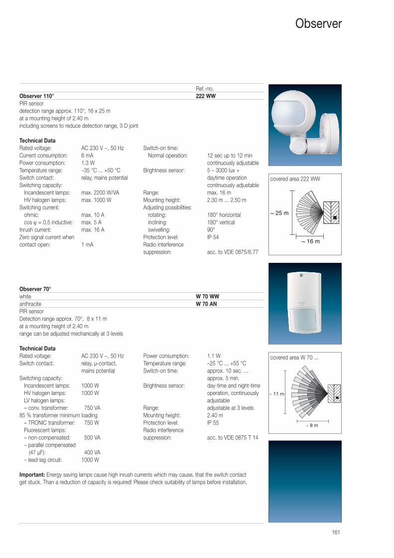
161
Ref.-no.Observer 110° 222 WWPIR sensordetection range approx. 110°, 16 x 25 mat a mounting height of 2.40 mincluding screens to reduce detection range, 3 D joint
Technical Data Rated voltage: AC 230 V ~, 50 Hz Switch-on time:Current consumption: 6 mA Normal operation: 12 sec up to 12 min Power consumption: 1.3 W continuously adjustableTemperature range: –35 °C ... +50 °C Brightness sensor: 5 – 3000 lux + Switch contact: relay, mains potential daytime operationSwitching capacity: continuously adjustable
Incandescent lamps: max. 2200 W/VA Range: max. 16 mHV halogen lamps: max. 1000 W Mounting height: 2.30 m ... 2.50 m
Switching current: Adjusting possibilities:ohmic: max. 10 A rotating: 180° horizontalcos ϕ = 0.5 inductive: max. 5 A inclining: 180° vertical
Inrush current: max. 16 A swivelling: 90°Zero signal current when Protection level: IP 54contact open: 1 mA Radio interference
suppression: acc. to VDE 0875/6.77
Observer 70°white W 70 WWanthracite W 70 ANPIR sensorDetection range approx. 70°, 8 x 11 mat a mounting height of 2.40 mrange can be adjusted mechanically at 3 levels
Technical Data Rated voltage: AC 230 V ~, 50 Hz Power consumption: 1.1 WSwitch contact: relay, μ-contact, Temperature range: –25 °C ... +55 °C
mains potential Switch-on time: approx. 10 sec. ... Switching capacity: approx. 5 min.
Incandescent lamps: 1000 W Brightness sensor: day-time and night-timeHV halogen lamps: 1000 W operation, continuously LV halogen lamps: adjustable– conv. transformer: 0750 VA Range: adjustable at 3 levels
85 % transformer minimum loading Mounting height: 2.40 m– TRONIC transformer: 0750 W Protection level: IP 55Fluorescent lamps: Radio interference – non-compensated: 0500 VA suppression: acc. to VDE 0875 T 14– parallel compensated
(47 μF): 0400 VA– lead-lag circuit: 1000 W
Important: Energy saving lamps cause high inrush currents which may cause, that the switch contact get stuck. Than a reduction of capacity is required! Please check suitability of lamps before installation.
Observer
~ 16 m
~ 25 m
covered area 222 WW
~ 8 m
~ 11 m
covered area W 70 ...
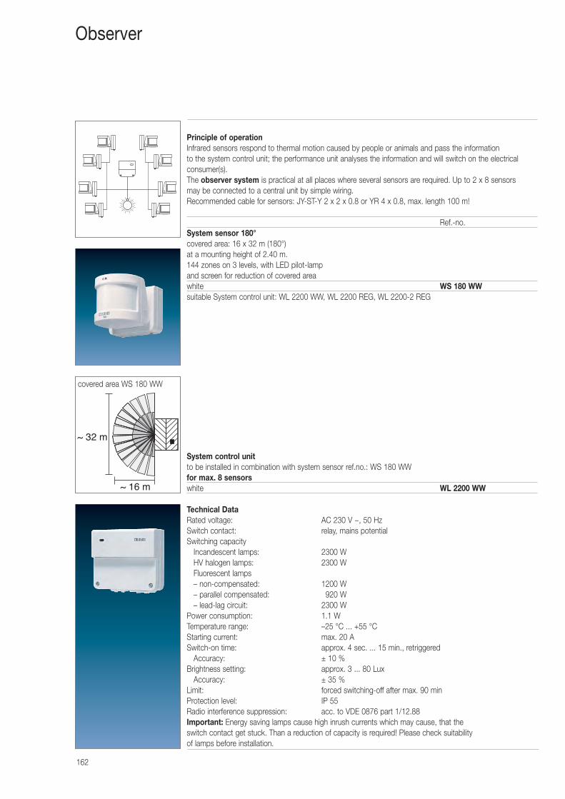
162
Principle of operationInfrared sensors respond to thermal motion caused by people or animals and pass the information to the system control unit; the performance unit analyses the information and will switch on the electrical consumer(s).The observer system is practical at all places where several sensors are required. Up to 2 x 8 sensors may be connected to a central unit by simple wiring. Recommended cable for sensors: JY-ST-Y 2 x 2 x 0.8 or YR 4 x 0.8, max. length 100 m!
Ref.-no.System sensor 180°covered area: 16 x 32 m (180°)at a mounting height of 2.40 m.144 zones on 3 levels, with LED pilot-lampand screen for reduction of covered areawhite WS 180 WWsuitable System control unit: WL 2200 WW, WL 2200 REG, WL 2200-2 REG
System control unitto be installed in combination with system sensor ref.no.: WS 180 WWfor max. 8 sensorswhite WL 2200 WW
Technical Data Rated voltage: AC 230 V ~, 50 HzSwitch contact: relay, mains potentialSwitching capacity
Incandescent lamps: 2300 WHV halogen lamps: 2300 WFluorescent lamps– non-compensated: 1200 W– parallel compensated: 0920 W– lead-lag circuit: 2300 W
Power consumption: 1.1 WTemperature range: –25 °C ... +55 °CStarting current: max. 20 ASwitch-on time: approx. 4 sec. ... 15 min., retriggered
Accuracy: ± 10 %Brightness setting: approx. 3 ... 80 Lux
Accuracy: ± 35 %Limit: forced switching-off after max. 90 minProtection level: IP 55Radio interference suppression: acc. to VDE 0876 part 1/12.88Important: Energy saving lamps cause high inrush currents which may cause, that theswitch contact get stuck. Than a reduction of capacity is required! Please check suitability of lamps before installation.
Observer
~ 16 m
~ 32 m
covered area WS 180 WW
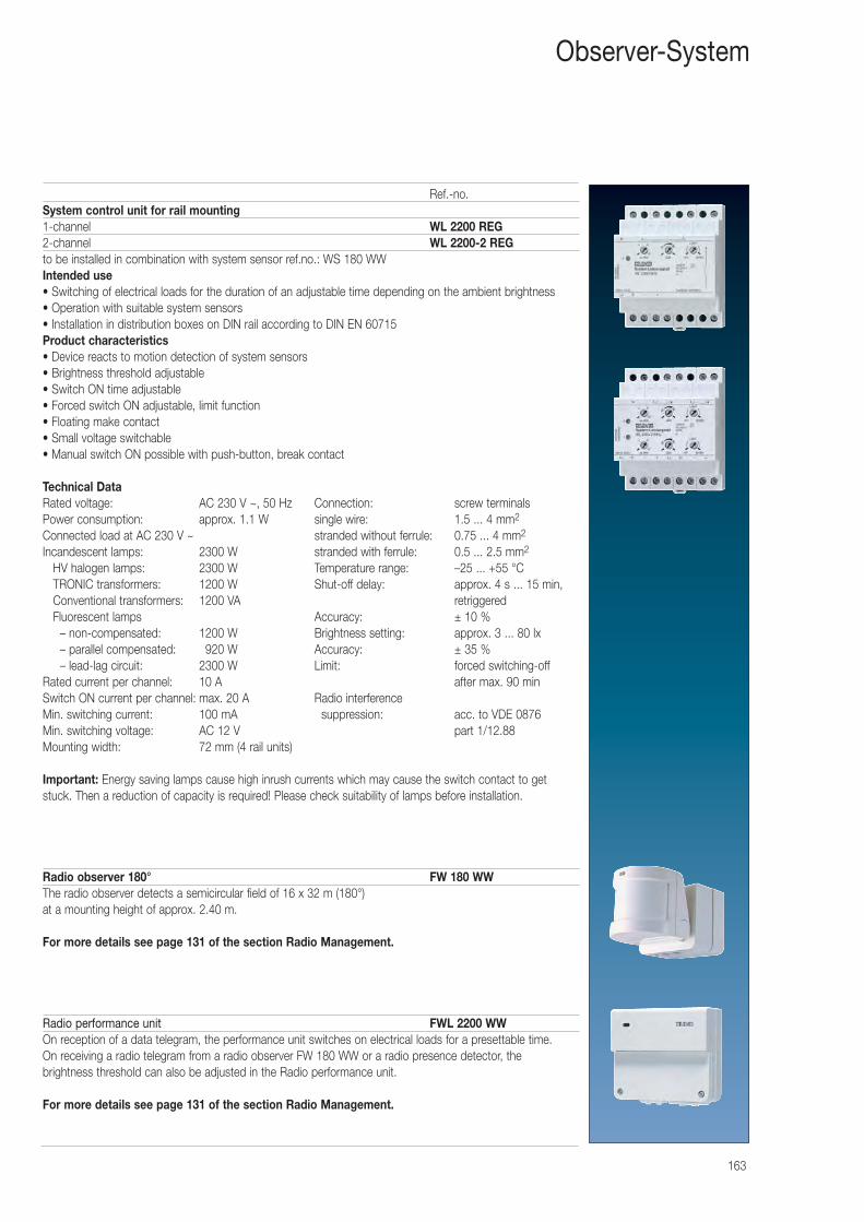
163
Ref.-no.System control unit for rail mounting1-channel WL 2200 REG2-channel WL 2200-2 REGto be installed in combination with system sensor ref.no.: WS 180 WWIntended use• Switching of electrical loads for the duration of an adjustable time depending on the ambient brightness • Operation with suitable system sensors• Installation in distribution boxes on DIN rail according to DIN EN 60715Product characteristics• Device reacts to motion detection of system sensors• Brightness threshold adjustable• Switch ON time adjustable• Forced switch ON adjustable, limit function• Floating make contact• Small voltage switchable• Manual switch ON possible with push-button, break contact
Technical Data Rated voltage: AC 230 V ~, 50 Hz Connection: screw terminals Power consumption: approx. 1.1 W single wire: 1.5 ... 4 mm2
Connected load at AC 230 V ~ stranded without ferrule: 0.75 ... 4 mm2
Incandescent lamps: 2300 W stranded with ferrule: 0.5 ... 2.5 mm2
HV halogen lamps: 2300 W Temperature range: –25 ... +55 °C TRONIC transformers: 1200 W Shut-off delay: approx. 4 s ... 15 min, Conventional transformers: 1200 VA retriggered Fluorescent lamps Accuracy: ± 10 %
– non-compensated: 1200 W Brightness setting: approx. 3 ... 80 lx – parallel compensated: 0920 W Accuracy: ± 35 % – lead-lag circuit: 2300 W Limit: forced switching-off
Rated current per channel: 10 A after max. 90 min Switch ON current per channel: max. 20 A Radio interference Min. switching current: 100 mA suppression: acc. to VDE 0876 Min. switching voltage: AC 12 V part 1/12.88 Mounting width: 72 mm (4 rail units)
Important: Energy saving lamps cause high inrush currents which may cause the switch contact to getstuck. Then a reduction of capacity is required! Please check suitability of lamps before installation.
Radio observer 180° FW 180 WWThe radio observer detects a semicircular field of 16 x 32 m (180°) at a mounting height of approx. 2.40 m.
For more details see page 131 of the section Radio Management.
Radio performance unit FWL 2200 WWOn reception of a data telegram, the performance unit switches on electrical loads for a presettable time. On receiving a radio telegram from a radio observer FW 180 WW or a radio presence detector, the brightness threshold can also be adjusted in the Radio performance unit.
For more details see page 131 of the section Radio Management.
Observer-System
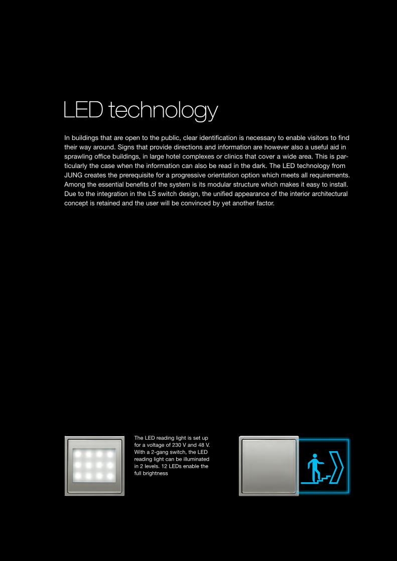
In buildings that are open to the public, clear identification is necessary to enable visitors to find their way around. Signs that provide directions and information are however also a useful aid in sprawling office buildings, in large hotel complexes or clinics that cover a wide area. This is par-ticularly the case when the information can also be read in the dark. The LED technology from JUNG creates the prerequisite for a progressive orientation option which meets all requirements. Among the essential benefits of the system is its modular structure which makes it easy to install. Due to the integration in the LS switch design, the unified appearance of the interior architectural concept is retained and the user will be convinced by yet another factor.
LED technology
The LED reading light is set up for a voltage of 230 V and 48 V. With a 2-gang switch, the LED reading light can be illuminated in 2 levels. 12 LEDs enable the full brightness
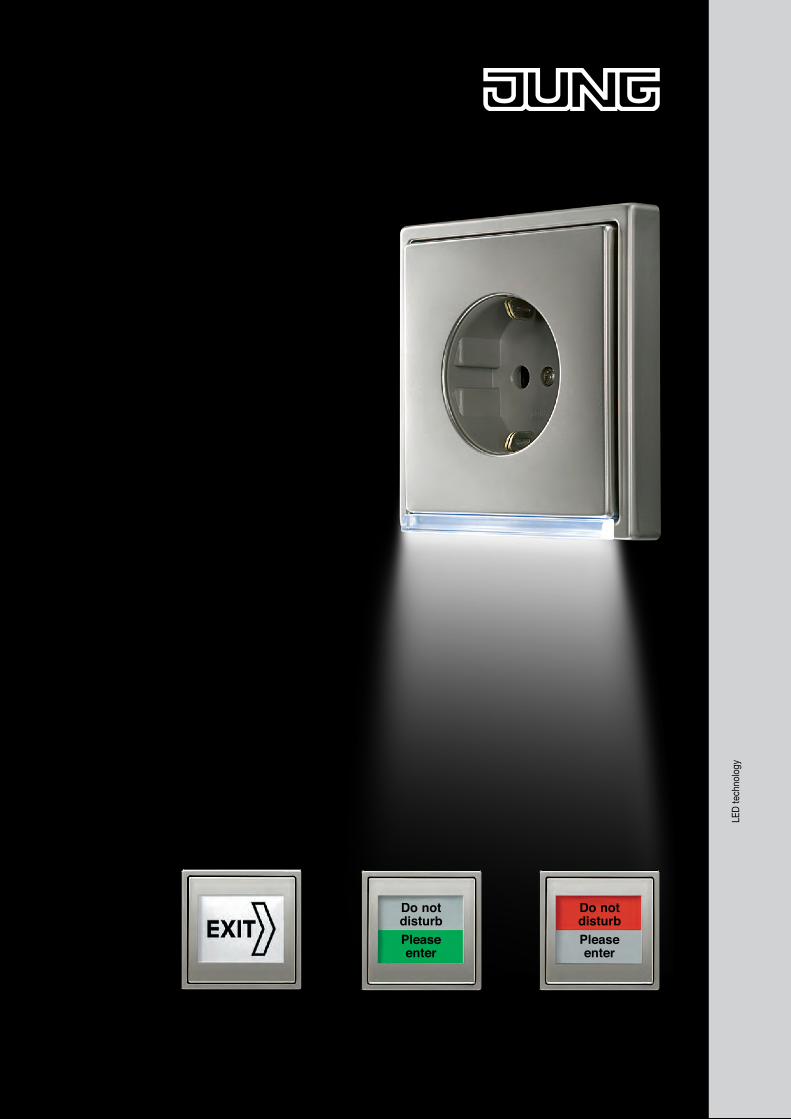
Do notdisturbPleaseenter
Do notdisturbPleaseenter
LED
tech
nolo
gy
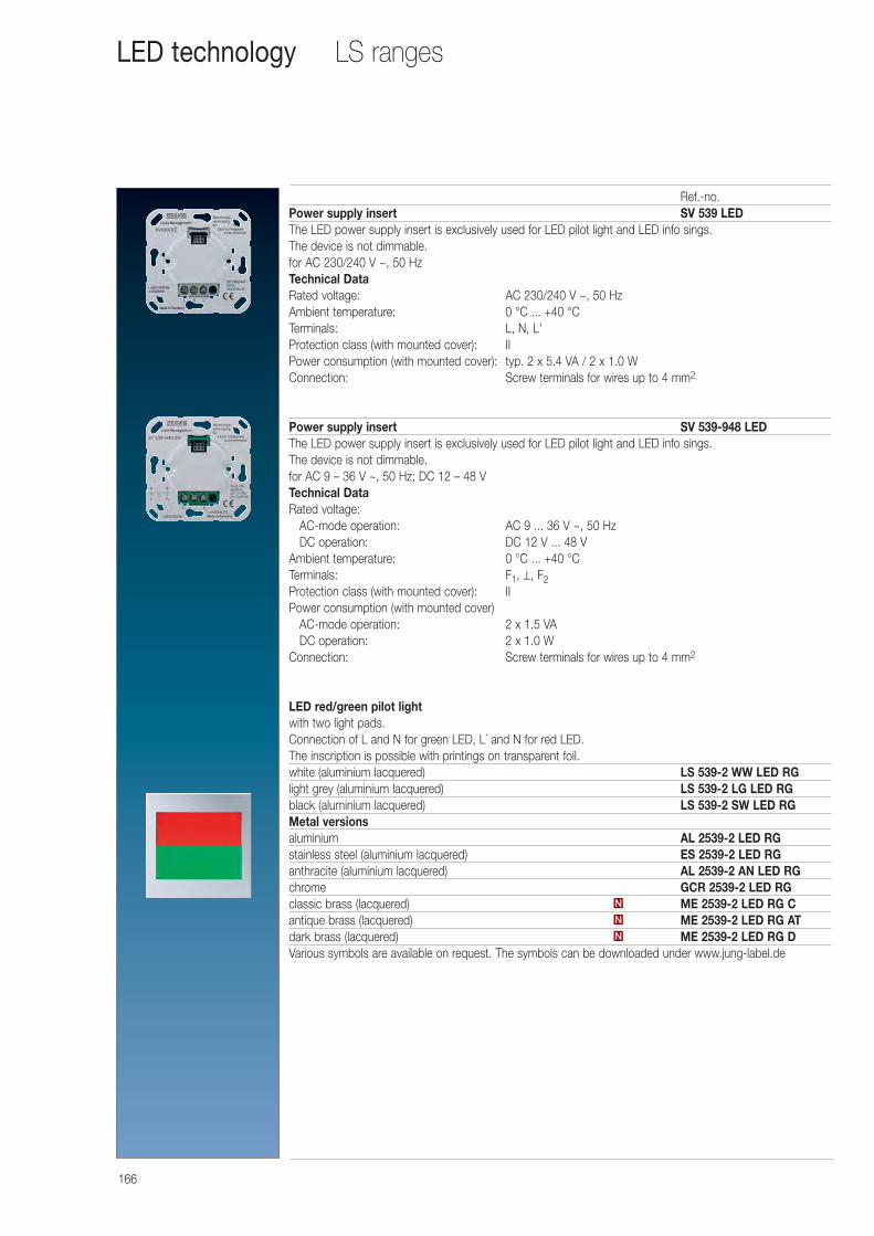
166
LS rangesLED technology
Ref.-no.Power supply insert SV 539 LEDThe LED power supply insert is exclusively used for LED pilot light and LED info sings.The device is not dimmable.for AC 230/240 V ~, 50 HzTechnical Data Rated voltage: AC 230/240 V ~, 50 HzAmbient temperature: 0 °C ... +40 °CTerminals: L, N, L'Protection class (with mounted cover): IIPower consumption (with mounted cover): typ. 2 x 5.4 VA / 2 x 1.0 WConnection: Screw terminals for wires up to 4 mm2
Power supply insert SV 539-948 LEDThe LED power supply insert is exclusively used for LED pilot light and LED info sings.The device is not dimmable.for AC 9 – 36 V ~, 50 Hz; DC 12 – 48 VTechnical Data Rated voltage:
AC-mode operation: AC 9 ... 36 V ~, 50 HzDC operation: DC 12 V ... 48 V
Ambient temperature: 0 °C ... +40 °CTerminals: F1, ⊥, F2Protection class (with mounted cover): IIPower consumption (with mounted cover)
AC-mode operation: 2 x 1.5 VADC operation: 2 x 1.0 W
Connection: Screw terminals for wires up to 4 mm2
LED red/green pilot light with two light pads.Connection of L and N for green LED, L´ and N for red LED.The inscription is possible with printings on transparent foil.white (aluminium lacquered) LS 539-2 WW LED RGlight grey (aluminium lacquered) LS 539-2 LG LED RGblack (aluminium lacquered) LS 539-2 SW LED RGMetal versionsaluminium AL 2539-2 LED RGstainless steel (aluminium lacquered) ES 2539-2 LED RGanthracite (aluminium lacquered) AL 2539-2 AN LED RGchrome GCR 2539-2 LED RGclassic brass (lacquered) ME 2539-2 LED RG Cantique brass (lacquered) ME 2539-2 LED RG ATdark brass (lacquered) ME 2539-2 LED RG DVarious symbols are available on request. The symbols can be downloaded under www.jung-label.de
N
N
N
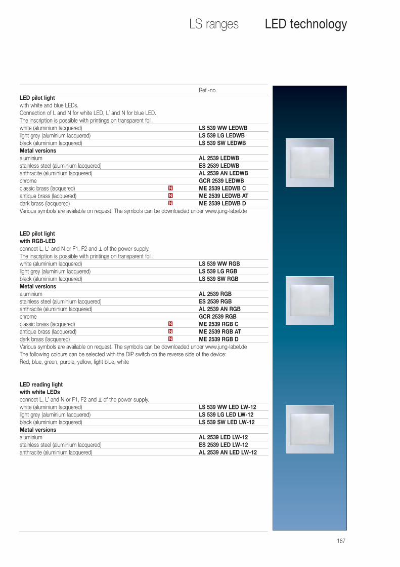
167
LS ranges LED technology
Ref.-no.LED pilot lightwith white and blue LEDs.Connection of L and N for white LED, L´ and N for blue LED.The inscription is possible with printings on transparent foil.white (aluminium lacquered) LS 539 WW LEDWBlight grey (aluminium lacquered) LS 539 LG LEDWBblack (aluminium lacquered) LS 539 SW LEDWBMetal versionsaluminium AL 2539 LEDWBstainless steel (aluminium lacquered) ES 2539 LEDWBanthracite (aluminium lacquered) AL 2539 AN LEDWBchrome GCR 2539 LEDWBclassic brass (lacquered) ME 2539 LEDWB Cantique brass (lacquered) ME 2539 LEDWB ATdark brass (lacquered) ME 2539 LEDWB DVarious symbols are available on request. The symbols can be downloaded under www.jung-label.de
LED pilot lightwith RGB-LEDconnect L, L' and N or F1, F2 and ⊥ of the power supply.The inscription is possible with printings on transparent foil.white (aluminium lacquered) LS 539 WW RGBlight grey (aluminium lacquered) LS 539 LG RGBblack (aluminium lacquered) LS 539 SW RGBMetal versionsaluminium AL 2539 RGBstainless steel (aluminium lacquered) ES 2539 RGBanthracite (aluminium lacquered) AL 2539 AN RGBchrome GCR 2539 RGBclassic brass (lacquered) ME 2539 RGB Cantique brass (lacquered) ME 2539 RGB ATdark brass (lacquered) ME 2539 RGB DVarious symbols are available on request. The symbols can be downloaded under www.jung-label.deThe following colours can be selected with the DIP switch on the reverse side of the device: Red, blue, green, purple, yellow, light blue, white
LED reading lightwith white LEDsconnect L, L’ and N or F1, F2 and ⊥ of the power supply. white (aluminium lacquered) LS 539 WW LED LW-12light grey (aluminium lacquered) LS 539 LG LED LW-12black (aluminium lacquered) LS 539 SW LED LW-12Metal versionsaluminium AL 2539 LED LW-12stainless steel (aluminium lacquered) ES 2539 LED LW-12anthracite (aluminium lacquered) AL 2539 AN LED LW-12
N
N
N
N
N
N

168
Ref.-no.LED info signwith neutral inscription field.Dimensions: Info sign 71 x 71 mm (complete device 71 x 142 mm).For complete installation a frame of the respective design range (see page 376 and 406) is required.with white LEDwhite (aluminium lacquered) LS 539 N71WWLED Wlight grey (aluminium lacquered) LS 539 N71LGLED Wblack (aluminium lacquered) LS 539 N71SWLED WMetal versionsaluminium AL 2539 N71LED Wstainless steel (aluminium lacquered) ES 2539 N71LED Wanthracite (aluminium lacquered) AL 2539 N71AN LED Wchrome GCR 2539 N71LED W
with blue LEDwhite (aluminium lacquered) LS 539 N71WWLED Blight grey (aluminium lacquered) LS 539 N71LGLED Bblack (aluminium lacquered) LS 539 N71SWLED BMetal versionsaluminium AL 2539 N71LED Bstainless steel (aluminium lacquered) ES 2539 N71LED Banthracite (aluminium lacquered) AL 2539 N71AN LED Bchrome GCR 2539 N71LED B
with RGB LEDwhite (aluminium lacquered) LS 539 N71WW RGBlight grey (aluminium lacquered) LS 539 N71LG RGBblack (aluminium lacquered) LS 539 N71SW RGBMetal versionsaluminium AL 2539 N71 RGBstainless steel (aluminium lacquered) ES 2539 N71 RGBanthracite (aluminium lacquered) AL 2539 N71AN RGBchrome GCR 2539 N71 RGBThe following colours can be selected with the DIP switch on the reverse side of the device: Red, blue, green, purple, yellow, light blue, white
For your individual inscription please visit our website www.jung-label.de
LS rangesLED technology
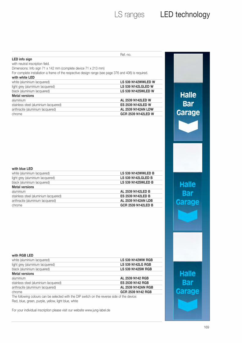
169
Ref.-no.LED info signwith neutral inscription field.Dimensions: Info sign 71 x 142 mm (complete device 71 x 213 mm)For complete installation a frame of the respective design range (see page 376 and 406) is required.with white LEDwhite (aluminium lacquered) LS 539 N142WWLED Wlight grey (aluminium lacquered) LS 539 N142LGLED Wblack (aluminium lacquered) LS 539 N142SWLED WMetal versionsaluminium AL 2539 N142LED Wstainless steel (aluminium lacquered) ES 2539 N142LED Wanthracite (aluminium lacquered) AL 2539 N142AN LDWchrome GCR 2539 N142LED W
with blue LEDwhite (aluminium lacquered) LS 539 N142WWLED Blight grey (aluminium lacquered) LS 539 N142LGLED Bblack (aluminium lacquered) LS 539 N142SWLED BMetal versionsaluminium AL 2539 N142LED Bstainless steel (aluminium lacquered) ES 2539 N142LED Banthracite (aluminium lacquered) AL 2539 N142AN LDBchrome GCR 2539 N142LED B
with RGB LEDwhite (aluminium lacquered) LS 539 N142WW RGBlight grey (aluminium lacquered) LS 539 N142LG RGBblack (aluminium lacquered) LS 539 N142SW RGBMetal versionsaluminium AL 2539 N142 RGBstainless steel (aluminium lacquered) ES 2539 N142 RGBanthracite (aluminium lacquered) AL 2539 N142AN RGBchrome GCR 2539 N142 RGBThe following colours can be selected with the DIP switch on the reverse side of the device: Red, blue, green, purple, yellow, light blue, white
For your individual inscription please visit our website www.jung-label.de
LS ranges LED technology
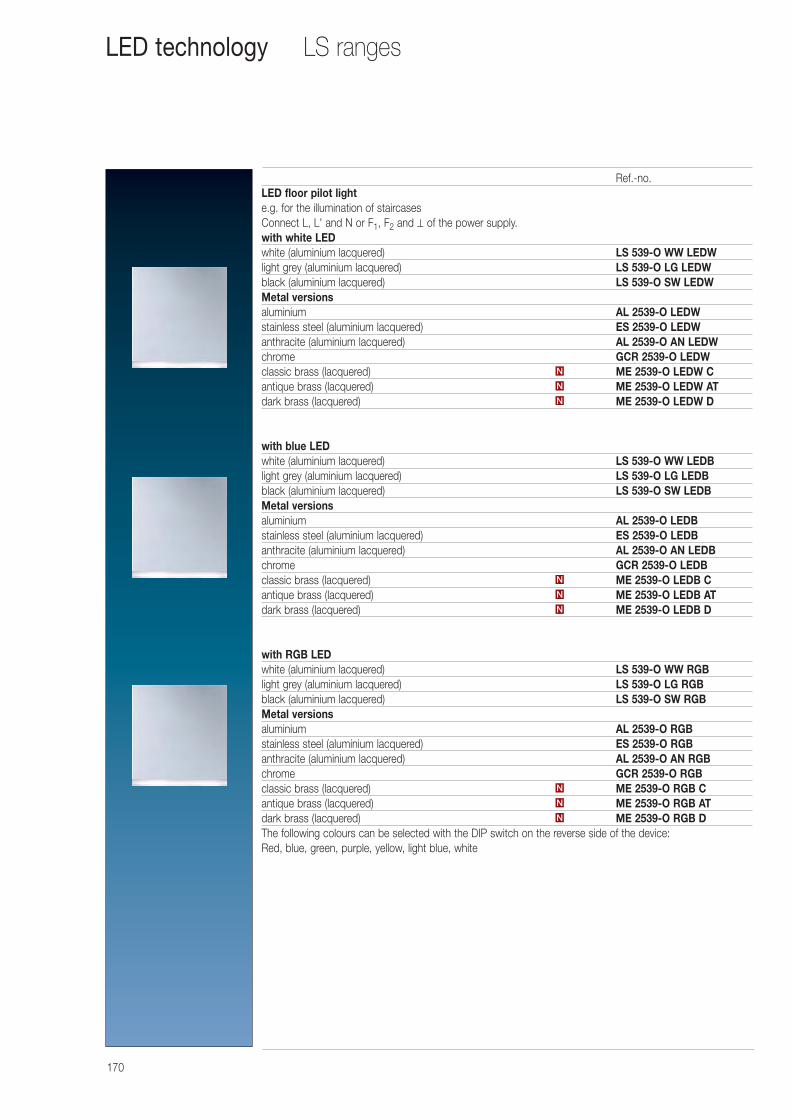
170
Ref.-no.LED floor pilot lighte.g. for the illumination of staircasesConnect L, L' and N or F1, F2 and ⊥ of the power supply.with white LEDwhite (aluminium lacquered) LS 539-O WW LEDWlight grey (aluminium lacquered) LS 539-O LG LEDWblack (aluminium lacquered) LS 539-O SW LEDWMetal versionsaluminium AL 2539-O LEDWstainless steel (aluminium lacquered) ES 2539-O LEDWanthracite (aluminium lacquered) AL 2539-O AN LEDWchrome GCR 2539-O LEDWclassic brass (lacquered) ME 2539-O LEDW Cantique brass (lacquered) ME 2539-O LEDW ATdark brass (lacquered) ME 2539-O LEDW D
with blue LEDwhite (aluminium lacquered) LS 539-O WW LEDBlight grey (aluminium lacquered) LS 539-O LG LEDBblack (aluminium lacquered) LS 539-O SW LEDBMetal versionsaluminium AL 2539-O LEDBstainless steel (aluminium lacquered) ES 2539-O LEDBanthracite (aluminium lacquered) AL 2539-O AN LEDBchrome GCR 2539-O LEDBclassic brass (lacquered) ME 2539-O LEDB Cantique brass (lacquered) ME 2539-O LEDB ATdark brass (lacquered) ME 2539-O LEDB D
with RGB LEDwhite (aluminium lacquered) LS 539-O WW RGBlight grey (aluminium lacquered) LS 539-O LG RGBblack (aluminium lacquered) LS 539-O SW RGBMetal versionsaluminium AL 2539-O RGBstainless steel (aluminium lacquered) ES 2539-O RGBanthracite (aluminium lacquered) AL 2539-O AN RGBchrome GCR 2539-O RGBclassic brass (lacquered) ME 2539-O RGB Cantique brass (lacquered) ME 2539-O RGB ATdark brass (lacquered) ME 2539-O RGB DThe following colours can be selected with the DIP switch on the reverse side of the device: Red, blue, green, purple, yellow, light blue, white
N
N
N
N
N
N
N
N
N
LS rangesLED technology
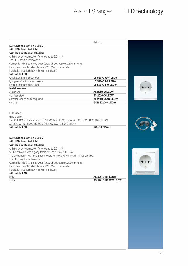
171
Ref.-no.SCHUKO socket 16 A / 250 V ~with LED floor pilot lightwith child protection (shutter)with screwless connection for wires up to 2.5 mm2
The LED insert is replaceable.Connection via 2 stranded wires (brown/blue), approx. 220 mm long.It can be connected directly to AC 230 V ~ or via switch.Installation into flush box min. 63 mm (depth)with white LEDwhite (aluminium lacquered) LS 520-O WW LEDWlight grey (aluminium lacquered) LS 520-O LG LEDWblack (aluminium lacquered) LS 520-O SW LEDWMetal versionsaluminium AL 2520-O LEDWstainless steel ES 2520-O LEDWanthracite (aluminium lacquered) AL 2520-O AN LEDWchrome GCR 2520-O LEDW
LED insert(Spare part)for SCHUKO sockets ref.-no.: LS 520-O WW LEDW, LS 520-O LG LEDW, AL 2520-O LEDW,AL 2520-O AN LEDW, ES 2520-O LEDW, GCR 2520-O LEDWwith white LED 520-O LEDW-1
SCHUKO socket 16 A / 250 V ~with LED floor pilot lightwith child protection (shutter)with screwless connection for wires up to 2.5 mm2
will be delivered with 1-gang frame ref..-no.: AS 581 BF INA..The combination with inscription module ref.-no..: AS 61 INA BT is not possible.The LED insert is replaceable.Connection via 2 stranded wires (brown/blue), approx. 220 mm long.It can be connected directly to AC 230 V ~ or via switch.Installation into flush box min. 63 mm (depth)with white LEDivory AS 520-O BF LEDWwhite AS 520-O BF WW LEDW
A and LS ranges LED technology
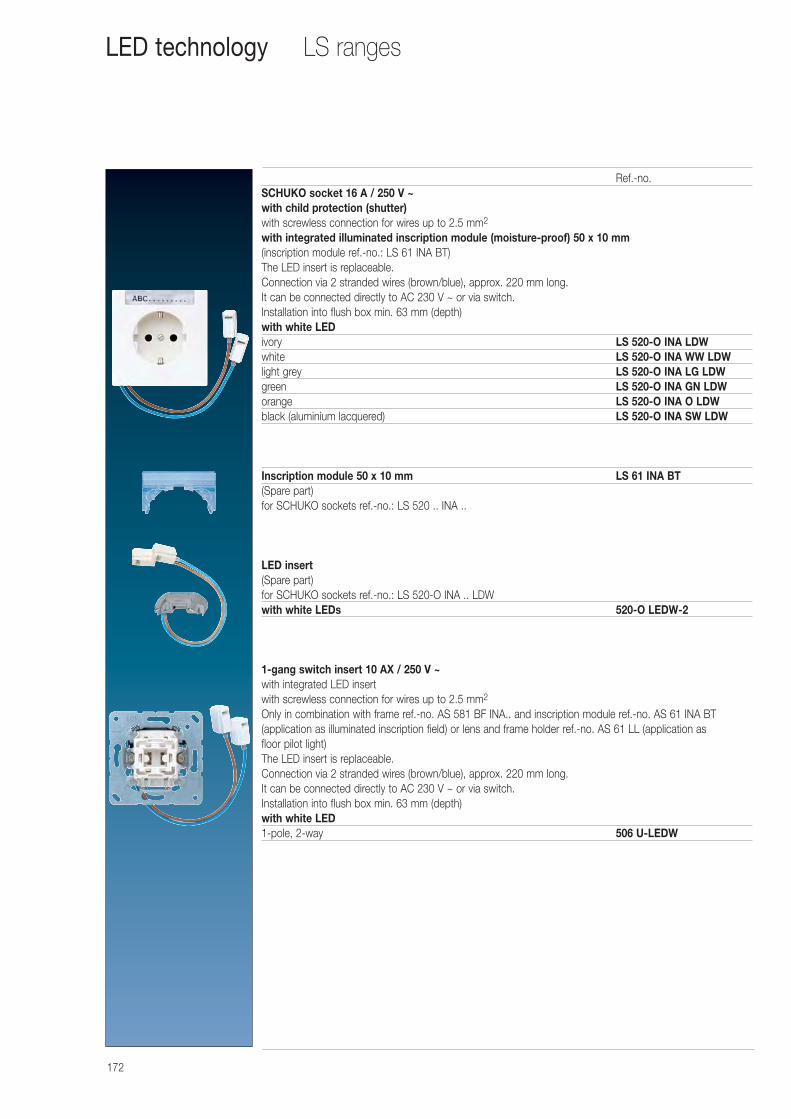
172
Ref.-no.SCHUKO socket 16 A / 250 V ~with child protection (shutter)with screwless connection for wires up to 2.5 mm2
with integrated illuminated inscription module (moisture-proof) 50 x 10 mm(inscription module ref.-no.: LS 61 INA BT)The LED insert is replaceable.Connection via 2 stranded wires (brown/blue), approx. 220 mm long.It can be connected directly to AC 230 V ~ or via switch.Installation into flush box min. 63 mm (depth)with white LEDivory LS 520-O INA LDWwhite LS 520-O INA WW LDWlight grey LS 520-O INA LG LDWgreen LS 520-O INA GN LDWorange LS 520-O INA O LDWblack (aluminium lacquered) LS 520-O INA SW LDW
Inscription module 50 x 10 mm LS 61 INA BT(Spare part)for SCHUKO sockets ref.-no.: LS 520 .. INA ..
LED insert(Spare part)for SCHUKO sockets ref.-no.: LS 520-O INA .. LDWwith white LEDs 520-O LEDW-2
1-gang switch insert 10 AX / 250 V ~with integrated LED insertwith screwless connection for wires up to 2.5 mm2
Only in combination with frame ref.-no. AS 581 BF INA.. and inscription module ref.-no. AS 61 INA BT (application as illuminated inscription field) or lens and frame holder ref.-no. AS 61 LL (application as floor pilot light)The LED insert is replaceable.Connection via 2 stranded wires (brown/blue), approx. 220 mm long.It can be connected directly to AC 230 V ~ or via switch.Installation into flush box min. 63 mm (depth)with white LED1-pole, 2-way 506 U-LEDW
LS rangesLED technology
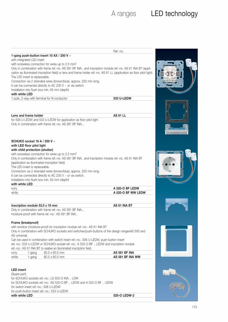
173
Ref.-no.1-gang push-button insert 10 AX / 250 V ~with integrated LED insertwith screwless connection for wires up to 2.5 mm2
Only in combination with frame ref.-no. AS 581 BF INA.. and inscription module ref.-no. AS 61 INA BT (appli-cation as illuminated inscription field) or lens and frame holder ref.-no. AS 61 LL (application as floor pilot light)The LED insert is replaceable.Connection via 2 stranded wires (brown/blue), approx. 220 mm long.It can be connected directly to AC 230 V ~ or via switch.Installation into flush box min. 63 mm (depth)with white LED1-pole, 2-way with terminal for N conductor 533 U-LEDW
Lens and frame holder AS 61 LLfor 506 U-LEDW and 533 U-LEDW for application as floor pilot lightOnly in combination with frame ref.-no. AS 581 BF INA...
SCHUKO socket 16 A / 250 V ~with LED floor pilot lightwith child protection (shutter)with screwless connection for wires up to 2.5 mm2
Only in combination with frame ref.-no. AS 581 BF INA.. and inscription module ref.-no. AS 61 INA BT (application as illuminated inscription field)The LED insert is replaceable.Connection via 2 stranded wires (brown/blue), approx. 220 mm long.It can be connected directly to AC 230 V ~ or via switch.Installation into flush box min. 63 mm (depth)with white LEDivory A 520-O BF LEDWwhite A 520-O BF WW LEDW
Inscription module 53.5 x 10 mm AS 61 INA BTOnly in combination with frame ref.-no. AS 581 BF INA...moisture-proof with frame ref.-no.: AS 581 BF INA..
Frame (breakproof)with window (moisture-proof) for inscription module ref.-no.: AS 61 INA BTOnly in combination with SCHUKO sockets and switches/push-buttons of the design rangesAS 500 andAS universal.Can be used in combination with switch insert ref.-no.: 506 U-LEDW, push button insert ref.-no.: 533 U-LEDW or SCHUKO-socket ref.-no.: A 520-O BF .. LEDW and inscription module ref.-no.: AS 61 INA BT to realise an illuminated inscription field.ivory 1-gang 80.5 x 80.5 mm AS 581 BF INAwhite 1-gang 80.5 x 80.5 mm AS 581 BF INA WW
LED insert(Spare part)for SCHUKO sockets ref.-no.: LS 520-O INA .. LDWfor SCHUKO sockets ref.-no.: AS 520-O BF .. LEDW and A 520-O BF .. LEDWfor switch insert ref.-no.: 506 U-LEDWfor push-button insert ref.-no.: 533 U-LEDWwith white LED 520-O LEDW-2
A ranges LED technology
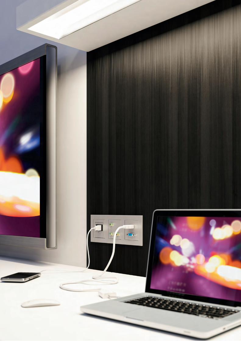
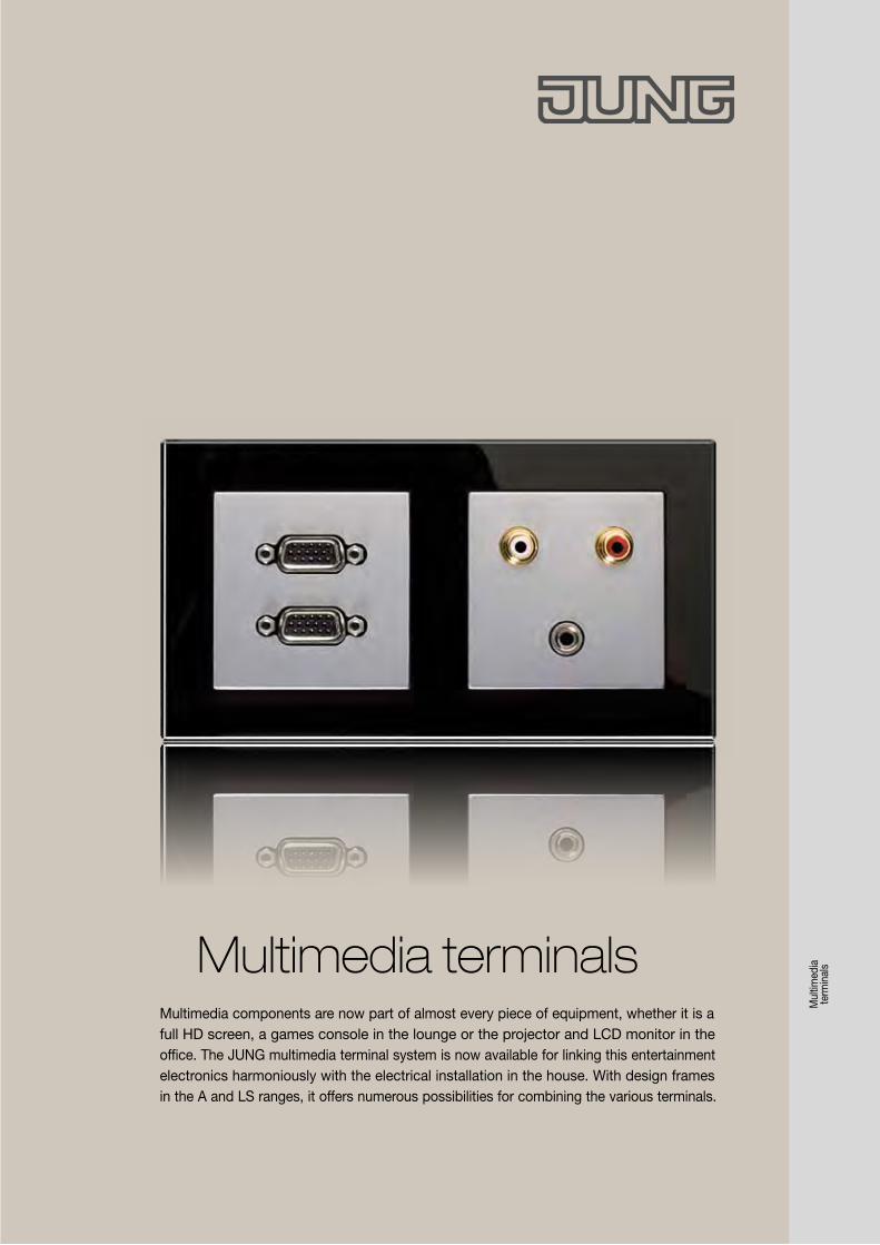
Multimedia terminalsMultimedia components are now part of almost every piece of equipment, whether it is a full HD screen, a games console in the lounge or the projector and LCD monitor in the office. The JUNG multimedia terminal system is now available for linking this entertainment electronics harmoniously with the electrical installation in the house. With design frames in the A and LS ranges, it offers numerous possibilities for combining the various terminals.
Mul
timed
ia
term
inal
s
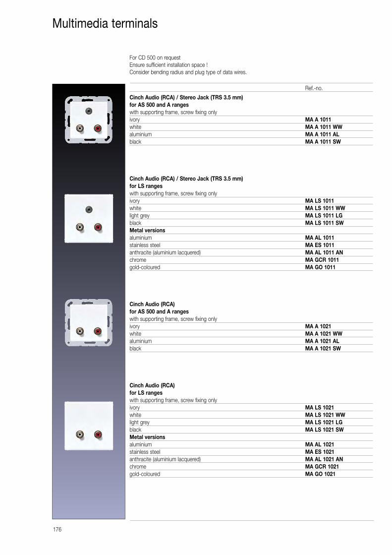
176
Multimedia terminals
Cinch Audio (RCA) / Stereo Jack (TRS 3.5 mm)for AS 500 and A rangeswith supporting frame, screw fixing onlyivory MA A 1011white MA A 1011 WWaluminium MA A 1011 ALblack MA A 1011 SW
Cinch Audio (RCA) / Stereo Jack (TRS 3.5 mm)for LS rangeswith supporting frame, screw fixing onlyivory MA LS 1011white MA LS 1011 WWlight grey MA LS 1011 LGblack MA LS 1011 SWMetal versionsaluminium MA AL 1011stainless steel MA ES 1011anthracite (aluminium lacquered) MA AL 1011 ANchrome MA GCR 1011gold-coloured MA GO 1011
Cinch Audio (RCA)for AS 500 and A rangeswith supporting frame, screw fixing onlyivory MA A 1021white MA A 1021 WWaluminium MA A 1021 ALblack MA A 1021 SW
Cinch Audio (RCA)for LS rangeswith supporting frame, screw fixing onlyivory MA LS 1021white MA LS 1021 WWlight grey MA LS 1021 LGblack MA LS 1021 SWMetal versionsaluminium MA AL 1021stainless steel MA ES 1021anthracite (aluminium lacquered) MA AL 1021 ANchrome MA GCR 1021gold-coloured MA GO 1021
Ref.-no.
For CD 500 on requestEnsure sufficient installation space !Consider bending radius and plug type of data wires.
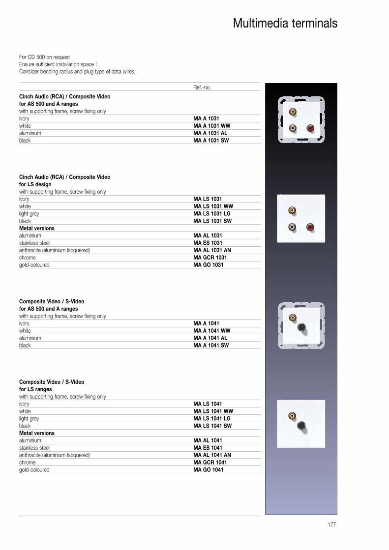
177
Multimedia terminals
Cinch Audio (RCA) / Composite Videofor AS 500 and A rangeswith supporting frame, screw fixing onlyivory MA A 1031white MA A 1031 WWaluminium MA A 1031 ALblack MA A 1031 SW
Cinch Audio (RCA) / Composite Videofor LS design with supporting frame, screw fixing onlyivory MA LS 1031white MA LS 1031 WWlight grey MA LS 1031 LGblack MA LS 1031 SWMetal versionsaluminium MA AL 1031stainless steel MA ES 1031anthracite (aluminium lacquered) MA AL 1031 ANchrome MA GCR 1031gold-coloured MA GO 1031
Composite Video / S-Videofor AS 500 and A rangeswith supporting frame, screw fixing onlyivory MA A 1041white MA A 1041 WWaluminium MA A 1041 ALblack MA A 1041 SW
Composite Video / S-Videofor LS rangeswith supporting frame, screw fixing onlyivory MA LS 1041white MA LS 1041 WWlight grey MA LS 1041 LGblack MA LS 1041 SWMetal versionsaluminium MA AL 1041stainless steel MA ES 1041anthracite (aluminium lacquered) MA AL 1041 ANchrome MA GCR 1041gold-coloured MA GO 1041
Ref.-no.
For CD 500 on requestEnsure sufficient installation space !Consider bending radius and plug type of data wires.
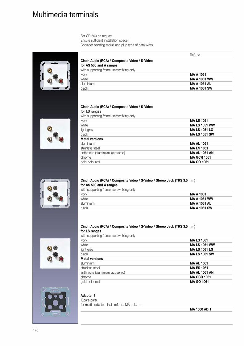
178
Multimedia terminals
Cinch Audio (RCA) / Composite Video / S-Videofor AS 500 and A rangeswith supporting frame, screw fixing onlyivory MA A 1051white MA A 1051 WWaluminium MA A 1051 ALblack MA A 1051 SW
Cinch Audio (RCA) / Composite Video / S-Videofor LS rangeswith supporting frame, screw fixing onlyivory MA LS 1051white MA LS 1051 WWlight grey MA LS 1051 LGblack MA LS 1051 SWMetal versionsaluminium MA AL 1051stainless steel MA ES 1051anthracite (aluminium lacquered) MA AL 1051 ANchrome MA GCR 1051gold-coloured MA GO 1051
Cinch Audio (RCA) / Composite Video / S-Video / Stereo Jack (TRS 3.5 mm)for AS 500 and A rangeswith supporting frame, screw fixing onlyivory MA A 1061white MA A 1061 WWaluminium MA A 1061 ALblack MA A 1061 SW
Cinch Audio (RCA) / Composite Video / S-Video / Stereo Jack (TRS 3.5 mm)for LS rangeswith supporting frame, screw fixing onlyivory MA LS 1061white MA LS 1061 WWlight grey MA LS 1061 LGblack MA LS 1061 SWMetal versionsaluminium MA AL 1061stainless steel MA ES 1061anthracite (aluminium lacquered) MA AL 1061 ANchrome MA GCR 1061gold-coloured MA GO 1061
Adapter 1(Spare part)for multimedia terminals ref.-no. MA .. 1..1 ..
MA 1000 AD 1
Ref.-no.
For CD 500 on requestEnsure sufficient installation space !Consider bending radius and plug type of data wires.
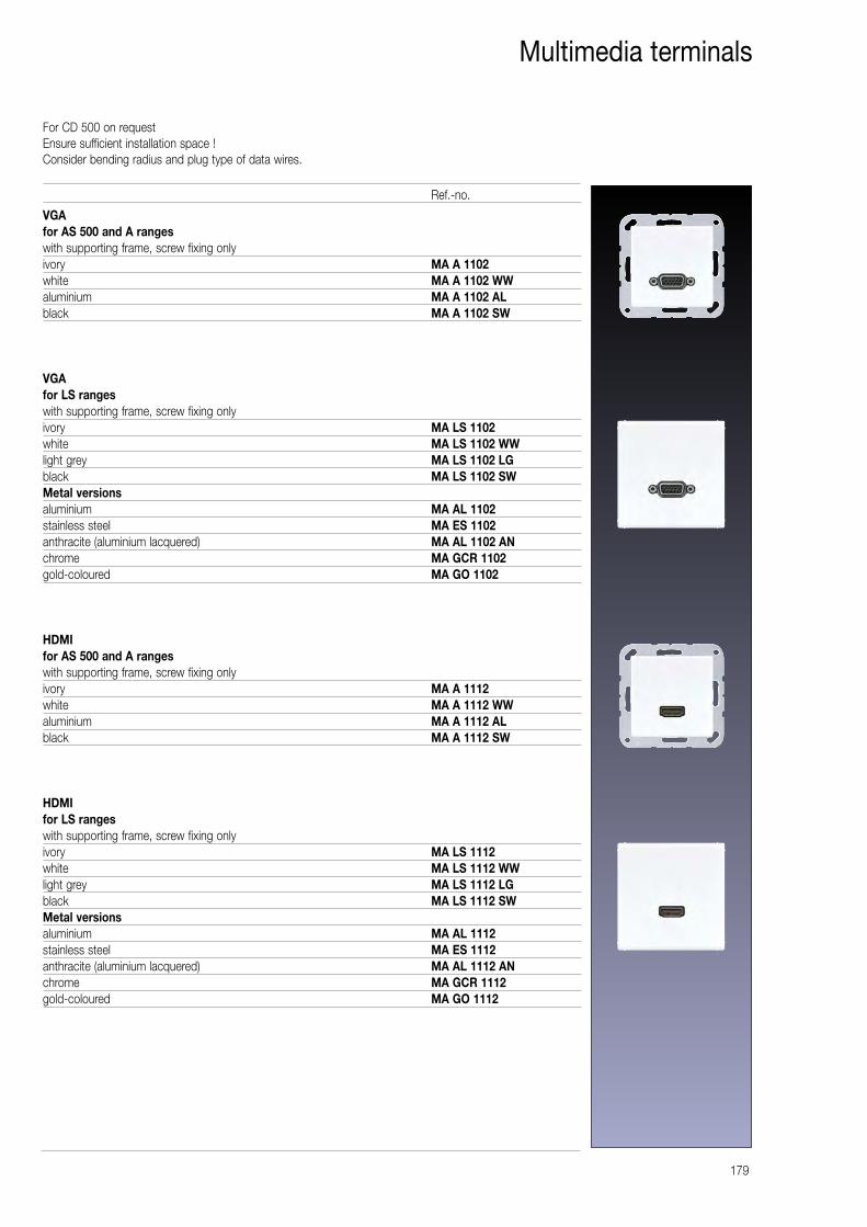
179
Multimedia terminals
VGAfor AS 500 and A rangeswith supporting frame, screw fixing onlyivory MA A 1102white MA A 1102 WWaluminium MA A 1102 ALblack MA A 1102 SW
VGAfor LS rangeswith supporting frame, screw fixing onlyivory MA LS 1102white MA LS 1102 WWlight grey MA LS 1102 LGblack MA LS 1102 SWMetal versionsaluminium MA AL 1102stainless steel MA ES 1102anthracite (aluminium lacquered) MA AL 1102 ANchrome MA GCR 1102gold-coloured MA GO 1102
HDMIfor AS 500 and A rangeswith supporting frame, screw fixing onlyivory MA A 1112white MA A 1112 WWaluminium MA A 1112 ALblack MA A 1112 SW
HDMIfor LS ranges with supporting frame, screw fixing onlyivory MA LS 1112white MA LS 1112 WWlight grey MA LS 1112 LGblack MA LS 1112 SWMetal versionsaluminium MA AL 1112stainless steel MA ES 1112anthracite (aluminium lacquered) MA AL 1112 ANchrome MA GCR 1112gold-coloured MA GO 1112
Ref.-no.
For CD 500 on requestEnsure sufficient installation space !Consider bending radius and plug type of data wires.
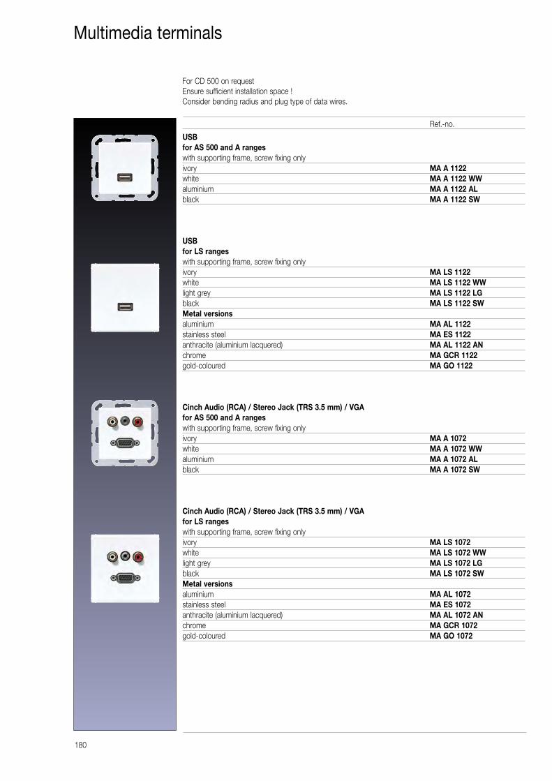
180
Multimedia terminals
USBfor AS 500 and A rangeswith supporting frame, screw fixing onlyivory MA A 1122white MA A 1122 WWaluminium MA A 1122 ALblack MA A 1122 SW
USBfor LS rangeswith supporting frame, screw fixing onlyivory MA LS 1122white MA LS 1122 WWlight grey MA LS 1122 LGblack MA LS 1122 SWMetal versionsaluminium MA AL 1122stainless steel MA ES 1122anthracite (aluminium lacquered) MA AL 1122 ANchrome MA GCR 1122gold-coloured MA GO 1122
Cinch Audio (RCA) / Stereo Jack (TRS 3.5 mm) / VGAfor AS 500 and A rangeswith supporting frame, screw fixing onlyivory MA A 1072white MA A 1072 WWaluminium MA A 1072 ALblack MA A 1072 SW
Cinch Audio (RCA) / Stereo Jack (TRS 3.5 mm) / VGAfor LS rangeswith supporting frame, screw fixing onlyivory MA LS 1072white MA LS 1072 WWlight grey MA LS 1072 LGblack MA LS 1072 SWMetal versionsaluminium MA AL 1072stainless steel MA ES 1072anthracite (aluminium lacquered) MA AL 1072 ANchrome MA GCR 1072gold-coloured MA GO 1072
Ref.-no.
For CD 500 on requestEnsure sufficient installation space !Consider bending radius and plug type of data wires.
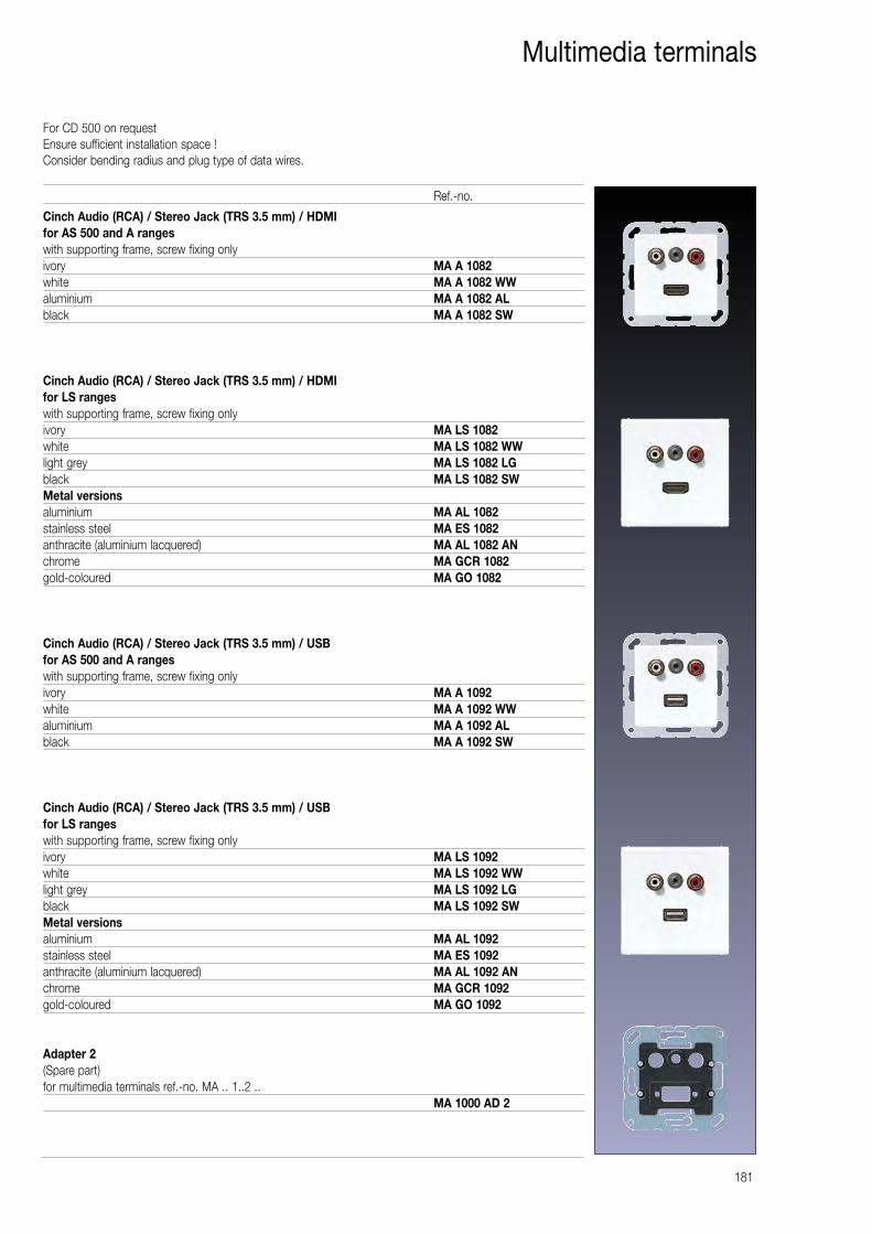
181
Multimedia terminals
Cinch Audio (RCA) / Stereo Jack (TRS 3.5 mm) / HDMIfor AS 500 and A rangeswith supporting frame, screw fixing onlyivory MA A 1082white MA A 1082 WWaluminium MA A 1082 ALblack MA A 1082 SW
Cinch Audio (RCA) / Stereo Jack (TRS 3.5 mm) / HDMIfor LS rangeswith supporting frame, screw fixing onlyivory MA LS 1082white MA LS 1082 WWlight grey MA LS 1082 LGblack MA LS 1082 SWMetal versionsaluminium MA AL 1082stainless steel MA ES 1082anthracite (aluminium lacquered) MA AL 1082 ANchrome MA GCR 1082gold-coloured MA GO 1082
Cinch Audio (RCA) / Stereo Jack (TRS 3.5 mm) / USBfor AS 500 and A rangeswith supporting frame, screw fixing onlyivory MA A 1092white MA A 1092 WWaluminium MA A 1092 ALblack MA A 1092 SW
Cinch Audio (RCA) / Stereo Jack (TRS 3.5 mm) / USBfor LS rangeswith supporting frame, screw fixing onlyivory MA LS 1092white MA LS 1092 WWlight grey MA LS 1092 LGblack MA LS 1092 SWMetal versionsaluminium MA AL 1092stainless steel MA ES 1092anthracite (aluminium lacquered) MA AL 1092 ANchrome MA GCR 1092gold-coloured MA GO 1092
Adapter 2(Spare part)for multimedia terminals ref.-no. MA .. 1..2 ..
MA 1000 AD 2
Ref.-no.
For CD 500 on requestEnsure sufficient installation space !Consider bending radius and plug type of data wires.

182
Multimedia terminals
2 x HDMIfor AS 500 and A rangeswith supporting frame, screw fixing onlyivory MA A 1133white MA A 1133 WWaluminium MA A 1133 ALblack MA A 1133 SW
2 x HDMIfor LS rangeswith supporting frame, screw fixing onlyivory MA LS 1133white MA LS 1133 WWlight grey MA LS 1133 LGblack MA LS 1133 SWMetal versionsaluminium MA AL 1133stainless steel MA ES 1133anthracite (aluminium lacquered) MA AL 1133 ANchrome MA GCR 1133gold-coloured MA GO 1133
2 x VGAfor AS 500 and A rangeswith supporting frame, screw fixing onlyivory MA A 1143white MA A 1143 WWaluminium MA A 1143 ALblack MA A 1143 SW
2 x VGAfor LS rangeswith supporting frame, screw fixing onlyivory MA LS 1143white MA LS 1143 WWlight grey MA LS 1143 LGblack MA LS 1143 SWMetal versionsaluminium MA AL 1143stainless steel MA ES 1143anthracite (aluminium lacquered) MA AL 1143 ANchrome MA GCR 1143gold-coloured MA GO 1143
Ref.-no.
For CD 500 on requestEnsure sufficient installation space !Consider bending radius and plug type of data wires.
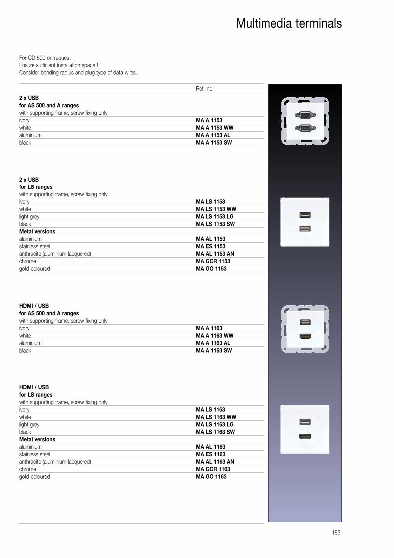
For CD 500 on requestEnsure sufficient installation space !Consider bending radius and plug type of data wires.
183
Multimedia terminals
2 x USBfor AS 500 and A rangeswith supporting frame, screw fixing onlyivory MA A 1153white MA A 1153 WWaluminium MA A 1153 ALblack MA A 1153 SW
2 x USBfor LS rangeswith supporting frame, screw fixing onlyivory MA LS 1153white MA LS 1153 WWlight grey MA LS 1153 LGblack MA LS 1153 SWMetal versionsaluminium MA AL 1153stainless steel MA ES 1153anthracite (aluminium lacquered) MA AL 1153 ANchrome MA GCR 1153gold-coloured MA GO 1153
HDMI / USBfor AS 500 and A rangeswith supporting frame, screw fixing onlyivory MA A 1163white MA A 1163 WWaluminium MA A 1163 ALblack MA A 1163 SW
HDMI / USBfor LS rangeswith supporting frame, screw fixing onlyivory MA LS 1163white MA LS 1163 WWlight grey MA LS 1163 LGblack MA LS 1163 SWMetal versionsaluminium MA AL 1163stainless steel MA ES 1163anthracite (aluminium lacquered) MA AL 1163 ANchrome MA GCR 1163gold-coloured MA GO 1163
Ref.-no.
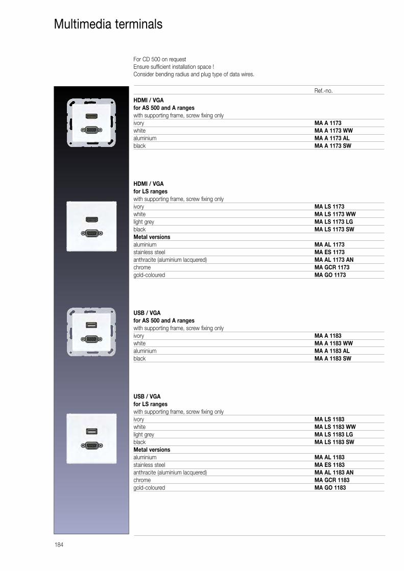
For CD 500 on requestEnsure sufficient installation space !Consider bending radius and plug type of data wires.
184
Multimedia terminals
HDMI / VGAfor AS 500 and A rangeswith supporting frame, screw fixing onlyivory MA A 1173white MA A 1173 WWaluminium MA A 1173 ALblack MA A 1173 SW
HDMI / VGAfor LS rangeswith supporting frame, screw fixing onlyivory MA LS 1173white MA LS 1173 WWlight grey MA LS 1173 LGblack MA LS 1173 SWMetal versionsaluminium MA AL 1173stainless steel MA ES 1173anthracite (aluminium lacquered) MA AL 1173 ANchrome MA GCR 1173gold-coloured MA GO 1173
USB / VGAfor AS 500 and A rangeswith supporting frame, screw fixing onlyivory MA A 1183white MA A 1183 WWaluminium MA A 1183 ALblack MA A 1183 SW
USB / VGAfor LS rangeswith supporting frame, screw fixing onlyivory MA LS 1183white MA LS 1183 WWlight grey MA LS 1183 LGblack MA LS 1183 SWMetal versionsaluminium MA AL 1183stainless steel MA ES 1183anthracite (aluminium lacquered) MA AL 1183 ANchrome MA GCR 1183gold-coloured MA GO 1183
Ref.-no.
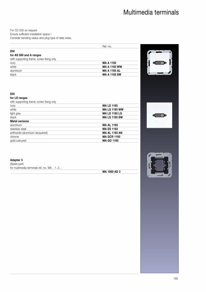
For CD 500 on requestEnsure sufficient installation space !Consider bending radius and plug type of data wires.
185
Multimedia terminals
DVIfor AS 500 and A rangeswith supporting frame, screw fixing onlyivory MA A 1193white MA A 1193 WWaluminium MA A 1193 ALblack MA A 1193 SW
DVIfor LS rangeswith supporting frame, screw fixing onlyivory MA LS 1193white MA LS 1193 WWlight grey MA LS 1193 LGblack MA LS 1193 SWMetal versionsaluminium MA AL 1193stainless steel MA ES 1193anthracite (aluminium lacquered) MA AL 1193 ANchrome MA GCR 1193gold-coloured MA GO 1193
Adapter 3(Spare part)for multimedia terminals ref.-no. MA .. 1..3 ..
MA 1000 AD 3
Ref.-no.
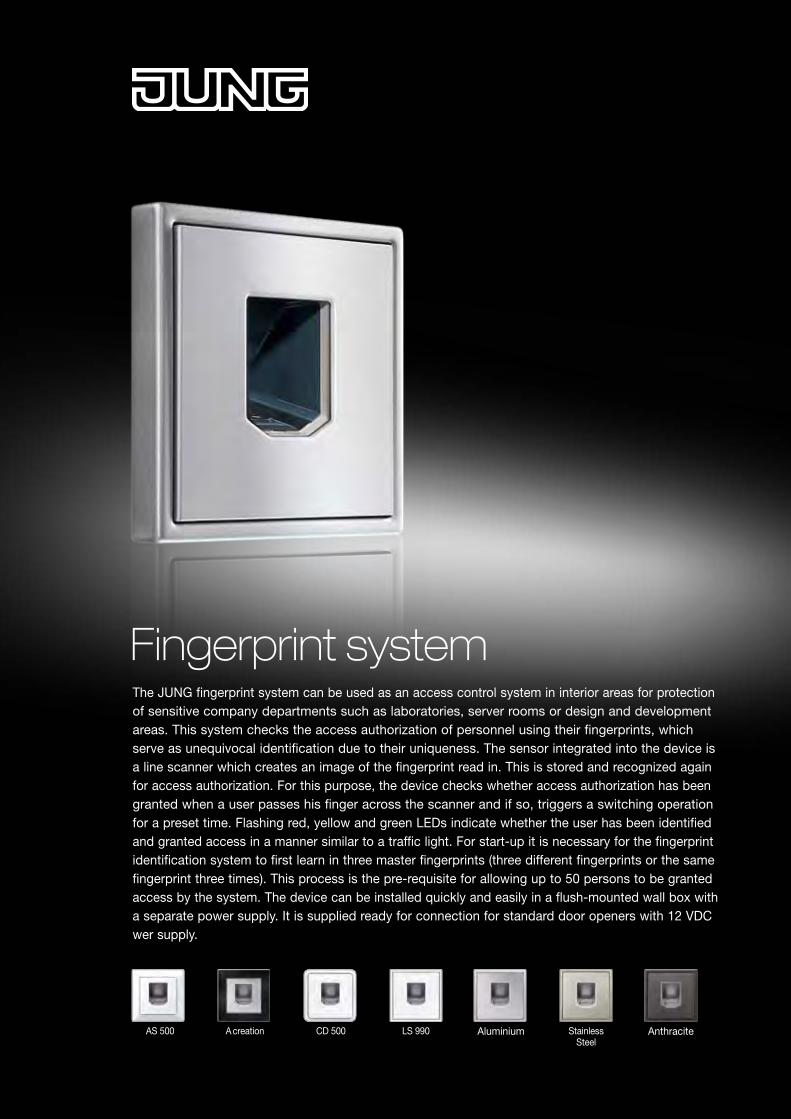
Fingerprint system
AS 500 A creation CD 500 LS 990 Aluminium StainlessSteel
Anthracite
The JUNG fingerprint system can be used as an access control system in interior areas for protection of sensitive company departments such as laboratories, server rooms or design and development areas. This system checks the access authorization of personnel using their fingerprints, which serve as unequivocal identification due to their uniqueness. The sensor integrated into the device is a line scanner which creates an image of the fingerprint read in. This is stored and recognized again for access authorization. For this purpose, the device checks whether access authorization has been granted when a user passes his finger across the scanner and if so, triggers a switching operation for a preset time. Flashing red, yellow and green LEDs indicate whether the user has been identified and granted access in a manner similar to a traffic light. For start-up it is necessary for the fingerprint identification system to first learn in three master fingerprints (three different fingerprints or the same fingerprint three times). This process is the pre-requisite for allowing up to 50 persons to be granted access by the system. The device can be installed quickly and easily in a flush-mounted wall box with a separate power supply. It is supplied ready for connection for standard door openers with 12 VDC wer supply.
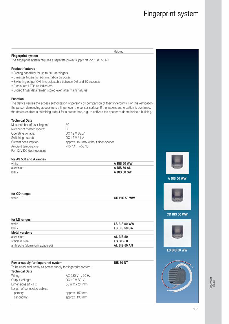
187
Ref.-no.Fingerprint systemThe fingerprint system requires a separate power supply ref.-no.: BIS 50 NT
Product features• Storing capability for up to 50 user fingers• 3 master fingers for administration purposes• Switching output ON time adjustable between 0.5 and 10 seconds• 3 coloured LEDs as indicators• Stored finger data remain stored even after mains failures
FunctionThe device verifies the access authorization of persons by comparison of their fingerprints. For this verification,the person demanding access runs a finger over the sensor surface. If the access authorization is confrmed,the device enables a switching output for a preset time, e.g. to activate the opener of doors inside a building.
Technical Data Max. number of user fingers: 50Number of master fingers: 3Operating voltage: DC 12 V SELVSwitching output: DC 12 V / 1 ACurrent consumption: approx. 150 mA without door-openerAmbient temperature: –15 °C ... +50 °CFor 12 V DC door-openers
for AS 500 and A rangeswhite A BIS 50 WWaluminium A BIS 50 ALblack A BIS 50 SW
for CD rangeswhite CD BIS 50 WW
for LS rangeswhite LS BIS 50 WWblack LS BIS 50 SWMetal versionsaluminium AL BIS 50stainless steel ES BIS 50anthracite (aluminium lacquered) AL BIS 50 AN
Power supply for fingerprint system BIS 50 NTTo be used exclusively as power supply for fingerprint system.Technical Data Wiring: AC 230 V ~, 50 HzOutput voltage: DC 12 V SELVDimensions (Ø x H): 55 mm x 24 mmLength of connected cables:
primary: approx. 150 mmsecondary: approx. 190 mm
Fingerprint system
A BIS 50 WW
CD BIS 50 WW
LS BIS 50 WW
Fing
erpr
int
Radi
o
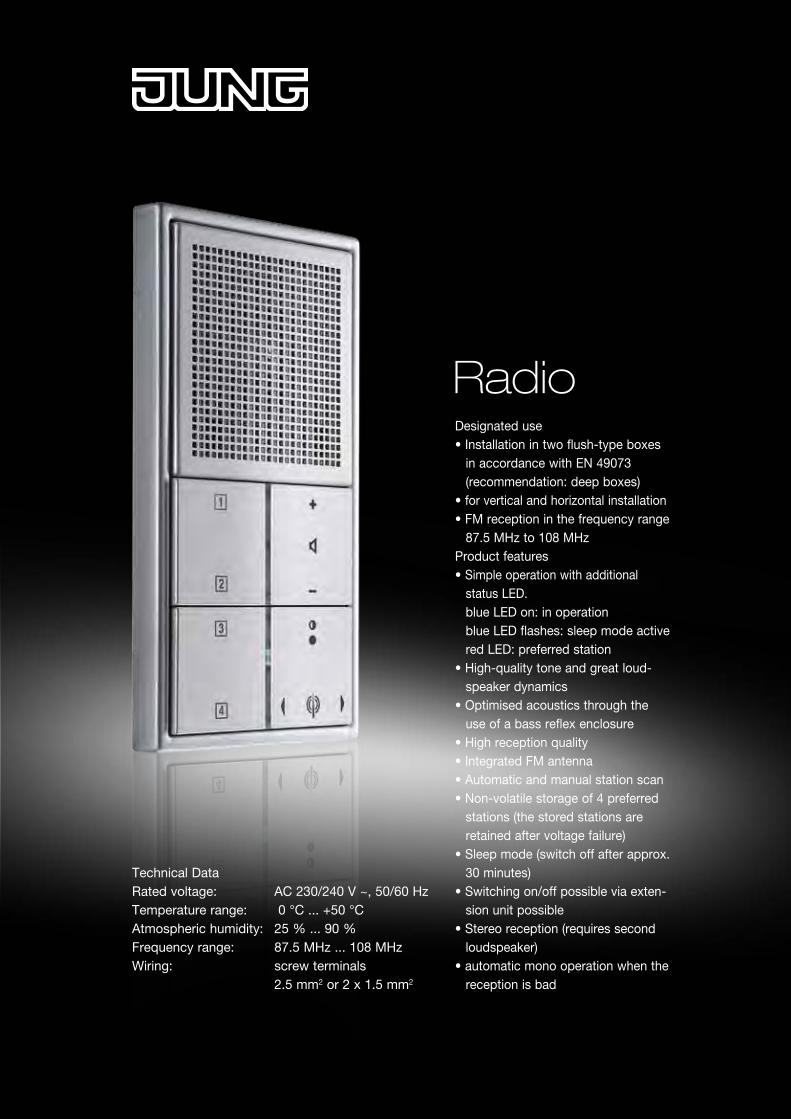
RadioDesignated use• Installation in two flush-type boxes in accordance with EN 49073 (recommendation: deep boxes)• for vertical and horizontal installation• FM reception in the frequency range 87.5 MHz to 108 MHz Product features• Simple operation with additional status LED. blue LED on: in operation blue LED flashes: sleep mode active red LED: preferred station• High-quality tone and great loud- speaker dynamics• Optimised acoustics through the use of a bass reflex enclosure• High reception quality• Integrated FM antenna• Automatic and manual station scan• Non-volatile storage of 4 preferred stations (the stored stations are retained after voltage failure) • Sleep mode (switch off after approx. 30 minutes)• Switching on/off possible via exten- sion unit possible• Stereo reception (requires second loudspeaker)• automatic mono operation when the reception is bad
Technical DataRated voltage: AC 230/240 V ~, 50/60 HzTemperature range: 0 °C ... +50 °CAtmospheric humidity: 25 % ... 90 %Frequency range: 87.5 MHz ... 108 MHzWiring: screw terminals 2.5 mm2 or 2 x 1.5 mm2
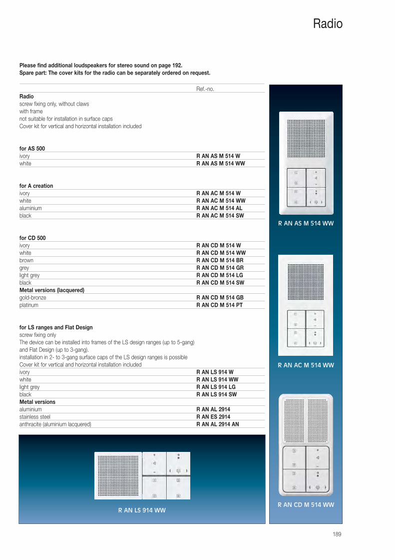
Please find additional loudspeakers for stereo sound on page 192.Spare part: The cover kits for the radio can be separately ordered on request.
189
Radio
Ref.-no.Radioscrew fixing only, without clawswith framenot suitable for installation in surface capsCover kit for vertical and horizontal installation included
for AS 500ivory R AN AS M 514 Wwhite R AN AS M 514 WW
for A creationivory R AN AC M 514 Wwhite R AN AC M 514 WWaluminium R AN AC M 514 ALblack R AN AC M 514 SW
for CD 500ivory R AN CD M 514 Wwhite R AN CD M 514 WWbrown R AN CD M 514 BRgrey R AN CD M 514 GRlight grey R AN CD M 514 LGblack R AN CD M 514 SWMetal versions (lacquered)gold-bronze R AN CD M 514 GBplatinum R AN CD M 514 PT
for LS ranges and Flat Designscrew fixing onlyThe device can be installed into frames of the LS design ranges (up to 5-gang) and Flat Design (up to 3-gang).installation in 2- to 3-gang surface caps of the LS design ranges is possibleCover kit for vertical and horizontal installation includedivory R AN LS 914 Wwhite R AN LS 914 WWlight grey R AN LS 914 LGblack R AN LS 914 SWMetal versionsaluminium R AN AL 2914stainless steel R AN ES 2914anthracite (aluminium lacquered) R AN AL 2914 AN
R AN AS M 514 WW
R AN AC M 514 WW
R AN CD M 514 WWR AN LS 914 WW
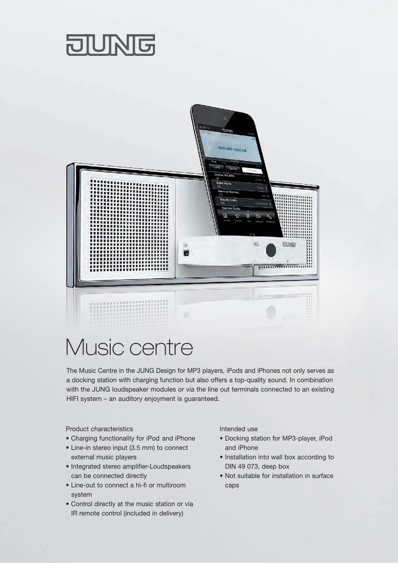
Product characteristics• Charging functionality for iPod and iPhone• Line-in stereo input (3.5 mm) to connect external music players• Integrated stereo amplifier-Loudspeakers can be connected directly• Line-out to connect a hi-fi or multiroom system• Control directly at the music station or via IR remote control (included in delivery)
Intended use• Docking station for MP3-player, iPod and iPhone• Installation into wall box according to DIN 49 073, deep box• Not suitable for installation in surface caps
Music centreThe Music Centre in the JUNG Design for MP3 players, iPods and iPhones not only serves as a docking station with charging function but also offers a top-quality sound. In combination with the JUNG loudspeaker modules or via the line out terminals connected to an existing HIFI system – an auditory enjoyment is guaranteed.
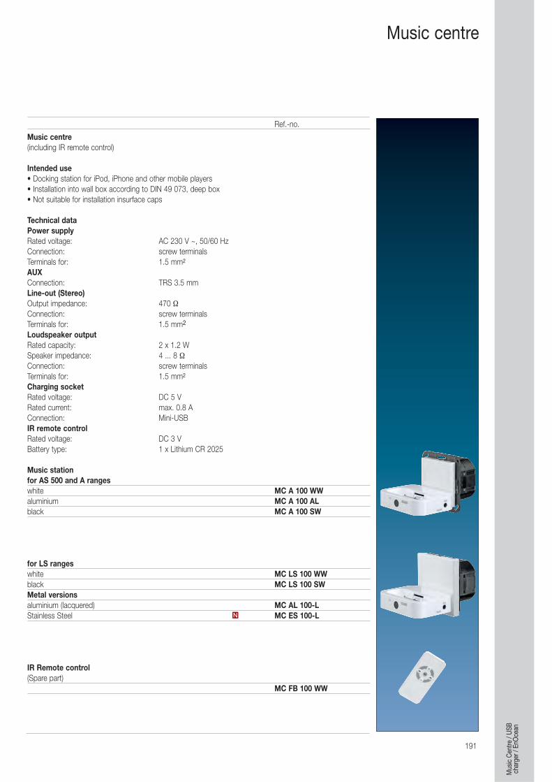
191
Music centre
Music centre(including IR remote control)
Intended use• Docking station for iPod, iPhone and other mobile players• Installation into wall box according to DIN 49 073, deep box• Not suitable for installation insurface caps
Technical dataPower supplyRated voltage: AC 230 V ~, 50/60 HzConnection: screw terminalsTerminals for: 1.5 mm2
AUXConnection: TRS 3.5 mmLine-out (Stereo)Output impedance: 470 ΩConnection: screw terminalsTerminals for: 1.5 mm2
Loudspeaker outputRated capacity: 2 x 1.2 WSpeaker impedance: 4 ... 8 ΩConnection: screw terminalsTerminals for: 1.5 mm2
Charging socketRated voltage: DC 5 VRated current: max. 0.8 AConnection: Mini-USBIR remote controlRated voltage: DC 3 VBattery type: 1 x Lithium CR 2025
Music stationfor AS 500 and A rangeswhite MC A 100 WWaluminium MC A 100 ALblack MC A 100 SW
for LS rangeswhite MC LS 100 WWblack MC LS 100 SWMetal versionsaluminium (lacquered) MC AL 100-LStainless Steel MC ES 100-L
IR Remote control(Spare part)
MC FB 100 WW
N
Ref.-no.
Mus
ic C
entre
/ US
Bch
arge
r / E
nOce
an
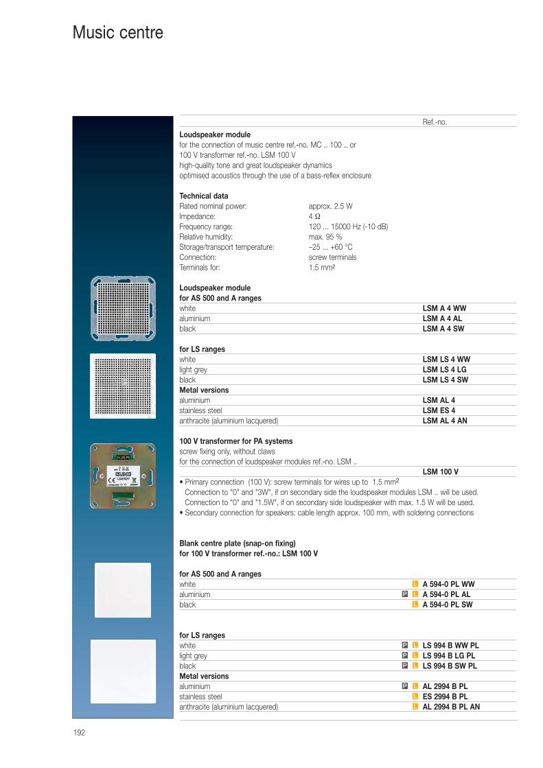
192
Music centre
Loudspeaker modulefor the connection of music centre ref.-no. MC .. 100 .. or 100 V transformer ref.-no. LSM 100 Vhigh-quality tone and great loudspeaker dynamics optimised acoustics through the use of a bass-reflex enclosure
Technical dataRated nominal power: approx. 2.5 WImpedance: 4 ΩFrequency range: 120 ... 15000 Hz (-10 dB)Relative humidity: max. 95 %Storage/transport temperature: –25 ... +60 °CConnection: screw terminalsTerminals for: 1.5 mm2
Loudspeaker modulefor AS 500 and A rangeswhite LSM A 4 WWaluminium LSM A 4 ALblack LSM A 4 SW
for LS rangeswhite LSM LS 4 WWlight grey LSM LS 4 LGblack LSM LS 4 SWMetal versionsaluminium LSM AL 4stainless steel LSM ES 4anthracite (aluminium lacquered) LSM AL 4 AN
100 V transformer for PA systemsscrew fixing only, without clawsfor the connection of loudspeaker modules ref.-no. LSM ..
LSM 100 V• Primary connection (100 V): screw terminals for wires up to 1.5 mm2
Connection to "0" and "3W", if on secondary side the loudspeaker modules LSM .. will be used. Connection to "0" and "1.5W", if on secondary side loudspeaker with max. 1.5 W will be used.
• Secondary connection for speakers: cable length approx. 100 mm, with soldering connections
Blank centre plate (snap-on fixing)for 100 V transformer ref.-no.: LSM 100 V
for AS 500 and A rangeswhite A 594-0 PL WWaluminium A 594-0 PL ALblack A 594-0 PL SW
for LS rangeswhite LS 994 B WW PLlight grey LS 994 B LG PLblack LS 994 B SW PLMetal versionsaluminium AL 2994 B PLstainless steel ES 2994 B PLanthracite (aluminium lacquered) AL 2994 B PL ANL
L
P L
P L
P L
P L
L
LP
L
Ref.-no.
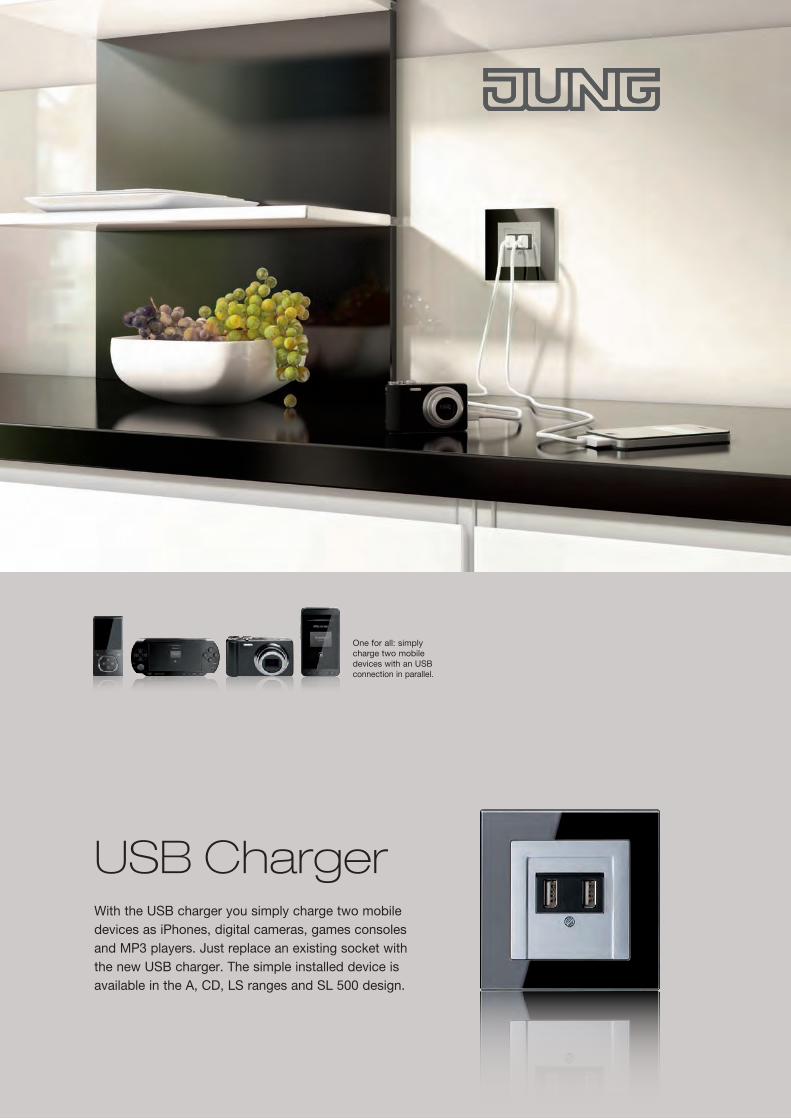
USB ChargerWith the USB charger you simply charge two mobile devices as iPhones, digital cameras, games consoles and MP3 players. Just replace an existing socket with the new USB charger. The simple installed device is available in the A, CD, LS ranges and SL 500 design.
One for all: simply charge two mobile devices with an USB connection in parallel.
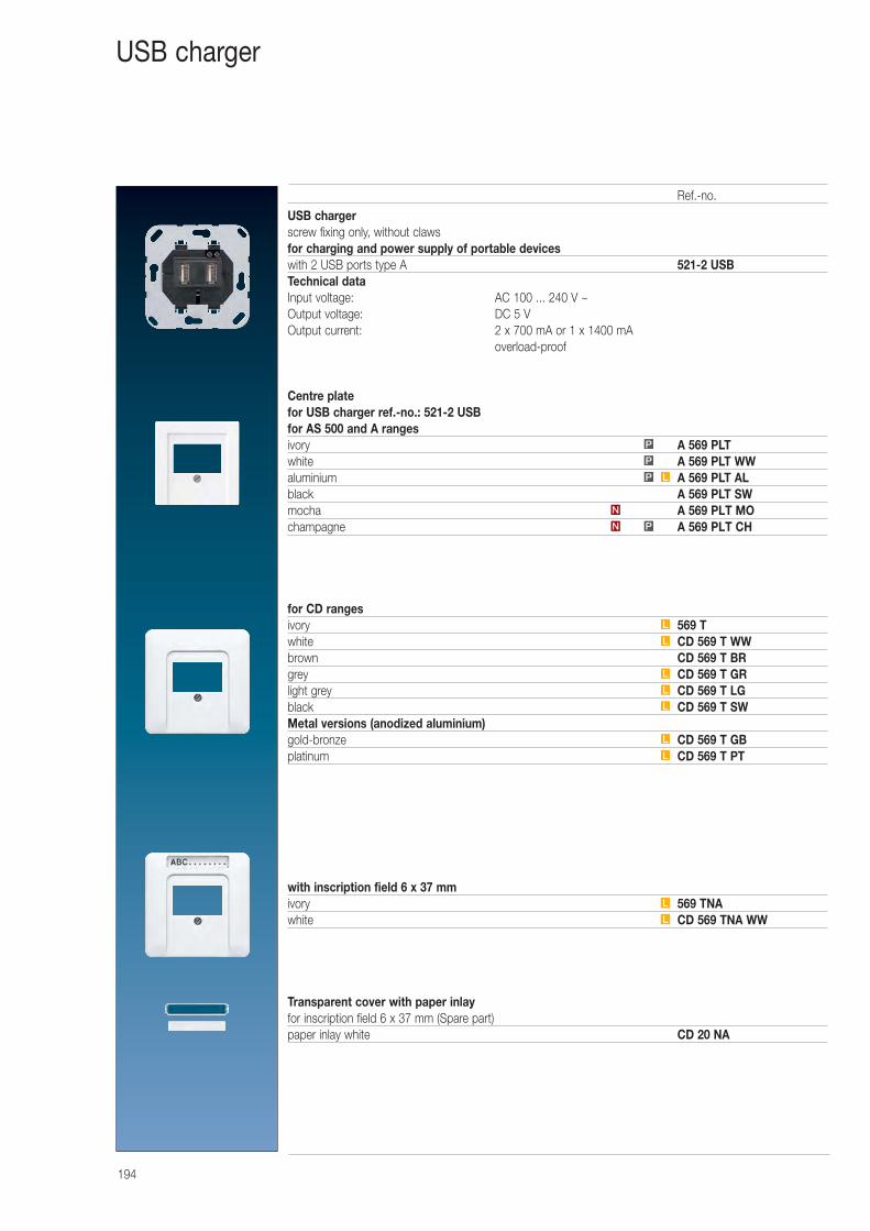
194
USB charger
USB chargerscrew fixing only, without clawsfor charging and power supply of portable deviceswith 2 USB ports type A 521-2 USBTechnical dataInput voltage: AC 100 ... 240 V ~Output voltage: DC 5 VOutput current: 2 x 700 mA or 1 x 1400 mA
overload-proof
Centre platefor USB charger ref.-no.: 521-2 USBfor AS 500 and A rangesivory A 569 PLTwhite A 569 PLT WWaluminium A 569 PLT ALblack A 569 PLT SWmocha A 569 PLT MOchampagne A 569 PLT CH
for CD rangesivory 569 Twhite CD 569 T WWbrown CD 569 T BRgrey CD 569 T GRlight grey CD 569 T LGblack CD 569 T SWMetal versions (anodized aluminium)gold-bronze CD 569 T GBplatinum CD 569 T PT
with inscription field 6 x 37 mmivory 569 TNAwhite CD 569 TNA WW
Transparent cover with paper inlayfor inscription field 6 x 37 mm (Spare part)paper inlay white CD 20 NA
L
L
L
L
P
L
L
L
L
L
L
P
P
N
PN
Ref.-no.
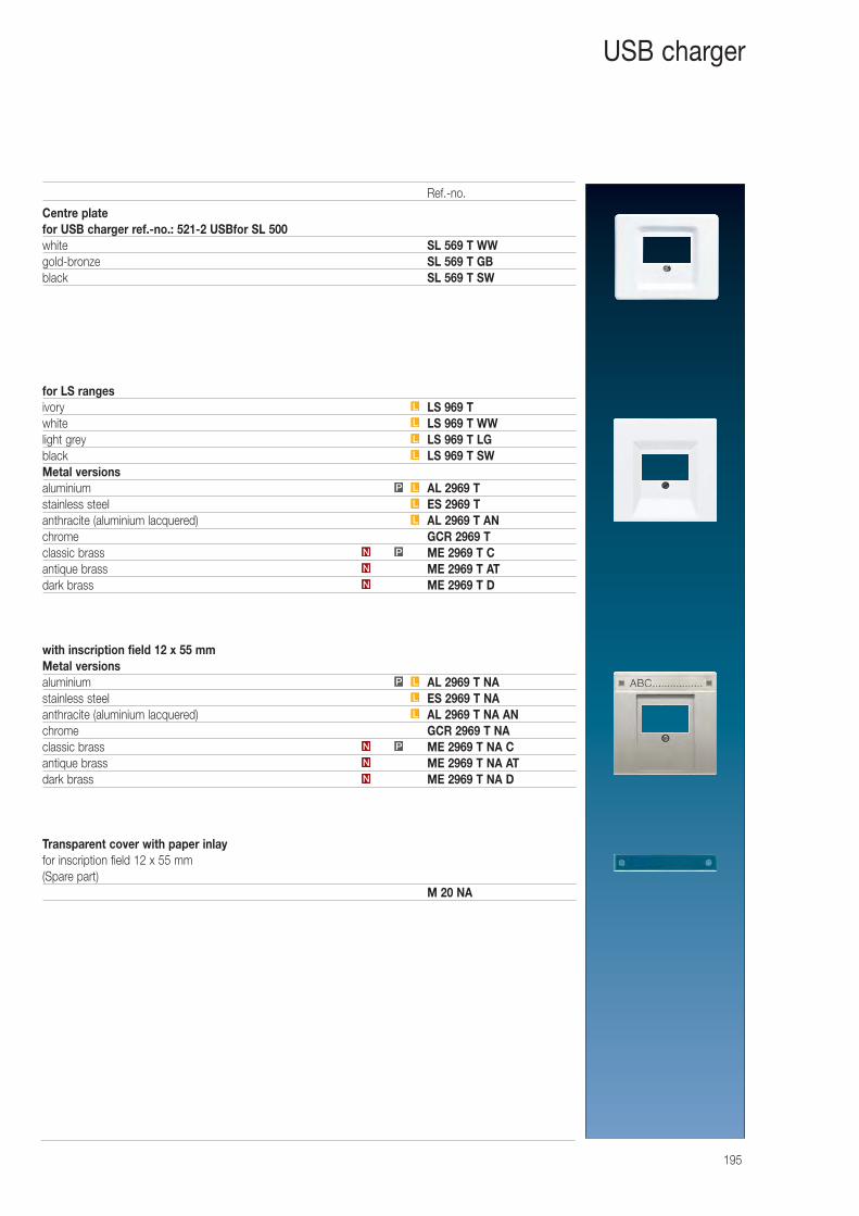
195
USB charger
Centre platefor USB charger ref.-no.: 521-2 USBfor SL 500white SL 569 T WWgold-bronze SL 569 T GBblack SL 569 T SW
for LS rangesivory LS 969 Twhite LS 969 T WWlight grey LS 969 T LGblack LS 969 T SWMetal versionsaluminium AL 2969 Tstainless steel ES 2969 Tanthracite (aluminium lacquered) AL 2969 T ANchrome GCR 2969 Tclassic brass ME 2969 T Cantique brass ME 2969 T ATdark brass ME 2969 T D
with inscription field 12 x 55 mmMetal versionsaluminium AL 2969 T NAstainless steel ES 2969 T NAanthracite (aluminium lacquered) AL 2969 T NA ANchrome GCR 2969 T NAclassic brass ME 2969 T NA Cantique brass ME 2969 T NA ATdark brass ME 2969 T NA D
Transparent cover with paper inlayfor inscription field 12 x 55 mm (Spare part)
M 20 NA
L
L
LP
L
L
LP
N
N
PN
L
L
L
L
N
N
PN
Ref.-no.
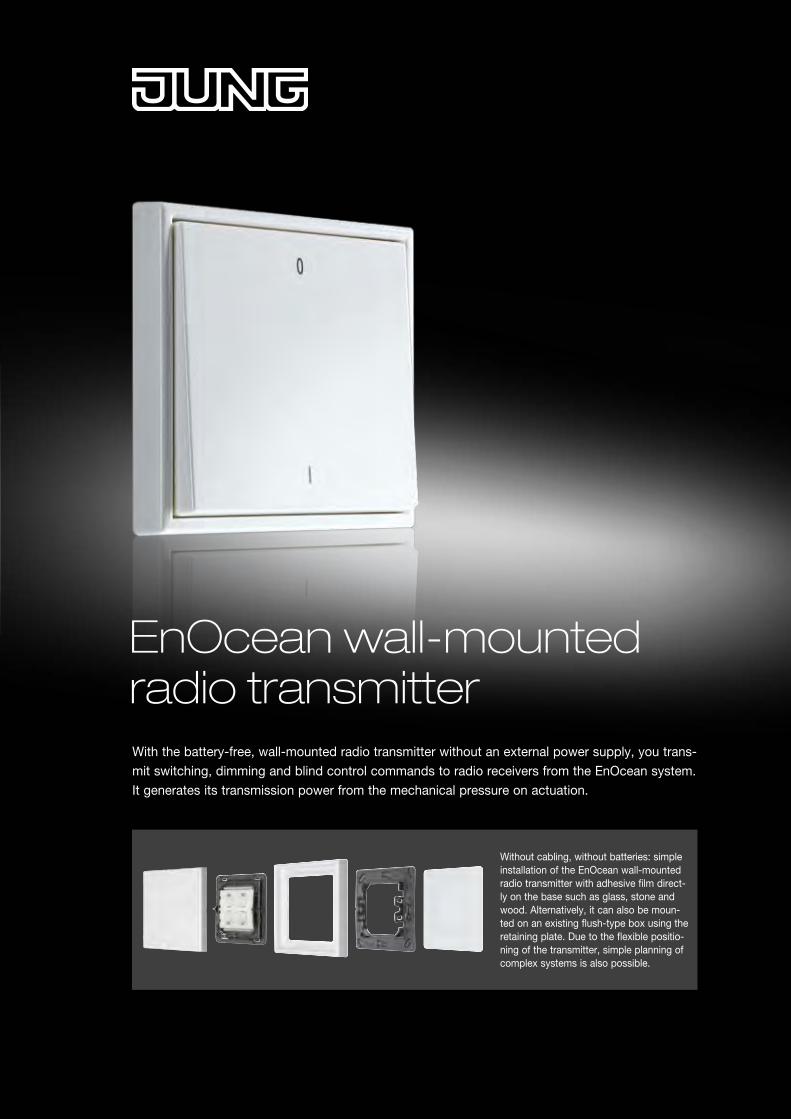
EnOcean wall-mounted radio transmitter
Without cabling, without batteries: simple installation of the EnOcean wall-mounted radio transmitter with adhesive film direct-ly on the base such as glass, stone and wood. Alternatively, it can also be moun-ted on an existing flush-type box using the retaining plate. Due to the flexible positio-ning of the transmitter, simple planning of complex systems is also possible.
With the battery-free, wall-mounted radio transmitter without an external power supply, you trans-mit switching, dimming and blind control commands to radio receivers from the EnOcean system. It generates its transmission power from the mechanical pressure on actuation.
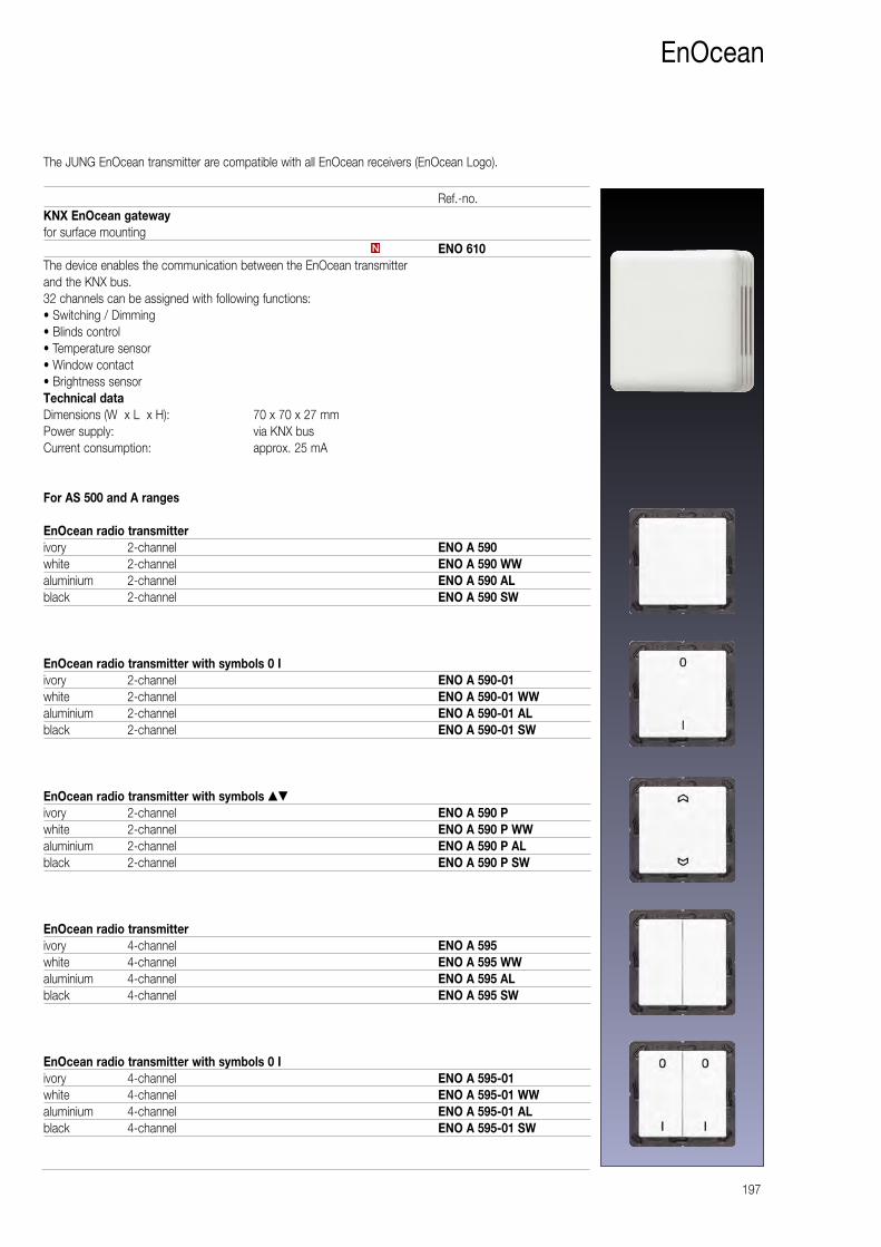
The JUNG EnOcean transmitter are compatible with all EnOcean receivers (EnOcean Logo).
197
EnOcean
KNX EnOcean gatewayfor surface mounting
ENO 610The device enables the communication between the EnOcean transmitter and the KNX bus. 32 channels can be assigned with following functions: • Switching / Dimming • Blinds control • Temperature sensor • Window contact • Brightness sensor Technical dataDimensions (W x L x H): 70 x 70 x 27 mm Power supply: via KNX bus Current consumption: approx. 25 mA
For AS 500 and A ranges
EnOcean radio transmitterivory 2-channel ENO A 590white 2-channel ENO A 590 WWaluminium 2-channel ENO A 590 ALblack 2-channel ENO A 590 SW
EnOcean radio transmitter with symbols 0 Iivory 2-channel ENO A 590-01white 2-channel ENO A 590-01 WWaluminium 2-channel ENO A 590-01 ALblack 2-channel ENO A 590-01 SW
EnOcean radio transmitter with symbols ▲▼
ivory 2-channel ENO A 590 Pwhite 2-channel ENO A 590 P WWaluminium 2-channel ENO A 590 P ALblack 2-channel ENO A 590 P SW
EnOcean radio transmitterivory 4-channel ENO A 595white 4-channel ENO A 595 WWaluminium 4-channel ENO A 595 ALblack 4-channel ENO A 595 SW
EnOcean radio transmitter with symbols 0 Iivory 4-channel ENO A 595-01white 4-channel ENO A 595-01 WWaluminium 4-channel ENO A 595-01 ALblack 4-channel ENO A 595-01 SW
N
Ref.-no.
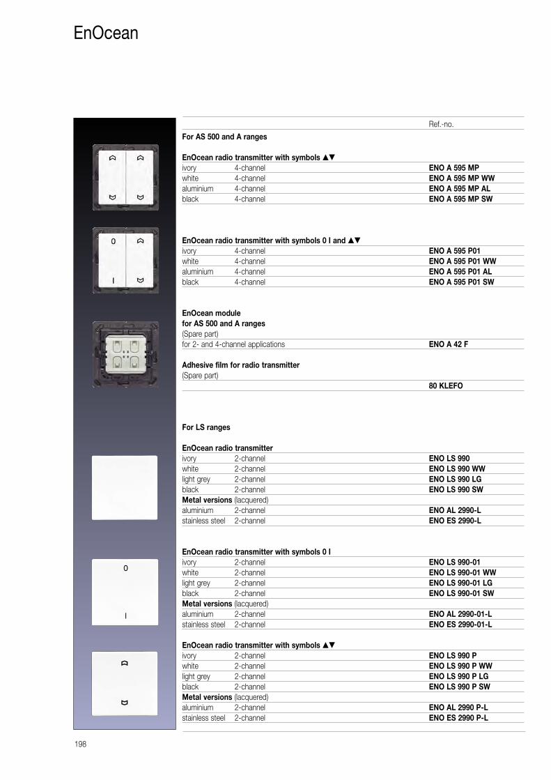
198
EnOcean
For AS 500 and A ranges
EnOcean radio transmitter with symbols ▲▼
ivory 4-channel ENO A 595 MPwhite 4-channel ENO A 595 MP WWaluminium 4-channel ENO A 595 MP ALblack 4-channel ENO A 595 MP SW
EnOcean radio transmitter with symbols 0 I and ▲▼
ivory 4-channel ENO A 595 P01white 4-channel ENO A 595 P01 WWaluminium 4-channel ENO A 595 P01 ALblack 4-channel ENO A 595 P01 SW
EnOcean modulefor AS 500 and A ranges(Spare part)for 2- and 4-channel applications ENO A 42 F
Adhesive film for radio transmitter(Spare part)
80 KLEFO
For LS ranges
EnOcean radio transmitterivory 2-channel ENO LS 990white 2-channel ENO LS 990 WWlight grey 2-channel ENO LS 990 LGblack 2-channel ENO LS 990 SWMetal versions (lacquered)aluminium 2-channel ENO AL 2990-Lstainless steel 2-channel ENO ES 2990-L
EnOcean radio transmitter with symbols 0 Iivory 2-channel ENO LS 990-01white 2-channel ENO LS 990-01 WWlight grey 2-channel ENO LS 990-01 LGblack 2-channel ENO LS 990-01 SWMetal versions (lacquered)aluminium 2-channel ENO AL 2990-01-Lstainless steel 2-channel ENO ES 2990-01-L
EnOcean radio transmitter with symbols ▲▼
ivory 2-channel ENO LS 990 Pwhite 2-channel ENO LS 990 P WWlight grey 2-channel ENO LS 990 P LGblack 2-channel ENO LS 990 P SWMetal versions (lacquered)aluminium 2-channel ENO AL 2990 P-Lstainless steel 2-channel ENO ES 2990 P-L
Ref.-no.
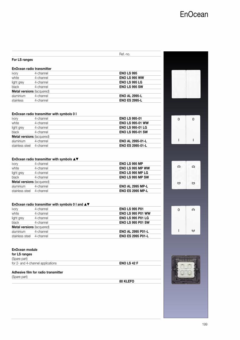
199
EnOcean
For LS ranges
EnOcean radio transmitterivory 4-channel ENO LS 995white 4-channel ENO LS 995 WWlight grey 4-channel ENO LS 995 LGblack 4-channel ENO LS 995 SWMetal versions (lacquered)aluminium 4-channel ENO AL 2995-Lstainless 4-channel ENO ES 2995-L
EnOcean radio transmitter with symbols 0 Iivory 4-channel ENO LS 995-01white 4-channel ENO LS 995-01 WWlight grey 4-channel ENO LS 995-01 LGblack 4-channel ENO LS 995-01 SWMetal versions (lacquered)aluminium 4-channel ENO AL 2995-01-Lstainless steel 4-channel ENO ES 2995-01-L
EnOcean radio transmitter with symbols ▲▼
ivory 4-channel ENO LS 995 MPwhite 4-channel ENO LS 995 MP WWlight grey 4-channel ENO LS 995 MP LGblack 4-channel ENO LS 995 MP SWMetal versions (lacquered)aluminium 4-channel ENO AL 2995 MP-Lstainless steel 4-channel ENO ES 2995 MP-L
EnOcean radio transmitter with symbols 0 I and ▲▼
ivory 4-channel ENO LS 995 P01white 4-channel ENO LS 995 P01 WWlight grey 4-channel ENO LS 995 P01 LGblack 4-channel ENO LS 995 P01 SWMetal versions (lacquered)aluminium 4-channel ENO AL 2995 P01-Lstainless steel 4-channel ENO ES 2995 P01-L
EnOcean modulefor LS ranges(Spare part)for 2- and 4-channel applications ENO LS 42 F
Adhesive film for radio transmitter(Spare part)
80 KLEFO
Ref.-no.
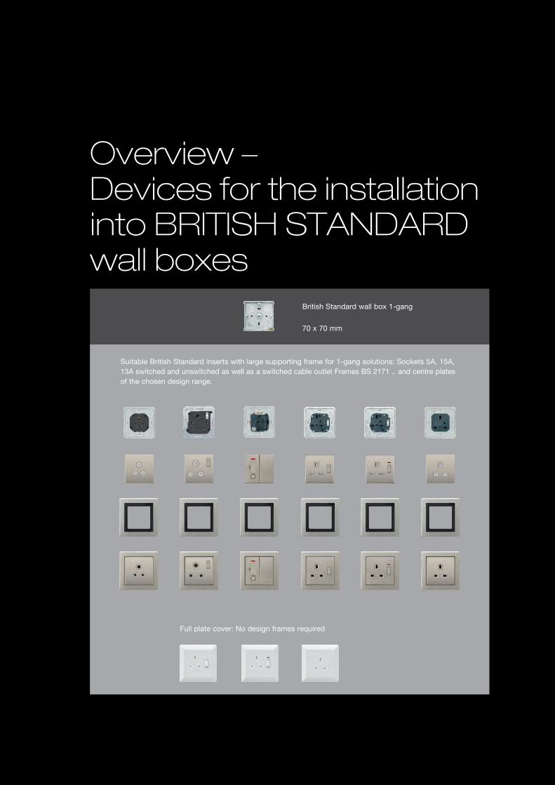
Overview – Devices for the installation into BRITISH STANDARD wall boxes
Full plate cover: No design frames required
British Standard wall box 1-gang
70 x 70 mm
Suitable British Standard inserts with large supporting frame for 1-gang solutions: Sockets 5A, 15A, 13A switched and unswitched as well as a switched cable outlet Frames BS 2171 .. and centre plates of the chosen design range.
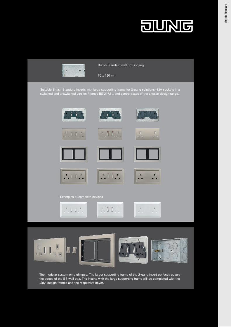
70 x 130 mm
British Standard wall box 2-gang
The modular system on a glimpse: The larger supporting frame of the 2-gang insert perfectly covers the edges of the BS wall box. The inserts with the large supporting frame will be completed with the „BS“ design frames and the respective cover.
Suitable British Standard inserts with large supporting frame for 2-gang solutions: 13A sockets in a switched and unswitched version Frames BS 2172 .. and centre plates of the chosen design range.
Examples of complete devices
Briti
sh S
tand
ard
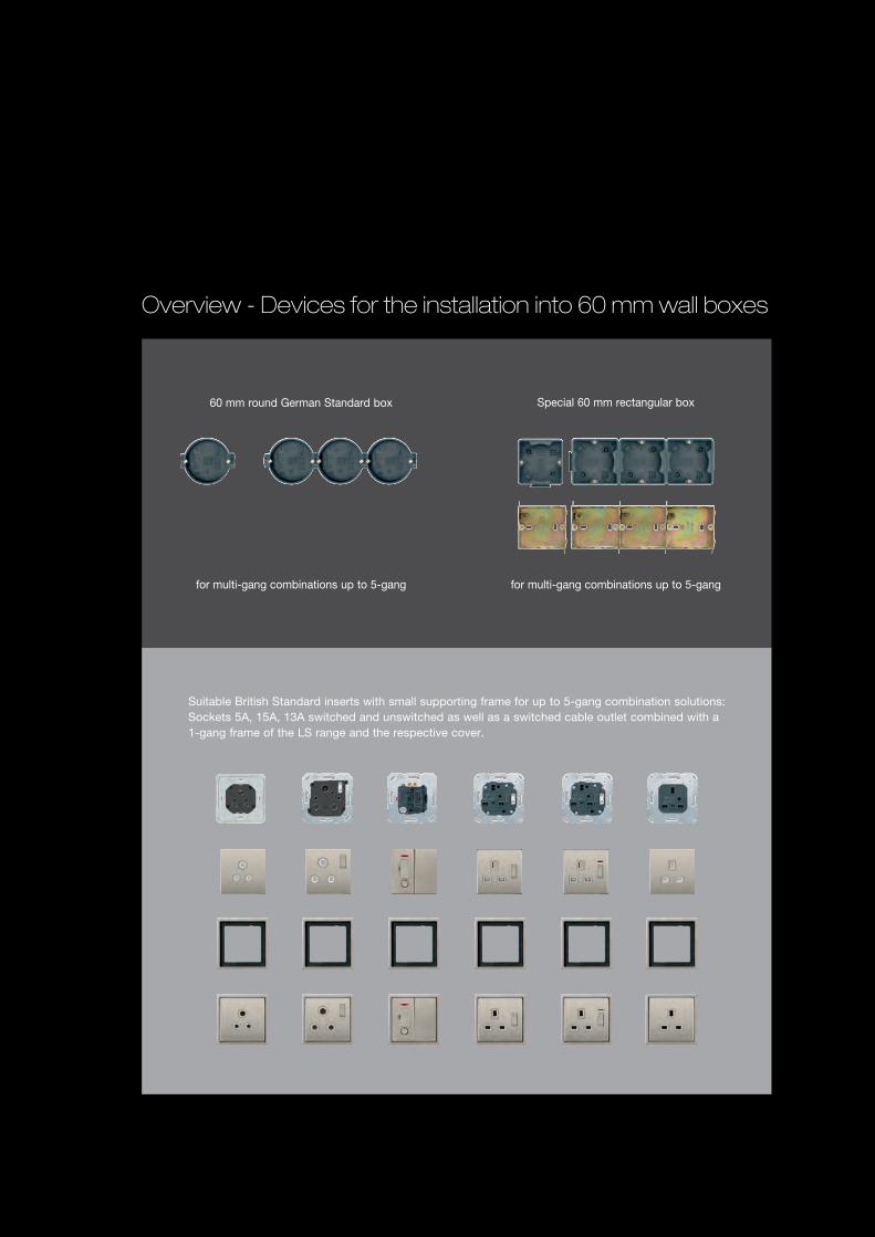
Overview - Devices for the installation into 60 mm wall boxes
Suitable British Standard inserts with small supporting frame for up to 5-gang combination solutions: Sockets 5A, 15A, 13A switched and unswitched as well as a switched cable outlet combined with a 1-gang frame of the LS range and the respective cover.
60 mm round German Standard box Special 60 mm rectangular box
for multi-gang combinations up to 5-gang for multi-gang combinations up to 5-gang
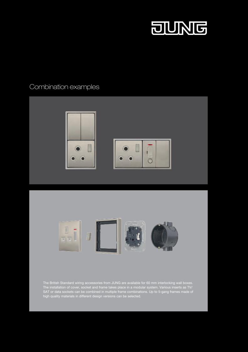
The British Standard wiring accessories from JUNG are available for 60 mm interlocking wall boxes. The installation of cover, socket and frame takes place in a modular system. Various inserts as TV/SAT or data sockets can be combined in multiple frame combinations. Up to 5-gang frames made of high quality materials in different design versions can be selected.
Combination examples
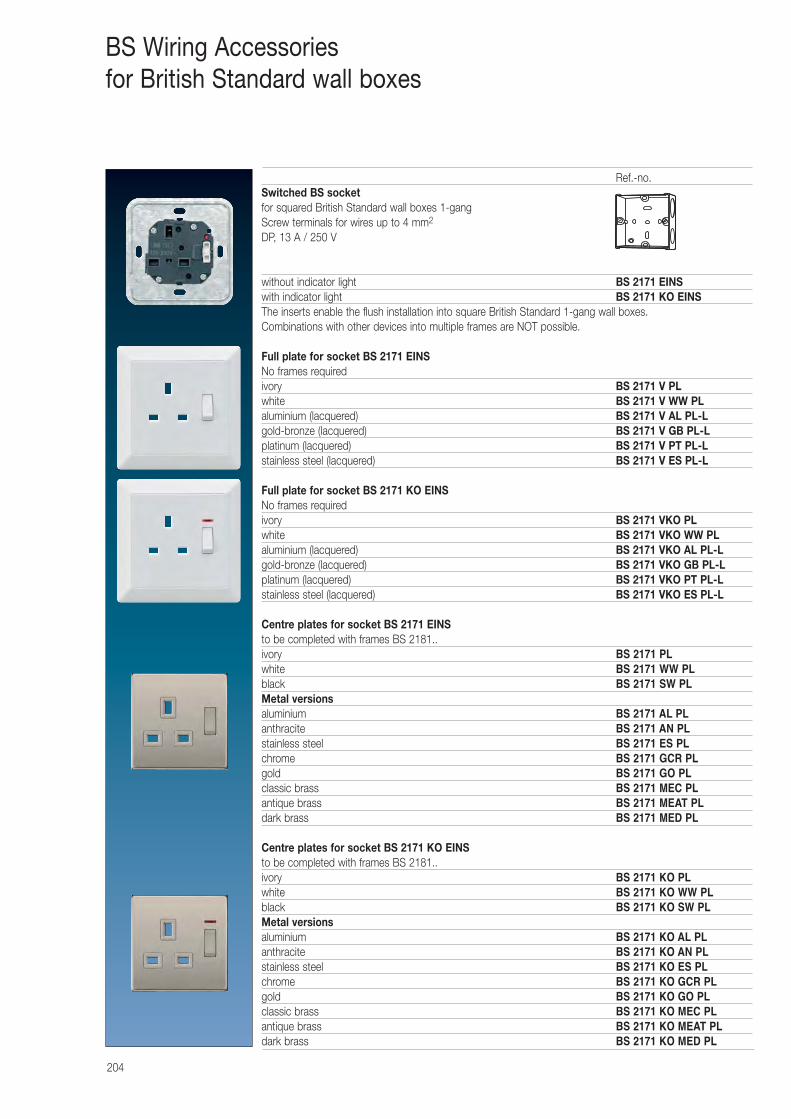
204
BS Wiring Accessoriesfor British Standard wall boxes
Ref.-no.Switched BS socketfor squared British Standard wall boxes 1-gangScrew terminals for wires up to 4 mm2
DP, 13 A / 250 V
without indicator light BS 2171 EINSwith indicator light BS 2171 KO EINSThe inserts enable the flush installation into square British Standard 1-gang wall boxes. Combinations with other devices into multiple frames are NOT possible.
Full plate for socket BS 2171 EINSNo frames requiredivory BS 2171 V PLwhite BS 2171 V WW PLaluminium (lacquered) BS 2171 V AL PL-Lgold-bronze (lacquered) BS 2171 V GB PL-Lplatinum (lacquered) BS 2171 V PT PL-Lstainless steel (lacquered) BS 2171 V ES PL-L
Full plate for socket BS 2171 KO EINSNo frames requiredivory BS 2171 VKO PLwhite BS 2171 VKO WW PLaluminium (lacquered) BS 2171 VKO AL PL-Lgold-bronze (lacquered) BS 2171 VKO GB PL-Lplatinum (lacquered) BS 2171 VKO PT PL-Lstainless steel (lacquered) BS 2171 VKO ES PL-L
Centre plates for socket BS 2171 EINSto be completed with frames BS 2181..ivory BS 2171 PLwhite BS 2171 WW PL black BS 2171 SW PLMetal versionsaluminium BS 2171 AL PLanthracite BS 2171 AN PLstainless steel BS 2171 ES PLchrome BS 2171 GCR PLgold BS 2171 GO PLclassic brass BS 2171 MEC PLantique brass BS 2171 MEAT PLdark brass BS 2171 MED PL
Centre plates for socket BS 2171 KO EINSto be completed with frames BS 2181..ivory BS 2171 KO PLwhite BS 2171 KO WW PL black BS 2171 KO SW PLMetal versionsaluminium BS 2171 KO AL PLanthracite BS 2171 KO AN PLstainless steel BS 2171 KO ES PLchrome BS 2171 KO GCR PLgold BS 2171 KO GO PLclassic brass BS 2171 KO MEC PLantique brass BS 2171 KO MEAT PLdark brass BS 2171 KO MED PL
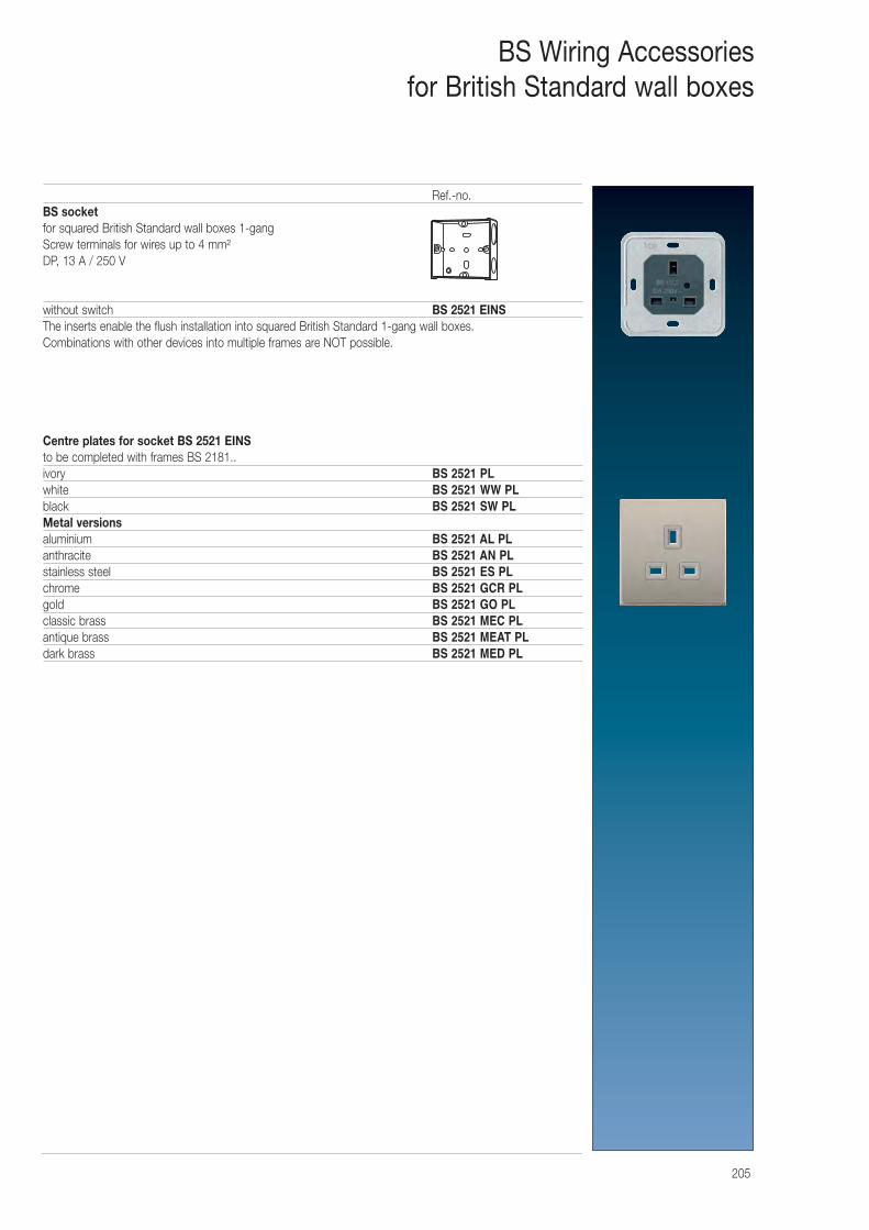
205
BS Wiring Accessoriesfor British Standard wall boxes
Ref.-no.BS socket for squared British Standard wall boxes 1-gangScrew terminals for wires up to 4 mm²DP, 13 A / 250 V
without switch BS 2521 EINSThe inserts enable the flush installation into squared British Standard 1-gang wall boxes. Combinations with other devices into multiple frames are NOT possible.
Centre plates for socket BS 2521 EINSto be completed with frames BS 2181..ivory BS 2521 PLwhite BS 2521 WW PL black BS 2521 SW PLMetal versionsaluminium BS 2521 AL PLanthracite BS 2521 AN PLstainless steel BS 2521 ES PLchrome BS 2521 GCR PLgold BS 2521 GO PLclassic brass BS 2521 MEC PLantique brass BS 2521 MEAT PLdark brass BS 2521 MED PL
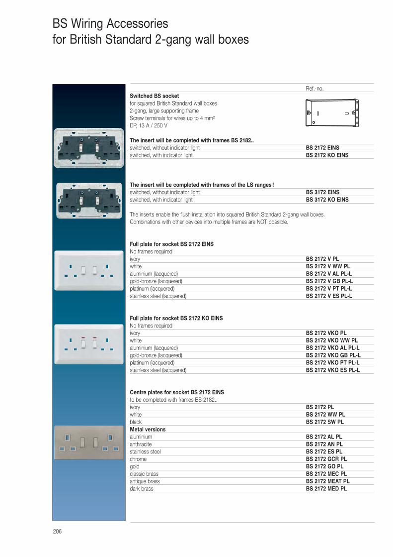
206
BS Wiring Accessoriesfor British Standard 2-gang wall boxes
Ref.-no.Switched BS socketfor squared British Standard wall boxes2-gang, large supporting frameScrew terminals for wires up to 4 mm²DP, 13 A / 250 V
The insert will be completed with frames BS 2182..switched, without indicator light BS 2172 EINSswitched, with indicator light BS 2172 KO EINS
The insert will be completed with frames of the LS ranges !switched, without indicator light BS 3172 EINSswitched, with indicator light BS 3172 KO EINS
The inserts enable the flush installation into squared British Standard 2-gang wall boxes. Combinations with other devices into multiple frames are NOT possible.
Full plate for socket BS 2172 EINSNo frames requiredivory BS 2172 V PLwhite BS 2172 V WW PLaluminium (lacquered) BS 2172 V AL PL-Lgold-bronze (lacquered) BS 2172 V GB PL-Lplatinum (lacquered) BS 2172 V PT PL-Lstainless steel (lacquered) BS 2172 V ES PL-L
Full plate for socket BS 2172 KO EINSNo frames requiredivory BS 2172 VKO PLwhite BS 2172 VKO WW PLaluminium (lacquered) BS 2172 VKO AL PL-Lgold-bronze (lacquered) BS 2172 VKO GB PL-Lplatinum (lacquered) BS 2172 VKO PT PL-Lstainless steel (lacquered) BS 2172 VKO ES PL-L
Centre plates for socket BS 2172 EINSto be completed with frames BS 2182..ivory BS 2172 PLwhite BS 2172 WW PL black BS 2172 SW PLMetal versionsaluminium BS 2172 AL PLanthracite BS 2172 AN PLstainless steel BS 2172 ES PLchrome BS 2172 GCR PLgold BS 2172 GO PLclassic brass BS 2172 MEC PLantique brass BS 2172 MEAT PLdark brass BS 2172 MED PL
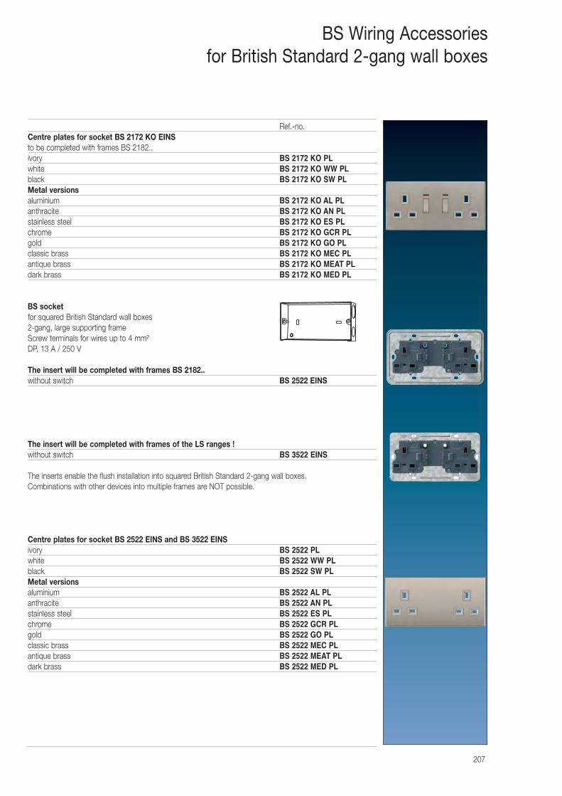
207
BS Wiring Accessoriesfor British Standard 2-gang wall boxes
Ref.-no.Centre plates for socket BS 2172 KO EINSto be completed with frames BS 2182..ivory BS 2172 KO PLwhite BS 2172 KO WW PL black BS 2172 KO SW PLMetal versionsaluminium BS 2172 KO AL PLanthracite BS 2172 KO AN PLstainless steel BS 2172 KO ES PLchrome BS 2172 KO GCR PLgold BS 2172 KO GO PLclassic brass BS 2172 KO MEC PLantique brass BS 2172 KO MEAT PLdark brass BS 2172 KO MED PL
BS socket for squared British Standard wall boxes2-gang, large supporting frameScrew terminals for wires up to 4 mm²DP, 13 A / 250 V
The insert will be completed with frames BS 2182..without switch BS 2522 EINS
The insert will be completed with frames of the LS ranges !without switch BS 3522 EINS
The inserts enable the flush installation into squared British Standard 2-gang wall boxes. Combinations with other devices into multiple frames are NOT possible.
Centre plates for socket BS 2522 EINS and BS 3522 EINSivory BS 2522 PLwhite BS 2522 WW PL black BS 2522 SW PLMetal versionsaluminium BS 2522 AL PLanthracite BS 2522 AN PLstainless steel BS 2522 ES PLchrome BS 2522 GCR PLgold BS 2522 GO PLclassic brass BS 2522 MEC PLantique brass BS 2522 MEAT PLdark brass BS 2522 MED PL
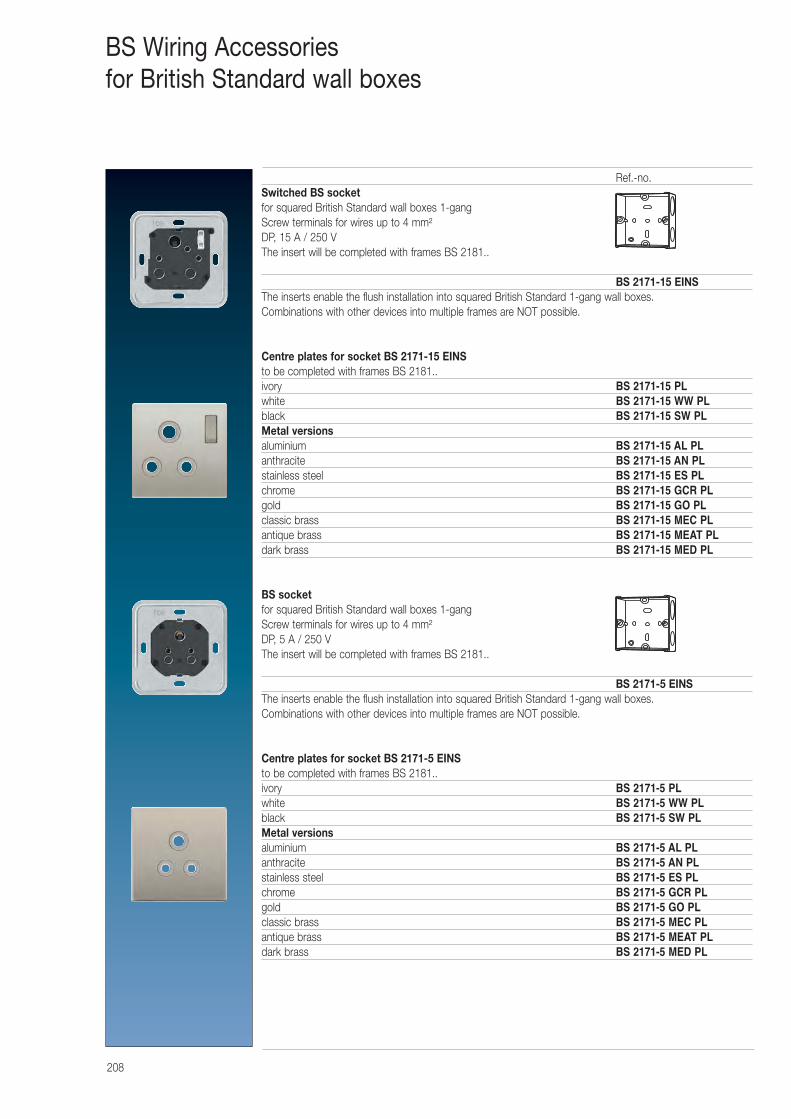
208
BS Wiring Accessoriesfor British Standard wall boxes
Ref.-no.Switched BS socketfor squared British Standard wall boxes 1-gangScrew terminals for wires up to 4 mm²DP, 15 A / 250 VThe insert will be completed with frames BS 2181..
BS 2171-15 EINSThe inserts enable the flush installation into squared British Standard 1-gang wall boxes. Combinations with other devices into multiple frames are NOT possible.
Centre plates for socket BS 2171-15 EINSto be completed with frames BS 2181..ivory BS 2171-15 PLwhite BS 2171-15 WW PLblack BS 2171-15 SW PLMetal versionsaluminium BS 2171-15 AL PLanthracite BS 2171-15 AN PLstainless steel BS 2171-15 ES PLchrome BS 2171-15 GCR PLgold BS 2171-15 GO PLclassic brass BS 2171-15 MEC PLantique brass BS 2171-15 MEAT PLdark brass BS 2171-15 MED PL
BS socket for squared British Standard wall boxes 1-gangScrew terminals for wires up to 4 mm²DP, 5 A / 250 VThe insert will be completed with frames BS 2181..
BS 2171-5 EINSThe inserts enable the flush installation into squared British Standard 1-gang wall boxes. Combinations with other devices into multiple frames are NOT possible.
Centre plates for socket BS 2171-5 EINSto be completed with frames BS 2181..ivory BS 2171-5 PLwhite BS 2171-5 WW PLblack BS 2171-5 SW PLMetal versionsaluminium BS 2171-5 AL PLanthracite BS 2171-5 AN PLstainless steel BS 2171-5 ES PLchrome BS 2171-5 GCR PLgold BS 2171-5 GO PLclassic brass BS 2171-5 MEC PLantique brass BS 2171-5 MEAT PLdark brass BS 2171-5 MED PL
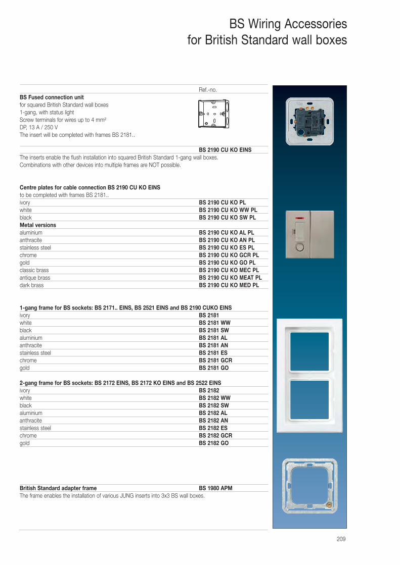
209
BS Wiring Accessoriesfor British Standard wall boxes
Ref.-no.BS Fused connection unitfor squared British Standard wall boxes 1-gang, with status lightScrew terminals for wires up to 4 mm²DP, 13 A / 250 VThe insert will be completed with frames BS 2181..
BS 2190 CU KO EINSThe inserts enable the flush installation into squared British Standard 1-gang wall boxes. Combinations with other devices into multiple frames are NOT possible.
Centre plates for cable connection BS 2190 CU KO EINSto be completed with frames BS 2181.. ivory BS 2190 CU KO PLwhite BS 2190 CU KO WW PLblack BS 2190 CU KO SW PLMetal versionsaluminium BS 2190 CU KO AL PLanthracite BS 2190 CU KO AN PLstainless steel BS 2190 CU KO ES PLchrome BS 2190 CU KO GCR PLgold BS 2190 CU KO GO PLclassic brass BS 2190 CU KO MEC PLantique brass BS 2190 CU KO MEAT PLdark brass BS 2190 CU KO MED PL
1-gang frame for BS sockets: BS 2171.. EINS, BS 2521 EINS and BS 2190 CUKO EINSivory BS 2181white BS 2181 WWblack BS 2181 SWaluminium BS 2181 ALanthracite BS 2181 ANstainless steel BS 2181 ESchrome BS 2181 GCRgold BS 2181 GO
2-gang frame for BS sockets: BS 2172 EINS, BS 2172 KO EINS and BS 2522 EINSivory BS 2182white BS 2182 WWblack BS 2182 SWaluminium BS 2182 ALanthracite BS 2182 ANstainless steel BS 2182 ESchrome BS 2182 GCRgold BS 2182 GO
British Standard adapter frame BS 1980 APMThe frame enables the installation of various JUNG inserts into 3x3 BS wall boxes.
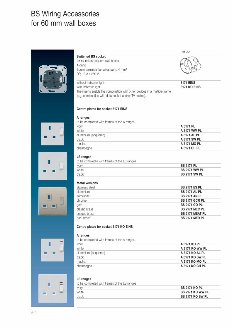
210
BS Wiring Accessoriesfor 60 mm wall boxes
Ref.-no.Switched BS socketfor round and square wall boxes1-gangScrew terminals for wires up to 4 mm²DP, 13 A / 250 V
without indicator light 3171 EINSwith indicator light 3171 KO EINSThe inserts enable the combination with other devices in a multiple frame (e.g. combination with data socket and/or TV socket).
Centre plates for socket 3171 EINS
A ranges to be completed with frames of the A rangesivory A 3171 PLwhite A 3171 WW PLaluminium (lacquered) A 3171 AL PLblack A 3171 SW PLmocha A 3171 MO PLchampagne A 3171 CH PL
LS rangesto be completed with frames of the LS rangesivory BS 2171 PLwhite BS 2171 WW PLblack BS 2171 SW PL
Metal versionsstainless steel BS 2171 ES PLaluminium BS 2171 AL PLanthracite BS 2171 AN PLchrome BS 2171 GCR PLgold BS 2171 GO PLclassic brass BS 2171 MEC PLantique brass BS 2171 MEAT PLdark brass BS 2171 MED PL
Centre plates for socket 3171 KO EINS
A ranges to be completed with frames of the A rangesivory A 3171 KO PLwhite A 3171 KO WW PLaluminium (lacquered) A 3171 KO AL PLblack A 3171 KO SW PLmocha A 3171 KO MO PLchampagne A 3171 KO CH PL
LS rangesto be completed with frames of the LS rangesivory BS 2171 KO PLwhite BS 2171 KO WW PLblack BS 2171 KO SW PL
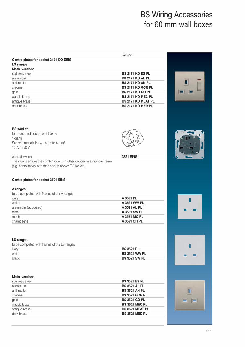
211
BS Wiring Accessoriesfor 60 mm wall boxes
Ref.-no.Centre plates for socket 3171 KO EINSLS rangesMetal versionsstainless steel BS 2171 KO ES PLaluminium BS 2171 KO AL PLanthracite BS 2171 KO AN PLchrome BS 2171 KO GCR PLgold BS 2171 KO GO PLclassic brass BS 2171 KO MEC PLantique brass BS 2171 KO MEAT PLdark brass BS 2171 KO MED PL
BS socket for round and square wall boxes1-gangScrew terminals for wires up to 4 mm²13 A / 250 V
without switch 3521 EINSThe inserts enable the combination with other devices in a multiple frame (e.g. combination with data socket and/or TV socket).
Centre plates for socket 3521 EINS
A rangesto be completed with frames of the A rangesivory A 3521 PLwhite A 3521 WW PLaluminium (lacquered) A 3521 AL PLblack A 3521 SW PLmocha A 3521 MO PLchampagne A 3521 CH PL
LS rangesto be completed with frames of the LS rangesivory BS 3521 PLwhite BS 3521 WW PLblack BS 3521 SW PL
Metal versionsstainless steel BS 3521 ES PLaluminium BS 3521 AL PLanthracite BS 3521 AN PLchrome BS 3521 GCR PLgold BS 3521 GO PLclassic brass BS 3521 MEC PLantique brass BS 3521 MEAT PLdark brass BS 3521 MED PL
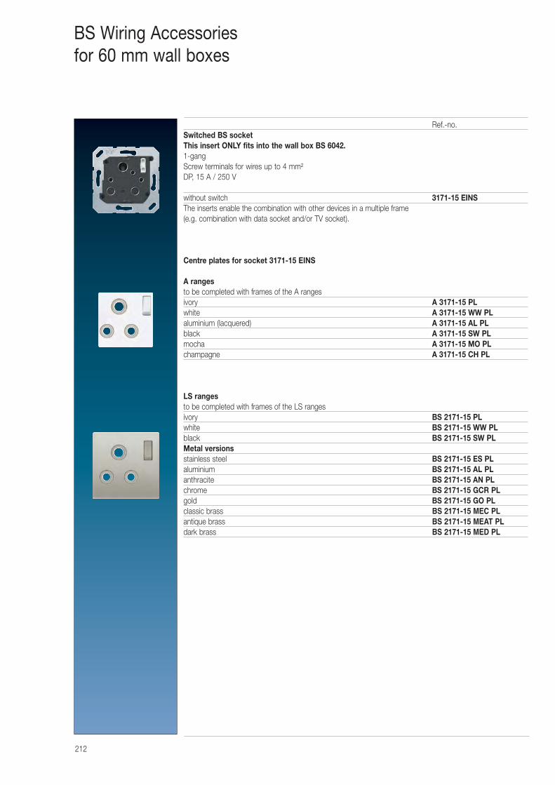
212
BS Wiring Accessoriesfor 60 mm wall boxes
Ref.-no.Switched BS socketThis insert ONLY fits into the wall box BS 6042.1-gangScrew terminals for wires up to 4 mm²DP, 15 A / 250 V
without switch 3171-15 EINSThe inserts enable the combination with other devices in a multiple frame (e.g. combination with data socket and/or TV socket).
Centre plates for socket 3171-15 EINS
A ranges to be completed with frames of the A rangesivory A 3171-15 PLwhite A 3171-15 WW PLaluminium (lacquered) A 3171-15 AL PLblack A 3171-15 SW PLmocha A 3171-15 MO PLchampagne A 3171-15 CH PL
LS rangesto be completed with frames of the LS rangesivory BS 2171-15 PLwhite BS 2171-15 WW PLblack BS 2171-15 SW PLMetal versionsstainless steel BS 2171-15 ES PLaluminium BS 2171-15 AL PLanthracite BS 2171-15 AN PLchrome BS 2171-15 GCR PLgold BS 2171-15 GO PLclassic brass BS 2171-15 MEC PLantique brass BS 2171-15 MEAT PLdark brass BS 2171-15 MED PL
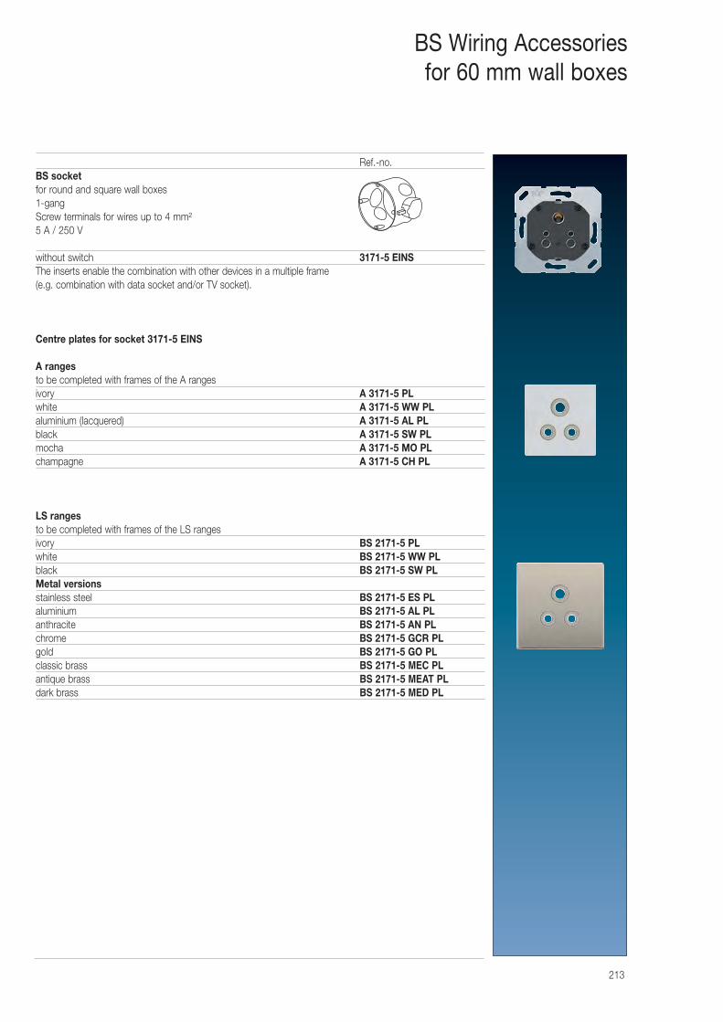
213
BS Wiring Accessoriesfor 60 mm wall boxes
Ref.-no.BS socket for round and square wall boxes1-gangScrew terminals for wires up to 4 mm²5 A / 250 V
without switch 3171-5 EINSThe inserts enable the combination with other devices in a multiple frame (e.g. combination with data socket and/or TV socket).
Centre plates for socket 3171-5 EINS
A rangesto be completed with frames of the A rangesivory A 3171-5 PLwhite A 3171-5 WW PLaluminium (lacquered) A 3171-5 AL PLblack A 3171-5 SW PLmocha A 3171-5 MO PLchampagne A 3171-5 CH PL
LS rangesto be completed with frames of the LS rangesivory BS 2171-5 PLwhite BS 2171-5 WW PLblack BS 2171-5 SW PLMetal versionsstainless steel BS 2171-5 ES PLaluminium BS 2171-5 AL PLanthracite BS 2171-5 AN PLchrome BS 2171-5 GCR PLgold BS 2171-5 GO PLclassic brass BS 2171-5 MEC PLantique brass BS 2171-5 MEAT PLdark brass BS 2171-5 MED PL
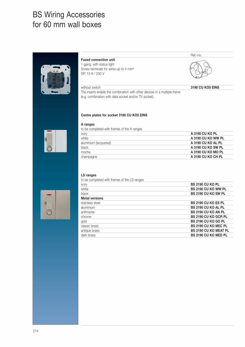
214
BS Wiring Accessoriesfor 60 mm wall boxes
Ref.-no.Fused connection unit1-gang, with status lightScrew terminals for wires up to 4 mm²DP, 13 A / 250 V
without switch 3190 CU KO5 EINSThe inserts enable the combination with other devices in a multiple frame (e.g. combination with data socket and/or TV socket).
Centre plates for socket 3190 CU KO5 EINS
A ranges to be completed with frames of the A rangesivory A 3190 CU KO PLwhite A 3190 CU KO WW PLaluminium (lacquered) A 3190 CU KO AL PLblack A 3190 CU KO SW PLmocha A 3190 CU KO MO PLchampagne A 3190 CU KO CH PL
LS rangesto be completed with frames of the LS rangesivory BS 2190 CU KO PLwhite BS 2190 CU KO WW PLblack BS 2190 CU KO SW PLMetal versionsstainless steel BS 2190 CU KO ES PLaluminium BS 2190 CU KO AL PLanthracite BS 2190 CU KO AN PLchrome BS 2190 CU KO GCR PLgold BS 2190 CU KO GO PLclassic brass BS 2190 CU KO MEC PLantique brass BS 2190 CU KO MEAT PLdark brass BS 2190 CU KO MED PL
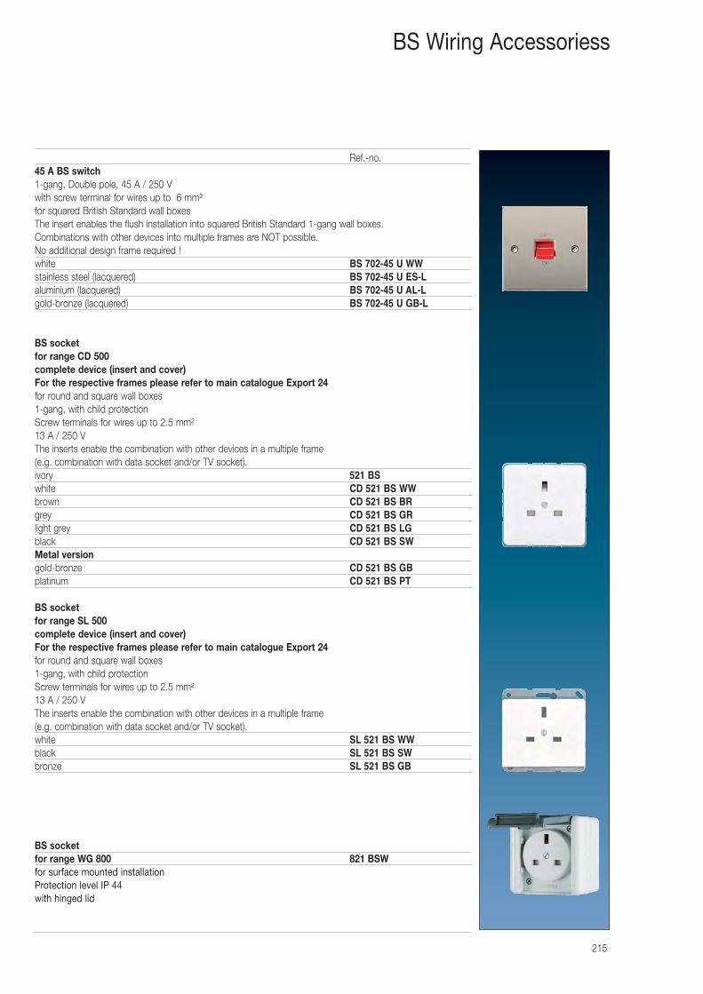
215
BS Wiring Accessoriess
Ref.-no.45 A BS switch1-gang, Double pole, 45 A / 250 Vwith screw terminal for wires up to 6 mm²for squared British Standard wall boxesThe insert enables the flush installation into squared British Standard 1-gang wall boxes. Combinations with other devices into multiple frames are NOT possible.No additional design frame required !white BS 702-45 U WWstainless steel (lacquered) BS 702-45 U ES-Laluminium (lacquered) BS 702-45 U AL-Lgold-bronze (lacquered) BS 702-45 U GB-L
BS socket for range CD 500complete device (insert and cover)For the respective frames please refer to main catalogue Export 24for round and square wall boxes1-gang, with child protectionScrew terminals for wires up to 2.5 mm²13 A / 250 VThe inserts enable the combination with other devices in a multiple frame (e.g. combination with data socket and/or TV socket).ivory 521 BS white CD 521 BS WWbrown CD 521 BS BRgrey CD 521 BS GRlight grey CD 521 BS LGblack CD 521 BS SWMetal versiongold-bronze CD 521 BS GBplatinum CD 521 BS PT
BS socketfor range SL 500complete device (insert and cover)For the respective frames please refer to main catalogue Export 24for round and square wall boxes1-gang, with child protectionScrew terminals for wires up to 2.5 mm²13 A / 250 VThe inserts enable the combination with other devices in a multiple frame (e.g. combination with data socket and/or TV socket).white SL 521 BS WWblack SL 521 BS SWbronze SL 521 BS GB
BS socket for range WG 800 821 BSWfor surface mounted installationProtection level IP 44with hinged lid
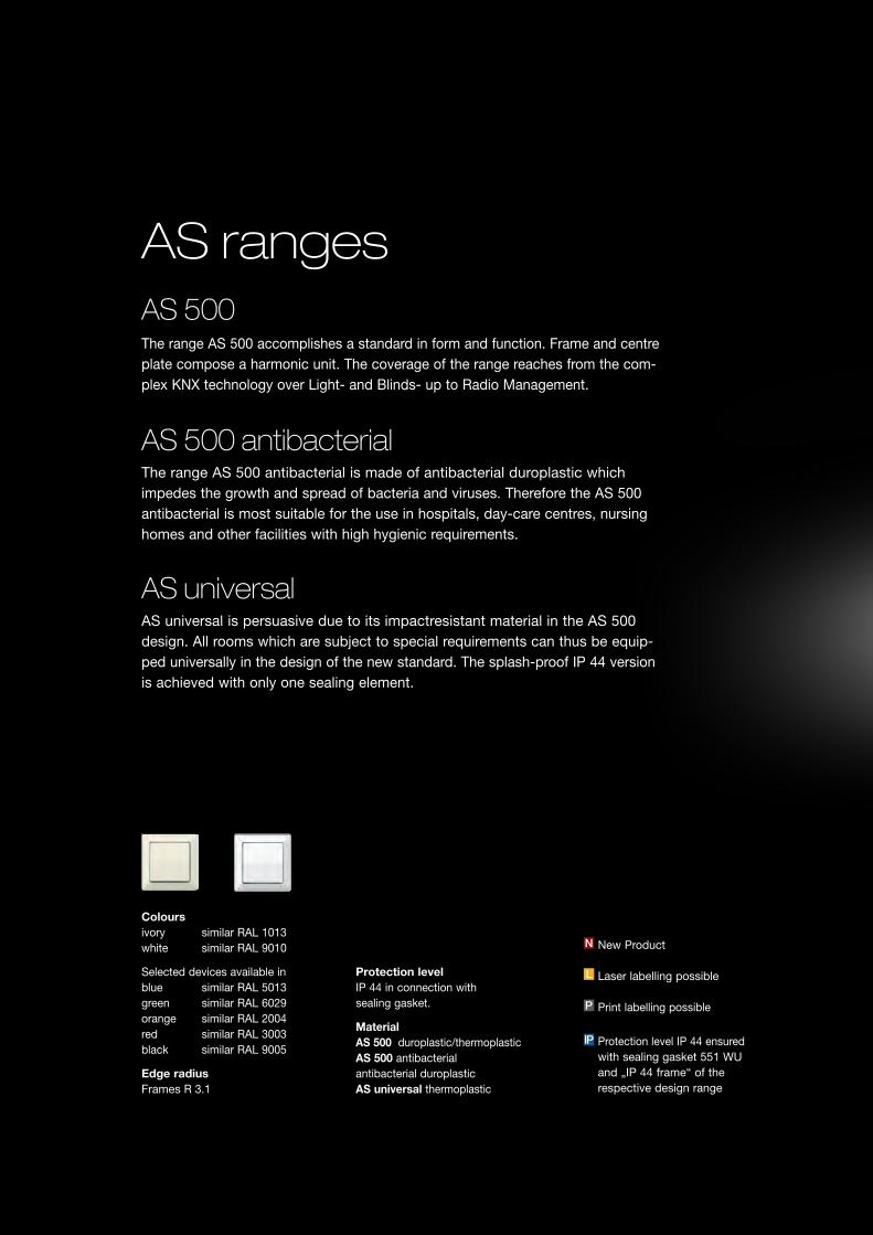
AS 500
AS 500 antibacterialThe range AS 500 antibacterial is made of antibacterial duroplastic which impedes the growth and spread of bacteria and viruses. Therefore the AS 500 antibacterial is most suitable for the use in hospitals, day-care centres, nursing homes and other facilities with high hygienic requirements.
AS ranges
The range AS 500 accomplishes a standard in form and function. Frame and centre plate compose a harmonic unit. The coverage of the range reaches from the com-plex KNX technology over Light- and Blinds- up to Radio Management.
AS universalAS universal is persuasive due to its impactresistant material in the AS 500 design. All rooms which are subject to special requirements can thus be equip-ped universally in the design of the new standard. The splash-proof IP 44 versionis achieved with only one sealing element.
Colours ivory similar RAL 1013 white similar RAL 9010
Selected devices available in blue similar RAL 5013 green similar RAL 6029 orange similar RAL 2004 red similar RAL 3003 black similar RAL 9005
Edge radius Frames R 3.1
Protection level IP 44 in connection with sealing gasket.
Material AS 500 duroplastic/thermoplastic AS 500 antibacterial antibacterial duroplastic AS universal thermoplastic
Protection level IP 44 ensured with sealing gasket 551 WU and „IP 44 frame“ of the respective design range
IP
New Product
Laser labelling possible
Print labelling possible
N
L
P
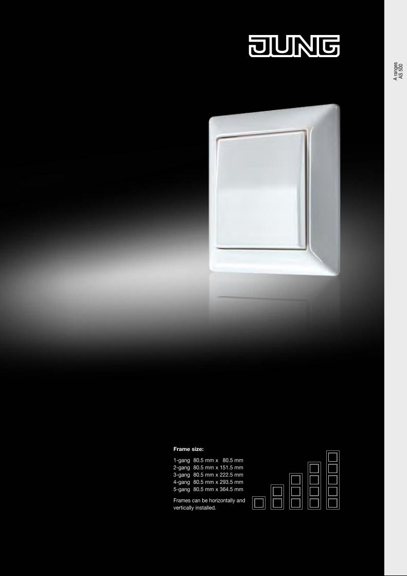
AS 500
AS 500 antibacterialThe range AS 500 antibacterial is made of antibacterial duroplastic which impedes the growth and spread of bacteria and viruses. Therefore the AS 500 antibacterial is most suitable for the use in hospitals, day-care centres, nursing homes and other facilities with high hygienic requirements.
AS ranges
The range AS 500 accomplishes a standard in form and function. Frame and centre plate compose a harmonic unit. The coverage of the range reaches from the com-plex KNX technology over Light- and Blinds- up to Radio Management.
AS universalAS universal is persuasive due to its impactresistant material in the AS 500 design. All rooms which are subject to special requirements can thus be equip-ped universally in the design of the new standard. The splash-proof IP 44 versionis achieved with only one sealing element.
Frame size:
1-gang 80.5 mm x 80.5 mm 2-gang 80.5 mm x 151.5 mm 3-gang 80.5 mm x 222.5 mm 4-gang 80.5 mm x 293.5 mm 5-gang 80.5 mm x 364.5 mm
Frames can be horizontally and vertically installed.
Colours ivory similar RAL 1013 white similar RAL 9010
Selected devices available in blue similar RAL 5013 green similar RAL 6029 orange similar RAL 2004 red similar RAL 3003 black similar RAL 9005
Edge radius Frames R 3.1
Protection level IP 44 in connection with sealing gasket.
Material AS 500 duroplastic/thermoplastic AS 500 antibacterial antibacterial duroplastic AS universal thermoplastic
Protection level IP 44 ensured with sealing gasket 551 WU and „IP 44 frame“ of the respective design range
IP
New Product
Laser labelling possible
Print labelling possible
N
L
P
A ra
nges
AS
500
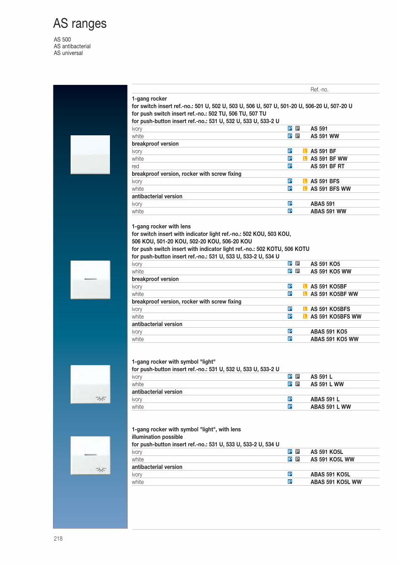
AS 500AS antibacterialAS universal
218
AS ranges
1-gang rockerfor switch insert ref.-no.: 501 U, 502 U, 503 U, 506 U, 507 U, 501-20 U, 506-20 U, 507-20 Ufor push switch insert ref.-no.: 502 TU, 506 TU, 507 TUfor push-button insert ref.-no.: 531 U, 532 U, 533 U, 533-2 Uivory AS 591white AS 591 WWbreakproof versionivory AS 591 BFwhite AS 591 BF WWred AS 591 BF RTbreakproof version, rocker with screw fixingivory AS 591 BFSwhite AS 591 BFS WWantibacterial versionivory ABAS 591white ABAS 591 WW
1-gang rocker with lensfor switch insert with indicator light ref.-no.: 502 KOU, 503 KOU, 506 KOU, 501-20 KOU, 502-20 KOU, 506-20 KOUfor push switch insert with indicator light ref.-no.: 502 KOTU, 506 KOTUfor push-button insert ref.-no.: 531 U, 533 U, 533-2 U, 534 Uivory AS 591 KO5white AS 591 KO5 WWbreakproof versionivory AS 591 KO5BFwhite AS 591 KO5BF WWbreakproof version, rocker with screw fixingivory AS 591 KO5BFSwhite AS 591 KO5BFS WWantibacterial versionivory ABAS 591 KO5white ABAS 591 KO5 WW
1-gang rocker with symbol "light"for push-button insert ref.-no.: 531 U, 532 U, 533 U, 533-2 Uivory AS 591 Lwhite AS 591 L WWantibacterial versionivory ABAS 591 Lwhite ABAS 591 L WW
1-gang rocker with symbol "light", with lensillumination possiblefor push-button insert ref.-no.: 531 U, 533 U, 533-2 U, 534 Uivory AS 591 KO5Lwhite AS 591 KO5L WWantibacterial versionivory ABAS 591 KO5Lwhite ABAS 591 KO5L WWIP
IP
PIP
PIP
IP
IP
PIP
PIP
IP
IP
LIP
LIP
LIP
LIP
PIP
PIP
IP
IP
LIP
LIP
IP
LIP
LIP
PIP
PIP
Ref.-no.
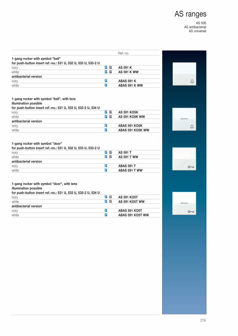
AS 500AS antibacterial
AS universal
219
AS ranges
1-gang rocker with symbol "bell"for push-button insert ref.-no.: 531 U, 532 U, 533 U, 533-2 Uivory AS 591 Kwhite AS 591 K WWantibacterial versionivory ABAS 591 Kwhite ABAS 591 K WW
1-gang rocker with symbol "bell", with lensillumination possiblefor push-button insert ref.-no.: 531 U, 533 U, 533-2 U, 534 Uivory AS 591 KO5Kwhite AS 591 KO5K WWantibacterial versionivory ABAS 591 KO5Kwhite ABAS 591 KO5K WW
1-gang rocker with symbol "door"for push-button insert ref.-no.: 531 U, 532 U, 533 U, 533-2 Uivory AS 591 Twhite AS 591 T WWantibacterial versionivory ABAS 591 Twhite ABAS 591 T WW
1-gang rocker with symbol "door", with lensillumination possiblefor push-button insert ref.-no.: 531 U, 533 U, 533-2 U, 534 Uivory AS 591 KO5Twhite AS 591 KO5T WWantibacterial versionivory ABAS 591 KO5Twhite ABAS 591 KO5T WW
IP P
IP P
IP
IP
IP
IP
PIP
PIP
IP
IP
PIP
PIP
IP
IP
PIP
PIP
Ref.-no.
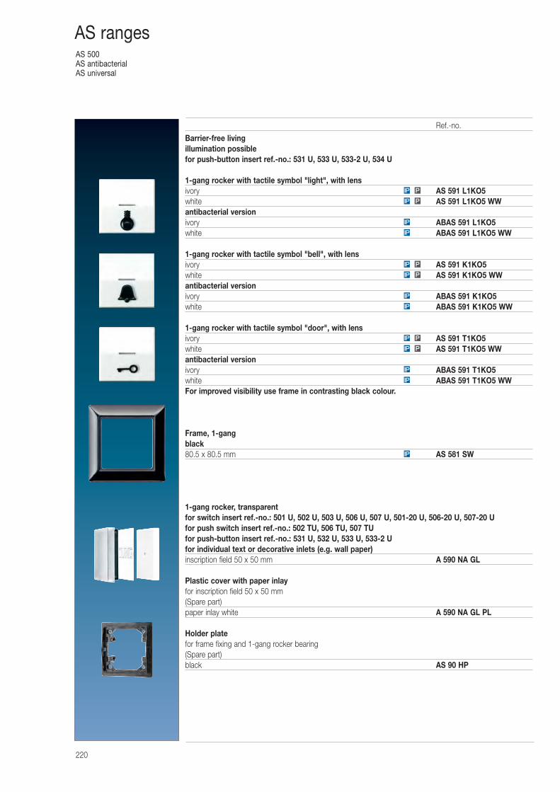
AS 500AS antibacterialAS universal
220
AS ranges
Barrier-free livingillumination possiblefor push-button insert ref.-no.: 531 U, 533 U, 533-2 U, 534 U
1-gang rocker with tactile symbol "light", with lensivory AS 591 L1KO5white AS 591 L1KO5 WWantibacterial versionivory ABAS 591 L1KO5white ABAS 591 L1KO5 WW
1-gang rocker with tactile symbol "bell", with lensivory AS 591 K1KO5white AS 591 K1KO5 WWantibacterial versionivory ABAS 591 K1KO5white ABAS 591 K1KO5 WW
1-gang rocker with tactile symbol "door", with lensivory AS 591 T1KO5white AS 591 T1KO5 WWantibacterial versionivory ABAS 591 T1KO5white ABAS 591 T1KO5 WWFor improved visibility use frame in contrasting black colour.
Frame, 1-gangblack80.5 x 80.5 mm AS 581 SW
1-gang rocker, transparentfor switch insert ref.-no.: 501 U, 502 U, 503 U, 506 U, 507 U, 501-20 U, 506-20 U, 507-20 Ufor push switch insert ref.-no.: 502 TU, 506 TU, 507 TUfor push-button insert ref.-no.: 531 U, 532 U, 533 U, 533-2 Ufor individual text or decorative inlets (e.g. wall paper)inscription field 50 x 50 mm A 590 NA GL
Plastic cover with paper inlayfor inscription field 50 x 50 mm(Spare part)paper inlay white A 590 NA GL PL
Holder platefor frame fixing and 1-gang rocker bearing(Spare part)black AS 90 HP
PIP
PIP
IP
IP
PIP
PIP
IP
IP
PIP
PIP
IP
IP
IP
Ref.-no.
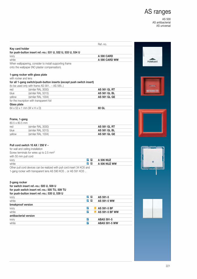
AS 500AS antibacterial
AS universal
221
AS ranges
Key card holderfor push-button insert ref.-no.: 531 U, 532 U, 533 U, 534 Uivory A 590 CARDwhite A 590 CARD WWWhen wallpapering, consider to install supporting frame onto the wallpaper (NO plaster compensation).
1-gang rocker with glass platewith rocker and lensfor all 1-gang switch/push-button inserts (except push switch insert)(to be used only with frame AS 581.. – AS 585..)red (similar RAL 3000) AS 561 GL RTblue (similar RAL 5015) AS 561 GL BLyellow (similar RAL 1004) AS 561 GL GEfor the inscription with transparent foilGlass plate64 x 53 x 1 mm (W x H x D) 60 GL
Frame, 1-gang80.5 x 80.5 mmred (similar RAL 3000) AS 581 GL RTblue (similar RAL 5015) AS 581 GL BLyellow (similar RAL 1004) AS 581 GL GE
Pull cord switch 10 AX / 250 V ~for wall and ceiling installationScrew terminals for wires up to 2.5 mm2
with 50 mm pull cordivory A 506 NUZwhite A 506 NUZ WWOther pull cord devices can be realized with pull cord insert 34 KO5 and 1-gang rocker with transparent lens AS 590 KO5 .. or AS 591 KO5 ..
2-gang rockerfor switch insert ref.-no.: 505 U, 509 Ufor push switch insert ref.-no.: 505 TU, 509 TUfor push-button insert ref.-no.: 535 U, 539 Uivory AS 591-5white AS 591-5 WWbreakproof versionivory AS 591-5 BFwhite AS 591-5 BF WWantibacterial versionivory ABAS 591-5white ABAS 591-5 WW
IP L
IP L
PIP
PIP
PIP
PIP
IP
IP
Ref.-no.
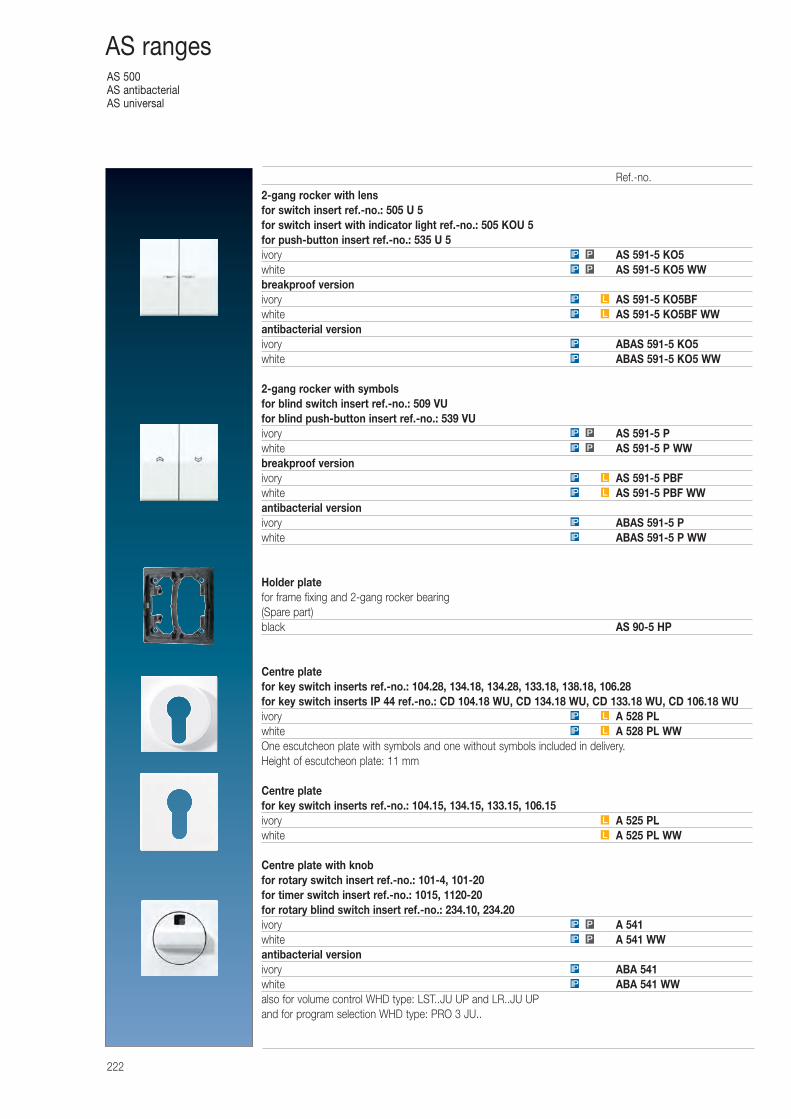
AS 500AS antibacterialAS universal
222
AS ranges
2-gang rocker with lensfor switch insert ref.-no.: 505 U 5for switch insert with indicator light ref.-no.: 505 KOU 5for push-button insert ref.-no.: 535 U 5ivory AS 591-5 KO5white AS 591-5 KO5 WWbreakproof versionivory AS 591-5 KO5BFwhite AS 591-5 KO5BF WWantibacterial versionivory ABAS 591-5 KO5white ABAS 591-5 KO5 WW
2-gang rocker with symbolsfor blind switch insert ref.-no.: 509 VUfor blind push-button insert ref.-no.: 539 VUivory AS 591-5 Pwhite AS 591-5 P WWbreakproof versionivory AS 591-5 PBFwhite AS 591-5 PBF WWantibacterial versionivory ABAS 591-5 Pwhite ABAS 591-5 P WW
Holder platefor frame fixing and 2-gang rocker bearing(Spare part)black AS 90-5 HP
Centre platefor key switch inserts ref.-no.: 104.28, 134.18, 134.28, 133.18, 138.18, 106.28for key switch inserts IP 44 ref.-no.: CD 104.18 WU, CD 134.18 WU, CD 133.18 WU, CD 106.18 WUivory A 528 PLwhite A 528 PL WWOne escutcheon plate with symbols and one without symbols included in delivery.Height of escutcheon plate: 11 mm
Centre platefor key switch inserts ref.-no.: 104.15, 134.15, 133.15, 106.15ivory A 525 PLwhite A 525 PL WW
Centre plate with knobfor rotary switch insert ref.-no.: 101-4, 101-20for timer switch insert ref.-no.: 1015, 1120-20for rotary blind switch insert ref.-no.: 234.10, 234.20ivory A 541white A 541 WWantibacterial versionivory ABA 541white ABA 541 WWalso for volume control WHD type: LST..JU UP and LR..JU UPand for program selection WHD type: PRO 3 JU..
PIP
PIP
LIP
LIP
IP
IP
PIP
PIP
L
L
LIP
LIP
IP
IP
LIP
LIP
PIP
PIP
IP
IP
Ref.-no.
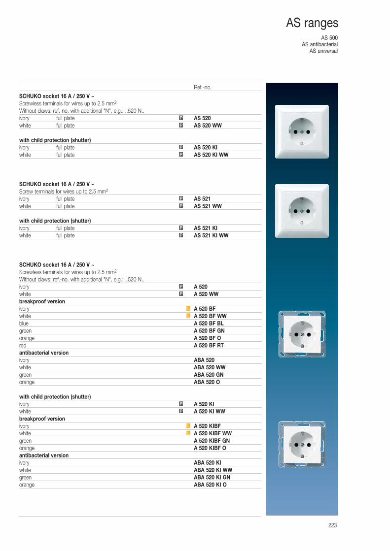
AS 500AS antibacterial
AS universal
223
AS ranges
SCHUKO socket 16 A / 250 V ~Screwless terminals for wires up to 2.5 mm2
Without claws: ref.-no. with additional "N", e.g.: ..520 N..ivory full plate AS 520white full plate AS 520 WW
with child protection (shutter)ivory full plate AS 520 KIwhite full plate AS 520 KI WW
SCHUKO socket 16 A / 250 V ~Screw terminals for wires up to 2.5 mm2
ivory full plate AS 521white full plate AS 521 WW
with child protection (shutter)ivory full plate AS 521 KIwhite full plate AS 521 KI WW
SCHUKO socket 16 A / 250 V ~Screwless terminals for wires up to 2.5 mm2
Without claws: ref.-no. with additional "N", e.g.: ..520 N..ivory A 520white A 520 WWbreakproof versionivory A 520 BFwhite A 520 BF WWblue A 520 BF BLgreen A 520 BF GNorange A 520 BF Ored A 520 BF RTantibacterial versionivory ABA 520white ABA 520 WWgreen ABA 520 GNorange ABA 520 O
with child protection (shutter)ivory A 520 KIwhite A 520 KI WWbreakproof versionivory A 520 KIBFwhite A 520 KIBF WWgreen A 520 KIBF GNorange A 520 KIBF Oantibacterial versionivory ABA 520 KIwhite ABA 520 KI WWgreen ABA 520 KI GNorange ABA 520 KI O
L
L
P
P
L
L
P
P
P
P
P
P
P
P
P
P
Ref.-no.
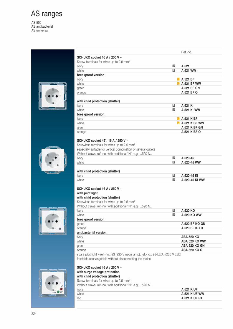
AS 500AS antibacterialAS universal
224
AS ranges
SCHUKO socket 16 A / 250 V ~Screw terminals for wires up to 2.5 mm2
ivory A 521white A 521 WWbreakproof versionivory A 521 BFwhite A 521 BF WWgreen A 521 BF GNorange A 521 BF O
with child protection (shutter)ivory A 521 KIwhite A 521 KI WWbreakproof versionivory A 521 KIBFwhite A 521 KIBF WWgreen A 521 KIBF GNorange A 521 KIBF O
SCHUKO socket 45°, 16 A / 250 V ~Screwless terminals for wires up to 2.5 mm2
especially suitable for vertical combination of several outletsWithout claws: ref.-no. with additional "N", e.g.: ..520 N..ivory A 520-45white A 520-45 WW
with child protection (shutter)ivory A 520-45 KIwhite A 520-45 KI WW
SCHUKO socket 16 A / 250 V ~with pilot lightwith child protection (shutter)Screwless terminals for wires up to 2.5 mm2
Without claws: ref.-no. with additional "N", e.g.: ..520 N..ivory A 520 KOwhite A 520 KO WWbreakproof versiongreen A 520 BF KO GNorange A 520 BF KO Oantibacterial versionivory ABA 520 KOwhite ABA 520 KO WWgreen ABA 520 KO GNorange ABA 520 KO Ospare pilot light – ref.-no.: 93 (230 V neon lamp), ref.-no.: 93-LED.. (230 V LED) frontside exchangeable without disconnecting the mains
SCHUKO socket 16 A / 250 V ~with surge voltage protectionwith child protection (shutter)Screw terminals for wires up to 2.5 mm2
Without claws: ref.-no. with additional "N", e.g.: ..520 N..ivory A 521 KIUFwhite A 521 KIUF WWred A 521 KIUF RT
P
P
L
L
P
P
P
P
P
P
L
L
P
P
Ref.-no.
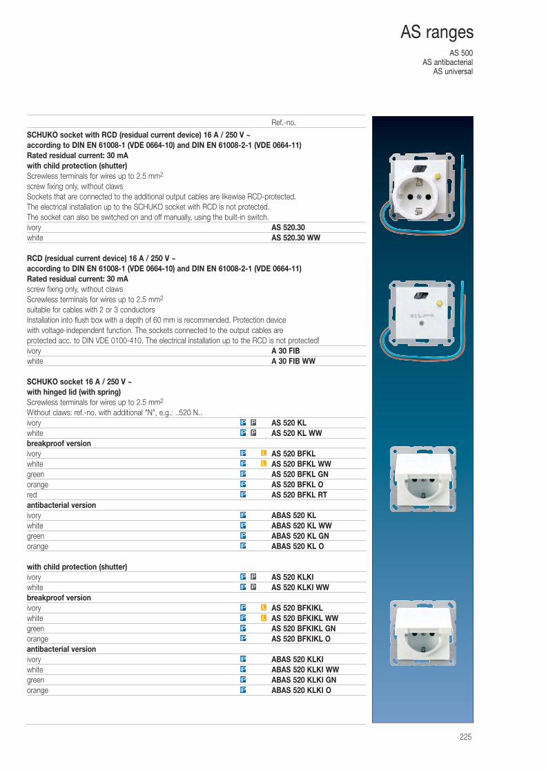
AS 500AS antibacterial
AS universal
225
AS ranges
SCHUKO socket with RCD (residual current device) 16 A / 250 V ~according to DIN EN 61008-1 (VDE 0664-10) and DIN EN 61008-2-1 (VDE 0664-11)Rated residual current: 30 mAwith child protection (shutter)Screwless terminals for wires up to 2.5 mm2
screw fixing only, without clawsSockets that are connected to the additional output cables are likewise RCD-protected. The electrical installation up to the SCHUKO socket with RCD is not protected. The socket can also be switched on and off manually, using the built-in switch.ivory AS 520.30white AS 520.30 WW
RCD (residual current device) 16 A / 250 V ~according to DIN EN 61008-1 (VDE 0664-10) and DIN EN 61008-2-1 (VDE 0664-11)Rated residual current: 30 mAscrew fixing only, without clawsScrewless terminals for wires up to 2.5 mm2
suitable for cables with 2 or 3 conductorsInstallation into flush box with a depth of 60 mm is recommended. Protection device with voltage-independent function. The sockets connected to the output cables are protected acc. to DIN VDE 0100-410. The electrical installation up to the RCD is not protected!ivory A 30 FIBwhite A 30 FIB WW
SCHUKO socket 16 A / 250 V ~with hinged lid (with spring)Screwless terminals for wires up to 2.5 mm2
Without claws: ref.-no. with additional "N", e.g.: ..520 N..ivory AS 520 KLwhite AS 520 KL WWbreakproof versionivory AS 520 BFKLwhite AS 520 BFKL WWgreen AS 520 BFKL GNorange AS 520 BFKL Ored AS 520 BFKL RTantibacterial versionivory ABAS 520 KLwhite ABAS 520 KL WWgreen ABAS 520 KL GNorange ABAS 520 KL O
with child protection (shutter)ivory AS 520 KLKIwhite AS 520 KLKI WWbreakproof versionivory AS 520 BFKIKLwhite AS 520 BFKIKL WWgreen AS 520 BFKIKL GNorange AS 520 BFKIKL Oantibacterial versionivory ABAS 520 KLKIwhite ABAS 520 KLKI WWgreen ABAS 520 KLKI GNorange ABAS 520 KLKI OIP
IP
IP
IP
IP
IP
LIP
LIP
PIP
PIP
IP
IP
IP
IP
IP
IP
IP
LIP
LIP
PIP
PIP
Ref.-no.
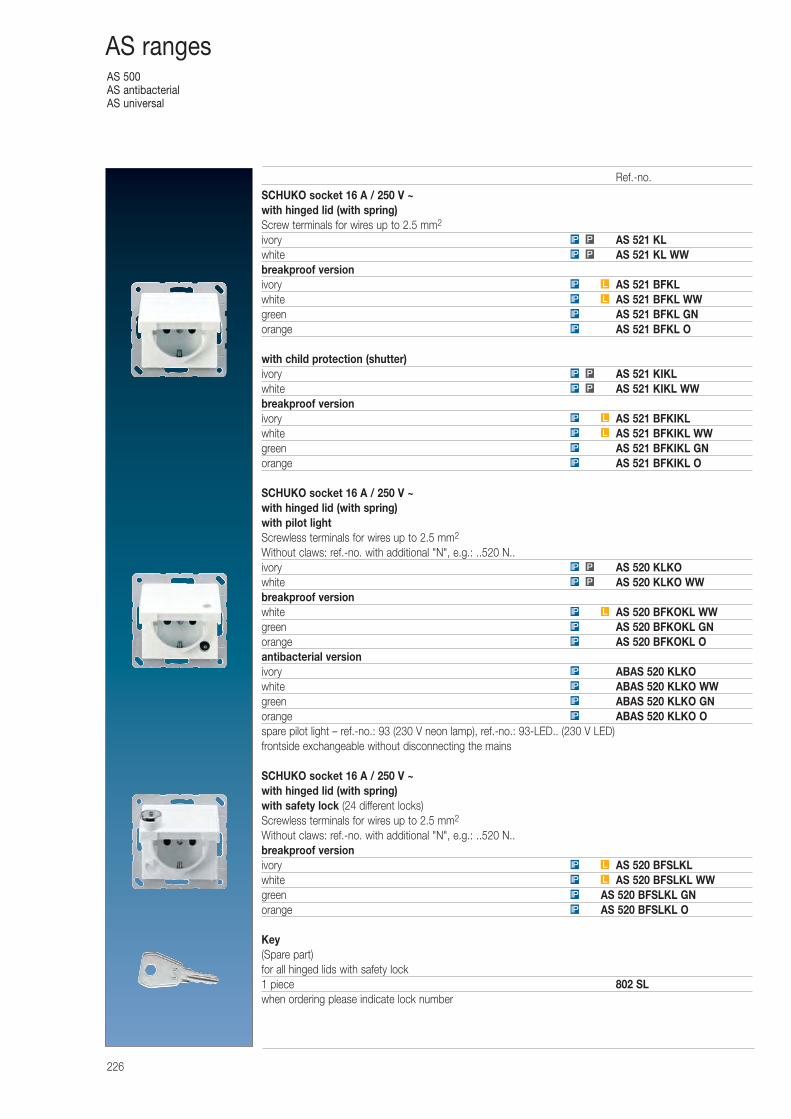
AS 500AS antibacterialAS universal
226
AS ranges
SCHUKO socket 16 A / 250 V ~with hinged lid (with spring)Screw terminals for wires up to 2.5 mm2
ivory AS 521 KLwhite AS 521 KL WWbreakproof versionivory AS 521 BFKLwhite AS 521 BFKL WWgreen AS 521 BFKL GNorange AS 521 BFKL O
with child protection (shutter)ivory AS 521 KIKLwhite AS 521 KIKL WWbreakproof versionivory AS 521 BFKIKLwhite AS 521 BFKIKL WWgreen AS 521 BFKIKL GNorange AS 521 BFKIKL O
SCHUKO socket 16 A / 250 V ~with hinged lid (with spring)with pilot lightScrewless terminals for wires up to 2.5 mm2
Without claws: ref.-no. with additional "N", e.g.: ..520 N..ivory AS 520 KLKOwhite AS 520 KLKO WWbreakproof versionwhite AS 520 BFKOKL WWgreen AS 520 BFKOKL GNorange AS 520 BFKOKL Oantibacterial versionivory ABAS 520 KLKOwhite ABAS 520 KLKO WWgreen ABAS 520 KLKO GNorange ABAS 520 KLKO Ospare pilot light – ref.-no.: 93 (230 V neon lamp), ref.-no.: 93-LED.. (230 V LED) frontside exchangeable without disconnecting the mains
SCHUKO socket 16 A / 250 V ~with hinged lid (with spring)with safety lock (24 different locks)Screwless terminals for wires up to 2.5 mm2
Without claws: ref.-no. with additional "N", e.g.: ..520 N..breakproof versionivory AS 520 BFSLKLwhite AS 520 BFSLKL WWgreen AS 520 BFSLKL GNorange AS 520 BFSLKL O
Key(Spare part)for all hinged lids with safety lock1 piece 802 SLwhen ordering please indicate lock number
IP
IP
LIP
LIP
IP
IP
IP
IP
IP
IP
LIP
PIP
PIP
IP
IP
LIP
LIP
PIP
PIP
IP
IP
LIP
LIP
PIP
PIP
Ref.-no.
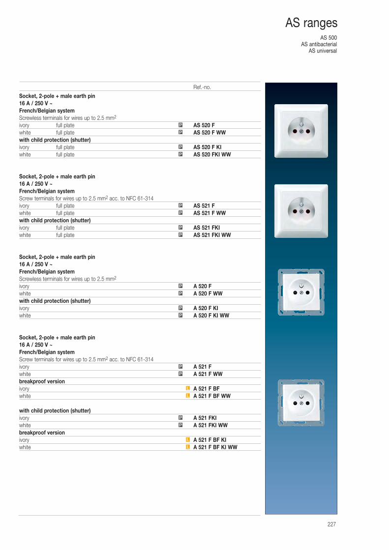
AS 500AS antibacterial
AS universal
227
AS ranges
Socket, 2-pole + male earth pin16 A / 250 V ~French/Belgian systemScrewless terminals for wires up to 2.5 mm2
ivory full plate AS 520 Fwhite full plate AS 520 F WWwith child protection (shutter)ivory full plate AS 520 F KIwhite full plate AS 520 FKI WW
Socket, 2-pole + male earth pin16 A / 250 V ~French/Belgian systemScrew terminals for wires up to 2.5 mm2 acc. to NFC 61-314ivory full plate AS 521 Fwhite full plate AS 521 F WWwith child protection (shutter)ivory full plate AS 521 FKIwhite full plate AS 521 FKI WW
Socket, 2-pole + male earth pin16 A / 250 V ~French/Belgian systemScrewless terminals for wires up to 2.5 mm2
ivory A 520 Fwhite A 520 F WWwith child protection (shutter)ivory A 520 F KIwhite A 520 F KI WW
Socket, 2-pole + male earth pin16 A / 250 V ~French/Belgian systemScrew terminals for wires up to 2.5 mm2 acc. to NFC 61-314ivory A 521 Fwhite A 521 F WWbreakproof versionivory A 521 F BFwhite A 521 F BF WW
with child protection (shutter)ivory A 521 FKIwhite A 521 FKI WWbreakproof versionivory A 521 F BF KIwhite A 521 F BF KI WWL
L
P
P
L
L
P
P
P
P
P
P
P
P
P
P
P
P
P
P
Ref.-no.
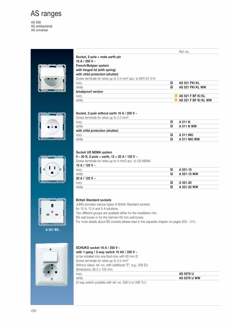
AS 500AS antibacterialAS universal
228
AS ranges
Socket, 2-pole + male earth pin16 A / 250 V ~French/Belgian systemwith hinged lid (with spring)with child protection (shutter)Screw terminals for wires up to 2.5 mm2 acc. to NFC 61-314ivory AS 521 FKI KLwhite AS 521 FKI KL WWbreakproof versionivory AS 521 F BF KI KLwhite AS 521 F BF KI KL WW
Socket, 2-pole without earth 16 A / 250 V ~Screw terminals for wires up to 2.5 mm2
ivory A 511 Nwhite A 511 N WWwith child protection (shutter)ivory A 511 NKIwhite A 511 NKI WW
Socket US NEMA system 5 – 20 R, 2-pole + earth, 15 + 20 A / 125 V ~Screw terminals for wires up to 4 mm2 acc. to US-NEMA15 A / 125 V ~ivory A 521-15white A 521-15 WW20 A / 125 V ~ivory A 521-20white A 521-20 WW
British Standard socketsJUNG provides various types of British Standard sockets for 15 A, 13 A and 5 A solutions. Two different groups are available either for the installation into BS wall boxes or for the German 60 mm wall boxes.For more details about BS sockets please read in the separate chapter on pages 200 – 215.
SCHUKO socket 16 A / 250 V ~ with 1-gang / 2-way switch 10 AX / 250 V ~to be installed into one flush-box with 60 mm ØScrew terminals for wires up to 2.5 mm2
Without claws: ref.-no. with additional "E", e.g.: 506 EUdimensions: 80.5 x 10⁵ mmivory AS 5576 Uwhite AS 5576 U WW(2-way switch possible with ref.-no. 506 U or 506 TU.)
P
P
P
P
P
P
P
P
L
L
P
P
Ref.-no.
.. A 521 BS ..
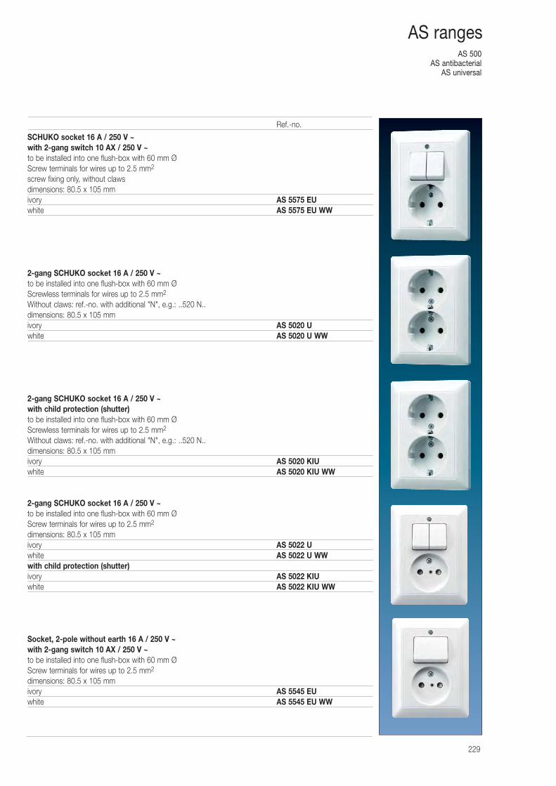
AS 500AS antibacterial
AS universal
229
AS ranges
SCHUKO socket 16 A / 250 V ~ with 2-gang switch 10 AX / 250 V ~to be installed into one flush-box with 60 mm ØScrew terminals for wires up to 2.5 mm2
screw fixing only, without clawsdimensions: 80.5 x 10⁵ mmivory AS 5575 EUwhite AS 5575 EU WW
2-gang SCHUKO socket 16 A / 250 V ~to be installed into one flush-box with 60 mm ØScrewless terminals for wires up to 2.5 mm2
Without claws: ref.-no. with additional "N", e.g.: ..520 N..dimensions: 80.5 x 10⁵ mmivory AS 5020 Uwhite AS 5020 U WW
2-gang SCHUKO socket 16 A / 250 V ~with child protection (shutter)to be installed into one flush-box with 60 mm ØScrewless terminals for wires up to 2.5 mm2
Without claws: ref.-no. with additional "N", e.g.: ..520 N..dimensions: 80.5 x 10⁵ mmivory AS 5020 KIUwhite AS 5020 KIU WW
2-gang SCHUKO socket 16 A / 250 V ~to be installed into one flush-box with 60 mm ØScrew terminals for wires up to 2.5 mm2
dimensions: 80.5 x 10⁵ mmivory AS 5022 Uwhite AS 5022 U WWwith child protection (shutter)ivory AS 5022 KIUwhite AS 5022 KIU WW
Socket, 2-pole without earth 16 A / 250 V ~ with 2-gang switch 10 AX / 250 V ~to be installed into one flush-box with 60 mm ØScrew terminals for wires up to 2.5 mm2
dimensions: 80.5 x 10⁵ mmivory AS 5545 EUwhite AS 5545 EU WW
Ref.-no.
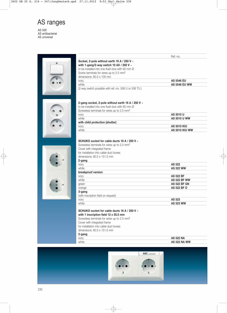
AS 500AS antibacterialAS universal
230
AS ranges
Socket, 2-pole without earth 16 A / 250 V ~ with 1-gang/2-way switch 10 AX / 250 V ~to be installed into one flush-box with 60 mm ØScrew terminals for wires up to 2.5 mm2
dimensions: 80.5 x 10⁵ mmivory AS 5546 EUwhite AS 5546 EU WW(2-way switch possible with ref.-no. 506 U or 506 TU.)
2-gang socket, 2-pole without earth 16 A / 250 V ~to be installed into one flush-box with 60 mm ØScrewless terminals for wires up to 2.5 mm2
ivory AS 5010 Uwhite AS 5010 U WWwith child protection (shutter)ivory AS 5010 KIUwhite AS 5010 KIU WW
SCHUKO socket for cable ducts 16 A / 250 V ~Screwless terminals for wires up to 2.5 mm2
Cover with integrated framefor installation into cable duct boxesdimensions: 80.5 x 151.5 mm2-gangivory AS 522white AS 522 WWbreakproof versionivory AS 522 BFwhite AS 522 BF WWgreen AS 522 BF GNorange AS 522 BF O3-gang(with inscription field on request)ivory AS 523white AS 523 WW
SCHUKO socket for cable ducts 16 A / 250 V ~with 1 inscription field 12 x 55.5 mmScrewless terminals for wires up to 2.5 mm2
Cover with integrated framefor installation into cable duct boxesdimensions: 80.5 x 151.5 mm2-gangivory AS 522 NAwhite AS 522 NA WW
Ref.-no.
3652 GB 25 S. 216 – 247:JungDeutsch.qxd 27.11.2012 9:53 Uhr Seite 230
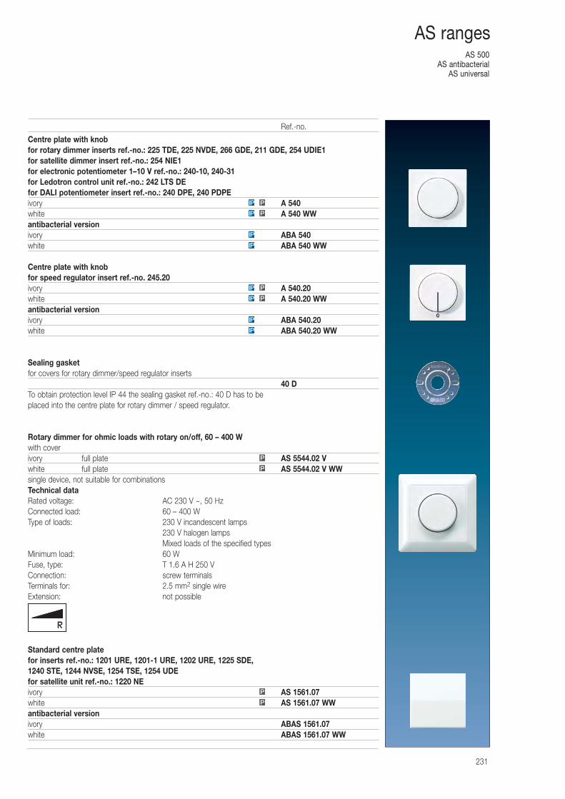
AS 500AS antibacterial
AS universal
231
AS ranges
Centre plate with knobfor rotary dimmer inserts ref.-no.: 225 TDE, 225 NVDE, 266 GDE, 211 GDE, 254 UDIE1for satellite dimmer insert ref.-no.: 254 NIE1for electronic potentiometer 1–10 V ref.-no.: 240-10, 240-31for Ledotron control unit ref.-no.: 242 LTS DEfor DALI potentiometer insert ref.-no.: 240 DPE, 240 PDPEivory A 540white A 540 WWantibacterial versionivory ABA 540white ABA 540 WW
Centre plate with knobfor speed regulator insert ref.-no. 245.20ivory A 540.20white A 540.20 WWantibacterial versionivory ABA 540.20white ABA 540.20 WW
Sealing gasketfor covers for rotary dimmer/speed regulator inserts
40 DTo obtain protection level IP 44 the sealing gasket ref.-no.: 40 D has to be placed into the centre plate for rotary dimmer / speed regulator.
Rotary dimmer for ohmic loads with rotary on/off, 60 – 400 Wwith coverivory full plate AS 5544.02 Vwhite full plate AS 5544.02 V WWsingle device, not suitable for combinationsTechnical dataRated voltage: AC 230 V ~, 50 HzConnected load: 60 – 400 WType of loads: 230 V incandescent lamps
230 V halogen lampsMixed loads of the specified types
Minimum load: 60 WFuse, type: T 1.6 A H 250 VConnection: screw terminalsTerminals for: 2.5 mm2 single wireExtension: not possible
Standard centre platefor inserts ref.-no.: 1201 URE, 1201-1 URE, 1202 URE, 1225 SDE, 1240 STE, 1244 NVSE, 1254 TSE, 1254 UDEfor satellite unit ref.-no.: 1220 NEivory AS 1561.07white AS 1561.07 WWantibacterial versionivory ABAS 1561.07white ABAS 1561.07 WW
P
P
IP
IP
PIP
PIP
IP
IP
PIP
PIP
P
P
Ref.-no.
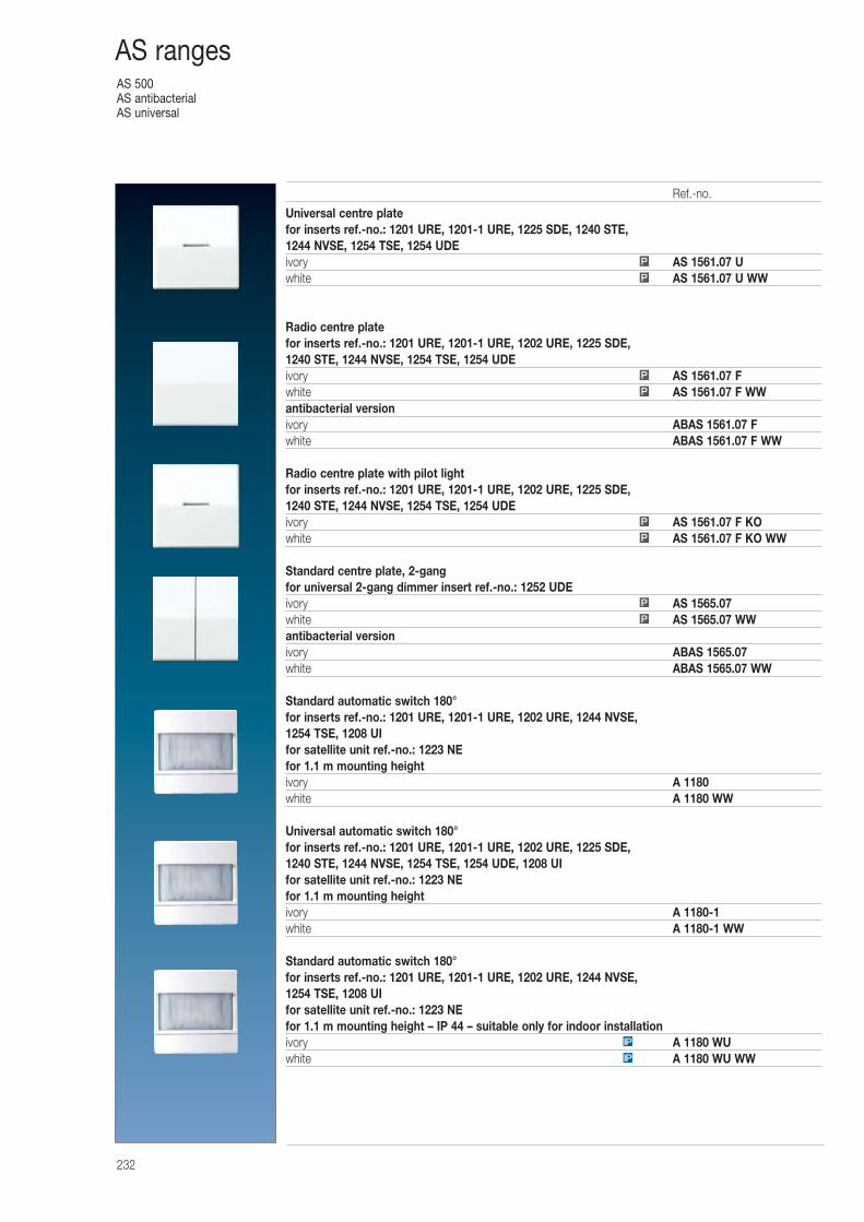
AS 500AS antibacterialAS universal
232
AS ranges
Universal centre platefor inserts ref.-no.: 1201 URE, 1201-1 URE, 1225 SDE, 1240 STE, 1244 NVSE, 1254 TSE, 1254 UDEivory AS 1561.07 Uwhite AS 1561.07 U WW
Radio centre platefor inserts ref.-no.: 1201 URE, 1201-1 URE, 1202 URE, 1225 SDE, 1240 STE, 1244 NVSE, 1254 TSE, 1254 UDEivory AS 1561.07 Fwhite AS 1561.07 F WWantibacterial versionivory ABAS 1561.07 Fwhite ABAS 1561.07 F WW
Radio centre plate with pilot lightfor inserts ref.-no.: 1201 URE, 1201-1 URE, 1202 URE, 1225 SDE, 1240 STE, 1244 NVSE, 1254 TSE, 1254 UDEivory AS 1561.07 F KOwhite AS 1561.07 F KO WW
Standard centre plate, 2-gangfor universal 2-gang dimmer insert ref.-no.: 1252 UDEivory AS 1565.07white AS 1565.07 WWantibacterial versionivory ABAS 1565.07white ABAS 1565.07 WW
Standard automatic switch 180°for inserts ref.-no.: 1201 URE, 1201-1 URE, 1202 URE, 1244 NVSE, 1254 TSE, 1208 UIfor satellite unit ref.-no.: 1223 NEfor 1.1 m mounting heightivory A 1180white A 1180 WW
Universal automatic switch 180° for inserts ref.-no.: 1201 URE, 1201-1 URE, 1202 URE, 1225 SDE, 1240 STE, 1244 NVSE, 1254 TSE, 1254 UDE, 1208 UIfor satellite unit ref.-no.: 1223 NEfor 1.1 m mounting heightivory A 1180-1white A 1180-1 WW
Standard automatic switch 180°for inserts ref.-no.: 1201 URE, 1201-1 URE, 1202 URE, 1244 NVSE, 1254 TSE, 1208 UIfor satellite unit ref.-no.: 1223 NEfor 1.1 m mounting height – IP 44 – suitable only for indoor installationivory A 1180 WUwhite A 1180 WU WW
P
P
P
P
P
P
P
P
IP
IP
Ref.-no.
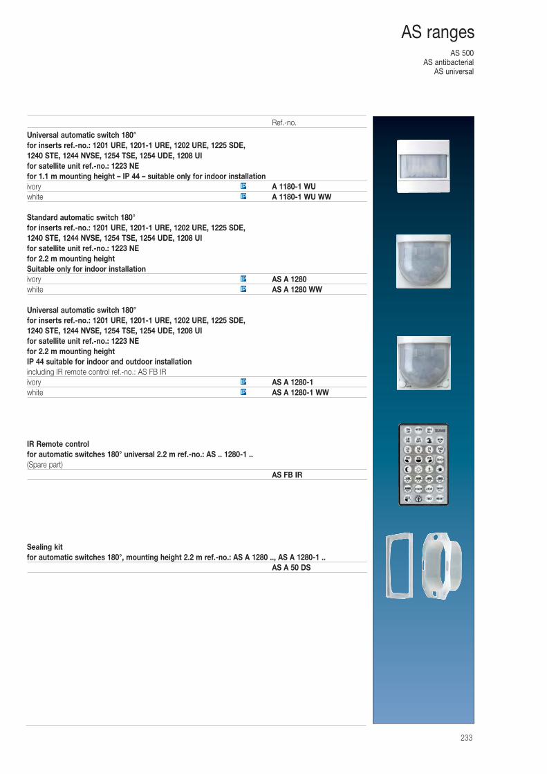
AS 500AS antibacterial
AS universal
233
AS ranges
Universal automatic switch 180° for inserts ref.-no.: 1201 URE, 1201-1 URE, 1202 URE, 1225 SDE, 1240 STE, 1244 NVSE, 1254 TSE, 1254 UDE, 1208 UIfor satellite unit ref.-no.: 1223 NEfor 1.1 m mounting height – IP 44 – suitable only for indoor installationivory A 1180-1 WUwhite A 1180-1 WU WW
Standard automatic switch 180°for inserts ref.-no.: 1201 URE, 1201-1 URE, 1202 URE, 1225 SDE, 1240 STE, 1244 NVSE, 1254 TSE, 1254 UDE, 1208 UIfor satellite unit ref.-no.: 1223 NEfor 2.2 m mounting heightSuitable only for indoor installationivory AS A 1280white AS A 1280 WW
Universal automatic switch 180° for inserts ref.-no.: 1201 URE, 1201-1 URE, 1202 URE, 1225 SDE, 1240 STE, 1244 NVSE, 1254 TSE, 1254 UDE, 1208 UIfor satellite unit ref.-no.: 1223 NEfor 2.2 m mounting heightIP 44 suitable for indoor and outdoor installationincluding IR remote control ref.-no.: AS FB IRivory AS A 1280-1white AS A 1280-1 WW
IR Remote controlfor automatic switches 180° universal 2.2 m ref.-no.: AS .. 1280-1 ..(Spare part)
AS FB IR
Sealing kitfor automatic switches 180°, mounting height 2.2 m ref.-no.: AS A 1280 .., AS A 1280-1 ..
AS A 50 DS
IP
IP
IP
IP
IP
IP
Ref.-no.
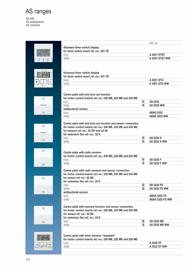
AS 500AS antibacterialAS universal
234
AS ranges
Standard timer switch displayfor timer switch insert ref.-no.: 201 TEivory A 5201 DTSTwhite A 5201 DTST WW
Universal timer switch displayfor timer switch insert ref.-no.: 201 TEivory A 5201 DTUwhite A 5201 DTU WW
Centre plate with anti lock-out functionfor motor control inserts ref.-no.: 230 ME, 232 ME and 224 MEivory AS 5232white AS 5232 WWantibacterial versionivory ABAS 5232white ABAS 5232 WW
Centre plate with anti lock-out function and sensor connectionfor motor control inserts ref.-no.: 230 ME, 232 ME and 224 MEfor sensors ref.-no.: 32 SD and LA 90for extension flex ref.-no.: 32 Kivory AS 5232 Swhite AS 5232 S WW
Centre plate with radio receiverfor motor control inserts ref.-no.: 230 ME, 232 ME and 224 MEivory AS 5232 Fwhite AS 5232 F WW
Centre plate with radio receiver and sensor connectionfor motor control inserts ref.-no.: 230 ME, 232 ME and 224 MEfor sensor ref.-no.: 32 SDfor extension flex ref.-no.: 32 Kivory AS 5232 FSwhite AS 5232 FS WWantibacterial versionivory ABAS 5232 FSwhite ABAS 5232 FS WW
Centre plate with memory function and sensor connectionfor motor control inserts ref.-no.: 230 ME, 232 ME and 224 MEfor sensor ref.-no.: 32 SDfor extension flex ref.-no.: 32 Kivory AS 5232 MSwhite AS 5232 MS WW
Centre plate with timer function "standard"for motor control inserts ref.-no.: 230 ME, 232 ME and 224 MEivory A 5232 STwhite A 5232 ST WW
P
P
P
P
P
P
P
P
P
P
Ref.-no.
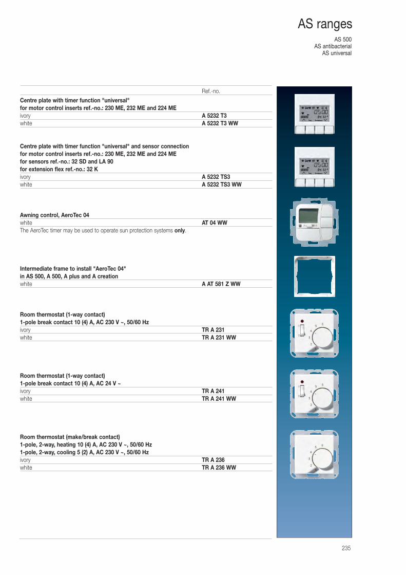
AS 500AS antibacterial
AS universal
235
AS ranges
Centre plate with timer function "universal"for motor control inserts ref.-no.: 230 ME, 232 ME and 224 MEivory A 5232 T3white A 5232 T3 WW
Centre plate with timer function "universal" and sensor connectionfor motor control inserts ref.-no.: 230 ME, 232 ME and 224 MEfor sensors ref.-no.: 32 SD and LA 90for extension flex ref.-no.: 32 Kivory A 5232 TS3white A 5232 TS3 WW
Awning control, AeroTec 04white AT 04 WWThe AeroTec timer may be used to operate sun protection systems only.
Intermediate frame to install "AeroTec 04"in AS 500, A 500, A plus and A creationwhite A AT 581 Z WW
Room thermostat (1-way contact)1-pole break contact 10 (4) A, AC 230 V ~, 50/60 Hzivory TR A 231white TR A 231 WW
Room thermostat (1-way contact)1-pole break contact 10 (4) A, AC 24 V ~ivory TR A 241white TR A 241 WW
Room thermostat (make/break contact)1-pole, 2-way, heating 10 (4) A, AC 230 V ~, 50/60 Hz1-pole, 2-way, cooling 5 (2) A, AC 230 V ~, 50/60 Hzivory TR A 236white TR A 236 WW
Ref.-no.
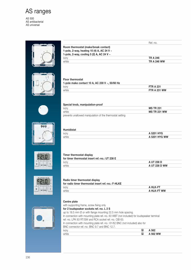
AS 500AS antibacterialAS universal
236
AS ranges
Room thermostat (make/break contact)1-pole, 2-way, heating 10 (4) A, AC 24 V ~1-pole, 2-way, cooling 5 (2) A, AC 24 V ~ivory TR A 246white TR A 246 WW
Floor thermostat1-pole make contact 10 A, AC 230 V ~, 50/60 Hzivory FTR A 231white FTR A 231 WW
Special knob, manipulation-proofivory MS TR 231white MS TR 231 WWprevents unallowed manipulation of the thermostat setting
Humidistativory A 5201 HYGwhite A 5201 HYG WW
Timer thermostat displayfor timer thermostat insert ref.-no.: UT 238 Eivory A UT 238 Dwhite A UT 238 D WW
Radio timer thermostat displayfor radio timer thermostat insert ref.-no.: F-HLKEivory A HLK-FTwhite A HLK-FT WW
Centre platewith supporting frame, screw fixing onlyfor 2 loudspeaker sockets ref.-no. L 2 Sup to 18.5 mm Ø or with flange mounting 22.5 mm hole spacing.In connection with mounting plate ref.-no. 63 WBT (not included) for loudspeaker terminalref.-no. LPK 63 RT/SW and RCA socket ref.-no. CIB 63.In connection with mounting plate ref.-no.: 61/62 BNC (not included) also for BNC connector ref.-no. BNC 9.7 and BNC 12.7.ivory A 562white A 562 WWP
P
Ref.-no.
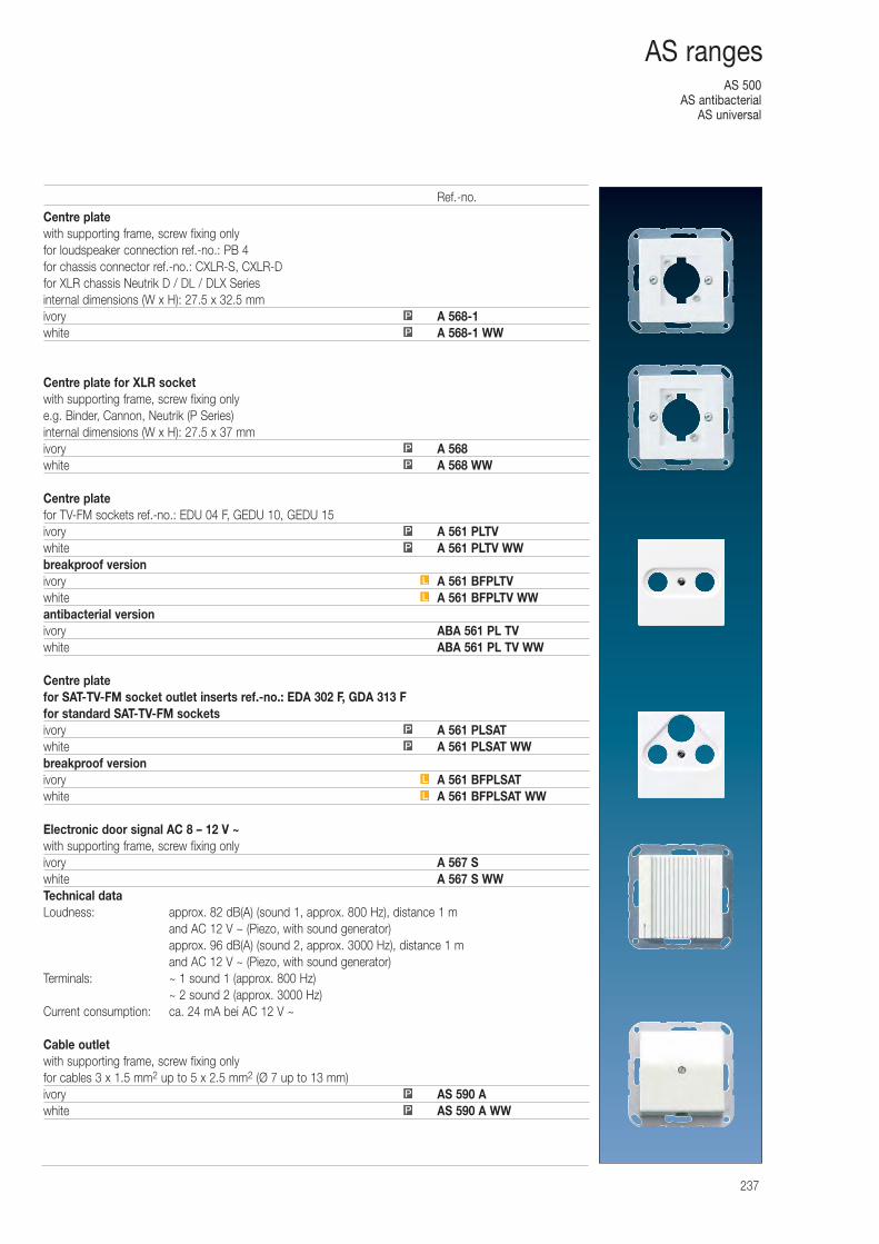
AS 500AS antibacterial
AS universal
237
AS ranges
Centre platewith supporting frame, screw fixing onlyfor loudspeaker connection ref.-no.: PB 4for chassis connector ref.-no.: CXLR-S, CXLR-Dfor XLR chassis Neutrik D / DL / DLX Seriesinternal dimensions (W x H): 27.5 x 32.5 mmivory A 568-1white A 568-1 WW
Centre plate for XLR socketwith supporting frame, screw fixing onlye.g. Binder, Cannon, Neutrik (P Series)internal dimensions (W x H): 27.5 x 37 mmivory A 568white A 568 WW
Centre platefor TV-FM sockets ref.-no.: EDU 04 F, GEDU 10, GEDU 15ivory A 561 PLTVwhite A 561 PLTV WWbreakproof versionivory A 561 BFPLTVwhite A 561 BFPLTV WWantibacterial versionivory ABA 561 PL TVwhite ABA 561 PL TV WW
Centre platefor SAT-TV-FM socket outlet inserts ref.-no.: EDA 302 F, GDA 313 Ffor standard SAT-TV-FM socketsivory A 561 PLSATwhite A 561 PLSAT WWbreakproof versionivory A 561 BFPLSATwhite A 561 BFPLSAT WW
Electronic door signal AC 8 – 12 V ~with supporting frame, screw fixing onlyivory A 567 Swhite A 567 S WWTechnical dataLoudness: approx. 82 dB(A) (sound 1, approx. 800 Hz), distance 1 m
and AC 12 V ~ (Piezo, with sound generator)approx. 96 dB(A) (sound 2, approx. 3000 Hz), distance 1 m and AC 12 V ~ (Piezo, with sound generator)
Terminals: ~ 1 sound 1 (approx. 800 Hz)~ 2 sound 2 (approx. 3000 Hz)
Current consumption: ca. 24 mA bei AC 12 V ~
Cable outletwith supporting frame, screw fixing onlyfor cables 3 x 1.5 mm2 up to 5 x 2.5 mm2 (Ø 7 up to 13 mm)ivory AS 590 Awhite AS 590 A WWP
P
L
L
P
P
L
L
P
P
P
P
P
P
Ref.-no.
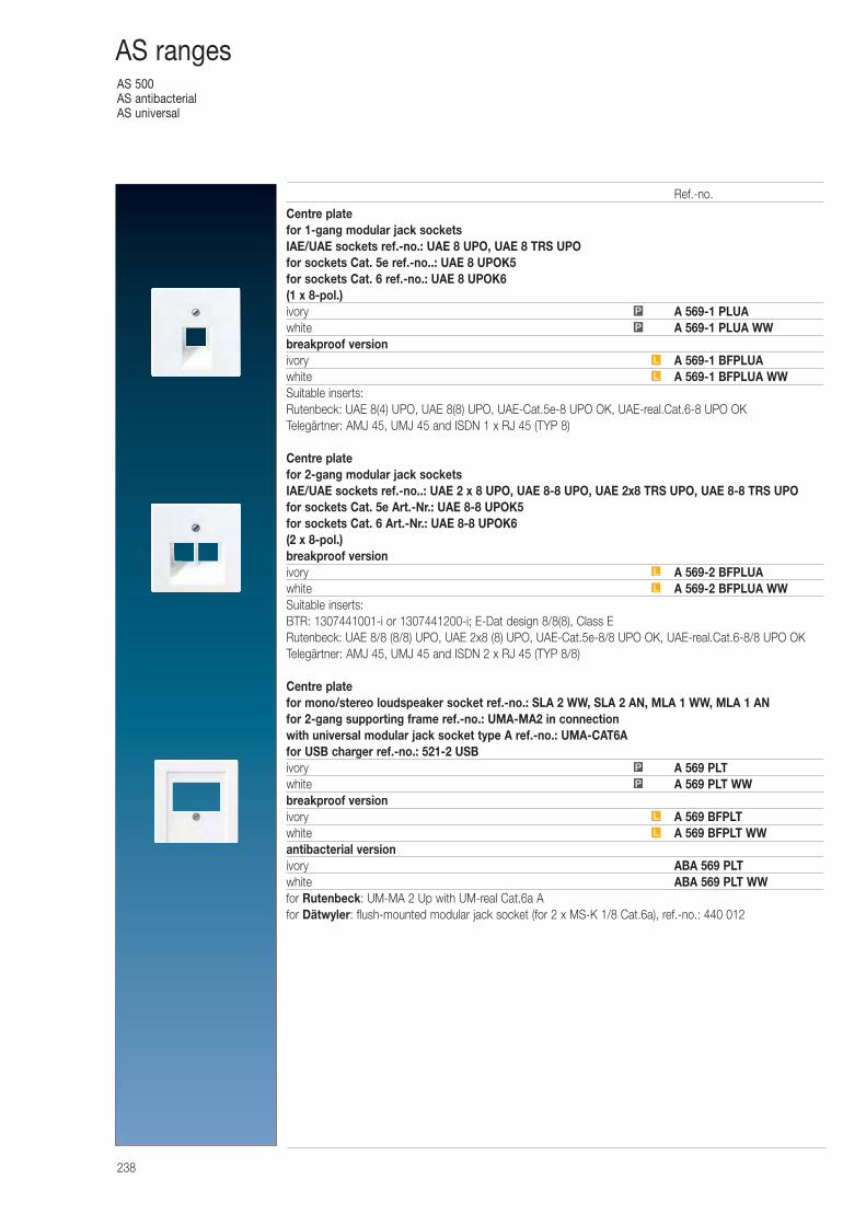
AS 500AS antibacterialAS universal
238
AS ranges
Centre platefor 1-gang modular jack socketsIAE/UAE sockets ref.-no.: UAE 8 UPO, UAE 8 TRS UPOfor sockets Cat. 5e ref.-no..: UAE 8 UPOK5for sockets Cat. 6 ref.-no.: UAE 8 UPOK6(1 x 8-pol.)ivory A 569-1 PLUAwhite A 569-1 PLUA WWbreakproof versionivory A 569-1 BFPLUAwhite A 569-1 BFPLUA WWSuitable inserts:Rutenbeck: UAE 8(4) UPO, UAE 8(8) UPO, UAE-Cat.5e-8 UPO OK, UAE-real.Cat.6-8 UPO OKTelegärtner: AMJ 45, UMJ 45 and ISDN 1 x RJ 45 (TYP 8)
Centre platefor 2-gang modular jack socketsIAE/UAE sockets ref.-no..: UAE 2 x 8 UPO, UAE 8-8 UPO, UAE 2x8 TRS UPO, UAE 8-8 TRS UPOfor sockets Cat. 5e Art.-Nr.: UAE 8-8 UPOK5for sockets Cat. 6 Art.-Nr.: UAE 8-8 UPOK6(2 x 8-pol.)breakproof versionivory A 569-2 BFPLUAwhite A 569-2 BFPLUA WWSuitable inserts:BTR: 1307441001-i or 1307441200-i; E-Dat design 8/8(8), Class ERutenbeck: UAE 8/8 (8/8) UPO, UAE 2x8 (8) UPO, UAE-Cat.5e-8/8 UPO OK, UAE-real.Cat.6-8/8 UPO OKTelegärtner: AMJ 45, UMJ 45 and ISDN 2 x RJ 45 (TYP 8/8)
Centre platefor mono/stereo loudspeaker socket ref.-no.: SLA 2 WW, SLA 2 AN, MLA 1 WW, MLA 1 ANfor 2-gang supporting frame ref.-no.: UMA-MA2 in connection with universal modular jack socket type A ref.-no.: UMA-CAT6Afor USB charger ref.-no.: 521-2 USBivory A 569 PLTwhite A 569 PLT WWbreakproof versionivory A 569 BFPLTwhite A 569 BFPLT WWantibacterial versionivory ABA 569 PLTwhite ABA 569 PLT WWfor Rutenbeck: UM-MA 2 Up with UM-real Cat.6a Afor Dätwyler: flush-mounted modular jack socket (for 2 x MS-K 1/8 Cat.6a), ref.-no.: 440 012
L
L
P
P
L
L
L
L
P
P
Ref.-no.
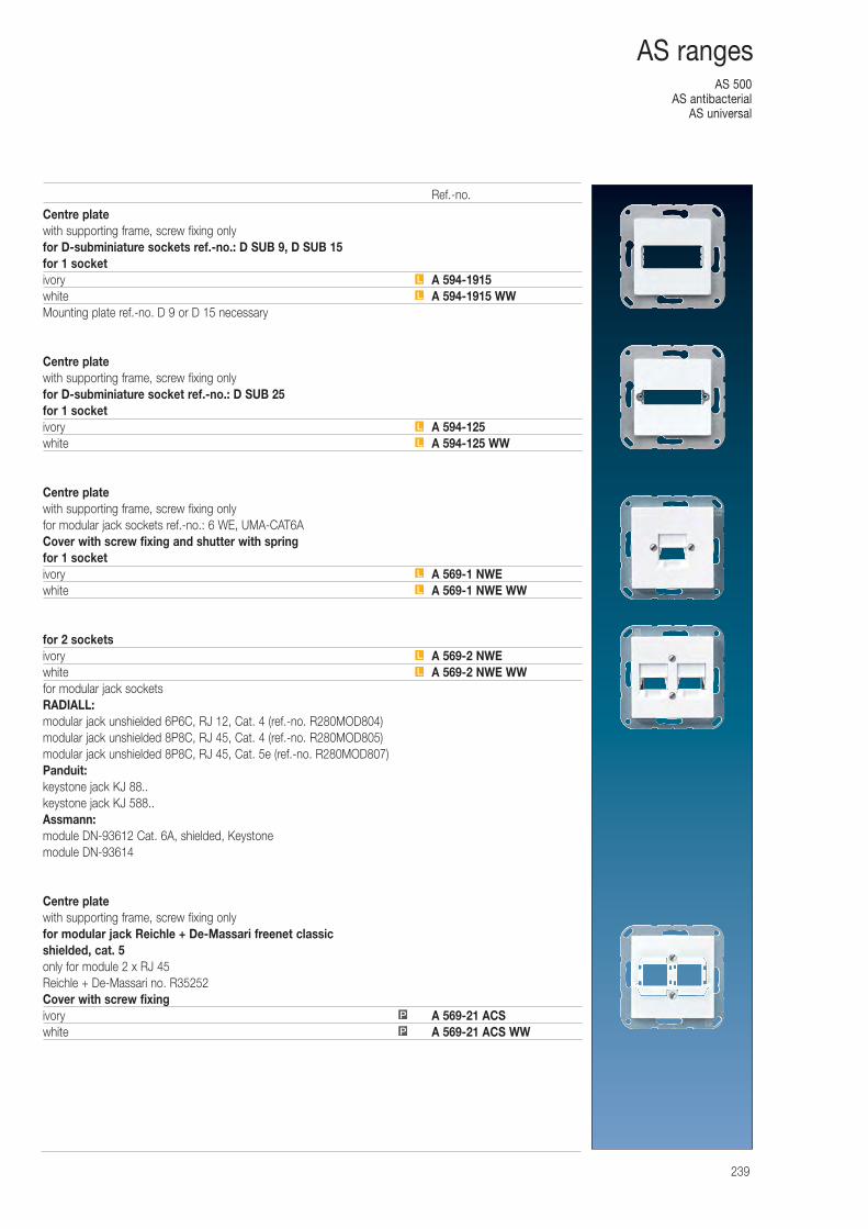
AS 500AS antibacterial
AS universal
239
AS ranges
Centre platewith supporting frame, screw fixing onlyfor D-subminiature sockets ref.-no.: D SUB 9, D SUB 15for 1 socketivory A 594-1915white A 594-1915 WWMounting plate ref.-no. D 9 or D 15 necessary
Centre platewith supporting frame, screw fixing onlyfor D-subminiature socket ref.-no.: D SUB 25for 1 socketivory A 594-125white A 594-125 WW
Centre platewith supporting frame, screw fixing onlyfor modular jack sockets ref.-no.: 6 WE, UMA-CAT6ACover with screw fixing and shutter with springfor 1 socketivory A 569-1 NWEwhite A 569-1 NWE WW
for 2 socketsivory A 569-2 NWEwhite A 569-2 NWE WWfor modular jack socketsRADIALL:modular jack unshielded 6P6C, RJ 12, Cat. 4 (ref.-no. R280MOD804)modular jack unshielded 8P8C, RJ 45, Cat. 4 (ref.-no. R280MOD805)modular jack unshielded 8P8C, RJ 45, Cat. 5e (ref.-no. R280MOD807)Panduit:keystone jack KJ 88..keystone jack KJ 588..Assmann:module DN-93612 Cat. 6A, shielded, Keystonemodule DN-93614
Centre platewith supporting frame, screw fixing onlyfor modular jack Reichle + De-Massari freenet classicshielded, cat. 5only for module 2 x RJ 45Reichle + De-Massari no. R35252Cover with screw fixingivory A 569-21 ACSwhite A 569-21 ACS WW
L
L
L
L
P
P
L
L
L
L
Ref.-no.
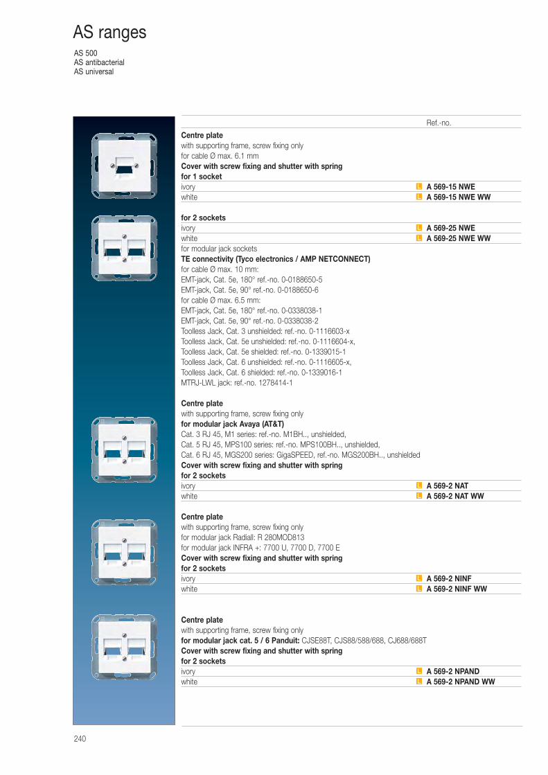
AS 500AS antibacterialAS universal
240
AS ranges
Centre platewith supporting frame, screw fixing onlyfor cable Ø max. 6.1 mmCover with screw fixing and shutter with springfor 1 socketivory A 569-15 NWEwhite A 569-15 NWE WW
for 2 socketsivory A 569-25 NWEwhite A 569-25 NWE WWfor modular jack socketsTE connectivity (Tyco electronics / AMP NETCONNECT)for cable Ø max. 10 mm:EMT-jack, Cat. 5e, 180° ref.-no. 0-0188650-5EMT-jack, Cat. 5e, 90° ref.-no. 0-0188650-6for cable Ø max. 6.5 mm:EMT-jack, Cat. 5e, 180° ref.-no. 0-0338038-1EMT-jack, Cat. 5e, 90° ref.-no. 0-0338038-2Toolless Jack, Cat. 3 unshielded: ref.-no. 0-1116603-xToolless Jack, Cat. 5e unshielded: ref.-no. 0-1116604-x, Toolless Jack, Cat. 5e shielded: ref.-no. 0-1339015-1Toolless Jack, Cat. 6 unshielded: ref.-no. 0-1116605-x, Toolless Jack, Cat. 6 shielded: ref.-no. 0-1339016-1MTRJ-LWL jack: ref.-no. 1278414-1
Centre platewith supporting frame, screw fixing onlyfor modular jack Avaya (AT&T)Cat. 3 RJ 45, M1 series: ref.-no. M1BH.., unshielded,Cat. 5 RJ 45, MPS100 series: ref.-no. MPS100BH.., unshielded,Cat. 6 RJ 45, MGS200 series: GigaSPEED, ref.-no. MGS200BH.., unshieldedCover with screw fixing and shutter with springfor 2 socketsivory A 569-2 NATwhite A 569-2 NAT WW
Centre platewith supporting frame, screw fixing onlyfor modular jack Radiall: R 280MOD813for modular jack INFRA +: 7700 U, 7700 D, 7700 ECover with screw fixing and shutter with springfor 2 socketsivory A 569-2 NINFwhite A 569-2 NINF WW
Centre platewith supporting frame, screw fixing onlyfor modular jack cat. 5 / 6 Panduit: CJSE88T, CJS88/588/688, CJ688/688TCover with screw fixing and shutter with springfor 2 socketsivory A 569-2 NPANDwhite A 569-2 NPAND WW
L
L
L
L
L
L
L
L
L
L
Ref.-no.
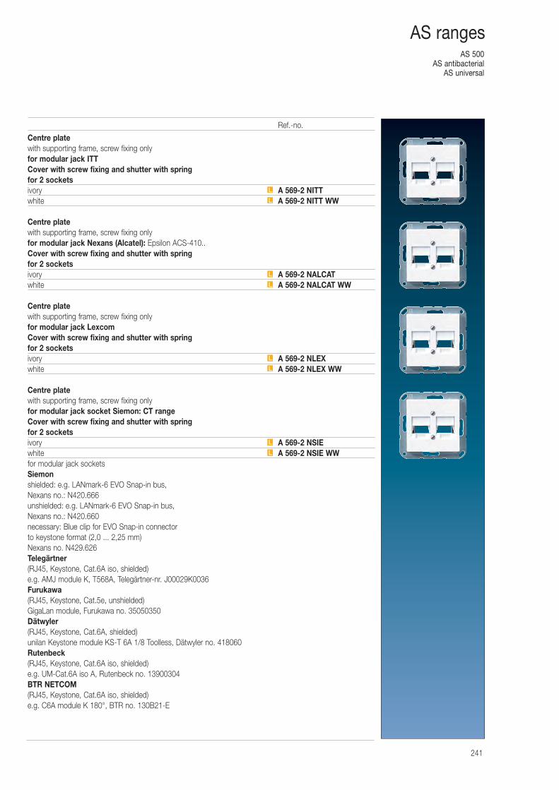
AS 500AS antibacterial
AS universal
241
AS ranges
Centre platewith supporting frame, screw fixing onlyfor modular jack ITTCover with screw fixing and shutter with springfor 2 socketsivory A 569-2 NITTwhite A 569-2 NITT WW
Centre platewith supporting frame, screw fixing onlyfor modular jack Nexans (Alcatel): Epsilon ACS-410..Cover with screw fixing and shutter with springfor 2 socketsivory A 569-2 NALCATwhite A 569-2 NALCAT WW
Centre platewith supporting frame, screw fixing onlyfor modular jack LexcomCover with screw fixing and shutter with springfor 2 socketsivory A 569-2 NLEXwhite A 569-2 NLEX WW
Centre platewith supporting frame, screw fixing onlyfor modular jack socket Siemon: CT rangeCover with screw fixing and shutter with springfor 2 socketsivory A 569-2 NSIEwhite A 569-2 NSIE WWfor modular jack socketsSiemonshielded: e.g. LANmark-6 EVO Snap-in bus, Nexans no.: N420.666unshielded: e.g. LANmark-6 EVO Snap-in bus, Nexans no.: N420.660necessary: Blue clip for EVO Snap-in connector to keystone format (2,0 ... 2,25 mm)Nexans no. N429.626Telegärtner(RJ45, Keystone, Cat.6A iso, shielded)e.g. AMJ module K, T568A, Telegärtner-nr. J00029K0036Furukawa(RJ45, Keystone, Cat.5e, unshielded)GigaLan module, Furukawa no. 35050350Dätwyler(RJ45, Keystone, Cat.6A, shielded)unilan Keystone module KS-T 6A 1/8 Toolless, Dätwyler no. 418060Rutenbeck(RJ45, Keystone, Cat.6A iso, shielded)e.g. UM-Cat.6A iso A, Rutenbeck no. 13900304BTR NETCOM(RJ45, Keystone, Cat.6A iso, shielded)e.g. C6A module K 180°, BTR no. 130B21-E
L
L
L
L
L
L
L
L
Ref.-no.
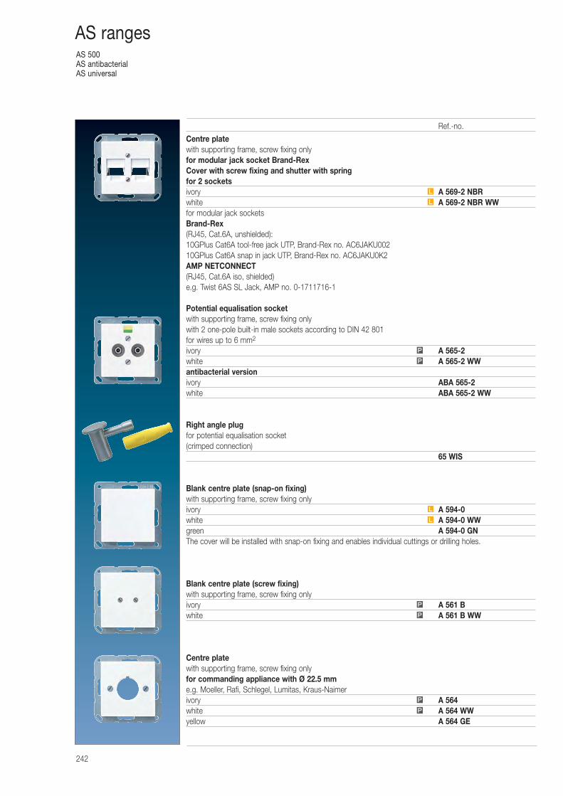
AS 500AS antibacterialAS universal
242
AS ranges
Centre platewith supporting frame, screw fixing onlyfor modular jack socket Brand-RexCover with screw fixing and shutter with springfor 2 socketsivory A 569-2 NBRwhite A 569-2 NBR WWfor modular jack socketsBrand-Rex(RJ45, Cat.6A, unshielded):10GPlus Cat6A tool-free jack UTP, Brand-Rex no. AC6JAKU00210GPlus Cat6A snap in jack UTP, Brand-Rex no. AC6JAKU0K2AMP NETCONNECT(RJ45, Cat.6A iso, shielded)e.g. Twist 6AS SL Jack, AMP no. 0-1711716-1
Potential equalisation socketwith supporting frame, screw fixing onlywith 2 one-pole built-in male sockets according to DIN 42 801for wires up to 6 mm2
ivory A 565-2white A 565-2 WWantibacterial versionivory ABA 565-2white ABA 565-2 WW
Right angle plugfor potential equalisation socket(crimped connection)
65 WIS
Blank centre plate (snap-on fixing)with supporting frame, screw fixing onlyivory A 594-0white A 594-0 WWgreen A 594-0 GNThe cover will be installed with snap-on fixing and enables individual cuttings or drilling holes.
Blank centre plate (screw fixing)with supporting frame, screw fixing onlyivory A 561 Bwhite A 561 B WW
Centre platewith supporting frame, screw fixing onlyfor commanding appliance with Ø 22.5 mme.g. Moeller, Rafi, Schlegel, Lumitas, Kraus-Naimerivory A 564white A 564 WWyellow A 564 GE
P
P
L
L
P
P
P
P
L
L
Ref.-no.
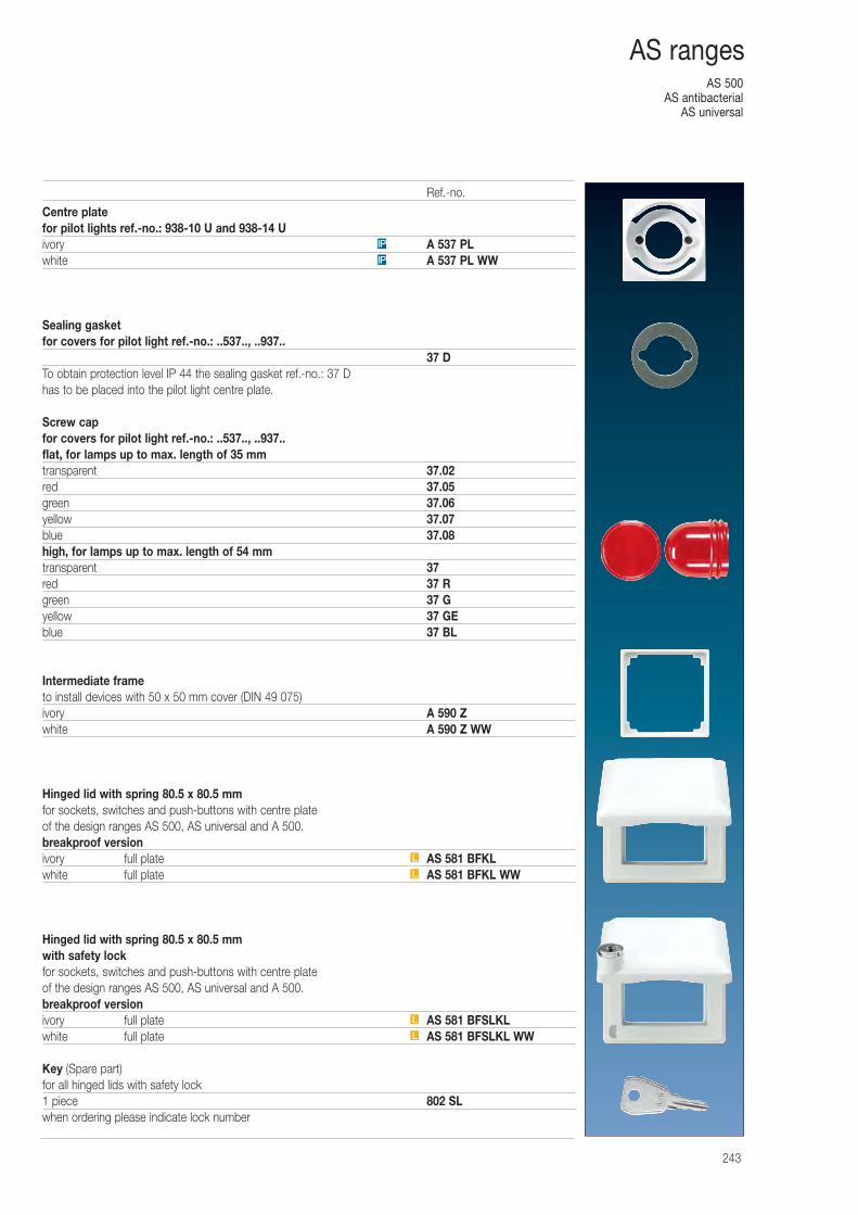
AS 500AS antibacterial
AS universal
243
AS ranges
Centre platefor pilot lights ref.-no.: 938-10 U and 938-14 Uivory A 537 PLwhite A 537 PL WW
Sealing gasketfor covers for pilot light ref.-no.: ..537.., ..937..
37 DTo obtain protection level IP 44 the sealing gasket ref.-no.: 37 D has to be placed into the pilot light centre plate.
Screw capfor covers for pilot light ref.-no.: ..537.., ..937..flat, for lamps up to max. length of 35 mmtransparent 37.02red 37.05green 37.06yellow 37.07blue 37.08high, for lamps up to max. length of 54 mmtransparent 37red 37 Rgreen 37 Gyellow 37 GEblue 37 BL
Intermediate frameto install devices with 50 x 50 mm cover (DIN 49 075)ivory A 590 Zwhite A 590 Z WW
Hinged lid with spring 80.5 x 80.5 mmfor sockets, switches and push-buttons with centre plate of the design ranges AS 500, AS universal and A 500.breakproof versionivory full plate AS 581 BFKLwhite full plate AS 581 BFKL WW
Hinged lid with spring 80.5 x 80.5 mmwith safety lockfor sockets, switches and push-buttons with centre plate of the design ranges AS 500, AS universal and A 500.breakproof versionivory full plate AS 581 BFSLKLwhite full plate AS 581 BFSLKL WW
Key (Spare part)for all hinged lids with safety lock1 piece 802 SLwhen ordering please indicate lock number
IP
IP
L
L
L
L
Ref.-no.
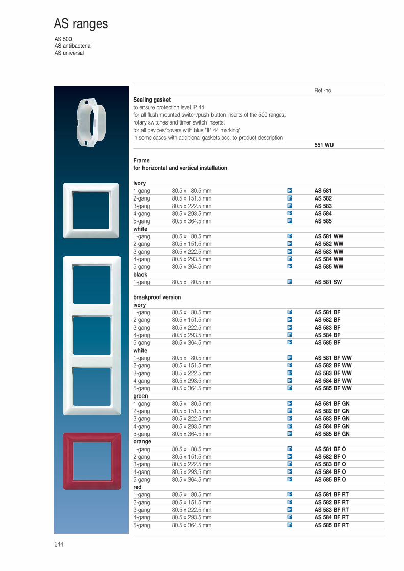
AS 500AS antibacterialAS universal
244
AS ranges
Sealing gasketto ensure protection level IP 44,for all flush-mounted switch/push-button inserts of the 500 ranges,rotary switches and timer switch inserts,for all devices/covers with blue "IP 44 marking"in some cases with additional gaskets acc. to product description
551 WU
Framefor horizontal and vertical installation
ivory1-gang 80.5 x 080.5 mm AS 5812-gang 80.5 x 151.5 mm AS 5823-gang 80.5 x 222.5 mm AS 5834-gang 80.5 x 293.5 mm AS 5845-gang 80.5 x 364.5 mm AS 585white1-gang 80.5 x 080.5 mm AS 581 WW2-gang 80.5 x 151.5 mm AS 582 WW3-gang 80.5 x 222.5 mm AS 583 WW4-gang 80.5 x 293.5 mm AS 584 WW5-gang 80.5 x 364.5 mm AS 585 WWblack1-gang 80.5 x 080.5 mm AS 581 SW
breakproof versionivory1-gang 80.5 x 080.5 mm AS 581 BF2-gang 80.5 x 151.5 mm AS 582 BF3-gang 80.5 x 222.5 mm AS 583 BF4-gang 80.5 x 293.5 mm AS 584 BF5-gang 80.5 x 364.5 mm AS 585 BFwhite1-gang 80.5 x 080.5 mm AS 581 BF WW2-gang 80.5 x 151.5 mm AS 582 BF WW3-gang 80.5 x 222.5 mm AS 583 BF WW4-gang 80.5 x 293.5 mm AS 584 BF WW5-gang 80.5 x 364.5 mm AS 585 BF WWgreen1-gang 80.5 x 080.5 mm AS 581 BF GN2-gang 80.5 x 151.5 mm AS 582 BF GN3-gang 80.5 x 222.5 mm AS 583 BF GN4-gang 80.5 x 293.5 mm AS 584 BF GN5-gang 80.5 x 364.5 mm AS 585 BF GNorange1-gang 80.5 x 080.5 mm AS 581 BF O2-gang 80.5 x 151.5 mm AS 582 BF O3-gang 80.5 x 222.5 mm AS 583 BF O4-gang 80.5 x 293.5 mm AS 584 BF O5-gang 80.5 x 364.5 mm AS 585 BF Ored1-gang 80.5 x 080.5 mm AS 581 BF RT2-gang 80.5 x 151.5 mm AS 582 BF RT3-gang 80.5 x 222.5 mm AS 583 BF RT4-gang 80.5 x 293.5 mm AS 584 BF RT5-gang 80.5 x 364.5 mm AS 585 BF RT
IP
IP
IP
IP
IP
IP
IP
IP
IP
IP
IP
IP
IP
IP
IP
IP
IP
IP
IP
IP
IP
IP
IP
IP
IP
IP
IP
IP
IP
IP
IP
IP
IP
IP
IP
IP
Ref.-no.
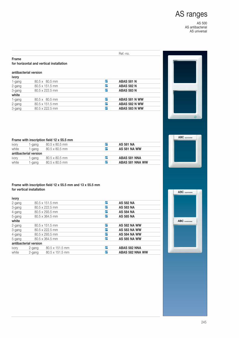
AS 500AS antibacterial
AS universal
245
AS ranges
Framefor horizontal and vertical installation
antibacterial versionivory1-gang 80.5 x 080.5 mm ABAS 581 N2-gang 80.5 x 151.5 mm ABAS 582 N3-gang 80.5 x 222.5 mm ABAS 583 Nwhite1-gang 80.5 x 080.5 mm ABAS 581 N WW2-gang 80.5 x 151.5 mm ABAS 582 N WW3-gang 80.5 x 222.5 mm ABAS 583 N WW
Frame with inscription field 12 x 55.5 mmivory 1-gang 80.5 x 80.5 mm AS 581 NAwhite 1-gang 80.5 x 80.5 mm AS 581 NA WWantibacterial versionivory 1-gang 80.5 x 80.5 mm ABAS 581 NNAwhite 1-gang 80.5 x 80.5 mm ABAS 581 NNA WW
Frame with inscription field 12 x 55.5 mm and 13 x 55.5 mm for vertical installation
ivory2-gang 80.5 x 151.5 mm AS 582 NA3-gang 80.5 x 222.5 mm AS 583 NA4-gang 80.5 x 293.5 mm AS 584 NA5-gang 80.5 x 364.5 mm AS 585 NAwhite2-gang 80.5 x 151.5 mm AS 582 NA WW3-gang 80.5 x 222.5 mm AS 583 NA WW4-gang 80.5 x 293.5 mm AS 584 NA WW5-gang 80.5 x 364.5 mm AS 585 NA WWantibacterial versionivory 2-gang 80.5 x 151.5 mm ABAS 582 NNAwhite 2-gang 80.5 x 151.5 mm ABAS 582 NNA WWIP
IP
IP
IP
IP
IP
IP
IP
IP
IP
IP
IP
IP
IP
IP
IP
IP
IP
IP
IP
Ref.-no.
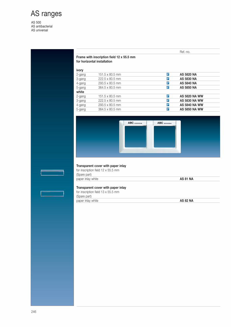
AS 500AS antibacterialAS universal
246
AS ranges
Frame with inscription field 12 x 55.5 mm for horizontal installation
ivory2-gang 151.5 x 80.5 mm AS 5820 NA3-gang 222.5 x 80.5 mm AS 5830 NA4-gang 293.5 x 80.5 mm AS 5840 NA5-gang 364.5 x 80.5 mm AS 5850 NAwhite2-gang 151.5 x 80.5 mm AS 5820 NA WW3-gang 222.5 x 80.5 mm AS 5830 NA WW4-gang 293.5 x 80.5 mm AS 5840 NA WW5-gang 364.5 x 80.5 mm AS 5850 NA WW
Transparent cover with paper inlayfor inscription field 12 x 55.5 mm(Spare part)paper inlay white AS 81 NA
Transparent cover with paper inlayfor inscription field 13 x 55.5 mm(Spare part)paper inlay white AS 82 NA
IP
IP
IP
IP
IP
IP
IP
IP
Ref.-no.
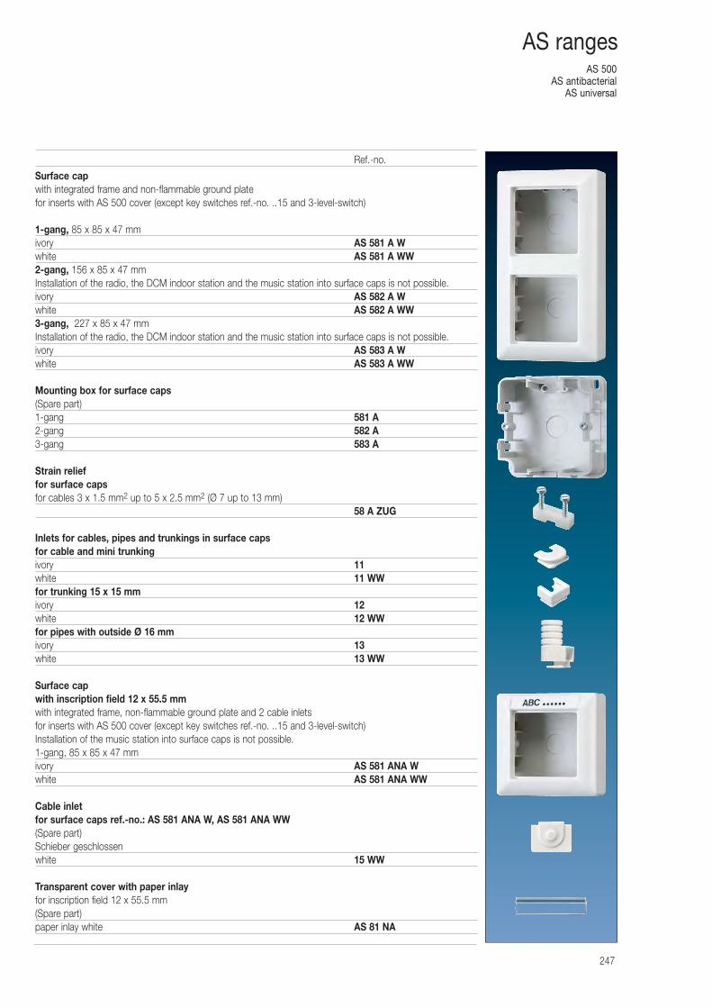
AS 500AS antibacterial
AS universal
247
AS ranges
Surface capwith integrated frame and non-flammable ground platefor inserts with AS 500 cover (except key switches ref.-no. ..15 and 3-level-switch)
1-gang, 85 x 85 x 47 mmivory AS 581 A Wwhite AS 581 A WW2-gang, 156 x 85 x 47 mmInstallation of the radio, the DCM indoor station and the music station into surface caps is not possible.ivory AS 582 A Wwhite AS 582 A WW3-gang, 227 x 85 x 47 mmInstallation of the radio, the DCM indoor station and the music station into surface caps is not possible.ivory AS 583 A Wwhite AS 583 A WW
Mounting box for surface caps(Spare part)1-gang 581 A2-gang 582 A3-gang 583 A
Strain relieffor surface capsfor cables 3 x 1.5 mm2 up to 5 x 2.5 mm2 (Ø 7 up to 13 mm)
58 A ZUG
Inlets for cables, pipes and trunkings in surface capsfor cable and mini trunkingivory 11white 11 WWfor trunking 15 x 15 mmivory 12white 12 WWfor pipes with outside Ø 16 mmivory 13white 13 WW
Surface capwith inscription field 12 x 55.5 mmwith integrated frame, non-flammable ground plate and 2 cable inletsfor inserts with AS 500 cover (except key switches ref.-no. ..15 and 3-level-switch)Installation of the music station into surface caps is not possible.1-gang, 85 x 85 x 47 mmivory AS 581 ANA Wwhite AS 581 ANA WW
Cable inletfor surface caps ref.-no.: AS 581 ANA W, AS 581 ANA WW(Spare part)Schieber geschlossenwhite 15 WW
Transparent cover with paper inlayfor inscription field 12 x 55.5 mm(Spare part)paper inlay white AS 81 NA
Ref.-no.
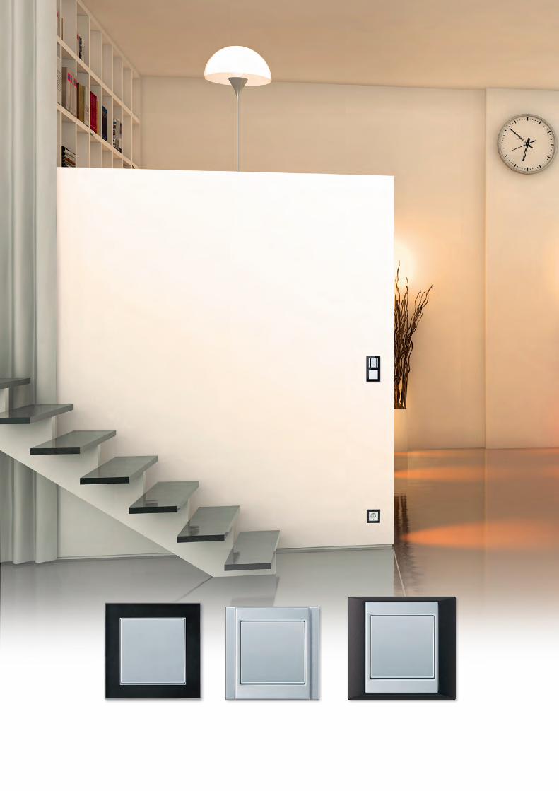
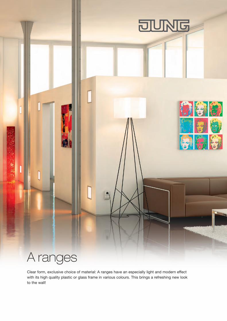
A ranges Clear form, exclusive choice of material: A ranges have an especially light and modern effect with its high quality plastic or glass frame in various colours. This brings a refreshing new look to the wall!
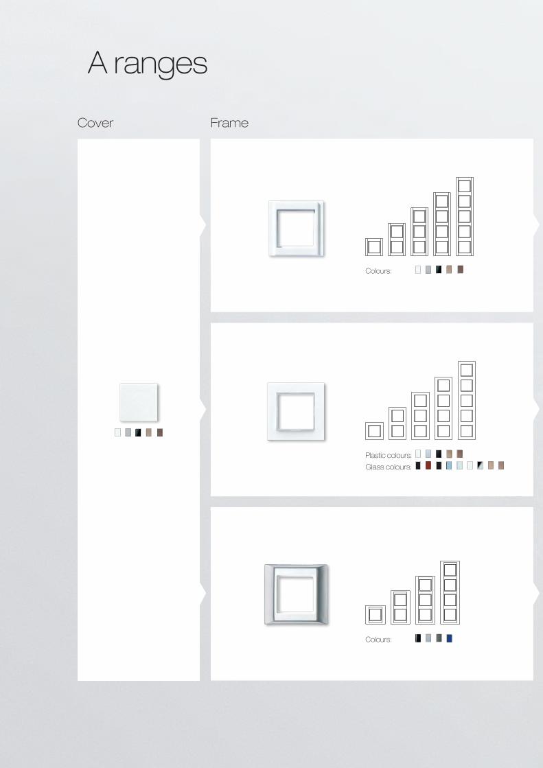
Plastic colours:
Glass colours:
A ranges
Colours:
Colours:
Cover Frame
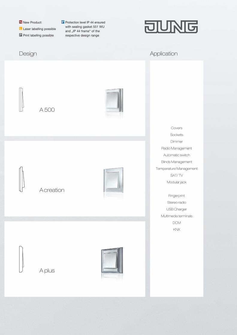
Covers
Sockets
Dimmer
Radio Management
Automatic switch
Blinds Management
Temperature Management
SAT/ TV
Modular jack
Fingerprint
Stereo radio
USB Charger
Multimedia terminals
DCM
KNX
A creation
A plus
A 500
Protection level IP 44 ensured with sealing gasket 551 WU and „IP 44 frame“ of the respective design range
IPNew ProductN
L Laser labelling possible
P Print labelling possible
Design Application
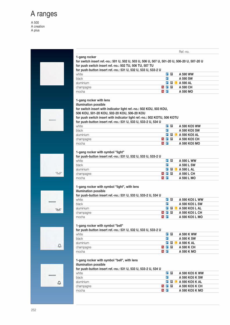
A 500A creationA plus
252
A ranges
1-gang rockerfor switch insert ref.-no.: 501 U, 502 U, 503 U, 506 U, 507 U, 501-20 U, 506-20 U, 507-20 Ufor push switch insert ref.-no.: 502 TU, 506 TU, 507 TUfor push-button insert ref.-no.: 531 U, 532 U, 533 U, 533-2 Uwhite A 590 WWblack A 590 SWaluminium A 590 ALchampagne A 590 CHmocha A 590 MO
1-gang rocker with lensillumination possiblefor switch insert with indicator light ref.-no.: 502 KOU, 503 KOU, 506 KOU, 501-20 KOU, 502-20 KOU, 506-20 KOUfor push switch insert with indicator light ref.-no.: 502 KOTU, 506 KOTUfor push-button insert ref.-no.: 531 U, 533 U, 533-2 U, 534 Uwhite A 590 KO5 WWblack A 590 KO5 SWaluminium A 590 KO5 ALchampagne A 590 KO5 CHmocha A 590 KO5 MO
1-gang rocker with symbol "light"for push-button insert ref.-no.: 531 U, 532 U, 533 U, 533-2 Uwhite A 590 L WWblack A 590 L SWaluminium A 590 L ALchampagne A 590 L CHmocha A 590 L MO
1-gang rocker with symbol "light", with lensillumination possiblefor push-button insert ref.-no.: 531 U, 533 U, 533-2 U, 534 Uwhite A 590 KO5 L WWblack A 590 KO5 L SWaluminium A 590 KO5 L ALchampagne A 590 KO5 L CHmocha A 590 KO5 L MO
1-gang rocker with symbol "bell"for push-button insert ref.-no.: 531 U, 532 U, 533 U, 533-2 Uwhite A 590 K WWblack A 590 K SWaluminium A 590 K ALchampagne A 590 K CHmocha A 590 K MO
1-gang rocker with symbol "bell", with lensillumination possiblefor push-button insert ref.-no.: 531 U, 533 U, 533-2 U, 534 Uwhite A 590 KO5 K WWblack A 590 KO5 K SWaluminium A 590 KO5 K ALchampagne A 590 KO5 K CHmocha A 590 KO5 K MOIPN
PIPN
LPIP
IP
PIP
IPN
PIPN
LPIP
IP
PIP
IPN
PIPN
LPIP
IP
PIP
IPN
PIPN
LPIP
IP
PIP
IPN
PIPN
LPIP
IP
PIP
IPN
PIPN
LPIP
IP
PIP
Ref.-no.
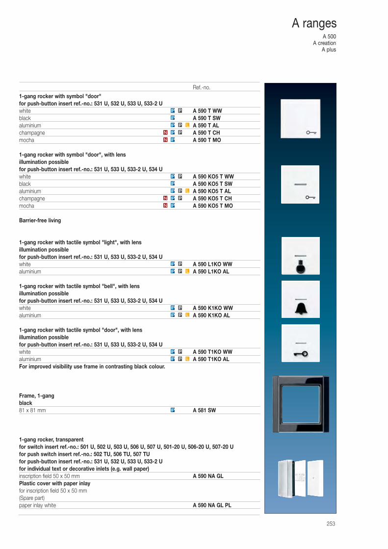
A 500A creation
A plus
253
A ranges
1-gang rocker with symbol "door"for push-button insert ref.-no.: 531 U, 532 U, 533 U, 533-2 Uwhite A 590 T WWblack A 590 T SWaluminium A 590 T ALchampagne A 590 T CHmocha A 590 T MO
1-gang rocker with symbol "door", with lensillumination possiblefor push-button insert ref.-no.: 531 U, 533 U, 533-2 U, 534 Uwhite A 590 KO5 T WWblack A 590 KO5 T SWaluminium A 590 KO5 T ALchampagne A 590 KO5 T CHmocha A 590 KO5 T MO
Barrier-free living
1-gang rocker with tactile symbol "light", with lensillumination possiblefor push-button insert ref.-no.: 531 U, 533 U, 533-2 U, 534 Uwhite A 590 L1KO WWaluminium A 590 L1KO AL
1-gang rocker with tactile symbol "bell", with lensillumination possiblefor push-button insert ref.-no.: 531 U, 533 U, 533-2 U, 534 Uwhite A 590 K1KO WWaluminium A 590 K1KO AL
1-gang rocker with tactile symbol "door", with lensillumination possiblefor push-button insert ref.-no.: 531 U, 533 U, 533-2 U, 534 Uwhite A 590 T1KO WWaluminium A 590 T1KO ALFor improved visibility use frame in contrasting black colour.
Frame, 1-gangblack81 x 81 mm A 581 SW
1-gang rocker, transparentfor switch insert ref.-no.: 501 U, 502 U, 503 U, 506 U, 507 U, 501-20 U, 506-20 U, 507-20 Ufor push switch insert ref.-no.: 502 TU, 506 TU, 507 TUfor push-button insert ref.-no.: 531 U, 532 U, 533 U, 533-2 Ufor individual text or decorative inlets (e.g. wall paper)inscription field 50 x 50 mm A 590 NA GLPlastic cover with paper inlayfor inscription field 50 x 50 mm(Spare part)paper inlay white A 590 NA GL PL
IP
LPIP
PIP
LPIP
PIP
LPIP
PIP
IPN
PIPN
LPIP
IP
PIP
IPN
PIPN
LPIP
IP
PIP
Ref.-no.
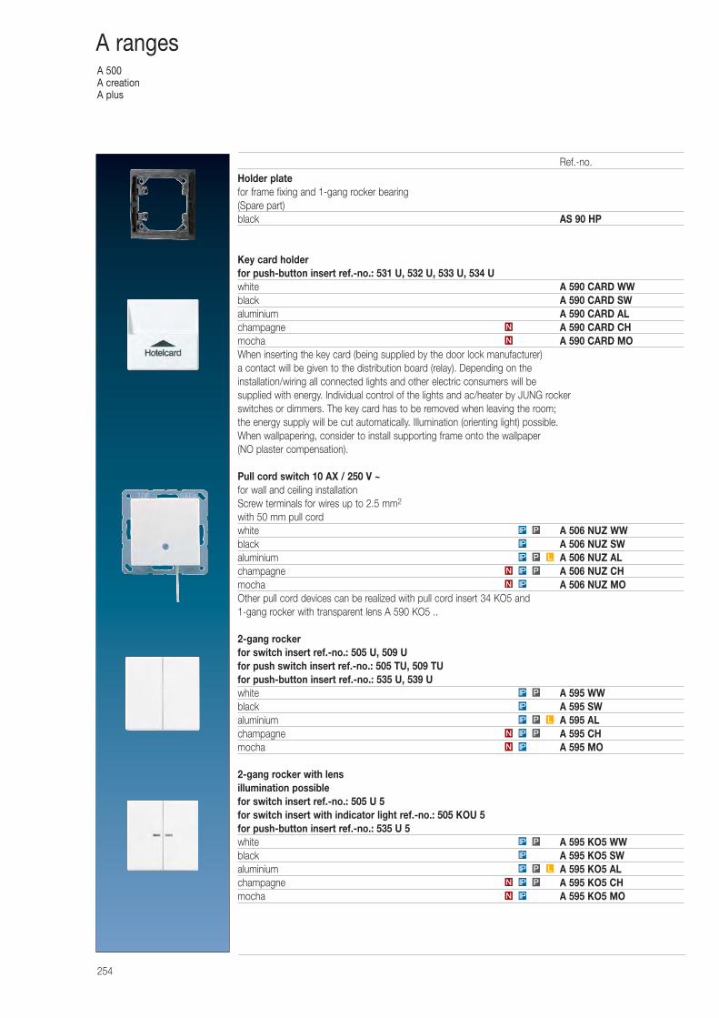
A 500A creationA plus
254
A ranges
Holder platefor frame fixing and 1-gang rocker bearing(Spare part)black AS 90 HP
Key card holderfor push-button insert ref.-no.: 531 U, 532 U, 533 U, 534 Uwhite A 590 CARD WWblack A 590 CARD SWaluminium A 590 CARD ALchampagne A 590 CARD CHmocha A 590 CARD MOWhen inserting the key card (being supplied by the door lock manufacturer) a contact will be given to the distribution board (relay). Depending on the installation/wiring all connected lights and other electric consumers will be supplied with energy. Individual control of the lights and ac/heater by JUNG rocker switches or dimmers. The key card has to be removed when leaving the room; the energy supply will be cut automatically. Illumination (orienting light) possible.When wallpapering, consider to install supporting frame onto the wallpaper (NO plaster compensation).
Pull cord switch 10 AX / 250 V ~for wall and ceiling installationScrew terminals for wires up to 2.5 mm2
with 50 mm pull cordwhite A 506 NUZ WWblack A 506 NUZ SWaluminium A 506 NUZ ALchampagne A 506 NUZ CHmocha A 506 NUZ MOOther pull cord devices can be realized with pull cord insert 34 KO5 and 1-gang rocker with transparent lens A 590 KO5 ..
2-gang rockerfor switch insert ref.-no.: 505 U, 509 Ufor push switch insert ref.-no.: 505 TU, 509 TUfor push-button insert ref.-no.: 535 U, 539 Uwhite A 595 WWblack A 595 SWaluminium A 595 ALchampagne A 595 CHmocha A 595 MO
2-gang rocker with lensillumination possiblefor switch insert ref.-no.: 505 U 5for switch insert with indicator light ref.-no.: 505 KOU 5for push-button insert ref.-no.: 535 U 5white A 595 KO5 WWblack A 595 KO5 SWaluminium A 595 KO5 ALchampagne A 595 KO5 CHmocha A 595 KO5 MOIPN
PIPN
LPIP
IP
PIP
IPN
PIPN
LPIP
IP
PIP
IPN
PIPN
LPIP
IP
PIP
N
N
Ref.-no.
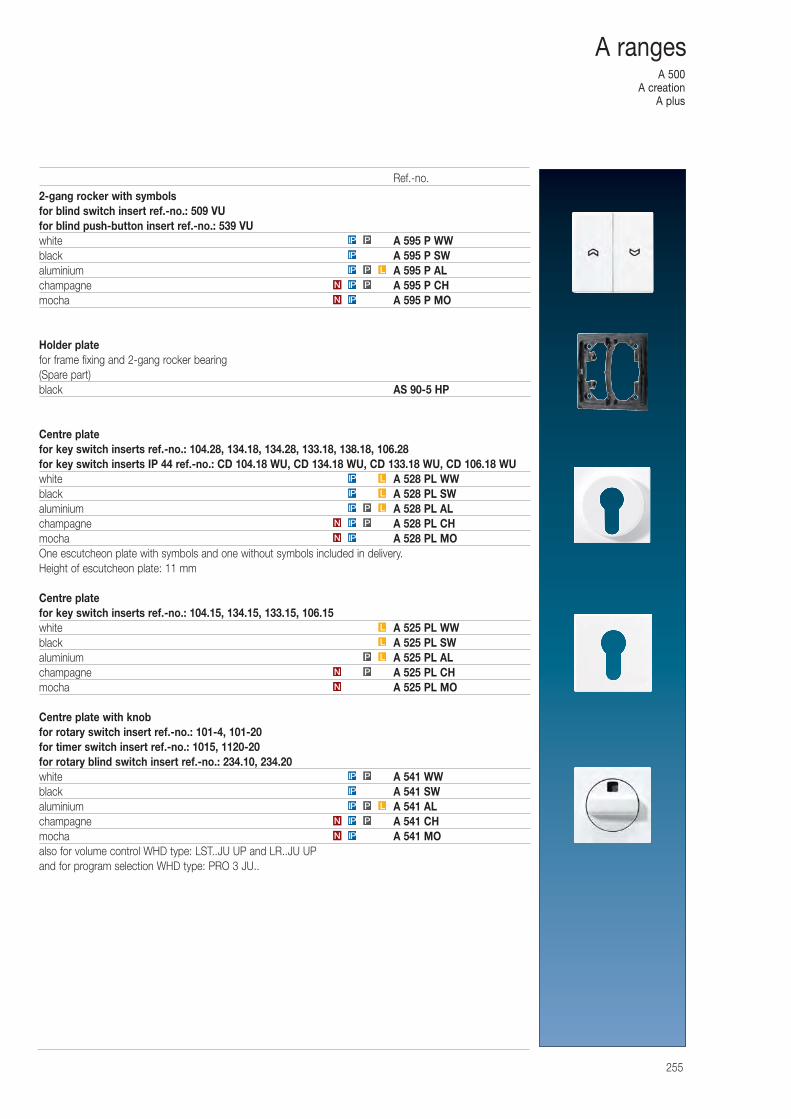
A 500A creation
A plus
255
A ranges
2-gang rocker with symbolsfor blind switch insert ref.-no.: 509 VUfor blind push-button insert ref.-no.: 539 VUwhite A 595 P WWblack A 595 P SWaluminium A 595 P ALchampagne A 595 P CHmocha A 595 P MO
Holder platefor frame fixing and 2-gang rocker bearing(Spare part)black AS 90-5 HP
Centre platefor key switch inserts ref.-no.: 104.28, 134.18, 134.28, 133.18, 138.18, 106.28for key switch inserts IP 44 ref.-no.: CD 104.18 WU, CD 134.18 WU, CD 133.18 WU, CD 106.18 WUwhite A 528 PL WWblack A 528 PL SWaluminium A 528 PL ALchampagne A 528 PL CHmocha A 528 PL MOOne escutcheon plate with symbols and one without symbols included in delivery.Height of escutcheon plate: 11 mm
Centre platefor key switch inserts ref.-no.: 104.15, 134.15, 133.15, 106.15white A 525 PL WWblack A 525 PL SWaluminium A 525 PL ALchampagne A 525 PL CHmocha A 525 PL MO
Centre plate with knobfor rotary switch insert ref.-no.: 101-4, 101-20for timer switch insert ref.-no.: 1015, 1120-20for rotary blind switch insert ref.-no.: 234.10, 234.20white A 541 WWblack A 541 SWaluminium A 541 ALchampagne A 541 CHmocha A 541 MOalso for volume control WHD type: LST..JU UP and LR..JU UPand for program selection WHD type: PRO 3 JU..
PIP
IP
IP P L
IPN
PIPN
IPN
PIPN
LPIP
IP
PIP
N
PN
LP
L
L
IPN
PIPN
LPIP
LIP
LIP
Ref.-no.
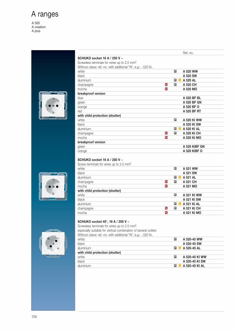
A 500A creationA plus
256
A ranges
SCHUKO socket 16 A / 250 V ~Screwless terminals for wires up to 2.5 mm2
Without claws: ref.-no. with additional "N", e.g.: ..520 N..white A 520 WWblack A 520 SWaluminium A 520 ALchampagne A 520 CHmocha A 520 MObreakproof versionblue A 520 BF BLgreen A 520 BF GNorange A 520 BF Ored A 520 BF RTwith child protection (shutter)white A 520 KI WWblack A 520 KI SWaluminium A 520 KI ALchampagne A 520 KI CHmocha A 520 KI MObreakproof versiongreen A 520 KIBF GNorange A 520 KIBF O
SCHUKO socket 16 A / 250 V ~Screw terminals for wires up to 2.5 mm2
white A 521 WWblack A 521 SWaluminium A 521 ALchampagne A 521 CHmocha A 521 MOwith child protection (shutter)white A 521 KI WWblack A 521 KI SWaluminium A 521 KI ALchampagne A 521 KI CHmocha A 521 KI MO
SCHUKO socket 45°, 16 A / 250 V ~Screwless terminals for wires up to 2.5 mm2
especially suitable for vertical combination of several outletsWithout claws: ref.-no. with additional "N", e.g.: ..520 N..white A 520-45 WWblack A 520-45 SWaluminium A 520-45 ALwith child protection (shutter)white A 520-45 KI WWblack A 520-45 KI SWaluminium A 520-45 KI ALP L
P
P
LP
PN
N
N
PN
LP
P
LP
P
N
PN
LP
P
N
PN
LP
P
Ref.-no.
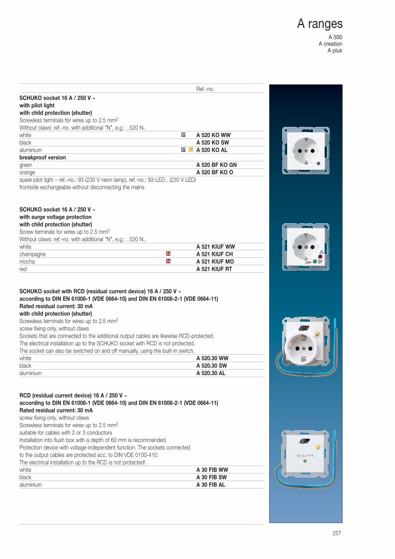
A 500A creation
A plus
257
A ranges
SCHUKO socket 16 A / 250 V ~with pilot lightwith child protection (shutter)Screwless terminals for wires up to 2.5 mm2
Without claws: ref.-no. with additional "N", e.g.: ..520 N..white A 520 KO WWblack A 520 KO SWaluminium A 520 KO ALbreakproof versiongreen A 520 BF KO GNorange A 520 BF KO Ospare pilot light – ref.-no.: 93 (230 V neon lamp), ref.-no.: 93-LED.. (230 V LED) frontside exchangeable without disconnecting the mains
SCHUKO socket 16 A / 250 V ~with surge voltage protectionwith child protection (shutter)Screw terminals for wires up to 2.5 mm2
Without claws: ref.-no. with additional "N", e.g.: ..520 N..white A 521 KIUF WWchampagne A 521 KIUF CHmocha A 521 KIUF MOred A 521 KIUF RT
SCHUKO socket with RCD (residual current device) 16 A / 250 V ~according to DIN EN 61008-1 (VDE 0664-10) and DIN EN 61008-2-1 (VDE 0664-11)Rated residual current: 30 mAwith child protection (shutter)Screwless terminals for wires up to 2.5 mm2
screw fixing only, without clawsSockets that are connected to the additional output cables are likewise RCD-protected. The electrical installation up to the SCHUKO socket with RCD is not protected. The socket can also be switched on and off manually, using the built-in switch.white A 520.30 WWblack A 520.30 SWaluminium A 520.30 AL
RCD (residual current device) 16 A / 250 V ~according to DIN EN 61008-1 (VDE 0664-10) and DIN EN 61008-2-1 (VDE 0664-11)Rated residual current: 30 mAscrew fixing only, without clawsScrewless terminals for wires up to 2.5 mm2
suitable for cables with 2 or 3 conductorsInstallation into flush box with a depth of 60 mm is recommended. Protection device with voltage-independent function. The sockets connected to the output cables are protected acc. to DIN VDE 0100-410. The electrical installation up to the RCD is not protected!white A 30 FIB WWblack A 30 FIB SWaluminium A 30 FIB AL
P
P L
N
N
Ref.-no.
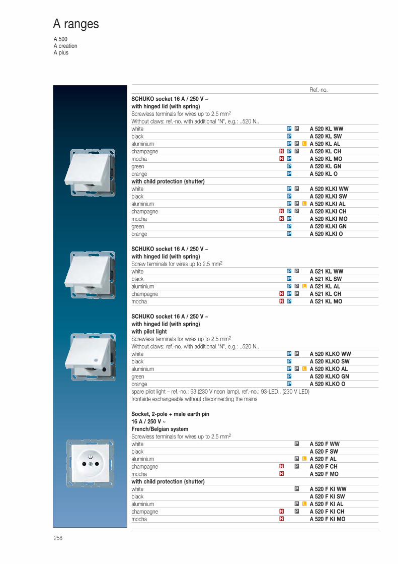
A 500A creationA plus
258
A ranges
SCHUKO socket 16 A / 250 V ~with hinged lid (with spring)Screwless terminals for wires up to 2.5 mm2
Without claws: ref.-no. with additional "N", e.g.: ..520 N..white A 520 KL WWblack A 520 KL SWaluminium A 520 KL ALchampagne A 520 KL CHmocha A 520 KL MOgreen A 520 KL GNorange A 520 KL Owith child protection (shutter)white A 520 KLKI WWblack A 520 KLKI SWaluminium A 520 KLKI ALchampagne A 520 KLKI CHmocha A 520 KLKI MOgreen A 520 KLKI GNorange A 520 KLKI O
SCHUKO socket 16 A / 250 V ~with hinged lid (with spring)Screw terminals for wires up to 2.5 mm2
white A 521 KL WWblack A 521 KL SWaluminium A 521 KL ALchampagne A 521 KL CHmocha A 521 KL MO
SCHUKO socket 16 A / 250 V ~with hinged lid (with spring)with pilot lightScrewless terminals for wires up to 2.5 mm2
Without claws: ref.-no. with additional "N", e.g.: ..520 N..white A 520 KLKO WWblack A 520 KLKO SWaluminium A 520 KLKO ALgreen A 520 KLKO GNorange A 520 KLKO Ospare pilot light – ref.-no.: 93 (230 V neon lamp), ref.-no.: 93-LED.. (230 V LED) frontside exchangeable without disconnecting the mains
Socket, 2-pole + male earth pin16 A / 250 V ~French/Belgian systemScrewless terminals for wires up to 2.5 mm2
white A 520 F WWblack A 520 F SWaluminium A 520 F ALchampagne A 520 F CHmocha A 520 F MOwith child protection (shutter)white A 520 F KI WWblack A 520 F KI SWaluminium A 520 F KI ALchampagne A 520 F KI CHmocha A 520 F KI MO
PIP
IP
LPIP
PIPN
LPIP
IP
PIP
IP
IP
IPN
PIPN
LPIP
IP
PIP
IP
IP
IPN
N
PN
LP
P
N
PN
LP
P
IP
IP
LPIP
IP
PIP
IPN
PIPN
Ref.-no.
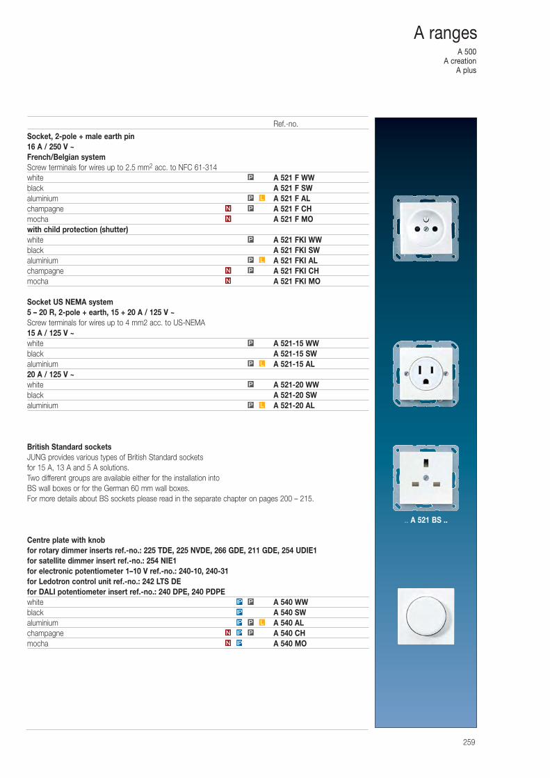
A 500A creation
A plus
259
A ranges
Socket, 2-pole + male earth pin16 A / 250 V ~French/Belgian systemScrew terminals for wires up to 2.5 mm2 acc. to NFC 61-314white A 521 F WWblack A 521 F SWaluminium A 521 F ALchampagne A 521 F CHmocha A 521 F MOwith child protection (shutter)white A 521 FKI WWblack A 521 FKI SWaluminium A 521 FKI ALchampagne A 521 FKI CHmocha A 521 FKI MO
Socket US NEMA system 5 – 20 R, 2-pole + earth, 15 + 20 A / 125 V ~Screw terminals for wires up to 4 mm2 acc. to US-NEMA15 A / 125 V ~white A 521-15 WWblack A 521-15 SWaluminium A 521-15 AL20 A / 125 V ~white A 521-20 WWblack A 521-20 SWaluminium A 521-20 AL
British Standard socketsJUNG provides various types of British Standard sockets for 15 A, 13 A and 5 A solutions. Two different groups are available either for the installation into BS wall boxes or for the German 60 mm wall boxes.For more details about BS sockets please read in the separate chapter on pages 200 – 215.
Centre plate with knobfor rotary dimmer inserts ref.-no.: 225 TDE, 225 NVDE, 266 GDE, 211 GDE, 254 UDIE1for satellite dimmer insert ref.-no.: 254 NIE1for electronic potentiometer 1–10 V ref.-no.: 240-10, 240-31for Ledotron control unit ref.-no.: 242 LTS DEfor DALI potentiometer insert ref.-no.: 240 DPE, 240 PDPEwhite A 540 WWblack A 540 SWaluminium A 540 ALchampagne A 540 CHmocha A 540 MO
P
N
PN
LP
P
N
PN
LP
P
IPN
PIPN
LPIP
IP
PIP
LP
P
LP
Ref.-no.
.. A 521 BS ..
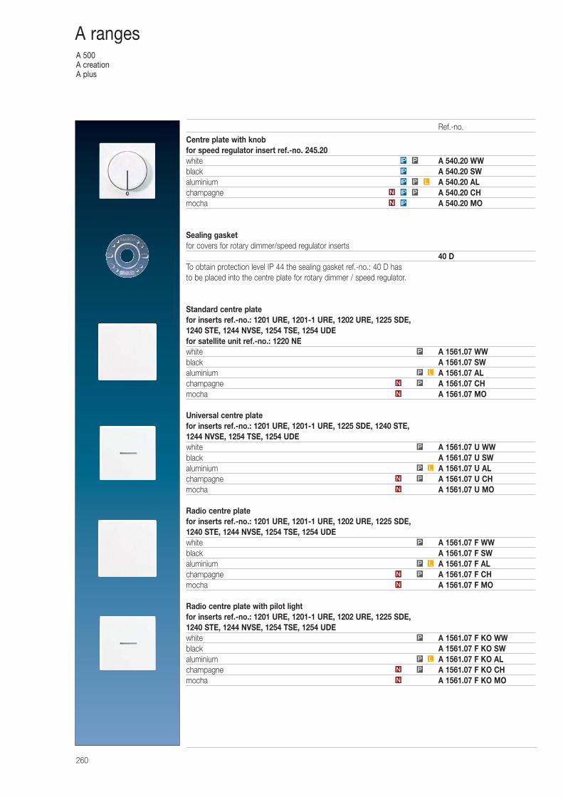
A 500A creationA plus
260
A ranges
Centre plate with knobfor speed regulator insert ref.-no. 245.20white A 540.20 WWblack A 540.20 SWaluminium A 540.20 ALchampagne A 540.20 CHmocha A 540.20 MO
Sealing gasketfor covers for rotary dimmer/speed regulator inserts
40 DTo obtain protection level IP 44 the sealing gasket ref.-no.: 40 D has to be placed into the centre plate for rotary dimmer / speed regulator.
Standard centre platefor inserts ref.-no.: 1201 URE, 1201-1 URE, 1202 URE, 1225 SDE, 1240 STE, 1244 NVSE, 1254 TSE, 1254 UDEfor satellite unit ref.-no.: 1220 NEwhite A 1561.07 WWblack A 1561.07 SWaluminium A 1561.07 ALchampagne A 1561.07 CHmocha A 1561.07 MO
Universal centre platefor inserts ref.-no.: 1201 URE, 1201-1 URE, 1225 SDE, 1240 STE, 1244 NVSE, 1254 TSE, 1254 UDEwhite A 1561.07 U WWblack A 1561.07 U SWaluminium A 1561.07 U ALchampagne A 1561.07 U CHmocha A 1561.07 U MO
Radio centre platefor inserts ref.-no.: 1201 URE, 1201-1 URE, 1202 URE, 1225 SDE, 1240 STE, 1244 NVSE, 1254 TSE, 1254 UDEwhite A 1561.07 F WWblack A 1561.07 F SWaluminium A 1561.07 F ALchampagne A 1561.07 F CHmocha A 1561.07 F MO
Radio centre plate with pilot lightfor inserts ref.-no.: 1201 URE, 1201-1 URE, 1202 URE, 1225 SDE, 1240 STE, 1244 NVSE, 1254 TSE, 1254 UDEwhite A 1561.07 F KO WWblack A 1561.07 F KO SWaluminium A 1561.07 F KO ALchampagne A 1561.07 F KO CHmocha A 1561.07 F KO MO
IP P
PN
LP
P
N
PN
LP
P
N
PN
LP
P
IPN
PIPN
LPIP
IP
N
PN
LP
P
N
Ref.-no.
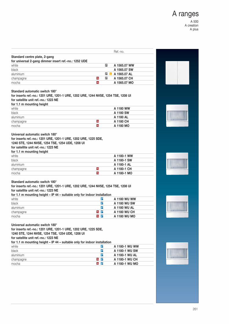
A 500A creation
A plus
261
A ranges
Standard centre plate, 2-gangfor universal 2-gang dimmer insert ref.-no.: 1252 UDEwhite A 1565.07 WWblack A 1565.07 SWaluminium A 1565.07 ALchampagne A 1565.07 CHmocha A 1565.07 MO
Standard automatic switch 180°for inserts ref.-no.: 1201 URE, 1201-1 URE, 1202 URE, 1244 NVSE, 1254 TSE, 1208 UIfor satellite unit ref.-no.: 1223 NEfor 1.1 m mounting heightwhite A 1180 WWblack A 1180 SWaluminium A 1180 ALchampagne A 1180 CHmocha A 1180 MO
Universal automatic switch 180° for inserts ref.-no.: 1201 URE, 1201-1 URE, 1202 URE, 1225 SDE, 1240 STE, 1244 NVSE, 1254 TSE, 1254 UDE, 1208 UIfor satellite unit ref.-no.: 1223 NEfor 1.1 m mounting heightwhite A 1180-1 WWblack A 1180-1 SWaluminium A 1180-1 ALchampagne A 1180-1 CHmocha A 1180-1 MO
Standard automatic switch 180°for inserts ref.-no.: 1201 URE, 1201-1 URE, 1202 URE, 1244 NVSE, 1254 TSE, 1208 UIfor satellite unit ref.-no.: 1223 NEfor 1.1 m mounting height – IP 44 – suitable only for indoor installationwhite A 1180 WU WWblack A 1180 WU SWaluminium A 1180 WU ALchampagne A 1180 WU CHmocha A 1180 WU MO
Universal automatic switch 180° for inserts ref.-no.: 1201 URE, 1201-1 URE, 1202 URE, 1225 SDE, 1240 STE, 1244 NVSE, 1254 TSE, 1254 UDE, 1208 UIfor satellite unit ref.-no.: 1223 NEfor 1.1 m mounting height – IP 44 – suitable only for indoor installationwhite A 1180-1 WU WWblack A 1180-1 WU SWaluminium A 1180-1 WU ALchampagne A 1180-1 WU CHmocha A 1180-1 WU MO
IP
IP
IP
IPN
IPN
IP
IP
IP
N
N
N
N
N
PN
LP
P
IPN
IPN
Ref.-no.
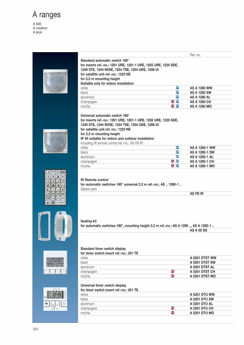
A 500A creationA plus
262
A ranges
Standard automatic switch 180°for inserts ref.-no.: 1201 URE, 1201-1 URE, 1202 URE, 1225 SDE, 1240 STE, 1244 NVSE, 1254 TSE, 1254 UDE, 1208 UIfor satellite unit ref.-no.: 1223 NEfor 2.2 m mounting heightSuitable only for indoor installationwhite AS A 1280 WWblack AS A 1280 SWaluminium AS A 1280 ALchampagne AS A 1280 CHmocha AS A 1280 MO
Universal automatic switch 180° for inserts ref.-no.: 1201 URE, 1201-1 URE, 1202 URE, 1225 SDE, 1240 STE, 1244 NVSE, 1254 TSE, 1254 UDE, 1208 UIfor satellite unit ref.-no.: 1223 NEfor 2.2 m mounting heightIP 44 suitable for indoor and outdoor installationincluding IR remote control ref.-no.: AS FB IRwhite AS A 1280-1 WWblack AS A 1280-1 SWaluminium AS A 1280-1 ALchampagne AS A 1280-1 CHmocha AS A 1280-1 MO
IR Remote controlfor automatic switches 180° universal 2.2 m ref.-no.: AS .. 1280-1 ..(Spare part)
AS FB IR
Sealing kitfor automatic switches 180°, mounting height 2.2 m ref.-no.: AS A 1280 .., AS A 1280-1 ..
AS A 50 DS
Standard timer switch displayfor timer switch insert ref.-no.: 201 TEwhite A 5201 DTST WWblack A 5201 DTST SWaluminium A 5201 DTST ALchampagne A 5201 DTST CHmocha A 5201 DTST MO
Universal timer switch displayfor timer switch insert ref.-no.: 201 TEwhite A 5201 DTU WWblack A 5201 DTU SWaluminium A 5201 DTU ALchampagne A 5201 DTU CHmocha A 5201 DTU MON
N
N
N
IPN
IPN
IP
IP
IP
IPN
IPN
IP
IP
IP
Ref.-no.
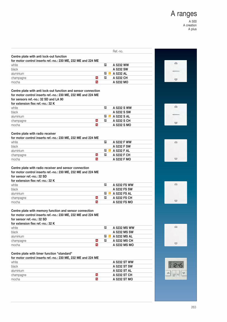
A 500A creation
A plus
263
A ranges
Centre plate with anti lock-out functionfor motor control inserts ref.-no.: 230 ME, 232 ME and 224 MEwhite A 5232 WWblack A 5232 SWaluminium A 5232 ALchampagne A 5232 CHmocha A 5232 MO
Centre plate with anti lock-out function and sensor connectionfor motor control inserts ref.-no.: 230 ME, 232 ME and 224 MEfor sensors ref.-no.: 32 SD and LA 90for extension flex ref.-no.: 32 Kwhite A 5232 S WWblack A 5232 S SWaluminium A 5232 S ALchampagne A 5232 S CHmocha A 5232 S MO
Centre plate with radio receiverfor motor control inserts ref.-no.: 230 ME, 232 ME and 224 MEwhite A 5232 F WWblack A 5232 F SWaluminium A 5232 F ALchampagne A 5232 F CHmocha A 5232 F MO
Centre plate with radio receiver and sensor connectionfor motor control inserts ref.-no.: 230 ME, 232 ME and 224 MEfor sensor ref.-no.: 32 SDfor extension flex ref.-no.: 32 Kwhite A 5232 FS WWblack A 5232 FS SWaluminium A 5232 FS ALchampagne A 5232 FS CHmocha A 5232 FS MO
Centre plate with memory function and sensor connectionfor motor control inserts ref.-no.: 230 ME, 232 ME and 224 MEfor sensor ref.-no.: 32 SDfor extension flex ref.-no.: 32 Kwhite A 5232 MS WWblack A 5232 MS SWaluminium A 5232 MS ALchampagne A 5232 MS CHmocha A 5232 MS MO
Centre plate with timer function "standard"for motor control inserts ref.-no.: 230 ME, 232 ME and 224 MEwhite A 5232 ST WWblack A 5232 ST SWaluminium A 5232 ST ALchampagne A 5232 ST CHmocha A 5232 ST MO
LP
P
N
N
N
PN
LP
P
N
PN
LP
P
N
PN
LP
P
N
PN
LP
P
N
PN
Ref.-no.
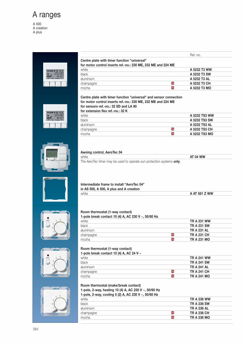
A 500A creationA plus
264
A ranges
Centre plate with timer function "universal"for motor control inserts ref.-no.: 230 ME, 232 ME and 224 MEwhite A 5232 T3 WWblack A 5232 T3 SWaluminium A 5232 T3 ALchampagne A 5232 T3 CHmocha A 5232 T3 MO
Centre plate with timer function "universal" and sensor connectionfor motor control inserts ref.-no.: 230 ME, 232 ME and 224 MEfor sensors ref.-no.: 32 SD and LA 90for extension flex ref.-no.: 32 Kwhite A 5232 TS3 WWblack A 5232 TS3 SWaluminium A 5232 TS3 ALchampagne A 5232 TS3 CHmocha A 5232 TS3 MO
Awning control, AeroTec 04white AT 04 WWThe AeroTec timer may be used to operate sun protection systems only.
Intermediate frame to install "AeroTec 04"in AS 500, A 500, A plus and A creationwhite A AT 581 Z WW
Room thermostat (1-way contact)1-pole break contact 10 (4) A, AC 230 V ~, 50/60 Hzwhite TR A 231 WWblack TR A 231 SWaluminium TR A 231 ALchampagne TR A 231 CHmocha TR A 231 MO
Room thermostat (1-way contact)1-pole break contact 10 (4) A, AC 24 V ~white TR A 241 WWblack TR A 241 SWaluminium TR A 241 ALchampagne TR A 241 CHmocha TR A 241 MO
Room thermostat (make/break contact)1-pole, 2-way, heating 10 (4) A, AC 230 V ~, 50/60 Hz1-pole, 2-way, cooling 5 (2) A, AC 230 V ~, 50/60 Hzwhite TR A 236 WWblack TR A 236 SWaluminium TR A 236 ALchampagne TR A 236 CHmocha TR A 236 MO
N
N
N
N
N
N
N
N
N
N
Ref.-no.
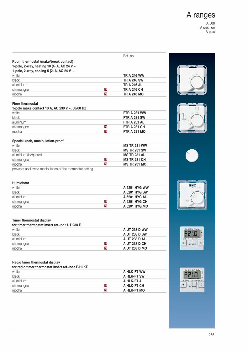
A 500A creation
A plus
265
A ranges
Room thermostat (make/break contact)1-pole, 2-way, heating 10 (4) A, AC 24 V ~1-pole, 2-way, cooling 5 (2) A, AC 24 V ~white TR A 246 WWblack TR A 246 SWaluminium TR A 246 ALchampagne TR A 246 CHmocha TR A 246 MO
Floor thermostat1-pole make contact 10 A, AC 230 V ~, 50/60 Hzwhite FTR A 231 WWblack FTR A 231 SWaluminium FTR A 231 ALchampagne FTR A 231 CHmocha FTR A 231 MO
Special knob, manipulation-proofwhite MS TR 231 WWblack MS TR 231 SWaluminium (lacquered) MS TR 231 ALchampagne MS TR 231 CHmocha MS TR 231 MOprevents unallowed manipulation of the thermostat setting
Humidistatwhite A 5201 HYG WWblack A 5201 HYG SWaluminium A 5201 HYG ALchampagne A 5201 HYG CHmocha A 5201 HYG MO
Timer thermostat displayfor timer thermostat insert ref.-no.: UT 238 Ewhite A UT 238 D WWblack A UT 238 D SWaluminium A UT 238 D ALchampagne A UT 238 D CHmocha A UT 238 D MO
Radio timer thermostat displayfor radio timer thermostat insert ref.-no.: F-HLKEwhite A HLK-FT WWblack A HLK-FT SWaluminium A HLK-FT ALchampagne A HLK-FT CHmocha A HLK-FT MO
N
N
N
N
N
N
N
N
N
N
N
N
Ref.-no.
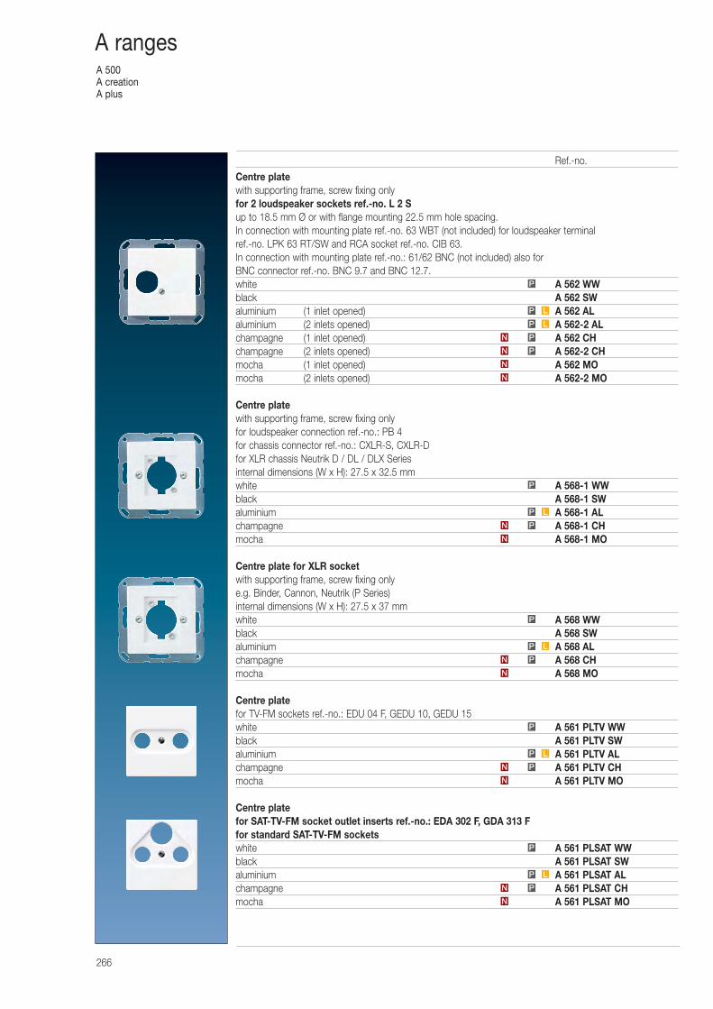
A 500A creationA plus
266
A ranges
Centre platewith supporting frame, screw fixing onlyfor 2 loudspeaker sockets ref.-no. L 2 Sup to 18.5 mm Ø or with flange mounting 22.5 mm hole spacing.In connection with mounting plate ref.-no. 63 WBT (not included) for loudspeaker terminalref.-no. LPK 63 RT/SW and RCA socket ref.-no. CIB 63.In connection with mounting plate ref.-no.: 61/62 BNC (not included) also for BNC connector ref.-no. BNC 9.7 and BNC 12.7.white A 562 WWblack A 562 SWaluminium (1 inlet opened) A 562 ALaluminium (2 inlets opened) A 562-2 ALchampagne (1 inlet opened) A 562 CHchampagne (2 inlets opened) A 562-2 CHmocha (1 inlet opened) A 562 MOmocha (2 inlets opened) A 562-2 MO
Centre platewith supporting frame, screw fixing onlyfor loudspeaker connection ref.-no.: PB 4for chassis connector ref.-no.: CXLR-S, CXLR-Dfor XLR chassis Neutrik D / DL / DLX Seriesinternal dimensions (W x H): 27.5 x 32.5 mmwhite A 568-1 WWblack A 568-1 SWaluminium A 568-1 ALchampagne A 568-1 CHmocha A 568-1 MO
Centre plate for XLR socketwith supporting frame, screw fixing onlye.g. Binder, Cannon, Neutrik (P Series)internal dimensions (W x H): 27.5 x 37 mmwhite A 568 WWblack A 568 SWaluminium A 568 ALchampagne A 568 CHmocha A 568 MO
Centre platefor TV-FM sockets ref.-no.: EDU 04 F, GEDU 10, GEDU 15white A 561 PLTV WWblack A 561 PLTV SWaluminium A 561 PLTV ALchampagne A 561 PLTV CHmocha A 561 PLTV MO
Centre platefor SAT-TV-FM socket outlet inserts ref.-no.: EDA 302 F, GDA 313 Ffor standard SAT-TV-FM socketswhite A 561 PLSAT WWblack A 561 PLSAT SWaluminium A 561 PLSAT ALchampagne A 561 PLSAT CHmocha A 561 PLSAT MO
P L
P
N
N
PN
PN
LP
LP
P
N
PN
LP
P
N
PN
LP
P
N
PN
LP
P
N
PN
Ref.-no.
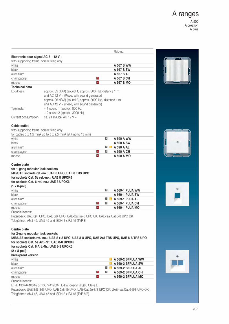
A 500A creation
A plus
267
A ranges
Electronic door signal AC 8 – 12 V ~with supporting frame, screw fixing onlywhite A 567 S WWblack A 567 S SWaluminium A 567 S ALchampagne A 567 S CHmocha A 567 S MOTechnical dataLoudness: approx. 82 dB(A) (sound 1, approx. 800 Hz), distance 1 m
and AC 12 V ~ (Piezo, with sound generator)approx. 96 dB(A) (sound 2, approx. 3000 Hz), distance 1 m and AC 12 V ~ (Piezo, with sound generator)
Terminals: ~ 1 sound 1 (approx. 800 Hz)~ 2 sound 2 (approx. 3000 Hz)
Current consumption: ca. 24 mA bei AC 12 V ~
Cable outletwith supporting frame, screw fixing onlyfor cables 3 x 1.5 mm2 up to 5 x 2.5 mm2 (Ø 7 up to 13 mm)white A 590 A WWblack A 590 A SWaluminium A 590 A ALchampagne A 590 A CHmocha A 590 A MO
Centre platefor 1-gang modular jack socketsIAE/UAE sockets ref.-no.: UAE 8 UPO, UAE 8 TRS UPOfor sockets Cat. 5e ref.-no..: UAE 8 UPOK5for sockets Cat. 6 ref.-no.: UAE 8 UPOK6(1 x 8-pol.)white A 569-1 PLUA WWblack A 569-1 PLUA SWaluminium A 569-1 PLUA ALchampagne A 569-1 PLUA CHmocha A 569-1 PLUA MOSuitable inserts:Rutenbeck: UAE 8(4) UPO, UAE 8(8) UPO, UAE-Cat.5e-8 UPO OK, UAE-real.Cat.6-8 UPO OKTelegärtner: AMJ 45, UMJ 45 and ISDN 1 x RJ 45 (TYP 8)
Centre platefor 2-gang modular jack socketsIAE/UAE sockets ref.-no..: UAE 2 x 8 UPO, UAE 8-8 UPO, UAE 2x8 TRS UPO, UAE 8-8 TRS UPOfor sockets Cat. 5e Art.-Nr.: UAE 8-8 UPOK5for sockets Cat. 6 Art.-Nr.: UAE 8-8 UPOK6(2 x 8-pol.)breakproof versionwhite A 569-2 BFPLUA WWblack A 569-2 BFPLUA SWaluminium A 569-2 BFPLUA ALchampagne A 569-2 BFPLUA CHmocha A 569-2 BFPLUA MOSuitable inserts:BTR: 1307441001-i or 1307441200-i; E-Dat design 8/8(8), Class ERutenbeck: UAE 8/8 (8/8) UPO, UAE 2x8 (8) UPO, UAE-Cat.5e-8/8 UPO OK, UAE-real.Cat.6-8/8 UPO OKTelegärtner: AMJ 45, UMJ 45 and ISDN 2 x RJ 45 (TYP 8/8)
N
PN
LP
P
N
N
N
PN
LP
L
L
N
PN
LP
P
Ref.-no.
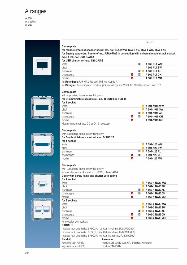
A 500A creationA plus
268
A ranges
Centre platefor mono/stereo loudspeaker socket ref.-no.: SLA 2 WW, SLA 2 AN, MLA 1 WW, MLA 1 ANfor 2-gang supporting frame ref.-no.: UMA-MA2 in connection with universal modular jack sockettype A ref.-no.: UMA-CAT6Afor USB charger ref.-no.: 521-2 USBwhite A 569 PLT WWblack A 569 PLT SWaluminium A 569 PLT ALchampagne A 569 PLT CHmocha A 569 PLT MOfor Rutenbeck: UM-MA 2 Up with UM-real Cat.6a Afor Dätwyler: flush-mounted modular jack socket (for 2 x MS-K 1/8 Cat.6a), ref.-no.: 440 012
Centre platewith supporting frame, screw fixing onlyfor D-subminiature sockets ref.-no.: D SUB 9, D SUB 15for 1 socketwhite A 594-1915 WWblack A 594-1915 SWaluminium A 594-1915 ALchampagne A 594-1915 CHmocha A 594-1915 MOMounting plate ref.-no. D 9 or D 15 necessary
Centre platewith supporting frame, screw fixing onlyfor D-subminiature socket ref.-no.: D SUB 25for 1 socketwhite A 594-125 WWblack A 594-125 SWaluminium A 594-125 ALchampagne A 594-125 CHmocha A 594-125 MO
Centre platewith supporting frame, screw fixing onlyfor modular jack sockets ref.-no.: 6 WE, UMA-CAT6ACover with screw fixing and shutter with springfor 1 socketwhite A 569-1 NWE WWblack A 569-1 NWE SWaluminium A 569-1 NWE ALchampagne A 569-1 NWE CHmocha A 569-1 NWE MOfor 2 socketswhite A 569-2 NWE WWblack A 569-2 NWE SWaluminium A 569-2 NWE ALchampagne A 569-2 NWE CHmocha A 569-2 NWE MOfor modular jack socketsRADIALL:modular jack unshielded 6P6C, RJ 12, Cat. 4 (ref.-no. R280MOD804)modular jack unshielded 8P8C, RJ 45, Cat. 4 (ref.-no. R280MOD805)modular jack unshielded 8P8C, RJ 45, Cat. 5e (ref.-no. R280MOD807)Panduit: Assmann:keystone jack KJ 88.. module DN-93612 Cat. 6A, shielded, Keystonekeystone jack KJ 588.. module DN-93614
N
PN
LP
L
L
N
PN
LP
P
N
PN
LP
L
L
N
PN
LP
L
L
N
PN
LP
L
L
Ref.-no.
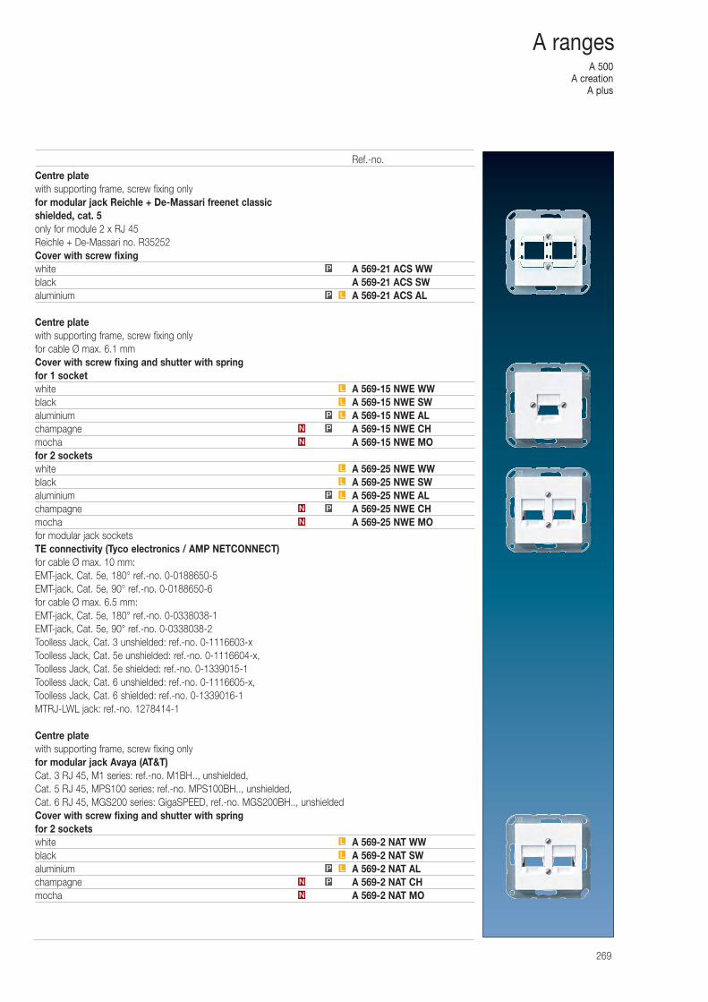
A 500A creation
A plus
269
A ranges
Centre platewith supporting frame, screw fixing onlyfor modular jack Reichle + De-Massari freenet classicshielded, cat. 5only for module 2 x RJ 45Reichle + De-Massari no. R35252Cover with screw fixingwhite A 569-21 ACS WWblack A 569-21 ACS SWaluminium A 569-21 ACS AL
Centre platewith supporting frame, screw fixing onlyfor cable Ø max. 6.1 mmCover with screw fixing and shutter with springfor 1 socketwhite A 569-15 NWE WWblack A 569-15 NWE SWaluminium A 569-15 NWE ALchampagne A 569-15 NWE CHmocha A 569-15 NWE MOfor 2 socketswhite A 569-25 NWE WWblack A 569-25 NWE SWaluminium A 569-25 NWE ALchampagne A 569-25 NWE CHmocha A 569-25 NWE MOfor modular jack socketsTE connectivity (Tyco electronics / AMP NETCONNECT)for cable Ø max. 10 mm:EMT-jack, Cat. 5e, 180° ref.-no. 0-0188650-5EMT-jack, Cat. 5e, 90° ref.-no. 0-0188650-6for cable Ø max. 6.5 mm:EMT-jack, Cat. 5e, 180° ref.-no. 0-0338038-1EMT-jack, Cat. 5e, 90° ref.-no. 0-0338038-2Toolless Jack, Cat. 3 unshielded: ref.-no. 0-1116603-xToolless Jack, Cat. 5e unshielded: ref.-no. 0-1116604-x, Toolless Jack, Cat. 5e shielded: ref.-no. 0-1339015-1Toolless Jack, Cat. 6 unshielded: ref.-no. 0-1116605-x, Toolless Jack, Cat. 6 shielded: ref.-no. 0-1339016-1MTRJ-LWL jack: ref.-no. 1278414-1
Centre platewith supporting frame, screw fixing onlyfor modular jack Avaya (AT&T)Cat. 3 RJ 45, M1 series: ref.-no. M1BH.., unshielded,Cat. 5 RJ 45, MPS100 series: ref.-no. MPS100BH.., unshielded,Cat. 6 RJ 45, MGS200 series: GigaSPEED, ref.-no. MGS200BH.., unshieldedCover with screw fixing and shutter with springfor 2 socketswhite A 569-2 NAT WWblack A 569-2 NAT SWaluminium A 569-2 NAT ALchampagne A 569-2 NAT CHmocha A 569-2 NAT MO
L
L
N
PN
LP
L
L
LP
P
N
PN
LP
L
L
N
PN
LP
Ref.-no.
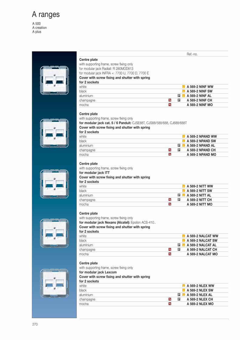
A 500A creationA plus
270
A ranges
Centre platewith supporting frame, screw fixing onlyfor modular jack Radiall: R 280MOD813for modular jack INFRA +: 7700 U, 7700 D, 7700 ECover with screw fixing and shutter with springfor 2 socketswhite A 569-2 NINF WWblack A 569-2 NINF SWaluminium A 569-2 NINF ALchampagne A 569-2 NINF CHmocha A 569-2 NINF MO
Centre platewith supporting frame, screw fixing onlyfor modular jack cat. 5 / 6 Panduit: CJSE88T, CJS88/588/688, CJ688/688TCover with screw fixing and shutter with springfor 2 socketswhite A 569-2 NPAND WWblack A 569-2 NPAND SWaluminium A 569-2 NPAND ALchampagne A 569-2 NPAND CHmocha A 569-2 NPAND MO
Centre platewith supporting frame, screw fixing onlyfor modular jack ITTCover with screw fixing and shutter with springfor 2 socketswhite A 569-2 NITT WWblack A 569-2 NITT SWaluminium A 569-2 NITT ALchampagne A 569-2 NITT CHmocha A 569-2 NITT MO
Centre platewith supporting frame, screw fixing onlyfor modular jack Nexans (Alcatel): Epsilon ACS-410..Cover with screw fixing and shutter with springfor 2 socketswhite A 569-2 NALCAT WWblack A 569-2 NALCAT SWaluminium A 569-2 NALCAT ALchampagne A 569-2 NALCAT CHmocha A 569-2 NALCAT MO
Centre platewith supporting frame, screw fixing onlyfor modular jack LexcomCover with screw fixing and shutter with springfor 2 socketswhite A 569-2 NLEX WWblack A 569-2 NLEX SWaluminium A 569-2 NLEX ALchampagne A 569-2 NLEX CHmocha A 569-2 NLEX MO
N
PN
LP
L
L
N
PN
LP
L
L
N
PN
LP
L
L
N
PN
LP
L
L
N
PN
LP
L
L
Ref.-no.
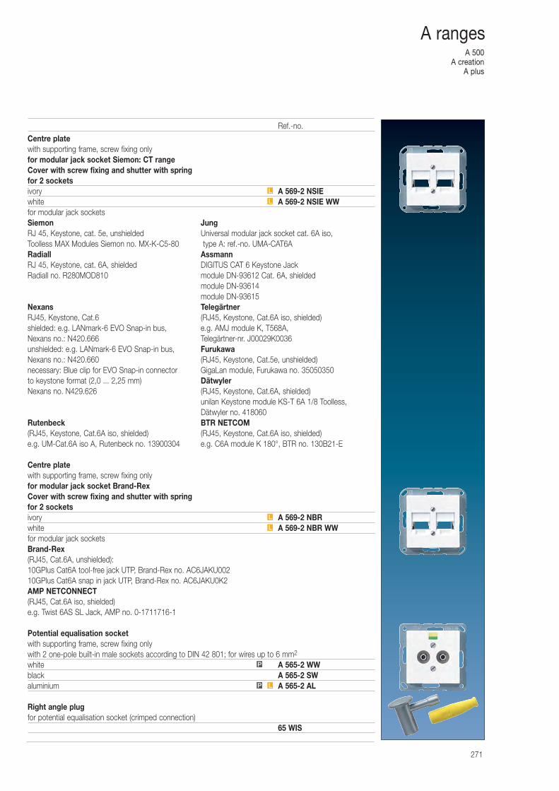
A 500A creation
A plus
271
A ranges
Centre platewith supporting frame, screw fixing onlyfor modular jack socket Siemon: CT rangeCover with screw fixing and shutter with springfor 2 socketsivory A 569-2 NSIEwhite A 569-2 NSIE WWfor modular jack socketsSiemon JungRJ 45, Keystone, cat. 5e, unshielded Universal modular jack socket cat. 6A iso,Toolless MAX Modules Siemon no. MX-K-C5-80 type A: ref.-no. UMA-CAT6ARadiall AssmannRJ 45, Keystone, cat. 6A, shielded DIGITUS CAT 6 Keystone JackRadiall no. R280MOD810 module DN-93612 Cat. 6A, shielded
module DN-93614module DN-93615
Nexans TelegärtnerRJ45, Keystone, Cat.6 (RJ45, Keystone, Cat.6A iso, shielded)shielded: e.g. LANmark-6 EVO Snap-in bus, e.g. AMJ module K, T568A, Nexans no.: N420.666 Telegärtner-nr. J00029K0036unshielded: e.g. LANmark-6 EVO Snap-in bus, FurukawaNexans no.: N420.660 (RJ45, Keystone, Cat.5e, unshielded)necessary: Blue clip for EVO Snap-in connector GigaLan module, Furukawa no. 35050350to keystone format (2,0 ... 2,25 mm) DätwylerNexans no. N429.626 (RJ45, Keystone, Cat.6A, shielded)
unilan Keystone module KS-T 6A 1/8 Toolless, Dätwyler no. 418060
Rutenbeck BTR NETCOM(RJ45, Keystone, Cat.6A iso, shielded) (RJ45, Keystone, Cat.6A iso, shielded)e.g. UM-Cat.6A iso A, Rutenbeck no. 13900304 e.g. C6A module K 180°, BTR no. 130B21-E
Centre platewith supporting frame, screw fixing onlyfor modular jack socket Brand-RexCover with screw fixing and shutter with springfor 2 socketsivory A 569-2 NBRwhite A 569-2 NBR WWfor modular jack socketsBrand-Rex(RJ45, Cat.6A, unshielded):10GPlus Cat6A tool-free jack UTP, Brand-Rex no. AC6JAKU00210GPlus Cat6A snap in jack UTP, Brand-Rex no. AC6JAKU0K2AMP NETCONNECT(RJ45, Cat.6A iso, shielded)e.g. Twist 6AS SL Jack, AMP no. 0-1711716-1
Potential equalisation socketwith supporting frame, screw fixing onlywith 2 one-pole built-in male sockets according to DIN 42 801; for wires up to 6 mm2
white A 565-2 WWblack A 565-2 SWaluminium A 565-2 AL
Right angle plugfor potential equalisation socket (crimped connection)
65 WIS
P L
P
L
L
L
L
Ref.-no.
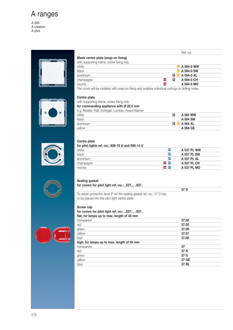
A 500A creationA plus
272
A ranges
Blank centre plate (snap-on fixing)with supporting frame, screw fixing onlywhite A 594-0 WWblack A 594-0 SWaluminium A 594-0 ALchampagne A 594-0 CHmocha A 594-0 MOThe cover will be installed with snap-on fixing and enables individual cuttings or drilling holes.
Centre platewith supporting frame, screw fixing onlyfor commanding appliance with Ø 22.5 mme.g. Moeller, Rafi, Schlegel, Lumitas, Kraus-Naimerwhite A 564 WWblack A 564 SWaluminium A 564 ALyellow A 564 GE
Centre platefor pilot lights ref.-no.: 938-10 U and 938-14 Uwhite A 537 PL WWblack A 537 PL SWaluminium A 537 PL ALchampagne A 537 PL CHmocha A 537 PL MO
Sealing gasketfor covers for pilot light ref.-no.: ..537.., ..937..
37 DTo obtain protection level IP 44 the sealing gasket ref.-no.: 37 D has to be placed into the pilot light centre plate.
Screw capfor covers for pilot light ref.-no.: ..537.., ..937..flat, for lamps up to max. length of 35 mmtransparent 37.02red 37.05green 37.06yellow 37.07blue 37.08high, for lamps up to max. length of 54 mmtransparent 37red 37 Rgreen 37 Gyellow 37 GEblue 37 BL
P
N
PN
LP
L
L
IPN
IPN
IP
IP
IP
LP
Ref.-no.
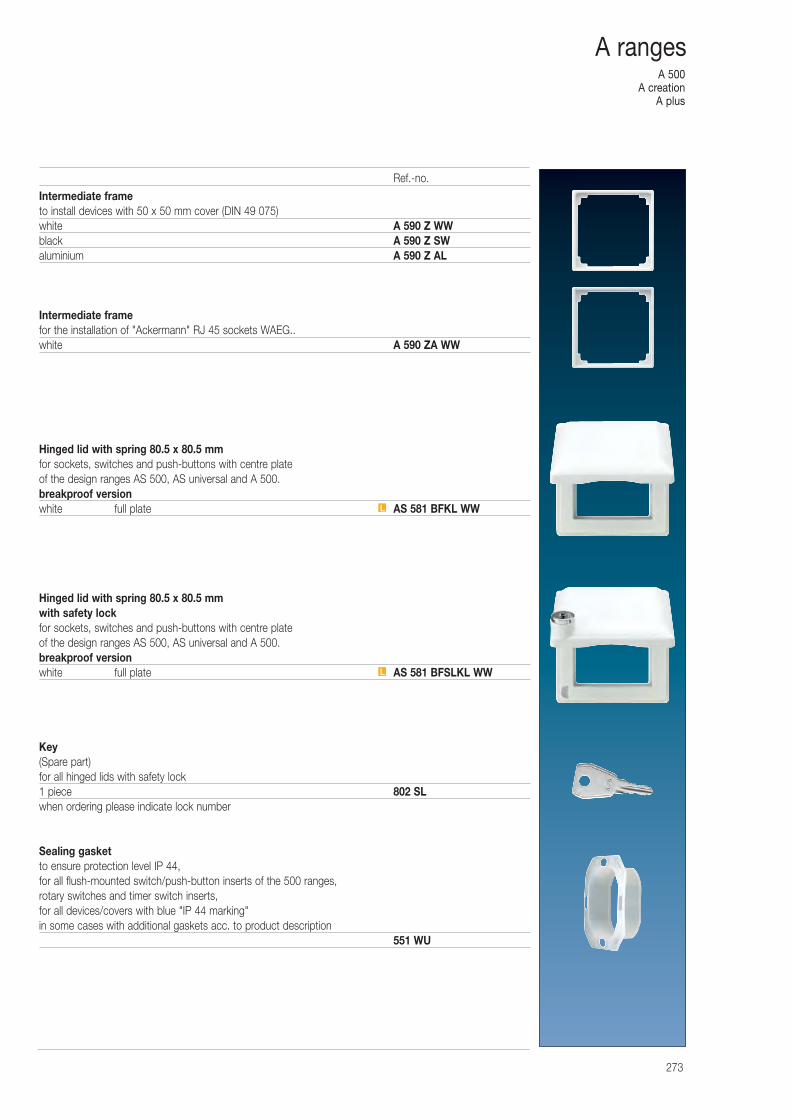
A 500A creation
A plus
273
A ranges
Intermediate frameto install devices with 50 x 50 mm cover (DIN 49 075)white A 590 Z WWblack A 590 Z SWaluminium A 590 Z AL
Intermediate framefor the installation of "Ackermann" RJ 45 sockets WAEG..white A 590 ZA WW
Hinged lid with spring 80.5 x 80.5 mmfor sockets, switches and push-buttons with centre plate of the design ranges AS 500, AS universal and A 500.breakproof versionwhite full plate AS 581 BFKL WW
Hinged lid with spring 80.5 x 80.5 mmwith safety lockfor sockets, switches and push-buttons with centre plate of the design ranges AS 500, AS universal and A 500.breakproof versionwhite full plate AS 581 BFSLKL WW
Key (Spare part)for all hinged lids with safety lock1 piece 802 SLwhen ordering please indicate lock number
Sealing gasketto ensure protection level IP 44,for all flush-mounted switch/push-button inserts of the 500 ranges,rotary switches and timer switch inserts,for all devices/covers with blue "IP 44 marking"in some cases with additional gaskets acc. to product description
551 WU
L
L
Ref.-no.
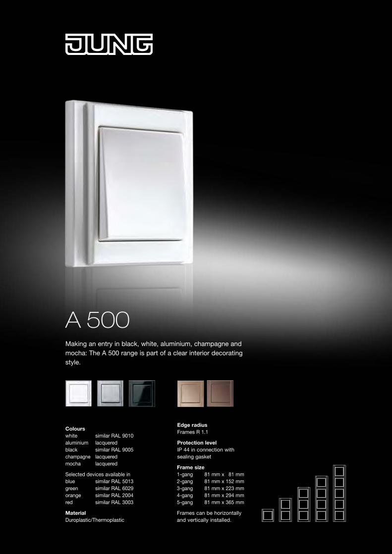
A 500Making an entry in black, white, aluminium, champagne and mocha: The A 500 range is part of a clear interior decorating style.
Frame size 1-gang 81 mm x 81 mm 2-gang 81 mm x 152 mm 3-gang 81 mm x 223 mm 4-gang 81 mm x 294 mm 5-gang 81 mm x 365 mm
Frames can be horizontally and vertically installed.
Colours white similar RAL 9010aluminium lacquered black similar RAL 9005champagne lacquered mocha lacquered
Selected devices available in blue similar RAL 5013 green similar RAL 6029 orange similar RAL 2004 red similar RAL 3003
Material Duroplastic/Thermoplastic
Edge radius Frames R 1.1
Protection level IP 44 in connection with sealing gasket
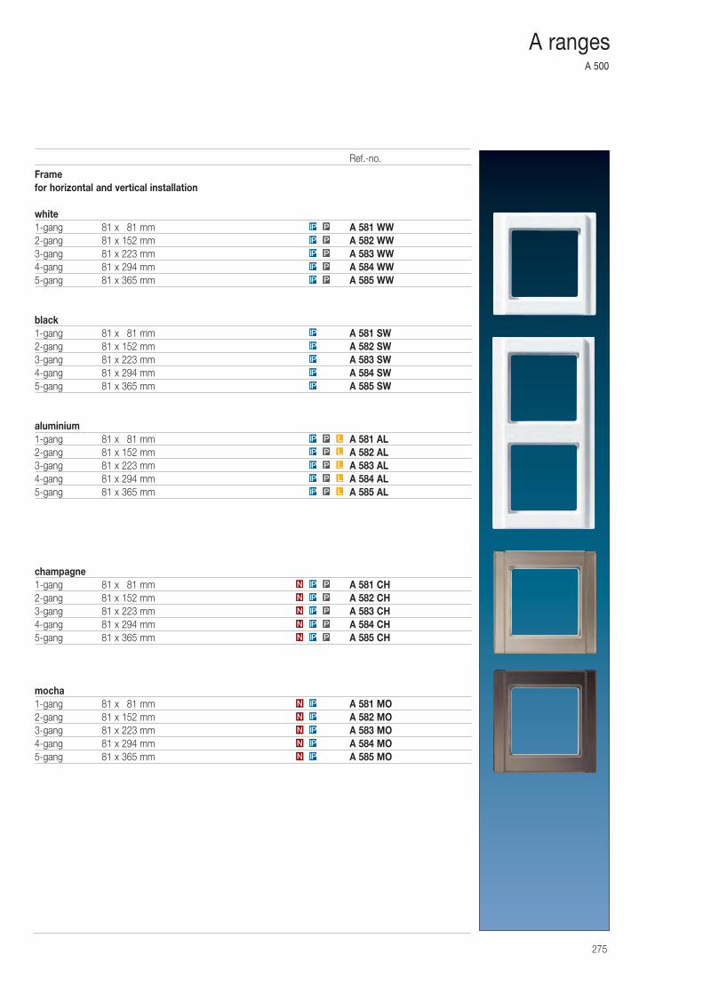
A 500
275
A ranges
Framefor horizontal and vertical installation
white1-gang 81 x 081 mm A 581 WW2-gang 81 x 152 mm A 582 WW3-gang 81 x 223 mm A 583 WW4-gang 81 x 294 mm A 584 WW5-gang 81 x 365 mm A 585 WW
black1-gang 81 x 081 mm A 581 SW2-gang 81 x 152 mm A 582 SW3-gang 81 x 223 mm A 583 SW4-gang 81 x 294 mm A 584 SW5-gang 81 x 365 mm A 585 SW
aluminium1-gang 81 x 081 mm A 581 AL2-gang 81 x 152 mm A 582 AL3-gang 81 x 223 mm A 583 AL4-gang 81 x 294 mm A 584 AL5-gang 81 x 365 mm A 585 AL
champagne1-gang 81 x 081 mm A 581 CH2-gang 81 x 152 mm A 582 CH3-gang 81 x 223 mm A 583 CH4-gang 81 x 294 mm A 584 CH5-gang 81 x 365 mm A 585 CH
mocha1-gang 81 x 081 mm A 581 MO2-gang 81 x 152 mm A 582 MO3-gang 81 x 223 mm A 583 MO4-gang 81 x 294 mm A 584 MO5-gang 81 x 365 mm A 585 MON IP
N IP
N IP
N IP
IP P
IP P
IP P
IP P
IP P
IP
IP
IP
IP
IP
IPN
PIPN
PIPN
PIPN
PIPN
PIPN
LPIP
LPIP
LPIP
LPIP
LPIP
Ref.-no.
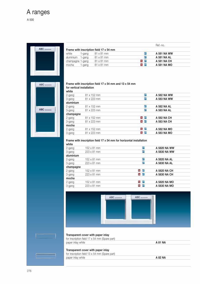
A 500
276
A ranges
Frame with inscription field 17 x 54 mmwhite 1-gang 81 x 81 mm A 581 NA WWaluminium 1-gang 81 x 81 mm A 581 NA ALchampagne 1-gang 81 x 81 mm A 581 NA CHmocha 1-gang 81 x 81 mm A 581 NA MO
Frame with inscription field 17 x 54 mm and 13 x 54 mm for vertical installationwhite2-gang 81 x 152 mm A 582 NA WW3-gang 81 x 223 mm A 583 NA WWaluminium2-gang 81 x 152 mm A 582 NA AL3-gang 81 x 223 mm A 583 NA ALchampagne2-gang 81 x 152 mm A 582 NA CH3-gang 81 x 223 mm A 583 NA CHmocha2-gang 81 x 152 mm A 582 NA MO3-gang 81 x 223 mm A 583 NA MO
Frame with inscription field 17 x 54 mm for horizontal installationwhite2-gang 152 x 81 mm A 5820 NA WW3-gang 223 x 81 mm A 5830 NA WWaluminium2-gang 152 x 81 mm A 5820 NA AL3-gang 223 x 81 mm A 5830 NA ALchampagne2-gang 152 x 81 mm A 5820 NA CH3-gang 223 x 81 mm A 5830 NA CHmocha2-gang 152 x 81 mm A 5820 NA MO3-gang 223 x 81 mm A 5830 NA MO
Transparent cover with paper inlayfor inscription field 17 x 54 mm (Spare part)paper inlay white A 81 NA
Transparent cover with paper inlayfor inscription field 13 x 54 mm (Spare part)paper inlay white A 82 NA
IP
IP
IPN
IPN
IP
IP
IP
IP
N IP
N IP
N IP
N IP
IP
IP
IPN
IPN
IPN
IPN
IP
IP
Ref.-no.
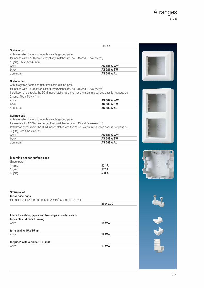
A 500
277
A ranges
Surface capwith integrated frame and non-flammable ground platefor inserts with A 500 cover (except key switches ref.-no. ..15 and 3-level-switch)1-gang, 85 x 85 x 47 mmwhite AS 581 A WWblack AS 581 A SWaluminium AS 581 A AL
Surface capwith integrated frame and non-flammable ground platefor inserts with A 500 cover (except key switches ref.-no. ..15 and 3-level-switch)Installation of the radio, the DCM indoor station and the music station into surface caps is not possible.2-gang, 156 x 85 x 47 mmwhite AS 582 A WWblack AS 582 A SWaluminium AS 582 A AL
Surface capwith integrated frame and non-flammable ground platefor inserts with A 500 cover (except key switches ref.-no. ..15 and 3-level-switch)Installation of the radio, the DCM indoor station and the music station into surface caps is not possible.3-gang, 227 x 85 x 47 mmwhite AS 583 A WWblack AS 583 A SWaluminium AS 583 A AL
Mounting box for surface caps(Spare part)1-gang 581 A2-gang 582 A3-gang 583 A
Strain relieffor surface capsfor cables 3 x 1.5 mm2 up to 5 x 2.5 mm2 (Ø 7 up to 13 mm)
58 A ZUG
Inlets for cables, pipes and trunkings in surface capsfor cable and mini trunkingwhite 11 WW
for trunking 15 x 15 mmwhite 12 WW
for pipes with outside Ø 16 mmwhite 13 WW
Ref.-no.
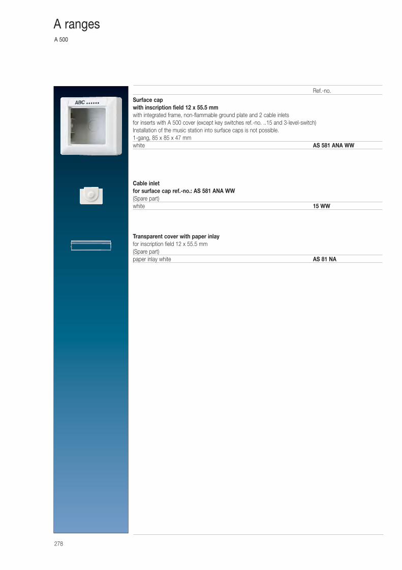
A 500
278
A ranges
Surface capwith inscription field 12 x 55.5 mmwith integrated frame, non-flammable ground plate and 2 cable inletsfor inserts with A 500 cover (except key switches ref.-no. ..15 and 3-level-switch)Installation of the music station into surface caps is not possible.1-gang, 85 x 85 x 47 mmwhite AS 581 ANA WW
Cable inletfor surface cap ref.-no.: AS 581 ANA WW(Spare part)white 15 WW
Transparent cover with paper inlayfor inscription field 12 x 55.5 mm(Spare part)paper inlay white AS 81 NA
Ref.-no.
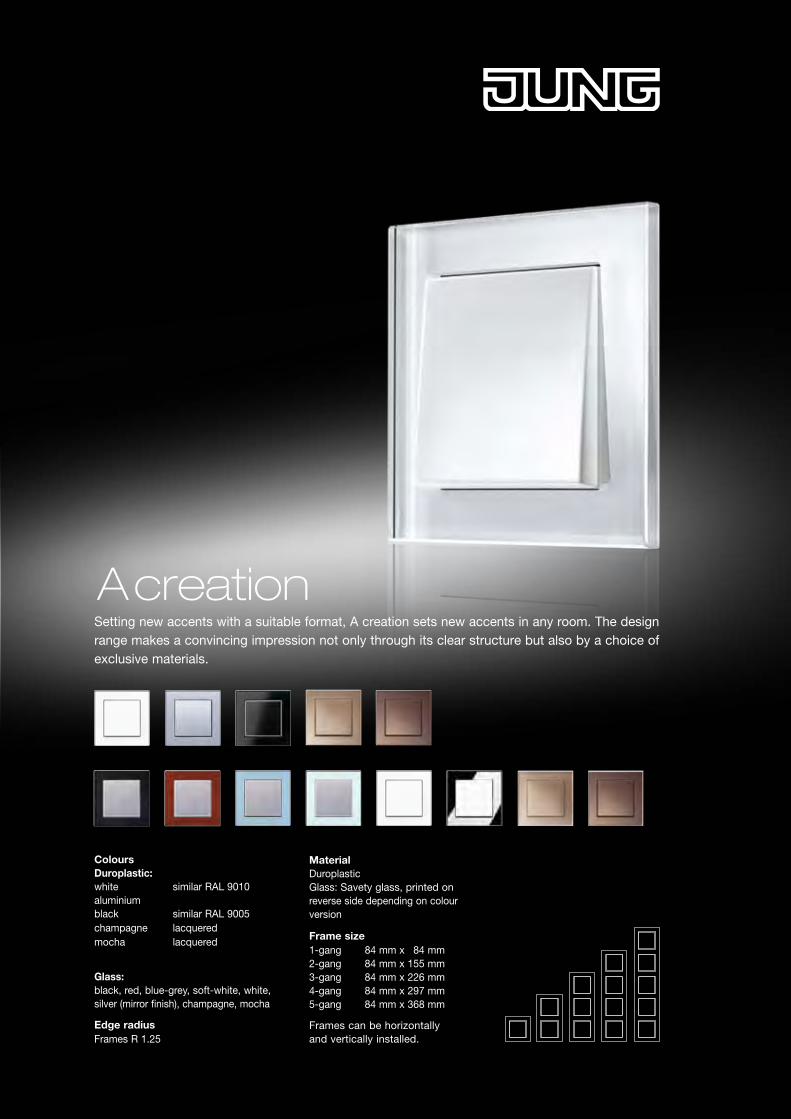
A creation
Colours Duroplastic: white similar RAL 9010 aluminium black similar RAL 9005 champagne lacquered mocha lacquered
Glass: black, red, blue-grey, soft-white, white, silver (mirror finish), champagne, mocha
Edge radius Frames R 1.25
Setting new accents with a suitable format, A creation sets new accents in any room. The design range makes a convincing impression not only through its clear structure but also by a choice of exclusive materials.
Material Duroplastic Glass: Savety glass, printed on reverse side depending on colour version
Frame size 1-gang 84 mm x 84 mm 2-gang 84 mm x 155 mm 3-gang 84 mm x 226 mm 4-gang 84 mm x 297 mm 5-gang 84 mm x 368 mm
Frames can be horizontally and vertically installed.
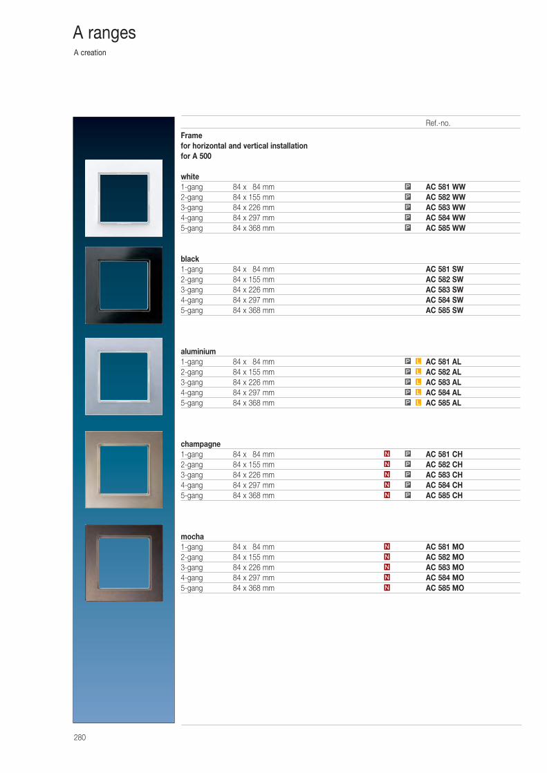
A creation
280
A ranges
Framefor horizontal and vertical installationfor A 500
white1-gang 84 x 084 mm AC 581 WW2-gang 84 x 155 mm AC 582 WW3-gang 84 x 226 mm AC 583 WW4-gang 84 x 297 mm AC 584 WW5-gang 84 x 368 mm AC 585 WW
black1-gang 84 x 084 mm AC 581 SW2-gang 84 x 155 mm AC 582 SW3-gang 84 x 226 mm AC 583 SW4-gang 84 x 297 mm AC 584 SW5-gang 84 x 368 mm AC 585 SW
aluminium1-gang 84 x 084 mm AC 581 AL2-gang 84 x 155 mm AC 582 AL3-gang 84 x 226 mm AC 583 AL4-gang 84 x 297 mm AC 584 AL5-gang 84 x 368 mm AC 585 AL
champagne1-gang 84 x 084 mm AC 581 CH2-gang 84 x 155 mm AC 582 CH3-gang 84 x 226 mm AC 583 CH4-gang 84 x 297 mm AC 584 CH5-gang 84 x 368 mm AC 585 CH
mocha1-gang 84 x 084 mm AC 581 MO2-gang 84 x 155 mm AC 582 MO3-gang 84 x 226 mm AC 583 MO4-gang 84 x 297 mm AC 584 MO5-gang 84 x 368 mm AC 585 MO
P
P
P
P
P
LP
LP
LP
LP
LP
PN
PN
PN
PN
PN
N
N
N
N
N
Ref.-no.
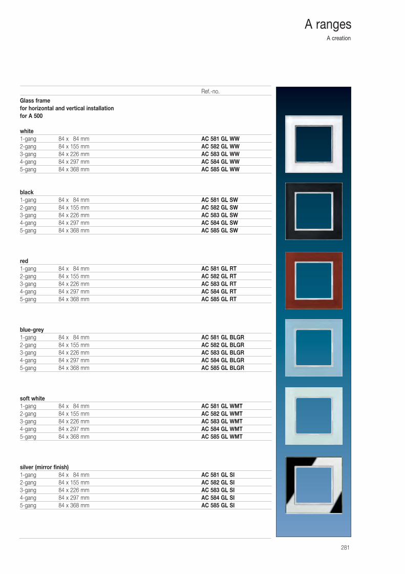
A creation
281
A ranges
Glass framefor horizontal and vertical installationfor A 500
white1-gang 84 x 084 mm AC 581 GL WW2-gang 84 x 155 mm AC 582 GL WW3-gang 84 x 226 mm AC 583 GL WW4-gang 84 x 297 mm AC 584 GL WW5-gang 84 x 368 mm AC 585 GL WW
black1-gang 84 x 084 mm AC 581 GL SW2-gang 84 x 155 mm AC 582 GL SW3-gang 84 x 226 mm AC 583 GL SW4-gang 84 x 297 mm AC 584 GL SW5-gang 84 x 368 mm AC 585 GL SW
red1-gang 84 x 084 mm AC 581 GL RT2-gang 84 x 155 mm AC 582 GL RT3-gang 84 x 226 mm AC 583 GL RT4-gang 84 x 297 mm AC 584 GL RT5-gang 84 x 368 mm AC 585 GL RT
blue-grey1-gang 84 x 084 mm AC 581 GL BLGR2-gang 84 x 155 mm AC 582 GL BLGR3-gang 84 x 226 mm AC 583 GL BLGR4-gang 84 x 297 mm AC 584 GL BLGR5-gang 84 x 368 mm AC 585 GL BLGR
soft white1-gang 84 x 084 mm AC 581 GL WMT2-gang 84 x 155 mm AC 582 GL WMT3-gang 84 x 226 mm AC 583 GL WMT4-gang 84 x 297 mm AC 584 GL WMT5-gang 84 x 368 mm AC 585 GL WMT
silver (mirror finish)1-gang 84 x 084 mm AC 581 GL SI2-gang 84 x 155 mm AC 582 GL SI3-gang 84 x 226 mm AC 583 GL SI4-gang 84 x 297 mm AC 584 GL SI5-gang 84 x 368 mm AC 585 GL SI
Ref.-no.
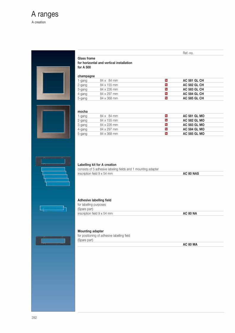
A creation
282
A ranges
Glass framefor horizontal and vertical installationfor A 500
champagne1-gang 84 x 084 mm AC 581 GL CH2-gang 84 x 155 mm AC 582 GL CH3-gang 84 x 226 mm AC 583 GL CH4-gang 84 x 297 mm AC 584 GL CH5-gang 84 x 368 mm AC 585 GL CH
mocha1-gang 84 x 084 mm AC 581 GL MO2-gang 84 x 155 mm AC 582 GL MO3-gang 84 x 226 mm AC 583 GL MO4-gang 84 x 297 mm AC 584 GL MO5-gang 84 x 368 mm AC 585 GL MO
Labelling kit for A creationconsists of 5 adhesive labeling fields and 1 mounting adapterinscription field 9 x 54 mm AC 80 NAS
Adhesive labelling fieldfor labelling purposes(Spare part)inscription field 9 x 54 mm AC 80 NA
Mounting adapterfor positioning of adhesive labelling field(Spare part)
AC 80 MA
N
N
N
N
N
N
N
N
N
N
Ref.-no.
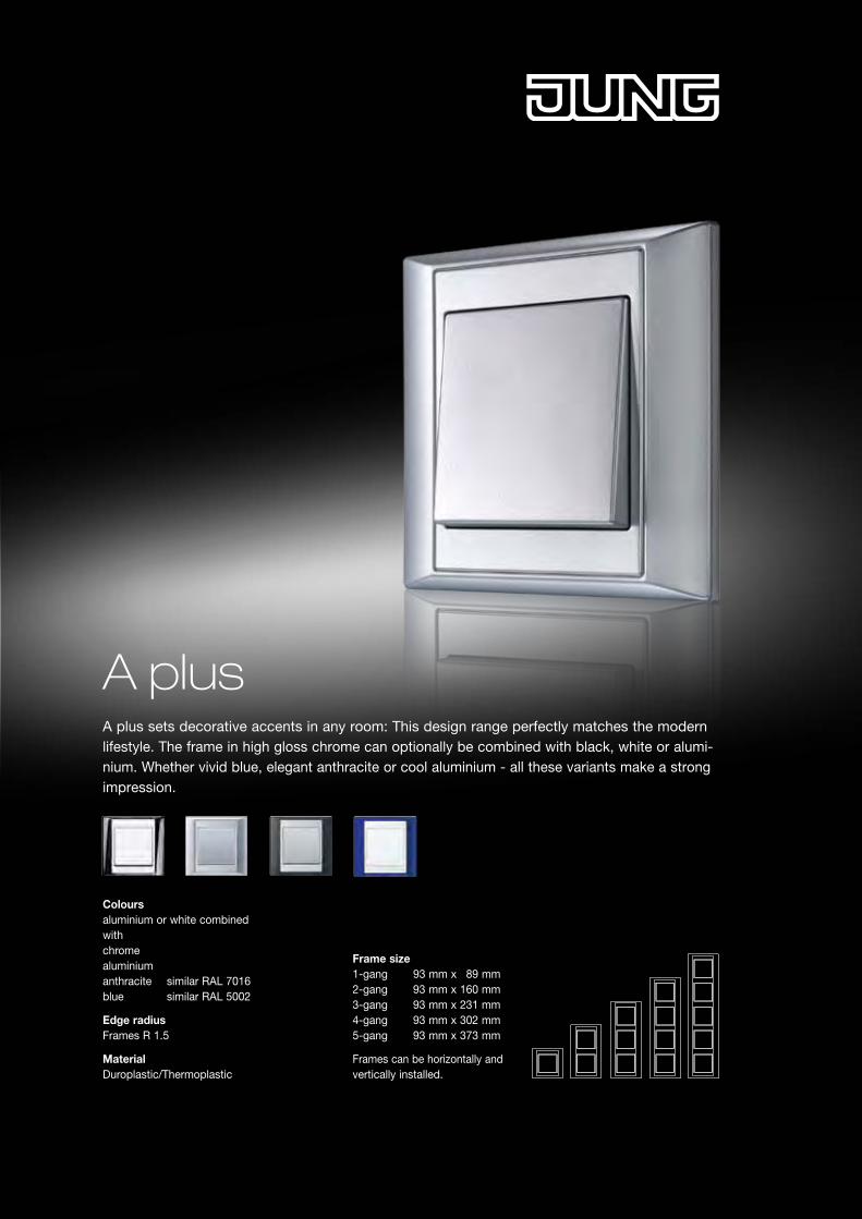
Colours aluminium or white combined with chrome aluminium anthracite similar RAL 7016 blue similar RAL 5002
Edge radius Frames R 1.5
Material Duroplastic/Thermoplastic
Frame size 1-gang 93 mm x 89 mm 2-gang 93 mm x 160 mm 3-gang 93 mm x 231 mm 4-gang 93 mm x 302 mm 5-gang 93 mm x 373 mm
Frames can be horizontally andvertically installed.
A plus sets decorative accents in any room: This design range perfectly matches the modern lifestyle. The frame in high gloss chrome can optionally be combined with black, white or alumi-nium. Whether vivid blue, elegant anthracite or cool aluminium - all these variants make a strong impression.
A plus
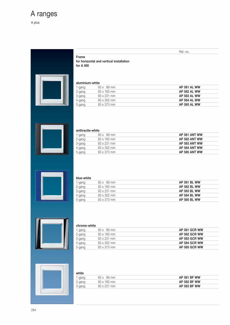
A plus
284
A ranges
Framefor horizontal and vertical installationfor A 500
aluminium-white1-gang 93 x 089 mm AP 581 AL WW2-gang 93 x 160 mm AP 582 AL WW3-gang 93 x 231 mm AP 583 AL WW4-gang 93 x 302 mm AP 584 AL WW5-gang 93 x 373 mm AP 585 AL WW
anthracite-white1-gang 93 x 089 mm AP 581 ANT WW2-gang 93 x 160 mm AP 582 ANT WW3-gang 93 x 231 mm AP 583 ANT WW4-gang 93 x 302 mm AP 584 ANT WW5-gang 93 x 373 mm AP 585 ANT WW
blue-white1-gang 93 x 089 mm AP 581 BL WW2-gang 93 x 160 mm AP 582 BL WW3-gang 93 x 231 mm AP 583 BL WW4-gang 93 x 302 mm AP 584 BL WW5-gang 93 x 373 mm AP 585 BL WW
chrome-white1-gang 93 x 089 mm AP 581 GCR WW2-gang 93 x 160 mm AP 582 GCR WW3-gang 93 x 231 mm AP 583 GCR WW4-gang 93 x 302 mm AP 584 GCR WW5-gang 93 x 373 mm AP 585 GCR WW
white1-gang 93 x 089 mm AP 581 BF WW 2-gang 93 x 160 mm AP 582 BF WW3-gang 93 x 231 mm AP 583 BF WW
Ref.-no.
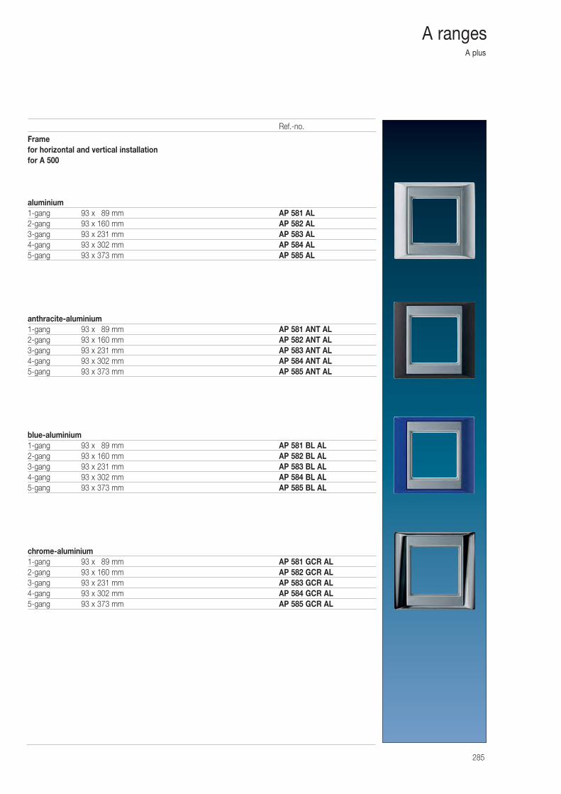
A plus
285
A ranges
Framefor horizontal and vertical installationfor A 500
aluminium1-gang 93 x 089 mm AP 581 AL 2-gang 93 x 160 mm AP 582 AL3-gang 93 x 231 mm AP 583 AL4-gang 93 x 302 mm AP 584 AL5-gang 93 x 373 mm AP 585 AL
anthracite-aluminium1-gang 93 x 089 mm AP 581 ANT AL2-gang 93 x 160 mm AP 582 ANT AL3-gang 93 x 231 mm AP 583 ANT AL4-gang 93 x 302 mm AP 584 ANT AL5-gang 93 x 373 mm AP 585 ANT AL
blue-aluminium1-gang 93 x 089 mm AP 581 BL AL2-gang 93 x 160 mm AP 582 BL AL3-gang 93 x 231 mm AP 583 BL AL4-gang 93 x 302 mm AP 584 BL AL5-gang 93 x 373 mm AP 585 BL AL
chrome-aluminium1-gang 93 x 089 mm AP 581 GCR AL2-gang 93 x 160 mm AP 582 GCR AL3-gang 93 x 231 mm AP 583 GCR AL4-gang 93 x 302 mm AP 584 GCR AL5-gang 93 x 373 mm AP 585 GCR AL
Ref.-no.
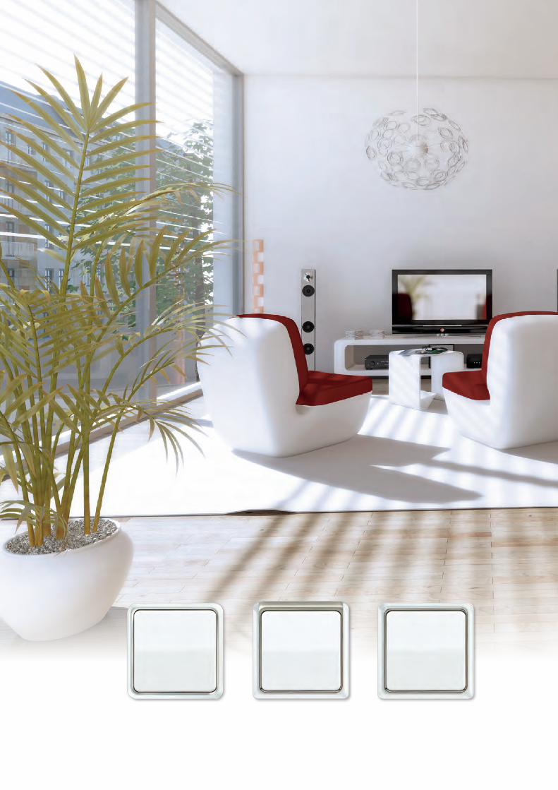
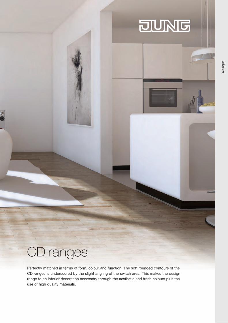
CD rangesPerfectly matched in terms of form, colour and function: The soft rounded contours of the CD ranges is underscored by the slight angling of the switch area. This makes the design range to an interior decoration accessory through the aesthetic and fresh colours plus the use of high quality materials.
CD
rang
es
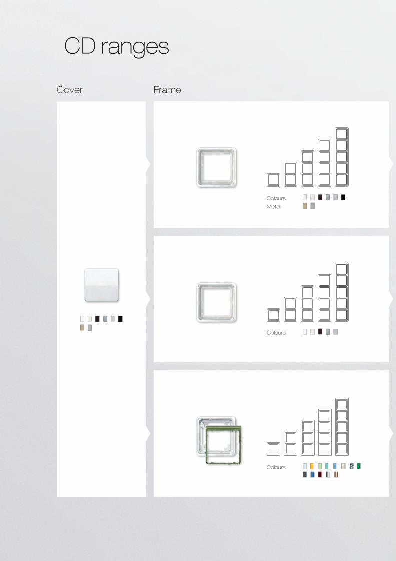
Cover Frame
CD ranges
Colours:
Colours:
Metal:
Colours:
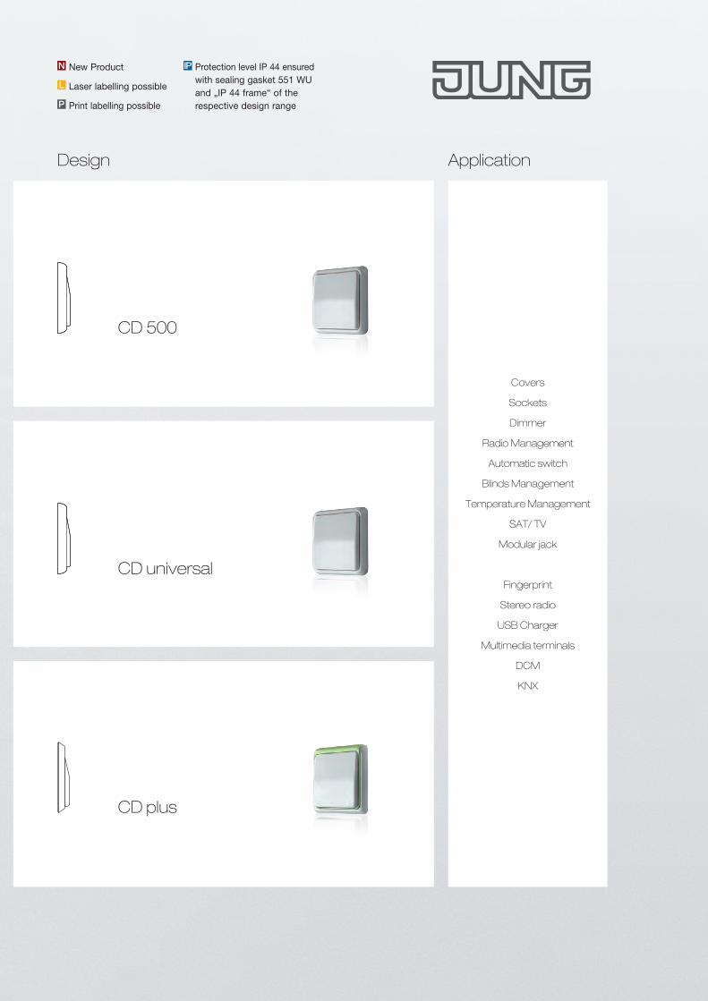
Covers
Sockets
Dimmer
Radio Management
Automatic switch
Blinds Management
Temperature Management
SAT/ TV
Modular jack
Fingerprint
Stereo radio
USB Charger
Multimedia terminals
DCM
KNX
Application
Protection level IP 44 ensured with sealing gasket 551 WU and „IP 44 frame“ of the respective design range
IPNew ProductN
L Laser labelling possible
P Print labelling possible
Design
CD plus
CD 500
CD universal
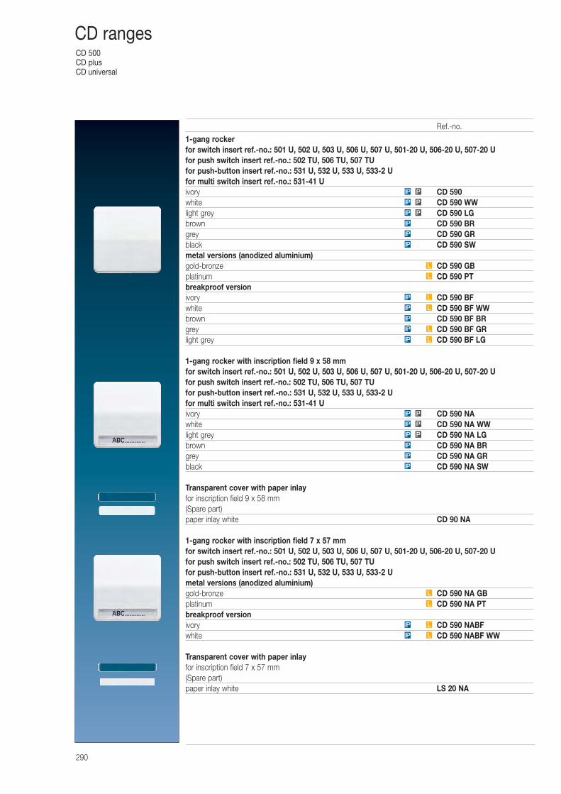
CD 500CD plusCD universal
290
CD ranges
1-gang rockerfor switch insert ref.-no.: 501 U, 502 U, 503 U, 506 U, 507 U, 501-20 U, 506-20 U, 507-20 Ufor push switch insert ref.-no.: 502 TU, 506 TU, 507 TUfor push-button insert ref.-no.: 531 U, 532 U, 533 U, 533-2 Ufor multi switch insert ref.-no.: 531-41 Uivory CD 590white CD 590 WWlight grey CD 590 LGbrown CD 590 BRgrey CD 590 GRblack CD 590 SWmetal versions (anodized aluminium)gold-bronze CD 590 GBplatinum CD 590 PTbreakproof versionivory CD 590 BFwhite CD 590 BF WWbrown CD 590 BF BRgrey CD 590 BF GRlight grey CD 590 BF LG
1-gang rocker with inscription field 9 x 58 mmfor switch insert ref.-no.: 501 U, 502 U, 503 U, 506 U, 507 U, 501-20 U, 506-20 U, 507-20 Ufor push switch insert ref.-no.: 502 TU, 506 TU, 507 TUfor push-button insert ref.-no.: 531 U, 532 U, 533 U, 533-2 Ufor multi switch insert ref.-no.: 531-41 Uivory CD 590 NAwhite CD 590 NA WWlight grey CD 590 NA LGbrown CD 590 NA BRgrey CD 590 NA GRblack CD 590 NA SW
Transparent cover with paper inlayfor inscription field 9 x 58 mm(Spare part)paper inlay white CD 90 NA
1-gang rocker with inscription field 7 x 57 mmfor switch insert ref.-no.: 501 U, 502 U, 503 U, 506 U, 507 U, 501-20 U, 506-20 U, 507-20 Ufor push switch insert ref.-no.: 502 TU, 506 TU, 507 TUfor push-button insert ref.-no.: 531 U, 532 U, 533 U, 533-2 Umetal versions (anodized aluminium)gold-bronze CD 590 NA GBplatinum CD 590 NA PTbreakproof versionivory CD 590 NABFwhite CD 590 NABF WW
Transparent cover with paper inlayfor inscription field 7 x 57 mm(Spare part)paper inlay white LS 20 NA
LIP
LIP
L
L
IP
IP
IP
PIP
PIP
PIP
LIP
LIP
IP
LIP
LIP
L
L
IP
IP
IP
PIP
PIP
PIP
Ref.-no.
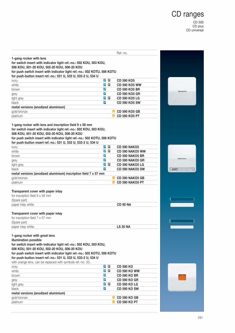
CD 500CD plus
CD universal
291
CD ranges
1-gang rocker with lensfor switch insert with indicator light ref.-no.: 502 KOU, 503 KOU, 506 KOU, 501-20 KOU, 502-20 KOU, 506-20 KOUfor push switch insert with indicator light ref.-no.: 502 KOTU, 506 KOTUfor push-button insert ref.-no.: 531 U, 533 U, 533-2 U, 534 Uivory CD 590 KO5white CD 590 KO5 WWbrown CD 590 KO5 BRgrey CD 590 KO5 GRlight grey CD 590 KO5 LGblack CD 590 KO5 SWmetal versions (anodized aluminium)gold-bronze CD 590 KO5 GBplatinum CD 590 KO5 PT
1-gang rocker with lens and inscription field 9 x 58 mmfor switch insert with indicator light ref.-no.: 502 KOU, 503 KOU, 506 KOU, 501-20 KOU, 502-20 KOU, 506-20 KOUfor push switch insert with indicator light ref.-no.: 502 KOTU, 506 KOTUfor push-button insert ref.-no.: 531 U, 533 U, 533-2 U, 534 Uivory CD 590 NAKO5white CD 590 NAKO5 WWbrown CD 590 NAKO5 BRgrey CD 590 NAKO5 GRlight grey CD 590 NAKO5 LGblack CD 590 NAKO5 SWmetal versions (anodized aluminium) inscription field 7 x 57 mmgold-bronze CD 590 NAKO5 GBplatinum CD 590 NAKO5 PT
Transparent cover with paper inlayfor inscription field 9 x 58 mm(Spare part)paper inlay white CD 90 NA
Transparent cover with paper inlayfor inscription field 7 x 57 mm(Spare part)paper inlay white LS 20 NA
1-gang rocker with great lensillumination possiblefor switch insert with indicator light ref.-no.: 502 KOU, 503 KOU, 506 KOU, 501-20 KOU, 502-20 KOU, 506-20 KOUfor push switch insert with indicator light ref.-no.: 502 KOTU, 506 KOTUfor push-button insert ref.-no.: 531 U, 533 U, 533-2 U, 534 Uwith orange lens, can be replaced with symbols ref.-no. 33..ivory CD 590 KOwhite CD 590 KO WWbrown CD 590 KO BRgrey CD 590 KO GRlight grey CD 590 KO LGblack CD 590 KO SWmetal versions (anodized aluminium)gold-bronze CD 590 KO GBplatinum CD 590 KO PTL
L
IP
PIP
IP
IP
PIP
PIP
L
L
IP
PIP
IP
IP
PIP
PIP
L
L
IP
PIP
IP
IP
PIP
PIP
Ref.-no.
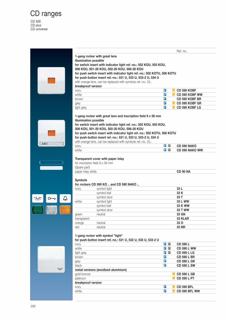
CD 500CD plusCD universal
292
CD ranges
1-gang rocker with great lensillumination possiblefor switch insert with indicator light ref.-no.: 502 KOU, 503 KOU, 506 KOU, 501-20 KOU, 502-20 KOU, 506-20 KOUfor push switch insert with indicator light ref.-no.: 502 KOTU, 506 KOTUfor push-button insert ref.-no.: 531 U, 533 U, 533-2 U, 534 Uwith orange lens, can be replaced with symbols ref.-no. 33..breakproof versionivory CD 590 KOBFwhite CD 590 KOBF WWbrown CD 590 KOBF BRgrey CD 590 KOBF GRlight grey CD 590 KOBF LG
1-gang rocker with great lens and inscription field 9 x 58 mmillumination possiblefor switch insert with indicator light ref.-no.: 502 KOU, 503 KOU, 506 KOU, 501-20 KOU, 502-20 KOU, 506-20 KOUfor push switch insert with indicator light ref.-no.: 502 KOTU, 506 KOTUfor push-button insert ref.-no.: 531 U, 533 U, 533-2 U, 534 Uwith orange lens, can be replaced with symbols ref.-no. 33..ivory CD 590 NAKOwhite CD 590 NAKO WW
Transparent cover with paper inlayfor inscription field 9 x 58 mm(Spare part)paper inlay white CD 90 NA
Symbolsfor rockers CD 590 KO .. and CD 590 NAKO ..ivory symbol light 33 L
symbol bell 33 Ksymbol door 33 T
white symbol light 33 L WWsymbol bell 33 K WWsymbol door 33 T WW
green neutral 33 GNtransparent 33 KLARorange neutral 33 Ored neutral 33 NR
1-gang rocker with symbol "light"for push-button insert ref.-no.: 531 U, 532 U, 533 U, 533-2 Uivory CD 590 Lwhite CD 590 L WWlight grey CD 590 L LGbrown CD 590 L BRgrey CD 590 L GRblack CD 590 L SWmetal versions (anodized aluminium)gold-bronze CD 590 L GBplatinum CD 590 L PTbreakproof versionivory CD 590 BFLwhite CD 590 BFL WW
LIP
LIP
LIP
IP
LIP
LIP
LIP
L
L
IP
IP
IP
PIP
PIP
PIP
PIP
PIP
Ref.-no.
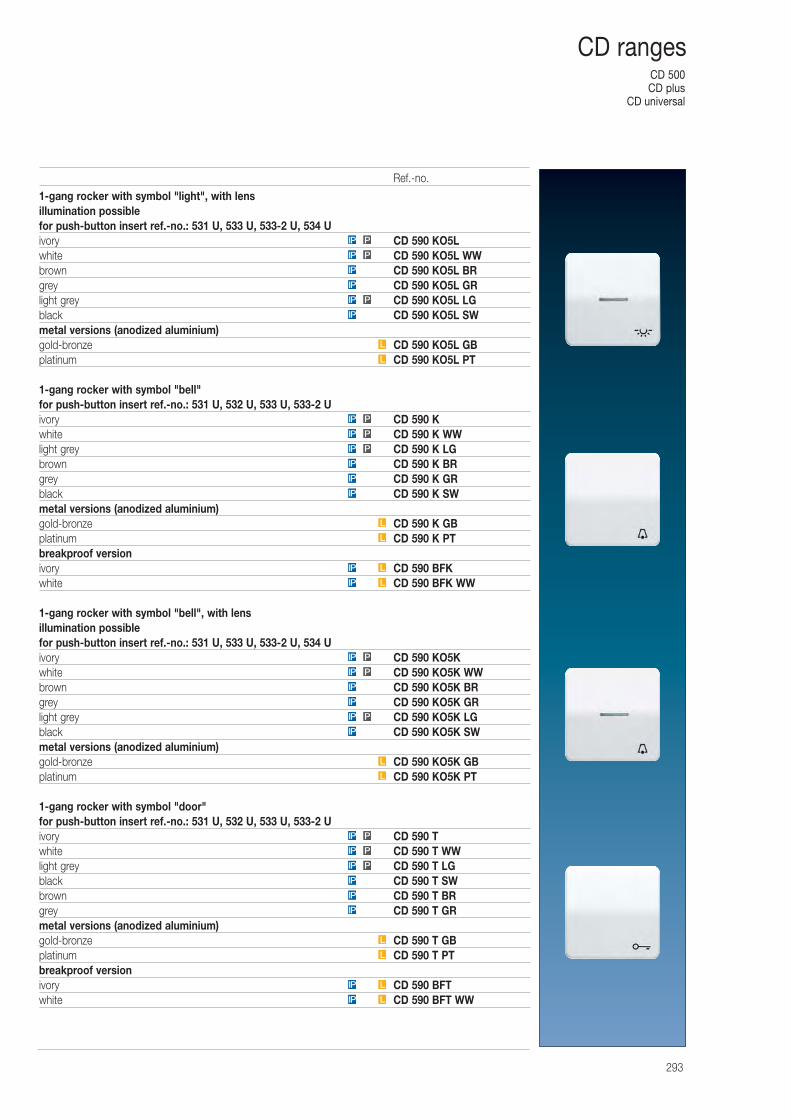
CD 500CD plus
CD universal
293
CD ranges
1-gang rocker with symbol "light", with lensillumination possiblefor push-button insert ref.-no.: 531 U, 533 U, 533-2 U, 534 Uivory CD 590 KO5Lwhite CD 590 KO5L WWbrown CD 590 KO5L BRgrey CD 590 KO5L GRlight grey CD 590 KO5L LGblack CD 590 KO5L SWmetal versions (anodized aluminium)gold-bronze CD 590 KO5L GBplatinum CD 590 KO5L PT
1-gang rocker with symbol "bell"for push-button insert ref.-no.: 531 U, 532 U, 533 U, 533-2 Uivory CD 590 Kwhite CD 590 K WWlight grey CD 590 K LGbrown CD 590 K BRgrey CD 590 K GRblack CD 590 K SWmetal versions (anodized aluminium)gold-bronze CD 590 K GBplatinum CD 590 K PTbreakproof versionivory CD 590 BFKwhite CD 590 BFK WW
1-gang rocker with symbol "bell", with lensillumination possiblefor push-button insert ref.-no.: 531 U, 533 U, 533-2 U, 534 Uivory CD 590 KO5Kwhite CD 590 KO5K WWbrown CD 590 KO5K BRgrey CD 590 KO5K GRlight grey CD 590 KO5K LGblack CD 590 KO5K SWmetal versions (anodized aluminium)gold-bronze CD 590 KO5K GBplatinum CD 590 KO5K PT
1-gang rocker with symbol "door"for push-button insert ref.-no.: 531 U, 532 U, 533 U, 533-2 Uivory CD 590 Twhite CD 590 T WWlight grey CD 590 T LGblack CD 590 T SWbrown CD 590 T BRgrey CD 590 T GRmetal versions (anodized aluminium)gold-bronze CD 590 T GBplatinum CD 590 T PTbreakproof versionivory CD 590 BFTwhite CD 590 BFT WW
L
L
IP
PIP
IP
IP
PIP
PIP
LIP
LIP
L
L
IP
IP
IP
PIP
PIP
PIP
L
L
IP
PIP
IP
IP
PIP
PIP
LIP
LIP
L
L
IP
IP
IP
PIP
PIP
PIP
Ref.-no.
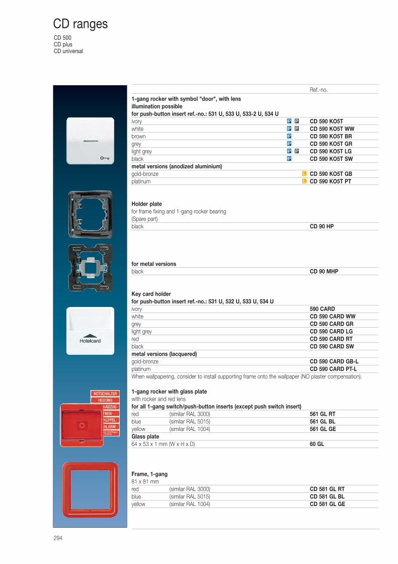
CD 500CD plusCD universal
294
CD ranges
1-gang rocker with symbol "door", with lensillumination possiblefor push-button insert ref.-no.: 531 U, 533 U, 533-2 U, 534 Uivory CD 590 KO5Twhite CD 590 KO5T WWbrown CD 590 KO5T BRgrey CD 590 KO5T GRlight grey CD 590 KO5T LGblack CD 590 KO5T SWmetal versions (anodized aluminium)gold-bronze CD 590 KO5T GBplatinum CD 590 KO5T PT
Holder platefor frame fixing and 1-gang rocker bearing(Spare part)black CD 90 HP
for metal versionsblack CD 90 MHP
Key card holderfor push-button insert ref.-no.: 531 U, 532 U, 533 U, 534 Uivory 590 CARDwhite CD 590 CARD WWgrey CD 590 CARD GRlight grey CD 590 CARD LGred CD 590 CARD RTblack CD 590 CARD SWmetal versions (lacquered)gold-bronze CD 590 CARD GB-Lplatinum CD 590 CARD PT-LWhen wallpapering, consider to install supporting frame onto the wallpaper (NO plaster compensation).
1-gang rocker with glass platewith rocker and red lensfor all 1-gang switch/push-button inserts (except push switch insert)red (similar RAL 3000) 561 GL RTblue (similar RAL 5015) 561 GL BLyellow (similar RAL 1004) 561 GL GEGlass plate64 x 53 x 1 mm (W x H x D) 60 GL
Frame, 1-gang81 x 81 mmred (similar RAL 3000) CD 581 GL RTblue (similar RAL 5015) CD 581 GL BLyellow (similar RAL 1004) CD 581 GL GE
L
L
IP
PIP
IP
IP
PIP
PIP
Ref.-no.

CD 500CD plus
CD universal
295
CD ranges
Pull cord switch 10 AX / 250 V ~for wall and ceiling installationScrew terminals for wires up to 2.5 mm2
with 50 mm pull cordivory full plate 5506 ZUwhite full plate 5506 ZU WWivory centre plate Z 506 NUZVwhite centre plate Z 506 NUZ VWWOther pull cord devices can be realized with pull cord insert 34 and 1-gang rocker with great lens A 590 KO .. or pull cord insert 34 KO5 and 1-gang rocker with lens A 590 KO5 ..
2-gang rockerfor switch insert ref.-no.: 505 U, 509 Ufor push switch insert ref.-no.: 505 TU, 509 TUfor push-button insert ref.-no.: 535 U, 539 Ufor multi switch insert ref.-no.: 532-4 Uivory CD 595white CD 595 WWbrown CD 595 BRgrey CD 595 GRlight grey CD 595 LGblack CD 595 SWmetal versions (anodized aluminium)gold-bronze CD 595 GBplatinum CD 595 PTbreakproof versionivory CD 595 BFwhite CD 595 BF WWbrown CD 595 BF BRgrey CD 595 BF GRlight grey CD 595 BF LG
2-gang rocker with inscription field 9 x 27 mmfor switch insert ref.-no.: 505 U, 509 Ufor push switch insert ref.-no.: 505 TU, 509 TUfor push-button insert ref.-no.: 535 U, 539 Ufor multi switch insert ref.-no.: 532-4 Uivory CD 595 NAwhite CD 595 NA WWbrown CD 595 NA BRgrey CD 595 NA GRlight grey CD 595 NA LGblack CD 595 NA SW
Transparent cover with paper inlayfor inscription field 9 x 27 mm(Spare part)A set of two coverspaper inlay white CD 95 NA
P
P
P
P
L
L
IP
PIP
IP
IP
PIP
PIP
IP
PIP
IP
IP
PIP
PIP
LIP
LIP
IP
LIP
LIP
Ref.-no.
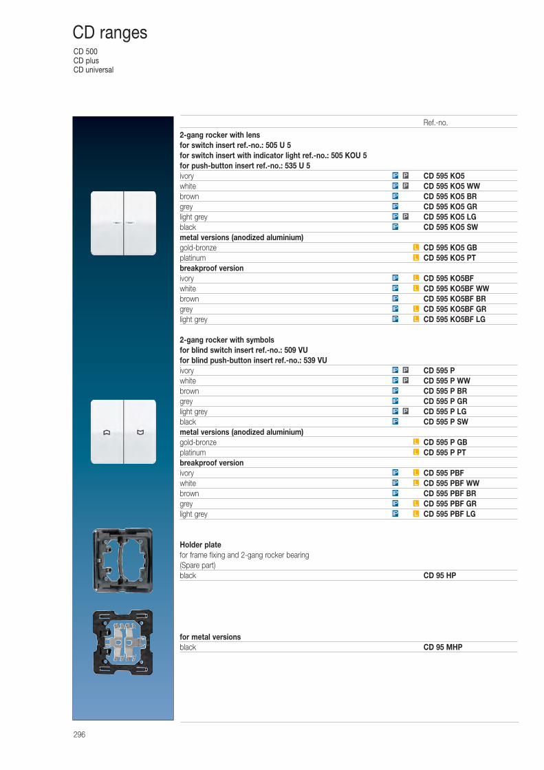
CD 500CD plusCD universal
296
CD ranges
2-gang rocker with lensfor switch insert ref.-no.: 505 U 5for switch insert with indicator light ref.-no.: 505 KOU 5for push-button insert ref.-no.: 535 U 5ivory CD 595 KO5white CD 595 KO5 WWbrown CD 595 KO5 BRgrey CD 595 KO5 GRlight grey CD 595 KO5 LGblack CD 595 KO5 SWmetal versions (anodized aluminium)gold-bronze CD 595 KO5 GBplatinum CD 595 KO5 PTbreakproof versionivory CD 595 KO5BFwhite CD 595 KO5BF WWbrown CD 595 KO5BF BRgrey CD 595 KO5BF GRlight grey CD 595 KO5BF LG
2-gang rocker with symbolsfor blind switch insert ref.-no.: 509 VUfor blind push-button insert ref.-no.: 539 VUivory CD 595 Pwhite CD 595 P WWbrown CD 595 P BRgrey CD 595 P GRlight grey CD 595 P LGblack CD 595 P SWmetal versions (anodized aluminium)gold-bronze CD 595 P GBplatinum CD 595 P PTbreakproof versionivory CD 595 PBFwhite CD 595 PBF WWbrown CD 595 PBF BRgrey CD 595 PBF GRlight grey CD 595 PBF LG
Holder platefor frame fixing and 2-gang rocker bearing(Spare part)black CD 95 HP
for metal versionsblack CD 95 MHP
IP
L
L
IP
PIP
IP
IP
PIP
PIP
LIP
LIP
IP
LIP
LIP
L
L
IP
P
IP
IP
PIP
PIP
LIP
LIP
IP
LIP
LIP
Ref.-no.
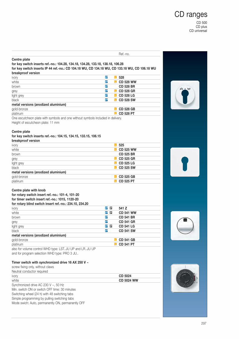
CD 500CD plus
CD universal
297
CD ranges
Centre platefor key switch inserts ref.-no.: 104.28, 134.18, 134.28, 133.18, 138.18, 106.28for key switch inserts IP 44 ref.-no.: CD 104.18 WU, CD 134.18 WU, CD 133.18 WU, CD 106.18 WUbreakproof versionivory 528white CD 528 WWbrown CD 528 BRgrey CD 528 GRlight grey CD 528 LGblack CD 528 SWmetal versions (anodized aluminium)gold-bronze CD 528 GBplatinum CD 528 PTOne escutcheon plate with symbols and one without symbols included in delivery.Height of escutcheon plate: 11 mm
Centre platefor key switch inserts ref.-no.: 104.15, 134.15, 133.15, 106.15breakproof versionivory 525white CD 525 WWbrown CD 525 BRgrey CD 525 GRlight grey CD 525 LGblack CD 525 SWmetal versions (anodized aluminium)gold-bronze CD 525 GBplatinum CD 525 PT
Centre plate with knobfor rotary switch insert ref.-no.: 101-4, 101-20for timer switch insert ref.-no.: 1015, 1120-20for rotary blind switch insert ref.-no.: 234.10, 234.20ivory 541 Zwhite CD 541 WWbrown CD 541 BRgrey CD 541 GRlight grey CD 541 LGblack CD 541 SWmetal versions (anodized aluminium)gold-bronze CD 541 GBplatinum CD 541 PTalso for volume control WHD type: LST..JU UP and LR..JU UPand for program selection WHD type: PRO 3 JU..
Timer switch with synchronized drive 16 AX 250 V ~screw fixing only, without clawsNeutral conductor requiredivory CD 5024white CD 5024 WWSynchronized drive AC 230 V ~, 50 HzMin. switch ON or switch OFF time: 30 minutesSwitching wheel (24 h) with 48 switching tabsSimple programming by pulling switching tabsMode swich: Auto, permanently ON, permanently OFF
LIP
LIP
IP
LIP
LIP
LIP
L
L
L
IP
PIP
IP
IP
PIP
PIP
L
L
L
L
L
L
L
L
Ref.-no.
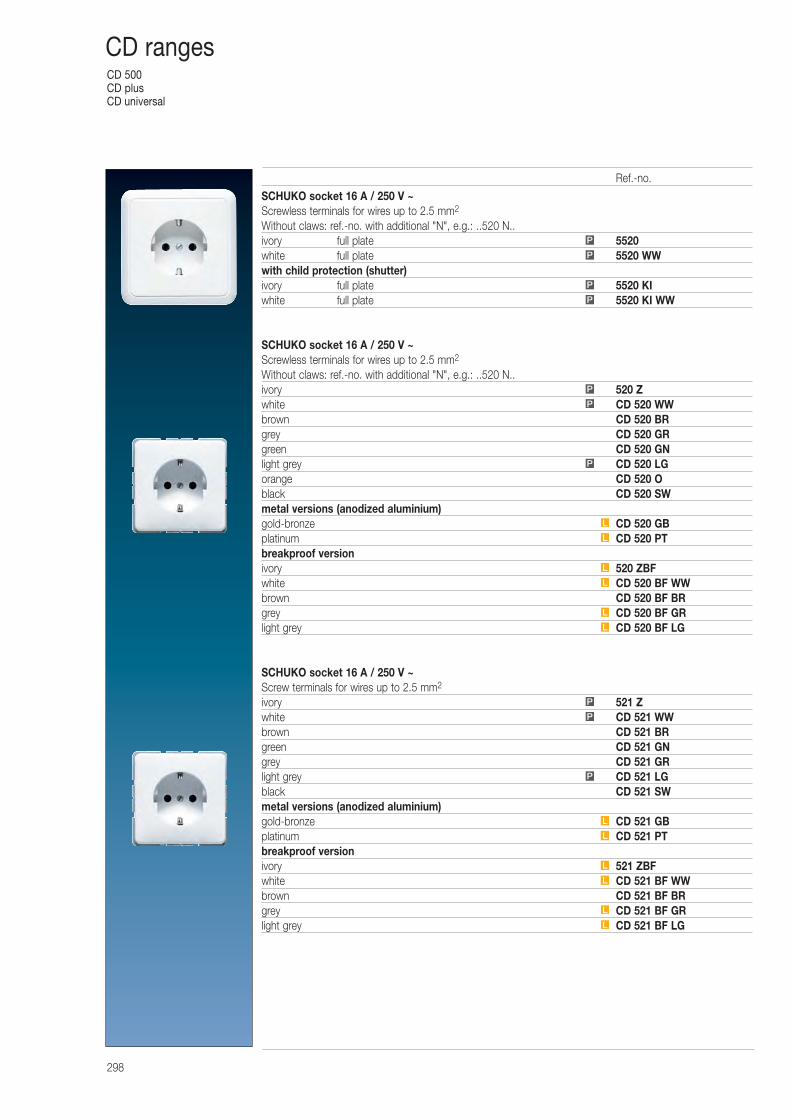
CD 500CD plusCD universal
298
CD ranges
SCHUKO socket 16 A / 250 V ~Screwless terminals for wires up to 2.5 mm2
Without claws: ref.-no. with additional "N", e.g.: ..520 N..ivory full plate 5520white full plate 5520 WWwith child protection (shutter)ivory full plate 5520 KIwhite full plate 5520 KI WW
SCHUKO socket 16 A / 250 V ~Screwless terminals for wires up to 2.5 mm2
Without claws: ref.-no. with additional "N", e.g.: ..520 N..ivory 520 Zwhite CD 520 WWbrown CD 520 BRgrey CD 520 GRgreen CD 520 GNlight grey CD 520 LGorange CD 520 Oblack CD 520 SWmetal versions (anodized aluminium)gold-bronze CD 520 GBplatinum CD 520 PTbreakproof versionivory 520 ZBFwhite CD 520 BF WWbrown CD 520 BF BRgrey CD 520 BF GRlight grey CD 520 BF LG
SCHUKO socket 16 A / 250 V ~Screw terminals for wires up to 2.5 mm2
ivory 521 Zwhite CD 521 WWbrown CD 521 BRgreen CD 521 GNgrey CD 521 GRlight grey CD 521 LGblack CD 521 SWmetal versions (anodized aluminium)gold-bronze CD 521 GBplatinum CD 521 PTbreakproof versionivory 521 ZBFwhite CD 521 BF WWbrown CD 521 BF BRgrey CD 521 BF GRlight grey CD 521 BF LG
L
L
L
L
L
P
P
P
L
L
L
L
L
L
P
P
P
P
P
P
P
L
Ref.-no.
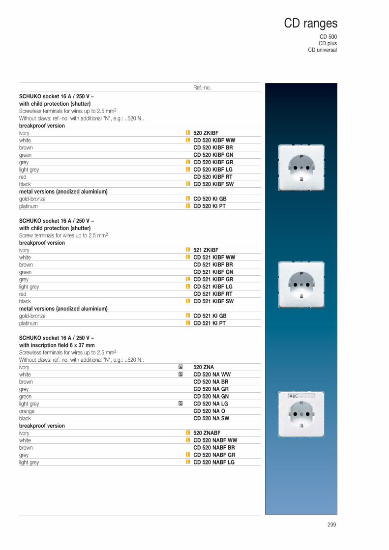
CD 500CD plus
CD universal
299
CD ranges
SCHUKO socket 16 A / 250 V ~with child protection (shutter)Screwless terminals for wires up to 2.5 mm2
Without claws: ref.-no. with additional "N", e.g.: ..520 N..breakproof versionivory 520 ZKIBFwhite CD 520 KIBF WWbrown CD 520 KIBF BRgreen CD 520 KIBF GNgrey CD 520 KIBF GRlight grey CD 520 KIBF LGred CD 520 KIBF RTblack CD 520 KIBF SWmetal versions (anodized aluminium)gold-bronze CD 520 KI GBplatinum CD 520 KI PT
SCHUKO socket 16 A / 250 V ~with child protection (shutter)Screw terminals for wires up to 2.5 mm2
breakproof versionivory 521 ZKIBFwhite CD 521 KIBF WWbrown CD 521 KIBF BRgreen CD 521 KIBF GNgrey CD 521 KIBF GRlight grey CD 521 KIBF LGred CD 521 KIBF RTblack CD 521 KIBF SWmetal versions (anodized aluminium)gold-bronze CD 521 KI GBplatinum CD 521 KI PT
SCHUKO socket 16 A / 250 V ~with inscription field 6 x 37 mmScrewless terminals for wires up to 2.5 mm2
Without claws: ref.-no. with additional "N", e.g.: ..520 N..ivory 520 ZNAwhite CD 520 NA WWbrown CD 520 NA BRgrey CD 520 NA GRgreen CD 520 NA GNlight grey CD 520 NA LGorange CD 520 NA Oblack CD 520 NA SWbreakproof versionivory 520 ZNABFwhite CD 520 NABF WWbrown CD 520 NABF BRgrey CD 520 NABF GRlight grey CD 520 NABF LGL
L
L
L
P
P
P
L
L
L
L
L
L
L
L
L
L
L
L
L
L
Ref.-no.
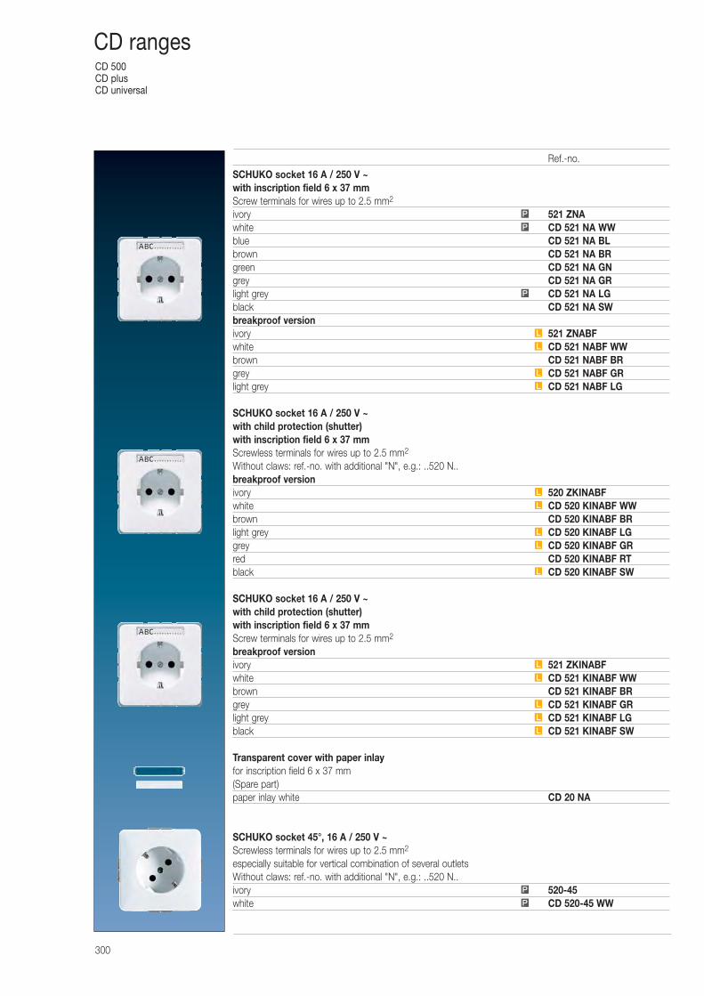
CD 500CD plusCD universal
300
CD ranges
SCHUKO socket 16 A / 250 V ~with inscription field 6 x 37 mmScrew terminals for wires up to 2.5 mm2
ivory 521 ZNAwhite CD 521 NA WWblue CD 521 NA BLbrown CD 521 NA BRgreen CD 521 NA GNgrey CD 521 NA GRlight grey CD 521 NA LGblack CD 521 NA SWbreakproof versionivory 521 ZNABFwhite CD 521 NABF WWbrown CD 521 NABF BRgrey CD 521 NABF GRlight grey CD 521 NABF LG
SCHUKO socket 16 A / 250 V ~with child protection (shutter)with inscription field 6 x 37 mmScrewless terminals for wires up to 2.5 mm2
Without claws: ref.-no. with additional "N", e.g.: ..520 N..breakproof versionivory 520 ZKINABFwhite CD 520 KINABF WWbrown CD 520 KINABF BRlight grey CD 520 KINABF LGgrey CD 520 KINABF GRred CD 520 KINABF RTblack CD 520 KINABF SW
SCHUKO socket 16 A / 250 V ~with child protection (shutter)with inscription field 6 x 37 mmScrew terminals for wires up to 2.5 mm2
breakproof versionivory 521 ZKINABFwhite CD 521 KINABF WWbrown CD 521 KINABF BRgrey CD 521 KINABF GRlight grey CD 521 KINABF LGblack CD 521 KINABF SW
Transparent cover with paper inlayfor inscription field 6 x 37 mm(Spare part)paper inlay white CD 20 NA
SCHUKO socket 45°, 16 A / 250 V ~Screwless terminals for wires up to 2.5 mm2
especially suitable for vertical combination of several outletsWithout claws: ref.-no. with additional "N", e.g.: ..520 N..ivory 520-45white CD 520-45 WW
P
P
P
L
L
L
L
L
L
L
L
L
L
L
L
L
L
P
P
Ref.-no.
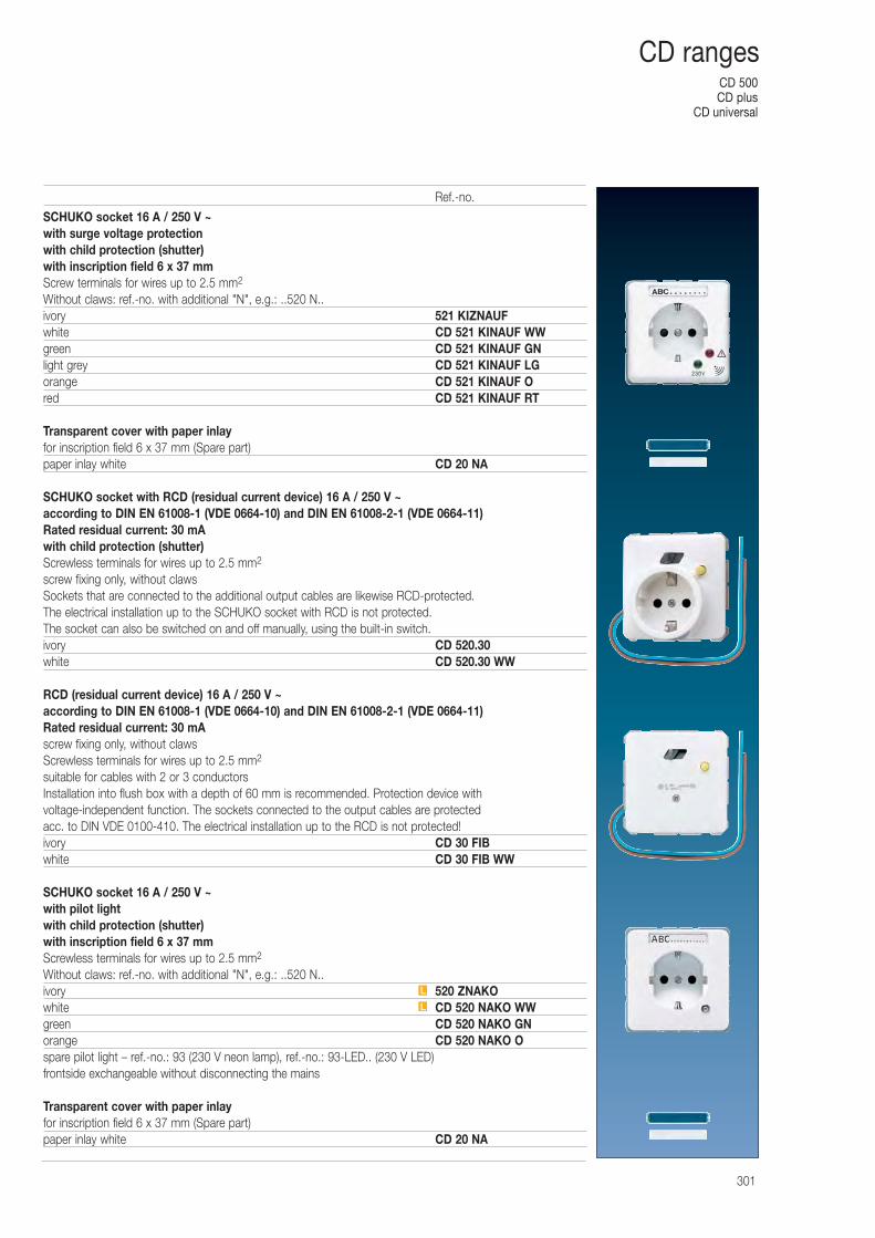
CD 500CD plus
CD universal
301
CD ranges
SCHUKO socket 16 A / 250 V ~with surge voltage protectionwith child protection (shutter)with inscription field 6 x 37 mmScrew terminals for wires up to 2.5 mm2
Without claws: ref.-no. with additional "N", e.g.: ..520 N..ivory 521 KIZNAUFwhite CD 521 KINAUF WWgreen CD 521 KINAUF GNlight grey CD 521 KINAUF LGorange CD 521 KINAUF Ored CD 521 KINAUF RT
Transparent cover with paper inlayfor inscription field 6 x 37 mm (Spare part)paper inlay white CD 20 NA
SCHUKO socket with RCD (residual current device) 16 A / 250 V ~according to DIN EN 61008-1 (VDE 0664-10) and DIN EN 61008-2-1 (VDE 0664-11)Rated residual current: 30 mAwith child protection (shutter)Screwless terminals for wires up to 2.5 mm2
screw fixing only, without clawsSockets that are connected to the additional output cables are likewise RCD-protected. The electrical installation up to the SCHUKO socket with RCD is not protected. The socket can also be switched on and off manually, using the built-in switch.ivory CD 520.30white CD 520.30 WW
RCD (residual current device) 16 A / 250 V ~according to DIN EN 61008-1 (VDE 0664-10) and DIN EN 61008-2-1 (VDE 0664-11)Rated residual current: 30 mAscrew fixing only, without clawsScrewless terminals for wires up to 2.5 mm2
suitable for cables with 2 or 3 conductorsInstallation into flush box with a depth of 60 mm is recommended. Protection device with voltage-independent function. The sockets connected to the output cables are protected acc. to DIN VDE 0100-410. The electrical installation up to the RCD is not protected!ivory CD 30 FIBwhite CD 30 FIB WW
SCHUKO socket 16 A / 250 V ~with pilot lightwith child protection (shutter)with inscription field 6 x 37 mmScrewless terminals for wires up to 2.5 mm2
Without claws: ref.-no. with additional "N", e.g.: ..520 N..ivory 520 ZNAKOwhite CD 520 NAKO WWgreen CD 520 NAKO GNorange CD 520 NAKO Ospare pilot light – ref.-no.: 93 (230 V neon lamp), ref.-no.: 93-LED.. (230 V LED) frontside exchangeable without disconnecting the mains
Transparent cover with paper inlayfor inscription field 6 x 37 mm (Spare part)paper inlay white CD 20 NA
L
L
Ref.-no.
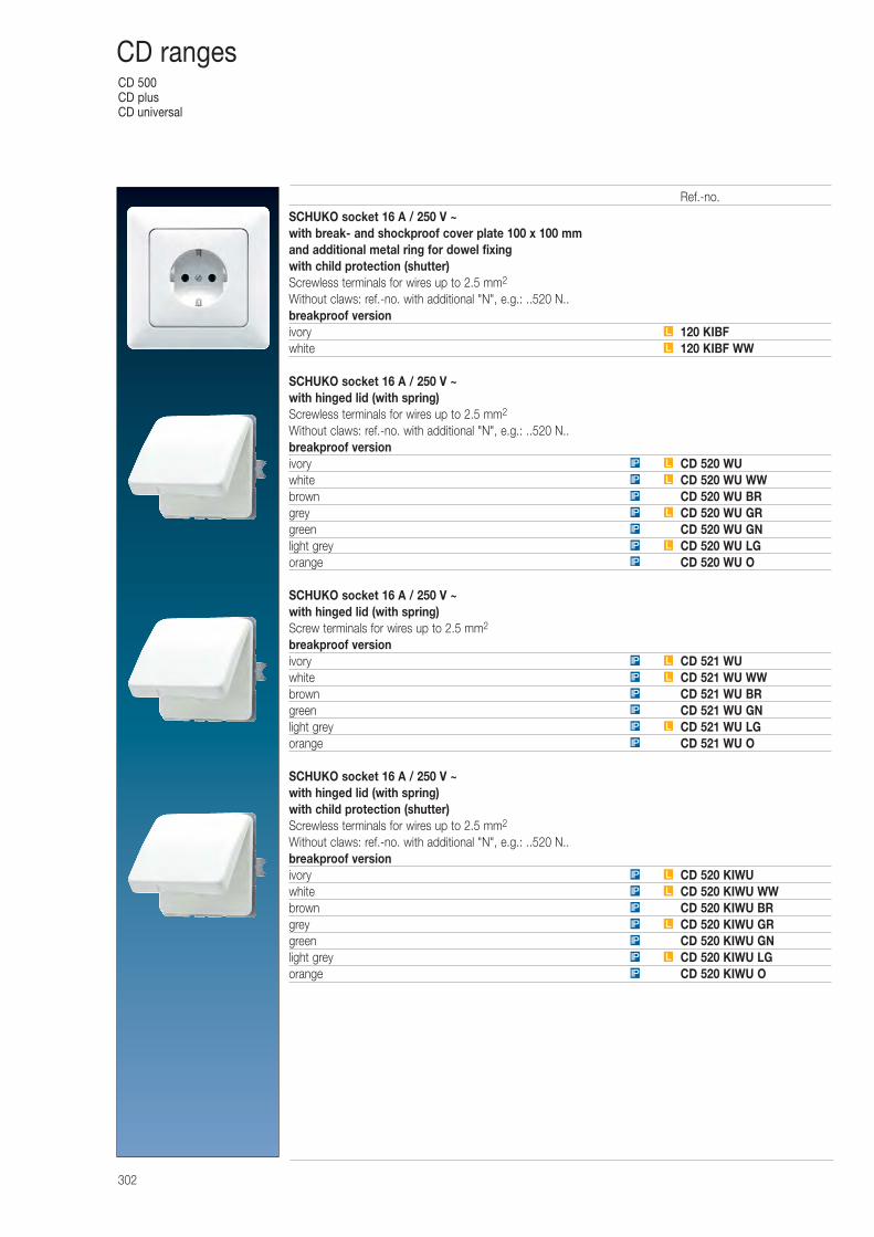
CD 500CD plusCD universal
302
CD ranges
SCHUKO socket 16 A / 250 V ~with break- and shockproof cover plate 100 x 100 mmand additional metal ring for dowel fixingwith child protection (shutter)Screwless terminals for wires up to 2.5 mm2
Without claws: ref.-no. with additional "N", e.g.: ..520 N..breakproof versionivory 120 KIBFwhite 120 KIBF WW
SCHUKO socket 16 A / 250 V ~with hinged lid (with spring)Screwless terminals for wires up to 2.5 mm2
Without claws: ref.-no. with additional "N", e.g.: ..520 N..breakproof versionivory CD 520 WUwhite CD 520 WU WWbrown CD 520 WU BRgrey CD 520 WU GRgreen CD 520 WU GNlight grey CD 520 WU LGorange CD 520 WU O
SCHUKO socket 16 A / 250 V ~with hinged lid (with spring)Screw terminals for wires up to 2.5 mm2
breakproof versionivory CD 521 WUwhite CD 521 WU WWbrown CD 521 WU BRgreen CD 521 WU GNlight grey CD 521 WU LGorange CD 521 WU O
SCHUKO socket 16 A / 250 V ~with hinged lid (with spring)with child protection (shutter)Screwless terminals for wires up to 2.5 mm2
Without claws: ref.-no. with additional "N", e.g.: ..520 N..breakproof versionivory CD 520 KIWUwhite CD 520 KIWU WWbrown CD 520 KIWU BRgrey CD 520 KIWU GRgreen CD 520 KIWU GNlight grey CD 520 KIWU LGorange CD 520 KIWU OIP
LIP
IP
LIP
IP
LIP
LIP
IP
LIP
IP
IP
LIP
LIP
IP
LIP
IP
LIP
IP
LIP
LIP
L
L
Ref.-no.
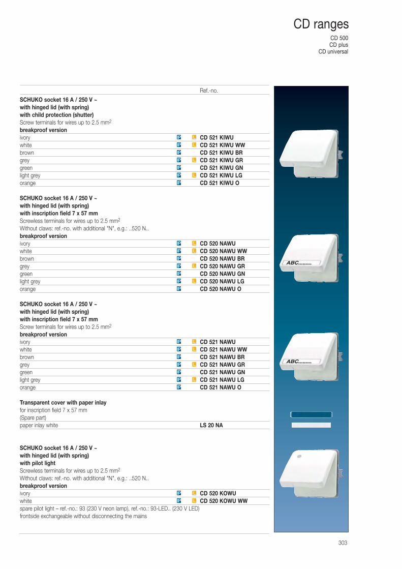
CD 500CD plus
CD universal
303
CD ranges
SCHUKO socket 16 A / 250 V ~with hinged lid (with spring)with child protection (shutter)Screw terminals for wires up to 2.5 mm2
breakproof versionivory CD 521 KIWUwhite CD 521 KIWU WWbrown CD 521 KIWU BRgrey CD 521 KIWU GRgreen CD 521 KIWU GNlight grey CD 521 KIWU LGorange CD 521 KIWU O
SCHUKO socket 16 A / 250 V ~with hinged lid (with spring)with inscription field 7 x 57 mmScrewless terminals for wires up to 2.5 mm2
Without claws: ref.-no. with additional "N", e.g.: ..520 N..breakproof versionivory CD 520 NAWUwhite CD 520 NAWU WWbrown CD 520 NAWU BRgrey CD 520 NAWU GRgreen CD 520 NAWU GNlight grey CD 520 NAWU LGorange CD 520 NAWU O
SCHUKO socket 16 A / 250 V ~with hinged lid (with spring)with inscription field 7 x 57 mmScrew terminals for wires up to 2.5 mm2
breakproof versionivory CD 521 NAWUwhite CD 521 NAWU WWbrown CD 521 NAWU BRgrey CD 521 NAWU GRgreen CD 521 NAWU GNlight grey CD 521 NAWU LGorange CD 521 NAWU O
Transparent cover with paper inlayfor inscription field 7 x 57 mm(Spare part)paper inlay white LS 20 NA
SCHUKO socket 16 A / 250 V ~with hinged lid (with spring)with pilot lightScrewless terminals for wires up to 2.5 mm2
Without claws: ref.-no. with additional "N", e.g.: ..520 N..breakproof versionivory CD 520 KOWUwhite CD 520 KOWU WWspare pilot light – ref.-no.: 93 (230 V neon lamp), ref.-no.: 93-LED.. (230 V LED) frontside exchangeable without disconnecting the mains
IP
LIP
IP
LIP
IP
LIP
LIP
LIP
LIP
IP
LIP
IP
LIP
IP
LIP
LIP
IP
LIP
IP
LIP
IP
LIP
LIP
Ref.-no.
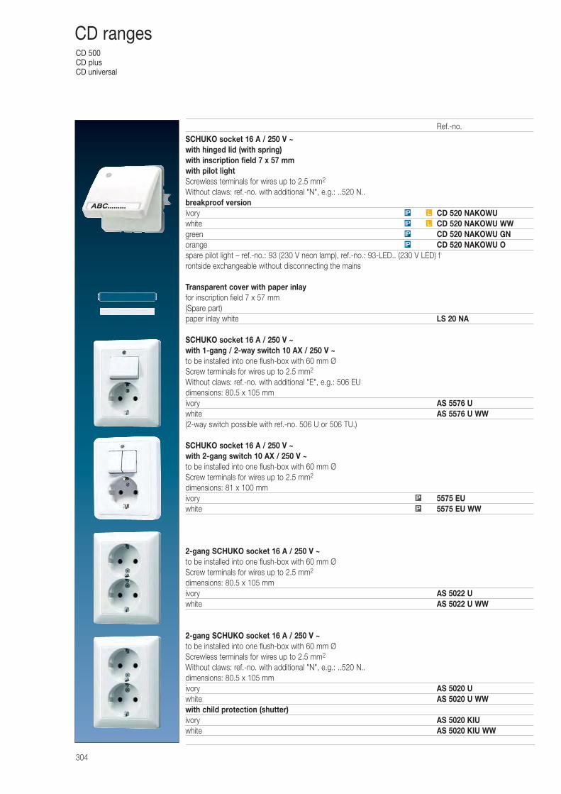
CD 500CD plusCD universal
304
CD ranges
SCHUKO socket 16 A / 250 V ~with hinged lid (with spring)with inscription field 7 x 57 mmwith pilot lightScrewless terminals for wires up to 2.5 mm2
Without claws: ref.-no. with additional "N", e.g.: ..520 N..breakproof versionivory CD 520 NAKOWUwhite CD 520 NAKOWU WWgreen CD 520 NAKOWU GNorange CD 520 NAKOWU Ospare pilot light – ref.-no.: 93 (230 V neon lamp), ref.-no.: 93-LED.. (230 V LED) frontside exchangeable without disconnecting the mains
Transparent cover with paper inlayfor inscription field 7 x 57 mm(Spare part)paper inlay white LS 20 NA
SCHUKO socket 16 A / 250 V ~ with 1-gang / 2-way switch 10 AX / 250 V ~to be installed into one flush-box with 60 mm ØScrew terminals for wires up to 2.5 mm2
Without claws: ref.-no. with additional "E", e.g.: 506 EUdimensions: 80.5 x 10⁵ mmivory AS 5576 Uwhite AS 5576 U WW(2-way switch possible with ref.-no. 506 U or 506 TU.)
SCHUKO socket 16 A / 250 V ~ with 2-gang switch 10 AX / 250 V ~to be installed into one flush-box with 60 mm ØScrew terminals for wires up to 2.5 mm2
dimensions: 81 x 100 mmivory 5575 EUwhite 5575 EU WW
2-gang SCHUKO socket 16 A / 250 V ~to be installed into one flush-box with 60 mm ØScrew terminals for wires up to 2.5 mm2
dimensions: 80.5 x 10⁵ mmivory AS 5022 Uwhite AS 5022 U WW
2-gang SCHUKO socket 16 A / 250 V ~to be installed into one flush-box with 60 mm ØScrewless terminals for wires up to 2.5 mm2
Without claws: ref.-no. with additional "N", e.g.: ..520 N..dimensions: 80.5 x 10⁵ mmivory AS 5020 Uwhite AS 5020 U WWwith child protection (shutter)ivory AS 5020 KIUwhite AS 5020 KIU WW
IP
IP
LIP
LIP
P
P
Ref.-no.
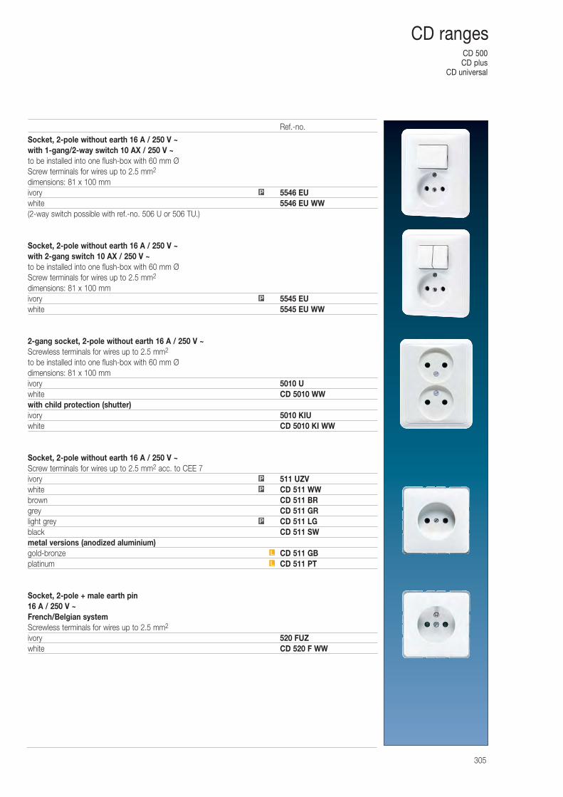
CD 500CD plus
CD universal
305
CD ranges
Socket, 2-pole without earth 16 A / 250 V ~ with 1-gang/2-way switch 10 AX / 250 V ~to be installed into one flush-box with 60 mm ØScrew terminals for wires up to 2.5 mm2
dimensions: 81 x 100 mmivory 5546 EUwhite 5546 EU WW(2-way switch possible with ref.-no. 506 U or 506 TU.)
Socket, 2-pole without earth 16 A / 250 V ~ with 2-gang switch 10 AX / 250 V ~to be installed into one flush-box with 60 mm ØScrew terminals for wires up to 2.5 mm2
dimensions: 81 x 100 mmivory 5545 EUwhite 5545 EU WW
2-gang socket, 2-pole without earth 16 A / 250 V ~Screwless terminals for wires up to 2.5 mm2
to be installed into one flush-box with 60 mm Ødimensions: 81 x 100 mmivory 5010 Uwhite CD 5010 WWwith child protection (shutter)ivory 5010 KIUwhite CD 5010 KI WW
Socket, 2-pole without earth 16 A / 250 V ~Screw terminals for wires up to 2.5 mm2 acc. to CEE 7ivory 511 UZVwhite CD 511 WWbrown CD 511 BRgrey CD 511 GRlight grey CD 511 LGblack CD 511 SWmetal versions (anodized aluminium)gold-bronze CD 511 GBplatinum CD 511 PT
Socket, 2-pole + male earth pin16 A / 250 V ~French/Belgian systemScrewless terminals for wires up to 2.5 mm2
ivory 520 FUZwhite CD 520 F WW
P
L
L
P
P
P
P
Ref.-no.
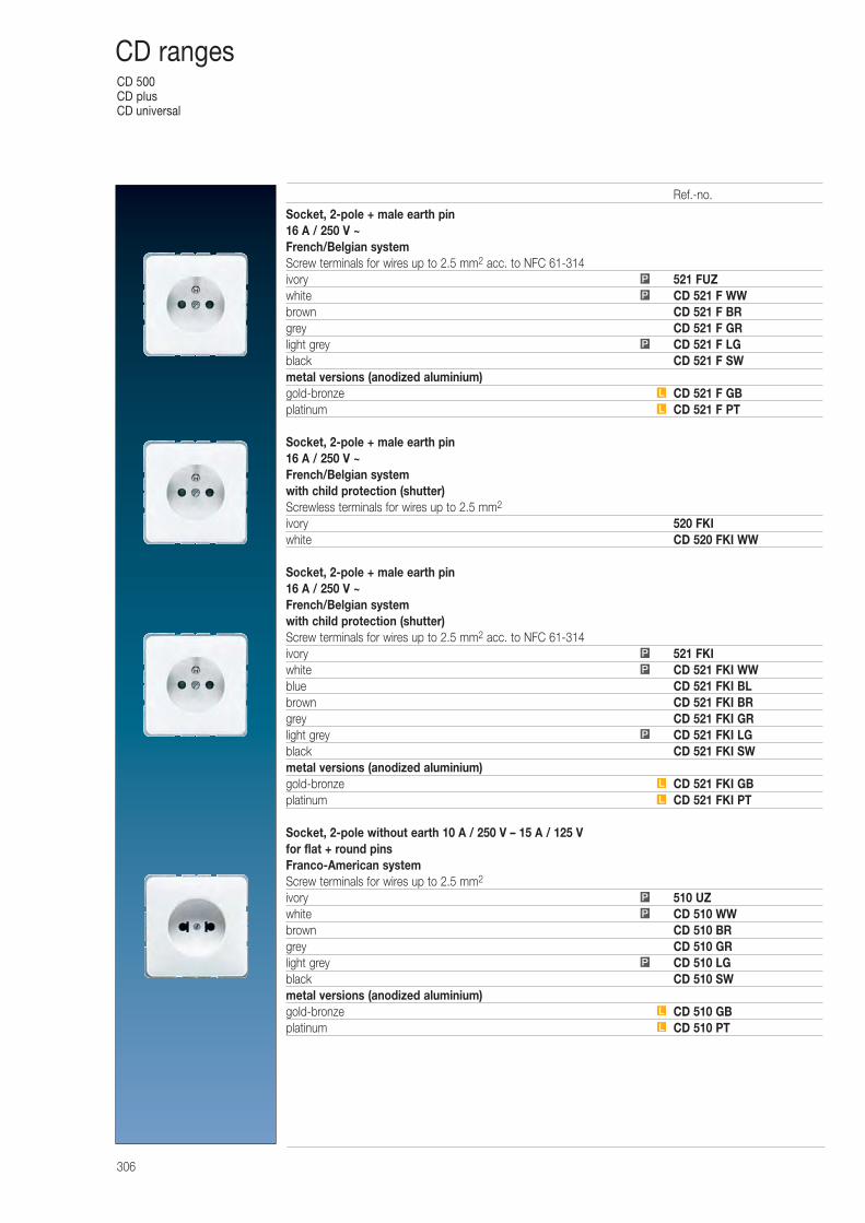
CD 500CD plusCD universal
306
CD ranges
Socket, 2-pole + male earth pin16 A / 250 V ~French/Belgian systemScrew terminals for wires up to 2.5 mm2 acc. to NFC 61-314ivory 521 FUZwhite CD 521 F WWbrown CD 521 F BRgrey CD 521 F GRlight grey CD 521 F LGblack CD 521 F SWmetal versions (anodized aluminium)gold-bronze CD 521 F GBplatinum CD 521 F PT
Socket, 2-pole + male earth pin16 A / 250 V ~French/Belgian systemwith child protection (shutter)Screwless terminals for wires up to 2.5 mm2
ivory 520 FKIwhite CD 520 FKI WW
Socket, 2-pole + male earth pin16 A / 250 V ~French/Belgian systemwith child protection (shutter)Screw terminals for wires up to 2.5 mm2 acc. to NFC 61-314ivory 521 FKIwhite CD 521 FKI WWblue CD 521 FKI BLbrown CD 521 FKI BRgrey CD 521 FKI GRlight grey CD 521 FKI LGblack CD 521 FKI SWmetal versions (anodized aluminium)gold-bronze CD 521 FKI GBplatinum CD 521 FKI PT
Socket, 2-pole without earth 10 A / 250 V – 15 A / 125 Vfor flat + round pinsFranco-American systemScrew terminals for wires up to 2.5 mm2
ivory 510 UZwhite CD 510 WWbrown CD 510 BRgrey CD 510 GRlight grey CD 510 LGblack CD 510 SWmetal versions (anodized aluminium)gold-bronze CD 510 GBplatinum CD 510 PT
L
L
P
P
P
L
L
P
P
P
L
L
P
P
P
Ref.-no.
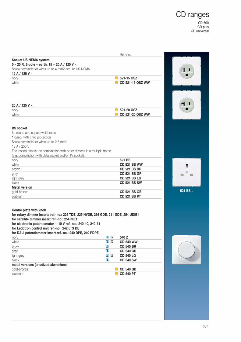
CD 500CD plus
CD universal
307
CD ranges
Socket US NEMA system 5 – 20 R, 2-pole + earth, 15 + 20 A / 125 V ~Screw terminals for wires up to 4 mm2 acc. to US-NEMA15 A / 125 V ~ivory 521-15 OSZwhite CD 521-15 OSZ WW
20 A / 125 V ~ivory 521-20 OSZwhite CD 521-20 OSZ WW
BS socket for round and square wall boxes1-gang, with child protectionScrew terminals for wires up to 2.5 mm²13 A / 250 VThe inserts enable the combination with other devices in a multiple frame (e.g. combination with data socket and/or TV socket).ivory 521 BS white CD 521 BS WWbrown CD 521 BS BRgrey CD 521 BS GRlight grey CD 521 BS LGblack CD 521 BS SWMetal versiongold-bronze CD 521 BS GBplatinum CD 521 BS PT
Centre plate with knobfor rotary dimmer inserts ref.-no.: 225 TDE, 225 NVDE, 266 GDE, 211 GDE, 254 UDIE1for satellite dimmer insert ref.-no.: 254 NIE1for electronic potentiometer 1–10 V ref.-no.: 240-10, 240-31for Ledotron control unit ref.-no.: 242 LTS DEfor DALI potentiometer insert ref.-no.: 240 DPE, 240 PDPEivory 540 Zwhite CD 540 WWbrown CD 540 BRgrey CD 540 GRlight grey CD 540 LGblack CD 540 SWmetal versions (anodized aluminium)gold-bronze CD 540 GBplatinum CD 540 PT
L
L
L
L
IP
PIP
IP
IP
PIP
PIP
L
L
Ref.-no.
521 BS ..
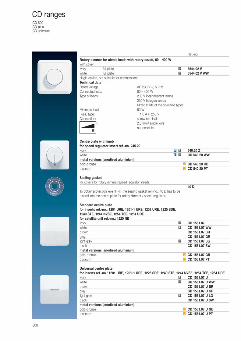
CD 500CD plusCD universal
308
CD ranges
Rotary dimmer for ohmic loads with rotary on/off, 60 – 400 Wwith coverivory full plate 5544.02 Vwhite full plate 5544.02 V WWsingle device, not suitable for combinationsTechnical dataRated voltage: AC 230 V ~, 50 HzConnected load: 60 – 400 WType of loads: 230 V incandescent lamps
230 V halogen lampsMixed loads of the specified types
Minimum load: 60 WFuse, type: T 1.6 A H 250 VConnection: screw terminalsTerminals for: 2.5 mm2 single wireExtension: not possible
Centre plate with knobfor speed regulator insert ref.-no. 245.20ivory 540.20 Zwhite CD 540.20 WWmetal versions (anodized aluminium)gold-bronze CD 540.20 GBplatinum CD 540.20 PT
Sealing gasketfor covers for rotary dimmer/speed regulator inserts
40 DTo obtain protection level IP 44 the sealing gasket ref.-no.: 40 D has to be placed into the centre plate for rotary dimmer / speed regulator.
Standard centre platefor inserts ref.-no.: 1201 URE, 1201-1 URE, 1202 URE, 1225 SDE, 1240 STE, 1244 NVSE, 1254 TSE, 1254 UDEfor satellite unit ref.-no.: 1220 NEivory CD 1561.07white CD 1561.07 WWbrown CD 1561.07 BRgrey CD 1561.07 GRlight grey CD 1561.07 LGblack CD 1561.07 SWmetal versions (anodized aluminium)gold-bronze CD 1561.07 GBplatinum CD 1561.07 PT
Universal centre platefor inserts ref.-no.: 1201 URE, 1201-1 URE, 1225 SDE, 1240 STE, 1244 NVSE, 1254 TSE, 1254 UDEivory CD 1561.07 Uwhite CD 1561.07 U WWbrown CD 1561.07 U BRgrey CD 1561.07 U GRlight grey CD 1561.07 U LGblack CD 1561.07 U SWmetal versions (anodized aluminium)gold-bronze CD 1561.07 U GBplatinum CD 1561.07 U PT
P
P
L
L
P
P
P
L
L
P
P
P
L
L
PIP
PIP
Ref.-no.
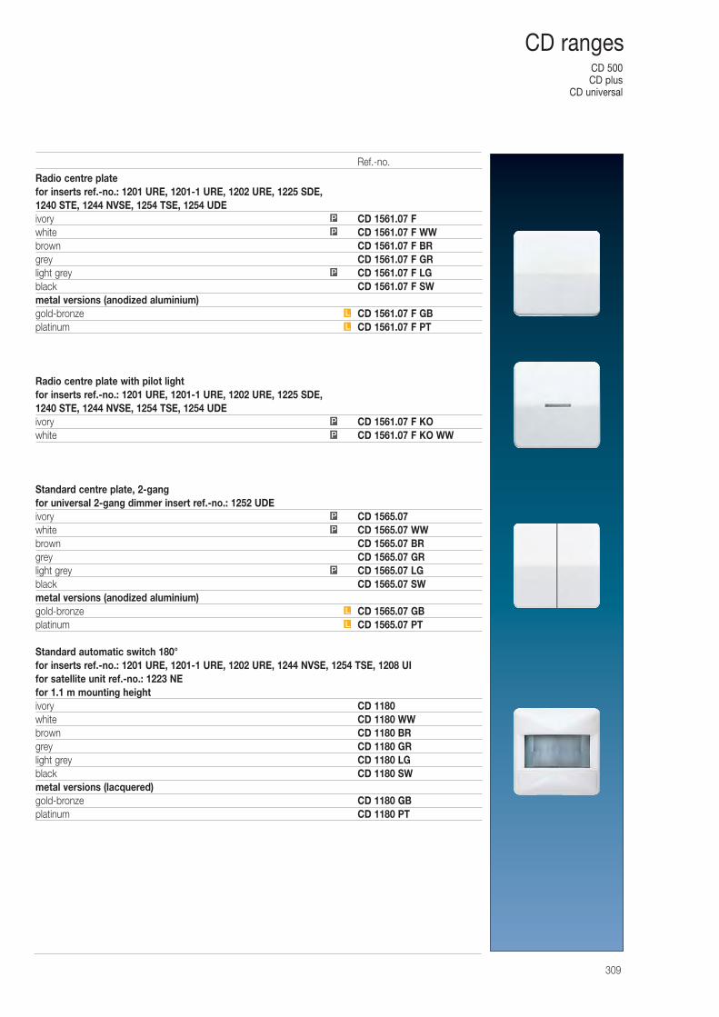
CD 500CD plus
CD universal
309
CD ranges
Radio centre platefor inserts ref.-no.: 1201 URE, 1201-1 URE, 1202 URE, 1225 SDE, 1240 STE, 1244 NVSE, 1254 TSE, 1254 UDEivory CD 1561.07 Fwhite CD 1561.07 F WWbrown CD 1561.07 F BRgrey CD 1561.07 F GRlight grey CD 1561.07 F LGblack CD 1561.07 F SWmetal versions (anodized aluminium)gold-bronze CD 1561.07 F GBplatinum CD 1561.07 F PT
Radio centre plate with pilot lightfor inserts ref.-no.: 1201 URE, 1201-1 URE, 1202 URE, 1225 SDE, 1240 STE, 1244 NVSE, 1254 TSE, 1254 UDEivory CD 1561.07 F KOwhite CD 1561.07 F KO WW
Standard centre plate, 2-gangfor universal 2-gang dimmer insert ref.-no.: 1252 UDEivory CD 1565.07white CD 1565.07 WWbrown CD 1565.07 BRgrey CD 1565.07 GRlight grey CD 1565.07 LGblack CD 1565.07 SWmetal versions (anodized aluminium)gold-bronze CD 1565.07 GBplatinum CD 1565.07 PT
Standard automatic switch 180°for inserts ref.-no.: 1201 URE, 1201-1 URE, 1202 URE, 1244 NVSE, 1254 TSE, 1208 UIfor satellite unit ref.-no.: 1223 NEfor 1.1 m mounting heightivory CD 1180white CD 1180 WWbrown CD 1180 BRgrey CD 1180 GRlight grey CD 1180 LGblack CD 1180 SWmetal versions (lacquered)gold-bronze CD 1180 GBplatinum CD 1180 PT
L
L
P
P
P
P
P
L
L
P
P
P
Ref.-no.
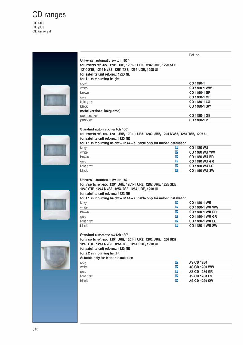
CD 500CD plusCD universal
310
CD ranges
Universal automatic switch 180° for inserts ref.-no.: 1201 URE, 1201-1 URE, 1202 URE, 1225 SDE, 1240 STE, 1244 NVSE, 1254 TSE, 1254 UDE, 1208 UIfor satellite unit ref.-no.: 1223 NEfor 1.1 m mounting heightivory CD 1180-1white CD 1180-1 WWbrown CD 1180-1 BRgrey CD 1180-1 GRlight grey CD 1180-1 LGblack CD 1180-1 SWmetal versions (lacquered)gold-bronze CD 1180-1 GBplatinum CD 1180-1 PT
Standard automatic switch 180°for inserts ref.-no.: 1201 URE, 1201-1 URE, 1202 URE, 1244 NVSE, 1254 TSE, 1208 UIfor satellite unit ref.-no.: 1223 NEfor 1.1 m mounting height – IP 44 – suitable only for indoor installationivory CD 1180 WUwhite CD 1180 WU WWbrown CD 1180 WU BRgrey CD 1180 WU GRlight grey CD 1180 WU LGblack CD 1180 WU SW
Universal automatic switch 180° for inserts ref.-no.: 1201 URE, 1201-1 URE, 1202 URE, 1225 SDE, 1240 STE, 1244 NVSE, 1254 TSE, 1254 UDE, 1208 UIfor satellite unit ref.-no.: 1223 NEfor 1.1 m mounting height – IP 44 – suitable only for indoor installationivory CD 1180-1 WUwhite CD 1180-1 WU WWbrown CD 1180-1 WU BRgrey CD 1180-1 WU GRlight grey CD 1180-1 WU LGblack CD 1180-1 WU SW
Standard automatic switch 180°for inserts ref.-no.: 1201 URE, 1201-1 URE, 1202 URE, 1225 SDE, 1240 STE, 1244 NVSE, 1254 TSE, 1254 UDE, 1208 UIfor satellite unit ref.-no.: 1223 NEfor 2.2 m mounting heightSuitable only for indoor installationivory AS CD 1280white AS CD 1280 WWgrey AS CD 1280 GRlight grey AS CD 1280 LGblack AS CD 1280 SWIP
IP
IP
IP
IP
IP
IP
IP
IP
IP
IP
IP
IP
IP
IP
IP
IP
Ref.-no.
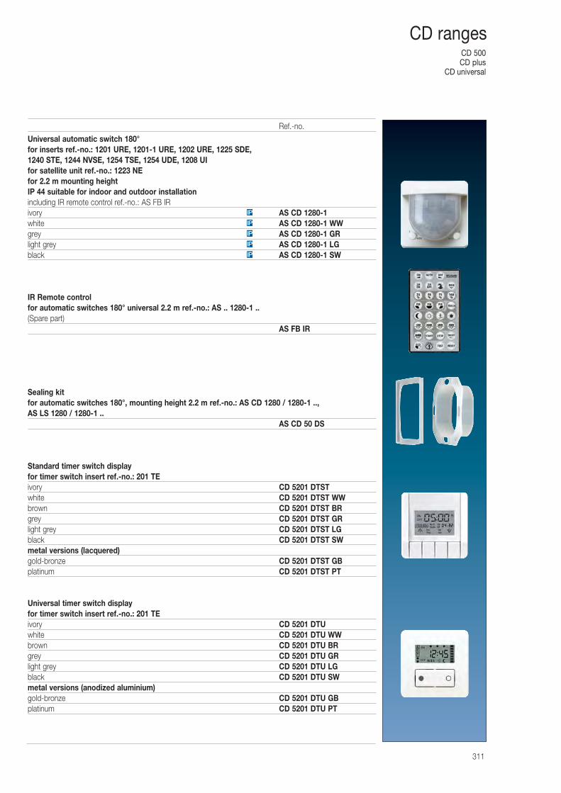
CD 500CD plus
CD universal
311
CD ranges
Universal automatic switch 180° for inserts ref.-no.: 1201 URE, 1201-1 URE, 1202 URE, 1225 SDE, 1240 STE, 1244 NVSE, 1254 TSE, 1254 UDE, 1208 UIfor satellite unit ref.-no.: 1223 NEfor 2.2 m mounting heightIP 44 suitable for indoor and outdoor installationincluding IR remote control ref.-no.: AS FB IRivory AS CD 1280-1white AS CD 1280-1 WWgrey AS CD 1280-1 GRlight grey AS CD 1280-1 LGblack AS CD 1280-1 SW
IR Remote controlfor automatic switches 180° universal 2.2 m ref.-no.: AS .. 1280-1 ..(Spare part)
AS FB IR
Sealing kitfor automatic switches 180°, mounting height 2.2 m ref.-no.: AS CD 1280 / 1280-1 ..,AS LS 1280 / 1280-1 ..
AS CD 50 DS
Standard timer switch displayfor timer switch insert ref.-no.: 201 TEivory CD 5201 DTSTwhite CD 5201 DTST WWbrown CD 5201 DTST BRgrey CD 5201 DTST GRlight grey CD 5201 DTST LGblack CD 5201 DTST SWmetal versions (lacquered)gold-bronze CD 5201 DTST GBplatinum CD 5201 DTST PT
Universal timer switch displayfor timer switch insert ref.-no.: 201 TEivory CD 5201 DTUwhite CD 5201 DTU WWbrown CD 5201 DTU BRgrey CD 5201 DTU GRlight grey CD 5201 DTU LGblack CD 5201 DTU SWmetal versions (anodized aluminium)gold-bronze CD 5201 DTU GBplatinum CD 5201 DTU PT
IP
IP
IP
IP
IP
Ref.-no.
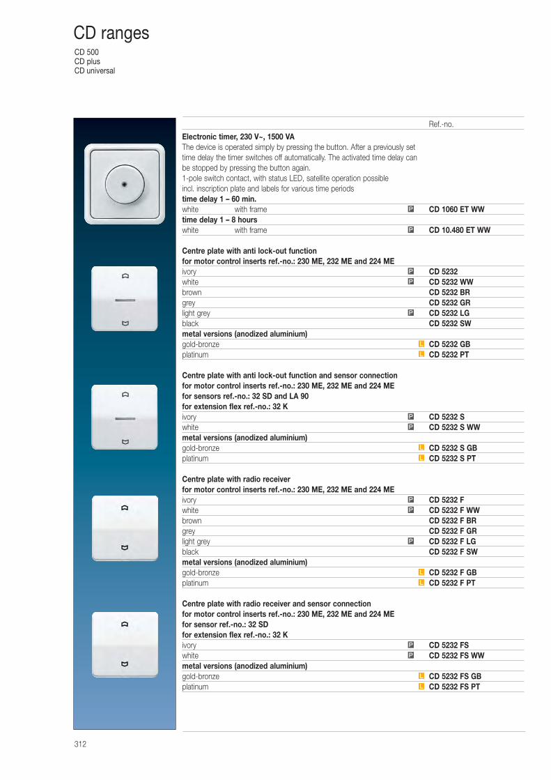
CD 500CD plusCD universal
312
CD ranges
Electronic timer, 230 V~, 1500 VAThe device is operated simply by pressing the button. After a previously set time delay the timer switches off automatically. The activated time delay can be stopped by pressing the button again.1-pole switch contact, with status LED, satellite operation possibleincl. inscription plate and labels for various time periodstime delay 1 – 60 min.white with frame CD 1060 ET WWtime delay 1 – 8 hourswhite with frame CD 10.480 ET WW
Centre plate with anti lock-out functionfor motor control inserts ref.-no.: 230 ME, 232 ME and 224 MEivory CD 5232white CD 5232 WWbrown CD 5232 BRgrey CD 5232 GRlight grey CD 5232 LGblack CD 5232 SWmetal versions (anodized aluminium)gold-bronze CD 5232 GBplatinum CD 5232 PT
Centre plate with anti lock-out function and sensor connectionfor motor control inserts ref.-no.: 230 ME, 232 ME and 224 MEfor sensors ref.-no.: 32 SD and LA 90for extension flex ref.-no.: 32 Kivory CD 5232 Swhite CD 5232 S WWmetal versions (anodized aluminium)gold-bronze CD 5232 S GBplatinum CD 5232 S PT
Centre plate with radio receiverfor motor control inserts ref.-no.: 230 ME, 232 ME and 224 MEivory CD 5232 Fwhite CD 5232 F WWbrown CD 5232 F BRgrey CD 5232 F GRlight grey CD 5232 F LGblack CD 5232 F SWmetal versions (anodized aluminium)gold-bronze CD 5232 F GBplatinum CD 5232 F PT
Centre plate with radio receiver and sensor connectionfor motor control inserts ref.-no.: 230 ME, 232 ME and 224 MEfor sensor ref.-no.: 32 SDfor extension flex ref.-no.: 32 Kivory CD 5232 FSwhite CD 5232 FS WWmetal versions (anodized aluminium)gold-bronze CD 5232 FS GBplatinum CD 5232 FS PT
L
L
P
P
L
L
P
P
P
P
P
L
L
P
P
L
L
P
P
P
Ref.-no.
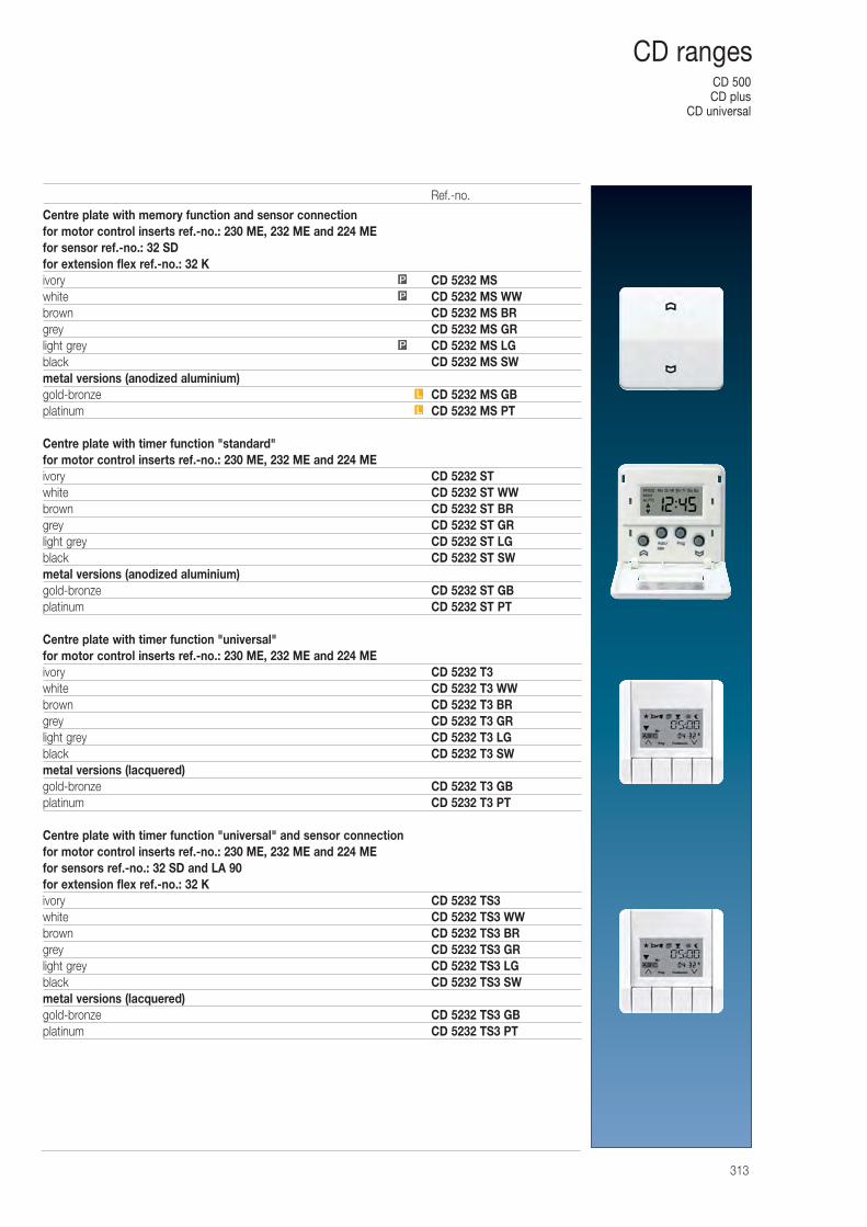
CD 500CD plus
CD universal
313
CD ranges
Centre plate with memory function and sensor connectionfor motor control inserts ref.-no.: 230 ME, 232 ME and 224 MEfor sensor ref.-no.: 32 SDfor extension flex ref.-no.: 32 Kivory CD 5232 MSwhite CD 5232 MS WWbrown CD 5232 MS BRgrey CD 5232 MS GRlight grey CD 5232 MS LGblack CD 5232 MS SWmetal versions (anodized aluminium)gold-bronze CD 5232 MS GBplatinum CD 5232 MS PT
Centre plate with timer function "standard"for motor control inserts ref.-no.: 230 ME, 232 ME and 224 MEivory CD 5232 STwhite CD 5232 ST WWbrown CD 5232 ST BRgrey CD 5232 ST GRlight grey CD 5232 ST LGblack CD 5232 ST SWmetal versions (anodized aluminium)gold-bronze CD 5232 ST GBplatinum CD 5232 ST PT
Centre plate with timer function "universal"for motor control inserts ref.-no.: 230 ME, 232 ME and 224 MEivory CD 5232 T3white CD 5232 T3 WWbrown CD 5232 T3 BRgrey CD 5232 T3 GRlight grey CD 5232 T3 LGblack CD 5232 T3 SWmetal versions (lacquered)gold-bronze CD 5232 T3 GBplatinum CD 5232 T3 PT
Centre plate with timer function "universal" and sensor connectionfor motor control inserts ref.-no.: 230 ME, 232 ME and 224 MEfor sensors ref.-no.: 32 SD and LA 90for extension flex ref.-no.: 32 Kivory CD 5232 TS3white CD 5232 TS3 WWbrown CD 5232 TS3 BRgrey CD 5232 TS3 GRlight grey CD 5232 TS3 LGblack CD 5232 TS3 SWmetal versions (lacquered)gold-bronze CD 5232 TS3 GBplatinum CD 5232 TS3 PT
L
L
P
P
P
Ref.-no.
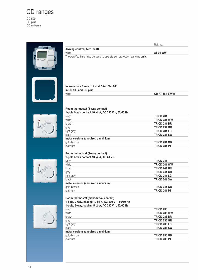
CD 500CD plusCD universal
314
CD ranges
Awning control, AeroTec 04white AT 04 WWThe AeroTec timer may be used to operate sun protection systems only.
Intermediate frame to install "AeroTec 04"in CD 500 and CD pluswhite CD AT 581 Z WW
Room thermostat (1-way contact)1-pole break contact 10 (4) A, AC 230 V ~, 50/60 Hzivory TR CD 231white TR CD 231 WWbrown TR CD 231 BRgrey TR CD 231 GRlight grey TR CD 231 LGblack TR CD 231 SWmetal versions (anodized aluminium)gold-bronze TR CD 231 GBplatinum TR CD 231 PT
Room thermostat (1-way contact)1-pole break contact 10 (4) A, AC 24 V ~ivory TR CD 241white TR CD 241 WWbrown TR CD 241 BRgrey TR CD 241 GRlight grey TR CD 241 LGblack TR CD 241 SWmetal versions (anodized aluminium)gold-bronze TR CD 241 GBplatinum TR CD 241 PT
Room thermostat (make/break contact)1-pole, 2-way, heating 10 (4) A, AC 230 V ~, 50/60 Hz1-pole, 2-way, cooling 5 (2) A, AC 230 V ~, 50/60 Hzivory TR CD 236white TR CD 236 WWbrown TR CD 236 BRgrey TR CD 236 GRlight grey TR CD 236 LGblack TR CD 236 SWmetal versions (anodized aluminium)gold-bronze TR CD 236 GBplatinum TR CD 236 PT
Ref.-no.
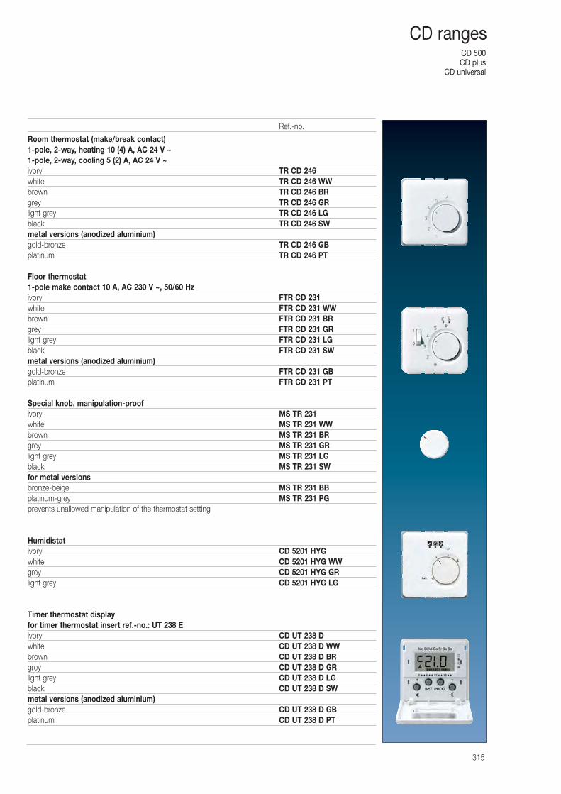
CD 500CD plus
CD universal
315
CD ranges
Room thermostat (make/break contact)1-pole, 2-way, heating 10 (4) A, AC 24 V ~1-pole, 2-way, cooling 5 (2) A, AC 24 V ~ivory TR CD 246white TR CD 246 WWbrown TR CD 246 BRgrey TR CD 246 GRlight grey TR CD 246 LGblack TR CD 246 SWmetal versions (anodized aluminium)gold-bronze TR CD 246 GBplatinum TR CD 246 PT
Floor thermostat1-pole make contact 10 A, AC 230 V ~, 50/60 Hzivory FTR CD 231white FTR CD 231 WWbrown FTR CD 231 BRgrey FTR CD 231 GRlight grey FTR CD 231 LGblack FTR CD 231 SWmetal versions (anodized aluminium)gold-bronze FTR CD 231 GBplatinum FTR CD 231 PT
Special knob, manipulation-proofivory MS TR 231white MS TR 231 WWbrown MS TR 231 BRgrey MS TR 231 GRlight grey MS TR 231 LGblack MS TR 231 SWfor metal versionsbronze-beige MS TR 231 BBplatinum-grey MS TR 231 PGprevents unallowed manipulation of the thermostat setting
Humidistativory CD 5201 HYGwhite CD 5201 HYG WWgrey CD 5201 HYG GRlight grey CD 5201 HYG LG
Timer thermostat displayfor timer thermostat insert ref.-no.: UT 238 Eivory CD UT 238 Dwhite CD UT 238 D WWbrown CD UT 238 D BRgrey CD UT 238 D GRlight grey CD UT 238 D LGblack CD UT 238 D SWmetal versions (anodized aluminium)gold-bronze CD UT 238 D GBplatinum CD UT 238 D PT
Ref.-no.
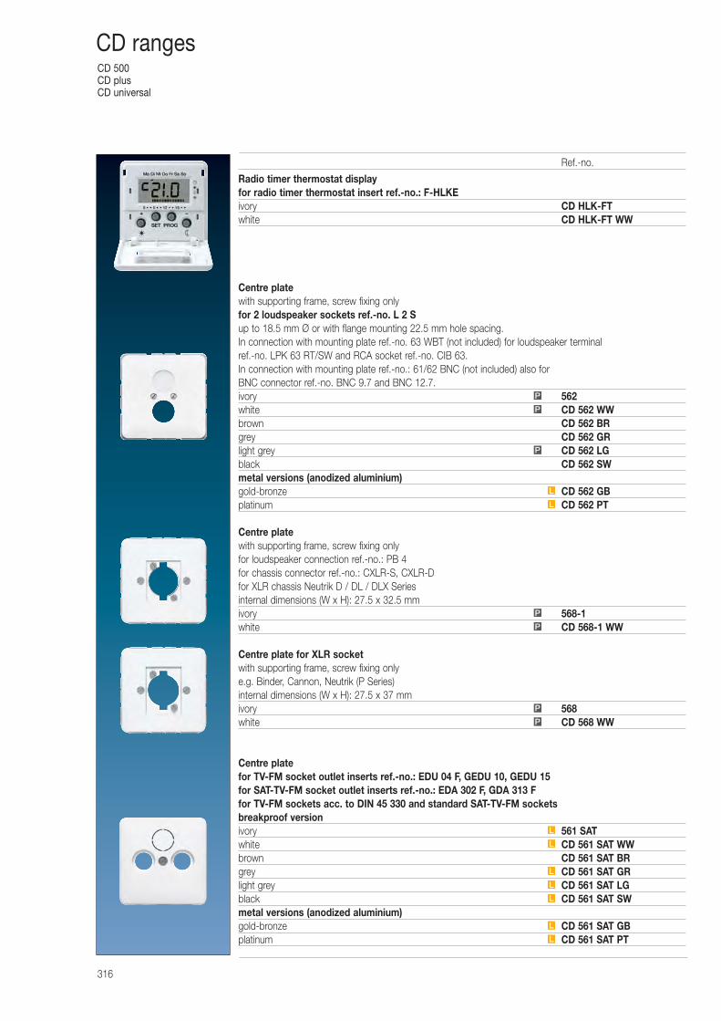
CD 500CD plusCD universal
316
CD ranges
Radio timer thermostat displayfor radio timer thermostat insert ref.-no.: F-HLKEivory CD HLK-FTwhite CD HLK-FT WW
Centre platewith supporting frame, screw fixing onlyfor 2 loudspeaker sockets ref.-no. L 2 Sup to 18.5 mm Ø or with flange mounting 22.5 mm hole spacing.In connection with mounting plate ref.-no. 63 WBT (not included) for loudspeaker terminalref.-no. LPK 63 RT/SW and RCA socket ref.-no. CIB 63.In connection with mounting plate ref.-no.: 61/62 BNC (not included) also for BNC connector ref.-no. BNC 9.7 and BNC 12.7.ivory 562white CD 562 WWbrown CD 562 BRgrey CD 562 GRlight grey CD 562 LGblack CD 562 SWmetal versions (anodized aluminium)gold-bronze CD 562 GBplatinum CD 562 PT
Centre platewith supporting frame, screw fixing onlyfor loudspeaker connection ref.-no.: PB 4for chassis connector ref.-no.: CXLR-S, CXLR-Dfor XLR chassis Neutrik D / DL / DLX Seriesinternal dimensions (W x H): 27.5 x 32.5 mmivory 568-1white CD 568-1 WW
Centre plate for XLR socketwith supporting frame, screw fixing onlye.g. Binder, Cannon, Neutrik (P Series)internal dimensions (W x H): 27.5 x 37 mmivory 568white CD 568 WW
Centre platefor TV-FM socket outlet inserts ref.-no.: EDU 04 F, GEDU 10, GEDU 15for SAT-TV-FM socket outlet inserts ref.-no.: EDA 302 F, GDA 313 Ffor TV-FM sockets acc. to DIN 45 330 and standard SAT-TV-FM socketsbreakproof versionivory 561 SATwhite CD 561 SAT WWbrown CD 561 SAT BRgrey CD 561 SAT GRlight grey CD 561 SAT LGblack CD 561 SAT SWmetal versions (anodized aluminium)gold-bronze CD 561 SAT GBplatinum CD 561 SAT PTL
L
L
L
L
L
L
P
P
P
P
L
L
P
P
P
Ref.-no.
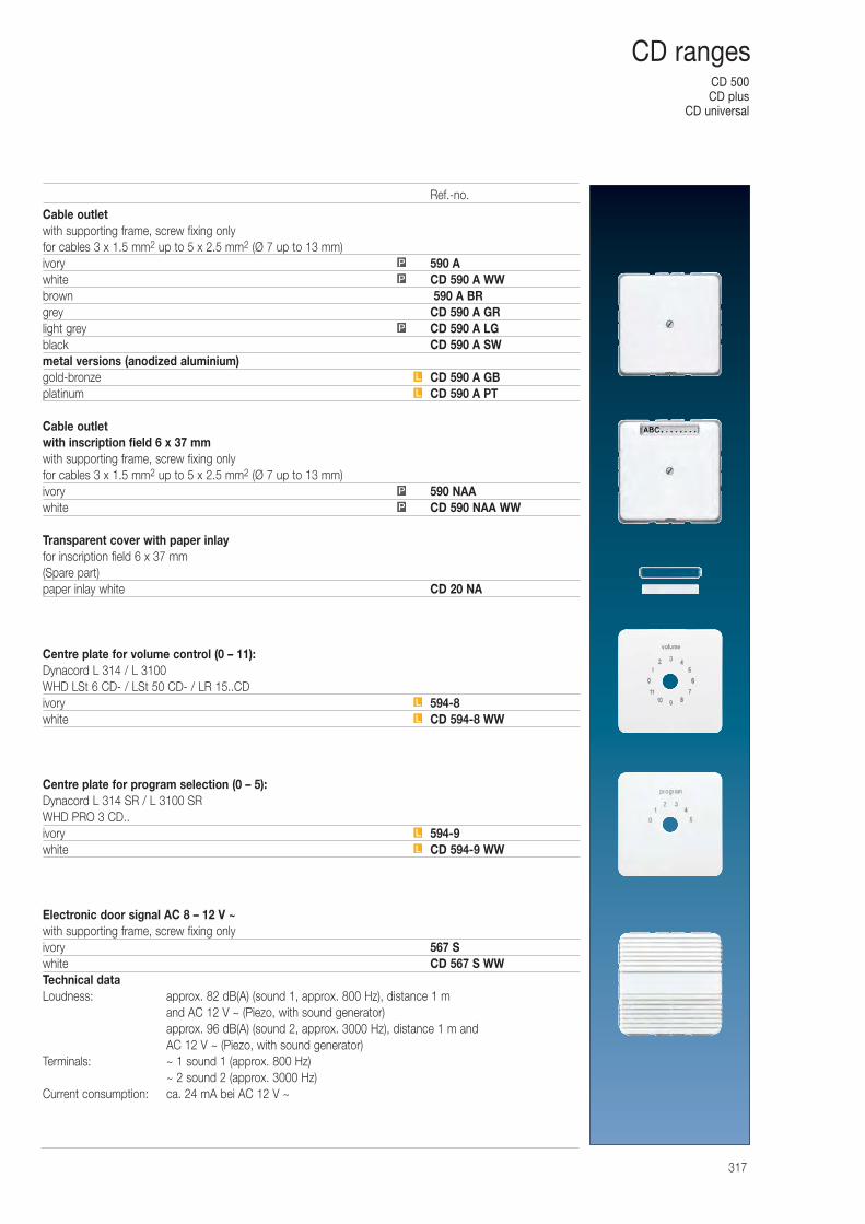
CD 500CD plus
CD universal
317
CD ranges
Cable outletwith supporting frame, screw fixing onlyfor cables 3 x 1.5 mm2 up to 5 x 2.5 mm2 (Ø 7 up to 13 mm)ivory 590 Awhite CD 590 A WWbrown 590 A BRgrey CD 590 A GRlight grey CD 590 A LGblack CD 590 A SWmetal versions (anodized aluminium)gold-bronze CD 590 A GBplatinum CD 590 A PT
Cable outletwith inscription field 6 x 37 mmwith supporting frame, screw fixing onlyfor cables 3 x 1.5 mm2 up to 5 x 2.5 mm2 (Ø 7 up to 13 mm)ivory 590 NAAwhite CD 590 NAA WW
Transparent cover with paper inlayfor inscription field 6 x 37 mm(Spare part)paper inlay white CD 20 NA
Centre plate for volume control (0 – 11):Dynacord L 314 / L 3100WHD LSt 6 CD- / LSt 50 CD- / LR 15..CDivory 594-8white CD 594-8 WW
Centre plate for program selection (0 – 5):Dynacord L 314 SR / L 3100 SRWHD PRO 3 CD..ivory 594-9white CD 594-9 WW
Electronic door signal AC 8 – 12 V ~with supporting frame, screw fixing onlyivory 567 Swhite CD 567 S WWTechnical dataLoudness: approx. 82 dB(A) (sound 1, approx. 800 Hz), distance 1 m
and AC 12 V ~ (Piezo, with sound generator)approx. 96 dB(A) (sound 2, approx. 3000 Hz), distance 1 m and AC 12 V ~ (Piezo, with sound generator)
Terminals: ~ 1 sound 1 (approx. 800 Hz)~ 2 sound 2 (approx. 3000 Hz)
Current consumption: ca. 24 mA bei AC 12 V ~
L
L
L
L
P
P
L
L
P
P
P
Ref.-no.
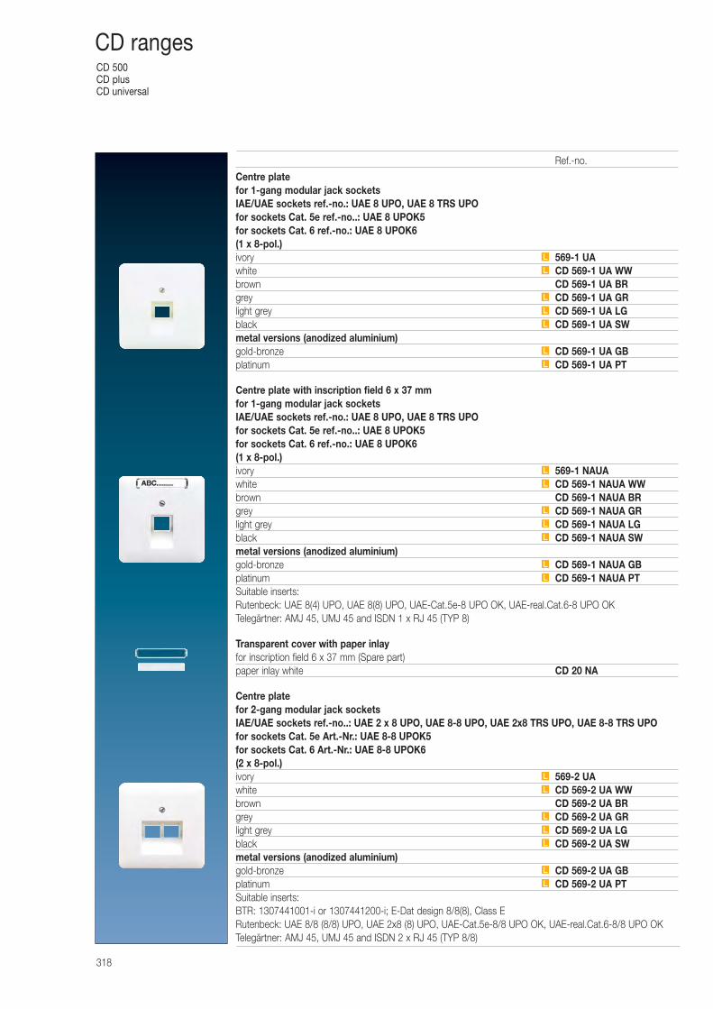
CD 500CD plusCD universal
318
CD ranges
Centre platefor 1-gang modular jack socketsIAE/UAE sockets ref.-no.: UAE 8 UPO, UAE 8 TRS UPOfor sockets Cat. 5e ref.-no..: UAE 8 UPOK5for sockets Cat. 6 ref.-no.: UAE 8 UPOK6(1 x 8-pol.)ivory 569-1 UAwhite CD 569-1 UA WWbrown CD 569-1 UA BRgrey CD 569-1 UA GRlight grey CD 569-1 UA LGblack CD 569-1 UA SWmetal versions (anodized aluminium)gold-bronze CD 569-1 UA GBplatinum CD 569-1 UA PT
Centre plate with inscription field 6 x 37 mmfor 1-gang modular jack socketsIAE/UAE sockets ref.-no.: UAE 8 UPO, UAE 8 TRS UPOfor sockets Cat. 5e ref.-no..: UAE 8 UPOK5for sockets Cat. 6 ref.-no.: UAE 8 UPOK6(1 x 8-pol.)ivory 569-1 NAUAwhite CD 569-1 NAUA WWbrown CD 569-1 NAUA BRgrey CD 569-1 NAUA GRlight grey CD 569-1 NAUA LGblack CD 569-1 NAUA SWmetal versions (anodized aluminium)gold-bronze CD 569-1 NAUA GBplatinum CD 569-1 NAUA PTSuitable inserts:Rutenbeck: UAE 8(4) UPO, UAE 8(8) UPO, UAE-Cat.5e-8 UPO OK, UAE-real.Cat.6-8 UPO OKTelegärtner: AMJ 45, UMJ 45 and ISDN 1 x RJ 45 (TYP 8)
Transparent cover with paper inlayfor inscription field 6 x 37 mm (Spare part)paper inlay white CD 20 NA
Centre platefor 2-gang modular jack socketsIAE/UAE sockets ref.-no..: UAE 2 x 8 UPO, UAE 8-8 UPO, UAE 2x8 TRS UPO, UAE 8-8 TRS UPOfor sockets Cat. 5e Art.-Nr.: UAE 8-8 UPOK5for sockets Cat. 6 Art.-Nr.: UAE 8-8 UPOK6(2 x 8-pol.)ivory 569-2 UAwhite CD 569-2 UA WWbrown CD 569-2 UA BRgrey CD 569-2 UA GRlight grey CD 569-2 UA LGblack CD 569-2 UA SWmetal versions (anodized aluminium)gold-bronze CD 569-2 UA GBplatinum CD 569-2 UA PTSuitable inserts:BTR: 1307441001-i or 1307441200-i; E-Dat design 8/8(8), Class ERutenbeck: UAE 8/8 (8/8) UPO, UAE 2x8 (8) UPO, UAE-Cat.5e-8/8 UPO OK, UAE-real.Cat.6-8/8 UPO OKTelegärtner: AMJ 45, UMJ 45 and ISDN 2 x RJ 45 (TYP 8/8)
L
L
L
L
L
L
L
L
L
L
L
L
L
L
L
L
L
L
L
L
L
Ref.-no.
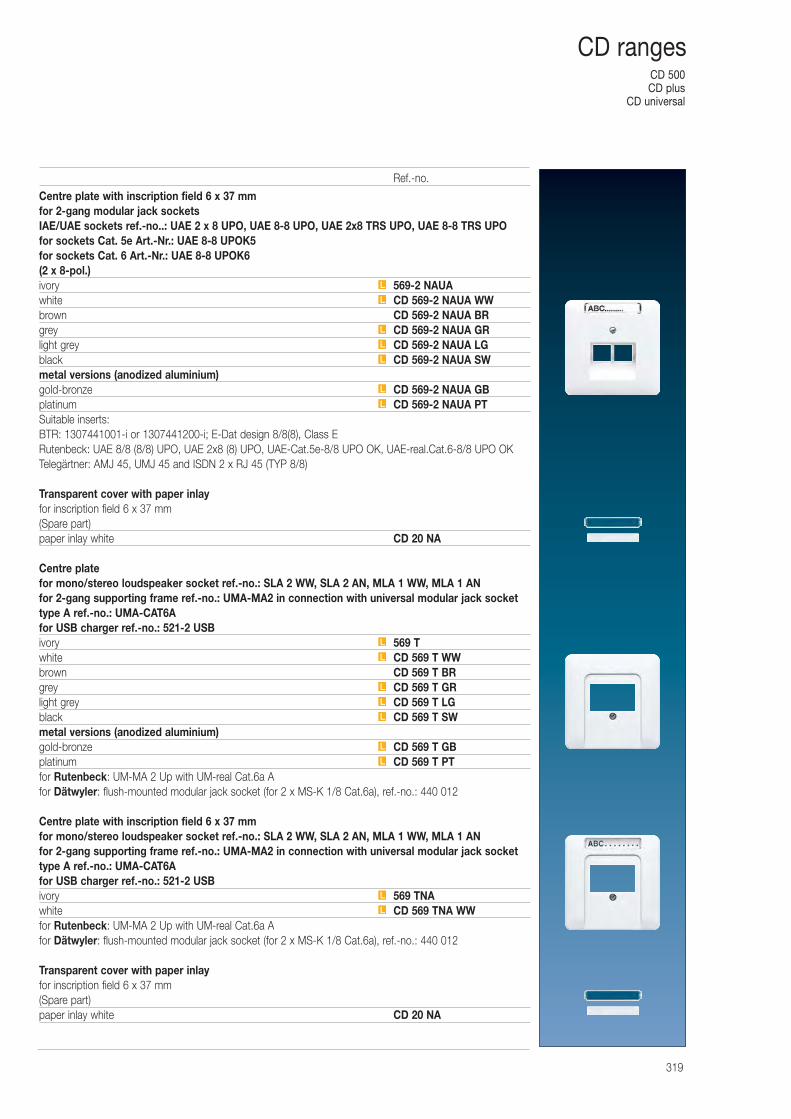
CD 500CD plus
CD universal
319
CD ranges
Centre plate with inscription field 6 x 37 mmfor 2-gang modular jack socketsIAE/UAE sockets ref.-no..: UAE 2 x 8 UPO, UAE 8-8 UPO, UAE 2x8 TRS UPO, UAE 8-8 TRS UPOfor sockets Cat. 5e Art.-Nr.: UAE 8-8 UPOK5for sockets Cat. 6 Art.-Nr.: UAE 8-8 UPOK6(2 x 8-pol.)ivory 569-2 NAUAwhite CD 569-2 NAUA WWbrown CD 569-2 NAUA BRgrey CD 569-2 NAUA GRlight grey CD 569-2 NAUA LGblack CD 569-2 NAUA SWmetal versions (anodized aluminium)gold-bronze CD 569-2 NAUA GBplatinum CD 569-2 NAUA PTSuitable inserts:BTR: 1307441001-i or 1307441200-i; E-Dat design 8/8(8), Class ERutenbeck: UAE 8/8 (8/8) UPO, UAE 2x8 (8) UPO, UAE-Cat.5e-8/8 UPO OK, UAE-real.Cat.6-8/8 UPO OKTelegärtner: AMJ 45, UMJ 45 and ISDN 2 x RJ 45 (TYP 8/8)
Transparent cover with paper inlayfor inscription field 6 x 37 mm(Spare part)paper inlay white CD 20 NA
Centre platefor mono/stereo loudspeaker socket ref.-no.: SLA 2 WW, SLA 2 AN, MLA 1 WW, MLA 1 ANfor 2-gang supporting frame ref.-no.: UMA-MA2 in connection with universal modular jack sockettype A ref.-no.: UMA-CAT6Afor USB charger ref.-no.: 521-2 USBivory 569 Twhite CD 569 T WWbrown CD 569 T BRgrey CD 569 T GRlight grey CD 569 T LGblack CD 569 T SWmetal versions (anodized aluminium)gold-bronze CD 569 T GBplatinum CD 569 T PTfor Rutenbeck: UM-MA 2 Up with UM-real Cat.6a Afor Dätwyler: flush-mounted modular jack socket (for 2 x MS-K 1/8 Cat.6a), ref.-no.: 440 012
Centre plate with inscription field 6 x 37 mmfor mono/stereo loudspeaker socket ref.-no.: SLA 2 WW, SLA 2 AN, MLA 1 WW, MLA 1 ANfor 2-gang supporting frame ref.-no.: UMA-MA2 in connection with universal modular jack sockettype A ref.-no.: UMA-CAT6Afor USB charger ref.-no.: 521-2 USBivory 569 TNAwhite CD 569 TNA WWfor Rutenbeck: UM-MA 2 Up with UM-real Cat.6a Afor Dätwyler: flush-mounted modular jack socket (for 2 x MS-K 1/8 Cat.6a), ref.-no.: 440 012
Transparent cover with paper inlayfor inscription field 6 x 37 mm(Spare part)paper inlay white CD 20 NA
L
L
L
L
L
L
L
L
L
L
L
L
L
L
L
L
Ref.-no.
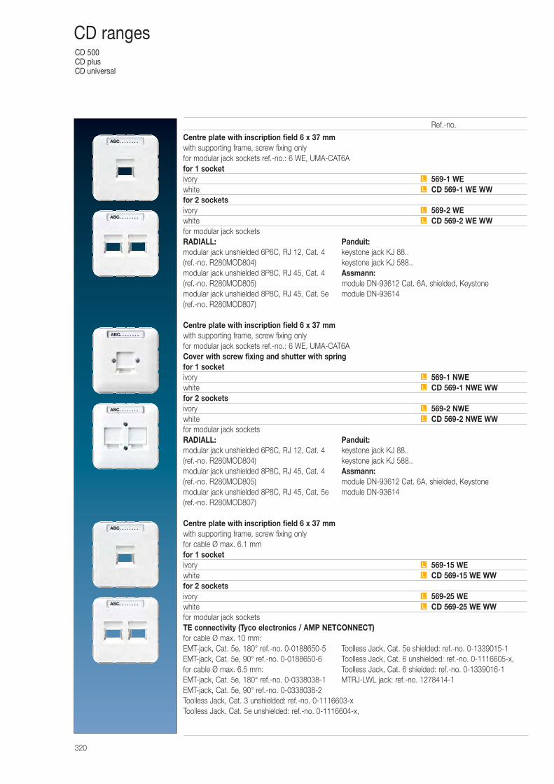
CD 500CD plusCD universal
320
CD ranges
Centre plate with inscription field 6 x 37 mmwith supporting frame, screw fixing onlyfor modular jack sockets ref.-no.: 6 WE, UMA-CAT6Afor 1 socketivory 569-1 WEwhite CD 569-1 WE WWfor 2 socketsivory 569-2 WEwhite CD 569-2 WE WWfor modular jack socketsRADIALL: Panduit:modular jack unshielded 6P6C, RJ 12, Cat. 4 keystone jack KJ 88..(ref.-no. R280MOD804) keystone jack KJ 588..modular jack unshielded 8P8C, RJ 45, Cat. 4 Assmann:(ref.-no. R280MOD805) module DN-93612 Cat. 6A, shielded, Keystonemodular jack unshielded 8P8C, RJ 45, Cat. 5e module DN-93614(ref.-no. R280MOD807)
Centre plate with inscription field 6 x 37 mmwith supporting frame, screw fixing onlyfor modular jack sockets ref.-no.: 6 WE, UMA-CAT6ACover with screw fixing and shutter with springfor 1 socketivory 569-1 NWEwhite CD 569-1 NWE WWfor 2 socketsivory 569-2 NWEwhite CD 569-2 NWE WWfor modular jack socketsRADIALL: Panduit:modular jack unshielded 6P6C, RJ 12, Cat. 4 keystone jack KJ 88..(ref.-no. R280MOD804) keystone jack KJ 588..modular jack unshielded 8P8C, RJ 45, Cat. 4 Assmann:(ref.-no. R280MOD805) module DN-93612 Cat. 6A, shielded, Keystonemodular jack unshielded 8P8C, RJ 45, Cat. 5e module DN-93614(ref.-no. R280MOD807)
Centre plate with inscription field 6 x 37 mmwith supporting frame, screw fixing onlyfor cable Ø max. 6.1 mmfor 1 socketivory 569-15 WEwhite CD 569-15 WE WWfor 2 socketsivory 569-25 WEwhite CD 569-25 WE WWfor modular jack socketsTE connectivity (Tyco electronics / AMP NETCONNECT)for cable Ø max. 10 mm:EMT-jack, Cat. 5e, 180° ref.-no. 0-0188650-5 Toolless Jack, Cat. 5e shielded: ref.-no. 0-1339015-1EMT-jack, Cat. 5e, 90° ref.-no. 0-0188650-6 Toolless Jack, Cat. 6 unshielded: ref.-no. 0-1116605-x, for cable Ø max. 6.5 mm: Toolless Jack, Cat. 6 shielded: ref.-no. 0-1339016-1EMT-jack, Cat. 5e, 180° ref.-no. 0-0338038-1 MTRJ-LWL jack: ref.-no. 1278414-1EMT-jack, Cat. 5e, 90° ref.-no. 0-0338038-2Toolless Jack, Cat. 3 unshielded: ref.-no. 0-1116603-xToolless Jack, Cat. 5e unshielded: ref.-no. 0-1116604-x,
L
L
L
L
L
L
L
L
L
L
L
L
Ref.-no.
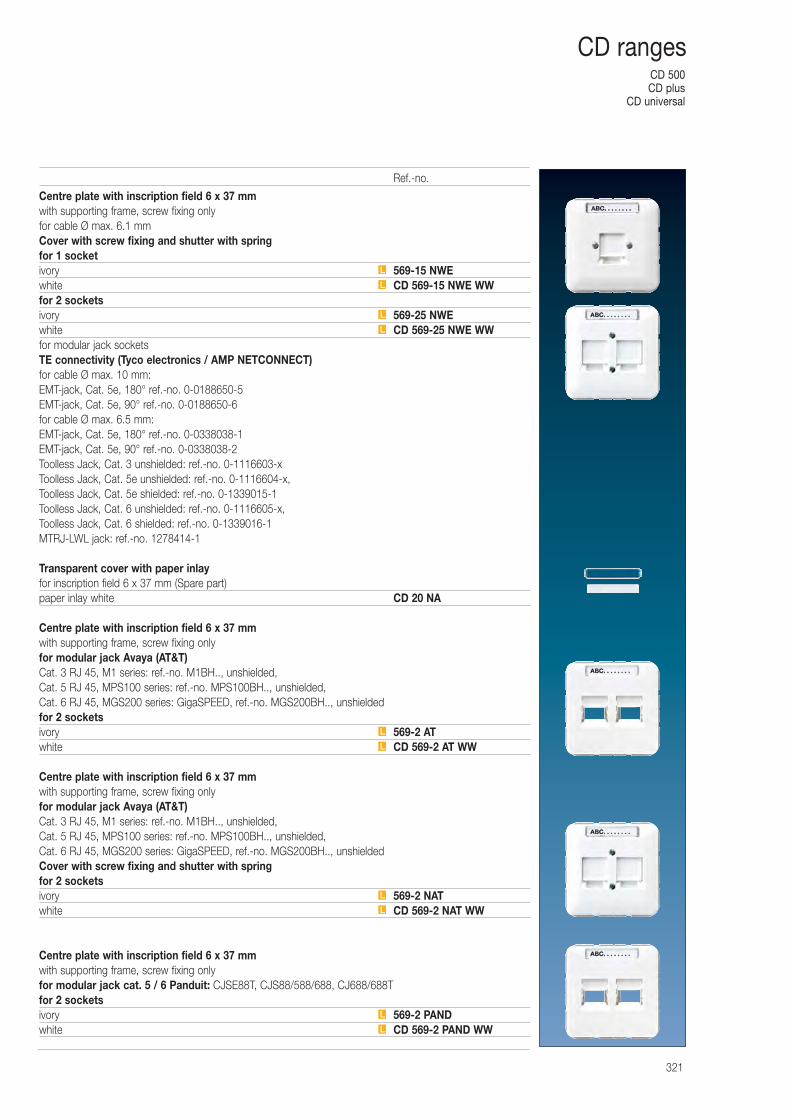
CD 500CD plus
CD universal
321
CD ranges
Centre plate with inscription field 6 x 37 mmwith supporting frame, screw fixing onlyfor cable Ø max. 6.1 mmCover with screw fixing and shutter with springfor 1 socketivory 569-15 NWEwhite CD 569-15 NWE WWfor 2 socketsivory 569-25 NWEwhite CD 569-25 NWE WWfor modular jack socketsTE connectivity (Tyco electronics / AMP NETCONNECT)for cable Ø max. 10 mm:EMT-jack, Cat. 5e, 180° ref.-no. 0-0188650-5EMT-jack, Cat. 5e, 90° ref.-no. 0-0188650-6for cable Ø max. 6.5 mm:EMT-jack, Cat. 5e, 180° ref.-no. 0-0338038-1EMT-jack, Cat. 5e, 90° ref.-no. 0-0338038-2Toolless Jack, Cat. 3 unshielded: ref.-no. 0-1116603-xToolless Jack, Cat. 5e unshielded: ref.-no. 0-1116604-x, Toolless Jack, Cat. 5e shielded: ref.-no. 0-1339015-1Toolless Jack, Cat. 6 unshielded: ref.-no. 0-1116605-x, Toolless Jack, Cat. 6 shielded: ref.-no. 0-1339016-1MTRJ-LWL jack: ref.-no. 1278414-1
Transparent cover with paper inlayfor inscription field 6 x 37 mm (Spare part)paper inlay white CD 20 NA
Centre plate with inscription field 6 x 37 mmwith supporting frame, screw fixing onlyfor modular jack Avaya (AT&T)Cat. 3 RJ 45, M1 series: ref.-no. M1BH.., unshielded,Cat. 5 RJ 45, MPS100 series: ref.-no. MPS100BH.., unshielded,Cat. 6 RJ 45, MGS200 series: GigaSPEED, ref.-no. MGS200BH.., unshieldedfor 2 socketsivory 569-2 ATwhite CD 569-2 AT WW
Centre plate with inscription field 6 x 37 mmwith supporting frame, screw fixing onlyfor modular jack Avaya (AT&T)Cat. 3 RJ 45, M1 series: ref.-no. M1BH.., unshielded,Cat. 5 RJ 45, MPS100 series: ref.-no. MPS100BH.., unshielded,Cat. 6 RJ 45, MGS200 series: GigaSPEED, ref.-no. MGS200BH.., unshieldedCover with screw fixing and shutter with springfor 2 socketsivory 569-2 NATwhite CD 569-2 NAT WW
Centre plate with inscription field 6 x 37 mmwith supporting frame, screw fixing onlyfor modular jack cat. 5 / 6 Panduit: CJSE88T, CJS88/588/688, CJ688/688Tfor 2 socketsivory 569-2 PANDwhite CD 569-2 PAND WWL
L
L
L
L
L
L
L
L
L
Ref.-no.
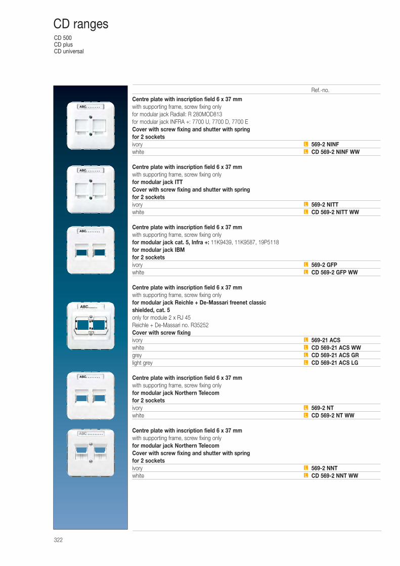
CD 500CD plusCD universal
322
CD ranges
Centre plate with inscription field 6 x 37 mmwith supporting frame, screw fixing onlyfor modular jack Radiall: R 280MOD813for modular jack INFRA +: 7700 U, 7700 D, 7700 ECover with screw fixing and shutter with springfor 2 socketsivory 569-2 NINFwhite CD 569-2 NINF WW
Centre plate with inscription field 6 x 37 mmwith supporting frame, screw fixing onlyfor modular jack ITTCover with screw fixing and shutter with springfor 2 socketsivory 569-2 NITTwhite CD 569-2 NITT WW
Centre plate with inscription field 6 x 37 mmwith supporting frame, screw fixing onlyfor modular jack cat. 5, Infra +: 11K9439, 11K9587, 19P5118for modular jack IBMfor 2 socketsivory 569-2 GFPwhite CD 569-2 GFP WW
Centre plate with inscription field 6 x 37 mmwith supporting frame, screw fixing onlyfor modular jack Reichle + De-Massari freenet classicshielded, cat. 5only for module 2 x RJ 45Reichle + De-Massari no. R35252Cover with screw fixingivory 569-21 ACSwhite CD 569-21 ACS WWgrey CD 569-21 ACS GRlight grey CD 569-21 ACS LG
Centre plate with inscription field 6 x 37 mmwith supporting frame, screw fixing onlyfor modular jack Northern Telecomfor 2 socketsivory 569-2 NTwhite CD 569-2 NT WW
Centre plate with inscription field 6 x 37 mmwith supporting frame, screw fixing onlyfor modular jack Northern TelecomCover with screw fixing and shutter with springfor 2 socketsivory 569-2 NNTwhite CD 569-2 NNT WWL
L
L
L
L
L
L
L
L
L
L
L
L
L
Ref.-no.
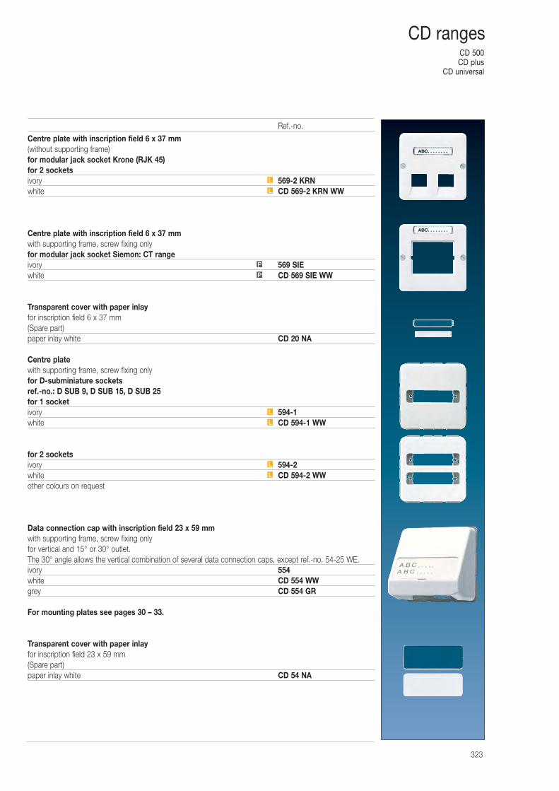
CD 500CD plus
CD universal
323
CD ranges
Centre plate with inscription field 6 x 37 mm(without supporting frame)for modular jack socket Krone (RJK 45)for 2 socketsivory 569-2 KRNwhite CD 569-2 KRN WW
Centre plate with inscription field 6 x 37 mmwith supporting frame, screw fixing onlyfor modular jack socket Siemon: CT rangeivory 569 SIEwhite CD 569 SIE WW
Transparent cover with paper inlayfor inscription field 6 x 37 mm(Spare part)paper inlay white CD 20 NA
Centre platewith supporting frame, screw fixing onlyfor D-subminiature socketsref.-no.: D SUB 9, D SUB 15, D SUB 25for 1 socketivory 594-1white CD 594-1 WW
for 2 socketsivory 594-2white CD 594-2 WWother colours on request
Data connection cap with inscription field 23 x 59 mmwith supporting frame, screw fixing onlyfor vertical and 15° or 30° outlet.The 30° angle allows the vertical combination of several data connection caps, except ref.-no. 54-25 WE.ivory 554white CD 554 WWgrey CD 554 GR
For mounting plates see pages 30 – 33.
Transparent cover with paper inlayfor inscription field 23 x 59 mm(Spare part)paper inlay white CD 54 NA
L
L
L
L
L
L
P
P
Ref.-no.
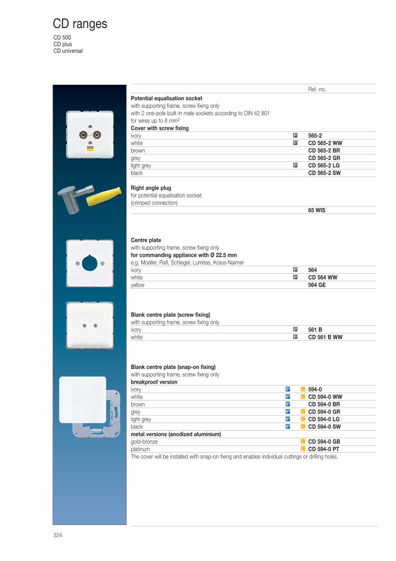
CD 500CD plusCD universal
324
CD ranges
Potential equalisation socketwith supporting frame, screw fixing onlywith 2 one-pole built-in male sockets according to DIN 42 801for wires up to 6 mm2
Cover with screw fixingivory 565-2white CD 565-2 WWbrown CD 565-2 BRgrey CD 565-2 GRlight grey CD 565-2 LGblack CD 565-2 SW
Right angle plugfor potential equalisation socket(crimped connection)
65 WIS
Centre platewith supporting frame, screw fixing onlyfor commanding appliance with Ø 22.5 mme.g. Moeller, Rafi, Schlegel, Lumitas, Kraus-Naimerivory 564white CD 564 WWyellow 564 GE
Blank centre plate (screw fixing)with supporting frame, screw fixing onlyivory 561 Bwhite CD 561 B WW
Blank centre plate (snap-on fixing)with supporting frame, screw fixing onlybreakproof versionivory 594-0white CD 594-0 WWbrown CD 594-0 BRgrey CD 594-0 GRlight grey CD 594-0 LGblack CD 594-0 SWmetal versions (anodized aluminium)gold-bronze CD 594-0 GBplatinum CD 594-0 PTThe cover will be installed with snap-on fixing and enables individual cuttings or drilling holes.
P
P
P
L
L
LIP
LIP
LIP
IP
LIP
LIP
P
P
P
P
Ref.-no.
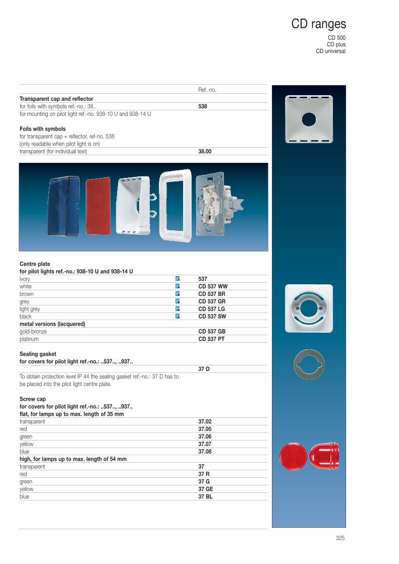
CD 500CD plus
CD universal
325
CD ranges
Transparent cap and reflectorfor foils with symbols ref.-no.: 38.. 538for mounting on pilot light ref.-no. 938-10 U and 938-14 U
Foils with symbolsfor transparent cap + reflector, ref-no. 538(only readable when pilot light is on)transparent (for individual text) 38.00
Centre platefor pilot lights ref.-no.: 938-10 U and 938-14 Uivory 537white CD 537 WWbrown CD 537 BRgrey CD 537 GRlight grey CD 537 LGblack CD 537 SWmetal versions (lacquered)gold-bronze CD 537 GBplatinum CD 537 PT
Sealing gasketfor covers for pilot light ref.-no.: ..537.., ..937..
37 DTo obtain protection level IP 44 the sealing gasket ref.-no.: 37 D has to be placed into the pilot light centre plate.
Screw capfor covers for pilot light ref.-no.: ..537.., ..937..flat, for lamps up to max. length of 35 mmtransparent 37.02red 37.05green 37.06yellow 37.07blue 37.08high, for lamps up to max. length of 54 mmtransparent 37red 37 Rgreen 37 Gyellow 37 GEblue 37 BL
IP
IP
IP
IP
IP
IP
Ref.-no.
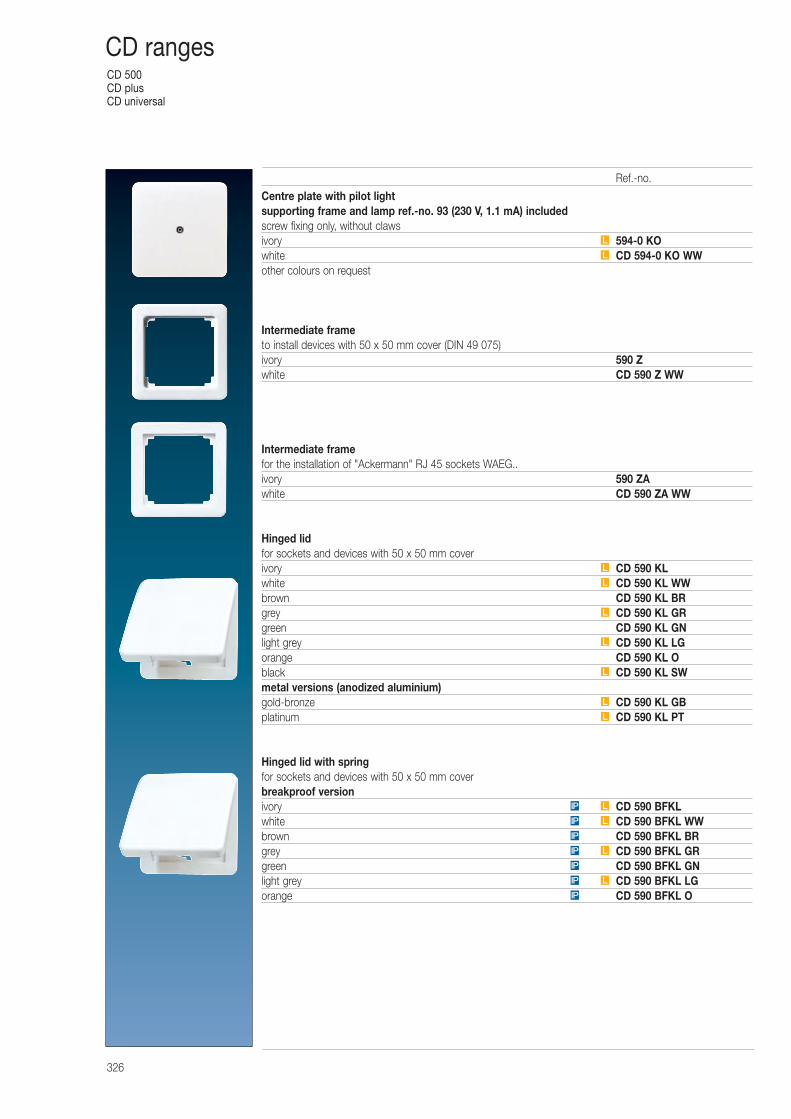
CD 500CD plusCD universal
326
CD ranges
Centre plate with pilot light supporting frame and lamp ref.-no. 93 (230 V, 1.1 mA) includedscrew fixing only, without clawsivory 594-0 KOwhite CD 594-0 KO WWother colours on request
Intermediate frameto install devices with 50 x 50 mm cover (DIN 49 075)ivory 590 Zwhite CD 590 Z WW
Intermediate framefor the installation of "Ackermann" RJ 45 sockets WAEG..ivory 590 ZAwhite CD 590 ZA WW
Hinged lidfor sockets and devices with 50 x 50 mm coverivory CD 590 KLwhite CD 590 KL WWbrown CD 590 KL BRgrey CD 590 KL GRgreen CD 590 KL GNlight grey CD 590 KL LGorange CD 590 KL Oblack CD 590 KL SWmetal versions (anodized aluminium)gold-bronze CD 590 KL GBplatinum CD 590 KL PT
Hinged lid with springfor sockets and devices with 50 x 50 mm coverbreakproof versionivory CD 590 BFKLwhite CD 590 BFKL WWbrown CD 590 BFKL BRgrey CD 590 BFKL GRgreen CD 590 BFKL GNlight grey CD 590 BFKL LGorange CD 590 BFKL OIP
LIP
IP
LIP
IP
LIP
LIP
L
L
L
L
L
L
L
L
L
Ref.-no.
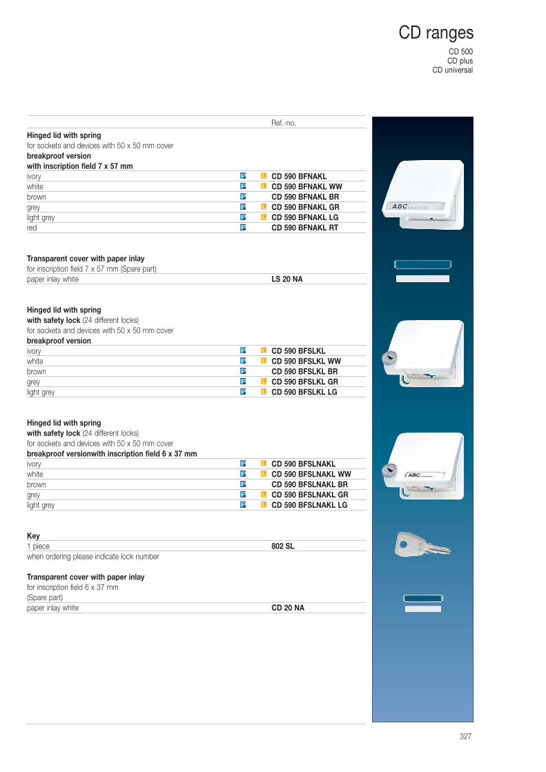
CD 500CD plus
CD universal
327
CD ranges
Hinged lid with springfor sockets and devices with 50 x 50 mm coverbreakproof versionwith inscription field 7 x 57 mmivory CD 590 BFNAKLwhite CD 590 BFNAKL WWbrown CD 590 BFNAKL BRgrey CD 590 BFNAKL GRlight grey CD 590 BFNAKL LGred CD 590 BFNAKL RT
Transparent cover with paper inlayfor inscription field 7 x 57 mm (Spare part)paper inlay white LS 20 NA
Hinged lid with springwith safety lock (24 different locks)for sockets and devices with 50 x 50 mm coverbreakproof versionivory CD 590 BFSLKLwhite CD 590 BFSLKL WWbrown CD 590 BFSLKL BRgrey CD 590 BFSLKL GRlight grey CD 590 BFSLKL LG
Hinged lid with springwith safety lock (24 different locks)for sockets and devices with 50 x 50 mm coverbreakproof versionwith inscription field 6 x 37 mmivory CD 590 BFSLNAKLwhite CD 590 BFSLNAKL WWbrown CD 590 BFSLNAKL BRgrey CD 590 BFSLNAKL GRlight grey CD 590 BFSLNAKL LG
Key1 piece 802 SLwhen ordering please indicate lock number
Transparent cover with paper inlayfor inscription field 6 x 37 mm(Spare part)paper inlay white CD 20 NA
LIP
LIP
IP
LIP
LIP
IP
LIP
LIP
IP
LIP
LIP
LIP
LIP
IP
LIP
LIP
Ref.-no.
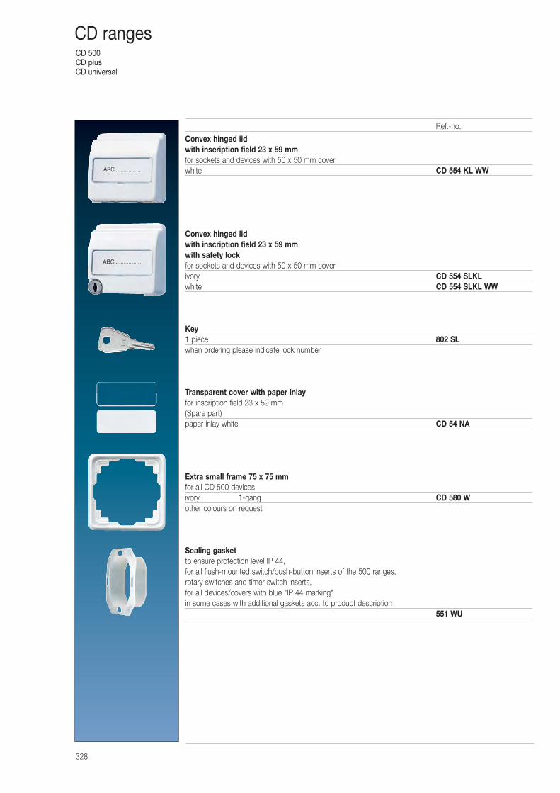
CD 500CD plusCD universal
328
CD ranges
Convex hinged lidwith inscription field 23 x 59 mmfor sockets and devices with 50 x 50 mm coverwhite CD 554 KL WW
Convex hinged lidwith inscription field 23 x 59 mmwith safety lockfor sockets and devices with 50 x 50 mm coverivory CD 554 SLKLwhite CD 554 SLKL WW
Key1 piece 802 SLwhen ordering please indicate lock number
Transparent cover with paper inlayfor inscription field 23 x 59 mm(Spare part)paper inlay white CD 54 NA
Extra small frame 75 x 75 mmfor all CD 500 devicesivory 1-gang CD 580 Wother colours on request
Sealing gasketto ensure protection level IP 44,for all flush-mounted switch/push-button inserts of the 500 ranges,rotary switches and timer switch inserts,for all devices/covers with blue "IP 44 marking"in some cases with additional gaskets acc. to product description
551 WU
Ref.-no.
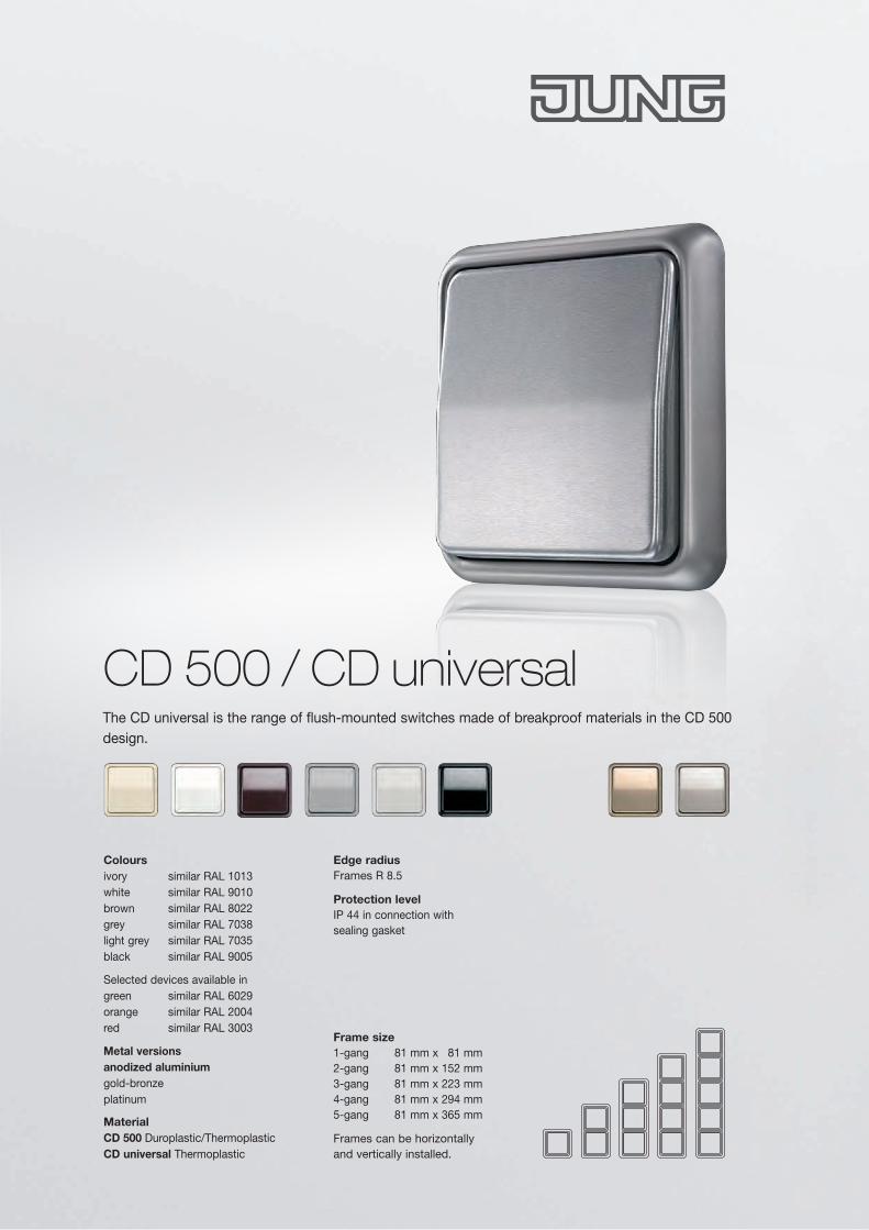
CD 500 / CD universal
Frame size 1-gang 81 mm x 81 mm 2-gang 81 mm x 152 mm 3-gang 81 mm x 223 mm 4-gang 81 mm x 294 mm 5-gang 81 mm x 365 mm
Frames can be horizontallyand vertically installed.
Edge radius Frames R 8.5
Protection level IP 44 in connection with sealing gasket
Colours ivory similar RAL 1013 white similar RAL 9010 brown similar RAL 8022 grey similar RAL 7038 light grey similar RAL 7035 black similar RAL 9005
Selected devices available in green similar RAL 6029 orange similar RAL 2004 red similar RAL 3003
Metal versions anodized aluminium gold-bronze platinum
Material CD 500 Duroplastic/Thermoplastic CD universal Thermoplastic
The CD universal is the range of flush-mounted switches made of breakproof materials in the CD 500 design.
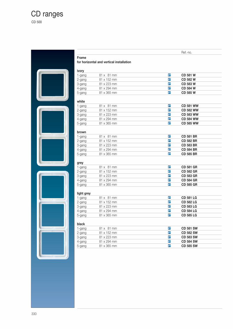
CD 500
330
CD ranges
Framefor horizontal and vertical installation
ivory1-gang 81 x 081 mm CD 581 W2-gang 81 x 152 mm CD 582 W3-gang 81 x 223 mm CD 583 W4-gang 81 x 294 mm CD 584 W5-gang 81 x 365 mm CD 585 W
white1-gang 81 x 081 mm CD 581 WW2-gang 81 x 152 mm CD 582 WW3-gang 81 x 223 mm CD 583 WW4-gang 81 x 294 mm CD 584 WW5-gang 81 x 365 mm CD 585 WW
brown1-gang 81 x 081 mm CD 581 BR2-gang 81 x 152 mm CD 582 BR3-gang 81 x 223 mm CD 583 BR4-gang 81 x 294 mm CD 584 BR5-gang 81 x 365 mm CD 585 BR
grey1-gang 81 x 081 mm CD 581 GR2-gang 81 x 152 mm CD 582 GR3-gang 81 x 223 mm CD 583 GR4-gang 81 x 294 mm CD 584 GR5-gang 81 x 365 mm CD 585 GR
light grey1-gang 81 x 081 mm CD 581 LG2-gang 81 x 152 mm CD 582 LG3-gang 81 x 223 mm CD 583 LG4-gang 81 x 294 mm CD 584 LG5-gang 81 x 365 mm CD 585 LG
black1-gang 81 x 081 mm CD 581 SW2-gang 81 x 152 mm CD 582 SW3-gang 81 x 223 mm CD 583 SW4-gang 81 x 294 mm CD 584 SW5-gang 81 x 365 mm CD 585 SWIP
IP
IP
IP
IP
IP
IP
IP
IP
IP
IP
IP
IP
IP
IP
IP
IP
IP
IP
IP
IP
IP
IP
IP
IP
IP
IP
IP
IP
IP
Ref.-no.
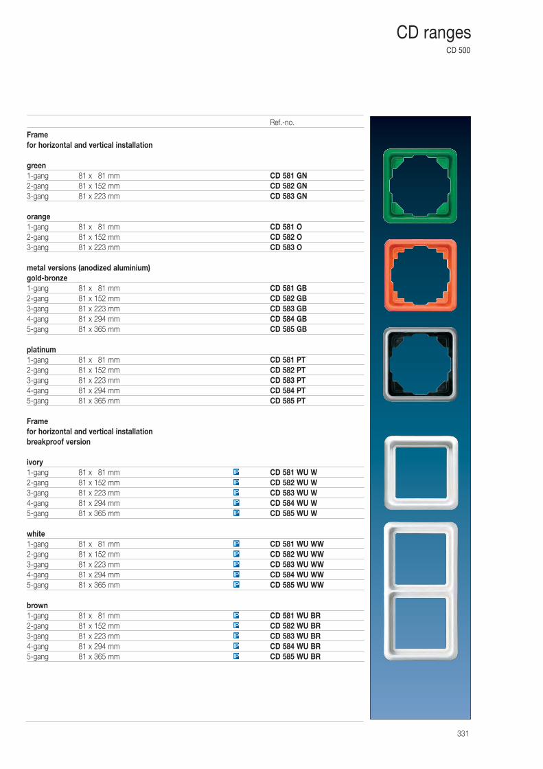
CD 500
331
CD ranges
Framefor horizontal and vertical installation
green1-gang 81 x 081 mm CD 581 GN2-gang 81 x 152 mm CD 582 GN3-gang 81 x 223 mm CD 583 GN
orange1-gang 81 x 081 mm CD 581 O2-gang 81 x 152 mm CD 582 O3-gang 81 x 223 mm CD 583 O
metal versions (anodized aluminium)gold-bronze1-gang 81 x 081 mm CD 581 GB2-gang 81 x 152 mm CD 582 GB3-gang 81 x 223 mm CD 583 GB4-gang 81 x 294 mm CD 584 GB5-gang 81 x 365 mm CD 585 GB
platinum1-gang 81 x 081 mm CD 581 PT2-gang 81 x 152 mm CD 582 PT3-gang 81 x 223 mm CD 583 PT4-gang 81 x 294 mm CD 584 PT5-gang 81 x 365 mm CD 585 PT
Framefor horizontal and vertical installationbreakproof version
ivory1-gang 81 x 081 mm CD 581 WU W2-gang 81 x 152 mm CD 582 WU W3-gang 81 x 223 mm CD 583 WU W4-gang 81 x 294 mm CD 584 WU W5-gang 81 x 365 mm CD 585 WU W
white1-gang 81 x 081 mm CD 581 WU WW2-gang 81 x 152 mm CD 582 WU WW3-gang 81 x 223 mm CD 583 WU WW4-gang 81 x 294 mm CD 584 WU WW5-gang 81 x 365 mm CD 585 WU WW
brown1-gang 81 x 081 mm CD 581 WU BR2-gang 81 x 152 mm CD 582 WU BR3-gang 81 x 223 mm CD 583 WU BR4-gang 81 x 294 mm CD 584 WU BR5-gang 81 x 365 mm CD 585 WU BRIP
IP
IP
IP
IP
IP
IP
IP
IP
IP
IP
IP
IP
IP
IP
Ref.-no.
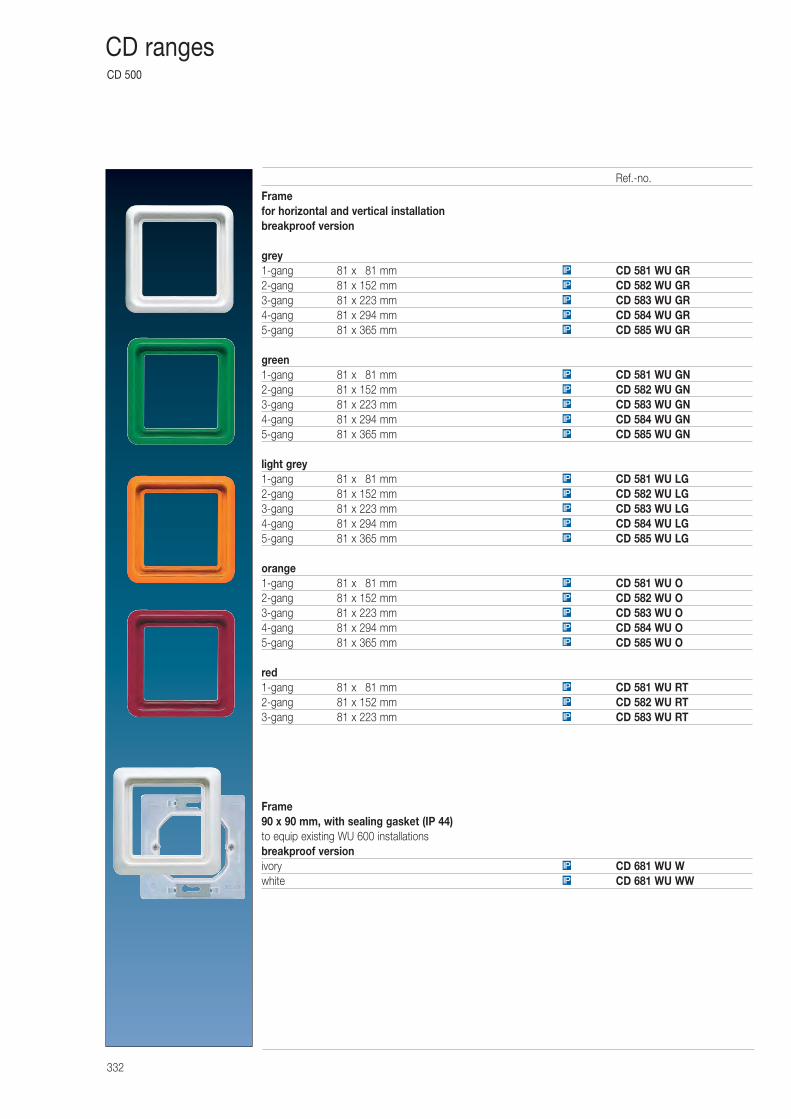
CD 500
332
CD ranges
Framefor horizontal and vertical installationbreakproof version
grey1-gang 81 x 081 mm CD 581 WU GR2-gang 81 x 152 mm CD 582 WU GR3-gang 81 x 223 mm CD 583 WU GR4-gang 81 x 294 mm CD 584 WU GR5-gang 81 x 365 mm CD 585 WU GR
green1-gang 81 x 081 mm CD 581 WU GN2-gang 81 x 152 mm CD 582 WU GN3-gang 81 x 223 mm CD 583 WU GN4-gang 81 x 294 mm CD 584 WU GN5-gang 81 x 365 mm CD 585 WU GN
light grey1-gang 81 x 081 mm CD 581 WU LG2-gang 81 x 152 mm CD 582 WU LG3-gang 81 x 223 mm CD 583 WU LG4-gang 81 x 294 mm CD 584 WU LG5-gang 81 x 365 mm CD 585 WU LG
orange1-gang 81 x 081 mm CD 581 WU O2-gang 81 x 152 mm CD 582 WU O3-gang 81 x 223 mm CD 583 WU O4-gang 81 x 294 mm CD 584 WU O5-gang 81 x 365 mm CD 585 WU O
red1-gang 81 x 081 mm CD 581 WU RT2-gang 81 x 152 mm CD 582 WU RT3-gang 81 x 223 mm CD 583 WU RT
Frame 90 x 90 mm, with sealing gasket (IP 44)to equip existing WU 600 installationsbreakproof versionivory CD 681 WU Wwhite CD 681 WU WWIP
IP
IP
IP
IP
IP
IP
IP
IP
IP
IP
IP
IP
IP
IP
IP
IP
IP
IP
IP
IP
IP
IP
IP
IP
Ref.-no.
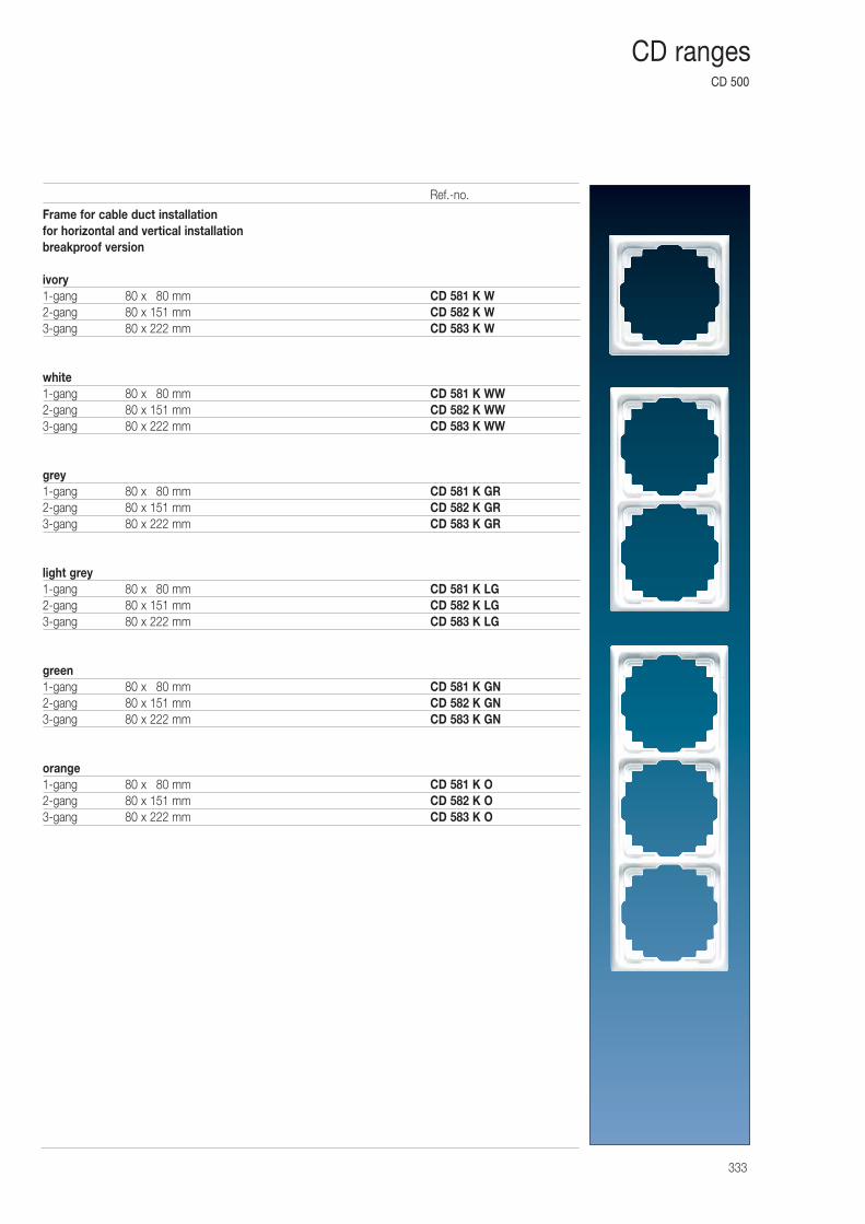
CD 500
333
CD ranges
Frame for cable duct installationfor horizontal and vertical installationbreakproof version
ivory1-gang 80 x 080 mm CD 581 K W2-gang 80 x 151 mm CD 582 K W3-gang 80 x 222 mm CD 583 K W
white1-gang 80 x 080 mm CD 581 K WW2-gang 80 x 151 mm CD 582 K WW3-gang 80 x 222 mm CD 583 K WW
grey1-gang 80 x 080 mm CD 581 K GR2-gang 80 x 151 mm CD 582 K GR3-gang 80 x 222 mm CD 583 K GR
light grey1-gang 80 x 080 mm CD 581 K LG2-gang 80 x 151 mm CD 582 K LG3-gang 80 x 222 mm CD 583 K LG
green1-gang 80 x 080 mm CD 581 K GN2-gang 80 x 151 mm CD 582 K GN3-gang 80 x 222 mm CD 583 K GN
orange1-gang 80 x 080 mm CD 581 K O2-gang 80 x 151 mm CD 582 K O3-gang 80 x 222 mm CD 583 K O
Ref.-no.
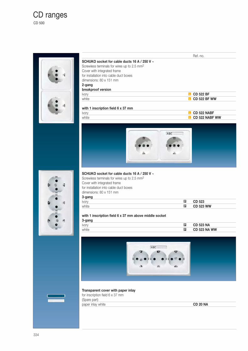
CD 500
334
CD ranges
SCHUKO socket for cable ducts 16 A / 250 V ~Screwless terminals for wires up to 2.5 mm2
Cover with integrated framefor installation into cable duct boxesdimensions: 80 x 151 mm2-gangbreakproof versionivory CD 522 BFwhite CD 522 BF WW
with 1 inscription field 6 x 37 mmivory CD 522 NABFwhite CD 522 NABF WW
SCHUKO socket for cable ducts 16 A / 250 V ~Screwless terminals for wires up to 2.5 mm2
Cover with integrated framefor installation into cable duct boxesdimensions: 80 x 151 mm3-gangivory CD 523white CD 523 WW
with 1 inscription field 6 x 37 mm above middle socket3-gangivory CD 523 NAwhite CD 523 NA WW
Transparent cover with paper inlayfor inscription field 6 x 37 mm(Spare part)paper inlay white CD 20 NA
P
P
P
P
L
L
L
L
Ref.-no.
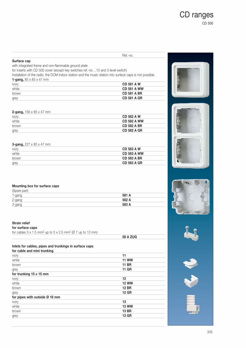
CD 500
335
CD ranges
Surface capwith integrated frame and non-flammable ground platefor inserts with CD 500 cover (except key switches ref.-no. ..15 and 3-level-switch)Installation of the radio, the DCM indoor station and the music station into surface caps is not possible.1-gang, 85 x 85 x 47 mmivory CD 581 A Wwhite CD 581 A WWbrown CD 581 A BRgrey CD 581 A GR
2-gang, 156 x 85 x 47 mmivory CD 582 A Wwhite CD 582 A WWbrown CD 582 A BRgrey CD 582 A GR
3-gang, 227 x 85 x 47 mmivory CD 583 A Wwhite CD 583 A WWbrown CD 583 A BRgrey CD 583 A GR
Mounting box for surface caps(Spare part)1-gang 581 A2-gang 582 A3-gang 583 A
Strain relieffor surface capsfor cables 3 x 1.5 mm2 up to 5 x 2.5 mm2 (Ø 7 up to 13 mm)
58 A ZUG
Inlets for cables, pipes and trunkings in surface capsfor cable and mini trunkingivory 11white 11 WWbrown 11 BRgrey 11 GRfor trunking 15 x 15 mmivory 12white 12 WWbrown 12 BRgrey 12 GRfor pipes with outside Ø 16 mmivory 13white 13 WWbrown 13 BRgrey 13 GR
Ref.-no.
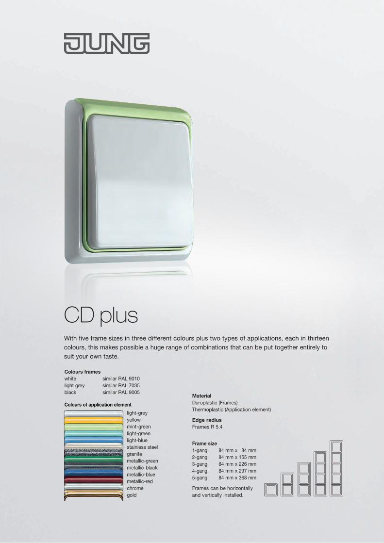
Frame size 1-gang 84 mm x 84 mm 2-gang 84 mm x 155 mm 3-gang 84 mm x 226 mm 4-gang 84 mm x 297 mm 5-gang 84 mm x 368 mm
Frames can be horizontallyand vertically installed.
Material Duroplastic (Frames) Thermoplastic (Application element)
Edge radiusFrames R 5.4
With five frame sizes in three different colours plus two types of applications, each in thirteen colours, this makes possible a huge range of combinations that can be put together entirely to suit your own taste.
CD plus
light-greyyellowmint-greenlight-greenlight-bluestainless steelgranitemetallic-greenmetallic-blackmetallic-bluemetallic-redchromegold
Colours frames white similar RAL 9010 light grey similar RAL 7035 black similar RAL 9005
Colours of application element
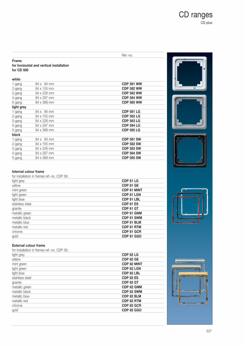
CD plus
337
CD ranges
Framefor horizontal and vertical installationfor CD 500
white1-gang 84 x 084 mm CDP 581 WW2-gang 84 x 155 mm CDP 582 WW3-gang 84 x 226 mm CDP 583 WW4-gang 84 x 297 mm CDP 584 WW5-gang 84 x 368 mm CDP 585 WWlight grey1-gang 84 x 084 mm CDP 581 LG2-gang 84 x 155 mm CDP 582 LG3-gang 84 x 226 mm CDP 583 LG4-gang 84 x 297 mm CDP 584 LG5-gang 84 x 368 mm CDP 585 LGblack1-gang 84 x 084 mm CDP 581 SW2-gang 84 x 155 mm CDP 582 SW3-gang 84 x 226 mm CDP 583 SW4-gang 84 x 297 mm CDP 584 SW5-gang 84 x 368 mm CDP 585 SW
Internal colour framefor installation in frames ref.-no. CDP 58..light grey CDP 81 LGyellow CDP 81 GEmint green CDP 81 MINTlight green CDP 81 LGNlight blue CDP 81 LBLstainless steel CDP 81 ESgranite CDP 81 GTmetallic green CDP 81 GNMmetallic black CDP 81 SWMmetallic blue CDP 81 BLMmetallic red CDP 81 RTMchrome CDP 81 GCRgold CDP 81 GGO
External colour framefor installation in frames ref.-no. CDP 58..light grey CDP 82 LGyellow CDP 82 GEmint green CDP 82 MINTlight green CDP 82 LGNlight blue CDP 82 LBLstainless steel CDP 82 ESgranite CDP 82 GTmetallic green CDP 82 GNMmetallic black CDP 82 SWMmetallic blue CDP 82 BLMmetallic red CDP 82 RTMchrome CDP 82 GCRgold CDP 82 GGO
Ref.-no.
SL 500
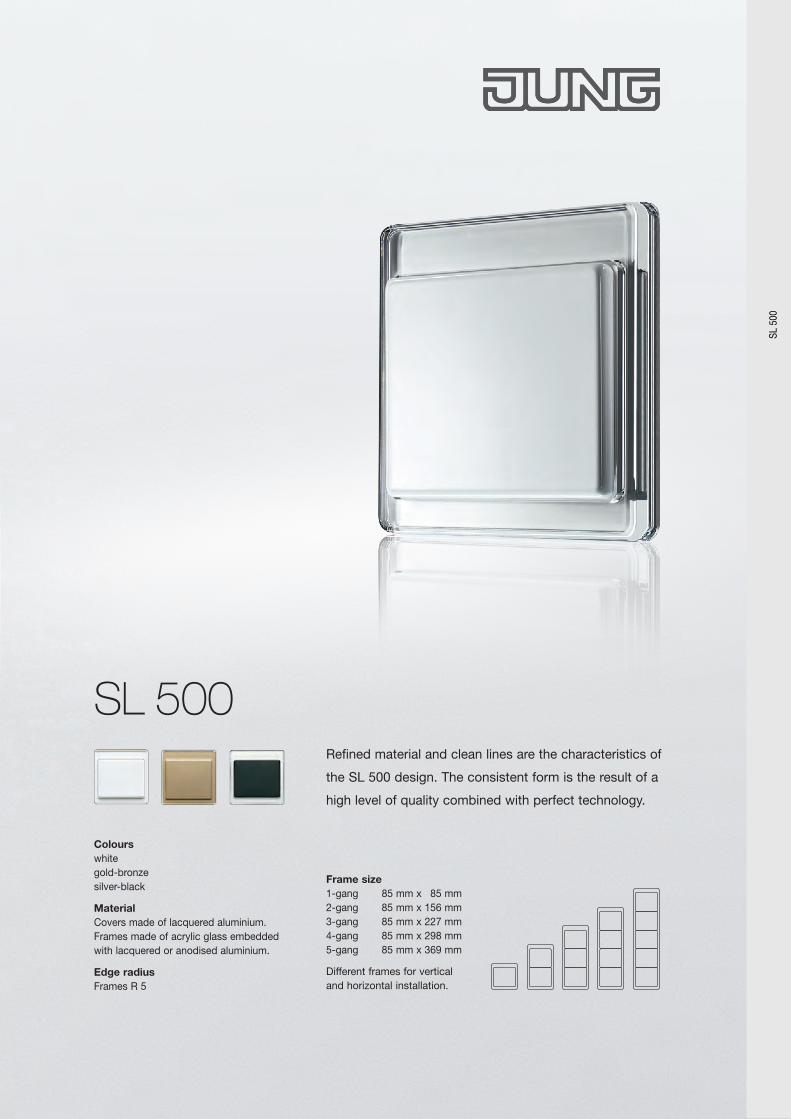
Colours white gold-bronze silver-black
Material Covers made of lacquered aluminium. Frames made of acrylic glass embedded with lacquered or anodised aluminium.
Edge radius Frames R 5
Frame size 1-gang 85 mm x 85 mm 2-gang 85 mm x 156 mm 3-gang 85 mm x 227 mm 4-gang 85 mm x 298 mm 5-gang 85 mm x 369 mm
Different frames for verticaland horizontal installation.
SL 500Refined material and clean lines are the characteristics of
the SL 500 design. The consistent form is the result of a
high level of quality combined with perfect technology.
SL 5
00
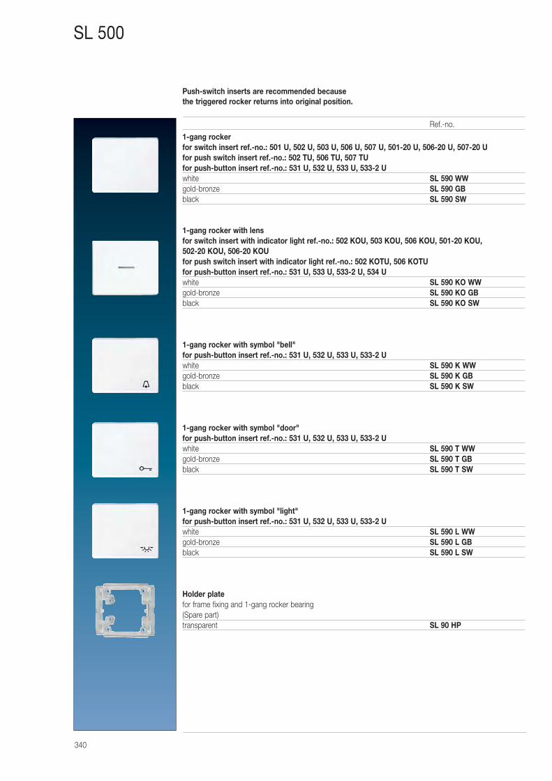
340
SL 500
1-gang rockerfor switch insert ref.-no.: 501 U, 502 U, 503 U, 506 U, 507 U, 501-20 U, 506-20 U, 507-20 Ufor push switch insert ref.-no.: 502 TU, 506 TU, 507 TUfor push-button insert ref.-no.: 531 U, 532 U, 533 U, 533-2 Uwhite SL 590 WWgold-bronze SL 590 GBblack SL 590 SW
1-gang rocker with lensfor switch insert with indicator light ref.-no.: 502 KOU, 503 KOU, 506 KOU, 501-20 KOU,502-20 KOU, 506-20 KOUfor push switch insert with indicator light ref.-no.: 502 KOTU, 506 KOTUfor push-button insert ref.-no.: 531 U, 533 U, 533-2 U, 534 Uwhite SL 590 KO WWgold-bronze SL 590 KO GBblack SL 590 KO SW
1-gang rocker with symbol "bell"for push-button insert ref.-no.: 531 U, 532 U, 533 U, 533-2 Uwhite SL 590 K WWgold-bronze SL 590 K GBblack SL 590 K SW
1-gang rocker with symbol "door"for push-button insert ref.-no.: 531 U, 532 U, 533 U, 533-2 Uwhite SL 590 T WWgold-bronze SL 590 T GBblack SL 590 T SW
1-gang rocker with symbol "light"for push-button insert ref.-no.: 531 U, 532 U, 533 U, 533-2 Uwhite SL 590 L WWgold-bronze SL 590 L GBblack SL 590 L SW
Holder platefor frame fixing and 1-gang rocker bearing(Spare part)transparent SL 90 HP
Ref.-no.
Push-switch inserts are recommended because the triggered rocker returns into original position.
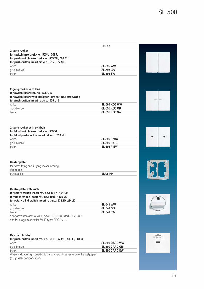
341
SL 500
2-gang rockerfor switch insert ref.-no.: 505 U, 509 Ufor push switch insert ref.-no.: 505 TU, 509 TUfor push-button insert ref.-no.: 535 U, 539 Uwhite SL 595 WWgold-bronze SL 595 GBblack SL 595 SW
2-gang rocker with lensfor switch insert ref.-no.: 505 U 5for switch insert with indicator light ref.-no.: 505 KOU 5for push-button insert ref.-no.: 535 U 5white SL 595 KO5 WWgold-bronze SL 595 KO5 GBblack SL 595 KO5 SW
2-gang rocker with symbolsfor blind switch insert ref.-no.: 509 VUfor blind push-button insert ref.-no.: 539 VUwhite SL 595 P WWgold-bronze SL 595 P GBblack SL 595 P SW
Holder platefor frame fixing and 2-gang rocker bearing(Spare part)transparent SL 95 HP
Centre plate with knobfor rotary switch insert ref.-no.: 101-4, 101-20for timer switch insert ref.-no.: 1015, 1120-20for rotary blind switch insert ref.-no.: 234.10, 234.20white SL 541 WWgold-bronze SL 541 GBblack SL 541 SWalso for volume control WHD type: LST..JU UP and LR..JU UPand for program selection WHD type: PRO 3 JU..
Key card holderfor push-button insert ref.-no.: 531 U, 532 U, 533 U, 534 Uwhite SL 590 CARD WWgold-bronze SL 590 CARD GBblack SL 590 CARD SWWhen wallpapering, consider to install supporting frame onto the wallpaper (NO plaster compensation).
Ref.-no.
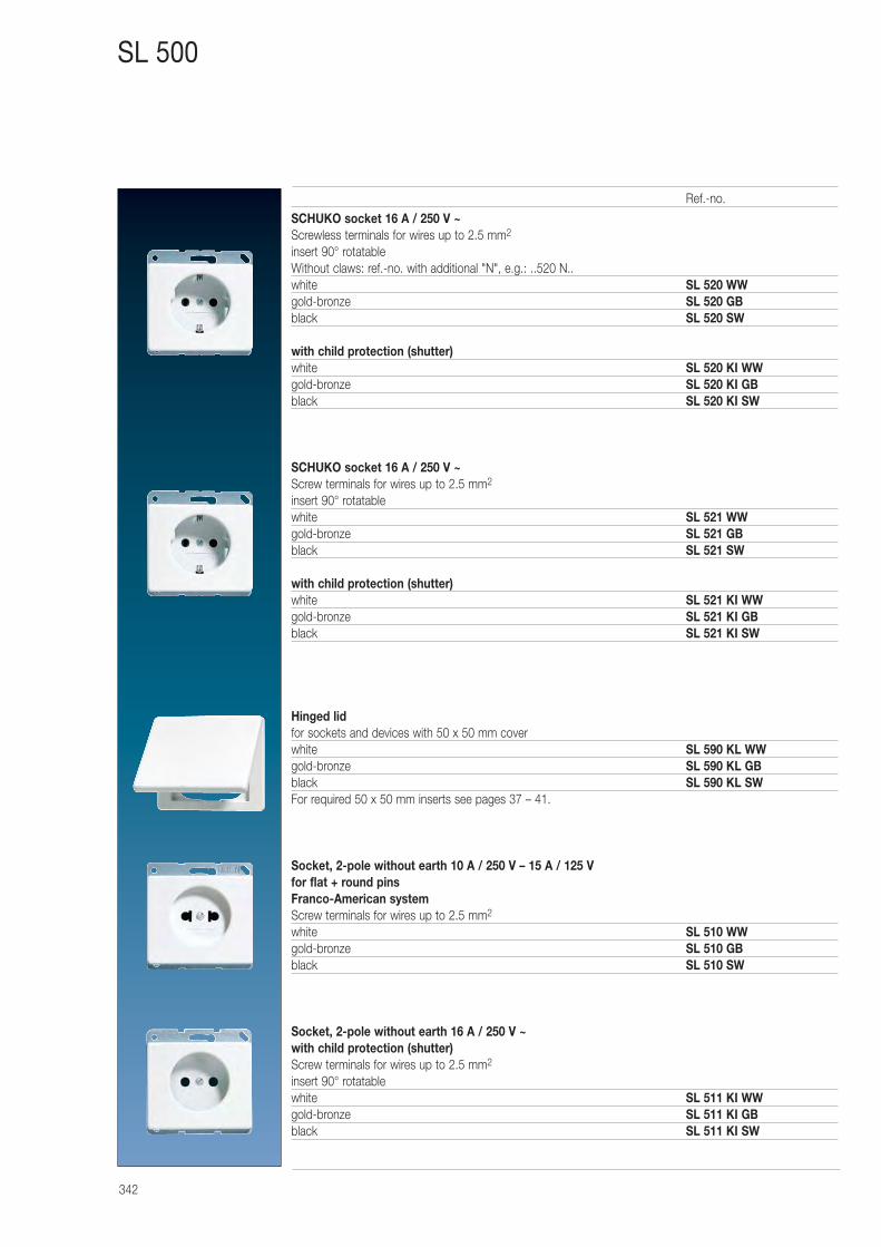
342
SL 500
SCHUKO socket 16 A / 250 V ~Screwless terminals for wires up to 2.5 mm2
insert 90° rotatableWithout claws: ref.-no. with additional "N", e.g.: ..520 N..white SL 520 WWgold-bronze SL 520 GBblack SL 520 SW
with child protection (shutter)white SL 520 KI WWgold-bronze SL 520 KI GBblack SL 520 KI SW
SCHUKO socket 16 A / 250 V ~Screw terminals for wires up to 2.5 mm2
insert 90° rotatablewhite SL 521 WWgold-bronze SL 521 GBblack SL 521 SW
with child protection (shutter)white SL 521 KI WWgold-bronze SL 521 KI GBblack SL 521 KI SW
Hinged lidfor sockets and devices with 50 x 50 mm coverwhite SL 590 KL WWgold-bronze SL 590 KL GBblack SL 590 KL SWFor required 50 x 50 mm inserts see pages 37 – 41.
Socket, 2-pole without earth 10 A / 250 V – 15 A / 125 Vfor flat + round pinsFranco-American systemScrew terminals for wires up to 2.5 mm2
white SL 510 WWgold-bronze SL 510 GBblack SL 510 SW
Socket, 2-pole without earth 16 A / 250 V ~with child protection (shutter)Screw terminals for wires up to 2.5 mm2
insert 90° rotatablewhite SL 511 KI WWgold-bronze SL 511 KI GBblack SL 511 KI SW
Ref.-no.
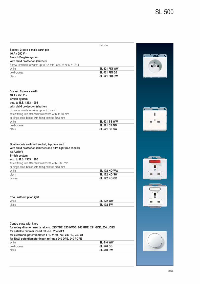
343
SL 500
Socket, 2-pole + male earth pin16 A / 250 V ~French/Belgian systemwith child protection (shutter)Screw terminals for wires up to 2.5 mm2 acc. to NFC 61-314white SL 521 FKI WWgold-bronze SL 521 FKI GBblack SL 521 FKI SW
Socket, 2-pole + earth 13 A / 250 V ~British systemacc. to B.S. 1363: 1995with child protection (shutter)Screw terminals for wires up to 2.5 mm2
screw fixing into standard wall boxes with Ø 60 mmor single steel boxes with fixing centres 60.3 mmwhite SL 521 BS WWgold-bronze SL 521 BS GBblack SL 521 BS SW
Double-pole switched socket, 2-pole + earthwith child protection (shutter) and pilot light (red rocker)13 A/250 VBritish systemacc. to B.S. 1363: 1995screw fixing into standard wall boxes with Ø 60 mmor single steel boxes with fixing centres 60.3 mmwhite SL 172 KO WWblack SL 172 KO SWbronze SL 172 KO GB
dtto., without pilot lightwhite SL 172 WWblack SL 172 SW
Centre plate with knobfor rotary dimmer inserts ref.-no.: 225 TDE, 225 NVDE, 266 GDE, 211 GDE, 254 UDIE1for satellite dimmer insert ref.-no.: 254 NIE1for electronic potentiometer 1–10 V ref.-no.: 240-10, 240-31for DALI potentiometer insert ref.-no.: 240 DPE, 240 PDPEwhite SL 540 WWgold-bronze SL 540 GBblack SL 540 SW
Ref.-no.
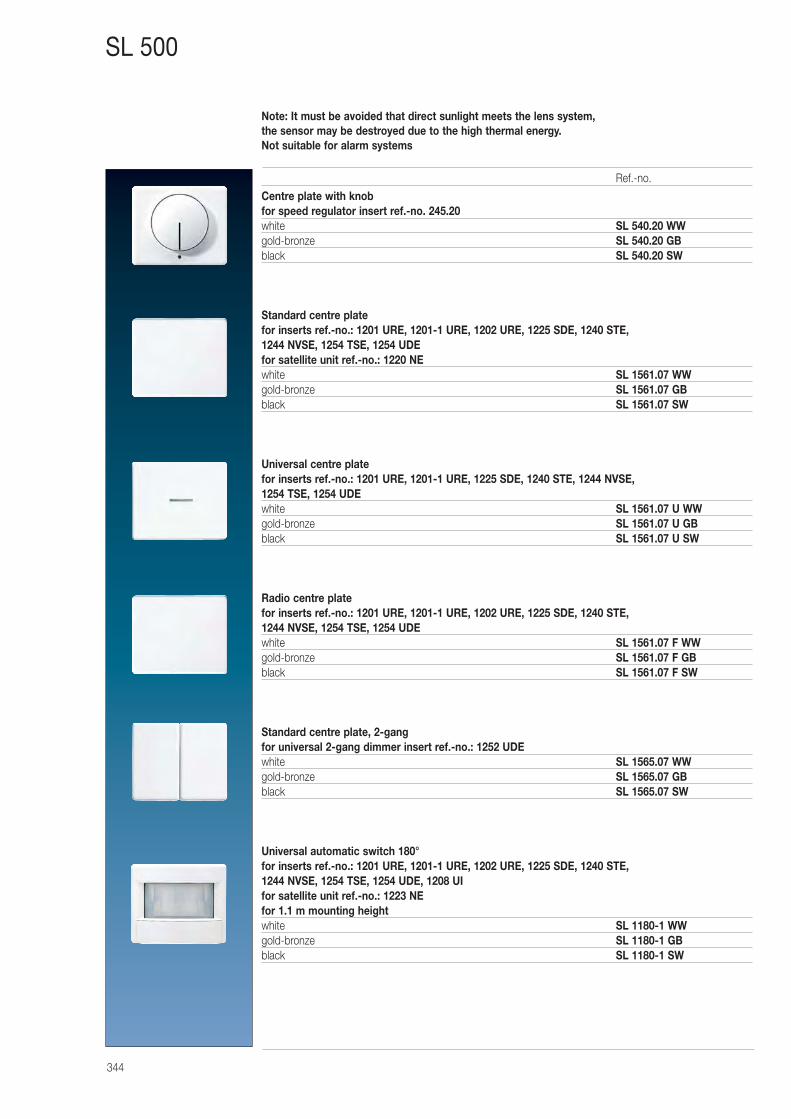
344
SL 500
Centre plate with knobfor speed regulator insert ref.-no. 245.20white SL 540.20 WWgold-bronze SL 540.20 GBblack SL 540.20 SW
Standard centre platefor inserts ref.-no.: 1201 URE, 1201-1 URE, 1202 URE, 1225 SDE, 1240 STE, 1244 NVSE, 1254 TSE, 1254 UDEfor satellite unit ref.-no.: 1220 NEwhite SL 1561.07 WWgold-bronze SL 1561.07 GBblack SL 1561.07 SW
Universal centre platefor inserts ref.-no.: 1201 URE, 1201-1 URE, 1225 SDE, 1240 STE, 1244 NVSE, 1254 TSE, 1254 UDEwhite SL 1561.07 U WWgold-bronze SL 1561.07 U GBblack SL 1561.07 U SW
Radio centre platefor inserts ref.-no.: 1201 URE, 1201-1 URE, 1202 URE, 1225 SDE, 1240 STE, 1244 NVSE, 1254 TSE, 1254 UDEwhite SL 1561.07 F WWgold-bronze SL 1561.07 F GBblack SL 1561.07 F SW
Standard centre plate, 2-gangfor universal 2-gang dimmer insert ref.-no.: 1252 UDEwhite SL 1565.07 WWgold-bronze SL 1565.07 GBblack SL 1565.07 SW
Universal automatic switch 180° for inserts ref.-no.: 1201 URE, 1201-1 URE, 1202 URE, 1225 SDE, 1240 STE, 1244 NVSE, 1254 TSE, 1254 UDE, 1208 UIfor satellite unit ref.-no.: 1223 NEfor 1.1 m mounting heightwhite SL 1180-1 WWgold-bronze SL 1180-1 GBblack SL 1180-1 SW
Ref.-no.
Note: It must be avoided that direct sunlight meets the lens system, the sensor may be destroyed due to the high thermal energy.Not suitable for alarm systems
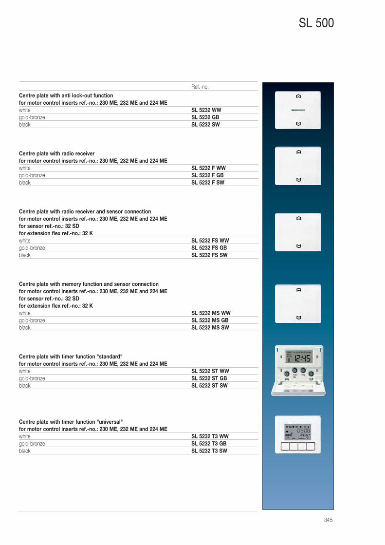
345
SL 500
Centre plate with anti lock-out functionfor motor control inserts ref.-no.: 230 ME, 232 ME and 224 MEwhite SL 5232 WWgold-bronze SL 5232 GBblack SL 5232 SW
Centre plate with radio receiverfor motor control inserts ref.-no.: 230 ME, 232 ME and 224 MEwhite SL 5232 F WWgold-bronze SL 5232 F GBblack SL 5232 F SW
Centre plate with radio receiver and sensor connectionfor motor control inserts ref.-no.: 230 ME, 232 ME and 224 MEfor sensor ref.-no.: 32 SDfor extension flex ref.-no.: 32 Kwhite SL 5232 FS WWgold-bronze SL 5232 FS GBblack SL 5232 FS SW
Centre plate with memory function and sensor connectionfor motor control inserts ref.-no.: 230 ME, 232 ME and 224 MEfor sensor ref.-no.: 32 SDfor extension flex ref.-no.: 32 Kwhite SL 5232 MS WWgold-bronze SL 5232 MS GBblack SL 5232 MS SW
Centre plate with timer function "standard"for motor control inserts ref.-no.: 230 ME, 232 ME and 224 MEwhite SL 5232 ST WWgold-bronze SL 5232 ST GBblack SL 5232 ST SW
Centre plate with timer function "universal"for motor control inserts ref.-no.: 230 ME, 232 ME and 224 MEwhite SL 5232 T3 WWgold-bronze SL 5232 T3 GBblack SL 5232 T3 SW
Ref.-no.
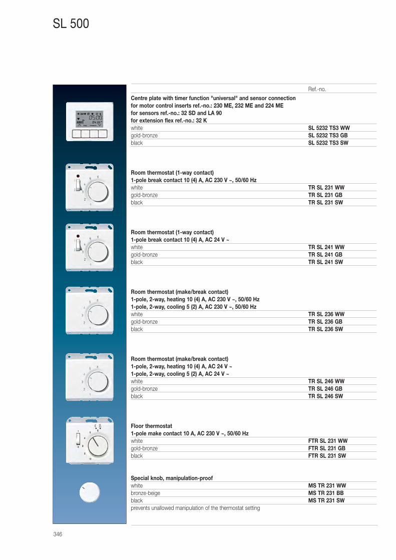
346
SL 500
Centre plate with timer function "universal" and sensor connectionfor motor control inserts ref.-no.: 230 ME, 232 ME and 224 MEfor sensors ref.-no.: 32 SD and LA 90for extension flex ref.-no.: 32 Kwhite SL 5232 TS3 WWgold-bronze SL 5232 TS3 GBblack SL 5232 TS3 SW
Room thermostat (1-way contact)1-pole break contact 10 (4) A, AC 230 V ~, 50/60 Hzwhite TR SL 231 WWgold-bronze TR SL 231 GBblack TR SL 231 SW
Room thermostat (1-way contact)1-pole break contact 10 (4) A, AC 24 V ~white TR SL 241 WWgold-bronze TR SL 241 GBblack TR SL 241 SW
Room thermostat (make/break contact)1-pole, 2-way, heating 10 (4) A, AC 230 V ~, 50/60 Hz1-pole, 2-way, cooling 5 (2) A, AC 230 V ~, 50/60 Hzwhite TR SL 236 WWgold-bronze TR SL 236 GBblack TR SL 236 SW
Room thermostat (make/break contact)1-pole, 2-way, heating 10 (4) A, AC 24 V ~1-pole, 2-way, cooling 5 (2) A, AC 24 V ~white TR SL 246 WWgold-bronze TR SL 246 GBblack TR SL 246 SW
Floor thermostat1-pole make contact 10 A, AC 230 V ~, 50/60 Hzwhite FTR SL 231 WWgold-bronze FTR SL 231 GBblack FTR SL 231 SW
Special knob, manipulation-proofwhite MS TR 231 WWbronze-beige MS TR 231 BBblack MS TR 231 SWprevents unallowed manipulation of the thermostat setting
Ref.-no.
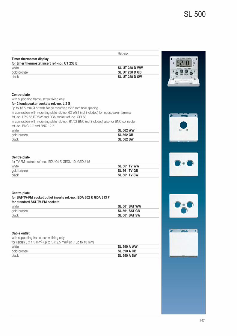
347
SL 500
Timer thermostat displayfor timer thermostat insert ref.-no.: UT 238 Ewhite SL UT 238 D WWgold-bronze SL UT 238 D GBblack SL UT 238 D SW
Centre platewith supporting frame, screw fixing onlyfor 2 loudspeaker sockets ref.-no. L 2 Sup to 18.5 mm Ø or with flange mounting 22.5 mm hole spacing.In connection with mounting plate ref.-no. 63 WBT (not included) for loudspeaker terminal ref.-no. LPK 63 RT/SW and RCA socket ref.-no. CIB 63.In connection with mounting plate ref.-no.: 61/62 BNC (not included) also for BNC connector ref.-no. BNC 9.7 and BNC 12.7.white SL 562 WWgold-bronze SL 562 GBblack SL 562 SW
Centre platefor TV-FM sockets ref.-no.: EDU 04 F, GEDU 10, GEDU 15white SL 561 TV WWgold-bronze SL 561 TV GBblack SL 561 TV SW
Centre platefor SAT-TV-FM socket outlet inserts ref.-no.: EDA 302 F, GDA 313 Ffor standard SAT-TV-FM socketswhite SL 561 SAT WWgold-bronze SL 561 SAT GBblack SL 561 SAT SW
Cable outletwith supporting frame, screw fixing onlyfor cables 3 x 1.5 mm2 up to 5 x 2.5 mm2 (Ø 7 up to 13 mm)white SL 590 A WWgold-bronze SL 590 A GBblack SL 590 A SW
Ref.-no.
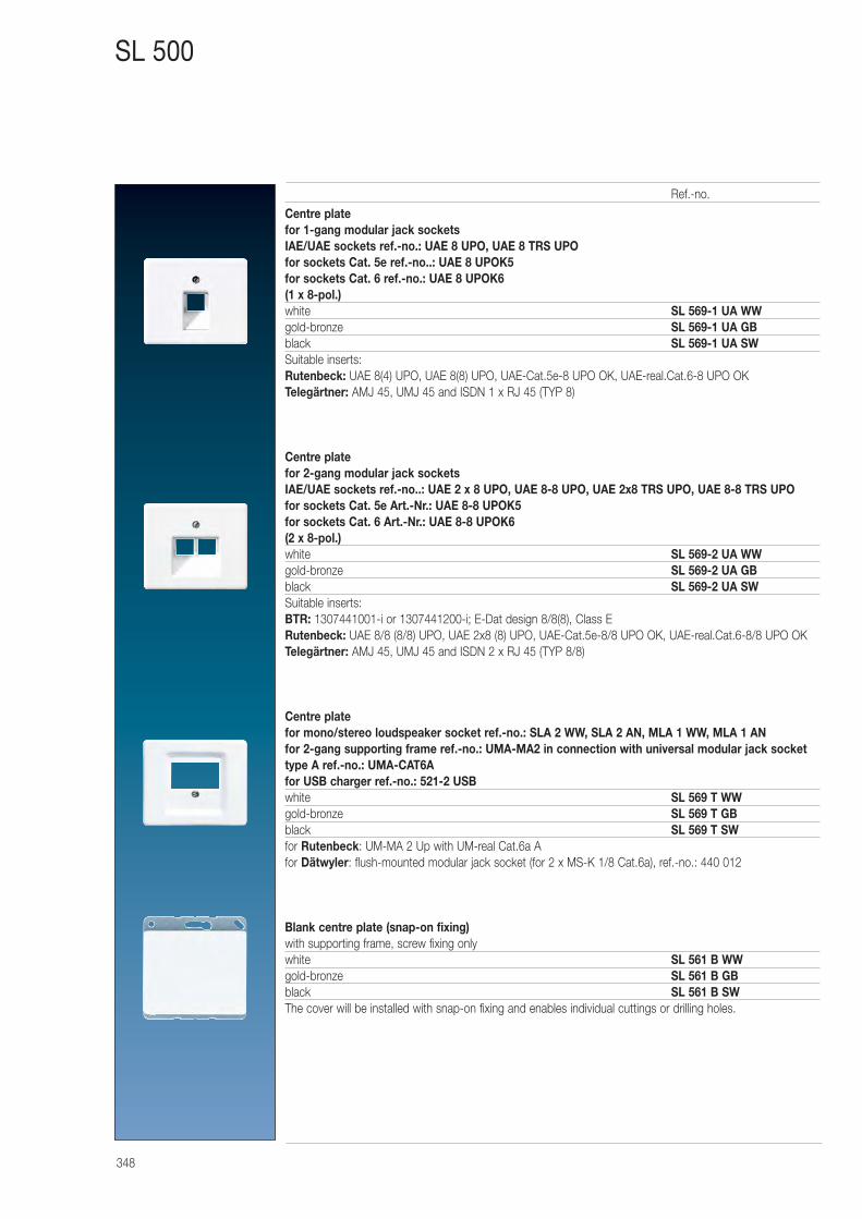
348
SL 500
Centre platefor 1-gang modular jack socketsIAE/UAE sockets ref.-no.: UAE 8 UPO, UAE 8 TRS UPOfor sockets Cat. 5e ref.-no..: UAE 8 UPOK5for sockets Cat. 6 ref.-no.: UAE 8 UPOK6(1 x 8-pol.)white SL 569-1 UA WWgold-bronze SL 569-1 UA GBblack SL 569-1 UA SWSuitable inserts:Rutenbeck: UAE 8(4) UPO, UAE 8(8) UPO, UAE-Cat.5e-8 UPO OK, UAE-real.Cat.6-8 UPO OKTelegärtner: AMJ 45, UMJ 45 and ISDN 1 x RJ 45 (TYP 8)
Centre platefor 2-gang modular jack socketsIAE/UAE sockets ref.-no..: UAE 2 x 8 UPO, UAE 8-8 UPO, UAE 2x8 TRS UPO, UAE 8-8 TRS UPOfor sockets Cat. 5e Art.-Nr.: UAE 8-8 UPOK5for sockets Cat. 6 Art.-Nr.: UAE 8-8 UPOK6(2 x 8-pol.)white SL 569-2 UA WWgold-bronze SL 569-2 UA GBblack SL 569-2 UA SWSuitable inserts:BTR: 1307441001-i or 1307441200-i; E-Dat design 8/8(8), Class ERutenbeck: UAE 8/8 (8/8) UPO, UAE 2x8 (8) UPO, UAE-Cat.5e-8/8 UPO OK, UAE-real.Cat.6-8/8 UPO OKTelegärtner: AMJ 45, UMJ 45 and ISDN 2 x RJ 45 (TYP 8/8)
Centre platefor mono/stereo loudspeaker socket ref.-no.: SLA 2 WW, SLA 2 AN, MLA 1 WW, MLA 1 ANfor 2-gang supporting frame ref.-no.: UMA-MA2 in connection with universal modular jack sockettype A ref.-no.: UMA-CAT6Afor USB charger ref.-no.: 521-2 USBwhite SL 569 T WWgold-bronze SL 569 T GBblack SL 569 T SWfor Rutenbeck: UM-MA 2 Up with UM-real Cat.6a Afor Dätwyler: flush-mounted modular jack socket (for 2 x MS-K 1/8 Cat.6a), ref.-no.: 440 012
Blank centre plate (snap-on fixing)with supporting frame, screw fixing onlywhite SL 561 B WWgold-bronze SL 561 B GBblack SL 561 B SWThe cover will be installed with snap-on fixing and enables individual cuttings or drilling holes.
Ref.-no.
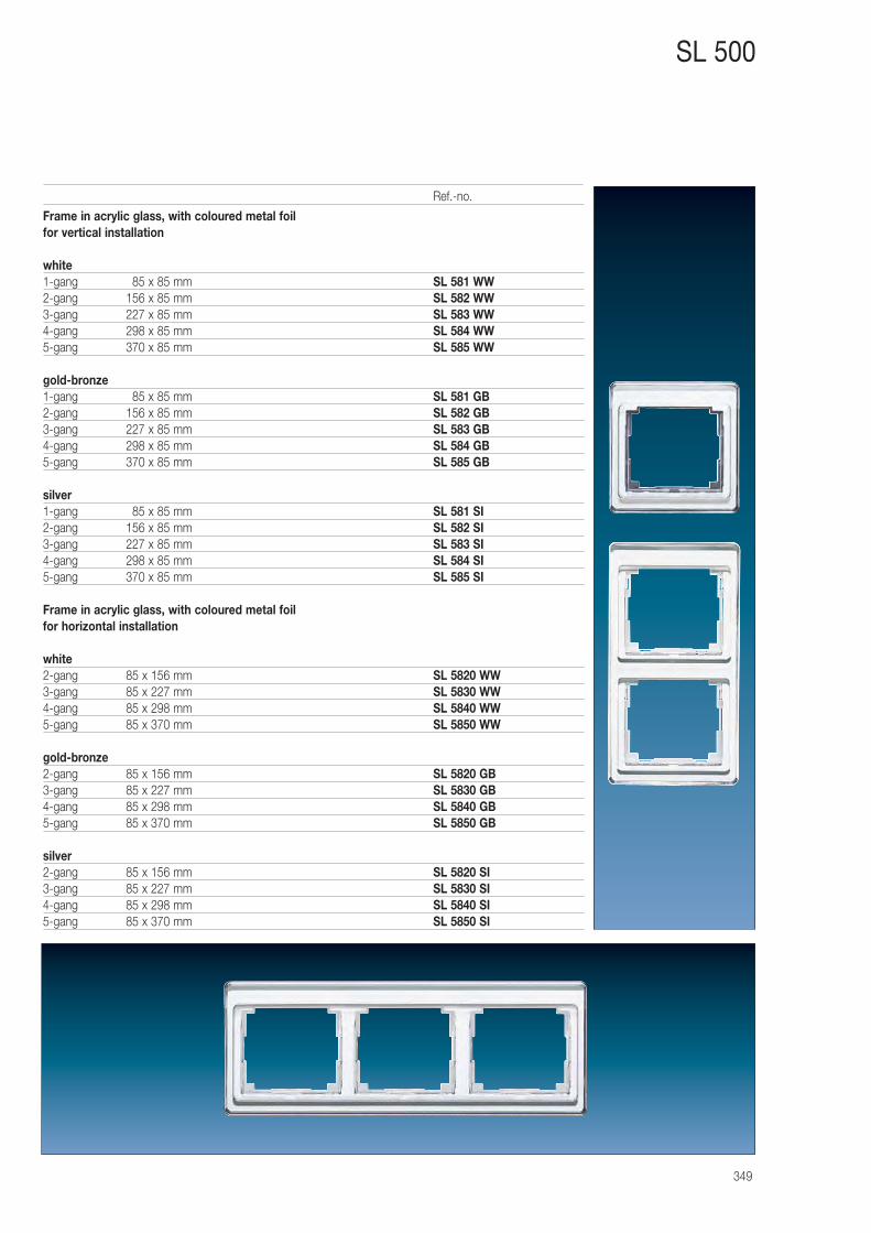
349
SL 500
Frame in acrylic glass, with coloured metal foilfor vertical installation
white1-gang 085 x 85 mm SL 581 WW2-gang 156 x 85 mm SL 582 WW3-gang 227 x 85 mm SL 583 WW4-gang 298 x 85 mm SL 584 WW5-gang 370 x 85 mm SL 585 WW
gold-bronze1-gang 085 x 85 mm SL 581 GB2-gang 156 x 85 mm SL 582 GB3-gang 227 x 85 mm SL 583 GB4-gang 298 x 85 mm SL 584 GB5-gang 370 x 85 mm SL 585 GB
silver1-gang 085 x 85 mm SL 581 SI2-gang 156 x 85 mm SL 582 SI3-gang 227 x 85 mm SL 583 SI4-gang 298 x 85 mm SL 584 SI5-gang 370 x 85 mm SL 585 SI
Frame in acrylic glass, with coloured metal foilfor horizontal installation
white2-gang 85 x 156 mm SL 5820 WW3-gang 85 x 227 mm SL 5830 WW4-gang 85 x 298 mm SL 5840 WW5-gang 85 x 370 mm SL 5850 WW
gold-bronze2-gang 85 x 156 mm SL 5820 GB3-gang 85 x 227 mm SL 5830 GB4-gang 85 x 298 mm SL 5840 GB5-gang 85 x 370 mm SL 5850 GB
silver2-gang 85 x 156 mm SL 5820 SI3-gang 85 x 227 mm SL 5830 SI4-gang 85 x 298 mm SL 5840 SI5-gang 85 x 370 mm SL 5850 SI
Ref.-no.
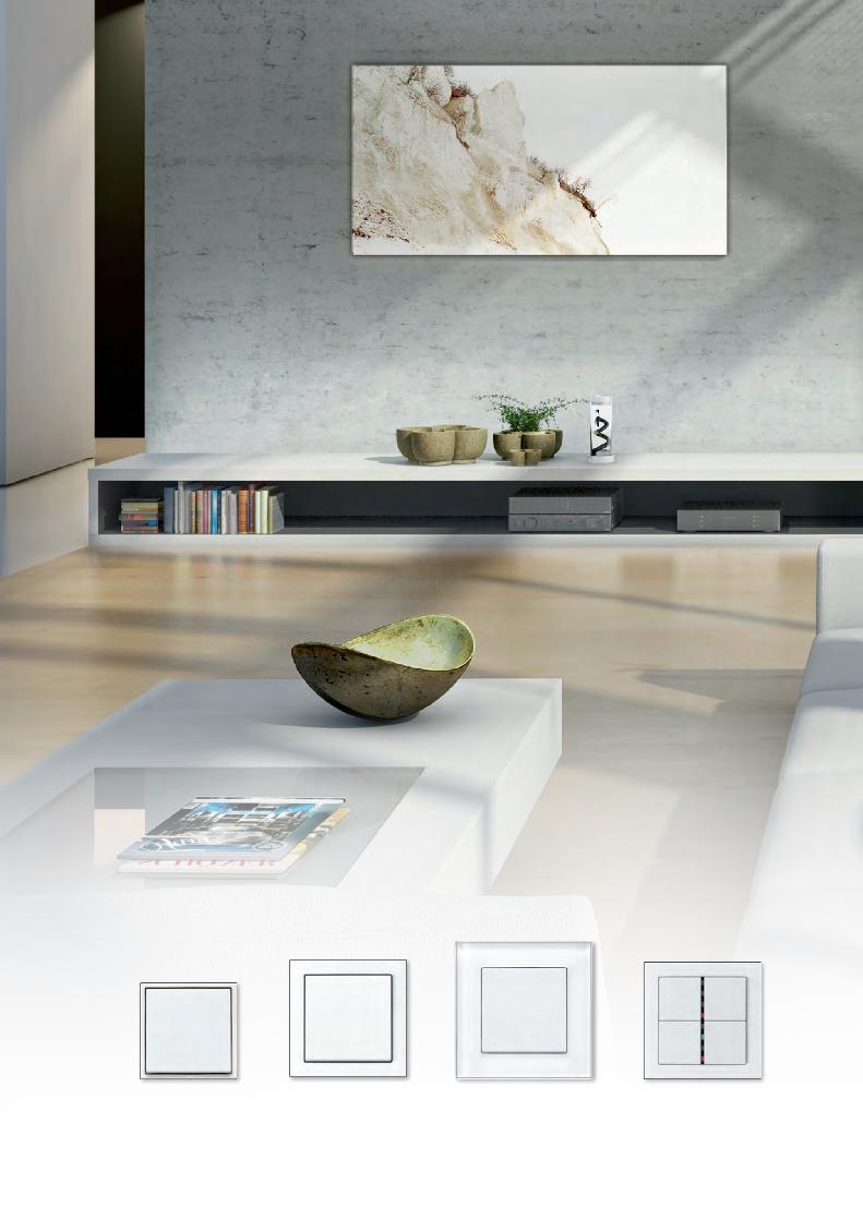
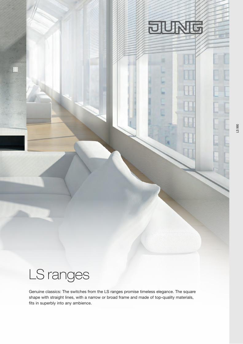
LS ranges Genuine classics: The switches from the LS ranges promise timeless elegance. The square shape with straight lines, with a narrow or broad frame and made of top-quality materials, fits in superbly into any ambience.
LS 9
90
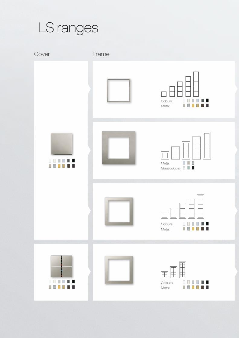
LS ranges
Metal:
Glass colours:
Colours:
Metal:
Colours:
Metal:
Colours:
Metal:
Cover Frame
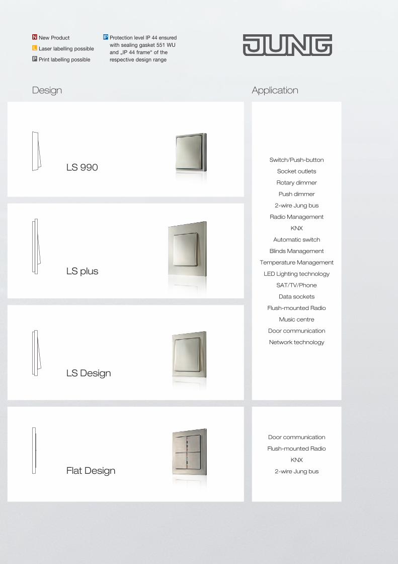
Switch/Push-button
Socket outlets
Rotary dimmer
Push dimmer
2-wire Jung bus
Radio Management
KNX
Automatic switch
Blinds Management
Temperature Management
LED Lighting technology
SAT/TV/Phone
Data sockets
Flush-mounted Radio
Music centre
Door communication
Network technology
Door communication
Flush-mounted Radio
KNX
2-wire Jung bus
Application
LS plus
LS Design
Flat Design
LS 990
Protection level IP 44 ensured with sealing gasket 551 WU and „IP 44 frame“ of the respective design range
IPNew ProductN
L Laser labelling possible
P Print labelling possible
Design
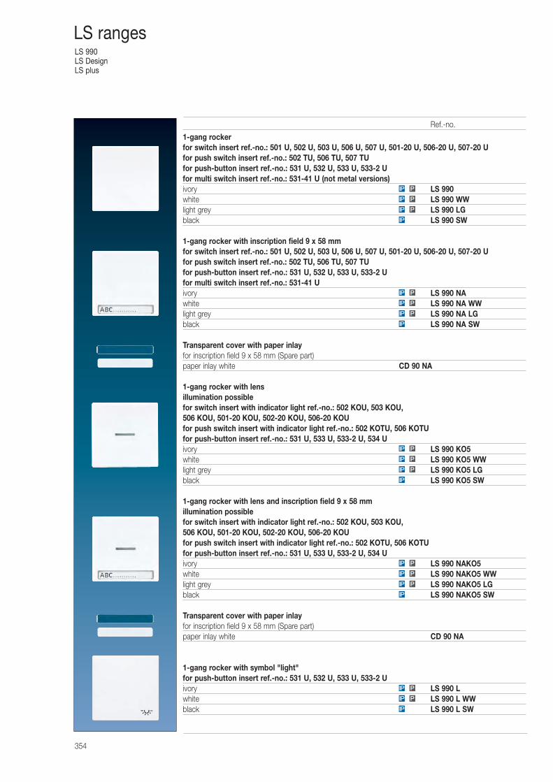
LS 990LS DesignLS plus
354
LS ranges
1-gang rockerfor switch insert ref.-no.: 501 U, 502 U, 503 U, 506 U, 507 U, 501-20 U, 506-20 U, 507-20 Ufor push switch insert ref.-no.: 502 TU, 506 TU, 507 TUfor push-button insert ref.-no.: 531 U, 532 U, 533 U, 533-2 Ufor multi switch insert ref.-no.: 531-41 U (not metal versions)ivory LS 990white LS 990 WWlight grey LS 990 LGblack LS 990 SW
1-gang rocker with inscription field 9 x 58 mmfor switch insert ref.-no.: 501 U, 502 U, 503 U, 506 U, 507 U, 501-20 U, 506-20 U, 507-20 Ufor push switch insert ref.-no.: 502 TU, 506 TU, 507 TUfor push-button insert ref.-no.: 531 U, 532 U, 533 U, 533-2 Ufor multi switch insert ref.-no.: 531-41 Uivory LS 990 NAwhite LS 990 NA WWlight grey LS 990 NA LGblack LS 990 NA SW
Transparent cover with paper inlayfor inscription field 9 x 58 mm (Spare part)paper inlay white CD 90 NA
1-gang rocker with lensillumination possiblefor switch insert with indicator light ref.-no.: 502 KOU, 503 KOU, 506 KOU, 501-20 KOU, 502-20 KOU, 506-20 KOUfor push switch insert with indicator light ref.-no.: 502 KOTU, 506 KOTUfor push-button insert ref.-no.: 531 U, 533 U, 533-2 U, 534 Uivory LS 990 KO5white LS 990 KO5 WWlight grey LS 990 KO5 LGblack LS 990 KO5 SW
1-gang rocker with lens and inscription field 9 x 58 mmillumination possiblefor switch insert with indicator light ref.-no.: 502 KOU, 503 KOU, 506 KOU, 501-20 KOU, 502-20 KOU, 506-20 KOUfor push switch insert with indicator light ref.-no.: 502 KOTU, 506 KOTUfor push-button insert ref.-no.: 531 U, 533 U, 533-2 U, 534 Uivory LS 990 NAKO5white LS 990 NAKO5 WWlight grey LS 990 NAKO5 LGblack LS 990 NAKO5 SW
Transparent cover with paper inlayfor inscription field 9 x 58 mm (Spare part)paper inlay white CD 90 NA
1-gang rocker with symbol "light"for push-button insert ref.-no.: 531 U, 532 U, 533 U, 533-2 Uivory LS 990 Lwhite LS 990 L WWblack LS 990 L SWIP
IP P
PIP
IP
PIP
PIP
PIP
IP
PIP
PIP
PIP
IP
PIP
PIP
PIP
IP
PIP
PIP
PIP
Ref.-no.
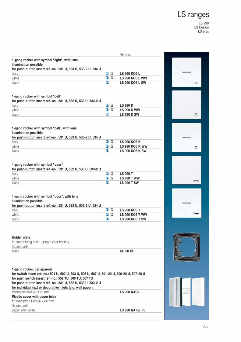
LS 990LS Design
LS plus
355
LS ranges
1-gang rocker with symbol "light", with lensillumination possiblefor push-button insert ref.-no.: 531 U, 533 U, 533-2 U, 534 Uivory LS 990 KO5 Lwhite LS 990 KO5 L WWblack LS 990 KO5 L SW
1-gang rocker with symbol "bell"for push-button insert ref.-no.: 531 U, 532 U, 533 U, 533-2 Uivory LS 990 Kwhite LS 990 K WWblack LS 990 K SW
1-gang rocker with symbol "bell", with lensillumination possiblefor push-button insert ref.-no.: 531 U, 533 U, 533-2 U, 534 Uivory LS 990 KO5 Kwhite LS 990 KO5 K WWblack LS 990 KO5 K SW
1-gang rocker with symbol "door"for push-button insert ref.-no.: 531 U, 532 U, 533 U, 533-2 Uivory LS 990 Twhite LS 990 T WWblack LS 990 T SW
1-gang rocker with symbol "door", with lensillumination possiblefor push-button insert ref.-no.: 531 U, 533 U, 533-2 U, 534 Uivory LS 990 KO5 Twhite LS 990 KO5 T WWblack LS 990 KO5 T SW
Holder platefor frame fixing and 1-gang rocker bearing(Spare part)black CD 90 HP
1-gang rocker, transparentfor switch insert ref.-no.: 501 U, 502 U, 503 U, 506 U, 507 U, 501-20 U, 506-20 U, 507-20 Ufor push switch insert ref.-no.: 502 TU, 506 TU, 507 TUfor push-button insert ref.-no.: 531 U, 532 U, 533 U, 533-2 Ufor individual text or decorative inlets (e.g. wall paper)inscription field 66 x 66 mm LS 990 NAGLPlastic cover with paper inlayfor inscription field 66 x 66 mm(Spare part)paper inlay white LS 990 NA GL PL
IP
PIP
PIP
IP
PIP
PIP
IP
PIP
PIP
IP
PIP
PIP
IP
PIP
PIP
Ref.-no.
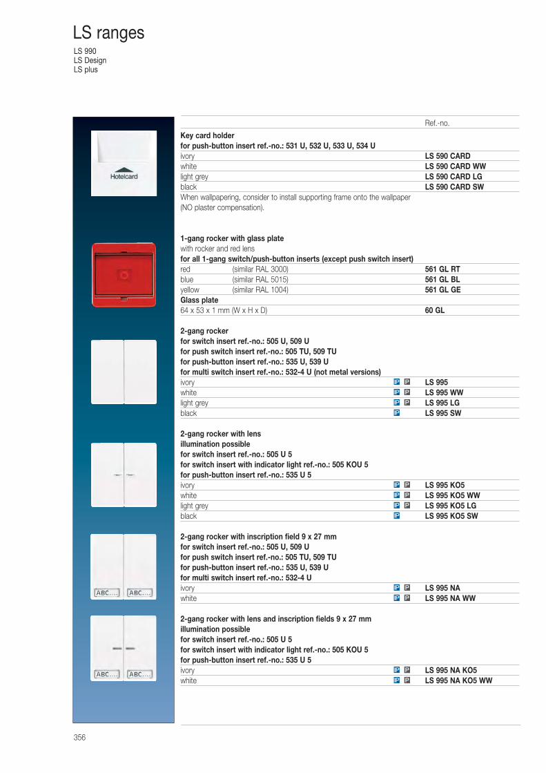
LS 990LS DesignLS plus
356
LS ranges
Key card holderfor push-button insert ref.-no.: 531 U, 532 U, 533 U, 534 Uivory LS 590 CARDwhite LS 590 CARD WWlight grey LS 590 CARD LGblack LS 590 CARD SWWhen wallpapering, consider to install supporting frame onto the wallpaper (NO plaster compensation).
1-gang rocker with glass platewith rocker and red lensfor all 1-gang switch/push-button inserts (except push switch insert)red (similar RAL 3000) 561 GL RTblue (similar RAL 5015) 561 GL BLyellow (similar RAL 1004) 561 GL GEGlass plate64 x 53 x 1 mm (W x H x D) 60 GL
2-gang rockerfor switch insert ref.-no.: 505 U, 509 Ufor push switch insert ref.-no.: 505 TU, 509 TUfor push-button insert ref.-no.: 535 U, 539 Ufor multi switch insert ref.-no.: 532-4 U (not metal versions)ivory LS 995white LS 995 WWlight grey LS 995 LGblack LS 995 SW
2-gang rocker with lensillumination possiblefor switch insert ref.-no.: 505 U 5for switch insert with indicator light ref.-no.: 505 KOU 5for push-button insert ref.-no.: 535 U 5ivory LS 995 KO5white LS 995 KO5 WWlight grey LS 995 KO5 LGblack LS 995 KO5 SW
2-gang rocker with inscription field 9 x 27 mmfor switch insert ref.-no.: 505 U, 509 Ufor push switch insert ref.-no.: 505 TU, 509 TUfor push-button insert ref.-no.: 535 U, 539 Ufor multi switch insert ref.-no.: 532-4 Uivory LS 995 NAwhite LS 995 NA WW
2-gang rocker with lens and inscription fields 9 x 27 mmillumination possiblefor switch insert ref.-no.: 505 U 5for switch insert with indicator light ref.-no.: 505 KOU 5for push-button insert ref.-no.: 535 U 5ivory LS 995 NA KO5white LS 995 NA KO5 WWPIP
PIP
PIP
PIP
IP
PIP
PIP
PIP
IP
PIP
PIP
PIP
Ref.-no.
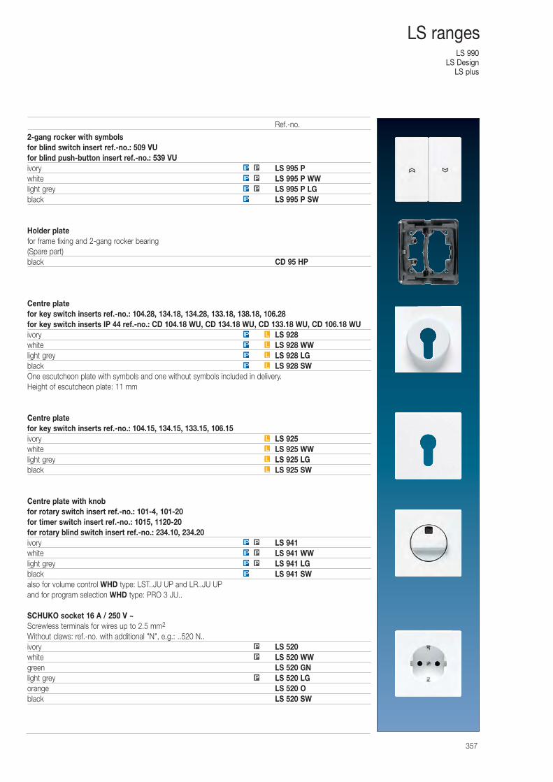
LS 990LS Design
LS plus
357
LS ranges
2-gang rocker with symbolsfor blind switch insert ref.-no.: 509 VUfor blind push-button insert ref.-no.: 539 VUivory LS 995 Pwhite LS 995 P WWlight grey LS 995 P LGblack LS 995 P SW
Holder platefor frame fixing and 2-gang rocker bearing(Spare part)black CD 95 HP
Centre platefor key switch inserts ref.-no.: 104.28, 134.18, 134.28, 133.18, 138.18, 106.28for key switch inserts IP 44 ref.-no.: CD 104.18 WU, CD 134.18 WU, CD 133.18 WU, CD 106.18 WUivory LS 928white LS 928 WWlight grey LS 928 LGblack LS 928 SWOne escutcheon plate with symbols and one without symbols included in delivery.Height of escutcheon plate: 11 mm
Centre platefor key switch inserts ref.-no.: 104.15, 134.15, 133.15, 106.15ivory LS 925white LS 925 WWlight grey LS 925 LGblack LS 925 SW
Centre plate with knobfor rotary switch insert ref.-no.: 101-4, 101-20for timer switch insert ref.-no.: 1015, 1120-20for rotary blind switch insert ref.-no.: 234.10, 234.20ivory LS 941white LS 941 WWlight grey LS 941 LGblack LS 941 SWalso for volume control WHD type: LST..JU UP and LR..JU UPand for program selection WHD type: PRO 3 JU..
SCHUKO socket 16 A / 250 V ~Screwless terminals for wires up to 2.5 mm2
Without claws: ref.-no. with additional "N", e.g.: ..520 N..ivory LS 520white LS 520 WWgreen LS 520 GNlight grey LS 520 LGorange LS 520 Oblack LS 520 SW
IP P
IP
PIP
PIP
P
P
P
IP
PIP
PIP
PIP
L
L
L
L
LIP
LIP
LIP
LIP
Ref.-no.
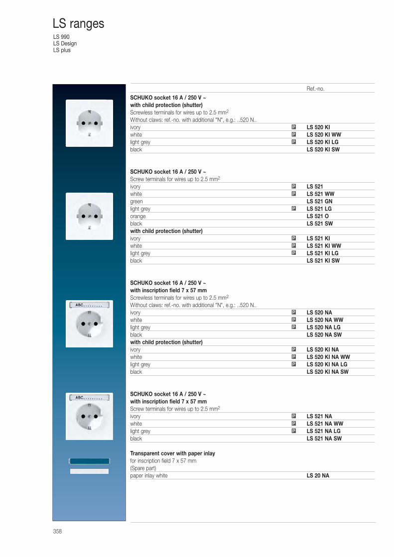
LS 990LS DesignLS plus
358
LS ranges
SCHUKO socket 16 A / 250 V ~with child protection (shutter)Screwless terminals for wires up to 2.5 mm2
Without claws: ref.-no. with additional "N", e.g.: ..520 N..ivory LS 520 KIwhite LS 520 KI WWlight grey LS 520 KI LGblack LS 520 KI SW
SCHUKO socket 16 A / 250 V ~Screw terminals for wires up to 2.5 mm2
ivory LS 521white LS 521 WWgreen LS 521 GNlight grey LS 521 LGorange LS 521 Oblack LS 521 SWwith child protection (shutter)ivory LS 521 KIwhite LS 521 KI WWlight grey LS 521 KI LGblack LS 521 KI SW
SCHUKO socket 16 A / 250 V ~with inscription field 7 x 57 mmScrewless terminals for wires up to 2.5 mm2
Without claws: ref.-no. with additional "N", e.g.: ..520 N..ivory LS 520 NAwhite LS 520 NA WWlight grey LS 520 NA LGblack LS 520 NA SWwith child protection (shutter)ivory LS 520 KI NAwhite LS 520 KI NA WWlight grey LS 520 KI NA LGblack LS 520 KI NA SW
SCHUKO socket 16 A / 250 V ~with inscription field 7 x 57 mmScrew terminals for wires up to 2.5 mm2
ivory LS 521 NAwhite LS 521 NA WWlight grey LS 521 NA LGblack LS 521 NA SW
Transparent cover with paper inlayfor inscription field 7 x 57 mm(Spare part)paper inlay white LS 20 NA
P
P
P
P
P
P
P
P
P
P
P
P
P
P
P
P
P
P
Ref.-no.
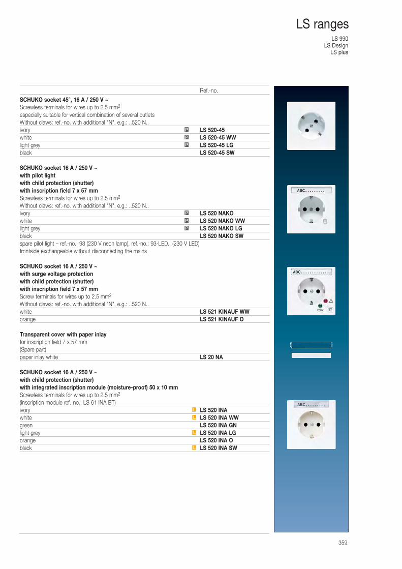
LS 990LS Design
LS plus
359
LS ranges
SCHUKO socket 45°, 16 A / 250 V ~Screwless terminals for wires up to 2.5 mm2
especially suitable for vertical combination of several outletsWithout claws: ref.-no. with additional "N", e.g.: ..520 N..ivory LS 520-45white LS 520-45 WWlight grey LS 520-45 LGblack LS 520-45 SW
SCHUKO socket 16 A / 250 V ~with pilot lightwith child protection (shutter)with inscription field 7 x 57 mmScrewless terminals for wires up to 2.5 mm2
Without claws: ref.-no. with additional "N", e.g.: ..520 N..ivory LS 520 NAKOwhite LS 520 NAKO WWlight grey LS 520 NAKO LGblack LS 520 NAKO SWspare pilot light – ref.-no.: 93 (230 V neon lamp), ref.-no.: 93-LED.. (230 V LED) frontside exchangeable without disconnecting the mains
SCHUKO socket 16 A / 250 V ~with surge voltage protectionwith child protection (shutter)with inscription field 7 x 57 mmScrew terminals for wires up to 2.5 mm2
Without claws: ref.-no. with additional "N", e.g.: ..520 N..white LS 521 KINAUF WWorange LS 521 KINAUF O
Transparent cover with paper inlayfor inscription field 7 x 57 mm(Spare part)paper inlay white LS 20 NA
SCHUKO socket 16 A / 250 V ~with child protection (shutter)with integrated inscription module (moisture-proof) 50 x 10 mmScrewless terminals for wires up to 2.5 mm2
(inscription module ref.-no.: LS 61 INA BT)ivory LS 520 INAwhite LS 520 INA WWgreen LS 520 INA GNlight grey LS 520 INA LGorange LS 520 INA Oblack LS 520 INA SW
P
P
P
P
P
P
L
L
L
L
Ref.-no.
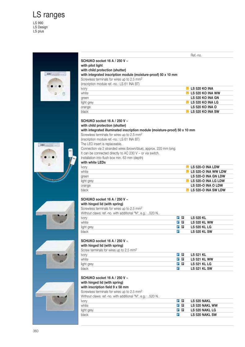
LS 990LS DesignLS plus
360
LS ranges
SCHUKO socket 16 A / 250 V ~with pilot lightwith child protection (shutter)with integrated inscription module (moisture-proof) 50 x 10 mmScrewless terminals for wires up to 2.5 mm2
(inscription module ref.-no.: LS 61 INA BT)ivory LS 520 KO INAwhite LS 520 KO INA WWgreen LS 520 KO INA GNlight grey LS 520 KO INA LGorange LS 520 KO INA Oblack LS 520 KO INA SW
SCHUKO socket 16 A / 250 V ~with child protection (shutter)with integrated illuminated inscription module (moisture-proof) 50 x 10 mmScrewless terminals for wires up to 2.5 mm2
(inscription module ref.-no.: LS 61 INA BT)The LED insert is replaceable.Connection via 2 stranded wires (brown/blue), approx. 220 mm long.It can be connected directly to AC 230 V ~ or via switch.Installation into flush box min. 63 mm (depth)with white LEDsivory LS 520-O INA LDWwhite LS 520-O INA WW LDWgreen LS 520-O INA GN LDWlight grey LS 520-O INA LG LDWorange LS 520-O INA O LDWblack LS 520-O INA SW LDW
SCHUKO socket 16 A / 250 V ~with hinged lid (with spring)Screwless terminals for wires up to 2.5 mm2
Without claws: ref.-no. with additional "N", e.g.: ..520 N..ivory LS 520 KLwhite LS 520 KL WWlight grey LS 520 KL LGblack LS 520 KL SW
SCHUKO socket 16 A / 250 V ~with hinged lid (with spring)Screw terminals for wires up to 2.5 mm2
ivory LS 521 KLwhite LS 521 KL WWlight grey LS 521 KL LGblack LS 521 KL SW
SCHUKO socket 16 A / 250 V ~with hinged lid (with spring)with inscription field 9 x 58 mmScrewless terminals for wires up to 2.5 mm2
Without claws: ref.-no. with additional "N", e.g.: ..520 N..ivory LS 520 NAKLwhite LS 520 NAKL WWlight grey LS 520 NAKL LGblack LS 520 NAKL SW
L
L
L
L
L
L
L
L
IP
PIP
PIP
PIP
IP
PIP
PIP
PIP
IP
PIP
PIP
PIP
Ref.-no.
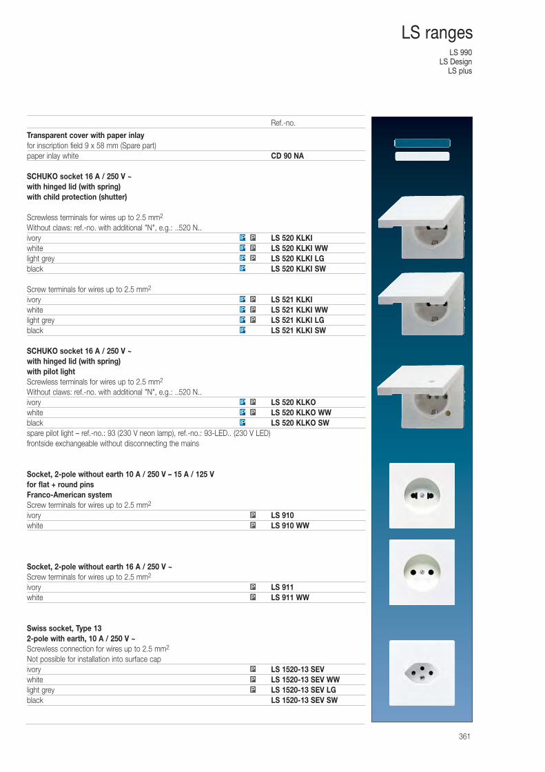
LS 990LS Design
LS plus
361
LS ranges
Transparent cover with paper inlayfor inscription field 9 x 58 mm (Spare part)paper inlay white CD 90 NA
SCHUKO socket 16 A / 250 V ~with hinged lid (with spring)with child protection (shutter)
Screwless terminals for wires up to 2.5 mm2
Without claws: ref.-no. with additional "N", e.g.: ..520 N..ivory LS 520 KLKIwhite LS 520 KLKI WWlight grey LS 520 KLKI LGblack LS 520 KLKI SW
Screw terminals for wires up to 2.5 mm2
ivory LS 521 KLKIwhite LS 521 KLKI WWlight grey LS 521 KLKI LGblack LS 521 KLKI SW
SCHUKO socket 16 A / 250 V ~with hinged lid (with spring)with pilot lightScrewless terminals for wires up to 2.5 mm2
Without claws: ref.-no. with additional "N", e.g.: ..520 N..ivory LS 520 KLKOwhite LS 520 KLKO WWblack LS 520 KLKO SWspare pilot light – ref.-no.: 93 (230 V neon lamp), ref.-no.: 93-LED.. (230 V LED) frontside exchangeable without disconnecting the mains
Socket, 2-pole without earth 10 A / 250 V – 15 A / 125 Vfor flat + round pinsFranco-American systemScrew terminals for wires up to 2.5 mm2
ivory LS 910white LS 910 WW
Socket, 2-pole without earth 16 A / 250 V ~Screw terminals for wires up to 2.5 mm2
ivory LS 911white LS 911 WW
Swiss socket, Type 132-pole with earth, 10 A / 250 V ~Screwless connection for wires up to 2.5 mm2
Not possible for installation into surface capivory LS 1520-13 SEVwhite LS 1520-13 SEV WWlight grey LS 1520-13 SEV LGblack LS 1520-13 SEV SW
P
P
P
PIP
PIP
PIP
PIP
IP
PIP
PIP
PIP
IP
P
P
P
P
IP
PIP
Ref.-no.
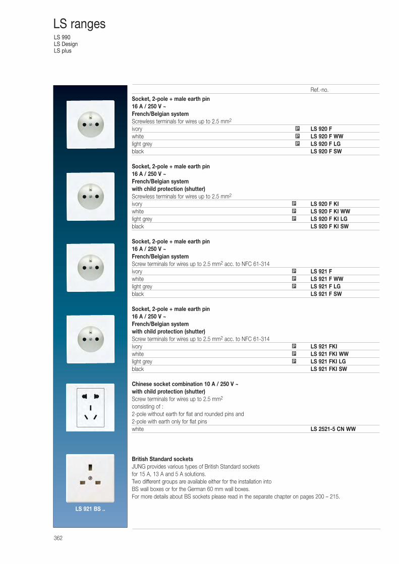
LS 990LS DesignLS plus
362
LS ranges
Socket, 2-pole + male earth pin16 A / 250 V ~French/Belgian systemScrewless terminals for wires up to 2.5 mm2
ivory LS 920 Fwhite LS 920 F WWlight grey LS 920 F LGblack LS 920 F SW
Socket, 2-pole + male earth pin16 A / 250 V ~French/Belgian systemwith child protection (shutter)Screwless terminals for wires up to 2.5 mm2
ivory LS 920 F KIwhite LS 920 F KI WWlight grey LS 920 F KI LGblack LS 920 F KI SW
Socket, 2-pole + male earth pin16 A / 250 V ~French/Belgian systemScrew terminals for wires up to 2.5 mm2 acc. to NFC 61-314ivory LS 921 Fwhite LS 921 F WWlight grey LS 921 F LGblack LS 921 F SW
Socket, 2-pole + male earth pin16 A / 250 V ~French/Belgian systemwith child protection (shutter)Screw terminals for wires up to 2.5 mm2 acc. to NFC 61-314ivory LS 921 FKIwhite LS 921 FKI WWlight grey LS 921 FKI LGblack LS 921 FKI SW
Chinese socket combination 10 A / 250 V ~with child protection (shutter)Screw terminals for wires up to 2.5 mm2
consisting of :2-pole without earth for flat and rounded pins and2-pole with earth only for flat pinswhite LS 2521-5 CN WW
British Standard socketsJUNG provides various types of British Standard sockets for 15 A, 13 A and 5 A solutions. Two different groups are available either for the installation into BS wall boxes or for the German 60 mm wall boxes.For more details about BS sockets please read in the separate chapter on pages 200 – 215.
P
P
P
P
P
P
P
P
P
P
P
P
Ref.-no.
LS 921 BS ..
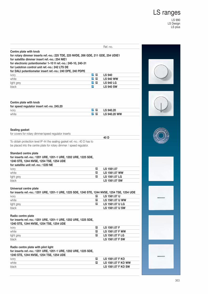
LS 990LS Design
LS plus
363
LS ranges
Centre plate with knobfor rotary dimmer inserts ref.-no.: 225 TDE, 225 NVDE, 266 GDE, 211 GDE, 254 UDIE1for satellite dimmer insert ref.-no.: 254 NIE1for electronic potentiometer 1–10 V ref.-no.: 240-10, 240-31for Ledotron control unit ref.-no.: 242 LTS DEfor DALI potentiometer insert ref.-no.: 240 DPE, 240 PDPEivory LS 940white LS 940 WWlight grey LS 940 LGblack LS 940 SW
Centre plate with knobfor speed regulator insert ref.-no. 245.20ivory LS 940.20white LS 940.20 WW
Sealing gasketfor covers for rotary dimmer/speed regulator inserts
40 DTo obtain protection level IP 44 the sealing gasket ref.-no.: 40 D has to be placed into the centre plate for rotary dimmer / speed regulator.
Standard centre platefor inserts ref.-no.: 1201 URE, 1201-1 URE, 1202 URE, 1225 SDE, 1240 STE, 1244 NVSE, 1254 TSE, 1254 UDEfor satellite unit ref.-no.: 1220 NEivory LS 1561.07white LS 1561.07 WWlight grey LS 1561.07 LGblack LS 1561.07 SW
Universal centre platefor inserts ref.-no.: 1201 URE, 1201-1 URE, 1225 SDE, 1240 STE, 1244 NVSE, 1254 TSE, 1254 UDEivory LS 1561.07 Uwhite LS 1561.07 U WWlight grey LS 1561.07 U LGblack LS 1561.07 U SW
Radio centre platefor inserts ref.-no.: 1201 URE, 1201-1 URE, 1202 URE, 1225 SDE, 1240 STE, 1244 NVSE, 1254 TSE, 1254 UDEivory LS 1561.07 Fwhite LS 1561.07 F WWlight grey LS 1561.07 F LGblack LS 1561.07 F SW
Radio centre plate with pilot lightfor inserts ref.-no.: 1201 URE, 1201-1 URE, 1202 URE, 1225 SDE, 1240 STE, 1244 NVSE, 1254 TSE, 1254 UDEivory LS 1561.07 F KOwhite LS 1561.07 F KO WWblack LS 1561.07 F KO SW
P
P
P
PIP
PIP
PIP
IP
P
P
P
P
P
P
P
P
PIP
PIP
Ref.-no.
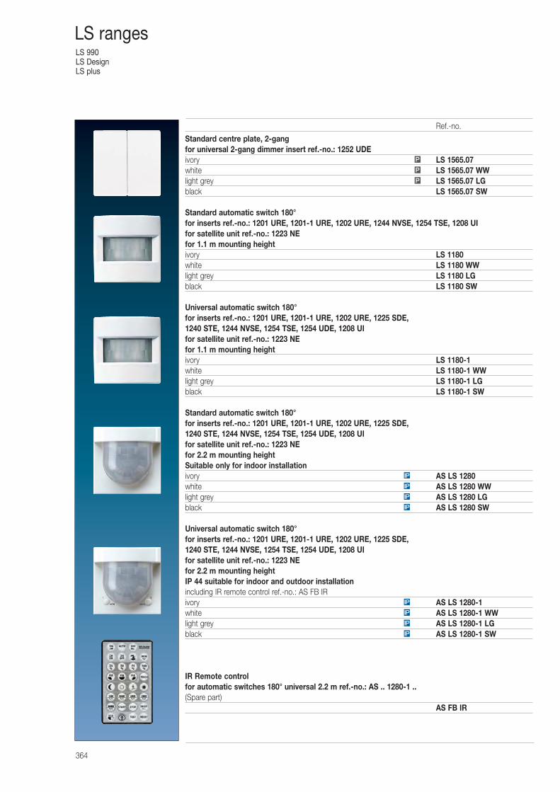
LS 990LS DesignLS plus
364
LS ranges
Standard centre plate, 2-gangfor universal 2-gang dimmer insert ref.-no.: 1252 UDEivory LS 1565.07white LS 1565.07 WWlight grey LS 1565.07 LGblack LS 1565.07 SW
Standard automatic switch 180°for inserts ref.-no.: 1201 URE, 1201-1 URE, 1202 URE, 1244 NVSE, 1254 TSE, 1208 UIfor satellite unit ref.-no.: 1223 NEfor 1.1 m mounting heightivory LS 1180white LS 1180 WWlight grey LS 1180 LGblack LS 1180 SW
Universal automatic switch 180° for inserts ref.-no.: 1201 URE, 1201-1 URE, 1202 URE, 1225 SDE, 1240 STE, 1244 NVSE, 1254 TSE, 1254 UDE, 1208 UIfor satellite unit ref.-no.: 1223 NEfor 1.1 m mounting heightivory LS 1180-1white LS 1180-1 WWlight grey LS 1180-1 LGblack LS 1180-1 SW
Standard automatic switch 180°for inserts ref.-no.: 1201 URE, 1201-1 URE, 1202 URE, 1225 SDE, 1240 STE, 1244 NVSE, 1254 TSE, 1254 UDE, 1208 UIfor satellite unit ref.-no.: 1223 NEfor 2.2 m mounting heightSuitable only for indoor installationivory AS LS 1280white AS LS 1280 WWlight grey AS LS 1280 LGblack AS LS 1280 SW
Universal automatic switch 180° for inserts ref.-no.: 1201 URE, 1201-1 URE, 1202 URE, 1225 SDE, 1240 STE, 1244 NVSE, 1254 TSE, 1254 UDE, 1208 UIfor satellite unit ref.-no.: 1223 NEfor 2.2 m mounting heightIP 44 suitable for indoor and outdoor installationincluding IR remote control ref.-no.: AS FB IRivory AS LS 1280-1white AS LS 1280-1 WWlight grey AS LS 1280-1 LGblack AS LS 1280-1 SW
IR Remote controlfor automatic switches 180° universal 2.2 m ref.-no.: AS .. 1280-1 ..(Spare part)
AS FB IR
P
P
P
IP
IP
IP
IP
IP
IP
IP
IP
Ref.-no.
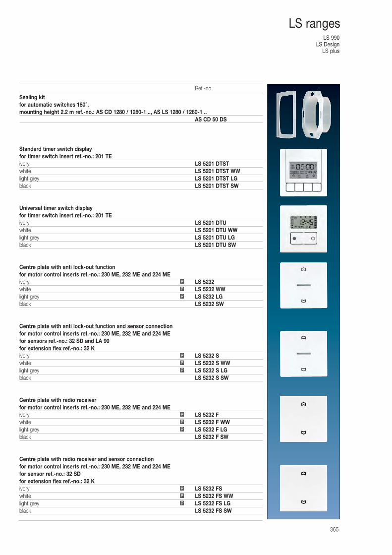
LS 990LS Design
LS plus
365
LS ranges
Sealing kitfor automatic switches 180°, mounting height 2.2 m ref.-no.: AS CD 1280 / 1280-1 .., AS LS 1280 / 1280-1 ..
AS CD 50 DS
Standard timer switch displayfor timer switch insert ref.-no.: 201 TEivory LS 5201 DTSTwhite LS 5201 DTST WWlight grey LS 5201 DTST LGblack LS 5201 DTST SW
Universal timer switch displayfor timer switch insert ref.-no.: 201 TEivory LS 5201 DTUwhite LS 5201 DTU WWlight grey LS 5201 DTU LGblack LS 5201 DTU SW
Centre plate with anti lock-out functionfor motor control inserts ref.-no.: 230 ME, 232 ME and 224 MEivory LS 5232white LS 5232 WWlight grey LS 5232 LGblack LS 5232 SW
Centre plate with anti lock-out function and sensor connectionfor motor control inserts ref.-no.: 230 ME, 232 ME and 224 MEfor sensors ref.-no.: 32 SD and LA 90for extension flex ref.-no.: 32 Kivory LS 5232 Swhite LS 5232 S WWlight grey LS 5232 S LGblack LS 5232 S SW
Centre plate with radio receiverfor motor control inserts ref.-no.: 230 ME, 232 ME and 224 MEivory LS 5232 Fwhite LS 5232 F WWlight grey LS 5232 F LGblack LS 5232 F SW
Centre plate with radio receiver and sensor connectionfor motor control inserts ref.-no.: 230 ME, 232 ME and 224 MEfor sensor ref.-no.: 32 SDfor extension flex ref.-no.: 32 Kivory LS 5232 FSwhite LS 5232 FS WWlight grey LS 5232 FS LGblack LS 5232 FS SW
P
P
P
P
P
P
P
P
P
P
P
P
Ref.-no.
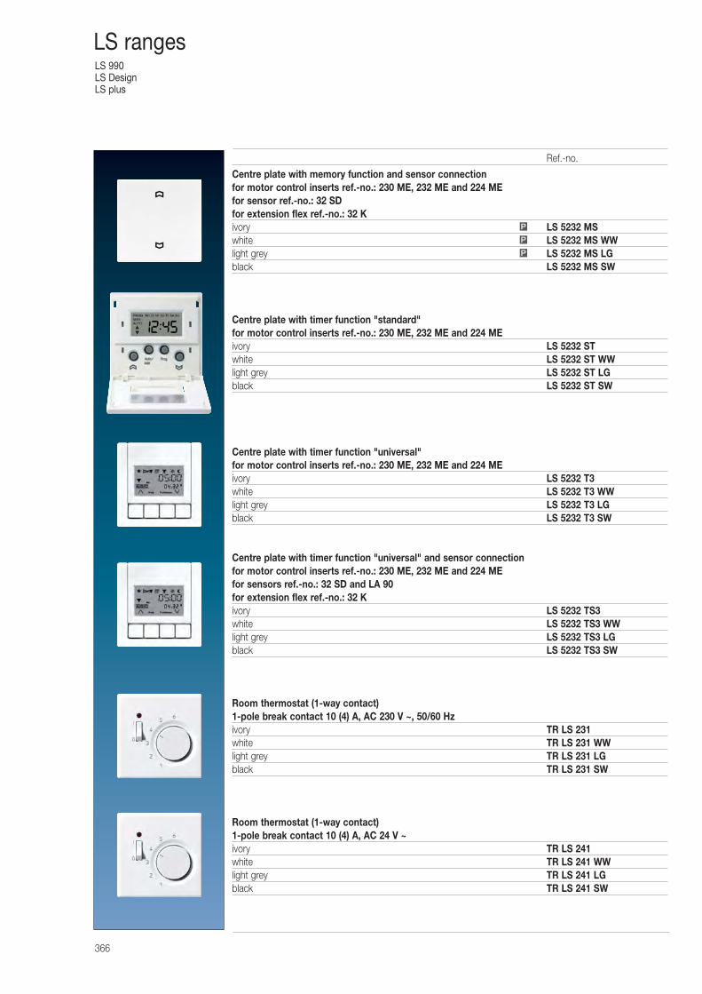
LS 990LS DesignLS plus
366
LS ranges
Centre plate with memory function and sensor connectionfor motor control inserts ref.-no.: 230 ME, 232 ME and 224 MEfor sensor ref.-no.: 32 SDfor extension flex ref.-no.: 32 Kivory LS 5232 MSwhite LS 5232 MS WWlight grey LS 5232 MS LGblack LS 5232 MS SW
Centre plate with timer function "standard"for motor control inserts ref.-no.: 230 ME, 232 ME and 224 MEivory LS 5232 STwhite LS 5232 ST WWlight grey LS 5232 ST LGblack LS 5232 ST SW
Centre plate with timer function "universal"for motor control inserts ref.-no.: 230 ME, 232 ME and 224 MEivory LS 5232 T3white LS 5232 T3 WWlight grey LS 5232 T3 LGblack LS 5232 T3 SW
Centre plate with timer function "universal" and sensor connectionfor motor control inserts ref.-no.: 230 ME, 232 ME and 224 MEfor sensors ref.-no.: 32 SD and LA 90for extension flex ref.-no.: 32 Kivory LS 5232 TS3white LS 5232 TS3 WWlight grey LS 5232 TS3 LGblack LS 5232 TS3 SW
Room thermostat (1-way contact)1-pole break contact 10 (4) A, AC 230 V ~, 50/60 Hzivory TR LS 231white TR LS 231 WWlight grey TR LS 231 LGblack TR LS 231 SW
Room thermostat (1-way contact)1-pole break contact 10 (4) A, AC 24 V ~ivory TR LS 241white TR LS 241 WWlight grey TR LS 241 LGblack TR LS 241 SW
P
P
P
Ref.-no.
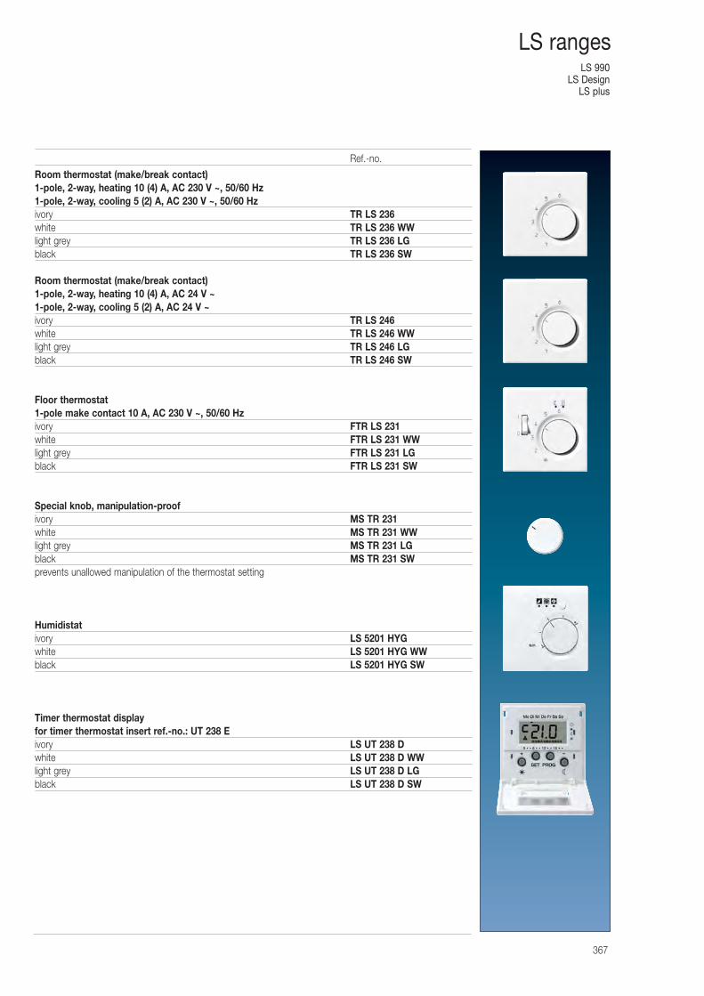
LS 990LS Design
LS plus
367
LS ranges
Room thermostat (make/break contact)1-pole, 2-way, heating 10 (4) A, AC 230 V ~, 50/60 Hz1-pole, 2-way, cooling 5 (2) A, AC 230 V ~, 50/60 Hzivory TR LS 236white TR LS 236 WWlight grey TR LS 236 LGblack TR LS 236 SW
Room thermostat (make/break contact)1-pole, 2-way, heating 10 (4) A, AC 24 V ~1-pole, 2-way, cooling 5 (2) A, AC 24 V ~ivory TR LS 246white TR LS 246 WWlight grey TR LS 246 LGblack TR LS 246 SW
Floor thermostat1-pole make contact 10 A, AC 230 V ~, 50/60 Hzivory FTR LS 231white FTR LS 231 WWlight grey FTR LS 231 LGblack FTR LS 231 SW
Special knob, manipulation-proofivory MS TR 231white MS TR 231 WWlight grey MS TR 231 LGblack MS TR 231 SWprevents unallowed manipulation of the thermostat setting
Humidistativory LS 5201 HYGwhite LS 5201 HYG WWblack LS 5201 HYG SW
Timer thermostat displayfor timer thermostat insert ref.-no.: UT 238 Eivory LS UT 238 Dwhite LS UT 238 D WWlight grey LS UT 238 D LGblack LS UT 238 D SW
Ref.-no.
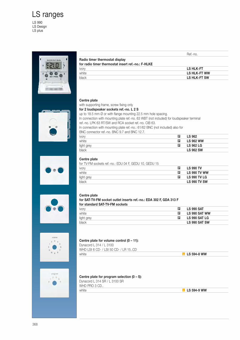
LS 990LS DesignLS plus
368
LS ranges
Radio timer thermostat displayfor radio timer thermostat insert ref.-no.: F-HLKEivory LS HLK-FTwhite LS HLK-FT WWblack LS HLK-FT SW
Centre platewith supporting frame, screw fixing onlyfor 2 loudspeaker sockets ref.-no. L 2 Sup to 18.5 mm Ø or with flange mounting 22.5 mm hole spacing.In connection with mounting plate ref.-no. 63 WBT (not included) for loudspeaker terminalref.-no. LPK 63 RT/SW and RCA socket ref.-no. CIB 63.In connection with mounting plate ref.-no.: 61/62 BNC (not included) also for BNC connector ref.-no. BNC 9.7 and BNC 12.7.ivory LS 962white LS 962 WWlight grey LS 962 LGblack LS 962 SW
Centre platefor TV-FM sockets ref.-no.: EDU 04 F, GEDU 10, GEDU 15ivory LS 990 TVwhite LS 990 TV WWlight grey LS 990 TV LGblack LS 990 TV SW
Centre platefor SAT-TV-FM socket outlet inserts ref.-no.: EDA 302 F, GDA 313 Ffor standard SAT-TV-FM socketsivory LS 990 SATwhite LS 990 SAT WWlight grey LS 990 SAT LGblack LS 990 SAT SW
Centre plate for volume control (0 – 11):Dynacord L 314 / L 3100WHD LSt 6 CD- / LSt 50 CD- / LR 15..CDwhite LS 594-8 WW
Centre plate for program selection (0 – 5):Dynacord L 314 SR / L 3100 SRWHD PRO 3 CD..white LS 594-9 WW
P
P
P
P
P
P
P
P
L
P
L
Ref.-no.
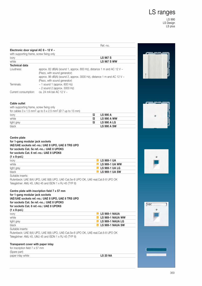
LS 990LS Design
LS plus
369
LS ranges
Electronic door signal AC 8 – 12 V ~with supporting frame, screw fixing onlyivory LS 967 Swhite LS 967 S WWTechnical dataLoudness: approx. 82 dB(A) (sound 1, approx. 800 Hz), distance 1 m and AC 12 V ~
(Piezo, with sound generator)approx. 96 dB(A) (sound 2, approx. 3000 Hz), distance 1 m and AC 12 V ~ (Piezo, with sound generator)
Terminals: ~ 1 sound 1 (approx. 800 Hz)~ 2 sound 2 (approx. 3000 Hz)
Current consumption: ca. 24 mA bei AC 12 V ~
Cable outletwith supporting frame, screw fixing onlyfor cables 3 x 1.5 mm2 up to 5 x 2.5 mm2 (Ø 7 up to 13 mm)ivory LS 990 Awhite LS 990 A WWlight grey LS 990 A LGblack LS 990 A SW
Centre platefor 1-gang modular jack socketsIAE/UAE sockets ref.-no.: UAE 8 UPO, UAE 8 TRS UPOfor sockets Cat. 5e ref.-no..: UAE 8 UPOK5for sockets Cat. 6 ref.-no.: UAE 8 UPOK6(1 x 8-pol.)ivory LS 969-1 UAwhite LS 969-1 UA WWlight grey LS 969-1 UA LGblack LS 969-1 UA SWSuitable inserts:Rutenbeck: UAE 8(4) UPO, UAE 8(8) UPO, UAE-Cat.5e-8 UPO OK, UAE-real.Cat.6-8 UPO OKTelegärtner: AMJ 45, UMJ 45 and ISDN 1 x RJ 45 (TYP 8)
Centre plate with inscription field 7 x 57 mm for 1-gang modular jack socketsIAE/UAE sockets ref.-no.: UAE 8 UPO, UAE 8 TRS UPOfor sockets Cat. 5e ref.-no..: UAE 8 UPOK5for sockets Cat. 6 ref.-no.: UAE 8 UPOK6(1 x 8-pol.)ivory LS 969-1 NAUAwhite LS 969-1 NAUA WWlight grey LS 969-1 NAUA LGblack LS 969-1 NAUA SWSuitable inserts:Rutenbeck: UAE 8(4) UPO, UAE 8(8) UPO, UAE-Cat.5e-8 UPO OK, UAE-real.Cat.6-8 UPO OKTelegärtner: AMJ 45, UMJ 45 and ISDN 1 x RJ 45 (TYP 8)
Transparent cover with paper inlayfor inscription field 7 x 57 mm(Spare part)paper inlay white LS 20 NA
P
P
P
L
L
L
L
L
L
L
L
Ref.-no.
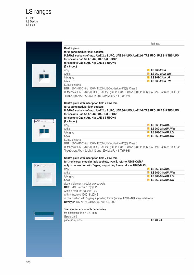
LS 990LS DesignLS plus
370
LS ranges
Centre platefor 2-gang modular jack socketsIAE/UAE sockets ref.-no..: UAE 2 x 8 UPO, UAE 8-8 UPO, UAE 2x8 TRS UPO, UAE 8-8 TRS UPOfor sockets Cat. 5e Art.-Nr.: UAE 8-8 UPOK5for sockets Cat. 6 Art.-Nr.: UAE 8-8 UPOK6(2 x 8-pol.)ivory LS 969-2 UAwhite LS 969-2 UA WWlight grey LS 969-2 UA LGblack LS 969-2 UA SWSuitable inserts:BTR: 1307441001-i or 1307441200-i; E-Dat design 8/8(8), Class ERutenbeck: UAE 8/8 (8/8) UPO, UAE 2x8 (8) UPO, UAE-Cat.5e-8/8 UPO OK, UAE-real.Cat.6-8/8 UPO OKTelegärtner: AMJ 45, UMJ 45 and ISDN 2 x RJ 45 (TYP 8/8)
Centre plate with inscription field 7 x 57 mm for 2-gang modular jack socketsIAE/UAE sockets ref.-no..: UAE 2 x 8 UPO, UAE 8-8 UPO, UAE 2x8 TRS UPO, UAE 8-8 TRS UPOfor sockets Cat. 5e Art.-Nr.: UAE 8-8 UPOK5for sockets Cat. 6 Art.-Nr.: UAE 8-8 UPOK6(2 x 8-pol.)ivory LS 969-2 NAUAwhite LS 969-2 NAUA WWlight grey LS 969-2 NAUA LGblack LS 969-2 NAUA SWSuitable inserts:BTR: 1307441001-i or 1307441200-i; E-Dat design 8/8(8), Class ERutenbeck: UAE 8/8 (8/8) UPO, UAE 2x8 (8) UPO, UAE-Cat.5e-8/8 UPO OK, UAE-real.Cat.6-8/8 UPO OKTelegärtner: AMJ 45, UMJ 45 and ISDN 2 x RJ 45 (TYP 8/8)
Centre plate with inscription field 7 x 57 mm for 3 universal modular jack sockets, type B, ref.-no. UMB-CAT6Aonly in connection with 3-gang supporting frame ref.-no. UMB-MA3ivory LS 969-3 NAUAwhite LS 969-3 NAUA WWlight grey LS 969-3 NAUA LGblack LS 969-3 NAUA SWalso suitable for modular jack socketsBTR: E-DAT modul 3x8(8) UP0without modules 1309141200-Ewith 3 modules 1309131200-Ein combination with 3-gang supporting frame (ref.-no. UMB-MA3) also suitable forDätwyler: MS-N 1/8 Cat.6a, ref.-no.: 440 000
Transparent cover with paper inlayfor inscription field 7 x 57 mm (Spare part)paper inlay white LS 20 NA
L
L
L
L
L
L
L
L
L
L
L
L
Ref.-no.
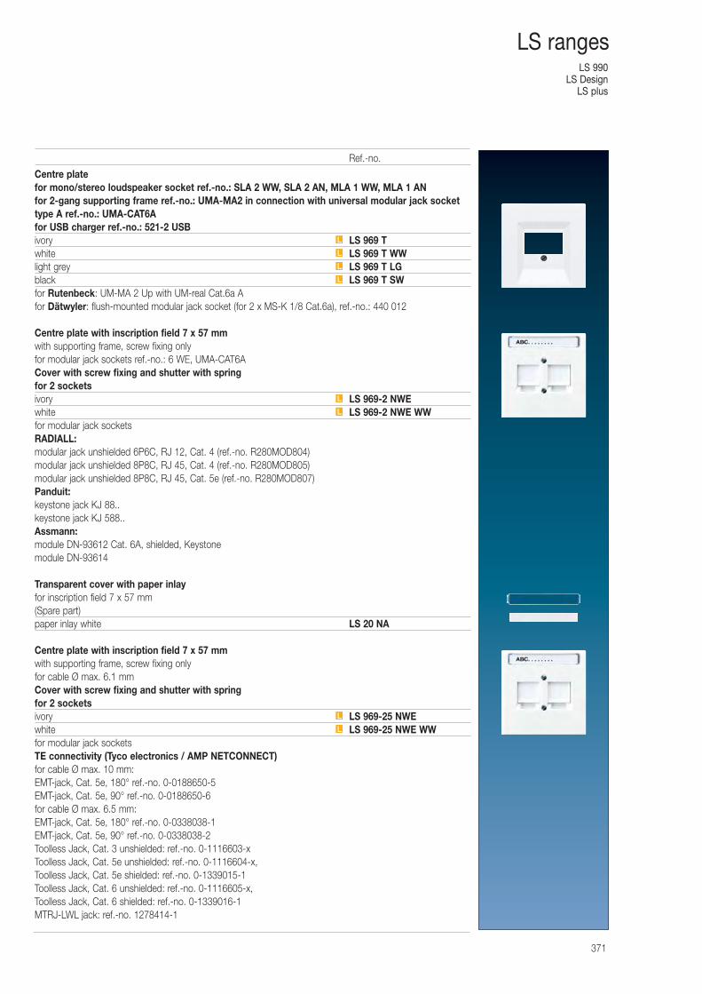
LS 990LS Design
LS plus
371
LS ranges
Centre platefor mono/stereo loudspeaker socket ref.-no.: SLA 2 WW, SLA 2 AN, MLA 1 WW, MLA 1 ANfor 2-gang supporting frame ref.-no.: UMA-MA2 in connection with universal modular jack sockettype A ref.-no.: UMA-CAT6Afor USB charger ref.-no.: 521-2 USBivory LS 969 Twhite LS 969 T WWlight grey LS 969 T LGblack LS 969 T SWfor Rutenbeck: UM-MA 2 Up with UM-real Cat.6a Afor Dätwyler: flush-mounted modular jack socket (for 2 x MS-K 1/8 Cat.6a), ref.-no.: 440 012
Centre plate with inscription field 7 x 57 mm with supporting frame, screw fixing onlyfor modular jack sockets ref.-no.: 6 WE, UMA-CAT6ACover with screw fixing and shutter with springfor 2 socketsivory LS 969-2 NWEwhite LS 969-2 NWE WWfor modular jack socketsRADIALL:modular jack unshielded 6P6C, RJ 12, Cat. 4 (ref.-no. R280MOD804)modular jack unshielded 8P8C, RJ 45, Cat. 4 (ref.-no. R280MOD805)modular jack unshielded 8P8C, RJ 45, Cat. 5e (ref.-no. R280MOD807)Panduit:keystone jack KJ 88..keystone jack KJ 588..Assmann:module DN-93612 Cat. 6A, shielded, Keystonemodule DN-93614
Transparent cover with paper inlayfor inscription field 7 x 57 mm(Spare part)paper inlay white LS 20 NA
Centre plate with inscription field 7 x 57 mm with supporting frame, screw fixing onlyfor cable Ø max. 6.1 mmCover with screw fixing and shutter with springfor 2 socketsivory LS 969-25 NWEwhite LS 969-25 NWE WWfor modular jack socketsTE connectivity (Tyco electronics / AMP NETCONNECT)for cable Ø max. 10 mm:EMT-jack, Cat. 5e, 180° ref.-no. 0-0188650-5EMT-jack, Cat. 5e, 90° ref.-no. 0-0188650-6for cable Ø max. 6.5 mm:EMT-jack, Cat. 5e, 180° ref.-no. 0-0338038-1EMT-jack, Cat. 5e, 90° ref.-no. 0-0338038-2Toolless Jack, Cat. 3 unshielded: ref.-no. 0-1116603-xToolless Jack, Cat. 5e unshielded: ref.-no. 0-1116604-x, Toolless Jack, Cat. 5e shielded: ref.-no. 0-1339015-1Toolless Jack, Cat. 6 unshielded: ref.-no. 0-1116605-x, Toolless Jack, Cat. 6 shielded: ref.-no. 0-1339016-1MTRJ-LWL jack: ref.-no. 1278414-1
L
L
L
L
L
L
L
L
Ref.-no.
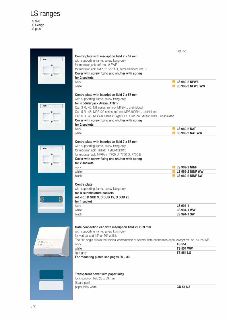
LS 990LS DesignLS plus
372
LS ranges
Centre plate with inscription field 7 x 57 mm with supporting frame, screw fixing onlyfor modular jack: ref.-no.: 8 FWEfor modular jack AMP: 2168-11-1, semi-shielded, cat. 3Cover with screw fixing and shutter with springfor 2 socketsivory LS 969-2 NFWEwhite LS 969-2 NFWE WW
Centre plate with inscription field 7 x 57 mm with supporting frame, screw fixing onlyfor modular jack Avaya (AT&T)Cat. 3 RJ 45, M1 series: ref.-no. M1BH.., unshielded,Cat. 5 RJ 45, MPS100 series: ref.-no. MPS100BH.., unshielded,Cat. 6 RJ 45, MGS200 series: GigaSPEED, ref.-no. MGS200BH.., unshieldedCover with screw fixing and shutter with springfor 2 socketsivory LS 969-2 NATwhite LS 969-2 NAT WW
Centre plate with inscription field 7 x 57 mm with supporting frame, screw fixing onlyfor modular jack Radiall: R 280MOD813for modular jack INFRA +: 7700 U, 7700 D, 7700 ECover with screw fixing and shutter with springfor 2 socketsivory LS 969-2 NINFwhite LS 969-2 NINF WWblack LS 969-2 NINF SW
Centre platewith supporting frame, screw fixing onlyfor D-subminiature socketsref.-no.: D SUB 9, D SUB 15, D SUB 25for 1 socketivory LS 994-1white LS 994-1 WWblack LS 994-1 SW
Data connection cap with inscription field 23 x 59 mmwith supporting frame, screw fixing onlyfor vertical and 15° or 30° outlet.The 30° angle allows the vertical combination of several data connection caps, except ref.-no. 54-25 WE.ivory TS 554white TS 554 WWlight grey TS 554 LGFor mounting plates see pages 30 – 33
Transparent cover with paper inlayfor inscription field 23 x 59 mm(Spare part)paper inlay white CD 54 NA
L
L
L
L
L
L
L
Ref.-no.
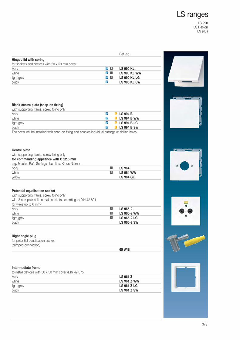
LS 990LS Design
LS plus
373
LS ranges
Hinged lid with springfor sockets and devices with 50 x 50 mm coverivory LS 990 KLwhite LS 990 KL WWlight grey LS 990 KL LGblack LS 990 KL SW
Blank centre plate (snap-on fixing)with supporting frame, screw fixing onlyivory LS 994 Bwhite LS 994 B WWlight grey LS 994 B LGblack LS 994 B SWThe cover will be installed with snap-on fixing and enables individual cuttings or drilling holes.
Centre platewith supporting frame, screw fixing onlyfor commanding appliance with Ø 22.5 mme.g. Moeller, Rafi, Schlegel, Lumitas, Kraus-Naimerivory LS 964white LS 964 WWyellow LS 964 GE
Potential equalisation socketwith supporting frame, screw fixing onlywith 2 one-pole built-in male sockets according to DIN 42 801for wires up to 6 mm2
ivory LS 965-2white LS 965-2 WWlight grey LS 965-2 LGblack LS 965-2 SW
Right angle plugfor potential equalisation socket(crimped connection)
65 WIS
Intermediate frameto install devices with 50 x 50 mm cover (DIN 49 075)ivory LS 961 Zwhite LS 961 Z WWlight grey LS 961 Z LGblack LS 961 Z SW
PIP
IP P
IP L
LIP
IP
PIP
P
P
P
P
P
LIP
LIP
Ref.-no.
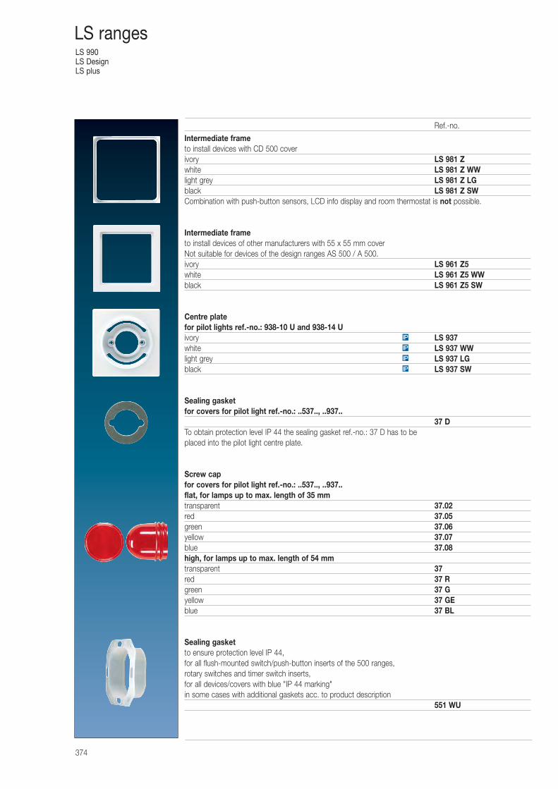
LS 990LS DesignLS plus
374
LS ranges
Intermediate frameto install devices with CD 500 coverivory LS 981 Zwhite LS 981 Z WWlight grey LS 981 Z LGblack LS 981 Z SWCombination with push-button sensors, LCD info display and room thermostat is not possible.
Intermediate frameto install devices of other manufacturers with 55 x 55 mm coverNot suitable for devices of the design ranges AS 500 / A 500.ivory LS 961 Z5white LS 961 Z5 WWblack LS 961 Z5 SW
Centre platefor pilot lights ref.-no.: 938-10 U and 938-14 Uivory LS 937white LS 937 WWlight grey LS 937 LGblack LS 937 SW
Sealing gasketfor covers for pilot light ref.-no.: ..537.., ..937..
37 DTo obtain protection level IP 44 the sealing gasket ref.-no.: 37 D has to be placed into the pilot light centre plate.
Screw capfor covers for pilot light ref.-no.: ..537.., ..937..flat, for lamps up to max. length of 35 mmtransparent 37.02red 37.05green 37.06yellow 37.07blue 37.08high, for lamps up to max. length of 54 mmtransparent 37red 37 Rgreen 37 Gyellow 37 GEblue 37 BL
Sealing gasketto ensure protection level IP 44,for all flush-mounted switch/push-button inserts of the 500 ranges,rotary switches and timer switch inserts,for all devices/covers with blue "IP 44 marking"in some cases with additional gaskets acc. to product description
551 WU
IP
IP
IP
IP
Ref.-no.
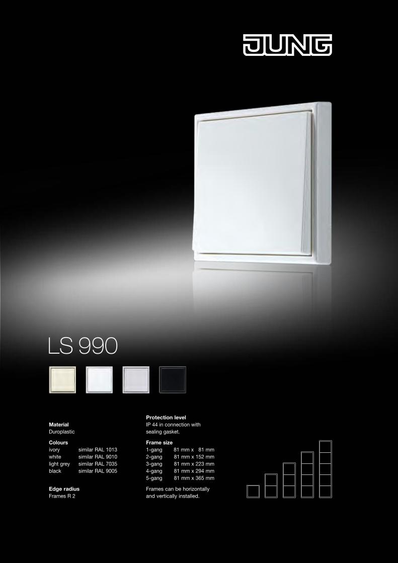
LS 990
MaterialDuroplastic
Colours ivory similar RAL 1013 white similar RAL 9010 light grey similar RAL 7035 black similar RAL 9005
Edge radius Frames R 2
Protection level IP 44 in connection withsealing gasket.
Frame size 1-gang 81 mm x 81 mm 2-gang 81 mm x 152 mm 3-gang 81 mm x 223 mm 4-gang 81 mm x 294 mm 5-gang 81 mm x 365 mm
Frames can be horizontallyand vertically installed.
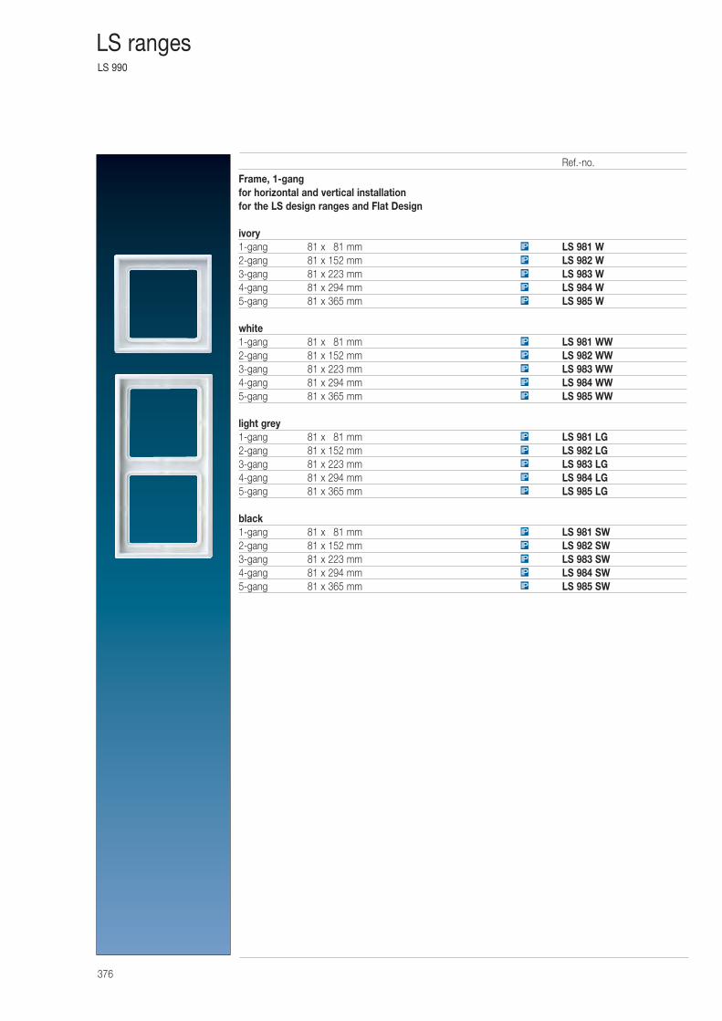
LS 990
376
LS ranges
Frame, 1-gangfor horizontal and vertical installationfor the LS design ranges and Flat Design
ivory1-gang 81 x 081 mm LS 981 W2-gang 81 x 152 mm LS 982 W3-gang 81 x 223 mm LS 983 W4-gang 81 x 294 mm LS 984 W5-gang 81 x 365 mm LS 985 W
white1-gang 81 x 081 mm LS 981 WW2-gang 81 x 152 mm LS 982 WW3-gang 81 x 223 mm LS 983 WW4-gang 81 x 294 mm LS 984 WW5-gang 81 x 365 mm LS 985 WW
light grey1-gang 81 x 081 mm LS 981 LG2-gang 81 x 152 mm LS 982 LG3-gang 81 x 223 mm LS 983 LG4-gang 81 x 294 mm LS 984 LG5-gang 81 x 365 mm LS 985 LG
black1-gang 81 x 081 mm LS 981 SW2-gang 81 x 152 mm LS 982 SW3-gang 81 x 223 mm LS 983 SW4-gang 81 x 294 mm LS 984 SW5-gang 81 x 365 mm LS 985 SW
IP
IP
IP
IP
IP
IP
IP
IP
IP
IP
IP
IP
IP
IP
IP
IP
IP
IP
IP
IP
Ref.-no.

LS 990
377
LS ranges
Surface capwith integrated frame and non-flammable ground platefor inserts with covers of the LS design ranges (except key switches ref.-no. ..15 and 3-level-switch)Installation of the music station into surface caps is not possible.1-gang, 81 x 81 x 47 mmivory LS 581 A Wwhite LS 581 A WWblack LS 581 A SW
Surface capwith integrated frame and non-flammable ground platefor inserts with covers of the LS design ranges (except key switches ref.-no. ..15 and 3-level-switch)Installation of radio ref.-no.: R AN ..914.. and DCM indoor station ref.–no.: TK IS..914.. into 2- to 3-gang surface caps is possible.Installation of the music station into surface caps is not possible.
2-gang, 152 x 81 x 47 mmivory LS 582 A Wwhite LS 582 A WWblack LS 582 A SW
3-gang, 223 x 81 x 47 mmivory LS 583 A Wwhite LS 583 A WWblack LS 583 A SW
Mounting box for surface caps(Spare part)1-gang 581 A2-gang 582 A3-gang 583 A
Strain relieffor surface capsfor cables 3 x 1.5 mm2 up to 5 x 2.5 mm2 (Ø 7 up to 13 mm)
58 A ZUG
Inlets for cables, pipes and trunkings in surface capsfor cable and mini trunkingivory 11white 11 WW
for trunking 15 x 15 mmivory 12white 12 WW
for pipes with outside Ø 16 mmivory 13white 13 WW
Ref.-no.
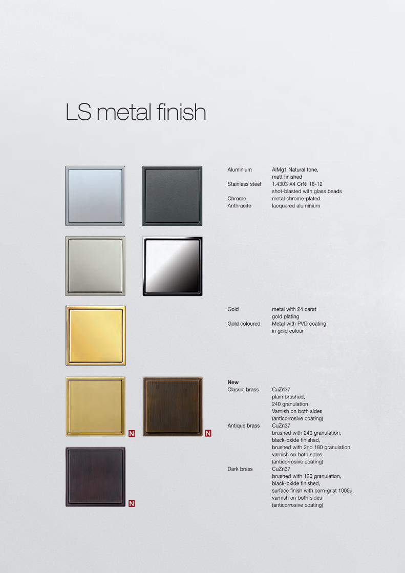
LS metal finish
Aluminium AlMg1 Natural tone, matt finished Stainless steel 1.4303 X4 CrNi 18-12 shot-blasted with glass beads Chrome metal chrome-plated Anthracite lacquered aluminium
New Classic brass CuZn37 plain brushed, 240 granulation Varnish on both sides (anticorrosive coating)Antique brass CuZn37 brushed with 240 granulation, black-oxide finished, brushed with 2nd 180 granulation, varnish on both sides (anticorrosive coating)Dark brass CuZn37 brushed with 120 granulation, black-oxide finished, surface finish with corn-grist 1000μ, varnish on both sides (anticorrosive coating)
Gold metal with 24 carat gold plating Gold coloured Metal with PVD coating in gold colour
N
N
N
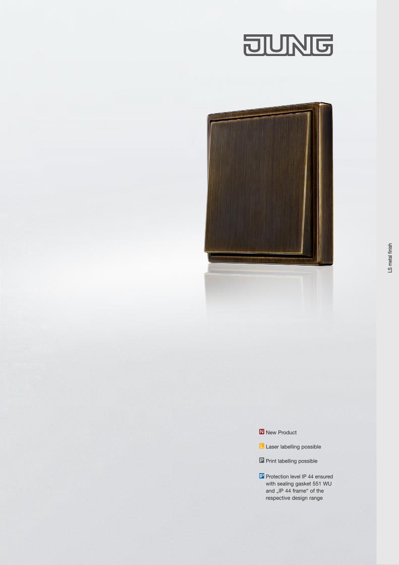
Protection level IP 44 ensured with sealing gasket 551 WU and „IP 44 frame“ of the respective design range
IP
New Product
Laser labelling possible
Print labelling possible
N
L
P
LS m
etal
fini
sh
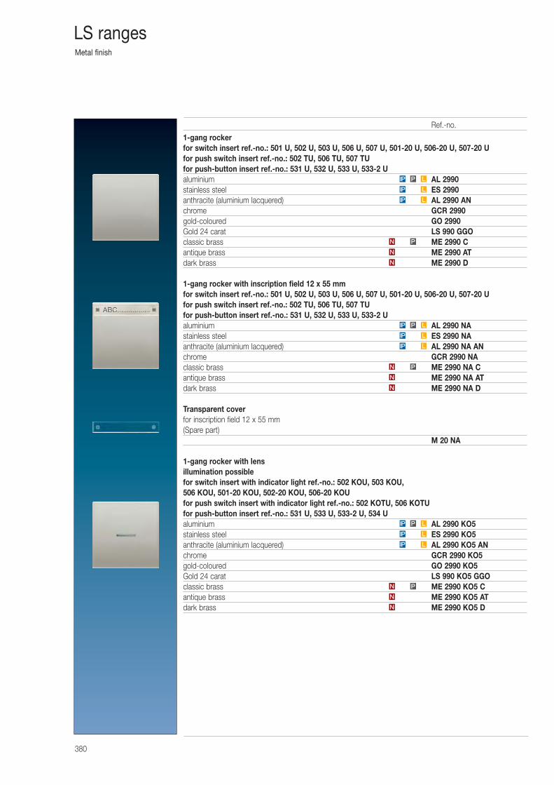
Metal finish
380
LS ranges
1-gang rockerfor switch insert ref.-no.: 501 U, 502 U, 503 U, 506 U, 507 U, 501-20 U, 506-20 U, 507-20 Ufor push switch insert ref.-no.: 502 TU, 506 TU, 507 TUfor push-button insert ref.-no.: 531 U, 532 U, 533 U, 533-2 Ualuminium AL 2990stainless steel ES 2990anthracite (aluminium lacquered) AL 2990 ANchrome GCR 2990gold-coloured GO 2990Gold 24 carat LS 990 GGOclassic brass ME 2990 Cantique brass ME 2990 ATdark brass ME 2990 D
1-gang rocker with inscription field 12 x 55 mmfor switch insert ref.-no.: 501 U, 502 U, 503 U, 506 U, 507 U, 501-20 U, 506-20 U, 507-20 Ufor push switch insert ref.-no.: 502 TU, 506 TU, 507 TUfor push-button insert ref.-no.: 531 U, 532 U, 533 U, 533-2 Ualuminium AL 2990 NAstainless steel ES 2990 NAanthracite (aluminium lacquered) AL 2990 NA ANchrome GCR 2990 NAclassic brass ME 2990 NA Cantique brass ME 2990 NA ATdark brass ME 2990 NA D
Transparent coverfor inscription field 12 x 55 mm(Spare part)
M 20 NA
1-gang rocker with lensillumination possiblefor switch insert with indicator light ref.-no.: 502 KOU, 503 KOU, 506 KOU, 501-20 KOU, 502-20 KOU, 506-20 KOUfor push switch insert with indicator light ref.-no.: 502 KOTU, 506 KOTUfor push-button insert ref.-no.: 531 U, 533 U, 533-2 U, 534 Ualuminium AL 2990 KO5stainless steel ES 2990 KO5anthracite (aluminium lacquered) AL 2990 KO5 ANchrome GCR 2990 KO5gold-coloured GO 2990 KO5Gold 24 carat LS 990 KO5 GGOclassic brass ME 2990 KO5 Cantique brass ME 2990 KO5 ATdark brass ME 2990 KO5 D
LPIP
N
N
PN
LIP
LIP
LPIP
N
N
PN
LIP
LIP
N
N
PN
LIP
LIP
LPIP
Ref.-no.
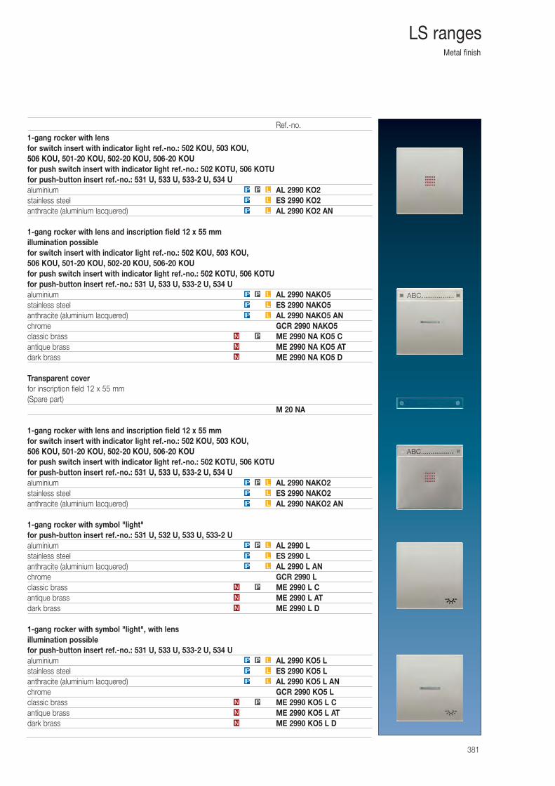
Metal finish
381
LS ranges
1-gang rocker with lensfor switch insert with indicator light ref.-no.: 502 KOU, 503 KOU, 506 KOU, 501-20 KOU, 502-20 KOU, 506-20 KOUfor push switch insert with indicator light ref.-no.: 502 KOTU, 506 KOTUfor push-button insert ref.-no.: 531 U, 533 U, 533-2 U, 534 Ualuminium AL 2990 KO2stainless steel ES 2990 KO2anthracite (aluminium lacquered) AL 2990 KO2 AN
1-gang rocker with lens and inscription field 12 x 55 mmillumination possiblefor switch insert with indicator light ref.-no.: 502 KOU, 503 KOU, 506 KOU, 501-20 KOU, 502-20 KOU, 506-20 KOUfor push switch insert with indicator light ref.-no.: 502 KOTU, 506 KOTUfor push-button insert ref.-no.: 531 U, 533 U, 533-2 U, 534 Ualuminium AL 2990 NAKO5stainless steel ES 2990 NAKO5anthracite (aluminium lacquered) AL 2990 NAKO5 ANchrome GCR 2990 NAKO5classic brass ME 2990 NA KO5 Cantique brass ME 2990 NA KO5 ATdark brass ME 2990 NA KO5 D
Transparent coverfor inscription field 12 x 55 mm(Spare part)
M 20 NA
1-gang rocker with lens and inscription field 12 x 55 mmfor switch insert with indicator light ref.-no.: 502 KOU, 503 KOU, 506 KOU, 501-20 KOU, 502-20 KOU, 506-20 KOUfor push switch insert with indicator light ref.-no.: 502 KOTU, 506 KOTUfor push-button insert ref.-no.: 531 U, 533 U, 533-2 U, 534 Ualuminium AL 2990 NAKO2stainless steel ES 2990 NAKO2anthracite (aluminium lacquered) AL 2990 NAKO2 AN
1-gang rocker with symbol "light"for push-button insert ref.-no.: 531 U, 532 U, 533 U, 533-2 Ualuminium AL 2990 Lstainless steel ES 2990 Lanthracite (aluminium lacquered) AL 2990 L ANchrome GCR 2990 Lclassic brass ME 2990 L Cantique brass ME 2990 L ATdark brass ME 2990 L D
1-gang rocker with symbol "light", with lensillumination possiblefor push-button insert ref.-no.: 531 U, 533 U, 533-2 U, 534 Ualuminium AL 2990 KO5 Lstainless steel ES 2990 KO5 Lanthracite (aluminium lacquered) AL 2990 KO5 L ANchrome GCR 2990 KO5 Lclassic brass ME 2990 KO5 L Cantique brass ME 2990 KO5 L ATdark brass ME 2990 KO5 L D
LPIP
LIP
LIP
N
N
PN
LIP
LIP
LPIP
N
N
PN
LIP
LIP
LPIP
LIP
LIP
LPIP
N
N
PN
LIP
LIP
LPIP
Ref.-no.
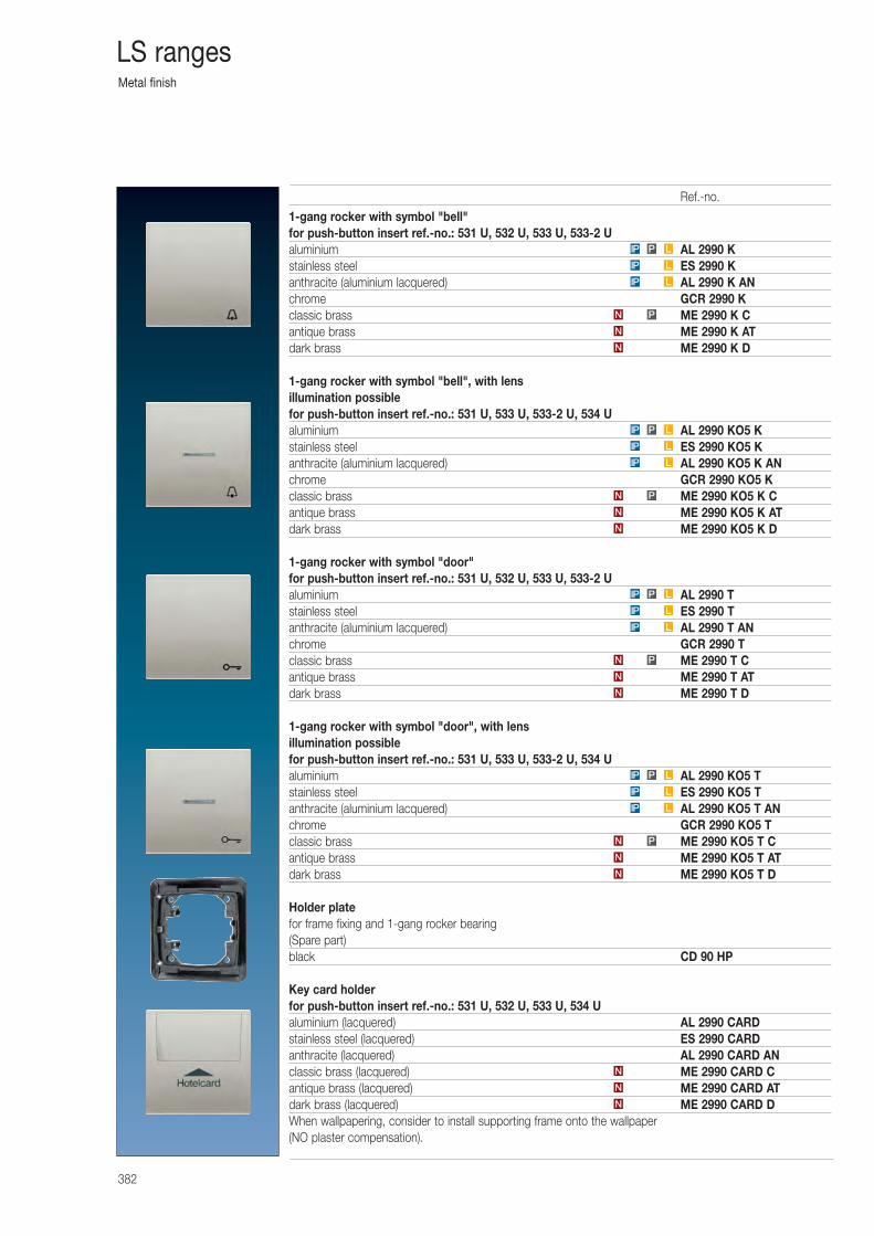
Metal finish
382
LS ranges
1-gang rocker with symbol "bell"for push-button insert ref.-no.: 531 U, 532 U, 533 U, 533-2 Ualuminium AL 2990 Kstainless steel ES 2990 Kanthracite (aluminium lacquered) AL 2990 K ANchrome GCR 2990 Kclassic brass ME 2990 K Cantique brass ME 2990 K ATdark brass ME 2990 K D
1-gang rocker with symbol "bell", with lensillumination possiblefor push-button insert ref.-no.: 531 U, 533 U, 533-2 U, 534 Ualuminium AL 2990 KO5 Kstainless steel ES 2990 KO5 Kanthracite (aluminium lacquered) AL 2990 KO5 K ANchrome GCR 2990 KO5 Kclassic brass ME 2990 KO5 K Cantique brass ME 2990 KO5 K ATdark brass ME 2990 KO5 K D
1-gang rocker with symbol "door"for push-button insert ref.-no.: 531 U, 532 U, 533 U, 533-2 Ualuminium AL 2990 Tstainless steel ES 2990 Tanthracite (aluminium lacquered) AL 2990 T ANchrome GCR 2990 Tclassic brass ME 2990 T Cantique brass ME 2990 T ATdark brass ME 2990 T D
1-gang rocker with symbol "door", with lensillumination possiblefor push-button insert ref.-no.: 531 U, 533 U, 533-2 U, 534 Ualuminium AL 2990 KO5 Tstainless steel ES 2990 KO5 Tanthracite (aluminium lacquered) AL 2990 KO5 T ANchrome GCR 2990 KO5 Tclassic brass ME 2990 KO5 T Cantique brass ME 2990 KO5 T ATdark brass ME 2990 KO5 T D
Holder platefor frame fixing and 1-gang rocker bearing(Spare part)black CD 90 HP
Key card holderfor push-button insert ref.-no.: 531 U, 532 U, 533 U, 534 Ualuminium (lacquered) AL 2990 CARDstainless steel (lacquered) ES 2990 CARDanthracite (lacquered) AL 2990 CARD ANclassic brass (lacquered) ME 2990 CARD Cantique brass (lacquered) ME 2990 CARD ATdark brass (lacquered) ME 2990 CARD DWhen wallpapering, consider to install supporting frame onto the wallpaper (NO plaster compensation).
N
N
PN
LIP
LIP
LPIP
N
N
N
N
N
PN
LIP
LIP
LPIP
N
N
PN
LIP
LIP
LPIP
N
N
PN
LIP
LIP
LPIP
Ref.-no.
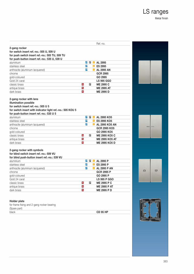
Metal finish
383
LS ranges
2-gang rockerfor switch insert ref.-no.: 505 U, 509 Ufor push switch insert ref.-no.: 505 TU, 509 TUfor push-button insert ref.-no.: 535 U, 539 Ualuminium AL 2995stainless steel ES 2995anthracite (aluminium lacquered) AL 2995 ANchrome GCR 2995gold-coloured GO 2995Gold 24 carat LS 995 GGOclassic brass ME 2995 Cantique brass ME 2995 ATdark brass ME 2995 D
2-gang rocker with lensillumination possiblefor switch insert ref.-no.: 505 U 5for switch insert with indicator light ref.-no.: 505 KOU 5for push-button insert ref.-no.: 535 U 5aluminium AL 2995 KO5stainless steel ES 2995 KO5anthracite (aluminium lacquered) AL 2995 KO5 ANchrome GCR 2995 KO5gold-coloured GO 2995 KO5classic brass ME 2995 KO5 Cantique brass ME 2995 KO5 ATdark brass ME 2995 KO5 D
2-gang rocker with symbolsfor blind switch insert ref.-no.: 509 VUfor blind push-button insert ref.-no.: 539 VUaluminium AL 2995 Pstainless steel ES 2995 Panthracite (aluminium lacquered) AL 2995 P ANchrome GCR 2995 Pgold-coloured GO 2995 PGold 24 carat LS 995 P GGOclassic brass ME 2995 P Cantique brass ME 2995 P ATdark brass ME 2995 P D
Holder platefor frame fixing and 2-gang rocker bearing(Spare part)black CD 95 HP
N
PN
LIP
LIP
LPIP
N
N
PN
LIP
LIP
LPIP
N
N
PN
LIP
LIP
LPIP
N
Ref.-no.
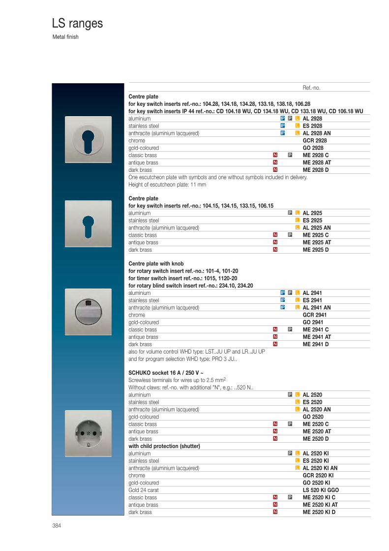
Metal finish
384
LS ranges
Centre platefor key switch inserts ref.-no.: 104.28, 134.18, 134.28, 133.18, 138.18, 106.28for key switch inserts IP 44 ref.-no.: CD 104.18 WU, CD 134.18 WU, CD 133.18 WU, CD 106.18 WUaluminium AL 2928stainless steel ES 2928anthracite (aluminium lacquered) AL 2928 ANchrome GCR 2928gold-coloured GO 2928classic brass ME 2928 Cantique brass ME 2928 ATdark brass ME 2928 DOne escutcheon plate with symbols and one without symbols included in delivery.Height of escutcheon plate: 11 mm
Centre platefor key switch inserts ref.-no.: 104.15, 134.15, 133.15, 106.15aluminium AL 2925stainless steel ES 2925anthracite (aluminium lacquered) AL 2925 ANclassic brass ME 2925 Cantique brass ME 2925 ATdark brass ME 2925 D
Centre plate with knobfor rotary switch insert ref.-no.: 101-4, 101-20for timer switch insert ref.-no.: 1015, 1120-20for rotary blind switch insert ref.-no.: 234.10, 234.20aluminium AL 2941stainless steel ES 2941anthracite (aluminium lacquered) AL 2941 ANchrome GCR 2941gold-coloured GO 2941classic brass ME 2941 Cantique brass ME 2941 ATdark brass ME 2941 Dalso for volume control WHD type: LST..JU UP and LR..JU UPand for program selection WHD type: PRO 3 JU..
SCHUKO socket 16 A / 250 V ~Screwless terminals for wires up to 2.5 mm2
Without claws: ref.-no. with additional "N", e.g.: ..520 N..aluminium AL 2520stainless steel ES 2520anthracite (aluminium lacquered) AL 2520 ANgold-coloured GO 2520classic brass ME 2520 Cantique brass ME 2520 ATdark brass ME 2520 Dwith child protection (shutter)aluminium AL 2520 KIstainless steel ES 2520 KIanthracite (aluminium lacquered) AL 2520 KI ANchrome GCR 2520 KIgold-coloured GO 2520 KIGold 24 carat LS 520 KI GGOclassic brass ME 2520 KI Cantique brass ME 2520 KI ATdark brass ME 2520 KI DN
N
N P
LPIP
LIP
LIP
PN
N
N
N
N
PN
L
L
LP
L
L
LP
N
N
PN
L
L
LP
N
N
PN
LIP
LIP
LPIP
Ref.-no.
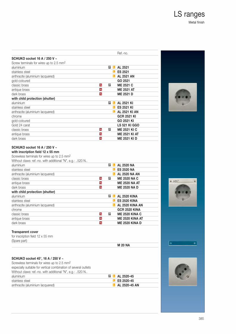
Metal finish
385
LS ranges
SCHUKO socket 16 A / 250 V ~Screw terminals for wires up to 2.5 mm2
aluminium AL 2521stainless steel ES 2521anthracite (aluminium lacquered) AL 2521 ANgold-coloured GO 2521classic brass ME 2521 Cantique brass ME 2521 ATdark brass ME 2521 Dwith child protection (shutter)aluminium AL 2521 KIstainless steel ES 2521 KIanthracite (aluminium lacquered) AL 2521 KI ANchrome GCR 2521 KIgold-coloured GO 2521 KIGold 24 carat LS 521 KI GGOclassic brass ME 2521 KI Cantique brass ME 2521 KI ATdark brass ME 2521 KI D
SCHUKO socket 16 A / 250 V ~with inscription field 12 x 55 mmScrewless terminals for wires up to 2.5 mm2
Without claws: ref.-no. with additional "N", e.g.: ..520 N..aluminium AL 2520 NAstainless steel ES 2520 NAanthracite (aluminium lacquered) AL 2520 NA ANclassic brass ME 2520 NA Cantique brass ME 2520 NA ATdark brass ME 2520 NA Dwith child protection (shutter)aluminium AL 2520 KINAstainless steel ES 2520 KINAanthracite (aluminium lacquered) AL 2520 KINA ANchrome GCR 2520 KINAclassic brass ME 2520 KINA Cantique brass ME 2520 KINA ATdark brass ME 2520 KINA D
Transparent coverfor inscription field 12 x 55 mm(Spare part)
M 20 NA
SCHUKO socket 45°, 16 A / 250 V ~Screwless terminals for wires up to 2.5 mm2
especially suitable for vertical combination of several outletsWithout claws: ref.-no. with additional "N", e.g.: ..520 N..aluminium AL 2520-45stainless steel ES 2520-45anthracite (aluminium lacquered) AL 2520-45 AN
L
L
LP
N
N
PN
L
L
LP
L
L
LP
N
N
PN
L
L
LP
N
N
PN
L
L
LP
N
N
PN
Ref.-no.
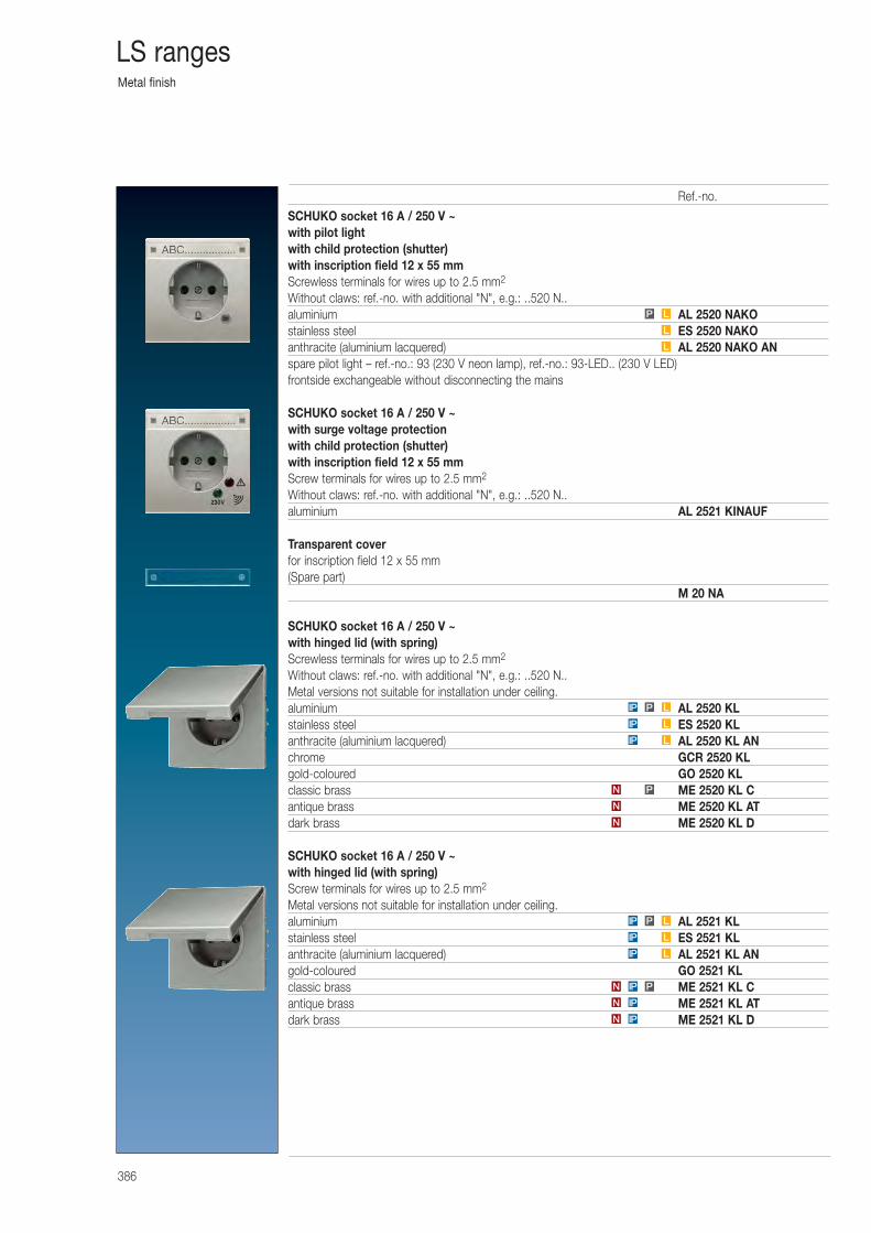
Metal finish
386
LS ranges
SCHUKO socket 16 A / 250 V ~with pilot lightwith child protection (shutter)with inscription field 12 x 55 mmScrewless terminals for wires up to 2.5 mm2
Without claws: ref.-no. with additional "N", e.g.: ..520 N..aluminium AL 2520 NAKOstainless steel ES 2520 NAKOanthracite (aluminium lacquered) AL 2520 NAKO ANspare pilot light – ref.-no.: 93 (230 V neon lamp), ref.-no.: 93-LED.. (230 V LED) frontside exchangeable without disconnecting the mains
SCHUKO socket 16 A / 250 V ~with surge voltage protectionwith child protection (shutter)with inscription field 12 x 55 mmScrew terminals for wires up to 2.5 mm2
Without claws: ref.-no. with additional "N", e.g.: ..520 N..aluminium AL 2521 KINAUF
Transparent coverfor inscription field 12 x 55 mm(Spare part)
M 20 NA
SCHUKO socket 16 A / 250 V ~with hinged lid (with spring)Screwless terminals for wires up to 2.5 mm2
Without claws: ref.-no. with additional "N", e.g.: ..520 N..Metal versions not suitable for installation under ceiling.aluminium AL 2520 KLstainless steel ES 2520 KLanthracite (aluminium lacquered) AL 2520 KL ANchrome GCR 2520 KLgold-coloured GO 2520 KLclassic brass ME 2520 KL Cantique brass ME 2520 KL ATdark brass ME 2520 KL D
SCHUKO socket 16 A / 250 V ~with hinged lid (with spring)Screw terminals for wires up to 2.5 mm2
Metal versions not suitable for installation under ceiling.aluminium AL 2521 KLstainless steel ES 2521 KLanthracite (aluminium lacquered) AL 2521 KL ANgold-coloured GO 2521 KLclassic brass ME 2521 KL Cantique brass ME 2521 KL ATdark brass ME 2521 KL D
L
L
LP
IPN
IPN
PIPN
LIP
LIP
LPIP
N
N
PN
LIP
LIP
LPIP
Ref.-no.
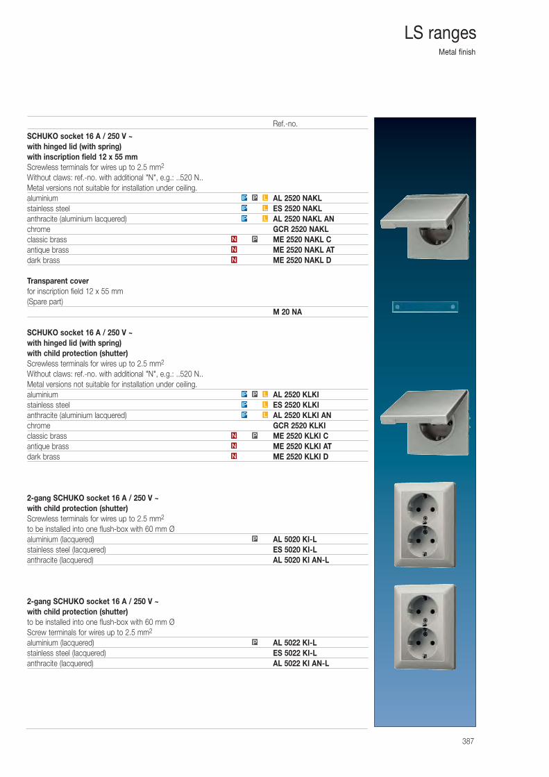
Metal finish
387
LS ranges
SCHUKO socket 16 A / 250 V ~with hinged lid (with spring)with inscription field 12 x 55 mmScrewless terminals for wires up to 2.5 mm2
Without claws: ref.-no. with additional "N", e.g.: ..520 N..Metal versions not suitable for installation under ceiling.aluminium AL 2520 NAKLstainless steel ES 2520 NAKLanthracite (aluminium lacquered) AL 2520 NAKL ANchrome GCR 2520 NAKLclassic brass ME 2520 NAKL Cantique brass ME 2520 NAKL ATdark brass ME 2520 NAKL D
Transparent coverfor inscription field 12 x 55 mm(Spare part)
M 20 NA
SCHUKO socket 16 A / 250 V ~with hinged lid (with spring)with child protection (shutter)Screwless terminals for wires up to 2.5 mm2
Without claws: ref.-no. with additional "N", e.g.: ..520 N..Metal versions not suitable for installation under ceiling.aluminium AL 2520 KLKIstainless steel ES 2520 KLKIanthracite (aluminium lacquered) AL 2520 KLKI ANchrome GCR 2520 KLKIclassic brass ME 2520 KLKI Cantique brass ME 2520 KLKI ATdark brass ME 2520 KLKI D
2-gang SCHUKO socket 16 A / 250 V ~with child protection (shutter)Screwless terminals for wires up to 2.5 mm2
to be installed into one flush-box with 60 mm Øaluminium (lacquered) AL 5020 KI-Lstainless steel (lacquered) ES 5020 KI-Lanthracite (lacquered) AL 5020 KI AN-L
2-gang SCHUKO socket 16 A / 250 V ~with child protection (shutter)to be installed into one flush-box with 60 mm ØScrew terminals for wires up to 2.5 mm2
aluminium (lacquered) AL 5022 KI-Lstainless steel (lacquered) ES 5022 KI-Lanthracite (lacquered) AL 5022 KI AN-L
N
N
PN
LIP
LIP
LPIP
P
P
N
N
PN
LIP
LIP
LPIP
Ref.-no.
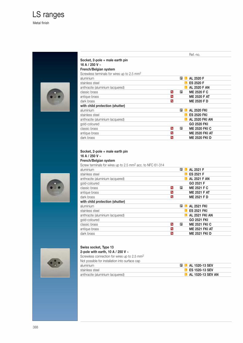
Metal finish
388
LS ranges
Socket, 2-pole + male earth pin16 A / 250 V ~French/Belgian systemScrewless terminals for wires up to 2.5 mm2
aluminium AL 2520 Fstainless steel ES 2520 Fanthracite (aluminium lacquered) AL 2520 F ANclassic brass ME 2520 F Cantique brass ME 2520 F ATdark brass ME 2520 F Dwith child protection (shutter)aluminium AL 2520 FKIstainless steel ES 2520 FKIanthracite (aluminium lacquered) AL 2520 FKI ANgold-coloured GO 2520 FKIclassic brass ME 2520 FKI Cantique brass ME 2520 FKI ATdark brass ME 2520 FKI D
Socket, 2-pole + male earth pin16 A / 250 V ~French/Belgian systemScrew terminals for wires up to 2.5 mm2 acc. to NFC 61-314aluminium AL 2521 Fstainless steel ES 2521 Fanthracite (aluminium lacquered) AL 2521 F ANgold-coloured GO 2521 Fclassic brass ME 2521 F Cantique brass ME 2521 F ATdark brass ME 2521 F Dwith child protection (shutter)aluminium AL 2521 FKIstainless steel ES 2521 FKIanthracite (aluminium lacquered) AL 2521 FKI ANgold-coloured GO 2521 FKIclassic brass ME 2521 FKI Cantique brass ME 2521 FKI ATdark brass ME 2521 FKI D
Swiss socket, Type 132-pole with earth, 10 A / 250 V ~Screwless connection for wires up to 2.5 mm2
Not possible for installation into surface capaluminium AL 1520-13 SEVstainless steel ES 1520-13 SEVanthracite (aluminium lacquered) AL 1520-13 SEV ANL
L
LP
PN
L
L
LP
N
N
PN
L
L
LP
N
N
PN
L
L
LP
N
N
PN
L
L
LP
N
N
Ref.-no.
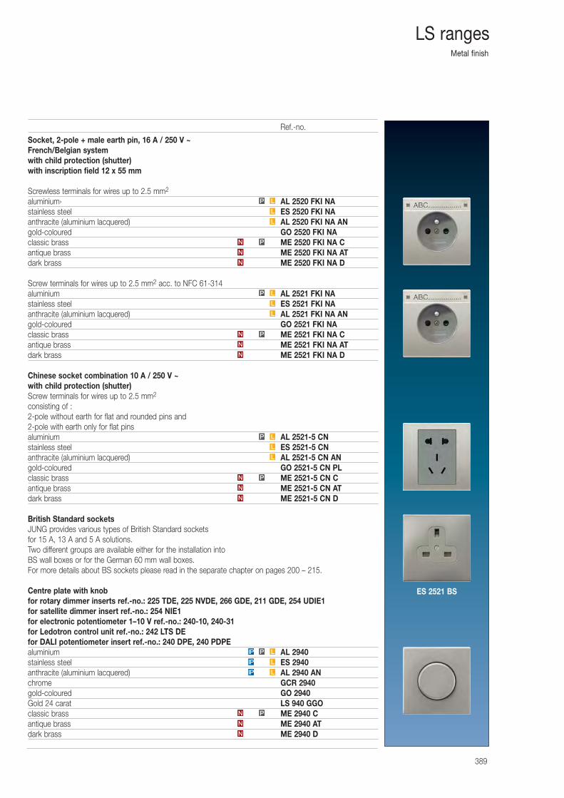
Metal finish
389
LS ranges
Socket, 2-pole + male earth pin, 16 A / 250 V ~French/Belgian systemwith child protection (shutter)with inscription field 12 x 55 mm
Screwless terminals for wires up to 2.5 mm2
aluminium› AL 2520 FKI NAstainless steel ES 2520 FKI NAanthracite (aluminium lacquered) AL 2520 FKI NA ANgold-coloured GO 2520 FKI NAclassic brass ME 2520 FKI NA Cantique brass ME 2520 FKI NA ATdark brass ME 2520 FKI NA D
Screw terminals for wires up to 2.5 mm2 acc. to NFC 61-314aluminium AL 2521 FKI NAstainless steel ES 2521 FKI NAanthracite (aluminium lacquered) AL 2521 FKI NA ANgold-coloured GO 2521 FKI NAclassic brass ME 2521 FKI NA Cantique brass ME 2521 FKI NA ATdark brass ME 2521 FKI NA D
Chinese socket combination 10 A / 250 V ~with child protection (shutter)Screw terminals for wires up to 2.5 mm2
consisting of :2-pole without earth for flat and rounded pins and2-pole with earth only for flat pinsaluminium AL 2521-5 CNstainless steel ES 2521-5 CNanthracite (aluminium lacquered) AL 2521-5 CN ANgold-coloured GO 2521-5 CN PLclassic brass ME 2521-5 CN Cantique brass ME 2521-5 CN ATdark brass ME 2521-5 CN D
British Standard socketsJUNG provides various types of British Standard sockets for 15 A, 13 A and 5 A solutions. Two different groups are available either for the installation into BS wall boxes or for the German 60 mm wall boxes.For more details about BS sockets please read in the separate chapter on pages 200 – 215.
Centre plate with knobfor rotary dimmer inserts ref.-no.: 225 TDE, 225 NVDE, 266 GDE, 211 GDE, 254 UDIE1for satellite dimmer insert ref.-no.: 254 NIE1for electronic potentiometer 1–10 V ref.-no.: 240-10, 240-31for Ledotron control unit ref.-no.: 242 LTS DEfor DALI potentiometer insert ref.-no.: 240 DPE, 240 PDPEaluminium AL 2940stainless steel ES 2940anthracite (aluminium lacquered) AL 2940 ANchrome GCR 2940gold-coloured GO 2940Gold 24 carat LS 940 GGOclassic brass ME 2940 Cantique brass ME 2940 ATdark brass ME 2940 DN
N
N P
IP L
IP L
IP P L
LP
L
L
PN
N
N
N
N
PN
L
L
LP
N
N
PN
L
L
LP
Ref.-no.
ES 2521 BS
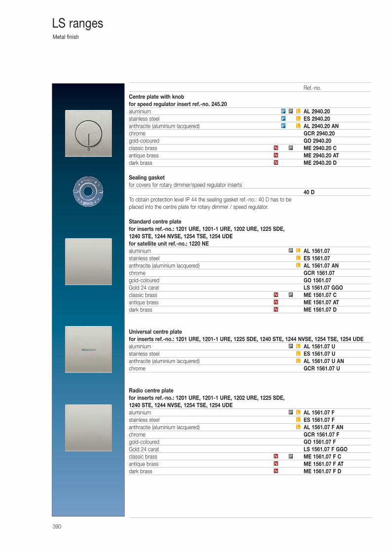
Metal finish
390
LS ranges
Centre plate with knobfor speed regulator insert ref.-no. 245.20aluminium AL 2940.20stainless steel ES 2940.20anthracite (aluminium lacquered) AL 2940.20 ANchrome GCR 2940.20gold-coloured GO 2940.20classic brass ME 2940.20 Cantique brass ME 2940.20 ATdark brass ME 2940.20 D
Sealing gasketfor covers for rotary dimmer/speed regulator inserts
40 DTo obtain protection level IP 44 the sealing gasket ref.-no.: 40 D has to be placed into the centre plate for rotary dimmer / speed regulator.
Standard centre platefor inserts ref.-no.: 1201 URE, 1201-1 URE, 1202 URE, 1225 SDE, 1240 STE, 1244 NVSE, 1254 TSE, 1254 UDEfor satellite unit ref.-no.: 1220 NEaluminium AL 1561.07stainless steel ES 1561.07anthracite (aluminium lacquered) AL 1561.07 ANchrome GCR 1561.07gold-coloured GO 1561.07Gold 24 carat LS 1561.07 GGOclassic brass ME 1561.07 Cantique brass ME 1561.07 ATdark brass ME 1561.07 D
Universal centre platefor inserts ref.-no.: 1201 URE, 1201-1 URE, 1225 SDE, 1240 STE, 1244 NVSE, 1254 TSE, 1254 UDEaluminium AL 1561.07 Ustainless steel ES 1561.07 Uanthracite (aluminium lacquered) AL 1561.07 U ANchrome GCR 1561.07 U
Radio centre platefor inserts ref.-no.: 1201 URE, 1201-1 URE, 1202 URE, 1225 SDE, 1240 STE, 1244 NVSE, 1254 TSE, 1254 UDEaluminium AL 1561.07 Fstainless steel ES 1561.07 Fanthracite (aluminium lacquered) AL 1561.07 F ANchrome GCR 1561.07 Fgold-coloured GO 1561.07 FGold 24 carat LS 1561.07 F GGOclassic brass ME 1561.07 F Cantique brass ME 1561.07 F ATdark brass ME 1561.07 F D
IP L
IP L
IP P L
LP
L
L
LP
N
N
PN
L
L
LP
N
N
PN
N
N
PN
L
L
Ref.-no.
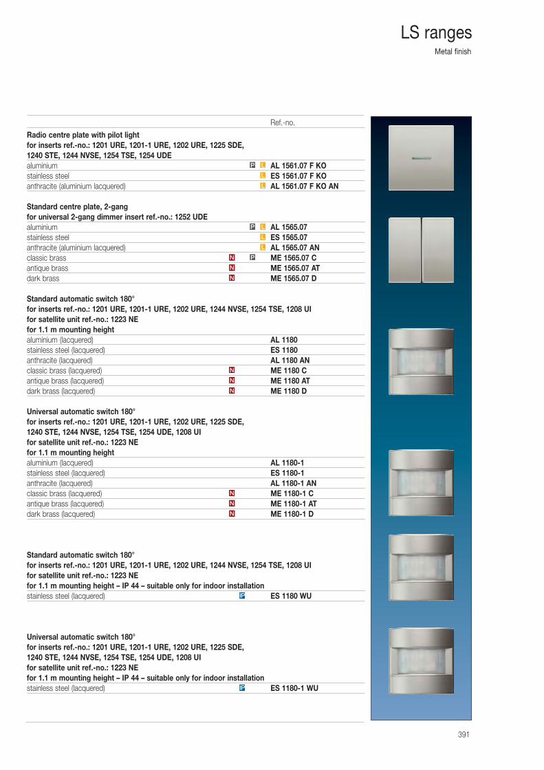
Metal finish
391
LS ranges
Radio centre plate with pilot lightfor inserts ref.-no.: 1201 URE, 1201-1 URE, 1202 URE, 1225 SDE, 1240 STE, 1244 NVSE, 1254 TSE, 1254 UDEaluminium AL 1561.07 F KOstainless steel ES 1561.07 F KOanthracite (aluminium lacquered) AL 1561.07 F KO AN
Standard centre plate, 2-gangfor universal 2-gang dimmer insert ref.-no.: 1252 UDEaluminium AL 1565.07stainless steel ES 1565.07anthracite (aluminium lacquered) AL 1565.07 ANclassic brass ME 1565.07 Cantique brass ME 1565.07 ATdark brass ME 1565.07 D
Standard automatic switch 180°for inserts ref.-no.: 1201 URE, 1201-1 URE, 1202 URE, 1244 NVSE, 1254 TSE, 1208 UIfor satellite unit ref.-no.: 1223 NEfor 1.1 m mounting heightaluminium (lacquered) AL 1180stainless steel (lacquered) ES 1180anthracite (lacquered) AL 1180 ANclassic brass (lacquered) ME 1180 Cantique brass (lacquered) ME 1180 ATdark brass (lacquered) ME 1180 D
Universal automatic switch 180° for inserts ref.-no.: 1201 URE, 1201-1 URE, 1202 URE, 1225 SDE, 1240 STE, 1244 NVSE, 1254 TSE, 1254 UDE, 1208 UIfor satellite unit ref.-no.: 1223 NEfor 1.1 m mounting heightaluminium (lacquered) AL 1180-1stainless steel (lacquered) ES 1180-1anthracite (lacquered) AL 1180-1 ANclassic brass (lacquered) ME 1180-1 Cantique brass (lacquered) ME 1180-1 ATdark brass (lacquered) ME 1180-1 D
Standard automatic switch 180°for inserts ref.-no.: 1201 URE, 1201-1 URE, 1202 URE, 1244 NVSE, 1254 TSE, 1208 UIfor satellite unit ref.-no.: 1223 NEfor 1.1 m mounting height – IP 44 – suitable only for indoor installationstainless steel (lacquered) ES 1180 WU
Universal automatic switch 180° for inserts ref.-no.: 1201 URE, 1201-1 URE, 1202 URE, 1225 SDE, 1240 STE, 1244 NVSE, 1254 TSE, 1254 UDE, 1208 UIfor satellite unit ref.-no.: 1223 NEfor 1.1 m mounting height – IP 44 – suitable only for indoor installationstainless steel (lacquered) ES 1180-1 WU
IP
N
N
N
N
N
N
N
N
PN
L
L
LP
L
L
LP
IP
Ref.-no.
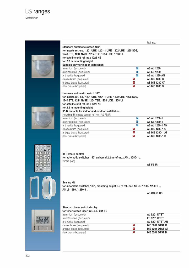
Metal finish
392
LS ranges
Standard automatic switch 180°for inserts ref.-no.: 1201 URE, 1201-1 URE, 1202 URE, 1225 SDE, 1240 STE, 1244 NVSE, 1254 TSE, 1254 UDE, 1208 UIfor satellite unit ref.-no.: 1223 NEfor 2.2 m mounting heightSuitable only for indoor installationaluminium (lacquered) AS AL 1280stainless steel (lacquered) AS ES 1280anthracite (lacquered) AS AL 1280 ANclassic brass (lacquered) AS ME 1280 Cantique brass (lacquered) AS ME 1280 ATdark brass (lacquered) AS ME 1280 D
Universal automatic switch 180° for inserts ref.-no.: 1201 URE, 1201-1 URE, 1202 URE, 1225 SDE, 1240 STE, 1244 NVSE, 1254 TSE, 1254 UDE, 1208 UIfor satellite unit ref.-no.: 1223 NEfor 2.2 m mounting heightIP 44 suitable for indoor and outdoor installationincluding IR remote control ref.-no.: AS FB IRaluminium (lacquered) AS AL 1280-1stainless steel (lacquered) AS ES 1280-1anthracite (lacquered) AS AL 1280-1 ANclassic brass (lacquered) AS ME 1280-1 Cantique brass (lacquered) AS ME 1280-1 ATdark brass (lacquered) AS ME 1280-1 D
IR Remote controlfor automatic switches 180° universal 2.2 m ref.-no.: AS .. 1280-1 ..(Spare part)
AS FB IR
Sealing kitfor automatic switches 180°, mounting height 2.2 m ref.-no.: AS CD 1280 / 1280-1 ..,AS LS 1280 / 1280-1 ..
AS CD 50 DS
Standard timer switch displayfor timer switch insert ref.-no.: 201 TEaluminium (lacquered) AL 5201 DTSTstainless steel (lacquered) ES 5201 DTSTanthracite (lacquered) AL 5201 DTST ANclassic brass (lacquered) ME 5201 DTST Cantique brass (lacquered) ME 5201 DTST ATdark brass (lacquered) ME 5201 DTST DN
N
N
N
N
N
IP
IP
IP
N
N
N
IP
IP
IP
Ref.-no.
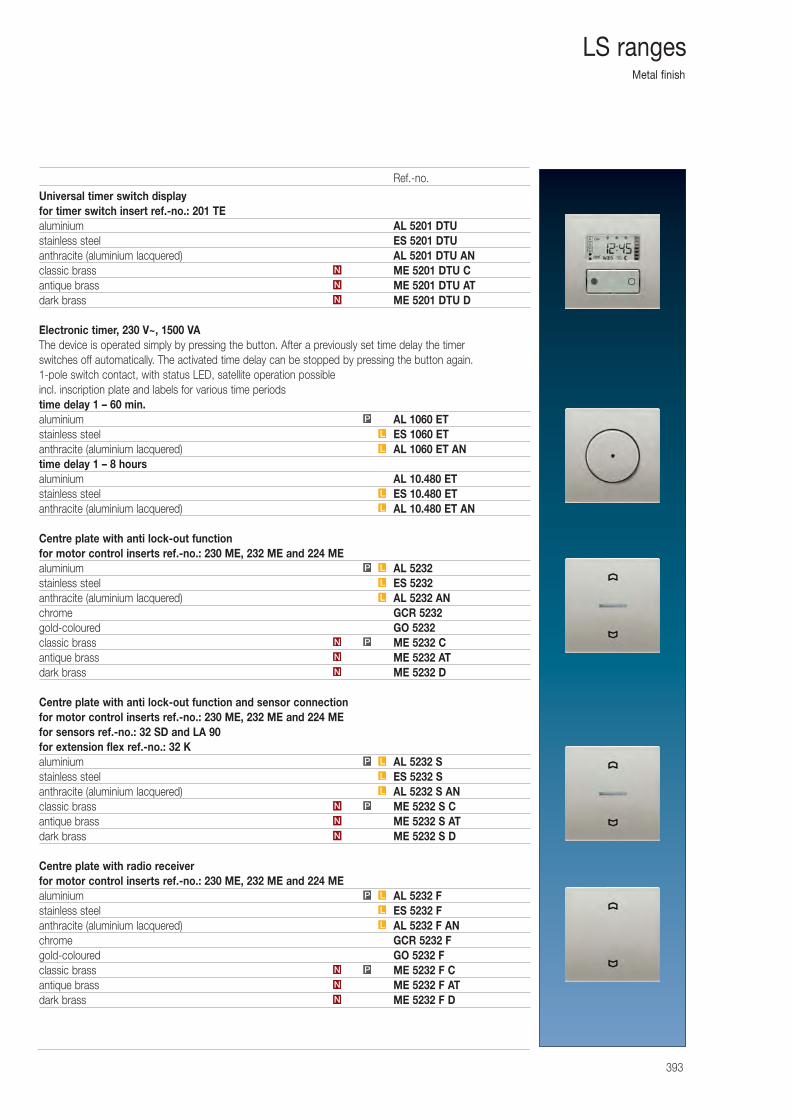
Metal finish
393
LS ranges
Universal timer switch displayfor timer switch insert ref.-no.: 201 TEaluminium AL 5201 DTUstainless steel ES 5201 DTUanthracite (aluminium lacquered) AL 5201 DTU ANclassic brass ME 5201 DTU Cantique brass ME 5201 DTU ATdark brass ME 5201 DTU D
Electronic timer, 230 V~, 1500 VAThe device is operated simply by pressing the button. After a previously set time delay the timer switches off automatically. The activated time delay can be stopped by pressing the button again.1-pole switch contact, with status LED, satellite operation possibleincl. inscription plate and labels for various time periodstime delay 1 – 60 min.aluminium AL 1060 ETstainless steel ES 1060 ETanthracite (aluminium lacquered) AL 1060 ET ANtime delay 1 – 8 hoursaluminium AL 10.480 ETstainless steel ES 10.480 ETanthracite (aluminium lacquered) AL 10.480 ET AN
Centre plate with anti lock-out functionfor motor control inserts ref.-no.: 230 ME, 232 ME and 224 MEaluminium AL 5232stainless steel ES 5232anthracite (aluminium lacquered) AL 5232 ANchrome GCR 5232gold-coloured GO 5232classic brass ME 5232 Cantique brass ME 5232 ATdark brass ME 5232 D
Centre plate with anti lock-out function and sensor connectionfor motor control inserts ref.-no.: 230 ME, 232 ME and 224 MEfor sensors ref.-no.: 32 SD and LA 90for extension flex ref.-no.: 32 Kaluminium AL 5232 Sstainless steel ES 5232 Santhracite (aluminium lacquered) AL 5232 S ANclassic brass ME 5232 S Cantique brass ME 5232 S ATdark brass ME 5232 S D
Centre plate with radio receiverfor motor control inserts ref.-no.: 230 ME, 232 ME and 224 MEaluminium AL 5232 Fstainless steel ES 5232 Fanthracite (aluminium lacquered) AL 5232 F ANchrome GCR 5232 Fgold-coloured GO 5232 Fclassic brass ME 5232 F Cantique brass ME 5232 F ATdark brass ME 5232 F D
N
N
N
N
N
PN
L
L
LP
N
N
PN
L
L
LP
N
N
PN
L
L
LP
L
L
L
L
P
Ref.-no.
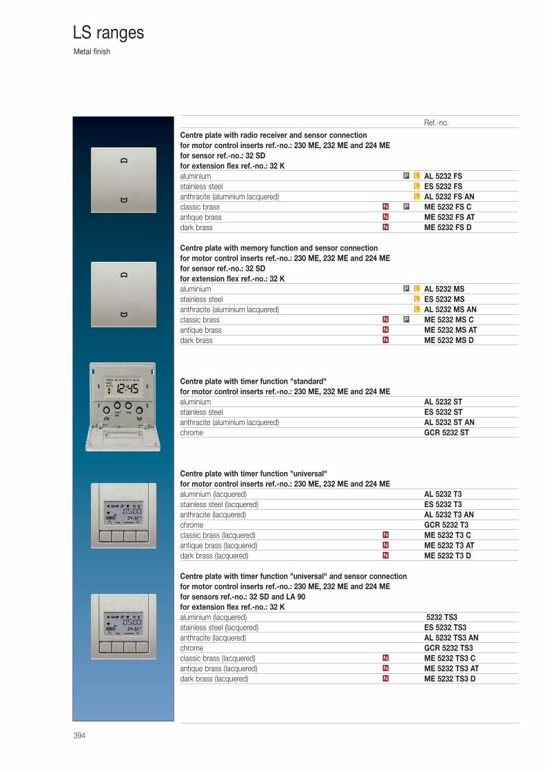
Metal finish
394
LS ranges
Centre plate with radio receiver and sensor connectionfor motor control inserts ref.-no.: 230 ME, 232 ME and 224 MEfor sensor ref.-no.: 32 SDfor extension flex ref.-no.: 32 Kaluminium AL 5232 FSstainless steel ES 5232 FSanthracite (aluminium lacquered) AL 5232 FS ANclassic brass ME 5232 FS Cantique brass ME 5232 FS ATdark brass ME 5232 FS D
Centre plate with memory function and sensor connectionfor motor control inserts ref.-no.: 230 ME, 232 ME and 224 MEfor sensor ref.-no.: 32 SDfor extension flex ref.-no.: 32 Kaluminium AL 5232 MSstainless steel ES 5232 MSanthracite (aluminium lacquered) AL 5232 MS ANclassic brass ME 5232 MS Cantique brass ME 5232 MS ATdark brass ME 5232 MS D
Centre plate with timer function "standard"for motor control inserts ref.-no.: 230 ME, 232 ME and 224 MEaluminium AL 5232 STstainless steel ES 5232 STanthracite (aluminium lacquered) AL 5232 ST ANchrome GCR 5232 ST
Centre plate with timer function "universal"for motor control inserts ref.-no.: 230 ME, 232 ME and 224 MEaluminium (lacquered) AL 5232 T3stainless steel (lacquered) ES 5232 T3anthracite (lacquered) AL 5232 T3 ANchrome GCR 5232 T3classic brass (lacquered) ME 5232 T3 Cantique brass (lacquered) ME 5232 T3 ATdark brass (lacquered) ME 5232 T3 D
Centre plate with timer function "universal" and sensor connectionfor motor control inserts ref.-no.: 230 ME, 232 ME and 224 MEfor sensors ref.-no.: 32 SD and LA 90for extension flex ref.-no.: 32 Kaluminium (lacquered) 5232 TS3stainless steel (lacquered) ES 5232 TS3anthracite (lacquered) AL 5232 TS3 ANchrome GCR 5232 TS3classic brass (lacquered) ME 5232 TS3 Cantique brass (lacquered) ME 5232 TS3 ATdark brass (lacquered) ME 5232 TS3 D
N
N
PN
L
L
LP
N
N
N
N
N
N
N
N
PN
L
L
LP
Ref.-no.
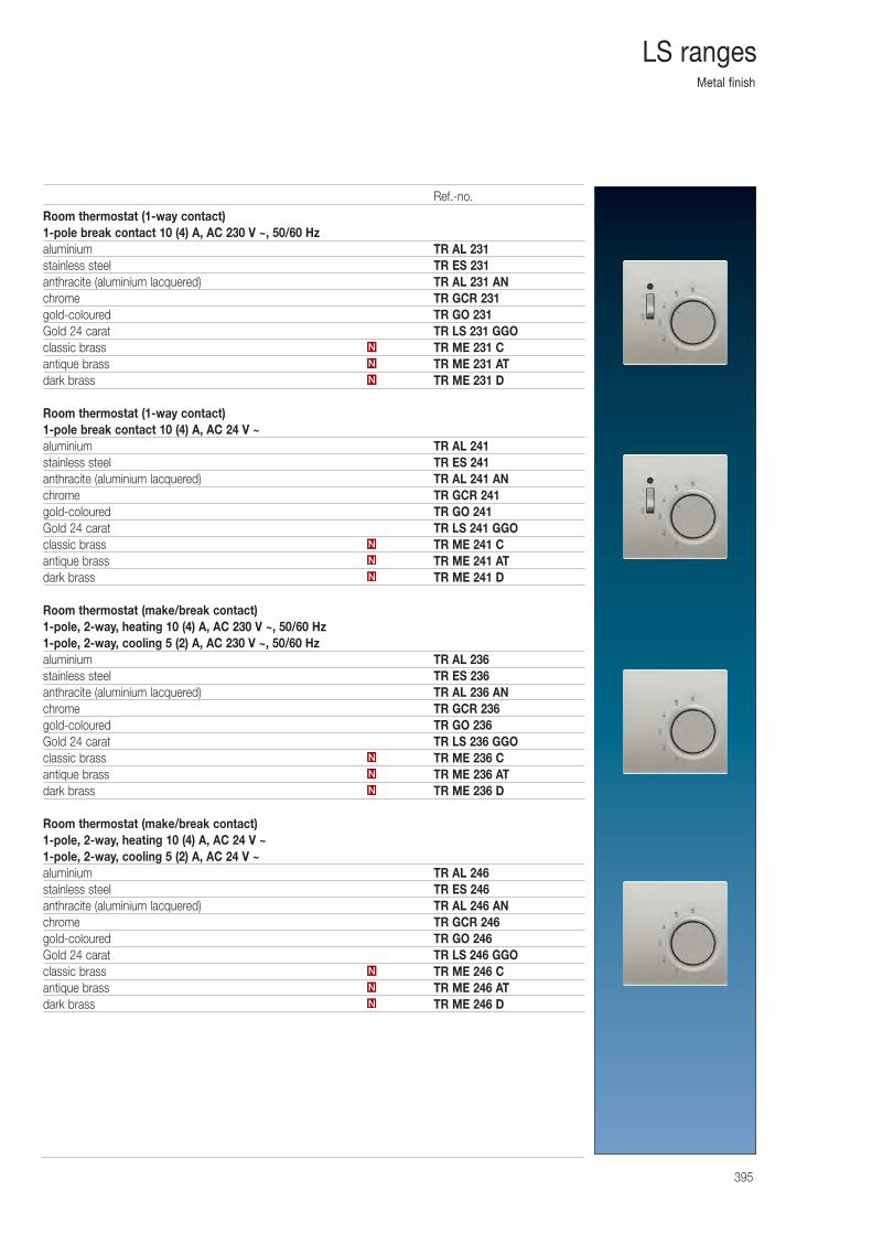
Metal finish
395
LS ranges
Room thermostat (1-way contact)1-pole break contact 10 (4) A, AC 230 V ~, 50/60 Hzaluminium TR AL 231stainless steel TR ES 231anthracite (aluminium lacquered) TR AL 231 ANchrome TR GCR 231gold-coloured TR GO 231Gold 24 carat TR LS 231 GGOclassic brass TR ME 231 Cantique brass TR ME 231 ATdark brass TR ME 231 D
Room thermostat (1-way contact)1-pole break contact 10 (4) A, AC 24 V ~aluminium TR AL 241stainless steel TR ES 241anthracite (aluminium lacquered) TR AL 241 ANchrome TR GCR 241gold-coloured TR GO 241Gold 24 carat TR LS 241 GGOclassic brass TR ME 241 Cantique brass TR ME 241 ATdark brass TR ME 241 D
Room thermostat (make/break contact)1-pole, 2-way, heating 10 (4) A, AC 230 V ~, 50/60 Hz1-pole, 2-way, cooling 5 (2) A, AC 230 V ~, 50/60 Hzaluminium TR AL 236stainless steel TR ES 236anthracite (aluminium lacquered) TR AL 236 ANchrome TR GCR 236gold-coloured TR GO 236Gold 24 carat TR LS 236 GGOclassic brass TR ME 236 Cantique brass TR ME 236 ATdark brass TR ME 236 D
Room thermostat (make/break contact)1-pole, 2-way, heating 10 (4) A, AC 24 V ~1-pole, 2-way, cooling 5 (2) A, AC 24 V ~aluminium TR AL 246stainless steel TR ES 246anthracite (aluminium lacquered) TR AL 246 ANchrome TR GCR 246gold-coloured TR GO 246Gold 24 carat TR LS 246 GGOclassic brass TR ME 246 Cantique brass TR ME 246 ATdark brass TR ME 246 D
N
N
N
N
N
N
N
N
N
N
N
N
Ref.-no.
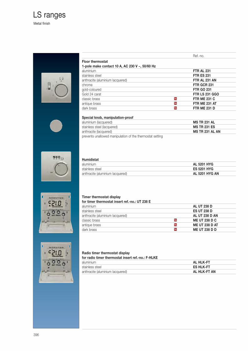
Metal finish
396
LS ranges
Floor thermostat1-pole make contact 10 A, AC 230 V ~, 50/60 Hzaluminium FTR AL 231stainless steel FTR ES 231anthracite (aluminium lacquered) FTR AL 231 ANchrome FTR GCR 231gold-coloured FTR GO 231Gold 24 carat FTR LS 231 GGOclassic brass FTR ME 231 Cantique brass FTR ME 231 ATdark brass FTR ME 231 D
Special knob, manipulation-proofaluminium (lacquered) MS TR 231 ALstainless steel (lacquered) MS TR 231 ESanthracite (lacquered) MS TR 231 AL ANprevents unallowed manipulation of the thermostat setting
Humidistataluminium AL 5201 HYGstainless steel ES 5201 HYGanthracite (aluminium lacquered) AL 5201 HYG AN
Timer thermostat displayfor timer thermostat insert ref.-no.: UT 238 Ealuminium AL UT 238 Dstainless steel ES UT 238 Danthracite (aluminium lacquered) AL UT 238 D ANclassic brass ME UT 238 D Cantique brass ME UT 238 D ATdark brass ME UT 238 D D
Radio timer thermostat displayfor radio timer thermostat insert ref.-no.: F-HLKEaluminium AL HLK-FTstainless steel ES HLK-FTanthracite (aluminium lacquered) AL HLK-FT AN
N
N
N
N
N
N
Ref.-no.
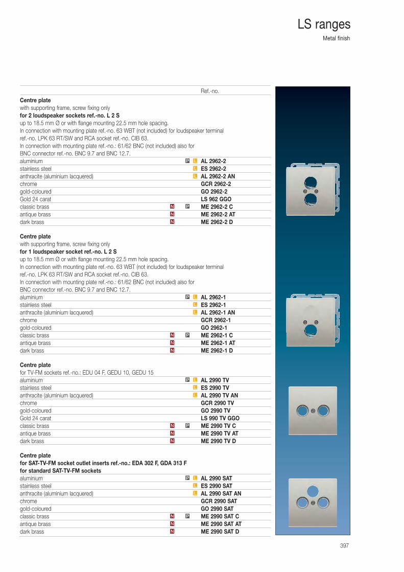
Metal finish
397
LS ranges
Centre platewith supporting frame, screw fixing onlyfor 2 loudspeaker sockets ref.-no. L 2 Sup to 18.5 mm Ø or with flange mounting 22.5 mm hole spacing.In connection with mounting plate ref.-no. 63 WBT (not included) for loudspeaker terminalref.-no. LPK 63 RT/SW and RCA socket ref.-no. CIB 63.In connection with mounting plate ref.-no.: 61/62 BNC (not included) also for BNC connector ref.-no. BNC 9.7 and BNC 12.7.aluminium AL 2962-2stainless steel ES 2962-2anthracite (aluminium lacquered) AL 2962-2 ANchrome GCR 2962-2gold-coloured GO 2962-2Gold 24 carat LS 962 GGOclassic brass ME 2962-2 Cantique brass ME 2962-2 ATdark brass ME 2962-2 D
Centre platewith supporting frame, screw fixing onlyfor 1 loudspeaker socket ref.-no. L 2 Sup to 18.5 mm Ø or with flange mounting 22.5 mm hole spacing.In connection with mounting plate ref.-no. 63 WBT (not included) for loudspeaker terminalref.-no. LPK 63 RT/SW and RCA socket ref.-no. CIB 63.In connection with mounting plate ref.-no.: 61/62 BNC (not included) also for BNC connector ref.-no. BNC 9.7 and BNC 12.7.aluminium AL 2962-1stainless steel ES 2962-1anthracite (aluminium lacquered) AL 2962-1 ANchrome GCR 2962-1gold-coloured GO 2962-1classic brass ME 2962-1 Cantique brass ME 2962-1 ATdark brass ME 2962-1 D
Centre platefor TV-FM sockets ref.-no.: EDU 04 F, GEDU 10, GEDU 15aluminium AL 2990 TVstainless steel ES 2990 TVanthracite (aluminium lacquered) AL 2990 TV ANchrome GCR 2990 TVgold-coloured GO 2990 TVGold 24 carat LS 990 TV GGOclassic brass ME 2990 TV Cantique brass ME 2990 TV ATdark brass ME 2990 TV D
Centre platefor SAT-TV-FM socket outlet inserts ref.-no.: EDA 302 F, GDA 313 Ffor standard SAT-TV-FM socketsaluminium AL 2990 SATstainless steel ES 2990 SATanthracite (aluminium lacquered) AL 2990 SAT ANchrome GCR 2990 SATgold-coloured GO 2990 SATclassic brass ME 2990 SAT Cantique brass ME 2990 SAT ATdark brass ME 2990 SAT D
N
N
PN
L
L
LP
N
N
PN
L
L
LP
N
N
PN
L
L
LP
N
N
PN
L
L
LP
Ref.-no.
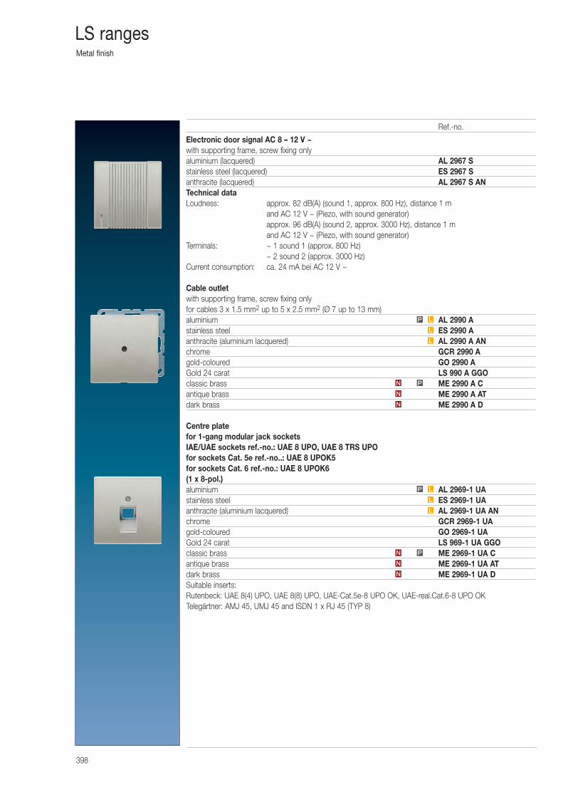
Metal finish
398
LS ranges
Electronic door signal AC 8 – 12 V ~with supporting frame, screw fixing onlyaluminium (lacquered) AL 2967 Sstainless steel (lacquered) ES 2967 Santhracite (lacquered) AL 2967 S ANTechnical dataLoudness: approx. 82 dB(A) (sound 1, approx. 800 Hz), distance 1 m
and AC 12 V ~ (Piezo, with sound generator)approx. 96 dB(A) (sound 2, approx. 3000 Hz), distance 1 m and AC 12 V ~ (Piezo, with sound generator)
Terminals: ~ 1 sound 1 (approx. 800 Hz)~ 2 sound 2 (approx. 3000 Hz)
Current consumption: ca. 24 mA bei AC 12 V ~
Cable outletwith supporting frame, screw fixing onlyfor cables 3 x 1.5 mm2 up to 5 x 2.5 mm2 (Ø 7 up to 13 mm)aluminium AL 2990 Astainless steel ES 2990 Aanthracite (aluminium lacquered) AL 2990 A ANchrome GCR 2990 Agold-coloured GO 2990 AGold 24 carat LS 990 A GGOclassic brass ME 2990 A Cantique brass ME 2990 A ATdark brass ME 2990 A D
Centre platefor 1-gang modular jack socketsIAE/UAE sockets ref.-no.: UAE 8 UPO, UAE 8 TRS UPOfor sockets Cat. 5e ref.-no..: UAE 8 UPOK5for sockets Cat. 6 ref.-no.: UAE 8 UPOK6(1 x 8-pol.)aluminium AL 2969-1 UAstainless steel ES 2969-1 UAanthracite (aluminium lacquered) AL 2969-1 UA ANchrome GCR 2969-1 UAgold-coloured GO 2969-1 UAGold 24 carat LS 969-1 UA GGOclassic brass ME 2969-1 UA Cantique brass ME 2969-1 UA ATdark brass ME 2969-1 UA DSuitable inserts:Rutenbeck: UAE 8(4) UPO, UAE 8(8) UPO, UAE-Cat.5e-8 UPO OK, UAE-real.Cat.6-8 UPO OKTelegärtner: AMJ 45, UMJ 45 and ISDN 1 x RJ 45 (TYP 8)
N
N
PN
L
L
LP
N
N
PN
L
L
LP
Ref.-no.
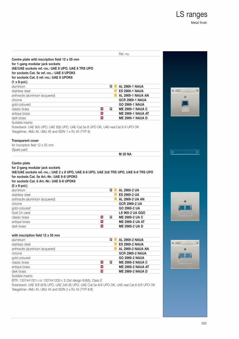
Metal finish
399
LS ranges
Centre plate with inscription field 12 x 55 mmfor 1-gang modular jack socketsIAE/UAE sockets ref.-no.: UAE 8 UPO, UAE 8 TRS UPOfor sockets Cat. 5e ref.-no..: UAE 8 UPOK5for sockets Cat. 6 ref.-no.: UAE 8 UPOK6(1 x 8-pol.)aluminium AL 2969-1 NAUAstainless steel ES 2969-1 NAUAanthracite (aluminium lacquered) AL 2969-1 NAUA ANchrome GCR 2969-1 NAUAgold-coloured GO 2969-1 NAUAclassic brass ME 2969-1 NAUA Cantique brass ME 2969-1 NAUA ATdark brass ME 2969-1 NAUA DSuitable inserts:Rutenbeck: UAE 8(4) UPO, UAE 8(8) UPO, UAE-Cat.5e-8 UPO OK, UAE-real.Cat.6-8 UPO OKTelegärtner: AMJ 45, UMJ 45 and ISDN 1 x RJ 45 (TYP 8)
Transparent coverfor inscription field 12 x 55 mm(Spare part)
M 20 NA
Centre platefor 2-gang modular jack socketsIAE/UAE sockets ref.-no..: UAE 2 x 8 UPO, UAE 8-8 UPO, UAE 2x8 TRS UPO, UAE 8-8 TRS UPOfor sockets Cat. 5e Art.-Nr.: UAE 8-8 UPOK5for sockets Cat. 6 Art.-Nr.: UAE 8-8 UPOK6(2 x 8-pol.)aluminium AL 2969-2 UAstainless steel ES 2969-2 UAanthracite (aluminium lacquered) AL 2969-2 UA ANchrome GCR 2969-2 UAgold-coloured GO 2969-2 UAGold 24 carat LS 969-2 UA GGOclassic brass ME 2969-2 UA Cantique brass ME 2969-2 UA ATdark brass ME 2969-2 UA D
with inscription field 12 x 55 mmaluminium AL 2969-2 NAUAstainless steel ES 2969-2 NAUAanthracite (aluminium lacquered) AL 2969-2 NAUA ANchrome GCR 2969-2 NAUAgold-coloured GO 2969-2 NAUAclassic brass ME 2969-2 NAUA Cantique brass ME 2969-2 NAUA ATdark brass ME 2969-2 NAUA DSuitable inserts:BTR: 1307441001-i or 1307441200-i; E-Dat design 8/8(8), Class ERutenbeck: UAE 8/8 (8/8) UPO, UAE 2x8 (8) UPO, UAE-Cat.5e-8/8 UPO OK, UAE-real.Cat.6-8/8 UPO OKTelegärtner: AMJ 45, UMJ 45 and ISDN 2 x RJ 45 (TYP 8/8)
N
PN
L
L
LP
N
N
PN
L
L
LP
N
N
PN
L
L
LP
N
Ref.-no.
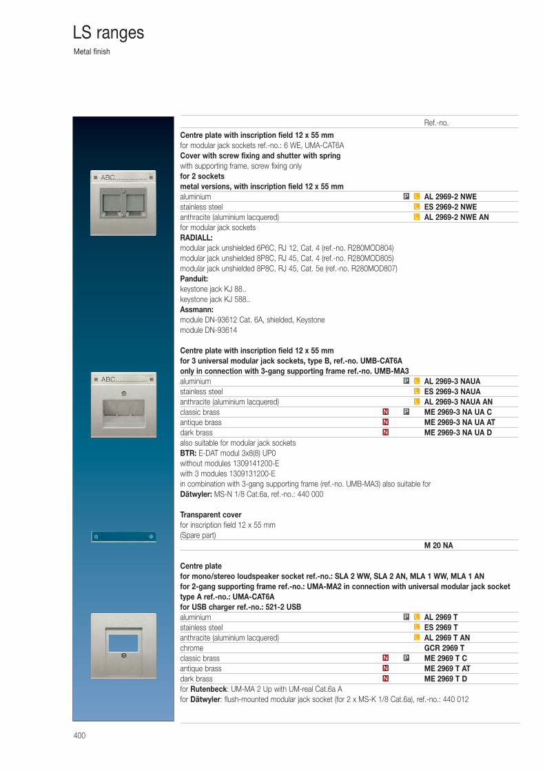
Metal finish
400
LS ranges
Centre plate with inscription field 12 x 55 mmfor modular jack sockets ref.-no.: 6 WE, UMA-CAT6ACover with screw fixing and shutter with springwith supporting frame, screw fixing onlyfor 2 socketsmetal versions, with inscription field 12 x 55 mmaluminium AL 2969-2 NWEstainless steel ES 2969-2 NWEanthracite (aluminium lacquered) AL 2969-2 NWE ANfor modular jack socketsRADIALL:modular jack unshielded 6P6C, RJ 12, Cat. 4 (ref.-no. R280MOD804)modular jack unshielded 8P8C, RJ 45, Cat. 4 (ref.-no. R280MOD805)modular jack unshielded 8P8C, RJ 45, Cat. 5e (ref.-no. R280MOD807)Panduit:keystone jack KJ 88..keystone jack KJ 588..Assmann:module DN-93612 Cat. 6A, shielded, Keystonemodule DN-93614
Centre plate with inscription field 12 x 55 mmfor 3 universal modular jack sockets, type B, ref.-no. UMB-CAT6Aonly in connection with 3-gang supporting frame ref.-no. UMB-MA3aluminium AL 2969-3 NAUAstainless steel ES 2969-3 NAUAanthracite (aluminium lacquered) AL 2969-3 NAUA ANclassic brass ME 2969-3 NA UA Cantique brass ME 2969-3 NA UA ATdark brass ME 2969-3 NA UA Dalso suitable for modular jack socketsBTR: E-DAT modul 3x8(8) UP0without modules 1309141200-Ewith 3 modules 1309131200-Ein combination with 3-gang supporting frame (ref.-no. UMB-MA3) also suitable forDätwyler: MS-N 1/8 Cat.6a, ref.-no.: 440 000
Transparent coverfor inscription field 12 x 55 mm(Spare part)
M 20 NA
Centre platefor mono/stereo loudspeaker socket ref.-no.: SLA 2 WW, SLA 2 AN, MLA 1 WW, MLA 1 ANfor 2-gang supporting frame ref.-no.: UMA-MA2 in connection with universal modular jack sockettype A ref.-no.: UMA-CAT6Afor USB charger ref.-no.: 521-2 USBaluminium AL 2969 Tstainless steel ES 2969 Tanthracite (aluminium lacquered) AL 2969 T ANchrome GCR 2969 Tclassic brass ME 2969 T Cantique brass ME 2969 T ATdark brass ME 2969 T Dfor Rutenbeck: UM-MA 2 Up with UM-real Cat.6a Afor Dätwyler: flush-mounted modular jack socket (for 2 x MS-K 1/8 Cat.6a), ref.-no.: 440 012
PN
L
L
LP
N
N
PN
L
L
LP
L
L
LP
N
N
Ref.-no.
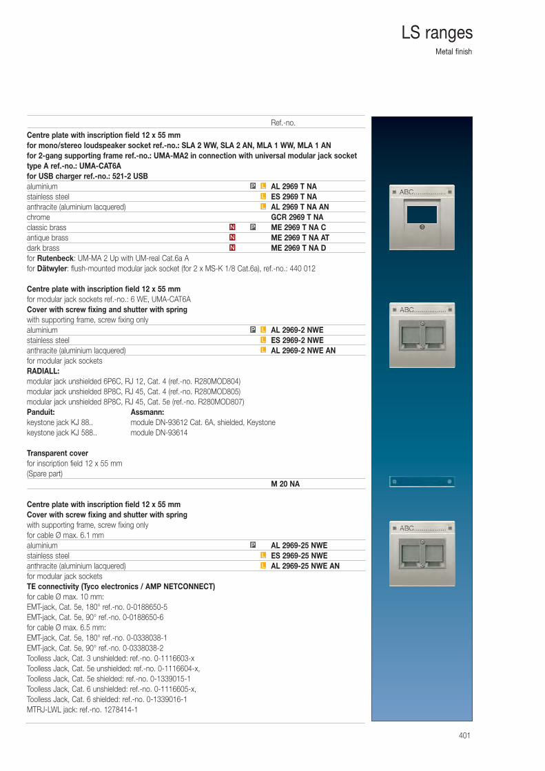
Metal finish
401
LS ranges
Centre plate with inscription field 12 x 55 mmfor mono/stereo loudspeaker socket ref.-no.: SLA 2 WW, SLA 2 AN, MLA 1 WW, MLA 1 ANfor 2-gang supporting frame ref.-no.: UMA-MA2 in connection with universal modular jack sockettype A ref.-no.: UMA-CAT6Afor USB charger ref.-no.: 521-2 USBaluminium AL 2969 T NAstainless steel ES 2969 T NAanthracite (aluminium lacquered) AL 2969 T NA ANchrome GCR 2969 T NAclassic brass ME 2969 T NA Cantique brass ME 2969 T NA ATdark brass ME 2969 T NA Dfor Rutenbeck: UM-MA 2 Up with UM-real Cat.6a Afor Dätwyler: flush-mounted modular jack socket (for 2 x MS-K 1/8 Cat.6a), ref.-no.: 440 012
Centre plate with inscription field 12 x 55 mmfor modular jack sockets ref.-no.: 6 WE, UMA-CAT6ACover with screw fixing and shutter with springwith supporting frame, screw fixing onlyaluminium AL 2969-2 NWEstainless steel ES 2969-2 NWEanthracite (aluminium lacquered) AL 2969-2 NWE ANfor modular jack socketsRADIALL:modular jack unshielded 6P6C, RJ 12, Cat. 4 (ref.-no. R280MOD804)modular jack unshielded 8P8C, RJ 45, Cat. 4 (ref.-no. R280MOD805)modular jack unshielded 8P8C, RJ 45, Cat. 5e (ref.-no. R280MOD807)Panduit: Assmann:keystone jack KJ 88.. module DN-93612 Cat. 6A, shielded, Keystonekeystone jack KJ 588.. module DN-93614
Transparent coverfor inscription field 12 x 55 mm(Spare part)
M 20 NA
Centre plate with inscription field 12 x 55 mmCover with screw fixing and shutter with springwith supporting frame, screw fixing onlyfor cable Ø max. 6.1 mmaluminium AL 2969-25 NWEstainless steel ES 2969-25 NWEanthracite (aluminium lacquered) AL 2969-25 NWE ANfor modular jack socketsTE connectivity (Tyco electronics / AMP NETCONNECT)for cable Ø max. 10 mm:EMT-jack, Cat. 5e, 180° ref.-no. 0-0188650-5EMT-jack, Cat. 5e, 90° ref.-no. 0-0188650-6for cable Ø max. 6.5 mm:EMT-jack, Cat. 5e, 180° ref.-no. 0-0338038-1EMT-jack, Cat. 5e, 90° ref.-no. 0-0338038-2Toolless Jack, Cat. 3 unshielded: ref.-no. 0-1116603-xToolless Jack, Cat. 5e unshielded: ref.-no. 0-1116604-x, Toolless Jack, Cat. 5e shielded: ref.-no. 0-1339015-1Toolless Jack, Cat. 6 unshielded: ref.-no. 0-1116605-x, Toolless Jack, Cat. 6 shielded: ref.-no. 0-1339016-1MTRJ-LWL jack: ref.-no. 1278414-1
L
L
P
L
L
LP
N
N
PN
L
L
LP
Ref.-no.
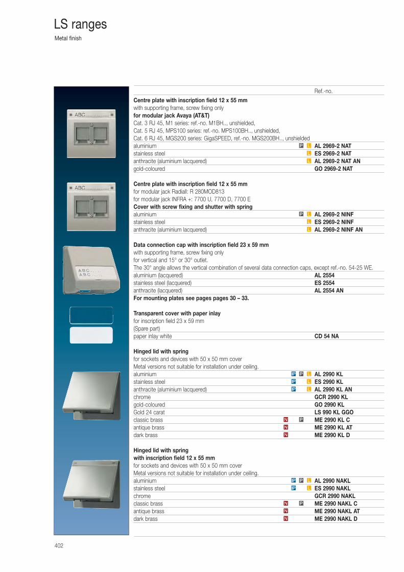
Metal finish
402
LS ranges
Centre plate with inscription field 12 x 55 mmwith supporting frame, screw fixing onlyfor modular jack Avaya (AT&T)Cat. 3 RJ 45, M1 series: ref.-no. M1BH.., unshielded,Cat. 5 RJ 45, MPS100 series: ref.-no. MPS100BH.., unshielded,Cat. 6 RJ 45, MGS200 series: GigaSPEED, ref.-no. MGS200BH.., unshieldedaluminium AL 2969-2 NATstainless steel ES 2969-2 NATanthracite (aluminium lacquered) AL 2969-2 NAT ANgold-coloured GO 2969-2 NAT
Centre plate with inscription field 12 x 55 mmfor modular jack Radiall: R 280MOD813for modular jack INFRA +: 7700 U, 7700 D, 7700 ECover with screw fixing and shutter with springaluminium AL 2969-2 NINFstainless steel ES 2969-2 NINFanthracite (aluminium lacquered) AL 2969-2 NINF AN
Data connection cap with inscription field 23 x 59 mmwith supporting frame, screw fixing onlyfor vertical and 15° or 30° outlet.The 30° angle allows the vertical combination of several data connection caps, except ref.-no. 54-25 WE.aluminium (lacquered) AL 2554stainless steel (lacquered) ES 2554anthracite (lacquered) AL 2554 ANFor mounting plates see pages pages 30 – 33.
Transparent cover with paper inlayfor inscription field 23 x 59 mm(Spare part)paper inlay white CD 54 NA
Hinged lid with springfor sockets and devices with 50 x 50 mm coverMetal versions not suitable for installation under ceiling.aluminium AL 2990 KLstainless steel ES 2990 KLanthracite (aluminium lacquered) AL 2990 KL ANchrome GCR 2990 KLgold-coloured GO 2990 KLGold 24 carat LS 990 KL GGOclassic brass ME 2990 KL Cantique brass ME 2990 KL ATdark brass ME 2990 KL D
Hinged lid with springwith inscription field 12 x 55 mmfor sockets and devices with 50 x 50 mm coverMetal versions not suitable for installation under ceiling.aluminium AL 2990 NAKLstainless steel ES 2990 NAKLchrome GCR 2990 NAKLclassic brass ME 2990 NAKL Cantique brass ME 2990 NAKL ATdark brass ME 2990 NAKL DN
N
N
PN
LIP
LIP
LPIP
L
L
LP
L
L
LP
N
PN
LIP
LPIP
Ref.-no.
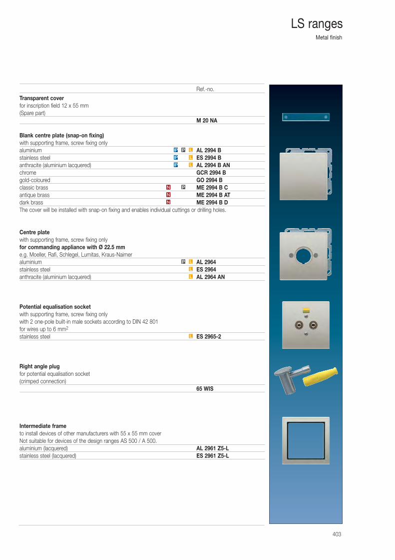
Metal finish
403
LS ranges
Transparent coverfor inscription field 12 x 55 mm(Spare part)
M 20 NA
Blank centre plate (snap-on fixing)with supporting frame, screw fixing onlyaluminium AL 2994 Bstainless steel ES 2994 Banthracite (aluminium lacquered) AL 2994 B ANchrome GCR 2994 Bgold-coloured GO 2994 Bclassic brass ME 2994 B Cantique brass ME 2994 B ATdark brass ME 2994 B DThe cover will be installed with snap-on fixing and enables individual cuttings or drilling holes.
Centre platewith supporting frame, screw fixing onlyfor commanding appliance with Ø 22.5 mme.g. Moeller, Rafi, Schlegel, Lumitas, Kraus-Naimeraluminium AL 2964stainless steel ES 2964anthracite (aluminium lacquered) AL 2964 AN
Potential equalisation socketwith supporting frame, screw fixing onlywith 2 one-pole built-in male sockets according to DIN 42 801for wires up to 6 mm2
stainless steel ES 2965-2
Right angle plugfor potential equalisation socket(crimped connection)
65 WIS
Intermediate frameto install devices of other manufacturers with 55 x 55 mm coverNot suitable for devices of the design ranges AS 500 / A 500.aluminium (lacquered) AL 2961 Z5-Lstainless steel (lacquered) ES 2961 Z5-L
L
L
L
LP
N
N
PN
LIP
LIP
LPIP
Ref.-no.
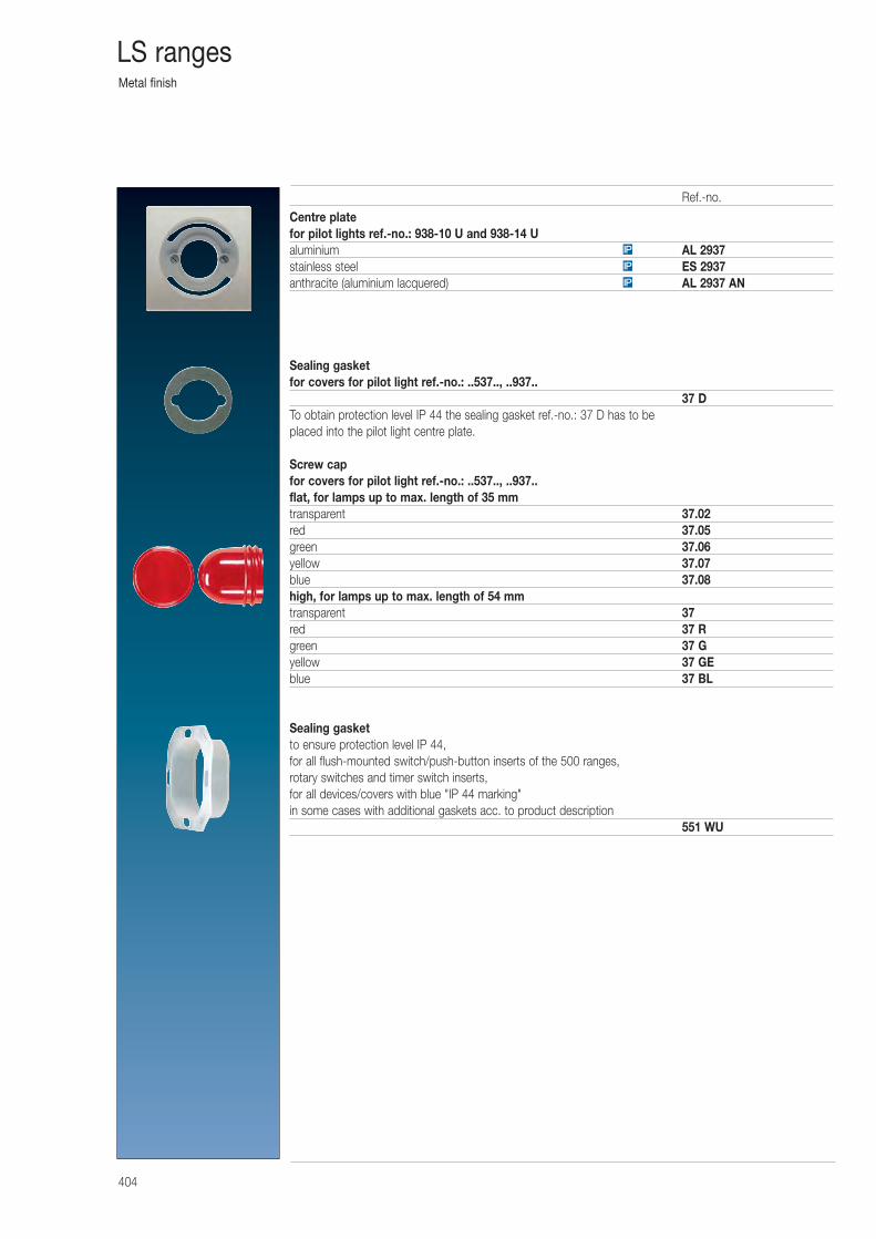
Metal finish
404
LS ranges
Centre platefor pilot lights ref.-no.: 938-10 U and 938-14 Ualuminium AL 2937stainless steel ES 2937anthracite (aluminium lacquered) AL 2937 AN
Sealing gasketfor covers for pilot light ref.-no.: ..537.., ..937..
37 DTo obtain protection level IP 44 the sealing gasket ref.-no.: 37 D has to be placed into the pilot light centre plate.
Screw capfor covers for pilot light ref.-no.: ..537.., ..937..flat, for lamps up to max. length of 35 mmtransparent 37.02red 37.05green 37.06yellow 37.07blue 37.08high, for lamps up to max. length of 54 mmtransparent 37red 37 Rgreen 37 Gyellow 37 GEblue 37 BL
Sealing gasketto ensure protection level IP 44,for all flush-mounted switch/push-button inserts of the 500 ranges,rotary switches and timer switch inserts,for all devices/covers with blue "IP 44 marking"in some cases with additional gaskets acc. to product description
551 WU
IP
IP
IP
Ref.-no.
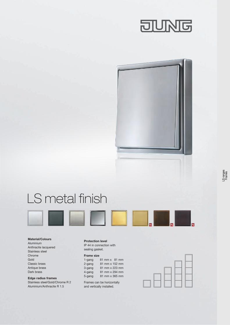
LS metal finish
Material/ColoursAluminiumAnthracite lacquered Stainless steel Chrome GoldClassic brassAntique brassDark brass
Edge radius frames Stainless steel/Gold/Chrome R 2 Aluminium/Anthracite R 1.5
Protection level IP 44 in connection withsealing gasket.
Frame size 1-gang 81 mm x 81 mm 2-gang 81 mm x 152 mm 3-gang 81 mm x 223 mm 4-gang 81 mm x 294 mm 5-gang 81 mm x 365 mm
Frames can be horizontallyand vertically installed.
N NNLS
rang
es
Fram
es
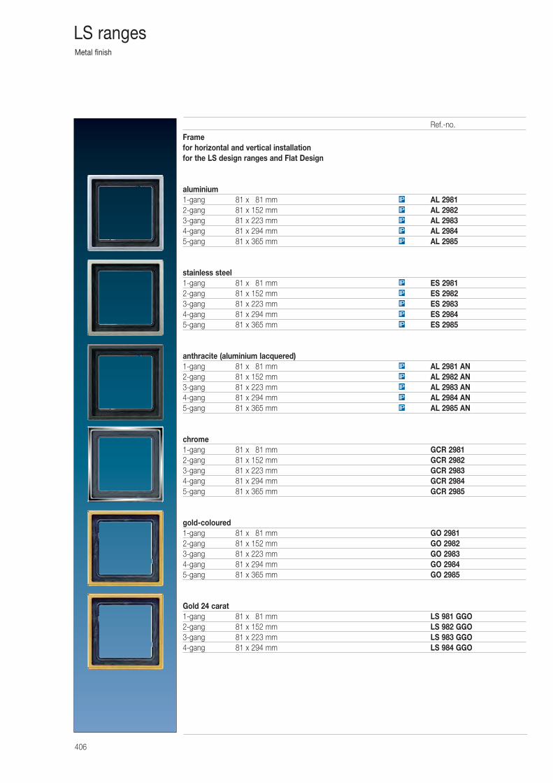
Metal finish
406
LS ranges
Framefor horizontal and vertical installationfor the LS design ranges and Flat Design
aluminium1-gang 81 x 081 mm AL 29812-gang 81 x 152 mm AL 29823-gang 81 x 223 mm AL 29834-gang 81 x 294 mm AL 29845-gang 81 x 365 mm AL 2985
stainless steel1-gang 81 x 081 mm ES 29812-gang 81 x 152 mm ES 29823-gang 81 x 223 mm ES 29834-gang 81 x 294 mm ES 29845-gang 81 x 365 mm ES 2985
anthracite (aluminium lacquered)1-gang 81 x 081 mm AL 2981 AN2-gang 81 x 152 mm AL 2982 AN3-gang 81 x 223 mm AL 2983 AN4-gang 81 x 294 mm AL 2984 AN5-gang 81 x 365 mm AL 2985 AN
chrome1-gang 81 x 081 mm GCR 29812-gang 81 x 152 mm GCR 29823-gang 81 x 223 mm GCR 29834-gang 81 x 294 mm GCR 29845-gang 81 x 365 mm GCR 2985
gold-coloured1-gang 81 x 081 mm GO 29812-gang 81 x 152 mm GO 29823-gang 81 x 223 mm GO 29834-gang 81 x 294 mm GO 29845-gang 81 x 365 mm GO 2985
Gold 24 carat1-gang 81 x 081 mm LS 981 GGO2-gang 81 x 152 mm LS 982 GGO3-gang 81 x 223 mm LS 983 GGO4-gang 81 x 294 mm LS 984 GGO
IP
IP
IP
IP
IP
IP
IP
IP
IP
IP
IP
IP
IP
IP
IP
Ref.-no.
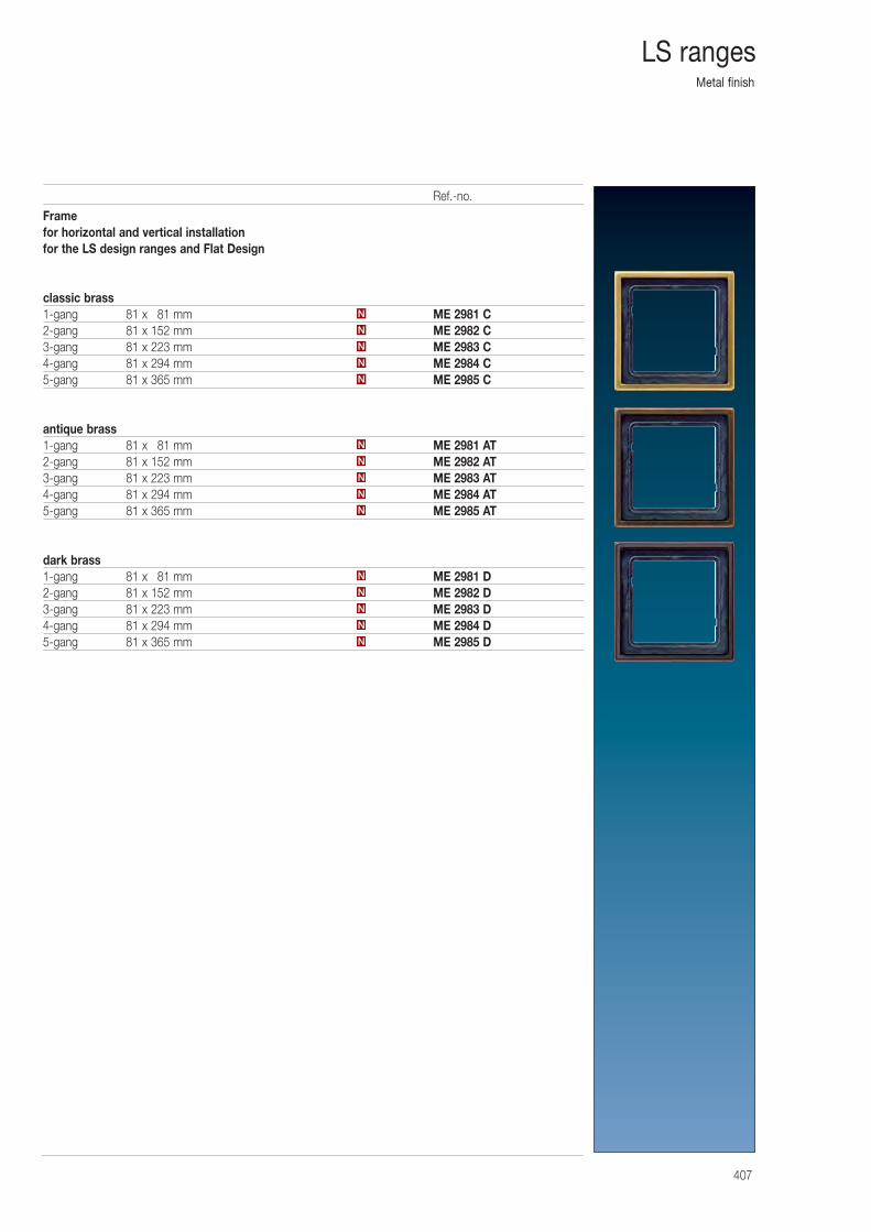
Metal finish
407
LS ranges
Framefor horizontal and vertical installationfor the LS design ranges and Flat Design
classic brass1-gang 81 x 081 mm ME 2981 C2-gang 81 x 152 mm ME 2982 C3-gang 81 x 223 mm ME 2983 C4-gang 81 x 294 mm ME 2984 C5-gang 81 x 365 mm ME 2985 C
antique brass1-gang 81 x 081 mm ME 2981 AT2-gang 81 x 152 mm ME 2982 AT3-gang 81 x 223 mm ME 2983 AT4-gang 81 x 294 mm ME 2984 AT5-gang 81 x 365 mm ME 2985 AT
dark brass1-gang 81 x 081 mm ME 2981 D2-gang 81 x 152 mm ME 2982 D3-gang 81 x 223 mm ME 2983 D4-gang 81 x 294 mm ME 2984 D5-gang 81 x 365 mm ME 2985 D
N
N
N
N
N
N
N
N
N
N
N
N
N
N
N
Ref.-no.
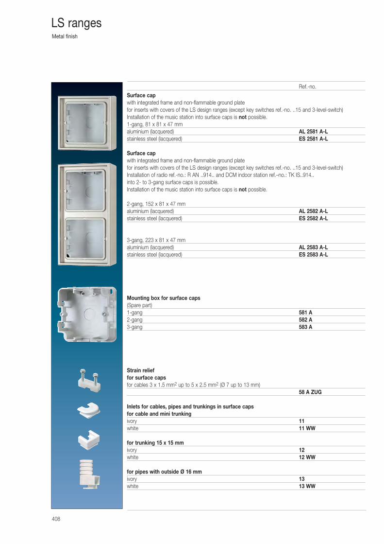
Metal finish
408
LS ranges
Surface capwith integrated frame and non-flammable ground platefor inserts with covers of the LS design ranges (except key switches ref.-no. ..15 and 3-level-switch)Installation of the music station into surface caps is not possible.1-gang, 81 x 81 x 47 mmaluminium (lacquered) AL 2581 A-Lstainless steel (lacquered) ES 2581 A-L
Surface capwith integrated frame and non-flammable ground platefor inserts with covers of the LS design ranges (except key switches ref.-no. ..15 and 3-level-switch)Installation of radio ref.-no.: R AN ..914.. and DCM indoor station ref.–no.: TK IS..914.. into 2- to 3-gang surface caps is possible.Installation of the music station into surface caps is not possible.
2-gang, 152 x 81 x 47 mmaluminium (lacquered) AL 2582 A-Lstainless steel (lacquered) ES 2582 A-L
3-gang, 223 x 81 x 47 mmaluminium (lacquered) AL 2583 A-Lstainless steel (lacquered) ES 2583 A-L
Mounting box for surface caps(Spare part)1-gang 581 A2-gang 582 A3-gang 583 A
Strain relieffor surface capsfor cables 3 x 1.5 mm2 up to 5 x 2.5 mm2 (Ø 7 up to 13 mm)
58 A ZUG
Inlets for cables, pipes and trunkings in surface capsfor cable and mini trunkingivory 11white 11 WW
for trunking 15 x 15 mmivory 12white 12 WW
for pipes with outside Ø 16 mmivory 13white 13 WW
Ref.-no.
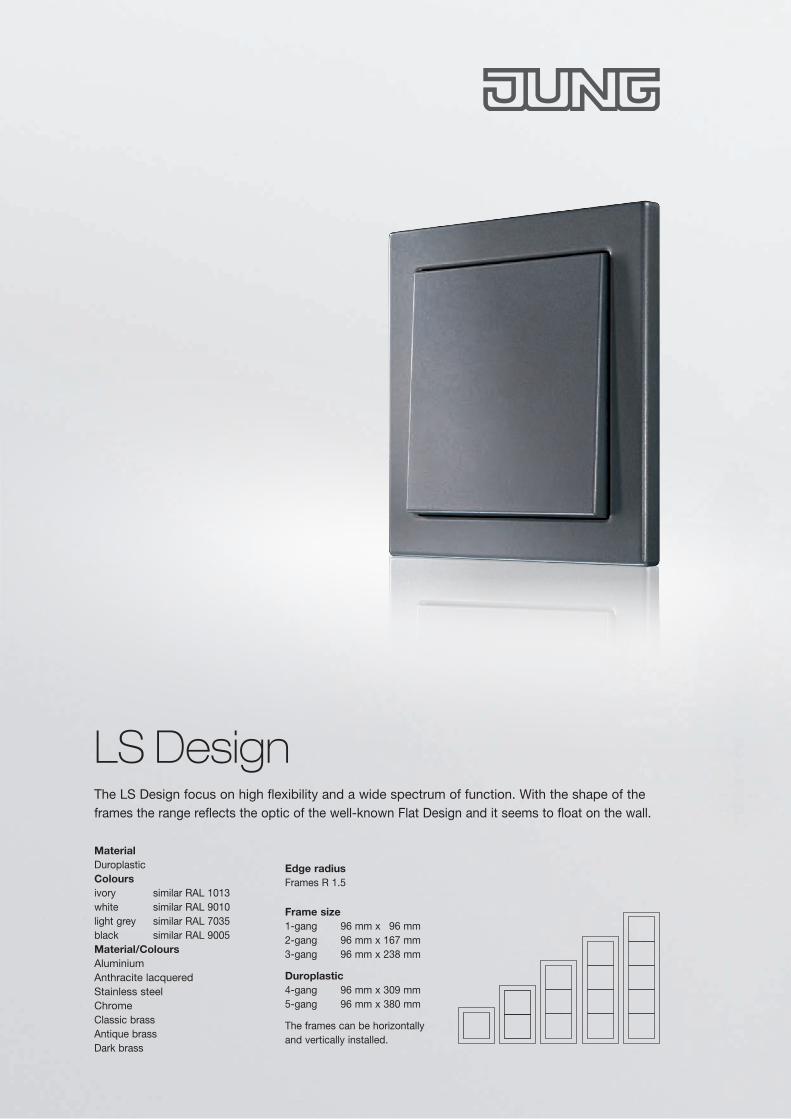
Material DuroplasticColours ivory similar RAL 1013 white similar RAL 9010 light grey similar RAL 7035 black similar RAL 9005Material/ColoursAluminium Anthracite lacquered Stainless steel ChromeClassic brassAntique brassDark brass
Frame size 1-gang 96 mm x 96 mm 2-gang 96 mm x 167 mm 3-gang 96 mm x 238 mm
Duroplastic 4-gang 96 mm x 309 mm 5-gang 96 mm x 380 mm
The frames can be horizontallyand vertically installed.
Edge radius Frames R 1.5
The LS Design focus on high flexibility and a wide spectrum of function. With the shape of the frames the range reflects the optic of the well-known Flat Design and it seems to float on the wall.
LS Design
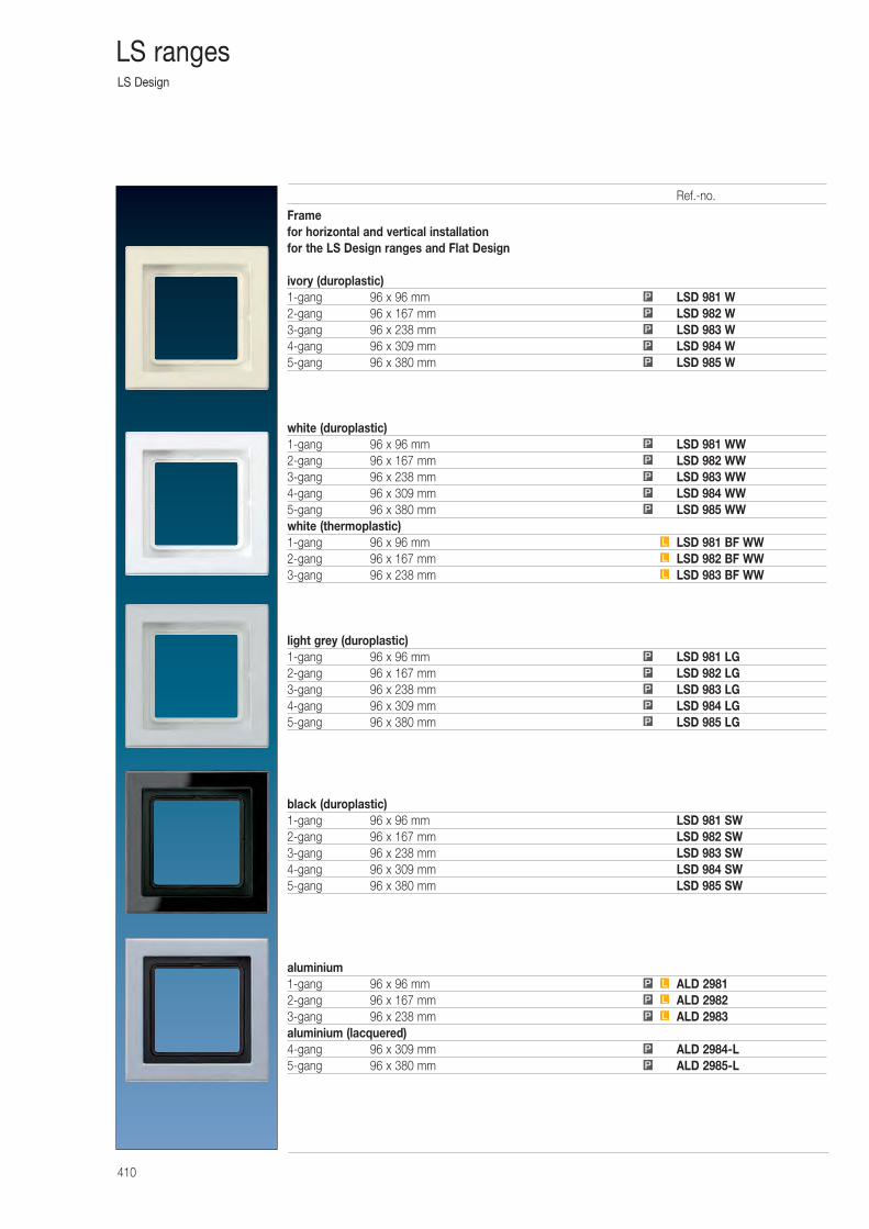
LS Design
410
LS ranges
Framefor horizontal and vertical installationfor the LS Design ranges and Flat Design
ivory (duroplastic)1-gang 96 x 96 mm LSD 981 W2-gang 96 x 167 mm LSD 982 W3-gang 96 x 238 mm LSD 983 W4-gang 96 x 309 mm LSD 984 W5-gang 96 x 380 mm LSD 985 W
white (duroplastic)1-gang 96 x 96 mm LSD 981 WW2-gang 96 x 167 mm LSD 982 WW3-gang 96 x 238 mm LSD 983 WW4-gang 96 x 309 mm LSD 984 WW5-gang 96 x 380 mm LSD 985 WWwhite (thermoplastic)1-gang 96 x 96 mm LSD 981 BF WW2-gang 96 x 167 mm LSD 982 BF WW3-gang 96 x 238 mm LSD 983 BF WW
light grey (duroplastic)1-gang 96 x 96 mm LSD 981 LG2-gang 96 x 167 mm LSD 982 LG3-gang 96 x 238 mm LSD 983 LG4-gang 96 x 309 mm LSD 984 LG5-gang 96 x 380 mm LSD 985 LG
black (duroplastic)1-gang 96 x 96 mm LSD 981 SW2-gang 96 x 167 mm LSD 982 SW3-gang 96 x 238 mm LSD 983 SW4-gang 96 x 309 mm LSD 984 SW5-gang 96 x 380 mm LSD 985 SW
aluminium1-gang 96 x 96 mm ALD 29812-gang 96 x 167 mm ALD 29823-gang 96 x 238 mm ALD 2983aluminium (lacquered)4-gang 96 x 309 mm ALD 2984-L5-gang 96 x 380 mm ALD 2985-LP
P
P L
P L
P L
P
P
P
P
P
L
L
L
P
P
P
P
P
P
P
P
P
P
Ref.-no.
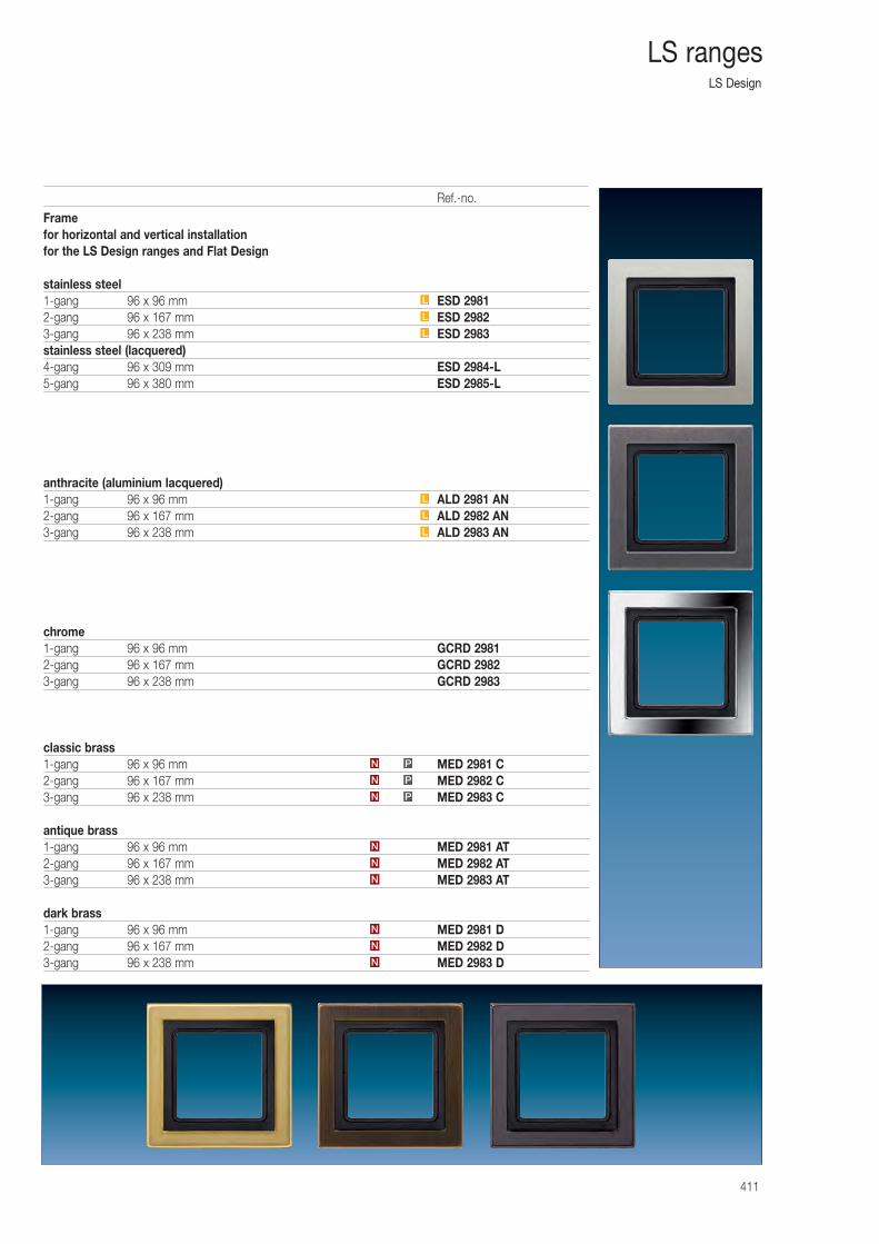
LS Design
411
LS ranges
Framefor horizontal and vertical installationfor the LS Design ranges and Flat Design
stainless steel1-gang 96 x 96 mm ESD 29812-gang 96 x 167 mm ESD 29823-gang 96 x 238 mm ESD 2983stainless steel (lacquered)4-gang 96 x 309 mm ESD 2984-L5-gang 96 x 380 mm ESD 2985-L
anthracite (aluminium lacquered)1-gang 96 x 96 mm ALD 2981 AN2-gang 96 x 167 mm ALD 2982 AN3-gang 96 x 238 mm ALD 2983 AN
chrome1-gang 96 x 96 mm GCRD 29812-gang 96 x 167 mm GCRD 29823-gang 96 x 238 mm GCRD 2983
classic brass1-gang 96 x 96 mm MED 2981 C2-gang 96 x 167 mm MED 2982 C3-gang 96 x 238 mm MED 2983 C
antique brass1-gang 96 x 96 mm MED 2981 AT2-gang 96 x 167 mm MED 2982 AT3-gang 96 x 238 mm MED 2983 AT
dark brass1-gang 96 x 96 mm MED 2981 D2-gang 96 x 167 mm MED 2982 D3-gang 96 x 238 mm MED 2983 D
L
L
L
L
L
N
N
N
N
N
N
PN
PN
PN
L
Ref.-no.
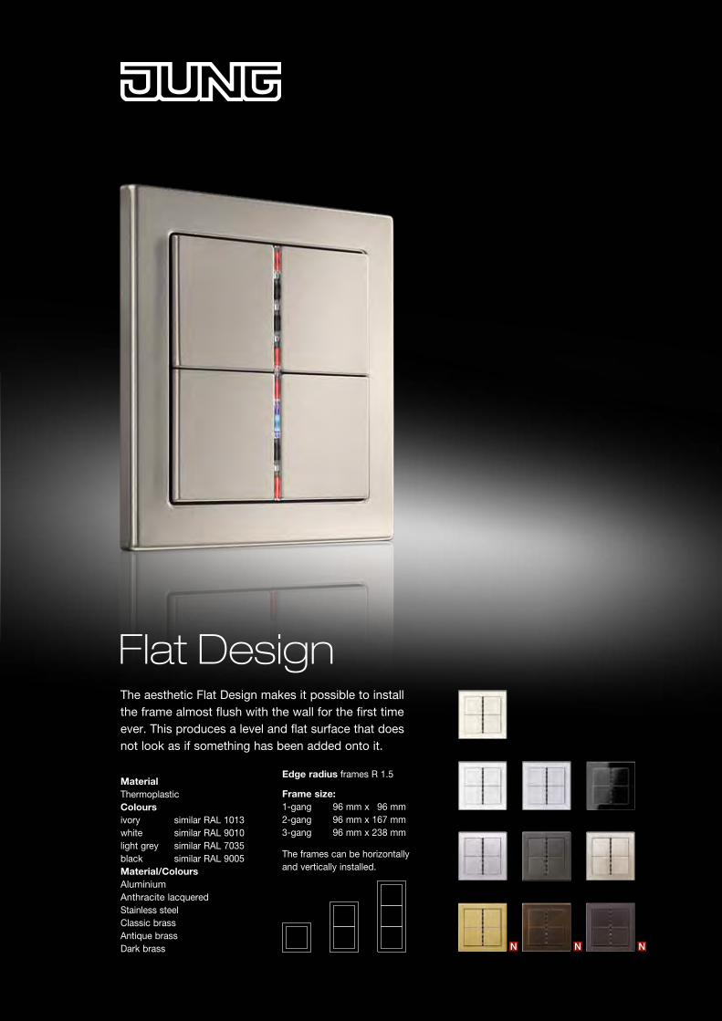
N NN
Flat DesignThe aesthetic Flat Design makes it possible to install the frame almost flush with the wall for the first time ever. This produces a level and flat surface that does not look as if something has been added onto it.
Edge radius frames R 1.5
Frame size: 1-gang 96 mm x 96 mm 2-gang 96 mm x 167 mm 3-gang 96 mm x 238 mm
The frames can be horizontallyand vertically installed.
Material ThermoplasticColours ivory similar RAL 1013 white similar RAL 9010 light grey similar RAL 7035 black similar RAL 9005Material/ColoursAluminium Anthracite lacquered Stainless steelClassic brassAntique brassDark brass
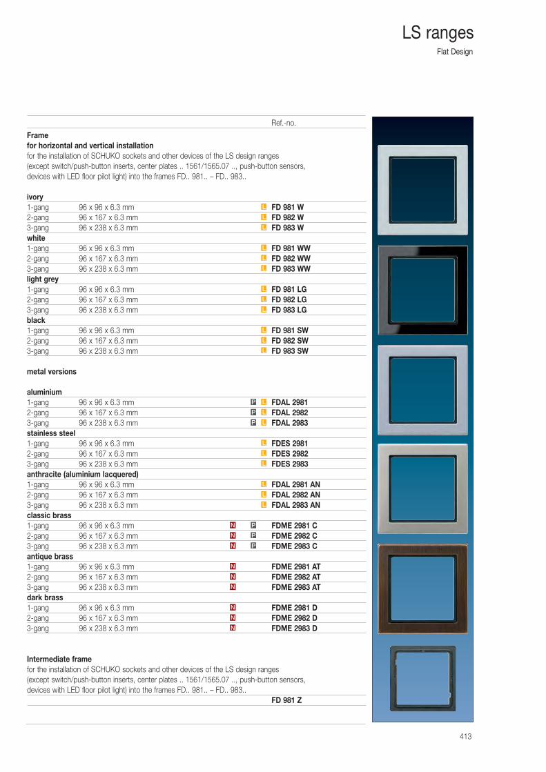
Flat Design
413
LS ranges
Framefor horizontal and vertical installationfor the installation of SCHUKO sockets and other devices of the LS design ranges (except switch/push-button inserts, center plates .. 1561/1565.07 .., push-button sensors, devices with LED floor pilot light) into the frames FD.. 981.. – FD.. 983..
ivory1-gang 96 x 96 x 6.3 mm FD 981 W2-gang 96 x 167 x 6.3 mm FD 982 W3-gang 96 x 238 x 6.3 mm FD 983 Wwhite1-gang 96 x 96 x 6.3 mm FD 981 WW2-gang 96 x 167 x 6.3 mm FD 982 WW3-gang 96 x 238 x 6.3 mm FD 983 WWlight grey1-gang 96 x 96 x 6.3 mm FD 981 LG2-gang 96 x 167 x 6.3 mm FD 982 LG3-gang 96 x 238 x 6.3 mm FD 983 LGblack1-gang 96 x 96 x 6.3 mm FD 981 SW2-gang 96 x 167 x 6.3 mm FD 982 SW3-gang 96 x 238 x 6.3 mm FD 983 SW
metal versions
aluminium1-gang 96 x 96 x 6.3 mm FDAL 29812-gang 96 x 167 x 6.3 mm FDAL 29823-gang 96 x 238 x 6.3 mm FDAL 2983stainless steel1-gang 96 x 96 x 6.3 mm FDES 29812-gang 96 x 167 x 6.3 mm FDES 29823-gang 96 x 238 x 6.3 mm FDES 2983anthracite (aluminium lacquered)1-gang 96 x 96 x 6.3 mm FDAL 2981 AN2-gang 96 x 167 x 6.3 mm FDAL 2982 AN3-gang 96 x 238 x 6.3 mm FDAL 2983 ANclassic brass1-gang 96 x 96 x 6.3 mm FDME 2981 C2-gang 96 x 167 x 6.3 mm FDME 2982 C3-gang 96 x 238 x 6.3 mm FDME 2983 Cantique brass1-gang 96 x 96 x 6.3 mm FDME 2981 AT2-gang 96 x 167 x 6.3 mm FDME 2982 AT3-gang 96 x 238 x 6.3 mm FDME 2983 ATdark brass1-gang 96 x 96 x 6.3 mm FDME 2981 D2-gang 96 x 167 x 6.3 mm FDME 2982 D3-gang 96 x 238 x 6.3 mm FDME 2983 D
Intermediate framefor the installation of SCHUKO sockets and other devices of the LS design ranges (except switch/push-button inserts, center plates .. 1561/1565.07 .., push-button sensors, devices with LED floor pilot light) into the frames FD.. 981.. – FD.. 983..
FD 981 Z
L
L
L
N
N
N
N
N
N
PN
PN
PN
L
L
L
L
L
L
LP
LP
LP
L
L
L
L
L
L
L
L
L
Ref.-no.
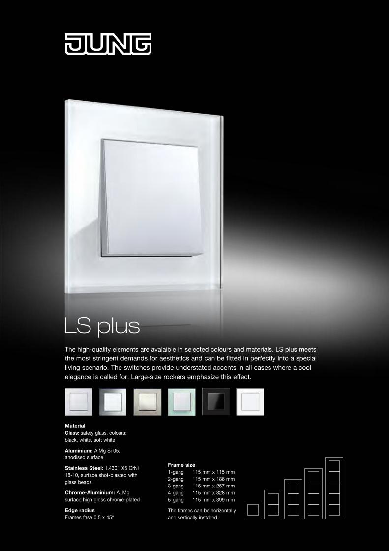
Material Glass: safety glass, colours: black, white, soft white
Aluminium: AlMg Si 05, anodised surface
Stainless Steel: 1.4301 X5 CrNi 18-10, surface shot-blasted with glass beads
Chrome-Aluminium: ALMg surface high gloss chrome-plated
Edge radius Frames fase 0.5 x 45°
Frame size 1-gang 115 mm x 115 mm 2-gang 115 mm x 186 mm 3-gang 115 mm x 257 mm 4-gang 115 mm x 328 mm 5-gang 115 mm x 399 mm
The frames can be horizontallyand vertically installed.
The high-quality elements are avalaible in selected colours and materials. LS plus meets the most stringent demands for aesthetics and can be fitted in perfectly into a special living scenario. The switches provide understated accents in all cases where a cool elegance is called for. Large-size rockers emphasize this effect.
LS plus
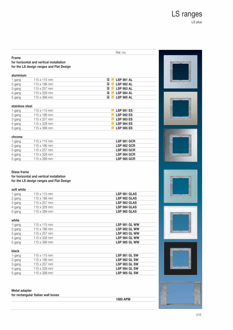
LS plus
415
LS ranges
Framefor horizontal and vertical installationfor the LS design ranges and Flat Design
aluminium1-gang 115 x 115 mm LSP 981 AL2-gang 115 x 186 mm LSP 982 AL3-gang 115 x 257 mm LSP 983 AL4-gang 115 x 328 mm LSP 984 AL5-gang 115 x 399 mm LSP 985 AL
stainless steel1-gang 115 x 115 mm LSP 981 ES2-gang 115 x 186 mm LSP 982 ES3-gang 115 x 257 mm LSP 983 ES4-gang 115 x 328 mm LSP 984 ES5-gang 115 x 399 mm LSP 985 ES
chrome1-gang 115 x 115 mm LSP 981 GCR2-gang 115 x 186 mm LSP 982 GCR3-gang 115 x 257 mm LSP 983 GCR4-gang 115 x 328 mm LSP 984 GCR5-gang 115 x 399 mm LSP 985 GCR
Glass framefor horizontal and vertical installationfor the LS design ranges and Flat Design
soft white1-gang 115 x 115 mm LSP 981 GLAS2-gang 115 x 186 mm LSP 982 GLAS3-gang 115 x 257 mm LSP 983 GLAS4-gang 115 x 328 mm LSP 984 GLAS5-gang 115 x 399 mm LSP 985 GLAS
white1-gang 115 x 115 mm LSP 981 GL WW2-gang 115 x 186 mm LSP 982 GL WW3-gang 115 x 257 mm LSP 983 GL WW4-gang 115 x 328 mm LSP 984 GL WW5-gang 115 x 399 mm LSP 985 GL WW
black1-gang 115 x 115 mm LSP 981 GL SW2-gang 115 x 186 mm LSP 982 GL SW3-gang 115 x 257 mm LSP 983 GL SW4-gang 115 x 328 mm LSP 984 GL SW5-gang 115 x 399 mm LSP 985 GL SW
Metal adapterfor rectangular Italian wall boxes
1980 APM
L
L
L
LP
LP
LP
LP
LP
L
L
Ref.-no.
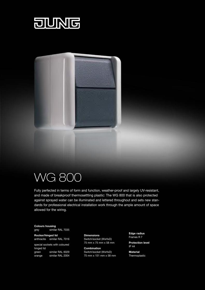
WG 800
Colours housing grey similar RAL 7035
Rocker/hinged lid anthracite similar RAL 7016
special sockets with coloured hinged lidgreen similar RAL 6029 orange similar RAL 2004
Fully perfected in terms of form and function, weather-proof and largely UV-resistant, and made of breakproof thermosettting plastic: The WG 800 that is also protected against sprayed water can be illuminated and lettered throughout and sets new stan-dards for professional electrical installation work through the ample amount of space allowed for the wiring.
Dimensions Switch/socket (WxHxD) 75 mm x 75 mm x 58 mm
Combination Switch/socket (WxHxD) 75 mm x 151 mm x 58 mm
Edge radius Frames R 7
Protection levelIP 44
MaterialThermoplastic
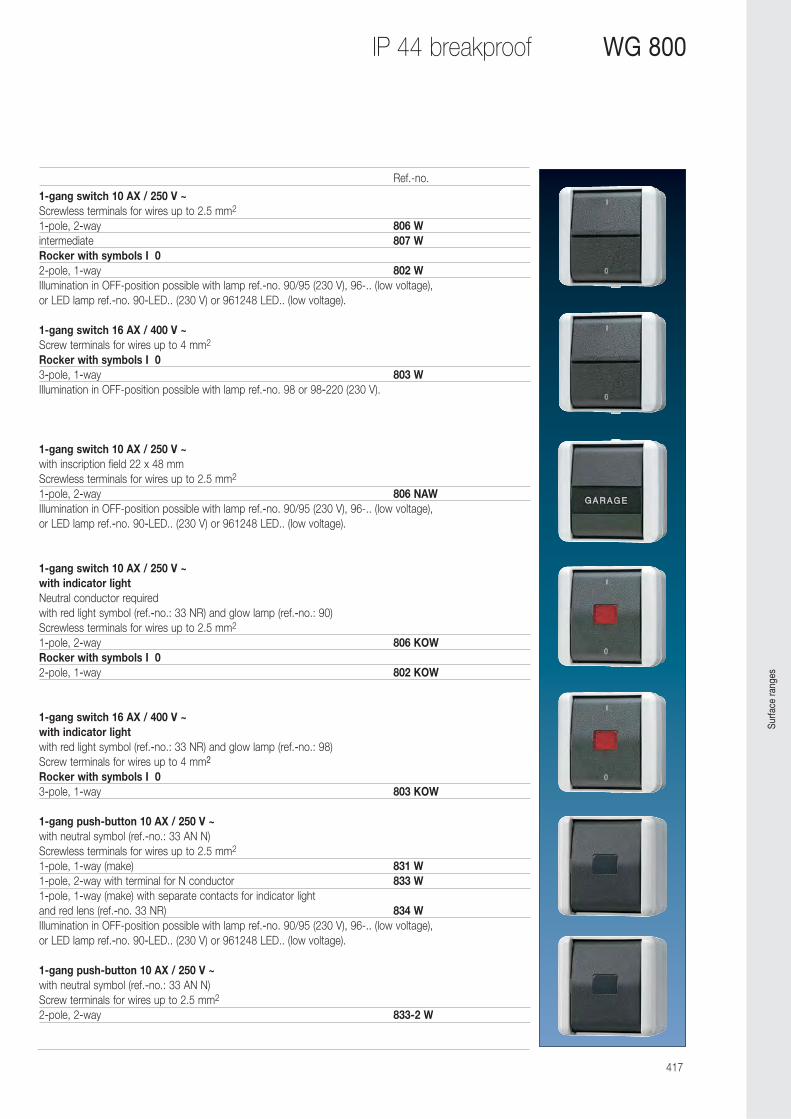
417
IP 44 breakproof WG 800
1-gang switch 10 AX / 250 V ~Screwless terminals for wires up to 2.5 mm2
1-pole, 2-way 806 Wintermediate 807 WRocker with symbols I 02-pole, 1-way 802 WIllumination in OFF-position possible with lamp ref.-no. 90/95 (230 V), 96-.. (low voltage), or LED lamp ref.-no. 90-LED.. (230 V) or 961248 LED.. (low voltage).
1-gang switch 16 AX / 400 V ~Screw terminals for wires up to 4 mm2
Rocker with symbols I 03-pole, 1-way 803 WIllumination in OFF-position possible with lamp ref.-no. 98 or 98-220 (230 V).
1-gang switch 10 AX / 250 V ~with inscription field 22 x 48 mmScrewless terminals for wires up to 2.5 mm2
1-pole, 2-way 806 NAWIllumination in OFF-position possible with lamp ref.-no. 90/95 (230 V), 96-.. (low voltage), or LED lamp ref.-no. 90-LED.. (230 V) or 961248 LED.. (low voltage).
1-gang switch 10 AX / 250 V ~ with indicator lightNeutral conductor requiredwith red light symbol (ref.-no.: 33 NR) and glow lamp (ref.-no.: 90)Screwless terminals for wires up to 2.5 mm2
1-pole, 2-way 806 KOWRocker with symbols I 02-pole, 1-way 802 KOW
1-gang switch 16 AX / 400 V ~ with indicator lightwith red light symbol (ref.-no.: 33 NR) and glow lamp (ref.-no.: 98)Screw terminals for wires up to 4 mm2
Rocker with symbols I 03-pole, 1-way 803 KOW
1-gang push-button 10 AX / 250 V ~with neutral symbol (ref.-no.: 33 AN N)Screwless terminals for wires up to 2.5 mm2
1-pole, 1-way (make) 831 W1-pole, 2-way with terminal for N conductor 833 W1-pole, 1-way (make) with separate contacts for indicator lightand red lens (ref.-no. 33 NR) 834 WIllumination in OFF-position possible with lamp ref.-no. 90/95 (230 V), 96-.. (low voltage), or LED lamp ref.-no. 90-LED.. (230 V) or 961248 LED.. (low voltage).
1-gang push-button 10 AX / 250 V ~with neutral symbol (ref.-no.: 33 AN N)Screw terminals for wires up to 2.5 mm2
2-pole, 2-way 833-2 W
Ref.-no.
Surfa
ce ra
nges
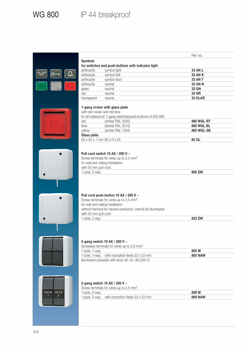
418
IP 44 breakproofWG 800
Symbolsfor switches and push-buttons with indicator lightanthracite symbol light 33 AN Lanthracite symbol bell 33 AN Kanthracite symbol door 33 AN Tanthracite neutral 33 AN Ngreen neutral 33 GNred neutral 33 NRtransparent neutral 33 KLAR
1-gang rocker with glass platewith red rocker and red lensfor all waterproof 1-gang switches/push-buttons of WG 800red (similar RAL 3000) 860 WGL RTblue (similar RAL 5015) 860 WGL BLyellow (similar RAL 1004) 860 WGL GEGlass plate64 x 53 x 1 mm (W x H x D) 60 GL
Pull cord switch 10 AX / 250 V ~Screw terminals for wires up to 2.5 mm2
for wall and ceiling installationwith 50 mm pull cord1-pole, 2-way 806 ZW
Pull cord push-button 10 AX / 250 V ~Screw terminals for wires up to 2.5 mm2
for wall and ceiling installationwithout terminal for neutral conductor, cannot be illuminatedwith 50 mm pull cord1-pole, 2-way 833 ZW
2-gang switch 10 AX / 250 V ~Screwless terminals for wires up to 2.5 mm2
1-pole, 1-way 805 W1-pole, 1-way with inscription fields 22 x 22 mm 805 NAWillumination possible with lamp ref.-no. 99 (230 V).
2-gang switch 10 AX / 250 V ~Screw terminals for wires up to 2.5 mm2
1-pole, 2-way 809 W1-pole, 2-way with inscription fields 22 x 22 mm 809 NAW
Ref.-no.
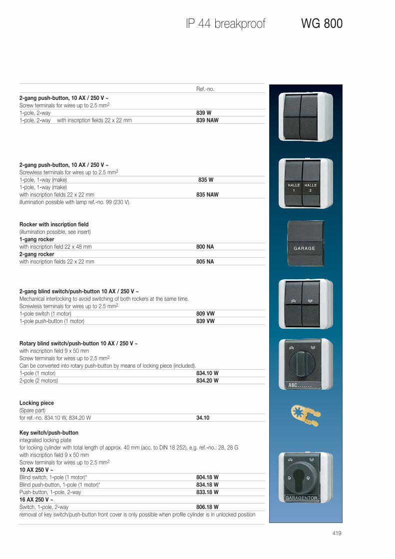
419
IP 44 breakproof WG 800
2-gang push-button, 10 AX / 250 V ~Screw terminals for wires up to 2.5 mm2
1-pole, 2-way 839 W1-pole, 2-way with inscription fields 22 x 22 mm 839 NAW
2-gang push-button, 10 AX / 250 V ~Screwless terminals for wires up to 2.5 mm2
1-pole, 1-way (make) 835 W1-pole, 1-way (make)with inscription fields 22 x 22 mm 835 NAWillumination possible with lamp ref.-no. 99 (230 V).
Rocker with inscription field(illumination possible, see insert)1-gang rockerwith inscription field 22 x 48 mm 800 NA2-gang rockerwith inscription fields 22 x 22 mm 805 NA
2-gang blind switch/push-button 10 AX / 250 V ~Mechanical interlocking to avoid switching of both rockers at the same time.Screwless terminals for wires up to 2.5 mm2
1-pole switch (1 motor) 809 VW1-pole push-button (1 motor) 839 VW
Rotary blind switch/push-button 10 AX / 250 V ~with inscription field 9 x 50 mmScrew terminals for wires up to 2.5 mm2
Can be converted into rotary push-button by means of locking piece (included).1-pole (1 motor) 834.10 W2-pole (2 motors) 834.20 W
Locking piece(Spare part)for ref.-no. 834.10 W, 834.20 W 34.10
Key switch/push-buttonintegrated locking platefor locking cylinder with total length of approx. 40 mm (acc. to DIN 18 252), e.g. ref.-no.: 28, 28 Gwith inscription field 9 x 50 mmScrew terminals for wires up to 2.5 mm2
10 AX 250 V ~Blind switch, 1-pole (1 motor)* 804.18 WBlind push-button, 1-pole (1 motor)* 834.18 WPush-button, 1-pole, 2-way 833.18 W16 AX 250 V ~Switch, 1-pole, 2-way 806.18 Wremoval of key switch/push-button front cover is only possible when profile cylinder is in unlocked position
Ref.-no.
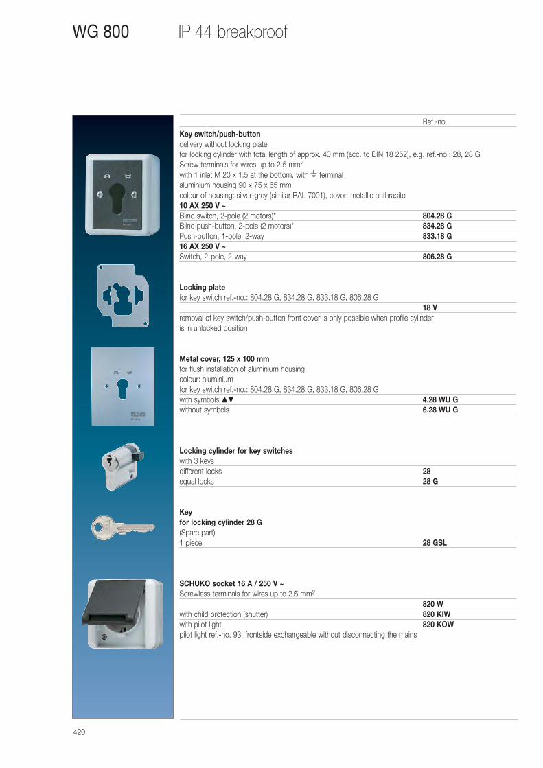
420
IP 44 breakproofWG 800
Key switch/push-buttondelivery without locking platefor locking cylinder with total length of approx. 40 mm (acc. to DIN 18 252), e.g. ref.-no.: 28, 28 GScrew terminals for wires up to 2.5 mm2
with 1 inlet M 20 x 1.5 at the bottom, with terminalaluminium housing 90 x 75 x 65 mmcolour of housing: silver-grey (similar RAL 7001), cover: metallic anthracite10 AX 250 V ~Blind switch, 2-pole (2 motors)* 804.28 GBlind push-button, 2-pole (2 motors)* 834.28 GPush-button, 1-pole, 2-way 833.18 G16 AX 250 V ~Switch, 2-pole, 2-way 806.28 G
Locking platefor key switch ref.-no.: 804.28 G, 834.28 G, 833.18 G, 806.28 G
18 Vremoval of key switch/push-button front cover is only possible when profile cylinder is in unlocked position
Metal cover, 125 x 100 mmfor flush installation of aluminium housingcolour: aluminiumfor key switch ref.-no.: 804.28 G, 834.28 G, 833.18 G, 806.28 Gwith symbols ▲▼ 4.28 WU Gwithout symbols 6.28 WU G
Locking cylinder for key switcheswith 3 keysdifferent locks 28equal locks 28 G
Key for locking cylinder 28 G(Spare part)1 piece 28 GSL
SCHUKO socket 16 A / 250 V ~Screwless terminals for wires up to 2.5 mm2
820 Wwith child protection (shutter) 820 KIWwith pilot light 820 KOWpilot light ref.-no. 93, frontside exchangeable without disconnecting the mains
Ref.-no.
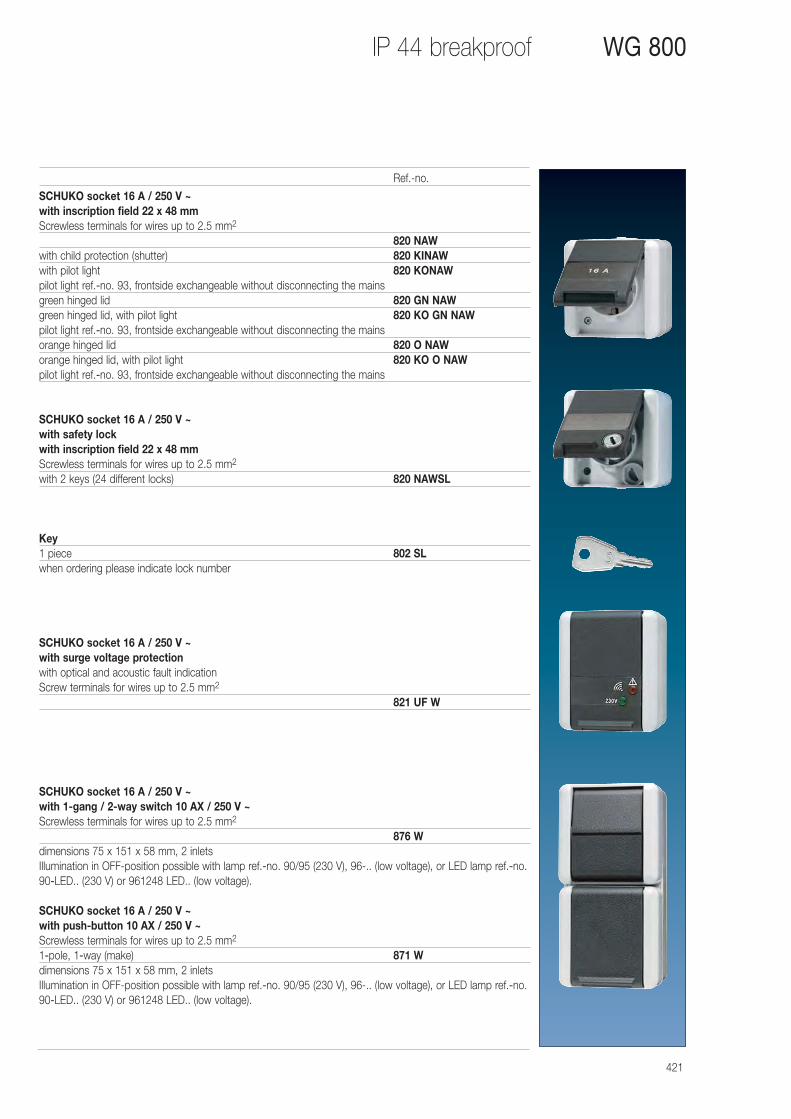
421
IP 44 breakproof WG 800
SCHUKO socket 16 A / 250 V ~with inscription field 22 x 48 mmScrewless terminals for wires up to 2.5 mm2
820 NAWwith child protection (shutter) 820 KINAWwith pilot light 820 KONAWpilot light ref.-no. 93, frontside exchangeable without disconnecting the mainsgreen hinged lid 820 GN NAWgreen hinged lid, with pilot light 820 KO GN NAWpilot light ref.-no. 93, frontside exchangeable without disconnecting the mainsorange hinged lid 820 O NAWorange hinged lid, with pilot light 820 KO O NAWpilot light ref.-no. 93, frontside exchangeable without disconnecting the mains
SCHUKO socket 16 A / 250 V ~with safety lockwith inscription field 22 x 48 mmScrewless terminals for wires up to 2.5 mm2
with 2 keys (24 different locks) 820 NAWSL
Key1 piece 802 SLwhen ordering please indicate lock number
SCHUKO socket 16 A / 250 V ~with surge voltage protectionwith optical and acoustic fault indicationScrew terminals for wires up to 2.5 mm2
821 UF W
SCHUKO socket 16 A / 250 V ~ with 1-gang / 2-way switch 10 AX / 250 V ~Screwless terminals for wires up to 2.5 mm2
876 Wdimensions 75 x 151 x 58 mm, 2 inletsIllumination in OFF-position possible with lamp ref.-no. 90/95 (230 V), 96-.. (low voltage), or LED lamp ref.-no.90-LED.. (230 V) or 961248 LED.. (low voltage).
SCHUKO socket 16 A / 250 V ~ with push-button 10 AX / 250 V ~Screwless terminals for wires up to 2.5 mm2
1-pole, 1-way (make) 871 Wdimensions 75 x 151 x 58 mm, 2 inletsIllumination in OFF-position possible with lamp ref.-no. 90/95 (230 V), 96-.. (low voltage), or LED lamp ref.-no.90-LED.. (230 V) or 961248 LED.. (low voltage).
Ref.-no.
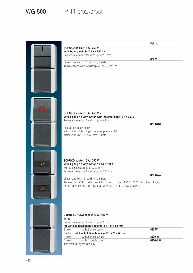
422
IP 44 breakproofWG 800
SCHUKO socket 16 A / 250 V ~ with 2-gang switch 10 AX / 250 V ~Screwless terminals for wires up to 2.5 mm2
875 Wdimensions 75 x 151 x 58 mm, 2 inletsillumination possible with lamp ref.-no. 99 (230 V).
SCHUKO socket 16 A / 250 V ~ with 1-gang / 2-way switch with indicator light 10 AX 250 V ~Screwless terminals for wires up to 2.5 mm2
876 KOWneutral conductor requiredwith indicator light, plug-in neon-lamp ref.-no. 90dimensions 75 x 151 x 58 mm, 2 inlets
SCHUKO socket 16 A / 250 V ~ with 1-gang / 2-way switch 10 AX / 250 V ~with two inscription fields 22 x 48 mmScrewless terminals for wires up to 2.5 mm2
876 NAWdimensions 75 x 151 x 58 mm, 2 inletsIllumination in OFF-position possible with lamp ref.-no. 90/95 (230 V), 96-.. (low voltage), or LED lamp ref.-no. 90-LED.. (230 V) or 961248 LED.. (low voltage).
2-gang SCHUKO socket 16 A / 250 V ~wiredScrewless terminals for wires up to 2.5 mm2
for vertical installation, housing 75 x 151 x 58 mm2 inlets with 2 single covers 822 Wfor horizontal installation, housing 151 x 75 x 58 mm4 inlets with 2 single covers 8220 W4 inlets with 1 double cover 8220-1 Winlet for trunking ref.-no: 895
Ref.-no.
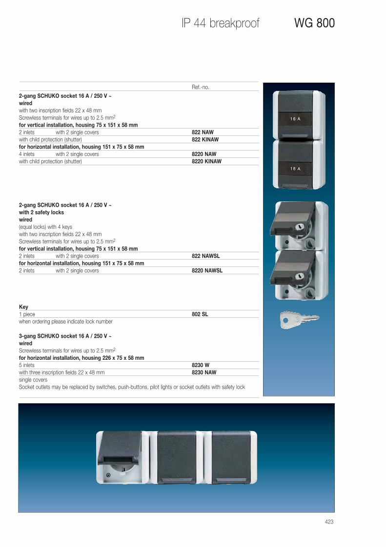
423
IP 44 breakproof WG 800
2-gang SCHUKO socket 16 A / 250 V ~wiredwith two inscription fields 22 x 48 mmScrewless terminals for wires up to 2.5 mm2
for vertical installation, housing 75 x 151 x 58 mm2 inlets with 2 single covers 822 NAWwith child protection (shutter) 822 KINAWfor horizontal installation, housing 151 x 75 x 58 mm4 inlets with 2 single covers 8220 NAWwith child protection (shutter) 8220 KINAW
2-gang SCHUKO socket 16 A / 250 V ~with 2 safety lockswired(equal locks) with 4 keyswith two inscription fields 22 x 48 mmScrewless terminals for wires up to 2.5 mm2
for vertical installation, housing 75 x 151 x 58 mm2 inlets with 2 single covers 822 NAWSLfor horizontal installation, housing 151 x 75 x 58 mm2 inlets with 2 single covers 8220 NAWSL
Key1 piece 802 SLwhen ordering please indicate lock number
3-gang SCHUKO socket 16 A / 250 V ~wiredScrewless terminals for wires up to 2.5 mm2
for horizontal installation, housing 226 x 75 x 58 mm5 inlets 8230 Wwith three inscription fields 22 x 48 mm 8230 NAWsingle coversSocket outlets may be replaced by switches, push-buttons, pilot lights or socket outlets with safety lock
Ref.-no.
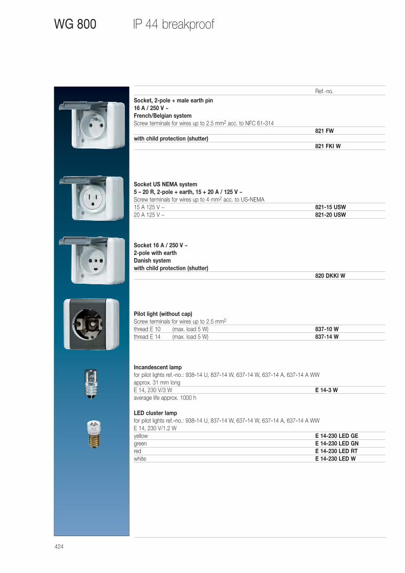
424
IP 44 breakproofWG 800
Socket, 2-pole + male earth pin16 A / 250 V ~French/Belgian systemScrew terminals for wires up to 2.5 mm2 acc. to NFC 61-314
821 FWwith child protection (shutter)
821 FKI W
Socket US NEMA system 5 – 20 R, 2-pole + earth, 15 + 20 A / 125 V ~Screw terminals for wires up to 4 mm2 acc. to US-NEMA15 A 125 V ~ 821-15 USW20 A 125 V ~ 821-20 USW
Socket 16 A / 250 V ~2-pole with earthDanish systemwith child protection (shutter)
820 DKKI W
Pilot light (without cap)Screw terminals for wires up to 2.5 mm2
thread E 10 (max. load 5 W) 837-10 Wthread E 14 (max. load 5 W) 837-14 W
Incandescent lampfor pilot lights ref.-no.: 938-14 U, 837-14 W, 637-14 W, 637-14 A, 637-14 A WWapprox. 31 mm longE 14, 230 V/3 W E 14-3 Waverage life approx. 1000 h
LED cluster lampfor pilot lights ref.-no.: 938-14 U, 837-14 W, 637-14 W, 637-14 A, 637-14 A WWE 14, 230 V/1.2 Wyellow E 14-230 LED GEgreen E 14-230 LED GNred E 14-230 LED RTwhite E 14-230 LED W
Ref.-no.
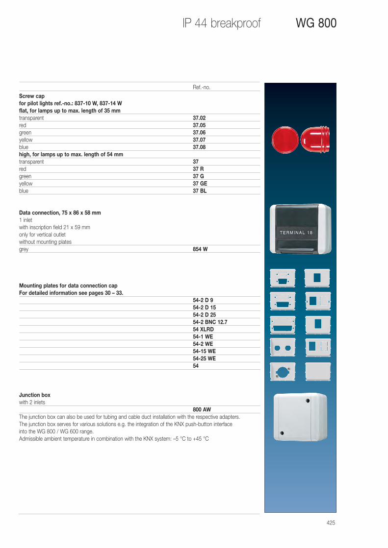
425
IP 44 breakproof WG 800
Screw capfor pilot lights ref.-no.: 837-10 W, 837-14 Wflat, for lamps up to max. length of 35 mmtransparent 37.02red 37.05green 37.06yellow 37.07blue 37.08high, for lamps up to max. length of 54 mmtransparent 37red 37 Rgreen 37 Gyellow 37 GEblue 37 BL
Data connection, 75 x 86 x 58 mm1 inlet with inscription field 21 x 59 mmonly for vertical outletwithout mounting platesgrey 854 W
Mounting plates for data connection capFor detailed information see pages 30 – 33.
54-2 D 954-2 D 1554-2 D 2554-2 BNC 12.754 XLRD54-1 WE54-2 WE54-15 WE54-25 WE54
Junction boxwith 2 inlets
800 AWThe junction box can also be used for tubing and cable duct installation with the respective adapters. The junction box serves for various solutions e.g. the integration of the KNX push-button interface into the WG 800 / WG 600 range. Admissible ambient temperature in combination with the KNX system: –5 °C to +45 °C
Ref.-no.
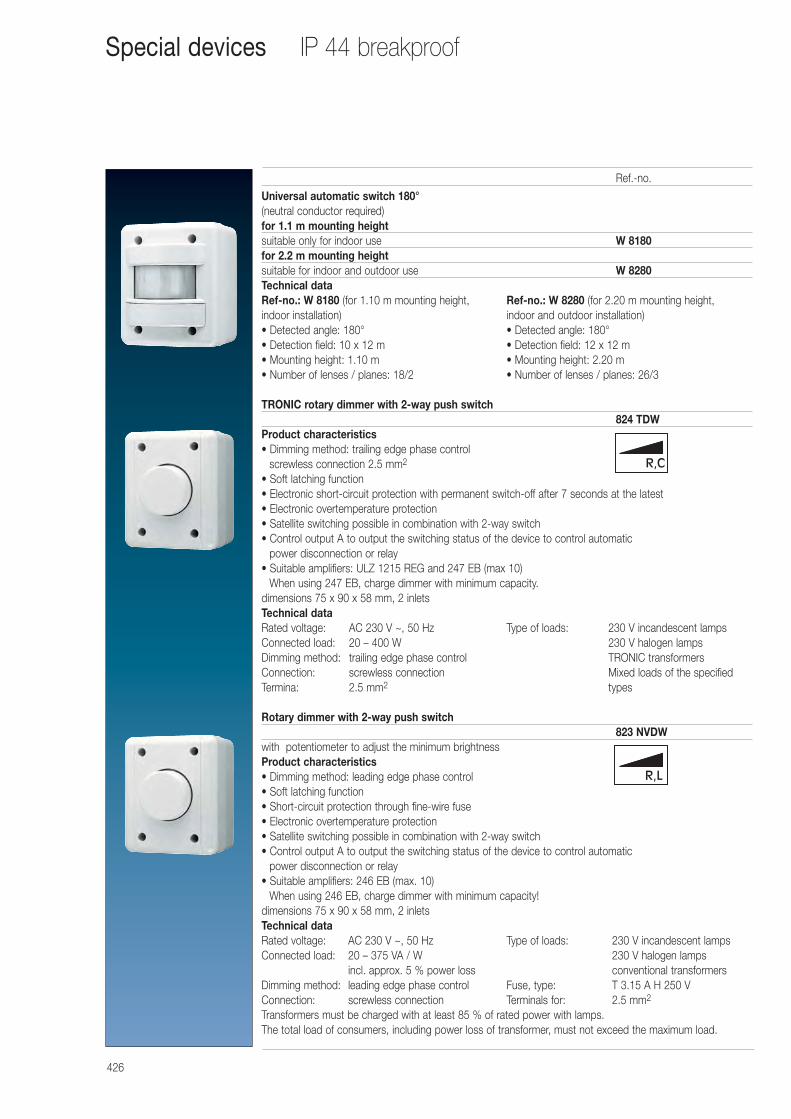
426
IP 44 breakproofSpecial devices
Universal automatic switch 180° (neutral conductor required)for 1.1 m mounting heightsuitable only for indoor use W 8180 for 2.2 m mounting heightsuitable for indoor and outdoor use W 8280 Technical dataRef-no.: W 8180 (for 1.10 m mounting height, Ref-no.: W 8280 (for 2.20 m mounting height, indoor installation) indoor and outdoor installation)• Detected angle: 180° • Detected angle: 180°• Detection field: 10 x 12 m • Detection field: 12 x 12 m • Mounting height: 1.10 m • Mounting height: 2.20 m• Number of lenses / planes: 18/2 • Number of lenses / planes: 26/3
TRONIC rotary dimmer with 2-way push switch824 TDW
Product characteristics• Dimming method: trailing edge phase control
screwless connection 2.5 mm2
• Soft latching function• Electronic short-circuit protection with permanent switch-off after 7 seconds at the latest• Electronic overtemperature protection• Satellite switching possible in combination with 2-way switch• Control output A to output the switching status of the device to control automatic
power disconnection or relay• Suitable amplifiers: ULZ 1215 REG and 247 EB (max 10)
When using 247 EB, charge dimmer with minimum capacity.dimensions 75 x 90 x 58 mm, 2 inletsTechnical dataRated voltage: AC 230 V ~, 50 Hz Type of loads: 230 V incandescent lampsConnected load: 20 – 400 W 230 V halogen lampsDimming method: trailing edge phase control TRONIC transformersConnection: screwless connection Mixed loads of the specified Termina: 2.5 mm2 types
Rotary dimmer with 2-way push switch823 NVDW
with potentiometer to adjust the minimum brightnessProduct characteristics• Dimming method: leading edge phase control• Soft latching function• Short-circuit protection through fine-wire fuse• Electronic overtemperature protection• Satellite switching possible in combination with 2-way switch• Control output A to output the switching status of the device to control automatic
power disconnection or relay• Suitable amplifiers: 246 EB (max. 10)
When using 246 EB, charge dimmer with minimum capacity!dimensions 75 x 90 x 58 mm, 2 inletsTechnical dataRated voltage: AC 230 V ~, 50 Hz Type of loads: 230 V incandescent lampsConnected load: 20 – 375 VA / W 230 V halogen lamps
incl. approx. 5 % power loss conventional transformersDimming method: leading edge phase control Fuse, type: T 3.15 A H 250 VConnection: screwless connection Terminals for: 2.5 mm2
Transformers must be charged with at least 85 % of rated power with lamps.The total load of consumers, including power loss of transformer, must not exceed the maximum load.
Ref.-no.
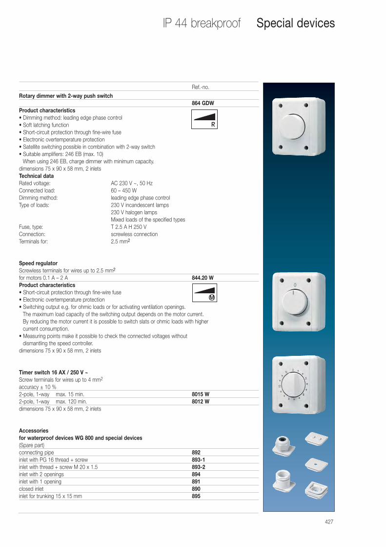
427
IP 44 breakproof Special devices
Rotary dimmer with 2-way push switch864 GDW
Product characteristics• Dimming method: leading edge phase control• Soft latching function• Short-circuit protection through fine-wire fuse• Electronic overtemperature protection• Satellite switching possible in combination with 2-way switch• Suitable amplifiers: 246 EB (max. 10)
When using 246 EB, charge dimmer with minimum capacity.dimensions 75 x 90 x 58 mm, 2 inletsTechnical dataRated voltage: AC 230 V ~, 50 HzConnected load: 60 – 450 WDimming method: leading edge phase controlType of loads: 230 V incandescent lamps
230 V halogen lampsMixed loads of the specified types
Fuse, type: T 2.5 A H 250 VConnection: screwless connectionTerminals for: 2.5 mm2
Speed regulatorScrewless terminals for wires up to 2.5 mm2
for motors 0.1 A – 2 A 844.20 WProduct characteristics• Short-circuit protection through fine-wire fuse• Electronic overtemperature protection• Switching output e.g. for ohmic loads or for activating ventilation openings.
The maximum load capacity of the switching output depends on the motor current. By reducing the motor current it is possible to switch slats or ohmic loads with higher current consumption.
• Measuring points make it possible to check the connected voltages without dismantling the speed controller.
dimensions 75 x 90 x 58 mm, 2 inlets
Timer switch 16 AX / 250 V ~Screw terminals for wires up to 4 mm2
accuracy ± 10 %2-pole, 1-way max. 15 min. 8015 W2-pole, 1-way max. 120 min. 8012 Wdimensions 75 x 90 x 58 mm, 2 inlets
Accessories for waterproof devices WG 800 and special devices(Spare part)connecting pipe 892inlet with PG 16 thread + screw 893-1inlet with thread + screw M 20 x 1.5 893-2inlet with 2 openings 894inlet with 1 opening 891closed inlet 890inlet for trunking 15 x 15 mm 895
Ref.-no.
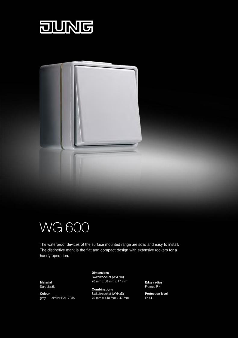
WG 600The waterproof devices of the surface mounted range are solid and easy to install. The distinctive mark is the flat and compact design with extensive rockers for a handy operation.
Material Duroplastic
Colour grey similar RAL 7035
Dimensions Switch/socket (WxHxD) 70 mm x 68 mm x 47 mm
Combinations Switch/socket (WxHxD) 70 mm x 140 mm x 47 mm
Edge radiusFrames R 4
Protection level IP 44
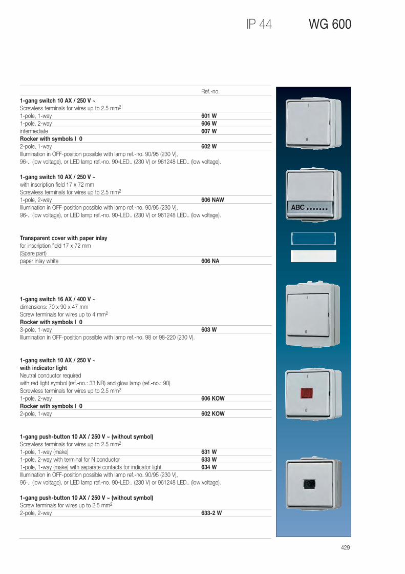
429
IP 44 WG 600
1-gang switch 10 AX / 250 V ~Screwless terminals for wires up to 2.5 mm2
1-pole, 1-way 601 W1-pole, 2-way 606 Wintermediate 607 WRocker with symbols I 02-pole, 1-way 602 WIllumination in OFF-position possible with lamp ref.-no. 90/95 (230 V), 96-.. (low voltage), or LED lamp ref.-no. 90-LED.. (230 V) or 961248 LED.. (low voltage).
1-gang switch 10 AX / 250 V ~with inscription field 17 x 72 mmScrewless terminals for wires up to 2.5 mm2
1-pole, 2-way 606 NAWIllumination in OFF-position possible with lamp ref.-no. 90/95 (230 V), 96-.. (low voltage), or LED lamp ref.-no. 90-LED.. (230 V) or 961248 LED.. (low voltage).
Transparent cover with paper inlayfor inscription field 17 x 72 mm(Spare part)paper inlay white 606 NA
1-gang switch 16 AX / 400 V ~dimensions: 70 x 90 x 47 mmScrew terminals for wires up to 4 mm2
Rocker with symbols I 03-pole, 1-way 603 WIllumination in OFF-position possible with lamp ref.-no. 98 or 98-220 (230 V).
1-gang switch 10 AX / 250 V ~ with indicator lightNeutral conductor requiredwith red light symbol (ref.-no.: 33 NR) and glow lamp (ref.-no.: 90)Screwless terminals for wires up to 2.5 mm2
1-pole, 2-way 606 KOWRocker with symbols I 02-pole, 1-way 602 KOW
1-gang push-button 10 AX / 250 V ~ (without symbol)Screwless terminals for wires up to 2.5 mm2
1-pole, 1-way (make) 631 W1-pole, 2-way with terminal for N conductor 633 W1-pole, 1-way (make) with separate contacts for indicator light 634 WIllumination in OFF-position possible with lamp ref.-no. 90/95 (230 V), 96-.. (low voltage), or LED lamp ref.-no. 90-LED.. (230 V) or 961248 LED.. (low voltage).
1-gang push-button 10 AX / 250 V ~ (without symbol)Screw terminals for wires up to 2.5 mm2
2-pole, 2-way 633-2 W
Ref.-no.
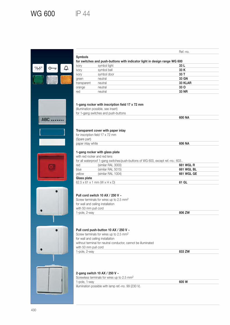
430
IP 44 WG 600
Symbolsfor switches and push-buttons with indicator light in design range WG 600ivory symbol light 33 Livory symbol bell 33 Kivory symbol door 33 Tgreen neutral 33 GNtransparent neutral 33 KLARorange neutral 33 Ored neutral 33 NR
1-gang rocker with inscription field 17 x 72 mm(illumination possible, see insert)for 1-gang switches and push-buttons
600 NA
Transparent cover with paper inlayfor inscription field 17 x 72 mm(Spare part)paper inlay white 606 NA
1-gang rocker with glass platewith red rocker and red lensfor all waterproof 1-gang switches/push-buttons of WG 600, except ref.-no.: 603..red (similar RAL 3000) 661 WGL Rblue (similar RAL 5015) 661 WGL BLyellow (similar RAL 1004) 661 WGL GEGlass plate62.5 x 61 x 1 mm (W x H x D) 61 GL
Pull cord switch 10 AX / 250 V ~Screw terminals for wires up to 2.5 mm2
for wall and ceiling installationwith 50 mm pull cord1-pole, 2-way 806 ZW
Pull cord push-button 10 AX / 250 V ~Screw terminals for wires up to 2.5 mm2
for wall and ceiling installationwithout terminal for neutral conductor, cannot be illuminatedwith 50 mm pull cord1-pole, 2-way 833 ZW
2-gang switch 10 AX / 250 V ~Screwless terminals for wires up to 2.5 mm2
1-pole, 1-way 605 Willumination possible with lamp ref.-no. 99 (230 V).
Ref.-no.
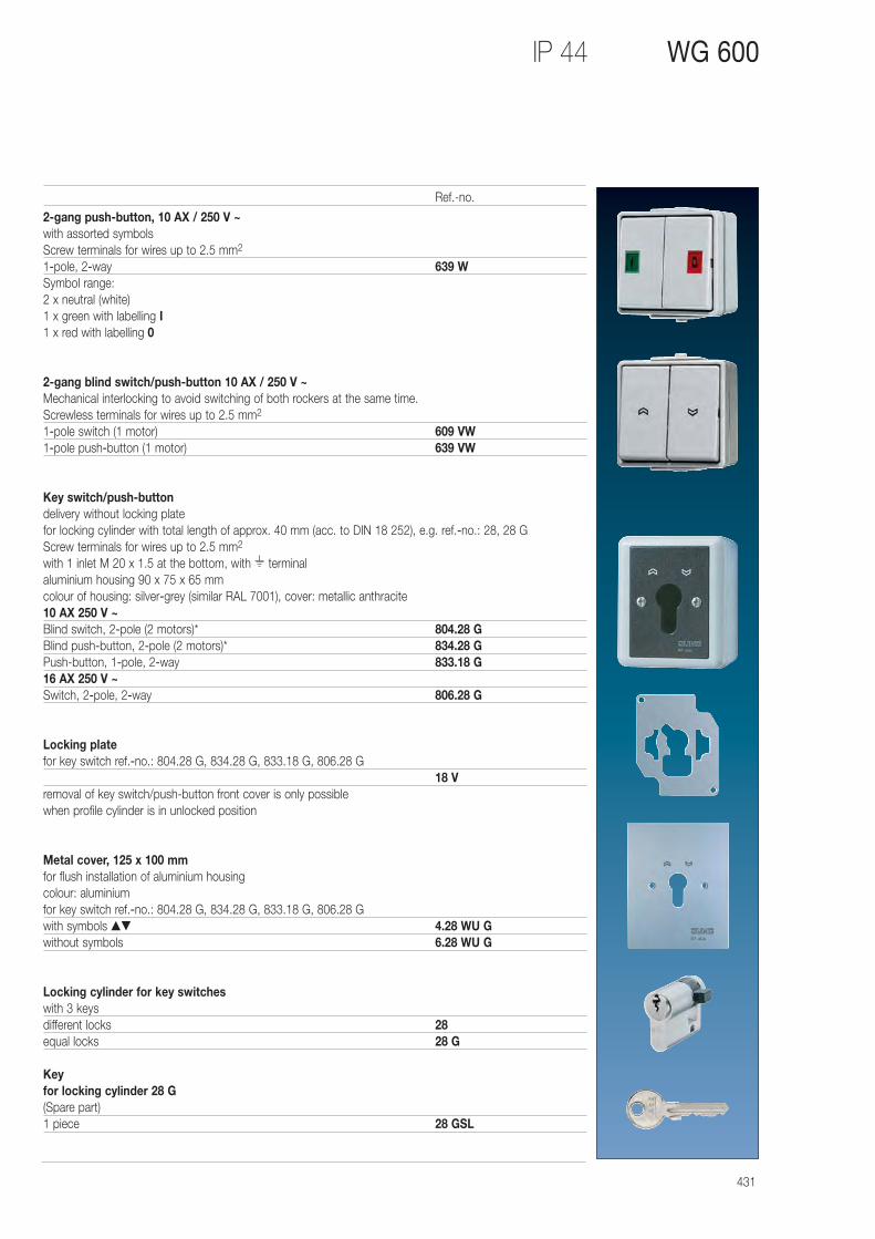
431
IP 44 WG 600
2-gang push-button, 10 AX / 250 V ~with assorted symbolsScrew terminals for wires up to 2.5 mm2
1-pole, 2-way 639 WSymbol range:2 x neutral (white)1 x green with labelling I1 x red with labelling 0
2-gang blind switch/push-button 10 AX / 250 V ~Mechanical interlocking to avoid switching of both rockers at the same time.Screwless terminals for wires up to 2.5 mm2
1-pole switch (1 motor) 609 VW1-pole push-button (1 motor) 639 VW
Key switch/push-buttondelivery without locking platefor locking cylinder with total length of approx. 40 mm (acc. to DIN 18 252), e.g. ref.-no.: 28, 28 GScrew terminals for wires up to 2.5 mm2
with 1 inlet M 20 x 1.5 at the bottom, with terminalaluminium housing 90 x 75 x 65 mmcolour of housing: silver-grey (similar RAL 7001), cover: metallic anthracite10 AX 250 V ~Blind switch, 2-pole (2 motors)* 804.28 GBlind push-button, 2-pole (2 motors)* 834.28 GPush-button, 1-pole, 2-way 833.18 G16 AX 250 V ~Switch, 2-pole, 2-way 806.28 G
Locking platefor key switch ref.-no.: 804.28 G, 834.28 G, 833.18 G, 806.28 G
18 Vremoval of key switch/push-button front cover is only possible when profile cylinder is in unlocked position
Metal cover, 125 x 100 mmfor flush installation of aluminium housingcolour: aluminiumfor key switch ref.-no.: 804.28 G, 834.28 G, 833.18 G, 806.28 Gwith symbols ▲▼ 4.28 WU Gwithout symbols 6.28 WU G
Locking cylinder for key switcheswith 3 keysdifferent locks 28equal locks 28 G
Key for locking cylinder 28 G(Spare part)1 piece 28 GSL
Ref.-no.
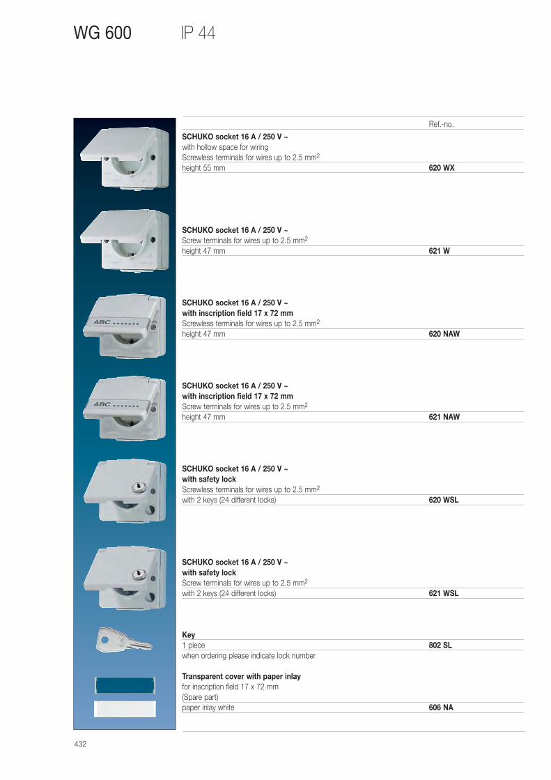
432
IP 44 WG 600
SCHUKO socket 16 A / 250 V ~with hollow space for wiringScrewless terminals for wires up to 2.5 mm2
height 55 mm 620 WX
SCHUKO socket 16 A / 250 V ~Screw terminals for wires up to 2.5 mm2
height 47 mm 621 W
SCHUKO socket 16 A / 250 V ~with inscription field 17 x 72 mmScrewless terminals for wires up to 2.5 mm2
height 47 mm 620 NAW
SCHUKO socket 16 A / 250 V ~with inscription field 17 x 72 mmScrew terminals for wires up to 2.5 mm2
height 47 mm 621 NAW
SCHUKO socket 16 A / 250 V ~with safety lockScrewless terminals for wires up to 2.5 mm2
with 2 keys (24 different locks) 620 WSL
SCHUKO socket 16 A / 250 V ~with safety lockScrew terminals for wires up to 2.5 mm2
with 2 keys (24 different locks) 621 WSL
Key1 piece 802 SLwhen ordering please indicate lock number
Transparent cover with paper inlayfor inscription field 17 x 72 mm(Spare part)paper inlay white 606 NA
Ref.-no.
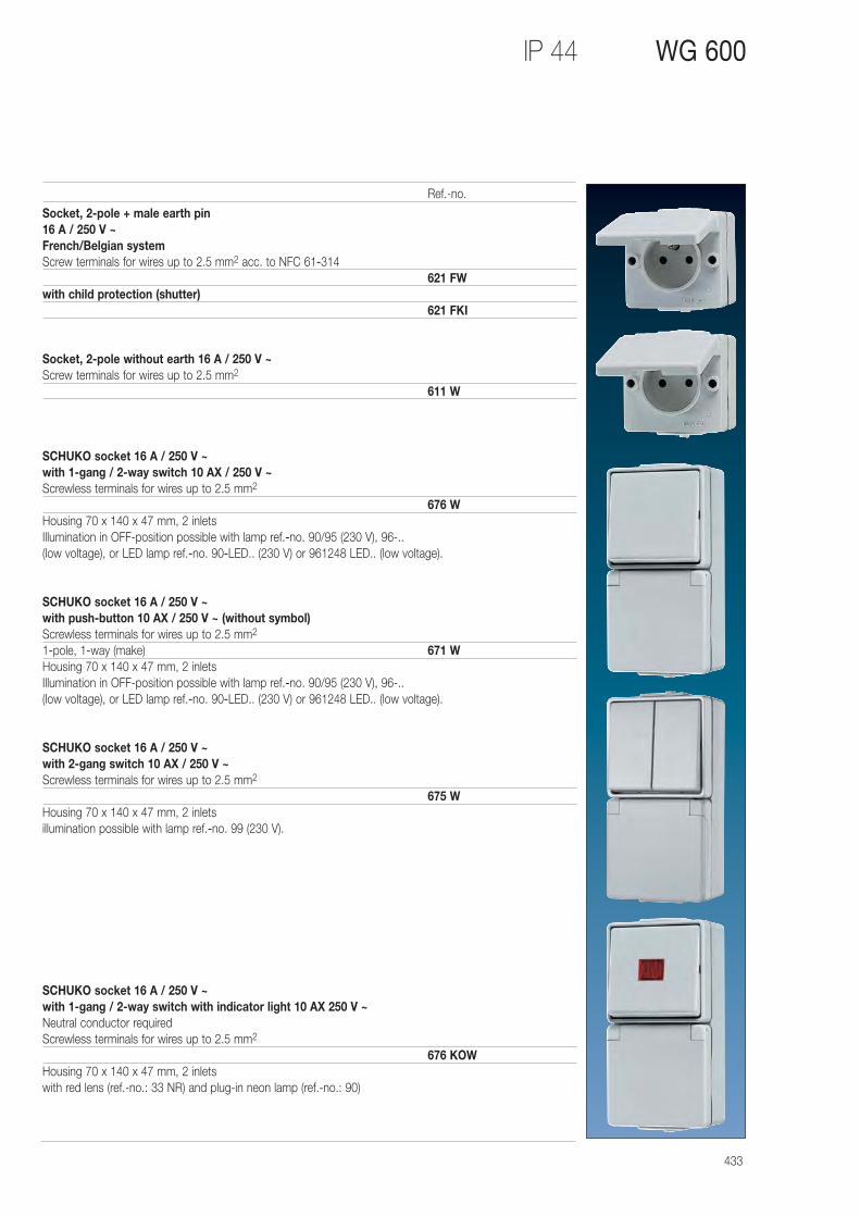
433
IP 44 WG 600
Socket, 2-pole + male earth pin16 A / 250 V ~French/Belgian systemScrew terminals for wires up to 2.5 mm2 acc. to NFC 61-314
621 FWwith child protection (shutter)
621 FKI
Socket, 2-pole without earth 16 A / 250 V ~Screw terminals for wires up to 2.5 mm2
611 W
SCHUKO socket 16 A / 250 V ~ with 1-gang / 2-way switch 10 AX / 250 V ~Screwless terminals for wires up to 2.5 mm2
676 WHousing 70 x 140 x 47 mm, 2 inletsIllumination in OFF-position possible with lamp ref.-no. 90/95 (230 V), 96-.. (low voltage), or LED lamp ref.-no. 90-LED.. (230 V) or 961248 LED.. (low voltage).
SCHUKO socket 16 A / 250 V ~ with push-button 10 AX / 250 V ~ (without symbol)Screwless terminals for wires up to 2.5 mm2
1-pole, 1-way (make) 671 WHousing 70 x 140 x 47 mm, 2 inletsIllumination in OFF-position possible with lamp ref.-no. 90/95 (230 V), 96-.. (low voltage), or LED lamp ref.-no. 90-LED.. (230 V) or 961248 LED.. (low voltage).
SCHUKO socket 16 A / 250 V ~ with 2-gang switch 10 AX / 250 V ~Screwless terminals for wires up to 2.5 mm2
675 WHousing 70 x 140 x 47 mm, 2 inletsillumination possible with lamp ref.-no. 99 (230 V).
SCHUKO socket 16 A / 250 V ~ with 1-gang / 2-way switch with indicator light 10 AX 250 V ~Neutral conductor requiredScrewless terminals for wires up to 2.5 mm2
676 KOWHousing 70 x 140 x 47 mm, 2 inletswith red lens (ref.-no.: 33 NR) and plug-in neon lamp (ref.-no.: 90)
Ref.-no.
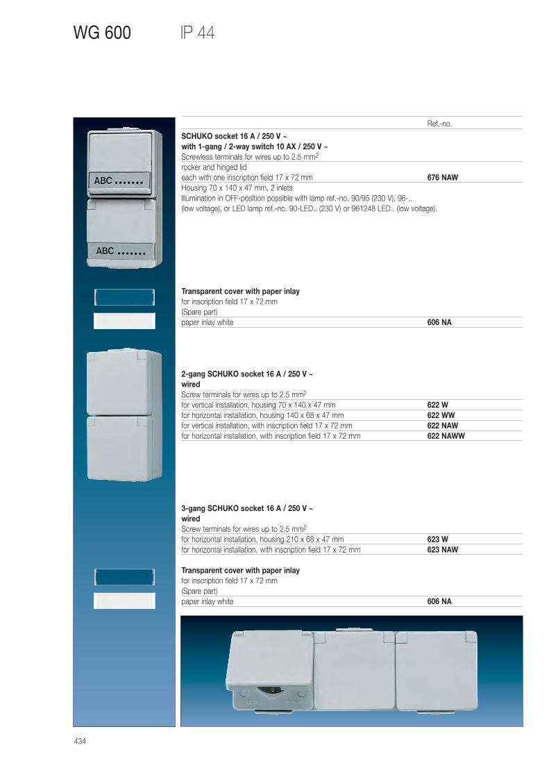
434
IP 44 WG 600
SCHUKO socket 16 A / 250 V ~ with 1-gang / 2-way switch 10 AX / 250 V ~Screwless terminals for wires up to 2.5 mm2
rocker and hinged lid each with one inscription field 17 x 72 mm 676 NAWHousing 70 x 140 x 47 mm, 2 inletsIllumination in OFF-position possible with lamp ref.-no. 90/95 (230 V), 96-.. (low voltage), or LED lamp ref.-no. 90-LED.. (230 V) or 961248 LED.. (low voltage).
Transparent cover with paper inlayfor inscription field 17 x 72 mm(Spare part)paper inlay white 606 NA
2-gang SCHUKO socket 16 A / 250 V ~wiredScrew terminals for wires up to 2.5 mm2
for vertical installation, housing 70 x 140 x 47 mm 622 Wfor horizontal installation, housing 140 x 68 x 47 mm 622 WWfor vertical installation, with inscription field 17 x 72 mm 622 NAWfor horizontal installation, with inscription field 17 x 72 mm 622 NAWW
3-gang SCHUKO socket 16 A / 250 V ~wiredScrew terminals for wires up to 2.5 mm2
for horizontal installation, housing 210 x 68 x 47 mm 623 Wfor horizontal installation, with inscription field 17 x 72 mm 623 NAW
Transparent cover with paper inlayfor inscription field 17 x 72 mm(Spare part)paper inlay white 606 NA
Ref.-no.
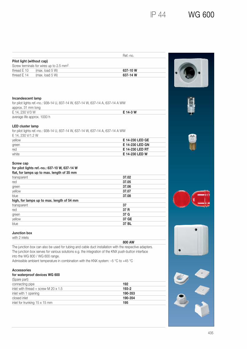
435
IP 44 WG 600
Pilot light (without cap)Screw terminals for wires up to 2.5 mm2
thread E 10 (max. load 5 W) 637-10 Wthread E 14 (max. load 5 W) 637-14 W
Incandescent lampfor pilot lights ref.-no.: 938-14 U, 837-14 W, 637-14 W, 637-14 A, 637-14 A WWapprox. 31 mm longE 14, 230 V/3 W E 14-3 Waverage life approx. 1000 h
LED cluster lampfor pilot lights ref.-no.: 938-14 U, 837-14 W, 637-14 W, 637-14 A, 637-14 A WWE 14, 230 V/1.2 Wyellow E 14-230 LED GEgreen E 14-230 LED GNred E 14-230 LED RTwhite E 14-230 LED W
Screw capfor pilot lights ref.-no.: 637-10 W, 637-14 Wflat, for lamps up to max. length of 35 mmtransparent 37.02red 37.05green 37.06yellow 37.07blue 37.08high, for lamps up to max. length of 54 mmtransparent 37red 37 Rgreen 37 Gyellow 37 GEblue 37 BL
Junction boxwith 2 inlets
800 AWThe junction box can also be used for tubing and cable duct installation with the respective adapters. The junction box serves for various solutions e.g. the integration of the KNX push-button interface into the WG 800 / WG 600 range. Admissible ambient temperature in combination with the KNX system: –5 °C to +45 °C
Accessories for waterproof devices WG 600(Spare part)connecting pipe 192inlet with thread + screw M 20 x 1.5 193-2inlet with 1 opening 190-353closed inlet 190-354inlet for trunking 15 x 15 mm 195
Ref.-no.
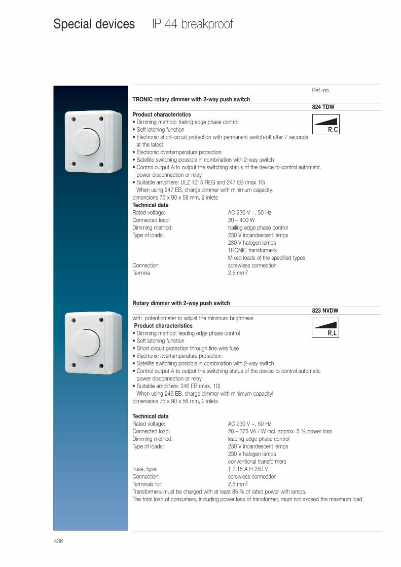
436
TRONIC rotary dimmer with 2-way push switch824 TDW
Product characteristics• Dimming method: trailing edge phase control• Soft latching function• Electronic short-circuit protection with permanent switch-off after 7 seconds
at the latest• Electronic overtemperature protection• Satellite switching possible in combination with 2-way switch• Control output A to output the switching status of the device to control automatic
power disconnection or relay• Suitable amplifiers: ULZ 1215 REG and 247 EB (max 10)
When using 247 EB, charge dimmer with minimum capacity.dimensions 75 x 90 x 58 mm, 2 inletsTechnical dataRated voltage: AC 230 V ~, 50 HzConnected load: 20 – 400 WDimming method: trailing edge phase controlType of loads: 230 V incandescent lamps
230 V halogen lampsTRONIC transformersMixed loads of the specified types
Connection: screwless connectionTermina 2.5 mm2
Rotary dimmer with 2-way push switch823 NVDW
with potentiometer to adjust the minimum brightnessProduct characteristics
• Dimming method: leading edge phase control• Soft latching function• Short-circuit protection through fine-wire fuse• Electronic overtemperature protection• Satellite switching possible in combination with 2-way switch• Control output A to output the switching status of the device to control automatic
power disconnection or relay• Suitable amplifiers: 246 EB (max. 10)
When using 246 EB, charge dimmer with minimum capacity!dimensions 75 x 90 x 58 mm, 2 inlets
Technical dataRated voltage: AC 230 V ~, 50 HzConnected load: 20 – 375 VA / W incl. approx. 5 % power lossDimming method: leading edge phase controlType of loads: 230 V incandescent lamps
230 V halogen lampsconventional transformers
Fuse, type: T 3.15 A H 250 VConnection: screwless connectionTerminals for: 2.5 mm2
Transformers must be charged with at least 85 % of rated power with lamps.The total load of consumers, including power loss of transformer, must not exceed the maximum load.
Ref.-no.
IP 44 breakproofSpecial devices
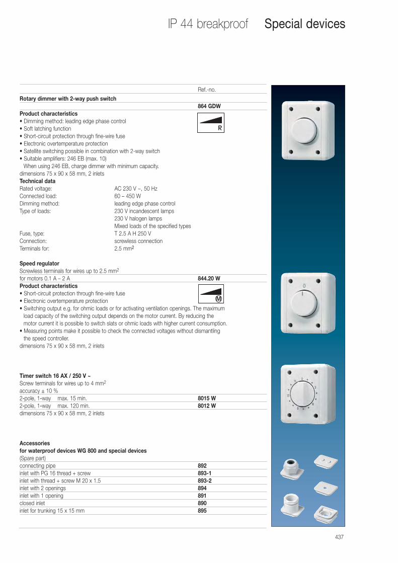
437
Rotary dimmer with 2-way push switch864 GDW
Product characteristics• Dimming method: leading edge phase control• Soft latching function• Short-circuit protection through fine-wire fuse• Electronic overtemperature protection• Satellite switching possible in combination with 2-way switch• Suitable amplifiers: 246 EB (max. 10)
When using 246 EB, charge dimmer with minimum capacity.dimensions 75 x 90 x 58 mm, 2 inletsTechnical dataRated voltage: AC 230 V ~, 50 HzConnected load: 60 – 450 WDimming method: leading edge phase controlType of loads: 230 V incandescent lamps
230 V halogen lampsMixed loads of the specified types
Fuse, type: T 2.5 A H 250 VConnection: screwless connectionTerminals for: 2.5 mm2
Speed regulatorScrewless terminals for wires up to 2.5 mm2
for motors 0.1 A – 2 A 844.20 WProduct characteristics• Short-circuit protection through fine-wire fuse• Electronic overtemperature protection• Switching output e.g. for ohmic loads or for activating ventilation openings. The maximum
load capacity of the switching output depends on the motor current. By reducing the motor current it is possible to switch slats or ohmic loads with higher current consumption.
• Measuring points make it possible to check the connected voltages without dismantling the speed controller.
dimensions 75 x 90 x 58 mm, 2 inlets
Timer switch 16 AX / 250 V ~Screw terminals for wires up to 4 mm2
accuracy ± 10 %2-pole, 1-way max. 15 min. 8015 W2-pole, 1-way max. 120 min. 8012 Wdimensions 75 x 90 x 58 mm, 2 inlets
Accessories for waterproof devices WG 800 and special devices(Spare part)connecting pipe 892inlet with PG 16 thread + screw 893-1inlet with thread + screw M 20 x 1.5 893-2inlet with 2 openings 894inlet with 1 opening 891closed inlet 890inlet for trunking 15 x 15 mm 895
Ref.-no.
IP 44 breakproof Special devices
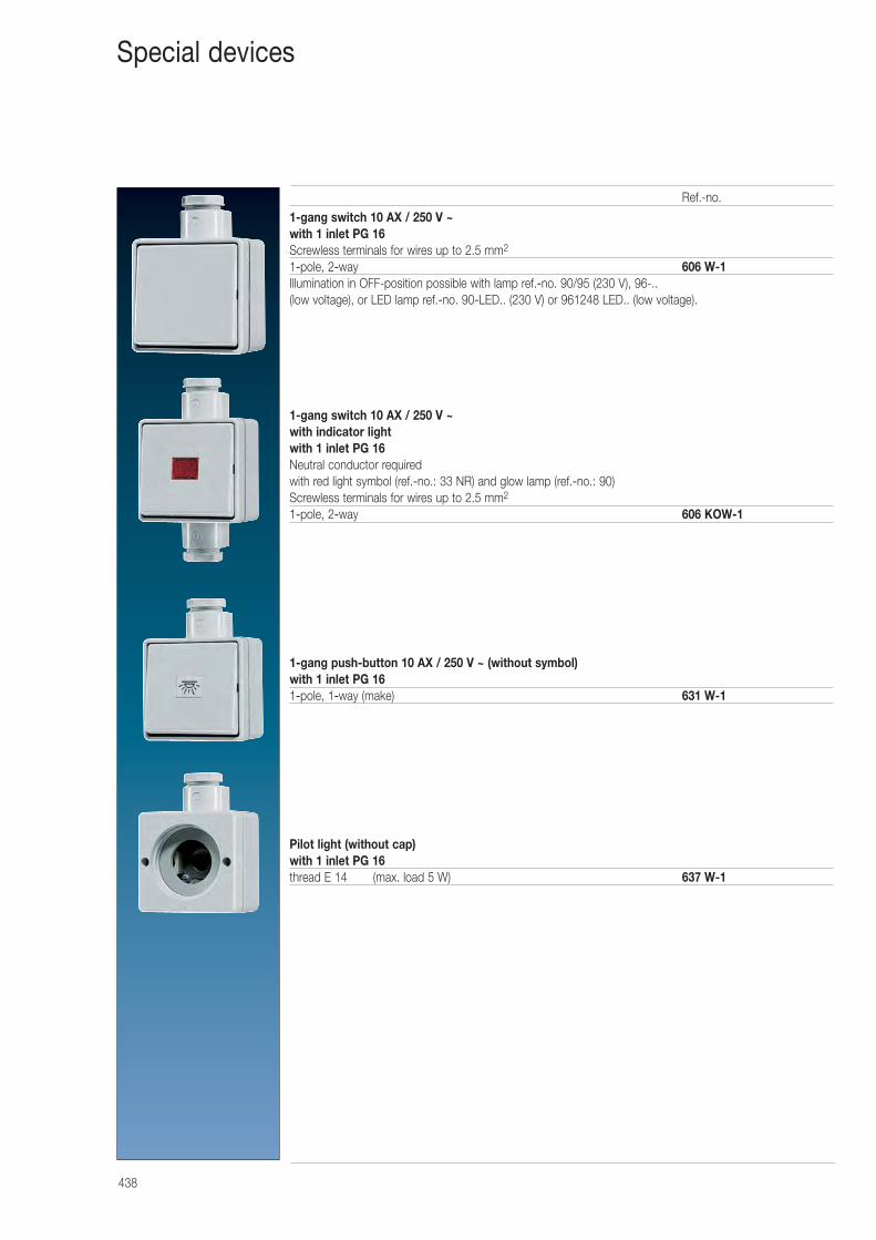
438
1-gang switch 10 AX / 250 V ~with 1 inlet PG 16Screwless terminals for wires up to 2.5 mm2
1-pole, 2-way 606 W-1Illumination in OFF-position possible with lamp ref.-no. 90/95 (230 V), 96-.. (low voltage), or LED lamp ref.-no. 90-LED.. (230 V) or 961248 LED.. (low voltage).
1-gang switch 10 AX / 250 V ~ with indicator lightwith 1 inlet PG 16Neutral conductor requiredwith red light symbol (ref.-no.: 33 NR) and glow lamp (ref.-no.: 90)Screwless terminals for wires up to 2.5 mm2
1-pole, 2-way 606 KOW-1
1-gang push-button 10 AX / 250 V ~ (without symbol)with 1 inlet PG 161-pole, 1-way (make) 631 W-1
Pilot light (without cap)with 1 inlet PG 16thread E 14 (max. load 5 W) 637 W-1
Ref.-no.
Special devices
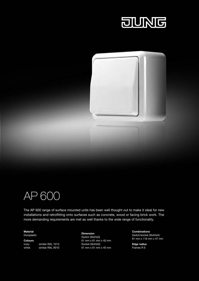
AP 600The AP 600 range of surface mounted units has been well thought out to make it ideal for new installations and retrofitting onto surfaces such as concrete, wood or facing brick work. The more demanding requirements are met as well thanks to the wide range of functionality.
MaterialDuroplastic
Colours ivory similar RAL 1013 white similar RAL 9010
Dimension Switch (WxHxD) 61 mm x 61 mm x 40 mm Socket (WxHxD) 61 mm x 61 mm x 40 mm
Combinations Switch/socket (WxHxH) 61 mm x 116 mm x 47 mm
Edge radius Frames R 6
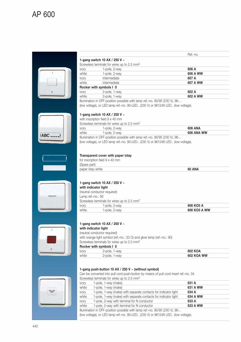
440
AP 600
1-gang switch 10 AX / 250 V ~Screwless terminals for wires up to 2.5 mm2
ivory 1-pole, 2-way 606 Awhite 1-pole, 2-way 606 A WWivory intermediate 607 Awhite intermediate 607 A WWRocker with symbols I 0ivory 2-pole, 1-way 602 Awhite 2-pole, 1-way 602 A WWIllumination in OFF-position possible with lamp ref.-no. 90/95 (230 V), 96-.. (low voltage), or LED lamp ref.-no. 90-LED.. (230 V) or 961248 LED.. (low voltage).
1-gang switch 10 AX / 250 V ~with inscription field 9 x 40 mmScrewless terminals for wires up to 2.5 mm2
ivory 1-pole, 2-way 606 ANAwhite 1-pole, 2-way 606 ANA WWIllumination in OFF-position possible with lamp ref.-no. 90/95 (230 V), 96-.. (low voltage), or LED lamp ref.-no. 90-LED.. (230 V) or 961248 LED.. (low voltage).
Transparent cover with paper inlayfor inscription field 9 x 40 mm(Spare part)paper inlay white 60 ANA
1-gang switch 10 AX / 250 V ~ with indicator light(neutral conductor required)Lamp ref.-no.: 90Screwless terminals for wires up to 2.5 mm2
ivory 1-pole, 2-way 606 KO5 Awhite 1-pole, 2-way 606 KO5 A WW
1-gang switch 10 AX / 250 V ~ with indicator light(neutral conductor required)with orange light symbol (ref.-no.: 33 O) and glow lamp (ref.-no.: 90)Screwless terminals for wires up to 2.5 mm2
Rocker with symbols I 0ivory 2-pole, 1-way 602 KOAwhite 2-pole, 1-way 602 KOA WW
1-gang push-button 10 AX / 250 V ~ (without symbol)Can be converted into pull cord push-button by means of pull cord insert ref.-no. 34.Screwless terminals for wires up to 2.5 mm2
ivory 1-pole, 1-way (make) 631 Awhite 1-pole, 1-way (make) 631 A WWivory 1-pole, 1-way (make) with separate contacts for indicator light 634 Awhite 1-pole, 1-way (make) with separate contacts for indicator light 634 A WWivory 1-pole, 2-way with terminal for N conductor 633 Awhite 1-pole, 2-way with terminal for N conductor 633 A WWIllumination in OFF-position possible with lamp ref.-no. 90/95 (230 V), 96-.. (low voltage), or LED lamp ref.-no. 90-LED.. (230 V) or 961248 LED.. (low voltage).
Ref.-no.
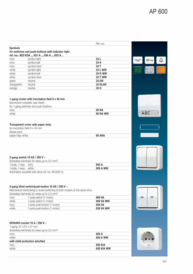
441
AP 600
Symbolsfor switches and push-buttons with indicator light ref.-no.: 602 KOA .., 631 A .., 634 A .., 633 A ..ivory symbol light 33 Livory symbol bell 33 Kivory symbol door 33 Twhite symbol light 33 L WWwhite symbol bell 33 K WWwhite symbol door 33 T WWgreen neutral 33 GNtransparent neutral 33 KLARorange neutral 33 O
1-gang rocker with inscription field 9 x 40 mm(illumination possible, see insert)for 1-gang switches and push-buttonsivory 60 NAwhite 60 NA WW
Transparent cover with paper inlayfor inscription field 9 x 40 mm(Spare part)paper inlay white 60 ANA
2-gang switch 10 AX / 250 V ~Screwless terminals for wires up to 2.5 mm2
1-pole, 1-way ivory 605 A1-pole, 1-way white 605 A WWillumination possible with lamp ref.-no. 99 (230 V).
2-gang blind switch/push-button 10 AX / 250 V ~Mechanical interlocking to avoid switching of both rockers at the same time.Screwless terminals for wires up to 2.5 mm2
ivory 1-pole switch (1 motor) 609 VAwhite 1-pole switch (1 motor) 609 VA WWivory 1-pole push-button (1 motor) 639 VAwhite 1-pole push-button (1 motor) 639 VA WW
SCHUKO socket 16 A / 250 V ~1-gang, 61 x 61 x 47 mmScrewless terminals for wires up to 2.5 mm2
ivory 620 Awhite 620 A WWwith child protection (shutter)ivory 620 KIAwhite 620 KIA WW
Ref.-no.
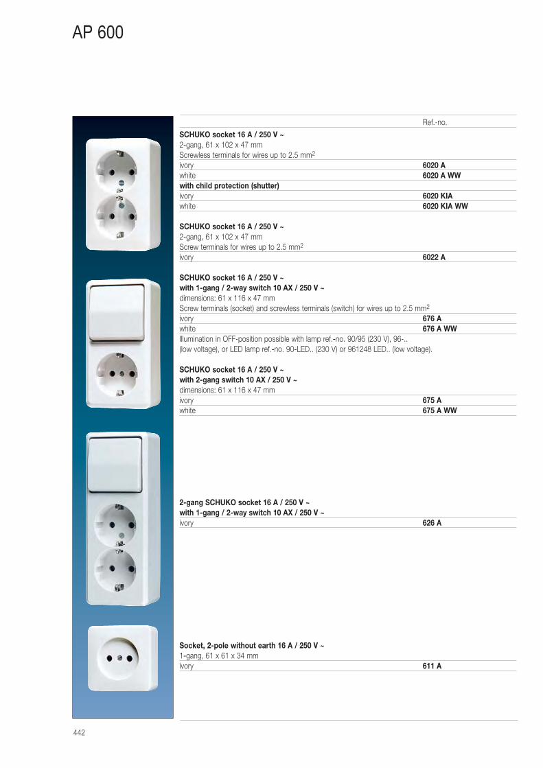
442
AP 600
SCHUKO socket 16 A / 250 V ~2-gang, 61 x 102 x 47 mmScrewless terminals for wires up to 2.5 mm2
ivory 6020 Awhite 6020 A WWwith child protection (shutter)ivory 6020 KIAwhite 6020 KIA WW
SCHUKO socket 16 A / 250 V ~2-gang, 61 x 102 x 47 mmScrew terminals for wires up to 2.5 mm2
ivory 6022 A
SCHUKO socket 16 A / 250 V ~ with 1-gang / 2-way switch 10 AX / 250 V ~dimensions: 61 x 116 x 47 mmScrew terminals (socket) and screwless terminals (switch) for wires up to 2.5 mm2
ivory 676 Awhite 676 A WWIllumination in OFF-position possible with lamp ref.-no. 90/95 (230 V), 96-.. (low voltage), or LED lamp ref.-no. 90-LED.. (230 V) or 961248 LED.. (low voltage).
SCHUKO socket 16 A / 250 V ~ with 2-gang switch 10 AX / 250 V ~dimensions: 61 x 116 x 47 mmivory 675 Awhite 675 A WW
2-gang SCHUKO socket 16 A / 250 V ~ with 1-gang / 2-way switch 10 AX / 250 V ~ivory 626 A
Socket, 2-pole without earth 16 A / 250 V ~1-gang, 61 x 61 x 34 mmivory 611 A
Ref.-no.
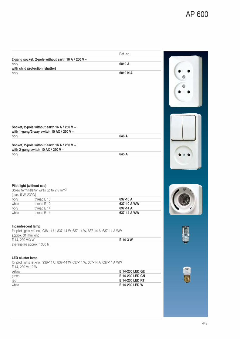
443
AP 600
2-gang socket, 2-pole without earth 16 A / 250 V ~ivory 6010 Awith child protection (shutter)ivory 6010 KIA
Socket, 2-pole without earth 16 A / 250 V ~ with 1-gang/2-way switch 10 AX / 250 V ~ivory 646 A
Socket, 2-pole without earth 16 A / 250 V ~ with 2-gang switch 10 AX / 250 V ~ivory 645 A
Pilot light (without cap)Screw terminals for wires up to 2.5 mm2
(max. 5 W, 230 V)ivory thread E 10 637-10 Awhite thread E 10 637-10 A WWivory thread E 14 637-14 Awhite thread E 14 637-14 A WW
Incandescent lampfor pilot lights ref.-no.: 938-14 U, 837-14 W, 637-14 W, 637-14 A, 637-14 A WWapprox. 31 mm longE 14, 230 V/3 W E 14-3 Waverage life approx. 1000 h
LED cluster lampfor pilot lights ref.-no.: 938-14 U, 837-14 W, 637-14 W, 637-14 A, 637-14 A WWE 14, 230 V/1.2 Wyellow E 14-230 LED GEgreen E 14-230 LED GNred E 14-230 LED RTwhite E 14-230 LED W
Ref.-no.
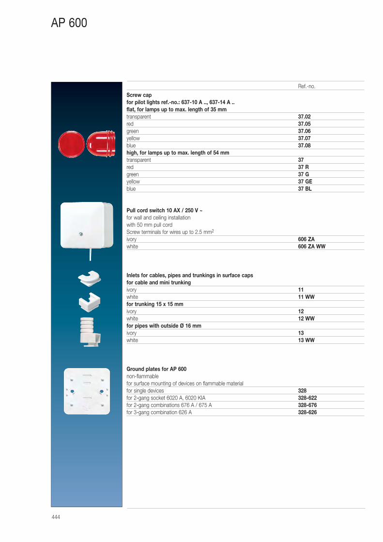
444
AP 600
Screw capfor pilot lights ref.-no.: 637-10 A .., 637-14 A ..flat, for lamps up to max. length of 35 mmtransparent 37.02red 37.05green 37.06yellow 37.07blue 37.08high, for lamps up to max. length of 54 mmtransparent 37red 37 Rgreen 37 Gyellow 37 GEblue 37 BL
Pull cord switch 10 AX / 250 V ~for wall and ceiling installationwith 50 mm pull cordScrew terminals for wires up to 2.5 mm2
ivory 606 ZAwhite 606 ZA WW
Inlets for cables, pipes and trunkings in surface capsfor cable and mini trunkingivory 11white 11 WWfor trunking 15 x 15 mmivory 12white 12 WWfor pipes with outside Ø 16 mmivory 13white 13 WW
Ground plates for AP 600non-flammablefor surface mounting of devices on flammable materialfor single devices 328for 2-gang socket 6020 A, 6020 KIA 328-622for 2-gang combinations 676 A / 675 A 328-676for 3-gang combination 626 A 328-626
Ref.-no.
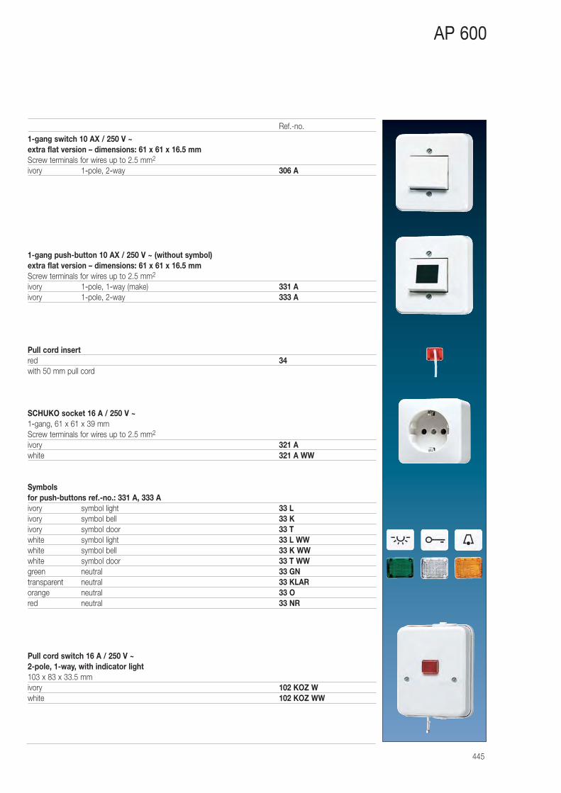
445
AP 600
1-gang switch 10 AX / 250 V ~extra flat version – dimensions: 61 x 61 x 16.5 mmScrew terminals for wires up to 2.5 mm2
ivory 1-pole, 2-way 306 A
1-gang push-button 10 AX / 250 V ~ (without symbol)extra flat version – dimensions: 61 x 61 x 16.5 mmScrew terminals for wires up to 2.5 mm2
ivory 1-pole, 1-way (make) 331 Aivory 1-pole, 2-way 333 A
Pull cord insertred 34with 50 mm pull cord
SCHUKO socket 16 A / 250 V ~1-gang, 61 x 61 x 39 mmScrew terminals for wires up to 2.5 mm2
ivory 321 Awhite 321 A WW
Symbolsfor push-buttons ref.-no.: 331 A, 333 Aivory symbol light 33 Livory symbol bell 33 Kivory symbol door 33 Twhite symbol light 33 L WWwhite symbol bell 33 K WWwhite symbol door 33 T WWgreen neutral 33 GNtransparent neutral 33 KLARorange neutral 33 Ored neutral 33 NR
Pull cord switch 16 A / 250 V ~2-pole, 1-way, with indicator light103 x 83 x 33.5 mmivory 102 KOZ Wwhite 102 KOZ WW
Ref.-no.
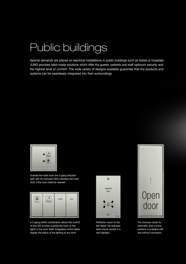
Public buildingsSpecial demands are placed on electrical installations in public buildings such as hotels or hospitals. JUNG provides tailor-made solutions which offer the guests, patients and staff optimum security and the highest level of comfort. The wide variety of designs available guarantee that the products and systems can be seamlessly integrated into their surroundings.
The oversize rocker for automatic door control systems is available with and without inscription.
A 2-gang switch combination allows the control of the LED function outside the room or the lights in the room itself. Integrated control lights display the status of the lighting at any time.
Outside the hotel room the 2-gang indicator light with its coloured LEDs indicates the hotel stuff, if the room shall be cleaned.
Perfection down to the last detail: the stainless steel shaver socket is a real highlight.
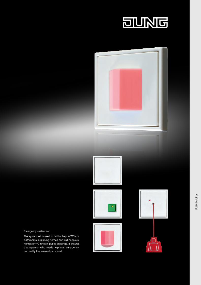
Emergency system set
The system set is used to call for help in WCs or bathrooms in nursing homes and old people‘s homes or WC units in public buildings. It ensures that a person who needs help in an emergency can notify the relevant personnel.
Publ
ic b
uild
ings
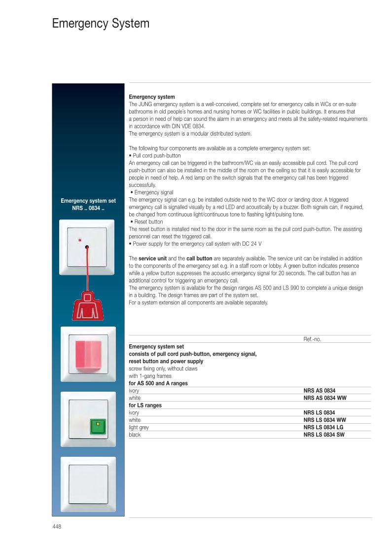
448
Emergency System
Emergency systemThe JUNG emergency system is a well-conceived, complete set for emergency calls in WCs or en-suite bathrooms in old people´s homes and nursing homes or WC facilities in public buildings. It ensures that a person in need of help can sound the alarm in an emergency and meets all the safety-related requirementsin accordance with DIN VDE 0834.The emergency system is a modular distributed system.
The following four components are available as a complete emergency system set:• Pull cord push-buttonAn emergency call can be triggered in the bathroom/WC via an easily accessible pull cord. The pull cordpush-button can also be installed in the middle of the room on the ceiling so that it is easily accessible forpeople in need of help. A red lamp on the switch signals that the emergency call has been triggered successfully.• Emergency signal
The emergency signal can e.g. be installed outside next to the WC door or landing door. A triggered emergency call is signalled visually by a red LED and acoustically by a buzzer. Both signals can, if required, be changed from continuous light/continuous tone to flashing light/pulsing tone.• Reset button
The reset button is installed next to the door in the same room as the pull cord push-button. The assistingpersonnel can reset the triggered call.• Power supply for the emergency call system with DC 24 V
The service unit and the call button are separately available. The service unit can be installed in addition to the components of the emergency set e.g. in a staff room or lobby. A green button indicates presencewhile a yellow button suppresses the acoustic emergency signal for 20 seconds. The call button has an additional control for triggering an emergency call.The emergency system is available for the design ranges AS 500 and LS 990 to complete a unique design in a building. The design frames are part of the system set.For a system extension all components are available separately.
Ref.-no.Emergency system setconsists of pull cord push-button, emergency signal, reset button and power supplyscrew fixing only, without clawswith 1-gang framesfor AS 500 and A rangesivory NRS AS 0834white NRS AS 0834 WWfor LS rangesivory NRS LS 0834white NRS LS 0834 WWlight grey NRS LS 0834 LGblack NRS LS 0834 SW
Emergency system setNRS .. 0834 ..
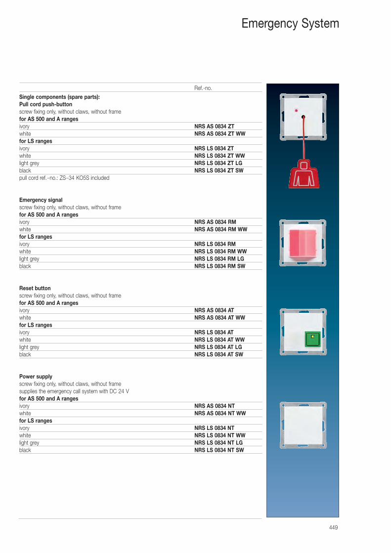
449
Emergency System
Single components (spare parts):Pull cord push-buttonscrew fixing only, without claws, without framefor AS 500 and A rangesivory NRS AS 0834 ZTwhite NRS AS 0834 ZT WWfor LS rangesivory NRS LS 0834 ZTwhite NRS LS 0834 ZT WWlight grey NRS LS 0834 ZT LGblack NRS LS 0834 ZT SWpull cord ref.-no.: ZS-34 KO5S included
Emergency signalscrew fixing only, without claws, without framefor AS 500 and A rangesivory NRS AS 0834 RMwhite NRS AS 0834 RM WWfor LS rangesivory NRS LS 0834 RMwhite NRS LS 0834 RM WWlight grey NRS LS 0834 RM LGblack NRS LS 0834 RM SW
Reset buttonscrew fixing only, without claws, without framefor AS 500 and A rangesivory NRS AS 0834 ATwhite NRS AS 0834 AT WWfor LS rangesivory NRS LS 0834 ATwhite NRS LS 0834 AT WWlight grey NRS LS 0834 AT LGblack NRS LS 0834 AT SW
Power supplyscrew fixing only, without claws, without framesupplies the emergency call system with DC 24 Vfor AS 500 and A rangesivory NRS AS 0834 NTwhite NRS AS 0834 NT WWfor LS rangesivory NRS LS 0834 NTwhite NRS LS 0834 NT WWlight grey NRS LS 0834 NT LGblack NRS LS 0834 NT SW
Ref.-no.
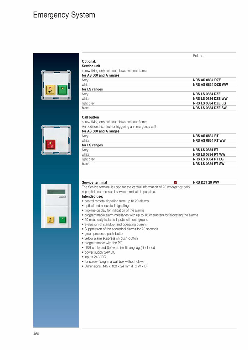
450
Emergency System
Optional:Service unitscrew fixing only, without claws, without framefor AS 500 and A rangesivory NRS AS 0834 DZEwhite NRS AS 0834 DZE WWfor LS rangesivory NRS LS 0834 DZEwhite NRS LS 0834 DZE WWlight grey NRS LS 0834 DZE LGblack NRS LS 0834 DZE SW
Call buttonscrew fixing only, without claws, without frameAn additional control for triggering an emergency call.for AS 500 and A rangesivory NRS AS 0834 RTwhite NRS AS 0834 RT WWfor LS rangesivory NRS LS 0834 RTwhite NRS LS 0834 RT WWlight grey NRS LS 0834 RT LGblack NRS LS 0834 RT SW
Service terminal NRS DZT 20 WWThe Service terminal is used for the central information of 20 emergency calls.A parallel use of several service terminals is possible.Intended use:• central remote signalling from up to 20 alarms• optical and acoustical signalling• two-line display for indication of the alarms• programmable alarm messages with up to 16 characters for allocating the alarms• 20 electrically isolated inputs with one ground• evaluation of standby- and operating current• Suppression of the acoustical alarms for 20 seconds• green presence push-button• yellow alarm suppression push-button• programmable with the PC• USB-cable and Software (multi-language) included• power supply 24V DC• inputs 24 V DC• for screw-fixing in a wall box without claws• Dimensions: 145 x 100 x 24 mm (H x W x D)
N
Ref.-no.
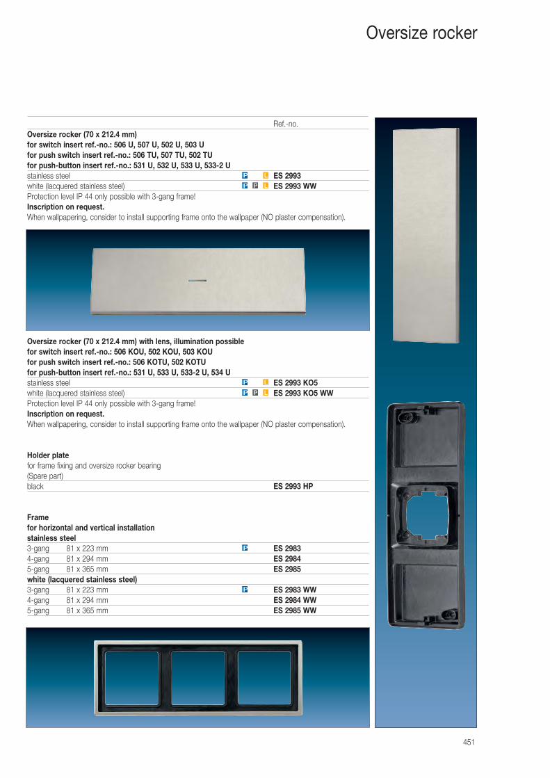
451
Oversize rocker
Oversize rocker (70 x 212.4 mm)for switch insert ref.-no.: 506 U, 507 U, 502 U, 503 Ufor push switch insert ref.-no.: 506 TU, 507 TU, 502 TUfor push-button insert ref.-no.: 531 U, 532 U, 533 U, 533-2 Ustainless steel ES 2993white (lacquered stainless steel) ES 2993 WWProtection level IP 44 only possible with 3-gang frame!Inscription on request.When wallpapering, consider to install supporting frame onto the wallpaper (NO plaster compensation).
Oversize rocker (70 x 212.4 mm) with lens, illumination possiblefor switch insert ref.-no.: 506 KOU, 502 KOU, 503 KOUfor push switch insert ref.-no.: 506 KOTU, 502 KOTUfor push-button insert ref.-no.: 531 U, 533 U, 533-2 U, 534 Ustainless steel ES 2993 KO5white (lacquered stainless steel) ES 2993 KO5 WWProtection level IP 44 only possible with 3-gang frame!Inscription on request.When wallpapering, consider to install supporting frame onto the wallpaper (NO plaster compensation).
Holder platefor frame fixing and oversize rocker bearing(Spare part)black ES 2993 HP
Framefor horizontal and vertical installationstainless steel3-gang 81 x 223 mm ES 29834-gang 81 x 294 mm ES 29845-gang 81 x 365 mm ES 2985white (lacquered stainless steel)3-gang 81 x 223 mm ES 2983 WW4-gang 81 x 294 mm ES 2984 WW5-gang 81 x 365 mm ES 2985 WW
IP
IP
LPIP
LIP
P LIP
LIP
Ref.-no.
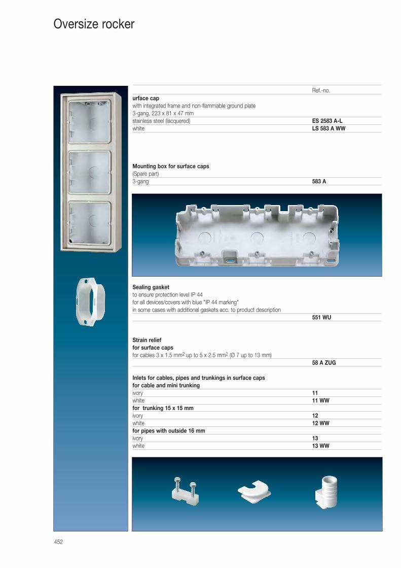
urface capwith integrated frame and non-flammable ground plate3-gang, 223 x 81 x 47 mmstainless steel (lacquered) ES 2583 A-Lwhite LS 583 A WW
Mounting box for surface caps(Spare part)3-gang 583 A
Sealing gasketto ensure protection level IP 44for all devices/covers with blue "IP 44 marking"in some cases with additional gaskets acc. to product description
551 WU
Strain relieffor surface capsfor cables 3 x 1.5 mm2 up to 5 x 2.5 mm2 (Ø 7 up to 13 mm)
58 A ZUG
Inlets for cables, pipes and trunkings in surface capsfor cable and mini trunkingivory 11white 11 WWfor trunking 15 x 15 mmivory 12white 12 WWfor pipes with outside 16 mmivory 13white 13 WW
452
Oversize rocker
Ref.-no.
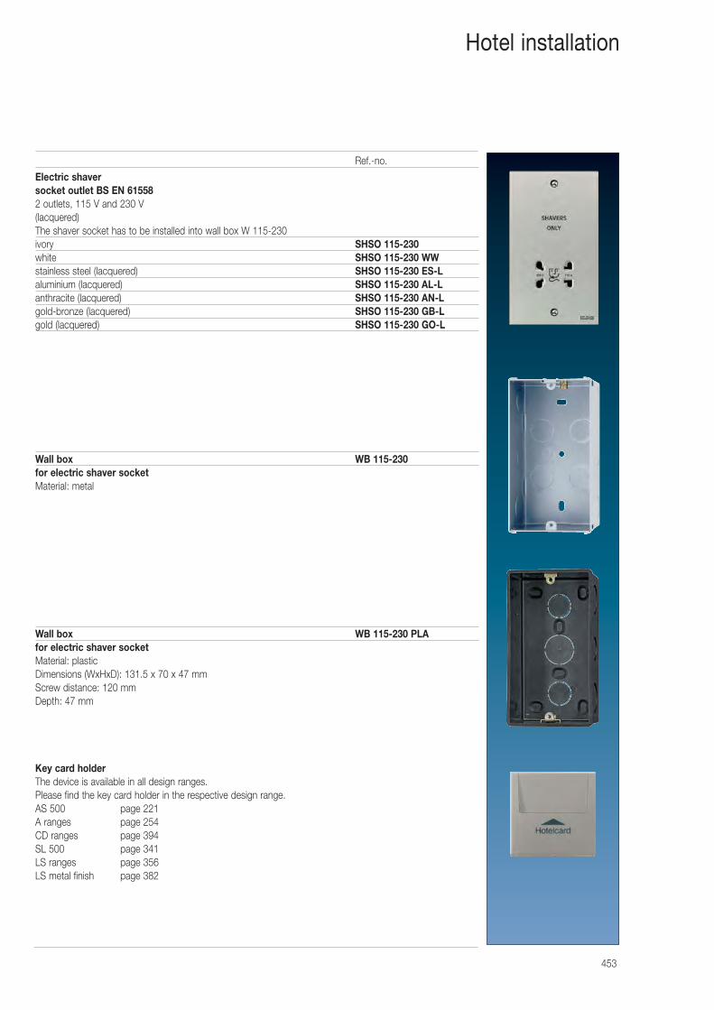
453
Hotel installation
Electric shaver socket outlet BS EN 615582 outlets, 115 V and 230 V (lacquered)The shaver socket has to be installed into wall box W 115-230ivory SHSO 115-230 white SHSO 115-230 WWstainless steel (lacquered) SHSO 115-230 ES-Laluminium (lacquered) SHSO 115-230 AL-Lanthracite (lacquered) SHSO 115-230 AN-Lgold-bronze (lacquered) SHSO 115-230 GB-Lgold (lacquered) SHSO 115-230 GO-L
Wall box WB 115-230for electric shaver socket Material: metal
Wall box WB 115-230 PLAfor electric shaver socket Material: plasticDimensions (WxHxD): 131.5 x 70 x 47 mmScrew distance: 120 mmDepth: 47 mm
Key card holderThe device is available in all design ranges. Please find the key card holder in the respective design range.AS 500 page 221A ranges page 254CD ranges page 394SL 500 page 341LS ranges page 356LS metal finish page 382
Ref.-no.
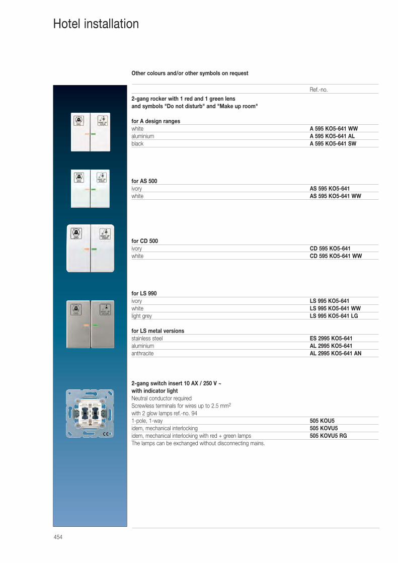
Other colours and/or other symbols on request
454
Hotel installation
2-gang rocker with 1 red and 1 green lens and symbols "Do not disturb" and "Make up room"
for A design rangeswhite A 595 KO5-641 WWaluminium A 595 KO5-641 ALblack A 595 KO5-641 SW
for AS 500ivory AS 595 KO5-641 white AS 595 KO5-641 WW
for CD 500ivory CD 595 KO5-641white CD 595 KO5-641 WW
for LS 990ivory LS 995 KO5-641 white LS 995 KO5-641 WWlight grey LS 995 KO5-641 LG
for LS metal versionsstainless steel ES 2995 KO5-641aluminium AL 2995 KO5-641anthracite AL 2995 KO5-641 AN
2-gang switch insert 10 AX / 250 V ~with indicator lightNeutral conductor requiredScrewless terminals for wires up to 2.5 mm2
with 2 glow lamps ref.-no. 941-pole, 1-way 505 KOU5idem, mechanical interlocking 505 KOVU5idem, mechanical interlocking with red + green lamps 505 KOVU5 RGThe lamps can be exchanged without disconnecting mains.
Ref.-no.
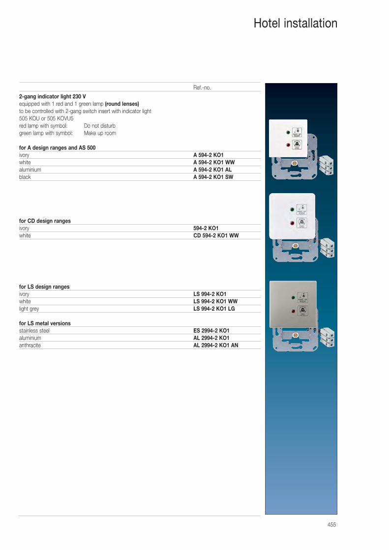
455
Hotel installation
2-gang indicator light 230 Vequipped with 1 red and 1 green lamp (round lenses)to be controlled with 2-gang switch insert with indicator light 505 KOU or 505 KOVU5red lamp with symbol: Do not disturbgreen lamp with symbol: Make up room
for A design ranges and AS 500ivory A 594-2 KO1white A 594-2 KO1 WWaluminium A 594-2 KO1 ALblack A 594-2 KO1 SW
for CD design ranges ivory 594-2 KO1white CD 594-2 KO1 WW
for LS design rangesivory LS 994-2 KO1white LS 994-2 KO1 WWlight grey LS 994-2 KO1 LG
for LS metal versionsstainless steel ES 2994-2 KO1aluminium AL 2994-2 KO1anthracite AL 2994-2 KO1 AN
Ref.-no.
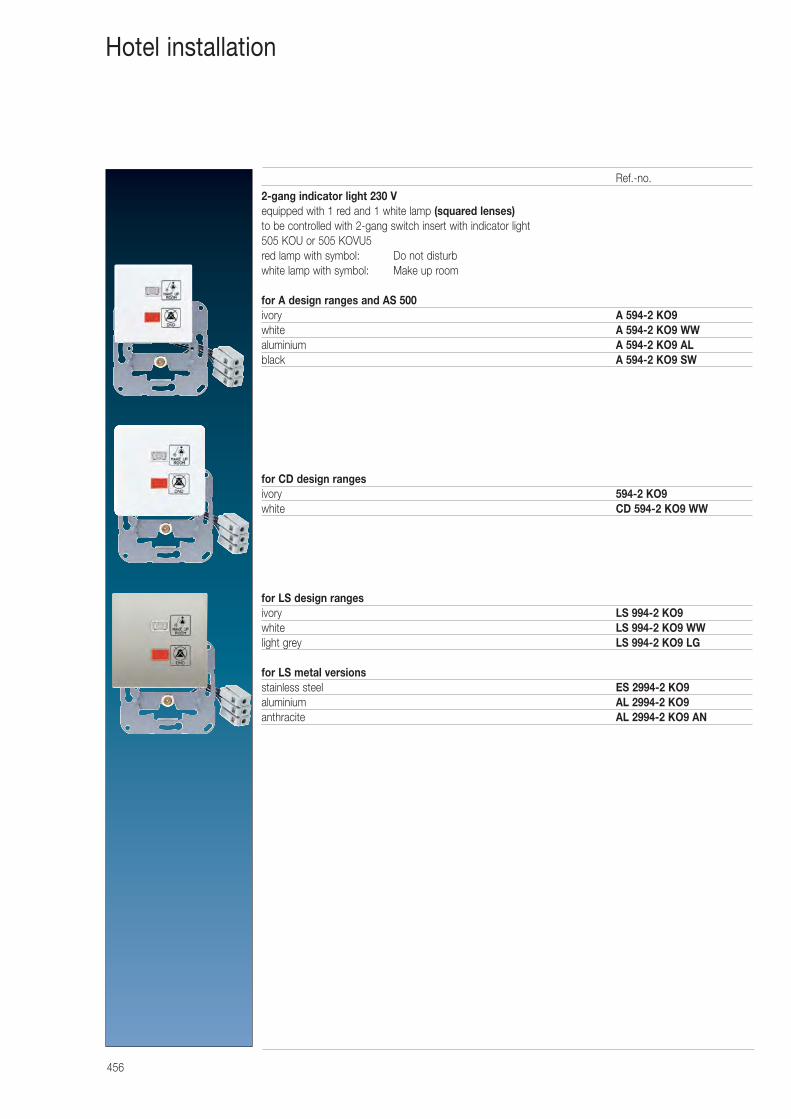
456
Hotel installation
2-gang indicator light 230 Vequipped with 1 red and 1 white lamp (squared lenses)to be controlled with 2-gang switch insert with indicator light 505 KOU or 505 KOVU5red lamp with symbol: Do not disturbwhite lamp with symbol: Make up room
for A design ranges and AS 500ivory A 594-2 KO9white A 594-2 KO9 WWaluminium A 594-2 KO9 ALblack A 594-2 KO9 SW
for CD design ranges ivory 594-2 KO9white CD 594-2 KO9 WW
for LS design rangesivory LS 994-2 KO9white LS 994-2 KO9 WWlight grey LS 994-2 KO9 LG
for LS metal versionsstainless steel ES 2994-2 KO9aluminium AL 2994-2 KO9anthracite AL 2994-2 KO9 AN
Ref.-no.
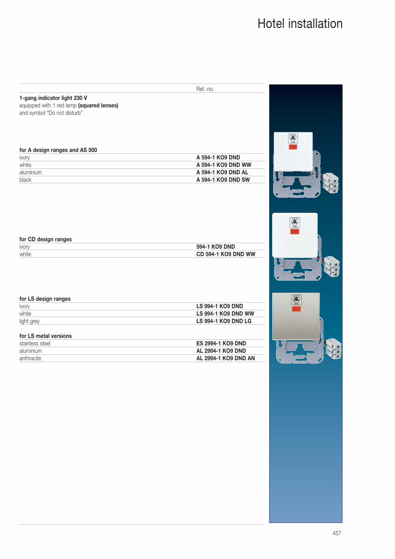
457
Hotel installation
1-gang indicator light 230 Vequipped with 1 red lamp (squared lenses)and symbol “Do not disturb”
for A design ranges and AS 500ivory A 594-1 KO9 DNDwhite A 594-1 KO9 DND WWaluminium A 594-1 KO9 DND ALblack A 594-1 KO9 DND SW
for CD design ranges ivory 594-1 KO9 DNDwhite CD 594-1 KO9 DND WW
for LS design rangesivory LS 994-1 KO9 DNDwhite LS 994-1 KO9 DND WWlight grey LS 994-1 KO9 DND LG
for LS metal versionsstainless steel ES 2994-1 KO9 DNDaluminium AL 2994-1 KO9 DNDanthracite AL 2994-1 KO9 DND AN
Ref.-no.
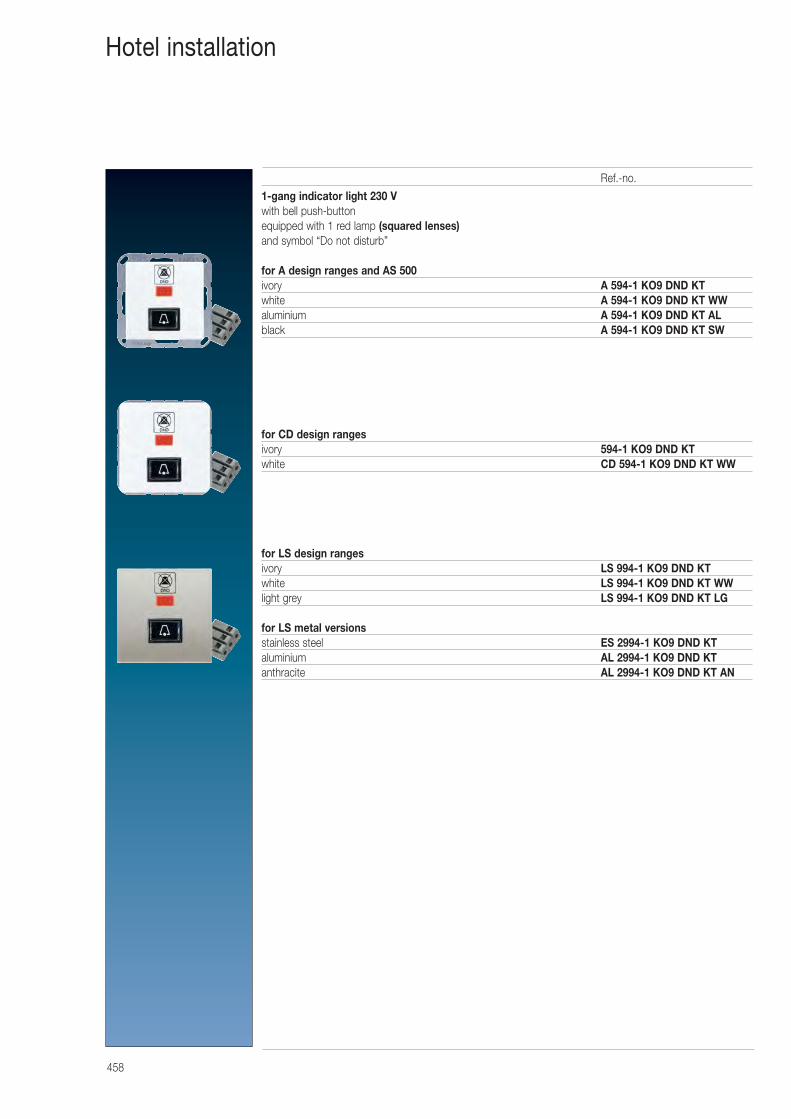
458
Hotel installation
1-gang indicator light 230 Vwith bell push-buttonequipped with 1 red lamp (squared lenses)and symbol “Do not disturb”
for A design ranges and AS 500ivory A 594-1 KO9 DND KTwhite A 594-1 KO9 DND KT WWaluminium A 594-1 KO9 DND KT ALblack A 594-1 KO9 DND KT SW
for CD design ranges ivory 594-1 KO9 DND KTwhite CD 594-1 KO9 DND KT WW
for LS design rangesivory LS 994-1 KO9 DND KTwhite LS 994-1 KO9 DND KT WWlight grey LS 994-1 KO9 DND KT LG
for LS metal versionsstainless steel ES 2994-1 KO9 DND KTaluminium AL 2994-1 KO9 DND KTanthracite AL 2994-1 KO9 DND KT AN
Ref.-no.
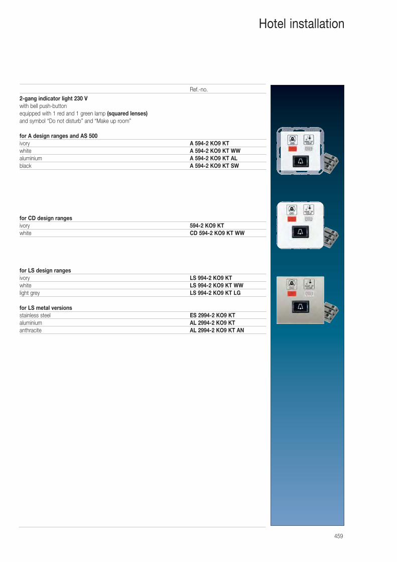
459
Hotel installation
2-gang indicator light 230 Vwith bell push-buttonequipped with 1 red and 1 green lamp (squared lenses)and symbol “Do not disturb” and “Make up room”
for A design ranges and AS 500ivory A 594-2 KO9 KTwhite A 594-2 KO9 KT WWaluminium A 594-2 KO9 KT ALblack A 594-2 KO9 KT SW
for CD design ranges ivory 594-2 KO9 KTwhite CD 594-2 KO9 KT WW
for LS design rangesivory LS 994-2 KO9 KTwhite LS 994-2 KO9 KT WWlight grey LS 994-2 KO9 KT LG
for LS metal versionsstainless steel ES 2994-2 KO9 KTaluminium AL 2994-2 KO9 KTanthracite AL 2994-2 KO9 KT AN
Ref.-no.
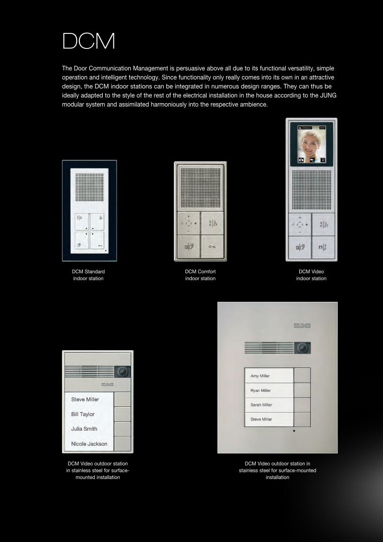
DCMThe Door Communication Management is persuasive above all due to its functional versatility, simple operation and intelligent technology. Since functionality only really comes into its own in an attractive design, the DCM indoor stations can be integrated in numerous design ranges. They can thus be ideally adapted to the style of the rest of the electrical installation in the house according to the JUNG modular system and assimilated harmoniously into the respective ambience.
DCM Comfort indoor station
DCM Standard indoor station
DCM Video outdoor station in stainless steel for surface-
mounted installation
DCM Video outdoor station instainless steel for surface-mounted
installation
DCM Video indoor station
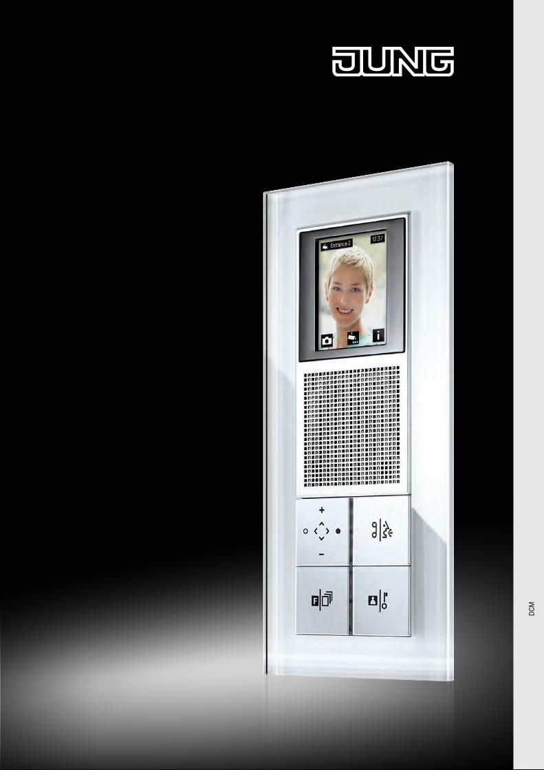
DC
M
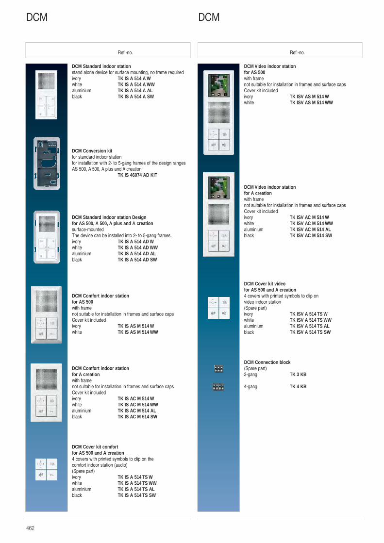
462
Ref.-no. Ref.-no.
DCM Video indoor stationfor AS 500with framenot suitable for installation in frames and surface capsCover kit includedivory TK ISV AS M 514 Wwhite TK ISV AS M 514 WW
DCM Video indoor stationfor A creationwith framenot suitable for installation in frames and surface capsCover kit includedivory TK ISV AC M 514 Wwhite TK ISV AC M 514 WWaluminium TK ISV AC M 514 ALblack TK ISV AC M 514 SW
DCM Cover kit videofor AS 500 and A creation4 covers with printed symbols to clip on video indoor station(Spare part)ivory TK ISV A 514 TS Wwhite TK ISV A 514 TS WWaluminium TK ISV A 514 TS ALblack TK ISV A 514 TS SW
DCM Connection block(Spare part)3-gang TK 3 KB
4-gang TK 4 KB
DCM Standard indoor stationstand alone device for surface mounting, no frame requiredivory TK IS A 514 A Wwhite TK IS A 514 A WWaluminium TK IS A 514 A ALblack TK IS A 514 A SW
DCM Conversion kitfor standard indoor stationfor installation with 2- to 5-gang frames of the design rangesAS 500, A 500, A plus and A creation
TK IS 46074 AD KIT
DCM Standard indoor station Designfor AS 500, A 500, A plus and A creationsurface-mountedThe device can be installed into 2- to 5-gang frames.ivory TK IS A 514 AD Wwhite TK IS A 514 AD WWaluminium TK IS A 514 AD ALblack TK IS A 514 AD SW
DCM Comfort indoor stationfor AS 500with framenot suitable for installation in frames and surface capsCover kit includedivory TK IS AS M 514 Wwhite TK IS AS M 514 WW
DCM Comfort indoor stationfor A creationwith framenot suitable for installation in frames and surface capsCover kit includedivory TK IS AC M 514 Wwhite TK IS AC M 514 WWaluminium TK IS AC M 514 ALblack TK IS AC M 514 SW
DCM Cover kit comfortfor AS 500 and A creation4 covers with printed symbols to clip on the comfort indoor station (audio)(Spare part)ivory TK IS A 514 TS Wwhite TK IS A 514 TS WWaluminium TK IS A 514 TS ALblack TK IS A 514 TS SW
DCMDCM
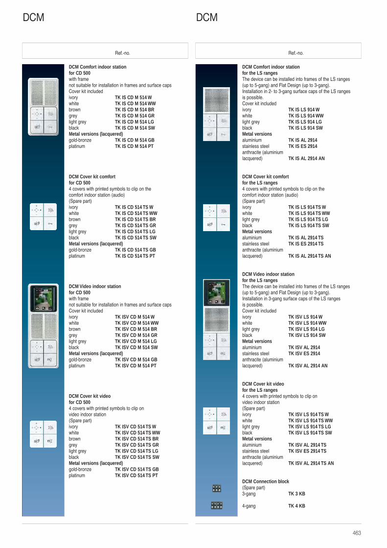
463
Ref.-no. Ref.-no.
DCM Comfort indoor stationfor the LS ranges The device can be installed into frames of the LS ranges (up to 5-gang) and Flat Design (up to 3-gang).Installation in 2- to 3-gang surface caps of the LS ranges is possible.Cover kit includedivory TK IS LS 914 Wwhite TK IS LS 914 WWlight grey TK IS LS 914 LGblack TK IS LS 914 SWMetal versionsaluminium TK IS AL 2914stainless steel TK IS ES 2914anthracite (aluminium lacquered) TK IS AL 2914 AN
DCM Cover kit comfortfor the LS ranges 4 covers with printed symbols to clip on the comfort indoor station (audio)(Spare part)ivory TK IS LS 914 TS Wwhite TK IS LS 914 TS WWlight grey TK IS LS 914 TS LGblack TK IS LS 914 TS SWMetal versionsaluminium TK IS AL 2914 TSstainless steel TK IS ES 2914 TSanthracite (aluminium lacquered) TK IS AL 2914 TS AN
DCM Video indoor stationfor the LS ranges The device can be installed into frames of the LS ranges (up to 5-gang) and Flat Design (up to 3-gang).Installation in 3-gang surface caps of the LS ranges is possible.Cover kit includedivory TK ISV LS 914 Wwhite TK ISV LS 914 WWlight grey TK ISV LS 914 LGblack TK ISV LS 914 SWMetal versionsaluminium TK ISV AL 2914stainless steel TK ISV ES 2914anthracite (aluminium lacquered) TK ISV AL 2914 AN
DCM Cover kit videofor the LS ranges 4 covers with printed symbols to clip on video indoor station(Spare part)ivory TK ISV LS 914 TS Wwhite TK ISV LS 914 TS WWlight grey TK ISV LS 914 TS LGblack TK ISV LS 914 TS SWMetal versionsaluminium TK ISV AL 2914 TSstainless steel TK ISV ES 2914 TSanthracite (aluminium lacquered) TK ISV AL 2914 TS AN
DCM Connection block(Spare part)3-gang TK 3 KB
4-gang TK 4 KB
DCM Comfort indoor stationfor CD 500with framenot suitable for installation in frames and surface capsCover kit includedivory TK IS CD M 514 Wwhite TK IS CD M 514 WWbrown TK IS CD M 514 BRgrey TK IS CD M 514 GRlight grey TK IS CD M 514 LGblack TK IS CD M 514 SWMetal versions (lacquered)gold-bronze TK IS CD M 514 GBplatinum TK IS CD M 514 PT
DCM Cover kit comfortfor CD 5004 covers with printed symbols to clip on the comfort indoor station (audio)(Spare part)ivory TK IS CD 514 TS Wwhite TK IS CD 514 TS WWbrown TK IS CD 514 TS BRgrey TK IS CD 514 TS GRlight grey TK IS CD 514 TS LGblack TK IS CD 514 TS SWMetal versions (lacquered)gold-bronze TK IS CD 514 TS GBplatinum TK IS CD 514 TS PT
DCM Video indoor stationfor CD 500with framenot suitable for installation in frames and surface capsCover kit includedivory TK ISV CD M 514 Wwhite TK ISV CD M 514 WWbrown TK ISV CD M 514 BRgrey TK ISV CD M 514 GRlight grey TK ISV CD M 514 LGblack TK ISV CD M 514 SWMetal versions (lacquered)gold-bronze TK ISV CD M 514 GBplatinum TK ISV CD M 514 PT
DCM Cover kit videofor CD 5004 covers with printed symbols to clip on video indoor station(Spare part)ivory TK ISV CD 514 TS Wwhite TK ISV CD 514 TS WWbrown TK ISV CD 514 TS BRgrey TK ISV CD 514 TS GRlight grey TK ISV CD 514 TS LGblack TK ISV CD 514 TS SWMetal versions (lacquered)gold-bronze TK ISV CD 514 TS GBplatinum TK ISV CD 514 TS PT
DCMDCM
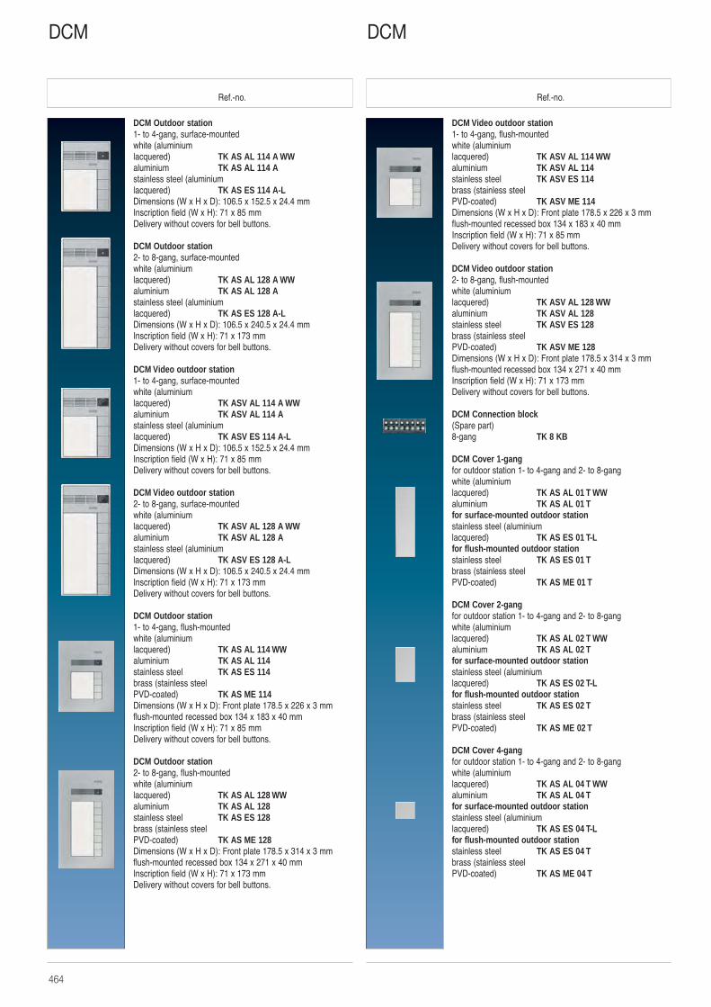
464
Ref.-no. Ref.-no.
DCM Video outdoor station1- to 4-gang, flush-mountedwhite (aluminium lacquered) TK ASV AL 114 WWaluminium TK ASV AL 114stainless steel TK ASV ES 114brass (stainless steel PVD-coated) TK ASV ME 114Dimensions (W x H x D): Front plate 178.5 x 226 x 3 mmflush-mounted recessed box 134 x 183 x 40 mmInscription field (W x H): 71 x 85 mmDelivery without covers for bell buttons.
DCM Video outdoor station2- to 8-gang, flush-mountedwhite (aluminium lacquered) TK ASV AL 128 WWaluminium TK ASV AL 128stainless steel TK ASV ES 128brass (stainless steel PVD-coated) TK ASV ME 128Dimensions (W x H x D): Front plate 178.5 x 314 x 3 mmflush-mounted recessed box 134 x 271 x 40 mmInscription field (W x H): 71 x 173 mmDelivery without covers for bell buttons.
DCM Connection block(Spare part)8-gang TK 8 KB
DCM Cover 1-gangfor outdoor station 1- to 4-gang and 2- to 8-gangwhite (aluminium lacquered) TK AS AL 01 T WWaluminium TK AS AL 01 Tfor surface-mounted outdoor stationstainless steel (aluminium lacquered) TK AS ES 01 T-Lfor flush-mounted outdoor stationstainless steel TK AS ES 01 Tbrass (stainless steel PVD-coated) TK AS ME 01 T
DCM Cover 2-gangfor outdoor station 1- to 4-gang and 2- to 8-gangwhite (aluminium lacquered) TK AS AL 02 T WWaluminium TK AS AL 02 Tfor surface-mounted outdoor stationstainless steel (aluminium lacquered) TK AS ES 02 T-Lfor flush-mounted outdoor stationstainless steel TK AS ES 02 Tbrass (stainless steel PVD-coated) TK AS ME 02 T
DCM Cover 4-gangfor outdoor station 1- to 4-gang and 2- to 8-gangwhite (aluminium lacquered) TK AS AL 04 T WWaluminium TK AS AL 04 Tfor surface-mounted outdoor stationstainless steel (aluminium lacquered) TK AS ES 04 T-Lfor flush-mounted outdoor stationstainless steel TK AS ES 04 Tbrass (stainless steel PVD-coated) TK AS ME 04 T
DCM Outdoor station1- to 4-gang, surface-mountedwhite (aluminiumlacquered) TK AS AL 114 A WWaluminium TK AS AL 114 Astainless steel (aluminium lacquered) TK AS ES 114 A-LDimensions (W x H x D): 106.5 x 152.5 x 24.4 mmInscription field (W x H): 71 x 85 mmDelivery without covers for bell buttons.
DCM Outdoor station2- to 8-gang, surface-mountedwhite (aluminium lacquered) TK AS AL 128 A WWaluminium TK AS AL 128 Astainless steel (aluminium lacquered) TK AS ES 128 A-LDimensions (W x H x D): 106.5 x 240.5 x 24.4 mmInscription field (W x H): 71 x 173 mmDelivery without covers for bell buttons.
DCM Video outdoor station1- to 4-gang, surface-mountedwhite (aluminium lacquered) TK ASV AL 114 A WWaluminium TK ASV AL 114 Astainless steel (aluminium lacquered) TK ASV ES 114 A-LDimensions (W x H x D): 106.5 x 152.5 x 24.4 mmInscription field (W x H): 71 x 85 mmDelivery without covers for bell buttons.
DCM Video outdoor station2- to 8-gang, surface-mountedwhite (aluminium lacquered) TK ASV AL 128 A WWaluminium TK ASV AL 128 Astainless steel (aluminium lacquered) TK ASV ES 128 A-LDimensions (W x H x D): 106.5 x 240.5 x 24.4 mmInscription field (W x H): 71 x 173 mmDelivery without covers for bell buttons.
DCM Outdoor station1- to 4-gang, flush-mountedwhite (aluminium lacquered) TK AS AL 114 WWaluminium TK AS AL 114stainless steel TK AS ES 114brass (stainless steel PVD-coated) TK AS ME 114Dimensions (W x H x D): Front plate 178.5 x 226 x 3 mmflush-mounted recessed box 134 x 183 x 40 mmInscription field (W x H): 71 x 85 mmDelivery without covers for bell buttons.
DCM Outdoor station2- to 8-gang, flush-mountedwhite (aluminium lacquered) TK AS AL 128 WWaluminium TK AS AL 128stainless steel TK AS ES 128brass (stainless steel PVD-coated) TK AS ME 128Dimensions (W x H x D): Front plate 178.5 x 314 x 3 mmflush-mounted recessed box 134 x 271 x 40 mmInscription field (W x H): 71 x 173 mmDelivery without covers for bell buttons.
DCMDCM
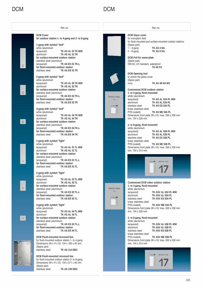
465
Ref.-no. Ref.-no.
DCM Glass coverfor inscription fieldfor flush-mounted and surface-mounted outdoor stations(Spare part)1 – 4-gang TK AS 4 NA2 – 8-gang TK AS 8 NA
DCM Foil for name-plate(Spare part)DIN A5, UV resistant, waterproof
TK 60 FO
DCM Opening toolto unlock the glass cover(Spare part)ivory TK AS 48 NA WZ
Customised DCM outdoor station1- to 4-gang, flush-mountedwhite (aluminium lacquered) TK AS AL 534 PL WWaluminium TK AS AL 534 PLstainless steel TK AS ES 534 PLbrass (stainless steel PVD-coated) TK AS ME 534 PLDimensions front plate (W x H): max. 530 x 530 mmmin. 154 x 226 mm
2- to 8-gang, flush-mountedwhite (aluminium lacquered) TK AS AL 538 PL WWaluminium TK AS AL 538 PLstainless steel TK AS ES 538 PLbrass (stainless steel PVD-coated) TK AS ME 538 PLDimensions front plate (W x H): max. 530 x 530 mmmin. 154 x 314 mm
Customised DCM video outdoor station1- to 4-gang, flush-mountedwhite (aluminium lacquered) TK ASV AL 534 PL WWaluminium TK ASV AL 534 PLstainless steel TK ASV ES 534 PLbrass (stainless steel PVD-coated) TK ASV ME 534 PLDimensions front plate (W x H): max. 530 x 530 mmmin. 154 x 226 mm
2- to 8-gang, flush-mountedwhite (aluminium lacquered) TK ASV AL 538 PL WWaluminium TK ASV AL 538 PLstainless steel TK ASV ES 538 PLbrass (stainless steel PVD-coated) TK ASV ME 538 PLDimensions front plate (W x H): max. 530 x 530 mmmin. 154 x 314 mm
DCM Cover for outdoor station 1- to 4-gang and 2- to 8-gang
1-gang with symbol "bell"white (aluminium lacquered) TK AS AL 01 TK WWaluminium TK AS AL 01 TKfor surface-mounted outdoor stationstainless steel (aluminium lacquered) TK AS ES 01 TK-Lfor flush-mounted outdoor stationstainless steel TK AS ES 01 TK
2-gang with symbol "bell"white (aluminium lacquered) TK AS AL 02 TK WWaluminium TK AS AL 02 TKfor surface-mounted outdoor stationstainless steel (aluminium lacquered) TK AS ES 02 TK-Lfor flush-mounted outdoor stationstainless steel TK AS ES 02 TK
4-gang with symbol "bell"white (aluminiumlacquered) TK AS AL 04 TK WWaluminium TK AS AL 04 TKfor surface-mounted outdoor stationstainless steel (aluminium lacquered) TK AS ES 04 TK-Lfor flush-mounted outdoor stationstainless steel TK AS ES 04 TK
1-gang with symbol "light"white (aluminium lacquered) TK AS AL 01 TL WWaluminium TK AS AL 01 TLfor surface-mounted outdoor stationstainless steel (aluminium lacquered) TK AS ES 01 TL-Lfor flush-mounted outdoor stationstainless steel TK AS ES 01 TL
2-gang with symbol "light"white (aluminium lacquered) TK AS AL 02 TL WWaluminium TK AS AL 02 TLfor surface-mounted outdoor stationstainless steel (aluminium lacquered) TK AS ES 02 TL-Lfor flush-mounted outdoor stationstainless steel TK AS ES 02 TL
4-gang with symbol "light"white (aluminium lacquered) TK AS AL 04 TL WWaluminium TK AS AL 04 TLfor surface-mounted outdoor stationstainless steel (aluminium lacquered) TK AS ES 04 TL-Lfor flush-mounted outdoor stationstainless steel TK AS ES 04 TL
DCM Flush-mounted recessed boxfor flush-mounted outdoor station 1- to 4-gangDimensions (W x H x D): 134 x 183 x 40 mm(Spare part)stainless steel TK AS 114 EBG
DCM Flush-mounted recessed boxfor flush-mounted outdoor station 2- to 8-gangDimensions (W x H x D): 134 x 271 x 40 mm(Spare part)stainless steel TK AS 128 EBG
DCMDCM
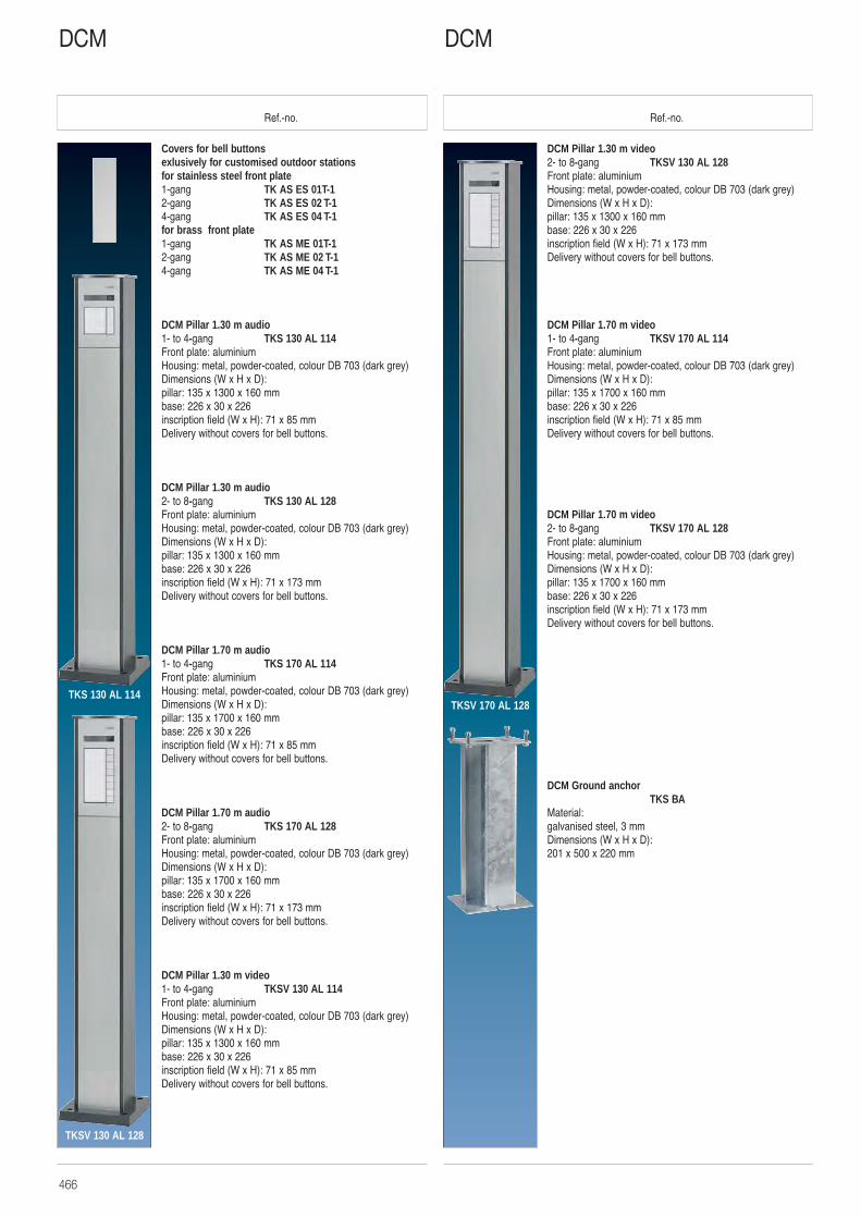
466
Ref.-no. Ref.-no.
Covers for bell buttons exlusively for customised outdoor stations for stainless steel front plate1-gang TK AS ES 01T-12-gang TK AS ES 02 T-14-gang TK AS ES 04 T-1for brass front plate1-gang TK AS ME 01T-12-gang TK AS ME 02 T-14-gang TK AS ME 04 T-1
DCM Pillar 1.30 m audio1- to 4-gang TKS 130 AL 114Front plate: aluminiumHousing: metal, powder-coated, colour DB 703 (dark grey)Dimensions (W x H x D): pillar: 135 x 1300 x 160 mmbase: 226 x 30 x 226inscription field (W x H): 71 x 85 mmDelivery without covers for bell buttons.
DCM Pillar 1.30 m audio2- to 8-gang TKS 130 AL 128Front plate: aluminiumHousing: metal, powder-coated, colour DB 703 (dark grey)Dimensions (W x H x D): pillar: 135 x 1300 x 160 mmbase: 226 x 30 x 226inscription field (W x H): 71 x 173 mmDelivery without covers for bell buttons.
DCM Pillar 1.70 m audio1- to 4-gang TKS 170 AL 114Front plate: aluminiumHousing: metal, powder-coated, colour DB 703 (dark grey)Dimensions (W x H x D): pillar: 135 x 1700 x 160 mmbase: 226 x 30 x 226inscription field (W x H): 71 x 85 mmDelivery without covers for bell buttons.
DCM Pillar 1.70 m audio2- to 8-gang TKS 170 AL 128Front plate: aluminiumHousing: metal, powder-coated, colour DB 703 (dark grey)Dimensions (W x H x D): pillar: 135 x 1700 x 160 mmbase: 226 x 30 x 226inscription field (W x H): 71 x 173 mmDelivery without covers for bell buttons.
DCM Pillar 1.30 m video1- to 4-gang TKSV 130 AL 114Front plate: aluminiumHousing: metal, powder-coated, colour DB 703 (dark grey)Dimensions (W x H x D): pillar: 135 x 1300 x 160 mmbase: 226 x 30 x 226inscription field (W x H): 71 x 85 mmDelivery without covers for bell buttons.
DCMDCM
DCM Pillar 1.30 m video2- to 8-gang TKSV 130 AL 128Front plate: aluminiumHousing: metal, powder-coated, colour DB 703 (dark grey)Dimensions (W x H x D): pillar: 135 x 1300 x 160 mmbase: 226 x 30 x 226inscription field (W x H): 71 x 173 mmDelivery without covers for bell buttons.
DCM Pillar 1.70 m video1- to 4-gang TKSV 170 AL 114Front plate: aluminiumHousing: metal, powder-coated, colour DB 703 (dark grey)Dimensions (W x H x D): pillar: 135 x 1700 x 160 mmbase: 226 x 30 x 226inscription field (W x H): 71 x 85 mmDelivery without covers for bell buttons.
DCM Pillar 1.70 m video2- to 8-gang TKSV 170 AL 128Front plate: aluminiumHousing: metal, powder-coated, colour DB 703 (dark grey)Dimensions (W x H x D): pillar: 135 x 1700 x 160 mmbase: 226 x 30 x 226inscription field (W x H): 71 x 173 mmDelivery without covers for bell buttons.
DCM Ground anchorTKS BA
Material:galvanised steel, 3 mmDimensions (W x H x D):201 x 500 x 220 mm
TKS 130 AL 114
TKSV 130 AL 128
TKSV 170 AL 128
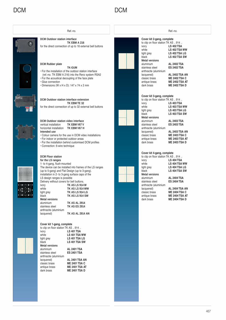
467
Ref.-no. Ref.-no.
Cover kit 2-gang, completeto clip on floor station TK AS .. 914 ..ivory LS 402 TSAwhite LS 402 TSA WWlight grey LS 402 TSA LGblack LS 402 TSA SWMetal versionsaluminium AL 2402 TSAstainless steel ES 2402 TSAanthracite (aluminium lacquered) AL 2402 TSA ANclassic brass ME 2402 TSA Cantique brass ME 2402 TSA ATdark brass ME 2402 TSA D
Cover kit 3-gang, completeto clip on floor station TK AS .. 914 ..ivory LS 403 TSAwhite LS 403 TSA WWlight grey LS 403 TSA LGblack LS 403 TSA SWMetal versionsaluminium AL 2403 TSAstainless steel ES 2403 TSAanthracite (aluminium lacquered) AL 2403 TSA ANclassic brass ME 2403 TSA Cantique brass ME 2403 TSA ATdark brass ME 2403 TSA D
Cover kit 4-gang, completeto clip on floor station TK AS .. 914 ..ivory LS 404 TSAwhite LS 404 TSA WWlight grey LS 404 TSA LGblack LS 404 TSA SWMetal versionsaluminium AL 2404 TSAstainless steel ES 2404 TSAanthracite (aluminium lacquered) AL 2404 TSA ANclassic brass ME 2404 TSA Cantique brass ME 2404 TSA ATdark brass ME 2404 TSA D
DCM Outdoor station interfaceTK EBM A 216
for the direct connection of up to 16 external bell buttons
DCM Rubber plateTK-GUM
• For the installation of the outdoor station interface(ref.-no. TK EBM A 216) into the Renz system RSA2
• For the acoustical decoupling of the face plate• Glue connection• Dimensions (W x H x D): 147 x 74 x 2 mm
DCM Outdoor station interface extensionTK EBM TE 32
for the direct connection of up to 32 external bell buttons
DCM Outdoor station video interfacevertical installation TK EBM V67 Vhorizontal installation TK EBM V67 HIntended use• Colour camera for the use in DCM video installations• For indoor or protected outdoor areas• For the installation behind customised DCM profiles• Connection: 6-wire technique
DCM Floor stationfor the LS ranges 1- to 4-gang, flush-mountedThe device can be installed into frames of the LS ranges (up to 5-gang) and Flat Design (up to 3-gang).installation in 2- to 3-gang surface caps of the LS design ranges is possibleDelivery without covers for bell buttons.ivory TK AS LS 914 Wwhite TK AS LS 914 WWlight grey TK AS LS 914 LGblack TK AS LS 914 SWMetal versionsaluminium TK AS AL 2914stainless steel TK AS ES 2914anthracite (aluminium lacquered) TK AS AL 2914 AN
Cover kit 1-gang, complete to clip on floor station TK AS .. 914 ..ivory LS 401 TSAwhite LS 401 TSA WWlight grey LS 401 TSA LGblack LS 401 TSA SWMetal versionsaluminium AL 2401 TSAstainless steel ES 2401 TSAanthracite (aluminium lacquered) AL 2401 TSA ANclassic brass ME 2401 TSA Cantique brass ME 2401 TSA ATdark brass ME 2401 TSA D
DCMDCM
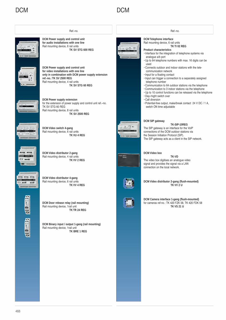
468
Ref.-no. Ref.-no.
DCM Telephone interfaceRail mounting device, 6 rail units
TK TI 02 REGProduct characteristics• Interface for the integration of telephone systems via
analogue a/b port• Up to 64 telephone numbers with max. 16 digits can be
used• Connects outdoor and indoor stations with the tele-
communication network• Input for a floating contact • Input can trigger a connection to a separately assigned
telephone number• Communication to 64 outdoor stations via the telephone• Communication to 3 indoor stations via the telephone• Up to 10 control functions can be released via the telephone• Day-/night switch over• Call diversion• Potential-free output, make/break contact 24 V DC / 1 A,
switch ON time adjustable
DCM SIP gatewayTK-SIP-10REG
The SIP gateway is an interface for the VoIP connections of the DCM outdoor stations via the Session Initiation Protocol (SIP). The SIP gateway acts as a client in the SIP network.
DCM Video boxTK-VD
The video box digitises an analogue video signal and provides the signal via a LAN connection on the local network.
DCM Video distributor 2-gang (flush-mounted)TK VV 2 U
DCM Camera interface 1-gang (flush-mounted)for cameras ref-no.: TK 420 FZK 58, TK 420 FDK 58
TK VS 21 U
DCM Power supply and control unitfor audio installations with one lineRail mounting device, 6 rail units
TK SV STG 600 REG
DCM Power supply and control unitfor video installations with one lineonly in combination with DCM power supply extensionref.-no.: TK SV 2500 REGRail mounting device, 4 rail units
TK SV STG 60 REG
DCM Power supply extensionfor the extension of power supply and control unit ref.–no.TK SV STG 60 REGRail mounting device, 8 rail units
TK SV 2500 REG
DCM Video switch 4-gangRail mounting device, 6 rail units
TK VU 4 REG
DCM Video distributor 2-gangRail mounting device, 4 rail units
TK VV 2 REG
DCM Video distributor 4-gangRail mounting device, 6 rail units
TK VV 4 REG
DCM Door release relay (rail mounting)Rail mounting device, 1rail unit
TK TR 24 REG
DCM Binary input / output 1-gang (rail mounting)Rail mounting device, 1rail unit
TK BRE 1 REG
DCMDCM
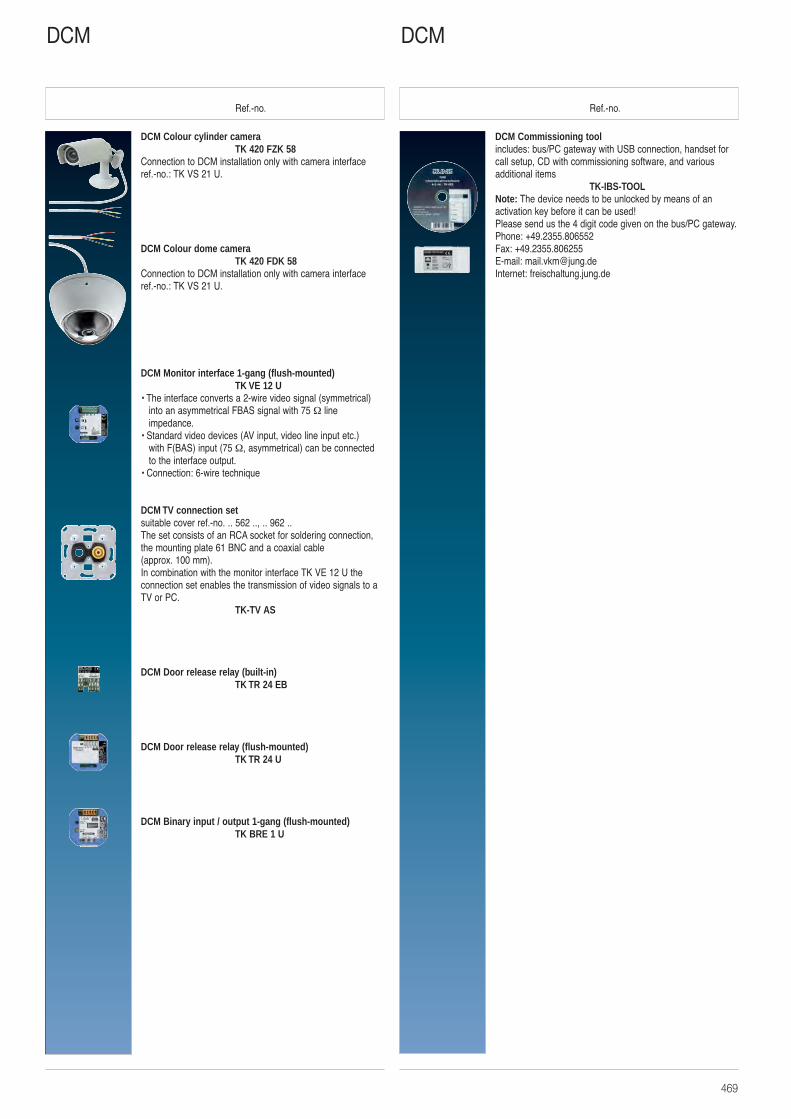
469
Ref.-no. Ref.-no.
DCM Commissioning toolincludes: bus/PC gateway with USB connection, handset forcall setup, CD with commissioning software, and various additional items
TK-IBS-TOOLNote: The device needs to be unlocked by means of anactivation key before it can be used!Please send us the 4 digit code given on the bus/PC gateway.Phone: +49.2355.806552Fax: +49.2355.806255E-mail: [email protected]: freischaltung.jung.de
DCM Colour cylinder cameraTK 420 FZK 58
Connection to DCM installation only with camera interfaceref.-no.: TK VS 21 U.
DCM Colour dome cameraTK 420 FDK 58
Connection to DCM installation only with camera interfaceref.-no.: TK VS 21 U.
DCM Monitor interface 1-gang (flush-mounted)TK VE 12 U
• The interface converts a 2-wire video signal (symmetrical)into an asymmetrical FBAS signal with 75 Ω line impedance.
• Standard video devices (AV input, video line input etc.) with F(BAS) input (75 Ω, asymmetrical) can be connectedto the interface output.
• Connection: 6-wire technique
DCM TV connection setsuitable cover ref.-no. .. 562 .., .. 962 ..The set consists of an RCA socket for soldering connection,the mounting plate 61 BNC and a coaxial cable(approx. 100 mm).In combination with the monitor interface TK VE 12 U theconnection set enables the transmission of video signals to aTV or PC.
TK-TV AS
DCM Door release relay (built-in)TK TR 24 EB
DCM Door release relay (flush-mounted)TK TR 24 U
DCM Binary input / output 1-gang (flush-mounted)TK BRE 1 U
DCMDCM
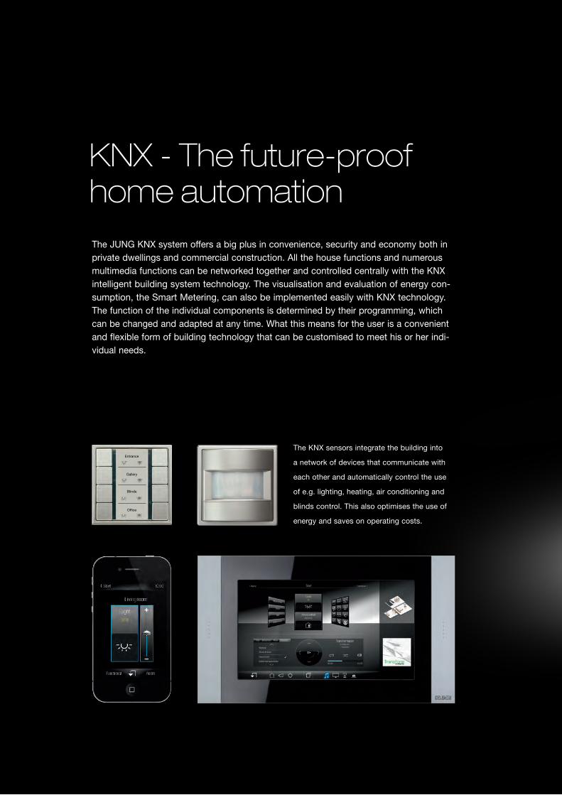
The JUNG KNX system offers a big plus in convenience, security and economy both in private dwellings and commercial construction. All the house functions and numerous multimedia functions can be networked together and controlled centrally with the KNX intelligent building system technology. The visualisation and evaluation of energy con-sumption, the Smart Metering, can also be implemented easily with KNX technology. The function of the individual components is determined by their programming, which can be changed and adapted at any time. What this means for the user is a convenient and flexible form of building technology that can be customised to meet his or her indi- vidual needs.
KNX - The future-proof home automation
Entrance
Gallery
Blinds
Office
The KNX sensors integrate the building into
a network of devices that communicate with
each other and automatically control the use
of e.g. lighting, heating, air conditioning and
blinds control. This also optimises the use of
energy and saves on operating costs.
KNX
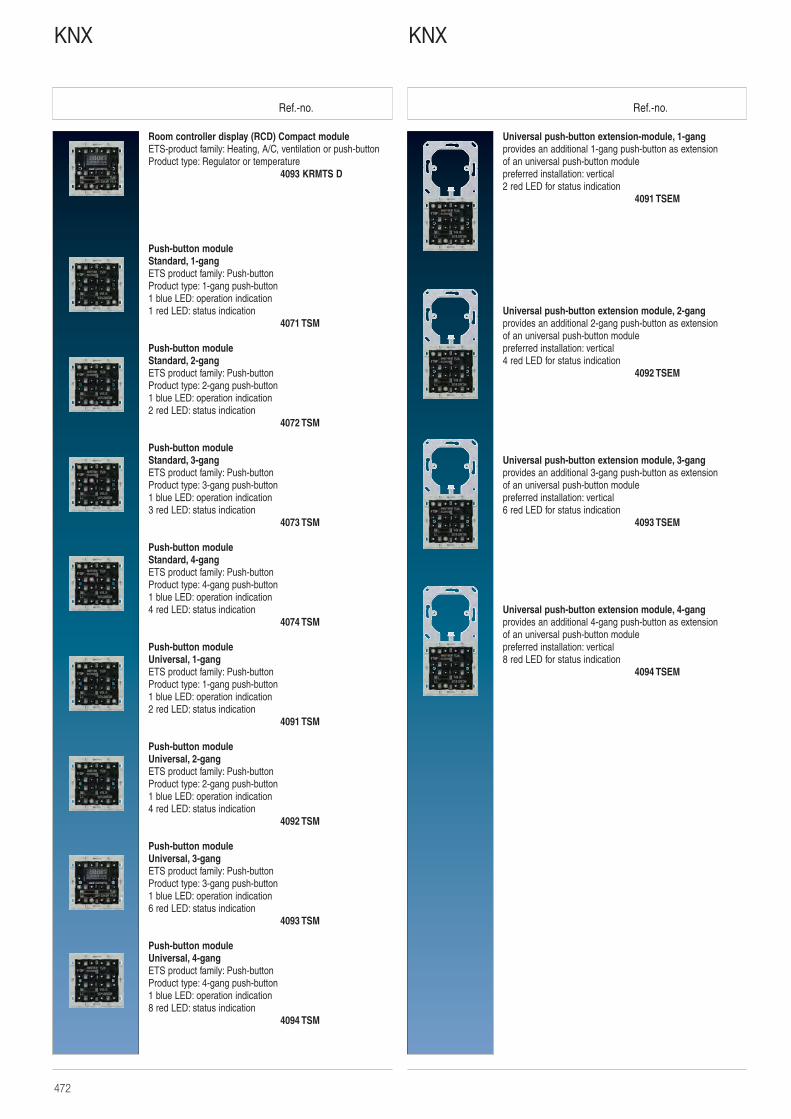
Ref.-no. Ref.-no.
Universal push-button extension-module, 1-gangprovides an additional 1-gang push-button as extension of an universal push-button modulepreferred installation: vertical2 red LED for status indication
4091 TSEM
Universal push-button extension module, 2-gangprovides an additional 2-gang push-button as extension of an universal push-button modulepreferred installation: vertical4 red LED for status indication
4092 TSEM
Universal push-button extension module, 3-gangprovides an additional 3-gang push-button as extension of an universal push-button modulepreferred installation: vertical6 red LED for status indication
4093 TSEM
Universal push-button extension module, 4-gangprovides an additional 4-gang push-button as extension of an universal push-button modulepreferred installation: vertical8 red LED for status indication
4094 TSEM
Room controller display (RCD) Compact moduleETS-product family: Heating, A/C, ventilation or push-buttonProduct type: Regulator or temperature
4093 KRMTS D
Push-button moduleStandard, 1-gangETS product family: Push-buttonProduct type: 1-gang push-button1 blue LED: operation indication1 red LED: status indication
4071 TSM
Push-button moduleStandard, 2-gangETS product family: Push-buttonProduct type: 2-gang push-button1 blue LED: operation indication2 red LED: status indication
4072 TSM
Push-button moduleStandard, 3-gangETS product family: Push-buttonProduct type: 3-gang push-button1 blue LED: operation indication3 red LED: status indication
4073 TSM
Push-button moduleStandard, 4-gangETS product family: Push-buttonProduct type: 4-gang push-button1 blue LED: operation indication4 red LED: status indication
4074 TSM
Push-button moduleUniversal, 1-gangETS product family: Push-buttonProduct type: 1-gang push-button1 blue LED: operation indication2 red LED: status indication
4091 TSM
Push-button moduleUniversal, 2-gangETS product family: Push-buttonProduct type: 2-gang push-button1 blue LED: operation indication4 red LED: status indication
4092 TSM
Push-button moduleUniversal, 3-gangETS product family: Push-buttonProduct type: 3-gang push-button1 blue LED: operation indication6 red LED: status indication
4093 TSM
Push-button moduleUniversal, 4-gangETS product family: Push-buttonProduct type: 4-gang push-button1 blue LED: operation indication8 red LED: status indication
4094 TSM
KNXKNX
472
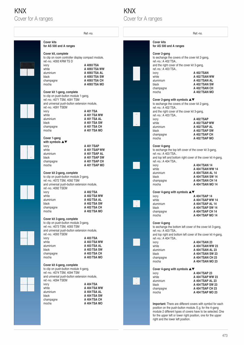
Ref.-no. Ref.-no.
Cover kits for AS 500 and A ranges
Cover 2-gangto exchange the covers of the cover kit 2-gang,ref.-no.: A 402 TSA.. and the right cover of the cover kit 3-gang,ref.-no.: A 403 TSA..ivory A 402 TSANwhite A 402 TSAN WWaluminium A 402 TSAN ALblack A 402 TSAN SWchampagne A 402 TSAN CHmocha A 402 TSAN MO
Cover 2-gang with symbols ▲▼
to exchange the covers of the cover kit 2-gang,ref.-no.: A 402 TSA.. and the right cover of the cover kit 3-gang,ref.-no.: A 403 TSA..ivory A 402 TSAPwhite A 402 TSAP WWaluminium A 402 TSAP ALblack A 402 TSAP SWchampagne A 402 TSAP CHmocha A 402 TSAP MO
Cover 4-gangto exchange the top left cover of the cover kit 3-gang,ref.-no.: A 403 TSA.. and top left and bottom right cover of the cover kit 4-gang,ref.-no.: A 404 TSA..ivory A 404 TSAN 14white A 404 TSAN WW 14aluminium A 404 TSAN AL 14black A 404 TSAN SW 14champagne A 404 TSAN CH 14mocha A 404 TSAN MO 14
Cover 4-gang with symbols ▲▼
ivory A 404 TSAP 14white A 404 TSAP WW 14aluminium A 404 TSAP AL 14black A 404 TSAP SW 14champagne A 404 TSAP CH 14mocha A 404 TSAP MO 14
Cover 4-gangto exchange the bottom left cover of the cover kit 3-gang,ref.-no.: A 403 TSA.. and top right and bottom left cover of the cover kit 4-gang,ref.-no.: A 404 TSA..ivory A 404 TSAN 23white A 404 TSAN WW 23aluminium A 404 TSAN AL 23black A 404 TSAN SW 23champagne A 404 TSAN CH 23mocha A 404 TSAN MO 23
Cover 4-gang with symbols ▲▼
ivory A 404 TSAP 23white A 404 TSAP WW 23aluminium A 404 TSAP AL 23black A 404 TSAP SW 23champagne A 404 TSAP CH 23mocha A 404 TSAP MO 23
Important: There are different covers with symbol for eachposition on the push-button module. E.g. for the 4-gang module 2 different types of covers have to be selected. Onefor the upper left or lower right position, one for the upper right and the lower left position.
Cover kits for AS 500 and A ranges
Cover kit, completeto clip on room controller display compact module, ref.-no.: 4093 KRM TS Divory A 4093 TSAwhite A 4093 TSA WWaluminium A 4093 TSA ALblack A 4093 TSA SWchampagne A 4093 TSA CHmocha A 4093 TSA MO
Cover kit 1-gang, completeto clip on push-button module 1-gang,ref.-no.: 4071 TSM, 4091 TSMand universal push-button extension module,ref.-no.: 4091 TSEMivory A 401 TSAwhite A 401 TSA WWaluminium A 401 TSA ALblack A 401 TSA SWchampagne A 401 TSA CHmocha A 401 TSA MO
Cover 1-gangwith symbols ▲▼
ivory A 401 TSAPwhite A 401 TSAP WWaluminium A 401 TSAP ALblack A 401 TSAP SWchampagne A 401 TSAP CHmocha A 401 TSAP MO
Cover kit 2-gang, completeto clip on push-button module 2-gang,ref.-no.: 4072 TSM, 4092 TSMand universal push-button extension module,ref.-no.: 4092 TSEMivory A 402 TSAwhite A 402 TSA WWaluminium A 402 TSA ALblack A 402 TSA SWchampagne A 402 TSA CHmocha A 402 TSA MO
Cover kit 3-gang, completeto clip on push-button module 3-gang,ref.-no.: 4073 TSM, 4093 TSMand universal push-button extension module,ref.-no.: 4093 TSEMivory A 403 TSAwhite A 403 TSA WWaluminium A 403 TSA ALblack A 403 TSA SWchampagne A 403 TSA CHmocha A 403 TSA MO
Cover kit 4-gang, completeto clip on push-button module 4-gang,ref.-no.: 4074 TSM, 4094 TSM and universal push-button extension module,ref.-no.: 4094 TSEMivory A 404 TSAwhite A 404 TSA WWaluminium A 404 TSA ALblack A 404 TSA SWchampagne A 404 TSA CHmocha A 404 TSA MO
KNXCover for A ranges
KNXCover for A ranges
473
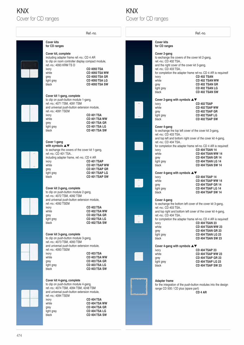
Ref.-no. Ref.-no.
Cover kitsfor CD ranges
Cover 2-gangto exchange the covers of the cover kit 2-gang,ref.-no.: CD 402 TSA.. and the right cover of the cover kit 3-gang,ref.-no.: CD 403 TSA..for completion the adapter frame ref-no. CD 4 AR is required!ivory CD 402 TSANwhite CD 402 TSAN WWgrey CD 402 TSAN GRlight grey CD 402 TSAN LGblack CD 402 TSAN SW
Cover 2-gang with symbols ▲▼
ivory CD 402 TSAPwhite CD 402 TSAP WWgrey CD 402 TSAP GRlight grey CD 402 TSAP LGblack CD 402 TSAP SW
Cover 4-gangto exchange the top left cover of the cover kit 3-gang,ref.-no.: CD 403 TSA.. and top left and bottom right cover of the cover kit 4-gang,ref.-no.: CD 404 TSA..for completion the adapter frame ref-no. CD 4 AR is required!ivory CD 404 TSAN 14white CD 404 TSAN WW 14grey CD 404 TSAN GR 14light grey CD 404 TSAN LG 14black CD 404 TSAN SW 14
Cover 4-gang with symbols ▲▼
ivory CD 404 TSAP 14white CD 404 TSAP WW 14grey CD 404 TSAP GR 14light grey CD 404 TSAP LG 14black CD 404 TSAP SW 14
Cover 4-gangto exchange the bottom left cover of the cover kit 3-gang,ref.-no.: CD 403 TSA.. and top right and bottom left cover of the cover kit 4-gang,ref.-no.: CD 404 TSA..for completion the adapter frame ref-no. CD 4 AR is required!ivory CD 404 TSAN 23white CD 404 TSAN WW 23grey CD 404 TSAN GR 23light grey CD 404 TSAN LG 23black CD 404 TSAN SW 23
Cover 4-gang with symbols ▲▼
ivory CD 404 TSAP 23white CD 404 TSAP WW 23grey CD 404 TSAP GR 23light grey CD 404 TSAP LG 23black CD 404 TSAP SW 23
Adapter framefor the integration of the push-button modules into the designrange CD 500 / CD plus (spare part)
CD 4 AR
Cover kitsfor CD ranges
Cover kit, completeincluding adapter frame ref.-no.: CD 4 ARto clip on room controller display compact module, ref.-no.: 4093 KRM TS Divory CD 4093 TSAwhite CD 4093 TSA WWgrey CD 4093 TSA GRlight grey CD 4093 TSA LGblack CD 4093 TSA SW
Cover kit 1-gang, completeto clip on push-button module 1-gang,ref.-no.: 4071 TSM, 4091 TSM and universal push-button extension module,ref.-no.: 4091 TSEMivory CD 401 TSAwhite CD 401 TSA WWgrey CD 401 TSA GRlight grey CD 401 TSA LGblack CD 401 TSA SW
Cover 1-gangwith symbols ▲▼
to exchange the covers of the cover kit 1-gang,ref.-no.: CD 401 TSA.. including adapter frame, ref.-no.: CD 4 ARivory CD 401 TSAPwhite CD 401 TSAP WWgrey CD 401 TSAP GRlight grey CD 401 TSAP LGblack CD 401 TSAP SW
Cover kit 2-gang, completeto clip on push-button module 2-gang,ref.-no.: 4072 TSM, 4092 TSMand universal push-button extension module,ref.-no.: 4092 TSEMivory CD 402 TSAwhite CD 402 TSA WWgrey CD 402 TSA GRlight grey CD 402 TSA LGblack CD 402 TSA SW
Cover kit 3-gang, completeto clip on push-button module 3-gang,ref.-no.: 4073 TSM, 4093 TSMand universal push-button extension module,ref.-no.: 4093 TSEMivory CD 403 TSAwhite CD 403 TSA WWgrey CD 403 TSA GRlight grey CD 403 TSA LGblack CD 403 TSA SW
Cover kit 4-gang, completeto clip on push-button module 4-gang,ref.-no.: 4074 TSM, 4094 TSM, 4248 TSM and universal push-button extension module,ref.-no.: 4094 TSEMivory CD 404 TSAwhite CD 404 TSA WWgrey CD 404 TSA GRlight grey CD 404 TSA LGblack CD 404 TSA SW
KNXCover for CD ranges
KNXCover for CD ranges
474

Ref.-no. Ref.-no.
Cover kits for LS ranges
Cover 2-gangto exchange the covers of the cover kit 2-gang,ref.-no.: ..402 TSA.. and the right cover of the cover kit 3-gang, ref.-no.: ..403 TSA..for completion the adapter frame ref-no. LS 4 AR is required!ivory LS 402 TSANwhite LS 402 TSAN WWlight grey LS 402 TSAN LGblack LS 402 TSAN SW
Cover 2-gang with symbols ▲▼
ivory LS 402 TSAPwhite LS 402 TSAP WWlight grey LS 402 TSAP LGblack LS 402 TSAP SW
Cover 4-gangto exchange the top left cover of the cover kit 3-gang,ref.-no.: ..403 TSA.. and top left and bottom right cover of the cover kit 4-gang,ref.-no.: ..404 TSA..for completion the adapter frame ref-no. LS 4 AR is required!ivory LS 404 TSAN 14white LS 404 TSAN WW 14light grey LS 404 TSAN LG 14black LS 404 TSAN SW 14
Cover 4-gang with symbols ▲▼
ivory LS 404 TSAP 14white LS 404 TSAP WW 14light grey LS 404 TSAP LG 14black LS 404 TSAP SW 14
Cover 4-gangto exchange the bottom left cover of the cover kit 3-gang,ref.-no.: ..403 TSA.. and top right and bottom left cover of the cover kit 4-gang,ref.-no.: ..404 TSA..for completion the adapter frame ref-no. LS 4 AR is required!ivory LS 404 TSAN 23white LS 404 TSAN WW 23light grey LS 404 TSAN LG 23black LS 404 TSAN SW 23
Cover 4-gang with symbols ▲▼
ivory LS 404 TSAP 23white LS 404 TSAP WW 23light grey LS 404 TSAP LG 23black LS 404 TSAP SW 23
Cover kits for LS ranges
Cover kit, completeincluding adapter frame ref.-no.: LS 4 AR to clip on room controller display compact module,ref.-no.: 4093 KRM TS Divory LS 4093 TSAwhite LS 4093 TSA WWlight grey LS 4093 TSA LGblack LS 4093 TSA SW
Cover kit 1-gang, complete to clip on push-button module 1-gang,ref.-no.: 4071 TSM, 4091 TSM and universal push-button extension module,ref.-no.: 4091 TSEMivory LS 401 TSAwhite LS 401 TSA WWlight grey LS 401 TSA LGblack LS 401 TSA SW
Cover 1-gang with symbols ▲▼
to exchange the covers of the cover kit 1-gang,ref.-no.: ..401 TSA.. including adapter frame, ref.-no.: LS 4 ARivory LS 401 TSAPwhite LS 401 TSAP WWlight grey LS 401 TSAP LGblack LS 401 TSAP SW
Cover kit 2-gang, completeto clip on push-button module 2-gang,ref.-no.: 4072 TSM, 4092 TSMand universal push-button extension module,ref.-no.: 4092 TSEMivory LS 402 TSAwhite LS 402 TSA WWlight grey LS 402 TSA LGblack LS 402 TSA SW
Cover kit 3-gang, completeto clip on push-button module 3-gang,ref.-no.: 4073 TSM, 4093 TSMand universal push-button extension module,ref.-no.: 4093 TSEMivory LS 403 TSAwhite LS 403 TSA WWlight grey LS 403 TSA LGblack LS 403 TSA SW
Cover kit 4-gang, completeto clip on push-button module 4-gang,ref.-no.: 4074 TSM, 4094 TSMand universal push-button extension module,ref.-no.: 4094 TSEMivory LS 404 TSAwhite LS 404 TSA WWlight grey LS 404 TSA LGblack LS 404 TSA SW
KNXCover for LS ranges
KNXCover for LS ranges
475
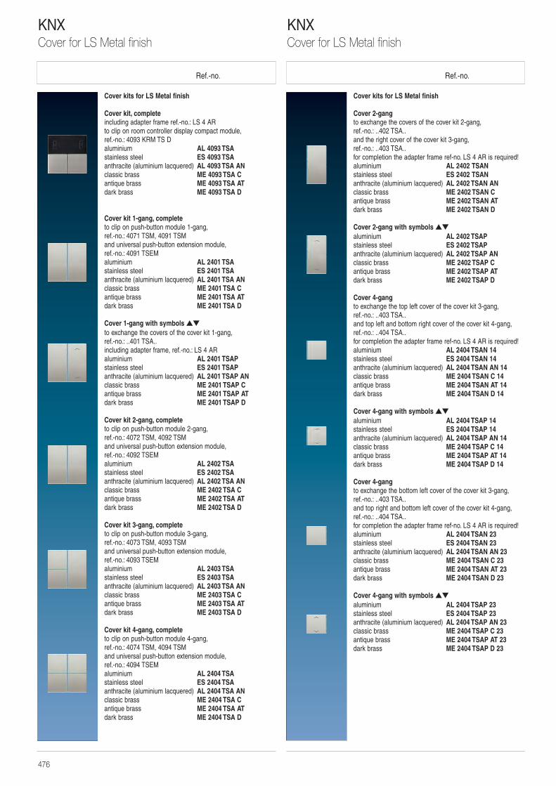
Ref.-no. Ref.-no.
Cover kits for LS Metal finish
Cover 2-gangto exchange the covers of the cover kit 2-gang,ref.-no.: ..402 TSA.. and the right cover of the cover kit 3-gang, ref.-no.: ..403 TSA..for completion the adapter frame ref-no. LS 4 AR is required!aluminium AL 2402 TSANstainless steel ES 2402 TSANanthracite (aluminium lacquered) AL 2402 TSAN ANclassic brass ME 2402 TSAN Cantique brass ME 2402 TSAN ATdark brass ME 2402 TSAN D
Cover 2-gang with symbols ▲▼
aluminium AL 2402 TSAPstainless steel ES 2402 TSAPanthracite (aluminium lacquered) AL 2402 TSAP ANclassic brass ME 2402 TSAP Cantique brass ME 2402 TSAP ATdark brass ME 2402 TSAP D
Cover 4-gangto exchange the top left cover of the cover kit 3-gang,ref.-no.: ..403 TSA.. and top left and bottom right cover of the cover kit 4-gang,ref.-no.: ..404 TSA..for completion the adapter frame ref-no. LS 4 AR is required!aluminium AL 2404 TSAN 14stainless steel ES 2404 TSAN 14anthracite (aluminium lacquered) AL 2404 TSAN AN 14classic brass ME 2404 TSAN C 14antique brass ME 2404 TSAN AT 14dark brass ME 2404 TSAN D 14
Cover 4-gang with symbols ▲▼
aluminium AL 2404 TSAP 14stainless steel ES 2404 TSAP 14anthracite (aluminium lacquered) AL 2404 TSAP AN 14classic brass ME 2404 TSAP C 14antique brass ME 2404 TSAP AT 14dark brass ME 2404 TSAP D 14
Cover 4-gangto exchange the bottom left cover of the cover kit 3-gang,ref.-no.: ..403 TSA.. and top right and bottom left cover of the cover kit 4-gang,ref.-no.: ..404 TSA..for completion the adapter frame ref-no. LS 4 AR is required!aluminium AL 2404 TSAN 23stainless steel ES 2404 TSAN 23anthracite (aluminium lacquered) AL 2404 TSAN AN 23classic brass ME 2404 TSAN C 23antique brass ME 2404 TSAN AT 23dark brass ME 2404 TSAN D 23
Cover 4-gang with symbols ▲▼
aluminium AL 2404 TSAP 23stainless steel ES 2404 TSAP 23anthracite (aluminium lacquered) AL 2404 TSAP AN 23classic brass ME 2404 TSAP C 23antique brass ME 2404 TSAP AT 23dark brass ME 2404 TSAP D 23
Cover kits for LS Metal finish
Cover kit, completeincluding adapter frame ref.-no.: LS 4 AR to clip on room controller display compact module,ref.-no.: 4093 KRM TS Daluminium AL 4093 TSAstainless steel ES 4093 TSAanthracite (aluminium lacquered) AL 4093 TSA ANclassic brass ME 4093 TSA Cantique brass ME 4093 TSA ATdark brass ME 4093 TSA D
Cover kit 1-gang, complete to clip on push-button module 1-gang,ref.-no.: 4071 TSM, 4091 TSM and universal push-button extension module,ref.-no.: 4091 TSEMaluminium AL 2401 TSAstainless steel ES 2401 TSAanthracite (aluminium lacquered) AL 2401 TSA ANclassic brass ME 2401 TSA Cantique brass ME 2401 TSA ATdark brass ME 2401 TSA D
Cover 1-gang with symbols ▲▼
to exchange the covers of the cover kit 1-gang,ref.-no.: ..401 TSA.. including adapter frame, ref.-no.: LS 4 ARaluminium AL 2401 TSAPstainless steel ES 2401 TSAPanthracite (aluminium lacquered) AL 2401 TSAP ANclassic brass ME 2401 TSAP Cantique brass ME 2401 TSAP ATdark brass ME 2401 TSAP D
Cover kit 2-gang, completeto clip on push-button module 2-gang,ref.-no.: 4072 TSM, 4092 TSMand universal push-button extension module,ref.-no.: 4092 TSEMaluminium AL 2402 TSAstainless steel ES 2402 TSAanthracite (aluminium lacquered) AL 2402 TSA ANclassic brass ME 2402 TSA Cantique brass ME 2402 TSA ATdark brass ME 2402 TSA D
Cover kit 3-gang, completeto clip on push-button module 3-gang,ref.-no.: 4073 TSM, 4093 TSMand universal push-button extension module,ref.-no.: 4093 TSEMaluminium AL 2403 TSAstainless steel ES 2403 TSAanthracite (aluminium lacquered) AL 2403 TSA ANclassic brass ME 2403 TSA Cantique brass ME 2403 TSA ATdark brass ME 2403 TSA D
Cover kit 4-gang, completeto clip on push-button module 4-gang,ref.-no.: 4074 TSM, 4094 TSMand universal push-button extension module,ref.-no.: 4094 TSEMaluminium AL 2404 TSAstainless steel ES 2404 TSAanthracite (aluminium lacquered) AL 2404 TSA ANclassic brass ME 2404 TSA Cantique brass ME 2404 TSA ATdark brass ME 2404 TSA D
KNXCover for LS Metal finish
KNXCover for LS Metal finish
476
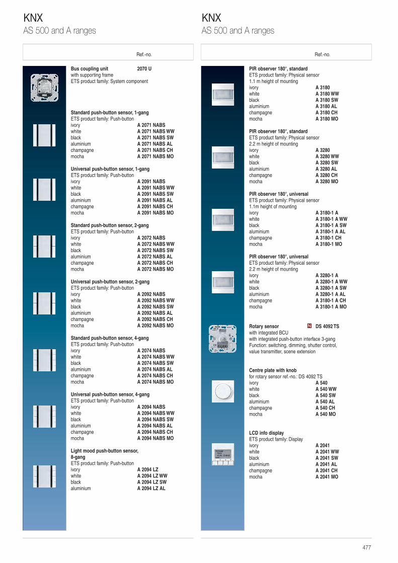
Ref.-no. Ref.-no.
PIR observer 180°, standardETS product family: Physical sensor1.1 m height of mounting ivory A 3180 white A 3180 WWblack A 3180 SWaluminium A 3180 ALchampagne A 3180 CHmocha A 3180 MO
PIR observer 180°, standardETS product family: Physical sensor2.2 m height of mounting ivory A 3280 white A 3280 WWblack A 3280 SWaluminium A 3280 ALchampagne A 3280 CHmocha A 3280 MO
PIR observer 180°, universalETS product family: Physical sensor1.1m height of mountingivory A 3180-1 Awhite A 3180-1 A WWblack A 3180-1 A SWaluminium A 3180-1 A ALchampagne A 3180-1 CHmocha A 3180-1 MO
PIR observer 180°, universalETS product family: Physical sensor2.2 m height of mountingivory A 3280-1 Awhite A 3280-1 A WWblack A 3280-1 A SWaluminium A 3280-1 A ALchampagne A 3180-1 A CHmocha A 3180-1 A MO
Rotary sensor DS 4092 TSwith integrated BCUwith integrated push-button interface 3-gangFunction: switching, dimming, shutter control, value transmitter, scene extension
Centre plate with knobfor rotary sensor ref.-no.: DS 4092 TSivory A 540white A 540 WWblack A 540 SWaluminium A 540 ALchampagne A 540 CHmocha A 540 MO
LCD info displayETS product family: Displayivory A 2041 white A 2041 WWblack A 2041 SWaluminium A 2041 ALchampagne A 2041 CHmocha A 2041 MO
N
Bus coupling unit 2070 Uwith supporting frameETS product family: System component
Standard push-button sensor, 1-gangETS product family: Push-buttonivory A 2071 NABS white A 2071 NABS WWblack A 2071 NABS SWaluminium A 2071 NABS ALchampagne A 2071 NABS CHmocha A 2071 NABS MO
Universal push-button sensor, 1-gangETS product family: Push-buttonivory A 2091 NABS white A 2091 NABS WWblack A 2091 NABS SWaluminium A 2091 NABS ALchampagne A 2091 NABS CHmocha A 2091 NABS MO
Standard push-button sensor, 2-gangETS product family: Push-buttonivory A 2072 NABS white A 2072 NABS WWblack A 2072 NABS SWaluminium A 2072 NABS ALchampagne A 2072 NABS CHmocha A 2072 NABS MO
Universal push-button sensor, 2-gangETS product family: Push-buttonivory A 2092 NABS white A 2092 NABS WWblack A 2092 NABS SWaluminium A 2092 NABS ALchampagne A 2092 NABS CHmocha A 2092 NABS MO
Standard push-button sensor, 4-gangETS product family: Push-buttonivory A 2074 NABS white A 2074 NABS WWblack A 2074 NABS SWaluminium A 2074 NABS ALchampagne A 2074 NABS CHmocha A 2074 NABS MO
Universal push-button sensor, 4-gangETS product family: Push-buttonivory A 2094 NABS white A 2094 NABS WWblack A 2094 NABS SWaluminium A 2094 NABS ALchampagne A 2094 NABS CHmocha A 2094 NABS MO
Light mood push-button sensor, 8-gangETS product family: Push-buttonivory A 2094 LZwhite A 2094 LZ WWblack A 2094 LZ SWaluminium A 2094 LZ AL
KNXAS 500 and A ranges
KNXAS 500 and A ranges
477
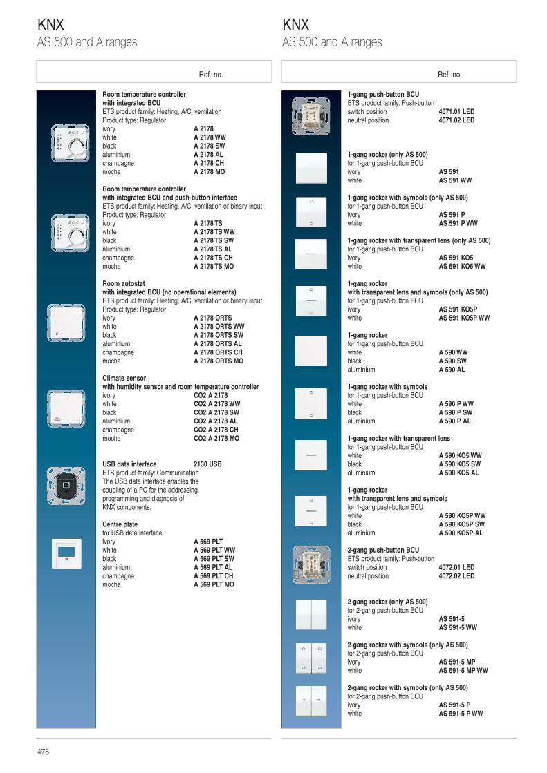
Ref.-no. Ref.-no.
1-gang push-button BCUETS product family: Push-buttonswitch position 4071.01 LEDneutral position 4071.02 LED
1-gang rocker (only AS 500)for 1-gang push-button BCUivory AS 591white AS 591 WW
1-gang rocker with symbols (only AS 500)for 1-gang push-button BCUivory AS 591 Pwhite AS 591 P WW
1-gang rocker with transparent lens (only AS 500)for 1-gang push-button BCUivory AS 591 KO5white AS 591 KO5 WW
1-gang rocker with transparent lens and symbols (only AS 500)for 1-gang push-button BCUivory AS 591 KO5Pwhite AS 591 KO5P WW
1-gang rockerfor 1-gang push-button BCUwhite A 590 WWblack A 590 SWaluminium A 590 AL
1-gang rocker with symbols for 1-gang push-button BCUwhite A 590 P WWblack A 590 P SWaluminium A 590 P AL
1-gang rocker with transparent lens for 1-gang push-button BCUwhite A 590 KO5 WWblack A 590 KO5 SWaluminium A 590 KO5 AL
1-gang rocker with transparent lens and symbolsfor 1-gang push-button BCUwhite A 590 KO5P WWblack A 590 KO5P SWaluminium A 590 KO5P AL
2-gang push-button BCUETS product family: Push-buttonswitch position 4072.01 LEDneutral position 4072.02 LED
2-gang rocker (only AS 500)for 2-gang push-button BCUivory AS 591-5white AS 591-5 WW
2-gang rocker with symbols (only AS 500)for 2-gang push-button BCUivory AS 591-5 MPwhite AS 591-5 MP WW
2-gang rocker with symbols (only AS 500)for 2-gang push-button BCUivory AS 591-5 Pwhite AS 591-5 P WW
Room temperature controllerwith integrated BCUETS product family: Heating, A/C, ventilationProduct type: Regulatorivory A 2178white A 2178 WWblack A 2178 SWaluminium A 2178 ALchampagne A 2178 CHmocha A 2178 MO
Room temperature controllerwith integrated BCU and push-button interfaceETS product family: Heating, A/C, ventilation or binary inputProduct type: Regulatorivory A 2178 TSwhite A 2178 TS WWblack A 2178 TS SWaluminium A 2178 TS ALchampagne A 2178 TS CHmocha A 2178 TS MO
Room autostatwith integrated BCU (no operational elements)ETS product family: Heating, A/C, ventilation or binary inputProduct type: Regulatorivory A 2178 ORTSwhite A 2178 ORTS WWblack A 2178 ORTS SWaluminium A 2178 ORTS ALchampagne A 2178 ORTS CHmocha A 2178 ORTS MO
Climate sensorwith humidity sensor and room temperature controllerivory CO2 A 2178 white CO2 A 2178 WWblack CO2 A 2178 SWaluminium CO2 A 2178 ALchampagne CO2 A 2178 CHmocha CO2 A 2178 MO
USB data interface 2130 USBETS product family: CommunicationThe USB data interface enables the coupling of a PC for the addressing, programming and diagnosis of KNX components.
Centre plate for USB data interfaceivory A 569 PLTwhite A 569 PLT WWblack A 569 PLT SWaluminium A 569 PLT ALchampagne A 569 PLT CHmocha A 569 PLT MO
KNXAS 500 and A ranges
KNXAS 500 and A ranges
478
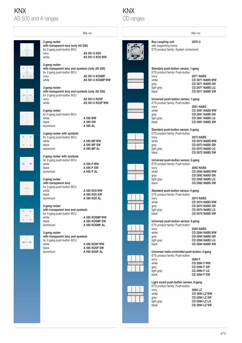
Ref.-no. Ref.-no.
Bus coupling unit 2070 Uwith supporting frameETS product family: System component
Standard push-button sensor, 1-gangETS product family: Push-buttonivory 2071 NABS white CD 2071 NABS WWgrey CD 2071 NABS GRlight grey CD 2071 NABS LGblack CD 2071 NABS SW
Universal push-button sensor, 1-gangETS product family: Push-buttonivory 2091 NABS white CD 2091 NABS WWgrey CD 2091 NABS GRlight grey CD 2091 NABS LGblack CD 2091 NABS SW
Standard push-button sensor, 2-gangETS product family: Push-buttonivory 2072 NABS white CD 2072 NABS WWgrey CD 2072 NABS GRlight grey CD 2072 NABS LGblack CD 2072 NABS SW
Universal push-button sensor, 2-gangETS product family: Push-buttonivory 2092 NABS white CD 2092 NABS WWgrey CD 2092 NABS GRlight grey CD 2092 NABS LGblack CD 2092 NABS SW
Standard push-button sensor, 4-gangETS product family: Push-buttonivory 2074 NABS white CD 2074 NABS WWgrey CD 2074 NABS GRlight grey CD 2074 NABS LGblack CD 2074 NABS SW
Universal push-button sensor, 4-gangETS product family: Push-buttonivory 2094 NABS white CD 2094 NABS WWgrey CD 2094 NABS GRlight grey CD 2094 NABS LGblack CD 2094 NABS SW
Universal radio-controlled push-button, 4-gang ETS product family: Push-buttonivory 2094 Fwhite CD 2094 F WWgrey CD 2094 F GRlight grey CD 2094 F LGblack CD 2094 F SW
Light mood push-button sensor, 8-gangETS product family: Push-buttonivory 2094 LZwhite CD 2094 LZ WWgrey CD 2094 LZ GRlight grey CD 2094 LZ LGblack CD 2094 LZ SW
2-gang rocker with transparent lens (only AS 500)for 2-gang push-button BCUivory AS 591-5 KO5white AS 591-5 KO5 WW
2-gang rocker with transparent lens and symbols (only AS 500)for 2-gang push-button BCUivory AS 591-5 KO5MPwhite AS 591-5 KO5MP WW
2-gang rocker with transparent lens and symbols (only AS 500)for 2-gang push-button BCUivory AS 591-5 KO5Pwhite AS 591-5 KO5P WW
2-gang rockerfor 2-gang push-button BCUwhite A 595 WWblack A 595 SWaluminium A 595 AL
2-gang rocker with symbolsfor 2-gang push-button BCUwhite A 595 MP WWblack A 595 MP SWaluminium A 595 MP AL
2-gang rocker with symbolsfor 2-gang push-button BCUwhite A 595 P WWblack A 595 P SWaluminium A 595 P AL
2-gang rocker with transparent lensfor 2-gang push-button BCUwhite A 595 KO5 WWblack A 595 KO5 SWaluminium A 595 KO5 AL
2-gang rocker with transparent lens and symbolsfor 2-gang push-button BCUwhite A 595 KO5MP WWblack A 595 KO5MP SWaluminium A 595 KO5MP AL
2-gang rocker with transparent lens and symbolsfor 2-gang push-button BCUwhite A 595 KO5P WWblack A 595 KO5P SWaluminium A 595 KO5P AL
KNXCD ranges
KNXAS 500 and A ranges
479
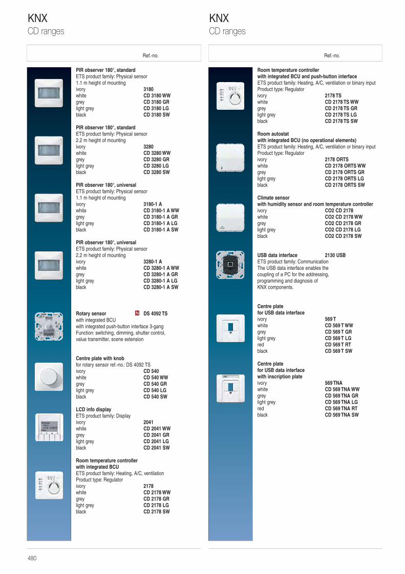
Ref.-no. Ref.-no.
Room temperature controllerwith integrated BCU and push-button interfaceETS product family: Heating, A/C, ventilation or binary inputProduct type: Regulatorivory 2178 TSwhite CD 2178 TS WWgrey CD 2178 TS GRlight grey CD 2178 TS LGblack CD 2178 TS SW
Room autostatwith integrated BCU (no operational elements)ETS product family: Heating, A/C, ventilation or binary inputProduct type: Regulatorivory 2178 ORTSwhite CD 2178 ORTS WWgrey CD 2178 ORTS GRlight grey CD 2178 ORTS LGblack CD 2178 ORTS SW
Climate sensorwith humidity sensor and room temperature controllerivory CO2 CD 2178 white CO2 CD 2178 WWgrey CO2 CD 2178 GRlight grey CO2 CD 2178 LGblack CO2 CD 2178 SW
USB data interface 2130 USBETS product family: CommunicationThe USB data interface enables the coupling of a PC for the addressing, programming and diagnosis of KNX components.
Centre plate for USB data interface ivory 569 Twhite CD 569 T WWgrey CD 569 T GRlight grey CD 569 T LGred CD 569 T RTblack CD 569 T SW
Centre plate for USB data interfacewith inscription plateivory 569 TNAwhite CD 569 TNA WWgrey CD 569 TNA GRlight grey CD 569 TNA LGred CD 569 TNA RTblack CD 569 TNA SW
PIR observer 180°, standardETS product family: Physical sensor1.1 m height of mountingivory 3180white CD 3180 WWgrey CD 3180 GRlight grey CD 3180 LGblack CD 3180 SW
PIR observer 180°, standardETS product family: Physical sensor2.2 m height of mountingivory 3280white CD 3280 WWgrey CD 3280 GRlight grey CD 3280 LGblack CD 3280 SW
PIR observer 180°, universalETS product family: Physical sensor1.1 m height of mountingivory 3180-1 Awhite CD 3180-1 A WWgrey CD 3180-1 A GRlight grey CD 3180-1 A LGblack CD 3180-1 A SW
PIR observer 180°, universalETS product family: Physical sensor2.2 m height of mountingivory 3280-1 Awhite CD 3280-1 A WWgrey CD 3280-1 A GRlight grey CD 3280-1 A LGblack CD 3280-1 A SW
Rotary sensor DS 4092 TSwith integrated BCUwith integrated push-button interface 3-gangFunction: switching, dimming, shutter control, value transmitter, scene extension
Centre plate with knobfor rotary sensor ref.-no.: DS 4092 TSivory CD 540white CD 540 WWgrey CD 540 GRlight grey CD 540 LGblack CD 540 SW
LCD info displayETS product family: Displayivory 2041 white CD 2041 WWgrey CD 2041 GRlight grey CD 2041 LGblack CD 2041 SW
Room temperature controller with integrated BCUETS product family: Heating, A/C, ventilationProduct type: Regulatorivory 2178white CD 2178 WWgrey CD 2178 GRlight grey CD 2178 LGblack CD 2178 SW
N
KNXCD ranges
KNXCD ranges
480
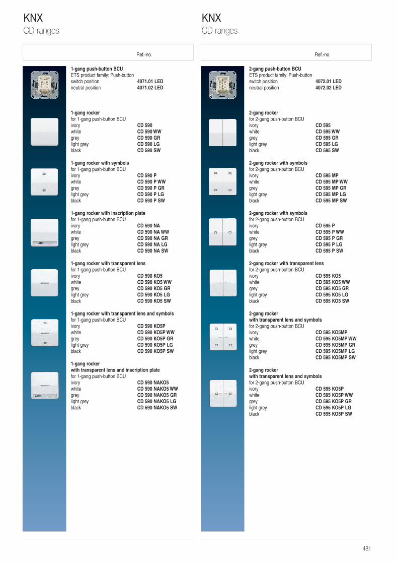
Ref.-no. Ref.-no.
2-gang push-button BCUETS product family: Push-buttonswitch position 4072.01 LEDneutral position 4072.02 LED
2-gang rocker for 2-gang push-button BCUivory CD 595white CD 595 WWgrey CD 595 GRlight grey CD 595 LGblack CD 595 SW
2-gang rocker with symbols for 2-gang push-button BCUivory CD 595 MPwhite CD 595 MP WWgrey CD 595 MP GRlight grey CD 595 MP LGblack CD 595 MP SW
2-gang rocker with symbols for 2-gang push-button BCUivory CD 595 Pwhite CD 595 P WWgrey CD 595 P GRlight grey CD 595 P LGblack CD 595 P SW
2-gang rocker with transparent lens for 2-gang push-button BCUivory CD 595 KO5 white CD 595 KO5 WWgrey CD 595 KO5 GRlight grey CD 595 KO5 LGblack CD 595 KO5 SW
2-gang rocker with transparent lens and symbolsfor 2-gang push-button BCUivory CD 595 KO5MPwhite CD 595 KO5MP WWgrey CD 595 KO5MP GRlight grey CD 595 KO5MP LGblack CD 595 KO5MP SW
2-gang rocker with transparent lens and symbolsfor 2-gang push-button BCUivory CD 595 KO5Pwhite CD 595 KO5P WWgrey CD 595 KO5P GRlight grey CD 595 KO5P LGblack CD 595 KO5P SW
1-gang push-button BCUETS product family: Push-buttonswitch position 4071.01 LEDneutral position 4071.02 LED
1-gang rocker for 1-gang push-button BCUivory CD 590white CD 590 WWgrey CD 590 GRlight grey CD 590 LGblack CD 590 SW
1-gang rocker with symbols for 1-gang push-button BCUivory CD 590 Pwhite CD 590 P WWgrey CD 590 P GRlight grey CD 590 P LGblack CD 590 P SW
1-gang rocker with inscription plate for 1-gang push-button BCUivory CD 590 NAwhite CD 590 NA WWgrey CD 590 NA GRlight grey CD 590 NA LGblack CD 590 NA SW
1-gang rocker with transparent lens for 1-gang push-button BCUivory CD 590 KO5white CD 590 KO5 WWgrey CD 590 KO5 GRlight grey CD 590 KO5 LGblack CD 590 KO5 SW
1-gang rocker with transparent lens and symbols for 1-gang push-button BCUivory CD 590 KO5Pwhite CD 590 KO5P WWgrey CD 590 KO5P GRlight grey CD 590 KO5P LGblack CD 590 KO5P SW
1-gang rocker with transparent lens and inscription plate for 1-gang push-button BCUivory CD 590 NAKO5white CD 590 NAKO5 WWgrey CD 590 NAKO5 GRlight grey CD 590 NAKO5 LGblack CD 590 NAKO5 SW
KNXCD ranges
KNXCD ranges
481
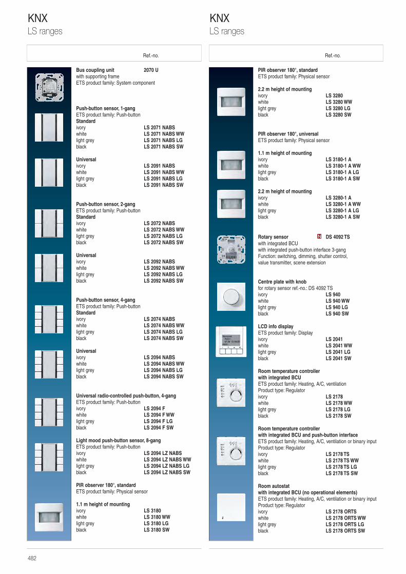
Ref.-no. Ref.-no.
PIR observer 180°, standardETS product family: Physical sensor
2.2 m height of mountingivory LS 3280 white LS 3280 WWlight grey LS 3280 LGblack LS 3280 SW
PIR observer 180°, universalETS product family: Physical sensor
1.1 m height of mountingivory LS 3180-1 A white LS 3180-1 A WWlight grey LS 3180-1 A LGblack LS 3180-1 A SW
2.2 m height of mountingivory LS 3280-1 A white LS 3280-1 A WWlight grey LS 3280-1 A LGblack LS 3280-1 A SW
Rotary sensor DS 4092 TSwith integrated BCUwith integrated push-button interface 3-gangFunction: switching, dimming, shutter control, value transmitter, scene extension
Centre plate with knobfor rotary sensor ref.-no.: DS 4092 TSivory LS 940 white LS 940 WWlight grey LS 940 LGblack LS 940 SW
LCD info displayETS product family: Displayivory LS 2041 white LS 2041 WWlight grey LS 2041 LGblack LS 2041 SW
Room temperature controllerwith integrated BCUETS product family: Heating, A/C, ventilationProduct type: Regulatorivory LS 2178 white LS 2178 WWlight grey LS 2178 LGblack LS 2178 SW
Room temperature controllerwith integrated BCU and push-button interfaceETS product family: Heating, A/C, ventilation or binary inputProduct type: Regulatorivory LS 2178 TS white LS 2178 TS WWlight grey LS 2178 TS LGblack LS 2178 TS SW
Room autostatwith integrated BCU (no operational elements)ETS product family: Heating, A/C, ventilation or binary inputProduct type: Regulatorivory LS 2178 ORTS white LS 2178 ORTS WWlight grey LS 2178 ORTS LGblack LS 2178 ORTS SW
N
Bus coupling unit 2070 Uwith supporting frameETS product family: System component
Push-button sensor, 1-gangETS product family: Push-buttonStandardivory LS 2071 NABS white LS 2071 NABS WWlight grey LS 2071 NABS LGblack LS 2071 NABS SW
Universalivory LS 2091 NABS white LS 2091 NABS WWlight grey LS 2091 NABS LGblack LS 2091 NABS SW
Push-button sensor, 2-gangETS product family: Push-buttonStandard ivory LS 2072 NABS white LS 2072 NABS WWlight grey LS 2072 NABS LGblack LS 2072 NABS SW
Universalivory LS 2092 NABS white LS 2092 NABS WWlight grey LS 2092 NABS LGblack LS 2092 NABS SW
Push-button sensor, 4-gangETS product family: Push-buttonStandard ivory LS 2074 NABS white LS 2074 NABS WWlight grey LS 2074 NABS LGblack LS 2074 NABS SW
Universalivory LS 2094 NABS white LS 2094 NABS WWlight grey LS 2094 NABS LGblack LS 2094 NABS SW
Universal radio-controlled push-button, 4-gang ETS product family: Push-buttonivory LS 2094 F white LS 2094 F WWlight grey LS 2094 F LGblack LS 2094 F SW
Light mood push-button sensor, 8-gangETS product family: Push-buttonivory LS 2094 LZ NABS white LS 2094 LZ NABS WWlight grey LS 2094 LZ NABS LGblack LS 2094 LZ NABS SW
PIR observer 180°, standardETS product family: Physical sensor
1.1 m height of mountingivory LS 3180 white LS 3180 WWlight grey LS 3180 LGblack LS 3180 SW
KNXLS ranges
KNXLS ranges
482
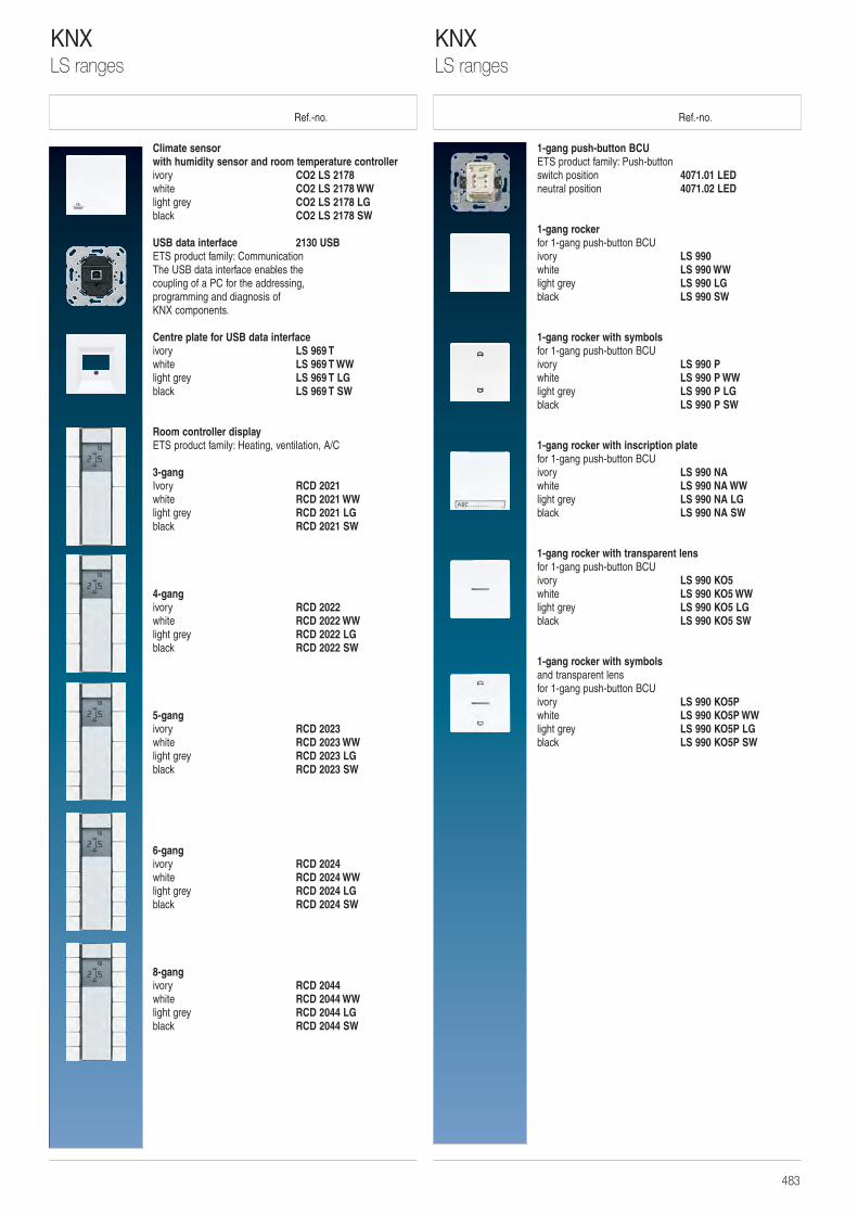
Ref.-no. Ref.-no.
1-gang push-button BCUETS product family: Push-buttonswitch position 4071.01 LEDneutral position 4071.02 LED
1-gang rocker for 1-gang push-button BCUivory LS 990 white LS 990 WWlight grey LS 990 LGblack LS 990 SW
1-gang rocker with symbolsfor 1-gang push-button BCUivory LS 990 P white LS 990 P WWlight grey LS 990 P LGblack LS 990 P SW
1-gang rocker with inscription platefor 1-gang push-button BCUivory LS 990 NA white LS 990 NA WWlight grey LS 990 NA LGblack LS 990 NA SW
1-gang rocker with transparent lensfor 1-gang push-button BCUivory LS 990 KO5 white LS 990 KO5 WWlight grey LS 990 KO5 LGblack LS 990 KO5 SW
1-gang rocker with symbols and transparent lensfor 1-gang push-button BCUivory LS 990 KO5P white LS 990 KO5P WWlight grey LS 990 KO5P LGblack LS 990 KO5P SW
Climate sensorwith humidity sensor and room temperature controllerivory CO2 LS 2178 white CO2 LS 2178 WWlight grey CO2 LS 2178 LGblack CO2 LS 2178 SW
USB data interface 2130 USBETS product family: CommunicationThe USB data interface enables the coupling of a PC for the addressing, programming and diagnosis of KNX components.
Centre plate for USB data interfaceivory LS 969 T white LS 969 T WWlight grey LS 969 T LGblack LS 969 T SW
Room controller displayETS product family: Heating, ventilation, A/C
3-gangIvory RCD 2021white RCD 2021 WWlight grey RCD 2021 LGblack RCD 2021 SW
4-gangivory RCD 2022 white RCD 2022 WWlight grey RCD 2022 LGblack RCD 2022 SW
5-gangivory RCD 2023 white RCD 2023 WWlight grey RCD 2023 LGblack RCD 2023 SW
6-gangivory RCD 2024 white RCD 2024 WWlight grey RCD 2024 LGblack RCD 2024 SW
8-gangivory RCD 2044 white RCD 2044 WWlight grey RCD 2044 LGblack RCD 2044 SW
KNXLS ranges
KNXLS ranges
483
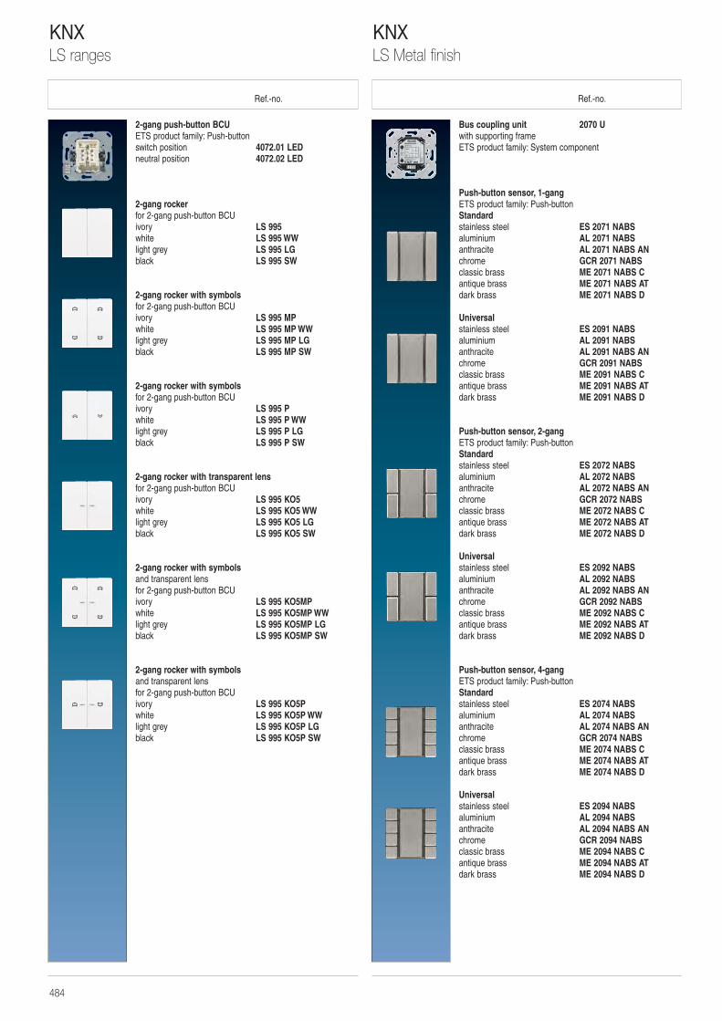
Ref.-no. Ref.-no.
Bus coupling unit 2070 Uwith supporting frameETS product family: System component
Push-button sensor, 1-gangETS product family: Push-buttonStandardstainless steel ES 2071 NABSaluminium AL 2071 NABSanthracite AL 2071 NABS ANchrome GCR 2071 NABS classic brass ME 2071 NABS C antique brass ME 2071 NABS AT dark brass ME 2071 NABS D
Universalstainless steel ES 2091 NABSaluminium AL 2091 NABSanthracite AL 2091 NABS ANchrome GCR 2091 NABS classic brass ME 2091 NABS C antique brass ME 2091 NABS AT dark brass ME 2091 NABS D
Push-button sensor, 2-gangETS product family: Push-buttonStandard stainless steel ES 2072 NABSaluminium AL 2072 NABSanthracite AL 2072 NABS ANchrome GCR 2072 NABS classic brass ME 2072 NABS C antique brass ME 2072 NABS AT dark brass ME 2072 NABS D
Universalstainless steel ES 2092 NABSaluminium AL 2092 NABSanthracite AL 2092 NABS ANchrome GCR 2092 NABS classic brass ME 2092 NABS C antique brass ME 2092 NABS AT dark brass ME 2092 NABS D
Push-button sensor, 4-gangETS product family: Push-buttonStandard stainless steel ES 2074 NABSaluminium AL 2074 NABSanthracite AL 2074 NABS ANchrome GCR 2074 NABS classic brass ME 2074 NABS C antique brass ME 2074 NABS AT dark brass ME 2074 NABS D
Universalstainless steel ES 2094 NABSaluminium AL 2094 NABSanthracite AL 2094 NABS ANchrome GCR 2094 NABS classic brass ME 2094 NABS C antique brass ME 2094 NABS AT dark brass ME 2094 NABS D
2-gang push-button BCUETS product family: Push-buttonswitch position 4072.01 LEDneutral position 4072.02 LED
2-gang rocker for 2-gang push-button BCUivory LS 995 white LS 995 WWlight grey LS 995 LGblack LS 995 SW
2-gang rocker with symbols for 2-gang push-button BCUivory LS 995 MP white LS 995 MP WWlight grey LS 995 MP LGblack LS 995 MP SW
2-gang rocker with symbols for 2-gang push-button BCUivory LS 995 P white LS 995 P WWlight grey LS 995 P LGblack LS 995 P SW
2-gang rocker with transparent lensfor 2-gang push-button BCUivory LS 995 KO5white LS 995 KO5 WWlight grey LS 995 KO5 LGblack LS 995 KO5 SW
2-gang rocker with symbols and transparent lensfor 2-gang push-button BCUivory LS 995 KO5MP white LS 995 KO5MP WWlight grey LS 995 KO5MP LGblack LS 995 KO5MP SW
2-gang rocker with symbols and transparent lensfor 2-gang push-button BCUivory LS 995 KO5P white LS 995 KO5P WWlight grey LS 995 KO5P LGblack LS 995 KO5P SW
KNXLS Metal finish
KNXLS ranges
484
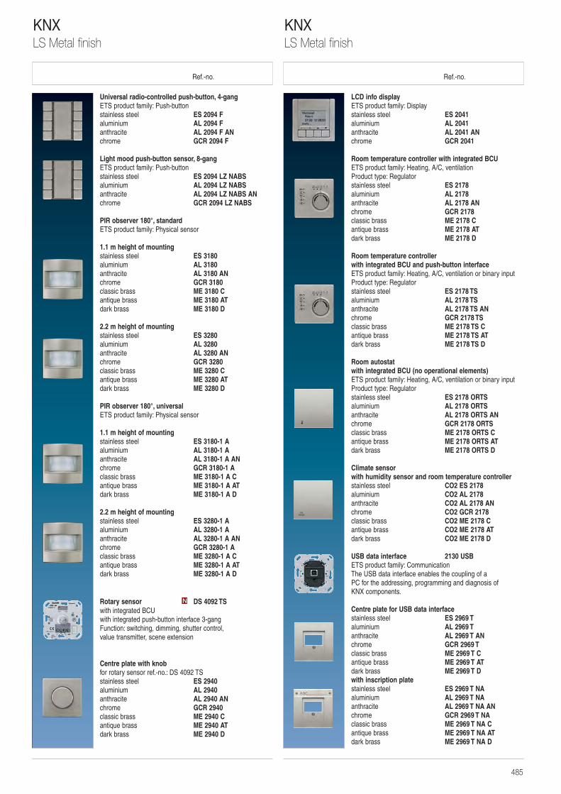
Ref.-no. Ref.-no.
LCD info displayETS product family: Displaystainless steel ES 2041aluminium AL 2041anthracite AL 2041 ANchrome GCR 2041
Room temperature controller with integrated BCUETS product family: Heating, A/C, ventilationProduct type: Regulatorstainless steel ES 2178aluminium AL 2178anthracite AL 2178 ANchrome GCR 2178classic brass ME 2178 C antique brass ME 2178 AT dark brass ME 2178 D
Room temperature controllerwith integrated BCU and push-button interfaceETS product family: Heating, A/C, ventilation or binary inputProduct type: Regulatorstainless steel ES 2178 TSaluminium AL 2178 TSanthracite AL 2178 TS ANchrome GCR 2178 TSclassic brass ME 2178 TS C antique brass ME 2178 TS AT dark brass ME 2178 TS D
Room autostatwith integrated BCU (no operational elements)ETS product family: Heating, A/C, ventilation or binary inputProduct type: Regulatorstainless steel ES 2178 ORTSaluminium AL 2178 ORTSanthracite AL 2178 ORTS ANchrome GCR 2178 ORTSclassic brass ME 2178 ORTS C antique brass ME 2178 ORTS AT dark brass ME 2178 ORTS D
Climate sensorwith humidity sensor and room temperature controllerstainless steel CO2 ES 2178aluminium CO2 AL 2178anthracite CO2 AL 2178 ANchrome CO2 GCR 2178classic brass CO2 ME 2178 C antique brass CO2 ME 2178 AT dark brass CO2 ME 2178 D
USB data interface 2130 USBETS product family: CommunicationThe USB data interface enables the coupling of a PC for the addressing, programming and diagnosis of KNX components.
Centre plate for USB data interfacestainless steel ES 2969 Taluminium AL 2969 Tanthracite AL 2969 T ANchrome GCR 2969 T classic brass ME 2969 T C antique brass ME 2969 T AT dark brass ME 2969 T D with inscription platestainless steel ES 2969 T NAaluminium AL 2969 T NAanthracite AL 2969 T NA ANchrome GCR 2969 T NA classic brass ME 2969 T NA C antique brass ME 2969 T NA AT dark brass ME 2969 T NA D
Universal radio-controlled push-button, 4-gang ETS product family: Push-buttonstainless steel ES 2094 F aluminium AL 2094 F anthracite AL 2094 F ANchrome GCR 2094 F
Light mood push-button sensor, 8-gangETS product family: Push-buttonstainless steel ES 2094 LZ NABSaluminium AL 2094 LZ NABSanthracite AL 2094 LZ NABS ANchrome GCR 2094 LZ NABS
PIR observer 180°, standardETS product family: Physical sensor
1.1 m height of mountingstainless steel ES 3180aluminium AL 3180anthracite AL 3180 ANchrome GCR 3180 classic brass ME 3180 C antique brass ME 3180 AT dark brass ME 3180 D
2.2 m height of mountingstainless steel ES 3280aluminium AL 3280anthracite AL 3280 ANchrome GCR 3280classic brass ME 3280 C antique brass ME 3280 AT dark brass ME 3280 D
PIR observer 180°, universalETS product family: Physical sensor
1.1 m height of mountingstainless steel ES 3180-1 A aluminium AL 3180-1 A anthracite AL 3180-1 A ANchrome GCR 3180-1 Aclassic brass ME 3180-1 A C antique brass ME 3180-1 A AT dark brass ME 3180-1 A D
2.2 m height of mountingstainless steel ES 3280-1 A aluminium AL 3280-1 A anthracite AL 3280-1 A ANchrome GCR 3280-1 Aclassic brass ME 3280-1 A C antique brass ME 3280-1 A AT dark brass ME 3280-1 A D
Rotary sensor DS 4092 TSwith integrated BCUwith integrated push-button interface 3-gangFunction: switching, dimming, shutter control, value transmitter, scene extension
Centre plate with knobfor rotary sensor ref.-no.: DS 4092 TSstainless steel ES 2940aluminium AL 2940anthracite AL 2940 ANchrome GCR 2940classic brass ME 2940 C antique brass ME 2940 AT dark brass ME 2940 D
N
KNXLS Metal finish
KNXLS Metal finish
485
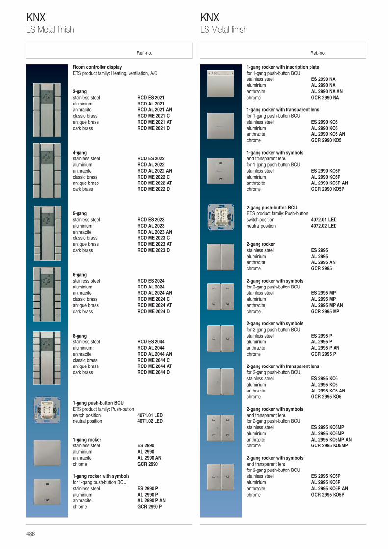
Ref.-no. Ref.-no.
1-gang rocker with inscription platefor 1-gang push-button BCUstainless steel ES 2990 NAaluminium AL 2990 NAanthracite AL 2990 NA ANchrome GCR 2990 NA
1-gang rocker with transparent lensfor 1-gang push-button BCUstainless steel ES 2990 KO5aluminium AL 2990 KO5anthracite AL 2990 KO5 ANchrome GCR 2990 KO5
1-gang rocker with symbols and transparent lensfor 1-gang push-button BCUstainless steel ES 2990 KO5Paluminium AL 2990 KO5Panthracite AL 2990 KO5P ANchrome GCR 2990 KO5P
2-gang push-button BCUETS product family: Push-buttonswitch position 4072.01 LEDneutral position 4072.02 LED
2-gang rocker stainless steel ES 2995aluminium AL 2995anthracite AL 2995 ANchrome GCR 2995
2-gang rocker with symbols for 2-gang push-button BCUstainless steel ES 2995 MPaluminium AL 2995 MPanthracite AL 2995 MP ANchrome GCR 2995 MP
2-gang rocker with symbols for 2-gang push-button BCUstainless steel ES 2995 Paluminium AL 2995 Panthracite AL 2995 P ANchrome GCR 2995 P
2-gang rocker with transparent lensfor 2-gang push-button BCUstainless steel ES 2995 KO5aluminium AL 2995 KO5anthracite AL 2995 KO5 ANchrome GCR 2995 KO5
2-gang rocker with symbols and transparent lensfor 2-gang push-button BCUstainless steel ES 2995 KO5MPaluminium AL 2995 KO5MPanthracite AL 2995 KO5MP ANchrome GCR 2995 KO5MP
2-gang rocker with symbols and transparent lensfor 2-gang push-button BCUstainless steel ES 2995 KO5Paluminium AL 2995 KO5Panthracite AL 2995 KO5P ANchrome GCR 2995 KO5P
Room controller displayETS product family: Heating, ventilation, A/C
3-gangstainless steel RCD ES 2021aluminium RCD AL 2021anthracite RCD AL 2021 ANclassic brass RCD ME 2021 Cantique brass RCD ME 2021 ATdark brass RCD ME 2021 D
4-gangstainless steel RCD ES 2022aluminium RCD AL 2022anthracite RCD AL 2022 ANclassic brass RCD ME 2022 Cantique brass RCD ME 2022 ATdark brass RCD ME 2022 D
5-gangstainless steel RCD ES 2023aluminium RCD AL 2023anthracite RCD AL 2023 ANclassic brass RCD ME 2023 Cantique brass RCD ME 2023 ATdark brass RCD ME 2023 D
6-gangstainless steel RCD ES 2024aluminium RCD AL 2024anthracite RCD AL 2024 ANclassic brass RCD ME 2024 Cantique brass RCD ME 2024 ATdark brass RCD ME 2024 D
8-gangstainless steel RCD ES 2044aluminium RCD AL 2044anthracite RCD AL 2044 ANclassic brass RCD ME 2044 Cantique brass RCD ME 2044 ATdark brass RCD ME 2044 D
1-gang push-button BCUETS product family: Push-buttonswitch position 4071.01 LEDneutral position 4071.02 LED
1-gang rocker stainless steel ES 2990aluminium AL 2990anthracite AL 2990 ANchrome GCR 2990
1-gang rocker with symbolsfor 1-gang push-button BCUstainless steel ES 2990 Paluminium AL 2990 Panthracite AL 2990 P ANchrome GCR 2990 P
KNXLS Metal finish
KNXLS Metal finish
486
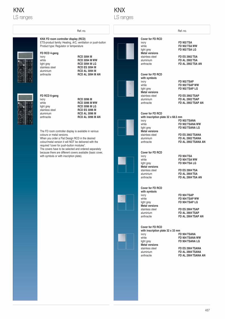
Ref.-no. Ref.-no.
Cover for FD RCDivory FD 902 TSAwhite FD 902 TSA WWlight grey FD 902 TSA LGMetal versionsstainless steel FD ES 2902 TSAaluminium FD AL 2902 TSAanthracite FD AL 2902 TSA AN
Cover for FD RCDwith symbolsivory FD 902 TSAPwhite FD 902 TSAP WWlight grey FD 902 TSAP LGMetal versionsstainless steel FD ES 2902 TSAPaluminium FD AL 2902 TSAPanthracite FD AL 2902 TSAP AN
Cover for FD RCDwith inscription plate 32 x 68.5 mmivory FD 902 TSANAwhite FD 902 TSANA WWlight grey FD 902 TSANA LGMetal versionsstainless steel FD ES 2902 TSANAaluminium FD AL 2902 TSANAanthracite FD AL 2902 TSANA AN
Cover for FD RCDivory FD 904 TSAwhite FD 904 TSA WWlight grey FD 904 TSA LGMetal versionsstainless steel FD ES 2904 TSAaluminium FD AL 2904 TSAanthracite FD AL 2904 TSA AN
Cover for FD RCDwith symbolsivory FD 904 TSAPwhite FD 904 TSAP WWlight grey FD 904 TSAP LGMetal versionsstainless steel FD ES 2904 TSAPaluminium FD AL 2904 TSAPanthracite FD AL 2904 TSAP AN
Cover for FD RCDwith inscription plate 32 x 33 mmivory FD 904 TSANAwhite FD 904 TSANA WWlight grey FD 904 TSANA LGMetal versionsstainless steel FD ES 2904 TSANAaluminium FD AL 2904 TSANAanthracite FD AL 2904 TSANA AN
KNX FD room controller display (RCD)ETS-product family: Heating, A/C, ventilation or push-buttonProduct type: Regulator or temperature
FD RCD 4-gangivory RCD 3094 M white RCD 3094 M WWlight grey RCD 3094 M LGstainless steel RCD ES 3094 Maluminium RCD AL 3094 Manthracite RCD AL 3094 M AN
FD RCD 6-gangivory RCD 3096 M white RCD 3096 M WWlight grey RCD 3096 M LGstainless steel RCD ES 3096 Maluminium RCD AL 3096 Manthracite RCD AL 3096 M AN
The FD room controller display is available in various colours or metal versions.When you order a Flat Design RCD in the desiredcolour/metal version it will NOT be delivered with the required “cover for push-button modules”. The covers have to be selected and ordered separatelybecause there are different covers available (basic cover, with symbols or with inscription plate).
KNXLS ranges
KNXLS ranges
487
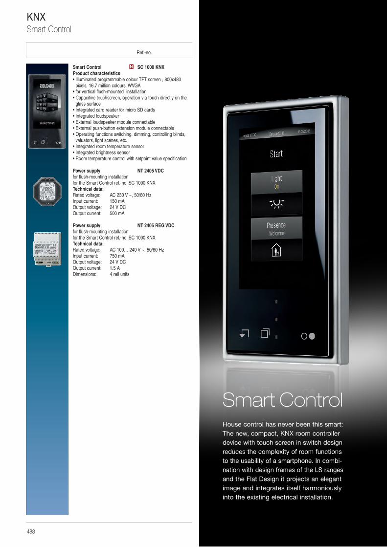
Ref.-no.
Smart Control SC 1000 KNXProduct characteristics• Illuminated programmable colour TFT screen , 800x480
pixels, 16.7 million colours, WVGA • for vertical flush-mounted installation • Capacitive touchscreen, operation via touch directly on the
glass surface • Integrated card reader for micro SD cards • Integrated loudspeaker • External loudspeaker module connectable• External push-button extension module connectable • Operating functions switching, dimming, controlling blinds,
valuators, light scenes, etc. • Integrated room temperature sensor • Integrated brightness sensor • Room temperature control with setpoint value specification
Power supply NT 2405 VDCfor flush-mounting installationfor the Smart Control ref.-no: SC 1000 KNXTechnical data:Rated voltage: AC 230 V ~, 50/60 HzInput current: 150 mAOutput voltage: 24 V DCOutput current: 500 mA
Power supply NT 2405 REG VDCfor flush-mounting installationfor the Smart Control ref.-no: SC 1000 KNXTechnical data:Rated voltage: AC 100… 240 V ~, 50/60 HzInput current: 750 mAOutput voltage: 24 V DCOutput current: 1.5 ADimensions: 4 rail units
N
KNXSmart Control
488
Smart ControlHouse control has never been this smart: The new, compact, KNX room controller device with touch screen in switch design reduces the complexity of room functions to the usability of a smartphone. In combi-nation with design frames of the LS ranges and the Flat Design it projects an elegant image and integrates itself harmoniously into the existing electrical installation.
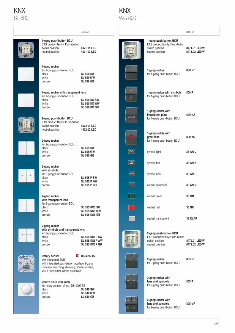
Ref.-no. Ref.-no.
1-gang push-button BCUETS product family: Push-buttonswitch position 8471.01 LED Wneutral position 8471.02 LED W
1-gang rocker 800 NTfor 1-gang push-button BCU
1-gang rocker with symbols 800 Pfor 1-gang push-button BCU
1-gang rocker with inscription plate 800 NAfor 1-gang push-button BCU
1-gang rocker with great lens 800 KOfor 1-gang push-button BCU
symbol light 33 AN L
symbol bell 33 AN K
symbol door 33 AN T
neutral anthracite 33 AN N
neutral green 33 GN
neutral red 33 NR
neutral transparent 33 KLAR
2-gang push-button BCUETS product family: Push-buttonswitch position 8472.01 LED Wneutral position 8472.02 LED W
2-gang rocker 805 NTfor 2-gang push-button BCU
2-gang rocker with lens and symbols 805 Pfor 2-gang push-button BCU
2-gang rocker with lens and symbols 805 MPfor 2-gang push-button BCU
1-gang push-button BCUETS product family: Push-buttonswitch position 4071.01 LEDneutral position 4071.02 LED
1-gang rocker for 1-gang push-button BCUblack SL 590 SWwhite SL 590 WWbronze SL 590 GB
1-gang rocker with transparent lensfor 1-gang push-button BCUblack SL 590 KO SWwhite SL 590 KO WWbronze SL 590 KO GB
2-gang push-button BCUETS product family: Push-buttonswitch position 4072.01 LEDneutral position 4072.02 LED
2-gang rocker for 2-gang push-button BCUblack SL 595 SWwhite SL 595 WWbronze SL 595 GB
2-gang rocker with symbolsfor 2-gang push-button BCUblack SL 595 P SWwhite SL 595 P WWbronze SL 595 P GB
2-gang rocker with transparent lensfor 2-gang push-button BCUblack SL 595 KO5 SWwhite SL 595 KO5 WWbronze SL 595 KO5 GB
2-gang rocker with symbols and transparent lensfor 2-gang push-button BCUblack SL 595 KO5P SWwhite SL 595 KO5P WWbronze SL 595 KO5P GB
Rotary sensor DS 4092 TSwith integrated BCUwith integrated push-button interface 3-gangFunction: switching, dimming, shutter control, value transmitter, scene extension
Centre plate with knobfor rotary sensor ref.-no.: DS 4092 TSblack SL 540 SWwhite SL 540 WWbronze SL 540 GB
N
KNXWG 800
KNXSL 500
489
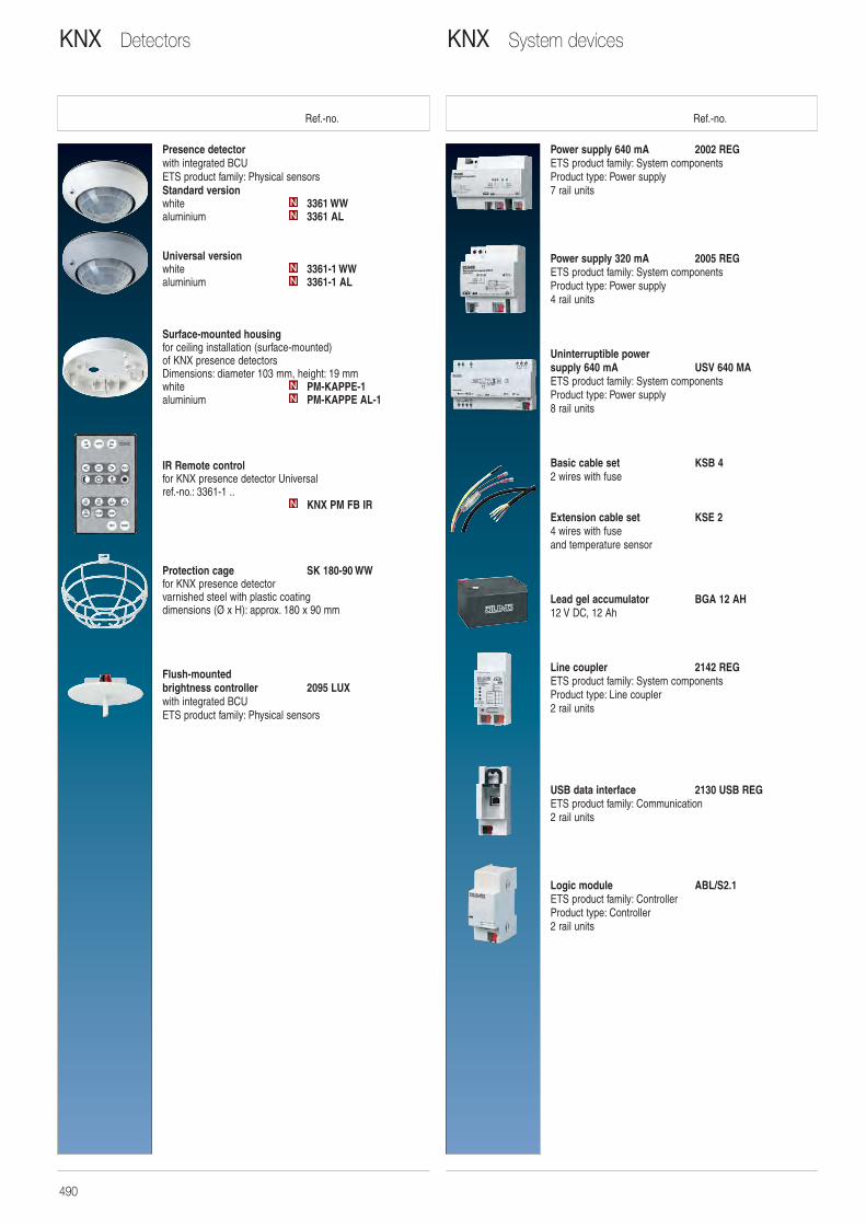
Ref.-no. Ref.-no.
Power supply 640 mA 2002 REGETS product family: System componentsProduct type: Power supply7 rail units
Power supply 320 mA 2005 REGETS product family: System componentsProduct type: Power supply4 rail units
Uninterruptible power supply 640 mA USV 640 MAETS product family: System componentsProduct type: Power supply8 rail units
Basic cable set KSB 42 wires with fuse
Extension cable set KSE 24 wires with fuse and temperature sensor
Lead gel accumulator BGA 12 AH12 V DC, 12 Ah
Line coupler 2142 REGETS product family: System componentsProduct type: Line coupler2 rail units
USB data interface 2130 USB REGETS product family: Communication2 rail units
Logic module ABL/S2.1ETS product family: ControllerProduct type: Controller 2 rail units
Presence detectorwith integrated BCUETS product family: Physical sensorsStandard versionwhite 3361 WWaluminium 3361 AL
Universal versionwhite 3361-1 WWaluminium 3361-1 AL
Surface-mounted housingfor ceiling installation (surface-mounted) of KNX presence detectorsDimensions: diameter 103 mm, height: 19 mmwhite PM-KAPPE-1aluminium PM-KAPPE AL-1
IR Remote control for KNX presence detector Universal ref.-no.: 3361-1 ..
KNX PM FB IR
Protection cage SK 180-90 WWfor KNX presence detector varnished steel with plastic coatingdimensions (Ø x H): approx. 180 x 90 mm
Flush-mounted brightness controller 2095 LUXwith integrated BCUETS product family: Physical sensors
N
NN
NN
NN
KNX System devicesKNX Detectors
490
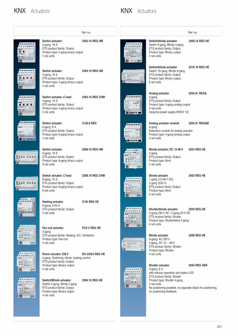
Ref.-no. Ref.-no.
Switch/blinds actuator 2308.16 REG HESwitch 8-gang, Blinds 4-gangETS product family: OutputProduct type: Binary output4 rail units
Switch/blinds actuator 2316.16 REG HESwitch 16-gang, Blinds 8-gangETS product family: OutputProduct type: Binary output8 rail units
Analog actuator 2204.01 REGA4-gangETS product family: OutputProduct type: 4-gang analog output4 rail units(requires power supply WSSV 10)
Analog actuator module 2204.01 REGAM4-gangExtension module for analog actuatorProduct type: 4-gang analog output4 rail units
Blinds actuator, DC 12-48 V 2424 REG HE4-gangETS product family: OutputProduct type: blind4 rail units
Blinds actuator 2502 REG HE1-gang (12-48 V DC)2-gang (230 V)ETS product family: OutputProduct type: blind4 rail units
Shutter/blinds actuator 2504 REG HE4-gang 230 V AC / 2-gang 24 V DCETS product family: ShutterProduct type: Shutter/blind 4-gang4 rail units
Blinds actuator 2508 REG HE8-gang, AC 230 V4-gang, DC 12 – 48 VETS product family: ShutterProduct type: Shutter4 rail units
Shutter actuator 2504 REG HER4-gang, 6 Awith manual operation and status LEDETS product family: ShutterProduct type: Shutter 4-gang4 rail unitsNo positioning possible, no separate object for positioning, no positioning feedback.
Switch actuator 2302.16 REG HM2-gang, 16 AETS product family: OutputProduct type: 2-gang binary output4 rail units
Switch actuator 2304.16 REG HM4-gang, 16 AETS product family: OutputProduct type: 4-gang binary output4 rail units
Switch actuator, C-load 2304.16 REG CHM4-gang, 16 AETS product family: OutputProduct type: 4-gang binary output4 rail units
Switch actuator 2136.6 REG6-gang, 6 AETS product family: OutputProduct type: 6-gang binary output4 rail units
Switch actuator 2308.16 REG HM8-gang, 16 AETS product family: OutputProduct type: 8-gang binary output8 rail units
Switch actuator, C-load 2308.16 REG CHM8-gang, 16 AETS product family: OutputProduct type: 8-gang binary output8 rail units
Heating actuator 2136 REG HZ6-gang, 0.05 AETS product family: Output4 rail units
Fan coil actuator FCA 2 REG HE2-gangETS product family: Heating, A/C, VentilationProduct type: Fan-coil4 rail units
Room actuator 230 V RA 23024 REG HE4-gang, Switching, blinds, heating controlETS product family: OutputProduct type: Binary output4 rail units
Switch/Blinds actuator 2304.16 REG HESwitch 4-gang, Blinds 2-gangETS product family: OutputProduct type: Binary output4 rail units
KNX ActuatorsKNX Actuators
491
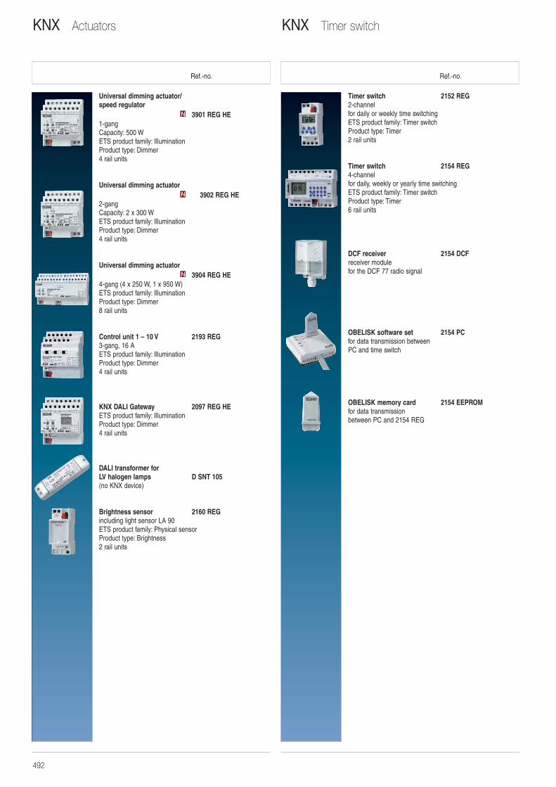
Ref.-no. Ref.-no.
Timer switch 2152 REG2-channelfor daily or weekly time switchingETS product family: Timer switchProduct type: Timer2 rail units
Timer switch 2154 REG4-channelfor daily, weekly or yearly time switchingETS product family: Timer switchProduct type: Timer6 rail units
DCF receiver 2154 DCFreceiver module for the DCF 77 radio signal
OBELISK software set 2154 PCfor data transmission between PC and time switch
OBELISK memory card 2154 EEPROMfor data transmission between PC and 2154 REG
Universal dimming actuator/speed regulator
3901 REG HE1-gangCapacity: 500 WETS product family: IlluminationProduct type: Dimmer4 rail units
Universal dimming actuator3902 REG HE
2-gangCapacity: 2 x 300 WETS product family: IlluminationProduct type: Dimmer4 rail units
Universal dimming actuator3904 REG HE
4-gang (4 x 250 W, 1 x 950 W)ETS product family: IlluminationProduct type: Dimmer8 rail units
Control unit 1 – 10 V 2193 REG3-gang, 16 AETS product family: IlluminationProduct type: Dimmer4 rail units
KNX DALI Gateway 2097 REG HEETS product family: IlluminationProduct type: Dimmer4 rail units
DALI transformer for LV halogen lamps D SNT 105(no KNX device)
Brightness sensor 2160 REGincluding light sensor LA 90ETS product family: Physical sensorProduct type: Brightness2 rail units
N
N
N
KNX Timer switchKNX Actuators
492
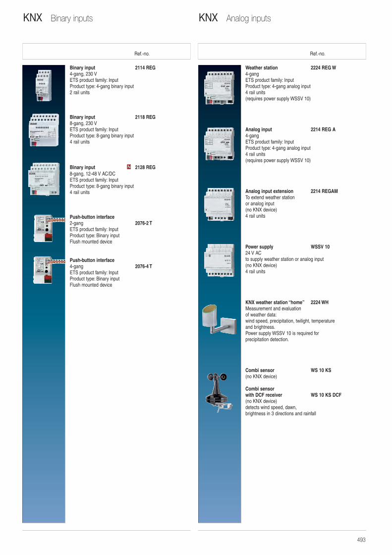
Ref.-no. Ref.-no.
Weather station 2224 REG W4-gangETS product family: InputProduct type: 4-gang analog input4 rail units(requires power supply WSSV 10)
Analog input 2214 REG A4-gangETS product family: InputProduct type: 4-gang analog input4 rail units(requires power supply WSSV 10)
Analog input extension 2214 REGAMTo extend weather station or analog input(no KNX device)4 rail units
Power supply WSSV 1024 V ACto supply weather station or analog input(no KNX device)4 rail units
KNX weather station “home” 2224 WHMeasurement and evaluationof weather data:wind speed, precipitation, twilight, temperature and brightness.Power supply WSSV 10 is required forprecipitation detection.
Combi sensor WS 10 KS(no KNX device)
Combi sensor with DCF receiver WS 10 KS DCF(no KNX device)detects wind speed, dawn,brightness in 3 directions and rainfall
Binary input 2114 REG4-gang, 230 VETS product family: InputProduct type: 4-gang binary input2 rail units
Binary input 2118 REG8-gang, 230 VETS product family: InputProduct type: 8-gang binary input4 rail units
Binary input 2128 REG8-gang, 12-48 V AC/DCETS product family: InputProduct type: 8-gang binary input4 rail units
Push-button interface2-gang 2076-2 TETS product family: InputProduct type: Binary inputFlush mounted device
Push-button interface4-gang 2076-4 TETS product family: InputProduct type: Binary inputFlush mounted device
N
KNX Analog inputsKNX Binary inputs
493
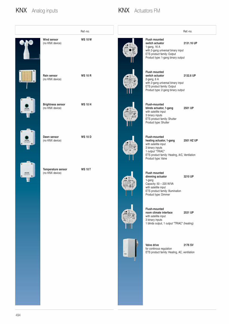
Ref.-no. Ref.-no.
Flush mounted switch actuator 2131.16 UP1-gang, 16 Awith 2-gang universal binary inputETS product family: OutputProduct type: 1-gang binary output
Flush mounted switch actuator 2132.6 UP2-gang, 6 Awith 2-gang universal binary inputETS product family: OutputProduct type: 2-gang binary output
Flush-mounted blinds actuator, 1-gang 2501 UPwith satellite input3 binary inputsETS product family: ShutterProduct type: Shutter
Flush-mounted heating actuator, 1-gang 2501 HZ UPwith satellite input3 binary inputs1 output "TRIAC"ETS product family: Heating, A/C, VentilationProduct type: Valve
Flush mounted dimming actuator 3210 UP1-gangCapacity: 50 – 220 W/VAwith satellite inputETS product family: IlluminationProduct type: Dimmer
Flush-mounted room climate interface 2531 UPwith satellite input3 binary inputs1 blinds output, 1 output "TRIAC" (heating)
Valve drive 2176 SVfor continous regulationETS product family: Heating, AC, ventilation
Wind sensor WS 10 W(no KNX device)
Rain sensor WS 10 R(no KNX device)
Brightness sensor WS 10 H(no KNX device)
Dawn sensor WS 10 D(no KNX device)
Temperature sensor WS 10 T(no KNX device)
KNX Actuators FMKNX Analog inputs
494
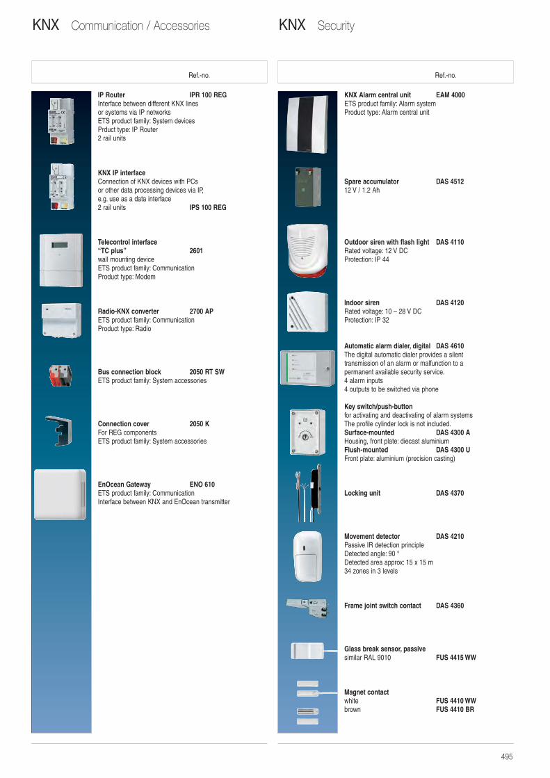
Ref.-no. Ref.-no.
KNX Alarm central unit EAM 4000ETS product family: Alarm systemProduct type: Alarm central unit
Spare accumulator DAS 451212 V / 1.2 Ah
Outdoor siren with flash light DAS 4110Rated voltage: 12 V DCProtection: IP 44
Indoor siren DAS 4120Rated voltage: 10 – 28 V DCProtection: IP 32
Automatic alarm dialer, digital DAS 4610The digital automatic dialer provides a silent transmission of an alarm or malfunction to a permanent available security service.4 alarm inputs4 outputs to be switched via phone
Key switch/push-buttonfor activating and deactivating of alarm systemsThe profile cylinder lock is not included.Surface-mounted DAS 4300 AHousing, front plate: diecast aluminiumFlush-mounted DAS 4300 UFront plate: aluminium (precision casting)
Locking unit DAS 4370
Movement detector DAS 4210Passive IR detection principleDetected angle: 90 °Detected area approx: 15 x 15 m34 zones in 3 levels
Frame joint switch contact DAS 4360
Glass break sensor, passivesimilar RAL 9010 FUS 4415 WW
Magnet contactwhite FUS 4410 WWbrown FUS 4410 BR
IP Router IPR 100 REGInterface between different KNX lines or systems via IP networksETS product family: System devicesPrduct type: IP Router2 rail units
KNX IP interfaceConnection of KNX devices with PCs or other data processing devices via IP,e.g. use as a data interface2 rail units IPS 100 REG
Telecontrol interface“TC plus” 2601wall mounting deviceETS product family: CommunicationProduct type: Modem
Radio-KNX converter 2700 APETS product family: CommunicationProduct type: Radio
Bus connection block 2050 RT SWETS product family: System accessories
Connection cover 2050 KFor REG componentsETS product family: System accessories
EnOcean Gateway ENO 610ETS product family: CommunicationInterface between KNX and EnOcean transmitter
KNX SecurityKNX Communication / Accessories
495
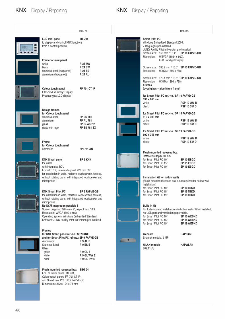
Ref.-no. Ref.-no.
Smart Pilot PCWindows Embedded Standard 2009, 7 languages pre-installed JUNG Facility Pilot full version pre-installedScreen size: 156 mm / 10.4’’ SP 10 FAPVD-GB Resolution: WSVGA (1024 x 600),
LED Backlight Display
Screen size: 396.2 mm / 15.6’’ SP 15 FAPVD-GB Resolution: WXGA (1366 x 768)
Screen size: 470.1 mm / 18.51’’ SP 19 FAPVD-GBResolution: WXGA (1366 x 768)Frames(dyed glass – aluminium frame)
for Smart Pilot PC ref.-no.: SP 10 FAPVD-GB333 x 200 mmwhite RSP 10 WW Dblack RSP 10 SW D
for Smart Pilot PC ref.-no.: SP 15 FAPVD-GB510 x 306 mmwhite RSP 15 WW Dblack RSP 15 SW D
for Smart Pilot PC ref.-no.: SP 19 FAPVD-GB600 x 345 mmwhite RSP 19 WW Dblack RSP 19 SW D
Flush-mounted recessed boxinstallation depth: 80 mmfor Smart Pilot PC 10" SP 10 EBGDfor Smart Pilot PC 15" SP 15 EBGDfor Smart Pilot PC 19" SP 19 EBGD
Installation kit for hollow walls(Flush-mounted recessed box is not required for hollow wallinstallation.)for Smart Pilot PC 10" SP 10 TBKDfor Smart Pilot PC 15" SP 15 TBKDfor Smart Pilot PC 19" SP 19 TBKD
Build in kit for flush-mounted installation into hollow walls. When installed,no USB port and ventilation gaps visible.for Smart Pilot PC 10" SP 10 WEBKDfor Smart Pilot PC 15" SP 15 WEBKDfor Smart Pilot PC 19" SP 19 WEBKD
Webcam HAPCAMSnap-on module, 2 MP
WLAN module HAPWLAN802.11b/g
LCD mini panel MT 701to display and control KNX functionsfrom a central position.
Frame for mini panelwhite R 24 WWblack R 24 SWstainless steel (lacquered) R 24 ESaluminium (lacquered) R 24 AL
Colour touch panel FP 701 CT IPETS-product family: DisplayProduct type: LCD display
Design frames for Colour touch panelstainless steel FP ES 781aluminium FP AL 781glass FP GLAS 781glass with logo FP ES 781 EX
Frame for Colour touch panel anthracite FPI 781 AN
KNX Smart panel SP 9 KNXfor installwith integrated BCUFormat: 16:9, Screen diagonal: 228 mm / 9’’for installation in walls, resistive touch screen, fanless,without rotating parts, with integrated loudspeaker andmicrophone
KNX Smart Pilot PC SP 9 FAPVE-GBfor installation in walls, resistive touch screen, fanless, without rotating parts, with integrated loudspeaker and microphoneNo DCM integration possible !Screen diagonal: 228 mm / 9’’, aspect ratio 16:9 Resolution: WVGA (800 x 480) Operating system: Windows Embedded Standard Software: JUNG Facility Pilot full version pre-installed
Framesfor KNX Smart panel ref.-no.: SP 9 KNXand for Smart Pilot PC ref.-no.: SP 9 FAPVE-GBAluminium R 9 AL EStainless Steel R 9 ES EGlass
green R 9 GL Ewhite R 9 GL WW Eblack R 9 GL SW E
Flush mounted recessed box EBG 24For LCD mini panel: MT 701,Colour touch panel: FP 701 CT IPand Smart Pilot PC: SP 9 FAPVE-GBDimensions: 212 x 124 x 75 mm
KNX Display / ReportingKNX Display / Reporting
496
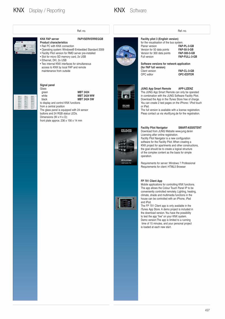
Ref.-no. Ref.-no.
Facility pilot 3 (English version)for the visualisation of the bus system.Planer version FAP-PL-3-GBVersion for 50 data points FAP-50-3-GBVersion for 300 data points FAP-300-3-GBFull version FAP-FULL-3-GB
Software versions for network application(for FAP full version)Client version FAP-CL-3-GBOPC editor OPC-EDITOR
JUNG App Smart Remote APP-LIZENZThe JUNG App Smart Remote can only be operated in combination with the JUNG Software Facility Pilot. Download the App in the iTunes Store free of charge.You can create 2 test pages on the iPhone / iPod touch or iPad.The full version is available with a license registration.Pleas contact us via [email protected] for the registration.
Facility Pilot Navigator SMART-ASSISTENTDownload from JUNG Website www.jung.de/enLicensing after online registration.Facility Pilot Navigator is a new configuration software for the Facility Pilot. When creating a KNX project for apartments and other constructions, the goal should be to create a logical structure of the complex content as the basis for simple operation.
Requirements for server: Windows 7 ProfessionalRequirements for client: HTML5 Browser
FP 701 Client AppMobile applications for controlling KNX functions. The app allows the Colour Touch Panel IP to be conveniently controlled remotely. Lighting, heating, climate, shade and multimedia functions in the house can be controlled with an iPhone, iPad and iPod.The FP 701 Client app is only available in the iTunes App Store. A demo project is included in the download version. You have the possibility to test the app “live” on your KNX system. Demo version:The app is limited to a runningtime of 15 minutes, and your personal project
is loaded at each new start.
KNX FAP server FAPVSERVERREGGBProduct characteristics • Rail PC with KNX connection • Operating system: Windows® Embedded Standard 2009 • Facility Pilot version for RMD server pre-installed • Slot for micro SD memory card, 2x USB• Ethernet, DVI, 2x USB • Two internal KNX interfaces for simultaneous
access to KNX by local FAP and remote maintenance from outside
Signal panelGlass
green MBT 2424white MBT 2424 WWblack MBT 2424 SW
to display and control KNX functions from a central positionThe glass panel is equipped with 24 sensor buttons and 24 RGB status LEDs.Dimensions (W x H x D):front plate approx. 236 x 156 x 14 mm
KNX SoftwareKNX Display / Reporting
497
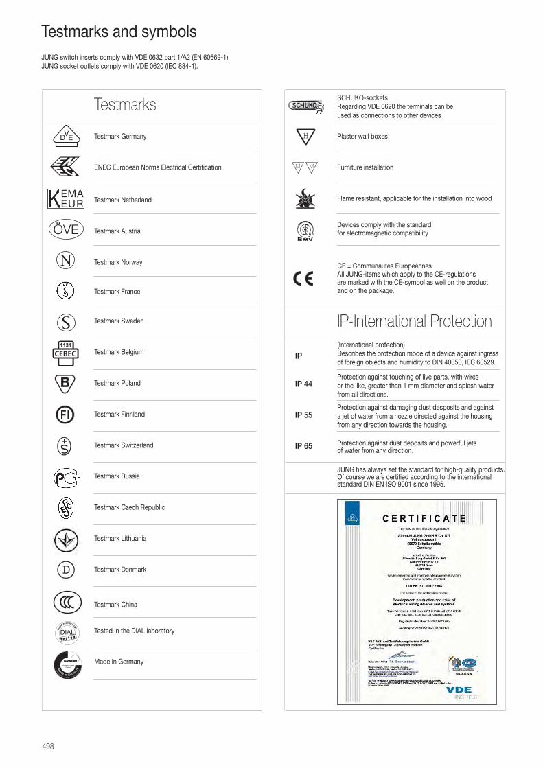
SCHUKO-socketsRegarding VDE 0620 the terminals can be used as connections to other devices
Plaster wall boxes
Furniture installation
Flame resistant, applicable for the installation into wood
Devices comply with the standard for electromagnetic compatibility
CE = Communautes Europeénnes All JUNG-items which apply to the CE-regulations are marked with the CE-symbol as well on the product and on the package.
(International protection)Describes the protection mode of a device against ingress of foreign objects and humidity to DIN 40050, IEC 60529.
Protection against touching of live parts, with wires or the like, greater than 1 mm diameter and splash water from all directions.
Protection against damaging dust desposits and against a jet of water from a nozzle directed against the housing from any direction towards the housing.
Protection against dust deposits and powerful jets of water from any direction.
JUNG has always set the standard for high-quality products.Of course we are certified according to the internationalstandard DIN EN ISO 9001 since 1995.
Testmarks and symbols
Testmark Germany
ENEC European Norms Electrical Certification
Testmark Netherland
Testmark Austria
Testmark Norway
Testmark France
Testmark Sweden
Testmark Belgium
Testmark Poland
Testmark Finnland
Testmark Switzerland
Testmark Russia
Testmark Czech Republic
Testmark Lithuania
Testmark Denmark
Testmark China
Tested in the DIAL laboratory
Made in Germany
VD E
IP
IP 44
IP 55
IP 65
Testmarks
IP-International Protection
JUNG switch inserts comply with VDE 0632 part 1/A2 (EN 60669-1).JUNG socket outlets comply with VDE 0620 (IEC 884-1).
Ligh
t technology
H
498
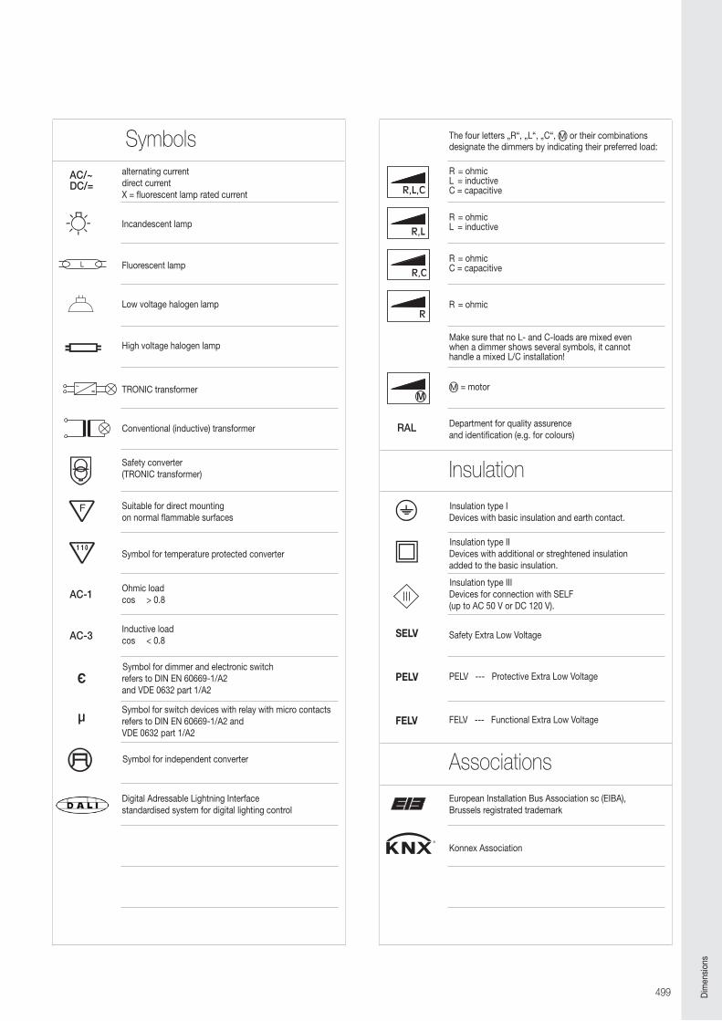
alternating currentdirect currentX = fluorescent lamp rated current
Incandescent lamp
Fluorescent lamp
Low voltage halogen lamp
High voltage halogen lamp
TRONIC transformer
Conventional (inductive) transformer
Safety converter(TRONIC transformer)
Suitable for direct mounting on normal flammable surfaces
Symbol for temperature protected converter
Ohmic load cos > 0.8
Inductive loadcos < 0.8
Symbol for dimmer and electronic switch refers to DIN EN 60669-1/A2 and VDE 0632 part 1/A2
Symbol for switch devices with relay with micro contacts refers to DIN EN 60669-1/A2 and VDE 0632 part 1/A2
Symbol for independent converter
Digital Adressable Lightning Interfacestandardised system for digital lighting control
The four letters „R“, „L“, „C“, � or their combinations designate the dimmers by indicating their preferred load:
R = ohmicL = inductiveC = capacitive
R = ohmicL = inductive
R = ohmicC = capacitive
R = ohmic
Make sure that no L- and C-loads are mixed even when a dimmer shows several symbols, it cannot handle a mixed L/C installation!
� = motor
Department for quality assurenceand identification (e.g. for colours)
Insulation type IDevices with basic insulation and earth contact.
Insulation type IIDevices with additional or streghtened insulationadded to the basic insulation.
Insulation type IIIDevices for connection with SELF (up to AC 50 V or DC 120 V).
Safety Extra Low Voltage
PELV --- Protective Extra Low Voltage
FELV --- Functional Extra Low Voltage
European Installation Bus Association sc (EIBA), Brussels registrated trademark
Konnex Association
R,L,C
R,L
R,C
R
M
µ
RAL
AC-1
AC-3
AC/~DC/=
Symbols M
M
Insulation
Associations
Є
SELV
PELV
FELV
499 Dim
ensi
ons
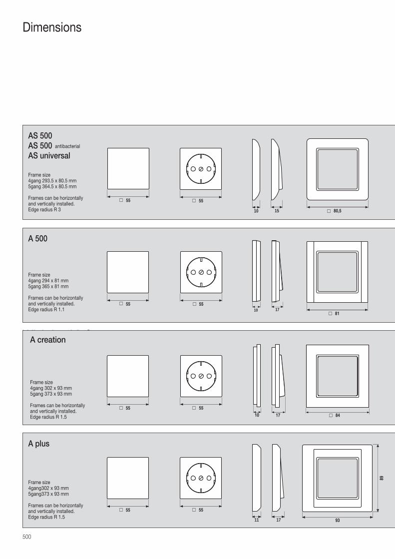
500
Dimensions
10 15
55 55
80,5
AS 500AS 500 AS universal
171055 55
81
A 500
1711
55 55
93
89
A plus
antibacterial
Frame size4gang 293.5 x 80.5 mm5gang 364.5 x 80.5 mm
Frames can be horizontally and vertically installed.Edge radius R 3
Frame size4gang302 x 93 mm5gang373 x 93 mm
Frames can be horizontally and vertically installed.Edge radius R 1.5
Frame size4gang 294 x 81 mm5gang 365 x 81 mm
Frames can be horizontally and vertically installed.Edge radius R 1.1
Wichtige Maße
10 17
55 55
84
A creation
Frame size4gang 302 x 93 mm5gang 373 x 93 mm
Frames can be horizontally and vertically installed.Edge radius R 1.5
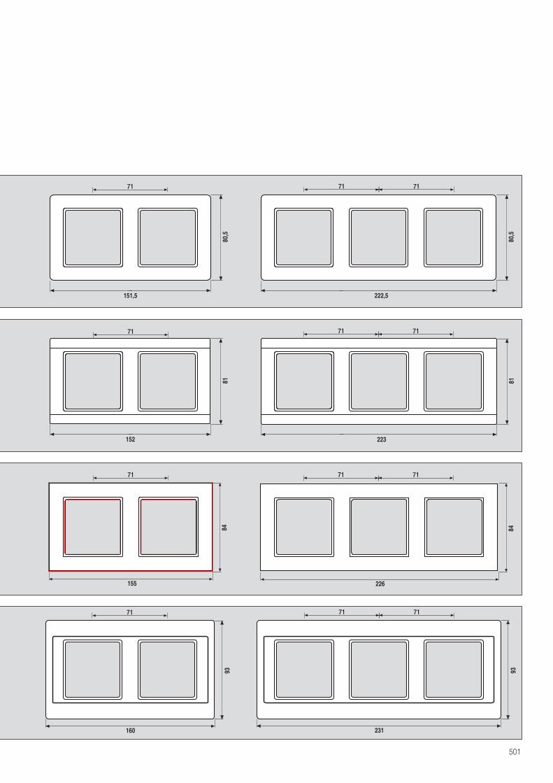
501
80,5
151,5
80,5
222,5
81
152
81
223
160
93
231
93
155
84 84
226
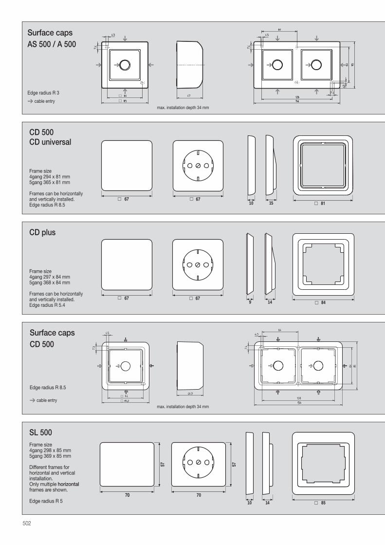
502
151067 67
CD 500CD universal
14967 67
84
CD plus
Surface capsCD 500
max. installation depth 34 mm
Frame size4gang 294 x 81 mm5gang 365 x 81 mm
Frames can be horizontally and vertically installed.Edge radius R 8.5
Frame size4gang 297 x 84 mm5gang 368 x 84 mm
Frames can be horizontally and vertically installed.Edge radius R 5.4
Edge radius R 8.5
➔ cable entry
➔
Surface capsAS 500 / A 500
Edge radius R 3
➔ cable entry
➔
➔ ➔ ➔ ➔ ➔
➔➔ ➔
➔ ➔➔
max. installation depth 34 mm
10
70
57
70
57
8514
SL 500Frame size4gang 298 x 85 mm5gang 369 x 85 mm
Different frames for horizontal and vertical installation.Only multiple horizontalframes are shown.
Edge radius R 5
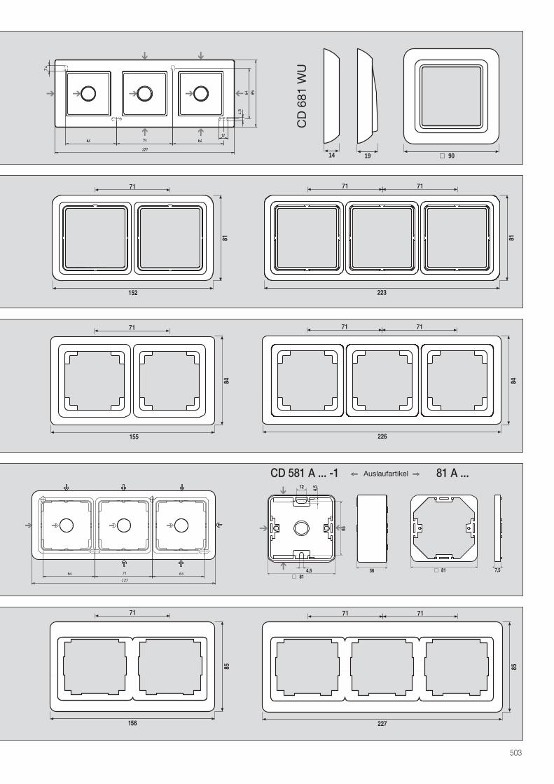
503
155
84 84
226
65
12 4,5
4,581
36➔
➔
➔
➔
7,581
CD 581 A ... -1 81 A ...
➔
➔ ➔ ➔ ➔
➔➔
➔ ➔
156
85
227
85
9014 19
CD
681
WU
⇐ Auslaufartikel ⇒
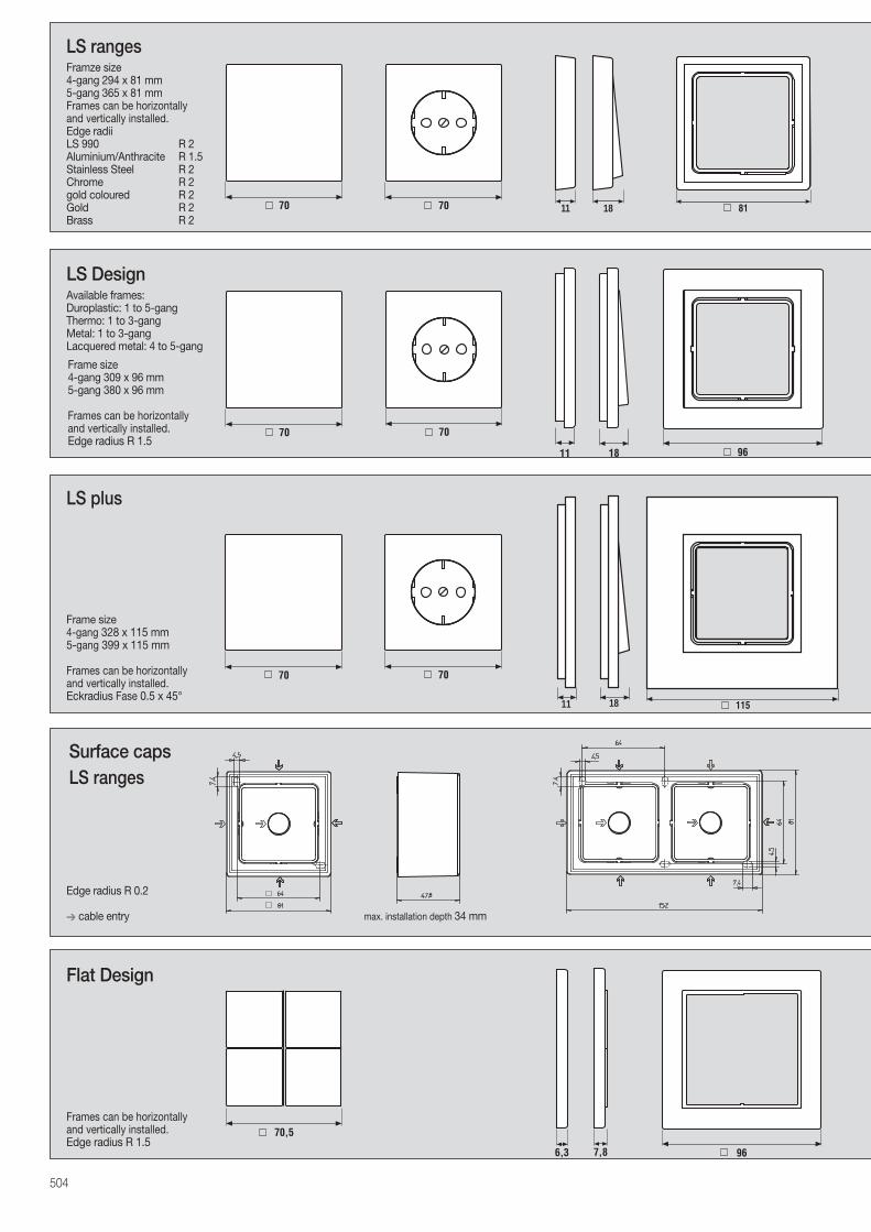
504
1170 70 18
LS ranges
Surface capsLS ranges
11
70 70
11518
LS plus
LS Design
70
11 18 96
70
Framze size4-gang 294 x 81 mm5-gang 365 x 81 mmFrames can be horizontally and vertically installed.Edge radii LS 990 R 2Aluminium/Anthracite R 1.5Stainless Steel R 2Chrome R 2gold coloured R 2Gold R 2Brass R 2
Available frames:Duroplastic: 1 to 5-gangThermo: 1 to 3-gangMetal: 1 to 3-gangLacquered metal: 4 to 5-gang
Frame size 4-gang 328 x 115 mm5-gang 399 x 115 mm
Frames can be horizontally and vertically installed.Eckradius Fase 0.5 x 45°
Frame size4-gang 309 x 96 mm5-gang 380 x 96 mm
Frames can be horizontally and vertically installed.Edge radius R 1.5
Flat Design
6,3 7,8 96
70,5Frames can be horizontally and vertically installed.Edge radius R 1.5
Edge radius R 0.2
➔ cable entry max. installation depth 34 mm
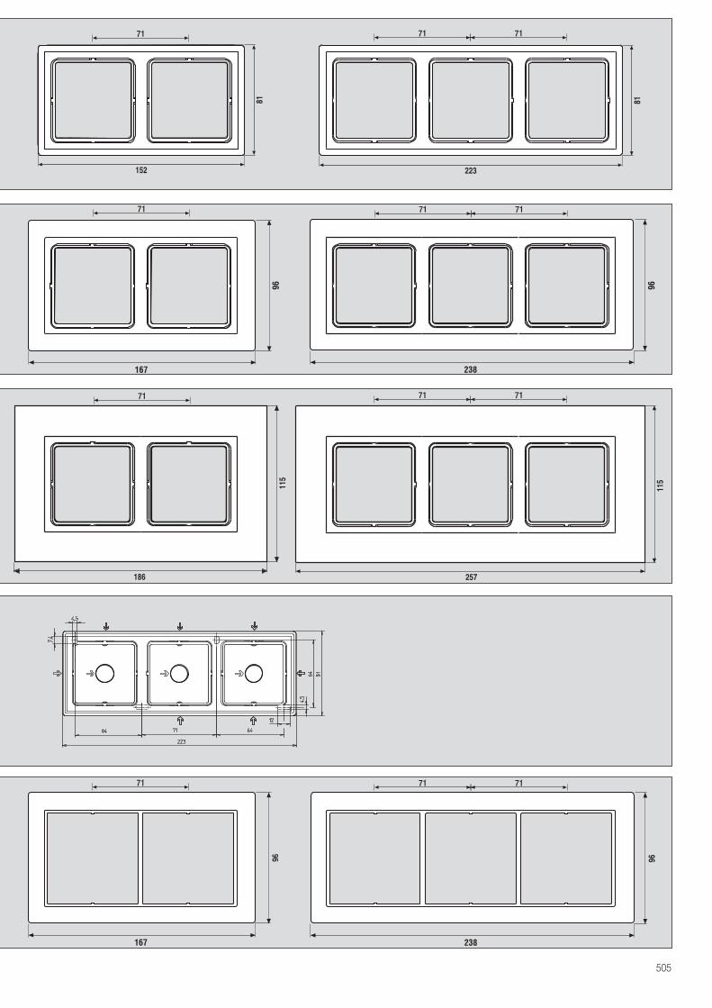
505
186
115
257
115
96
167
96
238
96
167
96
238
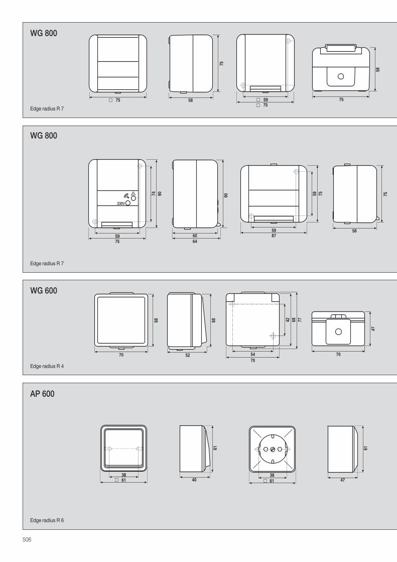
75
5875 5975
75
58
WG 800
47
61
59
90
75
74
230V
! 90
6064
6138
40
61
6138
AP 600
WG 800
68
5270
68 68
5470
7742
70
47
WG 600
59
75
87
59 75
58
506
Edge radius R 7
Edge radius R 7
Edge radius R 4
Edge radius R 6
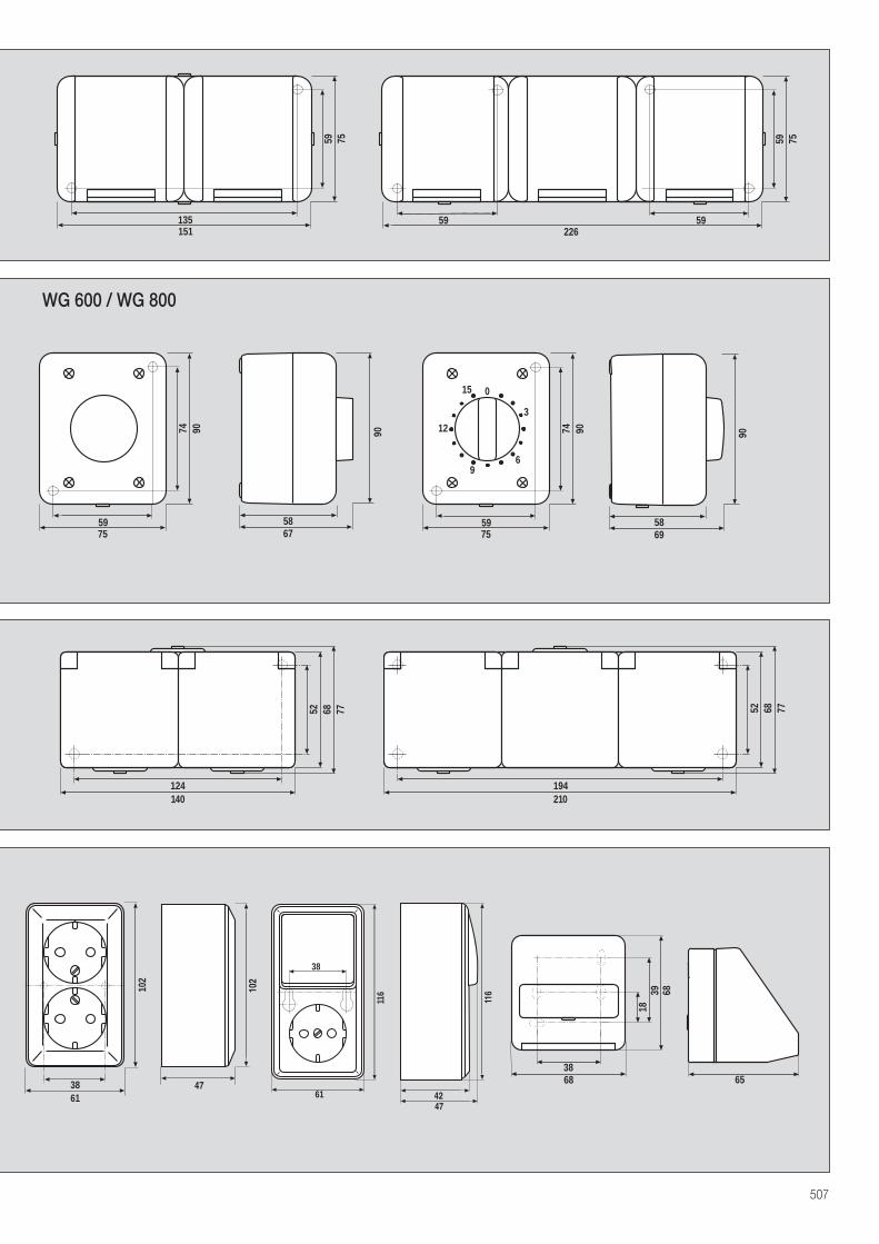
135
75
151
59
59
75
226
59
59
47
102
102
6138
116
38
614742
116 39
6838
18
68
65
90
5869
59
90
75
74 90
5867
59
90
75
7412
15
96
0
3
WG 600 / WG 800
140
68 77
124
52
210
68 7752
194
507
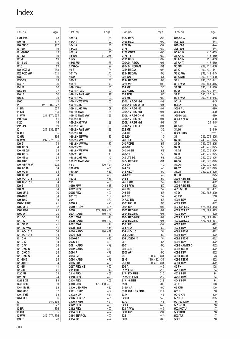
508
1 MF 250 26100 FR 117100 FRSG 117101-20 19101-20 KO 19101-32 19101-4 19101-4-20 191015 19102 KOZ W 445102 KOZ WW 4451030 191030-20 19104.15 20104.28 201056-04 27106.15 20106.28 201060 1911 247, 335, 37711 BR 33511 GR 33511 WW 247, 277, 335110 HNA 411120 191120-20 1912 247, 335, 37712 BR 33512 GR 33512 WW 247, 277, 335120 G 34120 KB G 34120 KB GN 34120 KB S 34120 KB W 34120 KIBF 302120 KIBF WW 302120 KO G 34120 KO S 34120 KO W 34120 KO-1011 34120 KO-1012 34120 S 34120 W 341201 URE 90120-1011 34120-1012 341201-1 URE 911202 URE 921208 REG 951208 UI 95121 DO 34121 FKI 41121 FKI B 41121 FKI WW 41121 KO-1017 34121 KO-1018 34121 O G 34121 O S 34121 O W 34121 OKO G 34121 OKO S 34121 OKO W 34121-1017 34121-1018 34121-15 41121-20 411220 NE 941223 NE 941225 SDE 881240 STE 891244 NVSE 931252 UDE 871254 TSE 931254 UDE 8613 247, 33513 37713 BR 33513 GR 33513 WW 247, 277, 335133.15 20
133.18 20134.15 20134.18 20134.28 20138.18 2015 WW 247, 2781545 U 361545 WU 361556-04 2716 S 24161 TV 401632 36165-2 41168-1 40168-1 WW 40169-1 NFWE 39169-1 NFWE WW 39169-1 NWE 38169-1 NWE WW 38169-1 UAE 39169-1 UAE WW 39169-15 NWE 38169-15 NWE WW 38169-2 NAT 39169-2 NAT WW 39169-2 NFWE 39169-2 NFWE WW 39169-2 NINF 39169-2 NINF WW 39169-2 NNW 39169-2 NNW WW 39169-2 NWE 38169-2 NWE WW 38169-2 UAE 40169-2 UAE WW 40169-25 NWE WW 3818 V 420, 431190-353 435190-354 435192 435193-2 435195 4351980 APM 4152002 REG 4902005 REG 490201 TE 1042041 4802050 K 4952050 RT SW 4952070 U 477, 479, 4822071 NABS 110, 4792071 TSM 1112072 NABS 110, 4792072 TSM 1112073 TSM 1112074 NABS 110, 4792074 TSM 1112076-2 T 4932076-4 T 4932091 NABS 4792092 NABS 4792094 F 4792094 LZ 4792094 NABS 4792095 LUX 4902097 REG HE 492211 GDE 492114 REG 4932118 REG 4932128 REG 4932130 USB 478, 480, 4832130 USB REG 4902131.16 UP 4942132.6 UP 4942136 REG HZ 4912136.6 REG 4912142 REG 4902152 REG 4922154 DCF 4922154 EEPROM 4922154 PC 492
2154 REG 4922160 REG 4922176 SV 4942178 4802178 ORTS 4802178 TS 4802193 REG 4922204.01 REGA 4912204.01 REGAM 4912214 REG A 4932214 REGAM 493222 WW 1612224 REG W 4932224 WH 493224 ME 136225 NVDE 51225 TDE 50230 ME 1362302.16 REG HM 4912304.16 REG CHM 4912304.16 REG HE 4912304.16 REG HM 4912308.16 REG CHM 4912308.16 REG HE 4912308.16 REG HM 4912316.16 REG HE 491232 ME 136234.10 19234.20 19240 DPE 55240 PDPE 56240-10 55240-10 EB 58240-31 55242 LTS DE 552424 REG HE 491243 EX 49244 EX 48244 HEX 50244-110 49245 Z 59245 Z GO 59245 Z WW 59245.20 57246 EB 58247 EB 57247.07 EB 572501 HZ UP 4942501 UP 4942502 REG HE 4912504 REG HE 4912504 REG HER 4912508 REG HE 4912531 UP 494254 NIE1 53254 NIE-110 54254 UDIE1 52254 UDIE-110 5426 652601 495266 GDE 482700 AP 49528 20, 420, 43128 G 20, 420, 43128 GSL 20, 420, 431306 A 4453171 EINS 2103171 KO EINS 2103171-15 EINS 2123171-5 EINS 2133180 4803180-1 A 4803190 CU KO5 EINS 21432 K 14332 SD 14332 U 143321 A 445321 A WW 4453210 UP 494328 4443280 480
Ref.-no. Page Ref.-no. Page Ref.-no. Page
3280-1 A 480328-622 444328-626 444328-676 44433 AN K 418, 48933 AN L 418, 48933 AN N 418, 48933 AN T 418, 48933 GN 292, 418, 43033 K 292, 430, 44133 K WW 292, 441, 44533 KLAR 292, 418, 43033 L 292, 430, 44133 L WW 292, 441, 44533 NR 292, 418, 43033 O 292, 430, 44133 T 292, 430, 44133 T WW 292, 441, 445331 A 445333 A 4453361 AL 4903361 WW 4903361-1 AL 4903361-1 WW 49034 24, 44534 KO5 2434.10 19, 4193521 EINS 21137 243, 272, 32537 BL 243, 272, 32537 D 243, 272, 32537 G 243, 272, 32537 GE 243, 272, 32537 R 243, 272, 32537.02 243, 272, 32537.05 243, 272, 32537.06 243, 272, 32537.07 243, 272, 32537.08 243, 272, 32538.00 3253901 REG HE 4923902 REG HE 4923904 REG HE 4924.28 WU G 420, 43140 D 260, 363, 39040 FW 1104008 TSM 734071 TSM 4724071.01 LED 478, 481, 4834071.02 LED 478, 481, 4834072 TSM 4724072.01 LED 478, 481, 4844072.02 LED 478, 481, 4844073 TSM 4724074 TSM 4724091 TSEM 4724091 TSM 4724092 TSEM 4724092 TSM 4724093 KRMTS D 4724093 TSEM 4724093 TSM 4724094 TSEM 734094 TSEM 4724094 TSM 47242 FH 1084212 TSM 844224 TSM 844236 TSM 844248 TSM 8448 FH 10848 KFH 108501 U 165010 KIU 3055010 U 305501-20 KOU 16501-20 U 16502 KOTU 17502 KOU 16502 TU 17502 U 16
Ref.-no. Page
Index
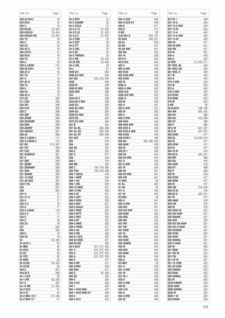
502-20 KOU 16503 KOU 16503 U 16505 KOU5 18, 454505 KOVU5 18, 454505 KOVU5 RG 18, 454505 TU 18505 U 18505 U5 18505-20 U 18506 KOTU 17506 KOU 16506 TU 17506 U 16506 U-LEDW 172506-20 KOU 16506-20 U 16507 TU 17507 U 16507-20 U 16509 TU 18509 U 18509 VU 18509-20 U 18510 UZ 306511 UZV 305520 FKI 306520 FUZ 305520 Z 298520 ZBF 298520 ZKIBF 299520 ZKINABF 300520 ZNA 299520 ZNABF 299520 ZNAKO 301520-45 300520-O LEDW-1 171520-O LEDW-2 172521 BS 215, 307521 FKI 306521 FUZ 306521 KIZNAUF 301521 Z 298521 ZBF 298521 ZKIBF 299521 ZKINABF 300521 ZNA 300521 ZNABF 300521-15 OSZ 307521-20 OSZ 3075232 TS3 394525 297528 297531 U 17531-41 U 17532 U 17532-4 U 18533 U 17533 U-LEDW 173533-2 U 17534 U 17535 U 18535 U5 18537 325538 325539 U 18539 VU 1854 33, 42554 ACO-1 3054 IBM 3054 OCS 3054 SC 3054 TPC 3254 WEV 3254 XLRD 30, 42554 XLRS 30540 Z 307540.20 Z 30854-1 ACS 3054-1 WE 30, 425541 Z 29754-15 WE 31, 42554-2 ACS 3154-2 AT 3254-2 BNC 12.7 31, 42554-2 BNC 9.7 31
509
54-2 BTR 3154-2 CHAMP 3254-2 CXLR 3154-2 D 15 31, 42554-2 D 25 31, 42554-2 D 9 31, 42554-2 FWE 3254-2 GFP 3254-2 ITT 3254-2 LWL 3254-2 SC 3254-2 TWINAX 3254-2 WE 33, 42554-25 WE 33, 42554-4 LWL 3355 L 275506 ZU 2955506 ZU WW 295551 WU 244, 273, 3285520 2985520 KI 2985520 KI WW 2985520 WW 298554 3235544.02 V 3085544.02 V WW 3085545 EU 3055545 EU WW 3055546 EU 3055546 EU WW 3055575 EU 3045575 EU WW 304561 B 324561 GL BL 294, 356561 GL GE 294, 356561 GL RT 294, 356561 SAT 316562 316564 324564 GE 324565-2 324567 S 317568 316568-1 316569 SIE 323569 T 194, 319, 480569 TNA 194, 319, 480569-1 NAUA 318569-1 NWE 320569-1 UA 318569-1 WE 320569-15 NWE 321569-15 WE 320569-2 AT 321569-2 GFP 322569-2 KRN 323569-2 NAT 321569-2 NAUA 319569-2 NINF 322569-2 NITT 322569-2 NNT 322569-2 NT 322569-2 NWE 320569-2 PAND 321569-2 UA 318569-2 WE 320569-21 ACS 322569-25 NWE 321569-25 WE 32058 A ZUG 247, 277, 335581 A 247, 277, 335582 A 247, 277, 335583 A 247, 277, 335590 A 317590 A BR 317590 CARD 294590 NAA 317590 Z 42, 326590 ZA 326594-0 324594-0 KO 326594-1 323594-1 KO9 DND 457594-1 KO9 DND KT 458594-2 323594-2 KO1 455
594-2 KO9 456594-2 KO9 KT 459594-8 317594-9 3176 WE 296.28 WU G 420, 43160 ANA 440, 44160 GL 35660 NA 44160 NA WW 441600 NA 430601 W 4296010 A 4436010 KIA 443602 A 440602 A WW 440602 KOA 440602 KOA WW 440602 KOW 429602 W 4296020 A 4426020 A WW 4426020 KIA 4426020 KIA WW 4426022 A 442603 W 429605 A 441605 A WW 441605 W 430606 A 440606 A WW 440606 ANA 440606 ANA WW 440606 KO5 A 440606 KO5 A WW 440606 KOW 429606 KOW-1 438606 NA 429, 430, 432606 NAW 429606 W 429606 W-1 438606 ZA 444606 ZA WW 444607 A 440607 A WW 440607 W 429609 VA 441609 VA WW 441609 VW 43161 BNC 2961 GL 43061 NA 35611 A 442611 W 43362 BNC 29620 A 441620 A WW 441620 KIA 441620 KIA WW 441620 NAW 432620 WSL 432620 WX 432621 FKI 433621 FW 433621 NAW 432621 W 432621 WSL 432622 NAW 434622 NAWW 434622 W 434622 WW 434623 NAW 434623 W 434626 A 44263 WBT 28631 A 440631 A WW 440631 W 429631 W-1 438633 A 440633 A WW 440633 W 429633-2 W 429634 A 440634 A WW 440634 W 429
Ref.-no. Page Ref.-no. Page Ref.-no. Page
637 W-1 438637-10 A 443637-10 A WW 443637-10 W 435637-14 A 443637-14 A WW 443637-14 W 435639 VA 441639 VA WW 441639 VW 431639 W 431645 A 443646 A 44365 WIS 41, 242, 271661 WGL BL 430661 WGL GE 430661 WGL R 430671 W 433675 A 442675 A WW 442675 W 433676 A 442676 A WW 442676 KOW 433676 NAW 434676 W 4338 WE 2980 KLEFO 198, 199800 AW 425, 435800 KO 489800 NA 419, 489800 NT 489800 P 4898012 W 427, 4378015 W 427, 437802 KOW 417802 SL 44, 226, 243802 W 417803 KOW 417803 W 417804.18 W 419804.28 G 420, 431805 MP 489805 NA 419805 NAW 418805 NT 489805 P 489805 W 418806 KOW 417806 NAW 417806 W 417806 ZW 418, 430806.18 W 419806.28 G 420, 431807 W 417809 NAW 418809 VW 419809 W 418820 DKKI W 424820 GN NAW 421820 KINAW 421820 KIW 420820 KO GN NAW 421820 KO O NAW 421820 KONAW 421820 KOW 420820 NAW 421820 NAWSL 421820 O NAW 421820 W 420821 BSW 215821 FKI W 424821 FW 424821 UF W 421821-15 USW 424821-20 USW 424822 KINAW 423822 NAW 423822 NAWSL 423822 W 4228220 KINAW 4238220 NAW 4238220 NAWSL 4238220 W 4228220-1 W 422823 NVDW 426
Ref.-no. Page
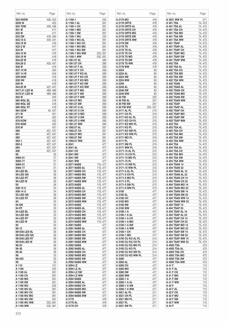
510
823 NVDW 436, 4238230 W 423824 TDW 426, 436831 W 417833 W 417833 ZW 418, 430833.18 G 420, 431833.18 W 419833-2 W 417834 W 417834.10 W 419834.18 W 419834.20 W 419834.28 G 420, 431835 W 419837-10 W 424837-14 W 424839 NAW 419839 VW 419839 W 419844.20 W 427, 4378471.01 LED W 489, 4898472.01 LED W 489, 489854 W 425860 WGL BL 418860 WGL GE 418860 WGL RT 418864 GDW 42, 437871 W 421875 W 422876 KOW 422876 NAW 422876 W 421890 427, 437891 427, 437892 427, 437893-1 427, 437893-2 427, 437894 427, 437895 427, 43790 259063-01 279063-77 279064-01 279064-77 2790-LED BL 2690-LED GN 2690-LED RT 2690-LED W 2693 26938-10 U 24938-14 U 2493-LED GN 2693-LED RT 2694 2594 GN 2594 RT 2594-LED BL 2594-LED GN 2594-LED RT 2594-LED W 2595 2596-12 26961248 LED BL 26961248 LED GN 26961248 LED RT 26961248 LED W 2696-24 2696-36 2696-48 2698 2598-220 2599 25A 110 157A 1180 232A 1180 AL 261A 1180 CH 261A 1180 MO 261A 1180 SW 261A 1180 WU 232A 1180 WU AL 261A 1180 WU CH 261A 1180 WU MO 261A 1180 WU SW 261A 1180 WU WW 232, 261A 1180 WW 232, 261
A 1180-1 232A 1180-1 AL 261A 1180-1 CH 261A 1180-1 MO 261A 1180-1 SW 261A 1180-1 WU 233A 1180-1 WU AL 261A 1180-1 WU CH 261A 1180-1 WU MO 261A 1180-1 WU SW 261A 1180-1 WU WW 233, 261A 1180-1 WW 232, 261A 1561.07 AL 260A 1561.07 CH 260A 1561.07 F AL 260A 1561.07 F CH 260A 1561.07 F KO AL 260A 1561.07 F KO CH 260A 1561.07 F KO MO 260A 1561.07 F KO SW 260A 1561.07 F KO WW 260A 1561.07 F MO 260A 1561.07 F SW 260A 1561.07 F WW 260A 1561.07 MO 260A 1561.07 SW 260A 1561.07 U AL 260A 1561.07 U CH 260A 1561.07 U MO 260A 1561.07 U SW 260A 1561.07 U WW 260A 1561.07 WW 260A 1565.07 AL 261A 1565.07 CH 261A 1565.07 MO 261A 1565.07 SW 261A 1565.07 WW 261A 2041 477A 2041 AL 477A 2041 CH 477A 2041 MO 477A 2041 SW 477A 2041 WW 477A 2071 NABS 110, 477A 2071 NABS AL 110, 477A 2071 NABS CH 110, 477A 2071 NABS MO 110, 477A 2071 NABS SW 110, 477A 2071 NABS WW 110, 477A 2072 NABS 110, 477A 2072 NABS AL 110, 477A 2072 NABS CH 110, 477A 2072 NABS MO 110, 477A 2072 NABS SW 110, 477A 2072 NABS WW 110, 477A 2074 NABS 110, 477A 2074 NABS AL 110, 477A 2074 NABS CH 110, 477A 2074 NABS MO 110, 477A 2074 NABS SW 110, 477A 2074 NABS WW 110, 477A 2091 NABS 477A 2091 NABS AL 477A 2091 NABS CH 477A 2091 NABS MO 477A 2091 NABS SW 477A 2091 NABS WW 477A 2092 NABS 477A 2092 NABS AL 477A 2092 NABS CH 477A 2092 NABS MO 477A 2092 NABS SW 477A 2092 NABS WW 477A 2094 LZ 477A 2094 LZ AL 477A 2094 LZ SW 477A 2094 LZ WW 477A 2094 NABS 477A 2094 NABS AL 477A 2094 NABS CH 477A 2094 NABS MO 477A 2094 NABS SW 477A 2094 NABS WW 477A 2178 478A 2178 AL 478A 2178 CH 478
A 2178 MO 478A 2178 ORTS 478A 2178 ORTS AL 478A 2178 ORTS CH 478A 2178 ORTS MO 478A 2178 ORTS SW 478A 2178 ORTS WW 478A 2178 SW 478A 2178 TS 478A 2178 TS AL 478A 2178 TS CH 478A 2178 TS MO 478A 2178 TS SW 478A 2178 TS WW 478A 2178 WW 478A 2224 83A 2224 AL 83A 2224 SW 83A 2224 WW 83A 2248 83A 2248 AL 83A 2248 SW 83A 2248 WW 83A 30 FIB 225A 30 FIB AL 257A 30 FIB SW 257A 30 FIB WW 225, 257A 3171 AL PL 210A 3171 CH PL 210A 3171 KO AL PL 210A 3171 KO CH PL 210A 3171 KO MO PL 210A 3171 KO PL 210A 3171 KO SW PL 210A 3171 KO WW PL 210A 3171 MO PL 210A 3171 PL 210A 3171 SW PL 210A 3171 WW PL 210A 3171-15 AL PL 212A 3171-15 CH PL 212A 3171-15 MO PL 212A 3171-15 PL 212A 3171-15 SW PL 212A 3171-15 WW PL 212A 3171-5 AL PL 213A 3171-5 CH PL 213A 3171-5 MO PL 213A 3171-5 PL 213A 3171-5 SW PL 213A 3171-5 WW PL 213A 3180 477A 3180 AL 477A 3180 CH 477A 3180 MO 477A 3180 SW 477A 3180 WW 477A 3180-1 A 477A 3180-1 A AL 477A 3180-1 A CH 477A 3180-1 A MO 477A 3180-1 A SW 477A 3180-1 A WW 477A 3180-1 CH 477A 3180-1 MO 477A 3190 CU KO AL PL 214A 3190 CU KO CH PL 214A 3190 CU KO MO PL 214A 3190 CU KO PL 214A 3190 CU KO SW PL 214A 3190 CU KO WW PL 214A 3280 477A 3280 AL 477A 3280 CH 477A 3280 MO 477A 3280 SW 477A 3280 WW 477A 3280-1 A 477A 3280-1 A AL 477A 3280-1 A SW 477A 3280-1 A WW 477A 3521 AL PL 211A 3521 CH PL 211A 3521 MO PL 211A 3521 PL 211A 3521 SW PL 211
Ref.-no. Page Ref.-no. Page Ref.-no. Page
A 3521 WW PL 211A 401 TSA 74, 473A 401 TSA AL 74, 473A 401 TSA CH 74, 473A 401 TSA MO 74, 473A 401 TSA SW 74, 473A 401 TSA WW 74, 473A 401 TSAP 74, 473A 401 TSAP AL 74, 473A 401 TSAP CH 74, 473A 401 TSAP MO 74, 473A 401 TSAP SW 74, 473A 401 TSAP WW 74, 473A 402 TSA 74, 473A 402 TSA AL 74, 473A 402 TSA CH 74, 473A 402 TSA MO 74, 473A 402 TSA SW 74, 473A 402 TSA WW 74, 473A 402 TSAN 75, 473A 402 TSAN AL 75, 473A 402 TSAN CH 75, 473A 402 TSAN MO 75, 473A 402 TSAN SW 75, 473A 402 TSAN WW 75, 473A 402 TSAP 75, 473A 402 TSAP AL 75, 473A 402 TSAP CH 75, 473A 402 TSAP MO 75, 473A 402 TSAP SW 75, 473A 402 TSAP WW 75, 473A 403 TSA 75, 473A 403 TSA AL 75, 473A 403 TSA CH 75, 473A 403 TSA MO 75, 473A 403 TSA SW 75, 473A 403 TSA WW 75, 473A 404 TSA 74, 473A 404 TSA AL 74, 473A 404 TSA CH 74, 473A 404 TSA MO 74, 473A 404 TSA SW 74, 473A 404 TSA WW 74, 473A 404 TSAN 14 75, 473A 404 TSAN 23 75, 473A 404 TSAN AL 14 75, 473A 404 TSAN AL 23 75, 473A 404 TSAN CH 14 75, 473A 404 TSAN CH 23 75, 473A 404 TSAN MO 14 75, 473A 404 TSAN MO 23 75, 473A 404 TSAN SW 14 75, 473A 404 TSAN SW 23 75, 473A 404 TSAN WW 14 75, 473A 404 TSAN WW 23 75, 473A 404 TSAP 14 75, 473A 404 TSAP 23 75, 473A 404 TSAP AL 14 75, 473A 404 TSAP AL 23 75, 473A 404 TSAP CH 14 75, 473A 404 TSAP CH 23 75, 473A 404 TSAP MO 14 75, 473A 404 TSAP MO 23 75, 473A 404 TSAP SW 14 75, 473A 404 TSAP SW 23 75, 473A 404 TSAP WW 14 75, 473A 404 TSAP WW 23 75, 473A 4093 TSA 473A 4093 TSA AL 473A 4093 TSA CH 473A 4093 TSA MO 473A 4093 TSA SW 473A 4093 TSA WW 473A 41 F 112A 41 F AL 112A 41 F CH 112A 41 F MO 112A 41 F SW 112A 41 F WW 112A 42 F 112A 42 F AL 112A 42 F CH 112A 42 F MO 112A 42 F SW 112A 42 F WW 112A 44 F 112
Ref.-no. Page
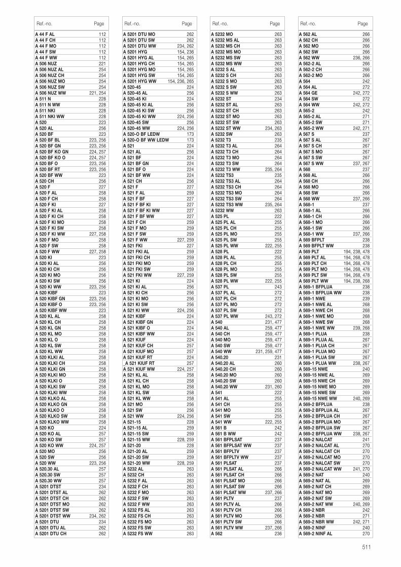
511
A 44 F AL 112A 44 F CH 112A 44 F MO 112A 44 F SW 112A 44 F WW 112A 506 NUZ 221A 506 NUZ AL 254A 506 NUZ CH 254A 506 NUZ MO 254A 506 NUZ SW 254A 506 NUZ WW 221, 254A 511 N 228A 511 N WW 228A 511 NKI 228A 511 NKI WW 228A 520 223A 520 AL 256A 520 BF 223A 520 BF BL 223, 256A 520 BF GN 223, 256A 520 BF KO GN 224, 257A 520 BF KO O 224, 257A 520 BF O 223, 256A 520 BF RT 223, 256A 520 BF WW 223A 520 CH 256A 520 F 227A 520 F AL 258A 520 F CH 258A 520 F KI 227A 520 F KI AL 258A 520 F KI CH 258A 520 F KI MO 258A 520 F KI SW 258A 520 F KI WW 227, 258A 520 F MO 258A 520 F SW 258A 520 F WW 227, 258A 520 KI 223A 520 KI AL 256A 520 KI CH 256A 520 KI MO 256A 520 KI SW 256A 520 KI WW 223, 256A 520 KIBF 223A 520 KIBF GN 223, 256A 520 KIBF O 223, 256A 520 KIBF WW 223A 520 KL AL 258A 520 KL CH 258A 520 KL GN 258A 520 KL MO 258A 520 KL O 258A 520 KL SW 258A 520 KL WW 258A 520 KLKI AL 258A 520 KLKI CH 258A 520 KLKI GN 258A 520 KLKI MO 258A 520 KLKI O 258A 520 KLKI SW 258A 520 KLKI WW 258A 520 KLKO AL 258A 520 KLKO GN 258A 520 KLKO O 258A 520 KLKO SW 258A 520 KLKO WW 258A 520 KO 224A 520 KO AL 257A 520 KO SW 257A 520 KO WW 224, 257A 520 MO 256A 520 SW 256A 520 WW 223, 256A 520.30 AL 257A 520.30 SW 257A 520.30 WW 257A 5201 DTST 234A 5201 DTST AL 262A 5201 DTST CH 262A 5201 DTST MO 262A 5201 DTST SW 262A 5201 DTST WW 234, 262A 5201 DTU 234A 5201 DTU AL 262A 5201 DTU CH 262
A 5201 DTU MO 262A 5201 DTU SW 262A 5201 DTU WW 234, 262A 5201 HYG 154, 236A 5201 HYG AL 154, 265A 5201 HYG CH 154, 265A 5201 HYG MO 154, 265A 5201 HYG SW 154, 265A 5201 HYG WW 154, 236, 265A 520-45 224A 520-45 AL 256A 520-45 KI 224A 520-45 KI AL 256A 520-45 KI SW 256A 520-45 KI WW 224, 256A 520-45 SW 256A 520-45 WW 224, 256A 520-O BF LEDW 173A 520-O BF WW LEDW 173A 521 224A 521 AL 256A 521 BF 224A 521 BF GN 224A 521 BF O 224A 521 BF WW 224A 521 CH 256A 521 F 227A 521 F AL 259A 521 F BF 227A 521 F BF KI 227A 521 F BF KI WW 227A 521 F BF WW 227A 521 F CH 259A 521 F MO 259A 521 F SW 259A 521 F WW 227, 259A 521 FKI 227A 521 FKI AL 259A 521 FKI CH 259A 521 FKI MO 259A 521 FKI SW 259A 521 FKI WW 227, 259A 521 KI 224A 521 KI AL 256A 521 KI CH 256A 521 KI MO 256A 521 KI SW 256A 521 KI WW 224, 256A 521 KIBF 224A 521 KIBF GN 224A 521 KIBF O 224A 521 KIBF WW 224A 521 KIUF 224A 521 KIUF CH 257A 521 KIUF MO 257A 521 KIUF RT 224_A 521 KIUF RT 257A 521 KIUF WW 224, 257A 521 KL AL 258A 521 KL CH 258A 521 KL MO 258A 521 KL SW 258A 521 KL WW 258A 521 MO 256A 521 SW 256A 521 WW 224, 256A 521-15 228A 521-15 AL 259A 521-15 SW 259A 521-15 WW 228, 259A 521-20 228A 521-20 AL 259A 521-20 SW 259A 521-20 WW 228, 259A 5232 AL 263A 5232 CH 263A 5232 F AL 263A 5232 F CH 263A 5232 F MO 263A 5232 F SW 263A 5232 F WW 263A 5232 FS AL 263A 5232 FS CH 263A 5232 FS MO 263A 5232 FS SW 263A 5232 FS WW 263
A 5232 MO 263A 5232 MS AL 263A 5232 MS CH 263A 5232 MS MO 263A 5232 MS SW 263A 5232 MS WW 263A 5232 S AL 263A 5232 S CH 263A 5232 S MO 263A 5232 S SW 263A 5232 S WW 263A 5232 ST 234A 5232 ST AL 263A 5232 ST CH 263A 5232 ST MO 263A 5232 ST SW 263A 5232 ST WW 234, 263A 5232 SW 263A 5232 T3 235A 5232 T3 AL 264A 5232 T3 CH 264A 5232 T3 MO 264A 5232 T3 SW 264A 5232 T3 WW 235, 264A 5232 TS3 235A 5232 TS3 AL 264A 5232 TS3 CH 264A 5232 TS3 MO 264A 5232 TS3 SW 264A 5232 TS3 WW 235, 264A 5232 WW 263A 525 PL 222A 525 PL AL 255A 525 PL CH 255A 525 PL MO 255A 525 PL SW 255A 525 PL WW 222, 255A 528 PL 222A 528 PL AL 255A 528 PL CH 255A 528 PL MO 255A 528 PL SW 255A 528 PL WW 222, 255A 537 PL 243A 537 PL AL 272A 537 PL CH 272A 537 PL MO 272A 537 PL SW 272A 537 PL WW 243, 272A 540 231, 477A 540 AL 259, 477A 540 CH 259, 477A 540 MO 259, 477A 540 SW 259, 477A 540 WW 231, 259, 477A 540.20 231A 540.20 AL 260A 540.20 CH 260A 540.20 MO 260A 540.20 SW 260A 540.20 WW 231, 260A 541 222A 541 AL 255A 541 CH 255A 541 MO 255A 541 SW 255A 541 WW 222, 255A 561 B 242A 561 B WW 242A 561 BFPLSAT 237A 561 BFPLSAT WW 237A 561 BFPLTV 237A 561 BFPLTV WW 237A 561 PLSAT 237A 561 PLSAT AL 266A 561 PLSAT CH 266A 561 PLSAT MO 266A 561 PLSAT SW 266A 561 PLSAT WW 237, 266A 561 PLTV 237A 561 PLTV AL 266A 561 PLTV CH 266A 561 PLTV MO 266A 561 PLTV SW 266A 561 PLTV WW 237, 266A 562 236
Ref.-no. Page Ref.-no. Page Ref.-no. Page
A 562 AL 266A 562 CH 266A 562 MO 266A 562 SW 266A 562 WW 236, 266A 562-2 AL 266A 562-2 CH 266A 562-2 MO 266A 564 242A 564 AL 272A 564 GE 242, 272A 564 SW 272A 564 WW 242, 272A 565-2 242A 565-2 AL 271A 565-2 SW 271A 565-2 WW 242, 271A 567 S 237A 567 S AL 267A 567 S CH 267A 567 S MO 267A 567 S SW 267A 567 S WW 237, 267A 568 237A 568 AL 266A 568 CH 266A 568 MO 266A 568 SW 266A 568 WW 237, 266A 568-1 237A 568-1 AL 266A 568-1 CH 266A 568-1 MO 266A 568-1 SW 266A 568-1 WW 237, 266A 569 BFPLT 238A 569 BFPLT WW 238A 569 PLT 194, 238, 478A 569 PLT AL 194, 268, 478A 569 PLT CH 194, 268, 478A 569 PLT MO 194, 268, 478A 569 PLT SW 194, 268, 478A 569 PLT WW 194, 238, 268A 569-1 BFPLUA 238A 569-1 BFPLUA WW 238A 569-1 NWE 239A 569-1 NWE AL 268A 569-1 NWE CH 268A 569-1 NWE MO 268A 569-1 NWE SW 268A 569-1 NWE WW 239, 268A 569-1 PLUA 238A 569-1 PLUA AL 267A 569-1 PLUA CH 267A 569-1 PLUA MO 267A 569-1 PLUA SW 267A 569-1 PLUA WW 238, 267A 569-15 NWE 240A 569-15 NWE AL 269A 569-15 NWE CH 269A 569-15 NWE MO 269A 569-15 NWE SW 269A 569-15 NWE WW 240, 269A 569-2 BFPLUA 238A 569-2 BFPLUA AL 267A 569-2 BFPLUA CH 267A 569-2 BFPLUA MO 267A 569-2 BFPLUA SW 267A 569-2 BFPLUA WW 238, 267A 569-2 NALCAT 241A 569-2 NALCAT AL 270A 569-2 NALCAT CH 270A 569-2 NALCAT MO 270A 569-2 NALCAT SW 270A 569-2 NALCAT WW 241, 270A 569-2 NAT 240A 569-2 NAT AL 269A 569-2 NAT CH 269A 569-2 NAT MO 269A 569-2 NAT SW 269A 569-2 NAT WW 240, 269A 569-2 NBR 242A 569-2 NBR 271A 569-2 NBR WW 242, 271A 569-2 NINF 240A 569-2 NINF AL 270
Ref.-no. Page
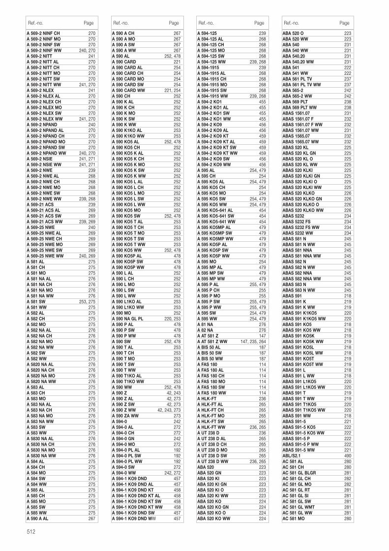
512
A 569-2 NINF CH 270A 569-2 NINF MO 270A 569-2 NINF SW 270A 569-2 NINF WW 240, 270A 569-2 NITT 241A 569-2 NITT AL 270A 569-2 NITT CH 270A 569-2 NITT MO 270A 569-2 NITT SW 270A 569-2 NITT WW 241, 270A 569-2 NLEX 241A 569-2 NLEX AL 270A 569-2 NLEX CH 270A 569-2 NLEX MO 270A 569-2 NLEX SW 270A 569-2 NLEX WW 241, 270A 569-2 NPAND 240A 569-2 NPAND AL 270A 569-2 NPAND CH 270A 569-2 NPAND MO 270A 569-2 NPAND SW 270A 569-2 NPAND WW 240, 270A 569-2 NSIE 241, 271A 569-2 NSIE WW 241, 271A 569-2 NWE 239A 569-2 NWE AL 268A 569-2 NWE CH 268A 569-2 NWE MO 268A 569-2 NWE SW 268A 569-2 NWE WW 239, 268A 569-21 ACS 239A 569-21 ACS AL 269A 569-21 ACS SW 269A 569-21 ACS WW 239, 269A 569-25 NWE 240A 569-25 NWE AL 269A 569-25 NWE CH 269A 569-25 NWE MO 269A 569-25 NWE SW 269A 569-25 NWE WW 240, 269A 581 AL 275A 581 CH 275A 581 MO 275A 581 NA AL 276A 581 NA CH 276A 581 NA MO 276A 581 NA WW 276A 581 SW 253, 275A 581 WW 275A 582 AL 275A 582 CH 275A 582 MO 275A 582 NA AL 276A 582 NA CH 276A 582 NA MO 276A 582 NA WW 276A 582 SW 275A 582 WW 275A 5820 NA AL 276A 5820 NA CH 276A 5820 NA MO 276A 5820 NA WW 276A 583 AL 275A 583 CH 275A 583 MO 275A 583 NA AL 276A 583 NA CH 276A 583 NA MO 276A 583 NA WW 276A 583 SW 275A 583 WW 275A 5830 NA AL 276A 5830 NA CH 276A 5830 NA MO 276A 5830 NA WW 276A 584 AL 275A 584 CH 275A 584 MO 275A 584 SW 275A 584 WW 275A 585 AL 275A 585 CH 275A 585 MO 275A 585 SW 275A 585 WW 275A 590 A AL 267
A 590 A CH 267A 590 A MO 267A 590 A SW 267A 590 A WW 267A 590 AL 252, 478A 590 CARD 221A 590 CARD AL 254A 590 CARD CH 254A 590 CARD MO 254A 590 CARD SW 254A 590 CARD WW 221, 254A 590 CH 252A 590 K AL 252A 590 K CH 252A 590 K MO 252A 590 K SW 252A 590 K WW 252A 590 K1KO AL 253A 590 K1KO WW 253A 590 KO5 AL 252, 478A 590 KO5 CH 252A 590 KO5 K AL 252A 590 KO5 K CH 252A 590 KO5 K MO 252A 590 KO5 K SW 252A 590 KO5 K WW 252A 590 KO5 L AL 252A 590 KO5 L CH 252A 590 KO5 L MO 252A 590 KO5 L SW 252A 590 KO5 L WW 252A 590 KO5 MO 252A 590 KO5 SW 252, 478A 590 KO5 T AL 253A 590 KO5 T CH 253A 590 KO5 T MO 253A 590 KO5 T SW 253A 590 KO5 T WW 253A 590 KO5 WW 252, 478A 590 KO5P AL 478A 590 KO5P SW 478A 590 KO5P WW 478A 590 L AL 252A 590 L CH 252A 590 L MO 252A 590 L SW 252A 590 L WW 252A 590 L1KO AL 253A 590 L1KO WW 253A 590 MO 252A 590 NA GL PL 220, 253A 590 P AL 478A 590 P SW 478A 590 P WW 478A 590 SW 252, 478A 590 T AL 253A 590 T CH 253A 590 T MO 253A 590 T SW 253A 590 T WW 253A 590 T1KO AL 253A 590 T1KO WW 253A 590 WW 252, 478A 590 Z 42, 243A 590 Z AL 42, 273A 590 Z SW 42, 273A 590 Z WW 42, 243, 273A 590 ZA WW 273A 594-0 242A 594-0 AL 272A 594-0 CH 272A 594-0 GN 242A 594-0 MO 272A 594-0 PL AL 192A 594-0 PL SW 192A 594-0 PL WW 192A 594-0 SW 272A 594-0 WW 242, 272A 594-1 KO9 DND 457A 594-1 KO9 DND AL 457A 594-1 KO9 DND KT 458A 594-1 KO9 DND KT AL 458A 594-1 KO9 DND KT SW 458A 594-1 KO9 DND KT WW 458A 594-1 KO9 DND SW 457A 594-1 KO9 DND WW 457
A 594-125 239A 594-125 AL 268A 594-125 CH 268A 594-125 MO 268A 594-125 SW 268A 594-125 WW 239, 268A 594-1915 239A 594-1915 AL 268A 594-1915 CH 268A 594-1915 MO 268A 594-1915 SW 268A 594-1915 WW 239, 268A 594-2 KO1 455A 594-2 KO1 AL 455A 594-2 KO1 SW 455A 594-2 KO1 WW 455A 594-2 KO9 456A 594-2 KO9 AL 456A 594-2 KO9 KT 459A 594-2 KO9 KT AL 459A 594-2 KO9 KT SW 459A 594-2 KO9 KT WW 459A 594-2 KO9 SW 456A 594-2 KO9 WW 456A 595 AL 254, 479A 595 CH 254A 595 KO5 AL 254, 479A 595 KO5 CH 254A 595 KO5 MO 254A 595 KO5 SW 254, 479A 595 KO5 WW 254, 479A 595 KO5-641 AL 454A 595 KO5-641 SW 454A 595 KO5-641 WW 454A 595 KO5MP AL 479A 595 KO5MP SW 479A 595 KO5MP WW 479A 595 KO5P AL 479A 595 KO5P SW 479A 595 KO5P WW 479A 595 MO 254A 595 MP AL 479A 595 MP SW 479A 595 MP WW 479A 595 P AL 255, 479A 595 P CH 255A 595 P MO 255A 595 P SW 255, 479A 595 P WW 255, 479A 595 SW 254, 479A 595 WW 254, 479A 81 NA 276A 82 NA 276A AT 581 Z 147A AT 581 Z WW 147, 235, 264A BIS 50 AL 187A BIS 50 SW 187A BIS 50 WW 187A FAS 180 114A FAS 180 AL 114A FAS 180 CH 114A FAS 180 MO 114A FAS 180 SW 114A FAS 180 WW 114A HLK-FT 236A HLK-FT AL 265A HLK-FT CH 265A HLK-FT MO 265A HLK-FT SW 265A HLK-FT WW 236, 265A UT 238 D 236A UT 238 D AL 265A UT 238 D CH 265A UT 238 D MO 265A UT 238 D SW 265A UT 238 D WW 236, 265ABA 520 223ABA 520 GN 223ABA 520 KI 223ABA 520 KI GN 223ABA 520 KI O 223ABA 520 KI WW 223ABA 520 KO 224ABA 520 KO GN 224ABA 520 KO O 224ABA 520 KO WW 224
Ref.-no. Page Ref.-no. Page Ref.-no. Page
ABA 520 O 223ABA 520 WW 223ABA 540 231ABA 540 WW 231ABA 540.20 231ABA 540.20 WW 231ABA 541 222ABA 541 WW 222ABA 561 PL TV 237ABA 561 PL TV WW 237ABA 565-2 242ABA 565-2 WW 242ABA 569 PLT 238ABA 569 PLT WW 238ABAS 1561.07 231ABAS 1561.07 F 232ABAS 1561.07 F WW 232ABAS 1561.07 WW 231ABAS 1565.07 232ABAS 1565.07 WW 232ABAS 520 KL 225ABAS 520 KL GN 225ABAS 520 KL O 225ABAS 520 KL WW 225ABAS 520 KLKI 225ABAS 520 KLKI GN 225ABAS 520 KLKI O 225ABAS 520 KLKI WW 225ABAS 520 KLKO 226ABAS 520 KLKO GN 226ABAS 520 KLKO O 226ABAS 520 KLKO WW 226ABAS 5232 234ABAS 5232 FS 234ABAS 5232 FS WW 234ABAS 5232 WW 234ABAS 581 N 245ABAS 581 N WW 245ABAS 581 NNA 245ABAS 581 NNA WW 245ABAS 582 N 245ABAS 582 N WW 245ABAS 582 NNA 245ABAS 582 NNA WW 245ABAS 583 N 245ABAS 583 N WW 245ABAS 591 218ABAS 591 K 219ABAS 591 K WW 219ABAS 591 K1KO5 220ABAS 591 K1KO5 WW 220ABAS 591 KO5 218ABAS 591 KO5 WW 218ABAS 591 KO5K 219ABAS 591 KO5K WW 219ABAS 591 KO5L 218ABAS 591 KO5L WW 218ABAS 591 KO5T 219ABAS 591 KO5T WW 219ABAS 591 L 218ABAS 591 L WW 218ABAS 591 L1KO5 220ABAS 591 L1KO5 WW 220ABAS 591 T 219ABAS 591 T WW 219ABAS 591 T1KO5 220ABAS 591 T1KO5 WW 220ABAS 591 WW 218ABAS 591-5 221ABAS 591-5 KO5 222ABAS 591-5 KO5 WW 222ABAS 591-5 P 222ABAS 591-5 P WW 222ABAS 591-5 WW 221ABL/S2.1 490AC 581 AL 280AC 581 CH 280AC 581 GL BLGR 281AC 581 GL CH 282AC 581 GL MO 282AC 581 GL RT 281AC 581 GL SI 281AC 581 GL SW 281AC 581 GL WMT 281AC 581 GL WW 281AC 581 MO 280
Ref.-no. Page
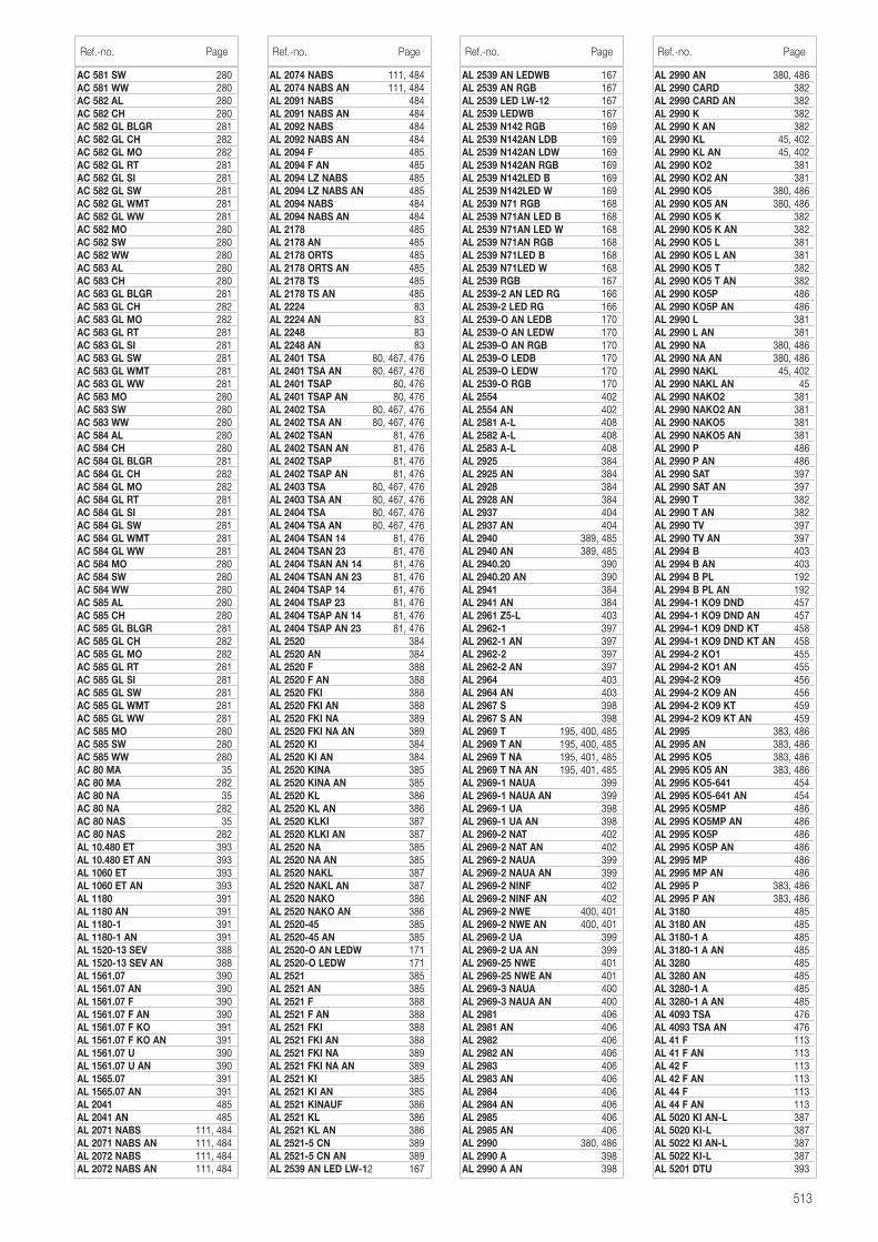
513
AC 581 SW 280AC 581 WW 280AC 582 AL 280AC 582 CH 280AC 582 GL BLGR 281AC 582 GL CH 282AC 582 GL MO 282AC 582 GL RT 281AC 582 GL SI 281AC 582 GL SW 281AC 582 GL WMT 281AC 582 GL WW 281AC 582 MO 280AC 582 SW 280AC 582 WW 280AC 583 AL 280AC 583 CH 280AC 583 GL BLGR 281AC 583 GL CH 282AC 583 GL MO 282AC 583 GL RT 281AC 583 GL SI 281AC 583 GL SW 281AC 583 GL WMT 281AC 583 GL WW 281AC 583 MO 280AC 583 SW 280AC 583 WW 280AC 584 AL 280AC 584 CH 280AC 584 GL BLGR 281AC 584 GL CH 282AC 584 GL MO 282AC 584 GL RT 281AC 584 GL SI 281AC 584 GL SW 281AC 584 GL WMT 281AC 584 GL WW 281AC 584 MO 280AC 584 SW 280AC 584 WW 280AC 585 AL 280AC 585 CH 280AC 585 GL BLGR 281AC 585 GL CH 282AC 585 GL MO 282AC 585 GL RT 281AC 585 GL SI 281AC 585 GL SW 281AC 585 GL WMT 281AC 585 GL WW 281AC 585 MO 280AC 585 SW 280AC 585 WW 280AC 80 MA 35AC 80 MA 282AC 80 NA 35AC 80 NA 282AC 80 NAS 35AC 80 NAS 282AL 10.480 ET 393AL 10.480 ET AN 393AL 1060 ET 393AL 1060 ET AN 393AL 1180 391AL 1180 AN 391AL 1180-1 391AL 1180-1 AN 391AL 1520-13 SEV 388AL 1520-13 SEV AN 388AL 1561.07 390AL 1561.07 AN 390AL 1561.07 F 390AL 1561.07 F AN 390AL 1561.07 F KO 391AL 1561.07 F KO AN 391AL 1561.07 U 390AL 1561.07 U AN 390AL 1565.07 391AL 1565.07 AN 391AL 2041 485AL 2041 AN 485AL 2071 NABS 111, 484AL 2071 NABS AN 111, 484AL 2072 NABS 111, 484AL 2072 NABS AN 111, 484
AL 2074 NABS 111, 484AL 2074 NABS AN 111, 484AL 2091 NABS 484AL 2091 NABS AN 484AL 2092 NABS 484AL 2092 NABS AN 484AL 2094 F 485AL 2094 F AN 485AL 2094 LZ NABS 485AL 2094 LZ NABS AN 485AL 2094 NABS 484AL 2094 NABS AN 484AL 2178 485AL 2178 AN 485AL 2178 ORTS 485AL 2178 ORTS AN 485AL 2178 TS 485AL 2178 TS AN 485AL 2224 83AL 2224 AN 83AL 2248 83AL 2248 AN 83AL 2401 TSA 80, 467, 476AL 2401 TSA AN 80, 467, 476AL 2401 TSAP 80, 476AL 2401 TSAP AN 80, 476AL 2402 TSA 80, 467, 476AL 2402 TSA AN 80, 467, 476AL 2402 TSAN 81, 476AL 2402 TSAN AN 81, 476AL 2402 TSAP 81, 476AL 2402 TSAP AN 81, 476AL 2403 TSA 80, 467, 476AL 2403 TSA AN 80, 467, 476AL 2404 TSA 80, 467, 476AL 2404 TSA AN 80, 467, 476AL 2404 TSAN 14 81, 476AL 2404 TSAN 23 81, 476AL 2404 TSAN AN 14 81, 476AL 2404 TSAN AN 23 81, 476AL 2404 TSAP 14 81, 476AL 2404 TSAP 23 81, 476AL 2404 TSAP AN 14 81, 476AL 2404 TSAP AN 23 81, 476AL 2520 384AL 2520 AN 384AL 2520 F 388AL 2520 F AN 388AL 2520 FKI 388AL 2520 FKI AN 388AL 2520 FKI NA 389AL 2520 FKI NA AN 389AL 2520 KI 384AL 2520 KI AN 384AL 2520 KINA 385AL 2520 KINA AN 385AL 2520 KL 386AL 2520 KL AN 386AL 2520 KLKI 387AL 2520 KLKI AN 387AL 2520 NA 385AL 2520 NA AN 385AL 2520 NAKL 387AL 2520 NAKL AN 387AL 2520 NAKO 386AL 2520 NAKO AN 386AL 2520-45 385AL 2520-45 AN 385AL 2520-O AN LEDW 171AL 2520-O LEDW 171AL 2521 385AL 2521 AN 385AL 2521 F 388AL 2521 F AN 388AL 2521 FKI 388AL 2521 FKI AN 388AL 2521 FKI NA 389AL 2521 FKI NA AN 389AL 2521 KI 385AL 2521 KI AN 385AL 2521 KINAUF 386AL 2521 KL 386AL 2521 KL AN 386AL 2521-5 CN 389AL 2521-5 CN AN 389AL 2539 AN LED LW-12 167
AL 2539 AN LEDWB 167AL 2539 AN RGB 167AL 2539 LED LW-12 167AL 2539 LEDWB 167AL 2539 N142 RGB 169AL 2539 N142AN LDB 169AL 2539 N142AN LDW 169AL 2539 N142AN RGB 169AL 2539 N142LED B 169AL 2539 N142LED W 169AL 2539 N71 RGB 168AL 2539 N71AN LED B 168AL 2539 N71AN LED W 168AL 2539 N71AN RGB 168AL 2539 N71LED B 168AL 2539 N71LED W 168AL 2539 RGB 167AL 2539-2 AN LED RG 166AL 2539-2 LED RG 166AL 2539-O AN LEDB 170AL 2539-O AN LEDW 170AL 2539-O AN RGB 170AL 2539-O LEDB 170AL 2539-O LEDW 170AL 2539-O RGB 170AL 2554 402AL 2554 AN 402AL 2581 A-L 408AL 2582 A-L 408AL 2583 A-L 408AL 2925 384AL 2925 AN 384AL 2928 384AL 2928 AN 384AL 2937 404AL 2937 AN 404AL 2940 389, 485AL 2940 AN 389, 485AL 2940.20 390AL 2940.20 AN 390AL 2941 384AL 2941 AN 384AL 2961 Z5-L 403AL 2962-1 397AL 2962-1 AN 397AL 2962-2 397AL 2962-2 AN 397AL 2964 403AL 2964 AN 403AL 2967 S 398AL 2967 S AN 398AL 2969 T 195, 400, 485AL 2969 T AN 195, 400, 485AL 2969 T NA 195, 401, 485AL 2969 T NA AN 195, 401, 485AL 2969-1 NAUA 399AL 2969-1 NAUA AN 399AL 2969-1 UA 398AL 2969-1 UA AN 398AL 2969-2 NAT 402AL 2969-2 NAT AN 402AL 2969-2 NAUA 399AL 2969-2 NAUA AN 399AL 2969-2 NINF 402AL 2969-2 NINF AN 402AL 2969-2 NWE 400, 401AL 2969-2 NWE AN 400, 401AL 2969-2 UA 399AL 2969-2 UA AN 399AL 2969-25 NWE 401AL 2969-25 NWE AN 401AL 2969-3 NAUA 400AL 2969-3 NAUA AN 400AL 2981 406AL 2981 AN 406AL 2982 406AL 2982 AN 406AL 2983 406AL 2983 AN 406AL 2984 406AL 2984 AN 406AL 2985 406AL 2985 AN 406AL 2990 380, 486AL 2990 A 398AL 2990 A AN 398
Ref.-no. Page Ref.-no. Page Ref.-no. Page
AL 2990 AN 380, 486AL 2990 CARD 382AL 2990 CARD AN 382AL 2990 K 382AL 2990 K AN 382AL 2990 KL 45, 402AL 2990 KL AN 45, 402AL 2990 KO2 381AL 2990 KO2 AN 381AL 2990 KO5 380, 486AL 2990 KO5 AN 380, 486AL 2990 KO5 K 382AL 2990 KO5 K AN 382AL 2990 KO5 L 381AL 2990 KO5 L AN 381AL 2990 KO5 T 382AL 2990 KO5 T AN 382AL 2990 KO5P 486AL 2990 KO5P AN 486AL 2990 L 381AL 2990 L AN 381AL 2990 NA 380, 486AL 2990 NA AN 380, 486AL 2990 NAKL 45, 402AL 2990 NAKL AN 45AL 2990 NAKO2 381AL 2990 NAKO2 AN 381AL 2990 NAKO5 381AL 2990 NAKO5 AN 381AL 2990 P 486AL 2990 P AN 486AL 2990 SAT 397AL 2990 SAT AN 397AL 2990 T 382AL 2990 T AN 382AL 2990 TV 397AL 2990 TV AN 397AL 2994 B 403AL 2994 B AN 403AL 2994 B PL 192AL 2994 B PL AN 192AL 2994-1 KO9 DND 457AL 2994-1 KO9 DND AN 457AL 2994-1 KO9 DND KT 458AL 2994-1 KO9 DND KT AN 458AL 2994-2 KO1 455AL 2994-2 KO1 AN 455AL 2994-2 KO9 456AL 2994-2 KO9 AN 456AL 2994-2 KO9 KT 459AL 2994-2 KO9 KT AN 459AL 2995 383, 486AL 2995 AN 383, 486AL 2995 KO5 383, 486AL 2995 KO5 AN 383, 486AL 2995 KO5-641 454AL 2995 KO5-641 AN 454AL 2995 KO5MP 486AL 2995 KO5MP AN 486AL 2995 KO5P 486AL 2995 KO5P AN 486AL 2995 MP 486AL 2995 MP AN 486AL 2995 P 383, 486AL 2995 P AN 383, 486AL 3180 485AL 3180 AN 485AL 3180-1 A 485AL 3180-1 A AN 485AL 3280 485AL 3280 AN 485AL 3280-1 A 485AL 3280-1 A AN 485AL 4093 TSA 476AL 4093 TSA AN 476AL 41 F 113AL 41 F AN 113AL 42 F 113AL 42 F AN 113AL 44 F 113AL 44 F AN 113AL 5020 KI AN-L 387AL 5020 KI-L 387AL 5022 KI AN-L 387AL 5022 KI-L 387AL 5201 DTU 393
Ref.-no. Page
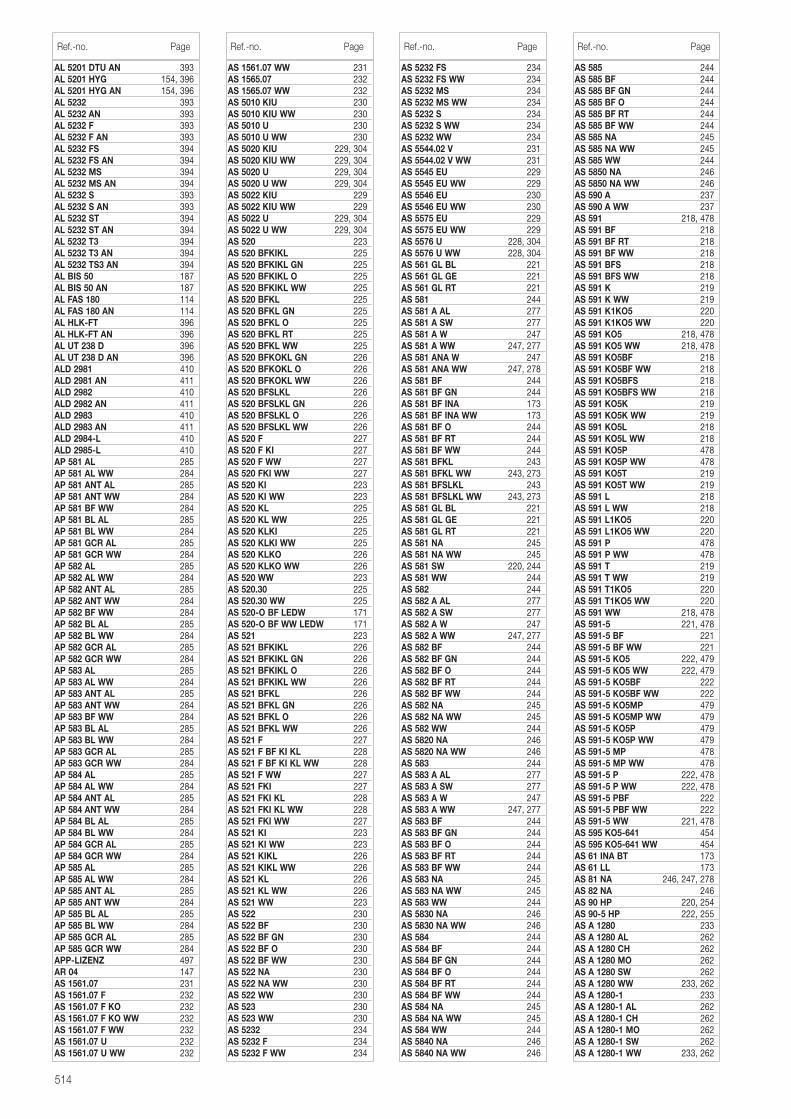
514
AL 5201 DTU AN 393AL 5201 HYG 154, 396AL 5201 HYG AN 154, 396AL 5232 393AL 5232 AN 393AL 5232 F 393AL 5232 F AN 393AL 5232 FS 394AL 5232 FS AN 394AL 5232 MS 394AL 5232 MS AN 394AL 5232 S 393AL 5232 S AN 393AL 5232 ST 394AL 5232 ST AN 394AL 5232 T3 394AL 5232 T3 AN 394AL 5232 TS3 AN 394AL BIS 50 187AL BIS 50 AN 187AL FAS 180 114AL FAS 180 AN 114AL HLK-FT 396AL HLK-FT AN 396AL UT 238 D 396AL UT 238 D AN 396ALD 2981 410ALD 2981 AN 411ALD 2982 410ALD 2982 AN 411ALD 2983 410ALD 2983 AN 411ALD 2984-L 410ALD 2985-L 410AP 581 AL 285AP 581 AL WW 284AP 581 ANT AL 285AP 581 ANT WW 284AP 581 BF WW 284AP 581 BL AL 285AP 581 BL WW 284AP 581 GCR AL 285AP 581 GCR WW 284AP 582 AL 285AP 582 AL WW 284AP 582 ANT AL 285AP 582 ANT WW 284AP 582 BF WW 284AP 582 BL AL 285AP 582 BL WW 284AP 582 GCR AL 285AP 582 GCR WW 284AP 583 AL 285AP 583 AL WW 284AP 583 ANT AL 285AP 583 ANT WW 284AP 583 BF WW 284AP 583 BL AL 285AP 583 BL WW 284AP 583 GCR AL 285AP 583 GCR WW 284AP 584 AL 285AP 584 AL WW 284AP 584 ANT AL 285AP 584 ANT WW 284AP 584 BL AL 285AP 584 BL WW 284AP 584 GCR AL 285AP 584 GCR WW 284AP 585 AL 285AP 585 AL WW 284AP 585 ANT AL 285AP 585 ANT WW 284AP 585 BL AL 285AP 585 BL WW 284AP 585 GCR AL 285AP 585 GCR WW 284APP-LIZENZ 497AR 04 147AS 1561.07 231AS 1561.07 F 232AS 1561.07 F KO 232AS 1561.07 F KO WW 232AS 1561.07 F WW 232AS 1561.07 U 232AS 1561.07 U WW 232
AS 1561.07 WW 231AS 1565.07 232AS 1565.07 WW 232AS 5010 KIU 230AS 5010 KIU WW 230AS 5010 U 230AS 5010 U WW 230AS 5020 KIU 229, 304AS 5020 KIU WW 229, 304AS 5020 U 229, 304AS 5020 U WW 229, 304AS 5022 KIU 229AS 5022 KIU WW 229AS 5022 U 229, 304AS 5022 U WW 229, 304AS 520 223AS 520 BFKIKL 225AS 520 BFKIKL GN 225AS 520 BFKIKL O 225AS 520 BFKIKL WW 225AS 520 BFKL 225AS 520 BFKL GN 225AS 520 BFKL O 225AS 520 BFKL RT 225AS 520 BFKL WW 225AS 520 BFKOKL GN 226AS 520 BFKOKL O 226AS 520 BFKOKL WW 226AS 520 BFSLKL 226AS 520 BFSLKL GN 226AS 520 BFSLKL O 226AS 520 BFSLKL WW 226AS 520 F 227AS 520 F KI 227AS 520 F WW 227AS 520 FKI WW 227AS 520 KI 223AS 520 KI WW 223AS 520 KL 225AS 520 KL WW 225AS 520 KLKI 225AS 520 KLKI WW 225AS 520 KLKO 226AS 520 KLKO WW 226AS 520 WW 223AS 520.30 225AS 520.30 WW 225AS 520-O BF LEDW 171AS 520-O BF WW LEDW 171AS 521 223AS 521 BFKIKL 226AS 521 BFKIKL GN 226AS 521 BFKIKL O 226AS 521 BFKIKL WW 226AS 521 BFKL 226AS 521 BFKL GN 226AS 521 BFKL O 226AS 521 BFKL WW 226AS 521 F 227AS 521 F BF KI KL 228AS 521 F BF KI KL WW 228AS 521 F WW 227AS 521 FKI 227AS 521 FKI KL 228AS 521 FKI KL WW 228AS 521 FKI WW 227AS 521 KI 223AS 521 KI WW 223AS 521 KIKL 226AS 521 KIKL WW 226AS 521 KL 226AS 521 KL WW 226AS 521 WW 223AS 522 230AS 522 BF 230AS 522 BF GN 230AS 522 BF O 230AS 522 BF WW 230AS 522 NA 230AS 522 NA WW 230AS 522 WW 230AS 523 230AS 523 WW 230AS 5232 234AS 5232 F 234AS 5232 F WW 234
AS 5232 FS 234AS 5232 FS WW 234AS 5232 MS 234AS 5232 MS WW 234AS 5232 S 234AS 5232 S WW 234AS 5232 WW 234AS 5544.02 V 231AS 5544.02 V WW 231AS 5545 EU 229AS 5545 EU WW 229AS 5546 EU 230AS 5546 EU WW 230AS 5575 EU 229AS 5575 EU WW 229AS 5576 U 228, 304AS 5576 U WW 228, 304AS 561 GL BL 221AS 561 GL GE 221AS 561 GL RT 221AS 581 244AS 581 A AL 277AS 581 A SW 277AS 581 A W 247AS 581 A WW 247, 277AS 581 ANA W 247AS 581 ANA WW 247, 278AS 581 BF 244AS 581 BF GN 244AS 581 BF INA 173AS 581 BF INA WW 173AS 581 BF O 244AS 581 BF RT 244AS 581 BF WW 244AS 581 BFKL 243AS 581 BFKL WW 243, 273AS 581 BFSLKL 243AS 581 BFSLKL WW 243, 273AS 581 GL BL 221AS 581 GL GE 221AS 581 GL RT 221AS 581 NA 245AS 581 NA WW 245AS 581 SW 220, 244AS 581 WW 244AS 582 244AS 582 A AL 277AS 582 A SW 277AS 582 A W 247AS 582 A WW 247, 277AS 582 BF 244AS 582 BF GN 244AS 582 BF O 244AS 582 BF RT 244AS 582 BF WW 244AS 582 NA 245AS 582 NA WW 245AS 582 WW 244AS 5820 NA 246AS 5820 NA WW 246AS 583 244AS 583 A AL 277AS 583 A SW 277AS 583 A W 247AS 583 A WW 247, 277AS 583 BF 244AS 583 BF GN 244AS 583 BF O 244AS 583 BF RT 244AS 583 BF WW 244AS 583 NA 245AS 583 NA WW 245AS 583 WW 244AS 5830 NA 246AS 5830 NA WW 246AS 584 244AS 584 BF 244AS 584 BF GN 244AS 584 BF O 244AS 584 BF RT 244AS 584 BF WW 244AS 584 NA 245AS 584 NA WW 245AS 584 WW 244AS 5840 NA 246AS 5840 NA WW 246
Ref.-no. Page Ref.-no. Page Ref.-no. Page
AS 585 244AS 585 BF 244AS 585 BF GN 244AS 585 BF O 244AS 585 BF RT 244AS 585 BF WW 244AS 585 NA 245AS 585 NA WW 245AS 585 WW 244AS 5850 NA 246AS 5850 NA WW 246AS 590 A 237AS 590 A WW 237AS 591 218, 478AS 591 BF 218AS 591 BF RT 218AS 591 BF WW 218AS 591 BFS 218AS 591 BFS WW 218AS 591 K 219AS 591 K WW 219AS 591 K1KO5 220AS 591 K1KO5 WW 220AS 591 KO5 218, 478AS 591 KO5 WW 218, 478AS 591 KO5BF 218AS 591 KO5BF WW 218AS 591 KO5BFS 218AS 591 KO5BFS WW 218AS 591 KO5K 219AS 591 KO5K WW 219AS 591 KO5L 218AS 591 KO5L WW 218AS 591 KO5P 478AS 591 KO5P WW 478AS 591 KO5T 219AS 591 KO5T WW 219AS 591 L 218AS 591 L WW 218AS 591 L1KO5 220AS 591 L1KO5 WW 220AS 591 P 478AS 591 P WW 478AS 591 T 219AS 591 T WW 219AS 591 T1KO5 220AS 591 T1KO5 WW 220AS 591 WW 218, 478AS 591-5 221, 478AS 591-5 BF 221AS 591-5 BF WW 221AS 591-5 KO5 222, 479AS 591-5 KO5 WW 222, 479AS 591-5 KO5BF 222AS 591-5 KO5BF WW 222AS 591-5 KO5MP 479AS 591-5 KO5MP WW 479AS 591-5 KO5P 479AS 591-5 KO5P WW 479AS 591-5 MP 478AS 591-5 MP WW 478AS 591-5 P 222, 478AS 591-5 P WW 222, 478AS 591-5 PBF 222AS 591-5 PBF WW 222AS 591-5 WW 221, 478AS 595 KO5-641 454AS 595 KO5-641 WW 454AS 61 INA BT 173AS 61 LL 173AS 81 NA 246, 247, 278AS 82 NA 246AS 90 HP 220, 254AS 90-5 HP 222, 255AS A 1280 233AS A 1280 AL 262AS A 1280 CH 262AS A 1280 MO 262AS A 1280 SW 262AS A 1280 WW 233, 262AS A 1280-1 233AS A 1280-1 AL 262AS A 1280-1 CH 262AS A 1280-1 MO 262AS A 1280-1 SW 262AS A 1280-1 WW 233, 262
Ref.-no. Page
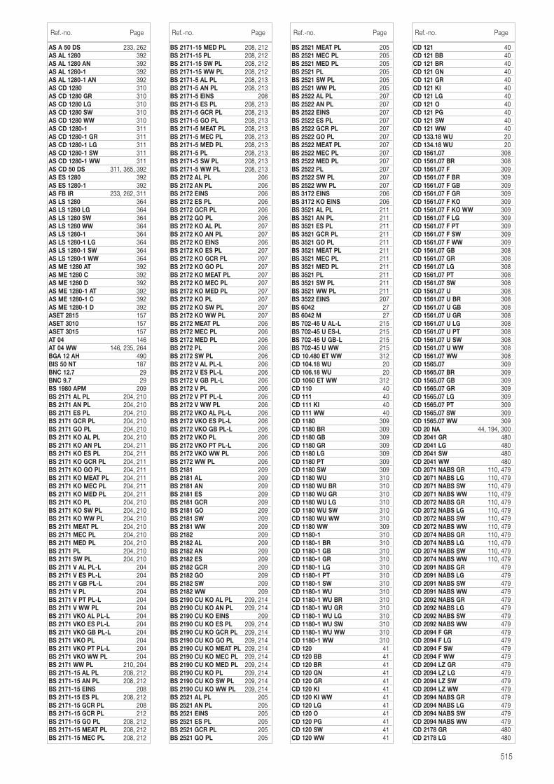
515
AS A 50 DS 233, 262AS AL 1280 392AS AL 1280 AN 392AS AL 1280-1 392AS AL 1280-1 AN 392AS CD 1280 310AS CD 1280 GR 310AS CD 1280 LG 310AS CD 1280 SW 310AS CD 1280 WW 310AS CD 1280-1 311AS CD 1280-1 GR 311AS CD 1280-1 LG 311AS CD 1280-1 SW 311AS CD 1280-1 WW 311AS CD 50 DS 311, 365, 392AS ES 1280 392AS ES 1280-1 392AS FB IR 233, 262, 311AS LS 1280 364AS LS 1280 LG 364AS LS 1280 SW 364AS LS 1280 WW 364AS LS 1280-1 364AS LS 1280-1 LG 364AS LS 1280-1 SW 364AS LS 1280-1 WW 364AS ME 1280 AT 392AS ME 1280 C 392AS ME 1280 D 392AS ME 1280-1 AT 392AS ME 1280-1 C 392AS ME 1280-1 D 392ASET 2815 157ASET 3010 157ASET 3015 157AT 04 146AT 04 WW 146, 235, 264BGA 12 AH 490BIS 50 NT 187BNC 12.7 29BNC 9.7 29BS 1980 APM 209BS 2171 AL PL 204, 210BS 2171 AN PL 204, 210BS 2171 ES PL 204, 210BS 2171 GCR PL 204, 210BS 2171 GO PL 204, 210BS 2171 KO AL PL 204, 210BS 2171 KO AN PL 204, 211BS 2171 KO ES PL 204, 211BS 2171 KO GCR PL 204, 211BS 2171 KO GO PL 204, 211BS 2171 KO MEAT PL 204, 211BS 2171 KO MEC PL 204, 211BS 2171 KO MED PL 204, 211BS 2171 KO PL 204, 210BS 2171 KO SW PL 204, 210BS 2171 KO WW PL 204, 210BS 2171 MEAT PL 204, 210BS 2171 MEC PL 204, 210BS 2171 MED PL 204, 210BS 2171 PL 204, 210BS 2171 SW PL 204, 210BS 2171 V AL PL-L 204BS 2171 V ES PL-L 204BS 2171 V GB PL-L 204BS 2171 V PL 204BS 2171 V PT PL-L 204BS 2171 V WW PL 204BS 2171 VKO AL PL-L 204BS 2171 VKO ES PL-L 204BS 2171 VKO GB PL-L 204BS 2171 VKO PL 204BS 2171 VKO PT PL-L 204BS 2171 VKO WW PL 204BS 2171 WW PL 210, 204BS 2171-15 AL PL 208, 212BS 2171-15 AN PL 208, 212BS 2171-15 EINS 208BS 2171-15 ES PL 208, 212BS 2171-15 GCR PL 208BS 2171-15 GCR PL 212BS 2171-15 GO PL 208, 212BS 2171-15 MEAT PL 208, 212BS 2171-15 MEC PL 208, 212
BS 2171-15 MED PL 208, 212BS 2171-15 PL 208, 212BS 2171-15 SW PL 208, 212BS 2171-15 WW PL 208, 212BS 2171-5 AL PL 208, 213BS 2171-5 AN PL 208, 213BS 2171-5 EINS 208BS 2171-5 ES PL 208, 213BS 2171-5 GCR PL 208, 213BS 2171-5 GO PL 208, 213BS 2171-5 MEAT PL 208, 213BS 2171-5 MEC PL 208, 213BS 2171-5 MED PL 208, 213BS 2171-5 PL 208, 213BS 2171-5 SW PL 208, 213BS 2171-5 WW PL 208, 213BS 2172 AL PL 206BS 2172 AN PL 206BS 2172 EINS 206BS 2172 ES PL 206BS 2172 GCR PL 206BS 2172 GO PL 206BS 2172 KO AL PL 207BS 2172 KO AN PL 207BS 2172 KO EINS 206BS 2172 KO ES PL 207BS 2172 KO GCR PL 207BS 2172 KO GO PL 207BS 2172 KO MEAT PL 207BS 2172 KO MEC PL 207BS 2172 KO MED PL 207BS 2172 KO PL 207BS 2172 KO SW PL 207BS 2172 KO WW PL 207BS 2172 MEAT PL 206BS 2172 MEC PL 206BS 2172 MED PL 206BS 2172 PL 206BS 2172 SW PL 206BS 2172 V AL PL-L 206BS 2172 V ES PL-L 206BS 2172 V GB PL-L 206BS 2172 V PL 206BS 2172 V PT PL-L 206BS 2172 V WW PL 206BS 2172 VKO AL PL-L 206BS 2172 VKO ES PL-L 206BS 2172 VKO GB PL-L 206BS 2172 VKO PL 206BS 2172 VKO PT PL-L 206BS 2172 VKO WW PL 206BS 2172 WW PL 206BS 2181 209BS 2181 AL 209BS 2181 AN 209BS 2181 ES 209BS 2181 GCR 209BS 2181 GO 209BS 2181 SW 209BS 2181 WW 209BS 2182 209BS 2182 AL 209BS 2182 AN 209BS 2182 ES 209BS 2182 GCR 209BS 2182 GO 209BS 2182 SW 209BS 2182 WW 209BS 2190 CU KO AL PL 209, 214BS 2190 CU KO AN PL 209, 214BS 2190 CU KO EINS 209BS 2190 CU KO ES PL 209, 214BS 2190 CU KO GCR PL 209, 214BS 2190 CU KO GO PL 209, 214BS 2190 CU KO MEAT PL 209, 214BS 2190 CU KO MEC PL 209, 214BS 2190 CU KO MED PL 209, 214BS 2190 CU KO PL 209, 214BS 2190 CU KO SW PL 209, 214BS 2190 CU KO WW PL 209, 214BS 2521 AL PL 205BS 2521 AN PL 205BS 2521 EINS 205BS 2521 ES PL 205BS 2521 GCR PL 205BS 2521 GO PL 205
BS 2521 MEAT PL 205BS 2521 MEC PL 205BS 2521 MED PL 205BS 2521 PL 205BS 2521 SW PL 205BS 2521 WW PL 205BS 2522 AL PL 207BS 2522 AN PL 207BS 2522 EINS 207BS 2522 ES PL 207BS 2522 GCR PL 207BS 2522 GO PL 207BS 2522 MEAT PL 207BS 2522 MEC PL 207BS 2522 MED PL 207BS 2522 PL 207BS 2522 SW PL 207BS 2522 WW PL 207BS 3172 EINS 206BS 3172 KO EINS 206BS 3521 AL PL 211BS 3521 AN PL 211BS 3521 ES PL 211BS 3521 GCR PL 211BS 3521 GO PL 211BS 3521 MEAT PL 211BS 3521 MEC PL 211BS 3521 MED PL 211BS 3521 PL 211BS 3521 SW PL 211BS 3521 WW PL 211BS 3522 EINS 207BS 6042 27BS 6042 M 27BS 702-45 U AL-L 215BS 702-45 U ES-L 215BS 702-45 U GB-L 215BS 702-45 U WW 215CD 10.480 ET WW 312CD 104.18 WU 20CD 106.18 WU 20CD 1060 ET WW 312CD 110 40CD 111 40CD 111 KI 40CD 111 WW 40CD 1180 309CD 1180 BR 309CD 1180 GB 309CD 1180 GR 309CD 1180 LG 309CD 1180 PT 309CD 1180 SW 309CD 1180 WU 310CD 1180 WU BR 310CD 1180 WU GR 310CD 1180 WU LG 310CD 1180 WU SW 310CD 1180 WU WW 310CD 1180 WW 309CD 1180-1 310CD 1180-1 BR 310CD 1180-1 GB 310CD 1180-1 GR 310CD 1180-1 LG 310CD 1180-1 PT 310CD 1180-1 SW 310CD 1180-1 WU 310CD 1180-1 WU BR 310CD 1180-1 WU GR 310CD 1180-1 WU LG 310CD 1180-1 WU SW 310CD 1180-1 WU WW 310CD 1180-1 WW 310CD 120 41CD 120 BB 41CD 120 BR 41CD 120 GN 41CD 120 GR 41CD 120 KI 41CD 120 KI WW 41CD 120 LG 41CD 120 O 41CD 120 PG 41CD 120 SW 41CD 120 WW 41
Ref.-no. Page Ref.-no. Page Ref.-no. Page
CD 121 40CD 121 BB 40CD 121 BR 40CD 121 GN 40CD 121 GR 40CD 121 KI 40CD 121 LG 40CD 121 O 40CD 121 PG 40CD 121 SW 40CD 121 WW 40CD 133.18 WU 20CD 134.18 WU 20CD 1561.07 308CD 1561.07 BR 308CD 1561.07 F 309CD 1561.07 F BR 309CD 1561.07 F GB 309CD 1561.07 F GR 309CD 1561.07 F KO 309CD 1561.07 F KO WW 309CD 1561.07 F LG 309CD 1561.07 F PT 309CD 1561.07 F SW 309CD 1561.07 F WW 309CD 1561.07 GB 308CD 1561.07 GR 308CD 1561.07 LG 308CD 1561.07 PT 308CD 1561.07 SW 308CD 1561.07 U 308CD 1561.07 U BR 308CD 1561.07 U GB 308CD 1561.07 U GR 308CD 1561.07 U LG 308CD 1561.07 U PT 308CD 1561.07 U SW 308CD 1561.07 U WW 308CD 1561.07 WW 308CD 1565.07 309CD 1565.07 BR 309CD 1565.07 GB 309CD 1565.07 GR 309CD 1565.07 LG 309CD 1565.07 PT 309CD 1565.07 SW 309CD 1565.07 WW 309CD 20 NA 44, 194, 300CD 2041 GR 480CD 2041 LG 480CD 2041 SW 480CD 2041 WW 480CD 2071 NABS GR 110, 479CD 2071 NABS LG 110, 479CD 2071 NABS SW 110, 479CD 2071 NABS WW 110, 479CD 2072 NABS GR 110, 479CD 2072 NABS LG 110, 479CD 2072 NABS SW 110, 479CD 2072 NABS WW 110, 479CD 2074 NABS GR 110, 479CD 2074 NABS LG 110, 479CD 2074 NABS SW 110, 479CD 2074 NABS WW 110, 479CD 2091 NABS GR 479CD 2091 NABS LG 479CD 2091 NABS SW 479CD 2091 NABS WW 479CD 2092 NABS GR 479CD 2092 NABS LG 479CD 2092 NABS SW 479CD 2092 NABS WW 479CD 2094 F GR 479CD 2094 F LG 479CD 2094 F SW 479CD 2094 F WW 479CD 2094 LZ GR 479CD 2094 LZ LG 479CD 2094 LZ SW 479CD 2094 LZ WW 479CD 2094 NABS GR 479CD 2094 NABS LG 479CD 2094 NABS SW 479CD 2094 NABS WW 479CD 2178 GR 480CD 2178 LG 480
Ref.-no. Page
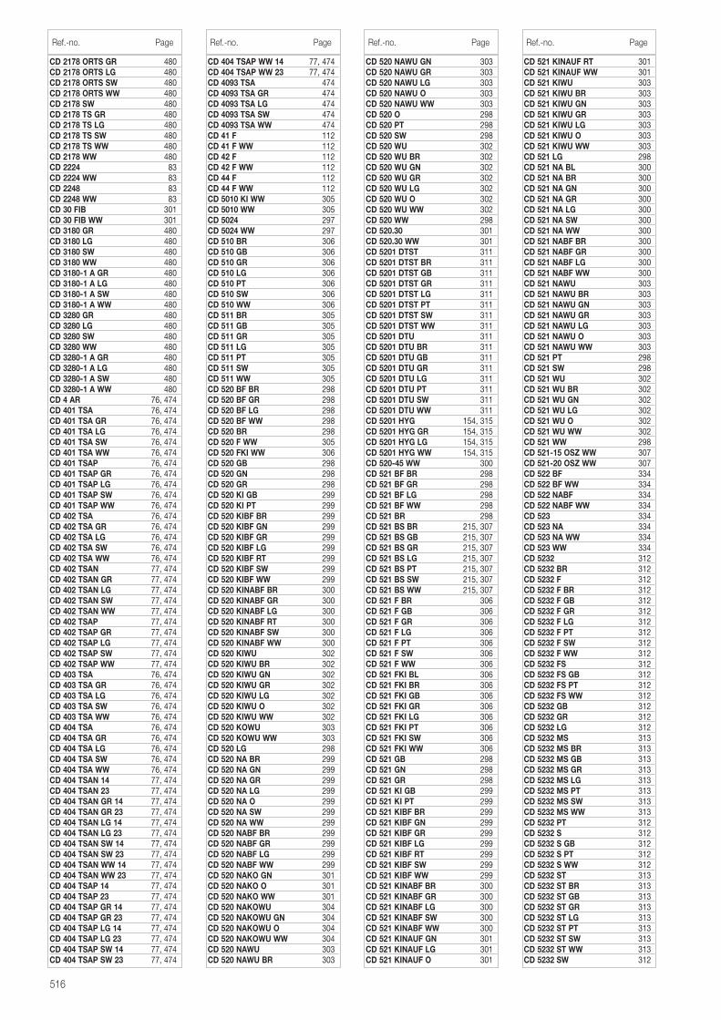
516
CD 2178 ORTS GR 480CD 2178 ORTS LG 480CD 2178 ORTS SW 480CD 2178 ORTS WW 480CD 2178 SW 480CD 2178 TS GR 480CD 2178 TS LG 480CD 2178 TS SW 480CD 2178 TS WW 480CD 2178 WW 480CD 2224 83CD 2224 WW 83CD 2248 83CD 2248 WW 83CD 30 FIB 301CD 30 FIB WW 301CD 3180 GR 480CD 3180 LG 480CD 3180 SW 480CD 3180 WW 480CD 3180-1 A GR 480CD 3180-1 A LG 480CD 3180-1 A SW 480CD 3180-1 A WW 480CD 3280 GR 480CD 3280 LG 480CD 3280 SW 480CD 3280 WW 480CD 3280-1 A GR 480CD 3280-1 A LG 480CD 3280-1 A SW 480CD 3280-1 A WW 480CD 4 AR 76, 474CD 401 TSA 76, 474CD 401 TSA GR 76, 474CD 401 TSA LG 76, 474CD 401 TSA SW 76, 474CD 401 TSA WW 76, 474CD 401 TSAP 76, 474CD 401 TSAP GR 76, 474CD 401 TSAP LG 76, 474CD 401 TSAP SW 76, 474CD 401 TSAP WW 76, 474CD 402 TSA 76, 474CD 402 TSA GR 76, 474CD 402 TSA LG 76, 474CD 402 TSA SW 76, 474CD 402 TSA WW 76, 474CD 402 TSAN 77, 474CD 402 TSAN GR 77, 474CD 402 TSAN LG 77, 474CD 402 TSAN SW 77, 474CD 402 TSAN WW 77, 474CD 402 TSAP 77, 474CD 402 TSAP GR 77, 474CD 402 TSAP LG 77, 474CD 402 TSAP SW 77, 474CD 402 TSAP WW 77, 474CD 403 TSA 76, 474CD 403 TSA GR 76, 474CD 403 TSA LG 76, 474CD 403 TSA SW 76, 474CD 403 TSA WW 76, 474CD 404 TSA 76, 474CD 404 TSA GR 76, 474CD 404 TSA LG 76, 474CD 404 TSA SW 76, 474CD 404 TSA WW 76, 474CD 404 TSAN 14 77, 474CD 404 TSAN 23 77, 474CD 404 TSAN GR 14 77, 474CD 404 TSAN GR 23 77, 474CD 404 TSAN LG 14 77, 474CD 404 TSAN LG 23 77, 474CD 404 TSAN SW 14 77, 474CD 404 TSAN SW 23 77, 474CD 404 TSAN WW 14 77, 474CD 404 TSAN WW 23 77, 474CD 404 TSAP 14 77, 474CD 404 TSAP 23 77, 474CD 404 TSAP GR 14 77, 474CD 404 TSAP GR 23 77, 474CD 404 TSAP LG 14 77, 474CD 404 TSAP LG 23 77, 474CD 404 TSAP SW 14 77, 474CD 404 TSAP SW 23 77, 474
CD 404 TSAP WW 14 77, 474CD 404 TSAP WW 23 77, 474CD 4093 TSA 474CD 4093 TSA GR 474CD 4093 TSA LG 474CD 4093 TSA SW 474CD 4093 TSA WW 474CD 41 F 112CD 41 F WW 112CD 42 F 112CD 42 F WW 112CD 44 F 112CD 44 F WW 112CD 5010 KI WW 305CD 5010 WW 305CD 5024 297CD 5024 WW 297CD 510 BR 306CD 510 GB 306CD 510 GR 306CD 510 LG 306CD 510 PT 306CD 510 SW 306CD 510 WW 306CD 511 BR 305CD 511 GB 305CD 511 GR 305CD 511 LG 305CD 511 PT 305CD 511 SW 305CD 511 WW 305CD 520 BF BR 298CD 520 BF GR 298CD 520 BF LG 298CD 520 BF WW 298CD 520 BR 298CD 520 F WW 305CD 520 FKI WW 306CD 520 GB 298CD 520 GN 298CD 520 GR 298CD 520 KI GB 299CD 520 KI PT 299CD 520 KIBF BR 299CD 520 KIBF GN 299CD 520 KIBF GR 299CD 520 KIBF LG 299CD 520 KIBF RT 299CD 520 KIBF SW 299CD 520 KIBF WW 299CD 520 KINABF BR 300CD 520 KINABF GR 300CD 520 KINABF LG 300CD 520 KINABF RT 300CD 520 KINABF SW 300CD 520 KINABF WW 300CD 520 KIWU 302CD 520 KIWU BR 302CD 520 KIWU GN 302CD 520 KIWU GR 302CD 520 KIWU LG 302CD 520 KIWU O 302CD 520 KIWU WW 302CD 520 KOWU 303CD 520 KOWU WW 303CD 520 LG 298CD 520 NA BR 299CD 520 NA GN 299CD 520 NA GR 299CD 520 NA LG 299CD 520 NA O 299CD 520 NA SW 299CD 520 NA WW 299CD 520 NABF BR 299CD 520 NABF GR 299CD 520 NABF LG 299CD 520 NABF WW 299CD 520 NAKO GN 301CD 520 NAKO O 301CD 520 NAKO WW 301CD 520 NAKOWU 304CD 520 NAKOWU GN 304CD 520 NAKOWU O 304CD 520 NAKOWU WW 304CD 520 NAWU 303CD 520 NAWU BR 303
CD 520 NAWU GN 303CD 520 NAWU GR 303CD 520 NAWU LG 303CD 520 NAWU O 303CD 520 NAWU WW 303CD 520 O 298CD 520 PT 298CD 520 SW 298CD 520 WU 302CD 520 WU BR 302CD 520 WU GN 302CD 520 WU GR 302CD 520 WU LG 302CD 520 WU O 302CD 520 WU WW 302CD 520 WW 298CD 520.30 301CD 520.30 WW 301CD 5201 DTST 311CD 5201 DTST BR 311CD 5201 DTST GB 311CD 5201 DTST GR 311CD 5201 DTST LG 311CD 5201 DTST PT 311CD 5201 DTST SW 311CD 5201 DTST WW 311CD 5201 DTU 311CD 5201 DTU BR 311CD 5201 DTU GB 311CD 5201 DTU GR 311CD 5201 DTU LG 311CD 5201 DTU PT 311CD 5201 DTU SW 311CD 5201 DTU WW 311CD 5201 HYG 154, 315CD 5201 HYG GR 154, 315CD 5201 HYG LG 154, 315CD 5201 HYG WW 154, 315CD 520-45 WW 300CD 521 BF BR 298CD 521 BF GR 298CD 521 BF LG 298CD 521 BF WW 298CD 521 BR 298CD 521 BS BR 215, 307CD 521 BS GB 215, 307CD 521 BS GR 215, 307CD 521 BS LG 215, 307CD 521 BS PT 215, 307CD 521 BS SW 215, 307CD 521 BS WW 215, 307CD 521 F BR 306CD 521 F GB 306CD 521 F GR 306CD 521 F LG 306CD 521 F PT 306CD 521 F SW 306CD 521 F WW 306CD 521 FKI BL 306CD 521 FKI BR 306CD 521 FKI GB 306CD 521 FKI GR 306CD 521 FKI LG 306CD 521 FKI PT 306CD 521 FKI SW 306CD 521 FKI WW 306CD 521 GB 298CD 521 GN 298CD 521 GR 298CD 521 KI GB 299CD 521 KI PT 299CD 521 KIBF BR 299CD 521 KIBF GN 299CD 521 KIBF GR 299CD 521 KIBF LG 299CD 521 KIBF RT 299CD 521 KIBF SW 299CD 521 KIBF WW 299CD 521 KINABF BR 300CD 521 KINABF GR 300CD 521 KINABF LG 300CD 521 KINABF SW 300CD 521 KINABF WW 300CD 521 KINAUF GN 301CD 521 KINAUF LG 301CD 521 KINAUF O 301
Ref.-no. Page Ref.-no. Page Ref.-no. Page
CD 521 KINAUF RT 301CD 521 KINAUF WW 301CD 521 KIWU 303CD 521 KIWU BR 303CD 521 KIWU GN 303CD 521 KIWU GR 303CD 521 KIWU LG 303CD 521 KIWU O 303CD 521 KIWU WW 303CD 521 LG 298CD 521 NA BL 300CD 521 NA BR 300CD 521 NA GN 300CD 521 NA GR 300CD 521 NA LG 300CD 521 NA SW 300CD 521 NA WW 300CD 521 NABF BR 300CD 521 NABF GR 300CD 521 NABF LG 300CD 521 NABF WW 300CD 521 NAWU 303CD 521 NAWU BR 303CD 521 NAWU GN 303CD 521 NAWU GR 303CD 521 NAWU LG 303CD 521 NAWU O 303CD 521 NAWU WW 303CD 521 PT 298CD 521 SW 298CD 521 WU 302CD 521 WU BR 302CD 521 WU GN 302CD 521 WU LG 302CD 521 WU O 302CD 521 WU WW 302CD 521 WW 298CD 521-15 OSZ WW 307CD 521-20 OSZ WW 307CD 522 BF 334CD 522 BF WW 334CD 522 NABF 334CD 522 NABF WW 334CD 523 334CD 523 NA 334CD 523 NA WW 334CD 523 WW 334CD 5232 312CD 5232 BR 312CD 5232 F 312CD 5232 F BR 312CD 5232 F GB 312CD 5232 F GR 312CD 5232 F LG 312CD 5232 F PT 312CD 5232 F SW 312CD 5232 F WW 312CD 5232 FS 312CD 5232 FS GB 312CD 5232 FS PT 312CD 5232 FS WW 312CD 5232 GB 312CD 5232 GR 312CD 5232 LG 312CD 5232 MS 313CD 5232 MS BR 313CD 5232 MS GB 313CD 5232 MS GR 313CD 5232 MS LG 313CD 5232 MS PT 313CD 5232 MS SW 313CD 5232 MS WW 313CD 5232 PT 312CD 5232 S 312CD 5232 S GB 312CD 5232 S PT 312CD 5232 S WW 312CD 5232 ST 313CD 5232 ST BR 313CD 5232 ST GB 313CD 5232 ST GR 313CD 5232 ST LG 313CD 5232 ST PT 313CD 5232 ST SW 313CD 5232 ST WW 313CD 5232 SW 312
Ref.-no. Page
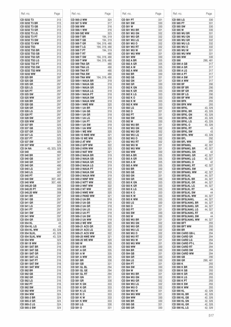
517
CD 5232 T3 313CD 5232 T3 BR 313CD 5232 T3 GB 313CD 5232 T3 GR 313CD 5232 T3 LG 313CD 5232 T3 PT 313CD 5232 T3 SW 313CD 5232 T3 WW 313CD 5232 TS3 313CD 5232 TS3 BR 313CD 5232 TS3 GB 313CD 5232 TS3 GR 313CD 5232 TS3 LG 313CD 5232 TS3 PT 313CD 5232 TS3 SW 313CD 5232 TS3 WW 313CD 5232 WW 312CD 525 BR 297CD 525 GB 297CD 525 GR 297CD 525 LG 297CD 525 PT 297CD 525 SW 297CD 525 WW 297CD 528 BR 297CD 528 GB 297CD 528 GR 297CD 528 LG 297CD 528 PT 297CD 528 SW 297CD 528 WW 297CD 537 BR 325CD 537 GB 325CD 537 GR 325CD 537 LG 325CD 537 PT 325CD 537 SW 325CD 537 WW 325CD 54 NA 43, 323, 328CD 540 480CD 540 BR 307CD 540 GB 307CD 540 GR 307CD 540 GR 480CD 540 LG 307CD 540 LG 480CD 540 PT 307CD 540 SW 307, 480CD 540 WW 307, 480CD 540.20 GB 308CD 540.20 PT 308CD 540.20 WW 308CD 541 BR 297CD 541 GB 297CD 541 GR 297CD 541 LG 297CD 541 PT 297CD 541 SW 297CD 541 WW 297CD 554 GR 323CD 554 KL 43CD 554 KL LG 43CD 554 KL WW 43, 328CD 554 SLKL 43, 328CD 554 SLKL WW 43, 328CD 554 WW 323CD 561 B WW 324CD 561 SAT BR 316CD 561 SAT GB 316CD 561 SAT GR 316CD 561 SAT LG 316CD 561 SAT PT 316CD 561 SAT SW 316CD 561 SAT WW 316CD 562 BR 316CD 562 GB 316CD 562 GR 316CD 562 LG 316CD 562 PT 316CD 562 SW 316CD 562 WW 316CD 564 WW 324CD 565-2 BR 324CD 565-2 GR 324CD 565-2 LG 324CD 565-2 SW 324
CD 565-2 WW 324CD 567 S WW 317CD 568 WW 316CD 568-1 WW 316CD 569 SIE WW 323CD 569 T BR 194, 319CD 569 T GB 194, 319CD 569 T GR 194, 319, 480CD 569 T LG 194, 319, 480CD 569 T PT 194, 319CD 569 T RT 480CD 569 T SW 194, 319, 480CD 569 T WW 194, 319, 480CD 569 TNA GR 480CD 569 TNA LG 480CD 569 TNA RT 480CD 569 TNA SW 480CD 569 TNA WW 194, 319, 480CD 569-1 NAUA BR 318CD 569-1 NAUA GB 318CD 569-1 NAUA GR 318CD 569-1 NAUA LG 318CD 569-1 NAUA PT 318CD 569-1 NAUA SW 318CD 569-1 NAUA WW 318CD 569-1 NWE WW 320CD 569-1 UA BR 318CD 569-1 UA GB 318CD 569-1 UA GR 318CD 569-1 UA LG 318CD 569-1 UA PT 318CD 569-1 UA SW 318CD 569-1 UA WW 318CD 569-1 WE WW 320CD 569-15 NWE WW 321CD 569-15 WE WW 320CD 569-2 AT WW 321CD 569-2 GFP WW 322CD 569-2 KRN WW 323CD 569-2 NAT WW 321CD 569-2 NAUA BR 319CD 569-2 NAUA GB 319CD 569-2 NAUA GR 319CD 569-2 NAUA LG 319CD 569-2 NAUA PT 319CD 569-2 NAUA SW 319CD 569-2 NAUA WW 319CD 569-2 NINF WW 322CD 569-2 NITT WW 322CD 569-2 NNT WW 322CD 569-2 NT WW 322CD 569-2 NWE WW 320CD 569-2 PAND WW 321CD 569-2 UA BR 318CD 569-2 UA GB 318CD 569-2 UA GR 318CD 569-2 UA LG 318CD 569-2 UA PT 318CD 569-2 UA SW 318CD 569-2 UA WW 318CD 569-2 WE WW 320CD 569-21 ACS GR 322CD 569-21 ACS LG 322CD 569-21 ACS WW 322CD 569-25 NWE WW 321CD 569-25 WE WW 320CD 580 W 328CD 581 A BR 335CD 581 A GR 335CD 581 A W 335CD 581 A WW 335CD 581 BR 330CD 581 GB 331CD 581 GL BL 294CD 581 GL GE 294CD 581 GL RT 294CD 581 GN 331CD 581 GR 330CD 581 K GN 333CD 581 K GR 333CD 581 K LG 333CD 581 K O 333CD 581 K W 333CD 581 K WW 333CD 581 LG 330CD 581 O 331
CD 581 PT 331CD 581 SW 330CD 581 W 330CD 581 WU BR 331CD 581 WU GN 332CD 581 WU GR 332CD 581 WU LG 332CD 581 WU O 332CD 581 WU RT 332CD 581 WU W 331CD 581 WU WW 331CD 581 WW 330CD 582 A BR 335CD 582 A GR 335CD 582 A W 335CD 582 A WW 335CD 582 BR 330CD 582 GB 331CD 582 GN 331CD 582 GR 330CD 582 K GN 333CD 582 K GR 333CD 582 K LG 333CD 582 K O 333CD 582 K W 333CD 582 K WW 333CD 582 LG 330CD 582 O 331CD 582 PT 331CD 582 SW 330CD 582 W 330CD 582 WU BR 331CD 582 WU GN 332CD 582 WU GR 332CD 582 WU LG 332CD 582 WU O 332CD 582 WU RT 332CD 582 WU W 331CD 582 WU WW 331CD 582 WW 330CD 583 A BR 335CD 583 A GR 335CD 583 A W 335CD 583 A WW 335CD 583 BR 330CD 583 GB 331CD 583 GN 331CD 583 GR 330CD 583 K GN 333CD 583 K GR 333CD 583 K LG 333CD 583 K O 333CD 583 K W 333CD 583 K WW 333CD 583 LG 330CD 583 O 331CD 583 PT 331CD 583 SW 330CD 583 W 330CD 583 WU BR 331CD 583 WU GN 332CD 583 WU GR 332CD 583 WU LG 332CD 583 WU O 332CD 583 WU RT 332CD 583 WU W 331CD 583 WU WW 331CD 583 WW 330CD 584 BR 330CD 584 GB 331CD 584 GR 330CD 584 LG 330CD 584 PT 331CD 584 SW 330CD 584 W 330CD 584 WU BR 331CD 584 WU GN 332CD 584 WU GR 332CD 584 WU LG 332CD 584 WU O 332CD 584 WU W 331CD 584 WU WW 331CD 584 WW 330CD 585 BR 330CD 585 GB 331CD 585 GR 330
Ref.-no. Page Ref.-no. Page Ref.-no. Page
CD 585 LG 330CD 585 PT 331CD 585 SW 330CD 585 W 330CD 585 WU BR 331CD 585 WU GN 332CD 585 WU GR 332CD 585 WU LG 332CD 585 WU O 332CD 585 WU W 331CD 585 WU WW 331CD 585 WW 330CD 590 290, 481CD 590 A GB 317CD 590 A GR 317CD 590 A LG 317CD 590 A PT 317CD 590 A SW 317CD 590 A WW 317CD 590 BF 290CD 590 BF BR 290CD 590 BF GR 290CD 590 BF LG 290CD 590 BF WW 290CD 590 BFK 293CD 590 BFK WW 293CD 590 BFKL 43, 326CD 590 BFKL BR 43, 326CD 590 BFKL GN 43, 326CD 590 BFKL GR 43, 326CD 590 BFKL LG 43, 326CD 590 BFKL O 43, 326CD 590 BFKL RT 43CD 590 BFKL SW 43CD 590 BFKL WW 43, 326CD 590 BFL 292CD 590 BFL WW 292CD 590 BFNAKL 42, 327CD 590 BFNAKL BR 42, 327CD 590 BFNAKL GN 42CD 590 BFNAKL GR 42, 327CD 590 BFNAKL LG 42, 327CD 590 BFNAKL O 42CD 590 BFNAKL RT 42, 327CD 590 BFNAKL SW 42CD 590 BFNAKL WW 42, 327CD 590 BFSLKL 44, 327CD 590 BFSLKL BR 44, 327CD 590 BFSLKL GR 44, 327CD 590 BFSLKL LG 44, 327CD 590 BFSLKL RT 44CD 590 BFSLKL SW 44CD 590 BFSLKL WW 44, 327CD 590 BFSLNAKL 44, 327CD 590 BFSLNAKL BR 44, 327CD 590 BFSLNAKL GR 44, 327CD 590 BFSLNAKL LG 44, 327CD 590 BFSLNAKL RT 44CD 590 BFSLNAKL SW 44CD 590 BFSLNAKL WW 44, 327CD 590 BFT 293CD 590 BFT WW 293CD 590 BR 290CD 590 CARD GB-L 294CD 590 CARD GR 294CD 590 CARD LG 294CD 590 CARD PT-L 294CD 590 CARD RT 294CD 590 CARD SW 294CD 590 CARD WW 294CD 590 GB 290CD 590 GR 290, 481CD 590 K 293CD 590 K BR 293CD 590 K GB 293CD 590 K GR 293CD 590 K LG 293CD 590 K PT 293CD 590 K SW 293CD 590 K WW 293CD 590 KL 42, 326CD 590 KL BR 42, 326CD 590 KL GB 42, 326CD 590 KL GN 42, 326CD 590 KL GR 42, 326CD 590 KL LG 42, 326
Ref.-no. Page
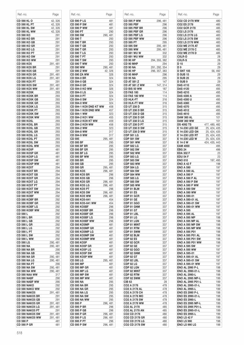
518
CD 590 KL O 42, 326CD 590 KL PT 42, 326CD 590 KL SW 42, 326CD 590 KL WW 42, 326CD 590 KO 291CD 590 KO BR 291CD 590 KO GB 291CD 590 KO GR 291CD 590 KO LG 291CD 590 KO PT 291CD 590 KO SW 291CD 590 KO WW 291CD 590 KO5 291, 481CD 590 KO5 BR 291CD 590 KO5 GB 291CD 590 KO5 GR 291, 481CD 590 KO5 LG 291, 481CD 590 KO5 PT 291CD 590 KO5 SW 291, 481CD 590 KO5 WW 291, 481CD 590 KO5K 293CD 590 KO5K BR 293CD 590 KO5K GB 293CD 590 KO5K GR 293CD 590 KO5K LG 293CD 590 KO5K PT 293CD 590 KO5K SW 293CD 590 KO5K WW 293CD 590 KO5L 293CD 590 KO5L BR 293CD 590 KO5L GB 293CD 590 KO5L GR 293CD 590 KO5L LG 293CD 590 KO5L PT 293CD 590 KO5L SW 293CD 590 KO5L WW 293CD 590 KO5P 481CD 590 KO5P GR 481CD 590 KO5P LG 481CD 590 KO5P SW 481CD 590 KO5P WW 481CD 590 KO5T 294CD 590 KO5T BR 294CD 590 KO5T GB 294CD 590 KO5T GR 294CD 590 KO5T LG 294CD 590 KO5T PT 294CD 590 KO5T SW 294CD 590 KO5T WW 294CD 590 KOBF 292CD 590 KOBF BR 292CD 590 KOBF GR 292CD 590 KOBF LG 292CD 590 KOBF WW 292CD 590 L 292CD 590 L BR 292CD 590 L GB 292CD 590 L GR 292CD 590 L LG 292CD 590 L PT 292CD 590 L SW 292CD 590 L WW 292CD 590 LG 290, 481CD 590 NA 290, 481CD 590 NA BR 290CD 590 NA GB 290CD 590 NA GR 290, 481CD 590 NA LG 290, 481CD 590 NA PT 290CD 590 NA SW 290, 481CD 590 NA WW 290, 481CD 590 NAA WW 317CD 590 NABF 290CD 590 NABF WW 290CD 590 NAKO 292CD 590 NAKO WW 292CD 590 NAKO5 291, 481CD 590 NAKO5 BR 291CD 590 NAKO5 GB 291CD 590 NAKO5 GR 291, 481CD 590 NAKO5 LG 291, 481CD 590 NAKO5 PT 291CD 590 NAKO5 SW 291, 481CD 590 NAKO5 WW 291, 481CD 590 P 481CD 590 P GR 481
CD 590 P LG 481CD 590 P SW 481CD 590 P WW 481CD 590 PT 290CD 590 SW 290, 481CD 590 T 293CD 590 T BR 293CD 590 T GB 293CD 590 T GR 293CD 590 T LG 293CD 590 T PT 293CD 590 T SW 293CD 590 T WW 293CD 590 WW 290, 481CD 590 Z WW 42, 326CD 590 ZA WW 326CD 594-0 BR 324CD 594-0 GB 324CD 594-0 GR 324CD 594-0 KO WW 326CD 594-0 LG 324CD 594-0 PT 324CD 594-0 SW 324CD 594-0 WW 324CD 594-1 KO9 DND KT WW 458CD 594-1 KO9 DND WW 457CD 594-1 WW 323CD 594-2 KO1 WW 455CD 594-2 KO9 KT WW 459CD 594-2 KO9 WW 456CD 594-2 WW 323CD 594-8 WW 317CD 594-9 WW 317CD 595 295, 481CD 595 BF 295CD 595 BF BR 295CD 595 BF GR 295CD 595 BF LG 295CD 595 BF WW 295CD 595 BR 295CD 595 GB 295CD 595 GR 295, 481CD 595 KO5 296, 481CD 595 KO5 BR 296CD 595 KO5 GB 296CD 595 KO5 GR 296, 481CD 595 KO5 LG 296, 481CD 595 KO5 PT 296CD 595 KO5 SW 296, 481CD 595 KO5 WW 296, 481CD 595 KO5-641 454CD 595 KO5-641 WW 454CD 595 KO5BF 296CD 595 KO5BF BR 296CD 595 KO5BF GR 296CD 595 KO5BF LG 296CD 595 KO5BF WW 296CD 595 KO5MP 481CD 595 KO5MP GR 481CD 595 KO5MP LG 481CD 595 KO5MP SW 481CD 595 KO5MP WW 481CD 595 KO5P 481CD 595 KO5P GR 481CD 595 KO5P LG 481CD 595 KO5P SW 481CD 595 KO5P WW 481CD 595 LG 295, 481CD 595 MP 481CD 595 MP GR 481CD 595 MP LG 481CD 595 MP SW 481CD 595 MP WW 481CD 595 NA 295CD 595 NA BR 295CD 595 NA GR 295CD 595 NA LG 295CD 595 NA SW 295CD 595 NA WW 295CD 595 P 296, 481CD 595 P BR 296CD 595 P GB 296CD 595 P GR 296, 481CD 595 P LG 296, 481CD 595 P PT 296CD 595 P SW 296, 481
CD 595 P WW 296, 481CD 595 PBF 296CD 595 PBF BR 296CD 595 PBF GR 296CD 595 PBF LG 296CD 595 PBF WW 296CD 595 PT 295CD 595 SW 295, 481CD 595 WW 295, 481CD 681 WU W 332CD 681 WU WW 332CD 90 HP 294, 355, 382CD 90 MHP 294CD 90 NA 291, 292, 354CD 95 HP 296, 357, 383CD 95 MHP 296CD 95 NA 295CD AT 581 Z 147CD AT 581 Z WW 147, 314CD BIS 50 WW 187CD FAS 180 114CD FAS 180 WW 114CD HLK-FT 316CD HLK-FT WW 316CD UT 238 D 315CD UT 238 D BR 315CD UT 238 D GB 315CD UT 238 D GR 315CD UT 238 D LG 315CD UT 238 D PT 315CD UT 238 D SW 315CD UT 238 D WW 315CDP 581 LG 337CDP 581 SW 337CDP 581 WW 337CDP 582 LG 337CDP 582 SW 337CDP 582 WW 337CDP 583 LG 337CDP 583 SW 337CDP 583 WW 337CDP 584 LG 337CDP 584 SW 337CDP 584 WW 337CDP 585 LG 337CDP 585 SW 337CDP 585 WW 337CDP 81 BLM 337CDP 81 ES 337CDP 81 GCR 337CDP 81 GE 337CDP 81 GGO 337CDP 81 GNM 337CDP 81 GT 337CDP 81 LBL 337CDP 81 LG 337CDP 81 LGN 337CDP 81 MINT 337CDP 81 RTM 337CDP 81 SWM 337CDP 82 BLM 337CDP 82 ES 337CDP 82 GCR 337CDP 82 GE 337CDP 82 GGO 337CDP 82 GNM 337CDP 82 GT 337CDP 82 LBL 337CDP 82 LG 337CDP 82 LGN 337CDP 82 MINT 337CDP 82 RTM 337CDP 82 SWM 337CIB 63 28CO2 A 2178 478CO2 A 2178 AL 478CO2 A 2178 CH 478CO2 A 2178 MO 478CO2 A 2178 SW 478CO2 A 2178 WW 478CO2 AL 2178 485CO2 AL 2178 AN 485CO2 CD 2178 480CO2 CD 2178 GR 480CO2 CD 2178 LG 480CO2 CD 2178 SW 480
Ref.-no. Page Ref.-no. Page Ref.-no. Page
CO2 CD 2178 WW 480CO2 ES 2178 485CO2 GCR 2178 485CO2 LS 2178 483CO2 LS 2178 LG 483CO2 LS 2178 SW 483CO2 LS 2178 WW 483CO2 ME 2178 AT 485CO2 ME 2178 C 485CO2 ME 2178 D 485CXLR-D 28CXLR-S 28D 15 29D 9 29D SNT 105 56, 492D SUB 15 29D SUB 25 29D SUB 9 29DAS 4110 495DAS 4120 495DAS 4210 495DAS 4300 A 495DAS 4300 U 495DAS 4360 495DAS 4370 495DAS 4512 495DAS 4610 495DAW 360 AL 101DAW 360 WW 101DS 4092 TS 477, 480, 482E 14-230 LED GE 25, 424, 435E 14-230 LED GN 25, 424, 435E 14-230 LED RT 25, 424, 435E 14-230 LED W 25, 424, 435E 14-3 W 424, 435, 443EAM 4000 495EBG 24 496EDA 302 F 23EDU 04 F 23ENO 610 197, 495ENO A 42 F 198ENO A 590 197ENO A 590 AL 197ENO A 590 P 197ENO A 590 P AL 197ENO A 590 P SW 197ENO A 590 P WW 197ENO A 590 SW 197ENO A 590 WW 197ENO A 590-01 197ENO A 590-01 AL 197ENO A 590-01 SW 197ENO A 590-01 WW 197ENO A 595 197ENO A 595 AL 197ENO A 595 MP 198ENO A 595 MP AL 198ENO A 595 MP SW 198ENO A 595 MP WW 198ENO A 595 P01 198ENO A 595 P01 AL 198ENO A 595 P01 SW 198ENO A 595 P01 WW 198ENO A 595 SW 197ENO A 595 WW 197ENO A 595-01 197ENO A 595-01 AL 197ENO A 595-01 SW 197ENO A 595-01 WW 197ENO AL 2990 P-L 198ENO AL 2990-01-L 198ENO AL 2990-L 198ENO AL 2995 MP-L 199ENO AL 2995 P01-L 199ENO AL 2995-01-L 199ENO AL 2995-L 199ENO ES 2990 P-L 198ENO ES 2990-01-L 198ENO ES 2990-L 198ENO ES 2995 MP-L 199ENO ES 2995 P01-L 199ENO ES 2995-01-L 199ENO ES 2995-L 199ENO LS 42 F 199ENO LS 990 198ENO LS 990 LG 198
Ref.-no. Page
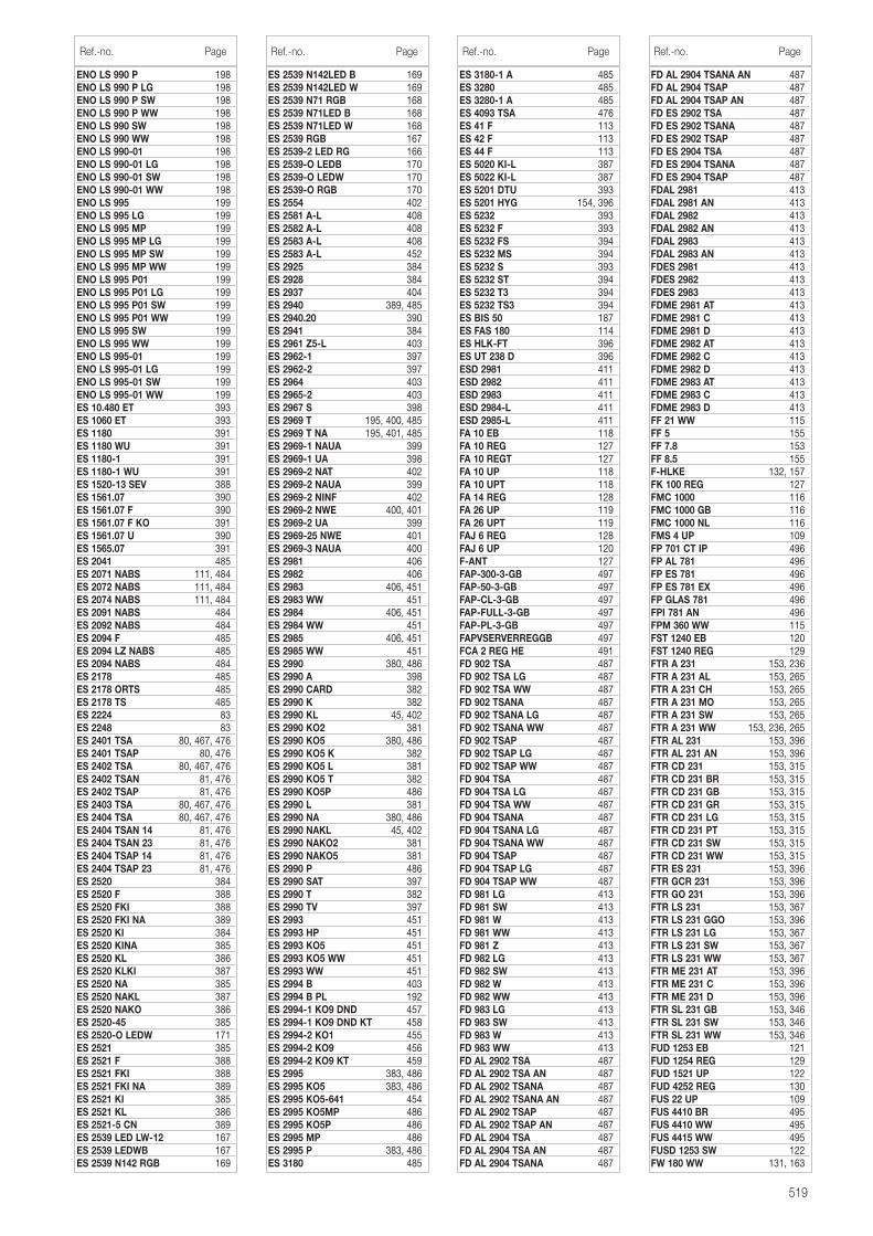
519
ENO LS 990 P 198ENO LS 990 P LG 198ENO LS 990 P SW 198ENO LS 990 P WW 198ENO LS 990 SW 198ENO LS 990 WW 198ENO LS 990-01 198ENO LS 990-01 LG 198ENO LS 990-01 SW 198ENO LS 990-01 WW 198ENO LS 995 199ENO LS 995 LG 199ENO LS 995 MP 199ENO LS 995 MP LG 199ENO LS 995 MP SW 199ENO LS 995 MP WW 199ENO LS 995 P01 199ENO LS 995 P01 LG 199ENO LS 995 P01 SW 199ENO LS 995 P01 WW 199ENO LS 995 SW 199ENO LS 995 WW 199ENO LS 995-01 199ENO LS 995-01 LG 199ENO LS 995-01 SW 199ENO LS 995-01 WW 199ES 10.480 ET 393ES 1060 ET 393ES 1180 391ES 1180 WU 391ES 1180-1 391ES 1180-1 WU 391ES 1520-13 SEV 388ES 1561.07 390ES 1561.07 F 390ES 1561.07 F KO 391ES 1561.07 U 390ES 1565.07 391ES 2041 485ES 2071 NABS 111, 484ES 2072 NABS 111, 484ES 2074 NABS 111, 484ES 2091 NABS 484ES 2092 NABS 484ES 2094 F 485ES 2094 LZ NABS 485ES 2094 NABS 484ES 2178 485ES 2178 ORTS 485ES 2178 TS 485ES 2224 83ES 2248 83ES 2401 TSA 80, 467, 476ES 2401 TSAP 80, 476ES 2402 TSA 80, 467, 476ES 2402 TSAN 81, 476ES 2402 TSAP 81, 476ES 2403 TSA 80, 467, 476ES 2404 TSA 80, 467, 476ES 2404 TSAN 14 81, 476ES 2404 TSAN 23 81, 476ES 2404 TSAP 14 81, 476ES 2404 TSAP 23 81, 476ES 2520 384ES 2520 F 388ES 2520 FKI 388ES 2520 FKI NA 389ES 2520 KI 384ES 2520 KINA 385ES 2520 KL 386ES 2520 KLKI 387ES 2520 NA 385ES 2520 NAKL 387ES 2520 NAKO 386ES 2520-45 385ES 2520-O LEDW 171ES 2521 385ES 2521 F 388ES 2521 FKI 388ES 2521 FKI NA 389ES 2521 KI 385ES 2521 KL 386ES 2521-5 CN 389ES 2539 LED LW-12 167ES 2539 LEDWB 167ES 2539 N142 RGB 169
ES 2539 N142LED B 169ES 2539 N142LED W 169ES 2539 N71 RGB 168ES 2539 N71LED B 168ES 2539 N71LED W 168ES 2539 RGB 167ES 2539-2 LED RG 166ES 2539-O LEDB 170ES 2539-O LEDW 170ES 2539-O RGB 170ES 2554 402ES 2581 A-L 408ES 2582 A-L 408ES 2583 A-L 408ES 2583 A-L 452ES 2925 384ES 2928 384ES 2937 404ES 2940 389, 485ES 2940.20 390ES 2941 384ES 2961 Z5-L 403ES 2962-1 397ES 2962-2 397ES 2964 403ES 2965-2 403ES 2967 S 398ES 2969 T 195, 400, 485ES 2969 T NA 195, 401, 485ES 2969-1 NAUA 399ES 2969-1 UA 398ES 2969-2 NAT 402ES 2969-2 NAUA 399ES 2969-2 NINF 402ES 2969-2 NWE 400, 401ES 2969-2 UA 399ES 2969-25 NWE 401ES 2969-3 NAUA 400ES 2981 406ES 2982 406ES 2983 406, 451ES 2983 WW 451ES 2984 406, 451ES 2984 WW 451ES 2985 406, 451ES 2985 WW 451ES 2990 380, 486ES 2990 A 398ES 2990 CARD 382ES 2990 K 382ES 2990 KL 45, 402ES 2990 KO2 381ES 2990 KO5 380, 486ES 2990 KO5 K 382ES 2990 KO5 L 381ES 2990 KO5 T 382ES 2990 KO5P 486ES 2990 L 381ES 2990 NA 380, 486ES 2990 NAKL 45, 402ES 2990 NAKO2 381ES 2990 NAKO5 381ES 2990 P 486ES 2990 SAT 397ES 2990 T 382ES 2990 TV 397ES 2993 451ES 2993 HP 451ES 2993 KO5 451ES 2993 KO5 WW 451ES 2993 WW 451ES 2994 B 403ES 2994 B PL 192ES 2994-1 KO9 DND 457ES 2994-1 KO9 DND KT 458ES 2994-2 KO1 455ES 2994-2 KO9 456ES 2994-2 KO9 KT 459ES 2995 383, 486ES 2995 KO5 383, 486ES 2995 KO5-641 454ES 2995 KO5MP 486ES 2995 KO5P 486ES 2995 MP 486ES 2995 P 383, 486ES 3180 485
ES 3180-1 A 485ES 3280 485ES 3280-1 A 485ES 4093 TSA 476ES 41 F 113ES 42 F 113ES 44 F 113ES 5020 KI-L 387ES 5022 KI-L 387ES 5201 DTU 393ES 5201 HYG 154, 396ES 5232 393ES 5232 F 393ES 5232 FS 394ES 5232 MS 394ES 5232 S 393ES 5232 ST 394ES 5232 T3 394ES 5232 TS3 394ES BIS 50 187ES FAS 180 114ES HLK-FT 396ES UT 238 D 396ESD 2981 411ESD 2982 411ESD 2983 411ESD 2984-L 411ESD 2985-L 411FA 10 EB 118FA 10 REG 127FA 10 REGT 127FA 10 UP 118FA 10 UPT 118FA 14 REG 128FA 26 UP 119FA 26 UPT 119FAJ 6 REG 128FAJ 6 UP 120F-ANT 127FAP-300-3-GB 497FAP-50-3-GB 497FAP-CL-3-GB 497FAP-FULL-3-GB 497FAP-PL-3-GB 497FAPVSERVERREGGB 497FCA 2 REG HE 491FD 902 TSA 487FD 902 TSA LG 487FD 902 TSA WW 487FD 902 TSANA 487FD 902 TSANA LG 487FD 902 TSANA WW 487FD 902 TSAP 487FD 902 TSAP LG 487FD 902 TSAP WW 487FD 904 TSA 487FD 904 TSA LG 487FD 904 TSA WW 487FD 904 TSANA 487FD 904 TSANA LG 487FD 904 TSANA WW 487FD 904 TSAP 487FD 904 TSAP LG 487FD 904 TSAP WW 487FD 981 LG 413FD 981 SW 413FD 981 W 413FD 981 WW 413FD 981 Z 413FD 982 LG 413FD 982 SW 413FD 982 W 413FD 982 WW 413FD 983 LG 413FD 983 SW 413FD 983 W 413FD 983 WW 413FD AL 2902 TSA 487FD AL 2902 TSA AN 487FD AL 2902 TSANA 487FD AL 2902 TSANA AN 487FD AL 2902 TSAP 487FD AL 2902 TSAP AN 487FD AL 2904 TSA 487FD AL 2904 TSA AN 487FD AL 2904 TSANA 487
Ref.-no. Page Ref.-no. Page Ref.-no. Page
FD AL 2904 TSANA AN 487FD AL 2904 TSAP 487FD AL 2904 TSAP AN 487FD ES 2902 TSA 487FD ES 2902 TSANA 487FD ES 2902 TSAP 487FD ES 2904 TSA 487FD ES 2904 TSANA 487FD ES 2904 TSAP 487FDAL 2981 413FDAL 2981 AN 413FDAL 2982 413FDAL 2982 AN 413FDAL 2983 413FDAL 2983 AN 413FDES 2981 413FDES 2982 413FDES 2983 413FDME 2981 AT 413FDME 2981 C 413FDME 2981 D 413FDME 2982 AT 413FDME 2982 C 413FDME 2982 D 413FDME 2983 AT 413FDME 2983 C 413FDME 2983 D 413FF 21 WW 115FF 5 155FF 7.8 153FF 8.5 155F-HLKE 132, 157FK 100 REG 127FMC 1000 116FMC 1000 GB 116FMC 1000 NL 116FMS 4 UP 109FP 701 CT IP 496FP AL 781 496FP ES 781 496FP ES 781 EX 496FP GLAS 781 496FPI 781 AN 496FPM 360 WW 115FST 1240 EB 120FST 1240 REG 129FTR A 231 153, 236FTR A 231 AL 153, 265FTR A 231 CH 153, 265FTR A 231 MO 153, 265FTR A 231 SW 153, 265FTR A 231 WW 153, 236, 265FTR AL 231 153, 396FTR AL 231 AN 153, 396FTR CD 231 153, 315FTR CD 231 BR 153, 315FTR CD 231 GB 153, 315FTR CD 231 GR 153, 315FTR CD 231 LG 153, 315FTR CD 231 PT 153, 315FTR CD 231 SW 153, 315FTR CD 231 WW 153, 315FTR ES 231 153, 396FTR GCR 231 153, 396FTR GO 231 153, 396FTR LS 231 153, 367FTR LS 231 GGO 153, 396FTR LS 231 LG 153, 367FTR LS 231 SW 153, 367FTR LS 231 WW 153, 367FTR ME 231 AT 153, 396FTR ME 231 C 153, 396FTR ME 231 D 153, 396FTR SL 231 GB 153, 346FTR SL 231 SW 153, 346FTR SL 231 WW 153, 346FUD 1253 EB 121FUD 1254 REG 129FUD 1521 UP 122FUD 4252 REG 130FUS 22 UP 109FUS 4410 BR 495FUS 4410 WW 495FUS 4415 WW 495FUSD 1253 SW 122FW 180 WW 131, 163
Ref.-no. Page
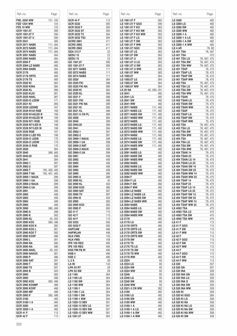
520
FWL 2200 WW 131, 163FZD 1254 WW 124FZS 10 WW 123GCR 1561.07 390GCR 1561.07 F 390GCR 1561.07 U 390GCR 2041 485GCR 2071 NABS 111, 484GCR 2072 NABS 111, 484GCR 2074 NABS 111, 484GCR 2091 NABS 484GCR 2092 NABS 484GCR 2094 F 485GCR 2094 LZ NABS 485GCR 2094 NABS 484GCR 2178 485GCR 2178 ORTS 485GCR 2178 TS 485GCR 2520 KI 384GCR 2520 KINA 385GCR 2520 KL 386GCR 2520 KLKI 387GCR 2520 NAKL 387GCR 2520-O LEDW 171GCR 2521 KI 385GCR 2539 LEDWB 167GCR 2539 N142 RGB 169GCR 2539 N142LED B 169GCR 2539 N142LED W 169GCR 2539 N71 RGB 168GCR 2539 N71LED B 168GCR 2539 N71LED W 168GCR 2539 RGB 167GCR 2539-2 LED RG 166GCR 2539-O LEDB 170GCR 2539-O LEDW 170GCR 2539-O RGB 170GCR 2928 384GCR 2940 389, 485GCR 2940.20 390GCR 2941 384GCR 2962-1 397GCR 2962-2 397GCR 2969 T 195, 400, 485GCR 2969 T NA 195, 401, 485GCR 2969-1 NAUA 399GCR 2969-1 UA 398GCR 2969-2 NAUA 399GCR 2969-2 UA 399GCR 2981 406GCR 2982 406GCR 2983 406GCR 2984 406GCR 2985 406GCR 2990 380, 486GCR 2990 A 398GCR 2990 K 382GCR 2990 KL 45, 402GCR 2990 KO5 380, 486GCR 2990 KO5 K 382GCR 2990 KO5 L 381GCR 2990 KO5 T 382GCR 2990 KO5P 486GCR 2990 L 381GCR 2990 NA 380GCR 2990 NA 486GCR 2990 NAKL 45, 402GCR 2990 NAKO5 381GCR 2990 P 486GCR 2990 SAT 397GCR 2990 T 382GCR 2990 TV 397GCR 2994 B 403GCR 2995 383GCR 2995 486GCR 2995 KO5 383, 486GCR 2995 KO5MP 486GCR 2995 KO5P 486GCR 2995 MP 486GCR 2995 P 383, 486GCR 3180 485GCR 3180-1 A 485GCR 3280 485GCR 3280-1 A 485GCR 41 F 113GCR 42 F 113
GCR 44 F 113GCR 5232 393GCR 5232 F 393GCR 5232 ST 394GCR 5232 T3 394GCR 5232 TS3 394GCRD 2981 411GCRD 2982 411GCRD 2983 411GDA 313 F 23GEDU 10 23GEDU 15 23GO 1561.07 390GO 1561.07 F 390GO 2071 NABS 111GO 2072 NABS 111GO 2074 NABS 111GO 2520 384GO 2520 FKI 388GO 2520 FKI NA 389GO 2520 KI 384GO 2520 KL 386GO 2521 F 388GO 2521 FKI 388GO 2521 FKI NA 389GO 2521 KI 385GO 2521 KL 386GO 2521-5 CN PL 389GO 2928 384GO 2940 389GO 2940.20 390GO 2941 384GO 2962-1 397GO 2962-2 397GO 2969-1 NAUA 399GO 2969-1 UA 398GO 2969-2 NAT 402GO 2969-2 NAUA 399GO 2969-2 UA 399GO 2981 406GO 2982 406GO 2983 406GO 2984 406GO 2985 406GO 2990 380GO 2990 A 398GO 2990 KL 45GO 2990 KL 402GO 2990 KO5 380GO 2990 SAT 397GO 2990 TV 397GO 2994 B 403GO 2995 383GO 2995 KO5 383GO 2995 P 383GO 41 F 113GO 42 F 113GO 44 F 113GO 5232 393GO 5232 F 393HAPCAM 496HAPWLAN 496HLK-FMS 133HLK-FMS 158IPR 100 REG 495IPS 100 REG 495KNX PM FB IR 490KSB 4 490KSE 2 490L 2 S 28LA 90 143LPK 63 RT 28LPK 63 SW 28LS 1180 364LS 1180 LG 364LS 1180 SW 364LS 1180 WW 364LS 1180-1 364LS 1180-1 LG 364LS 1180-1 SW 364LS 1180-1 WW 364LS 1520-13 SEV 361LS 1520-13 SEV LG 361LS 1520-13 SEV SW 361LS 1520-13 SEV WW 361LS 1561.07 363
LS 1561.07 F 363LS 1561.07 F GGO 390LS 1561.07 F KO 363LS 1561.07 F KO SW 363LS 1561.07 F KO WW 363LS 1561.07 F LG 363LS 1561.07 F SW 363LS 1561.07 F WW 363LS 1561.07 GGO 390LS 1561.07 LG 363LS 1561.07 SW 363LS 1561.07 U 363LS 1561.07 U LG 363LS 1561.07 U SW 363LS 1561.07 U WW 363LS 1561.07 WW 363LS 1565.07 364LS 1565.07 LG 364LS 1565.07 SW 364LS 1565.07 WW 364LS 20 NA 42, 290, 291LS 2041 482LS 2041 LG 482LS 2041 SW 482LS 2041 WW 482LS 2071 NABS 111, 482LS 2071 NABS LG 111, 482LS 2071 NABS SW 111, 482LS 2071 NABS WW 111, 482LS 2072 NABS 111, 482LS 2072 NABS LG 111, 482LS 2072 NABS SW 111, 482LS 2072 NABS WW 111, 482LS 2074 NABS 111, 482LS 2074 NABS LG 111, 482LS 2074 NABS SW 111, 482LS 2074 NABS WW 111, 482LS 2091 NABS 482LS 2091 NABS LG 482LS 2091 NABS SW 482LS 2091 NABS WW 482LS 2092 NABS 482LS 2092 NABS LG 482LS 2092 NABS SW 482LS 2092 NABS WW 482LS 2094 F 482LS 2094 F LG 482LS 2094 F SW 482LS 2094 F WW 482LS 2094 LZ NABS 482LS 2094 LZ NABS LG 482LS 2094 LZ NABS SW 482LS 2094 LZ NABS WW 482LS 2094 NABS 482LS 2094 NABS LG 482LS 2094 NABS SW 482LS 2094 NABS WW 482LS 2178 482LS 2178 LG 482LS 2178 ORTS 482LS 2178 ORTS LG 482LS 2178 ORTS SW 482LS 2178 ORTS WW 482LS 2178 SW 482LS 2178 TS 482LS 2178 TS LG 482LS 2178 TS SW 482LS 2178 TS WW 482LS 2178 WW 482LS 2224 83LS 2224 LG 83LS 2224 SW 83LS 2224 WW 83LS 2248 83LS 2248 LG 83LS 2248 SW 83LS 2248 WW 83LS 2521-5 CN WW 362LS 3180 482LS 3180 LG 482LS 3180 SW 482LS 3180 WW 482LS 3180-1 A 482LS 3180-1 A LG 482LS 3180-1 A SW 482LS 3180-1 A WW 482
Ref.-no. Page Ref.-no. Page Ref.-no. Page
LS 3280 482LS 3280 LG 482LS 3280 SW 482LS 3280 WW 482LS 3280-1 A 482LS 3280-1 A LG 482LS 3280-1 A SW 482LS 3280-1 A WW 482LS 4 AR 78, 80LS 401 TSA 78, 467LS 401 TSA 475LS 401 TSA LG 78, 467, 475LS 401 TSA SW 78, 467, 475LS 401 TSA WW 78, 467, 475LS 401 TSAP 78, 475LS 401 TSAP LG 78, 475LS 401 TSAP SW 78, 475LS 401 TSAP WW 78, 475LS 402 TSA 78, 467, 475LS 402 TSA LG 78, 467, 475LS 402 TSA SW 78, 467, 475LS 402 TSA WW 78, 467, 475LS 402 TSAN 79, 475LS 402 TSAN LG 79, 475LS 402 TSAN SW 79, 475LS 402 TSAN WW 79, 475LS 402 TSAP 79, 475LS 402 TSAP LG 79, 475LS 402 TSAP SW 79, 475LS 402 TSAP WW 79, 475LS 403 TSA 78, 467, 475LS 403 TSA LG 78, 467, 475LS 403 TSA SW 78, 467, 475LS 403 TSA WW 78, 467, 475LS 404 TSA 78, 467, 475LS 404 TSA LG 78, 467, 475LS 404 TSA SW 78, 467, 475LS 404 TSA WW 78, 467, 475LS 404 TSAN 14 79, 475LS 404 TSAN 23 79, 475LS 404 TSAN LG 14 79, 475LS 404 TSAN LG 23 79, 475LS 404 TSAN SW 14 79, 475LS 404 TSAN SW 23 79, 475LS 404 TSAN WW 14 79, 475LS 404 TSAN WW 23 79, 475LS 404 TSAP 14 79, 475LS 404 TSAP 23 79, 475LS 404 TSAP LG 14 79, 475LS 404 TSAP LG 23 79, 475LS 404 TSAP SW 14 79, 475LS 404 TSAP SW 23 79, 475LS 404 TSAP WW 14 79, 475LS 404 TSAP WW 23 79, 475LS 4093 TSA 475LS 4093 TSA LG 475LS 4093 TSA SW 475LS 4093 TSA WW 475LS 41 F 113LS 41 F GGO 113LS 41 F SW 113LS 41 F WW 113LS 42 F 113LS 42 F GGO 113LS 42 F SW 113LS 42 F WW 113LS 44 F 113LS 44 F GGO 113LS 44 F SW 113LS 44 F WW 113LS 520 357LS 520 GN 357LS 520 INA 359LS 520 INA GN 359LS 520 INA LG 359LS 520 INA O 359LS 520 INA SW 359LS 520 INA WW 359LS 520 KI 358LS 520 KI GGO 384LS 520 KI LG 358LS 520 KI NA 358LS 520 KI NA LG 358LS 520 KI NA SW 358LS 520 KI NA WW 358LS 520 KI SW 358
Ref.-no. Page
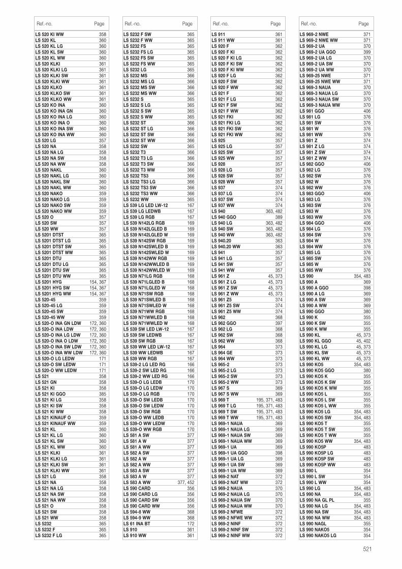
521
LS 520 KI WW 358LS 520 KL 360LS 520 KL LG 360LS 520 KL SW 360LS 520 KL WW 360LS 520 KLKI 361LS 520 KLKI LG 361LS 520 KLKI SW 361LS 520 KLKI WW 361LS 520 KLKO 361LS 520 KLKO SW 361LS 520 KLKO WW 361LS 520 KO INA 360LS 520 KO INA GN 360LS 520 KO INA LG 360LS 520 KO INA O 360LS 520 KO INA SW 360LS 520 KO INA WW 360LS 520 LG 357LS 520 NA 358LS 520 NA LG 358LS 520 NA SW 358LS 520 NA WW 358LS 520 NAKL 360LS 520 NAKL LG 360LS 520 NAKL SW 360LS 520 NAKL WW 360LS 520 NAKO 359LS 520 NAKO LG 359LS 520 NAKO SW 359LS 520 NAKO WW 359LS 520 O 357LS 520 SW 357LS 520 WW 357LS 5201 DTST 365LS 5201 DTST LG 365LS 5201 DTST SW 365LS 5201 DTST WW 365LS 5201 DTU 365LS 5201 DTU LG 365LS 5201 DTU SW 365LS 5201 DTU WW 365LS 5201 HYG 154, 367LS 5201 HYG SW 154, 367LS 5201 HYG WW 154, 367LS 520-45 359LS 520-45 LG 359LS 520-45 SW 359LS 520-45 WW 359LS 520-O INA GN LDW 172, 360LS 520-O INA LDW 172, 360LS 520-O INA LG LDW 172, 360LS 520-O INA O LDW 172, 360LS 520-O INA SW LDW 172, 360LS 520-O INA WW LDW 172, 360LS 520-O LG LEDW 171LS 520-O SW LEDW 171LS 520-O WW LEDW 171LS 521 358LS 521 GN 358LS 521 KI 358LS 521 KI GGO 385LS 521 KI LG 358LS 521 KI SW 358LS 521 KI WW 358LS 521 KINAUF O 359LS 521 KINAUF WW 359LS 521 KL 360LS 521 KL LG 360LS 521 KL SW 360LS 521 KL WW 360LS 521 KLKI 361LS 521 KLKI LG 361LS 521 KLKI SW 361LS 521 KLKI WW 361LS 521 LG 358LS 521 NA 358LS 521 NA LG 358LS 521 NA SW 358LS 521 NA WW 358LS 521 O 358LS 521 SW 358LS 521 WW 358LS 5232 365LS 5232 F 365LS 5232 F LG 365
LS 5232 F SW 365LS 5232 F WW 365LS 5232 FS 365LS 5232 FS LG 365LS 5232 FS SW 365LS 5232 FS WW 365LS 5232 LG 365LS 5232 MS 366LS 5232 MS LG 366LS 5232 MS SW 366LS 5232 MS WW 366LS 5232 S 365LS 5232 S LG 365LS 5232 S SW 365LS 5232 S WW 365LS 5232 ST 366LS 5232 ST LG 366LS 5232 ST SW 366LS 5232 ST WW 366LS 5232 SW 365LS 5232 T3 366LS 5232 T3 LG 366LS 5232 T3 SW 366LS 5232 T3 WW 366LS 5232 TS3 366LS 5232 TS3 LG 366LS 5232 TS3 SW 366LS 5232 TS3 WW 366LS 5232 WW 365LS 539 LG LED LW-12 167LS 539 LG LEDWB 167LS 539 LG RGB 167LS 539 N142LG RGB 169LS 539 N142LGLED B 169LS 539 N142LGLED W 169LS 539 N142SW RGB 169LS 539 N142SWLED B 169LS 539 N142SWLED W 169LS 539 N142WW RGB 169LS 539 N142WWLED B 169LS 539 N142WWLED W 169LS 539 N71LG RGB 168LS 539 N71LGLED B 168LS 539 N71LGLED W 168LS 539 N71SW RGB 168LS 539 N71SWLED B 168LS 539 N71SWLED W 168LS 539 N71WW RGB 168LS 539 N71WWLED B 168LS 539 N71WWLED W 168LS 539 SW LED LW-12 167LS 539 SW LEDWB 167LS 539 SW RGB 167LS 539 WW LED LW-12 167LS 539 WW LEDWB 167LS 539 WW RGB 167LS 539-2 LG LED RG 166LS 539-2 SW LED RG 166LS 539-2 WW LED RG 166LS 539-O LG LEDB 170LS 539-O LG LEDW 170LS 539-O LG RGB 170LS 539-O SW LEDB 170LS 539-O SW LEDW 170LS 539-O SW RGB 170LS 539-O WW LEDB 170LS 539-O WW LEDW 170LS 539-O WW RGB 170LS 581 A SW 377LS 581 A W 377LS 581 A WW 377LS 582 A SW 377LS 582 A W 377LS 582 A WW 377LS 583 A SW 377LS 583 A W 377LS 583 A WW 377, 452LS 590 CARD 356LS 590 CARD LG 356LS 590 CARD SW 356LS 590 CARD WW 356LS 594-8 WW 368LS 594-9 WW 368LS 61 INA BT 172LS 910 361LS 910 WW 361
LS 911 361LS 911 WW 361LS 920 F 362LS 920 F KI 362LS 920 F KI LG 362LS 920 F KI SW 362LS 920 F KI WW 362LS 920 F LG 362LS 920 F SW 362LS 920 F WW 362LS 921 F 362LS 921 F LG 362LS 921 F SW 362LS 921 F WW 362LS 921 FKI 362LS 921 FKI LG 362LS 921 FKI SW 362LS 921 FKI WW 362LS 925 357LS 925 LG 357LS 925 SW 357LS 925 WW 357LS 928 357LS 928 LG 357LS 928 SW 357LS 928 WW 357LS 937 374LS 937 LG 374LS 937 SW 374LS 937 WW 374LS 940 363, 482LS 940 GGO 389LS 940 LG 363, 482LS 940 SW 363, 482LS 940 WW 363, 482LS 940.20 363LS 940.20 WW 363LS 941 357LS 941 LG 357LS 941 SW 357LS 941 WW 357LS 961 Z 45, 373LS 961 Z LG 45, 373LS 961 Z SW 45, 373LS 961 Z WW 45, 373LS 961 Z5 374LS 961 Z5 SW 374LS 961 Z5 WW 374LS 962 368LS 962 GGO 397LS 962 LG 368LS 962 SW 368LS 962 WW 368LS 964 373LS 964 GE 373LS 964 WW 373LS 965-2 373LS 965-2 LG 373LS 965-2 SW 373LS 965-2 WW 373LS 967 S 369LS 967 S WW 369LS 969 T 195, 371, 483LS 969 T LG 195, 371, 483LS 969 T SW 195, 371, 483LS 969 T WW 195, 371, 483LS 969-1 NAUA 369LS 969-1 NAUA LG 369LS 969-1 NAUA SW 369LS 969-1 NAUA WW 369LS 969-1 UA 369LS 969-1 UA GGO 398LS 969-1 UA LG 369LS 969-1 UA SW 369LS 969-1 UA WW 369LS 969-2 NAT 372LS 969-2 NAT WW 372LS 969-2 NAUA 370LS 969-2 NAUA LG 370LS 969-2 NAUA SW 370LS 969-2 NAUA WW 370LS 969-2 NFWE 372LS 969-2 NFWE WW 372LS 969-2 NINF 372LS 969-2 NINF SW 372LS 969-2 NINF WW 372
Ref.-no. Page Ref.-no. Page Ref.-no. Page
LS 969-2 NWE 371LS 969-2 NWE WW 371LS 969-2 UA 370LS 969-2 UA GGO 399LS 969-2 UA LG 370LS 969-2 UA SW 370LS 969-2 UA WW 370LS 969-25 NWE 371LS 969-25 NWE WW 371LS 969-3 NAUA 370LS 969-3 NAUA LG 370LS 969-3 NAUA SW 370LS 969-3 NAUA WW 370LS 981 GGO 406LS 981 LG 376LS 981 SW 376LS 981 W 376LS 981 WW 376LS 981 Z 374LS 981 Z LG 374LS 981 Z SW 374LS 981 Z WW 374LS 982 GGO 406LS 982 LG 376LS 982 SW 376LS 982 W 376LS 982 WW 376LS 983 GGO 406LS 983 LG 376LS 983 SW 376LS 983 W 376LS 983 WW 376LS 984 GGO 406LS 984 LG 376LS 984 SW 376LS 984 W 376LS 984 WW 376LS 985 LG 376LS 985 SW 376LS 985 W 376LS 985 WW 376LS 990 354, 483LS 990 A 369LS 990 A GGO 398LS 990 A LG 369LS 990 A SW 369LS 990 A WW 369LS 990 GGO 380LS 990 K 355LS 990 K SW 355LS 990 K WW 355LS 990 KL 45, 373LS 990 KL GGO 45, 402LS 990 KL LG 45, 373LS 990 KL SW 45, 373LS 990 KL WW 45, 373LS 990 KO5 354, 483LS 990 KO5 GGO 380LS 990 KO5 K 355LS 990 KO5 K SW 355LS 990 KO5 K WW 355LS 990 KO5 L 355LS 990 KO5 L SW 355LS 990 KO5 L WW 355LS 990 KO5 LG 354, 483LS 990 KO5 SW 354, 483LS 990 KO5 T 355LS 990 KO5 T SW 355LS 990 KO5 T WW 355LS 990 KO5 WW 354, 483LS 990 KO5P 483LS 990 KO5P LG 483LS 990 KO5P SW 483LS 990 KO5P WW 483LS 990 L 354LS 990 L SW 354LS 990 L WW 354LS 990 LG 354, 483LS 990 NA 354, 483LS 990 NA GL PL 355LS 990 NA LG 354, 483LS 990 NA SW 354, 483LS 990 NA WW 354, 483LS 990 NAGL 355LS 990 NAKO5 354LS 990 NAKO5 LG 354
Ref.-no. Page
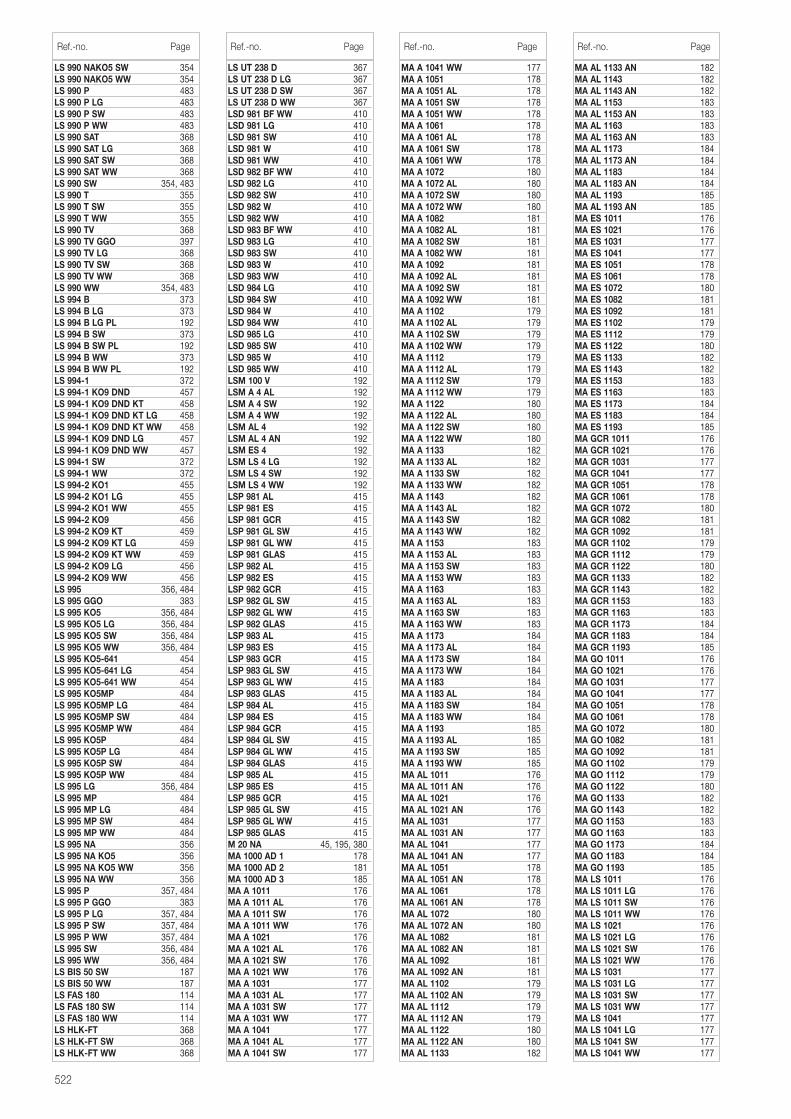
522
LS 990 NAKO5 SW 354LS 990 NAKO5 WW 354LS 990 P 483LS 990 P LG 483LS 990 P SW 483LS 990 P WW 483LS 990 SAT 368LS 990 SAT LG 368LS 990 SAT SW 368LS 990 SAT WW 368LS 990 SW 354, 483LS 990 T 355LS 990 T SW 355LS 990 T WW 355LS 990 TV 368LS 990 TV GGO 397LS 990 TV LG 368LS 990 TV SW 368LS 990 TV WW 368LS 990 WW 354, 483LS 994 B 373LS 994 B LG 373LS 994 B LG PL 192LS 994 B SW 373LS 994 B SW PL 192LS 994 B WW 373LS 994 B WW PL 192LS 994-1 372LS 994-1 KO9 DND 457LS 994-1 KO9 DND KT 458LS 994-1 KO9 DND KT LG 458LS 994-1 KO9 DND KT WW 458LS 994-1 KO9 DND LG 457LS 994-1 KO9 DND WW 457LS 994-1 SW 372LS 994-1 WW 372LS 994-2 KO1 455LS 994-2 KO1 LG 455LS 994-2 KO1 WW 455LS 994-2 KO9 456LS 994-2 KO9 KT 459LS 994-2 KO9 KT LG 459LS 994-2 KO9 KT WW 459LS 994-2 KO9 LG 456LS 994-2 KO9 WW 456LS 995 356, 484LS 995 GGO 383LS 995 KO5 356, 484LS 995 KO5 LG 356, 484LS 995 KO5 SW 356, 484LS 995 KO5 WW 356, 484LS 995 KO5-641 454LS 995 KO5-641 LG 454LS 995 KO5-641 WW 454LS 995 KO5MP 484LS 995 KO5MP LG 484LS 995 KO5MP SW 484LS 995 KO5MP WW 484LS 995 KO5P 484LS 995 KO5P LG 484LS 995 KO5P SW 484LS 995 KO5P WW 484LS 995 LG 356, 484LS 995 MP 484LS 995 MP LG 484LS 995 MP SW 484LS 995 MP WW 484LS 995 NA 356LS 995 NA KO5 356LS 995 NA KO5 WW 356LS 995 NA WW 356LS 995 P 357, 484LS 995 P GGO 383LS 995 P LG 357, 484LS 995 P SW 357, 484LS 995 P WW 357, 484LS 995 SW 356, 484LS 995 WW 356, 484LS BIS 50 SW 187LS BIS 50 WW 187LS FAS 180 114LS FAS 180 SW 114LS FAS 180 WW 114LS HLK-FT 368LS HLK-FT SW 368LS HLK-FT WW 368
LS UT 238 D 367LS UT 238 D LG 367LS UT 238 D SW 367LS UT 238 D WW 367LSD 981 BF WW 410LSD 981 LG 410LSD 981 SW 410LSD 981 W 410LSD 981 WW 410LSD 982 BF WW 410LSD 982 LG 410LSD 982 SW 410LSD 982 W 410LSD 982 WW 410LSD 983 BF WW 410LSD 983 LG 410LSD 983 SW 410LSD 983 W 410LSD 983 WW 410LSD 984 LG 410LSD 984 SW 410LSD 984 W 410LSD 984 WW 410LSD 985 LG 410LSD 985 SW 410LSD 985 W 410LSD 985 WW 410LSM 100 V 192LSM A 4 AL 192LSM A 4 SW 192LSM A 4 WW 192LSM AL 4 192LSM AL 4 AN 192LSM ES 4 192LSM LS 4 LG 192LSM LS 4 SW 192LSM LS 4 WW 192LSP 981 AL 415LSP 981 ES 415LSP 981 GCR 415LSP 981 GL SW 415LSP 981 GL WW 415LSP 981 GLAS 415LSP 982 AL 415LSP 982 ES 415LSP 982 GCR 415LSP 982 GL SW 415LSP 982 GL WW 415LSP 982 GLAS 415LSP 983 AL 415LSP 983 ES 415LSP 983 GCR 415LSP 983 GL SW 415LSP 983 GL WW 415LSP 983 GLAS 415LSP 984 AL 415LSP 984 ES 415LSP 984 GCR 415LSP 984 GL SW 415LSP 984 GL WW 415LSP 984 GLAS 415LSP 985 AL 415LSP 985 ES 415LSP 985 GCR 415LSP 985 GL SW 415LSP 985 GL WW 415LSP 985 GLAS 415M 20 NA 45, 195, 380MA 1000 AD 1 178MA 1000 AD 2 181MA 1000 AD 3 185MA A 1011 176MA A 1011 AL 176MA A 1011 SW 176MA A 1011 WW 176MA A 1021 176MA A 1021 AL 176MA A 1021 SW 176MA A 1021 WW 176MA A 1031 177MA A 1031 AL 177MA A 1031 SW 177MA A 1031 WW 177MA A 1041 177MA A 1041 AL 177MA A 1041 SW 177
MA A 1041 WW 177MA A 1051 178MA A 1051 AL 178MA A 1051 SW 178MA A 1051 WW 178MA A 1061 178MA A 1061 AL 178MA A 1061 SW 178MA A 1061 WW 178MA A 1072 180MA A 1072 AL 180MA A 1072 SW 180MA A 1072 WW 180MA A 1082 181MA A 1082 AL 181MA A 1082 SW 181MA A 1082 WW 181MA A 1092 181MA A 1092 AL 181MA A 1092 SW 181MA A 1092 WW 181MA A 1102 179MA A 1102 AL 179MA A 1102 SW 179MA A 1102 WW 179MA A 1112 179MA A 1112 AL 179MA A 1112 SW 179MA A 1112 WW 179MA A 1122 180MA A 1122 AL 180MA A 1122 SW 180MA A 1122 WW 180MA A 1133 182MA A 1133 AL 182MA A 1133 SW 182MA A 1133 WW 182MA A 1143 182MA A 1143 AL 182MA A 1143 SW 182MA A 1143 WW 182MA A 1153 183MA A 1153 AL 183MA A 1153 SW 183MA A 1153 WW 183MA A 1163 183MA A 1163 AL 183MA A 1163 SW 183MA A 1163 WW 183MA A 1173 184MA A 1173 AL 184MA A 1173 SW 184MA A 1173 WW 184MA A 1183 184MA A 1183 AL 184MA A 1183 SW 184MA A 1183 WW 184MA A 1193 185MA A 1193 AL 185MA A 1193 SW 185MA A 1193 WW 185MA AL 1011 176MA AL 1011 AN 176MA AL 1021 176MA AL 1021 AN 176MA AL 1031 177MA AL 1031 AN 177MA AL 1041 177MA AL 1041 AN 177MA AL 1051 178MA AL 1051 AN 178MA AL 1061 178MA AL 1061 AN 178MA AL 1072 180MA AL 1072 AN 180MA AL 1082 181MA AL 1082 AN 181MA AL 1092 181MA AL 1092 AN 181MA AL 1102 179MA AL 1102 AN 179MA AL 1112 179MA AL 1112 AN 179MA AL 1122 180MA AL 1122 AN 180MA AL 1133 182
Ref.-no. Page Ref.-no. Page Ref.-no. Page
MA AL 1133 AN 182MA AL 1143 182MA AL 1143 AN 182MA AL 1153 183MA AL 1153 AN 183MA AL 1163 183MA AL 1163 AN 183MA AL 1173 184MA AL 1173 AN 184MA AL 1183 184MA AL 1183 AN 184MA AL 1193 185MA AL 1193 AN 185MA ES 1011 176MA ES 1021 176MA ES 1031 177MA ES 1041 177MA ES 1051 178MA ES 1061 178MA ES 1072 180MA ES 1082 181MA ES 1092 181MA ES 1102 179MA ES 1112 179MA ES 1122 180MA ES 1133 182MA ES 1143 182MA ES 1153 183MA ES 1163 183MA ES 1173 184MA ES 1183 184MA ES 1193 185MA GCR 1011 176MA GCR 1021 176MA GCR 1031 177MA GCR 1041 177MA GCR 1051 178MA GCR 1061 178MA GCR 1072 180MA GCR 1082 181MA GCR 1092 181MA GCR 1102 179MA GCR 1112 179MA GCR 1122 180MA GCR 1133 182MA GCR 1143 182MA GCR 1153 183MA GCR 1163 183MA GCR 1173 184MA GCR 1183 184MA GCR 1193 185MA GO 1011 176MA GO 1021 176MA GO 1031 177MA GO 1041 177MA GO 1051 178MA GO 1061 178MA GO 1072 180MA GO 1082 181MA GO 1092 181MA GO 1102 179MA GO 1112 179MA GO 1122 180MA GO 1133 182MA GO 1143 182MA GO 1153 183MA GO 1163 183MA GO 1173 184MA GO 1183 184MA GO 1193 185MA LS 1011 176MA LS 1011 LG 176MA LS 1011 SW 176MA LS 1011 WW 176MA LS 1021 176MA LS 1021 LG 176MA LS 1021 SW 176MA LS 1021 WW 176MA LS 1031 177MA LS 1031 LG 177MA LS 1031 SW 177MA LS 1031 WW 177MA LS 1041 177MA LS 1041 LG 177MA LS 1041 SW 177MA LS 1041 WW 177
Ref.-no. Page
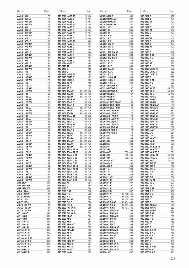
523
MA LS 1051 178MA LS 1051 LG 178MA LS 1051 SW 178MA LS 1051 WW 178MA LS 1061 178MA LS 1061 LG 178MA LS 1061 SW 178MA LS 1061 WW 178MA LS 1072 180MA LS 1072 LG 180MA LS 1072 SW 180MA LS 1072 WW 180MA LS 1082 181MA LS 1082 LG 181MA LS 1082 SW 181MA LS 1082 WW 181MA LS 1092 181MA LS 1092 LG 181MA LS 1092 SW 181MA LS 1092 WW 181MA LS 1102 179MA LS 1102 LG 179MA LS 1102 SW 179MA LS 1102 WW 179MA LS 1112 179MA LS 1112 LG 179MA LS 1112 SW 179MA LS 1112 WW 179MA LS 1122 180MA LS 1122 LG 180MA LS 1122 SW 180MA LS 1122 WW 180MA LS 1133 182MA LS 1133 LG 182MA LS 1133 SW 182MA LS 1133 WW 182MA LS 1143 182MA LS 1143 LG 182MA LS 1143 SW 182MA LS 1143 WW 182MA LS 1153 183MA LS 1153 LG 183MA LS 1153 SW 183MA LS 1153 WW 183MA LS 1163 183MA LS 1163 LG 183MA LS 1163 SW 183MA LS 1163 WW 183MA LS 1173 184MA LS 1173 LG 184MA LS 1173 SW 184MA LS 1173 WW 184MA LS 1183 184MA LS 1183 LG 184MA LS 1183 SW 184MA LS 1183 WW 184MA LS 1193 185MA LS 1193 LG 185MA LS 1193 SW 185MA LS 1193 WW 185MBT 2424 497MBT 2424 SW 497MBT 2424 WW 497MC A 100 AL 191MC A 100 SW 191MC A 100 WW 191MC AL 100-L 191MC ES 100-L 191MC FB 100 WW 191MC LS 100 SW 191MC LS 100 WW 191ME 1180 AT 391ME 1180 C 391ME 1180 D 391ME 1180-1 AT 391ME 1180-1 C 391ME 1180-1 D 391ME 1561.07 AT 390ME 1561.07 C 390ME 1561.07 D 390ME 1561.07 F AT 390ME 1561.07 F C 390ME 1561.07 F D 390ME 1565.07 AT 391ME 1565.07 C 391ME 1565.07 D 391
ME 2071 NABS AT 111, 484ME 2071 NABS C 111, 484ME 2071 NABS D 111, 484ME 2072 NABS AT 111, 484ME 2072 NABS C 111, 484ME 2072 NABS D 111, 484ME 2074 NABS AT 111, 484ME 2074 NABS C 111, 484ME 2074 NABS D 111, 484ME 2091 NABS AT 484ME 2091 NABS C 484ME 2091 NABS D 484ME 2092 NABS AT 484ME 2092 NABS C 484ME 2092 NABS D 484ME 2094 NABS AT 484ME 2094 NABS C 484ME 2094 NABS D 484ME 2178 AT 485ME 2178 C 485ME 2178 D 485ME 2178 ORTS AT 485ME 2178 ORTS C 485ME 2178 ORTS D 485ME 2178 TS AT 485ME 2178 TS C 485ME 2178 TS D 485ME 2401 TSA AT 80, 467, 476ME 2401 TSA C 80, 467, 476ME 2401 TSA D 80, 467, 476ME 2401 TSAP AT 80, 476ME 2401 TSAP C 80, 476ME 2401 TSAP D 80, 476ME 2402 TSA AT 80, 467, 476ME 2402 TSA C 80, 467, 476ME 2402 TSA D 80, 467, 476ME 2402 TSAN AT 81, 476ME 2402 TSAN C 81, 476ME 2402 TSAN D 81, 476ME 2402 TSAP AT 81, 476ME 2402 TSAP C 81, 476ME 2402 TSAP D 81, 476ME 2403 TSA AT 80, 467, 476ME 2403 TSA C 80, 467, 476ME 2403 TSA D 80, 467, 476ME 2404 TSA AT 80, 467, 476ME 2404 TSA C 80, 467, 476ME 2404 TSA D 80, 467, 476ME 2404 TSAN AT 14 81, 476ME 2404 TSAN AT 23 81, 476ME 2404 TSAN C 14 81, 476ME 2404 TSAN C 23 81, 476ME 2404 TSAN D 14 81, 476ME 2404 TSAN D 23 81, 476ME 2404 TSAP AT 14 81, 476ME 2404 TSAP AT 23 81, 476ME 2404 TSAP C 14 81, 476ME 2404 TSAP C 23 81, 476ME 2404 TSAP D 14 81, 476ME 2404 TSAP D 23 81, 476ME 2520 AT 384ME 2520 C 384ME 2520 D 384ME 2520 F AT 388ME 2520 F C 388ME 2520 F D 388ME 2520 FKI AT 388ME 2520 FKI C 388ME 2520 FKI D 388ME 2520 FKI NA AT 389ME 2520 FKI NA C 389ME 2520 FKI NA D 389ME 2520 KI AT 384ME 2520 KI C 384ME 2520 KI D 384ME 2520 KINA AT 385ME 2520 KINA C 385ME 2520 KINA D 385ME 2520 KL AT 386ME 2520 KL C 386ME 2520 KL D 386ME 2520 KLKI AT 387ME 2520 KLKI C 387ME 2520 KLKI D 387ME 2520 NA AT 385ME 2520 NA C 385
ME 2520 NA D 385ME 2520 NAKL AT 387ME 2520 NAKL C 387ME 2520 NAKL D 387ME 2521 AT 385ME 2521 C 385ME 2521 D 385ME 2521 F AT 388ME 2521 F C 388ME 2521 F D 388ME 2521 FKI AT 388ME 2521 FKI C 388ME 2521 FKI D 388ME 2521 FKI NA AT 389ME 2521 FKI NA C 389ME 2521 FKI NA D 389ME 2521 KI AT 385ME 2521 KI C 385ME 2521 KI D 385ME 2521 KL AT 386ME 2521 KL C 386ME 2521 KL D 386ME 2521-5 CN AT 389ME 2521-5 CN C 389ME 2521-5 CN D 389ME 2539 LEDWB AT 167ME 2539 LEDWB C 167ME 2539 LEDWB D 167ME 2539 RGB AT 167ME 2539 RGB C 167ME 2539 RGB D 167ME 2539-2 LED RG AT 166ME 2539-2 LED RG C 166ME 2539-2 LED RG D 166ME 2539-O LEDB AT 170ME 2539-O LEDB C 170ME 2539-O LEDB D 170ME 2539-O LEDW AT 170ME 2539-O LEDW C 170ME 2539-O LEDW D 170ME 2539-O RGB AT 170ME 2539-O RGB C 170ME 2539-O RGB D 170ME 2925 AT 384ME 2925 C 384ME 2925 D 384ME 2928 AT 384ME 2928 C 384ME 2928 D 384ME 2940 AT 389, 485ME 2940 C 389, 485ME 2940 D 389, 485ME 2940.20 AT 390ME 2940.20 C 390ME 2940.20 D 390ME 2941 AT 384ME 2941 C 384ME 2941 D 384ME 2962-1 AT 397ME 2962-1 C 397ME 2962-1 D 397ME 2962-2 AT 397ME 2962-2 C 397ME 2962-2 D 397ME 2969 T AT 195, 400, 485ME 2969 T C 195, 400, 485ME 2969 T D 195, 400, 485ME 2969 T NA AT 195, 401, 485ME 2969 T NA C 195, 401, 485ME 2969 T NA D 195, 401, 485ME 2969-1 NAUA AT 399ME 2969-1 NAUA C 399ME 2969-1 NAUA D 399ME 2969-1 UA AT 398ME 2969-1 UA C 398ME 2969-1 UA D 398ME 2969-2 NAUA AT 399ME 2969-2 NAUA C 399ME 2969-2 NAUA D 399ME 2969-2 UA AT 399ME 2969-2 UA C 399ME 2969-2 UA D 399ME 2969-3 NA UA AT 400ME 2969-3 NA UA C 400ME 2969-3 NA UA D 400ME 2981 AT 407
Ref.-no. Page Ref.-no. Page Ref.-no. Page
ME 2981 C 407ME 2981 D 407ME 2982 AT 407ME 2982 C 407ME 2982 D 407ME 2983 AT 407ME 2983 C 407ME 2983 D 407ME 2984 AT 407ME 2984 C 407ME 2984 D 407ME 2985 AT 407ME 2985 C 407ME 2985 D 407ME 2990 A AT 398ME 2990 A C 398ME 2990 A D 398ME 2990 AT 380ME 2990 C 380ME 2990 CARD AT 382ME 2990 CARD C 382ME 2990 CARD D 382ME 2990 D 380ME 2990 K AT 382ME 2990 K C 382ME 2990 K D 382ME 2990 KL AT 45, 402ME 2990 KL C 45, 402ME 2990 KL D 45, 402ME 2990 KO5 AT 380ME 2990 KO5 C 380ME 2990 KO5 D 380ME 2990 KO5 K AT 382ME 2990 KO5 K C 382ME 2990 KO5 K D 382ME 2990 KO5 L AT 381ME 2990 KO5 L C 381ME 2990 KO5 L D 381ME 2990 KO5 T AT 382ME 2990 KO5 T C 382ME 2990 KO5 T D 382ME 2990 L AT 381ME 2990 L C 381ME 2990 L D 381ME 2990 NA AT 380ME 2990 NA C 380ME 2990 NA D 380ME 2990 NA KO5 AT 381ME 2990 NA KO5 C 381ME 2990 NA KO5 D 381ME 2990 NAKL AT 45, 402ME 2990 NAKL C 45, 402ME 2990 NAKL D 45, 402ME 2990 SAT AT 397ME 2990 SAT C 397ME 2990 SAT D 397ME 2990 T AT 382ME 2990 T C 382ME 2990 T D 382ME 2990 TV AT 397ME 2990 TV C 397ME 2990 TV D 397ME 2994 B AT 403ME 2994 B C 403ME 2994 B D 403ME 2995 AT 383ME 2995 C 383ME 2995 D 383ME 2995 KO5 AT 383ME 2995 KO5 C 383ME 2995 KO5 D 383ME 2995 P AT 383ME 2995 P C 383ME 2995 P D 383ME 3180 AT 485ME 3180 C 485ME 3180 D 485ME 3180-1 A AT 485ME 3180-1 A C 485ME 3180-1 A D 485ME 3280 AT 485ME 3280 C 485ME 3280 D 485ME 3280-1 A AT 485ME 3280-1 A C 485ME 3280-1 A D 485
Ref.-no. Page
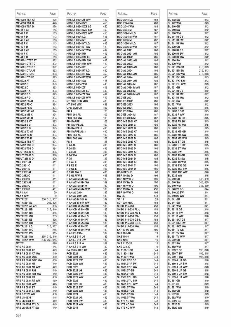
524
ME 4093 TSA AT 476ME 4093 TSA C 476ME 4093 TSA D 476ME 41 F AT 113ME 41 F C 113ME 41 F D 113ME 42 F AT 113ME 42 F C 113ME 42 F D 113ME 44 F AT 113ME 44 F C 113ME 44 F D 113ME 5201 DTST AT 392ME 5201 DTST C 392ME 5201 DTST D 392ME 5201 DTU AT 393ME 5201 DTU C 393ME 5201 DTU D 393ME 5232 AT 393ME 5232 C 393ME 5232 D 393ME 5232 F AT 393ME 5232 F C 393ME 5232 F D 393ME 5232 FS AT 394ME 5232 FS C 394ME 5232 FS D 394ME 5232 MS AT 394ME 5232 MS C 394ME 5232 MS D 394ME 5232 S AT 393ME 5232 S C 393ME 5232 S D 393ME 5232 T3 AT 394ME 5232 T3 C 394ME 5232 T3 D 394ME 5232 TS3 AT 394ME 5232 TS3 C 394ME 5232 TS3 D 394ME UT 238 D AT 396ME UT 238 D C 396ME UT 238 D D 396MED 2981 AT 411MED 2981 C 411MED 2981 D 411MED 2982 AT 411MED 2982 C 411MED 2982 D 411MED 2983 AT 411MED 2983 C 411MED 2983 D 411MLA 1 AN 29MLA 1 WW 29MS TR 231 236, 315, 367MS TR 231 AL 265, 396MS TR 231 AL AN 396MS TR 231 BB 315, 346MS TR 231 BR 315MS TR 231 CH 265MS TR 231 ES 396MS TR 231 GR 315MS TR 231 LG 315, 367MS TR 231 MO 265MS TR 231 PG 315MS TR 231 SW 265, 315, 346MS TR 231 WW 236, 265, 315MT 701 496NRS AS 0834 448NRS AS 0834 AT 449NRS AS 0834 AT WW 449NRS AS 0834 DZE 450NRS AS 0834 DZE WW 450NRS AS 0834 NT 449NRS AS 0834 NT WW 449NRS AS 0834 RM 449NRS AS 0834 RM WW 449NRS AS 0834 RT 450NRS AS 0834 RT WW 450NRS AS 0834 WW 448NRS AS 0834 ZT 449NRS AS 0834 ZT WW 449NRS DZT 20 WW 450NRS LS 0834 448NRS LS 0834 AT 449NRS LS 0834 AT LG 449NRS LS 0834 AT SW 449
NRS LS 0834 AT WW 449NRS LS 0834 DZE 450NRS LS 0834 DZE LG 450NRS LS 0834 DZE SW 450NRS LS 0834 DZE WW 450NRS LS 0834 LG 448NRS LS 0834 NT 449NRS LS 0834 NT LG 449NRS LS 0834 NT SW 449NRS LS 0834 NT WW 449NRS LS 0834 RM 449NRS LS 0834 RM LG 449NRS LS 0834 RM SW 449NRS LS 0834 RM WW 449NRS LS 0834 RT 450NRS LS 0834 RT LG 450NRS LS 0834 RT SW 450NRS LS 0834 RT WW 450NRS LS 0834 SW 448NRS LS 0834 WW 448NRS LS 0834 ZT 449NRS LS 0834 ZT LG 449NRS LS 0834 ZT SW 449NRS LS 0834 ZT WW 449NT 2405 REG VDC 488NT 2405 VDC 488OPC-EDITOR 497PB 4 28PMK 360 AL 103PMK 360 WW 103PM-KAPPE 102PM-KAPPE AL 102PM-KAPPE-1 490PM-KAPPE AL-1 490PMU 360 AL 102PMU 360 WW 102PS 4 28R 24 AL 496R 24 ES 496R 24 SW 496R 24 WW 496R 75 23R 9 AL E 496R 9 ES E 496R 9 GL E 496R 9 GL SW E 496R 9 GL WW E 496R AN AC M 514 AL 189R AN AC M 514 SW 189R AN AC M 514 W 189R AN AC M 514 WW 189R AN AL 2914 189R AN AL 2914 AN 189R AN AS M 514 W 189R AN AS M 514 WW 189R AN CD M 514 BR 189R AN CD M 514 GB 189R AN CD M 514 GR 189R AN CD M 514 LG 189R AN CD M 514 PT 189R AN CD M 514 SW 189R AN CD M 514 W 189R AN CD M 514 WW 189R AN ES 2914 189R AN LS 914 LG 189R AN LS 914 SW 189R AN LS 914 W 189R AN LS 914 WW 189RA 23024 REG HE 491RCD 2021 483RCD 2021 LG 483RCD 2021 SW 483RCD 2021 WW 483RCD 2022 483RCD 2022 LG 483RCD 2022 SW 483RCD 2022 WW 483RCD 2023 483RCD 2023 LG 483RCD 2023 SW 483RCD 2023 WW 483RCD 2024 483RCD 2024 LG 483RCD 2024 SW 483RCD 2024 WW 483RCD 2044 483
RCD 2044 LG 483RCD 2044 SW 483RCD 2044 WW 483RCD 3094 M 487RCD 3094 M LG 487RCD 3094 M WW 487RCD 3096 M 487RCD 3096 M LG 487RCD 3096 M WW 487RCD AL 2021 486RCD AL 2021 AN 486RCD AL 2022 486RCD AL 2022 AN 486RCD AL 2023 486RCD AL 2023 AN 486RCD AL 2024 486RCD AL 2024 AN 486RCD AL 2044 486RCD AL 2044 AN 486RCD AL 3094 M 487RCD AL 3094 M AN 487RCD AL 3096 M 487RCD AL 3096 M AN 487RCD ES 2021 486RCD ES 2022 486RCD ES 2023 486RCD ES 2024 486RCD ES 2044 486RCD ES 3094 M 487RCD ES 3096 M 487RCD ME 2021 AT 486RCD ME 2021 C 486RCD ME 2021 D 486RCD ME 2022 AT 486RCD ME 2022 C 486RCD ME 2022 D 486RCD ME 2023 AT 486RCD ME 2023 C 486RCD ME 2023 D 486RCD ME 2024 AT 486RCD ME 2024 C 486RCD ME 2024 D 486RCD ME 2044 AT 486RCD ME 2044 C 486RCD ME 2044 D 486RS 8 REGHE 68RSP 10 SW D 496RSP 10 WW D 496RSP 15 SW D 496RSP 15 WW D 496RSP 19 SW D 496RSP 19 WW D 496RW 95 143SA 13 24SC 1000 KNX 488SHSO 115-230 453SHSO 115-230 AL-L 453SHSO 115-230 AN-L 453SHSO 115-230 ES-L 453SHSO 115-230 GB-L 453SHSO 115-230 GO-L 453SHSO 115-230 WW 453SK 180-90 WW 490SKS 101-20 19SKS 101-4 19SKS 1015 19SKS 1120-20 19SKS 234.10 19SL 1180-1 GB 344SL 1180-1 SW 344SL 1180-1 WW 344SL 1561.07 F GB 344SL 1561.07 F SW 344SL 1561.07 F WW 344SL 1561.07 GB 344SL 1561.07 SW 344SL 1561.07 U GB 344SL 1561.07 U SW 344SL 1561.07 U WW 344SL 1561.07 WW 344SL 1565.07 GB 344SL 1565.07 SW 344SL 1565.07 WW 344SL 172 KO GB 343SL 172 KO SW 343SL 172 KO WW 343
Ref.-no. Page Ref.-no. Page Ref.-no. Page
SL 172 SW 343SL 172 WW 343SL 510 GB 342SL 510 SW 342SL 510 WW 342SL 511 KI GB 342SL 511 KI SW 342SL 511 KI WW 342SL 520 GB 342SL 520 KI GB 342SL 520 KI SW 342SL 520 KI WW 342SL 520 SW 342SL 520 WW 342SL 521 BS GB 215, 343SL 521 BS SW 215, 343SL 521 BS WW 215, 343SL 521 FKI GB 343SL 521 FKI SW 343SL 521 FKI WW 343SL 521 GB 342SL 521 KI GB 342SL 521 KI SW 342SL 521 KI WW 342SL 521 SW 342SL 521 WW 342SL 5232 F GB 345SL 5232 F SW 345SL 5232 F WW 345SL 5232 FS GB 345SL 5232 FS SW 345SL 5232 FS WW 345SL 5232 GB 345SL 5232 MS GB 345SL 5232 MS SW 345SL 5232 MS WW 345SL 5232 ST GB 345SL 5232 ST SW 345SL 5232 ST WW 345SL 5232 SW 345SL 5232 T3 GB 345SL 5232 T3 SW 345SL 5232 T3 WW 345SL 5232 TS3 GB 346SL 5232 TS3 SW 346SL 5232 TS3 WW 346SL 5232 WW 345SL 540 GB 343, 489SL 540 SW 343, 489SL 540 WW 343, 489SL 540.20 GB 344SL 540.20 SW 344SL 540.20 WW 344SL 541 GB 341SL 541 SW 341SL 541 WW 341SL 561 B GB 348SL 561 B SW 348SL 561 B WW 348SL 561 SAT GB 347SL 561 SAT SW 347SL 561 SAT WW 347SL 561 TV GB 347SL 561 TV SW 347SL 561 TV WW 347SL 562 GB 347SL 562 SW 347SL 562 WW 347SL 569 T GB 195, 348SL 569 T SW 195, 348SL 569 T WW 195, 348SL 569-1 UA GB 348SL 569-1 UA SW 348SL 569-1 UA WW 348SL 569-2 UA GB 348SL 569-2 UA SW 348SL 569-2 UA WW 348SL 581 GB 349SL 581 SI 349SL 581 WW 349SL 582 GB 349SL 582 SI 349SL 582 WW 349SL 5820 GB 349SL 5820 SI 349SL 5820 WW 349
Ref.-no. Page
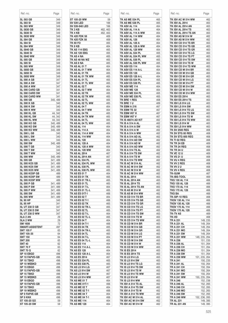
525
SL 583 GB 349SL 583 SI 349SL 583 WW 349SL 5830 GB 349SL 5830 SI 349SL 5830 WW 349SL 584 GB 349SL 584 SI 349SL 584 WW 349SL 5840 GB 349SL 5840 SI 349SL 5840 WW 349SL 585 GB 349SL 585 SI 349SL 585 WW 349SL 5850 GB 349SL 5850 SI 349SL 5850 WW 349SL 590 A GB 347SL 590 A SW 347SL 590 A WW 347SL 590 CARD GB 341SL 590 CARD SW 341SL 590 CARD WW 341SL 590 GB 340, 489SL 590 K GB 340SL 590 K SW 340SL 590 K WW 340SL 590 KL GB 44, 342SL 590 KL SW 44, 342SL 590 KL WW 44, 342SL 590 KO GB 340, 489SL 590 KO SW 340, 489SL 590 KO WW 340, 489SL 590 L GB 340SL 590 L SW 340SL 590 L WW 340SL 590 SW 340, 489SL 590 T GB 340SL 590 T SW 340SL 590 T WW 340SL 590 WW 340, 489SL 595 GB 341, 489SL 595 KO5 GB 341, 489SL 595 KO5 SW 341, 489SL 595 KO5 WW 341, 489SL 595 KO5P GB 489SL 595 KO5P SW 489SL 595 KO5P WW 489SL 595 P GB 341, 489SL 595 P SW 341, 489SL 595 P WW 341, 489SL 595 SW 341, 489SL 595 WW 341, 489SL 90 HP 340SL 95 HP 341SL UT 238 D GB 347SL UT 238 D SW 347SL UT 238 D WW 347SLA 2 AN 29SLA 2 WW 29SM 1608 72SMART-ASSISTENT 497SNT 105 F 63SNT 105-35 64SNT 150 64SNT 200 65SNT 40 62SNT 70 F 63SNT 70 Q 62SP 10 EBGD 496SP 10 FAPVD-GB 496SP 10 TBKD 496SP 10 WEBKD 496SP 15 EBGD 496SP 15 FAPVD-GB 496SP 15 TBKD 496SP 15 WEBKD 496SP 19 EBGD 496SP 19 FAPVD-GB 496SP 19 TBKD 496SP 19 WEBKD 496SP 9 FAPVE-GB 496SP 9 KNX 496ST 105-20 GO 59ST 105-20 SW 59
ST 105-20 WW 59SV 539 LED 166SV 539-948 LED 166TK 3 KB 462, 463TK 4 KB 462, 463TK 420 FDK 58 469TK 420 FZK 58 469TK 60 FO 465TK 8 KB 464TK AS 114 EBG 465TK AS 128 EBG 465TK AS 4 NA 465TK AS 48 NA WZ 465TK AS 8 NA 465TK AS AL 01 T 464TK AS AL 01 T WW 464TK AS AL 01 TK 465TK AS AL 01 TK WW 465TK AS AL 01 TL 465TK AS AL 01 TL WW 465TK AS AL 02 T 464TK AS AL 02 T WW 464TK AS AL 02 TK 465TK AS AL 02 TK WW 465TK AS AL 02 TL 465TK AS AL 02 TL WW 465TK AS AL 04 T 464TK AS AL 04 T WW 464TK AS AL 04 TK 465TK AS AL 04 TK WW 465TK AS AL 04 TL 465TK AS AL 04 TL WW 465TK AS AL 114 464TK AS AL 114 A 464TK AS AL 114 A WW 464TK AS AL 114 WW 464TK AS AL 128 464TK AS AL 128 A 464TK AS AL 128 A WW 464TK AS AL 128 WW 464TK AS AL 2914 467TK AS AL 2914 AN 467TK AS AL 534 PL 465TK AS AL 534 PL WW 465TK AS AL 538 PL 465TK AS AL 538 PL WW 465TK AS ES 01 T 464TK AS ES 01 TK 465TK AS ES 01 TK-L 465TK AS ES 01 TL 465TK AS ES 01 T-L 464TK AS ES 01 TL-L 465TK AS ES 01T-1 466TK AS ES 02 T 464TK AS ES 02 T-1 466TK AS ES 02 TK 465TK AS ES 02 TK-L 465TK AS ES 02 TL 465TK AS ES 02 T-L 464TK AS ES 02 TL-L 465TK AS ES 04 T 464TK AS ES 04 T-1 466TK AS ES 04 TK 465TK AS ES 04 TK-L 465TK AS ES 04 TL 465TK AS ES 04 T-L 464TK AS ES 04 TL-L 465TK AS ES 114 464TK AS ES 114 A-L 464TK AS ES 128 464TK AS ES 128 A-L 464TK AS ES 2914 467TK AS ES 534 PL 465TK AS ES 538 PL 465TK AS LS 914 LG 467TK AS LS 914 SW 467TK AS LS 914 W 467TK AS LS 914 WW 467TK AS ME 01 T 464TK AS ME 01T-1 466TK AS ME 02 T 464TK AS ME 02 T-1 466TK AS ME 04 T 464TK AS ME 04 T-1 466TK AS ME 114 464TK AS ME 128 464
TK AS ME 534 PL 465TK AS ME 538 PL 465TK ASV AL 114 464TK ASV AL 114 A 464TK ASV AL 114 A WW 464TK ASV AL 114 WW 464TK ASV AL 128 464TK ASV AL 128 A 464TK ASV AL 128 A WW 464TK ASV AL 128 WW 464TK ASV AL 534 PL 465TK ASV AL 534 PL WW 465TK ASV AL 538 PL 465TK ASV AL 538 PL WW 465TK ASV ES 114 464TK ASV ES 114 A-L 464TK ASV ES 128 464TK ASV ES 128 A-L 464TK ASV ES 534 PL 465TK ASV ES 538 PL 465TK ASV ME 114 464TK ASV ME 128 464TK ASV ME 534 PL 465TK ASV ME 538 PL 465TK BRE 1 REG 468TK BRE 1 U 469TK EBM A 216 467TK EBM TE 32 467TK EBM V67 H 467TK EBM V67 V 467TK IS 46074 AD KIT 462TK IS A 514 A AL 462TK IS A 514 A SW 462TK IS A 514 A W 462TK IS A 514 A WW 462TK IS A 514 AD AL 462TK IS A 514 AD SW 462TK IS A 514 AD W 462TK IS A 514 AD WW 462TK IS A 514 TS AL 462TK IS A 514 TS SW 462TK IS A 514 TS W 462TK IS A 514 TS WW 462TK IS AC M 514 AL 462TK IS AC M 514 SW 462TK IS AC M 514 W 462TK IS AC M 514 WW 462TK IS AL 2914 463TK IS AL 2914 AN 463TK IS AL 2914 TS 463TK IS AL 2914 TS AN 463TK IS AS M 514 W 462TK IS AS M 514 WW 462TK IS CD 514 TS BR 463TK IS CD 514 TS GB 463TK IS CD 514 TS GR 463TK IS CD 514 TS LG 463TK IS CD 514 TS PT 463TK IS CD 514 TS SW 463TK IS CD 514 TS W 463TK IS CD 514 TS WW 463TK IS CD M 514 BR 463TK IS CD M 514 GB 463TK IS CD M 514 GR 463TK IS CD M 514 LG 463TK IS CD M 514 PT 463TK IS CD M 514 SW 463TK IS CD M 514 W 463TK IS CD M 514 WW 463TK IS ES 2914 463TK IS ES 2914 TS 463TK IS LS 914 LG 463TK IS LS 914 SW 463TK IS LS 914 TS LG 463TK IS LS 914 TS SW 463TK IS LS 914 TS W 463TK IS LS 914 TS WW 463TK IS LS 914 W 463TK IS LS 914 WW 463TK ISV A 514 TS AL 462TK ISV A 514 TS SW 462TK ISV A 514 TS W 462TK ISV A 514 TS WW 462TK ISV AC M 514 AL 462TK ISV AC M 514 SW 462TK ISV AC M 514 W 462
Ref.-no. Page Ref.-no. Page Ref.-no. Page
TK ISV AC M 514 WW 462TK ISV AL 2914 463TK ISV AL 2914 AN 463TK ISV AL 2914 TS 463TK ISV AL 2914 TS AN 463TK ISV AS M 514 W 462TK ISV AS M 514 WW 462TK ISV CD 514 TS BR 463TK ISV CD 514 TS GB 463TK ISV CD 514 TS GR 463TK ISV CD 514 TS LG 463TK ISV CD 514 TS PT 463TK ISV CD 514 TS SW 463TK ISV CD 514 TS W 463TK ISV CD 514 TS WW 463TK ISV CD M 514 BR 463TK ISV CD M 514 GB 463TK ISV CD M 514 GR 463TK ISV CD M 514 LG 463TK ISV CD M 514 PT 463TK ISV CD M 514 SW 463TK ISV CD M 514 W 463TK ISV CD M 514 WW 463TK ISV ES 2914 463TK ISV ES 2914 TS 463TK ISV LS 914 LG 463TK ISV LS 914 SW 463TK ISV LS 914 TS LG 463TK ISV LS 914 TS SW 463TK ISV LS 914 TS W 463TK ISV LS 914 TS WW 463TK ISV LS 914 W 463TK ISV LS 914 WW 463TK SV 2500 REG 468TK SV STG 60 REG 468TK SV STG 600 REG 468TK TI 02 REG 468TK TR 24 EB 469TK TR 24 REG 468TK TR 24 U 469TK VE 12 U 469TK VS 21 U 468TK VU 4 REG 468TK VV 2 REG 468TK VV 2 U 468TK VV 4 REG 468TK-GUM 467TK-IBS-TOOL 469TKS 130 AL 114 466TKS 130 AL 128 466TKS 170 AL 114 466TKS 170 AL 128 466TKS BA 466TK-SIP-10 REG 468TKSV 130 AL 114 466TKSV 130 AL 128 466TKSV 170 AL 114 466TKSV 170 AL 128 466TK-TV AS 469TK-VD 468TR A 231 149, 235TR A 231 AL 149, 264TR A 231 CH 149, 264TR A 231 MO 149, 264TR A 231 SW 149, 264TR A 231 WW 149, 235, 264TR A 236 151, 235TR A 236 AL 151, 264TR A 236 CH 151, 264TR A 236 MO 151, 264TR A 236 SW 151, 264TR A 236 WW 151, 235, 264TR A 241 150, 235TR A 241 AL 150, 264TR A 241 CH 150, 264TR A 241 MO 150, 264TR A 241 SW 150, 264TR A 241 WW 150, 235, 264TR A 246 152, 236TR A 246 AL 152, 265TR A 246 CH 152, 265TR A 246 MO 152, 265TR A 246 SW 152, 265TR A 246 WW 152, 236, 265TR AL 231 149, 395TR AL 231 AN 149, 395
Ref.-no. Page
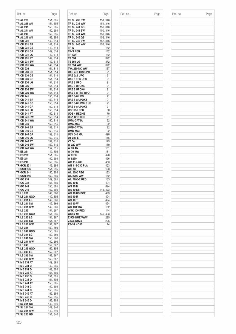
526
TR AL 236 151, 395TR AL 236 AN 151, 395TR AL 241 150, 395TR AL 241 AN 150, 395TR AL 246 152, 395TR AL 246 AN 152, 395TR CD 231 149, 314TR CD 231 BR 149, 314TR CD 231 GB 149, 314TR CD 231 GR 149, 314TR CD 231 LG 149, 314TR CD 231 PT 149, 314TR CD 231 SW 149, 314TR CD 231 WW 149, 314TR CD 236 151, 314TR CD 236 BR 151, 314TR CD 236 GB 151, 314TR CD 236 GR 151, 314TR CD 236 LG 151, 314TR CD 236 PT 151, 314TR CD 236 SW 151, 314TR CD 236 WW 151, 314TR CD 241 150, 314TR CD 241 BR 150, 314TR CD 241 GB 150, 314TR CD 241 GR 150, 314TR CD 241 LG 150, 314TR CD 241 PT 150, 314TR CD 241 SW 150, 314TR CD 241 WW 150, 314TR CD 246 152, 315TR CD 246 BR 152, 315TR CD 246 GB 152, 315TR CD 246 GR 152, 315TR CD 246 LG 152, 315TR CD 246 PT 152, 315TR CD 246 SW 152, 315TR CD 246 WW 152, 315TR ES 231 149, 395TR ES 236 151, 395TR ES 241 150, 395TR ES 246 152, 395TR GCR 231 149, 395TR GCR 236 151, 395TR GCR 241 150, 395TR GCR 246 152, 395TR GO 231 149, 395TR GO 236 151, 395TR GO 241 150, 395TR GO 246 152, 395TR LS 231 149, 366TR LS 231 GGO 149, 395TR LS 231 LG 149, 366TR LS 231 SW 149, 366TR LS 231 WW 149, 366TR LS 236 151, 367TR LS 236 GGO 151, 395TR LS 236 LG 151, 367TR LS 236 SW 151, 367TR LS 236 WW 151, 367TR LS 241 150, 366TR LS 241 GGO 150, 395TR LS 241 LG 150, 366TR LS 241 SW 150, 366TR LS 241 WW 150, 366TR LS 246 152, 367TR LS 246 GGO 152, 395TR LS 246 LG 152, 367TR LS 246 SW 152, 367TR LS 246 WW 152, 367TR ME 231 AT 149, 395TR ME 231 C 149, 395TR ME 231 D 149, 395TR ME 236 AT 151, 395TR ME 236 C 151, 395TR ME 236 D 151, 395TR ME 241 AT 150, 395TR ME 241 C 150, 395TR ME 241 D 150, 395TR ME 246 AT 152, 395TR ME 246 C 152, 395TR ME 246 D 152, 395TR SL 231 GB 149, 346TR SL 231 SW 149, 346TR SL 231 WW 149, 346TR SL 236 GB 151, 346
TR SL 236 SW 151, 346TR SL 236 WW 151, 346TR SL 241 GB 150, 346TR SL 241 SW 150, 346TR SL 241 WW 150, 346TR SL 246 GB 152, 346TR SL 246 SW 152, 346TR SL 246 WW 152, 346TR-S 142TR-S REG 142TR-SUP 142TS 554 372TS 554 LG 372TS 554 WW 372TVA 230 NC WW 157UAE 2x8 TRS UPO 21UAE 2x8 UPO 21UAE 8 TRS UPO 21UAE 8 UPO 21UAE 8 UPOK5 21UAE 8 UPOK6 21UAE 8-8 TRS UPO 21UAE 8-8 UPO 21UAE 8-8 UPOK5 21UAE 8-8 UPOK5 US 21UAE 8-8 UPOK6 21UD 1255 REG 60UDS 4 REGHE 70ULZ 1215 REG 61UMA-CAT6A 22UMA-MA2 22UMB-CAT6A 22UMB-MA3 22USV 640 MA 490UT 238 E 155VT 04 143W 220 WW 160W 70 AN 161W 70 WW 161W 8180 426W 8280 426WB 115-230 453WB 115-230 PLA 453WH 48 108WL 2200 REG 163WL 2200 WW 162WL 2200-2 REG 163WS 10 D 494WS 10 H 494WS 10 KS 145, 493WS 10 KS DCF 493WS 10 R 494WS 10 T 494WS 10 W 494WS 180 WW 162WSK 100 REG 144WSSV 10 145, 493Z 506 NUZ VWW 295Z 506 NUZV 295ZS-34 KO5S 24
Ref.-no. Page Ref.-no. Page Ref.-no. Page Ref.-no. Page
Terms and Conditions of Sale and Supply
I. General provisions
1) The mutual written declarations shall determine the scope of the supplies and services (hereinafter:supplies). However, General Terms and Conditions of Business on the part of the customer shall onlyapply insofar as we have expressly approved the same in writing.2) We shall unrestrictedly reserve our exploitation rights under proprietary right and copyright law to cost estimates, drawings and other documents (hereinafter: documents). Such documents may only berendered accessible to third parties with our prior consent and, upon request, shall, in the event that weshould not be awarded the commission, be returned to us without delay. Sentences 1 and 2 shall applymutatis mutandis to the customer’s submissions, though such submissions may be rendered accessibleto third parties to whom we have admissibly assigned responsibility for supplies.3) Partial supplies shall be admissible insofar as the customer may be reasonably expected to acceptthe same.
II. Prices and Terms and Conditions of Payment
1) Prices shall be understood to be ex-works excluding packaging and plus the statutory sales tax obtaining at any given time.2) Packaging shall be invoiced at the lowest possible prices and shall not be taken back.3) Insofar as nothing is agreed to the contrary, payment shall, irrespective of the receipt of the goodsinvolved, be made to us net within thirty days of the invoice date or within eight days with a 2 % discount.In the event that the payment deadline should be exceeded interest shall, without a reminder being required, be calculated pursuant to § 288 German Civil Code. 4) We shall be entitled to request advance payments in respect of the invoice amounts at any time priorto the dispatch of goods insofar as we deem such a step to be necessary. Should the customer defaulton the fulfilment of payment obligations or should the information pertaining to a customer no longer besatisfactory, we shall be entitled to request security for delivered goods or, once a payment deadline hasbeen set, withdraw from the purchase contract.5) The customer may only offset receivables which are undisputed or have been established on a legallybinding basis.
III. Reservation of title
Goods shall be supplied subject to reservation of title involving the following extensions:1) All supplied goods shall remain our property until such time as our claims vis-à-vis the customer, inclu-ding any such claims which may arise from the business link in the future, are settled in full and for suchtime as the account, including the bill and cheque commitments, has not been settled. This shall alsoapply in the event that the purchase price for certain deliveries of goods specified by the customer is tobe paid. In the case of a current account, the reserved title shall constitute security for our balance claim.2) The customer shall be revocable and, as long as they fulfil their obligations vis-à-vis ourselves andaffording consideration to the following provisions, entitled to sell and process during the normal course of business goods which are encumbered with reservation of title. However, the customer shall be forbidden from pledging or assigning as security goods subject to reservation of title which are supplied or processed. The customer shall, insofar as this is compatible with commercial practices, likewise under-take only to resell reserved goods which we have supplied in conjunction with reservation of title. Uponjustified request and in the case of default, the customer shall be obliged to apprise us of the name of thethird party customer.3) Insofar as goods encumbered with reservation of title are processed, such processing shall, thoughwithout any guarantee on our part, be effected for us. In the event of processing by the customer in conjunction with goods which are not our property, we shall be entitled to co-ownership of the new objectat the ratio of the value of the reserved goods to the other processed goods on the processing date.4) In the event that goods which we have supplied should be combined with other goods, we shallacquire co-ownership of the amount of the ratio of the value of the reserved goods in the combinationdate.5) Should the customer sell reserved goods which we have supplied or should such goods be suppliedto a third party – irrespective of what value or in which condition – or should such goods be installed within the framework of a work, work performance or a construction contract, the customer shall, untilsuch time as the claims stipulated in subsection 1) are settled in full, hereby assign to us, to the amount ofthe invoice value of our deliveries, the claim, together with all ancillary rights, including the compensationclaims accruing to them from the legal transaction involving the resale or installation, accruing to them vis-à-vis their customer or buyer from such sale, delivery or instalment. In the event of an assignment banobtaining in such work, work performance or contruction contract and in the event of payment default,the customer shall undertake to apprise their third party customers of the advance assignment.6) In the event that reserved goods which we have to supplied should be sold to third parties in con-junction with other goods, we shall be assigned that proportion of the total asking price corresponding to the invoice value of our deliveries.7) The reservation of title with the extensions pursuant to the above provision shall also remain in force in the event of individual claims against their customer on the part of the customer being included in thecurrent account. In this case, the customer shall, at this early juncture, assign to us the balance obtainingto their credit. The customer shall, upon request and particularly in the event of payment default on thepart of the purchaser, be obliged to facilitate the direct assertion of the claims involved and apprise thethird party debtor of the assignment.8) We shall be apprised without delay of any attachment and every kind of restriction which obtain in respect of our property. In the event that the value of the overall collateral stemming from the business linkwith which we have been furnished should exceed our delivery claims by more than 20 %, we shall, at therequest of the purchaser, be obliged to reassign the assigned claims to such extent.9) In the event of any incidence of damage or other impairment to the equipment supplied on the basisof our terms and conditions, the purchaser shall, at this early juncture, assign to us in advance the com-pensation claim accruing to them vis-à-vis the insurer from their insurance to the amount of the incidenceof damage in question to our reserved property.
IV. Deadline for deliveries; default
1) The deadline for deliveries or services shall commence on the day on which written agreement pertaining to the order in question obtains between the customer and ourselves. The observance of suchdeadline shall presuppose the prompt receipt of all the documents, requisite licences and releases to befurnished by the customer, the prompt clarification and approval of the plans and the observance of theagreed Terms of Conditions of Payment and other obligations. Should these prerequisites not be fulfilledon time, the delivery deadline shall be extended by an adequate period of time; this shall not apply in theevent that we should be responsible for a delay.2) Should the non-observance of deadlines be attributable to force majeure, such as mobilization, war civil commotion or similar occurrences, e.g. strike or lockout, delivery deadlines shall be extended by adequate periods of time.3) In the event that dispatch or delivery should, at the behest of the customer, be delayed by more thanone month following notification of dispatch readiness, the customer may, for every started month, beinvoiced storage costs to the amount of 0.5 % of the price of the delivery objects, though no more than a total of 5 %. The contracting parties shall be at liberty to prove that lower or higher storage costs have accrued.
V. Transfer of risk
The risk shall also pass to the customer in the event that carriagepaid delivery should have been agreed. In the absence of a written arrangement to the contrary, dispatch shall always be effected according toour best judgement. We shall not assume any responsibility for transportation at market prices. We shallonly arrange transport insurance policies the costs of which are borne by the purchaser upon express,written agreement.
VI. Acceptance
The customer may not refuse to accept deliveries on the grounds of the existence of minor defects.
VII. Material defects
1) The prerequisite for the assertion of material defects liability shall be the submission to us or our authorized representative of proof of acquisition (delivery note, invoice, etc.). The warranty entitlement may not be transferred to third parties without our consent. 2) All those components or services shall, as we see fit, be repaired, resupplied or refurnished which feature a material defect within the limitation period – irrespective of operating life – insofar as the origin of the same obtained at the point in time of transfer of risk.3) Material defects claims shall lapse after twelve month. This shall not apply insofar as the law pursuantto §§ 438, paragraph 1, no. 2 (constructions and objects for constructions), 479, paragraph 1 (claimunder a right of recourse) and 634a, paragraph 1, no. 2 (construction defects) German Civil Code makesprovision for longer periods of time, in instances of injury to life, body or health, in the event of a wilful orgrossly negligent breach of duty on our part and in the event of the malicious nondisclosure of a defect.The statutory provisions pertaining to the suspension of the running of a period, suspension and re-commencement of periods shall remain unaffected.4) The customer shall submit complaints pertaining to material defects to us in writing without delay.5) In the event of notifications of defects, payment on the part of the customer may be withheld on ascale which is in a reasonable ratio to the material defects which have occurred. The customer may onlywithhold payments should a complaint be asserted the justification of which is beyond doubt. Should acomplaint have been submitted without justification, we shall be entitled to request the that customerreimburse the costs which we incurred.6) In the first instance, we shall be granted the opportunity to effect subsequent fulfilment within a reasonable period of time.7) Should such subsequent fulfilment be unsuccessful, the customer – any compensation claims pursuant to subsection IX notwithstanding – may withdraw from the contract or reduce the amount of payment.8) Claims arising from defects shall not obtain in respect of a minor deviation from an agreed quality, aminor impairment to usefulness, natural wear and tear or incidences of prejudice which arise subsequentto the risk transfer in consequence of faulty or negligent handling, exessive strain, unsuitable operatingfacilities, faulty construction operations, unsuitable subsoil and, in particular, any external influences whichare not presupposed by the contract, as well as in respect of non-reproducible software defects.In theevent that modifications or maintenance operations should be improperly performed by the customer orany third parties, it shall likewise be the case that no claims arising from defects shall obtain for suchmodifications and maintenance operations or any resulting consequences.9) Any claims on the part of the customer for expenditure which it is necessary to incur for subsequentfulfilment purposes, particularly transport, travelling, labour and material costs, shall be excluded insofar assuch expenditure increases due to the fact that a delivery object has been subsequently transported to alocation other than the customer’s business premises unless such transportation is in line with the normalutilization of such object.10) Claims under rights of recourse vis-à-vis ourselves on the part of the customer pursuant to § 478German Civil Code (contractor’s recourse) shall only obtain insofar as the customer has not agreed anyarrangements with their customer exceeding the scope of the statutory claims arising from defects. No. 9 shall additionally apply mutatis mutandis to the scope of the customer’s claim under a right ofrecourse vis-à-vis ourselves pursuant to § 478, paragraph 1 German Civil Code. 11) It should be noted that subsection IX (other compensation claims) shall apply to compensationclaims. Any more farreaching claims for a material defect against us and our vicarious agents on the partof the customer and any claims for a material defect against us and our vicarious agents on the part ofthe customer other than those stipulated in subsection VII shall be excluded.
VIII. Impossibility, contractual revision
1) Insofar as a delivery is impossible the customer shall be entitled to claim compensation unless we arenot responsible for such impossibility. However, the customer’s entitlement to compensation shall berestrictes to 10 % of the value of that component of the delivery which cannot be put into appropriateoperation in consequence of such impossibility. This entitlement shall not apply insofar as, in cases of wilful intent, gross negligence or injury to life, body or heath, compulsory liability obtains; this shall not entail a change in the burden of proof to the detriment of the customer. The right of the customer to withdraw from the contract shall remain uneffected.2) Insofar as any unforeseeable occurrences within the purport of subsection IV, no. 2 considerably alter the economic importance or the object of a delivery or exercise a major influence on our operations,the contract shall be suitably revised in compliance with the principle of good faith. Insofar as this is noteconomically justifiable, we shall be entitled to withdraw from the contract. In the event that we shouldwish to exercise this right of withdrawal, we shall apprise the customer accordingly without delay uponbecoming cognizant of the implications of the occurrence in question, including in the event that an extension of the delivery period should initially have been agreed with the customer.
IX. Other compensation claims
1) Claims for compensation and claims for the compensation of expenses (hereinafter: compensationclaims), irrespective of on which legal grounds, particularly for a breach of the duties arising from the contractual obligation and for tortious acts, shall be excluded.2) This shall not apply insofar as compulsory liability obtains, e.g. pursuant to the Product Liability Act, in cases of wilful intent, gross negligence, injury to life, body or health and a breach of major contractualobligations. However, a claim to compensation for a breach of major contractual obligations shall berestricted to the contractually typical, foreseeable prejudice insofar as wilful intent or gross negligence donot obtain or liability obtains due to injury to life, body or health. The above stipulations shall not entail achange in the burden of proof to the detriment of the customer.3) Insofar as the customer is entitled to compensation claims pursuant to subsection IX, such claimsshall lapse upon the expiry of the limitation period pursuant to subsection VII, no. 3 applying to claims formaterial defects. In the case of compensation claims pursuant to the Product Liability Act, the prevailingstatutory limitation provisions shall apply.
X. Diagrams, measurements and weights
Diagrams, measurements and weights shall always be regarded as approximate.
XI. Place of performance, place of jurisdiction and applicable law
1) Insofar as nothing to the contrary is agreed, the place of performance shall be Schalksmühle.2) In the event of the customer being a businessman, the sole place of jurisdiction for all disputes arisingdirectly or indirectly from the contractual relationship shall be Hagen. However, we shall also be entitled toinstitute legal proceedings at the place of domicile of the customer.3) German substantive law shall, to the exclusion of the UN Convention on Contracts pertaining to theInternational Sale of Goods (CISG), apply to the legal relations obtaining in connection with this contract.
XII. The remaining provision of the contract shall continue to have binding force even in the event of the legal invalidity of any of the individual provisions contained in the same. This shall not apply inthe event of adherence to the contract constituting unreasonable hardship for one of the contractingparties.
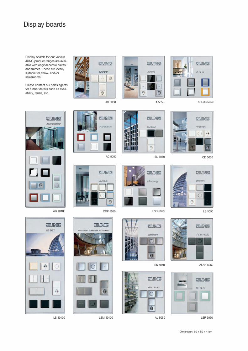
Display boards
Display boards for our various JUNG product ranges are avail-able with original centre plates and frames. These are ideally suitable for show- and/or salesrooms.
Please contact our sales agents for further details such as avail-ability, terms, etc.
Dimension: 50 x 50 x 4 cm
AS 5050
CD 5050
CDP 5050
AL 5050
LSD 5050
ALAN 5050ES 5050
LSP 5050LSM 40100LS 40100
LS 5050
A 5050
SL 5050AC 5050
AC 40100
APLUS 5050

1-gang switch insert 1-pole, 1-way, 10 AX/250 V 501 U 162-pole, 1-way, 10 AX/250 V 502 U 161-pole, 2-way, 10 AX/250 V 506 U 16Intermediate, 10 AX/250 V 507 U 163-pole, 1-way, 16 AX/400 V 503 U 16
1-gang switch insert with indicator light2-pole, 1-way, 10 AX/250 V 502 KOU 161-pole, 2-way, 10 AX/250 V 506 KOU 163-pole, 1-way, 16 AX/400 V 503 KOU 16
1-gang push switch insert2-pole, 1-way, 10 AX/250 V 502 TU 171-pole, 2-way, 10 AX/250 V 506 TU 17Intermediate, 10 AX/250 V 507 TU 171-gang push switch insert with indicator light2-pole, 1-way, 10 AX/250 V 502 KOTU 171-pole, 2-way, 10 AX/250 V 506 KOTU 17
1-gang switch insert1-pole, 1-way, 20 AX/250 V 501-20 U 161-pole, 2-way, 20 AX/250 V 506-20 U 16Intermediate, 20 AX/250 V 507-20 U 161-gang push switch insert with indicator light1-pole, 1-way, 20 AX/250 V 501-20 KOU 162-pole, 1-way, 20 AX/250 V 502-20 KOU 161-pole, 2-way, 20 AX/250 V 506-20 KOU 16
1-gang push button insert 10 AX/250 V1-pole, 1-way (make contact) 531 U2-pole, 1-way (make) 532 U 171-pole, 2-way(make+break contact) 533 U 171-pole, 1-way (make contact) 534 U 172-pole, 2-way (make+break contact) 533-2 U 17Multi switch 10 A 531-41 U 17
2-gang switch insert 10 AX/250 V1-pole, 1-way 505 U 121-pole, 2-way 509 U 12
2-gang switch insert 10 AX/250 V1-pole, 1-way (with lamp) 505 U 5 182-gang switch insert 10 AX/250 Vwith indicator lights1-pole, 1-way 505 KOU 5 181-pole, 1-way 505 KOVU 5 18with mechanical interlocking
2-gang push switch insert 10 AX/250 V1-pole, 1-way 505 TU 181-pole, 2-way 509 TU 18
2-gang push button 10 AX/250 V1-pole, 1-way (make contact) 535 U 181-pole, 2-way (make+break contact) 539 U 181-pole, 1-way (make contact) 535 U 5 18with lampsMulti switch 10 A 250 V 534-1 U 18
2-gang venetian blind insert 10 A/250 V1-pole switch 509 VU 181-pole push-button 539 VU 18
Rotary venetian blind switch 10 A/250 V1-pole 234.10 192-pole 234.20 19
Rotary switch insert 20 A/250 Vwithout pilot light 101-20 19with pilot light 101-20 KO 192-pole rotary switch insert, 32 AX/250 V 101-32 19
Multiple contact switch (0 – 1 – 2 – 3)16 AX/250 V 101-4 1920 AX/250 V, depth 45 mm 101-4-20 19
Time delay switch insert 16 AX/250 V 15 min., 2-pole 1015 1915 min., 1-pole/2-way 1015-20 1930 min., 2-pole 1030 1960 min., 1-pole/2-way 1060-20 192 hours, 1-pole/2-way 1120-20 19
Key switch/push-button inserts 10 AX/250 VVenetian blind switch, 2-pole 104.28 20Venetian blind push-button, 1-pole 134.18 20Venetian blind push-button, 2-pole 134.28 20Push-button, 1-pole, 2-way 133.18 20Push-button, 2-pole 138.18 20Key switch inserts 16 AX/250 V, 2-pole, 2-way 106.28 20
Key switch/push-button inserts 10 AX/250 VVenetian blind switch, 1-pole 104.15 20Venetian blind push-button, 1-pole 134.15 20Push-button, 1-pole, 2-way 133.15 20Key switch inserts 16 AX/250 V, 1-pole, 2-way 106.15 20
Key switch/push-button inserts 10 AX/250 VWaterproof version (IP 44)Venetian blind switch, 1-pole CD 104.18 WU 20Venetian blind push-button, 1-pole CD 134.18 WU 20Push-button, 1-pole, 2-way CD 133.18 WU 20Key switch inserts 16 AX/250 V, 1-pole, 2-way CD 106.18 WU 20
Modular Jack sockets1-gang, 8-pole, 1 Terminal UAE 8 UPO 212-gang, 8-pole, 1 Terminal UAE 2 x 8 UPO 212-gang, 8-pole, 2 Terminals UAE 8-8 UPO 212-gang, 8-pole, 2 Terminals, unshielded UAE8-8UPOK5US 21
Modular Jack sockets1-gang, 8-pole, Cat. 5e UAE 8 UPOK5 212-gang, 8-pole, Cat. 5e UAE 8-8 UPOK5 211-gang, 8-pole, Cat. 6 UAE 8 UPOK6 212-gang, 8-pole, Cat. 6 UAE 8-8 UPOK6 21
TV-FM socket insertSingle, terrestrial FS 1 D 23Through, terrestrial FS 12 D 23Single, satellite EDU 04 F 23Through, satellite GEDU 15 23SAT-TV-FM EDU 3902 F 23
Mechanical inserts Mechanical inserts
ref.no. page ref.no. page
UAE 2 x 8 UPO
UAE 8 UPOK5
EDU 04 F

Rotary dimmer insertwith two way push switchfor incandescent lamps, halogen lamps060 – 0600 W, 230 V ~ 266 GDE 48060 – 0360 W, 230 V ~ 244 EX 48100 – 1000 W, 230 V ~ 211 GDE 49060 – 0400 W, 110 V ~ 244-110 49
TRONIC-dimmer insertwith two way push switchfor incandescent lamps, halogen lamps,TRONIC transformer20 – 525 W, 230 V ~ 225 TDE 5020 – 360 W, 230 V ~ 243 EX 49
Rotary dimmer insertwith two way push switchfor incandescent lamps, halogen lamps, conventional transformers40 – 500 W, 230 V ~ 225 NVDE 5120 – 500 W, 230 V ~ 244 HEX 50
Universal dimmer insertwith incremental control for incandescent lamps, halogen lamps, conventional transformers, TRONIC transformer50 – 420 W, 230 V ~ 254 UDIE1 5250 – 340 W, 127 V ~ 254 UDIE-110 54
Satellite dimmer insertfor universal dimmer with incremental control230 V ~ 254 NIE1 53127 V ~ 254 NIE-110 54
LEDOTRON control unitfor switching and dimmingof LEDOTRON lamps 242 LTS DE 55
DALI dimmer insert 240 DPE 55DALI power potentiometer 240 PDPE 56for dimming of fluorescent lampscontrolled by DALI ballasts
Electronic potentiometer 1 – 10 Vwith switch function 240-10 55with push-button function 240-31 55
Speed regulator insert 245.20 57for controlling the speed of single-phase motors
Universal dimmer insert 1254 UDE 8650 – 420 W/VA, 230 V ~
Standard dimmer insert 1225 SDE 8120 – 500 VA, 230 V ~
Universal 2-gang dimmer insert 1252 UDE 8750 – 260 W/VA, AC 230 V ~, 50/60 Hz
Control unit 1 – 10 V 1240 STE 89for switching and dimming of electronic ballasts (EVC) with 1 – 10 V
Universal relay switch insert 1201 URE 901-channel switch230 V ~, max. 2300 W
Universal relay switch insert 1201-1 URE 911-channel switch with floating contact230 V ~, max. 800 W
Universal relay switch insert 1202 URE 922-channel switch with one floating contact and one contact with 230 V ~ mains potential 230 V ~ , max. 1000 W
TRONIC switch insert 1254 TSE 93for soundless switching50 – 420 W, 230 V ~
LV-Triac switch insert 1244 NVSE 9340 – 400 W, 230 V ~
Satellite insertsfor standard center plate 1220 NE 94for automatic switches 1223 NE 94
Pulse unit 1208 UI 95to realise a Staircase automatic switch circuit
Power unit 208 REG 88for series-embodiment installation
TRONIC transformer10 – 040 W SNT 40 6220 – 070 W SNT 70 Q 6220 – 070 W SNT 70 F 6320 – 105 W SNT 105 F 6335 – 105 W SNT 105-35 6420 – 150 W SNT 150 6450 – 200 W SNT 200 65
Built-in amplifierfor TRONIC, 60 – 700 W 247 EB 57for conventional, 100 – 600 W 246 EB 58
Universal dimmer UD 1255 REG 6050 – 500 WUniversal amplifier ULZ 1215 REG 61200 – 500 W
Electronics Electronics
ref.no. page ref.no. page
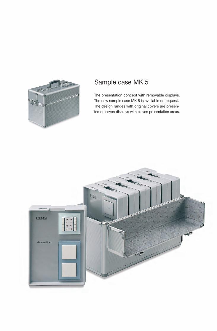
Cat
alog
ue E
xpor
t 25
B-GB-EXP 4 011377 049963
ALBRECHT JUNG GMBH & CO. KGP.O. Box 1320D-58569 SchalksmühleGermany
Tel.: +49 2355 806-553Fax: +49 2355 806-254E-mail: [email protected]: www.jung.de/en
For sales contacts in your country see: www.jung-salescontact.com
Certified proof of origine
„Made in Germany“ by TÜV Nord.
Catalogue Export 25November 2011
We assume/accept no liability for these catalogue being complete, correct or up-to-date.
At a glance: All manuals for you combined on a CD ROM – comfortable to download to your computer!
The presentation concept with removable displays. The new sample case MK 5 is available on request. The design ranges with original covers are presen-ted on seven displays with eleven presentation areas.
Sample case MK 5
Platzhalter
Catalogus 2013
Cat
alog
ue E
xpor
t 25
B-GB-EXP 4 011377 049963
ALBRECHT JUNG GMBH & CO. KGP.O. Box 1320D-58569 SchalksmühleGermany
Tel.: +49 2355 806-553Fax: +49 2355 806-254E-mail: [email protected]: www.jung.de/en
For sales contacts in your country see: www.jung-salescontact.com
Certified proof of origine
„Made in Germany“ by TÜV Nord.
Catalogue Export 25November 2011
We assume/accept no liability for these catalogue being complete, correct or up-to-date.
At a glance: All manuals for you combined on a CD ROM – comfortable to download to your computer!
The presentation concept with removable displays. The new sample case MK 5 is available on request. The design ranges with original covers are presen-ted on seven displays with eleven presentation areas.
Sample case MK 5
Catalogus 2013


