Download - Hose & Coupling Directory - Dixon Europe
• C
US
TO
ME
R S
ER
VIC
E •
IN
NO
VA
TIO
N •
MA
NU
FA
CT
UR
ING
• Q
UA
LIT
Y •
TE
CH
NIC
AL
EX
PE
RT
ISE
• E
XC
EL
LE
NC
E •
DE
SIG
N •
• C
US
TO
ME
R S
ER
VIC
E •
IN
NO
VA
TIO
N •
MA
NU
FA
CT
UR
ING
• Q
UA
LIT
Y •
TE
CH
NIC
AL
EX
PE
RT
ISE
• E
XC
EL
LE
NC
E •
DE
SIG
N •
Hose & Coupling Directory
www.dixoneurope.co.uk
Customer Service: +44 (0)1772 323 529
• C
US
TO
ME
R S
ER
VIC
E •
IN
NO
VA
TIO
N •
MA
NU
FA
CT
UR
ING
• Q
UA
LIT
Y •
TE
CH
NIC
AL
EX
PE
RT
ISE
• E
XC
EL
LE
NC
E •
DE
SIG
N •
2 Telephone: +44 (0)1772 323529 Fax: +44 (0)1772 314664
Contents
Air Fittings
“Air King” Universal Couplings & Clamps,European Compressor Couplings,Quick Release Couplings,King Cable Safety Hose Restraints, WhipchecksBlow Guns.
A
Cam & Groove
Dixon A-A-5932B Specification,DIN, Andrews, Boss-lock, EZ Boss, Line Drawings, High Pressure Snow Cannon Range, King Crimp Style, Seals & Gaskets, Reducing Couplers, Adapters, Replacement Handles, Accessories
B
Clamps & Accessories
Heavy Duty & Spiral Clamps, Worm Gear, K Series, Single & Double Bolt Clamps, Aero Seal and Preformed Band Clamps, Hi-Torque, T-Bolt, Band It™, Safety Clamps, Clamping Tools
C
Rubber, PVC and Composite Hose for Air/Water, Oil, Chemical, General Purpose and Food Applications, Bulkstream – Custom Built Hose, Metallic & PTFE, Specialist Armoured, Hose Protection and Jackets.
F
Hygienic Products
Couplings (DIN, RJT, SMS, IDF, Tri-Clamp), Clamps, Gaskets, Elbows, Tees, Ferrules, Reducers, Valves (Butterfly, Ball & Check), Sight Glasses, BPE Biopharm, Dairy, Actuated Valves, Bespoke Fabricated Configurations. G
Permanently Attached Couplings - Holedall®
Internal Expansion, External Crimp, External Swage, Stems, Ferrules, Hygienic, API Certified Fittings, Concrete Placement & Offshore Range, Rotary & High Pressure, Hose Lifter, Hammer Unions, Swaging Machines & Accessories. H
Tanker, Overfill & Storage Tank Products
Petroleum and Dry Bulk Fittings, Adapters & Couplers, API Valves, Caps, FloTech™ Overfill Prevention, Nozzles, Pressure & Vacuum Valves, Reducers, Tank Truck Fittings, Storz, Swivel Joints, Dry Quick Disconnect Couplings.
K
Valves - General & Industrial
Ball Valves, Gate Valves, Polypropylene Valves, Foot Valves, Skimmers & Strainers,Safety Check Valves, Locking Ball.(for other valves see section G & K)
L
Water Couplings
Agri Lock, Bauer Type, Hinge Lock, Victaulic, Geka Type, King Shank, King Combination Nipples, King Crimp Style, Wash Down Guns.(for Swivel Joints see section K)
M
Hose & Hose Assemblies
3Telephone: +44 (0)1772 323529 Fax: +44 (0)1772 314664
A
B
C
D
E
F
G
H
I
J
K
L
M
N
page
4
page
22
page
58
page
76
page
80
page
100
page
138
page
238
page
268
page
336
page
348
page
402
page
416
page
442
Air Fittings
Cam & Groove
Clamps & Accessories
Fire Products - Dixon Powhatan
Fittings, Gauges & Adapters
Hose & Hose Assemblies
Hygienic Products
Permanently Attached Couplings - Holedall®
Quick Release Couplings
Steam Couplings - Boss™
Tanker, Overfill & Storage Tank Products
Valves - General & Industrial
Water Couplings
Technical & Safety Information
Fire Products - Dixon Powhatan
Fire Protection Valves, Fire Department Connections, Mill Hose, Rack Hose, Hydrant Adapters, Expansion Rings,Hydrant Nozzles, Hose Couplings, Single & Double Jackets(for Storz fittings see section K)
D
Fittings, Gauges & Adapters
Pipe Fittings, Flanges, Smooth Tails, Instrumentation Fittings, Reducers, Threaded Adapters, Plugs, Swivel Adapters, Crimp Ferrules, Crimping Tools, Plastic Fittings, Brass Fittings
E
Quick Release Couplings
Quick Release Couplings for hydraulic and pneumatic applications. Interchanges with ISO A, ISO B, Snap-Tite, Rectus, MacDonald, Cjen, Parker. High Pressure Blow Out Preventors.
I
Steam Couplings - Boss™
Boss Coupling System, Boss Ground Joint Seal Coupling, Boss Stem & Wing Nuts, Boss Spud Adapters, Boss Adapters & Hose Menders, Boss Clamps, Steam Hose Fittings BS EN 14423:2004.
J
Technical & Safety Information
N
www.dixoneurope.co.uk
A
4 Telephone: +44 (0)1772 323529 Fax: +44 (0)1772 3146644 Telephone: +44 (0)1772 323529 Fax: +44 (0)1772 314664
A
A
5Telephone: +44 (0)1772 323529 Fax: +44 (0)1772 314664
N Series Quick Release Couplings - Bowes/MacDonald Interchange ... 6-11
P Series Quick Release Couplings - Thor Interchange ....................... 12-14
Air King Couplings ............................................................................. 15-18
Air King Clamps ................................................................................. 15-18
Crimp Ferrule .............................................................................................18
European Compressor Couplings ..............................................................19
European Compressor Two Bolt Clamps ....................................................19
King Safety Cable Hose Restraint - ‘Whipcheck Style’ ...............................20
Blow Guns .................................................................................................21
For a Full range oF air hoses to complement these Fittings see section F
5Telephone: +44 (0)1772 323529 Fax: +44 (0)1772 314664
Air Fittings A
6 Telephone: +44 (0)1772 323529 Fax: +44 (0)1772 314664
Air Fittings
AQuick release couplings - n series Bowes/macDonald interchange
n-series (mini-Bowes) interchange (coupler)
part no.
3nm43nBm4
BoDy siZe
3/8”3/8”
threaD siZe
1/2”-14 NPTFR1/2” BSPT
BoDy material
steelsteel
Bowes
-51000 Series51000 Series
‘n’ seriesinterchange
3/8”1/2”
11/4”
national
-Series ‘B’
-
macDonalD
-Quick-Action
-
Dixon
-Dixlock
-
operating Bar (psi)
21 (300)21 (300)21 (300)
perFormancespeciFications
3/8”1/2”
11/4”
BurstBar (psi)
207 (3,000)207 (3,000)103 (1,500)
Flow Dp=0.4 Bar(6.9 Bar inlet)
84 CFM250 CFM700 CFM
locking mechanism
Latch TabsLatch TabsLatch Tabs
us military
MIL-C-3486
interchangestanDarDs
1/2”
us government
A-A-50431A
internationalstanDarDs
-
ansi/nFpa
-
n-series (mini-Bowes) interchange (nipple)
part no.
n3m4n3Bm4
BoDy siZe
3/8”3/8”
threaD siZe
1/2”-14 NPTFR1/2” BSPT
BoDy material
steelsteel
n-series (mini-Bowes) interchange (coupler)
part no.
3ncs4
BoDy siZe
3/8”
BarBconFiguration
1/2” Collar Barb
BoDy material
steel
(Male Thread)
(Male Thread)
(Collar Barb)
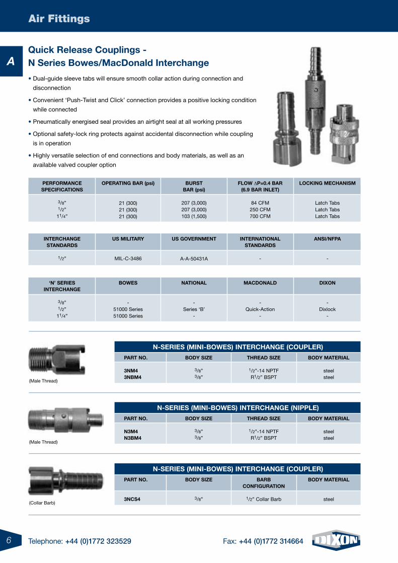
• Dual-guide sleeve tabs will ensure smooth collar action during connection and
disconnection
• Convenient ‘Push-Twist and Click’ connection provides a positive locking condition
while connected
• Pneumatically energised seal provides an airtight seal at all working pressures
• Optional safety-lock ring protects against accidental disconnection while coupling
is in operation
• Highly versatile selection of end connections and body materials, as well as an
available valved coupler option
7Telephone: +44 (0)1772 323529 Fax: +44 (0)1772 314664
Air Fittings
An-series (mini-Bowes) interchange (nipple)
part no.
n3cs4
BoDy siZe
3/8”
BarB conFiguration
1/2” Collar Barb
BoDy material
steel
n-series macDonalD interchange (unvalveD coupler)
part no.
4nF34nF3-B4nBF34nF44nF4-B4nBF44nBF4-B4nF64nF6-B4nF6-s4nBF64nBF6-B4nF84nF8-B4nBF84nBF8-B
BoDy siZe
1/2”1/2”1/2”1/2”1/2”1/2”1/2”1/2”1/2”1/2”1/2”1/2”1/2”1/2”1/2”1/2”
threaD siZe
3/8”-18 NPTF3/8”-18 NPTFG3/8” BSPP
1/2”-14 NPTF1/2”-14 NPTFG1/2” BSPPG1/2” BSPP
3/4”-14 NPTF3/4”-14 NPTF3/4”-14 NPTFG3/4” BSPPG3/4” BSPP
1”-111/2 NPTF1”-111/2 NPTF
G1” BSPPG1” BSPP
BoDy material
steelbrasssteelsteelbrasssteelbrasssteelbrass
303 SSsteelbrasssteelbrasssteelbrass
n-series macDonalD interchange (nipple)
part no.
n4F3n4F3-Bn4BF3n4F4n4F4-Bn4BF4n4BF4-Bn4F6n4F6-Bn4F6-sn4BF6n4BF6-Bn4F8n4F8-Bn4BF8n4BF8-B
BoDy siZe
1/2”1/2”1/2”1/2”1/2”1/2”1/2”1/2”1/2”1/2”1/2”1/2”1/2”1/2”1/2”1/2”
threaD siZe
3/8”-18 NPTF3/8”-18 NPTFG3/8” BSPP
1/2”-14 NPTF1/2”-14 NPTFG1/2” BSPPG1/2” BSPP
3/4”-14 NPTF3/4”-14 NPTF3/4”-14 NPTFG3/4” BSPPG3/4” BSPP
1”-111/2 NPTF1”-111/2 NPTF
G1” BSPPG1” BSPP
BoDy material
steelbrasssteelsteelbrasssteelbrasssteelbrass
303 SSsteelbrasssteelbrasssteelbrass
n-series macDonalD interchange (valveD coupler)
part no.
4nF6-v4nBF6-v
BoDy siZe
1/2”1/2”
threaD siZe
3/4”-14 NPTFG3/4” BSPP
BoDy material
steelsteel
n-series macDonalD interchange (saFety-lock nipple)
part no.
n4F4-B-lsn4F6-B-ls
BoDy siZe
1/2”1/2”
threaD siZe
1/2”-14 NPTF3/4”-14 NPTF
BoDy material
brassbrass
(Collar Barb)
(Female Thread)
(Female Thread)
(Female Thread)
(Female Thread)
8 Telephone: +44 (0)1772 323529 Fax: +44 (0)1772 314664
Air Fittings
An-series macDonalD interchange (unvalveD coupler)
part no.
4nm34nm3-B4nBm34nm44nm4-B4nBm44nBm4-B4nm64nm6-B4nm6-s4nBm64nBm6-B4nm84nm8-B4nBm84nBm8-B
BoDy siZe
1/2”1/2”1/2”1/2”1/2”1/2”1/2”1/2”1/2”1/2”1/2”1/2”1/2”1/2”1/2”1/2”
threaD siZe
3/8”-18 NPTF3/8”-18 NPTFR3/8” BSPT
1/2”-14 NPTF1/2”-14 NPTFR1/2” BSPTR1/2” BSPT
3/4”-14 NPTF3/4”-14 NPTF3/4”-14 NPTFR3/4” BSPTR3/4” BSPT
1”-111/2 NPTF1”-111/2 NPTF
R1” BSPTR1” BSPT
BoDy material
steelbrasssteelsteelbrasssteelbrasssteelbrass
303 SSsteelbrasssteelbrasssteelbrass
n-series macDonalD interchange (nipple)
part no.
n4m3n4m3-Bn4Bm3n4m4n4m4-Bn4Bm4n4Bm4-Bn4m6n4m6-Bn4m6-sn4Bm6n4Bm6-Bn4m8n4m8-Bn4Bm8n4Bm8-B
BoDy siZe
1/2”1/2”1/2”1/2”1/2”1/2”1/2”1/2”1/2”1/2”1/2”1/2”1/2”1/2”1/2”1/2”
threaD siZe
3/8”-18 NPTF3/8”-18 NPTFR3/8” BSPT
1/2”-14 NPTF1/2”-14 NPTFR1/2” BSPTR1/2” BSPT
3/4”-14 NPTF3/4”-14 NPTF3/4”-14 NPTFR3/4” BSPTR3/4” BSPT
1”-111/2 NPTF1”-111/2 NPTF
R1” BSPTR1” BSPT
BoDy material
steelbrasssteelsteelbrasssteelbrasssteelbrass
303 SSsteelbrasssteelbrasssteelbrass
n-series macDonalD interchange (saFety-lock nipple)
part no.
n4m4-lsn4m4-B-lsn4Bm4-lsn4m6-lsn4m6-B-lsn4m6-s-lsn4Bm6-ls
BoDy siZe
1/2”1/2”1/2”1/2”1/2”1/2”1/2”
threaD siZe
1/2”-14 NPTF1/2”-14 NPTFR1/2” BSPT
3/4”-14 NPTF3/4”-14 NPTF3/4”-14 NPTFR3/4” BSPT
BoDy material
steelbrasssteelsteelbrass
303 SSsteel
n-series macDonalD interchange (valveD coupler)
part no.
4nm6-v
BoDy siZe
1/2”
threaD siZe
3/4”-14 NPTF
BoDy material
steel
(Male Thread)
(Male Thread)
(Male Thread)
(Male Thread)
9Telephone: +44 (0)1772 323529 Fax: +44 (0)1772 314664
Air Fittings
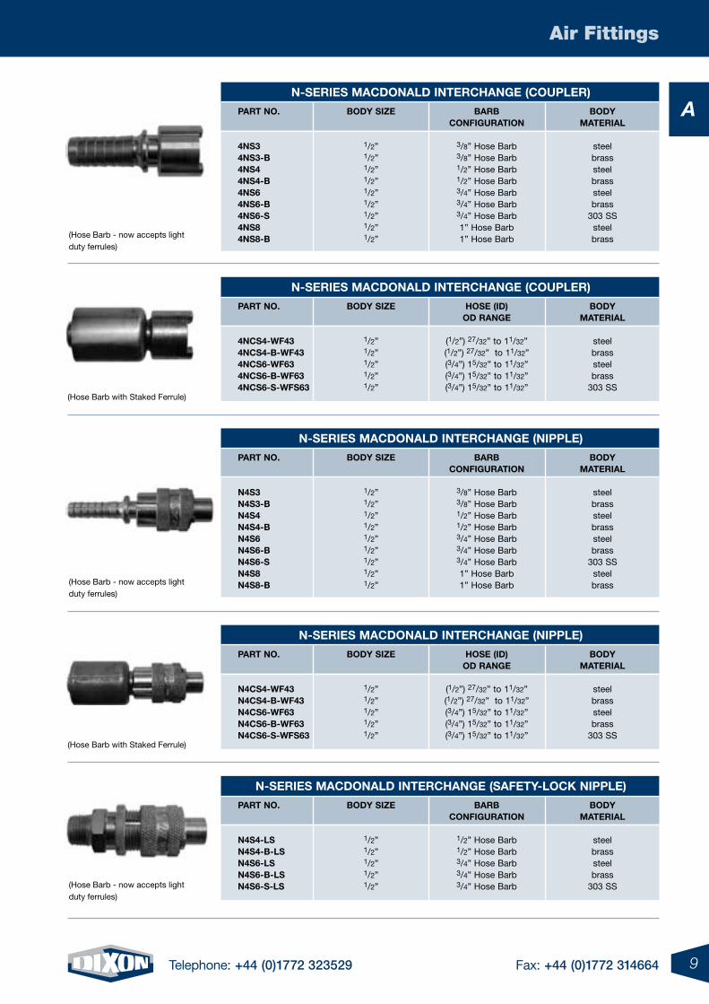
An-series macDonalD interchange (coupler)
part no.
4ns34ns3-B4ns44ns4-B4ns64ns6-B4ns6-s4ns84ns8-B
BoDy siZe
1/2”1/2”1/2”1/2”1/2”1/2”1/2”1/2”1/2”
BarB conFiguration
3/8” Hose Barb3/8” Hose Barb1/2” Hose Barb1/2” Hose Barb3/4” Hose Barb3/4” Hose Barb3/4” Hose Barb1” Hose Barb1” Hose Barb
BoDy material
steelbrasssteelbrasssteelbrass
303 SSsteelbrass
n-series macDonalD interchange (nipple)
part no.
n4s3n4s3-Bn4s4n4s4-Bn4s6n4s6-Bn4s6-sn4s8n4s8-B
BoDy siZe
1/2”1/2”1/2”1/2”1/2”1/2”1/2”1/2”1/2”
BarB conFiguration
3/8” Hose Barb3/8” Hose Barb1/2” Hose Barb1/2” Hose Barb3/4” Hose Barb3/4” Hose Barb3/4” Hose Barb1” Hose Barb1” Hose Barb
BoDy material
steelbrasssteelbrasssteelbrass
303 SSsteelbrass
n-series macDonalD interchange (coupler)
part no.
4ncs4-wF434ncs4-B-wF434ncs6-wF634ncs6-B-wF634ncs6-s-wFs63
BoDy siZe
1/2”1/2”1/2”1/2”1/2”
hose (iD)oD range
(1/2”) 27/32” to 11/32”(1/2”) 27/32” to 11/32”(3/4”) 15/32” to 11/32”(3/4”) 15/32” to 11/32”(3/4”) 15/32” to 11/32”
BoDy material
steelbrasssteelbrass
303 SS
n-series macDonalD interchange (nipple)
part no.
n4cs4-wF43n4cs4-B-wF43n4cs6-wF63n4cs6-B-wF63n4cs6-s-wFs63
BoDy siZe
1/2”1/2”1/2”1/2”1/2”
hose (iD)oD range
(1/2”) 27/32” to 11/32”(1/2”) 27/32” to 11/32”(3/4”) 15/32” to 11/32”(3/4”) 15/32” to 11/32”(3/4”) 15/32” to 11/32”
BoDy material
steelbrasssteelbrass
303 SS
n-series macDonalD interchange (saFety-lock nipple)
part no.
n4s4-lsn4s4-B-lsn4s6-lsn4s6-B-lsn4s6-s-ls
BoDy siZe
1/2”1/2”1/2”1/2”1/2”
BarBconFiguration
1/2” Hose Barb1/2” Hose Barb3/4” Hose Barb3/4” Hose Barb3/4” Hose Barb
BoDy material
steelbrasssteelbrass
303 SS
(Hose Barb - now accepts light duty ferrules)
(Hose Barb with Staked Ferrule)
(Hose Barb - now accepts light duty ferrules)
(Hose Barb with Staked Ferrule)
(Hose Barb - now accepts light duty ferrules)
10 Telephone: +44 (0)1772 323529 Fax: +44 (0)1772 314664
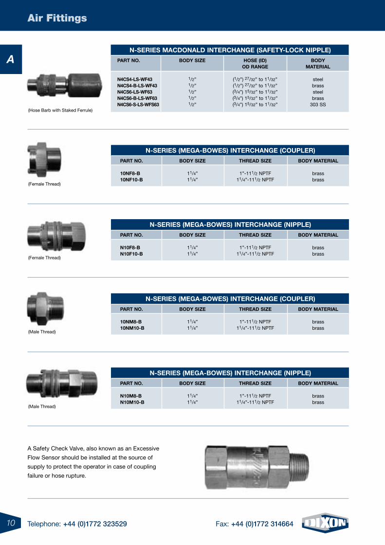
Air Fittings
A
A Safety Check Valve, also known as an Excessive
Flow Sensor should be installed at the source of
supply to protect the operator in case of coupling
failure or hose rupture.
n-series macDonalD interchange (saFety-lock nipple)
part no.
n4cs4-ls-wF43n4cs4-B-ls-wF43n4cs6-ls-wF63n4cs6-B-ls-wF63n4cs6-s-ls-wFs63
BoDy siZe
1/2”1/2”1/2”1/2”1/2”
hose (iD)oD range
(1/2”) 27/32” to 11/32”(1/2”) 27/32” to 11/32”(3/4”) 15/32” to 11/32”(3/4”) 15/32” to 11/32”(3/4”) 15/32” to 11/32”
BoDy material
steelbrasssteelbrass
303 SS
n-series (mega-Bowes) interchange (coupler)
part no.
10nF8-B10nF10-B
BoDy siZe
11/4”11/4”
threaD siZe
1”-111/2 NPTF11/4”-111/2 NPTF
BoDy material
brassbrass
n-series (mega-Bowes) interchange (nipple)
part no.
n10F8-Bn10F10-B
BoDy siZe
11/4”11/4”
threaD siZe
1”-111/2 NPTF11/4”-111/2 NPTF
BoDy material
brassbrass
n-series (mega-Bowes) interchange (coupler)
part no.
10nm8-B10nm10-B
BoDy siZe
11/4”11/4”
threaD siZe
1”-111/2 NPTF11/4”-111/2 NPTF
BoDy material
brassbrass
n-series (mega-Bowes) interchange (nipple)
part no.
n10m8-Bn10m10-B
BoDy siZe
11/4”11/4”
threaD siZe
1”-111/2 NPTF11/4”-111/2 NPTF
BoDy material
brassbrass
(Hose Barb with Staked Ferrule)
(Female Thread)
(Female Thread)
(Male Thread)
(Male Thread)
11Telephone: +44 (0)1772 323529 Fax: +44 (0)1772 314664
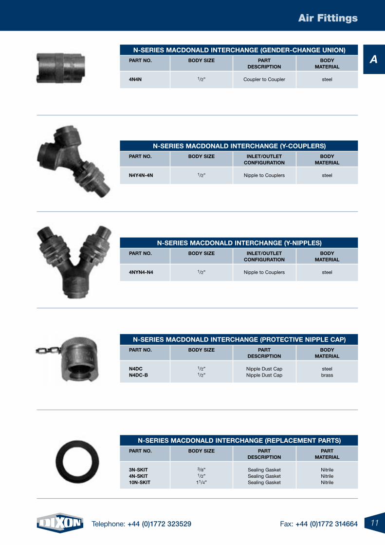
Air Fittings
An-series macDonalD interchange (genDer-change union)
part no.
4n4n
BoDy siZe
1/2”
partDescription
Coupler to Coupler
BoDy material
steel
n-series macDonalD interchange (y-couplers)
part no.
n4y4n-4n
BoDy siZe
1/2”
inlet/outletconFiguration
Nipple to Couplers
BoDy material
steel
n-series macDonalD interchange (y-nipples)
part no.
4nyn4-n4
BoDy siZe
1/2”
inlet/outletconFiguration
Nipple to Couplers
BoDy material
steel
n-series macDonalD interchange (protective nipple cap)
part no.
n4Dcn4Dc-B
BoDy siZe
1/2” 1/2”
partDescription
Nipple Dust CapNipple Dust Cap
BoDy material
steelbrass
n-series macDonalD interchange (replacement parts)
part no.
3n-skit4n-skit10n-skit
BoDy siZe
3/8”1/2”
11/4”
partDescription
Sealing GasketSealing GasketSealing Gasket
part material
NitrileNitrileNitrile
12 Telephone: +44 (0)1772 323529 Fax: +44 (0)1772 314664
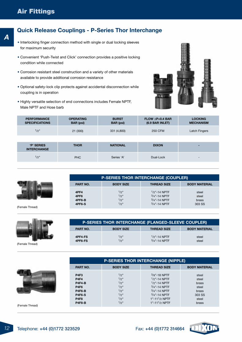
Air Fittings
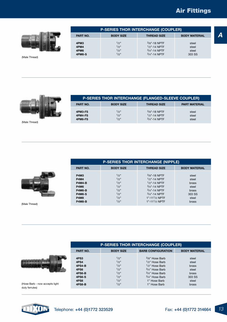
AQuick release couplings - p-series thor interchange
• Interlocking finger connection method with single or dual locking sleeves
for maximum security
• Convenient ‘Push-Twist and Click’ connection provides a positive locking
condition while connected
• Corrosion resistant steel construction and a variety of other materials
available to provide additional corrosion resistance
• Optional safety-lock clip protects against accidental disconnection while
coupling is in operation
• Highly versatile selection of end connections includes Female NPTF,
Male NPTF and Hose barb
p-series thor interchange (coupler)
part no.
4pF44pF64pF6-B4pF6-s
BoDy siZe
1/2”1/2”1/2”1/2”
threaD siZe
1/2”-14 NPTF3/4”-14 NPTF3/4”-14 NPTF3/4”-14 NPTF
BoDy material
steelsteelbrass
303 SS
p-series thor interchange (FlangeD-sleeve coupler)
part no.
4pF4-Fs4pF6-Fs
BoDy siZe
1/2”1/2”
threaD siZe
1/2”-14 NPTF3/4”-14 NPTF
BoDy material
steelsteel
p-series thor interchange (nipple)
part no.
p4F3p4F4p4F4-Bp4F6p4F6-Bp4F6-sp4F8p4F8-B
BoDy siZe
1/2”1/2”1/2”1/2”1/2”1/2”1/2”1/2”
threaD siZe
3/8”-18 NPTF1/2”-14 NPTF1/2”-14 NPTF3/4”-14 NPTF3/4”-14 NPTF3/4”-14 NPTF
1”-111/2 NPTF1”-111/2 NPTF
BoDy material
steelsteelbrasssteelbrass
303 SSsteelbrass
operating Bar (psi)
21 (300)
perFormancespeciFications
1/2”
BurstBar (psi)
331 (4,800)
Flow Dp=0.4 Bar(6.9 Bar inlet)
250 CFM
locking mechanism
Latch Fingers
thor
PHC
‘p’ seriesinterchange
1/2”
national
Series ‘A’
Dixon
Dual-Lock
-
-
(Female Thread)
(Female Thread)
(Female Thread)
13Telephone: +44 (0)1772 323529 Fax: +44 (0)1772 314664
Air Fittings
Ap-series thor interchange (coupler)
part no.
4pm34pm44pm64pm6-s
BoDy siZe
1/2”1/2”1/2”1/2”
threaD siZe
3/8”-18 NPTF1/2”-14 NPTF3/4”-14 NPTF3/4”-14 NPTF
BoDy material
steelsteelsteel
303 SS
p-series thor interchange (nipple)
part no.
p4m3p4m4p4m4-Bp4m6p4m6-Bp4m6-sp4m8p4m8-B
BoDy siZe
1/2”1/2”1/2”1/2”1/2”1/2”1/2”1/2”
threaD siZe
3/8”-18 NPTF1/2”-14 NPTF1/2”-14 NPTF3/4”-14 NPTF3/4”-14 NPTF3/4”-14 NPTF
1”-111/2 NPTF1”-111/2 NPTF
BoDy material
steelsteelbrasssteelbrass
303 SSsteelbrass
p-series thor interchange (coupler)
part no.
4ps34ps44ps4-B4ps64ps6-B4ps6-s4ps84ps8-B
BoDy siZe
1/2”1/2”1/2”1/2”1/2”1/2”1/2”1/2”
BarB conFiguration
3/8” Hose Barb1/2” Hose Barb1/2” Hose Barb3/4” Hose Barb3/4” Hose Barb3/4” Hose Barb1” Hose Barb1” Hose Barb
BoDy material
steelsteelbrasssteelbrass
303 SSsteelbrass
p-series thor interchange (FlangeD-sleeve coupler)
part no.
4pm3-Fs4pm4-Fs4pm6-Fs
BoDy siZe
1/2”1/2”1/2”
threaD siZe
3/8”-18 NPTF1/2”-14 NPTF3/4”-14 NPTF
part material
steelsteelsteel
(Male Thread)
(Male Thread)
(Hose Barb - now accepts light duty ferrules)
(Male Thread)
14 Telephone: +44 (0)1772 323529 Fax: +44 (0)1772 314664
Air Fittings
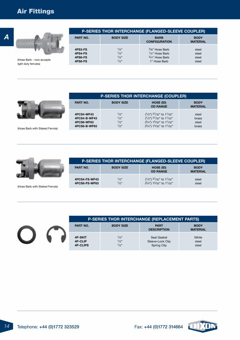
Ap-series thor interchange (FlangeD-sleeve coupler)
part no.
4ps3-Fs4ps4-Fs4ps6-Fs4ps8-Fs
BoDy siZe
1/2”1/2”1/2”1/2”
BarBconFiguration
3/8” Hose Barb1/2” Hose Barb3/4” Hose Barb1” Hose Barb
BoDy material
steelsteelsteelsteel
p-series thor interchange (coupler)
part no.
4pcs4-wF434pcs4-B-wF434pcs6-wF634pcs6-B-wF63
BoDy siZe
1/2”1/2”1/2”1/2”
hose (iD)oD range
(1/2”) 27/32” to 11/32”(1/2”) 27/32” to 11/32”(3/4”) 15/32” to 11/32”(3/4”) 15/32” to 11/32”
BoDy material
steelbrasssteelbrass
p-series thor interchange (replacement parts)
part no.
4p-skit4p-clip4p-clips
BoDy siZe
1/2”1/2”1/2”
partDescription
Seal GasketSleeve-Lock Clip
Spring Clip
BoDy material
Nitrilesteelsteel
p-series thor interchange (FlangeD-sleeve coupler)
part no.
4pcs4-Fs-wF434pcs6-Fs-wF63
BoDy siZe
1/2”1/2”
hose (iD)oD range
(1/2”) 27/32” to 11/32”(3/4”) 15/32” to 11/32”
BoDy material
steelsteel
(Hose Barb - now accepts light duty ferrules)
(Hose Barb with Staked Ferrule)
(Hose Barb with Staked Ferrule)
15Telephone: +44 (0)1772 323529 Fax: +44 (0)1772 314664
Air Fittings
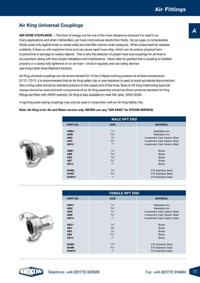
Aair king universal couplings
air hose couplings – This form of energy can be one of the most dangerous because it is used in so
many applications and when mishandled, can have more serious results than fluids. Air, as a gas, is compressible
(fluids press only against hose or vessel walls and lose little volume under pressure). When pressurised air releases
suddenly, it does so with explosive force and can cause rapid hose whip, which can do serious physical harm
to personnel or damage to nearby objects. This is why the selection of proper hose and couplings for air-lines is
so important, along with their proper installation and maintenance. Never take for granted that a coupling is installed
properly or a clamp fully tightened on an air hose – check it regularly and use safety devices
(see King Cable Hose Restraint Section).
Air King universal couplings can be recommended for 10 bar (150psi) working pressure at ambient temperature
(21°C / 70°F). It is recommended that an Air King safety clip or wire restrainer is used to avoid accidental disconnection.
Also a King cable should be standard practice on the supply end of the hose. Boss or Air King interlocking type bolt
clamps should be used and both components of an Air King assembly should be Dixon products standard Air King
fittings are fitted with AWR4 washers. Air King is also available to meet MIL spec. WWC-633D.
4-lug King quick-acting couplings may only be used in conjunction with an Air King Safety Clip.
note: air king is for air and water service only. never use any “air king” for steam service.
male npt enD
part no.
amB1 amB am2 am7 am12 aBB1 aBB aB2 aB7 aB12 ram2 ram7 ram12
siZe
1/4” 3/8” 1/2” 3/4” 1”
1/4” 3/8” 1/2” 3/4” 1”
1/2” 3/4” 1”
material
Malleable Iron Malleable Iron
Investment Cast Carbon Steel Investment Cast Carbon Steel Investment Cast Carbon Steel
Brass Brass Brass Brass Brass
316 Stainless Steel 316 Stainless Steel 316 Stainless Steel
Female npt enD
part no.
amc1 amc am3 am8 am13 aBc1 aBc aB3 aB8 aB13 ram3 ram8 ram13
siZe
1/4” 3/8” 1/2” 3/4” 1”
1/4” 3/8” 1/2” 3/4” 1”
1/2” 3/4” 1”
material
Malleable Iron Malleable Iron
Investment Cast Carbon Steel Investment Cast Carbon Steel Investment Cast Carbon Steel
Brass Brass Brass Brass Brass
316 Stainless Steel 316 Stainless Steel 316 Stainless Steel
16 Telephone: +44 (0)1772 323529 Fax: +44 (0)1772 314664
Air Fittings
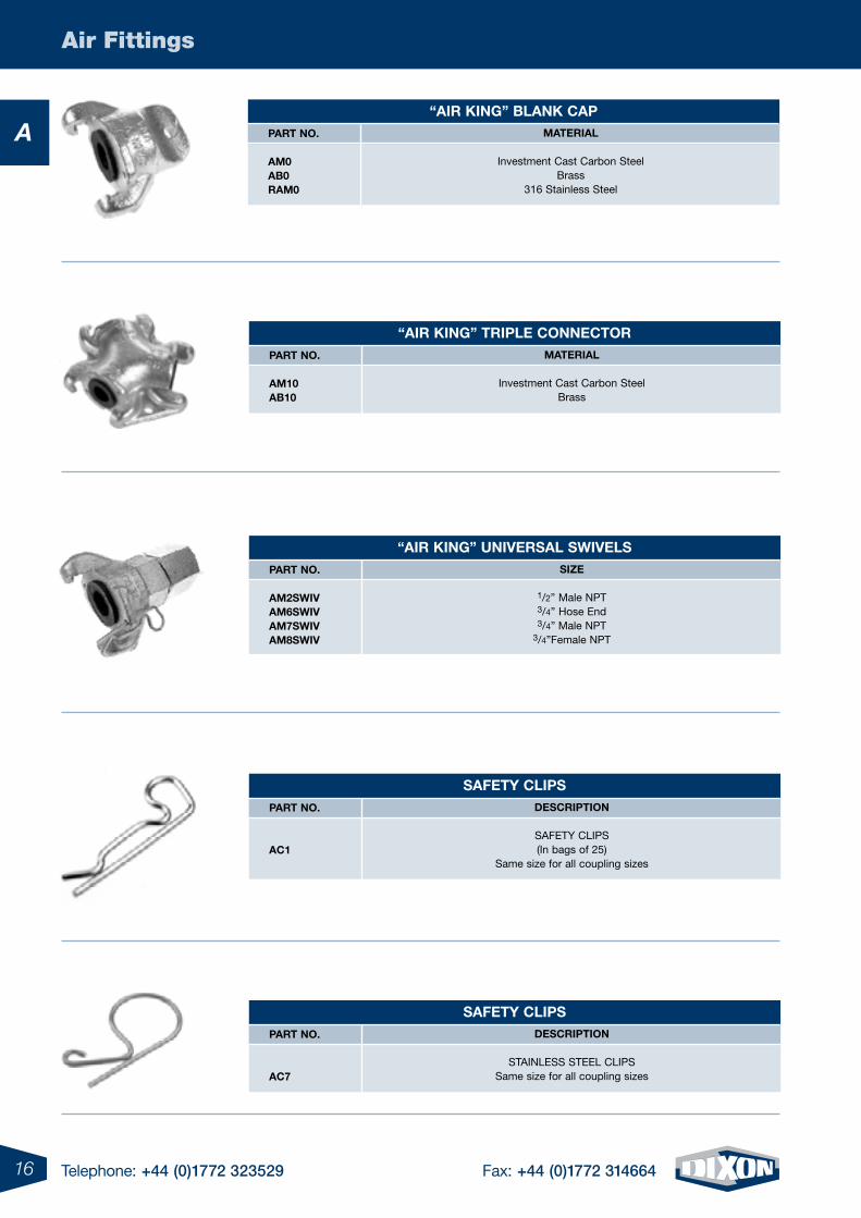
A“air king” Blank cap
part no.
am0 aB0 ram0
material
Investment Cast Carbon SteelBrass
316 Stainless Steel
saFety clips part no.
ac1
Description
SAFETY CLIPS (In bags of 25)
Same size for all coupling sizes
“air king” universal swivels part no.
am2swiv am6swiv am7swiv am8swiv
siZe
1/2” Male NPT3/4” Hose End3/4” Male NPT
3/4”Female NPT
“air king” triple connector part no.
am10 aB10
material
Investment Cast Carbon SteelBrass
saFety clips part no.
ac7
Description
STAINLESS STEEL CLIPSSame size for all coupling sizes
17Telephone: +44 (0)1772 323529 Fax: +44 (0)1772 314664
Air Fittings
A
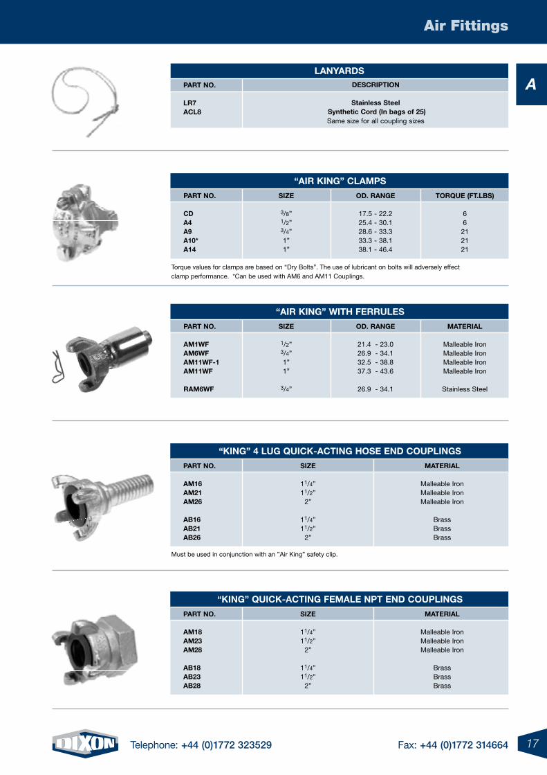
Torque values for clamps are based on “Dry Bolts”. The use of lubricant on bolts will adversely effect clamp performance. *Can be used with AM6 and AM11 Couplings.
Must be used in conjunction with an ”Air King” safety clip.
lanyarDs part no.
lr7 acl8
Description
stainless steel synthetic cord (in bags of 25)Same size for all coupling sizes
“air king” clamps
part no.
cD a4 a9 a10* a14
siZe
3/8”1/2”3/4” 1” 1”
oD. range
17.5 - 22.2 25.4 - 30.1 28.6 - 33.3 33.3 - 38.1 38.1 - 46.4
torQue (Ft.lBs)
66212121
“air king” with Ferrules
part no.
am1wF am6wF am11wF-1 am11wF ram6wF
siZe
1/2”3/4” 1” 1”
3/4”
oD. range
21.4 - 23.0 26.9 - 34.1 32.5 - 38.8 37.3 - 43.6
26.9 - 34.1
material
Malleable Iron Malleable Iron Malleable Iron Malleable Iron
Stainless Steel
“king” 4 lug Quick-acting hose enD couplings
part no.
am16 am21 am26 aB16 aB21 aB26
siZe
11/4” 11/2”
2”
11/4” 11/2”
2”
material
Malleable Iron Malleable Iron Malleable Iron
Brass Brass Brass
“king” Quick-acting Female npt enD couplings
part no.
am18 am23 am28 aB18 aB23 aB28
siZe
11/4” 11/2”
2”
11/4” 11/2”
2”
material
Malleable Iron Malleable Iron Malleable Iron
Brass Brass Brass
18 Telephone: +44 (0)1772 323529 Fax: +44 (0)1772 314664
Air Fittings
A
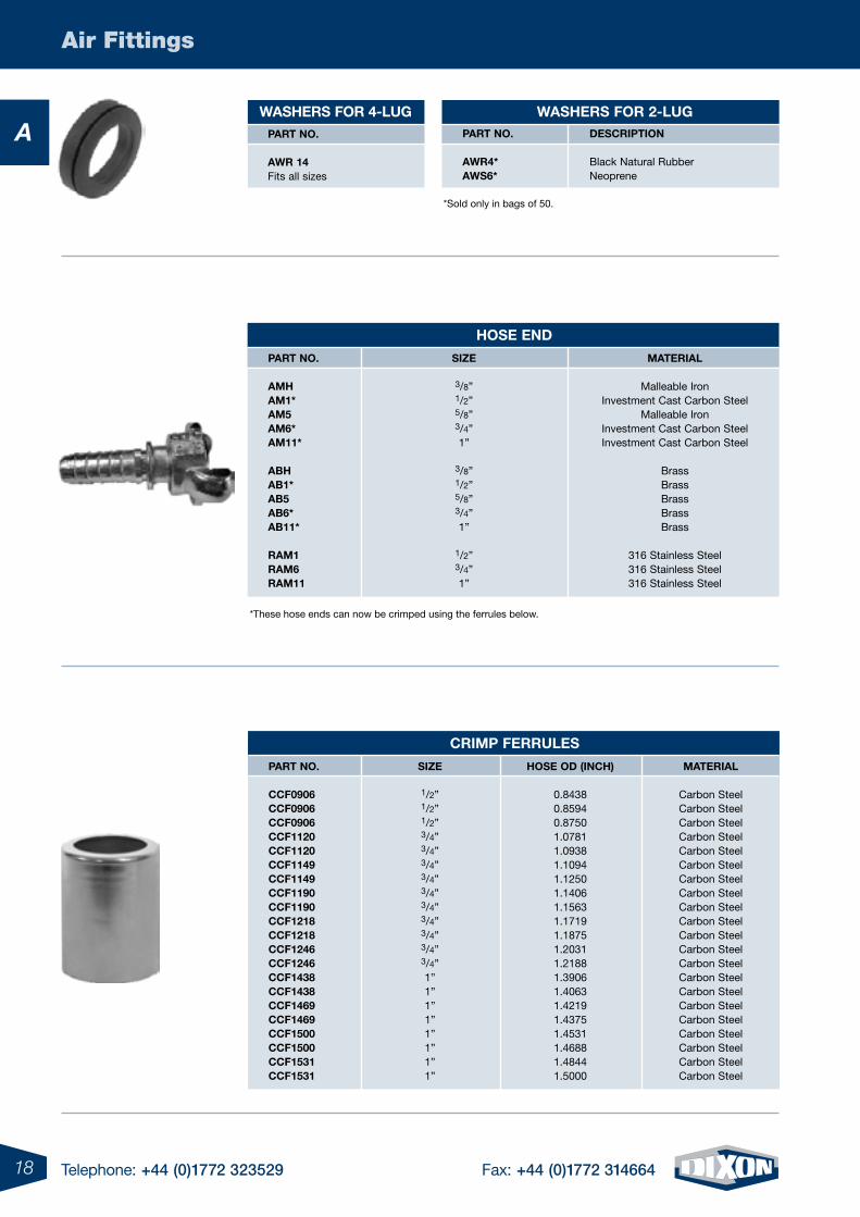
*These hose ends can now be crimped using the ferrules below.
hose enD
part no.
amh am1* am5 am6* am11* aBh aB1* aB5 aB6* aB11* ram1 ram6 ram11
siZe
3/8” 1/2” 5/8” 3/4” 1”
3/8” 1/2” 5/8” 3/4” 1”
1/2” 3/4” 1”
material
Malleable Iron Investment Cast Carbon Steel
Malleable Iron Investment Cast Carbon Steel Investment Cast Carbon Steel
Brass Brass Brass Brass Brass
316 Stainless Steel 316 Stainless Steel 316 Stainless Steel
crimp Ferrules
part no.
ccF0906 ccF0906 ccF0906 ccF1120 ccF1120 ccF1149 ccF1149 ccF1190 ccF1190 ccF1218 ccF1218 ccF1246 ccF1246 ccF1438 ccF1438 ccF1469 ccF1469 ccF1500 ccF1500 ccF1531 ccF1531
siZe
1/2”1/2”1/2” 3/4” 3/4” 3/4” 3/4” 3/4” 3/4” 3/4” 3/4” 3/4” 3/4” 1” 1” 1” 1” 1” 1” 1” 1”
hose oD (inch)
0.8438 0.8594 0.8750 1.0781 1.0938 1.1094 1.1250 1.1406 1.1563 1.1719 1.1875 1.2031 1.2188 1.3906 1.4063 1.4219 1.4375 1.4531 1.4688 1.4844 1.5000
material
Carbon Steel Carbon Steel Carbon Steel Carbon Steel Carbon Steel Carbon Steel Carbon Steel Carbon Steel Carbon Steel Carbon Steel Carbon Steel Carbon Steel Carbon SteelCarbon Steel Carbon Steel Carbon Steel Carbon Steel Carbon Steel Carbon Steel Carbon Steel Carbon Steel
*Sold only in bags of 50.
washers For 4-lug washers For 2-lug part no. awr 14 Fits all sizes
part no. awr4* aws6*
Description Black Natural Rubber Neoprene
19Telephone: +44 (0)1772 323529 Fax: +44 (0)1772 314664
Air Fittings
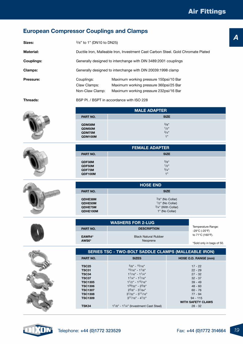
Aeuropean compressor couplings and clamps
series tsc - two-Bolt saDDle clamps (malleaBle iron)
part no.
tsc25 tsc31 tsc34 tsc37 tsc1305 tsc1306 tsc1307 tsc1308 tsc1309 tsk34
siZes
5/8” - 15/16” 15/16” - 11/8” 11/16” - 11/4” 11/4” - 17/16” 11/2” - 115/16” 129/32” - 23/8” 23/8” - 31/64”
31/32” - 311/16” 311/16” - 41/2”
11/8” - 11/4” (Investment Cast Steel)
hose o.D. range (mm)
17 - 22 22 - 29 27 - 32 32 - 37 39 - 49 48 - 60 60 - 76 77 - 94 94 - 115
with saFety claws 28 - 32
male aDapter part no.
QDm38m QDm50m QDm75m QDm100m
siZe
3/8” 1/2”3/4” 1”
Female aDapter part no.
QDF38m QDF50m QDF75m QDF100m
siZe
3/8” 1/2”3/4” 1”
hose enD part no.
QDhe38m QDhe50m QDhe75m QDhe100m
siZe
3/8” (No Collar) 1/2” (No Collar)
3/4” (With Collar) 1” (No Collar)
sizes: 3/8” to 1” (DN10 to DN25)
material: Ductile Iron, Malleable Iron, Investment Cast Carbon Steel. Gold Chromate Plated
couplings: Generally designed to interchange with DIN 3489:2001 couplings
clamps: Generally designed to interchange with DIN 20039:1998 clamp
pressure: Couplings: Maximum working pressure 150psi/10 Bar
Claw Clamps: Maximum working pressure 360psi/25 Bar
Non-Claw Clamp: Maximum working pressure 232psi/16 Bar
threads: BSP PI. / BSPT in accordance with ISO 228
Description
Black Natural Rubber Neoprene
Temperature Range: -29°C (-20°F) to 71°C (160°F). *Sold only in bags of 50.
washers For 2-lug part no.
eawr4* aws6*
20 Telephone: +44 (0)1772 323529 Fax: +44 (0)1772 314664
Air Fittings
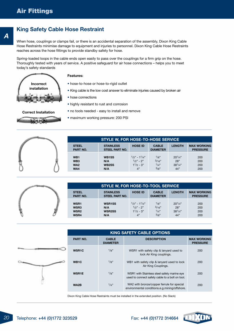
Aking safety cable hose restraint
When hose, couplings or clamps fail, or there is an accidental separation of the assembly, Dixon King Cable Hose Restraints minimise damage to equipment and injuries to personnel. Dixon King Cable Hose Restraints reaches across the hose fittings to provide standby safety for hose.
Spring-loaded loops in the cable ends open easily to pass over the couplings for a firm grip on the hose. Thoroughly tested with years of service. A positive safeguard for air hose connections – helps you to meet today’s safety standards
Features:
• hose-to-hose or hose-to-rigid outlet
• King cable is the low cost answer to eliminate injuries caused by broken air
• hose connections
• highly resistant to rust and corrosion
• no tools needed - easy to install and remove
• maximum working pressure: 200 PSI
style w, For hose-to-hose service
steel part no.
wB1 wB3 wa2 wa4
stainless steel part no.
wB1ss n/a wB2ss n/a
hose iD
1/2” - 11/4” 1/2” - 2” 11/2 - 3”
4”
caBle Diameter
1/8” 3/16” 1/4” 3/8”
length
201/4” 28”
381/4” 44”
max working pressure
200 200 200 200
style w, For hose-to-tool service
steel part no.
wsr1 wsr3 wsr2 wsr4
stainless steel part no.
wsr1ss n/a wsr2ss n/a
hose iD
1/2” - 11/4” 1/2” - 2” 11/2 - 3”
4”
caBle Diameter
1/8” 3/16” 1/4” 3/8”
length
201/4” 28”
381/4” 44”
max working pressure
200 200 200 200
king saFety caBle options
part no.
wsr1c wB1c wsr1e wa2B
caBle Diameter
1/8”
1/8”
1/8”
1/4”
Description
WSR1 with safety clip & lanyard used to lock Air King couplings.
WB1 with safety clip & lanyard used to lock
Air King Couplings.
WSR1 with Stainless steel safety marine eye used to connect safety cable to a bolt on tool.
WA2 with bronze/copper ferrule for special
environmental conditions.e.g.mining/offshore.
max working pressure
200
200
200
200
correct installation
Dixon King Cable Hose Restraints must be installed in the extended position. (No Slack)
incorrect installation
21Telephone: +44 (0)1772 323529 Fax: +44 (0)1772 314664
Air Fittings
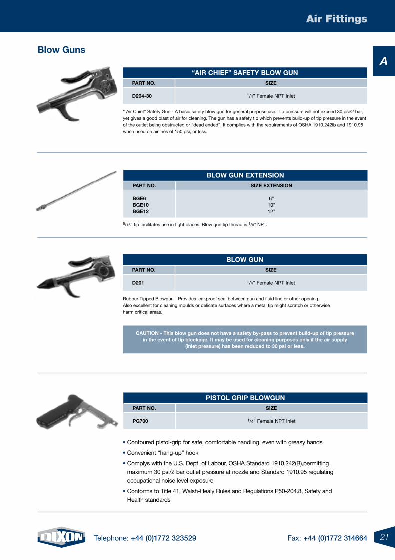
ABlow guns
“air chieF” saFety Blow gun part no. siZe D204-30 1/4” Female NPT Inlet
Blow gun part no. siZe D201 1/4” Female NPT Inlet
Blow gun extension part no. siZe extension Bge6 6” Bge10 10” Bge12 12”
pistol grip Blowgun part no. siZe pg700 1/4” Female NPT Inlet
“ Air Chief” Safety Gun - A basic safety blow gun for general purpose use. Tip pressure will not exceed 30 psi/2 bar, yet gives a good blast of air for cleaning. The gun has a safety tip which prevents build-up of tip pressure in the event of the outlet being obstructed or “dead ended”. It complies with the requirements of OSHA 1910.242lb and 1910.95 when used on airlines of 150 psi, or less.
• Contoured pistol-grip for safe, comfortable handling, even with greasy hands
• Convenient “hang-up” hook
• Complys with the U.S. Dept. of Labour, OSHA Standard 1910.242(B),permitting maximum 30 psi/2 bar outlet pressure at nozzle and Standard 1910.95 regulating occupational noise level exposure
• Conforms to Title 41, Walsh-Healy Rules and Regulations P50-204.8, Safety and Health standards
5/16” tip facilitates use in tight places. Blow gun tip thread is 1/8” NPT.
Rubber Tipped Blowgun - Provides leakproof seal between gun and fluid line or other opening. Also excellent for cleaning moulds or delicate surfaces where a metal tip might scratch or otherwise harm critical areas.
caution - this blow gun does not have a safety by-pass to prevent build-up of tip pressure in the event of tip blockage. it may be used for cleaning purposes only if the air supply
(inlet pressure) has been reduced to 30 psi or less.
B
4 Telephone: +44 (0)1772 323529 Fax: +44 (0)1772 31466422 Telephone: +44 (0)1772 323529 Fax: +44 (0)1772 314664
B
B
23Telephone: +44 (0)1772 323529 Fax: +44 (0)1772 314664
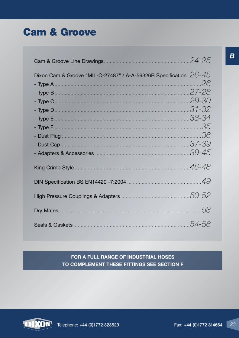
Cam & Groove Line Drawings ...........................................................24-25
Dixon Cam & Groove “MIL-C-27487” / A-A-59326B Specification ..26-45
- Type A .....................................................................................................26
- Type B .............................................................................................27-28
- Type C .............................................................................................29-30
- Type D .............................................................................................31-32
- Type E .............................................................................................33-34
- Type F .....................................................................................................35
- Dust Plug ................................................................................................36
- Dust Cap .........................................................................................37-39
- Adapters & Accessories .................................................................39-45
King Crimp Style ...............................................................................46-48
DIN Specification BS EN14420 -7:2004 ...................................................49
High Pressure Couplings & Adapters ...............................................50-52
Dry Mates ..................................................................................................53
Seals & Gaskets ................................................................................54-56
23Telephone: +44 (0)1772 323529 Fax: +44 (0)1772 314664
Cam & Groove
For a Full range oF industrial hoses
to complement these Fittings see section F
B
24 Telephone: +44 (0)1772 323529 Fax: +44 (0)1772 314664
Cam & Groove
B
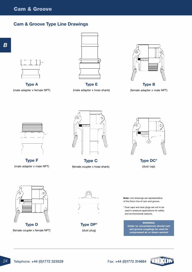
note: Line drawings are representative of the Dixon line of cam and groove.
* Dust caps and dust plugs are not to be used in pressure applications for safety and environmental reasons.
type a(male adapter x female NPT)
type e(male adapter x hose shank)
type B(female adapter x male NPT)
type F(male adapter x male NPT)
type c(female coupler x hose shank)
type dc*(dust cap)
type d(female coupler x female NPT)
type dp*(dust plug)
Warning: under no circumstances should cam
and groove couplings be used for compressed air or steam service!
cam & groove type line drawings
25Telephone: +44 (0)1772 323529 Fax: +44 (0)1772 314664
Cam & Groove
B
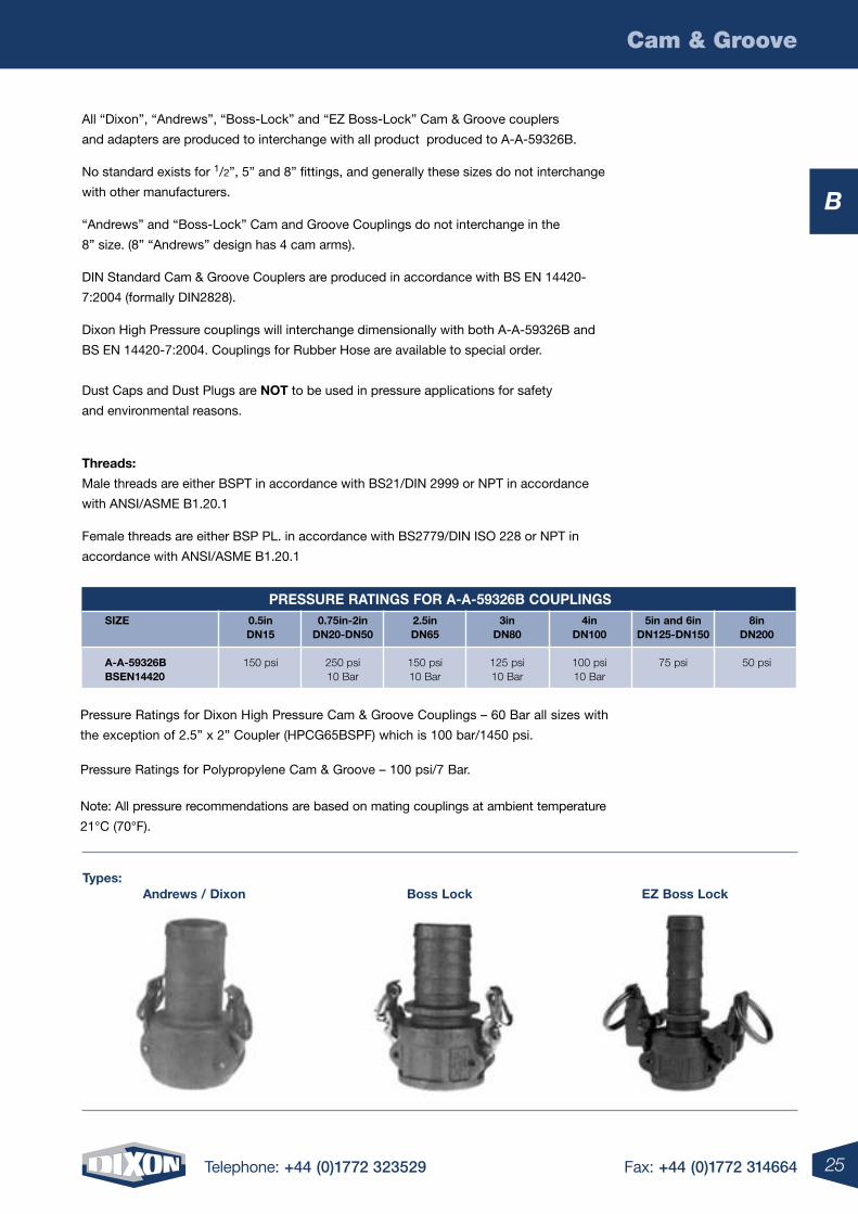
All “Dixon”, “Andrews”, “Boss-Lock” and “EZ Boss-Lock” Cam & Groove couplers
and adapters are produced to interchange with all product produced to A-A-59326B.
No standard exists for 1/2”, 5” and 8” fittings, and generally these sizes do not interchange
with other manufacturers.
“Andrews” and “Boss-Lock” Cam and Groove Couplings do not interchange in the
8” size. (8” “Andrews” design has 4 cam arms).
DIN Standard Cam & Groove Couplers are produced in accordance with BS EN 14420-
7:2004 (formally DIN2828).
Dixon High Pressure couplings will interchange dimensionally with both A-A-59326B and
BS EN 14420-7:2004. Couplings for Rubber Hose are available to special order.
Dust Caps and Dust Plugs are not to be used in pressure applications for safety
and environmental reasons.
threads:
Male threads are either BSPT in accordance with BS21/DIN 2999 or NPT in accordance
with ANSI/ASME B1.20.1
Female threads are either BSP PL. in accordance with BS2779/DIN ISO 228 or NPT in
accordance with ANSI/ASME B1.20.1
Pressure Ratings for Dixon High Pressure Cam & Groove Couplings – 60 Bar all sizes with
the exception of 2.5” x 2” Coupler (HPCG65BSPF) which is 100 bar/1450 psi.
Pressure Ratings for Polypropylene Cam & Groove – 100 psi/7 Bar.
Note: All pressure recommendations are based on mating couplings at ambient temperature
21°C (70°F).
andrews / dixon Boss lock eZ Boss locktypes:
pressure ratings For a-a-59326B couplings siZe 0.5in 0.75in-2in 2.5in 3in 4in 5in and 6in 8in dn15 dn20-dn50 dn65 dn80 dn100 dn125-dn150 dn200
a-a-59326B 150 psi 250 psi 150 psi 125 psi 100 psi 75 psi 50 psi Bsen14420 10 Bar 10 Bar 10 Bar 10 Bar
26 Telephone: +44 (0)1772 323529 Fax: +44 (0)1772 314664
Cam & Groove
B
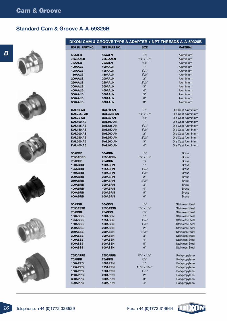
diXon cam & grooVe tYpe a adapter x npt threads a-a-59326B Bsp pl. part no. npt part no. siZe material
50aalB 50aaln 1/2” Aluminium 7550aalB 7550aaln 3/4” x 1/2” Aluminium 75aalB 75aaln 3/4” Aluminium 100aalB 100aaln 1” Aluminium 125aalB 125aaln 11/4” Aluminium 150aalB 150aaln 11/2” Aluminium 200aalB 200aaln 2” Aluminium 250aalB 250aaln 21/2” Aluminium 300aalB 300aaln 3” Aluminium 400aalB 400aaln 4” Aluminium 500aalB 500aaln 5” Aluminium 600aalB 600aaln 6” Aluminium 800aalB 800aaln 8” Aluminium
dal50 aB dal50 an 1/2” Die Cast Aluminium dal7550 aB dal7550 an 3/4” x 1/2” Die Cast Aluminium dal75 aB dal75 an 3/4” Die Cast Aluminium dal100 aB dal100 an 1” Die Cast Aluminium dal125 aB dal125 an 11/4” Die Cast Aluminium dal150 aB dal150 an 11/2” Die Cast Aluminium dal200 aB dal200 an 2” Die Cast Aluminium dal250 aB dal250 an 21/2” Die Cast Aluminium dal300 aB dal300 an 3” Die Cast Aluminium dal400 aB dal400 an 4” Die Cast Aluminium
50aBrB 50aBrn 1/2” Brass 7550aBrB 7550aBrn 3/4” x 1/2” Brass 75aBrB 75aBrn 3/4” Brass 100aBrB 100aBrn 1” Brass 125aBrB 125aBrn 11/4” Brass 150aBrB 150aBrn 11/2” Brass 200aBrB 200aBrn 2” Brass 250aBrB 250aBrn 21/2” Brass 300aBrB 300aBrn 3” Brass 400aBrB 400aBrn 4” Brass 500aBrB 500aBrn 5” Brass 600aBrB 600aBrn 6” Brass
50assB 50assn 1/2” Stainless Steel 7550assB 7550assn 3/4” x 1/2” Stainless Steel 75assB 75assn 3/4” Stainless Steel 100assB 100assn 1” Stainless Steel 125assB 125assn 11/4” Stainless Steel 150assB 150assn 11/2” Stainless Steel 200assB 200assn 2” Stainless Steel 250assB 250assn 21/2” Stainless Steel 300assB 300assn 3” Stainless Steel 400assB 400assn 4” Stainless Steel 500assB 500assn 5” Stainless Steel 600assB 600assn 6” Stainless Steel
7550appB 7550appn 3/4” x 1/2” Polypropylene 75appB 75appn 3/4” Polypropylene 100appB 100appn 1” Polypropylene 125appB 125appn 11/2” x 11/4” Polypropylene 150appB 150appn 11/2” Polypropylene 200appB 200appn 2” Polypropylene 300appB 300appn 3” Polypropylene 400appB 400appn 4” Polypropylene
standard cam & groove a-a-59326B
27Telephone: +44 (0)1772 323529 Fax: +44 (0)1772 314664
Cam & Groove
B
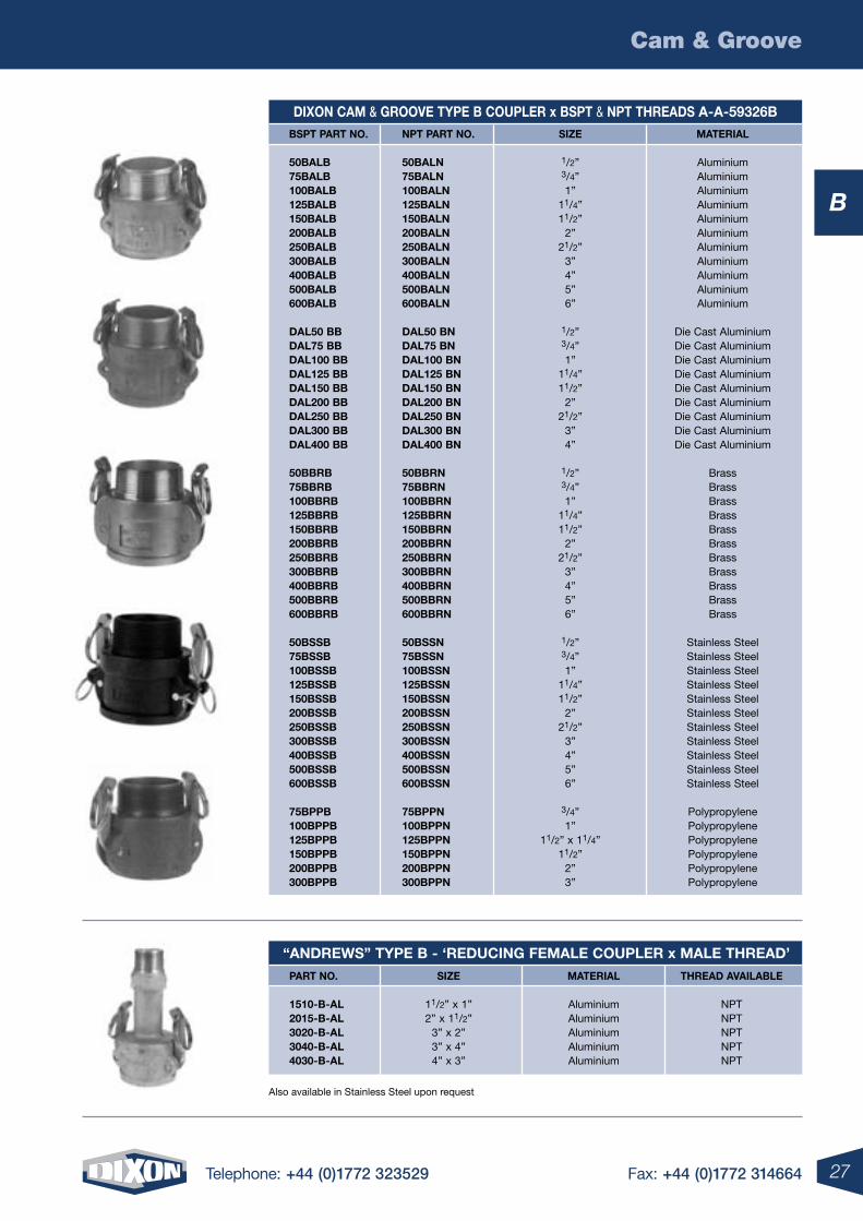
diXon cam & grooVe tYpe B coupler x Bspt & npt threads a-a-59326B Bspt part no. npt part no. siZe material
50BalB 50Baln 1/2” Aluminium 75BalB 75Baln 3/4” Aluminium 100BalB 100Baln 1” Aluminium 125BalB 125Baln 11/4” Aluminium 150BalB 150Baln 11/2” Aluminium 200BalB 200Baln 2” Aluminium 250BalB 250Baln 21/2” Aluminium 300BalB 300Baln 3” Aluminium 400BalB 400Baln 4” Aluminium 500BalB 500Baln 5” Aluminium 600BalB 600Baln 6” Aluminium
dal50 BB dal50 Bn 1/2” Die Cast Aluminium dal75 BB dal75 Bn 3/4” Die Cast Aluminium dal100 BB dal100 Bn 1” Die Cast Aluminium dal125 BB dal125 Bn 11/4” Die Cast Aluminium dal150 BB dal150 Bn 11/2” Die Cast Aluminium dal200 BB dal200 Bn 2” Die Cast Aluminium dal250 BB dal250 Bn 21/2” Die Cast Aluminium dal300 BB dal300 Bn 3” Die Cast Aluminium dal400 BB dal400 Bn 4” Die Cast Aluminium
50BBrB 50BBrn 1/2” Brass 75BBrB 75BBrn 3/4” Brass 100BBrB 100BBrn 1” Brass 125BBrB 125BBrn 11/4” Brass 150BBrB 150BBrn 11/2” Brass 200BBrB 200BBrn 2” Brass 250BBrB 250BBrn 21/2” Brass 300BBrB 300BBrn 3” Brass 400BBrB 400BBrn 4” Brass 500BBrB 500BBrn 5” Brass 600BBrB 600BBrn 6” Brass 50BssB 50Bssn 1/2” Stainless Steel 75BssB 75Bssn 3/4” Stainless Steel 100BssB 100Bssn 1” Stainless Steel 125BssB 125Bssn 11/4” Stainless Steel 150BssB 150Bssn 11/2” Stainless Steel 200BssB 200Bssn 2” Stainless Steel 250BssB 250Bssn 21/2” Stainless Steel 300BssB 300Bssn 3” Stainless Steel 400BssB 400Bssn 4” Stainless Steel 500BssB 500Bssn 5” Stainless Steel 600BssB 600Bssn 6” Stainless Steel
75BppB 75Bppn 3/4” Polypropylene 100BppB 100Bppn 1” Polypropylene 125BppB 125Bppn 11/2” x 11/4” Polypropylene 150BppB 150Bppn 11/2” Polypropylene 200BppB 200Bppn 2” Polypropylene 300BppB 300Bppn 3” Polypropylene
“andreWs” tYpe B - ‘reducing Female coupler x male thread’ part no. siZe material thread aVailaBle
1510-B-al 11/2” x 1” Aluminium NPT 2015-B-al 2” x 11/2” Aluminium NPT 3020-B-al 3” x 2” Aluminium NPT 3040-B-al 3” x 4” Aluminium NPT 4030-B-al 4” x 3” Aluminium NPT
Also available in Stainless Steel upon request
28 Telephone: +44 (0)1772 323529 Fax: +44 (0)1772 314664
Cam & Groove
B
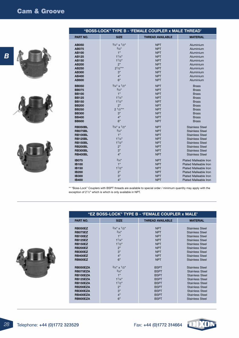
** “Boss-Lock” Couplers with BSPT threads are available to special order / minimum quantity may apply with the exception of 21/2” which is which is only available in NPT.
“Boss-locK” tYpe B - ‘Female coupler x male thread’ part no. siZe thread aVailaBle material
aB050 3/4” x 1/2” NPT Aluminium aB075 3/4” NPT Aluminium aB100 1” NPT Aluminium aB125 11/4” NPT Aluminium aB150 11/2” NPT Aluminium aB200 2” NPT Aluminium aB250 21/2”** NPT Aluminium aB300 3” NPT Aluminium aB400 4” NPT Aluminium aB600 6” NPT Aluminium
BB050 3/4” x 1/2” NPT Brass BB075 3/4” NPT Brass BB100 1” NPT Brass BB125 11/4” NPT Brass BB150 11/2” NPT Brass BB200 2” NPT Brass BB250 2 1/2”** NPT Brass BB300 3” NPT Brass BB400 4” NPT Brass BB600 6” NPT Brass
rB050Bl 3/4” x 1/2” NPT Stainless Steel rB075Bl 3/4” NPT Stainless Steel rB100Bl 1” NPT Stainless Steel rB125Bl 11/4” NPT Stainless Steel rB150Bl 11/2” NPT Stainless Steel rB200Bl 2” NPT Stainless Steel rB300Bl 3” NPT Stainless Steel rB400Bl 4” NPT Stainless Steel
iB075 3/4” NPT Plated Malleable Iron iB100 1” NPT Plated Malleable Iron iB150 11/2” NPT Plated Malleable Iron iB200 2” NPT Plated Malleable Iron iB300 3” NPT Plated Malleable Iron iB400 4” NPT Plated Malleable Iron
“eZ Boss-locK” tYpe B - ‘Female coupler x male’
part no. siZe thread aVailaBle material
rB050eZ 3/4” x 1/2” NPT Stainless Steel rB075eZ 3/4” NPT Stainless Steel rB100eZ 1” NPT Stainless Steel rB125eZ 11/4” NPT Stainless Steel rB150eZ 11/2” NPT Stainless Steel rB200eZ 2” NPT Stainless Steel rB300eZ 3” NPT Stainless Steel rB400eZ 4” NPT Stainless Steel rB600eZ 6” NPT Stainless Steel
rB050eZa 3/4” x 1/2” BSPT Stainless Steel rB075eZa 3/4” BSPT Stainless Steel rB100eZa 1” BSPT Stainless Steel rB125eZa 11/4” BSPT Stainless Steel rB150eZa 11/2” BSPT Stainless Steel rB200eZa 2” BSPT Stainless Steel rB300eZa 3” BSPT Stainless Steel rB400eZa 4” BSPT Stainless Steel rB600eZa 6” BSPT Stainless Steel
29Telephone: +44 (0)1772 323529 Fax: +44 (0)1772 314664
Cam & Groove
B
diXon cam & grooVe tYpe c coupler a-a-59326B part no. siZe material
50cal 1/2” Aluminium 75cal 3/4” Aluminium 100cal 1” Aluminium 125cal 11/4” Aluminium 150cal 11/2” Aluminium 200cal 2” Aluminium 250cal 21/2” Aluminium 300cal 3” Aluminium 400cal 4” Aluminium 500cal 5” Aluminium 600cal 6” Aluminium 800cal 8” Aluminium dal50c 1/2” Die Cast Aluminium dal75c 3/4” Die Cast Aluminium dal100c 1” Die Cast Aluminium dal125c 11/4” Die Cast Aluminium dal150c 11/2” Die Cast Aluminium dal200c 2” Die Cast Aluminium dal250c 21/2” Die Cast Aluminium dal300c 3” Die Cast Aluminium dal400c 4” Die Cast Aluminium dal600c 6” Die Cast Aluminium 50cBr 1/2” Brass 75cBr 3/4” Brass 100cBr 1” Brass 125cBr 11/4” Brass 150cBr 11/2” Brass 200cBr 2” Brass 250cBr 21/2” Brass 300cBr 3” Brass 400cBr 4” Brass 500cBr 5” Brass 600cBr 6” Brass 50css 1/2” Stainless Steel 75css 3/4” Stainless Steel 100css 1” Stainless Steel 125css 11/4” Stainless Steel 150css 11/2” Stainless Steel 200css 2” Stainless Steel 250css 21/2” Stainless Steel 300css 3” Stainless Steel 400css 4” Stainless Steel 500css 5” Stainless Steel 600css 6” Stainless Steel 75cpp 3/4” Polypropylene 100cpp 1” Polypropylene 125cpp 11/2” x 11/4” Polypropylene 150cpp 11/2” Polypropylene 200cpp 2” Polypropylene 300cpp 3” Polypropylene 400cpp 4” Polypropylene
“andreWs” tYpe c - ‘reducing Female coupler x hose tail’ part no. siZe material
3020-c-al 3” x 2” Aluminium 3040-c-al 3” x 4” Aluminium 4030-c-al 4” x 3” Aluminium
Also available in Stainless Steel upon request
30 Telephone: +44 (0)1772 323529 Fax: +44 (0)1772 314664
Cam & Groove
B
Note: All “Boss-Lock” Couplers come with SAFETY CLIPS. * “Andrews” and “Boss-Lock” Cam and Groove Couplings do not interchange in the 8” siZe. The 8” “Boss-Lock” design has 2 cam arms. The 8” “Boss-Lock” were designed to interchange with 8” Cam and Groove couplings manufactured by others.
Developed specifically for chemical transport hoses having Crosslinked Polyethylene (XLPE) or Ultra High Molecular Weight Polyethylene (UHMWPE) tubes. Swaged “Boss-Lock” provides you with a permanently attached Cam and Groove fitting when superior coupling retention is required. In testing tank transport hoses from a wide variety of manufacturers, the Swaged “Boss-Lock” fitting proved itself to be the clear winner in overall performance. Fittings are also available on special order for other sizes or hoses O.D.’s. Consult Dixon for pricing and availability of the special equipment required for installation.
“Boss-locK” tYpe c - ‘Female coupler x hose tail’ part no. siZe material
ac075 3/4” Aluminium ac100 1” Aluminium ac125 11/4” Aluminium ac150 11/2” Aluminium ac200 2” Aluminium ac250 21/2” Aluminium ac300 3” Aluminium ac400 4” Aluminium ac600 6” Aluminium ac800 8” Aluminium Bc075 3/4” Brass Bc100 1” Brass Bc125 11/4” Brass Bc150 11/2” Brass Bc200 2” Brass Bc250 21/2” Brass Bc300 3” Brass Bc400 4” Brass Bc600 6” Brass rc050Bl 3/4” x 1/2” Stainless Steel rc075Bl 3/4” Stainless Steel rc100Bl 1” Stainless Steel rc125Bl 11/4” Stainless Steel rc150Bl 11/2” Stainless Steel rc200Bl 2” Stainless Steel rc300Bl 3” Stainless Steel rc400Bl 4” Stainless Steel ic075 3/4” Plated Malleable Iron ic100 1” Plated Malleable Iron ic150 11/2” Plated Malleable Iron ic200 2” Plated Malleable Iron ic300 3” Plated Malleable Iron ic400 4” Plated Malleable Iron ic600 6” Plated Malleable Iron
“eZ Boss-locK” tYpe c - ‘Female coupler x hose tail’
part no. siZe material
rc050eZ 1/2” Stainless Steel rc075eZ 3/4” Stainless Steel rc100eZ 1” Stainless Steel rc125eZ 11/4” Stainless Steel rc200eZ 2” Stainless Steel rc300eZ 3” Stainless Steel rc400eZ 4” Stainless Steel rc600eZ 6” Stainless Steel
“Boss-locK” tYpe c - ‘coupler x hose tail With Ferrule’
part no. siZe minimum maXimum material hose o.d. hose o.d.
rc075eZ-70 3/4” 16/64” 122/64” Stainless Steel rc100eZ-20 1” 129/64” 135/64” Stainless Steel rc100eZ-70 1” 19/16” 111/16” Stainless Steel
31Telephone: +44 (0)1772 323529 Fax: +44 (0)1772 314664
Cam & Groove
B
“andreWs” tYpe d - ‘reducer coupler x Female thread’ part no. siZe thread aVailaBle material 1510-d-al 11/2” x 1” NPT Aluminium 2015-d-al 2” x 11/2” NPT Aluminium 3020-d-al 3” x 2” NPT Aluminium 4030-d-al 4” x 3” NPT Aluminium 4030-d-Br 4” x 3” NPT Brass 2015-d-ss 2” x 11/2” NPT Stainless Steel
diXon cam & grooVe tYpe d coupler x Bsp pl. & npt threads a-a-59326B Bsp pl. part no. npt part no. siZe material
50dalB 50daln 1/2” Aluminium 75dalB 75daln 3/4” Aluminium 100dalB 100daln 1” Aluminium 125dalB 125daln 11/4” Aluminium 150dalB 150daln 11/2” Aluminium 200dalB 200daln 2” Aluminium 250dalB 250daln 21/2” Aluminium 300dalB 300daln 3” Aluminium 400dalB 400daln 4” Aluminium 500dalB 500daln 5” Aluminium 600dalB 600daln 6” Aluminium 800dalB 800daln 8” Aluminium
dal50 dB dal50 dn 1/2” Die Cast Aluminium dal75 dB dal75 dn 3/4” Die Cast Aluminium dal100 dB dal100 dn 1” Die Cast Aluminium dal125 dB dal125 dn 11/4” Die Cast Aluminium dal150 dB dal150 dn 11/2 Die Cast Aluminium dal200 dB dal200 dn 2” Die Cast Aluminium dal250 dB dal250 dn 21/2” Die Cast Aluminium dal300 dB dal300 dn 3” Die Cast Aluminium dal400 dB dal400 dn 4” Die Cast Aluminium
50dBrB 50dBrn 1/2” Brass 75dBrB 75dBrn 3/4” Brass 100dBrB 100dBrn 1” Brass 125dBrB 125dBrn 11/4” Brass 150dBrB 150dBrn 11/2” Brass 200dBrB 200dBrn 2” Brass 250dBrB 250dBrn 21/2” Brass 300dBrB 300dBrn 3” Brass 400dBrB 400dBrn 4” Brass 500dBrB 500dBrn 5” Brass 600dBrB 600dBrn 6” Brass
50dssB 50dssn 1/2” Stainless Steel 75dssB 75dssn 3/4” Stainless Steel 100dssB 100dssn 1” Stainless Steel 125dssB 125dssn 11/4” Stainless Steel 150dssB 150dssn 11/2” Stainless Steel 200dssB 200dssn 2” Stainless Steel 250dssB 250dssn 21/2” Stainless Steel 300dssB 300dssn 3” Stainless Steel 400dssB 400dssn 4” Stainless Steel 500dssB 500dssn 5” Stainless Steel 600dssB 600dssn 6” Stainless Steel
75dppB 75dppn 3/4” Polypropylene 100dppB 100dppn 1” Polypropylene 125dppB 125dppn 11/2” x 11/4” Polypropylene 150dppB 150dppn 11/2” Polypropylene 200dppB 200dppn 2” Polypropylene 300dppB 300dppn 3” Polypropylene 400dppB 400dppn 4” Polypropylene
* “Andrews” and “Boss-Lock” Cam and Groove Couplings do not interchange in the 8” siZe. The 8” “Boss-Lock” design has 2 cam arms. The 8” “Boss-Lock” were designed to interchange with 8” Cam and Groove couplings manufactured by others.
32 Telephone: +44 (0)1772 323529 Fax: +44 (0)1772 314664
Cam & Groove
B
Note: “Boss-Lock” Couplers with BSPT threads are available to special order.
All “Boss-Lock” Couplers come with SAFETY CLIPS. * “Andrews” and “Boss-Lock” Cam and Groove Couplings do not interchange in the 8” siZe. The 8” “Boss-Lock” design has 2 cam arms. The 8” “Boss-Lock” were designed to interchange with 8” Cam and Groove couplings manufactured by others.
“Boss-locK” tYpe d ‘Female coupler x Female thread’ part no. siZe thread aVailaBle material
ad050 3/4” x 1/2” NPT Aluminium ad075 3/4” NPT Aluminium ad100 1” NPT Aluminium ad125 11/4” NPT Aluminium ad150 11/2” NPT Aluminium ad200 2” NPT Aluminium ad250 21/2”** NPT Aluminium ad300 3” NPT Aluminium ad400 4” NPT Aluminium ad600 6” NPT Aluminium ad800 8” NPT Aluminium
Bd050 3/4” x 1/2” NPT Brass Bd075 3/4” NPT Brass Bd100 1” NPT Brass Bd125 11/4” NPT Brass Bd150 11/2” NPT Brass Bd200 2” NPT Brass Bd250 21/2”** NPT Brass Bd300 3” NPT Brass Bd400 4” NPT Brass Bd600 6” NPT Brass
rd050 3/4” x 1/2” NPT Stainless Steel rd075 3/4” NPT Stainless Steel rd100 1” NPT Stainless Steel rd125 11/4” NPT Stainless Steel rd150 11/2” NPT Stainless Steel rd200 2” NPT Stainless Steel rd300 3” NPT Stainless Steel rd400 4” NPT Stainless Steel
id075 3/4” NPT Plated Malleable Iron id100 1” NPT Plated Malleable Iron id150 11/2” NPT Plated Malleable Iron id200 2” NPT Plated Malleable Iron id300 3” NPT Plated Malleable Iron id400 4” NPT Plated Malleable Iron id600 6” NPT Plated Malleable Iron
** “Boss-Lock” Couplers with BSPT threads are available to special order / minimum quantity may apply with the exception of 21/2” which is only available in NPT.
“eZ Boss-locK” tYpe d - ‘Female coupler x Female thread’ part no. siZe thread aVailaBle material rd050eZ 1/2” NPT Stainless Steel rd075eZ 3/4” NPT Stainless Steel rd100eZ 1” NPT Stainless Steel rd125eZ 11/4” NPT Stainless Steel rd150eZ 11/2” NPT Stainless Steel rd200eZ 2” NPT Stainless Steel rd300eZ 3” NPT Stainless Steel rd400eZ 4” NPT Stainless Steel
33Telephone: +44 (0)1772 323529 Fax: +44 (0)1772 314664
Cam & Groove
B
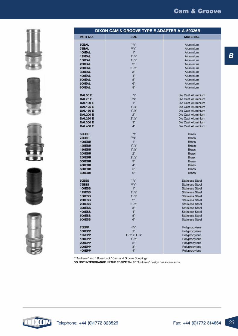
diXon cam & grooVe tYpe e adapter a-a-59326B part no. siZe material
50eal 1/2” Aluminium 75eal 3/4” Aluminium 100eal 1” Aluminium 125eal 11/4” Aluminium 150eal 11/2” Aluminium 200eal 2” Aluminium 250eal 21/2” Aluminium 300eal 3” Aluminium 400eal 4” Aluminium 500eal 5” Aluminium 600eal 6” Aluminium 800eal 8” Aluminium dal50 e 1/2” Die Cast Aluminium dal75 e 3/4” Die Cast Aluminium dal100 e 1” Die Cast Aluminium dal125 e 11/4” Die Cast Aluminium dal150 e 11/2” Die Cast Aluminium dal200 e 2” Die Cast Aluminium dal250 e 21/2” Die Cast Aluminium dal300 e 3” Die Cast Aluminium dal400 e 4” Die Cast Aluminium 50eBr 1/2” Brass 75eBr 3/4” Brass 100eBr 1” Brass 125eBr 11/4” Brass 150eBr 11/2” Brass 200eBr 2” Brass 250eBr 21/2” Brass 300eBr 3” Brass 400eBr 4” Brass 500eBr 5” Brass 600eBr 6” Brass 50ess 1/2” Stainless Steel 75ess 3/4” Stainless Steel 100ess 1” Stainless Steel 125ess 11/4” Stainless Steel 150ess 11/2” Stainless Steel 200ess 2” Stainless Steel 250ess 21/2” Stainless Steel 300ess 3” Stainless Steel 400ess 4” Stainless Steel 500ess 5” Stainless Steel 600ess 6” Stainless Steel 75epp 3/4” Polypropylene 100epp 1” Polypropylene 125epp 11/2” x 11/4” Polypropylene 150epp 11/2” Polypropylene 200epp 2” Polypropylene 300epp 3” Polypropylene 400epp 4” Polypropylene
* “Andrews” and “ Boss-Lock” Cam and Groove Couplings do not interchange in the 8” siZe The 8” “Andrews” design has 4 cam arms.
34 Telephone: +44 (0)1772 323529 Fax: +44 (0)1772 314664
Cam & Groove
B
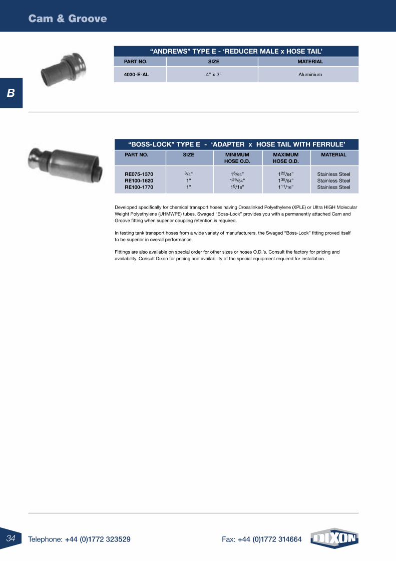
Developed specifically for chemical transport hoses having Crosslinked Polyethylene (XPLE) or Ultra HIGH Molecular Weight Polyethylene (UHMWPE) tubes. Swaged “Boss-Lock” provides you with a permanently attached Cam and Groove fitting when superior coupling retention is required.
In testing tank transport hoses from a wide variety of manufacturers, the Swaged “Boss-Lock” fitting proved itself to be superior in overall performance.
Fittings are also available on special order for other sizes or hoses O.D.’s. Consult the factory for pricing and availability. Consult Dixon for pricing and availability of the special equipment required for installation.
“Boss-locK” tYpe e - ‘adapter x hose tail With Ferrule’ part no. siZe minimum maXimum material hose o.d. hose o.d.
re075-1370 3/4” 16/64” 122/64” Stainless Steel re100-1620 1” 129/64” 135/64” Stainless Steel re100-1770 1” 19/16” 111/16” Stainless Steel
“andreWs” tYpe e - ‘reducer male x hose tail’ part no. siZe material
4030-e-al 4” x 3” Aluminium
35Telephone: +44 (0)1772 323529 Fax: +44 (0)1772 314664
Cam & Groove
B
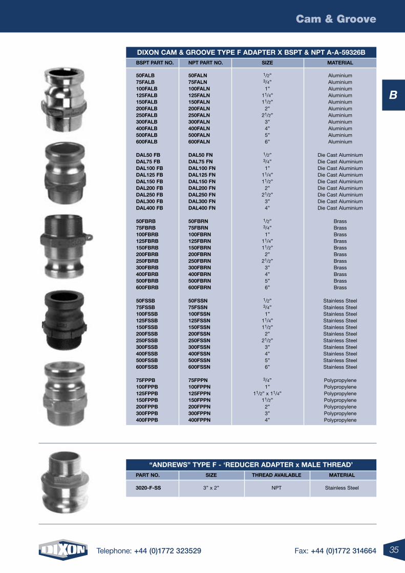
diXon cam & grooVe tYpe F adapter X Bspt & npt a-a-59326B Bspt part no. npt part no. siZe material
50FalB 50Faln 1/2” Aluminium 75FalB 75Faln 3/4” Aluminium 100FalB 100Faln 1” Aluminium 125FalB 125Faln 11/4” Aluminium 150FalB 150Faln 11/2” Aluminium 200FalB 200Faln 2” Aluminium 250FalB 250Faln 21/2” Aluminium 300FalB 300Faln 3” Aluminium 400FalB 400Faln 4” Aluminium 500FalB 500Faln 5” Aluminium 600FalB 600Faln 6” Aluminium
dal50 FB dal50 Fn 1/2” Die Cast Aluminium dal75 FB dal75 Fn 3/4” Die Cast Aluminium dal100 FB dal100 Fn 1” Die Cast Aluminium dal125 FB dal125 Fn 11/4” Die Cast Aluminium dal150 FB dal150 Fn 11/2” Die Cast Aluminium dal200 FB dal200 Fn 2” Die Cast Aluminium dal250 FB dal250 Fn 21/2” Die Cast Aluminium dal300 FB dal300 Fn 3” Die Cast Aluminium dal400 FB dal400 Fn 4” Die Cast Aluminium
50FBrB 50FBrn 1/2” Brass 75FBrB 75FBrn 3/4” Brass 100FBrB 100FBrn 1” Brass 125FBrB 125FBrn 11/4” Brass 150FBrB 150FBrn 11/2” Brass 200FBrB 200FBrn 2” Brass 250FBrB 250FBrn 21/2” Brass 300FBrB 300FBrn 3” Brass 400FBrB 400FBrn 4” Brass 500FBrB 500FBrn 5” Brass 600FBrB 600FBrn 6” Brass
50FssB 50Fssn 1/2” Stainless Steel 75FssB 75Fssn 3/4” Stainless Steel 100FssB 100Fssn 1” Stainless Steel 125FssB 125Fssn 11/4” Stainless Steel 150FssB 150Fssn 11/2” Stainless Steel 200FssB 200Fssn 2” Stainless Steel 250FssB 250Fssn 21/2” Stainless Steel 300FssB 300Fssn 3” Stainless Steel 400FssB 400Fssn 4” Stainless Steel 500FssB 500Fssn 5” Stainless Steel 600FssB 600Fssn 6” Stainless Steel
75FppB 75Fppn 3/4” Polypropylene 100FppB 100Fppn 1” Polypropylene 125FppB 125Fppn 11/2” x 11/4” Polypropylene 150FppB 150Fppn 11/2” Polypropylene 200FppB 200Fppn 2” Polypropylene 300FppB 300Fppn 3” Polypropylene 400FppB 400Fppn 4” Polypropylene
“andreWs” tYpe F - ‘reducer adapter x male thread’ part no. siZe thread aVailaBle material
3020-F-ss 3” x 2” NPT Stainless Steel
36 Telephone: +44 (0)1772 323529 Fax: +44 (0)1772 314664
Cam & Groove
B
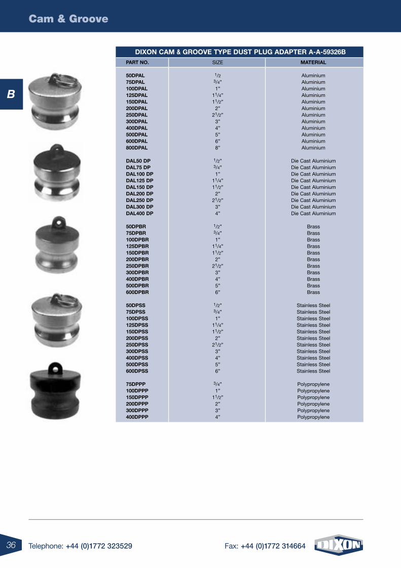
diXon cam & grooVe tYpe dust plug adapter a-a-59326B part no. material
50dpal Aluminium 75dpal Aluminium 100dpal Aluminium 125dpal Aluminium 150dpal Aluminium 200dpal Aluminium 250dpal Aluminium 300dpal Aluminium 400dpal Aluminium 500dpal Aluminium 600dpal Aluminium 800dpal Aluminium
dal50 dp Die Cast Aluminium dal75 dp Die Cast Aluminium dal100 dp Die Cast Aluminium dal125 dp Die Cast Aluminium dal150 dp Die Cast Aluminium dal200 dp Die Cast Aluminium dal250 dp Die Cast Aluminium dal300 dp Die Cast Aluminium dal400 dp Die Cast Aluminium
50dpBr Brass 75dpBr Brass 100dpBr Brass 125dpBr Brass 150dpBr Brass 200dpBr Brass 250dpBr Brass 300dpBr Brass 400dpBr Brass 500dpBr Brass 600dpBr Brass
50dpss Stainless Steel 75dpss Stainless Steel 100dpss Stainless Steel 125dpss Stainless Steel 150dpss Stainless Steel 200dpss Stainless Steel 250dpss Stainless Steel 300dpss Stainless Steel 400dpss Stainless Steel 500dpss Stainless Steel 600dpss Stainless Steel
75dppp Polypropylene 100dppp Polypropylene 150dppp Polypropylene 200dppp Polypropylene 300dppp Polypropylene 400dppp Polypropylene
SIZE
1/2 3/4” 1” 11/4” 11/2” 2” 21/2” 3” 4” 5” 6” 8”
1/2” 3/4” 1” 11/4” 11/2” 2” 21/2” 3” 4”
1/2” 3/4” 1” 11/4” 11/2” 2” 21/2” 3” 4” 5” 6”
1/2” 3/4” 1” 11/4” 11/2” 2” 21/2” 3” 4” 5” 6”
3/4” 1” 11/2” 2” 3” 4”
37Telephone: +44 (0)1772 323529 Fax: +44 (0)1772 314664
Cam & Groove
B
Note: All “Boss-Lock” Couplers come with SAFETY CLIPS. * “Andrews” and “Boss-Lock” Cam and Groove Couplings do not interchange in the 8” siZe. The 8” “Boss-Lock” design has 2 cam arms. The 8” “Boss-Lock” were designed to interchange with 8” Cam and Groove couplings manufactured by others.
diXon cam & grooVe tYpe dust cap coupler a-a-59326B part no. siZe material
50dcal 1/2” Aluminium 75dcal 3/4” Aluminium 100dcal 1” Aluminium 125dcal 11/4” Aluminium 150dcal 11/2” Aluminium 200dcal 2” Aluminium 250dcal 21/2” Aluminium 300dcal 3” Aluminium 400dcal 4” Aluminium 500dcal 5” Aluminium 600dcal 6” Aluminium 800dcal 8” Aluminium dal50dc 1/2” Die Cast Aluminium dal75dc 3/4” Die Cast Aluminium dal100dc 1” Die Cast Aluminium dal125dc 11/4” Die Cast Aluminium dal150dc 11/2” Die Cast Aluminium dal200dc 2” Die Cast Aluminium dal250dc 21/2” Die Cast Aluminium dal300dc 3” Die Cast Aluminium dal400dc 4” Die Cast Aluminium 50dcBr 1/2” Brass 75dcBr 3/4” Brass 100dcBr 1” Brass 125dcBr 11/4” Brass 150dcBr 11/2” Brass 200dcBr 2” Brass 250dcBr 21/2” Brass 300dcBr 3” Brass 400dcBr 4” Brass 500dcBr 5” Brass 600dcBr 6” Brass 50dcss 1/2” Stainless Steel 75dcss 3/4” Stainless Steel 100dcss 1” Stainless Steel 125dcss 11/4” Stainless Steel 150dcss 11/2” Stainless Steel 200dcss 2” Stainless Steel 250dcss 21/2” Stainless Steel 300dcss 3” Stainless Steel 400dcss 4” Stainless Steel 500dcss 5” Stainless Steel 600dcss 6” Stainless Steel 75dcpp 3/4” Polypropylene 100dcpp 1” Polypropylene 150dcpp 11/2” Polypropylene 200dcpp 2” Polypropylene 300dcpp 3” Polypropylene 400dcpp 4” Polypropylene
38 Telephone: +44 (0)1772 323529 Fax: +44 (0)1772 314664
Cam & Groove
B
“andreWs” locKaBle dust cap part no. siZe material
200-dc-l-al 2” Aluminium 300-dc-l-al 3” Aluminium 400-dc-l-al 4” Aluminium 600-dc-l-al 6” Aluminium
200-dc-l-Br 2” Brass 300-dc-l-Br 3” Brass 400-dc-l-Br 4” Brass
200dc-l-ss 2” Stainless Steel 300dc-l-ss 3” Stainless Steel
“Boss-locK” - ‘dust caps’ part no. siZe material
ah075 3/4” Aluminium ah100 1” Aluminium ah125 11/4” Aluminium ah150 11/2” Aluminium ah200 2” Aluminium ah250 21/2” Aluminium ah300 3” Aluminium ah400 4” Aluminium ah600 6” Aluminium
Bh075 3/4” Brass Bh100 1” Brass Bh125 11/4” Brass Bh150 11/2” Brass Bh200 2” Brass Bh250 21/2”** Brass Bh300 3” Brass Bh400 4” Brass Bh600 6” Brass
rh075Bl 3/4” Stainless Steel rh100Bl 1” Stainless Steel rh125Bl 11/4” Stainless Steel rh150Bl 11/2” Stainless Steel rh200Bl 2” Stainless Steel rh300Bl 3” Stainless Steel rh400Bl 4” Stainless Steel
ih100 1” Plated Malleable Iron ih150 11/2” Plated Malleable Iron ih200 2” Plated Malleable Iron ih300 3” Plated Malleable Iron ih400 4” Plated Malleable Iron ih600 6” Plated Malleable Iron
locKing / paddle handles For “andreWs” dust cap part no. coupler siZe description
200-lh-Br 2” Locking Handle, Brass 300-lh-Br 3” Locking Handle, Brass 400-lh-Br 4” Locking Handle, Brass 300h-padBr 3” and 4” Paddle Handle, Brass
39Telephone: +44 (0)1772 323529 Fax: +44 (0)1772 314664
Cam & Groove
B
Note: All “Boss-Lock” Couplers come with SAFETY CLIPS. * “Andrews” and “Boss-Lock” Cam and Groove Couplings do not interchange in the 8” siZe. The 8” “Boss-Lock” design has 2 cam arms. The 8” “Boss-Lock” were designed to interchange with 8” Cam and Groove couplings manufactured by others.
”eZ Boss-locK“ – ’dust caps‘ part no. siZe material
rh075eZ 3/4” Stainless Steel rh100eZ 1” Stainless Steel rh125eZ 11/4” Stainless Steel rh150eZ 11/2” Stainless Steel rh200eZ 2” Stainless Steel rh300eZ 3” Stainless Steel rh400eZ 4” Stainless Steel rh600eZ 6” Stainless Steel
“andreWs” - ‘reducing Female couplers x male adapters’ part no. siZe / description material
1510-da-al 11/2” Coupler x 1” Adapter Aluminium 1520-da-al 11/2” Coupler x 2” Adapter Aluminium 2015-da-al 2” Coupler x 11/2” Adapter Aluminium 2030-da-al 2” Coupler x 3” Adapter Aluminium 2040-da-al 2” Coupler x 4” Adapter Aluminium 3015-da-al 3” Coupler x 11/2” Adapter Aluminium 3020-da-al 3” Coupler x 2” Adapter Aluminium 3040-da-al 3” Coupler x 4” Adapter Aluminium 4020-da-al 4” Coupler x 2” Adapter Aluminium 4025-da-al 4” Coupler x 21/2” Adapter Aluminium 4030-da-al 4” Coupler x 3” Adapter Aluminium 4060-da-al 4” Coupler x 6” Adapter Aluminium 5040-da-al 5” Coupler x 4” Adapter Aluminium 6030-da-al 6” Coupler x 3” Adapter Aluminium 6040-da-al 6” Coupler x 4” Adapter Aluminium
3020-da-alh 3” Coupler x 2” Adapter Aluminium Hard Coat 4030-da-alh 4” Coupler x 3” Adapter Aluminium Hard Coat 3020-da-Br 3” Coupler x 2” Adapter Brass 4030-da-Br 4” Coupler x 3” Adapter Brass 6040-da-Br 6” Coupler x 4” Adapter Brass
3020-da-mi 3” Coupler x 2” Adapter Unplated Malleable Iron 4030-da-mi 4” Coupler x 3” Adapter Unplated Malleable Iron 6040-da-mi 6” Coupler x 4” Adapter Unplated Malleable Iron
1520-da-ss 11/2” Coupler x 2” Adapter Stainless Steel 2015-da-ss 2” Coupler x 11/2” Adapter Stainless Steel 2030-da-ss 2” Coupler x 3” Adapter Stainless Steel 3020-da-ss 3” Coupler x 2” Adapter Stainless Steel 3040-da-ss 3” Coupler x 4” Adapter Stainless Steel 4030-da-ss 4” Coupler x 3” Adapter Stainless Steel 6040-da-ss 6” Coupler x 4” Adapter Stainless Steel
“eZ Boss-locK” coupler x adapter part no. siZe material
rda3020eZ 3” x 2” Stainless Steel rda4030eZ 4” x 3” Stainless Steel
40 Telephone: +44 (0)1772 323529 Fax: +44 (0)1772 314664
Cam & Groove
B
“andreWs” - ‘male x male adapter’ part no. siZe material
150-aa-al 11/2” Aluminium 1520-aa-al 11/2” x 2 Aluminium 200-aa-al 2” Aluminium 2030-aa-al 2” x 3” Aluminium 2040-aa-al 2” x 4” Aluminium 300-aa-al 3” Aluminium 3040-aa-al 3” x 4” Aluminium 400-aa-al 4” Aluminium 4060-aa-al 4” x 6” Aluminium 600-aa-al 6” Aluminium
150-aa-Br 11/2” Brass 200-aa-Br 2” Brass 300-aa-Br 3” Brass
100-aa-ss 1” Stainless Steel 150-aa-ss 11/2” Stainless Steel 1520-aa-ss 11/2” x 2” Stainless Steel 200-aa-ss 2” Stainless Steel 2030-aa-ss 2” x 3” Stainless Steel 300-aa-ss 3” Stainless Steel
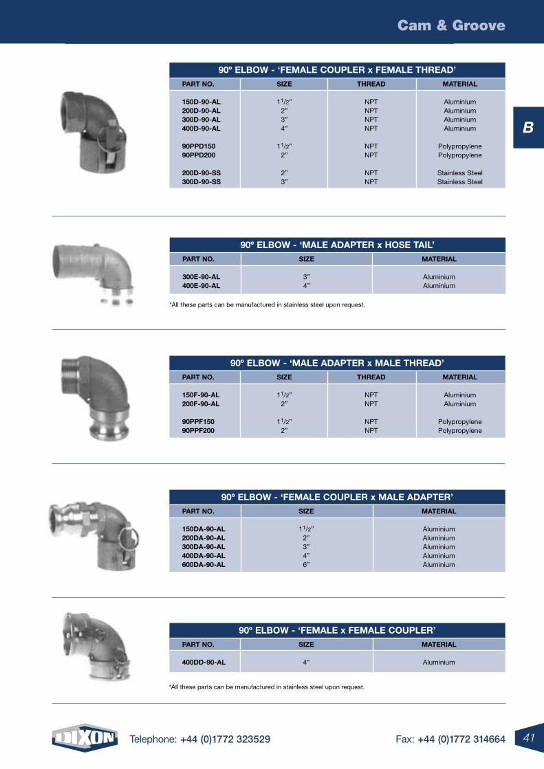
90º elBoW - ‘Female coupler x hose tail’ part no. siZe material
150c-90-al 11/2” Aluminium 200c-90-al 2” Aluminium 300c-90-al 3” Aluminium 400c-90-al 4” Aluminium
90ppc150 11/2” Polypropylene 90ppc200 2” Polypropylene
300c90-ss 3” Stainless Steel
90º elBoW - ‘male adapter x Female thread’ part no. siZe thread material
150a-90-al 11/2” NPT Aluminium 200a-90-al 2” NPT Aluminium 300a-90-al 3” NPT Aluminium 400a-90-al 4” NPT Aluminium
90ppa150 11/2” NPT Polypropylene 90ppa200 2” NPT Polypropylene
300a-90-ss 3” NPT Stainless Steel
90º elBoW - ‘Female coupler x male thread’ part no. siZe thread material
150B-90-al 11/2” NPT Aluminium 200B-90-al 2” NPT Aluminium
41Telephone: +44 (0)1772 323529 Fax: +44 (0)1772 314664
Cam & Groove
B
*All these parts can be manufactured in stainless steel upon request.
90º elBoW - ‘male adapter x hose tail’ part no. siZe material
300e-90-al 3” Aluminium 400e-90-al 4” Aluminium
90º elBoW - ‘Female coupler x Female thread’ part no. siZe thread material
150d-90-al 11/2” NPT Aluminium 200d-90-al 2” NPT Aluminium 300d-90-al 3” NPT Aluminium 400d-90-al 4” NPT Aluminium
90ppd150 11/2” NPT Polypropylene 90ppd200 2” NPT Polypropylene
200d-90-ss 2” NPT Stainless Steel 300d-90-ss 3” NPT Stainless Steel
90º elBoW - ‘male adapter x male thread’ part no. siZe thread material
150F-90-al 11/2” NPT Aluminium 200F-90-al 2” NPT Aluminium
90ppF150 11/2” NPT Polypropylene 90ppF200 2” NPT Polypropylene
90º elBoW - ‘Female coupler x male adapter’ part no. siZe material
150da-90-al 11/2” Aluminium 200da-90-al 2” Aluminium 300da-90-al 3” Aluminium 400da-90-al 4” Aluminium 600da-90-al 6” Aluminium
90º elBoW - ‘Female x Female coupler’ part no. siZe material
400dd-90-al 4” Aluminium
*All these parts can be manufactured in stainless steel upon request.
42 Telephone: +44 (0)1772 323529 Fax: +44 (0)1772 314664
Cam & Groove
B
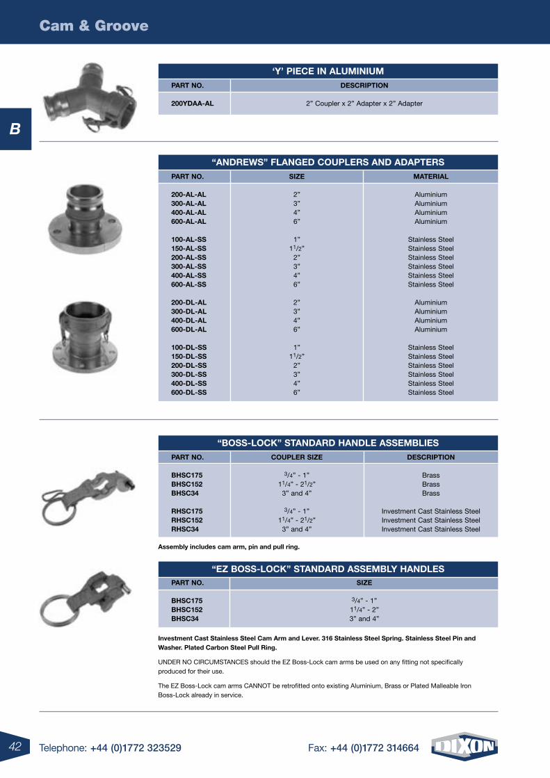
investment cast stainless steel cam arm and lever. 316 stainless steel spring. stainless steel pin and Washer. plated carbon steel pull ring.
UNDER NO CIRCUMSTANCES should the EZ Boss-Lock cam arms be used on any fitting not specifically produced for their use.
The EZ Boss-Lock cam arms CANNOT be retrofitted onto existing Aluminium, Brass or Plated Malleable Iron Boss-Lock already in service.
assembly includes cam arm, pin and pull ring.
‘Y’ piece in aluminium part no. description
200Ydaa-al 2” Coupler x 2” Adapter x 2” Adapter
“andreWs” Flanged couplers and adapters part no. siZe material
200-al-al 2” Aluminium 300-al-al 3” Aluminium 400-al-al 4” Aluminium 600-al-al 6” Aluminium
100-al-ss 1” Stainless Steel 150-al-ss 11/2” Stainless Steel 200-al-ss 2” Stainless Steel 300-al-ss 3” Stainless Steel 400-al-ss 4” Stainless Steel 600-al-ss 6” Stainless Steel
200-dl-al 2” Aluminium 300-dl-al 3” Aluminium 400-dl-al 4” Aluminium 600-dl-al 6” Aluminium
100-dl-ss 1” Stainless Steel 150-dl-ss 11/2” Stainless Steel 200-dl-ss 2” Stainless Steel 300-dl-ss 3” Stainless Steel 400-dl-ss 4” Stainless Steel 600-dl-ss 6” Stainless Steel
“Boss-locK” standard handle assemBlies part no. coupler siZe description
Bhsc175 3/4” - 1” Brass Bhsc152 11/4” - 21/2” Brass Bhsc34 3” and 4” Brass
rhsc175 3/4” - 1” Investment Cast Stainless Steel rhsc152 11/4” - 21/2” Investment Cast Stainless Steel rhsc34 3” and 4” Investment Cast Stainless Steel
“eZ Boss-locK” standard assemBlY handles part no. siZe
Bhsc175 3/4” - 1” Bhsc152 11/4” - 2” Bhsc34 3” and 4”
43Telephone: +44 (0)1772 323529 Fax: +44 (0)1772 314664
Cam & Groove
B
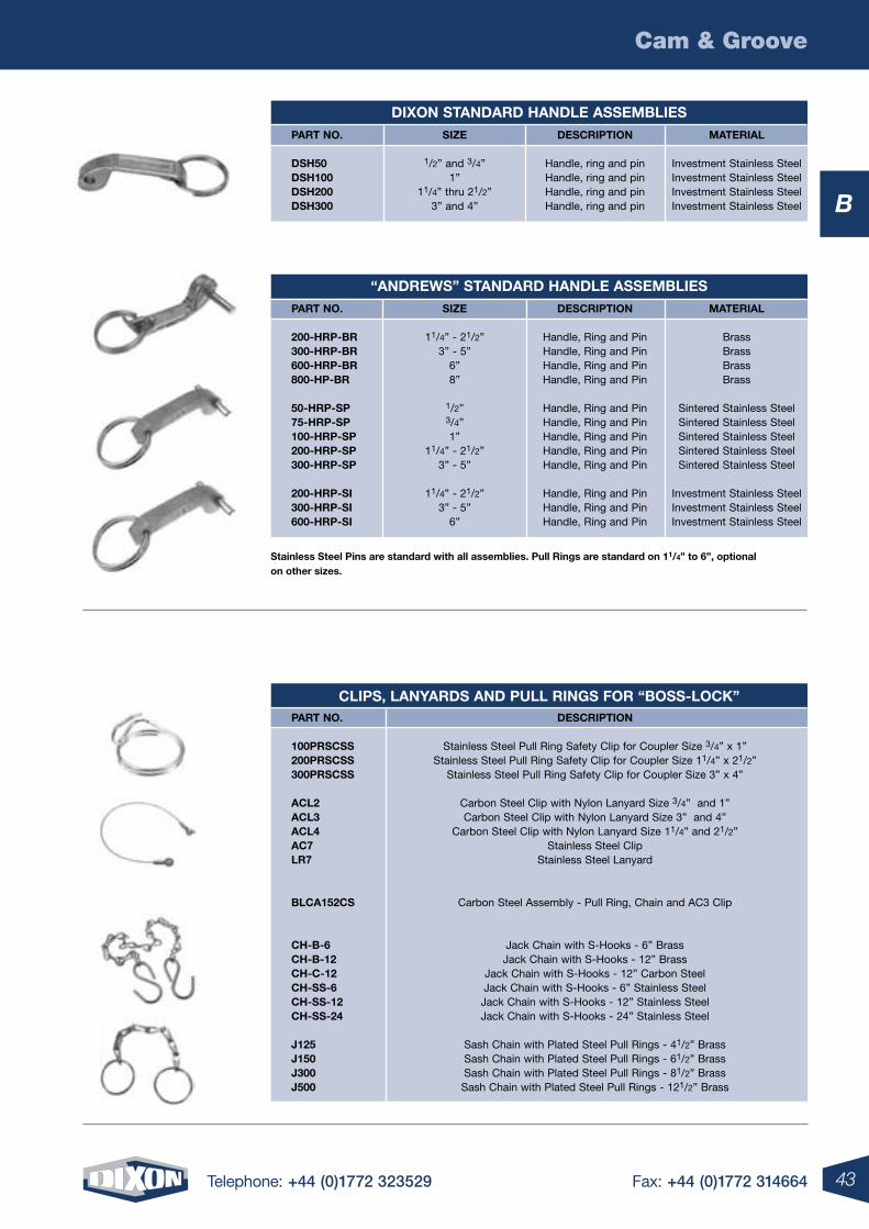
stainless steel pins are standard with all assemblies. pull rings are standard on 11/4” to 6”, optional on other sizes.
diXon standard handle assemBlies part no. siZe description material
dsh50 1/2” and 3/4” Handle, ring and pin Investment Stainless Steel dsh100 1” Handle, ring and pin Investment Stainless Steel dsh200 11/4” thru 21/2” Handle, ring and pin Investment Stainless Steel dsh300 3” and 4” Handle, ring and pin Investment Stainless Steel
“andreWs” standard handle assemBlies part no. siZe description material
200-hrp-Br 11/4” - 21/2” Handle, Ring and Pin Brass 300-hrp-Br 3” - 5” Handle, Ring and Pin Brass 600-hrp-Br 6” Handle, Ring and Pin Brass 800-hp-Br 8” Handle, Ring and Pin Brass
50-hrp-sp 1/2” Handle, Ring and Pin Sintered Stainless Steel 75-hrp-sp 3/4” Handle, Ring and Pin Sintered Stainless Steel 100-hrp-sp 1” Handle, Ring and Pin Sintered Stainless Steel 200-hrp-sp 11/4” - 21/2” Handle, Ring and Pin Sintered Stainless Steel 300-hrp-sp 3” - 5” Handle, Ring and Pin Sintered Stainless Steel
200-hrp-si 11/4” - 21/2” Handle, Ring and Pin Investment Stainless Steel 300-hrp-si 3” - 5” Handle, Ring and Pin Investment Stainless Steel 600-hrp-si 6” Handle, Ring and Pin Investment Stainless Steel
clips, lanYards and pull rings For “Boss-locK” part no. description
100prscss Stainless Steel Pull Ring Safety Clip for Coupler Size 3/4” x 1” 200prscss Stainless Steel Pull Ring Safety Clip for Coupler Size 11/4” x 21/2” 300prscss Stainless Steel Pull Ring Safety Clip for Coupler Size 3” x 4”
acl2 Carbon Steel Clip with Nylon Lanyard Size 3/4” and 1” acl3 Carbon Steel Clip with Nylon Lanyard Size 3” and 4” acl4 Carbon Steel Clip with Nylon Lanyard Size 11/4” and 21/2” ac7 Stainless Steel Clip lr7 Stainless Steel Lanyard
Blca152cs Carbon Steel Assembly - Pull Ring, Chain and AC3 Clip
ch-B-6 Jack Chain with S-Hooks - 6” Brass ch-B-12 Jack Chain with S-Hooks - 12” Brass ch-c-12 Jack Chain with S-Hooks - 12” Carbon Steel ch-ss-6 Jack Chain with S-Hooks - 6” Stainless Steel ch-ss-12 Jack Chain with S-Hooks - 12” Stainless Steel ch-ss-24 Jack Chain with S-Hooks - 24” Stainless Steel
J125 Sash Chain with Plated Steel Pull Rings - 41/2” Brass J150 Sash Chain with Plated Steel Pull Rings - 61/2” Brass J300 Sash Chain with Plated Steel Pull Rings - 81/2” Brass J500 Sash Chain with Plated Steel Pull Rings - 121/2” Brass
44 Telephone: +44 (0)1772 323529 Fax: +44 (0)1772 314664
Cam & Groove
B
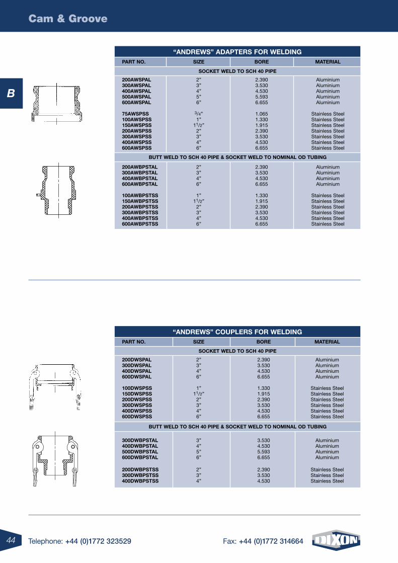
“andreWs” adapters For Welding part no. siZe Bore material
200aWspal 2” 2.390 Aluminium 300aWspal 3” 3.530 Aluminium 400aWspal 4” 4.530 Aluminium 500aWspal 5” 5.593 Aluminium 600aWspal 6” 6.655 Aluminium 75aWspss 3/4” 1.065 Stainless Steel 100aWspss 1” 1.330 Stainless Steel 150aWspss 11/2” 1.915 Stainless Steel 200aWspss 2” 2.390 Stainless Steel 300aWspss 3” 3.530 Stainless Steel 400aWspss 4” 4.530 Stainless Steel 600aWspss 6” 6.655 Stainless Steel 200aWBpstal 2” 2.390 Aluminium 300aWBpstal 3” 3.530 Aluminium 400aWBpstal 4” 4.530 Aluminium 600aWBpstal 6” 6.655 Aluminium
100aWBpstss 1” 1.330 Stainless Steel 150aWBpstss 11/2” 1.915 Stainless Steel 200aWBpstss 2” 2.390 Stainless Steel 300aWBpstss 3” 3.530 Stainless Steel 400aWBpstss 4” 4.530 Stainless Steel 600aWBpstss 6” 6.655 Stainless Steel
socKet Weld to sch 40 pipe
Butt Weld to sch 40 pipe & socKet Weld to nominal od tuBing
“andreWs” couplers For Welding part no. siZe Bore material
200dWspal 2” 2.390 Aluminium 300dWspal 3” 3.530 Aluminium 400dWspal 4” 4.530 Aluminium 600dWspal 6” 6.655 Aluminium
100dWspss 1” 1.330 Stainless Steel 150dWspss 11/2” 1.915 Stainless Steel 200dWspss 2” 2.390 Stainless Steel 300dWspss 3” 3.530 Stainless Steel 400dWspss 4” 4.530 Stainless Steel 600dWspss 6” 6.655 Stainless Steel
300dWBpstal 3” 3.530 Aluminium 400dWBpstal 4” 4.530 Aluminium 500dWBpstal 5” 5.593 Aluminium 600dWBpstal 6” 6.655 Aluminium
200dWBpstss 2” 2.390 Stainless Steel 300dWBpstss 3” 3.530 Stainless Steel 400dWBpstss 4” 4.530 Stainless Steel
Butt Weld to sch 40 pipe & socKet Weld to nominal od tuBing
socKet Weld to sch 40 pipe
45Telephone: +44 (0)1772 323529 Fax: +44 (0)1772 314664
Cam & Groove
B
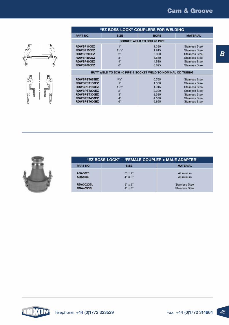
“eZ Boss-locK” - ‘Female coupler x male adapter’ part no. siZe material
ada3020 3” x 2” Aluminium ada4030 4” X 3” Aluminium rda3020Bl 3” x 2” Stainless Steel rda4030Bl 4” x 3” Stainless Steel
“eZ Boss-locK” couplers For Welding part no. siZe Bore material
rdWsp100eZ 1” 1.330 Stainless Steel rdWsp150eZ 11/2” 1.915 Stainless Steel rdWsp200eZ 2” 2.390 Stainless Steel rdWsp300eZ 3” 3.530 Stainless Steel rdWsp400eZ 4” 4.530 Stainless Steel rdWsp600eZ 6” 6.695 Stainless Steel
rdWBpst075eZ 3/4” 0.765 Stainless Steel rdWBpst100eZ 1” 1.330 Stainless Steel rdWBpst150eZ 11/2” 1.915 Stainless Steel rdWBpst200eZ 2” 2.390 Stainless Steel rdWBpst300eZ 3” 3.530 Stainless Steel rdWBpst400eZ 4” 4.530 Stainless Steel rdWBpst600eZ 6” 6.655 Stainless Steel
socKet Weld to sch 40 pipe
Butt Weld to sch 40 pipe & socKet Weld to nominal od tuBing
46 Telephone: +44 (0)1772 323529 Fax: +44 (0)1772 314664
Cam & Groove
B
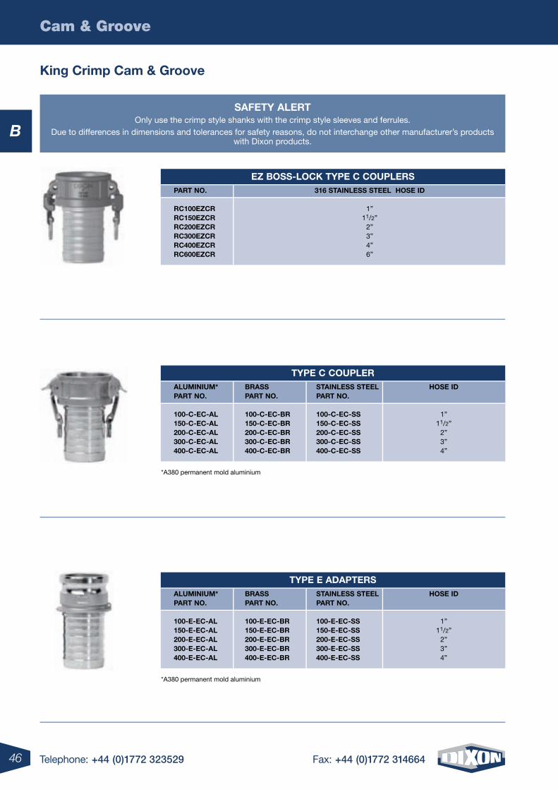
saFetY alertOnly use the crimp style shanks with the crimp style sleeves and ferrules.
Due to differences in dimensions and tolerances for safety reasons, do not interchange other manufacturer’s products with Dixon products.
King crimp cam & groove
eZ Boss-locK tYpe c couplers part no. 316 stainless steel hose id
rc100eZcr 1” rc150eZcr 11/2” rc200eZcr 2” rc300eZcr 3” rc400eZcr 4” rc600eZcr 6”
tYpe c coupler aluminium* Brass stainless steel hose id part no. part no. part no.
100-c-ec-al 100-c-ec-Br 100-c-ec-ss 1” 150-c-ec-al 150-c-ec-Br 150-c-ec-ss 11/2” 200-c-ec-al 200-c-ec-Br 200-c-ec-ss 2” 300-c-ec-al 300-c-ec-Br 300-c-ec-ss 3” 400-c-ec-al 400-c-ec-Br 400-c-ec-ss 4”
tYpe e adapters aluminium* Brass stainless steel hose id part no. part no. part no.
100-e-ec-al 100-e-ec-Br 100-e-ec-ss 1” 150-e-ec-al 150-e-ec-Br 150-e-ec-ss 11/2” 200-e-ec-al 200-e-ec-Br 200-e-ec-ss 2” 300-e-ec-al 300-e-ec-Br 300-e-ec-ss 3” 400-e-ec-al 400-e-ec-Br 400-e-ec-ss 4”
*A380 permanent mold aluminium
*A380 permanent mold aluminium
47Telephone: +44 (0)1772 323529 Fax: +44 (0)1772 314664
Cam & Groove
B
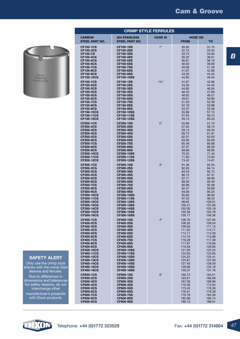
crimp stYle Ferrules
carBon 304 stainless hose id hose od steel part no. steel part no. From to
cF100-1cs cF100-1ss 1” 30.56 31.75 cF100-2cs cF100-2ss 32.15 33.34 cF100-cs cF100-3ss 33.73 34.93 cF100-4cs cF100-4ss 35.32 36.51 cF100-5cs cF100-5ss 36.91 38.10 cF100-6cs cF100-6ss 38.50 39.69 cF100-7cs cF100-7ss 40.08 41.28 cF100-8cs cF100-8ss 41.67 42.86 cF100-9cs cF100-9ss 43.26 44.45 cF100-10cs cF100-10ss 44.85 46.04
cF150-1cs cF150-1ss 1½” 41.67 42.86 cF150-2cs cF150-2ss 43.26 44.45 cF150-3cs cF150-3ss 44.85 46.04 cF150-4cs cF150-4ss 46.43 47.63 cF150-5cs cF150-5ss 48.02 49.21 cF150-6cs cF150-6ss 49.61 50.80 cF150-7cs cF150-7ss 51.20 52.39 cF150-8cs cF150-8ss 52.78 53.98 cF150-9cs cF150-9ss 54.37 55.56 cF150-10cs cF150-10ss 55.96 57.15 cF150-11cs cF150-11ss 57.55 58.74 cF150-12cs cF150-12ss 59.13 60.33
cF200-1cs cF200-1ss 2” 55.96 57.15 cF200-2cs cF200-2ss 57.55 58.74 cF200-3cs cF200-3ss 59.13 60.33 cF200-4cs cF200-4ss 60.72 61.91 cF200-5cs cF200-5ss 62.31 63.50 cF200-6cs cF200-6ss 63.90 65.09 cF200-7cs cF200-7ss 65.48 66.68 cF200-8cs cF200-8ss 67.07 68.26 cF200-9cs cF200-9ss 68.66 69.85 cF200-10cs cF200-10ss 70.25 71.44 cF200-11cs cF200-11ss 71.83 73.03 cF200-12cs cF200-12ss 73.42 74.61
cF300-1cs cF300-1ss 3” 81.36 82.55 cF300-2cs cF300-2ss 82.95 84.14 cF300-3cs cF300-3ss 84.53 85.73 cF300-4cs cF300-4ss 86.12 87.31 cF300-5cs cF300-5ss 87.71 88.90 cF300-6cs cF300-6ss 89.30 90.49 cF300-7cs cF300-7ss 90.88 92.08 cF300-8cs cF300-8ss 92.47 93.66 cF300-9cs cF300-9ss 94.06 95.25 cF300-10cs cF300-10ss 95.65 96.84 cF300-11cs cF300-11ss 97.23 98.43 cF300-12cs cF300-12ss 98.82 100.01 cF300-13cs cF300-13ss 100.41 101.60 cF300-14cs cF300-14ss 102.00 103.19 cF300-15cs cF300-15ss 103.58 104.78 cF300-16cs cF300-16ss 105.17 106.36
cF400-1cs cF400-1ss 4” 106.76 107.95 cF400-2cs cF400-2ss 108.35 109.54 cF400-3cs cF400-3ss 109.93 111.13 cF400-4cs cF400-4ss 111.52 112.71 cF400-5cs cF400-5ss 113.11 114.30 cF400-6cs cF400-6ss 114.70 115.89 cF400-7cs cF400-7ss 116.28 117.48 cF400-8cs cF400-8ss 117.87 119.06 cF400-9cs cF400-9ss 119.46 120.65 cF400-10cs cF400-10ss 121.05 122.24 cF400-11cs cF400-11ss 122.63 123.83 cF400-12cs cF400-12ss 124.22 125.41 cF400-13cs cF400-13ss 125.81 127.00 cF400-14cs cF400-14ss 127.40 128.59 cF400-15cs cF400-15ss 128.98 130.18 cF400-16cs cF400-16ss 130.57 131.76
cF600-1cs cF600-1ss 6” 160.73 163.51 cF600-2cs cF600-2ss 163.91 166.69 cF600-3cs cF600-3ss 167.08 169.86 cF600-4cs cF600-4ss 170.26 173.04 cF600-5cs cF600-5ss 173.43 176.39 cF600-6cs cF600-6ss 176.61 179.39 cF600-7cs cF600-7ss 179.78 182.56 cF600-8cs cF600-8ss 182.96 185.74 cF600-9cs cF600-9ss 186.13 188.91
saFetY alertOnly use the crimp style
shanks with the crimp style sleeves and ferrules.Due to differences in
dimensions and tolerances for safety reasons, do not
interchange othermanufacturer’s products
with Dixon products.
48 Telephone: +44 (0)1772 323529 Fax: +44 (0)1772 314664
Cam & Groove
B
saFetY alertOnly use the crimp style
shanks with the crimp style sleeves and ferrules.Due to differences in
dimensions and tolerances for safety reasons, do not
interchange othermanufacturer’s products
with Dixon products.
crimp stYle sleeVes
carBon 304 stainless aluminium hose id hose od steel part no. steel part no. part no. From to
cs100-1cs cs100-1ss cs100-1al 1” 30.56 31.75 cs100-2cs cs100-2ss cs100-2al 32.15 33.34 cs100-3cs cs100-3ss cs100-3al 33.73 34.93 cs100-4cs cs100-4ss cs100-4al 35.32 36.51 cs100-5cs cs100-5ss cs100-5al 36.91 38.10 cs100-6cs cs100-6ss cs100-6al 38.50 39.69 cs100-7cs cs100-7ss cs100-7al 40.08 41.28 cs100-8cs cs100-8ss cs100-8al 41.67 42.86 cs100-9cs cs100-9ss cs100-9al 43.26 44.45 cs100-10cs cs100-10ss cs100-10al 44.85 46.04
cs150-1cs cs150-1ss cs150-1al 1½” 41.67 42.86 cs150-2cs cs150-2ss cs150-2al 43.26 44.45 cs150-3cs cs150-3ss cs150-3al 44.85 46.04 cs150-4cs cs150-4ss cs150-4al 46.43 47.63 cs150-5cs cs150-5ss cs150-5al 48.02 49.21 cs150-6cs cs150-6ss cs150-6al 49.61 50.80 cs150-7cs cs150-7ss cs150-7al 51.20 52.39 cs150-8cs cs150-8ss cs150-8al 52.78 53.98 cs150-9cs cs150-9ss cs150-9al 54.37 55.56 cs150-10cs cs150-10ss cs150-10al 55.96 57.15 cs150-11cs cs150-11ss cs150-11al 57.55 58.74 cs150-12cs cs150-12ss cs150-12al 59.13 60.33
cs200-1cs cs200-1ss cs200-1al 2” 55.96 57.15 cs200-2cs cs200-2ss cs200-2al 57.55 58.74 cs200-3cs cs200-3ss cs200-3al 59.13 60.33 cs200-4cs cs200-4ss cs200-4al 60.72 61.91 cs200-5cs cs200-5ss cs200-5al 62.31 63.50 cs200-6cs cs200-6ss cs200-6al 63.90 65.09 cs200-7cs cs200-7ss cs200-7al 65.48 66.68 cs200-8cs cs200-8ss cs200-8al 67.07 68.26 cs200-9cs cs200-9ss cs200-9al 68.66 69.85 cs200-10cs cs200-10ss cs200-10al 70.25 71.44 cs200-11cs cs200-11ss cs200-11al 71.83 73.03 cs200-12cs cs200-12ss cs200-12al 73.42 74.61
cs300-1cs cs300-1ss cs300-1al 3” 81.36 82.55 cs300-2cs cs300-2ss cs300-2al 82.95 84.14 cs300-3cs cs300-3ss cs300-3al 84.53 85.73 cs300-4cs cs300-4ss cs300-4al 86.12 87.31 cs300-5cs cs300-5ss cs300-5al 87.71 88.90 cs300-6cs cs300-6ss cs300-6al 89.30 90.49 cs300-7cs cs300-7ss cs300-7al 90.88 92.08 cs300-8cs cs300-8ss cs300-8al 92.47 93.66 cs300-9cs cs300-9ss cs300-9al 94.06 95.25 cs300-10cs cs300-10ss cs300-10al 95.65 96.84 cs300-11cs cs300-11ss cs300-11al 97.23 98.43 cs300-12cs cs300-12ss cs300-12al 98.82 100.01 cs300-13cs cs300-13ss cs300-13al 100.41 101.60 cs300-14cs cs300-14ss cs300-14al 102.00 103.19 cs300-15cs cs300-15ss cs300-15al 103.58 104.78 cs300-16cs cs300-16ss cs300-16al 105.17 106.36
cs400-1cs cs400-1ss cs400-1al 4” 106.76 107.95 cs400-2cs cs400-2ss cs400-2al 108.35 109.54 cs400-3cs cs400-3ss cs400-3al 109.93 111.13 cs400-4cs cs400-4ss cs400-4al 111.52 112.71 cs400-5cs cs400-5ss cs400-5al 113.11 114.30 cs400-6cs cs400-6ss cs400-6al 114.70 115.89 cs400-7cs cs400-7ss cs400-7al 116.28 117.48 cs400-8cs cs400-8ss cs400-8al 117.87 119.06 cs400-9cs cs400-9ss cs400-9al 119.46 120.65 cs400-10cs cs400-10ss cs400-10al 121.05 122.24 cs400-11cs cs400-11ss cs400-11al 122.63 123.83 cs400-12cs cs400-12ss cs400-12al 124.22 125.41 cs400-13cs cs400-13ss cs400-13al 125.81 127.00 cs400-14cs cs400-14ss cs400-14al 127.40 128.59 cs400-15cs cs400-15ss cs400-15al 128.98 130.18 cs400-16cs cs400-16ss cs400-16al 130.57 131.76
cs600-1cs cs600-1ss cs600-1al 6” 160.73 163.51 cs600-2cs cs600-2ss cs600-2al 163.91 166.69 cs600-3cs cs600-3ss cs600-3al 167.08 169.86 cs600-4cs cs600-4ss cs600-4al 170.26 173.04 cs600-5cs cs600-5ss cs600-5al 173.43 176.39 cs600-6cs cs600-6ss cs600-6al 176.61 179.39 cs600-7cs cs600-7ss cs600-7al 179.78 182.56 cs600-8cs cs600-8ss cs600-8al 182.96 185.74 cs600-9cs cs600-9ss cs600-9al 186.13 188.91
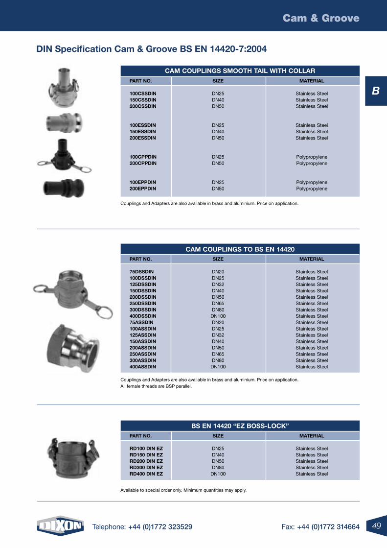
49Telephone: +44 (0)1772 323529 Fax: +44 (0)1772 314664
Cam & Groove
B
din specification cam & groove Bs en 14420-7:2004
Couplings and Adapters are also available in brass and aluminium. Price on application. All female threads are BSP parallel.
Available to special order only. Minimum quantities may apply.
cam couplings smooth tail With collar part no. siZe material
100cssdin DN25 Stainless Steel 150cssdin DN40 Stainless Steel 200cssdin DN50 Stainless Steel
100essdin DN25 Stainless Steel 150essdin DN40 Stainless Steel 200essdin DN50 Stainless Steel
100cppdin DN25 Polypropylene 200cppdin DN50 Polypropylene
100eppdin DN25 Polypropylene 200eppdin DN50 Polypropylene
cam couplings to Bs en 14420 part no. siZe material
75dssdin DN20 Stainless Steel 100dssdin DN25 Stainless Steel 125dssdin DN32 Stainless Steel 150dssdin DN40 Stainless Steel 200dssdin DN50 Stainless Steel 250dssdin DN65 Stainless Steel 300dssdin DN80 Stainless Steel 400dssdin DN100 Stainless Steel 75assdin DN20 Stainless Steel 100assdin DN25 Stainless Steel 125assdin DN32 Stainless Steel 150assdin DN40 Stainless Steel 200assdin DN50 Stainless Steel 250assdin DN65 Stainless Steel 300assdin DN80 Stainless Steel 400assdin DN100 Stainless Steel
Bs en 14420 “eZ Boss-locK” part no. siZe material
rd100 din eZ DN25 Stainless Steel rd150 din eZ DN40 Stainless Steel rd200 din eZ DN50 Stainless Steel rd300 din eZ DN80 Stainless Steel rd400 din eZ DN100 Stainless Steel
Couplings and Adapters are also available in brass and aluminium. Price on application.
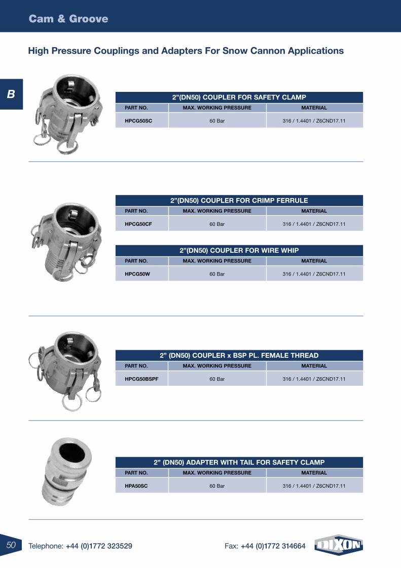
50 Telephone: +44 (0)1772 323529 Fax: +44 (0)1772 314664
Cam & Groove
B
high pressure couplings and adapters For snow cannon applications
2”(dn50) coupler For saFetY clamp part no. maX. WorKing pressure material
hpcg50sc 60 Bar 316 / 1.4401 / Z6CND17.11
2”(dn50) coupler For crimp Ferrule part no. maX. WorKing pressure material
hpcg50cF 60 Bar 316 / 1.4401 / Z6CND17.11
2”(dn50) coupler For Wire Whip part no. maX. WorKing pressure material
hpcg50W 60 Bar 316 / 1.4401 / Z6CND17.11
2” (dn50) coupler x Bsp pl. Female thread part no. maX. WorKing pressure material
hpcg50BspF 60 Bar 316 / 1.4401 / Z6CND17.11
2” (dn50) adapter With tail For saFetY clamp part no. maX. WorKing pressure material
hpa50sc 60 Bar 316 / 1.4401 / Z6CND17.11
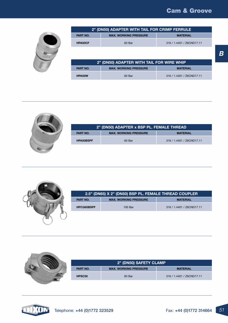
51Telephone: +44 (0)1772 323529 Fax: +44 (0)1772 314664
Cam & Groove
B
2” (dn50) adapter With tail For crimp Ferrule part no. maX. WorKing pressure material
hpa50cF 60 Bar 316 / 1.4401 / Z6CND17.11
2” (dn50) adapter With tail For Wire Whip part no. maX. WorKing pressure material
hpa50W 60 Bar 316 / 1.4401 / Z6CND17.11
2” (dn50) adapter x Bsp pl. Female thread part no. maX. WorKing pressure material
hpa50BspF 60 Bar 316 / 1.4401 / Z6CND17.11
2.5” (dn65) X 2” (dn50) Bsp pl. Female thread coupler part no. maX. WorKing pressure material
hpcg65BspF 100 Bar 316 / 1.4401 / Z6CND17.11
2” (dn50) saFetY clamp part no. maX. WorKing pressure material
hpsc50 60 Bar 316 / 1.4401 / Z6CND17.11
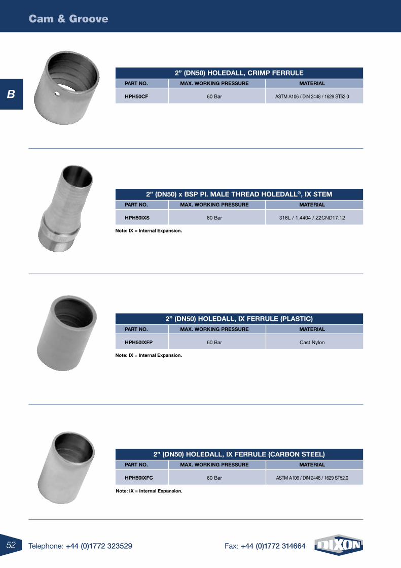
52 Telephone: +44 (0)1772 323529 Fax: +44 (0)1772 314664
Cam & Groove
B
note: iX = internal expansion.
note: iX = internal expansion.
note: iX = internal expansion.
2” (dn50) holedall‚ crimp Ferrule part no. maX. WorKing pressure material
hph50cF 60 Bar ASTM A106 / DIN 2448 / 1629 ST52.0
2” (dn50) x Bsp pl. male thread holedall®‚ iX stem part no. maX. WorKing pressure material
hph50iXs 60 Bar 316L / 1.4404 / Z2CND17.12
2” (dn50) holedall, iX Ferrule (plastic) part no. maX. WorKing pressure material
hph50iXFp 60 Bar Cast Nylon
2” (dn50) holedall‚ iX Ferrule (carBon steel) part no. maX. WorKing pressure material
hph50iXFc 60 Bar ASTM A106 / DIN 2448 / 1629 ST52.0
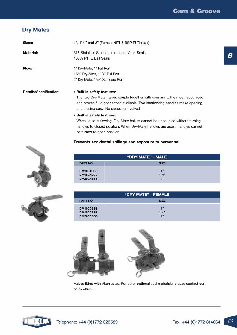
53Telephone: +44 (0)1772 323529 Fax: +44 (0)1772 314664
Cam & Groove
B
dry mates
“drY-mate” - male part no. siZe
dm100aBss 1” dm150aBss 11/2” dm200aBss 2”
“drY-mate” - Female part no. siZe
dm100dBss 1” dm150dBss 11/2” dm200dBss 2”
sizes: 1”, 11/2” and 2” (Female NPT & BSP PI Thread)
material: 316 Stainless Steel construction, Viton Seals.
100% PTFE Ball Seals
Flow: 1” Dry-Mate, 1” Full Port
11/2” Dry-Mate, 11/2” Full Port
2” Dry-Mate, 11/2” Standard Port
details/specification: • Built in safety features:
The two Dry-Mate halves couple together with cam arms, the most recognised
and proven fluid connection available. Two interlocking handles make opening
and closing easy. No guessing involved
• Built in safety features:
When liquid is flowing, Dry-Mate halves cannot be uncoupled without turning
handles to closed position. When Dry-Mate handles are apart, handles cannot
be turned to open position
prevents accidental spillage and exposure to personnel.
Valves fitted with Viton seals. For other optional seal materials, please contact our
sales office.
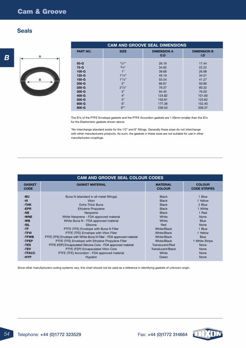
54 Telephone: +44 (0)1772 323529 Fax: +44 (0)1772 314664
Cam & Groove
B
The ID’s of the PTFE Envelope gaskets and the PTFE Accordion gaskets are 1.59mm smaller than the ID’s for the Elastomeric gaskets shown above.
*No interchange standard exists for the 1/2” and 8” fittings. Generally these sizes do not interchange with other manufacturers products. As such, the gaskets in these sizes are not suitable for use in other manufacturers couplings.
Since other manufacturers coding systems vary, this chart should not be used as a reference in identifying gaskets of unknown origin.
a
B
seals
cam and grooVe seal colour codes
gasKet gasKet material material colour code colour code stripes
-Bu Buna N (standard in all metal fittings) Black 1 Blue -Vi Viton Black 1 Yellow -thK Extra Thick Buna Black 2 Blue -epr Ethylene Propylene Black 1 White -ne Neoprene Black 1 Red -Wne White Neoprene - FDA approved material White None -WB White Buna N - FDA approved material White Blue -sil Silicone Red None -tF PTFE (TFE) Envelope with Buna N Filler White/Black 1 Blue -tFVi PTFE (TFE) Envelope with Viton Filler White/Black 1 Yellow -tFWB PTFE (TFE) Envelope with White Buna N Filler - FDA approved material White/Black Blue -tFep PTFE (TFE) Envelope with Ethylene Propylene Filler White/Black 1 White Stripe -tes PTFE (FEP) Encapsulated Silicone Core - FDA approved material Translucent/Red None -teV PTFE (FEP) Encapsulated Viton Core Translucent/Black None -tFacc PTFE (TFE) Accordion - FDA approved material White None -hYp Hypalon Green None
cam and grooVe seal dimensions part no. siZe dimension a dimension B o.d i.d 50-g 1/2”* 26.19 17.44 75-g 3/4” 34.92 22.22 100-g 1” 39.68 26.98 125-g 11/4” 49.19 34.51 150-g 11/2” 55.54 41.27 200-g 2” 66.67 50.80 250-g 21/2” 79.37 60.32 300-g 3” 94.45 76.20 400-g 4” 124.82 101.60 500-g 5” 150.81 123.82 600-g 6” 177.38 152.40 800-g 8”* 236.53 206.37
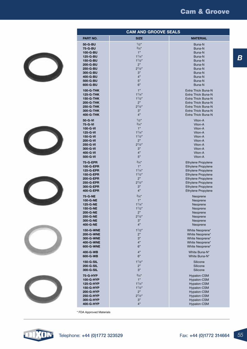
55Telephone: +44 (0)1772 323529 Fax: +44 (0)1772 314664
Cam & Groove
B
* FDA Approved Materials
cam and grooVe seals part no. siZe material
50-g-Bu 1/2” Buna-N 75-g-Bu 3/4” Buna-N 100-g-Bu 1” Buna-N 125-g-Bu 11/4” Buna-N 150-g-Bu 11/2” Buna-N 200-g-Bu 2” Buna-N 250-g-Bu 21/2” Buna-N 300-g-Bu 3” Buna-N 400-g-Bu 4” Buna-N 500-g-Bu 5” Buna-N 600-g-Bu 6” Buna-N 100-g-thK 1” Extra Thick Buna-N 125-g-thK 11/4” Extra Thick Buna-N 150-g-thK 11/2” Extra Thick Buna-N 200-g-thK 2” Extra Thick Buna-N 250-g-thK 21/2” Extra Thick Buna-N 300-g-thK 3” Extra Thick Buna-N 400-g-thK 4” Extra Thick Buna-N
50-g-Vi 1/2” Viton-A 75-g-Vi 3/4” Viton-A 100-g-Vi 1” Viton-A 125-g-Vi 11/4” Viton-A 150-g-Vi 11/2” Viton-A 200-g-Vi 2” Viton-A 250-g-Vi 21/2” Viton-A 300-g-Vi 3” Viton-A 400-g-Vi 4” Viton-A 500-g-Vi 5” Viton-A
75-g-epr 3/4” Ethylene Propylene 100-g-epr 1” Ethylene Propylene 125-g-epr 11/4” Ethylene Propylene 150-g-epr 11/2” Ethylene Propylene 200-g-epr 2” Ethylene Propylene 250-g-epr 21/2” Ethylene Propylene 300-g-epr 3” Ethylene Propylene 400-g-epr 4” Ethylene Propylene
75-g-ne 3/4” Neoprene 100-g-ne 1” Neoprene 125-g-ne 11/4” Neoprene 150-g-ne 11/2” Neoprene 200-g-ne 2” Neoprene 250-g-ne 21/2” Neoprene 300-g-ne 3” Neoprene 400-g-ne 4” Neoprene
150-g-Wne 11/2” White Neoprene* 200-g-Wne 2” White Neoprene* 300-g-Wne 3” White Neoprene* 400-g-Wne 4” White Neoprene* 600-g-Wne 6” White Neoprene*
400-g-WB 4” White Buna-N* 600-g-WB 6” White Buna-N*
150-g-sil 11/2” Silicone 200-g-sil 2” Silicone 300-g-sil 3” Silicone
75-g-hYp 3/4” Hypalon-CSM 100-g-hYp 1” Hypalon-CSM 125-g-hYp 11/4” Hypalon-CSM 150-g-hYp 11/2” Hypalon-CSM 200-g-hYp 2” Hypalon-CSM 250-g-hYp 21/2” Hypalon-CSM 300-g-hYp 3” Hypalon-CSM 400-g-hYp 4” Hypalon-CSM
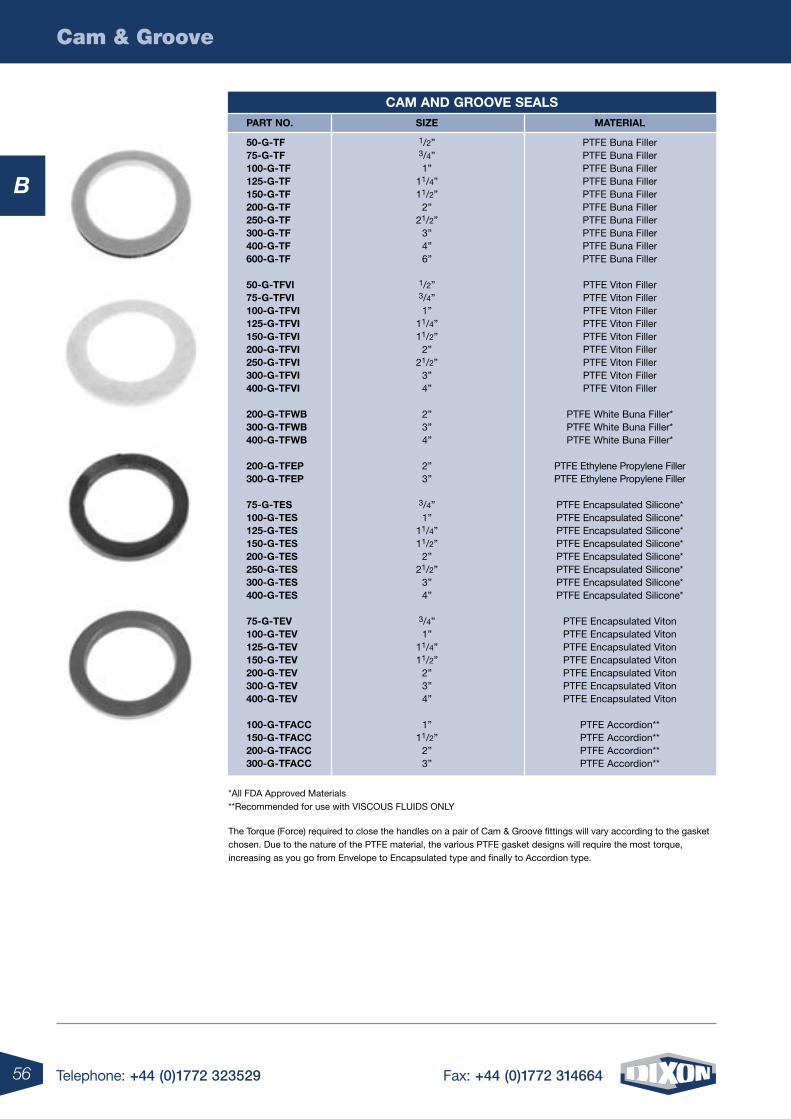
56 Telephone: +44 (0)1772 323529 Fax: +44 (0)1772 314664
Cam & Groove
B
cam and grooVe seals part no. siZe material
50-g-tF 1/2” PTFE Buna Filler 75-g-tF 3/4” PTFE Buna Filler 100-g-tF 1” PTFE Buna Filler 125-g-tF 11/4” PTFE Buna Filler 150-g-tF 11/2” PTFE Buna Filler 200-g-tF 2” PTFE Buna Filler 250-g-tF 21/2” PTFE Buna Filler 300-g-tF 3” PTFE Buna Filler 400-g-tF 4” PTFE Buna Filler 600-g-tF 6” PTFE Buna Filler
50-g-tFVi 1/2” PTFE Viton Filler 75-g-tFVi 3/4” PTFE Viton Filler 100-g-tFVi 1” PTFE Viton Filler 125-g-tFVi 11/4” PTFE Viton Filler 150-g-tFVi 11/2” PTFE Viton Filler 200-g-tFVi 2” PTFE Viton Filler 250-g-tFVi 21/2” PTFE Viton Filler 300-g-tFVi 3” PTFE Viton Filler 400-g-tFVi 4” PTFE Viton Filler
200-g-tFWB 2” PTFE White Buna Filler* 300-g-tFWB 3” PTFE White Buna Filler* 400-g-tFWB 4” PTFE White Buna Filler*
200-g-tFep 2” PTFE Ethylene Propylene Filler 300-g-tFep 3” PTFE Ethylene Propylene Filler
75-g-tes 3/4” PTFE Encapsulated Silicone* 100-g-tes 1” PTFE Encapsulated Silicone* 125-g-tes 11/4” PTFE Encapsulated Silicone* 150-g-tes 11/2” PTFE Encapsulated Silicone* 200-g-tes 2” PTFE Encapsulated Silicone* 250-g-tes 21/2” PTFE Encapsulated Silicone* 300-g-tes 3” PTFE Encapsulated Silicone* 400-g-tes 4” PTFE Encapsulated Silicone*
75-g-teV 3/4” PTFE Encapsulated Viton 100-g-teV 1” PTFE Encapsulated Viton 125-g-teV 11/4” PTFE Encapsulated Viton 150-g-teV 11/2” PTFE Encapsulated Viton 200-g-teV 2” PTFE Encapsulated Viton 300-g-teV 3” PTFE Encapsulated Viton 400-g-teV 4” PTFE Encapsulated Viton
100-g-tFacc 1” PTFE Accordion** 150-g-tFacc 11/2” PTFE Accordion** 200-g-tFacc 2” PTFE Accordion** 300-g-tFacc 3” PTFE Accordion**
*All FDA Approved Materials **Recommended for use with VISCOUS FLUIDS ONLY
The Torque (Force) required to close the handles on a pair of Cam & Groove fittings will vary according to the gasket chosen. Due to the nature of the PTFE material, the various PTFE gasket designs will require the most torque, increasing as you go from Envelope to Encapsulated type and finally to Accordion type.
B
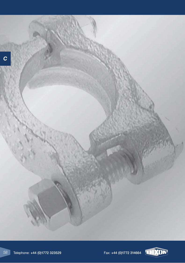
C
4 Telephone: +44 (0)1772 323529 Fax: +44 (0)1772 31466458 Telephone: +44 (0)1772 323529 Fax: +44 (0)1772 314664
C
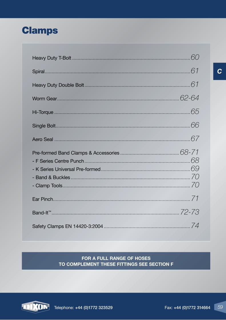
C
59Telephone: +44 (0)1772 323529 Fax: +44 (0)1772 314664
Heavy Duty T-Bolt ......................................................................................60
Spiral ..........................................................................................................61
Heavy Duty Double Bolt .............................................................................61
Worm Gear ......................................................................................... 62-64
Hi-Torque ...................................................................................................65
Single Bolt ..................................................................................................66
Aero Seal ...................................................................................................67
Pre-formed Band Clamps & Accessories ........................................... 68-71
- F Series Centre Punch .............................................................................68
- K Series Universal Pre-formed .................................................................69
- Band & Buckles .......................................................................................70
- Clamp Tools .............................................................................................70
Ear Pinch....................................................................................................71
Band-It™ ............................................................................................. 72-73
Safety Clamps EN 14420-3:2004 ...............................................................74
59Telephone: +44 (0)1772 323529 Fax: +44 (0)1772 314664
Clamps
For a Full range oF hoses to complement these Fittings see section F
C
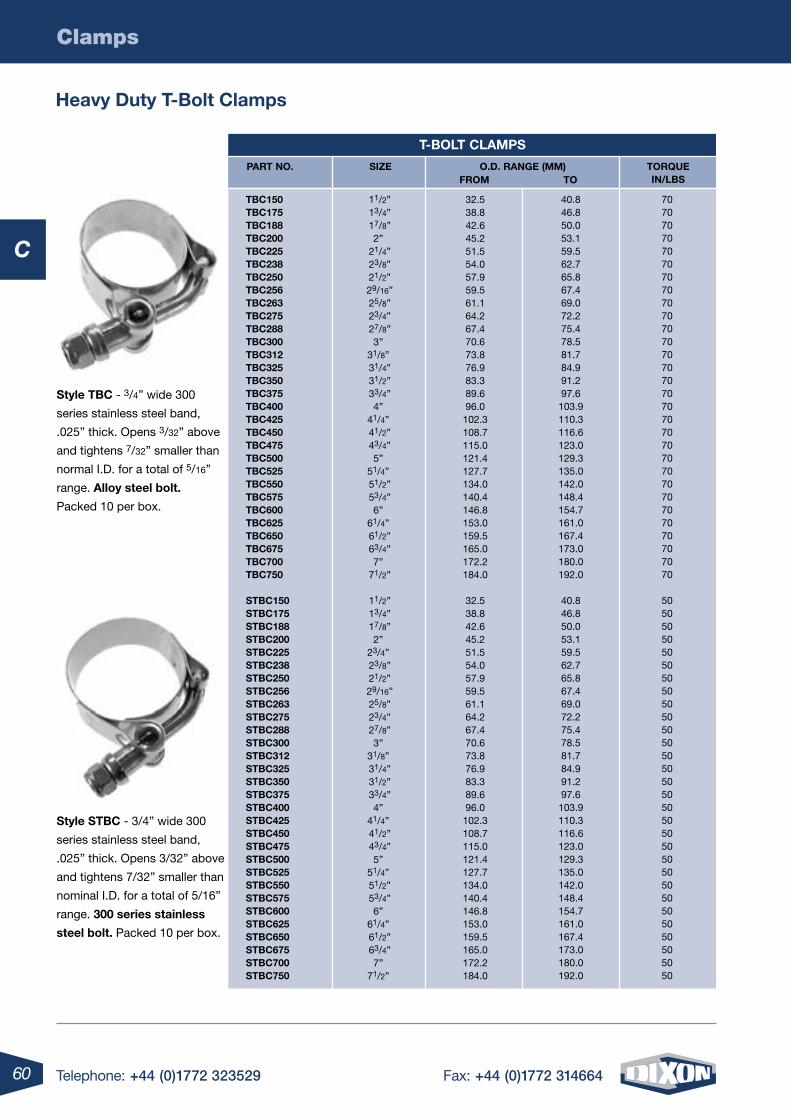
60 Telephone: +44 (0)1772 323529 Fax: +44 (0)1772 314664
C
Clamps
heavy Duty t-Bolt clamps
style stBc - 3/4” wide 300
series stainless steel band,
.025” thick. Opens 3/32” above
and tightens 7/32” smaller than
nominal I.D. for a total of 5/16”
range. 300 series stainless
steel bolt. Packed 10 per box.
style tBc - 3/4” wide 300
series stainless steel band,
.025” thick. Opens 3/32” above
and tightens 7/32” smaller than
normal I.D. for a total of 5/16”
range. alloy steel bolt.
Packed 10 per box.
t-Bolt clamps
tBc150 tBc175 tBc188 tBc200 tBc225 tBc238 tBc250 tBc256 tBc263 tBc275 tBc288 tBc300 tBc312 tBc325 tBc350 tBc375 tBc400 tBc425 tBc450 tBc475 tBc500 tBc525 tBc550 tBc575 tBc600 tBc625 tBc650 tBc675 tBc700 tBc750
stBc150 stBc175 stBc188 stBc200 stBc225 stBc238 stBc250 stBc256 stBc263 stBc275 stBc288 stBc300 stBc312 stBc325 stBc350 stBc375 stBc400 stBc425 stBc450 stBc475 stBc500 stBc525 stBc550 stBc575 stBc600 stBc625 stBc650 stBc675 stBc700 stBc750
32.538.842.645.251.554.057.959.561.164.267.470.673.876.983.389.696.0102.3108.7115.0121.4127.7134.0140.4146.8153.0159.5165.0172.2184.0
32.538.842.645.251.554.057.959.561.164.267.470.673.876.983.389.696.0102.3108.7115.0121.4127.7134.0140.4146.8153.0159.5165.0172.2184.0
40.846.850.053.159.562.765.867.469.072.275.478.581.784.991.297.6103.9110.3116.6123.0129.3135.0142.0148.4154.7161.0167.4173.0180.0192.0
40.846.850.053.159.562.765.867.469.072.275.478.581.784.991.297.6103.9110.3116.6123.0129.3135.0142.0148.4154.7161.0167.4173.0180.0192.0
707070707070707070707070707070707070707070707070707070707070
505050505050505050505050505050505050505050505050505050505050
11/2” 13/4” 17/8”
2” 21/4” 23/8” 21/2” 29/16” 25/8” 23/4” 27/8”
3”31/8” 31/4” 31/2” 33/4”
4”41/4” 41/2” 43/4”
5”51/4” 51/2” 53/4”
6”61/4” 61/2” 63/4”
7” 71/2”
11/2” 13/4” 17/8”
2”23/4” 23/8” 21/2” 29/16” 25/8” 23/4” 27/8”
3”31/8” 31/4” 31/2” 33/4”
4”41/4” 41/2” 43/4”
5” 51/4” 51/2” 53/4”
6”61/4” 61/2” 63/4”
7”71/2”
part no. o.D. range (mm)From to
torquein/lBs
siZe
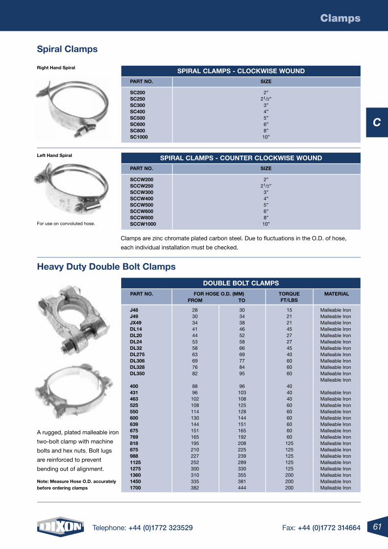
61Telephone: +44 (0)1772 323529 Fax: +44 (0)1772 314664
C
Clamps
spiral clamps
heavy Duty Double Bolt clamps
For use on convoluted hose.
left hand spiral
right hand spiral
Clamps are zinc chromate plated carbon steel. Due to fluctuations in the O.D. of hose,
each individual installation must be checked.
A rugged, plated malleable iron
two-bolt clamp with machine
bolts and hex nuts. Bolt lugs
are reinforced to prevent
bending out of alignment.
note: measure hose o.D. accurately before ordering clamps
spiral clamps - clocKWise WounD
part no. siZe
sc200 sc250 sc300 sc400 sc500 sc600 sc800 sc1000
2”21/2”
3”4”5”6”8”10”
spiral clamps - counter clocKWise WounD
part no. siZe
sccW200 sccW250 sccW300 sccW400 sccW500 sccW600 sccW800 sccW1000
2”21/2”
3”4”5”6”8”10”
DouBle Bolt clamps
J48 J49 JX49 Dl14 Dl20 Dl24 Dl32 Dl275 Dl306 Dl328 Dl350
400 431 463 525 550 600 639 675 769 818 875 988 1125 1275 1360 1450 1700
Malleable IronMalleable IronMalleable IronMalleable IronMalleable IronMalleable IronMalleable IronMalleable IronMalleable IronMalleable IronMalleable IronMalleable Iron
Malleable IronMalleable IronMalleable IronMalleable IronMalleable IronMalleable IronMalleable IronMalleable IronMalleable IronMalleable IronMalleable IronMalleable IronMalleable IronMalleable IronMalleable IronMalleable Iron
2830344144535863697682
8896102108114130144151165195210227252300310335382
3034384652586669778495
96103108125128144151165192208225239289330355381444
1521214527274540606060
404040606060606060125125125125125200200200
part no. For hose o.D. (mm)From to
materialtorqueFt/lBs
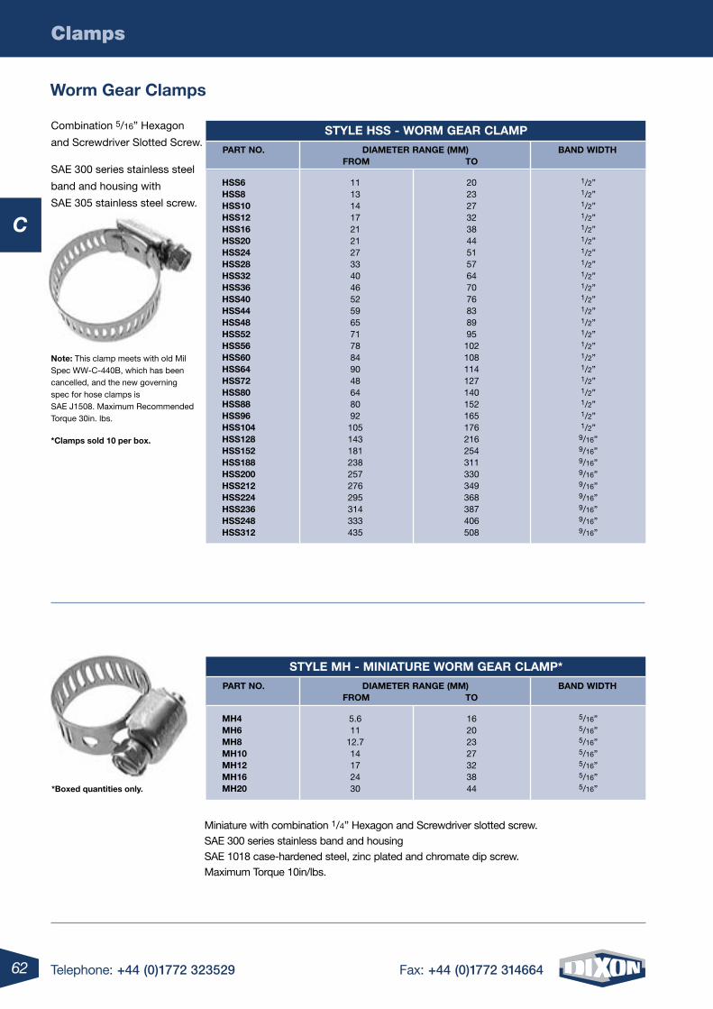
62 Telephone: +44 (0)1772 323529 Fax: +44 (0)1772 314664
C
Clamps
Worm gear clamps
Combination 5/16” Hexagon
and Screwdriver Slotted Screw.
SAE 300 series stainless steel
band and housing with
SAE 305 stainless steel screw.
note: This clamp meets with old Mil Spec WW-C-440B, which has been cancelled, and the new governing spec for hose clamps is SAE J1508. Maximum Recommended Torque 30in. lbs.
*clamps sold 10 per box.
Miniature with combination 1/4” Hexagon and Screwdriver slotted screw. SAE 300 series stainless band and housingSAE 1018 case-hardened steel, zinc plated and chromate dip screw.Maximum Torque 10in/lbs.
*Boxed quantities only.
style hss - Worm gear clamp
hss6 hss8 hss10 hss12 hss16 hss20 hss24 hss28 hss32 hss36 hss40 hss44 hss48 hss52 hss56 hss60 hss64 hss72 hss80 hss88 hss96 hss104 hss128 hss152 hss188 hss200 hss212 hss224 hss236 hss248 hss312
111314172121273340465259657178849048648092105143181238257276295314333435
2023273238445157647076838995102108114127140152165176216254311330349368387406508
1/2”1/2”1/2”1/2”1/2”1/2”1/2”1/2”1/2”1/2”1/2”1/2”1/2”1/2”1/2”1/2”1/2”1/2”1/2”1/2”1/2”1/2”9/16”9/16”9/16”9/16”9/16”9/16”9/16”9/16”9/16”
part no. Diameter range (mm) BanD WiDthFrom to
style mh - miniature Worm gear clamp*
mh4 mh6 mh8 mh10 mh12 mh16 mh20
5.611
12.714172430
16202327323844
5/16”5/16”5/16”5/16”5/16”5/16”5/16”
part no. Diameter range (mm) BanD WiDthFrom to
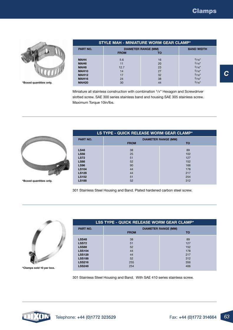
63Telephone: +44 (0)1772 323529 Fax: +44 (0)1772 314664
C
Clamps
Miniature all stainless construction with combination 1/4” Hexagon and Screwdriver
slotted screw. SAE 300 series stainless band and housing SAE 305 stainless screw.
Maximum Torque 10in/lbs.
301 Stainless Steel Housing and Band. Plated hardened carbon steel screw.
301 Stainless Steel Housing and Band. With SAE 410 series stainless screw.
*Boxed quantities only.
*Boxed quantities only.
style mah - miniature Worm gear clamp*
mah4 mah6 mah8 mah10 mah12 mah16 mah20
5.611
12.714172430
16202327323844
5/16”5/16”5/16”5/16”5/16”5/16”5/16”
part no. Diameter range (mm) BanD WiDthFrom to
ls type - quicK release Worm gear clamp*
ls48 ls56 ls72 ls88 ls96 ls104 ls128 ls152 ls188
382551529044445152
89102127152166178217254312
part no. Diameter range (mm)From to
*clamps sold 10 per box.
lss type - quicK release Worm gear clamp*
lss48 lss72 lss88 lss104 lss128 lss188 lss216 lss248
385152444452255254
89127152178217312356406
part no. Diameter range (mm)From to
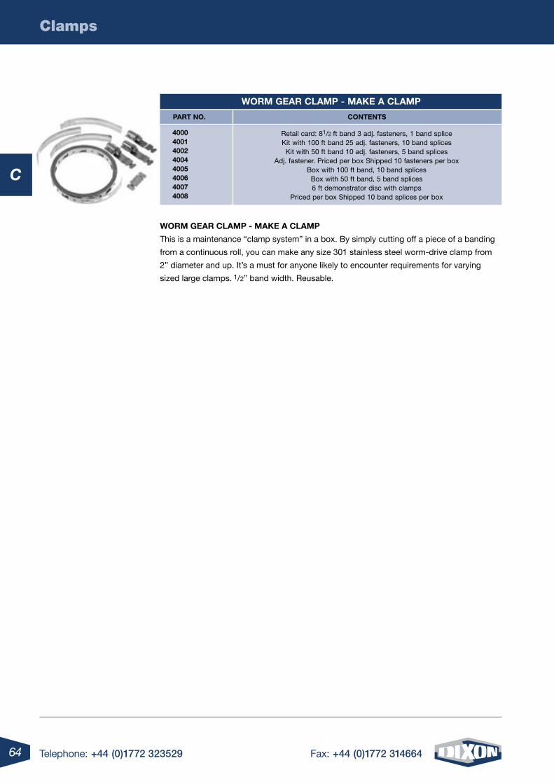
64 Telephone: +44 (0)1772 323529 Fax: +44 (0)1772 314664
C
Clamps
Worm gear clamp - maKe a clamp
4000 4001 4002 4004 4005 4006 4007 4008
Retail card: 81/2 ft band 3 adj. fasteners, 1 band splice Kit with 100 ft band 25 adj. fasteners, 10 band splices
Kit with 50 ft band 10 adj. fasteners, 5 band splices Adj. fastener. Priced per box Shipped 10 fasteners per box
Box with 100 ft band, 10 band splices Box with 50 ft band, 5 band splices 6 ft demonstrator disc with clamps
Priced per box Shipped 10 band splices per box
part no. contents
Worm gear clamp - maKe a clamp
This is a maintenance “clamp system” in a box. By simply cutting off a piece of a banding
from a continuous roll, you can make any size 301 stainless steel worm-drive clamp from
2” diameter and up. It’s a must for anyone likely to encounter requirements for varying
sized large clamps. 1/2” band width. Reusable.
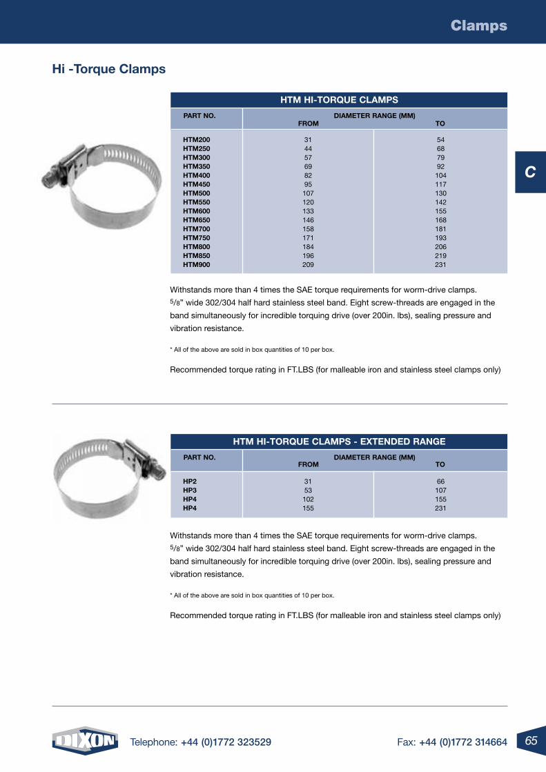
65Telephone: +44 (0)1772 323529 Fax: +44 (0)1772 314664
C
Clamps
Withstands more than 4 times the SAE torque requirements for worm-drive clamps. 5/8” wide 302/304 half hard stainless steel band. Eight screw-threads are engaged in the
band simultaneously for incredible torquing drive (over 200in. lbs), sealing pressure and
vibration resistance.
* All of the above are sold in box quantities of 10 per box.
Recommended torque rating in FT.LBS (for malleable iron and stainless steel clamps only)
hi -torque clamps
htm hi-torque clamps
htm200 htm250 htm300 htm350 htm400 htm450 htm500 htm550 htm600 htm650 htm700 htm750 htm800 htm850 htm900
314457698295107120133146158171184196209
54687992104117130142155168181193206219231
part no. Diameter range (mm)From to
htm hi-torque clamps - eXtenDeD range
hp2 hp3 hp4 hp4
3153102155
66107155231
part no. Diameter range (mm)From to
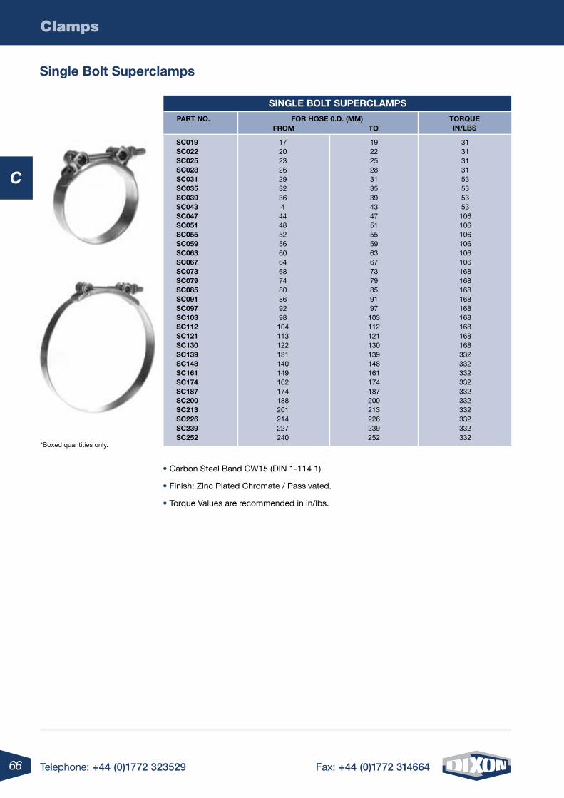
66 Telephone: +44 (0)1772 323529 Fax: +44 (0)1772 314664
C
Clamps
single Bolt superclamps
• Carbon Steel Band CW15 (DIN 1-114 1).
• Finish: Zinc Plated Chromate / Passivated.
• Torque Values are recommended in in/lbs.
*Boxed quantities only.
single Bolt superclamps
sc019 sc022 sc025 sc028 sc031 sc035 sc039 sc043 sc047 sc051 sc055 sc059 sc063 sc067 sc073 sc079 sc085 sc091 sc097 sc103 sc112 sc121 sc130 sc139 sc148 sc161 sc174 sc187 sc200 sc213 sc226 sc239 sc252
172023262932364444852566064687480869298104113122131140149162174188201214227240
19222528313539434751555963677379859197103112121130139148161174187200213226239252
3131313153535353106106106106106106168168168168168168168168168332332332332332332332332332332
part no. For hose 0.D. (mm)From to
torque in/lBs
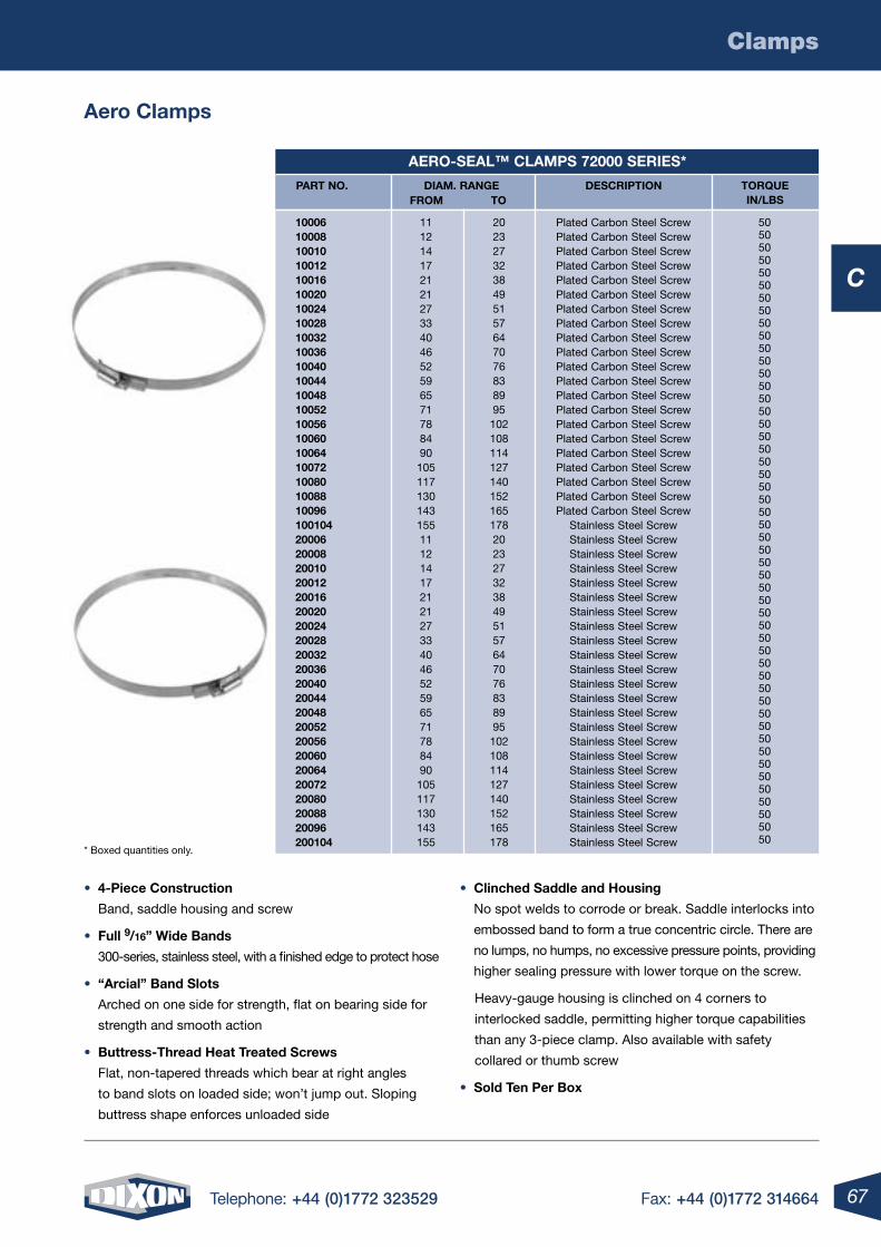
67Telephone: +44 (0)1772 323529 Fax: +44 (0)1772 314664
C
Clamps
• 4-piece construction
Band, saddle housing and screw
• Full 9/16” Wide Bands
300-series, stainless steel, with a finished edge to protect hose
• “arcial” Band slots
Arched on one side for strength, flat on bearing side for
strength and smooth action
• Buttress-thread heat treated screws
Flat, non-tapered threads which bear at right angles
to band slots on loaded side; won’t jump out. Sloping
buttress shape enforces unloaded side
• clinched saddle and housing
No spot welds to corrode or break. Saddle interlocks into
embossed band to form a true concentric circle. There are
no lumps, no humps, no excessive pressure points, providing
higher sealing pressure with lower torque on the screw.
Heavy-gauge housing is clinched on 4 corners to
interlocked saddle, permitting higher torque capabilities
than any 3-piece clamp. Also available with safety
collared or thumb screw
• sold ten per Box
aero clamps
* Boxed quantities only.
aero-seal™ clamps 72000 series*
10006 10008 10010 10012 10016 10020 10024 10028 10032 10036 10040 10044 10048 10052 10056 10060 10064 10072 10080 10088 10096 100104 20006 20008 20010 20012 20016 20020 20024 20028 20032 20036 20040 20044 20048 20052 20056 20060 20064 20072 20080 20088 20096 200104
Plated Carbon Steel ScrewPlated Carbon Steel ScrewPlated Carbon Steel ScrewPlated Carbon Steel ScrewPlated Carbon Steel ScrewPlated Carbon Steel ScrewPlated Carbon Steel ScrewPlated Carbon Steel ScrewPlated Carbon Steel ScrewPlated Carbon Steel ScrewPlated Carbon Steel ScrewPlated Carbon Steel ScrewPlated Carbon Steel ScrewPlated Carbon Steel ScrewPlated Carbon Steel ScrewPlated Carbon Steel ScrewPlated Carbon Steel ScrewPlated Carbon Steel ScrewPlated Carbon Steel ScrewPlated Carbon Steel ScrewPlated Carbon Steel Screw
Stainless Steel ScrewStainless Steel ScrewStainless Steel ScrewStainless Steel ScrewStainless Steel ScrewStainless Steel ScrewStainless Steel ScrewStainless Steel ScrewStainless Steel ScrewStainless Steel ScrewStainless Steel ScrewStainless Steel ScrewStainless Steel ScrewStainless Steel ScrewStainless Steel ScrewStainless Steel ScrewStainless Steel ScrewStainless Steel ScrewStainless Steel ScrewStainless Steel ScrewStainless Steel ScrewStainless Steel ScrewStainless Steel Screw
11121417212127334046525965717884901051171301431551112141721212733404652596571788490105117130143155
20232732384951576470768389951021081141271401521651782023273238495157647076838995102108114127140152165178
5050505050505050505050505050505050505050505050505050505050505050505050505050505050505050505050505050
part no. Diam. rangeFrom to
Description torquein/lBs
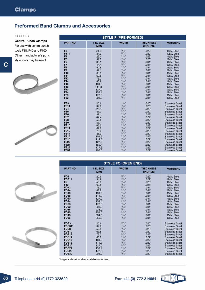
68 Telephone: +44 (0)1772 323529 Fax: +44 (0)1772 314664
C
Clamps
*Larger and custom sizes available on request
Clamps
preformed Band clamps and accessories
F series
centre punch clamps
For use with centre punch
tools F38, F40 and F100.
Other manufacturer’s punch
style tools may be used.
style F (pre-FormeD)
F3 F311 F4 F5 F6 F7 F8 F9 F10 F11 F12 F14 F16 F18 F20 F24 F28 F32
Fs3 Fs11 Fs4 Fs5 Fs6 Fs7 Fs8 Fs9 Fs10 Fs11 Fs12 Fs14 Fs16 Fs18 Fs20 Fs24 Fs28 Fs32
.022”
.022”
.025”
.025”
.031”
.031”
.031”
.031”
.031”
.031”
.031”
.031”
.031”
.031”
.031”
.031”
.031”
.031”
.020”
.020”
.022”
.022”
.022”
.022”
.022”
.022”
.022”
.022”
.022”
.022”
.022”
.022”
.022”
.022”
.022”
.022”
20.6 34.9 25.4 31.7 38.1 44.4 50.8 57.1 63.5 69.8 76.2 88.9 101.6114.3 127.0 152.4 177.8 203.0
20.6 34.9 25.4 31.7 38.1 44.4 50.8 57.1 63.5 69.8 76.2 88.9 101.6 114.3 127.0 152.4 177.8 203.0
Galv. SteelGalv. SteelGalv. SteelGalv. SteelGalv. SteelGalv. SteelGalv. SteelGalv. SteelGalv. SteelGalv. SteelGalv. SteelGalv. SteelGalv. SteelGalv. SteelGalv. SteelGalv. SteelGalv. SteelGalv. Steel
Stainless SteelStainless SteelStainless SteelStainless SteelStainless SteelStainless SteelStainless SteelStainless SteelStainless SteelStainless SteelStainless SteelStainless SteelStainless SteelStainless SteelStainless SteelStainless SteelStainless SteelStainless Steel
3/8”3/8”5/8”5/8”5/8”5/8”5/8”5/8”5/8”5/8”5/8”5/8”5/8”5/8”5/8”5/8”5/8”5/8”
3/8”3/8”5/8”5/8”5/8”5/8”5/8”5/8”5/8”5/8”5/8”5/8”5/8”5/8”5/8”5/8”5/8”5/8”
part no. i. D. siZe(mm)
WiDth thicKness(inches)
material
style Fo (open enD)
Fo3 Fo311 F8 F10 Fo12 Fo14 Fo16 Fo18 Fo20 Fo24 Fo28 Fo32 Fo36 Fo40 Fo48 Fo56
Fos3 Fos311 Fos8 Fos10 Fos12 Fos14 Fos16 Fos18 Fos20 Fos24 Fos28 Fos32
.022”
.022”
.025”
.025”
.031”
.031”
.031”
.031”
.031”
.031”
.031”
.031”
.031”
.031”
.031”
.031”
.020”
.020”
.022”
.022”
.022”
.022”
.022”
.022”
.022”
.022”
.022”
.022”
20.6 34.9 50.8 63.5 76.2 88.9 101.6 114.3 127.0 152.4 177.8 203.0 228.0 254.0 304.0 355.0
20.6 34.9 50.8 63.5 76.2 88.9 101.6 114.3 127.0 152.4 177.8 203.0
Galv. SteelGalv. SteelGalv. SteelGalv. SteelGalv. SteelGalv. SteelGalv. SteelGalv. SteelGalv. SteelGalv. SteelGalv. SteelGalv. SteelGalv. SteelGalv. SteelGalv. SteelGalv. Steel
Stainless SteelStainless SteelStainless SteelStainless SteelStainless SteelStainless SteelStainless SteelStainless SteelStainless SteelStainless SteelStainless SteelStainless Steel
3/8”3/8”5/8”5/8”5/8”5/8”5/8”5/8”5/8”5/8”5/8”5/8”5/8”5/8”5/8”5/8”
3/8”3/8”5/8”5/8”5/8”5/8”5/8”5/8”5/8”5/8”5/8”5/8”
part no. i. D. siZe(mm)
WiDth thicKness(inches)
material
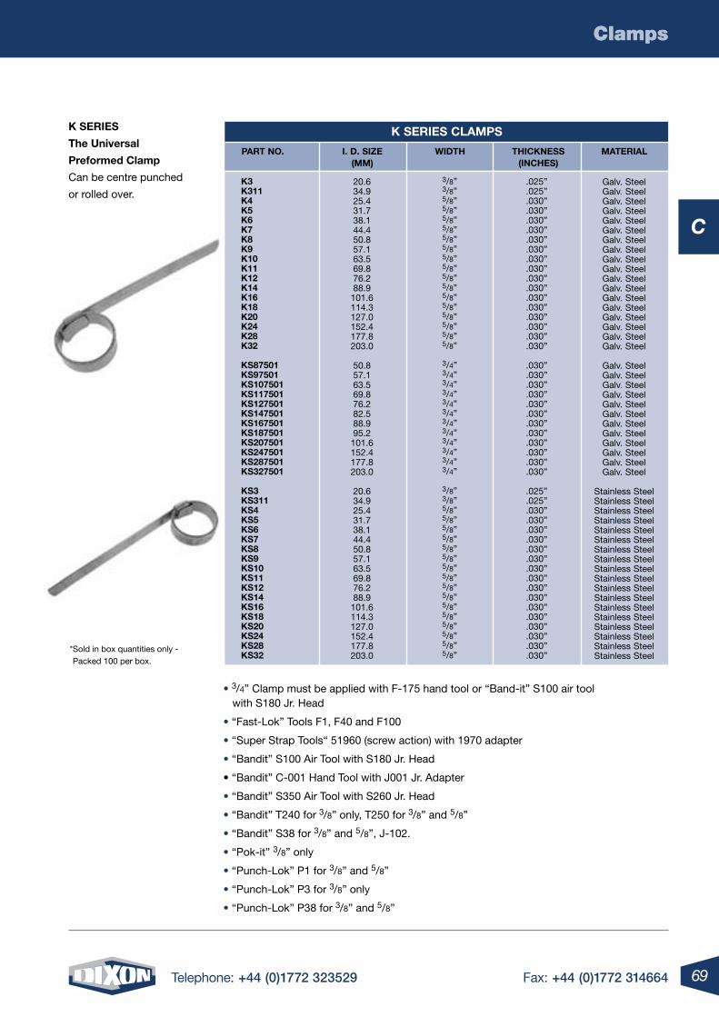
69Telephone: +44 (0)1772 323529 Fax: +44 (0)1772 314664
C
ClampsClamps
• 3/4” Clamp must be applied with F-175 hand tool or “Band-it” S100 air tool with S180 Jr. Head
• “Fast-Lok” Tools F1, F40 and F100
• “Super Strap Tools“ 51960 (screw action) with 1970 adapter
• “Bandit” S100 Air Tool with S180 Jr. Head
• “Bandit” C-001 Hand Tool with J001 Jr. Adapter
• “Bandit” S350 Air Tool with S260 Jr. Head
• “Bandit” T240 for 3/8” only, T250 for 3/8” and 5/8”
• “Bandit” S38 for 3/8” and 5/8”, J-102.
• “Pok-it” 3/8” only
• “Punch-Lok” P1 for 3/8” and 5/8”
• “Punch-Lok” P3 for 3/8” only
• “Punch-Lok” P38 for 3/8” and 5/8”
K series
the universal
preformed clamp
Can be centre punched
or rolled over.
* Sold in box quantities only - Packed 100 per box.
K series clamps
K3 K311 K4 K5 K6 K7 K8 K9 K10 K11 K12 K14 K16 K18 K20 K24 K28 K32
Ks87501 Ks97501 Ks107501 Ks117501 Ks127501 Ks147501 Ks167501 Ks187501 Ks207501 Ks247501 Ks287501 Ks327501
Ks3 Ks311 Ks4 Ks5 Ks6 Ks7 Ks8 Ks9 Ks10 Ks11 Ks12 Ks14 Ks16 Ks18 Ks20 Ks24 Ks28 Ks32
.025”
.025”
.030”
.030”
.030”
.030”
.030”
.030”
.030”
.030”
.030”
.030”
.030”
.030”
.030”
.030”
.030”
.030”
.030”
.030”
.030”
.030”
.030”
.030”
.030”
.030”
.030”
.030”
.030”
.030”
.025”
.025”
.030”
.030”
.030”
.030”
.030”
.030”
.030”
.030”
.030”
.030”
.030”
.030”
.030”
.030”
.030”
.030”
20.634.925.431.738.144.450.857.163.569.876.288.9101.6114.3127.0152.4177.8203.0
50.857.163.569.876.282.588.995.2101.6152.4177.8203.0
20.634.925.431.738.144.450.857.163.569.876.288.9101.6114.3127.0152.4177.8203.0
Galv. SteelGalv. SteelGalv. SteelGalv. SteelGalv. SteelGalv. SteelGalv. SteelGalv. SteelGalv. SteelGalv. SteelGalv. SteelGalv. SteelGalv. SteelGalv. SteelGalv. SteelGalv. SteelGalv. SteelGalv. Steel
Galv. SteelGalv. SteelGalv. SteelGalv. SteelGalv. SteelGalv. SteelGalv. SteelGalv. SteelGalv. SteelGalv. SteelGalv. SteelGalv. Steel
Stainless SteelStainless SteelStainless SteelStainless SteelStainless SteelStainless SteelStainless SteelStainless SteelStainless SteelStainless SteelStainless SteelStainless SteelStainless SteelStainless SteelStainless SteelStainless SteelStainless SteelStainless Steel
3/8”3/8”5/8”5/8”5/8”5/8”5/8”5/8”5/8”5/8”5/8”5/8”5/8”5/8”5/8”5/8”5/8”5/8”
3/4”3/4”3/4”3/4”3/4”3/4”3/4”3/4”3/4”3/4”3/4”3/4”
3/8”3/8”5/8”5/8”5/8”5/8”5/8”5/8”5/8”5/8”5/8”5/8”5/8”5/8”5/8”5/8”5/8”5/8”
part no. i. D. siZe(mm)
WiDth thicKness(inches)
material
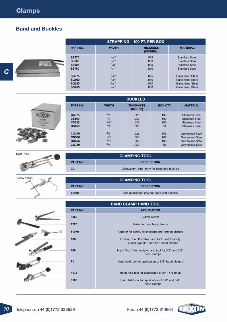
70 Telephone: +44 (0)1772 323529 Fax: +44 (0)1772 314664
C
Clamps
Band and Buckles
(Jack Type)
(Screw Action)
strapping - 100 Ft. per BoX
part no. WiDth thicKness material (inches)
ss375 ss500 ss625 ss750 sg375 sg500 sg625 sg750
.025
.030
.030
.030
.025
.030
.030
.030
3/8”1/2”5/8”3/4”
3/8”1/2”5/8”3/4”
Stainless Steel Stainless Steel Stainless Steel Stainless Steel
Galvanised SteelGalvanised SteelGalvanised SteelGalvanised Steel
BucKles
cs375 cs500 cs625 cs750
cg375 cg500 cg625 cg750
10010010050
10010010050
3/8”1/2”5/8”3/4”
3/8”1/2”5/8”3/4”
.025
.030
.030
.030
.025
.030
.030
.030
Stainless Steel Stainless Steel Stainless Steel Stainless Steel
Galvanised SteelGalvanised SteelGalvanised SteelGalvanised Steel
part no. WiDth thicKness(inches)
BoX qty material
clamping tool
c2 Lightweight, side-entry for band and buckles
part no. Description
clamping tool
51960 Vice application only for band and buckles
part no. Description
BanD clamp hanD tool
F550
F225
51970
F38
F40
F1
F175
F100
Clamp Cutter
Mallet for punching clamps
Adapter for 51960 for installing pre-formed clamps
Locking Tool. Portable hand tool used to apply punch type 3/8” and 5/8” band clamps
Hand Tool. Intermediate hand tool for 3/8” and 5/8” band clamps
Hand held tool for application of 5/8” band clamps
Hand held tool for application of 3/4” K clamps
Hand held tool for application of 3/8” and 5/8” band clamps
part no. application
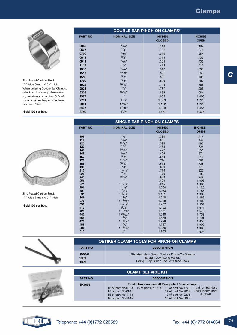
71Telephone: +44 (0)1772 323529 Fax: +44 (0)1772 314664
C
Clamps
Zinc Plated Carbon Steel. 1/4” Wide Band x 0.03” thick. When ordering Double Ear Clamps, select nominal clamp size nearest to, but always larger than O.D. of material to be clamped after insert has been fitted.
*sold 100 per bag.
DouBle ear pinch on clamps* part no. nominal siZe inches inches closeD open
0305 0507 0709 0811 0911 1113 1315 1517 1518 1720 1922 2023 2225 2327 2731 2831 3437 3740
.118
.197
.276
.315
.354
.433
.512
.591
.591
.669
.748
.787
.866
.9051.0631.1021.3391.457
3/16”1/4”5/16”3/8”7/16”1/2”9/16”19/32”5/8”3/4”
13/16”7/8”
15/16”1”
11/8”13/16”17/16”11/2”
.197
.276
.354
.433
.433
.512
.591
.669
.708
.787
.866
.905
.9841.0631.2201.2201.4571.575
Zinc Plated Carbon Steel. 1/4” Wide Band x 0.03” thick. *sold 100 per bag.
single ear pinch on clamps part no. nominal siZe inches inches closeD open
105 113 123 133 140 145 157 170 185 198 210 226 241 256 271 286 301 331 346 376 396 410 425 440 455 470 485 500 515
.350
.381
.394
.453
.472
.496
.543594.618.669.716.779.839.898.9451.0041.0631.1811.2401.3581.4371.4921.5511.6101.6691.7281.7871.8461.905
3/8”7/16”15/32”1/2”
35/64”9/16”5/8”
11/16”23/32”3/4”
1 3/16”7/8”
15/16”1”
1 1/16”1 1/8”1 3/16”1 5/16”1 3/8”
1 15/32”1 9/16”15/8”
1 11/16”1 23/32”1 3/4”
1 13/16”1 7/8”
1 15/16”2”
.414
.444
.486
.524
.551
.571
.618
.669
.728
.779
.827
.890
.9491.0081.0671.1261.1851.3031.3621.4801.5591.6141.6731.7321.7911.8501.9091.9682.028
oetiKer clamp tools For pinch-on clamps
1098-0 9901 1099
Standard Jaw Clamp Tool for Pinch-On Clamps Straight Jaw (Long Handle)
Heavy Duty Clamp Tool with Side Jaws
part no. Description
clamp service Kit
sK1098
plastic box contains all Zinc plated 2-ear clamps
part no. Description
15 of part No.070815 of part No.091115 of part No.111315 of part No.1315
12 of part No.172012 of part No.202312 of part No.222512 of part No.2327
15 of part No.1518 1 pair of Standard Jaw Pincers part
No.1098
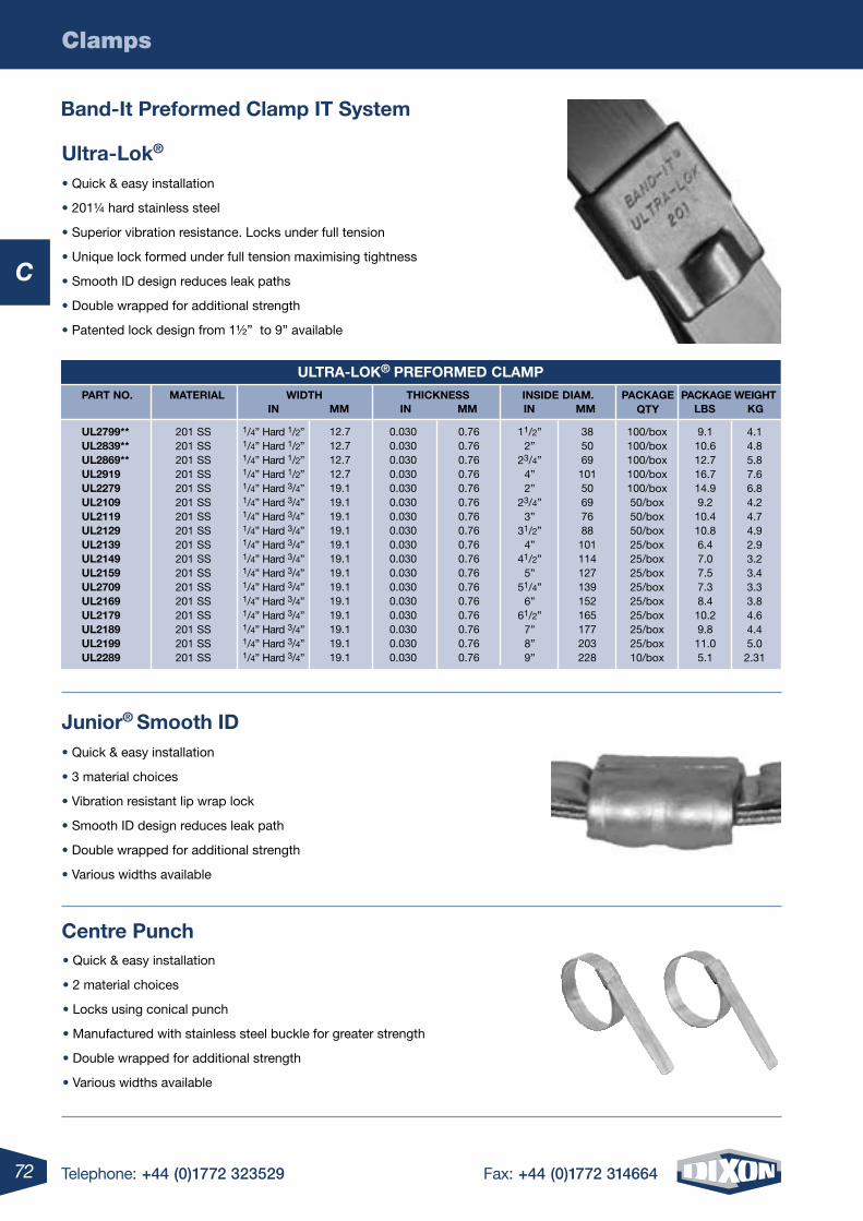
72 Telephone: +44 (0)1772 323529 Fax: +44 (0)1772 314664
C
Clamps
Band-it preformed clamp it system
ultra-lok®
• Quick & easy installation
• 201¼ hard stainless steel
• Superior vibration resistance. Locks under full tension
• Unique lock formed under full tension maximising tightness
• Smooth ID design reduces leak paths
• Double wrapped for additional strength
• Patented lock design from 1½” to 9” available
Junior® smooth iD• Quick & easy installation
• 3 material choices
• Vibration resistant lip wrap lock
• Smooth ID design reduces leak path
• Double wrapped for additional strength
• Various widths available
centre punch• Quick & easy installation
• 2 material choices
• Locks using conical punch
• Manufactured with stainless steel buckle for greater strength
• Double wrapped for additional strength
• Various widths available
ultra-loK® preFormeD clamp
part no. material WiDth thicKness insiDe Diam. pacKage qty
pacKage Weightin in in lBsmm mmmm Kg
ul2799** ul2839** ul2869** ul2919 ul2279 ul2109 ul2119 ul2129 ul2139 ul2149 ul2159 ul2709 ul2169 ul2179 ul2189 ul2199 ul2289
201 SS 201 SS 201 SS 201 SS 201 SS 201 SS 201 SS 201 SS 201 SS 201 SS 201 SS 201 SS 201 SS 201 SS 201 SS 201 SS 201 SS
100/box100/box100/box100/box100/box50/box50/box50/box25/box25/box25/box25/box25/box25/box25/box25/box10/box
9.110.612.716.714.99.210.410.86.47.07.57.38.410.29.811.05.1
38506910150697688101114127139152165177203228
0.76 0.76 0.76 0.76 0.760.76 0.76 0.76 0.76 0.760.76 0.76 0.76 0.76 0.760.76 0.76
0.0300.0300.0300.0300.0300.0300.0300.0300.0300.0300.0300.0300.0300.0300.0300.0300.030
12.712.712.712.719.119.119.119.119.119.119.119.119.119.119.119.119.1
11/2”2”
23/4”4”2”
23/4”3”
31/2”4”
41/2”5”
51/4”6”
61/2”7”8”9”
4.14.85.87.66.84.24.74.92.93.23.43.33.84.64.45.0
2.31
1/4” Hard 1/2”1/4” Hard 1/2”1/4” Hard 1/2”1/4” Hard 1/2”1/4” Hard 3/4”1/4” Hard 3/4”1/4” Hard 3/4”1/4” Hard 3/4”1/4” Hard 3/4”1/4” Hard 3/4”1/4” Hard 3/4”1/4” Hard 3/4”1/4” Hard 3/4”1/4” Hard 3/4”1/4” Hard 3/4”1/4” Hard 3/4”1/4” Hard 3/4”
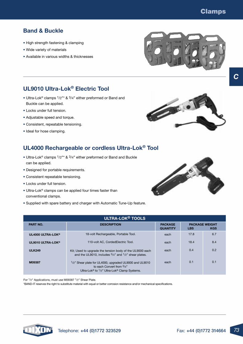
73Telephone: +44 (0)1772 323529 Fax: +44 (0)1772 314664
C
Clamps
ul9010 ultra-lok® electric tool• Ultra-Lok® clamps 1/2”* & 3/4” either preformed or Band and
Buckle can be applied.
• Locks under full tension.
• Adjustable speed and torque.
• Consistent, repeatable tensioning.
• Ideal for hose clamping.
ul4000 rechargeable or cordless ultra-lok® tool
• Ultra-Lok® clamps 1/2”* & 3/4” either preformed or Band and Buckle
can be applied.
• Designed for portable requirements.
• Consistent repeatable tensioning.
• Locks under full tension.
• Ultra-Lok® clamps can be applied four times faster than
conventional clamps.
• Supplied with spare battery and charger with Automatic Tune-Up feature.
For 1/2” Applications, must use M09387 1/2” Shear Plate. *BAND-IT reserves the right to substitute material with equal or better corrosion resistance and/or mechanical specifications.
Band & Buckle
• High strength fastening & clamping
• Wide variety of materials
• Available in various widths & thicknesses
ultra-loK® tools part no.
Description pacKagequantity
pacKage Weight
ul4000 ultra-loK® ul9010 ultra-loK® ulK249
m09387
each
each
each
each
18-volt Rechargeable, Portable Tool.
110-volt AC, CordedElectric Tool.
Kit; Used to upgrade the tension body of the UL9000 each and the UL9010, includes 3/4” and 1/2” shear plates.
1/2” Shear plate for UL4000, upgraded UL9000 and UL9010 to each Convert from 3/4”
Ultra-Lok® to 1/2” Ultra-Lok® Clamp Systems.
6.7
8.4
0.2
0.1
17.8
18.4
0.4
0.1
lBs Kgs
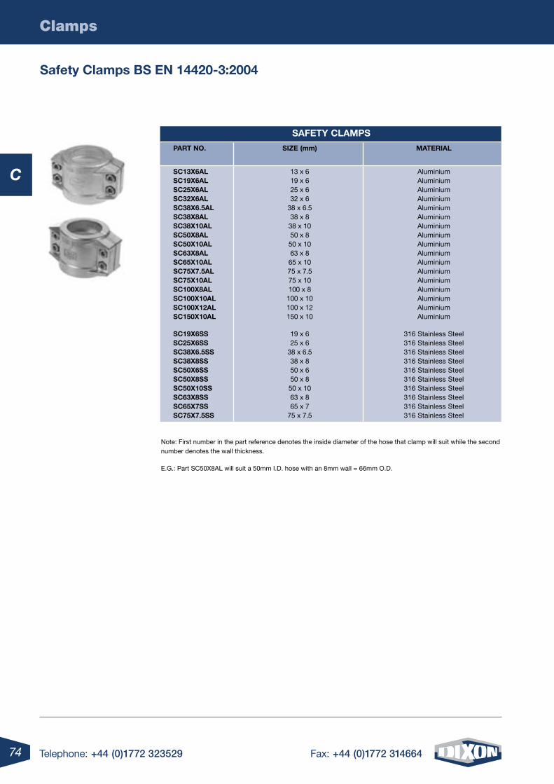
74 Telephone: +44 (0)1772 323529 Fax: +44 (0)1772 314664
Clamps
C
Note: First number in the part reference denotes the inside diameter of the hose that clamp will suit while the second number denotes the wall thickness.
E.G.: Part SC50X8AL will suit a 50mm I.D. hose with an 8mm wall = 66mm O.D.
safety clamps Bs en 14420-3:2004
saFety clamps
part no. siZe (mm) material
sc13X6al 13 x 6 Aluminium sc19X6al 19 x 6 Aluminium sc25X6al 25 x 6 Aluminium sc32X6al 32 x 6 Aluminium sc38X6.5al 38 x 6.5 Aluminium sc38X8al 38 x 8 Aluminium sc38X10al 38 x 10 Aluminium sc50X8al 50 x 8 Aluminium sc50X10al 50 x 10 Aluminium sc63X8al 63 x 8 Aluminium sc65X10al 65 x 10 Aluminium sc75X7.5al 75 x 7.5 Aluminium sc75X10al 75 x 10 Aluminium sc100X8al 100 x 8 Aluminium sc100X10al 100 x 10 Aluminium sc100X12al 100 x 12 Aluminium sc150X10al 150 x 10 Aluminium sc19X6ss 19 x 6 316 Stainless Steel sc25X6ss 25 x 6 316 Stainless Steel sc38X6.5ss 38 x 6.5 316 Stainless Steel sc38X8ss 38 x 8 316 Stainless Steel sc50X6ss 50 x 6 316 Stainless Steel sc50X8ss 50 x 8 316 Stainless Steel sc50X10ss 50 x 10 316 Stainless Steel sc63X8ss 63 x 8 316 Stainless Steel sc65X7ss 65 x 7 316 Stainless Steel sc75X7.5ss 75 x 7.5 316 Stainless Steel
C
D
4 Telephone: +44 (0)1772 323529 Fax: +44 (0)1772 31466476 Telephone: +44 (0)1772 323529 Fax: +44 (0)1772 314664
D
D
77Telephone: +44 (0)1772 323529 Fax: +44 (0)1772 314664
Valves .........................................................................................................78
Fire Department Connections .....................................................................78
Hose ..........................................................................................................78
Hydrant Adapters .......................................................................................79
Hydrant Nozzles .........................................................................................79
Hose Couplings ..........................................................................................79
For a Full range oF hoses to complement these Fittings see section F
77Telephone: +44 (0)1772 323529 Fax: +44 (0)1772 314664
Fire Products - Dixon Powhatan
D
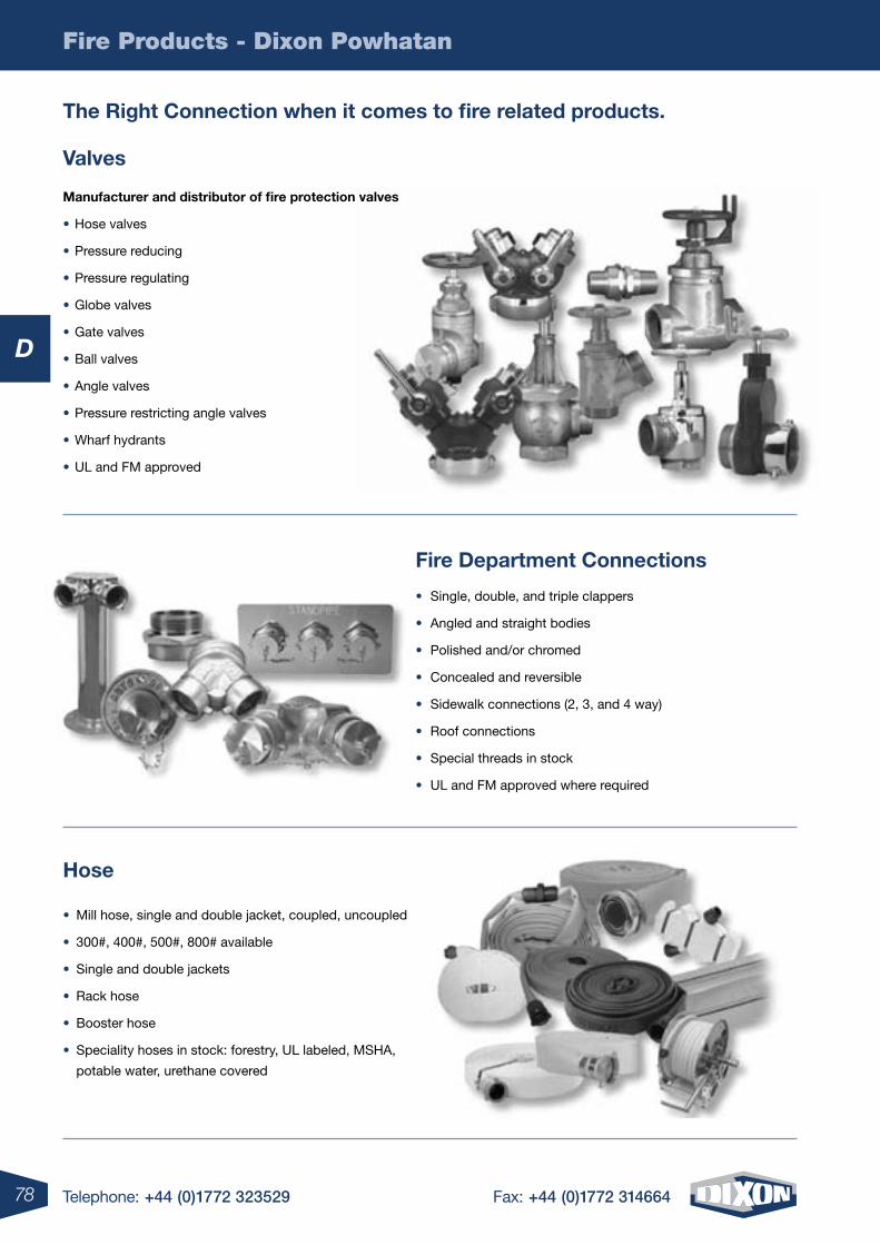
78 Telephone: +44 (0)1772 323529 Fax: +44 (0)1772 314664
Fire Products - Dixon Powhatan
D
the right connection when it comes to fire related products.
manufacturer and distributor of fire protection valves
• Hose valves
• Pressure reducing
• Pressure regulating
• Globe valves
• Gate valves
• Ball valves
• Angle valves
• Pressure restricting angle valves
• Wharf hydrants
• UL and FM approved
• Single, double, and triple clappers
• Angled and straight bodies
• Polished and/or chromed
• Concealed and reversible
• Sidewalk connections (2, 3, and 4 way)
• Roof connections
• Special threads in stock
• UL and FM approved where required
• Mill hose, single and double jacket, coupled, uncoupled
• 300#, 400#, 500#, 800# available
• Single and double jackets
• Rack hose
• Booster hose
• Speciality hoses in stock: forestry, UL labeled, MSHA,
potable water, urethane covered
Valves
Fire Department connections
hose
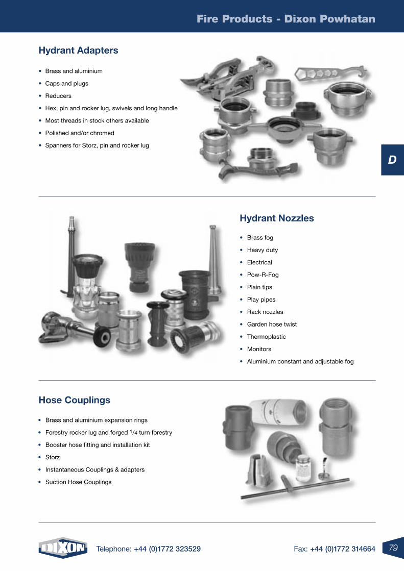
79Telephone: +44 (0)1772 323529 Fax: +44 (0)1772 314664
Fire Products - Dixon Powhatan
D
hydrant adapters
hydrant nozzles
hose couplings
• Brass and aluminium
• Caps and plugs
• Reducers
• Hex, pin and rocker lug, swivels and long handle
• Most threads in stock others available
• Polished and/or chromed
• Spanners for Storz, pin and rocker lug
• Brass and aluminium expansion rings
• Forestry rocker lug and forged 1/4 turn forestry
• Booster hose fitting and installation kit
• Storz
• Instantaneous Couplings & adapters
• Suction Hose Couplings
• Brass fog
• Heavy duty
• Electrical
• Pow-R-Fog
• Plain tips
• Play pipes
• Rack nozzles
• Garden hose twist
• Thermoplastic
• Monitors
• Aluminium constant and adjustable fog
Telephone: +44 (0)1772 323529 Fax: +44 (0)1772 314664
E
4 Telephone: +44 (0)1772 323529 Fax: +44 (0)1772 31466480 Telephone: +44 (0)1772 323529 Fax: +44 (0)1772 314664
E
Telephone: +44 (0)1772 323529 Fax: +44 (0)1772 314664
E
81Telephone: +44 (0)1772 323529 Fax: +44 (0)1772 314664
Hydraulic Pipe Fittings ....................................................................... 82-85
316 Stainless Steel Weld End Pipe Fittings ................................................86
316 Stainless Steel Flanges .......................................................................87
Smooth Tails BS EN 14420-2 .....................................................................88
Fixed & Swivel Smooth Tails BS EN 14420-2 .............................................89
Instrumentation Fittings ...................................................................... 90-93
Brass Hose Fittings ....................................................................................93
Brass Crimp Ferrules..................................................................................94
Ferrule Crimping Tools ....................................................................... 95-96
Tuff-Lite & Plastic Fittings ...........................................................................97
Glycerine Filled Pressure Gauges ...............................................................98
81Telephone: +44 (0)1772 323529 Fax: +44 (0)1772 314664
Fittings, Gauges & Adapters
For a Full range oF hoses to complement these Fittings see section F
E
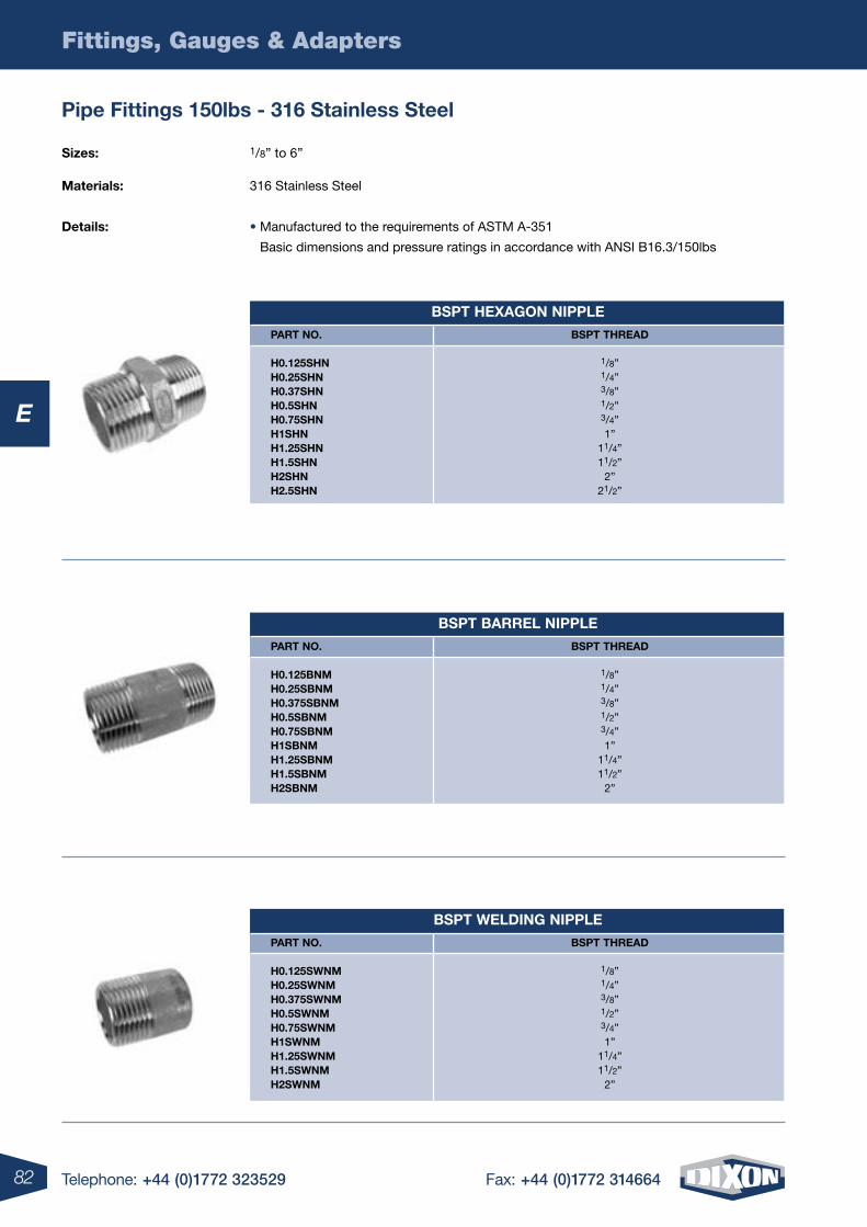
82
Fittings, Gauges & Adapters
Telephone: +44 (0)1772 323529 Fax: +44 (0)1772 314664
E
Bspt heXagon nipple
part no.
h0.125shn h0.25shn h0.37shn h0.5shn h0.75shn h1shn h1.25shn h1.5shn h2shn h2.5shn
Bspt threaD
1/8” 1/4” 3/8” 1/2” 3/4” 1”
11/4” 11/2”
2” 21/2”
Bspt Barrel nipple
part no.
h0.125Bnm h0.25sBnm h0.375sBnm h0.5sBnm h0.75sBnm h1sBnm h1.25sBnm h1.5sBnm h2sBnm
Bspt threaD
1/8” 1/4” 3/8” 1/2” 3/4” 1”
11/4” 11/2”
2”
Bspt WelDing nipple
part no.
h0.125sWnm h0.25sWnm h0.375sWnm h0.5sWnm h0.75sWnm h1sWnm h1.25sWnm h1.5sWnm h2sWnm
Bspt threaD
1/8” 1/4” 3/8” 1/2” 3/4” 1”
11/4” 11/2”
2”
sizes: 1/8” to 6”
materials: 316 Stainless Steel
Details: • Manufactured to the requirements of ASTM A-351
Basic dimensions and pressure ratings in accordance with ANSI B16.3/150lbs
pipe Fittings 150lbs - 316 stainless steel
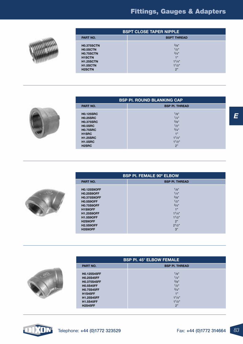
83
Fittings, Gauges & Adapters
Telephone: +44 (0)1772 323529 Fax: +44 (0)1772 314664
E
Bspt close taper nipple part no.
h0.375sctn h0.5sctn h0.75sctn h1sctn h1.25sctn h1.5sctn h2sctn
Bspt threaD
3/8” 1/2” 3/4” 1”
11/4”11/2”
2”
Bsp pi. rounD BlanKing cap part no.
h0.125src h0.25src h0.375src h0.5src h0.75src h1src h1.25src h1.5src h2src
Bsp pi. threaD
1/8” 1/4” 3/8” 1/2” 3/4” 1”
11/4” 11/2”
2”
Bsp pi. Female 90º elBoW part no.
h0.125s9oFF h0.25s9oFF h0.375s9oFF h0.5s9oFF h0.75s9oFF h1s9oFF h1.25s9oFF h1.5s9oFF h2s9oFF h2.5s9oFF h3s9oFF
Bsp pl. threaD
1/8” 1/4” 3/8” 1/2” 3/4” 1”
11/4” 11/2”
2”21/2”
3”
Bsp pl. 45° elBoW Female part no.
h0.125s45FF h0.25s45FF h0.375s45FF h0.5s45FF h0.75s45FF h1s45FF h1.25s45FF h1.5s45FF h2s45FF
Bsp pl. threaD
1/8” 1/4” 3/8” 1/2” 3/4” 1”
11/4” 11/2”
2”
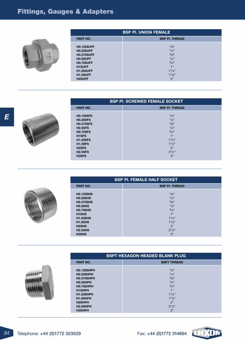
84
Fittings, Gauges & Adapters
Telephone: +44 (0)1772 323529 Fax: +44 (0)1772 314664
E
Bsp pl. union Female
part no.
h0.125suFF h0.25suFF h0.375suFF h0.5suFF h0.75suFF h1suFF h1.25suFF h1.5suFF h2suFF
Bsp pl. threaD
1/8” 1/4” 3/8” 1/2” 3/4” 1”
11/4” 11/2”
2”
Bsp pi. Female halF socKet part no.
h0.125shs h0.25shs h0.375shs h0.5shs h0.75shs h1shs h1.25shs h1.5shs h2shs h2.5shs h3shs
Bsp pi. threaD
1/8” 1/4” 3/8” 1/2” 3/4” 1”
11/4” 11/2”
2” 21/2”
3”
Bspt heXagon heaDeD BlanK plug
part no.
h0.125shph h0.25shph h0.375shph h0.5shph h0.75shph h1shph h1.25shph h1.5shph h2shph h2.5shph h3shph
Bspt threaD
1/8” 1/4” 3/8” 1/2” 3/4” 1”
11/4” 11/2”
2” 21/2”
3”
Bsp pl. screWeD Female socKet
part no.
h0.125sFs h0.25sFs h0.375sFs h0.5sFs h0.75sFs h1sFs h1.25sFs h1.5sFs h2sFs h2.5sFs h3sFs
Bsp pl. threaD
1/8” 1/4” 3/8” 1/2” 3/4” 1”
11/4” 11/2”
2”21/2”
3”
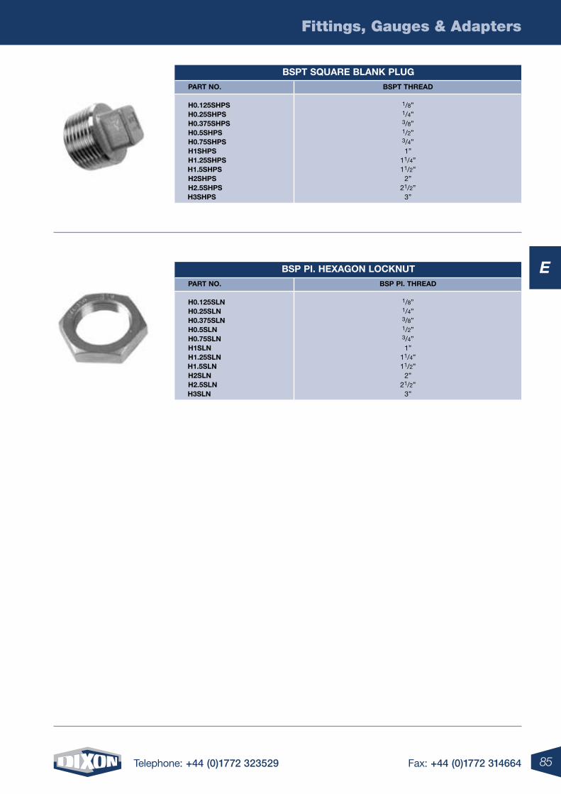
85
Fittings, Gauges & Adapters
Telephone: +44 (0)1772 323529 Fax: +44 (0)1772 314664
E
Bspt sQuare BlanK plug
part no.
h0.125shps h0.25shps h0.375shps h0.5shps h0.75shps h1shps h1.25shps h1.5shps h2shps h2.5shps h3shps
Bspt threaD
1/8” 1/4” 3/8” 1/2” 3/4” 1”
11/4” 11/2”
2” 21/2”
3”
Bsp pi. heXagon locKnut
part no.
h0.125sln h0.25sln h0.375sln h0.5sln h0.75sln h1sln h1.25sln h1.5sln h2sln h2.5sln h3sln
Bsp pi. threaD
1/8” 1/4” 3/8” 1/2” 3/4” 1”
11/4” 11/2”
2” 21/2”
3”
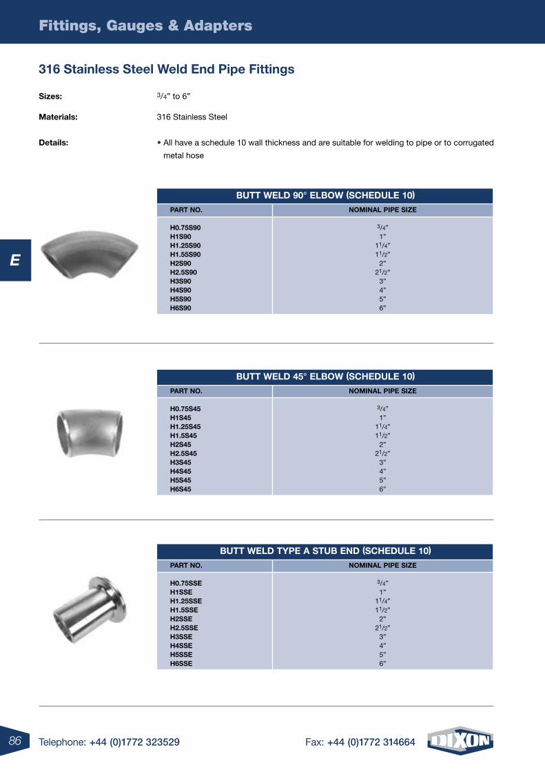
86
Fittings, Gauges & Adapters
Telephone: +44 (0)1772 323529 Fax: +44 (0)1772 314664
E
Butt WelD 45° elBoW (scheDule 10)
part no.
h0.75s45 h1s45 h1.25s45 h1.5s45 h2s45 h2.5s45 h3s45 h4s45 h5s45 h6s45
nominal pipe siZe
3/4” 1”
11/4” 11/2”
2” 21/2”
3” 4” 5” 6”
Butt WelD tYpe a stuB enD (scheDule 10)
part no.
h0.75sse h1sse h1.25sse h1.5sse h2sse h2.5sse h3sse h4sse h5sse h6sse
nominal pipe siZe
3/4” 1”
11/4” 11/2”
2” 21/2”
3” 4” 5” 6”
Butt WelD 90° elBoW (scheDule 10)
part no.
h0.75s90 h1s90 h1.25s90 h1.55s90 h2s90 h2.5s90 h3s90 h4s90 h5s90 h6s90
nominal pipe siZe
3/4” 1”
11/4” 11/2”
2” 21/2”
3” 4” 5” 6”
sizes: 3/4” to 6”
materials: 316 Stainless Steel
Details: • All have a schedule 10 wall thickness and are suitable for welding to pipe or to corrugated
metal hose
316 stainless steel Weld end pipe Fittings
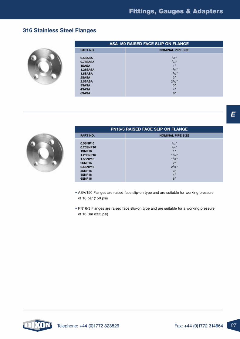
87
Fittings, Gauges & Adapters
Telephone: +44 (0)1772 323529 Fax: +44 (0)1772 314664
E
316 stainless steel Flanges
asa 150 raiseD Face slip on Flange
part no.
0.5sasa 0.75sasa 1sasa 1.25sasa 1.5sasa 2sasa 2.5sasa 3sasa 4sasa 6sasa
nominal pipe siZe
1/2” 3/4” 1”
11/4” 11/2”
2” 21/2”
3”4”6”
pn16/3 raiseD Face slip on Flange
part no.
0.5snp16 0.75snp16 1snp16 1.25snp16 1.5snp16 2snp16 2.5snp16 3snp16 4snp16 6snp16
nominal pipe siZe
1/2” 3/4” 1”
11/4” 11/2”
2” 21/2”
3”4”6”
• ASA/150 Flanges are raised face slip-on type and are suitable for working pressure
of 10 bar (150 psi)
• PN16/3 Flanges are raised face slip-on type and are suitable for a working pressure
of 16 Bar (225 psi)
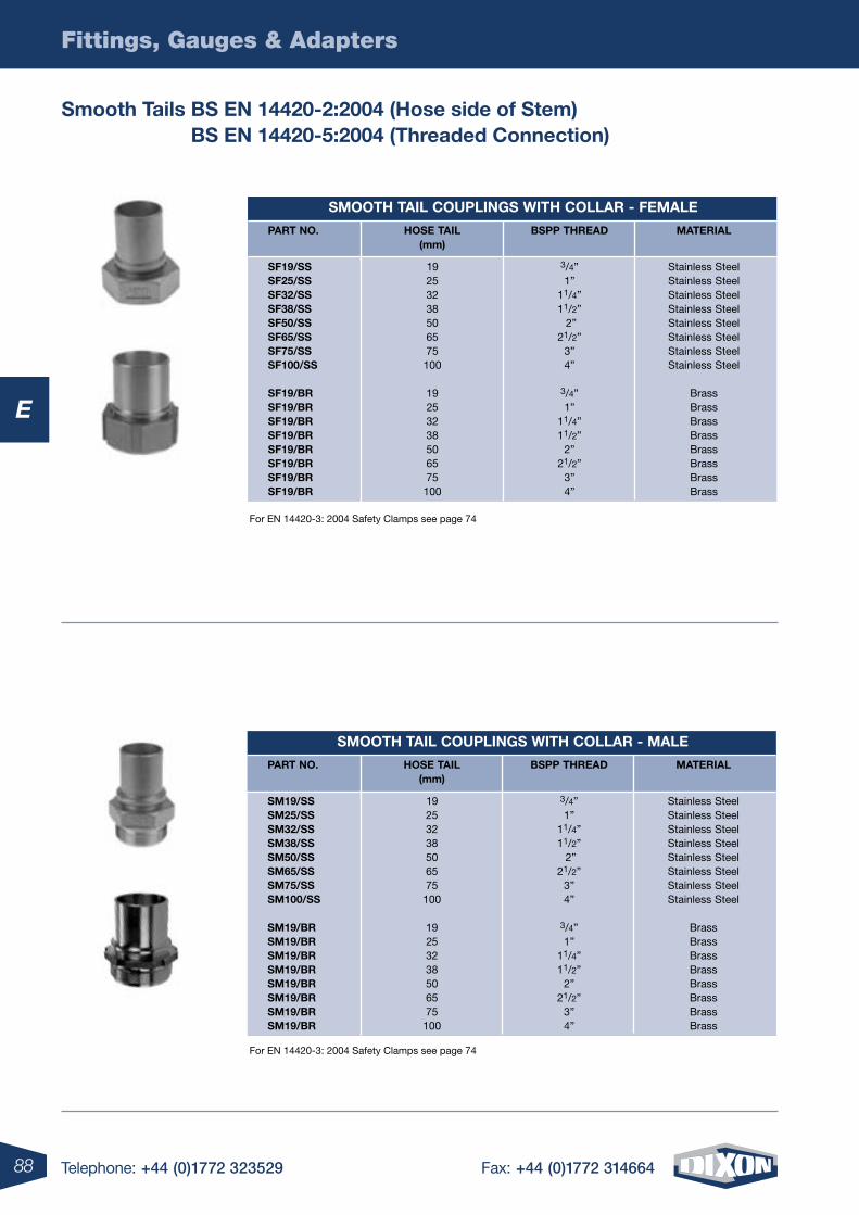
88
Fittings, Gauges & Adapters
Telephone: +44 (0)1772 323529 Fax: +44 (0)1772 314664
E
For EN 14420-3: 2004 Safety Clamps see page 74
For EN 14420-3: 2004 Safety Clamps see page 74
smooth tail couplings With collar - Female
part no. hose tail Bspp threaD material (mm)
sF19/ss 19 3/4” Stainless Steel sF25/ss 25 1” Stainless Steel sF32/ss 32 11/4” Stainless Steel sF38/ss 38 11/2” Stainless Steel sF50/ss 50 2” Stainless Steel sF65/ss 65 21/2” Stainless Steel sF75/ss 75 3” Stainless Steel sF100/ss 100 4” Stainless Steel sF19/Br 19 3/4” Brass sF19/Br 25 1” Brass sF19/Br 32 11/4” Brass sF19/Br 38 11/2” Brass sF19/Br 50 2” Brass sF19/Br 65 21/2” Brass sF19/Br 75 3” Brass sF19/Br 100 4” Brass
smooth tail couplings With collar - male
part no. hose tail Bspp threaD material (mm)
sm19/ss 19 3/4” Stainless Steel sm25/ss 25 1” Stainless Steel sm32/ss 32 11/4” Stainless Steel sm38/ss 38 11/2” Stainless Steel sm50/ss 50 2” Stainless Steel sm65/ss 65 21/2” Stainless Steel sm75/ss 75 3” Stainless Steel sm100/ss 100 4” Stainless Steel sm19/Br 19 3/4” Brass sm19/Br 25 1” Brass sm19/Br 32 11/4” Brass sm19/Br 38 11/2” Brass sm19/Br 50 2” Brass sm19/Br 65 21/2” Brass sm19/Br 75 3” Brass sm19/Br 100 4” Brass
smooth tails Bs en 14420-2:2004 (hose side of stem) Bs en 14420-5:2004 (threaded connection)
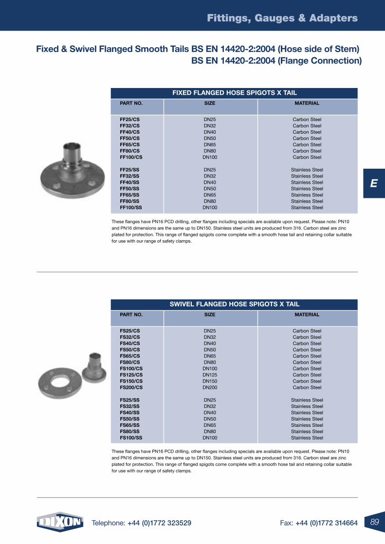
89
Fittings, Gauges & Adapters
Telephone: +44 (0)1772 323529 Fax: +44 (0)1772 314664
E
These flanges have PN16 PCD drilling, other flanges including specials are available upon request. Please note: PN10 and PN16 dimensions are the same up to DN150. Stainless steel units are produced from 316. Carbon steel are zinc plated for protection. This range of flanged spigots come complete with a smooth hose tail and retaining collar suitable for use with our range of safety clamps.
These flanges have PN16 PCD drilling, other flanges including specials are available upon request. Please note: PN10 and PN16 dimensions are the same up to DN150. Stainless steel units are produced from 316. Carbon steel are zinc plated for protection. This range of flanged spigots come complete with a smooth hose tail and retaining collar suitable for use with our range of safety clamps.
FiXeD FlangeD hose spigots X tail
part no. siZe material
FF25/cs DN25 Carbon Steel FF32/cs DN32 Carbon Steel FF40/cs DN40 Carbon Steel FF50/cs DN50 Carbon Steel FF65/cs DN65 Carbon Steel FF80/cs DN80 Carbon Steel FF100/cs DN100 Carbon Steel FF25/ss DN25 Stainless Steel FF32/ss DN32 Stainless Steel FF40/ss DN40 Stainless Steel FF50/ss DN50 Stainless Steel FF65/ss DN65 Stainless Steel FF80/ss DN80 Stainless Steel FF100/ss DN100 Stainless Steel
sWiVel FlangeD hose spigots X tail
part no. siZe material
Fs25/cs DN25 Carbon Steel Fs32/cs DN32 Carbon Steel Fs40/cs DN40 Carbon Steel Fs50/cs DN50 Carbon Steel Fs65/cs DN65 Carbon Steel Fs80/cs DN80 Carbon Steel Fs100/cs DN100 Carbon Steel Fs125/cs DN125 Carbon Steel Fs150/cs DN150 Carbon Steel Fs200/cs DN200 Carbon Steel Fs25/ss DN25 Stainless Steel Fs32/ss DN32 Stainless Steel Fs40/ss DN40 Stainless Steel Fs50/ss DN50 Stainless Steel Fs65/ss DN65 Stainless Steel Fs80/ss DN80 Stainless Steel Fs100/ss DN100 Stainless Steel
Fixed & swivel Flanged smooth tails Bs en 14420-2:2004 (hose side of stem) Bs en 14420-2:2004 (Flange connection)
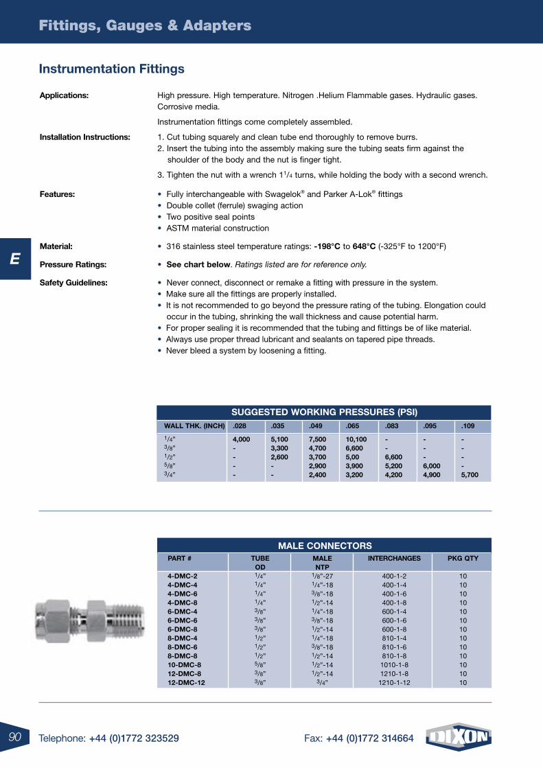
90
Fittings, Gauges & Adapters
Telephone: +44 (0)1772 323529 Fax: +44 (0)1772 314664
E
applications: High pressure. High temperature. Nitrogen .Helium Flammable gases. Hydraulic gases. Corrosive media.
Instrumentation fittings come completely assembled.
installation instructions: 1. Cut tubing squarely and clean tube end thoroughly to remove burrs. 2. Insert the tubing into the assembly making sure the tubing seats firm against the shoulder of the body and the nut is finger tight.
3. Tighten the nut with a wrench 11/4 turns, while holding the body with a second wrench. Features: • Fully interchangeable with Swagelok® and Parker A-Lok® fittings • Double collet (ferrule) swaging action • Two positive seal points • ASTM material construction material: • 316 stainless steel temperature ratings: -198°c to 648°c (-325°F to 1200°F) pressure ratings: • see chart below. Ratings listed are for reference only. safety guidelines: • Never connect, disconnect or remake a fitting with pressure in the system. • Make sure all the fittings are properly installed. • It is not recommended to go beyond the pressure rating of the tubing. Elongation could occur in the tubing, shrinking the wall thickness and cause potential harm. • For proper sealing it is recommended that the tubing and fittings be of like material. • Always use proper thread lubricant and sealants on tapered pipe threads. • Never bleed a system by loosening a fitting.
instrumentation Fittings
male connectors tuBe oD 1/4” 1/4” 1/4” 1/4” 3/8” 3/8” 3/8” 1/2” 1/2” 1/2” 5/8” 3/8” 3/8”
male ntp 1/8”-27 1/4”-18 3/8”-18 1/2”-14 1/4”-18 3/8”-18 1/2”-14 1/4”-18 3/8”-18 1/2”-14 1/2”-14 1/2”-14 3/4”
interchanges
400-1-2 400-1-4 400-1-6 400-1-8 600-1-4 600-1-6 600-1-8 810-1-4 810-1-6 810-1-8 1010-1-8 1210-1-8 1210-1-12
part #
4-Dmc-2 4-Dmc-4 4-Dmc-6 4-Dmc-8 6-Dmc-4 6-Dmc-6 6-Dmc-8 8-Dmc-4 8-Dmc-6 8-Dmc-8 10-Dmc-8 12-Dmc-8 12-Dmc-12
pKg QtY
10 10 10 10 10 10 10 10 10 10 10 10 10
suggesteD WorKing pressures (psi)Wall thK. (inch)
1/4” 3/8” 1/2” 5/8” 3/4”
.028
4,000----
.035
5,100 3,300 2,600- -
.049
7,500 4,700 3,700 2,900 2,400
.065
10,100 6,600 5,00 3,900 3,200
.083
- - 6,600 5,200 4,200
.095
- - - 6,000 4,900
.109
- - - - 5,700
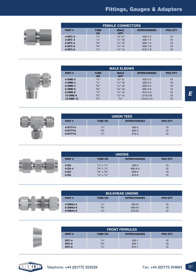
91
Fittings, Gauges & Adapters
Telephone: +44 (0)1772 323529 Fax: +44 (0)1772 314664
E
union tees part #
4-Dttt-4 6-Dttt-6 8-Dttt-8
tuBe oD
1/4” 3/8” 1/2”
interchanges
400-3 600-3 810-3
pKg QtY
10 10 10
Front Ferrules part #
DFc-4 DFc-6 DFc-8
tuBe oD
1/4” 3/8” 1/2”
interchanges
403-1 603-1 813-1
pKg QtY
10 10 10
unions part #
4-Du 6-Du-4 6-Du 8-Du
tuBe oD
1/4” x 1/4” 3/8” x 1/4” 3/8” x 3/8” 1/2” x 1/2”
interchanges
400-6 600-6-4 600-6 810-6
pKg QtY
10 10 10 10
BulKheaD unions part #
4-DBhu-4 6-DBhu-6 8-DBhu-8
tuBe oD
1/4” 3/8” 1/2”
interchanges
400-61 600-61 810-61
pKg QtY
10 10 10
male elBoWs part #
4-Dme-2 4-Dme-4 6-Dme-4 6-Dme-6 8-Dme-8 12-Dme-8 12-Dme-12
tuBe oD 1/4” 1/4” 3/8” 3/8” 1/2” 3/4” 3/4”
male ntp 1/8”-27 1/4”-18 1/4”-18 3/8”-18 1/2”-14 1/2”-14 3/4”
interchanges
400-2-2 400-3-4 600-2-4 600-2-6 810-2-8 1210-2-8 1210-2-12
pKg QtY
10 10 10 10 10 10 10
Female connectors part #
4-DFc-2 4-DFc-4 6-DFc-4 6-DFc-8 8-DFc-8
tuBe oD 1/4” 1/4” 3/8” 3/8” 1/2”
male ntp 1/8”-27 1/4”-18 1/4”-18 1/2”-14 1/2”-14
interchanges
400-7-2 400-7-4 600-7-4 600-7-8 810-7-8
pKg QtY
10 10 10 10 10
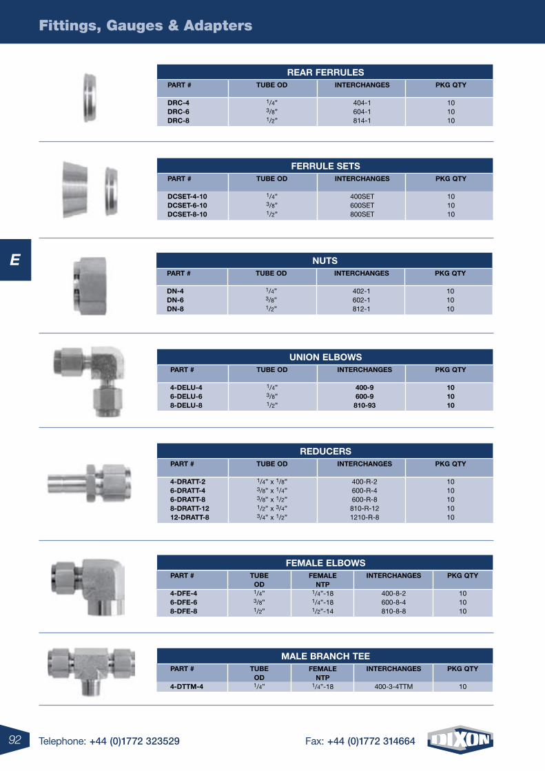
92
Fittings, Gauges & Adapters
Telephone: +44 (0)1772 323529 Fax: +44 (0)1772 314664
E
union elBoWs part #
4-Delu-4 6-Delu-6 8-Delu-8
tuBe oD
1/4” 3/8” 1/2”
interchanges
400-9 600-9 810-93
pKg QtY
10 10 10
reDucers part #
4-Dratt-2 6-Dratt-4 6-Dratt-8 8-Dratt-12 12-Dratt-8
tuBe oD
1/4” x 1/8” 3/8” x 1/4” 3/8” x 1/2” 1/2” x 3/4” 3/4” x 1/2”
interchanges
400-R-2 600-R-4 600-R-8 810-R-12 1210-R-8
pKg QtY
10 10 10 10 10
Female elBoWs part #
4-DFe-4 6-DFe-6 8-DFe-8
tuBe oD 1/4” 3/8” 1/2”
Female ntp 1/4”-18 1/4”-18 1/2”-14
interchanges
400-8-2 600-8-4 810-8-8
pKg QtY
10 10 10
male Branch tee part #
4-Dttm-4
tuBe oD 1/4”
Female ntp 1/4”-18
interchanges
400-3-4TTM
pKg QtY
10
rear Ferrules part #
Drc-4 Drc-6 Drc-8
tuBe oD
1/4” 3/8” 1/2”
interchanges
404-1 604-1 814-1
pKg QtY
10 10 10
Ferrule sets part #
Dcset-4-10 Dcset-6-10 Dcset-8-10
tuBe oD
1/4” 3/8” 1/2”
interchanges
400SET 600SET 800SET
pKg QtY
10 10 10
nuts part #
Dn-4 Dn-6 Dn-8
tuBe oD
1/4” 3/8” 1/2”
interchanges
402-1 602-1 812-1
pKg QtY
10 10 10
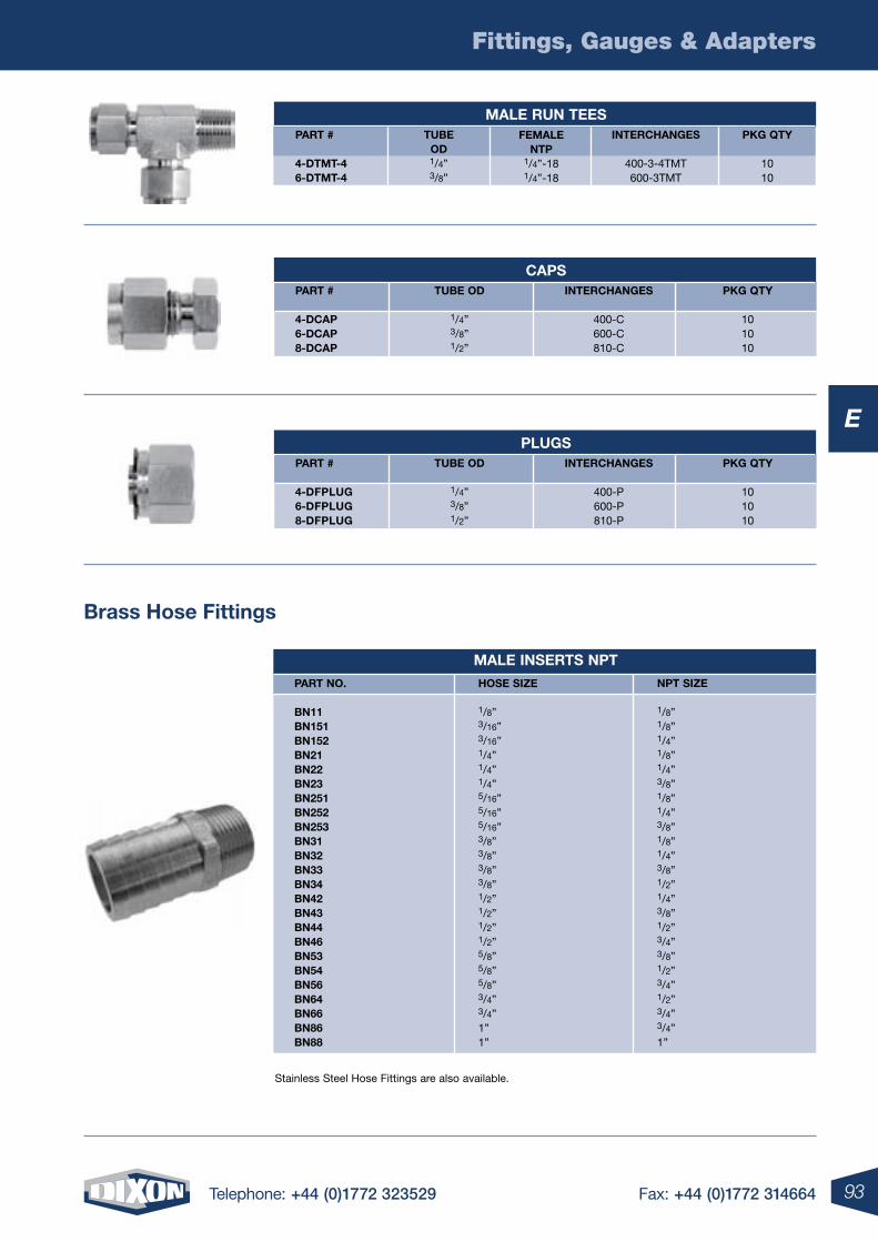
93
Fittings, Gauges & Adapters
Telephone: +44 (0)1772 323529 Fax: +44 (0)1772 314664
E
Brass hose Fittings
male inserts npt
part no.
Bn11 Bn151 Bn152 Bn21 Bn22 Bn23 Bn251 Bn252 Bn253 Bn31 Bn32 Bn33 Bn34 Bn42 Bn43 Bn44 Bn46 Bn53 Bn54 Bn56 Bn64 Bn66 Bn86 Bn88
npt siZe
1/8” 1/8” 1/4” 1/8” 1/4”3/8” 1/8” 1/4” 3/8” 1/8” 1/4” 3/8”1/2” 1/4” 3/8” 1/2” 3/4” 3/8” 1/2” 3/4” 1/2” 3/4” 3/4” 1”
hose siZe
1/8” 3/16” 3/16” 1/4” 1/4” 1/4” 5/16” 5/16” 5/16” 3/8” 3/8” 3/8” 3/8” 1/2” 1/2” 1/2” 1/2” 5/8” 5/8” 5/8” 3/4” 3/4” 1” 1”
Stainless Steel Hose Fittings are also available.
caps part #
4-Dcap 6-Dcap 8-Dcap
tuBe oD
1/4” 3/8” 1/2”
interchanges
400-C 600-C 810-C
pKg QtY
10 10 10
plugs part #
4-DFplug 6-DFplug 8-DFplug
tuBe oD
1/4” 3/8” 1/2”
interchanges
400-P 600-P 810-P
pKg QtY
10 10 10
male run tees part #
4-Dtmt-4 6-Dtmt-4
tuBe oD 1/4” 3/8”
Female ntp 1/4”-18 1/4”-18
interchanges
400-3-4TMT 600-3TMT
pKg QtY
10 10
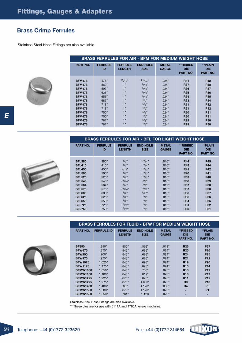
94
Fittings, Gauges & Adapters
Telephone: +44 (0)1772 323529 Fax: +44 (0)1772 314664
E
Stainless Steel Hose Fittings are also available.
** These dies are for use with 5111A and 1765A ferrule machines.
Brass Ferrules For air - BFm For meDium Weight hose
Brass Ferrules For air - BFl For light Weight hose
Brass Ferrules For FluiD - BFW For meDium Weight hose
part no.
BFm478 BFm478 BFm478 BFm478 BFm478 BFm478 BFm478 BFm478 BFm478 BFm478 BFm478 BFm478
part no.
BFl380 BFl410 BFl450 BFl500 BFl525 BFl548 BFl564 BFl575 BFl600 BFl625 BFl650 BFl725 BFl750
part no.
BF850 BFW875 BFW900 BFW975 BFW1025 BFW1175 BFmW1050 BFmW1100 BFmW1225 BFmW1275 BFmW1400 BFmW1500 BFmW1550
Ferrule iD
.478”
.562”
.593”
.625”
.656”
.687”
.718”
.718”
.750”
.750”
.781”
.781”
Ferrule iD
.380”
.410”
.450”
.500”
.525”
.548”
.564”
.575”
.600”
.625”
.650”
.725”
.750”
Ferrule iD
.850”
.875”
.900”
.975” 1.025” 1.175” 1.050” 1.100” 1.225” 1.275” 1.400” 1.500” 1.550”
Ferrule length
11/16”
1” 1” 1” 1” 1” 1” 1” 1” 1” 1” 1”
Ferrule length
1/2” 1/2” 9/16” 1/2” 1/2”
31/64” 3/4”
31/64” 1/2” 1/2” 1/2”
17/32” 17/32”
Ferrule length
.850” .843” .843” .843” .843” .843” .843” .843” .875” .875” .687 .875” .781”
enD hole siZe
21/64” 7/16” 7/16” 7/16” 7/16” 1/2” 5/8” 1/2” 5/8” 1/2” 5/8” 1/2”
enD hole siZe
17/64” 17/64” 11/32” 11/32” 11/32” 3/8” 3/8”
15/32” 1/2”” 1/2” 1/2” 1/2” 1/2”
enD hole siZe
.568” .688” .688” .688” .693” .875” .750” .812” .875” 1.000” 1.120” 1.120” 1.120
metal gauge
.024” .024” .024” .024”.024” .024” .024” .024” .024”.024” .024” .024”
metal gauge
.016” .016” .016” .016”.016” .016” .019” .016” .016”.016” .016” .016” .016”
metal gauge
.019” .024” .024” .024” .024” .024” .025” .023” .025” .025” .030” .025” .020”
**plain Die
part no.
p42 p38 p37 p36p35 p34 p32 p32 p31 p31 p30 p30
**plain Die
part no.
p45 p44 p42 p41p40 p39 p38 p38 p37 p36 p35 p32 p31
**plain Die
part no.
p27 p26 p25 p22p20 p14 p19 p17 p12 p10 p5 p1 -
**riBBeD Die
part no.
r41 r37 r36 r35r34 r33 r31 r31 r30 r30 r29 r29
**riBBeD Die
part no.
r44 r43 r41 r40r39 r38 r37 r37 r36 r35 r34 r31 r30
**riBBeD Die
part no.
r26 r25 r24 r21r19 r13 r18 r16 r11 r9 r4 - -
Stainless Steel Hose Fittings are also available.
Brass crimp Ferrules
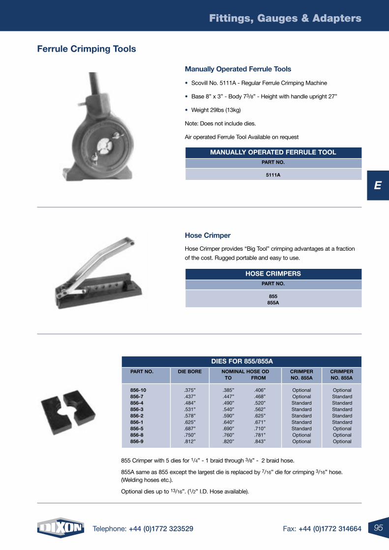
95
Fittings, Gauges & Adapters
Telephone: +44 (0)1772 323529 Fax: +44 (0)1772 314664
E
manuallY operateD Ferrule toolpart no.
5111a
hose crimperspart no.
855855a
hose crimper
Hose Crimper provides “Big Tool” crimping advantages at a fraction
of the cost. Rugged portable and easy to use.
855 Crimper with 5 dies for 1/4” - 1 braid through 3/8” - 2 braid hose.
855A same as 855 except the largest die is replaced by 7/16” die for crimping 3/16” hose. (Welding hoses etc.).
Optional dies up to 13/16”. (1/2” I.D. Hose available).
manually operated Ferrule tools
• Scovill No. 5111A - Regular Ferrule Crimping Machine
• Base 8” x 3” - Body 73/8” - Height with handle upright 27”
• Weight 29lbs (13kg)
Note: Does not include dies.
Air operated Ferrule Tool Available on request
Ferrule crimping tools
Dies For 855/855a
part no. Die Bore nominal hose oDto From
crimper no. 855a
crimper no. 855a
856-10 .375” .385” .406” Optional Optional856-7 .437” .447” .468” Optional Standard856-4 .484” .490” .520” Standard Standard856-3 .531” .540” .562” Standard Standard856-2 .578” .590” .625” Standard Standard856-1 .625” .640” .671” Standard Standard856-5 .687” .690” .710” Standard Optional856-8 .750” .760” .781” Optional Optional856-9 .812” .820” .843” Optional Optional
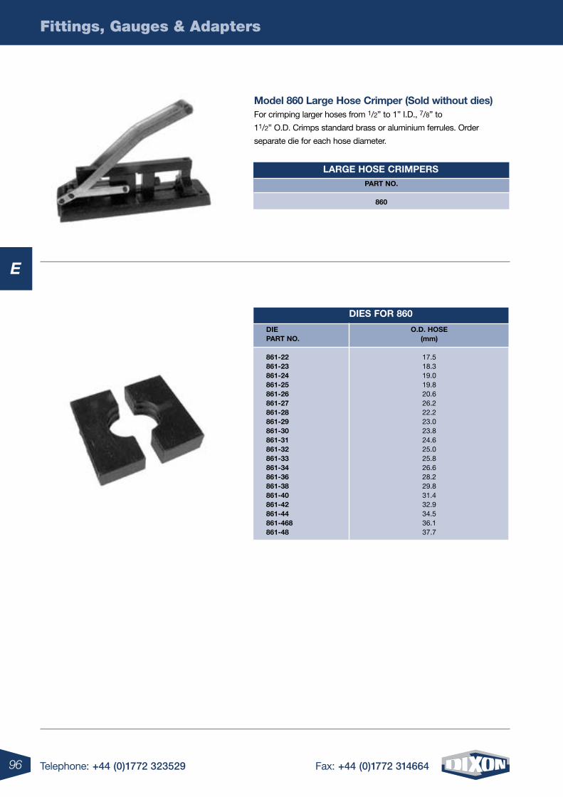
96
Fittings, Gauges & Adapters
Telephone: +44 (0)1772 323529 Fax: +44 (0)1772 314664
E
large hose crimpers
Dies For 860
part no.
860
Die part no.
861-22 861-23 861-24 861-25 861-26 861-27 861-28 861-29 861-30 861-31 861-32 861-33 861-34 861-36 861-38 861-40 861-42 861-44 861-468 861-48
o.D. hose(mm)
17.5 18.3 19.0 19.8 20.6 26.2 22.2 23.0 23.8 24.6 25.0 25.8 26.6 28.2 29.8 31.4 32.9 34.5 36.1 37.7
model 860 large hose crimper (sold without dies) For crimping larger hoses from 1/2” to 1” I.D., 7/8” to
11/2” O.D. Crimps standard brass or aluminium ferrules. Order
separate die for each hose diameter.
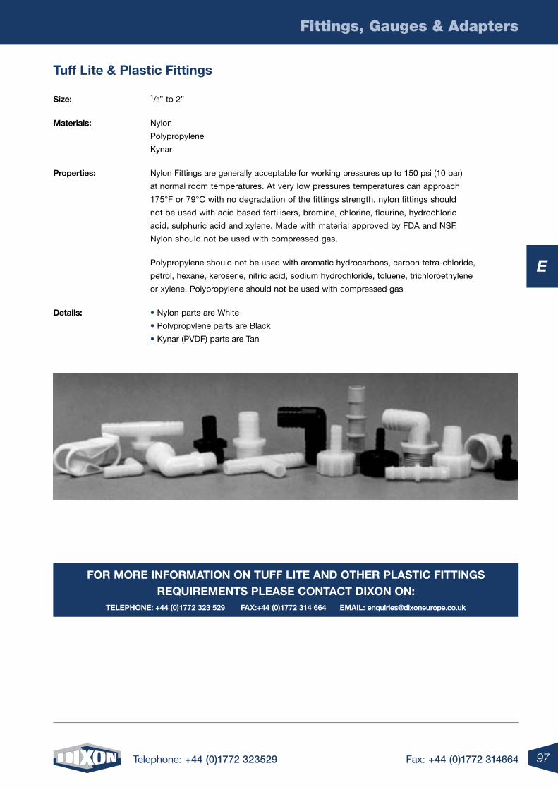
97
Fittings, Gauges & Adapters
Telephone: +44 (0)1772 323529 Fax: +44 (0)1772 314664
E
For more inFormation on tuFF lite anD other plastic Fittings reQuirements please contact DiXon on:
telephone: +44 (0)1772 323 529 FaX:+44 (0)1772 314 664 email: [email protected]
size: 1/8” to 2”
materials: Nylon
Polypropylene
Kynar
properties: Nylon Fittings are generally acceptable for working pressures up to 150 psi (10 bar)
at normal room temperatures. At very low pressures temperatures can approach
175°F or 79°C with no degradation of the fittings strength. nylon fittings should
not be used with acid based fertilisers, bromine, chlorine, flourine, hydrochloric
acid, sulphuric acid and xylene. Made with material approved by FDA and NSF.
Nylon should not be used with compressed gas.
Polypropylene should not be used with aromatic hydrocarbons, carbon tetra-chloride,
petrol, hexane, kerosene, nitric acid, sodium hydrochloride, toluene, trichloroethylene
or xylene. Polypropylene should not be used with compressed gas
Details: • Nylon parts are White
• Polypropylene parts are Black
• Kynar (PVDF) parts are Tan
tuff lite & plastic Fittings
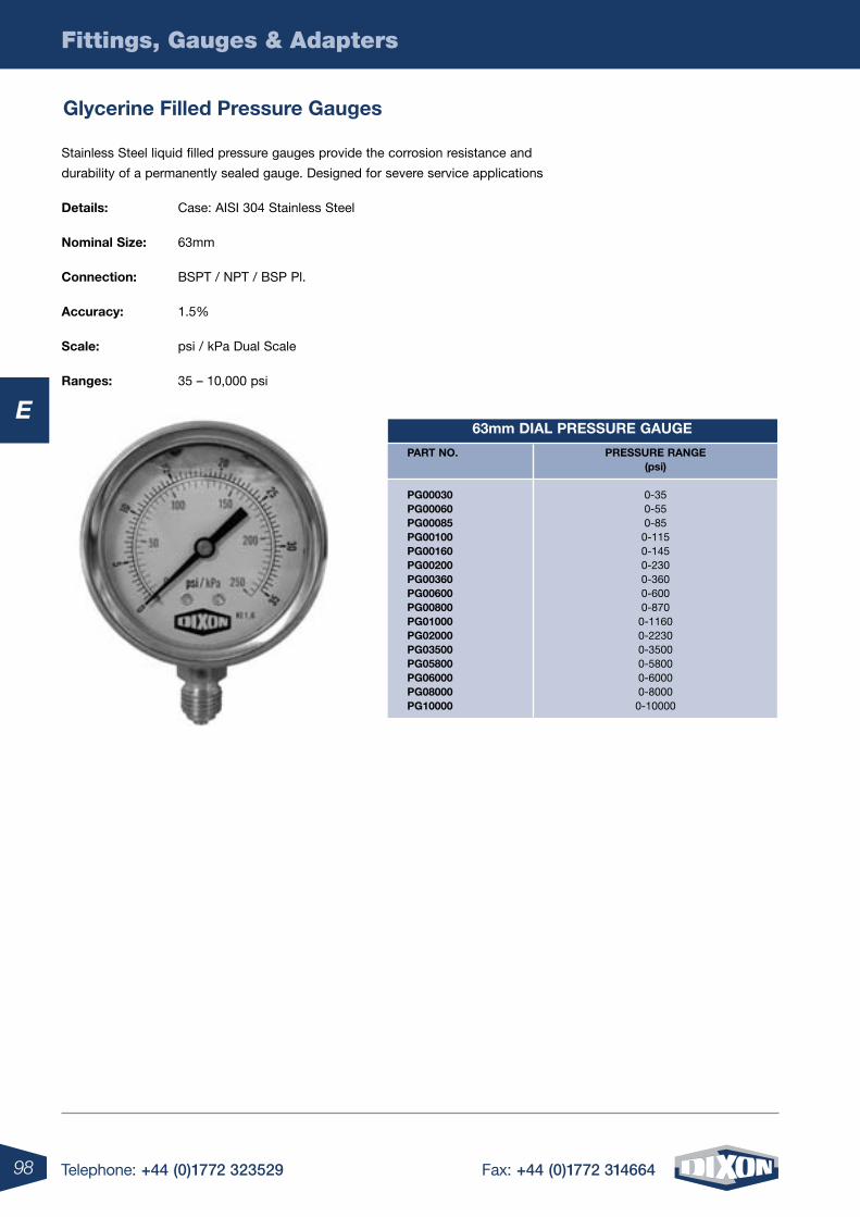
98
Fittings, Gauges & Adapters
Telephone: +44 (0)1772 323529 Fax: +44 (0)1772 314664
E63mm Dial pressure gauge
part no.
pg00030 pg00060 pg00085 pg00100 pg00160 pg00200 pg00360 pg00600 pg00800 pg01000 pg02000 pg03500 pg05800 pg06000 pg08000 pg10000
pressure range(psi)
0-35 0-55 0-85 0-115 0-145 0-230 0-360 0-600 0-870 0-1160 0-2230 0-3500 0-5800 0-6000 0-8000 0-10000
Stainless Steel liquid filled pressure gauges provide the corrosion resistance and
durability of a permanently sealed gauge. Designed for severe service applications
Details: Case: AISI 304 Stainless Steel
nominal size: 63mm
connection: BSPT / NPT / BSP Pl.
accuracy: 1.5%
scale: psi / kPa Dual Scale
ranges: 35 – 10,000 psi
glycerine Filled pressure gauges
99
Fittings, Gauges & Adapters
Telephone: +44 (0)1772 323529 Fax: +44 (0)1772 314664
E
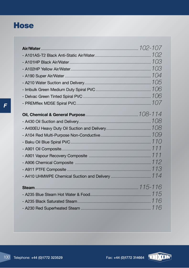
F
4 Telephone: +44 (0)1772 323529 Fax: +44 (0)1772 314664
Air/Water ..................................................................................... 102-107
- A101AS-T2 Black Anti-Static Air/Water .................................................102
- A101HP Black Air/Water .......................................................................103
- A102HP Yellow Air/Water ......................................................................103
- A190 Super Air/Water ...........................................................................104
- A210 Water Suction and Delivery ..........................................................105
- Irribulk Green Medium Duty Spiral PVC ................................................106
- Delvac Green Tinted Spiral PVC ...........................................................106
- PREMflex MDSE Spiral PVC .................................................................107
Oil, Chemical & General Purpose ..............................................108-114
- A430 Oil Suction and Delivery ...............................................................108
- A400EU Heavy Duty Oil Suction and Delivery .......................................108
- A104 Red Multi-Purpose Non-Conductive ............................................109
- Baku Oil Blue Spiral PVC ......................................................................110
- A901 Oil Composite ..............................................................................111
- A901 Vapour Recovery Composite ......................................................111
- A906 Chemical Composite ..................................................................112
- A911 PTFE Composite .........................................................................113
- A410 UHMWPE Chemical Suction and Delivery ...................................114
Steam .......................................................................................... 115-116
- A235 Blue Steam Hot Water & Food .....................................................115
- A235 Black Saturated Steam ................................................................116
- A230 Red Superheated Steam .............................................................116
100 Telephone: +44 (0)1772 323529 Fax: +44 (0)1772 314664
Hose
F
F
101Telephone: +44 (0)1772 323529 Fax: +44 (0)1772 314664
Food & Beverage ........................................................................ 117-122
- San-Hygienic Food Grade Suction and Delivery ...................................117
- San-Hygienic Premium Food Grade Suction and Delivery ....................118
- San-Hygienic Food Grade Delivery .......................................................119
- SAN-sil™ Silicone Suction and Delivery ...............................................120
- PREM-vin Transparent PVC ..................................................................121
- Delikatesse Non-Toxic Clear PVC .........................................................122
Large Bore Custom Built - Bulkstream ......................................... 123-127
Metallic & PTFE ............................................................................ 128-132
Specialist High Pressure, High Temperature & Armoured ............. 133-135
Hose Protection & Fire Jackets ....................................................136-137
A Full rAnGe OF COmPlementAry FittinGS
tO Suit All hOSeS Are AvAilABle thrOuGhOut thiS CAtAlOGue
101Telephone: +44 (0)1772 323529 Fax: +44 (0)1772 314664
F
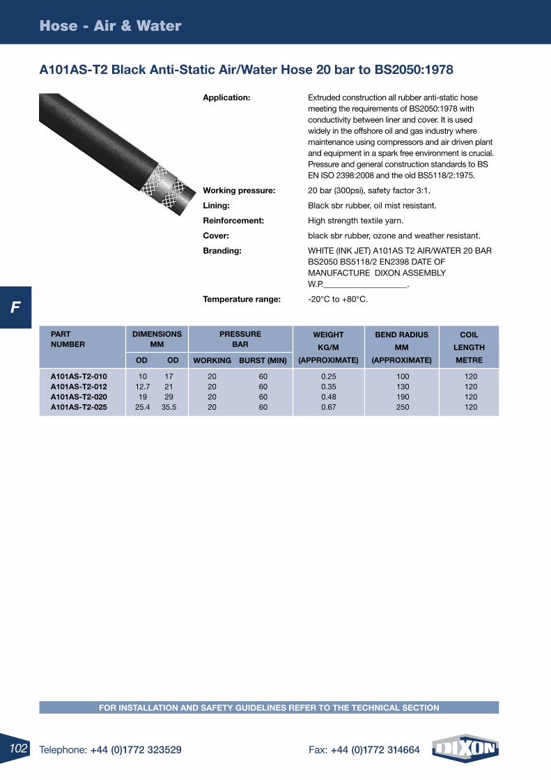
102 Telephone: +44 (0)1772 323529 Fax: +44 (0)1772 314664
F
Hose - Air & Water
A101AS-t2 Black Anti-Static Air/Water hose 20 bar to BS2050:1978
WeiGht
KG/m
(APPrOXimAte)
BenD rADiuS
mm
(APPrOXimAte)
COil
lenGth
metre
DimenSiOnS mm
OD OD
PreSSure BAr
WOrKinG BurSt (min)
A101AS-t2-010 10 17 20 60 0.25 100 120 A101AS-t2-012 12.7 21 20 60 0.35 130 120 A101AS-t2-020 19 29 20 60 0.48 190 120 A101AS-t2-025 25.4 35.5 20 60 0.67 250 120
PArt numBer
Application: Extruded construction all rubber anti-static hose meeting the requirements of BS2050:1978 with conductivity between liner and cover. It is used widely in the offshore oil and gas industry where maintenance using compressors and air driven plant and equipment in a spark free environment is crucial. Pressure and general construction standards to BS EN ISO 2398:2008 and the old BS5118/2:1975.
Working pressure: 20 bar (300psi), safety factor 3:1.
lining: Black sbr rubber, oil mist resistant.
reinforcement: High strength textile yarn.
Cover: black sbr rubber, ozone and weather resistant.
Branding: WHITE (INK JET) A101AS T2 AIR/WATER 20 BAR BS2050 BS5118/2 EN2398 DATE OF MANUFACTURE DIXON ASSEMBLY W.P.____________________.
temperature range: -20°C to +80°C.
FOr inStAllAtiOn AnD SAFety GuiDelineS reFer tO the teChniCAl SeCtiOn
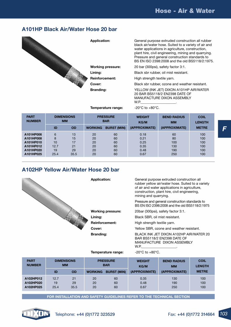
103Telephone: +44 (0)1772 323529 Fax: +44 (0)1772 314664
F
Hose - Air & Water
A101hP Black Air/Water hose 20 bar
WeiGht
KG/m
(APPrOXimAte)
BenD rADiuS
mm
(APPrOXimAte)
COil
lenGth
metre
DimenSiOnS mm
iD OD
PreSSure BAr
WOrKinG BurSt (min)
A101hP006 6 13 20 60 0.18 60 100 A101hP008 8 15 20 60 0.21 80 100 A101hP010 10 17 20 60 0.25 100 100 A101hP012 12.7 21 20 60 0.35 130 100 A101hP020 19 29 20 60 0.48 190 100 A101hP025 25.4 35.5 20 60 0.67 250 100
PArt numBer
Application: General purpose extruded construction all rubber black air/water hose. Suited to a variety of air and water applications in agriculture, construction, plant hire, civil engineering, mining and quarrying. Pressure and general construction standards to BS EN ISO 2398:2008 and the old BS5118/2:1975.
Working pressure: 20 bar (300psi), safety factor 3:1.
lining: Black sbr rubber, oil mist resistant.
reinforcement: High strength textile yarn.
Cover: Black sbr rubber, ozone and weather resistant.
Branding: YELLOW (INK JET) DIXON A101HP AIR/WATER 20 BAR BS5118/2 EN2398 DATE OF MANUFACTURE DIXON ASSEMBLY W.P.____________________.
temperature range: -20°C to +80°C.
Application: General purpose extruded construction all rubber yellow air/water hose. Suited to a variety of air and water applications in agriculture, construction, plant hire, civil engineering, mining and quarrying.
Pressure and general construction standards to BS EN ISO 2398:2008 and the old BS5118/2:1975
Working pressure: 20bar (300psi), safety factor 3:1.
lining: Black SBR, oil mist resistant.
reinforcement: High strength textile yarn.
Cover: Yellow SBR, ozone and weather resistant.
Branding: BLACK INK JET DIXON A102HP AIR/WATER 20 BAR BS5118/2 EN2398 DATE OF MANUFACTURE DIXON ASSEMBLY W.P.____________________.
temperature range: -20°C to +80°C.
A102hP yellow Air/Water hose 20 bar
WeiGht
KG/m
(APPrOXimAte)
BenD rADiuS
mm
(APPrOXimAte)
COil
lenGth
metre
DimenSiOnS mm
iD OD
PreSSure BAr
WOrKinG BurSt (min)
A102hP012 12.7 21 20 60 0.35 130 100 A102hP020 19 29 20 60 0.48 190 100 A102hP025 25.4 35.5 20 60 0.67 250 100
PArt numBer
FOr inStAllAtiOn AnD SAFety GuiDelineS reFer tO the teChniCAl SeCtiOn
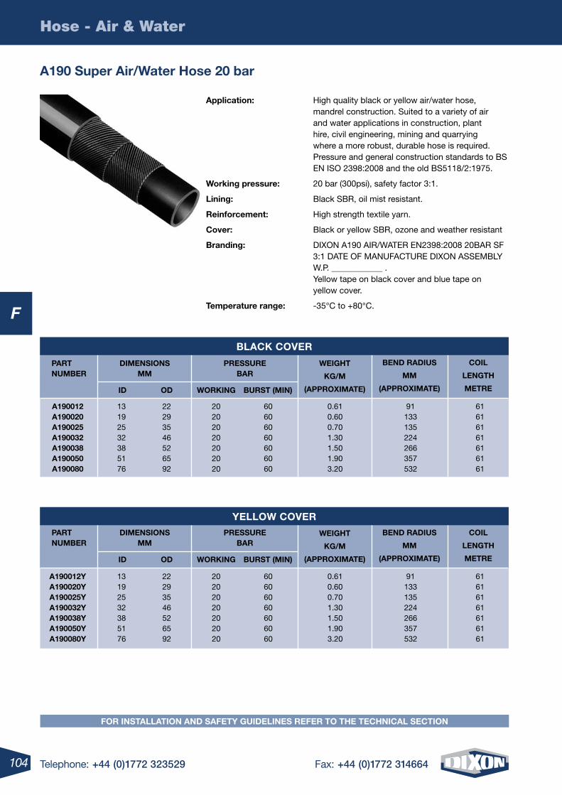
104 Telephone: +44 (0)1772 323529 Fax: +44 (0)1772 314664
F
Hose - Air & Water
A190 Super Air/Water hose 20 bar
WeiGht
KG/m
(APPrOXimAte)
BenD rADiuS
mm
(APPrOXimAte)
COil
lenGth
metre
DimenSiOnS mm
iD OD
PreSSure BAr
WOrKinG BurSt (min)
A190012 13 22 20 60 0.61 91 61 A190020 19 29 20 60 0.60 133 61 A190025 25 35 20 60 0.70 135 61 A190032 32 46 20 60 1.30 224 61 A190038 38 52 20 60 1.50 266 61 A190050 51 65 20 60 1.90 357 61 A190080 76 92 20 60 3.20 532 61
PArt numBer
BlACK COver
WeiGht
KG/m
(APPrOXimAte)
BenD rADiuS
mm
(APPrOXimAte)
COil
lenGth
metre
DimenSiOnS mm
iD OD
PreSSure BAr
WOrKinG BurSt (min)
A190012y 13 22 20 60 0.61 91 61 A190020y 19 29 20 60 0.60 133 61 A190025y 25 35 20 60 0.70 135 61 A190032y 32 46 20 60 1.30 224 61 A190038y 38 52 20 60 1.50 266 61 A190050y 51 65 20 60 1.90 357 61 A190080y 76 92 20 60 3.20 532 61
PArt numBer
yellOW COver
Application: High quality black or yellow air/water hose, mandrel construction. Suited to a variety of air and water applications in construction, plant hire, civil engineering, mining and quarrying where a more robust, durable hose is required. Pressure and general construction standards to BS EN ISO 2398:2008 and the old BS5118/2:1975.
Working pressure: 20 bar (300psi), safety factor 3:1.
lining: Black SBR, oil mist resistant.
reinforcement: High strength textile yarn.
Cover: Black or yellow SBR, ozone and weather resistant
Branding: DIXON A190 AIR/WATER EN2398:2008 20BAR SF 3:1 DATE OF MANUFACTURE DIXON ASSEMBLY W.P. ____________ . Yellow tape on black cover and blue tape on yellow cover.
temperature range: -35°C to +80°C.
FOr inStAllAtiOn AnD SAFety GuiDelineS reFer tO the teChniCAl SeCtiOn
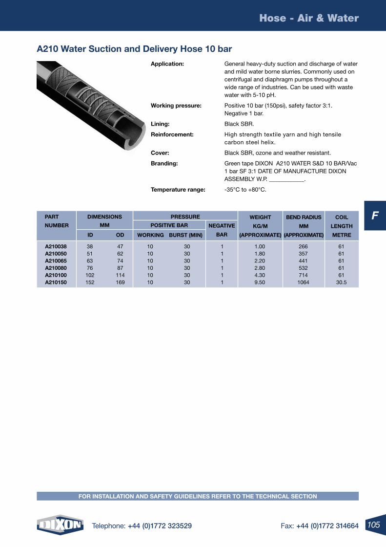
105Telephone: +44 (0)1772 323529 Fax: +44 (0)1772 314664
F
Hose - Air & Water
A210 Water Suction and Delivery hose 10 bar
Application: General heavy-duty suction and discharge of water and mild water borne slurries. Commonly used on centrifugal and diaphragm pumps throughout a wide range of industries. Can be used with waste water with 5-10 pH.
Working pressure: Positive 10 bar (150psi), safety factor 3:1. Negative 1 bar.
lining: Black SBR.
reinforcement: High strength textile yarn and high tensile carbon steel helix.
Cover: Black SBR, ozone and weather resistant.
Branding: Green tape DIXON A210 WATER S&D 10 BAR/Vac 1 bar SF 3:1 DATE OF MANUFACTURE DIXON ASSEMBLY W.P. ____________.
temperature range: -35°C to +80°C.
WeiGht
KG/m
(APPrOXimAte)
BenD rADiuS
mm
(APPrOXimAte)
COil
lenGth
metre
DimenSiOnS
mm
iD OD
POSitive BAr
WOrKinG BurSt (min)
A210038 38 47 10 30 1 1.00 266 61 A210050 51 62 10 30 1 1.80 357 61 A210065 63 74 10 30 1 2.20 441 61 A210080 76 87 10 30 1 2.80 532 61 A210100 102 114 10 30 1 4.30 714 61 A210150 152 169 10 30 1 9.50 1064 30.5
PArt
numBer neGAtive
BAr
PreSSure
FOr inStAllAtiOn AnD SAFety GuiDelineS reFer tO the teChniCAl SeCtiOn
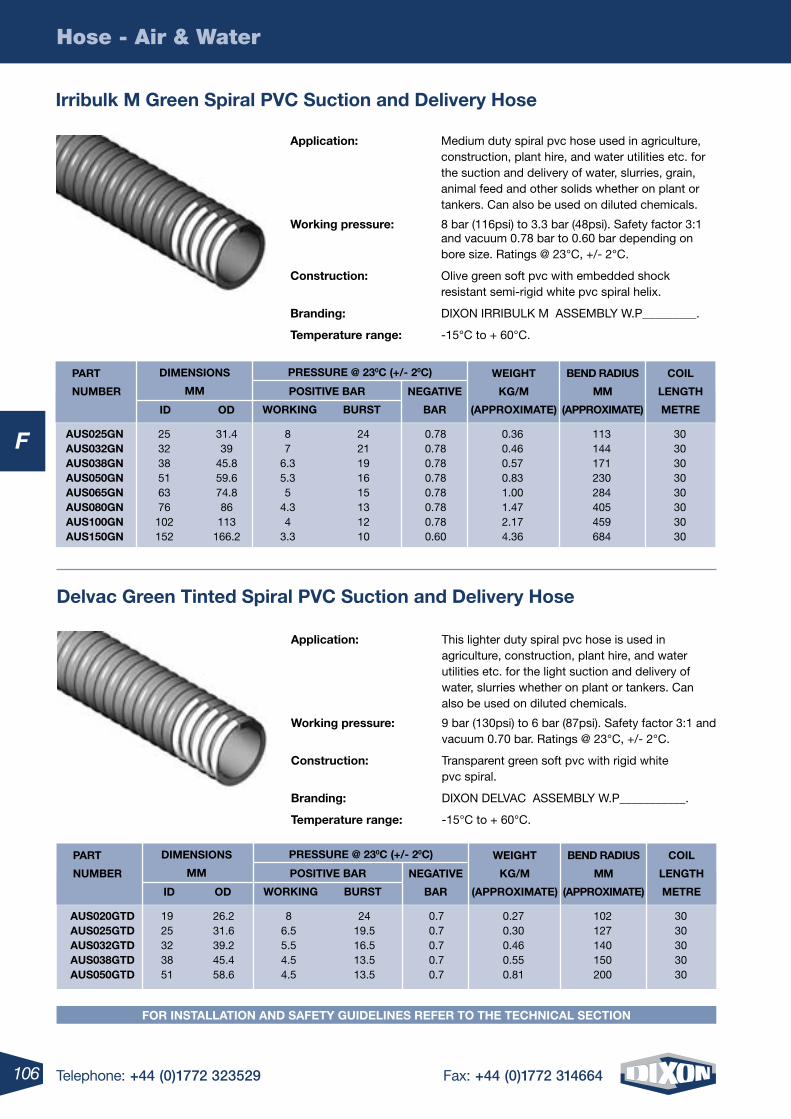
106 Telephone: +44 (0)1772 323529 Fax: +44 (0)1772 314664
F
Hose - Air & Water
Delvac Green tinted Spiral PvC Suction and Delivery hose
Application: This lighter duty spiral pvc hose is used in agriculture, construction, plant hire, and water utilities etc. for the light suction and delivery of water, slurries whether on plant or tankers. Can also be used on diluted chemicals.
Working pressure: 9 bar (130psi) to 6 bar (87psi). Safety factor 3:1 and vacuum 0.70 bar. Ratings @ 23°C, +/- 2°C.
Construction: Transparent green soft pvc with rigid white pvc spiral.
Branding: DIXON DELVAC ASSEMBLY W.P___________.
temperature range: -15°C to + 60°C.
AuS020GtD 19 26.2 8 24 0.7 0.27 102 30 AuS025GtD 25 31.6 6.5 19.5 0.7 0.30 127 30 AuS032GtD 32 39.2 5.5 16.5 0.7 0.46 140 30 AuS038GtD 38 45.4 4.5 13.5 0.7 0.55 150 30 AuS050GtD 51 58.6 4.5 13.5 0.7 0.81 200 30
WeiGht
KG/m
(APPrOXimAte)
BenD rADiuS
mm
(APPrOXimAte)
COil
lenGth
metre
POSitive BAr
WOrKinG BurSt
PArt
numBer neGAtive
BAr
PreSSure @ 230C (+/- 20C)DimenSiOnS
mm
iD OD
FOr inStAllAtiOn AnD SAFety GuiDelineS reFer tO the teChniCAl SeCtiOn
irribulk m Green Spiral PvC Suction and Delivery hose
Application: Medium duty spiral pvc hose used in agriculture, construction, plant hire, and water utilities etc. for the suction and delivery of water, slurries, grain, animal feed and other solids whether on plant or tankers. Can also be used on diluted chemicals.
Working pressure: 8 bar (116psi) to 3.3 bar (48psi). Safety factor 3:1 and vacuum 0.78 bar to 0.60 bar depending on bore size. Ratings @ 23°C, +/- 2°C.
Construction: Olive green soft pvc with embedded shock resistant semi-rigid white pvc spiral helix.
Branding: DIXON IRRIBULK M ASSEMBLY W.P_________.
temperature range: -15°C to + 60°C.
AuS025Gn 25 31.4 8 24 0.78 0.36 113 30 AuS032Gn 32 39 7 21 0.78 0.46 144 30 AuS038Gn 38 45.8 6.3 19 0.78 0.57 171 30 AuS050Gn 51 59.6 5.3 16 0.78 0.83 230 30 AuS065Gn 63 74.8 5 15 0.78 1.00 284 30 AuS080Gn 76 86 4.3 13 0.78 1.47 405 30 AuS100Gn 102 113 4 12 0.78 2.17 459 30 AuS150Gn 152 166.2 3.3 10 0.60 4.36 684 30
WeiGht
KG/m
(APPrOXimAte)
BenD rADiuS
mm
(APPrOXimAte)
COil
lenGth
metre
POSitive BAr
WOrKinG BurSt
PArt
numBer neGAtive
BAr
PreSSure @ 230C (+/- 20C)DimenSiOnS
mm
iD OD
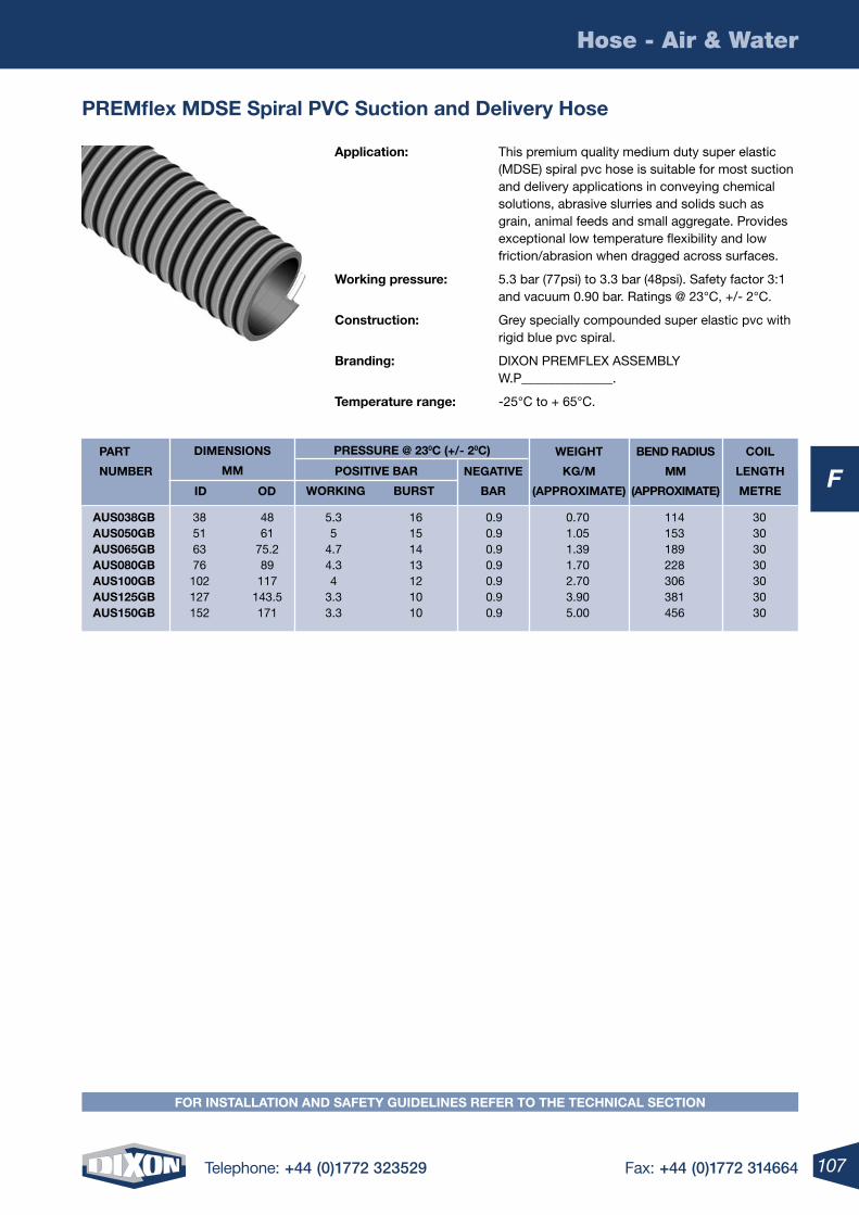
107Telephone: +44 (0)1772 323529 Fax: +44 (0)1772 314664
F
Hose - Air & Water
Premflex mDSe Spiral PvC Suction and Delivery hose
Application: This premium quality medium duty super elastic (MDSE) spiral pvc hose is suitable for most suction and delivery applications in conveying chemical solutions, abrasive slurries and solids such as grain, animal feeds and small aggregate. Provides exceptional low temperature flexibility and low friction/abrasion when dragged across surfaces.
Working pressure: 5.3 bar (77psi) to 3.3 bar (48psi). Safety factor 3:1 and vacuum 0.90 bar. Ratings @ 23°C, +/- 2°C.
Construction: Grey specially compounded super elastic pvc with rigid blue pvc spiral.
Branding: DIXON PREMFLEX ASSEMBLY W.P______________.
temperature range: -25°C to + 65°C.
AuS038GB 38 48 5.3 16 0.9 0.70 114 30 AuS050GB 51 61 5 15 0.9 1.05 153 30 AuS065GB 63 75.2 4.7 14 0.9 1.39 189 30 AuS080GB 76 89 4.3 13 0.9 1.70 228 30 AuS100GB 102 117 4 12 0.9 2.70 306 30 AuS125GB 127 143.5 3.3 10 0.9 3.90 381 30 AuS150GB 152 171 3.3 10 0.9 5.00 456 30
WeiGht
KG/m
(APPrOXimAte)
BenD rADiuS
mm
(APPrOXimAte)
COil
lenGth
metre
POSitive BAr
WOrKinG BurSt
PArt
numBer neGAtive
BAr
PreSSure @ 230C (+/- 20C)DimenSiOnS
mm
iD OD
FOr inStAllAtiOn AnD SAFety GuiDelineS reFer tO the teChniCAl SeCtiOn
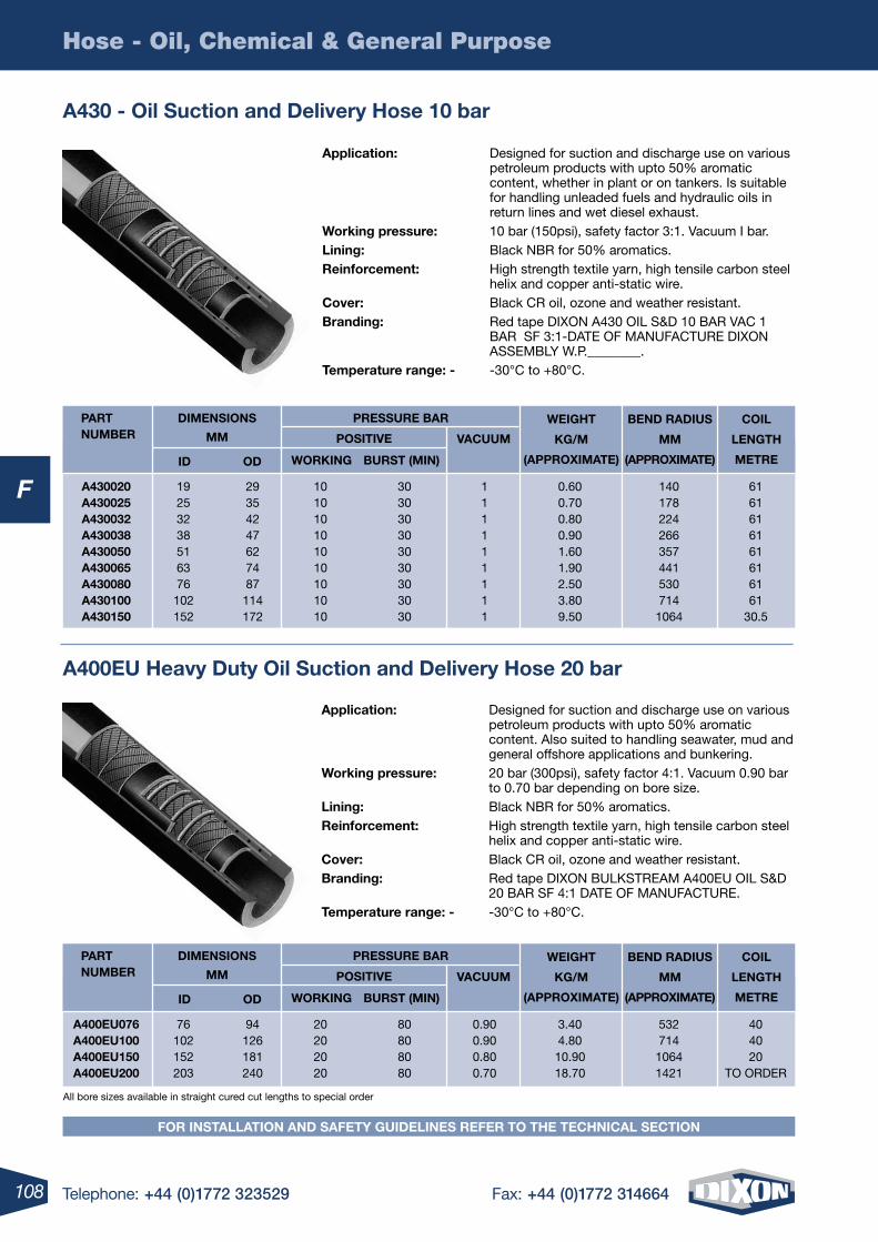
108 Telephone: +44 (0)1772 323529 Fax: +44 (0)1772 314664
F
Hose - Oil, Chemical & General Purpose
A430 - Oil Suction and Delivery hose 10 bar
WeiGht
KG/m
(APPrOXimAte)
BenD rADiuS
mm
(APPrOXimAte)
COil
lenGth
metre
DimenSiOnS
mm
iD OD
POSitive
WOrKinG BurSt (min)
A430020 19 29 10 30 1 0.60 140 61 A430025 25 35 10 30 1 0.70 178 61 A430032 32 42 10 30 1 0.80 224 61 A430038 38 47 10 30 1 0.90 266 61 A430050 51 62 10 30 1 1.60 357 61 A430065 63 74 10 30 1 1.90 441 61 A430080 76 87 10 30 1 2.50 530 61 A430100 102 114 10 30 1 3.80 714 61 A430150 152 172 10 30 1 9.50 1064 30.5
PArt numBer vACuum
PreSSure BAr
Application: Designed for suction and discharge use on various petroleum products with upto 50% aromatic content, whether in plant or on tankers. Is suitable for handling unleaded fuels and hydraulic oils in return lines and wet diesel exhaust.
Working pressure: 10 bar (150psi), safety factor 3:1. Vacuum I bar.lining: Black NBR for 50% aromatics.reinforcement: High strength textile yarn, high tensile carbon steel
helix and copper anti-static wire.Cover: Black CR oil, ozone and weather resistant.Branding: Red tape DIXON A430 OIL S&D 10 BAR VAC 1
BAR SF 3:1-DATE OF MANUFACTURE DIXON ASSEMBLY W.P.________.
temperature range: - -30°C to +80°C.
A400eu heavy Duty Oil Suction and Delivery hose 20 bar
WeiGht
KG/m
(APPrOXimAte)
BenD rADiuS
mm
(APPrOXimAte)
COil
lenGth
metre
DimenSiOnS
mm
iD OD
POSitive
WOrKinG BurSt (min)
A400eu076 76 94 20 80 0.90 3.40 532 40 A400eu100 102 126 20 80 0.90 4.80 714 40 A400eu150 152 181 20 80 0.80 10.90 1064 20 A400eu200 203 240 20 80 0.70 18.70 1421 TO ORDER
PArt numBer vACuum
PreSSure BAr
All bore sizes available in straight cured cut lengths to special order
Application: Designed for suction and discharge use on various petroleum products with upto 50% aromatic content. Also suited to handling seawater, mud and general offshore applications and bunkering.
Working pressure: 20 bar (300psi), safety factor 4:1. Vacuum 0.90 bar to 0.70 bar depending on bore size.
lining: Black NBR for 50% aromatics. reinforcement: High strength textile yarn, high tensile carbon steel helix and copper anti-static wire.Cover: Black CR oil, ozone and weather resistant.Branding: Red tape DIXON BULKSTREAM A400EU OIL S&D
20 BAR SF 4:1 DATE OF MANUFACTURE. temperature range: - -30°C to +80°C.
FOr inStAllAtiOn AnD SAFety GuiDelineS reFer tO the teChniCAl SeCtiOn
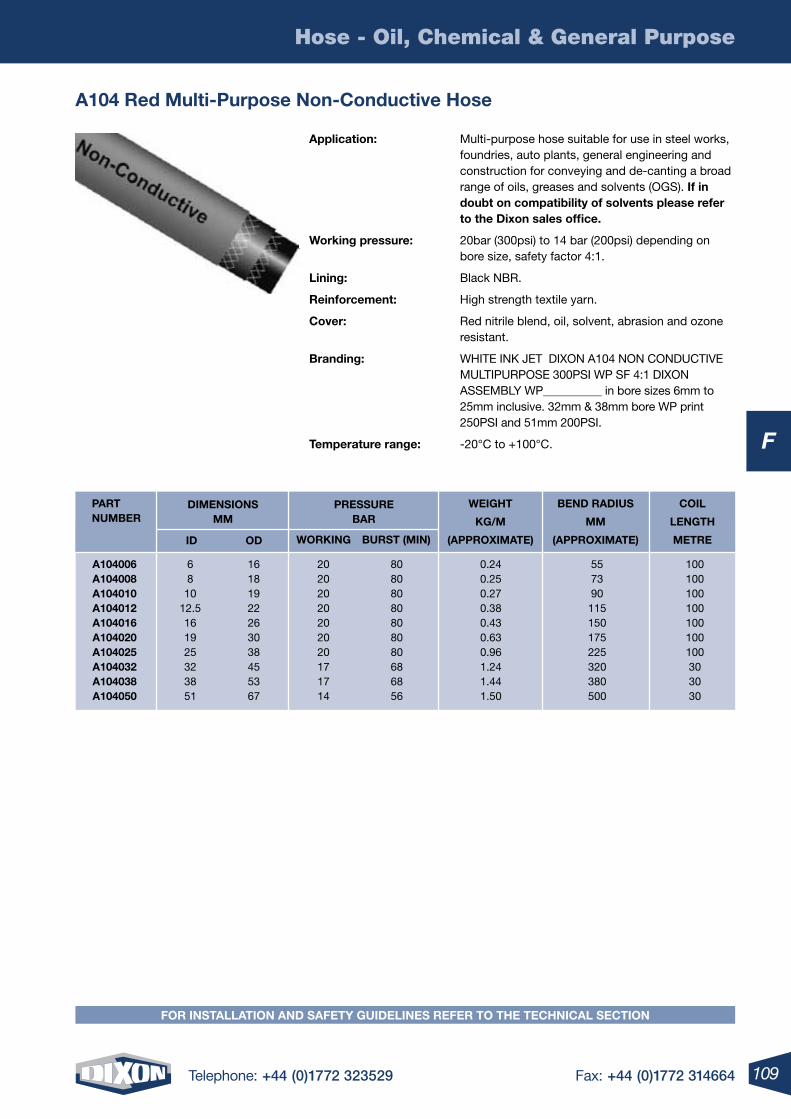
109Telephone: +44 (0)1772 323529 Fax: +44 (0)1772 314664
F
Hose - Oil, Chemical & General Purpose
FOr inStAllAtiOn AnD SAFety GuiDelineS reFer tO the teChniCAl SeCtiOn
A104 red multi-Purpose non-Conductive hose
Application: Multi-purpose hose suitable for use in steel works, foundries, auto plants, general engineering and construction for conveying and de-canting a broad range of oils, greases and solvents (OGS). if in doubt on compatibility of solvents please refer to the Dixon sales office.
Working pressure: 20bar (300psi) to 14 bar (200psi) depending on bore size, safety factor 4:1.
lining: Black NBR.
reinforcement: High strength textile yarn.
Cover: Red nitrile blend, oil, solvent, abrasion and ozone resistant.
Branding: WHITE INK JET DIXON A104 NON CONDUCTIVE MULTIPURPOSE 300PSI WP SF 4:1 DIXON ASSEMBLY WP__________ in bore sizes 6mm to 25mm inclusive. 32mm & 38mm bore WP print 250PSI and 51mm 200PSI.
temperature range: -20°C to +100°C.
WeiGht
KG/m
(APPrOXimAte)
BenD rADiuS
mm
(APPrOXimAte)
COil
lenGth
metre
DimenSiOnS mm
iD OD
PreSSure BAr
WOrKinG BurSt (min)
A104006 6 16 20 80 0.24 55 100 A104008 8 18 20 80 0.25 73 100 A104010 10 19 20 80 0.27 90 100 A104012 12.5 22 20 80 0.38 115 100 A104016 16 26 20 80 0.43 150 100 A104020 19 30 20 80 0.63 175 100 A104025 25 38 20 80 0.96 225 100 A104032 32 45 17 68 1.24 320 30 A104038 38 53 17 68 1.44 380 30 A104050 51 67 14 56 1.50 500 30
PArt numBer
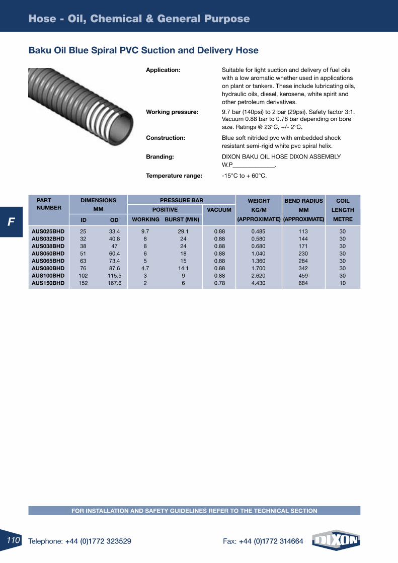
110 Telephone: +44 (0)1772 323529 Fax: +44 (0)1772 314664
F
Hose - Oil, Chemical & General Purpose
Baku Oil Blue Spiral PvC Suction and Delivery hose
Application: Suitable for light suction and delivery of fuel oils with a low aromatic whether used in applications on plant or tankers. These include lubricating oils, hydraulic oils, diesel, kerosene, white spirit and other petroleum derivatives.
Working pressure: 9.7 bar (140psi) to 2 bar (29psi). Safety factor 3:1. Vacuum 0.88 bar to 0.78 bar depending on bore size. Ratings @ 23°C, +/- 2°C.
Construction: Blue soft nitrided pvc with embedded shock resistant semi-rigid white pvc spiral helix.
Branding: DIXON BAKU OIL HOSE DIXON ASSEMBLY W.P______________.
temperature range: -15°C to + 60°C.
WeiGht
KG/m
(APPrOXimAte)
BenD rADiuS
mm
(APPrOXimAte)
COil
lenGth
metre
DimenSiOnS
mm
iD OD
POSitive
WOrKinG BurSt (min)
AuS025BhD 25 33.4 9.7 29.1 0.88 0.485 113 30 AuS032BhD 32 40.8 8 24 0.88 0.580 144 30 AuS038BhD 38 47 8 24 0.88 0.680 171 30 AuS050BhD 51 60.4 6 18 0.88 1.040 230 30 AuS065BhD 63 73.4 5 15 0.88 1.360 284 30 AuS080BhD 76 87.6 4.7 14.1 0.88 1.700 342 30 AuS100BhD 102 115.5 3 9 0.88 2.620 459 30 AuS150BhD 152 167.6 2 6 0.78 4.430 684 10
PArt numBer vACuum
PreSSure BAr
FOr inStAllAtiOn AnD SAFety GuiDelineS reFer tO the teChniCAl SeCtiOn
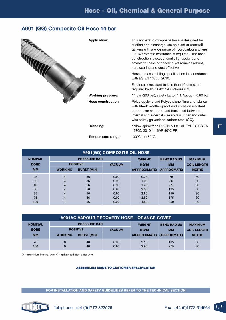
111Telephone: +44 (0)1772 323529 Fax: +44 (0)1772 314664
F
Hose - Oil, Chemical & General Purpose
FOr inStAllAtiOn AnD SAFety GuiDelineS reFer tO the teChniCAl SeCtiOn
A901 (GG) Composite Oil hose 14 bar
(A = aluminium internal wire, G = galvanised steel outer wire)
ASSEMBLIES MADE TO CUSTOMER SPECIFICATION
Application: This anti-static composite hose is designed for suction and discharge use on plant or road/rail tankers with a wide range of hydrocarbons where 100% aromatic resistance is required. The hose construction is exceptionally lightweight and flexible for ease of handling yet remains robust, hardwearing and cost effective.
Hose and assembling specification in accordance with BS EN 13765: 2010.
Electrically resistant to less than 10 ohms, as required by BS 5842: 1980 clause 6.2.
Working pressure: 14 bar (203 psi), safety factor 4:1. Vacuum 0.90 bar.
hose construction: Polypropylene and Polyethylene films and fabrics with black weather-proof and abrasion resistant outer cover wrapped and tensioned between internal and external wire spirals. Inner and outer wire spiral, galvanised carbon steel (GG).
Branding: Yellow spiral tape DIXON A901 OIL TYPE 3 BS EN 13765: 2010 14 BAR 80°C PP.
temperature range: -30°C to +80°C.
25 14 56 0.90 0.75 75 30 32 14 56 0.90 1.00 80 30 40 14 56 0.90 1.40 85 30 50 14 56 0.90 2.00 125 30 65 14 56 0.90 2.80 150 30 75 14 56 0.90 3.50 175 30 100 14 56 0.90 4.80 250 30
nOminAl
BOre
mm
WeiGht
KG/m
(APPrOXimAte)
BenD rADiuS
mm
(APPrOXimAte)
mAXimum
COil lenGth
metre
vACuum
POSitive
WOrKinG BurSt (min)
PreSSure BAr
A901(GG) COmPOSite Oil hOSe
76 10 40 0.90 2.10 185 30 100 10 40 0.90 2.90 275 30
nOminAl
BOre
mm
WeiGht
KG/m
(APPrOXimAte)
BenD rADiuS
mm
(APPrOXimAte)
mAXimum
COil lenGth
metre
vACuum
POSitive
WOrKinG BurSt (min)
PreSSure BAr
A901AG vAPOur reCOvery hOSe – OrAnGe COver
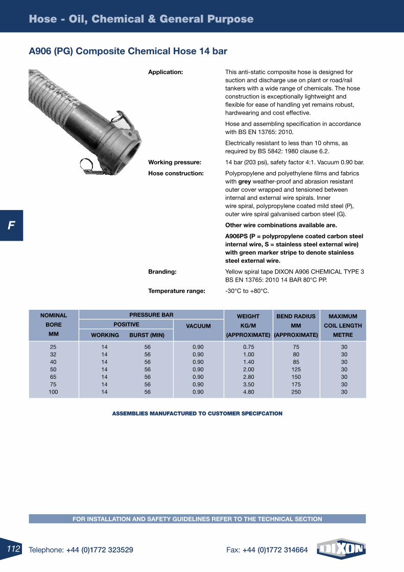
112 Telephone: +44 (0)1772 323529 Fax: +44 (0)1772 314664
F
Hose - Oil, Chemical & General Purpose
FOr inStAllAtiOn AnD SAFety GuiDelineS reFer tO the teChniCAl SeCtiOn
A906 (PG) Composite Chemical hose 14 bar
Application: This anti-static composite hose is designed for suction and discharge use on plant or road/rail tankers with a wide range of chemicals. The hose construction is exceptionally lightweight and flexible for ease of handling yet remains robust, hardwearing and cost effective.
Hose and assembling specification in accordance with BS EN 13765: 2010.
Electrically resistant to less than 10 ohms, as required by BS 5842: 1980 clause 6.2.
Working pressure: 14 bar (203 psi), safety factor 4:1. Vacuum 0.90 bar.
hose construction: Polypropylene and polyethylene films and fabrics with grey weather-proof and abrasion resistant outer cover wrapped and tensioned between internal and external wire spirals. Inner wire spiral, polypropylene coated mild steel (P), outer wire spiral galvanised carbon steel (G).
Other wire combinations available are.
A906PS (P = polypropylene coated carbon steel internal wire, S = stainless steel external wire) with green marker stripe to denote stainless steel external wire.
Branding: Yellow spiral tape DIXON A906 CHEMICAL TYPE 3 BS EN 13765: 2010 14 BAR 80°C PP.
temperature range: -30°C to +80°C.
25 14 56 0.90 0.75 75 30 32 14 56 0.90 1.00 80 30 40 14 56 0.90 1.40 85 30 50 14 56 0.90 2.00 125 30 65 14 56 0.90 2.80 150 30 75 14 56 0.90 3.50 175 30 100 14 56 0.90 4.80 250 30
nOminAl
BOre
mm
WeiGht
KG/m
(APPrOXimAte)
BenD rADiuS
mm
(APPrOXimAte)
mAXimum
COil lenGth
metre
vACuum
POSitive
WOrKinG BurSt (min)
PreSSure BAr
ASSEMBLIES MANUFACTURED TO CUSTOMER SPECIFCATION
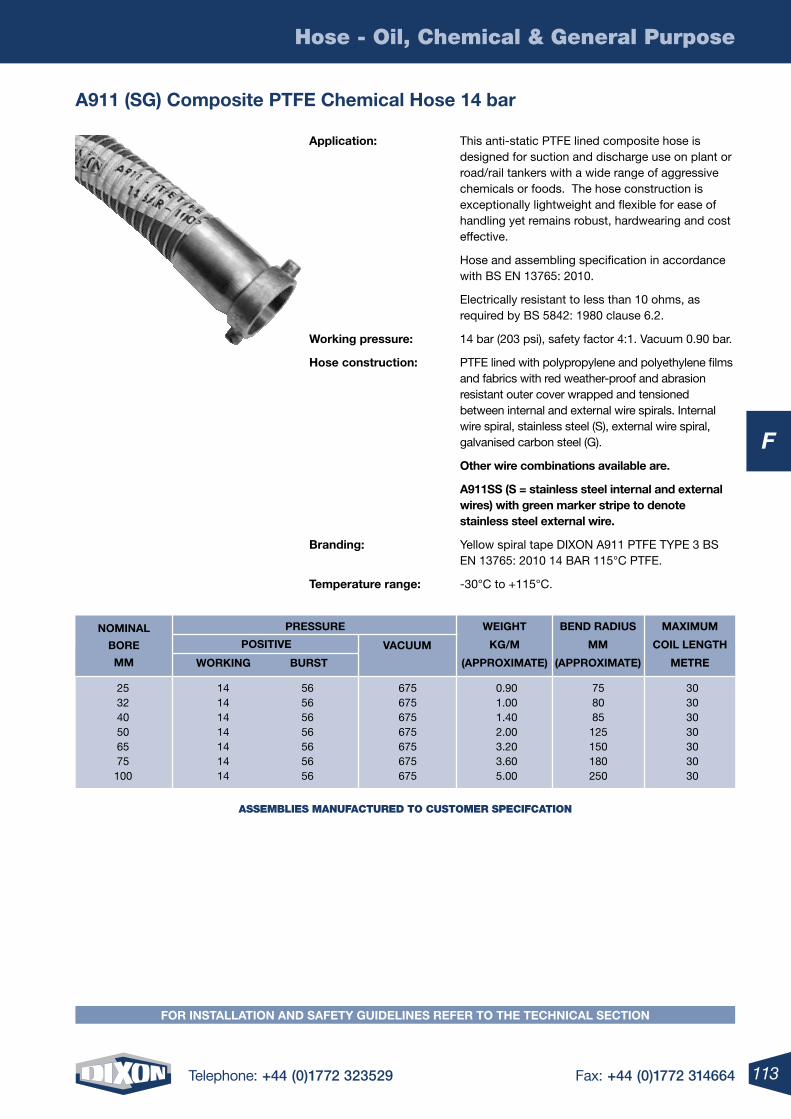
113Telephone: +44 (0)1772 323529 Fax: +44 (0)1772 314664
F
Hose - Oil, Chemical & General Purpose
FOr inStAllAtiOn AnD SAFety GuiDelineS reFer tO the teChniCAl SeCtiOn
A911 (SG) Composite PtFe Chemical hose 14 bar
Application: This anti-static PTFE lined composite hose is designed for suction and discharge use on plant or road/rail tankers with a wide range of aggressive chemicals or foods. The hose construction is exceptionally lightweight and flexible for ease of handling yet remains robust, hardwearing and cost effective.
Hose and assembling specification in accordance with BS EN 13765: 2010.
Electrically resistant to less than 10 ohms, as required by BS 5842: 1980 clause 6.2.
Working pressure: 14 bar (203 psi), safety factor 4:1. Vacuum 0.90 bar.
hose construction: PTFE lined with polypropylene and polyethylene films and fabrics with red weather-proof and abrasion resistant outer cover wrapped and tensioned between internal and external wire spirals. Internal wire spiral, stainless steel (S), external wire spiral, galvanised carbon steel (G).
Other wire combinations available are.
A911SS (S = stainless steel internal and external wires) with green marker stripe to denote stainless steel external wire.
Branding: Yellow spiral tape DIXON A911 PTFE TYPE 3 BS EN 13765: 2010 14 BAR 115°C PTFE.
temperature range: -30°C to +115°C.
25 14 56 675 0.90 75 30 32 14 56 675 1.00 80 30 40 14 56 675 1.40 85 30 50 14 56 675 2.00 125 30 65 14 56 675 3.20 150 30 75 14 56 675 3.60 180 30 100 14 56 675 5.00 250 30
nOminAl
BOre
mm
WeiGht
KG/m
(APPrOXimAte)
BenD rADiuS
mm
(APPrOXimAte)
mAXimum
COil lenGth
metre
vACuum
POSitive
WOrKinG BurSt
PreSSure
ASSEMBLIES MANUFACTURED TO CUSTOMER SPECIFCATION
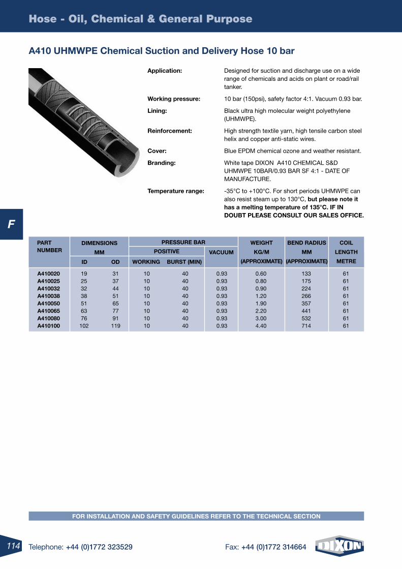
114 Telephone: +44 (0)1772 323529 Fax: +44 (0)1772 314664
F
Hose - Oil, Chemical & General Purpose
A410 uhmWPe Chemical Suction and Delivery hose 10 bar
Application: Designed for suction and discharge use on a wide range of chemicals and acids on plant or road/rail tanker.
Working pressure: 10 bar (150psi), safety factor 4:1. Vacuum 0.93 bar.
lining: Black ultra high molecular weight polyethylene (UHMWPE).
reinforcement: High strength textile yarn, high tensile carbon steel helix and copper anti-static wires.
Cover: Blue EPDM chemical ozone and weather resistant.
Branding: White tape DIXON A410 CHEMICAL S&D UHMWPE 10BAR/0.93 BAR SF 4:1 - DATE OF MANUFACTURE.
temperature range: -35°C to +100°C. For short periods UHMWPE can also resist steam up to 130°C, but please note it has a melting temperature of 135°C. iF in DOuBt PleASe COnSult Our SAleS OFFiCe.
WeiGht
KG/m
(APPrOXimAte)
BenD rADiuS
mm
(APPrOXimAte)
COil
lenGth
metre
mm
iD OD
DimenSiOnSPOSitive
WOrKinG BurSt (min)
A410020 19 31 10 40 0.93 0.60 133 61 A410025 25 37 10 40 0.93 0.80 175 61 A410032 32 44 10 40 0.93 0.90 224 61 A410038 38 51 10 40 0.93 1.20 266 61 A410050 51 65 10 40 0.93 1.90 357 61 A410065 63 77 10 40 0.93 2.20 441 61 A410080 76 91 10 40 0.93 3.00 532 61 A410100 102 119 10 40 0.93 4.40 714 61
PArt numBer vACuum
PreSSure BAr
FOr inStAllAtiOn AnD SAFety GuiDelineS reFer tO the teChniCAl SeCtiOn
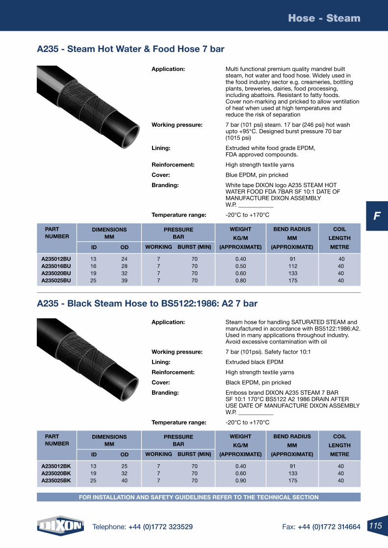
115Telephone: +44 (0)1772 323529 Fax: +44 (0)1772 314664
F
Hose - Steam
FOr inStAllAtiOn AnD SAFety GuiDelineS reFer tO the teChniCAl SeCtiOn
A235 - Steam hot Water & Food hose 7 bar
A235 - Black Steam hose to BS5122:1986: A2 7 bar
Application: Multi functional premium quality mandrel built steam, hot water and food hose. Widely used in the food industry sector e.g. creameries, bottling plants, breweries, dairies, food processing, including abattoirs. Resistant to fatty foods. Cover non-marking and pricked to allow ventilation of heat when used at high temperatures and reduce the risk of separation
Working pressure: 7 bar (101 psi) steam. 17 bar (246 psi) hot wash upto +95°C. Designed burst pressure 70 bar (1015 psi)
lining: Extruded white food grade EPDM, FDA approved compounds.
reinforcement: High strength textile yarns
Cover: Blue EPDM, pin pricked
Branding: White tape DIXON logo A235 STEAM HOT WATER FOOD FDA 7BAR SF 10:1 DATE OF MANUFACTURE DIXON ASSEMBLY W.P. ____________
temperature range: -20°C to +170°C
Application: Steam hose for handling SATURATED STEAM and manufactured in accordance with BS5122:1986:A2. Used in many applications throughout industry. Avoid excessive contamination with oil
Working pressure: 7 bar (101psi). Safety factor 10:1
lining: Extruded black EPDM
reinforcement: High strength textile yarns
Cover: Black EPDM, pin pricked
Branding: Emboss brand DIXON A235 STEAM 7 BAR SF 10:1 170°C BS5122 A2 1986 DRAIN AFTER USE DATE OF MANUFACTURE DIXON ASSEMBLY W.P. ____________
temperature range: -20°C to +170°C
WeiGht
KG/m
(APPrOXimAte)
BenD rADiuS
mm
(APPrOXimAte)
COil
lenGth
metre
DimenSiOnS mm
iD OD
PreSSure BAr
WOrKinG BurSt (min)
A235012Bu 13 24 7 70 0.40 91 40 A235016Bu 16 28 7 70 0.50 112 40 A235020Bu 19 32 7 70 0.60 133 40 A235025Bu 25 39 7 70 0.80 175 40
PArt numBer
WeiGht
KG/m
(APPrOXimAte)
BenD rADiuS
mm
(APPrOXimAte)
COil
lenGth
metre
DimenSiOnS mm
iD OD
PreSSure BAr
WOrKinG BurSt (min)
A235012BK 13 25 7 70 0.40 91 40 A235020BK 19 32 7 70 0.60 133 40 A235025BK 25 40 7 70 0.90 175 40
PArt numBer
FOr inStAllAtiOn AnD SAFety GuiDelineS reFer tO the teChniCAl SeCtiOn
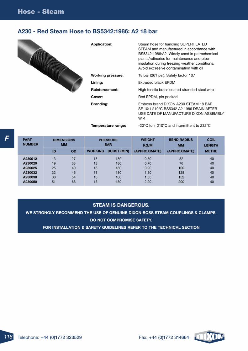
116 Telephone: +44 (0)1772 323529 Fax: +44 (0)1772 314664
F
Hose - Steam
A230 - red Steam hose to BS5342:1986: A2 18 bar
Application: Steam hose for handling SUPERHEATED STEAM and manufactured in accordance with BS5342:1986:A2. Widely used in petrochemical plants/refineries for maintenance and pipe insulation during freezing weather conditions. Avoid excessive contamination with oil
Working pressure: 18 bar (261 psi). Safety factor 10:1
lining: Extruded black EPDM
reinforcement: High tensile brass coated stranded steel wire
Cover: Red EPDM, pin pricked
Branding: Emboss brand DIXON A230 STEAM 18 BAR SF 10:1 210°C BS5342 A2 1986 DRAIN AFTER USE DATE OF MANUFACTURE DIXON ASSEMBLY W.P. ____________
temperature range: -20°C to + 210°C and intermittent to 232°C
WeiGht
KG/m
(APPrOXimAte)
BenD rADiuS
mm
(APPrOXimAte)
COil
lenGth
metre
DimenSiOnS mm
iD OD
PreSSure BAr
WOrKinG BurSt (min)
A230012 13 27 18 180 0.50 52 40 A230020 19 33 18 180 0.70 76 40 A230025 25 40 18 180 0.90 100 40 A230032 32 46 18 180 1.30 128 40 A230038 38 54 18 180 1.65 152 40 A230050 51 68 18 180 2.20 200 40
PArt numBer
SteAm iS DAnGerOuS.
We StrOnGly reCOmmenD the uSe OF Genuine DiXOn BOSS SteAm COuPlinGS & ClAmPS.
DO nOt COmPrOmiSe SAFety.
FOr inStAllAtiOn & SAFety GuiDelineS reFer tO the teChniCAl SeCtiOn
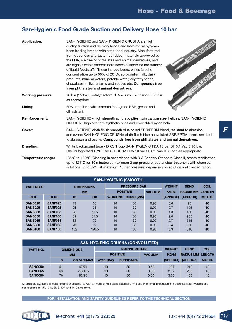
117Telephone: +44 (0)1772 323529 Fax: +44 (0)1772 314664
F
Hose - Food & Beverage
FOr inStAllAtiOn AnD SAFety GuiDelineS reFer tO the teChniCAl SeCtiOn
San-hygienic Food Grade Suction and Delivery hose 10 bar
Application: SAN-HYGIENIC and SAN-HYGIENIC CRUSHA are high quality suction and delivery hoses and have for many years been leading brands within the food industry. Manufactured from odourless and taste free rubber materials approved by the FDA, are free of phthalates and animal derivatives, and are highly flexible smooth bore hoses suitable for the transfer of liquid foodstuffs. These include beers, wines (alcohol concentration up to 96% @ 20°C), soft-drinks, milk, dairy products, mineral waters, potable water, oily fatty foods, chocolates, milks, creams and sauces etc. Compounds free from phthalates and animal derivatives.
Working pressure: 10 bar (150psi), safety factor 3:1. Vacuum 0.90 bar or 0.60 bar as appropriate.
lining: FDA compliant, white smooth food grade NBR, grease and oil resistant.
reinforcement: SAN-HYGIENIC - high strength synthetic plies, twin carbon steel helices. SAN-HYGIENIC CRUSHA - high strength synthetic plies and embedded nylon helix.
Cover: SAN-HYGIENIC cloth finish smooth blue or red SBR/EPDM blend, resistant to abrasion and ozone SAN-HYGIENIC CRUSHA cloth finish blue convoluted SBR/EPDM blend, resistant to abrasion and ozone. Compounds free from phthalates and animal derivatives.
Branding: White background tape - DIXON logo SAN- HYGIENIC FDA 10 bar SF 3:1 Vac 0.90 bar, DIXON logo SAN-HYGIENIC CRUSHA FDA 10 bar SF 3:1 Vac 0.60 bar, as appropriate.
temperature range: -35°C to +80°C. Cleaning in accordance with 3-A Sanitary Standard Class II, steam sterilisation up to 121°C for 30 minutes at maximum 2 bar pressure, bactericidal treatment with chemical solutions up to 82°C at maximum 10 bar pressure, depending on solution and concentration.
All sizes are available in loose lengths or assemblies with all types of Holedall® External Crimp and IX Internal Expansion 316 stainless steel hygienic end connections in RJT, DIN, SMS, IDF, and Tri-Clamp form.
40404040404040
95125190255315380510
0.60.71.32.02.73.45.3
0.900.900.900.900.900.900.90
10101010101010
192538516376102
SAnB020SAnB025SAnB038SAnB050SAnB065SAnB080SAnB100
reD iDBlue OD
30303030303030
3036
51.565.57992
120.5
SAnF020SAnF025SAnF038SAnF050SAnF065SAnF080SAnF100
PArt nO.S DimenSiOnS
mm
WeiGht
KG/m
(APPrOX)
BenD
rADiuS mm
(APPrOX)
COil
lenGth
metre
vACuum
POSitive
WOrKinG BurSt (min)
PreSSure BAr
SAn-hyGieniC (SmOOth)
404040
210280430
1.972.373.60
0.600.600.60
101010
516376
SAnC050SAnC065SAnC080
iD OD min/mAX
303030
67/7479/86.592/98
PArt nO. DimenSiOnS
mm
WeiGht
KG/m
(APPrOX)
BenD
rADiuS mm
(APPrOX)
COil
lenGth
metre
vACuum
POSitive
WOrKinG BurSt (min)
PreSSure BAr
SAn-hyGieniC CruShA (COnvOluteD)
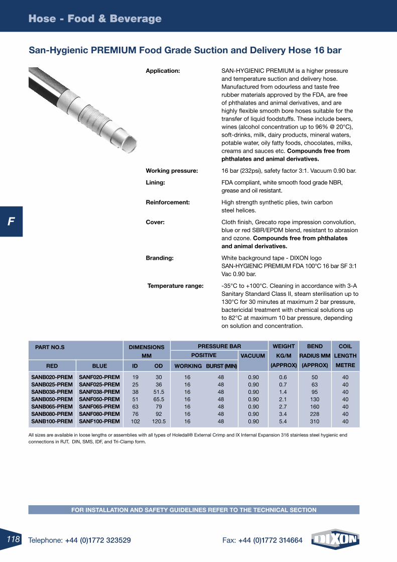
118 Telephone: +44 (0)1772 323529 Fax: +44 (0)1772 314664
F
Hose - Food & Beverage
Application: SAN-HYGIENIC PREMIUM is a higher pressure and temperature suction and delivery hose. Manufactured from odourless and taste free rubber materials approved by the FDA, are free of phthalates and animal derivatives, and are highly flexible smooth bore hoses suitable for the transfer of liquid foodstuffs. These include beers, wines (alcohol concentration up to 96% @ 20°C), soft-drinks, milk, dairy products, mineral waters, potable water, oily fatty foods, chocolates, milks, creams and sauces etc. Compounds free from phthalates and animal derivatives.
Working pressure: 16 bar (232psi), safety factor 3:1. Vacuum 0.90 bar.
lining: FDA compliant, white smooth food grade NBR, grease and oil resistant.
reinforcement: High strength synthetic plies, twin carbon steel helices.
Cover: Cloth finish, Grecato rope impression convolution, blue or red SBR/EPDM blend, resistant to abrasion and ozone. Compounds free from phthalates and animal derivatives.
Branding: White background tape - DIXON logo SAN-HYGIENIC PREMIUM FDA 100°C 16 bar SF 3:1 Vac 0.90 bar.
temperature range: -35°C to +100°C. Cleaning in accordance with 3-A Sanitary Standard Class II, steam sterilisation up to 130°C for 30 minutes at maximum 2 bar pressure, bactericidal treatment with chemical solutions up to 82°C at maximum 10 bar pressure, depending on solution and concentration.
San-hygienic Premium Food Grade Suction and Delivery hose 16 bar
All sizes are available in loose lengths or assemblies with all types of Holedall® External Crimp and IX Internal Expansion 316 stainless steel hygienic end connections in RJT, DIN, SMS, IDF, and Tri-Clamp form.
40404040404040
506395
130160228310
0.60.71.42.12.73.45.4
0.900.900.900.900.900.900.90
16161616161616
192538516376102
SAnB020-PremSAnB025-PremSAnB038-PremSAnB050-PremSAnB065-PremSAnB080-PremSAnB100-Prem
SAnF020-PremSAnF025-PremSAnF038-PremSAnF050-PremSAnF065-PremSAnF080-PremSAnF100-Prem
reD iDBlue OD
48484848484848
3036
51.565.57992
120.5
PArt nO.S DimenSiOnS
mm
WeiGht
KG/m
(APPrOX)
BenD
rADiuS mm
(APPrOX)
COil
lenGth
metre
vACuum
POSitive
WOrKinG BurSt (min)
PreSSure BAr
FOr inStAllAtiOn AnD SAFety GuiDelineS reFer tO the teChniCAl SeCtiOn
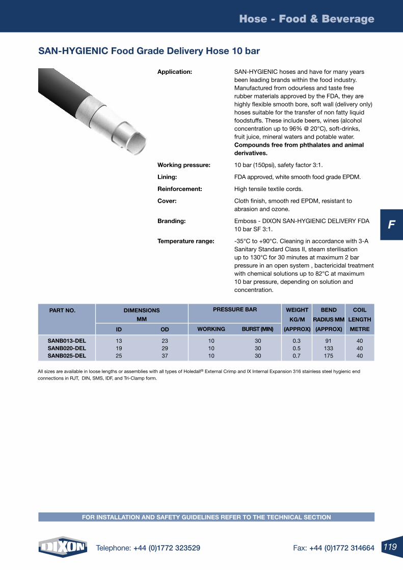
119Telephone: +44 (0)1772 323529 Fax: +44 (0)1772 314664
F
Hose - Food & Beverage
FOr inStAllAtiOn AnD SAFety GuiDelineS reFer tO the teChniCAl SeCtiOn
SAn-hyGieniC Food Grade Delivery hose 10 bar
Application: SAN-HYGIENIC hoses and have for many years been leading brands within the food industry. Manufactured from odourless and taste free rubber materials approved by the FDA, they are highly flexible smooth bore, soft wall (delivery only) hoses suitable for the transfer of non fatty liquid foodstuffs. These include beers, wines (alcohol concentration up to 96% @ 20°C), soft-drinks, fruit juice, mineral waters and potable water. Compounds free from phthalates and animal derivatives.
Working pressure: 10 bar (150psi), safety factor 3:1.
lining: FDA approved, white smooth food grade EPDM.
reinforcement: High tensile textile cords.
Cover: Cloth finish, smooth red EPDM, resistant to abrasion and ozone.
Branding: Emboss - DIXON SAN-HYGIENIC DELIVERY FDA 10 bar SF 3:1.
temperature range: -35°C to +90°C. Cleaning in accordance with 3-A Sanitary Standard Class II, steam sterilisation up to 130°C for 30 minutes at maximum 2 bar pressure in an open system , bactericidal treatment with chemical solutions up to 82°C at maximum 10 bar pressure, depending on solution and concentration.
404040
91133175
0.30.50.7
101010
131925
SAnB013-DelSAnB020-DelSAnB025-Del
iD OD
303030
232937
PArt nO. DimenSiOnS
mm
WeiGht
KG/m
(APPrOX)
BenD
rADiuS mm
(APPrOX)
COil
lenGth
metreWOrKinG BurSt (min)
PreSSure BAr
All sizes are available in loose lengths or assemblies with all types of Holedall® External Crimp and IX Internal Expansion 316 stainless steel hygienic end connections in RJT, DIN, SMS, IDF, and Tri-Clamp form.
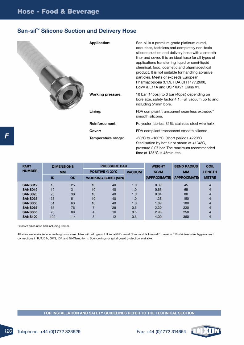
120 Telephone: +44 (0)1772 323529 Fax: +44 (0)1772 314664
F
Hose - Food & Beverage
San-sil™ Silicone Suction and Delivery hose
Application: San-sil is a premium grade platinum cured, odourless, tasteless and completely non-toxic silicone suction and delivery hose with a smooth liner and cover. It is an ideal hose for all types of applications transferring liquid or semi-liquid chemical, food, cosmetic and pharmaceutical product. It is not suitable for handling abrasive particles. Meets or exceeds European Pharmacopoeia 3.1.9, FDA CFR 177.2600, BgVV & L11A and USP XXV1 Class V1.
Working pressure: 10 bar (145psi) to 3 bar (46psi) depending on bore size, safety factor 4:1. Full vacuum up to and including 51mm bore.
lining: FDA compliant transparent seamless extruded* smooth silicone.
reinforcement: Polyester fabrics, 316L stainless steel wire helix.
Cover: FDA compliant transparent smooth silicone.
temperature range: -60°C to +180°C. (short periods +220°C Sterilisation by hot air or steam at +134°C, pressure 2.07 bar. The maximum recommended time at 135°C is 45minutes.
WeiGht
KG/m
(APPrOXimAte)
BenD rADiuS
mm
(APPrOXimAte)
COil
lenGth
metre
mm
iD OD
DimenSiOnS
POSitive @ 20°C
WOrKinG BurSt (min)
SAnS012SAnS019SAnS025SAnS038SAnS050SAnS065SAnS065SAnS100
13192538516376
102
1010101010743
25313851637689114
4040404040281612
1.01.01.01.01.00.50.50.5
0.390.630.841.381.892.302.984.00
456580
150180220250360
44444444
PArt numBer vACuum
PreSSure BAr
* in bore sizes upto and including 63mm. All sizes are available in loose lengths or assemblies with all types of Holedall® External Crimp and IX Internal Expansion 316 stainless steel hygienic end connections in RJT, DIN, SMS, IDF, and Tri-Clamp form. Bounce rings or spiral guard protection available.
FOr inStAllAtiOn AnD SAFety GuiDelineS reFer tO the teChniCAl SeCtiOn
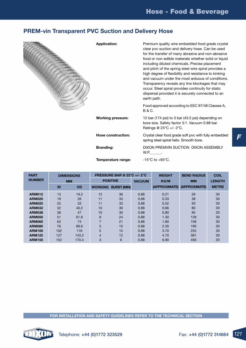
121Telephone: +44 (0)1772 323529 Fax: +44 (0)1772 314664
F
Hose - Food & Beverage
FOr inStAllAtiOn AnD SAFety GuiDelineS reFer tO the teChniCAl SeCtiOn
Prem-vin transparent PvC Suction and Delivery hose
Application: Premium quality wire embedded food grade crystal clear pvc suction and delivery hose. Can be used for the transfer of many abrasive and non-abrasive food or non-edible materials whether solid or liquid including diluted chemicals. Precise placement and pitch of the spring steel wire spiral provides a high degree of flexibility and resistance to kinking and vacuum under the most arduous of conditions. Transparency reveals any line blockages that may occur. Steel spiral provides continuity for static dispersal provided it is securely connected to an earth path.
Food approved according to EEC 97/48 Classes A, B & C.
Working pressure: 12 bar (174 psi) to 3 bar (43.5 psi) depending on bore size. Safety factor 3:1. Vacuum 0.88 bar. Ratings @ 23°C +/- 2°C.
hose construction: Crystal clear food grade soft pvc with fully embedded spring steel spiral helix. Smooth bore.
Branding: DIXON PREMVIN SUCTION DIXON ASSEMBLY W.P.______.
temperature range: -15°C to +65°C.
WeiGht
KG/m
(APPrOXimAte)
BenD rADiuS
mm
(APPrOXimAte)
COil
lenGth
metre
mm
iD OD
DimenSiOnSPOSitive
WOrKinG BurSt (min)
Arm012Arm020Arm025Arm032Arm038Arm050Arm065Arm080Arm100Arm125Arm150
1319253238516376102127152
1211111010875543
19.22633
40.247
61.874
89.6118
143.2170.4
363333303024211515129
0.880.880.880.880.880.880.880.880.880.880.88
0.210.330.520.660.801.301.802.303.704.706.90
2638508095
128158190255381456
3030303030303030303020
PArt numBer vACuum
PreSSure BAr @ 23°C +/- 2°C
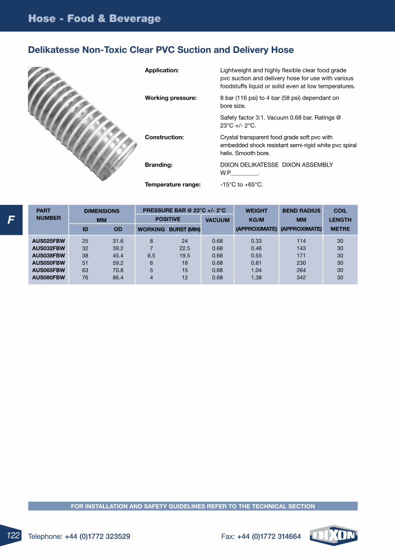
122 Telephone: +44 (0)1772 323529 Fax: +44 (0)1772 314664
F
Hose - Food & Beverage
Application: Lightweight and highly flexible clear food grade pvc suction and delivery hose for use with various foodstuffs liquid or solid even at low temperatures.
Working pressure: 8 bar (116 psi) to 4 bar (58 psi) dependant on bore size.
Safety factor 3:1. Vacuum 0.68 bar. Ratings @ 23°C +/- 2°C.
Construction: Crystal transparent food grade soft pvc with embedded shock resistant semi-rigid white pvc spiral helix. Smooth bore.
Branding: DIXON DELIKATESSE DIXON ASSEMBLY W.P_________.
temperature range: -15°C to +65°C.
Delikatesse non-toxic Clear PvC Suction and Delivery hose
WeiGht
KG/m
(APPrOXimAte)
BenD rADiuS
mm
(APPrOXimAte)
COil
lenGth
metre
mm
iD OD
DimenSiOnSPOSitive
WOrKinG BurSt (min)
AuS025FBWAuS032FBWAuS038FBWAuS050FBWAuS065FBWAuS080FBW
253238516376
87
6.5654
31.639.245.459.270.886.4
2422.519.5181512
0.680.680.680.680.680.68
0.330.460.550.811.041.38
114143171230264342
303030303030
PArt numBer vACuum
PreSSure BAr @ 23°C +/- 2°C
FOr inStAllAtiOn AnD SAFety GuiDelineS reFer tO the teChniCAl SeCtiOn
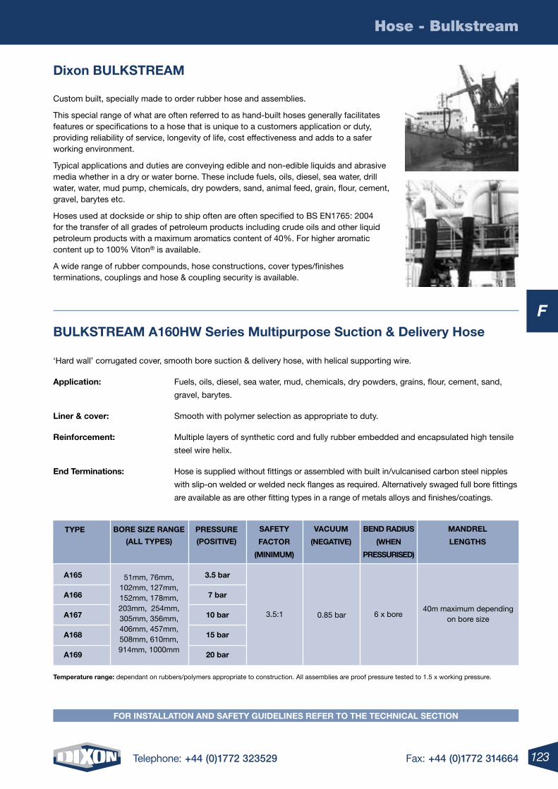
123Telephone: +44 (0)1772 323529 Fax: +44 (0)1772 314664
F
Hose - Bulkstream
FOr inStAllAtiOn AnD SAFety GuiDelineS reFer tO the teChniCAl SeCtiOn
Dixon BulKStreAm
Custom built, specially made to order rubber hose and assemblies.
This special range of what are often referred to as hand-built hoses generally facilitates features or specifications to a hose that is unique to a customers application or duty, providing reliability of service, longevity of life, cost effectiveness and adds to a safer working environment.
Typical applications and duties are conveying edible and non-edible liquids and abrasive media whether in a dry or water borne. These include fuels, oils, diesel, sea water, drill water, water, mud pump, chemicals, dry powders, sand, animal feed, grain, flour, cement, gravel, barytes etc.
Hoses used at dockside or ship to ship often are often specified to BS EN1765: 2004 for the transfer of all grades of petroleum products including crude oils and other liquid petroleum products with a maximum aromatics content of 40%. For higher aromatic content up to 100% Viton® is available.
A wide range of rubber compounds, hose constructions, cover types/finishes terminations, couplings and hose & coupling security is available.
BulKStreAm A160hW Series multipurpose Suction & Delivery hose
‘Hard wall’ corrugated cover, smooth bore suction & delivery hose, with helical supporting wire.
Application: Fuels, oils, diesel, sea water, mud, chemicals, dry powders, grains, flour, cement, sand,
gravel, barytes.
liner & cover: Smooth with polymer selection as appropriate to duty.
reinforcement: Multiple layers of synthetic cord and fully rubber embedded and encapsulated high tensile
steel wire helix.
end terminations: Hose is supplied without fittings or assembled with built in/vulcanised carbon steel nipples
with slip-on welded or welded neck flanges as required. Alternatively swaged full bore fittings
are available as are other fitting types in a range of metals alloys and finishes/coatings.
SAFety
FACtOr
(minimum)
vACuum
(neGAtive)
BenD rADiuS
(When
PreSSuriSeD)
mAnDrel
lenGthS
BOre SiZe rAnGe
(All tyPeS)
PreSSure
(POSitive)
A165
A166
A167
A168
A169
3.5 bar
7 bar
10 bar
15 bar
20 bar
51mm, 76mm, 102mm, 127mm, 152mm, 178mm, 203mm, 254mm, 305mm, 356mm, 406mm, 457mm, 508mm, 610mm, 914mm, 1000mm
3.5:1 0.85 bar 6 x bore40m maximum depending
on bore size
tyPe
temperature range: dependant on rubbers/polymers appropriate to construction. All assemblies are proof pressure tested to 1.5 x working pressure.
124 Telephone: +44 (0)1772 323529 Fax: +44 (0)1772 314664
F
Hose - Bulkstream
BulKStreAm A170SW Series multipurpose Delivery hose
‘Soft wall’ smooth cover and bore delivery hose, without helical supporting wire.
Application: Fuels, oils, diesel, sea water, mud, chemicals, dry powders, grains, flour, cement, sand,
gravel, barytes.
liner & cover: Smooth with polymer selection as appropriate to duty.
reinforcement: Multiple layers of synthetic cord.
end terminations: Hose is supplied without fittings or assembled with built in/vulcanised carbon steel nipples
with slip-on welded or welded neck flanges as required. Alternatively swaged full bore fittings
are available as are other fitting types in a range of metals alloys and finishes/coatings.
SAFety
FACtOr
(minimum)
BenD rADiuS
(When
PreSSuriSeD)
mAnDrel lenGthSBOre SiZe rAnGe
(All tyPeS)
PreSSure
(POSitive)
A170
A171
A172
A173
3.5 bar
7 bar
10 bar
15 bar
51mm, 76mm, 102mm, 127mm, 152mm, 178mm, 203mm, 254mm, 305mm, 356mm, 406mm, 457mm, 508mm, 610mm,
3.5:1 8 x boreUp to and including 305mm bore = 20m
Larger bore sizes = 12m
tyPe
temperature range: dependant on rubbers/polymers appropriate to construction. All assemblies are proof pressure tested to 1.5 x working pressure.
FOr inStAllAtiOn AnD SAFety GuiDelineS reFer tO the teChniCAl SeCtiOn
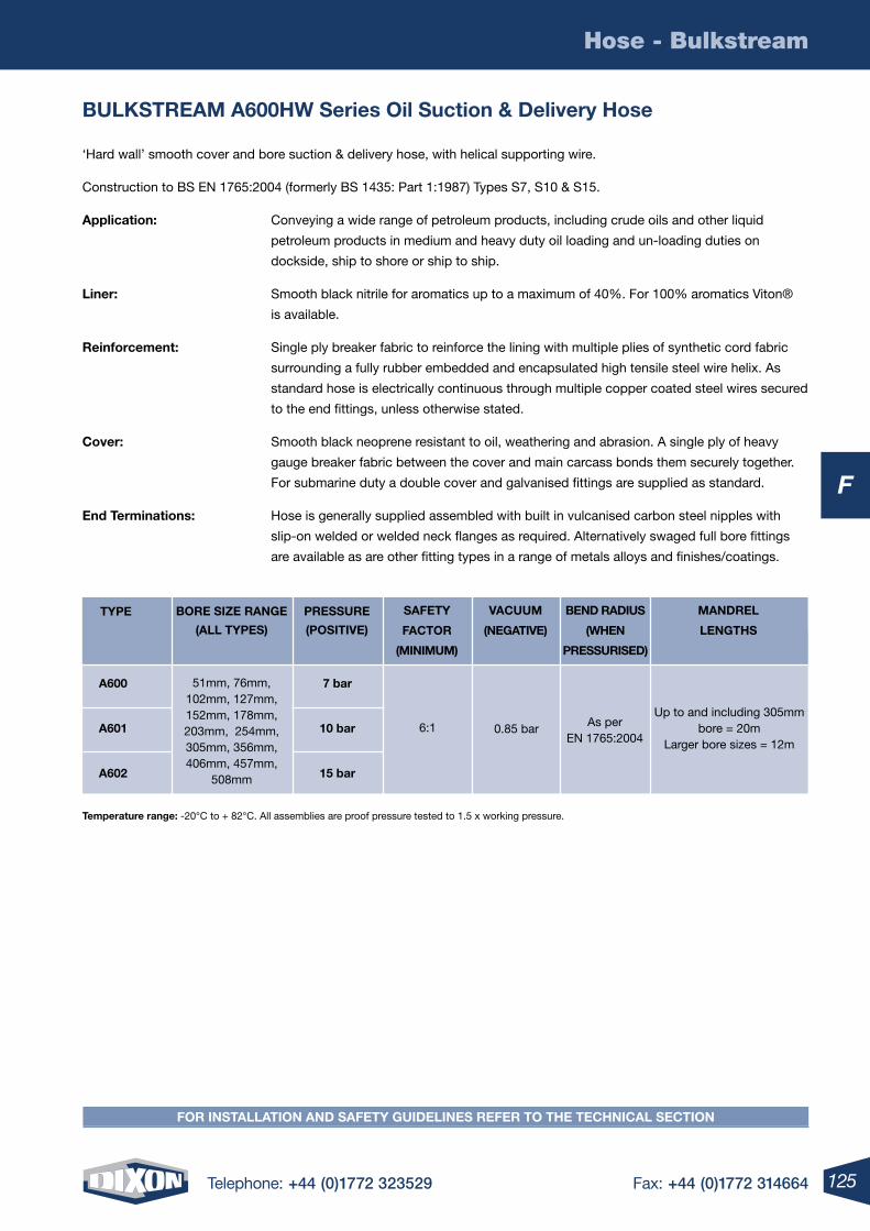
125Telephone: +44 (0)1772 323529 Fax: +44 (0)1772 314664
F
Hose - Bulkstream
FOr inStAllAtiOn AnD SAFety GuiDelineS reFer tO the teChniCAl SeCtiOn
BulKStreAm A600hW Series Oil Suction & Delivery hose
‘Hard wall’ smooth cover and bore suction & delivery hose, with helical supporting wire.
Construction to BS EN 1765:2004 (formerly BS 1435: Part 1:1987) Types S7, S10 & S15.
Application: Conveying a wide range of petroleum products, including crude oils and other liquid
petroleum products in medium and heavy duty oil loading and un-loading duties on
dockside, ship to shore or ship to ship.
liner: Smooth black nitrile for aromatics up to a maximum of 40%. For 100% aromatics Viton®
is available.
reinforcement: Single ply breaker fabric to reinforce the lining with multiple plies of synthetic cord fabric
surrounding a fully rubber embedded and encapsulated high tensile steel wire helix. As
standard hose is electrically continuous through multiple copper coated steel wires secured
to the end fittings, unless otherwise stated.
Cover: Smooth black neoprene resistant to oil, weathering and abrasion. A single ply of heavy
gauge breaker fabric between the cover and main carcass bonds them securely together.
For submarine duty a double cover and galvanised fittings are supplied as standard.
end terminations: Hose is generally supplied assembled with built in vulcanised carbon steel nipples with
slip-on welded or welded neck flanges as required. Alternatively swaged full bore fittings
are available as are other fitting types in a range of metals alloys and finishes/coatings.
SAFety
FACtOr
(minimum)
vACuum
(neGAtive)
BenD rADiuS
(When
PreSSuriSeD)
mAnDrel
lenGthS
BOre SiZe rAnGe
(All tyPeS)
PreSSure
(POSitive)
A600
A601
A602
7 bar
10 bar
15 bar
51mm, 76mm, 102mm, 127mm, 152mm, 178mm, 203mm, 254mm, 305mm, 356mm, 406mm, 457mm,
508mm
6:1 0.85 bar As per EN 1765:2004
Up to and including 305mm bore = 20m
Larger bore sizes = 12m
tyPe
temperature range: -20°C to + 82°C. All assemblies are proof pressure tested to 1.5 x working pressure.
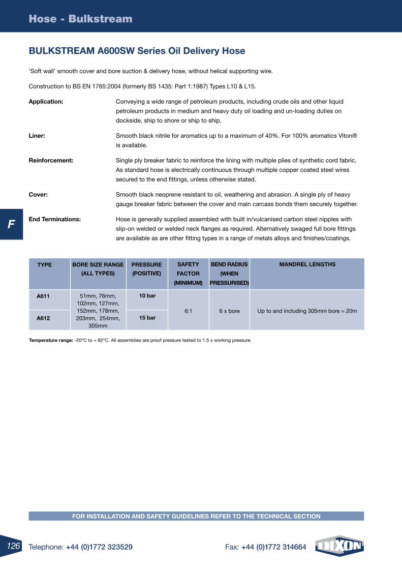
126 Telephone: +44 (0)1772 323529 Fax: +44 (0)1772 314664
F
Hose - Bulkstream
BulKStreAm A600SW Series Oil Delivery hose
‘Soft wall’ smooth cover and bore suction & delivery hose, without helical supporting wire.
Construction to BS EN 1765:2004 (formerly BS 1435: Part 1:1987) Types L10 & L15.
Application: Conveying a wide range of petroleum products, including crude oils and other liquid
petroleum products in medium and heavy duty oil loading and un-loading duties on
dockside, ship to shore or ship to ship.
liner: Smooth black nitrile for aromatics up to a maximum of 40%. For 100% aromatics Viton®
is available.
reinforcement: Single ply breaker fabric to reinforce the lining with multiple plies of synthetic cord fabric.
As standard hose is electrically continuous through multiple copper coated steel wires
secured to the end fittings, unless otherwise stated.
Cover: Smooth black neoprene resistant to oil, weathering and abrasion. A single ply of heavy
gauge breaker fabric between the cover and main carcass bonds them securely together.
end terminations: Hose is generally supplied assembled with built in/vulcanised carbon steel nipples with
slip-on welded or welded neck flanges as required. Alternatively swaged full bore fittings
are available as are other fitting types in a range of metals alloys and finishes/coatings.
SAFety
FACtOr
(minimum)
BenD rADiuS
(When
PreSSuriSeD)
mAnDrel lenGthSBOre SiZe rAnGe
(All tyPeS)
PreSSure
(POSitive)
A611
A612
10 bar
15 bar
51mm, 76mm, 102mm, 127mm, 152mm, 178mm, 203mm, 254mm,
305mm
6:1 6 x bore Up to and including 305mm bore = 20m
tyPe
temperature range: -20°C to + 82°C. All assemblies are proof pressure tested to 1.5 x working pressure.
FOr inStAllAtiOn AnD SAFety GuiDelineS reFer tO the teChniCAl SeCtiOn
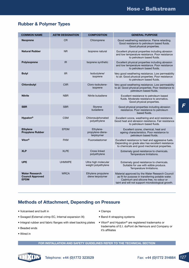
127Telephone: +44 (0)1772 323529 Fax: +44 (0)1772 314664
F
Hose - Bulkstream
FOr inStAllAtiOn AnD SAFety GuiDelineS reFer tO the teChniCAl SeCtiOn
rubber & Polymer types
methods of Attachment, Depending on Pressure
COmmOn nAme AStm DeSiGnAtiOn COmPOSitiOn GenerAl PurPOSe
neoprene
Polyisoprene
Chlorobutyl
SBr
natural rubber
Butyl
nitrile
hypalon®
viton®
ethylene Propylene rubber
XlP
uPe
Water research Council Approved ePDm
CR
IR
CIIR
SBR
NR
IIR
NBR
CSM
FKM
EPDM
XLPE
UHMWPE
WRCA
Chloroprene
Isoprene synthetic
Cloro-isobutene-isoprene
Styrene butadiene
Isoprene natural
Isobutylene/isoprene
Nitrile butadiene
Chlorosulphonated polyethylene
Fluoroelastomer
Ethylene- propylene-diene-
terploymer
Cross linked polyethylene
Ultra high molecular weight polyethylene
Ethylene propylene diene terpolymer
Good weathering resistance. Flame retarding. Good resistance to petroleum based fluids.
Good physical properties.
Excellent physical properties including abrasion and low temperature resistance. Poor resistance
to petroleum based fluids.
Very good weathering resistance. Low permeability to air. Good physical properties. Poor resistance to
petroleum based fluids.
Good physical properties including abrasion resistance. Poor resistance to petroleum
based fluids.
Excellent physical properties including abrasion and low temperature resistance. Poor resistance
to petroleum based fluids.
Very good weathering resistance. Low permeability to air. Good physical properties. Poor resistance
to petroleum based fluids.
Excellent resistance to petroleum based fluids. Moderate resistance to aromatics.
Good physical properties.
Excellent ozone, weathering and acid resistance. Good heat and abrasion resistance. Fair resistance
to petroleum based fluids.
Excellent resistance to heat and aggressive fuels. Depending on grade also has excellent resistance
to chemicals and good mechanical properties.
Excellent ozone, chemical, heat and ageing characteristics. Poor resistance to
petroleum based fluids.
Extremely good resistance to chemicals. Temperature limitations.
Extremely good resistance to chemicals. Suitable for use with edible produce.
Temperature limitations.
Material approved by the Water Research Council as fit for purpose in transferring potable water.
Cadmium and silicone free, no odour or taint and will not support microbiological growth.
• Vulcanised and built in
• Swaged (External crimp EC, Internal expansion IX)
• Integral rubber and fabric flanges with steel backing plates
• Beaded ends
• Wired in
• Clamps
• Band-It strapping systems
• Viton® and Hypalon® are registered trademarks or trademarks of E.I. duPont de Nemours and Company or it’s affiliates
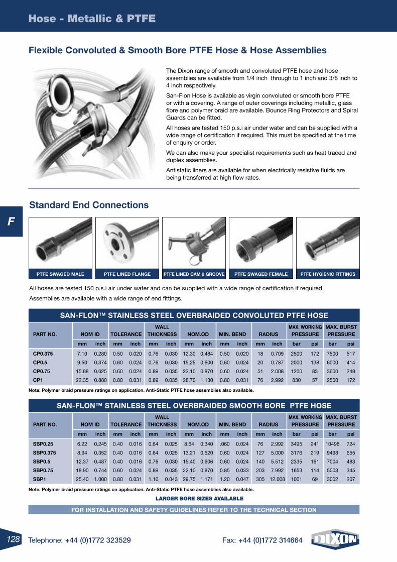
128 Telephone: +44 (0)1772 323529 Fax: +44 (0)1772 314664
F
Hose - Metallic & PTFE
Flexible Convoluted & Smooth Bore PtFe hose & hose Assemblies
The Dixon range of smooth and convoluted PTFE hose and hose assemblies are available from 1/4 inch through to 1 inch and 3/8 inch to 4 inch respectively.
San-Flon Hose is available as virgin convoluted or smooth bore PTFE or with a covering. A range of outer coverings including metallic, glass fibre and polymer braid are available. Bounce Ring Protectors and Spiral Guards can be fitted.
All hoses are tested 150 p.s.i air under water and can be supplied with a wide range of certification if required. This must be specified at the time of enquiry or order.
We can also make your specialist requirements such as heat traced and duplex assemblies.
Antistatic liners are available for when electrically resistive fluids are being transferred at high flow rates.
Standard end Connections
All hoses are tested 150 p.s.i air under water and can be supplied with a wide range of certification if required.
Assemblies are available with a wide range of end fittings.
WAll mAX. WOrKinG mAX. BurSt PArt nO. nOm iD tOlerAnCe thiCKneSS nOm.OD min. BenD rADiuS PreSSure PreSSure
mm inch mm inch mm inch mm inch mm inch mm inch bar psi bar psi
CP0.375 7.10 0.280 0.50 0.020 0.76 0.030 12.30 0.484 0.50 0.020 18 0.709 2500 172 7500 517
CP0.5 9.50 0.374 0.60 0.024 0.76 0.030 15.25 0.600 0.60 0.024 20 0.787 2000 138 6000 414
CP0.75 15.88 0.625 0.60 0.024 0.89 0.035 22.10 0.870 0.60 0.024 51 2.008 1200 83 3600 248
CP1 22.35 0.880 0.80 0.031 0.89 0.035 28.70 1.130 0.80 0.031 76 2.992 830 57 2500 172
SAn-FlOn™ StAinleSS Steel OverBrAiDeD COnvOluteD PtFe hOSe
WAll mAX. WOrKinG mAX. BurSt PArt nO. nOm iD tOlerAnCe thiCKneSS nOm.OD min. BenD rADiuS PreSSure PreSSure
mm inch mm inch mm inch mm inch mm inch mm inch bar psi bar psi
SBP0.25 6.22 0.245 0.40 0.016 0.64 0.025 8.64 0.340 .060 0.024 76 2.992 3495 241 10498 724
SBP0.375 8.94 0.352 0.40 0.016 0.64 0.025 13.21 0.520 0.60 0.024 127 5.000 3176 219 9498 655
SBP0.5 12.37 0.487 0.40 0.016 0.76 0.030 15.40 0.606 0.60 0.024 140 5.512 2335 161 7004 483
SBP0.75 18.90 0.744 0.60 0.024 0.89 0.035 22.10 0.870 0.85 0.033 203 7.992 1653 114 5003 345
SBP1 25.40 1.000 0.80 0.031 1.10 0.043 29.75 1.171 1.20 0.047 305 12.008 1001 69 3002 207
SAn-FlOn™ StAinleSS Steel OverBrAiDeD SmOOth BOre PtFe hOSe
PtFe SWAGeD mAle PtFe lineD FlAnGe PtFe lineD CAm & GrOOve PtFe SWAGeD FemAle PtFe hyGieniC FittinGS
LARGER BORE SIZES AVAILABLE
note: Polymer braid pressure ratings on application. Anti-Static PtFe hose assemblies also available.
note: Polymer braid pressure ratings on application. Anti-Static PtFe hose assemblies also available.
FOr inStAllAtiOn AnD SAFety GuiDelineS reFer tO the teChniCAl SeCtiOn
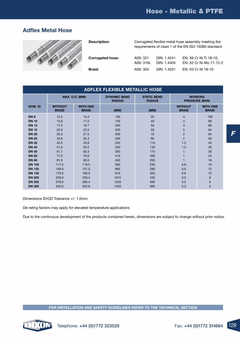
129Telephone: +44 (0)1772 323529 Fax: +44 (0)1772 314664
F
Hose - Metallic & PTFE
FOr inStAllAtiOn AnD SAFety GuiDelineS reFer tO the teChniCAl SeCtiOn
Adflex metal hose
Description: Corrugated flexible metal hose assembly meeting the requirements of class 1 of the EN ISO 10380 standard.
Corrugated hose: AISI: 321 DIN: 1.4541 EN: X6 Cr Ni Ti 18-10, AISI: 316L DIN: 1.4404 EN: X2 Cr Ni Mo 17-12-2
Braid: AISI: 304 DIN: 1.4031 EN: X5 Cr Ni 18-10
Dimensions ID/OD Tolerance +/- 1.0mm
De-rating factors may apply for elevated temperature applications
Due to the continuous development of the products contained herein, dimensions are subject to change without prior notice.
mAX. O.D. (mm) DynAmiC BenD StAtiC BenD WOrKinG rADiuS rADiuS PreSSure (BAr)
nOm. iD WithOut With One WithOut With One BrAiD BrAiD (mm) (mm) BrAiD BrAiD
Dn 6 12.2 13.4 100 25 4 100 Dn 10 15.8 17.0 150 40 4 90 Dn 12 17.5 18.7 200 50 3 80 Dn 15 22.0 23.2 200 50 2 64 Dn 20 26.3 27.5 200 70 2 64 Dn 25 33.8 35.3 200 90 2 50 Dn 32 42.0 43.6 250 110 1.5 40 Dn 40 51.6 53.2 250 130 1.5 30 Dn 50 61.7 63.3 350 175 1 28 Dn 65 77.0 79.0 410 200 1 24 Dn 80 91.0 93.0 450 205 1 18 Dn 100 117.5 119.5 560 230 0.8 16 Dn 125 149.0 151.0 660 280 0.6 12 Dn 150 178.0 180.0 815 320 0.6 10 Dn 200 228.0 230.4 1015 435 0.5 8 Dn 250 278.0 280.4 1220 560 0.5 6 Dn 300 333.0 335.8 1420 660 0.3 5
ADFleX FleXiBle metAlliC hOSe
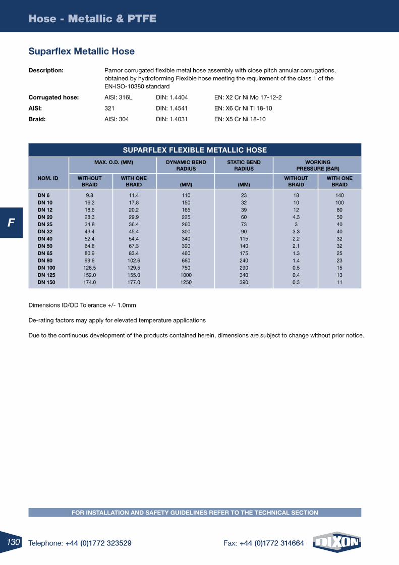
130 Telephone: +44 (0)1772 323529 Fax: +44 (0)1772 314664
F
Hose - Metallic & PTFE
Suparflex metallic hose
Description: Parnor corrugated flexible metal hose assembly with close pitch annular corrugations, obtained by hydroforming Flexible hose meeting the requirement of the class 1 of the EN-ISO-10380 standard
Corrugated hose: AISI: 316L DIN: 1.4404 EN: X2 Cr Ni Mo 17-12-2
AiSi: 321 DIN: 1.4541 EN: X6 Cr Ni Ti 18-10
Braid: AISI: 304 DIN: 1.4031 EN: X5 Cr Ni 18-10
Dimensions ID/OD Tolerance +/- 1.0mm
De-rating factors may apply for elevated temperature applications
Due to the continuous development of the products contained herein, dimensions are subject to change without prior notice.
mAX. O.D. (mm) DynAmiC BenD StAtiC BenD WOrKinG rADiuS rADiuS PreSSure (BAr)
nOm. iD WithOut With One WithOut With One BrAiD BrAiD (mm) (mm) BrAiD BrAiD
Dn 6 9.8 11.4 110 23 18 140 Dn 10 16.2 17.8 150 32 10 100 Dn 12 18.6 20.2 165 39 12 80 Dn 20 28.3 29.9 225 60 4.3 50 Dn 25 34.8 36.4 260 73 3 40 Dn 32 43.4 45.4 300 90 3.3 40 Dn 40 52.4 54.4 340 115 2.2 32 Dn 50 64.8 67.3 390 140 2.1 32 Dn 65 80.9 83.4 460 175 1.3 25 Dn 80 99.6 102.6 660 240 1.4 23 Dn 100 126.5 129.5 750 290 0.5 15 Dn 125 152.0 155.0 1000 340 0.4 13 Dn 150 174.0 177.0 1250 390 0.3 11
SuPArFleX FleXiBle metAlliC hOSe
FOr inStAllAtiOn AnD SAFety GuiDelineS reFer tO the teChniCAl SeCtiOn
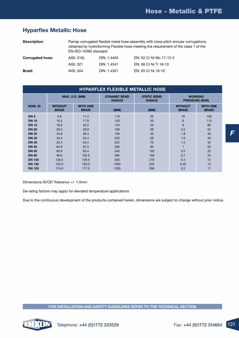
131Telephone: +44 (0)1772 323529 Fax: +44 (0)1772 314664
F
Hose - Metallic & PTFE
FOr inStAllAtiOn AnD SAFety GuiDelineS reFer tO the teChniCAl SeCtiOn
hyparflex metallic hose
Description: Parrap corrugated flexible metal hose assembly with close pitch annular corrugations, obtained by hydroforming Flexible hose meeting the requirement of the class 1 of the EN-ISO-10380 standard
Corrugated hose: AISI: 316L DIN: 1.4404 EN: X2 Cr Ni Mo 17-12-2
AISI: 321 DIN: 1.4541 EN: X6 Cr Ni Ti 18-10
Braid: AISI: 304 DIN: 1.4301 EN: X5 Cr Ni 18-10
Dimensions ID/OD Tolerance +/- 1.0mm
De-rating factors may apply for elevated temperature applications
Due to the continuous development of the products contained herein, dimensions are subject to change without prior notice.
mAX. O.D. (mm) DynAmiC BenD StAtiC BenD WOrKinG rADiuS rADiuS PreSSure (BAr)
nOm. iD WithOut With One WithOut With One BrAiD BrAiD (mm) (mm) BrAiD BrAiD
Dn 6 9.8 11.4 110 20 18 150 Dn 10 16.2 17.8 150 20 6 115 Dn 12 18.6 20.2 124 25 6 80 Dn 20 28.3 29.9 169 38 2.2 55 Dn 25 34.8 36.4 195 45 1.8 40 Dn 32 43.4 45.4 225 58 1.6 40 Dn 40 52.4 54.4 225 70 1.2 32 Dn 50 64.8 67.3 293 85 1 32 Dn 65 80.9 83.4 345 105 0.5 25 Dn 80 99.6 102.6 495 180 0.7 23 Dn 100 126.5 129.5 563 218 0.4 15 Dn 125 152.0 155.0 1000 255 0.25 13 Dn 150 174.0 177.0 1250 290 0.2 11
hyPArFleX FleXiBle metAlliC hOSe
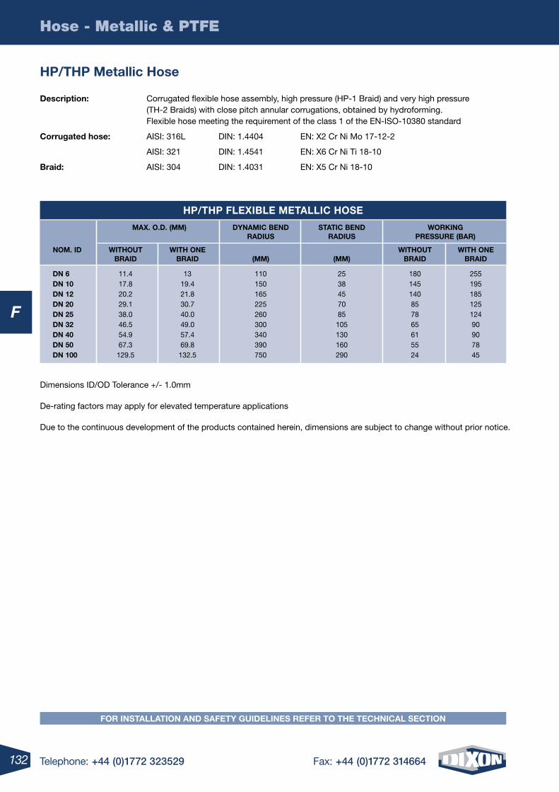
132 Telephone: +44 (0)1772 323529 Fax: +44 (0)1772 314664
F
Hose - Metallic & PTFE
hP/thP metallic hose
Description: Corrugated flexible hose assembly, high pressure (HP-1 Braid) and very high pressure (TH-2 Braids) with close pitch annular corrugations, obtained by hydroforming. Flexible hose meeting the requirement of the class 1 of the EN-ISO-10380 standard
Corrugated hose: AISI: 316L DIN: 1.4404 EN: X2 Cr Ni Mo 17-12-2
AISI: 321 DIN: 1.4541 EN: X6 Cr Ni Ti 18-10
Braid: AISI: 304 DIN: 1.4031 EN: X5 Cr Ni 18-10
Dimensions ID/OD Tolerance +/- 1.0mm
De-rating factors may apply for elevated temperature applications
Due to the continuous development of the products contained herein, dimensions are subject to change without prior notice.
mAX. O.D. (mm) DynAmiC BenD StAtiC BenD WOrKinG rADiuS rADiuS PreSSure (BAr)
nOm. iD WithOut With One WithOut With One BrAiD BrAiD (mm) (mm) BrAiD BrAiD
Dn 6 11.4 13 110 25 180 255 Dn 10 17.8 19.4 150 38 145 195 Dn 12 20.2 21.8 165 45 140 185 Dn 20 29.1 30.7 225 70 85 125 Dn 25 38.0 40.0 260 85 78 124 Dn 32 46.5 49.0 300 105 65 90 Dn 40 54.9 57.4 340 130 61 90 Dn 50 67.3 69.8 390 160 55 78 Dn 100 129.5 132.5 750 290 24 45
hP/thP FleXiBle metAlliC hOSe
FOr inStAllAtiOn AnD SAFety GuiDelineS reFer tO the teChniCAl SeCtiOn
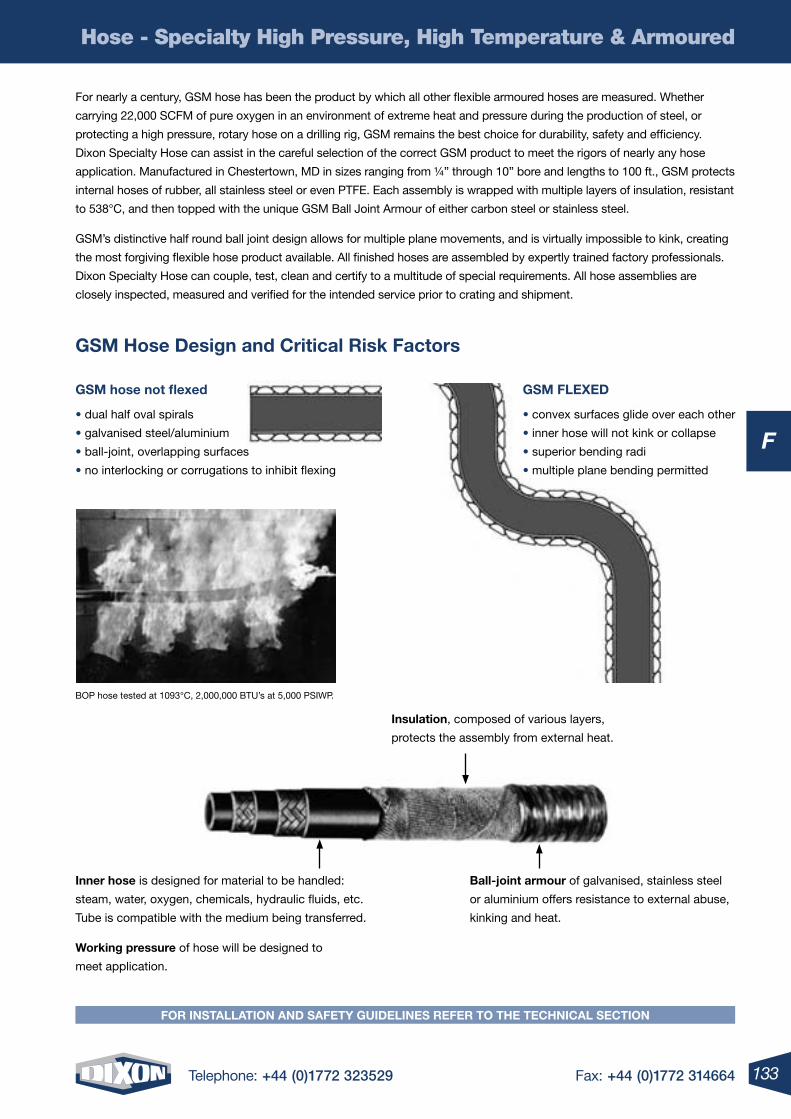
133Telephone: +44 (0)1772 323529 Fax: +44 (0)1772 314664
F
Hose - Specialty High Pressure, High Temperature & Armoured
FOr inStAllAtiOn AnD SAFety GuiDelineS reFer tO the teChniCAl SeCtiOn
For nearly a century, GSM hose has been the product by which all other flexible armoured hoses are measured. Whether
carrying 22,000 SCFM of pure oxygen in an environment of extreme heat and pressure during the production of steel, or
protecting a high pressure, rotary hose on a drilling rig, GSM remains the best choice for durability, safety and efficiency.
Dixon Specialty Hose can assist in the careful selection of the correct GSM product to meet the rigors of nearly any hose
application. Manufactured in Chestertown, MD in sizes ranging from ¼” through 10” bore and lengths to 100 ft., GSM protects
internal hoses of rubber, all stainless steel or even PTFE. Each assembly is wrapped with multiple layers of insulation, resistant
to 538°C, and then topped with the unique GSM Ball Joint Armour of either carbon steel or stainless steel.
GSM’s distinctive half round ball joint design allows for multiple plane movements, and is virtually impossible to kink, creating
the most forgiving flexible hose product available. All finished hoses are assembled by expertly trained factory professionals.
Dixon Specialty Hose can couple, test, clean and certify to a multitude of special requirements. All hose assemblies are
closely inspected, measured and verified for the intended service prior to crating and shipment.
GSm hose Design and Critical risk Factors
GSm hose not flexed
• dual half oval spirals
• galvanised steel/aluminium
• ball-joint, overlapping surfaces
• no interlocking or corrugations to inhibit flexing
insulation, composed of various layers,
protects the assembly from external heat.
inner hose is designed for material to be handled:
steam, water, oxygen, chemicals, hydraulic fluids, etc.
Tube is compatible with the medium being transferred.
Working pressure of hose will be designed to
meet application.
Ball-joint armour of galvanised, stainless steel
or aluminium offers resistance to external abuse,
kinking and heat.
BOP hose tested at 1093°C, 2,000,000 BTU’s at 5,000 PSIWP.
GSm FleXeD
• convex surfaces glide over each other
• inner hose will not kink or collapse
• superior bending radi
• multiple plane bending permitted
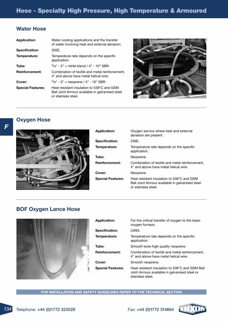
134 Telephone: +44 (0)1772 323529 Fax: +44 (0)1772 314664
F
Hose - Specialty High Pressure, High Temperature & Armoured
Water hose
Oxygen hose
BOF Oxygen lance hose
Application: Water cooling applications and the transfer of water involving heat and external abrasion.
Specification: 350E.
temperature: Temperature rate depends on the specific application.
tube: 3/8” - 3” = nitrile blend / 4” - 10” SBR.
reinforcement: Combination of textile and metal reinforcement, 4” and above have metal helical wire.
Cover: 3/8” - 3” = neoprene / 4” - 10” SBR.
Special Features: Heat resistant insulation to 538°C and GSM Ball Joint Armour available in galvanised steel or stainless steel.
Application: Oxygen service where heat and external abrasion are present.
Specification: 256E.
temperature: Temperature rate depends on the specific application.
tube: Neoprene.
reinforcement: Combination of textile and metal reinforcement, 4” and above have metal helical wire.
Cover: Neoprene.
Special Features: Heat resistant insulation to 538°C and GSM Ball Joint Armour available in galvanised steel or stainless steel.
Application: For the critical transfer of oxygen to the basic oxygen furnace.
Specification: LW65.
temperature: Temperature rate depends on the specific application.
tube: Smooth bore-high quality neoprene.
reinforcement: Combination of textile and metal reinforcement, 4” and above have metal helical wire.
Cover: Smooth neoprene.
Special Features: Heat resistant insulation to 538°C and GSM Ball Joint Armour available in galvanised steel or stainless steel.
FOr inStAllAtiOn AnD SAFety GuiDelineS reFer tO the teChniCAl SeCtiOn
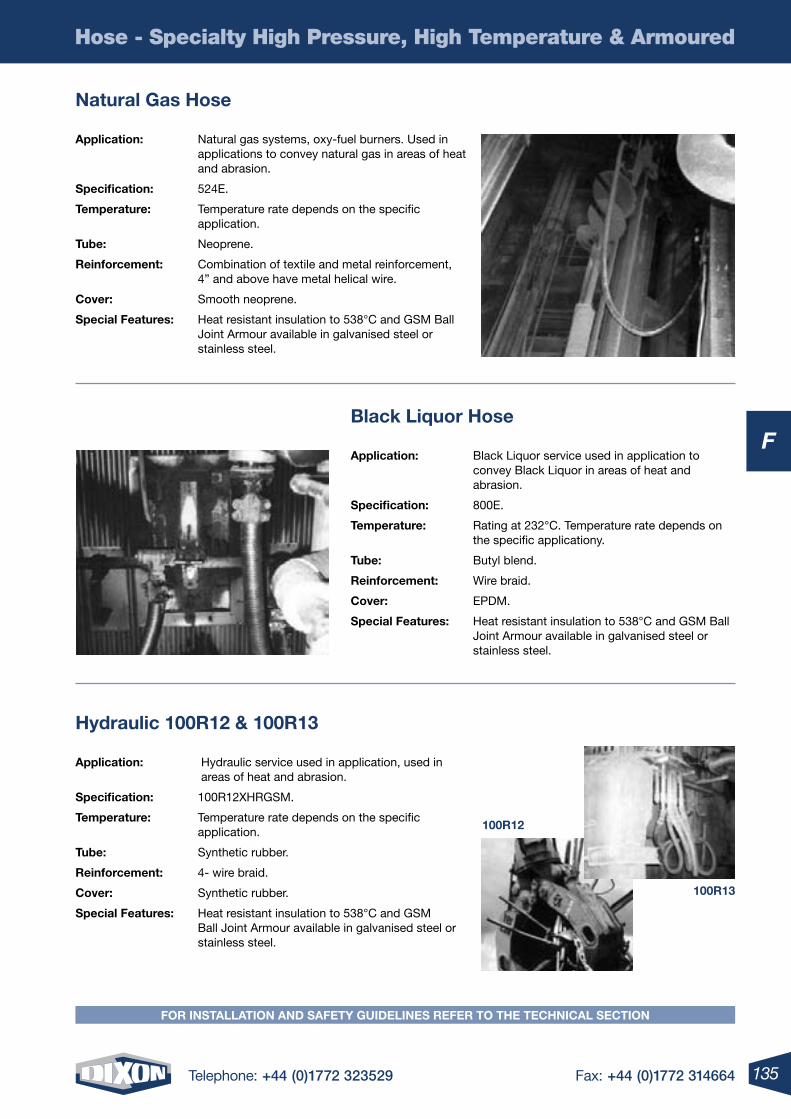
135Telephone: +44 (0)1772 323529 Fax: +44 (0)1772 314664
F
Hose - Specialty High Pressure, High Temperature & Armoured
FOr inStAllAtiOn AnD SAFety GuiDelineS reFer tO the teChniCAl SeCtiOn
natural Gas hose
hydraulic 100r12 & 100r13
Black liquor hose
Application: Natural gas systems, oxy-fuel burners. Used in applications to convey natural gas in areas of heat and abrasion.
Specification: 524E.
temperature: Temperature rate depends on the specific application.
tube: Neoprene.
reinforcement: Combination of textile and metal reinforcement, 4” and above have metal helical wire.
Cover: Smooth neoprene.
Special Features: Heat resistant insulation to 538°C and GSM Ball Joint Armour available in galvanised steel or stainless steel.
Application: Hydraulic service used in application, used in areas of heat and abrasion.
Specification: 100R12XHRGSM.
temperature: Temperature rate depends on the specific application.
tube: Synthetic rubber.
reinforcement: 4- wire braid.
Cover: Synthetic rubber.
Special Features: Heat resistant insulation to 538°C and GSM Ball Joint Armour available in galvanised steel or stainless steel.
Application: Black Liquor service used in application to convey Black Liquor in areas of heat and abrasion.
Specification: 800E.
temperature: Rating at 232°C. Temperature rate depends on the specific applicationy.
tube: Butyl blend.
reinforcement: Wire braid.
Cover: EPDM.
Special Features: Heat resistant insulation to 538°C and GSM Ball Joint Armour available in galvanised steel or stainless steel.
100r12
100r13
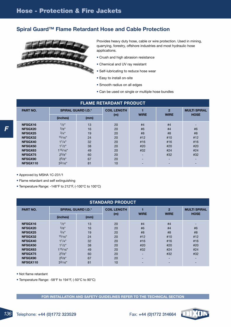
136 Telephone: +44 (0)1772 323529 Fax: +44 (0)1772 314664
FnFSGX16nFSGX20nFSGX25nFSGX32nFSGX40nFSGX50nFSGX63nFSGX75nFSGX90nFSGX110
1/2”5/8”3/4”
15/16”11/4”11/2”
115/16”23/8”25/8”33/16”
13161924323849606781
20202020202020202010
#4#6#8
#12#16#20#32
---
#4#4#8
#10#16#20#24#32
--
-#6#8
#12#16#20#24#32
--
nFSGX16nFSGX20nFSGX25nFSGX32nFSGX40nFSGX50nFSGX63nFSGX75nFSGX90nFSGX110
1/2”5/8”3/4”
15/16”11/4”11/2”
115/16”23/8”25/8”33/16”
13161924323849606781
20202020202020202010
#4#6#8
#12#16#20#32
---
#4#4#8
#10#16#20#24#32
--
-#6#8
#12#16#20#24#32
--
SPirAl GuArD i.D.*
SPirAl GuArD i.D.*
(inches)
(inches)
(mm)
(mm)
COil lenGth(m)
COil lenGth(m)
1Wire
1Wire
2Wire
2Wire
multi SPirAlhOSe
multi SPirAlhOSe
PArt nO.
PArt nO.
Hose - Protection & Fire Jackets
FOr inStAllAtiOn AnD SAFety GuiDelineS reFer tO the teChniCAl SeCtiOn
FlAme retArDAnt PrODuCt
StAnDArD PrODuCt
Provides heavy duty hose, cable or wire protection. Used in mining, quarrying, forestry, offshore industries and most hydraulic hose applications.
• Crush and high abrasion resistance
• Chemical and UV ray resistant
• Self-lubricating to reduce hose wear
• Easy to install on-site
• Smooth radius on all edges
• Can be used on single or multiple hose bundles
Spiral Guard™ Flame retardant hose and Cable Protection
• Approved by MSHA 1C-231/1
• Flame retardant and self extinguishing
• Temperature Range: -148°F to 212°F, (-100°C to 100°C)
• Not flame retardant
• Temperature Range: -58°F to 194°F, (-50°C to 90°C)
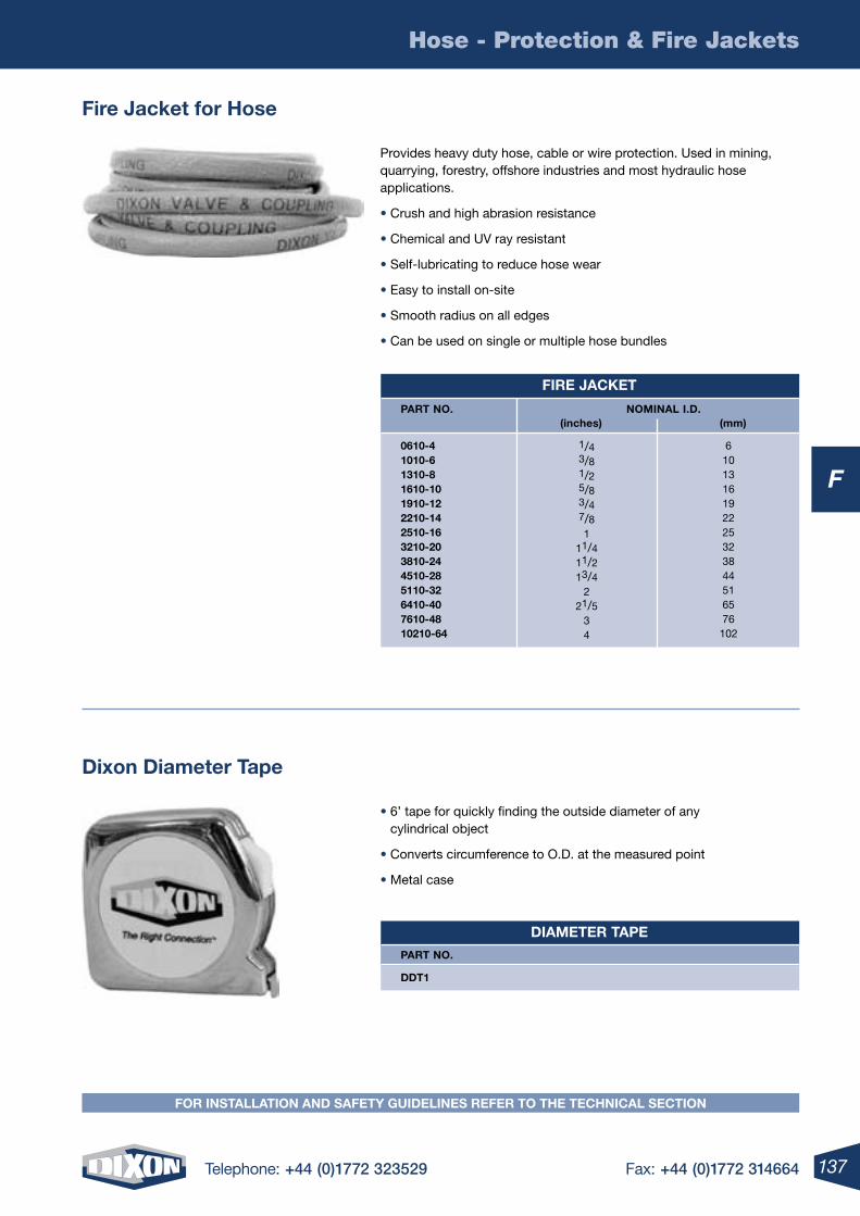
137Telephone: +44 (0)1772 323529 Fax: +44 (0)1772 314664
F
Hose - Protection & Fire Jackets
FOr inStAllAtiOn AnD SAFety GuiDelineS reFer tO the teChniCAl SeCtiOn
Provides heavy duty hose, cable or wire protection. Used in mining, quarrying, forestry, offshore industries and most hydraulic hose applications.
• Crush and high abrasion resistance
• Chemical and UV ray resistant
• Self-lubricating to reduce hose wear
• Easy to install on-site
• Smooth radius on all edges
• Can be used on single or multiple hose bundles
• 6’ tape for quickly finding the outside diameter of any cylindrical object
• Converts circumference to O.D. at the measured point
• Metal case
Fire Jacket for hose
Dixon Diameter tape
Fire JACKet
PArt nO. nOminAl i.D. (inches) (mm)
0610-4 1010-6 1310-8 1610-10 1910-12 2210-14 2510-16 3210-20 3810-24 4510-28 5110-32 6410-40 7610-48 10210-64
DiAmeter tAPe
PArt nO.
DDt1
1/43/81/25/83/47/81
11/411/213/4
221/5
34
6101316192225323844516576102
138 Telephone: +44 (0)1772 323529 Fax: +44 (0)1772 314664
Hygienic Products
G
4 Telephone: +44 (0)1772 323529 Fax: +44 (0)1772 314664
Hygienic Introduction ...................................................................140-142
RJT BS:4825 ................................................................................143-146
DIN 11851 ....................................................................................147-150
IDF ...............................................................................................151-154
SMS ............................................................................................ 155-158
Clamp Type ................................................................................. 159-168
Bends, Tees & Reducers ............................................................. 169-172
UK Dairy Standard Fittings .......................................................... 173-174
High Purity BioPharm Fittings ..................................................... 175-178
Sight Glasses ..........................................................................................179
Pipe Hangers ..........................................................................................180
Hygienic Pressure Gauges ......................................................................181
Spray Balls ..............................................................................................182
Check Valves ...............................................................................183-187
Ball Valves ....................................................................................188-196
Butterfly Valves ............................................................................197-202
138 Telephone: +44 (0)1772 323529 Fax: +44 (0)1772 314664
Hygienic Products
G
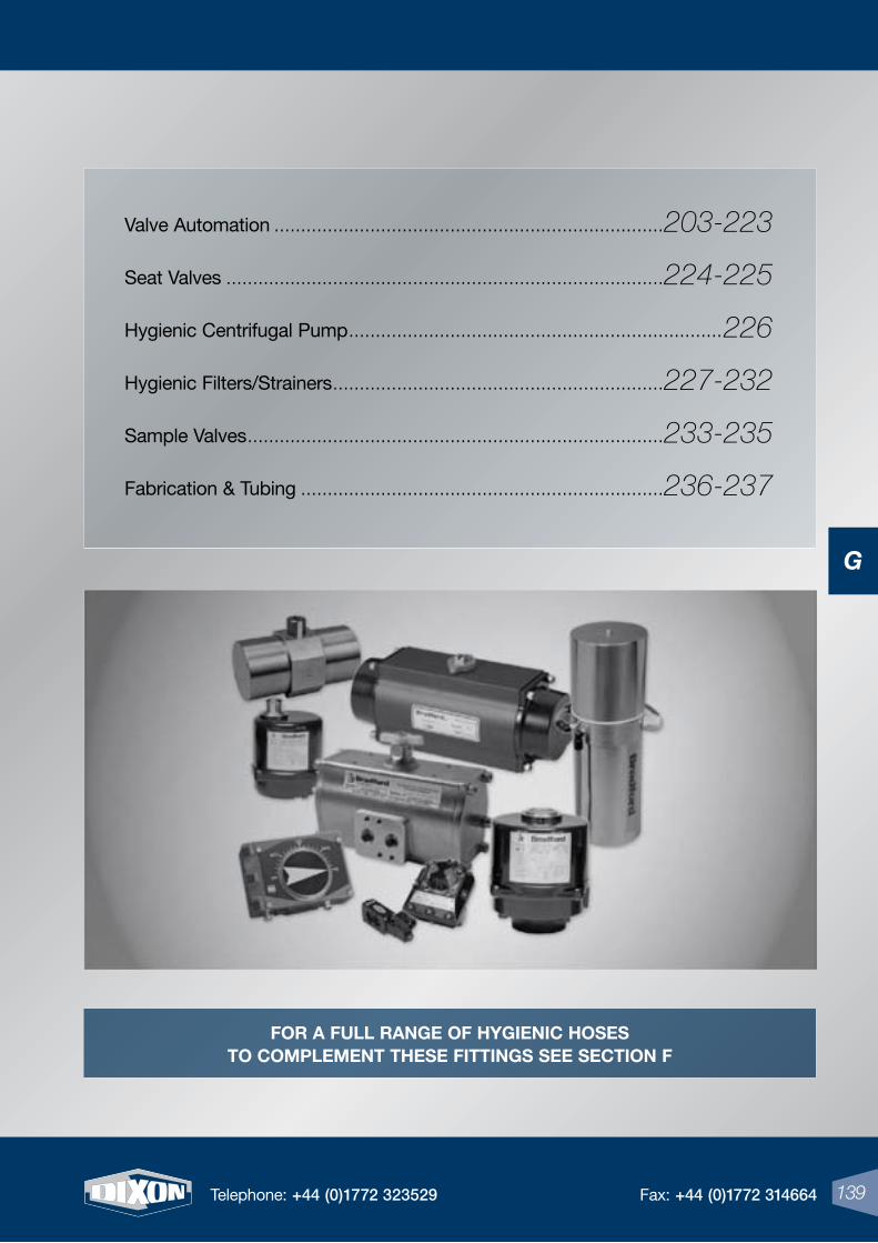
139Telephone: +44 (0)1772 323529 Fax: +44 (0)1772 314664
G
139Telephone: +44 (0)1772 323529 Fax: +44 (0)1772 314664
Valve Automation .........................................................................203-223
Seat Valves ..................................................................................224-225
Hygienic Centrifugal Pump ......................................................................226
Hygienic Filters/Strainers ..............................................................227-232
Sample Valves ..............................................................................233-235
Fabrication & Tubing ....................................................................236-237
For a Full range oF HYgIenIC Hoses to Complement tHese FIttIngs see seCtIon F
139Telephone: +44 (0)1772 323529 Fax: +44 (0)1772 314664
G
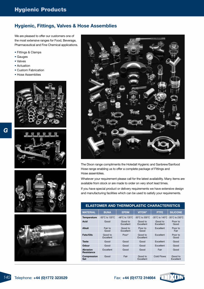
140 Telephone: +44 (0)1772 323529 Fax: +44 (0)1772 314664
Hygienic Products
G
Hygienic, Fittings, Valves & Hose assemblies
We are pleased to offer our customers one of the most extensive ranges for Food, Beverage, Pharmaceutical and Fine Chemical applications.
• Fittings & Clamps • Gauges • Valves • Actuation • Custom Fabrication • Hose Assemblies
The Dixon range compliments the Holedall Hygienic and Sanbrew/Sanfood Hose range enabling us to offer a complete package of Fittings and Hose assemblies.
Whatever your requirement please call for the latest availability. Many items are available from stock or are made to order on very short lead times.
If you have special product or delivery requirements we have extensive design and manufacturing facilities which can be used to satisfy your requirements.
materIal Buna epDm VIton® ptFe sIlICone
temperature -50°C to 120°C -48°C to 135°C -30°C to 200°C -35°C to 140°C -35°C to 230°C
acid Good Good to Good to Good to Poor to Excellent Excellent Excellent Good
alkali Fair to Good to Poor to Excellent Poor to Good Excellent Good Fair
Fats/oils Good to Poor* Good to Excellent Poor to Excellent Excellent Good
taste Good Good Good Excellent Good
odour Good Good Good Excellent Good
abrasion Excellent Good Good Fair Good resistance
Compression Good Fair Good to Cold Flows Good to set Excellent Excellent
elastomer anD tHermoplastIC CHaraCterIstICs
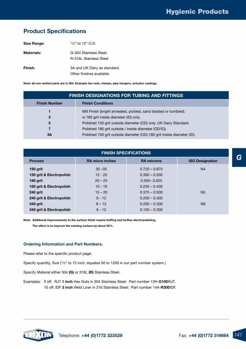
141Telephone: +44 (0)1772 323529 Fax: +44 (0)1772 314664
Hygienic Products
G
product specifications
size range: 1/2“ to 12“ O.D.
materials: G-304 Stainless Steel.
R-316L Stainless Steel.
Finish: 3A and UK Dairy as standard.
Other finishes available.
note: all non-wetted parts are in 304. example hex nuts, clamps, pipe hangers, actuator castings.
note: additional Improvements to the surface finish require buffing and further electropolishing.
the effect is to improve the existing surface by about 50%.
ordering Information and part numbers.
Please refer to the specific product page.
Specify quantity, Size (1/2” to 12 inch, equates 50 to 1200 in our part number system.)
Specify Material either 304 (g) or 316L (r) Stainless Steel.
Examples: 5 off, RJT 1 inch Hex Nuts in 304 Stainless Steel: Part number 13H-g100RJT.
10 off, IDF 3 inch Weld Liner in 316 Stainless Steel: Part number 14A-r300IDF.
FInIsH speCIFICatIons
process ra micro inches ra microns Iso Designation
150 grit 30 –35 0.720 – 0.875 N4
150 grit & electropolish 12 - 20 0.300 – 0.500
180 grit 20 – 25 0.500– 0.625
180 grit & electropolish 10 - 16 0.250 – 0.400
240 grit 15 – 20 0.375 – 0.500 N5
240 grit & electropolish 8 - 12 0.200 – 0.300
340 grit 8 – 12 0.200 – 0.300 N6
340 grit & electropolish 6 - 12 0.150 – 0.300
FInIsH DesIgnatIons For tuBIng anD FIttIngs
Finish number Finish Conditions
1 Mill Finish (bright annealed, pickled, sand blasted or tumbled).
3 w 180 grit inside diameter (ID) only.
5 Polished 150 grit outside diameter (OD) only. UK Dairy Standard.
7 Polished 180 grit outside / inside diameter (OD/ID).
3a Polished 150 grit outside diameter (OD),180 grit inside diameter (ID).
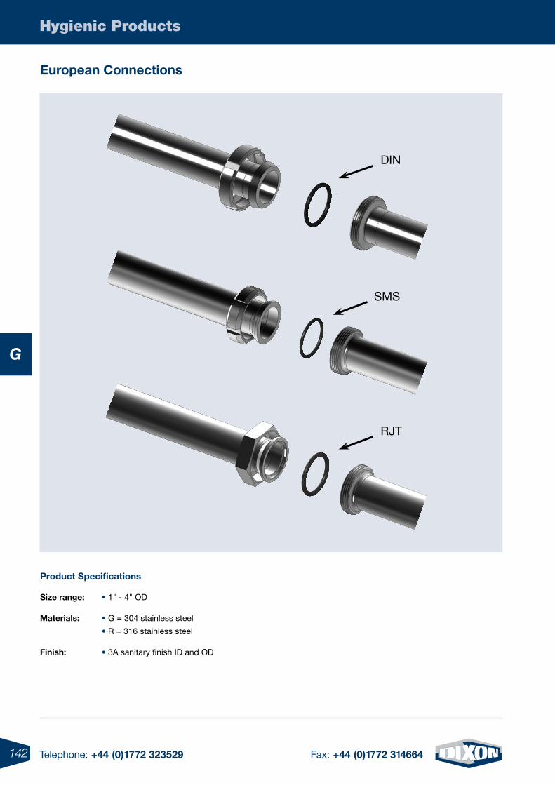
142 Telephone: +44 (0)1772 323529 Fax: +44 (0)1772 314664
Hygienic Products
G
size range: • 1" - 4" OD
materials: • G = 304 stainless steel
• R = 316 stainless steel
Finish: • 3A sanitary finish ID and OD
product specifications
DIN
SMS
RJT
european Connections
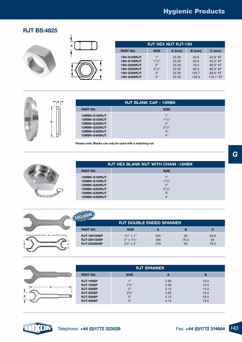
143Telephone: +44 (0)1772 323529 Fax: +44 (0)1772 314664
Hygienic Products
G
143
rJt BlanK Cap - 13rBn
part no. sIZe
13rBn-g100rJt 1” 13rBn-g150rJt 11/2” 13rBn-g200rJt 2” 13rBn-g250rJt 21/2” 13rBn-g300rJt 3” 13rBn-g400rJt 4”
rJt HeX BlanK nut WItH CHaIn -13HBn
part no. sIZe
13HBn-g100rJt 1” 13HBn-g150rJt 11/2” 13HBn-g200rJt 2” 13HBn-g250rJt 21/2” 13HBn-g300rJt 3” 13HBn-g400rJt 4”
rJt spanner
part no. sIZe a B
rJt-100sp 1” 2.00 10.5 rJt-150sp 1½” 2.56 12.0 rJt-200sp 2” 3.12 14.0 rJt-250sp 2½” 3.62 16.3 rJt-300sp 3” 4.12 18.5 rJt-400sp 4” 5.12 19.5
rJt DouBle enDeD spanner
part no. sIZe a B C
rJt-150100sp 1½” x 1” 305 65 50.8 rJt-200150sp 2” x 1½” 356 79.3 65 rJt-250200sp 2½” x 2” 419 92 79.3
rJt HeX nut rJt-13H
part no. sIZe a (mm) B (mm) C (mm)
13H-g100rJt 1” 22.20 50.8 42.6* 8T 13H-g150rJt 11/2” 22.20 65.0 55.3* 6T 13H-g200rJt 2” 22.20 79.3 68.3* 6T 13H-g250rJt 21/2” 22.20 92.0 80.9* 6T 13H-g300rJt 3” 22.20 104.7 93.6* 6T 13H-g400rJt 4” 22.20 130.0 119.1* 6T
please note: Blanks can only be used with a matching nut
A
B
rJt Bs:4825
A
B
EXCLUSIVEEXCLUSIVE
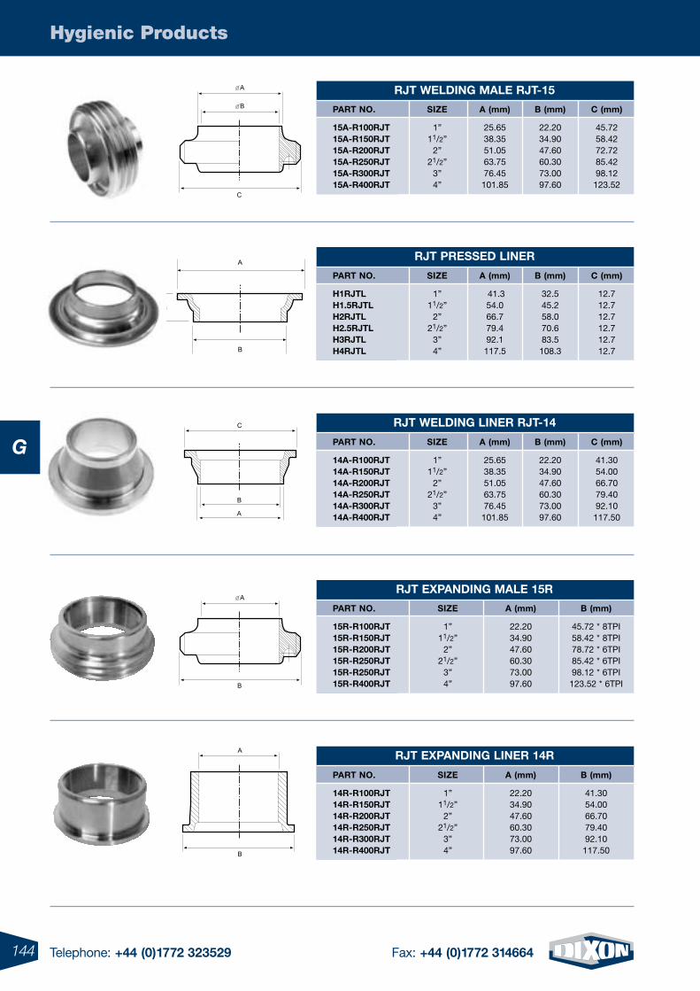
144 Telephone: +44 (0)1772 323529 Fax: +44 (0)1772 314664
Hygienic Products
GrJt WelDIng lIner rJt-14
part no. sIZe a (mm) B (mm) C (mm)
14a-r100rJt 1” 25.65 22.20 41.30 14a-r150rJt 11/2” 38.35 34.90 54.00 14a-r200rJt 2” 51.05 47.60 66.70 14a-r250rJt 21/2” 63.75 60.30 79.40 14a-r300rJt 3” 76.45 73.00 92.10 14a-r400rJt 4” 101.85 97.60 117.50
rJt presseD lIner
part no. sIZe a (mm) B (mm) C (mm)
H1rJtl 1” 41.3 32.5 12.7 H1.5rJtl 11/2” 54.0 45.2 12.7 H2rJtl 2” 66.7 58.0 12.7 H2.5rJtl 21/2” 79.4 70.6 12.7 H3rJtl 3” 92.1 83.5 12.7 H4rJtl 4” 117.5 108.3 12.7
rJt WelDIng male rJt-15
part no. sIZe a (mm) B (mm) C (mm)
15a-r100rJt 1” 25.65 22.20 45.72 15a-r150rJt 11/2” 38.35 34.90 58.42 15a-r200rJt 2” 51.05 47.60 72.72 15a-r250rJt 21/2” 63.75 60.30 85.42 15a-r300rJt 3” 76.45 73.00 98.12 15a-r400rJt 4” 101.85 97.60 123.52
rJt eXpanDIng male 15r
part no. sIZe a (mm) B (mm)
15r-r100rJt 1” 22.20 45.72 * 8TPI 15r-r150rJt 11/2” 34.90 58.42 * 8TPI 15r-r200rJt 2” 47.60 78.72 * 6TPI 15r-r250rJt 21/2” 60.30 85.42 * 6TPI 15r-r250rJt 3” 73.00 98.12 * 6TPI 15r-r400rJt 4” 97.60 123.52 * 6TPI
rJt eXpanDIng lIner 14r
part no. sIZe a (mm) B (mm)
14r-r100rJt 1” 22.20 41.30 14r-r150rJt 11/2” 34.90 54.00 14r-r200rJt 2” 47.60 66.70 14r-r250rJt 21/2” 60.30 79.40 14r-r300rJt 3” 73.00 92.10 14r-r400rJt 4” 97.60 117.50
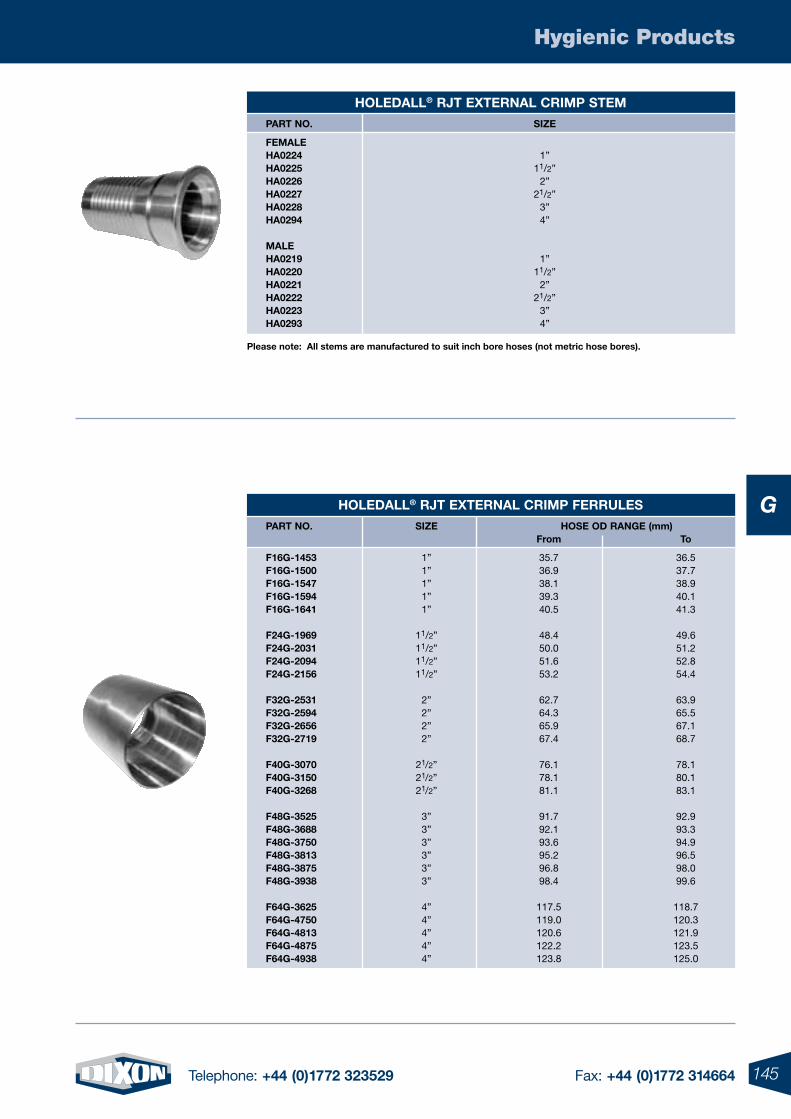
145Telephone: +44 (0)1772 323529 Fax: +44 (0)1772 314664
Hygienic Products
G
please note: all stems are manufactured to suit inch bore hoses (not metric hose bores).
HoleDall® rJt eXternal CrImp Ferrules
part no. sIZe Hose oD range (mm) From to
F16g-1453 1” 35.7 36.5 F16g-1500 1” 36.9 37.7 F16g-1547 1” 38.1 38.9 F16g-1594 1” 39.3 40.1 F16g-1641 1” 40.5 41.3
F24g-1969 11/2” 48.4 49.6 F24g-2031 11/2” 50.0 51.2 F24g-2094 11/2” 51.6 52.8 F24g-2156 11/2” 53.2 54.4
F32g-2531 2” 62.7 63.9 F32g-2594 2” 64.3 65.5 F32g-2656 2” 65.9 67.1 F32g-2719 2” 67.4 68.7
F40g-3070 21/2” 76.1 78.1 F40g-3150 21/2” 78.1 80.1 F40g-3268 21/2” 81.1 83.1
F48g-3525 3” 91.7 92.9 F48g-3688 3” 92.1 93.3 F48g-3750 3” 93.6 94.9 F48g-3813 3” 95.2 96.5 F48g-3875 3” 96.8 98.0 F48g-3938 3” 98.4 99.6
F64g-3625 4” 117.5 118.7 F64g-4750 4” 119.0 120.3 F64g-4813 4” 120.6 121.9 F64g-4875 4” 122.2 123.5 F64g-4938 4” 123.8 125.0
HoleDall® rJt eXternal CrImp stem
part no. sIZe
Female Ha0224 1” Ha0225 11/2” Ha0226 2” Ha0227 21/2” Ha0228 3” Ha0294 4”
male Ha0219 1” Ha0220 11/2” Ha0221 2” Ha0222 21/2” Ha0223 3” Ha0293 4”
146 Telephone: +44 (0)1772 323529 Fax: +44 (0)1772 314664
Hygienic Products
G
please Call For all Your otHer rJt requIrements. manY otHer parts aVaIlaBle.
rJt o-rIng / sIlICone
part no. sIZe ID oD
40mp-XW100rJt 1” 30 33.30 40mp-XW150rJt 11/2” 39.40 46.00 40mp-XW200rJt 2” 55.50 62.10 40mp-XW250rJt 21/2” 68.10 74.70 40mp-XW300rJt 3” 80.80 78.40 40mp-XW400rJt 4” 97.20 103.80
rJt o-rIng / epDm
part no. sIZe ID oD
40mp-e100rJt 1” 30 33.30 40mp-e150rJt 11/2” 39.40 46.00 40mp-e200rJt 2” 55.50 62.10 40mp-e250rJt 21/2” 68.10 74.70 40mp-e300rJt 3” 80.80 78.40 40mp-e400rJt 4” 97.20 103.80
rJt o-rIng / VIton®
part no. sIZe ID oD
40mp-sFY100rJt 1” 30 33.30 40mp-sFY150rJt 11/2” 39.40 46.00 40mp-sFY200rJt 2” 55.50 62.10 40mp-sFY250rJt 21/2” 68.10 74.70 40mp-sFY300rJt 3” 80.80 78.40 40mp-sFY400rJt 4” 97.20 103.80
rJt o-rIng / Buna
part no. sIZe ID oD
40mp-u100rJt 1” 30 33.30 40mp-u150rJt 11/2” 39.40 46.00 40mp-u200rJt 2” 55.50 62.10 40mp-u250rJt 21/2” 68.10 74.70 40mp-u300rJt 3” 80.80 78.40 40mp-u400rJt 4” 97.20 103.80
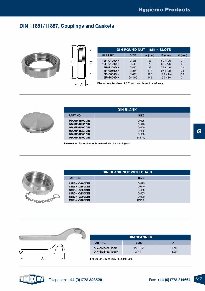
147Telephone: +44 (0)1772 323529 Fax: +44 (0)1772 314664
Hygienic Products
G
DIn BlanK
part no. sIZe
16amp-r100DIn DN25 16amp-r150DIn DN40 16amp-r200DIn DN50 16amp-r250DIn DN65 16amp-r300DIn DN80 16amp-r400DIn DN100
DIn BlanK nut WItH CHaIn
part no. sIZe
13rBn-g100DIn DN25 13rBn-g150DIn DN40 13rBn-g200DIn DN50 13rBn-g250DIn DN65 13rBn-g300DIn DN80 13rBn-g400DIn DN100
DIn spanner
part no. sIZe a
DIn-sms-60/90sp 1”- 11/2” 11.00 DIn-sms-90/155sp 2”- 4” 13.00
DIn rounD nut 11851 4 slots
part no. sIZe a (mm) B (mm) C (mm)
13r-g100DIn DN25 63 52 x 1/6 21 13r-g150DIn DN40 78 65 x 1/6 21 13r-g200DIn DN50 92 78 x 1/6 22 13r-g250DIn DN65 112 95 x 1/6 25 13r-g300DIn DN80 127 110 x 1/4 30 13r-g400DIn DN100 148 130 x 1/4 31
please note: Blanks can only be used with a matching nut.
For use on DIN or SMS Rounded Nuts.
C
A
B
A
please note: for sizes of 2.5" and over this nut has 6 slots
DIn 11851/11887, Couplings and gaskets
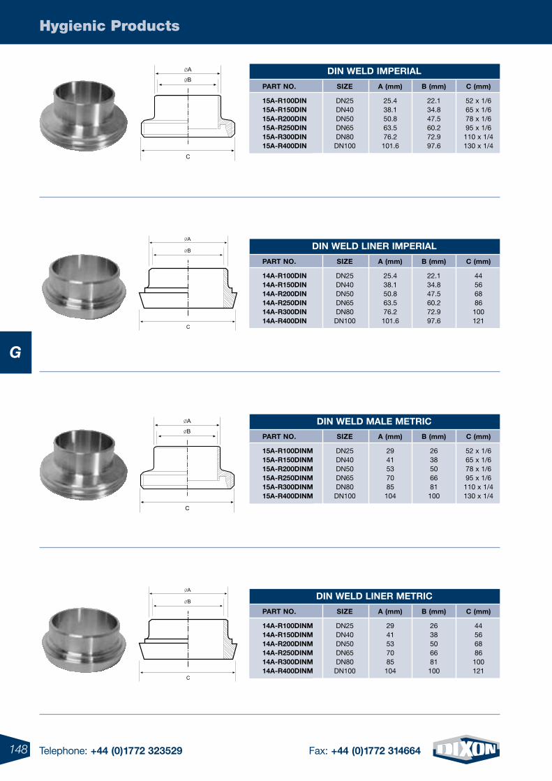
148 Telephone: +44 (0)1772 323529 Fax: +44 (0)1772 314664
Hygienic Products
G
DIn WelD ImperIal
part no. sIZe a (mm) B (mm) C (mm)
15a-r100DIn DN25 25.4 22.1 52 x 1/6 15a-r150DIn DN40 38.1 34.8 65 x 1/6 15a-r200DIn DN50 50.8 47.5 78 x 1/6 15a-r250DIn DN65 63.5 60.2 95 x 1/6 15a-r300DIn DN80 76.2 72.9 110 x 1/4 15a-r400DIn DN100 101.6 97.6 130 x 1/4
DIn WelD lIner ImperIal
part no. sIZe a (mm) B (mm) C (mm)
14a-r100DIn DN25 25.4 22.1 44 14a-r150DIn DN40 38.1 34.8 56 14a-r200DIn DN50 50.8 47.5 68 14a-r250DIn DN65 63.5 60.2 86 14a-r300DIn DN80 76.2 72.9 100 14a-r400DIn DN100 101.6 97.6 121
DIn WelD male metrIC
part no. sIZe a (mm) B (mm) C (mm)
15a-r100DInm DN25 29 26 52 x 1/6 15a-r150DInm DN40 41 38 65 x 1/6 15a-r200DInm DN50 53 50 78 x 1/6 15a-r250DInm DN65 70 66 95 x 1/6 15a-r300DInm DN80 85 81 110 x 1/4 15a-r400DInm DN100 104 100 130 x 1/4
DIn WelD lIner metrIC
part no. sIZe a (mm) B (mm) C (mm)
14a-r100DInm DN25 29 26 44 14a-r150DInm DN40 41 38 56 14a-r200DInm DN50 53 50 68 14a-r250DInm DN65 70 66 86 14a-r300DInm DN80 85 81 100 14a-r400DInm DN100 104 100 121
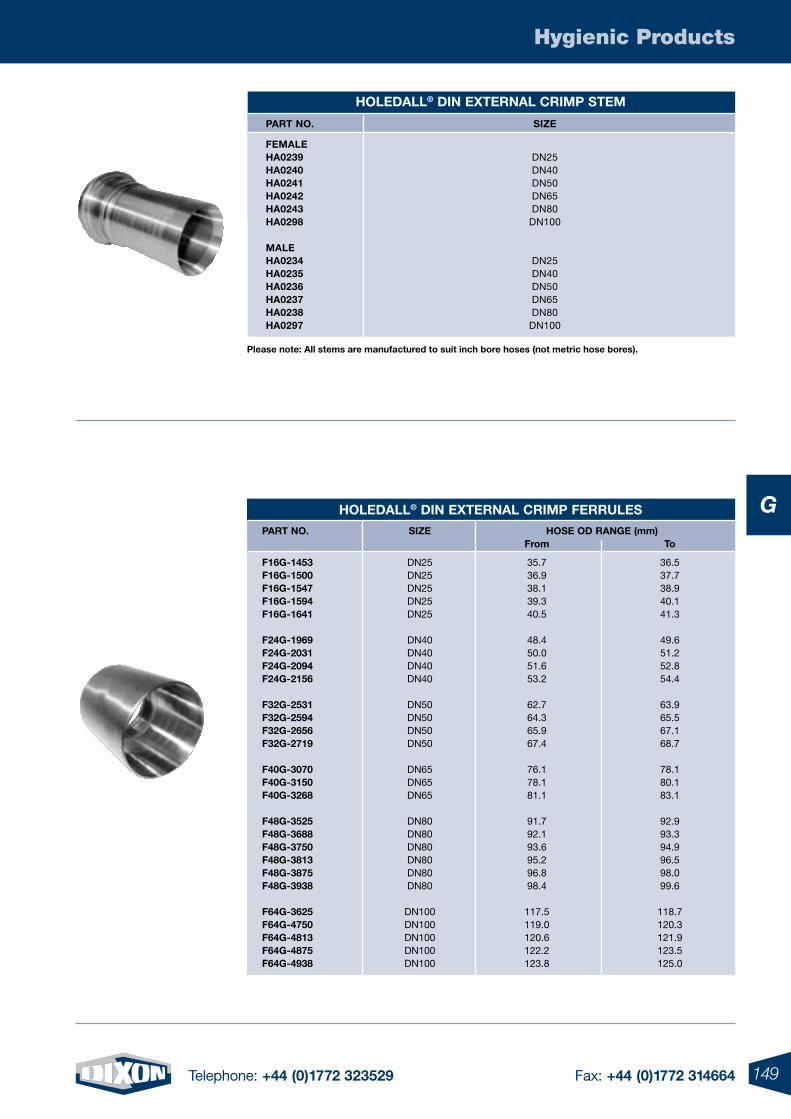
149Telephone: +44 (0)1772 323529 Fax: +44 (0)1772 314664
Hygienic Products
G
HoleDall® DIn eXternal CrImp stem
part no. sIZe
Female Ha0239 DN25 Ha0240 DN40 Ha0241 DN50 Ha0242 DN65 Ha0243 DN80 Ha0298 DN100
male Ha0234 DN25 Ha0235 DN40 Ha0236 DN50 Ha0237 DN65 Ha0238 DN80 Ha0297 DN100
HoleDall® DIn eXternal CrImp Ferrules
part no. sIZe Hose oD range (mm) From to
F16g-1453 DN25 35.7 36.5 F16g-1500 DN25 36.9 37.7 F16g-1547 DN25 38.1 38.9 F16g-1594 DN25 39.3 40.1 F16g-1641 DN25 40.5 41.3
F24g-1969 DN40 48.4 49.6 F24g-2031 DN40 50.0 51.2 F24g-2094 DN40 51.6 52.8 F24g-2156 DN40 53.2 54.4
F32g-2531 DN50 62.7 63.9 F32g-2594 DN50 64.3 65.5 F32g-2656 DN50 65.9 67.1 F32g-2719 DN50 67.4 68.7
F40g-3070 DN65 76.1 78.1 F40g-3150 DN65 78.1 80.1 F40g-3268 DN65 81.1 83.1
F48g-3525 DN80 91.7 92.9 F48g-3688 DN80 92.1 93.3 F48g-3750 DN80 93.6 94.9 F48g-3813 DN80 95.2 96.5 F48g-3875 DN80 96.8 98.0 F48g-3938 DN80 98.4 99.6
F64g-3625 DN100 117.5 118.7 F64g-4750 DN100 119.0 120.3 F64g-4813 DN100 120.6 121.9 F64g-4875 DN100 122.2 123.5 F64g-4938 DN100 123.8 125.0
please note: all stems are manufactured to suit inch bore hoses (not metric hose bores).
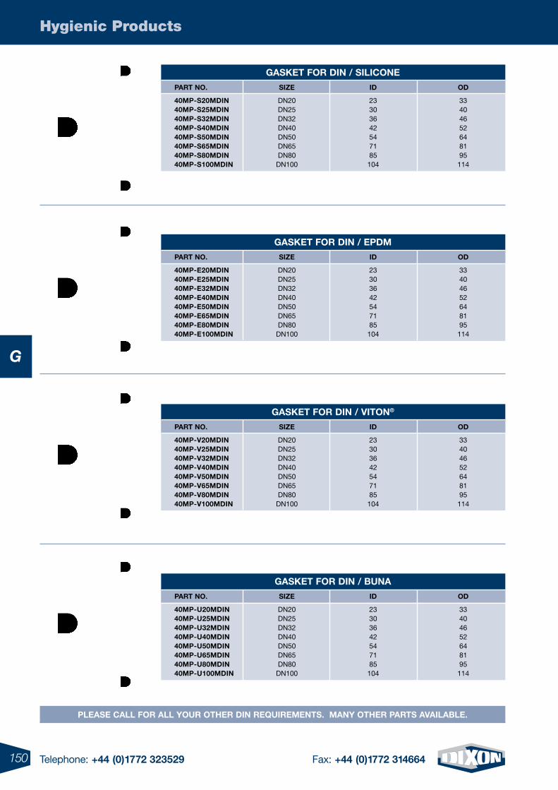
150 Telephone: +44 (0)1772 323529 Fax: +44 (0)1772 314664
Hygienic Products
G
please Call For all Your otHer DIn requIrements. manY otHer parts aVaIlaBle.
gasKet For DIn / sIlICone
part no. sIZe ID oD
40mp-s20mDIn DN20 23 33 40mp-s25mDIn DN25 30 40 40mp-s32mDIn DN32 36 46 40mp-s40mDIn DN40 42 52 40mp-s50mDIn DN50 54 64 40mp-s65mDIn DN65 71 81 40mp-s80mDIn DN80 85 95 40mp-s100mDIn DN100 104 114
gasKet For DIn / epDm
part no. sIZe ID oD
40mp-e20mDIn DN20 23 33 40mp-e25mDIn DN25 30 40 40mp-e32mDIn DN32 36 46 40mp-e40mDIn DN40 42 52 40mp-e50mDIn DN50 54 64 40mp-e65mDIn DN65 71 81 40mp-e80mDIn DN80 85 95 40mp-e100mDIn DN100 104 114
gasKet For DIn / VIton®
part no. sIZe ID oD
40mp-V20mDIn DN20 23 33 40mp-V25mDIn DN25 30 40 40mp-V32mDIn DN32 36 46 40mp-V40mDIn DN40 42 52 40mp-V50mDIn DN50 54 64 40mp-V65mDIn DN65 71 81 40mp-V80mDIn DN80 85 95 40mp-V100mDIn DN100 104 114
gasKet For DIn / Buna
part no. sIZe ID oD
40mp-u20mDIn DN20 23 33 40mp-u25mDIn DN25 30 40 40mp-u32mDIn DN32 36 46 40mp-u40mDIn DN40 42 52 40mp-u50mDIn DN50 54 64 40mp-u65mDIn DN65 71 81 40mp-u80mDIn DN80 85 95 40mp-u100mDIn DN100 104 114
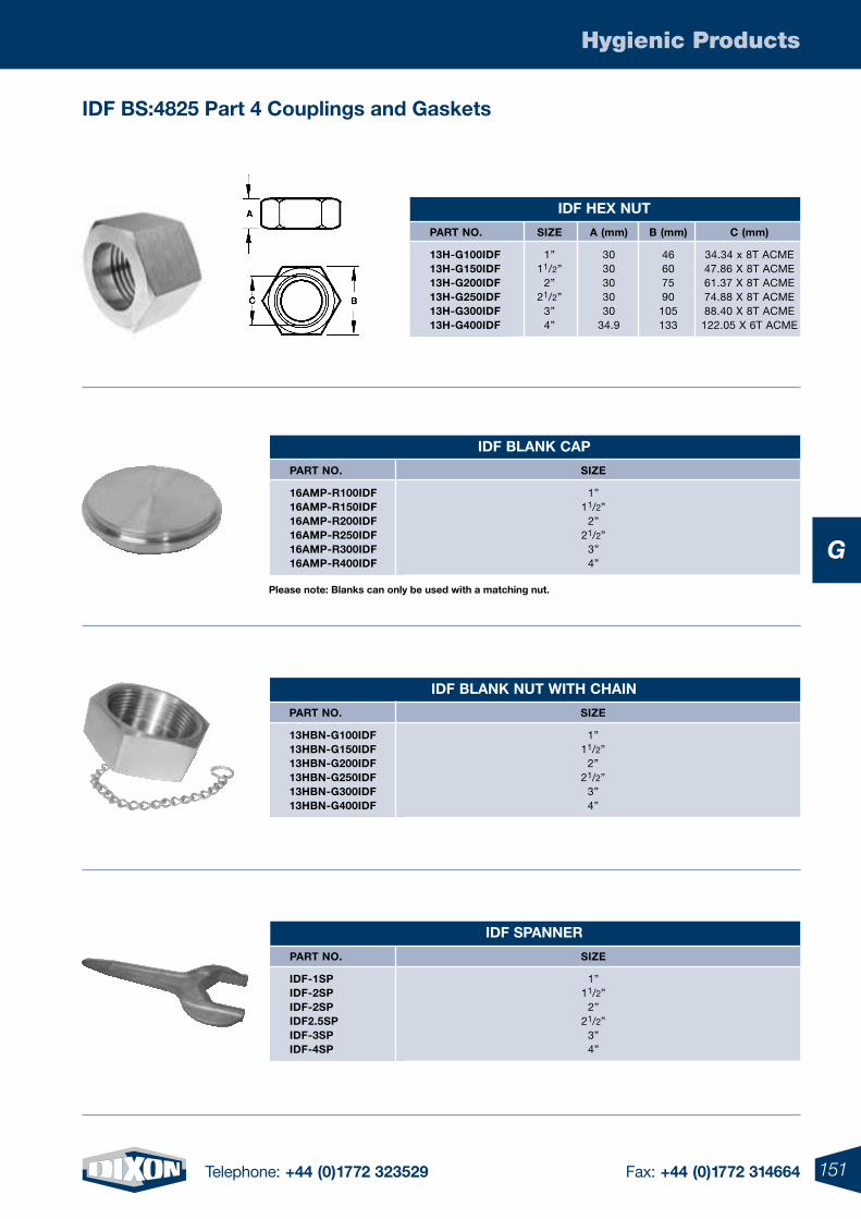
151Telephone: +44 (0)1772 323529 Fax: +44 (0)1772 314664
Hygienic Products
G
IDF Bs:4825 part 4 Couplings and gaskets
IDF BlanK Cap
part no. sIZe
16amp-r100IDF 1” 16amp-r150IDF 11/2” 16amp-r200IDF 2” 16amp-r250IDF 21/2” 16amp-r300IDF 3” 16amp-r400IDF 4”
IDF BlanK nut WItH CHaIn
part no. sIZe
13HBn-g100IDF 1” 13HBn-g150IDF 11/2” 13HBn-g200IDF 2” 13HBn-g250IDF 21/2” 13HBn-g300IDF 3” 13HBn-g400IDF 4”
IDF spanner
part no. sIZe
IDF-1sp 1” IDF-2sp 11/2” IDF-2sp 2” IDF2.5sp 21/2” IDF-3sp 3” IDF-4sp 4”
IDF HeX nut
part no. sIZe a (mm) B (mm) C (mm)
13H-g100IDF 1” 30 46 34.34 x 8T ACME 13H-g150IDF 11/2” 30 60 47.86 X 8T ACME 13H-g200IDF 2” 30 75 61.37 X 8T ACME 13H-g250IDF 21/2” 30 90 74.88 X 8T ACME 13H-g300IDF 3” 30 105 88.40 X 8T ACME 13H-g400IDF 4” 34.9 133 122.05 X 6T ACME
please note: Blanks can only be used with a matching nut.
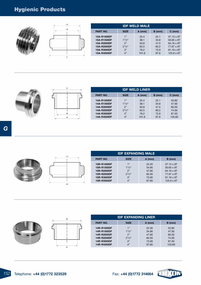
152 Telephone: +44 (0)1772 323529 Fax: +44 (0)1772 314664
Hygienic Products
G
IDF WelD lIner
part no. sIZe a (mm) B (mm) C (mm)
14a-r100IDF 1” 25.4 22.1 33.80 14a-r150IDF 11/2” 38.1 34.8 47.00 14a-r200IDF 2” 50.8 47.5 60.50 14a-r250IDF 21/2” 63.5 60.2 74.00 14a-r300IDF 3” 76.2 72.9 87.50 14a-r400IDF 4” 101.6 97.6 120.60
IDF WelD male
part no. sIZe a (mm) B (mm) C (mm)
15a-r100IDF 1” 25.4 22.1 37.13 x 8T 15a-r150IDF 11/2” 38.1 34.8 50.65 x 8T 15a-r200IDF 2” 50.8 47.5 64.16 x 8T 15a-r250IDF 21/2” 63.5 60.2 77.67 x 8T 15a-r300IDF 3” 76.2 72.9 91.19 x 8T 15a-r400IDF 4” 101.6 97.6 125.9 x 6T
IDF eXpanDIng lIner
part no. sIZe a (mm) B (mm)
14r-r100IDF 1” 22.30 33.80 14r-r150IDF 11/2” 34.90 47.00 14r-r200IDF 2” 47.60 60.50 14r-r250IDF 21/2” 60.30 74.00 14r-r300IDF 3” 73.00 87.50 14r-r400IDF 4” 97.60 120.60
IDF eXpanDIng male
part no. sIZe a (mm) B (mm)
15r-r100IDF 1” 22.20 37.13 x 8T 15r-r150IDF 11/2” 34.90 50.65 x 8T 15r-r200IDF 2” 47.60 64.16 x 8T 15r-r250IDF 21/2” 60.30 77.67 x 8T 15r-r300IDF 3” 73.00 91.19 x 8T 15r-r350IDF 4” 97.60 125.9 x 6T

153Telephone: +44 (0)1772 323529 Fax: +44 (0)1772 314664
Hygienic Products
G
HoleDall® IDF eXternal CrImp stem
part no. sIZe
Female Ha0628 1” Ha0629 11/2” Ha0630 2” Ha0631 21/2” Ha0632 3” Ha0633 4”
male Ha0634 1” Ha0635 1º” Ha0636 2” Ha0637 21/2” Ha0638 3” Ha0639 4”
HoleDall® IDF eXternal CrImp Ferrules
part no. sIZe Hose oD range (mm) From to
F16g-1453 1” 35.7 36.5 F16g-1500 1” 36.9 37.7 F16g-1547 1” 38.1 38.9 F16g-1594 1” 39.3 40.1 F16g-1641 1” 40.5 41.3
F24g-1969 11/2” 48.4 49.6 F24g-2031 11/2” 50.0 51.2 F24g-2094 11/2” 51.6 52.8 F24g-2156 11/2” 53.2 54.4
F32g-2531 2” 62.7 63.9 F32g-2594 2” 64.3 65.5 F32g-2656 2” 65.9 67.1 F32g-2719 2” 67.4 68.7
F40g-3070 21/2” 76.1 78.1 F40g-3150 21/2” 78.1 80.1 F40g-3268 21/2” 81.1 83.1
F48g-3525 3” 91.7 92.9 F48g-3688 3” 92.1 93.3 F48g-3750 3” 93.6 94.9 F48g-3813 3” 95.2 96.5 F48g-3875 3” 96.8 98.0 F48g-3938 3” 98.4 99.6
F64g-3625 4” 117.5 118.7 F64g-4750 4” 119.0 120.3 F64g-4813 4” 120.6 121.9 F64g-4875 4” 122.2 123.5 F64g-4938 4” 123.8 125.0
please note: all stems are manufactured to suit inch bore hoses (not metric hose bores).
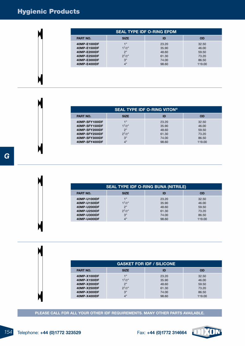
154 Telephone: +44 (0)1772 323529 Fax: +44 (0)1772 314664
Hygienic Products
G
please Call For all Your otHer IDF requIrements. manY otHer parts aVaIlaBle.
seal tYpe IDF o-rIng epDm
part no. sIZe ID oD
40mp-e100IDF 1” 23.20 32.50 40mp-e150IDF 11/2” 35.90 46.00 40mp-e200IDF 2” 48.60 59.50 40mp-e250IDF 21/2” 61.30 73.20 40mp-e300IDF 3” 74.00 86.50 40mp-e400IDF 4” 98.60 119.00
seal tYpe IDF o-rIng VIton®
part no. sIZe ID oD
40mp-sFY100IDF 1” 23.20 32.50 40mp-sFY150IDF 11/2” 35.90 46.00 40mp-sFY200IDF 2” 48.60 59.50 40mp-sFY250IDF 21/2” 61.30 73.20 40mp-sFY300IDF 3” 74.00 86.50 40mp-sFY400IDF 4” 98.60 119.00
seal tYpe IDF o-rIng Buna (nItrIle)
part no. sIZe ID oD
40mp-u100IDF 1” 23.20 32.50 40mp-u150IDF 11/2” 35.90 46.00 40mp-u200IDF 2” 48.60 59.50 40mp-u250IDF 21/2” 61.30 73.20 40mp-u300IDF 3” 74.00 86.50 40mp-u400IDF 4” 98.60 119.00
gasKet For IDF / sIlICone
part no. sIZe ID oD
40mp-X100IDF 1” 23.20 32.50 40mp-X150IDF 11/2” 35.90 46.00 40mp-X200IDF 2” 48.60 59.50 40mp-X250IDF 21/2” 61.30 73.20 40mp-X300IDF 3” 74.00 86.50 40mp-X400IDF 4” 98.60 119.00
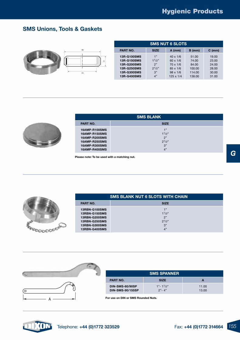
155Telephone: +44 (0)1772 323529 Fax: +44 (0)1772 314664
Hygienic Products
G
sms BlanK
part no. sIZe
16amp-r100sms 1” 16amp-r150sms 11/2” 16amp-r200sms 2” 16amp-r250sms 21/2” 16amp-r300sms 3” 16amp-r400sms 4”
sms BlanK nut 6 slots WItH CHaIn
part no. sIZe
13rBn-g100sms 1” 13rBn-g150sms 11/2” 13rBn-g200sms 2” 13rBn-g250sms 21/2” 13rBn-g300sms 3” 13rBn-g400sms 4”
sms nut 6 slots
part no. sIZe a (mm) B (mm) C (mm)
13r-g100sms 1” 40 x 1/6 51.00 19.00 13r-g150sms 11/2” 60 x 1/6 74.00 23.00 13r-g200sms 2” 70 x 1/6 84.00 24.00 13r-g250sms 21/2” 85 x 1/6 100.00 28.00 13r-g300sms 3” 98 x 1/6 114.00 30.00 13r-g400sms 4” 125 x 1/4 138.00 31.00
please note: to be used with a matching nut.
sms spanner
part no. sIZe a
DIn-sms-60/90sp 1”- 11/2” 11.00 DIn-sms-90/155sp 2”- 4” 13.00
sms unions, tools & gaskets
For use on DIn or sms rounded nuts.A
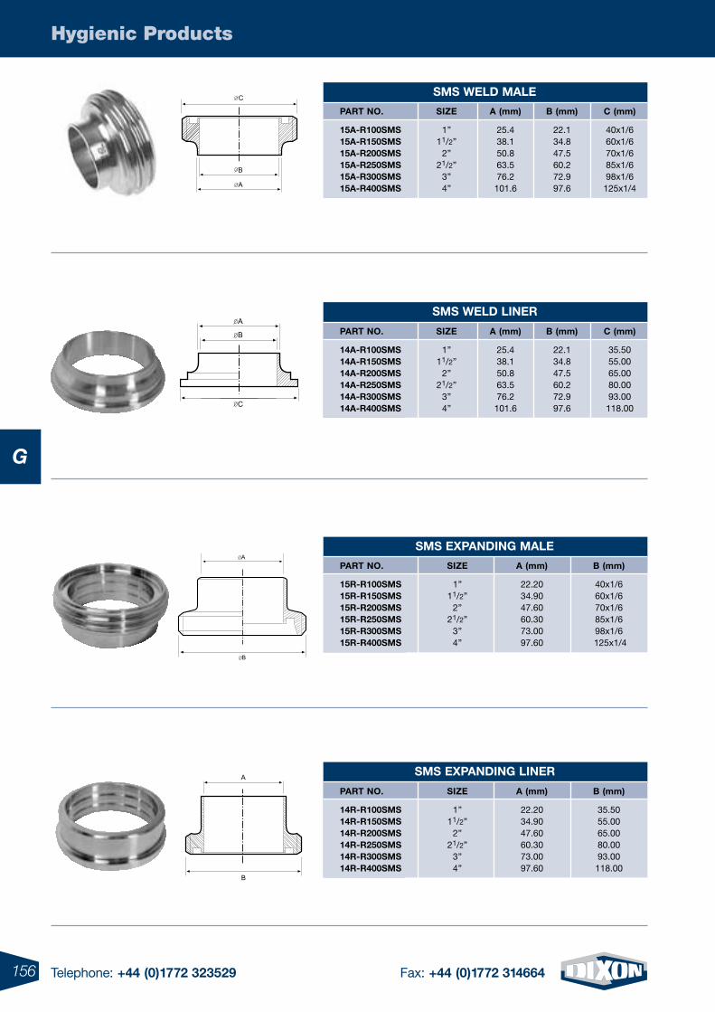
156 Telephone: +44 (0)1772 323529 Fax: +44 (0)1772 314664
Hygienic Products
G
sms WelD lIner
part no. sIZe a (mm) B (mm) C (mm)
14a-r100sms 1” 25.4 22.1 35.50 14a-r150sms 11/2” 38.1 34.8 55.00 14a-r200sms 2” 50.8 47.5 65.00 14a-r250sms 21/2” 63.5 60.2 80.00 14a-r300sms 3” 76.2 72.9 93.00 14a-r400sms 4” 101.6 97.6 118.00
sms WelD male
part no. sIZe a (mm) B (mm) C (mm)
15a-r100sms 1” 25.4 22.1 40x1/6 15a-r150sms 11/2” 38.1 34.8 60x1/6 15a-r200sms 2” 50.8 47.5 70x1/6 15a-r250sms 21/2” 63.5 60.2 85x1/6 15a-r300sms 3” 76.2 72.9 98x1/6 15a-r400sms 4” 101.6 97.6 125x1/4
sms eXpanDIng lIner
part no. sIZe a (mm) B (mm)
14r-r100sms 1” 22.20 35.50 14r-r150sms 11/2” 34.90 55.00 14r-r200sms 2” 47.60 65.00 14r-r250sms 21/2” 60.30 80.00 14r-r300sms 3” 73.00 93.00 14r-r400sms 4” 97.60 118.00
sms eXpanDIng male
part no. sIZe a (mm) B (mm)
15r-r100sms 1” 22.20 40x1/6 15r-r150sms 11/2” 34.90 60x1/6 15r-r200sms 2” 47.60 70x1/6 15r-r250sms 21/2” 60.30 85x1/6 15r-r300sms 3” 73.00 98x1/6 15r-r400sms 4” 97.60 125x1/4
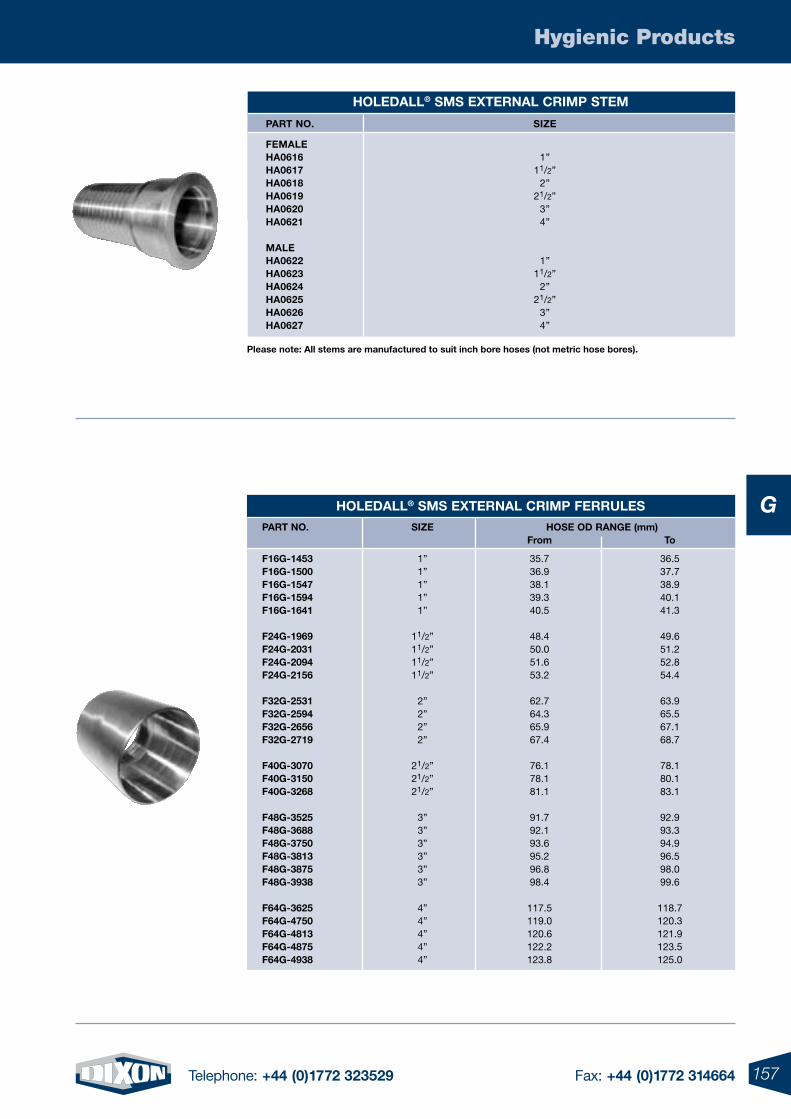
157Telephone: +44 (0)1772 323529 Fax: +44 (0)1772 314664
Hygienic Products
G
HoleDall® sms eXternal CrImp stem
part no. sIZe
Female Ha0616 1” Ha0617 11/2” Ha0618 2” Ha0619 21/2” Ha0620 3” Ha0621 4”
male Ha0622 1” Ha0623 11/2” Ha0624 2” Ha0625 21/2” Ha0626 3” Ha0627 4”
HoleDall® sms eXternal CrImp Ferrules
part no. sIZe Hose oD range (mm) From to
F16g-1453 1” 35.7 36.5 F16g-1500 1” 36.9 37.7 F16g-1547 1” 38.1 38.9 F16g-1594 1” 39.3 40.1 F16g-1641 1” 40.5 41.3
F24g-1969 11/2” 48.4 49.6 F24g-2031 11/2” 50.0 51.2 F24g-2094 11/2” 51.6 52.8 F24g-2156 11/2” 53.2 54.4
F32g-2531 2” 62.7 63.9 F32g-2594 2” 64.3 65.5 F32g-2656 2” 65.9 67.1 F32g-2719 2” 67.4 68.7
F40g-3070 21/2” 76.1 78.1 F40g-3150 21/2” 78.1 80.1 F40g-3268 21/2” 81.1 83.1
F48g-3525 3” 91.7 92.9 F48g-3688 3” 92.1 93.3 F48g-3750 3” 93.6 94.9 F48g-3813 3” 95.2 96.5 F48g-3875 3” 96.8 98.0 F48g-3938 3” 98.4 99.6
F64g-3625 4” 117.5 118.7 F64g-4750 4” 119.0 120.3 F64g-4813 4” 120.6 121.9 F64g-4875 4” 122.2 123.5 F64g-4938 4” 123.8 125.0
please note: all stems are manufactured to suit inch bore hoses (not metric hose bores).
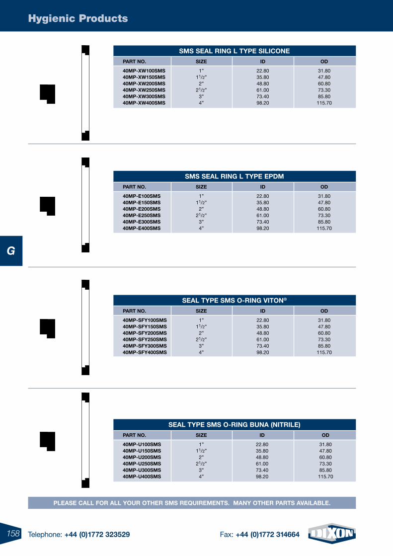
158 Telephone: +44 (0)1772 323529 Fax: +44 (0)1772 314664
Hygienic Products
G
please Call For all Your otHer sms requIrements. manY otHer parts aVaIlaBle.
sms seal rIng l tYpe sIlICone
part no. sIZe ID oD
40mp-XW100sms 1” 22.80 31.80 40mp-XW150sms 11/2” 35.80 47.80 40mp-XW200sms 2” 48.80 60.80 40mp-XW250sms 21/2” 61.00 73.30 40mp-XW300sms 3” 73.40 85.80 40mp-XW400sms 4” 98.20 115.70
sms seal rIng l tYpe epDm
part no. sIZe ID oD
40mp-e100sms 1” 22.80 31.80 40mp-e150sms 11/2” 35.80 47.80 40mp-e200sms 2” 48.80 60.80 40mp-e250sms 21/2” 61.00 73.30 40mp-e300sms 3” 73.40 85.80 40mp-e400sms 4” 98.20 115.70
seal tYpe sms o-rIng VIton®
part no. sIZe ID oD
40mp-sFY100sms 1” 22.80 31.80 40mp-sFY150sms 11/2” 35.80 47.80 40mp-sFY200sms 2” 48.80 60.80 40mp-sFY250sms 21/2” 61.00 73.30 40mp-sFY300sms 3” 73.40 85.80 40mp-sFY400sms 4” 98.20 115.70
seal tYpe sms o-rIng Buna (nItrIle)
part no. sIZe ID oD
40mp-u100sms 1” 22.80 31.80 40mp-u150sms 11/2” 35.80 47.80 40mp-u200sms 2” 48.80 60.80 40mp-u250sms 21/2” 61.00 73.30 40mp-u300sms 3” 73.40 85.80 40mp-u400sms 4” 98.20 115.70
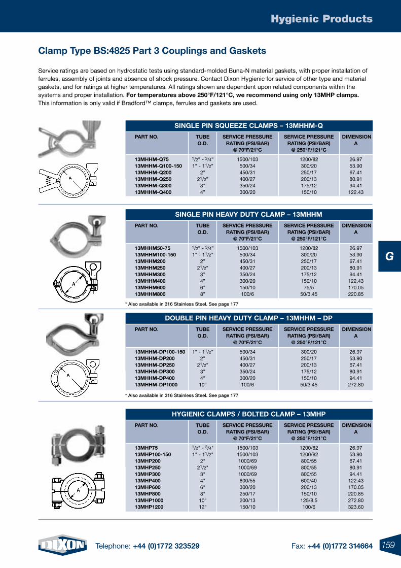
159Telephone: +44 (0)1772 323529 Fax: +44 (0)1772 314664
Hygienic Products
G
Clamp type Bs:4825 part 3 Couplings and gaskets
Service ratings are based on hydrostatic tests using standard-molded Buna-N material gaskets, with proper installation of ferrules, assembly of joints and absence of shock pressure. Contact Dixon Hygienic for service of other type and material gaskets, and for ratings at higher temperatures. All ratings shown are dependent upon related components within the systems and proper installation. For temperatures above 250°F/121°C, we recommend using only 13mHp clamps. This information is only valid if Bradford™ clamps, ferrules and gaskets are used.
sIngle pIn squeeZe Clamps – 13mHHm-q
part no.
13mHHm-q75 13mHHm-q100-150 13mHHm-q200 13mHHm-q250 13mHHm-q300 13mHHm-q400
tuBe o.D.
1/2” - 3/4”1” - 11/2”
2”21/2”
3”4”
DImensIon a
26.9753.9067.4180.9194.41
122.43
serVICe pressure ratIng (psI/Bar)
@ 250°F/121°C
1200/82300/20250/17200/13175/12150/10
serVICe pressure ratIng (psI/Bar)
@ 70°F/21°C
1500/103 500/34 450/31 400/27 350/24 300/20
sIngle pIn HeaVY DutY Clamp – 13mHHm
part no.
13mHHm50-75 13mHHm100-150 13mHHm200 13mHHm250 13mHHm300 13mHHm400 13mHHm600 13mHHm800
tuBe o.D.
1/2” - 3/4”1” - 11/2”
2”21/2”
3”4”6”8”
DImensIon a
26.9753.9067.4180.9194.41
122.43170.05220.85
serVICe pressure ratIng (psI/Bar)
@ 250°F/121°C
1200/82300/20250/17200/13175/12150/10
75/550/3.45
serVICe pressure ratIng (psI/Bar)
@ 70°F/21°C
1500/103 500/34 450/31 400/27 350/24 300/20 150/10 100/6
DouBle pIn HeaVY DutY Clamp – 13mHHm – Dp
part no.
13mHHm-Dp100-150 13mHHm-Dp200 13mHHm-Dp250 13mHHm-Dp300 13mHHm-Dp400 13mHHm-Dp1000
tuBe o.D.
1” - 11/2”
2”21/2”
3”4”10”
DImensIon a
26.9753.9067.4180.9194.41
272.80
serVICe pressure ratIng (psI/Bar)
@ 250°F/121°C
300/20250/17200/13175/12150/1050/3.45
serVICe pressure ratIng (psI/Bar)
@ 70°F/21°C
500/34 450/31 400/27 350/24 300/20 100/6
HYgIenIC Clamps / BolteD Clamp – 13mHp
part no.
13mHp75 13mHp100-150 13mHp200 13mHp250 13mHp300 13mHp400 13mHp600 13mHp800 13mHp1000 13mHp1200
tuBe o.D.
1/2" - 3/4"1" - 11/2"
2" 21/2"
3" 4" 6" 8" 10" 12"
DImensIon a
26.9753.9067.4180.9194.41
122.43170.05220.85272.80323.60
serVICe pressure ratIng (psI/Bar)
@ 250°F/121°C
1200/821200/82800/55800/55800/55600/40200/13150/10125/8.5100/6
serVICe pressure ratIng (psI/Bar)
@ 70°F/21°C
1500/1031500/1031000/691000/691000/69800/55300/20250/17200/13150/10
* Also available in 316 Stainless Steel. See page 177
* Also available in 316 Stainless Steel. See page 177
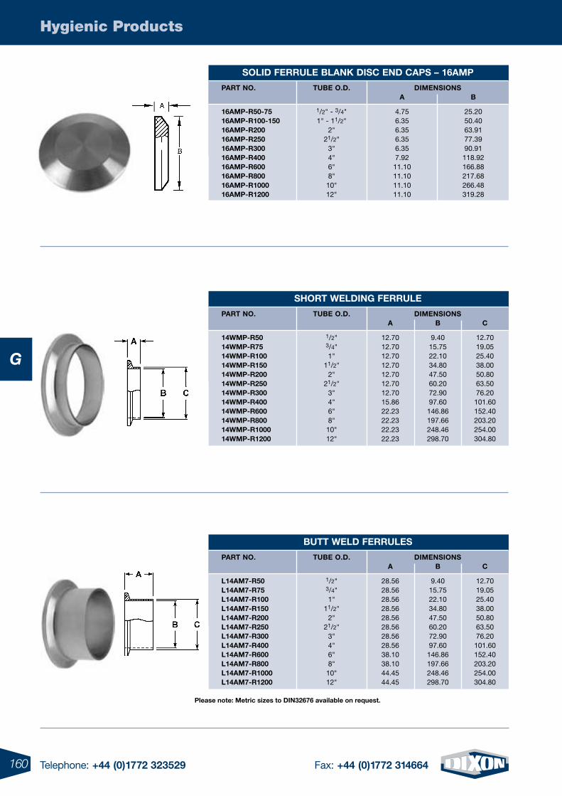
160 Telephone: +44 (0)1772 323529 Fax: +44 (0)1772 314664
Hygienic Products
G
solID Ferrule BlanK DIsC enD Caps – 16amp
part no.
16amp-r50-75 16amp-r100-150 16amp-r200 16amp-r250 16amp-r300 16amp-r400 16amp-r600 16amp-r800 16amp-r1000 16amp-r1200
tuBe o.D.
1/2" - 3/4" 1" - 11/2"
2" 21/2"
3" 4" 6" 8" 10" 12"
a
4.756.356.356.356.357.9211.1011.1011.1011.10
B
25.2050.4063.9177.3990.91118.92166.88217.68266.48319.28
DImensIons
sHort WelDIng Ferrule
DImensIons part no.
14Wmp-r50 14Wmp-r75 14Wmp-r100 14Wmp-r150 14Wmp-r200 14Wmp-r250 14Wmp-r300 14Wmp-r400 14Wmp-r600 14Wmp-r800 14Wmp-r1000 14Wmp-r1200
tuBe o.D.
1/2" 3/4" 1"
11/2" 2"
21/2" 3" 4" 6" 8" 10" 12"
a
12.7012.7012.7012.7012.7012.7012.7015.8622.2322.2322.2322.23
B
9.4015.7522.1034.8047.5060.2072.9097.60146.86197.66248.46298.70
C
12.7019.0525.4038.0050.8063.5076.20101.60152.40203.20254.00304.80
Butt WelD Ferrules
DImensIons part no.
l14am7-r50 l14am7-r75 l14am7-r100 l14am7-r150 l14am7-r200 l14am7-r250 l14am7-r300 l14am7-r400 l14am7-r600 l14am7-r800 l14am7-r1000 l14am7-r1200
tuBe o.D.
1/2"3/4" 1"
11/2" 2"
21/2" 3" 4" 6" 8" 10" 12"
a
28.5628.5628.5628.5628.5628.5628.5628.5638.1038.1044.4544.45
B
9.4015.7522.1034.8047.5060.2072.9097.60146.86197.66248.46298.70
C
12.7019.0525.4038.0050.8063.5076.20101.60152.40203.20254.00304.80
please note: metric sizes to DIn32676 available on request.
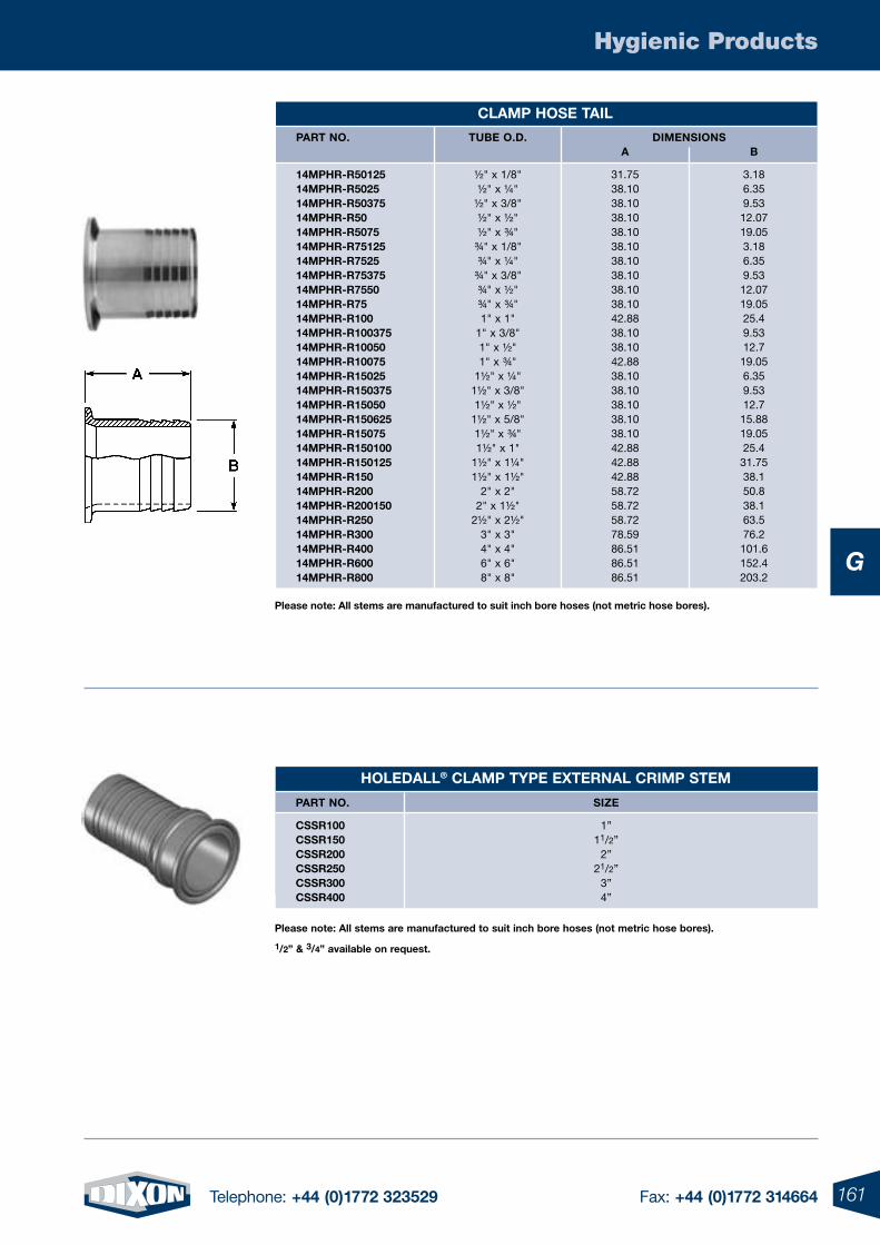
161Telephone: +44 (0)1772 323529 Fax: +44 (0)1772 314664
Hygienic Products
G
HoleDall® Clamp tYpe eXternal CrImp stem
part no. sIZe
Cssr100 1” Cssr150 11/2” Cssr200 2” Cssr250 21/2” Cssr300 3” Cssr400 4”
please note: all stems are manufactured to suit inch bore hoses (not metric hose bores).
1/2” & 3/4” available on request.
please note: all stems are manufactured to suit inch bore hoses (not metric hose bores).
Clamp Hose taIl
DImensIons part no.
14mpHr-r50125 14mpHr-r5025 14mpHr-r50375 14mpHr-r50 14mpHr-r5075 14mpHr-r75125 14mpHr-r7525 14mpHr-r75375 14mpHr-r7550 14mpHr-r75 14mpHr-r100 14mpHr-r100375 14mpHr-r10050 14mpHr-r10075 14mpHr-r15025 14mpHr-r150375 14mpHr-r15050 14mpHr-r150625 14mpHr-r15075 14mpHr-r150100 14mpHr-r150125 14mpHr-r150 14mpHr-r200 14mpHr-r200150 14mpHr-r250 14mpHr-r300 14mpHr-r400 14mpHr-r600 14mpHr-r800
tuBe o.D.
½" x 1/8"½" x ¼"
½" x 3/8" ½" x ½" ½" x ¾"
¾" x 1/8"¾" x ¼"
¾" x 3/8" ¾" x ½" ¾" x ¾" 1" x 1"
1" x 3/8" 1" x ½" 1" x ¾"
1½" x ¼" 1½" x 3/8" 1½" x ½"
1½" x 5/8" 1½" x ¾" 1½" x 1"
1½" x 1¼" 1½" x 1½"
2" x 2" 2" x 1½"
2½" x 2½" 3" x 3" 4" x 4"6" x 6"8" x 8"
a
31.7538.1038.1038.1038.1038.1038.1038.1038.1038.1042.8838.1038.1042.8838.1038.1038.1038.1038.1042.8842.8842.8858.7258.7258.7278.5986.5186.5186.51
B
3.186.359.5312.0719.053.186.359.5312.0719.0525.49.5312.719.056.359.5312.715.8819.0525.431.7538.150.838.163.576.2101.6152.4203.2
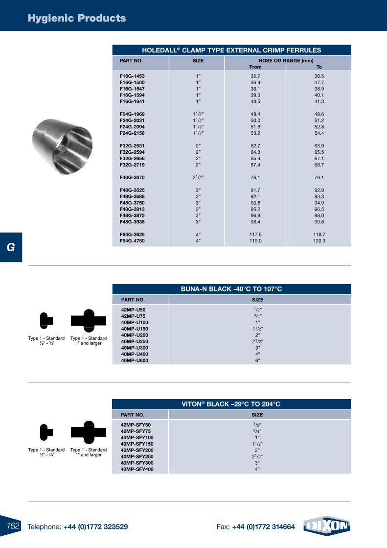
162 Telephone: +44 (0)1772 323529 Fax: +44 (0)1772 314664
Hygienic Products
G
HoleDall® Clamp tYpe eXternal CrImp Ferrules
part no. sIZe Hose oD range (mm) From to
F16g-1453 1” 35.7 36.5 F16g-1500 1” 36.9 37.7 F16g-1547 1” 38.1 38.9 F16g-1594 1” 39.3 40.1 F16g-1641 1” 40.5 41.3
F24g-1969 11/2” 48.4 49.6 F24g-2031 11/2” 50.0 51.2 F24g-2094 11/2” 51.6 52.8 F24g-2156 11/2” 53.2 54.4
F32g-2531 2” 62.7 63.9 F32g-2594 2” 64.3 65.5 F32g-2656 2” 65.9 67.1 F32g-2719 2” 67.4 68.7
F40g-3070 21/2” 76.1 78.1
F48g-3525 3” 91.7 92.9 F48g-3688 3” 92.1 93.3 F48g-3750 3” 93.6 94.9 F48g-3813 3” 95.2 96.5 F48g-3875 3” 96.8 98.0 F48g-3938 3” 98.4 99.6
F64g-3625 4” 117.5 118.7 F64g-4750 4” 119.0 120.3
Buna-n BlaCK -40°C to 107°C
part no. sIZe
42mp-u50 1/2” 42mp-u75 3/4” 40mp-u100 1” 40mp-u150 11/2” 40mp-u200 2” 40mp-u250 21/2” 40mp-u300 3” 40mp-u400 4” 40mp-u600 6”
VIton® BlaCK –29°C to 204°C
part no. sIZe
42mp-sFY50 1/2” 42mp-sFY75 3/4” 40mp-sFY100 1” 40mp-sFY150 11/2” 40mp-sFY200 2” 40mp-sFY250 21/2” 40mp-sFY300 3” 40mp-sFY400 4”
Type 1 - Standard ½" - ¾"
Type 1 - Standard1" and larger
Type 1 - Standard ½" - ¾"
Type 1 - Standard1" and larger
Type 1 - Standard ½" - ¾"
Type 1 - Standard1" and larger
Type 1 - Standard ½" - ¾"
Type 1 - Standard1" and larger
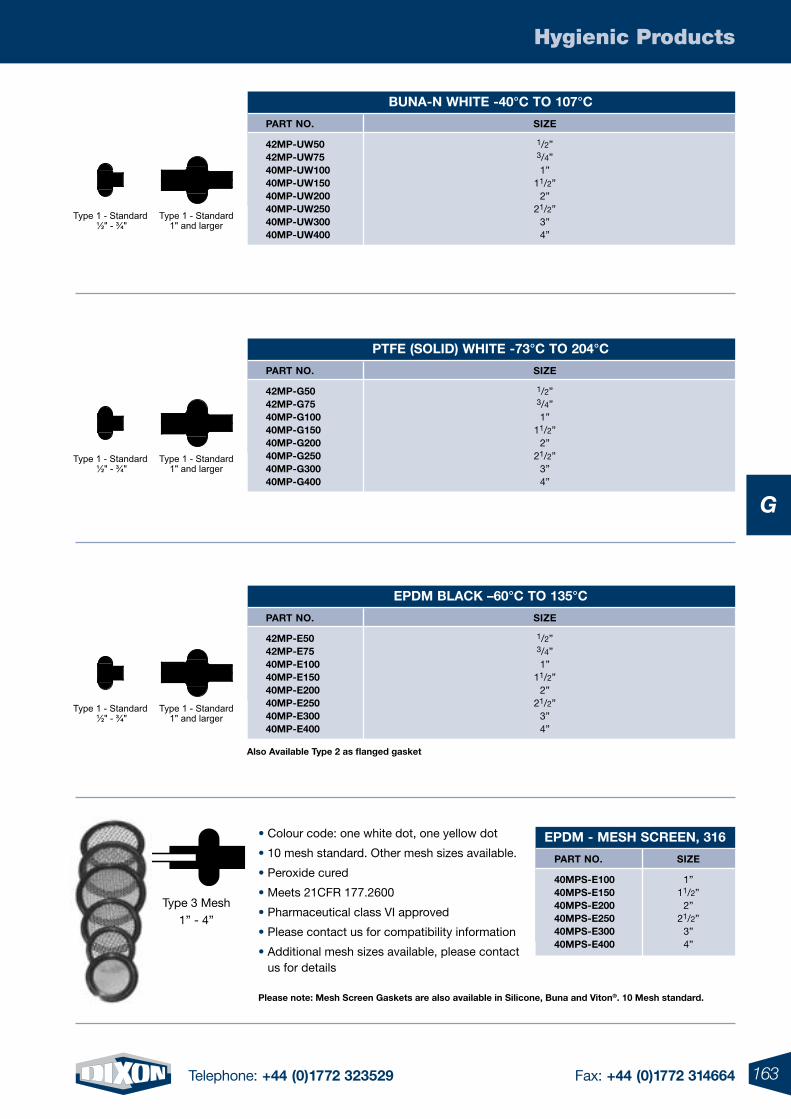
163Telephone: +44 (0)1772 323529 Fax: +44 (0)1772 314664
Hygienic Products
G
epDm BlaCK –60°C to 135°C
part no. sIZe
42mp-e50 1/2” 42mp-e75 3/4” 40mp-e100 1” 40mp-e150 11/2” 40mp-e200 2” 40mp-e250 21/2” 40mp-e300 3” 40mp-e400 4”
Buna-n WHIte -40°C to 107°C
part no. sIZe
42mp-uW50 1/2” 42mp-uW75 3/4” 40mp-uW100 1” 40mp-uW150 11/2” 40mp-uW200 2” 40mp-uW250 21/2” 40mp-uW300 3” 40mp-uW400 4”
ptFe (solID) WHIte -73°C to 204°C
part no. sIZe
42mp-g50 1/2” 42mp-g75 3/4” 40mp-g100 1” 40mp-g150 11/2” 40mp-g200 2” 40mp-g250 21/2” 40mp-g300 3” 40mp-g400 4”
please note: mesh screen gaskets are also available in silicone, Buna and Viton®. 10 mesh standard.
• Colour code: one white dot, one yellow dot
• 10 mesh standard. Other mesh sizes available.
• Peroxide cured
• Meets 21CFR 177.2600
• Pharmaceutical class VI approved
• Please contact us for compatibility information
• Additional mesh sizes available, please contact us for details
epDm - mesH sCreen, 316
part no.
40mps-e100 40mps-e150 40mps-e200 40mps-e250 40mps-e300 40mps-e400
sIZe
1”11/2”
2”21/2”
3”4”
Type 3 Mesh1” - 4”
also available type 2 as flanged gasket
Type 1 - Standard ½" - ¾"
Type 1 - Standard1" and larger
Type 1 - Standard ½" - ¾"
Type 1 - Standard1" and larger
Type 1 - Standard ½" - ¾"
Type 1 - Standard1" and larger
Type 1 - Standard ½" - ¾"
Type 1 - Standard1" and larger
Type 1 - Standard ½" - ¾"
Type 1 - Standard1" and larger
Type 1 - Standard ½" - ¾"
Type 1 - Standard1" and larger
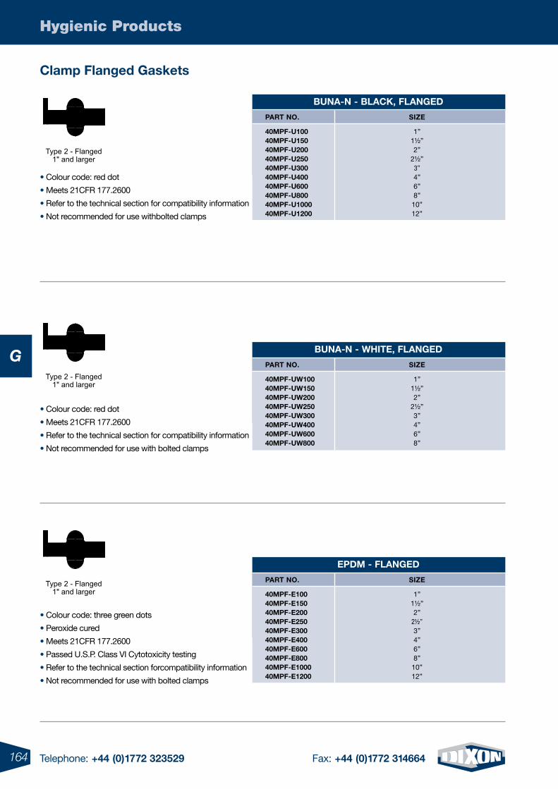
164 Telephone: +44 (0)1772 323529 Fax: +44 (0)1772 314664
Hygienic Products
G
• Colour code: red dot
• Meets 21CFR 177.2600
• Refer to the technical section for compatibility information
• Not recommended for use withbolted clamps
• Colour code: red dot
• Meets 21CFR 177.2600
• Refer to the technical section for compatibility information
• Not recommended for use with bolted clamps
• Colour code: three green dots
• Peroxide cured
• Meets 21CFR 177.2600
• Passed U.S.P. Class VI Cytotoxicity testing
• Refer to the technical section forcompatibility information
• Not recommended for use with bolted clamps
Type 2 - Flanged1" and larger
Type 2 - Flanged1" and larger
Type 2 - Flanged1" and larger
Clamp Flanged gaskets
epDm - FlangeD
part no. sIZe
40mpF-e100 1” 40mpF-e150 1½” 40mpF-e200 2” 40mpF-e250 2½” 40mpF-e300 3” 40mpF-e400 4” 40mpF-e600 6” 40mpF-e800 8” 40mpF-e1000 10” 40mpF-e1200 12”
Buna-n - WHIte, FlangeD
part no. sIZe
40mpF-uW100 1” 40mpF-uW150 1½” 40mpF-uW200 2” 40mpF-uW250 2½” 40mpF-uW300 3” 40mpF-uW400 4” 40mpF-uW600 6” 40mpF-uW800 8”
Buna-n - BlaCK, FlangeD
part no. sIZe
40mpF-u100 1” 40mpF-u150 1½” 40mpF-u200 2” 40mpF-u250 2½” 40mpF-u300 3” 40mpF-u400 4” 40mpF-u600 6” 40mpF-u800 8” 40mpF-u1000 10” 40mpF-u1200 12”
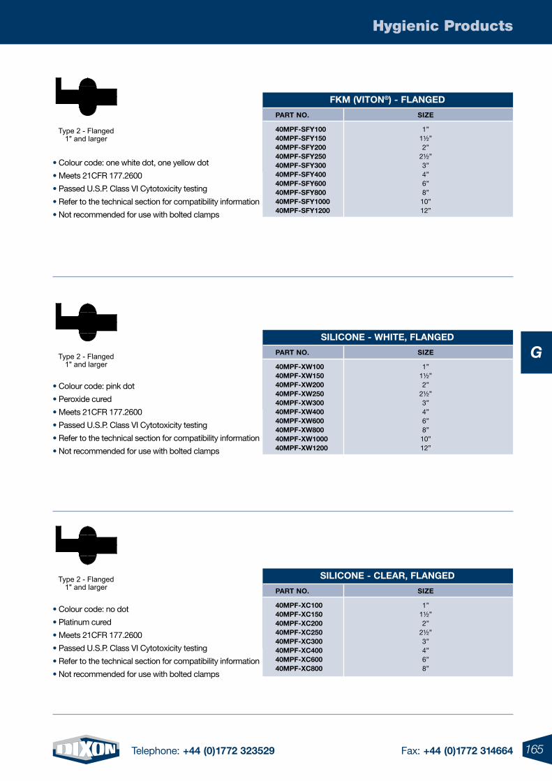
165Telephone: +44 (0)1772 323529 Fax: +44 (0)1772 314664
Hygienic Products
G
• Colour code: one white dot, one yellow dot
• Meets 21CFR 177.2600
• Passed U.S.P. Class VI Cytotoxicity testing
• Refer to the technical section for compatibility information
• Not recommended for use with bolted clamps
Type 2 - Flanged1" and larger
• Colour code: pink dot
• Peroxide cured
• Meets 21CFR 177.2600
• Passed U.S.P. Class VI Cytotoxicity testing
• Refer to the technical section for compatibility information
• Not recommended for use with bolted clamps
Type 2 - Flanged1" and larger
• Colour code: no dot
• Platinum cured
• Meets 21CFR 177.2600
• Passed U.S.P. Class VI Cytotoxicity testing
• Refer to the technical section for compatibility information
• Not recommended for use with bolted clamps
Type 2 - Flanged1" and larger
FKm (VIton®) - FlangeD
part no. sIZe
40mpF-sFY100 1” 40mpF-sFY150 1½” 40mpF-sFY200 2” 40mpF-sFY250 2½” 40mpF-sFY300 3” 40mpF-sFY400 4” 40mpF-sFY600 6” 40mpF-sFY800 8” 40mpF-sFY1000 10” 40mpF-sFY1200 12”
sIlICone - WHIte, FlangeD
part no. sIZe
40mpF-XW100 1” 40mpF-XW150 1½” 40mpF-XW200 2” 40mpF-XW250 2½” 40mpF-XW300 3” 40mpF-XW400 4” 40mpF-XW600 6” 40mpF-XW800 8” 40mpF-XW1000 10” 40mpF-XW1200 12”
sIlICone - Clear, FlangeD
part no. sIZe
40mpF-XC100 1” 40mpF-XC150 1½” 40mpF-XC200 2” 40mpF-XC250 2½” 40mpF-XC300 3” 40mpF-XC400 4” 40mpF-XC600 6” 40mpF-XC800 8”
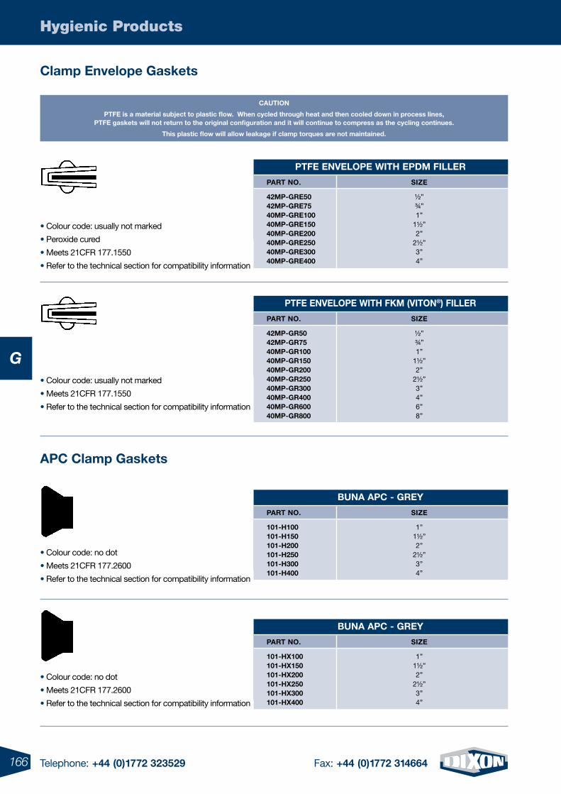
166 Telephone: +44 (0)1772 323529 Fax: +44 (0)1772 314664
Hygienic Products
G
CautIon
ptFe is a material subject to plastic flow. When cycled through heat and then cooled down in process lines, ptFe gaskets will not return to the original configuration and it will continue to compress as the cycling continues.
this plastic flow will allow leakage if clamp torques are not maintained.
Clamp envelope gaskets
apC Clamp gaskets
• Colour code: usually not marked
• Meets 21CFR 177.1550
• Refer to the technical section for compatibility information
• Colour code: no dot
• Meets 21CFR 177.2600
• Refer to the technical section for compatibility information
• Colour code: no dot
• Meets 21CFR 177.2600
• Refer to the technical section for compatibility information
ptFe enVelope WItH epDm FIller
part no. sIZe
42mp-gre50 ½” 42mp-gre75 ¾” 40mp-gre100 1” 40mp-gre150 1½” 40mp-gre200 2” 40mp-gre250 2½” 40mp-gre300 3” 40mp-gre400 4”
ptFe enVelope WItH FKm (VIton®) FIller
part no. sIZe
42mp-gr50 ½” 42mp-gr75 ¾” 40mp-gr100 1” 40mp-gr150 1½” 40mp-gr200 2” 40mp-gr250 2½” 40mp-gr300 3” 40mp-gr400 4” 40mp-gr600 6” 40mp-gr800 8”
Buna apC - greY
part no. sIZe
101-H100 1” 101-H150 1½” 101-H200 2” 101-H250 2½” 101-H300 3” 101-H400 4”
Buna apC - greY
part no. sIZe
101-HX100 1” 101-HX150 1½” 101-HX200 2” 101-HX250 2½” 101-HX300 3” 101-HX400 4”
• Colour code: usually not marked
• Peroxide cured
• Meets 21CFR 177.1550
• Refer to the technical section for compatibility information
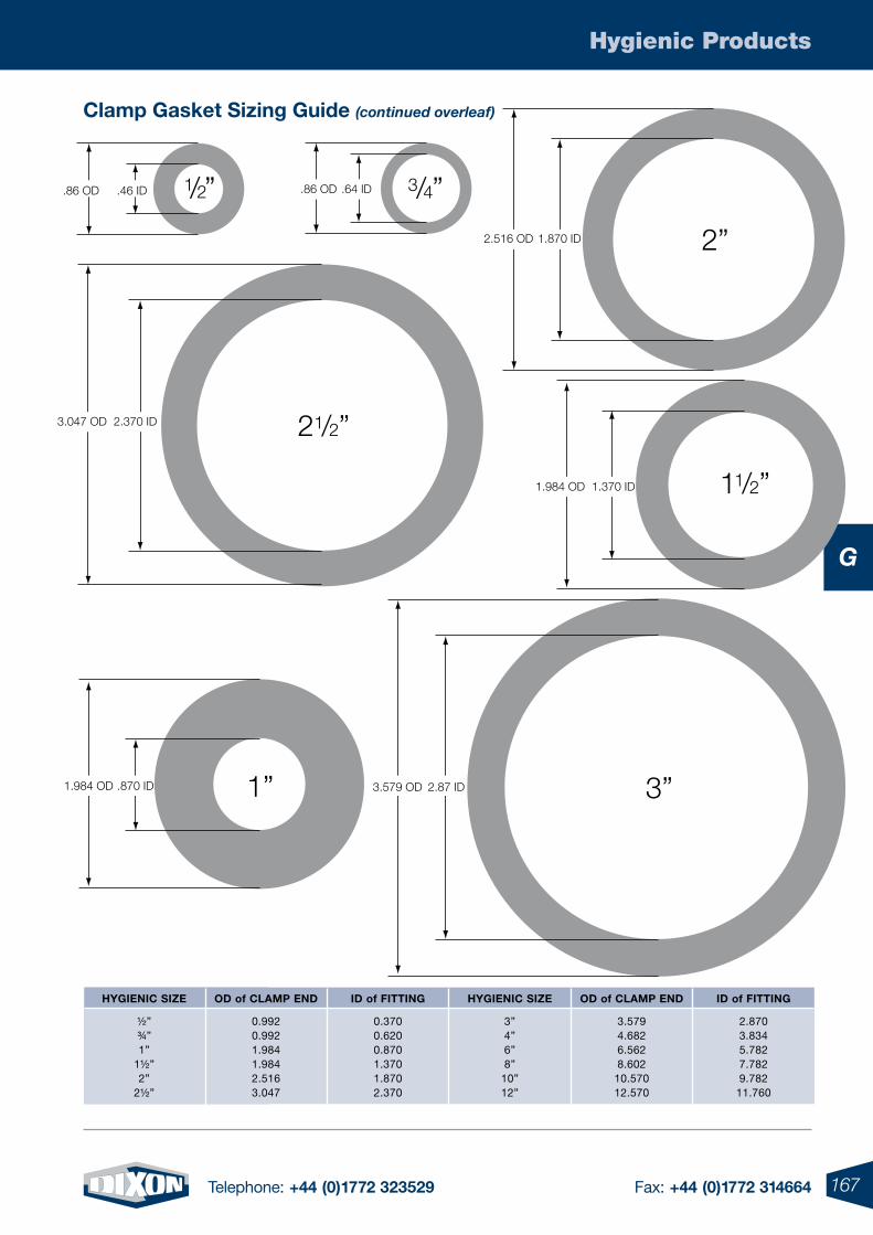
167Telephone: +44 (0)1772 323529 Fax: +44 (0)1772 314664
Hygienic Products
G
1/2”
21/2”
11/2”
3/4”
1” 3”
2”
.86 OD .46 ID .86 OD .64 ID
2.516 OD 1.870 ID
1.984 OD 1.370 ID
3.579 OD 2.87 ID
3.047 OD 2.370 ID
1.984 OD .870 ID
Clamp gasket sizing guide (continued overleaf)
HYgIenIC sIZe
½” ¾” 1”
1½” 2”
2½”
oD of Clamp enD
0.9920.9921.9841.9842.5163.047
ID of FIttIng
0.3700.6200.8701.3701.8702.370
HYgIenIC sIZe
3”4”6”8”
10”12”
oD of Clamp enD
3.5794.6826.5628.602
10.57012.570
ID of FIttIng
2.8703.8345.7827.7829.782
11.760
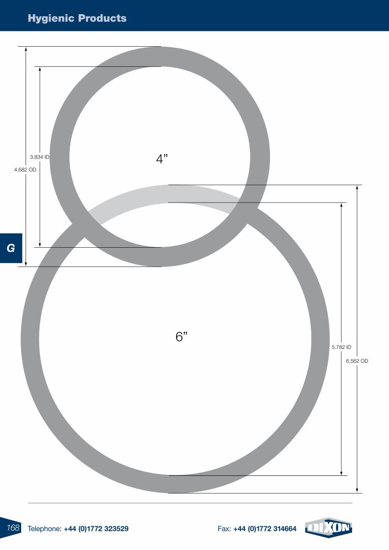
168 Telephone: +44 (0)1772 323529 Fax: +44 (0)1772 314664
Hygienic Products
G
4”
6”
3.834 ID
5.782 ID
6.562 OD
4.682 OD
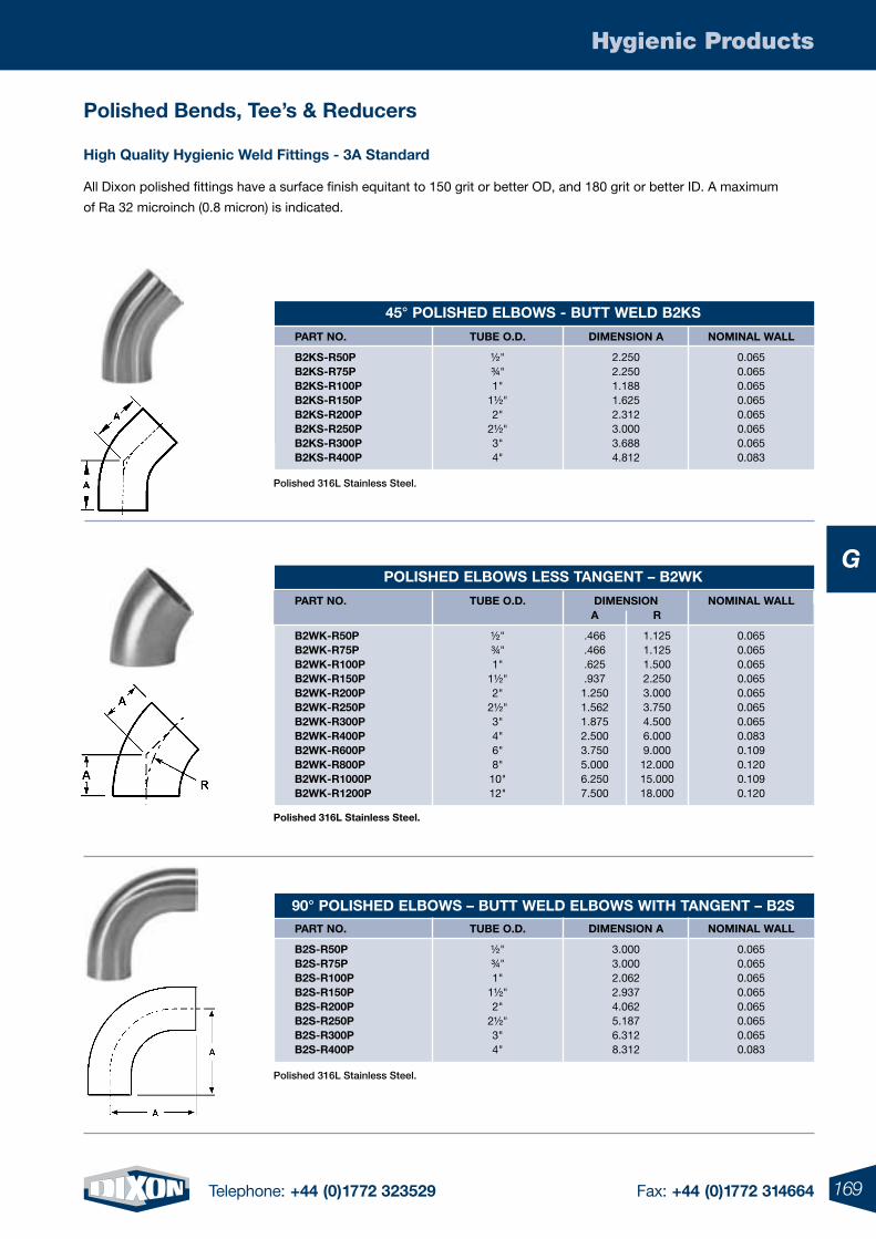
169Telephone: +44 (0)1772 323529 Fax: +44 (0)1772 314664
Hygienic Products
G
4”
6”
3.834 ID
5.782 ID
6.562 OD
4.682 OD
All Dixon polished fittings have a surface finish equitant to 150 grit or better OD, and 180 grit or better ID. A maximum
of Ra 32 microinch (0.8 micron) is indicated.
High quality Hygienic Weld Fittings - 3a standard
Polished 316L Stainless Steel.
90° polIsHeD elBoWs – Butt WelD elBoWs WItH tangent – B2s part no.
B2s-r50p B2s-r75p B2s-r100p B2s-r150p B2s-r200p B2s-r250p B2s-r300p B2s-r400p
tuBe o.D.
½" ¾" 1"
1½" 2"
2½" 3" 4"
DImensIon a
3.0003.0002.0622.9374.0625.1876.3128.312
nomInal Wall
0.0650.0650.0650.0650.0650.0650.0650.083
polished 316l stainless steel.
polIsHeD elBoWs less tangent – B2WK
DImensIon part no.
B2WK-r50p B2WK-r75p B2WK-r100p B2WK-r150p B2WK-r200p B2WK-r250p B2WK-r300p B2WK-r400p B2WK-r600p B2WK-r800p B2WK-r1000p B2WK-r1200p
tuBe o.D.
½"¾"1"
1½" 2"
2½" 3" 4" 6" 8" 10" 12"
nomInal Wall
0.0650.0650.0650.0650.0650.0650.0650.0830.1090.1200.1090.120
a
.466
.466
.625
.9371.2501.5621.8752.5003.7505.0006.2507.500
r
1.1251.1251.5002.2503.0003.7504.5006.0009.00012.00015.00018.000
45° polIsHeD elBoWs - Butt WelD B2Ks
part no.
B2Ks-r50p B2Ks-r75p B2Ks-r100p B2Ks-r150p B2Ks-r200p B2Ks-r250p B2Ks-r300p B2Ks-r400p
tuBe o.D.
½"¾"1"
1½" 2"
2½" 3" 4"
DImensIon a
2.2502.2501.1881.6252.3123.0003.6884.812
nomInal Wall
0.0650.0650.0650.0650.0650.0650.0650.083
Polished 316L Stainless Steel.
polished Bends, tee’s & reducers
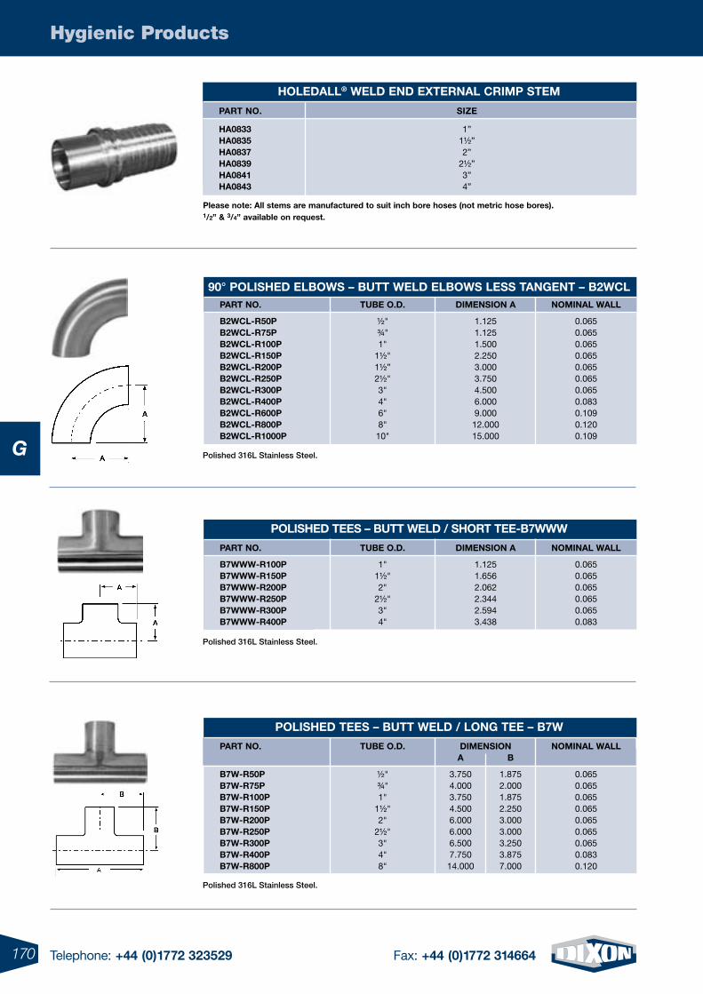
170 Telephone: +44 (0)1772 323529 Fax: +44 (0)1772 314664
Hygienic Products
G
Polished 316L Stainless Steel.
Polished 316L Stainless Steel.
part no.
B2WCl-r50p B2WCl-r75p B2WCl-r100p B2WCl-r150p B2WCl-r200p B2WCl-r250p B2WCl-r300p B2WCl-r400p B2WCl-r600p B2WCl-r800p B2WCl-r1000p
tuBe o.D.
½" ¾" 1"
1½" 1½” 2½" 3" 4" 6" 8" 10"
DImensIon a
1.1251.1251.5002.2503.0003.7504.5006.0009.00012.00015.000
nomInal Wall
0.0650.0650.0650.0650.0650.0650.0650.0830.1090.1200.109
90° polIsHeD elBoWs – Butt WelD elBoWs less tangent – B2WCl
Polished 316L Stainless Steel.
polIsHeD tees – Butt WelD / sHort tee-B7WWW
part no.
B7WWW-r100p B7WWW-r150p B7WWW-r200p B7WWW-r250p B7WWW-r300p B7WWW-r400p
tuBe o.D.
1" 1½" 2"
2½" 3" 4"
DImensIon a
1.1251.6562.0622.3442.5943.438
nomInal Wall
0.0650.0650.0650.0650.0650.083
polIsHeD tees – Butt WelD / long tee – B7W
DImensIon part no.
B7W-r50p B7W-r75p B7W-r100p B7W-r150p B7W-r200p B7W-r250p B7W-r300p B7W-r400p B7W-r800p
tuBe o.D.
½"¾"1"
1½" 2"
2½" 3" 4"8"
nomInal Wall
0.0650.0650.0650.0650.0650.0650.0650.0830.120
a
3.7504.0003.7504.5006.0006.0006.5007.75014.000
B
1.8752.0001.8752.2503.0003.0003.2503.8757.000
HoleDall® WelD enD eXternal CrImp stem
part no. sIZe
Ha0833 1” Ha0835 1½” Ha0837 2” Ha0839 2½” Ha0841 3” Ha0843 4”
please note: all stems are manufactured to suit inch bore hoses (not metric hose bores).1/2” & 3/4” available on request.
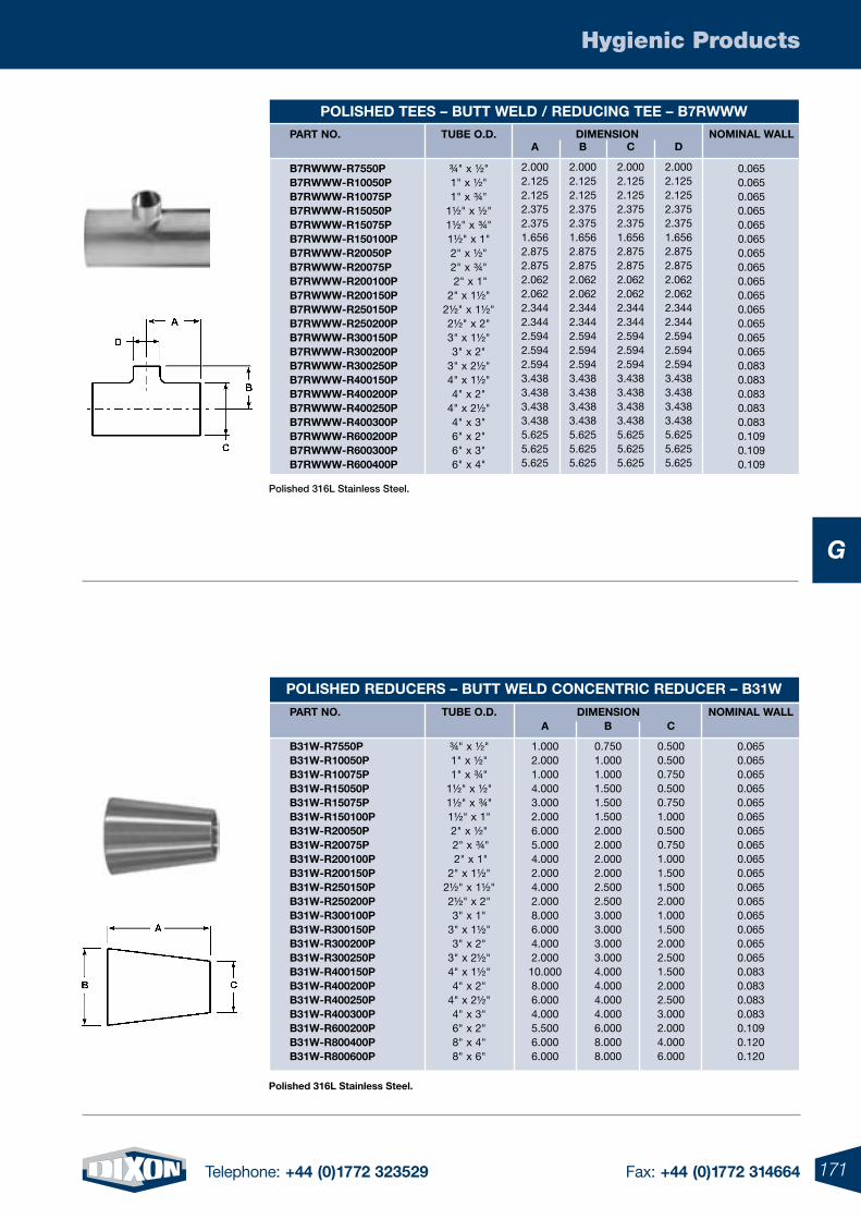
171Telephone: +44 (0)1772 323529 Fax: +44 (0)1772 314664
Hygienic Products
G
Polished 316L Stainless Steel.
part no.
B7rWWW-r7550p B7rWWW-r10050p B7rWWW-r10075p B7rWWW-r15050p B7rWWW-r15075p B7rWWW-r150100p B7rWWW-r20050p B7rWWW-r20075p B7rWWW-r200100p B7rWWW-r200150p B7rWWW-r250150p B7rWWW-r250200p B7rWWW-r300150p B7rWWW-r300200p B7rWWW-r300250p B7rWWW-r400150p B7rWWW-r400200p B7rWWW-r400250p B7rWWW-r400300p B7rWWW-r600200p B7rWWW-r600300p B7rWWW-r600400p
tuBe o.D.
¾" x ½" 1" x ½" 1" x ¾"
1½" x ½"1½" x ¾"1½" x 1" 2" x ½" 2" x ¾" 2" x 1" 2" x 1½"
2½" x 1½" 2½" x 2" 3" x 1½" 3" x 2"
3" x 2½" 4" x 1½" 4" x 2"
4" x 2½" 4" x 3" 6" x 2" 6" x 3" 6" x 4"
DImensIon nomInal Wall
0.0650.0650.0650.0650.0650.0650.0650.0650.0650.0650.0650.0650.0650.0650.0830.0830.0830.0830.0830.1090.1090.109
polIsHeD tees – Butt WelD / reDuCIng tee – B7rWWW a
2.0002.1252.1252.3752.3751.6562.8752.8752.0622.0622.3442.3442.5942.5942.5943.4383.4383.4383.4385.6255.6255.625
B
2.0002.1252.1252.3752.3751.6562.8752.8752.0622.0622.3442.3442.5942.5942.5943.4383.4383.4383.4385.6255.6255.625
C
2.0002.1252.1252.3752.3751.6562.8752.8752.0622.0622.3442.3442.5942.5942.5943.4383.4383.4383.4385.6255.6255.625
D
2.0002.1252.1252.3752.3751.6562.8752.8752.0622.0622.3442.3442.5942.5942.5943.4383.4383.4383.4385.6255.6255.625
DImensIon
polIsHeD reDuCers – Butt WelD ConCentrIC reDuCer – B31W
part no.
B31W-r7550p B31W-r10050p B31W-r10075p B31W-r15050p B31W-r15075p B31W-r150100p B31W-r20050p B31W-r20075p B31W-r200100p B31W-r200150p B31W-r250150p B31W-r250200p B31W-r300100p B31W-r300150p B31W-r300200p B31W-r300250p B31W-r400150p B31W-r400200p B31W-r400250p B31W-r400300p B31W-r600200p B31W-r800400p B31W-r800600p
tuBe o.D.
¾" x ½" 1" x ½" 1" x ¾"
1½" x ½" 1½" x ¾"1½" x 1"2" x ½" 2" x ¾" 2" x 1" 2" x 1½"
2½" x 1½" 2½" x 2" 3" x 1"
3" x 1½" 3" x 2"
3" x 2½"4" x 1½" 4" x 2"
4" x 2½" 4" x 3" 6" x 2" 8" x 4" 8" x 6"
nomInal Wall
0.0650.0650.0650.0650.0650.0650.0650.0650.0650.0650.0650.0650.0650.0650.0650.0650.0830.0830.0830.0830.1090.1200.120
a
1.0002.0001.0004.0003.0002.0006.0005.0004.0002.0004.0002.0008.0006.0004.0002.00010.0008.0006.0004.0005.5006.0006.000
B
0.7501.0001.0001.5001.5001.5002.0002.0002.0002.0002.5002.5003.0003.0003.0003.0004.0004.0004.0004.0006.0008.0008.000
C
0.5000.5000.7500.5000.7501.0000.5000.7501.0001.5001.5002.0001.0001.5002.0002.5001.5002.0002.5003.0002.0004.0006.000
polished 316l stainless steel.
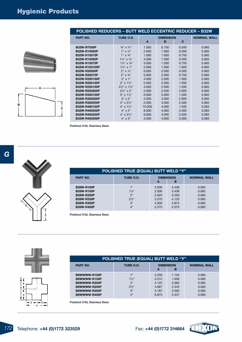
172 Telephone: +44 (0)1772 323529 Fax: +44 (0)1772 314664
Hygienic Products
G
B
A
Polished 316L Stainless Steel.
Polished 316L Stainless Steel.
Polished 316L Stainless Steel.
DImensIon
polIsHeD reDuCers – Butt WelD eCCentrIC reDuCer – B32W
part no.
B32W-r7550p B32W-r10050p B32W-r10075p B32W-r15050p B32W-r15075p B32W-r150100p B32W-r20050p B32W-r20075p B32W-r200100p B32W-r200150p B32W-r250150p B32W-r250200p B32W-r300150p B32W-r300200p B32W-r300250p B32W-r400150p B32W-r400200p B32W-r400250p B32W-r400300p
tuBe o.D.
¾" x ½" 1" x ½" 1" x ¾"
1½" x ½" 1½" x ¾"1½" x 1" 2" x ½" 2" x ¾" 2" x 1"
2" x 1½" 2½" x 1½" 2½" x 2" 3" x 1½" 3" x 2"
3" x 2½" 4" x 1½" 4" x 2"
4" x 2½" 4" x 3"
nomInal Wall
0.0650.0650.0650.0650.0650.0650.0650.0650.0650.0650.0650.0650.0650.0650.0650.0830.0830.0830.083
a
1.0002.0001.0004.0003.0002.0006.0005.0004.0002.0004.0002.0006.0004.0002.00010.0008.0006.0004.000
B
0.7501.0001.0001.5001.5001.5002.0002.0002.0002.0002.5002.5003.0003.0003.0004.0004.0004.0004.000
C
0.5000.5000.7500.5000.7501.0000.5000.7501.0001.5001.5002.0001.5002.0002.5001.5002.0002.5003.000
polIsHeD true (equal) Butt WelD “Y”
DImensIon part no.
B28W-r100p B28W-r150p B28W-r200p B28W-r250p B28W-r300p B28W-r400p
tuBe o.D.
1" 1½" 2"
2½" 3" 4"
nomInal Wall
0.0650.0650.0650.0650.0650.083
a
2.0002.0002.6253.3704.0005.375
B
2.4382.4383.2504.1254.8755.375
polIsHeD true (equal) Butt WelD “Y”
part no.
B9WWWW-r100p B9WWWW-r150p B9WWWW-r200p B9WWWW-r250p B9WWWW-r300p B9WWWW-r400p
DImensIontuBe o.D.
1" 1½" 2"
2½" 3" 4"
nomInal Wall
0.0650.0650.0650.0650.0650.083
a
2.2503.3124.1254.6875.1876.875
B
1.1251.6562.0622.3432.5933.437
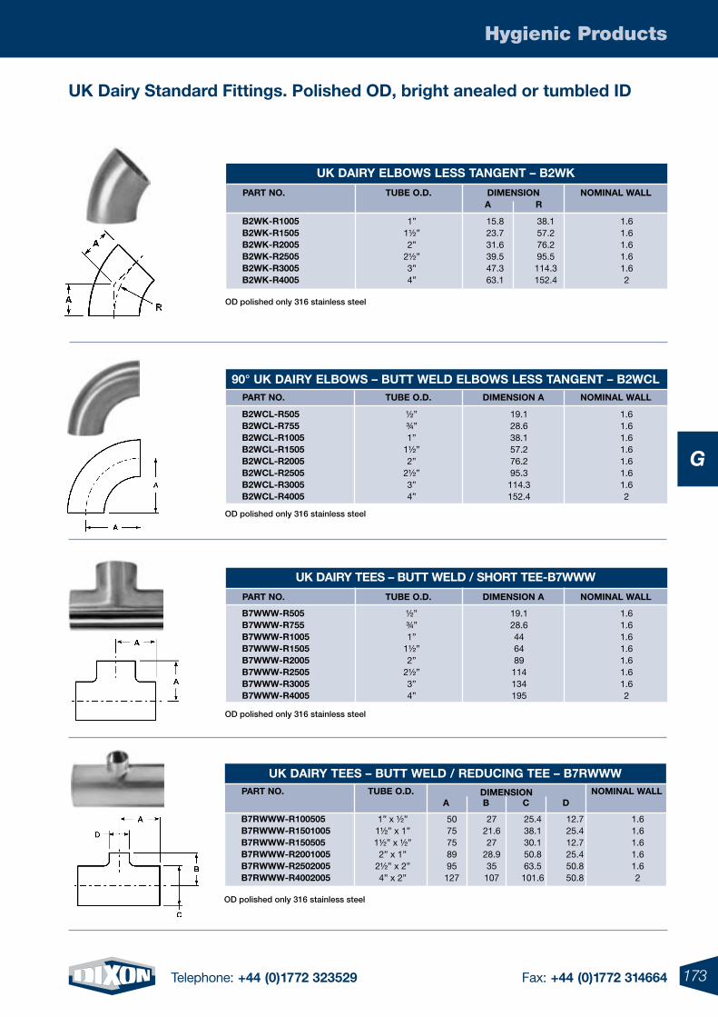
173Telephone: +44 (0)1772 323529 Fax: +44 (0)1772 314664
Hygienic Products
G
uK Dairy standard Fittings. polished oD, bright anealed or tumbled ID
OD polished only 316 stainless steel
OD polished only 316 stainless steel
uK DaIrY elBoWs less tangent – B2WK
DImensIon part no. tuBe o.D. nomInal Wall a
r
B2WK-r1005 B2WK-r1505 B2WK-r2005 B2WK-r2505 B2WK-r3005 B2WK-r4005
1” 15.8 38.1 1.6 1½” 23.7 57.2 1.6 2” 31.6 76.2 1.6 2½” 39.5 95.5 1.6 3” 47.3 114.3 1.6 4” 63.1 152.4 2
part no. tuBe o.D. DImensIon a nomInal Wall
90° uK DaIrY elBoWs – Butt WelD elBoWs less tangent – B2WCl
B2WCl-r505 B2WCl-r755 B2WCl-r1005 B2WCl-r1505 B2WCl-r2005 B2WCl-r2505 B2WCl-r3005 B2WCl-r4005
½” 19.1 1.6 ¾” 28.6 1.6 1” 38.1 1.6 1½” 57.2 1.6 2” 76.2 1.6 2½” 95.3 1.6 3” 114.3 1.6 4” 152.4 2
uK DaIrY tees – Butt WelD / sHort tee-B7WWW
part no. tuBe o.D. DImensIon a nomInal Wall
B7WWW-r505 B7WWW-r755 B7WWW-r1005 B7WWW-r1505 B7WWW-r2005 B7WWW-r2505 B7WWW-r3005 B7WWW-r4005
½” 19.1 1.6 ¾” 28.6 1.6 1” 44 1.6 1½” 64 1.6 2” 89 1.6 2½” 114 1.6 3” 134 1.6 4” 195 2
OD polished only 316 stainless steel
uK DaIrY tees – Butt WelD / reDuCIng tee – B7rWWW part no. tuBe o.D. nomInal Wall
a B
C
D
DImensIon
B7rWWW-r100505 B7rWWW-r1501005 B7rWWW-r150505 B7rWWW-r2001005 B7rWWW-r2502005 B7rWWW-r4002005
1” x ½” 50 27 25.4 12.7 1.6 1½” x 1” 75 21.6 38.1 25.4 1.6 1½” x ½” 75 27 30.1 12.7 1.6 2” x 1” 89 28.9 50.8 25.4 1.6 2½” x 2” 95 35 63.5 50.8 1.6 4” x 2” 127 107 101.6 50.8 2
OD polished only 316 stainless steel
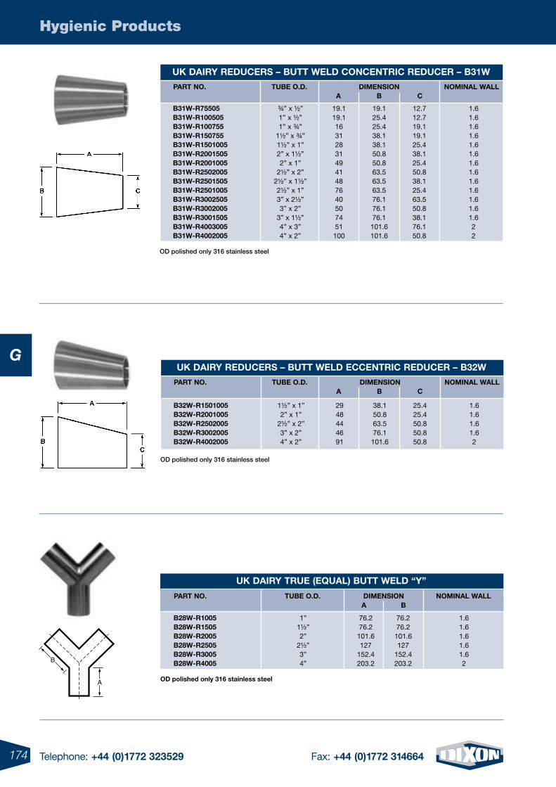
174 Telephone: +44 (0)1772 323529 Fax: +44 (0)1772 314664
Hygienic Products
G
OD polished only 316 stainless steel
B
A oD polished only 316 stainless steel
OD polished only 316 stainless steel
uK DaIrY reDuCers – Butt WelD ConCentrIC reDuCer – B31W
part no. tuBe o.D. nomInal Wall a
B
C
DImensIon
B31W-r75505 B31W-r100505 B31W-r100755 B31W-r150755 B31W-r1501005 B31W-r2001505 B31W-r2001005 B31W-r2502005 B31W-r2501505 B31W-r2501005 B31W-r3002505 B31W-r3002005 B31W-r3001505 B31W-r4003005 B31W-r4002005
¾” x ½” 19.1 19.1 12.7 1.6 1” x ½” 19.1 25.4 12.7 1.6 1” x ¾” 16 25.4 19.1 1.6 1½” x ¾” 31 38.1 19.1 1.6 1½” x 1” 28 38.1 25.4 1.6 2” x 1½” 31 50.8 38.1 1.6 2” x 1” 49 50.8 25.4 1.6 2½” x 2” 41 63.5 50.8 1.6 2½” x 1½” 48 63.5 38.1 1.6 2½” x 1” 76 63.5 25.4 1.6 3” x 2½” 40 76.1 63.5 1.6 3” x 2” 50 76.1 50.8 1.6 3” x 1½” 74 76.1 38.1 1.6 4” x 3” 51 101.6 76.1 2 4” x 2” 100 101.6 50.8 2
uK DaIrY true (equal) Butt WelD “Y”
part no. tuBe o.D. nomInal Wall a
B
DImensIon
B28W-r1005 B28W-r1505 B28W-r2005 B28W-r2505 B28W-r3005 B28W-r4005
1” 76.2 76.2 1.6 1½” 76.2 76.2 1.6 2” 101.6 101.6 1.6 2½” 127 127 1.6 3” 152.4 152.4 1.6 4” 203.2 203.2 2
DImensIon
uK DaIrY reDuCers – Butt WelD eCCentrIC reDuCer – B32W
part no. tuBe o.D. nomInal Wall a
B
C
B32W-r1501005 B32W-r2001005 B32W-r2502005 B32W-r3002005 B32W-r4002005
1½” x 1” 29 38.1 25.4 1.6 2” x 1” 48 50.8 25.4 1.6 2½” x 2” 44 63.5 50.8 1.6 3” x 2” 46 76.1 50.8 1.6 4” x 2” 91 101.6 50.8 2
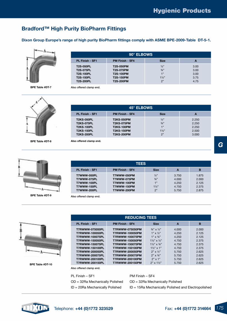
175Telephone: +44 (0)1772 323529 Fax: +44 (0)1772 314664
Hygienic Products
GBpe table #Dt-8
Bradford™ High purity Biopharm Fittings
Bpe table #Dt-7
Bpe table #Dt-9
Bpe table #Dt-10
45° elBoWs
pl Finish - sF1 pm Finish - sF4 size a
t2Ks-050pl t2Ks-050pm ½” 2.250 t2Ks-075pl t2Ks-075pm ¾” 2.250 t2Ks-100pl t2Ks-100pm 1” 2.250 t2Ks-150pl t2Ks-150pm 1½” 2.500 t2Ks-200pl t2Ks-200pm 2” 3.000
90° elBoWs
pl Finish - sF1 pm Finish - sF4 size a
t2s-050pl t2s-050pm ½” 3.00 t2s-075pl t2s-075pm ¾” 3.00 t2s-100pl t2s-100pm 1” 3.00 t2s-150pl t2s-150pm 1½” 3.75 t2s-200pl t2s-200pm 2” 4.75
reDuCIng tees
pl Finish - sF1 pm Finish - sF4 size a B
t7rWWW-075050pl t7rWWW-075050pm ¾” x ½” 4.000 2.000 t7rWWW-100050pl t7rWWW-100050pm 1” x ½” 4.250 2.125 t7rWWW-100075pl t7rWWW-100075pm 1” x ¾” 4.250 2.125 t7rWWW-150050pl t7rWWW-150050pm 1½” x ½” 4.750 2.375 t7rWWW-150075pl t7rWWW-150075pm 1½” x ¾” 4.750 2.375 t7rWWW-150100pl t7rWWW-150100pm 1½” x 1” 4.750 2.375 t7rWWW-200050pl t7rWWW-200050pm 2” x ½” 5.750 2.625 t7rWWW-200075pl t7rWWW-200075pm 2” x ¾” 5.750 2.625 t7rWWW-200100pl t7rWWW-200100pm 2” x 1” 5.750 2.625 t7rWWW-200150pl t7rWWW-200150pm 2” x 1½” 5.750 2.625
PL Finish – SF1 PM Finish – SF4
OD = 32Ra Mechanically Polished OD = 32Ra Mechanically Polished
ID = 20Ra Mechanically Polished ID = 15Ra Mechanically Polished and Electropolished
tees
pl Finish - sF1 pm Finish - sF4 size a B
t7WWW-050pl t7WWW-050pm ½” 3.750 1.875 t7WWW-075pl t7WWW-075pm ¾” 4.000 2.000 t7WWW-100pl t7WWW-100pm 1” 4.250 2.125 t7WWW-150pl t7WWW-150pm 1½” 4.750 2.375 t7WWW-200pl t7WWW-200pm 2” 5.750 2.875
Also offered clamp end.
also offered clamp end.
Also offered clamp end.
Also offered clamp end.
Dixon group europe’s range of high purity Biopharm fittings comply with asme Bpe-2009-table Dt-5-1.
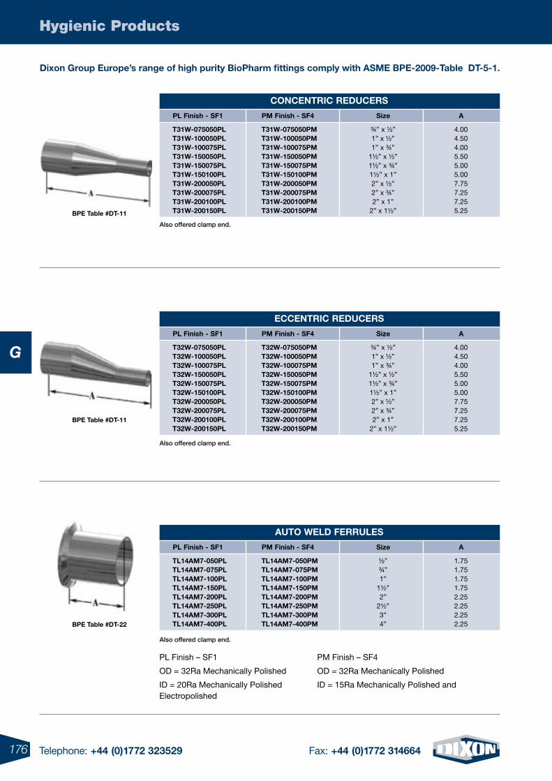
176 Telephone: +44 (0)1772 323529 Fax: +44 (0)1772 314664
Hygienic Products
G
ConCentrIC reDuCers
pl Finish - sF1 pm Finish - sF4 size a
t31W-075050pl t31W-075050pm ¾” x ½” 4.00 t31W-100050pl t31W-100050pm 1” x ½” 4.50 t31W-100075pl t31W-100075pm 1” x ¾” 4.00 t31W-150050pl t31W-150050pm 1½” x ½” 5.50 t31W-150075pl t31W-150075pm 1½” x ¾” 5.00 t31W-150100pl t31W-150100pm 1½” x 1” 5.00 t31W-200050pl t31W-200050pm 2” x ½” 7.75 t31W-200075pl t31W-200075pm 2” x ¾” 7.25 t31W-200100pl t31W-200100pm 2” x 1” 7.25 t31W-200150pl t31W-200150pm 2” x 1½” 5.25
eCCentrIC reDuCers
pl Finish - sF1 pm Finish - sF4 size a
t32W-075050pl t32W-075050pm ¾” x ½” 4.00 t32W-100050pl t32W-100050pm 1” x ½” 4.50 t32W-100075pl t32W-100075pm 1” x ¾” 4.00 t32W-150050pl t32W-150050pm 1½” x ½” 5.50 t32W-150075pl t32W-150075pm 1½” x ¾” 5.00 t32W-150100pl t32W-150100pm 1½” x 1” 5.00 t32W-200050pl t32W-200050pm 2” x ½” 7.75 t32W-200075pl t32W-200075pm 2” x ¾” 7.25 t32W-200100pl t32W-200100pm 2” x 1” 7.25 t32W-200150pl t32W-200150pm 2” x 1½” 5.25
auto WelD Ferrules
pl Finish - sF1 pm Finish - sF4 size a
tl14am7-050pl tl14am7-050pm ½” 1.75 tl14am7-075pl tl14am7-075pm ¾” 1.75 tl14am7-100pl tl14am7-100pm 1” 1.75 tl14am7-150pl tl14am7-150pm 1½” 1.75 tl14am7-200pl tl14am7-200pm 2” 2.25 tl14am7-250pl tl14am7-250pm 2½” 2.25 tl14am7-300pl tl14am7-300pm 3” 2.25 tl14am7-400pl tl14am7-400pm 4” 2.25
Bpe table #Dt-11
Bpe table #Dt-11
Bpe table #Dt-22
PL Finish – SF1 PM Finish – SF4
OD = 32Ra Mechanically Polished OD = 32Ra Mechanically Polished
ID = 20Ra Mechanically Polished ID = 15Ra Mechanically Polished and Electropolished
Also offered clamp end.
Also offered clamp end.
Also offered clamp end.
Dixon group europe’s range of high purity Biopharm fittings comply with asme Bpe-2009-table Dt-5-1.
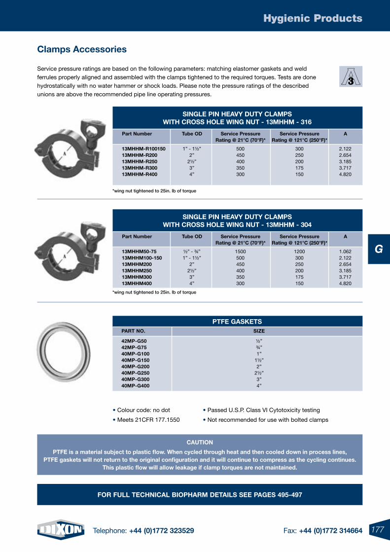
177Telephone: +44 (0)1772 323529 Fax: +44 (0)1772 314664
Hygienic Products
G
sIngle pIn HeaVY DutY Clamps WItH Cross Hole WIng nut - 13mHHm - 316
part number tube oD service pressure service pressure a rating @ 21°C (70°F)* rating @ 121°C (250°F)*
13mHHm-r100150 1” - 1½” 500 300 2.122 13mHHm-r200 2” 450 250 2.654 13mHHm-r250 2½” 400 200 3.185 13mHHm-r300 3” 350 175 3.717 13mHHm-r400 4” 300 150 4.820
sIngle pIn HeaVY DutY Clamps WItH Cross Hole WIng nut - 13mHHm - 304
part number tube oD service pressure service pressure a rating @ 21°C (70°F)* rating @ 121°C (250°F)*
13mHHm50-75 ½” - ¾” 1500 1200 1.062 13mHHm100-150 1” - 1½” 500 300 2.122 13mHHm200 2” 450 250 2.654 13mHHm250 2½” 400 200 3.185 13mHHm300 3” 350 175 3.717 13mHHm400 4” 300 150 4.820
CautIon
ptFe is a material subject to plastic flow. When cycled through heat and then cooled down in process lines,ptFe gaskets will not return to the original configuration and it will continue to compress as the cycling continues.
this plastic flow will allow leakage if clamp torques are not maintained.
Service pressure ratings are based on the following parameters: matching elastomer gaskets and weld ferrules properly aligned and assembled with the clamps tightened to the required torques. Tests are done hydrostatically with no water hammer or shock loads. Please note the pressure ratings of the described unions are above the recommended pipe line operating pressures.
Clamps accessories
ptFe gasKets part no. sIZe
42mp-g50 ½” 42mp-g75 ¾” 40mp-g100 1” 40mp-g150 1½” 40mp-g200 2” 40mp-g250 2½” 40mp-g300 3” 40mp-g400 4”
• Colour code: no dot
• Meets 21CFR 177.1550
• Passed U.S.P. Class VI Cytotoxicity testing
• Not recommended for use with bolted clamps
For Full teCHnICal BIopHarm DetaIls see pages 495-497
*wing nut tightened to 25in. lb of torque
*wing nut tightened to 25in. lb of torque
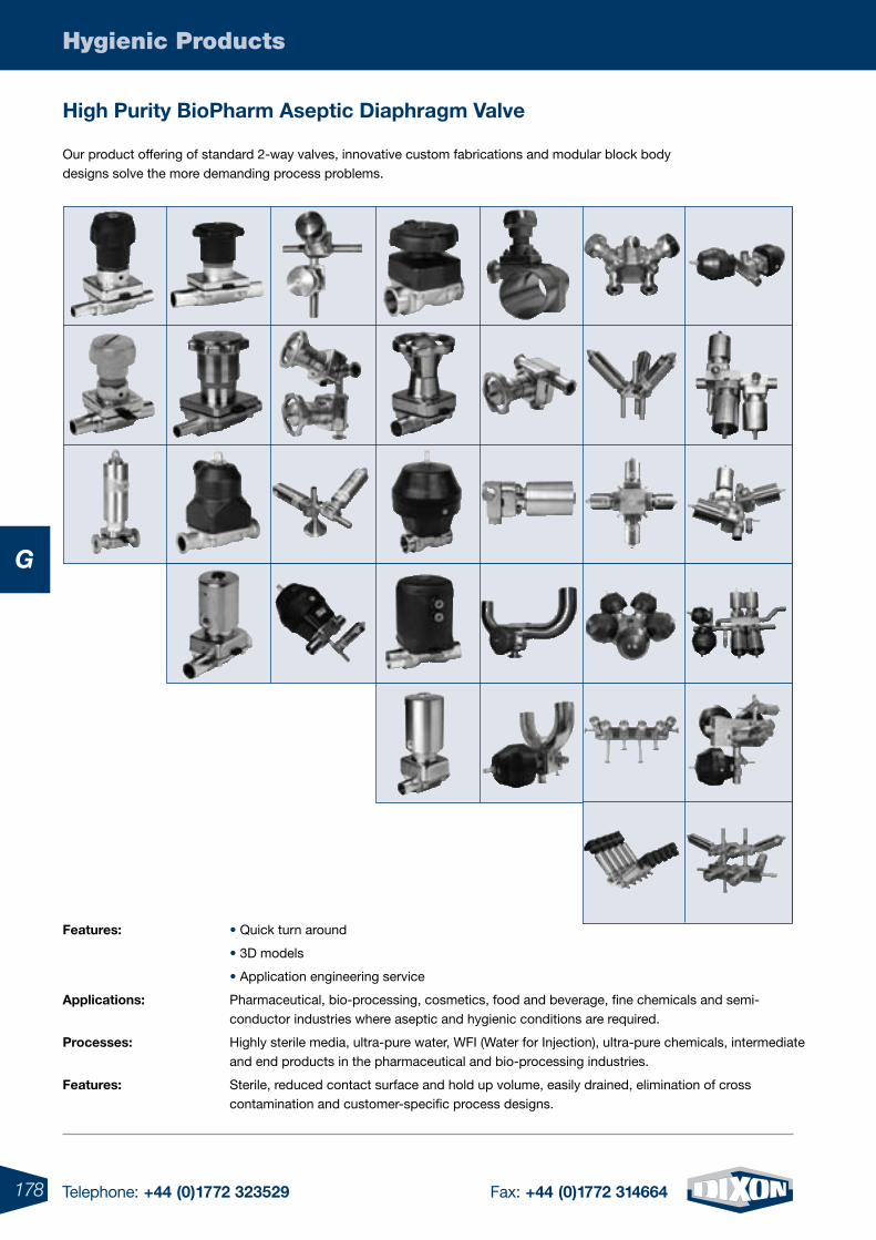
178 Telephone: +44 (0)1772 323529 Fax: +44 (0)1772 314664
Hygienic Products
G
Our product offering of standard 2-way valves, innovative custom fabrications and modular block body designs solve the more demanding process problems.
Features: • Quick turn around
• 3D models
• Application engineering service
applications: Pharmaceutical, bio-processing, cosmetics, food and beverage, fine chemicals and semi-conductor industries where aseptic and hygienic conditions are required.
processes: Highly sterile media, ultra-pure water, WFI (Water for Injection), ultra-pure chemicals, intermediate and end products in the pharmaceutical and bio-processing industries.
Features: Sterile, reduced contact surface and hold up volume, easily drained, elimination of cross contamination and customer-specific process designs.
High purity Biopharm aseptic Diaphragm Valve
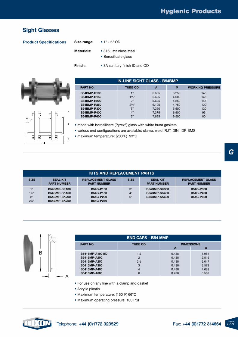
179Telephone: +44 (0)1772 323529 Fax: +44 (0)1772 314664
Hygienic Products
G
sight glasses
product specifications size range: • 1" - 6" OD
materials: • 316L stainless steel
• Borosilicate glass
Finish: • 3A sanitary finish ID and OD
B
A
• made with borosilicate (Pyrex®) glass with white buna gaskets
• various end configurations are available: clamp, weld, RJT, DIN, IDF, SMS
• maximum temperature: (200°F) 93°C
• For use on any line with a clamp and gasket
• Acrylic plastic
• Maximum temperature: (150°F) 66°C
• Maximum operating pressure: 100 PSI
enD Caps – B5416mp
part no. tuBe oD DImensIonsa B
B5416mp-a100150 1½ 0.438 1.984 B5416mp-a200 2 0.438 2.516 B5416mp-a250 2½ 0.438 3.047 B5416mp-a300 3 0.438 3.579 B5416mp-a400 4 0.438 4.682 B5416mp-a600 6 0.438 6.562
KIts anD replaCement parts
sIZe seal KIt replaCement glass part numBer part numBer
1” B54Bmp-sK100 B54g-p100 1½” B54Bmp-sK150 B54g-p150 2” B54Bmp-sK200 B54g-p200 2½” B54Bmp-sK250 B54g-p250
3” B54Bmp-sK300 B54g-p300 4” B54Bmp-sK400 B54g-p400 6” B54Bmp-sK600 B54g-p600
sIZe seal KIt replaCement glass part numBer part numBer
In-lIne sIgHt glass - B54Bmp
part no. tuBe oD a B
B54Bmp-r100 1” 5.625 3.250 145 B54Bmp-r150 1½” 5.625 4.000 145 B54Bmp-r200 2” 5.625 4.250 145 B54Bmp-r250 2½” 6.125 4.750 120 B54Bmp-r300 3” 7.250 5.500 120 B54Bmp-r400 4” 7.375 6.500 95 B54Bmp-r600 6” 7.625 9.500 80
WorKIng pressure
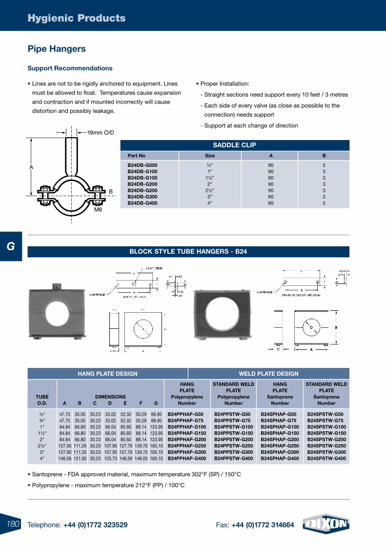
180 Telephone: +44 (0)1772 323529 Fax: +44 (0)1772 314664
Hygienic Products
G
pipe Hangers
A
B
19mm O/D
M8
• Santoprene - FDA approved material, maximum temperature 302°F (SP) / 150°C
• Polypropylene - maximum temperature 212°F (PP) / 100°C
support recommendations
• Lines are not to be rigidly anchored to equipment. Lines
must be allowed to float. Temperatures cause expansion
and contraction and if mounted incorrectly will cause
distortion and possibly leakage.
• Proper Installation:
- Straight sections need support every 10 feet / 3 metres
- Each side of every valve (as close as possible to the
connection) needs support
- Support at each change of direction
BloCK stYle tuBe Hangers - B24
tuBeo.D.
Hang plate DesIgn WelD plate DesIgn
DImensIons a B C D e F g
Hang plate
polypropylenenumber
stanDarD WelD plate
polypropylenenumber
Hang plate
santoprenenumber
stanDarD WelD plate
santoprenenumber
½"¾"1"
1½"2"
2½"3"4"
B24ppHap-g50B24ppHap-g75B24ppHap-g100B24ppHap-g150B24ppHap-g200B24ppHap-g250B24ppHap-g300B24ppHap-g400
B24ppstW-g50B24ppstW-g75B24ppstW-g100B24ppstW-g150B24ppstW-g200B24ppstW-g250B24ppstW-g300B24ppstW-g400
B24spHap-g50B24spHap-g75B24spHap-g100B24spHap-g150B24spHap-g200B24spHap-g250B24spHap-g300B24spHap-g400
B24spstW-g50B24spstW-g75B24spstW-g100B24spstW-g150B24spstW-g200B24spstW-g250B24spstW-g300B24spstW-g400
47.7547.7584.8484.8484.84127.00127.00146.56
35.0535.0566.8066.8066.80111.25111.25121.92
30.2330.2330.2330.2330.2330.2330.2330.23
33.0233.0266.0466.0466.04107.95107.95125.73
52.3252.3285.6085.6085.60127.76127.76146.56
50.2950.2988.1488.1488.14139.70139.70146.05
88.9088.90123.95123.95123.95165.10165.10165.10
saDDle ClIp
part no size a B
B24DB-g050 ½” 90 3 B24DB-g100 1” 90 3 B24DB-g150 1½” 90 3 B24DB-g200 2” 90 3 B24DB-g250 2½” 90 3 B24DB-g300 3” 90 3 B24DB-g400 4” 90 3
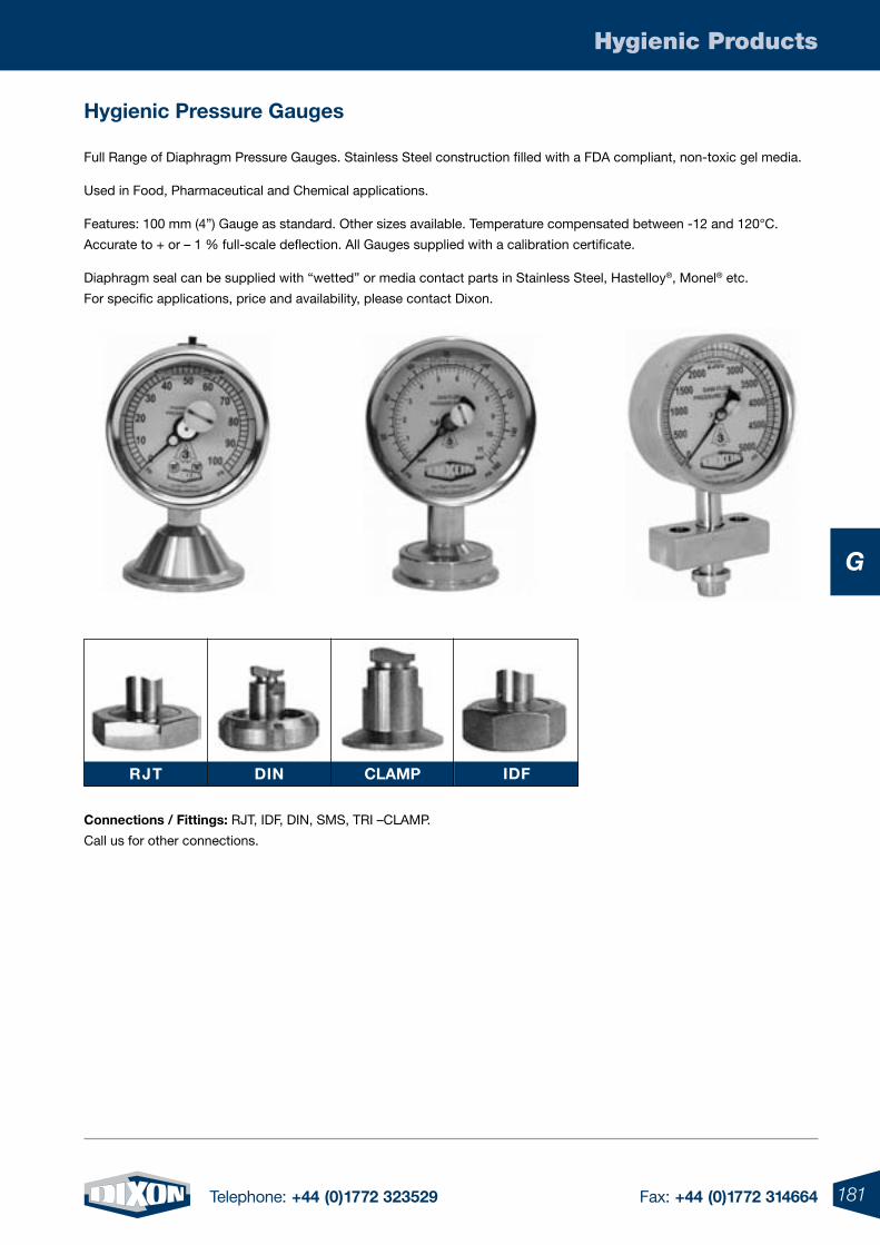
181Telephone: +44 (0)1772 323529 Fax: +44 (0)1772 314664
Hygienic Products
G
rJt DIn Clamp IDF
Connections / Fittings: RJT, IDF, DIN, SMS, TRI –CLAMP.
Call us for other connections.
Full Range of Diaphragm Pressure Gauges. Stainless Steel construction filled with a FDA compliant, non-toxic gel media.
Used in Food, Pharmaceutical and Chemical applications.
Features: 100 mm (4”) Gauge as standard. Other sizes available. Temperature compensated between -12 and 120°C.
Accurate to + or – 1 % full-scale deflection. All Gauges supplied with a calibration certificate.
Diaphragm seal can be supplied with “wetted” or media contact parts in Stainless Steel, Hastelloy®, Monel® etc.
For specific applications, price and availability, please contact Dixon.
Hygienic pressure gauges
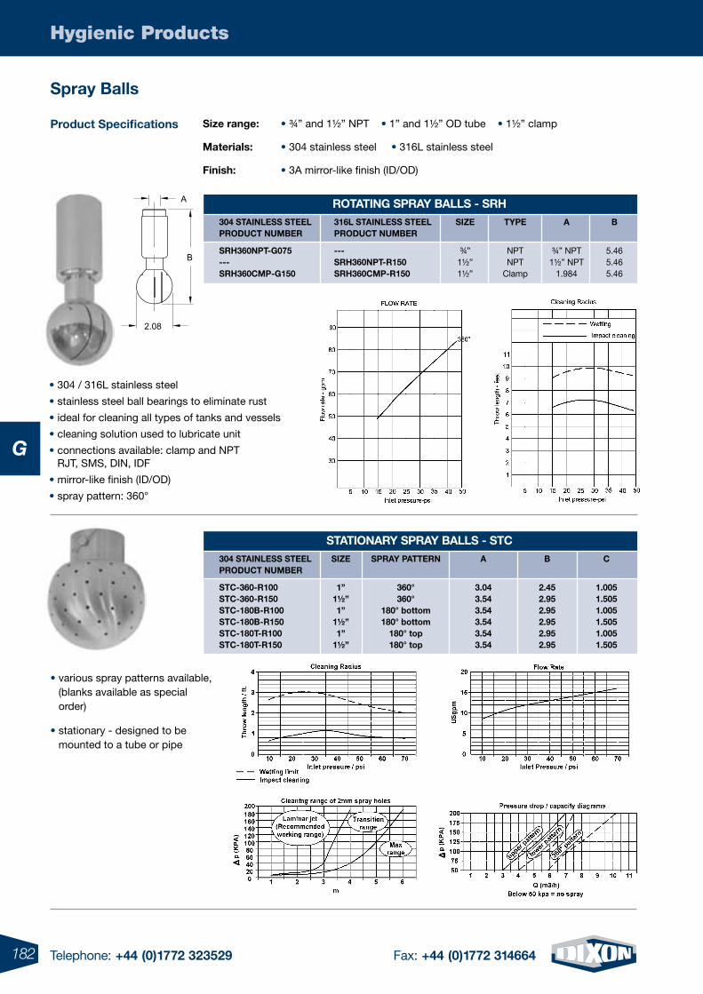
182 Telephone: +44 (0)1772 323529 Fax: +44 (0)1772 314664
Hygienic Products
G
A
B
2.08
size range: • ¾” and 1½” NPT • 1” and 1½” OD tube • 1½” clamp
materials: • 304 stainless steel • 316L stainless steel
Finish: • 3A mirror-like finish (ID/OD)
• various spray patterns available, (blanks available as special order)
• stationary - designed to be mounted to a tube or pipe
• 304 / 316L stainless steel
• stainless steel ball bearings to eliminate rust
• ideal for cleaning all types of tanks and vessels
• cleaning solution used to lubricate unit
• connections available: clamp and NPT RJT, SMS, DIN, IDF
• mirror-like finish (ID/OD)
• spray pattern: 360°
product specifications
rotatIng spraY Balls - srH
srH360npt-g075 --- ¾” NPT ¾” NPT 5.46 --- srH360npt-r150 1½” NPT 1½” NPT 5.46 srH360Cmp-g150 srH360Cmp-r150 1½” Clamp 1.984 5.46
304 staInless steel 316l staInless steel sIZe tYpe a B proDuCt numBer proDuCt numBer
statIonarY spraY Balls - stC
stC-360-r100 1” 360° 3.04 2.45 1.005 stC-360-r150 1½” 360° 3.54 2.95 1.505 stC-180B-r100 1” 180° bottom 3.54 2.95 1.005 stC-180B-r150 1½” 180° bottom 3.54 2.95 1.505 stC-180t-r100 1” 180° top 3.54 2.95 1.005 stC-180t-r150 1½” 180° top 3.54 2.95 1.505
304 staInless steel sIZe spraY pattern a B C proDuCt numBer
spray Balls
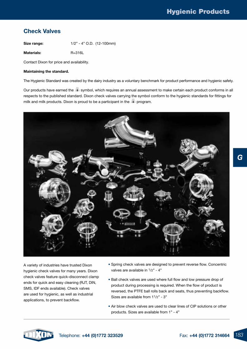
183Telephone: +44 (0)1772 323529 Fax: +44 (0)1772 314664
Hygienic Products
G
Check Valves
A variety of industries have trusted Dixon
hygienic check valves for many years. Dixon
check valves feature quick-disconnect clamp
ends for quick and easy cleaning (RJT, DIN,
SMS, IDF ends available). Check valves
are used for hygienic, as well as industrial
applications, to prevent backflow.
size range: 1/2” - 4” O.D. (12-100mm)
materials: R=316L
Contact Dixon for price and availability.
maintaining the standard.
The Hygienic Standard was created by the dairy industry as a voluntary benchmark for product performance and hygienic safety.
Our products have earned the symbol, which requires an annual assessment to make certain each product conforms in all
respects to the published standard. Dixon check valves carrying the symbol conform to the hygienic standards for fittings for
milk and milk products. Dixon is proud to be a participant in the program.
• Spring check valves are designed to prevent reverse flow. Concentric
valves are available in 1/2” - 4”
• Ball check valves are used where full flow and low pressure drop of
product during processing is required. When the flow of product is
reversed, the PTFE ball rolls back and seats, thus preventing backflow.
Sizes are available from 11/2” - 3”
• Air blow check valves are used to clear lines of CIP solutions or other
products. Sizes are available from 1” - 4”
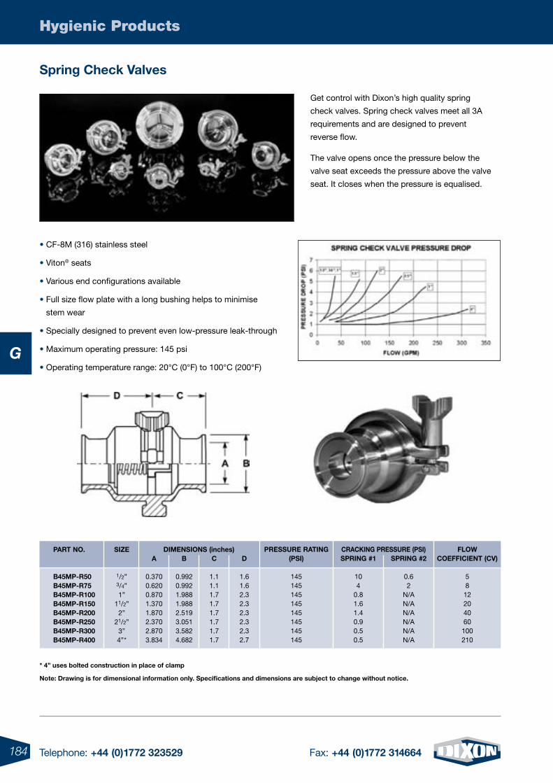
184 Telephone: +44 (0)1772 323529 Fax: +44 (0)1772 314664
Hygienic Products
G
spring Check Valves
Get control with Dixon’s high quality spring
check valves. Spring check valves meet all 3A
requirements and are designed to prevent
reverse flow.
The valve opens once the pressure below the
valve seat exceeds the pressure above the valve
seat. It closes when the pressure is equalised.
* 4” uses bolted construction in place of clamp
note: Drawing is for dimensional information only. specifications and dimensions are subject to change without notice.
• CF-8M (316) stainless steel
• Viton® seats
• Various end configurations available
• Full size flow plate with a long bushing helps to minimise
stem wear
• Specially designed to prevent even low-pressure leak-through
• Maximum operating pressure: 145 psi
• Operating temperature range: 20°C (0°F) to 100°C (200°F)
part no.
B45mp-r50B45mp-r75B45mp-r100B45mp-r150B45mp-r200B45mp-r250B45mp-r300B45mp-r400
sIZe
1/2”3/4”1”
11/2”2”
21/2”3”4”*
a
0.3700.6200.8701.3701.8702.3702.8703.834
B
0.9920.9921.9881.9882.5193.0513.5824.682
C
1.11.11.71.71.71.71.71.7
D
1.61.62.32.32.32.32.32.7
pressure ratIng(psI)
145145145145145145145145
sprIng #1
104
0.81.61.40.90.50.5
sprIng #2
0.62
N/AN/AN/AN/AN/AN/A
FloW CoeFFICIent (CV)
58
12204060
100210
CraCKIng pressure (psI)DImensIons (inches)
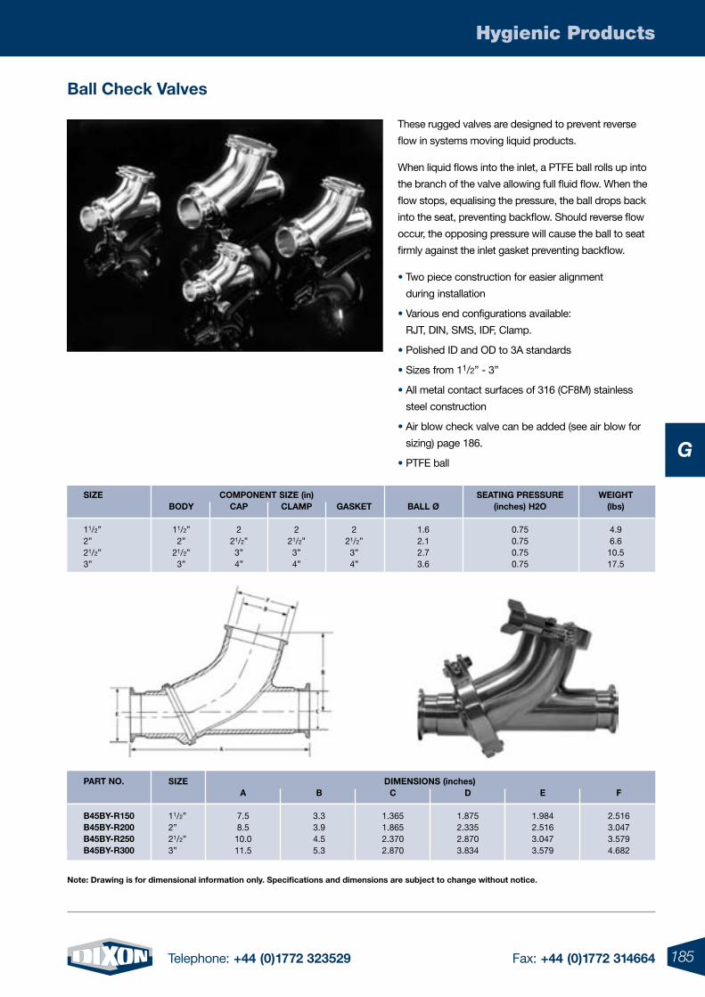
185Telephone: +44 (0)1772 323529 Fax: +44 (0)1772 314664
Hygienic Products
G
Ball Check Valves
These rugged valves are designed to prevent reverse
flow in systems moving liquid products.
When liquid flows into the inlet, a PTFE ball rolls up into
the branch of the valve allowing full fluid flow. When the
flow stops, equalising the pressure, the ball drops back
into the seat, preventing backflow. Should reverse flow
occur, the opposing pressure will cause the ball to seat
firmly against the inlet gasket preventing backflow.
• Two piece construction for easier alignment
during installation
• Various end configurations available:
RJT, DIN, SMS, IDF, Clamp.
• Polished ID and OD to 3A standards
• Sizes from 11/2” - 3”
• All metal contact surfaces of 316 (CF8M) stainless
steel construction
• Air blow check valve can be added (see air blow for
sizing) page 186.
• PTFE ball
note: Drawing is for dimensional information only. specifications and dimensions are subject to change without notice.
sIZe Component sIZe (in) seatIng pressure WeIgHt BoDY Cap Clamp gasKet Ball Ø (inches) H2o (lbs)
11/2” 11/2” 2 2 2 1.6 0.75 4.9 2” 2” 21/2” 21/2” 21/2” 2.1 0.75 6.6 21/2” 21/2” 3” 3” 3” 2.7 0.75 10.5 3” 3” 4” 4” 4” 3.6 0.75 17.5
sIZe DImensIons (inches) a B C D e F
11/2” 7.5 3.3 1.365 1.875 1.984 2.516 2” 8.5 3.9 1.865 2.335 2.516 3.047 21/2” 10.0 4.5 2.370 2.870 3.047 3.579 3” 11.5 5.3 2.870 3.834 3.579 4.682
part no.
B45BY-r150B45BY-r200B45BY-r250B45BY-r300
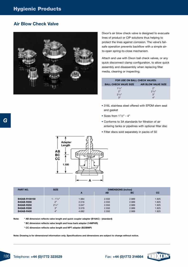
186 Telephone: +44 (0)1772 323529 Fax: +44 (0)1772 314664
Hygienic Products
G
air Blow Check Valve
Dixon’s air blow check valve is designed to evacuate
lines of product or CIP solutions thus helping to
protect the lines against corrosion. The valve’s fail-
safe operation prevents backflow with a simple air-
to-open spring-to-close mechanism.
Attach and use with Dixon ball check valves, or any
quick disconnect clamp configuration, to allow quick
assembly and disassembly when replacing filter
media, cleaning or inspecting.
note: * aB dimension reflects valve length and quick coupler adapter (B16aC) - (standard)
* BC dimension reflects valve length and hose barb adapter (14mpHr)
* CC dimension reflects valve length and npt adapter (B23Bmp)
For use on Ball CHeCK ValVes:
Ball CHeCK ValVe sIZe aIr BloW ValVe sIZe
11/2” 2” 2” 21/2” 21/2” 3” 3” 4”
• 316L stainless steel offered with EPDM stem seat
and gasket
• Sizes from 11/2” - 4”
• Conforms to 3A standards for filtration of air
entering tanks or pipelines with optional filter disc
• Filter discs sold separately in packs of 50
note: Drawing is for dimensional information only. specifications and dimensions are subject to change without notice.
sIZe DImensIons (inches) a aB BC CC
1 - 11/2” 1.984 2.550 2.989 1.925 2” 2.516 2.550 2.989 1.925 21/2” 3.047 2.550 2.989 1.925 3” 3.579 2.550 2.989 1.925 4” 4.682 2.550 2.989 1.925
part no.
B45aB-r100150B45aB-r200B45aB-r250B45aB-r300B45aB-r400
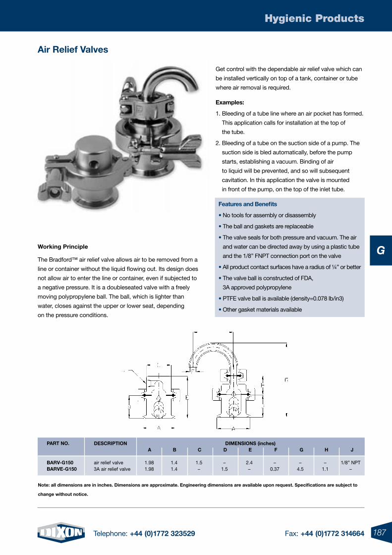
187Telephone: +44 (0)1772 323529 Fax: +44 (0)1772 314664
Hygienic Products
G
air relief Valves
Get control with the dependable air relief valve which can
be installed vertically on top of a tank, container or tube
where air removal is required.
examples:
1. Bleeding of a tube line where an air pocket has formed.
This application calls for installation at the top of
the tube.
2. Bleeding of a tube on the suction side of a pump. The
suction side is bled automatically, before the pump
starts, establishing a vacuum. Binding of air
to liquid will be prevented, and so will subsequent
cavitation. In this application the valve is mounted
in front of the pump, on the top of the inlet tube.
Features and Benefits
• No tools for assembly or disassembly
• The ball and gaskets are replaceable
• The valve seals for both pressure and vacuum. The air
and water can be directed away by using a plastic tube
and the 1/8” FNPT connection port on the valve
• All product contact surfaces have a radius of ¼” or better
• The valve ball is constructed of FDA,
3A approved polypropylene
• PTFE valve ball is available (density=0.078 lb/in3)
• Other gasket materials available
note: all dimensions are in inches. Dimensions are approximate. engineering dimensions are available upon request. specifications are subject to
change without notice.
Working principle
The Bradford™ air relief valve allows air to be removed from a
line or container without the liquid flowing out. Its design does
not allow air to enter the line or container, even if subjected to
a negative pressure. It is a doubleseated valve with a freely
moving polypropylene ball. The ball, which is lighter than
water, closes against the upper or lower seat, depending
on the pressure conditions.
DesCrIptIon DImensIons (inches) a B C D e F g H J
air relief valve 1.98 1.4 1.5 – 2.4 – – – 1/8” NPT 3A air relief valve 1.98 1.4 – 1.5 – 0.37 4.5 1.1 –
part no.
BarV-g150BarVe-g150
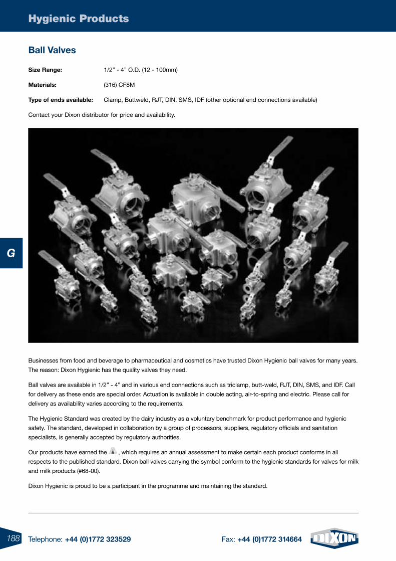
188 Telephone: +44 (0)1772 323529 Fax: +44 (0)1772 314664
Hygienic Products
G
Ball Valves
size range: 1/2” - 4” O.D. (12 - 100mm)
materials: (316) CF8M
type of ends available: Clamp, Buttweld, RJT, DIN, SMS, IDF (other optional end connections available)
Contact your Dixon distributor for price and availability.
Businesses from food and beverage to pharmaceutical and cosmetics have trusted Dixon Hygienic ball valves for many years.
The reason: Dixon Hygienic has the quality valves they need.
Ball valves are available in 1/2” - 4” and in various end connections such as triclamp, butt-weld, RJT, DIN, SMS, and IDF. Call
for delivery as these ends are special order. Actuation is available in double acting, air-to-spring and electric. Please call for
delivery as availability varies according to the requirements.
The Hygienic Standard was created by the dairy industry as a voluntary benchmark for product performance and hygienic
safety. The standard, developed in collaboration by a group of processors, suppliers, regulatory officials and sanitation
specialists, is generally accepted by regulatory authorities.
Our products have earned the , which requires an annual assessment to make certain each product conforms in all
respects to the published standard. Dixon ball valves carrying the symbol conform to the hygienic standards for valves for milk
and milk products (#68-00).
Dixon Hygienic is proud to be a participant in the programme and maintaining the standard.
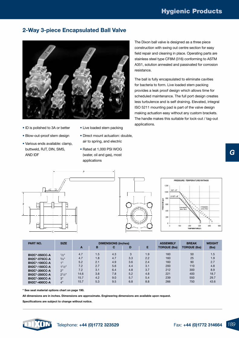
189Telephone: +44 (0)1772 323529 Fax: +44 (0)1772 314664
Hygienic Products
G
2-Way 3-piece encapsulated Ball Valve
• ID is polished to 3A or better
• Blow-out-proof stem design
• Various ends available: clamp,
buttweld, RJT, DIN, SMS,
AND IDF
• Live loaded stem packing
• Direct mount actuation: double,
air to spring, and electric
• Rated at 1,000 PSI WOG
(water, oil and gas), most
applications
The Dixon ball valve is designed as a three piece
construction with swing out centre section for easy
field repair and cleaning in place. Operating parts are
stainless steel type CF8M (316) conforming to ASTM
A351, solution annealed and passivated for corrosion
resistance.
The ball is fully encapsulated to eliminate cavities
for bacteria to form. Live loaded stem packing
provides a leak proof design which allows time for
scheduled maintenance. The full port design creates
less turbulence and is self draining. Elevated, integral
ISO 5211 mounting pad is part of the valve design
making actuation easy without any custom brackets.
The handle makes this suitable for lock-out / tag-out
applications.
sIZe DImensIons (inches) assemBlY BreaK WeIgHt a B C D e torque (lbs) torque (lbs) (lbs) 1/2” 3/4” 1” 11/2” 2” 21/2” 3” 4”
part no.
BV2C*-050CC-aBV2C*-075CC-aBV2C*-100CC-aBV2C*-150CC-aBV2C*-200CC-aBV2C*-250CC-aBV2C*-300CC-aBV2C*-400CC-a
4.74.75.27.27.2
14.615.715.7
1.51.82.12.73.13.84.25.3
4.34.74.95.66.47.89.09.5
33.33.64.44.85.25.76.8
1.92.22.43.13.74.85.48.8
160160160200212221239266
502590
110300400550750
1.51.92.74.88.9
18.729.743.6
* see seat material options chart on page 190.
all dimensions are in inches. Dimensions are approximate. engineering dimensions are available upon request.
specifications are subject to change without notice.
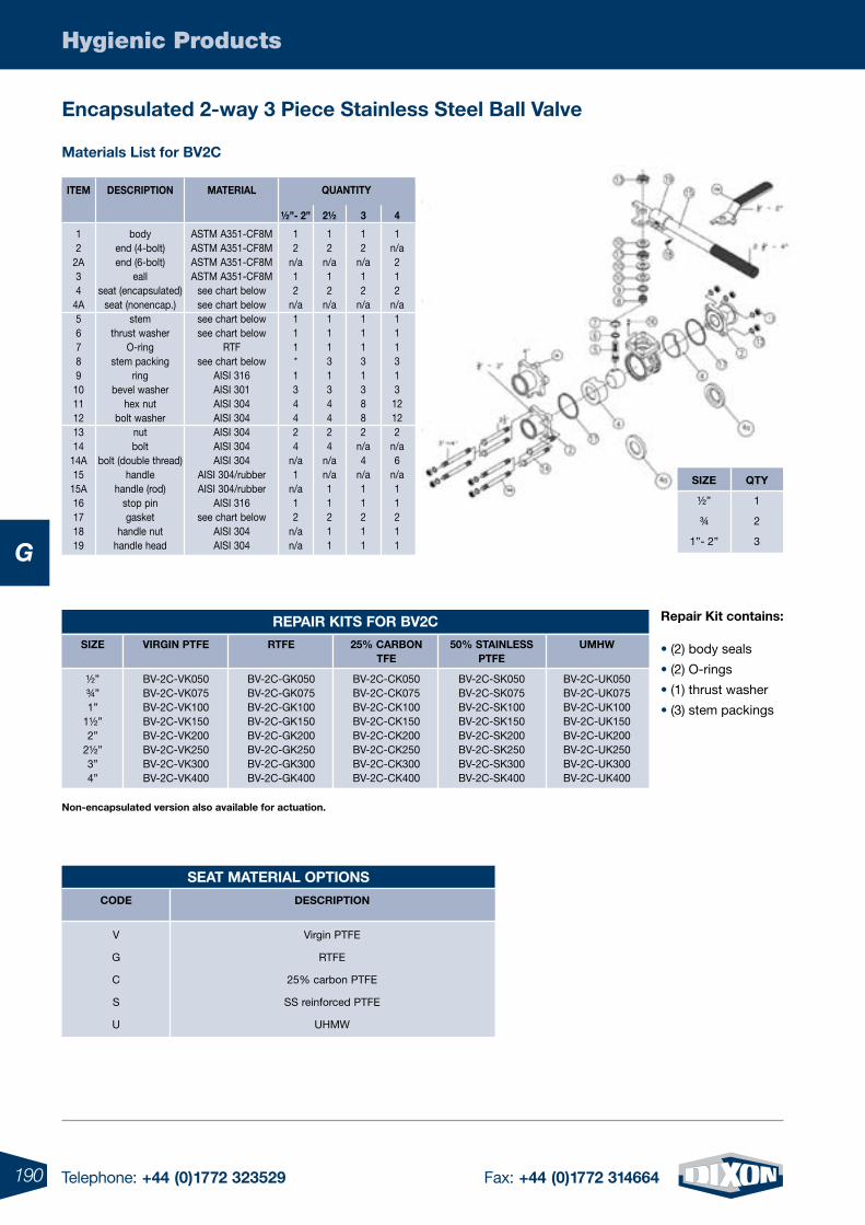
190 Telephone: +44 (0)1772 323529 Fax: +44 (0)1772 314664
Hygienic Products
G
encapsulated 2-way 3 piece stainless steel Ball Valve
materials list for BV2C
Item
12
2A34
4A56789
1011121314
14A15
15A16171819
DesCrIptIon
bodyend (4-bolt)end (6-bolt)
eallseat (encapsulated)
seat (nonencap.)stem
thrust washerO-ring
stem packingring
bevel washerhex nut
bolt washernutbolt
bolt (double thread)handle
handle (rod)stop pingasket
handle nuthandle head
materIal
ASTM A351-CF8MASTM A351-CF8MASTM A351-CF8MASTM A351-CF8M
see chart belowsee chart belowsee chart belowsee chart below
RTFsee chart below
AISI 316AISI 301AISI 304AISI 304AISI 304AISI 304AISI 304
AISI 304/rubberAISI 304/rubber
AISI 316see chart below
AISI 304AISI 304
½”- 2”
12
n/a12
n/a111*134424
n/a1
n/a12
n/an/a
2½
12
n/a12
n/a1113134424
n/an/a11211
3
12
n/a12
n/a111313882
n/a4
n/a11211
4
1n/a212
n/a11131312122
n/a6
n/a11211
quantItY
repair Kit contains:
• (2) body seals
• (2) O-rings
• (1) thrust washer
• (3) stem packings
non-encapsulated version also available for actuation.
seat materIal optIons
CoDe
V
G
C
S
U
DesCrIptIon
Virgin PTFE
RTFE
25% carbon PTFE
SS reinforced PTFE
UHMW
sIZe
½”
¾
1”- 2”
qtY
1
2
3
repaIr KIts For BV2C sIZe
½”¾”1”
1½”2”
2½”3”4”
VIrgIn ptFe
BV-2C-VK050BV-2C-VK075BV-2C-VK100BV-2C-VK150BV-2C-VK200BV-2C-VK250BV-2C-VK300BV-2C-VK400
rtFe
BV-2C-GK050BV-2C-GK075BV-2C-GK100BV-2C-GK150BV-2C-GK200BV-2C-GK250BV-2C-GK300BV-2C-GK400
25% CarBontFe
BV-2C-CK050BV-2C-CK075BV-2C-CK100BV-2C-CK150BV-2C-CK200BV-2C-CK250BV-2C-CK300BV-2C-CK400
50% staInless ptFe
BV-2C-SK050BV-2C-SK075BV-2C-SK100BV-2C-SK150BV-2C-SK200BV-2C-SK250BV-2C-SK300BV-2C-SK400
umHW
BV-2C-UK050BV-2C-UK075BV-2C-UK100BV-2C-UK150BV-2C-UK200BV-2C-UK250BV-2C-UK300BV-2C-UK400
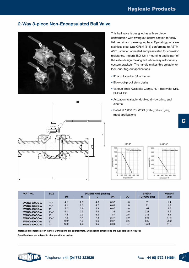
191Telephone: +44 (0)1772 323529 Fax: +44 (0)1772 314664
Hygienic Products
G
2-Way 3-piece non-encapsulated Ball Valve
sIZe DImensIons (inches) BreaK WeIgHt D1 H l Øa ØD torque (lbs) (lbs) 1/2” 3/4” 1” 11/2” 2” 21/2” 3” 4”
part no.
BV2gg-050CC-aBV2gg-075CC-aBV2gg-100CC-aBV2gg-150CC-aBV2gg-200CC-aBV2gg-250CC-aBV2gg-300CC-aBV2gg-400CC-a
note: all dimensions are in inches. Dimensions are approximate. engineering dimensions are available upon request.
specifications are subject to change without notice.
This ball valve is designed as a three piece
construction with swing out centre section for easy
field repair and cleaning in place. Operating parts are
stainless steel type CF8M (316) conforming to ASTM
A351, solution annealed and passivated for corrosion
resistance. Integral ISO 5211 mounting pad is part of
the valve design making actuation easy without any
custom brackets. The handle makes this suitable for
lock-out / tag-out applications.
• ID is polished to 3A or better
• Blow-out-proof stem design
• Various Ends Available: Clamp, RJT, Buttweld, DIN,
SMS & IDF
• Actuation available: double, air-to-spring, and
electric
• Rated at 1,000 PSI WOG (water, oil and gas),
most applications
4.14.15.06.17.67.6
10.913.2
2.32.52.83.53.94.44.96.6
4.64.74.95.66.47.89.09.6
0.370.630.871.381.872.372.873.83
1.01.02.02.02.53.03.64.7
55711012213458838301323
1.41.82.64.68.5
17.828.241.4
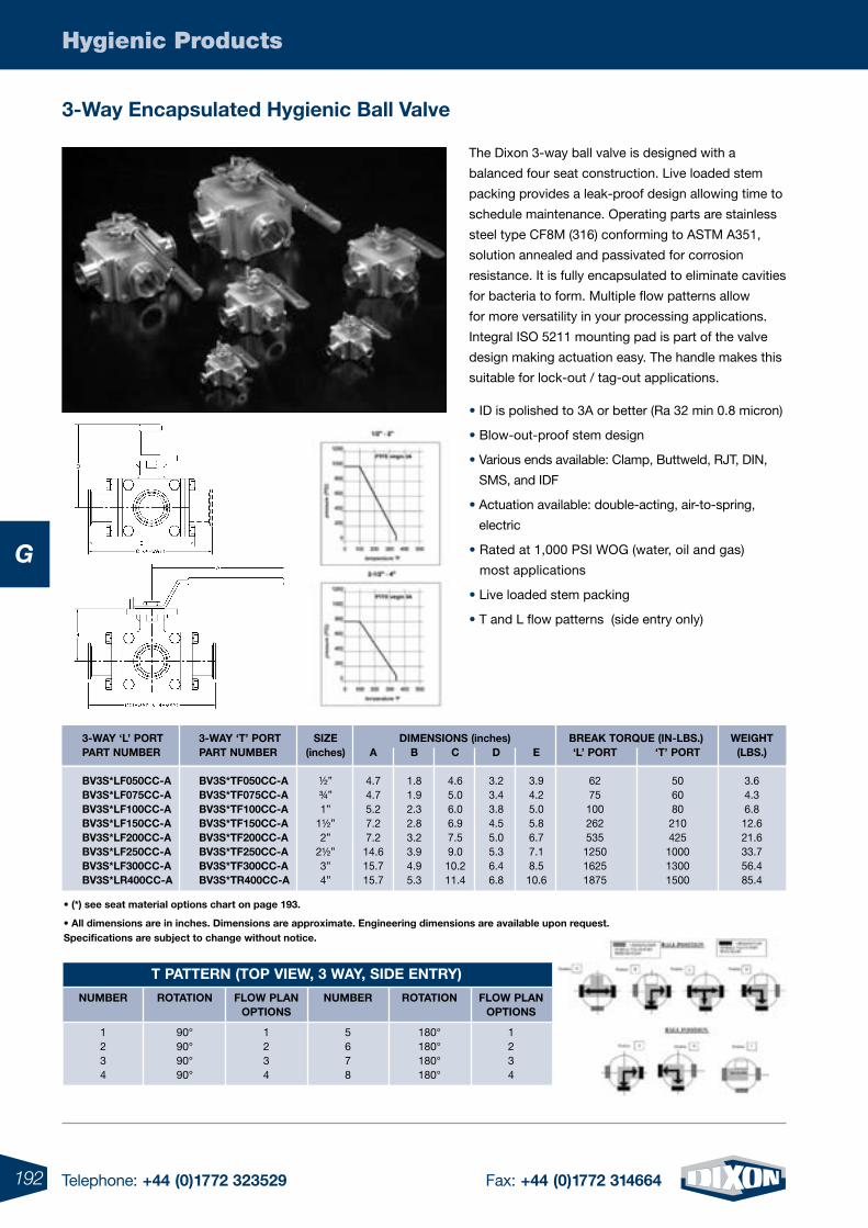
192 Telephone: +44 (0)1772 323529 Fax: +44 (0)1772 314664
Hygienic Products
G
3-Way encapsulated Hygienic Ball Valve
The Dixon 3-way ball valve is designed with a
balanced four seat construction. Live loaded stem
packing provides a leak-proof design allowing time to
schedule maintenance. Operating parts are stainless
steel type CF8M (316) conforming to ASTM A351,
solution annealed and passivated for corrosion
resistance. It is fully encapsulated to eliminate cavities
for bacteria to form. Multiple flow patterns allow
for more versatility in your processing applications.
Integral ISO 5211 mounting pad is part of the valve
design making actuation easy. The handle makes this
suitable for lock-out / tag-out applications.
• ID is polished to 3A or better (Ra 32 min 0.8 micron)
• Blow-out-proof stem design
• Various ends available: Clamp, Buttweld, RJT, DIN,
SMS, and IDF
• Actuation available: double-acting, air-to-spring,
electric
• Rated at 1,000 PSI WOG (water, oil and gas)
most applications
• Live loaded stem packing
• T and L flow patterns (side entry only)
t pattern (top VIeW, 3 WaY, sIDe entrY)
numBer
1234
rotatIon
90°90°90°90°
FloW plan optIons
1234
numBer
5678
rotatIon
180°180°180°180°
FloW plan optIons
1234
3-WaY ‘l’ portpart numBer
BV3s*lF050CC-aBV3s*lF075CC-aBV3s*lF100CC-aBV3s*lF150CC-aBV3s*lF200CC-aBV3s*lF250CC-aBV3s*lF300CC-aBV3s*lr400CC-a
3-WaY ‘t’ portpart numBer
BV3s*tF050CC-aBV3s*tF075CC-aBV3s*tF100CC-aBV3s*tF150CC-aBV3s*tF200CC-aBV3s*tF250CC-aBV3s*tF300CC-aBV3s*tr400CC-a
sIZe(inches)
½”¾”1”
1½”2”
2½”3”4”
BreaK torque (In-lBs.)‘l’ port
6275
100262535
125016251875
‘t’ port
506080
210425
100013001500
WeIgHt(lBs.)
3.64.36.8
12.621.633.756.485.4
DImensIons (inches)a
4.74.75.27.27.2
14.615.715.7
B
1.81.92.32.83.23.94.95.3
C
4.65.06.06.97.59.0
10.211.4
D
3.23.43.84.55.05.36.46.8
e
3.94.25.05.86.77.18.5
10.6
• (*) see seat material options chart on page 193.
• All dimensions are in inches. Dimensions are approximate. Engineering dimensions are available upon request.specifications are subject to change without notice.
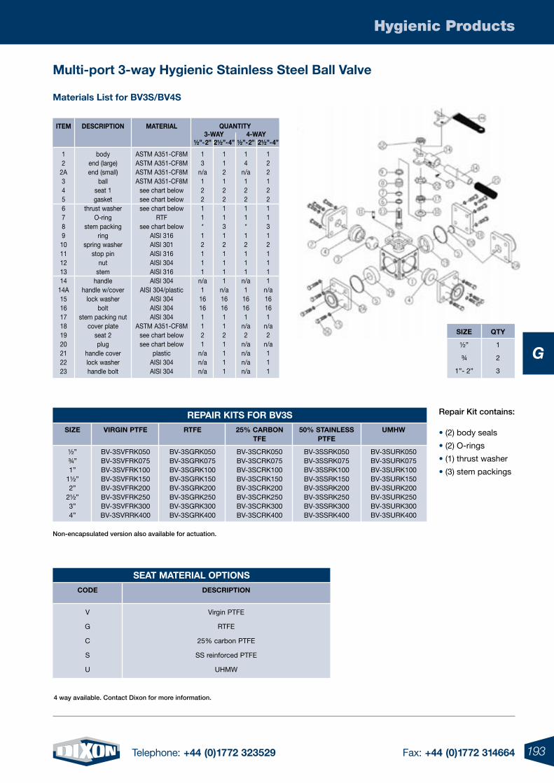
193Telephone: +44 (0)1772 323529 Fax: +44 (0)1772 314664
Hygienic Products
G
4 way available. Contact Dixon for more information.
multi-port 3-way Hygienic stainless steel Ball Valve
materials list for BV3s/BV4s
Item
12
2A34567891011121314
14A151617181920212223
DesCrIptIon
bodyend (large)end (small)
ballseat 1gasket
thrust washerO-ring
stem packingring
spring washerstop pin
nutstem
handlehandle w/cover
lock washerbolt
stem packing nutcover plate
seat 2plug
handle coverlock washerhandle bolt
materIal
ASTM A351-CF8MASTM A351-CF8MASTM A351-CF8MASTM A351-CF8M
see chart belowsee chart belowsee chart below
RTFsee chart below
AISI 316AISI 301AISI 316AISI 304AISI 316AISI 304
AISI 304/plasticAISI 304AISI 304AISI 304
ASTM A351-CF8Msee chart belowsee chart below
plasticAISI 304AISI 304
½”-2”
13
n/a12211*12111
n/a1
16161121
n/an/an/a
2½”-4”
112122113121111
n/a16161121111
½”-2”
14
n/a12211*12111
n/a116161
n/a2
n/an/an/an/a
2½”-4”
122122113121111
n/a16161
n/a2
n/a111
quantItY3-WaY 4-WaY
seat materIal optIons
CoDe
V
G
C
S
U
DesCrIptIon
Virgin PTFE
RTFE
25% carbon PTFE
SS reinforced PTFE
UHMW
sIZe
½”
¾
1”- 2”
qtY
1
2
3
Repair Kit contains:
• (2) body seals
• (2) O-rings
• (1) thrust washer
• (3) stem packings
Non-encapsulated version also available for actuation.
repaIr KIts For BV3ssIZe
½”¾”1”
1½”2”
2½”3”4”
VIrgIn ptFe
BV-3SVFRK050BV-3SVFRK075BV-3SVFRK100BV-3SVFRK150BV-3SVFRK200BV-3SVFRK250BV-3SVFRK300BV-3SVRRK400
rtFe
BV-3SGRK050BV-3SGRK075BV-3SGRK100BV-3SGRK150BV-3SGRK200BV-3SGRK250BV-3SGRK300BV-3SGRK400
25% CarBontFe
BV-3SCRK050BV-3SCRK075BV-3SCRK100BV-3SCRK150BV-3SCRK200BV-3SCRK250BV-3SCRK300BV-3SCRK400
50% staInless ptFe
BV-3SSRK050BV-3SSRK075BV-3SSRK100BV-3SSRK150BV-3SSRK200BV-3SSRK250BV-3SSRK300BV-3SSRK400
umHW
BV-3SURK050BV-3SURK075BV-3SURK100BV-3SURK150BV-3SURK200BV-3SURK250BV-3SURK300BV-3SURK400
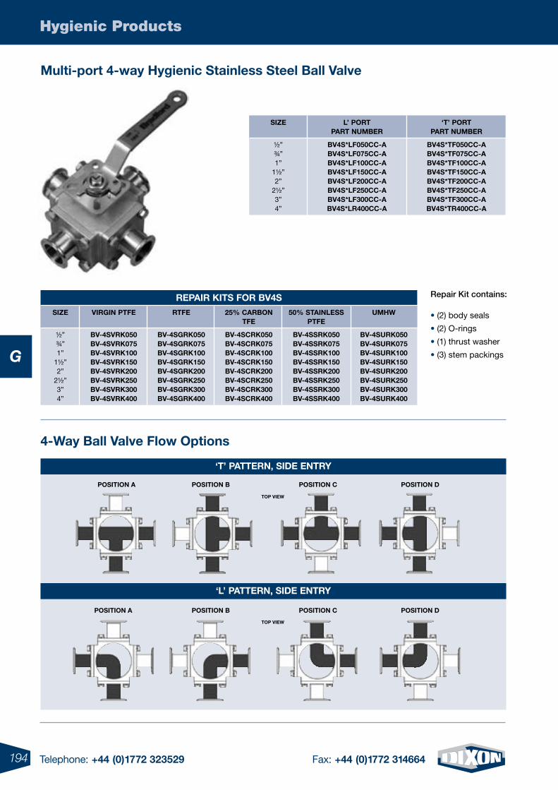
194 Telephone: +44 (0)1772 323529 Fax: +44 (0)1772 314664
Hygienic Products
G
Multi-port 4-way Hygienic Stainless Steel Ball Valve
Repair Kit contains:
• (2) body seals
• (2) O-rings
• (1) thrust washer
• (3) stem packings
RepaiR KitS foR BV4SSiZe
½”¾”1”
1½”2”
2½”3”4”
ViRGiN ptfe
BV-4SVRK050BV-4SVRK075BV-4SVRK100BV-4SVRK150BV-4SVRK200BV-4SVRK250BV-4SVRK300BV-4SVRK400
Rtfe
BV-4SGRK050BV-4SGRK075BV-4SGRK100BV-4SGRK150BV-4SGRK200BV-4SGRK250BV-4SGRK300BV-4SGRK400
25% CaRBoNtfe
BV-4SCRK050BV-4SCRK075BV-4SCRK100BV-4SCRK150BV-4SCRK200BV-4SCRK250BV-4SCRK300BV-4SCRK400
50% StaiNLeSS ptfe
BV-4SSRK050BV-4SSRK075BV-4SSRK100BV-4SSRK150BV-4SSRK200BV-4SSRK250BV-4SSRK300BV-4SSRK400
UMHW
BV-4SURK050BV-4SURK075BV-4SURK100BV-4SURK150BV-4SURK200BV-4SURK250BV-4SURK300BV-4SURK400
SiZe
½”¾”1”
1½”2”
2½”3”4”
L’ poRtpaRt NUMBeR
BV4S*Lf050CC-aBV4S*Lf075CC-aBV4S*Lf100CC-aBV4S*Lf150CC-aBV4S*Lf200CC-aBV4S*Lf250CC-aBV4S*Lf300CC-aBV4S*LR400CC-a
‘t’ poRt paRt NUMBeR
BV4S*tf050CC-aBV4S*tf075CC-aBV4S*tf100CC-aBV4S*tf150CC-aBV4S*tf200CC-aBV4S*tf250CC-aBV4S*tf300CC-aBV4S*tR400CC-a
4-Way Ball Valve flow options
‘t’ patteRN, Side eNtRy
‘L’ patteRN, Side eNtRy
poSitioN a poSitioN B poSitioN C poSitioN d
poSitioN B poSitioN C poSitioN dpoSitioN a
top VieW
top VieW
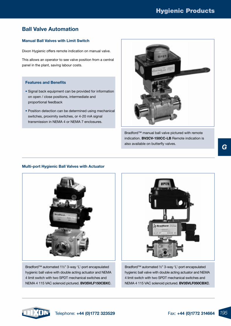
195Telephone: +44 (0)1772 323529 Fax: +44 (0)1772 314664
Hygienic Products
G
Ball Valve automation
Dixon Hygienic offers remote indication on manual valve.
This allows an operator to see valve position from a central
panel in the plant, saving labour costs.
features and Benefits
• Signal back equipment can be provided for information
on open / close positions, intermediate and
proportional feedback
• Position detection can be determined using mechanical
switches, proximity switches, or 4-20 mA signal
transmission in NEMA 4 or NEMA 7 enclosures.
Bradford™ manual ball valve pictured with remote
indication. BV2CV-150CC-LB Remote indication is
also available on butterfly valves.
Multi-port Hygienic Ball Valves with actuator
Bradford™ automated 1½” 3-way ‘L’-port encapsulated
hygienic ball valve with double acting actuator and NEMA
4 limit switch with two SPDT mechanical switches and
NEMA 4 115 VAC solenoid pictured. BV3SVLf150CBXC.
Manual Ball Valves with Limit Switch
Bradford™ automated ½” 3-way ‘L’-port encapsulated
hygienic ball valve with double acting actuator and NEMA
4 limit switch with two SPDT mechanical switches and
NEMA 4 115 VAC solenoid pictured. BV3SVLf050CBXC.
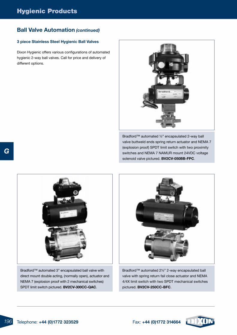
196 Telephone: +44 (0)1772 323529 Fax: +44 (0)1772 314664
Hygienic Products
G
3 piece Stainless Steel Hygienic Ball Valves
Dixon Hygienic offers various configurations of automated
hygienic 2-way ball valves. Call for price and delivery of
different options.
Bradford™ automated ½” encapsulated 2-way ball
valve buttweld ends spring return actuator and NEMA 7
(explosion proof) SPDT limit switch with two proximity
switches and NEMA 7 NAMUR mount 24VDC voltage
solenoid valve pictured. BV2CV-050BB-fpC.
Bradford™ automated 3” encapsulated ball valve with
direct mount double acting, (normally open), actuator and
NEMA 7 (explosion proof with 2 mechanical switches)
SPDT limit switch pictured. BV2CV-300CC-QaC.
Bradford™ automated 2½” 2-way encapsulated ball
valve with spring return fail close actuator and NEMA
4/4X limit switch with two SPDT mechanical switches
pictured. BV2CV-250CC-BfC.
Ball Valve automation (continued)
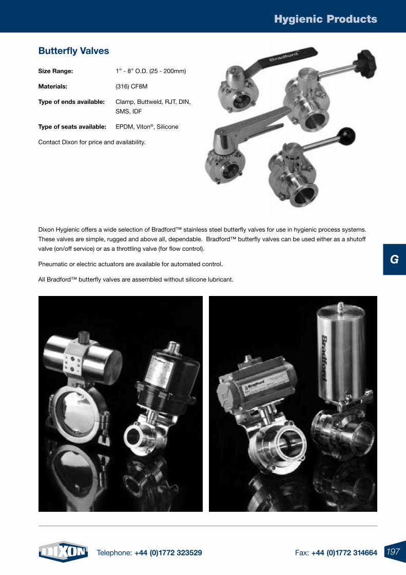
197Telephone: +44 (0)1772 323529 Fax: +44 (0)1772 314664
Hygienic Products
G
Butterfly Valves
Size Range: 1” - 8” O.D. (25 - 200mm)
Materials: (316) CF8M
type of ends available: Clamp, Buttweld, RJT, DIN,
SMS, IDF
type of seats available: EPDM, Viton®, Silicone
Contact Dixon for price and availability.
Dixon Hygienic offers a wide selection of Bradford™ stainless steel butterfly valves for use in hygienic process systems.
These valves are simple, rugged and above all, dependable. Bradford™ butterfly valves can be used either as a shutoff
valve (on/off service) or as a throttling valve (for flow control).
Pneumatic or electric actuators are available for automated control.
All Bradford™ butterfly valves are assembled without silicone lubricant.
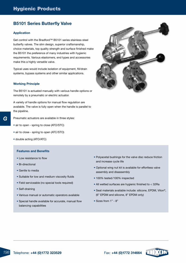
198 Telephone: +44 (0)1772 323529 Fax: +44 (0)1772 314664
Hygienic Products
G
B5101 Series Butterfly Valve
application
Get control with the Bradford™ B5101 series stainless steel
butterfly valves. The slim design, superior craftsmanship,
choice materials, top quality strength and surface finished make
the B5101 the preference of many industries with hygienic
requirements. Various elastomers, end types and accessories
make this a highly versatile valve.
Typical uses would include isolation of equipment, fill/drain
systems, bypass systems and other similar applications.
Working principle
The B5101 is actuated manually with various handle options or
remotely by a pneumatic or electric actuator.
A variety of handle options for manual flow regulation are
available. The valve is fully open when the handle is parallel to
the pipeline.
Pneumatic actuators are available in three styles:
• air to open - spring to close (ATO/STC)
• air to close - spring to open (ATC/STO)
• double acting (ATO/ATC)
features and Benefits
• Low resistance to flow
• Bi-directional
• Gentle to media
• Suitable for low and medium viscosity fluids
• Field serviceable (no special tools required)
• Self-draining
• Various manual or automatic operators available
• Special handle available for accurate, manual flow
balancing capabilities
• Polyacetal bushings for the valve disc reduce friction
and increase cycle life
• Optional wing nut kit is available for effortless valve
assembly and disassembly
• 100% tested/100% inspected
• All wetted surfaces are hygienic finished to < 32Ra
• Seat materials available include: silicone, EPDM, Viton®,
(6” EPDM and silicone, 8” EPDM only)
• Sizes from 1” - 8”
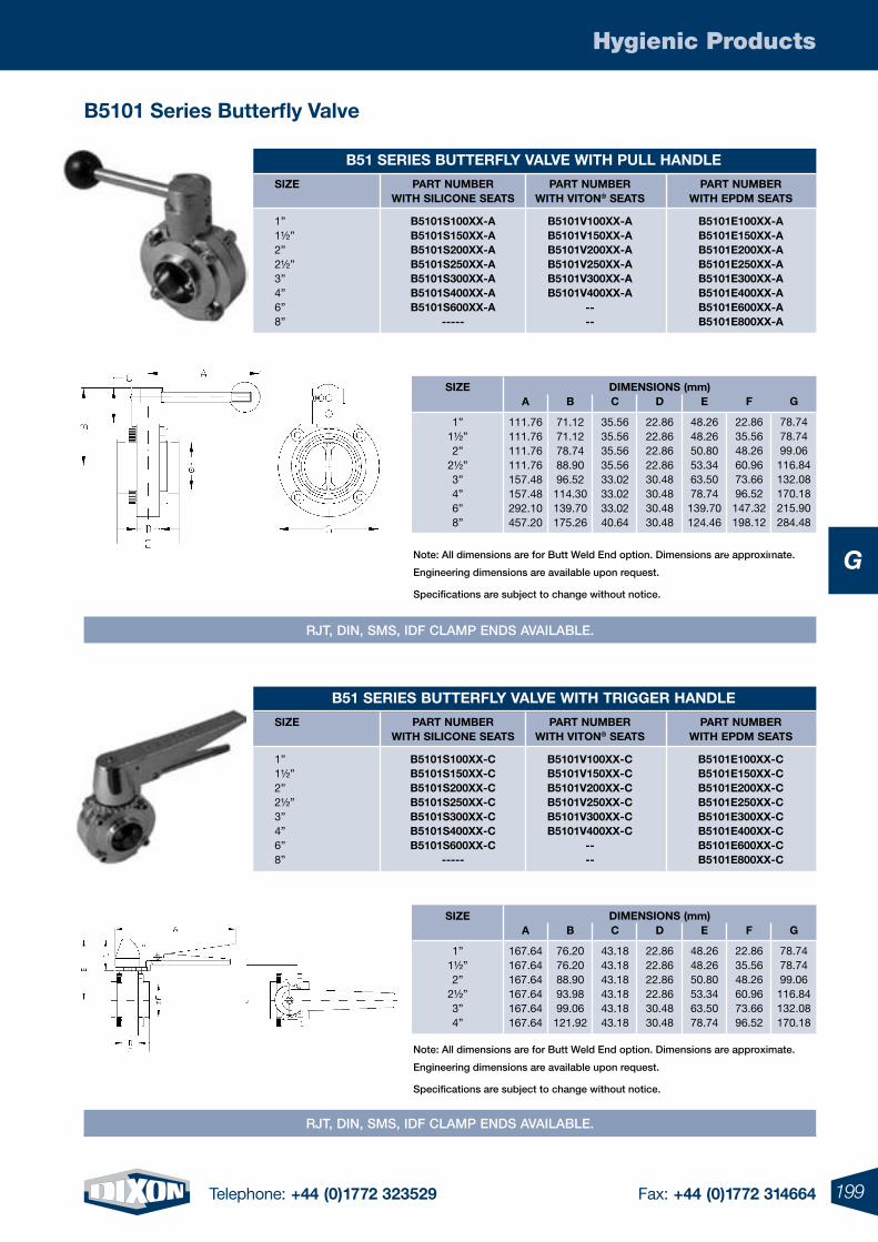
199Telephone: +44 (0)1772 323529 Fax: +44 (0)1772 314664
Hygienic Products
G
B5101 Series Butterfly Valve
B51 SeRieS BUtteRfLy VaLVe WitH pULL HaNdLe
SiZe paRt NUMBeR paRt NUMBeR paRt NUMBeR WitH SiLiCoNe SeatS WitH VitoN® SeatS WitH epdM SeatS
1” B5101S100XX-a B5101V100XX-a B5101e100XX-a 1½” B5101S150XX-a B5101V150XX-a B5101e150XX-a 2” B5101S200XX-a B5101V200XX-a B5101e200XX-a 2½” B5101S250XX-a B5101V250XX-a B5101e250XX-a 3” B5101S300XX-a B5101V300XX-a B5101e300XX-a 4” B5101S400XX-a B5101V400XX-a B5101e400XX-a 6” B5101S600XX-a -- B5101e600XX-a 8” ----- -- B5101e800XX-a
Note: All dimensions are for Butt Weld End option. Dimensions are approximate.
Engineering dimensions are available upon request.
Specifications are subject to change without notice.
SiZe
1”1½”2”
2½”3”4”6”8”
a
111.76111.76111.76111.76157.48157.48292.10457.20
B
71.1271.1278.7488.9096.52114.30139.70175.26
C
35.5635.5635.5635.5633.0233.0233.0240.64
d
22.8622.8622.8622.8630.4830.4830.4830.48
e
48.2648.2650.8053.3463.5078.74139.70124.46
f
22.8635.5648.2660.9673.6696.52147.32198.12
G
78.7478.7499.06
116.84132.08170.18215.90284.48
diMeNSioNS (mm)
B51 SeRieS BUtteRfLy VaLVe WitH tRiGGeR HaNdLe
SiZe paRt NUMBeR paRt NUMBeR paRt NUMBeR WitH SiLiCoNe SeatS WitH VitoN® SeatS WitH epdM SeatS
1” B5101S100XX-C B5101V100XX-C B5101e100XX-C 1½” B5101S150XX-C B5101V150XX-C B5101e150XX-C 2” B5101S200XX-C B5101V200XX-C B5101e200XX-C 2½” B5101S250XX-C B5101V250XX-C B5101e250XX-C 3” B5101S300XX-C B5101V300XX-C B5101e300XX-C 4” B5101S400XX-C B5101V400XX-C B5101e400XX-C 6” B5101S600XX-C -- B5101e600XX-C 8” ----- -- B5101e800XX-C
SiZe
1”1½”2”
2½”3”4”
a
167.64167.64167.64167.64167.64167.64
B
76.2076.2088.9093.9899.06121.92
C
43.1843.1843.1843.1843.1843.18
d
22.8622.8622.8622.8630.4830.48
e
48.2648.2650.8053.3463.5078.74
f
22.8635.5648.2660.9673.6696.52
G
78.7478.7499.06
116.84132.08170.18
diMeNSioNS (mm)
Note: All dimensions are for Butt Weld End option. Dimensions are approximate.
Engineering dimensions are available upon request.
Specifications are subject to change without notice.
RJT, DIN, SMS, IDF ClAMp ENDS AvAIlABlE.
RJT, DIN, SMS, IDF ClAMp ENDS AvAIlABlE.
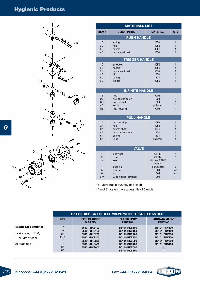
200 Telephone: +44 (0)1772 323529 Fax: +44 (0)1772 314664
Hygienic Products
G
* 6" valve has a quantity of 8 each
4" and 8" valves have a quantity of 6 each
B51 SeRieS BUtteRfLy VaLVe WitH tRiGGeR HaNdLe
SiZe
1”1½”2”
2½”3”4”6”8”
Repair Kit contains:
(1) silicone, EPDM,
or Viton® seal
(2) bushings
(Red) SiLiCoNepaRt No.
(BLaCK) epdMpaRt No.
B5101-RKS100B5101-RKS150B5101-RKS200B5101-RKS250B5101-RKS300B5101-RKS400B5101-RKS600
---
B5101-RKe100B5101-RKe150B5101-RKe200B5101-RKe250B5101-RKe300B5101-RKe400B5101-RKe600B5101-RKe800
B5101-RKV100B5101-RKV150B5101-RKV200B5101-RKV250B5101-RKV300B5101-RKS400
------
(BRoWN) VitoN®
paRt No.
iteM #
1D2D3D4D
springhubhandlehex socket bolt
deSCRiptioN MateRiaL Qty
1111
304CF8CF8304
pUSH HaNdLe
tRiGGeR HaNdLe1C2C3C4C5C6C
sprockethandlehex socket boltpinspringtrigger
111111
CF8CF8304304304CF8
iNfiNite HaNdLe1B2B3B4B5B
hubhex socket screwhandle shaftknobhub housing
11111
CF8304304
polymerCF8
pULL HaNdLe1A2A3A4A5A6A
hub housinghubhandle shafthex socket screwspringknob
111111
CF8CF8304304304
polymer
VaLVe123
456
6W
body halfdiscseat
bushinghex nutboltwing nut kit (optional)
111
24 *4 *4 *
CF8MCF8M
silicone EPDMViton®
polyacetal304304304
MateRiaLS LiSt
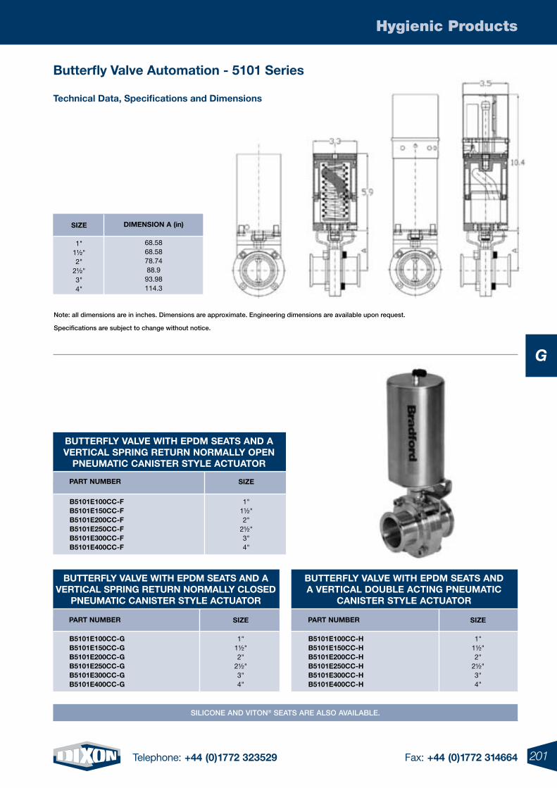
201Telephone: +44 (0)1772 323529 Fax: +44 (0)1772 314664
Hygienic Products
G
Butterfly Valve automation - 5101 Series
technical data, Specifications and dimensions
Note: all dimensions are in inches. Dimensions are approximate. Engineering dimensions are available upon request.
Specifications are subject to change without notice.
SiZe
1"1½" 2"
2½" 3" 4"
diMeNSioN a (in)
68.5868.5878.7488.9
93.98114.3
BUtteRfLy VaLVe WitH epdM SeatS aNd a VeRtiCaL SpRiNG RetURN NoRMaLLy opeN
pNeUMatiC CaNiSteR StyLe aCtUatoR
B5101e100CC-fB5101e150CC-fB5101e200CC-fB5101e250CC-fB5101e300CC-fB5101e400CC-f
paRt NUMBeR SiZe
1"1½" 2"
2½" 3" 4"
BUtteRfLy VaLVe WitH epdM SeatS aNd a VeRtiCaL SpRiNG RetURN NoRMaLLy CLoSed
pNeUMatiC CaNiSteR StyLe aCtUatoR
B5101e100CC-GB5101e150CC-GB5101e200CC-GB5101e250CC-GB5101e300CC-GB5101e400CC-G
paRt NUMBeR
BUtteRfLy VaLVe WitH epdM SeatS aNd a VeRtiCaL doUBLe aCtiNG pNeUMatiC
CaNiSteR StyLe aCtUatoR
SiZe
1"1½" 2"
2½" 3" 4"
SiZe
1"1½" 2"
2½" 3" 4"
B5101e100CC-HB5101e150CC-HB5101e200CC-HB5101e250CC-HB5101e300CC-HB5101e400CC-H
paRt NUMBeR
SIlICoNE AND vIToN® SEATS ARE AlSo AvAIlABlE.
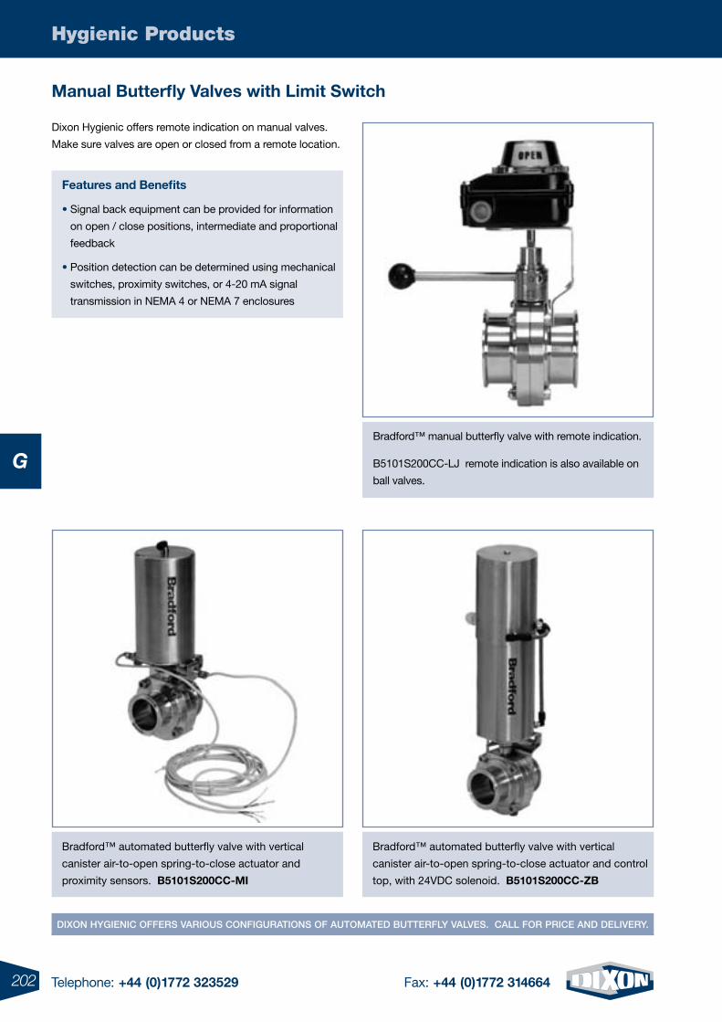
202 Telephone: +44 (0)1772 323529 Fax: +44 (0)1772 314664
Hygienic Products
G
Manual Butterfly Valves with Limit Switch
Dixon Hygienic offers remote indication on manual valves.
Make sure valves are open or closed from a remote location.
features and Benefits
• Signal back equipment can be provided for information
on open / close positions, intermediate and proportional
feedback
• Position detection can be determined using mechanical
switches, proximity switches, or 4-20 mA signal
transmission in NEMA 4 or NEMA 7 enclosures
DIxoN HygIENIC oFFERS vARIouS CoNFIguRATIoNS oF AuToMATED BuTTERFly vAlvES. CAll FoR pRICE AND DElIvERy.
Bradford™ manual butterfly valve with remote indication.
B5101S200CC-LJ remote indication is also available on
ball valves.
Bradford™ automated butterfly valve with vertical
canister air-to-open spring-to-close actuator and
proximity sensors. B5101S200CC-Mi
Bradford™ automated butterfly valve with vertical
canister air-to-open spring-to-close actuator and control
top, with 24VDC solenoid. B5101S200CC-ZB
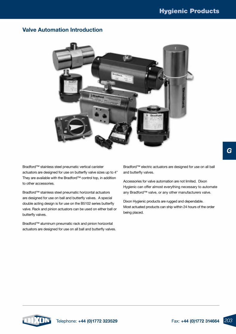
203Telephone: +44 (0)1772 323529 Fax: +44 (0)1772 314664
Hygienic Products
G
Bradford™ stainless steel pneumatic vertical canister
actuators are designed for use on butterfly valve sizes up to 4"
They are available with the Bradford™ control top, in addition
to other accessories.
Bradford™ stainless steel pneumatic horizontal actuators
are designed for use on ball and butterfly valves. A special
double acting design is for use on the B5102 series butterfly
valve. Rack and pinion actuators can be used on either ball or
butterfly valves.
Bradford™ aluminum pneumatic rack and pinion horizontal
actuators are designed for use on all ball and butterfly valves.
Bradford™ electric actuators are designed for use on all ball
and butterfly valves.
Accessories for valve automation are not limited. Dixon
Hygienic can offer almost everything necessary to automate
any Bradford™ valve, or any other manufacturers valve.
Dixon Hygienic products are rugged and dependable.
Most actuated products can ship within 24 hours of the order
being placed.
Valve automation introduction
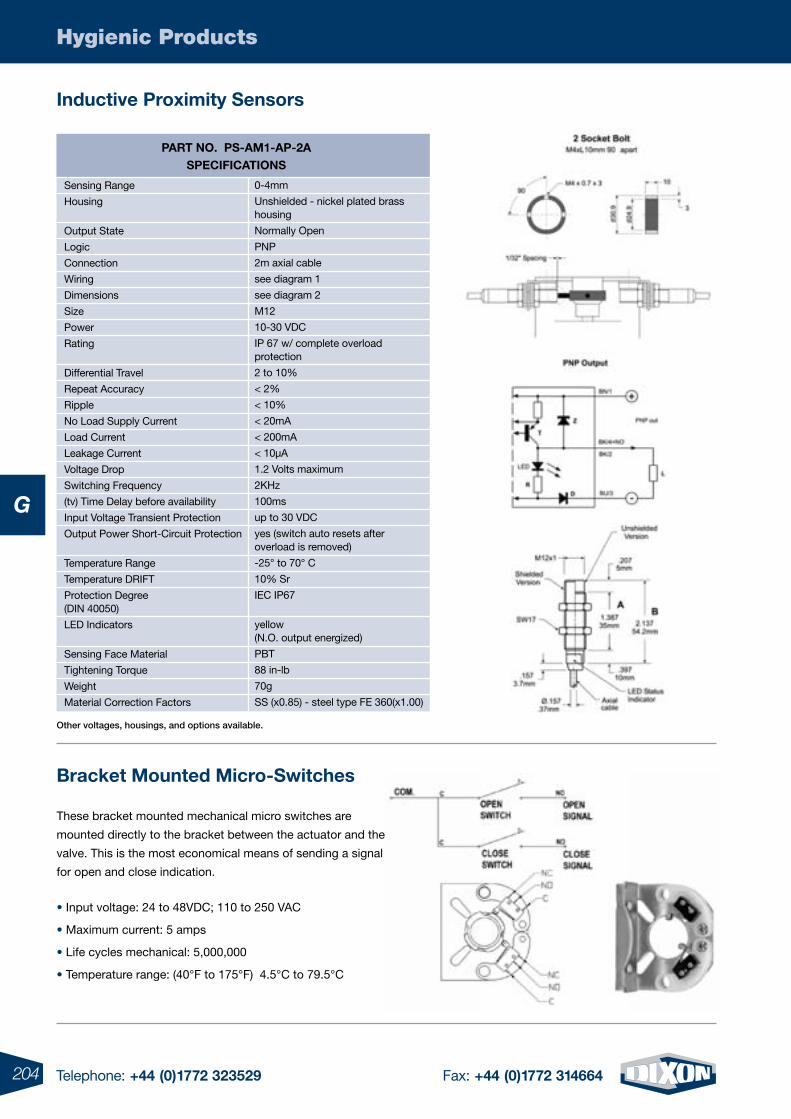
204 Telephone: +44 (0)1772 323529 Fax: +44 (0)1772 314664
Hygienic Products
G
Bracket Mounted Micro-Switches
These bracket mounted mechanical micro switches are
mounted directly to the bracket between the actuator and the
valve. This is the most economical means of sending a signal
for open and close indication.
• Input voltage: 24 to 48VDC; 110 to 250 VAC
• Maximum current: 5 amps
• Life cycles mechanical: 5,000,000
• Temperature range: (40°F to 175°F) 4.5°C to 79.5°C
inductive proximity Sensors
other voltages, housings, and options available.
paRt No. pS-aM1-ap-2aSpeCifiCatioNS
Sensing Range
Housing
Output State
Logic
Connection
Wiring
Dimensions
Size
Power
Rating
Differential Travel
Repeat Accuracy
Ripple
No Load Supply Current
Load Current
Leakage Current
Voltage Drop
Switching Frequency
(tv) Time Delay before availability
Input Voltage Transient Protection
Output Power Short-Circuit Protection
Temperature Range
Temperature DRIFT
Protection Degree (DIN 40050)
LED Indicators
Sensing Face Material
Tightening Torque
Weight
Material Correction Factors
0-4mm
Unshielded - nickel plated brass housing
Normally Open
PNP
2m axial cable
see diagram 1
see diagram 2
M12
10-30 VDC
IP 67 w/ complete overload protection
2 to 10%
< 2%
< 10%
< 20mA
< 200mA
< 10µA
1.2 Volts maximum
2KHz
100ms
up to 30 VDC
yes (switch auto resets after overload is removed)
-25° to 70° C
10% Sr
IEC IP67
yellow (N.O. output energized)
PBT
88 in-lb
70g
SS (x0.85) - steel type FE 360(x1.00)
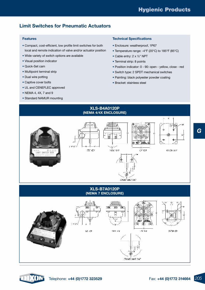
205Telephone: +44 (0)1772 323529 Fax: +44 (0)1772 314664
Hygienic Products
G
features
• Compact, cost-efficient, low profile limit switches for both
local and remote indication of valve and/or actuator position
• Wide variety of switch options are available
• Visual position indicator
• Quick-Set cam
• Multipoint terminal strip
• Dual wire potting
• Captive cover bolts
• UL and CENEFLEC approved
• NEMA 4, 4X, 7 and 9
• Standard NAMUR mounting
Limit Switches for pneumatic actuators
technical Specifications
• Enclosure: weatherproof, 1P67
• Temperature range: -4°F (20°C) to 185°F (85°C)
• Cable entry: 2 x ½" NPT
• Terminal strip: 8 points
• Position indicator: 0 - 90: open - yellow, close - red
• Switch type: 2 SPDT mechanical switches
• Painting: black polyester powder coating
• Bracket: stainless steel
XLS-B4a0120p(NeMa 4/4X eNCLoSURe)
XLS-B7a0120p(NeMa 7 eNCLoSURe)
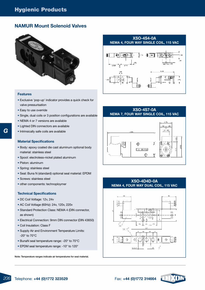
206 Telephone: +44 (0)1772 323529 Fax: +44 (0)1772 314664
Hygienic Products
G
NaMUR Mount Solenoid Valves
features
• Exclusive 'pop-up' indicator provides a quick check for
valve pressurisation
• Easy to use override
• Single, dual coils or 3 position configurations are available
• NEMA 4 or 7 versions are available
• Lighted DIN connectors are available
• Intrinsically safe coils are available
technical Specifications
• DC Coil Voltage: 12v, 24v
• AC Coil Voltage (60Hz): 24v, 120v, 220v
• Standard Protection Class: NEMA 4 (DIN connector,
as shown)
• Electrical Connection: 9mm DIN connector (DIN 43650)
• Coil Insulation: Class F
• Supply Air and Environment Temperature Limits:
-20° to 70°C
• BunaN seal temperature range: -20° to 70°C
• EPDM seal temperature range: -10° to 120°
Note: Temperature ranges indicate air temperatures for seal material.
Material Specifications
• Body: epoxy coated die cast aluminum optional body
material: stainless steel
• Spool: electroless-nickel plated aluminum
• Piston: aluminum
• Spring: stainless steel
• Seal: Buna N (standard) optional seal material: EPDM
• Screws: stainless steel
• other components: technoploymer
XSo-4S4-0aNeMa 4, foUR Way SiNGLe CoiL, 115 VaC
XSo-4d4d-0aNeMa 4, foUR Way dUaL CoiL, 115 VaC
XSo-4S7-0aNeMa 7, foUR Way SiNGLe CoiL, 115 VaC
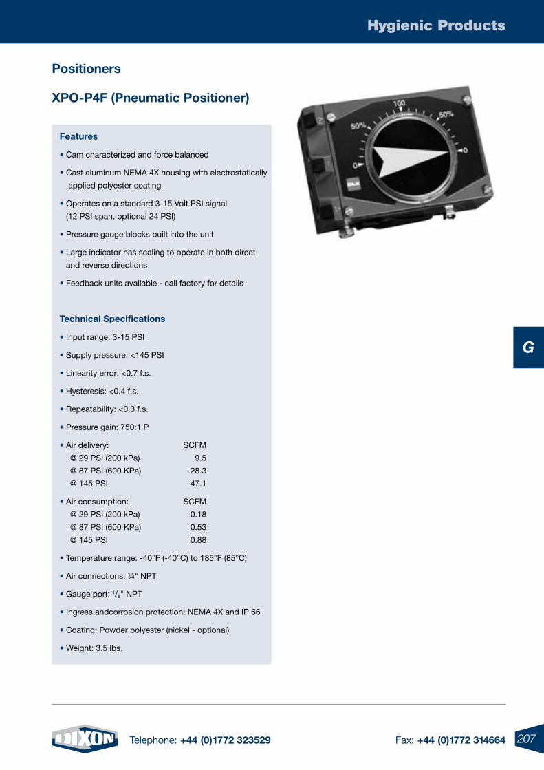
207Telephone: +44 (0)1772 323529 Fax: +44 (0)1772 314664
Hygienic Products
G
features
• Cam characterized and force balanced
• Cast aluminum NEMA 4X housing with electrostatically
applied polyester coating
• Operates on a standard 3-15 Volt PSI signal
(12 PSI span, optional 24 PSI)
• Pressure gauge blocks built into the unit
• Large indicator has scaling to operate in both direct
and reverse directions
• Feedback units available - call factory for details
technical Specifications
• Input range: 3-15 PSI
• Supply pressure: <145 PSI
• Linearity error: <0.7 f.s.
• Hysteresis: <0.4 f.s.
• Repeatability: <0.3 f.s.
• Pressure gain: 750:1 P
• Air delivery: SCFM
@ 29 PSI (200 kPa) 9.5
@ 87 PSI (600 KPa) 28.3
@ 145 PSI 47.1
• Air consumption: SCFM
@ 29 PSI (200 kPa) 0.18
@ 87 PSI (600 KPa) 0.53
@ 145 PSI 0.88
• Temperature range: -40°F (-40°C) to 185°F (85°C)
• Air connections: ¼" NPT
• Gauge port: 1/8" NPT
• Ingress andcorrosion protection: NEMA 4X and IP 66
• Coating: Powder polyester (nickel - optional)
• Weight: 3.5 lbs.
Xpo-p4f (pneumatic positioner)
positioners
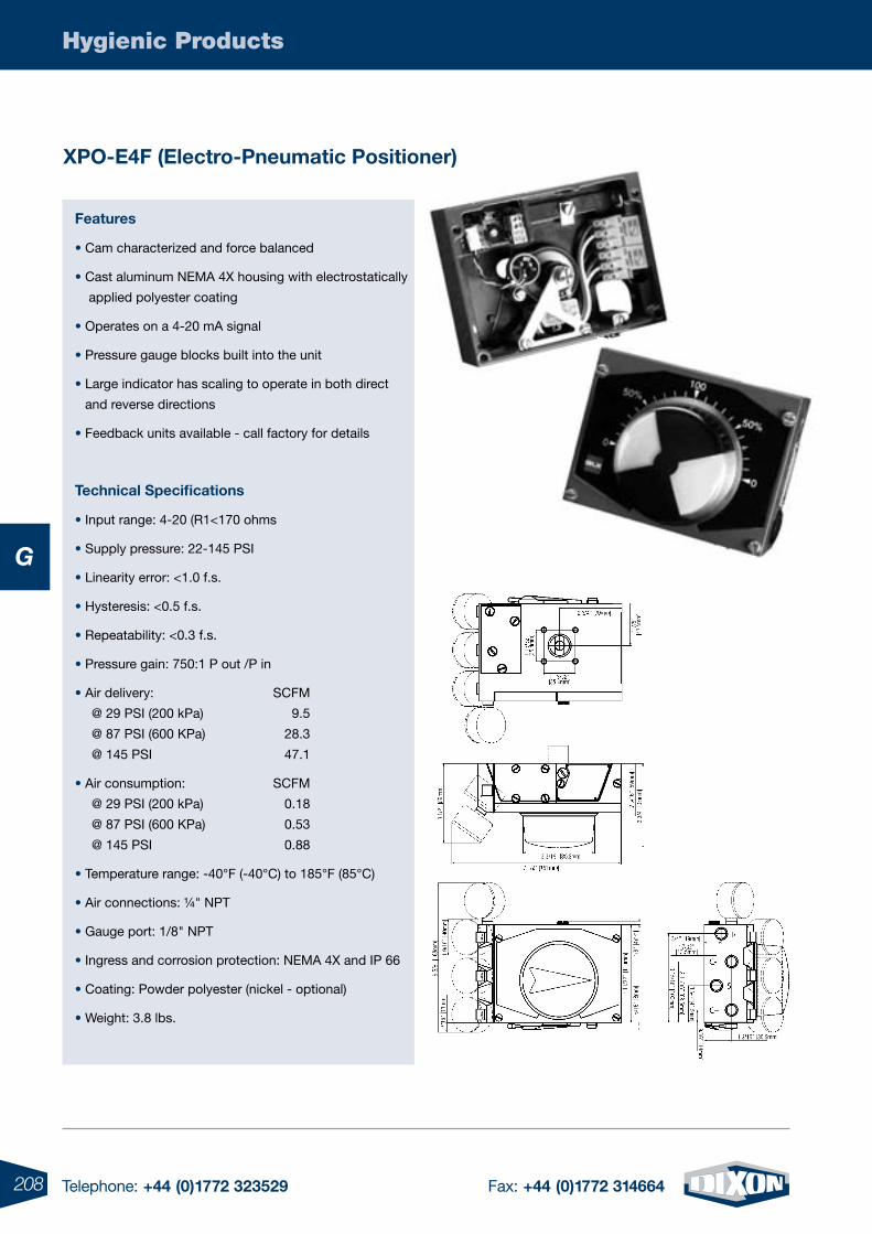
208 Telephone: +44 (0)1772 323529 Fax: +44 (0)1772 314664
Hygienic Products
G
Xpo-e4f (electro-pneumatic positioner)
features
• Cam characterized and force balanced
• Cast aluminum NEMA 4X housing with electrostatically
applied polyester coating
• Operates on a 4-20 mA signal
• Pressure gauge blocks built into the unit
• Large indicator has scaling to operate in both direct
and reverse directions
• Feedback units available - call factory for details
technical Specifications
• Input range: 4-20 (R1<170 ohms
• Supply pressure: 22-145 PSI
• Linearity error: <1.0 f.s.
• Hysteresis: <0.5 f.s.
• Repeatability: <0.3 f.s.
• Pressure gain: 750:1 P out /P in
• Air delivery: SCFM
@ 29 PSI (200 kPa) 9.5
@ 87 PSI (600 KPa) 28.3
@ 145 PSI 47.1
• Air consumption: SCFM
@ 29 PSI (200 kPa) 0.18
@ 87 PSI (600 KPa) 0.53
@ 145 PSI 0.88
• Temperature range: -40°F (-40°C) to 185°F (85°C)
• Air connections: ¼" NPT
• Gauge port: 1/8" NPT
• Ingress and corrosion protection: NEMA 4X and IP 66
• Coating: Powder polyester (nickel - optional)
• Weight: 3.8 lbs.
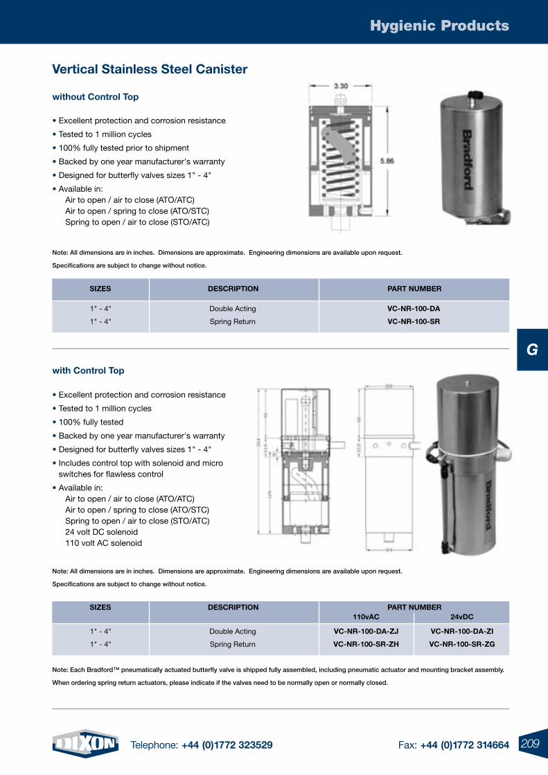
209Telephone: +44 (0)1772 323529 Fax: +44 (0)1772 314664
Hygienic Products
G
• Excellent protection and corrosion resistance
• Tested to 1 million cycles
• 100% fully tested prior to shipment
• Backed by one year manufacturer's warranty
• Designed for butterfly valves sizes 1" - 4"
• Available in: Air to open / air to close (ATO/ATC) Air to open / spring to close (ATO/STC) Spring to open / air to close (STO/ATC)
Vertical Stainless Steel Canister
without Control top
Note: Each Bradford™ pneumatically actuated butterfly valve is shipped fully assembled, including pneumatic actuator and mounting bracket assembly.
When ordering spring return actuators, please indicate if the valves need to be normally open or normally closed.
with Control top
Note: All dimensions are in inches. Dimensions are approximate. Engineering dimensions are available upon request.
Specifications are subject to change without notice.
Note: All dimensions are in inches. Dimensions are approximate. Engineering dimensions are available upon request.
Specifications are subject to change without notice.
paRt NUMBeR
VC-NR-100-da
VC-NR-100-SR
deSCRiptioN
Double Acting
Spring Return
SiZeS
1" - 4"
1" - 4"
• Excellent protection and corrosion resistance
• Tested to 1 million cycles
• 100% fully tested
• Backed by one year manufacturer's warranty
• Designed for butterfly valves sizes 1" - 4"
• Includes control top with solenoid and micro switches for flawless control
• Available in: Air to open / air to close (ATO/ATC) Air to open / spring to close (ATO/STC) Spring to open / air to close (STO/ATC) 24 volt DC solenoid 110 volt AC solenoid
paRt NUMBeRdeSCRiptioN
Double Acting
Spring Return
SiZeS
1" - 4"
1" - 4"
VC-NR-100-da-Zi
VC-NR-100-SR-ZG
VC-NR-100-da-ZJ
VC-NR-100-SR-ZH
110vaC 24vdC
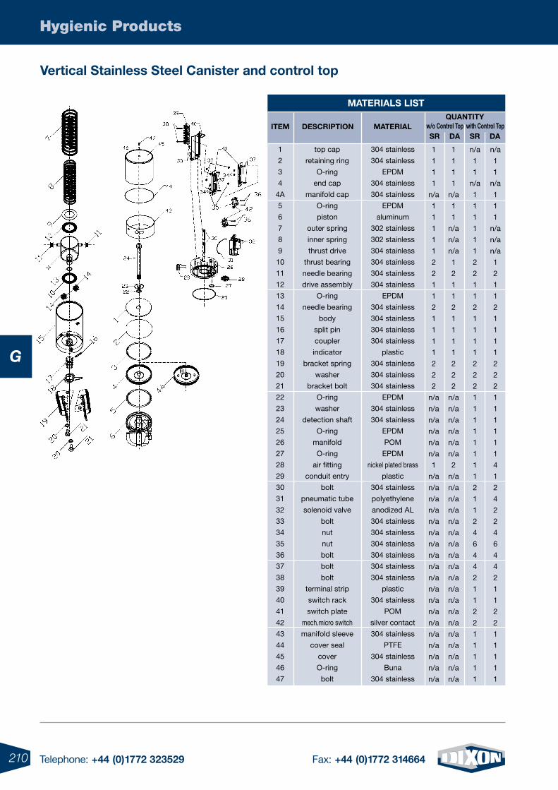
210 Telephone: +44 (0)1772 323529 Fax: +44 (0)1772 314664
Hygienic Products
G
Vertical Stainless Steel Canister and control top
MateRiaLS LiSt
304 stainless
304 stainless
EPDM
304 stainless
304 stainless
EPDM
aluminum
302 stainless
302 stainless
304 stainless
304 stainless
304 stainless
304 stainless
EPDM
304 stainless
304 stainless
304 stainless
304 stainless
plastic
304 stainless
304 stainless
304 stainless
EPDM
304 stainless
304 stainless
EPDM
POM
EPDM
nickel plated brass
plastic
304 stainless
polyethylene
anodized AL
304 stainless
304 stainless
304 stainless
304 stainless
304 stainless
304 stainless
plastic
304 stainless
POM
silver contact
304 stainless
PTFE
304 stainless
Buna
304 stainless
MateRiaLiteM deSCRiptioNQUaNtity
top cap
retaining ring
O-ring
end cap
manifold cap
O-ring
piston
outer spring
inner spring
thrust drive
thrust bearing
needle bearing
drive assembly
O-ring
needle bearing
body
split pin
coupler
indicator
bracket spring
washer
bracket bolt
O-ring
washer
detection shaft
O-ring
manifold
O-ring
air fitting
conduit entry
bolt
pneumatic tube
solenoid valve
bolt
nut
nut
bolt
bolt
bolt
terminal strip
switch rack
switch plate
mech.micro switch
manifold sleeve
cover seal
cover
O-ring
bolt
1
2
3
4
4A
5
6
7
8
9
10
11
12
13
14
15
16
17
18
19
20
21
22
23
24
25
26
27
28
29
30
31
32
33
34
35
36
37
38
39
40
41
42
43
44
45
46
47
SR da
n/a
1
1
n/a
1
1
1
1
1
1
2
2
1
1
2
1
1
1
1
2
2
2
1
1
1
1
1
1
1
1
2
1
1
2
4
6
4
4
2
1
1
2
2
1
1
1
1
1
w/o Control top with Control topSR da
n/a
1
1
n/a
1
1
1
n/a
n/a
n/a
1
2
1
1
2
1
1
1
1
2
2
2
1
1
1
1
1
1
4
1
2
4
2
2
4
6
4
4
2
1
1
2
2
1
1
1
1
1
1
1
1
1
n/a
1
1
1
1
1
2
2
1
1
2
1
1
1
1
2
2
2
n/a
n/a
n/a
n/a
n/a
n/a
1
n/a
n/a
n/a
n/a
n/a
n/a
n/a
n/a
n/a
n/a
n/a
n/a
n/a
n/a
n/a
n/a
n/a
n/a
n/a
1
1
1
1
n/a
1
1
n/a
n/a
n/a
1
2
1
1
2
1
1
1
1
2
2
2
n/a
n/a
n/a
n/a
n/a
n/a
2
n/a
n/a
n/a
n/a
n/a
n/a
n/a
n/a
n/a
n/a
n/a
n/a
n/a
n/a
n/a
n/a
n/a
n/a
n/a
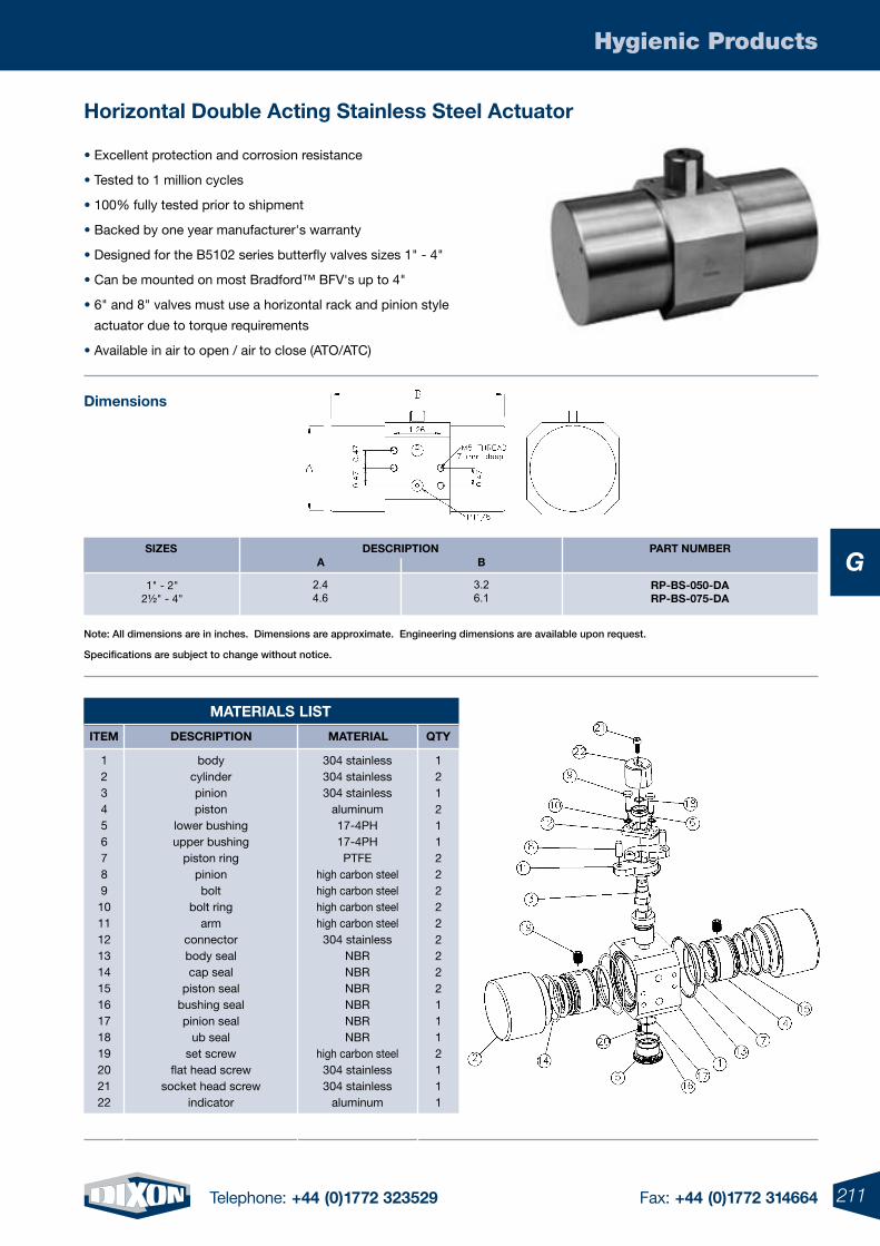
211Telephone: +44 (0)1772 323529 Fax: +44 (0)1772 314664
Hygienic Products
G
MateRiaLS LiSt
• Excellent protection and corrosion resistance
• Tested to 1 million cycles
• 100% fully tested prior to shipment
• Backed by one year manufacturer's warranty
• Designed for the B5102 series butterfly valves sizes 1" - 4"
• Can be mounted on most Bradford™ BFV's up to 4"
• 6" and 8" valves must use a horizontal rack and pinion style
actuator due to torque requirements
• Available in air to open / air to close (ATO/ATC)
Horizontal double acting Stainless Steel actuator
dimensions
304 stainless304 stainless304 stainless
aluminum17-4PH17-4PHPTFE
high carbon steelhigh carbon steelhigh carbon steelhigh carbon steel304 stainless
NBRNBRNBRNBRNBRNBR
high carbon steel304 stainless304 stainless
aluminum
MateRiaLiteM deSCRiptioN Qty
1212112222222221112111
bodycylinderpinionpiston
lower bushingupper bushing
piston ringpinionbolt
bolt ringarm
connectorbody sealcap seal
piston sealbushing sealpinion seal
ub sealset screw
flat head screwsocket head screw
indicator
12345678910111213141516171819202122
Note: All dimensions are in inches. Dimensions are approximate. Engineering dimensions are available upon request.
Specifications are subject to change without notice.
Rp-BS-050-daRp-BS-075-da
1" - 2"2½" - 4"
2.44.6
3.26.1
paRt NUMBeRdeSCRiptioNSiZeSa B
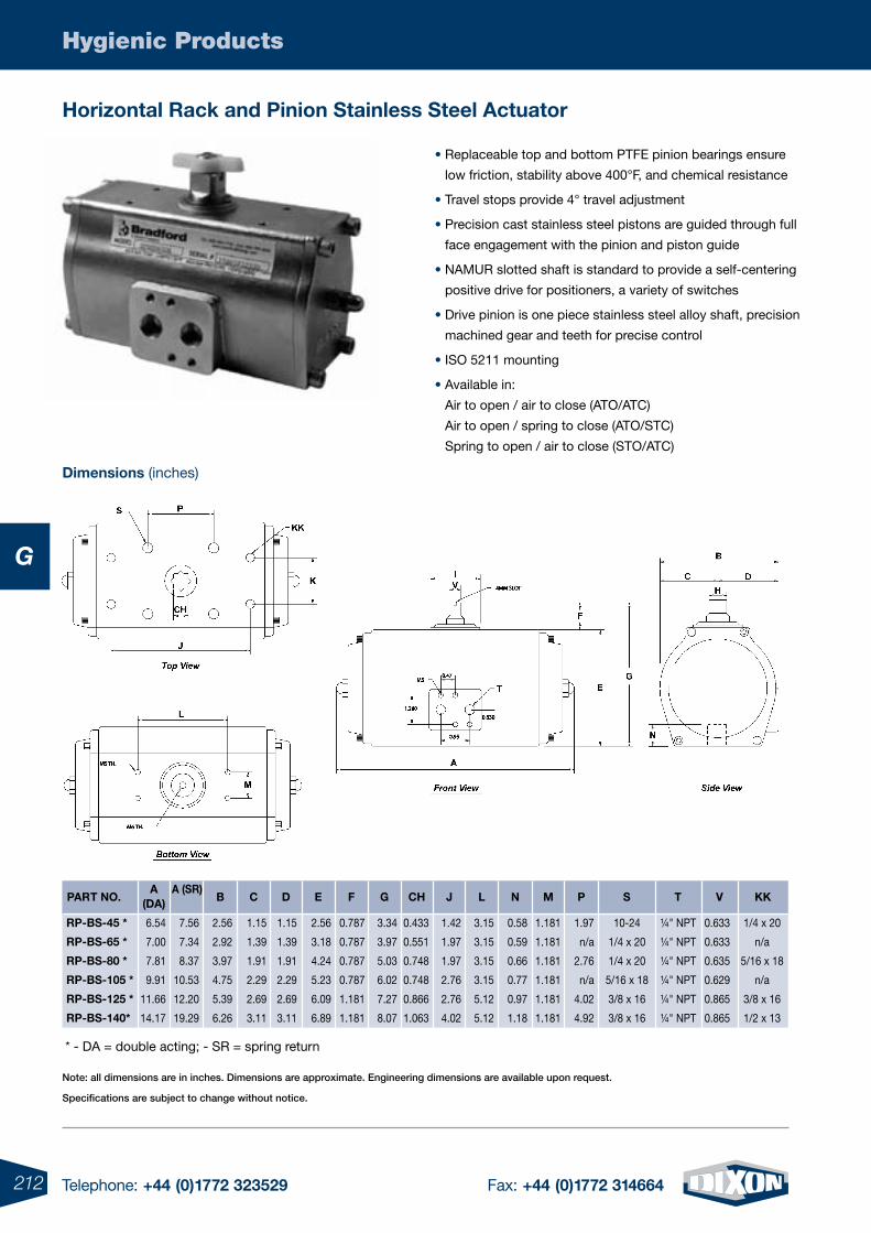
212 Telephone: +44 (0)1772 323529 Fax: +44 (0)1772 314664
Hygienic Products
G
Horizontal Rack and pinion Stainless Steel actuator
• Replaceable top and bottom PTFE pinion bearings ensure
low friction, stability above 400°F, and chemical resistance
• Travel stops provide 4° travel adjustment
• Precision cast stainless steel pistons are guided through full
face engagement with the pinion and piston guide
• NAMUR slotted shaft is standard to provide a self-centering
positive drive for positioners, a variety of switches
• Drive pinion is one piece stainless steel alloy shaft, precision
machined gear and teeth for precise control
• ISO 5211 mounting
• Available in:
Air to open / air to close (ATO/ATC)
Air to open / spring to close (ATO/STC)
Spring to open / air to close (STO/ATC)
dimensions (inches)
* - DA = double acting; - SR = spring return
dpaRt No.a
(da)a (SR)
B C f Ge CH
Rp-BS-45 *
Rp-BS-65 *
Rp-BS-80 *
Rp-BS-105 *
Rp-BS-125 *
Rp-BS-140*
6.54
7.00
7.81
9.91
11.66
14.17
J L N M p S t V KK
10-24
1/4 x 20
1/4 x 20
5/16 x 18
3/8 x 16
3/8 x 16
¼" NPT
¼" NPT
¼" NPT
¼" NPT
¼" NPT
¼" NPT
0.633
0.633
0.635
0.629
0.865
0.865
1/4 x 20
n/a
5/16 x 18
n/a
3/8 x 16
1/2 x 13
7.56
7.34
8.37
10.53
12.20
19.29
2.56
2.92
3.97
4.75
5.39
6.26
1.15
1.39
1.91
2.29
2.69
3.11
1.15
1.39
1.91
2.29
2.69
3.11
2.56
3.18
4.24
5.23
6.09
6.89
0.787
0.787
0.787
0.787
1.181
1.181
3.34
3.97
5.03
6.02
7.27
8.07
0.433
0.551
0.748
0.748
0.866
1.063
1.42
1.97
1.97
2.76
2.76
4.02
3.15
3.15
3.15
3.15
5.12
5.12
0.58
0.59
0.66
0.77
0.97
1.18
1.181
1.181
1.181
1.181
1.181
1.181
1.97
n/a
2.76
n/a
4.02
4.92
Note: all dimensions are in inches. Dimensions are approximate. Engineering dimensions are available upon request.
Specifications are subject to change without notice.
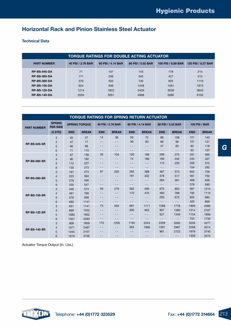
213Telephone: +44 (0)1772 323529 Fax: +44 (0)1772 314664
Hygienic Products
G
Horizontal Rack and pinion Stainless Steel actuator
technical data
toRQUe RatiNGS foR doUBLe aCtiNG aCtUatoR
80 pSi / 5.52 BaRpaRt NUMBeR 40 pSi / 2.76 BaR 60 pSi / 4.14 BaR 100 pSi / 6.89 BaR 120 pSi / 8.27 BaR
Rp-BS-045-da
Rp-BS-065-da
Rp-BS-080-da
Rp-BS-105-da
Rp-BS-125-da
Rp-BS-140-da
71
171
370
624
1214
2034
107
256
555
936
1822
3051
143
342
740
1249
2429
4068
178
427
925
1561
3036
5085
214
512
1110
1873
3643
6102
toRQUe RatiNGS foR SpRiNG RetURN aCtUatoR
80 pSi / 5.52 BaRpaRt NUMBeR
40 pSi / 2.76 BaR 60 pSi / 4.14 BaR 100 pSi / BaR
Rp-BS-045-SR
Rp-BS-065-SR
Rp-BS-080-SR
Rp-BS-105-SR
Rp-BS-125-SR
Rp-BS-140-SR
14
- -
- -
- -
35
- -
- -
- -
97
- -
- -
- -
50
- -
- -
- -
73
- -
- -
- -
175
- -
- -
- -
50
30
- -
- -
120
74
- -
- -
282
191
- -
- -
362
170
- -
- -
681
300
- -
- -
1192
564
- -
- -
86
66
47
- -
206
160
115
- -
467
376
284
- -
675
483
293
- -
1288
907
527
- -
2209
1581
961
- -
121
101
82
63
291
245
200
154
652
561
469
378
987
795
605
420
1895
1514
1134
753
3226
2598
1978
1359
36
- -
- -
- -
104
- -
- -
- -
203
- -
- -
- -
278
- -
- -
- -
563
- -
- -
- -
1226
- -
- -
- -
72
60
- -
- -
189
166
- -
- -
388
332
- -
- -
590
475
- -
- -
1171
953
- -
- -
2243
1980
- -
- -
108
96
83
- -
275
252
230
- -
573
517
461
- -
903
788
673
- -
1778
1560
1349
- -
3260
2997
2723
- -
143
131
118
107
360
337
315
292
758
702
646
590
1215
1110
985
869
2385
2167
1956
1735
4277
4014
3740
3475
57
77
96
115
136
182
227
273
273
364
456
547
574
766
956
1141
1141
1522
1902
2283
1859
2487
3107
3726
SpRiNG toRQUe
35
47
60
71
67
90
112
135
167
223
279
335
346
461
576
692
651
869
1080
1301
808
1071
1345
1610
SpRiNGpeR Side
3
4
5
6
3
4
5
6
3
4
5
6
3
4
5
6
3
4
5
6
3
4
5
6
eNdeNd eNd eNdBReaKBReaK BReaK BReaKBReaKeNd(5 Std)
Actuator Torque Output (In. Lbs.)
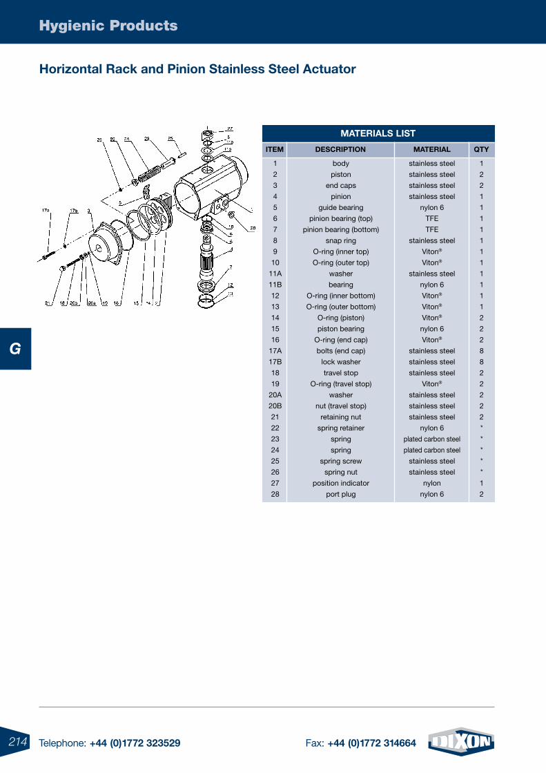
214 Telephone: +44 (0)1772 323529 Fax: +44 (0)1772 314664
Hygienic Products
G
Horizontal Rack and pinion Stainless Steel actuator
MateRiaLS LiSt
stainless steel
stainless steel
stainless steel
stainless steel
nylon 6
TFE
TFE
stainless steel
Viton®
Viton®
stainless steel
nylon 6
Viton®
Viton®
Viton®
nylon 6
Viton®
stainless steel
stainless steel
stainless steel
Viton®
stainless steel
stainless steel
stainless steel
nylon 6
plated carbon steel
plated carbon steel
stainless steel
stainless steel
nylon
nylon 6
MateRiaLiteM deSCRiptioN Qty
1
2
2
1
1
1
1
1
1
1
1
1
1
1
2
2
2
8
8
2
2
2
2
2
*
*
*
*
*
1
2
body
piston
end caps
pinion
guide bearing
pinion bearing (top)
pinion bearing (bottom)
snap ring
O-ring (inner top)
O-ring (outer top)
washer
bearing
O-ring (inner bottom)
O-ring (outer bottom)
O-ring (piston)
piston bearing
O-ring (end cap)
bolts (end cap)
lock washer
travel stop
O-ring (travel stop)
washer
nut (travel stop)
retaining nut
spring retainer
spring
spring
spring screw
spring nut
position indicator
port plug
1
2
3
4
5
6
7
8
9
10
11A
11B
12
13
14
15
16
17A
17B
18
19
20A
20B
21
22
23
24
25
26
27
28
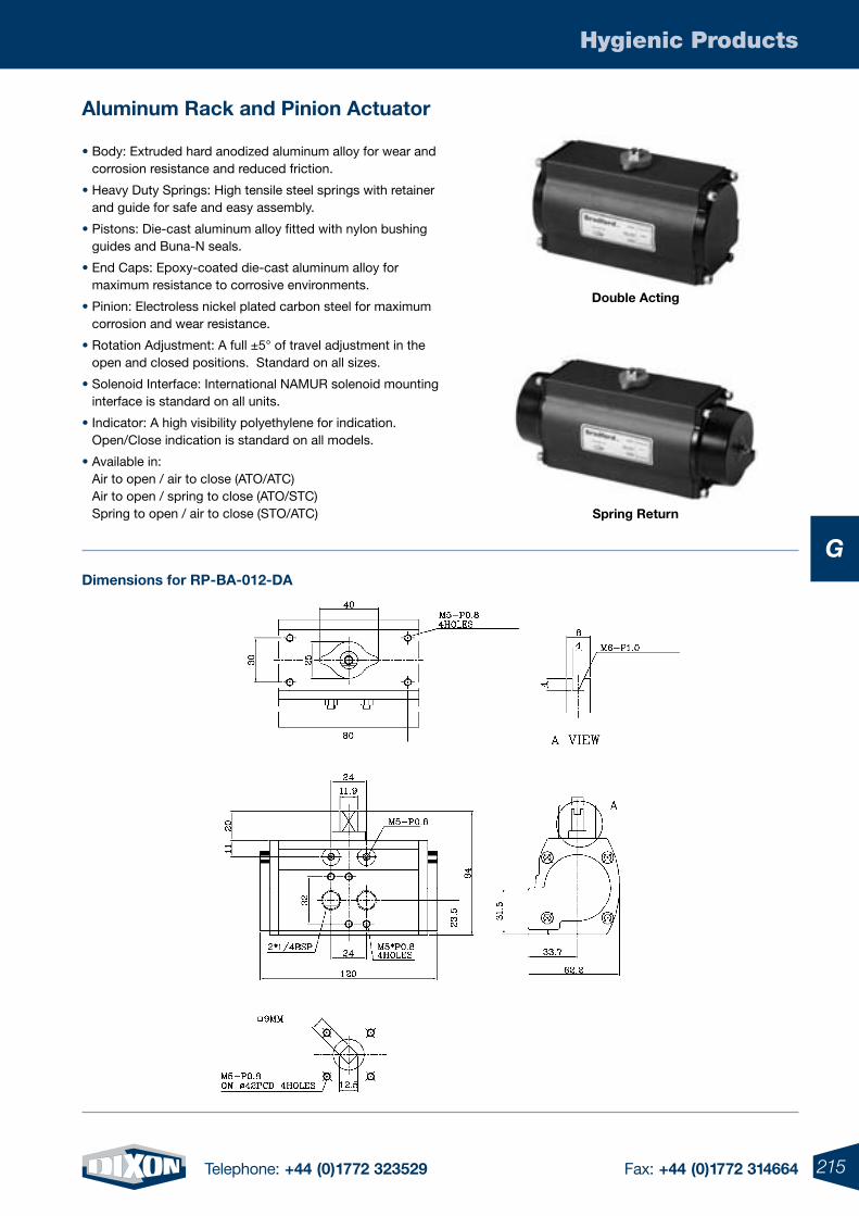
215Telephone: +44 (0)1772 323529 Fax: +44 (0)1772 314664
Hygienic Products
G
aluminum Rack and pinion actuator
• Body: Extruded hard anodized aluminum alloy for wear and corrosion resistance and reduced friction.
• Heavy Duty Springs: High tensile steel springs with retainer and guide for safe and easy assembly.
• Pistons: Die-cast aluminum alloy fitted with nylon bushing guides and Buna-N seals.
• End Caps: Epoxy-coated die-cast aluminum alloy for maximum resistance to corrosive environments.
• Pinion: Electroless nickel plated carbon steel for maximum corrosion and wear resistance.
• Rotation Adjustment: A full ±5° of travel adjustment in the open and closed positions. Standard on all sizes.
• Solenoid Interface: International NAMUR solenoid mounting interface is standard on all units.
• Indicator: A high visibility polyethylene for indication. Open/Close indication is standard on all models.
• Available in: Air to open / air to close (ATO/ATC) Air to open / spring to close (ATO/STC) Spring to open / air to close (STO/ATC)
dimensions for Rp-Ba-012-da
double acting
Spring Return
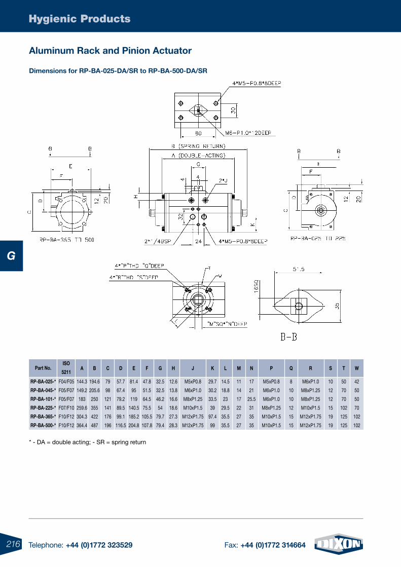
216 Telephone: +44 (0)1772 323529 Fax: +44 (0)1772 314664
Hygienic Products
G
aluminum Rack and pinion actuator
dimensions for Rp-Ba-025-da/SR to Rp-Ba-500-da/SR
diSo
5211a B C f Ge H
F04/F05
F05/F07
F05/F07
F07/F10
F10/F12
F10/F12
144.3
149.2
183
259.6
304.3
364.4
194.6
205.6
250
355
422
487
J K L M N p Q R S t W
79
98
121
141
176
196
57.7
67.4
79.2
89.5
99.1
116.5
81.4
95
119
140.5
185.2
204.8
47.8
51.5
64.5
75.5
105.5
107.8
32.5
32.5
46.2
54
79.7
79.4
12.6
13.8
16.6
18.6
27.3
28.3
29.7
30.2
33.5
39
97.4
99
14.5
18.8
23
29.5
35.5
35.5
11
14
17
22
27
27
17
21
25.5
31
35
35
8
10
10
12
15
15
M6xP1.0
M8xP1.25
M8xP1.25
M10xP1.5
M12xP1.75
M12xP1.75
10
12
12
15
19
19
50
70
70
102
125
125
42
50
50
70
102
102
part No.
M5xP0.8
M6xP1.0
M6xP1.0
M8xP1.25
M10xP1.5
M10xP1.5
M5xP0.8
M6xP1.0
M8xP1.25
M10xP1.5
M12xP1.75
M12xP1.75
Rp-Ba-025-*
Rp-Ba-045-*
Rp-Ba-101-*
Rp-Ba-225-*
Rp-Ba-365-*
Rp-Ba-500-*
* - DA = double acting; - SR = spring return
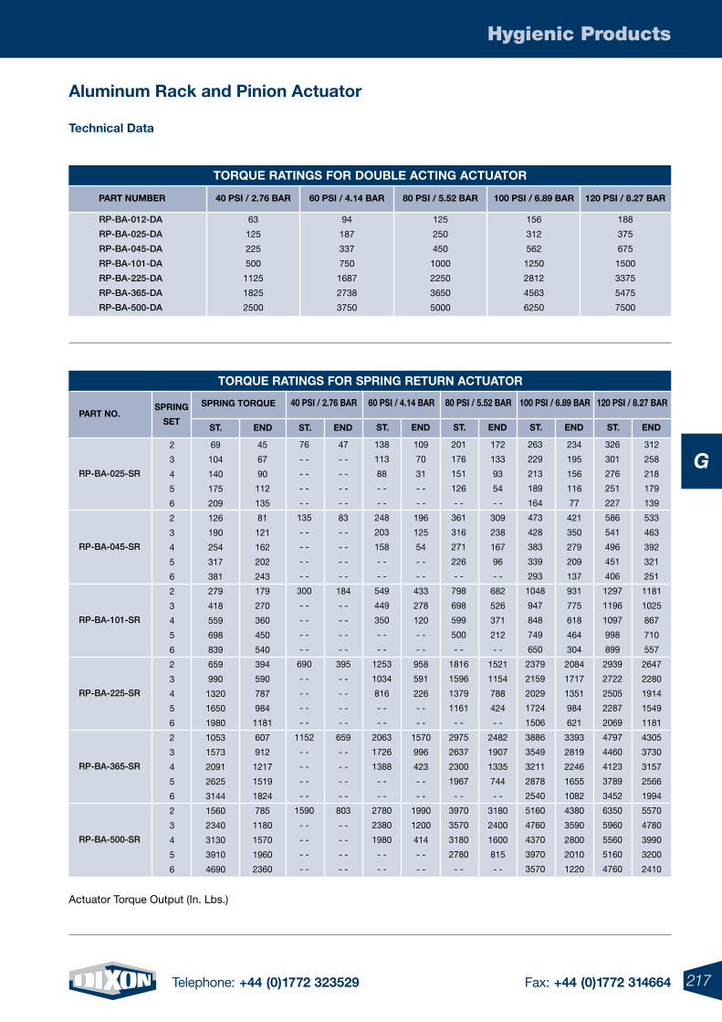
217Telephone: +44 (0)1772 323529 Fax: +44 (0)1772 314664
Hygienic Products
G
Actuator Torque Output (In. Lbs.)
aluminum Rack and pinion actuator
technical data
toRQUe RatiNGS foR SpRiNG RetURN aCtUatoR
paRt No.40 pSi / 2.76 BaR
Rp-BA-025-SR
Rp-BA-045-SR
Rp-BA-101-SR
Rp-BA-225-SR
Rp-BA-365-SR
Rp-BA-500-SR
76
- -
- -
- -
- -
135
- -
- -
- -
- -
300
- -
- -
- -
- -
690
- -
- -
- -
- -
1152
- -
- -
- -
- -
1590
- -
- -
- -
- -
47
- -
- -
- -
- -
83
- -
- -
- -
- -
184
- -
- -
- -
- -
395
- -
- -
- -
- -
659
- -
- -
- -
- -
803
- -
- -
- -
- -
45
67
90
112
135
81
121
162
202
243
179
270
360
450
540
394
590
787
984
1181
607
912
1217
1519
1824
785
1180
1570
1960
2360
SpRiNG toRQUe
69
104
140
175
209
126
190
254
317
381
279
418
559
698
839
659
990
1320
1650
1980
1053
1573
2091
2625
3144
1560
2340
3130
3910
4690
SpRiNG
Set
2
3
4
5
6
2
3
4
5
6
2
3
4
5
6
2
3
4
5
6
2
3
4
5
6
2
3
4
5
6
St. eNdeNdSt.
60 pSi / 4.14 BaR
138
113
88
- -
- -
248
203
158
- -
- -
549
449
350
- -
- -
1253
1034
816
- -
- -
2063
1726
1388
- -
- -
2780
2380
1980
- -
- -
109
70
31
- -
- -
196
125
54
- -
- -
433
278
120
- -
- -
958
591
226
- -
- -
1570
996
423
- -
- -
1990
1200
414
- -
- -
St. eNd
80 pSi / 5.52 BaR
201
176
151
126
- -
361
316
271
226
- -
798
698
599
500
- -
1816
1596
1379
1161
- -
2975
2637
2300
1967
- -
3970
3570
3180
2780
- -
172
133
93
54
- -
309
238
167
96
- -
682
526
371
212
- -
1521
1154
788
424
- -
2482
1907
1335
744
- -
3180
2400
1600
815
- -
St. eNd
100 pSi / 6.89 BaR
263
229
213
189
164
473
428
383
339
293
1048
947
848
749
650
2379
2159
2029
1724
1506
3886
3549
3211
2878
2540
5160
4760
4370
3970
3570
234
195
156
116
77
421
350
279
209
137
931
775
618
464
304
2084
1717
1351
984
621
3393
2819
2246
1655
1082
4380
3590
2800
2010
1220
St. eNd
120 pSi / 8.27 BaR
326
301
276
251
227
586
541
496
451
406
1297
1196
1097
998
899
2939
2722
2505
2287
2069
4797
4460
4123
3789
3452
6350
5960
5560
5160
4760
312
258
218
179
139
533
463
392
321
251
1181
1025
867
710
557
2647
2280
1914
1549
1181
4305
3730
3157
2566
1994
5570
4780
3990
3200
2410
St. eNd
toRQUe RatiNGS foR doUBLe aCtiNG aCtUatoR
80 pSi / 5.52 BaRpaRt NUMBeR 40 pSi / 2.76 BaR 60 pSi / 4.14 BaR 100 pSi / 6.89 BaR 120 pSi / 8.27 BaR
Rp-BA-012-DA
Rp-BA-025-DA
Rp-BA-045-DA
Rp-BA-101-DA
Rp-BA-225-DA
Rp-BA-365-DA
Rp-BA-500-DA
63
125
225
500
1125
1825
2500
94
187
337
750
1687
2738
3750
125
250
450
1000
2250
3650
5000
156
312
562
1250
2812
4563
6250
188
375
675
1500
3375
5475
7500
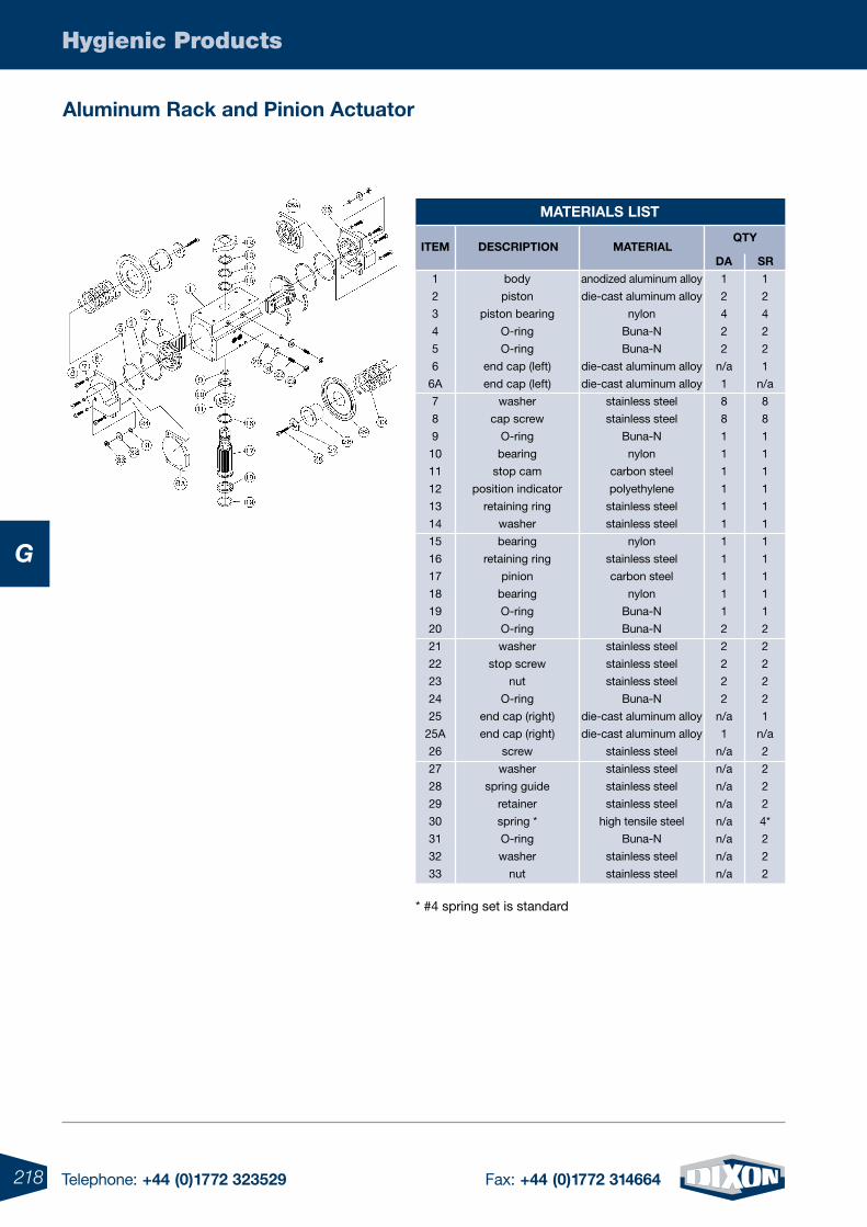
218 Telephone: +44 (0)1772 323529 Fax: +44 (0)1772 314664
Hygienic Products
G
MateRiaLS LiSt
aluminum Rack and pinion actuator
MateRiaLiteM deSCRiptioNQty
da
anodized aluminum alloy
die-cast aluminum alloy
nylon
Buna-N
Buna-N
die-cast aluminum alloy
die-cast aluminum alloy
stainless steel
stainless steel
Buna-N
nylon
carbon steel
polyethylene
stainless steel
stainless steel
nylon
stainless steel
carbon steel
nylon
Buna-N
Buna-N
stainless steel
stainless steel
stainless steel
Buna-N
die-cast aluminum alloy
die-cast aluminum alloy
stainless steel
stainless steel
stainless steel
stainless steel
high tensile steel
Buna-N
stainless steel
stainless steel
1
2
4
2
2
n/a
1
8
8
1
1
1
1
1
1
1
1
1
1
1
2
2
2
2
2
n/a
1
n/a
n/a
n/a
n/a
n/a
n/a
n/a
n/a
body
piston
piston bearing
O-ring
O-ring
end cap (left)
end cap (left)
washer
cap screw
O-ring
bearing
stop cam
position indicator
retaining ring
washer
bearing
retaining ring
pinion
bearing
O-ring
O-ring
washer
stop screw
nut
O-ring
end cap (right)
end cap (right)
screw
washer
spring guide
retainer
spring *
O-ring
washer
nut
1
2
3
4
5
6
6A
7
8
9
10
11
12
13
14
15
16
17
18
19
20
21
22
23
24
25
25A
26
27
28
29
30
31
32
33
1
2
4
2
2
1
n/a
8
8
1
1
1
1
1
1
1
1
1
1
1
2
2
2
2
2
1
n/a
2
2
2
2
4*
2
2
2
SR
* #4 spring set is standard
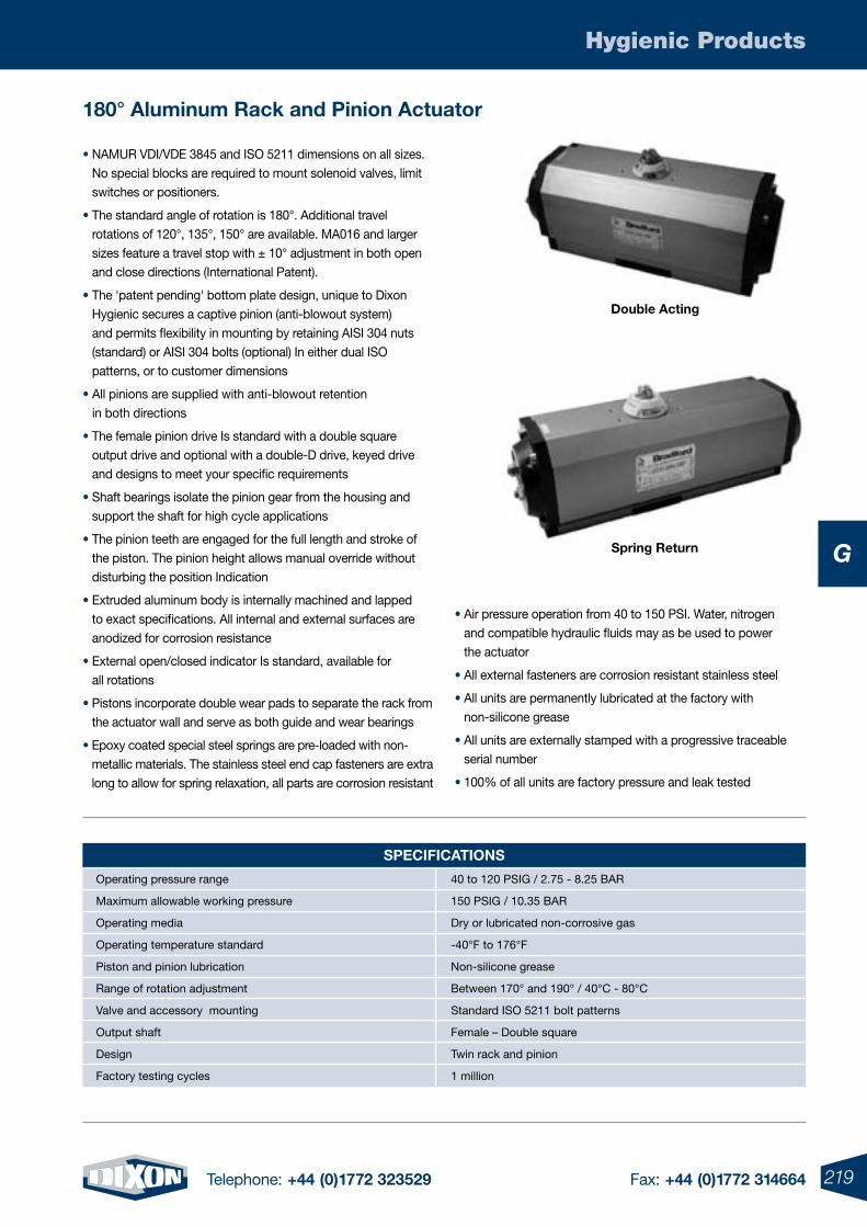
219Telephone: +44 (0)1772 323529 Fax: +44 (0)1772 314664
Hygienic Products
G
180° aluminum Rack and pinion actuator
double acting
Spring Return
• NAMUR VDI/VDE 3845 and ISO 5211 dimensions on all sizes. No special blocks are required to mount solenoid valves, limit switches or positioners.
• The standard angle of rotation is 180°. Additional travel rotations of 120°, 135°, 150° are available. MA016 and larger sizes feature a travel stop with ± 10° adjustment in both open and close directions (International Patent).
• The 'patent pending' bottom plate design, unique to Dixon Hygienic secures a captive pinion (anti-blowout system) and permits flexibility in mounting by retaining AISI 304 nuts (standard) or AISI 304 bolts (optional) In either dual ISO patterns, or to customer dimensions
• All pinions are supplied with anti-blowout retention in both directions
• The female pinion drive Is standard with a double square output drive and optional with a double-D drive, keyed drive and designs to meet your specific requirements
• Shaft bearings isolate the pinion gear from the housing and support the shaft for high cycle applications
• The pinion teeth are engaged for the full length and stroke of the piston. The pinion height allows manual override without disturbing the position Indication
• Extruded aluminum body is internally machined and lapped to exact specifications. All internal and external surfaces are anodized for corrosion resistance
• External open/closed indicator Is standard, available for all rotations
• Pistons incorporate double wear pads to separate the rack from the actuator wall and serve as both guide and wear bearings
• Epoxy coated special steel springs are pre-loaded with non-metallic materials. The stainless steel end cap fasteners are extra long to allow for spring relaxation, all parts are corrosion resistant
• Air pressure operation from 40 to 150 PSI. Water, nitrogen and compatible hydraulic fluids may as be used to power the actuator
• All external fasteners are corrosion resistant stainless steel
• All units are permanently lubricated at the factory with non-silicone grease
• All units are externally stamped with a progressive traceable serial number
• 100% of all units are factory pressure and leak tested
SpeCifiCatioNS
40 to 120 PSIG / 2.75 - 8.25 BAR
150 PSIG / 10.35 BAR
Dry or lubricated non-corrosive gas
-40°F to 176°F
Non-silicone grease
Between 170° and 190° / 40°C - 80°C
Standard ISO 5211 bolt patterns
Female – Double square
Twin rack and pinion
1 million
Operating pressure range
Maximum allowable working pressure
Operating media
Operating temperature standard
Piston and pinion lubrication
Range of rotation adjustment
Valve and accessory mounting
Output shaft
Design
Factory testing cycles
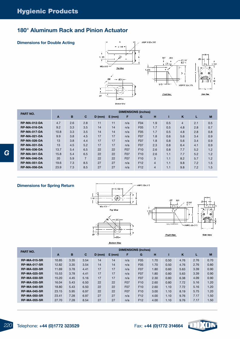
220 Telephone: +44 (0)1772 323529 Fax: +44 (0)1772 314664
Hygienic Products
G
180° aluminum Rack and pinion actuator
dimensions for double acting
dimensions for Spring Return
paRt No.diMeNSioNS (inches)
a B d (mm) e (mm)C f G H i K L
4.7
9.2
10.8
9.9
13
13
13.7
15.8
20
19.6
23.9
Rp-Ma-012-daRp-Ma-016-daRp-Ma-017-daRp-Ma-021-daRp-Ma-026-daRp-Ma-031-daRp-Ma-036-daRp-Ma-041-daRp-Ma-046-daRp-Ma-051-daRp-Ma-056-da
2.6
3.3
3.3
3.8
3.8
4.5
5.4
5.4
5.9
7.3
7.3
11
14
14
17
17
17
22
22
22
27
27
11
14
14
17
17
17
22
22
22
27
27
2.8
3.5
3.5
4.5
4.4
5.2
6.5
6.5
7
8.5
8.5
n/a
n/a
n/a
n/a
n/a
n/a
F07
F07
F07
n/a
n/a
F04
F05
F05
F07
F07
F07
F10
F10
F10
F12
F12
1.9
1.7
1.7
1.8
1.8
2.3
2.6
2.6
3
4
4
0.5
0.5
0.5
0.6
0.8
0.8
0.8
1.1
1.1
1.1
1.1
4
4.8
4.8
5.6
5.6
6.4
7.7
7.7
8.2
9.8
9.8
2.1
2.8
2.8
3.4
3.4
4.1
5.2
5.2
5.7
7.2
7.2
0.5
0.7
0.8
0.9
0.9
0.9
1.2
1.2
1.2
1.5
1.5
M
paRt No.
10.85
12.82
11.69
15.53
15.20
16.04
18.80
23.15
23.41
27.70
Rp-Ma-015-SRRp-Ma-017-SRRp-Ma-020-SRRp-Ma-025-SRRp-Ma-030-SRRp-Ma-035-SRRp-Ma-040-SRRp-Ma-045-SRRp-Ma-050-SRRp-Ma-055-SR
3.35
3.35
3.78
3.78
4.45
5.43
5.43
5.95
7.28
7.28
14
14
17
17
17
22
22
22
27
27
14
14
17
17
17
22
22
22
27
27
3.54
3.54
4.41
4.41
5.16
6.50
6.50
6.97
6.97
8.54
diMeNSioNS (inches)
a B d (mm) e (mm)C
n/a
n/a
n/a
n/a
n/a
F07
F07
F07
n/a
n/a
f
F05
F05
F07
F07
F07
F10
F10
F10
F12
F12
G
1.70
1.70
1.80
1.80
2.30
2.60
2.60
3.00
4.00
4.00
H
0.50
0.50
0.60
0.80
0.80
0.80
1.10
1.10
1.10
1.10
i
4.76
4.76
5.63
5.63
6.38
7.72
7.72
8.19
9.76
9.76
K
2.76
2.76
3.39
3.39
4.09
5.16
5.16
5.75
7.17
7.17
L
0.70
0.80
0.90
0.90
0.90
1.20
1.20
1.20
1.50
1.50
M
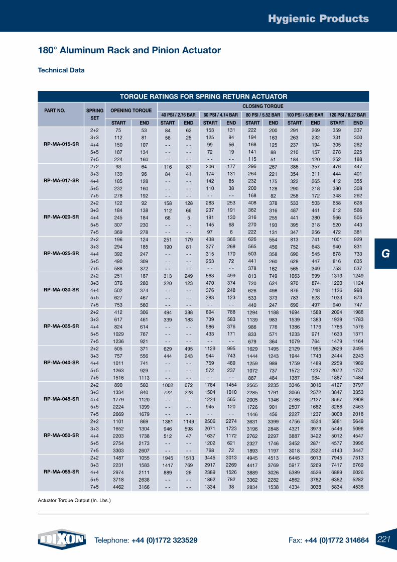
221Telephone: +44 (0)1772 323529 Fax: +44 (0)1772 314664
Hygienic Products
G
180° aluminum Rack and pinion actuator
technical data
toRQUe RatiNGS foR SpRiNG RetURN aCtUatoR
paRt No.40 pSi / 2.76 BaR
opeNiNG toRQUeSpRiNGSet
StaRt eNdeNdStaRt
60 pSi / 4.14 BaR
StaRt eNd
80 pSi / 5.52 BaR
StaRt eNd
100 pSi / 6.89 BaR
StaRt eNd
120 pSi / 8.27 BaR
Rp-Ma-015-SR
Rp-Ma-017-SR
Rp-Ma-020-SR
Rp-Ma-025-SR
Rp-Ma-030-SR
Rp-Ma-035-SR
Rp-Ma-040-SR
Rp-Ma-045-SR
Rp-Ma-050-SR
Rp-Ma-055-SR
84
56
- -
- -
- -
116
84
- -
- -
- -
158
112
66
- -
- -
251
190
- -
- -
- -
313
220
- -
- -
- -
494
339
- -
- -
- -
629
444
- -
- -
- -
1002
722
- -
- -
- -
1381
946
512
- -
- -
1945
1417
889
- -
- -
62
25
- -
- -
- -
87
41
- -
- -
- -
128
66
5
- -
- -
179
81
- -
- -
- -
249
123
- -
- -
- -
388
183
- -
- -
- -
495
243
- -
- -
- -
672
228
- -
- -
- -
1149
598
47
- -
- -
1513
769
26
- -
- -
53
81
107
134
160
64
96
128
160
192
92
138
184
230
278
124
185
247
309
372
187
280
374
467
560
306
461
614
767
921
371
556
741
929
1113
560
840
1120
1399
1679
869
1304
1738
2173
2607
1055
1583
2111
2638
3166
75
112
150
187
224
93
139
185
232
278
122
184
245
307
369
196
294
392
490
588
251
376
502
627
753
412
617
824
1029
1236
505
757
1011
1263
1516
890
1334
1779
2224
2669
1101
1652
2203
2754
3303
1487
2231
2974
3718
4462
2+2
3+3
4+4
5+5
7+5
2+2
3+3
4+4
5+5
7+5
2+2
3+3
4+4
5+5
7+5
2+2
3+3
4+4
5+5
7+5
2+2
3+3
4+4
5+5
7+5
2+2
3+3
4+4
5+5
7+5
2+2
3+3
4+4
5+5
7+5
2+2
3+3
4+4
5+5
7+5
2+2
3+3
4+4
5+5
7+5
2+2
3+3
4+4
5+5
7+5
153
125
99
72
- -
206
174
142
110
- -
283
237
191
145
97
438
377
315
253
- -
563
470
376
283
- -
894
739
586
433
- -
1129
944
759
572
- -
1784
1504
1224
945
- -
2506
2071
1637
1202
768
3445
2917
2389
1862
1334
131
94
56
19
- -
177
131
85
38
- -
253
191
130
68
6
366
268
170
72
- -
499
374
248
123
- -
788
583
376
171
- -
995
743
489
237
- -
1454
1010
565
120
- -
2274
1723
1172
621
72
3013
2269
1526
782
38
222
194
168
141
115
296
264
232
200
168
408
362
316
270
222
626
565
503
441
378
813
720
626
533
440
1294
1139
986
833
679
1629
1444
1259
1072
887
2565
2285
2005
1726
1446
3631
3196
2762
2327
1893
4945
4417
3889
3362
2834
200
163
125
88
51
267
221
175
128
82
378
316
255
193
131
554
456
358
260
162
749
624
498
373
247
1188
983
776
571
364
1495
1243
989
737
484
2235
1791
1346
901
456
3399
2848
2297
1746
1197
4513
3769
3026
2282
1538
291
263
237
210
184
386
354
322
290
258
533
487
441
395
347
813
752
690
628
565
1063
970
876
783
690
1694
1539
1386
1233
1079
2129
1944
1759
1572
1387
3346
3066
2786
2507
2227
4756
4321
3887
3452
3018
6445
5917
5389
4862
4334
269
232
194
157
120
357
311
265
218
172
503
441
380
318
256
741
643
545
447
349
999
874
748
623
497
1588
1383
1176
971
764
1995
1743
1489
1237
984
3016
2572
2127
1682
1237
4524
3973
3422
2871
2322
6013
5269
4526
3782
3038
359
331
305
278
252
476
444
412
380
348
658
612
566
520
472
1001
940
878
816
753
1313
1220
1126
1033
940
2094
1939
1786
1633
1479
2629
2444
2259
2072
1887
4127
3847
3567
3288
3008
5881
5446
5012
4577
4143
7945
7417
6889
6362
5834
337
300
262
225
188
447
401
355
308
262
628
566
505
443
381
929
831
733
635
537
1249
1124
998
873
747
1988
1783
1576
1371
1164
2495
2243
1989
1737
1484
3797
3353
2908
2463
2018
5649
5098
4547
3996
3447
7513
6769
6026
5282
4538
StaRt eNd
CLoSiNG toRQUe
Actuator Torque Output (In. Lbs.)
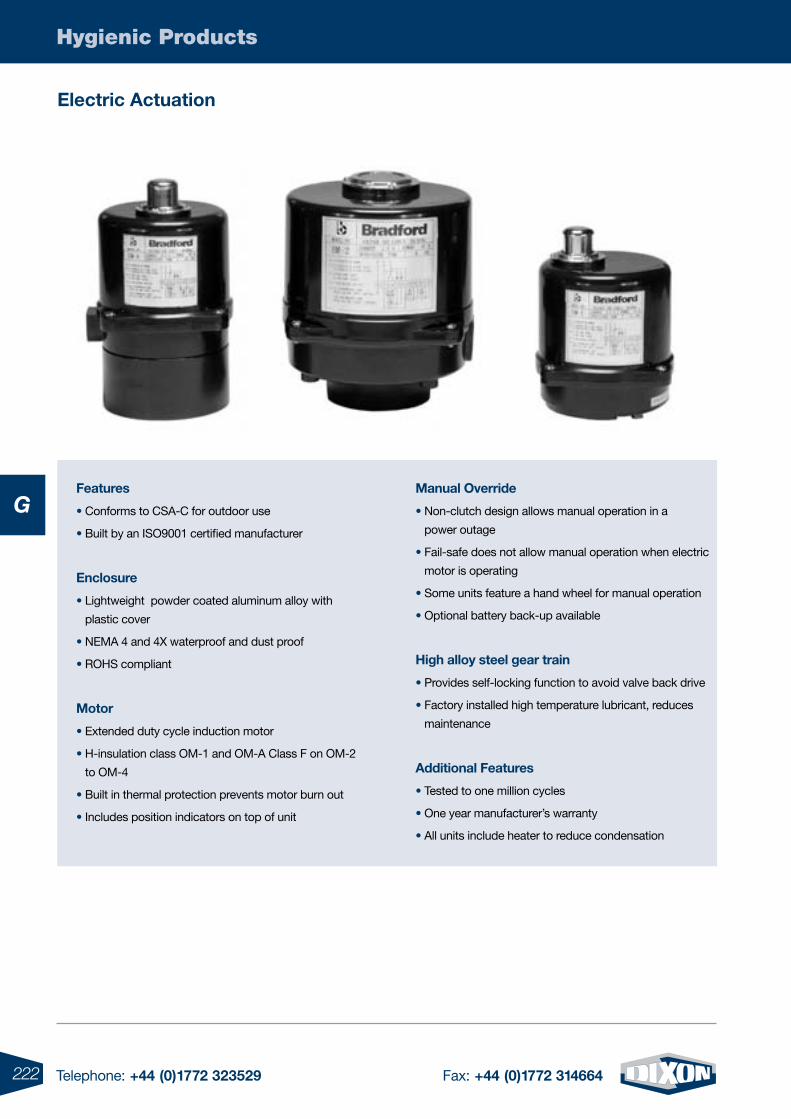
222 Telephone: +44 (0)1772 323529 Fax: +44 (0)1772 314664
Hygienic Products
G
Electric Actuation
Features
• Conforms to CSA-C for outdoor use
• Built by an ISO9001 certified manufacturer
Enclosure
• Lightweight powder coated aluminum alloy with
plastic cover
• NEMA 4 and 4X waterproof and dust proof
• ROHS compliant
Motor
• Extended duty cycle induction motor
• H-insulation class OM-1 and OM-A Class F on OM-2
to OM-4
• Built in thermal protection prevents motor burn out
• Includes position indicators on top of unit
Manual Override
• Non-clutch design allows manual operation in a
power outage
• Fail-safe does not allow manual operation when electric
motor is operating
• Some units feature a hand wheel for manual operation
• Optional battery back-up available
High alloy steel gear train
• Provides self-locking function to avoid valve back drive
• Factory installed high temperature lubricant, reduces
maintenance
Additional Features
• Tested to one million cycles
• One year manufacturer’s warranty
• All units include heater to reduce condensation
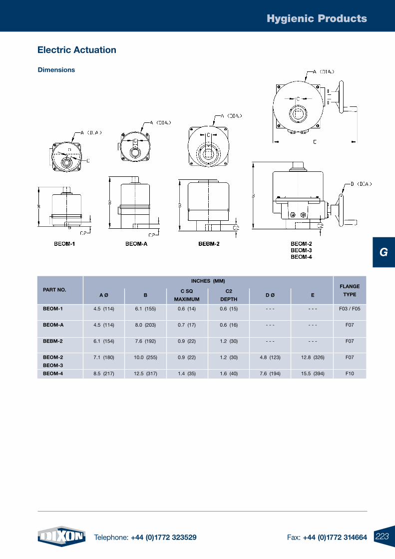
223Telephone: +44 (0)1772 323529 Fax: +44 (0)1772 314664
Hygienic Products
G
Electric Actuation
Dimensions
PArt NO.
4.5 (114)
4.5 (114)
6.1 (154)
7.1 (180)
8.5 (217)
BEOM-1
BEOM-A
BEBM-2
BEOM-2
BEOM-3
BEOM-4
6.1 (155)
8.0 (203)
7.6 (192)
10.0 (255)
12.5 (317)
0.6 (15)
0.6 (16)
1.2 (30)
1.2 (30)
1.6 (40)
- - -
- - -
- - -
4.8 (123)
7.6 (194)
0.6 (14)
0.7 (17)
0.9 (22)
0.9 (22)
1.4 (35)
F03 / F05
F07
F07
F07
F10
FlANgE
tyPE
iNcHEs (MM)
A Ø Bc2
DEPtHD Ø
c sq
MAxiMuM
- - -
- - -
- - -
12.8 (326)
15.5 (394)
E
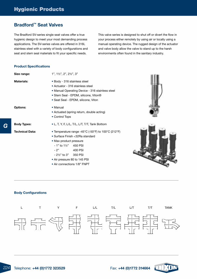
224 Telephone: +44 (0)1772 323529 Fax: +44 (0)1772 314664
Hygienic Products
G
Bradford™ seat Valves
Body configurations
L T Y F L/L T/L L/T T/T TANK
The Bradford SV-series single seat valves offer a true
hygienic design to meet your most demanding process
applications. The SV-series valves are offered in 316L
stainless steel with a variety of body configurations and
seat and stem seal materials to fit your specific needs.
This valve series is designed to shut off or divert the flow in
your process either remotely by using air or locally using a
manual operating device. The rugged design of the actuator
and valve body allow the valve to stand up to the harsh
environments often found in the sanitary industry.
Product specifications
size range: 1”, 1½”, 2”, 2½”, 3”
Materials: • Body - 316 stainless steel
• Actuator - 316 stainless steel
• Manual Operating Device - 316 stainless steel
• Stem Seal - EPDM, silicone, Viton®
• Seat Seal - EPDM, silicone, Viton
Options: • Manual
• Actuated (spring return, double acting)
• Control Tops
Body types: • L, T, Y, F, L/L, T/L, L/T, T/T, Tank Bottom
technical Data: • Temperature range -45°C (-50°F) to 100°C (212°F)
• Surface Finish <32Ra standard
• Max product pressure
- 1” to 1½” 450 PSI
- 2” 400 PSI
- 2½” to 3” 350 PSI
• Air pressure 80 to 145 PSI
• Air connections 1/8” FNPT
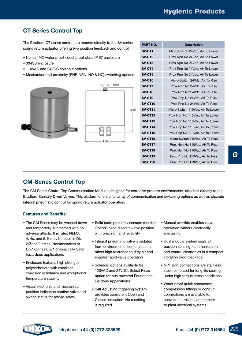
225Telephone: +44 (0)1772 323529 Fax: +44 (0)1772 314664
Hygienic Products
G
ct-series control top
cM-series control topThe CM Series Control Top Communication Module, designed for corrosive process environments, attaches directly to the
Bradford Sanitary Divert Valves. This platform offers a full array of communication and switching options as well as discrete
integral pneumatic control for spring return actuator operation.
The Bradford CT series control top mounts directly to the SV series
spring return actuator offering two position feedback and control
• Nema 4/4X water proof / dust proof class IP 67 enclosure
• 304SS enclosure
• 110VAC and 24VDC solenoid options
• Mechanical and proximity (PNP, NPN, NO & NC) switching options
PArt NO. Description
sV-ct1 Micro Switch 24Vdc, Air To Lower
sV-ct2 Prox Npn Nc 24Vdc, Air To Lower
sV-ct3 Prox Npn No 24Vdc, Air To Lower
sV-ct4 Prox Pnp Nc 24Vdc, Air To Lower
sV-ct5 Prox Pnp No 24Vdc, Air To Lower
sV-ct6 Micro Switch 24Vdc, Air To Rise
sV-ct7 Prox Npn Nc 24Vdc, Air To Rise
sV-ct8 Prox Npn No 24Vdc, Air To Rise
sV-ct9 Prox Pnp Nc 24Vdc, Air To Rise
sV-ct10 Prox Pnp No 24Vdc, Air To Rise
sV-ct11 Micro Switch 110Vac, Air To Lower
sV-ct12 Prox Npn Nc 110Vac, Air To Lower
sV-ct13 Prox Npn No 110Vac, Air To Lower
sV-ct14 Prox Pnp Nc 110Vac, Air To Lower
sV-ct15 Prox Pnp No 110Vac, Air To Lower
sV-ct16 Micro Switch 110Vac, Air To Rise
sV-ct17 Prox Npn Nc 110Vac, Air To Rise
sV-ct18 Prox Npn No 110Vac, Air To Rise
sV-ct19 Prox Pnp Nc 110Vac, Air To Rise
sV-ct20 Prox Pnp No 110Vac, Air To Rise
Features and Benefits:
• The CM Series may be washed down and temporarily submersed with no adverse affects. It is rated NEMA 4, 4x, and 6. It may be used in Div. 2/Zone 2 areas (Nonincendive) or Div.1/Zones 0 & 1 (Intrinsically Safe) hazardous applications
• Enclosure features high strength polycarbonate with excellent corrosion resistance and exceptional temperature stability
• Visual electronic and mechanical position indication confirm valve and switch status for added safety
• Solid state proximity sensors monitor Open/Closed discrete valve position with precision and reliability
• Integral pneumatic valve is isolated from environmental contamination, offers high tolerance to dirty air and enables rapid valve operation
• Solenoid options available for 120VAC and 24VDC. Select Piezo option for bus powered Foundation Fieldbus Applications
• Self Adjusting triggering system provides consistent Open and Closed indication. No resetting is required
• Manual override enables valve operation without electrically energising
• Dual module system seals all position sensing, communication and control electronics in a compact vibration proof package
• NPT port connections are stainless steel reinforced for long life sealing under high torque stress conditions
• Water proof quick connectors, compression fittings or conduit connections are available for convenient, reliable attachment to plant electrical systems
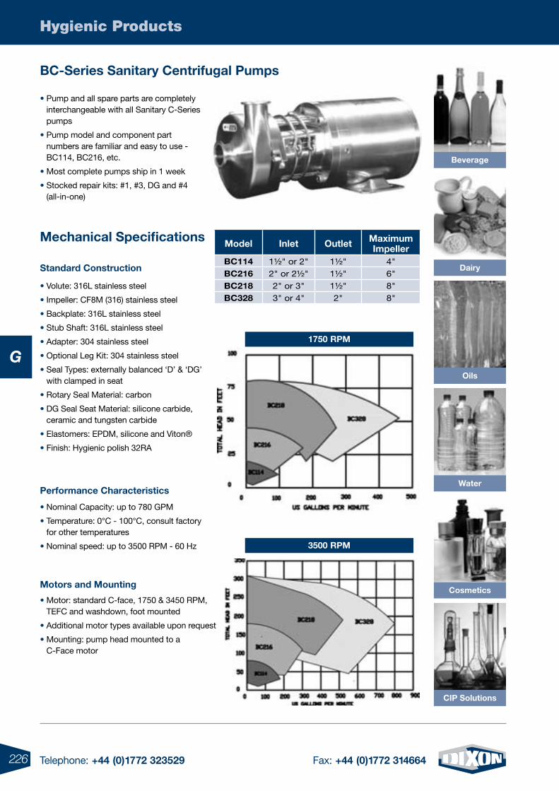
226 Telephone: +44 (0)1772 323529 Fax: +44 (0)1772 314664
Hygienic Products
G
Bc-series sanitary centrifugal Pumps
Motors and Mounting
standard construction
Mechanical specifications
• Volute: 316L stainless steel
• Impeller: CF8M (316) stainless steel
• Backplate: 316L stainless steel
• Stub Shaft: 316L stainless steel
• Adapter: 304 stainless steel
• Optional Leg Kit: 304 stainless steel
• Seal Types: externally balanced ‘D’ & ‘DG’ with clamped in seat
• Rotary Seal Material: carbon
• DG Seal Seat Material: silicone carbide, ceramic and tungsten carbide
• Elastomers: EPDM, silicone and Viton®
• Finish: Hygienic polish 32RA
• Pump and all spare parts are completely interchangeable with all Sanitary C-Series pumps
• Pump model and component part numbers are familiar and easy to use - BC114, BC216, etc.
• Most complete pumps ship in 1 week
• Stocked repair kits: #1, #3, DG and #4 (all-in-one)
Performance characteristics
• Nominal Capacity: up to 780 GPM
• Temperature: 0°C - 100°C, consult factory for other temperatures
• Nominal speed: up to 3500 RPM - 60 Hz
1750 rPM
3500 rPM
• Motor: standard C-face, 1750 & 3450 RPM, TEFC and washdown, foot mounted
• Additional motor types available upon request
• Mounting: pump head mounted to a C-Face motor
Beverage
cosmetics
ciP solutions
Model inlet Outlet Maximumimpeller
Bc114 1½" or 2" 1½" 4"Bc216 2" or 2½" 1½" 6"Bc218 2" or 3" 1½" 8"Bc328 3" or 4" 2" 8"
Oils
Dairy
Water
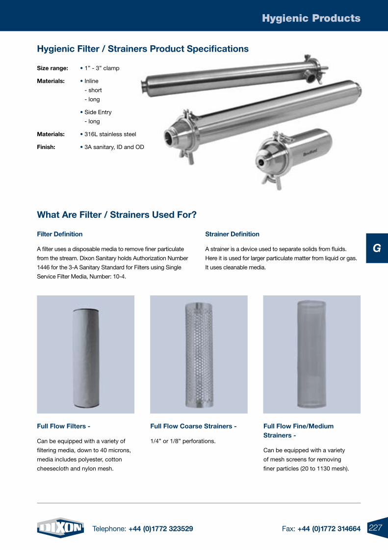
227Telephone: +44 (0)1772 323529 Fax: +44 (0)1772 314664
Hygienic Products
G
Hygienic Filter / strainers Product specifications
What Are Filter / strainers used For?
Full Flow Filters -
Can be equipped with a variety of
filtering media, down to 40 microns,
media includes polyester, cotton
cheesecloth and nylon mesh.
Filter Definition
A filter uses a disposable media to remove finer particulate
from the stream. Dixon Sanitary holds Authorization Number
1446 for the 3-A Sanitary Standard for Filters using Single
Service Filter Media, Number: 10-4.
strainer Definition
A strainer is a device used to separate solids from fluids.
Here it is used for larger particulate matter from liquid or gas.
It uses cleanable media.
Full Flow coarse strainers -
1/4” or 1/8” perforations.
Full Flow Fine/Medium strainers -
Can be equipped with a variety
of mesh screens for removing
finer particles (20 to 1130 mesh).
size range: • 1” - 3” clamp
Materials: • Inline
- short
- long
• Side Entry
- long
Materials: • 316L stainless steel
Finish: • 3A sanitary, ID and OD
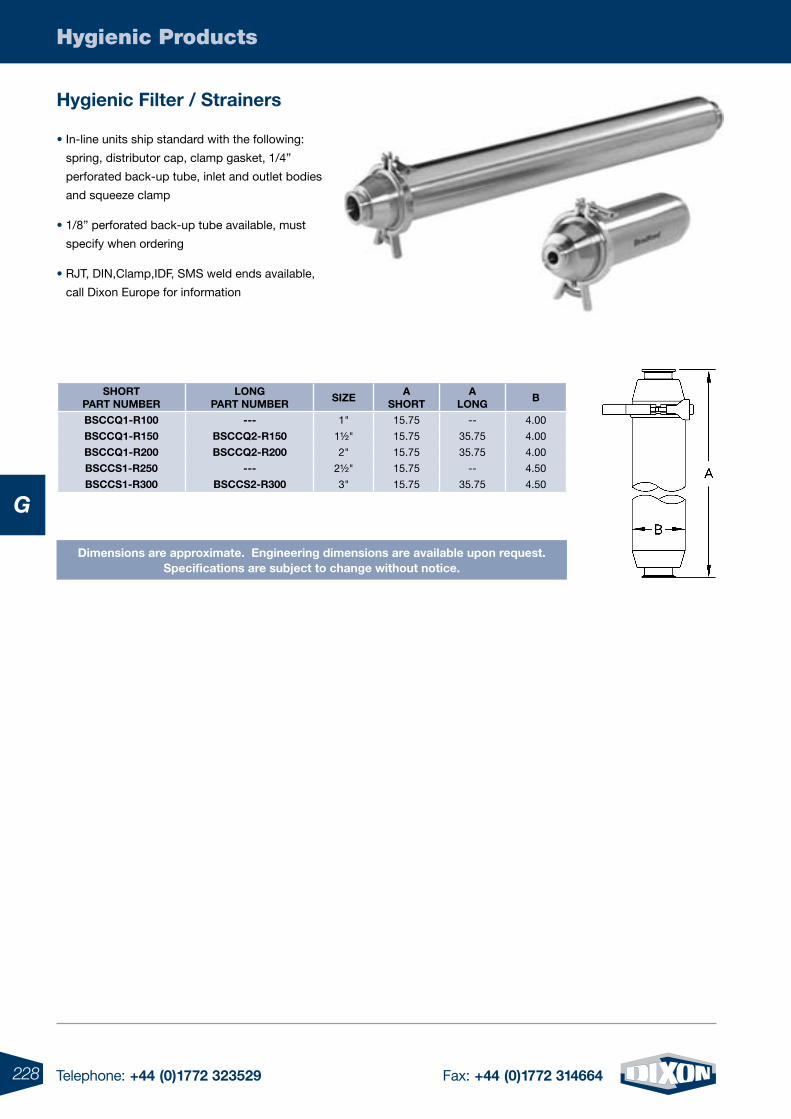
228 Telephone: +44 (0)1772 323529 Fax: +44 (0)1772 314664
Hygienic Products
G
Hygienic Filter / strainers
• In-line units ship standard with the following:
spring, distributor cap, clamp gasket, 1/4”
perforated back-up tube, inlet and outlet bodies
and squeeze clamp
• 1/8” perforated back-up tube available, must
specify when ordering
• RJT, DIN,Clamp,IDF, SMS weld ends available,
call Dixon Europe for information
sHOrtPArt NuMBEr
lONgPArt NuMBEr
sizEA
sHOrtA
lONgB
Bsccq1-r100 --- 1" 15.75 -- 4.00
Bsccq1-r150 Bsccq2-r150 1½" 15.75 35.75 4.00
Bsccq1-r200 Bsccq2-r200 2" 15.75 35.75 4.00
Bsccs1-r250 --- 2½" 15.75 -- 4.50
Bsccs1-r300 Bsccs2-r300 3" 15.75 35.75 4.50
Dimensions are approximate. Engineering dimensions are available upon request.specifications are subject to change without notice.
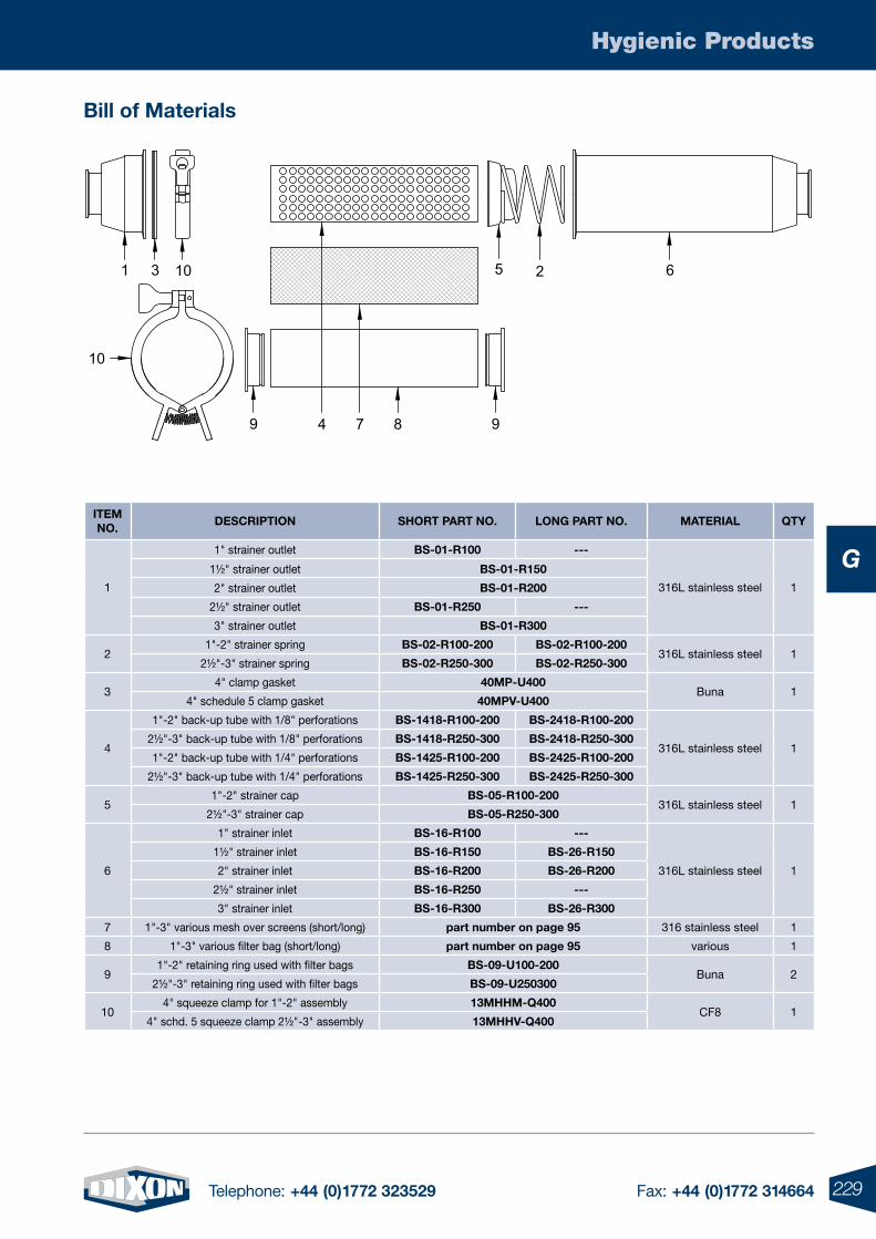
229Telephone: +44 (0)1772 323529 Fax: +44 (0)1772 314664
Hygienic Products
G
Bill of Materials
itEM NO.
DEscriPtiON sHOrt PArt NO. lONg PArt NO. MAtEriAl qty
1
1" strainer outlet Bs-01-r100 ---
316L stainless steel 1
1½" strainer outlet Bs-01-r150
2" strainer outlet Bs-01-r200
2½" strainer outlet Bs-01-r250 ---
3" strainer outlet Bs-01-r300
21"-2" strainer spring Bs-02-r100-200 Bs-02-r100-200
316L stainless steel 12½"-3" strainer spring Bs-02-r250-300 Bs-02-r250-300
34" clamp gasket 40MP-u400
Buna 14" schedule 5 clamp gasket 40MPV-u400
4
1"-2" back-up tube with 1/8" perforations Bs-1418-r100-200 Bs-2418-r100-200
316L stainless steel 12½"-3" back-up tube with 1/8" perforations Bs-1418-r250-300 Bs-2418-r250-300
1"-2" back-up tube with 1/4" perforations Bs-1425-r100-200 Bs-2425-r100-200
2½"-3" back-up tube with 1/4" perforations Bs-1425-r250-300 Bs-2425-r250-300
51"-2" strainer cap Bs-05-r100-200
316L stainless steel 12½"-3" strainer cap Bs-05-r250-300
6
1" strainer inlet Bs-16-r100 ---
316L stainless steel 1
1½" strainer inlet Bs-16-r150 Bs-26-r150
2" strainer inlet Bs-16-r200 Bs-26-r200
2½" strainer inlet Bs-16-r250 ---
3" strainer inlet Bs-16-r300 Bs-26-r300
7 1"-3" various mesh over screens (short/long) part number on page 95 316 stainless steel 1
8 1"-3" various filter bag (short/long) part number on page 95 various 1
91"-2" retaining ring used with filter bags Bs-09-u100-200
Buna 22½"-3" retaining ring used with filter bags Bs-09-u250300
104" squeeze clamp for 1"-2" assembly 13MHHM-q400
CF8 14" schd. 5 squeeze clamp 2½"-3" assembly 13MHHV-q400
10
4
1 3 10 5
87
62
99
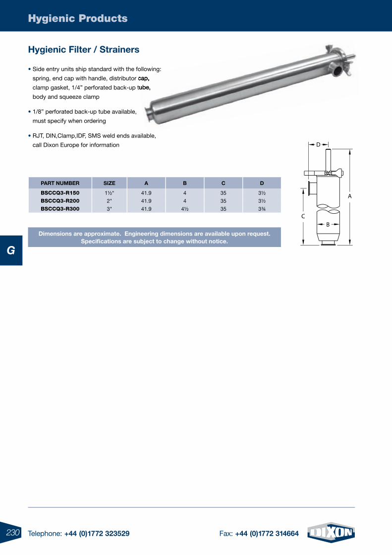
230 Telephone: +44 (0)1772 323529 Fax: +44 (0)1772 314664
Hygienic Products
G
Hygienic Filter / strainers
• Side entry units ship standard with the following:
spring, end cap with handle, distributor cap,
clamp gasket, 1/4” perforated back-up tube,
body and squeeze clamp
• 1/8” perforated back-up tube available,
must specify when ordering
• RJT, DIN,Clamp,IDF, SMS weld ends available,
call Dixon Europe for information
Dimensions are approximate. Engineering dimensions are available upon request.specifications are subject to change without notice.
spring, end cap with handle, distributor cap,
clamp gasket, 1/4” perforated back-up tube,
PArt NuMBEr sizE A B c D
BSCCQ3-R150 1½" 41.9 4 35 3½
BSCCQ3-R200 2" 41.9 4 35 3½
BSCCQ3-R300 3" 41.9 4½ 35 3¾
D
A
CB
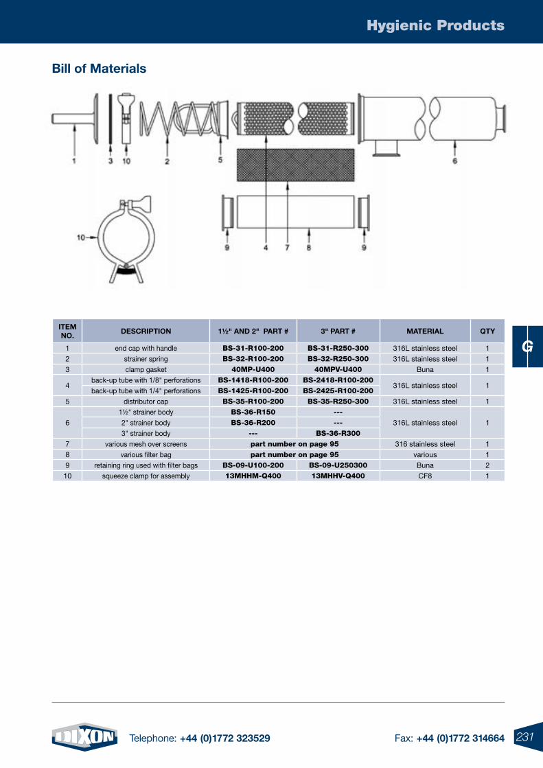
231Telephone: +44 (0)1772 323529 Fax: +44 (0)1772 314664
Hygienic Products
G
Bill of Materials
itEM NO.
DEscriPtiON 1½" AND 2" PArt # 3" PArt # MAtEriAl qty
1 end cap with handle BS-31-R100-200 BS-31-R250-300 316L stainless steel 1
2 strainer spring BS-32-R100-200 BS-32-R250-300 316L stainless steel 1
3 clamp gasket 40MP-U400 40MPV-U400 Buna 1
4back-up tube with 1/8" perforations BS-1418-R100-200 BS-2418-R100-200
316L stainless steel 1back-up tube with 1/4" perforations BS-1425-R100-200 BS-2425-R100-200
5 distributor cap BS-35-R100-200 BS-35-R250-300 316L stainless steel 1
6
1½" strainer body BS-36-R150 ---316L stainless steel 12" strainer body BS-36-R200 ---
3" strainer body --- BS-36-R3007 various mesh over screens part number on page 95 316 stainless steel 1
8 various filter bag part number on page 95 various 1
9 retaining ring used with filter bags BS-09-U100-200 BS-09-U250300 Buna 2
10 squeeze clamp for assembly 13MHHM-Q400 13MHHV-Q400 CF8 1
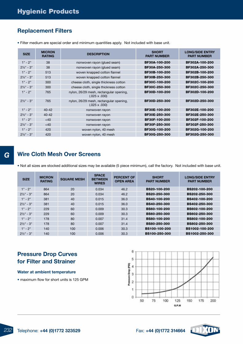
232 Telephone: +44 (0)1772 323529 Fax: +44 (0)1772 314664
Hygienic Products
G• Not all sizes are stocked additional sizes may be available (5 piece minimum), call the factory. Not included with base unit.
sizEMicrON rAtiNg
squArE MEsHsPAcE
BEtWEEN WirEs
PErcENt OF OPEN ArEA
sHOrtPArt NuMBEr
lONg/siDE ENtryPArt NuMBEr
1" - 2" 864 20 0.034 46.2 BS20-100-200 BS202-100-200
2½" - 3" 864 20 0.034 46.2 BS20-250-300 BS202-250-300
1" - 2" 381 40 0.015 36.0 BS40-100-200 BS402-100-200
2½" - 3" 381 40 0.015 36.0 BS40-250-300 BS402-250-300
1" - 2" 229 60 0.009 30.3 BS60-100-200 BS602-100-200
2½" - 3" 229 60 0.009 30.3 BS60-250-300 BS602-250-300
1" - 2" 178 80 0.007 31.4 BS80-100-200 BS802-100-200
2½" - 3" 178 80 0.007 31.4 BS80-250-300 BS802-250-300
1" - 2" 140 100 0.006 30.3 BS100-100-200 BS1002-100-200
2½" - 3" 140 100 0.006 30.3 BS100-250-300 BS1002-250-300
Water at ambient temperature
• maximum flow for short units is 125 GPM
replacement Filters
Wire cloth Mesh Over screens
• Filter medium are special order and minimum quantities apply. Not included with base unit.
Pressure Drop curves for Filter and strainer
sizEMicrON rAtiNg
DEscriPtiONsHOrt
PArt NuMBErlONg/siDE ENtry
PArt NuMBEr
1" - 2" 38 nonwoven rayon (glued seam) BF30A-100-200 BF302A-100-200
2½" - 3" 38 nonwoven rayon (glued seam) BF30A-250-300 BF302A-250-300
1" - 2" 513 woven knapped cotton flannel BF30B-100-200 BF302B-100-200
2½" - 3" 513 woven knapped cotton flannel BF30B-250-300 BF302B-250-300
1" - 2" 300 cheese cloth, single thickness cotton BF30C-100-200 BF302C-100-200
2½" - 3" 300 cheese cloth, single thickness cotton BF30C-250-300 BF302C-250-300
1" - 2" 765 nylon, 26/29 mesh, rectangular opening, (.025 x .030)
BF30D-100-200 BF302D-100-200
2½" - 3" 765 nylon, 26/29 mesh, rectangular opening, (.025 x .030)
BF30D-250-300 BF302D-250-300
1" - 2" 40-42 nonwoven rayon BF30E-100-200 BF302E-100-200
2½" - 3" 40-42 nonwoven rayon BF30E-250-300 BF302E-250-300
1" - 2" <40 nonwoven rayon BF30F-100-200 BF302F-100-200
2½" - 3" <40 nonwoven rayon BF30F-250-300 BF302F-250-300
1" - 2" 420 woven nylon, 40 mesh BF30G-100-200 BF302G-100-200
2½" - 3" 420 woven nylon, 40 mesh BF30G-250-300 BF302G-250-300
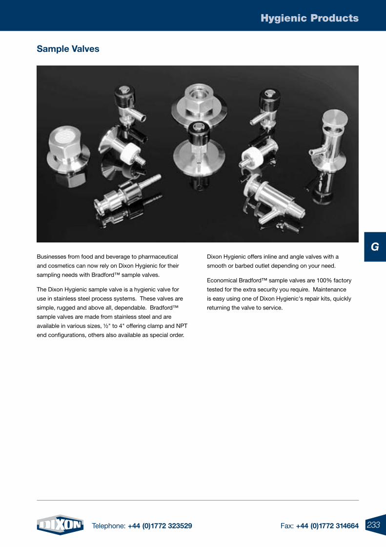
233Telephone: +44 (0)1772 323529 Fax: +44 (0)1772 314664
Hygienic Products
GBusinesses from food and beverage to pharmaceutical
and cosmetics can now rely on Dixon Hygienic for their
sampling needs with Bradford™ sample valves.
The Dixon Hygienic sample valve is a hygienic valve for
use in stainless steel process systems. These valves are
simple, rugged and above all, dependable. Bradford™
sample valves are made from stainless steel and are
available in various sizes, ½" to 4" offering clamp and NPT
end configurations, others also available as special order.
Dixon Hygienic offers inline and angle valves with a
smooth or barbed outlet depending on your need.
Economical Bradford™ sample valves are 100% factory
tested for the extra security you require. Maintenance
is easy using one of Dixon Hygienic's repair kits, quickly
returning the valve to service.
sample Valves
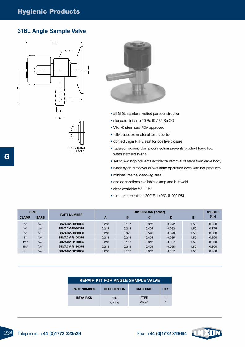
234 Telephone: +44 (0)1772 323529 Fax: +44 (0)1772 314664
Hygienic Products
G
316l Angle sample Valve
• all 316L stainless wetted part construction
• standard finish to 20 Ra ID / 32 Ra OD
• Viton® stem seal FDA approved
• fully traceable (material test reports)
• domed virgin PTFE seat for positive closure
• tapered hygienic clamp connection prevents product back flow
when installed in-line
• set screw stop prevents accidental removal of stem from valve body
• black nylon nut cover allows hand operation even with hot products
• minimal internal dead-leg area
• end connections available: clamp and buttweld
• sizes available: ½" - 1½"
• temperature rating: (300°F) 149°C @ 200 PSI
BsVAcV-r050025BsVAcV-r050375BsVAcV-r050050BsVAcV-r100375BsVAcV-r150025BsVAcV-r150375BsVAcV-r200025
PArt NuMBErsizE DiMENsiONs (inches)
½"
½"
½"
1"
1½"
1½"
2"
WEigHt(lbs)
0.250
0.375
0.500
0.500
0.500
0.500
0.750
A
0.218
0.218
0.218
0.218
0.218
0.218
0.218
B
0.187
0.218
0.375
0.218
0.187
0.218
0.187
c
0.312
0.405
0.540
0.405
0.312
0.405
0.312
D
0.972
0.952
0.878
0.985
0.987
0.985
0.987
E
1.50
1.50
1.50
1.50
1.50
1.50
1.50
clAMP BArB
1/4"3/8"1/2"3/8"1/4"3/8"1/4"
rEPAir Kit FOr ANglE sAMPlE VAlVE
BsVA-rKs
PArt NuMBEr DEscriPtiON
PTFE
Viton®
seal
O-ring
MAtEriAl qty.
1
1
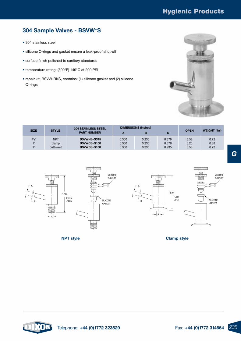
235Telephone: +44 (0)1772 323529 Fax: +44 (0)1772 314664
Hygienic Products
G
304 sample Valves - BsVW*s
• 304 stainless steel
• silicone O-rings and gasket ensure a leak-proof shut-off
• surface finish polished to sanitary standards
• temperature rating: (300°F) 149°C at 200 PSI
• repair kit, BSVW-RKS, contains: (1) silicone gasket and (2) silicone
O-rings
NPt style
GASKETSILICONE
O-RINGSSILICONE
3.58
FULLYOPEN
A
C
B
clamp style
C
B
A
3.25FULLYOPEN
O-RINGSSILICONE
GASKETSILICONE
304 stAiNlEss stEElPArt NuMBEr
DiMENsiONs (inches)sizE
3/8"1"1”
stylE
NPTclamp
butt-weld
BsVWNs-g375BsVWcs-g100BsVWBs-g100
WEigHt (lbs)OPENA B c
0.720.880.72
3.583.253.58
0.3600.3600.360
0.2350.2350.235
0.3780.3780.235
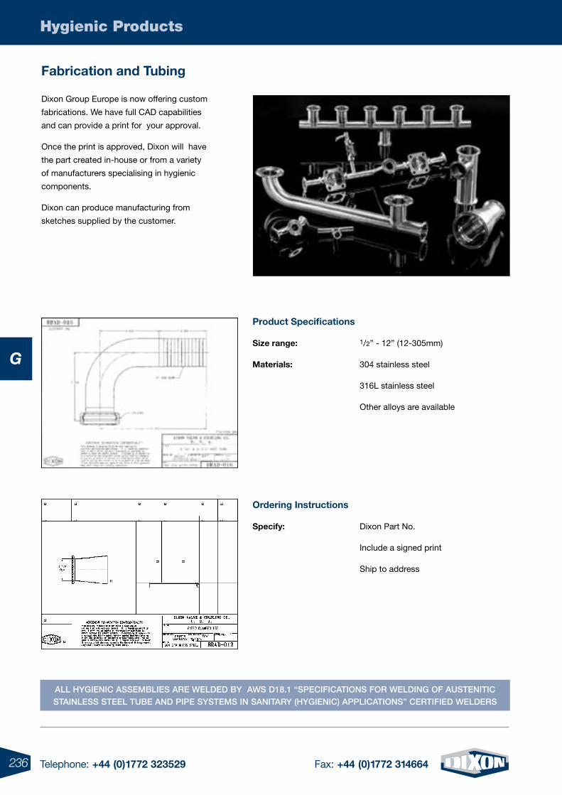
236 Telephone: +44 (0)1772 323529 Fax: +44 (0)1772 314664
Hygienic Products
G
Fabrication and tubing
Dixon Group Europe is now offering custom
fabrications. We have full CAD capabilities
and can provide a print for your approval.
Once the print is approved, Dixon will have
the part created in-house or from a variety
of manufacturers specialising in hygienic
components.
Dixon can produce manufacturing from
sketches supplied by the customer.
Product specifications
size range: 1/2” - 12” (12-305mm)
Materials: 304 stainless steel
316L stainless steel
Other alloys are available
Ordering instructions
specify: Dixon Part No.
Include a signed print
Ship to address
All hygienic Assemblies Are welded by Aws d18.1 “specificAtions for welding of Austenitic stAinless steel tube And pipe systems in sAnitAry (hygienic) ApplicAtions” certified welders
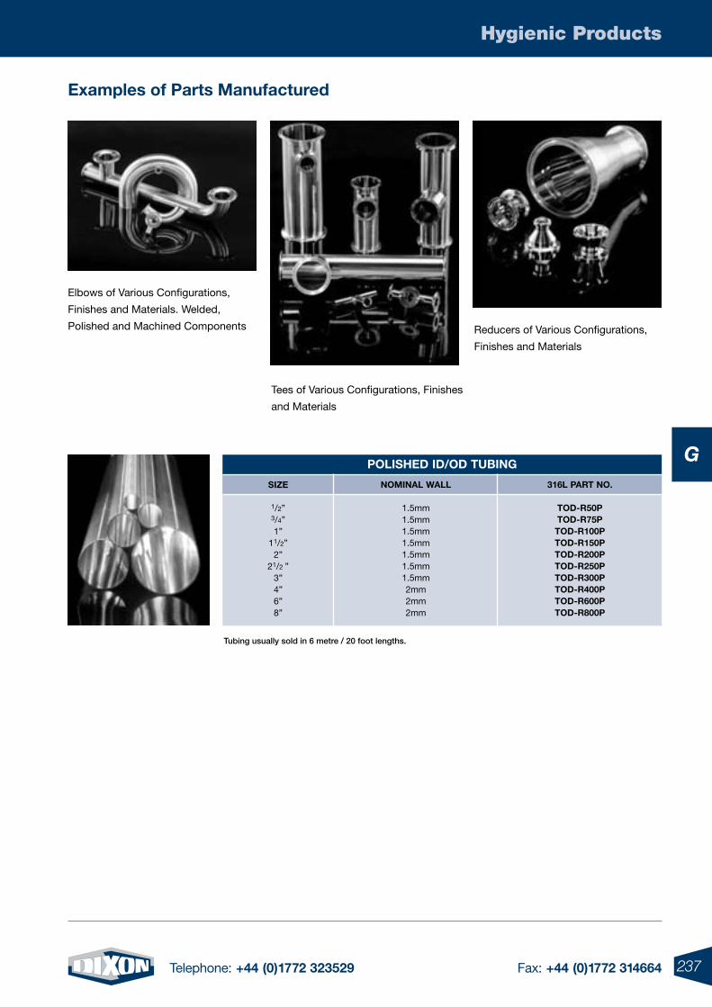
237Telephone: +44 (0)1772 323529 Fax: +44 (0)1772 314664
Hygienic Products
G
Elbows of Various Configurations,
Finishes and Materials. Welded,
Polished and Machined Components
Tees of Various Configurations, Finishes
and Materials
Reducers of Various Configurations,
Finishes and Materials
POlisHED iD/OD tuBiNg
sizE
1/2”3/4”1”
11/2”2”
21/2 ”3”4”6”8”
NOMiNAl WAll
1.5mm1.5mm1.5mm1.5mm1.5mm1.5mm1.5mm2mm2mm2mm
316l PArt NO.
tOD-r50PtOD-r75PtOD-r100PtOD-r150PtOD-r200PtOD-r250PtOD-r300PtOD-r400PtOD-r600PtOD-r800P
tubing usually sold in 6 metre / 20 foot lengths.
Examples of Parts Manufactured
H
4 Telephone: +44 (0)1772 323529 Fax: +44 (0)1772 314664238 Telephone: +44 (0)1772 323529 Fax: +44 (0)1772 314664
H
H
239Telephone: +44 (0)1772 323529 Fax: +44 (0)1772 314664
The Holedall System & Accessories .............................................240-244
Internal Expansion (IX) Couplings & Ferrules ................................245-246
Hygienic Stem & Ferrule ...............................................................247-248
Permanent Petroleum Couplings ..................................................249-252
Pump Hose Couplings .................................................................253-254
External Swage (ES) Couplings & Ferrules ...................................255-256
External Crimp (EC) Couplings & Ferrules ....................................257-258
Hookie Hook Stem & Ferrules .................................................................259
Holedall® Swaging Machines .................................................................260
Holedall® Internal Expansion Machine Tooling ........................................261
High Pressure & Custom Made Couplings ..............................................262
Holedall Swaged Rotary Drilling Hose Coupling System ..............263-264
Forged Steel Hammer Unions ......................................................265-266
For a Full range oF hoses to complement these Fittings see section F
239Telephone: +44 (0)1772 323529 Fax: +44 (0)1772 314664
Permanently Attached Couplings -Holedall® System
H
240 Telephone: +44 (0)1772 323529 Fax: +44 (0)1772 314664
H
Permanently Attached Couplings - Holedall® System
holedall® - permanently attached coupling system
Based upon the already highly successful Holedall®/Mulconroy Coupling
System, which has been manufactured and marketed by our parent company
- Dixon Valve & Coupling since 1940 in the United States. This comprehensive
range has been specifically designed and developed to service the needs of
both industrial and the Offshore Oil & Gas markets.
Holedall couplings conform to all European specifications and quality
requirements, including: EN1765 and EN14421.
IX Couplings are specified for use in Type Approved Hose Assemblies by Det
Norsk Veritas, Lloyds Register of Shipping etc., and are in service with most of
the World’s major oil drilling companies on Offshore and hand rig applications.
The Holedall® Coupling System provides a safe and cost effective method of
outstanding strength and durability of attaching couplings to hose. Ease of
operation, flexibility and economy make the Holedall method an un-equalled
hose assembly system.
With both Internal Expansion and External Swage Couplings, the Holedall system utilises a cold worked, draw type
progressive swage method which gives a full 360° uninterrupted expansion or compression band aroun the hose, giving
superb coupling retention and end load characteristics.
The Holedall range of External Crimp Couplings which includes an interlocking groove and collar offers an alternative safe
and secure method of producing hose assemblies to 8” nominal bore.
Only quality assured, materials are used in the production of Holedall Couplings, with materials used for swaging having
been selected to establish the proof/yield stress to ensure that brittle fracture does not occur. Certification in accordance
with EN10204 3.1. is available with all couplings.
The Holedall system does not stop at couplings. We also manufacture and supply a range of machines for hose
assembly including, Internal Expansion Machines, External Swaging Machines, Dual Swaging Machines, External Crimping
Machines and Coupling Inserting Machines and Hydrostatic Test Pumps.
Definitions
• “Stem”, Nipple, Tail is an externally serrated coupling which fits inside the bore of the hose.
• “Ferrule” is an internally serrated steel cylinder which fits over the outside of the hose or pipe and interlocks with the stem.
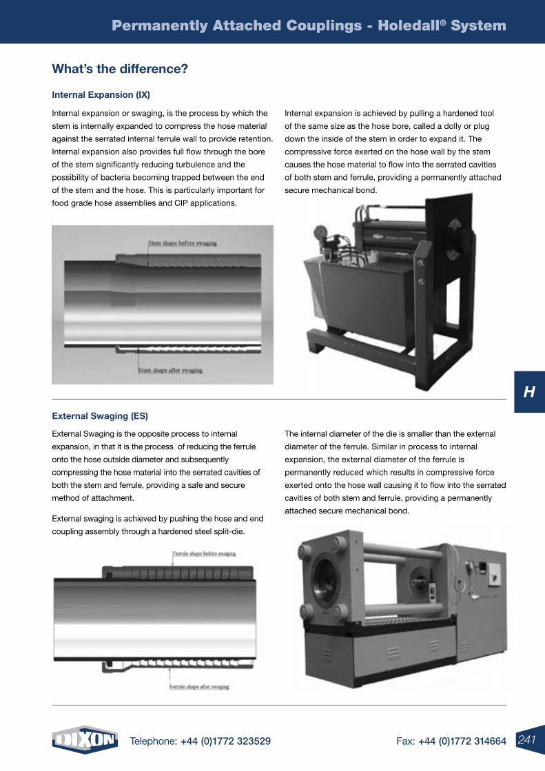
241Telephone: +44 (0)1772 323529 Fax: +44 (0)1772 314664
H
Permanently Attached Couplings - Holedall® System
What’s the difference?
internal expansion (iX)
external swaging (es)
Internal expansion or swaging, is the process by which the
stem is internally expanded to compress the hose material
against the serrated internal ferrule wall to provide retention.
Internal expansion also provides full flow through the bore
of the stem significantly reducing turbulence and the
possibility of bacteria becoming trapped between the end
of the stem and the hose. This is particularly important for
food grade hose assemblies and CIP applications.
Internal expansion is achieved by pulling a hardened tool
of the same size as the hose bore, called a dolly or plug
down the inside of the stem in order to expand it. The
compressive force exerted on the hose wall by the stem
causes the hose material to flow into the serrated cavities
of both stem and ferrule, providing a permanently attached
secure mechanical bond.
External Swaging is the opposite process to internal
expansion, in that it is the process of reducing the ferrule
onto the hose outside diameter and subsequently
compressing the hose material into the serrated cavities of
both the stem and ferrule, providing a safe and secure
method of attachment.
External swaging is achieved by pushing the hose and end
coupling assembly through a hardened steel split-die.
The internal diameter of the die is smaller than the external
diameter of the ferrule. Similar in process to internal
expansion, the external diameter of the ferrule is
permanently reduced which results in compressive force
exerted onto the hose wall causing it to flow into the serrated
cavities of both stem and ferrule, providing a permanently
attached secure mechanical bond.
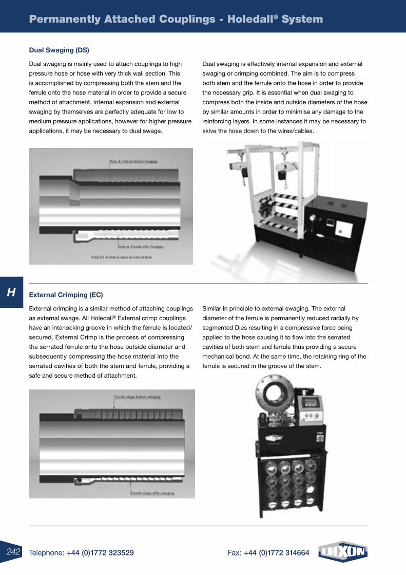
242 Telephone: +44 (0)1772 323529 Fax: +44 (0)1772 314664
H
Permanently Attached Couplings - Holedall® System
Dual swaging (Ds)
external crimping (ec)
Dual swaging is mainly used to attach couplings to high
pressure hose or hose with very thick wall section. This
is accomplished by compressing both the stem and the
ferrule onto the hose material in order to provide a secure
method of attachment. Internal expansion and external
swaging by themselves are perfectly adequate for low to
medium pressure applications, however for higher pressure
applications, it may be necessary to dual swage.
Dual swaging is effectively internal expansion and external
swaging or crimping combined. The aim is to compress
both stem and the ferrule onto the hose in order to provide
the necessary grip. It is essential when dual swaging to
compress both the inside and outside diameters of the hose
by similar amounts in order to minimise any damage to the
reinforcing layers. In some instances it may be necessary to
skive the hose down to the wires/cables.
External crimping is a similar method of attaching couplings
as external swage. All Holedall® External crimp couplings
have an interlocking groove in which the ferrule is located/
secured. External Crimp is the process of compressing
the serrated ferrule onto the hose outside diameter and
subsequently compressing the hose material into the
serrated cavities of both the stem and ferrule, providing a
safe and secure method of attachment.
Similar in principle to external swaging. The external
diameter of the ferrule is permanently reduced radially by
segmented Dies resulting in a compressive force being
applied to the hose causing it to flow into the serrated
cavities of both stem and ferrule thus providing a secure
mechanical bond. At the same time, the retaining ring of the
ferrule is secured in the groove of the stem.
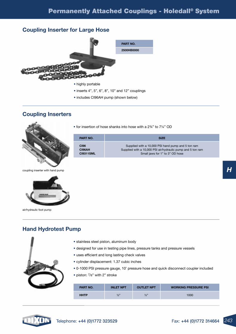
243Telephone: +44 (0)1772 323529 Fax: +44 (0)1772 314664
H
Permanently Attached Couplings - Holedall® System
part no.
2500hB0000
• highly portable
• inserts 4”, 5”, 6”, 8”, 10” and 12” couplings
• includes CI96AH pump (shown below)
coupling inserter for large hose
• for insertion of hose shanks into hose with a 2¾” to 7¼” OD
• stainless steel piston, aluminum body
• designed for use in testing pipe lines, pressure tanks and pressure vessels
• uses efficient and long lasting check valves
• cylinder displacement: 1.37 cubic inches
• 0-1000 PSI pressure gauge, 10’ pressure hose and quick disconnect coupler included
• piston: 7/8” with 2” stroke
coupling inserters
hand hydrotest pump
size
Supplied with a 10,000 PSI hand pump and 5 ton ramSupplied with a 10,000 PSI air/hydraulic pump and 5 ton ram
Small jaws for 1” to 3” OD hose
part no.
ci96 ci96ah ci9311sml
part no.
hhtp
inlet npt
½”
outlet npt
½”
Working pressure psi
1000
coupling inserter with hand pump
air/hydraulic foot pump
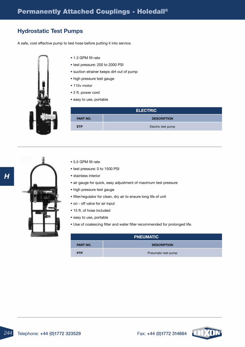
244 Telephone: +44 (0)1772 323529 Fax: +44 (0)1772 314664
Permanently Attached Couplings - Holedall®
H
• 1.3 GPM fill rate
• test pressure: 200 to 2000 PSI
• suction strainer keeps dirt out of pump
• high pressure test gauge
• 115v motor
• 2 ft. power cord
• easy to use, portable
• 5.5 GPM fill rate
• test pressure: 0 to 1500 PSI
• stainless interior
• air gauge for quick, easy adjustment of maximum test pressure
• high pressure test gauge
• filter/regulator for clean, dry air to ensure long life of unit
• on - off valve for air input
• 15 ft. of hose included
• easy to use, portable
• Use of coalescing filter and water filter recommended for prolonged life.
A safe, cost effective pump to test hose before putting it into service.
hydrostatic test pumps
Description
Electric test pump
part no.
etp
electric
Description
Pneumatic test pump
part no.
ptp
pneumatic
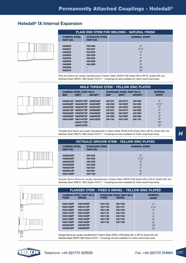
245Telephone: +44 (0)1772 323529 Fax: +44 (0)1772 314664
Permanently Attached Couplings - Holedall®
H
holedall® iX internal expansion
plain enD stem For WelDing - natural Finishnominal Bore*
2”21/2”
3”4”5”6”8”10”12”
carBon steel part no.
ha0050 ha0037 ha0032 ha0029 ha0054 ha0058 ha0099 ha0369 ha0370
stainless steel part no.
ha1050 ha1037 ha1032 ha1029 ha1054 ha1058 ha1099 - -
FlangeD stem - FiXeD & sWiVel - YelloW zinc plateDnominal
Bore*
2”21/2”
3”4”5”6”8”10”12”
FiXeD
ha0134zp ha0135zp ha0136zp ha0137zp ha0138zp ha0139zp ha0140zp ha0924zp ha0925zp
FiXeD
ha1134 ha1135 ha1136 ha1137 ha1138 ha1139 ha1140 - -
sWiVel
ha0150zpha0151zpha0152zpha0153zpha0154zpha0155zpha0156zpha0397zpha0926zp
sWiVel
ha1150 ha1151 ha1152 ha1153 ha1154 ha1155 ha1156--
carBon steel part no.s stainless steel part no.s
Flanged Stems are usually manufactured in Carbon Steel: ASTM A106 Grade A/B or API 5L Grade A/B, and Stainless Steel: BS970:1983 Grade 316 S11. *Couplings are also available for metric sized hose bores
Plain End Stems are usually manufactured in Carbon Steel: ASTM A106 Grade A/B or API 5L Grade A/B, and Stainless Steel: BS970: 1983 Grade 316 S11. * Couplings are also available for metric sized hose bores.
male threaD stem - YelloW zinc plateDnominal
Bore*
2”21/2”
3”4”5”6”8”10”12”
Bsp
ha0051zp ha0038zp ha0033zp ha0031zp ha0055zp ha0059zp ha0144zp - -
Bsp
ha1051 ha1038 ha1033 ha1031 ha1055 ha1059 ha1144 - -
Bspt
ha0051tzpha0038tzpha0033tzpha0031tzpha0055tzpha0059tzpha0144tzpha0371tzpha0372tzp
Bspt
ha1051tha1038tha1033tha1031tha1055tha1059tha1144t--
api/npt
ha0052zpha0039zpha0034zpha0026zpha0056zpha0060zpha0145zp--
api/npt
ha1052ha1039ha1034ha1026ha1056ha1060ha1145--
carBon steel part no.s stainless steel part no.s
Threaded End Stems are usually manufactured in Carbon Steel: ASTM A106 Grade A/B or API 5L Grade A/B, and Stainless Steel: BS970: 1983 Grade 316 S11. * Couplings are also available for metric sized hose bores.
Victaulic grooVe stem - YelloW zinc plateDnominal Bore*
2”21/2”
3”4”5”6”8”
carBon steel part no.
ha0053zp ha0040zp ha0035zp ha0030zp ha0057zp ha0061zp ha0148zp
stainless steel part no.
ha1053 ha1040 ha1035 ha1030 ha1057 ha1061 ha1148
Victaulic Groove Stems are usually manufactured in Carbon Steel: ASTM A106 Grade A/B or API 5L Grade A/B, and Stainless Steel: BS970: 1983 Grade 316 S11. * Couplings are also available for metric sized hose bores.
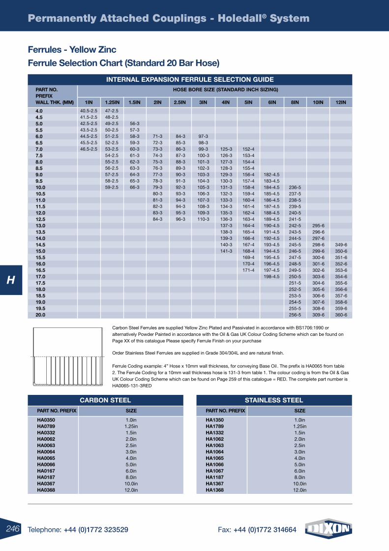
246 Telephone: +44 (0)1772 323529 Fax: +44 (0)1772 314664
H
Permanently Attached Couplings - Holedall® System
internal eXpansion Ferrule selection guiDe part no. preFiX Wall thk. (mm)
4.0 4.5 5.0 5.5 6.0 6.5 7.0 7.5 8.0 8.5 9.0 9.5 10.0 10.5 11.0 11.5 12.0 12.5 13.0 13.5 14.0 14.5 15.0 15.5 16.0 16.5 17.0 17.5 18.0 18.5 19.0 19.5 20.0
hose Bore size (stanDarD inch sizing)
1in 1.25in 1.5in 2in 2.5in 3in 4in 5in 6in 8in 10in 12in
40.5-2.541.5-2.542.5-2.543.5-2.544.5-2.545.5-2.546.5-2.5
47-2.548-2.549-2.550-2.551-2.552-2.553-2.554-2.555-2.556-2.557-2.558-2.559-2.5
56-357-358-359-360-361-362-363-364-365-366-3
71-372-373-374-375-376-377-378-379-380-381-382-383-384-3
84-385-386-387-388-389-390-391-392-393-394-394-395-396-3
97-398-399-3
100-3101-3102-3103-3104-3105-3106-3107-3108-3109-3110-3
125-3126-3127-3128-3129-3130-3131-3132-3133-3134-3135-3136-3137-3138-3139-3140-3141-3
152-4153-4154-4155-4156-4157-4158-4159-4160-4161-4162-4163-4164-4165-4166-4167-4168-4169-4170-4171-4
182-4.5183-4.5184-4.5185-4.5186-4.5187-4.5188-4.5189-4.5190-4.5191-4.5192-4.5193-4.5194-4.5195-4.5196-4.5197-4.5198-4.5
236-5237-5238-5239-5240-5241-5242-5243-5244-5245-5246-5247-5248-5249-5250-5251-5252-5253-5254-5255-5256-5
295-6296-6297-6298-6299-6300-6301-6302-6303-6304-6305-6306-6307-6308-6309-6
349-6350-6351-6352-6353-6354-6355-6356-6357-6358-6359-6360-6
Carbon Steel Ferrules are supplied Yellow Zinc Plated and Passivated in accordance with BS1706:1990 or alternatively Powder Painted in accordance with the Oil & Gas UK Colour Coding Scheme which can be found on Page XX of this catalogue Please specify Ferrule Finish on your purchase
Order Stainless Steel Ferrules are supplied in Grade 304/304L and are natural finish. Ferrule Coding example: 4” Hose x 10mm wall thickness, for conveying Base Oil . The prefix is HA0065 from table 2. The Ferrule Coding for a 10mm wall thickness hose is 131-3 from table 1. The colour coding is from the Oil & Gas UK Colour Coding Scheme which can be found on Page 259 of this catalogue = RED. The complete part number is HA0065-131-3RED
Ferrules - Yellow zinc Ferrule selection chart (standard 20 Bar hose)
carBon steel
size part no. preFiX
ha0350 ha0789 ha0332 ha0062 ha0063 ha0064 ha0065 ha0066 ha0167 ha0187 ha0367 ha0368
1.0in1.25in1.5in2.0in2.5in3.0in4.0in5.0in6.0in8.0in
10.0in12.0in
stainless steel
size part no. preFiX
ha1350 ha1789 ha1332 ha1062 ha1063 ha1064 ha1065 ha1066 ha1067 ha1187 ha1367 ha1368
1.0in1.25in1.5in2.0in2.5in3.0in4.0in5.0in6.0in8.0in10.0in12.0in
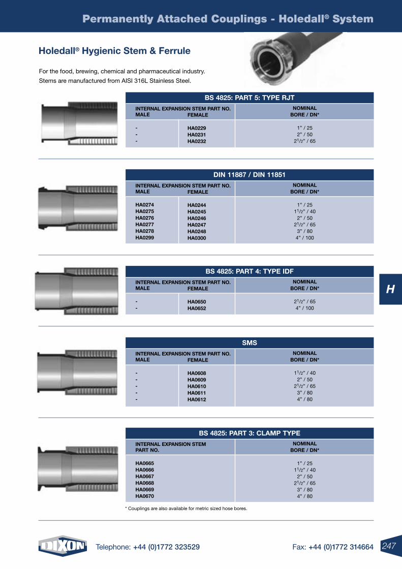
247Telephone: +44 (0)1772 323529 Fax: +44 (0)1772 314664
H
Permanently Attached Couplings - Holedall® System
For the food, brewing, chemical and pharmaceutical industry.
Stems are manufactured from AISI 316L Stainless Steel.
holedall® hygienic stem & Ferrule
Bs 4825: part 5: tYpe rJtnominal
Bore / Dn*
1” / 252” / 50
21/2” / 65
male
- - -
internal eXpansion stem part no. Female ha0229 ha0231 ha0232
Din 11887 / Din 11851nominal
Bore / Dn*
1” / 2511/2” / 40
2” / 5021/2” / 65
3” / 80 4” / 100
male
ha0274 ha0275 ha0276 ha0277 ha0278 ha0299
internal eXpansion stem part no. Female ha0244 ha0245 ha0246 ha0247 ha0248 ha0300
Bs 4825: part 4: tYpe iDFnominal
Bore / Dn*
21/2” / 654” / 100
male
- -
internal eXpansion stem part no. Female ha0650 ha0652
smsnominal
Bore / Dn*
11/2” / 402” / 50
21/2” / 653” / 80 4” / 80
male
- - - - -
internal eXpansion stem part no. Female ha0608 ha0609 ha0610 ha0611 ha0612
Bs 4825: part 3: clamp tYpenominal
Bore / Dn*
1” / 2511/2” / 40
2” / 5021/2” / 65
3” / 80 4” / 80
part no.
ha0665 ha0666 ha0667 ha0668 ha0669 ha0670
internal eXpansion stem
* Couplings are also available for metric sized hose bores.
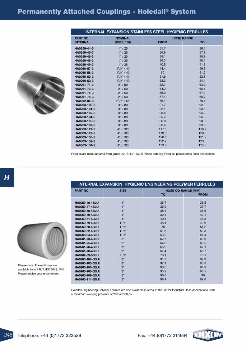
248 Telephone: +44 (0)1772 323529 Fax: +44 (0)1772 314664
H
Permanently Attached Couplings - Holedall® System
Holedall Engineering Polymer Ferrules are also available in sizes 1” thru 3” for Industrial Hose applications, with a maximum working pressure of 20 Bar/300 psi.
internal eXpansion stainless steel hYgienic Ferrulesnominal
Bore / Dn
1” / 251” / 251” / 251” / 251” / 25
11/2” / 4011/2” / 4011/2” / 4011/2” / 40
2” / 502” / 502” / 502” / 50
21/2” / 653” / 803” / 803” / 803” / 803” / 803” / 804” / 1004” / 1004” / 1004” / 1004” / 100
hose rangeto
36.537.738.940.141.349.651.252.854.463.965.567.168.778.192.993.394.996.598.099.6118.7120.3121.9123.5125.0
From
35.736.938.139.340.548.450
51.653.262.764.365.967.476.191.792.193.695.296.898.4117.5119.0120.6122.2123.8
part no. internal
ha0259-44-3ha0259-45-3ha0259-46-3ha0259-48-3ha0259-49-3ha0260-57-3ha0260-58-3ha0260-60-3ha0260-62-3ha0261-71-3ha0261-73-3ha0261-74-3ha0261-76-3ha0262-85-3ha0263-100-3ha0263-101-3ha0263-102-3ha0263-104-3ha0263-105-3ha0263-107-3ha0303-127-3ha0303-129-3ha0303-130-3ha0303-132-3ha0303-134-3
Please note: These fittings are available to suit RJT, IDF, SMS, DIN. Please advise your requirement.
internal eXpansion hYgienic engineering polYmer Ferrulessize
1”1”1”1”1”
11/2”11/2”11/2”11/2”
2”2”2”2”
21/2”3”3”3”3”3”3”
hose oD range (mm)From
36.537.738.940.141.349.651.252.854.463.965.567.168.778.192.993.394.996.598
99.6
to
35.736.938.139.340.548.450
51.653.262.764.365.967.476.191.792.193.695.296.898.4
part no.
ha0259-46-4Blu ha0259-47-4Blu ha0259-48-4Blu ha0259-50-4Blu ha0259-51-4Blu ha0260-59-4Blu ha0260-60-4Blu ha0260-62-4Blu ha0260-64-4Blu ha0261-73-4Blu ha0261-75-4Blu ha0261-76-4Blu ha0261-78-4Blu ha0262-89-5Blu ha0263-104-5Blu ha0263-105-5Blu ha0263-106-5Blu ha0263-108-5Blu ha0263-109-5Blu ha0263-111-5Blu
Ferrules are manufactured from grade 304 S15 (1.4301) When ordering Ferrules, please state hose dimensions.
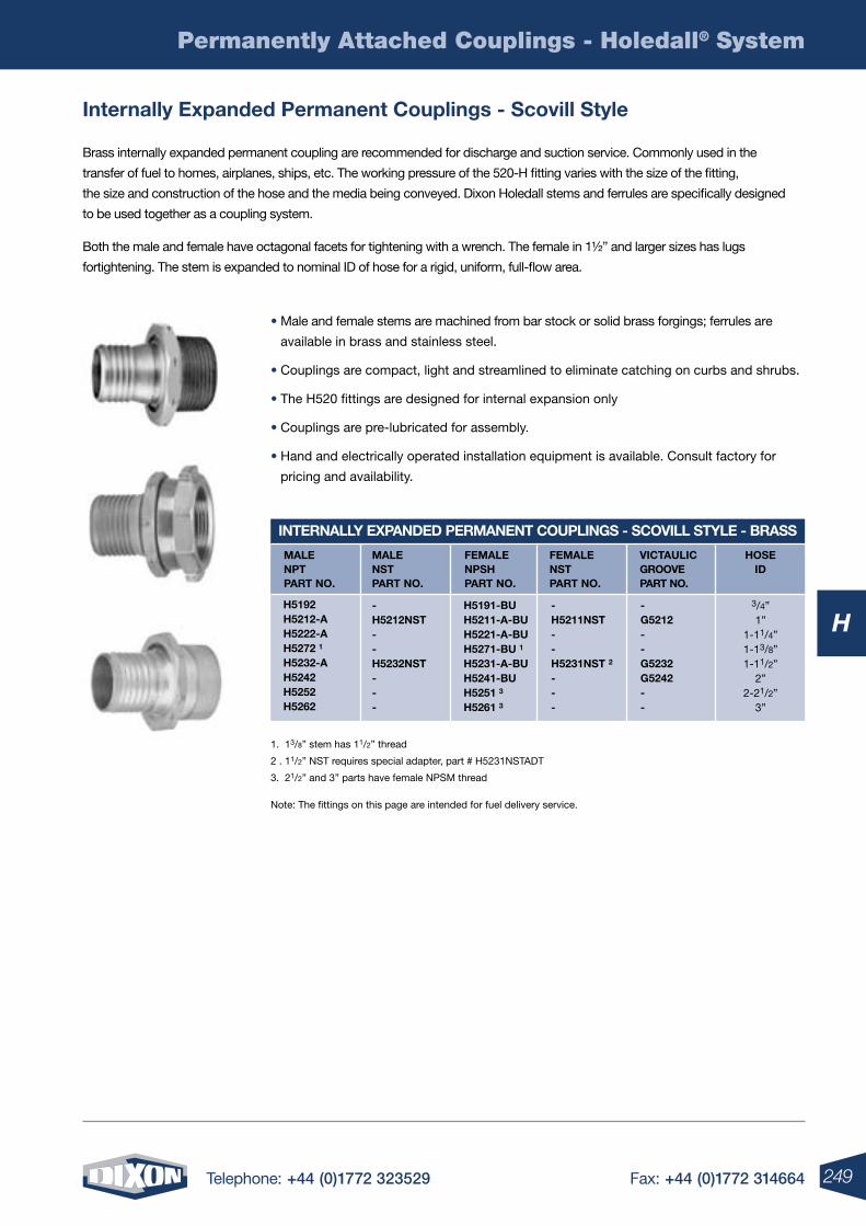
249Telephone: +44 (0)1772 323529 Fax: +44 (0)1772 314664
H
Permanently Attached Couplings - Holedall® System
Brass internally expanded permanent coupling are recommended for discharge and suction service. Commonly used in the
transfer of fuel to homes, airplanes, ships, etc. The working pressure of the 520-H fitting varies with the size of the fitting,
the size and construction of the hose and the media being conveyed. Dixon Holedall stems and ferrules are specifically designed
to be used together as a coupling system.
Both the male and female have octagonal facets for tightening with a wrench. The female in 1½” and larger sizes has lugs
fortightening. The stem is expanded to nominal ID of hose for a rigid, uniform, full-flow area.
internally expanded permanent couplings - scovill style
internallY eXpanDeD permanent couplings - scoVill stYle - Brass
3/4”1”
1-11/4”1-13/8”1-11/2”
2”2-21/2”
3”
male npt part no.
male nst part no.
Female npsh part no.
Female nst part no.
Victaulic grooVe part no.
hose iD
h5192 h5212-a h5222-a h5272 1
h5232-a h5242 h5252 h5262
- h5212nst - - h5232nst - - -
h5191-Bu h5211-a-Bu h5221-a-Bu h5271-Bu 1
h5231-a-Bu h5241-Bu h5251 3
h5261 3
- h5211nst - - h5231nst 2
- - -
- g5212 - - g5232 g5242 - -
• Male and female stems are machined from bar stock or solid brass forgings; ferrules are
available in brass and stainless steel.
• Couplings are compact, light and streamlined to eliminate catching on curbs and shrubs.
• The H520 fittings are designed for internal expansion only
• Couplings are pre-lubricated for assembly.
• Hand and electrically operated installation equipment is available. Consult factory for
pricing and availability.
1. 13/8” stem has 11/2” thread
2 . 11/2” NST requires special adapter, part # H5231NSTADT
3. 21/2” and 3” parts have female NPSM thread
Note: The fittings on this page are intended for fuel delivery service.
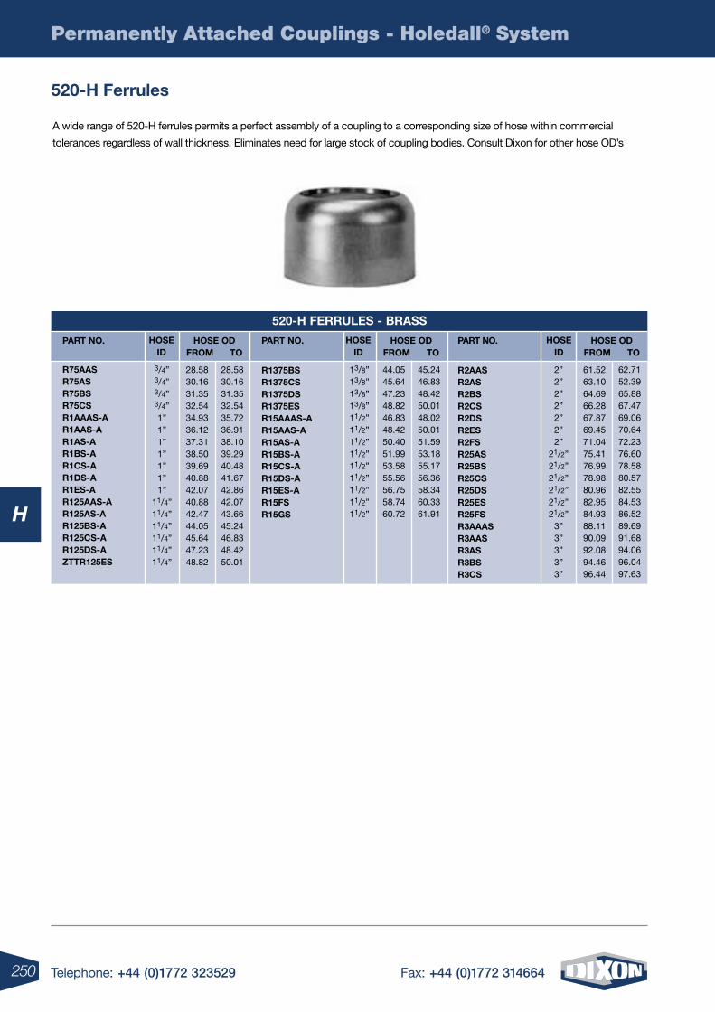
250 Telephone: +44 (0)1772 323529 Fax: +44 (0)1772 314664
H
Permanently Attached Couplings - Holedall® System
A wide range of 520-H ferrules permits a perfect assembly of a coupling to a corresponding size of hose within commercial
tolerances regardless of wall thickness. Eliminates need for large stock of coupling bodies. Consult Dixon for other hose OD’s
520-h Ferrules
520-h Ferrules - Brass
hose iD
hose iD
hose iD
28.5830.1631.3532.5434.9336.1237.3138.5039.6940.8842.0740.8842.4744.0545.6447.2348.82
44.0545.6447.2348.8246.8348.4250.4051.9953.5855.5656.7558.7460.72
3/4”3/4”3/4”3/4”1”1”1”1”1”1”1”
11/4”11/4”11/4”11/4”11/4”11/4”
13/8”13/8”13/8” 13/8”11/2”11/2”11/2”11/2”11/2”11/2”11/2”11/2”11/2”
61.5263.1064.6966.2867.8769.4571.0475.4176.9978.9880.9682.9584.9388.1190.0992.0894.4696.44
2”2”2”2”2”2”2”
21/2”21/2”21/2”21/2”21/2”21/2”
3”3”3”3”3”
28.5830.1631.3532.5435.7236.9138.1039.2940.4841.6742.8642.0743.6645.2446.8348.4250.01
45.2446.8348.4250.0148.0250.0151.5953.1855.1756.3658.3460.3361.91
62.7152.3965.8867.4769.0670.6472.2376.6078.5880.5782.5584.5386.5289.6991.6894.0696.0497.63
part no. hose oDFrom to
hose oDFrom to
hose oDFrom to
part no. part no.
r75aas r75as r75Bs r75cs r1aaas-a r1aas-a r1as-a r1Bs-a r1cs-a r1Ds-a r1es-a r125aas-a r125as-a r125Bs-a r125cs-a r125Ds-a zttr125es
r1375Bs r1375cs r1375Ds r1375es r15aaas-a r15aas-a r15as-a r15Bs-a r15cs-a r15Ds-a r15es-a r15Fs r15gs
r2aas r2as r2Bs r2cs r2Ds r2es r2Fs r25as r25Bs r25cs r25Ds r25es r25Fs r3aaas r3aas r3as r3Bs r3cs
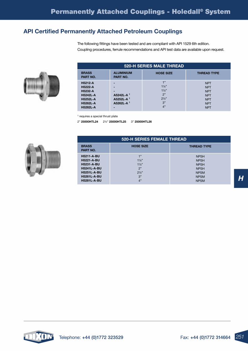
251Telephone: +44 (0)1772 323529 Fax: +44 (0)1772 314664
H
Permanently Attached Couplings - Holedall® System
The following fittings have been tested and are compliant with API 1529 6th edition.
Coupling procedures, ferrule recommendations and API test data are available upon request.
1 requires a special thrust plate
2” 25000htl24 2½” 25000htl25 3” 25000htl26
api certified permanently attached petroleum couplings
520-h series male threaD
Brass part no.
aluminium part no.
threaD tYpehose size
h5212-a h5222-a h5232-a h5242l-a h5252l-a h5262l-a h5282l-a
- - - a5242l-a 1
a5252l-a 1
a5262l-a 1
-
NPTNPTNPTNPTNPTNPTNPT
1”1¼”1½”2”
2½”3”4”
520-h series Female threaD
Brass part no.
hose size threaD tYpe
h5211-a-Bu h5221-a-Bu h5231-a-Bu h5241l-a-Bu h5251l-a-Bu h5261l-a-Bu h5281l-a-Bu
1”1¼”1½”2”
2½”3”4”
NPSHNPSHNPSHNPSHNPSMNPSMNPSM
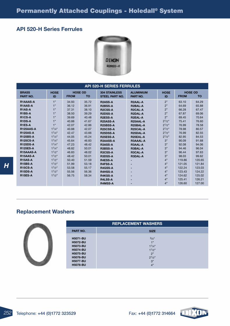
252 Telephone: +44 (0)1772 323529 Fax: +44 (0)1772 314664
H
Permanently Attached Couplings - Holedall® System
api 520-h series Ferrules
api 520-h series Ferrules
hose iD
hose iD
34.9336.1237.3138.5039.6940.8842.0740.8842.4744.0545.6447.2348.8246.8348.4250.4051.9953.5855.5656.75
63.1064.6966.2867.8769.4575.4176.9978.9876.9982.9590.0992.0894.4696.4498.03119.86121.05122.24123.43124.62125.41126.60
2”2”2”2”2”
21/2”21/2”21/2”21/2”21/2”
3”3”3”3”3”4”4”4”4”4”4”4”
1”1”1”1”1”1”1”
11/4”11/4”11/4”11/4”11/4”11/4”11/2”11/2”11/2”11/2”11/2”11/2”11/2”
35.7236.9138.1039.2940.4841.6742.8642.0743.6645.2446.8348.4250.0148.0250.0151.5953.1855.1756.3658.34
64.2965.8867.4769.0670.6476.6078.5880.5782.5584.5391.6894.0696.0497.6399.62120.65121.84123.03124.22125.02126.21127.00
Brass part no.
hose oD hose oDFrom Fromto to
r1aaas-a r1aas-a r1as-a r1Bs-a r1cs-a r1Ds-a r1es-a r125aas-a r125as-a r125Bs-a r125cs-a r125Ds-a r125es-a r15aaas-a r15aas-a r15as-a r15Bs-a r15cs-a r15Ds-a r15es-a
304 stainless steel part no.
aluminium part no.
r2ass-a r2Bss-a r2css-a r2Dss-a r2ess-a r25ass-a r25Bss-a r25css-a r25Dss-a r25ess-a r3aass-a r3ass-a r3Bss-a r3css-a r3Dss-a r4ess-a r4Fss-a r4gss-a r4hss-a r4kss-a r4lss-a r4mss-a
r2aal-a r2Bal-a r2cal-a r2Dal-a r2eal-a r25aal-a r25Bal-a r25cal-a r25Dal-a r25eal-a r3aaal-a r3aal-a r3Bal-a r3cal-a r3Dal-a - - - - - - -
replacement Washers
size
3/4”1”
11/4”11/2”
2”21/2”
3”4”
part no.
h5071-Bu h5072-Bu h5073-Bu h5074-Bu h5075-Bu h5076-Bu h5077-Bu h5078-Bu
replacement Washers
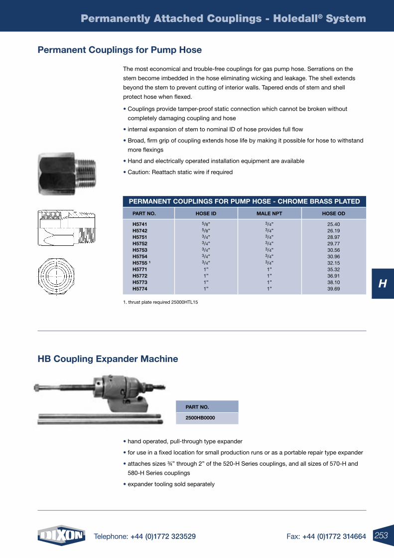
253Telephone: +44 (0)1772 323529 Fax: +44 (0)1772 314664
H
Permanently Attached Couplings - Holedall® System
The most economical and trouble-free couplings for gas pump hose. Serrations on the
stem become imbedded in the hose eliminating wicking and leakage. The shell extends
beyond the stem to prevent cutting of interior walls. Tapered ends of stem and shell
protect hose when flexed.
• Couplings provide tamper-proof static connection which cannot be broken without
completely damaging coupling and hose
• internal expansion of stem to nominal ID of hose provides full flow
• Broad, firm grip of coupling extends hose life by making it possible for hose to withstand
more flexings
• Hand and electrically operated installation equipment are available
• Caution: Reattach static wire if required
permanent couplings for pump hose
permanent couplings For pump hose - chrome Brass plateD
hose iD male npt hose oD
5/8”5/8”3/4”3/4”3/4”3/4”3/4”1”1”1”1”
3/4”3/4”3/4”3/4”3/4”3/4”3/4”1”1”1”1”
25.4026.1928.9729.7730.5630.9632.1535.3236.9138.1039.69
part no.
h5741 h5742 h5751 h5752 h5753 h5754 h5755 1
h5771 h5772 h5773 h5774
part no.
2500hB0000
1. thrust plate required 25000HTL15
• hand operated, pull-through type expander
• for use in a fixed location for small production runs or as a portable repair type expander
• attaches sizes ¾” through 2” of the 520-H Series couplings, and all sizes of 570-H and
580-H Series couplings
• expander tooling sold separately
hB coupling expander machine
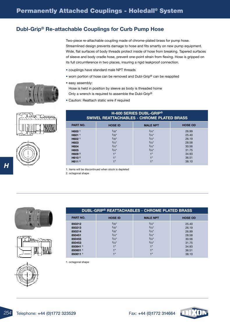
254 Telephone: +44 (0)1772 323529 Fax: +44 (0)1772 314664
H
Permanently Attached Couplings - Holedall® System
Two-piece re-attachable coupling made of chrome-plated brass for pump hose.
Streamlined design prevents damage to hose and fits smartly on new pump equipment.
Wide, flat surfaces of body threads protect inside of hose from breaking. Tapered surfaces
of sleeve and body cradle hose, prevent one-point strain from flexing. Hose is gripped on
its full circumference in two places, insuring a rigid leakproof connection.
• couplings have standard male NPT threads
• worn portion of hose can be removed and Dubl-Grip® can be reapplied
• easy assembly:
Hose is held in position by sleeve as body is threaded home
Only a wrench is required to assemble the Dubl-Grip®
• Caution: Reattach static wire if required
DuBl-grip® reattachaBles - chrome plateD Brass
hose iD male npt hose oD
5/8”5/8”5/8”3/4”3/4”3/4”1”1”1”
3/4”3/4”3/4”3/4”3/4”3/4”1”1”1”
25.4026.1926.9928.5830.5631.7534.9336.5138.10
part no.
850212 850213 850214 850451 850455 850453 850841 1
850801 1
850811 1
Dubl-grip® re-attachable couplings for curb pump hose
1. octagonal shape
h-600 series DuBl-grip® sWiVel reattachaBles - chrome plateD Brass
hose iD male npt hose oD
5/8”5/8”5/8”3/4”3/4”3/4”1”1”1”
3/4”3/4”3/4”3/4”3/4”3/4”1”1”1”
26.9925.4026.1928.5830.5631.7534.9336.5138.10
part no.
h600 1
h601 1
h602 1
h603 h604 h605 h609 2
h610 2
h611 2
1. items will be discontinued when stock is depleted 2. octagonal shape
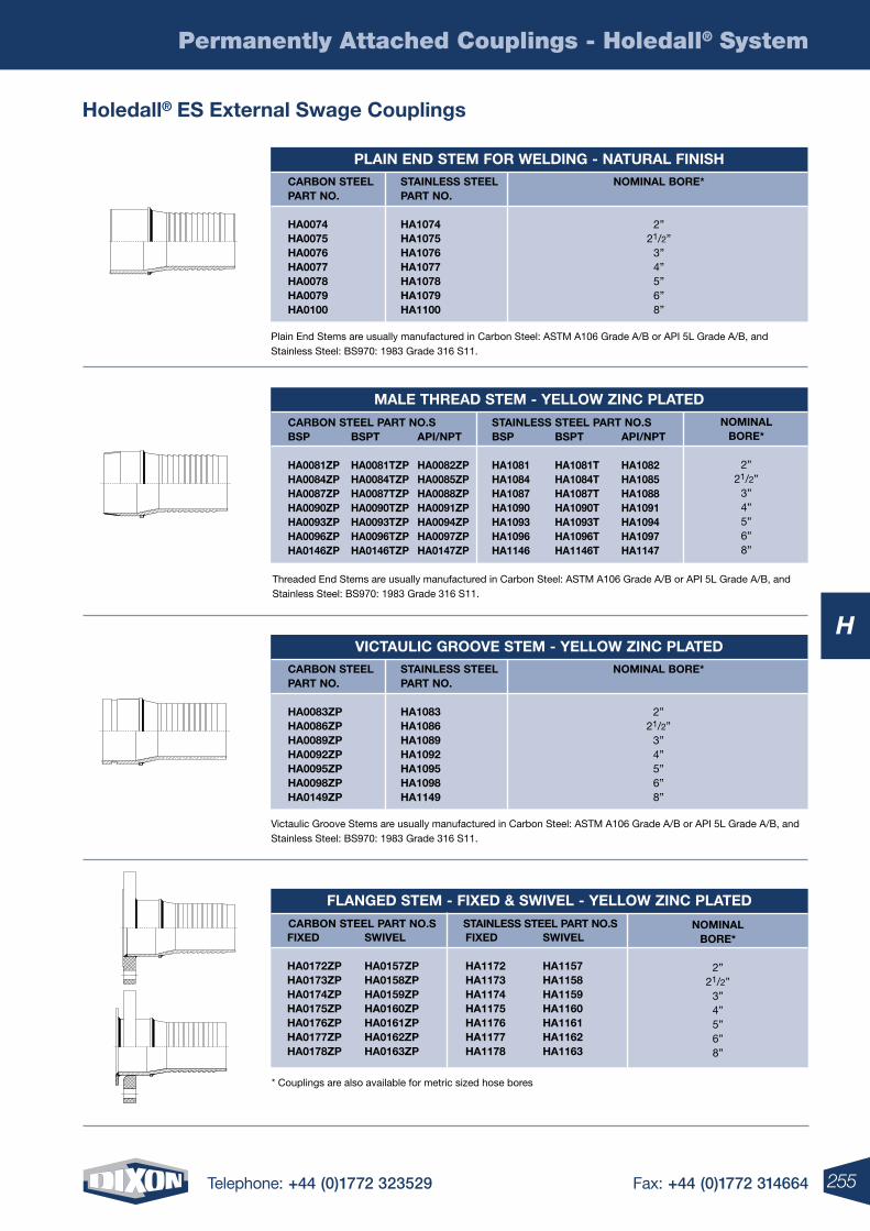
255Telephone: +44 (0)1772 323529 Fax: +44 (0)1772 314664
H
Permanently Attached Couplings - Holedall® System
holedall® es external swage couplings
plain enD stem For WelDing - natural Finishnominal Bore*
2”21/2”
3”4”5”6”8”
carBon steel part no.
ha0074 ha0075 ha0076 ha0077 ha0078 ha0079 ha0100
stainless steel part no.
ha1074 ha1075 ha1076 ha1077 ha1078 ha1079 ha1100
Victaulic grooVe stem - YelloW zinc plateDnominal Bore*
2”21/2”
3”4”5”6”8”
carBon steel part no.
ha0083zp ha0086zp ha0089zp ha0092zp ha0095zp ha0098zp ha0149zp
stainless steel part no.
ha1083 ha1086 ha1089 ha1092 ha1095 ha1098 ha1149
male threaD stem - YelloW zinc plateDnominal
Bore*
2”21/2”
3”4”5”6”8”
Bsp
ha0081zp ha0084zp ha0087zp ha0090zp ha0093zp ha0096zp ha0146zp
Bsp
ha1081 ha1084 ha1087 ha1090 ha1093 ha1096 ha1146
Bspt
ha0081tzpha0084tzpha0087tzpha0090tzpha0093tzpha0096tzpha0146tzp
Bspt
ha1081tha1084tha1087tha1090tha1093tha1096tha1146t
api/npt
ha0082zpha0085zpha0088zpha0091zpha0094zpha0097zpha0147zp
api/npt
ha1082ha1085ha1088ha1091ha1094ha1097ha1147
carBon steel part no.s stainless steel part no.s
FlangeD stem - FiXeD & sWiVel - YelloW zinc plateD
nominal Bore*
2”21/2”
3”4”5”6”8”
FiXeD
ha0172zp ha0173zp ha0174zp ha0175zp ha0176zp ha0177zp ha0178zp
FiXeD
ha1172 ha1173 ha1174 ha1175 ha1176 ha1177 ha1178
sWiVel
ha0157zpha0158zpha0159zpha0160zpha0161zpha0162zpha0163zp
sWiVel
ha1157 ha1158 ha1159 ha1160 ha1161 ha1162 ha1163
carBon steel part no.s stainless steel part no.s
* Couplings are also available for metric sized hose bores
Plain End Stems are usually manufactured in Carbon Steel: ASTM A106 Grade A/B or API 5L Grade A/B, and Stainless Steel: BS970: 1983 Grade 316 S11.
Threaded End Stems are usually manufactured in Carbon Steel: ASTM A106 Grade A/B or API 5L Grade A/B, and Stainless Steel: BS970: 1983 Grade 316 S11.
Victaulic Groove Stems are usually manufactured in Carbon Steel: ASTM A106 Grade A/B or API 5L Grade A/B, and Stainless Steel: BS970: 1983 Grade 316 S11.
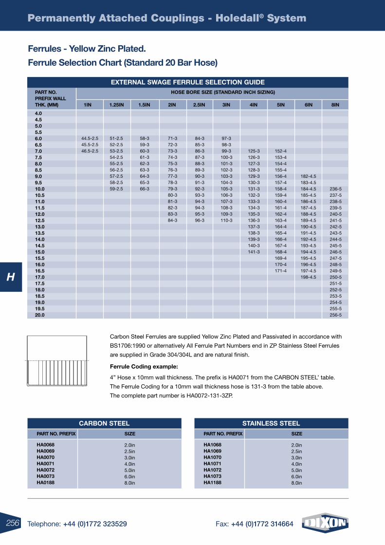
256 Telephone: +44 (0)1772 323529 Fax: +44 (0)1772 314664
H
Permanently Attached Couplings - Holedall® System
Ferrules - Yellow zinc plated.
Ferrule selection chart (standard 20 Bar hose)
Carbon Steel Ferrules are supplied Yellow Zinc Plated and Passivated in accordance with
BS1706:1990 or alternatively All Ferrule Part Numbers end in ZP Stainless Steel Ferrules
are supplied in Grade 304/304L and are natural finish.
Ferrule coding example:
4” Hose x 10mm wall thickness. The prefix is HA0071 from the CARBON STEEL’ table.
The Ferrule Coding for a 10mm wall thickness hose is 131-3 from the table above.
The complete part number is HA0072-131-3ZP.
eXternal sWage Ferrule selection guiDe part no. preFiX Wall thk. (mm)
4.0 4.5 5.0 5.5 6.0 6.5 7.0 7.5 8.0 8.5 9.0 9.5 10.0 10.5 11.0 11.5 12.0 12.5 13.0 13.5 14.0 14.5 15.0 15.5 16.0 16.5 17.0 17.5 18.0 18.5 19.0 19.5 20.0
hose Bore size (stanDarD inch sizing)
1in 1.25in 1.5in 2in 2.5in 3in 4in 5in 6in 8in
44.5-2.545.5-2.546.5-2.5
51-2.552-2.553-2.554-2.555-2.556-2.557-2.558-2.559-2.5
58-359-360-361-362-363-364-365-366-3
71-372-373-374-375-376-377-378-379-380-381-382-383-384-3
84-385-386-387-388-389-390-391-392-393-394-394-395-396-3
97-398-399-3
100-3101-3102-3103-3104-3105-3106-3107-3108-3109-3110-3
125-3126-3127-3128-3129-3130-3131-3132-3133-3134-3135-3136-3137-3138-3139-3140-3141-3
152-4153-4154-4155-4156-4157-4158-4159-4160-4161-4162-4163-4164-4165-4166-4167-4168-4169-4170-4171-4
182-4.5183-4.5184-4.5185-4.5186-4.5187-4.5188-4.5189-4.5190-4.5191-4.5192-4.5193-4.5194-4.5195-4.5196-4.5197-4.5198-4.5
236-5237-5238-5239-5240-5241-5242-5243-5244-5245-5246-5247-5248-5249-5250-5251-5252-5253-5254-5255-5256-5
carBon steel
size part no. preFiX
ha0068 ha0069 ha0070 ha0071 ha0072 ha0073 ha0188
2.0in2.5in3.0in4.0in5.0in6.0in8.0in
stainless steel
size part no. preFiX
ha1068 ha1069 ha1070 ha1071 ha1072 ha1073 ha1188
2.0in2.5in3.0in4.0in5.0in6.0in8.0in
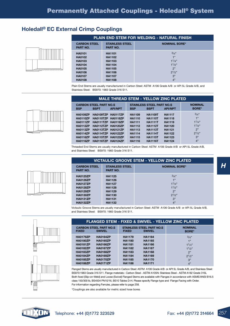
257Telephone: +44 (0)1772 323529 Fax: +44 (0)1772 314664
H
Permanently Attached Couplings - Holedall® System
holedall® ec external crimp couplings
plain enD stem For WelDing - natural Finishnominal Bore*
3/4”1”
11/4”11/2”
2”21/2”
3”4”
carBon steel part no.
ha0101 ha0102 ha0103 ha0104 ha0105 ha0106 ha0107 ha0108
stainless steel part no.
ha1101 ha1102 ha1103 ha1104 ha1105 ha1106 ha1107 ha1108
Plain End Stems are usually manufactured in Carbon Steel: ASTM A106 Grade A/B or API 5L Grade A/B, and Stainless Steel: BS970: 1983 Grade 316 S11.
male threaD stem - YelloW zinc plateDnominal
Bore*
3/4”1”
11/4”11/2”
2”21/2”
3”4”
Bsp
ha0109zp ha0110zp ha0111zp ha0112zp ha0113zp ha0114zp ha0116zp ha0116zp
Bsp
ha1109 ha1110 ha1111 ha1112 ha1113 ha1114 ha1115 ha1116
Bspt
ha0109tzpha0110tzpha0111tzpha0112tzpha0113tzpha0114tzpha0115tzpha0116tzp
Bspt
ha1109tha1110tha1111tha1112tha1113tha1114tha1115tha1116t
api/npt
ha0117zpha0118zpha0119zpha0120zpha0121zpha0122zpha0123zpha0124zp
api/npt
ha1117ha1118ha1119ha1120ha1121ha1122ha1123ha1124
carBon steel part no.s stainless steel part no.s
Threaded End Stems are usually manufactured in Carbon Steel: ASTM A106 Grade A/B or API 5L Grade A/B, and Stainless Steel: BS970: 1983 Grade 316 S11.
Victaulic grooVe stem - YelloW zinc plateDnominal Bore*
3/4”1”
11/4”11/2”
2”21/2”
3”4”
carBon steel part no.
ha0125zp ha0126zp ha0127zp ha0128zp ha0129zp ha0130zp ha0131zp ha0132zp
stainless steel part no.
ha1125 ha1126 ha1127 ha1128 ha1129 ha1130 ha1131 ha1132
Victaulic Groove Stems are usually manufactured in Carbon Steel: ASTM A106 Grade A/B or API 5L Grade A/B, and Stainless Steel: BS970: 1983 Grade 316 S11.
FlangeD stem - FiXeD & sWiVel - YelloW zinc plateDnominal
Bore*
3/4”1”
11/4”11/2”
2”21/2”
3”4”
FiXeD
ha0179zp ha0180zp ha0181zp ha0182zp ha0183zp ha0184zp ha0185zp ha0186zp
FiXeD
ha1179 ha1180 ha1181 ha1182 ha1183 ha1184 ha1185 ha1186
sWiVel
ha0164zpha0165zpha0166zpha0167zpha0168zpha0169zpha0170zpha0171zp
sWiVel
ha1164 ha1165 ha1166 ha1167 ha1168 ha1169 ha1170ha1171
carBon steel part no.s stainless steel part no.s
Flanged Stems are usually manufactured in Carbon Steel: ASTM A106 Grade A/B or API 5L Grade A/B, and Stainless Steel: BS970:1983 Grade 316 S11. Flange materials:- Carbon Steel - ASTM A105N: Stainless Steel - ASTM A182 Grade 316L Both fixed (Slip-on-Weld) and Loose (Swivel) Flanged Stems are available with Flanges in accordance with ASME/ANSI B16.5 class 150/300 lb, BS4504 PN10/16, BS10 Tables D-H. Please specify Flange type and Flange Facing with Order. For information regarding Ferrules, please refer to page 258.
*Couplings are also available for metric sized hose bores
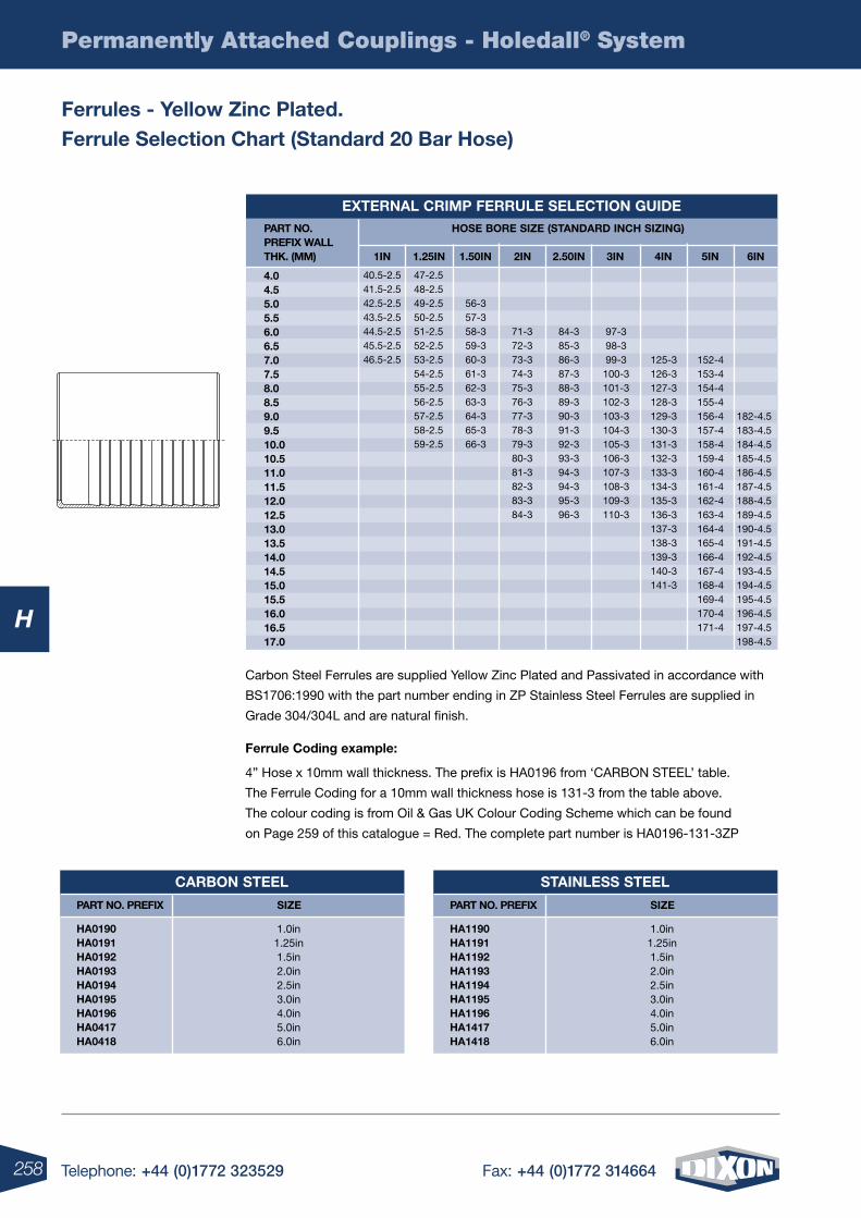
258 Telephone: +44 (0)1772 323529 Fax: +44 (0)1772 314664
H
Permanently Attached Couplings - Holedall® System
Ferrules - Yellow zinc plated. Ferrule selection chart (standard 20 Bar hose)
Carbon Steel Ferrules are supplied Yellow Zinc Plated and Passivated in accordance with
BS1706:1990 with the part number ending in ZP Stainless Steel Ferrules are supplied in
Grade 304/304L and are natural finish.
Ferrule coding example:
4” Hose x 10mm wall thickness. The prefix is HA0196 from ‘CARBON STEEL’ table.
The Ferrule Coding for a 10mm wall thickness hose is 131-3 from the table above.
The colour coding is from Oil & Gas UK Colour Coding Scheme which can be found
on Page 259 of this catalogue = Red. The complete part number is HA0196-131-3ZP
eXternal crimp Ferrule selection guiDe part no. preFiX Wall thk. (mm)
hose Bore size (stanDarD inch sizing)
1in
40.5-2.541.5-2.5 42.5-2.543.5-2.544.5-2.545.5-2.546.5-2.5
47-2.548-2.549-2.550-2.551-2.552-2.553-2.554-2.555-2.556-2.5 57-2.558-2.559-2.5
56-357-358-359-360-361-362-363-364-365-366-3
71-372-373-374-375-376-377-378-379-380-381-382-383-384-3
84-385-386-387-388-389-390-391-392-393-394-394-395-396-3
97-398-399-3
100-3101-3102-3103-3104-3105-3106-3107-3108-3109-3110-3
125-3126-3127-3128-3129-3130-3131-3132-3133-3134-3135-3136-3137-3138-3139-3140-3141-3
152-4153-4154-4155-4156-4157-4158-4159-4160-4161-4162-4163-4164-4165-4166-4167-4168-4169-4170-4171-4
182-4.5 183-4.5 184-4.5 185-4.5 186-4.5 187-4.5188-4.5 189-4.5 190-4.5 191-4.5 192-4.5 193-4.5 194-4.5 195-4.5 196-4.5 197-4.5 198-4.5
1.25in 1.50in 2in 2.50in 3in 4in 5in 6in
4.0 4.5 5.0 5.5 6.0 6.5 7.0 7.5 8.0 8.5 9.0 9.5 10.0 10.5 11.0 11.5 12.0 12.5 13.0 13.5 14.0 14.5 15.0 15.5 16.0 16.5 17.0
stainless steel
size part no. preFiX
ha1190 ha1191 ha1192 ha1193 ha1194 ha1195 ha1196 ha1417 ha1418
1.0in1.25in1.5in2.0in2.5in3.0in4.0in5.0in6.0in
carBon steel
size part no. preFiX
ha0190 ha0191 ha0192 ha0193 ha0194 ha0195 ha0196 ha0417 ha0418
1.0in1.25in1.5in2.0in2.5in3.0in4.0in5.0in6.0in
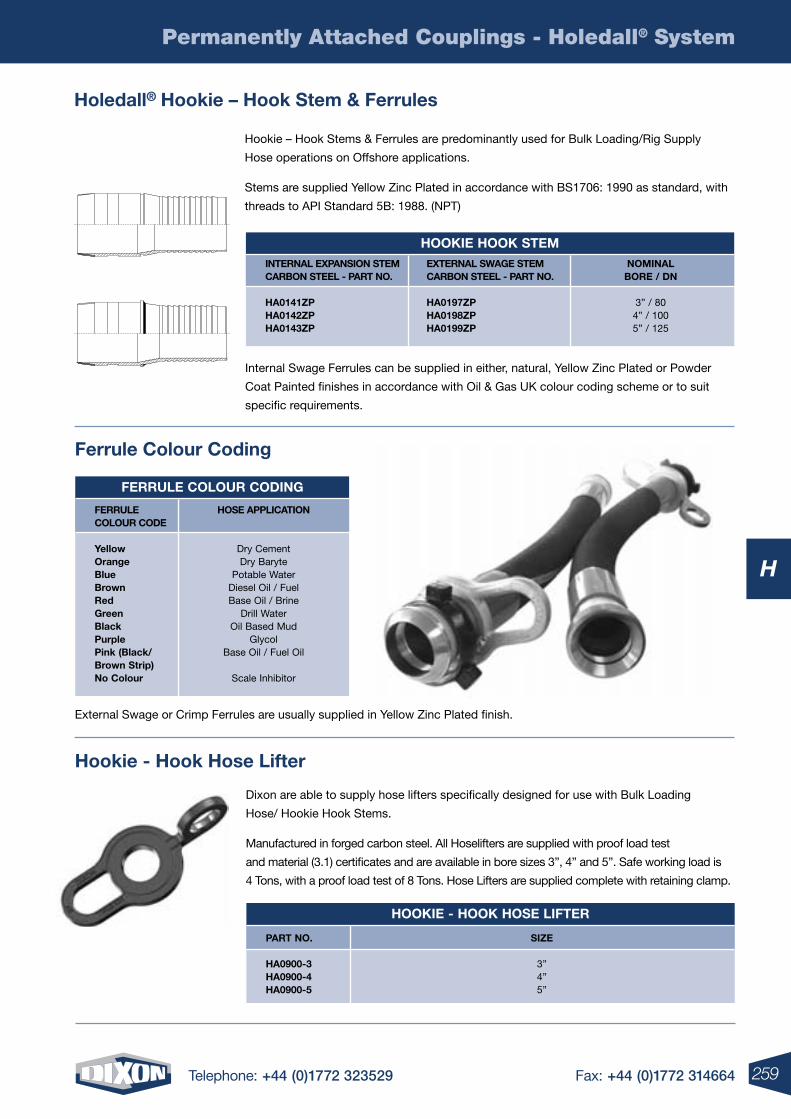
259Telephone: +44 (0)1772 323529 Fax: +44 (0)1772 314664
H
Permanently Attached Couplings - Holedall® System
holedall® hookie – hook stem & Ferrules
Hookie – Hook Stems & Ferrules are predominantly used for Bulk Loading/Rig Supply
Hose operations on Offshore applications.
Stems are supplied Yellow Zinc Plated in accordance with BS1706: 1990 as standard, with
threads to API Standard 5B: 1988. (NPT)
Internal Swage Ferrules can be supplied in either, natural, Yellow Zinc Plated or Powder
Coat Painted finishes in accordance with Oil & Gas UK colour coding scheme or to suit
specific requirements.
hookie hook stemnominal
Bore / Dn
3” / 804” / 1005” / 125
internal eXpansion stem carBon steel - part no.
ha0141zp ha0142zp ha0143zp
eXternal sWage stem carBon steel - part no.
ha0197zp ha0198zp ha0199zp
hookie - hook hose liFter
part no.
ha0900-3 ha0900-4 ha0900-5
size
3”4”5”
External Swage or Crimp Ferrules are usually supplied in Yellow Zinc Plated finish.
Dixon are able to supply hose lifters specifically designed for use with Bulk Loading
Hose/ Hookie Hook Stems.
Manufactured in forged carbon steel. All Hoselifters are supplied with proof load test
and material (3.1) certificates and are available in bore sizes 3”, 4” and 5”. Safe working load is
4 Tons, with a proof load test of 8 Tons. Hose Lifters are supplied complete with retaining clamp.
Ferrule colour coDing
hose application
Dry CementDry Baryte
Potable WaterDiesel Oil / FuelBase Oil / Brine
Drill WaterOil Based Mud
GlycolBase Oil / Fuel Oil
Scale Inhibitor
Ferrule colour coDe
Yellow orange Blue Brown red green Black purple pink (Black/ Brown strip) no colour
hookie - hook hose lifter
Ferrule colour coding
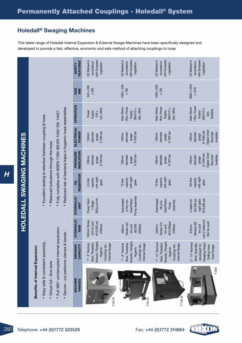
260 Telephone: +44 (0)1772 323529 Fax: +44 (0)1772 314664
H
Permanently Attached Couplings - Holedall® System
holedall® swaging machines
This latest range of Holedall Internal Expansion & External Swage Machines have been specifically designed and
developed to provide a fast, effective, economic and safe method of attaching couplings to hose.
ho
leD
all
sW
ag
ing
ma
ch
ine
s
Ben
efits
of
inte
rnal
exp
ansi
on:
• Eas
y sa
fe &
con
sist
ent
asse
mb
ly.
• Virt
ual f
ull -
flow
bor
e
• Ful
l 360
° un
inte
rrup
ted
inte
rnal
exp
ansi
on.
• Sec
ure
- ou
t p
erfo
rms
clam
ps
& b
and
s.
sW
ag
ing
ca
pac
itY
hY
Dr
au
lic
ra
mh
YD
ra
uli
cu
nit
oil
re
se
rV
oir
pr
es
su
re
inD
ica
tio
ne
lec
tr
ica
lp
oW
er
op
er
at
ion
siz
em
ms
aFe
tY
Fea
tu
re
s
1”-
3” N
omin
al
Bor
e, T
hrea
ded,
Vi
ctau
lic, F
lang
ed,
Hyg
ieni
c C
oupl
ings
etc
.. In
tern
al S
wag
e
1”-
6” N
omin
al
Bor
e, T
hrea
ded,
Vi
ctau
lic, F
lang
ed,
Hyg
ieni
c C
oupl
ings
etc
.. In
tern
al S
wag
e
1”-
12”
Nom
inal
B
ore,
Thr
eade
d,
Vict
aulic
, Fla
nged
, H
ygie
nic
Cou
plin
gs e
tc..
Inte
rnal
Sw
age
2”-
14”
Nom
inal
B
ore,
Spe
cial
ly,
deve
lope
d fo
r, Sw
agin
g R
otar
y D
rillin
g H
ose
Dua
l Sw
age
T-35
0
160m
m S
troke
x
20 to
n pu
ll @
10,0
00 p
si
(700
bar)
400m
m
Stro
ke x
52
ton
pull
@5,
000
(3
50ba
r)
550m
m
Stro
ke x
75
ton
pull,
@
10,0
00ps
i (7
00ba
r)
915m
m
Stro
kex1
88
ton
pull
and
2 G
alls
/min
35
4 to
n pu
sh
Pow
er T
eam
2
Sta
ge
300c
u.in
/min
Subm
erge
d 3/
16L/
min
G
ear/P
isto
n Pu
mp
Asse
mbl
y
Subm
erge
d 1
8L/m
in
Gea
r/Pis
ton
Pum
p A
ssem
bly
4
Gal
ls/m
in
@3,
500
psi
sig
ht g
lass
@
10,0
00 p
si
4.5
litre
ca
paci
ty
with
sig
ht
glas
s
70 li
tre
capa
city
w
ith s
ight
gl
ass
70
litre
ca
paci
ty
with
sig
ht
glas
s
100
litre
ca
paci
ty
with
sig
ht
glas
s
100m
m
diam
eter
gu
age
0-70
0 ba
r
100m
m
diam
eter
gu
age
0-35
0 ba
r
100m
m
diam
eter
gu
age
0-70
0 ba
r
100m
m
diam
eter
gu
age
0-10
00 b
ar
Dig
ital C
hart
Rec
orde
r Av
aila
ble
100m
m
diam
eter
gu
age
0-70
0 ba
r
100m
m
diam
eter
gu
age
0-35
0 ba
r
100m
m
diam
eter
gu
age
0-70
0 ba
r
100m
m
diam
eter
gu
age
0-10
00 b
ar
Dig
ital C
hart
Rec
orde
r Av
aila
ble
CE
Mar
ked
in
acco
rdan
ce
with
Eur
opea
n Le
gisl
atio
n
CE
Mar
ked
in
acco
rdan
ce
with
Eur
opea
n Le
gisl
atio
n
CE
Mar
ked
in
acco
rdan
ce
with
Eur
opea
n Le
gisl
atio
n
CE
Mar
ked
in
acco
rdan
ce
with
Eur
opea
n Le
gisl
atio
n
Pow
er
Supp
ly :
230
v,
1ph,
50H
z
Mai
n M
otor
3K
w, P
ower
Su
pply
: 38
0/41
5 v,
3p
h, 5
0Hz
M
ain
Mot
or
4Kw
, Pow
er
Supp
ly :
380/
415
v,
3ph,
50H
z
Mai
n M
otor
11
Kw
, Pow
er
Supp
ly :
380/
415
v,
3ph,
50
/60H
z
345
x 20
0
x 20
5
1000
x 5
50
x 78
5
1000
x 6
50
x 70
0
3600
x 2
554
x
1016
ma
ch
ine
r
an
ge
s
• Exc
elle
nt s
ealin
g &
ret
entio
n b
etw
een
coup
ling
& h
ose
• Red
uced
tur
bul
ence
thr
ough
the
hos
e
• Ful
ly c
omp
lies
with
BS
EN
176
5/ B
S:E
N 1
435/
EN
: 144
21
• Red
uced
ris
k of
bac
teria
tra
ps
in h
ygie
nic
hose
ass
emb
lies
T-10
0 IX
T-50
IX
T-20
IX
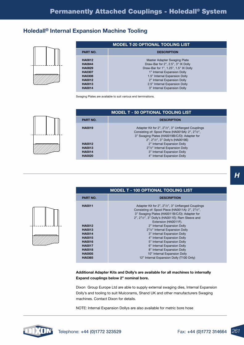
261Telephone: +44 (0)1772 323529 Fax: +44 (0)1772 314664
H
Permanently Attached Couplings - Holedall® System
holedall® internal expansion machine tooling
additional adapter kits and Dolly’s are available for all machines to internally
expand couplings below 2” nominal bore.
Dixon Group Europe Ltd are able to supply external swaging dies, Internal Expansion
Dolly’s and tooling to suit Mulcorams, Shand UK and other manufacturers Swaging
machines. Contact Dixon for details.
NOTE: Internal Expansion Dollys are also available for metric bore hose
Swaging Plates are available to suit various end terminations.
moDel t-20 optional tooling list
part no. Description
ha0812 Master Adapter Swaging Plate ha0844 Draw-Bar for 2”, 2.5”, 3” IX Dolly ha0829 Draw-Bar for 1”, 1.25”, 1.5” IX Dolly ha0307 1” Internal Expansion Dolly ha0308 1.5” Internal Expansion Dolly ha0012 2” Internal Expansion Dolly ha0013 2.5” Internal Expansion Dolly ha0014 3” Internal Expansion Dolly
moDel t - 50 optional tooling list
part no.
ha0019
ha0012 ha0013 ha0014 ha0020
Description
Adapter Kit for 2”, 21/2”, 3” Unflanged Couplings Consisting of: Spool Piece (HA0019A): 2”, 21/2”, 3” Swaging Plates (HA0019B/C/D): Adapter for
2”, 21/2”, 3” Dolly’s (HA0019E) 2” Internal Expansion Dolly
21/2” Internal Expansion Dolly3” Internal Expansion Dolly4” Internal Expansion Dolly
moDel t - 100 optional tooling list
part no.
ha0011
ha0012 ha0013 ha0014 ha0015 ha0016 ha0017 ha0018 ha0005 ha0365
Description
Adapter Kit for 2”, 21/2”, 3” Unflanged Couplings Consisting of: Spool Piece (HA0011A): 2”, 21/2”, 3” Swaging Plates (HA0011B/C/D): Adapter for 2”, 21/2”, 3” Dolly’s (HA0011E): Ram Sleeve and
Extension (HA0011F).2” Internal Expansion Dolly
21/2” Internal Expansion Dolly3” Internal Expansion Dolly4” Internal Expansion Dolly5” Internal Expansion Dolly6” Internal Expansion Dolly8” Internal Expansion Dolly10” Internal Expansion Dolly
12” Internal Expansion Dolly (T100 Only)
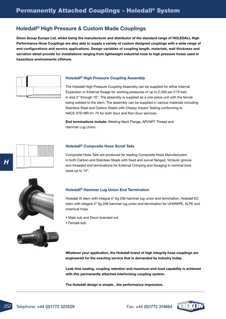
262 Telephone: +44 (0)1772 323529 Fax: +44 (0)1772 314664
H
Permanently Attached Couplings - Holedall® System
holedall® high pressure & custom made couplings
holedall® high pressure coupling assembly
The Holedall High Pressure Coupling Assembly can be supplied for either Internal
Expansion or External Swage for working pressures of up to 2,500 psi (170 bar)
in size 2” through 10”. The assembly is supplied as a one-piece unit with the ferrule
being welded to the stem. The assembly can be supplied in various materials including:
Stainless Steel and Carbon Steels with Charpy Impact Testing conforming to
NACE STD MR-01-75 for both Sour and Non-Sour services.
end terminations include: Welding Neck Flange, API/NPT Thread and
Hammer Lug Union.
holedall® composite hose scroll tails
Composite Hose Tails are produced for leading Composite Hose Manufacturers
in both Carbon and Stainless Steels with fixed and swivel flanged, Victaulic groove
and threaded end terminations for External Crimping and Swaging in nominal bore
sizes up to 10”.
holedall® hammer lug union end termination
Holedall IX stem with integral 4” fig 206 hammer lug union end termination. Holedall EC
stem with integral 4” fig 206 hammer lug union end termination for UHMWPE, XLPE and
chemical hose.
• Male sub and Dixon branded nut
• Female sub
Whatever your application, the holedall brand of high integrity hose couplings are
engineered for the exacting service that is demanded by industry today.
leak-free sealing, coupling retention and maximum end-load capability is achieved
with this permanently attached interlocking coupling system.
the holedall design is simple…the performance impressive.
Dixon group europe ltd, whilst being the manufacturer and distributor of the standard range of holeDall high
performance hose couplings are also able to supply a variety of custom designed couplings with a wide range of
end configurations and service applications. Design variables of coupling length, materials, wall thickness and
serration detail provide for installations ranging from lightweight industrial hose to high pressure hoses used in
hazardous environments offshore.
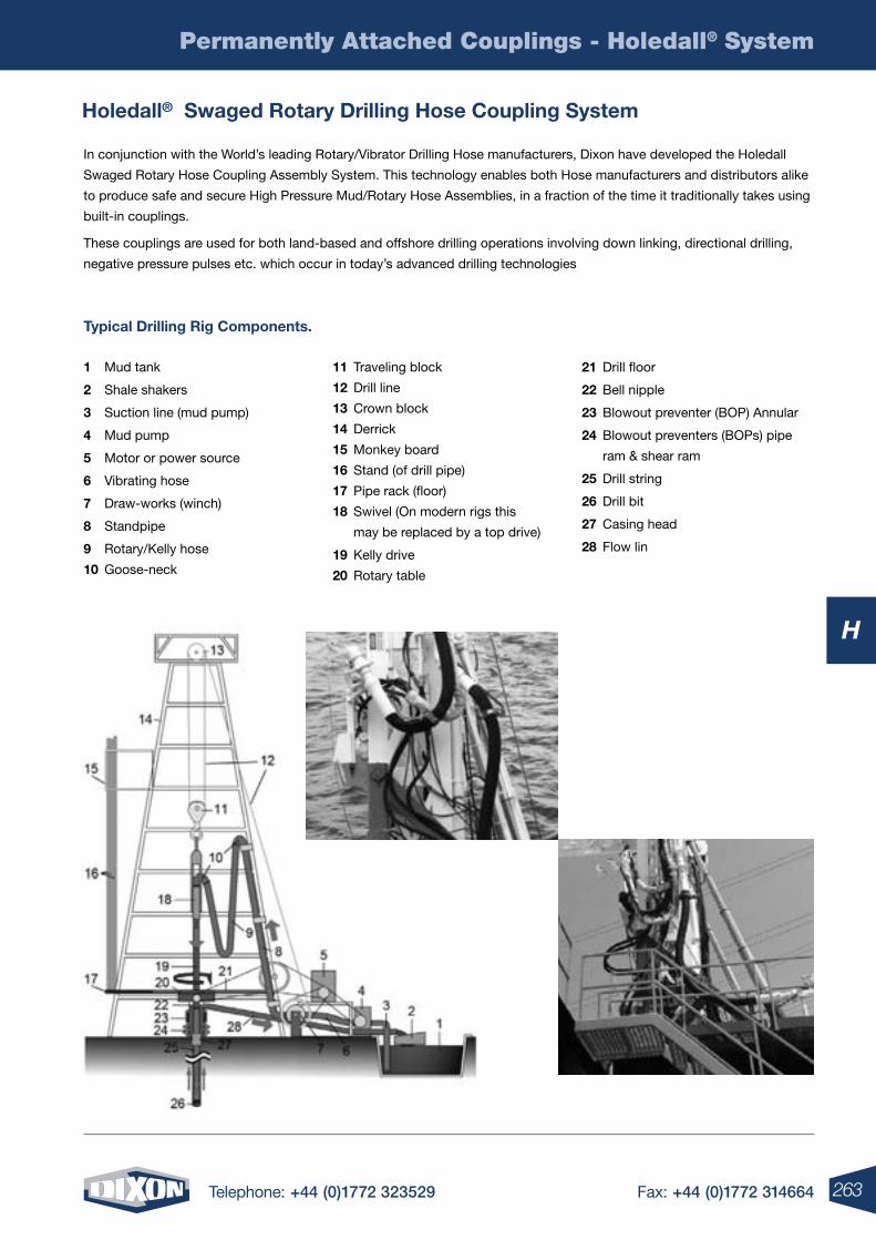
263Telephone: +44 (0)1772 323529 Fax: +44 (0)1772 314664
H
Permanently Attached Couplings - Holedall® System
holedall® swaged rotary Drilling hose coupling system
In conjunction with the World’s leading Rotary/Vibrator Drilling Hose manufacturers, Dixon have developed the Holedall
Swaged Rotary Hose Coupling Assembly System. This technology enables both Hose manufacturers and distributors alike
to produce safe and secure High Pressure Mud/Rotary Hose Assemblies, in a fraction of the time it traditionally takes using
built-in couplings.
These couplings are used for both land-based and offshore drilling operations involving down linking, directional drilling,
negative pressure pulses etc. which occur in today’s advanced drilling technologies
1 Mud tank
2 Shale shakers
3 Suction line (mud pump)
4 Mud pump
5 Motor or power source
6 Vibrating hose
7 Draw-works (winch)
8 Standpipe
9 Rotary/Kelly hose
10 Goose-neck
11 Traveling block
12 Drill line
13 Crown block
14 Derrick
15 Monkey board
16 Stand (of drill pipe)
17 Pipe rack (floor)
18 Swivel (On modern rigs this
may be replaced by a top drive)
19 Kelly drive
20 Rotary table
21 Drill floor
22 Bell nipple
23 Blowout preventer (BOP) Annular
24 Blowout preventers (BOPs) pipe
ram & shear ram
25 Drill string
26 Drill bit
27 Casing head
28 Flow lin
typical Drilling rig components.
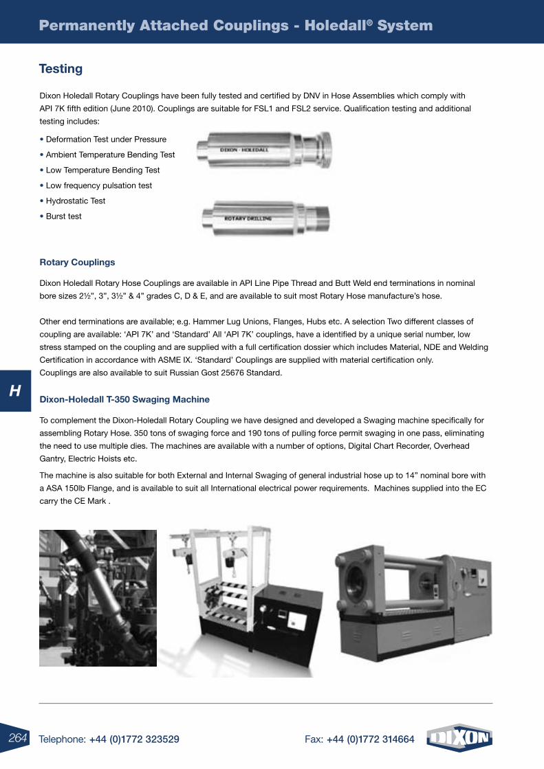
264 Telephone: +44 (0)1772 323529 Fax: +44 (0)1772 314664
H
Permanently Attached Couplings - Holedall® System
testing
Dixon Holedall Rotary Couplings have been fully tested and certified by DNV in Hose Assemblies which comply with
API 7K fifth edition (June 2010). Couplings are suitable for FSL1 and FSL2 service. Qualification testing and additional
testing includes:
• Deformation Test under Pressure
• Ambient Temperature Bending Test
• Low Temperature Bending Test
• Low frequency pulsation test
• Hydrostatic Test
• Burst test
rotary couplings
Dixon Holedall Rotary Hose Couplings are available in API Line Pipe Thread and Butt Weld end terminations in nominal
bore sizes 2½”, 3”, 3½” & 4” grades C, D & E, and are available to suit most Rotary Hose manufacture’s hose.
Other end terminations are available; e.g. Hammer Lug Unions, Flanges, Hubs etc. A selection Two different classes of
coupling are available: ‘API 7K’ and ‘Standard’ All ‘API 7K’ couplings, have a identified by a unique serial number, low
stress stamped on the coupling and are supplied with a full certification dossier which includes Material, NDE and Welding
Certification in accordance with ASME IX. ‘Standard’ Couplings are supplied with material certification only.
Couplings are also available to suit Russian Gost 25676 Standard.
Dixon-holedall t-350 swaging machine
To complement the Dixon-Holedall Rotary Coupling we have designed and developed a Swaging machine specifically for
assembling Rotary Hose. 350 tons of swaging force and 190 tons of pulling force permit swaging in one pass, eliminating
the need to use multiple dies. The machines are available with a number of options, Digital Chart Recorder, Overhead
Gantry, Electric Hoists etc.
The machine is also suitable for both External and Internal Swaging of general industrial hose up to 14” nominal bore with
a ASA 150lb Flange, and is available to suit all International electrical power requirements. Machines supplied into the EC
carry the CE Mark .
rotary text image
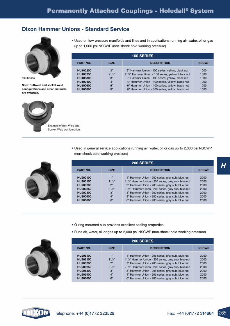
265Telephone: +44 (0)1772 323529 Fax: +44 (0)1772 314664
H
Permanently Attached Couplings - Holedall® System
• Used on low pressure manifolds and lines and in applications running air, water, oil or gas
up to 1,000 psi NSCWP (non-shock cold working pressure)
100 Series
note: Buttweld and socket weld configurations and other materials are available.
• Used in general service applications running air, water, oil or gas up to 2,000 psi NSCWP
(non-shock cold working pressure)
• O-ring mounted sub provides excellent sealing properties
• Runs air, water, oil or gas up to 2,000 psi NSCWP (non-shock cold working pressure)
Dixon hammer unions - standard service
100 series
part no.
hu100200 hu100250 hu100300 hu100400 hu100600 hu100800
Description
2” Hammer Union - 100 series, yellow, black nut21/2” Hammer Union - 100 series, yellow, black nut
3” Hammer Union - 100 series, yellow, black nut 4” Hammer Union - 100 series, yellow, black nut 6” Hammer Union - 100 series, yellow, black nut 6” Hammer Union - 100 series, yellow, black nut
size
2”21/2”
3”4”6”8”
nscWp
100010001000100010001000
200 series
part no.
hu200100 hu200150 hu200200 hu200250 hu200300 hu200400 hu200600
Description
1” Hammer Union - 200 series, grey sub, blue nut11/2” Hammer Union - 200 series, grey sub, blue nut
2” Hammer Union - 200 series, grey sub, blue nut21/2” Hammer Union - 200 series, grey sub, blue nut
3” Hammer Union - 200 series, grey sub, blue nut4” Hammer Union - 200 series, grey sub, blue nut6” Hammer Union - 200 series, grey sub, blue nut
size
1”11/2”
2”21/2”
3”4”6”
nscWp
2000200020002000200020002000
206 series
part no.
hu206100 hu206150 hu206200 hu206250 hu206300 hu206400 hu206600
Description
1” Hammer Union - 206 series, grey sub, blue nut11/2” Hammer Union - 206 series, grey sub, blue nut
2” Hammer Union - 206 series, grey sub, blue nut21/2” Hammer Union - 206 series, grey sub, blue nut
3” Hammer Union - 206 series, grey sub, blue nut4” Hammer Union - 206 series, grey sub, blue nut6” Hammer Union - 206 series, grey sub, blue nut
size
1”11/2”
2”21/2”
3”4”6”
nscWp
2000200020002000200020002000
Example of Butt Weld and Socket Weld configuration.
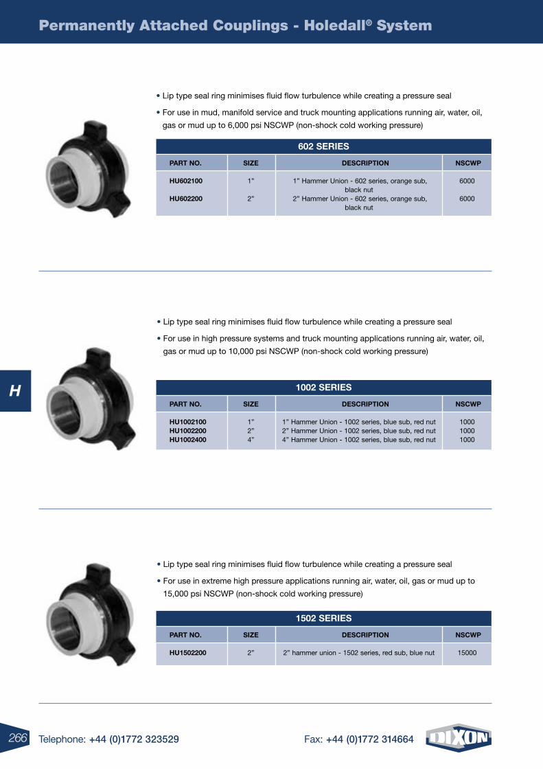
266 Telephone: +44 (0)1772 323529 Fax: +44 (0)1772 314664
H
Permanently Attached Couplings - Holedall® System
• Lip type seal ring minimises fluid flow turbulence while creating a pressure seal
• For use in high pressure systems and truck mounting applications running air, water, oil,
gas or mud up to 10,000 psi NSCWP (non-shock cold working pressure)
1002 series
part no.
hu1002100 hu1002200 hu1002400
Description
1” Hammer Union - 1002 series, blue sub, red nut2” Hammer Union - 1002 series, blue sub, red nut4” Hammer Union - 1002 series, blue sub, red nut
size
1”2”4”
nscWp
100010001000
• Lip type seal ring minimises fluid flow turbulence while creating a pressure seal
• For use in extreme high pressure applications running air, water, oil, gas or mud up to
15,000 psi NSCWP (non-shock cold working pressure)
1502 series
part no.
hu1502200
Description
2” hammer union - 1502 series, red sub, blue nut
size
2”
nscWp
15000
• Lip type seal ring minimises fluid flow turbulence while creating a pressure seal
• For use in mud, manifold service and truck mounting applications running air, water, oil,
gas or mud up to 6,000 psi NSCWP (non-shock cold working pressure)
602 series
part no.
hu602100 hu602200
Description
1” Hammer Union - 602 series, orange sub, black nut
2” Hammer Union - 602 series, orange sub, black nut
size
1”
2”
nscWp
6000
6000
267Telephone: +44 (0)1772 323529 Fax: +44 (0)1772 314664
Permanently Attached Couplings - Holedall®
H
268 Telephone: +44 (0)1772 323529 Fax: +44 (0)1772 314664
I
4 Telephone: +44 (0)1772 323529 Fax: +44 (0)1772 314664268 Telephone: +44 (0)1772 323529 Fax: +44 (0)1772 314664
Quick Release Profiles ................................................................. 270-272
H Series: ISO 7241 Series B Interchange ..................................... 273-277
H-Series ISO-B Food Grade Couplings ...................................................278
HS-Series ISO-B Steam Interchange ......................................................279
K-Series ISO7241 Series ‘A’ Interchange ..................................... 280-281
AG-Series Agricultural Interchange ............................................... 282-283
TR-Series TEMA European Interchange ..................................................284
VEP-Series Threaded Flushface ..............................................................285
W Series Wing Style Interchange ................................................. 286-287
HT-Series ISO16028 Flushface Interchange ................................. 288-290
ST-Series Snap-Tite ‘71’ Interchange ........................................... 291-293
WS-Series High Pressure Wingstyle ............................................. 294-295
WS-Series Blowout Prevention Safety Coupling .....................................296
PD-Series ISO15171-1 Diagnostic Interchange .......................................297
V Series: Snap-Tite H/IH Interchange ........................................... 298-303
T-Series High Pressure Screw-Together ..................................................304
Quick Release Couplings
I
269Telephone: +44 (0)1772 323529 Fax: +44 (0)1772 314664
I
269Telephone: +44 (0)1772 323529 Fax: +44 (0)1772 314664 269Telephone: +44 (0)1772 323529 Fax: +44 (0)1772 314664
CVV-Series European Screw-Together Interchange .................................305
E-Series Straight-Through Interchange ........................................ 306-308
EA-Series Water-Blast Interchange .........................................................309
CM-Series Mould Coolant Interchange ........................................ 310-312
DF-Series Industrial Interchange .................................................. 313-318
BR-Series Rectus ‘21’ Interchange .............................................. 319-320
J-Series Truflate Automotive Interchange ..................................... 321-323
CJ-Series European High-Flow Interchange ................................. 324-326
N Series Bowes/MacDonald Interchange ..................................... 327-332
P-Series Thor Interchange ............................................................ 333-335 I
QUICK DISCONNECT COUPLING FLUID COMPATIBILITY GUIDE AVAILABLE ON PAGES 500-501 OF THE TECHNICAL SECTION
FOr A FULL rANGE OF HOSES TO COMPLEMENT THESE FITTINGS SEE SECTION F
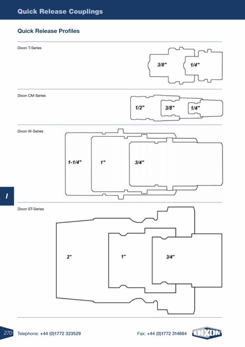
Quick Release Couplings
270 Telephone: +44 (0)1772 323529 Fax: +44 (0)1772 314664
I
Quick release Profiles
Dixon T-Series
Dixon CM-Series
Dixon W-Series
Dixon ST-Series
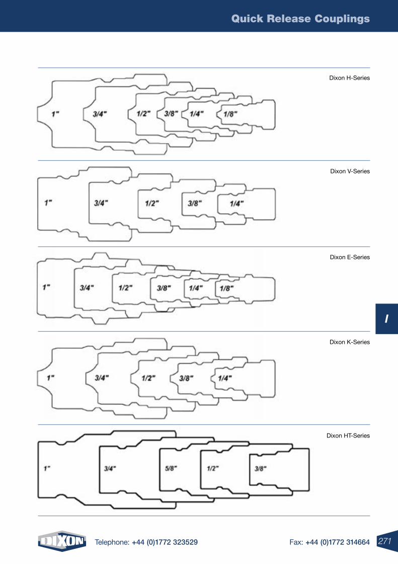
Quick Release Couplings
271Telephone: +44 (0)1772 323529 Fax: +44 (0)1772 314664
I
Dixon H-Series
Dixon V-Series
Dixon E-Series
Dixon K-Series
Dixon HT-Series
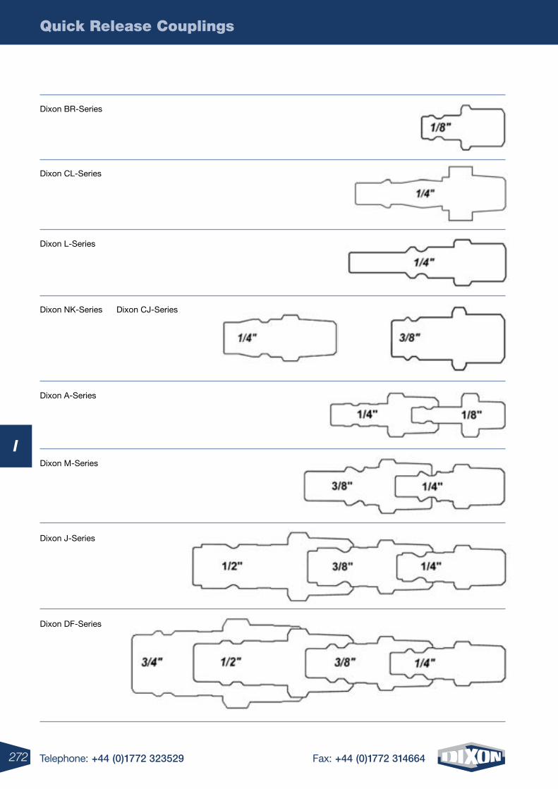
Quick Release Couplings
272 Telephone: +44 (0)1772 323529 Fax: +44 (0)1772 314664
I
Dixon BR-Series
Dixon CL-Series
Dixon L-Series
Dixon NK-Series Dixon CJ-Series
Dixon A-Series
Dixon M-Series
Dixon J-Series
Dixon DF-Series
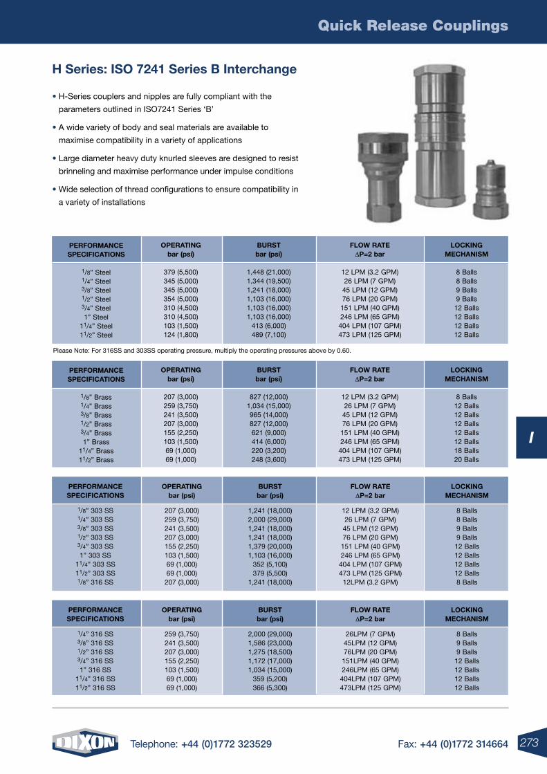
Quick Release Couplings
273Telephone: +44 (0)1772 323529 Fax: +44 (0)1772 314664
I
H Series: ISO 7241 Series B Interchange
• H-Series couplers and nipples are fully compliant with the
parameters outlined in ISO7241 Series ‘B’
• A wide variety of body and seal materials are available to
maximise compatibility in a variety of applications
• Large diameter heavy duty knurled sleeves are designed to resist
brinneling and maximise performance under impulse conditions
• Wide selection of thread configurations to ensure compatibility in
a variety of installations
LOCKINGMECHANISM
8 Balls8 Balls9 Balls9 Balls12 Balls12 Balls12 Balls12 Balls
FLOw rATEDP=2 bar
12 LPM (3.2 GPM)26 LPM (7 GPM)45 LPM (12 GPM)76 LPM (20 GPM)151 LPM (40 GPM)246 LPM (65 GPM)404 LPM (107 GPM)473 LPM (125 GPM)
PErFOrMANCESPECIFICATIONS
1/8” Steel1/4” Steel3/8” Steel1/2” Steel3/4” Steel1” Steel
11/4” Steel11/2” Steel
BUrSTbar (psi)
1,448 (21,000)1,344 (19,500)1,241 (18,000)1,103 (16,000)1,103 (16,000)1,103 (16,000)
413 (6,000)489 (7,100)
OPErATINGbar (psi)
379 (5,500)345 (5,000)345 (5,000)354 (5,000)310 (4,500)310 (4,500)103 (1,500)124 (1,800)
LOCKINGMECHANISM
8 Balls12 Balls12 Balls12 Balls12 Balls12 Balls18 Balls20 Balls
FLOw rATEDP=2 bar
12 LPM (3.2 GPM)26 LPM (7 GPM)45 LPM (12 GPM)76 LPM (20 GPM)151 LPM (40 GPM)246 LPM (65 GPM)404 LPM (107 GPM)473 LPM (125 GPM)
PErFOrMANCESPECIFICATIONS
1/8” Brass1/4” Brass3/8” Brass1/2” Brass3/4” Brass1” Brass
11/4” Brass11/2” Brass
BUrSTbar (psi)
827 (12,000)1,034 (15,000)965 (14,000)827 (12,000)621 (9,000)414 (6,000)220 (3,200)248 (3,600)
OPErATINGbar (psi)
207 (3,000)259 (3,750)241 (3,500)207 (3,000)155 (2,250)103 (1,500)69 (1,000)69 (1,000)
PErFOrMANCE OPErATING BUrST FLOw rATE LOCKING SPECIFICATIONS bar (psi) bar (psi) DP=2 bar MECHANISM
1/8” 303 SS 207 (3,000) 1,241 (18,000) 12 LPM (3.2 GPM) 8 Balls 1/4” 303 SS 259 (3,750) 2,000 (29,000) 26 LPM (7 GPM) 8 Balls 3/8” 303 SS 241 (3,500) 1,241 (18,000) 45 LPM (12 GPM) 9 Balls 1/2” 303 SS 207 (3,000) 1,241 (18,000) 76 LPM (20 GPM) 9 Balls 3/4” 303 SS 155 (2,250) 1,379 (20,000) 151 LPM (40 GPM) 12 Balls 1” 303 SS 103 (1,500) 1,103 (16,000) 246 LPM (65 GPM) 12 Balls 11/4” 303 SS 69 (1,000) 352 (5,100) 404 LPM (107 GPM) 12 Balls 11/2” 303 SS 69 (1,000) 379 (5,500) 473 LPM (125 GPM) 12 Balls 1/8” 316 SS 207 (3,000) 1,241 (18,000) 12LPM (3.2 GPM) 8 Balls
PErFOrMANCE OPErATING BUrST FLOw rATE LOCKING SPECIFICATIONS bar (psi) bar (psi) DP=2 bar MECHANISM
1/4” 316 SS 259 (3,750) 2,000 (29,000) 26LPM (7 GPM) 8 Balls 3/8” 316 SS 241 (3,500) 1,586 (23,000) 45LPM (12 GPM) 9 Balls 1/2” 316 SS 207 (3,000) 1,275 (18,500) 76LPM (20 GPM) 9 Balls 3/4” 316 SS 155 (2,250) 1,172 (17,000) 151LPM (40 GPM) 12 Balls 1” 316 SS 103 (1,500) 1,034 (15,000) 246LPM (65 GPM) 12 Balls 11/4” 316 SS 69 (1,000) 359 (5,200) 404LPM (107 GPM) 12 Balls 11/2” 316 SS 69 (1,000) 366 (5,300) 473LPM (125 GPM) 12 Balls
Please Note: For 316SS and 303SS operating pressure, multiply the operating pressures above by 0.60.
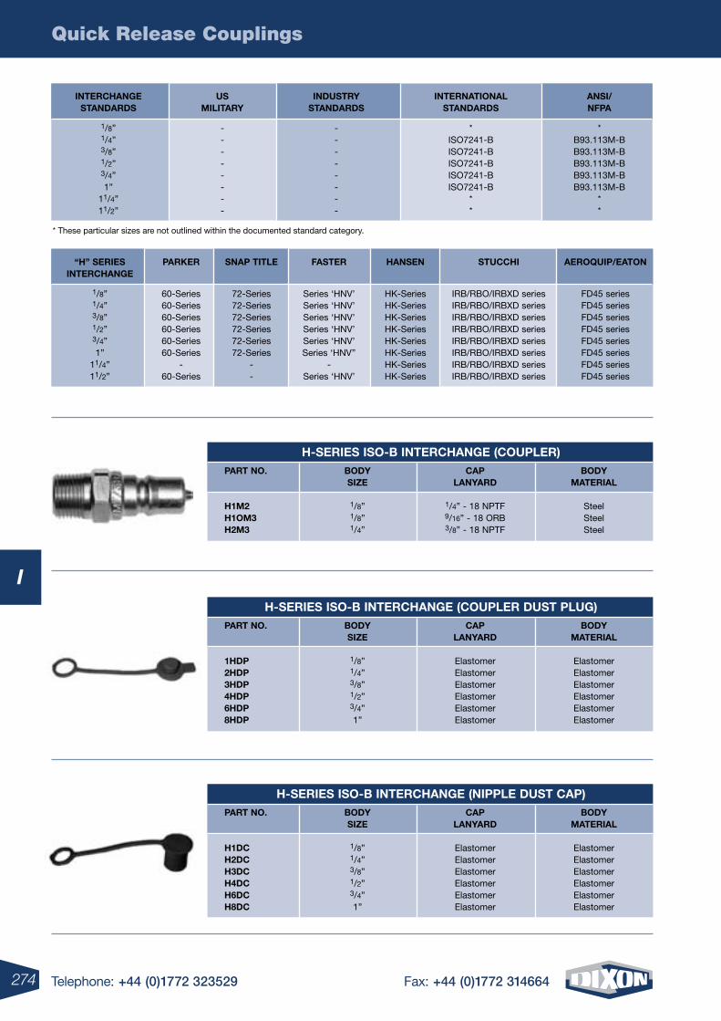
Quick Release Couplings
274 Telephone: +44 (0)1772 323529 Fax: +44 (0)1772 314664
I
INTErCHANGE US INDUSTrY INTErNATIONAL ANSI/ STANDArDS MILITArY STANDArDS STANDArDS NFPA
1/8” - - * * 1/4” - - ISO7241-B B93.113M-B 3/8” - - ISO7241-B B93.113M-B 1/2” - - ISO7241-B B93.113M-B 3/4” - - ISO7241-B B93.113M-B 1” - - ISO7241-B B93.113M-B 11/4” - - * * 11/2” - - * *
* These particular sizes are not outlined within the documented standard category.
H-SErIES ISO-B INTErCHANGE (COUPLEr) PArT NO. BODY CAP BODY SIzE LANYArD MATErIAL
H1M2 1/8” 1/4” - 18 NPTF Steel H1OM3 1/8” 9/16” - 18 ORB Steel H2M3 1/4” 3/8” - 18 NPTF Steel
H-SErIES ISO-B INTErCHANGE (COUPLEr DUST PLUG) PArT NO. BODY CAP BODY SIzE LANYArD MATErIAL
1HDP 1/8” Elastomer Elastomer 2HDP 1/4” Elastomer Elastomer 3HDP 3/8” Elastomer Elastomer 4HDP 1/2” Elastomer Elastomer 6HDP 3/4” Elastomer Elastomer 8HDP 1” Elastomer Elastomer
H-SErIES ISO-B INTErCHANGE (NIPPLE DUST CAP) PArT NO. BODY CAP BODY SIzE LANYArD MATErIAL
H1DC 1/8” Elastomer Elastomer H2DC 1/4” Elastomer Elastomer H3DC 3/8” Elastomer Elastomer H4DC 1/2” Elastomer Elastomer H6DC 3/4” Elastomer Elastomer H8DC 1” Elastomer Elastomer
“H” SErIES PArKEr SNAP TITLE FASTEr HANSEN STUCCHI AErOQUIP/EATON INTErCHANGE
1/8” 60-Series 72-Series Series ‘HNV’ HK-Series IRB/RBO/IRBXD series FD45 series 1/4” 60-Series 72-Series Series ‘HNV’ HK-Series IRB/RBO/IRBXD series FD45 series 3/8” 60-Series 72-Series Series ‘HNV’ HK-Series IRB/RBO/IRBXD series FD45 series 1/2” 60-Series 72-Series Series ‘HNV’ HK-Series IRB/RBO/IRBXD series FD45 series 3/4” 60-Series 72-Series Series ‘HNV’ HK-Series IRB/RBO/IRBXD series FD45 series 1” 60-Series 72-Series Series ‘HNV’’ HK-Series IRB/RBO/IRBXD series FD45 series 11/4” - - - HK-Series IRB/RBO/IRBXD series FD45 series 11/2” 60-Series - Series ‘HNV’ HK-Series IRB/RBO/IRBXD series FD45 series
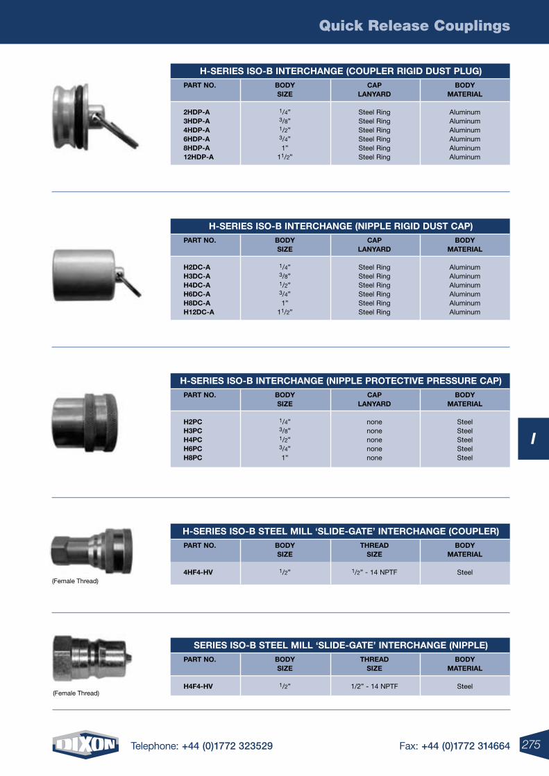
Quick Release Couplings
275Telephone: +44 (0)1772 323529 Fax: +44 (0)1772 314664
I
H-SErIES ISO-B INTErCHANGE (COUPLEr rIGID DUST PLUG) PArT NO. BODY CAP BODY SIzE LANYArD MATErIAL
2HDP-A 1/4” Steel Ring Aluminum 3HDP-A 3/8” Steel Ring Aluminum 4HDP-A 1/2” Steel Ring Aluminum 6HDP-A 3/4” Steel Ring Aluminum 8HDP-A 1” Steel Ring Aluminum 12HDP-A 11/2” Steel Ring Aluminum
H-SErIES ISO-B INTErCHANGE (NIPPLE rIGID DUST CAP) PArT NO. BODY CAP BODY SIzE LANYArD MATErIAL
H2DC-A 1/4” Steel Ring Aluminum H3DC-A 3/8” Steel Ring Aluminum H4DC-A 1/2” Steel Ring Aluminum H6DC-A 3/4” Steel Ring Aluminum H8DC-A 1” Steel Ring Aluminum H12DC-A 11/2” Steel Ring Aluminum
H-SErIES ISO-B INTErCHANGE (NIPPLE PrOTECTIVE PrESSUrE CAP) PArT NO. BODY CAP BODY SIzE LANYArD MATErIAL
H2PC 1/4” none Steel H3PC 3/8” none Steel H4PC 1/2” none Steel H6PC 3/4” none Steel H8PC 1” none Steel
SErIES ISO-B STEEL MILL ‘SLIDE-GATE’ INTErCHANGE (NIPPLE) PArT NO. BODY THrEAD BODY SIzE SIzE MATErIAL
H4F4-HV 1/2” 1/2” - 14 NPTF Steel
H-SErIES ISO-B STEEL MILL ‘SLIDE-GATE’ INTErCHANGE (COUPLEr) PArT NO. BODY THrEAD BODY SIzE SIzE MATErIAL
4HF4-HV 1/2” 1/2” - 14 NPTF Steel(Female Thread)
(Female Thread)
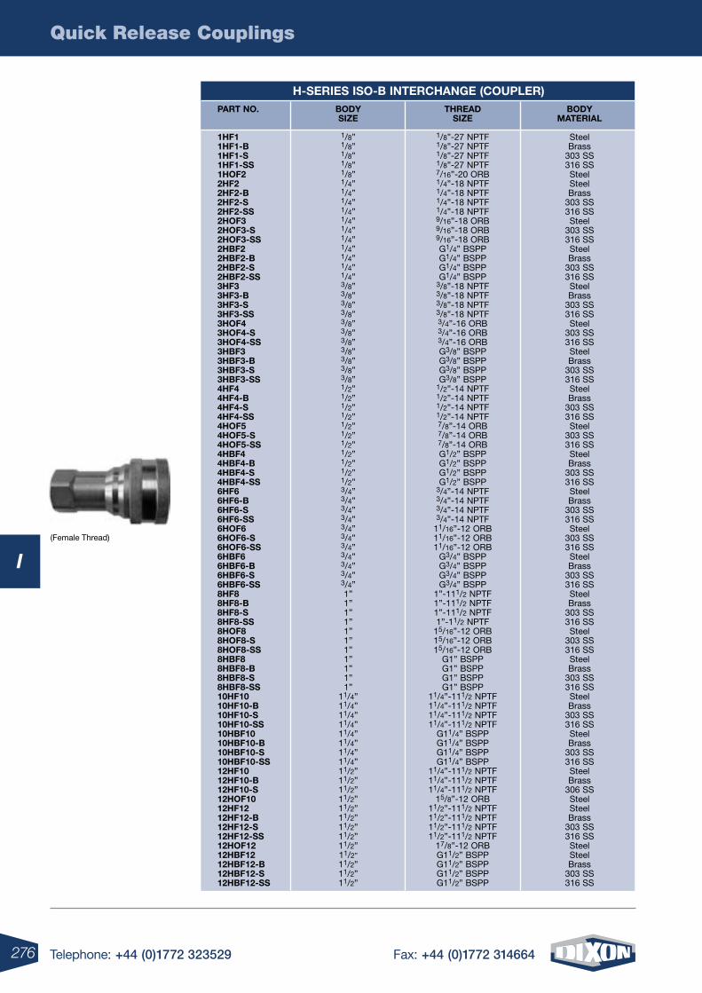
Quick Release Couplings
276 Telephone: +44 (0)1772 323529 Fax: +44 (0)1772 314664
I
H-SErIES ISO-B INTErCHANGE (COUPLEr) PArT NO. BODY THrEAD BODY SIzE SIzE MATErIAL
1HF1 1/8” 1/8”-27 NPTF Steel 1HF1-B 1/8” 1/8”-27 NPTF Brass 1HF1-S 1/8” 1/8”-27 NPTF 303 SS 1HF1-SS 1/8” 1/8”-27 NPTF 316 SS 1HOF2 1/8” 7/16”-20 ORB Steel 2HF2 1/4” 1/4”-18 NPTF Steel 2HF2-B 1/4” 1/4”-18 NPTF Brass 2HF2-S 1/4” 1/4”-18 NPTF 303 SS 2HF2-SS 1/4” 1/4”-18 NPTF 316 SS 2HOF3 1/4” 9/16”-18 ORB Steel 2HOF3-S 1/4” 9/16”-18 ORB 303 SS 2HOF3-SS 1/4” 9/16”-18 ORB 316 SS 2HBF2 1/4” G1/4” BSPP Steel 2HBF2-B 1/4” G1/4” BSPP Brass 2HBF2-S 1/4” G1/4” BSPP 303 SS 2HBF2-SS 1/4” G1/4” BSPP 316 SS 3HF3 3/8” 3/8”-18 NPTF Steel 3HF3-B 3/8” 3/8”-18 NPTF Brass 3HF3-S 3/8” 3/8”-18 NPTF 303 SS 3HF3-SS 3/8” 3/8”-18 NPTF 316 SS 3HOF4 3/8” 3/4”-16 ORB Steel 3HOF4-S 3/8” 3/4”-16 ORB 303 SS 3HOF4-SS 3/8” 3/4”-16 ORB 316 SS 3HBF3 3/8” G3/8” BSPP Steel 3HBF3-B 3/8” G3/8” BSPP Brass 3HBF3-S 3/8” G3/8” BSPP 303 SS 3HBF3-SS 3/8” G3/8” BSPP 316 SS 4HF4 1/2” 1/2”-14 NPTF Steel 4HF4-B 1/2” 1/2”-14 NPTF Brass 4HF4-S 1/2” 1/2”-14 NPTF 303 SS 4HF4-SS 1/2” 1/2”-14 NPTF 316 SS 4HOF5 1/2” 7/8”-14 ORB Steel 4HOF5-S 1/2” 7/8”-14 ORB 303 SS 4HOF5-SS 1/2” 7/8”-14 ORB 316 SS 4HBF4 1/2” G1/2” BSPP Steel 4HBF4-B 1/2” G1/2” BSPP Brass 4HBF4-S 1/2” G1/2” BSPP 303 SS 4HBF4-SS 1/2” G1/2” BSPP 316 SS 6HF6 3/4” 3/4”-14 NPTF Steel 6HF6-B 3/4” 3/4”-14 NPTF Brass 6HF6-S 3/4” 3/4”-14 NPTF 303 SS 6HF6-SS 3/4” 3/4”-14 NPTF 316 SS 6HOF6 3/4” 11/16”-12 ORB Steel 6HOF6-S 3/4” 11/16”-12 ORB 303 SS 6HOF6-SS 3/4” 11/16”-12 ORB 316 SS 6HBF6 3/4” G3/4” BSPP Steel 6HBF6-B 3/4” G3/4” BSPP Brass 6HBF6-S 3/4” G3/4” BSPP 303 SS 6HBF6-SS 3/4” G3/4” BSPP 316 SS 8HF8 1” 1”-111/2 NPTF Steel 8HF8-B 1” 1”-111/2 NPTF Brass 8HF8-S 1” 1”-111/2 NPTF 303 SS 8HF8-SS 1” 1”-11/2 NPTF 316 SS 8HOF8 1” 15/16”-12 ORB Steel 8HOF8-S 1” 15/16”-12 ORB 303 SS 8HOF8-SS 1” 15/16”-12 ORB 316 SS 8HBF8 1” G1” BSPP Steel 8HBF8-B 1” G1” BSPP Brass 8HBF8-S 1” G1” BSPP 303 SS 8HBF8-SS 1” G1” BSPP 316 SS 10HF10 11/4” 11/4”-111/2 NPTF Steel 10HF10-B 11/4” 11/4”-111/2 NPTF Brass 10HF10-S 11/4” 11/4”-111/2 NPTF 303 SS 10HF10-SS 11/4” 11/4”-111/2 NPTF 316 SS 10HBF10 11/4” G11/4” BSPP Steel 10HBF10-B 11/4” G11/4” BSPP Brass 10HBF10-S 11/4” G11/4” BSPP 303 SS 10HBF10-SS 11/4” G11/4” BSPP 316 SS 12HF10 11/2” 11/4”-111/2 NPTF Steel 12HF10-B 11/2” 11/4”-111/2 NPTF Brass 12HF10-S 11/2” 11/4”-111/2 NPTF 306 SS 12HOF10 11/2” 15/8”-12 ORB Steel 12HF12 11/2” 11/2”-111/2 NPTF Steel 12HF12-B 11/2” 11/2”-111/2 NPTF Brass 12HF12-S 11/2” 11/2”-111/2 NPTF 303 SS 12HF12-SS 11/2” 11/2”-111/2 NPTF 316 SS 12HOF12 11/2” 17/8”-12 ORB Steel 12HBF12 11/2” G11/2” BSPP Steel 12HBF12-B 11/2” G11/2” BSPP Brass 12HBF12-S 11/2” G11/2” BSPP 303 SS 12HBF12-SS 11/2” G11/2” BSPP 316 SS
(Female Thread)
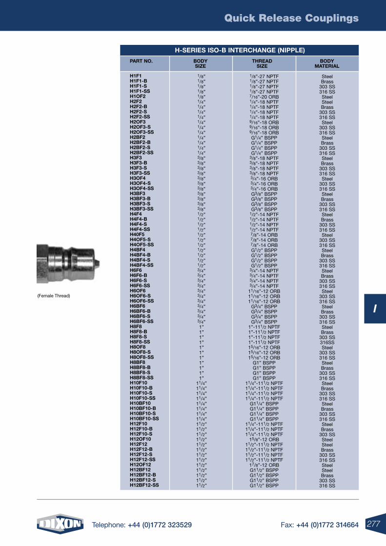
Quick Release Couplings
277Telephone: +44 (0)1772 323529 Fax: +44 (0)1772 314664
I
H-SErIES ISO-B INTErCHANGE (NIPPLE)
(Female Thread)
PArT NO. BODY THrEAD BODY SIzE SIzE MATErIAL
H1F1H1F1-BH1F1-SH1F1-SSH1OF2H2F2H2F2-BH2F2-SH2F2-SSH2OF3H2OF3-SH2OF3-SSH2BF2H2BF2-BH2BF2-SH2BF2-SSH3F3H3F3-BH3F3-SH3F3-SSH3OF4H3OF4-SH3OF4-SSH3BF3H3BF3-BH3BF3-SH3BF3-SSH4F4H4F4-BH4F4-SH4F4-SSH40F5H4OF5-SH4OF5-SSH4BF4H4BF4-BH4BF4-SH4BF4-SSH6F6H6F6-BH6F6-SH6F6-SSH6OF6H6OF6-SH6OF6-SSH6BF6H6BF6-BH6BF6-SH6BF6-SSH8F8H8F8-BH8F8-SH8F8-SSH8OF8H8OF8-SH8OF8-SSH8BF8H8BF8-BH8BF8-SH8BF8-SSH10F10H10F10-BH10F10-SH10F10-SSH10BF10H10BF10-BH10BF10-SH10BF10-SSH12F10H12F10-BH12F10-SH12OF10H12F12H12F12-BH12F12-SH12F12-SSH12OF12H12BF12H12BF12-BH12BF12-SH12BF12-SS
1/8”1/8”1/8”1/8”1/8”1/4”1/4”1/4”1/4”1/4”1/4”1/4”1/4”1/4”1/4”1/4”3/8”3/8”3/8”3/8”3/8”3/8”3/8”3/8”3/8”3/8”3/8”1/2”1/2”1/2”1/2”1/2”1/2”1/2”1/2”1/2”1/2”1/2”3/4”3/4”3/4”3/4”3/4”3/4”3/4”3/4”3/4”3/4”3/4”1”1”1”1”1”1”1”1”1”1”1”
11/4”11/4”11/4”11/4”11/4”11/4”11/4”11/4”11/2”11/2”11/2”11/2”11/2”11/2”11/2”11/2”11/2”11/2”11/2”11/2”11/2”
1/8”-27 NPTF1/8”-27 NPTF1/8”-27 NPTF1/8”-27 NPTF 7/16”-20 ORB1/4”-18 NPTF1/4”-18 NPTF1/4”-18 NPTF1/4”-18 NPTF9/16”-18 ORB9/16”-18 ORB9/16”-18 ORBG1/4” BSPPG1/4” BSPPG1/4” BSPPG1/4” BSPP
3/8”-18 NPTF3/8”-18 NPTF3/8”-18 NPTF3/8”-18 NPTF3/4”-16 ORB3/4”-16 ORB3/4”-16 ORBG3/8” BSPPG3/8” BSPPG3/8” BSPPG3/8” BSPP
1/2”-14 NPTF1/2”-14 NPTF1/2”-14 NPTF1/2”-14 NPTF7/8”-14 ORB7/8”-14 ORB7/8”-14 ORBG1/2” BSPPG1/2” BSPPG1/2” BSPPG1/2” BSPP
3/4”-14 NPTF3/4”-14 NPTF3/4”-14 NPTF3/4”-14 NPTF
11/16”-12 ORB11/16”-12 ORB11/16”-12 ORB
G3/4” BSPPG3/4” BSPPG3/4” BSPPG3/4” BSPP
1”-111/2 NPTF1”-111/2 NPTF1”-111/2 NPTF1”-111/2 NPTF15/16”-12 ORB15/16”-12 ORB15/16”-12 ORB
G1” BSPPG1” BSPPG1” BSPPG1” BSPP
11/4”-111/2 NPTF11/4”-111/2 NPTF11/4”-111/2 NPTF11/4”-111/2 NPTF
G11/4” BSPPG11/4” BSPPG11/4” BSPPG11/4” BSPP
11/4”-111/2 NPTF11/4”-111/2 NPTF11/4”-111/2 NPTF
15/8”-12 ORB11/2”-111/2 NPTF11/2”-111/2 NPTF11/2”-111/2 NPTF11/2”-111/2 NPTF
17/8”-12 ORBG11/2” BSPPG11/2” BSPPG11/2” BSPPG11/2” BSPP
SteelBrass
303 SS316 SSSteelSteelBrass
303 SS316 SSSteel
303 SS316 SSSteelBrass
303 SS316 SSSteelBrass
303 SS316 SSSteel
303 SS316 SSSteelBrass
303 SS316 SSSteelBrass
303 SS316 SSSteel
303 SS316 SSSteelBrass
303 SS316 SSSteelBrass
303 SS316 SSSteel
303 SS316 SSSteelBrass
303 SS316 SSSteelBrass
303 SS316SSSteel
303 SS316 SSSteelBrass
303 SS316 SSSteelBrass
303 SS316 SSSteelBrass
303 SS316 SSSteelBrass
303 SSSteelSteelBrass
303 SS316 SSSteelSteelBrass
303 SS316 SS
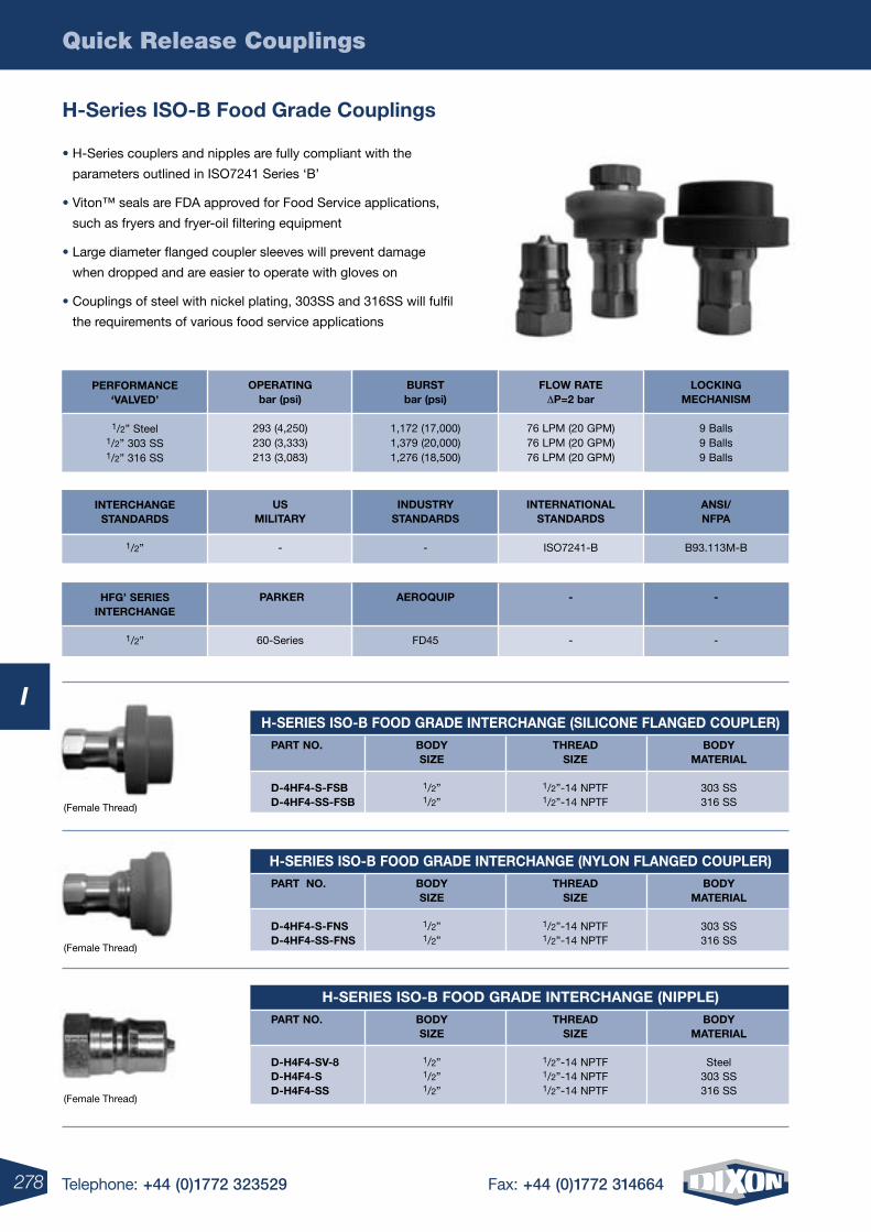
Quick Release Couplings
278 Telephone: +44 (0)1772 323529 Fax: +44 (0)1772 314664
I
H-Series ISO-B Food Grade Couplings
• H-Series couplers and nipples are fully compliant with the
parameters outlined in ISO7241 Series ‘B’
• Viton™ seals are FDA approved for Food Service applications,
such as fryers and fryer-oil filtering equipment
• Large diameter flanged coupler sleeves will prevent damage
when dropped and are easier to operate with gloves on
• Couplings of steel with nickel plating, 303SS and 316SS will fulfil
the requirements of various food service applications
LOCKINGMECHANISM
9 Balls9 Balls9 Balls
FLOw rATEDP=2 bar
76 LPM (20 GPM)76 LPM (20 GPM)76 LPM (20 GPM)
PErFOrMANCE‘VALVED’
1/2” Steel1/2” 303 SS1/2” 316 SS
BUrSTbar (psi)
1,172 (17,000)1,379 (20,000)1,276 (18,500)
OPErATINGbar (psi)
293 (4,250)230 (3,333)213 (3,083)
ANSI/NFPA
B93.113M-B
INTErNATIONALSTANDArDS
ISO7241-B
INTErCHANGESTANDArDS
1/2”
INDUSTrYSTANDArDS
-
USMILITArY
-
-
-
-
-
HFG’ SErIESINTErCHANGE
1/2”
AErOQUIP
FD45
PArKEr
60-Series
H-SErIES ISO-B FOOD GrADE INTErCHANGE (SILICONE FLANGED COUPLEr) PArT NO. BODY THrEAD BODY SIzE SIzE MATErIAL
D-4HF4-S-FSB 1/2” 1/2”-14 NPTF 303 SS D-4HF4-SS-FSB 1/2” 1/2”-14 NPTF 316 SS
H-SErIES ISO-B FOOD GrADE INTErCHANGE (NYLON FLANGED COUPLEr) PArT NO. BODY THrEAD BODY SIzE SIzE MATErIAL
D-4HF4-S-FNS 1/2” 1/2”-14 NPTF 303 SS D-4HF4-SS-FNS 1/2” 1/2”-14 NPTF 316 SS
H-SErIES ISO-B FOOD GrADE INTErCHANGE (NIPPLE) PArT NO. BODY THrEAD BODY SIzE SIzE MATErIAL
D-H4F4-SV-8 1/2” 1/2”-14 NPTF Steel D-H4F4-S 1/2” 1/2”-14 NPTF 303 SS D-H4F4-SS 1/2” 1/2”-14 NPTF 316 SS
(Female Thread)
(Female Thread)
(Female Thread)
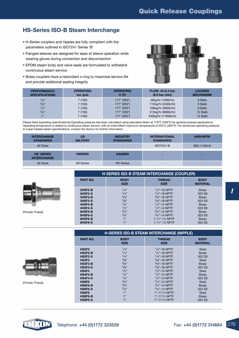
Quick Release Couplings
279Telephone: +44 (0)1772 323529 Fax: +44 (0)1772 314664
I
HS-Series ISO-B Steam Interchange
• H-Series couplers and nipples are fully compliant with the parameters outlined in ISO7241 Series ‘B’
• Flanged sleeves are designed for ease of sleeve operation while wearing gloves during connection and disconnection
• EPDM steam body and valve seals are formulated to withstand continuous steam service
• Brass couplers have a redundant o-ring to maximise service life and provide additional sealing integrity
LOCKINGMECHANISM
8 Balls9 Balls9 Balls12 Balls12 Balls
FLOw DP=0.4 bar(6.9 bar inlet)
49kg/hr (108lb/hr)112kg/hr (246lb/hr)166kg/hr (366lb/hr)313kg/hr (689lb/hr)540kg/hr (1190lb/hr)
PErFOrMANCESPECIFICATIONS
1/4”3/8”1/2”3/4”1”
OPErATINGC (F)
177° (350°)177° (350°)177° (350°)177° (350°)177° (350°)
OPErATINGbar (psi)
7 (100)7 (100)7 (100)7 (100)7 (100)
Please Note (operating specifications):Operating pressure has been calculated using saturated steam at 170°C (338°F) for general purpose applications. Operating temperature is related to continuous steam service, with an intermittent maximum temperature of 204°C (400°F). For advanced operating pressure or super-heated steam specifications, contact the factory for further information.
ANSI/NFPA
B93.113M-B
INTErNATIONAL STANDArDS
ISO7241-B
INTErCHANGE STANDArDS
All Sizes
INDUSTrY STANDArDS
-
US MILITArY
-
-
-
-
-
HS’ SErIES INTErCHANGE
All Sizes
HANSEN
HK-Series
PArKEr
60-Series
(Female Thread)
(Female Thread)
H-SErIES ISO-B STEAM INTErCHANGE (COUPLEr) PArT NO. BODY THrEAD BODY SIzE SIzE MATErIAL
2HSF2-B 1/4” 1/4”-18 NPTF Brass 2HSF2-S 1/4” 1/4”-18 NPTF 303 SS 3HSF3-B 3/8” 3/8”-18 NPTF Brass 3HSF3-S 3/8” 3/8”-18 NPTF 303 SS 4HSF4-B 1/2” 1/2”-14 NPTF Brass 4HSF4-S 1/2” 1/2”-14 NPTF 303 SS 6HSF6-B 3/4” 3/4”-14 NPTF Brass 6HSF6-S 3/4” 3/4”-14 NPTF 303 SS 8HSF8-B 1” 1-11”-1/2 NPTF Brass 8HSF8-S 1” 1-11”-1/2 NPTF 303 SS
H-SErIES ISO-B STEAM INTErCHANGE (NIPPLE) PArT NO. BODY THrEAD BODY SIzE SIzE MATErIAL
HS2F2 1/4” 1/4”-18 NPTF Steel HS2F2-B 1/4” 1/4”-18 NPTF Brass HS2F2-S 1/4” 1/4”-18 NPTF 303 SS HS3F3 3/8” 3/8”-18 NPTF Steel HS3F3-B 3/8” 3/8”-18 NPTF Brass HS3F3-S 3/8” 3/8”-18 NPTF 303 SS HS4F4 1/2” 1/2”-14 NPTF Steel HS4F4-B 1/2” 1/2”-14 NPTF Brass HS4F4-S 1/2” 1/2”-14 NPTF 303 SS HS6F6 3/4” 3/4”-14 NPTF Steel HS6F6-B 3/4” 3/4”-14 NPTF Brass HS6F6-S 3/4” 3/4”-14 NPTF 303 SS HS8F8 1” 1”-111/2 NPTF Steel HS8F8-B 1” 1”-111/2 NPTF Brass HS8F8-S 1” 1”-111/2 NPTF 303 SS
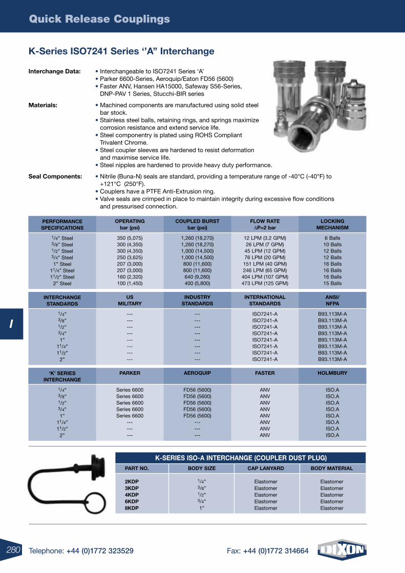
Quick Release Couplings
280 Telephone: +44 (0)1772 323529 Fax: +44 (0)1772 314664
I
K-Series ISO7241 Series ‘’A’’ Interchange
K-SErIES ISO-A INTErCHANGE (COUPLEr DUST PLUG) PArT NO. BODY SIzE CAP LANYArD BODY MATErIAL
2KDP 1/4” Elastomer Elastomer 3KDP 3/8” Elastomer Elastomer 4KDP 1/2” Elastomer Elastomer 6KDP 3/4” Elastomer Elastomer 8KDP 1” Elastomer Elastomer
LOCKINGMECHANISM
6 Balls10 Balls12 Balls12 Balls16 Balls16 Balls16 Balls15 Balls
FLOw rATE DP=2 bar
12 LPM (3.2 GPM)26 LPM (7 GPM)45 LPM (12 GPM)76 LPM (20 GPM)151 LPM (40 GPM)246 LPM (65 GPM)404 LPM (107 GPM)473 LPM (125 GPM)
PErFOrMANCESPECIFICATIONS
1/4” Steel3/8” Steel1/2” Steel3/4” Steel1” Steel
11/4” Steel11/2” Steel
2” Steel
COUPLED BUrSTbar (psi)
1,260 (18,270)1,260 (18,270)1,000 (14,500)1,000 (14,500)800 (11,600)800 (11,600)640 (9,280)400 (5,800)
OPErATINGbar (psi)
350 (5,075)300 (4,350)300 (4,350)250 (3,625)207 (3,000)207 (3,000)160 (2,320)100 (1,450)
ANSI/NFPA
B93.113M-AB93.113M-AB93.113M-AB93.113M-AB93.113M-AB93.113M-AB93.113M-AB93.113M-A
INTErNATIONALSTANDArDS
ISO7241-AISO7241-AISO7241-AISO7241-AISO7241-AISO7241-AISO7241-AISO7241-A
INTErCHANGESTANDArDS
1/4”3/8”1/2”3/4”1”
11/4”11/2”
2”
INDUSTrYSTANDArDS
------------------------
USMILITArY
------------------------
HOLMBUrY
ISO.AISO.AISO.AISO.AISO.AISO.AISO.AISO.A
FASTEr
ANVANVANVANVANVANVANVANV
‘K’ SErIESINTErCHANGE
1/4”3/8”1/2”3/4”1”
11/4”11/2”
2”
AErOQUIP
FD56 (5600)FD56 (5600)FD56 (5600)FD56 (5600)FD56 (5600)
---------
PArKEr
Series 6600Series 6600Series 6600Series 6600Series 6600
---------
Interchange Data: • Interchangeable to ISO7241 Series ‘A’ • Parker 6600-Series, Aeroquip/Eaton FD56 (5600) • Faster ANV, Hansen HA15000, Safeway S56-Series,
DNP-PAV 1 Series, Stucchi-BIR series
Materials: • Machined components are manufactured using solid steel bar stock.
• Stainless steel balls, retaining rings, and springs maximize corrosion resistance and extend service life.
• Steel componentry is plated using ROHS Compliant Trivalent Chrome.
• Steel coupler sleeves are hardened to resist deformation and maximise service life.
• Steel nipples are hardened to provide heavy duty performance.
Seal Components: • Nitrile (Buna-N) seals are standard, providing a temperature range of -40°C (-40°F) to +121°C (250°F).
• Couplers have a PTFE Anti-Extrusion ring. • Valve seals are crimped in place to maintain integrity during excessive flow conditions
and pressurised connection.
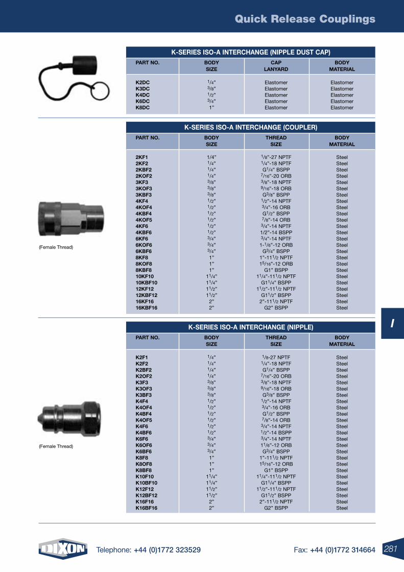
Quick Release Couplings
281Telephone: +44 (0)1772 323529 Fax: +44 (0)1772 314664
I
K-SErIES ISO-A INTErCHANGE (NIPPLE DUST CAP) PArT NO. BODY CAP BODY SIzE LANYArD MATErIAL
K2DC 1/4” Elastomer Elastomer K3DC 3/8” Elastomer Elastomer K4DC 1/2” Elastomer Elastomer K6DC 3/4” Elastomer Elastomer K8DC 1” Elastomer Elastomer
K-SErIES ISO-A INTErCHANGE (NIPPLE) PArT NO. BODY THrEAD BODY SIzE SIzE MATErIAL
K2F1 1/4” 1/8-27 NPTF Steel K2F2 1/4” 1/4”-18 NPTF Steel K2BF2 1/4” G1/4” BSPP Steel K2OF2 1/4” 7/16”-20 ORB Steel K3F3 3/8” 3/8”-18 NPTF Steel K3OF3 3/8” 9/16”-18 ORB Steel K3BF3 3/8” G3/8” BSPP Steel K4F4 1/2” 1/2”-14 NPTF Steel K4OF4 1/2” 3/4”-16 ORB Steel K4BF4 1/2” G1/2” BSPP Steel K4OF5 1/2” 7/8”-14 ORB Steel K4F6 1/2” 3/4”-14 NPTF Steel K4BF6 1/2” 1/2”-14 BSPP Steel K6F6 3/4” 3/4”-14 NPTF Steel K6OF6 3/4” 11/6”-12 ORB Steel K6BF6 3/4” G3/4” BSPP Steel K8F8 1” 1”-111/2 NPTF Steel K8OF8 1” 15/16”-12 ORB Steel K8BF8 1” G1” BSPP Steel K10F10 11/4” 11/4”-111/2 NPTF Steel K10BF10 11/4” G11/4” BSPP Steel K12F12 11/2” 11/2”-111/2 NPTF Steel K12BF12 11/2” G11/2” BSPP Steel K16F16 2” 2”-111/2 NPTF Steel K16BF16 2” G2” BSPP Steel
K-SErIES ISO-A INTErCHANGE (COUPLEr) PArT NO. BODY THrEAD BODY SIzE SIzE MATErIAL
2KF1 1/4” 1/8”-27 NPTF Steel 2KF2 1/4” 1/4”-18 NPTF Steel 2KBF2 1/4” G1/4” BSPP Steel 2KOF2 1/4” 7/16”-20 ORB Steel 3KF3 3/8” 3/8”-18 NPTF Steel 3KOF3 3/8” 9/16”-18 ORB Steel 3KBF3 3/8” G3/8” BSPP Steel 4KF4 1/2” 1/2”-14 NPTF Steel 4KOF4 1/2” 3/4”-16 ORB Steel 4KBF4 1/2” G1/2” BSPP Steel 4KOF5 1/2” 7/8”-14 ORB Steel 4KF6 1/2” 3/4”-14 NPTF Steel 4KBF6 1/2” 1/2”-14 BSPP Steel 6KF6 3/4” 3/4”-14 NPTF Steel 6KOF6 3/4” 1-1/6”-12 ORB Steel 6KBF6 3/4” G3/4” BSPP Steel 8KF8 1” 1”-111/2 NPTF Steel 8KOF8 1” 15/16”-12 ORB Steel 8KBF8 1” G1” BSPP Steel 10KF10 11/4” 11/4”-111/2 NPTF Steel 10KBF10 11/4” G11/4” BSPP Steel 12KF12 11/2” 11/2”-111/2 NPTF Steel 12KBF12 11/2” G11/2” BSPP Steel 16KF16 2” 2”-111/2 NPTF Steel 16KBF16 2” G2” BSPP Steel
(Female Thread)
(Female Thread)
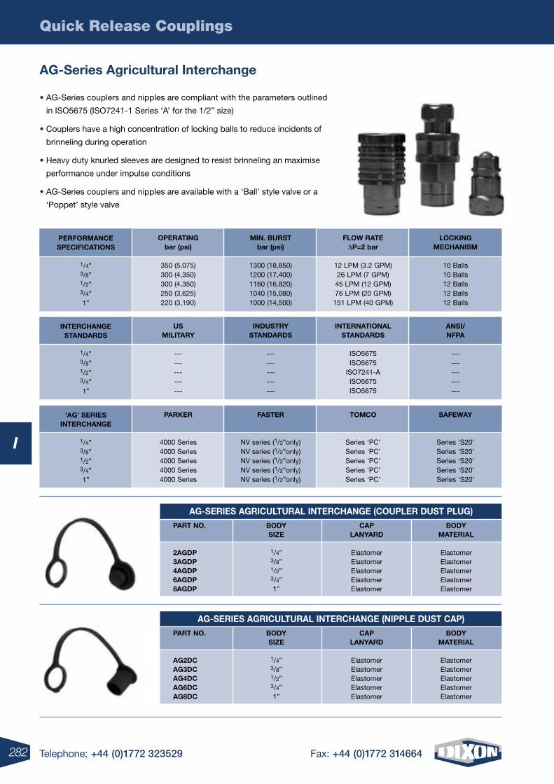
Quick Release Couplings
282 Telephone: +44 (0)1772 323529 Fax: +44 (0)1772 314664
I
AG-SErIES AGrICULTUrAL INTErCHANGE (COUPLEr DUST PLUG) PArT NO. BODY CAP BODY SIzE LANYArD MATErIAL
2AGDP 1/4” Elastomer Elastomer 3AGDP 3/8” Elastomer Elastomer 4AGDP 1/2” Elastomer Elastomer 6AGDP 3/4” Elastomer Elastomer 8AGDP 1” Elastomer Elastomer
AG-SErIES AGrICULTUrAL INTErCHANGE (NIPPLE DUST CAP) PArT NO. BODY CAP BODY SIzE LANYArD MATErIAL
AG2DC 1/4” Elastomer Elastomer AG3DC 3/8” Elastomer Elastomer AG4DC 1/2” Elastomer Elastomer AG6DC 3/4” Elastomer Elastomer AG8DC 1” Elastomer Elastomer
AG-Series Agricultural Interchange
• AG-Series couplers and nipples are compliant with the parameters outlined
in ISO5675 (ISO7241-1 Series ‘A’ for the 1/2” size)
• Couplers have a high concentration of locking balls to reduce incidents of
brinneling during operation
• Heavy duty knurled sleeves are designed to resist brinneling an maximise
performance under impulse conditions
• AG-Series couplers and nipples are available with a ‘Ball’ style valve or a
‘Poppet’ style valve
LOCKINGMECHANISM
10 Balls10 Balls12 Balls12 Balls12 Balls
FLOw rATE DP=2 bar
12 LPM (3.2 GPM)26 LPM (7 GPM)45 LPM (12 GPM)76 LPM (20 GPM)151 LPM (40 GPM)
PErFOrMANCESPECIFICATIONS
1/4”3/8”1/2”3/4”1”
MIN. BUrSTbar (psi)
1300 (18,850)1200 (17,400)1160 (16,820)1040 (15,080)1000 (14,500)
OPErATINGbar (psi)
350 (5,075)300 (4,350)300 (4,350)250 (3,625)220 (3,190)
ANSI/NFPA
---------------
INTErNATIONALSTANDArDS
ISO5675ISO5675
ISO7241-AISO5675ISO5675
INTErCHANGESTANDArDS
1/4”3/8”1/2”3/4”1”
INDUSTrYSTANDArDS
---------------
USMILITArY
---------------
SAFEwAY
Series ‘S20’Series ‘S20’Series ‘S20’Series ‘S20’Series ‘S20’
TOMCO
Series ‘PC’Series ‘PC’Series ‘PC’Series ‘PC’Series ‘PC’
‘AG’ SErIESINTErCHANGE
1/4”3/8”1/2”3/4”1”
FASTEr
NV series (1/2”only)NV series (1/2”only)NV series (1/2”only)NV series (1/2”only)NV series (1/2”only)
PArKEr
4000 Series4000 Series4000 Series4000 Series4000 Series
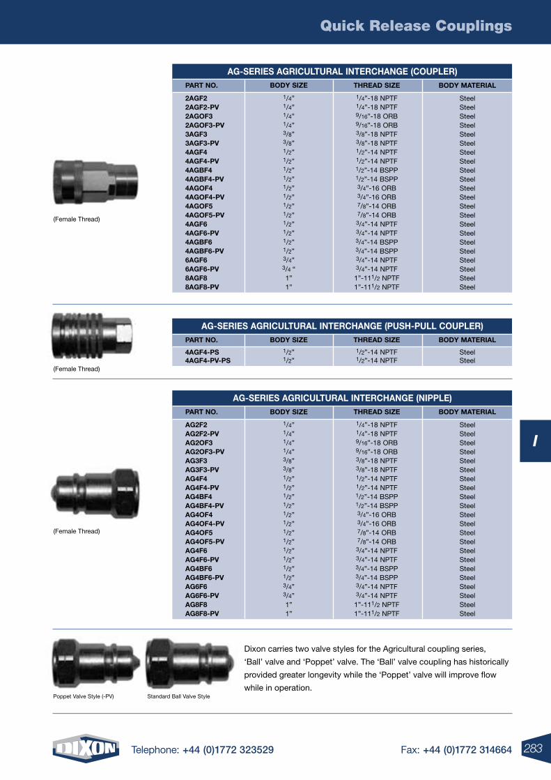
Quick Release Couplings
283Telephone: +44 (0)1772 323529 Fax: +44 (0)1772 314664
I
Dixon carries two valve styles for the Agricultural coupling series,
‘Ball’ valve and ‘Poppet’ valve. The ‘Ball’ valve coupling has historically
provided greater longevity while the ‘Poppet’ valve will improve flow
while in operation.
(Female Thread)
(Female Thread)
(Female Thread)
Poppet Valve Style (-PV) Standard Ball Valve Style
AG-SErIES AGrICULTUrAL INTErCHANGE (COUPLEr)PArT NO.
2AGF22AGF2-PV2AGOF32AGOF3-PV3AGF33AGF3-PV4AGF44AGF4-PV4AGBF44AGBF4-PV4AGOF44AGOF4-PV4AGOF54AGOF5-PV4AGF64AGF6-PV4AGBF64AGBF6-PV6AGF66AGF6-PV8AGF88AGF8-PV
BODY SIzE
1/4”1/4”1/4”1/4”3/8”3/8”1/2”1/2”1/2”1/2”1/2”1/2”1/2”1/2”1/2”1/2”1/2”1/2”3/4”3/4 “1”1”
THrEAD SIzE
1/4”-18 NPTF1/4”-18 NPTF9/16”-18 ORB9/16”-18 ORB3/8”-18 NPTF3/8”-18 NPTF1/2”-14 NPTF1/2”-14 NPTF1/2”-14 BSPP1/2”-14 BSPP3/4”-16 ORB3/4”-16 ORB7/8”-14 ORB7/8”-14 ORB3/4”-14 NPTF3/4”-14 NPTF3/4”-14 BSPP3/4”-14 BSPP3/4”-14 NPTF3/4”-14 NPTF
1”-111/2 NPTF1”-111/2 NPTF
BODY MATErIAL
SteelSteelSteelSteelSteelSteelSteelSteelSteelSteelSteelSteelSteelSteelSteelSteelSteelSteel SteelSteelSteelSteel
AG-SErIES AGrICULTUrAL INTErCHANGE (PUSH-PULL COUPLEr)PArT NO.
4AGF4-PS4AGF4-PV-PS
BODY SIzE
1/2”1/2”
THrEAD SIzE
1/2”-14 NPTF1/2”-14 NPTF
BODY MATErIAL
SteelSteel
AG-SErIES AGrICULTUrAL INTErCHANGE (NIPPLE)PArT NO.
AG2F2AG2F2-PVAG2OF3AG2OF3-PVAG3F3AG3F3-PVAG4F4AG4F4-PVAG4BF4AG4BF4-PVAG4OF4AG4OF4-PVAG4OF5AG4OF5-PVAG4F6AG4F6-PVAG4BF6AG4BF6-PVAG6F6AG6F6-PVAG8F8AG8F8-PV
BODY SIzE
1/4”1/4”1/4”1/4”3/8”3/8”1/2”1/2”1/2”1/2”1/2”1/2”1/2”1/2”1/2”1/2”1/2”1/2”3/4”3/4”1”1”
THrEAD SIzE
1/4”-18 NPTF1/4”-18 NPTF9/16”-18 ORB9/16”-18 ORB3/8”-18 NPTF3/8”-18 NPTF1/2”-14 NPTF1/2”-14 NPTF1/2”-14 BSPP1/2”-14 BSPP3/4”-16 ORB3/4”-16 ORB7/8”-14 ORB7/8”-14 ORB3/4”-14 NPTF3/4”-14 NPTF3/4”-14 BSPP3/4”-14 BSPP3/4”-14 NPTF3/4”-14 NPTF
1”-111/2 NPTF1”-111/2 NPTF
BODY MATErIAL
SteelSteelSteelSteelSteelSteelSteelSteelSteelSteelSteelSteelSteelSteelSteelSteelSteelSteel SteelSteelSteelSteel
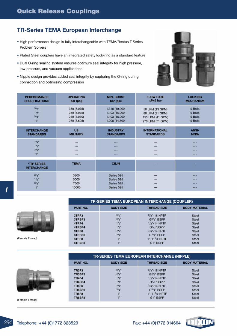
Quick Release Couplings
284 Telephone: +44 (0)1772 323529 Fax: +44 (0)1772 314664
I
Tr-Series TEMA European Interchange
• High performance design is fully interchangeable with TEMA/Rectus T-Series
Problem Solvers
• Plated Steel couplers have an integrated safety lock-ring as a standard feature
• Dual O-ring sealing system ensures optimum seal integrity for high pressure,
low pressure, and vacuum applications
• Nipple design provides added seal integrity by capturing the O-ring during
connection and optimising compression
LOCKINGMECHANISM
9 Balls9 Balls9 Balls9 Balls
FLOw rATE DP=2 bar
50 LPM (13 GPM)80 LPM (21 GPM)155 LPM (41 GPM)270 LPM (71 GPM)
PErFOrMANCESPECIFICATIONS
3/8”1/2”3/4”1”
MIN. BUrSTbar (psi)
1,310 (19,000)1,103 (16,000)1,103 (16,000)1,000 (14,500)
OPErATINGbar (psi)
350 (5,075)350 (5,075)280 (4,060)250 (3,625)
ANSI/NFPA
------------
INTErNATIONALSTANDArDS
------------
INTErCHANGESTANDArDS
3/8”1/2”3/4”1”
INDUSTrYSTANDArDS
------------
USMILITArY
------------
-
------------
-
------------
‘Tr’ SErIESINTErCHANGE
3/8”1/2”3/4”1”
CEJN
Series 525Series 525Series 525Series 525
TEMA
380050007500
10000
(Female Thread)
(Female Thread)
Tr-SErIES TEMA EUrOPEAN INTErCHANGE (COUPLEr)
PArT NO. BODY SIzE THrEAD SIzE BODY MATErIAL 3TrF3 3/8” 3/8”-18 NPTF Steel 3TrBF3 3/8” G3/8” BSPP Steel 4TrF4 1/2” 1/2”-14 NPTF Steel 4TrBF4 1/2” G1/2”BSPP Steel 6TrF6 3/4” 3/4”-14 NPTF Steel 6TrBF6 3/4” G3/4” BSPP Steel 8TrF8 1” 1”-111/2 NPTF Steel 8TrBF8 1” G1” BSPP Steel
Tr-SErIES TEMA EUrOPEAN INTErCHANGE (NIPPLE)
PArT NO. BODY SIzE THrEAD SIzE BODY MATErIAL Tr3F3 3/8” 3/8”-18 NPTF Steel Tr3BF3 3/8” G3/8” BSPP Steel Tr4F4 1/2” 1/2”-14 NPTF Steel Tr4BF4 1/2” G1/2”BSPP Steel Tr6F6 3/4” 3/4”-14 NPTF Steel Tr6BF6 3/4” G3/4” BSPP Steel Tr8F8 1” 1”-111/2 NPTF Steel Tr8BF8 1” G1” BSPP Steel
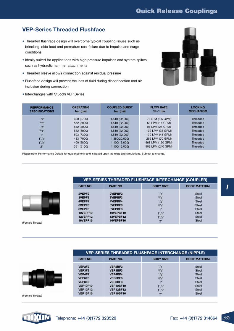
Quick Release Couplings
285Telephone: +44 (0)1772 323529 Fax: +44 (0)1772 314664
I
VEP-Series Threaded Flushface
• Threaded flushface design will overcome typical coupling issues such as
brinelling, side-load and premature seal failure due to impulse and surge
conditions.
• Ideally suited for applications with high pressure impulses and system spikes,
such as hydraulic hammer attachments
• Threaded sleeve allows connection against residual pressure
• Flushface design will prevent the loss of fluid during disconnection and air
inclusion during connection
• Interchanges with Stucchi VEP Series
(Female Thread)
Please note: Performance Data is for guidance only and is based upon lab tests and simulations. Subject to change.
VEP-SErIES THrEADED FLUSHFACE INTErCHANGE (COUPLEr)
PArT NO. PArT NO. BODY SIzE BODY MATErIAL
2VEPF23VEPF34VEPF46VEPF68VEPF810VEPF1012VEPF1216VEPF16
2VEPBF23VEPBF34VEPBF46VEPBF68VEPBF810VEPBF1012VEPBF1216VEPBF16
1/4”3/8”1/2”3/4”1”
11/4”11/2”
2”
SteelSteelSteelSteelSteelSteelSteelSteel
VEP-SErIES THrEADED FLUSHFACE INTErCHANGE (NIPPLE)
PArT NO. PArT NO. BODY SIzE BODY MATErIAL
VEP2F2VEP3F3VEP4F4VEP6F6VEP8F8VEP10F10VEP12F12VEP16F16
VEP2BF2VEP3BF3VEP4BF4VEP6BF6VEP8BF8VEP10BF10VEP12BF12VEP16BF16
1/4”3/8”1/2”3/4”1”
11/4”11/2”
2”
SteelSteelSteelSteelSteelSteelSteelSteel
(Female Thread)
LOCKINGMECHANISM
ThreadedThreadedThreadedThreadedThreadedThreadedThreadedThreaded
FLOw rATE DP=1 bar
21 LPM (5.5 GPM)53 LPM (14 GPM)91 LPM (24 GPM)132 LPM (35 GPM)170 LPM (45 GPM)265 LPM (70 GPM)568 LPM (150 GPM)908 LPM (240 GPM)
PErFOrMANCESPECIFICATIONS
1/4”3/8”1/2”3/4”1”
11/4”11/2”
2”
COUPLED BUrSTbar (psi)
1,510 (22,000)1,510 (22,000)1,510 (22,000)1,510 (22,000)1,510 (22,000)1,380(20,000)1,100(16,000)1,100(16,000)
OPErATINGbar (psi)
600 (8700)552 (8000)552 (8000)552 (8000)503 (7300)483 (7000)400 (5800)351 (5100)
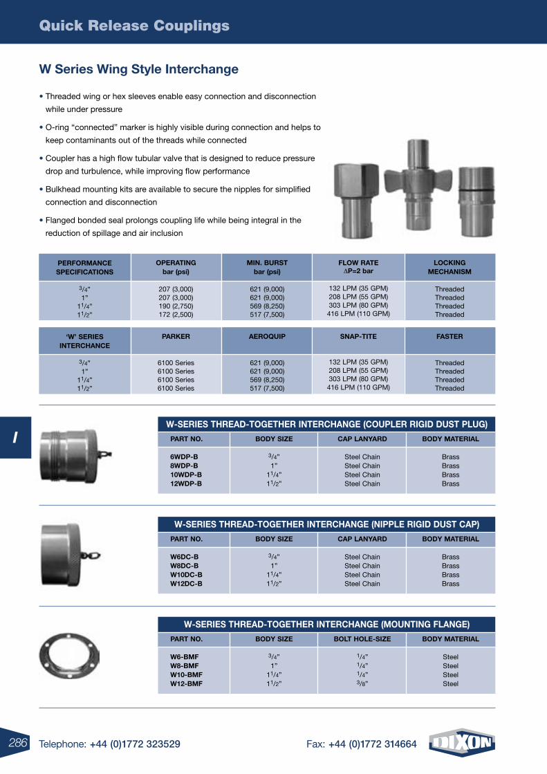
Quick Release Couplings
286 Telephone: +44 (0)1772 323529 Fax: +44 (0)1772 314664
I
w Series wing Style Interchange
• Threaded wing or hex sleeves enable easy connection and disconnection
while under pressure
• O-ring “connected” marker is highly visible during connection and helps to
keep contaminants out of the threads while connected
• Coupler has a high flow tubular valve that is designed to reduce pressure
drop and turbulence, while improving flow performance
• Bulkhead mounting kits are available to secure the nipples for simplified
connection and disconnection
• Flanged bonded seal prolongs coupling life while being integral in the
reduction of spillage and air inclusion
LOCKINGMECHANISM
ThreadedThreadedThreadedThreaded
FLOw rATE DP=2 bar
132 LPM (35 GPM)208 LPM (55 GPM)303 LPM (80 GPM)416 LPM (110 GPM)
PErFOrMANCESPECIFICATIONS
3/4”1”
11/4”11/2”
MIN. BUrSTbar (psi)
621 (9,000)621 (9,000)569 (8,250)517 (7,500)
OPErATINGbar (psi)
207 (3,000)207 (3,000)190 (2,750)172 (2,500)
FASTEr
ThreadedThreadedThreadedThreaded
SNAP-TITE
132 LPM (35 GPM)208 LPM (55 GPM)303 LPM (80 GPM)416 LPM (110 GPM)
‘w’ SErIES INTErCHANCE
3/4”1”
11/4”11/2”
AErOQUIP
621 (9,000)621 (9,000)569 (8,250)517 (7,500)
PArKEr
6100 Series6100 Series6100 Series6100 Series
w-SErIES THrEAD-TOGETHEr INTErCHANGE (COUPLEr rIGID DUST PLUG)
PArT NO. BODY SIzE CAP LANYArD BODY MATErIAL 6wDP-B 3/4” Steel Chain Brass 8wDP-B 1” Steel Chain Brass 10wDP-B 11/4” Steel Chain Brass 12wDP-B 11/2” Steel Chain Brass
w-SErIES THrEAD-TOGETHEr INTErCHANGE (NIPPLE rIGID DUST CAP)
PArT NO. BODY SIzE CAP LANYArD BODY MATErIAL w6DC-B 3/4” Steel Chain Brass w8DC-B 1” Steel Chain Brass w10DC-B 11/4” Steel Chain Brass w12DC-B 11/2” Steel Chain Brass
w-SErIES THrEAD-TOGETHEr INTErCHANGE (MOUNTING FLANGE)
PArT NO. BODY SIzE BOLT HOLE-SIzE BODY MATErIAL w6-BMF 3/4” 1/4” Steel w8-BMF 1” 1/4” Steel w10-BMF 11/4” 1/4” Steel w12-BMF 11/2” 3/8” Steel
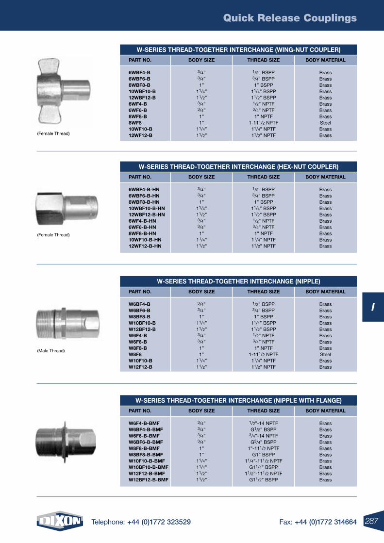
Quick Release Couplings
287Telephone: +44 (0)1772 323529 Fax: +44 (0)1772 314664
I
w-SErIES THrEAD-TOGETHEr INTErCHANGE (wING-NUT COUPLEr)
PArT NO. BODY SIzE THrEAD SIzE BODY MATErIAL 6wBF4-B 3/4” 1/2” BSPP Brass 6wBF6-B 3/4” 3/4” BSPP Brass 8wBF8-B 1” 1” BSPP Brass 10wBF10-B 11/4” 11/4” BSPP Brass 12wBF12-B 11/2” 11/2” BSPP Brass 6wF4-B 3/4” 1/2” NPTF Brass 6wF6-B 3/4” 3/4” NPTF Brass 8wF8-B 1” 1” NPTF Brass 8wF8 1” 1-111/2 NPTF Steel 10wF10-B 11/4” 11/4” NPTF Brass 12wF12-B 11/2” 11/2” NPTF Brass
w-SErIES THrEAD-TOGETHEr INTErCHANGE (HEX-NUT COUPLEr)
PArT NO. BODY SIzE THrEAD SIzE BODY MATErIAL 6wBF4-B-HN 3/4” 1/2” BSPP Brass 6wBF6-B-HN 3/4” 3/4” BSPP Brass 8wBF8-B-HN 1” 1” BSPP Brass 10wBF10-B-HN 11/4” 11/4” BSPP Brass 12wBF12-B-HN 11/2” 11/2” BSPP Brass 6wF4-B-HN 3/4” 1/2” NPTF Brass 6wF6-B-HN 3/4” 3/4” NPTF Brass 8wF8-B-HN 1” 1” NPTF Brass 10wF10-B-HN 11/4” 11/4” NPTF Brass 12wF12-B-HN 11/2” 11/2” NPTF Brass
w-SErIES THrEAD-TOGETHEr INTErCHANGE (NIPPLE)
PArT NO. BODY SIzE THrEAD SIzE BODY MATErIAL w6BF4-B 3/4” 1/2” BSPP Brass w6BF6-B 3/4” 3/4” BSPP Brass w8BF8-B 1” 1” BSPP Brass w10BF10-B 11/4” 11/4” BSPP Brass w12BF12-B 11/2” 11/2” BSPP Brass w6F4-B 3/4” 1/2” NPTF Brass w6F6-B 3/4” 3/4” NPTF Brass w8F8-B 1” 1” NPTF Brass w8F8 1” 1-111/2 NPTF Steel w10F10-B 11/4” 11/4” NPTF Brass w12F12-B 11/2” 11/2” NPTF Brass
w-SErIES THrEAD-TOGETHEr INTErCHANGE (NIPPLE wITH FLANGE)
PArT NO. BODY SIzE THrEAD SIzE BODY MATErIAL w6F4-B-BMF 3/4” 1/2”-14 NPTF Brass w6BF4-B-BMF 3/4” G1/2” BSPP Brass w6F6-B-BMF 3/4” 3/4”-14 NPTF Brass w6BF6-B-BMF 3/4” G3/4” BSPP Brass w8F8-B-BMF 1” 1”-111/2 NPTF Brass w8BF8-B-BMF 1” G1” BSPP Brass w10F10-B-BMF 11/4” 11/4”-111/2 NPTF Brass w10BF10-B-BMF 11/4” G11/4” BSPP Brass w12F12-B-BMF 11/2” 11/2”-111/2 NPTF Brass w12BF12-B-BMF 11/2” G11/2” BSPP Brass
(Female Thread)
(Female Thread)
(Male Thread)
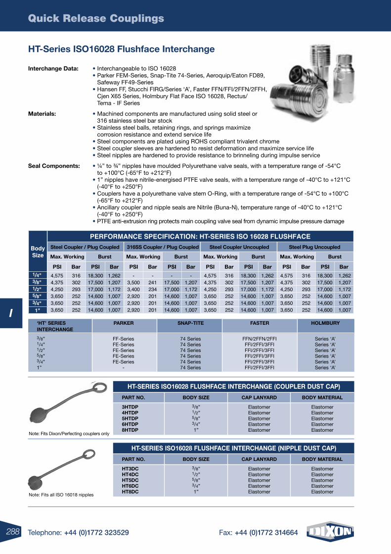
Quick Release Couplings
288 Telephone: +44 (0)1772 323529 Fax: +44 (0)1772 314664
I
HT-Series ISO16028 Flushface Interchange
HT-SErIES ISO16028 FLUSHFACE INTErCHANGE (NIPPLE DUST CAP)
PArT NO. BODY SIzE CAP LANYArD BODY MATErIAL
HT3DC 3/8” Elastomer Elastomer HT4DC 1/2” Elastomer Elastomer HT5DC 5/8” Elastomer Elastomer HT6DC 3/4” Elastomer Elastomer HT8DC 1” Elastomer Elastomer
HT-SErIES ISO16028 FLUSHFACE INTErCHANGE (COUPLEr DUST CAP)
PArT NO. BODY SIzE CAP LANYArD BODY MATErIAL
3HTDP 3/8” Elastomer Elastomer 4HTDP 1/2” Elastomer Elastomer 5HTDP 5/8” Elastomer Elastomer 6HTDP 3/4” Elastomer Elastomer 8HTDP 1” Elastomer Elastomer
Note: Fits Dixon/Perfecting couplers only
Note: Fits all ISO 16018 nipples
Interchange Data: • Interchangeable to ISO 16028 • Parker FEM-Series, Snap-Tite 74-Series, Aeroquip/Eaton FD89,
Safeway FF49-Series • Hansen FF, Stucchi FIRG/Series ‘A’, Faster FFN/FFI/2FFN/2FFH,
Cjen X65 Series, Holmbury Flat Face ISO 16028, Rectus/ Tema - IF Series
Materials: • Machined components are manufactured using solid steel or 316 stainless steel bar stock
• Stainless steel balls, retaining rings, and springs maximize corrosion resistance and extend service life
• Steel components are plated using ROHS compliant trivalent chrome • Steel coupler sleeves are hardened to resist deformation and maximize service life • Steel nipples are hardened to provide resistance to brinneling during impulse service
Seal Components: • ¼” to ¾” nipples have moulded Polyurethane valve seals, with a temperature range of -54°C to +100°C (-65°F to +212°F)
• 1” nipples have nitrile-energised PTFE valve seals, with a temperature range of -40°C to +121°C (-40°F to +250°F)
• Couplers have a polyurethane valve stem O-Ring, with a temperature range of -54°C to +100°C (-65°F to +212°F)
• Ancillary coupler and nipple seals are Nitrile (Buna-N), temperature range of -40°C to +121°C (-40°F to +250°F)
• PTFE anti-extrusion ring protects main coupling valve seal from dynamic impulse pressure damage
3/8” FF-Series 74 Series FFN/2FFN/2FFI Series ‘A’ 1/4” FE-Series 74 Series FFI/2FFI/3FFI Series ‘A’ 1/2” FE-Series 74 Series FFI/2FFI/3FFI Series ‘A’ 5/8” FE-Series 74 Series FFI/2FFI/3FFI Series ‘A’ 3/4” FE-Series 74 Series FFI/2FFI/3FFI Series ‘A’ 1” - 74 Series FFI/2FFI/3FFI Series ‘A’
‘HT’ SErIES PArKEr SNAP-TITE FASTEr HOLMBUrY INTErCHANGE
BodySize
PERFORMANCE SPECIFICATION: HT-SERIES ISO 16028 FLUSHFACESteel Coupler / Plug Coupled 316SS Coupler / Plug Coupled Steel Coupler Uncoupled Steel Plug Uncoupled
1/4"3/8"
4,575 316 18,300 1,262 - - - - 4,575 316 18,300 1,262 4,575 316 18,300 1,2624,375 302 17,500 1,207 3,500 241 17,500 1,207 4,375 302 17,500 1,207 4,375 302 17,500 1,2074,250 293 17,000 1,172 3,400 234 17,000 1,172 4,250 293 17,000 1,172 4,250 293 17,000 1,1723,650 252 14,600 1,007 2,920 201 14,600 1,007 3,650 252 14,600 1,007 3,650 252 14,600 1,0073,650 252 14,600 1,007 2,920 201 14,600 1,007 3,650 252 14,600 1,007 3,650 252 14,600 1,0073,650 252 14,600 1,007 2,920 201 14,600 1,007 3,650 252 14,600 1,007 3,650 252 14,600 1,007
1/2"5/8"3/4"1"
Max. Working Burst Max. Working Burst Max. Working Burst Max. Working Burst
PSI Bar PSI Bar PSI Bar PSI Bar PSI Bar PSI Bar PSI Bar PSI Bar
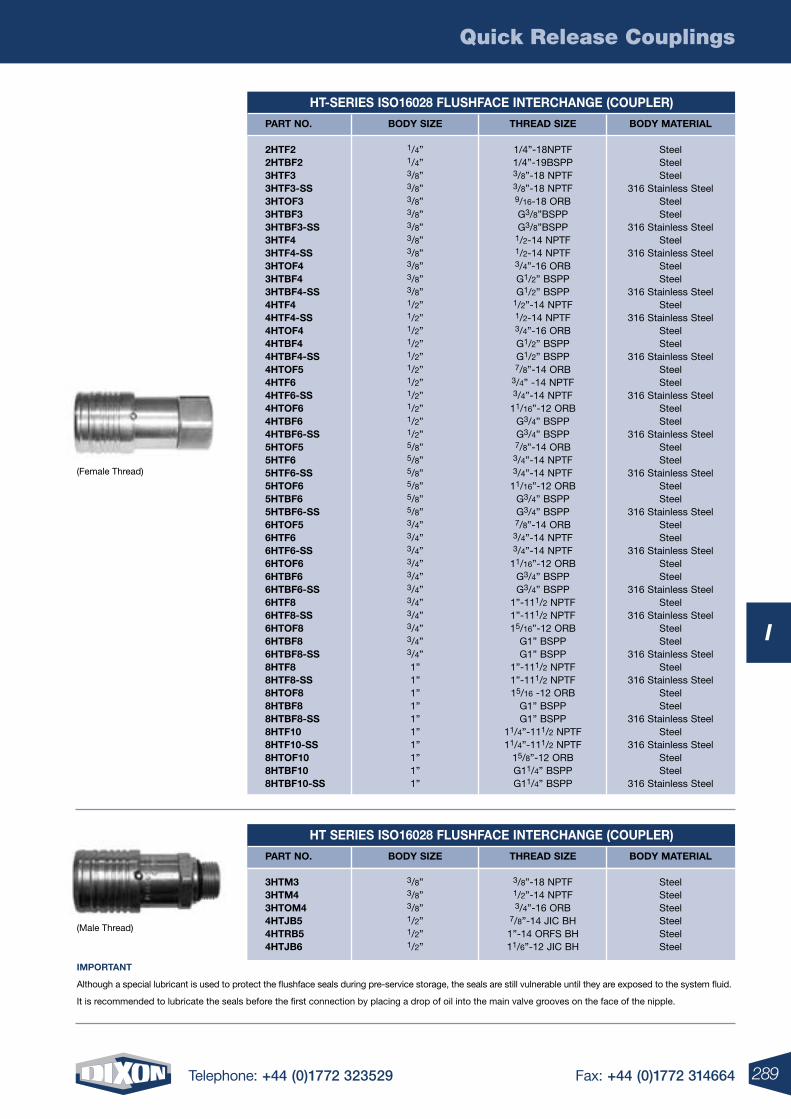
Quick Release Couplings
289Telephone: +44 (0)1772 323529 Fax: +44 (0)1772 314664
I
(Female Thread)
(Male Thread)
IMPOrTANT
Although a special lubricant is used to protect the flushface seals during pre-service storage, the seals are still vulnerable until they are exposed to the system fluid.
It is recommended to lubricate the seals before the first connection by placing a drop of oil into the main valve grooves on the face of the nipple.
HT-SErIES ISO16028 FLUSHFACE INTErCHANGE (COUPLEr)
PArT NO. BODY SIzE THrEAD SIzE BODY MATErIAL 2HTF2 1/4” 1/4”-18NPTF Steel 2HTBF2 1/4” 1/4”-19BSPP Steel 3HTF3 3/8” 3/8”-18 NPTF Steel 3HTF3-SS 3/8” 3/8”-18 NPTF 316 Stainless Steel 3HTOF3 3/8” 9/16-18 ORB Steel 3HTBF3 3/8” G3/8”BSPP Steel 3HTBF3-SS 3/8” G3/8”BSPP 316 Stainless Steel 3HTF4 3/8” 1/2-14 NPTF Steel 3HTF4-SS 3/8” 1/2-14 NPTF 316 Stainless Steel 3HTOF4 3/8” 3/4”-16 ORB Steel 3HTBF4 3/8” G1/2” BSPP Steel 3HTBF4-SS 3/8” G1/2” BSPP 316 Stainless Steel 4HTF4 1/2” 1/2”-14 NPTF Steel 4HTF4-SS 1/2” 1/2-14 NPTF 316 Stainless Steel 4HTOF4 1/2” 3/4”-16 ORB Steel 4HTBF4 1/2” G1/2” BSPP Steel 4HTBF4-SS 1/2” G1/2” BSPP 316 Stainless Steel 4HTOF5 1/2” 7/8”-14 ORB Steel 4HTF6 1/2” 3/4” -14 NPTF Steel 4HTF6-SS 1/2” 3/4”-14 NPTF 316 Stainless Steel 4HTOF6 1/2” 11/16”-12 ORB Steel 4HTBF6 1/2” G3/4” BSPP Steel 4HTBF6-SS 1/2” G3/4” BSPP 316 Stainless Steel 5HTOF5 5/8” 7/8”-14 ORB Steel 5HTF6 5/8” 3/4”-14 NPTF Steel 5HTF6-SS 5/8” 3/4”-14 NPTF 316 Stainless Steel 5HTOF6 5/8” 11/16”-12 ORB Steel 5HTBF6 5/8” G3/4” BSPP Steel 5HTBF6-SS 5/8” G3/4” BSPP 316 Stainless Steel 6HTOF5 3/4” 7/8”-14 ORB Steel 6HTF6 3/4” 3/4”-14 NPTF Steel 6HTF6-SS 3/4” 3/4”-14 NPTF 316 Stainless Steel 6HTOF6 3/4” 11/16”-12 ORB Steel 6HTBF6 3/4” G3/4” BSPP Steel 6HTBF6-SS 3/4” G3/4” BSPP 316 Stainless Steel 6HTF8 3/4” 1”-111/2 NPTF Steel 6HTF8-SS 3/4” 1”-111/2 NPTF 316 Stainless Steel 6HTOF8 3/4” 15/16”-12 ORB Steel 6HTBF8 3/4” G1” BSPP Steel 6HTBF8-SS 3/4” G1” BSPP 316 Stainless Steel 8HTF8 1” 1”-111/2 NPTF Steel 8HTF8-SS 1” 1”-111/2 NPTF 316 Stainless Steel 8HTOF8 1” 15/16 -12 ORB Steel 8HTBF8 1” G1” BSPP Steel 8HTBF8-SS 1” G1” BSPP 316 Stainless Steel 8HTF10 1” 11/4”-111/2 NPTF Steel 8HTF10-SS 1” 11/4”-111/2 NPTF 316 Stainless Steel 8HTOF10 1” 15/8”-12 ORB Steel 8HTBF10 1” G11/4” BSPP Steel 8HTBF10-SS 1” G11/4” BSPP 316 Stainless Steel
HT SErIES ISO16028 FLUSHFACE INTErCHANGE (COUPLEr)
PArT NO. BODY SIzE THrEAD SIzE BODY MATErIAL 3HTM3 3/8” 3/8”-18 NPTF Steel 3HTM4 3/8” 1/2”-14 NPTF Steel 3HTOM4 3/8” 3/4”-16 ORB Steel 4HTJB5 1/2” 7/8”-14 JIC BH Steel 4HTrB5 1/2” 1”-14 ORFS BH Steel 4HTJB6 1/2” 11/6”-12 JIC BH Steel
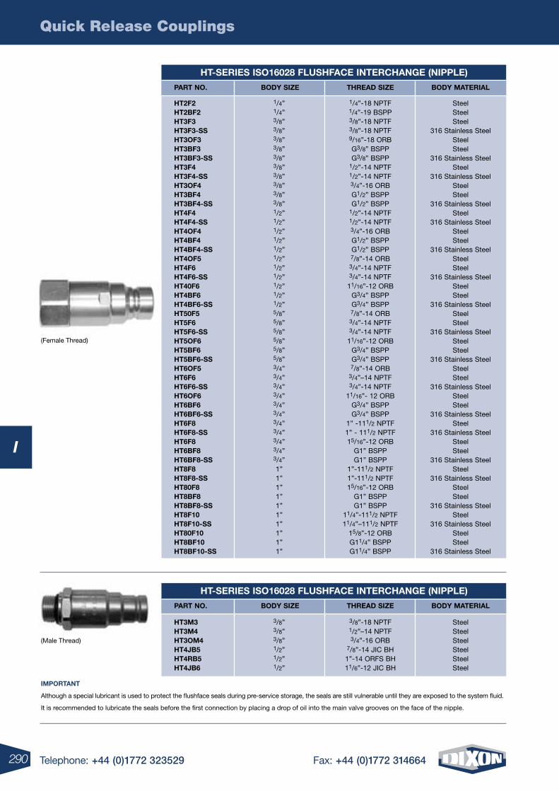
Quick Release Couplings
290 Telephone: +44 (0)1772 323529 Fax: +44 (0)1772 314664
I
IMPOrTANT
Although a special lubricant is used to protect the flushface seals during pre-service storage, the seals are still vulnerable until they are exposed to the system fluid.
It is recommended to lubricate the seals before the first connection by placing a drop of oil into the main valve grooves on the face of the nipple.
HT-SErIES ISO16028 FLUSHFACE INTErCHANGE (NIPPLE)
(Female Thread)
(Male Thread)
PArT NO. BODY SIzE THrEAD SIzE BODY MATErIAL
HT-SErIES ISO16028 FLUSHFACE INTErCHANGE (NIPPLE)
PArT NO. BODY SIzE THrEAD SIzE BODY MATErIAL
HT3M3 3/8” 3/8”-18 NPTF Steel HT3M4 3/8” 1/2”–14 NPTF Steel HT3OM4 3/8” 3/4”-16 ORB Steel HT4JB5 1/2” 7/8”-14 JIC BH Steel HT4rB5 1/2” 1”-14 ORFS BH Steel HT4JB6 1/2” 11/6”-12 JIC BH Steel
HT2F2 1/4” 1/4”-18 NPTF Steel HT2BF2 1/4” 1/4”-19 BSPP Steel HT3F3 3/8” 3/8”-18 NPTF Steel HT3F3-SS 3/8” 3/8”-18 NPTF 316 Stainless Steel HT3OF3 3/8” 9/16”-18 ORB Steel HT3BF3 3/8” G3/8” BSPP Steel HT3BF3-SS 3/8” G3/8” BSPP 316 Stainless Steel HT3F4 3/8” 1/2”-14 NPTF Steel HT3F4-SS 3/8” 1/2”-14 NPTF 316 Stainless Steel HT3OF4 3/8” 3/4”-16 ORB Steel HT3BF4 3/8” G1/2” BSPP Steel HT3BF4-SS 3/8” G1/2” BSPP 316 Stainless Steel HT4F4 1/2” 1/2”-14 NPTF Steel HT4F4-SS 1/2” 1/2”-14 NPTF 316 Stainless Steel HT4OF4 1/2” 3/4”-16 ORB Steel HT4BF4 1/2” G1/2” BSPP Steel HT4BF4-SS 1/2” G1/2” BSPP 316 Stainless Steel HT4OF5 1/2” 7/8”-14 ORB Steel HT4F6 1/2” 3/4”-14 NPTF Steel HT4F6-SS 1/2” 3/4”-14 NPTF 316 Stainless Steel HT40F6 1/2” 11/16”-12 ORB Steel HT4BF6 1/2” G3/4” BSPP Steel HT4BF6-SS 1/2” G3/4” BSPP 316 Stainless Steel HT50F5 5/8” 7/8”-14 ORB Steel HT5F6 5/8” 3/4”-14 NPTF Steel HT5F6-SS 5/8” 3/4”-14 NPTF 316 Stainless Steel HT5OF6 5/8” 11/16”-12 ORB Steel HT5BF6 5/8” G3/4” BSPP Steel HT5BF6-SS 5/8” G3/4” BSPP 316 Stainless Steel HT6OF5 3/4” 7/8”-14 ORB Steel HT6F6 3/4” 3/4”–14 NPTF Steel HT6F6-SS 3/4” 3/4”-14 NPTF 316 Stainless Steel HT6OF6 3/4” 11/16”- 12 ORB Steel HT6BF6 3/4” G3/4” BSPP Steel HT6BF6-SS 3/4” G3/4” BSPP 316 Stainless Steel HT6F8 3/4” 1” -111/2 NPTF Steel HT6F8-SS 3/4” 1” - 111/2 NPTF 316 Stainless Steel HT6F8 3/4” 15/16”-12 ORB Steel HT6BF8 3/4” G1” BSPP Steel HT6BF8-SS 3/4” G1” BSPP 316 Stainless Steel HT8F8 1” 1”-111/2 NPTF Steel HT8F8-SS 1” 1”-111/2 NPTF 316 Stainless Steel HT80F8 1” 15/16”-12 ORB Steel HT8BF8 1” G1” BSPP Steel HT8BF8-SS 1” G1” BSPP 316 Stainless Steel HT8F10 1” 11/4”-111/2 NPTF Steel HT8F10-SS 1” 11/4”–111/2 NPTF 316 Stainless Steel HT80F10 1” 15/8”-12 ORB Steel HT8BF10 1” G11/4” BSPP Steel HT8BF10-SS 1” G11/4” BSPP 316 Stainless Steel
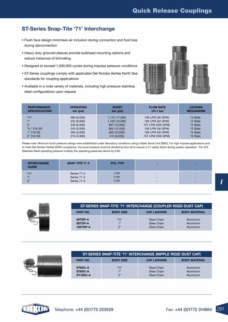
Quick Release Couplings
291Telephone: +44 (0)1772 323529 Fax: +44 (0)1772 314664
I
ST-Series Snap-Tite ‘71’ Interchange
• Flush face design minimises air inclusion during connection and fluid loss
during disconnection
• Heavy duty grooved sleeves provide bulkhead mounting options and
reduce instances of brinneling
• Designed to exceed 1,000,000 cycles during impulse pressure conditions
• ST-Series couplings comply with applicable Det Norske Veritas North Sea
standards for coupling applications
• Available in a wide variety of materials, including high pressure stainless
steel configurations upon request
Please note: Minimum burst pressure ratings were established under laboratory conditions using a Static Burst Unit (SBU). For high impulse applications and to meet Det Norske Veritas (DNV) compliance, the burst pressure must be divided by four (4) to ensure a 4:1 safety factor during system operation. For 316 Stainless Steel operating pressure multiply the operating pressures above by 0.60.
3/4” 586 (8,500) 1,172 (17,000) 138 LPM (36 GPM) 12 Balls 1” 552 (8,000) 1,103 (16,000) 189 LPM (50 GPM) 12 Balls 2” 448 (6,500) 897 (13,000) 757 LPM (200 GPM) 12 Balls 3/4” 316 SS 345 (5,000) 865 (12,500) 138 LPM (36 GPM) 12 Balls 1” 316 SS 280 (4,000) 690 (10,000) 189 LPM (50 GPM) 12 Balls 2” 316 SS 210 (3,000) 415 (6,000) 757 LPM (200 GPM) 12 Balls
3/4” Series 71-3 71FF - - 1” Series 71-3 71FF - - 2” Series 71-3 71FF - -
PErFOrMANCE OPErATING BUrST FLOw rATE LOCKING SPECIFICATIONS bar (psi) bar (psi) DP=1 bar MECHANISM
INTErCHANGE SNAP-TITE 71-3 PCL 71FF - - GUIDE
ST-SErIES SNAP-TITE ‘71’ INTErCHANGE (COUPLEr rIGID DUST CAP)
ST-SErIES SNAP-TITE ‘71’ INTErCHANGE (NIPPLE rIGID DUST CAP)
PArT NO. BODY SIzE CAP LANYArD BODY MATErIAL 6STDP-A 3/4” Steel Chain Aluminium 8STDP-A 1” Steel Chain Aluminium 16STDP-A 2” Steel Chain Aluminium
PArT NO. BODY SIzE CAP LANYArD BODY MATErIAL ST6DC-A 3/4” Steel Chain Aluminium ST8DC-A 1” Steel Chain Aluminium ST16DC-A 2” Steel Chain Aluminium
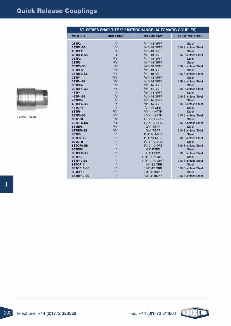
Quick Release Couplings
292 Telephone: +44 (0)1772 323529 Fax: +44 (0)1772 314664
I
(Female Thread)
ST–SErIES SNAP-TITE ‘71’ INTErCHANGE (AUTOMATIC COUPLEr)
PArT NO. BODY SIzE THrEAD SIzE BODY MATErIAL 2STF2 1/4” 1/4”- 18 NPTF Steel 2STF2-SS 1/4” 1/4”- 18 NPTF 316 Stainless Steel 2STBF2 1/4” 1/4”- 19 BSPP Steel 2STBF2-SS 1/4” 1/4”- 19 BSPP 316 Stainless Steel 3STF2 3/8” 1/4”- 18 NPTF Steel 3STF3 3/8” 3/8”- 18 NPTF Steel 3STF3-SS 3/8” 3/8”- 18 NPTF 316 Stainless Steel 3STBF3 3/8” 3/8”- 19 BSPP Steel 3STBF3-SS 3/8” 3/8”- 19 BSPP 316 Stainless Steel 3STF4 3/8” 1/2”- 14 NPTF Steel 3STF4-SS 3/8” 1/2”- 14 NPTF 316 Stainless Steel 3STBF4 3/8” 1/2”- 14 BSPP Steel 3STBF4-SS 3/8” 1/2”- 14 BSPP 316 Stainless Steel 4STF4 1/2” 1/2”- 14 NPTF Steel 4STF4-SS 1/2” 1/2”- 14 NPTF 316 Stainless Steel 4STBF4 1/2” 1/2”- 14 BSPP Steel 4STBF4-SS 1/2” 1/2”- 14 BSPP 316 Stainless Steel 4STOF4 1/2” 3/4”-16 ORB Steel 6STF6 3/4” 3/4”-14 NPTF Steel 6STF6-SS 3/4” 3/4”-14 NPTF 316 Stainless Steel 6STOF6 3/4” 11/16”-12 ORB Steel 6STOF6-SS 3/4” 11/16”-12 ORB 316 Stainless Steel 6STBF6 3/4” G3/4”BSPP Steel 6STBF6-SS 3/4” G3/4”BSPP 316 Stainless Steel 8STF8 1” 1”-111/2 NPTF Steel 8STF8-SS 1” 1”-111/2 NPTF 316 Stainless Steel 8STOF8 1” 15/16”-12 ORB Steel 8STOF8-SS 1” 15/16”-12 ORB 316 Stainless Steel 8STBF8 1” G1” BSPP Steel 8STBF8-SS 1” G1” BSPP 316 Stainless Steel 8STF10 1” 11/4”-111/2 NPTF Steel 8STF10-SS 1” 11/4”-111/2 NPTF 316 Stainless Steel 8STOF10 1” 15/8”-12 ORB Steel 8STOF10-SS 1” 15/8”-12 ORB 316 Stainless Steel 8STBF10 1” G11/4” BSPP Steel 8STBF10-SS 1” G11/4” BSPP 316 Stainless Steel
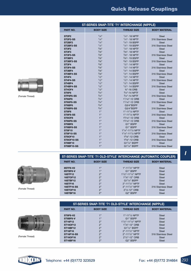
Quick Release Couplings
293Telephone: +44 (0)1772 323529 Fax: +44 (0)1772 314664
I
ST-SErIES SNAP-TITE ‘71’ INTErCHANGE (NIPPLE)
PArT NO. BODY SIzE THrEAD SIzE BODY MATErIAL ST2F2 1/4” 1/4”- 18 NPTF Steel ST2F2-SS 1/4” 1/4”- 18 NPTF 316 Stainless Steel ST2BF2 1/4” 1/4”- 19 BSPP Steel ST2BF2-SS 1/4” 1/4”- 19 BSPP 316 Stainless Steel ST3F2 3/8” 1/4”- 18 NPTF Steel ST3F3 3/8” 3/8”- 18 NPTF Steel ST3F3-SS 3/8” 3/8”- 18 NPTF 316 Stainless Steel ST3BF3 3/8” 3/8”- 19 BSPP Steel ST3BF3-SS 3/8” 3/8”- 19 BSPP 316 Stainless Steel ST3F4 3/8” 1/2”- 14 NPTF Steel ST3F4-SS 3/8” 1/2”- 14 NPTF 316 Stainless Steel ST3BF4 3/8” 1/2”- 14 BSPP Steel ST3BF4-SS 3/8” 1/2”- 14 BSPP 316 Stainless Steel ST4F4 1/2” 1/2”- 14 NPTF Steel ST4F4-SS 1/2” 1/2”- 14 NPTF 316 Stainless Steel ST4BF4 1/2” 1/2”- 14 BSPP Steel ST4BF4-SS 1/2” 1/2”- 14 BSPP 316 Stainless Steel ST4OF4 1/2” ¾”-16 ORB Steel ST6F6 3/4” 3/4”-14 NPTF Steel STF6F6-SS 3/4” 3/4”-14 NPTF 316 Stainless Steel ST60F6 3/4” 11/16”-12 ORB Steel ST60F6-SS 3/4” 11/16”-12 ORB 316 Stainless Steel ST6BF6 3/4” G3/4”BSPP Steel ST6BF6-SS 3/4” G3/4”BSPP 316 Stainless Steel ST8F8 1” 1”-111/2 NPTF Steel ST8F8-SS 1” 1”-111/2 NPTF 316 Stainless Steel ST8OF8 1” 15/16”-12 ORB Steel ST80F8-SS 1” 15/16”-12 ORB 316 Stainless Steel ST8BF8 1” G1” BSPP Steel ST8BF8-SS 1” G1” BSPP 316 Stainless Steel ST8F10 1” 11/4”-111/2 NPTF Steel ST8F10-SS 1” 11/4”-111/2 NPTF 316 Stainless Steel ST8OF10 1” 15/8”-12 ORB Steel ST8OF10-SS 1” 15/8”-12 ORB 316 Stainless Steel ST8BF10 1” G11/4” BSPP Steel ST8BF10-SS 1” G11/4” BSPP 316 Stainless Steel
ST-SErIES SNAP-TITE ‘71 OLD-STYLE’ INTErCHANGE (AUTOMATIC COUPLEr)
PArT NO. BODY SIzE THrEAD SIzE BODY MATErIAL 8STF8-V2 1” 1”-111/2” NPTF Steel 8STBF8-V 1” G1” BSPP Steel 16STF12 2” 11/2”-111/2” NPTF Steel 16STOF12 2” 17/8”-12” ORB Steel 16STBF12 2” G11/4” BSPP Steel 16STF16 2” 2”-111/2” NPTF Steel 16STF16-SS 2” 2”-111/2” NPTF 316 Stainless Steel 16STOF16 2” 21/2-12” ORB Steel 16STBF16 2” G2” BSPP Steel
ST-SErIES SNAP-TITE ‘71 OLD-STYLE’ INTErCHANGE (NIPPLE)
PArT NO. BODY SIzE THrEAD SIzE BODY MATErIAL ST8F8-V2 1” 1”-111/2 NPTF Steel ST8BF8-V 1” G1” BSPP Steel ST16F12 2” 11/2”-111/2” NPTF Steel ST16OF12 2” 17/8”-12” ORB Steel ST16BF12 2” G11/4” BSPP Steel ST16F16 2” 2”-111/2” NPTF Steel ST16F16-SS 2” 2”-111/2” NPTF 316 Stainless Steel ST16OF16 2” 21/2”-12” ORB Steel ST16BF16 2” G2” BSPP Steel
(Female Thread)
(Female Thread)
(Female Thread)
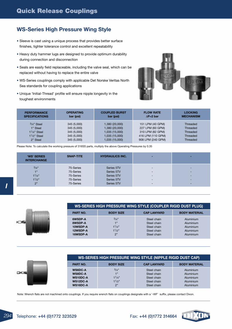
Quick Release Couplings
294 Telephone: +44 (0)1772 323529 Fax: +44 (0)1772 314664
I
wS-SErIES HIGH PrESSUrE wING STYLE (COUPLEr rIGID DUST PLUG)
wS-SErIES HIGH PrESSUrE wING STYLE (NIPPLE rIGID DUST CAP)
Note: Wrench flats are not machined onto couplings. If you require wrench flats on couplings designate with a ‘-WF’ suffix, please contact Dixon.
wS-Series High Pressure wing Style
• Sleeve is cast using a unique process that provides better surface
finishes, tighter tolerance control and excellent repeatability
• Heavy duty hammer lugs are designed to provide optimum durability
during connection and disconnection
• Seals are easily field replaceable, including the valve seal, which can be
replaced without having to replace the entire valve
• WS-Series couplings comply with applicable Det Norske Veritas North
Sea standards for coupling applications
• Unique ‘Initial-Thread’ profile will ensure nipple longevity in the
toughest environments
Please Note: To calculate the working pressure of 316SS parts, multiply the above Operating Pressures by 0.35
LOCKINGMECHANISM
ThreadedThreadedThreadedThreadedThreaded
FLOw rATE DP=2 bar
151 LPM (40 GPM)227 LPM (60 GPM)310 LPM (82 GPM)416 LPM (110 GPM)908 LPM (240 GPM)
PErFOrMANCESPECIFICATIONS
3/4” Steel1” Steel
11/4” Steel11/2” Steel
2” Steel
COUPLED BUrSTbar (psi)
1,380 (20,000)1,380 (20,000)1,035 (15,000)1,035 (15,000)1,035 (15,000)
OPErATINGbar (psi)
345 (5,000)345 (5,000)345 (5,000)345 (5,000)345 (5,000)
-
-----
-
-----
‘wS’ SErIESINTErCHANGE
3/4”1”
11/4”11/2”
2”
HYDrAULICS INC.
Series 5TVSeries 5TVSeries 5TVSeries 5TVSeries 5TV
SNAP-TITE
75-Series75-Series75-Series75-Series75-Series
6wSDP-A8wSDP-A10wSDP-A12wSDP-A16wSDP-A
3/4”1”
11/4”11/2”
2”
Steel chainSteel chainSteel chainSteel chainSteel chain
AluminiumAluminiumAluminiumAluminiumAluminium
PArT NO. BODY SIzE CAP LANYArD BODY MATErIAL
PArT NO. BODY SIzE CAP LANYArD BODY MATErIAL
wS6DC-AwS8DC-AwS10DC-AwS12DC-AwS16DC-A
3/4”1”
11/4”11/2”
2”
Steel chainSteel chainSteel chainSteel chainSteel chain
AluminiumAluminiumAluminiumAluminiumAluminium
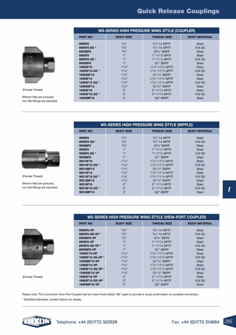
Quick Release Couplings
295Telephone: +44 (0)1772 323529 Fax: +44 (0)1772 314664
I
wS-SErIES HIGH PrESSUrE wING STYLE (COUPLEr)
wS-SErIES HIGH PrESSUrE wING STYLE (NIPPLE)
wS-SErIES HIGH PrESSUrE wING STYLE (VIEw-POrT COUPLEr)
PArT NO. BODY SIzE THrEAD SIzE BODY MATErIAL
PArT NO. BODY SIzE THrEAD SIzE BODY MATErIAL
PArT NO. BODY SIzE THrEAD SIzE BODY MATErIAL
6wSF66wSF6-SS *6wSBF68wSF88wSF8-SS *8wSBF810wSF1010wSF10-SS *10wSBF1012wSF1212wSF12-SS *12wSBF1216wSF1616wSF16-SS *16wSBF16
3/4”-14 NPTF3/4”-14 NPTFG3/4” BSPP
1”-111/2 NPTF1”-111/2 NPTF
G1” BSPP11/4”-111/2 NPTF11/4”-111/2 NPTF
G11/4” BSPP11/2”-111/2 NPTF11/2”-111/2 NPTF
G11/2” BSPP2”-111/2 NPTF2”-111/2 NPTF
G2” BSPP
Steel316 SSSteelSteel
316 SSSteelSteel
316 SSSteelSteel
316 SSSteelSteel
316 SSSteel
wS6F6wS6F6-SS *wS6BF6wS8F8wS8F8-SS *wS8BF8wS10F10wS10F10-SS *wS10BF10wS12F12wS12F12-SS *wS12BF12wS16F16wS16F16-SS *wS16BF16
3/4”-14 NPTF3/4”-14 NPTFG3/4” BSPP
1”-111/2 NPTF1”-111/2 NPTF
G1” BSPP11/4”-111/2 NPTF11/4”-111/2 NPTF
G11/4” BSPP11/2”-111/2 NPTF11/2”-111/2 NPTF
G11/2” BSPP2”-111/2 NPTF2”-111/2 NPTF
G2” BSPP
Steel316 SSSteelSteel
316 SSSteelSteel
316 SSSteelSteel
316 SSSteelSteel
316 SSSteel
6wSF6-VP6wSF6-SS-VP *6wSBF6-VP8wSF8-VP8wSF8-SS-VP *8wSBF8-VP10wSF10-VP10wSF10-SS-VP *10wSBF10-VP12wSF12-VP12wSF12-SS-VP *12wSBF12-VP16wSF16-VP16wSF16-SS-VP *16wSBF16-VP
3/4”3/4”3/4”1”1”1”
11/4”11/4”11/4”11/2”11/2”11/2”
2”2”2”
3/4”3/4”3/4”1”1”1”
11/4”11/4”11/4”11/2”11/2”11/2”
2”2”2”
3/4”3/4”3/4”1”1”1”
11/4”11/4”11/4”11/2”11/2”11/2”
2”2”2”
3/4”-14 NPTF3/4”-14 NPTFG3/4” BSPP
1”-111/2 NPTF1”-111/2 NPTF
G1” BSPP11/4”-111/2 NPTF11/4”-111/2 NPTF
G11/4” BSPP11/2”-111/2 NPTF11/2”-111/2 NPTF
G11/2” BSPP2”-111/2 NPTF2”-111/2 NPTF
G2” BSPP
Steel316 SSSteelSteel
316 SSSteelSteel
316 SSSteelSteel
316 SSSteelSteel
316 SSSteel
(Female Thread)
Wrench flats are pictured, non-flat fittings are standard
(Female Thread)
Wrench flats are pictured, non-flat fittings are standard
Please note: The Connection View-Port Coupler has two View-Ports drilled 180° apart to provide a visual confirmation of complete connection.
* Standard deliveries, contact factory for details.
(Female Thread)
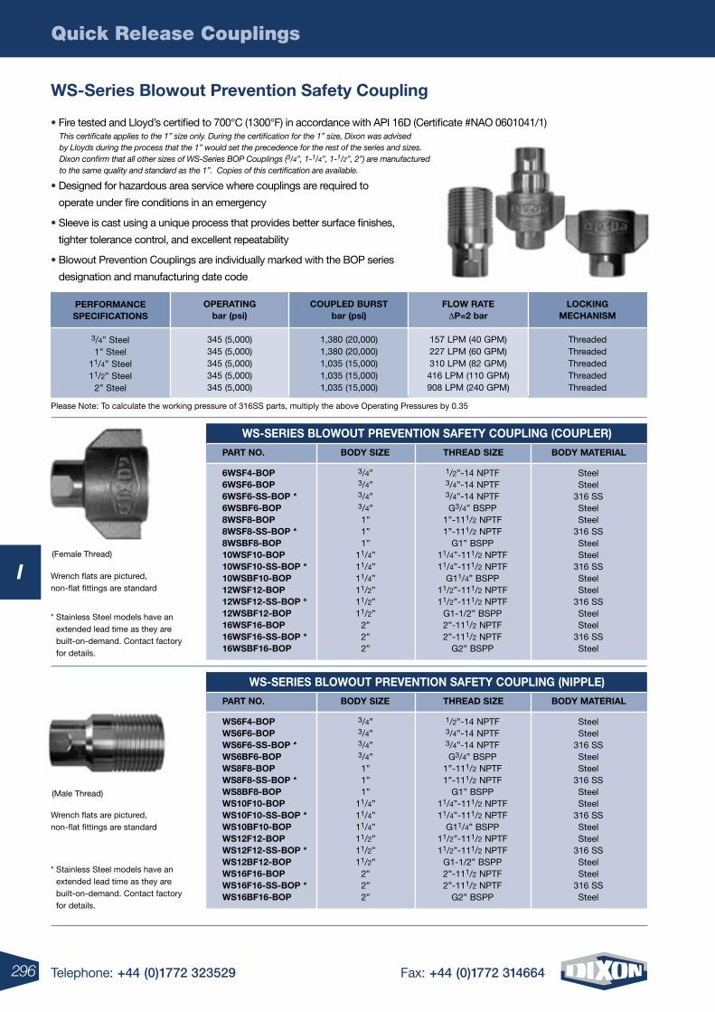
Quick Release Couplings
296 Telephone: +44 (0)1772 323529 Fax: +44 (0)1772 314664
I(Female Thread)
Wrench flats are pictured, non-flat fittings are standard
wS-SErIES BLOwOUT PrEVENTION SAFETY COUPLING (COUPLEr)
PArT NO. BODY SIzE THrEAD SIzE BODY MATErIAL
6wSF4-BOP6wSF6-BOP6wSF6-SS-BOP *6wSBF6-BOP8wSF8-BOP8wSF8-SS-BOP *8wSBF8-BOP10wSF10-BOP10wSF10-SS-BOP *10wSBF10-BOP12wSF12-BOP12wSF12-SS-BOP *12wSBF12-BOP16wSF16-BOP16wSF16-SS-BOP *16wSBF16-BOP
1/2”-14 NPTF3/4”-14 NPTF3/4”-14 NPTFG3/4” BSPP
1”-111/2 NPTF1”-111/2 NPTF
G1” BSPP11/4”-111/2 NPTF11/4”-111/2 NPTF
G11/4” BSPP11/2”-111/2 NPTF11/2”-111/2 NPTF
G1-1/2” BSPP2”-111/2 NPTF2”-111/2 NPTF
G2” BSPP
SteelSteel
316 SSSteelSteel
316 SSSteelSteel
316 SSSteelSteel
316 SSSteelSteel
316 SSSteel
3/4”3/4”3/4”3/4”1”1”1”
11/4”11/4”11/4”11/2”11/2”11/2”
2”2”2”
wS-SErIES BLOwOUT PrEVENTION SAFETY COUPLING (NIPPLE)
PArT NO. BODY SIzE THrEAD SIzE BODY MATErIAL
wS6F4-BOPwS6F6-BOPwS6F6-SS-BOP *wS6BF6-BOPwS8F8-BOPwS8F8-SS-BOP *wS8BF8-BOPwS10F10-BOPwS10F10-SS-BOP *wS10BF10-BOPwS12F12-BOPwS12F12-SS-BOP *wS12BF12-BOPwS16F16-BOPwS16F16-SS-BOP *wS16BF16-BOP
1/2”-14 NPTF3/4”-14 NPTF3/4”-14 NPTFG3/4” BSPP
1”-111/2 NPTF1”-111/2 NPTF
G1” BSPP11/4”-111/2 NPTF11/4”-111/2 NPTF
G11/4” BSPP11/2”-111/2 NPTF11/2”-111/2 NPTF
G1-1/2” BSPP2”-111/2 NPTF2”-111/2 NPTF
G2” BSPP
SteelSteel
316 SSSteelSteel
316 SSSteelSteel
316 SSSteelSteel
316 SSSteelSteel
316 SSSteel
3/4”3/4”3/4”3/4”1”1”1”
11/4”11/4”11/4”11/2”11/2”11/2”
2”2”2”
wS-Series Blowout Prevention Safety Coupling
(Male Thread)
Wrench flats are pictured, non-flat fittings are standard
Please Note: To calculate the working pressure of 316SS parts, multiply the above Operating Pressures by 0.35
* Stainless Steel models have an extended lead time as they are built-on-demand. Contact factory for details.
* Stainless Steel models have an extended lead time as they are built-on-demand. Contact factory for details.
LOCKINGMECHANISM
ThreadedThreadedThreadedThreadedThreaded
FLOw rATE DP=2 bar
157 LPM (40 GPM)227 LPM (60 GPM)310 LPM (82 GPM)416 LPM (110 GPM)908 LPM (240 GPM)
PErFOrMANCESPECIFICATIONS
3/4” Steel1” Steel
11/4” Steel11/2” Steel
2” Steel
COUPLED BUrSTbar (psi)
1,380 (20,000)1,380 (20,000)1,035 (15,000)1,035 (15,000)1,035 (15,000)
OPErATINGbar (psi)
345 (5,000)345 (5,000)345 (5,000)345 (5,000)345 (5,000)
• Fire tested and Lloyd’s certified to 700°C (1300°F) in accordance with API 16D (Certificate #NAO 0601041/1)
• Designed for hazardous area service where couplings are required to
operate under fire conditions in an emergency
• Sleeve is cast using a unique process that provides better surface finishes,
tighter tolerance control, and excellent repeatability
• Blowout Prevention Couplings are individually marked with the BOP series
designation and manufacturing date code
This certificate applies to the 1” size only. During the certification for the 1” size, Dixon was advised by Lloyds during the process that the 1” would set the precedence for the rest of the series and sizes. Dixon confirm that all other sizes of WS-Series BOP Couplings (3/4”, 1-1/4”, 1-1/2”, 2”) are manufactured to the same quality and standard as the 1”. Copies of this certification are available.
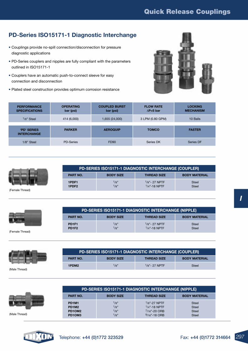
Quick Release Couplings
297Telephone: +44 (0)1772 323529 Fax: +44 (0)1772 314664
I
PD-Series ISO15171-1 Diagnostic Interchange
• Couplings provide no-spill connection/disconnection for pressure
diagnostic applications
• PD-Series couplers and nipples are fully compliant with the parameters
outlined in ISO15171-1
• Couplers have an automatic push-to-connect sleeve for easy
connection and disconnection
• Plated steel construction provides optimum corrosion resistance
(Female Thread)
(Female Thread)
(Male Thread)
(Male Thread)
LOCKINGMECHANISM
10 Balls
FLOw rATE DP=5 bar
3 LPM (0.80 GPM)
PErFOrMANCESPECIFICATIONS
1/8” Steel
COUPLED BUrSTbar (psi)
1,655 (24,000)
OPErATINGbar (psi)
414 (6,000)
FASTEr
Series DF
TOMCO
Series DK
‘PD’ SErIESINTErCHANGE
1/8” Steel
AErOQUIP
FD90
PArKEr
PD-Series
PD-SErIES ISO15171-1 DIAGNOSTIC INTErCHANGE (COUPLEr)
PArT NO. BODY SIzE THrEAD SIzE BODY MATErIAL
1PDF11PDF2
1/8”- 27 NPTF1/4”-18 NPTF
SteelSteel
1/8”1/8”
PD-SErIES ISO15171-1 DIAGNOSTIC INTErCHANGE (NIPPLE)
PArT NO. BODY SIzE THrEAD SIzE BODY MATErIAL
PD1F1PD1F2
1/8”- 27 NPTF1/4”-18 NPTF
SteelSteel
1/8”1/8”
PD-SErIES ISO15171-1 DIAGNOSTIC INTErCHANGE (NIPPLE)
PArT NO. BODY SIzE THrEAD SIzE BODY MATErIAL
PD1M1PD1M2PD1OM2PD1OM3
1/8”-27 NPTF1/4”-18 NPTF7/16”-20 ORB9/16”-18 ORB
SteelSteelSteelSteel
1/8”1/8”1/8”1/8”
PD-SErIES ISO15171-1 DIAGNOSTIC INTErCHANGE (COUPLEr)
PArT NO. BODY SIzE THrEAD SIzE BODY MATErIAL
1PDM2 1/8”- 27 NPTF Steel1/8”
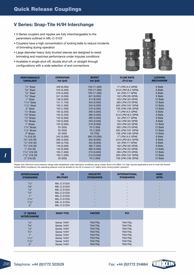
Quick Release Couplings
298 Telephone: +44 (0)1772 323529 Fax: +44 (0)1772 314664
I
V Series: Snap-Tite H/IH Interchange
LOCKINGMECHANISM
6 Balls6 Balls9 Balls9 Balls12 Balls12 Balls12 Balls12 Balls6 Balls6 Balls9 Balls9 Balls12 Balls12 Balls12 Balls12 Balls6 Balls6 Balls9 Balls9 Balls12 Balls12 Balls12 Balls12 Balls
FLOw rATEDP=2 bar
17 LPM (4.5 GPM)24.6 LPM (6.5 GPM)
64 LPM (17 GPM)132 LPM (35 GPM)163 LPM (43 GPM)265 LPM (70 GPM)405 LPM (107 GPM)738 LPM (195 GPM)17 LPM (4.5 GPM)
24.6 LPM (6.5 GPM)64 LPM (17 GPM)132 LPM (35 GPM)163 LPM (43 GPM)265 LPM (70 GPM)405 LPM (107 GPM)738 LPM (195 GPM)17 LPM (4.5 GPM)
24.6 LPM (6.5 GPM)64 LPM (17 GPM)132 LPM (35 GPM)163 LPM (43 GPM)265 LPM (70 GPM)405 LPM (107 GPM)738 LPM (195 GPM)
PErFOrMANCE‘UNVALVED’
1/4” Steel3/8” Steel1/2” Steel3/4” Steel1” Steel
11/4” Steel11/2” Steel
2” Steel1/4” Brass3/8” Brass1/2” Brass3/4” Brass1” Brass
11/4” Brass11/2” Brass
2” Brass1/4 316 SS3/8” 316 SS1/2” 316 SS3/4” 316 SS1” 316 SS
11/4” 316 SS11/2” 316 SS
2” 316 SS
BUrSTbar (psi)
759 (11,000)759 (11,000)759 (11,000)621 (9,000)414 (6,000)345 (5,000)345 (5,000)276 (4,000)280 (4,000)280 (4,000)280 (4,000)245 (3,500)210 (3,000)70 (1,000)70 (1,000)55 (750)
690 (10,000)555 (8,000)555 (8,000)485 (7,000)280 (4,000)210 (3,000)210 (3,000)70 (1,000)
OPErATINGbar (psi)
448 (6,500)310 (4,500)276 (4,000)241 (3,500)138 (2,000)121 (1,750)103 (1,500)103 (1,500)155 (2,250)155 (2,250)140 (2,000)140 (2,000)125 (2,000)
25 (350)25 (350)25 (400)
345 (5,000)280 (4,000)260 (3,750)140 (2,000)140 (2,000)105 (1,500)105 (1,500)
35 (500)
ANSI/NFPA
--------
INTErNATIONALSTANDArDS
--------
INTErCHANGESTANDArDS
1/4”3/8”1/2”3/4”1”
11/4”11/2”
2”
INDUSTrYSTANDArDS
--------
USMILITArY
MIL-C-51234MIL-C-51234MIL-C-51234MIL-C-51234MIL-C-51234MIL-C-51234MIL-C-51234MIL-C-51234
PCI
TNV/TNLTNV/TNLTNV/TNLTNV/TNLTNV/TNLTNV/TNLTNV/TNLTNV/TNL
‘V’ SErIESINTErCHANGE
1/4”3/8”1/2”3/4”1”
11/4”11/2”
2”
FASTEr
TNV/TNLTNV/TNLTNV/TNLTNV/TNLTNV/TNLTNV/TNLTNV/TNLTNV/TNL
SNAP-TITE
Series ‘H/IH’Series ‘H/IH’Series ‘H/IH’Series ‘H/IH’Series ‘H/IH’Series ‘H/IH’Series ‘H/IH’Series ‘H/IH’
Please note: Minimum burst pressure ratings were established under laboratory conditions using a Static Burst Unit (SBU). For high impulse applications and to meet Det Norske Veritas (DNV) compliance, the operating pressure must be divided by two (2) to ensure a 4:1 safety factor during system operation.
• V-Series couplers and nipples are fully interchangeable to the parameters outlined in MIL-C-5123
• Couplers have a high concentration of locking balls to reduce incidents of brinneling during operation
• Large diameter heavy duty knurled sleeves are designed to resist brinneling and maximise performance under impulse conditions
• Available in single shut-off, double shut-off, or straight through configurations with a wide selection of end connections
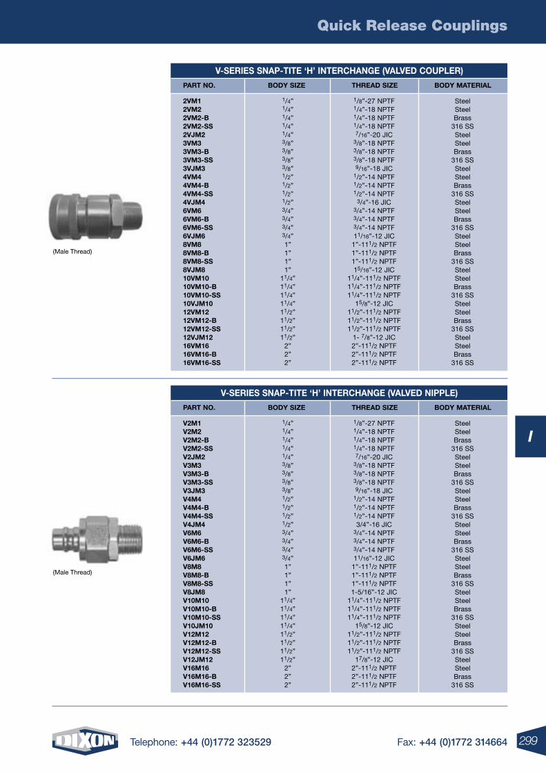
Quick Release Couplings
299Telephone: +44 (0)1772 323529 Fax: +44 (0)1772 314664
I
V-SErIES SNAP-TITE ‘H’ INTErCHANGE (VALVED COUPLEr)
PArT NO. BODY SIzE THrEAD SIzE BODY MATErIAL
2VM1 2VM22VM2-B2VM2-SS2VJM23VM33VM3-B3VM3-SS3VJM34VM44VM4-B4VM4-SS4VJM46VM66VM6-B6VM6-SS6VJM68VM88VM8-B8VM8-SS8VJM810VM1010VM10-B10VM10-SS10VJM1012VM1212VM12-B12VM12-SS12VJM1216VM1616VM16-B16VM16-SS
1/8”-27 NPTF1/4”-18 NPTF1/4”-18 NPTF1/4”-18 NPTF7/16”-20 JIC
3/8”-18 NPTF3/8”-18 NPTF3/8”-18 NPTF9/16”-18 JIC
1/2”-14 NPTF1/2”-14 NPTF1/2”-14 NPTF
3/4”-16 JIC3/4”-14 NPTF3/4”-14 NPTF3/4”-14 NPTF11/16”-12 JIC
1”-111/2 NPTF1”-111/2 NPTF1”-111/2 NPTF15/16”-12 JIC
11/4”-111/2 NPTF11/4”-111/2 NPTF11/4”-111/2 NPTF
15/8”-12 JIC11/2”-111/2 NPTF11/2”-111/2 NPTF11/2”-111/2 NPTF
1- 7/8”-12 JIC2”-111/2 NPTF2”-111/2 NPTF2”-111/2 NPTF
Steel SteelBrass
316 SSSteelSteelBrass
316 SSSteelSteelBrass
316 SSSteelSteelBrass
316 SSSteelSteelBrass
316 SSSteelSteelBrass
316 SSSteelSteelBrass
316 SSSteelSteelBrass
316 SS
1/4”1/4”1/4”1/4”1/4”3/8”3/8”3/8”3/8”1/2”1/2”1/2”1/2”3/4”3/4”3/4”3/4”1”1”1”1”
11/4”11/4”11/4”11/4”11/2”11/2”11/2”11/2”
2”2”2”
(Male Thread)
(Male Thread)
V-SErIES SNAP-TITE ‘H’ INTErCHANGE (VALVED NIPPLE)
PArT NO. BODY SIzE THrEAD SIzE BODY MATErIAL
V2M1V2M2V2M2-BV2M2-SSV2JM2V3M3V3M3-BV3M3-SSV3JM3V4M4V4M4-BV4M4-SSV4JM4V6M6V6M6-BV6M6-SSV6JM6V8M8V8M8-BV8M8-SSV8JM8V10M10V10M10-BV10M10-SSV10JM10V12M12V12M12-BV12M12-SSV12JM12V16M16V16M16-BV16M16-SS
1/8”-27 NPTF1/4”-18 NPTF1/4”-18 NPTF1/4”-18 NPTF7/16”-20 JIC
3/8”-18 NPTF3/8”-18 NPTF3/8”-18 NPTF9/16”-18 JIC
1/2”-14 NPTF1/2”-14 NPTF1/2”-14 NPTF3/4”-16 JIC
3/4”-14 NPTF3/4”-14 NPTF3/4”-14 NPTF11/16”-12 JIC
1”-111/2 NPTF1”-111/2 NPTF1”-111/2 NPTF1-5/16”-12 JIC
11/4”-111/2 NPTF11/4”-111/2 NPTF11/4”-111/2 NPTF
15/8”-12 JIC11/2”-111/2 NPTF11/2”-111/2 NPTF11/2”-111/2 NPTF
17/8”-12 JIC2”-111/2 NPTF2”-111/2 NPTF2”-111/2 NPTF
SteelSteelBrass
316 SSSteelSteelBrass
316 SSSteelSteelBrass
316 SSSteelSteelBrass
316 SSSteelSteelBrass
316 SSSteelSteelBrass
316 SSSteelSteelBrass
316 SSSteelSteelBrass
316 SS
1/4”1/4”1/4”1/4”1/4”3/8”3/8”3/8”3/8”1/2”1/2”1/2”1/2”3/4”3/4”3/4”3/4”1”1”1”1”
11/4”11/4”11/4”11/4”11/2”11/2”11/2”11/2”
2”2”2”
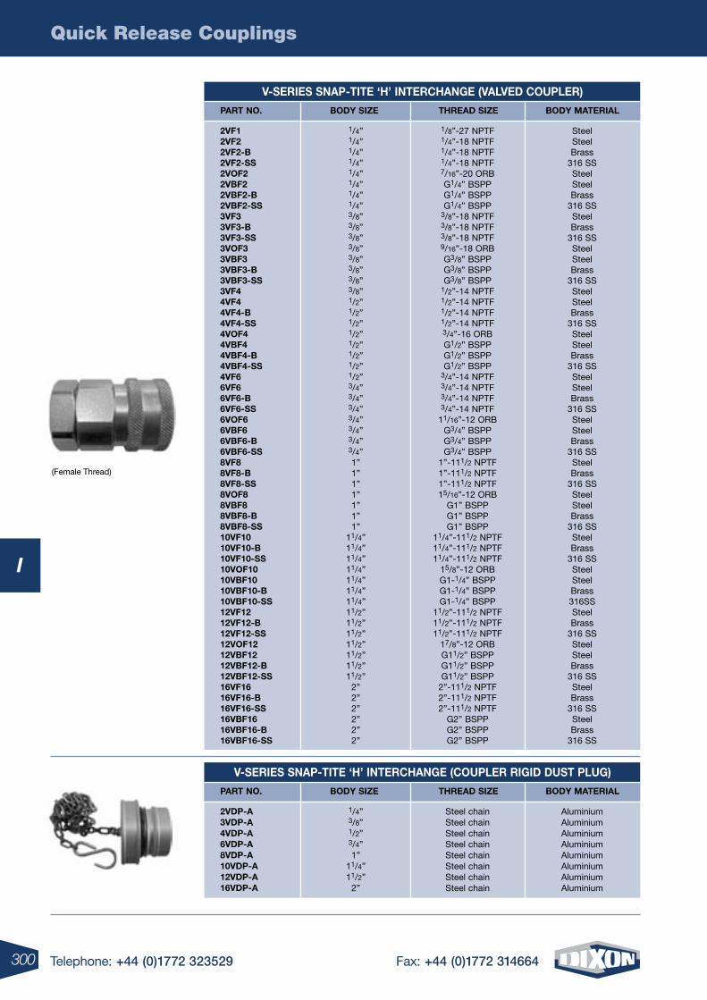
Quick Release Couplings
300 Telephone: +44 (0)1772 323529 Fax: +44 (0)1772 314664
I
V-SErIES SNAP-TITE ‘H’ INTErCHANGE (VALVED COUPLEr)
PArT NO. BODY SIzE THrEAD SIzE BODY MATErIAL
2VF12VF22VF2-B2VF2-SS2VOF22VBF22VBF2-B2VBF2-SS3VF33VF3-B3VF3-SS3VOF33VBF33VBF3-B3VBF3-SS3VF44VF44VF4-B4VF4-SS4VOF44VBF44VBF4-B4VBF4-SS4VF66VF66VF6-B6VF6-SS6VOF66VBF66VBF6-B6VBF6-SS8VF88VF8-B8VF8-SS8VOF88VBF88VBF8-B8VBF8-SS10VF1010VF10-B10VF10-SS10VOF1010VBF1010VBF10-B10VBF10-SS12VF1212VF12-B12VF12-SS12VOF1212VBF1212VBF12-B12VBF12-SS16VF1616VF16-B16VF16-SS16VBF1616VBF16-B16VBF16-SS
1/8”-27 NPTF1/4”-18 NPTF1/4”-18 NPTF1/4”-18 NPTF7/16”-20 ORBG1/4” BSPPG1/4” BSPPG1/4” BSPP
3/8”-18 NPTF3/8”-18 NPTF3/8”-18 NPTF9/16”-18 ORBG3/8” BSPPG3/8” BSPPG3/8” BSPP
1/2”-14 NPTF1/2”-14 NPTF1/2”-14 NPTF1/2”-14 NPTF3/4”-16 ORBG1/2” BSPPG1/2” BSPPG1/2” BSPP
3/4”-14 NPTF3/4”-14 NPTF3/4”-14 NPTF3/4”-14 NPTF
11/16”-12 ORBG3/4” BSPPG3/4” BSPPG3/4” BSPP
1”-111/2 NPTF1”-111/2 NPTF1”-111/2 NPTF15/16”-12 ORB
G1” BSPPG1” BSPPG1” BSPP
11/4”-111/2 NPTF11/4”-111/2 NPTF11/4”-111/2 NPTF
15/8”-12 ORBG1-1/4” BSPPG1-1/4” BSPPG1-1/4” BSPP
11/2”-111/2 NPTF11/2”-111/2 NPTF11/2”-111/2 NPTF
17/8”-12 ORBG11/2” BSPPG11/2” BSPPG11/2” BSPP
2”-111/2 NPTF2”-111/2 NPTF2”-111/2 NPTF
G2” BSPPG2” BSPPG2” BSPP
SteelSteelBrass
316 SSSteelSteelBrass
316 SSSteelBrass
316 SSSteelSteelBrass
316 SSSteelSteelBrass
316 SSSteelSteelBrass
316 SSSteelSteelBrass
316 SSSteelSteelBrass
316 SSSteelBrass
316 SSSteelSteelBrass
316 SSSteelBrass
316 SSSteelSteelBrass316SSSteelBrass
316 SSSteelSteelBrass
316 SSSteelBrass
316 SSSteelBrass
316 SS
1/4”1/4”1/4”1/4”1/4”1/4”1/4”1/4”3/8”3/8”3/8”3/8”3/8”3/8”3/8”3/8”1/2”1/2”1/2”1/2”1/2”1/2”1/2”1/2”3/4”3/4”3/4”3/4”3/4”3/4”3/4”1”1”1”1”1”1”1”
11/4”11/4”11/4”11/4”11/4”11/4”11/4”11/2”11/2”11/2”11/2”11/2”11/2”11/2”
2”2”2”2”2”2”
V-SErIES SNAP-TITE ‘H’ INTErCHANGE (COUPLEr rIGID DUST PLUG)
PArT NO. BODY SIzE THrEAD SIzE BODY MATErIAL
2VDP-A3VDP-A4VDP-A6VDP-A8VDP-A10VDP-A12VDP-A16VDP-A
Steel chainSteel chainSteel chainSteel chainSteel chainSteel chainSteel chainSteel chain
AluminiumAluminiumAluminiumAluminiumAluminiumAluminiumAluminiumAluminium
1/4”3/8”1/2”3/4”1”
11/4”11/2”
2”
(Female Thread)
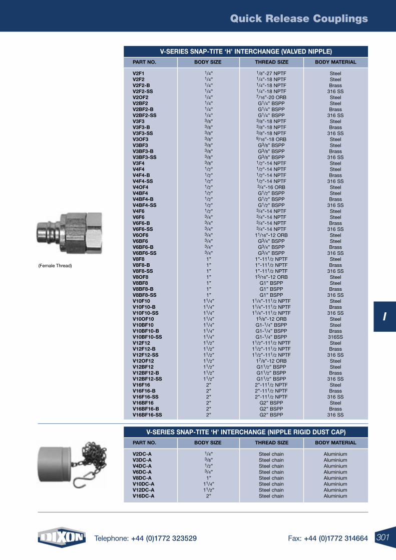
Quick Release Couplings
301Telephone: +44 (0)1772 323529 Fax: +44 (0)1772 314664
I
V-SErIES SNAP-TITE ‘H’ INTErCHANGE (VALVED NIPPLE)
PArT NO. BODY SIzE THrEAD SIzE BODY MATErIAL
V2F1V2F2V2F2-BV2F2-SSV2OF2V2BF2V2BF2-BV2BF2-SSV3F3V3F3-BV3F3-SSV3OF3V3BF3V3BF3-BV3BF3-SSV3F4V4F4V4F4-BV4F4-SSV4OF4V4BF4V4BF4-BV4BF4-SSV4F6V6F6V6F6-BV6F6-SSV6OF6V6BF6V6BF6-BV6BF6-SSV8F8V8F8-BV8F8-SSV8OF8V8BF8V8BF8-BV8BF8-SSV10F10V10F10-BV10F10-SSV10OF10V10BF10V10BF10-BV10BF10-SSV12F12V12F12-BV12F12-SSV12OF12V12BF12V12BF12-BV12BF12-SSV16F16V16F16-BV16F16-SSV16BF16V16BF16-BV16BF16-SS
1/8”-27 NPTF1/4”-18 NPTF1/4”-18 NPTF1/4”-18 NPTF7/16”-20 ORBG1/4” BSPPG1/4” BSPPG1/4” BSPP
3/8”-18 NPTF3/8”-18 NPTF3/8”-18 NPTF9/16”-18 ORBG3/8” BSPPG3/8” BSPPG3/8” BSPP
1/2”-14 NPTF1/2”-14 NPTF1/2”-14 NPTF1/2”-14 NPTF3/4”-16 ORBG1/2” BSPPG1/2” BSPPG1/2” BSPP
3/4”-14 NPTF3/4”-14 NPTF3/4”-14 NPTF3/4”-14 NPTF
11/16”-12 ORBG3/4” BSPPG3/4” BSPPG3/4” BSPP
1”-111/2 NPTF1”-111/2 NPTF1”-111/2 NPTF15/16”-12 ORB
G1” BSPPG1” BSPPG1” BSPP
11/4”-111/2 NPTF11/4”-111/2 NPTF11/4”-111/2 NPTF
15/8”-12 ORBG1-1/4” BSPPG1-1/4” BSPPG1-1/4” BSPP
11/2”-111/2 NPTF11/2”-111/2 NPTF11/2”-111/2 NPTF
17/8”-12 ORBG11/2” BSPPG11/2” BSPPG11/2” BSPP
2”-111/2 NPTF2”-111/2 NPTF2”-111/2 NPTF
G2” BSPPG2” BSPPG2” BSPP
SteelSteelBrass
316 SSSteelSteelBrass
316 SSSteelBrass
316 SSSteelSteelBrass
316 SSSteelSteelBrass
316 SSSteelSteelBrass
316 SSSteelSteelBrass
316 SSSteelSteelBrass
316 SSSteelBrass
316 SSSteelSteelBrass
316 SSSteelBrass
316 SSSteelSteelBrass316SSSteelBrass
316 SSSteelSteelBrass
316 SSSteelBrass
316 SSSteelBrass
316 SS
1/4”1/4”1/4”1/4”1/4”1/4”1/4”1/4”3/8”3/8”3/8”3/8”3/8”3/8”3/8”3/8”1/2”1/2”1/2”1/2”1/2”1/2”1/2”1/2”3/4”3/4”3/4”3/4”3/4”3/4”3/4”1”1”1”1”1”1”1”
11/4”11/4”11/4”11/4”11/4”11/4”11/4”11/2”11/2”11/2”11/2”11/2”11/2”11/2”
2”2”2”2”2”2”
(Female Thread)
V-SErIES SNAP-TITE ‘H’ INTErCHANGE (NIPPLE rIGID DUST CAP)
PArT NO. BODY SIzE THrEAD SIzE BODY MATErIAL
V2DC-AV3DC-AV4DC-AV6DC-AV8DC-AV10DC-AV12DC-AV16DC-A
Steel chainSteel chainSteel chainSteel chainSteel chainSteel chainSteel chainSteel chain
AluminiumAluminiumAluminiumAluminiumAluminiumAluminiumAluminiumAluminium
1/4”3/8”1/2”3/4”1”
11/4”11/2”
2”
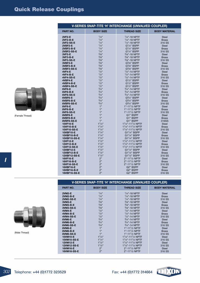
Quick Release Couplings
302 Telephone: +44 (0)1772 323529 Fax: +44 (0)1772 314664
I
V-SErIES SNAP-TITE ‘H’ INTErCHANGE (UNVALVED COUPLEr)
PArT NO. BODY SIzE THrEAD SIzE BODY MATErIAL
2VF2-E2VF2-B-E2VF2-SS-E2VBF2-E2VBF2-B-E2VBF2-SS-E3VF3-E3VF3-B-E3VF3-SS-E3VBF3-E3VBF3-B-E3VBF3-SS-E4VF4-E4VF4-B-E4VF4-SS-E4VBF4-E4VBF4-B-E4VBF4-SS-E6VF6-E6VF6-B-E6VF6-SS-E6VBF6-E6VBF6-B-E6VBF6-SS-E8VF8-E8VF8-B-E8VF8-SS-E8VBF8-E8VBF8-B-E8VBF8-SS-E10VF10-E10VF10-B-E10VF10-SS-E10VBF10-E10VBF10-B-E10VBF10-SS-E12VF12-E12VF12-B-E12VF12-SS-E12VBF12-E12VBF12-B-E12VBF12-SS-E16VF16-E16VF16-B-E16VF16-SS-E16VBF16-E16VBF16-B-E16VBF16-SS-E
1/4”-18 NPTF1/4”-18 NPTF1/4”-18 NPTFG1/4” BSPPG1/4” BSPPG1/4” BSPP
3/8”-18 NPTF3/8”-18 NPTF3/8”-18 NPTFG3/8” BSPPG3/8” BSPPG3/8” BSPP
1/2”-14 NPTF1/2”-14 NPTF1/2”-14 NPTFG1/2” BSPPG1/2” BSPPG1/2” BSPP
3/4”-14 NPTF3/4”-14 NPTF3/4”-14 NPTFG3/4” BSPPG3/4” BSPPG3/4” BSPP
1”-111/2 NPTF1”-111/2 NPTF1”-111/2 NPTF
G1” BSPPG1” BSPPG1” BSPP
11/4”-111/2 NPTF11/4”-111/2 NPTF11/4”-111/2 NPTF
G11/4” BSPPG11/4” BSPPG11/4” BSPP
11/2”-111/2 NPTF11/2”-111/2 NPTF11/2”-111/2 NPTF
G11/2” BSPPG11/2” BSPPG11/2” BSPP
2”-111/2 NPTF2”-111/2 NPTF2”-111/2 NPTF
G2” BSPPG2” BSPPG2” BSPP
SteelBrass
316 SSSteelBrass
316 SSSteelBrass
316 SSSteelBrass
316 SSSteelBrass
316 SSSteelBrass
316 SSSteelBrass
316 SSSteelBrass
316 SSSteelBrass
316 SSSteelBrass316SSSteelBrass
316 SSSteelBrass
316 SSSteelBrass
316 SSSteelBrass
316 SSSteelBrass
316 SSSteelBrass
316 SS
1/4”1/4”1/4”1/4”1/4”1/4”3/8”3/8”3/8”3/8”3/8”3/8”1/2”1/2”1/2”1/2”1/2”1/2”3/4”3/4”3/4”3/4”3/4”3/4”1”1”1”1”1”1”
11/4”11/4”11/4”11/4”11/4”11/4”11/2”11/2”11/2”11/2”11/2”11/2”
2”2”2”2”2”2”
(Female Thread)
(Male Thread)
V-SErIES SNAP-TITE ‘H’ INTErCHANGE (UNVALVED COUPLEr)
PArT NO. BODY SIzE THrEAD SIzE BODY MATErIAL
2VM2-E2VM2-B-E2VM2-SS-E3VM3-E3VM3-B-E3VM3-SS-E4VM4-E4VM4-B-E4VM4-SS-E6VM6-E6VM6-B-E6VM6-SS-E8VM8-E8VM8-B-E8VM8-SS-E10VM10-E10VM10-SS-E12VM12-E12VM12-SS-E16VM16-E16VM16-SS-E
1/4”-18 NPTF1/4”-18 NPTF1/4”-18 NPTF3/8”-18 NPTF3/8”-18 NPTF3/8”-18 NPTF1/2”-14 NPTF1/2”-14 NPTF1/2”-14 NPTF3/4”-14 NPTF3/4”-14 NPTF3/4”-14 NPTF
1”-111/2 NPTF1”-111/2 NPTF1”-111/2 NPTF
11/4”-111/2 NPTF11/4”-111/2 NPTF11/2”-111/2 NPTF11/2”-111/2 NPTF
2”-111/2 NPTF2”-111/2 NPTF
SteelBrass
316 SSSteelBrass
316 SSSteelBrass
316 SSSteelBrass
316 SSSteelBrass
316 SSSteel
316 SSSteel
316 SSSteel
316 SS
1/4”1/4”1/4”3/8”3/8”3/8”1/2”1/2”1/2”3/4”3/4”3/4”1”1”1”
11/4”11/4”11/2”11/2”
2”2”
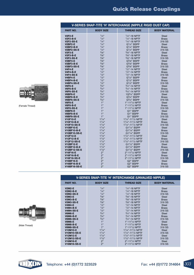
Quick Release Couplings
303Telephone: +44 (0)1772 323529 Fax: +44 (0)1772 314664
I
(Male Thread)
(Female Thread)
V-SErIES SNAP-TITE ‘H’ INTErCHANGE (NIPPLE rIGID DUST CAP)
PArT NO. BODY SIzE THrEAD SIzE BODY MATErIAL
V2F2-EV2F2-B-EV2F2-SS-EV2BF2-EV2BF2-B-EV2BF2-SS-EV3F3-EV3F3-B-EV3F3-SS-EV3BF3-EV3BF3-B-EV3BF3-SS-EV4F4-EV4F4-B-EV4F4-SS-EV4BF4-EV4BF4-B-EV4BF4-SS-EV6F6-EV6F6-B-EV6F6-SS-EV6BF6-EV6BF6-B-EV6BF6-SS-EV8F8-EV8F8-B-EV8F8-SS-EV8BF8-EV8BF8-B-EV8BF8-SS-EV10F10-EV10F10-B-EV10F10-SS-EV10BF10-EV10BF10-B-EV10BF10-SS-EV12F12-EV12F12-B-EV12F12-SS-EV12BF12-EV12BF12-B-EV12BF12-SS-EV16F16-EV16F16-B-EV16F16-SS-EV16BF16-EV16BF16-B-EV16BF16-SS-E
1/4”-18 NPTF1/4”-18 NPTF1/4”-18 NPTFG1/4” BSPPG1/4” BSPPG1/4” BSPP
3/8”-18 NPTF3/8”-18 NPTF3/8”-18 NPTFG3/8” BSPPG3/8” BSPPG3/8” BSPP
1/2”-14 NPTF1/2”-14 NPTF1/2”-14 NPTFG1/2” BSPPG1/2” BSPPG1/2” BSPP
3/4”-14 NPTF3/4”-14 NPTF3/4”-14 NPTF1G3/4” BSPPG3/4” BSPPG3/4” BSPP
1”-111/2 NPTF1”-111/2 NPTF1”-111/2 NPTF
G1” BSPPG1” BSPPG1” BSPP
11/4”-111/2 NPTF11/4”-111/2 NPTF11/4”-111/2 NPTF
G11/4” BSPPG11/4” BSPPG11/4” BSPP
11/2”-111/2 NPTF11/2”-111/2 NPTF11/2”-111/2 NPTF
G11/2” BSPPG11/2” BSPPG11/2” BSPP
2”-111/2 NPTF2”-111/2 NPTF2”-111/2 NPTF
G2” BSPPG2” BSPPG2” BSPP
SteelBrass
316 SSSteelBrass
316 SSSteelBrass
316 SSSteelBrass
316 SSSteelBrass
316 SSSteelBrass
316 SSSteelBrass
316 SSSteelBrass
316 SSSteelBrass
316 SSSteelBrass
316 SSSteelBrass
316 SSSteelBrass
316 SSSteelBrass
316 SSSteelBrass
316 SSSteelBrass
316 SSSteelBrass
316 SS
1/4”1/4”1/4”1/4”1/4”1/4”3/8”3/8”3/8”3/8”3/8”3/8”1/2”1/2”1/2”1/2”1/2”1/2”3/4”3/4”3/4”3/4”3/4”3/4”1”1”1”1”1”1”
11/4”11/4”11/4”11/4”11/4”11/4”11/2”11/2”11/2”11/2”11/2”11/2”
2”2”2”2”2”2”
V-SErIES SNAP-TITE ‘H’ INTErCHANGE (UNVALVED NIPPLE)
PArT NO. BODY SIzE THrEAD SIzE BODY MATErIAL
V2M2-EV2M2-B-EV2M2-SS-EV3M3-EV3M3-B-EV3M3-SS-EV4M4-EV4M4-B-EV4M4-SS-EV6M6-EV6M6-B-EV6M6-SS-EV8M8-EV8M8-B-EV8M8-SS-EV10M10-EV10M10-SS-EV12M12-EV12M12-SS-EV16M16-EV16M16-SS-E
1/4”-18 NPTF1/4”-18 NPTF1/4”-18 NPTF3/8”-18 NPTF3/8”-18 NPTF3/8”-18 NPTF1/2”-14 NPTF1/2”-14 NPTF1/2”-14 NPTF3/4”-14 NPTF3/4”-14 NPTF3/4”-14 NPTF
1”-111/2 NPTF1”-111/2 NPTF1”-111/2 NPTF
11/4”-111/2 NPTF11/4”-111/2 NPTF11/2”-111/2 NPTF11/2”-111/2 NPTF
2”-111/2 NPTF2”-111/2 NPTF
SteelBrass
316 SSSteelBrass
316 SSSteelBrass
316 SSSteelBrass
316 SSSteelBrass
316 SSSteel
316 SSSteel
316 SSSteel
316 SS
1/4”1/4”1/4”3/8”3/8”3/8”1/2”1/2”1/2”3/4”3/4”3/4”1”1”1”
11/4”11/4”11/2”11/2”
2”2”
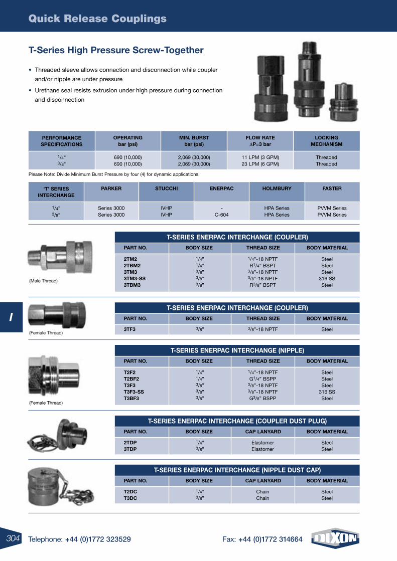
Quick Release Couplings
304 Telephone: +44 (0)1772 323529 Fax: +44 (0)1772 314664
I
T-SErIES ENErPAC INTErCHANGE (COUPLEr)
PArT NO. BODY SIzE THrEAD SIzE BODY MATErIAL
2TM22TBM23TM33TM3-SS3TBM3
1/4”-18 NPTFR1/4” BSPT
3/8”-18 NPTF3/8”-18 NPTFR3/8” BSPT
SteelSteelSteel
316 SSSteel
1/4”1/4”3/8”3/8”3/8”
T-SErIES ENErPAC INTErCHANGE (NIPPLE)
PArT NO. BODY SIzE THrEAD SIzE BODY MATErIAL
T2F2T2BF2T3F3T3F3-SST3BF3
1/4”-18 NPTFG1/4” BSPP
3/8”-18 NPTF3/8”-18 NPTFG3/8” BSPP
SteelSteelSteel
316 SSSteel
1/4”1/4”3/8”3/8”3/8”
3TF3 3/8”-18 NPTF Steel3/8”
T-SErIES ENErPAC INTErCHANGE (COUPLEr)
PArT NO. BODY SIzE THrEAD SIzE BODY MATErIAL
T-SErIES ENErPAC INTErCHANGE (COUPLEr DUST PLUG)
PArT NO. BODY SIzE CAP LANYArD BODY MATErIAL
2TDP3TDP
ElastomerElastomer
SteelSteel
1/4”3/8”
T-SErIES ENErPAC INTErCHANGE (NIPPLE DUST CAP)
PArT NO. BODY SIzE CAP LANYArD BODY MATErIAL
T2DCT3DC
ChainChain
SteelSteel
1/4”3/8”
Please Note: Divide Minimum Burst Pressure by four (4) for dynamic applications.
LOCKINGMECHANISM
ThreadedThreaded
FLOw rATE DP=3 bar
11 LPM (3 GPM)23 LPM (6 GPM)
PErFOrMANCESPECIFICATIONS
1/4”3/8”
MIN. BUrSTbar (psi)
2,069 (30,000)2,069 (30,000)
OPErATINGbar (psi)
690 (10,000)690 (10,000)
(Male Thread)
(Female Thread)
(Female Thread)
T-Series High Pressure Screw-Together
• Threaded sleeve allows connection and disconnection while coupler
and/or nipple are under pressure
• Urethane seal resists extrusion under high pressure during connection
and disconnection
HOLMBUrY
HPA Series HPA Series
ENErPAC
- C-604
FASTEr
PVVM Series PVVM Series
‘T’ SErIES INTErCHANGE
1/4” 3/8”
STUCCHI
IVHP IVHP
PArKEr
Series 3000 Series 3000
3TF3 3/8”-18 NPTF Steel3/8”
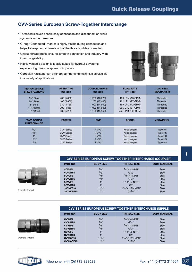
Quick Release Couplings
305Telephone: +44 (0)1772 323529 Fax: +44 (0)1772 314664
I
CVV-Series European Screw-Together Interchange
• Threaded sleeves enable easy connection and disconnection while
system is under pressure
• O-ring “Connected” marker is highly visible during connection and
helps to keep contaminants out of the threads while connected
• Unique thread profile ensures smooth connection and industry-wide
interchangeability
• Highly versatile design is ideally suited for hydraulic systems
experiencing pressure spikes or impulses
• Corrosion resistant high strength components maximise service life
in a variety of applications
CVV-SErIES EUrOPEAN SCrEw-TOGETHEr INTErCHANGE (COUPLEr)
PArT NO. BODY SIzE THrEAD SIzE BODY MATErIAL
4CVVF44CVVBF46CVVF66CVVBF68CVVF88CVVBF810CVVF1010CVVBF10
1/2”-14 NPTFG1/2”
3/4”-14 NPTFG3/4”
1”-111/2 NPTFG1”
11/4”-111/2 NPTFG11/4”
SteelSteelSteelSteelSteelSteelSteelSteel
1/2”1/2”3/4”3/4”1”1”
11/4”11/4”
CVV-SErIES EUrOPEAN SCrEw-TOGETHEr INTErCHANGE (NIPPLE)
PArT NO. BODY SIzE THrEAD SIzE BODY MATErIAL
CVV4F4CVV4BF4CVV6F6CVV6BF6CVV8F8CVV8BF8CVV10F10CVV10BF10
1/2”-14 NPTFG1/2”
3/4”-14 NPTFG3/4”
1”-111/2 NPTFG1”
11/4”-111/2 NPTFG11/4”
SteelSteelSteelSteelSteelSteelSteelSteel
1/2”1/2”3/4”3/4”1”1”
11/4”11/4”
(Female Thread)
(Female Thread)
LOCKINGMECHANISM
ThreadedThreadedThreadedThreadedThreaded
FLOw rATE DP=1 bar
189 LPM (13 GPM)102 LPM (27 GPM)159 LPM (42 GPM)305 LPM (81 GPM)450 LPM (119 GPM)
PErFOrMANCESPECIFICATIONS
1/2” Steel3/4” Steel1” Steel
11/4” Steel11/2” Steel
COUPLED BUrSTbar (psi)
1,260 (18,270)1,200 (17,400)1,000 (14,500)1,000 (14,500)1,100 (15,950)
OPErATINGbar (psi)
400 (5,800)400 (5,800)330 (4,785)300 (4,350)365 (5,295)
VOSwINKEL
Type HSType HSType HSType HSType HS
ArGUS
KupplengenKupplengenKupplengenKupplengenKupplengen
‘CVV’ SErIESINTErCHANGE
1/2”3/4”1”
11/4”11/2”
DNP
PVV3PVV3PVV3PVV3PVV3
FASTEr
CVV-SeriesCVV-SeriesCVV-SeriesCVV-SeriesCVV-Series
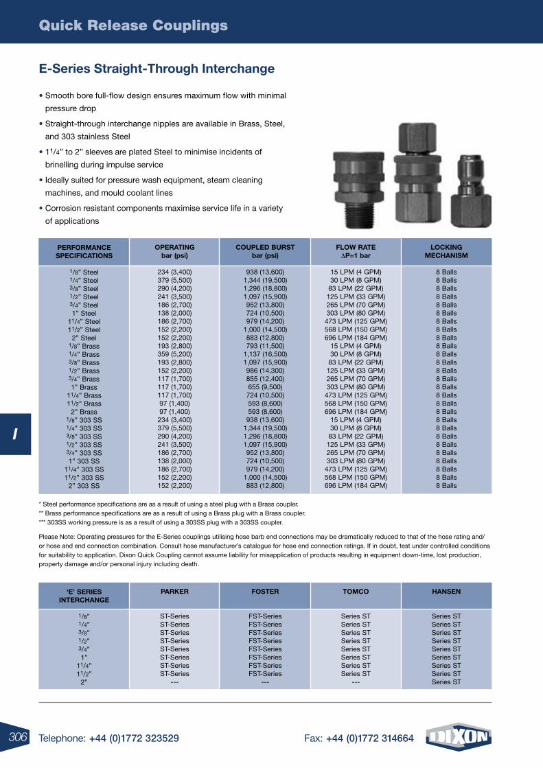
Quick Release Couplings
306 Telephone: +44 (0)1772 323529 Fax: +44 (0)1772 314664
I
E-Series Straight-Through Interchange
* Steel performance specifications are as a result of using a steel plug with a Brass coupler. ** Brass performance specifications are as a result of using a Brass plug with a Brass coupler. *** 303SS working pressure is as a result of using a 303SS plug with a 303SS coupler.
Please Note: Operating pressures for the E-Series couplings utilising hose barb end connections may be dramatically reduced to that of the hose rating and/or hose and end connection combination. Consult hose manufacturer’s catalogue for hose end connection ratings. If in doubt, test under controlled conditions for suitability to application. Dixon Quick Coupling cannot assume liability for misapplication of products resulting in equipment down-time, lost production, property damage and/or personal injury including death.
(Female Thread)
• Smooth bore full-flow design ensures maximum flow with minimal
pressure drop
• Straight-through interchange nipples are available in Brass, Steel,
and 303 stainless Steel
• 11/4” to 2” sleeves are plated Steel to minimise incidents of
brinelling during impulse service
• Ideally suited for pressure wash equipment, steam cleaning
machines, and mould coolant lines
• Corrosion resistant components maximise service life in a variety
of applications
LOCKINGMECHANISM
8 Balls8 Balls8 Balls8 Balls8 Balls8 Balls8 Balls8 Balls8 Balls8 Balls8 Balls8 Balls8 Balls8 Balls8 Balls8 Balls8 Balls8 Balls8 Balls8 Balls8 Balls8 Balls8 Balls8 Balls8 Balls8 Balls8 Balls
FLOw rATE DP=1 bar
15 LPM (4 GPM)30 LPM (8 GPM)83 LPM (22 GPM)125 LPM (33 GPM)265 LPM (70 GPM)303 LPM (80 GPM)473 LPM (125 GPM)568 LPM (150 GPM)696 LPM (184 GPM)
15 LPM (4 GPM)30 LPM (8 GPM)83 LPM (22 GPM)125 LPM (33 GPM)265 LPM (70 GPM)303 LPM (80 GPM)473 LPM (125 GPM)568 LPM (150 GPM)696 LPM (184 GPM)
15 LPM (4 GPM)30 LPM (8 GPM)83 LPM (22 GPM)125 LPM (33 GPM)265 LPM (70 GPM)303 LPM (80 GPM)473 LPM (125 GPM)568 LPM (150 GPM)696 LPM (184 GPM)
PErFOrMANCESPECIFICATIONS
1/8” Steel1/4” Steel3/8” Steel1/2” Steel3/4” Steel1” Steel
11/4” Steel11/2” Steel
2” Steel1/8” Brass1/4” Brass3/8” Brass1/2” Brass3/4” Brass1” Brass
11/4” Brass11/2” Brass
2” Brass1/8” 303 SS1/4” 303 SS3/8” 303 SS1/2” 303 SS3/4” 303 SS1” 303 SS
11/4” 303 SS11/2” 303 SS
2” 303 SS
COUPLED BUrSTbar (psi)
938 (13,600)1,344 (19,500)1,296 (18,800)1,097 (15,900)952 (13,800)724 (10,500)979 (14,200)
1,000 (14,500)883 (12,800)793 (11,500)
1,137 (16,500)1,097 (15,900)986 (14,300)855 (12,400)655 (9,500)724 (10,500)593 (8,600)593 (8,600)938 (13,600)
1,344 (19,500)1,296 (18,800)1,097 (15,900)952 (13,800)724 (10,500)979 (14,200)
1,000 (14,500)883 (12,800)
OPErATINGbar (psi)
234 (3,400)379 (5,500)290 (4,200)241 (3,500)186 (2,700)138 (2,000)186 (2,700)152 (2,200)152 (2,200)193 (2,800)359 (5,200)193 (2,800)152 (2,200)117 (1,700)117 (1,700)117 (1,700)97 (1,400)97 (1,400)
234 (3,400)379 (5,500)290 (4,200)241 (3,500)186 (2,700)138 (2,000)186 (2,700)152 (2,200)152 (2,200)
HANSEN
Series STSeries STSeries STSeries STSeries STSeries STSeries STSeries STSeries ST
TOMCO
Series STSeries STSeries STSeries STSeries STSeries STSeries STSeries ST
---
‘E’ SErIESINTErCHANGE
1/8”1/4”3/8”1/2”3/4”1”
11/4”11/2”
2”
FOSTEr
FST-SeriesFST-SeriesFST-SeriesFST-SeriesFST-SeriesFST-SeriesFST-SeriesFST-Series
---
PArKEr
ST-SeriesST-SeriesST-SeriesST-SeriesST-SeriesST-SeriesST-SeriesST-Series
---
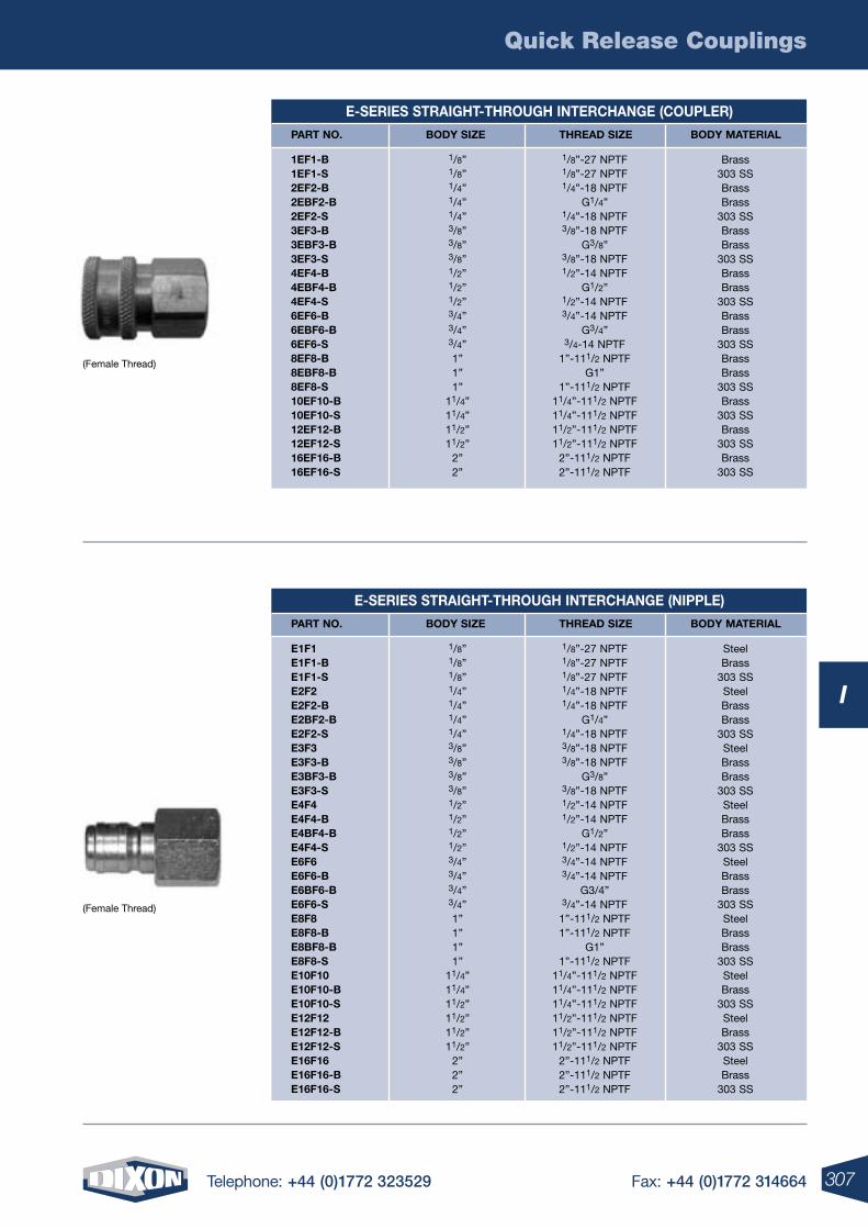
Quick Release Couplings
307Telephone: +44 (0)1772 323529 Fax: +44 (0)1772 314664
I
E-SErIES STrAIGHT-THrOUGH INTErCHANGE (COUPLEr)
PArT NO. BODY SIzE THrEAD SIzE BODY MATErIAL
1EF1-B1EF1-S2EF2-B2EBF2-B2EF2-S3EF3-B3EBF3-B3EF3-S4EF4-B4EBF4-B4EF4-S6EF6-B6EBF6-B6EF6-S8EF8-B8EBF8-B8EF8-S10EF10-B10EF10-S12EF12-B12EF12-S16EF16-B16EF16-S
1/8”-27 NPTF1/8”-27 NPTF1/4”-18 NPTF
G1/4”1/4”-18 NPTF3/8”-18 NPTF
G3/8”3/8”-18 NPTF1/2”-14 NPTF
G1/2”1/2”-14 NPTF3/4”-14 NPTF
G3/4”3/4-14 NPTF
1”-111/2 NPTFG1”
1”-111/2 NPTF11/4”-111/2 NPTF11/4”-111/2 NPTF11/2”-111/2 NPTF11/2”-111/2 NPTF
2”-111/2 NPTF2”-111/2 NPTF
Brass303 SSBrassBrass
303 SSBrassBrass
303 SSBrassBrass
303 SSBrassBrass
303 SSBrassBrass
303 SSBrass
303 SSBrass
303 SSBrass
303 SS
1/8”1/8”1/4”1/4”1/4”3/8”3/8”3/8”1/2”1/2”1/2”3/4”3/4”3/4”1”1”1”
11/4”11/4”11/2”11/2”
2”2”
E-SErIES STrAIGHT-THrOUGH INTErCHANGE (NIPPLE)
PArT NO. BODY SIzE THrEAD SIzE BODY MATErIAL
E1F1E1F1-BE1F1-SE2F2E2F2-BE2BF2-BE2F2-SE3F3E3F3-BE3BF3-BE3F3-SE4F4E4F4-BE4BF4-BE4F4-SE6F6E6F6-BE6BF6-BE6F6-SE8F8E8F8-BE8BF8-BE8F8-SE10F10E10F10-BE10F10-SE12F12E12F12-BE12F12-SE16F16E16F16-BE16F16-S
1/8”-27 NPTF1/8”-27 NPTF1/8”-27 NPTF1/4”-18 NPTF1/4”-18 NPTF
G1/4”1/4”-18 NPTF3/8”-18 NPTF3/8”-18 NPTF
G3/8”3/8”-18 NPTF1/2”-14 NPTF1/2”-14 NPTF
G1/2”1/2”-14 NPTF3/4”-14 NPTF3/4”-14 NPTF
G3/4”3/4”-14 NPTF
1”-111/2 NPTF1”-111/2 NPTF
G1”1”-111/2 NPTF
11/4”-111/2 NPTF11/4”-111/2 NPTF11/4”-111/2 NPTF11/2”-111/2 NPTF11/2”-111/2 NPTF11/2”-111/2 NPTF
2”-111/2 NPTF2”-111/2 NPTF2”-111/2 NPTF
SteelBrass
303 SSSteelBrassBrass
303 SSSteelBrassBrass
303 SSSteelBrassBrass
303 SSSteelBrassBrass
303 SSSteelBrassBrass
303 SSSteelBrass
303 SSSteelBrass
303 SSSteelBrass
303 SS
1/8”1/8”1/8”1/4”1/4”1/4”1/4”3/8”3/8”3/8”3/8”1/2”1/2”1/2”1/2”3/4”3/4”3/4”3/4”1”1”1”1”
11/4”11/4”11/2”11/2”11/2”11/2”
2”2”2”
(Female Thread)
(Female Thread)
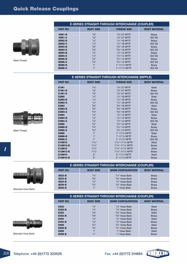
Quick Release Couplings
308 Telephone: +44 (0)1772 323529 Fax: +44 (0)1772 314664
I
E-SErIES STrAIGHT-THrOUGH INTErCHANGE (COUPLEr)
PArT NO. BODY SIzE THrEAD SIzE BODY MATErIAL
1EM1-B1EM1-S2EM2-B2EM2-S3EM3-B3EM3-S4EM4-B4EM4-S6EM6-B6EM6-S8EM8-B8EM8-S
1/8”-27 NPTF1/8”-27 NPTF1/4”-18 NPTF1/4”-18 NPTF3/8”-18 NPTF3/8”-18 NPTF1/2”-14 NPTF1/2”-14 NPTF3/4”-14 NPTF3/4”-14 NPTF
1”-111/2 NPTF1”-111/2 NPTF
Brass303 SSBrass
303 SSBrass
303 SSBrass
303 SSBrass
303 SSBrass
303 SS
1/8”1/8”1/4”1/4”3/8”3/8”1/2”1/2”3/4”3/4”1”1”
E-SErIES STrAIGHT-THrOUGH INTErCHANGE (COUPLEr)
PArT NO. BODY SIzE BArB CONFIGUrATION BODY MATErIAL
2ES2-B3ES3-B4ES4-B6ES6-B8ES8-B
1/4” Hose Barb3/8” Hose Barb1/2” Hose Barb3/4” Hose Barb1” Hose Barb
BrassBrassBrassBrassBrass
1/4”3/8”1/2”3/4”1”
E-SErIES STrAIGHT-THrOUGH INTErCHANGE (NIPPLE)
PArT NO. BODY SIzE THrEAD SIzE BODY MATErIAL
E1M1E1M1-BE1M1-SE2M2E2M2-BE2M2-SE3M3E3M3-BE3M3-SE4M4E4M4-BE4M4-SE6M6E6M6-BE6M6-SE8M8E8M8-BE8M8-SE10M10E10M10-BE12M12E12M12-BE16M16E16M16-B
1/8”-27 NPTF1/8”-27 NPTF1/8”-27 NPTF1/4”-18 NPTF1/4”-18 NPTF1/4”-18 NPTF3/8”-18 NPTF3/8”-18 NPTF3/8”-18 NPTF1/2”-14 NPTF1/2”-14 NPTF1/2”-14 NPTF3/4”-14 NPTF3/4”-14 NPTF3/4”-14 NPTF
1”-111/2 NPTF1”-111/2 NPTF1”-111/2 NPTF
11/4”-111/2 NPTF11/4”-111/2 NPTF11/2”-111/2 NPTF11/2”-111/2 NPTF
2”-111/2 NPTF2”-111/2 NPTF
SteelBrass
303 SSSteelBrass
303 SSSteelBrass
303 SSSteelBrass
303 SSSteelBrass
303 SSSteelBrass
303 SSSteelBrassSteelBrassSteelBrass
1/8”1/8”1/8”1/4”1/4”1/4”3/8”3/8”3/8”1/2”1/2”1/2”3/4”3/4”3/4”1”1”1”
11/4”11/4”11/2”11/2”
2”2”
(Standard Hose Barb)
(Male Thread)
(Male Thread)
E-SErIES STrAIGHT-THrOUGH INTErCHANGE (COUPLEr)
PArT NO. BODY SIzE BArB CONFIGUrATION BODY MATErIAL
E2S2E2S2-BE3S3E3S3-BE4S4E4S4-BE6S6E6S6-BE8S8E8S8-B
1/4” Hose Barb1/4” Hose Barb3/8” Hose Barb3/8” Hose Barb1/2” Hose Barb1/2” Hose Barb3/4” Hose Barb3/4” Hose Barb1” Hose Barb1” Hose Barb
SteelBrassSteelBrassSteelBrassSteelBrassSteelBrass
1/4”1/4”3/8”3/8”1/2”1/2”3/4”3/4”1”1”(Standard Hose Barb)
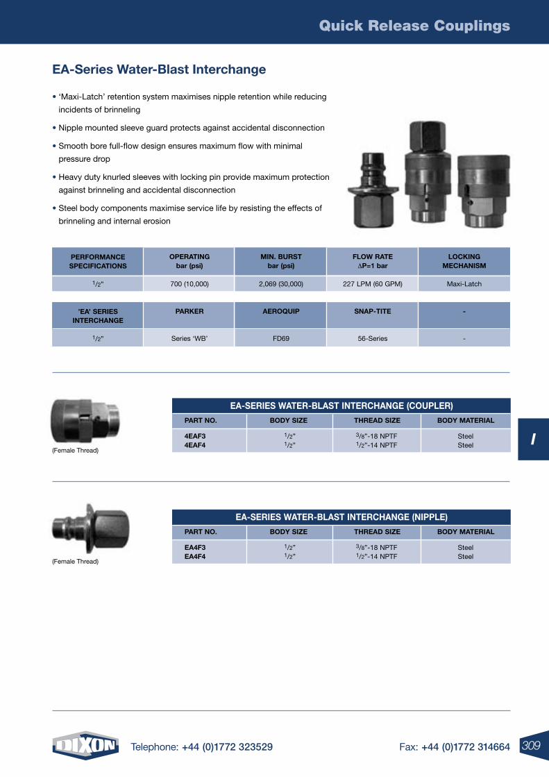
Quick Release Couplings
309Telephone: +44 (0)1772 323529 Fax: +44 (0)1772 314664
I
EA-SErIES wATEr-BLAST INTErCHANGE (COUPLEr)
PArT NO. BODY SIzE THrEAD SIzE BODY MATErIAL
4EAF34EAF4
3/8”-18 NPTF1/2”-14 NPTF
SteelSteel
1/2”1/2”
EA-SErIES wATEr-BLAST INTErCHANGE (NIPPLE)
PArT NO. BODY SIzE THrEAD SIzE BODY MATErIAL
EA4F3EA4F4
3/8”-18 NPTF1/2”-14 NPTF
SteelSteel
1/2”1/2”
PErFOrMANCESPECIFICATIONS
1/2”
OPErATINGbar (psi)
700 (10,000)
MIN. BUrSTbar (psi)
2,069 (30,000)
FLOw rATE DP=1 bar
227 LPM (60 GPM)
LOCKINGMECHANISM
Maxi-Latch
’EA’ SErIESINTErCHANGE
1/2”
PArKEr
Series ‘WB’
AErOQUIP
FD69
SNAP-TITE
56-Series
-
-
EA-Series water-Blast Interchange
• ‘Maxi-Latch’ retention system maximises nipple retention while reducing
incidents of brinneling
• Nipple mounted sleeve guard protects against accidental disconnection
• Smooth bore full-flow design ensures maximum flow with minimal
pressure drop
• Heavy duty knurled sleeves with locking pin provide maximum protection
against brinneling and accidental disconnection
• Steel body components maximise service life by resisting the effects of
brinneling and internal erosion
(Female Thread)
(Female Thread)
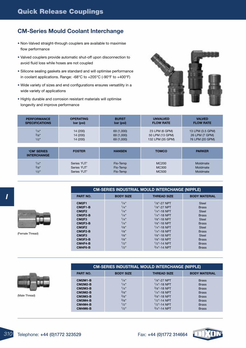
Quick Release Couplings
310 Telephone: +44 (0)1772 323529 Fax: +44 (0)1772 314664
ICM-SErIES INDUSTrIAL MOULD INTErCHANGE (NIPPLE)
PArT NO. BODY SIzE THrEAD SIzE BODY MATErIAL
CM2F1CM2F1-BCM2F2CM2F2-BCM2F3CM2F3-BCM3F2CM3F2-BCM3F3CM3F3-BCM4F4-BCM4F6-B
1/8”-27 NPT1/8”-27 NPT1/4”-18 NPT1/4”-18 NPT3/8”-18 NPT3/8”-18 NPT1/4”-18 NPT1/4”-18 NPT3/8”-18 NPT3/8”-18 NPT1/2”-14 NPT3/4”-14 NPT
SteelBrassSteelBrassSteelBrassSteelBrassSteelBrassBrassBrass
1/4”1/4”1/4”1/4”1/4”1/4”3/8”3/8”3/8”3/8”1/2”1/2”
CM-SErIES INDUSTrIAL MOULD INTErCHANGE (NIPPLE)
PArT NO. BODY SIzE THrEAD SIzE BODY MATErIAL
CM2M1-BCM2M2-BCM2M3-BCM3M2-BCM3M3-BCM3M4-BCM4M4-BCM4M6-B
1/8”-27 NPT1/4”-18 NPT3/8”-18 NPT1/4”-18 NPT3/8”-18 NPT1/2”-14 NPT1/2”-14 NPT3/4”-14 NPT
BrassBrassBrassBrassBrassBrassBrassBrass
1/4”1/4”1/4”3/8”3/8”3/8”1/2”1/2”
CM-Series Mould Coolant Interchange
• Non-Valved straight-through couplers are available to maximise
flow performance
• Valved couplers provide automatic shut-off upon disconnection to
avoid fluid loss while hoses are not coupled
• Silicone sealing gaskets are standard and will optimise performance
in coolant applications. Range: -68°C to +205°C (-90°F to +400°F)
• Wide variety of sizes and end configurations ensures versatility in a
wide variety of applications
• Highly durable and corrosion resistant materials will optimise
longevity and improve performance
PErFOrMANCESPECIFICATIONS
1/4”3/8”1/2”
OPErATINGbar (psi)
14 (200)14 (200)14 (200)
BUrSTbar (psi)
69 (1,000)69 (1,000)69 (1,000)
UNVALVEDFLOw rATE
23 LPM (6 GPM)50 LPM (13 GPM)132 LPM (35 GPM)
VALVEDFLOw rATE
13 LPM (3.5 GPM)26 LPM (7 GPM)76 LPM (20 GPM)
‘CM’ SErIESINTErCHANGE
1/4”3/8”1/2”
FOSTEr
Series ‘FJT’Series ‘FJT’Series ‘FJT’
HANSEN
Flo-TempFlo-TempFlo-Temp
TOMCO
MC200MC300MC500
PArKEr
MoldmateMoldmateMoldmate
(Female Thread)
(Male Thread)
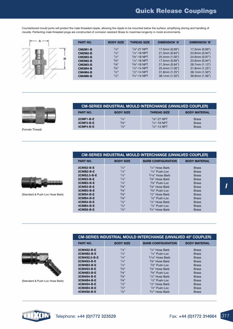
Quick Release Couplings
311Telephone: +44 (0)1772 323529 Fax: +44 (0)1772 314664
I
CM-SErIES INDUSTrIAL MOULD INTErCHANGE (UNVALVED COUPLEr)
PArT NO. BODY SIzE THrEAD SIzE BODY MATErIAL
2CMF1-B-E3CMF2-B-E4CMF4-B-E
1/8”-27 NPT1/4”-18 NPT1/2”-14 NPT
BrassBrassBrass
1/4”3/8”1/2”
CM-SErIES INDUSTrIAL MOULD INTErCHANGE (UNVALVED COUPLEr)
PArT NO. BODY SIzE BArB CONFIGUrATION BODY MATErIAL
2CMS2-B-E2CMB2-B-E2CMS2.5-B-E2CMS3-B-E2CMB3-B-E3CMS3-B-E3CMB3-B-E3CMS4-B-E3CMB4-B-E4CMS4-B-E4CMB4-B-E4CMS6-B-E
1/4” Hose Barb1/4” Push-Loc
5/16” Hose Barb3/8” Hose Barb3/8” Push-Loc
3/8” Hose Barb3/8” Push-Loc
1/2” Hose Barb1/2” Push-Loc
1/2” Hose Barb1/2” Push-Loc
3/4” Hose Barb
BrassBrassBrassBrassBrassBrassBrassBrassBrassBrassBrassBrass
1/4”1/4”1/4”1/4”1/4”3/8”3/8”3/8”3/8”1/2”1/2”1/2”
CM-SErIES INDUSTrIAL MOULD INTErCHANGE (UNVALVED 45º COUPLEr)
PArT NO. BODY SIzE BArB CONFIGUrATION BODY MATErIAL
2CM4S2-B-E2CM4B2-B-E2CM4S2.5-B-E2CM4S3-B-E2CM4B3-B-E3CM4S3-B-E3CM4B3-B-E3CM4S4-B-E3CM4B4-B-E4CM4S4-B-E4CM4B4-B-E4CM4S6-B-E
1/4” Hose Barb1/4” Push-Loc
5/16” Hose Barb3/8” Hose Barb3/8” Push-Loc
3/8” Hose Barb3/8” Push-Loc
1/2” Hose Barb1/2” Push-Loc
1/2” Hose Barb1/2” Push-Loc
3/4” Hose Barb
BrassBrassBrassBrassBrassBrassBrassBrassBrassBrassBrassBrass
1/4”1/4”1/4”1/4”1/4”3/8”3/8”3/8”3/8”1/2”1/2”1/2”
Counterbored mould ports will protect the male threaded nipple, allowing the nipple to be mounted below the surface, simplifying storing and handling of moulds. Perfecting male threaded plugs are constructed of corrosion resistant Brass to maximise longevity in moist environments.
(Female Thread)
(Standard & Push-Loc Hose Barb)
(Standard & Push-Loc Hose Barb)
PArT NO. BODY SIzE THrEAD SIzE DIMENSION ‘A’ DIMENSION ‘B’
CM2M1-BCM2M2-BCM2M3-BCM3M2-BCM3M3-BCM3M4-BCM4M4-BCM4M6-B
1/4”1/4”1/4”3/8”3/8”3/8”1/2”1/2”
1/8”-27 NPT1/4”-18 NPT3/8”-18 NPT1/4”-18 NPT3/8”-18 NPT1/2”-14 NPT1/2”-14 NPT3/4”-14 NPT
17.5mm (0.69”)23.9mm (0.94”)24.6mm (0.97”)23.9mm (0.94”)28.7mm (1.13”)31.8mm (1.25”)38.1mm (1.50”)39.6mm (1.56”)
17.5mm (0.69”)21.3mm (0.84”)25.4mm (1.00”)17.5mm (0.69”)21.3mm (0.84”)25.4mm (1.00”)31.8mm (1.25”)38.1mm (1.50”)
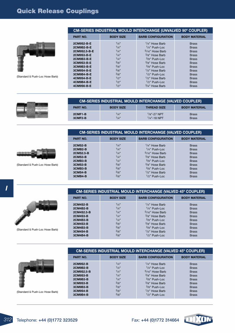
Quick Release Couplings
312 Telephone: +44 (0)1772 323529 Fax: +44 (0)1772 314664
I
CM-SErIES INDUSTrIAL MOULD INTErCHANGE (VALVED COUPLEr)
PArT NO. BODY SIzE THrEAD SIzE BODY MATErIAL
2CMF1-B3CMF2-B
1/8”-27 NPT1/4”-18 NPT
BrassBrass
1/4”1/4”
CM-SErIES INDUSTrIAL MOULD INTErCHANGE (UNVALVED 90º COUPLEr)
PArT NO. BODY SIzE BArB CONFIGUrATION BODY MATErIAL
2CM9S2-B-E2CM9B2-B-E2CM9S2.5-B-E2CM9S3-B-E2CM9B3-B-E3CM9S3-B-E3CM9B3-B-E3CM9S4-B-E3CM9B4-B-E4CM9S4-B-E4CM9B4-B-E4CM9S6-B-E
1/4” Hose Barb1/4” Push-Loc
5/16” Hose Barb3/8” Hose Barb3/8” Push-Loc
3/8” Hose Barb3/8” Push-Loc
1/2” Hose Barb1/2” Push-Loc
1/2” Hose Barb1/2” Push-Loc
3/4” Hose Barb
BrassBrassBrassBrassBrassBrassBrassBrassBrassBrassBrassBrass
1/4”1/4”1/4”1/4”1/4”3/8”3/8”3/8”3/8”1/2”1/2”1/2”
CM-SErIES INDUSTrIAL MOULD INTErCHANGE (VALVED 45º COUPLEr)
PArT NO. BODY SIzE BArB CONFIGUrATION BODY MATErIAL
2CM9S2-B2CM9B2-B2CM9S2.5-B2CM9S3-B2CM9B3-B3CM9S3-B3CM9B3-B3CM9S4-B3CM9B4-B
1/4” Hose Barb1/4” Push-Loc
5/16” Hose Barb3/8” Hose Barb3/8” Push-Loc
3/8” Hose Barb3/8” Push-Loc
1/2” Hose Barb1/2” Push-Loc
BrassBrassBrassBrassBrassBrassBrassBrassBrass
1/4”1/4”1/4”1/4”1/4”3/8”3/8”3/8”3/8”
CM-SErIES INDUSTrIAL MOULD INTErCHANGE (VALVED COUPLEr)
PArT NO. BODY SIzE BArB CONFIGUrATION BODY MATErIAL
2CMS2-B2CMB2-B2CMS2.5-B2CMS3-B2CMB3-B3CMS3-B3CMB3-B3CMS4-B3CMB4-B
1/4” Hose Barb1/4” Push-Loc
5/16” Hose Barb3/8” Hose Barb3/8” Push-Loc
3/8” Hose Barb3/8” Push-Loc
1/2” Hose Barb1/2” Push-Loc
BrassBrassBrassBrassBrassBrassBrassBrassBrass
1/4”1/4”1/4”1/4”1/4”3/8”3/8”3/8”3/8”
CM-SErIES INDUSTrIAL MOULD INTErCHANGE (VALVED 45º COUPLEr)
PArT NO. BODY SIzE BArB CONFIGUrATION BODY MATErIAL
2CM4S2-B2CM4B2-B2CM4S2.5-B2CM4S3-B2CM4B3-B3CM4S3-B3CM4B3-B3CM4S4-B3CM4B4-B
1/4” Hose Barb1/4” Push-Loc
5/16” Hose Barb3/8” Hose Barb3/8” Push-Loc
3/8” Hose Barb3/8” Push-Loc
1/2” Hose Barb1/2” Push-Loc
BrassBrassBrassBrassBrassBrassBrassBrassBrass
1/4”1/4”1/4”1/4”1/4”3/8”3/8”3/8”3/8”
(Standard & Push-Loc Hose Barb)
(Standard & Push-Loc Hose Barb)
(Standard & Push-Loc Hose Barb)
(Standard & Push-Loc Hose Barb)
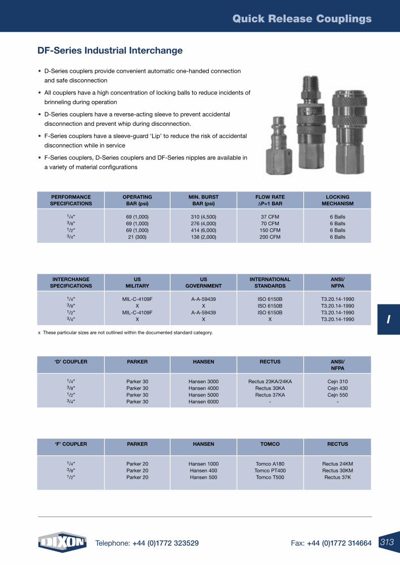
Quick Release Couplings
313Telephone: +44 (0)1772 323529 Fax: +44 (0)1772 314664
I
DF-Series Industrial Interchange
• D-Series couplers provide convenient automatic one-handed connection
and safe disconnection
• All couplers have a high concentration of locking balls to reduce incidents of
brinneling during operation
• D-Series couplers have a reverse-acting sleeve to prevent accidental
disconnection and prevent whip during disconnection.
• F-Series couplers have a sleeve-guard ‘Lip’ to reduce the risk of accidental
disconnection while in service
• F-Series couplers, D-Series couplers and DF-Series nipples are available in
a variety of material configurations
OPErATINGBAr (psi)
69 (1,000) 69 (1,000) 69 (1,000) 21 (300)
PErFOrMANCESPECIFICATIONS
1/4” 3/8” 1/2” 3/4”
MIN. BUrSTBAr (psi)
310 (4,500) 276 (4,000) 414 (6,000) 138 (2,000)
FLOw rATE DP=1 BAr
37 CFM 70 CFM 150 CFM 200 CFM
LOCKINGMECHANISM
6 Balls 6 Balls 6 Balls 6 Balls
x These particular sizes are not outlined within the documented standard category.
USMILITArY
MIL-C-4109F
X MIL-C-4109F
X
INTErCHANGESPECIFICATIONS
1/4” 3/8” 1/2” 3/4”
USGOVErNMENT
A-A-59439 X
A-A-59439 X
INTErNATIONAL STANDArDS
ISO 6150B ISO 6150B ISO 6150B
X
ANSI/ NFPA
T3.20.14-1990 T3.20.14-1990 T3.20.14-1990 T3.20.14-1990
PArKEr
Parker 30 Parker 30 Parker 30 Parker 30
‘D’ COUPLEr
1/4” 3/8” 1/2” 3/4”
HANSEN
Hansen 3000 Hansen 4000 Hansen 5000 Hansen 6000
rECTUS
Rectus 23KA/24KA Rectus 30KARectus 37KA
-
ANSI/ NFPA
Cejn 310Cejn 430Cejn 550
-
PArKEr
Parker 20 Parker 20 Parker 20
‘F’ COUPLEr
1/4” 3/8” 1/2”
HANSEN
Hansen 1000 Hansen 400 Hansen 500
TOMCO
Tomco A180 Tomco PT400Tomco T500
rECTUS
Rectus 24KMRectus 30KMRectus 37K
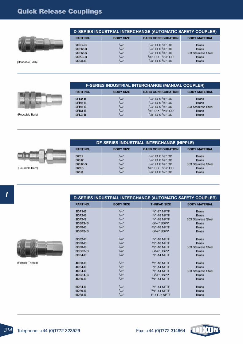
Quick Release Couplings
314 Telephone: +44 (0)1772 323529 Fax: +44 (0)1772 314664
I
(Reusable Barb)
(Reusable Barb)
(Reusable Barb)
(Female Thread)
D-SErIES INDUSTrIAL INTErCHANGE (AUTOMATIC SAFETY COUPLEr)
PArT NO. BODY SIzE BArB CONFIGUrATION BODY MATErIAL
2DE2-B 2DH2-B 2DH2-S 2DK3-B 2DL3-B
1/4” ID X 1/2” OD 1/4” ID X 5/8” OD 1/4” ID X 5/8” OD
3/8” ID X 11/16” OD 3/8” ID X 3/4” OD
BrassBrass
303 Stainless Steel BrassBrass
1/4”1/4” 1/4”1/4” 1/4”
F-SErIES INDUSTrIAL INTErCHANGE (MANUAL COUPLEr)
PArT NO. BODY SIzE BArB CONFIGUrATION BODY MATErIAL
2FE2-B 2FH2-B 2FH2-S 2FK3-B 2FL3-B
1/4” ID X 1/2” OD 1/4” ID X 5/8” OD 1/4” ID X 5/8” OD
3/8” ID X 11/16” OD 3/8” ID X 3/4” OD
BrassBrass
303 Stainless Steel BrassBrass
1/4”1/4” 1/4”1/4” 1/4”
DF-SErIES INDUSTrIAL INTErCHANGE (NIPPLE)
PArT NO. BODY SIzE BArB CONFIGUrATION BODY MATErIAL
D2E2 D2H2 D2H2-S D2K3 D2L3
1/4” ID X 1/2” OD 1/4” ID X 5/8” OD 1/4” ID X 5/8” OD
3/8” ID X 11/16” OD 3/8” ID X 3/4” OD
BrassBrass
303 Stainless Steel BrassBrass
1/4”1/4” 1/4”1/4” 1/4”
D-SErIES INDUSTrIAL INTErCHANGE (AUTOMATIC SAFETY COUPLEr)
PArT NO. BODY SIzE THrEAD SIzE BODY MATErIAL
2DF1-B 2DF2-B 2DF2-S 2DBF2-B 2DF3-B 2DBF3-B 3DF2-B 3DF3-B 3DF3-S 3DBF3-B 3DF4-B
4DF3-B 4DF4-B 4DF4-S 4DBF4-B 4DF6-B
6DF4-B 6DF6-B 6DF8-B
1/8”-27 NPTF 1/4”-18 NPTF 1/4”-18 NPTF G1/4” BSPP
3/8”-18 NPTF G3/8” BSPP
1/4”-18 NPTF 3/8”-18 NPTF 3/8”-18 NPTF G3/8” BSPP
1/2”-14 NPTF
3/8”-18 NPTF 1/2”-14 NPTF 1/2”-14 NPTF G1/2” BSPP
3/4”-14 NPTF
1/2”-14 NPTF 3/4”-14 NPTF
1”-111/2 NPTF
BrassBrass
303 Stainless Steel BrassBrass Brass
Brass Brass
303 Stainless Steel Brass Brass
Brass Brass
303 Stainless Steel Brass Brass
Brass Brass Brass
1/4”1/4” 1/4”1/4” 1/4” 1/4”
3/8” 3/8” 3/8” 3/8” 3/8”
1/2” 1/2” 1/2” 1/2” 1/2”
3/4” 3/4” 3/4”
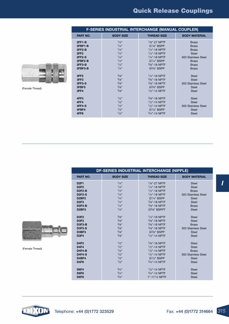
Quick Release Couplings
315Telephone: +44 (0)1772 323529 Fax: +44 (0)1772 314664
I
(Female Thread)
(Female Thread)
F-SErIES INDUSTrIAL INTErCHANGE (MANUAL COUPLEr)
PArT NO. BODY SIzE THrEAD SIzE BODY MATErIAL
2FF1-B 2FBF1-B 2FF2-B 2FF2 2FF2-S 2FBF2-B 2FF3-B 2FBF3-B
3FF2 3FF3 3FF3-S 3FBF3 3FF4 4FF3 4FF4 4FF4-S 4FBF4 4FF6
1/8”-27 NPTF G1/8” BSPP
1/4”-18 NPTF 1/4”-18 NPTF 1/4”-18 NPTF G1/4” BSPP
3/8”-18 NPTF G3/8” BSPP
1/4”-18 NPTF 3/8”-18 NPTF 3/8”-18 NPTF G3/8” BSPP
1/2”-14 NPTF
3/8”-18 NPTF 1/2”-14 NPTF 1/2”-14 NPTF G1/2” BSPP
3/4”-14 NPTF
BrassBrass BrassSteel
303 Stainless Steel Brass Brass Brass
Steel Steel
303 Stainless Steel Steel Steel
Steel Steel
303 Stainless Steel Steel Steel
1/4”1/4” 1/4”1/4” 1/4” 1/4” 1/4” 1/4”
3/8” 3/8” 3/8” 3/8” 3/8”
1/2” 1/2” 1/2” 1/2” 1/2”
DF-SErIES INDUSTrIAL INTErCHANGE (NIPPLE)
PArT NO. BODY SIzE THrEAD SIzE BODY MATErIAL
D2F1 D2F2 D2F2-B D2F2-S D2BF2 D2F3 D2F3-B D2BF3
D3F2 D3F3 D3F3-B D3F3-S D3BF3 D3F4 D4F3 D4F4 D4F4-B D4F4-S D4BF4 D4F6
D6F4 D6F6 D6F8
1/8”-27 NPTF 1/4”-18 NPTF 1/4”-18 NPTF 1/4”-18 NPTF G1/4” BSPP
3/8”-18 NPTF 3/8”-18 NPTF G3/8” BSPPT
1/4”-18 NPTF 3/8”-18 NPTF 3/8”-18 NPTF 3/8”-18 NPTF G3/8” BSPP
1/2”-14 NPTF
3/8”-18 NPTF 1/2”-14 NPTF 1/2”-14 NPTF 1/2”-14 NPTF G1/2” BSPP
3/4”-14 NPTF
1/2”-14 NPTF 3/4”-14 NPTF
1”-111/2 NPTF
Steel Steel Brass
303 Stainless Steel Steel Steel Brass Steel
Steel Steel Brass
303 Stainless Steel Steel Steel
Steel Steel Brass
303 Stainless Steel Steel Steel
Steel Steel Steel
1/4”1/4” 1/4”1/4” 1/4” 1/4” 1/4” 1/4”
3/8” 3/8” 3/8” 3/8” 3/8” 3/8”
1/2” 1/2” 1/2” 1/2” 1/2” 1/2”
3/4” 3/4” 3/4”
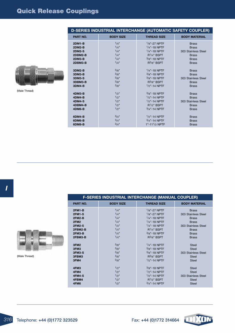
Quick Release Couplings
316 Telephone: +44 (0)1772 323529 Fax: +44 (0)1772 314664
I
(Male Thread)
(Male Thread)
D-SErIES INDUSTrIAL INTErCHANGE (AUTOMATIC SAFETY COUPLEr)
PArT NO. BODY SIzE THrEAD SIzE BODY MATErIAL
2DM1-B 2DM2-B 2DM2-S 2DBM2-B 2DM3-B 2DBM3-B 3DM2-B 3DM3-B 3DM3-S 3DBM3-B 3DM4-B
4DM3-B 4DM4-B 4DM4-S 4DBM4-B 4DM6-B
6DM4-B 6DM6-B 6DM8-B
1/8”-27 NPTF 1/4”-18 NPTF 1/4”-18 NPTF R1/4” BSPT
3/8”-18 NPTF R3/8” BSPT
1/4”-18 NPTF 3/8”-18 NPTF 3/8”-18 NPTF R3/8” BSPT
1/2”-14 NPTF
3/8”-18 NPTF 1/2”-14 NPTF 1/2”-14 NPTF R1/2” BSPT
3/4”-14 NPTF
1/2”-14 NPTF 3/4”-14 NPTF
1”-111/2 NPTF
BrassBrass
303 Stainless Steel BrassBrass Brass
Brass Brass
303 Stainless Steel Brass Brass
Brass Brass
303 Stainless Steel Brass Brass
Brass Brass Brass
1/4”1/4” 1/4”1/4” 1/4” 1/4”
3/8” 3/8” 3/8” 3/8” 3/8”
1/2” 1/2” 1/2” 1/2” 1/2”
3/4” 3/4” 3/4”
F-SErIES INDUSTrIAL INTErCHANGE (MANUAL COUPLEr)
PArT NO. BODY SIzE THrEAD SIzE BODY MATErIAL
2FM1-B 2FM1-S 2FM2-B 2FM2 2FM2-S 2FBM2-B 2FM3-B 2FBM3-B
3FM2 3FM3 3FM3-S 3FBM3 3FM4
4FM3 4FM4 4FM4-S 4FBM4 4FM6
1/8”-27 NPTF 1/8”-27 NPTF 1/4”-18 NPTF 1/4”-18 NPTF 1/4”-18 NPTF R1/4” BSPT
3/8”-18 NPTF R3/8” BSPT
1/4”-18 NPTF 3/8”-18 NPTF 3/8”-18 NPTF R3/8” BSPT
1/2”-14 NPTF
3/8”-18 NPTF 1/2”-14 NPTF 1/2”-14 NPTF R1/2” BSPT
3/4”-14 NPTF
Brass303 Stainless Steel
BrassBrass
303 Stainless Steel Brass Brass Brass
Steel Steel
303 Stainless Steel Steel Steel
Steel Steel
303 Stainless Steel Steel Steel
1/4”1/4” 1/4”1/4” 1/4” 1/4” 1/4” 1/4”
3/8” 3/8” 3/8” 3/8” 3/8”
1/2” 1/2” 1/2” 1/2” 1/2”
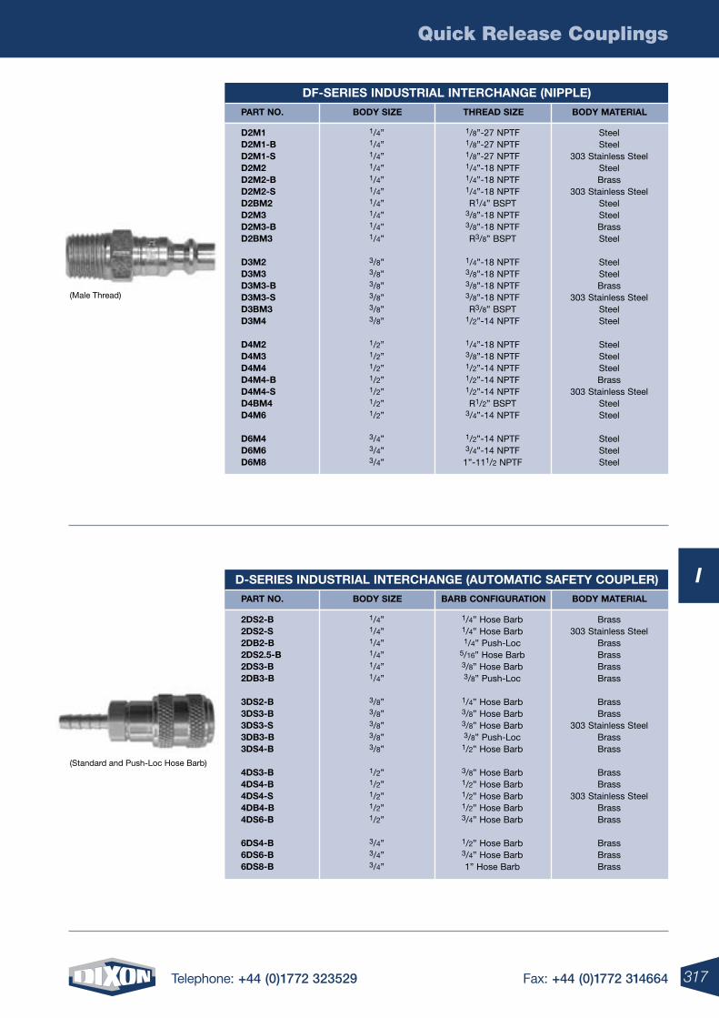
Quick Release Couplings
317Telephone: +44 (0)1772 323529 Fax: +44 (0)1772 314664
I
(Male Thread)
(Standard and Push-Loc Hose Barb)
DF-SErIES INDUSTrIAL INTErCHANGE (NIPPLE)
PArT NO. BODY SIzE THrEAD SIzE BODY MATErIAL
D2M1 D2M1-B D2M1-S D2M2 D2M2-B D2M2-S D2BM2 D2M3 D2M3-B D2BM3
D3M2 D3M3 D3M3-B D3M3-S D3BM3 D3M4
D4M2 D4M3 D4M4 D4M4-B D4M4-S D4BM4 D4M6
D6M4 D6M6 D6M8
1/8”-27 NPTF 1/8”-27 NPTF 1/8”-27 NPTF 1/4”-18 NPTF 1/4”-18 NPTF 1/4”-18 NPTF R1/4” BSPT
3/8”-18 NPTF 3/8”-18 NPTF R3/8” BSPT
1/4”-18 NPTF 3/8”-18 NPTF 3/8”-18 NPTF 3/8”-18 NPTF R3/8” BSPT
1/2”-14 NPTF
1/4”-18 NPTF 3/8”-18 NPTF 1/2”-14 NPTF 1/2”-14 NPTF 1/2”-14 NPTF R1/2” BSPT
3/4”-14 NPTF
1/2”-14 NPTF 3/4”-14 NPTF
1”-111/2 NPTF
Steel Steel
303 Stainless Steel SteelBrass
303 Stainless Steel Steel Steel Brass Steel
Steel Steel Brass
303 Stainless Steel Steel Steel
Steel Steel Steel Brass
303 Stainless Steel Steel Steel
Steel Steel Steel
1/4”1/4” 1/4”1/4” 1/4” 1/4” 1/4” 1/4” 1/4” 1/4”
3/8” 3/8” 3/8” 3/8” 3/8” 3/8”
1/2” 1/2” 1/2” 1/2” 1/2” 1/2” 1/2”
3/4” 3/4” 3/4”
D-SErIES INDUSTrIAL INTErCHANGE (AUTOMATIC SAFETY COUPLEr)
PArT NO. BODY SIzE BArB CONFIGUrATION BODY MATErIAL
2DS2-B 2DS2-S 2DB2-B 2DS2.5-B 2DS3-B 2DB3-B
3DS2-B 3DS3-B 3DS3-S 3DB3-B 3DS4-B
4DS3-B 4DS4-B 4DS4-S 4DB4-B 4DS6-B
6DS4-B 6DS6-B 6DS8-B
Brass 303 Stainless Steel
Brass Brass Brass Brass
Brass Brass
303 Stainless Steel Brass Brass
Brass Brass
303 Stainless Steel Brass Brass
Brass Brass Brass
1/4” Hose Barb 1/4” Hose Barb 1/4” Push-Loc
5/16” Hose Barb 3/8” Hose Barb 3/8” Push-Loc
1/4” Hose Barb 3/8” Hose Barb 3/8” Hose Barb 3/8” Push-Loc
1/2” Hose Barb
3/8” Hose Barb 1/2” Hose Barb 1/2” Hose Barb 1/2” Hose Barb 3/4” Hose Barb
1/2” Hose Barb 3/4” Hose Barb 1” Hose Barb
1/4”1/4” 1/4”1/4” 1/4” 1/4”
3/8” 3/8” 3/8” 3/8” 3/8”
1/2” 1/2” 1/2” 1/2” 1/2”
3/4” 3/4” 3/4”
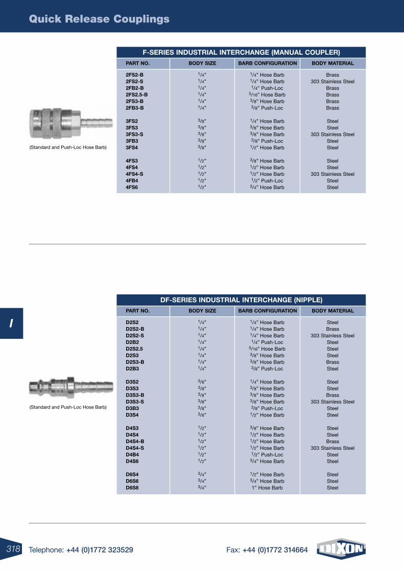
Quick Release Couplings
318 Telephone: +44 (0)1772 323529 Fax: +44 (0)1772 314664
I
(Standard and Push-Loc Hose Barb)
(Standard and Push-Loc Hose Barb)
F-SErIES INDUSTrIAL INTErCHANGE (MANUAL COUPLEr)
PArT NO. BODY SIzE BArB CONFIGUrATION BODY MATErIAL
2FS2-B 2FS2-S 2FB2-B 2FS2.5-B 2FS3-B 2FB3-B 3FS2 3FS3 3FS3-S 3FB3 3FS4
4FS3 4FS4 4FS4-S 4FB4 4FS6
1/4” Hose Barb 1/4” Hose Barb 1/4” Push-Loc
5/16” Hose Barb 3/8” Hose Barb 3/8” Push-Loc
1/4” Hose Barb 3/8” Hose Barb 3/8” Hose Barb 3/8” Push-Loc
1/2” Hose Barb
3/8” Hose Barb 1/2” Hose Barb 1/2” Hose Barb 1/2” Push-Loc
3/4” Hose Barb
Brass303 Stainless Steel
BrassBrass Brass Brass
Steel Steel
303 Stainless Steel Steel Steel
Steel Steel
303 Stainless Steel Steel Steel
1/4”1/4” 1/4”1/4” 1/4” 1/4”
3/8” 3/8” 3/8” 3/8” 3/8”
1/2” 1/2” 1/2” 1/2” 1/2”
DF-SErIES INDUSTrIAL INTErCHANGE (NIPPLE)
PArT NO. BODY SIzE BArB CONFIGUrATION BODY MATErIAL
D2S2 D2S2-B D2S2-S D2B2 D2S2.5 D2S3 D2S3-B D2B3
D3S2 D3S3 D3S3-B D3S3-S D3B3 D3S4
D4S3 D4S4 D4S4-B D4S4-S D4B4 D4S6
D6S4 D6S6 D6S8
1/4” Hose Barb 1/4” Hose Barb 1/4” Hose Barb 1/4” Push-Loc
5/16” Hose Barb 3/8” Hose Barb 3/8” Hose Barb 3/8” Push-Loc
1/4” Hose Barb 3/8” Hose Barb 3/8” Hose Barb 3/8” Hose Barb 3/8” Push-Loc
1/2” Hose Barb
3/8” Hose Barb 1/2” Hose Barb 1/2” Hose Barb 1/2” Hose Barb 1/2” Push-Loc
3/4” Hose Barb
1/2” Hose Barb 3/4” Hose Barb 1” Hose Barb
Steel Brass
303 Stainless Steel Steel Steel Steel BrassSteel
Steel Steel Brass
303 Stainless Steel Steel Steel
Steel Steel Brass
303 Stainless Steel Steel Steel
Steel SteelSteel
1/4”1/4” 1/4”1/4” 1/4” 1/4” 1/4” 1/4”
3/8” 3/8” 3/8” 3/8” 3/8” 3/8”
1/2” 1/2” 1/2” 1/2” 1/2” 1/2”
3/4” 3/4” 3/4”
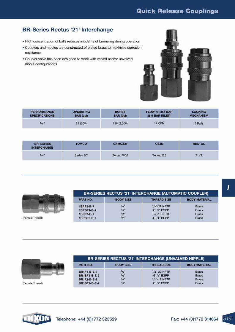
Quick Release Couplings
319Telephone: +44 (0)1772 323529 Fax: +44 (0)1772 314664
I
Br-Series rectus ‘21’ Interchange
(Female Thread)
(Female Thread)
Br-SErIES rECTUS ‘21’ INTErCHANGE (UNVALVED NIPPLE)
PArT NO. BODY SIzE THrEAD SIzE BODY MATErIAL
Br1F1-B-E-7Br1BF1-B-E-7Br1F2-B-E-7
Br1BF2-B-E-7
1/8”-27 NPTFG1/8” BSPP
1/4”-18 NPTFG1/4” BSPP
BrassBrassBrassBrass
1/8”1/8”1/8”1/8”
Br-SErIES rECTUS ‘21’ INTErCHANGE (AUTOMATIC COUPLEr)
PArT NO. BODY SIzE THrEAD SIzE BODY MATErIAL
1BrF1-B-71BrBF1-B-71BrF2-B-7
1BrBF2-B-7
1/8”-27 NPTFG1/8” BSPP
1/4”-18 NPTFG1/4” BSPP
BrassBrassBrassBrass
1/8”1/8”1/8”1/8”
OPErATINGBAr (psi)
21 (300)
PErFOrMANCESPECIFICATIONS
1/8”
BUrSTBAr (psi)
138 (2,000)
FLOw DP=0.4 BAr(6.9 BAr INLET)
17 CFM
LOCKINGMECHANISM
6 Balls
TOMCO
Series SC
‘Br’ SErIESINTErCHANGE
1/8”
CAMOzzI
Series 5000
CEJN
Series 223
rECTUS
21KA
• High concentration of balls reduces incidents of brinneling during operation
• Couplers and nipples are constructed of plated brass to maximise corrosion resistance
• Coupler valve has been designed to work with valved and/or unvalved nipple configurations
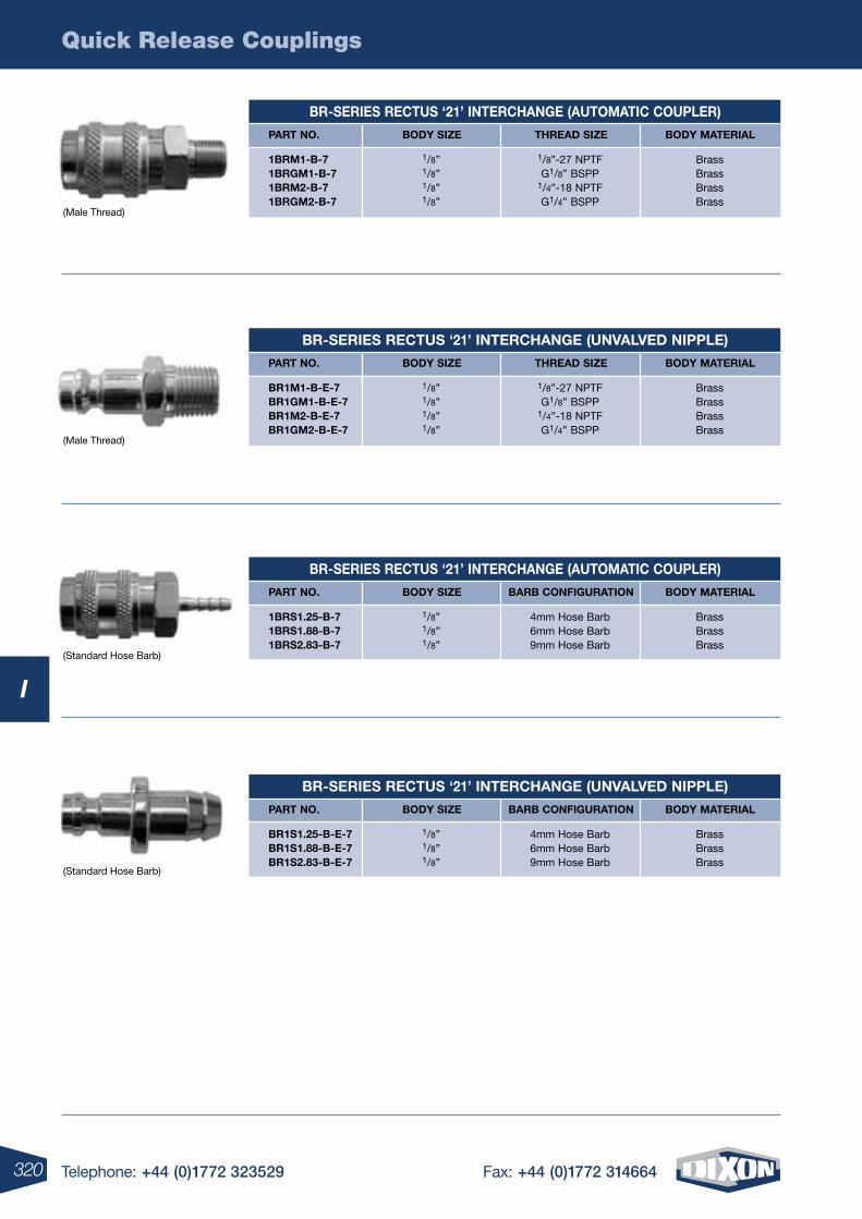
Quick Release Couplings
320 Telephone: +44 (0)1772 323529 Fax: +44 (0)1772 314664
I
(Male Thread)
(Male Thread)
(Standard Hose Barb)
(Standard Hose Barb)
Br-SErIES rECTUS ‘21’ INTErCHANGE (AUTOMATIC COUPLEr)
PArT NO. BODY SIzE THrEAD SIzE BODY MATErIAL
1BrM1-B-71BrGM1-B-71BrM2-B-7
1BrGM2-B-7
1/8”-27 NPTFG1/8” BSPP
1/4”-18 NPTFG1/4” BSPP
BrassBrassBrassBrass
1/8”1/8”1/8”1/8”
Br-SErIES rECTUS ‘21’ INTErCHANGE (UNVALVED NIPPLE)
PArT NO. BODY SIzE THrEAD SIzE BODY MATErIAL
Br1M1-B-E-7Br1GM1-B-E-7Br1M2-B-E-7
Br1GM2-B-E-7
1/8”-27 NPTFG1/8” BSPP
1/4”-18 NPTFG1/4” BSPP
BrassBrassBrassBrass
1/8”1/8”1/8”1/8”
Br-SErIES rECTUS ‘21’ INTErCHANGE (AUTOMATIC COUPLEr)
PArT NO. BODY SIzE BArB CONFIGUrATION BODY MATErIAL
1BrS1.25-B-71BrS1.88-B-7
1BrS2.83-B-7
4mm Hose Barb6mm Hose Barb9mm Hose Barb
BrassBrassBrass
1/8”1/8”1/8”
Br-SErIES rECTUS ‘21’ INTErCHANGE (UNVALVED NIPPLE)
PArT NO. BODY SIzE BArB CONFIGUrATION BODY MATErIAL
Br1S1.25-B-E-7Br1S1.88-B-E-7
Br1S2.83-B-E-7
4mm Hose Barb6mm Hose Barb9mm Hose Barb
BrassBrassBrass
1/8”1/8”1/8”
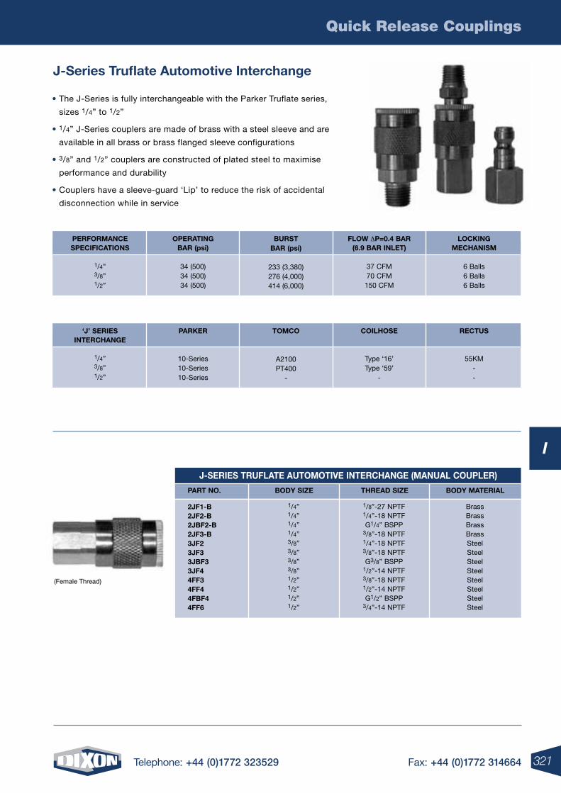
Quick Release Couplings
321Telephone: +44 (0)1772 323529 Fax: +44 (0)1772 314664
I
(Female Thread)
J-Series Truflate Automotive Interchange
J-SErIES TrUFLATE AUTOMOTIVE INTErCHANGE (MANUAL COUPLEr)
PArT NO. BODY SIzE THrEAD SIzE BODY MATErIAL
2JF1-B2JF2-B2JBF2-B2JF3-B3JF23JF33JBF33JF44FF34FF44FBF4
4FF6
1/8”-27 NPTF1/4”-18 NPTFG1/4” BSPP
3/8”-18 NPTF1/4”-18 NPTF3/8”-18 NPTFG3/8” BSPP
1/2”-14 NPTF3/8”-18 NPTF1/2”-14 NPTFG1/2” BSPP
3/4”-14 NPTF
BrassBrassBrassBrassSteelSteelSteelSteelSteelSteelSteelSteel
1/4”1/4”1/4”1/4”3/8”3/8”3/8”3/8”1/2”1/2”1/2”1/2”
• The J-Series is fully interchangeable with the Parker Truflate series,
sizes 1/4” to 1/2”
• 1/4” J-Series couplers are made of brass with a steel sleeve and are
available in all brass or brass flanged sleeve configurations
• 3/8” and 1/2” couplers are constructed of plated steel to maximise
performance and durability
• Couplers have a sleeve-guard ‘Lip’ to reduce the risk of accidental
disconnection while in service
OPErATINGBAr (psi)
34 (500)34 (500)34 (500)
PErFOrMANCESPECIFICATIONS
1/4”3/8”1/2”
BUrSTBAr (psi)
233 (3,380)276 (4,000)414 (6,000)
FLOw DP=0.4 BAr(6.9 BAr INLET)
37 CFM70 CFM150 CFM
LOCKINGMECHANISM
6 Balls 6 Balls 6 Balls
PArKEr
10-Series10-Series10-Series
‘J’ SErIESINTErCHANGE
1/4”3/8”1/2”
TOMCO
A2100PT400
-
COILHOSE
Type ‘16’Type ‘59’
-
rECTUS
55KM--
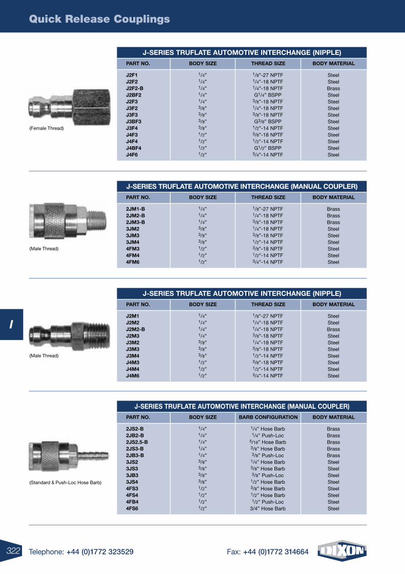
Quick Release Couplings
322 Telephone: +44 (0)1772 323529 Fax: +44 (0)1772 314664
I
(Female Thread)
(Male Thread)
(Male Thread)
(Standard & Push-Loc Hose Barb)
J-SErIES TrUFLATE AUTOMOTIVE INTErCHANGE (NIPPLE)
PArT NO. BODY SIzE THrEAD SIzE BODY MATErIAL
J2F1J2F2J2F2-BJ2BF2J2F3J3F2J3F3J3BF3J3F4J4F3J4F4J4BF4
J4F6
1/8”-27 NPTF1/4”-18 NPTF1/4”-18 NPTFG1/4” BSPP
3/8”-18 NPTF1/4”-18 NPTF3/8”-18 NPTFG3/8” BSPP
1/2”-14 NPTF3/8”-18 NPTF1/2”-14 NPTFG1/2” BSPP
3/4”-14 NPTF
SteelSteelBrassSteelSteelSteelSteelSteelSteelSteelSteelSteelSteel
1/4”1/4”1/4”1/4”1/4”3/8”3/8”3/8”3/8”1/2”1/2”1/2”1/2”
J-SErIES TrUFLATE AUTOMOTIVE INTErCHANGE (MANUAL COUPLEr)
PArT NO. BODY SIzE BArB CONFIGUrATION BODY MATErIAL
2JS2-B2JB2-B2JS2.5-B2JS3-B2JB3-B3JS23JS33JB33JS44FS34FS44FB4
4FS6
1/4” Hose Barb1/4” Push-Loc
5/16” Hose Barb3/8” Hose Barb3/8” Push-Loc
1/4” Hose Barb3/8” Hose Barb3/8” Push-Loc
1/2” Hose Barb3/8” Hose Barb1/2” Hose Barb1/2” Push-Loc
3/4” Hose Barb
BrassBrassBrassBrassBrassSteelSteelSteelSteelSteelSteelSteelSteel
1/4”1/4”1/4”1/4”1/4”3/8”3/8”3/8”3/8”1/2”1/2”1/2”1/2”
J-SErIES TrUFLATE AUTOMOTIVE INTErCHANGE (NIPPLE)
PArT NO. BODY SIzE THrEAD SIzE BODY MATErIAL
J2M1J2M2J2M2-BJ2M3J3M2J3M3J3M4J4M3J4M4
J4M6
1/8”-27 NPTF1/4”-18 NPTF1/4”-18 NPTF3/8”-18 NPTF1/4”-18 NPTF3/8”-18 NPTF1/2”-14 NPTF3/8”-18 NPTF1/2”-14 NPTF3/4”-14 NPTF
SteelSteelBrassSteelSteelSteelSteelSteelSteelSteel
1/4”1/4”1/4”1/4”3/8”3/8”3/8”1/2”1/2”1/2”
J-SErIES TrUFLATE AUTOMOTIVE INTErCHANGE (MANUAL COUPLEr)
PArT NO. BODY SIzE THrEAD SIzE BODY MATErIAL
2JM1-B2JM2-B2JM3-B3JM23JM33JM44FM34FM4
4FM6
1/8”-27 NPTF1/4”-18 NPTF3/8”-18 NPTF1/4”-18 NPTF3/8”-18 NPTF1/2”-14 NPTF3/8”-18 NPTF1/2”-14 NPTF3/4”-14 NPTF
BrassBrassBrassSteelSteelSteelSteelSteelSteel
1/4”1/4”1/4”3/8”3/8”3/8”1/2”1/2”1/2”
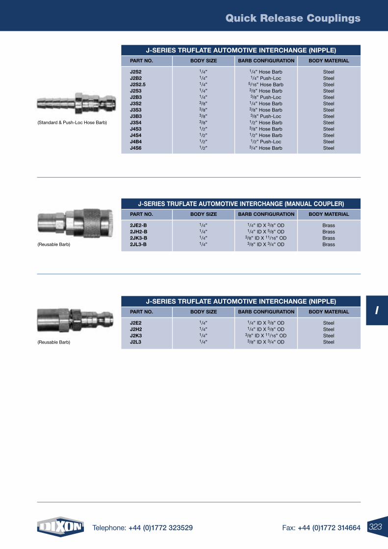
Quick Release Couplings
323Telephone: +44 (0)1772 323529 Fax: +44 (0)1772 314664
I
(Standard & Push-Loc Hose Barb)
(Reusable Barb)
J-SErIES TrUFLATE AUTOMOTIVE INTErCHANGE (NIPPLE)
PArT NO. BODY SIzE BArB CONFIGUrATION BODY MATErIAL
J2S2J2B2J2S2.5J2S3J2B3J3S2J3S3J3B3J3S4J4S3J4S4J4B4
J4S6
1/4” Hose Barb1/4” Push-Loc
5/16” Hose Barb3/8” Hose Barb3/8” Push-Loc
1/4” Hose Barb3/8” Hose Barb3/8” Push-Loc
1/2” Hose Barb3/8” Hose Barb1/2” Hose Barb1/2” Push-Loc
3/4” Hose Barb
SteelSteelSteelSteelSteelSteelSteelSteelSteelSteelSteelSteelSteel
1/4”1/4”1/4”1/4”1/4”3/8”3/8”3/8”3/8”1/2”1/2”1/2”1/2”
(Reusable Barb)
J-SErIES TrUFLATE AUTOMOTIVE INTErCHANGE (MANUAL COUPLEr)
PArT NO. BODY SIzE BArB CONFIGUrATION BODY MATErIAL
2JE2-B2JH2-B2JK3-B
2JL3-B
1/4” ID X 3/8” OD1/4” ID X 5/8” OD
3/8” ID X 11/16” OD3/8” ID X 3/4” OD
BrassBrassBrassBrass
1/4”1/4”1/4”1/4”
J-SErIES TrUFLATE AUTOMOTIVE INTErCHANGE (NIPPLE)
PArT NO. BODY SIzE BArB CONFIGUrATION BODY MATErIAL
J2E2J2H2J2K3
J2L3
1/4” ID X 3/8” OD1/4” ID X 5/8” OD
3/8” ID X 11/16” OD3/8” ID X 3/4” OD
SteelSteelSteelSteel
1/4”1/4”1/4”1/4”
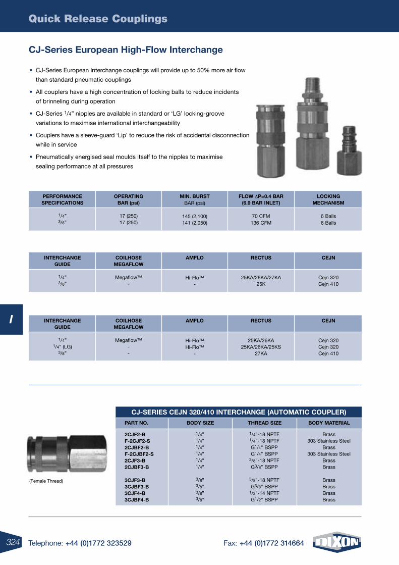
Quick Release Couplings
324 Telephone: +44 (0)1772 323529 Fax: +44 (0)1772 314664
I
CJ-Series European High-Flow Interchange
(Female Thread)
CJ-SErIES CEJN 320/410 INTErCHANGE (AUTOMATIC COUPLEr)
PArT NO. BODY SIzE THrEAD SIzE BODY MATErIAL
2CJF2-B F-2CJF2-S 2CJBF2-B F-2CJBF2-S 2CJF3-B 2CJBF3-B 3CJF3-B 3CJBF3-B 3CJF4-B 3CJBF4-B
1/4”-18 NPTF 1/4”-18 NPTF G1/4” BSPP G1/4” BSPP
3/8”-18 NPTF G3/8” BSPP
3/8”-18 NPTF G3/8” BSPP
1/2”-14 NPTF G1/2” BSPP
Brass303 Stainless Steel
Brass 303 Stainless Steel
Brass Brass
Brass Brass Brass Brass
1/4”1/4” 1/4”1/4” 1/4” 1/4”
3/8” 3/8” 3/8” 3/8”
• CJ-Series European Interchange couplings will provide up to 50% more air flow
than standard pneumatic couplings
• All couplers have a high concentration of locking balls to reduce incidents
of brinneling during operation
• CJ-Series 1/4” nipples are available in standard or ‘LG’ locking-groove
variations to maximise international interchangeability
• Couplers have a sleeve-guard ‘Lip’ to reduce the risk of accidental disconnection
while in service
• Pneumatically energised seal moulds itself to the nipples to maximise
sealing performance at all pressures
OPErATINGBAr (psi)
17 (250)17 (250)
PErFOrMANCESPECIFICATIONS
1/4” 3/8”
MIN. BUrSTBAR (psi)
145 (2,100) 141 (2,050)
FLOw DP=0.4 BAr(6.9 BAr INLET)
70 CFM 136 CFM
LOCKINGMECHANISM
6 Balls 6 Balls
COILHOSEMEGAFLOw
Megaflow™
-
INTErCHANGEGUIDE
1/4” 3/8”
AMFLO
Hi-Flo™ -
rECTUS
25KA/26KA/27KA 25K
CEJN
Cejn 320 Cejn 410
COILHOSEMEGAFLOw
Megaflow™
- -
INTErCHANGEGUIDE
1/4” 1/4” (LG)
3/8”
AMFLO
Hi-Flo™ Hi-Flo™
-
rECTUS
25KA/26KA 25KA/26KA/25KS
27KA
CEJN
Cejn 320 Cejn 320 Cejn 410
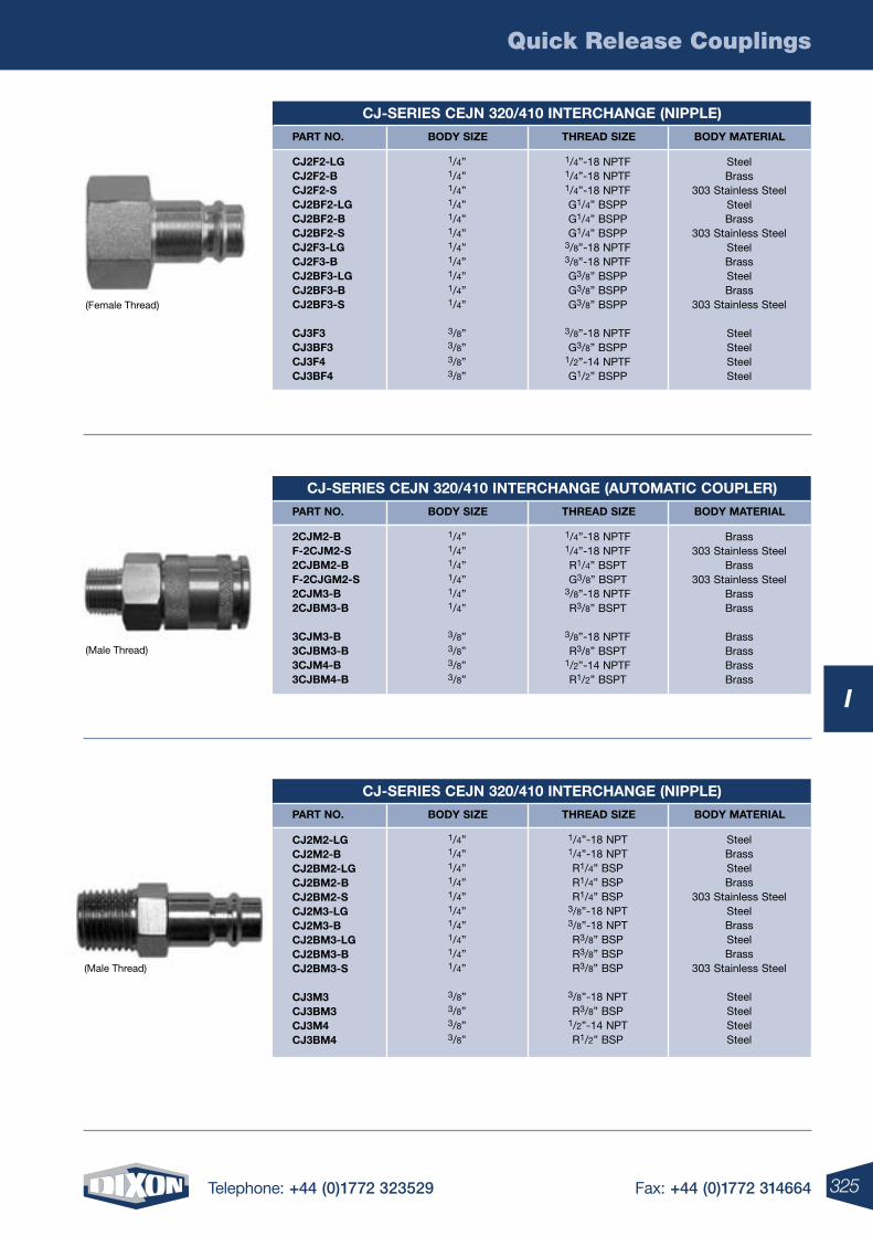
Quick Release Couplings
325Telephone: +44 (0)1772 323529 Fax: +44 (0)1772 314664
I
(Female Thread)
(Male Thread)
(Male Thread)
CJ-SErIES CEJN 320/410 INTErCHANGE (NIPPLE)
PArT NO. BODY SIzE THrEAD SIzE BODY MATErIAL
CJ2F2-LG CJ2F2-B CJ2F2-S CJ2BF2-LG CJ2BF2-B CJ2BF2-S CJ2F3-LG CJ2F3-B CJ2BF3-LG CJ2BF3-B CJ2BF3-S
CJ3F3 CJ3BF3 CJ3F4 CJ3BF4
1/4”-18 NPTF 1/4”-18 NPTF 1/4”-18 NPTF G1/4” BSPP G1/4” BSPP G1/4” BSPP
3/8”-18 NPTF 3/8”-18 NPTF G3/8” BSPP G3/8” BSPP G3/8” BSPP
3/8”-18 NPTF G3/8” BSPP
1/2”-14 NPTF G1/2” BSPP
Steel Brass
303 Stainless Steel Steel Brass
303 Stainless Steel Steel Brass Steel Brass
303 Stainless Steel
Steel Steel Steel Steel
1/4”1/4” 1/4”1/4” 1/4” 1/4” 1/4” 1/4” 1/4” 1/4” 1/4”
3/8” 3/8” 3/8” 3/8”
CJ-SErIES CEJN 320/410 INTErCHANGE (NIPPLE)
PArT NO. BODY SIzE THrEAD SIzE BODY MATErIAL
CJ2M2-LG CJ2M2-B CJ2BM2-LG CJ2BM2-B CJ2BM2-S CJ2M3-LG CJ2M3-B CJ2BM3-LG CJ2BM3-B CJ2BM3-S
CJ3M3 CJ3BM3 CJ3M4 CJ3BM4
1/4”-18 NPT 1/4”-18 NPT R1/4” BSP R1/4” BSP R1/4” BSP
3/8”-18 NPT 3/8”-18 NPT R3/8” BSP R3/8” BSP R3/8” BSP
3/8”-18 NPT R3/8” BSP
1/2”-14 NPT R1/2” BSP
Steel BrassSteel Brass
303 Stainless Steel Steel Brass Steel Brass
303 Stainless Steel
Steel Steel Steel Steel
1/4”1/4” 1/4”1/4” 1/4” 1/4” 1/4” 1/4” 1/4” 1/4”
3/8” 3/8” 3/8” 3/8”
CJ-SErIES CEJN 320/410 INTErCHANGE (AUTOMATIC COUPLEr)
PArT NO. BODY SIzE THrEAD SIzE BODY MATErIAL
2CJM2-B F-2CJM2-S 2CJBM2-B F-2CJGM2-S 2CJM3-B 2CJBM3-B
3CJM3-B 3CJBM3-B 3CJM4-B 3CJBM4-B
1/4”-18 NPTF 1/4”-18 NPTF R1/4” BSPT G3/8” BSPT
3/8”-18 NPTF R3/8” BSPT
3/8”-18 NPTF R3/8” BSPT
1/2”-14 NPTF R1/2” BSPT
Brass303 Stainless Steel
Brass303 Stainless Steel
Brass Brass
Brass Brass Brass Brass
1/4”1/4” 1/4”1/4” 1/4” 1/4”
3/8” 3/8” 3/8” 3/8”
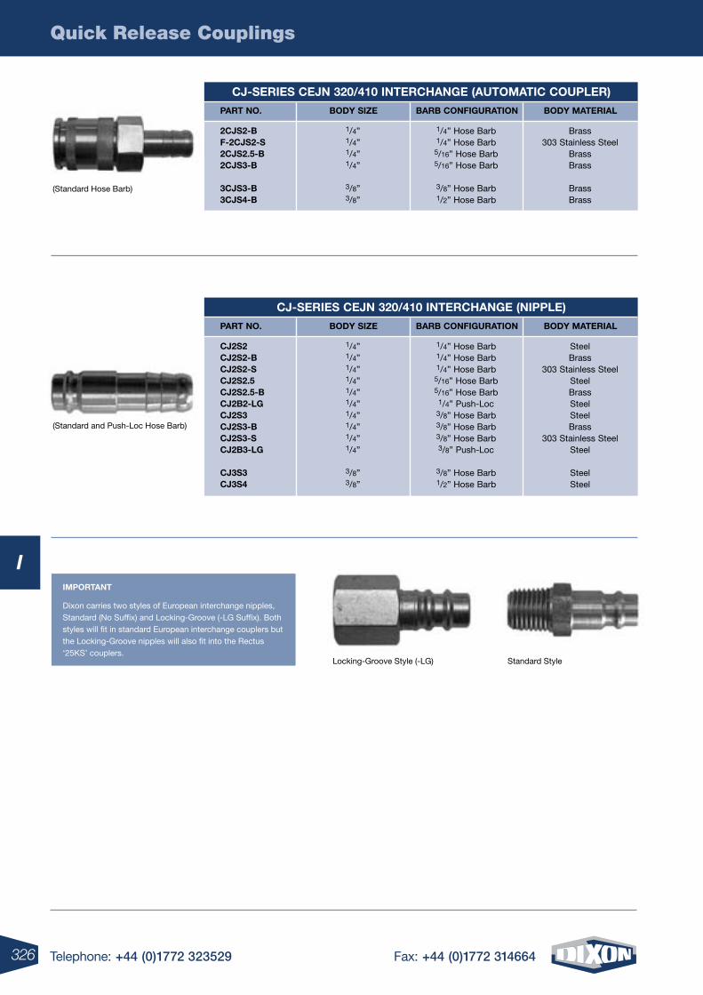
Quick Release Couplings
326 Telephone: +44 (0)1772 323529 Fax: +44 (0)1772 314664
I
(Standard Hose Barb)
(Standard and Push-Loc Hose Barb)
Standard StyleLocking-Groove Style (-LG)
IMPOrTANT
Dixon carries two styles of European interchange nipples, Standard (No Suffix) and Locking-Groove (-LG Suffix). Both styles will fit in standard European interchange couplers but the Locking-Groove nipples will also fit into the Rectus ‘25KS’ couplers.
CJ-SErIES CEJN 320/410 INTErCHANGE (AUTOMATIC COUPLEr)
PArT NO. BODY SIzE BArB CONFIGUrATION BODY MATErIAL
2CJS2-B F-2CJS2-S 2CJS2.5-B 2CJS3-B
3CJS3-B 3CJS4-B
1/4” Hose Barb 1/4” Hose Barb 5/16” Hose Barb 5/16” Hose Barb
3/8” Hose Barb 1/2” Hose Barb
Brass303 Stainless Steel
Brass Brass
Brass Brass
1/4”1/4” 1/4”1/4”
3/8” 3/8”
CJ-SErIES CEJN 320/410 INTErCHANGE (NIPPLE)
PArT NO. BODY SIzE BArB CONFIGUrATION BODY MATErIAL
CJ2S2 CJ2S2-B CJ2S2-S CJ2S2.5 CJ2S2.5-B CJ2B2-LG CJ2S3 CJ2S3-B CJ2S3-S CJ2B3-LG
CJ3S3 CJ3S4
1/4” Hose Barb 1/4” Hose Barb 1/4” Hose Barb 5/16” Hose Barb 5/16” Hose Barb
1/4” Push-Loc 3/8” Hose Barb 3/8” Hose Barb 3/8” Hose Barb 3/8” Push-Loc
3/8” Hose Barb 1/2” Hose Barb
Steel Brass
303 Stainless Steel Steel Brass Steel Steel Brass
303 Stainless Steel Steel
Steel Steel
1/4”1/4” 1/4”1/4” 1/4”1/4” 1/4”1/4” 1/4”1/4”
3/8” 3/8”
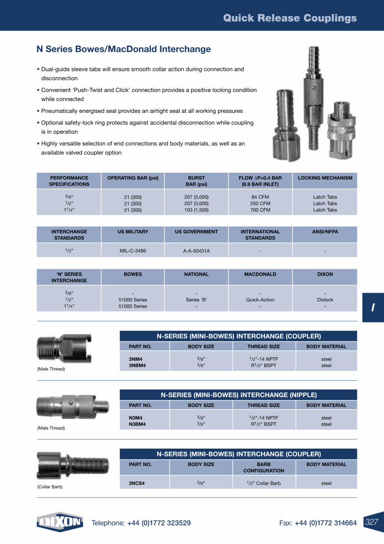
Quick Release Couplings
327Telephone: +44 (0)1772 323529 Fax: +44 (0)1772 314664
I
N Series Bowes/MacDonald Interchange
N-SErIES (MINI-BOwES) INTErCHANGE (COUPLEr)
PArT NO.
3NM43NBM4
BODY SIzE
3/8”3/8”
THrEAD SIzE
1/2”-14 NPTFR1/2” BSPT
BODY MATErIAL
steelsteel
BOwES
-51000 Series51000 Series
‘N’ SErIESINTErCHANGE
3/8”1/2”
11/4”
NATIONAL
-Series ‘B’
-
MACDONALD
-Quick-Action
-
DIXON
-Dixlock
-
OPErATING BAr (psi)
21 (300)21 (300)21 (300)
PErFOrMANCESPECIFICATIONS
3/8”1/2”
11/4”
BUrSTBAr (psi)
207 (3,000)207 (3,000)103 (1,500)
FLOw DP=0.4 BAr(6.9 BAr INLET)
84 CFM250 CFM700 CFM
LOCKING MECHANISM
Latch TabsLatch TabsLatch Tabs
US MILITArY
MIL-C-3486
INTErCHANGESTANDArDS
1/2”
US GOVErNMENT
A-A-50431A
INTErNATIONALSTANDArDS
-
ANSI/NFPA
-
N-SErIES (MINI-BOwES) INTErCHANGE (NIPPLE)
PArT NO.
N3M4N3BM4
BODY SIzE
3/8”3/8”
THrEAD SIzE
1/2”-14 NPTFR1/2” BSPT
BODY MATErIAL
steelsteel
N-SErIES (MINI-BOwES) INTErCHANGE (COUPLEr)
PArT NO.
3NCS4
BODY SIzE
3/8”
BArBCONFIGUrATION
1/2” Collar Barb
BODY MATErIAL
steel
(Male Thread)
(Male Thread)
(Collar Barb)
• Dual-guide sleeve tabs will ensure smooth collar action during connection and
disconnection
• Convenient ‘Push-Twist and Click’ connection provides a positive locking condition
while connected
• Pneumatically energised seal provides an airtight seal at all working pressures
• Optional safety-lock ring protects against accidental disconnection while coupling
is in operation
• Highly versatile selection of end connections and body materials, as well as an
available valved coupler option
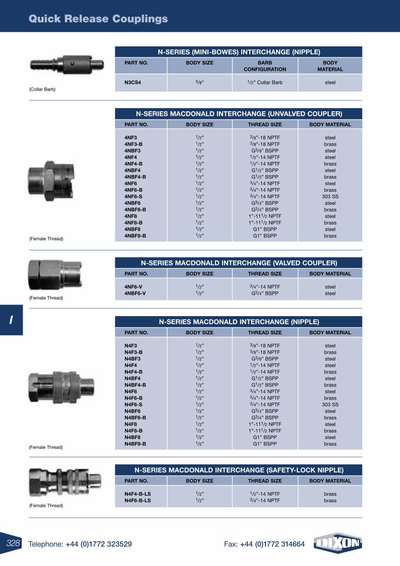
Quick Release Couplings
328 Telephone: +44 (0)1772 323529 Fax: +44 (0)1772 314664
I
N-SErIES (MINI-BOwES) INTErCHANGE (NIPPLE)
PArT NO.
N3CS4
BODY SIzE
3/8”
BArB CONFIGUrATION
1/2” Collar Barb
BODY MATErIAL
steel
N-SErIES MACDONALD INTErCHANGE (UNVALVED COUPLEr)
PArT NO.
4NF34NF3-B4NBF34NF44NF4-B4NBF44NBF4-B4NF64NF6-B4NF6-S4NBF64NBF6-B4NF84NF8-B4NBF84NBF8-B
BODY SIzE
1/2”1/2”1/2”1/2”1/2”1/2”1/2”1/2”1/2”1/2”1/2”1/2”1/2”1/2”1/2”1/2”
THrEAD SIzE
3/8”-18 NPTF3/8”-18 NPTFG3/8” BSPP
1/2”-14 NPTF1/2”-14 NPTFG1/2” BSPPG1/2” BSPP
3/4”-14 NPTF3/4”-14 NPTF3/4”-14 NPTFG3/4” BSPPG3/4” BSPP
1”-111/2 NPTF1”-111/2 NPTF
G1” BSPPG1” BSPP
BODY MATErIAL
steelbrasssteelsteelbrasssteelbrasssteelbrass
303 SSsteelbrasssteelbrasssteelbrass
N-SErIES MACDONALD INTErCHANGE (NIPPLE)
PArT NO.
N4F3N4F3-BN4BF3N4F4N4F4-BN4BF4N4BF4-BN4F6N4F6-BN4F6-SN4BF6N4BF6-BN4F8N4F8-BN4BF8N4BF8-B
BODY SIzE
1/2”1/2”1/2”1/2”1/2”1/2”1/2”1/2”1/2”1/2”1/2”1/2”1/2”1/2”1/2”1/2”
THrEAD SIzE
3/8”-18 NPTF3/8”-18 NPTFG3/8” BSPP
1/2”-14 NPTF1/2”-14 NPTFG1/2” BSPPG1/2” BSPP
3/4”-14 NPTF3/4”-14 NPTF3/4”-14 NPTFG3/4” BSPPG3/4” BSPP
1”-111/2 NPTF1”-111/2 NPTF
G1” BSPPG1” BSPP
BODY MATErIAL
steelbrasssteelsteelbrasssteelbrasssteelbrass
303 SSsteelbrasssteelbrasssteelbrass
N-SErIES MACDONALD INTErCHANGE (VALVED COUPLEr)
PArT NO.
4NF6-V4NBF6-V
BODY SIzE
1/2”1/2”
THrEAD SIzE
3/4”-14 NPTFG3/4” BSPP
BODY MATErIAL
steelsteel
N-SErIES MACDONALD INTErCHANGE (SAFETY-LOCK NIPPLE)
PArT NO.
N4F4-B-LSN4F6-B-LS
BODY SIzE
1/2”1/2”
THrEAD SIzE
1/2”-14 NPTF3/4”-14 NPTF
BODY MATErIAL
brassbrass
(Collar Barb)
(Female Thread)
(Female Thread)
(Female Thread)
(Female Thread)
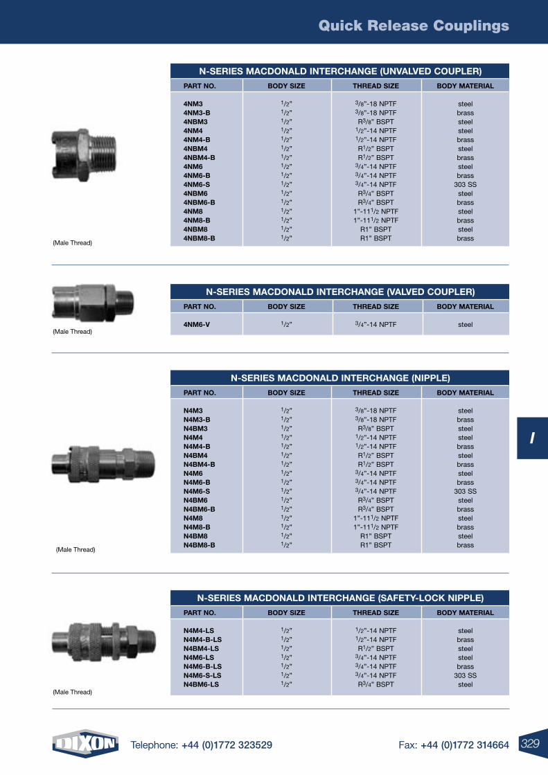
Quick Release Couplings
329Telephone: +44 (0)1772 323529 Fax: +44 (0)1772 314664
I
N-SErIES MACDONALD INTErCHANGE (UNVALVED COUPLEr)
PArT NO.
4NM34NM3-B4NBM34NM44NM4-B4NBM44NBM4-B4NM64NM6-B4NM6-S4NBM64NBM6-B4NM84NM8-B4NBM84NBM8-B
BODY SIzE
1/2”1/2”1/2”1/2”1/2”1/2”1/2”1/2”1/2”1/2”1/2”1/2”1/2”1/2”1/2”1/2”
THrEAD SIzE
3/8”-18 NPTF3/8”-18 NPTFR3/8” BSPT
1/2”-14 NPTF1/2”-14 NPTFR1/2” BSPTR1/2” BSPT
3/4”-14 NPTF3/4”-14 NPTF3/4”-14 NPTFR3/4” BSPTR3/4” BSPT
1”-111/2 NPTF1”-111/2 NPTF
R1” BSPTR1” BSPT
BODY MATErIAL
steelbrasssteelsteelbrasssteelbrasssteelbrass
303 SSsteelbrasssteelbrasssteelbrass
N-SErIES MACDONALD INTErCHANGE (NIPPLE)
PArT NO.
N4M3N4M3-BN4BM3N4M4N4M4-BN4BM4N4BM4-BN4M6N4M6-BN4M6-SN4BM6N4BM6-BN4M8N4M8-BN4BM8N4BM8-B
BODY SIzE
1/2”1/2”1/2”1/2”1/2”1/2”1/2”1/2”1/2”1/2”1/2”1/2”1/2”1/2”1/2”1/2”
THrEAD SIzE
3/8”-18 NPTF3/8”-18 NPTFR3/8” BSPT
1/2”-14 NPTF1/2”-14 NPTFR1/2” BSPTR1/2” BSPT
3/4”-14 NPTF3/4”-14 NPTF3/4”-14 NPTFR3/4” BSPTR3/4” BSPT
1”-111/2 NPTF1”-111/2 NPTF
R1” BSPTR1” BSPT
BODY MATErIAL
steelbrasssteelsteelbrasssteelbrasssteelbrass
303 SSsteelbrasssteelbrasssteelbrass
N-SErIES MACDONALD INTErCHANGE (SAFETY-LOCK NIPPLE)
PArT NO.
N4M4-LSN4M4-B-LSN4BM4-LSN4M6-LSN4M6-B-LSN4M6-S-LSN4BM6-LS
BODY SIzE
1/2”1/2”1/2”1/2”1/2”1/2”1/2”
THrEAD SIzE
1/2”-14 NPTF1/2”-14 NPTFR1/2” BSPT
3/4”-14 NPTF3/4”-14 NPTF3/4”-14 NPTFR3/4” BSPT
BODY MATErIAL
steelbrasssteelsteelbrass
303 SSsteel
N-SErIES MACDONALD INTErCHANGE (VALVED COUPLEr)
PArT NO.
4NM6-V
BODY SIzE
1/2”
THrEAD SIzE
3/4”-14 NPTF
BODY MATErIAL
steel
(Male Thread)
(Male Thread)
(Male Thread)
(Male Thread)
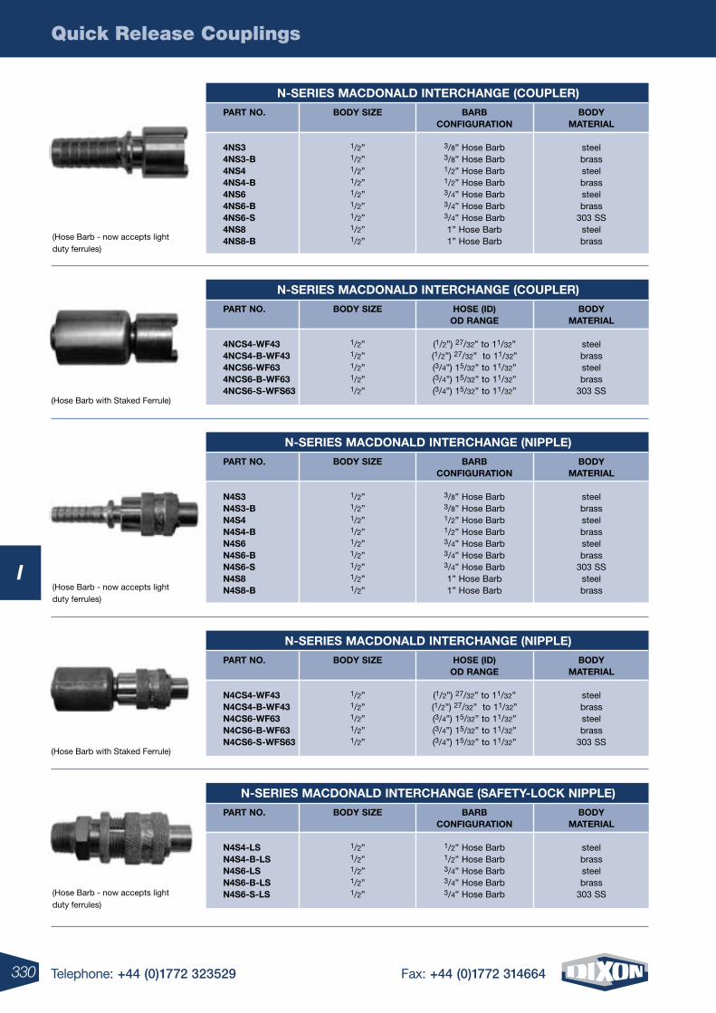
Quick Release Couplings
330 Telephone: +44 (0)1772 323529 Fax: +44 (0)1772 314664
I
N-SErIES MACDONALD INTErCHANGE (COUPLEr)
PArT NO.
4NS34NS3-B4NS44NS4-B4NS64NS6-B4NS6-S4NS84NS8-B
BODY SIzE
1/2”1/2”1/2”1/2”1/2”1/2”1/2”1/2”1/2”
BArB CONFIGUrATION
3/8” Hose Barb3/8” Hose Barb1/2” Hose Barb1/2” Hose Barb3/4” Hose Barb3/4” Hose Barb3/4” Hose Barb1” Hose Barb1” Hose Barb
BODY MATErIAL
steelbrasssteelbrasssteelbrass
303 SSsteelbrass
N-SErIES MACDONALD INTErCHANGE (NIPPLE)
PArT NO.
N4S3N4S3-BN4S4N4S4-BN4S6N4S6-BN4S6-SN4S8N4S8-B
BODY SIzE
1/2”1/2”1/2”1/2”1/2”1/2”1/2”1/2”1/2”
BArB CONFIGUrATION
3/8” Hose Barb3/8” Hose Barb1/2” Hose Barb1/2” Hose Barb3/4” Hose Barb3/4” Hose Barb3/4” Hose Barb1” Hose Barb1” Hose Barb
BODY MATErIAL
steelbrasssteelbrasssteelbrass
303 SSsteelbrass
N-SErIES MACDONALD INTErCHANGE (COUPLEr)
PArT NO.
4NCS4-wF434NCS4-B-wF434NCS6-wF634NCS6-B-wF634NCS6-S-wFS63
BODY SIzE
1/2”1/2”1/2”1/2”1/2”
HOSE (ID)OD rANGE
(1/2”) 27/32” to 11/32”(1/2”) 27/32” to 11/32”(3/4”) 15/32” to 11/32”(3/4”) 15/32” to 11/32”(3/4”) 15/32” to 11/32”
BODY MATErIAL
steelbrasssteelbrass
303 SS
N-SErIES MACDONALD INTErCHANGE (NIPPLE)
PArT NO.
N4CS4-wF43N4CS4-B-wF43N4CS6-wF63N4CS6-B-wF63N4CS6-S-wFS63
BODY SIzE
1/2”1/2”1/2”1/2”1/2”
HOSE (ID)OD rANGE
(1/2”) 27/32” to 11/32”(1/2”) 27/32” to 11/32”(3/4”) 15/32” to 11/32”(3/4”) 15/32” to 11/32”(3/4”) 15/32” to 11/32”
BODY MATErIAL
steelbrasssteelbrass
303 SS
N-SErIES MACDONALD INTErCHANGE (SAFETY-LOCK NIPPLE)
PArT NO.
N4S4-LSN4S4-B-LSN4S6-LSN4S6-B-LSN4S6-S-LS
BODY SIzE
1/2”1/2”1/2”1/2”1/2”
BArBCONFIGUrATION
1/2” Hose Barb1/2” Hose Barb3/4” Hose Barb3/4” Hose Barb3/4” Hose Barb
BODY MATErIAL
steelbrasssteelbrass
303 SS
(Hose Barb - now accepts light duty ferrules)
(Hose Barb with Staked Ferrule)
(Hose Barb - now accepts light duty ferrules)
(Hose Barb with Staked Ferrule)
(Hose Barb - now accepts light duty ferrules)
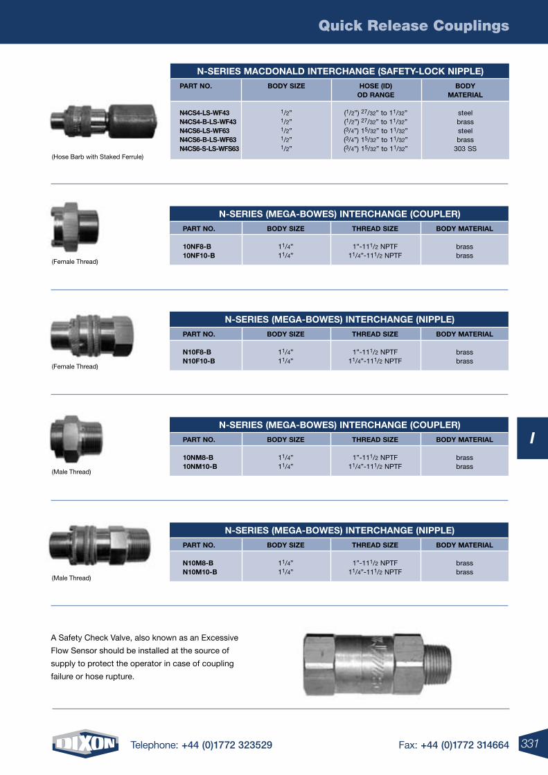
Quick Release Couplings
331Telephone: +44 (0)1772 323529 Fax: +44 (0)1772 314664
I
A Safety Check Valve, also known as an Excessive
Flow Sensor should be installed at the source of
supply to protect the operator in case of coupling
failure or hose rupture.
N-SErIES MACDONALD INTErCHANGE (SAFETY-LOCK NIPPLE)
PArT NO.
N4CS4-LS-wF43N4CS4-B-LS-wF43N4CS6-LS-wF63N4CS6-B-LS-wF63N4CS6-S-LS-wFS63
BODY SIzE
1/2”1/2”1/2”1/2”1/2”
HOSE (ID)OD rANGE
(1/2”) 27/32” to 11/32”(1/2”) 27/32” to 11/32”(3/4”) 15/32” to 11/32”(3/4”) 15/32” to 11/32”(3/4”) 15/32” to 11/32”
BODY MATErIAL
steelbrasssteelbrass
303 SS
N-SErIES (MEGA-BOwES) INTErCHANGE (COUPLEr)
PArT NO.
10NF8-B10NF10-B
BODY SIzE
11/4”11/4”
THrEAD SIzE
1”-111/2 NPTF11/4”-111/2 NPTF
BODY MATErIAL
brassbrass
N-SErIES (MEGA-BOwES) INTErCHANGE (NIPPLE)
PArT NO.
N10F8-BN10F10-B
BODY SIzE
11/4”11/4”
THrEAD SIzE
1”-111/2 NPTF11/4”-111/2 NPTF
BODY MATErIAL
brassbrass
N-SErIES (MEGA-BOwES) INTErCHANGE (COUPLEr)
PArT NO.
10NM8-B10NM10-B
BODY SIzE
11/4”11/4”
THrEAD SIzE
1”-111/2 NPTF11/4”-111/2 NPTF
BODY MATErIAL
brassbrass
N-SErIES (MEGA-BOwES) INTErCHANGE (NIPPLE)
PArT NO.
N10M8-BN10M10-B
BODY SIzE
11/4”11/4”
THrEAD SIzE
1”-111/2 NPTF11/4”-111/2 NPTF
BODY MATErIAL
brassbrass
(Hose Barb with Staked Ferrule)
(Female Thread)
(Female Thread)
(Male Thread)
(Male Thread)
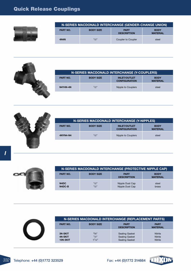
Quick Release Couplings
332 Telephone: +44 (0)1772 323529 Fax: +44 (0)1772 314664
I
N-SErIES MACDONALD INTErCHANGE (GENDEr-CHANGE UNION)
PArT NO.
4N4N
BODY SIzE
1/2”
PArTDESCrIPTION
Coupler to Coupler
BODY MATErIAL
steel
N-SErIES MACDONALD INTErCHANGE (Y-COUPLErS)
PArT NO.
N4Y4N-4N
BODY SIzE
1/2”
INLET/OUTLETCONFIGUrATION
Nipple to Couplers
BODY MATErIAL
steel
N-SErIES MACDONALD INTErCHANGE (Y-NIPPLES)
PArT NO.
4NYN4-N4
BODY SIzE
1/2”
INLET/OUTLETCONFIGUrATION
Nipple to Couplers
BODY MATErIAL
steel
N-SErIES MACDONALD INTErCHANGE (PrOTECTIVE NIPPLE CAP)
PArT NO.
N4DCN4DC-B
BODY SIzE
1/2” 1/2”
PArTDESCrIPTION
Nipple Dust CapNipple Dust Cap
BODY MATErIAL
steelbrass
N-SErIES MACDONALD INTErCHANGE (rEPLACEMENT PArTS)
PArT NO.
3N-SKIT4N-SKIT10N-SKIT
BODY SIzE
3/8”1/2”
11/4”
PArTDESCrIPTION
Sealing GasketSealing GasketSealing Gasket
PArT MATErIAL
NitrileNitrileNitrile
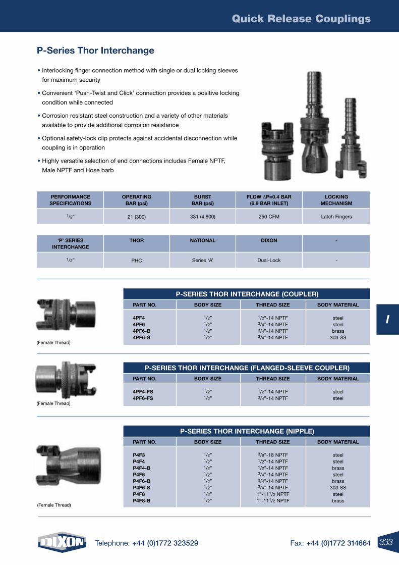
Quick Release Couplings
333Telephone: +44 (0)1772 323529 Fax: +44 (0)1772 314664
I
P-Series Thor Interchange
• Interlocking finger connection method with single or dual locking sleeves
for maximum security
• Convenient ‘Push-Twist and Click’ connection provides a positive locking
condition while connected
• Corrosion resistant steel construction and a variety of other materials
available to provide additional corrosion resistance
• Optional safety-lock clip protects against accidental disconnection while
coupling is in operation
• Highly versatile selection of end connections includes Female NPTF,
Male NPTF and Hose barb
P-SErIES THOr INTErCHANGE (COUPLEr)
PArT NO.
4PF44PF64PF6-B4PF6-S
BODY SIzE
1/2”1/2”1/2”1/2”
THrEAD SIzE
1/2”-14 NPTF3/4”-14 NPTF3/4”-14 NPTF3/4”-14 NPTF
BODY MATErIAL
steelsteelbrass
303 SS
P-SErIES THOr INTErCHANGE (FLANGED-SLEEVE COUPLEr)
PArT NO.
4PF4-FS4PF6-FS
BODY SIzE
1/2”1/2”
THrEAD SIzE
1/2”-14 NPTF3/4”-14 NPTF
BODY MATErIAL
steelsteel
P-SErIES THOr INTErCHANGE (NIPPLE)
PArT NO.
P4F3P4F4P4F4-BP4F6P4F6-BP4F6-SP4F8P4F8-B
BODY SIzE
1/2”1/2”1/2”1/2”1/2”1/2”1/2”1/2”
THrEAD SIzE
3/8”-18 NPTF1/2”-14 NPTF1/2”-14 NPTF3/4”-14 NPTF3/4”-14 NPTF3/4”-14 NPTF
1”-111/2 NPTF1”-111/2 NPTF
BODY MATErIAL
steelsteelbrasssteelbrass
303 SSsteelbrass
OPErATING BAr (psi)
21 (300)
PErFOrMANCESPECIFICATIONS
1/2”
BUrSTBAr (psi)
331 (4,800)
FLOw DP=0.4 BAr(6.9 BAr INLET)
250 CFM
LOCKING MECHANISM
Latch Fingers
THOr
PHC
‘P’ SErIESINTErCHANGE
1/2”
NATIONAL
Series ‘A’
DIXON
Dual-Lock
-
-
(Female Thread)
(Female Thread)
(Female Thread)
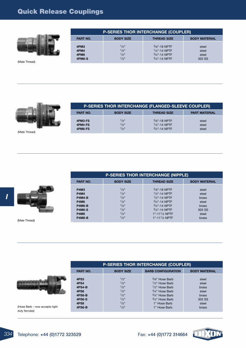
Quick Release Couplings
334 Telephone: +44 (0)1772 323529 Fax: +44 (0)1772 314664
I
P-SErIES THOr INTErCHANGE (COUPLEr)
PArT NO.
4PM34PM44PM64PM6-S
BODY SIzE
1/2”1/2”1/2”1/2”
THrEAD SIzE
3/8”-18 NPTF1/2”-14 NPTF3/4”-14 NPTF3/4”-14 NPTF
BODY MATErIAL
steelsteelsteel
303 SS
P-SErIES THOr INTErCHANGE (NIPPLE)
PArT NO.
P4M3P4M4P4M4-BP4M6P4M6-BP4M6-SP4M8P4M8-B
BODY SIzE
1/2”1/2”1/2”1/2”1/2”1/2”1/2”1/2”
THrEAD SIzE
3/8”-18 NPTF1/2”-14 NPTF1/2”-14 NPTF3/4”-14 NPTF3/4”-14 NPTF3/4”-14 NPTF
1”-111/2 NPTF1”-111/2 NPTF
BODY MATErIAL
steelsteelbrasssteelbrass
303 SSsteelbrass
P-SErIES THOr INTErCHANGE (COUPLEr)
PArT NO.
4PS34PS44PS4-B4PS64PS6-B4PS6-S4PS84PS8-B
BODY SIzE
1/2”1/2”1/2”1/2”1/2”1/2”1/2”1/2”
BArB CONFIGUrATION
3/8” Hose Barb1/2” Hose Barb1/2” Hose Barb3/4” Hose Barb3/4” Hose Barb3/4” Hose Barb1” Hose Barb1” Hose Barb
BODY MATErIAL
steelsteelbrasssteelbrass
303 SSsteelbrass
P-SErIES THOr INTErCHANGE (FLANGED-SLEEVE COUPLEr)
PArT NO.
4PM3-FS4PM4-FS4PM6-FS
BODY SIzE
1/2”1/2”1/2”
THrEAD SIzE
3/8”-18 NPTF1/2”-14 NPTF3/4”-14 NPTF
PArT MATErIAL
steelsteelsteel
(Male Thread)
(Male Thread)
(Hose Barb - now accepts light duty ferrules)
(Male Thread)
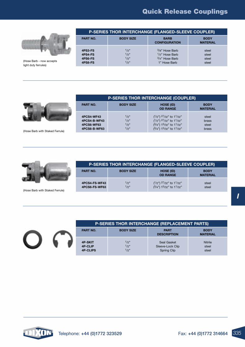
Quick Release Couplings
335Telephone: +44 (0)1772 323529 Fax: +44 (0)1772 314664
I
P-SErIES THOr INTErCHANGE (FLANGED-SLEEVE COUPLEr)
PArT NO.
4PS3-FS4PS4-FS4PS6-FS4PS8-FS
BODY SIzE
1/2”1/2”1/2”1/2”
BArBCONFIGUrATION
3/8” Hose Barb1/2” Hose Barb3/4” Hose Barb1” Hose Barb
BODY MATErIAL
steelsteelsteelsteel
P-SErIES THOr INTErCHANGE (COUPLEr)
PArT NO.
4PCS4-wF434PCS4-B-wF434PCS6-wF634PCS6-B-wF63
BODY SIzE
1/2”1/2”1/2”1/2”
HOSE (ID)OD rANGE
(1/2”) 27/32” to 11/32”(1/2”) 27/32” to 11/32”(3/4”) 15/32” to 11/32”(3/4”) 15/32” to 11/32”
BODY MATErIAL
steelbrasssteelbrass
P-SErIES THOr INTErCHANGE (rEPLACEMENT PArTS)
PArT NO.
4P-SKIT4P-CLIP4P-CLIPS
BODY SIzE
1/2”1/2”1/2”
PArTDESCrIPTION
Seal GasketSleeve-Lock Clip
Spring Clip
BODY MATErIAL
Nitrilesteelsteel
P-SErIES THOr INTErCHANGE (FLANGED-SLEEVE COUPLEr)
PArT NO.
4PCS4-FS-wF434PCS6-FS-wF63
BODY SIzE
1/2”1/2”
HOSE (ID)OD rANGE
(1/2”) 27/32” to 11/32”(3/4”) 15/32” to 11/32”
BODY MATErIAL
steelsteel
(Hose Barb - now accepts light duty ferrules)
(Hose Barb with Staked Ferrule)
(Hose Barb with Staked Ferrule)
J
4 Telephone: +44 (0)1772 323529 Fax: +44 (0)1772 314664336 Telephone: +44 (0)1772 323529 Fax: +44 (0)1772 314664
J
J
337Telephone: +44 (0)1772 323529 Fax: +44 (0)1772 314664
Boss Coupling System ............................................................................338
Boss Ground Joint Seal Couplings ..........................................................339
Boss Stems .............................................................................................340
Boss Wing Nuts ......................................................................................340
Boss Spud Adapters ...............................................................................341
Boss Hose Menders ...............................................................................342
Boss Adapters & Stems ............................................................... 342-343
Boss Clamps ................................................................................ 344-345
Steam Hose Fittings BS EN 14423:2004 .................................................346
337Telephone: +44 (0)1772 323529 Fax: +44 (0)1772 314664
Steam Couplings - Boss™
For a Full range oF STeaM hoSeS To coMpleMenT TheSe FiTTingS See SecTion F J
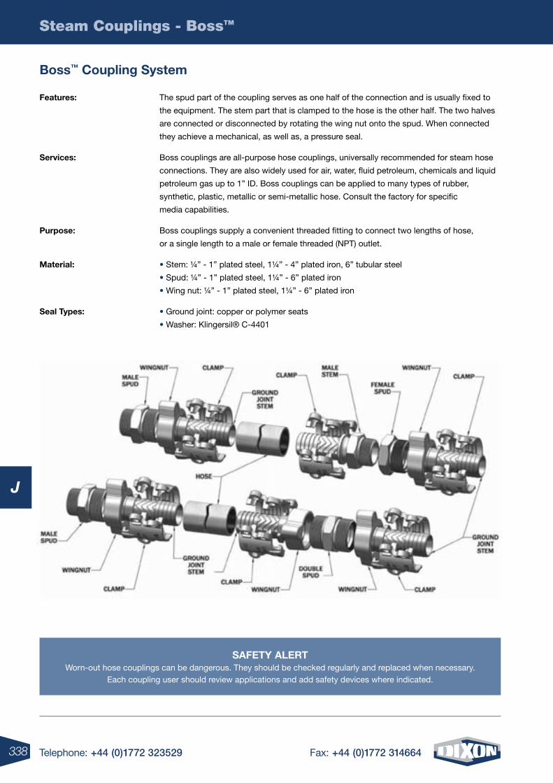
338 Telephone: +44 (0)1772 323529 Fax: +44 (0)1772 314664
Steam Couplings - BossTM
J
Boss™ coupling System
Features: The spud part of the coupling serves as one half of the connection and is usually fixed to
the equipment. The stem part that is clamped to the hose is the other half. The two halves
are connected or disconnected by rotating the wing nut onto the spud. When connected
they achieve a mechanical, as well as, a pressure seal.
Services: Boss couplings are all-purpose hose couplings, universally recommended for steam hose
connections. They are also widely used for air, water, fluid petroleum, chemicals and liquid
petroleum gas up to 1” ID. Boss couplings can be applied to many types of rubber,
synthetic, plastic, metallic or semi-metallic hose. Consult the factory for specific
media capabilities.
purpose: Boss couplings supply a convenient threaded fitting to connect two lengths of hose,
or a single length to a male or female threaded (NPT) outlet.
Material: • Stem: ¼” - 1” plated steel, 1¼” - 4” plated iron, 6” tubular steel
• Spud: ¼” - 1” plated steel, 1¼” - 6” plated iron
• Wing nut: ¼” - 1” plated steel, 1¼” - 6” plated iron
Seal Types: • Ground joint: copper or polymer seats
• Washer: Klingersil® C-4401
SaFeTY alerTWorn-out hose couplings can be dangerous. They should be checked regularly and replaced when necessary.
Each coupling user should review applications and add safety devices where indicated.
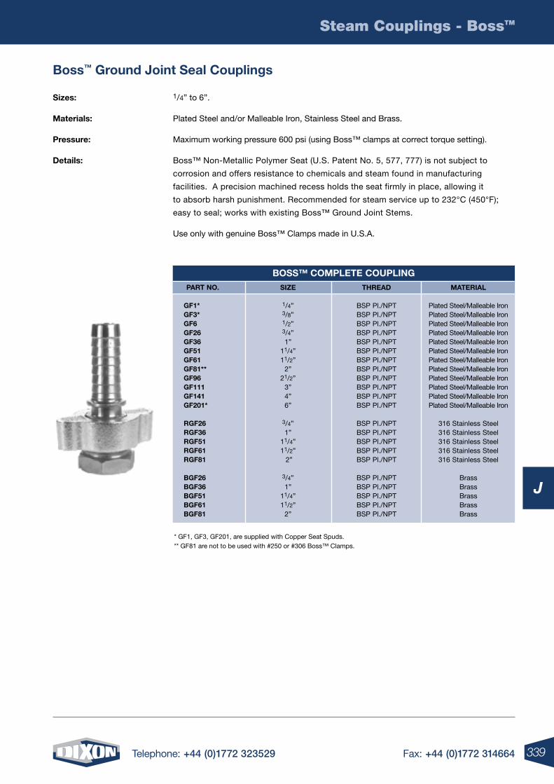
339Telephone: +44 (0)1772 323529 Fax: +44 (0)1772 314664
Steam Couplings - BossTM
J
Boss™ ground Joint Seal couplings
Sizes: 1/4” to 6”.
Materials: Plated Steel and/or Malleable Iron, Stainless Steel and Brass.
pressure: Maximum working pressure 600 psi (using Boss™ clamps at correct torque setting).
Details: Boss™ Non-Metallic Polymer Seat (U.S. Patent No. 5, 577, 777) is not subject to
corrosion and offers resistance to chemicals and steam found in manufacturing
facilities. A precision machined recess holds the seat firmly in place, allowing it
to absorb harsh punishment. Recommended for steam service up to 232°C (450°F);
easy to seal; works with existing Boss™ Ground Joint Stems.
Use only with genuine Boss™ Clamps made in U.S.A.
* GF1, GF3, GF201, are supplied with Copper Seat Spuds. ** GF81 are not to be used with #250 or #306 Boss™ Clamps.
BoSS™ coMpleTe coupling Size
1/4”3/8”1/2”3/4”1”
11/4”11/2”
2”21/2”
3”4”6”
3/4”1”
11/4”11/2” 2”
3/4”1”
11/4”11/2”
2”
ThreaD
BSP Pl./NPTBSP Pl./NPTBSP Pl./NPTBSP Pl./NPTBSP Pl./NPTBSP Pl./NPTBSP Pl./NPTBSP Pl./NPTBSP Pl./NPTBSP Pl./NPTBSP Pl./NPTBSP Pl./NPT
BSP Pl./NPTBSP Pl./NPTBSP Pl./NPTBSP Pl./NPTBSP Pl./NPT
BSP Pl./NPTBSP Pl./NPTBSP Pl./NPTBSP Pl./NPTBSP Pl./NPT
MaTerial
Plated Steel/Malleable IronPlated Steel/Malleable IronPlated Steel/Malleable IronPlated Steel/Malleable IronPlated Steel/Malleable IronPlated Steel/Malleable IronPlated Steel/Malleable IronPlated Steel/Malleable IronPlated Steel/Malleable IronPlated Steel/Malleable IronPlated Steel/Malleable IronPlated Steel/Malleable Iron
316 Stainless Steel316 Stainless Steel316 Stainless Steel316 Stainless Steel316 Stainless Steel
BrassBrassBrassBrassBrass
parT no.
gF1* gF3* gF6 gF26 gF36 gF51 gF61 gF81** gF96 gF111 gF141 gF201*
rgF26 rgF36 rgF51 rgF61 rgF81
BgF26 BgF36 BgF51 BgF61 BgF81
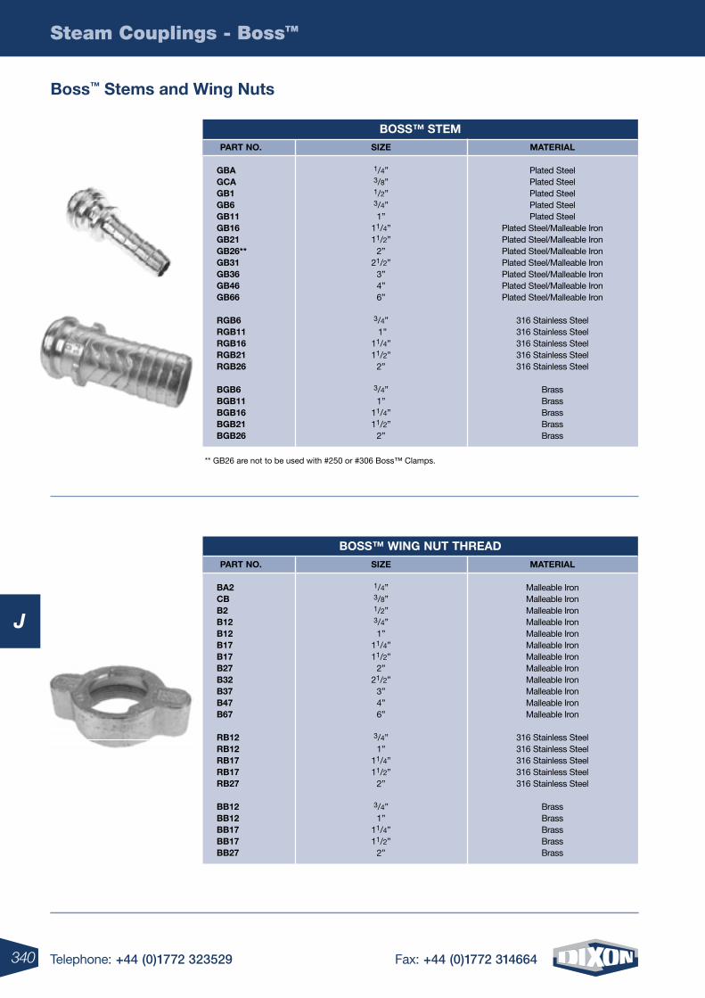
340 Telephone: +44 (0)1772 323529 Fax: +44 (0)1772 314664
Steam Couplings - BossTM
J
Boss™ Stems and Wing nuts
** GB26 are not to be used with #250 or #306 Boss™ Clamps.
BoSS™ STeMSize
1/4”3/8”1/2”3/4”1”
11/4”11/2”
2”21/2”
3”4”6”
3/4” 1”
11/4”11/2”
2”
3/4”1”
11/4”11/2”
2”
MaTerial
Plated SteelPlated SteelPlated SteelPlated SteelPlated Steel
Plated Steel/Malleable IronPlated Steel/Malleable IronPlated Steel/Malleable IronPlated Steel/Malleable IronPlated Steel/Malleable IronPlated Steel/Malleable IronPlated Steel/Malleable Iron
316 Stainless Steel316 Stainless Steel316 Stainless Steel316 Stainless Steel316 Stainless Steel
BrassBrassBrassBrassBrass
parT no.
gBa gca gB1 gB6 gB11 gB16 gB21 gB26** gB31 gB36 gB46 gB66
rgB6 rgB11 rgB16 rgB21 rgB26 BgB6 BgB11 BgB16 BgB21 BgB26
BoSS™ Wing nuT ThreaDSize
1/4”3/8”1/2”3/4”1”
11/4”11/2”
2”21/2”
3”4”6”
3/4”1”
11/4”11/2”
2”
3/4”1”
11/4”11/2”
2”
MaTerial
Malleable IronMalleable IronMalleable IronMalleable IronMalleable IronMalleable IronMalleable IronMalleable IronMalleable IronMalleable IronMalleable IronMalleable Iron
316 Stainless Steel316 Stainless Steel316 Stainless Steel316 Stainless Steel316 Stainless Steel
BrassBrassBrassBrassBrass
parT no.
Ba2 cB B2 B12 B12 B17 B17 B27 B32 B37 B47 B67 rB12 rB12 rB17 rB17 rB27 BB12 BB12 BB17 BB17 BB27
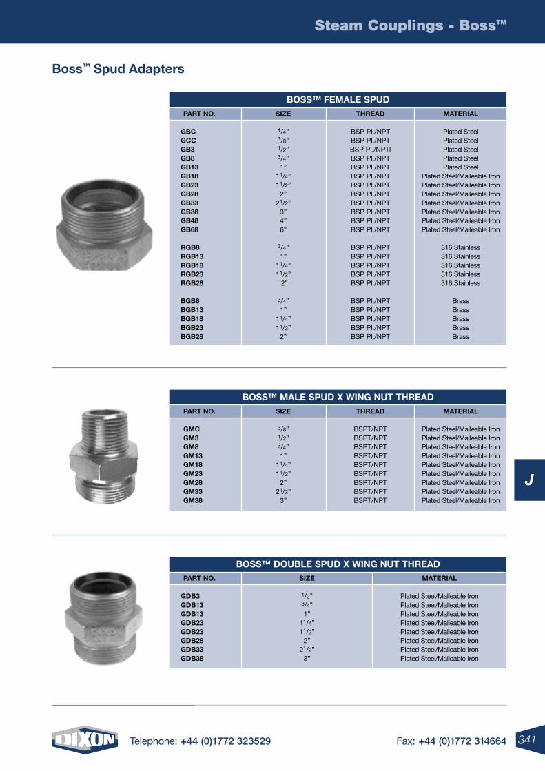
341Telephone: +44 (0)1772 323529 Fax: +44 (0)1772 314664
Steam Couplings - BossTM
J
Boss™ Spud adapters
BoSS™ FeMale SpuD Size
1/4”3/8”1/2”3/4”1”
11/4”11/2”
2”21/2”
3”4”6”
3/4”1”
11/4”11/2” 2”
3/4”1”
11/4”11/2”
2”
ThreaD
BSP Pl./NPTBSP Pl./NPTBSP Pl./NPTlBSP Pl./NPTBSP Pl./NPTBSP Pl./NPTBSP Pl./NPTBSP Pl./NPTBSP Pl./NPTBSP Pl./NPTBSP Pl./NPTBSP Pl./NPT
BSP Pl./NPTBSP Pl./NPTBSP Pl./NPTBSP Pl./NPTBSP Pl./NPT
BSP Pl./NPTBSP Pl./NPTBSP Pl./NPTBSP Pl./NPTBSP Pl./NPT
MaTerial
Plated Steel Plated SteelPlated SteelPlated SteelPlated Steel
Plated Steel/Malleable IronPlated Steel/Malleable IronPlated Steel/Malleable IronPlated Steel/Malleable IronPlated Steel/Malleable IronPlated Steel/Malleable IronPlated Steel/Malleable Iron
316 Stainless 316 Stainless 316 Stainless 316 Stainless 316 Stainless
BrassBrass Brass Brass Brass
parT no.
gBc gcc gB3 gB8 gB13 gB18 gB23 gB28 gB33 gB38 gB48 gB68 rgB8 rgB13 rgB18 rgB23 rgB28 BgB8 BgB13 BgB18 BgB23 BgB28
BoSS™ Male SpuD x Wing nuT ThreaDSize
3/8”1/2”3/4”1”
11/4”11/2”
2”21/2”
3”
ThreaD
BSPT/NPTBSPT/NPTBSPT/NPTBSPT/NPTBSPT/NPTBSPT/NPTBSPT/NPTBSPT/NPTBSPT/NPT
MaTerial
Plated Steel/Malleable IronPlated Steel/Malleable IronPlated Steel/Malleable IronPlated Steel/Malleable IronPlated Steel/Malleable IronPlated Steel/Malleable IronPlated Steel/Malleable IronPlated Steel/Malleable IronPlated Steel/Malleable Iron
parT no. gMc gM3 gM8 gM13 gM18 gM23 gM28 gM33 gM38
BoSS™ DouBle SpuD x Wing nuT ThreaDSize
1/2”3/4”1”
11/4”11/2”
2”21/2”
3”
MaTerial
Plated Steel/Malleable IronPlated Steel/Malleable IronPlated Steel/Malleable IronPlated Steel/Malleable IronPlated Steel/Malleable IronPlated Steel/Malleable IronPlated Steel/Malleable IronPlated Steel/Malleable Iron
parT no. gDB3 gDB13 gDB13 gDB23 gDB23 gDB28 gDB33 gDB38
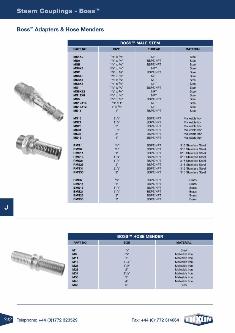
342 Telephone: +44 (0)1772 323529 Fax: +44 (0)1772 314664
Steam Couplings - BossTM
J
Boss™ adapters & hose Menders
BoSS™ Male STeMSize
1/4” x 1/8” 1/4” x 1/4” 1/4” x 3/8” 3/8” x 1/4” 3/8” x 3/8” 3/8” x 1/2” 1/2” x 1/4” 1/2” x 3/8” 1/2” x 1/2” 1/2” x 3/4” 3/4” x 1/2” 3/4” x 3/4” 3/4” x 1” 1” x 3/4”
1”
11/4” 11/2”
2” 21/2”
3” 4”
1/2” 3/4” 1”
11/4” 11/2”
2” 21/2”
3”
3/4” 1”
11/4” 11/2”
2” 3”
ThreaD
NPTBSPT/NPTBSPT/NPT
NPTBSPT/NPT
NPT NPT NPT
BSPT/NPT NPT NPT
BSPT/NPTNPT NPT
BSPT/NPT
BSPT/NPTBSPT/NPTBSPT/NPTBSPT/NPTBSPT/NPTBSPT/NPT
BSPT/NPTBSPT/NPTBSPT/NPTBSPT/NPTBSPT/NPTBSPT/NPTBSPT/NPTBSPT/NPT
BSPT/NPTBSPT/NPTBSPT/NPTBSPT/NPTBSPT/NPTBSPT/NPT
MaTerial
SteelSteelSteelSteelSteelSteelSteelSteelSteelSteelSteelSteelSteelSteelSteel
Malleable IronMalleable IronMalleable IronMalleable IronMalleable IronMalleable Iron
316 Stainless Steel316 Stainless Steel316 Stainless Steel316 Stainless Steel316 Stainless Steel316 Stainless Steel316 Stainless Steel316 Stainless Steel
BrassBrassBrassBrassBrassBrass
parT no.
MS4x2 MSa MSB MS6x4 MSc MS6x8 MS8x4 MS8x6 MS1 MS8x12 MS12x8 MS6 MS12x16 MS16x12 MS11
MS16 MS21 MS26 MS31 MS36 MS46
rMS1 rMS6 rMS11 rMS16 rMS21 rMS26 rMS31 rMS36
BMS6 BMS11 BMS16 BMS21 BMS26 BMS36
BoSS™ hoSe MenDerSize
1/2”3/4”1”
11/4”11/2”
2”21/2”
3”4”6”
MaTerial
SteelMalleable IronMalleable IronMalleable IronMalleable IronMalleable IronMalleable IronMalleable IronMalleable Iron
Steel
parT no. M1 M6 M11 M16 M21 M26 M31 M36 M46 M66
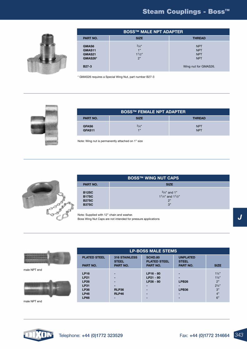
343Telephone: +44 (0)1772 323529 Fax: +44 (0)1772 314664
Steam Couplings - BossTM
J
* GMAS26 requires a Special Wing Nut, part number B27-3
BoSS™ Male npT aDapTerSize
3/4”1”
11/2”2”
ThreaD
NPTNPTNPTNPT
Wing nut for GMAS26.
parT no. gMaS6 gMaS11 gMaS21 gMaS26*
B27-3
Note: Wing nut is permanently attached on 1” size
BoSS™ FeMale npT aDapTerSize
3/4”1”
ThreaD
NPTNPT
parT no. gFaS6 gFaS11
Note: Supplied with 12” chain and washer. Boss Wing Nut Caps are not intended for pressure applications
BoSS™ Wing nuT capSSize
3/4” and 1”11/4” and 11/2”
2”3”
parT no. B12Sc B17Sc B27Sc B37Sc
lp-BoSS Male STeMS plaTeD STeel parT no.
lp16 lp21 lp26 lp31 lp36 lp46 lp66
316 STainleSS STeel parT no. - - - - rlp36 rlp46 -
SchD.80 plaTeD STeel parT no. lp16 - 80 lp21 - 80 lp26 - 80 - - - -
unplaTeD STeel parT no. - - lpB26 - lpB36 - -
Size
1¼”1½”2”
2½”3”4”6”
male NPT end
male NPT end
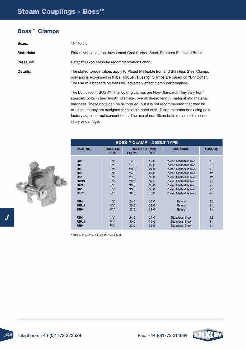
344 Telephone: +44 (0)1772 323529 Fax: +44 (0)1772 314664
Steam Couplings - BossTM
J
Boss™ clamps
Sizes: 1/4” to 3”.
Materials: Plated Malleable Iron, Investment Cast Carbon Steel, Stainless Steel and Brass.
pressure: Refer to Dixon pressure recommendations chart.
Details: The stated torque values apply to Plated Malleable Iron and Stainless Steel Clamps
only and is expressed in ft.lbs. Torque values for Clamps are based on “Dry Bolts”.
The use of lubricants on bolts will adversely effect clamp performance.
The bolt used in BOSS™ interlocking clamps are Non-Standard. They vary from
standard bolts in their length, diameter, overall thread length, material and material
hardness. These bolts can be re-torqued, but it is not recommended that they be
re-used, as they are designed for a single bend only. Dixon recommends using only
factory supplied replacement bolts. The use of non Dixon bolts may result in serious
injury or damage.
BoSS™ claMp - 2 BolT TYpehoSe i.D.
Size
1/4”3/8”1/2”1/2”1/2”3/4”3/4”3/4”3/4”
1/2”3/4”3/4”
1/2”3/4”3/4”
hoSe o.D. (MM)FroM:
14.017.520.524.027.029.530.033.038.0
24.030.033.0
24.030.033.0
To:
17.022.024.027.030.032.533.038.043.0
27.033.038.0
27.033.038.0
TorQue
666121221212121
122121
122121
MaTerial
Plated Malleable IronPlated Malleable IronPlated Malleable IronPlated Malleable IronPlated Malleable IronPlated Malleable IronPlated Malleable IronPlated Malleable IronPlated Malleable Iron
BrassBrassBrass
Stainless SteelStainless SteelStainless Steel
parT no.
BD* cD* DD* B4* B5* Bu9S Bu9 B9* B10*
BB4 BBu9 BB9
rB4 rBu9 rB9
* Global Investment Cast Carbon Steel
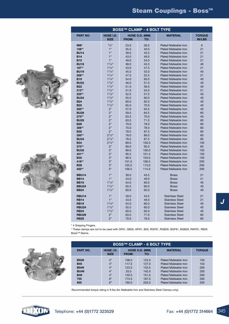
345Telephone: +44 (0)1772 323529 Fax: +44 (0)1772 314664
Steam Couplings - BossTM
J
Recommended torque rating in ft.lbs (for Malleable Iron and Stainless Steel Clamps only).
* 4 Gripping Fingers. † These clamps are not to be used with GF81, GB26, WF81, B26, RGF81, RGB26, BGF81, BGB26, RWF81, RB26 Boss™ Stems.
BoSS™ claMp - 4 BolT TYpehoSe i.D.
Size
1/2”1”1”1”1”
11/4”11/4”11/4”11/4”11/4”11/2”11/2”11/2”11/2”11/2”11/2”11/2”
2”2”2”2”2”2”2”
21/2”21/2”21/2”
3”3”3”3”3”3”3”
1”1”
11/4”11/2”11/2”
1”1”
11/4”11/2”11/2”
2”2”
hoSe o.D. (MM)FroM:
23.035.539.043.049.038.043.045.547.554.046.051.051.052.555.560.065.057.059.563.563.570.070.078.578.078.589.089.089.095.596.5101.5103.5106.5
39.043.054.055.560.0
39.043.054.055.560.063.570.0
To:
26.040.043.549.054.045.547.553.052.560.051.056.054.057.060.065.070.063.564.570.071.078.078.087.589.087.5100.095.0100.0101.5103.0106.5113.0114.0
43.549.060.060.065.0
43.549.060.060.065.071.078.0
TorQuein/lBS
621212121402140214040402140404040406040606060606060
15060
150150150200200200
2121404040
21214040406060
MaTerial
Plated Malleable IronPlated Malleable IronPlated Malleable IronPlated Malleable IronPlated Malleable IronPlated Malleable IronPlated Malleable IronPlated Malleable IronPlated Malleable IronPlated Malleable IronPlated Malleable IronPlated Malleable IronPlated Malleable IronPlated Malleable IronPlated Malleable IronPlated Malleable IronPlated Malleable IronPlated Malleable IronPlated Malleable IronPlated Malleable IronPlated Malleable IronPlated Malleable IronPlated Malleable IronPlated Malleable IronPlated Malleable IronPlated Malleable IronPlated Malleable IronPlated Malleable IronPlated Malleable IronPlated Malleable IronPlated Malleable IronPlated Malleable IronPlated Malleable IronPlated Malleable Iron
BrassBrassBrassBrassBrass
Stainless SteelStainless SteelStainless SteelStainless SteelStainless SteelStainless SteelStainless Steel
parT no.
968†
156*†
Bu14 B14 B15 Bu18 187*†
Bu19 206*†
B19 Bu22 B22 212*†
225*†
Bu24 B24 B25 250*†
Bu28 275*†
Bu29 B29 306*†
B30 350*†
Bu34 B34 375*†
Bu35 401*†
B35 418*†
B39 450*†
BBu14 BB14 BB19 BBu24 BB24
rBu14 rB14 rB19 rBu24 rB24 rBu29 rB29
BoSS™ claMp - 6 BolT TYpehoSe i.D.
Size
3”4”4”4”4”6”6”
hoSe o.D. (MM)FroM:
108.0117.5123.533.5140.5174.5190.0
To:
122.0127.0133.5142.0151.0187.0203.0
TorQue
150150200200200200200
MaTerial
Plated Malleable IronPlated Malleable IronPlated Malleable IronPlated Malleable IronPlated Malleable IronPlated Malleable IronPlated Malleable Iron
parT no.
BS39 B45 BS49 Bu49 B49 750 850
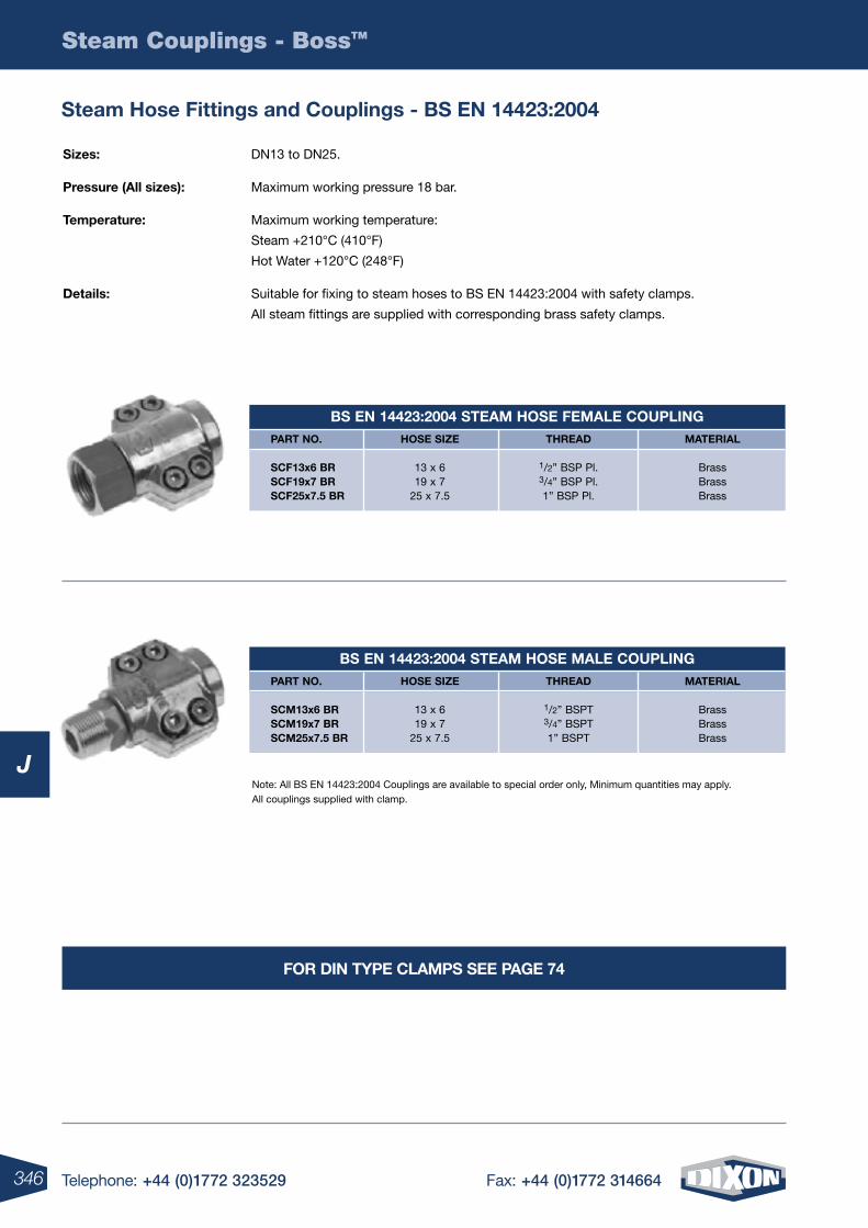
346 Telephone: +44 (0)1772 323529 Fax: +44 (0)1772 314664
Steam Couplings - BossTM
J
Steam hose Fittings and couplings - BS en 14423:2004
Sizes: DN13 to DN25.
pressure (all sizes): Maximum working pressure 18 bar.
Temperature: Maximum working temperature:
Steam +210°C (410°F)
Hot Water +120°C (248°F)
Details: Suitable for fixing to steam hoses to BS EN 14423:2004 with safety clamps.
All steam fittings are supplied with corresponding brass safety clamps.
Note: All BS EN 14423:2004 Couplings are available to special order only, Minimum quantities may apply. All couplings supplied with clamp.
BS en 14423:2004 STeaM hoSe FeMale couplinghoSe Size
13 x 619 x 7
25 x 7.5
ThreaD
1/2” BSP Pl.3/4” BSP Pl.1” BSP Pl.
MaTerial
BrassBrassBrass
parT no. ScF13x6 Br ScF19x7 Br ScF25x7.5 Br
BS en 14423:2004 STeaM hoSe Male couplinghoSe Size
13 x 619 x 7
25 x 7.5
ThreaD
1/2” BSPT3/4” BSPT1” BSPT
MaTerial
BrassBrassBrass
parT no. ScM13x6 Br ScM19x7 Br ScM25x7.5 Br
For Din TYpe claMpS See page 74
347Telephone: +44 (0)1772 323529 Fax: +44 (0)1772 314664
Steam Couplings - BossTM
J
K
4 Telephone: +44 (0)1772 323529 Fax: +44 (0)1772 314664348 Telephone: +44 (0)1772 323529 Fax: +44 (0)1772 314664
K
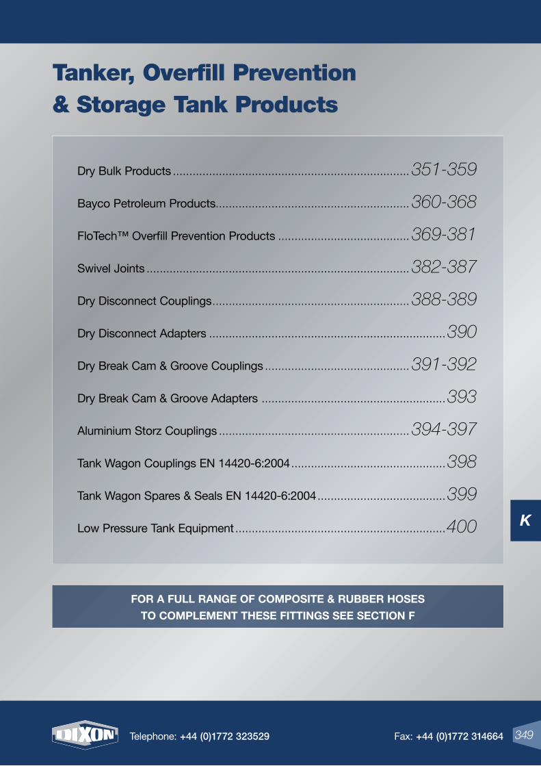
K
349Telephone: +44 (0)1772 323529 Fax: +44 (0)1772 314664
Dry Bulk Products ........................................................................ 351-359
Bayco Petroleum Products........................................................... 360-368
FloTech™ Overfill Prevention Products ........................................ 369-381
Swivel Joints ................................................................................ 382-387
Dry Disconnect Couplings ............................................................ 388-389
Dry Disconnect Adapters ........................................................................390
Dry Break Cam & Groove Couplings ............................................ 391-392
Dry Break Cam & Groove Adapters ........................................................393
Aluminium Storz Couplings .......................................................... 394-397
Tank Wagon Couplings EN 14420-6:2004 ...............................................398
Tank Wagon Spares & Seals EN 14420-6:2004 .......................................399
Low Pressure Tank Equipment ................................................................400
349Telephone: +44 (0)1772 323529 Fax: +44 (0)1772 314664
Tanker, Overfill Prevention& Storage Tank Products
For a Full range oF Composite & rubber hoses
to Complement these Fittings see seCtion F
K
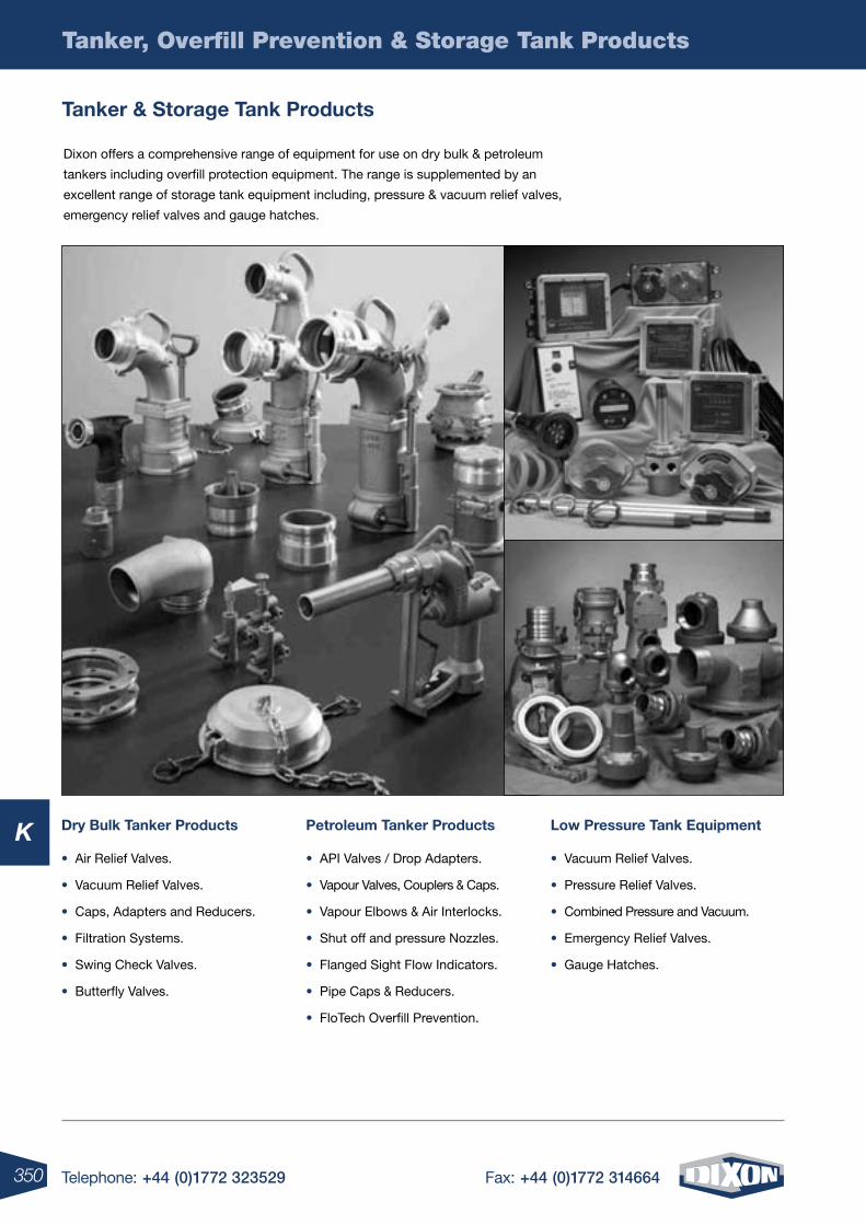
350 Telephone: +44 (0)1772 323529 Fax: +44 (0)1772 314664
K
Tanker, Overfill Prevention & Storage Tank Products
tanker & storage tank products
Dixon offers a comprehensive range of equipment for use on dry bulk & petroleum
tankers including overfill protection equipment. The range is supplemented by an
excellent range of storage tank equipment including, pressure & vacuum relief valves,
emergency relief valves and gauge hatches.
Dry bulk tanker products
• Air Relief Valves.
• Vacuum Relief Valves.
• Caps, Adapters and Reducers.
• Filtration Systems.
• Swing Check Valves.
• Butterfly Valves.
petroleum tanker products
• API Valves / Drop Adapters.
• Vapour Valves, Couplers & Caps.
• Vapour Elbows & Air Interlocks.
• Shut off and pressure Nozzles.
• Flanged Sight Flow Indicators.
• Pipe Caps & Reducers.
• FloTech Overfill Prevention.
low pressure tank equipment
• Vacuum Relief Valves.
• Pressure Relief Valves.
• Combined Pressure and Vacuum.
• Emergency Relief Valves.
• Gauge Hatches.
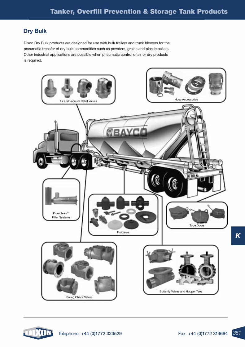
351Telephone: +44 (0)1772 323529 Fax: +44 (0)1772 314664
K
Tanker, Overfill Prevention & Storage Tank Products
Dry bulk
Dixon Dry Bulk products are designed for use with bulk trailers and truck blowers for the
pneumatic transfer of dry bulk commodities such as powders, grains and plastic pellets.
Other industrial applications are possible when pneumatic control of air or dry products
is required.
Air and Vacuum Relief ValvesHose Accessories
Tube Doors
Fluidisers
Swing Check Valves
Pneuclean™ Filter Systems
Butterfly Valves and Hopper Tees
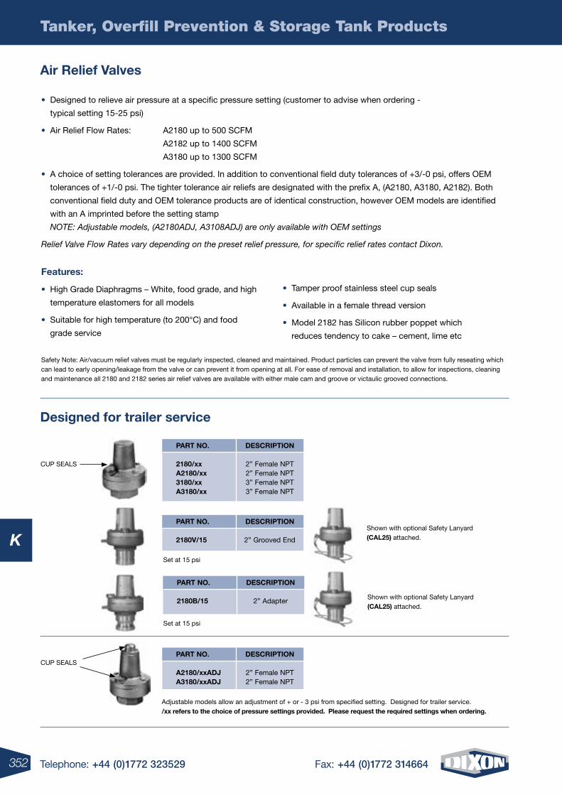
352 Telephone: +44 (0)1772 323529 Fax: +44 (0)1772 314664
K
Tanker, Overfill Prevention & Storage Tank Products
• Designed to relieve air pressure at a specific pressure setting (customer to advise when ordering -
typical setting 15-25 psi)
• Air Relief Flow Rates: A2180 up to 500 SCFM
A2182 up to 1400 SCFM
A3180 up to 1300 SCFM
• A choice of setting tolerances are provided. In addition to conventional field duty tolerances of +3/-0 psi, offers OEM
tolerances of +1/-0 psi. The tighter tolerance air reliefs are designated with the prefix A, (A2180, A3180, A2182). Both
conventional field duty and OEM tolerance products are of identical construction, however OEM models are identified
with an A imprinted before the setting stamp
NOTE: Adjustable models, (A2180ADJ, A3108ADJ) are only available with OEM settings
Relief Valve Flow Rates vary depending on the preset relief pressure, for specific relief rates contact Dixon.
Features:
• High Grade Diaphragms – White, food grade, and high
temperature elastomers for all models
• Suitable for high temperature (to 200°C) and food
grade service
• Tamper proof stainless steel cup seals
• Available in a female thread version
• Model 2182 has Silicon rubber poppet which
reduces tendency to cake – cement, lime etc
Shown with optional Safety Lanyard (Cal25) attached.
Shown with optional Safety Lanyard (Cal25) attached.
Adjustable models allow an adjustment of + or - 3 psi from specified setting. Designed for trailer service. /xx refers to the choice of pressure settings provided. please request the required settings when ordering.
Safety Note: Air/vacuum relief valves must be regularly inspected, cleaned and maintained. Product particles can prevent the valve from fully reseating which can lead to early opening/leakage from the valve or can prevent it from opening at all. For ease of removal and installation, to allow for inspections, cleaning and maintenance all 2180 and 2182 series air relief valves are available with either male cam and groove or victaulic grooved connections.
Designed for trailer service
air relief Valves
CUP SEALS
CUP SEALS
DesCription
2” Female NPT2” Female NPT3” Female NPT3” Female NPT
part no.
2180/xx a2180/xx 3180/xx a3180/xx
Set at 15 psi
DesCription
2” Adapter
part no.
2180b/15
Set at 15 psi
DesCription
2” Grooved End
part no.
2180V/15
DesCription
2” Female NPT2” Female NPT
part no.
a2180/xxaDJ a3180/xxaDJ
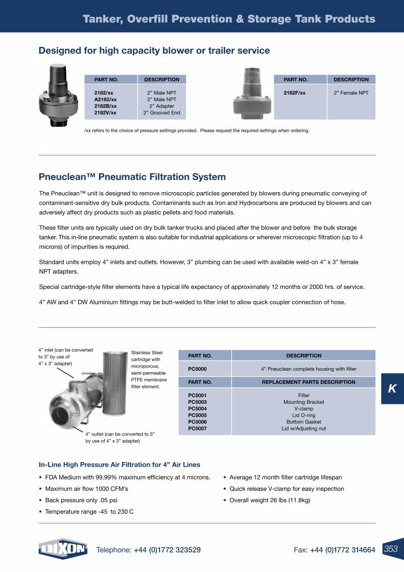
353Telephone: +44 (0)1772 323529 Fax: +44 (0)1772 314664
K
Tanker, Overfill Prevention & Storage Tank Products
The Pneuclean™ unit is designed to remove microscopic particles generated by blowers during pneumatic conveying of
contaminant-sensitive dry bulk products. Contaminants such as Iron and Hydrocarbons are produced by blowers and can
adversely affect dry products such as plastic pellets and food materials.
These filter units are typically used on dry bulk tanker trucks and placed after the blower and before the bulk storage
tanker. This in-line pneumatic system is also suitable for industrial applications or wherever microscopic filtration (up to 4
microns) of impurities is required.
Standard units employ 4” inlets and outlets. However, 3” plumbing can be used with available weld-on 4” x 3” female
NPT adapters.
Special cartridge-style filter elements have a typical life expectancy of approximately 12 months or 2000 hrs. of service.
4” AW and 4” DW Aluminium fittings may be butt-welded to filter inlet to allow quick coupler connection of hose.
pneuclean™ pneumatic Filtration system
/xx refers to the choice of pressure settings provided. Please request the required settings when ordering.
Designed for high capacity blower or trailer service
in-line high pressure air Filtration for 4” air lines
• FDA Medium with 99.99% maximum efficiency at 4 microns.
• Maximum air flow 1000 CFM’s
• Back pressure only .05 psi
• Temperature range -45˚ to 230˚C
• Average 12 month filter cartridge lifespan
• Quick release V-clamp for easy inspection
• Overall weight 26 lbs (11.8kg)
4” inlet (can be converted to 3” by use of 4” x 3” adapter)
4” outlet (can be converted to 3” by use of 4” x 3” adapter)
Stainless Steel cartridge with microporous, semi-permeable PTFE membrane filter element.
DesCription
2” Female NPT
part no.
2182F/xx
DesCription
2” Male NPT2” Male NPT2” Adapter
2” Grooved End
part no.
2182/xx a2182/xx 2182b/xx 2182V/xx
DesCription
4” Pneuclean complete housing with filter
replaCement parts DesCription
FilterMounting Bracket
V-clampLid O-ring
Bottom GasketLid w/Adjusting nut
part no.
pC5000
part no.
pC5001 pC5003 pC5004 pC5005 pC5006 pC5007
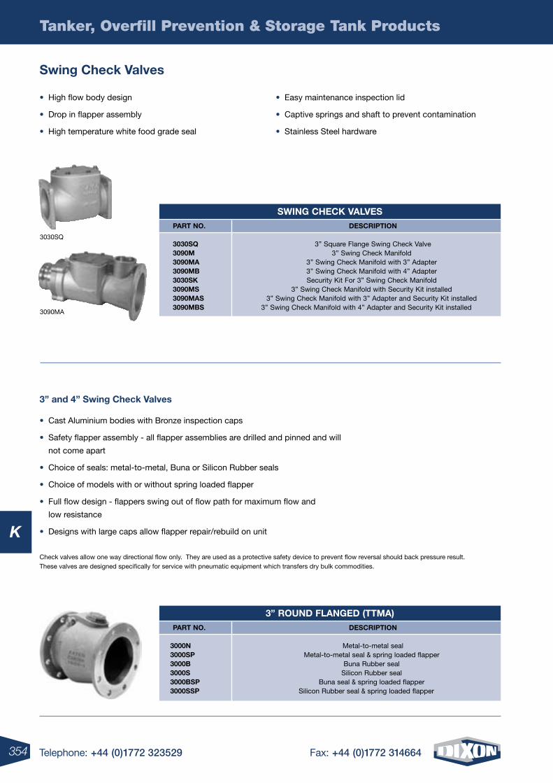
354 Telephone: +44 (0)1772 323529 Fax: +44 (0)1772 314664
K
Tanker, Overfill Prevention & Storage Tank Products
3” and 4” swing Check Valves
• Cast Aluminium bodies with Bronze inspection caps
• Safety flapper assembly - all flapper assemblies are drilled and pinned and will
not come apart
• Choice of seals: metal-to-metal, Buna or Silicon Rubber seals
• Choice of models with or without spring loaded flapper
• Full flow design - flappers swing out of flow path for maximum flow and
low resistance
• Designs with large caps allow flapper repair/rebuild on unit
Check valves allow one way directional flow only. They are used as a protective safety device to prevent flow reversal should back pressure result. These valves are designed specifically for service with pneumatic equipment which transfers dry bulk commodities.
swing Check Valves
3090MA
3030SQ
• High flow body design
• Drop in flapper assembly
• High temperature white food grade seal
• Easy maintenance inspection lid
• Captive springs and shaft to prevent contamination
• Stainless Steel hardware
sWing CheCK ValVes DesCription
3” Square Flange Swing Check Valve3” Swing Check Manifold
3” Swing Check Manifold with 3” Adapter3” Swing Check Manifold with 4” AdapterSecurity Kit For 3” Swing Check Manifold
3” Swing Check Manifold with Security Kit installed3” Swing Check Manifold with 3” Adapter and Security Kit installed
3” Swing Check Manifold with 4” Adapter and Security Kit installed
part no.
3030sQ 3090m 3090ma 3090mb 3030sK 3090ms 3090mas 3090mbs
3” rounD FlangeD (ttma) DesCription
Metal-to-metal sealMetal-to-metal seal & spring loaded flapper
Buna Rubber sealSilicon Rubber seal
Buna seal & spring loaded flapperSilicon Rubber seal & spring loaded flapper
part no.
3000n3000sp3000b3000s3000bsp3000ssp
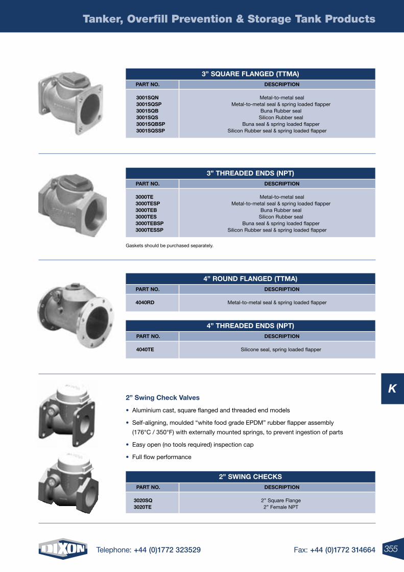
355Telephone: +44 (0)1772 323529 Fax: +44 (0)1772 314664
K
Tanker, Overfill Prevention & Storage Tank Products
Gaskets should be purchased separately.
2” swing Check Valves
• Aluminium cast, square flanged and threaded end models
• Self-aligning, moulded “white food grade EPDM” rubber flapper assembly
(176°C / 350°F) with externally mounted springs, to prevent ingestion of parts
• Easy open (no tools required) inspection cap
• Full flow performance
3” sQuare FlangeD (ttma) DesCription
Metal-to-metal sealMetal-to-metal seal & spring loaded flapper
Buna Rubber sealSilicon Rubber seal
Buna seal & spring loaded flapperSilicon Rubber seal & spring loaded flapper
part no.
3001sQn3001sQsp3001sQb3001sQs3001sQbsp3001sQssp
3” threaDeD enDs (npt) DesCription
Metal-to-metal sealMetal-to-metal seal & spring loaded flapper
Buna Rubber sealSilicon Rubber seal
Buna seal & spring loaded flapperSilicon Rubber seal & spring loaded flapper
part no.
3000te3000tesp3000teb3000tes3000tebsp3000tessp
4” rounD FlangeD (ttma) DesCription
Metal-to-metal seal & spring loaded flapper
part no.
4040rD
4” threaDeD enDs (npt) DesCription
Silicone seal, spring loaded flapper
part no.
4040te
2” sWing CheCKs DesCription
2” Square Flange2” Female NPT
part no.
3020sQ3020te
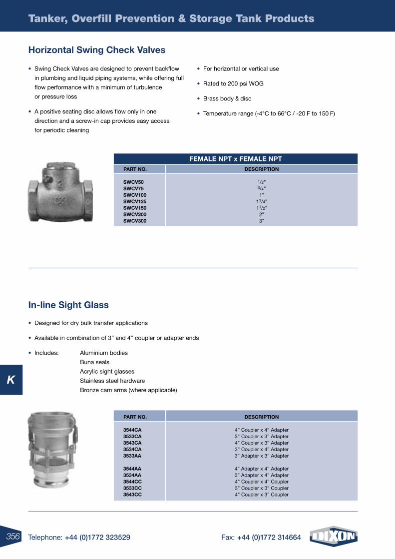
356 Telephone: +44 (0)1772 323529 Fax: +44 (0)1772 314664
K
Tanker, Overfill Prevention & Storage Tank Products
horizontal swing Check Valves
in-line sight glass
• Swing Check Valves are designed to prevent backflow
in plumbing and liquid piping systems, while offering full
flow performance with a minimum of turbulence
or pressure loss
• A positive seating disc allows flow only in one
direction and a screw-in cap provides easy access
for periodic cleaning
• For horizontal or vertical use
• Rated to 200 psi WOG
• Brass body & disc
• Temperature range (-4°C to 66°C / -20˚F to 150˚F)
Female npt x Female nptDesCription
1/2”3/4”1”
11/4”11/2”
2”3”
part no.
sWCV50sWCV75sWCV100sWCV125sWCV150sWCV200sWCV300
• Designed for dry bulk transfer applications
• Available in combination of 3” and 4” coupler or adapter ends
• Includes: Aluminium bodies
Buna seals
Acrylic sight glasses
Stainless steel hardware
Bronze cam arms (where applicable)
DesCription
4” Coupler x 4” Adapter3” Coupler x 3” Adapter4” Coupler x 3” Adapter3” Coupler x 4” Adapter3” Adapter x 3” Adapter
4” Adapter x 4” Adapter3” Adapter x 4” Adapter4” Coupler x 4” Coupler3” Coupler x 3” Coupler4” Coupler x 3” Coupler
part no.
3544Ca3533Ca3543Ca3534Ca3533aa
3544aa3534aa3544CC3533CC3543CC
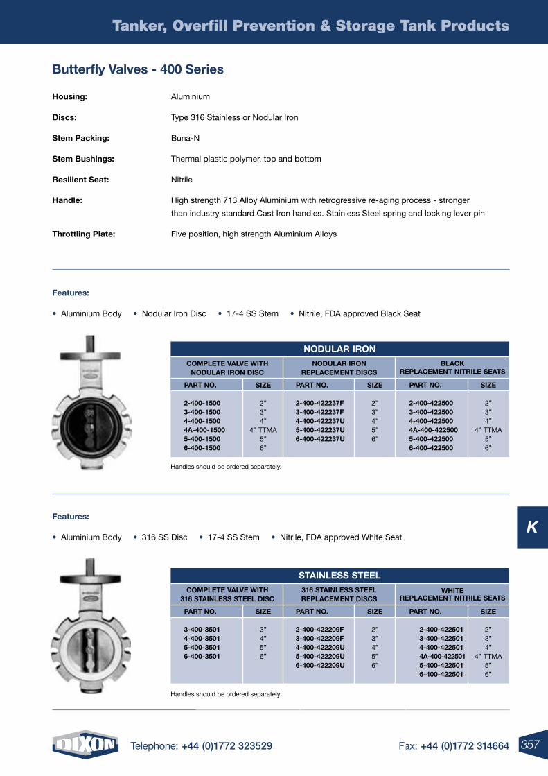
357Telephone: +44 (0)1772 323529 Fax: +44 (0)1772 314664
K
Tanker, Overfill Prevention & Storage Tank Products
butterfly Valves - 400 series
Handles should be ordered separately.
housing: Aluminium
Discs: Type 316 Stainless or Nodular Iron
stem packing: Buna-N
stem bushings: Thermal plastic polymer, top and bottom
resilient seat: Nitrile
handle: High strength 713 Alloy Aluminium with retrogressive re-aging process - stronger
than industry standard Cast Iron handles. Stainless Steel spring and locking lever pin
throttling plate: Five position, high strength Aluminium Alloys
Handles should be ordered separately.
Features:
• Aluminium Body • Nodular Iron Disc • 17-4 SS Stem • Nitrile, FDA approved Black Seat
Features:
• Aluminium Body • 316 SS Disc • 17-4 SS Stem • Nitrile, FDA approved White Seat
noDular iron
siZe
2”3”4”
4” TTMA5”6”
siZe
2”3”4”5”6”
siZe
2”3”4”
4” TTMA5”6”
Complete ValVe WithnoDular iron DisC
noDular ironreplaCement DisCs
blaCKreplaCement nitrile seats
part no.
2-400-15003-400-15004-400-15004a-400-15005-400-15006-400-1500
part no.
2-400-422237F3-400-422237F4-400-422237u5-400-422237u6-400-422237u
part no.
2-400-4225003-400-4225004-400-4225004a-400-4225005-400-4225006-400-422500
stainless steel
siZe
3”4”5”6”
siZe
2”3”4”5”6”
siZe
2”3”4”
4” TTMA5”6”
Complete ValVe With316 stainless steel DisC
316 stainless steelreplaCement DisCs
White replaCement nitrile seats
part no.
3-400-35014-400-35015-400-35016-400-3501
part no.
2-400-422209F3-400-422209F4-400-422209u5-400-422209u6-400-422209u
part no.
2-400-4225013-400-4225014-400-4225014a-400-4225015-400-4225016-400-422501
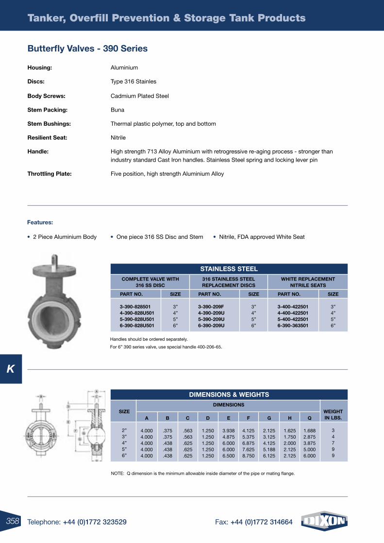
358 Telephone: +44 (0)1772 323529 Fax: +44 (0)1772 314664
K
Tanker, Overfill Prevention & Storage Tank Products
housing: Aluminium
Discs: Type 316 Stainles
body screws: Cadmium Plated Steel
stem packing: Buna
stem bushings: Thermal plastic polymer, top and bottom
resilient seat: Nitrile
handle: High strength 713 Alloy Aluminium with retrogressive re-aging process - stronger than industry standard Cast Iron handles. Stainless Steel spring and locking lever pin
throttling plate: Five position, high strength Aluminium Alloy
Features:
• 2 Piece Aluminium Body • One piece 316 SS Disc and Stem • Nitrile, FDA approved White Seat
NOTE: Q dimension is the minimum allowable inside diameter of the pipe or mating flange.
Handles should be ordered separately.
For 6” 390 series valve, use special handle 400-206-65.
butterfly Valves - 390 series
stainless steel
siZe
3”4”5”6”
siZe
3”4”5”6”
siZe
3”4”5”6”
Complete ValVe With316 ss DisC
316 stainless steelreplaCement DisCs
White replaCementnitrile seats
part no.
3-390-8285014-390-828u5015-390-828u5016-390-828u501
part no.
3-390-209F4-390-209u5-390-209u6-390-209u
part no.
3-400-4225014-400-4225015-400-4225016-390-363501
Dimensions & Weights
Weight in lbs.
34799
DimensionssiZe
2”3”4”5”6”
a
4.0004.0004.0004.0004.000
b
.375
.375
.438
.438
.438
C
.563
.563
.625
.625
.625
D
1.2501.2501.2501.2501.250
e
3.9384.8756.0006.0006.500
F
4.1255.3756.8757.6258.750
g
2.1253.1254.1255.1886.125
h
1.6251.7502.0002.1252.125
Q
1.6882.8753.8755.0006.000
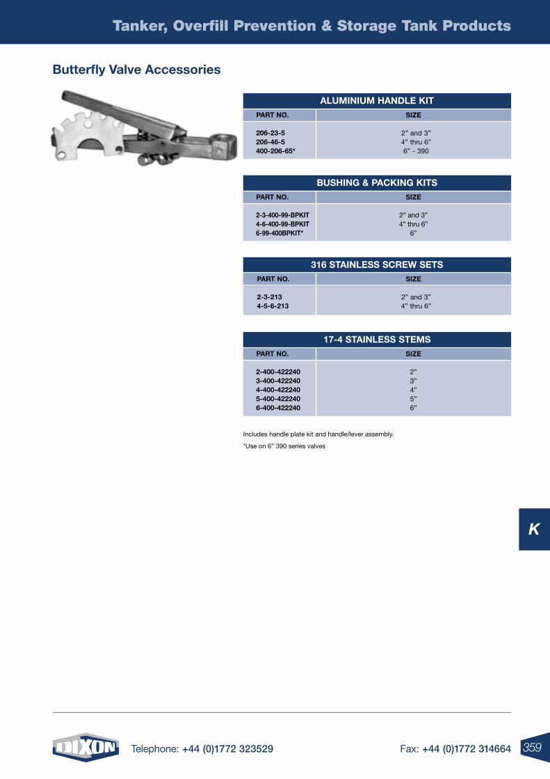
359Telephone: +44 (0)1772 323529 Fax: +44 (0)1772 314664
K
Tanker, Overfill Prevention & Storage Tank Products
Includes handle plate kit and handle/lever assembly.
*Use on 6” 390 series valves
butterfly Valve accessories
aluminium hanDle Kit
17-4 stainless stems
316 stainless sCreW sets
bushing & paCKing Kits
siZe
2” and 3”4” thru 6”6” - 390
siZe
2”3”4”5”6”
siZe
2” and 3”4” thru 6”
siZe
2” and 3”4” thru 6”
6”
part no.
206-23-5206-46-5400-206-65*
part no.
2-400-4222403-400-4222404-400-4222405-400-4222406-400-422240
part no.
2-3-2134-5-6-213
part no.
2-3-400-99-bpKit4-6-400-99-bpKit6-99-400bpKit*
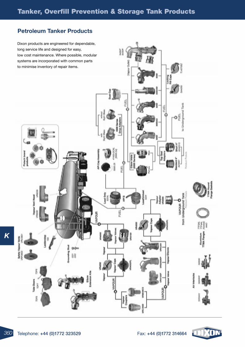
Telephone: +44 (0)1772 323529 Fax: +44 (0)1772 314664
K
Tanker, Overfill Prevention & Storage Tank Products
360
petroleum tanker products
Dixon products are engineered for dependable,
long service life and designed for easy,
low cost maintenance. Where possible, modular
systems are incorporated with common parts
to minimise inventory of repair items.
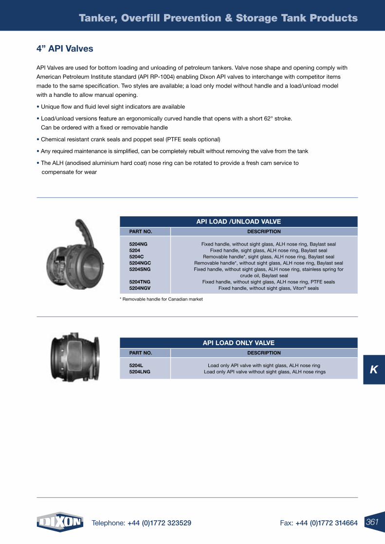
361Telephone: +44 (0)1772 323529 Fax: +44 (0)1772 314664
K
Tanker, Overfill Prevention & Storage Tank Products
api loaD only ValVeDesCription
Load only API valve with sight glass, ALH nose ring Load only API valve without sight glass, ALH nose rings
part no.
5204l 5204lng
4” api Valves
API Valves are used for bottom loading and unloading of petroleum tankers. Valve nose shape and opening comply with
American Petroleum Institute standard (API RP-1004) enabling Dixon API valves to interchange with competitor items
made to the same specification. Two styles are available; a load only model without handle and a load/unload model
with a handle to allow manual opening.
• Unique flow and fluid level sight indicators are available
• Load/unload versions feature an ergonomically curved handle that opens with a short 62° stroke.
Can be ordered with a fixed or removable handle
• Chemical resistant crank seals and poppet seal (PTFE seals optional)
• Any required maintenance is simplified, can be completely rebuilt without removing the valve from the tank
• The ALH (anodised aluminium hard coat) nose ring can be rotated to provide a fresh cam service to
compensate for wear
* Removable handle for Canadian market
api loaD /unloaD ValVeDesCription
Fixed handle, without sight glass, ALH nose ring, Baylast seal Fixed handle, sight glass, ALH nose ring, Baylast seal Removable handle*, sight glass, ALH nose ring, Baylast seal Removable handle*, without sight glass, ALH nose ring, Baylast seal Fixed handle, without sight glass, ALH nose ring, stainless spring for
crude oil, Baylast seal Fixed handle, without sight glass, ALH nose ring, PTFE seals Fixed handle, without sight glass, Viton® seals
part no.
5204ng 5204 5204C 5204ngC 5204sng 5204tng 5204ngV
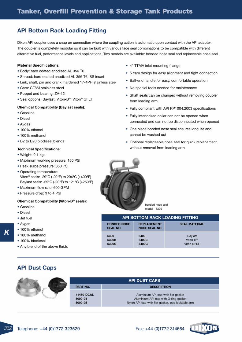
362 Telephone: +44 (0)1772 323529 Fax: +44 (0)1772 314664
K
material specifi cations:
• Body: hard coated anodized AL 356 T6
• Shroud: hard coated anodized AL 356 T6, SS insert
• Link, shaft, pin and crank: hardened 17-4PH stainless steel
• Cam: CF8M stainless steel
• Poppet and bearing: ZA-12
• Seal options: Baylast, Viton-B®, Viton® GFLT
Chemical Compatibility (baylast seals):
• Gasoline
• Diesel
• Avgas
• 100% ethanol
• 100% methanol
• B2 to B20 biodiesel blends
technical specifications:
• Weight: 9.1 kgs.
• Maximum working pressure: 150 PSI
• Peak surge pressure: 350 PSI
• Operating temperature: Viton® seals: -29°C (-20°F) to 204°C (+400°F) Baylast seals: -29°C (-20°F) to 121°C (+250°F)
• Maximum flow rate: 600 GPM
• Pressure drop: 3 to 4 PSI
Chemical Compatibility (Viton-b® seals):
• Gasoline
• Diesel
• Jet fuel
• Avgas
• 100% ethanol
• 100% methanol
• 100% biodiesel
• Any blend of the above fluids
Tanker, Overfill Prevention & Storage Tank Products
api bottom rack loading Fitting
Dixon API coupler uses a snap on connection where the coupling action is automatic upon contact with the API adapter.
The coupler is completely modular so it can be built with various face seal combinations to be compatible with different
alternative fuel, performance levels and applications. Two models are available: bonded nose seal and replaceable nose seal.
api bottom raCK loaDing Fitting
seal material
Baylast Viton-B®
Viton GFLT
bonDeD nose seal no.
5300 5300b 5300g
replaCement nose seal no.
5400 5400b 5400g
api Dust Caps
api Dust CapsDesCription
Aluminium API cap with flat gasket Aluminium API cap with O-ring gasket
Nylon API cap with flat gasket, pad lockable arm
part no.
41450-DCal 5000-24 5000-25
• 4” TTMA inlet mounting fl ange
• 5 cam design for easy alignment and tight connection
• Ball-end handle for easy, comfortable operation
• No special tools needed for maintenance
• Shaft seals can be changed without removing coupler
from loading arm
• Fully compliant with API RP1004:2003 specifications
• Fully interlocked collar can not be opened when
connected and can not be disconnected when opened
• One piece bonded nose seal ensures long life and
cannot be washed out
• Optional replaceable nose seal for quick replacement
without removal from loading arm
bonded nose seal model - 5300
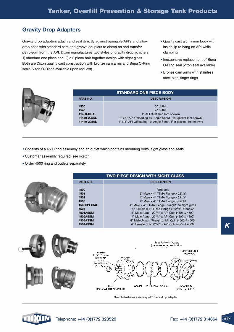
363Telephone: +44 (0)1772 323529 Fax: +44 (0)1772 314664
K
Tanker, Overfill Prevention & Storage Tank Products
gravity Drop adapters
Gravity drop adapters attach and seal directly against openable API’s and allow
drop hose with standard cam and groove couplers to clamp on and transfer
petroleum from the API. Dixon manufactures two styles of gravity drop adapters:
1) standard one piece and, 2) a 2 piece bolt together design with sight glass.
Both are Dixon quality cast construction with bronze cam arms and Buna O-Ring
seals (Viton O-Rings available upon request).
Sketch illustrates assembly of 2 piece drop adapter
• Consists of a 4500 ring assembly and an outlet which contains mounting bolts, sight glass and seals
• Customer assembly required (see sketch)
• Order 4500 ring and outlets separately
stanDarD one pieCe boDyDesCription
3” outlet4” outlet
4” API Dust Cap (not shown)3” x 4” API Offloading 10˚ Angle Spout, Flat gasket (not shown) 4” x 4” API Offloading 10˚ Angle Spout, Flat gasket (not shown)
part no.
4530454041450-DCal31440-225al41440-225al
tWo pieCe Design With sight glassDesCription
Ring only3” Male x 4” TTMA Flange x 221/2°4” Male x 4” TTMA Flange x 221/2°4” Male x 4” TTMA Flange Straight
4” Male x 4” TTMA Flange Straight, no sight glass4” Female x 4” TTMA Flange x 221/2° Coupler3” Male Adapt. 221/2° x API Cplr. (4501 & 4500)4” Male Adapt. 221/2° x API Cplr. (4502 & 4500)
4” Male Adapt. Straight x API Cplr. (4503 & 4500)4” Female Cplr. 221/2° x API Cplr. (4504 & 4500)
part no.
45004501450245034503speCial45044501assm4502assm4503assm4504assm
• Quality cast aluminium body with
inside lip to hang on API while
clamping
• Inexpensive replacement of Buna
O-Ring seal (Viton seal available)
• Bronze cam arms with stainless
steel pins, finger rings
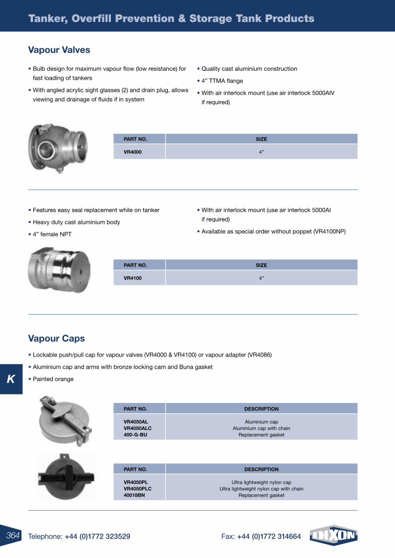
364 Telephone: +44 (0)1772 323529 Fax: +44 (0)1772 314664
K
Tanker, Overfill Prevention & Storage Tank Products
Vapour Valves
Vapour Caps
• Bulb design for maximum vapour flow (low resistance) for
fast loading of tankers
• With angled acrylic sight glasses (2) and drain plug, allows
viewing and drainage of fluids if in system
• Quality cast aluminium construction
• 4” TTMA flange
• With air interlock mount (use air interlock 5000AIV
if required)
• Lockable push/pull cap for vapour valves (VR4000 & VR4100) or vapour adapter (VR4086)
• Aluminium cap and arms with bronze locking cam and Buna gasket
• Painted orange
• Features easy seal replacement while on tanker
• Heavy duty cast aluminium body
• 4” female NPT
• With air interlock mount (use air interlock 5000AI
if required)
• Available as special order without poppet (VR4100NP)
siZe
4”
part no.
Vr4000
siZe
4”
part no.
Vr4100
DesCription
Aluminium capAluminium cap with chain
Replacement gasket
part no.
Vr4050alVr4050alC400-g-bu
DesCription
Ultra lightweight nylon capUltra lightweight nylon cap with chain
Replacement gasket
part no.
Vr4050plVr4050plC40018bn
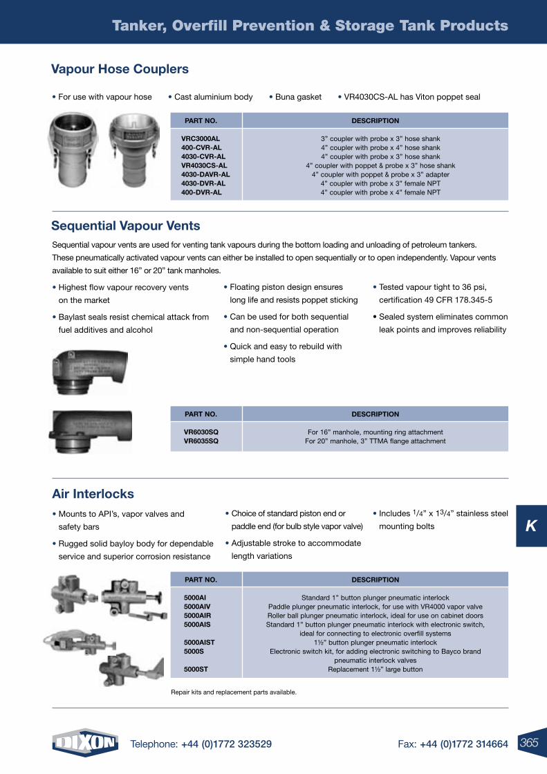
365Telephone: +44 (0)1772 323529 Fax: +44 (0)1772 314664
K
Tanker, Overfill Prevention & Storage Tank Products
Vapour hose Couplers
sequential Vapour Vents
air interlocks
• For use with vapour hose • Cast aluminium body • Buna gasket • VR4030CS-AL has Viton poppet seal
DesCription
3” coupler with probe x 3” hose shank4” coupler with probe x 4” hose shank4” coupler with probe x 3” hose shank
4” coupler with poppet & probe x 3” hose shank4” coupler with poppet & probe x 3” adapter
4” coupler with probe x 3” female NPT4” coupler with probe x 4” female NPT
part no.
VrC3000al400-CVr-al4030-CVr-alVr4030Cs-al4030-DaVr-al4030-DVr-al400-DVr-al
DesCription
For 16” manhole, mounting ring attachmentFor 20” manhole, 3” TTMA flange attachment
part no.
Vr6030sQ Vr6035sQ
DesCription
Standard 1” button plunger pneumatic interlockPaddle plunger pneumatic interlock, for use with VR4000 vapor valveRoller ball plunger pneumatic interlock, ideal for use on cabinet doorsStandard 1” button plunger pneumatic interlock with electronic switch,
ideal for connecting to electronic overfill systems1½” button plunger pneumatic interlock
Electronic switch kit, for adding electronic switching to Bayco brand pneumatic interlock valves
Replacement 1½” large button
part no.
5000ai 5000aiV 5000air 5000ais
5000aist 5000s
5000st
Sequential vapour vents are used for venting tank vapours during the bottom loading and unloading of petroleum tankers.
These pneumatically activated vapour vents can either be installed to open sequentially or to open independently. Vapour vents
available to suit either 16” or 20” tank manholes.
• Highest flow vapour recovery vents
on the market
• Baylast seals resist chemical attack from
fuel additives and alcohol
• Mounts to API’s, vapor valves and
safety bars
• Rugged solid bayloy body for dependable
service and superior corrosion resistance
• Floating piston design ensures
long life and resists poppet sticking
• Can be used for both sequential
and non-sequential operation
• Quick and easy to rebuild with
simple hand tools
• Choice of standard piston end or
paddle end (for bulb style vapor valve)
• Adjustable stroke to accommodate
length variations
• Tested vapour tight to 36 psi,
certification 49 CFR 178.345-5
• Sealed system eliminates common
leak points and improves reliability
• Includes 1/4” x 13/4” stainless steel
mounting bolts
Repair kits and replacement parts available.
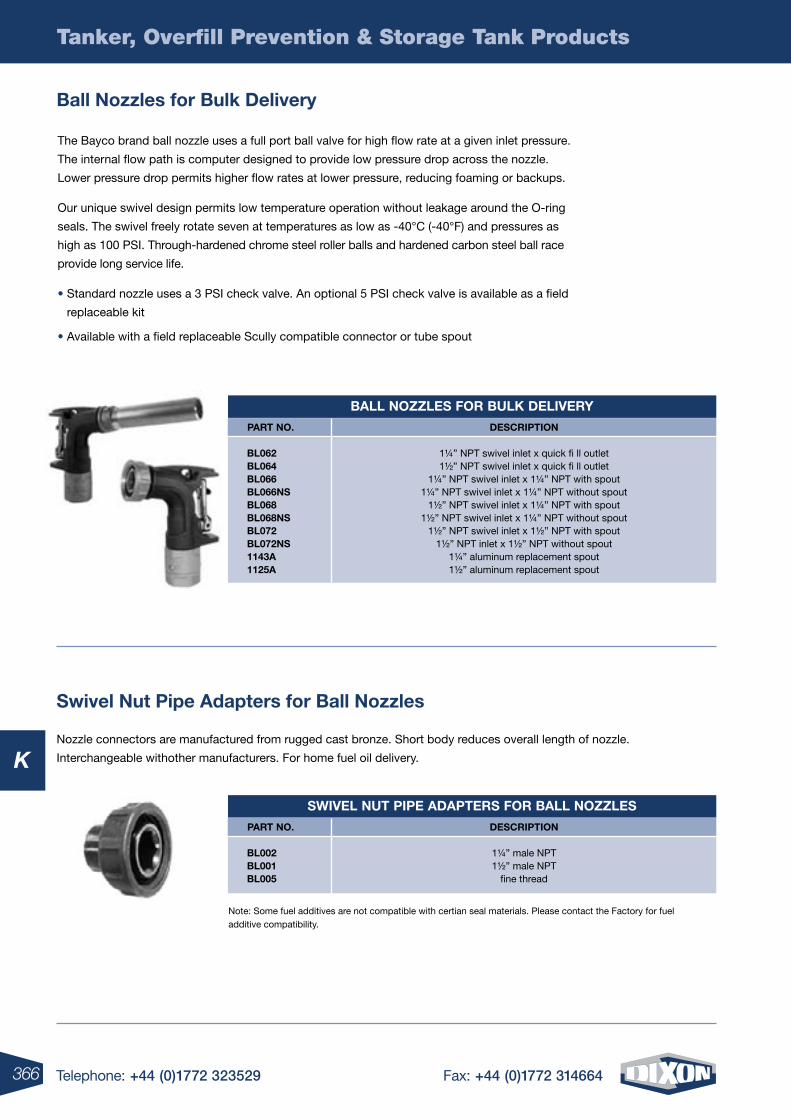
366 Telephone: +44 (0)1772 323529 Fax: +44 (0)1772 314664
K
Tanker, Overfill Prevention & Storage Tank Products
sWiVel nut pipe aDapters For ball noZZles
DesCription
1¼” male NPT 1½” male NPT
fine thread
part no.
bl002bl001bl005
Note: Some fuel additives are not compatible with certian seal materials. Please contact the Factory for fuel additive compatibility.
Nozzle connectors are manufactured from rugged cast bronze. Short body reduces overall length of nozzle.
Interchangeable withother manufacturers. For home fuel oil delivery.
swivel nut pipe adapters for ball nozzles
ball nozzles for bulk Delivery
The Bayco brand ball nozzle uses a full port ball valve for high flow rate at a given inlet pressure.
The internal flow path is computer designed to provide low pressure drop across the nozzle.
Lower pressure drop permits higher flow rates at lower pressure, reducing foaming or backups.
Our unique swivel design permits low temperature operation without leakage around the O-ring
seals. The swivel freely rotate seven at temperatures as low as -40°C (-40°F) and pressures as
high as 100 PSI. Through-hardened chrome steel roller balls and hardened carbon steel ball race
provide long service life.
• Standard nozzle uses a 3 PSI check valve. An optional 5 PSI check valve is available as a field
replaceable kit
• Available with a field replaceable Scully compatible connector or tube spout
ball noZZles For bulK DeliVery
DesCription
1¼” NPT swivel inlet x quick fi ll outlet 1½” NPT swivel inlet x quick fi ll outlet
1¼” NPT swivel inlet x 1¼” NPT with spout 1¼” NPT swivel inlet x 1¼” NPT without spout
1½” NPT swivel inlet x 1¼” NPT with spout 1½” NPT swivel inlet x 1¼” NPT without spout
1½” NPT swivel inlet x 1½” NPT with spout 1½” NPT inlet x 1½” NPT without spout
1¼” aluminum replacement spout 1½” aluminum replacement spout
part no.
bl062bl064bl066bl066nsbl068bl068nsbl072bl072ns1143a1125a
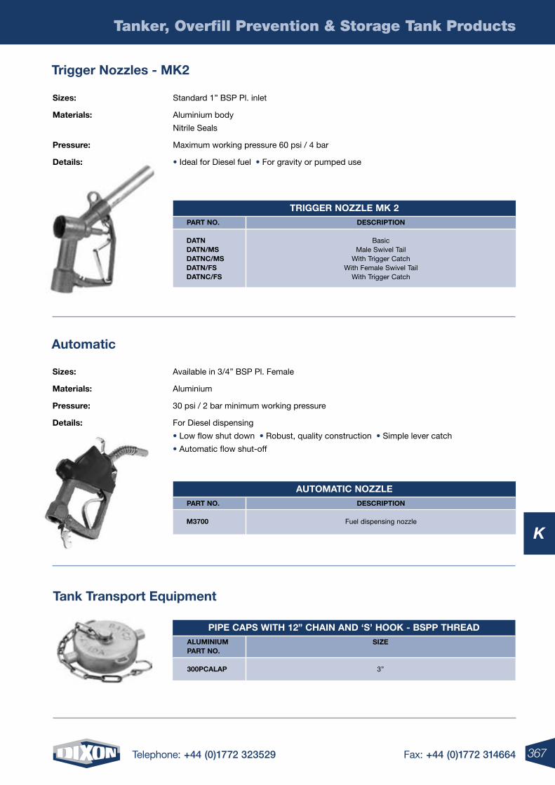
367Telephone: +44 (0)1772 323529 Fax: +44 (0)1772 314664
K
Tanker, Overfill Prevention & Storage Tank Products
trigger nozzles - mK2
automatic
sizes: Standard 1” BSP Pl. inlet
materials: Aluminium body
Nitrile Seals
pressure: Maximum working pressure 60 psi / 4 bar
Details: • Ideal for Diesel fuel • For gravity or pumped use
sizes: Available in 3/4” BSP Pl. Female
materials: Aluminium
pressure: 30 psi / 2 bar minimum working pressure
Details: For Diesel dispensing
• Low flow shut down • Robust, quality construction • Simple lever catch
• Automatic flow shut-off
trigger noZZle mK 2DesCription
BasicMale Swivel Tail
With Trigger CatchWith Female Swivel Tail
With Trigger Catch
part no.
DatnDatn/msDatnC/msDatn/FsDatnC/Fs
automatiC noZZleDesCription
Fuel dispensing nozzle
part no.
m3700
tank transport equipment
pipe Caps With 12” Chain anD ‘s’ hooK - bspp threaDsiZe
3”
aluminium part no.
300pCalap
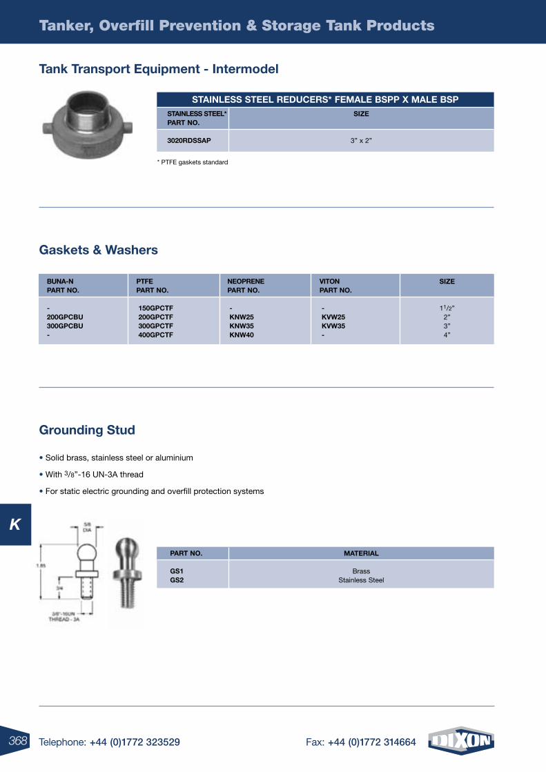
368 Telephone: +44 (0)1772 323529 Fax: +44 (0)1772 314664
K
Tanker, Overfill Prevention & Storage Tank Products
tank transport equipment - intermodel
gaskets & Washers
grounding stud
* PTFE gaskets standard
• Solid brass, stainless steel or aluminium
• With 3/8”-16 UN-3A thread
• For static electric grounding and overfill protection systems
stainless steel reDuCers* Female bspp X male bspsiZe
3” x 2”
stainless steel* part no.
3020rDssap
siZe
11/2”2”3”4”
buna-n part no.
-200gpCbu300gpCbu-
ptFe part no.
150gpCtF200gpCtF300gpCtF400gpCtF
neoprene part no.
-KnW25KnW35KnW40
Viton part no.
-KVW25KVW35-
material
BrassStainless Steel
part no.
gs1gs2
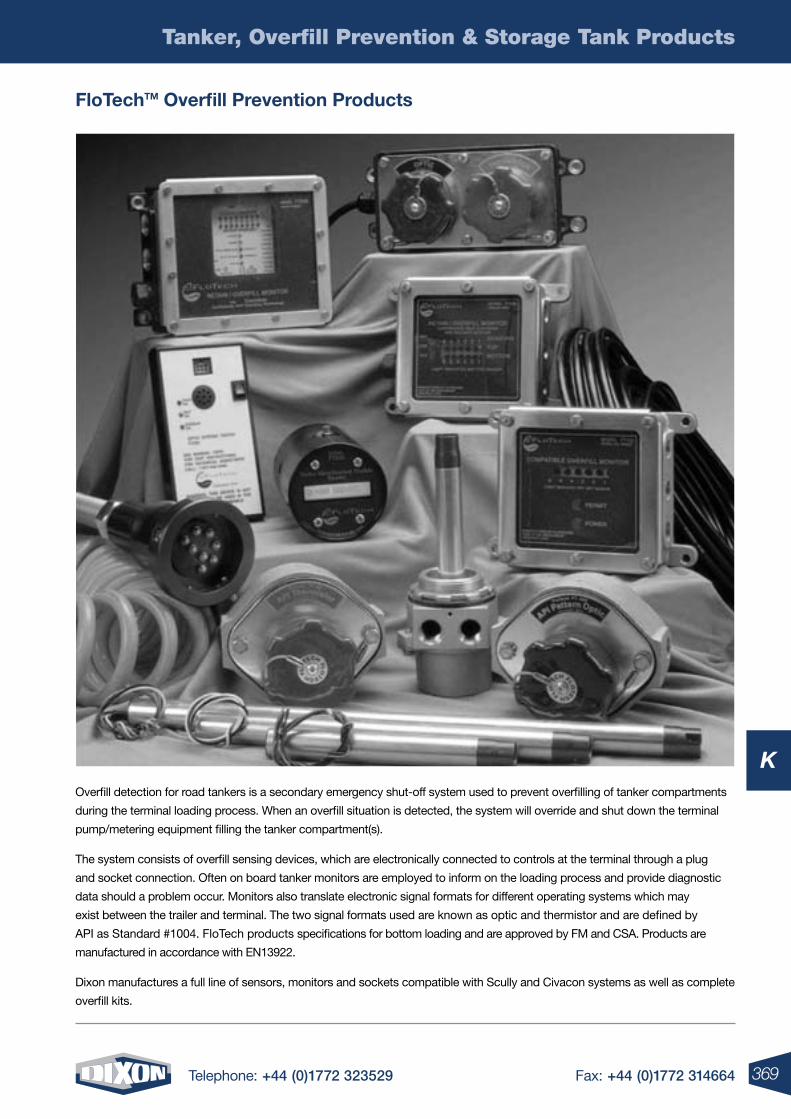
369Telephone: +44 (0)1772 323529 Fax: +44 (0)1772 314664
K
Tanker, Overfill Prevention & Storage Tank Products
Overfill detection for road tankers is a secondary emergency shut-off system used to prevent overfilling of tanker compartments
during the terminal loading process. When an overfill situation is detected, the system will override and shut down the terminal
pump/metering equipment filling the tanker compartment(s).
The system consists of overfill sensing devices, which are electronically connected to controls at the terminal through a plug
and socket connection. Often on board tanker monitors are employed to inform on the loading process and provide diagnostic
data should a problem occur. Monitors also translate electronic signal formats for different operating systems which may
exist between the trailer and terminal. The two signal formats used are known as optic and thermistor and are defined by
API as Standard #1004. FloTech products specifications for bottom loading and are approved by FM and CSA. Products are
manufactured in accordance with EN13922.
Dixon manufactures a full line of sensors, monitors and sockets compatible with Scully and Civacon systems as well as complete
overfill kits.
Flotechtm overfill prevention products
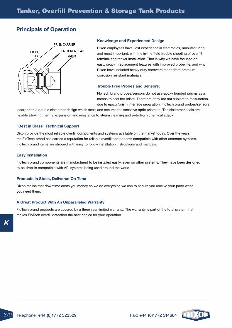
370 Telephone: +44 (0)1772 323529 Fax: +44 (0)1772 314664
K
Tanker, Overfill Prevention & Storage Tank Products
principals of operation
Knowledge and experienced Design
Dixon employees have vast experience in electronics, manufacturing
and most important, with the in-the-field trouble shooting of overfill
terminal and tanker installation. That is why we have focused on
easy, drop-in replacement features with improved probe life, and why
Dixon have included heavy duty hardware made from premium,
corrosion resistant materials.
trouble Free probes and sensors:
FloTech brand probes/sensors do not use epoxy bonded prisms as a
means to seal the prism. Therefore, they are not subject to malfunction
due to epoxy/prism interface separation. FloTech brand probes/sensors
incorporate a double elastomer design which seals and secures the sensitive optic prism tip. The elastomer seals are
flexible allowing thermal expansion and resistance to steam cleaning and petroleum chemical attack.
“best in Class” technical support
Dixon provide the most reliable overfill components and systems available on the market today. Over the years
the FloTech brand has earned a reputation for reliable overfill components compatible with other common systems.
FloTech brand items are shipped with easy to follow installation instructions and manuals.
easy installation
FloTech brand components are manufactured to be installed easily, even on other systems. They have been designed
to be drop-in compatible with API systems being used around the world.
products in stock, Delivered on time
Dixon realise that downtime costs you money so we do everything we can to ensure you receive your parts when
you need them.
a great product With an unparalleled Warranty
FloTech brand products are covered by a three year limited warranty. The warranty is part of the total system that
makes FloTech overfill detection the best choice for your operation.
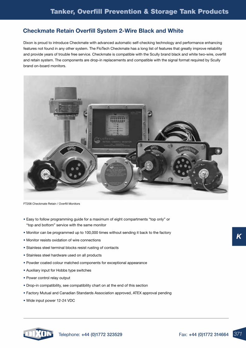
371Telephone: +44 (0)1772 323529 Fax: +44 (0)1772 314664
K
Tanker, Overfill Prevention & Storage Tank Products
Checkmate retain overfill system 2-Wire black and White
Dixon is proud to introduce Checkmate with advanced automatic self-checking technology and performance enhancing
features not found in any other system. The FloTech Checkmate has a long list of features that greatly improve reliability
and provide years of trouble free service. Checkmate is compatible with the Scully brand black and white two-wire, overfill
and retain system. The components are drop-in replacements and compatible with the signal format required by Scully
brand on-board monitors.
• Easy to follow programming guide for a maximum of eight compartments “top only” or
“top and bottom” service with the same monitor
• Monitor can be programmed up to 100,000 times without sending it back to the factory
• Monitor resists oxidation of wire connections
• Stainless steel terminal blocks resist rusting of contacts
• Stainless steel hardware used on all products
• Powder coated colour matched components for exceptional appearance
• Auxiliary input for Hobbs type switches
• Power control relay output
• Drop-in compatibility, see compatibility chart on at the end of this section
• Factory Mutual and Canadian Standards Association approved, ATEX approval pending
• Wide input power 12-24 VDC
FT208 Checkmate Retain / Overfill Monitors
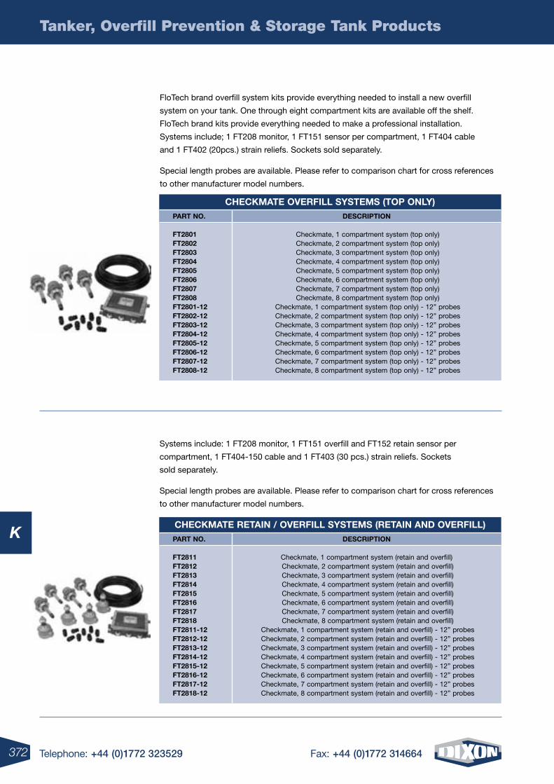
372 Telephone: +44 (0)1772 323529 Fax: +44 (0)1772 314664
K
Tanker, Overfill Prevention & Storage Tank Products
FloTech brand overfill system kits provide everything needed to install a new overfill
system on your tank. One through eight compartment kits are available off the shelf.
FloTech brand kits provide everything needed to make a professional installation.
Systems include; 1 FT208 monitor, 1 FT151 sensor per compartment, 1 FT404 cable
and 1 FT402 (20pcs.) strain reliefs. Sockets sold separately.
Special length probes are available. Please refer to comparison chart for cross references
to other manufacturer model numbers.
Systems include: 1 FT208 monitor, 1 FT151 overfill and FT152 retain sensor per
compartment, 1 FT404-150 cable and 1 FT403 (30 pcs.) strain reliefs. Sockets
sold separately.
Special length probes are available. Please refer to comparison chart for cross references
to other manufacturer model numbers.
CheCKmate oVerFill systems (top only)DesCription
Checkmate, 1 compartment system (top only) Checkmate, 2 compartment system (top only) Checkmate, 3 compartment system (top only) Checkmate, 4 compartment system (top only) Checkmate, 5 compartment system (top only) Checkmate, 6 compartment system (top only) Checkmate, 7 compartment system (top only) Checkmate, 8 compartment system (top only)
Checkmate, 1 compartment system (top only) - 12” probes Checkmate, 2 compartment system (top only) - 12” probes Checkmate, 3 compartment system (top only) - 12” probes Checkmate, 4 compartment system (top only) - 12” probes Checkmate, 5 compartment system (top only) - 12” probes Checkmate, 6 compartment system (top only) - 12” probes Checkmate, 7 compartment system (top only) - 12” probes Checkmate, 8 compartment system (top only) - 12” probes
part no.
Ft2801 Ft2802 Ft2803 Ft2804 Ft2805 Ft2806 Ft2807 Ft2808 Ft2801-12 Ft2802-12 Ft2803-12 Ft2804-12 Ft2805-12 Ft2806-12 Ft2807-12 Ft2808-12
CheCKmate retain / oVerFill systems (retain anD oVerFill)DesCription
Checkmate, 1 compartment system (retain and overfill) Checkmate, 2 compartment system (retain and overfill) Checkmate, 3 compartment system (retain and overfill) Checkmate, 4 compartment system (retain and overfill) Checkmate, 5 compartment system (retain and overfill) Checkmate, 6 compartment system (retain and overfill) Checkmate, 7 compartment system (retain and overfill) Checkmate, 8 compartment system (retain and overfill)
Checkmate, 1 compartment system (retain and overfill) - 12” probes Checkmate, 2 compartment system (retain and overfill) - 12” probes Checkmate, 3 compartment system (retain and overfill) - 12” probes Checkmate, 4 compartment system (retain and overfill) - 12” probes Checkmate, 5 compartment system (retain and overfill) - 12” probes Checkmate, 6 compartment system (retain and overfill) - 12” probes Checkmate, 7 compartment system (retain and overfill) - 12” probes Checkmate, 8 compartment system (retain and overfill) - 12” probes
part no.
Ft2811 Ft2812 Ft2813 Ft2814 Ft2815 Ft2816 Ft2817 Ft2818 Ft2811-12 Ft2812-12 Ft2813-12 Ft2814-12 Ft2815-12 Ft2816-12 Ft2817-12 Ft2818-12
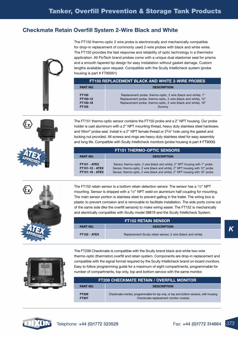
373Telephone: +44 (0)1772 323529 Fax: +44 (0)1772 314664
K
Tanker, Overfill Prevention & Storage Tank Products
Checkmate retain overfill system 2-Wire black and White
The FT150 thermo-optic 2 wire probe is electronically and mechanically compatible for drop-in replacement of commonly used 2-wire probes with black and white wires. The FT150 provides the fast response and reliability of optic technology in a thermistor application. All FloTech brand probes come with a unique dual elastomer seal for prisms and a smooth tapered tip design for easy installation without gasket damage. Custom lengths available upon request. Compatible with the Scully Intellicheck system (probe housing is part # FT90001)
The FT151 thermo-optic sensor contains the FT150 probe and a 2” NPT housing. Our probe holder is cast aluminium with a 2” NPT mounting thread, heavy duty stainless steel hardware, and Viton® probe seal. Install in a 2” NPT female thread or 23/8” hole using the gasket and locking nut provided. All screws and rings are heavy duty stainless steel for easy assembly and long life. Compatible with Scully Intellicheck monitors (probe housing is part # FT9000)
The FT208 Checkmate is compatible with the Scully brand black and white two-wire thermo-optic (thermistor) overfill and retain system. Components are drop-in replacement and compatible with the signal format required by the Scully Intellicheck brand on-board monitors. Easy to follow programming guide for a maximum of eight compartments, programmable for number of compartments, top only, top and bottom service with the same monitor.
The FT152 retain sensor is a bottom retain detection sensor. The sensor has a 1/2” NPT mounting. Sensor is shipped with a 1/2” NPT weld-on aluminium half coupling for mounting. The main sensor portion is stainless steel to prevent galling in the trailer. The wiring box is plastic to prevent corrosion and is removable to facilitate installation. The side ports come out of the same side (like the overfill sensors) to make wiring easier. The FT152 is mechanically and electrically compatible with Scully model 08819 and the Scully Intellicheck System.
Ft150 replaCement blaCK anD White 2-Wire probesDesCription
Replacement probe, thermo-optic, 2 wire (black and white), 7”Replacement probe, thermo-optic, 2 wire (black and white), 12”Replacement probe, thermo-optic, 2 wire (black and white), 18”
Dummy
part no.
Ft150 Ft150-12 Ft150-18 Ft155
Ft151 thermo-optiC sensorsDesCription
Sensor, thermo-optic, 2 wire (black and white), 2” NPT housing with 7” probeSensor, thermo-optic, 2 wire (black and white), 2” NPT housing with 12” probeSensor, thermo-optic, 2 wire (black and white), 2” NPT housing with 18” probe
part no.
Ft151 - ateX Ft151-12 - ateX Ft151-18 - ateX
Ft152 retain sensorDesCription
Replacement Scully retain sensor, 2 wire (black and white)
part no.
Ft152 - ateX
Ft208 CheCKmate retain / oVerFill monitorDesCription
Checkmate monitor, programmable for top only, or top and bottom sensors, with housingCheckmate replacement monitor module
part no.
Ft208 Ft207
ATEXAPPROVEDAPPROVED
ATEX
ATEXAPPROVEDAPPROVED
ATEX
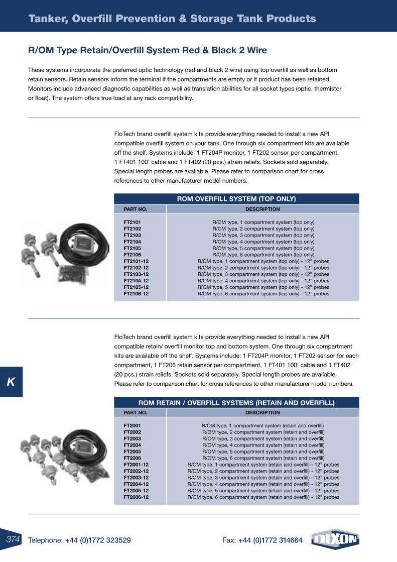
374 Telephone: +44 (0)1772 323529 Fax: +44 (0)1772 314664
K
Tanker, Overfill Prevention & Storage Tank Products
r/om type retain/overfill system red & black 2 Wire
These systems incorporate the preferred optic technology (red and black 2 wire) using top overfill as well as bottom
retain sensors. Retain sensors inform the terminal if the compartments are empty or if product has been retained.
Monitors include advanced diagnostic capabilities as well as translation abilities for all socket types (optic, thermistor
or float). The system offers true load at any rack compatibility.
FloTech brand overfill system kits provide everything needed to install a new API
compatible retain/ overfill monitor top and bottom system. One through six compartment
kits are available off the shelf. Systems include: 1 FT204P monitor, 1 FT202 sensor for each
compartment, 1 FT206 retain sensor per compartment, 1 FT401 100’ cable and 1 FT402
(20 pcs.) strain reliefs. Sockets sold separately. Special length probes are available.
Please refer to comparison chart for cross references to other manufacturer model numbers.
FloTech brand overfill system kits provide everything needed to install a new API
compatible overfill system on your tank. One through six compartment kits are available
off the shelf. Systems include: 1 FT204P monitor, 1 FT202 sensor per compartment,
1 FT401 100’ cable and 1 FT402 (20 pcs.) strain reliefs. Sockets sold separately.
Special length probes are available. Please refer to comparison chart for cross
references to other manufacturer model numbers.
rom oVerFill system (top only)DesCription
R/OM type, 1 compartment system (top only) R/OM type, 2 compartment system (top only) R/OM type, 3 compartment system (top only) R/OM type, 4 compartment system (top only) R/OM type, 5 compartment system (top only) R/OM type, 6 compartment system (top only)
R/OM type, 1 compartment system (top only) - 12” probes R/OM type, 2 compartment system (top only) - 12” probes R/OM type, 3 compartment system (top only) - 12” probes R/OM type, 4 compartment system (top only) - 12” probes R/OM type, 5 compartment system (top only) - 12” probes R/OM type, 6 compartment system (top only) - 12” probes
part no.
Ft2101 Ft2102 Ft2103 Ft2104 Ft2105 Ft2106 Ft2101-12 Ft2102-12 Ft2103-12 Ft2104-12 Ft2105-12 Ft2106-12
rom retain / oVerFill systems (retain anD oVerFill)DesCription
R/OM type, 1 compartment system (retain and overfill) R/OM type, 2 compartment system (retain and overfill) R/OM type, 3 compartment system (retain and overfill) R/OM type, 4 compartment system (retain and overfill) R/OM type, 5 compartment system (retain and overfill) R/OM type, 6 compartment system (retain and overfill)
R/OM type, 1 compartment system (retain and overfill) - 12” probes R/OM type, 2 compartment system (retain and overfill) - 12” probes R/OM type, 3 compartment system (retain and overfill) - 12” probes R/OM type, 4 compartment system (retain and overfill) - 12” probes R/OM type, 5 compartment system (retain and overfill) - 12” probes R/OM type, 6 compartment system (retain and overfill) - 12” probes
part no.
Ft2001 Ft2002 Ft2003 Ft2004 Ft2005 Ft2006 Ft2001-12 Ft2002-12 Ft2003-12 Ft2004-12 Ft2005-12 Ft2006-12
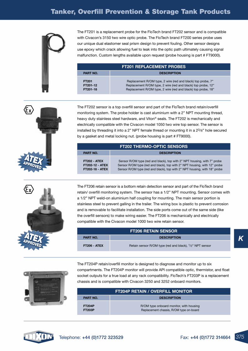
375Telephone: +44 (0)1772 323529 Fax: +44 (0)1772 314664
K
Tanker, Overfill Prevention & Storage Tank Products
The FT204P retain/overfill monitor is designed to diagnose and monitor up to six
compartments. The FT204P monitor will provide API compatible optic, thermistor, and float
socket outputs for a true load at any rack compatibility. FloTech’s FT203P is a replacement
chassis and is compatible with Civacon 3250 and 3252 onboard monitors.
The FT206 retain sensor is a bottom retain detection sensor and part of the FloTech brand
retain/ overfill monitoring system. The sensor has a 1/2” NPT mounting. Sensor comes with
a 1/2” NPT weld-on aluminium half coupling for mounting. The main sensor portion is
stainless steel to prevent galling in the trailer. The wiring box is plastic to prevent corrosion
and is removable to facilitate installation. The side ports come out of the same side (like
the overfill sensors) to make wiring easier. The FT206 is mechanically and electrically
compatible with the Civacon model 1000 two wire retain sensor.
The FT202 sensor is a top overfill sensor and part of the FloTech brand retain/overfill
monitoring system. The probe holder is cast aluminium with a 2” NPT mounting thread,
heavy duty stainless steel hardware, and Viton® seals. The FT202 is mechanically and
electrically compatible with the Civacon model 1050 two wire top sensor. The sensor is
installed by threading it into a 2” NPT female thread or mounting it in a 23/8” hole secured
by a gasket and metal locking nut. (probe housing is part # FT9000).
The FT201 is a replacement probe for the FloTech brand FT202 sensor and is compatible
with Civacon’s 3150 two wire optic probe. The FloTech brand FT200 series probe uses
our unique dual elastomer seal prism design to prevent fouling. Other sensor designs
use epoxy which crack allowing fuel to leak into the optic path ultimately causing signal
malfunction. Custom lengths available upon request (probe housing is part # FT9000).
Ft201 replaCement probesDesCription
Replacement R/OM type, 2 wire (red and black) top probe, 7” Replacement R/OM type, 2 wire (red and black) top probe, 12” Replacement R/OM type, 2 wire (red and black) top probe, 18”
part no.
Ft201 Ft201-12 Ft201-18
Ft202 thermo-optiC sensorsDesCription
Sensor R/OM type (red and black), top with 2” NPT housing, with 7” probeSensor R/OM type (red and black), top with 2” NPT housing, with 12” probeSensor R/OM type (red and black), top with 2” NPT housing, with 18” probe
part no.
Ft202 - ateX Ft202-12 - ateX Ft202-18 - ateX
Ft206 retain sensorDesCription
Retain sensor R/OM type (red and black), 1/2” NPT sensor
part no.
Ft206 - ateX
Ft204p retain / oVerFill monitorDesCription
R/OM type onboard monitor, with housingReplacement chassis, R/OM type on-board
part no.
Ft204p Ft203p
ATEXAPPROVEDAPPROVED
ATEX
ATEXAPPROVEDAPPROVED
ATEX
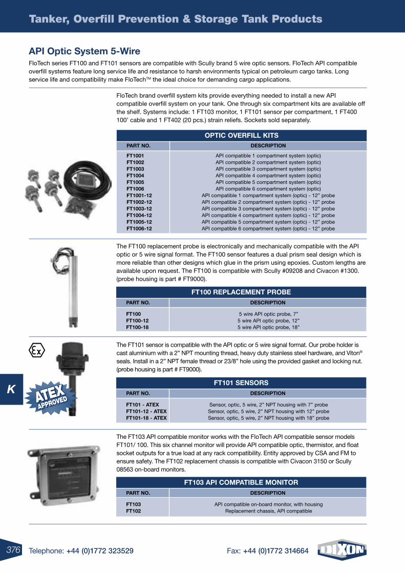
376 Telephone: +44 (0)1772 323529 Fax: +44 (0)1772 314664
K
Tanker, Overfill Prevention & Storage Tank Products
api optic system 5-WireFloTech series FT100 and FT101 sensors are compatible with Scully brand 5 wire optic sensors. FloTech API compatible overfill systems feature long service life and resistance to harsh environments typical on petroleum cargo tanks. Long service life and compatibility make FloTechTM the ideal choice for demanding cargo applications.
FloTech brand overfill system kits provide everything needed to install a new API compatible overfill system on your tank. One through six compartment kits are available off the shelf. Systems include: 1 FT103 monitor, 1 FT101 sensor per compartment, 1 FT400 100’ cable and 1 FT402 (20 pcs.) strain reliefs. Sockets sold separately.
The FT100 replacement probe is electronically and mechanically compatible with the API optic or 5 wire signal format. The FT100 sensor features a dual prism seal design which is more reliable than other designs which glue in the prism using epoxies. Custom lengths are available upon request. The FT100 is compatible with Scully #09208 and Civacon #1300. (probe housing is part # FT9000).
The FT101 sensor is compatible with the API optic or 5 wire signal format. Our probe holder is cast aluminium with a 2” NPT mounting thread, heavy duty stainless steel hardware, and Viton® seals. Install in a 2” NPT female thread or 23/8” hole using the provided gasket and locking nut. (probe housing is part # FT9000).
The FT103 API compatible monitor works with the FloTech API compatible sensor models FT101/ 100. This six channel monitor will provide API compatible optic, thermistor, and float socket outputs for a true load at any rack compatibility. Entity approved by CSA and FM to ensure safety. The FT102 replacement chassis is compatible with Civacon 3150 or Scully 08563 on-board monitors.
optiC oVerFill KitsDesCription
API compatible 1 compartment system (optic)API compatible 2 compartment system (optic)API compatible 3 compartment system (optic)API compatible 4 compartment system (optic)API compatible 5 compartment system (optic)API compatible 6 compartment system (optic)
API compatible 1 compartment system (optic) - 12” probeAPI compatible 2 compartment system (optic) - 12” probeAPI compatible 3 compartment system (optic) - 12” probeAPI compatible 4 compartment system (optic) - 12” probeAPI compatible 5 compartment system (optic) - 12” probeAPI compatible 6 compartment system (optic) - 12” probe
part no.
Ft1001 Ft1002 Ft1003 Ft1004 Ft1005 Ft1006 Ft1001-12 Ft1002-12 Ft1003-12 Ft1004-12 Ft1005-12 Ft1006-12
Ft100 replaCement probeDesCription
5 wire API optic probe, 7” 5 wire API optic probe, 12” 5 wire API optic probe, 18”
part no.
Ft100 Ft100-12 Ft100-18
Ft103 api Compatible monitorDesCription
API compatible on-board monitor, with housing Replacement chassis, API compatible
part no.
Ft103 Ft102
Ft101 sensorsDesCription
Sensor, optic, 5 wire, 2” NPT housing with 7” probe Sensor, optic, 5 wire, 2” NPT housing with 12” probe Sensor, optic, 5 wire, 2” NPT housing with 18” probe
part no.
Ft101 - ateX Ft101-12 - ateX Ft101-18 - ateX
ATEXAPPROVEDAPPROVEDATEX
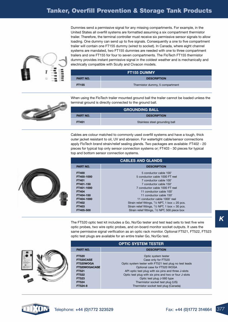
377Telephone: +44 (0)1772 323529 Fax: +44 (0)1772 314664
K
Tanker, Overfill Prevention & Storage Tank Products
Dummies send a permissive signal for any missing compartments. For example, in the United States all overfill systems are formatted assuming a six compartment thermistor trailer. Therefore, the terminal controller must receive six permissive sensor signals to allow loading. One dummy can send up to five signals. Consequently a one to five compartment trailer will contain one FT155 dummy (wired to socket). In Canada, where eight channel systems are mandated, two FT155 dummies are needed with one to three compartment trailers and one FT155 for four to seven compartments. The FloTech FT155 thermistor dummy provides instant permissive signal in the coldest weather and is mechanically and electrically compatible with Scully and Civacon models.
When using the FloTech trailer mounted ground ball the trailer cannot be loaded unless the terminal ground is directly connected to the ground ball.
Cables are colour matched to commonly used overfill systems and have a tough, thick outer jacket resistant to oil, UV and abrasion. For watertight cable/sensor connections apply FloTech brand strain/relief sealing glands. Two packages are available: FT402 - 20 pieces for typical top only sensor connection systems or; FT403 - 30 pieces for typical top and bottom sensor connection systems.
The FT520 optic test kit includes a Go, No/Go tester and test lead sets to test five wire optic probes, two wire optic probes, and on-board monitor socket outputs. It uses the same permissive signal verification as an optic rack monitor. Optional FT521, FT522, FT523 optic test plugs are available for an entire trailer Go, No/Go test.
Ft155 DummyDesCription
Thermistor dummy, 5 compartment
part no.
Ft155
grounDing ballDesCription
Stainless steel grounding ball
part no.
Ft451
Cables anD glanDsDesCription
5 conductor cable 100’ 5 conductor cable 1000 FT reel
7 conductor cable 100’ 7 conductor cable 150’
7 conductor cable 1000 FT reel 11 conductor cable 100’ 11 conductor cable 150’
11 conductor cable 1000’ reel Strain relief fittings, 1/2 NPT, 1 box = 20 pcs. Strain relief fittings, 1/2 NPT, 1 box = 30 pcs. Strain relief fittings, 1/2 NPT, 500 piece box
part no.
Ft400 Ft400-1000 Ft401 Ft401-150 Ft401-1000 Ft404 Ft404-150 Ft404-1000 Ft402 Ft403 Ft405-500
optiC system testerDesCription
Optic system tester Case only for FT520
Optic system tester with FT521 test plug no test leads Optional case for FT520 WOGA
API optic test plug with six pins and three J-slots Optic test plug with six pins and two or four J-slots
Optic test plug J-560 type Thermistor socket test plug (US)
Thermistor socket test plug (Canada)
part no.
Ft520 Ft520Case Ft520Woga Ft520WogaCase Ft521 Ft522 Ft523 Ft524 Ft524-8
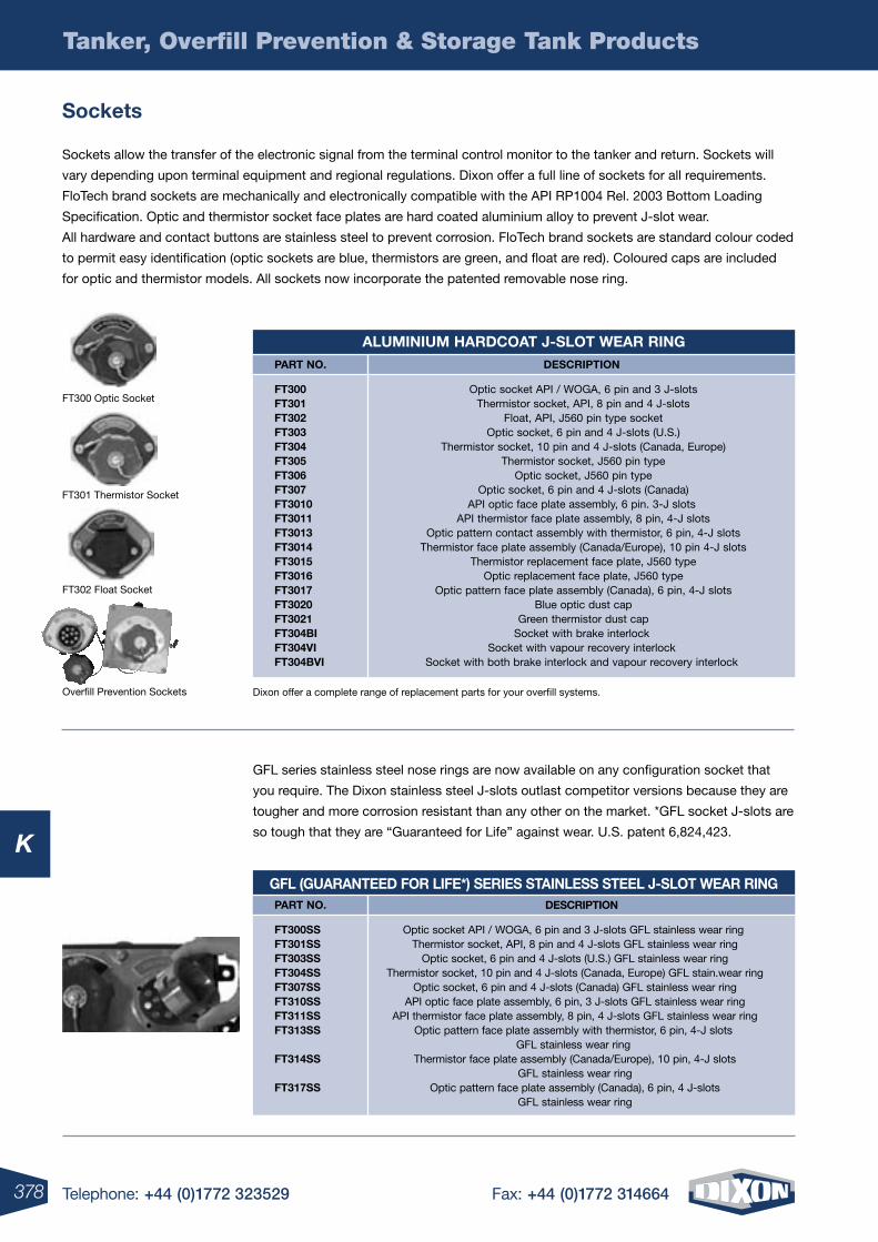
378 Telephone: +44 (0)1772 323529 Fax: +44 (0)1772 314664
K
Tanker, Overfill Prevention & Storage Tank Products
sockets
Sockets allow the transfer of the electronic signal from the terminal control monitor to the tanker and return. Sockets will
vary depending upon terminal equipment and regional regulations. Dixon offer a full line of sockets for all requirements.
FloTech brand sockets are mechanically and electronically compatible with the API RP1004 Rel. 2003 Bottom Loading
Specification. Optic and thermistor socket face plates are hard coated aluminium alloy to prevent J-slot wear.
All hardware and contact buttons are stainless steel to prevent corrosion. FloTech brand sockets are standard colour coded
to permit easy identification (optic sockets are blue, thermistors are green, and float are red). Coloured caps are included
for optic and thermistor models. All sockets now incorporate the patented removable nose ring.
GFL series stainless steel nose rings are now available on any configuration socket that
you require. The Dixon stainless steel J-slots outlast competitor versions because they are
tougher and more corrosion resistant than any other on the market. *GFL socket J-slots are
so tough that they are “Guaranteed for Life” against wear. U.S. patent 6,824,423.
FT300 Optic Socket
FT301 Thermistor Socket
FT302 Float Socket
Overfill Prevention Sockets
aluminium harDCoat J-slot Wear ringDesCription
Optic socket API / WOGA, 6 pin and 3 J-slots Thermistor socket, API, 8 pin and 4 J-slots
Float, API, J560 pin type socket Optic socket, 6 pin and 4 J-slots (U.S.)
Thermistor socket, 10 pin and 4 J-slots (Canada, Europe) Thermistor socket, J560 pin type
Optic socket, J560 pin type Optic socket, 6 pin and 4 J-slots (Canada)
API optic face plate assembly, 6 pin. 3-J slots API thermistor face plate assembly, 8 pin, 4-J slots
Optic pattern contact assembly with thermistor, 6 pin, 4-J slots Thermistor face plate assembly (Canada/Europe), 10 pin 4-J slots
Thermistor replacement face plate, J560 type Optic replacement face plate, J560 type
Optic pattern face plate assembly (Canada), 6 pin, 4-J slots Blue optic dust cap
Green thermistor dust capSocket with brake interlock
Socket with vapour recovery interlockSocket with both brake interlock and vapour recovery interlock
part no.
Ft300 Ft301 Ft302 Ft303 Ft304 Ft305 Ft306 Ft307 Ft3010 Ft3011 Ft3013 Ft3014 Ft3015 Ft3016 Ft3017 Ft3020 Ft3021 Ft304bi Ft304Vi Ft304bVi
gFl (guaranteeD For liFe*) series stainless steel J-slot Wear ringDesCription
Optic socket API / WOGA, 6 pin and 3 J-slots GFL stainless wear ring Thermistor socket, API, 8 pin and 4 J-slots GFL stainless wear ring
Optic socket, 6 pin and 4 J-slots (U.S.) GFL stainless wear ring Thermistor socket, 10 pin and 4 J-slots (Canada, Europe) GFL stain.wear ring
Optic socket, 6 pin and 4 J-slots (Canada) GFL stainless wear ring API optic face plate assembly, 6 pin, 3 J-slots GFL stainless wear ring API thermistor face plate assembly, 8 pin, 4 J-slots GFL stainless wear ring
Optic pattern face plate assembly with thermistor, 6 pin, 4-J slots GFL stainless wear ring
Thermistor face plate assembly (Canada/Europe), 10 pin, 4-J slots GFL stainless wear ring
Optic pattern face plate assembly (Canada), 6 pin, 4 J-slots GFL stainless wear ring
part no.
Ft300ss Ft301ss Ft303ss Ft304ss Ft307ss Ft310ss Ft311ss Ft313ss Ft314ss Ft317ss
Dixon offer a complete range of replacement parts for your overfill systems.
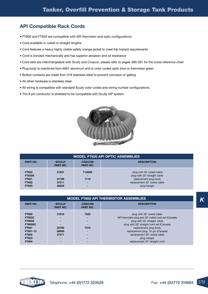
379Telephone: +44 (0)1772 323529 Fax: +44 (0)1772 314664
K
moDel Ft620 api optiC assemblies
moDel Ft600 api thermistor assemblies
Tanker, Overfill Prevention & Storage Tank Products
api Compatible rack Cords
• FT600 and FT620 are compatible with API thermistor and optic configurations
• Cord available in coiled or straight lengths
• Cord features a heavy highly visible safety orange jacket to meet trip hazard requirements
• Cord is bonded mechanically and has superior abrasion and oil resistance
• Cord sets are interchangeable with Scully and Civacon, please refer to pages 380-381 for the cross reference chart
• Plug body is machined from 6061 aluminum and is color coded optic blue or thermistor green
• Button contacts are made from 316 stainless steel to prevent corrosion or galling
• All other hardware is stainless steel
• All wiring is compatible with standard Scully color codes and wiring number configurations
• The 9 pin conductor is shielded to be compatible with Scully VIP system
sCully part no.
21831-
217662721108235
CiVaCon part no.
7120sr-
7110--
part no.
Ft620 Ft620s Ft621 Ft622 Ft623
DesCription
plug with 30’ coiled cableplug with 20’ straight cable
replacement plug bodyreplacement 30’ coiled cable
plug hanger
DesCription
plug with 30’ coiled cableAPI thermistor plug and 30’ coiled cord set (Canada)
plug with 20’ straight cableplug with 20’ straight cord set (Canada)
replacement plug bodyreplacement plug, 10 pin (Canada)
replacement 30’ coiled cableplug hanger
replacement 20’ straight cord
sCully part no.
21818---
207690895927211
--
CiVaCon part no.
7320---
7310----
part no.
Ft600 Ft600C Ft600s Ft600sC Ft601 Ft601-10 Ft602 Ft603 Ft604
380 Telephone: +44 (0)1772 323529 Fax: +44 (0)1772 314664
K
Tanker, Overfill Prevention & Storage Tank Products
Comparison reference Chart
Listed is a cross reference between FloTech brand “Drop In” replacement parts and competitor products.
Civacon and R/OM are registered trademarks of Civacon/Dover Corp. Intellicheck is a registered trademark of Scully Signal Co.
replaCement parts & Competitor proDuCtsDesCription
Replacement probe, optic, 5-wire, 7” longReplacement probe, optic, 5-wire, 12” long
Sensor, optic, 5-wire, 2” NPT housing, 7” probeSensor, optic, 5-wire, 2” NPT housing with 12” probe
Replacement probe, thermo-optic, 7” long, 2-wire (black & white)Replacement probe, thermo-optic, 12” long, 2-wire (black & white)Sensor, thermo-optic, 2” NPT housing, 7” probe, 2-wire (black & white)Sensor, thermo-optic, 2” NPT housing,12” probe, 2-wire (black &
white)Retain sensor
Thermistor dummy, 5 compartmentReplacement R/OM type, 7” top probe, 2-wire (red & black)
Replacement R/OM type, 12” top probe, 2-wire (red & black)Top sensor R/OM type, 2” NPT housing, 7” probe, 2-wire (red & black)Top sensor R/OM type, 2” NPT housing, 12” probe, 2-wire(red & black)
TerminatorRetain sensor R/OM type, ?” NPT sensor (red & black)
DesCription
Replacement chassis, API compatibleAPI compatible on-board monitor, with housing
Replacement chassis, R/OM type on-board monitorR/OM type on-board monitor, with housing
Replacement module, Checkmate on-board monitorCheckmate programmable monitor for top, or top and bottom sensors
DesCription
API compatible optic socket with cap (6 pin, 3 J-slots)API compatible thermistor socket with cap (8 pin, 2/4 J-slots)
API compatible float socketOptic pattern with thermistor J-slots, and cap (6 pin, 2/4 J-slots)
Canadian / European thermistor socket with cap (10 pin, 4 J-slots)Thermistor socket, J560 type
Optic socket, J560 typeAPI optic face plate assembly with cap
API thermistor face plate assembly with capCanadian / European thermistor replacement face plate with cap
Blue optic dust capGreen thermistor dust cap
EZ-Cept dual socket assemblySocket with brake interlock
Socket with vapour recovery interlockSocket with both brake interlock and vapour recovery interlock
DesCription
5 conductor cable 100’7 conductor cable 100’
20 strain relief fittings, 1/2 NPT30 strain relief fittings, 1/2 NPT
Optic system testerT.I.M. reader
CiVaConpart no.
1300 13008 1110 11108 1650 16508 1550 15508
- 1900 1350 13508 1050 - 1910 1000
CiVaCon part no.
3150 3100 3252 3202 - -
CiVaCon part no
4100 4400 4600 4200 4401 4500 4300 4110 4410 - 4150 4450 - - 4401b 4401e-sQs
CiVaCon part no
2100 2310 2510 - - -
sCullypart no.
09209 09214 09208 09213 09409 09414 09408 09413
08810 08542 - - - - - -
sCully part no.
08563 88687 - - 09100/09111 09109.09107
sCully part no.
07974 07720 08116 07976 07716 07681 08199 21790 20770 20768 08575 08574 09060 08646i 08646p 08646ip
sCully part no.
22056 27382 - - - -
FloteCh part no.
Ft100 Ft100-12 Ft101 Ft101-12 Ft150 Ft150-12 Ft151 F151-12 Ft152 Ft155 Ft201 Ft201-12 Ft202 Ft202-12 Ft205 Ft206
FloteCh part no.
Ft102 Ft103 Ft203p Ft204p Ft207 Ft208
FloteCh part no.
Ft300 Ft301 Ft302 Ft303 Ft304 Ft305 Ft306 Ft310 Ft311 Ft314 Ft320 Ft321 Ft390 Ft304bi Ft304Vi Ft304bVi
FloteCh part no.
Ft400 Ft401 Ft402 Ft403 Ft520 Ft530
liQuiDleVelsensors
on boarDmonitors
soCKets
harDWaresystemtesters
381Telephone: +44 (0)1772 323529 Fax: +44 (0)1772 314664
K
Tanker, Overfill Prevention & Storage Tank Products
Comparison reference Chart (continued)
Dixon Valve and Coupling Company warrants the FloTech products described herein, and manufactured by Dixon to be free
from defects in material and workmanship for a period of three (3) years from date of shipment by Dixon under normal use
and service.
For further warranty information see page 509.
Civacon and R/OM are registered trademarks of Civacon/Dover Corp. Intellicheck is a registered trademark of Scully Signal Co.
Listed is a cross reference between FloTech brand “Drop In” replacement parts and competitor products.
replaCement parts & Competitor proDuCtsDesCription
API compatible 4 compartment systemAPI compatible 5 compartment system
R/OM type, 4 compartment systemR/OM type, 5 compartment system
R/OM type, 4 compartment system (top only)R/OM type, 5 compartment system (top only)
Checkmate system, one compartment, top onlyCheckmate system, two compartment, top only
Checkmate system, three compartment, top onlyCheckmate system, four compartment, top onlyCheckmate system, five compartment, top onlyCheckmate system, six compartment, top only
Checkmate system, seven compartment, top onlyCheckmate system, eight compartment, top only
Checkmate system, one compartment, top and bottom sensorsCheckmate system, two compartment, top and bottom sensors
Checkmate system, three compartment, top and bottom sensorsCheckmate system, four compartment, top and bottom sensorsCheckmate system, five compartment, top and bottom sensorsCheckmate system, six compartment, top and bottom sensors
Checkmate system, seven compartment, top and bottom sensorsCheckmate system, eight compartment, top and bottom sensors
CiVaConpart no.
2004 2005 3024 3025 3034 3035 - - - - - - - - - - - - - - - -
sCullypart no.
08305 08306 - - - - 08251 08352 08353 08354 08355 08356 08380 08381 08361 08362 08363 08364 08365 08366 08382 08383
FloteCh part no.
Ft1004 Ft1005 Ft2004 Ft2005 Ft2104 Ft2105 Ft2801 Ft2802 Ft2803 Ft2804 Ft2805 Ft2806 Ft2807 Ft2808 Ft2811 Ft2812 Ft2813 Ft2814 Ft2815 Ft2816 Ft2817 Ft2818
on boarDsystems
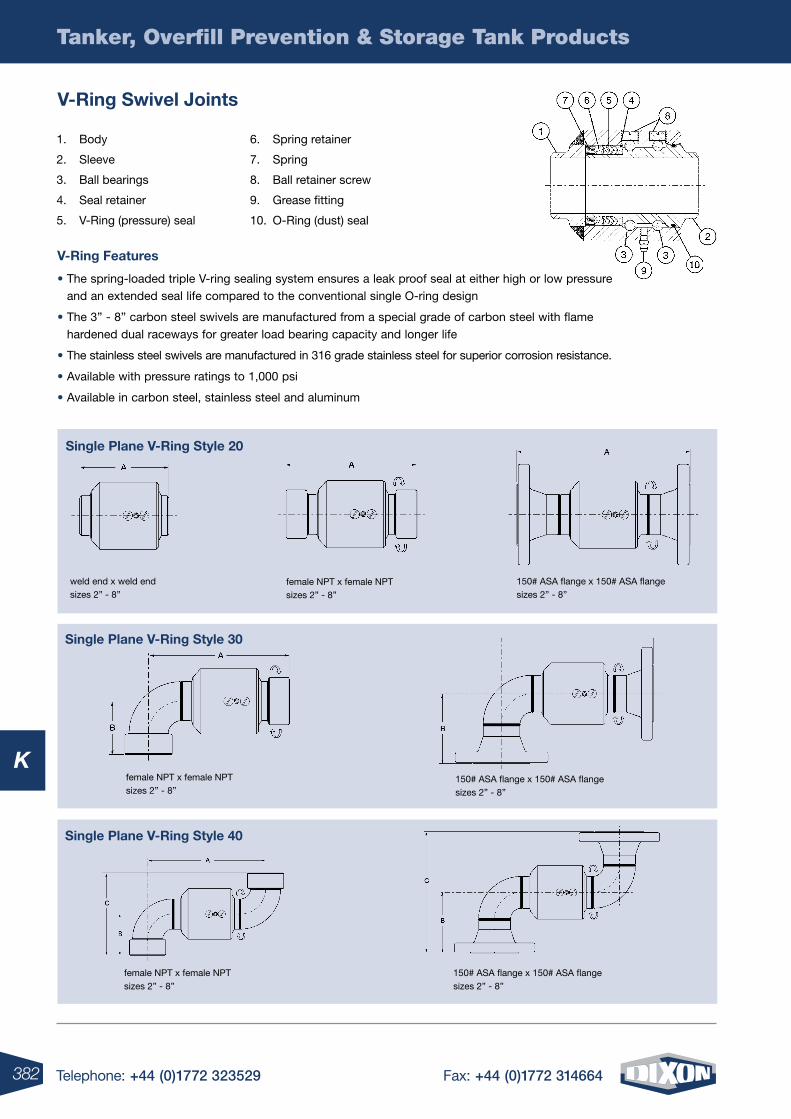
382 Telephone: +44 (0)1772 323529 Fax: +44 (0)1772 314664
K
Tanker, Overfill Prevention & Storage Tank Products
V-ring swivel Joints
V-ring Features
• The spring-loaded triple V-ring sealing system ensures a leak proof seal at either high or low pressure and an extended seal life compared to the conventional single O-ring design
• The 3” - 8” carbon steel swivels are manufactured from a special grade of carbon steel with flame hardened dual raceways for greater load bearing capacity and longer life
• The stainless steel swivels are manufactured in 316 grade stainless steel for superior corrosion resistance.
• Available with pressure ratings to 1,000 psi
• Available in carbon steel, stainless steel and aluminum
1. Body
2. Sleeve
3. Ball bearings
4. Seal retainer
5. V-Ring (pressure) seal
6. Spring retainer
7. Spring
8. Ball retainer screw
9. Grease fitting
10. O-Ring (dust) seal
weld end x weld end sizes 2” - 8”
female NPT x female NPT sizes 2” - 8”
150# ASA flange x 150# ASA flange sizes 2” - 8”
female NPT x female NPT sizes 2” - 8”
150# ASA flange x 150# ASA flange sizes 2” - 8”
female NPT x female NPT sizes 2” - 8”
150# ASA flange x 150# ASA flange sizes 2” - 8”
single plane V-ring style 20
single plane V-ring style 30
single plane V-ring style 40
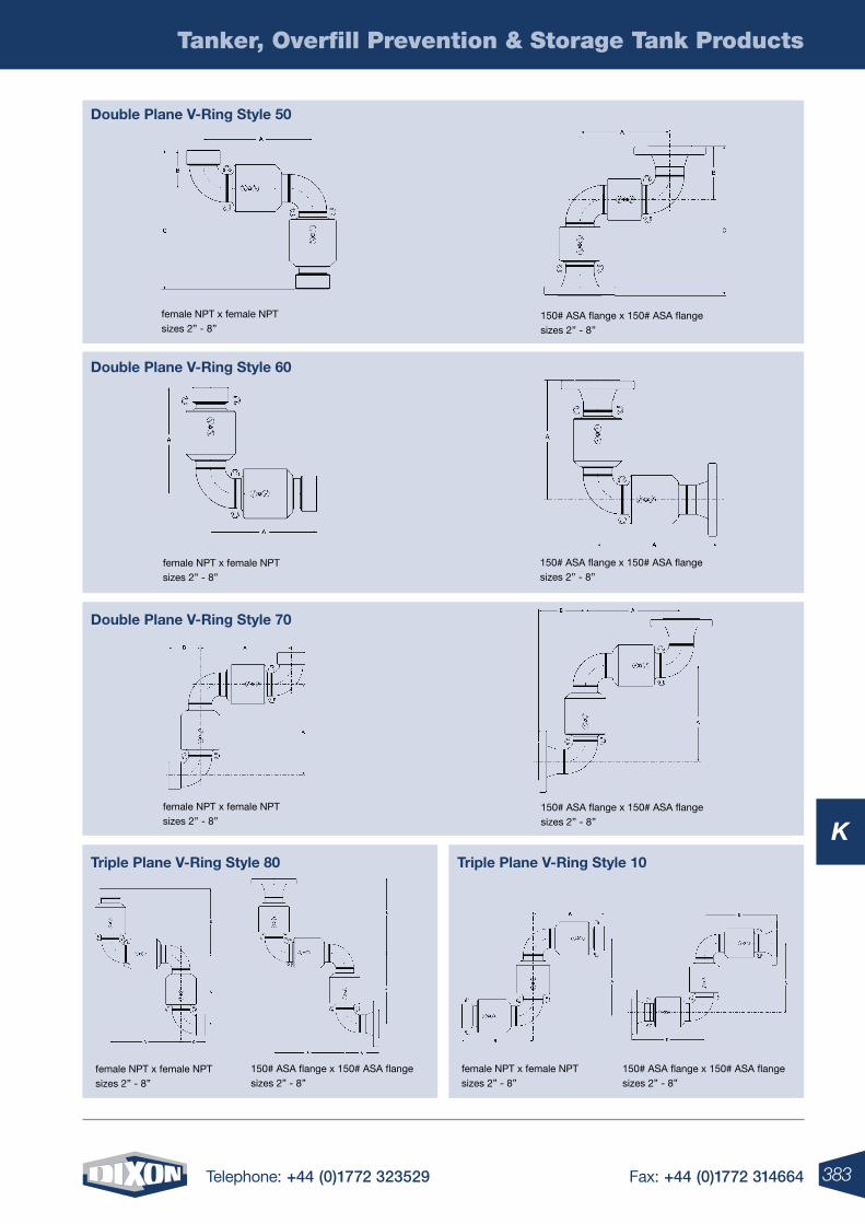
383Telephone: +44 (0)1772 323529 Fax: +44 (0)1772 314664
K
Tanker, Overfill Prevention & Storage Tank Products
Double plane V-ring style 50
Double plane V-ring style 60
Double plane V-ring style 70
triple plane V-ring style 80 triple plane V-ring style 10
female NPT x female NPT sizes 2” - 8”
150# ASA flange x 150# ASA flange sizes 2” - 8”
female NPT x female NPT sizes 2” - 8”
150# ASA flange x 150# ASA flange sizes 2” - 8”
female NPT x female NPT sizes 2” - 8”
female NPT x female NPT sizes 2” - 8”
150# ASA flange x 150# ASA flange sizes 2” - 8”
150# ASA flange x 150# ASA flange sizes 2” - 8”
female NPT x female NPT sizes 2” - 8”
150# ASA flange x 150# ASA flange sizes 2” - 8”
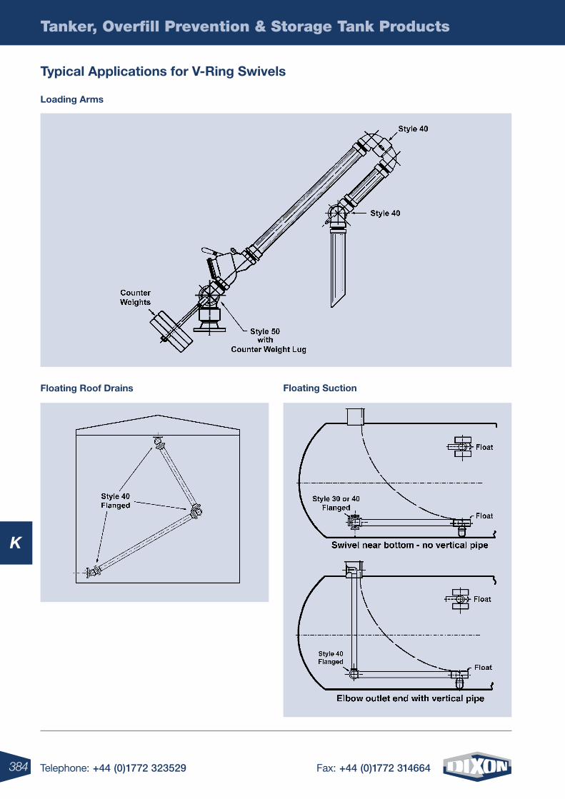
384 Telephone: +44 (0)1772 323529 Fax: +44 (0)1772 314664
K
Tanker, Overfill Prevention & Storage Tank Products
typical applications for V-ring swivels
Floating roof Drains Floating suction
loading arms
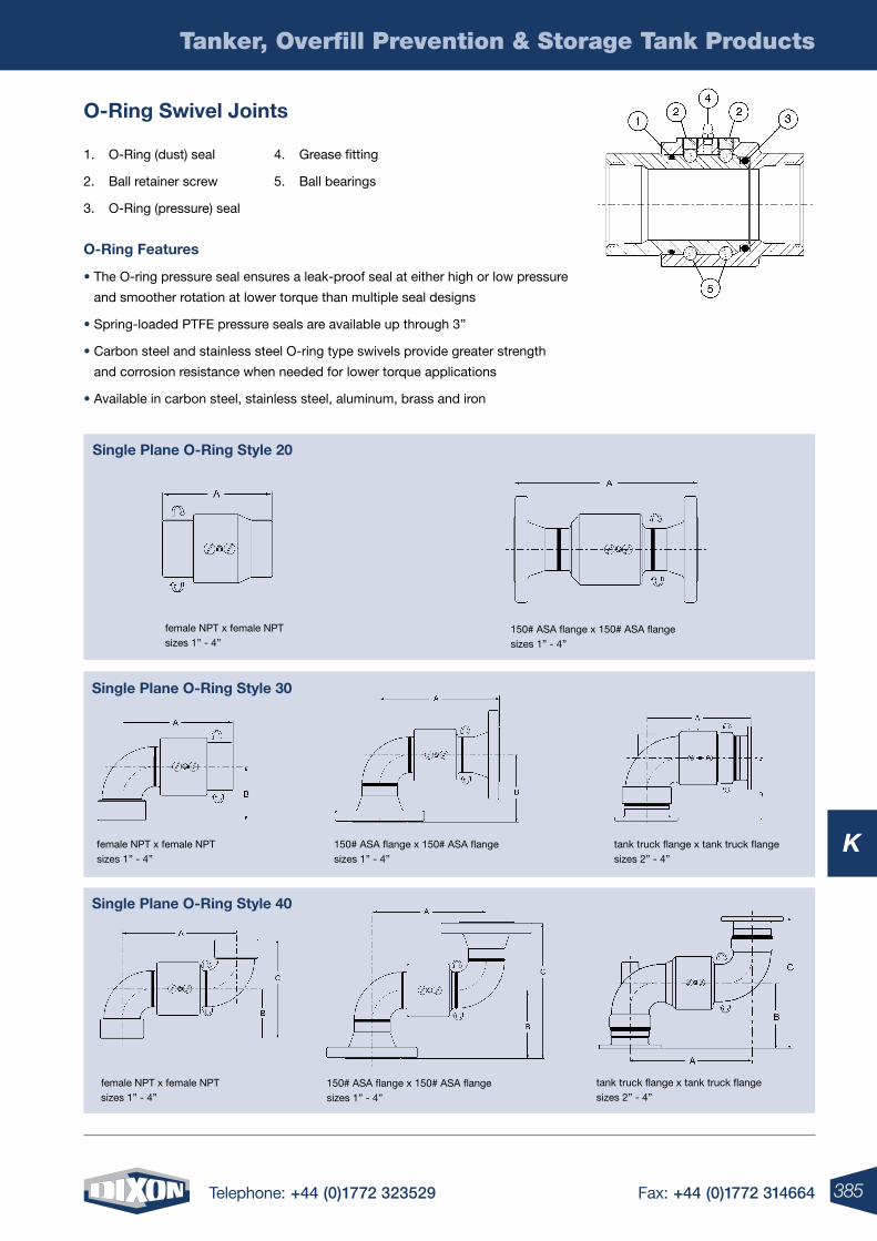
385Telephone: +44 (0)1772 323529 Fax: +44 (0)1772 314664
K
Tanker, Overfill Prevention & Storage Tank Products
o-ring swivel Joints
o-ring Features
• The O-ring pressure seal ensures a leak-proof seal at either high or low pressure
and smoother rotation at lower torque than multiple seal designs
• Spring-loaded PTFE pressure seals are available up through 3”
• Carbon steel and stainless steel O-ring type swivels provide greater strength
and corrosion resistance when needed for lower torque applications
• Available in carbon steel, stainless steel, aluminum, brass and iron
150# ASA flange x 150# ASA flange sizes 1” - 4”
1. O-Ring (dust) seal
2. Ball retainer screw
3. O-Ring (pressure) seal
4. Grease fitting
5. Ball bearings
female NPT x female NPT sizes 1” - 4”
tank truck flange x tank truck flange sizes 2” - 4”
150# ASA flange x 150# ASA flange sizes 1” - 4”
single plane o-ring style 30
single plane o-ring style 40
female NPT x female NPT sizes 1” - 4”
tank truck flange x tank truck flange sizes 2” - 4”
150# ASA flange x 150# ASA flange sizes 1” - 4”
female NPT x female NPT sizes 1” - 4”
single plane o-ring style 20
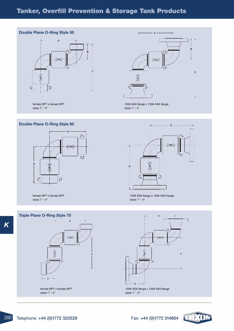
386 Telephone: +44 (0)1772 323529 Fax: +44 (0)1772 314664
K
Tanker, Overfill Prevention & Storage Tank Products
female NPT x female NPT sizes 1” - 4”
150# ASA flange x 150# ASA flange sizes 1” - 4”
Double plane o-ring style 50
female NPT x female NPT sizes 1” - 4”
150# ASA flange x 150# ASA flange sizes 1” - 4”
Double plane o-ring style 60
triple plane o-ring style 70
female NPT x female NPT sizes 1” - 4”
150# ASA flange x 150# ASA flange sizes 1” - 4”
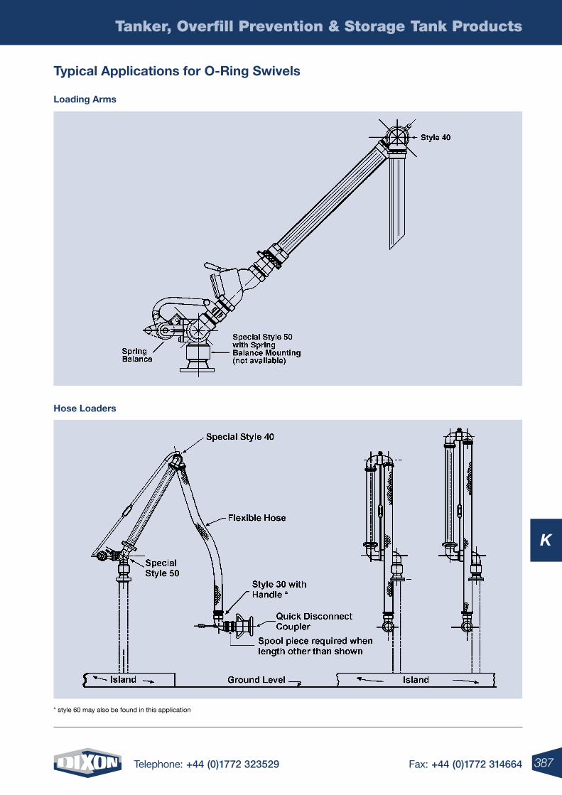
387Telephone: +44 (0)1772 323529 Fax: +44 (0)1772 314664
K
Tanker, Overfill Prevention & Storage Tank Products
* style 60 may also be found in this application
hose loaders
typical applications for o-ring swivels
loading arms
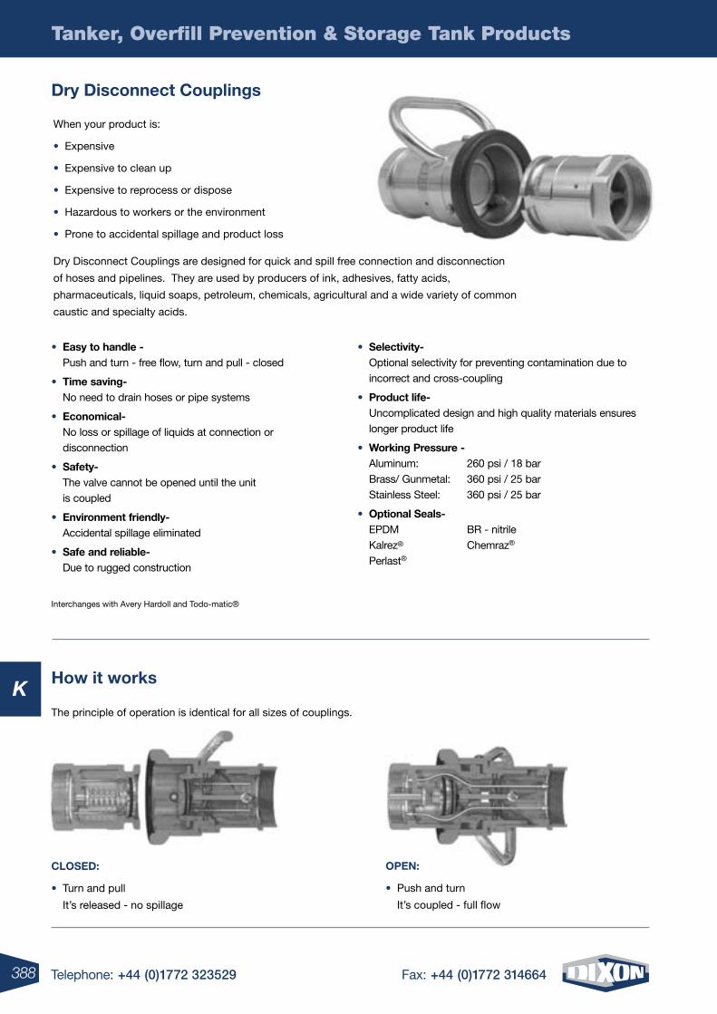
388 Telephone: +44 (0)1772 323529 Fax: +44 (0)1772 314664
K
Tanker, Overfill Prevention & Storage Tank Products
Dry Disconnect Couplings
When your product is:
• Expensive
• Expensive to clean up
• Expensive to reprocess or dispose
• Hazardous to workers or the environment
• Prone to accidental spillage and product loss
Dry Disconnect Couplings are designed for quick and spill free connection and disconnection
of hoses and pipelines. They are used by producers of ink, adhesives, fatty acids,
pharmaceuticals, liquid soaps, petroleum, chemicals, agricultural and a wide variety of common
caustic and specialty acids.
how it works
• easy to handle - Push and turn - free flow, turn and pull - closed
• time saving- No need to drain hoses or pipe systems
• economical- No loss or spillage of liquids at connection or disconnection
• safety- The valve cannot be opened until the unit is coupled
• environment friendly- Accidental spillage eliminated
• safe and reliable- Due to rugged construction
• selectivity- Optional selectivity for preventing contamination due to incorrect and cross-coupling
• product life- Uncomplicated design and high quality materials ensures longer product life
• Working pressure - Aluminum: 260 psi / 18 bar Brass/ Gunmetal: 360 psi / 25 bar Stainless Steel: 360 psi / 25 bar
• optional seals- EPDM BR - nitrile Kalrez® Chemraz® Perlast®
Interchanges with Avery Hardoll and Todo-matic®
The principle of operation is identical for all sizes of couplings.
open:
• Push and turn
It’s coupled - full flow
CloseD:
• Turn and pull
It’s released - no spillage
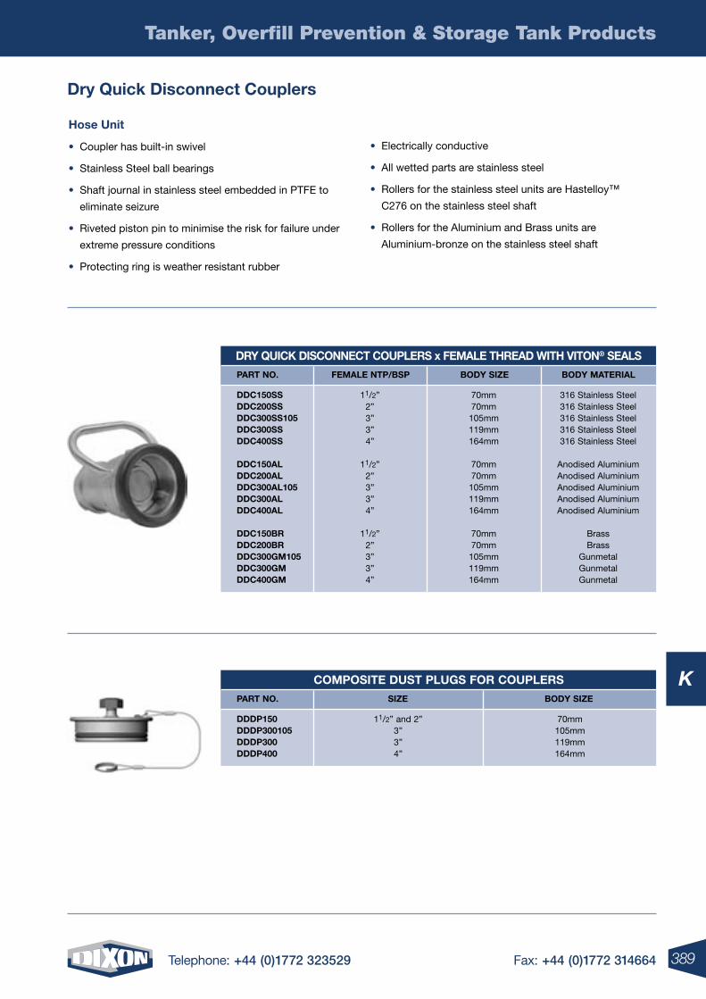
389Telephone: +44 (0)1772 323529 Fax: +44 (0)1772 314664
K
Tanker, Overfill Prevention & Storage Tank Products
Dry Quick Disconnect Couplers
hose unit
• Coupler has built-in swivel
• Stainless Steel ball bearings
• Shaft journal in stainless steel embedded in PTFE to
eliminate seizure
• Riveted piston pin to minimise the risk for failure under
extreme pressure conditions
• Protecting ring is weather resistant rubber
• Electrically conductive
• All wetted parts are stainless steel
• Rollers for the stainless steel units are Hastelloy™
C276 on the stainless steel shaft
• Rollers for the Aluminium and Brass units are
Aluminium-bronze on the stainless steel shaft
Dry QuiCK DisConneCt Couplers x Female threaD With Viton® seals
part no. Female ntp/bsp boDy siZe boDy material
DDC150ss DDC200ss DDC300ss105 DDC300ss DDC400ss
DDC150al DDC200al DDC300al105 DDC300al DDC400al
DDC150br DDC200br DDC300gm105 DDC300gm DDC400gm
70mm70mm105mm119mm164mm
70mm70mm105mm119mm164mm
70mm70mm105mm119mm164mm
316 Stainless Steel 316 Stainless Steel 316 Stainless Steel 316 Stainless Steel 316 Stainless Steel
Anodised Aluminium Anodised Aluminium Anodised Aluminium Anodised Aluminium Anodised Aluminium
BrassBrass
Gunmetal Gunmetal Gunmetal
11/2”2”3”3”4”
11/2”2”3”3”4”
11/2”2”3”3”4”
Composite Dust plugs For Couplers
part no. siZe boDy siZe
DDDp150 DDDp300105 DDDp300 DDDp400
70mm105mm119mm164mm
11/2” and 2” 3”3”4”
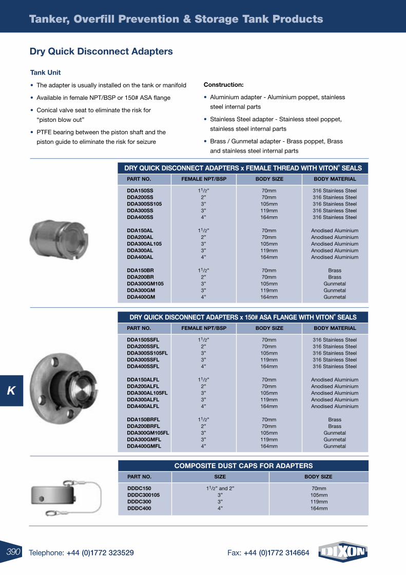
390 Telephone: +44 (0)1772 323529 Fax: +44 (0)1772 314664
K
Tanker, Overfill Prevention & Storage Tank Products
Dry Quick Disconnect adapters
tank unit
• The adapter is usually installed on the tank or manifold
• Available in female NPT/BSP or 150# ASA flange
• Conical valve seat to eliminate the risk for
“piston blow out”
• PTFE bearing between the piston shaft and the
piston guide to eliminate the risk for seizure
Construction:
• Aluminium adapter - Aluminium poppet, stainless
steel internal parts
• Stainless Steel adapter - Stainless steel poppet,
stainless steel internal parts
• Brass / Gunmetal adapter - Brass poppet, Brass
and stainless steel internal parts
Dry QuiCK DisConneCt aDapters x Female threaD With Viton® seals
part no. Female npt/bsp boDy siZe boDy material
DDa150ss DDa200ss DDa300ss105 DDa300ss DDa400ss
DDa150al DDa200al DDa300al105 DDa300al DDa400al
DDa150br DDa200br DDa300gm105 DDa300gm DDa400gm
70mm 70mm 105mm 119mm 164mm
70mm 70mm 105mm 119mm 164mm
70mm 70mm 105mm 119mm 164mm
316 Stainless Steel 316 Stainless Steel 316 Stainless Steel 316 Stainless Steel 316 Stainless Steel
Anodised Aluminium Anodised Aluminium Anodised Aluminium Anodised AluminiumAnodised Aluminium
Brass Brass
Gunmetal Gunmetal Gunmetal
11/2” 2” 3”3” 4”
11/2” 2” 3”3” 4”
11/2” 2” 3”3” 4”
Dry QuiCK DisConneCt aDapters x 150# asa Flange With Viton® seals
part no. Female npt/bsp boDy siZe boDy material
DDa150ssFl DDa200ssFl DDa300ss105Fl DDa300ssFl DDa400ssFl
DDa150alFl DDa200alFl DDa300al105Fl DDa300alFl DDa400alFl
DDa150brFl DDa200brFl DDa300gm105Fl DDa300gmFl DDa400gmFl
70mm 70mm 105mm 119mm 164mm
70mm 70mm 105mm 119mm 164mm
70mm 70mm 105mm 119mm 164mm
316 Stainless Steel 316 Stainless Steel 316 Stainless Steel 316 Stainless Steel 316 Stainless Steel
Anodised Aluminium Anodised Aluminium Anodised Aluminium Anodised AluminiumAnodised Aluminium
Brass Brass
Gunmetal Gunmetal Gunmetal
11/2” 2” 3”3” 4”
11/2” 2” 3”3” 4”
11/2” 2” 3”3” 4”
Composite Dust Caps For aDapters
part no. siZe boDy siZe
DDDC150 DDDC300105 DDDC300 DDDC400
70mm105mm119mm164mm
11/2” and 2” 3”3”4”
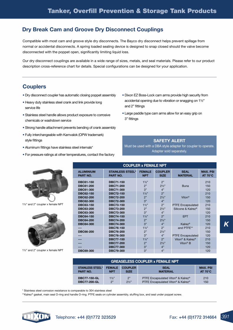
391Telephone: +44 (0)1772 323529 Fax: +44 (0)1772 314664
K
Tanker, Overfill Prevention & Storage Tank Products
Dry break Cam and groove Dry Disconnect Couplings
Compatible with most cam and groove style dry disconnects. The Bayco dry disconnect helps prevent spillage from
normal or accidental disconnects. A spring loaded sealing device is designed to snap closed should the valve become
disconnected with the poppet open, significantly limiting liquid loss.
Our dry disconnect couplings are available in a wide range of sizes, metals, and seal materials. Please refer to our product
description cross-reference chart for details. Special configurations can be designed for your application.
Couplers• Dry disconnect coupler has automatic closing poppet assembly
• Heavy duty stainless steel crank and link provide long
service life
• Stainless steel handle allows product exposure to corrosive
chemicals or washdown service
• Strong handle attachment prevents bending of crank assembly
• Fully interchangeable with Kamvalok (OPW trademark)
style fittings
• Aluminum fittings have stainless steel internals*
• For pressure ratings at other temperatures, contact the factory
• Dixon EZ Boss-Lock cam arms provide high security from
accidental opening due to vibration or snagging on 1½”
and 2” fittings
• Large paddle type cam arms allow for an easy grip on
3” fittings
Coupler x Female npt
aluminium part no.
stainless steel* part no.
Femalenpt
DbC61-150 DbC61-200 DbC61-300 DbC62-150 DbC62-200 DbC62-300 DbC63-150 DbC63-200 DbC63-300 DbC64-150 DbC64-200 DbC64-300 --- DbC66-200 --- --- --- --- DbC69-300
DbC71-150 DbC71-200 DbC71-300 DbC72-150 DbC72-200 DbC72-300 DbC73-150 DbC73-200 DbC73-300 DbC74-150 DbC74-200 DbC74-300 DbC76-150 DbC76-200 DbC76-300 DbC77-150 DbC77-200 DbC77-300 DbC79-300
1½”2”3”
1½”2”3”
1½”2”3”
1½”2”3”
1½”2”3”
1½”2”3”3”
CouplersiZe
2”2½”4”2”
2½”4”2”
2½”4”2”
2½”4”2”
2½”4”2”
2½”4”4”
maX. psi at 70°C
210150120210150120210150120210150120210150120210150120120
seal material
Buna
Viton®
PTFE EncapsulatedSilicone & Kalrez®
EPT
Kalrez®
and PTFE**
PTFE EncapsulatedViton® & Kalrez®
Viton® B
greaseless Coupler x Female npt
stainless steel* part no.
Femalenpt
CouplersiZe
maX. psi at 70°C
seal material
DbC77-150-gl DbC77-200-gl
1½”2”
2”2½”
210150
PTFE Encapsulated Viton® & Kalrez®
PTFE Encapsulated Viton® & Kalrez®
* Stainless steel corrosion resistance is comparable to 304 stainless steel **Kalrez® gasket, main seal O-ring and handle O-ring. PTFE seals on cylinder assembly, stuffing box, and seal under poppet screw.
1½” and 2” coupler x female NPT
1½” and 2” coupler x female NPT
saFety alertMust be used with a DBA style adapter for coupler to operate.
Adapter sold separately.
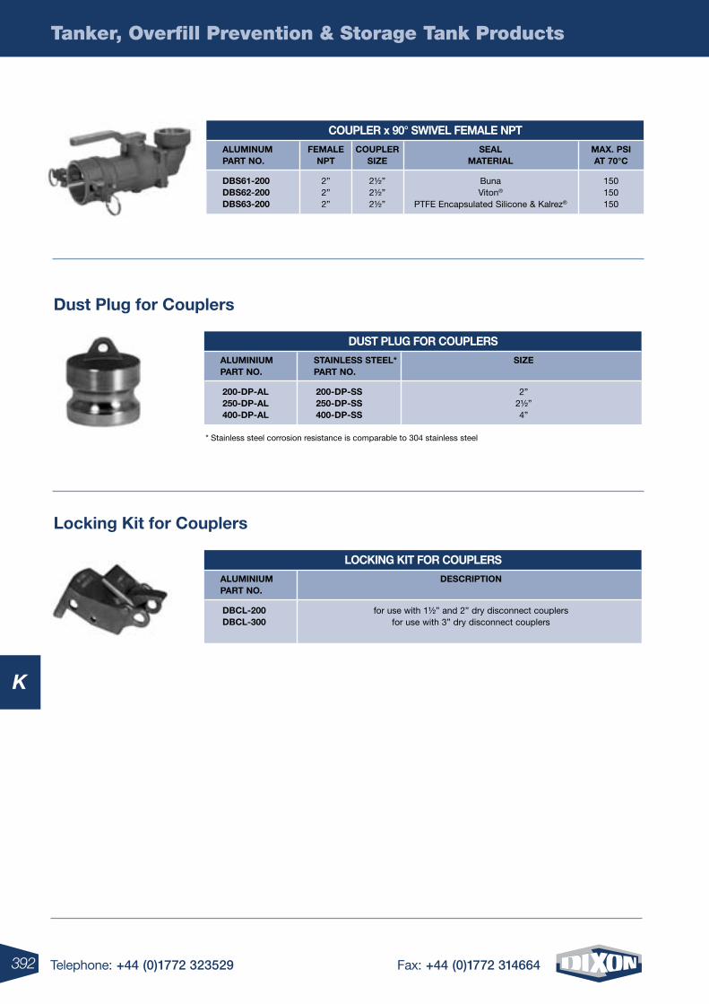
392 Telephone: +44 (0)1772 323529 Fax: +44 (0)1772 314664
Tanker, Overfill Prevention & Storage Tank Products
K
Dust plug for Couplers
locking Kit for Couplers
Coupler x 90° sWiVel Female npt
aluminum part no.
Femalenpt
CouplersiZe
maX. psi at 70°C
seal material
Dbs61-200 Dbs62-200 Dbs63-200
2”2”2”
2½”2½”2½”
150150150
BunaViton®
PTFE Encapsulated Silicone & Kalrez®
Dust plug For Couplers
loCKing Kit For Couplers
aluminium part no.
aluminium part no.
stainless steel* part no.
siZe
200-Dp-al 250-Dp-al 400-Dp-al
200-Dp-ss 250-Dp-ss 400-Dp-ss
2”2½”4”
DbCl-200 DbCl-300
DesCription
for use with 1½” and 2” dry disconnect couplersfor use with 3” dry disconnect couplers
* Stainless steel corrosion resistance is comparable to 304 stainless steel
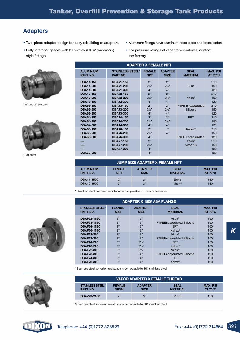
393Telephone: +44 (0)1772 323529 Fax: +44 (0)1772 314664
Tanker, Overfill Prevention & Storage Tank Products
K
adapters
• Two-piece adapter design for easy rebuilding of adapters
• Fully interchangeable with Kamvalok (OPW trademark)
style fittings
• Aluminum fittings have aluminum nose piece and brass piston
• For pressure ratings at other temperatures, contact
the factory
aDapter X Female npt
Jump siZe aDapter X Female npt
aluminium part no.
aluminium part no.
stainless steel* part no.
Femalenpt
Dba11-150 Dba11-200 Dba11-300 Dba12-150 Dba12-200 Dba12-300 Dba63-150 Dba63-200 Dba63-300 Dba64-150 Dba64-200 Dba64-300 Dba66-150 Dba66-200 Dba66-300 --- --- --- Dba69-300
Dba71-150 Dba71-200 Dba71-300 Dba72-150 Dba72-200 Dba72-300 Dba73-150 Dba73-200 Dba73-300 Dba74-150 Dba74-200 Dba74-300 Dba76-150 Dba76-200 Dba76-300 Dba77-150 Dba77-200 Dba77-300 ---
2”2½”4”2”
2½”4”2”
2½”4”2”
2½”4”2”
2½”4”2”
2½”4”4”
aDaptersiZe
2”2½”4”2”
2½”4”2”
2½”4”2”
2½”4” ”4”
maX. psi at 70°C
210150120210150120210150120210150120210150120210150120120
seal material
Buna
Viton®
PTFE EncapsulatedSilicone
EPT
Kalrez®
PTFE EncapsulatedViton®
Viton® B
Femalenpt
aDaptersiZe
maX. psi at 70°C
seal material
Dba11-1520 Dba12-1520
2”2”
2”2”
150150
BunaViton®
1½” and 2” adapter
3” adapter
* Stainless steel corrosion resistance is comparable to 304 stainless steel
Vapor aDapter X Female threaD
stainless steel* part no.
Femalenpsm
aDaptersiZe
maX. psi at 70°C
seal material
DbaV73-2030 2” 3” 150PTFE
* Stainless steel corrosion resistance is comparable to 304 stainless steel
aDapter X 150# asa Flange
stainless steel* part no.
DbaF72-1520 DbaF73-1520 DbaF74-1520 DbaF76-1520 DbaF72-200 DbaF73-200 DbaF74-200 DbaF76-200 DbaF72-300 DbaF73-300 DbaF74-300 DbaF76-300
FlangesiZe
aDaptersiZe
2”2”2”2”2”2”2”2”2”3”3”3”
2”2”2”2”2”2”
2½”2½”2½”4”4”4”
maX. psi at 70°C
150150150150150150150150150120120120
seal material
Viton®
PTFE Encapsulated SiliconeEPT
Kalrez®
Viton®
PTFE Encapsulated SiliconeEPT
Kalrez®
Viton®
PTFE Encapsulated SiliconeEPT
Kalrez®
* Stainless steel corrosion resistance is comparable to 304 stainless steel
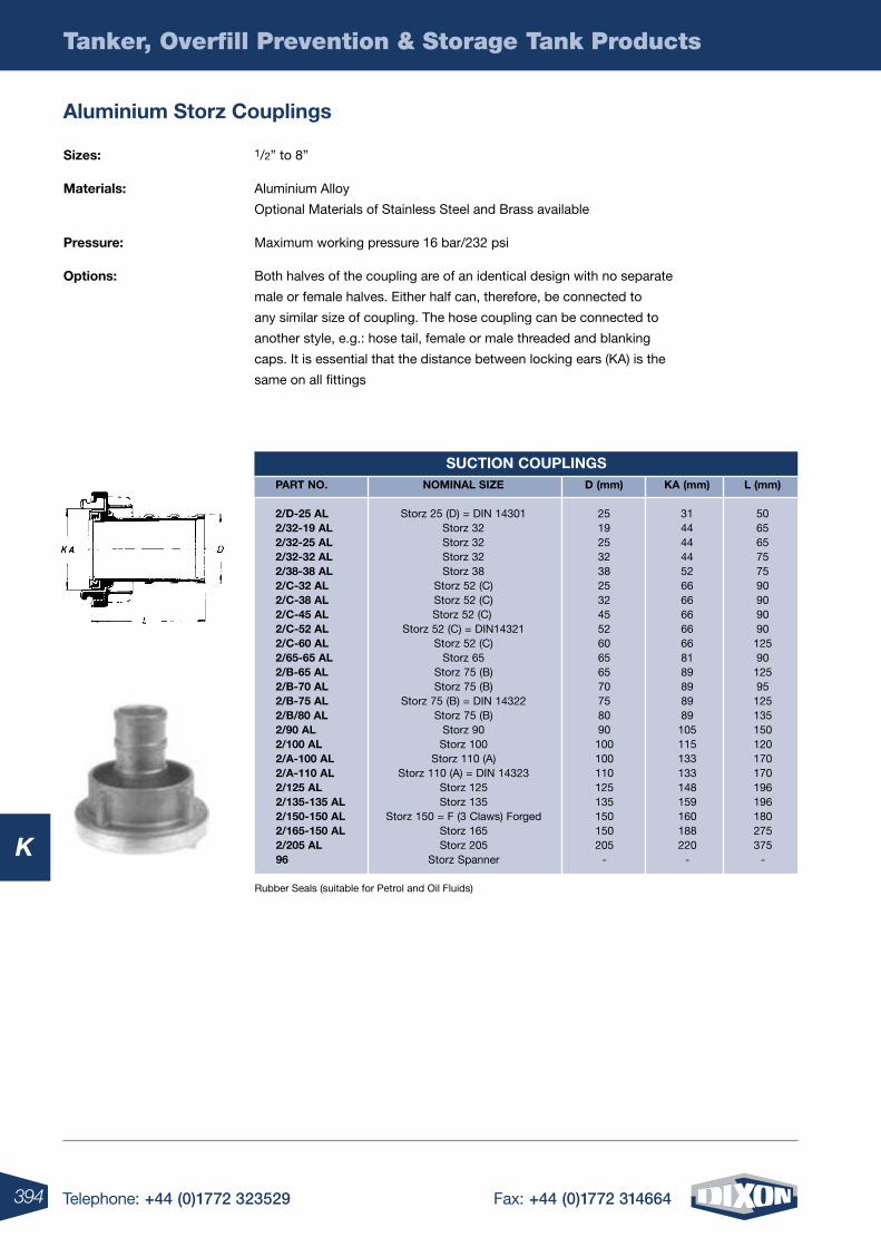
394 Telephone: +44 (0)1772 323529 Fax: +44 (0)1772 314664
Tanker, Overfill Prevention & Storage Tank Products
KRubber Seals (suitable for Petrol and Oil Fluids)
aluminium storz Couplings
sizes: 1/2” to 8”
materials: Aluminium Alloy
Optional Materials of Stainless Steel and Brass available
pressure: Maximum working pressure 16 bar/232 psi
options: Both halves of the coupling are of an identical design with no separate
male or female halves. Either half can, therefore, be connected to
any similar size of coupling. The hose coupling can be connected to
another style, e.g.: hose tail, female or male threaded and blanking
caps. It is essential that the distance between locking ears (KA) is the
same on all fittings
suCtion Couplings part no. nominal siZe D (mm) Ka (mm) l (mm)
2/D-25 al Storz 25 (D) = DIN 14301 25 31 50 2/32-19 al Storz 32 19 44 65 2/32-25 al Storz 32 25 44 65 2/32-32 al Storz 32 32 44 75 2/38-38 al Storz 38 38 52 75 2/C-32 al Storz 52 (C) 25 66 90 2/C-38 al Storz 52 (C) 32 66 90 2/C-45 al Storz 52 (C) 45 66 90 2/C-52 al Storz 52 (C) = DIN14321 52 66 90 2/C-60 al Storz 52 (C) 60 66 125 2/65-65 al Storz 65 65 81 90 2/b-65 al Storz 75 (B) 65 89 125 2/b-70 al Storz 75 (B) 70 89 95 2/b-75 al Storz 75 (B) = DIN 14322 75 89 125 2/b/80 al Storz 75 (B) 80 89 135 2/90 al Storz 90 90 105 150 2/100 al Storz 100 100 115 120 2/a-100 al Storz 110 (A) 100 133 170 2/a-110 al Storz 110 (A) = DIN 14323 110 133 170 2/125 al Storz 125 125 148 196 2/135-135 al Storz 135 135 159 196 2/150-150 al Storz 150 = F (3 Claws) Forged 150 160 180 2/165-150 al Storz 165 150 188 275 2/205 al Storz 205 205 220 375 96 Storz Spanner - - -
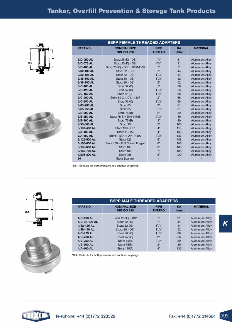
395Telephone: +44 (0)1772 323529 Fax: +44 (0)1772 314664
Tanker, Overfill Prevention & Storage Tank Products
K
*DS - Suitable for both pressure and suction couplings
*DS - Suitable for both pressure and suction couplings
bspp Female threaDeD aDapters part no. nominal siZe pipe Ka material Din iso 228 threaD (mm) 3/D-050 al Storz 25 (D) - DS* 1/2” 31 Aluminium Alloy 3/D-075 al Storz 25 (D) - DS* 3/4” 31 Aluminium Alloy 3/D-100 al Storz 25 (D) - DS* = DIN14306 1” 31 Aluminium Alloy 3/32-100 al Storz 32 - DS* 1” 44 Aluminium Alloy 3/32-125 al Storz 32 - DS* 11/4” 44 Aluminium Alloy 3/38-150 al Storz 38 - DS* 11/2” 52 Aluminium Alloy 3/38-200 al Storz 38 - DS* 2” 52 Aluminium Alloy 3/C-100 al Storz 52 (C) 1” 66 Aluminium Alloy 3/C-125 al Storz 52 (C) 11/4” 66 Aluminium Alloy 3/C-150 al Storz 52 (C) 11/2” 66 Aluminium Alloy 3/C-200 al Storz 52 C = DIN14307 2” 66 Aluminium Alloy 3/C-250 al Storz 52 (C) 21/2” 66 Aluminium Alloy 3/65-200 al Storz 65 2” 81 Aluminium Alloy 3/65-250 al Storz 65 21/2” 81 Aluminium Alloy 3/b-200 al Storz 75 (B) 2” 89 Aluminium Alloy 3/b-250 al Storz 75 B = DIN 14308 21/2” 89 Aluminium Alloy 3/b-300 al Storz 75 (B) 3” 89 Aluminium Alloy 3/90-300 al Storz 90 3” 105 Aluminium Alloy 3/100-400 al Storz 100 - DS* 4” 115 Aluminium Alloy 3/a-400 al Storz 110 (A) 4” 133 Aluminium Alloy 3/a-450 al Storz 110 A = DIN 14309 41/2” 133 Aluminium Alloy 3/125-500 al Storz 125 5” 148 Aluminium Alloy 3/150-600 al Storz 150 = F (3 Claws) Forged 6” 160 Aluminium Alloy 3/165-600 al Storz 165 6” 188 Aluminium Alloy 3/165-700 al Storz 165 7” 188 Aluminium Alloy 3/205-800 al Storz 205 8” 220 Aluminium Alloy 96 Storz Spanner - - -
bspp male threaDeD aDapters part no. nominal siZe pipe Ka material Din iso 228 threaD (mm) 4/D-100 al Storz 25 (D) - DS* 1” 31 Aluminium Alloy 4/D-32-100 al Storz 32 DS* 1” 44 Aluminium Alloy 4/32-125 al Storz 32 DS* 11/4” 44 Aluminium Alloy 4/38-150 al Storz 38 - DS* 11/2” 52 Aluminium Alloy 4/C-125 al Storz 52 (C) 11/4” 66 Aluminium Alloy 4/C-200 al Storz 52 (C) 2” 66 Aluminium Alloy 4/b-250 al Storz 75(B) 21/2” 89 Aluminium Alloy 4/b-300 al Storz 75(B) 3” 89 Aluminium Alloy 4/a-400 al Storz 110(A) 4” 133 Aluminium Alloy
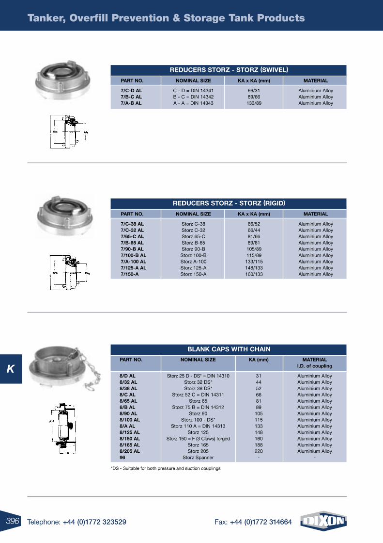
396 Telephone: +44 (0)1772 323529 Fax: +44 (0)1772 314664
Tanker, Overfill Prevention & Storage Tank Products
K
*DS - Suitable for both pressure and suction couplings
part no. nominal siZe Ka x Ka (mm) material
7/C-D al C - D = DIN 14341 66/31 Aluminium Alloy 7/b-C al B - C = DIN 14342 89/66 Aluminium Alloy 7/a-b al A - A = DIN 14343 133/89 Aluminium Alloy
reDuCers storZ - storZ (sWiVel)
part no. nominal siZe Ka x Ka (mm) material
7/C-38 al Storz C-38 66/52 Aluminium Alloy 7/C-32 al Storz C-32 66/44 Aluminium Alloy 7/65-C al Storz 65-C 81/66 Aluminium Alloy 7/b-65 al Storz B-65 89/81 Aluminium Alloy 7/90-b al Storz 90-B 105/89 Aluminium Alloy 7/100-b al Storz 100-B 115/89 Aluminium Alloy 7/a-100 al Storz A-100 133/115 Aluminium Alloy 7/125-a al Storz 125-A 148/133 Aluminium Alloy 7/150-a Storz 150-A 160/133 Aluminium Alloy
reDuCers storZ - storZ (rigiD)
blanK Caps With Chain
part no. nominal siZe Ka (mm) material i.D. of coupling
8/D al Storz 25 D - DS* = DIN 14310 31 Aluminium Alloy 8/32 al Storz 32 DS* 44 Aluminium Alloy 8/38 al Storz 38 DS* 52 Aluminium Alloy 8/C al Storz 52 C = DIN 14311 66 Aluminium Alloy 8/65 al Storz 65 81 Aluminium Alloy 8/b al Storz 75 B = DIN 14312 89 Aluminium Alloy 8/90 al Storz 90 105 Aluminium Alloy 8/100 al Storz 100 - DS* 115 Aluminium Alloy 8/a al Storz 110 A = DIN 14313 133 Aluminium Alloy 8/125 al Storz 125 148 Aluminium Alloy 8/150 al Storz 150 = F (3 Claws) forged 160 Aluminium Alloy 8/165 al Storz 165 188 Aluminium Alloy 8/205 al Storz 205 220 Aluminium Alloy 96 Storz Spanner - -
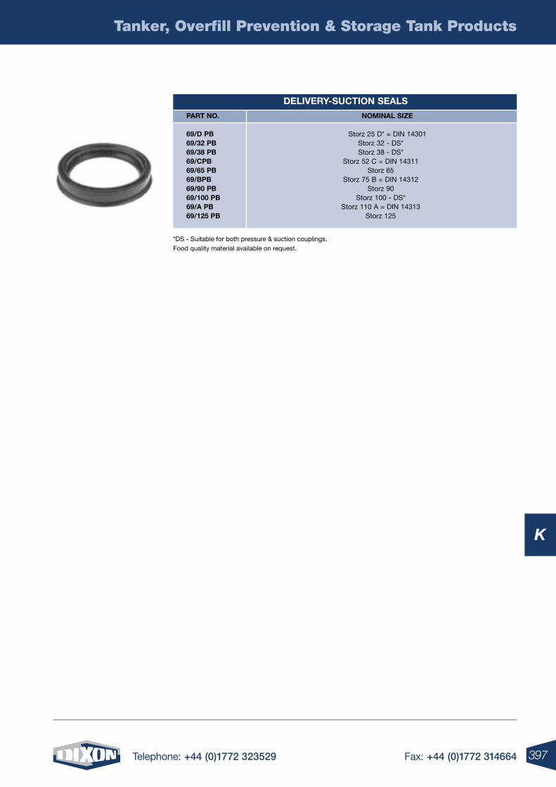
397Telephone: +44 (0)1772 323529 Fax: +44 (0)1772 314664
Tanker, Overfill Prevention & Storage Tank Products
K
*DS - Suitable for both pressure & suction couplings. Food quality material available on request.
DeliVery-suCtion seals
part no.
69/D pb 69/32 pb 69/38 pb 69/Cpb 69/65 pb 69/bpb 69/90 pb 69/100 pb 69/a pb 69/125 pb
nominal siZe
Storz 25 D* = DIN 14301Storz 32 - DS*Storz 38 - DS*
Storz 52 C = DIN 14311Storz 65
Storz 75 B = DIN 14312Storz 90
Storz 100 - DS*Storz 110 A = DIN 14313
Storz 125
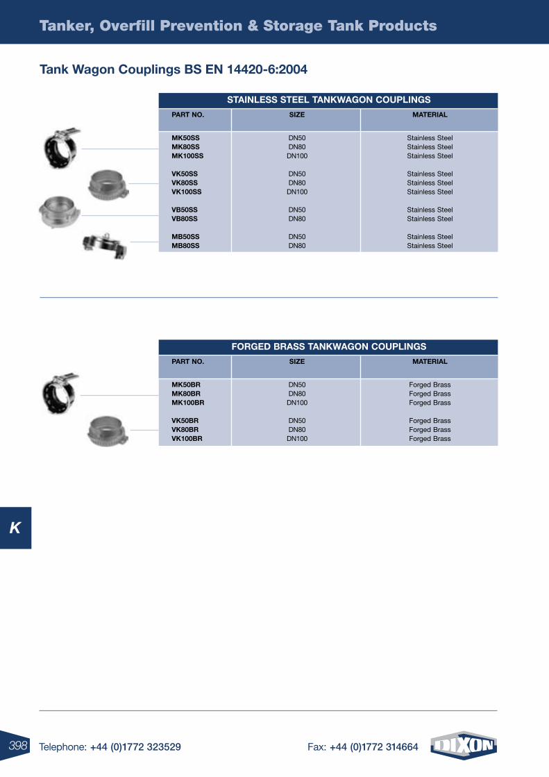
398 Telephone: +44 (0)1772 323529 Fax: +44 (0)1772 314664
Tanker, Overfill Prevention & Storage Tank Products
K
tank Wagon Couplings bs en 14420-6:2004
stainless steel tanKWagon Couplings
part no. siZe material
mK50ss DN50 Stainless Steel mK80ss DN80 Stainless Steel mK100ss DN100 Stainless Steel VK50ss DN50 Stainless Steel VK80ss DN80 Stainless Steel VK100ss DN100 Stainless Steel Vb50ss DN50 Stainless Steel Vb80ss DN80 Stainless Steel mb50ss DN50 Stainless Steel mb80ss DN80 Stainless Steel
ForgeD brass tanKWagon Couplings
part no. siZe material
mK50br DN50 Forged Brass mK80br DN80 Forged Brass mK100br DN100 Forged Brass VK50br DN50 Forged Brass VK80br DN80 Forged Brass VK100br DN100 Forged Brass
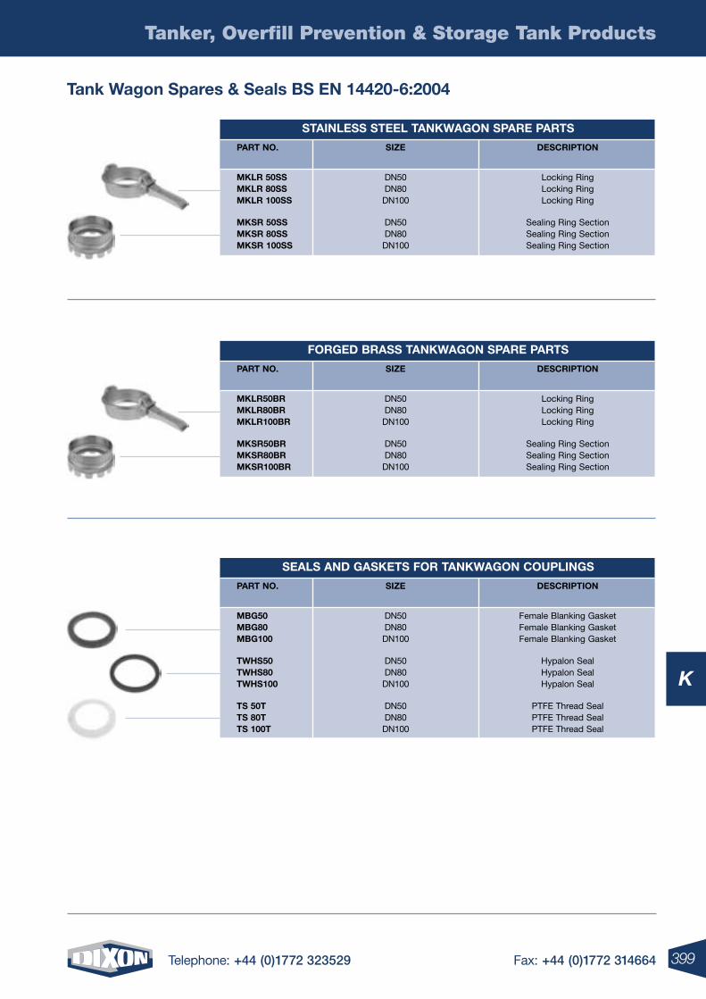
399Telephone: +44 (0)1772 323529 Fax: +44 (0)1772 314664
Tanker, Overfill Prevention & Storage Tank Products
K
tank Wagon spares & seals bs en 14420-6:2004
stainless steel tanKWagon spare parts
part no. siZe DesCription
mKlr 50ss DN50 Locking Ring mKlr 80ss DN80 Locking Ring mKlr 100ss DN100 Locking Ring mKsr 50ss DN50 Sealing Ring Section mKsr 80ss DN80 Sealing Ring Section mKsr 100ss DN100 Sealing Ring Section
ForgeD brass tanKWagon spare parts
part no. siZe DesCription
mKlr50br DN50 Locking Ring mKlr80br DN80 Locking Ring mKlr100br DN100 Locking Ring mKsr50br DN50 Sealing Ring Section mKsr80br DN80 Sealing Ring Section mKsr100br DN100 Sealing Ring Section
seals anD gasKets For tanKWagon Couplings
part no. siZe DesCription
mbg50 DN50 Female Blanking Gasket mbg80 DN80 Female Blanking Gasket mbg100 DN100 Female Blanking Gasket tWhs50 DN50 Hypalon Seal tWhs80 DN80 Hypalon Seal tWhs100 DN100 Hypalon Seal ts 50t DN50 PTFE Thread Seal ts 80t DN80 PTFE Thread Seal ts 100t DN100 PTFE Thread Seal
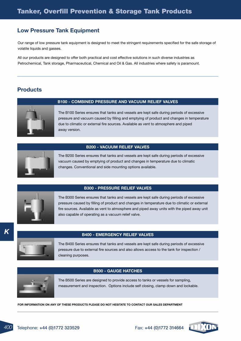
400 Telephone: +44 (0)1772 323529 Fax: +44 (0)1772 314664
Tanker, Overfill Prevention & Storage Tank Products
K
Our range of low pressure tank equipment is designed to meet the stringent requirements specified for the safe storage of
volatile liquids and gasses.
All our products are designed to offer both practical and cost effective solutions in such diverse industries as
Petrochemical, Tank storage, Pharmaceutical, Chemical and Oil & Gas. All industries where safety is paramount.
For inFormation on any oF these proDuCts please Do not hesitate to ContaCt our sales Department
low pressure tank equipment
products
b100 - CombineD pressure anD VaCuum relieF ValVes
The B100 Series ensures that tanks and vessels are kept safe during periods of excessive
pressure and vacuum caused by filling and emptying of product and changes in temperature
due to climatic or external fire sources. Available as vent to atmosphere and piped
away version.
b200 - VaCuum relieF ValVes
The B200 Series ensures that tanks and vessels are kept safe during periods of excessive
vacuum caused by emptying of product and changes in temperature due to climatic
changes. Conventional and side mounting options available.
b400 - emergenCy relieF ValVes
The B400 Series ensures that tanks and vessels are kept safe during periods of excessive
pressure due to external fire sources and also allows access to the tank for inspection /
cleaning purposes.
b500 - gauge hatChes
The B500 Series are designed to provide access to tanks or vessels for sampling,
measurement and inspection. Options include self closing, clamp down and lockable.
The B300 Series ensures that tanks and vessels are kept safe during periods of excessive
pressure caused by filling of product and changes in temperature due to climatic or external
fire sources. Available as vent to atmosphere and piped away units with the piped away unit
also capable of operating as a vacuum relief valve.
b300 - pressure relieF ValVes
401Telephone: +44 (0)1772 323529 Fax: +44 (0)1772 314664
Tanker, Overfill Prevention & Storage Tank Products
K
L
4 Telephone: +44 (0)1772 323529 Fax: +44 (0)1772 314664402 Telephone: +44 (0)1772 323529 Fax: +44 (0)1772 314664
L
L
403Telephone: +44 (0)1772 323529 Fax: +44 (0)1772 314664
Ball / Gate Valves ......................................................................... 404-405
Safety Vented Ball ...................................................................................406
Bronze Deadman Spring Return ..............................................................406
Steam Ball ...............................................................................................407
Carbon Steel Ball ....................................................................................407
Locking Handle Ball ................................................................................408
Polypropylene Valves .............................................................................409
Foot Valves, Skimmers & Strainers .............................................. 410-413
Safety Check Valves ................................................................................414
403Telephone: +44 (0)1772 323529 Fax: +44 (0)1772 314664
Valves - Industrial & General Purpose
Other valve types are available in the hygienic and tanker sectiOn
L
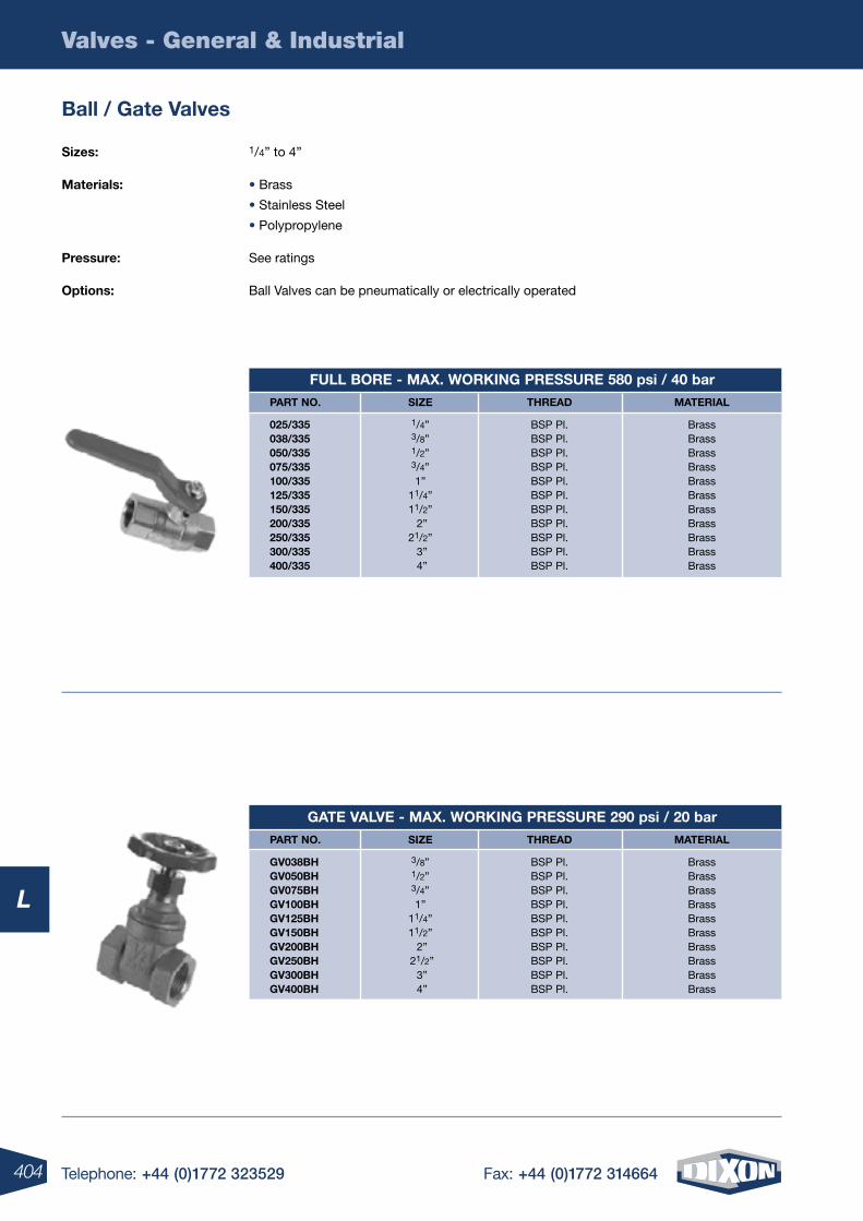
404 Telephone: +44 (0)1772 323529 Fax: +44 (0)1772 314664
Valves - General & Industrial
L
sizes: 1/4” to 4”
Materials: • Brass
• Stainless Steel
• Polypropylene
pressure: See ratings
Options: Ball Valves can be pneumatically or electrically operated
ball / gate valves
part nO. siZe thread Material
gv038bh 3/8” BSP Pl. Brass gv050bh 1/2” BSP Pl. Brass gv075bh 3/4” BSP Pl. Brass gv100bh 1” BSP Pl. Brass gv125bh 11/4” BSP Pl. Brass gv150bh 11/2” BSP Pl. Brass gv200bh 2” BSP Pl. Brass gv250bh 21/2” BSP Pl. Brass gv300bh 3” BSP Pl. Brass gv400bh 4” BSP Pl. Brass
gate valve - MaX. WOrking pressUre 290 psi / 20 bar
part nO. siZe thread Material
025/335 1/4” BSP Pl. Brass 038/335 3/8” BSP Pl. Brass 050/335 1/2” BSP Pl. Brass 075/335 3/4” BSP Pl. Brass 100/335 1” BSP Pl. Brass 125/335 11/4” BSP Pl. Brass 150/335 11/2” BSP Pl. Brass 200/335 2” BSP Pl. Brass 250/335 21/2” BSP Pl. Brass 300/335 3” BSP Pl. Brass 400/335 4” BSP Pl. Brass
FUll bOre - MaX. WOrking pressUre 580 psi / 40 bar
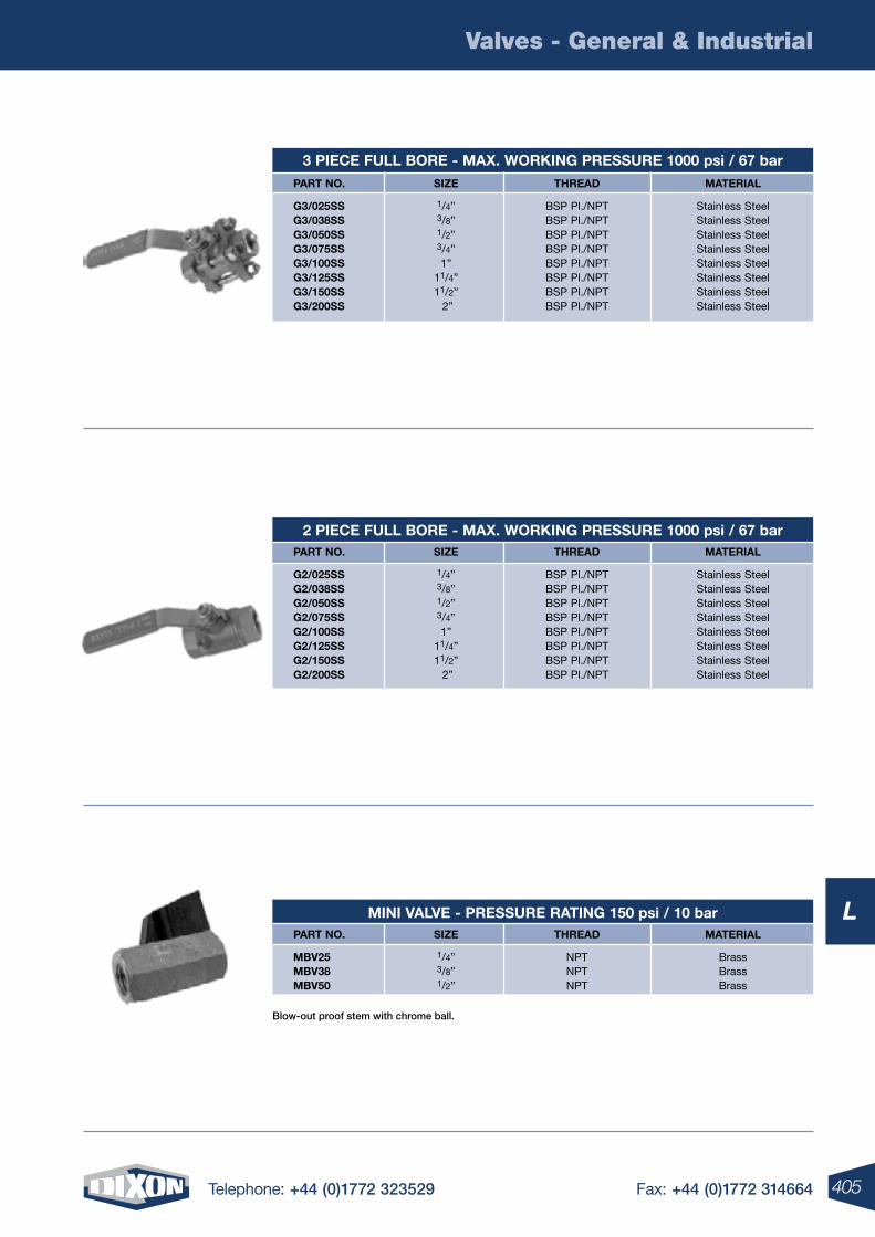
405Telephone: +44 (0)1772 323529 Fax: +44 (0)1772 314664
Valves - General & Industrial
L
Blow-out proof stem with chrome ball.
part nO. siZe thread Material
Mbv25 1/4” NPT Brass Mbv38 3/8” NPT Brass Mbv50 1/2” NPT Brass
Mini valve - pressUre rating 150 psi / 10 bar
part nO. siZe thread Material
g3/025ss 1/4” BSP Pl./NPT Stainless Steel g3/038ss 3/8” BSP Pl./NPT Stainless Steel g3/050ss 1/2” BSP Pl./NPT Stainless Steel g3/075ss 3/4” BSP Pl./NPT Stainless Steel g3/100ss 1” BSP Pl./NPT Stainless Steel g3/125ss 11/4” BSP Pl./NPT Stainless Steel g3/150ss 11/2” BSP Pl./NPT Stainless Steel g3/200ss 2” BSP Pl./NPT Stainless Steel
3 piece FUll bOre - MaX. WOrking pressUre 1000 psi / 67 bar
part nO. siZe thread Material
g2/025ss 1/4” BSP Pl./NPT Stainless Steel g2/038ss 3/8” BSP Pl./NPT Stainless Steel g2/050ss 1/2” BSP Pl./NPT Stainless Steel g2/075ss 3/4” BSP Pl./NPT Stainless Steel g2/100ss 1” BSP Pl./NPT Stainless Steel g2/125ss 11/4” BSP Pl./NPT Stainless Steel g2/150ss 11/2” BSP Pl./NPT Stainless Steel g2/200ss 2” BSP Pl./NPT Stainless Steel
2 piece FUll bOre - MaX. WOrking pressUre 1000 psi / 67 bar
406 Telephone: +44 (0)1772 323529 Fax: +44 (0)1772 314664
Valves - General & Industrial
L
sizes: • 1/4” to 1/2” Full Port
• 3/4” to 2” Standard Port
Material: Brass
pressure: • Maximum working pressure 400 psi / 28 bar
• 150 psi /10 bar Saturated Steam
details: Female x Female NPT ends. Air only. Lockable ball valves vent downstream air
in accordance with new OSHA regulations for pneumatic system.
safety vented ball valves
sizes: • 1/2” Full Port
• 3/4” to 1” Standard Port
Materials: • Bronze Valve Body
• Stainless Steel Lever
• Chromium Plated Ball
pressure: 600 psi / 41 bar WOG, 150 psi / 10 bar Steam
details: Female NPT x Female NPT. Standard Port. Operating torque approx. 3 times standard valve
torque. Spring return to open and close valve. Reinforced PTFE Seats and Stuffing Box Ring.
Blow-out proof Stem design. Adjustable Packing Gland.
bronze “deadman” spring return handle valves
Other sizes available on request.
part nO. siZe thread
bbv25lv 1/4” NPT bbv38lv 3/8” NPT bbv50lv 1/2” NPT bbv75lv 3/4” NPT bbv100lv 1” NPT bbv125lv 11/4” NPT bbv150lv 11 /2” NPT bbv200lv 2” NPT
saFety vented ball valves
part nO. siZe thread
bbv50sr 1/2” NPT
bbv75sr 3/4” NPT
bbv100sr 1” NPT
brOnZe “deadMan” spring retUrn handle valve
407Telephone: +44 (0)1772 323529 Fax: +44 (0)1772 314664
Valves - General & Industrial
L
sizes: 1/2” to 2” NPT/BSP
Materials: • Threaded Bronze Valve
• Stainless Steel Ball and Stem
• Chromium Plated Ball
pressure: 600 psi / 41 bar WOG, 150 psi / 17 bar Steam
details: • Multi-Fill PTFE Seats
• Multi-Fill Stuffing Box Ring Blow-out proof Stem design
• Adjustable Packing Gland
steam ball valves
sizes: 1/4” to 2” NPT/BSP
Materials: Carbon Steel / Lock Handle
pressure: • Suitable for 150 psi / 10 bar Steam service
• 1/4” - 1” rated to 2000 psi / 138 bar
• 11/4” - 2” rated to 1500 psi / 103 bar
details: For control of air, water, oil and gas in hose or pipe lines
carbon steel ball valves
part nO. siZe thread
bbv50st 1/2” NPT / BSP Pl. bbv75st 3/4” NPT / BSP Pl. bbv100st 1” NPT / BSP Pl. bbv200st 2” NPT / BSP Pl.
steaM ball valve
part nO. siZe thread
ibv25 1/4” NPT / BSP Pl. ibv38 3/8” NPT / BSP Pl. ibv50 1/2” NPT / BSP Pl. ibv75 3/4” NPT / BSP Pl. ibv100 1” NPT / BSP Pl. ibv125 11/4” NPT / BSP Pl. ibv150 11/2” NPT / BSP Pl. ibv200 2” NPT / BSP Pl.
carbOn steel ball valves
408 Telephone: +44 (0)1772 323529 Fax: +44 (0)1772 314664
Valves - General & Industrial
L
sizes: 1/4” to 2” NPT/BSP
Materials: Brass
pressure: • Full Port - Rated to 600 psi / 41 bar WOG and 150 psi / 10 bar Steam
• Standard Port - Rated to 400 psi / 28 bar WOG and 125 psi / 9 bar Steam
details: Female x Female
part nO. siZe thread
bblv25 1/4” NPT / BSP Pl. bblv38 3/8” NPT / BSP Pl. bblv50 1/2” NPT / BSP Pl. bblv75 3/4” NPT / BSP Pl. bblv100 1” NPT / BSP Pl.
FUll pOrt With lOcking handles
part nO. siZe thread
bblv125 11/4” NPT / BSP Pl. bblv150 11/2” NPT / BSP Pl. bblv200 2” NPT / BSP Pl.
standard pOrt With lOcking handles
locking handle ball valves
409Telephone: +44 (0)1772 323529 Fax: +44 (0)1772 314664
Valves - General & Industrial
L
part nO. siZe descriptiOn
pv100 1” Standard 4 bolt pv200 2” Standard 4 bolt
standard pOrt valves npt Only
part nO. siZe descriptiOn
pvFp50 1/2” 4 bolt pvFp75 3/4” 4 bolt pvFp100 1” 4 bolt pvFp150 11/2” 4 bolt pvFp200 2” 6 bolt pvFp300 3” 6 bolt
FUll pOrt valves npt Only
part nO. siZe thread Material
sUbv50 1/2” NPT Polypropylene sUbv75 3/4” NPT Polypropylene sUbv100 1” NPT Polypropylene sUbv125 11/4” NPT Polypropylene sUbv150 11/2” NPT Polypropylene sUbv200 2” NPT Polypropylene sUbv300 3” NPT Polypropylene
single UniOn
polypropylene valves
Corrosion resistant Polypropylene•
PTFE ball seats, EPDM ‘O’ Rings•
Rated to 75 psi•
Precision-moulded from strong, chemical resistant•
Reinforced polypropylene. PTFE seats and EPDM•
‘O’ Ring seals. Easy to service and easy•
Non-stick operation. Rated to 125 psi•
Precision-moulded from strong, chemical resistant•
Reinforced polypropylene. PTFE seats and EPDM•
‘O’ Ring seals. Easy to service and easy•
Non-stick operation. Rated to 125 psi•
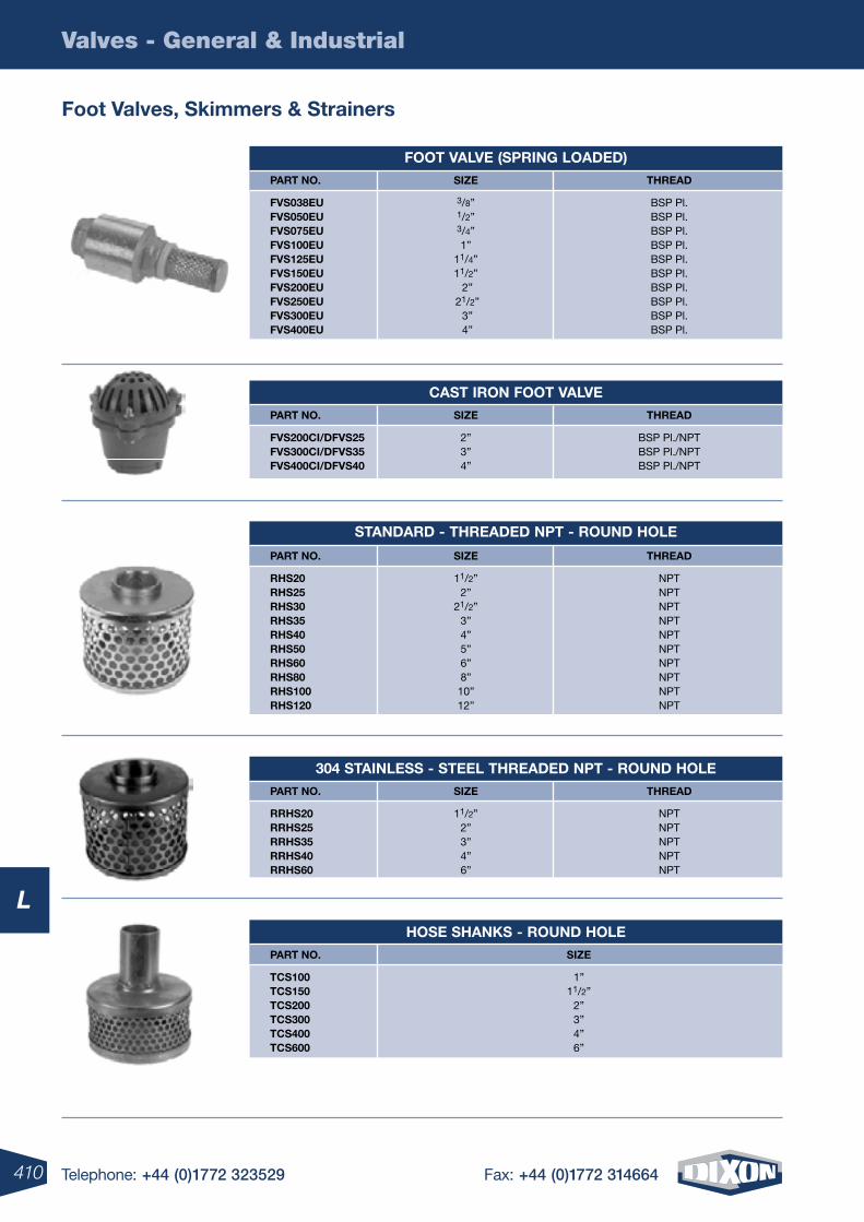
410 Telephone: +44 (0)1772 323529 Fax: +44 (0)1772 314664
Valves - General & Industrial
L
Foot valves, skimmers & strainers
cast irOn FOOt valve part nO. siZe thread
Fvs200ci/dFvs25 2” BSP Pl./NPT Fvs300ci/dFvs35 3” BSP Pl./NPT Fvs400ci/dFvs40 4” BSP Pl./NPT
FOOt valve (spring lOaded) part nO. siZe thread
Fvs038eU 3/8” BSP Pl. Fvs050eU 1/2” BSP Pl. Fvs075eU 3/4” BSP Pl. Fvs100eU 1” BSP Pl. Fvs125eU 11/4” BSP Pl. Fvs150eU 11/2” BSP Pl. Fvs200eU 2” BSP Pl. Fvs250eU 21/2” BSP Pl. Fvs300eU 3” BSP Pl. Fvs400eU 4” BSP Pl.
standard - threaded npt - rOUnd hOle
part nO. siZe thread
rhs20 11/2” NPT rhs25 2” NPT rhs30 21/2” NPT rhs35 3” NPT rhs40 4” NPT rhs50 5” NPT rhs60 6” NPT rhs80 8” NPT rhs100 10” NPT rhs120 12” NPT
304 stainless - steel threaded npt - rOUnd hOle part nO. siZe thread
rrhs20 11/2” NPT rrhs25 2” NPT rrhs35 3” NPT rrhs40 4” NPT rrhs60 6” NPT
hOse shanks - rOUnd hOle part nO. siZe
tcs100 1” tcs150 11/2” tcs200 2” tcs300 3” tcs400 4” tcs600 6”
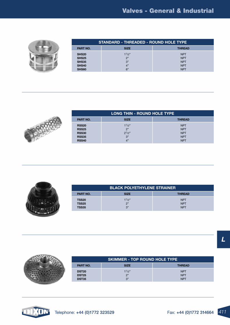
411Telephone: +44 (0)1772 323529 Fax: +44 (0)1772 314664
Valves - General & Industrial
L
skiMMer - tOp rOUnd hOle type part nO. siZe thread
dst20 11/2” NPT dst25 2” NPT dst35 3” NPT
black pOlyethylene strainer part nO. siZe thread
tss20 11/2” NPT tss25 2” NPT tss35 3” NPT
lOng thin - rOUnd hOle type part nO. siZe thread
rss20 11/2” NPT rss25 2” NPT rss30 21/2” NPT rss35 3” NPT rss40 4” NPT
standard - threaded - rOUnd hOle type part nO. siZe thread
shs20 11/2” NPT shs25 2” NPT shs35 3” NPT shs40 4” NPT shs60 6” NPT
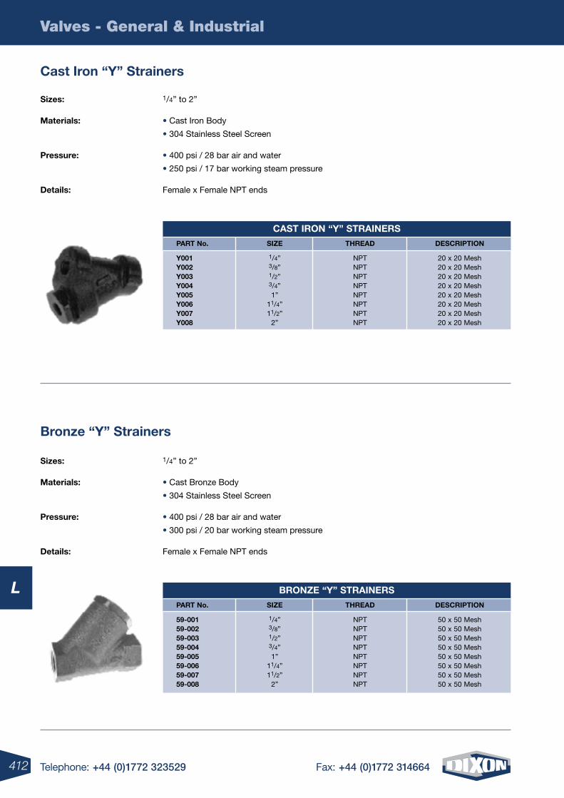
412 Telephone: +44 (0)1772 323529 Fax: +44 (0)1772 314664
Valves - General & Industrial
L
sizes: 1/4” to 2”
Materials: • Cast Iron Body
• 304 Stainless Steel Screen
pressure: • 400 psi / 28 bar air and water
• 250 psi / 17 bar working steam pressure
details: Female x Female NPT ends
cast iron “y” strainers
sizes: 1/4” to 2”
Materials: • Cast Bronze Body
• 304 Stainless Steel Screen
pressure: • 400 psi / 28 bar air and water
• 300 psi / 20 bar working steam pressure
details: Female x Female NPT ends
bronze “y” strainers
part no. siZe thread descriptiOn
y001 1/4” NPT 20 x 20 Mesh y002 3/8” NPT 20 x 20 Mesh y003 1/2” NPT 20 x 20 Mesh y004 3/4” NPT 20 x 20 Mesh y005 1” NPT 20 x 20 Mesh y006 11/4” NPT 20 x 20 Mesh y007 11/2” NPT 20 x 20 Mesh y008 2” NPT 20 x 20 Mesh
cast irOn “y” strainers
part no. siZe thread descriptiOn
59-001 1/4” NPT 50 x 50 Mesh 59-002 3/8” NPT 50 x 50 Mesh 59-003 1/2” NPT 50 x 50 Mesh 59-004 3/4” NPT 50 x 50 Mesh 59-005 1” NPT 50 x 50 Mesh 59-006 11/4” NPT 50 x 50 Mesh 59-007 11/2” NPT 50 x 50 Mesh 59-008 2” NPT 50 x 50 Mesh
brOnZe “y” strainers
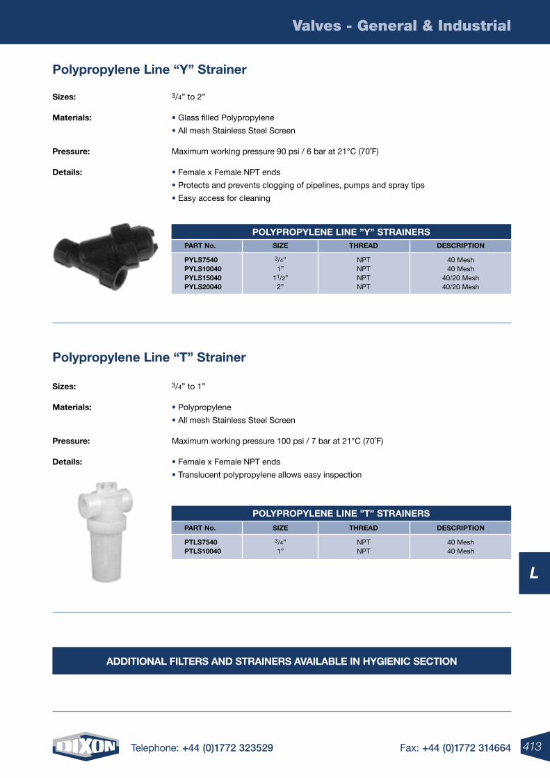
413Telephone: +44 (0)1772 323529 Fax: +44 (0)1772 314664
Valves - General & Industrial
L
part no. siZe thread descriptiOn
ptls7540 3/4” NPT 40 Mesh ptls10040 1” NPT 40 Mesh
pOlyprOpylene line ”t” strainers
polypropylene line “y” strainer
sizes: 3/4” to 2”
Materials: • Glass filled Polypropylene
• All mesh Stainless Steel Screen
pressure: Maximum working pressure 90 psi / 6 bar at 21°C (70˚F)
details: • Female x Female NPT ends
• Protects and prevents clogging of pipelines, pumps and spray tips
• Easy access for cleaning
sizes: 3/4” to 1”
Materials: • Polypropylene
• All mesh Stainless Steel Screen
pressure: Maximum working pressure 100 psi / 7 bar at 21°C (70˚F)
details: • Female x Female NPT ends
• Translucent polypropylene allows easy inspection
part no. siZe thread descriptiOn
pyls7540 3/4” NPT 40 Mesh pyls10040 1” NPT 40 Mesh pyls15040 11/2” NPT 40/20 Mesh pyls20040 2” NPT 40/20 Mesh
pOlyprOpylene line ”y” strainers
polypropylene line “t” strainer
additiOnal Filters and strainers available in hygienic sectiOn
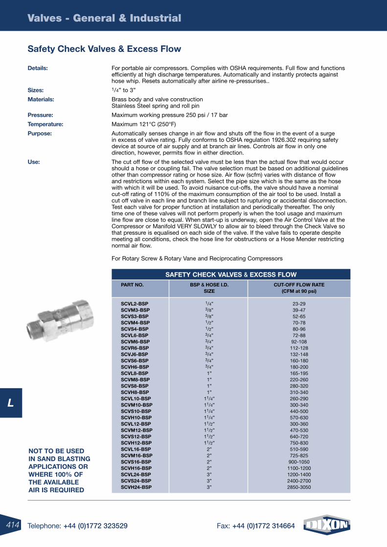
414 Telephone: +44 (0)1772 323529 Fax: +44 (0)1772 314664
Valves - General & Industrial
L
details: For portable air compressors. Complies with OSHA requirements. Full flow and functions efficiently at high discharge temperatures. Automatically and instantly protects against hose whip. Resets automatically after airline re-pressurises..
sizes: 1/4” to 3”
Materials: Brass body and valve construction Stainless Steel spring and roll pin
pressure: Maximum working pressure 250 psi / 17 bar
temperature: Maximum 121°C (250°F)
purpose: Automatically senses change in air flow and shuts off the flow in the event of a surge in excess of valve rating. Fully conforms to OSHA regulation 1926.302 requiring safety device at source of air supply and at branch air lines. Controls air flow in only one direction, however, permits flow in either direction.
Use: The cut off flow of the selected valve must be less than the actual flow that would occur should a hose or coupling fail. The valve selection must be based on additional guidelines other than compressor rating or hose size. Air flow (scfm) varies with distance of flow and restrictions within each system. Select the pipe size which is the same as the hose with which it will be used. To avoid nuisance cut-offs, the valve should have a nominal cut-off rating of 110% of the maximum consumption of the air tool to be used. Install a cut off valve in each line and branch line subject to rupturing or accidental disconnection. Test each valve for proper function at installation and periodically thereafter. The only time one of these valves will not perform properly is when the tool usage and maximum line flow are close to equal. When start-up is underway, open the Air Control Valve at the Compressor or Manifold VERY SLOWLY to allow air to bleed through the Check Valve so that pressure is equalised on each side of the valve. If the valve fails to operate despite meeting all conditions, check the hose line for obstructions or a Hose Mender restricting normal air flow. For Rotary Screw & Rotary Vane and Reciprocating Compressors
safety check valves & excess Flow
part nO. bsp & hOse i.d. cUt-OFF FlOW rate siZe (cFM at 90 psi)
scvl2-bsp 1/4” 23-29 scvM3-bsp 3/8” 39-47 scvs3-bsp 3/8” 52-65 scvM4-bsp 1/2” 70-78 scvs4-bsp 1/2” 80-96 scvl6-bsp 3/4” 72-88 scvM6-bsp 3/4” 92-108 scvr6-bsp 3/4” 112-128 scvJ6-bsp 3/4” 132-148 scvs6-bsp 3/4” 160-180 scvh6-bsp 3/4” 180-200 scvl8-bsp 1” 165-195 scvM8-bsp 1” 220-260 scvs8-bsp 1” 280-320 scvh8-bsp 1” 310-340 scvl10-bsp 11/4” 260-290 scvM10-bsp 11/4” 300-340 scvs10-bsp 11/4” 440-500 scvh10-bsp 11/4” 570-630 scvl12-bsp 11/2” 300-360 scvM12-bsp 11/2” 470-530 scvs12-bsp 11/2” 640-720 scvh12-bsp 11/2” 750-830 scvl16-bsp 2” 510-590 scvM16-bsp 2” 725-825 scvs16-bsp 2” 900-1050 scvh16-bsp 2” 1100-1200 scvl24-bsp 3” 1200-1400 scvs24-bsp 3” 2400-2700 scvh24-bsp 3” 2850-3050
saFety check valves & eXcess FlOW
nOt tO be Used in sand blasting applicatiOns Or Where 100% OF the available air is reqUired
415Telephone: +44 (0)1772 323529 Fax: +44 (0)1772 314664
Valves - General & Industrial
L
M
4 Telephone: +44 (0)1772 323529 Fax: +44 (0)1772 314664416 Telephone: +44 (0)1772 323529 Fax: +44 (0)1772 314664
M
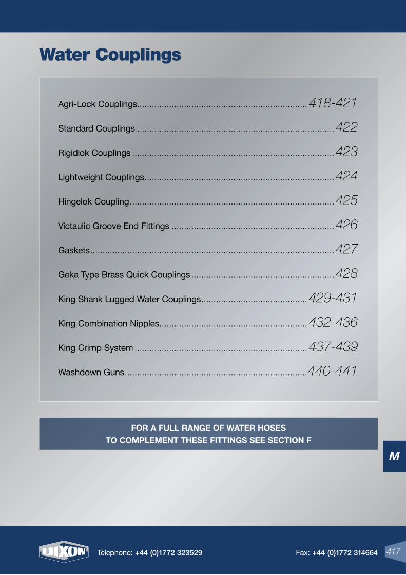
M
417Telephone: +44 (0)1772 323529 Fax: +44 (0)1772 314664
Agri-Lock Couplings ..................................................................... 418-421
Standard Couplings ................................................................................422
Rigidlok Couplings ..................................................................................423
Lightweight Couplings .............................................................................424
Hingelok Coupling ...................................................................................425
Victaulic Groove End Fittings ..................................................................426
Gaskets ...................................................................................................427
Geka Type Brass Quick Couplings ..........................................................428
King Shank Lugged Water Couplings ........................................... 429-431
King Combination Nipples ............................................................ 432-436
King Crimp System ...................................................................... 437-439
Washdown Guns ..........................................................................440-441
417Telephone: +44 (0)1772 323529 Fax: +44 (0)1772 314664
Water Couplings
For a Full range oF water hoses
to complement these Fittings see section F
M
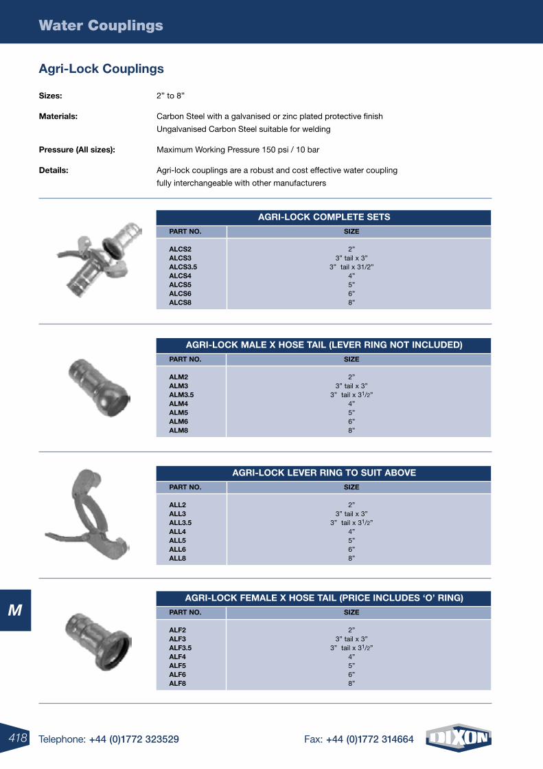
418 Telephone: +44 (0)1772 323529 Fax: +44 (0)1772 314664
Water Couplings
M
agri-lock couplings
sizes: 2” to 8”
materials: Carbon Steel with a galvanised or zinc plated protective finish
Ungalvanised Carbon Steel suitable for welding
pressure (all sizes): Maximum Working Pressure 150 psi / 10 bar
Details: Agri-lock couplings are a robust and cost effective water coupling
fully interchangeable with other manufacturers
agri-locK complete sets
part no. siZe
alcs2 2” alcs3 3” tail x 3” alcs3.5 3” tail x 31/2” alcs4 4” alcs5 5” alcs6 6” alcs8 8”
agri-locK male X hose tail (leVer ring not incluDeD)
part no. siZe
alm2 2” alm3 3” tail x 3” alm3.5 3” tail x 31/2” alm4 4” alm5 5” alm6 6” alm8 8”
agri-locK leVer ring to suit aBoVe
part no. siZe
all2 2” all3 3” tail x 3” all3.5 3” tail x 31/2” all4 4” all5 5” all6 6” all8 8”
agri-locK Female X hose tail (price incluDes ‘o’ ring)
part no. siZe
alF2 2” alF3 3” tail x 3” alF3.5 3” tail x 31/2” alF4 4” alF5 5” alF6 6” alF8 8”
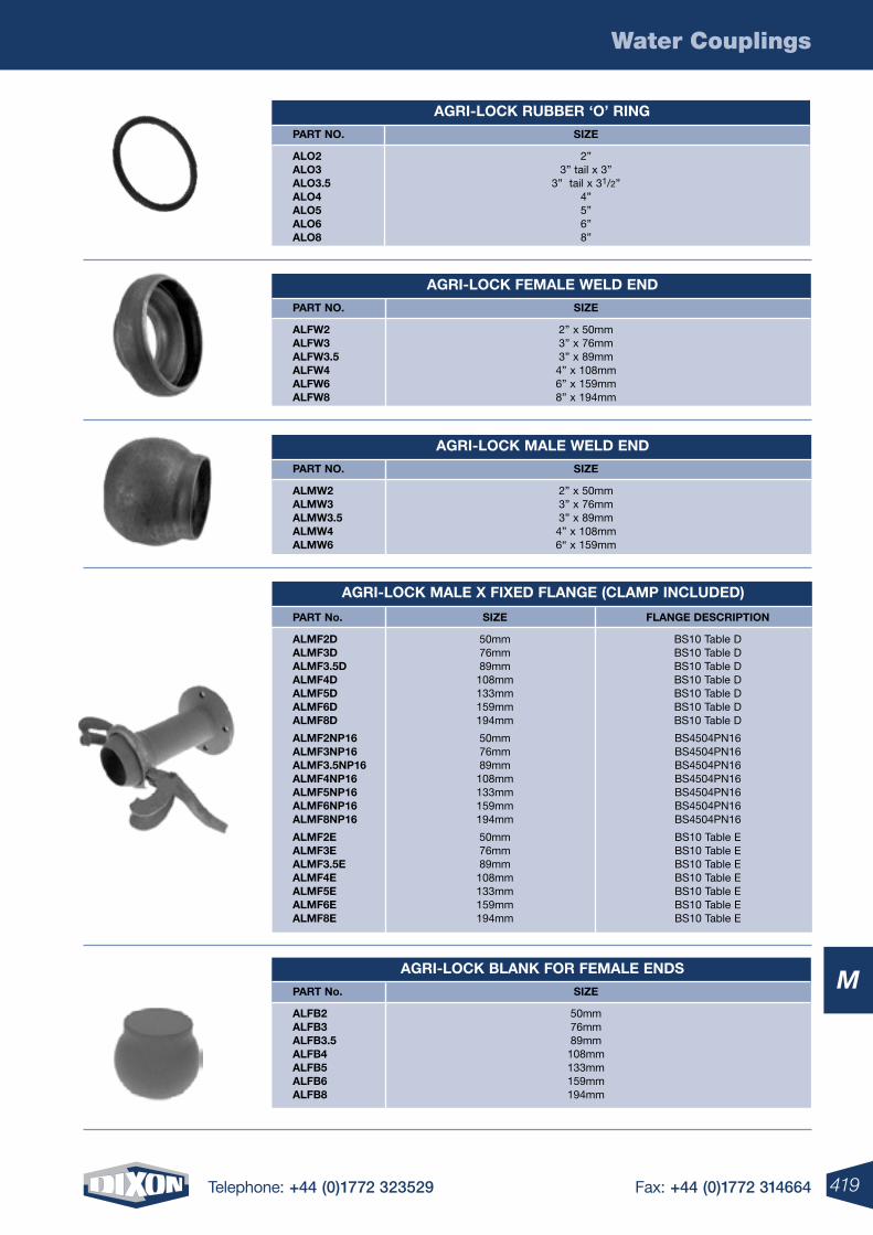
419Telephone: +44 (0)1772 323529 Fax: +44 (0)1772 314664
Water Couplings
M
agri-locK ruBBer ‘o’ ring
part no. siZe
alo2 2” alo3 3” tail x 3” alo3.5 3” tail x 31/2” alo4 4” alo5 5” alo6 6” alo8 8”
agri-locK Female welD enD
part no. siZe
alFw2 2” x 50mm alFw3 3” x 76mm alFw3.5 3” x 89mm alFw4 4” x 108mm alFw6 6” x 159mm alFw8 8” x 194mm
agri-locK male welD enD
part no. siZe
almw2 2” x 50mm almw3 3” x 76mm almw3.5 3” x 89mm almw4 4” x 108mm almw6 6“ x 159mm
agri-locK BlanK For Female enDs
part no. siZe
alFB2 50mm alFB3 76mm alFB3.5 89mm alFB4 108mm alFB5 133mm alFB6 159mm alFB8 194mm
agri-locK male X FiXeD Flange (clamp incluDeD)
part no. siZe Flange Description
almF2D 50mm BS10 Table D almF3D 76mm BS10 Table D almF3.5D 89mm BS10 Table D almF4D 108mm BS10 Table D almF5D 133mm BS10 Table D almF6D 159mm BS10 Table D almF8D 194mm BS10 Table D
almF2np16 50mm BS4504PN16 almF3np16 76mm BS4504PN16 almF3.5np16 89mm BS4504PN16 almF4np16 108mm BS4504PN16 almF5np16 133mm BS4504PN16 almF6np16 159mm BS4504PN16 almF8np16 194mm BS4504PN16
almF2e 50mm BS10 Table E almF3e 76mm BS10 Table E almF3.5e 89mm BS10 Table E almF4e 108mm BS10 Table E almF5e 133mm BS10 Table E almF6e 159mm BS10 Table E almF8e 194mm BS10 Table E
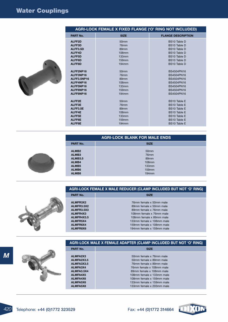
420 Telephone: +44 (0)1772 323529 Fax: +44 (0)1772 314664
Water Couplings
M
agri-locK Female X FiXeD Flange (‘o’ ring not incluDeD)
part no. siZe Flange Description
alFF2D 50mm BS10 Table D alFF3D 76mm BS10 Table D alFF3.5D 89mm BS10 Table D alFF4D 108mm BS10 Table D alFF5D 133mm BS10 Table D alFF6D 159mm BS10 Table D alFF8D 194mm BS10 Table D
alFF2np16 50mm BS4504PN16 alFF3np16 76mm BS4504PN16 alFF3.5np16 89mm BS4504PN16 alFF4np16 108mm BS4504PN16 alFF5np16 133mm BS4504PN16 alFF6np16 159mm BS4504PN16 alFF8np16 194mm BS4504PN16
alFF2e 50mm BS10 Table E alFF3e 76mm BS10 Table E alFF3.5e 89mm BS10 Table E alFF4e 108mm BS10 Table E alFF5e 133mm BS10 Table E alFF6e 159mm BS10 Table E alFF8e 194mm BS10 Table E
agri-locK BlanK For male enDs
part no. siZe
almB2 50mm almB3 76mm almB3.5 89mm almB4 108mm almB5 133mm almB6 159mm almB8 194mm
agri-locK Female X male reDucer (clamp incluDeD But not ‘o’ ring)
part no. siZe
almFr3X2 76mm female x 50mm male almFr3.5X2 89mm female x 50mm male almFr3.5X3 89mm female x 76mm male almFr4X3 108mm female x 76mm male almFr4X3.5 108mm female x 89mm male almFr5X4 133mm female x 108mm male almFr6X4 159mm female x 108mm male almFr8X6 194mm female x 159mm male
agri-locK male X Female aDapter (clamp incluDeD But not ‘o’ ring)
part no. siZe
almFa2X3 50mm female x 76mm male almFa2X3.5 50mm female x 89mm male almFa3X3.5 76mm female x 89mm male almFa3X4 76mm female x 108mm male almFa3.5X4 89mm female x 108mm male almFa4X5 108mm female x 133mm male almFa4X6 108mm female x 159mm male almFa5X6 133mm female x 159mm male almFa5X8 133mm female x 203mm male
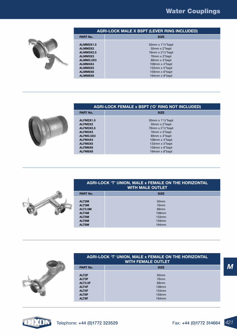
421Telephone: +44 (0)1772 323529 Fax: +44 (0)1772 314664
Water Couplings
M
agri-locK male X Bspt (leVer ring incluDeD) part no. siZe
almm2X1.5 50mm x 11/2”bspt almm2X2 50mm x 2”bspt almm3X2.5 76mm x 21/2”bspt almm3X3 76mm x 3”bspt almm3.5X3 89mm x 3”bspt almm4X4 108mm x 4”bspt almm5X5 133mm x 5”bspt almm6X6 159mm x 6”bspt almm8X8 194mm x 8”bspt
agri-locK Female x Bspt (‘o’ ring not incluDeD) part no. siZe
alFm2X1.5 50mm x 11/2”bspt alFm2X2 50mm x 2”bspt alFm3X2.5 76mm x 21/2”bspt alFm3X3 76mm x 3”bspt alFm3.5X3 89mm x 3”bspt alFm4X4 108mm x 4”bspt alFm5X5 133mm x 5”bspt alFm6X6 159mm x 6”bspt alFm8X8 194mm x 8”bspt
agri-locK ‘t’ union, male x Female on the horiZontal with male outlet
part no. siZe
alt2m 50mm alt3m 76mm alt3.5m 89mm alt4m 108mm alt5m 133mm alt6m 159mm alt8m 194mm
agri-locK ‘t’ union, male x Female on the horiZontal with Female outlet
part no. siZe
alt2F 50mm alt3F 76mm alt3.5F 89mm alt4F 108mm alt5F 133mm alt6F 159mm alt8F 194mm
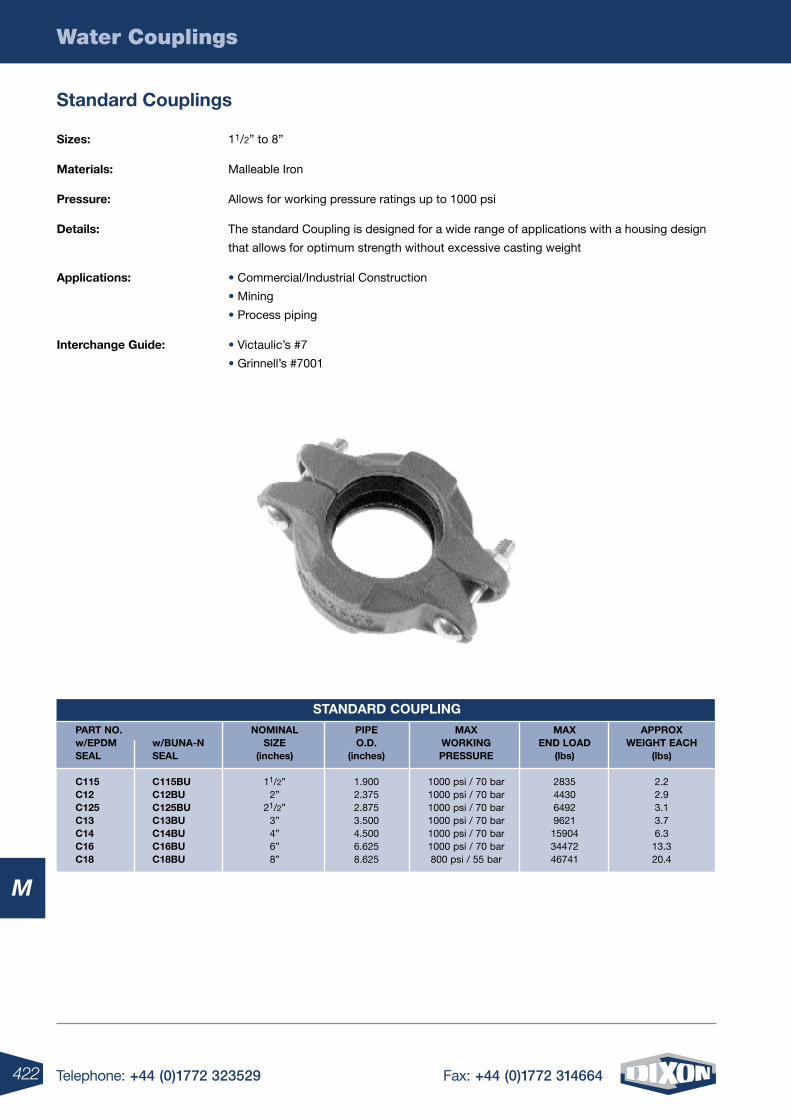
422 Telephone: +44 (0)1772 323529 Fax: +44 (0)1772 314664
Water Couplings
M
standard couplings
sizes: 11/2” to 8”
materials: Malleable Iron
pressure: Allows for working pressure ratings up to 1000 psi
Details: The standard Coupling is designed for a wide range of applications with a housing design
that allows for optimum strength without excessive casting weight
applications: • Commercial/Industrial Construction
• Mining
• Process piping
interchange guide: • Victaulic’s #7
• Grinnell’s #7001
stanDarD coupling
part no. nominal pipe maX maX approX w/epDm w/Buna-n siZe o.D. worKing enD loaD weight each seal seal (inches) (inches) pressure (lbs) (lbs) c115 c115Bu 11/2” 1.900 1000 psi / 70 bar 2835 2.2 c12 c12Bu 2” 2.375 1000 psi / 70 bar 4430 2.9 c125 c125Bu 21/2” 2.875 1000 psi / 70 bar 6492 3.1 c13 c13Bu 3” 3.500 1000 psi / 70 bar 9621 3.7 c14 c14Bu 4” 4.500 1000 psi / 70 bar 15904 6.3 c16 c16Bu 6” 6.625 1000 psi / 70 bar 34472 13.3 c18 c18Bu 8” 8.625 800 psi / 55 bar 46741 20.4
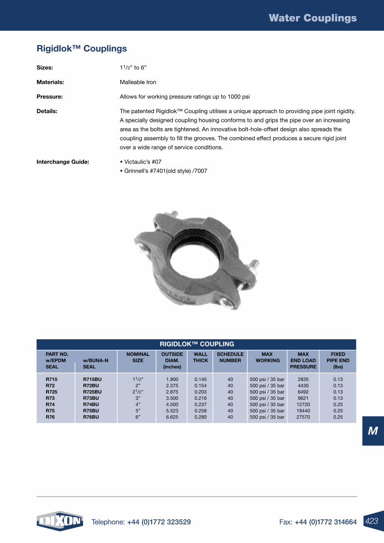
423Telephone: +44 (0)1772 323529 Fax: +44 (0)1772 314664
Water Couplings
M
rigidlok™ couplings
sizes: 11/2” to 6”
materials: Malleable Iron
pressure: Allows for working pressure ratings up to 1000 psi
Details: The patented Rigidlok™ Coupling utilises a unique approach to providing pipe joint rigidity.
A specially designed coupling housing conforms to and grips the pipe over an increasing
area as the bolts are tightened. An innovative bolt-hole-offset design also spreads the
coupling assembly to fill the grooves. The combined effect produces a secure rigid joint
over a wide range of service conditions.
interchange guide: • Victaulic’s #07
• Grinnell’s #7401(old style) /7007
rigiDloK™ coupling
part no. nominal outsiDe wall scheDule maX maX FiXeD w/epDm w/Buna-n siZe Diam. thicK numBer worKing enD loaD pipe enD seal seal (inches) pressure (lbs)
r715 r715Bu 11/2” 1.900 0.145 40 500 psi / 35 bar 2835 0.13 r72 r72Bu 2” 2.375 0.154 40 500 psi / 35 bar 4430 0.13 r725 r725Bu 21/2” 2.875 0.203 40 500 psi / 35 bar 6492 0.13 r73 r73Bu 3” 3.500 0.216 40 500 psi / 35 bar 9621 0.13 r74 r74Bu 4” 4.500 0.237 40 500 psi / 35 bar 12720 0.25 r75 r75Bu 5” 5.523 0.258 40 500 psi / 35 bar 19440 0.25 r76 r76Bu 6” 6.625 0.280 40 500 psi / 35 bar 27570 0.25
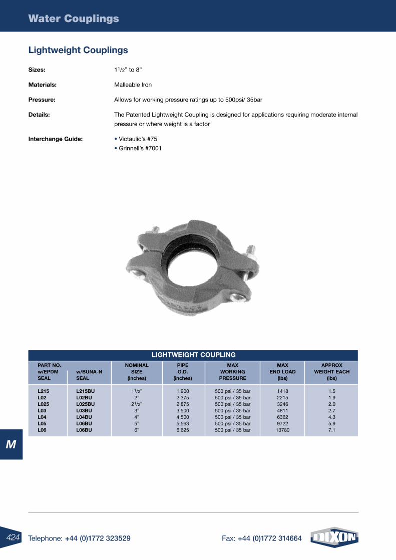
424 Telephone: +44 (0)1772 323529 Fax: +44 (0)1772 314664
Water Couplings
M
lightweight couplings
sizes: 11/2” to 8”
materials: Malleable Iron
pressure: Allows for working pressure ratings up to 500psi/ 35bar
Details: The Patented Lightweight Coupling is designed for applications requiring moderate internal
pressure or where weight is a factor
interchange guide: • Victaulic’s #75
• Grinnell’s #7001
lightweight coupling
part no. nominal pipe maX maX approX w/epDm w/Buna-n siZe o.D. worKing enD loaD weight each seal seal (inches) (inches) pressure (lbs) (lbs)
l215 l215Bu 11/2” 1.900 500 psi / 35 bar 1418 1.5 l02 l02Bu 2” 2.375 500 psi / 35 bar 2215 1.9 l025 l025Bu 21/2” 2.875 500 psi / 35 bar 3246 2.0 l03 l03Bu 3” 3.500 500 psi / 35 bar 4811 2.7 l04 l04Bu 4” 4.500 500 psi / 35 bar 6362 4.3 l05 l06Bu 5” 5.563 500 psi / 35 bar 9722 5.9 l06 l06Bu 6” 6.625 500 psi / 35 bar 13789 7.1
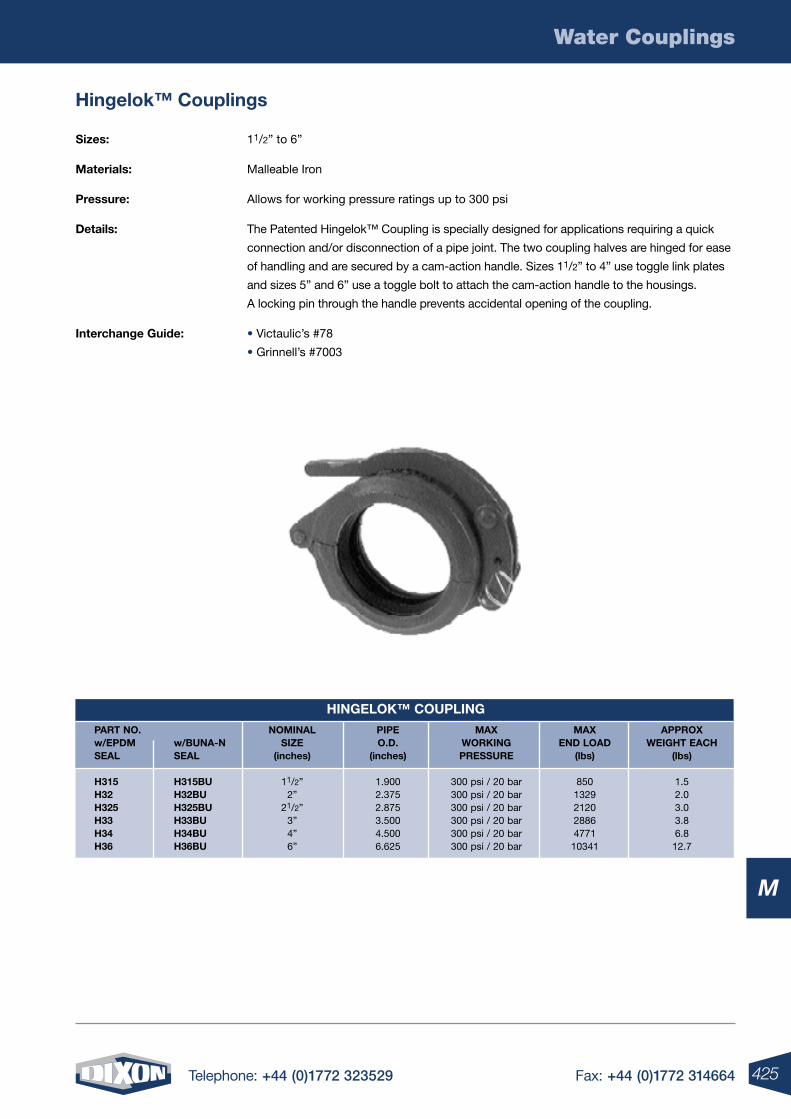
425Telephone: +44 (0)1772 323529 Fax: +44 (0)1772 314664
Water Couplings
M
hingelok™ couplings
sizes: 11/2” to 6”
materials: Malleable Iron
pressure: Allows for working pressure ratings up to 300 psi
Details: The Patented Hingelok™ Coupling is specially designed for applications requiring a quick
connection and/or disconnection of a pipe joint. The two coupling halves are hinged for ease
of handling and are secured by a cam-action handle. Sizes 11/2” to 4” use toggle link plates
and sizes 5” and 6” use a toggle bolt to attach the cam-action handle to the housings.
A locking pin through the handle prevents accidental opening of the coupling.
interchange guide: • Victaulic’s #78
• Grinnell’s #7003
hingeloK™ coupling
part no. nominal pipe maX maX approX w/epDm w/Buna-n siZe o.D. worKing enD loaD weight each seal seal (inches) (inches) pressure (lbs) (lbs)
h315 h315Bu 11/2” 1.900 300 psi / 20 bar 850 1.5 h32 h32Bu 2” 2.375 300 psi / 20 bar 1329 2.0 h325 h325Bu 21/2” 2.875 300 psi / 20 bar 2120 3.0 h33 h33Bu 3” 3.500 300 psi / 20 bar 2886 3.8 h34 h34Bu 4” 4.500 300 psi / 20 bar 4771 6.8 h36 h36Bu 6” 6.625 300 psi / 20 bar 10341 12.7
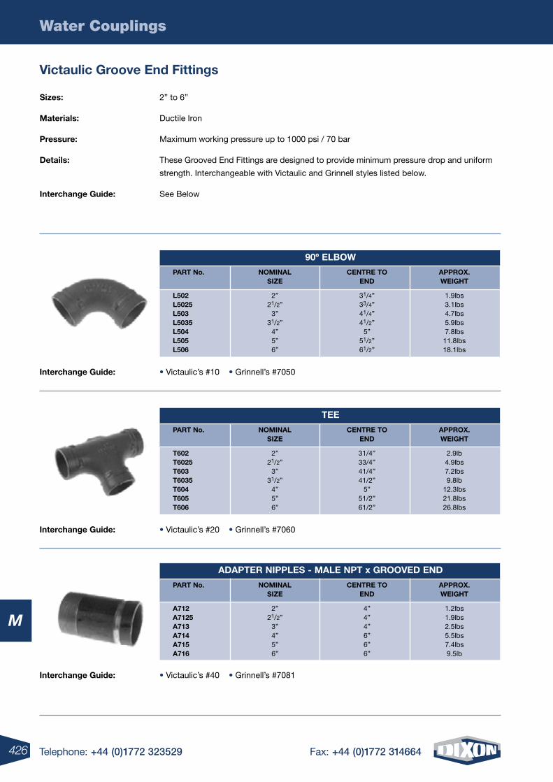
426 Telephone: +44 (0)1772 323529 Fax: +44 (0)1772 314664
Water Couplings
M
Victaulic groove end Fittings
sizes: 2” to 6”
materials: Ductile Iron
pressure: Maximum working pressure up to 1000 psi / 70 bar
Details: These Grooved End Fittings are designed to provide minimum pressure drop and uniform
strength. Interchangeable with Victaulic and Grinnell styles listed below.
interchange guide: See Below
interchange guide: • Victaulic’s #40 • Grinnell’s #7081
90º elBow
part no. nominal centre to approX. siZe enD weight
l502 2” 31/4” 1.9lbs l5025 21/2” 33/4” 3.1lbs l503 3” 41/4” 4.7lbs l5035 31/2” 41/2” 5.9lbs l504 4” 5” 7.8lbs l505 5” 51/2” 11.8lbs l506 6” 61/2” 18.1lbs
tee
part no. nominal centre to approX. siZe enD weight
t602 2” 31/4” 2.9lb t6025 21/2” 33/4” 4.9lbs t603 3” 41/4” 7.2lbs t6035 31/2” 41/2” 9.8lb t604 4” 5” 12.3lbs t605 5” 51/2” 21.8lbs t606 6” 61/2” 26.8lbs
aDapter nipples - male npt x grooVeD enD
part no. nominal centre to approX. siZe enD weight
a712 2” 4” 1.2lbs a7125 21/2” 4” 1.9lbs a713 3” 4” 2.5lbs a714 4” 6” 5.5lbs a715 5” 6” 7.4lbs a716 6” 6” 9.5lb
interchange guide: • Victaulic’s #10 • Grinnell’s #7050
interchange guide: • Victaulic’s #20 • Grinnell’s #7060
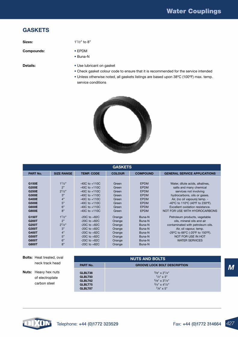
427Telephone: +44 (0)1772 323529 Fax: +44 (0)1772 314664
Water Couplings
M
gasKets
sizes: 11/2” to 8”
compounds: • EPDM
• Buna-N
Details: • Use lubricant on gasket
• Check gasket colour code to ensure that it is recommended for the service intended
• Unless otherwise noted, all gaskets listings are based upon 38ºC (100ºF) max. temp.
service conditions
gasKets
part no. siZe range temp. coDe colour compounD general serVice applications
g150e 11/2” -40C to +110C Green EPDM Water, dilute acids, alkalines, g200e 2” -40C to +110C Green EPDM salts and many chemical g250e 21/2” -40C to +110C Green EPDM services not involving g300e 3” -40C to +110C Green EPDM hydrocarbons, oils or gases. g400e 4” -40C to +110C Green EPDM Air, (no oil vapours) temp. - g500e 5” -40C to +110C Green EPDM -40ºC to 110ºC (40ºF to 230ºF). g600e 6” -40C to +110C Green EPDM Excellent oxidation resistance. g800e 8” -40C to +110C Green EPDM NOT FOR USE WITH HYDROCARBONS
g150t 11/2” -20C to +82C Orange Buna-N Petroleum products, vegetable g200t 2” -20C to +82C Orange Buna-N oils, mineral oils and air g250t 21/2” -20C to +82C Orange Buna-N contaminated with petroleum oils. g300t 3” -20C to +82C Orange Buna-N Air, oil vapour, temp. g400t 4” -20C to +82C Orange Buna-N -29ºC to 66ºC (-20ºF to 150ºF). g500t 5” -20C to +82C Orange Buna-N NOT FOR USE IN HOT g600t 6” -20C to +82C Orange Buna-N WATER SERVICES g800t 8” -20C to +82C Orange Buna-N
Bolts: Heat treated, oval
neck track head
nuts: Heavy hex nuts
of electroplate
carbon steel
nuts anD Bolts
part no. grooVe locK Bolt Description glBlt38 3/8” x 21/4” glBlt50 1/2” x 3” glBlt62 5/8” x 31/4” glBlt75 3/4” x 41/2” glBlt87 7/8” x 5”
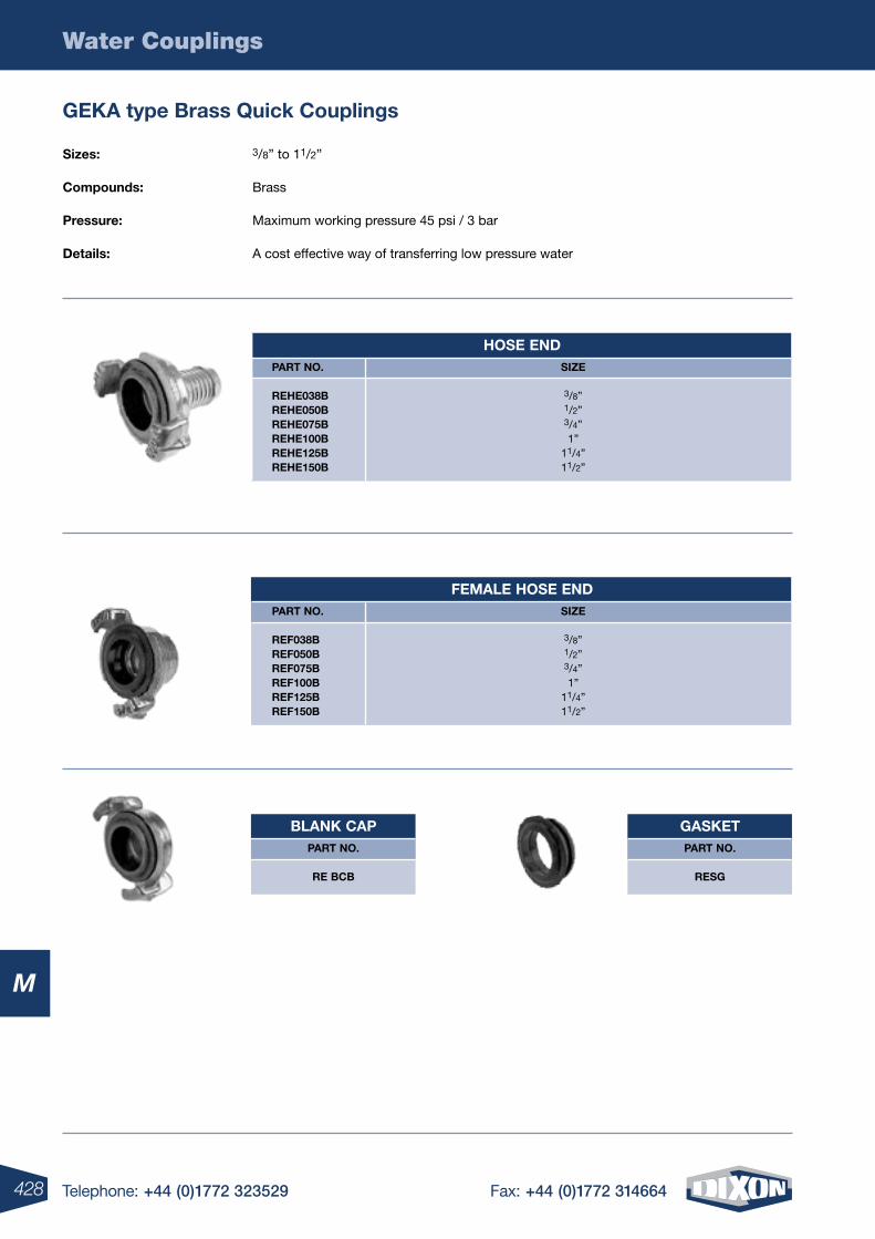
428 Telephone: +44 (0)1772 323529 Fax: +44 (0)1772 314664
Water Couplings
M
geKa type Brass Quick couplings
hose enD part no. siZe
rehe038B 3/8” rehe050B 1/2” rehe075B 3/4” rehe100B 1” rehe125B 11/4” rehe150B 11/2”
Female hose enD part no. siZe
reF038B 3/8” reF050B 1/2” reF075B 3/4” reF100B 1” reF125B 11/4” reF150B 11/2”
BlanK cappart no.
re BcB
gasKetpart no.
resg
sizes: 3/8” to 11/2”
compounds: Brass
pressure: Maximum working pressure 45 psi / 3 bar
Details: A cost effective way of transferring low pressure water
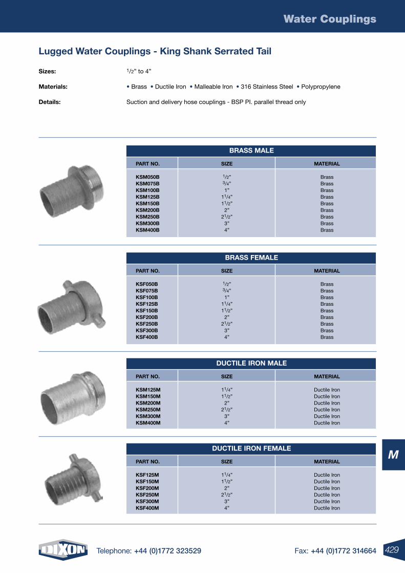
429Telephone: +44 (0)1772 323529 Fax: +44 (0)1772 314664
Water Couplings
M
lugged water couplings - King shank serrated tail
sizes: 1/2” to 4”
materials: • Brass • Ductile Iron • Malleable Iron • 316 Stainless Steel • Polypropylene
Details: Suction and delivery hose couplings - BSP PI. parallel thread only
Brass male
part no. siZe material
Ksm050B 1/2” Brass Ksm075B 3/4” Brass Ksm100B 1” Brass Ksm125B 11/4” Brass Ksm150B 11/2” Brass Ksm200B 2” Brass Ksm250B 21/2” Brass Ksm300B 3” Brass Ksm400B 4” Brass
Brass Female
part no. siZe material
KsF050B 1/2” Brass KsF075B 3/4” Brass KsF100B 1” Brass KsF125B 11/4” Brass KsF150B 11/2” Brass KsF200B 2” Brass KsF250B 21/2” Brass KsF300B 3” Brass KsF400B 4” Brass
Ductile iron male
part no. siZe material
Ksm125m 11/4” Ductile Iron Ksm150m 11/2” Ductile Iron Ksm200m 2” Ductile Iron Ksm250m 21/2” Ductile Iron Ksm300m 3” Ductile Iron Ksm400m 4” Ductile Iron
Ductile iron Female
part no. siZe material
KsF125m 11/4” Ductile Iron KsF150m 11/2” Ductile Iron KsF200m 2” Ductile Iron KsF250m 21/2” Ductile Iron KsF300m 3” Ductile Iron KsF400m 4” Ductile Iron
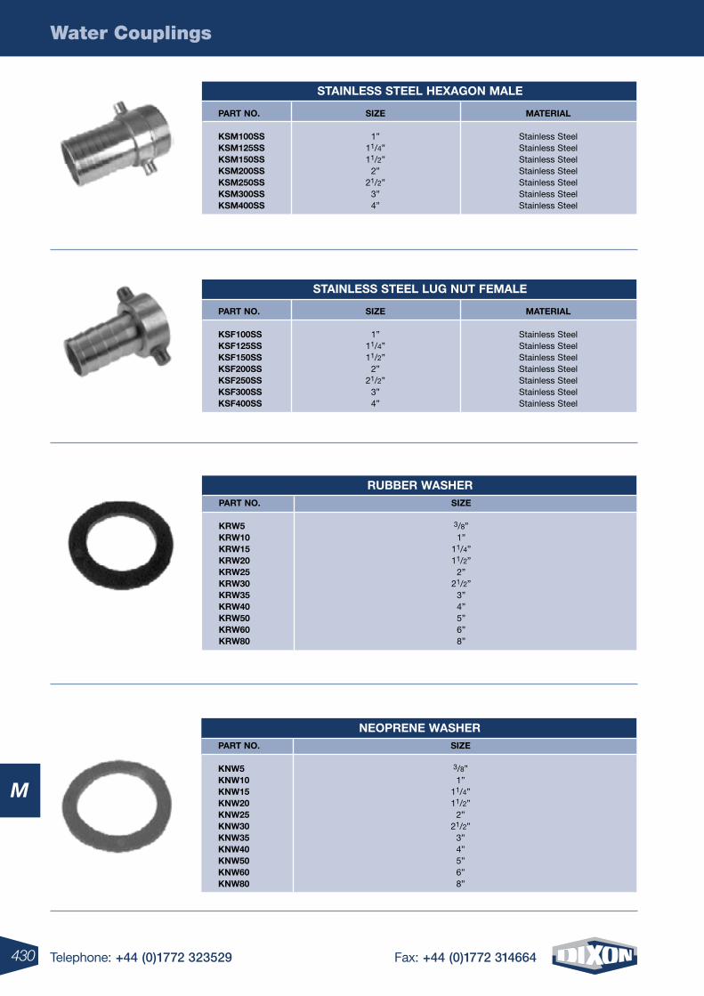
430 Telephone: +44 (0)1772 323529 Fax: +44 (0)1772 314664
Water Couplings
M
stainless steel heXagon male
part no. siZe material
Ksm100ss 1” Stainless Steel Ksm125ss 11/4” Stainless Steel Ksm150ss 11/2” Stainless Steel Ksm200ss 2” Stainless Steel Ksm250ss 21/2” Stainless Steel Ksm300ss 3” Stainless Steel Ksm400ss 4” Stainless Steel
stainless steel lug nut Female
part no. siZe material
KsF100ss 1” Stainless Steel KsF125ss 11/4” Stainless Steel KsF150ss 11/2” Stainless Steel KsF200ss 2” Stainless Steel KsF250ss 21/2” Stainless Steel KsF300ss 3” Stainless Steel KsF400ss 4” Stainless Steel
neoprene washer part no. siZe
Knw5 3/8” Knw10 1” Knw15 11/4” Knw20 11/2” Knw25 2” Knw30 21/2” Knw35 3” Knw40 4” Knw50 5” Knw60 6” Knw80 8”
ruBBer washer part no. siZe
Krw5 3/8” Krw10 1” Krw15 11/4” Krw20 11/2” Krw25 2” Krw30 21/2” Krw35 3” Krw40 4” Krw50 5” Krw60 6” Krw80 8”
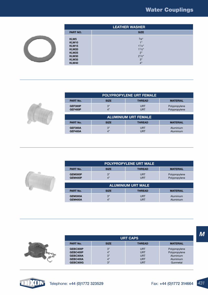
431Telephone: +44 (0)1772 323529 Fax: +44 (0)1772 314664
Water Couplings
M
leather washer part no. siZe
Klw5 3/8” Klw10 1” Klw15 11/4” Klw20 11/2” Klw25 2” Klw30 21/2” Klw35 3” Klw40 4”
polYpropYlene urt Female part no. siZe threaD material
geF300p 3” URT Polypropylene geF400p 4” URT Polypropylene
aluminium urt Female part no. siZe threaD material
geF300a 3” URT Aluminium geF400a 4” URT Aluminium
polYpropYlene urt male part no. siZe threaD material
gem300p 3” URT Polypropylene gem400p 4” URT Polypropylene
aluminium urt male part no. siZe threaD material
gem300a 3” URT Aluminium gem400a 4” URT Aluminium
urt caps part no. siZe threaD material
geBc300p 3” URT Polypropylene geBc400p 4” URT Polypropylene geBc300a 3” URT Aluminium geBc400a 4” URT Aluminium geBc300g 3” URT Gunmetal
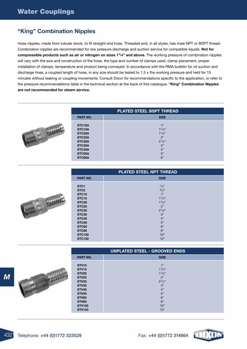
432 Telephone: +44 (0)1772 323529 Fax: +44 (0)1772 314664
Water Couplings
M
“King” combination nipples
Hose nipples, made from tubular stock, to fit straight end hose. Threaded end, in all styles, has male NPT or BSPT thread.
Combination nipples are recommended for low pressure discharge and suction service for compatible liquids. not for
compressible products such as air or nitrogen on sizes 11/4” and above. The working pressure of combination nipples
will vary with the size and construction of the hose, the type and number of clamps used, clamp placement, proper
installation of clamps, temperature and product being conveyed. In accordance with the RMA bulletin for oil suction and
discharge hose, a coupled length of hose, in any size should be tested to 1.5 x the working pressure and held for 15
minutes without leaking or coupling movements. Consult Dixon for recommendations specific to the application, or refer to
the pressure recommendations table in the technical section at the back of this catalogue. “King” combination nipples
are not recommended for steam service.
plateD steel Bspt threaD part no. siZe
stc10a 1” stc15a 11/4” stc20a 11/2” stc25a 2” stc30a 21/2” stc35a 3” stc40a 4” stc50a 5” stc60a 6”
plateD steel npt threaD part no. siZe
stc1 1/2” stc5 3/4” stc10 1” stc15 11/4” stc20 11/2” stc25 2” stc30 21/2” stc35 3” stc40 4” stc50 5” stc60 6” stc80 8” stc100 10” stc120 12”
unplateD steel - grooVeD enDs part no. siZe
stV10 1” stV15 11/4” stV20 11/2” stV25 2” stV30 21/2” stV35 3” stV40 4” stV50 5” stV60 6” stV80 8” stV100 10” stV120 12”
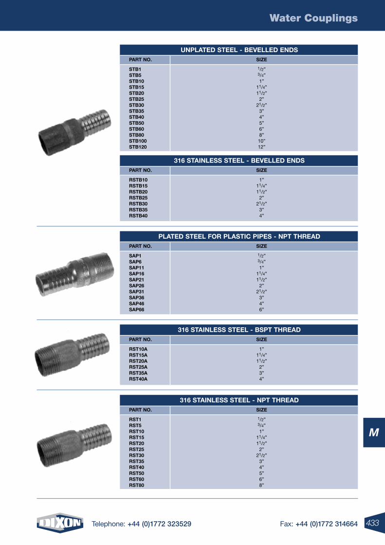
433Telephone: +44 (0)1772 323529 Fax: +44 (0)1772 314664
Water Couplings
M
unplateD steel - BeVelleD enDs part no. siZe
stB1 1/2” stB5 3/4” stB10 1” stB15 11/4” stB20 11/2” stB25 2” stB30 21/2” stB35 3” stB40 4” stB50 5” stB60 6” stB80 8” stB100 10” stB120 12”
316 stainless steel - BeVelleD enDs part no. siZe
rstB10 1” rstB15 11/4” rstB20 11/2” rstB25 2” rstB30 21/2” rstB35 3” rstB40 4”
plateD steel For plastic pipes - npt threaD part no. siZe
sap1 1/2” sap6 3/4” sap11 1” sap16 11/4” sap21 11/2” sap26 2” sap31 21/2” sap36 3” sap46 4” sap66 6”
316 stainless steel - Bspt threaD part no. siZe
rst10a 1” rst15a 11/4” rst20a 11/2” rst25a 2” rst35a 3” rst40a 4”
316 stainless steel - npt threaD part no. siZe
rst1 1/2” rst5 3/4” rst10 1” rst15 11/4” rst20 11/2” rst25 2” rst30 21/2” rst35 3” rst40 4” rst50 5” rst60 6” rst80 8”
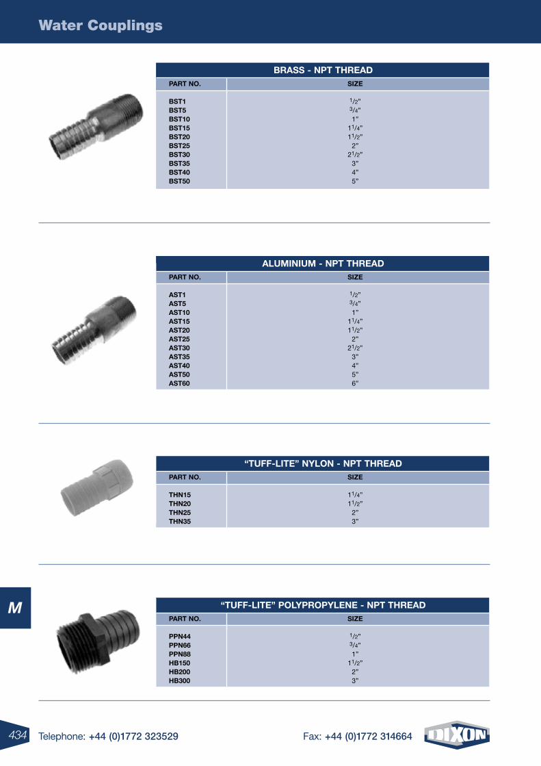
434 Telephone: +44 (0)1772 323529 Fax: +44 (0)1772 314664
Water Couplings
M
Brass - npt threaD part no. siZe
Bst1 1/2” Bst5 3/4” Bst10 1” Bst15 11/4” Bst20 11/2” Bst25 2” Bst30 21/2” Bst35 3” Bst40 4” Bst50 5”
aluminium - npt threaD part no. siZe
ast1 1/2” ast5 3/4” ast10 1” ast15 11/4” ast20 11/2” ast25 2” ast30 21/2” ast35 3” ast40 4” ast50 5” ast60 6”
“tuFF-lite” nYlon - npt threaD part no. siZe
thn15 11/4” thn20 11/2” thn25 2” thn35 3”
“tuFF-lite” polYpropYlene - npt threaD part no. siZe
ppn44 1/2” ppn66 3/4” ppn88 1” hB150 11/2” hB200 2” hB300 3”
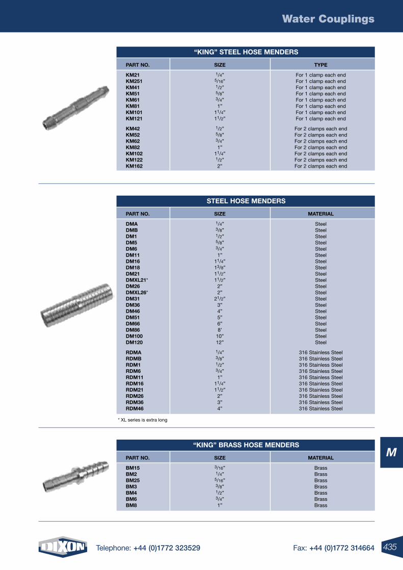
435Telephone: +44 (0)1772 323529 Fax: +44 (0)1772 314664
Water Couplings
M
“King” steel hose menDers
part no. siZe tYpe
Km21 1/4” For 1 clamp each end Km251 5/16” For 1 clamp each end Km41 1/2” For 1 clamp each end Km51 5/8” For 1 clamp each end Km61 3/4” For 1 clamp each end Km81 1” For 1 clamp each end Km101 11/4” For 1 clamp each end Km121 11/2” For 1 clamp each end
Km42 1/2” For 2 clamps each end Km52 5/8” For 2 clamps each end Km62 3/4” For 2 clamps each end Km82 1” For 2 clamps each end Km102 11/4” For 2 clamps each end Km122 1/2” For 2 clamps each end Km162 2” For 2 clamps each end
“King” Brass hose menDers
part no. siZe material
Bm15 3/16” Brass Bm2 1/4” Brass Bm25 5/16” Brass Bm3 3/8” Brass Bm4 1/2” Brass Bm6 3/4” Brass Bm8 1” Brass
steel hose menDers
part no. siZe material
Dma 1/4” Steel DmB 3/8” Steel Dm1 1/2” Steel Dm5 5/8” Steel Dm6 3/4” Steel Dm11 1” Steel Dm16 11/4” Steel Dm18 13/8” Steel Dm21 11/2” Steel DmXl21* 11/2” Steel Dm26 2” Steel DmXl26* 2” Steel Dm31 21/2” Steel Dm36 3” Steel Dm46 4” Steel Dm51 5” Steel Dm66 6” Steel Dm86 8’ Steel Dm100 10” Steel Dm120 12” Steel
rDma 1/4” 316 Stainless Steel rDmB 3/8” 316 Stainless Steel rDm1 1/2” 316 Stainless Steel rDm6 3/4” 316 Stainless Steel rDm11 1” 316 Stainless Steel rDm16 11/4” 316 Stainless Steel rDm21 11/2” 316 Stainless Steel rDm26 2” 316 Stainless Steel rDm36 3” 316 Stainless Steel rDm46 4” 316 Stainless Steel
* XL series is extra long
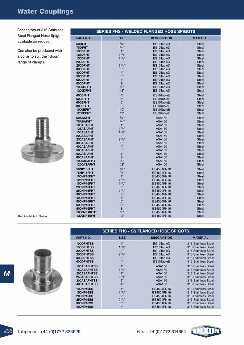
436 Telephone: +44 (0)1772 323529 Fax: +44 (0)1772 314664
Water Couplings
M
series Fhs - welDeD FlangeD hose spigots
part no. siZe Description material
50DFht 1/2” BS10TableD Steel 75DFht 3/4” BS10TableD Steel 100DFht 1” BS10TableD Steel 125DFht 11/4” BS10TableD Steel 150DFht 11/2” BS10TableD Steel 200DFht 2” BS10TableD Steel 250DFht 21/2” BS10TableD Steel 300DFht 3” BS10TableD Steel 400DFht 4” BS10TableD Steel 500DFht 5” BS10TableD Steel 600DFht 6” BS10TableD Steel 800DFht 8’ BS10TableD Steel 1000DFht 10” BS10TableD Steel 1200DFht 12” BS10TableD Steel
400eFht 4” BS10TableE Steel 500eFht 5” BS10TableE Steel 600eFht 6” BS10TableE Steel 800eFht 8” BS10TableE Steel 1000eFht 10” BS10TableE Steel 1200eFht 12” BS10TableE Steel
50asaFht 1/2” ASA150 Steel 75asaFht 3/4” ASA150 Steel 100asaFht 1” ASA150 Steel 125asaFht 11/4” ASA150 Steel 150asaFht 11/2” ASA150 Steel 200asaFht 2” ASA150 Steel 250asaFht 21/2” ASA150 Steel 300asaFht 3” ASA150 Steel 400asaFht 4” ASA150 Steel 500asaFht 5” ASA150 Steel 600asaFht 6” ASA150 Steel 800asaFht 8’ ASA150 Steel 1000asaFht 10” ASA150 Steel 1200asaFht 12” ASA150 Steel
50np16Fht 1/2” BS4504PN16 Steel 75np16Fht 3/4” BS4504PN16 Steel 100np16Fht 1” BS4504PN16 Steel 125np16Fht 11/2” BS4504PN16 Steel 150np16Fht 11/2” BS4504PN16 Steel 200np16Fht 2” BS4504PN16 Steel 250np16Fht 21/2” BS4504PN16 Steel 300np16Fht 3” BS4504PN16 Steel 400np16Fht 4” BS4504PN16 Steel 500np16Fht 5” BS4504PN16 Steel 600np16Fht 6” BS4504PN16 Steel 800np16Fht 8’ BS4504PN16 Steel 1000np16Fht 10” BS4504PN16 Steel 1200np16Fht 12” BS4504PN16 Steel
series Fhs - ss FlangeD hose spigots
part no. siZe Description material
100DFhtss 1” BS10TableD 316 Stainless Steel 150DFhtss 11/2” BS10TableD 316 Stainless Steel 200DFhtss 2” BS10TableD 316 Stainless Steel 250DFhtss 21/2” BS10TableD 316 Stainless Steel 300DFhtss 3” BS10TableD 316 Stainless Steel 400DFhtss 4” BS10TableE 316 Stainless Steel
100asaFhtss 1” ASA150 316 Stainless Steel 150asaFhtss 11/2” ASA150 316 Stainless Steel 200asaFhtss 2” ASA150 316 Stainless Steel 250asaFhtss 21/2” ASA150 316 Stainless Steel 300asaFhtss 3” ASA150 316 Stainless Steel 400asaFhtss 4” ASA150 316 Stainless Steel
100np16ss 1” BS4504PN16 316 Stainless Steel 150np16ss 11/2” BS4504PN16 316 Stainless Steel 200np16ss 2” BS4504PN16 316 Stainless Steel 250np16ss 21/2” BS4504PN16 316 Stainless Steel 300np16ss 3” BS4504PN16 316 Stainless Steel 400np16ss 4” BS4504PN16 316 Stainless Steel
Also Available in Swivel
Other sizes of 316 Stainless
Steel Flanged Hose Spigots
available on request.
Can also be produced with
a collar to suit the “Boss”
range of clamps.
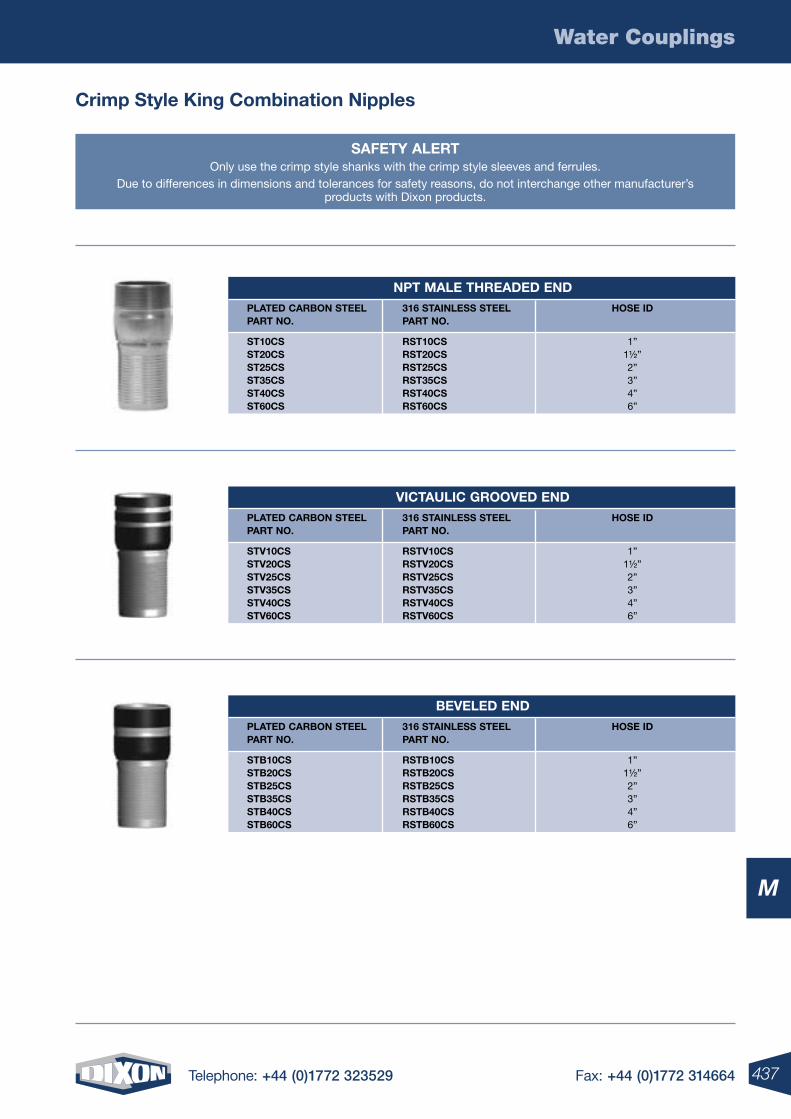
437Telephone: +44 (0)1772 323529 Fax: +44 (0)1772 314664
Water Couplings
M
crimp style King combination nipples
saFetY alertOnly use the crimp style shanks with the crimp style sleeves and ferrules.
Due to differences in dimensions and tolerances for safety reasons, do not interchange other manufacturer’s products with Dixon products.
npt male threaDeD enD plateD carBon steel 316 stainless steel hose iD part no. part no.
st10cs rst10cs 1” st20cs rst20cs 1½” st25cs rst25cs 2” st35cs rst35cs 3” st40cs rst40cs 4” st60cs rst60cs 6”
BeVeleD enD plateD carBon steel 316 stainless steel hose iD part no. part no.
stB10cs rstB10cs 1” stB20cs rstB20cs 1½” stB25cs rstB25cs 2” stB35cs rstB35cs 3” stB40cs rstB40cs 4” stB60cs rstB60cs 6”
Victaulic grooVeD enD plateD carBon steel 316 stainless steel hose iD part no. part no.
stV10cs rstV10cs 1” stV20cs rstV20cs 1½” stV25cs rstV25cs 2” stV35cs rstV35cs 3” stV40cs rstV40cs 4” stV60cs rstV60cs 6”
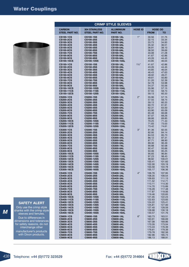
438 Telephone: +44 (0)1772 323529 Fax: +44 (0)1772 314664
Water Couplings
M
saFetY alertOnly use the crimp style
shanks with the crimp style sleeves and ferrules.Due to differences in
dimensions and tolerances for safety reasons, do not
interchange othermanufacturer’s products
with Dixon products.
crimp stYle sleeVes
carBon 304 stainless aluminium hose iD hose oD steel part no. steel part no. part no. From to
cs100-1cs cs100-1ss cs100-1al 1” 30.56 31.75 cs100-2cs cs100-2ss cs100-2al 32.15 33.34 cs100-3cs cs100-3ss cs100-3al 33.73 34.93 cs100-4cs cs100-4ss cs100-4al 35.32 36.51 cs100-5cs cs100-5ss cs100-5al 36.91 38.10 cs100-6cs cs100-6ss cs100-6al 38.50 39.69 cs100-7cs cs100-7ss cs100-7al 40.08 41.28 cs100-8cs cs100-8ss cs100-8al 41.67 42.86 cs100-9cs cs100-9ss cs100-9al 43.26 44.45 cs100-10cs cs100-10ss cs100-10al 44.85 46.04
cs150-1cs cs150-1ss cs150-1al 1½” 41.67 42.86 cs150-2cs cs150-2ss cs150-2al 43.26 44.45 cs150-3cs cs150-3ss cs150-3al 44.85 46.04 cs150-4cs cs150-4ss cs150-4al 46.43 47.63 cs150-5cs cs150-5ss cs150-5al 48.02 49.21 cs150-6cs cs150-6ss cs150-6al 49.61 50.80 cs150-7cs cs150-7ss cs150-7al 51.20 52.39 cs150-8cs cs150-8ss cs150-8al 52.78 53.98 cs150-9cs cs150-9ss cs150-9al 54.37 55.56 cs150-10cs cs150-10ss cs150-10al 55.96 57.15 cs150-11cs cs150-11ss cs150-11al 57.55 58.74 cs150-12cs cs150-12ss cs150-12al 59.13 60.33
cs200-1cs cs200-1ss cs200-1al 2” 55.96 57.15 cs200-2cs cs200-2ss cs200-2al 57.55 58.74 cs200-3cs cs200-3ss cs200-3al 59.13 60.33 cs200-4cs cs200-4ss cs200-4al 60.72 61.91 cs200-5cs cs200-5ss cs200-5al 62.31 63.50 cs200-6cs cs200-6ss cs200-6al 63.90 65.09 cs200-7cs cs200-7ss cs200-7al 65.48 66.68 cs200-8cs cs200-8ss cs200-8al 67.07 68.26 cs200-9cs cs200-9ss cs200-9al 68.66 69.85 cs200-10cs cs200-10ss cs200-10al 70.25 71.44 cs200-11cs cs200-11ss cs200-11al 71.83 73.03 cs200-12cs cs200-12ss cs200-12al 73.42 74.61
cs300-1cs cs300-1ss cs300-1al 3” 81.36 82.55 cs300-2cs cs300-2ss cs300-2al 82.95 84.14 cs300-3cs cs300-3ss cs300-3al 84.53 85.73 cs300-4cs cs300-4ss cs300-4al 86.12 87.31 cs300-5cs cs300-5ss cs300-5al 87.71 88.90 cs300-6cs cs300-6ss cs300-6al 89.30 90.49 cs300-7cs cs300-7ss cs300-7al 90.88 92.08 cs300-8cs cs300-8ss cs300-8al 92.47 93.66 cs300-9cs cs300-9ss cs300-9al 94.06 95.25 cs300-10cs cs300-10ss cs300-10al 95.65 96.84 cs300-11cs cs300-11ss cs300-11al 97.23 98.43 cs300-12cs cs300-12ss cs300-12al 98.82 100.01 cs300-13cs cs300-13ss cs300-13al 100.41 101.60 cs300-14cs cs300-14ss cs300-14al 102.00 103.19 cs300-15cs cs300-15ss cs300-15al 103.58 104.78 cs300-16cs cs300-16ss cs300-16al 105.17 106.36
cs400-1cs cs400-1ss cs400-1al 4” 106.76 107.95 cs400-2cs cs400-2ss cs400-2al 108.35 109.54 cs400-3cs cs400-3ss cs400-3al 109.93 111.13 cs400-4cs cs400-4ss cs400-4al 111.52 112.71 cs400-5cs cs400-5ss cs400-5al 113.11 114.30 cs400-6cs cs400-6ss cs400-6al 114.70 115.89 cs400-7cs cs400-7ss cs400-7al 116.28 117.48 cs400-8cs cs400-8ss cs400-8al 117.87 119.06 cs400-9cs cs400-9ss cs400-9al 119.46 120.65 cs400-10cs cs400-10ss cs400-10al 121.05 122.24 cs400-11cs cs400-11ss cs400-11al 122.63 123.83 cs400-12cs cs400-12ss cs400-12al 124.22 125.41 cs400-13cs cs400-13ss cs400-13al 125.81 127.00 cs400-14cs cs400-14ss cs400-14al 127.40 128.59 cs400-15cs cs400-15ss cs400-15al 128.98 130.18 cs400-16cs cs400-16ss cs400-16al 130.57 131.76
cs600-1cs cs600-1ss cs600-1al 6” 160.73 163.51 cs600-2cs cs600-2ss cs600-2al 163.91 166.69 cs600-3cs cs600-3ss cs600-3al 167.08 169.86 cs600-4cs cs600-4ss cs600-4al 170.26 173.04 cs600-5cs cs600-5ss cs600-5al 173.43 176.39 cs600-6cs cs600-6ss cs600-6al 176.61 179.39 cs600-7cs cs600-7ss cs600-7al 179.78 182.56 cs600-8cs cs600-8ss cs600-8al 182.96 185.74 cs600-9cs cs600-9ss cs600-9al 186.13 188.91
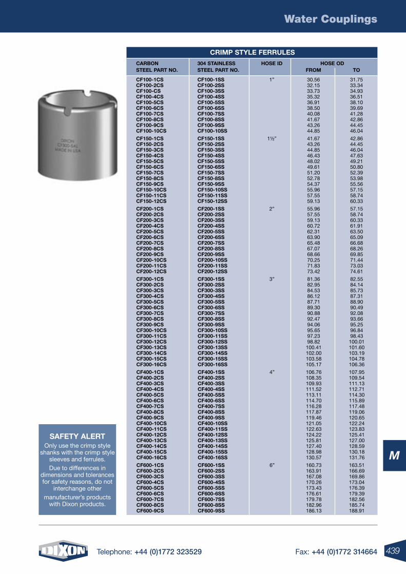
439Telephone: +44 (0)1772 323529 Fax: +44 (0)1772 314664
Water Couplings
M
saFetY alertOnly use the crimp style
shanks with the crimp style sleeves and ferrules.Due to differences in
dimensions and tolerances for safety reasons, do not
interchange othermanufacturer’s products
with Dixon products.
crimp stYle Ferrules
carBon 304 stainless hose iD hose oD steel part no. steel part no. From to
cF100-1cs cF100-1ss 1” 30.56 31.75 cF100-2cs cF100-2ss 32.15 33.34 cF100-cs cF100-3ss 33.73 34.93 cF100-4cs cF100-4ss 35.32 36.51 cF100-5cs cF100-5ss 36.91 38.10 cF100-6cs cF100-6ss 38.50 39.69 cF100-7cs cF100-7ss 40.08 41.28 cF100-8cs cF100-8ss 41.67 42.86 cF100-9cs cF100-9ss 43.26 44.45 cF100-10cs cF100-10ss 44.85 46.04
cF150-1cs cF150-1ss 1½” 41.67 42.86 cF150-2cs cF150-2ss 43.26 44.45 cF150-3cs cF150-3ss 44.85 46.04 cF150-4cs cF150-4ss 46.43 47.63 cF150-5cs cF150-5ss 48.02 49.21 cF150-6cs cF150-6ss 49.61 50.80 cF150-7cs cF150-7ss 51.20 52.39 cF150-8cs cF150-8ss 52.78 53.98 cF150-9cs cF150-9ss 54.37 55.56 cF150-10cs cF150-10ss 55.96 57.15 cF150-11cs cF150-11ss 57.55 58.74 cF150-12cs cF150-12ss 59.13 60.33
cF200-1cs cF200-1ss 2” 55.96 57.15 cF200-2cs cF200-2ss 57.55 58.74 cF200-3cs cF200-3ss 59.13 60.33 cF200-4cs cF200-4ss 60.72 61.91 cF200-5cs cF200-5ss 62.31 63.50 cF200-6cs cF200-6ss 63.90 65.09 cF200-7cs cF200-7ss 65.48 66.68 cF200-8cs cF200-8ss 67.07 68.26 cF200-9cs cF200-9ss 68.66 69.85 cF200-10cs cF200-10ss 70.25 71.44 cF200-11cs cF200-11ss 71.83 73.03 cF200-12cs cF200-12ss 73.42 74.61
cF300-1cs cF300-1ss 3” 81.36 82.55 cF300-2cs cF300-2ss 82.95 84.14 cF300-3cs cF300-3ss 84.53 85.73 cF300-4cs cF300-4ss 86.12 87.31 cF300-5cs cF300-5ss 87.71 88.90 cF300-6cs cF300-6ss 89.30 90.49 cF300-7cs cF300-7ss 90.88 92.08 cF300-8cs cF300-8ss 92.47 93.66 cF300-9cs cF300-9ss 94.06 95.25 cF300-10cs cF300-10ss 95.65 96.84 cF300-11cs cF300-11ss 97.23 98.43 cF300-12cs cF300-12ss 98.82 100.01 cF300-13cs cF300-13ss 100.41 101.60 cF300-14cs cF300-14ss 102.00 103.19 cF300-15cs cF300-15ss 103.58 104.78 cF300-16cs cF300-16ss 105.17 106.36
cF400-1cs cF400-1ss 4” 106.76 107.95 cF400-2cs cF400-2ss 108.35 109.54 cF400-3cs cF400-3ss 109.93 111.13 cF400-4cs cF400-4ss 111.52 112.71 cF400-5cs cF400-5ss 113.11 114.30 cF400-6cs cF400-6ss 114.70 115.89 cF400-7cs cF400-7ss 116.28 117.48 cF400-8cs cF400-8ss 117.87 119.06 cF400-9cs cF400-9ss 119.46 120.65 cF400-10cs cF400-10ss 121.05 122.24 cF400-11cs cF400-11ss 122.63 123.83 cF400-12cs cF400-12ss 124.22 125.41 cF400-13cs cF400-13ss 125.81 127.00 cF400-14cs cF400-14ss 127.40 128.59 cF400-15cs cF400-15ss 128.98 130.18 cF400-16cs cF400-16ss 130.57 131.76
cF600-1cs cF600-1ss 6” 160.73 163.51 cF600-2cs cF600-2ss 163.91 166.69 cF600-3cs cF600-3ss 167.08 169.86 cF600-4cs cF600-4ss 170.26 173.04 cF600-5cs cF600-5ss 173.43 176.39 cF600-6cs cF600-6ss 176.61 179.39 cF600-7cs cF600-7ss 179.78 182.56 cF600-8cs cF600-8ss 182.96 185.74 cF600-9cs cF600-9ss 186.13 188.91
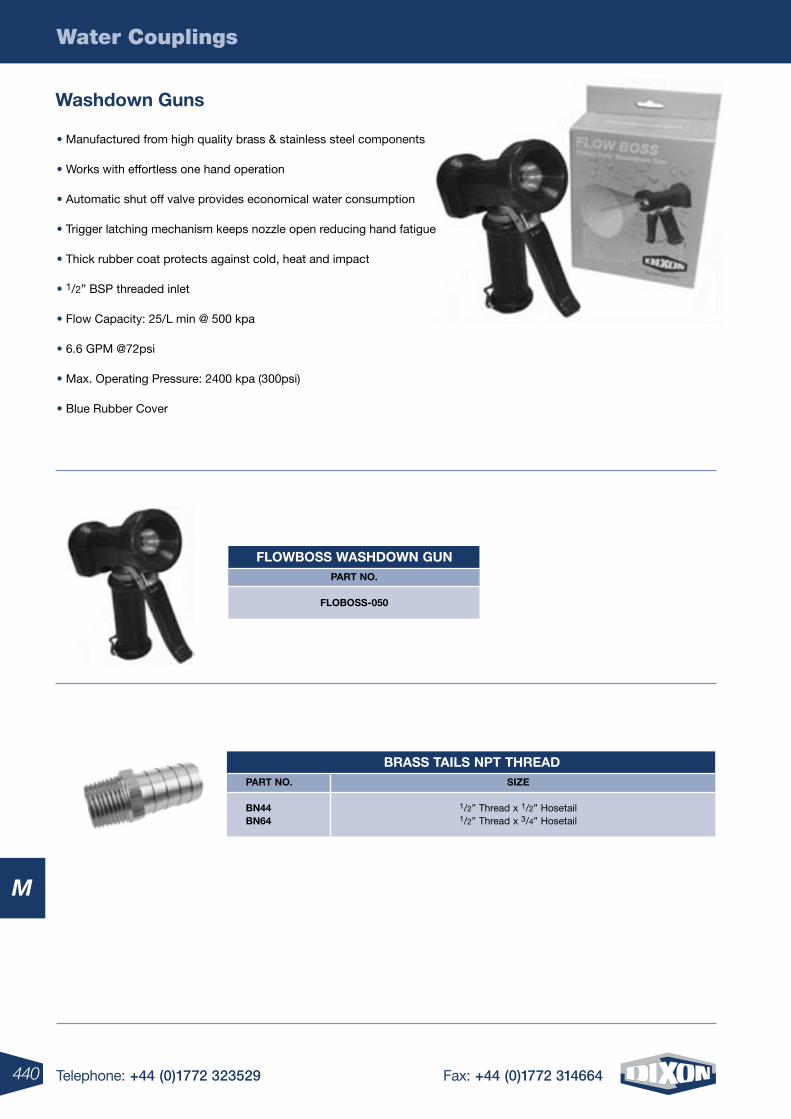
440 Telephone: +44 (0)1772 323529 Fax: +44 (0)1772 314664
Water Couplings
M
washdown guns
Brass tails npt threaD part no. siZe
Bn44 1/2” Thread x 1/2” Hosetail Bn64 1/2” Thread x 3/4” Hosetail
• Manufactured from high quality brass & stainless steel components
• Works with effortless one hand operation
• Automatic shut off valve provides economical water consumption
• Trigger latching mechanism keeps nozzle open reducing hand fatigue
• Thick rubber coat protects against cold, heat and impact
• 1/2” BSP threaded inlet
• Flow Capacity: 25/L min @ 500 kpa
• 6.6 GPM @72psi
• Max. Operating Pressure: 2400 kpa (300psi)
• Blue Rubber Cover
FlowBoss washDown gunpart no.
FloBoss-050
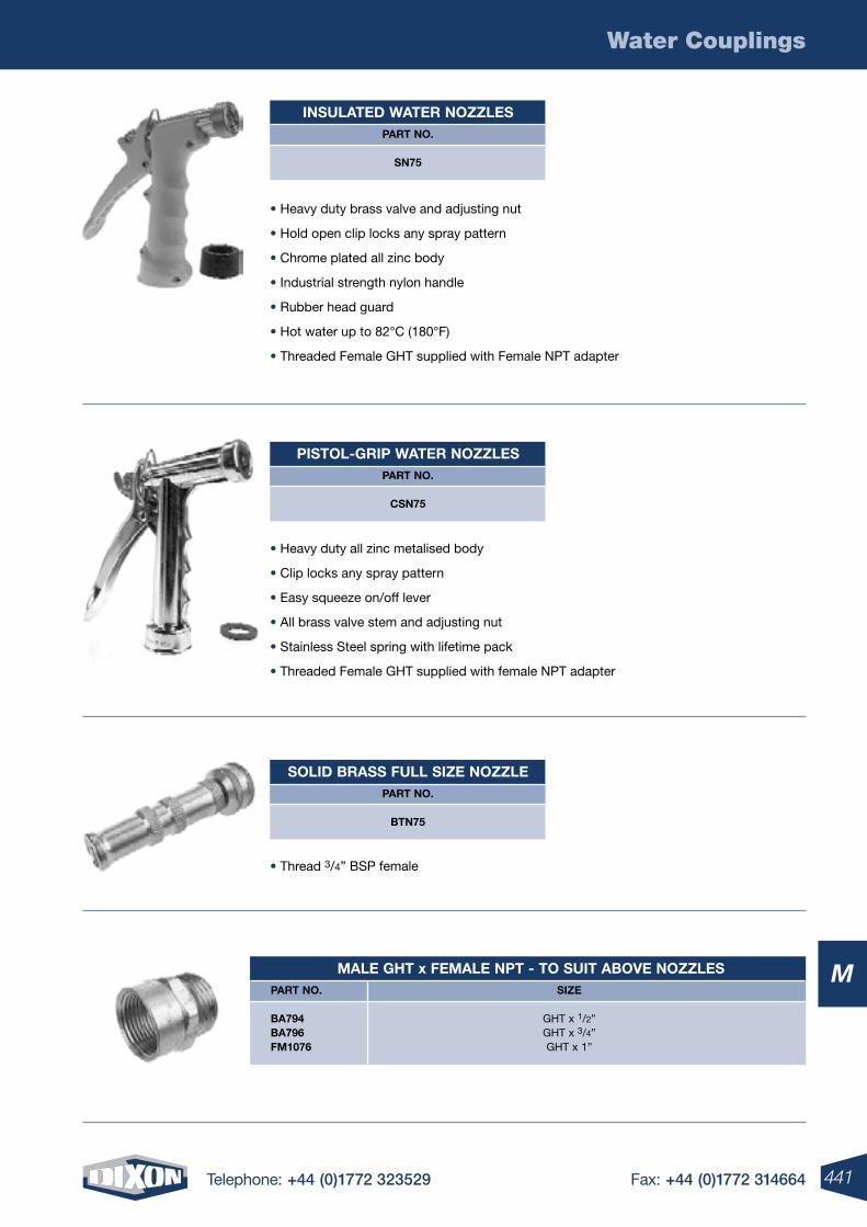
441Telephone: +44 (0)1772 323529 Fax: +44 (0)1772 314664
Water Couplings
M male ght x Female npt - to suit aBoVe noZZles part no. siZe
Ba794 GHT x 1/2” Ba796 GHT x 3/4” Fm1076 GHT x 1”
insulateD water noZZlespart no.
sn75
pistol-grip water noZZlespart no.
csn75
soliD Brass Full siZe noZZlepart no.
Btn75
• Heavy duty brass valve and adjusting nut
• Hold open clip locks any spray pattern
• Chrome plated all zinc body
• Industrial strength nylon handle
• Rubber head guard
• Hot water up to 82°C (180°F)
• Threaded Female GHT supplied with Female NPT adapter
• Heavy duty all zinc metalised body
• Clip locks any spray pattern
• Easy squeeze on/off lever
• All brass valve stem and adjusting nut
• Stainless Steel spring with lifetime pack
• Threaded Female GHT supplied with female NPT adapter
• Thread 3/4” BSP female
N
4 Telephone: +44 (0)1772 323529 Fax: +44 (0)1772 314664442 Telephone: +44 (0)1772 323529 Fax: +44 (0)1772 314664
N
N
443Telephone: +44 (0)1772 323529 Fax: +44 (0)1772 314664
Hose & Hose Coupling Safety Information ...................................444-445
S.T.A.M.P.E.D ..........................................................................................446
B.E.S.A.F.E ..............................................................................................447
Hose Assembling, Installation & Safety ........................................448-453
Hose & Coupling Pressure Recommendations .............................454-458
Corrosion Resistance Guide .........................................................459-464
Measurement & Conversion Information ......................................465-468
Coupling Flange & Thread Information .........................................469-479
Crimp Recommendations ............................................................480-487
Valve Information ..........................................................................488-494
BPE Technical Information ...........................................................495-498
Regulations: OSHA & MSHA ........................................................499-500
Fluid Compatibility Guide ................................................................ 500-501
Glossary of Terms ........................................................................502-508
Dixon Terms & Conditions .......................................................................509
443Telephone: +44 (0)1772 323529 Fax: +44 (0)1772 314664
Technical & Safety Information
N
444 Telephone: +44 (0)1772 323529 Fax: +44 (0)1772 314664
Technical & Safety Information
N
Technical & Safety Information
Hose and Hose Coupling Safety
“The very properties that make compressed gases useful in almost every area of modern life can also make them
dangerous when mishandled. Years of experience with compressed gases have led to practices and equipment which,
if employed, result in complete safety.”**
Dixon hose couplings have been carefully engineered to meet specific requirements. If hose or couplings are not
used in correct applications or are incorrectly applied, accidents and downtime can result. It is up to the end user
to inform the distributor of the application and pressures involved when ordering hose assemblies and it is up to
the distributor to supply the right hose and coupling for that application. When in doubt, Dixon is here to help you
with a proper coupling recommendation.
1. Air hose couplings
This form of energy can be one of the most dangerous because it is used in so many applications and, when
mishandled, can have more serious results than fluids. Air, as a gas, is compressible (fluids press only against hose or
vessel walls and lose little volume under pressure). When pressurised air releases suddenly, it does so with explosive
force and can cause rapid hose whip, which can do serious physical harm to personnel or damage to nearby objects.
This is why the selection of proper hose and couplings for air lines is so important, along with their proper installation
and maintenance. Never take for granted that a coupling is installed properly or a clamp fully tightened on an air hose -
check it regularly and use safety devices (see paragraph 4).
2. Steam and gas
The same rules apply for steam and gas, but, because these are inherently more hazardous materials, personnel tend to
treat hose and couplings on these lines with more respect and care. Checking clamp tightness is very important with
steam hose, where it is not unusual for clamps to loosen in service, in which case they must be retightened! Safety
devices should also be used (see paragraph 4).
3. Fluid hose couplings
Again, nothing should be taken for granted - in particular, check clamps for tightness each time the lines are used -
especially when petroleum products or other hazardous liquids are involved. Large diameter hose, when suspended,
can also be quite dangerous if it drops unexpectedly due to a coupling “pull-out” or sudden disconnection. A heavy
fitting or clamp, plus the weight of the hose itself falling from any significant height, can cause injuries or damage. Be
sure to use safety devices (see paragraph 4).
4. All hose assemblies
All hose assemblies should be treated with respect as potential hazards. Worn-out fittings should be replaced.
Retaining devices such as clips, cables or chains should be used. Clamps should be checked regularly. Under no
circumstances should any coupling be disconnected while under pressure, unless the coupling is specifically designed
to do so. Disconnecting couplings under pressure could result in serious injury or death, and destruction of property
and equipment.
**”Handbook of Compressed Gases”
445Telephone: +44 (0)1772 323529 Fax: +44 (0)1772 314664
Technical & Safety Information
N
Technical & Safety Information
Pressure Ratings
Pressure ratings for couplings, as stated in this catalogue, are based upon ambient temperature (21°C or 70°F)
applications with true hose I.D., new Dixon supplied couplings, new Dixon supplied clamps, new quality hose, and proper
installation by a qualified assembler using Dixon procedures and equipment. In addition, temperature can affect coupling
retention. For temperatures other than ambient (21°C or 70°F) contact the hose manufacturer or call Dixon.
Product Selection
Many of the products in this catalogue are used in hose assemblies in a variety of applications. The safety of any hose
assembly rests on the proper selection, installation, testing and use of each product. The safe use of any product in this
catalogue is dependent upon the correct selection of the hose, fittings and method of attachment. To ensure such a proper
selection, the user must inform the distributor of the application and pressure involved when ordering hose assemblies.
The use of S.T.A.M.P.E.D. (Size, Temperature, Application, Media, Pressure, Ends, Dixon) will help in the proper selection
of hose assembly components (see next page). The selection of couplings and clamping devices is the responsibility of the
purchaser or user, based upon the hose manufacturer’s recommendations. If the purchaser or user is uncertain about the
use or application of a product, Dixon stands ready to provide information, including test results (if available), coupling and
clamping recommendations and other data to help resolve those matters.
Installation
To achieve a safe and reliable assembly, proper installation procedures must be followed. Each component of the assembly
has a part in determining these procedures. The purchaser or user must follow proper procedures.
If the purchaser or user has any questions regarding installation, please contact Dixon.
Testing
Dixon recommends that all hose assemblies be tested in accordance with the hose manufacturer’s recommendations.
Re-testing and inspection
Dixon recommends inspection and re-testing of hose assemblies on a regular and consistent basis in accordance with the
hose manufacturer’s recommendations. The application determines the regularity of the inspection and retesting schedule.
Any worn-out fittings, damaged hoses or missing safety devices should be replaced immediately. Bolt-style clamps must
be checked and retightened on a regular and consistent basis.
Proper selection, care, use and maintenance of hose couplings and accessory Items
All hose assemblies should be viewed as potential hazards. This document is designed to inform and educate anyone
who manufactures, specifies, supplies, purchases, assembles, uses, maintains or tests any hose assembly or its
component parts. The proper selection and maintenance of hose, couplings, attachment devices and accessories are
imperative. It is the end users responsibility to identify to the distributor the application and any special conditions that
the hose assembly must meet. It is the distributors responsibility to supply the proper assembly for the intended
application. Accidents and down time may occur if hose assemblies are not properly selected for the specific application.
The performance and safety of the assembly is affected by the quality of the individual components. The use of the
acronym S.T.A.M.P.E.D. (Size, Temperature, Application, Media, Pressure, Ends, Dixon) will help in the proper selection
of the hose assembly components (see following page).
WARnInG!Failure to use these procedures can result in serious injury or death, and destruction of property and equipment.
General Safety Information
If anyone is uncertain about the use or application of a product, Dixon can provide test results, coupling and clamping
recommendations and other data to help resolve those matters. Please call Dixon.
446 Telephone: +44 (0)1772 323529 Fax: +44 (0)1772 314664
Technical & Safety Information
N
Technical & Safety Information
When fabricating and specifying hose assemblies ask the following questions:
S.T.A.M.P.E.D.
Size: What is the I.D. (Inside Diameter) of the hose? What is the O.D. (Outside Diameter) of
both ends of the hose? What is the overall length of the assembly required?
Temperature: What is the temperature range of the media (product) that is flowing through the hose
assembly? What is the temperature range of the environment that surrounds the outside
of the hose assembly?
Application: How is the hose assembly actually being used? Is it a pressure application? Is it
a vacuum (suction) application? Is it a gravity flow application? Are there any special
requirements that the hose assembly is expected to perform? Is the hose being used
in a horizontal or vertical position? Are there any pulsations or vibrations acting on
the hose assembly?
Media: What is the media/material that is flowing through the hose assembly? Being specific
is critical. Check for: Abrasive materials, chemical compatibility, etc..
Pressure: What is the maximum pressure including surges (or, maximum vacuum) that this hose
assembly will be subjected to? Always rate the maximum working pressure of your
hose assembly by the lowest rated component in the system.
Ends: What couplings have been requested by the user? Are they the proper fittings for
the application and hose selected?
Dixon: Dixon recommends that, based on the hose, fittings and attachment method used,
all assemblies be permanently marked with the designed working pressure and
intended media. Do not use other manufacture’s fittings or ferrules with Dixon products
due to the differences in dimensions and tolerances. We also recommend that all hose
assemblies be tested frequently.
Be Safe: Any questions on application, use or assembly please call Dixon.
447Telephone: +44 (0)1772 323529 Fax: +44 (0)1772 314664
Technical & Safety Information
N
Technical & Safety Information
Beware hose assemblies when used improperly or in the wrong application can be dangerous.
The maximum working pressure shown on the hose is not an indication of the working
pressure of the assembly. Based on the hose, fittings and attachment method used all
assemblies should be permanently marked with the designed working pressure and the
intended media. The assembly working pressure should be permanently displayed.
Hose assemblies must be used for the intended service only. Never alter manufactured
product or substitute component parts.
Eliminate hazardous conditions by inspecting, maintaining and testing hose assemblies.
Dixon recommends that all hose assemblies are tested in accordance with the hose
manufacturer’s specifications. The application determines the regularity of the
re-testing schedule.
Secure and inspect hose, fittings, clamping devices and safety accessories before each use.
Never take for granted that the coupling or attachment devices are properly installed.
Always inspect and re-tighten the bolts of any bolt style clamping device to the manufacturer’s
torque specifications.
Fittings hose and clamping devices that are worn out or damaged must be removed from service.
Educate your employees about the proper use, care and potential hazards of hose assemblies.
Take advantage of Dixon’s free Hose Assembly Safety Programme and the follow
up Training Seminar to aid you in setting up your own inspection programme.
Any questions on applications, use or assembly call our technical support team.
Hose assemblies must be inspected prior to each use. Worn out fittings, attachment devices, hose and accessory items
must be replaced. Retaining devices (safety devices) such as clips, cables or chains must be used. Clamps must be checked
regularly to the specified torque found in the Dixon literature. Under no circumstance should any coupling be disconnected
while under pressure unless the coupling is specifically designed to do so. Disconnecting couplings under pressure could
result in serious injury or death, and destruction to property and equipment.
For all hose assemblies in use:
We encourage you to share this information with anyone who may be effected by the selection, installation,
maintenance or use of any hose assembly. Always use quality products to B.E.S.A.F.E.
B.E.S.A.F.E.
448 Telephone: +44 (0)1772 323529 Fax: +44 (0)1772 314664
Technical & Safety Information
N
Technical & Safety Information
Dixon Hose Assembling
To provide a complete service to it’s customers Dixon has made considerable investment in its extensive in-house hose
assembling capabilities, under pinned by a traceable Quality System in accordance with BSEN ISO 9001:2008 and
compliance with PED 97/23/EC. The capability is supported by a huge inventory of couplings to produce hose assemblies
utilising the following methods:
Rubber, PTFE* and Composite**
• Internal Expansion (IX) 25mm to 305mm nominal bore
• External Crimp (EC) 6mm to 102mm nominal bore
• External Swage (ES) 25mm to 102mm nominal bore
* EC only, **EC & ES only
Rubber and PVC
• Heavy Duty Double Bolt Clamps
• Band & Pre-formed Band Clamps
• Heavy Duty T-Bolt Clamps
• Hi-Torque Clamps
• Compression Rings
• BSEN 14420-3:2004 Safety Clamps (formerly DIN 2817 etc)
Metal
• Welding procedures are in accordance with ASME IX, and BSEN 288
• Welders Qualifications to ASME IX and BSEN 287
Test procedures and additional services
Our pressure testing facilities include:
• Pneumatic Leak Test (Air under Water)
• Hydrostatic Proof and Burst tests up to 380 bar (5510 psig)
• Hydrostatic Proof and Burst test certification can be supplied with a Chart Recorder read-out if
requested at time of order placement
• Assemblies can also be Hydrostatically tested using de-mineralised water
(Maximum Chloride content of 30mg/l) when requested
• Liquid Penetrant Inspection to ASME V Article 6 & ASME B31.3 Table 341.3.2
• Liquid Penetrant Technicians qualified to PCN Level 2
• Sub-Contract X-Ray in accordance with ASME V Article 6 with acceptance level to ASME B31.3 Table 341.3.2
• Endoscope
Registered supplier to the Uk Ministry of Defence.
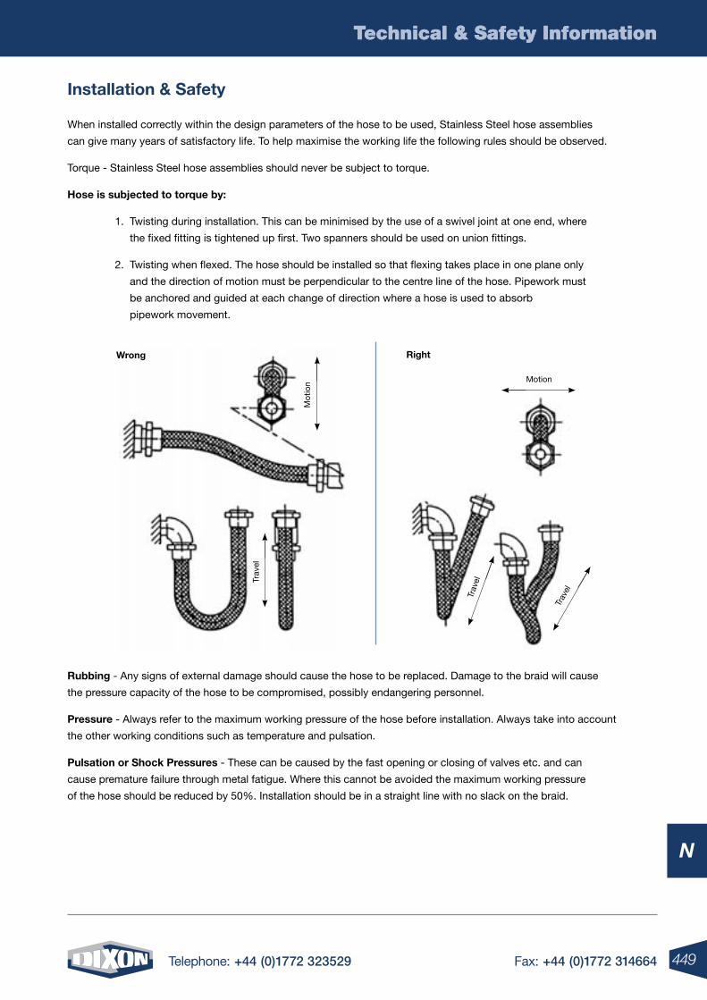
449Telephone: +44 (0)1772 323529 Fax: +44 (0)1772 314664
Technical & Safety Information
N
Technical & Safety Information
Installation & Safety
When installed correctly within the design parameters of the hose to be used, Stainless Steel hose assemblies
can give many years of satisfactory life. To help maximise the working life the following rules should be observed.
Torque - Stainless Steel hose assemblies should never be subject to torque.
Hose is subjected to torque by:
1. Twisting during installation. This can be minimised by the use of a swivel joint at one end, where
the fixed fitting is tightened up first. Two spanners should be used on union fittings.
2. Twisting when flexed. The hose should be installed so that flexing takes place in one plane only
and the direction of motion must be perpendicular to the centre line of the hose. Pipework must
be anchored and guided at each change of direction where a hose is used to absorb
pipework movement.
Rubbing - Any signs of external damage should cause the hose to be replaced. Damage to the braid will cause
the pressure capacity of the hose to be compromised, possibly endangering personnel.
Pressure - Always refer to the maximum working pressure of the hose before installation. Always take into account
the other working conditions such as temperature and pulsation.
Pulsation or Shock Pressures - These can be caused by the fast opening or closing of valves etc. and can
cause premature failure through metal fatigue. Where this cannot be avoided the maximum working pressure
of the hose should be reduced by 50%. Installation should be in a straight line with no slack on the braid.
Wrong
Motion
Mot
ion
Trav
el
Trav
el
Trav
el
Right
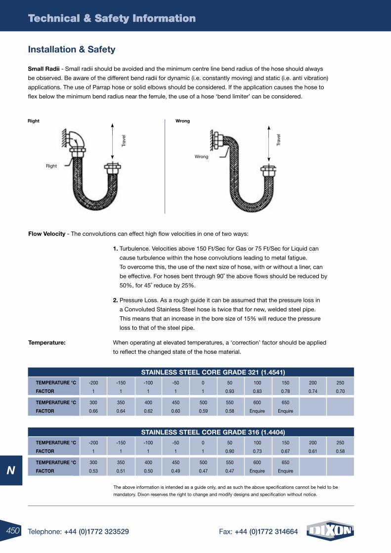
450 Telephone: +44 (0)1772 323529 Fax: +44 (0)1772 314664
Technical & Safety Information
N
Technical & Safety Information
Installation & Safety
Small Radii - Small radii should be avoided and the minimum centre line bend radius of the hose should always
be observed. Be aware of the different bend radii for dynamic (i.e. constantly moving) and static (i.e. anti vibration)
applications. The use of Parrap hose or solid elbows should be considered. If the application causes the hose to
flex below the minimum bend radius near the ferrule, the use of a hose ‘bend limiter’ can be considered.
Flow Velocity - The convolutions can effect high flow velocities in one of two ways:
1. Turbulence. Velocities above 150 Ft/Sec for Gas or 75 Ft/Sec for Liquid can
cause turbulence within the hose convolutions leading to metal fatigue.
To overcome this, the use of the next size of hose, with or without a liner, can
be effective. For hoses bent through 90˚ the above flows should be reduced by
50%, for 45˚ reduce by 25%.
2. Pressure Loss. As a rough guide it can be assumed that the pressure loss in
a Convoluted Stainless Steel hose is twice that for new, welded steel pipe.
This means that an increase in the bore size of 15% will reduce the pressure
loss to that of the steel pipe.
Temperature: When operating at elevated temperatures, a ‘correction’ factor should be applied
to reflect the changed state of the hose material.
Right Wrong
Right
Wrong
The above information is intended as a guide only, and as such the above specifications cannot be held to be
mandatory. Dixon reserves the right to change and modify designs and specification without notice.
TEMPERATURE °C
FACToR
-200
1
-150
1
-100
1
-50
1
0
1
50
0.93
100
0.83
150
0.78
200
0.74
250
0.70
300
0.66
350
0.64
400
0.62
450
0.60
500
0.59
550
0.58
600
Enquire
650
Enquire
STAInlESS STEEl CoRE GRADE 321 (1.4541)
TEMPERATURE °C
FACToR
TEMPERATURE °C
FACToR
-200
1
-150
1
-100
1
-50
1
0
1
50
0.90
100
0.73
150
0.67
200
0.61
250
0.58
300
0.53
350
0.51
400
0.50
450
0.49
500
0.47
550
0.47
600
Enquire
650
Enquire
STAInlESS STEEl CoRE GRADE 316 (1.4404)
TEMPERATURE °C
FACToR
Trav
el
Trav
el

451Telephone: +44 (0)1772 323529 Fax: +44 (0)1772 314664
Technical & Safety Information
N
Technical & Safety Information
Pressure Equipment Directive 97/23/EC
The Pressure Equipment Directive 97/23/EC was embraced by the European Parliament and the Council
of Ministers on 29 May 1997, enforced a further 2 years later on 29 November 1999 but with a 3 year grace,
whereby compliance to its requirements were elective until 29 May 2002.
Failure to comply could result in prosecution by way of a fine, prison sentence or both.
On the whole the PED is legislation across the European Environment Agency (EEA), which requires that all
pressure equipment must be fully compliant with regards to particular aspects such as material selection, design,
manufacturing techniques, personnel qualification, testing requirements, product marking and user liability.
The Directive covers pressure equipment and assemblies with a maximum allowable pressure PS greater than
0.5 bar and includes such equipment as reaction vessels, industrial pipe-work, pressurised storage containers,
heat exchangers, pressure accessories and safety devices. The PED’s interpretation of an assembly being
several pieces of pressure equipment assembled to form an integrated system.
PED accreditation, where applicable, allows for the active placing of the CE mark on pressure equipment and is
a given passport to free trade within the EEA, without the need for statutory inspection by current Member States.
As a result, Dixon Group Europe have revised their manufacturing methodology and integrated an already
efficient ISO 9001 quality management system with the Essential Safety Requirements of the PED, accredited
by Lloyds Register, Notified Body Number 0038.
For further information on how this can benefit your business, please contact us on 01772 323529

452 Telephone: +44 (0)1772 323529 Fax: +44 (0)1772 314664
Technical & Safety Information
N
Technical & Safety Information
Hose & Coupling Site Safety Survey
At Dixon we recognise the need for onsite safety and how understanding the importance this holds and helps
generate a stronger relationship with your customer.
As a result Dixon now offers hose and coupling safety surveys.
Today, plant safety is an ongoing endeavour where it is impossible to be an expert in every field. The use of damaged or
misapplied hose couplings and related items occurs. To the untrained eye these hazards may continue to exist until an
accident happens threatening not only plant machinery but also the well being of personnel.
Dixon can assist in your efforts to make the facilities you service as safe, efficient and productive as possible.
oUR PRoGRAM InClUDES:• A visual inspection of hose assemblies and related accessories
• A professionally written report detailing our observations and recommendations for corrective action.
• The safety survey report is completely confidential and will only be shown to authorised parties.
Don’t Forget:
Hoses from Dixon are Certified to PED 97/23/EC Module D1 by Lloyds Register Quality Assurance.
When it’s got to be right, it’s got to be Dixon
For more information contact Dixon today on 01772 323529 or [email protected]

453Telephone: +44 (0)1772 323529 Fax: +44 (0)1772 314664
Technical & Safety Information
N
Technical & Safety Information
Safety is everyone’s concern!
Dixon provides many safety products designed to protect personnel and property.
Recommendations and safety warnings are also included for your review.
• Hose and coupling safety
• S.T.A.M.P.E.D.
• EZ Boss-Lock cam and groove
• Cam and groove safety clips
• Air King - not to be used for steam
• The importance of whip hose
• King cable safety cables
• Safety shut-off valves, OSHA REG. 1926.302
• 30 psi safety blow guns
• Safety vented ball valves
• Safety tags and safety tape
• Pressure recommendations
Dixon is pleased to offer a hose and coupling safety survey of your plant, at no cost to you, to assist in your efforts
to make your facility as safe, efficient and productive as possible.
Today, plant safety is an enormous, ongoing endeavour in which it is impossible to be an expert in every field.
The use of damaged or misapplied hose couplings and related items occurs. To the untrained eye, these hazards
may continue to exist until an accident happens, threatening not only plant machinery but also the well-being
of plant personnel.
Our programme includes a visual inspection of hose assemblies and related accessories in your plant by trained
technicians. A professionally written report containing our observations and recommendations for corrective action
is subsequently provided to augment your own ongoing safety programme. If desired, photographs of the areas of
concern can be supplied with the report. As a follow-up, the programme offers an educational hands-on seminar
directly relating to the safety concerns in your facility.
Plant safety is coming under increasing scrutiny by various regulatory agencies. Let Dixon’s trained personnel assist
you in establishing and maintaining safety compliance in your plant.
The safety survey report is completely confidential and will only be shown to authorised plant personnel.
Again, there is no cost to you for this service. For more information, please contact our technical support team.
Hose Assembly Safety Program
Safety Products In This Catalogue
454 Telephone: +44 (0)1772 323529 Fax: +44 (0)1772 314664
Technical & Safety Information
N
Technical & Safety Information
Hose & Coupling Pressure Recommendations
Mark hose assembly with pressure from this chart or hose working pressure, whichever is lower all pressure
recommendations are in pounds per square inch (psi)
1. This chart is intended as a guide only. It only applies to metal couplings as shown, for ambient temperature
(21°C or 70°F) applications with true I.D. hose. It assumes new Dixon supplied couplings, new Dixon supplied
clamps, new quality hose and proper installation by a qualified assembler using Dixon procedures and
equipment. Temperature can affect the coupling retention. For questions relating to temperatures other than
ambient (21°C or 70°F) contact the hose manufacturer or Dixon.
2. This chart does not apply to non-Dixon products, with used hose, in non-approved or unsupported
applications or in non-standard assemblies.
3. Do not use this chart if it conflicts with the hose manufacturer’s recommendations.
4. All hose assemblies should be pressure tested to hose manufacturers or Rubber Manufacturers
Association (R.M.A.) specifications prior to being put into service.
5. Our test experience indicates that coupling retention can vary with changes in hose design. For pressure
ratings other than those listed and shown, or if questions arise, please call our technical support team
for assistance.
6. All hose assembly components must be compatible with the materials and environments with which they
are to come in contact.
7. Dixon recommends that all hose assemblies be marked with the assembly working pressure and media of
the intended application. Under no circumstances should the assembly working pressure exceed the working
pressure of the lowest rated component (coupling, clamp, ferrule or hose).
8. For further safety information, refer to ‘The Proper Selection, Care, Use & Maintenance of Hose Couplings
& Accessory Items’ pamphlet.
Contact Dixon to request a copy of this literature.
9. To convert the following pressure recommendations that are stated in psi Divide the psi figure by
14.5 to convert to (bar).
* Procedures can be found at www.dixoneurope.co.uk
Trademarks
Delrin®, Kevlar®, PTFE and Zytel® are registered trademarks of E.I. duPont Nemours and Company. Kalrez® and
Viton® are registered trademarks of DuPont Dow Elastomers.
All other trademarks appearing in Dixon’s Illustrated Price List are the property of their respective owners.
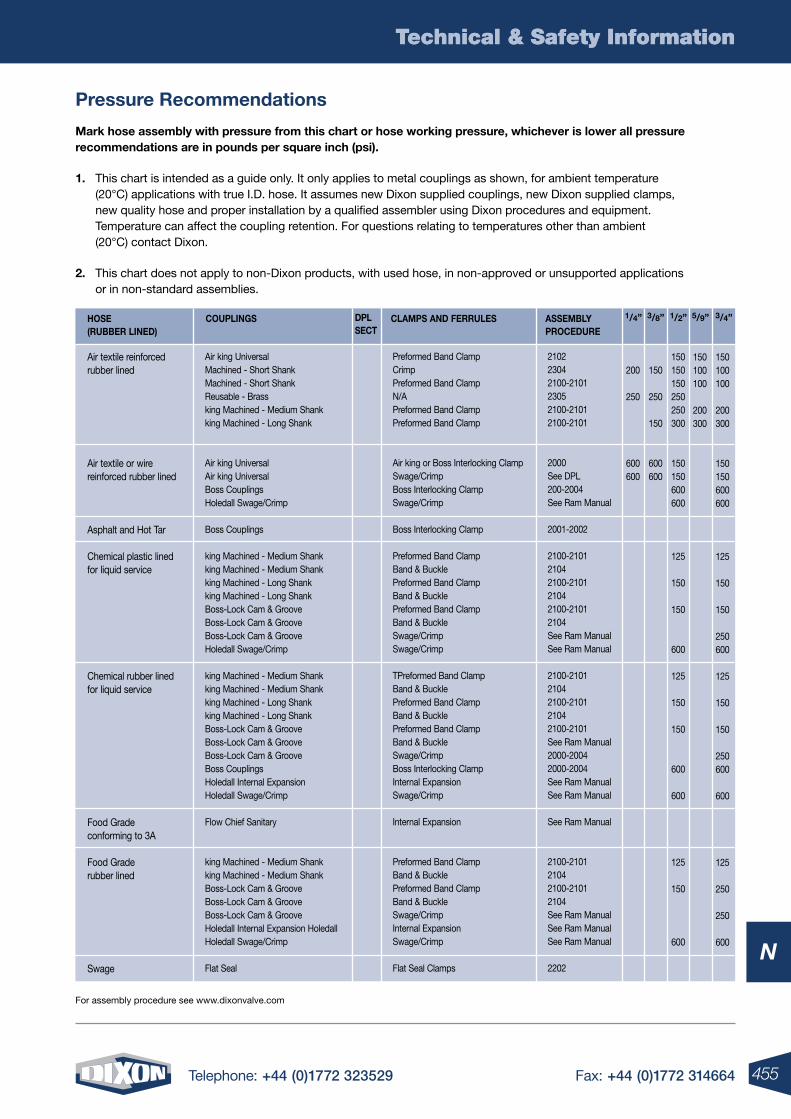
455Telephone: +44 (0)1772 323529 Fax: +44 (0)1772 314664
Technical & Safety Information
N
Technical & Safety Information
Mark hose assembly with pressure from this chart or hose working pressure, whichever is lower all pressure recommendations are in pounds per square inch (psi).
1. This chart is intended as a guide only. It only applies to metal couplings as shown, for ambient temperature (20°C) applications with true I.D. hose. It assumes new Dixon supplied couplings, new Dixon supplied clamps, new quality hose and proper installation by a qualified assembler using Dixon procedures and equipment. Temperature can affect the coupling retention. For questions relating to temperatures other than ambient (20°C) contact Dixon.
2. This chart does not apply to non-Dixon products, with used hose, in non-approved or unsupported applications or in non-standard assemblies.
Pressure Recommendations
For assembly procedure see www.dixonvalve.com
Air textile reinforcedrubber lined
Air textile or wirereinforced rubber lined
Asphalt and Hot Tar
Chemical plastic linedfor liquid service
Chemical rubber linedfor liquid service
Food Gradeconforming to 3A
Food Graderubber lined
Swage
HoSE (RUBBER lInED)
CoUPlInGS ClAMPS AnD FERRUlES ASSEMBlYPRoCEDURE
DPlSECT
1/4” 3/8” 1/2” 5/9” 3/4”
Air king UniversalMachined - Short ShankMachined - Short ShankReusable - Brassking Machined - Medium Shankking Machined - Long Shank
Air king UniversalAir king UniversalBoss CouplingsHoledall Swage/Crimp
Boss Couplings
king Machined - Medium Shankking Machined - Medium Shankking Machined - Long Shankking Machined - Long ShankBoss-Lock Cam & GrooveBoss-Lock Cam & Groove Boss-Lock Cam & GrooveHoledall Swage/Crimp
king Machined - Medium Shankking Machined - Medium Shankking Machined - Long Shankking Machined - Long ShankBoss-Lock Cam & GrooveBoss-Lock Cam & GrooveBoss-Lock Cam & GrooveBoss CouplingsHoledall Internal ExpansionHoledall Swage/Crimp
Flow Chief Sanitary
king Machined - Medium Shankking Machined - Medium ShankBoss-Lock Cam & GrooveBoss-Lock Cam & GrooveBoss-Lock Cam & Groove Holedall Internal Expansion HoledallHoledall Swage/Crimp
Flat Seal
Preformed Band ClampCrimpPreformed Band ClampN/APreformed Band ClampPreformed Band Clamp
Air king or Boss Interlocking ClampSwage/CrimpBoss Interlocking ClampSwage/Crimp
Boss Interlocking Clamp
Preformed Band Clamp Band & BucklePreformed Band ClampBand & BucklePreformed Band ClampBand & BuckleSwage/CrimpSwage/Crimp
TPreformed Band ClampBand & BucklePreformed Band ClampBand & BucklePreformed Band Clamp Band & BuckleSwage/CrimpBoss Interlocking ClampInternal ExpansionSwage/Crimp
Internal Expansion
Preformed Band ClampBand & BucklePreformed Band ClampBand & BuckleSwage/CrimpInternal ExpansionSwage/Crimp
Flat Seal Clamps
210223042100-210123052100-21012100-2101
2000See DPL200-2004See Ram Manual
2001-2002
2100-210121042100-210121042100-21012104See Ram ManualSee Ram Manual
2100-210121042100-210121042100-2101See Ram Manual2000-20042000-2004See Ram ManualSee Ram Manual
See Ram Manual
2100-210121042100-21012104See Ram ManualSee Ram ManualSee Ram Manual
2202
200
250
600600
150
250
150
600600
150150150250250300
150150600600
125
150
150
600
125
150
150
600
600
125
150
600
150100100
200300
150100100
200300
150150600600
125
150
150
250600
125
150
150
250600
600
125
250
250
600
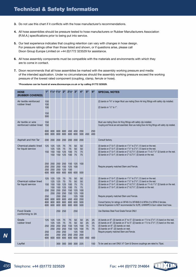
456 Telephone: +44 (0)1772 323529 Fax: +44 (0)1772 314664
Technical & Safety Information
N
Technical & Safety Information
3. Do not use this chart if it conflicts with the hose manufacturer’s recommendations.
4. All hose assemblies should be pressure tested to hose manufacturers or Rubber Manufacturers Association (R.M.A.) specifications prior to being put into service.
5. Our test experience indicates that coupling retention can vary with changes in hose design. For pressure ratings other than those listed and shown, or if questions arise, please call Dixon Group Europe Limited on +44 (0)1772 323529 for assistance.
6. All hose assembly components must be compatible with the materials and environments with which they are to come in contact.
7. Dixon recommends that all hose assemblies be marked with the assembly working pressure and media of the intended application. Under no circumstances should the assembly working pressure exceed the working pressure of the lowest rated component (coupling, clamp, ferrule or hose).
*Procedures can be found at www.dixoneurope.co.uk or by calling 01772 323529.
Air textile reinforcedrubber lined
Air textile or wirereinforced rubber lined
Asphalt and Hot Tar
Chemical plastic linedfor liquid service
Chemical rubber linedfor liquid service
Food Gradeconforming to 3A
Grade rubber lined
Layflat
(2) bands on 5/8” or larger Must use mating Dixon Air king fittings with safety clip installed.
(2) bands on 1/2” to 1”.
Must use mating Dixon Air King fittings with safety clip installed.Coupling and Ferrule are sold assembled. Must use mating Dixon Air King fittings with safety clip installed.
Consult factory.
(3) bands on 3” & 4”; (2) bands on 11/2” to 21/2”; (1) band on the rest.(3) bands on 3” & 4”; (2) bands on 11/2” to 21/2”; (1) band on the rest.(5) bands on 3” & 4”; (4) bands on 2” & 21/2”; (3) bands on 11/4 & 11/2” (2) bands on the rest.(5) bands on 3” & 4”; (4) bands on 2” & 21/2”; (3) bands on the rest.
Require property matched Stem and Ferrule.
(3) bands on 3” & 4”; (2) bands on 11/2” to 21/2”; (1) band on the rest. (3) bands on 3” & 4”; (2) bands on 11/2” to 21/2”; (1) band on the rest. (5) bands on 3” & 4”; (4) bands on 2” & 21/2”; (3) bands on 11/4 & 11/2” (2) bands on the rest. (5) bands on 3” & 4”; (4) bands on 2” & 21/2”; (3) bands on the rest.
Require properly matched Stem and Ferrule.
Consult factory for ratings on IXF48-3 to IXF4848-5 & IXF64-2 to IXF64-5 ferrules.Internal Expansion is NOT recommended for XLPE, UHMWPE & Gum rubber lined hose.
Use Stainless Steel Food Grade Ferrule ONLY.
(4) bands on 6”; (3) bands on 3” to 5”; (2) bands on 11/2 to 21/2”; (1) band on the rest.(4) bands on 6”; (3) bands on 3” to 5”; (2) bands on 11/2 to 21/2”; (1) band on the rest.(3) bands on 6”; (2) bands on rest.(3) bands on 6”; (2) bands on rest.Require properly matched Stem and Ferrule.
To be used as a set ONLY. 6” Cam & Groove couplings are rated to 75psi.
HoSE (RUBBER CoVERED)
SPECIAl noTES1” 11/4” 3”11/2” 4”2” 5”21/2” 6”
150100100
150300
150150
600600
200
125
150
250250250600
125
150
250
250600800600
125
250
250250600
600600
200
125125150150
250250250600
125125150150250250
600800600
125125250250
600
600600
200
125125150150
250250250600
125125150150250250250600800600
250
125125250250250250600
300
600600
200
7575125125
250150125600
7575125125250250250600800600
250
7575250250250250600
300
450600
200
7575100100
150125100600
7575100100150150
450600600
7575150150
250600
300
450600
200
50507575
125100
600
50507575125125125450600600
250
5050125125125250600
300
250500
200
50507575
100
500
50507575100100100250500500
5050100100100200500
225
450
25257575
450
250400
25257575
400
150
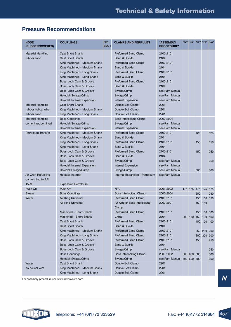
457Telephone: +44 (0)1772 323529 Fax: +44 (0)1772 314664
Technical & Safety Information
N
Technical & Safety Information
Pressure Recommendations
For assembly procedure see www.dixonvalve.com
Material Handling
rubber lined
Material Handling
rubber helical wire
rubber lined
Material Handling
cement rubber lined
Petroleum Transfer
Air Craft Refuelling
conforming to API
1529
Push On
Steam
Water
Water
no helical wire
HoSE (RUBBERCoVERED)
CoUPlInGS ClAMPS AnD FERRUlES *ASSEMBlYPRoCEDURE*
DPlSECT
1/4” 3/8” 1/2” 5/9” 3/4”
Cast Short Shank
Cast Short Shank
King Machined - Medium Shank
King Machined - Medium Shank
King Machined - Long Shank
King Machined - Long Shank
Boss-Lock Cam & Groove
Boss-Lock Cam & Groove
Boss-Lock Cam & Groove
Holedall Swage/Crimp
Holedall Internal Expansion
Cast Short Shank
King Machined - Medium Shank
King Machined - Long Shank
Boss Couplings
Holedall Swage/Crimp
Holedall Internal Expansion
King Machined - Medium Shank
King Machined - Medium Shank
King Machined - Long Shank
King Machined - Long Shank
Boss-Lock Cam & Groove
Boss-Lock Cam & Groove
Boss-Lock Cam & Groove
Holedall Internal Expansion
Holedall Swage/Crimp
Holedall Internal
Expansion Petroleum
Push On
Boss Couplings
Air King Universal
Air King Universal
Machined - Short Shank
Machined - Short Shank
Cast Short Shank
Cast Short Shank
King Machined - Medium Shank
King Machined - Long Shank
Boss-Lock Cam & Groove
Boss-Lock Cam & Groove
Boss-Lock Cam & Groove
Boss Couplings
Holedall Swage/Crimp
Cast Short Shank
King Machined - Medium Shank
King Machined - Long Shank
Preformed Band Clamp
Band & Buckle
Preformed Band Clamp
Band & Buckle
Preformed Band Clamp
Band & Buckle
Preformed Band Clamp
Band & Buckle
Swage/Crimp
Swage/Crimp
Internal Expansion
Double Bolt Clamp
Double Bolt Clamp
Double Bolt Clamp
Boss Interlocking Clamp
Swage/Crimp
Internal Expansion
Preformed Band Clamp
Band & Buckle
Preformed Band Clamp
Band & Buckle
Preformed Band Clamp
Band & Buckle
Swage/Crimp
Internal Expansion
Swage/Crimp
Internal Expansion - Petroleum
N/A
Boss Interlocking Clamp
Preformed Band Clamp
Air King or Boss Interlocking
Clamp
Preformed Band Clamp
Crimp
Preformed Band Clamp
Band & Buckle
Preformed Band Clamp
Preformed Band Clamp
Preformed Band Clamp
Band & Buckle
Swage/Crimp
Boss Interlocking Clamp
Swage/Crimp
Double Bolt Clamp
Double Bolt Clamp
Double Bolt Clamp
2100-2101
2104
2100-2101
2104
2100-2101
2104
2100-2101
2104
see Ram Manual
see Ram Manual
see Ram Manual
2201
2201
2201
2000-2004
see Ram Manual
see Ram Manual
2100-2101
2104
2100-2101
2104
2100-2101
2104
see Ram Manual
see Ram Manual
see Ram Manual
see Ram Manual
2001-2002
2000-2004
2100-2101
2000-2001
2100-2101
2304
2100-2101
2104
2100-2101
2100-2101
2100-2101
2104
see Ram Manual
2000-2002
see Ram Manual
2201
2201
2201
175
200
600
600
175
150
600
600
125
150
150
600
175
250
150
150
150
150
150
250
300
150
600
600
175
150
150
100
100
100
200
300
125
150
250
250
600
175
250
150
100
100
100
200
300
250
250
600
600
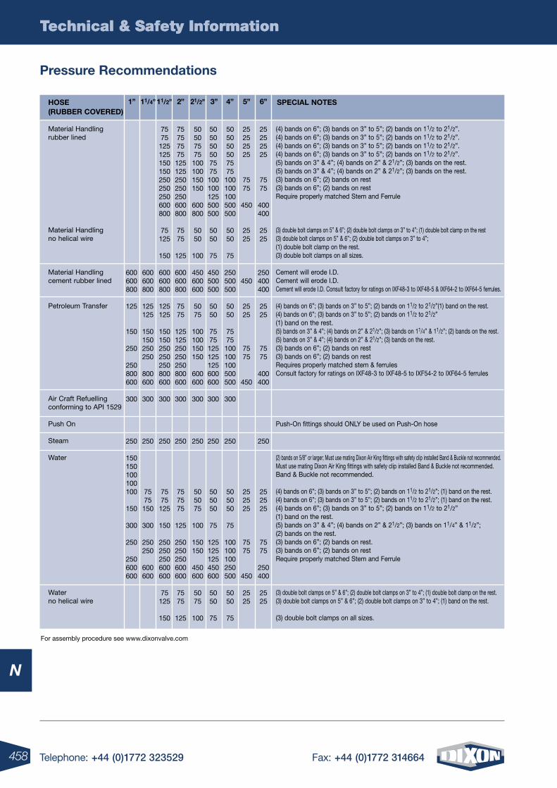
458 Telephone: +44 (0)1772 323529 Fax: +44 (0)1772 314664
Technical & Safety Information
N
Technical & Safety Information
For assembly procedure see www.dixonvalve.com
Pressure Recommendations
Material Handlingrubber lined
Material Handlingno helical wire
Material Handlingcement rubber lined
Petroleum Transfer
Air Craft Refuellingconforming to API 1529
Push On
Steam
Water
Waterno helical wire
(4) bands on 6”; (3) bands on 3” to 5”; (2) bands on 11/2 to 21/2”.(4) bands on 6”; (3) bands on 3” to 5”; (2) bands on 11/2 to 21/2”.(4) bands on 6”; (3) bands on 3” to 5”; (2) bands on 11/2 to 21/2”.(4) bands on 6”; (3) bands on 3” to 5”; (2) bands on 11/2 to 21/2”.(5) bands on 3” & 4”; (4) bands on 2” & 21/2”; (3) bands on the rest.(5) bands on 3” & 4”; (4) bands on 2” & 21/2”; (3) bands on the rest.(3) bands on 6”; (2) bands on rest (3) bands on 6”; (2) bands on restRequire properly matched Stem and Ferrule
(3) double bolt clamps on 5” & 6”; (2) double bolt clamps on 3” to 4”; (1) double bolt clamp on the rest(3) double bolt clamps on 5” & 6”; (2) double bolt clamps on 3” to 4”;(1) double bolt clamp on the rest. (3) double bolt clamps on all sizes.
Cement will erode I.D. Cement will erode I.D. Cement will erode I.D. Consult factory for ratings on IXF48-3 to IXF48-5 & IXF64-2 to IXF64-5 ferrules.
(4) bands on 6”; (3) bands on 3” to 5”; (2) bands on 11/2 to 21/2”(1) band on the rest.(4) bands on 6”; (3) bands on 3” to 5”; (2) bands on 11/2 to 21/2”(1) band on the rest.(5) bands on 3” & 4”; (4) bands on 2” & 21/2”; (3) bands on 11/4” & 11/2”; (2) bands on the rest.(5) bands on 3” & 4”; (4) bands on 2” & 21/2”; (3) bands on the rest.(3) bands on 6”; (2) bands on rest(3) bands on 6”; (2) bands on restRequires properly matched stem & ferrulesConsult factory for ratings on IXF48-3 to IXF48-5 to IXF54-2 to IXF64-5 ferrules
Push-On fittings should ONLY be used on Push-On hose
(2) bands on 5/8” or larger; Must use mating Dixon Air King fittings with safety clip installed Band & Buckle not recommended.Must use mating Dixon Air King fittings with safety clip installed Band & Buckle not recommended.Band & Buckle not recommended.
(4) bands on 6”; (3) bands on 3” to 5”; (2) bands on 11/2 to 21/2”; (1) band on the rest. (4) bands on 6”; (3) bands on 3” to 5”; (2) bands on 11/2 to 21/2”; (1) band on the rest.(4) bands on 6”; (3) bands on 3” to 5”; (2) bands on 11/2 to 21/2”(1) band on the rest.(5) bands on 3” & 4”; (4) bands on 2” & 21/2”; (3) bands on 11/4” & 11/2”; (2) bands on the rest.(3) bands on 6”; (2) bands on rest.(3) bands on 6”; (2) bands on restRequire properly matched Stem and Ferrule
(3) double bolt clamps on 5” & 6”; (2) double bolt clamps on 3” to 4”; (1) double bolt clamp on the rest.(3) double bolt clamps on 5” & 6”; (2) double bolt clamps on 3” to 4”; (1) band on the rest.
(3) double bolt clamps on all sizes.
HoSE (RUBBER CoVERED)
SPECIAl noTES1” 11/4” 3”11/2” 4”2” 5”21/2” 6”
600600800
125
150
250
250800600
300
250
150150100100100
150
300
250
250600600
600600800
125125
150150250250
800600
300
250
7575150
300
250250
600600
7575125125150150250250250600800
75125
150
600600800
125125
150150250250250800600
300
250
7575125
150
250250250600600
75125
150
75757575125125250250250600800
7575
125
600600800
7575
125125250250250800600
300
250
757575
125
250250250600600
7575
125
50507575100100150150
600800
5050
100
450600600
5075
100100150150
600600
300
250
505075
100
150150
450600
5075
100
505050507575100100125500500
5050
75
450500500
5050
7575125125125600600
300
250
505050
75
125125125450600
5050
75
505050507575100100100500500
5050
75
250500500
5050
7575100100100500500
300
250
505050
75
100100100250500
5050
75
25252525
7575
450
2525
450
2525
7575
450
252525
7575
450
2525
25252525
7575
400400
2525
250400400
2525
7575
400400
250
252525
7575
250400
2525
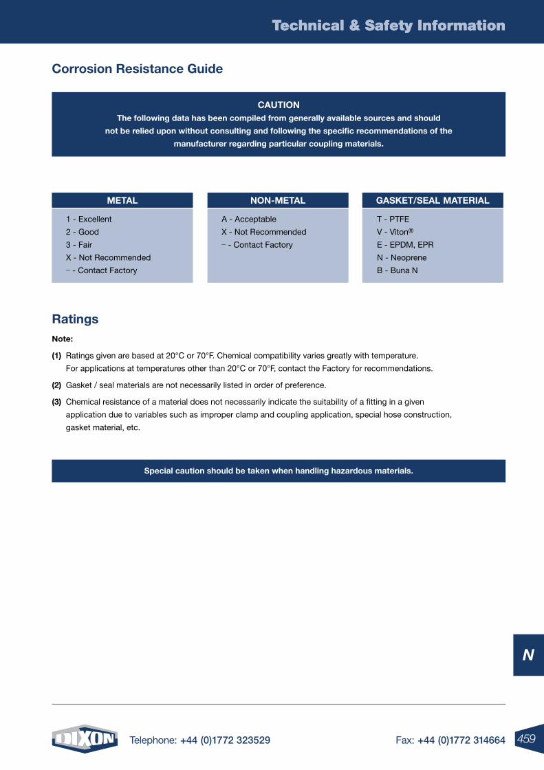
459Telephone: +44 (0)1772 323529 Fax: +44 (0)1772 314664
Technical & Safety Information
N
Technical & Safety Information
Corrosion Resistance Guide
CAUTIonThe following data has been compiled from generally available sources and should
not be relied upon without consulting and following the specific recommendations of the
manufacturer regarding particular coupling materials.
Special caution should be taken when handling hazardous materials.
Ratingsnote:
(1) Ratings given are based at 20°C or 70°F. Chemical compatibility varies greatly with temperature.
For applications at temperatures other than 20°C or 70°F, contact the Factory for recommendations.
(2) Gasket / seal materials are not necessarily listed in order of preference.
(3) Chemical resistance of a material does not necessarily indicate the suitability of a fitting in a given
application due to variables such as improper clamp and coupling application, special hose construction,
gasket material, etc.
METAl
1 - Excellent
2 - Good
3 - Fair
X - Not Recommended _ - Contact Factory
non-METAl
A - Acceptable
X - Not Recommended _ - Contact Factory
GASkET/SEAl MATERIAl
T - PTFE
V - Viton®
E - EPDM, EPR
N - Neoprene
B - Buna N
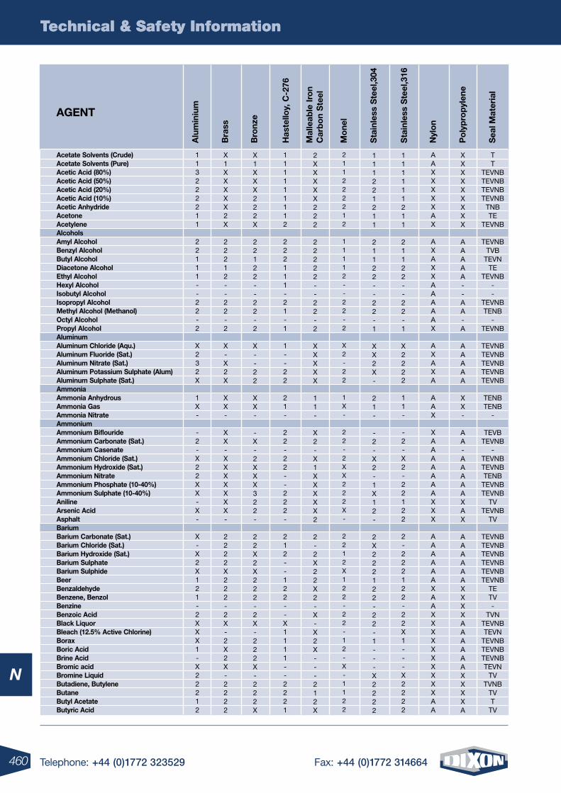
460 Telephone: +44 (0)1772 323529 Fax: +44 (0)1772 314664
Technical & Safety Information
N
Technical & Safety Information
Acetate Solvents (Crude) Acetate Solvents (Pure) Acetic Acid (80%) Acetic Acid (50%) Acetic Acid (20%) Acetic Acid (10%) Acetic Anhydride Acetone Acetylene Alcohols Amyl Alcohol Benzyl Alcohol Butyl Alcohol Diacetone Alcohol Ethyl Alcohol Hexyl Alcohol Isobutyl Alcohol Isopropyl Alcohol Methyl Alcohol (Methanol) octyl Alcohol Propyl Alcohol Aluminum Aluminum Chloride (Aqu.) Aluminum Fluoride (Sat.) Aluminum nitrate (Sat.) Aluminum Potassium Sulphate (Alum) Aluminum Sulphate (Sat.) Ammonia Ammonia Anhydrous Ammonia Gas Ammonia nitrate Ammonium Ammonium Biflouride Ammonium Carbonate (Sat.) Ammonium Casenate Ammonium Chloride (Sat.) Ammonium Hydroxide (Sat.) Ammonium nitrate Ammonium Phosphate (10-40%) Ammonium Sulphate (10-40%) Aniline Arsenic Acid Asphalt Barium Barium Carbonate (Sat.) Barium Chloride (Sat.) Barium Hydroxide (Sat.) Barium Sulphate Barium Sulphide Beer Benzaldehyde Benzene, Benzol Benzine Benzoic Acid Black liquor Bleach (12.5% Active Chlorine) Borax Boric Acid Brine Acid Bromic acid Bromine liquid Butadiene, Butylene Butane Butyl Acetate Butyric Acid
111111112
222111-21-1
1--22
21-
22-22--222-
212--122--X1111--2221
Has
tello
y, C
-276
Bra
ss
Bro
nze
nyl
on
Po
lyp
rop
ylen
e
Sta
inle
ss S
teel
,316
Sea
l Mat
eria
l
Alu
min
ium
Sta
inle
ss S
teel
,304
Mal
leab
le Ir
on
Car
bo
n S
teel
Mo
nelAGEnT
AAXXXXXAX
AXAXXAAAAAX
AXAXA
AAX
XAAAAAAAXXX
AAAAAAXAAXXXXXXXXXXAA
T T
TEVNB TEVNB TEVNB TEVNB
TNB TE
TEVNB
TEVNB TVB
TEVN TE
TEVNB --
TEVNB TENB
- TEVNB
TEVNB TEVNB TEVNB TEVNB TEVNB
TENB TENB
-
TEVB TEVNB
- TEVNB TEVNB TENB
TEVNB TEVNB
TV TEVNB
TV
TEVNB TEVNB TEVNB TEVNB TEVNB TEVNB
TE TV -
TVN TEVNB TEVN
TEVNB TEVNB TEVNB TEVN
TV TVNB
TV T
TV
XXXXXXXXX
AAAAA--AA-A
AAAAA
XX-
AA-AAAAAXAX
AAAAAAXXXXAAAAAAXXXXA
111111211
21122--22-1
X2222
11-
-2-X2-22122
2-222122-22X1---X2222
211222212
11112--22-2
X2-22
1X-
22-2XX222X-
2212X122-22-12-X-1122
113222211
22111--22-2
X232X
1X-
-2-X22XX-X-
X-X2X121-2XXX1-X22212
X1XXXXX2X
22212--22-2
X-X2X
XX-
XX-XXXXXXX-
2222X222-2X-2X2X-2222
X1XXX222X
22122--22-2
X--22
XX-
-X-2XXX322-
22X2X222-2X-222X-222X
2XXXXX222
22222--22-2
XXXXX
11-
X2-X1XXXXX2
2-2X22X2-X-X2X---212X
111221211
21122--22-1
XX2X-
21-
-2-X2-1X12-
2X222122-22-1---X2222
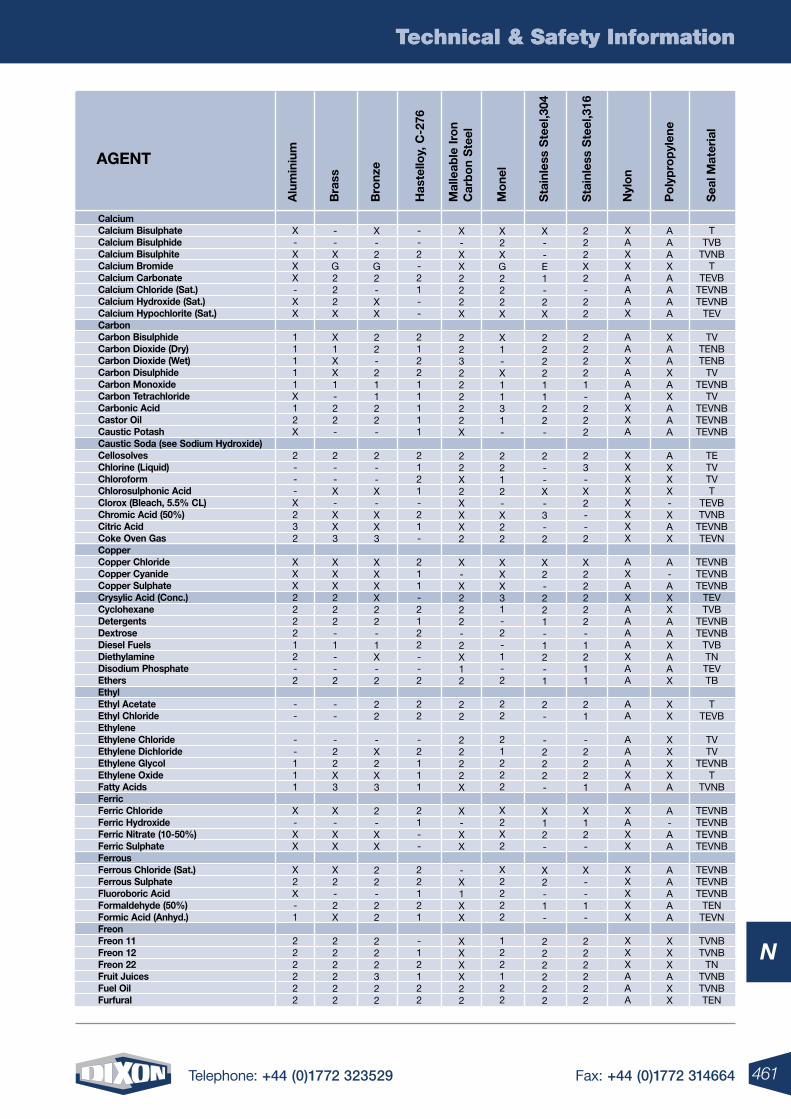
461Telephone: +44 (0)1772 323529 Fax: +44 (0)1772 314664
Technical & Safety Information
N
Calcium Calcium Bisulphate Calcium Bisulphide Calcium Bisulphite Calcium Bromide Calcium Carbonate Calcium Chloride (Sat.) Calcium Hydroxide (Sat.) Calcium Hypochlorite (Sat.) Carbon Carbon Bisulphide Carbon Dioxide (Dry) Carbon Dioxide (Wet) Carbon Disulphide Carbon Monoxide Carbon Tetrachloride Carbonic Acid Castor oil Caustic Potash Caustic Soda (see Sodium Hydroxide) Cellosolves Chlorine (liquid) Chloroform Chlorosulphonic Acid Clorox (Bleach, 5.5% Cl) Chromic Acid (50%) Citric Acid Coke oven Gas Copper Copper Chloride Copper Cyanide Copper Sulphate Crysylic Acid (Conc.) Cyclohexane Detergents Dextrose Diesel Fuels Diethylamine Disodium Phosphate Ethers Ethyl Ethyl Acetate Ethyl Chloride Ethylene Ethylene Chloride Ethylene Dichloride Ethylene Glycol Ethylene oxide Fatty Acids Ferric Ferric Chloride Ferric Hydroxide Ferric nitrate (10-50%) Ferric Sulphate Ferrous Ferrous Chloride (Sat.) Ferrous Sulphate Fluoroboric Acid Formaldehyde (50%) Formic Acid (Anhyd.) Freon Freon 11 Freon 12 Freon 22 Fruit Juices Fuel oil Furfural
Technical & Safety Information
--2-21--
212211111
2121-21-
211-2122--2
22
-2111
21--
22121
-12122
Has
tello
y, C
-276
Bra
ss
Bro
nze
nyl
on
Po
lyp
rop
ylen
e
Sta
inle
ss S
teel
,316
Sea
l Mat
eria
l
Alu
min
ium
Sta
inle
ss S
teel
,304
Mal
leab
le Ir
on
Car
bo
n S
teel
Mo
nelAGEnT
XAXXAAAX
AAXAAAXXA
XXXXXXXX
AXAXAAAAXAA
AA
AAAXA
XAXX
XXXXX
XXXAAA
TTVB
TVNBT
TEVBTEVNBTEVNB
TEV
TVTENBTENB
TVTEVNB
TVTEVNBTEVNBTEVNB
TETVTVT
TEVBTVNB
TEVNBTEVN
TEVNBTEVNBTEVNB
TEVTVB
TEVNBTEVNB
TVBTNTEVTB
TTEVB
TVTV
TEVNBT
TVNB
TEVNBTEVNBTEVNBTEVNB
TEVNBTEVNBTEVNB
TENTEVN
TVNBTVNB
TNTVNBTVNBTEN
AAAXAAAA
XAAXAXAAA
AXXX-XAX
A-AXXAAXAAX
XX
XXXXA
A-AA
AAAAA
XXXAXX
222X2-22
22221-222
23-X2--2
X22222-1211
21
-2221
X12-
X--1-
222222
X2XG222X
X1-X1131-
2212-X22
XXX31-2-1-2
22
21222
X2X2
X2222
122122
X-XXX-XX
11111X12X
2---X232
XXX222212-2
--
--111
X-XX
X2X-1
222222
--XG222X
X1XX1-22-
2--X-XX3
XXX222-1--2
--
-22X3
X-XX
X2-2X
222222
X-2G2-XX
22-21122-
2--X-XX3
XXXX22-1X-2
22
-X2X3
2-XX
22-22
222322
X-XX222X
22322222X
22X2XXX2
X-X222-2X12
22
2222X
X-XX
-X1XX
XXXX22
X--E1-2X
22221122-
2--X-3-2
X2-221-12-1
2-
-222-
X12-
X2-1-
222222
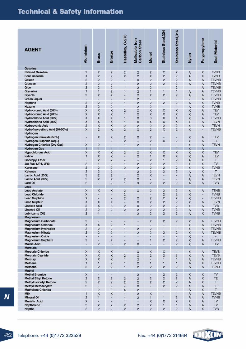
462 Telephone: +44 (0)1772 323529 Fax: +44 (0)1772 314664
Technical & Safety Information
N
Technical & Safety Information
Has
tello
y, C
-276
Bra
ss
Bro
nze
nyl
on
Po
lyp
rop
ylen
e
Sta
inle
ss S
teel
,316
Sea
l Mat
eria
l
Alu
min
ium
Sta
inle
ss S
teel
,304
Mal
leab
le Ir
on
Car
bo
n S
teel
Mo
nelAGEnT
TVNBTVNB
TEVNBTEVNBTEVNBTEVNBTEVNBTEVNBTVNBTVNBTEVTEV
TEVNBTEVNTEVN
TEVNB
TEVTE
TEVN
TEVTEV
TTV
TVNBT
TEVNTEVNTVB
TENBTVNB
TEVNBTEVNTVB
TVNBTVNB
TEVNBTEVNBTEVNBTEVNB
-TEVNB
TEV
TEVBTEVB
TEVNBTEVNBTENB
TVTETTT
TEVNBTVNB
TVTV
TVB
XXAAAAAAXXAAAAA-
AAAAXAXXXXAAA
A--AAAX
AAAA-AA
AAAXA
XXXAXAAAAX
Gasoline Refined Gasoline Sour Gasoline Gelatin Glucose Glue Glycerine Glycols Green liquor Heptane Hexane Hydrobromic Acid (50%) Hydrobromic Acid (20%) Hydrochloric Acid (20%) Hydrochloric Acid (38%) Hydrocyanic Acid Hydrofluorosilicic Acid (10-50%) Hydrogen Hydrogen Peroxide (50%) Hydrogen Sulphide (Aqu.) Hydrogen Chloride (Dry Gas) Hydrogen Gas Hypochlorous Acid Iodine Isopropyl Ether Jet Fuel (JP4, JP5) kerosene ketones lactic Acid (25%) lactic Acid (80%) lard oil lead lead Acetate lead Chloride lead Sulphate lime Sulphur linoleic Acid linseed oil lubricants (oil) Magnesium Magnesium Carbonate Magnesium Chloride Magnesium Hydroxide Magnesium nitrate Magnesium oxide Magnesium Sulphate Maleic Acid Mercuric Mercuric Chloride Mercuric Cyanide Mercury Methane Methanol Methyl Methyl Bromide Methyl Ethyl ketone Methyl Isobutyl ketone Methyl Methacrylate Methylene Chloride Milk Mineral oil Muriatic Acid napthalene naptha
2X22212-22XXXX2X
--X1X1-222322
XXXX222
2X22-2-
XXX12
X222-12X22
2222212-22XXXXX2
X-21XX212222-
X--XX21
-X22--2
XXX12
-22-2X1-22
2222222-22XXXXXX
X--1XX22222X2
X--X32-
-222-23
XXX22
-22-2X--22
22--11--11211122
22112--121121
222-22-
-111--2
-2111
-22-X1-122
22X2222222XXXX2X
X-2-XX-222XX3
X-XXX22
--22--X
XX222
222X222-22
AAAA-AA-AAXXXXXX
XXXXXXAXXAAAA
XXXXXAA
XXXXXXX
XXAAA
XAAXAAAXAA
2222212-21XXXX22
-2-1XX2222--2
2222222
2-12-22
-2112
2222-12X12
2222-12-21XXXX2X
-X-1XX1222--2
2222222
2-12-2-
X2112
2222-11X12
2X22212-22XX3X22
2211X12222X-2
2-22222
2-22-1-
X2-12
-22--X1X22
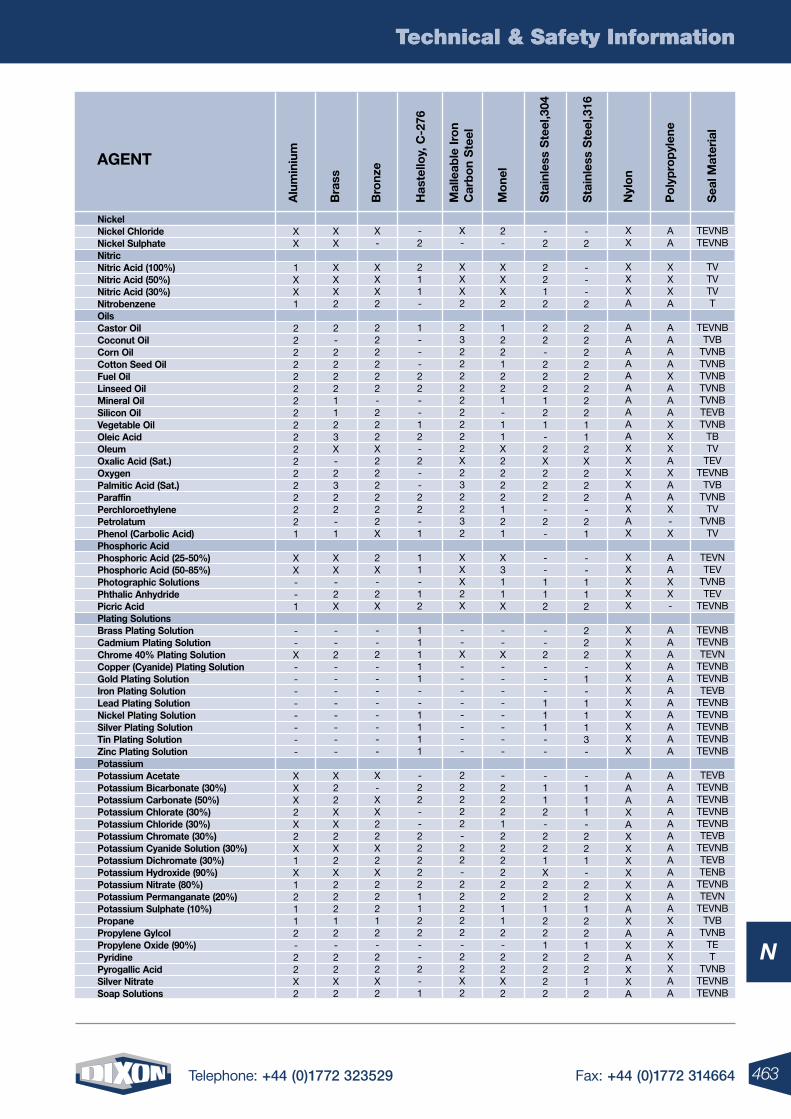
463Telephone: +44 (0)1772 323529 Fax: +44 (0)1772 314664
Technical & Safety Information
N
Technical & Safety Information
Has
tello
y, C
-276
Bra
ss
Bro
nze
nyl
on
Po
lyp
rop
ylen
e
Sta
inle
ss S
teel
,316
Sea
l Mat
eria
l
Alu
min
ium
Sta
inle
ss S
teel
,304
Mal
leab
le Ir
on
Car
bo
n S
teel
Mo
nelAGEnT
nickel nickel Chloride nickel Sulphate nitric nitric Acid (100%) nitric Acid (50%) nitric Acid (30%) nitrobenzene oils Castor oil Coconut oil Corn oil Cotton Seed oil Fuel oil linseed oil Mineral oil Silicon oil Vegetable oil oleic Acid oleum oxalic Acid (Sat.) oxygen Palmitic Acid (Sat.) Paraffin Perchloroethylene Petrolatum Phenol (Carbolic Acid) Phosphoric Acid Phosphoric Acid (25-50%) Phosphoric Acid (50-85%) Photographic Solutions Phthalic Anhydride Picric Acid Plating Solutions Brass Plating Solution Cadmium Plating Solution Chrome 40% Plating Solution Copper (Cyanide) Plating Solution Gold Plating Solution Iron Plating Solution lead Plating Solution nickel Plating Solution Silver Plating Solution Tin Plating Solution Zinc Plating Solution Potassium Potassium Acetate Potassium Bicarbonate (30%) Potassium Carbonate (50%) Potassium Chlorate (30%) Potassium Chloride (30%) Potassium Chromate (30%) Potassium Cyanide Solution (30%) Potassium Dichromate (30%) Potassium Hydroxide (90%) Potassium nitrate (80%) Potassium Permanganate (20%) Potassium Sulphate (10%) Propane Propylene Gylcol Propylene oxide (90%) Pyridine Pyrogallic Acid Silver nitrate Soap Solutions
XX
1XX1
222222222222222221
XX--1
--X--------
XXX2X2X1X12112-22X2
XX
XXX2
2-22221123X-2322-1
XX-2X
--2--------
X22XX2X2X22212-22X2
X-
XXX2
222222-222X222222X
2X-2X
--2--------
X-XX22X2X22212-22X2
-2
211-
1---22--12-2--22-1
11-12
11111--1111
-22--222221122--2-1
X-
XXX2
23222222222X232232
XXX2X
--X--------
22222-22-22222-22X2
XX
XXXA
AAAAAAAAAAXXXXAXAX
XXXXX
XXXXXXXXXXX
AAAXAXXXXXXAXAXAXXA
-2
---2
22222222112X222-21
--112
222-1-1113-
-111-221-2212212212
-2
2212
22-222121-2X222-2-
--112
--2---111--
-112-221X2212212222
2-
XXX2
1221221-11X2222121
X311X
--X--------
-2221222222112-22X2
AA
XXXA
AAAAXAAAXXXAXAAX-X
AAXX-
AAAAAAAAAAA
AAAAAAAAAAAAXAXXXAA
TEVNBTEVNB
TVTVTVT
TEVNBTVB
TVNBTVNBTVNBTVNBTVNBTEVBTVNB
TBTV
TEVTEVNB
TVBTVNB
TVTVNB
TV
TEVNTEV
TVNBTEV
TEVNB
TEVNBTEVNBTEVN
TEVNBTEVNBTEVB
TEVNBTEVNBTEVNBTEVNBTEVNB
TEVBTEVNBTEVNBTEVNBTEVNBTEVB
TEVNBTEVBTENB
TEVNBTEVN
TEVNBTVB
TVNBTET
TVNBTEVNBTEVNB
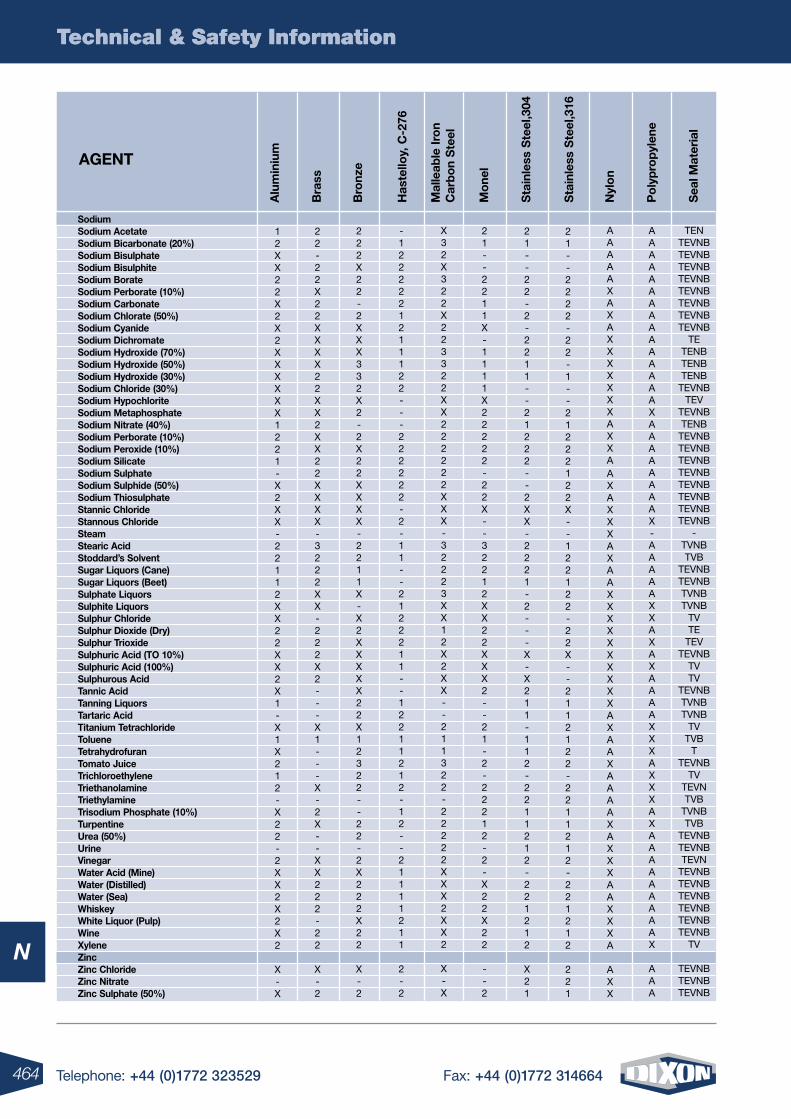
464 Telephone: +44 (0)1772 323529 Fax: +44 (0)1772 314664
Technical & Safety Information
N
Technical & Safety Information
Has
tello
y, C
-276
Bra
ss
Bro
nze
nyl
on
Po
lyp
rop
ylen
e
Sta
inle
ss S
teel
,316
Sea
l Mat
eria
l
Alu
min
ium
Sta
inle
ss S
teel
,304
Mal
leab
le Ir
on
Car
bo
n S
teel
Mo
nelAGEnT
Sodium Sodium Acetate Sodium Bicarbonate (20%) Sodium Bisulphate Sodium Bisulphite Sodium Borate Sodium Perborate (10%) Sodium Carbonate Sodium Chlorate (50%) Sodium Cyanide Sodium Dichromate Sodium Hydroxide (70%) Sodium Hydroxide (50%) Sodium Hydroxide (30%) Sodium Chloride (30%) Sodium Hypochlorite Sodium Metaphosphate Sodium nitrate (40%) Sodium Perborate (10%) Sodium Peroxide (10%) Sodium Silicate Sodium Sulphate Sodium Sulphide (50%) Sodium Thiosulphate Stannic Chloride Stannous Chloride Steam Stearic Acid Stoddard’s Solvent Sugar liquors (Cane) Sugar liquors (Beet) Sulphate liquors Sulphite liquors Sulphur Chloride Sulphur Dioxide (Dry) Sulphur Trioxide Sulphuric Acid (To 10%) Sulphuric Acid (100%) Sulphurous Acid Tannic Acid Tanning liquors Tartaric Acid Titanium Tetrachloride Toluene Tetrahydrofuran Tomato Juice Trichloroethylene Triethanolamine Triethylamine Trisodium Phosphate (10%) Turpentine Urea (50%) Urine Vinegar Water Acid (Mine) Water (Distilled) Water (Sea) Whiskey White liquor (Pulp) Wine Xylene Zinc Zinc Chloride Zinc nitrate Zinc Sulphate (50%)
12XX22X2X2XXXXXX1221-X2XX-22112XX22XX2X1-X1X212-X22-2XX2X2X2
X-X
22-22X22XXXX22XX2XX22XXXX-3222XX-222X2---X1---X-2X--XX222-22
X-2
222X22-2XXX332X2-2X22XXXX-2211X-X2XXXXX22X12322--22-2X222X22
X-2
-1222221211122---222222-2-11--2122211--12211212-12--21111211
2-2
X32X322X223322XX222222XXX-32223XX12X2XX--211322-22222XXX2XX2
X-X
AAAAAXAXAXXXXXXXAXXAAXAXXXAXAAXXXXXXXXXXAXAAXAAAAXAXXXAAXXXA
AXX
21--2222-22-1--21222122X--122122-22X--2112122-2211212-221212
221
21--22-2-2211--21222--2XX-2221-2---X-X211-112-2211212-221212
X21
21--2211X-1111X22222-22X--32212XX22XXX2--21-2-22212-2-X22X22
--2
AAAAAAAAAAAAAAAXAAAAAAAAX-AAAAAXXAXAXAAAAXXXAXXXAXAAAAAAAAAX
AAA
TENTEVNBTEVNBTEVNBTEVNBTEVNBTEVNBTEVNBTEVNB
TETENBTENBTENB
TEVNBTEV
TEVNBTENB
TEVNBTEVNBTEVNBTEVNBTEVNBTEVNBTEVNBTEVNB
-TVNBTVB
TEVNBTEVNBTVNBTVNB
TVTE
TEVTEVNB
TVTV
TEVNBTVNBTVNB
TVTVB
TTEVNB
TVTEVNTVB
TVNBTVB
TEVNBTEVNBTEVN
TEVNBTEVNBTEVNBTEVNBTEVNBTEVNB
TV
TEVNBTEVNBTEVNB
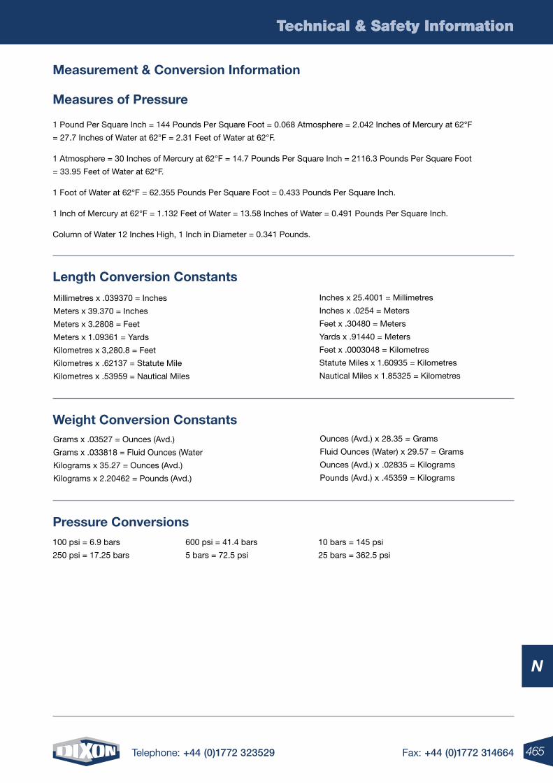
465Telephone: +44 (0)1772 323529 Fax: +44 (0)1772 314664
Technical & Safety Information
N
Technical & Safety Information
100 psi = 6.9 bars
250 psi = 17.25 bars
600 psi = 41.4 bars
5 bars = 72.5 psi
10 bars = 145 psi
25 bars = 362.5 psi
Measurement & Conversion Information
Measures of Pressure
1 Pound Per Square Inch = 144 Pounds Per Square Foot = 0.068 Atmosphere = 2.042 Inches of Mercury at 62°F
= 27.7 Inches of Water at 62°F = 2.31 Feet of Water at 62°F.
1 Atmosphere = 30 Inches of Mercury at 62°F = 14.7 Pounds Per Square Inch = 2116.3 Pounds Per Square Foot
= 33.95 Feet of Water at 62°F.
1 Foot of Water at 62°F = 62.355 Pounds Per Square Foot = 0.433 Pounds Per Square Inch.
1 Inch of Mercury at 62°F = 1.132 Feet of Water = 13.58 Inches of Water = 0.491 Pounds Per Square Inch.
Column of Water 12 Inches High, 1 Inch in Diameter = 0.341 Pounds.
Pressure Conversions
Inches x 25.4001 = Millimetres
Inches x .0254 = Meters
Feet x .30480 = Meters
Yards x .91440 = Meters
Feet x .0003048 = Kilometres
Statute Miles x 1.60935 = Kilometres
Nautical Miles x 1.85325 = Kilometres
Millimetres x .039370 = Inches
Meters x 39.370 = Inches
Meters x 3.2808 = Feet
Meters x 1.09361 = Yards
Kilometres x 3,280.8 = Feet
Kilometres x .62137 = Statute Mile
Kilometres x .53959 = Nautical Miles
Ounces (Avd.) x 28.35 = Grams
Fluid Ounces (Water) x 29.57 = Grams
Ounces (Avd.) x .02835 = Kilograms
Pounds (Avd.) x .45359 = Kilograms
Grams x .03527 = Ounces (Avd.)
Grams x .033818 = Fluid Ounces (Water
Kilograms x 35.27 = Ounces (Avd.)
Kilograms x 2.20462 = Pounds (Avd.)
Weight Conversion Constants
length Conversion Constants
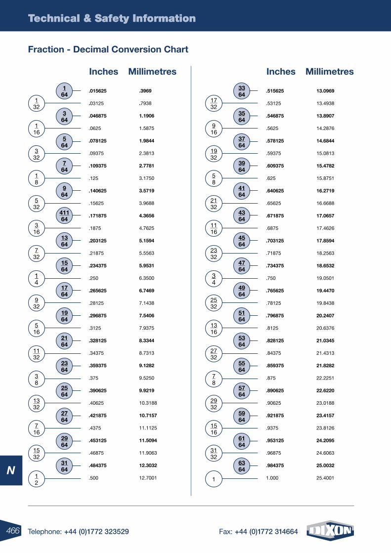
466 Telephone: +44 (0)1772 323529 Fax: +44 (0)1772 314664
Technical & Safety Information
N
Technical & Safety Information
Fraction - Decimal Conversion Chart
Inches Millimetres
6364
5764
78
2532
4964
34
4764
2332
4564
1116
4364
2132
4164
58
3964
1932
3764
916
3564
1732
3364
.515625
.53125
.546875
.5625
.578125
.59375
.609375
.625
.640625
.65625
.671875
.6875
.703125
.71875
.734375
.750
.765625
.78125
.796875
.8125
.828125
.84375
.859375
.875
.890625
.90625
.921875
.9375
.953125
.96875
.984375
1.000
13.0969
13.4938
13.8907
14.2876
14.6844
15.0813
15.4782
15.8751
16.2719
16.6688
17.0657
17.4626
17.8594
18.2563
18.6532
19.0501
19.4470
19.8438
20.2407
20.6376
21.0345
21.4313
21.8282
22.2251
22.6220
23.0188
23.4157
23.8126
24.2095
24.6063
25.0032
25.4001
5164
1316
5364
2732
5564
2932
5964
1516
6164
3132
1
Inches Millimetres
3164
2564
38
932
1764
14
1564
732
1364
316
41164
532
964
18
764
332
564
116
364
132
164
.015625
.03125
.046875
.0625
.078125
.09375
.109375
.125
.140625
.15625
.171875
.1875
.203125
.21875
.234375
.250
.265625
.28125
.296875
.3125
.328125
.34375
.359375
.375
.390625
.40625
.421875
.4375
.453125
.46875
.484375
.500
.3969
.7938
1.1906
1.5875
1.9844
2.3813
2.7781
3.1750
3.5719
3.9688
4.3656
4.7625
5.1594
5.5563
5.9531
6.3500
6.7469
7.1438
7.5406
7.9375
8.3344
8.7313
9.1282
9.5250
9.9219
10.3188
10.7157
11.1125
11.5094
11.9063
12.3032
12.7001
1964
516
2164
1132
2364
1332
2764
716
2964
1532
12
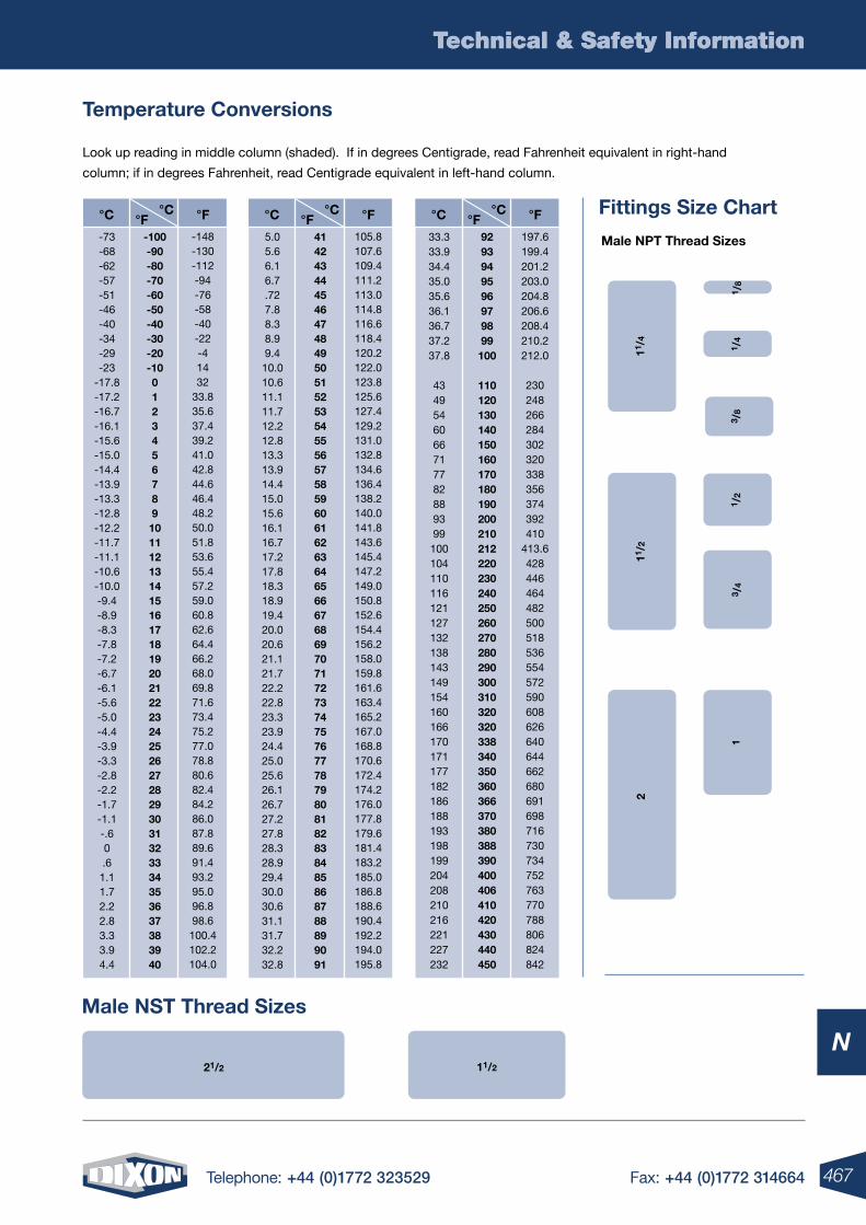
467Telephone: +44 (0)1772 323529 Fax: +44 (0)1772 314664
Technical & Safety Information
N
Technical & Safety Information
Look up reading in middle column (shaded). If in degrees Centigrade, read Fahrenheit equivalent in right-hand
column; if in degrees Fahrenheit, read Centigrade equivalent in left-hand column.
Temperature Conversions
Fittings Size Chart
11/4
11/2
11/2
11 /
21 /
41 /
8
21/2
3 /4
3 /8
Male nST Thread Sizes
Male nPT Thread Sizes
°C°F°C °F
-100-90-80-70-60-50-40-30-20-10012345678910111213141516171819202122232425262728293031323334353637383940
-73-68-62-57-51-46-40-34-29-23
-17.8-17.2-16.7-16.1-15.6-15.0-14.4-13.9-13.3-12.8-12.2-11.7-11.1-10.6-10.0-9.4-8.9-8.3-7.8-7.2-6.7-6.1-5.6-5.0-4.4-3.9-3.3-2.8-2.2-1.7-1.1-.60.61.11.72.22.83.33.94.4
-148-130-112-94-76-58-40-22-41432
33.835.637.439.241.042.844.646.448.250.051.853.655.457.259.060.862.664.466.268.069.871.673.475.277.078.880.682.484.286.087.889.691.493.295.096.898.6
100.4102.2104.0
°C°F°C °F
9293949596979899100
110120130140150160170180190200210212220230240250260270280290300310320320338340350360366370380388390400406410420430440450
33.333.934.435.035.636.136.737.237.8
4349546066717782889399100104110116121127132138143149154160166170171177182186188193198199204208210216221227232
197.6199.4201.2203.0204.8206.6208.4210.2212.0
230248266284302320338356374392410
413.6428446464482500518536554572590608626640644662680691698716730734752763770788806824842
°C°F°C °F
414243444546474849505152535455565758596061626364656667686970717273747576777879808182838485868788899091
5.05.66.16.7.727.88.38.99.4
10.010.611.111.712.212.813.313.914.415.015.616.116.717.217.818.318.919.420.020.621.121.722.222.823.323.924.425.025.626.126.727.227.828.328.929.430.030.631.131.732.232.8
105.8107.6109.4111.2113.0114.8116.6118.4120.2122.0123.8125.6127.4129.2131.0132.8134.6136.4138.2140.0141.8143.6145.4147.2149.0150.8152.6154.4156.2158.0159.8161.6163.4165.2167.0168.8170.6172.4174.2176.0177.8179.6181.4183.2185.0186.8188.6190.4192.2194.0195.8
2
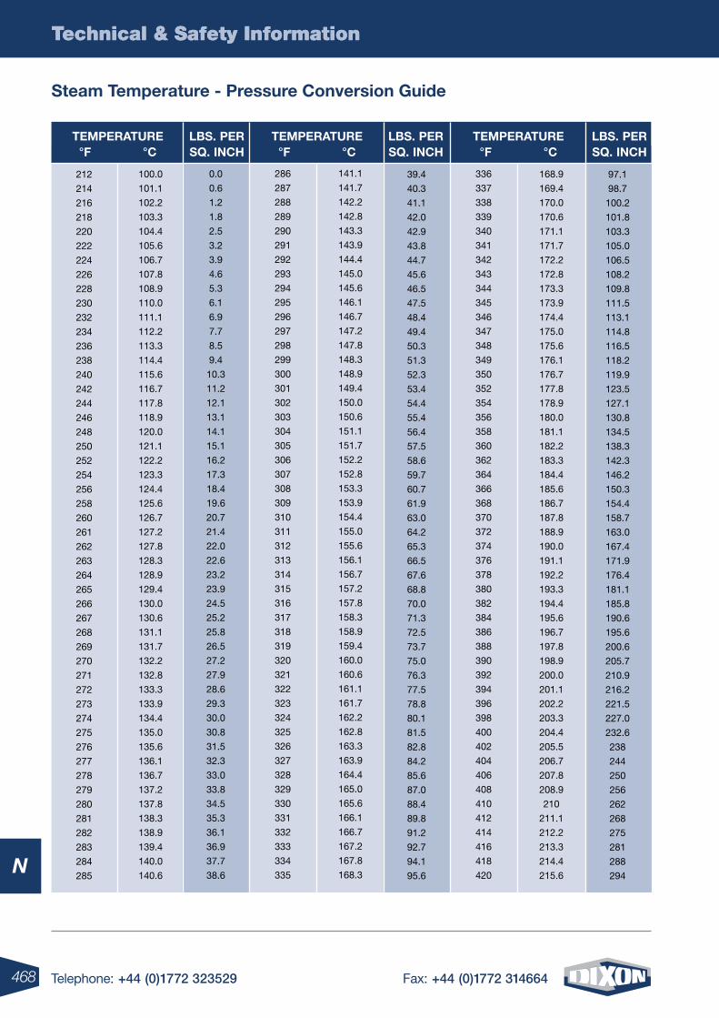
468 Telephone: +44 (0)1772 323529 Fax: +44 (0)1772 314664
Technical & Safety Information
N
Technical & Safety Information
Steam Temperature - Pressure Conversion Guide
212
214
216
218
220
222
224
226
228
230
232
234
236
238
240
242
244
246
248
250
252
254
256
258
260
261
262
263
264
265
266
267
268
269
270
271
272
273
274
275
276
277
278
279
280
281
282
283
284
285
100.0
101.1
102.2
103.3
104.4
105.6
106.7
107.8
108.9
110.0
111.1
112.2
113.3
114.4
115.6
116.7
117.8
118.9
120.0
121.1
122.2
123.3
124.4
125.6
126.7
127.2
127.8
128.3
128.9
129.4
130.0
130.6
131.1
131.7
132.2
132.8
133.3
133.9
134.4
135.0
135.6
136.1
136.7
137.2
137.8
138.3
138.9
139.4
140.0
140.6
0.0
0.6
1.2
1.8
2.5
3.2
3.9
4.6
5.3
6.1
6.9
7.7
8.5
9.4
10.3
11.2
12.1
13.1
14.1
15.1
16.2
17.3
18.4
19.6
20.7
21.4
22.0
22.6
23.2
23.9
24.5
25.2
25.8
26.5
27.2
27.9
28.6
29.3
30.0
30.8
31.5
32.3
33.0
33.8
34.5
35.3
36.1
36.9
37.7
38.6
286
287
288
289
290
291
292
293
294
295
296
297
298
299
300
301
302
303
304
305
306
307
308
309
310
311
312
313
314
315
316
317
318
319
320
321
322
323
324
325
326
327
328
329
330
331
332
333
334
335
141.1
141.7
142.2
142.8
143.3
143.9
144.4
145.0
145.6
146.1
146.7
147.2
147.8
148.3
148.9
149.4
150.0
150.6
151.1
151.7
152.2
152.8
153.3
153.9
154.4
155.0
155.6
156.1
156.7
157.2
157.8
158.3
158.9
159.4
160.0
160.6
161.1
161.7
162.2
162.8
163.3
163.9
164.4
165.0
165.6
166.1
166.7
167.2
167.8
168.3
97.1
98.7
100.2
101.8
103.3
105.0
106.5
108.2
109.8
111.5
113.1
114.8
116.5
118.2
119.9
123.5
127.1
130.8
134.5
138.3
142.3
146.2
150.3
154.4
158.7
163.0
167.4
171.9
176.4
181.1
185.8
190.6
195.6
200.6
205.7
210.9
216.2
221.5
227.0
232.6
238
244
250
256
262
268
275
281
288
294
168.9
169.4
170.0
170.6
171.1
171.7
172.2
172.8
173.3
173.9
174.4
175.0
175.6
176.1
176.7
177.8
178.9
180.0
181.1
182.2
183.3
184.4
185.6
186.7
187.8
188.9
190.0
191.1
192.2
193.3
194.4
195.6
196.7
197.8
198.9
200.0
201.1
202.2
203.3
204.4
205.5
206.7
207.8
208.9
210
211.1
212.2
213.3
214.4
215.6
336
337
338
339
340
341
342
343
344
345
346
347
348
349
350
352
354
356
358
360
362
364
366
368
370
372
374
376
378
380
382
384
386
388
390
392
394
396
398
400
402
404
406
408
410
412
414
416
418
420
TEMPERATURE°F °C
TEMPERATURE°F °C
TEMPERATURE°F °C
lBS. PERSQ. InCH
lBS. PERSQ. InCH
lBS. PERSQ. InCH
39.4
40.3
41.1
42.0
42.9
43.8
44.7
45.6
46.5
47.5
48.4
49.4
50.3
51.3
52.3
53.4
54.4
55.4
56.4
57.5
58.6
59.7
60.7
61.9
63.0
64.2
65.3
66.5
67.6
68.8
70.0
71.3
72.5
73.7
75.0
76.3
77.5
78.8
80.1
81.5
82.8
84.2
85.6
87.0
88.4
89.8
91.2
92.7
94.1
95.6
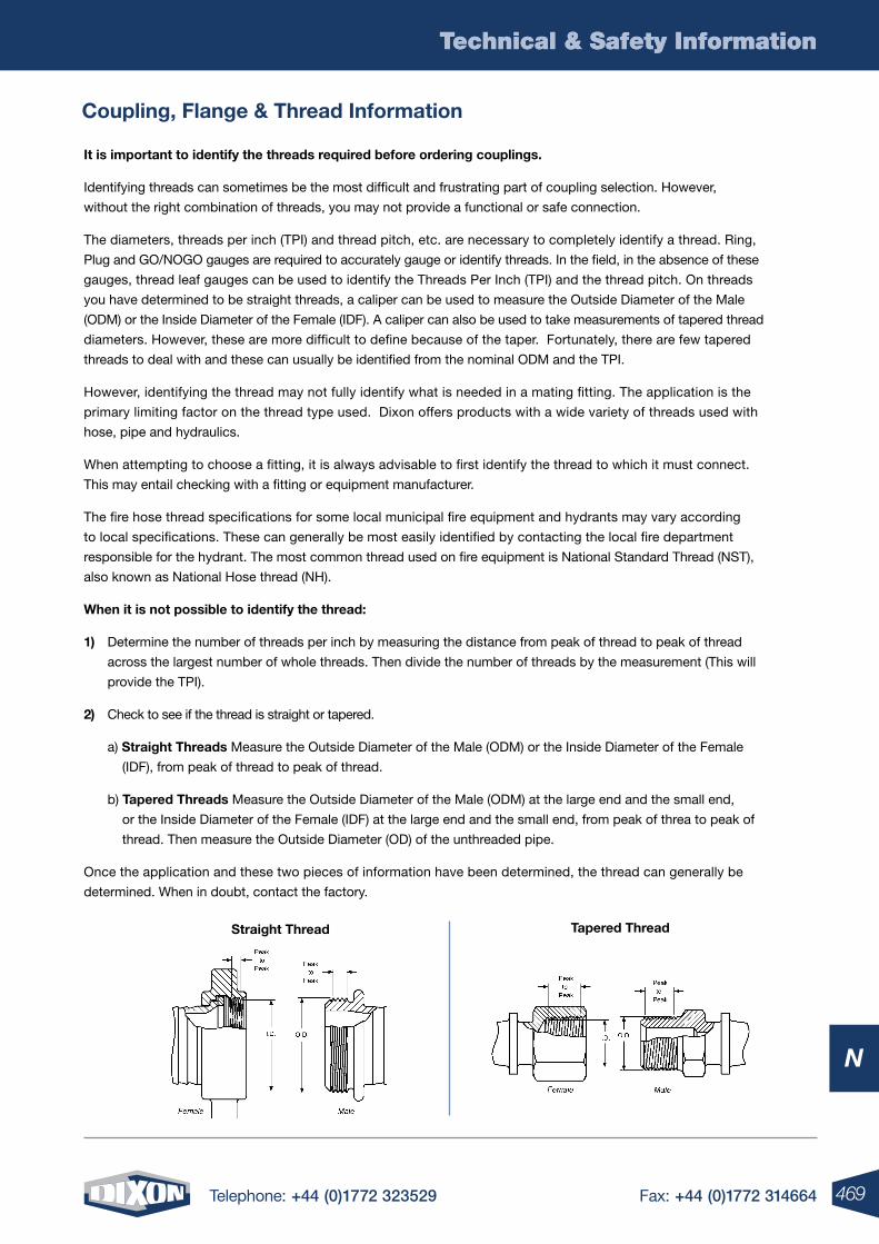
469Telephone: +44 (0)1772 323529 Fax: +44 (0)1772 314664
Technical & Safety Information
N
Technical & Safety Information
It is important to identify the threads required before ordering couplings.
Identifying threads can sometimes be the most difficult and frustrating part of coupling selection. However,
without the right combination of threads, you may not provide a functional or safe connection.
The diameters, threads per inch (TPI) and thread pitch, etc. are necessary to completely identify a thread. Ring,
Plug and GO/NOGO gauges are required to accurately gauge or identify threads. In the field, in the absence of these
gauges, thread leaf gauges can be used to identify the Threads Per Inch (TPI) and the thread pitch. On threads
you have determined to be straight threads, a caliper can be used to measure the Outside Diameter of the Male
(ODM) or the Inside Diameter of the Female (IDF). A caliper can also be used to take measurements of tapered thread
diameters. However, these are more difficult to define because of the taper. Fortunately, there are few tapered
threads to deal with and these can usually be identified from the nominal ODM and the TPI.
However, identifying the thread may not fully identify what is needed in a mating fitting. The application is the
primary limiting factor on the thread type used. Dixon offers products with a wide variety of threads used with
hose, pipe and hydraulics.
When attempting to choose a fitting, it is always advisable to first identify the thread to which it must connect.
This may entail checking with a fitting or equipment manufacturer.
The fire hose thread specifications for some local municipal fire equipment and hydrants may vary according
to local specifications. These can generally be most easily identified by contacting the local fire department
responsible for the hydrant. The most common thread used on fire equipment is National Standard Thread (NST),
also known as National Hose thread (NH).
When it is not possible to identify the thread:
1) Determine the number of threads per inch by measuring the distance from peak of thread to peak of thread
across the largest number of whole threads. Then divide the number of threads by the measurement (This will
provide the TPI).
2) Check to see if the thread is straight or tapered.
a) Straight Threads Measure the Outside Diameter of the Male (ODM) or the Inside Diameter of the Female
(IDF), from peak of thread to peak of thread.
b) Tapered Threads Measure the Outside Diameter of the Male (ODM) at the large end and the small end,
or the Inside Diameter of the Female (IDF) at the large end and the small end, from peak of threa to peak of
thread. Then measure the Outside Diameter (OD) of the unthreaded pipe.
Once the application and these two pieces of information have been determined, the thread can generally be
determined. When in doubt, contact the factory.
Tapered ThreadStraight Thread
Coupling, Flange & Thread Information
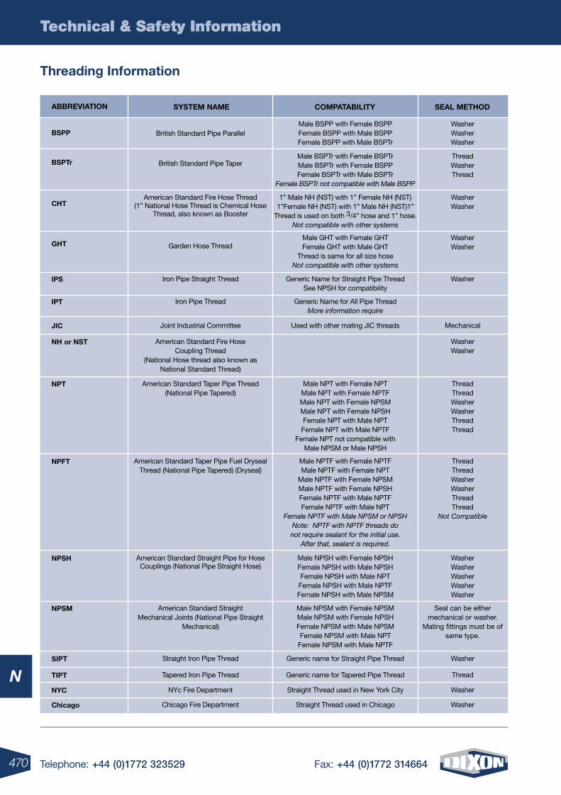
470 Telephone: +44 (0)1772 323529 Fax: +44 (0)1772 314664
Technical & Safety Information
N
Technical & Safety Information
Threading Information
Male BSPTr with Female BSPTrMale BSPTr with Female BSPPFemale BSPTr with Male BSPTrFemale BSPTr not compatible with Male BSPP
ABBREVIATIon SYSTEM nAME CoMPATABIlITY SEAl METHoD
British Standard Pipe Parallel
British Standard Pipe Taper
American Standard Fire Hose Thread (1” National Hose Thread is Chemical Hose
Thread, also known as Booster
Garden Hose Thread
Iron Pipe Straight Thread
American Standard Taper Pipe Thread(National Pipe Tapered)
American Standard Taper Pipe Fuel Dryseal Thread (National Pipe Tapered) (Dryseal)
American Standard Straight Pipe for Hose Couplings (National Pipe Straight Hose)
American Standard Straight Mechanical Joints (National Pipe Straight
Mechanical)
Straight Iron Pipe Thread
Tapered Iron Pipe Thread
NYc Fire Department
Chicago Fire Department
American Standard Fire Hose Coupling Thread
(National Hose thread also known as National Standard Thread)
Joint Industrial Committee
Iron Pipe Thread
Male BSPP with Female BSPPFemale BSPP with Male BSPPFemale BSPP with Male BSPTr
Male BSPTr with Female BSPTrMale BSPTr with Female BSPPFemale BSPTr with Male BSPTr
Female BSPTr not compatible with Male BSPP
1” Male NH (NST) with 1” Female NH (NST)1”Female NH (NST) with 1” Male NH (NST)1”
Thread is used on both 3/4” hose and 1” hose. Not compatible with other systems
Male GHT with Female GHTFemale GHT with Male GHT
Thread is same for all size hoseNot compatible with other systems
Generic Name for Straight Pipe ThreadSee NPSH for compatibility
Male NPT with Female NPTMale NPT with Female NPTFMale NPT with Female NPSMMale NPT with Female NPSHFemale NPT with Male NPT
Female NPT with Male NPTFFemale NPT not compatible with
Male NPSM or Male NPSH
Male NPTF with Female NPTFMale NPTF with Female NPT
Male NPTF with Female NPSMMale NPTF with Female NPSHFemale NPTF with Male NPTFFemale NPTF with Male NPT
Female NPTF with Male NPSM or NPSHNote: NPTF with NPTF threads do not require sealant for the initial use.
After that, sealant is required.
Male NPSH with Female NPSHFemale NPSH with Male NPSHFemale NPSH with Male NPT
Female NPSH with Male NPTFFemale NPSH with Male NPSM
Male NPSM with Female NPSMMale NPSM with Female NPSHFemale NPSM with Male NPSMFemale NPSM with Male NPT
Female NPSM with Male NPTF
Generic name for Straight Pipe Thread
Generic name for Tapered Pipe Thread
Straight Thread used in New York City
Straight Thread used in Chicago
Used with other mating JIC threads
Generic Name for All Pipe ThreadMore information require
WasherWasherWasher
ThreadWasherThread
WasherWasher
WasherWasher
Washer
ThreadThreadWasherWasherThreadThread
ThreadThreadWasherWasherThreadThread
Not Compatible
WasherWasherWasherWasherWasher
Seal can be either mechanical or washer.
Mating fittings must be of same type.
Washer
Thread
Washer
Washer
WasherWasher
Mechanical
BSPP
BSPTr
CHT
GHT
IPS
nPT
nPFT
nPSH
nPSM
SIPT
TIPT
nYC
Chicago
nH or nST
JIC
IPT
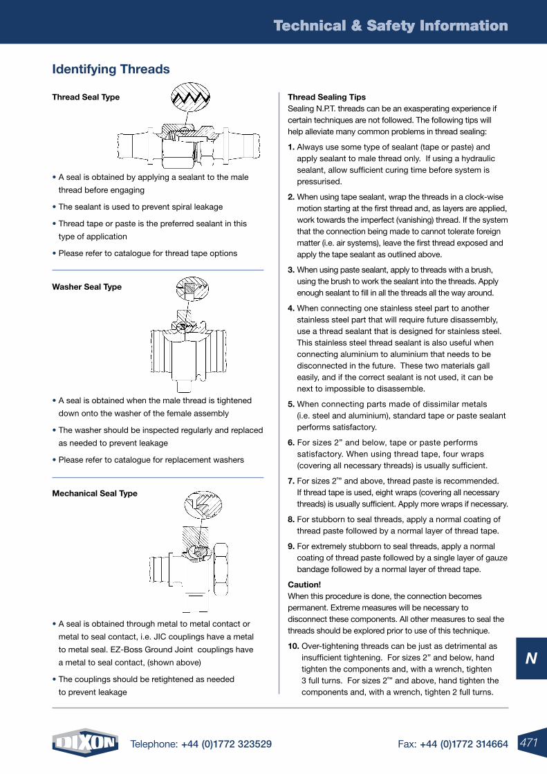
471Telephone: +44 (0)1772 323529 Fax: +44 (0)1772 314664
Technical & Safety Information
N
Technical & Safety Information
Identifying Threads
Thread Sealing Tips Sealing N.P.T. threads can be an exasperating experience if certain techniques are not followed. The following tips will help alleviate many common problems in thread sealing:
1. Always use some type of sealant (tape or paste) and apply sealant to male thread only. If using a hydraulic sealant, allow sufficient curing time before system is pressurised.
2. When using tape sealant, wrap the threads in a clock-wise motion starting at the first thread and, as layers are applied, work towards the imperfect (vanishing) thread. If the system that the connection being made to cannot tolerate foreign matter (i.e. air systems), leave the first thread exposed and apply the tape sealant as outlined above.
3. When using paste sealant, apply to threads with a brush, using the brush to work the sealant into the threads. Apply enough sealant to fill in all the threads all the way around.
4. When connecting one stainless steel part to another stainless steel part that will require future disassembly, use a thread sealant that is designed for stainless steel. This stainless steel thread sealant is also useful when connecting aluminium to aluminium that needs to be disconnected in the future. These two materials gall easily, and if the correct sealant is not used, it can be next to impossible to disassemble.
5. When connecting parts made of dissimilar metals (i.e. steel and aluminium), standard tape or paste sealant performs satisfactory.
6. For sizes 2” and below, tape or paste performs satisfactory. When using thread tape, four wraps (covering all necessary threads) is usually sufficient.
7. For sizes 2˚” and above, thread paste is recommended. If thread tape is used, eight wraps (covering all necessary threads) is usually sufficient. Apply more wraps if necessary.
8. For stubborn to seal threads, apply a normal coating of thread paste followed by a normal layer of thread tape.
9. For extremely stubborn to seal threads, apply a normal coating of thread paste followed by a single layer of gauze bandage followed by a normal layer of thread tape.
Caution! When this procedure is done, the connection becomes permanent. Extreme measures will be necessary to disconnect these components. All other measures to seal the threads should be explored prior to use of this technique.
10. Over-tightening threads can be just as detrimental as insufficient tightening. For sizes 2” and below, hand tighten the components and, with a wrench, tighten 3 full turns. For sizes 2˚” and above, hand tighten the components and, with a wrench, tighten 2 full turns.
Thread Seal Type
• A seal is obtained by applying a sealant to the male
thread before engaging
• The sealant is used to prevent spiral leakage
• Thread tape or paste is the preferred sealant in this
type of application
• Please refer to catalogue for thread tape options
Washer Seal Type
• A seal is obtained when the male thread is tightened
down onto the washer of the female assembly
• The washer should be inspected regularly and replaced
as needed to prevent leakage
• Please refer to catalogue for replacement washers
Mechanical Seal Type
• A seal is obtained through metal to metal contact or
metal to seal contact, i.e. JIC couplings have a metal
to metal seal. EZ-Boss Ground Joint couplings have
a metal to seal contact, (shown above)
• The couplings should be retightened as needed
to prevent leakage
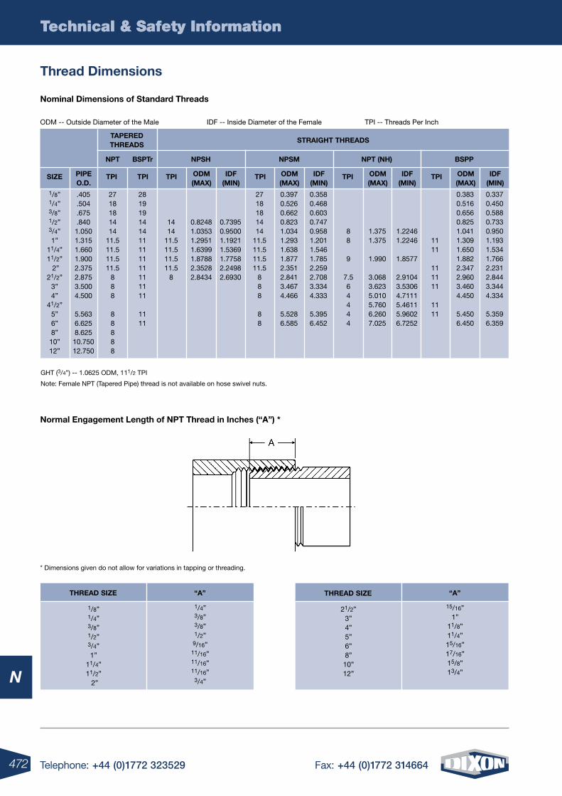
472 Telephone: +44 (0)1772 323529 Fax: +44 (0)1772 314664
Technical & Safety Information
N
Technical & Safety Information
GHT (3/4”) -- 1.0625 ODM, 111/2 TPI
Note: Female NPT (Tapered Pipe) thread is not available on hose swivel nuts.
ODM -- Outside Diameter of the Male IDF -- Inside Diameter of the Female TPI -- Threads Per Inch
nominal Dimensions of Standard Threads
Thread Dimensions
STRAIGHT THREADSTAPERED THREADS
BSPTr nPSH nPSM nPT (nH) BSPPnPT
PIPE o.D.
oDM (MAX)
oDM (MAX)
oDM (MAX)
oDM (MAX)
IDF (MIn)
IDF (MIn)
IDF (MIn)
IDF (MIn)
SIZE TPI TPI TPI TPITPI TPI
* Dimensions given do not allow for variations in tapping or threading.
normal Engagement length of nPT Thread in Inches (“A”) *
1/8”1/4”3/8”1/2”3/4”1”
11/4”11/2” 2”
21/2”3”4”
41/2”5”6”8”10”12”
.405
.504
.675
.8401.0501.3151.6601.9002.3752.8753.5004.500
5.5636.6258.62510.75012.750
2718181414
11.511.511.511.5
888
88888
281919141411111111111111
1111
1414
11.511.511.511.5
8
0.82481.03531.29511.63991.87882.35282.8434
0.73950.95001.19211.53691.77582.24982.6930
2718181414
11.511.511.511.5
888
88
0.3970.5260.6620.8231.0341.2931.6381.8772.3512.8413.4674.466
5.5286.585
0.3580.4680.6030.7470.9581.2011.5461.7852.2592.7083.3344.333
5.3956.452
88
9
7.564444
1.3751.375
1.990
3.0683.6235.0105.7606.2607.025
1.22461.2246
1.8577
2.91043.53064.71115.46115.96026.7252
1111
111111
1111
0.3830.5160.6560.8251.0411.3091.6501.8822.3472.9603.4604.450
5.4506.450
0.3370.4500.5880.7330.9501.1931.5341.7662.2312.8443.3444.334
5.3596.359
THREAD SIZE “A”
1/8”1/4”3/8”1/2”3/4”1”
11/4”11/2” 2”
1/4”3/8”3/8”1/2”9/16”11/16”11/16”11/16”3/4”
THREAD SIZE “A”
21/2”3”4”5”6”8”10”12”
15/16”1”
11/8”11/4”15/16”17/16”15/8”13/4”
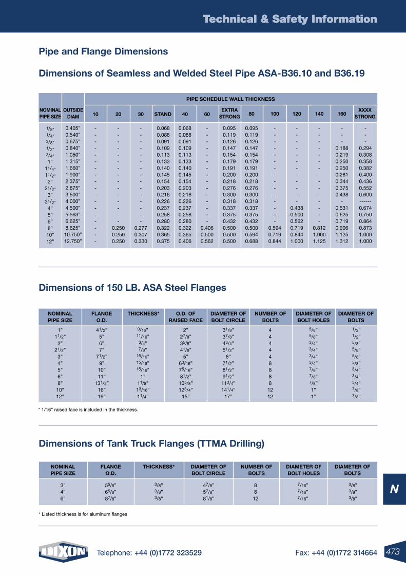
473Telephone: +44 (0)1772 323529 Fax: +44 (0)1772 314664
Technical & Safety Information
N
Technical & Safety Information
Pipe and Flange Dimensions
Dimensions of Seamless and Welded Steel Pipe ASA-B36.10 and B36.19
Dimensions of 150 lB. ASA Steel Flanges
* 1/16” raised face is included in the thickness.
Dimensions of Tank Truck Flanges (TTMA Drilling)
* Listed thickness is for aluminum flanges
oUTSIDEDIAM
noMInAlPIPE SIZE 10 20 30 STAnD 40 60
EXTRA STRonG
XXXX STRonG80 100 120 140 160
------------------
---------------
0.2500.2500.250
---------------
0.2770.3070.330
0.0680.0880.0910.1090.1130.1330.1400.1450.1540.2030.2160.2260.2370.2580.2800.3220.3650.375
0.0680.0880.0910.1090.1130.1330.1400.1450.1540.2030.2160.2260.2370.2580.2800.3220.3650.406
---------------
0.4060.5000.562
0.0950.1190.1260.1470.1540.1790.1910.2000.2180.2760.3000.3180.3370.3750.4320.5000.5000.500
0.0950.1190.1260.1470.1540.1790.1910.2000.2180.2760.3000.3180.3370.3750.4320.5000.5940.688
---------------
0.5940.7190.844
------------
0.4380.5000.5620.7190.8441.000
---------------
0.8121.0001.125
---
0.1880.2190.2500.2500.2810.3440.3750.438
-0.5310.6250.7190.9061.1251.312
---
0.2940.3080.3580.3820.4000.4360.5520.600------0.6740.7500.8640.8731.0001.000
0.405”0.540”0.675”0.840”1.050”1.315”1.660”1.900”2.375”2.875”3.500”4.000”4.500”5.563”6.625”8.625”10.750”12.750”
1/8”1/4”3/8”1/2”3/4”
1”11/4”
11/2”
2”21/2”
3”31/2”
4”5”6”8”10”12”
PIPE SCHEDUlE WAll THICknESS
noMInAlPIPE SIZE
noMInAlPIPE SIZE
FlAnGEo.D.
FlAnGEo.D.
THICknESS*
THICknESS*
DIAMETER oFBolT CIRClE
DIAMETER oFBolT CIRClE
o.D. oFRAISED FACE
DIAMETER oFBolT HolES
DIAMETER oFBolT HolES
nUMBER oFBolTS
nUMBER oFBolTS
DIAMETER oFBolTS
DIAMETER oFBolTS
3”4”6”
8812
55/8”65/8”87/8”
1”11/2”
2”21/2”
3”4”5”6”8”10”12”
41/2” 5”6”7”
71/2”9”
10”11”
131/2”16”19”
9/16” 11/16”3/4”7/8”
15/16”15/16”15/16”
1”11/8”13/16”11/4”
2” 27/8”35/8”41/8”
5”63/16”75/16”81/2”
105/8”123/4”
15”
4444488881212
31/8”37/8”43/4”51/2”
6”71/2”81/2”91/2”113/4”141/4”
17”
5/8”5/8”3/4”3/4”3/4”3/4”7/8”7/8”7/8”1”1”
1/2”1/2”5/8”5/8”5/8”5/8”3/4”3/4”3/4”7/8”7/8”
47/8”57/8”81/8”
3/8”3/8”3/8”
3/8”3/8”3/8”
7/16”7/16”7/16”
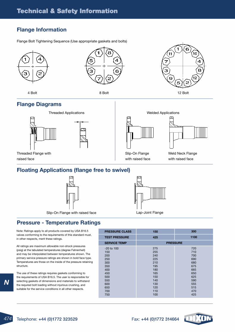
474 Telephone: +44 (0)1772 323529 Fax: +44 (0)1772 314664
Technical & Safety Information
N
Technical & Safety Information
Flange Information
Note: Ratings apply to all products covered by USA B16.5 valves conforming to the requirements of this standard must, in other respects, merit these ratings.
All ratings are maximum allowable non-shock pressures (psig) at the tabulated temperatures (degree Fahrenheit) and may be interpolated between temperatures shown. The primary service pressure ratings are shown in bold face type. Temperatures are those on the inside of the pressure retaining structure.
The use of these ratings requires gaskets conforming to the requirements of USA B16.5. The user is responsible for selecting gaskets of dimensions and materials to withstand the required bolt loading without injurious crushing, and suitable for the service conditions in all other respects.
Pressure - Temperature Ratings
Weld Neck Flange
with raised face
Slip-On Flange
with raised face
Threaded Flange with
raised face
Welded ApplicationsThreaded Applications
Flange Diagrams
Flange Bolt Tightening Sequence (Use appropriate gaskets and bolts)
12 Bolt8 Bolt4 Bolt
Slip-On Flange with raised face Lap-Joint Flange
Floating Applications (flange free to swivel)
300
1100
275255240225210195180165150140130120110100
720710700690680675665650625590555515470425
PRESSURE
-20 to 100150200250300350400450500550600650700750
150
425
PRESSURE ClASS
TEST PRESSURE
SERVICE TEMP
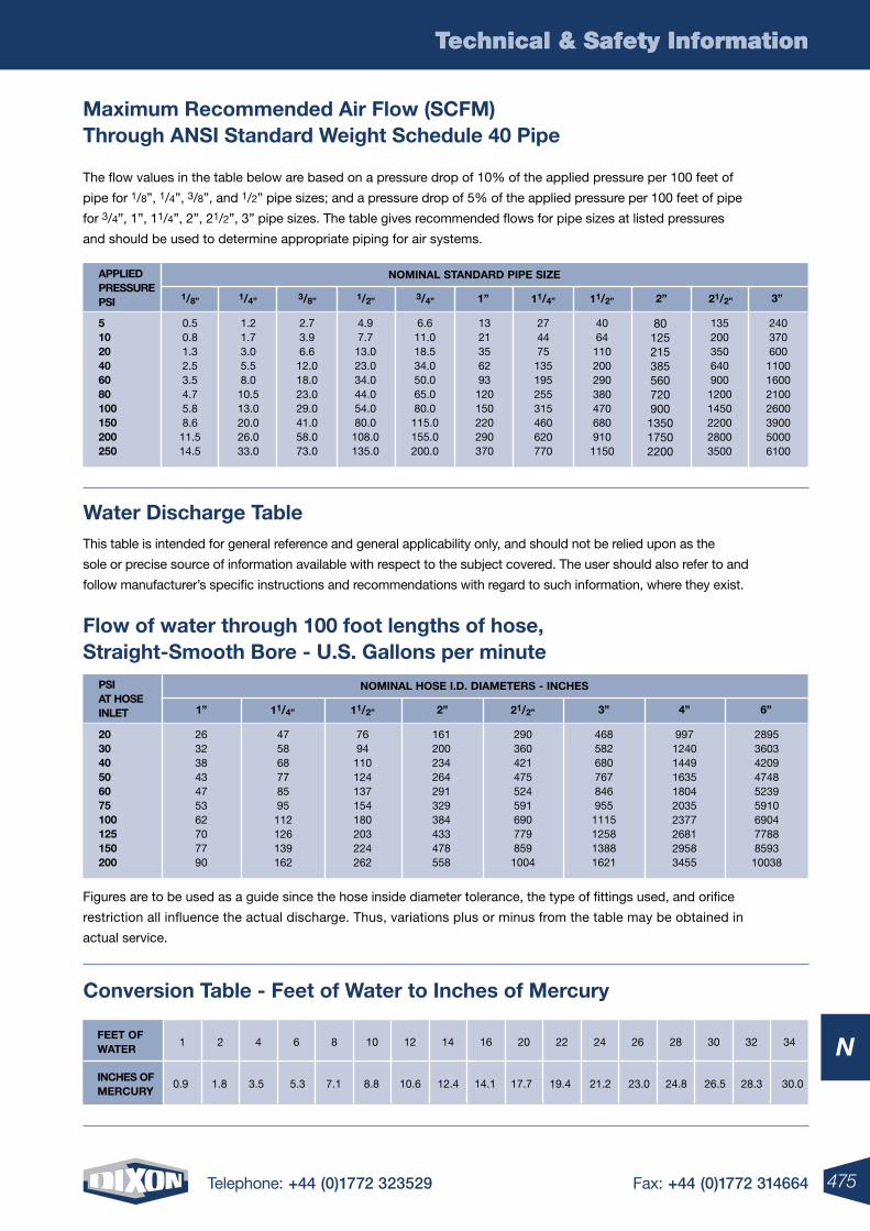
475Telephone: +44 (0)1772 323529 Fax: +44 (0)1772 314664
Technical & Safety Information
N
Technical & Safety Information
Maximum Recommended Air Flow (SCFM) Through AnSI Standard Weight Schedule 40 Pipe
Figures are to be used as a guide since the hose inside diameter tolerance, the type of fittings used, and orifice
restriction all influence the actual discharge. Thus, variations plus or minus from the table may be obtained in
actual service.
Water Discharge Table
Conversion Table - Feet of Water to Inches of Mercury
This table is intended for general reference and general applicability only, and should not be relied upon as the
sole or precise source of information available with respect to the subject covered. The user should also refer to and
follow manufacturer’s specific instructions and recommendations with regard to such information, where they exist.
Flow of water through 100 foot lengths of hose, Straight-Smooth Bore - U.S. Gallons per minute
0.9 1.8 3.5 5.3 7.1 8.8 10.6 12.4 14.1 17.7 19.4 21.2 23.0 24.8 26.5 28.3 30.0InCHES oF MERCURY
34323028262422201614121086421FEET oFWATER
The flow values in the table below are based on a pressure drop of 10% of the applied pressure per 100 feet of
pipe for 1/8”, 1/4”, 3/8”, and 1/2” pipe sizes; and a pressure drop of 5% of the applied pressure per 100 feet of pipe
for 3/4”, 1”, 11/4”, 2”, 21/2”, 3” pipe sizes. The table gives recommended flows for pipe sizes at listed pressures
and should be used to determine appropriate piping for air systems.
APPlIEDPRESSUREPSI
noMInAl STAnDARD PIPE SIZE
240370600
1100160021002600390050006100
13520035064090012001450220028003500
80125215385560720900135017502200
40641102002903804706809101150
274475135195255315460620770
51020406080100150200250
0.50.81.32.53.54.75.88.611.514.5
1.21.73.05.58.0
10.513.020.026.033.0
2.73.96.6
12.018.023.029.041.058.073.0
4.97.7
13.023.034.044.054.080.0
108.0135.0
6.611.018.534.050.065.080.0115.0155.0200.0
1321356293120150220290370
3”21/2”2”11/2”11/4”1”3/4”1/2”3/8”1/4”1/8”
PSIAT HoSEInlET
noMInAl HoSE I.D. DIAMETERS - InCHES
289536034209474852395910690477888593
10038
997124014491635180420352377268129583455
203040506075100125150200
26323843475362707790
475868778595
112126139162
7694
110124137154180203224262
161200234264291329384433478558
2903604214755245916907798591004
4685826807678469551115125813881621
6”4”3”21/2”2”11/2”11/4”1”
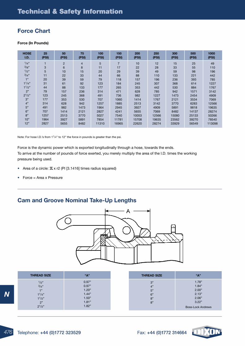
476 Telephone: +44 (0)1772 323529 Fax: +44 (0)1772 314664
Technical & Safety Information
N
Technical & Safety Information
Force Chart
Force (In Pounds)
Note: For hose I.D.’s from 11/4” to 12” the force in pounds is greater than the psi.
Force is the dynamic power which is exported longitudinally through a hose, towards the ends.
To arrive at the number of pounds of force exerted, you merely multiply the area of the I.D. times the working
pressure being used.
• Area of a circle: x r2 (PI [3.1416] times radius squared)
• Force = Area x Pressure
Cam and Groove nominal Take-Up lengths
THREAD SIZE “A”
1/2”3/4”1”
11/4”11/2” 2”
21/2”
0.97”0.97”1.20”1.44”1.50”1.81”1.82”
THREAD SIZE “A”
3”4”5”6”8”8”
1.78”1.84”2.00”2.13”2.06”3.22”
Boss-Lock Andrews
HoSEI.D.
25(PSI)
75(PSI)
150(PSI)
250(PSI)
500(PSI)
50(PSI)
100(PSI)
200(PSI)
300(PSI)
1000(PSI)
1/4”3/8”1/2”3/4”1”
11/4”11/2” 2”
21/2”3”4”5”6”8”10”12”
1351120314479123177314491707125719642827
48
15335992
133236368530942
14732121377058918482
49110196442785122717673142490970691256619635282745026678540113098
26
1022396188
157245353628982
1414251339275655
511204479
123177314491707
12571964282750277854
11310
7172966118184265471736106018852945424175401178116965
102239881572453536289821414251339275655100531570822620
12284911019630744278512271767314249097069125661963528274
15335913323636853094214732121377058918482150802356233929
2555982213936148841571245435346283981814137251333927056549
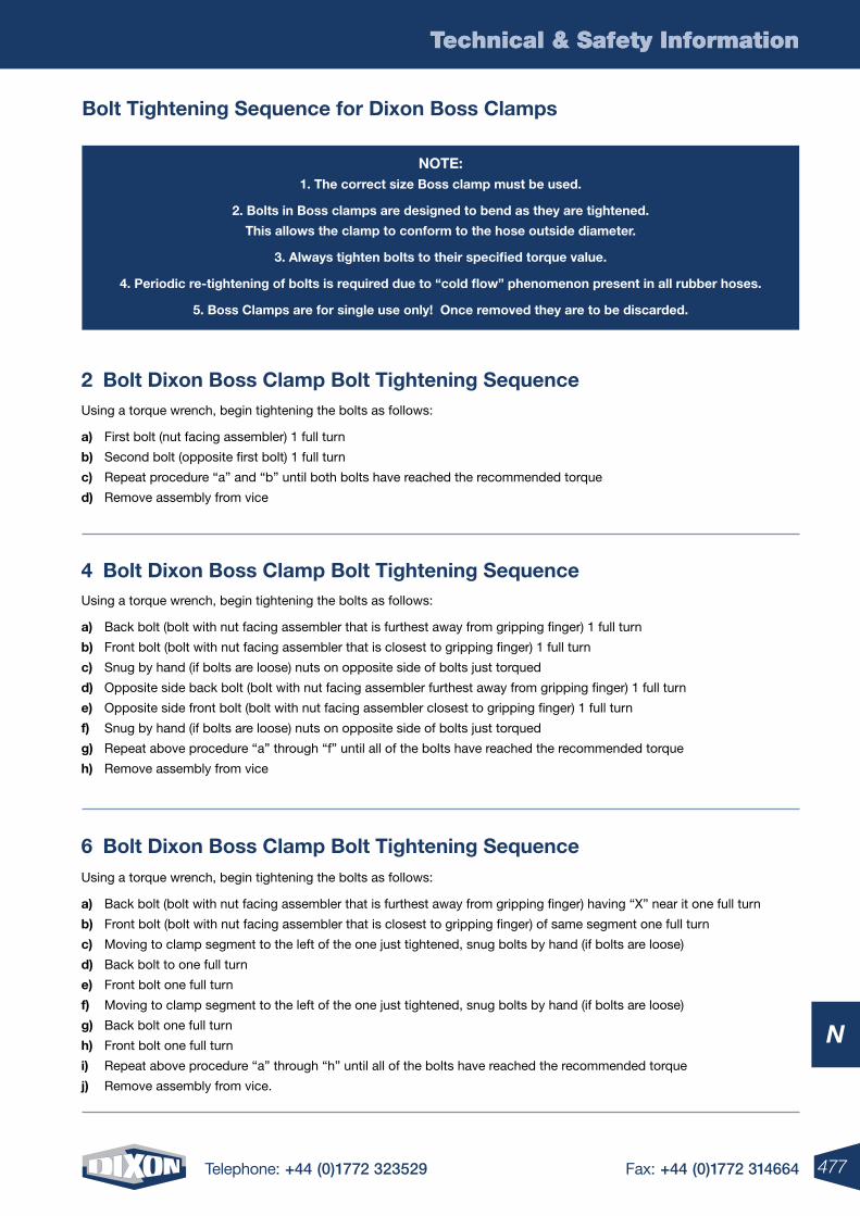
477Telephone: +44 (0)1772 323529 Fax: +44 (0)1772 314664
Technical & Safety Information
N
Technical & Safety Information
Bolt Tightening Sequence for Dixon Boss Clamps
noTE:1. The correct size Boss clamp must be used.
2. Bolts in Boss clamps are designed to bend as they are tightened.
This allows the clamp to conform to the hose outside diameter.
3. Always tighten bolts to their specified torque value.
4. Periodic re-tightening of bolts is required due to “cold flow” phenomenon present in all rubber hoses.
5. Boss Clamps are for single use only! once removed they are to be discarded.
2 Bolt Dixon Boss Clamp Bolt Tightening SequenceUsing a torque wrench, begin tightening the bolts as follows:
a) First bolt (nut facing assembler) 1 full turn
b) Second bolt (opposite first bolt) 1 full turn
c) Repeat procedure “a” and “b” until both bolts have reached the recommended torque
d) Remove assembly from vice
4 Bolt Dixon Boss Clamp Bolt Tightening SequenceUsing a torque wrench, begin tightening the bolts as follows:
a) Back bolt (bolt with nut facing assembler that is furthest away from gripping finger) 1 full turn
b) Front bolt (bolt with nut facing assembler that is closest to gripping finger) 1 full turn
c) Snug by hand (if bolts are loose) nuts on opposite side of bolts just torqued
d) Opposite side back bolt (bolt with nut facing assembler furthest away from gripping finger) 1 full turn
e) Opposite side front bolt (bolt with nut facing assembler closest to gripping finger) 1 full turn
f) Snug by hand (if bolts are loose) nuts on opposite side of bolts just torqued
g) Repeat above procedure “a” through “f” until all of the bolts have reached the recommended torque
h) Remove assembly from vice
6 Bolt Dixon Boss Clamp Bolt Tightening SequenceUsing a torque wrench, begin tightening the bolts as follows:
a) Back bolt (bolt with nut facing assembler that is furthest away from gripping finger) having “X” near it one full turn
b) Front bolt (bolt with nut facing assembler that is closest to gripping finger) of same segment one full turn
c) Moving to clamp segment to the left of the one just tightened, snug bolts by hand (if bolts are loose)
d) Back bolt to one full turn
e) Front bolt one full turn
f) Moving to clamp segment to the left of the one just tightened, snug bolts by hand (if bolts are loose)
g) Back bolt one full turn
h) Front bolt one full turn
i) Repeat above procedure “a” through “h” until all of the bolts have reached the recommended torque
j) Remove assembly from vice.
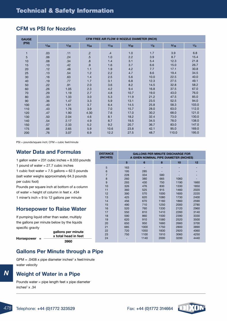
478 Telephone: +44 (0)1772 323529 Fax: +44 (0)1772 314664
Technical & Safety Information
N
Technical & Safety Information
PSI = pounds/square inch; CFM = cubic feet/minute
Water Data and Formulas
----
1660185020202220240025902780296031403330350037003890406042504440
---
10601190133014601600173018602000212022602390252026602800292030603200
--
5806657508309151000108011601250133014101500158016601750183019102000
-2853343804304765255706206707107608108609109501000105011001140
163195228260293326360390425456490520550590620650685720750
-
56789101112131415161718192021222324
GAllonS PER MInUTE DISCHARGE FoR A GIVEn noMInAl PIPE DIAMETER (InCHES)
DISTAnCE(InCHES)
6 8 10 12 51 gallon water = 231 cubic inches = 8.333 pounds
1 pound of water = 27.7 cubic inches
1 cubic foot water = 7.5 gallons = 62.5 pounds
(salt water weighs approximately 64.3 pounds
per cubic foot)
Pounds per square inch at bottom of a column
of water = height of column in feet x .434
1 miner’s inch = 9 to 12 gallons per minute
Pounds water = pipe length feet x pipe diameter
inches2 x .34
GPM = .0408 x pipe diameter inches2 x feet/minute
water velocity
If pumping liquid other than water, multiply
the gallons per minute below by the liquids
specific gravity
Horsepower =
gallons per minute x total head in feet
3960
CFM vs PSI for nozzles
CFM FREE AIR FloW @ noZZlE DIAMETER (InCH)
6.815.421.826.730.834.540.049.158.267.076.085.094.0103.0112.0121.0130.0138.0147.0169.0195.0
3.98.712.315.017.119.422.527.532.837.543.047.552.558.363.068.073.078.083.095.0110.0
1.73.95.46.67.78.610.012.314.516.819.021.223.525.828.030.232.434.536.742.148.7
1.02.23.13.74.24.75.66.88.29.410.711.913.114.515.717.018.219.520.723.827.5
.41.01.41.61.92.22.53.13.64.24.85.35.96.47.07.68.18.79.210.612.2
.2
.5
.8
.91.11.21.41.72.02.32.73.03.33.73.94.304.64.95.25.96.9
.11
.24
.34
.42
.48
.54
.63
.77
.911.051.191.331.471.611.761.902.042.172.332.653.07
.03
.06
.08
.10
.12
.13
.16
.19
.22
.26
.29
.33
.36
.40
.43
.47
.50
.54
.57
.66
.76
151015202530405060708090100110120130140150175200
1/43/161/83/321/64 1/32 3/64 1/16
GAUGE(PSI)
Weight of Water in a Pipe
Gallons Per Minute through a Pipe
Horsepower to Raise Water
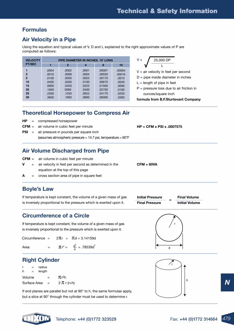
479Telephone: +44 (0)1772 323529 Fax: +44 (0)1772 314664
Technical & Safety Information
N
Technical & Safety Information
Formulas
Using the equation and typical values of V, D and L explained to the right approximate values of P are computed as follows:
Air Velocity in a Pipe
.00004
.00016.0010.0040.0090.0160.0250.0360
.00007
.00030
.00170
.00670
.01500
.02700
.04170
.06000
.0001
.0004
.0025
.0100
.0225
.0400
.0625
.0900
.0002
.0008
.0050
.0200
.04500080.1250.1800
.0004
.0016
.0100
.0400
.0900
.1600
.2500
.3600
1251015202530
PIPE DIAMETER In InCHES, 10’ lonGVEloCITYFT/SEC 106421
V = air velocity in feet per second
D = pipe inside diameter in inches
L = length of pipe in feet
P = pressure loss due to air friction in
ounces/square inch
formula from B.F.Sturtevant Company
25,000 DP
L
V =
Theoretical Horsepower to Compress Air
HP = CFM x PSI x .0007575
HP = compressed horsepower
CFM = air volume in cubic feet per minute
PSI = air pressure in pounds per square inch
(assumes atmospheric pressure = 14.7 psi, temperature = 60°F
Air Volume Discharged from Pipe
CFM = 60VA
CFM = air volume in cubic feet per minute
V = air velocity in feet per second as determined in the
equation at the top of this page
A = cross section area of pipe in square feet
r
d
r
h
Circumference of a CircleIf temperature is kept constant, the volume of a given mass of gas
is inversely proportional to the pressure which is exerted upon it.
Circumference = 2 r = d = 3.14159d
Area = r2 = = .78539d2d2
4
Right Cylinder
Volume = r2h
Surface Area = 2 r (r+h)
r = radiush = length
If end planes are parallel but not at 90° to h, the same formulas apply,
but a slice at 90° through the cylinder must be used to determine r.
Boyle’s lawInitial Pressure
Final Pressure=
Final Volume
Initial Volume
If temperature is kept constant, the volume of a given mass of gas
is inversely proportional to the pressure which is exerted upon it.
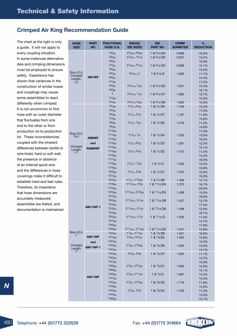
480 Telephone: +44 (0)1772 323529 Fax: +44 (0)1772 314664
Technical & Safety Information
N
Technical & Safety Information
Crimped Air king Recommendation Guide
The chart at the right is only
a guide. It will not apply to
every coupling situation.
In some instances alternative
dies and crimping dimensions
must be employed to ensure
safety. Experience has
shown that variances in the
construction of similar hoses
and couplings may cause
some assemblies to react
differently when crimped.
It is not uncommon to find
hose with an outer diameter
that fluctuates from one
end to the other or from
production lot to production
lot. These inconsistencies
coupled with the inherent
differences between textile or
wire braid, hard or soft wall,
the presence or absence
of an internal spiral wire
and the differences in hose
coverings make it difficult to
establish hard and fast rules.
Therefore, its imperative
that hose dimensions are
accurately measured,
assemblies are tested, and
documentation is maintained.
18.3%13.2%16.9%12.1%15.5%11.1%14.4%17.2%13.4%16.1%12.7%15.3%12.0%13.4%17.3%11.9%15.8%11.2%14.6%17.5%13.0%16.2%12.3%15.1%11.5%14.4%16.9%13.5%15.9%12.6%15.0%12.1%16.7%20.5%15.0%18.6%13.7%17.5%12.8%16.1%11.5%14.7%17.6%13.9%16.8%12.8%15.4%12.0%14.7%11.1%13.7%15.9%12.9%15.1%12.4%14.5%11.8%14.0%11.3%13.3%15.1%
0.9060.937
0.968
1.000
1.031
1.062
1.0931.156
1.187
1.218
1.250
1.281
1.312
1.343
1.375
1.4061.375
1.406
1.437
1.468
1.500
1.5311.5311.562
1.593
1.625
1.656
1.687
1.718
1.750
54/6455/6456/6457/6458/6459/6460/6461/6462/6463/64
111/64
12/64
14/64
15/64
16/64
17/64
18/64
19/64
110/64
111/64
112/64
113/64
114/64
115/64
116/64
117/64
118/64
119/64
120/64
121/64
122/64
118/64
119/64
120/64
121/64
122/64
123/64
124/64
125/64
126/64
127/64
128/64
129/64
130/64
131/64
132/64
133/64
134/64
135/64
136/64
137/64
138/64
139/64
140/64
141/64
142/64
143/64
144/64
145/64
146/64
13/16 x 29/32
13/16 x 15/16
13/16 x 31/16
13/16 x 1
13/16 x 1/32
13/16 x 1/16
13/16 x 3/32
11/2 x 5/32
11/2 x 3/16
11/2 x 7/32
11/2 x 1/4
11/2 x 9/32
11/2 x 5/16
11/2 x 11/32
11/2 x 13/8
11/2 x 113/32
111/16 x 13/8
111/16 x 113/32
111/16 x 17/16
111/16 x 17/16
111/16 x 11/2
111/16 x 117/32
17/8 x 117/32
17/8 x 19/16
17/8 x 119/32
17/8 x 15/8
17/8 x 121/32
17/8 x 111/16
17/8 x 123/32
17/8 x 13/4
1 & 3/16 D41 & 3/16 D5
1 & 3/16 D3
1 & 3/16 D
1 & 3/16 D2
1 & 3/16 D1
1 & 3/16 D61 & 1/2 D6
1 & 1/2 D7
1 & 1/2 D5
1 & 1/2 D4
1 & 1/2 D3
1 & 1/2 D2
1 & 1/2 D
1 & 1/2 D1
1 & 1/2 D81 & 11/16 D4
1 & 11/16 D5
1 & 11/16 D8
1 & 11/16 D6
1 & 11/16 D
1 & 11/16 D21 & 7/8 D81 & 7/8 D5
1 & 7/8 D6
1 & 7/8 D7
1 & 7/8 D1
1 & 7/8 D
1 & 7/8 D2
1 & 7/8 D4
Size (I.D.): 1”
Crimped Length:
1”
Size (I.D.): 3/4”
Crimped Length:
1˘”
Size (I.D.): Crimped Length:
1/2”
AM11WF
and
AM11WF-1
AM11WF
AM11WF-1
AM6WF
and
RAM6WF
AM1WF
SWAGE DIE SIZES
% REDUCTIon
FRACTIonAl HoSE o.D.
HoSE SIZE
PART no
CRIMP DIAMETER
DIE PART no
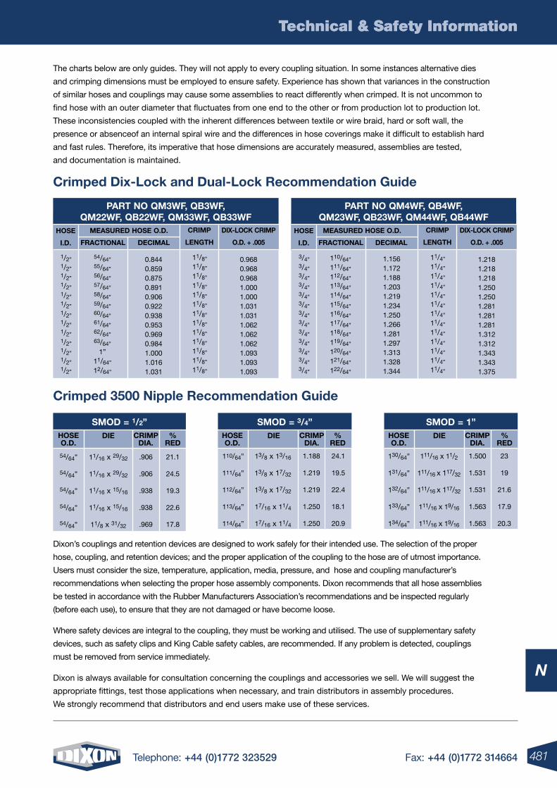
481Telephone: +44 (0)1772 323529 Fax: +44 (0)1772 314664
Technical & Safety Information
N
Technical & Safety Information
The charts below are only guides. They will not apply to every coupling situation. In some instances alternative dies
and crimping dimensions must be employed to ensure safety. Experience has shown that variances in the construction
of similar hoses and couplings may cause some assemblies to react differently when crimped. It is not uncommon to
find hose with an outer diameter that fluctuates from one end to the other or from production lot to production lot.
These inconsistencies coupled with the inherent differences between textile or wire braid, hard or soft wall, the
presence or absenceof an internal spiral wire and the differences in hose coverings make it difficult to establish hard
and fast rules. Therefore, its imperative that hose dimensions are accurately measured, assemblies are tested,
and documentation is maintained.
Crimped Dix-lock and Dual-lock Recommendation Guide
Crimped 3500 nipple Recommendation Guide
PART no QM3WF, QB3WF, QM22WF, QB22WF, QM33WF, QB33WF
1/2”1/2”1/2”1/2”1/2”1/2”1/2”1/2”1/2”1/2”1/2”1/2”1/2”
54/64”55/64”56/64”57/64”58/64”59/64”60/64”61/64”62/64”63/64”
1”11/64”
12/64”
0.8440.8590.8750.8910.9060.9220.9380.9530.9690.9841.0001.0161.031
11/8”
11/8”
11/8”
11/8”
11/8”
11/8”
11/8”
11/8”
11/8”
11/8”
11/8”
11/8”
11/8”
0.9680.9680.9681.0001.0001.0311.0311.0621.0621.0621.0931.0931.093
HoSE
I.D.
MEASURED HoSE o.D.
FRACTIonAl DECIMAl
CRIMP
lEnGTH
DIX-loCk CRIMP
o.D. + .005
PART no QM4WF, QB4WF, QM23WF, QB23WF, QM44WF, QB44WF
3/4”3/4”3/4”3/4”3/4”3/4”3/4”3/4”3/4”3/4”3/4”3/4”3/4”
110/64”
111/64”
112/64”
113/64”
114/64”
115/64”
116/64”
117/64”
118/64”
119/64”
120/64”
121/64”
122/64”
1.1561.1721.1881.2031.2191.2341.2501.2661.2811.2971.3131.3281.344
11/4”
11/4”
11/4”
11/4”
11/4”
11/4”
11/4”
11/4”
11/4”
11/4”
11/4”
11/4”
11/4”
1.2181.2181.2181.2501.2501.2811.2811.2811.3121.3121.3431.3431.375
HoSE
I.D.
MEASURED HoSE o.D.
FRACTIonAl DECIMAl
CRIMP
lEnGTH
DIX-loCk CRIMP
o.D. + .005
Dixon’s couplings and retention devices are designed to work safely for their intended use. The selection of the proper
hose, coupling, and retention devices; and the proper application of the coupling to the hose are of utmost importance.
Users must consider the size, temperature, application, media, pressure, and hose and coupling manufacturer’s
recommendations when selecting the proper hose assembly components. Dixon recommends that all hose assemblies
be tested in accordance with the Rubber Manufacturers Association’s recommendations and be inspected regularly
(before each use), to ensure that they are not damaged or have become loose.
Where safety devices are integral to the coupling, they must be working and utilised. The use of supplementary safety
devices, such as safety clips and King Cable safety cables, are recommended. If any problem is detected, couplings
must be removed from service immediately.
Dixon is always available for consultation concerning the couplings and accessories we sell. We will suggest the
appropriate fittings, test those applications when necessary, and train distributors in assembly procedures.
We strongly recommend that distributors and end users make use of these services.
SMoD = 1/2”
54/64”
54/64”
54/64”
54/64”
54/64”
11/16 x 29/32
11/16 x 29/32
11/16 x 15/16
11/16 x 15/16
11/8 x 31/32
.906
.906
.938
.938
.969
21.1
24.5
19.3
22.6
17.8
HoSEo.D.
CRIMPDIA.
%RED
DIE
SMoD = 3/4”
110/64”
111/64”
112/64”
113/64”
114/64”
13/8 x 13/16
13/8 x 17/32
13/8 x 17/32
17/16 x 11/4
17/16 x 11/4
1.188
1.219
1.219
1.250
1.250
24.1
19.5
22.4
18.1
20.9
HoSEo.D.
CRIMPDIA.
%RED
DIE
SMoD = 1”
130/64”
131/64”
132/64”
133/64”
134/64”
111/16 x 11/2
111/16 x 117/32
111/16 x 117/32
111/16 x 19/16
111/16 x 19/16
1.500
1.531
1.531
1.563
1.563
23
19
21.6
17.9
20.3
HoSEo.D.
CRIMPDIA.
%RED
DIE
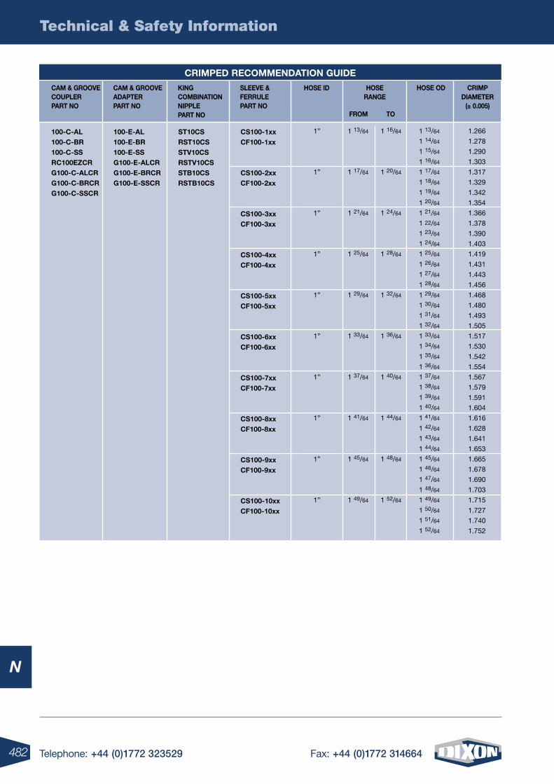
482 Telephone: +44 (0)1772 323529 Fax: +44 (0)1772 314664
Technical & Safety Information
N
CAM & GRooVE CoUPlER PART no
CAM & GRooVE ADAPTER PART no
kInG CoMBInATIon nIPPlE PART no
HoSE ID SlEEVE & FERRUlE PART no
HoSE RAnGE
FRoM To
HoSE oD CRIMP DIAMETER
(± 0.005)
100-C-Al 100-C-BR 100-C-SS RC100EZCR G100-C-AlCR G100-C-BRCR G100-C-SSCR
100-E-Al 100-E-BR 100-E-SS G100-E-AlCR G100-E-BRCR G100-E-SSCR
ST10CS RST10CS STV10CS RSTV10CS STB10CS RSTB10CS
CS100-1xx CF100-1xx
CS100-2xx CF100-2xx
CS100-3xx CF100-3xx
CS100-4xx CF100-4xx
CS100-5xx CF100-5xx
CS100-6xx CF100-6xx
CS100-7xx CF100-7xx
CS100-8xx CF100-8xx
CS100-9xx CF100-9xx
CS100-10xx CF100-10xx
1”
1”
1”
1”
1”
1”
1”
1”
1”
1”
1 13/64
1 14/64
1 15/64
1 16/64
1 17/64
1 18/64
1 19/64
1 20/64
1 21/64
1 22/64
1 23/64
1 24/64
1 25/64
1 26/64
1 27/64
1 28/64
1 29/64
1 30/64
1 31/64
1 32/64
1 33/64
1 34/64
1 35/64
1 36/64
1 37/64
1 38/64
1 39/64
1 40/64
1 41/64
1 42/64
1 43/64
1 44/64
1 45/64
1 46/64
1 47/64
1 48/64
1 49/64
1 50/64
1 51/64
1 52/64
1.266
1.278
1.290
1.303
1.317
1.329
1.342
1.354
1.366
1.378
1.390
1.403
1.419
1.431
1.443
1.456
1.468
1.480
1.493
1.505
1.517
1.530
1.542
1.554
1.567
1.579
1.591
1.604
1.616
1.628
1.641
1.653
1.665
1.678
1.690
1.703
1.715
1.727
1.740
1.752
1 13/64
1 17/64
1 21/64
1 25/64
1 29/64
1 33/64
1 37/64
1 41/64
1 45/64
1 49/64
1 16/64
1 20/64
1 24/64
1 28/64
1 32/64
1 36/64
1 40/64
1 44/64
1 48/64
1 52/64
CRIMPED RECoMMEnDATIon GUIDE
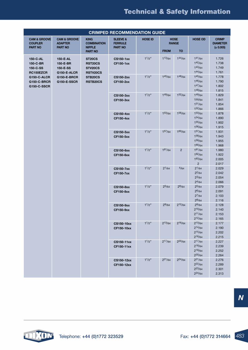
483Telephone: +44 (0)1772 323529 Fax: +44 (0)1772 314664
Technical & Safety Information
N
CAM & GRooVE CoUPlER PART no
CAM & GRooVE ADAPTER PART no
kInG CoMBInATIon nIPPlE PART no
HoSE ID SlEEVE & FERRUlE PART no
HoSE RAnGE
FRoM To
HoSE oD CRIMP DIAMETER
(± 0.005)
150-C-Al 150-C-BR 150-C-SS RC150EZCR G150-C-AlCR G150-C-BRCR G150-C-SSCR
150-E-Al 150-E-BR 150-E-SS G150-E-AlCR G150-E-BRCR G150-E-SSCR
ST20CS RST20CS STV20CS RSTV20CS STB20CS RSTB20CS
CS150-1xx CF150-1xx
CS150-2xx CF150-2xx
CS150-3xx CF150-3xx
CS150-4xx CF150-4xx
CS150-5xx CF150-5xx
CS150-6xx CF150-6xx
CS150-7xx CF150-7xx
CS150-8xx CF150-8xx
CS150-9xx CF150-9xx
CS150-10xx CF150-10xx
CS150-11xx CF150-11xx
CS150-12xx CF150-12xx
11/2”
11/2”
11/2”
11/2”
11/2”
11/2”
11/2”
11/2”
11/2”
11/2”
11/2”
11/2”
141/64
142/64
143/64
144/64
145/64
146/64
147/64
148/64
149/64
150/64
151/64
152/64
153/64
154/64
155/64
156/64
157/64
158/64
159/64
160/64
161/64
162/64
163/64
2
21/64
22/64
23/64
24/64
25/64
26/64
27/64
28/64
29/64
210/64
211/64
212/64
213/64
214/64
215/64
216/64
217/64
218/64
219/64
220/64
221/64
222/64
223/64
224/64
1.726
1.738
1.749
1.761
1.778
1.790
1.802
1.815
1.829
1.841
1.854
1.866
1.878
1.890
1.902
1.915
1.931
1.943
1.955
1.968
1.980
1.922
2.005
2.017
2.029
2.042
2.054
2.066
2.079
2.091
2.103
2.116
2.128
2.140
2.153
2.165
2.177
2.190
2.202
2.215
2.227
2.239
2.252
2.264
2.276
2.289
2.301
2.313
113/64
145/64
149/64
153/64
157/64
161/64
21/64
25/64
29/64
213/64
217/64
221/64
144/64
148/64
152/64
156/64
160/64
2
4/64
28/64
212/64
216/64
220/64
224/64
CRIMPED RECoMMEnDATIon GUIDE
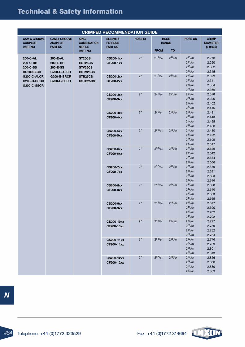
484 Telephone: +44 (0)1772 323529 Fax: +44 (0)1772 314664
Technical & Safety Information
N
CAM & GRooVE CoUPlER PART no
CAM & GRooVE ADAPTER PART no
kInG CoMBInATIon nIPPlE PART no
HoSE ID SlEEVE & FERRUlE PART no
HoSE RAnGE
FRoM To
HoSE oD CRIMP DIAMETER
(± 0.005)
200-C-Al 200-C-BR 200-C-SS RC200EZCR G200-C-AlCR G200-C-BRCR G200-C-SSCR
200-E-Al 200-E-BR 200-E-SS G200-E-AlCR G200-E-BRCR G200-E-SSCR
ST25CS RST25CS STV25CS RSTV25CS STB25CS RSTB25CS
CRIMPED RECoMMEnDATIon GUIDE
CS200-1xx CF200-1xx
CS200-2xx CF200-2xx
CS200-3xx CF200-3xx
CS200-4xx CF200-4xx
CS200-5xx CF200-5xx
CS200-6xx CF200-6xx
CS200-7xx CF200-7xx
CS200-8xx CF200-8xx
CS200-9xx CF200-9xx
CS200-10xx CF200-10xx
CS200-11xx CF200-11xx
CS200-12xx CF200-12xx
2”
2”
2”
2”
2”
2”
2”
2”
2”
2”
2”
2”
213/64
214/64
215/64
216/64
217/64
218/64
219/64
220/64
221/64
222/64
223/64
224/64
225/64
226/64
227/64
228/64
229/64
230/64
231/64
232/64
233/64
234/64
235/64
236/64
237/64
238/64
239/64
240/64
241/64
242/64
243/64
244/64
245/64
246/64
247/64
248/64
249/64
250/64
251/64
252/64
253/64
254/64
255/64
256/64
257/64
258/64
259/64
260/64
2.278
2.290
2.302
2.315
2.329
2.341
2.354
2.366
2.378
2.390
2.402
2.415
2.431
2.443
2.455
2.468
2.480
2.492
2.505
2.517
2.529
2.542
2.554
2.566
2.579
2.591
2.603
2.616
2.628
2.640
2.653
2.665
2.677
2.690
2.702
2.792
2.727
2.739
2.752
2.764
2.776
2.789
2.801
2.813
2.826
2.838
2.850
2.863
213/64
217/64
221/64
225/64
229/64
233/64
237/64
241/64
245/64
249/64
253/64
257/64
216/64
220/64
224/64
228/64
232/64
236/64
240/64
244/64
248/64
252/64
256/64
260/64
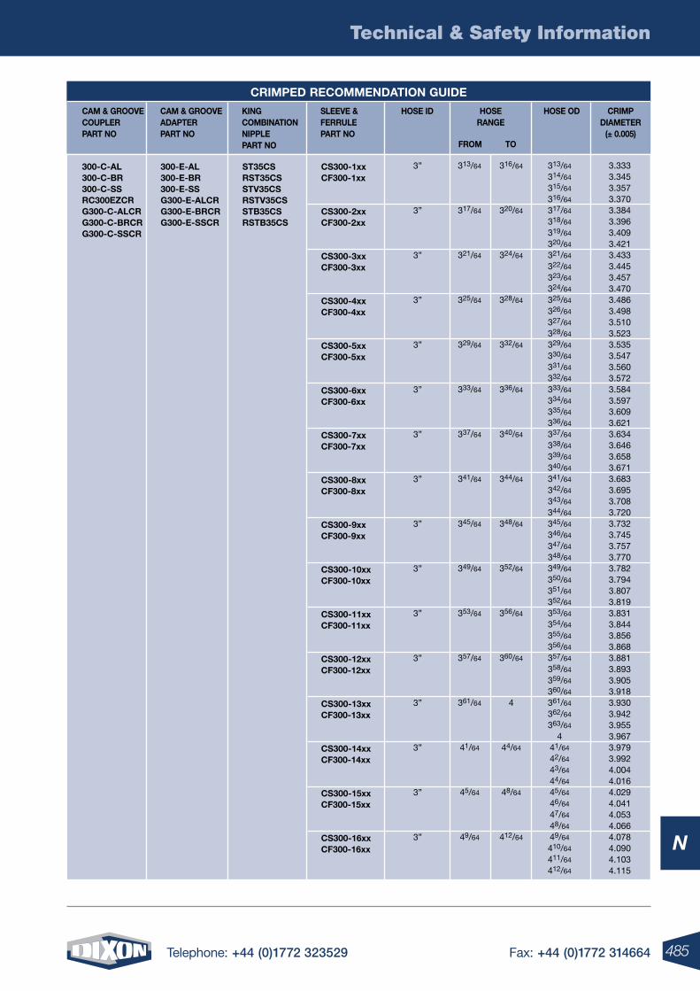
485Telephone: +44 (0)1772 323529 Fax: +44 (0)1772 314664
Technical & Safety Information
N
CAM & GRooVE CoUPlER PART no
CAM & GRooVE ADAPTER PART no
kInG CoMBInATIon nIPPlE PART no
HoSE ID SlEEVE & FERRUlE PART no
HoSE RAnGE
FRoM To
HoSE oD CRIMP DIAMETER
(± 0.005)
300-C-Al 300-C-BR 300-C-SS RC300EZCR G300-C-AlCR G300-C-BRCR G300-C-SSCR
300-E-Al 300-E-BR 300-E-SS G300-E-AlCR G300-E-BRCR G300-E-SSCR
ST35CS RST35CS STV35CS RSTV35CS STB35CS RSTB35CS
CS300-1xx CF300-1xx
CS300-2xx CF300-2xx
CS300-3xx CF300-3xx
CS300-4xx CF300-4xx
CS300-5xx CF300-5xx
CS300-6xx CF300-6xx
CS300-7xx CF300-7xx
CS300-8xx CF300-8xx
CS300-9xx CF300-9xx
CS300-10xx CF300-10xx
CS300-11xx CF300-11xx
CS300-12xx CF300-12xx
CS300-13xx CF300-13xx
CS300-14xx CF300-14xx
CS300-15xx CF300-15xx
CS300-16xx CF300-16xx
3”
3”
3”
3”
3”
3”
3”
3”
3”
3”
3”
3”
3”
3”
3”
3”
CRIMPED RECoMMEnDATIon GUIDE
313/64
317/64
321/64
325/64
329/64
333/64
337/64
341/64
345/64
349/64
353/64
357/64
361/64
41/64
45/64
49/64
316/64
320/64
324/64
328/64
332/64
336/64
340/64
344/64
348/64
352/64
356/64
360/64
4
44/64
48/64
412/64
313/64
314/64
315/64
316/64
317/64
318/64
319/64
320/64
321/64
322/64
323/64
324/64
325/64
326/64
327/64
328/64
329/64
330/64
331/64
332/64
333/64
334/64
335/64
336/64
337/64
338/64
339/64
340/64
341/64
342/64
343/64
344/64
345/64
346/64
347/64
348/64
349/64
350/64
351/64
352/64
353/64
354/64
355/64
356/64
357/64
358/64
359/64
360/64
361/64
362/64
363/64
441/64
42/64
43/64
44/64
45/64
46/64
47/64
48/64
49/64
410/64
411/64
412/64
3.3333.3453.3573.3703.3843.3963.4093.4213.4333.4453.4573.4703.4863.4983.5103.5233.5353.5473.5603.5723.5843.5973.6093.6213.6343.6463.6583.6713.6833.6953.7083.7203.7323.7453.7573.7703.7823.7943.8073.8193.8313.8443.8563.8683.8813.8933.9053.9183.9303.9423.9553.9673.9793.9924.0044.0164.0294.0414.0534.0664.0784.0904.1034.115
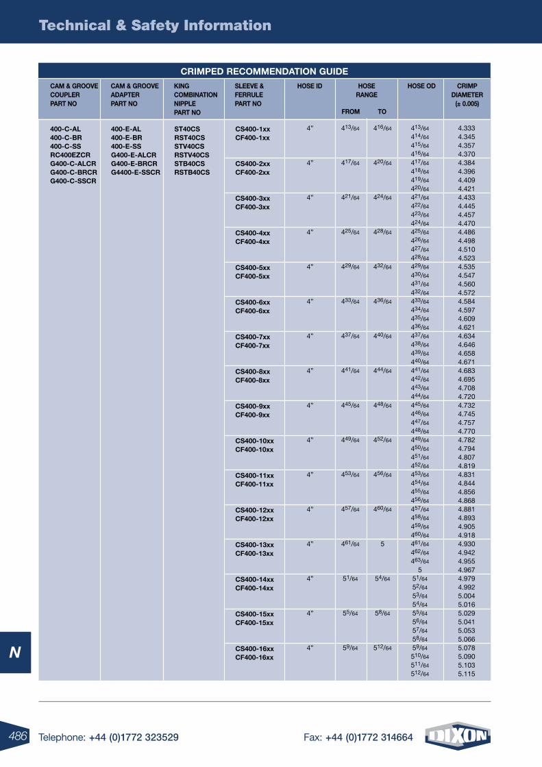
486 Telephone: +44 (0)1772 323529 Fax: +44 (0)1772 314664
Technical & Safety Information
N
CAM & GRooVE CoUPlER PART no
CAM & GRooVE ADAPTER PART no
kInG CoMBInATIon nIPPlE PART no
HoSE ID SlEEVE & FERRUlE PART no
HoSE RAnGE
FRoM To
HoSE oD CRIMP DIAMETER
(± 0.005)
400-C-Al 400-C-BR 400-C-SS RC400EZCR G400-C-AlCR G400-C-BRCR G400-C-SSCR
400-E-Al 400-E-BR 400-E-SS G400-E-AlCR G400-E-BRCR G4400-E-SSCR
ST40CS RST40CS STV40CS RSTV40CS STB40CS RSTB40CS
CS400-1xx CF400-1xx
CS400-2xx CF400-2xx
CS400-3xx CF400-3xx
CS400-4xx CF400-4xx
CS400-5xx CF400-5xx
CS400-6xx CF400-6xx
CS400-7xx CF400-7xx
CS400-8xx CF400-8xx
CS400-9xx CF400-9xx
CS400-10xx CF400-10xx
CS400-11xx CF400-11xx
CS400-12xx CF400-12xx
CS400-13xx CF400-13xx
CS400-14xx CF400-14xx
CS400-15xx CF400-15xx
CS400-16xx CF400-16xx
4”
4”
4”
4”
4”
4”
4”
4”
4”
4”
4”
4”
4”
4”
4”
4”
CRIMPED RECoMMEnDATIon GUIDE
413/64
417/64
421/64
425/64
429/64
433/64
437/64
441/64
445/64
449/64
453/64
457/64
461/64
51/64
55/64
59/64
416/64
420/64
424/64
428/64
432/64
436/64
440/64
444/64
448/64
452/64
456/64
460/64
5
54/64
58/64
512/64
413/64
414/64
415/64
416/64
417/64
418/64
419/64
420/64
421/64
422/64
423/64
424/64
425/64
426/64
427/64
428/64
429/64
430/64
431/64
432/64
433/64
434/64
435/64
436/64
437/64
438/64
439/64
440/64
441/64
442/64
443/64
444/64
445/64
446/64
447/64
448/64
449/64
450/64
451/64
452/64
453/64
454/64
455/64
456/64
457/64
458/64
459/64
460/64
461/64
462/64
463/64
551/64
52/64
53/64
54/64
55/64
56/64
57/64
58/64
59/64
510/64
511/64
512/64
4.3334.3454.3574.3704.3844.3964.4094.4214.4334.4454.4574.4704.4864.4984.5104.5234.5354.5474.5604.5724.5844.5974.6094.6214.6344.6464.6584.6714.6834.6954.7084.7204.7324.7454.7574.7704.7824.7944.8074.8194.8314.8444.8564.8684.8814.8934.9054.9184.9304.9424.9554.9674.9794.9925.0045.0165.0295.0415.0535.0665.0785.0905.1035.115
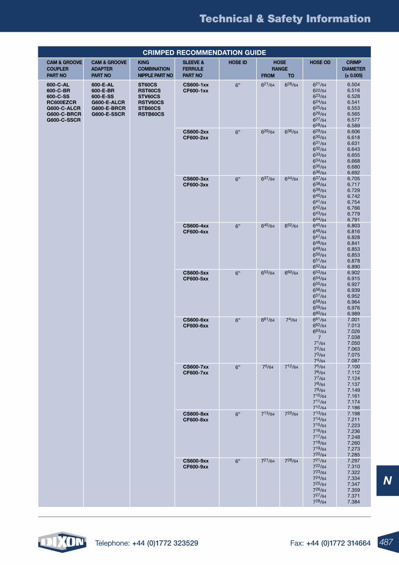
487Telephone: +44 (0)1772 323529 Fax: +44 (0)1772 314664
Technical & Safety Information
N
CAM & GRooVE CoUPlER PART no
CAM & GRooVE ADAPTER PART no
kInG CoMBInATIon nIPPlE PART no
HoSE ID SlEEVE & FERRUlE PART no
HoSE RAnGE
FRoM To
HoSE oD CRIMP DIAMETER
(± 0.005)
600-C-Al 600-C-BR 600-C-SS RC600EZCR G600-C-AlCR G600-C-BRCR G600-C-SSCR
600-E-Al 600-E-BR 600-E-SS G600-E-AlCR G600-E-BRCR G600-E-SSCR
ST60CS RST60CS STV60CS RSTV60CS STB60CS RSTB60CS
CS600-1xx CF600-1xx
CS600-2xx CF600-2xx
CS600-3xx CF600-3xx
CS600-4xx CF600-4xx
CS600-5xx CF600-5xx
CS600-6xx CF600-6xx
CS600-7xx CF600-7xx
CS600-8xx CF600-8xx
CS600-9xx CF600-9xx
6”
6”
6”
6”
6”
6”
6”
6”
6”
621/64
622/64
623/64
624/64
625/64
626/64
627/64
628/64
629/64
630/64
631/64
632/64
633/64
634/64
635/64
636/64
637/64
638/64
639/64
640/64
641/64
642/64
643/64
644/64
645/64
646/64
647/64
648/64
649/64
650/64
651/64
652/64
653/64
654/64
655/64
656/64
657/64
658/64
659/64
660/64
661/64
662/64
663/64
771/64
72/64
73/64
74/64
75/64
76/64
77/64
78/64
79/64
710/64
711/64
712/64
713/64
714/64
715/64
716/64
717/64
718/64
719/64
720/64
721/64
722/64
723/64
724/64
725/64
726/64
727/64
728/64
6.5046.5166.5286.5416.5536.5656.5776.5896.6066.6186.6316.6436.6556.6686.6806.6926.7056.7176.7296.7426.7546.7666.7796.7916.8036.8166.8286.8416.8536.8536.8786.8906.9026.9156.9276.9396.9526.9646.9766.9897.0017.0137.0267.0387.0507.0637.0757.0877.1007.1127.1247.1377.1497.1617.1747.1867.1987.2117.2237.2367.2487.2607.2737.2857.2977.3107.3227.3347.3477.3597.3717.384
621/64
629/64
637/64
645/64
653/64
661/64
75/64
713/64
721/64
628/64
636/64
644/64
652/64
660/64
74/64
712/64
720/64
728/64
CRIMPED RECoMMEnDATIon GUIDE
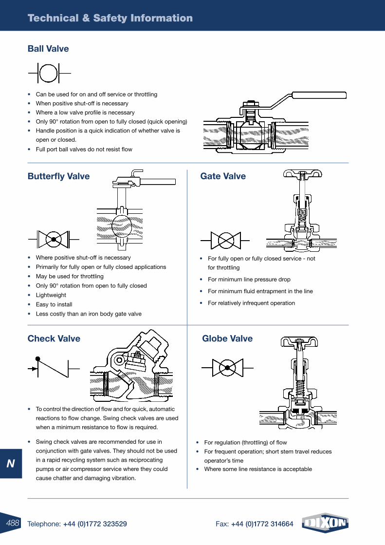
488 Telephone: +44 (0)1772 323529 Fax: +44 (0)1772 314664
Technical & Safety Information
N
• Can be used for on and off service or throttling
• When positive shut-off is necessary
• Where a low valve profile is necessary
• Only 90° rotation from open to fully closed (quick opening)
• Handle position is a quick indication of whether valve is
open or closed.
• Full port ball valves do not resist flow
• Where some line resistance is acceptable
Ball Valve
Globe Valve
Gate Valve
Check Valve
Butterfly Valve
• For fully open or fully closed service - not
for throttling
• For minimum line pressure drop
• For minimum fluid entrapment in the line
• For relatively infrequent operation
• Where positive shut-off is necessary
• Primarily for fully open or fully closed applications
• May be used for throttling
• Only 90° rotation from open to fully closed
• Lightweight
• Easy to install
• Less costly than an iron body gate valve
• To control the direction of flow and for quick, automatic
reactions to flow change. Swing check valves are used
when a minimum resistance to flow is required.
• Swing check valves are recommended for use in
conjunction with gate valves. They should not be used
in a rapid recycling system such as reciprocating
pumps or air compressor service where they could
cause chatter and damaging vibration.
• For regulation (throttling) of flow
• For frequent operation; short stem travel reduces
operator’s time
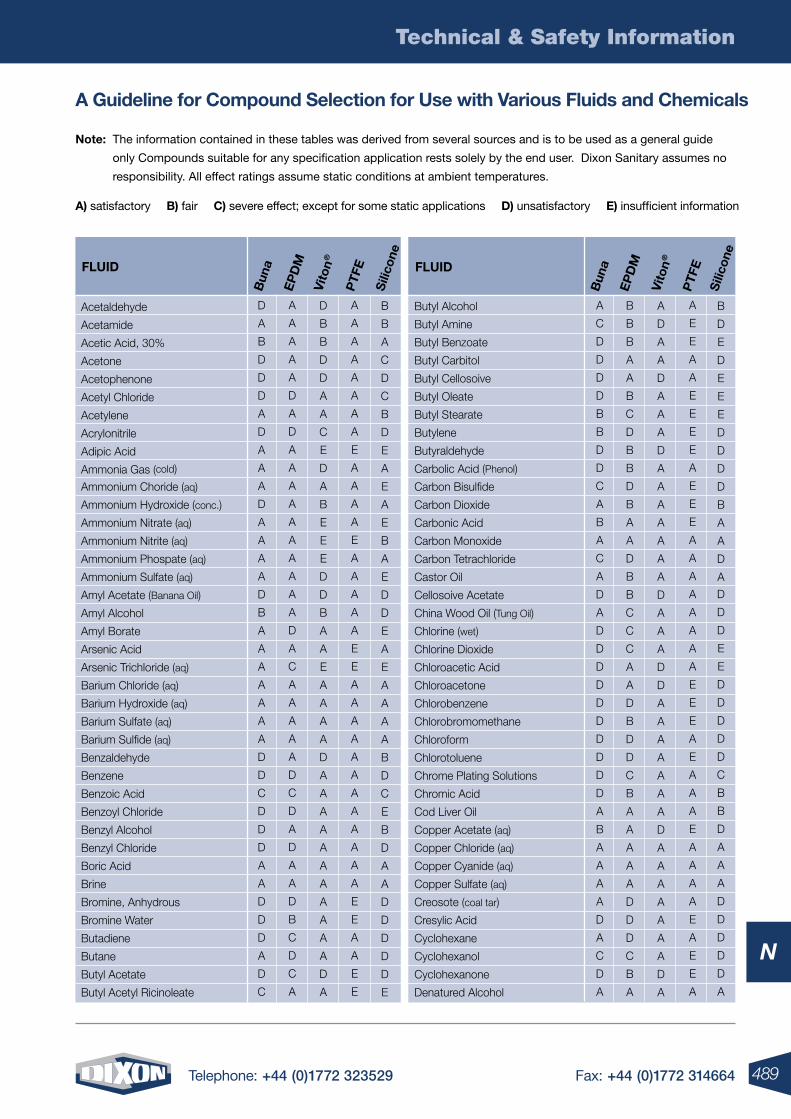
489Telephone: +44 (0)1772 323529 Fax: +44 (0)1772 314664
Technical & Safety Information
N
A Guideline for Compound Selection for Use with Various Fluids and Chemicals
note: The information contained in these tables was derived from several sources and is to be used as a general guide
only Compounds suitable for any specification application rests solely by the end user. Dixon Sanitary assumes no
responsibility. All effect ratings assume static conditions at ambient temperatures.
A) satisfactory B) fair C) severe effect; except for some static applications D) unsatisfactory E) insufficient information
A
A
A
A
A
D
A
D
A
A
A
A
A
A
A
A
A
A
D
A
C
A
A
A
A
A
D
C
D
A
D
A
A
D
B
C
D
C
A
D
A
B
D
D
D
A
D
A
A
A
D
A
A
A
A
D
B
A
A
A
A
A
A
A
D
D
C
D
D
D
A
A
D
D
D
A
D
C
D
B
B
D
D
A
A
C
E
D
A
B
E
E
E
D
D
B
A
A
E
A
A
A
A
D
A
A
A
A
A
A
A
A
A
A
A
D
A
B
B
A
C
D
C
B
D
E
A
E
A
E
B
A
E
D
D
E
A
E
A
A
A
A
B
D
C
E
B
D
A
A
D
D
D
D
D
E
Acetaldehyde
Acetamide
Acetic Acid, 30%
Acetone
Acetophenone
Acetyl Chloride
Acetylene
Acrylonitrile
Adipic Acid
Ammonia Gas (cold)
Ammonium Choride (aq)
Ammonium Hydroxide (conc.)
Ammonium Nitrate (aq)
Ammonium Nitrite (aq)
Ammonium Phospate (aq)
Ammonium Sulfate (aq)
Amyl Acetate (Banana Oil)
Amyl Alcohol
Amyl Borate
Arsenic Acid
Arsenic Trichloride (aq)
Barium Chloride (aq)
Barium Hydroxide (aq)
Barium Sulfate (aq)
Barium Sulfide (aq)
Benzaldehyde
Benzene
Benzoic Acid
Benzoyl Chloride
Benzyl Alcohol
Benzyl Chloride
Boric Acid
Brine
Bromine, Anhydrous
Bromine Water
Butadiene
Butane
Butyl Acetate
Butyl Acetyl Ricinoleate
FlUID
Sili
cone
PTF
E
Vito
n®
EP
DM
Bun
a
A
A
A
A
A
A
A
A
E
A
A
A
A
E
A
A
A
A
A
E
E
A
A
A
A
A
A
A
A
A
A
A
A
E
E
A
A
E
E
A
C
D
D
D
D
B
B
D
D
C
A
B
A
C
A
D
A
D
D
D
D
D
D
D
D
D
D
A
B
A
A
A
A
D
A
C
D
A
B
B
B
A
A
B
C
D
B
B
D
B
A
A
D
B
B
C
C
C
A
A
D
B
D
D
C
B
A
A
A
A
A
D
D
D
C
B
A
A
D
A
A
D
A
A
A
D
A
A
A
A
A
A
A
D
A
A
A
D
D
A
A
A
A
A
A
A
D
A
A
A
A
A
A
A
D
A
B
D
E
D
E
E
E
D
D
D
D
B
A
A
D
A
D
D
D
E
E
D
D
D
D
D
C
B
B
D
A
A
A
D
D
D
D
D
A
Butyl Alcohol
Butyl Amine
Butyl Benzoate
Butyl Carbitol
Butyl Cellosoive
Butyl Oleate
Butyl Stearate
Butylene
Butyraldehyde
Carbolic Acid (Phenol)
Carbon Bisulfide
Carbon Dioxide
Carbonic Acid
Carbon Monoxide
Carbon Tetrachloride
Castor Oil
Cellosoive Acetate
China Wood Oil (Tung Oil)
Chlorine (wet)
Chlorine Dioxide
Chloroacetic Acid
Chloroacetone
Chlorobenzene
Chlorobromomethane
Chloroform
Chlorotoluene
Chrome Plating Solutions
Chromic Acid
Cod Liver Oil
Copper Acetate (aq)
Copper Chloride (aq)
Copper Cyanide (aq)
Copper Sulfate (aq)
Creosote (coal tar)
Cresylic Acid
Cyclohexane
Cyclohexanol
Cyclohexanone
Denatured Alcohol
FlUID
Sili
cone
PTF
E
Vito
n®
EP
DM
Bun
a
A
E
E
A
A
E
E
E
E
A
E
E
E
A
A
A
A
A
A
A
A
E
E
E
A
E
A
A
A
E
A
A
A
A
E
A
E
E
A
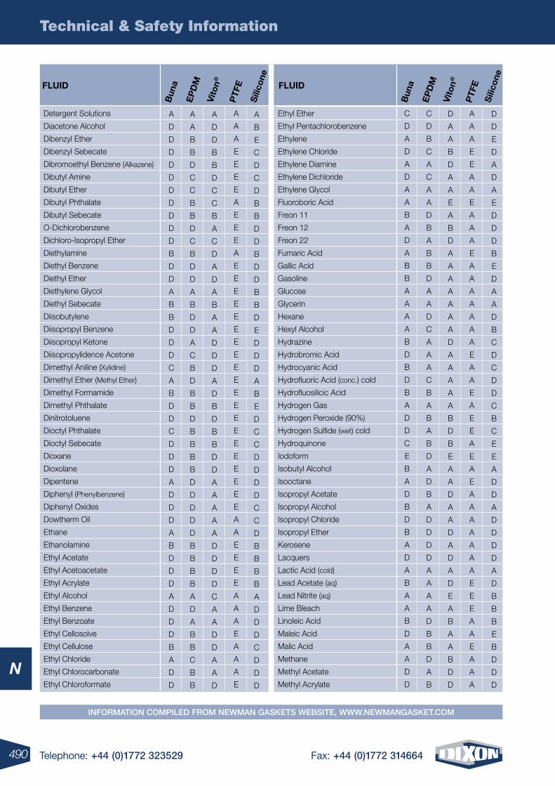
490 Telephone: +44 (0)1772 323529 Fax: +44 (0)1772 314664
Technical & Safety Information
N
C
D
A
D
A
D
A
A
B
A
D
A
B
B
A
A
A
A
B
D
B
D
B
A
D
D
C
E
B
A
D
B
D
B
A
D
A
B
A
A
B
D
A
A
D
D
C
D
B
C
A
C
A
A
D
B
A
B
B
D
A
A
D
C
A
A
A
C
B
A
B
A
B
D
A
D
B
A
D
D
D
D
A
A
A
A
D
B
B
D
A
B
D
A
A
B
D
A
A
E
A
B
D
A
A
A
A
A
A
A
D
A
A
A
A
A
B
D
B
E
A
A
D
A
A
D
A
D
A
D
E
A
B
A
A
B
D
D
D
D
E
D
A
D
A
E
D
D
D
B
E
D
A
A
D
B
C
D
C
D
D
C
B
C
E
E
A
D
D
A
D
D
D
D
A
D
B
B
B
E
B
D
D
D
A
D
D
D
D
D
D
D
D
D
D
B
D
D
A
B
B
D
D
D
C
A
B
D
D
C
D
D
D
A
D
D
D
A
B
D
D
D
A
D
D
D
B
A
D
D
A
A
B
B
D
C
C
B
B
D
C
B
D
D
A
B
D
D
A
C
B
D
B
B
D
B
B
B
B
D
D
D
D
D
B
B
B
B
A
D
A
B
B
C
B
B
A
D
D
B
B
D
C
C
B
A
C
D
A
D
A
B
A
A
D
D
D
A
D
B
D
B
B
D
D
A
A
A
A
A
D
D
D
D
C
A
A
D
D
A
A
D
A
B
E
C
D
C
D
B
B
D
D
B
D
D
B
B
D
E
D
D
D
A
B
E
D
C
C
D
D
D
D
C
C
D
B
B
B
B
A
D
D
D
C
D
D
D
Sili
cone
FlUID
PTF
E
Vito
n®
EP
DM
Bun
a
Ethyl Ether
Ethyl Pentachlorobenzene
Ethylene
Ethylene Chloride
Ethylene Diamine
Ethylene Dichloride
Ethylene Glycol
Fluoroboric Acid
Freon 11
Freon 12
Freon 22
Fumaric Acid
Gallic Acid
Gasoline
Glucose
Glycerin
Hexane
Hexyl Alcohol
Hydrazine
Hydrobromic Acid
Hydrocyanic Acid
Hydrofluoric Acid (conc.) cold
Hydrofluosilicic Acid
Hydrogen Gas
Hydrogen Peroxide (90%)
Hydrogen Sulfide (wet) cold
Hydroquinone
Iodoform
Isobutyl Alcohol
Isooctane
Isopropyl Acetate
Isopropyl Alcohol
Isopropyl Chloride
Isopropyl Ether
Kerosene
Lacquers
Lactic Acid (cold)
Lead Acetate (aq)
Lead Nitrite (aq)
Lime Bleach
Linoleic Acid
Maleic Acid
Malic Acid
Methane
Methyl Acetate
Methyl Acrylate
Sili
cone
FlUID
PTF
E
Vito
n®
EP
DM
Bun
a
Detergent Solutions
Diacetone Alcohol
Dibenzyl Ether
Dibenzyl Sebecate
Dibromoethyl Benzene (Alkazene)
Dibutyl Amine
Dibutyl Ether
Dibutyl Phthalate
Dibutyl Sebecate
O-Dichlorobenzene
Dichloro-Isopropyl Ether
Diethylamine
Diethyl Benzene
Diethyl Ether
Diethylene Glycol
Diethyl Sebecate
Diisobutylene
Diisopropyl Benzene
Diisopropyl Ketone
Diisopropylidence Acetone
Dimethyl Aniline (Xylidine)
Dimethyl Ether (Methyl Ether)
Dimethyl Formamide
Dimethyl Phthalate
Dinitrotoluene
Dioctyl Phthalate
Dioctyl Sebecate
Dioxane
Dioxolane
Dipentene
Diphenyl (Phenylbenzene)
Diphenyl Oxides
Dowtherm Oil
Ethane
Ethanolamine
Ethyl Acetate
Ethyl Acetoacetate
Ethyl Acrylate
Ethyl Alcohol
Ethyl Benzene
Ethyl Benzoate
Ethyl Cellosoive
Ethyl Cellulose
Ethyl Chloride
Ethyl Chlorocarbonate
Ethyl Chloroformate
A
A
A
E
E
E
E
A
E
E
E
A
E
E
E
E
E
E
E
E
E
E
E
E
E
E
E
E
E
E
E
E
A
A
E
E
E
E
A
A
A
E
A
A
A
E
A
A
A
E
E
A
A
E
A
A
A
E
A
A
A
A
A
A
A
E
A
A
E
A
E
E
A
E
A
E
A
A
A
A
A
A
A
E
E
E
A
A
E
A
A
A
InformatIon compIled from newman Gaskets websIte, www.newmanGasket.com
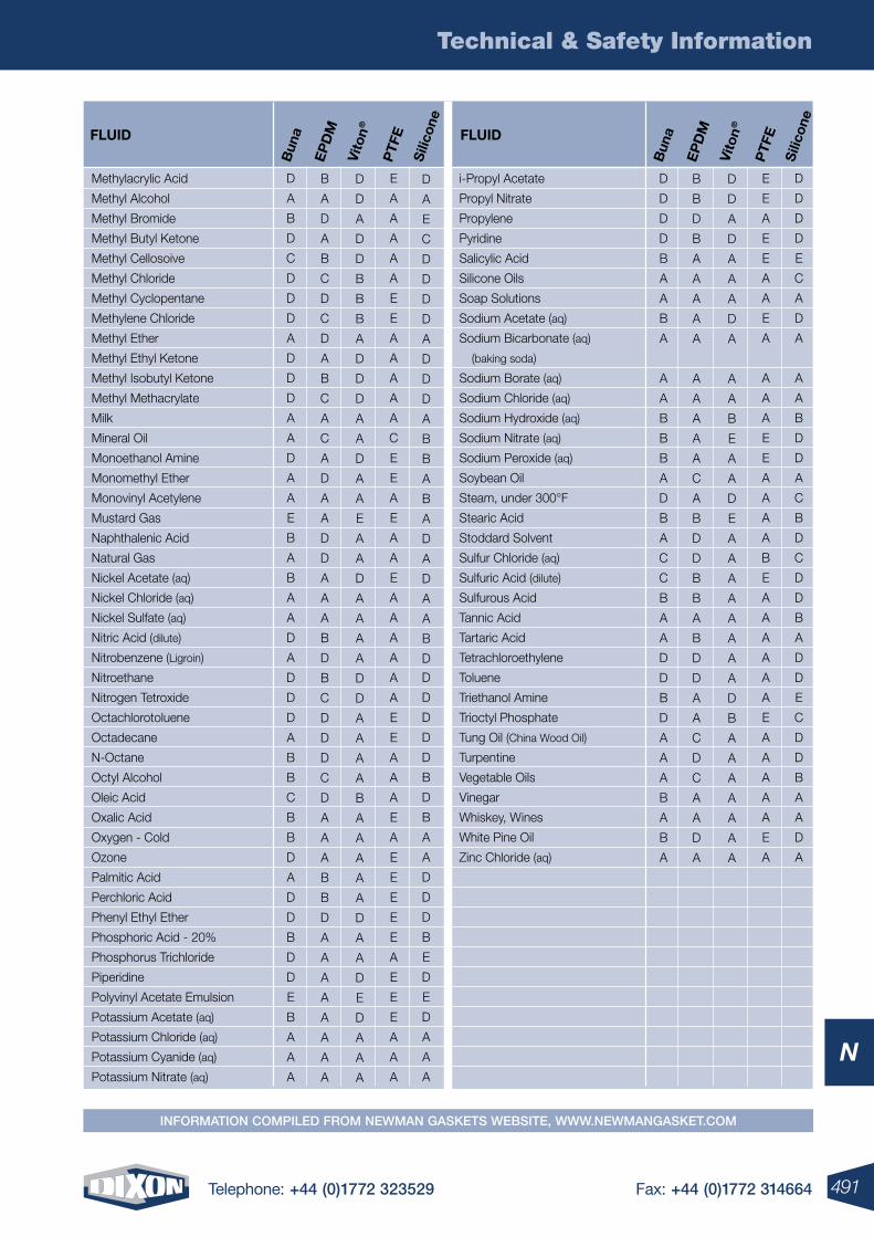
491Telephone: +44 (0)1772 323529 Fax: +44 (0)1772 314664
Technical & Safety Information
N
InformatIon compIled from newman Gaskets websIte, www.newmanGasket.com
D
D
D
D
E
C
A
D
A
A
A
B
D
D
A
C
B
D
C
D
D
B
A
D
D
E
C
D
D
B
A
A
D
A
D
D
D
D
B
A
A
B
A
A
A
B
B
B
A
D
B
A
C
C
B
A
A
D
D
B
D
A
A
A
B
A
B
A
B
B
D
B
A
A
A
A
A
A
A
A
A
A
C
A
B
D
D
B
B
A
B
D
D
A
A
C
D
C
A
A
D
A
D
D
A
D
A
A
A
D
A
A
A
B
E
A
A
D
E
A
A
A
A
A
A
A
A
D
B
A
A
A
A
A
A
A
Sili
cone
FlUID
PTF
E
Vito
n®
EP
DM
Bun
a
i-Propyl Acetate
Propyl Nitrate
Propylene
Pyridine
Salicylic Acid
Silicone Oils
Soap Solutions
Sodium Acetate (aq)
Sodium Bicarbonate (aq)
(baking soda)
Sodium Borate (aq)
Sodium Chloride (aq)
Sodium Hydroxide (aq)
Sodium Nitrate (aq)
Sodium Peroxide (aq)
Soybean Oil
Steam, under 300°F
Stearic Acid
Stoddard Solvent
Sulfur Chloride (aq)
Sulfuric Acid (dilute)
Sulfurous Acid
Tannic Acid
Tartaric Acid
Tetrachloroethylene
Toluene
Triethanol Amine
Trioctyl Phosphate
Tung Oil (China Wood Oil)
Turpentine
Vegetable Oils
Vinegar
Whiskey, Wines
White Pine Oil
Zinc Chloride (aq)
E
E
A
E
E
A
A
E
A
A
A
A
E
E
A
A
A
A
B
E
A
A
A
A
A
A
E
A
A
A
A
A
E
A
Sili
cone
D
A
B
D
C
D
D
D
A
D
D
D
A
A
D
A
A
E
B
A
B
A
A
D
A
D
D
D
A
B
B
C
B
B
D
A
D
D
B
D
D
E
B
A
A
A
B
A
D
A
B
C
D
C
D
A
B
C
A
C
A
D
A
A
D
D
A
A
A
B
D
B
C
D
D
D
C
D
A
A
A
B
B
D
A
A
A
A
A
A
A
A
D
D
A
D
D
B
B
B
A
D
D
D
A
A
D
A
A
E
A
A
D
A
A
A
A
D
D
A
A
A
A
B
A
A
A
A
A
D
A
A
D
E
D
A
A
A
D
A
E
C
D
D
D
D
A
D
D
D
A
B
B
A
B
A
D
A
D
A
A
B
D
D
D
D
D
D
B
D
B
A
A
D
D
D
B
E
D
E
D
A
A
A
FlUID
PTF
E
Vito
n®
EP
DM
Bun
a
Methylacrylic Acid
Methyl Alcohol
Methyl Bromide
Methyl Butyl Ketone
Methyl Cellosoive
Methyl Chloride
Methyl Cyclopentane
Methylene Chloride
Methyl Ether
Methyl Ethyl Ketone
Methyl Isobutyl Ketone
Methyl Methacrylate
Milk
Mineral Oil
Monoethanol Amine
Monomethyl Ether
Monovinyl Acetylene
Mustard Gas
Naphthalenic Acid
Natural Gas
Nickel Acetate (aq)
Nickel Chloride (aq)
Nickel Sulfate (aq)
Nitric Acid (dilute)
Nitrobenzene (Ligroin)
Nitroethane
Nitrogen Tetroxide
Octachlorotoluene
Octadecane
N-Octane
Octyl Alcohol
Oleic Acid
Oxalic Acid
Oxygen - Cold
Ozone
Palmitic Acid
Perchloric Acid
Phenyl Ethyl Ether
Phosphoric Acid - 20%
Phosphorus Trichloride
Piperidine
Polyvinyl Acetate Emulsion
Potassium Acetate (aq)
Potassium Chloride (aq)
Potassium Cyanide (aq)
Potassium Nitrate (aq)
E
A
A
A
A
A
E
E
A
A
A
A
A
C
E
E
A
E
A
A
E
A
A
A
A
A
A
E
E
A
A
A
E
A
E
E
E
E
E
A
E
E
E
A
A
A
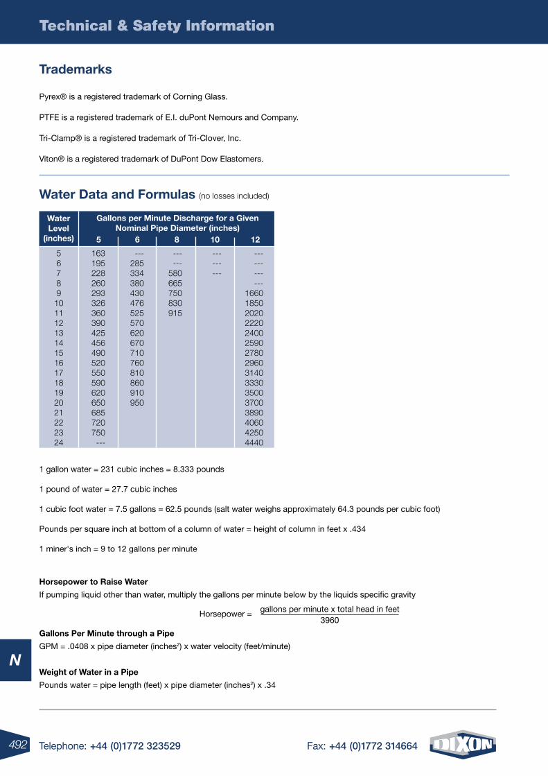
492 Telephone: +44 (0)1772 323529 Fax: +44 (0)1772 314664
Technical & Safety Information
N
Pyrex® is a registered trademark of Corning Glass.
PTFE is a registered trademark of E.I. duPont Nemours and Company.
Tri-Clamp® is a registered trademark of Tri-Clover, Inc.
Viton® is a registered trademark of DuPont Dow Elastomers.
Trademarks
Water Data and Formulas (no losses included)
Water level
(inches)
Gallons per Minute Discharge for a Given nominal Pipe Diameter (inches)
10865
56789101112131415161718192021222324
12
163195228260293326360390425456490520550590620650685720750
---
---285334380430476525570620670710760810860910950
------
580665750830915
---------
------------
1660185020202220240025902780296031403330350037003890406042504440
1 gallon water = 231 cubic inches = 8.333 pounds
1 pound of water = 27.7 cubic inches
1 cubic foot water = 7.5 gallons = 62.5 pounds (salt water weighs approximately 64.3 pounds per cubic foot)
Pounds per square inch at bottom of a column of water = height of column in feet x .434
1 miner's inch = 9 to 12 gallons per minute
Horsepower to Raise Water
If pumping liquid other than water, multiply the gallons per minute below by the liquids specific gravity
Gallons Per Minute through a Pipe
GPM = .0408 x pipe diameter (inches2) x water velocity (feet/minute)
Weight of Water in a Pipe
Pounds water = pipe length (feet) x pipe diameter (inches2) x .34
Horsepower = gallons per minute x total head in feet3960
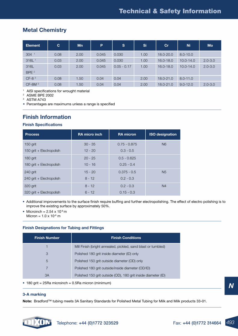
493Telephone: +44 (0)1772 323529 Fax: +44 (0)1772 314664
Technical & Safety Information
N
Finish Designations for Tubing and Fittings
1
3
5
7
3A
Finish number
Mill Finish (bright annealed, pickled, sand blast or tumbled)
Polished 180 grit inside diameter (ID) only
Polished 150 grit outside diameter (OD) only
Polished 180 grit outside/inside diameter (OD/ID)
Polished 150 grit outside (OD), 180 grit inside diameter (ID)
Finish Conditions
• Additional improvements to the surface finish require buffing and further electropolishing. The effect of electro polishing is to improve the existing surface by approximately 50%.
• Microinch = 2.54 x 10⁻⁸ m Micron = 1.0 x 10⁻⁶ m
Finish Information
Metal Chemistry
1 AISI specifications for wrought material2 ASME BPE 20023 ASTM A743• Percentages are maximums unless a range is specified
304 1
316L 1
316L
BPE 2
CF-8 3
CF-8M 3
Element C Mn P S Si Cr ni Mo
0.030
0.030
0.05 - 0.17
0.04
0.04
2.00
2.00
2.00
1.50
1.50
0.045
0.045
0.045
0.04
0.04
0.08
0.03
0.03
0.08
0.08
1.00
1.00
1.00
2.00
2.00
18.0-20.0
16.0-18.0
16.0-18.0
18.0-21.0
18.0-21.0
8.0-10.0
10.0-14.0
10.0-14.0
8.0-11.0
9.0-12.0
2.0-3.0
2.0-3.0
2.0-3.0
N6
N5
N4
ISo designation
0.75 - 0.875
0.3 - 0.5
0.5 - 0.625
0.25 - 0.4
0.375 - 0.5
0.2 - 0.3
0.2 - 0.3
0.15 - 0.3
RA micron
30 - 35
12 - 20
20 - 25
10 - 16
15 - 20
8 - 12
8 - 12
6 - 12
RA micro inch
150 grit
150 grit + Electropolish
180 grit
180 grit + Electropolish
240 grit
240 grit + Electropolish
320 grit
320 grit + Electropolish
Process
Finish Specifications
• 180 grit = 25Ra microinch = 0.5Ra micron (minimum)
note: Bradford™ tubing meets 3A Sanitary Standards for Polished Metal Tubing for Milk and Milk products 33-01.
3-A marking
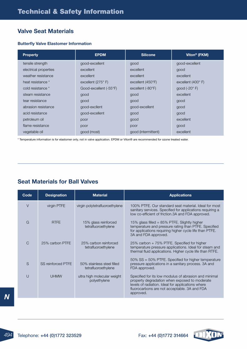
494 Telephone: +44 (0)1772 323529 Fax: +44 (0)1772 314664
Technical & Safety Information
N
Valve Seat Materials
Butterfly Valve Elastomer Information
* Temperature information is for elastomer only, not in valve application. EPDM or Viton® are recommended for ozone treated water.
tensile strength
electrical properties
weather resistance
heat resistance *
cold resistance *
steam resistance
tear resistance
abrasion resistance
acid resistance
petroleum oil
flame resistance
vegetable oil
Property EPDM Silicone Viton® (FkM)
good
excellent
excellent
excellent (450°F)
excellent (-80°F)
good
good
good-excellent
good
good
poor
good (intermittent)
good-excellent
good
excellent
excellent (400° F)
good (-20° F)
excellent
good
good
good
excellent
good
excellent
good-excellent
excellent
excellent
excellent (275° F)
Good-excellent (-55°F)
good
good
good-excllent
good-excellent
poor
poor
good (most)
Seat Materials for Ball Valves
ApplicationsCode Designation Material
V
G
C
S
U
virgin polytetrafluoroethylene
15% glass reinforcedtetrafluoroethylene
25% carbon reinforcedtetrafluoroethylene
50% stainless steel filledtetrafluoroethylene
ultra high molecular weightpolyethylene
virgin PTFE
RTFE
25% carbon PTFE
SS reinforced PTFE
UHMW
100% PTFE. Our standard seat material. Ideal for most sanitary services. Specified for applications requiring a low co-efficient of friction.3A and FDA approved.
15% glass filled = 85% PTFE. Slightly higher temperature and pressure rating than PTFE. Specified for applications requiring higher cycle life than PTFE. 3A and FDA approved.
25% carbon + 75% PTFE. Specified for higher temperature pressure applications. Ideal for steam and thermal fluid applications. Higher cycle life than RTFE.
50% SS = 50% PTFE. Specified for higher temperature pressure applications in a sanitary process. 3A and FDA approved.
Specified for its low modulus of abrasion and minimal property degradation when exposed to moderate levels of radiation. Ideal for applications where fluorocarbons are not acceptable. 3A and FDA approved.
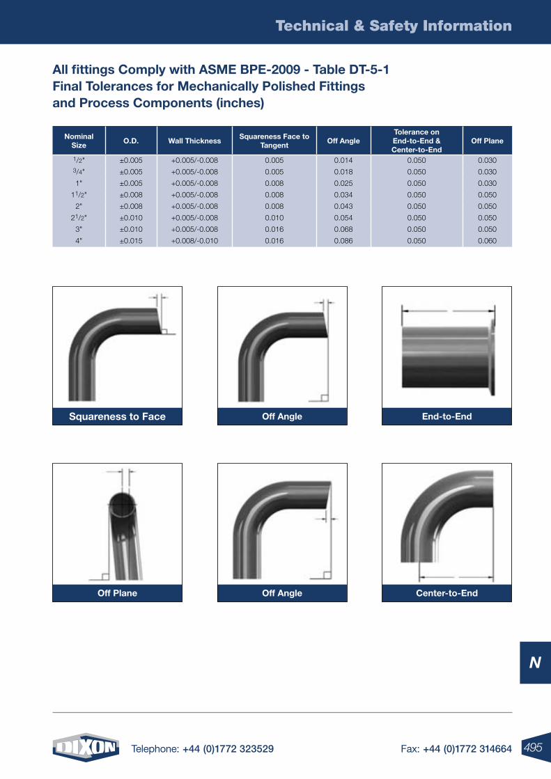
495Telephone: +44 (0)1772 323529 Fax: +44 (0)1772 314664
Technical & Safety Information
N
All fittings Comply with ASME BPE-2009 - Table DT-5-1 Final Tolerances for Mechanically Polished Fittings and Process Components (inches)
nominal Size
o.D. Wall ThicknessSquareness Face to
Tangent off Angle
Tolerance on End-to-End & Center-to-End
off Plane
1/2" ±0.005 +0.005/-0.008 0.005 0.014 0.050 0.0303/4" ±0.005 +0.005/-0.008 0.005 0.018 0.050 0.030
1" ±0.005 +0.005/-0.008 0.008 0.025 0.050 0.030
11/2" ±0.008 +0.005/-0.008 0.008 0.034 0.050 0.050
2" ±0.008 +0.005/-0.008 0.008 0.043 0.050 0.050
21/2" ±0.010 +0.005/-0.008 0.010 0.054 0.050 0.050
3" ±0.010 +0.005/-0.008 0.016 0.068 0.050 0.050
4" ±0.015 +0.008/-0.010 0.016 0.086 0.050 0.060
Squareness to Face
off Plane
off Angle
off Angle
End-to-End
Center-to-End
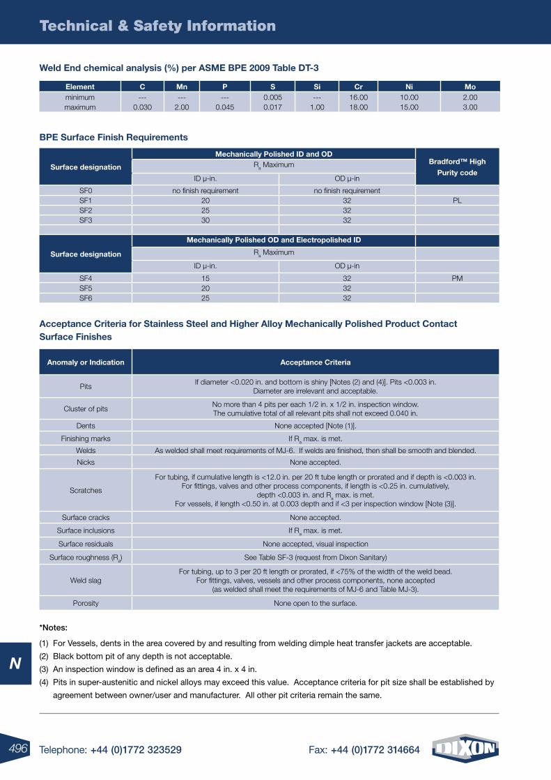
496 Telephone: +44 (0)1772 323529 Fax: +44 (0)1772 314664
Technical & Safety Information
N
Element C Mn P S Si Cr ni Mominimum --- --- --- 0.005 --- 16.00 10.00 2.00maximum 0.030 2.00 0.045 0.017 1.00 18.00 15.00 3.00
Weld End chemical analysis (%) per ASME BPE 2009 Table DT-3
BPE Surface Finish Requirements
Surface designation
Mechanically Polished ID and oDBradford™ High
Purity codeRa Maximum
ID µ-in. OD µ-in
SF0 no finish requirement no finish requirementSF1 20 32 PLSF2 25 32SF3 30 32
Surface designation
Mechanically Polished oD and Electropolished ID
Ra Maximum
ID µ-in. OD µ-in
SF4 15 32 PMSF5 20 32SF6 25 32
Acceptance Criteria for Stainless Steel and Higher Alloy Mechanically Polished Product Contact Surface Finishes
Anomaly or Indication Acceptance Criteria
PitsIf diameter <0.020 in. and bottom is shiny [Notes (2) and (4)]. Pits <0.003 in.
Diameter are irrelevant and acceptable.
Cluster of pitsNo more than 4 pits per each 1/2 in. x 1/2 in. inspection window. The cumulative total of all relevant pits shall not exceed 0.040 in.
Dents None accepted [Note (1)].
Finishing marks If Ra max. is met.
Welds As welded shall meet requirements of MJ-6. If welds are finished, then shall be smooth and blended.
Nicks None accepted.
Scratches
For tubing, if cumulative length is <12.0 in. per 20 ft tube length or prorated and if depth is <0.003 in.For fittings, valves and other process components, if length is <0.25 in. cumulatively,
depth <0.003 in. and Ra max. is met.For vessels, if length <0.50 in. at 0.003 depth and if <3 per inspection window [Note (3)].
Surface cracks None accepted.
Surface inclusions If Ra max. is met.
Surface residuals None accepted, visual inspection
Surface roughness (Ra) See Table SF-3 (request from Dixon Sanitary)
Weld slagFor tubing, up to 3 per 20 ft length or prorated, if <75% of the width of the weld bead.
For fittings, valves, vessels and other process components, none accepted (as welded shall meet the requirements of MJ-6 and Table MJ-3).
Porosity None open to the surface.
*notes:
(1) For Vessels, dents in the area covered by and resulting from welding dimple heat transfer jackets are acceptable.
(2) Black bottom pit of any depth is not acceptable.
(3) An inspection window is defined as an area 4 in. x 4 in.
(4) Pits in super-austenitic and nickel alloys may exceed this value. Acceptance criteria for pit size shall be established by
agreement between owner/user and manufacturer. All other pit criteria remain the same.
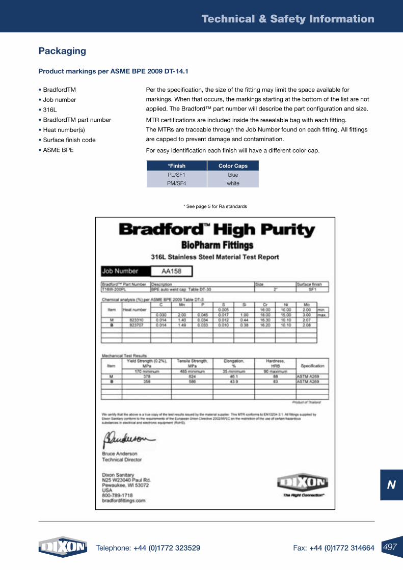
497Telephone: +44 (0)1772 323529 Fax: +44 (0)1772 314664
Technical & Safety Information
N
• BradfordTM
• Job number
• 316L
• BradfordTM part number
• Heat number(s)
• Surface finish code
• ASME BPE
Per the specification, the size of the fitting may limit the space available for
markings. When that occurs, the markings starting at the bottom of the list are not
applied. The Bradford™ part number will describe the part configuration and size.
MTR certifications are included inside the resealable bag with each fitting.
The MTRs are traceable through the Job Number found on each fitting. All fittings
are capped to prevent damage and contamination.
For easy identification each finish will have a different color cap.
Product markings per ASME BPE 2009 DT-14.1
Packaging
* See page 5 for Ra standards
*Finish Color Caps
PL/SF1 blue
PM/SF4 white
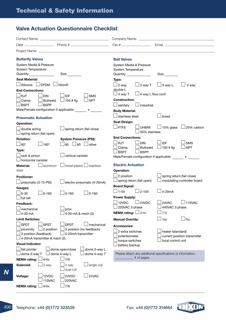
498 Telephone: +44 (0)1772 323529 Fax: +44 (0)1772 314664
Technical & Safety Information
N
Valve Actuation Questionnaire Checklist
Contact Name: Company Name:
Date Phone # Fax # Email
Project Name:
Please attach any additional specifications or information, ___________ # of pages.
Butterfly Valves
System Media & PressureSystem TemperatureQuantity Size
Seat Material:
Silicone EPDM Viton®
End Connections:
RJT DIN IDF SMS Clamp Buttweld 150 # flg NPT BSPT BSPP
Male/Female configuration if applicable: x
Pneumatic Actuation
operation:
double acting spring return (fail close) spring return (fail open)
Rotation: System Pressure (PSI):
90° 180° 80 60 other
Type:
rack & pinion vertical canister horizontal canister
Material: aluminum nickel plated stainless steel
Positioner:
pneumatic (3-15 PSI) electro-pneumatic (4-20mA)
Gauges:
0-30 0-160 0-160 0-160 full set
Feedback:
mechanical prox 4-20 mA 4-20 mA & mech (2)
limit Switches:
SPDT SPST DPDT mechanical proximity 2 position 3 position (no feedback) 3 position (feedback) 4-20mA transmitter 4-20mA transmitter & mech (2)
Visual Indicator:
flat pointer dome open/close dome 3-way L dome 3-way T dome 4-way L dome 4-way T
nEMA rating: 4/4x 7/9
Solenoid: 3 way 4 way single coil dual coil
Voltage: 12VDC 24VDC 24VAC 110VAC 220VAC
nEMA rating: 4/4x 7/9
Ball Valves
System Media & PressureSystem TemperatureQuantity Size
Type:
2 way 3 way T 3 way L 4 way double L
4 way T 4 way L flow conf.
Construction:
sanitary industrial
Body Material:
stainless steel brass
Seat Design:
PTFE UHMW 15% glass 25% carbon 50% stainless
End Connections:
RJT DIN IDF SMS Clamp Buttweld 150 # flg NPT BSPT BSPP
Male/Female configuration if applicable: x
Electric Actuation
operation:
2 position spring return (fail close) spring return (fail open) modulating controller board
Board Signal:
1-5V 2-10V 4-20mA
Power Supply:
12VDC 24VDC 24VAC 110VAC 220VAC 3 phase 440VAC 3 phase
nEMA rating: 4/4x 7/9
Manual overide: Yes No
Accessories:
2 extra switches heater (standard) potentiometer current position transmitter torque switches local control unit battery backup
499Telephone: +44 (0)1772 323529 Fax: +44 (0)1772 314664
Technical & Safety Information
N
Standards - 29 CFR, 1910.242 (partial): (b) Compressed air used for cleaning - Compressed air shall not be used for cleaning purposes except where reduced tless than 30 psi and
then only with effective chip guarding and personal protective equipment.
Standards - 29 CFR, 1915.131 (partial): (e) Before use, pneumatic tools shall be secured to the extension hose or whip by some positive means to prevent the tool from becoming accidentally disconnected from the whip.
Standards - 29 CFR, 1926.302 (partial): (b)(1) Pneumatic power tools shall be secured to the hose or whip by some positive means to prevent the tool from becoming accidentally disconnected. (b)(2) Safety clips or retainers shall be securely installed and maintained on pneumatic impact (percussion) tools to prevent attachments from being accidentally expelled.
(b)(3) All pneumatically driven nailers, staplers and other similar equipment provided with automatic fastener feed, which operate at more than 100 psi pressure at the tool shall have a safety device on the muzzle to prevent the tool from ejecting fasteners, unless the muzzle is in contact with the work surface. (b)(4) Compressed air shall not be used for cleaning purposes except where reduced to 30 psi and then only with effective chip guarding and personal protective equipment which meets the requirements of Subpart E of this part. The 30 psi requirement does not apply for concrete form, mill scale and similar cleaning purposes. (b)(5) The manufacturer’s safe operating pressure for hoses, pipes, valves, filters and other fittings shall not be exceeded. (b)(6) The use of hoses for hoisting or lowering tools shall not be permitted. (b)(7) All hoses exceeding 1/2” inside diameter shall have a safety device at the source of supply or branch line toreduce pressure in case of hose failure.
Standards - 29 CFR, 1926.306 (a) “General requirements” (a)(1) “Application.” This section applies to compressed air receivers, and other equipment used in providing and utilising compressed air for performing operations such as cleaning, drilling, hoisting, and chipping. On the otherhand, however, this section does not deal with the special problems created by using compressed air to conveymaterials nor the problems created when men work in compressed air as in tunnels and caissons. This section is not intended to apply to compressed air machinery and equipment used on transportation vehicles such as steam railroad cars, electric railway cars, and automotive equipment. (a)(2) “New and existing equipment.” (a)(2)(i) All new air receivers installed after the effective date of these regulations shall be constructed in accordance with the 1968 edition of the A.S.M.E. Boiler and Pressure Vessel Code Section VIII. (a)(2)(ii) All safety valves used shall be constructed, installed and maintained in accordance with the A.S.M.E. Boiler and Pressure Vessel Code, Section VIII Edition 1968. (b) 1926.306(b) “Installation and equipment requirements” (b)(1) “Installation.” Air receivers shall be so installed that all drains, handholes, and manholes therein are easily accessible. Under no circumstances shall an air receiver be buried underground or located in an inaccessibleplace. (b)(2) “Drains and traps.” A drain pipe and valve shall be installed at the lowest point of every air receiver to provide for the removal of accumulated oil and water. Adequate automatic traps may be installed in addition to drain valves. The drain valve on the air receiver shall be opened and the receiver completely drained frequently and at such intervals as to prevent the accumulation of excessive amounts of liquid in the receiver. (b)(3) “Gauges and valves.” (b)(3)(i) Every air receiver shall be equipped with an indicating pressure gauge (so located as to be readily visible) and with one or more spring-loaded safety valves. The total relieving capacity of such safety valves shall be such as to prevent pressure in the receiver from exceeding the maximum allowable working pressure of the receiver by more than 10 percent. (b)(3)(ii) No valve of any type shall be placed between the air receiver and its safety valve or valves.
Standards - 29 CFR, 1926.603 (partial): (a)(9) Steam hose leading to a steam hammer or jet pipe shall be securely attached to the hammer with an adequate length of at least 1/4-inch diameter chain or cable to prevent whipping in the event the joint at the hammer is broken. Air hammer hoses shall be provided with the same protection as required for steam lines. (a)(10) Safety chains, or equivalent means, shall be provided for each hose connection to prevent the line from thrashing around in case the coupling becomes disconnected.
Regulations: oSHA & MSHA
oSHA
500 Telephone: +44 (0)1772 323529 Fax: +44 (0)1772 314664
Technical & Safety Information
N
Standards - 30 CFR Sections 56.13021 and 57.13021 Except where automatic shut-off valves are used, safety chains or other suitable locking devices shall be used at connections to machines
of high-pressure hose line of 3/4” inside diameter or larger, and between high-pressure hose lines of 3/4” inside diameter of larger, where a connection failure would create a hazard.
Standards - 30 CFR Section 75.1730 (e) Safety chains, suitable locking devices, or automatic cut-off valves shall be used at connections to machines of high-pressure hose lines of
3/4” inside diameter or larger, and between high-pressure hose lines of 3/4” inside diameter or larger, where a connection failure would create a hazard. For purposes of this paragraph, high-pressure means pressure of 100 psi or more.
Standards - 30 CFR Section 77.412 (d) Safety chains or suitable locking devices shall be used at connections to machines of high-pressure hose line of 1-inch inside diameter or
larger, and between high-pressure hose line of 1-inch inside diameter or larger, where a connection failure would create a hazard.
MSHA (Mine Safety and Health Administration)
Fluid Compatibility Guide - Dixon Quick Couplings
Material Prefix Code Trade name Availability* Range °C Range °F
Buna-N Standard Nitrile Stock -40°C to +121°C -40°F to +250°F
Buna-N (MIL-H-5606 Fluids) M- Nitrile 3-5 Days -54°C to +135°C -65°F to +275°F
Buna-N (Hydrocarbon Fuels) JF- Nitrile 3-5 Days -54°C to +71°C -65°F to +160°F
Fluorocarbon Rubber (FKM) F- Viton 3-5 Days -29°C to +204°C -20°F to +400°F
Ethyl Propylene Diene Monomer P- EPDM 5-7 Days -54°C to +149°C -65°F to +300°F
Neoprene E- Neoprene 7-10 Days -43°C to +149°C -45°F to +300°F
Silicone S- Silicone 7-10 Days -73°C to +177°C -100°F to +350°F
Fluorosilicone (FVMQ) FS- Silastic 7-10 Days -60°C to +180°C -76°F to +376°F
Urethane U- Urethane 7-10 Days -40°C to +82°C -40°F to +180°F
Polyurethane UP- Polyurethane 7-10 Days -54°C to +100°C -65°F to 212°F
PTFE Encapsulated Silicone TS- TES 7-10 Days -73°C to +204°C -100°F to +400°F
Perfluoroelastomer (Compound 1) K4- Kalrez 4079 5-7 Days -20°C to +316°C -4°F to +600°F
Perfluoroelastomer (Compound 2) K6- Kalrez 6375 7-10 Days -20°C to +275°C -4°F to +525°F
Perfluoroelastomer (Compound 3) K7- Kalrez 7075 7-10 Days -20°C to +327°C -4°F to +620°F
Fluoroelastomer H- Aflas 7-10 Days -5°C to +204°C +23°F to +400°F
WARnInG!The following chart is intended only as a guide in selecting various elastomers and metals for use with fluids to be
conveyed through Dixon Quick Disconnect Couplings. This list does not guarantee suitability for a particular application. Final selection is dependent upon operating pressure, fluid and ambient temperature, concentration of media, duration of
exposure, environmental conditions, and frequency of connect and disconnect.
Regulations: oSHA & MSHA (cont’d)
* For guidance purposes - consult sales office for more information/details.
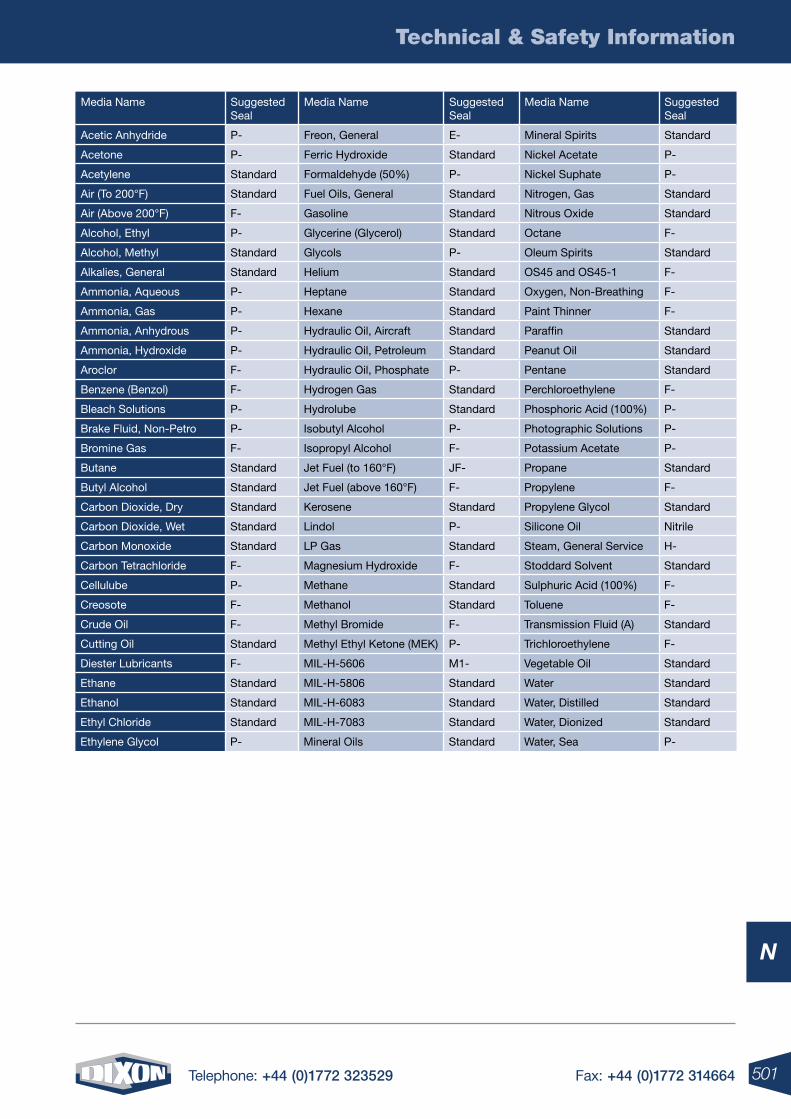
501Telephone: +44 (0)1772 323529 Fax: +44 (0)1772 314664
Technical & Safety Information
N
Media Name Suggested Seal
Media Name Suggested Seal
Media Name Suggested Seal
Acetic Anhydride P- Freon, General E- Mineral Spirits Standard
Acetone P- Ferric Hydroxide Standard Nickel Acetate P-
Acetylene Standard Formaldehyde (50%) P- Nickel Suphate P-
Air (To 200°F) Standard Fuel Oils, General Standard Nitrogen, Gas Standard
Air (Above 200°F) F- Gasoline Standard Nitrous Oxide Standard
Alcohol, Ethyl P- Glycerine (Glycerol) Standard Octane F-
Alcohol, Methyl Standard Glycols P- Oleum Spirits Standard
Alkalies, General Standard Helium Standard OS45 and OS45-1 F-
Ammonia, Aqueous P- Heptane Standard Oxygen, Non-Breathing F-
Ammonia, Gas P- Hexane Standard Paint Thinner F-
Ammonia, Anhydrous P- Hydraulic Oil, Aircraft Standard Paraffin Standard
Ammonia, Hydroxide P- Hydraulic Oil, Petroleum Standard Peanut Oil Standard
Aroclor F- Hydraulic Oil, Phosphate P- Pentane Standard
Benzene (Benzol) F- Hydrogen Gas Standard Perchloroethylene F-
Bleach Solutions P- Hydrolube Standard Phosphoric Acid (100%) P-
Brake Fluid, Non-Petro P- Isobutyl Alcohol P- Photographic Solutions P-
Bromine Gas F- Isopropyl Alcohol F- Potassium Acetate P-
Butane Standard Jet Fuel (to 160°F) JF- Propane Standard
Butyl Alcohol Standard Jet Fuel (above 160°F) F- Propylene F-
Carbon Dioxide, Dry Standard Kerosene Standard Propylene Glycol Standard
Carbon Dioxide, Wet Standard Lindol P- Silicone Oil Nitrile
Carbon Monoxide Standard LP Gas Standard Steam, General Service H-
Carbon Tetrachloride F- Magnesium Hydroxide F- Stoddard Solvent Standard
Cellulube P- Methane Standard Sulphuric Acid (100%) F-
Creosote F- Methanol Standard Toluene F-
Crude Oil F- Methyl Bromide F- Transmission Fluid (A) Standard
Cutting Oil Standard Methyl Ethyl Ketone (MEK) P- Trichloroethylene F-
Diester Lubricants F- MIL-H-5606 M1- Vegetable Oil Standard
Ethane Standard MIL-H-5806 Standard Water Standard
Ethanol Standard MIL-H-6083 Standard Water, Distilled Standard
Ethyl Chloride Standard MIL-H-7083 Standard Water, Dionized Standard
Ethylene Glycol P- Mineral Oils Standard Water, Sea P-
502 Telephone: +44 (0)1772 323529 Fax: +44 (0)1772 314664
Technical & Safety Information
N
Glossary of Terms
3A Symbol for 3A Sanitary Standards Symbol Administrative Council. The 3A Sanitary Standard were created by
the dairy industry as a voluntary benchmark for product performance and sanitary safety. The standard, collaboratively
developed by a group of processors, suppliers, regulatory officials and sanitation specialists, is accepted by federal,
state and local regulatory authorities. Our products have earned the 3A symbol, through third party verification.
This assessment makes certain each product conforms in all respects to the published standards. Dixon Sanitary
is proud to be a participant in the 3A program.
3A Finish Product surface finish equivalent to 150 grit or better OD, and 180 grit or better ID. A maximum of Ra 32
microinch (0.8 micron) is indicated.
ABS (Acrylicnitrile-butadiene-styrene) a thermoplastic resin with an excellent resistance to acids, bases, salts and
some solvents. It is heat resistant to 230° F.
AnSI American National Standards Institute, Inc.
ASME American Society of Mechanical Engineers.
ASTM American Society for Testing and Materials.
Acme Thread A flat grooved helical ridge on a nut or bolt. This typically has a 29° included angle. Used on bevel
seat, John Perry fittings and IDF.
Anneal Stress relief of stainless steel, a heat treatment to remove the stresses generated in forming and welding
operations. This heat treatment is best done under controlled atmosphere or vacuum to maintain the mill finish.
The fittings are not quenched, as in solution annealing; this would reintroduce residual stresses. Done correctly,
parts are processed to provide minium residual stresses and full corrosion resistance.
Anodizel A process for aluminum, similar to zinc or chrome plating steel, in which an aluminum part is electrically
charged then, dipped in various chemicals to produce various colours and/or surface hardness.
API American Petroleum Institute
Available nPSH (net positive suction head) A characteristic of the system and is defined as the energy which
is in a liquid at the suction connection of the pump (regardless of the type of pump) over and above that energy in
the liquid due to its vapor pressure.
Bright Anneal Annealing in a protective medium to prevent discoloration of the surface.
Bright Annealed Finish A silvery satin surface, approximately the mill finish of stainless steel.
Buna Synthetic rubber, a copolymer of acrylonitrile and butadiene.
Burst Pressure The pressure at which rupture occurs.
Cavitation When the NPSH required by the pump is greater than the NPSH available by the system, cavitation
occurs. Vapor is formed and moves along with the stream. These vapor bubbles or “cavities” collapse when they
reach regions of higher pressure on their way through the pump cavities are forming in the liquid being pumped.
When these cavities form at the suction of the pump several things happen all at once.
• Loss in capacity
• Loss of head (pressure)
• The efficiency drops
• The cavities or bubbles will collapse when they pass into the higher regions of pressure causing noise,
vibration, and damage to many of the components
503Telephone: +44 (0)1772 323529 Fax: +44 (0)1772 314664
Technical & Safety Information
N
Glossary of Terms
CW Clockwise.
CCW Counter clockwise
Chamfer To cut an angle on the hose tube aid in stem insertion and to prevent the hose end from flaring when
a stem is inserted.
Clamp A device used to join mechanical parts, fittings, ensuring a quick leak-proof connection and enabling easy
take down.
Cold Flow Continued deformation or movement of rubber or PTFE under stress.
Compression Set The deformation that remains in rubber or PTFE after it has been subjected to and released
from stress such as a clamp. The longer the stress is maintained the more definitive the deformation.
Coupling A device at the end or ends of a length of hose that allows a connection to be made.
Crimping The act of forming the metal sleeve or ferrule of a hose fitting with a surrounding series of die segments
to compress the hose within the fitting. The crimping process changes the shape of the entire circumference and
length simultaneously. Often interchanged with the term “swaged”.DIn Deutches Institut für Normung - German
National-standards Organisation.
Double-Acting (DA) Pneumatic Actuator Any pneumatic actuator which uses air to drive the actuator output
shaft in both the open and close direction. The air supply is piped to one side of a piston-drive or a diaphragm
while the air contained on the opposing side is exhausted.
Dn Diameter nominal.
DPDT Double pole-double throw, a switch.
Durometer An instrument for measuring the hardness of rubber by resitance to penetration.
Durometer Hardness A numerical value which indicates the resistance to indentation of the blunt indentor of
the durometer.
EPDM Ethylene propylene diene monome, a synthetic rubber.
Elastomer Any of various elastic substances resembling rubber.
Electric Actuator An electro-mechanical device used to open and close or modulate a valve. The actuator
(which is mounted and coupled to the valve in similar fashion as the pneumatic actuator), operates the valve
using an electric motor driving a gear train. While the basic function of the electric actuator is similar to the
pneumatic, there are distinct differences in the application and flexibility of the two types, and these differences
should be considered to select the proper type.
Electric Failsafe Actuator Electrically driven actuator that contains an internal spring to close the valve on
loss of electricity.
Encapsulation The enclosing of material by an encapsulant for protective purposes. In a ball valve the
ball is encased in PTFE, preventing the material flowing through the valve from getting behind the ball causing
contamination problems.
Expansion Ring Typically refers to a type of fire hose couplings that are attached by expanding a sleeve (usually brass)
outward to compress the hose against the wall of the bowl of the coupling.
504 Telephone: +44 (0)1772 323529 Fax: +44 (0)1772 314664
Technical & Safety Information
N
External Swage (Swaging) A ferrule is passed through a reducing die, usually split, to bring the ferrule O.D.
down to a predetermined size (for proper coupling retention) forcing the hose tube down into the stem serrations.
Fail-Closed Spring return pneumatic actuator is applied to the valve such that the spring will drive the valve
to the closed position upon loss of air (may be termed air-to open).
Fail-open Spring return pneumatic actuator is applied to the valve such that the spring will drive the valve to
the open position upon loss of air (may be termed air-to close).
Flow Coefficient (Cv) Cv is defined as the flow rate in U.S. gallons of water (at 60°F) that will pass through the
valve in one minute with a differential pressure across the valve of 1 PSI.
Ferrule A collar placed over a hose end to attach the fitting to the hose. The ferrule may be crimped or swaged,
forcing the hose against the shank of the coupling, or the shank may be expanded, forcing the hose out against
the ferrule, or both.
Fitting A small part of an apparatus (may be detachable).
Fluorocarbon Elastomer known as Viton® a registered trademark of DuPont.
Friction loss The part of the total loss that occurs as the fluid flows through straight pipe.
Gripping Finger The part of the clamp that goes over and behind the stem collar to aid in clamp retention.
Hard Coat An anodising process in which the surface hardness of aluminum becomes similar to or greater
than that of case hardened steel.
ISo5211 International standard for actuator and valve interface.
IDF International Dairy Federation.
JIC Joint Industrial Commitee
JIC Thread Typically refers to the threads on hydraulic fittings having 37° conical sealing surfaces.
Internal Expansion (IX) A plug (or bullet) is pulled through a stem or a set of blades (fingers) increase the stem
I.D. to the plug O.D. or a predetermined setting when using expansion blades (fingers). This forces the stem
serrations into the hose tube and the hose cover into the serrations of the ferrule.
laminar Flow The resistance of flow as a liquid is moved through a pipe due to viscous shear stresses within
the liquid and turbulence that occur.
Manual override Any mechanical device by which an automated valve may be manually operated. On smaller
actuators, this may simply be wrench flats on the output shaft of the actuator. Larger actuators may require
a more sophisticated system, such as de-clutchable hand wheels, manual gears, jack screws or hydraulic hand
pump over-ride.
Maximum-Shut-off Pressure (Delta-P) The pressure of the media flowing into the valve against which the
valve will have to close.
Media The material flowing through the valve.
MSHA Mine Safety and Health Administration.
Modulating Service Proportional positioning of a valve between the open and closed position. Used for flow
control processes.
Glossary of Terms
505Telephone: +44 (0)1772 323529 Fax: +44 (0)1772 314664
Technical & Safety Information
N
nAMUR International Standard of Interface for actuator accessories connections.
nEMA Rating National electrical code ratings for electrical component enclosures.
nEMA 4 Weather-proof enclosure suitable for indoor/outdoor applications to protect from windblown dust, rain
or hose-directed water.
nEMA 4x Offers the same protection as NEMA 4 with the addition of corrosion resistance.
nEMA 6 Enclosure that may be submerged up to six feet for 30 minutes.
nEMA 7 Enclosure for hazardous locations must be capable of withstanding an internal explosion of gases so as
not to ignite an external gas-air mixture.
net Positive Suction Head Amount of energy in the liquid at the pump datum. It must be defined to have a meaning,
as either available or required NPSH.
neoprene Synthetic rubber, chemically and structurally similar to natural rubber.
nipple The section of the fitting that is inserted into the hose. Also known as the shank of a coupling.
nominal Size A dimensional value assigned for the purpose of convenient designation.
on-off Service When the valve is being used to start or stop flow by being cycled to the full open or full closed position.
operating Pressure The pressure at which system functions. Also known as working pressure.
Permanent Fitting The type of fitting which, after it is applied, cannot be removed for reuse.
Polymer A macromolecular material formed by the chemical combination of monomers having the same or different
chemical composition.
Pneumatic Actuator An air operated mechanical device used to open and close or modulate a valve. The
actuator, which is mounted to the valve by a bracket and coupled to the stem, is designed to convert air pressure
into mechanical force sufficient to operate the valve.
Polish To make smooth and shiny by rubbing. Fittings may be machine polished to 180 grit finish. Polish is ID,
OD, or both per customer request.
Polyproylene A lightweight synthetic plastic.
Pressure The force per unit area applied on a surface in a direction perpendicular to that surface.
Pressure Head Must be considered when a pumping system either begins or terminates in a tank which is under
some pressure other than atmospheric. The pressure in such a tank must first be converted to feet of liquid.
A vacuum in the suction tank or a positive pressure in the discharge tank must be added to the system head,
whereas a positive pressure in the suction tank or vacuum in the discharge tank would be subtracted. The following
is a handy formula for converting inches of mercury vacuum into feet of liquid.
Vacuum, in. of Hg X 1.13 Vacuum, ft of liquid =
Sp. Gr.
Proof Pressure A specified pressure which exceeds the hose assemblies rated working pressure to indicate its reliability at
normal working pressure. Follow R.M.A.’s testing guidelines for specific pressures and duration’s for various types of hose.
The above forms of head, namely static, friction, velocity, and pressure, are combined to make up the total system head at
any particular flow rate.
Glossary of Terms
506 Telephone: +44 (0)1772 323529 Fax: +44 (0)1772 314664
Technical & Safety Information
N
Glossary of Terms
PSI Pounds per square inch.
PSIG Pounds per square inch gauge.
PTFE Tetrafluoroethylene, DuPont’s PTFE, is a high performance thermo plastic polymer that has excellent
dielectric strength, chemical and temperature resistance.
Required nPSH A characteristic of the pump design. It is determined by test or computation and is the energy
needed to fill a pump on the suction side and overcome the friction and low losses from the suction connection
to that point in the pump at which more energy is added. Required NPSH varies with pump design, pump size
and operating conditions and is supplied by the pump manufacturer.
Santoprene A thermoplastic elastomer, a rubber-like material that complies to FDA requirements.
Service Temperature The maximum and minimum temperature of the media.
RJT Ring Joint Type.
RMA Rubber Manufacturers Association.
Reusable Fitting The type of fitting that is designed to be removed from a hose and recoupled on another hose.
SAE Society of Automotive Engineers.
SAE Threads Similar to J.I.C. except 45° conical sealing surfaces.
Silicone Dimethyl silicone, a synthetic rubber.
Sintering Heat process in which powdered metal particles are heated to near melting point, fusing the metal
granules together.
Safety Factor A ratio used to establish the working pressure of a hose based upon the burst pressure.
Typical Safety Factors are as follows:
1. Water hose up to 150 psi WP: 3 to 1.
2. Hose for all other liquids, solid materials suspended in liquids or air and water hose over 150 psi WP: 4 to 1.
3. Hose for compressed air and other gases: 4 to 1.
4. Hose for liquid media that immediately changes into gas under standard atmospheric conditions: 5 to 1.
5. Steam hose: 10 to 1.
SCFM Standard Cubic Feet per Minute. Typically refers to the amount of compressed air a compressor.
Serration The part of the shank (stem) that grips the hose tube.
Shank The section of the fitting or coupling that is inserted into the hose.
Sintered Process in which powdered metal is formed in a mould under extreme pressure to form a finished part.
SMS Swedish Metric System.
SPDT Single pole double throw switch.
SPST Single pole single throw switch.
507Telephone: +44 (0)1772 323529 Fax: +44 (0)1772 314664
Technical & Safety Information
N
Spring-Return (SR) Pneumatic Actuator Any pneumatic actuator which contains a single coil spring or group
of coil springs to oppose the movement of a piston or diaphragm. As air moves the piston or diaphragm the
spring is compressed. When the air supply is discontinued and exhausted, the spring extends and drives
the piston or diaphragm in the opposite direction. This type of actuator is normally used for applications where
it is necessary for the valve to move to the open or close position upon loss of air supply, whether by design
or by system failure.
Static Discharge Head The vertical distance in feet between the pump centerline and the point of free
discharge or the surface of the liquid in the discharge tank.
Static Head The pressure at any point in a liquid can be thought of as being caused by a vertical column of
the liquid which, due to its weight, exerts a pressure equal to the pressure at the point in question. The height
of this column is called the “static head” and is expressed in terms of feet of liquid. Stem Torque The force
required at the valve stem to open or close the valve against system pressure and service conditions.
Suction Head Exists when the source of supply is above the centerline of the pump. Thus the static suction
head is the vertical distance in feet from the centerline of the pump to the free level of the liquid to be pumped.
Suction lift Exists when the source of supply is below the center line of the pump. Thus the static suction
lift is the vertical distance in feet from the center line of the pump to the free level of the liquid to be pumped.
Supply Pressure The plant air supply pressure available to operate a pneumatic actuator (plant air).
Surge A rapid rise or decrease of internal pressure.
Torque A twisting or turning force. Usually measured in inch pounds (in-lbs) or foot pounds
(ft-lbs)/(force through a distance).
Total Dynamic Discharge Head (hd) The static discharge head plus the velocity head at the pump discharge
flange plus the total friction head in the discharge line. The total dynamic discharge head, as determined on
pump test, is the reading of a gauge at the discharge flange, converted to feet of liquid and corrected to the
pump centerline, plus the velocity head at the point of gauge attachment.
Total Dynamic Suction Head (hs) The static suction head plus the velocity head at the pump suction flange
minus the total friction head in the suction line. The total dynamic suction head, as determined on pump test,
is the reading of the gauge on the suction flange, converted to feet of liquid and corrected to the pump
centerline, plus the velocity head at the point of gauge attachment.
Total Dynamic Suction lift (hs) The static suction lift minus the velocity head at the pump suction flange
plus the total friction head in the suction line. The total dynamic suction lift, as determined on pump tests, is
the reading of a gauge on the suction flange, converted to feet of liquid and corrected to the pump centerline,
minus the velocity head at the point of gauge attachment.
Total Head (H) or Total Dynamic Head The total dynamic discharge head minus the total dynamic suction
head or plus the total dynamic suction lift.
TDH = hd + hs (with suction lift)
TDH = hd - hs (with a suction head)
Total Static Head The vertical distance in feet between the free level of the source of supply and the point of
free discharge or the free surface of the discharge liquid.
Tube The innermost part of the hose that’s purpose is to contain the media being transported. Usually, rubber
tcompounds or plastics are blended to give the tube specific properties so that it is compatible with certain media.
Glossary of Terms
508 Telephone: +44 (0)1772 323529 Fax: +44 (0)1772 314664
Technical & Safety Information
N
Tube Fitting A length of tubing formed into a usable shape either welded to an apparatus or welded to ferrules
for use in an apparatus.
Tubing A piece or length of tube.
Tumble Polish Surface A uniform finish applied by vibratory equipment to stainless steel, varying from matt grey
to bright, depending on media used. This process may cause work hardening on the surfaces.
Turbulent Flow Irregular flow that is characterized by tiny whirlpool regions. The velocity of this fluid is definitely
not constant at every point.
UHMW Ultra High Molecular Weight. Next generation of chemical hoses after cross-linked polyethylene having
a thin tube liner made from extremely dense material giving it excellent chemical resistance properties.
Velocity Head (hv) The energy of a liquid as a result of its motion at some velocity V. It is the equivalent head in
feet through which the water would have to fall to acquire the same velocity, or in other words, the head necessary
to accelerate the water. Velocity head can be calculated from the following formula:
H = V2
2g
Where g = 32.3 ft/second
V = liquid velocity in feet per second
The velocity head is usually insignificant and can be ignored in most high head systems. However, it can be a large
factor and must be considered in low head systems.
Victaulic Groove A style of couplings that has a groove cut near the end of the stem where threads would typically
be. The couplings are attached using a “C” shaped clamp that fits into the grooves on the stem.
WoG Water, Oil, Gas. Pressure rating for valves handling these products. This does not include steam.
Welding Join two (or more) peices of material by applying heat to produce a localized union through fusion across
the interface.
For sanitary fittings, a ferrule is attached to the ends of a tube fitting by TIG welding without the addition of filler
metal. Tube fittings can then be joined with clamps and gaskets to form parts of a system.
Work (Strain) Hardening An increase in hardness and strength caused by plastic deformation at temperatures
below the annealing ranges.
WP Working Pressure
Working Pressure The maximum pressure to which a hose assembly will be subjected to including pressure surges.
XlPE Cross-Linked Polyethylene. Tube material that has good chemical resistance properties.
Glossary of Terms

509Telephone: +44 (0)1772 323529 Fax: +44 (0)1772 314664
N
Terms & Conditions
Dixon Terms & Conditions
limited Warranty
Dixon Group Europe Ltd (herein called “Dixon”) warrants the products described herein, and manufactured by Dixon to be free from defects in material and workmanship for a period of one (1) year from date of shipment by Dixon under normal use and service. It’s sole obligation under this warranty being limited to repairing or replacing, as hereinafter provided, at its option any product found to Dixon’s satisfaction to be defective upon examination by it, provided that such product shall be returned for inspection to Dixon’s factory within three (3) months after discovery of the defect. The repair or replacement of defective products will be made without charge for parts or labour. This warranty shall not apply to: (a) parts or products not manufactured by Dixon, the warranty of such items being limited to the actual warranty extended to Dixon by its supplier; (b) any product that has been subject to abuse, negligence, accident, or misapplication; (c) any product altered or repaired by others than Dixon; and (d) to normal maintenance services and the replacement of service items (such as washers, gaskets and lubricants) made in connection with such services. To the extent permitted by United Kingdom law, this limited warranty shall extend only to the buyer and any other person reasonably expected to use or consume the goods who is injured in person by any breach of the warranty. No action may be brought against Dixon for an alleged breach of warranty unless such action is instituted within one (1) year from the date the cause of action accrues. This limited warranty shall be construed and enforced to the fullest extent allowable by applicable United Kingdom law.
oTHER THAn THE oBlIGATIon oF DIXon SET FoRTH HEREIn, DIXon DISClAIMS All WARRAnTIES, EXPRESS oR IMPlIED, InClUDInG BUT noT lIMITED To AnY IMPlIED WARRAnTIES oF MERCHAnTABIlITY oR FITnESS FoR A PARTICUlAR PURPoSE, AnD AnY oTHER oBlIGATIon oR lIABIlITY. THE FoREGoInG ConSTITUTES DIXon’S SolE oBlIGATIon WITH RESPECT To DAMAGES, WHETHER DIRECT, InCIDEnTAl oR ConSEQUEnTIAl, RESUlTInG FRoM THE USE oR PERFoRMAnCE oF THE PRoDUCT.
Some products and sizes may be discontinued when stock is depleted, or may require a minimum quantity for ordering.
Dixon Group Europe Ltd is committed to a policy of continuous development, and as such, the above detailed specification and may be subject to change without notice. Dixon Group Europe Ltd reserves the right to change and modify designs and specification without notice.
Pricing
Dixon will always try to maintain pricing, however, with the fluctuation of material cost we may be forced to change prices. Please be aware pricing is subject to change without notice.
Freight/Postage & Carriage Charges
Postage & carriage charges are at the customer’s expense and will be charged at current appropriate rates.
Returns
Dixon will allow its customers to return any product for any reason within 30 days of shipment, provided it is received in a saleable condition. The customer must call to receive a CCR number prior to returning goods to Dixon and shipping will be at the customer’s expense, unless it is determined Dixon created the reason for the return.
A re-stocking charge of 25% applies to all returns.
limits of liability
This catalogue is intended as a product offering. It is not intended to be a user or technical manual. Information in this catalogue is subject to change without notice. All users and distributors of products sold through this catalogue should contact Dixon with questions of use, compatibility’s, coupling procedures and life of product. Dixon’s full time engineering and test staff is always available to recommend uses and to assist distributors and users with questions.
Copyright
Copyright© 2012 by Dixon Group Europe Ltd.
All rights reserved. This book is copyrighted material. Use, reproduction or copying of it by anyone other than Dixon is strictly forbidden without its express written consent.
510 Telephone: +44 (0)1772 323529 Fax: +44 (0)1772 314664
N
Index
Index
Page # Page No.
3A Standard 141
520-H Ferrules 250
A
A101AS Air/Water Hose 102
A101HP Air/Water Hose 103
A102HP Air/Water Hose 103
A104 Multipurpose Hose 109
A190 Air/Water Hose 104
A210 Water S & D Hose 105
A230 Steam Hose 116
A235 Steam Hose 115
A400EU Heavy Duty Oil Hose 108
A410 UHMWPE Chemical Hose 114
A430 Oil S & D Hose 108
A901 Oil Composite Hose 111
A901AG Vapour Recovery Hose 111
A906 Chemical Composite Hose 112
A911 PTFE Composite Hose 113
A-A-59326B Specification 26-45
Actuated Valves 203-223
Adapters - Boss 341, 343 - European Compressor 19 - High Pressure 50-52 - Dry Disconnect/ Dry Break 388-393
Adflex Metal Hose 129
Aero Seal 67
AG Series 282-283
Agricultural Interchange 282-283
Agri-lock Couplings 418-421
Air Fittings 6-21
Air/Water Hose 102-107
Air Hose Couplings 6-19
Air Interlock 365
Air King 15-19 - Clamps 17, 19 - Couplings 15-18 - Crimp Ferrules 18 - Hose End 18-19 - Safety Clips 16 - Washers 18 - Universal 15
Air Relief Valves 187, 352-353
Amoured Hose 133-135
APC Clamp Gasket 166
API - Bottom Rack Loading 362 - Certified Couplings 251-252 - Compatible Rack Cord 379 - Dust Cap 62 - Optic System 376-377 - Valves 361
Aseptic Diaphragm Valve 178
ASME: BPE 175-178
ATEX 373-377
B
B.E.S.A.F.E 447
Baku PVC Hose 110
Ball Nozzles 66
Ball Valves 188-196, 404-405 - 2 Way 3 Piece 189 - 3 Way Encapsulated Hygienic 192 - Automation 195-196 - Encapsulated 2 Way 3 Piece 190 - Multi Port 3 Way 193 - Multi Port 4 Way 194 - Non-Encapsulated 2 Way 3 Piece 191
Band It Clamps 72
Barrell Nipple 82
Bayco 348-401
Beverage Hose 117-122
Biopharm Fittings 175-178
Blank Plug/Cap 83-85
Blow Gun 21
Blow Out Prevention Safety Coupling 296
Boss 336-346 - Adapters 341 - Clamps 344-345 - Couplings 338-346 - Coupling System 338 - Hose Menders 342 - Stems 340 - Wing Nuts 340
Boss Lock 28, 30, 32, 34, 38, 42 - Clips 43 - Y Piece 42
Bowes Interchange 6-11, 327-332
BPE Technical Information 495-498
BR Series 319-320
Braided PTFE Hose 128
Brass Crimp Fittings 94
Brass Hose Fittings 93
Brewery Hose 117-122
BS EN14423:2004 - Steam Hose Coupling 346
Buckles 70-73
Bulkstream Hoses 123-127
Butterfly Valves 197-202, 357-359
C
Cam & Groove 24-56 - 90 Degree Elbow 40-41 - A-A-59326B 26-45 - Andrews 27, 29, 31, 34-35, 38-40, 42-44 - Boss Lock 28, 30, 32, 34, 38, 42 - Crimp Style 46-48 - DIN BS EN 14420 49 - Dust Plugs/Caps 36-39 - EZ Boss Lock 28, 30, 32, 42, 45, 49 - Handle Assemblies 42-43 - High Pressure 50-52 - Line Drawings 24 - Seals 54-56 - Type A 26
- Type B 27 - Type C 29 - Type D 31 - Type E 33 - Type F 35
Carbon Steel Ball Valve 407
Cejn Interchange 324-326
Centre Punch Clamps 72
Centrifugal Pump 226
Check Valves 183-187 - Air Blow 186 - Ball 188 - Spring 184
Checkmate Retain Overfill System 371-373
Chemical Hose 108-114
CJ Series 324-326
Clamp Type BS: 4825 Part 3 - Couplings & Gaskets 59-168 - Butt Weld Ferrule 160 - Double Pin Heavy Duty 159 - External Crimp Ferrule 161 - Gaskets 162-164 - Hose Tail 161 - Hygienic Bolted 159 - Seal 162-164 - Short Weld Ferrule 160 - Single Pin Heavy Duty 159 - Single Pin Squeeze 159 - Solid Ferrule Blank Disc 160
Clamping Tools 70
Clamps 59-74 - Aero Seal 67 - Band It 72 - Centre Punch 72 - Double Bolt 61 - Double Ear 71 - Heavy Duty 60 - Hi Torque 65 - Hygienic 159-168 - Junior 72 - K Series 69 - Safety 74 - Single Bolt Superclamps 66 - Single Ear 7 - Spiral 61 - T Bolt 60 - Ultra Lok 72 - Worm Gear 62-64
CM Series 310-312
Composite Hose 111-113
Corrosion Resistance Guide 459-464
Coupling Inserters 243
Crimp Couplings 46, 240-257, 437
Crimp Dies 95-96
Crimp Recommendations 480-487
Crimp Style - Cam & Groove 46 - Ferrules 48, 439 - King Combination Nipples 437 - Sleeves 47, 438
Crimping Tool 95-96
Custom Built Hoses 123-127
CVV Series 305
511Telephone: +44 (0)1772 323529 Fax: +44 (0)1772 314664
N
Index
D
D Series 313-318
Dairy Standard - Polished OD 173-174 - Elbows 173 - Reducers 174 - Tees 173 - Y 174
Deadman Spring Return Valve 406
Delikatesse PVC Hose 122
Delivery Nozzle 366-367
Delvac PVC Hose 106
DF Series 313-318
Diameter Tape 137
Dies 95-96
DIN 11851/11887 Couplings & Gaskets 147-150 - Blank Cap 147 - Blank Nut 147 - External Crimp Ferrule 149 - External Crimp Stem 149 - Gasket 150 - Round Nut 147 - Spanner 147 - Weld Liner 148 - Storz 394-397
Double Bolt Clamps 61
Double Ear Clamps 71
Dry Break Cam & Groove Adapters 388-393
Dry Break Cam & Groove Couplings 388-393
Dry Bulk Tanker Products 351-359
Dry Disconnect Adapters 388-393
Dry Disconnect Couplings 388-393
Dry Mates 53
E
E Series 306-308
EA Series 309
Elbow 45º 83-84
Elbow 90º 83-84
Electric Actuation 222
EN 14420-6:2004 Tank Wagon Couplings 398-399
Enerpac Interchange 304
Envelope Gasket 166
European Compressor Couplings 19
European High Flow Interchange 324-326
European Screw Together Series 305
Excess Flow Sensor Check Valve 414
External Crimp 257-258
External Swage 255-256
EZ Boss Lock 28, 30, 32, 42, 45, 49
F
F Series 313-318
Fabrication & Tubing 236
Ferrule Colour Coding 259
Ferrule Crimping Tool 95
Filters 227-232
Filtration Systems 353
Finish Designations 141
Fire Connections 78-89
Fire Guard 137
Fire Hose Couplings 78-89
Fire Jackets 78-89
Fire Products 78-89
Fire Protection Valves 78-89
Flanged Gasket 164
Flanges - Stainless Steel 87
Flanged Hose Spigots 85
FloTech Comparison Chart 380-381
FloTech Overfill Prevention 369-381
FlowBoss Washdown Gun 440
Fluid Compatibilty Guide - Dixon Quick Couplings 500
Flushface Interchange 288-290
Food Grade Interchange 278
Food Hose 117-122
Foot Valve 410
Forged Steel Hammer Union 265
G
Gasket Sizing Guide 1 67-168
Gaskets 146, 150, 154, 158, 162-166, 368, 427
Gate Valve 404-405
Gauges 96
Geka Type Couplings 428
Gravity Drop Adapter 363
Grinnell Couplings 422-425
Ground Joint Seal Couplings 339
Grounding Ball 377
Grounding Studs 368
GSM Hose 133-135
H
H Series 273-277
H Series ISO-B 278
Hammer Unions 265
Heavy Duty Clamps 60
Hexagon Nipple 82
Hi Torque Clamps 65
High Pressure Cam & Groove 50-52
High Pressure Coupling 294-295
High Purity Fittings 175-178 - Aseptic Diaphragm Valve 178 - Auto Weld Ferrules 176 - Elbows 175 - Gaskets 1 77
- Heavy Duty Clamp 177 - Reducers 175-176 - Tees 175
Hingelok Coupling 425
Holedall Swaged Couplings 240-267 - External Crimp 257-258 - External Swage 255-256 - Flanged Stem & Ferrules 247 - Hygienic 247-248 - Internal Expansion 245-248 - Petroleum 249-252 - Rotary 263-264 - Swaging Machines 260
Hookie Hook Hose Lifter 259
Horizontal Swing Check Valve 356
Hose 100-137 - A101AS 102 - A101HP 103 - A102HP 103 - A104 109 - A160HW 123 - A170SW 124 - A190 104 - A210 105 - A230 116 - A235 115 - A410 114 - A430 108 - A499EU 108 - A600HW 125 - A600SW 126 - A901 111 - A901AG 111 - A906 112 - A911 113 - Adflex Metal 129 - Air Hose 102-107 - Amoured 133-135 - Baku PVC 110 - Beverage 117-122 - Braided PTFE 128 - Brewery 117-122 - Bulkstream 123-127 - Chemical 108-114 - Composite 111-113 - Custom Built 123-127 - Delikatesse PVC 122 - Delvac PVC 106 - Diameter Tape 137 - Fire Guard 137 - Food 117-122 - GSM 133-135 - Hygienic 117-122 - Hyparflex Metal 131 - Irribulk PVC 106 - Lifter 259 - Menders 435 - Metallic 127-122 - Multi-Purpose 108-114 - Oil 108-114 - PREMflex 107 - PREM-vin PVC 121 - PTFE 128 - PVC 106-107, 110, 121-122 - Restraint 20 - San-Hygienic Crusha 117 - San-Hygienic Food Grade 117 - San-Hygienic Premium 118 - San-sil Silicone 120
512 Telephone: +44 (0)1772 323529 Fax: +44 (0)1772 314664
N
Index
- Spigots 436 - Spiral Guard 137 - Steam 115-116 - Suparflex Metal 126 - UHMWPE 114 - Water 102-107
Hose Assembly Safety 448-453
Hose Coupling Safety 444-445
HT Series 288-290
Hydrant Adapters 78-89
Hydrant Nozzles 78-89
Hydroststic Test Pump 244
Hygienic 138-237 - Actuation 203-223 - Bends, Tees & Reducers 138-176 - Clamp Type Couplings & Gaskets 159-168 - Clamps 159, 177 - Couplings 138-176 - DIN Couplings & Gaskets 147-150 - Fabrication 236 - Fittings 138-176 - Hose Assemblies 117-122 - IDF Couplings & Gaskets 151-154 - Pressure Gauges 182 - RJT Couplings & Gaskets 143-146 - SMS Couplings & Gaskets 155-158 - Spanner 143, 147, 151, 155 - Valves 183-235
Hyparflex Metal Hose 131
I
IDF BS: 4825 Part 4 Couplings & Gaskets 151-154 - Blank Cap 151 - Expanding Liner 152 - Expanding Male 152 - External Crimp Ferrule 153 - External Crimp Stem 153 - Hex Nut 151 - Seal 154 - Spanner 143, 147, 151, 155 - Weld Liner 152 - Welding Male 152
In Line Sight Glass 356
Industrial Interchange 313-318
Instantaneous Couplings 78-89
Instrumentation Fittings 90-93
Internal Expansion 245-248
Irribulk PVC Hose 106
ISO 15171-1 Diagnostic Interchange 297
ISO 16028 Interchange 288-290
ISO A Interchange 280-281
ISO B Interchange 288-290
ISO7241 Series Interchange 273-277
J
J Series 321-323
Junior Smooth Clamps 72
k
K Series 280-281
K Series Clamps 69
King Combination Nipples 4 32-436
King Crimp Cam & Groove 46-48
King Safety Cable Hose Restraint 20
l
Lanyards 17
Lightweight Couplings 24
Low Pressure Tank Equipment 400
Lugged Water 429-431
Loading Arm 384, 387
M
MacDonald Interchange 6-11, 327-332
Measurement & Conversion Information 465-468
Metallic Hose 128-132
Mould Coolant Interchange 310-312
MSHA Regulations 500
Multi-Purpose Hose 108-114
n
N Series 6-11, 327-332
Nozzles 366-367
Non Conductive Hose 109
Nut - Hex/Round 143, 147, 151, 155 - Blank 143, 147, 151, 155 - Wing 341
o
Oetiker Clamps 71
Oil Hose 108-114
Optic Sensor Tester 377
OSHA Regulations 499
Overfill Prevention Socket 378
Overfill System 369-377
P
P Series 12-14, 333-335
PD Series 297
Petroleum Couplings 251
Petroleum Tanker Products 360-668
Pipe Fittings 82-85
Pipe Hangers 180
Plastic Fittings 97
Pneuclean 353
Polished Fittings 169-172 - Elbows 169 - Reducers 171 - Tees 170
Polyproplylene Valve 409
Preformed Band Clamps 6 8
PREMflex PVC Hose 107
PREM-vin PVC Hose 121
Pressure Equipment Directive 451
Pressure Gauges 96, 181
Pressure Recommendations 454-458
PTFE Hose 128
Pump Hose Fittings 253-254
PVC Hose 106-107, 110, 121-122
Q
Quick Release Couplings 268-335 - Fluid Compatibility Guide 500
R
R/OM Type Retain Overfill System 374-375
Rack & Pinion Actuators 212-221
Rack Cord 379
Rectus 21 Interchange 319-320
Replacement Probes 369-377
Returned Goods 508
Rigidlok Couplings 423
RJT BS: 4825 Couplings & Gaskets 143-146 - Blank Cap 143 - Expanding Liner 144 - External Crimp Ferrule 145 - External Crimp Stem 145 - O-Ring 146 - Pressed Liner 144 - Spanner 143 - Welding Liner 144 - Welding Male 144
Rotary Couplings 262-264
S
S.T.A.M.P.E.D 446
Safety Check Valve 414
Safety Clamps 74
Safety Clips 16
Safety Vented Ball Valve 406
Sample Valves 233-235
San-Hygienic Crusha Hose 117
San-Hygienic Food Grade Delivery Hose 119
San-Hygienic Food Grade Hose 117
San-Hygienic Premium Hose 118
San-sil Silicone Hose 120
Scovill Couplings 249
513Telephone: +44 (0)1772 323529 Fax: +44 (0)1772 314664
N
Index
Screw Together Couplings 304-305
Seals - Cam & Groove 54-56 - DIN 150 - IDF 154 - RJT 146 - SMS 158 - Storz 397 - Tankwagon 398-399
Seat Valves 224-225 CM Series 225 CT Series 225
Sequential Vapour Vents 365
Sight Glass - End Caps 79 - In Line 179 - Replacement Parts 179
Single Bolt Superclamps 66
Single Ear Clamps 71
Skimmers & Strainers 410-413
Smooth Tails 88-89 - Couplings 89 - Fixed 89 - Swivel 89
SMS Unions, Tools & Gaskets 155-158 - Blank Cap 155 - Expanding Liner 156 - Expanding Male 156 - External Crimp Ferrule 157 - External Crimp Stem 157 - Seal 158 - Spanner 155 - Weld Liner 156 - Welding Male 156
Snap-Tite 71 Interchange 291-293
Snap-Tite H/IH Interchange 298-303
Snow Cannon Fittings 50-52
Sockets 378
Spanner 143, 147, 151, 155
Spanner - Double Ended 143
Spiral Clamps 61
Spiral Guard Hose Protection 137
Spray Balls 182
Spud Adapters 341
ST Series 291-293
Steam - Ball Valve 407 - Clamps 344-345 - Couplings 336-346 - Hose 115-116 - Interchange 279
Storz 394-397
Straight-Through Interchange 306-308
Strainers 227-232
Strapping 70-73
Suparflex Metal Hose 130
Swage Couplings 240-259
Swaging Machines 260
Swing Check Valves 354-356
Swivel Joints 382-387
T
T Bolt Clamps 60
T Series 304
Tank Wagen Couplings - Brass 398-399 - Gaskets 398-399 - Seals 398-399 - Spare Parts 398-399 - Stainless Steel 398-399
Tanker Products 348-401
Tema European Interchange 84
Terms & Conditions 509
Thermo Optic Sensor 373, 375
Thor Interchange 12-14, 333-335
TR Series 284
Trigger Nozzles 367
Truflate Automotive Interchange 321-323
Tube Hangers 180
Tuff Lite 97, 434
TW Couplings 398-399
U
UHMWPE Hose 114
Ultra Lok Clamps 72
V
V Series 298-303
Vacuum Relief Valves 352-353
Valve Automation 203-223 - Bracket Mounted Microswitches 204 - Limit Switches 205 - Postitioners 207 - Proximity Sensors 204 - Rack & Pinion 212-221 - Solenoid Valves 206 - Stainless Steel Actuator 211 - Stainless Steel Canister 209
Valve Information 488-494
Valves - Actuated 203-223 - Ball 404-405 - Carbon Steel 407 - Deadman 406 - Foot 410 - Gate 404-405 - Locking Handle 408 - Mini 405 - Polypropylene 409 - Safety Vented 406 - Spring Return 406 - Steam Ball 407 - Vapour 364 - Hygienic 183-235
Vapour Caps 364
Vapour Hose Coupler 365
Vapour Valve 364
VEP Series 285
Victaulic Coupling 426
W
W Series 286-287
Warranty 508
Washdown Guns 440-441
Water Blast Interchange 309
Water Couplings 416-441
Water/Air Hose 102-107
Weld End Pipe Fittings 86
Welding Nipple 82
Whipcheck 20
Wing Style Coupling 294-295
Wing Style Interchange 286-287
Worm Gear Clamps 62-64
WS Series 294-295
WS Series Blowout 296
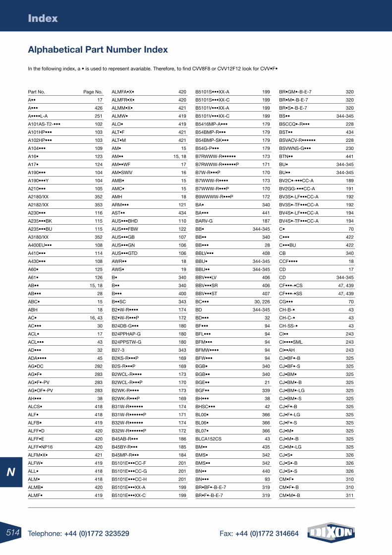
514 Telephone: +44 (0)1772 323529 Fax: +44 (0)1772 314664
N
Index
Alphabetical Part number Index
In the following index, a • is used to represent avariable. Therefore, to find CVV8F8 or CVV12F12 look for CVV•F•
Part No. Page No.
A•• 17
A••• 426
A••••L-A 251
A101AS-T2-••• 102
A101HP••• 103
A102HP••• 103
A104••• 109
A16• 123
A17• 124
A190••• 104
A190•••Y 104
A210••• 105
A2180/XX 352
A2182/XX 353
A230••• 116
A235•••BK 115
A235•••BU 115
A3180/XX 352
A400EU••• 108
A410••• 114
A430••• 108
A60• 125
A61• 126
AB•• 15, 18
AB••• 28
ABC• 15
ABH 18
AC• 16, 43
AC••• 30
ACL• 17
ACL••• 43
AD••• 32
ADA•••• 45
AG•DC 282
AG•F• 283
AG•F•-PV 283
AG•OF•-PV 283
AH••• 38
ALCS• 418
ALF• 418
ALFB• 419
ALFF•D 420
ALFF•E 420
ALFF•NP16 420
ALFM•X• 421
ALFW• 419
ALL• 418
ALM• 418
ALMB• 420
ALMF• 419
ALMFA•X• 420
ALMFR•X• 420
ALMM•X• 421
ALMW• 419
ALO• 419
ALT•F 421
ALT•M 421
AM• 15
AM•• 15, 18
AM••WF 17
AM•SWIV 16
AMB• 15
AMC• 15
AMH 18
ARM••• 121
AST•• 434
AUS•••BHD 110
AUS•••FBW 122
AUS•••GB 107
AUS•••GN 106
AUS•••GTD 106
AWR•• 18
AWS• 19
B• 340
B•• 340
B••• 400
B••SC 343
B2•W-R•••• 174
B2•W-R•••P 172
B24DB-G••• 180
B24PPHAP-G 180
B24PPSTW-G 180
B27-3 343
B2KS-R•••P 169
B2S-R•••P 169
B2WCL-R•••• 173
B2WCL-R•••P 170
B2WK-R•••• 173
B2WK-R•••P 169
B31W-R•••••• 174
B31W-R••••••P 171
B32W-R•••••• 174
B32W-R••••••P 172
B45AB-R••• 186
B45BY-R••• 185
B45MP-R••• 184
B5101E•••CC-F 201
B5101E•••CC-G 201
B5101E•••CC-H 201
B5101E•••XX-A 199
B5101E•••XX-C 199
B5101S•••XX-A 199
B5101S•••XX-C 199
B5101V•••XX-A 199
B5101V•••XX-C 199
B5416MP-A••• 179
B54BMP-R••• 179
B54BMP-SK••• 179
B54G-P••• 179
B7RWWW-R•••••• 173
B7RWWW-R••••••P 171
B7W-R•••P 170
B7WWW-R•••• 173
B7WWW-R•••P 170
B9WWWW-R•••P 172
BA• 340
BA••• 441
BARV-G 187
BB• 344-345
BB•• 340
BB••• 28
BBLV••• 408
BBU• 344-345
BBU•• 344-345
BBV•••LV 406
BBV•••SR 406
BBV•••ST 407
BC••• 30, 226
BD 344-345
BD••• 32
BF••• 94
BFL••• 94
BFM••• 94
BFMW•••• 94
BFW••• 94
BGB• 340
BGB•• 340
BGE•• 21
BGF•• 339
BH••• 38
BHSC••• 42
BL00• 366
BL06• 366
BL07• 366
BLCA152CS 43
BM•• 435
BMS• 342
BMS•• 342
BN•• 440
BN••• 93
BR•BF•-B-E-7 319
BR•F•-B-E-7 319
BR•GM•-B-E-7 320
BR•M•-B-E-7 320
BR•S•-B-E-7 320
BS•• 344-345
BSCCQ•-R••• 228
BST•• 434
BSVACV-R•••••• 228
BSVWNS-G••• 230
BTN•• 441
BU• 344-345
BU•• 344-345
BV2C•-•••CC-A 189
BV2GG-•••CC-A 191
BV3S•-LF•••CC-A 192
BV3S•-TF•••CC-A 192
BV4S•-LF•••CC-A 194
BV4S•-TF•••CC-A 194
C• 70
C••• 422
C•••BU 422
CB 340
CCF•••• 18
CD 17
CD 344-345
CF•••-•CS 47, 439
CF•••-•SS 47, 439
CG••• 70
CH-B-• 43
CH-C-• 43
CH-SS-• 43
CI•• 243
CI••••SML 243
CI••AH 243
CJ•BF•-B 325
CJ•BF•-S 325
CJ•BM• 325
CJ•BM•-B 325
CJ•BM•-LG 325
CJ•BM•-S 325
CJ•F•-B 325
CJ•F•-LG 325
CJ•F•-S 325
CJ•M• 325
CJ•M•-B 325
CJ•M•-LG 325
CJ•S• 326
CJ•S•-B 326
CJ•S•-S 326
CM•F• 310
CM•F•-B 310
CM•M•-B 311
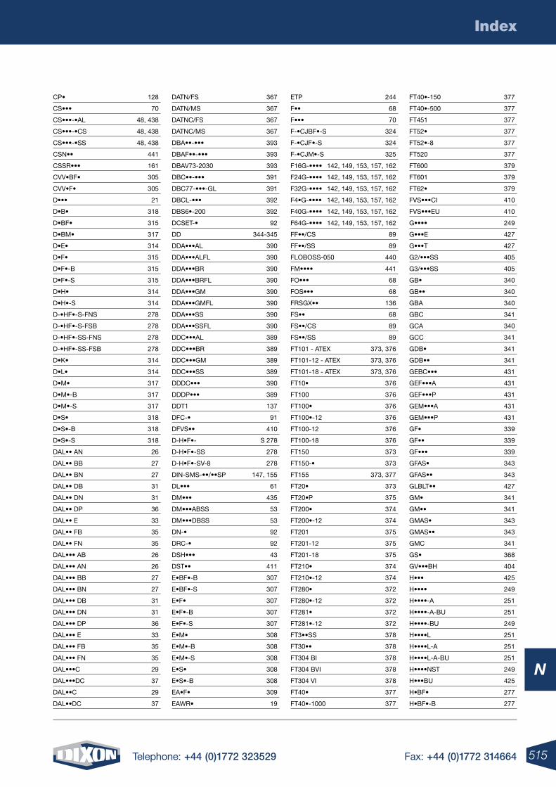
515Telephone: +44 (0)1772 323529 Fax: +44 (0)1772 314664
N
Index
CP• 128
CS••• 70
CS•••-•AL 48, 438
CS•••-•CS 48, 438
CS•••-•SS 48, 438
CSN•• 441
CSSR••• 161
CVV•BF• 305
CVV•F• 305
D••• 21
D•B• 318
D•BF• 315
D•BM• 317
D•E• 314
D•F• 315
D•F•-B 315
D•F•-S 315
D•H• 314
D•H•-S 314
D-•HF•-S-FNS 278
D-•HF•-S-FSB 278
D-•HF•-SS-FNS 278
D-•HF•-SS-FSB 278
D•K• 314
D•L• 314
D•M• 317
D•M•-B 317
D•M•-S 317
D•S• 318
D•S•-B 318
D•S•-S 318
DAL•• AN 26
DAL•• BB 27
DAL•• BN 27
DAL•• DB 31
DAL•• DN 31
DAL•• DP 36
DAL•• E 33
DAL•• FB 35
DAL•• FN 35
DAL••• AB 26
DAL••• AN 26
DAL••• BB 27
DAL••• BN 27
DAL••• DB 31
DAL••• DN 31
DAL••• DP 36
DAL••• E 33
DAL••• FB 35
DAL••• FN 35
DAL•••C 29
DAL•••DC 37
DAL••C 29
DAL••DC 37
DATN/FS 367
DATN/MS 367
DATNC/FS 367
DATNC/MS 367
DBA••-••• 393
DBAF••-••• 393
DBAV73-2030 393
DBC••-••• 391
DBC77-•••-GL 391
DBCL-••• 392
DBS6•-200 392
DCSET-• 92
DD 344-345
DDA•••AL 390
DDA•••ALFL 390
DDA•••BR 390
DDA•••BRFL 390
DDA•••GM 390
DDA•••GMFL 390
DDA•••SS 390
DDA•••SSFL 390
DDC•••AL 389
DDC•••BR 389
DDC•••GM 389
DDC•••SS 389
DDDC••• 390
DDDP••• 389
DDT1 137
DFC-• 91
DFVS•• 410
D-H•F•- S 278
D-H•F•-SS 278
D-H•F•-SV-8 278
DIN-SMS-••/••SP 147, 155
DL••• 61
DM••• 435
DM•••ABSS 53
DM•••DBSS 53
DN-• 92
DRC-• 92
DSH••• 43
DST•• 411
E•BF•-B 307
E•BF•-S 307
E•F• 307
E•F•-B 307
E•F•-S 307
E•M• 308
E•M•-B 308
E•M•-S 308
E•S• 308
E•S•-B 308
EA•F• 309
EAWR• 19
ETP 244
F•• 68
F••• 70
F-•CJBF•-S 324
F-•CJF•-S 324
F-•CJM•-S 325
F16G-•••• 142, 149, 153, 157, 162
F24G-•••• 142, 149, 153, 157, 162
F32G-•••• 142, 149, 153, 157, 162
F4•G-•••• 142, 149, 153, 157, 162
F40G-•••• 142, 149, 153, 157, 162
F64G-•••• 142, 149, 153, 157, 162
FF••/CS 89
FF••/SS 89
FLOBOSS-050 440
FM•••• 441
FO••• 68
FOS••• 68
FRSGX•• 136
FS•• 68
FS••/CS 89
FS••/SS 89
FT101 - ATEX 373, 376
FT101-12 - ATEX 373, 376
FT101-18 - ATEX 373, 376
FT10• 376
FT100 376
FT100• 376
FT100•-12 376
FT100-12 376
FT100-18 376
FT150 373
FT150-• 373
FT155 373, 377
FT20• 373
FT20•P 375
FT200• 374
FT200•-12 374
FT201 375
FT201-12 375
FT201-18 375
FT210• 374
FT210•-12 374
FT280• 372
FT280•-12 372
FT281• 372
FT281•-12 372
FT3••SS 378
FT30•• 378
FT304 BI 378
FT304 BVI 378
FT304 VI 378
FT40• 377
FT40•-1000 377
FT40•-150 377
FT40•-500 377
FT451 377
FT52• 377
FT52•-8 377
FT520 377
FT600 379
FT601 379
FT62• 379
FVS•••CI 410
FVS•••EU 410
G•••• 249
G•••E 427
G•••T 427
G2/•••SS 405
G3/•••SS 405
GB• 340
GB•• 340
GBA 340
GBC 341
GCA 340
GCC 341
GDB• 341
GDB•• 341
GEBC••• 431
GEF•••A 431
GEF•••P 431
GEM•••A 431
GEM•••P 431
GF• 339
GF•• 339
GF••• 339
GFAS• 343
GFAS•• 343
GLBLT•• 427
GM• 341
GM•• 341
GMAS• 343
GMAS•• 343
GMC 341
GS• 368
GV•••BH 404
H••• 425
H•••• 249
H••••-A 251
H••••-A-BU 251
H••••-BU 249
H••••L 251
H••••L-A 251
H••••L-A-BU 251
H••••NST 249
H•••BU 425
H•BF• 277
H•BF•-B 277
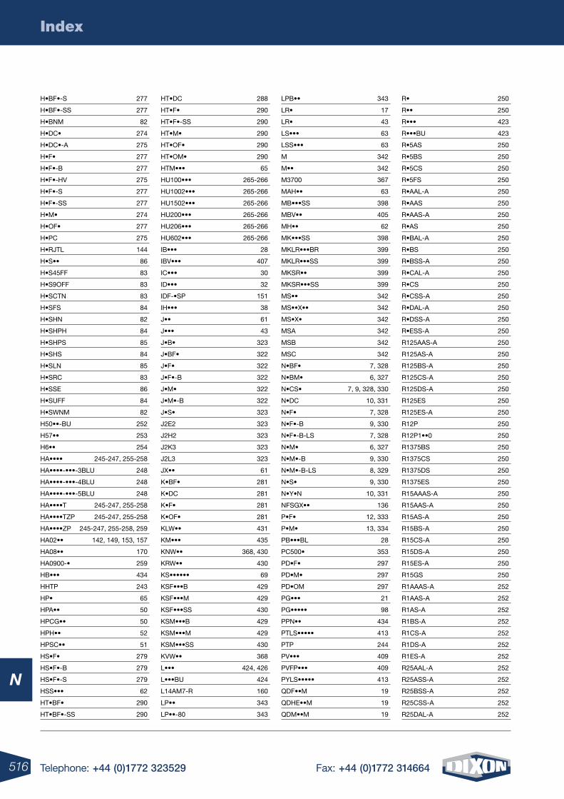
516 Telephone: +44 (0)1772 323529 Fax: +44 (0)1772 314664
N
Index
H•BF•-S 277
H•BF•-SS 277
H•BNM 82
H•DC• 274
H•DC•-A 275
H•F• 277
H•F•-B 277
H•F•-HV 275
H•F•-S 277
H•F•-SS 277
H•M• 274
H•OF• 277
H•PC 275
H•RJTL 144
H•S•• 86
H•S45FF 83
H•S9OFF 83
H•SCTN 83
H•SFS 84
H•SHN 82
H•SHPH 84
H•SHPS 85
H•SHS 84
H•SLN 85
H•SRC 83
H•SSE 86
H•SUFF 84
H•SWNM 82
H50••-BU 252
H57•• 253
H6•• 254
HA•••• 245-247, 255-258
HA••••-•••-3BLU 248
HA••••-•••-4BLU 248
HA••••-•••-5BLU 248
HA••••T 245-247, 255-258
HA••••TZP 245-247, 255-258
HA••••ZP 245-247, 255-258, 259
HA02•• 142, 149, 153, 157
HA08•• 170
HA0900-• 259
HB••• 434
HHTP 243
HP• 65
HPA•• 50
HPCG•• 50
HPH•• 52
HPSC•• 51
HS•F• 279
HS•F•-B 279
HS•F•-S 279
HSS••• 62
HT•BF• 290
HT•BF•-SS 290
HT•DC 288
HT•F• 290
HT•F•-SS 290
HT•M• 290
HT•OF• 290
HT•OM• 290
HTM••• 65
HU100••• 265-266
HU1002••• 265-266
HU1502••• 265-266
HU200••• 265-266
HU206••• 265-266
HU602••• 265-266
IB••• 28
IBV••• 407
IC••• 30
ID••• 32
IDF-•SP 151
IH••• 38
J•• 61
J••• 43
J•B• 323
J•BF• 322
J•F• 322
J•F•-B 322
J•M• 322
J•M•-B 322
J•S• 323
J2E2 323
J2H2 323
J2K3 323
J2L3 323
JX•• 61
K•BF• 281
K•DC 281
K•F• 281
K•OF• 281
KLW•• 431
KM••• 435
KNW•• 368, 430
KRW•• 430
KS•••••• 69
KSF•••B 429
KSF•••M 429
KSF•••SS 430
KSM•••B 429
KSM•••M 429
KSM•••SS 430
KVW•• 368
L••• 424, 426
L•••BU 424
L14AM7-R 160
LP•• 343
LP••-80 343
LPB•• 343
LR• 17
LR• 43
LS••• 63
LSS••• 63
M 342
M•• 342
M3700 367
MAH•• 63
MB•••SS 398
MBV•• 405
MH•• 62
MK•••SS 398
MKLR•••BR 399
MKLR•••SS 399
MKSR•• 399
MKSR•••SS 399
MS•• 342
MS••X•• 342
MS•X• 342
MSA 342
MSB 342
MSC 342
N•BF• 7, 328
N•BM• 6, 327
N•CS• 7, 9, 328, 330
N•DC 10, 331
N•F• 7, 328
N•F•-B 9, 330
N•F•-B-LS 7, 328
N•M• 6, 327
N•M•-B 9, 330
N•M•-B-LS 8, 329
N•S• 9, 330
N•Y•N 10, 331
NFSGX•• 136
P•F• 12, 333
P•M• 13, 334
PB•••BL 28
PC500• 353
PD•F• 297
PD•M• 297
PD•OM 297
PG••• 21
PG••••• 98
PPN•• 434
PTLS••••• 413
PTP 244
PV••• 409
PVFP••• 409
PYLS••••• 413
QDF••M 19
QDHE••M 19
QDM••M 19
R• 250
R•• 250
R••• 423
R•••BU 423
R•5AS 250
R•5BS 250
R•5CS 250
R•5FS 250
R•AAL-A 250
R•AAS 250
R•AAS-A 250
R•AS 250
R•BAL-A 250
R•BS 250
R•BSS-A 250
R•CAL-A 250
R•CS 250
R•CSS-A 250
R•DAL-A 250
R•DSS-A 250
R•ESS-A 250
R125AAS-A 250
R125AS-A 250
R125BS-A 250
R125CS-A 250
R125DS-A 250
R125ES 250
R125ES-A 250
R12P 250
R12P1••0 250
R1375BS 250
R1375CS 250
R1375DS 250
R1375ES 250
R15AAAS-A 250
R15AAS-A 250
R15AS-A 250
R15BS-A 250
R15CS-A 250
R15DS-A 250
R15ES-A 250
R15GS 250
R1AAAS-A 252
R1AAS-A 252
R1AS-A 252
R1BS-A 252
R1CS-A 252
R1DS-A 252
R1ES-A 252
R25AAL-A 252
R25ASS-A 252
R25BSS-A 252
R25CSS-A 252
R25DAL-A 252
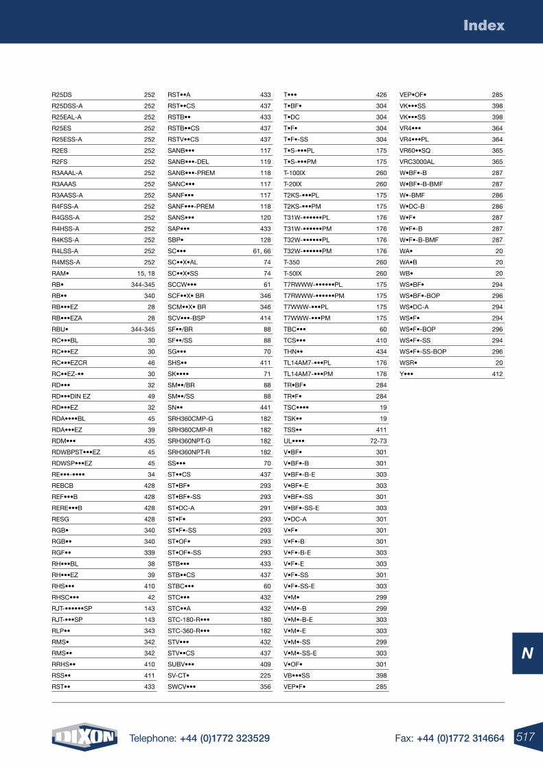
517Telephone: +44 (0)1772 323529 Fax: +44 (0)1772 314664
N
Index
R25DS 252
R25DSS-A 252
R25EAL-A 252
R25ES 252
R25ESS-A 252
R2ES 252
R2FS 252
R3AAAL-A 252
R3AAAS 252
R3AASS-A 252
R4FSS-A 252
R4GSS-A 252
R4HSS-A 252
R4KSS-A 252
R4LSS-A 252
R4MSS-A 252
RAM• 15, 18
RB• 344-345
RB•• 340
RB•••EZ 28
RB•••EZA 28
RBU• 344-345
RC•••BL 30
RC•••EZ 30
RC•••EZCR 46
RC••EZ-•• 30
RD••• 32
RD•••DIN EZ 49
RD•••EZ 32
RDA••••BL 45
RDA•••EZ 39
RDM••• 435
RDWBPST•••EZ 45
RDWSP•••EZ 45
RE•••-•••• 34
REBCB 428
REF•••B 428
RERE•••B 428
RESG 428
RGB• 340
RGB•• 340
RGF•• 339
RH•••BL 38
RH•••EZ 39
RHS••• 410
RHSC••• 42
RJT-••••••SP 143
RJT-•••SP 143
RLP•• 343
RMS• 342
RMS•• 342
RRHS•• 410
RSS•• 411
RST•• 433
RST••A 433
RST••CS 437
RSTB•• 433
RSTB••CS 437
RSTV••CS 437
SANB••• 117
SANB•••-DEL 119
SANB•••-PREM 118
SANC••• 117
SANF••• 117
SANF•••-PREM 118
SANS••• 120
SAP••• 433
SBP• 128
SC••• 61, 66
SC••X•AL 74
SC••X•SS 74
SCCW••• 61
SCF••X• BR 346
SCM••X• BR 346
SCV•••-BSP 414
SF••/BR 88
SF••/SS 88
SG••• 70
SHS•• 411
SK•••• 71
SM••/BR 88
SM••/SS 88
SN•• 441
SRH360CMP-G 182
SRH360CMP-R 182
SRH360NPT-G 182
SRH360NPT-R 182
SS••• 70
ST••CS 437
ST•BF• 293
ST•BF•-SS 293
ST•DC-A 291
ST•F• 293
ST•F•-SS 293
ST•OF• 293
ST•OF•-SS 293
STB••• 433
STB••CS 437
STBC••• 60
STC••• 432
STC••A 432
STC-180-R••• 180
STC-360-R••• 182
STV••• 432
STV••CS 437
SUBV••• 409
SV-CT• 225
SWCV••• 356
T••• 426
T•BF• 304
T•DC 304
T•F• 304
T•F•-SS 304
T•S-•••PL 175
T•S-•••PM 175
T-100IX 260
T-20IX 260
T2KS-•••PL 175
T2KS-•••PM 175
T31W-••••••PL 176
T31W-••••••PM 176
T32W-••••••PL 176
T32W-••••••PM 176
T-350 260
T-50IX 260
T7RWWW-••••••PL 175
T7RWWW-••••••PM 175
T7WWW-•••PL 175
T7WWW-•••PM 175
TBC••• 60
TCS••• 410
THN•• 434
TL14AM7-•••PL 176
TL14AM7-•••PM 176
TR•BF• 284
TR•F• 284
TSC•••• 19
TSK•• 19
TSS•• 411
UL•••• 72-73
V•BF• 301
V•BF•-B 301
V•BF•-B-E 303
V•BF•-E 303
V•BF•-SS 301
V•BF•-SS-E 303
V•DC-A 301
V•F• 301
V•F•-B 301
V•F•-B-E 303
V•F•-E 303
V•F•-SS 301
V•F•-SS-E 303
V•M• 299
V•M•-B 299
V•M•-B-E 303
V•M•-E 303
V•M•-SS 299
V•M•-SS-E 303
V•OF• 301
VB•••SS 398
VEP•F• 285
VEP•OF• 285
VK•••SS 398
VK•••SS 398
VR4••• 364
VR4•••PL 364
VR60••SQ 365
VRC3000AL 365
W•BF•-B 287
W•BF•-B-BMF 287
W•-BMF 286
W•DC-B 286
W•F• 287
W•F•-B 287
W•F•-B-BMF 287
WA• 20
WA•B 20
WB• 20
WS•BF• 294
WS•BF•-BOP 296
WS•DC-A 294
WS•F• 294
WS•F•-BOP 296
WS•F•-SS 294
WS•F•-SS-BOP 296
WSR• 20
Y••• 412
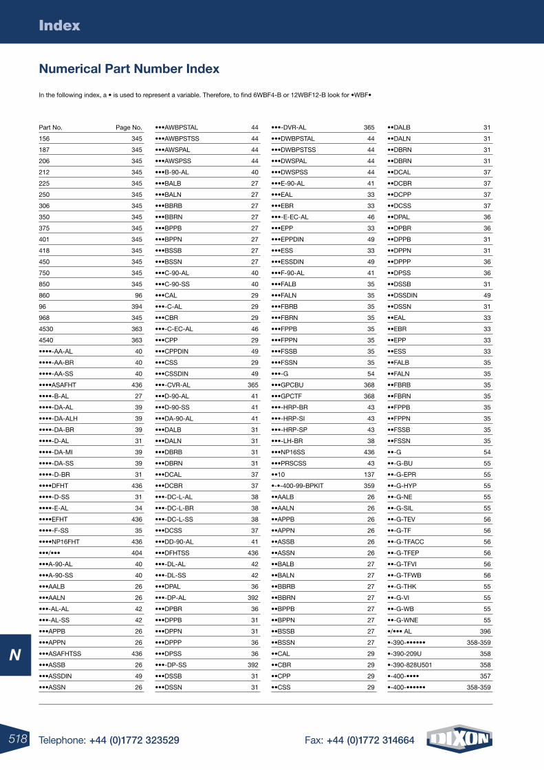
518 Telephone: +44 (0)1772 323529 Fax: +44 (0)1772 314664
N
Index
numerical Part number Index
In the following index, a • is used to represent a variable. Therefore, to find 6WBF4-B or 12WBF12-B look for •WBF•
Part No. Page No.
156 345
187 345
206 345
212 345
225 345
250 345
306 345
350 345
375 345
401 345
418 345
450 345
750 345
850 345
860 96
96 394
968 345
4530 363
4540 363
••••-AA-AL 40
••••-AA-BR 40
••••-AA-SS 40
••••ASAFHT 436
••••-B-AL 27
••••-DA-AL 39
••••-DA-ALH 39
••••-DA-BR 39
••••-D-AL 31
••••-DA-MI 39
••••-DA-SS 39
••••-D-BR 31
••••DFHT 436
••••-D-SS 31
••••-E-AL 34
••••EFHT 436
••••-F-SS 35
••••NP16FHT 436
•••/••• 404
•••A-90-AL 40
•••A-90-SS 40
•••AALB 26
•••AALN 26
•••-AL-AL 42
•••-AL-SS 42
•••APPB 26
•••APPN 26
•••ASAFHTSS 436
•••ASSB 26
•••ASSDIN 49
•••ASSN 26
•••AWBPSTAL 44
•••AWBPSTSS 44
•••AWSPAL 44
•••AWSPSS 44
•••B-90-AL 40
•••BALB 27
•••BALN 27
•••BBRB 27
•••BBRN 27
•••BPPB 27
•••BPPN 27
•••BSSB 27
•••BSSN 27
•••C-90-AL 40
•••C-90-SS 40
•••CAL 29
•••-C-AL 29
•••CBR 29
•••-C-EC-AL 46
•••CPP 29
•••CPPDIN 49
•••CSS 29
•••CSSDIN 49
•••-CVR-AL 365
•••D-90-AL 41
•••D-90-SS 41
•••DA-90-AL 41
•••DALB 31
•••DALN 31
•••DBRB 31
•••DBRN 31
•••DCAL 37
•••DCBR 37
•••-DC-L-AL 38
•••-DC-L-BR 38
•••-DC-L-SS 38
•••DCSS 37
•••DD-90-AL 41
•••DFHTSS 436
•••-DL-AL 42
•••-DL-SS 42
•••DPAL 36
•••-DP-AL 392
•••DPBR 36
•••DPPB 31
•••DPPN 31
•••DPPP 36
•••DPSS 36
•••-DP-SS 392
•••DSSB 31
•••DSSN 31
•••-DVR-AL 365
•••DWBPSTAL 44
•••DWBPSTSS 44
•••DWSPAL 44
•••DWSPSS 44
•••E-90-AL 41
•••EAL 33
•••EBR 33
•••-E-EC-AL 46
•••EPP 33
•••EPPDIN 49
•••ESS 33
•••ESSDIN 49
•••F-90-AL 41
•••FALB 35
•••FALN 35
•••FBRB 35
•••FBRN 35
•••FPPB 35
•••FPPN 35
•••FSSB 35
•••FSSN 35
•••-G 54
•••GPCBU 368
•••GPCTF 368
•••-HRP-BR 43
•••-HRP-SI 43
•••-HRP-SP 43
•••-LH-BR 38
•••NP16SS 436
•••PRSCSS 43
••10 137
•-•-400-99-BPKIT 359
••AALB 26
••AALN 26
••APPB 26
••APPN 26
••ASSB 26
••ASSN 26
••BALB 27
••BALN 27
••BBRB 27
••BBRN 27
••BPPB 27
••BPPN 27
••BSSB 27
••BSSN 27
••CAL 29
••CBR 29
••CPP 29
••CSS 29
••DALB 31
••DALN 31
••DBRN 31
••DBRN 31
••DCAL 37
••DCBR 37
••DCPP 37
••DCSS 37
••DPAL 36
••DPBR 36
••DPPB 31
••DPPN 31
••DPPP 36
••DPSS 36
••DSSB 31
••DSSDIN 49
••DSSN 31
••EAL 33
••EBR 33
••EPP 33
••ESS 33
••FALB 35
••FALN 35
••FBRB 35
••FBRN 35
••FPPB 35
••FPPN 35
••FSSB 35
••FSSN 35
••-G 54
••-G-BU 55
••-G-EPR 55
••-G-HYP 55
••-G-NE 55
••-G-SIL 55
••-G-TEV 56
••-G-TF 56
••-G-TFACC 56
••-G-TFEP 56
••-G-TFVI 56
••-G-TFWB 56
••-G-THK 55
••-G-VI 55
••-G-WB 55
••-G-WNE 55
•/••• AL 396
•-390-•••••• 358-359
•-390-209U 358
•-390-828U501 358
•-400-•••• 357
•-400-•••••• 358-359
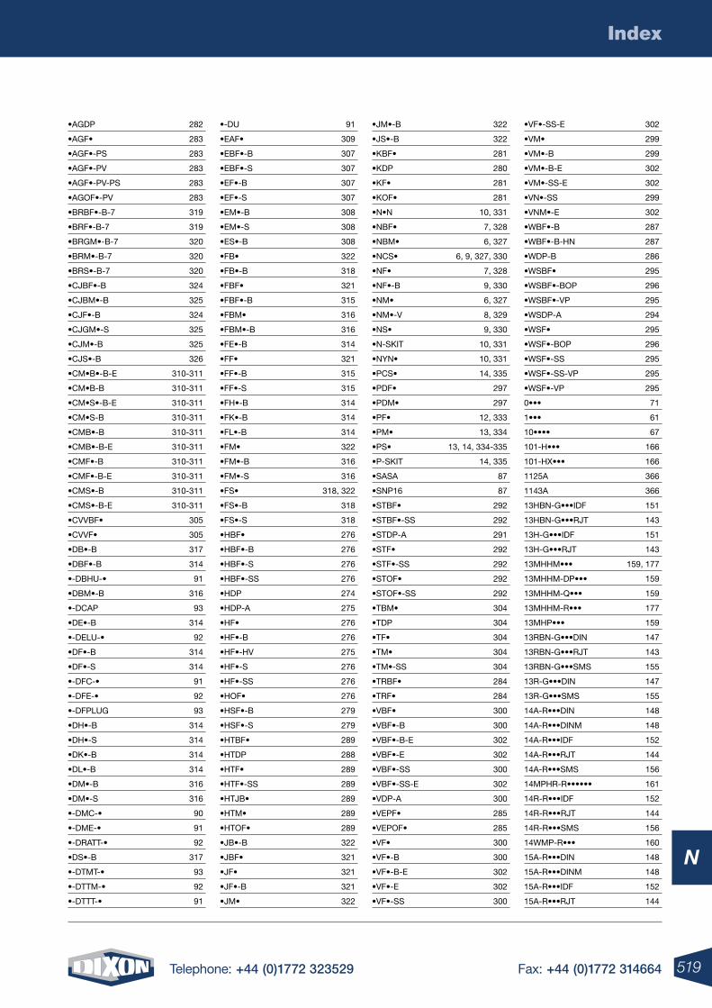
519Telephone: +44 (0)1772 323529 Fax: +44 (0)1772 314664
N
Index
•AGDP 282
•AGF• 283
•AGF•-PS 283
•AGF•-PV 283
•AGF•-PV-PS 283
•AGOF•-PV 283
•BRBF•-B-7 319
•BRF•-B-7 319
•BRGM•-B-7 320
•BRM•-B-7 320
•BRS•-B-7 320
•CJBF•-B 324
•CJBM•-B 325
•CJF•-B 324
•CJGM•-S 325
•CJM•-B 325
•CJS•-B 326
•CM•B•-B-E 310-311
•CM•B-B 310-311
•CM•S•-B-E 310-311
•CM•S-B 310-311
•CMB•-B 310-311
•CMB•-B-E 310-311
•CMF•-B 310-311
•CMF•-B-E 310-311
•CMS•-B 310-311
•CMS•-B-E 310-311
•CVVBF• 305
•CVVF• 305
•DB•-B 317
•DBF•-B 314
•-DBHU-• 91
•DBM•-B 316
•-DCAP 93
•DE•-B 314
•-DELU-• 92
•DF•-B 314
•DF•-S 314
•-DFC-• 91
•-DFE-• 92
•-DFPLUG 93
•DH•-B 314
•DH•-S 314
•DK•-B 314
•DL•-B 314
•DM•-B 316
•DM•-S 316
•-DMC-• 90
•-DME-• 91
•-DRATT-• 92
•DS•-B 317
•-DTMT-• 93
•-DTTM-• 92
•-DTTT-• 91
•-DU 91
•EAF• 309
•EBF•-B 307
•EBF•-S 307
•EF•-B 307
•EF•-S 307
•EM•-B 308
•EM•-S 308
•ES•-B 308
•FB• 322
•FB•-B 318
•FBF• 321
•FBF•-B 315
•FBM• 316
•FBM•-B 316
•FE•-B 314
•FF• 321
•FF•-B 315
•FF•-S 315
•FH•-B 314
•FK•-B 314
•FL•-B 314
•FM• 322
•FM•-B 316
•FM•-S 316
•FS• 318, 322
•FS•-B 318
•FS•-S 318
•HBF• 276
•HBF•-B 276
•HBF•-S 276
•HBF•-SS 276
•HDP 274
•HDP-A 275
•HF• 276
•HF•-B 276
•HF•-HV 275
•HF•-S 276
•HF•-SS 276
•HOF• 276
•HSF•-B 279
•HSF•-S 279
•HTBF• 289
•HTDP 288
•HTF• 289
•HTF•-SS 289
•HTJB• 289
•HTM• 289
•HTOF• 289
•JB•-B 322
•JBF• 321
•JF• 321
•JF•-B 321
•JM• 322
•JM•-B 322
•JS•-B 322
•KBF• 281
•KDP 280
•KF• 281
•KOF• 281
•N•N 10, 331
•NBF• 7, 328
•NBM• 6, 327
•NCS• 6, 9, 327, 330
•NF• 7, 328
•NF•-B 9, 330
•NM• 6, 327
•NM•-V 8, 329
•NS• 9, 330
•N-SKIT 10, 331
•NYN• 10, 331
•PCS• 14, 335
•PDF• 297
•PDM• 297
•PF• 12, 333
•PM• 13, 334
•PS• 13, 14, 334-335
•P-SKIT 14, 335
•SASA 87
•SNP16 87
•STBF• 292
•STBF•-SS 292
•STDP-A 291
•STF• 292
•STF•-SS 292
•STOF• 292
•STOF•-SS 292
•TBM• 304
•TDP 304
•TF• 304
•TM• 304
•TM•-SS 304
•TRBF• 284
•TRF• 284
•VBF• 300
•VBF•-B 300
•VBF•-B-E 302
•VBF•-E 302
•VBF•-SS 300
•VBF•-SS-E 302
•VDP-A 300
•VEPF• 285
•VEPOF• 285
•VF• 300
•VF•-B 300
•VF•-B-E 302
•VF•-E 302
•VF•-SS 300
•VF•-SS-E 302
•VM• 299
•VM•-B 299
•VM•-B-E 302
•VM•-SS-E 302
•VN•-SS 299
•VNM•-E 302
•WBF•-B 287
•WBF•-B-HN 287
•WDP-B 286
•WSBF• 295
•WSBF•-BOP 296
•WSBF•-VP 295
•WSDP-A 294
•WSF• 295
•WSF•-BOP 296
•WSF•-SS 295
•WSF•-SS-VP 295
•WSF•-VP 295
0••• 71
1••• 61
10•••• 67
101-H••• 166
101-HX••• 166
1125A 366
1143A 366
13HBN-G•••IDF 151
13HBN-G•••RJT 143
13H-G•••IDF 151
13H-G•••RJT 143
13MHHM••• 159, 177
13MHHM-DP••• 159
13MHHM-Q••• 159
13MHHM-R••• 177
13MHP••• 159
13RBN-G•••DIN 147
13RBN-G•••RJT 143
13RBN-G•••SMS 155
13R-G•••DIN 147
13R-G•••SMS 155
14A-R•••DIN 148
14A-R•••DINM 148
14A-R•••IDF 152
14A-R•••RJT 144
14A-R•••SMS 156
14MPHR-R•••••• 161
14R-R•••IDF 152
14R-R•••RJT 144
14R-R•••SMS 156
14WMP-R••• 160
15A-R•••DIN 148
15A-R•••DINM 148
15A-R•••IDF 152
15A-R•••RJT 144
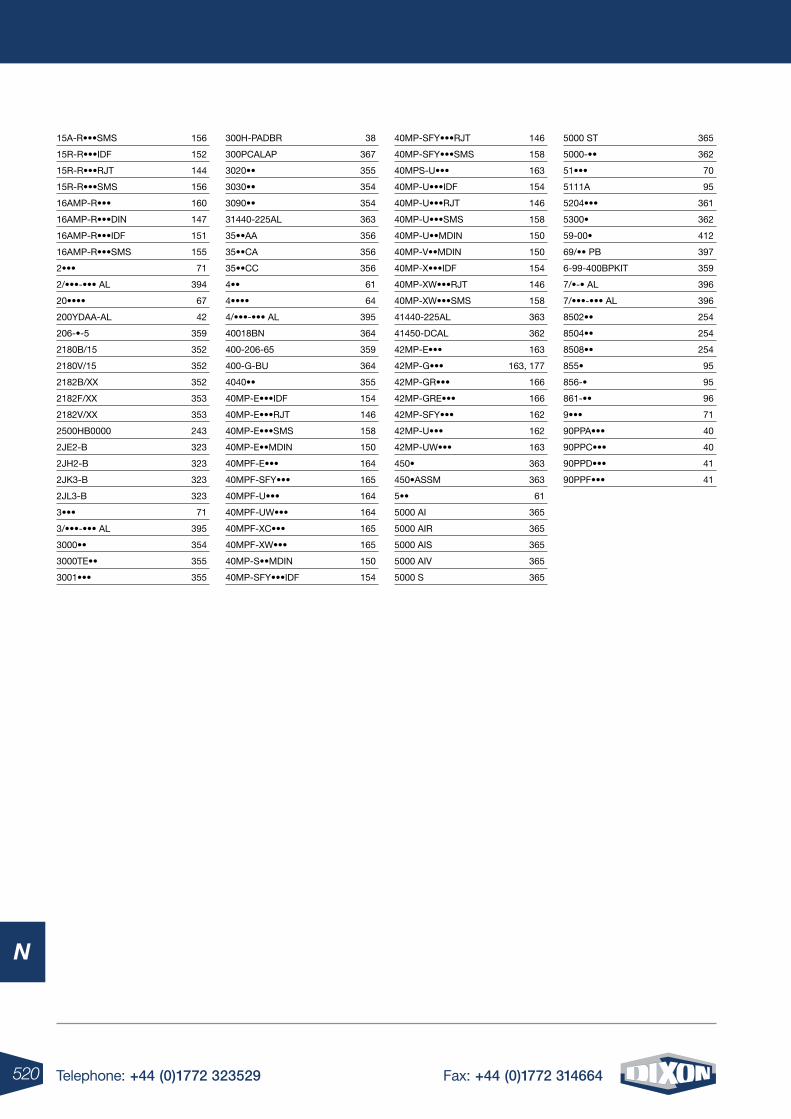
520 Telephone: +44 (0)1772 323529 Fax: +44 (0)1772 314664
N
15A-R•••SMS 156
15R-R•••IDF 152
15R-R•••RJT 144
15R-R•••SMS 156
16AMP-R••• 160
16AMP-R•••DIN 147
16AMP-R•••IDF 151
16AMP-R•••SMS 155
2••• 71
2/•••-••• AL 394
20•••• 67
200YDAA-AL 42
206-•-5 359
2180B/15 352
2180V/15 352
2182B/XX 352
2182F/XX 353
2182V/XX 353
2500HB0000 243
2JE2-B 323
2JH2-B 323
2JK3-B 323
2JL3-B 323
3••• 71
3/•••-••• AL 395
3000•• 354
3000TE•• 355
3001••• 355
300H-PADBR 38
300PCALAP 367
3020•• 355
3030•• 354
3090•• 354
31440-225AL 363
35••AA 356
35••CA 356
35••CC 356
4•• 61
4•••• 64
4/•••-••• AL 395
40018BN 364
400-206-65 359
400-G-BU 364
4040•• 355
40MP-E•••IDF 154
40MP-E•••RJT 146
40MP-E•••SMS 158
40MP-E••MDIN 150
40MPF-E••• 164
40MPF-SFY••• 165
40MPF-U••• 164
40MPF-UW••• 164
40MPF-XC••• 165
40MPF-XW••• 165
40MP-S••MDIN 150
40MP-SFY•••IDF 154
40MP-SFY•••RJT 146
40MP-SFY•••SMS 158
40MPS-U••• 163
40MP-U•••IDF 154
40MP-U•••RJT 146
40MP-U•••SMS 158
40MP-U••MDIN 150
40MP-V••MDIN 150
40MP-X•••IDF 154
40MP-XW•••RJT 146
40MP-XW•••SMS 158
41440-225AL 363
41450-DCAL 362
42MP-E••• 163
42MP-G••• 163, 177
42MP-GR••• 166
42MP-GRE••• 166
42MP-SFY••• 162
42MP-U••• 162
42MP-UW••• 163
450• 363
450•ASSM 363
5•• 61
5000 AI 365
5000 AIR 365
5000 AIS 365
5000 AIV 365
5000 S 365
5000 ST 365
5000-•• 362
51••• 70
5111A 95
5204••• 361
5300• 362
59-00• 412
69/•• PB 397
6-99-400BPKIT 359
7/•-• AL 396
7/•••-••• AL 396
8502•• 254
8504•• 254
8508•• 254
855• 95
856-• 95
861-•• 96
9••• 71
90PPA••• 40
90PPC••• 40
90PPD••• 41
90PPF••• 41
521Telephone: +44 (0)1772 323529 Fax: +44 (0)1772 314664
Technical & Safety Information
N
notes
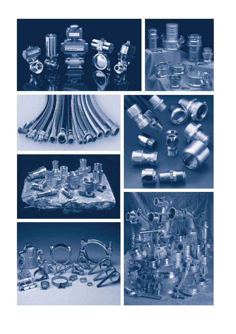
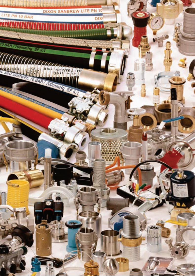
Dixon Deutschland GmbHGodesberger Strasse 20bD – 53842 Troisdorf – SpichGermanyTel: +49 (0)2241 844 060Email: [email protected]
Dixon Russia22/2 A Sadovaya StreetOffice 27-HSaint PetersburgRussiaTel: +7 (812) 448-83-67Email: [email protected]
Dixon Middle EastExecutive Suite, PO Box 121599, Saif Zone-Sharjah, United Arab EmiratesEmail: [email protected]
Dixon France105 Route Pommiers UBIDOCA Center, 5837 F-74370 Saint Martin Bellevue France Email: [email protected]
Dixon Valve & Coupling Co800 High StreetChestertownMD 21620USATel: +1 410 778 2000Email: [email protected]
Dixon Asia PacificPO Box 2491Regency ParkSA 5942AustraliaTel: +61 8 8202 6000Email: [email protected]
Dixon ShanghaiRoom 801-803 No.3553 North Zhongshan RdPutuo District Shanghai, China Tel: +86 21 6173 7998 Email: [email protected] Dixon India90, Virwani Industrial Estate,Western Express Highway,Goregaon East,Mumbai – 400 063, IndiaTel - +91-22-61949494 / 29271152Email: [email protected]
Dixon Group Europe Limited
Dixon House, 350 Leach Place, Walton Summit Centre, Preston PR5 8AS, UK.
Telephone: +44 (0)1772 323 529 Fax: +44 (0)1772 314 664Email: [email protected] www.dixoneurope.co.uk / www.dixoneurope.eu
Stay connected with Dixon on or
www.youtube.com/user/DixonValve
Dixon Europe
Dixon Worldwide
A
B
C
D
E
F
G
H
I
J
K
L
M
N
page
4
page
22
page
58
page
76
page
80
page
100
page
138
page
238
page
268
page
336
page
348
page
402
page
416
page
442
Air Fittings
Cam & Groove
Clamps & Accessories
Fire Products - Dixon Powhatan
Fittings, Gauges & Adapters
Hose & Hose Assemblies
Hygienic Products
Permanently Attached Couplings - Holedall®
Quick Release Couplings
Steam Couplings - Boss™
Tanker, Overfill & Storage Tank Products
Valves - General & Industrial
Water Couplings
Technical & Safety Information
© 2012 DGEL Printed in the UK HOSE&COUPCAT02
Customer Service: +44 (0)1772 323 529


