Handbook on
Electricity Meters
APEC/APLMF Training Courses in Legal Metrology (CTI 10/2005T)
February 28 - March 3, 2006 Ho Chi Minh City, Viet Nam
APEC Secretariat
35 Heng Mui Keng Terrace Singapore 119616. Tel: +65-6775-6012, Fax: +65-6775-6013 E-mail: [email protected] Website: www.apec.org
APLMF Secretariat
AIST Tsukuba Central 3-9 1-1-1 Umezono, Tsukuba, Ibaraki 305-8563, Japan Tel: +81-29-861-4362, Fax: +81-29-861-4393 E-mail: [email protected] Website: www.aplmf.org
© 2006 APEC Secretariat APEC# 206-CT-03.3 ISBN 4-9903094-0-5 June 2006
Asia-Pacific
Legal Metrology Forum


Contents
1 Foreword 1
2 Summary Report 3
3 Agenda 5
4 Participants List ........................................................................................................... 9
5 Lecture 5.1 Introduction to the Training Course on Electricity Meters...................................... 11 Electricity Distribution Systems .............................................................................. 13 Sine Wave and Phasor (Vector) Concepts............................................................... 14 Electricity Metering Circuits ................................................................................... 19
Single Phase Load Analysis Single Phase 2-Wire Load ....................................................................................... 34 Single Phase 2-Wire Service ................................................................................... 36 Single Phase 3-Wire Service ................................................................................... 37
Polyphase Load Analysis Polyphase Phasors ................................................................................................... 40 3 Phase 4 Wire Wye Service ................................................................................... 42 3 Phase 3-Wire Wye Delta Service ......................................................................... 43
Measurement Concepts 4 Quadrant Measurement......................................................................................... 46 Watts hours (Wh)..................................................................................................... 47 Reactive Volt-Ampere hours (VARh) ..................................................................... 49 Volt-Ampere hours (VAh)....................................................................................... 51
Demand Measurement ............................................................................................. 53 Volt-Ampere Demand Measurement....................................................................... 61
Basic Induction Meters Motor Section .......................................................................................................... 65 Breaking Section...................................................................................................... 67 Gear Train Section................................................................................................... 68
Electronic Metering ................................................................................................. 72 Type Approval of Electricity Meters....................................................................... 84 Verification and Test Method.................................................................................. 89 Reverification Intervals ........................................................................................... 95 In-Service Compliance Programs ............................................................................ 99 Measurement Standards and Test Equipment........................................................ 102 Measurement Dispute Investigations..................................................................... 108
5.2 Overview of the Electricity Meters in Japan Legislation ............................................................................................................. 111 Type Approval ....................................................................................................... 115 Verification ............................................................................................................ 120 Verification Standards ........................................................................................... 126
Overview of International Standards on Electricity Meters .................................. 131
Current Situation of the Revision of OIML Recommendation ............................. 134
6 Reports from the Trainees
6.1 Cambodia (This is a non-APEC economy.) .......................................................... 137
6.2 Chile....................................................................................................................... 139
6.3 People’s Republic of China ................................................................................... 141
6.4 Indonesia................................................................................................................ 144
6.5 Japan ...................................................................................................................... 146
6.6 Lao People’s Democratic Republic (This is a non-APEC economy.)................... 149
6.7 Malaysia................................................................................................................. 153
6.8 Mongolia (This is a non-APEC economy.) ........................................................... 155
6.9 Papua New Guinea ................................................................................................ 158
6.10 Philippines ............................................................................................................. 160
6.11 Chinese Taipei ....................................................................................................... 164
6.12 Thailand ................................................................................................................. 167
6.13 Viet Nam................................................................................................................ 171
Fore word
This booklet is one of outcomes of the APEC Seminars and Training Courses in Legal Metrology titled ‘Training Course on Electricity Meters’ that was held on February 28 - March 3, 2006 at the Rex Hotel in Ho Chi Minh City, Viet Nam. This training course was the second training course conducted as a follow-up of the first course held in March, 2005 in Hanoi. It was organized by the Asia-Pacific Legal Metrology Forum (APLMF) with a support fund of APEC-TILF (Trade and Investment Liberalization and Facilitation) program, CTI-10/2005T. The training course was also supported by (1) Directorate for Standards and Quality (STAMEQ), Viet Nam, (2) Measurement Canada, Government of Canada, (3) National Metrology Institute of Japan (NMIJ) and (4) Japan Electric Meters Inspection Corporation (JEMIC). Having this result, I would like to extend my sincere gratitude to all the staffs of STAMEQ, two trainers from Measurement Canada and two trainers from JEMIC, and the Working Group on Utility Meters of APLMF chaired by Measurement Canada. Also, special thanks should be extended to the APEC Secretariat for their great contributions.
We have conducted the surveys among the APEC member economies concerning seminar and training programs in legal metrology to find their needs as well as possible resources which would be available for the region. The survey shows that there is still a strong need for repeating training courses on electricity meters that is one of the most essential categories of instruments in legal metrology and is also closely connected to our daily life. In addition, according to the globalization of international trade in worldwide, the compliance to international recommendations related to electricity meters, which are represented by the ISO/IEC 62053 series and the OIML Recommendation R46, is becoming an important issue for the APEC and APLMF member economies.
Main target of this training course was to assist the experts in charge of type approval and/or verification of electricity meters in the APEC / APLMF member economies to learn in depth and to develop common understanding about the verification procedures based on the international standards and OIML recommendations. Thus the target would meet the APEC objective to harmonize metrology legislation within the OIML framework. The contents of the training course were focused on the understandings of basic principle and construction of electricity meters, international or national recommendations related to the electricity meters, and learning of actual test procedures.
In view of these situations, this training course on electricity meters had been planned and completed successfully so as to settle a sure basis of confidence in legal metrology related to the measurement of electric power within the Asia-Pacific region. I would like to say that this
1
is certainly the valuable second step to fruitful activities in legal metrology related to electricity meters in the Asia-Pacific region.
I am really pleased to have this outcome from the training course and again deeply appreciate the APEC Secretariat’s generosity in contributing to the development in legal metrology among the APLMF member economies.
June 1, 2006
Dr. Akira Ooiwa
APLMF President
2
Summary Report on the Training Course on Electricity Meters
The APEC/APLMF Training Course on Electricity Meters was held in Ho Chi Minh
City, Viet Nam from February 28 to March 3, 2006. The course was attended by 35 participants representing 13 economies including Cambodia, Chile, People’s Republic of China, Indonesia, Japan, Lao PDR, Malaysia, Mongolia, Papua New Guinea, Philippines, Chinese Taipei, Thailand and the host economy Viet Nam. The course was organized by the APLMF with support from APEC, the Directorate for Standards and Quality (STAMEQ) of Viet Nam, the National Metrology Institute of Japan (NMIJ), the Japan Electric Meter Inspection Corporation (JEMIC) and Measurement Canada.
While electricity is one of the most commonly used and traded commodities in the world today; the nature of electrical power and energy, the forms in which it is delivered to the consumer, and the methods used in trade measurement are complex and often poorly understood by the general population. In order to develop and maintain mutual confidence in the trade measurement of electricity, APLMF member economies have recognized the need for effective and harmonized legal metrology programs.
The course was designed to provide participants with a greater understanding of the issues and challenges associated with achieving accuracy and equity in the trade measurement of electricity.
Participants came with a variety of technical and legislative expertise. Such benefit as a diverse group provides participants an exposure to legal metrology from different perspectives. While it is beneficial for legislators to understand the significance of the technical aspects of electricity measurement, it is equally important for technical personnel to appreciate the benefits of using national requirements that are in harmony with international standards or policies. The course was structured in a manner that would allow participants with varying levels of technical and legislative expertise to enhance their understanding of electricity measurement from a legal metrology perspective while providing the flexibility to add or expand on content where required to address the training needs of the participants.
At present, the legal requirements for electricity measurement vary significantly between the participating APLMF economies. In order to provide participants with a greater understanding and appreciation of the various policies and practices of other APLMF economies, participants were requested to make a three minute presentation on the current requirements within their respective economies, in relation to nine key questions. This provided a means for establishing the training needs of the individual participants, and also gave them with a greater understanding of the differing practices of other economies.
This was followed by lectures by Mr. Takao Oki, Director, Technical Research Laboratory, and Mr. Masatoshi Tetsuka, Senior Staff of Verification Management Division of the Japan Electric Meters Inspection Corporation (JEMIC). The lectures presented an overview of the legal requirements for electricity meters in Japan and provided participants with an example of a mature legal metrology program for electricity meters, along with an update on the progression of applicable OIML and IEC documents.
The remainder of the training session was presented by Mr. George Smith and Mr. Paul Rivers, Electricity Specialists for Measurement Canada, which is the government organization responsible for the administration of the legal metrology legislation for Canada. The session covered a broad range of topics applicable to the development of an effective legal metrology program for electricity measurement. Topics included the various single phase and polyphase electricity delivery configurations, energy and power analysis, measurement concepts, various methods for calculating the units of measure, energy and demand measurement options, induction and electronic meters, type approval, meter verification and test methods,
3
reverification intervals, in-service compliance programs, meter test equipment, and the dispute investigation process used in the resolution of complaints.
The successful completion of this course is a tribute to all of those involved with organization, presentation and participation in the training. The participants demonstrated their commitment to the training session, often working well into their break periods and after class to gain a greater understanding of the concepts presented. The contributions of the APLMF Executive Secretary, Dr. Tsuyoshi Matsumoto, and Mr. Bui Quy Long, (STAMEQ) are greatly appreciated for the arrangement of such a well organized and productive training session.
Mr. Gilles Vinet Vice President
Measurement Canada
4
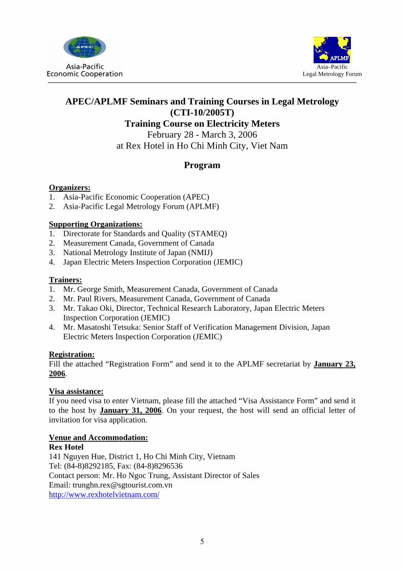
APEC/APLMF Seminars and Training Courses in Legal Metrology (CTI-10/2005T)
Training Course on Electricity Meters February 28 - March 3, 2006
at Rex Hotel in Ho Chi Minh City, Viet Nam
Program
Organizers: 1. Asia-Pacific Economic Cooperation (APEC) 2. Asia-Pacific Legal Metrology Forum (APLMF)
Supporting Organizations: 1. Directorate for Standards and Quality (STAMEQ) 2. Measurement Canada, Government of Canada 3. National Metrology Institute of Japan (NMIJ) 4. Japan Electric Meters Inspection Corporation (JEMIC)
Trainers: 1. Mr. George Smith, Measurement Canada, Government of Canada 2. Mr. Paul Rivers, Measurement Canada, Government of Canada 3. Mr. Takao Oki, Director, Technical Research Laboratory, Japan Electric Meters
Inspection Corporation (JEMIC) 4. Mr. Masatoshi Tetsuka: Senior Staff of Verification Management Division, Japan
Electric Meters Inspection Corporation (JEMIC)
Registration: Fill the attached “Registration Form” and send it to the APLMF secretariat by January 23, 2006.
Visa assistance: If you need visa to enter Vietnam, please fill the attached “Visa Assistance Form” and send it to the host by January 31, 2006. On your request, the host will send an official letter of invitation for visa application.
Venue and Accommodation: Rex Hotel 141 Nguyen Hue, District 1, Ho Chi Minh City, Vietnam Tel: (84-8)8292185, Fax: (84-8)8296536 Contact person: Mr. Ho Ngoc Trung, Assistant Director of Sales Email: [email protected] http://www.rexhotelvietnam.com/
Asia–Pacific
Legal Metrology Forum
5

The accommodation will be prepared at the Rex Hotel with the rates below. Please use the registration form to reserve a room at the hotel.
Superior: USD60.00/single – USD 70.00/double Deluxe: USD65.00/single – USD 75.00/double Rex Suite: USD80.00/single – USD 90.00/double (Above rates include breakfast, 10%VAT and 5% service charge)
Contact Persons for the Training Course:
1. APLMF Secretariat (registration, travel support and lectures by JEMIC) Tsuyoshi Matsumoto and Ms. Ayako Murata NMIJ/AIST Tsukuba Central 3-9, 1-1-1 Umezono, Tsukuba, Ibaraki 305-8563, Japan Tel: +81-298-61-4362, Fax: +81-298-61-4393 E-mail: [email protected], [email protected]
2. Working Group on Utility Meters of APLMF (lectures by Measurement Canada) Mr. Gilles Vinet Vice-President, Program Development Directorate, Measurement Canada Holland Avenue, Tunney's Pasture, Ottawa, Ontario, K1A 0C9 Canada Tel: +1-613-941-8918, Fax: +1-613-952-1736 E-mail: [email protected]
3. Host in Vietnam (visa assistance, accommodation and venue) Mr. Bui Quy Long Project Manager, Planning and Cooperation Department, Directorate for Standards & Quality Tran Hung Dao Street, Hanoi, Vietnam Tel: +84-4-7911633, Fax: +84-4-7911605 E-mail: [email protected]
6
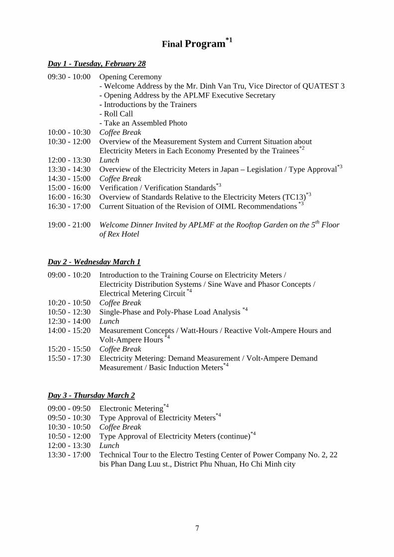
Final Program*1
Day 1 - Tuesday, February 28
09:30 - 10:00 Opening Ceremony - Welcome Address by the Mr. Dinh Van Tru, Vice Director of QUATEST 3 - Opening Address by the APLMF Executive Secretary - Introductions by the Trainers - Roll Call - Take an Assembled Photo
10:00 - 10:30 Coffee Break 10:30 - 12:00 Overview of the Measurement System and Current Situation about
Electricity Meters in Each Economy Presented by the Trainees*2 12:00 - 13:30 Lunch 13:30 - 14:30 Overview of the Electricity Meters in Japan – Legislation / Type Approval*3 14:30 - 15:00 Coffee Break 15:00 - 16:00 Verification / Verification Standards*3 16:00 - 16:30 Overview of Standards Relative to the Electricity Meters (TC13)*3 16:30 - 17:00 Current Situation of the Revision of OIML Recommendations *3 19:00 - 21:00 Welcome Dinner Invited by APLMF at the Rooftop Garden on the 5th Floor
of Rex Hotel Day 2 - Wednesday March 1
09:00 - 10:20 Introduction to the Training Course on Electricity Meters / Electricity Distribution Systems / Sine Wave and Phasor Concepts / Electrical Metering Circuit *4
10:20 - 10:50 Coffee Break 10:50 - 12:30 Single-Phase and Poly-Phase Load Analysis *4 12:30 - 14:00 Lunch 14:00 - 15:20 Measurement Concepts / Watt-Hours / Reactive Volt-Ampere Hours and
Volt-Ampere Hours *4 15:20 - 15:50 Coffee Break 15:50 - 17:30 Electricity Metering: Demand Measurement / Volt-Ampere Demand
Measurement / Basic Induction Meters*4 Day 3 - Thursday March 2
09:00 - 09:50 Electronic Metering*4 09:50 - 10:30 Type Approval of Electricity Meters*4 10:30 - 10:50 Coffee Break 10:50 - 12:00 Type Approval of Electricity Meters (continue)*4 12:00 - 13:30 Lunch 13:30 - 17:00 Technical Tour to the Electro Testing Center of Power Company No. 2, 22
bis Phan Dang Luu st., District Phu Nhuan, Ho Chi Minh city
7
Day 4 - Friday March 3
09:00 - 09:10 Overview of the Measurement System and Current Situation about Electricity Meters in Papua New Guinea by Mr. Victor Gabi*2
09:10 - 10:20 Electricity Meter Verification and Test Methods / Reverification Intervals / In-service Compliance Programs*4
10:20 - 10:50 Coffee Break 10:50 - 12:30 Electricity Metering: Measurement Standards and Test Equipment
/ Measurement Dispute Investigations*4 12:30 - 14:00 Lunch 14:00 - 14:30 Review / Questions / Answers 14:30 - 14:40 Introduction of NMIJ with Video 14:40 - 14:50 Introduction of JEMIC with Video 14:50 - 15:00 Introduction of APLMF by Dr. Matsumoto 15:00 - 15:50 Coffee Break 15:50 - 16:30 Closing Ceremony
- Give a Certificate to All Trainees - Closing Address by the APLMF Executive Secretary. - Closing Address by the Dr. Ngo Quy Viet, Director General of STAMEQ
17:30 Leave the Hotel for the Farewell Dinner 18:00-20:00 Farewell Dinner Invited by STAMEQ at the Tan Cang Resort, A 100 Ung
Van Khiem, P. 25, Binh Thanh Dist., Ho Chi Minh city
Additional Comments:
*1 This proposed course outline is based on the trainee’s having previous knowledge and experience with Electricity Metering.
*2 This session will be presented by the Trainees A trainee from each economy provides a brief (3 minutes or less) overview of the measurement system and current situation about electricity meters in their economy. For example: - What organization(s) regulate the measurement of electricity in your economy? - What are the legal units of measure for the sale of electricity? - Do electricity meters require approval of type? - What organization performs approval of type testing? - Is meter verification testing required? - What organization performs the meter verification tests? - Are tests performed on meters in service? - Are meters given a reverification interval? (8 years? 12 years?) - Is there as measurement complaint/dispute resolution process?
*3 These lectures will be given by Mr. Takao Oki and Mr. Masatoshi Tetsuka.
*4 These lectures will be given by Mr. George Smith and Mr. Paul Rivers.
8
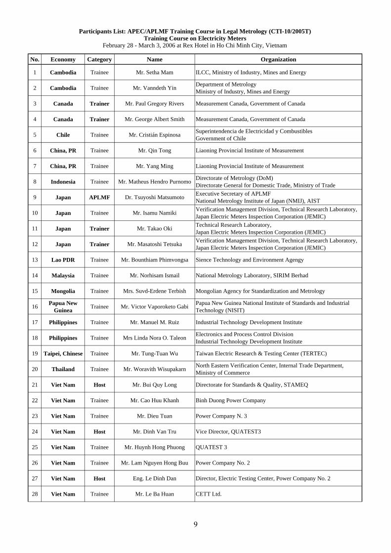
No. Economy Category Name Organization
1 Cambodia Trainee Mr. Setha Mam ILCC, Ministry of Industry, Mines and Energy
2 Cambodia Trainee Mr. Vanndeth Yin Department of MetrologyMinistry of Industry, Mines and Energy
3 Canada Trainer Mr. Paul Gregory Rivers Measurement Canada, Government of Canada
4 Canada Trainer Mr. George Albert Smith Measurement Canada, Government of Canada
5 Chile Trainee Mr. Cristián Espinosa Superintendencia de Electricidad y CombustiblesGovernment of Chile
6 China, PR Trainee Mr. Qin Tong Liaoning Provincial Institute of Measurement
7 China, PR Trainee Mr. Yang Ming Liaoning Provincial Institute of Measurement
8 Indonesia Trainee Mr. Matheus Hendro Purnomo Directorate of Metrology (DoM)Directorate General for Domestic Trade, Ministry of Trade
9 Japan APLMF Dr. Tsuyoshi Matsumoto Executive Secretary of APLMFNational Metrology Institute of Japan (NMIJ), AIST
10 Japan Trainee Mr. Isamu Namiki Verification Management Division, Technical Research Laboratory,Japan Electric Meters Inspection Corporation (JEMIC)
11 Japan Trainer Mr. Takao Oki Technical Research Laboratory,Japan Electric Meters Inspection Corporation (JEMIC)
12 Japan Trainer Mr. Masatoshi Tetsuka Verification Management Division, Technical Research Laboratory,Japan Electric Meters Inspection Corporation (JEMIC)
13 Lao PDR Trainee Mr. Bounthiam Phimvongsa Sience Technology and Environment Agengy
14 Malaysia Trainee Mr. Norhisam Ismail National Metrology Laboratory, SIRIM Berhad
15 Mongolia Trainee Mrs. Suvd-Erdene Terbish Mongolian Agency for Standardization and Metrology
16 Papua NewGuinea Trainee Mr. Victor Vaporoketo Gabi Papua New Guinea National Institute of Standards and Industrial
Technology (NISIT)
17 Philippines Trainee Mr. Manuel M. Ruiz Industrial Technology Development Institute
18 Philippines Trainee Mrs Linda Nora O. Taleon Electronics and Process Control DivisionIndustrial Technology Development Institute
19 Taipei, Chinese Trainee Mr. Tung-Tuan Wu Taiwan Electric Research & Testing Center (TERTEC)
20 Thailand Trainee Mr. Woravith Wisupakarn North Eastern Verification Center, Internal Trade Department,Ministry of Commerce
21 Viet Nam Host Mr. Bui Quy Long Directorate for Standards & Quality, STAMEQ
22 Viet Nam Trainee Mr. Cao Huu Khanh Binh Duong Power Company
23 Viet Nam Trainee Mr. Dieu Tuan Power Company N. 3
24 Viet Nam Host Mr. Dinh Van Tru Vice Director, QUATEST3
25 Viet Nam Trainee Mr. Huynh Hong Phuong QUATEST 3
26 Viet Nam Trainee Mr. Lam Nguyen Hong Buu Power Company No. 2
27 Viet Nam Host Eng. Le Dinh Dan Director, Electric Testing Center, Power Company No. 2
28 Viet Nam Trainee Mr. Le Ba Huan CETT Ltd.
Participants List: APEC/APLMF Training Course in Legal Metrology (CTI-10/2005T)Training Course on Electricity Meters
February 28 - March 3, 2006 at Rex Hotel in Ho Chi Minh City, Vietnam
9
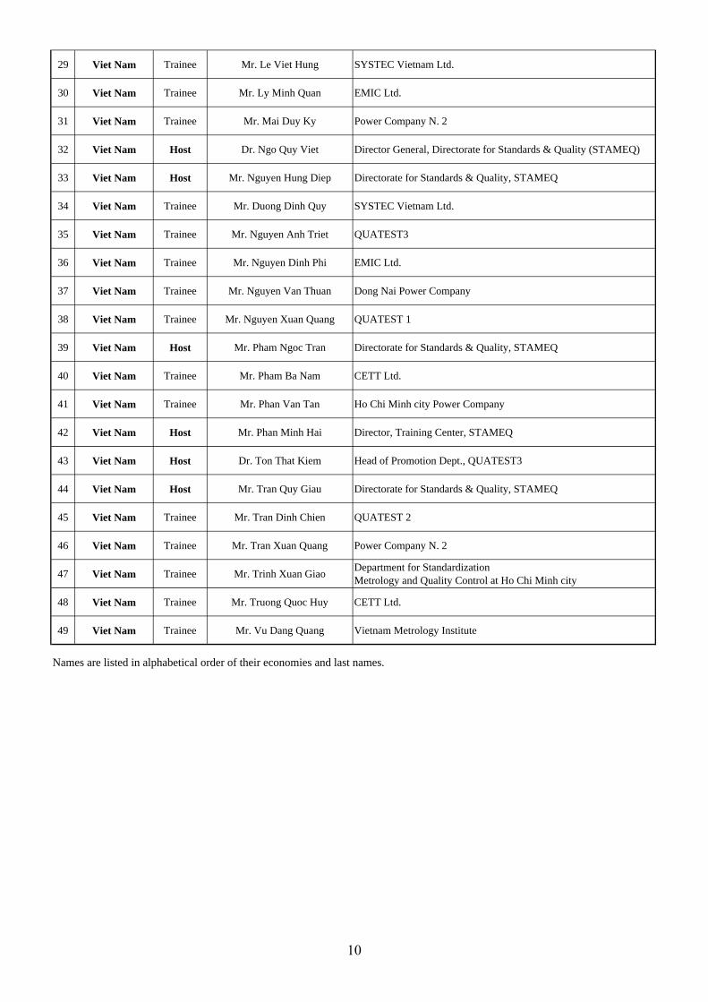
29 Viet Nam Trainee Mr. Le Viet Hung SYSTEC Vietnam Ltd.
30 Viet Nam Trainee Mr. Ly Minh Quan EMIC Ltd.
31 Viet Nam Trainee Mr. Mai Duy Ky Power Company N. 2
32 Viet Nam Host Dr. Ngo Quy Viet Director General, Directorate for Standards & Quality (STAMEQ)
33 Viet Nam Host Mr. Nguyen Hung Diep Directorate for Standards & Quality, STAMEQ
34 Viet Nam Trainee Mr. Duong Dinh Quy SYSTEC Vietnam Ltd.
35 Viet Nam Trainee Mr. Nguyen Anh Triet QUATEST3
36 Viet Nam Trainee Mr. Nguyen Dinh Phi EMIC Ltd.
37 Viet Nam Trainee Mr. Nguyen Van Thuan Dong Nai Power Company
38 Viet Nam Trainee Mr. Nguyen Xuan Quang QUATEST 1
39 Viet Nam Host Mr. Pham Ngoc Tran Directorate for Standards & Quality, STAMEQ
40 Viet Nam Trainee Mr. Pham Ba Nam CETT Ltd.
41 Viet Nam Trainee Mr. Phan Van Tan Ho Chi Minh city Power Company
42 Viet Nam Host Mr. Phan Minh Hai Director, Training Center, STAMEQ
43 Viet Nam Host Dr. Ton That Kiem Head of Promotion Dept., QUATEST3
44 Viet Nam Host Mr. Tran Quy Giau Directorate for Standards & Quality, STAMEQ
45 Viet Nam Trainee Mr. Tran Dinh Chien QUATEST 2
46 Viet Nam Trainee Mr. Tran Xuan Quang Power Company N. 2
47 Viet Nam Trainee Mr. Trinh Xuan Giao Department for StandardizationMetrology and Quality Control at Ho Chi Minh city
48 Viet Nam Trainee Mr. Truong Quoc Huy CETT Ltd.
49 Viet Nam Trainee Mr. Vu Dang Quang Vietnam Metrology Institute
Names are listed in alphabetical order of their economies and last names.
10
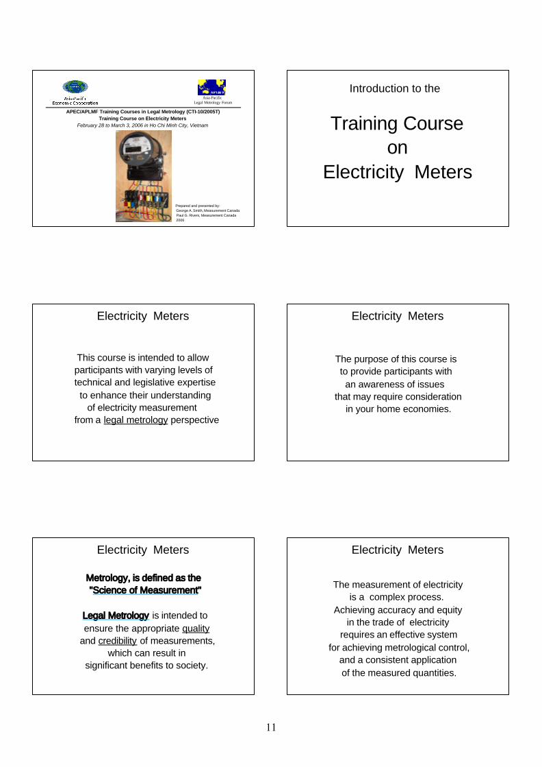
APEC/APLMF Training Courses in Legal Metrology (CTI-10/2005T)
Training Course on Electricity MetersFebruary 28 to March 3, 2006 in Ho Chi Minh City, Vietnam
Asia-PacificLegal Metrology Forum
Prepared and presented by: George A. Smith, Measurement Canada Paul G. Rivers, Measurement Canada 2006
Training Courseon
Electricity Meters
Introduction to the
This course is intended to allowparticipants with varying levels of technical and legislative expertise to enhance their understanding of electricity measurement from a legal metrology perspective
Electricity Meters
The purpose of this course is to provide participants with an awareness of issues that may require consideration in your home economies.
Electricity Meters
Metrology, is defined as the "Science of Measurement"
Legal Metrology is intended to ensure the appropriate quality
and credibility of measurements, which can result in
significant benefits to society.
Electricity Meters
Electricity Meters
The measurement of electricityis a complex process.
Achieving accuracy and equityin the trade of electricity
requires an effective system for achieving metrological control,
and a consistent application of the measured quantities.
11
Electricity Meters
The process of ensuring accuracy and equity in the trade of electricity requires a common understanding of:
- electricity delivery configurations, - the measurement principles, - the quantities being measured, - the purpose of the measurements, and - how accuracy and equity are achieved
This session is designed to focus on the principles of electricity measurement that are required to more effectively
achieve an acceptable level of accuracy and equity in the trade of electricity.
Electricity Meters
Electricity Meters
Questions?
Comments?
Next: Electricity Distribution Systems
Electricity MetersThis course on Electricity Meters is comprised of the following modules:
1) Introduction to Electricity Metering 2) Electricity Metering Circuits 3) Single Phase & Polyphase Load Analysis 4) Measurement Concepts 5) Demand Measurement 6) Volt-Ampere Demand Measurement 7) Basic Induction Meter 8) Electronic Metering 9) Type Approval of Electricity Meters 10) Verification & Test Methods 11) Reverification Intervals 12) In-Service Compliance Programs 13) Measurement Standards & Test Equipment
14) Measurement Dispute Investigations
There are a number of waysto measure electricity.
Measurement accuracywill not necessarily result in equity
if the accurate measurements are used in an inappropriate or inconsistent
manner.
Electricity Meters
12
Electricity DistributionSystems
Electricity Distribution Systems
The transmission and distribution of alternating current electricity typically ranges from 100 volts for residential
consumers to 500,000 volts or greater for transmission lines.
The frequency is usually 50 or 60 hertz, or cycles per second, but other
frequencies are sometimes used.
Electricity Distribution Systems
Electricity Measurement Points: Generation plants High voltage transmission lines Transmission interchange sites Distribution substations Industrial operations Commercial operations Apartment complexes Urban residential services Rural services
Electricity Distribution Systems
Distribution Systems may deliverelectricity using the followingservice configurations:
Single Phase 2-wire Single Phase 3-wire Polyphase 3-wire Network Polyphase 3-wire Delta Polyphase 4-wire Delta Polyphase 4-wire Wye
Electricity Distribution Systems
Single Phase 2-wire:A common residential service in many parts of the world which provides a single voltage, usually 100 to 240 volts
Single Phase 3-wire:A common residential service in North America which provides 2 voltages, 120 volts and 240 volts
Electricity Distribution Systems
Polyphase 3-wire Network: Common in apartment buildings where it provides 120 volts and 208 volts.
Polyphase 3-wire Delta:Generally used in industrial operations or for a single polyphase motor load such as water pumping station.
13
Electricity Distribution Systems
Polyphase 4-wire Delta:Sometimes used in supplying electricity to sparsely populated rural areas.
It is an economical way of providing a combination of a single phase 3-wire service and a limited supply of polyphase power.
Electricity Distribution Systems
Polyphase 4-wire Wye:Commonly used for industrial and commercial operations.
It is widely used for electricity distribution systems, where it is transformed to other suitable service configurations.
Electricity Distribution Systems
During this session the electricity metering for these various service
types will be examined.
Electricity Distribution Systems
Questions?
Comments?
Next: Sine Wave and Phasor (Vector) Concepts
Sine Wave andPhasor (Vector) Concepts
Electrical power in alternating current systems can be visually represented in
different ways, including the use of sine waves and phasors.
The type of circuit evaluation required will determine the method used.
Sine Wave and Phasor Concepts
14
Sine waves are useful for illustrating the quality of the alternating current and
voltage wave forms, including the effects of harmonic distortion.
Phasors (vectors) are useful in determining how an electricity meter will respond in calculating electrical power
and energy.
Sine Wave and Phasor Concepts
Much of this course will involve the visual representation of electricity
within metering circuits.
This portion of the session is intended to ensure a common understanding of
the methods used.
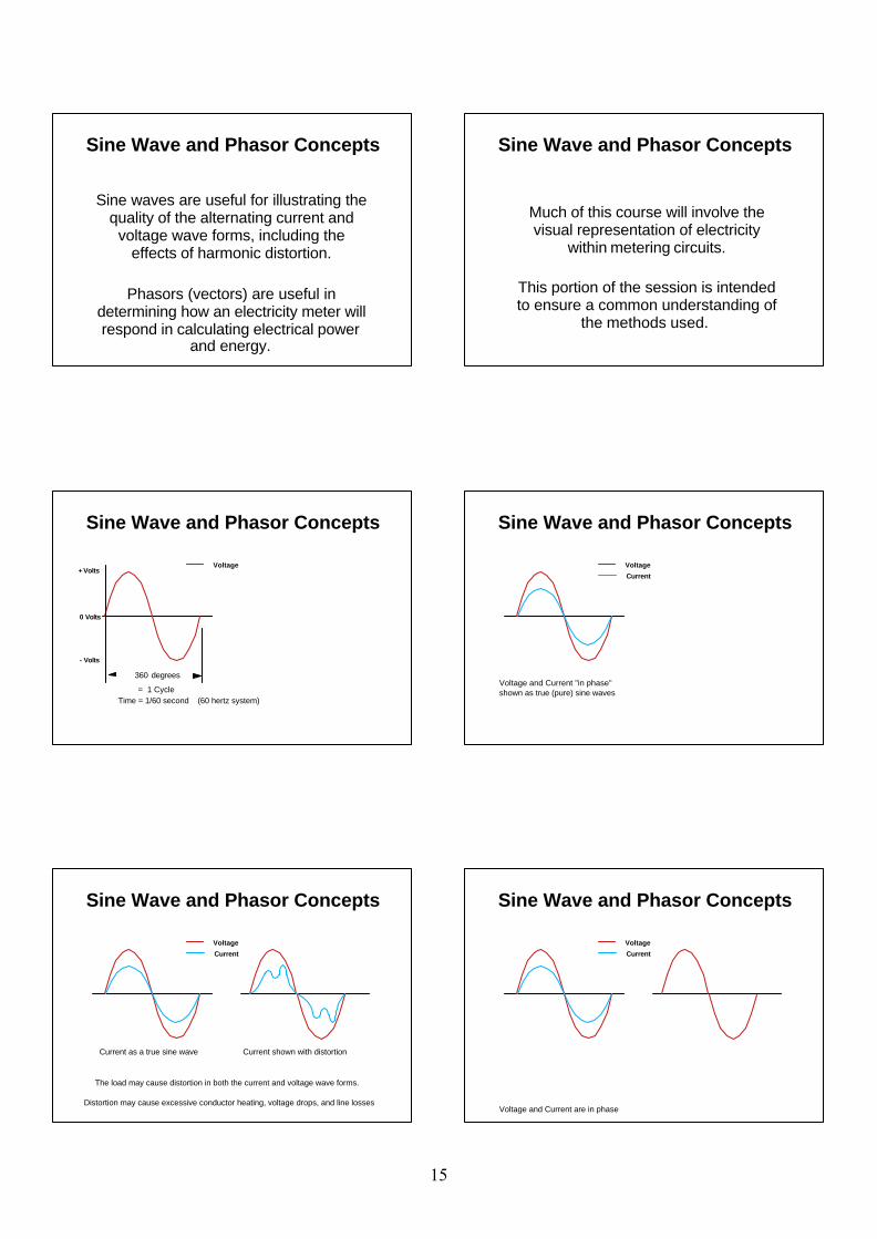
Sine Wave and Phasor Concepts
360 degrees
Voltage
= 1 Cycle
Sine Wave and Phasor Concepts
Time = 1/60 second (60 hertz system)
+ Volts
- Volts
0 Volts
Voltage
Current
Voltage and Current "in phase"shown as true (pure) sine waves
Sine Wave and Phasor Concepts
Voltage
Current
Current as a true sine wave Current shown with distortion
The load may cause distortion in both the current and voltage wave forms.
Distortion may cause excessive conductor heating, voltage drops, and line losses
Sine Wave and Phasor Concepts
Voltage
Current
Voltage and Current are in phase
Sine Wave and Phasor Concepts
15
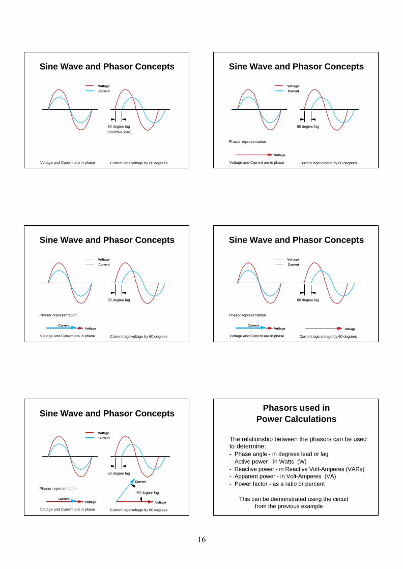
60 degree lag
Voltage
Current
Voltage and Current are in phase Current lags voltage by 60 degrees
(inductive load)
Sine Wave and Phasor Concepts
60 degree lag
Voltage
Current
Voltage and Current are in phase Current lags voltage by 60 degrees
Voltage
Phasor representation
Sine Wave and Phasor Concepts
60 degree lag
Voltage
Current
Voltage and Current are in phase Current lags voltage by 60 degrees
VoltageCurrent
Phasor representation
Sine Wave and Phasor Concepts
60 degree lag
Voltage
Current
Voltage and Current are in phase Current lags voltage by 60 degrees
Voltage VoltageCurrent
Phasor representation
Sine Wave and Phasor Concepts
60 degree lag
60 degree lag
Voltage
Current
Voltage and Current are in phase Current lags voltage by 60 degrees
Voltage VoltageCurrent
Current
Phasor representation
Sine Wave and Phasor Concepts
The relationship between the phasors can be used to determine:- Phase angle - in degrees lead or lag- Active power - in Watts (W)- Reactive power - in Reactive Volt-Amperes (VARs)- Apparent power - in Volt-Amperes (VA)- Power factor - as a ratio or percent
This can be demonstrated using the circuit from the previous example
Phasors used inPower Calculations
16
Current
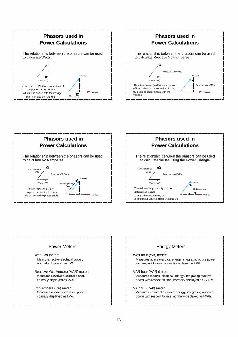
The relationship between the phasors can be used to calculate Watts:
Watts (W)
Watts (W)
Active power (Watts) is comprised of the portion of the current which is in phase with the voltage (the "in phase component")
Voltage
Phasors used inPower Calculations
Current
Watts (W)
Reactive VA (VARs)
Reactive power (VARs) is comprised of the portion of the current which is90 degrees out of phase with the voltage
Reactive VA (VARs)
Voltage
The relationship between the phasors can be used to calculate Reactive Volt-amperes:
Phasors used inPower Calculations
Current
Watts (W)
Reactive VA (Vars)(VA)
Volt-amperes
Apparent power (VA) is comprised of the total current, without regard to phase angle.
Volt-amperes(VA)
Voltage
The relationship between the phasors can be used to calculate Volt-amperes:
Phasors used inPower Calculations
60 degree lag
Voltage
Current
Reactive VA (VARs)(VA)
Volt-amperes
The value of any quantity can be determined using:1) any other two values, or2) one other value and the phase angle
Watts (W)
The relationship between the phasors can be used to calculate values using the Power Triangle
Phasors used inPower Calculations
Power Meters
Watt (W) meter:Measures active electrical power, normally displayed as kW.
Reactive Volt-Ampere (VAR) meter: Measures reactive electrical power, normally displayed as kVAR.
Volt-Ampere (VA) meter Measures apparent electrical power, normally displayed as kVA.
Energy Meters
Watt hour (Wh) meter:Measures active electrical energy, integrating active powerwith respect to time, normally displayed as kWh.
VAR hour (VARh) meter: Measures reactive electrical energy, integrating reactive power with respect to time, normally displayed as kVARh.
VA hour (VAh) meter Measures apparent electrical energy, integrating apparent power with respect to time, normally displayed as kVAh.
17
Electrical Power and Energy
Power - the rate of energy output or transfer
Energy - capacity to do work - integration of power over time
The methods for calculation of these values will be covered in more detail later in the course.
Questions?
Comments?
Sine Wave and Phasor Concepts
18
Electricity Metering Circuits
Prepared and presented by: George A. Smith, Measurement Canada Paul G. Rivers, Measurement Canada 2006
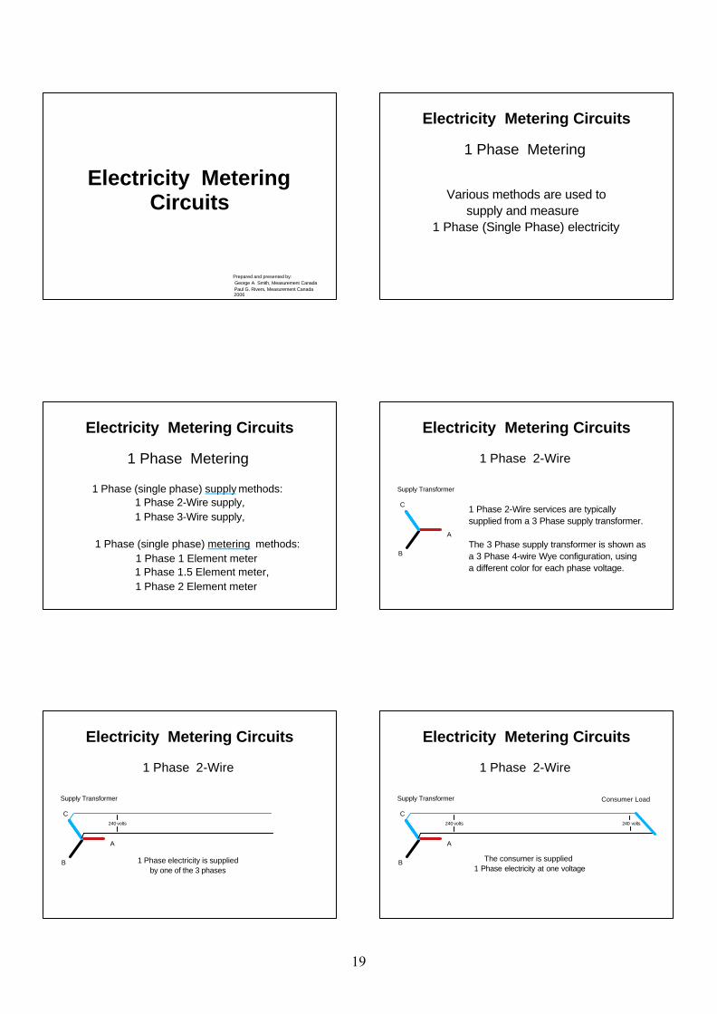
1 Phase Metering
Various methods are used to supply and measure1 Phase (Single Phase) electricity
Electricity Metering Circuits
1 Phase Metering
1 Phase (single phase) supply methods: 1 Phase 2-Wire supply, 1 Phase 3-Wire supply,
1 Phase (single phase) metering methods: 1 Phase 1 Element meter 1 Phase 1.5 Element meter, 1 Phase 2 Element meter
Electricity Metering Circuits
Supply Transformer
B
C
A
1 Phase 2-Wire
1 Phase 2-Wire services are typicallysupplied from a 3 Phase supply transformer.
The 3 Phase supply transformer is shown asa 3 Phase 4-wire Wye configuration, using a different color for each phase voltage.
Electricity Metering Circuits
Electricity Metering Circuits
Supply Transformer
B
C
A
1 Phase 2-Wire
240 volts
1 Phase electricity is supplied by one of the 3 phases
Electricity Metering Circuits
Supply Transformer Consumer Load
B
C
A
1 Phase 2-Wire
240 volts240 volts
The consumer is supplied1 Phase electricity at one voltage
19
Electricity Metering Circuits
Supply Transformer Consumer Load
B
C
A
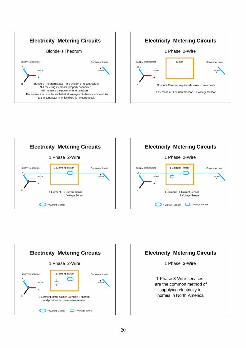
Blondel's Theorum
240 volts240 volts
Blondel's Theorum states: In a system of N conductors, N-1 metering elements, properly connected, will measure the power or energy taken. The connection must be such that all voltage coils have a common tie to the conductor in which there is no current coil.
Electricity Metering Circuits
Supply Transformer Consumer Load Meter
B
C
A
1 Phase 2-Wire
240 volts240 volts
Blondel's Theorem requires (N wires - 1) elements
1 Element = 1 Current Sensor + 1 Voltage Sensor
Electricity Metering Circuits
Supply Transformer Consumer Load 1 Element Meter
B
C
A
1 Phase 2-Wire
= Current Sensor
240 volts240 volts
1 Element: 1 Current Sensor 1 Voltage Sensor
Electricity Metering Circuits
Supply Transformer Consumer Load 1 Element Meter
B
C
A
1 Phase 2-Wire
= Current Sensor = Voltage Sensor
240 volts240 volts
1 Element: 1 Current Sensor 1 Voltage Sensor
Electricity Metering Circuits
Supply Transformer Consumer Load 1 Element Meter
B
C
A
1 Phase 2-Wire
= Current Sensor = Voltage Sensor
240 volts240 volts
1 Element Meter satifies Blondel's Theorem, and provides accurate measurement
Electricity Metering Circuits
1 Phase 3-Wire
1 Phase 3-Wire servicesare the common method of supplying electricity to homes in North America
20
Electricity Metering Circuits
Supply Transformer(s)
B
C
A
1 Phase 3-Wire
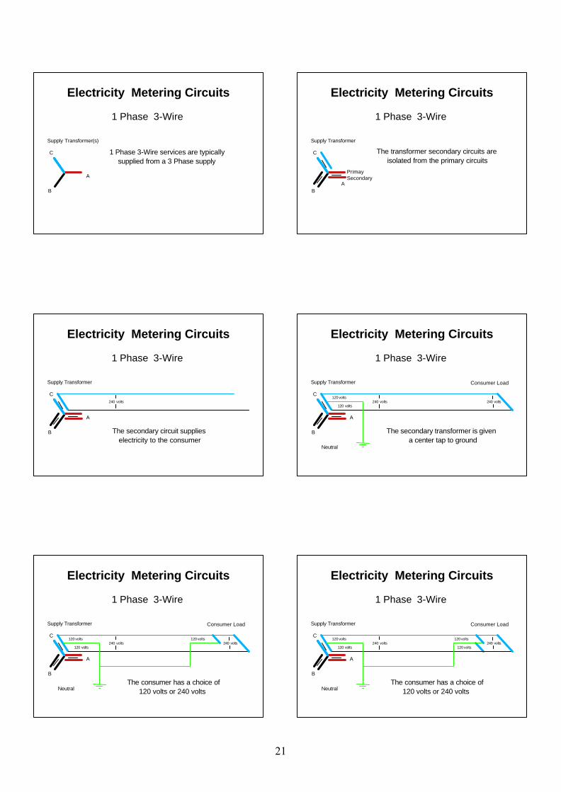
1 Phase 3-Wire services are typically supplied from a 3 Phase supply
Electricity Metering Circuits
Supply Transformer
B
C
A
1 Phase 3-Wire
The transformer secondary circuits are isolated from the primary circuits
PrimaySecondary
Electricity Metering Circuits
Supply Transformer
B
C
A
1 Phase 3-Wire
240 volts
The secondary circuit supplies electricity to the consumer
Electricity Metering Circuits
Supply Transformer Consumer Load
B
C
Neutral
A
1 Phase 3-Wire
240 volts120 volts
120 volts240 volts
The secondary transformer is given a center tap to ground
Electricity Metering Circuits
Supply Transformer Consumer Load
B
C
Neutral
A
1 Phase 3-Wire
120 volts240 volts
120 volts
120 volts240 volts
The consumer has a choice of 120 volts or 240 volts
Electricity Metering Circuits
Supply Transformer Consumer Load
B
C
Neutral
A
1 Phase 3-Wire
120 volts
120 volts240 volts
120 volts
120 volts240 volts
The consumer has a choice of 120 volts or 240 volts
21
Electricity Metering Circuits
1 Phase 3-Wire
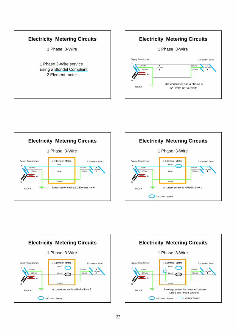
1 Phase 3-Wire service using a Blondel Compliant 2 Element meter
Electricity Metering Circuits
Supply Transformer Consumer Load
B
C
Neutral
A
1 Phase 3-Wire
120 volts
120 volts240 volts
120 volts
120 volts240 volts
The consumer has a choice of 120 volts or 240 volts
Electricity Metering Circuits
Supply Transformer Consumer Load
B
C
Neutral
A
1 Phase 3-Wire
120 volts
120 volts240 volts
120 volts
120 volts
Measurement using a 2 Element meter
Line 1
Line 2
Neutral
2 Element Meter
Electricity Metering Circuits
Supply Transformer Consumer Load
B
C
Neutral
A
1 Phase 3-Wire
= Current Sensor
120 volts
120 volts240 volts
120 volts
120 volts
A current sensor is added to Line 1
Line 1
Line 2
Neutral
2 Element Meter
Electricity Metering Circuits
Supply Transformer Consumer Load
B
C
Neutral
A
1 Phase 3-Wire
= Current Sensor
120 volts
120 volts240 volts
120 volts
120 volts
A current sensor is added to Line 2
Line 1
Line 2
Neutral
2 Element Meter
Electricity Metering Circuits
Supply Transformer Consumer Load 2 Element Meter
B
C
Neutral
A
1 Phase 3-Wire
= Current Sensor = Voltage Sensor
120 volts
120 volts240 volts
120 volts
120 volts
A voltage sensor is connected between Line 1 and neutral (ground)
Line 1
Line 2
Neutral
22
Electricity Metering Circuits
Supply Transformer Consumer Load 2 Element Meter
B
C
Neutral
A
1 Phase 3-Wire
= Current Sensor = Voltage Sensor
120 volts
120 volts240 volts
120 volts
120 volts
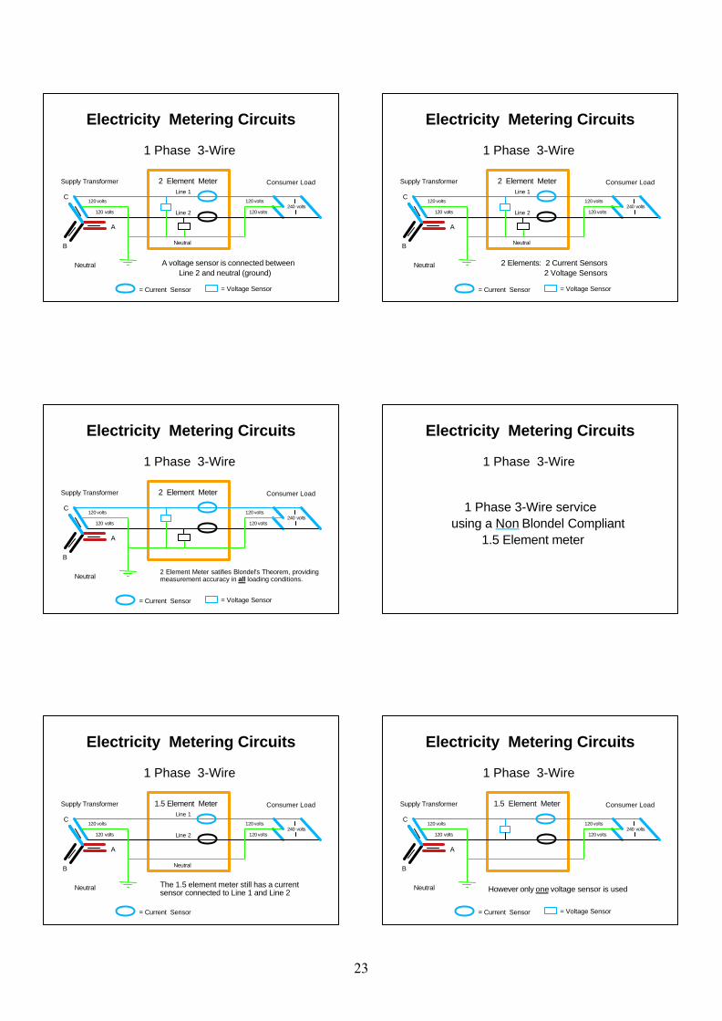
A voltage sensor is connected between Line 2 and neutral (ground)
Line 1
Line 2
Neutral
Electricity Metering Circuits
Supply Transformer Consumer Load 2 Element Meter
B
C
Neutral
A
1 Phase 3-Wire
= Current Sensor = Voltage Sensor
120 volts
120 volts240 volts
120 volts
120 volts
2 Elements: 2 Current Sensors 2 Voltage Sensors
Line 1
Line 2
Neutral
Electricity Metering Circuits
Supply Transformer Consumer Load 2 Element Meter
B
C
Neutral
A
1 Phase 3-Wire
= Current Sensor = Voltage Sensor
120 volts
120 volts240 volts
120 volts
120 volts
2 Element Meter satifies Blondel's Theorem, providing measurement accuracy in all loading conditions.
Electricity Metering Circuits
1 Phase 3-Wire
1 Phase 3-Wire service using a Non Blondel Compliant 1.5 Element meter
Electricity Metering Circuits
Supply Transformer Consumer Load1.5 Element Meter
B
C
Neutral
A
1 Phase 3-Wire
= Current Sensor
120 volts
120 volts240 volts
120 volts
120 volts
The 1.5 element meter still has a current sensor connected to Line 1 and Line 2
Line 1
Line 2
Neutral
Electricity Metering Circuits
Supply Transformer Consumer Load1.5 Element Meter
B
C
Neutral
A
1 Phase 3-Wire
= Current Sensor = Voltage Sensor
120 volts
120 volts240 volts
120 volts
120 volts
However only one voltage sensor is used
23
Electricity Metering Circuits
Supply Transformer Consumer Load1.5 Element Meter
B
C
Neutral
A
1 Phase 3-Wire
= Current Sensor = Voltage Sensor
120 volts
120 volts240 volts
120 volts
120 volts
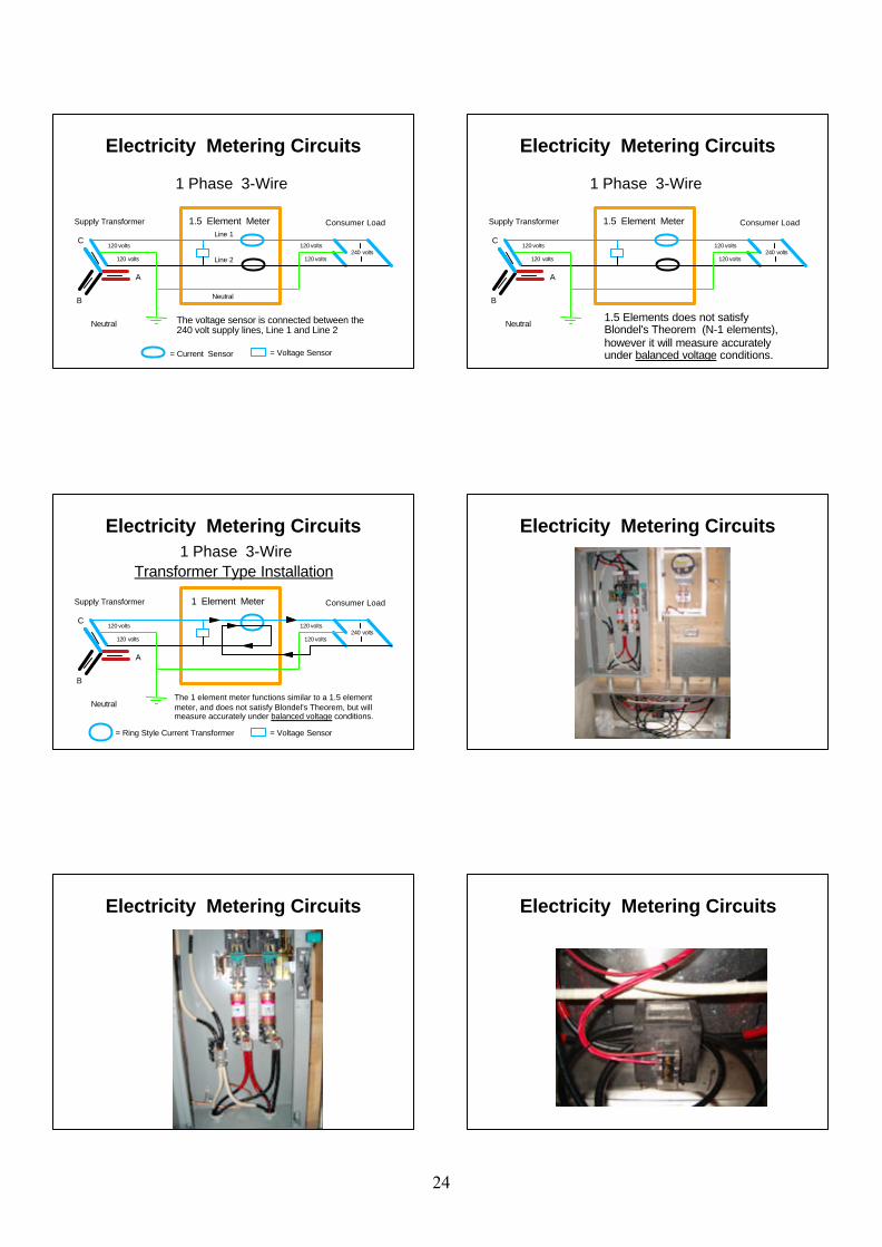
The voltage sensor is connected between the 240 volt supply lines, Line 1 and Line 2
Line 1
Line 2
Neutral
Electricity Metering Circuits
Supply Transformer Consumer Load1.5 Element Meter
B
C
Neutral
A
1 Phase 3-Wire
120 volts
120 volts240 volts
120 volts
120 volts
1.5 Elements does not satisfy Blondel's Theorem (N-1 elements), however it will measure accurately under balanced voltage conditions.
Electricity Metering Circuits
Supply Transformer Consumer Load 1 Element Meter
B
C
Neutral
A
1 Phase 3-WireTransformer Type Installation
= Ring Style Current Transformer = Voltage Sensor
120 volts
120 volts240 volts
120 volts
120 volts
The 1 element meter functions similar to a 1.5 element meter, and does not satisfy Blondel's Theorem, but will measure accurately under balanced voltage conditions.
Electricity Metering Circuits
Electricity Metering Circuits Electricity Metering Circuits
24
Electricity Metering Circuits Electricity Metering Circuits
1 Phase Metering
Questions?
Comments?
Next: 3 Phase 4-Wire Open Delta
Electricity Metering Circuits
3 Phase 4-Wire Open Delta
The 3 Phase 4-Wire open delta service is an economical way of providing a combination of a single phase 3-wire
service and a limited supply of polyphase power.
Electricity Metering Circuits
Supply Transformer Consumer Load Meter
B
C
A
3 Phase 4-Wire Open Delta
120 volts
120 volts
120 volts
120 volts
Line 1
Line 2
Neutral
C
120 volts
120 volts
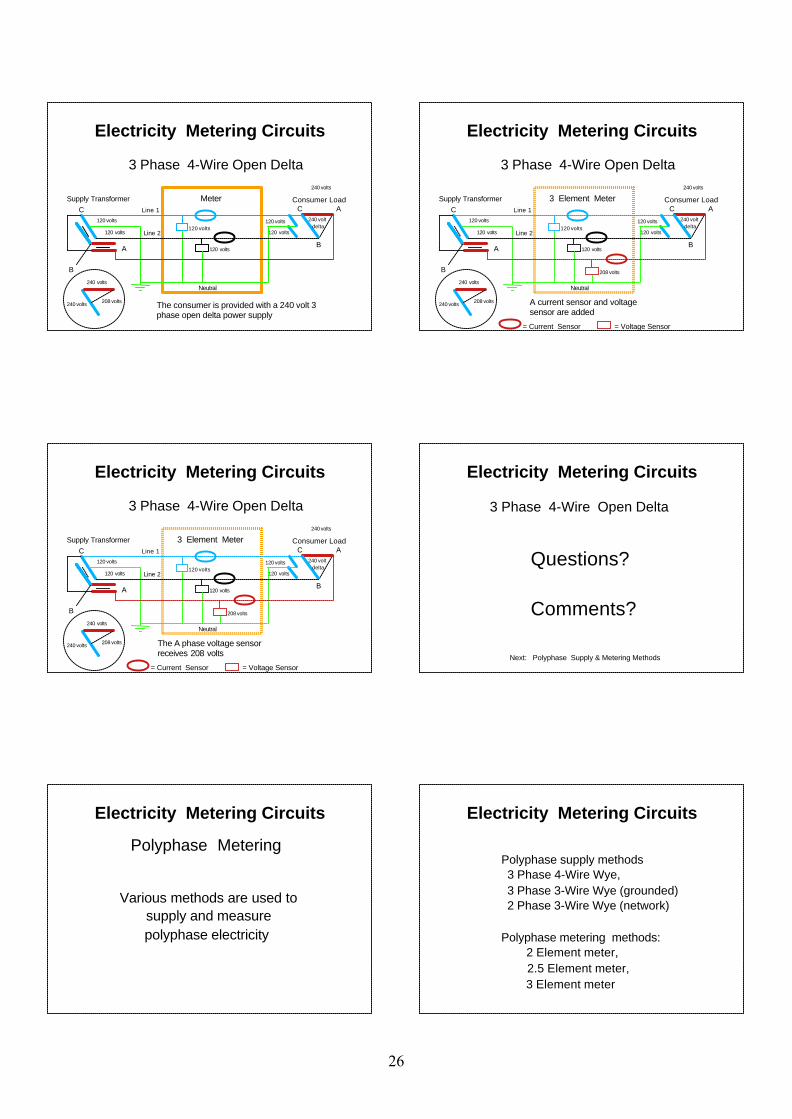
The service configuration begins as a single phase 3-wire service.
Electricity Metering Circuits
Supply Transformer Consumer Load Meter
B
C
A
3 Phase 4-Wire Open Delta
120 volts
120 volts
120 volts
120 volts
Line 1
Line 2
Neutral
C
240 volts
240 volts
120 volts
120 volts
208 volts The non-polarity connection of the 'A' phase secondary winding is connected to the polarity connection of the 'C' phase secondary winding.
Electricity Metering Circuits
Supply Transformer Consumer Load
B
C
A
3 Phase 4-Wire Open Delta
120 volts
120 volts
120 volts
120 volts
'A' phase power is supplied to the consumer
Line 1
Line 2
Neutral
C
240 volts
240 volts
120 volts
120 volts
208 volts
Meter
25
Electricity Metering Circuits
Supply Transformer Consumer Load
B
C
A
3 Phase 4-Wire Open Delta
120 volts
120 volts
240 volts
120 volts
120 volts
Line 1
Line 2
Neutral
A
B
C240 volt delta
240 volts
240 volts
120 volts
120 volts
208 volts
Meter
The consumer is provided with a 240 volt 3 phase open delta power supply
Electricity Metering Circuits
Supply Transformer Consumer Load 3 Element Meter
B
C
A
3 Phase 4-Wire Open Delta
= Current Sensor = Voltage Sensor
120 volts
120 volts
240 volts
120 volts
120 volts
Line 1
Line 2
Neutral
A
B
C240 volt delta
240 volts
240 volts
120 volts
120 volts
208 volts
208 volts
A current sensor and voltage sensor are added
Electricity Metering Circuits
Supply Transformer Consumer Load 3 Element Meter
B
C
A
3 Phase 4-Wire Open Delta
= Current Sensor = Voltage Sensor
120 volts
120 volts
240 volts
120 volts
120 volts
Line 1
Line 2
Neutral
A
B
C240 volt delta
240 volts
240 volts
120 volts
120 volts
208 volts
208 volts
The A phase voltage sensor receives 208 volts
Electricity Metering Circuits
3 Phase 4-Wire Open Delta
Questions?
Comments?
Next: Polyphase Supply & Metering Methods
Electricity Metering Circuits
Polyphase Metering
Various methods are used to supply and measure polyphase electricity
Polyphase supply methods 3 Phase 4-Wire Wye, 3 Phase 3-Wire Wye (grounded) 2 Phase 3-Wire Wye (network)
Polyphase metering methods: 2 Element meter, 2.5 Element meter, 3 Element meter
Electricity Metering Circuits
26
Electricity Metering Circuits
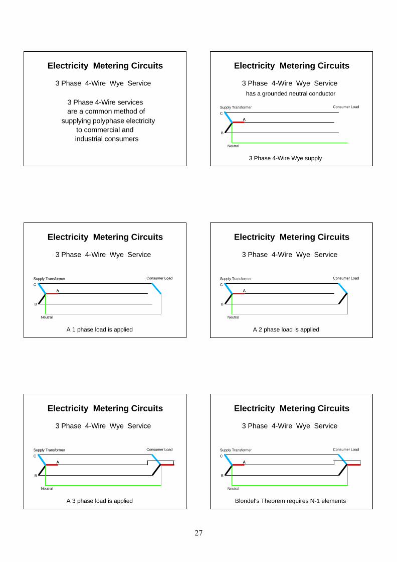
3 Phase 4-Wire services are a common method ofsupplying polyphase electricity to commercial and industrial consumers
3 Phase 4-Wire Wye Service
Electricity Metering Circuits
Supply Transformer Consumer Load
A
B
C
Neutral
A
has a grounded neutral conductor
3 Phase 4-Wire Wye Service
3 Phase 4-Wire Wye supply
Electricity Metering Circuits
Supply Transformer Consumer Load
A
B
C
Neutral
A
3 Phase 4-Wire Wye Service
A 1 phase load is applied
Electricity Metering Circuits
Supply Transformer Consumer Load
A
B
C
Neutral
A
3 Phase 4-Wire Wye Service
A 2 phase load is applied
Electricity Metering Circuits
Supply Transformer Consumer Load
A
B
C
Neutral
A
3 Phase 4-Wire Wye Service
A 3 phase load is applied
Electricity Metering Circuits
Supply Transformer Consumer Load
A
B
C
Neutral
A
3 Phase 4-Wire Wye Service
Blondel's Theorem requires N-1 elements
27

Electricity Metering Circuits
Supply Transformer Consumer LoadMeter
A
B
C
Neutral
A
3 Phase 4-Wire Wye Service
A 3 element meter is recommended
Electricity Metering Circuits
Supply Transformer Consumer LoadMeter
A
B
C
Neutral
A A
= Current Sensor
3 Phase 4-Wire Wye Service
Electricity Metering Circuits
Supply Transformer Consumer LoadMeter
A
B
C
Neutral
A A
= Current Sensor = Voltage Sensor
3 Phase 4-Wire Wye Service
Electricity Metering Circuits
Supply Transformer Consumer LoadMeter
A
B
C
Neutral
A A
= Current Sensor = Voltage Sensor
B
3 Phase 4-Wire Wye Service
Electricity Metering Circuits
Supply Transformer Consumer LoadMeter
A
B
C
Neutral
A A
= Current Sensor = Voltage Sensor
B
3 Phase 4-Wire Wye Service
Electricity Metering Circuits
Supply Transformer Consumer LoadMeter
A
B
C
Neutral
A A
C
= Current Sensor = Voltage Sensor
B
3 Phase 4-Wire Wye Service
28
Electricity Metering Circuits
Supply Transformer Consumer Load3 Element Meter
A
B
C
Neutral
A A
C
= Current Sensor = Voltage Sensor
B
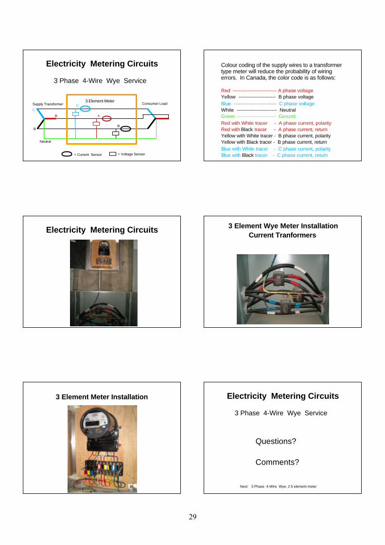
3 Phase 4-Wire Wye Service
Colour coding of the supply wires to a transformer type meter will reduce the probability of wiring errors. In Canada, the color code is as follows:
Red --------------------------- A phase voltageYellow ----------------------- B phase voltageBlue -------------------------- C phase voltageWhite ------------------------ NeutralGreen ------------------------ GroundRed with White tracer - A phase current, polarityRed with Black tracer - A phase current, returnYellow with White tracer - B phase current, polarityYellow with Black tracer - B phase current, returnBlue with White tracer - C phase current, polarity Blue with Black tracer - C phase current, return
Electricity Metering Circuits 3 Element Wye Meter InstallationCurrent Tranformers
3 Element Meter Installation Electricity Metering Circuits
3 Phase 4-Wire Wye Service
Questions?
Comments?
Next: 3 Phase 4-Wire Wye, 2.5 element meter
29
Electricity Metering Circuits
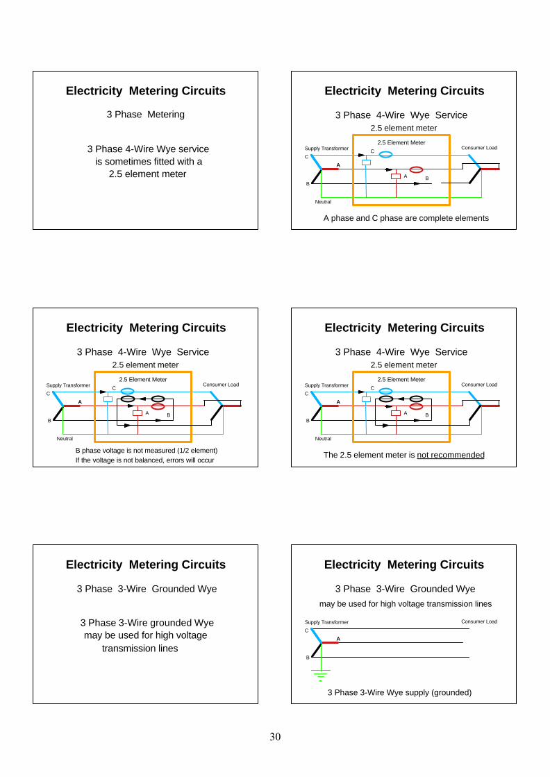
3 Phase Metering
3 Phase 4-Wire Wye service is sometimes fitted with a 2.5 element meter
Supply Transformer Consumer Load2.5 Element Meter
A
B
C
Neutral
A
A
C
B
2.5 element meter3 Phase 4-Wire Wye Service
Electricity Metering Circuits
A phase and C phase are complete elements
Supply Transformer Consumer Load2.5 Element Meter
A
B
C
Neutral
A
A
C
B
2.5 element meter3 Phase 4-Wire Wye Service
Electricity Metering Circuits
B phase voltage is not measured (1/2 element)If the voltage is not balanced, errors will occur
Supply Transformer Consumer Load2.5 Element Meter
A
B
C
Neutral
A
A
C
B
2.5 element meter3 Phase 4-Wire Wye Service
Electricity Metering Circuits
The 2.5 element meter is not recommended
Electricity Metering Circuits
3 Phase 3-Wire grounded Wye may be used for high voltage transmission lines
3 Phase 3-Wire Grounded Wye
Electricity Metering Circuits
Supply Transformer Consumer Load
A
B
C
A
may be used for high voltage transmission lines
3 Phase 3-Wire Grounded Wye
3 Phase 3-Wire Wye supply (grounded)
30
Electricity Metering Circuits
Supply Transformer Consumer Load3 Element Meter
A
B
C
Neutral
A A
C
B
3 Phase 3-Wire Grounded Wye
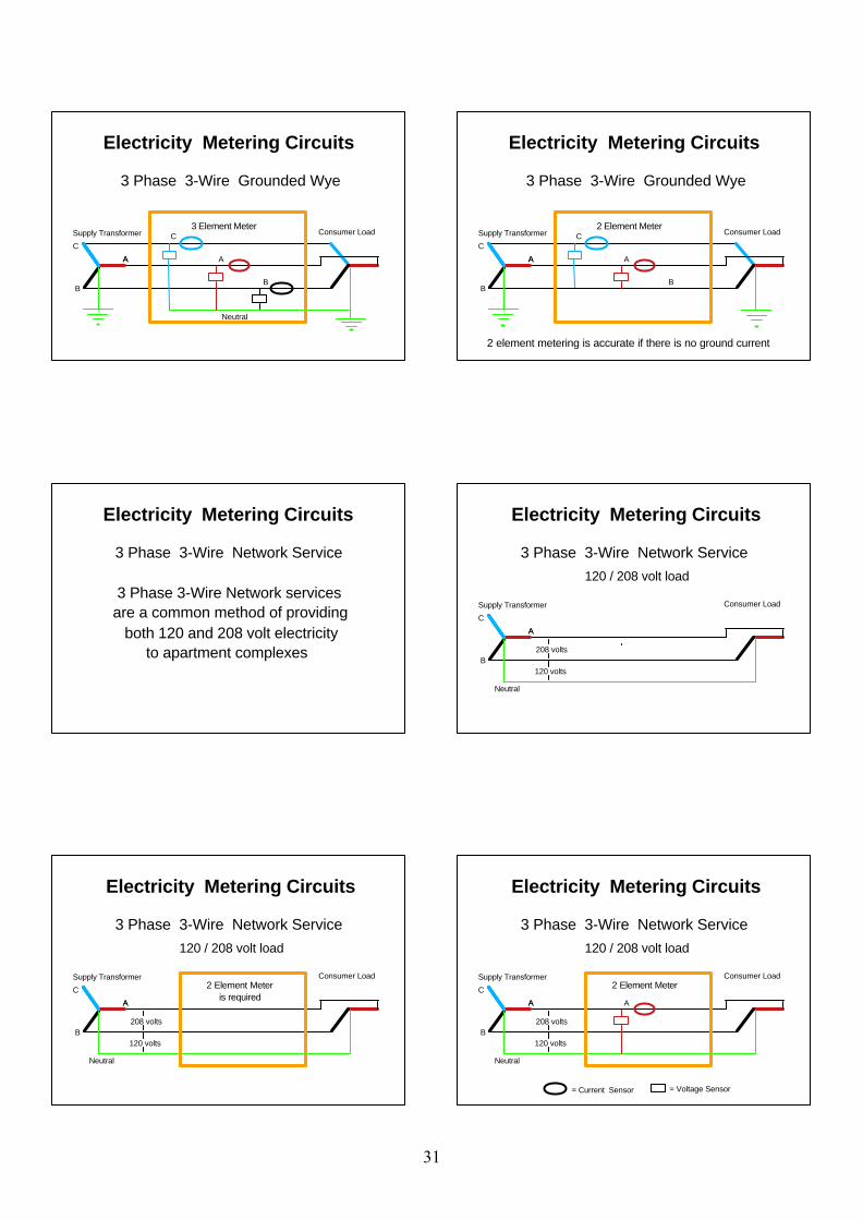
Electricity Metering Circuits
Supply Transformer Consumer Load2 Element Meter
A
B
C
A A
C
B
3 Phase 3-Wire Grounded Wye
2 element metering is accurate if there is no ground current
3 Phase 3-Wire Network services are a common method of providing both 120 and 208 volt electricity to apartment complexes
3 Phase 3-Wire Network Service
Electricity Metering Circuits
Supply Transformer Consumer Load
A
B
C
Neutral
A
3 Phase 3-Wire Network Service120 / 208 volt load
208 volts
120 volts
Electricity Metering Circuits
Supply Transformer Consumer Load2 Element Meter is required
A
B
C
Neutral
A
3 Phase 3-Wire Network Service120 / 208 volt load
208 volts
120 volts
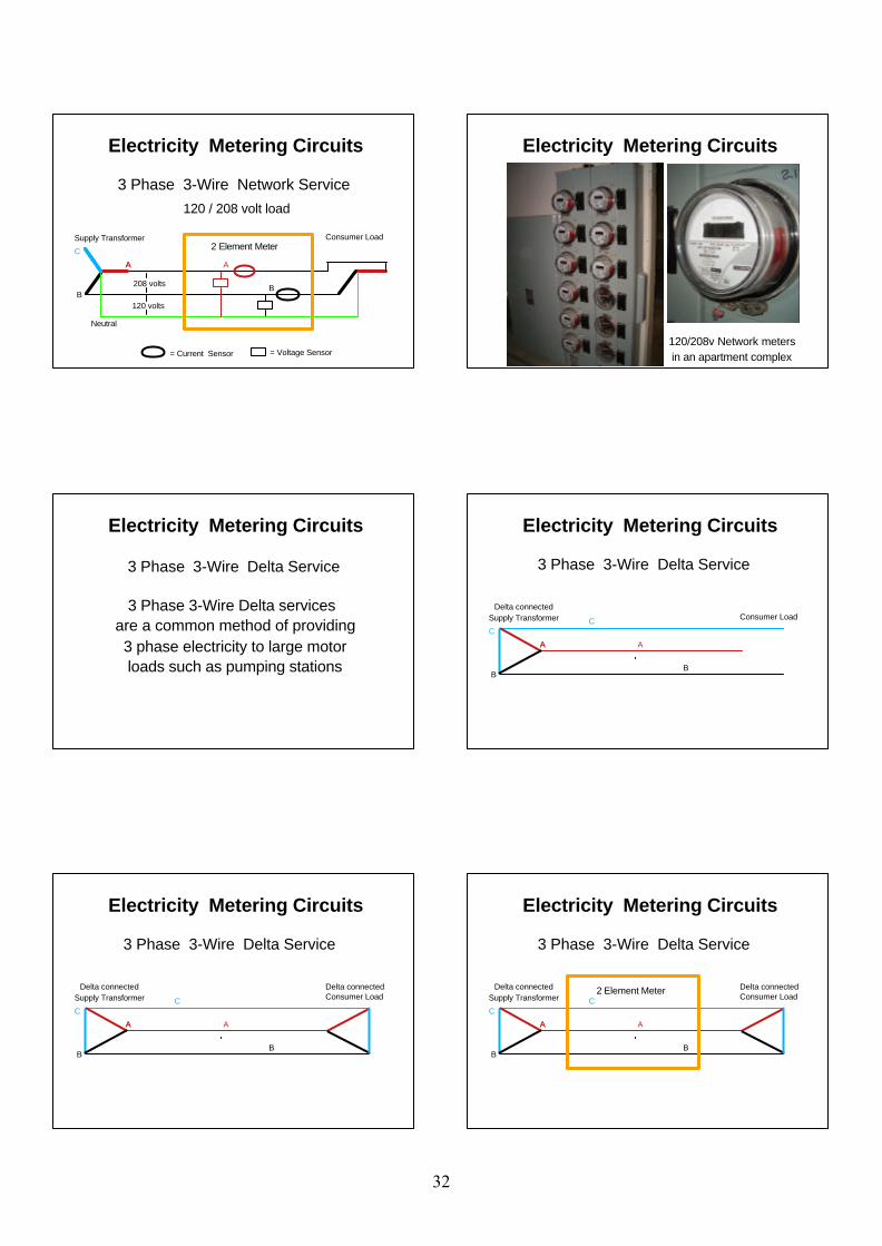
Electricity Metering Circuits
Supply Transformer Consumer Load2 Element Meter
A
B
C
Neutral
A A
3 Phase 3-Wire Network Service
= Current Sensor = Voltage Sensor
120 / 208 volt load
208 volts
120 volts
Electricity Metering Circuits
31
Supply Transformer Consumer Load2 Element Meter
A
B
C
Neutral
A A
3 Phase 3-Wire Network Service
= Current Sensor = Voltage Sensor
B
120 / 208 volt load
208 volts
120 volts
Electricity Metering Circuits Electricity Metering Circuits
120/208v Network meters in an apartment complex
3 Phase 3-Wire Delta services are a common method of providing 3 phase electricity to large motor loads such as pumping stations
3 Phase 3-Wire Delta Service
Electricity Metering Circuits
Supply Transformer Consumer Load
A
B
C
A A
C
3 Phase 3-Wire Delta Service
B
Delta connected
Electricity Metering Circuits
Supply Transformer Consumer Load
A
B
C
A A
C
3 Phase 3-Wire Delta Service
B
Delta connected Delta connected
Electricity Metering Circuits
Supply Transformer Consumer Load2 Element Meter
A
B
C
A A
C
3 Phase 3-Wire Delta Service
B
Delta connected Delta connected
Electricity Metering Circuits
32
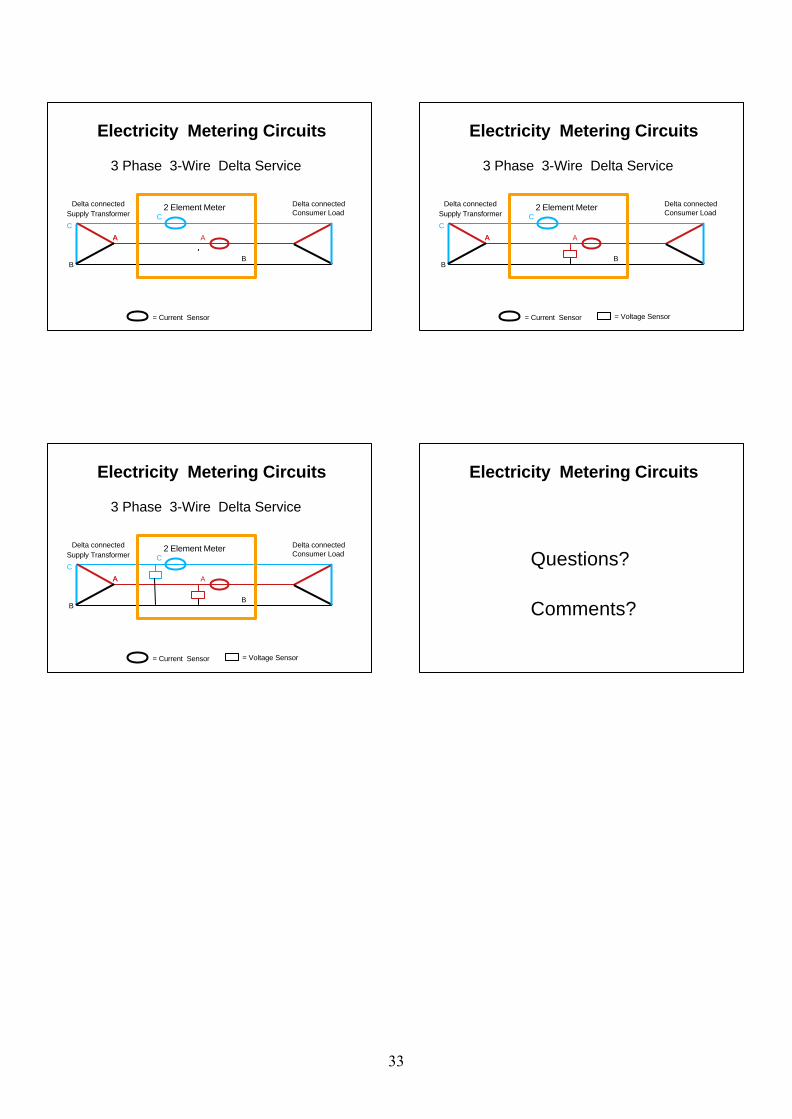
Supply Transformer Consumer Load2 Element Meter
A
B
C
A A
C
3 Phase 3-Wire Delta Service
= Current Sensor
B
Delta connected Delta connected
Electricity Metering Circuits
Supply Transformer Consumer Load2 Element Meter
A
B
C
A A
C
3 Phase 3-Wire Delta Service
= Current Sensor = Voltage Sensor
B
Delta connected Delta connected
Electricity Metering Circuits
Supply Transformer Consumer Load2 Element Meter
A
B
C
A A
C
3 Phase 3-Wire Delta Service
= Current Sensor = Voltage Sensor
B
Delta connected Delta connected
Electricity Metering Circuits
Questions?
Comments?
Electricity Metering Circuits
33
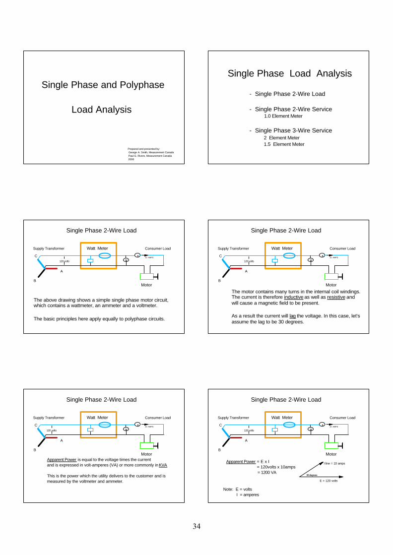
Single Phase and Polyphase
Load Analysis
Prepared and presented by: George A. Smith, Measurement Canada Paul G. Rivers, Measurement Canada 2006
Single Phase Load Analysis
- Single Phase 2-Wire Load
- Single Phase 2-Wire Service 1.0 Element Meter
- Single Phase 3-Wire Service 2 Element Meter 1.5 Element Meter
Supply Transformer Consumer Load Watt Meter
B
C
A
120 volts
A
V10 AMPS
Motor
The above drawing shows a simple single phase motor circuit, which contains a wattmeter, an ammeter and a voltmeter.
The basic principles here apply equally to polyphase circuits.
Single Phase 2-Wire Load
Supply Transformer Consumer Load
B
C
A
120 volts
A
V10 AMPS
Motor
Watt Meter
The motor contains many turns in the internal coil windings. The current is therefore inductive as well as resistive and will cause a magnetic field to be present.
As a result the current will lag the voltage. In this case, let's assume the lag to be 30 degrees.
Single Phase 2-Wire Load
Supply Transformer Consumer Load
B
C
A
120 volts
A
V10 AMPS
MotorApparent Power is equal to the voltage times the currentand is expressed in volt-amperes (VA) or more commonly in KVA
This is the power which the utility delivers to the customer and is measured by the voltmeter and ammeter.
Watt Meter
Single Phase 2-Wire Load
Supply Transformer Consumer Load
B
C
A
120 volts
A
V10 AMPS
Motor
Apparent Power = E x I = 120volts x 10amps = 1200 VA
30 degrees
E = 120 volts
I line = 10 amps
Watt Meter
Note: E = volts I = amperes
Single Phase 2-Wire Load
34
Supply Transformer Consumer Load
B
C
A
120 volts
A
V10 AMPS
Motor
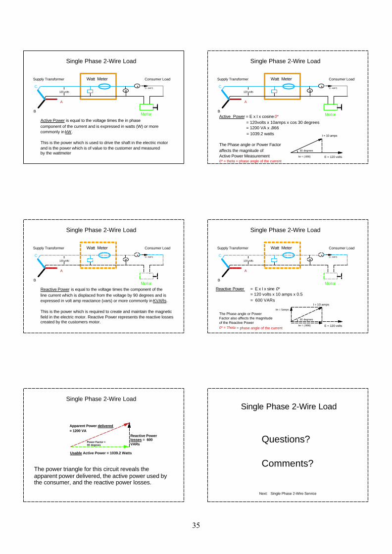
Watt Meter
Active Power is equal to the voltage times the in phase component of the current and is expressed in watts (W) or morecommonly in kW.
This is the power which is used to drive the shaft in the electric motorand is the power which is of value to the customer and measured by the wattmeter
Single Phase 2-Wire Load
Supply Transformer Consumer Load
B
C
A
120 volts
A
V10 AMPS
MotorActive Power = E x I x cosine 0* = 120volts x 10amps x cos 30 degrees = 1200 VA x .866 = 1039.2 watts
The Phase angle or Power Factoraffects the magnitude of Active Power Measurement0* = theta = phase angle of the current
30 degrees
Iw = (.866)
I = 10 amps
E = 120 volts
Watt Meter
Single Phase 2-Wire Load
Supply Transformer Consumer Load
B
C
A
120 volts
A
V10 AMPS
Motor
Watt Meter
Reactive Power is equal to the voltage times the component of theline current which is displaced from the voltage by 90 degrees and is expressed in volt amp reactance (vars) or more commonly in KVARs.
This is the power which is required to create and maintain the magneticfield in the electric motor. Reactive Power represents the reactive lossescreated by the customers motor.
Single Phase 2-Wire Load
Supply Transformer Consumer Load
B
C
A
120 volts
A
V10 AMPS
MotorReactive Power = E x I x sine 0*
= 120 volts x 10 amps x 0.5 = 600 VARs
30 degrees
E = 120 volts
I = 10 amps
Iw = (.866)
Im = 5amps
The Phase angle or Power Factor also affects the magnitudeof the Reactive Power0* = Theta = phase angle of the current
Watt Meter
Single Phase 2-Wire Load
Usable Active Power = 1039.2 Watts
Apparent Power delivered= 1200 VA
Reactive Power losses = 600 VARs
Power Factor = 30 degrees
The power triangle for this circuit reveals the apparent power delivered, the active power used by the consumer, and the reactive power losses.
Single Phase 2-Wire Load
Questions?
Comments?
Next: Single Phase 2-Wire Service
Single Phase 2-Wire Load
35
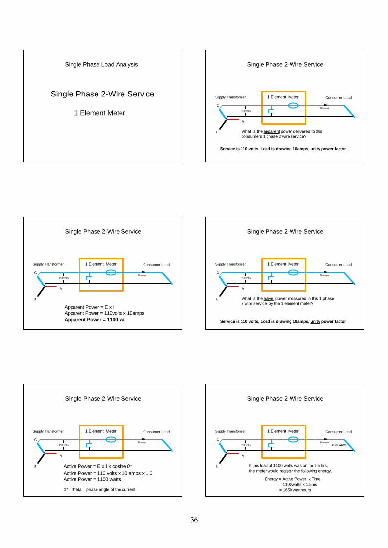
Single Phase 2-Wire Service 1 Element Meter
Single Phase Load Analysis
Supply Transformer Consumer Load 1 Element Meter
B
C
A
110 volts
What is the apparent power delivered to this consumers 1 phase 2 wire service?
10 amps
Service is 110 volts, Load is drawing 10amps, unity power factor
Single Phase 2-Wire Service
Supply Transformer Consumer Load 1 Element Meter
B
C
A
110 volts10 amps
Apparent Power = E x IApparent Power = 110volts x 10ampsApparent Power = 1100 va
Single Phase 2-Wire Service
Supply Transformer Consumer Load 1 Element Meter
B
C
A
110 volts
What is the active power measured in this 1 phase 2 wire service, by the 1 element meter?
Service is 110 volts, Load is drawing 10amps, unity power factor
10 amps
Single Phase 2-Wire Service
Supply Transformer Consumer Load 1 Element Meter
B
C
A
110 volts10 amps
Active Power = E x I x cosine 0*Active Power = 110 volts x 10 amps x 1.0Active Power = 1100 watts
0* = theta = phase angle of the current
Single Phase 2-Wire Service
Supply Transformer Consumer Load 1 Element Meter
B
C
A
1100 watts110 volts10 amps
If this load of 1100 watts was on for 1.5 hrs, the meter would register the following energy.
Energy = Active Power x Time = 1100watts x 1.5hrs = 1650 watthours
Single Phase 2-Wire Service
36
Questions?
Comments?
Next: Single Phase 3-Wire Service, 2 Element Meter
Single Phase 2-Wire Service
Single Phase 3-Wire Service 2 Element Meter
Single Phase Load Analysis
Supply Transformer Consumer Load
B
C
Neutral
A
10 amps
5 amps20 amps
110 volts
110 volts Line 2
Line 1
Neutral
220 volts
How much active power is the consumers load drawing?
Note : Unity power factor
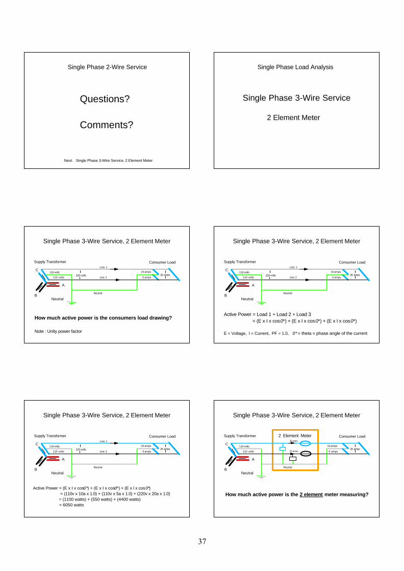
Single Phase 3-Wire Service, 2 Element Meter
Supply Transformer Consumer Load
B
C
Neutral
A
10 amps
5 amps20 amps
110 volts
110 volts Line 2
Line 1
Neutral
220 volts
Active Power = Load 1 + Load 2 + Load 3 = (E x I x cos0*) + (E x I x cos0*) + (E x I x cos0*)
E = Voltage, I = Current, PF = 1.0, 0* = theta = phase angle of the current
Single Phase 3-Wire Service, 2 Element Meter
Supply Transformer Consumer Load
B
C
Neutral
A
10 amps
5 amps20 amps
110 volts
110 volts Line 2
Line 1
Neutral
220 volts
Active Power = (E x I x cos0*) + (E x I x cos0*) + (E x I x cos0*) = (110v x 10a x 1.0) + (110v x 5a x 1.0) + (220v x 20a x 1.0) = (1100 watts) + (550 watts) + (4400 watts) = 6050 watts
Single Phase 3-Wire Service, 2 Element Meter
Supply Transformer Consumer Load 2 Element Meter
B
C
Neutral
A
10 amps
5 amps20 amps
110 volts
110 volts 25 amps
30 amps
Neutral
How much active power is the 2 element meter measuring?
Single Phase 3-Wire Service, 2 Element Meter
37
Supply Transformer Consumer Load 2 Element Meter
B
C
Neutral
A
10 amps
5 amps20 amps
110 volts
110 volts 25 amps
30 amps
Neutral
Active Power (meter) = (Element 1) + (Element 2)
Element = One voltage sensor and one current sensor
Single Phase 3-Wire Service, 2 Element Meter
Supply Transformer Consumer Load 2 Element Meter
B
C
Neutral
A
10 amps
5 amps20 amps
110 volts
110 volts 25 amps
30 amps
Neutral
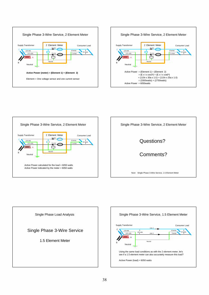
Active Power = (Element 1) + (Element 2) = (E x I x cos0*) + (E x I x cos0*) = (110v x 30a x 1.0) + (110v x 25a x 1.0) = (3300watts) + (2750watts)Active Power = 6050watts
Single Phase 3-Wire Service, 2 Element Meter
Supply Transformer Consumer Load 2 Element Meter
B
C
Neutral
A
10 amps
5 amps20 amps
110 volts
110 volts 25 amps
30 amps
Neutral
Active Power calculated for the load = 6050 wattsActive Power indicated by the meter = 6050 watts
Single Phase 3-Wire Service, 2 Element Meter
Questions?
Comments?
Next: Single Phase 3-Wire Service, 1.5 Element Meter
Single Phase 3-Wire Service, 2 Element Meter
Single Phase 3-Wire Service 1.5 Element Meter
Single Phase Load Analysis
Supply Transformer Consumer Load
B
C
Neutral
A
10 amps
5 amps20 amps
110 volts
110 volts Line 2
Line 1
Neutral
220 volts
Using the same load conditions as with the 2 element meter, let's see if a 1.5 element meter can also accurately measure this load?
Active Power (load) = 6050 watts
Single Phase 3-Wire Service, 1.5 Element Meter
38
Supply Transformer Consumer Load1.5 Element Meter
B
C
Neutral
A
= Current Sensor
110 volts
110 volts220 volts
110 volts
110 volts
Line 1
Line 2
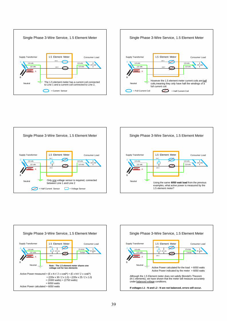
The 1.5 element meter has a current coil connected to Line 1 and a current coil connected to Line 2,
Single Phase 3-Wire Service, 1.5 Element Meter
Supply Transformer Consumer Load1.5 Element Meter
B
C
Neutral
A
= Full Current Coil
110 volts
110 volts220 volts
110 volts
110 volts
However the 1.5 element meter current coils are half coils,meaning they only have half the windings of a full current coil.
Line 1
Line 2
= Half Current Coil
Single Phase 3-Wire Service, 1.5 Element Meter
Supply Transformer Consumer Load1.5 Element Meter
B
C
Neutral
A
= Half Current Sensor = Voltage Sensor
110 volts
110 volts220 volts
110 volts
110 volts
Only one voltage sensor is required, connected between Line 1 and Line 2
Line 1
Line 2
Single Phase 3-Wire Service, 1.5 Element Meter
Supply Transformer Consumer Load1.5 Element Meter
B
C
Neutral
A
110 volts
110 volts220 volts
110 volts
110 volts
Line 1
Line 2
Using the same 6050 watt load from the previous examples, what active power is measured by the 1.5 element meter?
Single Phase 3-Wire Service, 1.5 Element Meter
Supply Transformer Consumer Load1.5 Element Meter
B
C
Neutral
A
10 amps
5 amps20 amps
110 volts
110 volts
Line 1
Line 2
220 volts
Note : The 1.5 element meter shares one voltage coil for two elements
Active Power measured = (E x IL1 / 2 x cos0*) + (E x IL2 / 2 x cos0*) = (220v x 30 / 2 x 1.0) + (220v x 25 / 2 x 1.0) = (3300 watts) + (2750 watts) = 6050 wattsActive Power calculated = 6050 watts
Single Phase 3-Wire Service, 1.5 Element Meter
Supply Transformer Consumer Load1.5 Element Meter
B
C
Neutral
A
10 amps
5 amps20 amps
110 volts
110 volts
Line 1
Line 2
Active Power calculated for the load = 6050 wattsActive Power indicated by the meter = 6050 watts
220 volts
Although the 1.5 Element meter does not satisfy Blondel's Theorem (N-1 elements), we have shown that the meter will measure accurately under balanced voltage conditions.
If voltages L1 - N and L2 - N are not balanced, errors will occur.
Single Phase 3-Wire Service, 1.5 Element Meter
39
Questions?
Comments?
Next: Polyphase Load Analysis
Single Phase 3-Wire Service, 1.5 Element Meter
Polyphase Load Analysis
- Polyphase Phasors
- 3 Phase 4 Wire Wye Service 3 Element Meter 2.5 Element Meter
- 3 Phase 3-Wire Delta Service 2 Element Meter
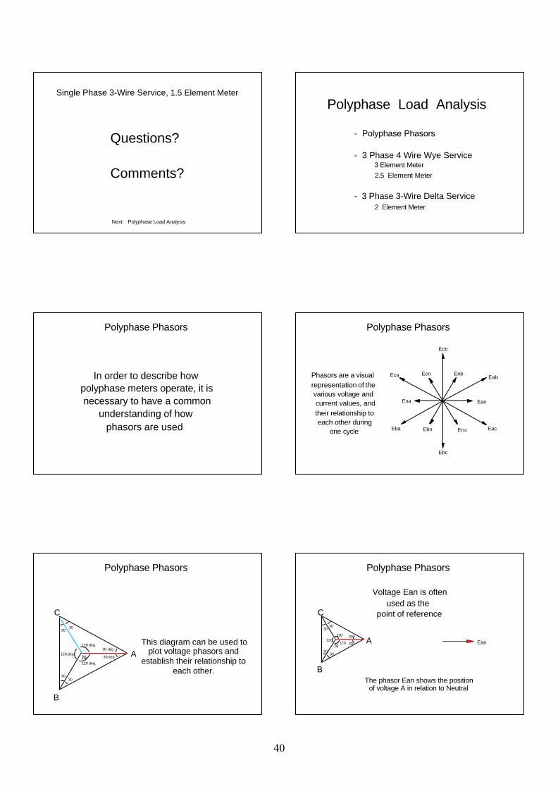
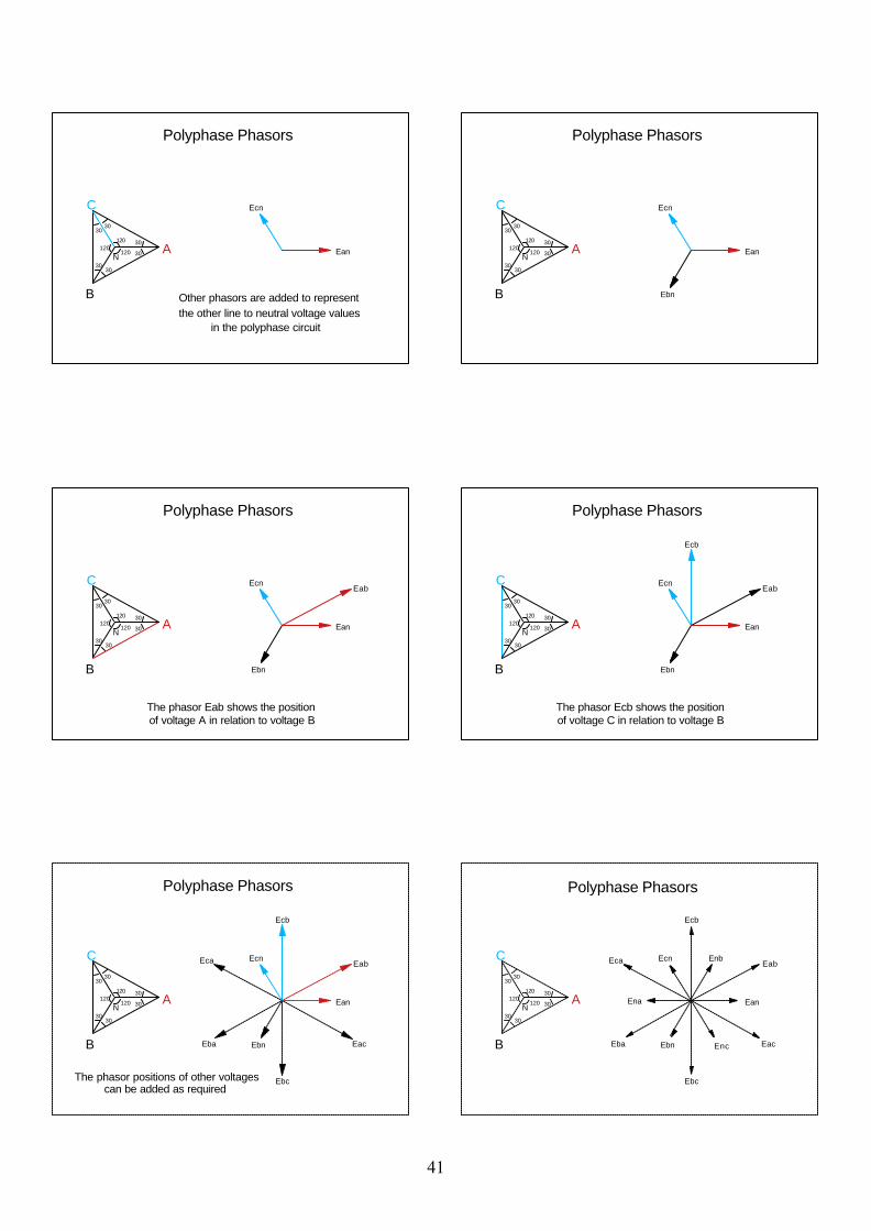
In order to describe how polyphase meters operate, it is necessary to have a common understanding of how phasors are used
Polyphase Phasors
EanEna
Eab
Ecb
Ebc
Ecn
Ebn
Enb
EncEba
Eca
Eac
Phasors are a visualrepresentation of the various voltage and current values, and their relationship to each other during one cycle
Polyphase Phasors
A
B
C
N
This diagram can be used to plot voltage phasors and
establish their relationship to each other.
120 deg.
120 deg
120 deg.
30
30 deg
30 deg
3030
30
Polyphase Phasors
A
B
C30
30
120120
120
30
30
3030
EanN
Voltage Ean is often used as the point of reference
The phasor Ean shows the position of voltage A in relation to Neutral
Polyphase Phasors
40
A
B
C30
30
120120
120
30
30
3030
EanN
Ecn
Other phasors are added to representthe other line to neutral voltage values in the polyphase circuit
Polyphase Phasors
A
B
C30
30
120120
120
30
30
3030
EanN
Ecn
Ebn
Polyphase Phasors
A
B
C30
30
120120
120
30
30
3030
EanN
EabEcn
Ebn
The phasor Eab shows the position of voltage A in relation to voltage B
Polyphase Phasors
A
B
C30
30
120120
120
30
30
3030
EanN
Eab
Ecb
Ecn
Ebn
The phasor Ecb shows the position of voltage C in relation to voltage B
Polyphase Phasors
A
B
C30
30
120120
120
30
30
3030
EanN
Eab
Ecb
Ebc
Ecn
EbnEba
Eca
Eac
The phasor positions of other voltages can be added as required
Polyphase Phasors
A
B
C30
30
120120
120
30
30
3030
EanEnaN
Eab
Ecb
Ebc
Ecn
Ebn
Enb
EncEba
Eca
Eac
Polyphase Phasors
41
Next: 3 Phase 4-wire Wye Services, 3 Element Meter
Questions?
Comments?
Polyphase Phasors
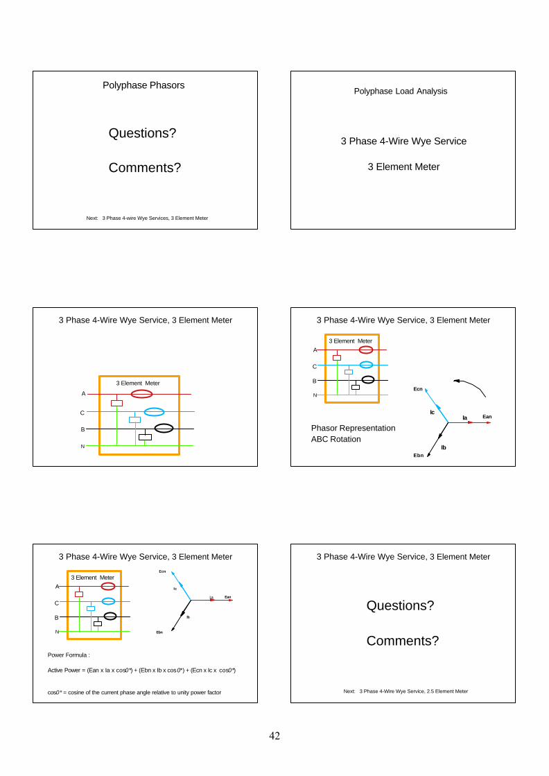
3 Phase 4-Wire Wye Service
3 Element Meter
Polyphase Load Analysis
3 Element Meter
A
C
B
N
3 Phase 4-Wire Wye Service, 3 Element Meter
3 Element MeterA
C
B
N
Phasor RepresentationABC Rotation
Ean
EbnIb
Ecn
IcIa
3 Phase 4-Wire Wye Service, 3 Element Meter
A
C
B
N
Power Formula :
Active Power = (Ean x Ia x cos0*) + (Ebn x Ib x cos0*) + (Ecn x Ic x cos0*)
cos0* = cosine of the current phase angle relative to unity power factor
EanIa
Ebn
Ib
Ecn
Ic
3 Element Meter
3 Phase 4-Wire Wye Service, 3 Element Meter
Questions?
Comments?
Next: 3 Phase 4-Wire Wye Service, 2.5 Element Meter
3 Phase 4-Wire Wye Service, 3 Element Meter
42
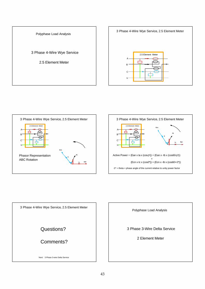
3 Phase 4-Wire Wye Service
2.5 Element Meter
Polyphase Load Analysis
2.5 Element Meter
A
B
C
N
3 Phase 4-Wire Wye Service, 2.5 Element Meter
2.5 Element Meter
A
B
C
N
Phasor RepresentationABC Rotation
EanIa
-Ib
Ecn
Ic
3 Phase 4-Wire Wye Service, 2.5 Element Meter
2.5 Element Meter
A
B
C
N
Active Power = (Ean x Ia x (cos0*)) + (Ean x -Ib x (cos60-0*)) +
(Ecn x Ic x (cos0*)) + (Ecn x -Ib x (cos60+0*))
0* = theta = phase angle of the current relative to unity power factor
EanIa
-Ib
Ecn
Ic
3 Phase 4-Wire Wye Service, 2.5 Element Meter
Questions?
Comments?
Next: 3 Phase 3-wire Delta Service
3 Phase 4-Wire Wye Service, 2.5 Element Meter
3 Phase 3-Wire Delta Service
2 Element Meter
Polyphase Load Analysis
43
2 Element Meter
A
C
B
3 Phase 3-Wire Delta Service
A
C
B
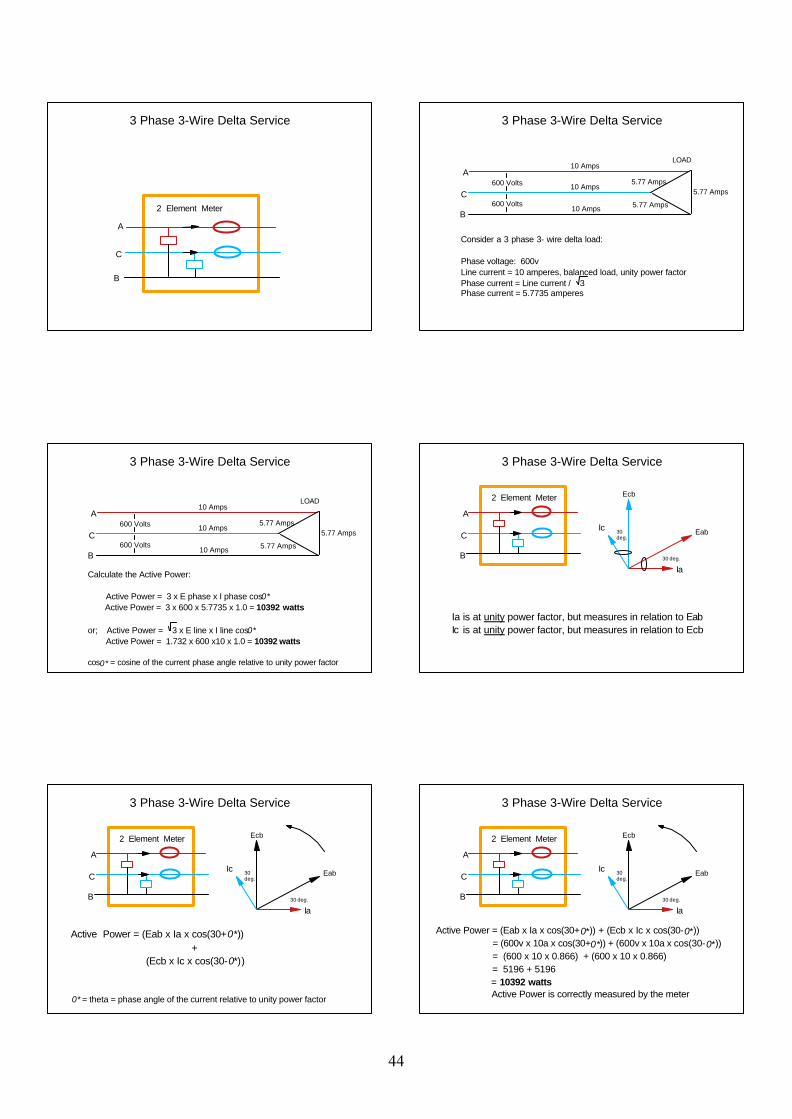
Consider a 3 phase 3- wire delta load:
Phase voltage: 600vLine current = 10 amperes, balanced load, unity power factorPhase current = Line current / 3Phase current = 5.7735 amperes
10 Amps
10 Amps
10 Amps
5.77 Amps
5.77 Amps5.77 Amps
LOAD
600 Volts
600 Volts
3 Phase 3-Wire Delta Service
A
C
B10 Amps
10 Amps
10 Amps
5.77 Amps
5.77 Amps5.77 Amps
LOAD
600 Volts
600 Volts
Calculate the Active Power:
Active Power = 3 x E phase x I phase cos0* Active Power = 3 x 600 x 5.7735 x 1.0 = 10392 watts
or; Active Power = 3 x E line x I line cos0* Active Power = 1.732 x 600 x10 x 1.0 = 10392 watts
cos0* = cosine of the current phase angle relative to unity power factor
3 Phase 3-Wire Delta Service
2 Element Meter
A
C
B
Ia is at unity power factor, but measures in relation to EabIc is at unity power factor, but measures in relation to Ecb
Eab
Ia
Ecb
Ic
30 deg.
30 deg.
3 Phase 3-Wire Delta Service
2 Element Meter
A
C
B
Eab
Ia
Ecb
Ic
30 deg.
30 deg.
Active Power = (Eab x Ia x cos(30+0*)) + (Ecb x Ic x cos(30-0*))
0* = theta = phase angle of the current relative to unity power factor
3 Phase 3-Wire Delta Service
2 Element Meter
A
C
B
Eab
Ia
Ecb
Ic
30 deg.
30 deg.
Active Power = (Eab x Ia x cos(30+0*)) + (Ecb x Ic x cos(30-0*)) = (600v x 10a x cos(30+0*)) + (600v x 10a x cos(30-0*)) = (600 x 10 x 0.866) + (600 x 10 x 0.866) = 5196 + 5196 = 10392 watts Active Power is correctly measured by the meter
3 Phase 3-Wire Delta Service
44

Questions?
Comments?
3 Phase 3-Wire Delta Service
45

4 Quadrant Measurement
Watts hours, (Wh) Reactive Volt-Ampere hours (VARh)
and Volt-Ampere hours (VAh)
Prepared and presented by: George A. Smith, Measurement Canada Paul G. Rivers, Measurement Canada 2006
Measurement Concepts
Watts
VARs
VA
Watts
VARs
VA
Measurement Concepts
The Power Triangle
10,392 Watts
6,000 VARs12,000 VA
VA = Square root of (10,392 W squared + 6,000 VARs squared) = 12,000 VA
30 degrees
Measurement Concepts
Most metering points require measurementof electricity being delivered to a consumer. Electricity is often transferred between suppliers, and require that electricity be measured in two directions, with both lagging and leading power factor.
Where bi-directional measurement is required, 4 Quadrant metering is often used.
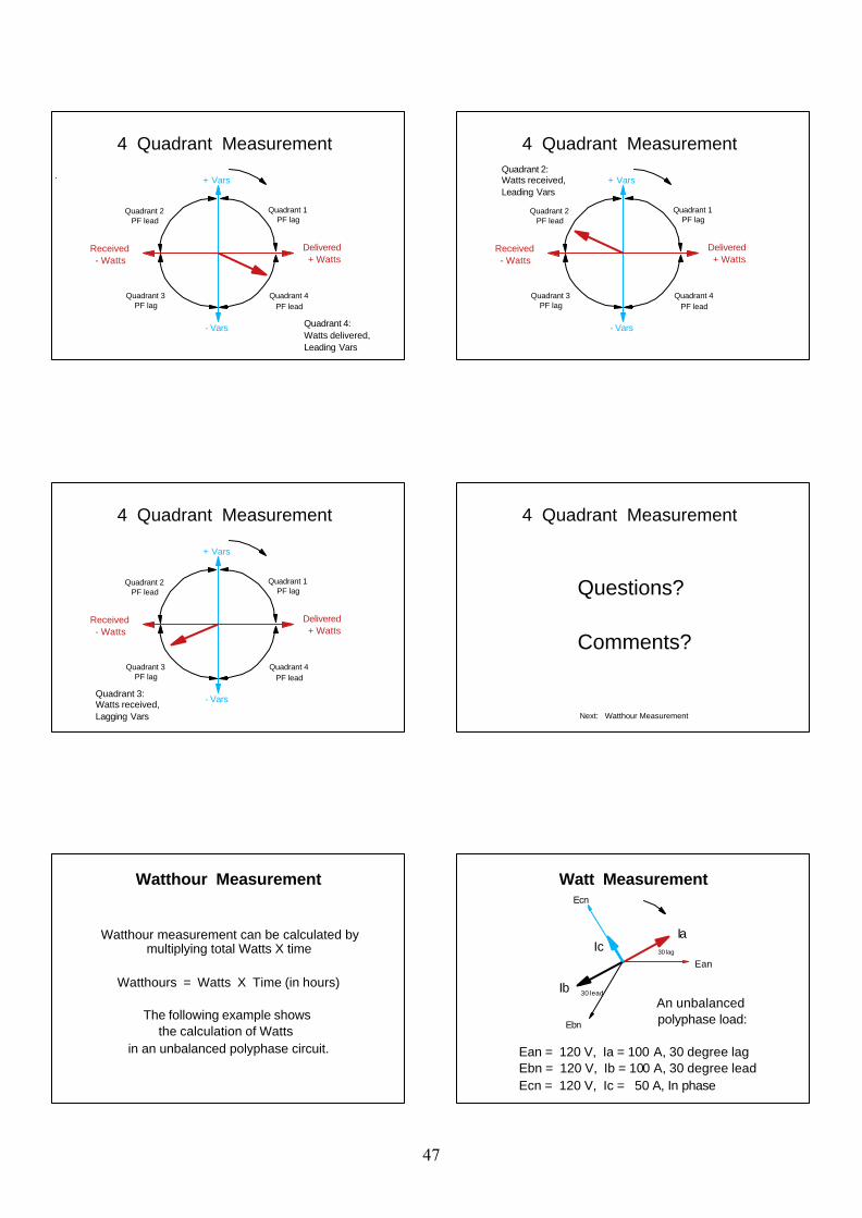
4 Quadrant Measurement
4 Quadrant measurement can berepresented using a single phasor diagram
that combines the measurement ofelectricity in all phases, in both directions,
including all possible power factors.
4 Quadrant Measurement
Delivered + Watts
Received - Watts
Quadrant 1 PF lag
Quadrant 4 PF lead
Quadrant 3 PF lag
Quadrant 2 PF lead
+ Vars
- Vars
Quadrant 1:Watts delivered,Lagging Vars
4 Quadrant Measurement
46
Delivered + Watts
Received - Watts
Quadrant 1 PF lag
Quadrant 4 PF lead
Quadrant 3 PF lag
Quadrant 2 PF lead
+ Vars
- Vars Quadrant 4:Watts delivered,Leading Vars
4 Quadrant Measurement
Delivered + Watts
Received - Watts
Quadrant 1 PF lag
Quadrant 4 PF lead
Quadrant 3 PF lag
Quadrant 2 PF lead
+ Vars
- Vars
Quadrant 2:Watts received,Leading Vars
4 Quadrant Measurement
Delivered + Watts
Received - Watts
Quadrant 1 PF lag
Quadrant 4 PF lead
Quadrant 3 PF lag
Quadrant 2 PF lead
+ Vars
- VarsQuadrant 3:Watts received,Lagging Vars
4 Quadrant Measurement
Questions?
Comments?
Next: Watthour Measurement
4 Quadrant Measurement
Watthour measurement can be calculated by multiplying total Watts X time
Watthours = Watts X Time (in hours)
The following example shows the calculation of Watts
in an unbalanced polyphase circuit.
Watthour MeasurementEcn
Ebn
Ia
Ib 30 lead
30 lag
Watt Measurement
Ic
An unbalanced polyphase load:
Ean = 120 V, Ia = 100 A, 30 degree lagEbn = 120 V, Ib = 100 A, 30 degree leadEcn = 120 V, Ic = 50 A, In phase
Ean
47
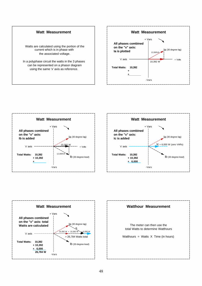
Watts are calculated using the portion of the current which is in phase with
the associated voltage.
In a polyphase circuit the watts in the 3 phases can be represented on a phasor diagram
using the same 'x' axis as reference.
Watt Measurement
-Vars
+ Vars
'x' axis
All phases combinedon the "x" axis:Ia is plotted
10,392 W
12,000VA
+ Volts
Ia (30 degree lag)
Total Watts: 10,392 + +
Watt Measurement
-Vars
+ Vars
'x' axis
All phases combinedon the "x" axis:Ib is added
10,392 W
12,000VA
+ Volts
Ia (30 degree lag)
Ib (30 degree lead)Total Watts: 10,392 + 10,392 +
Watt Measurement
-Vars
+ Vars
'x' axis
All phases combinedon the "x" axis:Ic is added
Ic = 6,000 W (zero VARs)
Ia (30 degree lag)
Ib (30 degree lead)Total Watts: 10,392 + 10,392 + 6,000
Watt Measurement
-Vars
+ Vars
'x' axis
All phases combinedon the "x" axis: totalWatts are calculated
10,392 W + 10,392 W + 6,000 W
= 26,784 Watts total
Ib
Total Watts: 10,392 + 10,392 + 6,000 26,784 W
Ia (30 degree lag)
Ib (30 degree lead)
Watt Measurement
The meter can then use thetotal Watts to determine Watthours
Watthours = Watts X Time (in hours)
Watthour Measurement
48
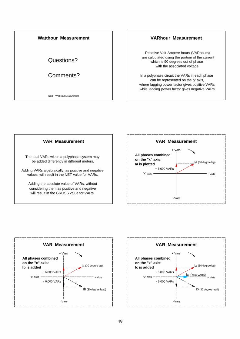
Next: VAR hour Measurement
Questions?
Comments?
Watthour Measurement
Reactive Volt-Ampere hours (VARhours) are calculated using the portion of the current
which is 90 degrees out of phase with the associated voltage
In a polyphase circuit the VARs in each phase can be represented on the 'y' axis,
where lagging power factor gives positive VARswhile leading power factor gives negative VARs
VARhour Measurement
The total VARs within a polyphase system maybe added differently in different meters.
Adding VARs algebraically, as positive and negative values, will result in the NET value for VARs.
Adding the absolute value of VARs, withoutconsidering them as positive and negativewill result in the GROSS value for VARs.
VAR Measurement
-Vars
+ Vars
'x' axis
Ia (30 degree lag)
+ 6,000 VARs
All phases combinedon the "x" axis:Ia is plotted
+ Volts
VAR Measurement
-Vars
+ Vars
'x' axis
Ia (30 degree lag)
+ 6,000 VARs
Ib (30 degree lead)
- 6,000 VARs
All phases combinedon the "x" axis:Ib is added
+ Volts
VAR Measurement
-Vars
+ Vars
'x' axis
Ia (30 degree lag)
+ 6,000 VARs
Ib (30 degree lead)
- 6,000 VARs
All phases combinedon the "x" axis:Ic is added
Ic (zero VARS)+ Volts
VAR Measurement
49
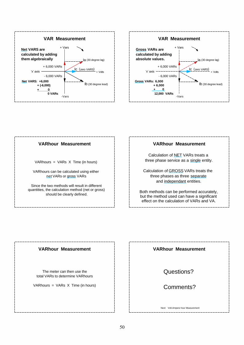
-Vars
+ Vars
'x' axis
Ia (30 degree lag)
+ 6,000 VARs
Ib (30 degree lead)
- 6,000 VARs
Net VARS arecalculated by addingthem algebraically
Ic (zero VARS)
Net VARS: +6,000 + (-6,000) + 0 0 VARs
+ Volts
VAR Measurement
-Vars
+ Vars
'x' axis
Ia (30 degree lag)
+ 6,000 VARs
Ib (30 degree lead)
- 6,000 VARs
Gross VARs are calculated by addingabsolute values.
Ic (zero VARS)
Gross VARs: 6,000 + 6,000 + 0 12,000 VARs
+ Volts
VAR Measurement
VARhour Measurement
VARhours = VARs X Time (in hours)
VARhours can be calculated using either net VARs or gross VARs
Since the two methods will result in different quantities, the calculation method (net or gross)
should be clearly defined.
Calculation of NET VARs treats a three phase service as a single entity.
Calculation of GROSS VARs treats the three phases as three separate
and independant entities.
Both methods can be performed accurately, but the method used can have a significant effect on the calculation of VARs and VA.
VARhour Measurement
The meter can then use thetotal VARs to determine VARhours
VARhours = VARs X Time (in hours)
VARhour Measurement
Questions?
Comments?
VARhour Measurement
Next: Volt-Ampere hour Measurement
50
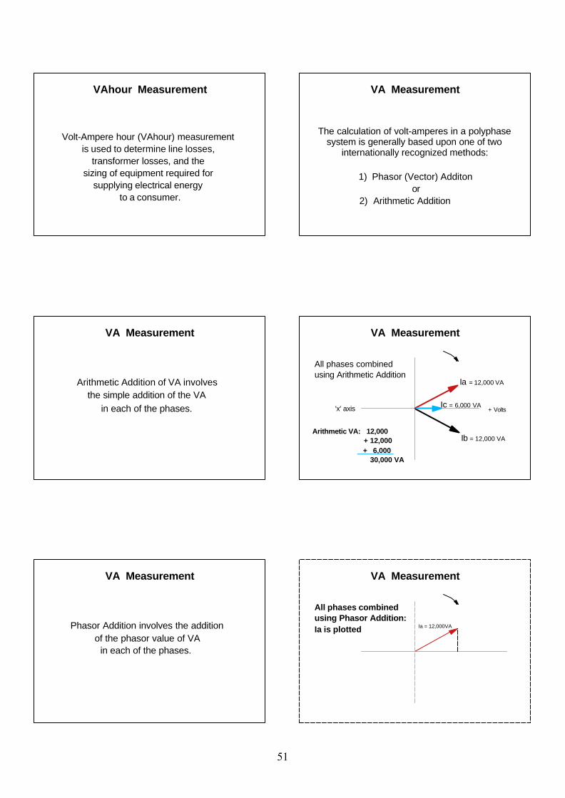
Volt-Ampere hour (VAhour) measurement is used to determine line losses,
transformer losses, and the sizing of equipment required for
supplying electrical energy to a consumer.
VAhour Measurement
The calculation of volt-amperes in a polyphase system is generally based upon one of two
internationally recognized methods:
1) Phasor (Vector) Additonor
2) Arithmetic Addition
VA Measurement
Arithmetic Addition of VA involves the simple addition of the VA
in each of the phases.
VA Measurement
'x' axis
Ib = 12,000 VA
Ic = 6,000 VA
Ia = 12,000 VA
All phases combinedusing Arithmetic Addition
Arithmetic VA: 12,000 + 12,000 + 6,000 30,000 VA
+ Volts
VA Measurement
Phasor Addition involves the addition of the phasor value of VA
in each of the phases.
VA Measurement
All phases combinedusing Phasor Addition:Ia is plotted Ia = 12,000VA
VA Measurement
51
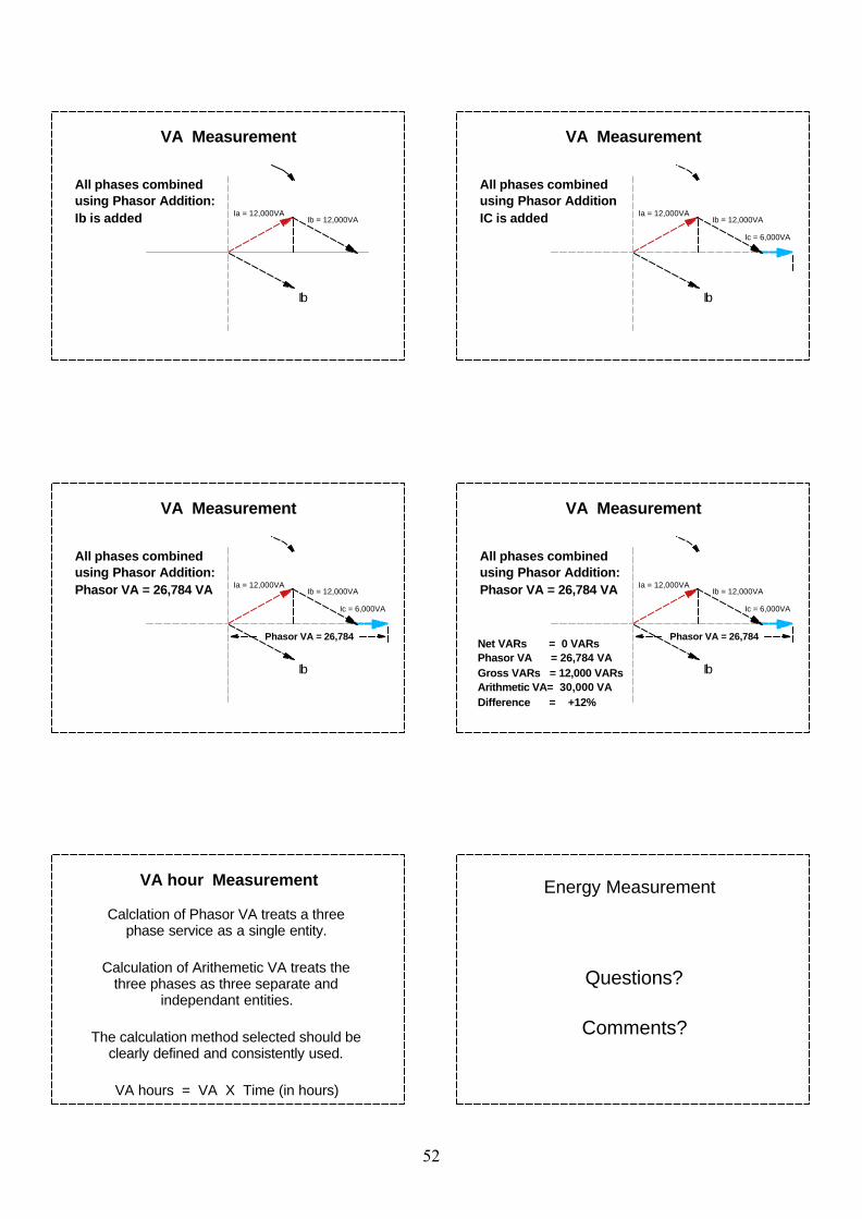
Ib
All phases combinedusing Phasor Addition:Ib is added Ia = 12,000VA
Ib = 12,000VA
VA Measurement
Ib
All phases combinedusing Phasor AdditionIC is added Ia = 12,000VA
Ib = 12,000VA
Ic = 6,000VA
VA Measurement
All phases combinedusing Phasor Addition:Phasor VA = 26,784 VA Ia = 12,000VA
Ib = 12,000VA
Ic = 6,000VA
Phasor VA = 26,784
Ib
VA Measurement
Ib
Ia = 12,000VAIb = 12,000VA
Phasor VA = 26,784 Net VARs = 0 VARsPhasor VA = 26,784 VAGross VARs = 12,000 VARsArithmetic VA= 30,000 VADifference = +12%
Ic = 6,000VA
All phases combinedusing Phasor Addition:Phasor VA = 26,784 VA
VA Measurement
Calclation of Phasor VA treats a three phase service as a single entity.
Calculation of Arithemetic VA treats the three phases as three separate and
independant entities.
The calculation method selected should be clearly defined and consistently used.
VA hours = VA X Time (in hours)
VA hour Measurement Energy Measurement
Questions?
Comments?
52
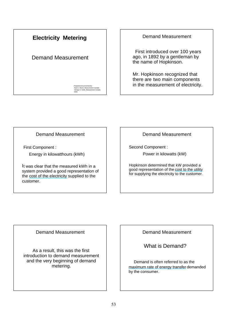
Electricity Metering
Demand Measurement
Prepared and presented by: Paul G. Rivers, Measurement Canada George A. Smith, Measurement Canada 2006
First introduced over 100 years ago, in 1892 by a gentleman by the name of Hopkinson.
Mr. Hopkinson recognized that there are two main components in the measurement of electricity.
Demand Measurement
First Component :
Energy in kilowatthours (kWh)
It was clear that the measured kWh in a system provided a good representation of the cost of the electricity supplied to the customer.
Demand Measurement
Second Component :
Power in kilowatts (kW)
Hopkinson determined that kW provided a good representation of the cost to the utility for supplying the electricity to the customer.
Demand Measurement
As a result, this was the first
introduction to demand measurement and the very beginning of demand
metering.
Demand Measurement
What is Demand?
Demand is often referred to as the maximum rate of energy transfer demanded by the consumer.
Demand Measurement
53
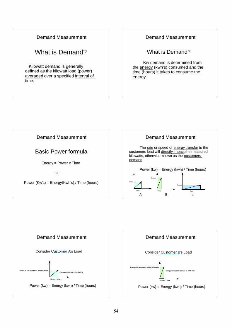
What is Demand?
Kilowatt demand is generally defined as the kilowatt load (power) averaged over a specified interval of time.
Demand Measurement
What is Demand?
Kw demand is determined from the energy (kwh's) consumed and the time (hours) it takes to consume the energy.
Demand Measurement
Basic Power formula
Energy = Power x Time
or
Power (Kw's) = Energy(Kwh's) / Time (hours)
Demand Measurement
The rate or speed of energy transfer to the customers load will directly impact the measured kilowatts, otherwise known as the customers demand.
Power (kw) = Energy (kwh) / Time (hours)
Time
Power
Time
Power
Time
Power
A B C
Demand Measurement
Consider Customer A's Load
Power (kw) = Energy (kwh) / Time (hours)
Time = 2 hours
Power or KW demand = 1000 kilowattsEnergy consumed = 2000kwh's
Demand Measurement
Time = 1 hour
Power or KW demand = 2000 kilowatts
Energy consumed remains at 2000 kwh
Demand Measurement
Consider Customer B's Load
Power (kw) = Energy (kwh) / Time (hours)
54
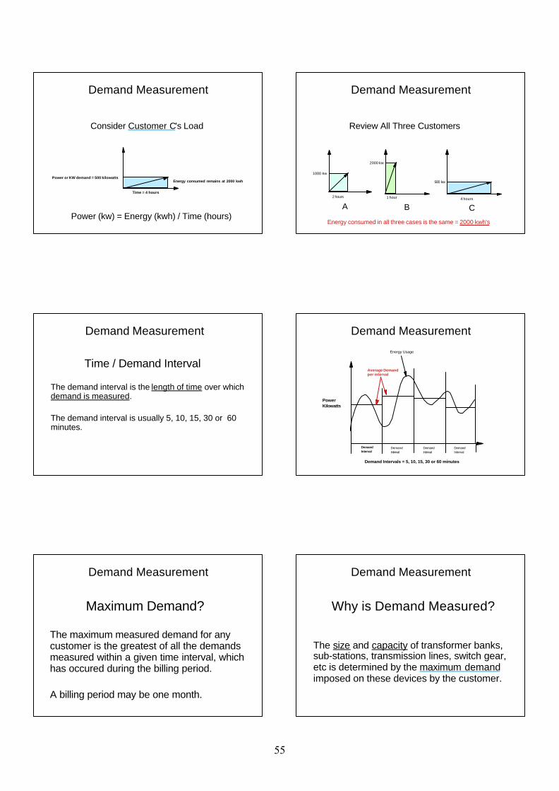
Time = 4 hours
Power or KW demand = 500 kilowattsEnergy consumed remains at 2000 kwh
Demand Measurement
Consider Customer C's Load
Power (kw) = Energy (kwh) / Time (hours)
Review All Three Customers
2 hours
1000 kw
1 hour
2000 kw
4 hours
500 kw
A B C
Energy consumed in all three cases is the same = 2000 kwh's
Demand Measurement
Time / Demand Interval The demand interval is the length of time over which demand is measured.
The demand interval is usually 5, 10, 15, 30 or 60 minutes.
Demand Measurement
PowerKilowatts
Average Demand per interval
Energy Usage
DemandInterval
DemandInterval
DemandInterval
DemandInterval
Demand Measurement
Demand Intervals = 5, 10, 15, 30 or 60 minutes
Maximum Demand?
The maximum measured demand for any customer is the greatest of all the demands measured within a given time interval, which has occured during the billing period.
A billing period may be one month.
Demand Measurement
Why is Demand Measured?
The size and capacity of transformer banks, sub-stations, transmission lines, switch gear, etc is determined by the maximum demand imposed on these devices by the customer.
Demand Measurement
55
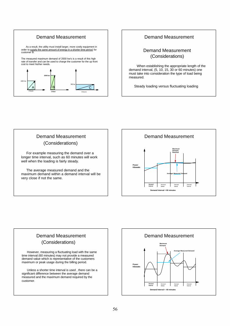
As a result, the utility must install larger, more costly equipment in order to supply the same amount of energy in a shorter time period for customer B.
The measured maximum demand of 2000 kw's is a result of this high rate of transfer and can be used to charge the customer for the up front cost to meet his/her needs.
2 hours
1000 kw
1 hour
2000 kw
4 hours
500 kw
A B C
Demand Measurement
Demand Measurement (Considerations)
When establishing the appropriate length of the demand interval, (5, 10, 15, 30 or 60 minutes) one must take into consideration the type of load being measured.
Steady loading versus fluctuating loading
Demand Measurement
(Considerations)
For example measuring the demand over a longer time interval, such as 60 minutes will work well when the loading is fairly steady.
The average measured demand and the maximum demand within a demand interval will be very close if not the same.
Demand Measurement
PowerKilowatts
Maximum Demand Reached
DemandInterval
DemandInterval
DemandInterval
DemandInterval
Average Measured Demand
Demand Measurement
Demand Interval = 60 minutes
(Considerations)
However, measuring a fluctuating load with the same time interval (60 minutes) may not provide a measured demand value which is representative of the customers maximum or peak usage during the billing period.
Unless a shorter time interval is used , there can be a significant difference between the average demand measured and the maximum demand required by the customer.
Demand Measurement
PowerKilowatts
Maximum Demand
DemandInterval
DemandInterval
DemandInterval
DemandInterval
Average Measured Demand
Demand Measurement
Demand Interval = 60 minutes
56
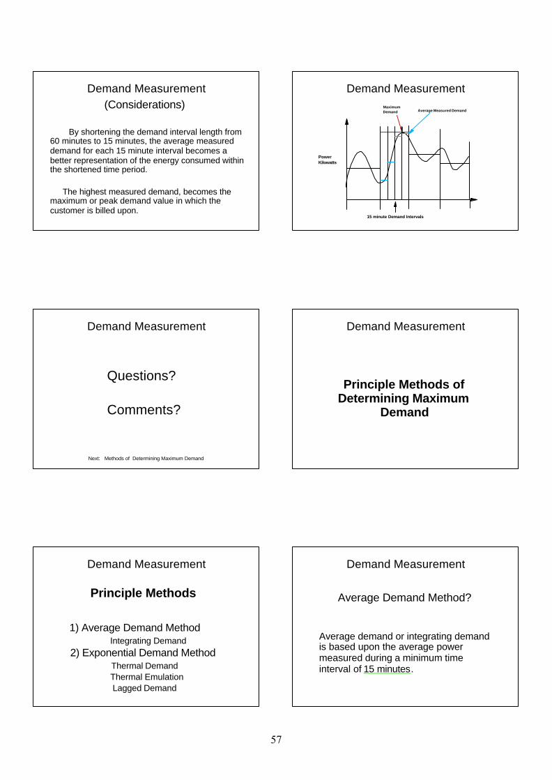
Demand Measurement (Considerations)
By shortening the demand interval length from 60 minutes to 15 minutes, the average measured demand for each 15 minute interval becomes a better representation of the energy consumed within the shortened time period.
The highest measured demand, becomes the maximum or peak demand value in which the customer is billed upon.
PowerKilowatts
Maximum Demand Average Measured Demand
Demand Measurement
15 minute Demand Intervals
Questions?
Comments?
Demand Measurement
Next: Methods of Determining Maximum Demand
Principle Methods of Determining Maximum
Demand
Demand Measurement
Principle Methods
1) Average Demand Method Integrating Demand
2) Exponential Demand MethodThermal Demand
Thermal EmulationLagged Demand
Demand Measurement
Average Demand Method?
Average demand or integrating demand is based upon the average power measured during a minimum time interval of 15 minutes.
Demand Measurement
57
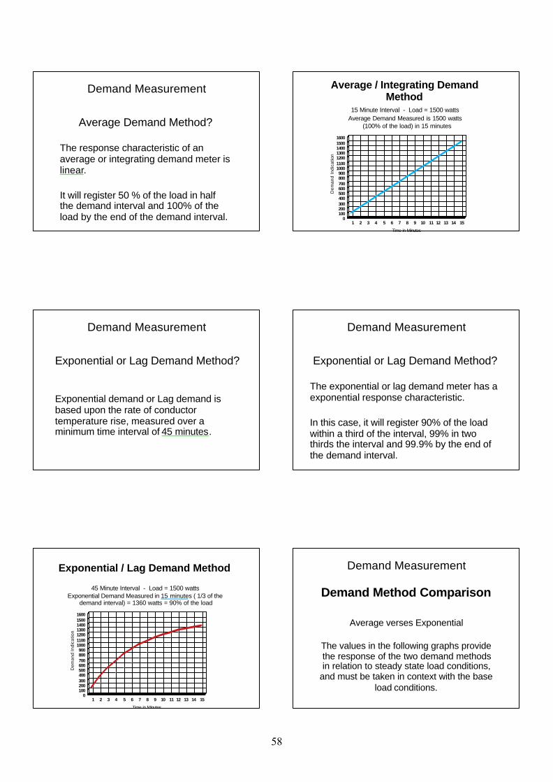
Demand Measurement
Average Demand Method?
The response characteristic of an average or integrating demand meter is linear.
It will register 50 % of the load in half the demand interval and 100% of the load by the end of the demand interval.
Average / Integrating Demand Method
15 Minute Interval - Load = 1500 wattsAverage Demand Measured is 1500 watts
(100% of the load) in 15 minutes
1 2 3 4 5 6 7 8 9 10 11 12 13 14 15
Time in Minutes
0100200300400500600700800900
1000110012001300140015001600
Dem
and
Indi
catio
n
Exponential or Lag Demand Method?
Exponential demand or Lag demand is based upon the rate of conductor temperature rise, measured over a minimum time interval of 45 minutes.
Demand Measurement Demand Measurement
Exponential or Lag Demand Method?
The exponential or lag demand meter has a exponential response characteristic.
In this case, it will register 90% of the load within a third of the interval, 99% in two thirds the interval and 99.9% by the end of the demand interval.
Exponential / Lag Demand Method
45 Minute Interval - Load = 1500 wattsExponential Demand Measured in 15 minutes ( 1/3 of the
demand interval) = 1360 watts = 90% of the load
1 2 3 4 5 6 7 8 9 10 11 12 13 14 15
Time in Minutes
0100200300400500600700800900
1000110012001300140015001600
Dem
and
Indi
catio
n
Demand Method Comparison
Demand Measurement
Average verses Exponential
The values in the following graphs provide the response of the two demand methods in relation to steady state load conditions,
and must be taken in context with the base load conditions.
58
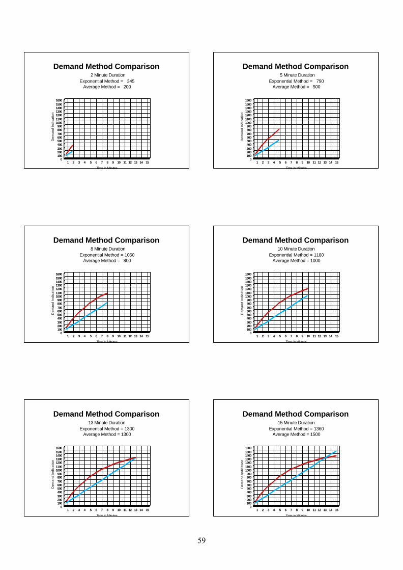
Demand Method Comparison 2 Minute Duration
Exponential Method = 345Average Method = 200
1 2 3 4 5 6 7 8 9 10 11 12 13 14 15
Time in Minutes
0100200300400500600700800900
1000110012001300140015001600
Dem
and
Indi
catio
n
Demand Method Comparison 5 Minute Duration
Exponential Method = 790Average Method = 500
1 2 3 4 5 6 7 8 9 10 11 12 13 14 15
Time in Minutes
0100200300400500600700800900
1000110012001300140015001600
Dem
and
Indi
catio
nDemand Method Comparison
8 Minute DurationExponential Method = 1050
Average Method = 800
1 2 3 4 5 6 7 8 9 10 11 12 13 14 15
Time in Minutes
0100200300400500600700800900
1000110012001300140015001600
Dem
and
Indi
catio
n
Demand Method Comparison10 Minute Duration
Exponential Method = 1180Average Method = 1000
1 2 3 4 5 6 7 8 9 10 11 12 13 14 15
Time in Minutes
0100200300400500600700800900
1000110012001300140015001600
Dem
and
Indi
catio
n
Demand Method Comparison13 Minute Duration
Exponential Method = 1300Average Method = 1300
1 2 3 4 5 6 7 8 9 10 11 12 13 14 15
Time in Minutes
0100200300400500600700800900
1000110012001300140015001600
Dem
and
Indi
catio
n
Demand Method Comparison15 Minute Duration
Exponential Method = 1360Average Method = 1500
1 2 3 4 5 6 7 8 9 10 11 12 13 14 15
Time in Minutes
0100200300400500600700800900
1000110012001300140015001600
Dem
and
Indi
catio
n
59

Demand Meter Response Characteristics (Considerations)
Similiar to the length of the demand interval, the response characteristics of a demand meter (linear vs exponential) can also impact on the measurements end result, depending on the type of loading imposed on the system, by the customer.
Demand Measurement
Overall Considerations
Consideration should be given to the standardization of both the demand interval length and the response type of the demand meter used within one's respective economy to ensure all customers are billed equitably.
Demand Measurement
Questions?
Comments?
Demand Measurement
60
Volt-Ampere Demand
Measurement
Prepared and presented by: George A. Smith, Measurement Canada Paul G. Rivers, Measurement Canada 2006
The cost of supplying electrical energy to a consumer increases as
the power factor decreases.
The cost increase is due to 2 factors: 1) increased capital costs, and
2) increased line losses
Volt-Ampere Demand
Volt- Ampere demand measurement is a common method for electricity
suppliers to recover these increased costs.
Volt-Ampere Demand
The method of integrating energy consumption over time (e.g. 15 minutes)
to establish Volt-Ampere demand,is similar to the method used to
calculate Watt demand.
However, there is only one generally accepted definition of total Watts in a polyphase circuit,
but there are more than one definitionof total Volt-Amperes.
Volt-Ampere Demand
The addition of volt-amperes in a polyphase system is generally based upon one of two
internationally recognized methods:
1) Phasor (Vector) Additonor
2) Arithmetic Addition
Volt-Ampere Demand
'Phasor Addition' and 'Arithmetic Addition' methods use the same units of measure (VA) but can yield significantly different
values for the same load conditions.
This can lead to measurement inequity, consumer complaints, and a reduced
confidence in measurement.
Volt-Ampere Demand
61
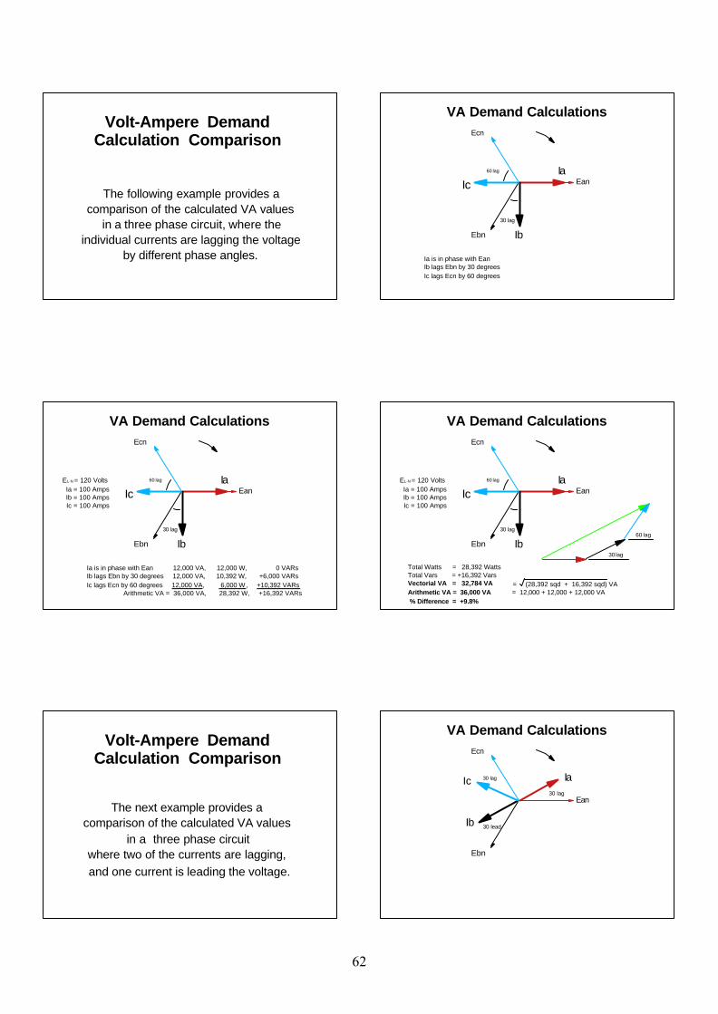
The following example provides acomparison of the calculated VA values
in a three phase circuit, where theindividual currents are lagging the voltage
by different phase angles.
Volt-Ampere Demand Calculation Comparison
VA Demand Calculations
Ean
Ecn
Ia
Ib30 lag
60 lag
Ic
Ebn
Ia is in phase with Ean Ib lags Ebn by 30 degrees Ic lags Ecn by 60 degrees
Ean
Ecn
Ia
Ib30 lag
60 lagEL-N = 120 Volts Ia = 100 Amps Ib = 100 Amps Ic = 100 Amps
VA Demand Calculations
Ic
Ebn
Ia is in phase with Ean 12,000 VA, 12,000 W, 0 VARsIb lags Ebn by 30 degrees 12,000 VA, 10,392 W, +6,000 VARs Ic lags Ecn by 60 degrees 12,000 VA, 6,000 W, +10,392 VARs Arithmetic VA = 36,000 VA, 28,392 W, +16,392 VARs
Ebn
Ecn
Ia
Ib30 lag
60 lag
30 lag
60 lag
VA Demand Calculations
Ic EanEL-N = 120 Volts Ia = 100 Amps Ib = 100 Amps Ic = 100 Amps
Total Watts = 28,392 Watts Total Vars = +16,392 VarsVectorial VA = 32,784 VA = (28,392 sqd + 16,392 sqd) VA Arithmetic VA = 36,000 VA = 12,000 + 12,000 + 12,000 VA % Difference = +9.8%
The next example provides a comparison of the calculated VA values
in a three phase circuit where two of the currents are lagging, and one current is leading the voltage.
Volt-Ampere Demand Calculation Comparison
Ean
Ebn
Ecn
Ic Ia30 lag
Ib 30 lead
VA Demand Calculations
30 lag
62

Ean
Ebn
Ecn
Ic Ia30 lag
Ib 30 lead
Total Watts = 31177 Watts Gross Vars = 18000 Vars Net Vars = +6000 Vars
30 lag
VA Demand Calculations
EL-N = 120 Volts Ia = 100 Amps Ib = 100 Amps Ic = 100 Amps
Ean
Ebn
Ecn
Ic Ia30 lag
Ib 30 lead
Total Watts = 31177 Watts Vectorial VA = 31749 VAGross Vars = 18000 Vars Arithmetic VA = 36000 VANet Vars = +6000 Vars % Difference = +13.4%
30 lag
30 lag
30 lead
VA Demand Calculations
EL-N = 120 Volts Ia = 100 Amps Ib = 100 Amps Ic = 100 Amps
This last example provides a comparisonof the calculated VA values in a
120/208 volt network service with a purely resistive (1.0 PF) 208 volt load.
Ia and Ib represent the same current, with Ib serving as the return for Ia.
Volt-Ampere Demand Calculation Comparison
Ean
Ebn
Ia
Ib 30 lead
VA Demand Calculations
30 lag
Example of a purely resistive (1.0 PF) 208 volt loadconnected between Ean and Ebn. (zero VARs)Ia & Ib represent the same current, with Ib serving as the return for Ia.
Ean
Ebn
Ia
Ib 30 lead
Total Watts = 20785 Watts Gross Vars = 12000 VarsNet Vars = 0 Vars
VA Demand Calculations
30 lagEL-N = 120 Volts Ia = 100 Amps Ib = 100 Amps Ic = n/a
Ecn is not connected
Ia
Ib 30 lead
Total Watts = 20785 Watts Vectorial VA = 20785 VAGross Vars = 12000 Vars Arithmetic VA = 24000 VANet Vars = 0 Vars % Difference = +15.5%
30 lag
30 lead
30 lag
VA Demand Calculations
Ean
Ebn
EL-N = 120 Volts Ia = 100 Amps Ib = 100 Amps Ic = n/a
63
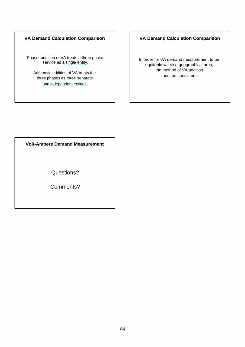
Phasor addition of VA treats a three phase service as a single entity.
Arithmetic addition of VA treats the three phases as three separate
and independant entities.
VA Demand Calculation Comparison
In order for VA demand measurement to be equitable within a geographical area,
the method of VA additionmust be consistent.
VA Demand Calculation Comparison
Questions?
Comments?
Volt-Ampere Demand Measurement
64
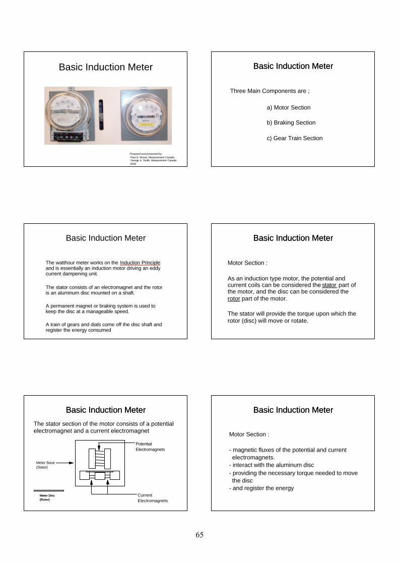
Basic Induction Meter
Prepared and presented by: Paul G. Rivers, Measurement Canada George A. Smith, Measurement Canada 2006
Basic Induction Meter
Three Main Components are ;
a) Motor Section
b) Braking Section
c) Gear Train Section
Basic Induction Meter
The watthour meter works on the Induction Principle and is essentially an induction motor driving an eddy current dampening unit.
The stator consists of an electromagnet and the rotor is an aluminum disc mounted on a shaft.
A permanent magnet or braking system is used to keep the disc at a manageable speed.
A train of gears and dials come off the disc shaft and register the energy consumed
Basic Induction Meter Basic Induction Meter
Motor Section :
As an induction type motor, the potential and current coils can be considered the stator part of the motor, and the disc can be considered the rotor part of the motor.
The stator will provide the torque upon which the rotor (disc) will move or rotate.
Basic Induction Meter
Basic Induction Meter
The stator section of the motor consists of a potential electromagnet and a current electromagnet
Meter Disc(Rotor)
CurrentElectromagnets
Potential Electromagnets
Meter Base(Stator)
Basic Induction Meter Basic Induction Meter
Motor Section :
- magnetic fluxes of the potential and current electromagnets. - interact with the aluminum disc - providing the necessary torque needed to move the disc - and register the energy
Basic Induction Meter
65
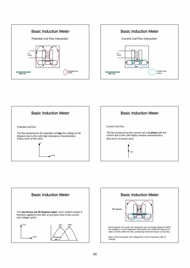
Basic Induction Meter
Potential Coil Flux Interaction
LineVoltage
Potential Lines of Flux
Meter Disc
Basic Induction Meter Basic Induction Meter
Current Coil Flux Interaction
LineVoltage
Current Linesof FluxMeter Disc
Basic Induction Meter
Basic Induction Meter
Potential Coil Flux :
The flux produced by the potential coil lags the voltage by 90 degrees due to the coils high inductance characteristics. (many turns of fine wire)
E
Eflux
Basic Induction Meter Basic Induction Meter
Current Coil Flux :
The flux produced by the current coil is in phase with the current due to the coils highly resistive characteristics.(few turns of course wire)
I
Iflux
Basic Induction Meter
Basic Induction Meter
The two fluxes are 90 degrees apart. Even uniform torque is therefore applied to the disc at any given time in the current and voltage cycles.
I flux
Eflux
I fluxmax
E fluxmax
90 degrees apart
Basic Induction Meter Basic Induction Meter
Every quarter of a cycle, the maximum rate of change (slope) of either the voltage or current signwave will produce the maximum amount of eddy currents within the disc, producing maximum torque on the disc.
Here in the 1st quarter, the voltage flux is at it's maximum rate of change.
1ST Quarter
Basic Induction Meter
66
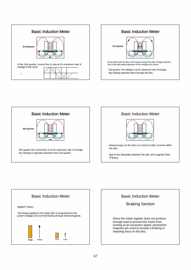
Basic Induction Meter
In the 2nd quarter, current flux is now at it's maximum rate of change in the cycle
2nd Quarter
Basic Induction Meter Basic Induction Meter
Every half cycle the flow of the fluxes through the disc change direction due to the alternating signwave of the voltage and current.
- 3rd quarter, the voltage is at it's maximum rate of change. - flux flowing opposite direct through the disc.
3rd Quarter
Basic Induction Meter
Basic Induction Meter
- 4th quarter the current flux is at it's maximum rate of change- flux flowing in opposite direction from 2nd quarter.
4th Quarter
Basic Induction Meter Basic Induction Meter
- driving torque on the disc is a result of eddy currents within the disc.
- due to the interaction between the disc and magnetic lines of fluxes.
Basic Induction Meter
Applied Torque :
The torque applied to the meter disc is proportional to the power (voltage and current) flowing through electromagnets.
Power TorquePower Power Torque
Basic Induction Meter
Since the meter register does not produce enough load to prevent the meter from running at an excessive speed, permanent magnets are used to provide a braking or retarding force on the disc.
Braking Section
67
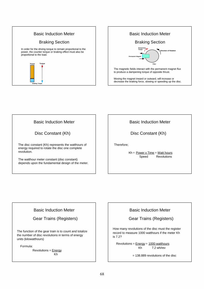
Basic Induction Meter
Braking Section In order for the driving torque to remain proportional to the power, the counter torque or braking effect must also be proportional to the load.
Power Torque
Braking Torque
Basic Induction Meter
Direction of Rotation
Disc
Permanent Magnet
The magnetic fields interact with the permanent magnet flux to produce a dampening torque of opposite thrust.
Moving the magnet inward or outward, will increase or decrease the braking force, slowing or speeding up the disc.
Dampening Torque
Braking Section
Basic Induction Meter
Disc Constant (Kh)
The disc constant (Kh) represents the watthours of energy required to rotate the disc one complete revolution.
The watthour meter constant (disc constant) depends upon the fundamental design of the meter.
Basic Induction Meter
Therefore;
Kh = Power x Time = Watt hours Speed Revolutions
Disc Constant (Kh)
Basic Induction Meter
Gear Trains (Registers)
The function of the gear train is to count and totalize the number of disc revolutions in terms of energy units (kilowatthours)
Formula: Revolutions = Energy Kh
Basic Induction Meter
How many revolutions of the disc must the register record to measure 1000 watthours if the meter Khis 7.2?
Revolutions = Energy = 1000 watthours Kh 7.2 wh/rev
= 138.889 revolutions of the disc
Gear Trains (Registers)
68
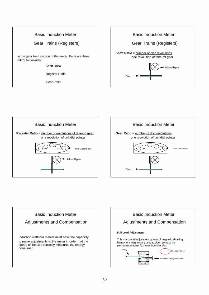
Basic Induction Meter
In the gear train section of the meter, there are threeratio's to consider
Shaft Ratio
Register Ratio
Gear Ratio
Gear Trains (Registers)
Basic Induction Meter
Shaft Ratio = number of disc revolutions one revolution of take-off gear
take-off gear
Disk
Gear Trains (Registers)
Basic Induction Meter
Register Ratio = number of revolutions of take-off gear one revolution of unit dial pointer
take-off gear
Unit Dial Pointer
Basic Induction Meter
Gear Ratio = number of disc revolutions one revolution of unit dial pointer
Disk
Unit Dial Pointer
Basic Induction Meter
Induction watthour meters must have the capability to make adjustments to the meter in order that the speed of the disc correctly measures the energy consumed.
Adjustments and Compensation
Basic Induction Meter
Adjustments and Compensation
Full Load Adjustment :
This is a course adjustment by way of magnetic shunting. Permanent magnets are used to divert some of the permanent magnet flux away from the disc.
Disk
Permanent Magnet Screw
Shunted Fluxes
69
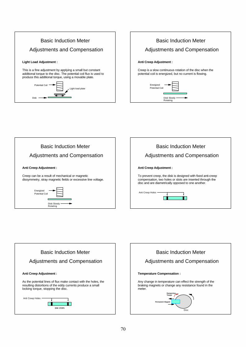
Basic Induction Meter
Adjustments and Compensation
Light Load Adjustment :
This is a fine adjustment by applying a small but constant additional torque to the disc. The potential coil flux is used to produce this additional torque, using a movable plate.
Potential Coil
Disk
Light load plate
Basic Induction Meter
Adjustments and Compensation
Anti Creep Adjustment :
Creep is a slow continuous rotation of the disc when the potential coil is energized, but no current is flowing.
EnergizedPotential Coil
Disk Slowly Rotating
Basic Induction Meter
Adjustments and Compensation
Anti Creep Adjustment :
Creep can be a result of mechanical or magnetic dissymmetry, stray magnetic fields or excessive line voltage.
EnergizedPotential Coil
Disk Slowly Rotating
Basic Induction Meter
Adjustments and Compensation
Anti Creep Adjustment :
To prevent creep, the disk is designed with fixed anti-creep compensation, two holes or slots are inserted through the disc and are diametrically opposed to one another.
Anti Creep Holes
Basic Induction Meter
Adjustments and Compensation
Anti Creep Adjustment :
As the potential lines of flux make contact with the holes, the resulting distortions of the eddy currents produce a small locking torque, stopping the disc.
Anti Creep Holes
DISK STOPS
Basic Induction Meter
Adjustments and Compensation
Temperature Compensation :
Any change in temperature can effect the strength of the braking magnets or change any resistance found in the meter.
Disc
Permanent Magnet
Dampening Torque
70
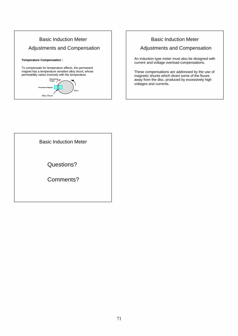
Basic Induction Meter
Adjustments and Compensation
Temperature Compensation :
To compensate for temperature effects, the permanent magnet has a temperature sensitive alloy shunt, whose permeability varies inversely with the temperature.
DiscPermanent Magnet
Dampening Torque
Alloy Shunt
Basic Induction Meter
An induction type meter must also be designed with current and voltage overload compensations.
These compensations are addressed by the use of magnetic shunts which divert some of the fluxes away from the disc, produced by excessively high voltages and currents.
Adjustments and Compensation
Basic Induction Meter
Questions?
Comments?
71
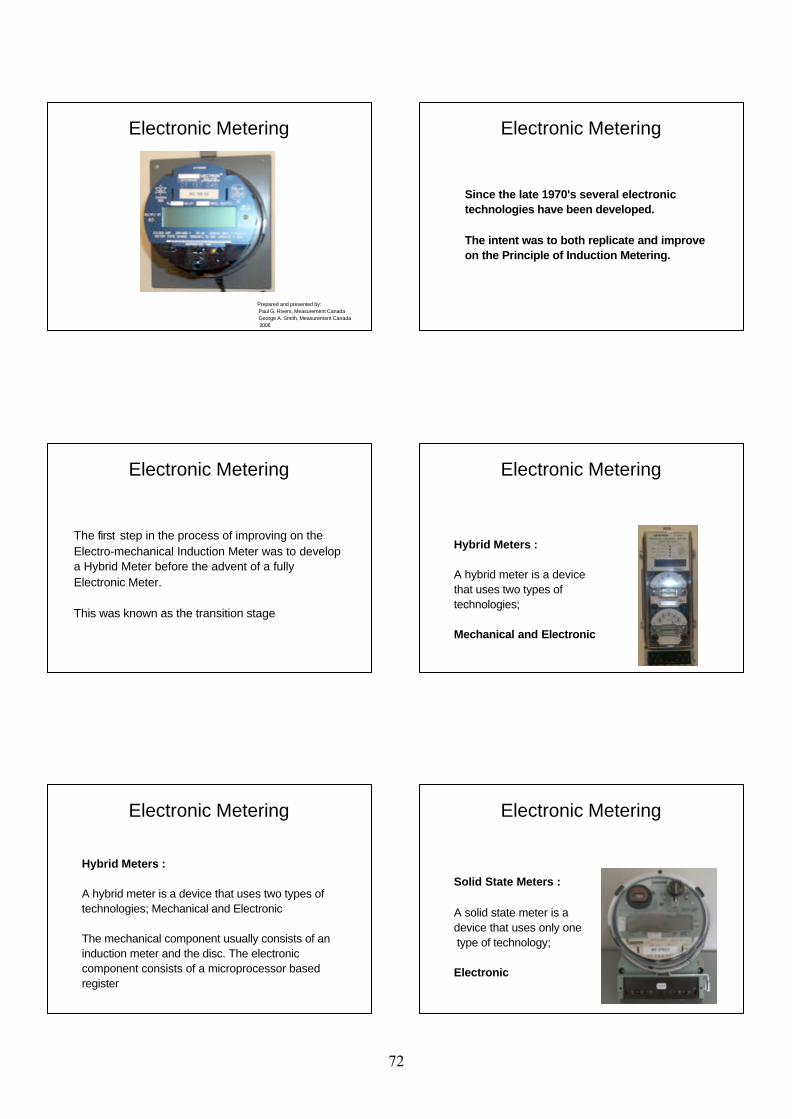
Electronic Metering
Prepared and presented by: Paul G. Rivers, Measurement Canada George A. Smith, Measurement Canada 2006
Since the late 1970's several electronic technologies have been developed.
The intent was to both replicate and improve on the Principle of Induction Metering.
Electronic Metering
The first step in the process of improving on the Electro-mechanical Induction Meter was to develop a Hybrid Meter before the advent of a fullyElectronic Meter.
This was known as the transition stage
Electronic Metering
Hybrid Meters :
A hybrid meter is a device that uses two types oftechnologies;
Mechanical and Electronic
Electronic Metering
Hybrid Meters :
A hybrid meter is a device that uses two types oftechnologies; Mechanical and Electronic
The mechanical component usually consists of an induction meter and the disc. The electroniccomponent consists of a microprocessor basedregister
Electronic Metering
Solid State Meters :
A solid state meter is a device that uses only one type of technology;
Electronic
Electronic Metering
72
Solid State Meters :
A solid state meter is a device that uses only one type of technology; Electronic
The device is completely microprocessor based with no induction meter disc.
Electronic Metering
Measurement Capabilities:
A single electronic meter is capable of measuring a multitude of billing functions such as ;
Watts / Watthours VA / VAhours Amp squared hoursVar / Varhours Volt squared hoursTransformer / line loss compensation
Electronic Metering
Measurement Capabilities:
The demand section of the meter can be programmed to measure ;
- Averaging or Block Interval - Sliding Average or Sliding Block Interval - Exponential (or thermal emulation)
Electronic Metering
Measurement Capabilities:
In addition, the demand intervals or sub-intervals can be programmed to different values such as;
60 minute interval, 15 minute sub-interval
15 minute interval, 5 minute sub-interval
Electronic Metering
Measurement Capabilities:
The VA function can be programmed to measure ;
- Arithmetic VA, or, - Phasor (Vector) VA
Electronic Metering
Features and Functionality :
Electronic meters have many different features and functionalities which can be utilized for;
various billing applicationsload monitoring purposescommunication and programming efficiencies
Electronic Metering
73
Features and Functionality :
Mass Memory RecorderPulse Outputs (KYZ)Load ProfilingTime of Use Interval Data or Time Stamping
Electronic Metering
Additional Features and Functionalities :
- Communication Ports (optical / modems) - Automatic Meter Readers - Pre-payment metering - Loss Compensation - Bi-directional - 4 quadrant metering
Electronic Metering
Electronic Metering
Modes of Operation:
Electronic meters typically have three modes of operation:
- Normal (Main) Mode - Alternate Mode - Test Mode
Normal Mode :
This is the default mode and is the mode in which the meter operates while in service.
Typically this mode is used to display main billing quantities, such as KWH, maximum KW, maximum KVA.
Electronic Metering
Alternate Mode :
Used to display quantities that are not needed on a regular basis, such as power factor, volts, amps, etc.
Typically accessed via a magnetic read switch.
Meter automatically returns to normal mode
Electronic Metering
Test Mode :
Purpose of this mode is to provide a convenient means of testing a meters accuracy. Allows testing of the registers without altering billing data.
In test mode operation the demand interval is reduced to 3 minutes in order to facilitate accelerated testing.
Electronic Metering
74
An electricity meter, whether fully electro-mechanicala hybrid or fully electronic can always be divided into four elemental components.
Electronic Metering
An electricity meter, electromechanical or electronic can be divided into four elemental components;
SENSORS MULTIPLIERS NUMERICAL CONVERSION REGISTERS
Electronic Metering
SENSORS
Provide interface between incoming voltage and current and the metering circuit.
Electronic Metering
MULTIPLIERS
Perform the heart of the metering function by providing the product of the voltage and current.
Electronic Metering
NUMERICAL CONVERSION
Process of transforming the output of the multiplierstage into a form which can be processed by the register
Electronic Metering
REGISTERS
The devices that store and display the metering quantities.
Electronic Metering
75
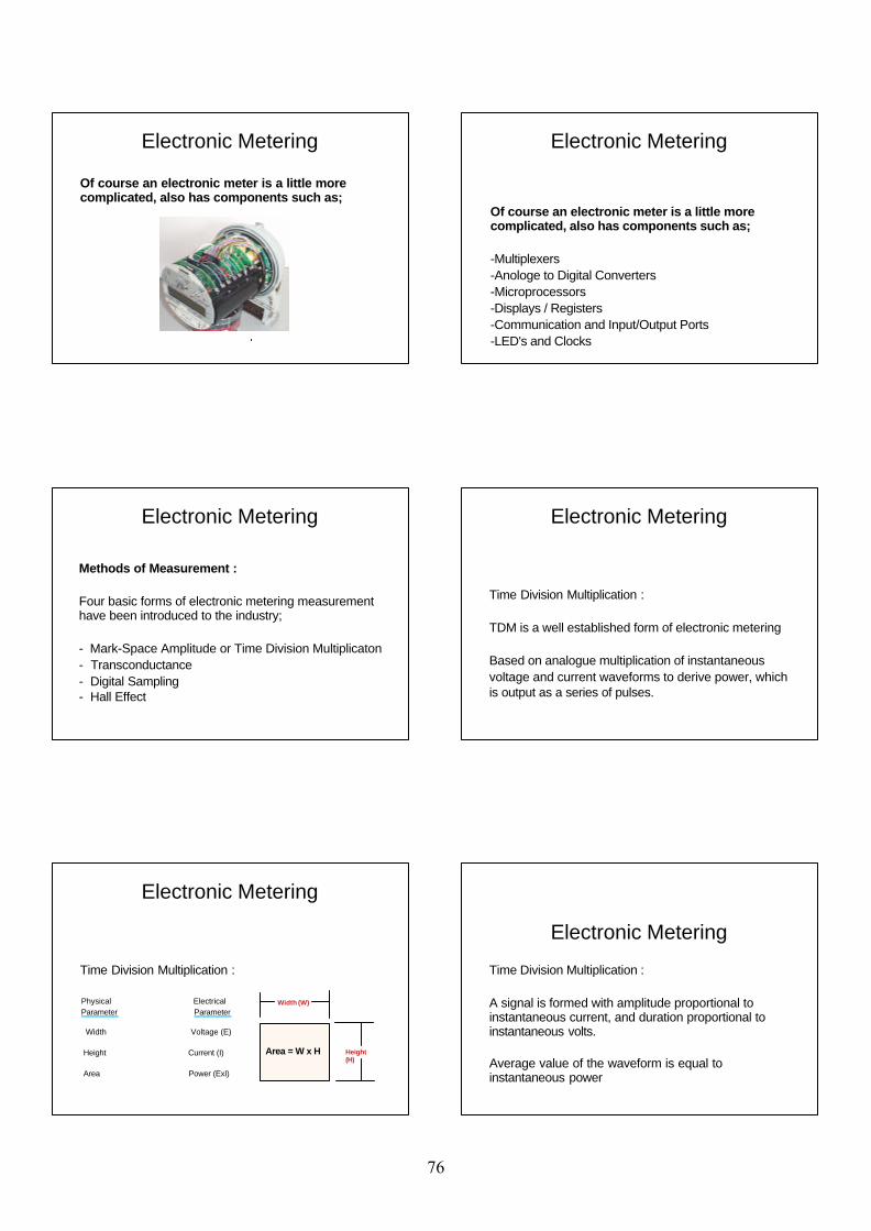
Of course an electronic meter is a little more complicated, also has components such as;
Electronic Metering
Of course an electronic meter is a little more complicated, also has components such as;
-Multiplexers-Anologe to Digital Converters-Microprocessors-Displays / Registers-Communication and Input/Output Ports -LED's and Clocks
Electronic Metering
Methods of Measurement :
Four basic forms of electronic metering measurement have been introduced to the industry;
- Mark-Space Amplitude or Time Division Multiplicaton- Transconductance- Digital Sampling- Hall Effect
Electronic Metering
Time Division Multiplication :
TDM is a well established form of electronic metering
Based on analogue multiplication of instantaneousvoltage and current waveforms to derive power, which is output as a series of pulses.
Electronic Metering
Time Division Multiplication :
Width (W)
Height (H)
Area = W x H
Physical ElectricalParameter Parameter
Width Voltage (E) Height Current (I)
Area Power (ExI)
Electronic Metering
Electronic Metering
Time Division Multiplication :
A signal is formed with amplitude proportional to instantaneous current, and duration proportional to instantaneous volts.
Average value of the waveform is equal to instantaneous power
76
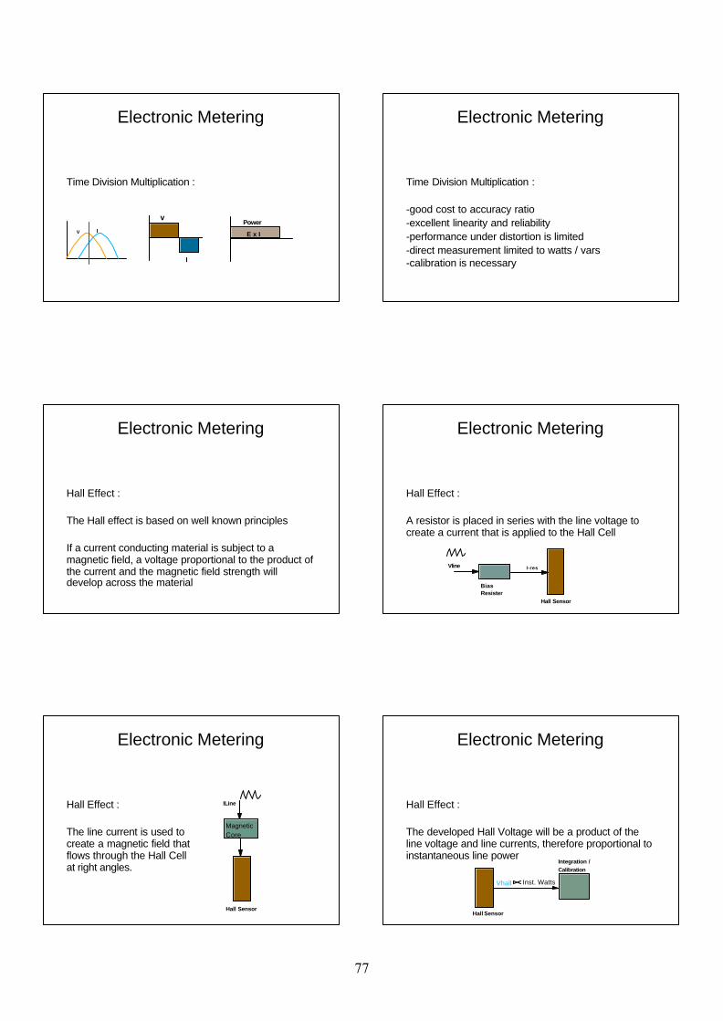
Time Division Multiplication :
V I
v
I
E x I
Power
Electronic Metering
Time Division Multiplication :
-good cost to accuracy ratio-excellent linearity and reliability-performance under distortion is limited-direct measurement limited to watts / vars-calibration is necessary
Electronic Metering
Hall Effect :
The Hall effect is based on well known principles
If a current conducting material is subject to a magnetic field, a voltage proportional to the product of the current and the magnetic field strength will develop across the material
Electronic Metering
Hall Effect :
A resistor is placed in series with the line voltage to create a current that is applied to the Hall Cell
Vline
BiasResister
Hall Sensor
I-res
Electronic Metering
Hall Effect :
The line current is used to create a magnetic field that flows through the Hall Cell at right angles.
ILine
MagneticCore
Hall Sensor
Electronic Metering
Hall Effect :
The developed Hall Voltage will be a product of the line voltage and line currents, therefore proportional to instantaneous line power
Hall Sensor
Integration /Calibration
Vhall Inst. Watts
Electronic Metering
77

Hall Effects :
Vline
ILine
BiasResister
Hall Sensor
MagneticCore
Integration /Calibration
Register Module
LED
Electronic Metering
Hall Effect :
-very cost effective technology-can measure watts / vars, but not va-linearity less than TDM technology-excellent response for harmonic content-susceptable to large temperature changes
Electronic Metering
Transconductance :
Transconductance is another form of metering that incorporates both TDM and Hall Effect technology by;
- conducting analogue multiplication of the line voltage and current to produce a voltage signal proportional to line power via the use of transistors.
Electronic Metering
Transconductance :
The secondary current from the meters transformers is converted to a voltage and applied across the bases of the two transistors.
The line voltage is applied between the collectors and the emitters of the transistors.
Electronic Metering
Transconductance :
A potential difference between the two collector legs is created.
This voltage is the product of the line voltage and line currents and therefore proportional to the line power.
Electronic Metering
Transconductance :
-excellent cost to accuracy ratio-requires four quadrant amplifier for superior performance under varying power factors and harmonic distortion.
Electronic Metering
78
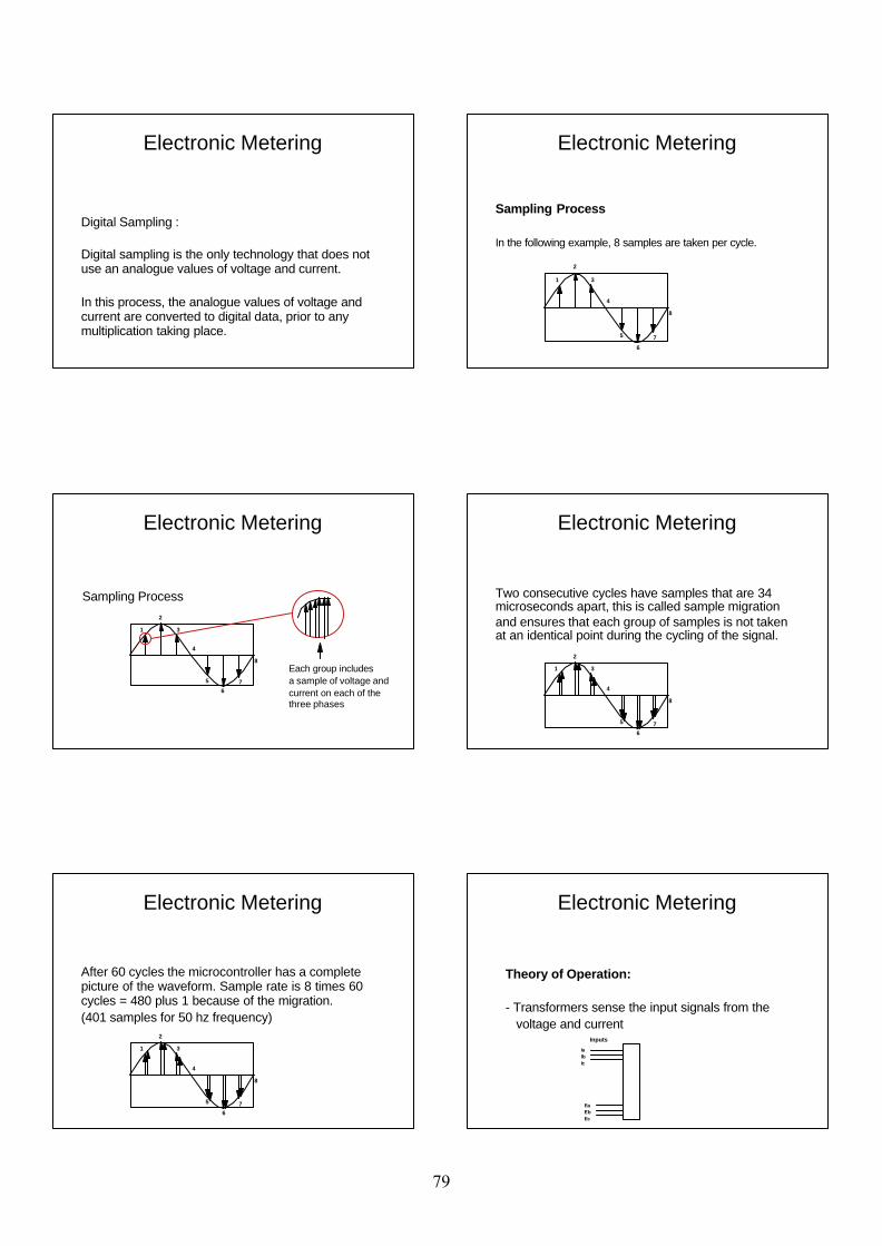
Digital Sampling :
Digital sampling is the only technology that does not use an analogue values of voltage and current.
In this process, the analogue values of voltage and current are converted to digital data, prior to any multiplication taking place.
Electronic Metering
Sampling Process
In the following example, 8 samples are taken per cycle.
1
2
3
4
5
6
7
8
Electronic Metering
Sampling Process
1
2
3
4
5
67
8Each group includesa sample of voltage andcurrent on each of the three phases
Electronic Metering
Two consecutive cycles have samples that are 34 microseconds apart, this is called sample migration and ensures that each group of samples is not taken at an identical point during the cycling of the signal.
1
2
3
4
5
67
8
Electronic Metering
After 60 cycles the microcontroller has a complete picture of the waveform. Sample rate is 8 times 60 cycles = 480 plus 1 because of the migration. (401 samples for 50 hz frequency)
1
2
3
4
5
67
8
Electronic Metering
Theory of Operation:
- Transformers sense the input signals from the voltage and current
Inputs
IaIbIc
EaEbEc
Electronic Metering
79
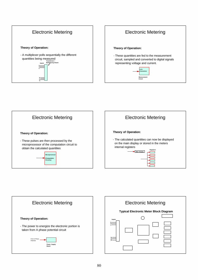
Theory of Operation:
- A multiplexer polls sequentially the different quantities being measured
Inputs
I aI bIc
EaEbEc
Transformer /Multiplexing Board
Electronic Metering
Theory of Operation:
- These quantities are fed to the measurement circuit, sampled and converted to digital signals representing voltage and current.
MeasurementCircuit
A / DConverters
Electronic Metering
Theory of Operation:
- These pulses are then processed by the microprocessor of the computation circuit to obtain the calculated quantities
Microprocessor
(ComputationCircuitry)
Electronic Metering
Theory of Operation:
- The calculated quantities can now be displayed on the main display or stored in the meters internal registers
Main DisplayRegisters
Electronic Metering
Theory of Operation:
- The power to energize the electronic portion is taken from A phase potential circuit
Power Supply Board
From A PhasePotential
Electronic Metering
Typical Electronic Meter Block Diagram
Inputs
I aI bIc
EaEbEc
Electronic Metering
80
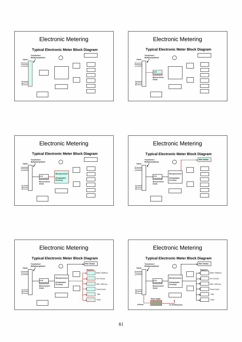
Typical Electronic Meter Block Diagram
Inputs
I aI bIc
EaEbEc
Transformer /Multiplexing Board
Electronic Metering
Typical Electronic Meter Block Diagram
Inputs
I aI bIc
EaEbEc
Transformer /Multiplexing Board
MeasurementCircuit
A / DConverters
Electronic Metering
Typical Electronic Meter Block Diagram
Inputs
I aI bIc
EaEbEc
Transformer /Multiplexing Board
MeasurementCircuit
A / DConverters
Microprocessor
(ComputationCircuitry)
Electronic Metering
Typical Electronic Meter Block Diagram
Inputs
I aI bIc
EaEbEc
Transformer /Multiplexing Board
MeasurementCircuit
A / DConverters
Microprocessor
(ComputationCircuitry)
Main Display
Electronic Metering
Typical Electronic Meter Block Diagram
Inputs
I aI bIc
EaEbEc
Transformer /Multiplexing Board
MeasurementCircuit
A / DConverters
Microprocessor
(ComputationCircuitry)
Main Display
Registers
Watts / Watthour
VA / VA hour
VAR / VAR hour
Power Factor
Volts
Amps
Electronic Metering
Typical Electronic Meter Block Diagram
Inputs
I aI bIc
EaEbEc
Transformer /Multiplexing Board
MeasurementCircuit
A / DConverters
Microprocessor
(ComputationCircuitry)
Main Display
Registers
Watts / Watthour
VA / VA hour
VAR / VAR hour
Power Factor
Volts
AmpsPower Supply
To All ElectronicsA Phase
Electronic Metering
81
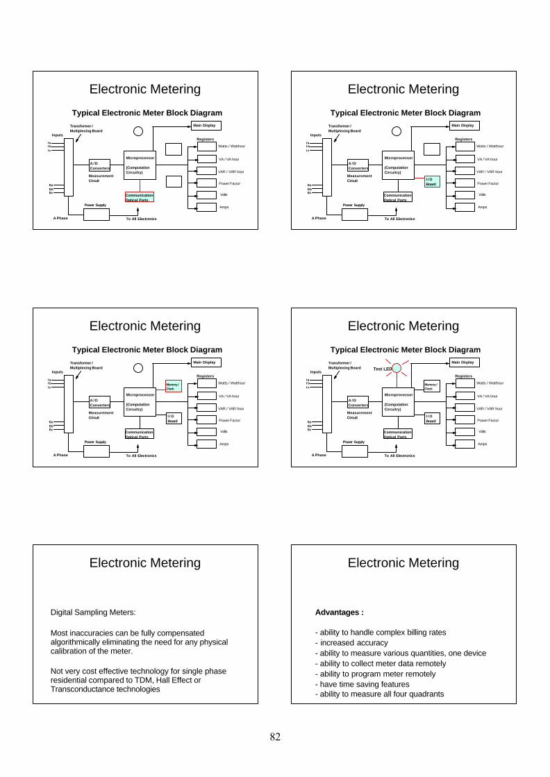
Typical Electronic Meter Block Diagram
Inputs
I aI bIc
EaEbEc
Transformer /Multiplexing Board
MeasurementCircuit
A / DConverters
Microprocessor
(ComputationCircuitry)
Main Display
Registers
Watts / Watthour
VA / VA hour
VAR / VAR hour
Power Factor
Volts
AmpsPower Supply
To All ElectronicsA Phase
CommunicationOptical Ports
Electronic Metering
Typical Electronic Meter Block Diagram
Inputs
I aI bIc
EaEbEc
Transformer /Multiplexing Board
MeasurementCircuit
A / DConverters
Microprocessor
(ComputationCircuitry)
Main Display
Registers
Watts / Watthour
VA / VA hour
VAR / VAR hour
Power Factor
Volts
AmpsPower Supply
To All ElectronicsA Phase
CommunicationOptical Ports
I / O Board
Memory / Clock
Test LED
Electronic Metering
Digital Sampling Meters:
Most inaccuracies can be fully compensated algorithmically eliminating the need for any physical calibration of the meter.
Not very cost effective technology for single phase residential compared to TDM, Hall Effect or Transconductance technologies
Electronic Metering
Advantages :
- ability to handle complex billing rates- increased accuracy- ability to measure various quantities, one device- ability to collect meter data remotely- ability to program meter remotely- have time saving features- ability to measure all four quadrants
Electronic Metering
82
Disadvantages :
- more sophisticated testing apparatus required- more accurate reference standards are required- more advanced training is required
Electronic Metering
Questions?
Comments?
Electronic Metering
83
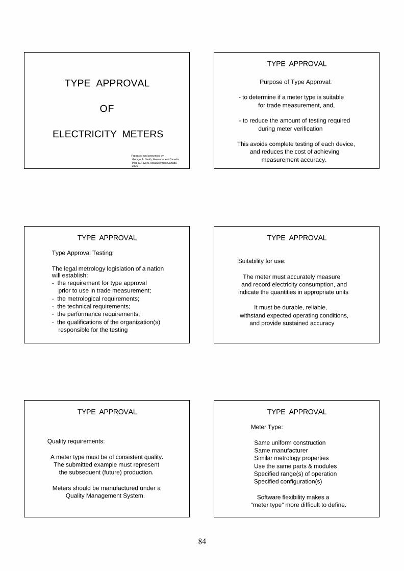
TYPE APPROVAL
OF
ELECTRICITY METERS
Prepared and presented by: George A. Smith, Measurement Canada Paul G. Rivers, Measurement Canada 2006
TYPE APPROVAL
Purpose of Type Approval: - to determine if a meter type is suitable for trade measurement, and,
- to reduce the amount of testing required during meter verification
This avoids complete testing of each device, and reduces the cost of achieving measurement accuracy.
TYPE APPROVAL
Type Approval Testing:
The legal metrology legislation of a nation will establish:- the requirement for type approval prior to use in trade measurement;- the metrological requirements;- the technical requirements;- the performance requirements;- the qualifications of the organization(s) responsible for the testing
TYPE APPROVAL
Suitability for use: The meter must accurately measure and record electricity consumption, and indicate the quantities in appropriate units
It must be durable, reliable, withstand expected operating conditions, and provide sustained accuracy
TYPE APPROVAL
Quality requirements:
A meter type must be of consistent quality. The submitted example must represent the subsequent (future) production.
Meters should be manufactured under a Quality Management System.
TYPE APPROVAL
Meter Type:
Same uniform construction Same manufacturer Similar metrology properties Use the same parts & modules Specified range(s) of operation Specified configuration(s)
Software flexibility makes a “meter type” more difficult to define.
84

TYPE APPROVAL
Documentation:
The documentation submitted must provide evidence that the meter type complies with the specified requirements
TYPE APPROVAL
Accuracy requirements:
Electricity meters are presently tested using National, Regional, or IEC Standards (International Electrotechnical Commission)
TYPE APPROVAL
International Standards and Recommendations:
An international standard which is accepted in most parts of the world, should reduce testing costs for manufacturers, nations and consumers.
TYPE APPROVAL
International Standards:
OIML Recommendation IR-46 for Electrical Energy Metershas been withdrawn and is being revised to address changing technology
(Technical Committee TC12)
TYPE APPROVAL
Rated operating conditions:
The meter operating conditions should be clearly defined - Configuration - Voltage range - Current range - Frequency range - Phase angle range (e.g.from 0.5 inductive to 1 to 0.8 capacitive)
TYPE APPROVAL
Accuracy in relation to current range:
Meter accuracy can vary considerably over the range from zero current to maximum current.
Terminolgy defines the different current values used in type approval testing
85
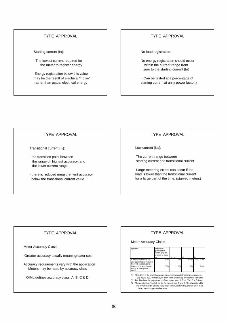
TYPE APPROVAL
Starting current (Ist):
The lowest current required for the meter to register energy
Energy registration below this value may be the result of electrical "noise" rather than actual electrical energy
TYPE APPROVAL
No-load registration:
No energy registration should occur within the current range from zero to the starting current (Ist)
(Can be tested at a percentage of starting current at unity power factor.)
TYPE APPROVAL
Transitional current (Itr):
- the transition point between the range of highest accuracy, and the lower current range.
- there is reduced measurement accuracy below the transitional current value
TYPE APPROVAL
Low current (Ilow):
The current range between starting current and transitional current
Large metering errors can occur if the load is lower than the transitional current for a large part of the time. (starved meters)
TYPE APPROVAL
Meter Accuracy Class:
Greater accuracy usually means greater cost
Accuracy requirements vary with the application Meters may be rated by accuracy class
OIML defines accuracy class A, B, C & D
TYPE APPROVAL
Quantity Maximum permissible errors (%) for meters of classA B (1) C D
Current I from Itr to Imax and power factor variation from 0.8 cap to 0.5 ind,
2.0% 1.0% 0.5% (2) 0.2%
Current I between Itr and Ilow(3), at unity power factor
2.5% 1.5% 1.0% 0.4%
Meter Accuracy Class:
(1) This class is the lowest accuracy class recommended for large consumers, e.g. above 5000 kWh/year, or other value chosen by the National Authority.(2) For this class the requirement is from power factor 0.5 ind. To 1.0 to 0.5 cap.(3) The relation Ilow / Itr shall be 0.4 for class A and B and 0.2 for class C and D. The meter shall be able to carry Imax continuously without larger error than base maximum permissible error.
86
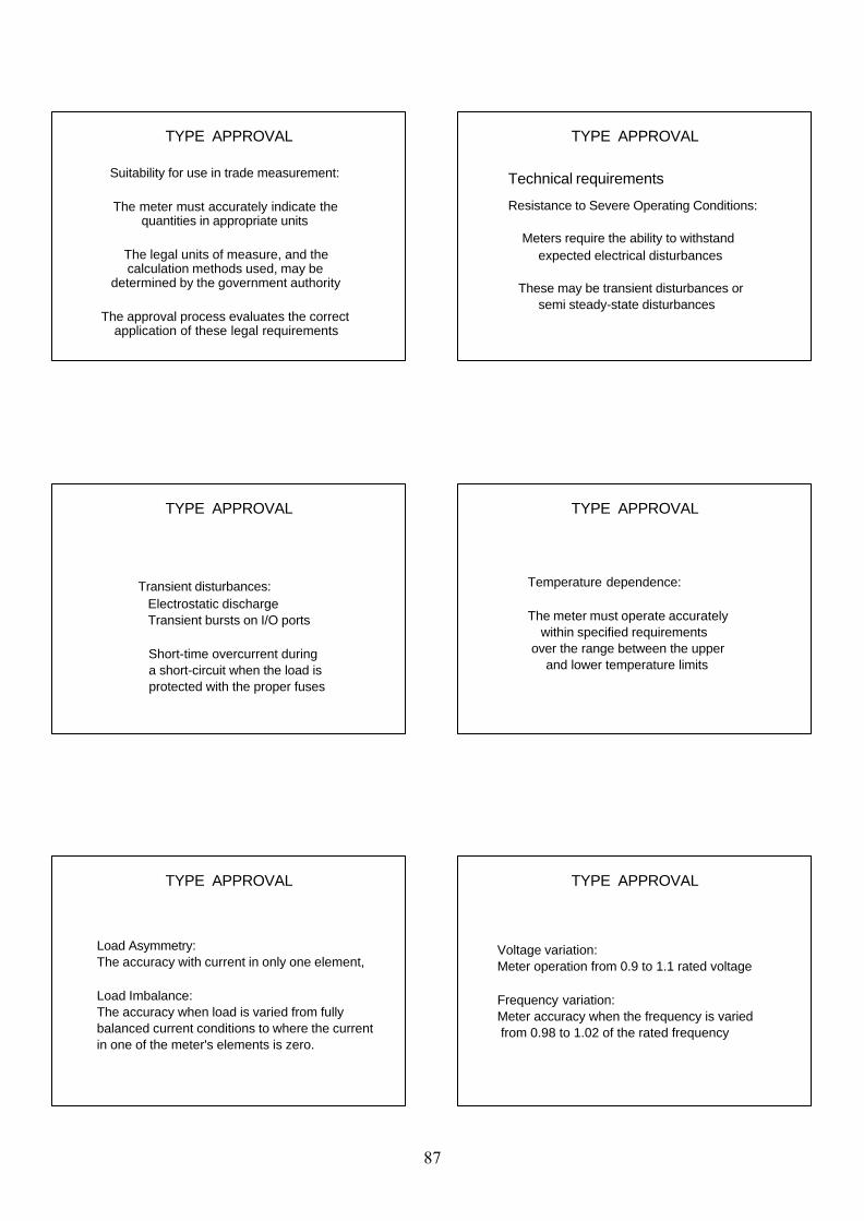
TYPE APPROVAL
Suitability for use in trade measurement:
The meter must accurately indicate the quantities in appropriate units
The legal units of measure, and the calculation methods used, may be
determined by the government authority
The approval process evaluates the correct application of these legal requirements
TYPE APPROVAL
Resistance to Severe Operating Conditions:
Meters require the ability to withstand expected electrical disturbances
These may be transient disturbances or semi steady-state disturbances
Technical requirements
TYPE APPROVAL
Transient disturbances: Electrostatic discharge Transient bursts on I/O ports
Short-time overcurrent during a short-circuit when the load is protected with the proper fuses
TYPE APPROVAL
Temperature dependence:
The meter must operate accurately within specified requirements over the range between the upper and lower temperature limits
TYPE APPROVAL
Load Asymmetry:The accuracy with current in only one element,
Load Imbalance:The accuracy when load is varied from fully balanced current conditions to where the currentin one of the meter's elements is zero.
TYPE APPROVAL
Voltage variation:Meter operation from 0.9 to 1.1 rated voltage
Frequency variation:Meter accuracy when the frequency is varied from 0.98 to 1.02 of the rated frequency
87
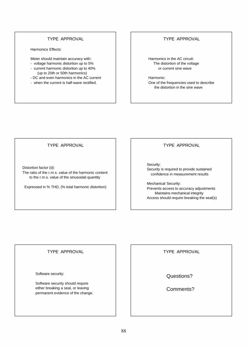
TYPE APPROVAL
Harmonics Effects:
Meter should maintain accuracy with: - voltage harmonic distortion up to 5% - current harmonic distortion up to 40% (up to 20th or 50th harmonics) - DC and even harmonics in the AC current - when the current is half-wave rectified.
TYPE APPROVAL
Harmonics in the AC circuit: The distortion of the voltage or current sine wave
Harmonic:One of the frequencies used to describe the distortion in the sine wave
TYPE APPROVAL
Distortion factor (d):The ratio of the r.m.s. value of the harmonic content to the r.m.s. value of the sinusoidal quantity
Expressed in % THD, (% total harmonic distortion)
TYPE APPROVAL
Security:Security is required to provide sustained confidence in measurement results
Mechanical Security:Prevents access to accuracy adjustments Maintains mechanical integrity Access should require breaking the seal(s)
TYPE APPROVAL
Software security: Software security should require either breaking a seal, or leaving permanent evidence of the change.
TYPE APPROVAL
Questions?
Comments?
88
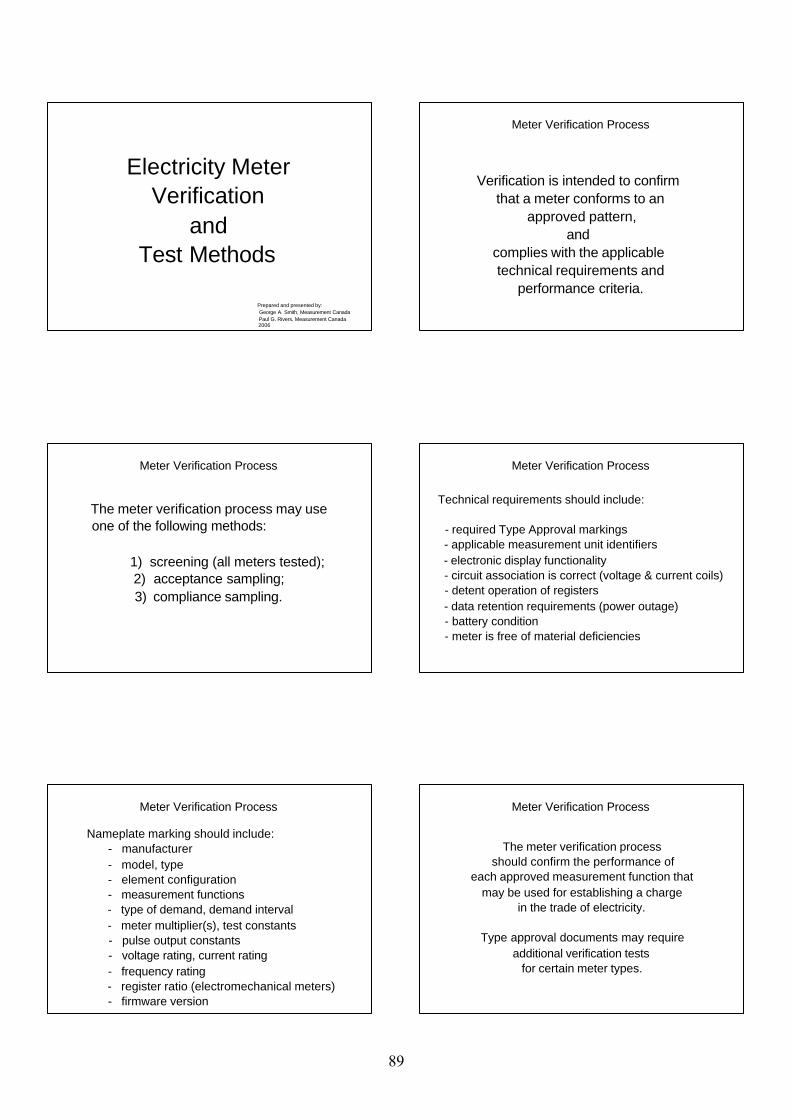
Electricity MeterVerification
andTest Methods
Prepared and presented by: George A. Smith, Measurement Canada Paul G. Rivers, Measurement Canada 2006
Meter Verification Process
Verification is intended to confirm that a meter conforms to an
approved pattern,and
complies with the applicable technical requirements and
performance criteria.
Meter Verification Process
The meter verification process may useone of the following methods:
1) screening (all meters tested); 2) acceptance sampling;3) compliance sampling.
Meter Verification Process
Technical requirements should include:
- required Type Approval markings - applicable measurement unit identifiers - electronic display functionality - circuit association is correct (voltage & current coils) - detent operation of registers - data retention requirements (power outage) - battery condition - meter is free of material deficiencies
Meter Verification Process
Nameplate marking should include: - manufacturer - model, type - element configuration - measurement functions - type of demand, demand interval - meter multiplier(s), test constants - pulse output constants - voltage rating, current rating - frequency rating - register ratio (electromechanical meters) - firmware version
Meter Verification Process
The meter verification processshould confirm the performance of
each approved measurement function thatmay be used for establishing a charge
in the trade of electricity.
Type approval documents may requireadditional verification tests
for certain meter types.
89
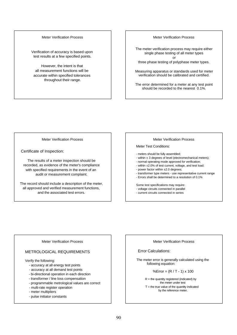
Meter Verification Process
Verification of accuracy is based upon test results at a few specified points.
However, the intent is that all measurement functions will be
accurate within specified tolerances throughout their range.
Meter Verification Process
The meter verification process may require either single phase testing of all meter types
orthree phase testing of polyphase meter types.
Measuring apparatus or standards used for meter verification should be calibrated and certified.
The error determined for a meter at any test point should be recorded to the nearest 0.1%.
Meter Verification Process
Certificate of Inspection:
The results of a meter inspection should berecorded, as evidence of the meter's compliance
with specified requirements in the event of anaudit or measurement complaint.
The record should include a description of the meter,all approved and verified measurement functions,
and the associated test errors.
Meter Verification Process
Meter Test Conditions:
- meters should be fully assembled;- within ± 3 degrees of level (electromechanical meters); - normal operating mode approved for verification;- within ±2.0% of test current, voltage, and test load;- power factor within ±2.0 degrees;- transformer type meters - use representative current range - Errors shall be determined to a resolution of 0.1%
Some test specifications may require:- voltage circuits connected in parallel- current circuits connected in series
Meter Verification Process
METROLOGICAL REQUIREMENTS
Verify the following: - accuracy at all energy test points - accuracy at all demand test points - bi-directional operation in each direction - transformer / line loss compensation - programmable metrological values are correct - multi-rate register operation - meter multipliers - pulse initiator constants
Meter Verification Process
Error Calculations:
The meter error is generally calculated using the following equation:
%Error = (R / T - 1) x 100
R = the quantity registered (indicated) by the meter under test
T = the true value of the quantity indicated by the reference meter.
90

Meter Verification Process
Voltage Squared Hour Meters:
Voltage squared hour function shall be evaluated at 95% and 105% of the nominal nameplate voltage.
Ampere Squared Hour Meters:
Ampere squared hour function shall be evaluated at 2.5%Imax and 25%Imax.
Meter Verification Process
Prepayment meters:
- Verify the programmed parameters.
- Perform tests which confirm correct operation of the programmed parameters.
Meter Verification Process
Zero load test - An electromechanical meter should not complete one revolution of its disc. - An electronic meter should not register energy at a current less than the starting current.
Comparative registration (dial) test - Electromechanical meters - zero error relative to the disc, tested to a resolution of 3.0%. - Electronic meters - ±1.0%
Meter Verification Process
Electromechanical meters have a long history of being relatively consistent in
construction and operating characteristics.
The test points required for the verification of this meter type are quite
well established, as are indicated in the following test tables.
Meter Verification Process
Test Configuration Current Power Factor Tolerance
Series Test 25% Imax 1.0 ±1.0%
Series Test 25% Imax 0.5 ±1.0%
Series Test 2.5% Imax 1.0 ±1.0%
Energy Tests: Single Phase, 1 Element and 1½ Element Meters
Meter Verification Process
Test Configuration Current Power Factor
Power Factor
Power Factor Tolerance
W•h, VA•h var•h (1) Q•h (1)
Series Test 25% Imax 1.0 0.5 0.5 ±1.0%
Series Test 2.5% Imax 1.0 0.5 0.5 ±1.0%
Each Element 25% Imax 1.0 0.5 0.5 ±1.0%
Each Element 25% Imax 0.5 0.866 1.0 ±1.0%
Energy Tests: Polyphase 2 Element and 3 Element meters
Var hour and Q hour meters that operate on the crossed phase principle shall be tested as watt hour meters.
91

Meter Verification Process
Energy Tests: Polyphase 2½ Element Wye Meters
Test Configuration Current Power
FactorPower Factor
Power Factor Tolerance
W•h, VA•h var•h Q•h
Series Test 25% Imax 1.0 0.5 0.5 ±1.0%
Series Test 2.5% Imax 1.0 0.5 0.5 ±1.0%
Each element 50% Imax 1.0 0.5 0.5 ±1.0%
Each element 50% Imax 0.5 0.866 1.0 ±1.0%
Split coil element 50% Imax 1.0 0.5 0.5 ±1.0%
Var hour and Q hour meters that operate on the crossed phase principle shall be tested as watt hour meters.
The split coil element test is not required on reverification.
Meter Verification Process
Energy Tests: Polyphase 2½ Element Delta meters
The tests for each element of 2½ element 4-wire Delta meters shall be applied to:(a) the 2-wire element; (b) the 3-wire element in series.
The series test for 3 element 4-wire Delta meters shall be conducted at the rated voltage of the lower rated potential coil.
The individual element tests shall be conducted at the rated voltage of the respective potential coil.
Test Configuration Current Power
Factor Power Factor
Power Factor Tolerance
W•h, VA•h var•h Q•hSeries Test 25% Imax 1.0 0.5 0.5 ±1.0%Series Test 2.5% Imax 1.0 0.5 0.5 ±1.0%
Each Element 25% Imax 1.0 0.5 0.5 ±1.0%Each Element 25% Imax 0.5 0.866 1.0 ±1.0%Each Element 2.5% Imax 1.0 0.5 0.5 ±1.0%
Meter Verification Process
Demand meter verification requirements:
- demand Type (block/rolling block or exponential)- demand Interval (15 minute, 5 minute update etc)- three full demand response periods- demand reset operation - normal mode demand interval
Meter Verification Process
Electromechanical Demand Meters:
- zero load must register within 1/32 inch of true zero- take readings only after the driving pointer has disengaged- block interval must be within ±1.0% of the set interval.
Grease dampened demand pointers:- tested for hysteresis (grease memory) - tested for pull-back after the test load is removed
Meter Verification Process
Demand Tests: Electromechanical 1 and 1½ Element Thermal Demand Meters
Test Configuration Test Point Power Factor Tolerance
Series 66.6% F.S. 1.0 ±1.5% F.S.
VA only: Series 66.6% F.S. 0.5 ±1.5% F.S.
Any one element 20% F.S. 1.0 ±1.5% F.S.
Meter Verification Process
Demand Tests: Electromechanical 2, 2½ and 3 Element Thermal Demand Meters
Test Configuration Test Point Power Factor Tolerance
Series test 66.6% F.S. 1.0 ±1.5% F.S.
VA only: Series test 66.6% F.S. 0.5
2 el: Any one element 20 % F.S. 1.0 ±1.5% F.S.
3 el: Any two elements 20 % F.S. 1.0 ±1.5% F.S.
2½ el: Each single element (delta meters) 20 % F.S. 1.0 ±1.5% F.S.
2½ el: Each single element (wye meters) 16.6 % F.S. 1.0 ±1.5% F.S.
92
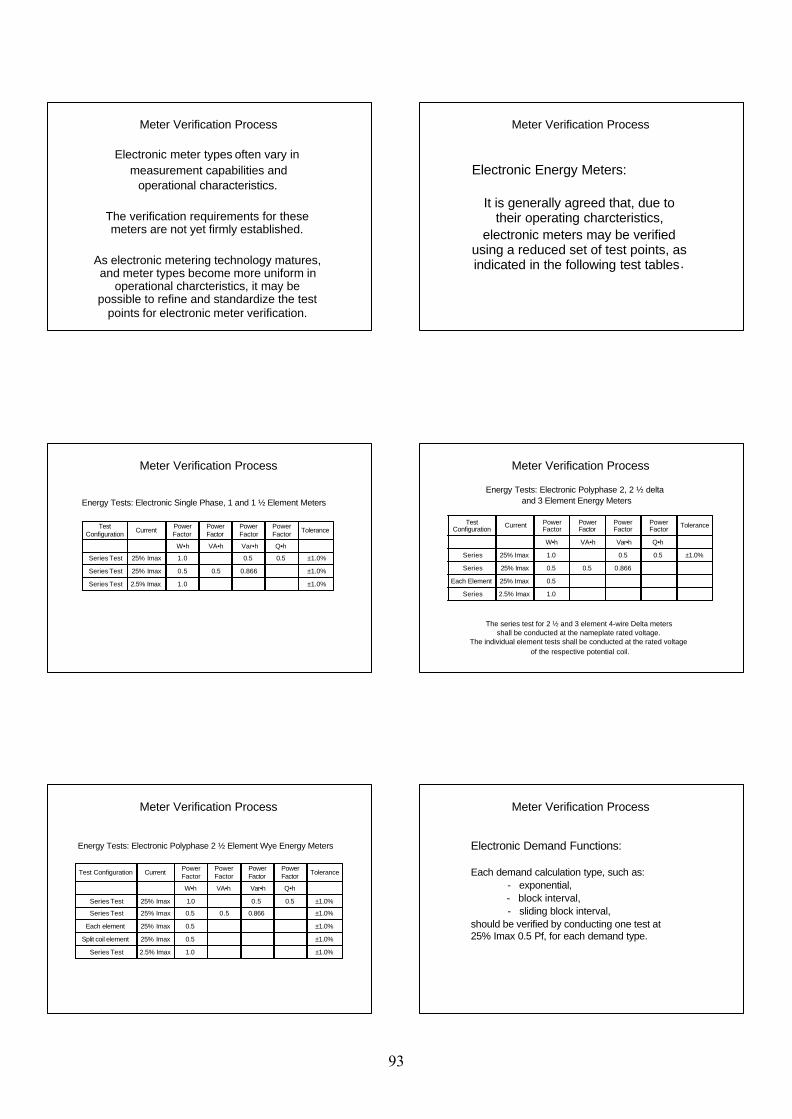
Meter Verification Process
Electronic meter types often vary in measurement capabilities and
operational characteristics.
The verification requirements for these meters are not yet firmly established.
As electronic metering technology matures, and meter types become more uniform in
operational charcteristics, it may be possible to refine and standardize the test
points for electronic meter verification.
Meter Verification Process
Electronic Energy Meters:
It is generally agreed that, due to their operating charcteristics,
electronic meters may be verified using a reduced set of test points, as indicated in the following test tables.
Meter Verification Process
Energy Tests: Electronic Single Phase, 1 and 1 ½ Element Meters
Test Configuration Current Power
FactorPower Factor
Power Factor
Power Factor Tolerance
W•h VA•h Var•h Q•h
Series Test 25% Imax 1.0 0.5 0.5 ±1.0%
Series Test 25% Imax 0.5 0.5 0.866 ±1.0%
Series Test 2.5% Imax 1.0 ±1.0%
Meter Verification Process
Energy Tests: Electronic Polyphase 2, 2 ½ delta and 3 Element Energy Meters
Test Configuration Current Power
FactorPower Factor
Power Factor
Power Factor Tolerance
W•h VA•h Var•h Q•h
Series 25% Imax 1.0 0.5 0.5 ±1.0%
Series 25% Imax 0.5 0.5 0.866
Each Element 25% Imax 0.5
Series 2.5% Imax 1.0
The series test for 2 ½ and 3 element 4-wire Delta meters shall be conducted at the nameplate rated voltage.
The individual element tests shall be conducted at the rated voltage of the respective potential coil.
Meter Verification Process
Test Configuration Current Power Factor
Power Factor
Power Factor
Power Factor Tolerance
W•h VA•h Var•h Q•h
Series Test 25% Imax 1.0 0.5 0.5 ±1.0%
Series Test 25% Imax 0.5 0.5 0.866 ±1.0%
Each element 25% Imax 0.5 ±1.0%
Split coil element 25% Imax 0.5 ±1.0%
Series Test 2.5% Imax 1.0 ±1.0%
Energy Tests: Electronic Polyphase 2 ½ Element Wye Energy Meters
Meter Verification Process
Electronic Demand Functions:
Each demand calculation type, such as: - exponential, - block interval, - sliding block interval,should be verified by conducting one test at 25% Imax 0.5 Pf, for each demand type.
93
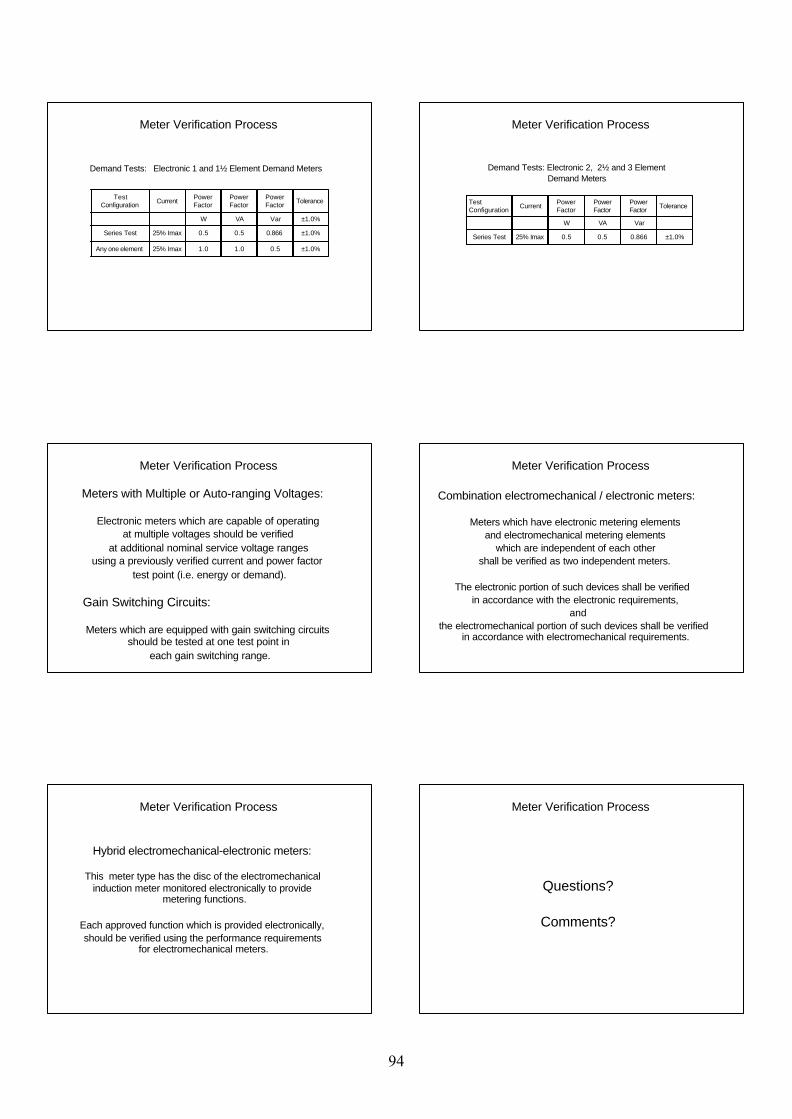
Meter Verification Process
Demand Tests: Electronic 1 and 1½ Element Demand Meters
TestConfiguration Current Power
Factor Power Factor
Power Factor Tolerance
W VA Var ±1.0%
Series Test 25% Imax 0.5 0.5 0.866 ±1.0%
Any one element 25% Imax 1.0 1.0 0.5 ±1.0%
Meter Verification Process
Demand Tests: Electronic 2, 2½ and 3 ElementDemand Meters
Test Configuration Current Power
FactorPower Factor
Power Factor Tolerance
W VA Var
Series Test 25% Imax 0.5 0.5 0.866 ±1.0%
Meter Verification Process
Meters with Multiple or Auto-ranging Voltages:
Electronic meters which are capable of operating at multiple voltages should be verified
at additional nominal service voltage ranges using a previously verified current and power factor
test point (i.e. energy or demand).
Gain Switching Circuits:
Meters which are equipped with gain switching circuits should be tested at one test point in
each gain switching range.
Meter Verification Process
Combination electromechanical / electronic meters:
Meters which have electronic metering elementsand electromechanical metering elements
which are independent of each othershall be verified as two independent meters.
The electronic portion of such devices shall be verified in accordance with the electronic requirements,
andthe electromechanical portion of such devices shall be verified
in accordance with electromechanical requirements.
Meter Verification Process
Hybrid electromechanical-electronic meters:
This meter type has the disc of the electromechanical induction meter monitored electronically to provide
metering functions.
Each approved function which is provided electronically,should be verified using the performance requirements
for electromechanical meters.
Meter Verification Process
Questions?
Comments?
94
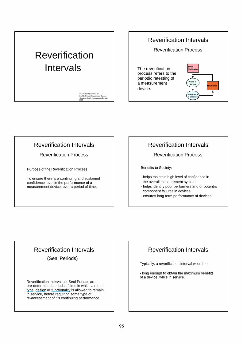
ReverificationIntervals
Prepared and presented by: Paul G. Rivers, Measurement Canada George A. Smith, Measurement Canada 2006
The reverification process refers to the periodic retesting of a measurement device.
Initial Verification
Placed in Service
Removed or re-assessed
ReVerified
Reverification Intervals
Reverification Process
Purpose of the Reverification Process;
To ensure there is a continuing and sustained confidence level in the performance of a measurement device, over a period of time.
Reverification Intervals
Reverification Process Reverification Process
Benefits to Society;
- helps maintain high level of confidence in the overall measurement system.- helps identify poor performers and or potential component failures in devices. - ensures long term performance of devices
Reverification Intervals
Reverification Intervals or Seal Periods are pre-determined periods of time in which a meter type, design or functionality is allowed to remain in service, before requiring some type of re-accessment of it's continuing performance.
Reverification Intervals (Seal Periods)
Typically, a reverification interval would be;
- long enough to obtain the maximum benefits of a device, while in service.
Reverification Intervals
95
Typically, a reverification interval would be;
- long enough to obtain the maximum benefits of a device, while in service.
- short enough to ensure any re-accessment of a devices performance is completed prior to any component or system failures. (life expectancy)
Reverification Intervals
Establishing Intervals or Seal Periods ;
- Reviewing Historical Data,
Reverification Intervals
Establishing Intervals or Seal Periods ;
- Reviewing Historical Data,- Reviewing Past Practices,
Reverification Intervals
Establishing Intervals or Seal Periods ;
- Reviewing Historical Data,- Reviewing Past Practices, - Reliability analysis,
Reverification Intervals
Establishing Intervals or Seal Periods ;
- Reviewing Historical Data,- Reviewing Past Practices, - Reliability analysis, - Approval of Type evaluation.
Reverification Intervals
Considerations :
- manufactures performance data
Reverification Intervals
96
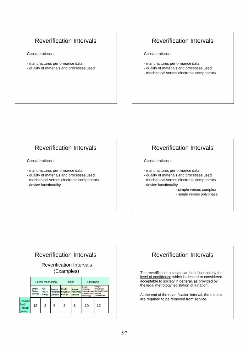
Considerations :
- manufactures performance data- quality of materials and processes used
Reverification Intervals
Considerations :
- manufactures performance data- quality of materials and processes used- mechanical verses electronic components
Reverification Intervals
Considerations :
- manufactures performance data- quality of materials and processes used- mechanical verses electronic components - device functionality
Reverification Intervals
Considerations :
- manufactures performance data- quality of materials and processes used- mechanical verses electronic components - device functionality - simple verses complex - single verses polyphase
Reverification Intervals
Reverification Intervals (Examples)
Electro-mechanical Hybrid Electronic
PossibleSealPeriods(years)
Single PhaseEnergy
PolyPhaseEnergy
Single /PolyphaseDemand
Single /PolyphaseEnergy
Single/PolyphaseDemand
Single/PolyphaseEnergy/DemandTDM/Hall EffectTechnology
Single/PolyphaseEnergy/DemandDigitalTechnology
12 8 6 8 6 10 12
Reverification Intervals
The reverification interval can be influenced by the level of confidence which is desired or considered acceptable to society in general, as provided by the legal metrology legislation of a nation.
At the end of the reverification interval, the meters are required to be removed from service.
Reverification Intervals
97
The meters require reverification prior to return to service. The reverification process may include:
1) Screening (inspection of all meters), or
2) Sample inspection
Reverification Intervals
Methods of Reverification
Reverification Intervals
Methods of Reverification
Sampling:
Depending on the level of confidence desired, sampling is a cost effective alternative to 100 % inspection.
A sample of the reserviced meters is taken, and the overall performance is accessed, using a sampling plan such as ISO 2859.
Reverification Intervals
The reverification interval is influenced by the expected reliability of the device.
The reliability of a meter is reduced after being in servce.
The reverification interval for a reverified meter may be reduced as a result of the
reduction in expected reliability.
Questions?
Comments?
Reverification Intervals
98
In-Service Compliance Programs
Prepared and presented by: George A. Smith, Measurement Canada Paul G. Rivers, Measurement Canada 2006
In-Service Compliance Programs
The use of meter reverification intervals is intended to ensure that the meters removed from service before reliability deteriorates, or accuracy drifts beyond specified
accuracy requirements.
In-Service Compliance Programs
While this prevents meters of inferior accuracy from remaining
in service, it also requires the removal of meter types with superior accuracy retention.
In-Service Compliance Programs
The purpose of the in-service compliance program is to establish
the appropriate reverification interval, based upon the performance of a group of homogeneous meters.
In-Service Compliance Programs
COMPLIANCE SAMPLE PROCESS
The process begins with meters that were first verified using the accepted
method, and placed into service.
The in-service meters are then listed in homogeneous compliance sample
groups, or lots.
In-Service Compliance Programs
Homogeneous lot criteria is contained in ISO 2859-1:1999*, section 6.6.
The criteria requires that "each lot shall, as far as practicable, consist of items of a single type, grade, class, size and composition, manufactured under the same uniform conditions at
essentially the same time."* Sampling procedures for Inspection by Attributes
99
In-Service Compliance Programs
Electricity meter homogeneous criteria may include: - manufacturer, - model, - number of elements - voltage, - current range - metering functions - year of manufacture - year of reservicing - recervicing organization
In-Service Compliance Programs
When the lot of meters approaches the end of the reverification interval, a
random sample is selected from the lot, removed from service, and tested.
An analysis is performed on the test results to determine the degree of
compliance with performance criteria.
In-Service Compliance Programs
Meter lots which demonstrate a lower level of compliance are required to be
removed from service at the end of the original reverification interval.
Meter lots which demonstrate a high level of compliance are granted an
extension beyond the original reverification interval.
In-Service Compliance Programs
The higher the level of accuracy, the longer the extension applied to the
reverification interval.
The interval could be extended from 1/6 to to a maximum of 2/3 of the
original reverification interval.
The performance based approach to re-evaluation of the reverification interval
Excellent Performance
2 4 6
Very Good Performance
Good Performance
Poor Performance
FailureExtension - Years
The results of the assessment determine the length of extension to the reverificationinteval.
In-Service Compliance Programs In-Service Compliance Programs
Meter lots that receive extensions are elegible for compliance sampling
as they approach the end of the extended reverification interval.
100
In-Service Compliance Programs
This process has been used in Canada
for the past thirty years.
It has demonstrated that some meter models will receive short, or no
extension to their reverification intervals, while other meter models have
remained in service after receiving numerous consecutive extensions to the
reverification interval.
In-Service Compliance Programs
Questions?
Comments?
101
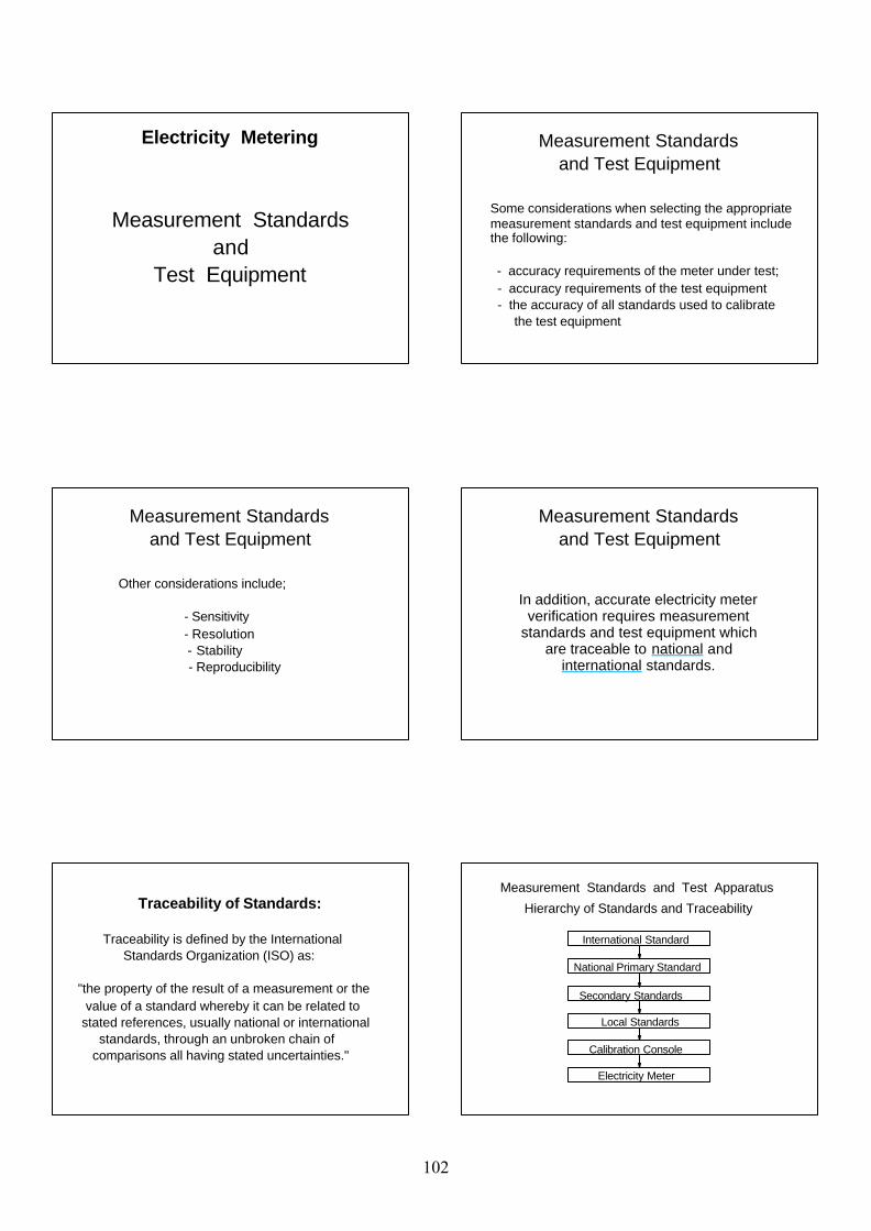
Measurement Standardsand
Test Equipment
Electricity Metering
Some considerations when selecting the appropriate measurement standards and test equipment include the following:
- accuracy requirements of the meter under test; - accuracy requirements of the test equipment - the accuracy of all standards used to calibrate the test equipment
Measurement Standards and Test Equipment
Other considerations include; - Sensitivity - Resolution - Stability - Reproducibility
Measurement Standards and Test Equipment
In addition, accurate electricity meter verification requires measurement
standards and test equipment which are traceable to national and
international standards.
Measurement Standards and Test Equipment
Traceability of Standards:
Traceability is defined by the International Standards Organization (ISO) as:
"the property of the result of a measurement or the value of a standard whereby it can be related to stated references, usually national or international standards, through an unbroken chain of comparisons all having stated uncertainties."
National Primary Standard
International Standard
Local Standards
Calibration Console
Electricity Meter
Hierarchy of Standards and Traceability
Secondary Standards
Measurement Standards and Test Apparatus
102
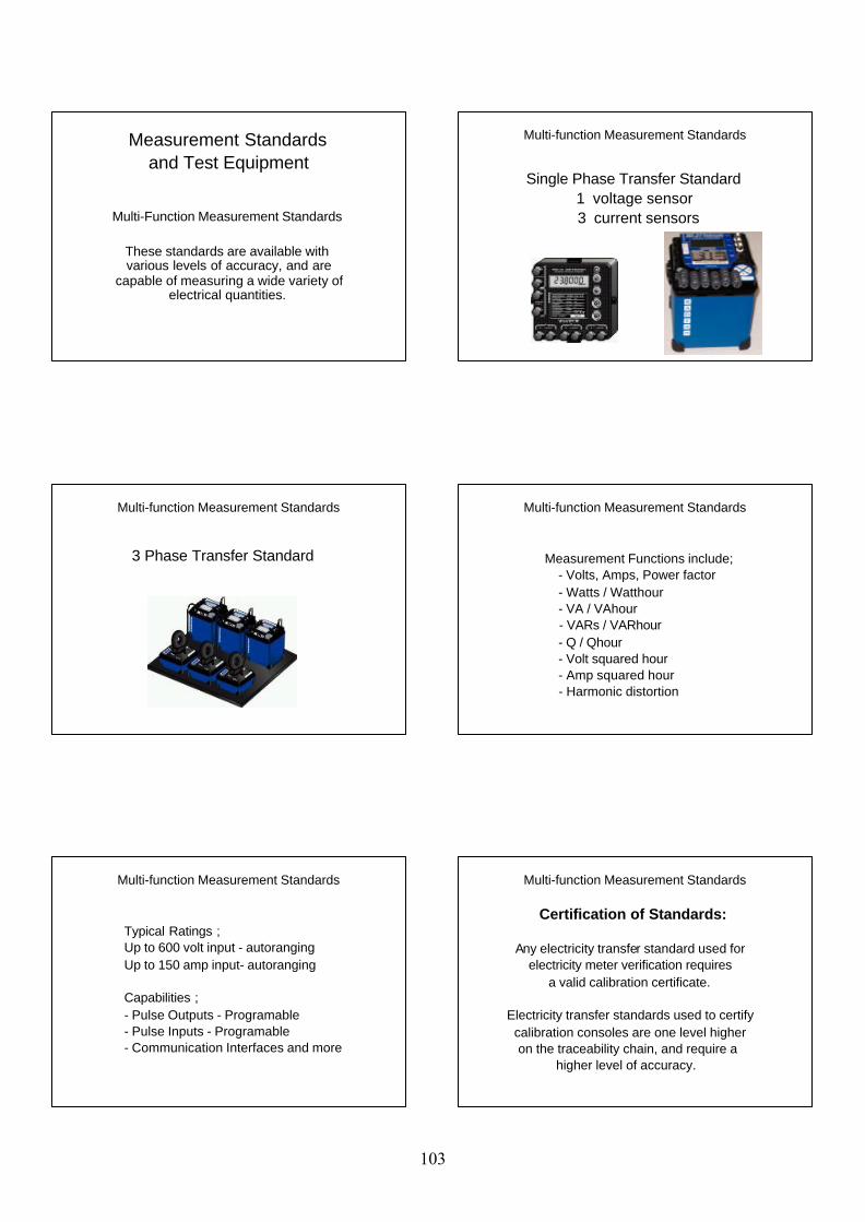
Multi-Function Measurement Standards
These standards are available with various levels of accuracy, and are
capable of measuring a wide variety of electrical quantities.
Measurement Standards and Test Equipment
Single Phase Transfer Standard1 voltage sensor
3 current sensors
Multi-function Measurement Standards
3 Phase Transfer Standard
Multi-function Measurement Standards
Measurement Functions include; - Volts, Amps, Power factor - Watts / Watthour - VA / VAhour - VARs / VARhour - Q / Qhour - Volt squared hour - Amp squared hour - Harmonic distortion
Multi-function Measurement Standards
Typical Ratings ;Up to 600 volt input - autorangingUp to 150 amp input- autoranging
Capabilities ;- Pulse Outputs - Programable- Pulse Inputs - Programable- Communication Interfaces and more
Multi-function Measurement Standards
Certification of Standards:
Any electricity transfer standard used for electricity meter verification requires a valid calibration certificate.
Electricity transfer standards used to certify calibration consoles are one level higher on the traceability chain, and require a higher level of accuracy.
Multi-function Measurement Standards
103
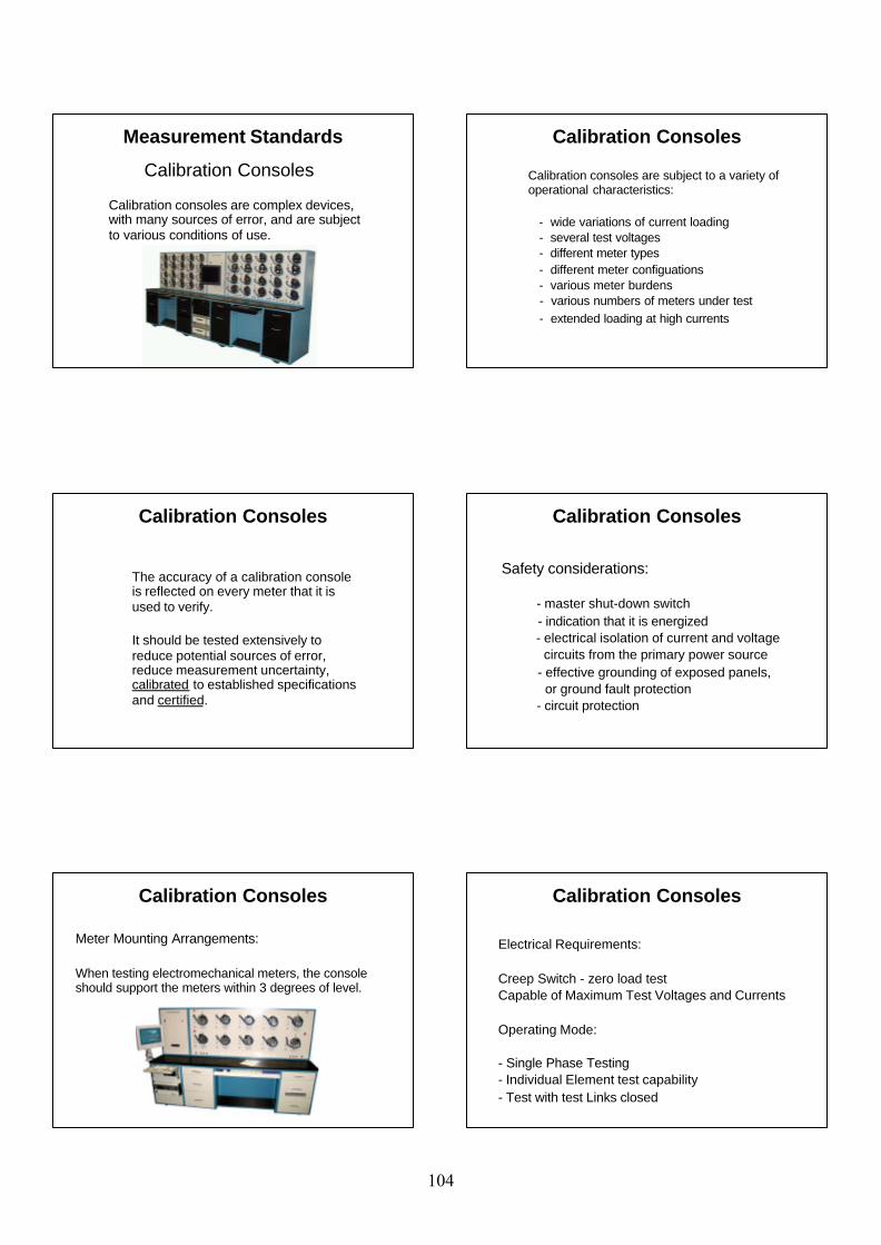
Calibration Consoles
Measurement Standards
Calibration consoles are complex devices, with many sources of error, and are subject to various conditions of use.
Calibration consoles are subject to a variety of operational characteristics:
- wide variations of current loading - several test voltages - different meter types - different meter configuations - various meter burdens - various numbers of meters under test - extended loading at high currents
Calibration Consoles
The accuracy of a calibration console is reflected on every meter that it is used to verify.
It should be tested extensively to reduce potential sources of error, reduce measurement uncertainty, calibrated to established specifications and certified.
Calibration Consoles
Safety considerations:
- master shut-down switch - indication that it is energized - electrical isolation of current and voltage circuits from the primary power source - effective grounding of exposed panels, or ground fault protection - circuit protection
Calibration Consoles
Meter Mounting Arrangements:
When testing electromechanical meters, the console should support the meters within 3 degrees of level.
Calibration Consoles
Electrical Requirements:
Creep Switch - zero load testCapable of Maximum Test Voltages and Currents
Operating Mode:
- Single Phase Testing- Individual Element test capability- Test with test Links closed
Calibration Consoles
104
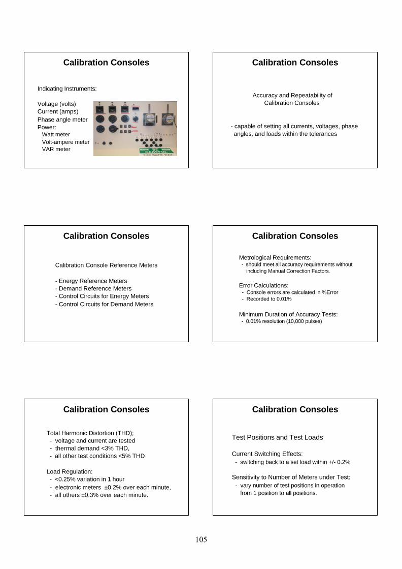
Indicating Instruments:
Voltage (volts)Current (amps)Phase angle meterPower:
Watt meterVolt-ampere meterVAR meter
Calibration Consoles
Accuracy and Repeatability of Calibration Consoles
- capable of setting all currents, voltages, phase angles, and loads within the tolerances
Calibration Consoles
Calibration Console Reference Meters
- Energy Reference Meters- Demand Reference Meters- Control Circuits for Energy Meters- Control Circuits for Demand Meters
Calibration Consoles
Metrological Requirements: - should meet all accuracy requirements without including Manual Correction Factors.
Error Calculations: - Console errors are calculated in %Error - Recorded to 0.01%
Minimum Duration of Accuracy Tests: - 0.01% resolution (10,000 pulses)
Calibration Consoles
Total Harmonic Distortion (THD); - voltage and current are tested - thermal demand <3% THD, - all other test conditions <5% THD
Load Regulation: - <0.25% variation in 1 hour - electronic meters ±0.2% over each minute, - all others ±0.3% over each minute.
Calibration Consoles
Test Positions and Test Loads
Current Switching Effects: - switching back to a set load within +/- 0.2%
Sensitivity to Number of Meters under Test: - vary number of test positions in operation from 1 position to all positions.
Calibration Consoles
105
Burden Effects: - high burden vs low burden test deviation <0.1% - perform tests using the burden producing the highest error. Variations from Position to Position: - errors < 0.1% allows testing in one position only when determining console errors. - 0.1 to 0.2% requires testing in all positions for determining individual position errors.
Calibration Consoles
Sources of Errors
Intervening current transformer errors:Intervening voltage transformer errors:
1:1 isolation transformers: - for testing single phase 3-wire meters - each position, - each test point
Calibration Consoles
Interchanging certified console reference meters is permitted.
Pulse Counters and Generators are verified
Rangeability of console error calculation is verified to ensure that meters with large errors are correctly calculated
Statistical Calculations are verified
Calibration Consoles
USE REQUIREMENTS
Certified calibration consoles require periodic accuracy checks to ensure accuracy deviations do not exceed specified tolerances.
Daily or weekly accuracy checks, with a tolerance of ± 0.20% are recommended,
Calibration Consoles
During use, accuracy deviations may occur for many reasons including:
- equipment degradation - inadequate maintenance - inadequate accuracy checks - inappropriate accuracy checks - inadequate test procedures - inadequate training
Calibration Consoles
Quality Management System Audits are recommended to evaluate the process, and ensure the following:
- the appropriate test equipment is used - the test equipment is used appropriately - use requirements are performed - additional processes required to fulfill use requirements are performed - the complete process achieves the intent of meter verification
Calibration Consoles
106

Calibration consoles and measurement standards are clearly an inherent part of any traceable measurement system and require a high level of calibration accuracy, with corresponding documented results.
Calibration Consoles
Questions? Comments?
Measurement Standards and Test Equipment
107
Measurement DisputeInvestigations
Prepared and presented by: George A. Smith, Measurement Canada Paul G. Rivers, Measurement Canada 2006
Measurement Dispute Investigations
An effective meter approval and verification process
should increase measurement accuracy,
and reduce the number of measurement complaints.
Measurement Dispute Investigations
However, there will be times where the accuracy and equity in the trade measurement of
electricity comes into question.
When this occurs, a dispute resolution process should be in
place, and supported by the appropriate legislation.
Measurement Dispute Investigations
When a purchaser or seller is dissatisfied with:
- the condition or registration of a meter, or
- the application of the measured quantities in the billing process,
a process for requesting a measurement dispute investigation should be available to the person(s) making the complaint.
Measurement Dispute Investigations
Legislation can assist the dispute resolution process if it is an offence to supply less electricity* than the seller:
(1) professes to supply, or
(2) should supply, based upon the total price charged, and the stated price per unit of measurement used to determine the total price.
* subject to accepted limits of error
Measurement Dispute Investigations
The investigation should include one or more of the following steps:
(1) Seek information from the buyer, seller or any person who could be expected to have knowledge relevant to the matter;
(2) Examine any records that may be relevant to the matter; and
(3) Test the meter for accuracy.
108
Measurement Dispute Investigations
The testing of the meter should be scheduled so that the buyer
and seller can witness the meter test if they choose.
Measurement Dispute Investigations
If a meter is found to register with an error exceeding specified
tolerances, the error duration will need to be established.
Billing Corrections
Measurement Dispute Investigations
The duration of error may be easily determined where:
(a) the meter was incorrectly connected, or
(b) an incorrect multiplier has been used, or
(b) there has been an incorrect use of equipment effecting meter registration.
Measurement Dispute Investigations
The measurement error resulting from these types of conditions
can be reasonably determined to have existed from the date of installation of the meter, or for the period that the multiplier or
incorrect equipment was in use.
Measurement Dispute Investigations
Where the duration of the error is determined from past readings of a
meter or other information, the buyer or seller can be made liable for the amount of the charge for electricity
based on the full error, and for the full duration of time the error existed.
Measurement Dispute Investigations
Where the duration of the error is not clearly evident, the legislation should specify a time duration, beginning at a period of time before the date of the complaint or request for an investigation.
109
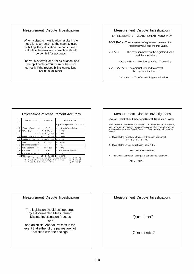
Measurement Dispute Investigations
When a dispute investigation results in the need for a correction to the quantity used for billing, the calculation methods used to calculate the error and correction should
be verified for accuracy.
The various terms for error calculation, and the applicable formulas, must be used
correctly if the revised billing corrections are to be accurate.
Measurement Dispute Investigations EXPRESSIONS OF MEASUREMENT ACCURACY:
ACCURACY: The closeness of agreement between the registered value and the true value.
ERROR: The deviation between the registered value and the true value.
Absolute Error = Registered value - True value
CORRECTION: The amount required to correct the registered value.
Correction = True Value - Registered value
Expressions of Measurement Accuracy
EXPRESSION FORMULA APPLICATION
e.g. meter registers ½ of true value
1 Absolute Error = R - T = - 50 units * (see below)
2 %True Error = (R - T) / T x 100 = - 50% or = (R / T - 1) x 100 = - 50%
3 % Field Note Error = (R - T) / R x 100 = - 100%4 % Fiducial Error = (R - T) / F x 100 = - 25%
5 % Proof = R / T x 100 = 200%6 Registration Factor = R / T = 0.5
7 % Registration = R / T x 100 = 50%8 Correction = T - R = + 50 units * (see below)
9 Correction Factor = T / R = 2.010 % Correction = (T - R) / R x 100 = + 100%
* T = True value determined using certified traceable standards e.g. 100 units (T) R = Registered value as indicated by the device under test e.g. 50 units (R) F = Fiducial (Full Scale) range of the device. e.g. 200 units (F)
Measurement Dispute InvestigationsOverall Registration Factor and Overall Correction Factor
When the error of one device is passed on to the error of the next device, such as where an incorrect transformer is connected to a meter with an unacceptable error, the Overall Correction Factor can be calculated as follows:
1) Calculate the Registration Factor (RF) for each component. (i.e. RF1, RF2, RF3, etc.)
2) Calculate the Overall Registration Factor (RFo)
RFo = RF1 x RF2 x RF3, etc.
3) The Overall Correction Factor (CFo) can then be calculated;
CFo = 1 / RFo
Measurement Dispute Investigations
The legislation should be supported by a documented Measurement Dispute Investigation Process
andand an official Appeal Process in the event that either of the parties are not
satisfied with the findings.
Measurement Dispute Investigations
Questions?
Comments?
110
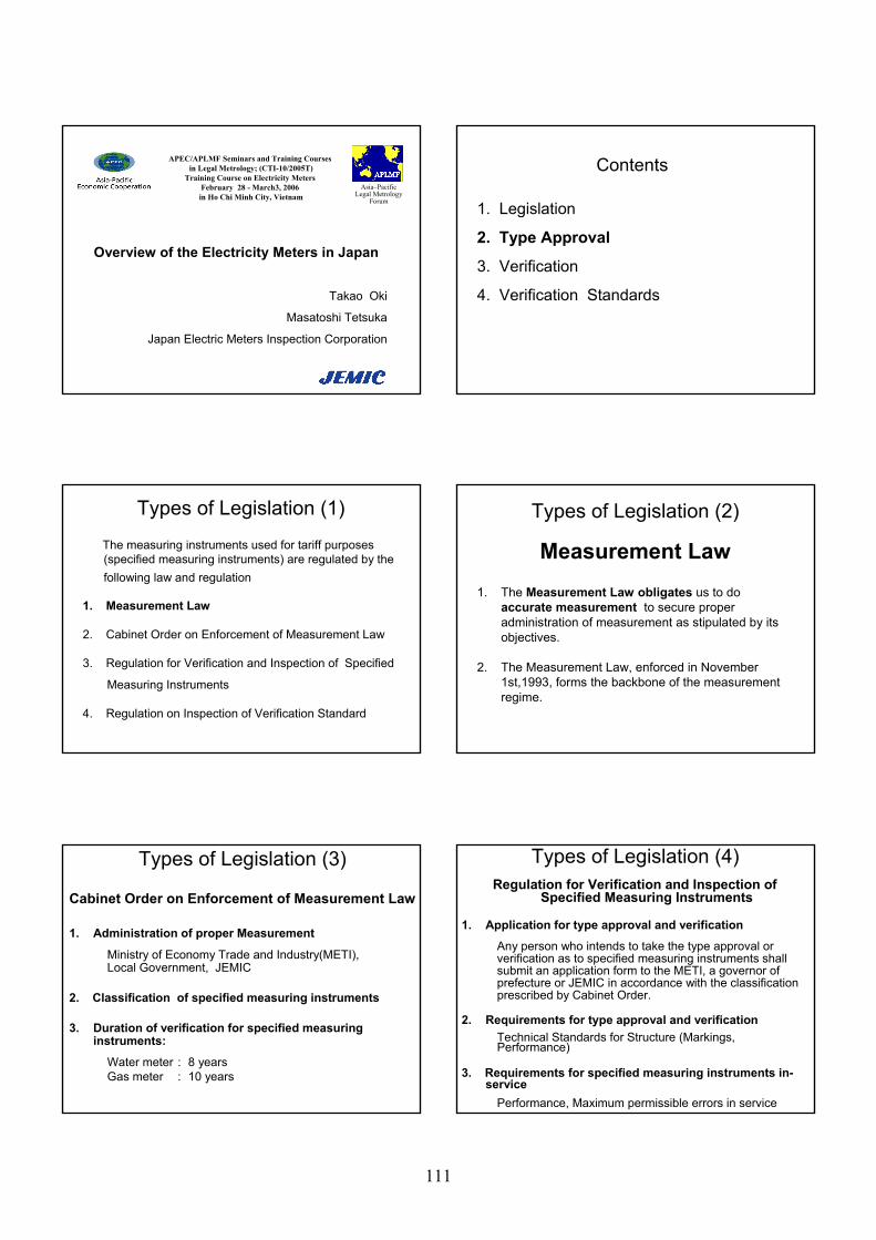
Takao Oki
Masatoshi Tetsuka
Japan Electric Meters Inspection Corporation
Overview of the Electricity Meters in Japan
APEC/APLMF Seminars and Training Coursesin Legal Metrology; (CTI-10/2005T)
Training Course on Electricity MetersFebruary 28 - March3, 2006in Ho Chi Minh City, Vietnam
Asia–PacificLegal Metrology
Forum 1. Legislation
2. Type Approval
3. Verification
4. Verification Standards
Contents
The measuring instruments used for tariff purposes (specified measuring instruments) are regulated by the following law and regulation
1. Measurement Law
2. Cabinet Order on Enforcement of Measurement Law
3. Regulation for Verification and Inspection of Specified
Measuring Instruments
4. Regulation on Inspection of Verification Standard
Types of Legislation (1)
Measurement Law1. The Measurement Law obligates us to do
accurate measurement to secure proper administration of measurement as stipulated by its objectives.
2. The Measurement Law, enforced in November 1st,1993, forms the backbone of the measurement regime.
Types of Legislation (2)
Cabinet Order on Enforcement of Measurement Law
1. Administration of proper Measurement
Ministry of Economy Trade and Industry(METI), Local Government, JEMIC
2. Classification of specified measuring instruments
3. Duration of verification for specified measuring instruments:
Water meter : 8 yearsGas meter : 10 years
Types of Legislation (3)Regulation for Verification and Inspection of
Specified Measuring Instruments
1. Application for type approval and verification
Any person who intends to take the type approval or verification as to specified measuring instruments shall submit an application form to the METI, a governor of prefecture or JEMIC in accordance with the classification prescribed by Cabinet Order.
2. Requirements for type approval and verificationTechnical Standards for Structure (Markings, Performance)
3. Requirements for specified measuring instruments in-service
Performance, Maximum permissible errors in service
Types of Legislation (4)
111
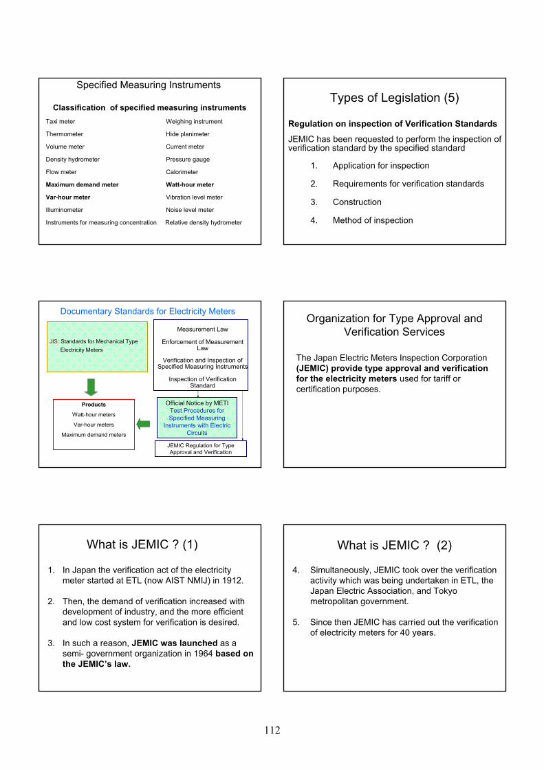
Classification of specified measuring instrumentsTaxi meter Weighing instrument
Thermometer Hide planimeter
Volume meter Current meter
Density hydrometer Pressure gauge
Flow meter Calorimeter
Maximum demand meter Watt-hour meter
Var-hour meter Vibration level meter
Illuminometer Noise level meter
Instruments for measuring concentration Relative density hydrometer
Specified Measuring Instruments
Regulation on inspection of Verification Standards
JEMIC has been requested to perform the inspection of verification standard by the specified standard
1. Application for inspection
2. Requirements for verification standards
3. Construction
4. Method of inspection
Types of Legislation (5)
Documentary Standards for Electricity Meters
Measurement Law
Enforcement of Measurement Law
Verification and Inspection ofSpecified Measuring Instruments
Inspection of Verification Standard
Official Notice by METITest Procedures forSpecified Measuring
Instruments with Electric Circuits
Products
Watt-hour meters
Var-hour meters
Maximum demand meters
JIS: Standards for Mechanical Type Electricity Meters
JEMIC Regulation for Type Approval and Verification
Organization for Type Approval and Verification Services
The Japan Electric Meters Inspection Corporation(JEMIC) provide type approval and verification for the electricity meters used for tariff or certification purposes.
What is JEMIC ? (1)
1. In Japan the verification act of the electricity meter started at ETL (now AIST NMIJ) in 1912.
2. Then, the demand of verification increased withdevelopment of industry, and the more efficientand low cost system for verification is desired.
3. In such a reason, JEMIC was launched as asemi- government organization in 1964 based onthe JEMIC’s law.
What is JEMIC ? (2)
4. Simultaneously, JEMIC took over the verificationactivity which was being undertaken in ETL, theJapan Electric Association, and Tokyo metropolitan government.
5. Since then JEMIC has carried out the verificationof electricity meters for 40 years.
112
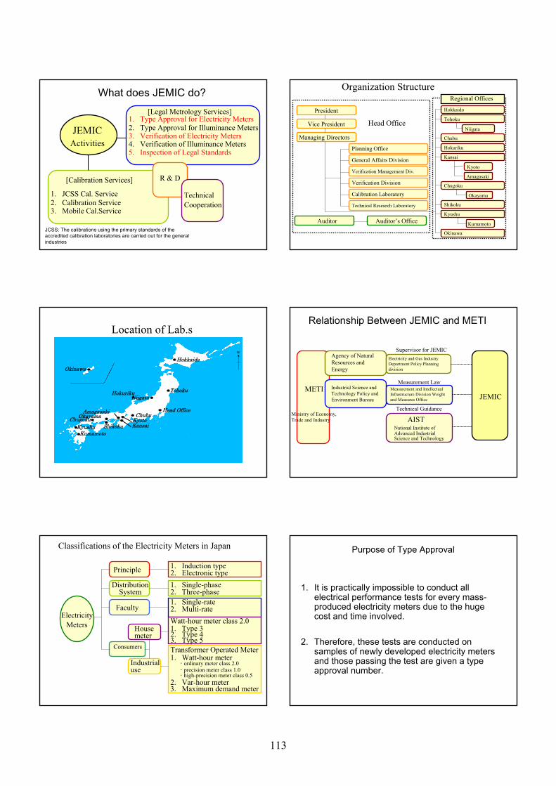
JEMICActivities
[Calibration Services]
1. JCSS Cal. Service2. Calibration Service3. Mobile Cal.Service
R & D
[Legal Metrology Services]1. Type Approval for Electricity Meters2. Type Approval for Illuminance Meters3. Verification of Electricity Meters4. Verification of Illuminance Meters5. Inspection of Legal Standards
TechnicalCooperation
What does JEMIC do?
JCSS: The calibrations using the primary standards of the accredited calibration laboratories are carried out for the general industries
General Affairs Division
Verification Management Div.
Verification Division
Calibration Laboratory
Technical Research Laboratory
Planning Office
Hokkaido
Tohoku
Chubu
Hokuriku
Kansai
Chugoku
Shikoku
Kyushu
President
Vice President
Managing Directors
Auditor Auditor’s Office
Head Office
Regional Offices
Okinawa
Niigata
Kyoto
Amagasaki
Okayama
Organization Structure
Kumamoto
Hokkaido
Tohoku
Head Office
Niigata
ChubuKyotoKansai
OkayamaChugokuAmagasaki
ShikokuKyushuKumamoto
Okinawa
Location of Lab.s
N
Hokuriku METI
Agency of Natural Resources and Energy
Industrial Science and Technology Policy and Environment Bureau
Electricity and Gas Industry Department Policy Planning division
Measurement and Intellectual Infrastructure Division Weight and Measures Office
AISTNational Institute ofAdvanced Industrial Science and Technology
JEMIC
Ministry of Economy,Trade and Industry
Supervisor for JEMIC
Measurement Law
Technical Guidance
Relationship Between JEMIC and METI
ElectricityMeters
Principle
Faculty
DistributionSystem
Consumers
Housemeter
Industrialuse
1. Induction type2. Electronic type
1. Single-rate2. Multi-rate
1. Single-phase2. Three-phase
Watt-hour meter class 2.01. Type 32. Type 43. Type 5Transformer Operated Meter1. Watt-hour meter
2. Var-hour meter3. Maximum demand meter
・ ordinary meter class 2.0・ precision meter class 1.0・ high-precision meter class 0.5
Classifications of the Electricity Meters in Japan
1. It is practically impossible to conduct all electrical performance tests for every mass-produced electricity meters due to the huge cost and time involved.
2. Therefore, these tests are conducted onsamples of newly developed electricity meters and those passing the test are given a type approval number.
Purpose of Type Approval
113

Summary of Legislation
1. Legal basisThe measuring instruments used for tariff purposes (specified measuring instruments) are regulated by the relevant regulations based on the Measurement Law of Japan.
2. National regulatory organizationMinistry of Economy Trade and Industry(METI)
3. Type approval and Verification body for Electricity meters
Japan Electric Meters Inspection Corporation (JEMIC)
114
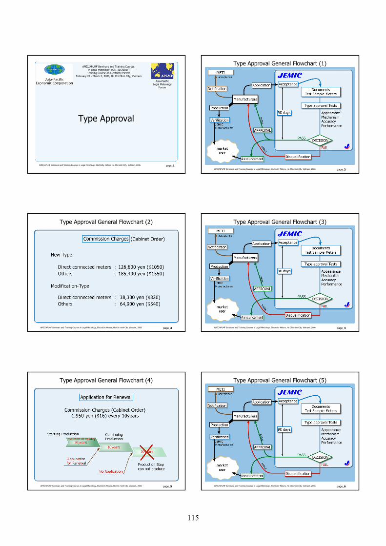
APEC/APLMF Seminars and Training Courses in Legal Metrology, Electricity Meters, Ho Chi minh City, Vietnam, 2006 page_1
Asia-PacificLegal Metrology
Forum
Type Approval
APEC/APLMF Seminars and Training Courses in Legal Metrology; (CTI-10/2005T)Training Course on Electricity Meters
February 28 - March 3, 2006, Ho Chi Minh City, Vietnam
APEC/APLMF Seminars and Training Courses in Legal Metrology, Electricity Meters, Ho Chi minh City, Vietnam, 2006 page_2
Type Approval General Flowchart (1)
APEC/APLMF Seminars and Training Courses in Legal Metrology, Electricity Meters, Ho Chi minh City, Vietnam, 2006 page_3
Type Approval General Flowchart (2)
APEC/APLMF Seminars and Training Courses in Legal Metrology, Electricity Meters, Ho Chi minh City, Vietnam, 2006 page_4
Type Approval General Flowchart (3)
APEC/APLMF Seminars and Training Courses in Legal Metrology, Electricity Meters, Ho Chi minh City, Vietnam, 2006 page_5
Type Approval General Flowchart (4)
APEC/APLMF Seminars and Training Courses in Legal Metrology, Electricity Meters, Ho Chi minh City, Vietnam, 2006 page_6
Type Approval General Flowchart (5)
115
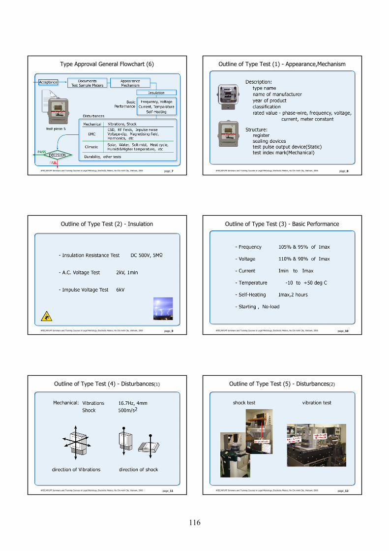
APEC/APLMF Seminars and Training Courses in Legal Metrology, Electricity Meters, Ho Chi minh City, Vietnam, 2006 page_7
Type Approval General Flowchart (6)
APEC/APLMF Seminars and Training Courses in Legal Metrology, Electricity Meters, Ho Chi minh City, Vietnam, 2006 page_8
Outline of Type Test (1) - Appearance,Mechanism
APEC/APLMF Seminars and Training Courses in Legal Metrology, Electricity Meters, Ho Chi minh City, Vietnam, 2006 page_9
Outline of Type Test (2) - Insulation
APEC/APLMF Seminars and Training Courses in Legal Metrology, Electricity Meters, Ho Chi minh City, Vietnam, 2006 page_10
Outline of Type Test (3) - Basic Performance
APEC/APLMF Seminars and Training Courses in Legal Metrology, Electricity Meters, Ho Chi minh City, Vietnam, 2006 page_11
Outline of Type Test (4) - Disturbances(1)
APEC/APLMF Seminars and Training Courses in Legal Metrology, Electricity Meters, Ho Chi minh City, Vietnam, 2006 page_12
Outline of Type Test (5) - Disturbances(2)
116
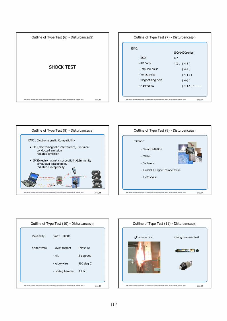
APEC/APLMF Seminars and Training Courses in Legal Metrology, Electricity Meters, Ho Chi minh City, Vietnam, 2006 page_13
Outline of Type Test (6) - Disturbances(3)
SHOCK TEST
APEC/APLMF Seminars and Training Courses in Legal Metrology, Electricity Meters, Ho Chi minh City, Vietnam, 2006 page_14
Outline of Type Test (7) - Disturbances(4)
APEC/APLMF Seminars and Training Courses in Legal Metrology, Electricity Meters, Ho Chi minh City, Vietnam, 2006 page_15
Outline of Type Test (8) - Disturbances(5)
APEC/APLMF Seminars and Training Courses in Legal Metrology, Electricity Meters, Ho Chi minh City, Vietnam, 2006 page_16
Outline of Type Test (9) - Disturbances(6)
APEC/APLMF Seminars and Training Courses in Legal Metrology, Electricity Meters, Ho Chi minh City, Vietnam, 2006 page_17
Outline of Type Test (10) - Disturbances(7)
APEC/APLMF Seminars and Training Courses in Legal Metrology, Electricity Meters, Ho Chi minh City, Vietnam, 2006 page_18
Outline of Type Test (11) - Disturbances(8)
117
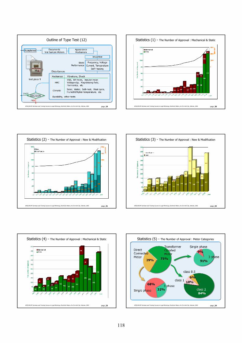
APEC/APLMF Seminars and Training Courses in Legal Metrology, Electricity Meters, Ho Chi minh City, Vietnam, 2006 page_19
Outline of Type Test (12)
APEC/APLMF Seminars and Training Courses in Legal Metrology, Electricity Meters, Ho Chi minh City, Vietnam, 2006 page_20
Statistics (1) - The Number of Approval : Mechanical & Static
APEC/APLMF Seminars and Training Courses in Legal Metrology, Electricity Meters, Ho Chi minh City, Vietnam, 2006 page_21
Statistics (2) - The Number of Approval : New & Modification
APEC/APLMF Seminars and Training Courses in Legal Metrology, Electricity Meters, Ho Chi minh City, Vietnam, 2006 page_22
Statistics (3) - The Number of Approval : New & Modification
APEC/APLMF Seminars and Training Courses in Legal Metrology, Electricity Meters, Ho Chi minh City, Vietnam, 2006 page_23
Statistics (4) - The Number of Approval : Mechanical & Static
APEC/APLMF Seminars and Training Courses in Legal Metrology, Electricity Meters, Ho Chi minh City, Vietnam, 2006 page_24
Statistics (5) - The Number of Approval : Meter Categories
118
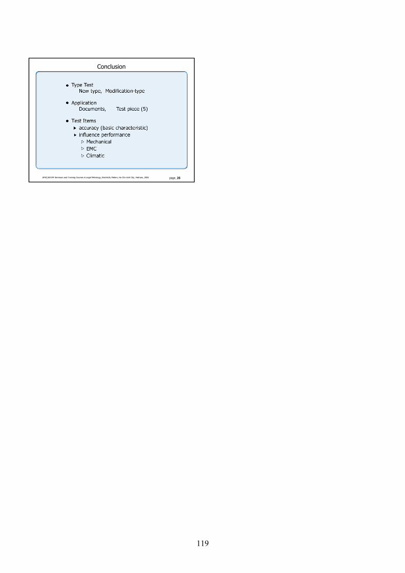
APEC/APLMF Seminars and Training Courses in Legal Metrology, Electricity Meters, Ho Chi minh City, Vietnam, 2006 page_25
Conclusion
119
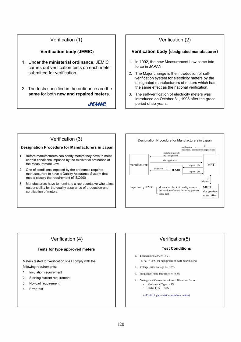
Verification (1)
Verification body (JEMIC)
1. Under the ministerial ordinance, JEMIC carries out verification tests on each meter submitted for verification.
2. The tests specified in the ordinance are the same for both new and repaired meters.
Verification (2)
Verification body (designated manufacturer)
1. In 1992, the new Measurement Law came into force in JAPAN.
2. The Major change is the introduction of self-verification system for electricity meters by the designated manufacturers of meters which has the same effect as the national verification.
3. The self-verification of electricity meters was introduced on October 31, 1998 after the grace period of six years.
Verification (3)Designation Procedure for Manufacturers in Japan
1. Before manufacturers can certify meters they have to meet certain conditions imposed by the ministerial ordinance of the Measurement Law.
2. One of conditions imposed by the ordinance requires manufacturers to have a Quality Assurance System that meets closely the requirement of ISO9001.
3. Manufacturers have to nominate a representative who takes responsibility for the quality assurance of production and certification of meters.
manufacturersJEMIC
METI
METIdesignationcommittee
Inspection by JEMIC document check of quality manual inspection of manufacturing processfinal test
(1) application
request (2)
inspection (3)report (4)
(5)judgment
(indefinite period)(6) designation
notification(less than 3 months from application)
(6)
Designation Procedure for Manufacturers in Japan
Tests for type approved meters
Meters tested for verification shall comply with the
following requirements:
1. Insulation requirement
2. Starting current requirement
3. No-load requirement
4. Error test
Verification (4)
Test Conditions
1. Temperature: 23ºC+/- 5 ℃.
(23 ºC +/- 2 ºC for high precision watt-hour meters)
2. Voltage: rated voltage +/- 0.3%
3. Frequency: rated frequency +/- 0.5%
4. Voltage and Current waveforms: Distortion Factor• Mechanical Type <3%• Static Type <2%
(<1% for high precision watt-hour meters)
Verification(5)
120
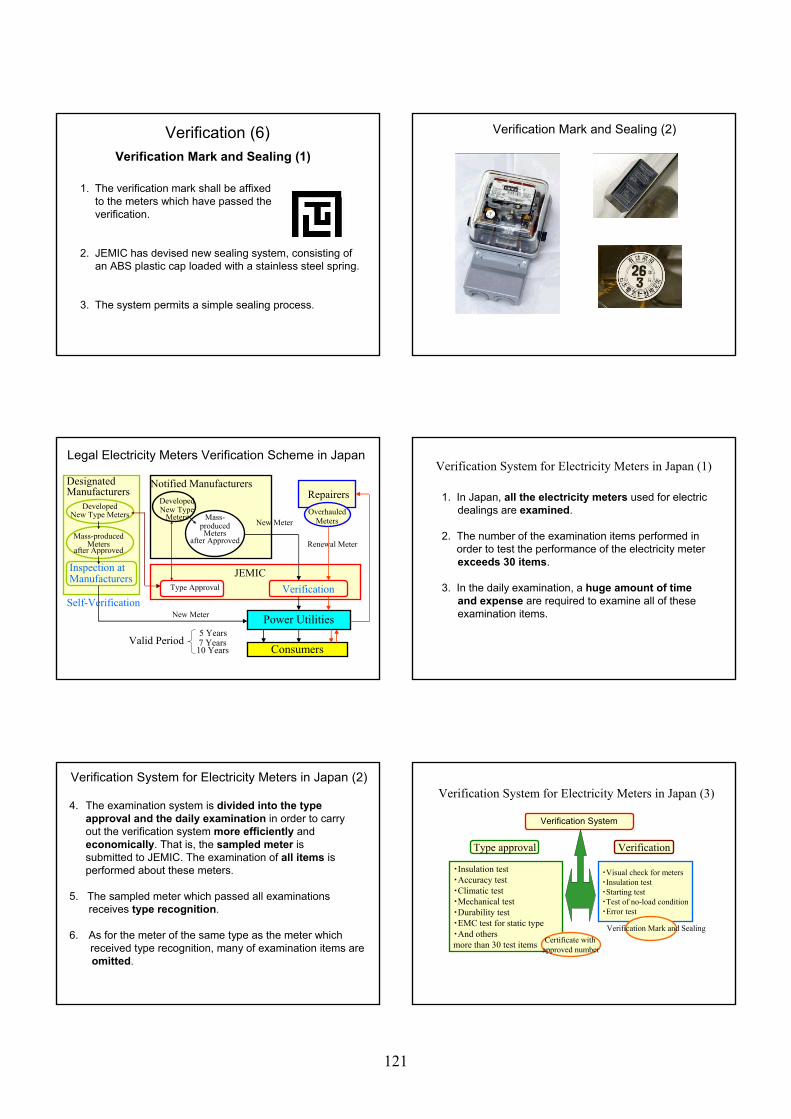
1. The verification mark shall be affixed to the meters which have passed theverification.
2. JEMIC has devised new sealing system, consisting of an ABS plastic cap loaded with a stainless steel spring.
3. The system permits a simple sealing process.
Verification (6)Verification Mark and Sealing (1)
Verification Mark and Sealing (2)
Verification
DesignatedManufacturers
DevelopedNew Type Meters
Mass-producedMeters
after Approved
Inspection atManufacturers
Self-Verification
Notified ManufacturersDevelopedNew Type
Meters Mass-producedMeters
after Approved
Repairers
Renewal Meter
OverhauledMeters
Type Approval
JEMIC
Power Utilities
Consumers
New Meter
New Meter
Valid Period5 Years7 Years10 Years
Legal Electricity Meters Verification Scheme in Japan
1. In Japan, all the electricity meters used for electricdealings are examined.
2. The number of the examination items performed inorder to test the performance of the electricity meterexceeds 30 items.
3. In the daily examination, a huge amount of time and expense are required to examine all of theseexamination items.
Verification System for Electricity Meters in Japan (1)
4. The examination system is divided into the typeapproval and the daily examination in order to carryout the verification system more efficiently andeconomically. That is, the sampled meter issubmitted to JEMIC. The examination of all items isperformed about these meters.
5. The sampled meter which passed all examinationsreceives type recognition.
6. As for the meter of the same type as the meter whichreceived type recognition, many of examination items areomitted.
Verification System for Electricity Meters in Japan (2)Verification System for Electricity Meters in Japan (3)
・Insulation test・Accuracy test・Climatic test・Mechanical test・Durability test・EMC test for static type・And othersmore than 30 test items
・Visual check for meters・Insulation test・Starting test・Test of no-load condition・Error test
Type approval Verification
Verification System
Certificate with approved number
Verification Mark and Sealing
121
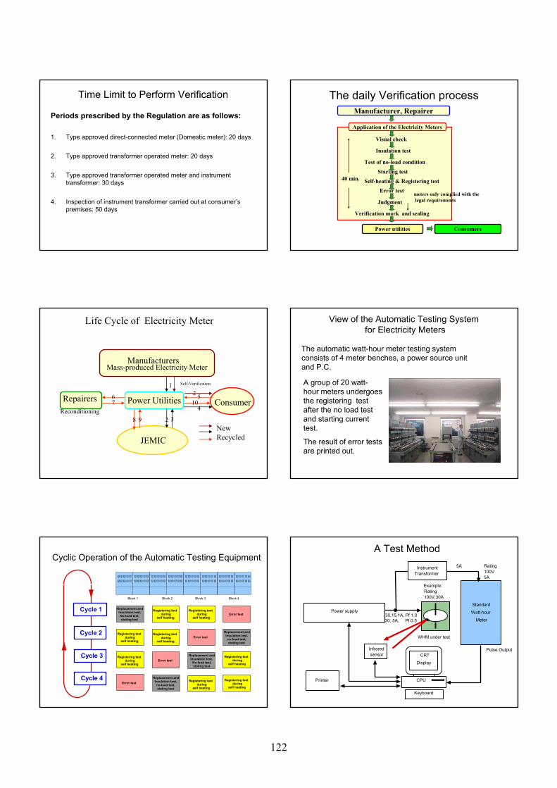
Periods prescribed by the Regulation are as follows:
1. Type approved direct-connected meter (Domestic meter): 20 days
2. Type approved transformer operated meter: 20 days
3. Type approved transformer operated meter and instrument transformer: 30 days
4. Inspection of instrument transformer carried out at consumer’s premises: 50 days
Time Limit to Perform VerificationManufacturer, Repairer
Application of the Electricity Meters
Visual check
Insulation test
Test of no-load condition
Starting test
Self-heating & Registering test
Error test
Judgment
Verification mark and sealing
Consumers
40 min.
Power utilities
meters only complied with thelegal requirements
The daily Verification process
ManufacturersMass-produced Electricity Meter
RepairersReconditioning
Power Utilities Consumer
JEMIC
3
4
567
8 9
10
NewRecycled
Life Cycle of Electricity Meter
2
21 Self-Verification
View of the Automatic Testing Systemfor Electricity Meters
The automatic watt-hour meter testing system consists of 4 meter benches, a power source unit and P.C.
A group of 20 watt-hour meters undergoes the registering test after the no load test and starting current test.
The result of error tests are printed out.
Registering testduring
self heating
Replacement and Insulation test, no-load test, stating test
Error test
Registering testduring
self heatingError test
Registering testduring
self heating
Registering testduring
self heating
Error test
Registering testduring
self heating
Registering testduring
self heating
Error test
Registering testduring
self heating
Registering testduring
self heating
Block 1 Block 2 Block 3 Block 4
Cycle 3
Cycle 2
Replacement and Insulation test, No-load test, stating test
Replacement and Insulation test,
No-load test,stating test
Replacement and Insulation test, no-load test, stating test
Cyclic Operation of the Automatic Testing Equipment
Cycle 4
Cycle 1
Infraredsensor
A Test Method
Power supply
InstrumentTransformer
WHM under test
CRT
Display
CPU
Keyboard
Printer
Standard
Watt-hour
Meter
Pulse Output
Rating100V5A
Example:Rating100V,30A
5A
30,15,1A, Pf 1.030, 5A, Pf 0.5
122
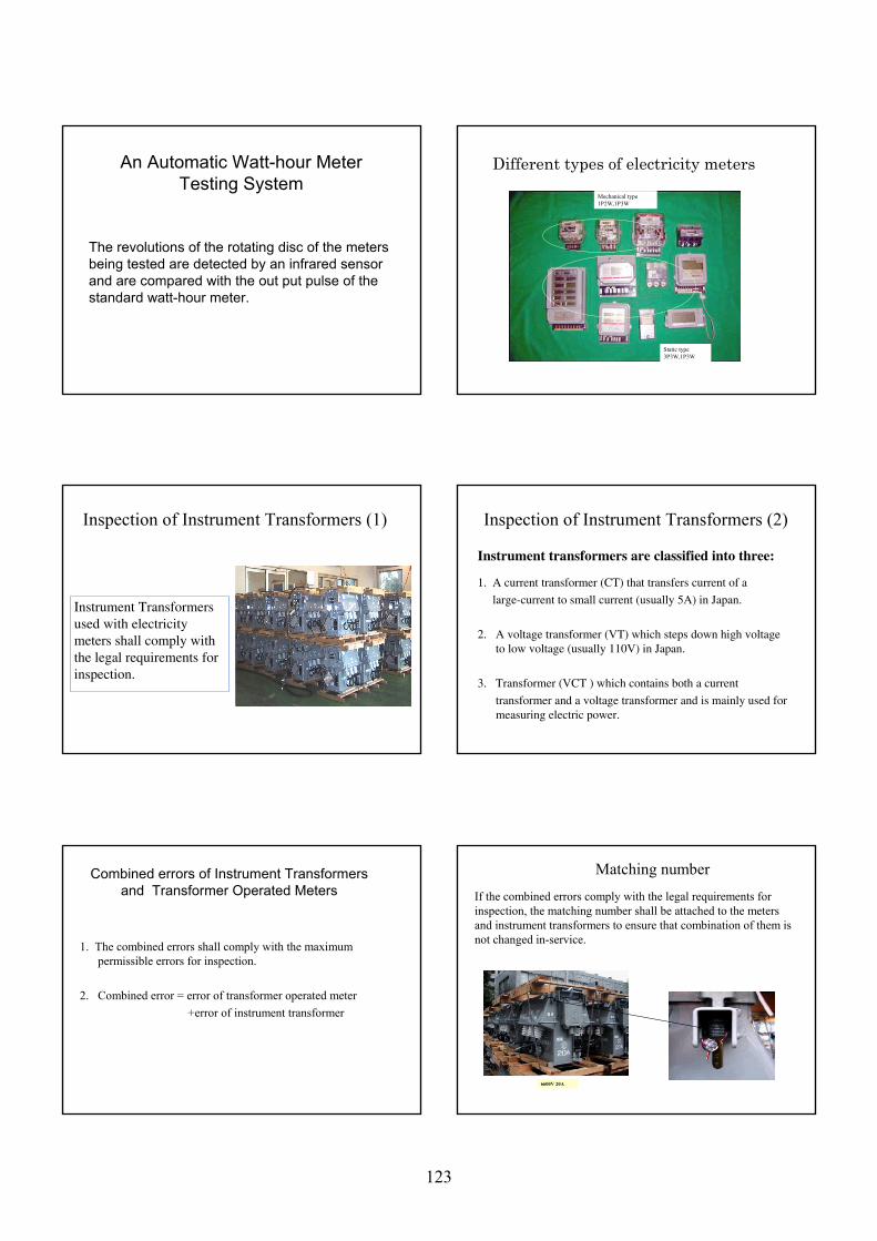
An Automatic Watt-hour Meter Testing System
The revolutions of the rotating disc of the meters being tested are detected by an infrared sensor and are compared with the out put pulse of the standard watt-hour meter.
Different types of electricity meters
Static type3P3W,1P3W
Mechanical type1P2W,1P3W
Inspection of Instrument Transformers (1)
Instrument Transformers used with electricity meters shall comply with the legal requirements for inspection.
Inspection of Instrument Transformers (2)
Instrument transformers are classified into three:
1. A current transformer (CT) that transfers current of a
large-current to small current (usually 5A) in Japan.
2. A voltage transformer (VT) which steps down high voltage to low voltage (usually 110V) in Japan.
3. Transformer (VCT ) which contains both a current
transformer and a voltage transformer and is mainly used for measuring electric power.
Combined errors of Instrument Transformers and Transformer Operated Meters
1. The combined errors shall comply with the maximum permissible errors for inspection.
2. Combined error = error of transformer operated meter+error of instrument transformer
Matching numberIf the combined errors comply with the legal requirements for inspection, the matching number shall be attached to the meters and instrument transformers to ensure that combination of them is not changed in-service.
6600V 20A
123
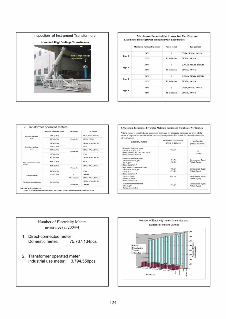
Inspection of Instrument Transformers
Standard High Voltage Transformer
600kV high voltage capacitance
Maximum Permissible Errors for Verification1. Domestic meters (Direct-connected watt-hour meters)
Maximum Permissible errors Power factor Test current
Type 22.0% 1 5%In, 50%In, 100%In
2.5% 0.5 inductive 20%In, 100%In
Type 32.0% 1 3.3%In, 50%In, 100%In
2.5% 0.5 inductive 20%In, 100%In
Type 42.0% 1 2.5%In, 50%In, 100%In
2.5% 0.5 inductive 20%In, 100%In
Type 52.0% 1 2%In, 50%In, 100%In
2.5% 0.5 inductive 20%In, 100%In
2. Transformer operated metersMaximum Permissible errors Power factor Test current
Ordinary watt-hour meters
2.0% (2.0%) 1 5%In, 50%In, 100%In
2.5% (2.5%) 0.5 inductive 20%In, 100%In
Precision watt-hour meters
1.0% (1.2%) 1 20%In, 50%In, 100%In
1.5% (1.8%) 5%In
1.0% (1.3%)0.5 inductive
20%In, 50%In, 100%In
1.5% (2.0%) 5%In
High precision watt-hour meters
0.5% (0.6%)1
20%In, 50%In, 100%In
0.8% (1.0%) 5%In
0.5% (0.7%)0.5 inductive
20%In, 50%In, 100%In
0.8% (1.1%) 5%In
Var-hour meters 2.5% (2.5%) 0 100%In
0.866 inductive 20%In, 50%In, 100%In
Maximum demand meters 3.0% (3.0%) 1 10%In, 50%In, 100%In
0.5 inductive 100%In
Note (1) In: Rated current(2) ( ): Maximum Permissible errors for a meter error + an instrument transformer error
Electricity metersMaximum permissible
errors in-serviceVerification
period (in years)
Domestic Watt-hour meter100%In to 20%In, pf 1Rated current: 30, 120, 200 , 250ARated current: 20, 60 A
+/-3.0%10
7 (20, 60A)
Precision watt-hour meter100%In to 10%In, pf 15%In, pf 1
Rated current: 5 A
+/-1.7%+/-2.5%
5(mechanical Type)7(static Type)
High precision watt-hour meter100%In to 10%In, pf 15%In, pf 1Rated current: 5 A
+/-0.9%+/-1.4%
5(mechanical Type)7(static Type)
Var-hour meter 50%In, pf 0.866Rated current: 5 A
+/-4.0% 5(mechanical Type)7(static Type)
Maximum demand meter50%In, pf 1Rated current: 5 A
+/-4.0% 5(mechanical Type)7(static Type)
3. Maximum Permissible Errors for Meters in-service and Duration of Verification
After a meter is installed on a customers premises for charging purposes, an error of the meter is required to remain within the maximum permissible errors for the entire duration of verification
Number of Electricity Metersin-service (at 2004/4)
1. Direct-connected meterDomestic meter: 75,737,134pcs
2. Transformer operated meterIndustrial use meter: 3,794,558pcs
Number of Electricity meters in service and
Number of Meters Verified
1,9931,9941,995 1,996 1,997 1,998 1,999 2,000 2,001 2,002 2,003
Stat
ic
Mec
hani
cal
Tot
al
Inst
alle
d M
eter 0
1,000
2,000
3,000
4,000
5,000
6,000
7,000
8,000
Num
ber
of M
eter
s(t
en th
ousa
nds)
Fiscal Year
StaticMechanicalTotalInstalled Meter
124
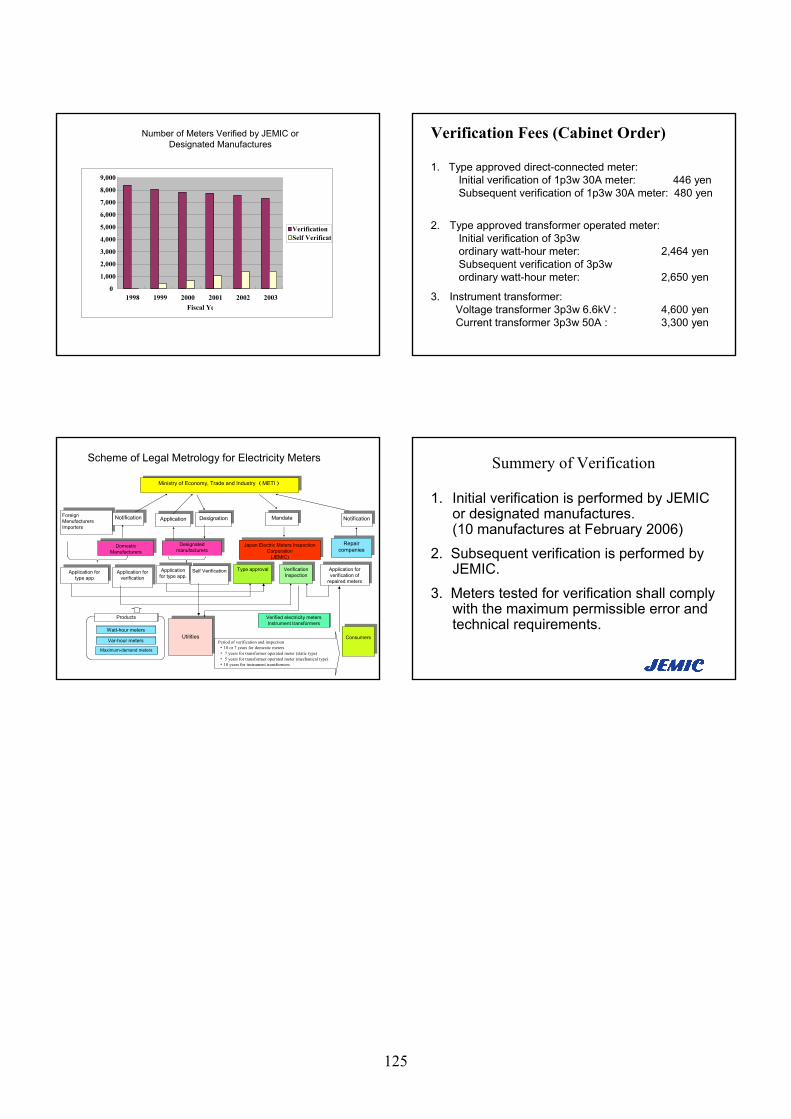
Number of Meters Verified by JEMIC or Designated Manufactures
0
1,000
2,000
3,000
4,000
5,000
6,000
7,000
8,000
9,000
1998 1999 2000 2001 2002 2003Fiscal Ye
Verification Self Verificat
Verification Fees (Cabinet Order)
1. Type approved direct-connected meter: Initial verification of 1p3w 30A meter: 446 yenSubsequent verification of 1p3w 30A meter: 480 yen
2. Type approved transformer operated meter: Initial verification of 3p3w ordinary watt-hour meter: 2,464 yenSubsequent verification of 3p3w ordinary watt-hour meter: 2,650 yen
3. Instrument transformer: Voltage transformer 3p3w 6.6kV : 4,600 yenCurrent transformer 3p3w 50A : 3,300 yen
Application fortype app. Application for
type app.
Foreign Manufacturers Importers
Foreign Manufacturers Importers
Ministry of Economy, Trade and Industry (METI)Ministry of Economy, Trade and Industry (METI)
Domestic Manufacturers Domestic
Manufacturers
Designated manufacturersDesignated
manufacturersJapan Electric Meters Inspection
Corporation(JEMIC)
Japan Electric Meters Inspection Corporation
(JEMIC)
Repair companiesRepair
companies
NotificationNotification ApplicationApplication DesignationDesignation MandateMandate
UtilitiesUtilities ConsumersConsumers
Type approvalType approval VerificationInspectionVerification
InspectionApplication
for type app.Application for type app.
Application for verificationApplication for
verification
Application for verification of
repaired meters
Application for verification of
repaired meters
Self Verification Self Verification
Scheme of Legal Metrology for Electricity Meters
NotificationNotification
Watt-hour meters
Var-hour meters
Maximum-demand meters
Verified electricity metersInstrument transformers
Products
Period of verification and inspection・10 or 7 years for domestic meters・ 7 years for transformer operated meter (static type)・ 5 years for transformer operated meter (mechanical type)・10 years for instrument transformers
Summery of Verification
1. Initial verification is performed by JEMIC or designated manufactures.(10 manufactures at February 2006)
2. Subsequent verification is performed by JEMIC.
3. Meters tested for verification shall comply with the maximum permissible error and technical requirements.
125
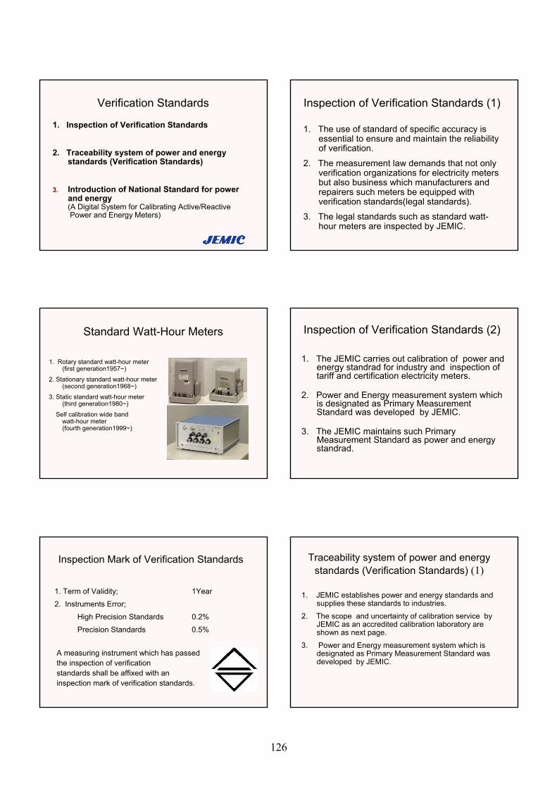
Verification Standards
1. Inspection of Verification Standards
2. Traceability system of power and energy standards (Verification Standards)
3. Introduction of National Standard for power and energy(A Digital System for Calibrating Active/ReactivePower and Energy Meters)
Inspection of Verification Standards (1)
1. The use of standard of specific accuracy is essential to ensure and maintain the reliability of verification.
2. The measurement law demands that not only verification organizations for electricity meters but also business which manufacturers and repairers such meters be equipped with verification standards(legal standards).
3. The legal standards such as standard watt-hour meters are inspected by JEMIC.
Standard Watt-Hour Meters
1. Rotary standard watt-hour meter(first generation1957~)
2. Stationary standard watt-hour meter(second generation1968~)
3. Static standard watt-hour meter(third generation1980~)
Self calibration wide band watt-hour meter(fourth generation1999~)
Inspection of Verification Standards (2)
1. The JEMIC carries out calibration of power and energy standrad for industry and inspection of tariff and certification electricity meters.
2. Power and Energy measurement system which is designated as Primary Measurement Standard was developed by JEMIC.
3. The JEMIC maintains such Primary Measurement Standard as power and energy standrad.
Inspection Mark of Verification Standards
1. Term of Validity; 1Year
2. Instruments Error;
High Precision Standards 0.2%
Precision Standards 0.5%
A measuring instrument which has passedthe inspection of verification standards shall be affixed with aninspection mark of verification standards.
Traceability system of power and energy standards (Verification Standards) (1)
1. JEMIC establishes power and energy standards and supplies these standards to industries.
2. The scope and uncertainty of calibration service by JEMIC as an accredited calibration laboratory are shown as next page.
3. Power and Energy measurement system which is designated as Primary Measurement Standard was developed by JEMIC.
126
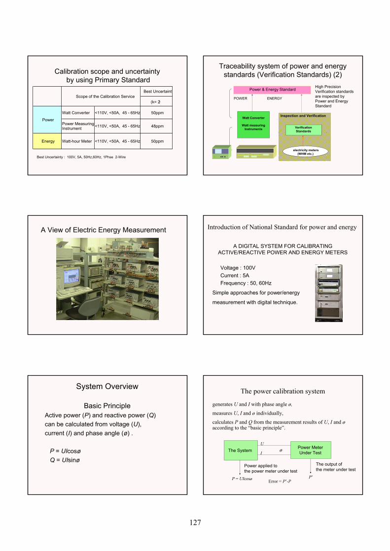
Calibration scope and uncertaintyby using Primary Standard
Best Uncertainty
(k= 2)
Watt Converter <110V, <50A, 45 - 65Hz 50ppm
Power MeasuringInstrument <110V, <50A, 45 - 65Hz 48ppm
Energy Watt-hour Meter <110V, <50A, 45 - 65Hz 50ppm
Scope of the Calibration Service
Power
Best Uncertainty : 100V, 5A, 50Hz,60Hz, 1Phse 2-Wire
Traceability system of power and energy standards (Verification Standards) (2)
Inspection and Verification
Power & Energy Standard
Watt Converter
Watt measuring Instruments Verification
Standards
ENERGY
electricity meters (WHM etc.)
POWER
High Precision Verification standards are inspected by Power and Energy Standard
A View of Electric Energy Measurement Introduction of National Standard for power and energy
A DIGITAL SYSTEM FOR CALIBRATING ACTIVE/REACTIVE POWER AND ENERGY METERS
Voltage : 100VCurrent : 5AFrequency : 50, 60Hz
Simple approaches for power/energy
measurement with digital technique.
System Overview
Basic PrincipleActive power (P) and reactive power (Q)can be calculated from voltage (U), current (I) and phase angle (ø) .
P = UIcosøQ = UIsinø
The power calibration system
generates U and I with phase angle ø,
measures U, I and ø individually,
calculates P and Q from the measurement results of U, I and øaccording to the “basic principle”.
The SystemPower MeterUnder Test
U
I ø
P = UIcosø P’
The output ofthe meter under test
Error = P’-P
Power applied tothe power meter under test
127
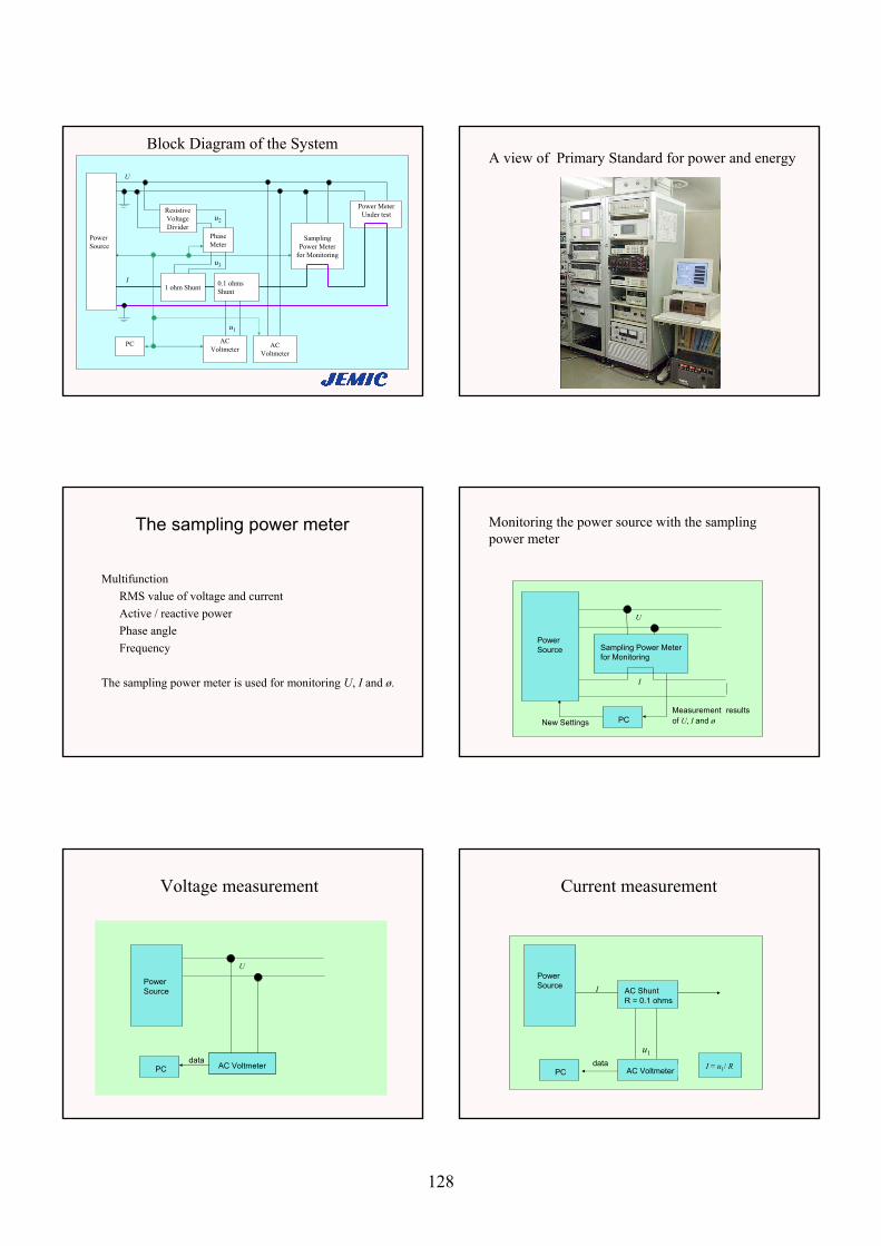
Block Diagram of the System
ResistiveVoltageDivider
Power MeterUnder test
SamplingPower Meter
for Monitoring
PC
PhaseMeter
Power Source
I
u2
u3
u1
U
1 ohm Shunt 0.1 ohms Shunt
ACVoltmeter
ACVoltmeter
A view of Primary Standard for power and energy
The sampling power meter
MultifunctionRMS value of voltage and currentActive / reactive powerPhase angleFrequency
The sampling power meter is used for monitoring U, I and ø.
Monitoring the power source with the sampling power meter
U
Measurement resultsof U, I and øNew Settings
I
Sampling Power Meterfor Monitoring
PowerSource
PC
Voltage measurement
U
PowerSource
PCdata
AC Voltmeter
Current measurement
IPowerSource
AC ShuntR = 0.1 ohms
AC Voltmeter
u1
I = u1/ RPCdata
128
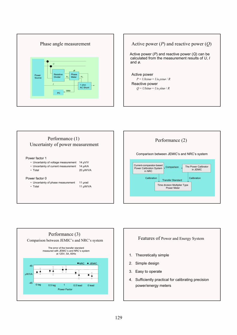
Phase angle measurement
I
U
ResistiveDivider
1 ohmAC Shunt
u2 u3PowerSource
ø
PCdata
PhaseMeter
Active power (P) and reactive power (Q)
Active power (P) and reactive power (Q) can be calculated from the measurement results of U, Iand ø.
Active powerP = UIcosø = Uu1cosø / R
Reactive powerQ = UIsinø = Uu1sinø / R
Performance (1)Uncertainty of power measurement
Power factor 1• Uncertainty of voltage measurement 14 µV/V• Uncertainty of current measurement 14 µA/A• Total 20 µW/VA
Power factor 0• Uncertainty of phase measurement 11 µrad• Total 11 µW/VA
Performance (2)
Comparison between JEMIC’s and NRC’s system
Current-comparator-basedPower Calibration System
in NRC
The Power Calibratorin JEMIC
Transfer Standard
Comparison
Calibration
Time division Multiplier TypePower Meter
Calibration
Performance (3)Comparison between JEMIC’s and NRC’s system
The error of the transfer standardmeasured with JEMIC’s and NRC’s system
at 120V, 5A, 60Hz
µW/VA
45
-4510.5 lag 0.5 lead 0 lead0 lag
Power Factor
NRC JEMIC
Features of Power and Energy System
1. Theoretically simple
2. Simple design
3. Easy to operate
4. Sufficiently practical for calibrating precision power/energy meters
129
Summery of Verification Standards
1. The verification equipment must be traceable to national standards and be inspected by JEMIC.
2. Traceable to the primary standards on energy measurements are essential to maintain a fair trade.
3. A fair trade is to contribute for consume confidence.
Thank you for your Attention
130
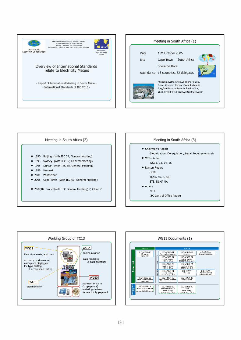
Asia-PacificLegal Metrology
Forum
Overview of International Standardsrelate to Electricity Meters
- Report of International Meeting in South Africa -- International Standards of IEC TC13 -
APEC/APLMF Seminars and Training Courses in Legal Metrology; (CTI-10/2005T)Training Course on Electricity Meters
February 28 - March 3, 2006, Ho Chi Minh City, Vietnam
Meeting in South Africa (1)
Meeting in South Africa (2) Meeting in South Africa (3)
Working Group of TC13 WG11 Documents (1)
131
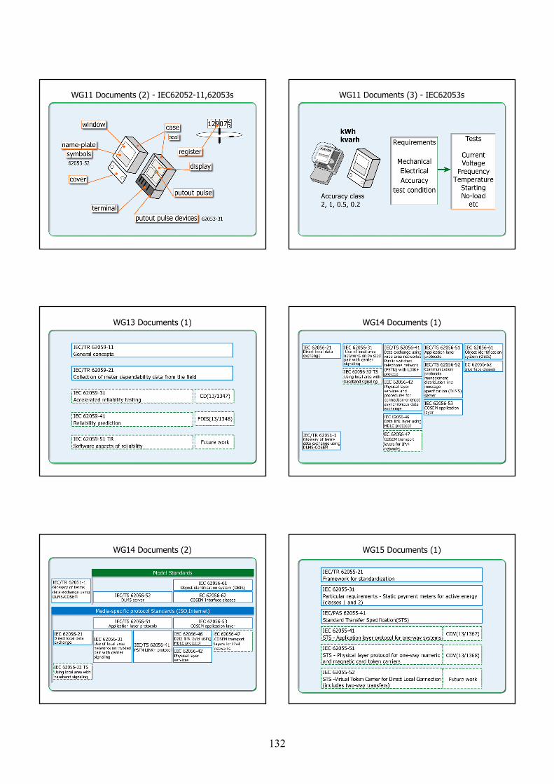
WG11 Documents (2) - IEC62052-11,62053s WG11 Documents (3) - IEC62053s
WG13 Documents (1) WG14 Documents (1)
WG14 Documents (2) WG15 Documents (1)
132
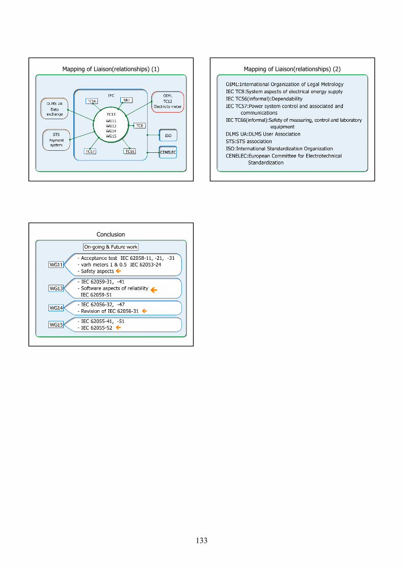
Mapping of Liaison(relationships) (1) Mapping of Liaison(relationships) (2)
Conclusion
133

Asia-PacificLegal Metrology
Forum
Current Situationof
the Revision of OIML Recommendation
- Draft of R46 Electricity Meters -
APEC/APLMF Seminars and Training Courses in Legal Metrology; (CTI-10/2005T)Training Course on Electricity Meters
February 28 - March 3, 2006, Ho Chi Minh City, Vietnam
Introduction
Progress Outline of Contents(1)
20 pages20 pages over 40 pagesover 40 pages
Outline of Contents(2) Outline of Contents(3)
15 test items15 test items over 30 test itemsover 30 test items
134
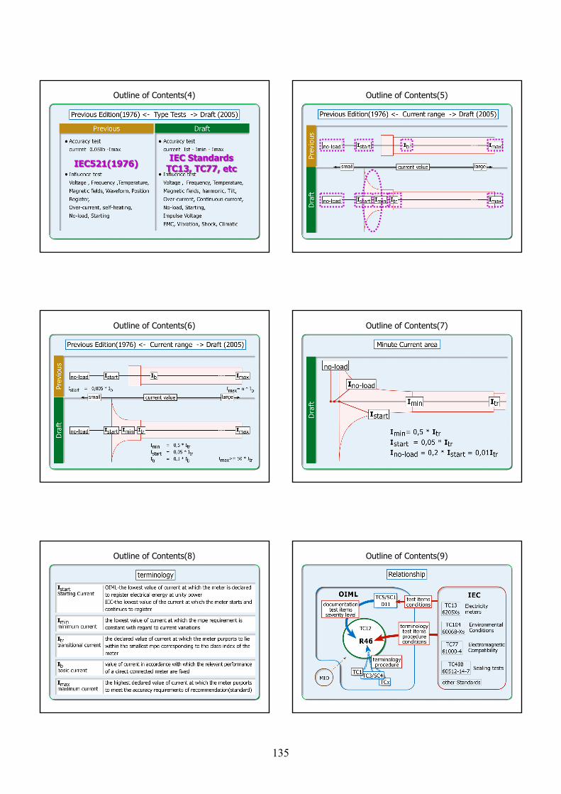
Outline of Contents(4)
IEC521(1976)IEC521(1976) IEC StandardsTC13, TC77, etcIEC Standards
TC13, TC77, etc
Outline of Contents(5)
Outline of Contents(6) Outline of Contents(7)
Outline of Contents(8) Outline of Contents(9)
135
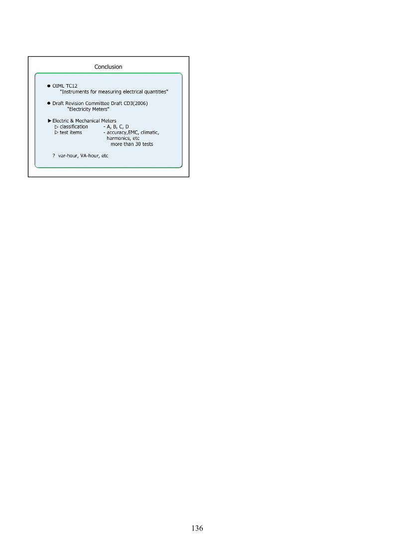
Conclusion
136
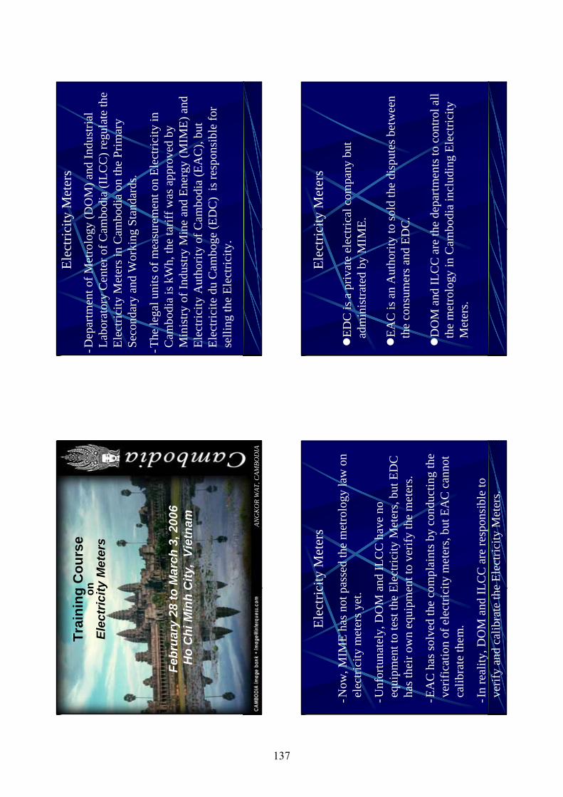
ANG
KO
R W
AT, C
AMBO
DIA
Trai
ning
Cou
rse
onEl
ectr
icity
Met
ers
Febr
uary
28
to M
arch
3, 2
006
Ho
Chi
Min
hC
ity,
Viet
nam
Elec
trici
ty M
eter
s-D
epar
tmen
t of M
etro
logy
(DO
M) a
nd In
dust
rial
Labo
rato
ry C
ente
r of C
ambo
dia
(ILC
C) r
egul
ate
the
Elec
trici
ty M
eter
s in
Cam
bodi
a on
the
Prim
ary
Se
cond
ary
and
Wor
king
Sta
ndar
ds.
-The
lega
l uni
ts o
f mea
sure
men
t on
Elec
trici
ty in
C
ambo
dia
is k
Wh,
the
tarif
f was
app
rove
d by
M
inis
try o
f Ind
ustry
Min
e an
d En
ergy
(MIM
E) a
nd
Elec
trici
ty A
utho
rity
of C
ambo
dia
(EA
C),
but
Elec
trici
tedu
Cam
boge
(ED
C)
is re
spon
sibl
e fo
r se
lling
the
Elec
trici
ty.
-Now
, MIM
E ha
s not
pas
sed
the
met
rolo
gy la
w o
n el
ectri
city
met
ers y
et.
-Unf
ortu
nate
ly, D
OM
and
ILC
C h
ave
no
equi
pmen
t to
test
the
Elec
trici
ty M
eter
s, bu
t ED
C
has t
heir
own
equi
pmen
t to
verif
y th
e m
eter
s.
-EA
C h
as so
lved
the
com
plai
nts b
y co
nduc
ting
the
verif
icat
ion
of e
lect
ricity
met
ers,
but E
AC
can
not
calib
rate
them
.
-In
real
ity, D
OM
and
ILC
C a
re re
spon
sibl
e to
ve
rify
and
calib
rate
the
Elec
trici
ty M
eter
s.
Elec
trici
ty M
eter
s
EDC
is a
priv
ate
elec
trica
l com
pany
but
ad
min
istra
ted
by M
IME.
EAC
is a
n A
utho
rity
to so
ld th
e di
sput
es b
etw
een
the
cons
umer
s and
ED
C.
DO
M a
nd IL
CC
are
the
depa
rtmen
ts to
con
trol a
ll th
e m
etro
logy
in C
ambo
dia
incl
udin
g El
ectri
city
M
eter
s.
Elec
trici
ty M
eter
s
137
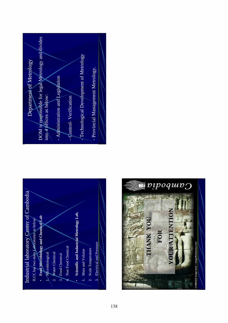
ILC
C h
as tw
o m
ain
Labo
rato
ries a
s bel
ow:
•Fo
od M
icro
biol
ogy
and
Che
mic
al L
ab
1.M
icro
biol
ogic
al
2.W
ater
Che
mic
al
3.Fo
od C
hem
ical
4.N
on F
ood
Che
mic
al
•Sc
ient
ific
and
Indu
stri
al M
etro
logy
Lab
.
1.M
ass a
nd V
olum
e
2.Sc
ale
Tem
pera
ture
3.El
ectri
cal a
nd P
ress
ure
Indu
stria
l lab
orat
ory
Cen
ter o
f Cam
bodi
a
DO
M is
resp
onsi
ble
for l
egal
Met
rolo
gy a
nd d
ivid
es
into
4 o
ffic
es a
s bel
ow:
-Adm
inis
tratio
n an
d Le
gisl
atio
n
-Con
trol-
Ver
ifica
tion
-Tec
hnol
ogic
al D
evel
opm
ent o
f Met
rolo
gy
-Pro
vinc
ial M
anag
emen
t Met
rolo
gy.
Dep
artm
ent o
f Met
rolo
gy
TH
AN
K Y
OU
FOR
YO
UR
AT
TE
NT
ION
138
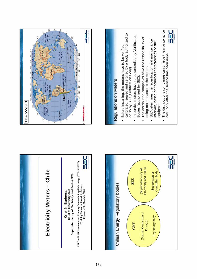
Elec
tric
ity
Met
ers
–C
hile
Cri
stiá
n E
spin
osa
Ch
ief
of E
lect
rici
ty A
rea
Supe
rin
ten
den
cy o
f El
ectr
icit
y an
d Fu
els
(SEC
)
APE
C/A
PLM
F Se
min
ars a
nd T
rain
ing
Cou
rses
in L
egal
Met
rolo
gy (C
TI-
10/2
005T
)T
rain
ing
Cou
rse
on E
lect
rici
ty M
eter
sFe
brua
ry 2
8 -M
arch
3, 2
006
Chi
leSa
ntia
go
Chile
an E
nerg
y Reg
ulat
ory
bodi
es
CN
E
(Nat
inal
Com
issi
on o
f En
ergy
)
Reg
ulat
ory
body
SEC
(Sup
erin
tend
ency
of
Elec
trici
ty a
nd F
uels
)
Supe
rvis
ion
or
Con
trolle
r bo
dy
Reg
ulat
ions
on
Met
ers
•Be
fore
inst
allin
g, t
he m
eter
s ha
ve t
o be
ver
ified
, ca
libra
ted,
sea
led
and
cert
ified
by
a bo
dy a
utho
rized
to
do s
o by
SEC
(Ce
rtifi
catio
n Bo
dy).
•In
ser
vice
met
ers
have
to
be c
ontr
olle
d by
Ver
ifica
tion
Bodi
es (
auth
oriz
ed b
y SE
C).
•Th
e di
strib
utio
n co
mpa
nies
hav
e th
e re
spon
sibi
lity
of
doin
g m
aint
enan
ce t
o th
e m
eter
s.•
SEC
dete
rmin
es t
he r
ever
ifica
tion
and
mai
nten
ance
in
terv
als,
bas
ed o
n te
chni
cal c
hara
cter
istic
s of
the
eq
uipm
ent.
•Th
e di
strib
utio
ns c
ompa
nies
can
cha
rge
the
mai
nten
ance
co
st, on
ly a
fter
the
ser
vice
has
bee
n do
ne.
139
Som
e Fa
cts
•Th
ere
are
abou
t 5.
000.
000
elec
tric
ity c
usto
mer
s an
d m
eter
s in
Chi
le.
•Th
e di
strib
utio
n co
mpa
nies
ow
n ab
out
half
of t
hese
m
eter
s, a
nd r
ent
them
to
the
cust
omer
s (t
he t
ariff
in
clud
es m
aint
enan
ce).
•Th
e cu
stom
ers
that
ow
n th
e m
eter
s ha
ve t
o pa
y th
e “m
aint
enan
ce”
(rev
erifi
catio
n).
•Bo
th p
rices
are
set
by
a ta
riff
fixin
g pr
oces
s, le
ad b
y CN
E.•
The
Verif
icat
ion
Bodi
es a
re in
depe
nden
t co
mpa
nies
ow
ned
by t
he d
istr
ibut
ion
com
pani
es (
subs
idia
ries)
.
Mai
nten
ance
Tar
iff•
Mai
nten
ance
and
ren
t ta
riffs
are
ver
y si
mila
r in
pre
sent
va
lue,
but
the
ren
t is
a p
er m
onth
tar
iff.
•Th
e m
aint
enan
ce t
ariff
was
cal
cula
ted
with
a r
ever
ifica
tion
inte
rval
for
cus
tom
er o
wne
d m
eter
s of
4 y
ears
.•
The
tarif
f de
cree
indi
cate
s th
at t
he in
terv
al w
ill b
e 4
year
s un
til S
EC d
eter
min
es a
diff
eren
t in
terv
al.
•SE
C de
term
ined
10
year
s. T
he G
over
nmen
t N
atio
nal
Cont
rolle
r di
ctat
ed t
hat
SEC
cann
ot d
o th
is u
ntil
a ne
w
tarif
f pr
oces
s is
hel
d. S
EC a
ppea
led.
•
Very
unp
opul
ar s
ervi
ce•
Cost
: U
S$ 2
0 to
US$
35,
dep
endi
ng o
n th
e ta
riff
area
.•
Rec
lam
atio
ns f
rom
cus
tom
ers
and
auth
oriti
es
Mea
sure
men
t com
plai
nt/d
ispu
te re
solu
tion
proc
ess
•If
a c
usto
mer
s as
ks f
or a
rev
erifi
catio
n, t
he
dist
ribut
ion
com
pany
has
to
do s
o by
an
auth
oriz
ed
Verif
icat
ion
Body
.•
If t
he m
eter
is O
K,th
e re
verif
icat
ion
is p
aid
by t
he
cust
omer
, oth
erw
ise
paid
by
the
com
pany
.
Elec
tric
ity
Met
ers
–C
hile
Cri
stiá
n E
spin
osa
Ch
ief
of E
lect
rici
ty A
rea
Supe
rin
ten
den
cy o
f El
ectr
icit
y an
d Fu
els
(SEC
)
APE
C/A
PLM
F Se
min
ars a
nd T
rain
ing
Cou
rses
in L
egal
Met
rolo
gy (C
TI-
10/2
005T
)T
rain
ing
Cou
rse
on E
lect
rici
ty M
eter
sFe
brua
ry 2
8 -M
arch
3, 2
006
140
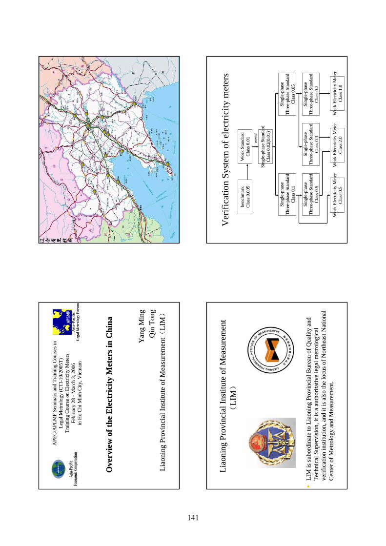
APE
C/A
PLM
F Se
min
ars a
nd T
rain
ing
Cou
rses
in
APE
C/A
PLM
F Se
min
ars a
nd T
rain
ing
Cou
rses
in
Lega
l Met
rolo
gy (C
TILe
gal M
etro
logy
(CTI
-- 10/
2005
T)10
/200
5T)
Trai
ning
Cou
rse
on E
lect
ricity
Met
ers
Trai
ning
Cou
rse
on E
lect
ricity
Met
ers
Febr
uary
28
Febr
uary
28
-- Mar
ch 3
, 200
6M
arch
3, 2
006
in H
o C
hi
in H
o C
hi M
inh
Min
hC
ity, V
ietn
amC
ity, V
ietn
am
Ove
rvie
w o
f the
Ele
ctri
city
Met
ers i
n C
hina
Ove
rvie
w o
f the
Ele
ctri
city
Met
ers i
n C
hina
Yan
g Y
ang
Min
g M
ing
Qin
Qin
Tong
Tong
Liao
ning
Liao
ning
Prov
inci
al In
stitu
te o
f Mea
sure
men
tPr
ovin
cial
Inst
itute
of M
easu
rem
ent ((
LIM
LIM))
Asi
a–Pa
cific
Leg
al M
etro
logy
For
um
Liao
ning
Liao
ning
Prov
inci
al In
stitu
te o
f Mea
sure
men
tPr
ovin
cial
Inst
itute
of M
easu
rem
ent
((LI
MLI
M))
••LI
M is
subo
rdin
ate
to
LIM
is su
bord
inat
e to
Lia
onin
gLi
aoni
ngPr
ovin
cial
Bur
eau
of Q
ualit
y an
d Pr
ovin
cial
Bur
eau
of Q
ualit
y an
d Te
chni
cal S
uper
visi
on, i
t is a
aut
horit
ativ
e le
gal m
etro
logi
cal
Tech
nica
l Sup
ervi
sion
, it i
s a a
utho
ritat
ive
lega
l met
rolo
gica
l ve
rific
atio
n in
stitu
tion,
and
it is
als
o th
e lo
cus o
f Nor
thea
st
verif
icat
ion
inst
itutio
n, a
nd it
is a
lso
the
locu
s of N
orth
east
Nat
iona
l N
atio
nal
Cen
ter o
f Met
rolo
gy a
nd M
easu
rem
ent.
C
ente
r of M
etro
logy
and
Mea
sure
men
t.
Ver
ifica
tion
Syst
em o
f ele
ctric
ity m
eter
s
benc
hmar
kbe
nchm
ark
Cla
ss 0
.005
Cla
ss 0
.005
Wor
k St
anda
rdW
ork
Stan
dard
Cla
ss 0
.01
Cla
ss 0
.01
amen
dam
end
Sing
leSi
ngle
-- pha
se S
tand
ard
phas
e St
anda
rdC
lass
0.0
2(0.
01)
Cla
ss 0
.02(
0.01
)
Sing
leSi
ngle
-- pha
seph
ase
Thre
eTh
ree --
phas
e St
anda
rdph
ase
Stan
dard
Cla
ss 0
.1C
lass
0.1
Sing
leSi
ngle
-- pha
seph
ase
Thre
eTh
ree --
phas
e St
anda
rdph
ase
Stan
dard
Cla
ss 0
.05
Cla
ss 0
.05
Sing
leSi
ngle
-- pha
seph
ase
Thre
eTh
ree --
phas
e St
anda
rdph
ase
Stan
dard
Cla
ss 0
.5C
lass
0.5
Sing
leSi
ngle
-- pha
seph
ase
Thre
eTh
ree --
phas
e St
anda
rdph
ase
Stan
dard
Cla
ss 0
.3C
lass
0.3
Sing
leSi
ngle
-- pha
seph
ase
Thre
eTh
ree --
phas
e St
anda
rdph
ase
Stan
dard
Cla
ss 0
.2C
lass
0.2
Wor
k El
ectri
city
Met
erW
ork
Elec
trici
ty M
eter
Cla
ss 0
.5C
lass
0.5
Wor
k El
ectri
city
Met
erW
ork
Elec
trici
ty M
eter
Cla
ss 2
.0C
lass
2.0
Wor
k El
ectri
city
Met
erW
ork
Elec
trici
ty M
eter
Cla
ss 1
.0C
lass
1.0
141
OOrg
aniz
atio
n(s
rgan
izat
ion(
s ) ) w
hich
w
hich
regu
late
the
mea
sure
men
t re
gula
te th
e m
easu
rem
ent
of e
lect
ricity
in
of e
lect
ricity
in o
urour e
cono
my
econ
omy
••In
our
eco
nom
y, th
e m
easu
rem
ent o
f ele
ctric
ity is
In
our
eco
nom
y, th
e m
easu
rem
ent o
f ele
ctric
ity is
re
gula
ted
by
regu
late
d by
Gen
eral
Adm
inis
tratio
n of
Qua
lity
Gen
eral
Adm
inis
tratio
n of
Qua
lity
Supe
rvis
ion,
Insp
ectio
n an
d Q
uara
ntin
e of
the
Peop
le's
Supe
rvis
ion,
Insp
ectio
n an
d Q
uara
ntin
e of
the
Peop
le's
Rep
ublic
of C
hina
Rep
ublic
of C
hina
. (A
QSI
Q)
. (A
QSI
Q)
The
lega
l uni
ts o
f mea
sure
for t
he sa
le o
f el
ectri
city
•kW
h
•kV
ARh
•kV
Ah
TT ypeype
AApp
rova
lpp
rova
l••
All
kind
s of e
lect
ricity
met
ers r
equi
re a
ppro
val o
f typ
e te
st.
All
kind
s of e
lect
ricity
met
ers r
equi
re a
ppro
val o
f typ
e te
st.
••Th
e ap
prov
al o
f typ
e te
st in
clud
es in
sula
tion
perf
orm
ance
Th
e ap
prov
al o
f typ
e te
st in
clud
es in
sula
tion
perf
orm
ance
te
st, a
ccur
acy
dem
and
test
, ele
ctric
dem
and
test
, EM
C te
st,
test
, acc
urac
y de
man
d te
st, e
lect
ric d
eman
d te
st, E
MC
test
, cl
imat
ic in
fluen
ce te
st, m
echa
nism
dem
and
test
.cl
imat
ic in
fluen
ce te
st, m
echa
nism
dem
and
test
.
••O
nly
the
orga
niza
tion
of m
etro
logy
and
mea
sure
men
t whi
ch
Onl
y th
e or
gani
zatio
n of
met
rolo
gy a
nd m
easu
rem
ent w
hich
be
aut
horiz
ed b
y A
QSI
Q c
an d
o th
e ap
prov
al o
f typ
e te
st.
be a
utho
rized
by
AQ
SIQ
can
do
the
appr
oval
of t
ype
test
.
••El
ectri
city
met
ers c
an b
e pr
oduc
ed a
fter t
hey
pass
ed
Elec
trici
ty m
eter
s can
be
prod
uced
afte
r the
y pa
ssed
ap
prov
al o
f typ
e te
st.
appr
oval
of t
ype
test
.
Met
er V
erifi
catio
n Te
stin
g
•M
eter
ver
ifica
tion
test
ing
is re
quire
d.
•Th
e ve
rific
atio
n ce
ntre
of e
lect
ricity
met
ers
whi
ch b
e au
thor
ized
by
AQ
SIQ
can
do
the
met
er v
erifi
catio
n te
stin
g.
•Te
sts a
re p
erfo
rmed
on
met
ers i
n se
rvic
e.
142
Re
Re --
verif
icat
ion
Inte
rval
sve
rific
atio
n In
terv
als
Dom
estic
Sin
gle
Dom
estic
Sin
gle --
phas
e M
eter
phas
e M
eter
Bas
ic In
duct
ion
Met
erB
asic
Indu
ctio
n M
eter
Elec
troni
c M
eter
Elec
troni
c M
eter
5 ye
ars
5 ye
ars
Sing
leSi
ngle
-- dia
mon
d A
xlet
ree
diam
ond
Axl
etre
e5
year
s 5
year
s D
oubl
eD
oubl
e --di
amon
d A
xlet
ree
diam
ond
Axl
etre
e10
yea
rs10
yea
rs
Than
k yo
u fo
r you
r Atte
ntio
n
143
Elec
tric
ity M
eter
M
easu
rem
ent S
yste
m in
Indo
nesi
a
M H
EN
DR
O P
UR
NO
MO
OVE
RVI
EW
Num
ber o
f el
ectri
city
met
er in
stal
led
is
mor
e th
an 3
8 m
illio
n
All
of e
lect
ricity
met
er a
re b
elon
ging
to
PLN
(Nat
iona
l Ele
ctric
ity C
ompa
ny)
OVE
RVI
EW
Dire
ctor
ate
of M
etro
logy
(DoM
) is
inst
itutio
n un
der M
inis
try o
f Tra
de h
as re
spon
sibl
e to
ca
rry
out l
egal
met
rolo
gy in
Indo
nesi
a
Min
istry
of T
rade
regu
late
the
mea
sure
men
t of
ele
ctric
ity i
n In
done
sia
(ME
T-40
05/3
548/
VIII
/199
1)
OVE
RVI
EW
Ele
ctric
ity m
eter
is a
lega
l met
rolo
gy
mea
surin
g in
stru
men
t w
hich
mus
t pas
s in
ve
rific
atio
n an
d re
-ver
ifica
tion
Dire
ctor
ate
of M
etro
logy
(DoM
) per
form
s
appr
oval
of t
ype,
ver
ifica
tion,
re-
verif
icat
ion
test
144
OVE
RVI
EW
Met
ers
are
give
n a
re-v
erifi
catio
n ev
ery
10 y
ears
The
lega
l uni
ts o
f mea
sure
for t
he s
ale
of e
lect
ricity
are
:-
kWh
(res
iden
ce)
-kv
arh
(fact
ory)
CU
RR
ENT
SITU
ATI
ON
14 m
illio
ns m
eter
s m
ust b
e re
-ver
ify a
nd
finis
hed
in 2
007
Dom
and
RV
O c
ould
not
han
dle
Third
par
ty n
eede
d
145
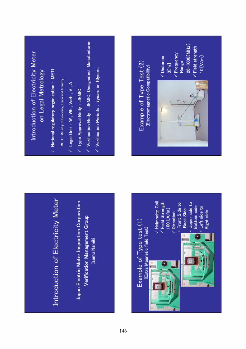
Intr
odu
ction o
f Ele
ctr
icity
Mete
r
Jap
an E
lectr
ic M
ete
r In
spection C
orp
ora
tion
Verificat
ion M
anag
em
ent
Gro
up
Isam
u N
amik
i
Intr
odu
ction o
f Ele
ctr
icity
Mete
ron L
ega
l M
etr
olo
gy
Nat
ional
regu
lato
ry o
rgan
izat
ion :
METI
METI:
Min
istr
y of
Econom
y,Tra
de a
nd
Indust
ry
Lega
l U
nit :
W , W
h , V
arh , V
, A
Typ
e A
ppro
val B
ody
:JEM
IC
Verificat
ion B
ody
:JEM
IC, D
esi
gnat
ed
Man
ufa
ctu
rer
Verificat
ion
Periods
:7ye
ars
or
10ye
ars
Exa
mpl
e o
f Typ
e t
est
(1)
(Ext
ra M
agnetic f
ield
Test
) Helm
holtz
Coil
Fie
ld S
trengt
h100 〔
A/m
〕D
irection
・Fro
nt
Sid
e t
oB
ack
Sid
e・
Upper
side
to
Bott
om
sid
e・
Left
sid
e t
oR
ight
side
Exa
mpl
e o
f Typ
e T
est
(2)
(Ele
ctr
om
agnetic C
om
pat
ibili
ty)
Dis
tance
3〔m
〕
Fre
quency
Ran
ge
26-1000〔M
Hz〕
Fie
ld s
trengt
h
10〔V
/m
〕
146
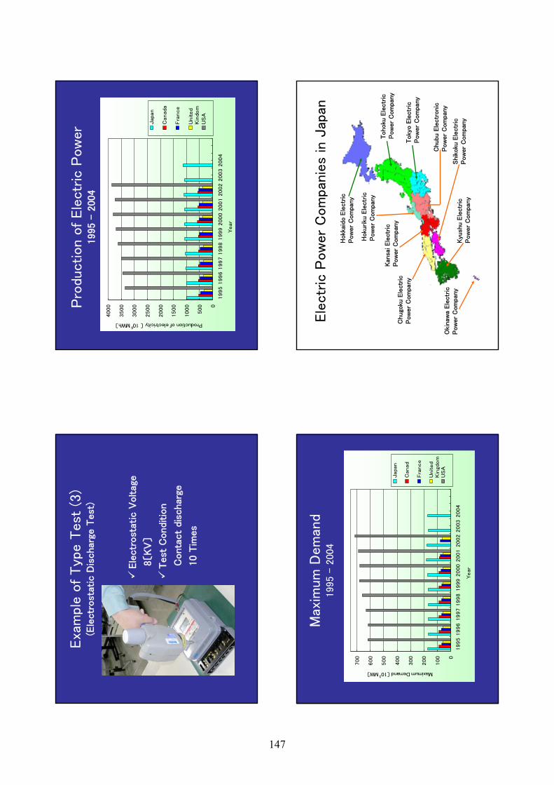
Exa
mpl
e o
f Typ
e T
est
(3)
(Ele
ctr
ost
atic
Dis
char
ge T
est
)
Ele
ctr
ost
atic
Voltag
e
8〔KV
〕
Test
Conditio
n
Conta
ct
disc
har
ge
10 T
imes
Pro
duction o
f Ele
ctr
ic P
ow
er
1995 –
2004
0
500
1000
1500
2000
2500
3000
3500
4000
1995
1996
1997
1998
1999
2000
2001
2002
2003
2004
Year
Production of electricity 〔 106 MWh〕
Japan
Canada
Fra
nce
United
Kin
dom
US
A
Max
imum
Dem
and
1995 -
2004
0
100
200
300
400
500
600
700
1995
1996
1997
1998
1999
2000
2001
2002
2003
2004
Year
Maximum Demand 〔103 MW〕
Japan
Canad
Fra
nce
United
Kin
gdom
US
A
Ele
ctr
ic P
ow
er
Com
panie
s in
Jap
an
Hokk
aido E
lectr
ic
Pow
er
Com
pany
Tohoku
Ele
ctr
icP
ow
er
Com
pany
Toky
o E
lectr
ic
Pow
er
Com
pany
Chubu E
lectr
onic
P
ow
er
Com
pany
Kan
sai Ele
ctr
ic
Pow
er
Com
pany
Shik
oku
Ele
ctr
ic
Pow
er
Com
pany
Chugo
ku E
lectr
ic
Pow
er
Com
pany
Kyu
shu E
lectr
ic
Pow
er
Com
pany
Hoku
riku
Ele
ctr
ic
Pow
er
Com
pany
Oki
naw
a Ele
ctr
ic
Pow
er
Com
pany
147
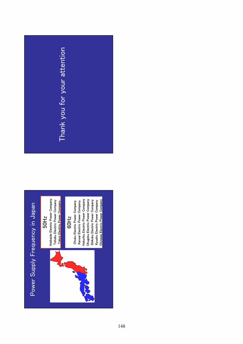
Pow
er
Supp
ly F
requ
ency
in J
apan
50H
zH
okk
aido E
lectr
ic P
ow
er
Com
pan
y
Tohoku
Ele
ctr
ic P
ow
er
Com
pan
y
Toky
o E
lectr
ic P
ow
er
Com
pany
60H
zC
hubu E
lectr
ic P
ow
er
Com
pan
y
Kan
sai Ele
ctr
ic P
ow
er
Com
pany
Hoku
riku
Ele
ctr
ic P
ow
er
Com
pan
y
Chugo
ku E
lectr
ic P
ow
er
Com
pan
y
Shik
oku
Ele
ctr
ic P
ow
er
Com
pan
y
Kyu
shu E
lectr
ic P
ow
er
Com
pany
Oki
naw
a Ele
ctr
ic P
ow
er
Com
pan
y
Than
k yo
u f
or
your
atte
ntion
148
Trai
ning
Cou
rses
Tr
aini
ng C
ours
es
onon
Coun
try
repo
rt o
f M
etro
logy
in L
ao
PDR
Coun
try
repo
rt o
f M
etro
logy
in L
ao
PDR
Febr
uary
28
Fe
brua
ry
28 --
Mar
ch 3
,200
6
in H
o Ch
i M
arch
3,2
006
in
Ho
Chi M
inh
Min
hCi
ty,V
ietn
amCi
ty,V
ietn
am
Bac
kgro
un
d
Lao
peap
le’s
Dem
ocra
tic R
epub
lic (
Lao
PDR)
esta
blis
hed
Dep
artm
ent
of I
ntel
lect
ual p
rope
rty
Stan
dard
izat
ion
and
Met
rolo
gy (
DIS
M)
in 1
993.
Th
e M
etro
logy
Div
isio
n (M
D)
that
car
ries
out
indu
stria
l and
lega
l Met
rolo
gy a
ctiv
ities
is o
ne o
f th
e fo
ur D
ivis
ions
tha
t fu
nctio
n w
ithin
the
pu
rvie
w o
f th
e D
epar
tmen
t of
Int
elle
ctua
l Pr
oper
ty, S
tand
ardi
zatio
n an
d M
etro
logy
(D
ISM
) es
tabl
ishe
d un
der
the
Scie
nce,
Tec
hnol
ogy
and
Envi
ronm
ent
Agen
cy (
STEA
).
This
age
ncy,
whi
ch is
a G
over
nmen
t bo
dy, i
s th
e fo
cal p
oint
res
pons
ible
for
adv
isin
g th
e G
over
nmen
t on
issu
es o
f St
anda
rds,
Met
rolo
gy,
Test
ing
and
Qua
lity
(SM
TQ).
MD
is g
over
ned
by t
he D
ecre
e on
Met
rolo
gy
man
agem
ent
of L
ao P
DR is
sued
in 1
993
as w
ell
as a
reg
ulat
ion
on M
easu
ring
inst
rum
ents
issu
ed
in 1
995.
Ano
ther
reg
ulat
ion
that
has
bee
n is
sued
ha
s be
en w
ith r
espe
ct t
o th
e re
gist
ratio
n of
fue
l di
spen
ser
pum
ps in
200
1. R
egul
atio
ns
are
bein
g pr
epar
ed p
rese
ntly
for
pre
-pac
kage
d fo
ods
and
road
tan
kers
.
149
The
Met
rolo
gy D
ivis
ion
is pr
esen
tly
Viet
nam
is
prov
idin
g as
sist
ance
to
cons
truc
t an
d eq
uip
a N
atio
nal M
etro
logy
Cen
ter
The
revi
ewin
g a
draf
t M
etro
logy
law
, and
new
bui
ldin
g t
hat
will
hou
se
labo
rato
ry an
d ad
min
istr
ativ
e a
rea
is p
rese
ntly
un
der
cons
truc
tion.
STEA
has
use
d t
his
labo
rato
ry a
s th
e th
ird p
arty
fo
r co
ntro
l of
met
erin
g el
ectr
ic e
nerg
y in
the
w
hole
cou
ntry
. Thr
ough
the
cal
ibra
tion
of w
att-
met
er is
bei
ng c
ondu
cted
, it
is n
ot a
ctiv
ely
cond
ucte
d by
the
nat
iona
l adm
inis
trat
ive
body
an
d en
trus
ted
to t
he c
ompa
ny it
self
to c
alib
rate
du
e to
the
lack
of
refe
renc
e in
stru
men
t.
FUN
CTI
ON
S &
DU
TIES
OF
MET
RO
LOG
Y
DIV
ISIO
N (
MD
)
–Bei
ng a
cus
todi
an o
f na
tiona
l mea
sure
men
t st
anda
rds;
–Est
ablis
hmen
t an
d m
aint
enan
ce o
f in
tern
atio
nal
trac
eabi
lity
of n
atio
nal m
easu
rem
ent
stan
dard
s;
–Ver
ifica
tion
of m
easu
ring
equi
pmen
t us
ed in
tr
ade
and
com
mer
ce;
–Su
perv
isio
n, in
spec
tion
and
regi
stra
tion
of
mea
surin
g in
stru
men
ts;
–Pr
ovis
ion
of c
alib
ratio
n an
d tr
acea
bilit
yse
rvic
es t
o in
dust
rial a
nd c
omm
erci
al
esta
blis
hmen
ts;
–Co
oper
atio
n w
ith r
egio
nal a
nd in
tern
atio
nal
or
gani
satio
ns in
the
fie
ld o
f m
etro
logy
;
150
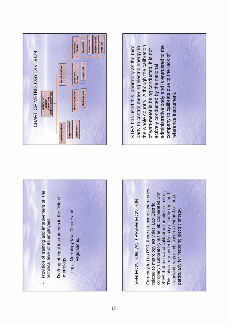
-Pr
ovis
ion
of t
rain
ing
and
impr
ovem
ent
of
the
tech
nica
l lev
el o
f its
em
ploy
ees;
-D
raft
ing
of le
gal i
nstr
umen
ts in
the
fie
ld o
f m
etro
logy
,
e.g.
)M
etro
logy
law
, Dec
ree
and
Reg
ulat
ions
.
CHAR
T O
F M
ETRO
LOG
Y D
IVIS
ION
CHAR
T O
F M
ETRO
LOG
Y D
IVIS
ION
MET
RO
LOG
Y D
IVIS
ION
(DIR
ECTO
R)
(DEP
UTY
DIR
ECTO
R)
MET
RO
LOG
Y D
IVIS
ION
(DIR
ECTO
R)
(DEP
UTY
DIR
ECTO
R)
Tech
nica
l Affa
irsTe
chni
cal A
ffairs
Legi
slat
ion
Affa
irsLe
gisl
atio
n A
ffairs
App
eal U
nit
App
eal U
nit
Legi
slat
ion
Uni
tLe
gisl
atio
n U
nit
Dim
ensi
ons
Sect
ion
Dim
ensi
ons
Sect
ion Leng
th U
nit
Leng
th U
nit
Elec
tric
ity S
ectio
nEl
ectr
icity
Sec
tion
Elec
tric
ity U
nit
Elec
tric
ity U
nit
Mec
hani
cal
Sect
ion
Mec
hani
cal
Sect
ion
Mas
s U
nit
Mas
s U
nit
Volu
me
Uni
tVo
lum
e U
nit
Pres
sure
For
cePr
essu
re F
orce
Forc
e U
nit
Forc
e U
nit
VERIF
ICAT
ION
AN
D R
EVER
IFIC
ATIO
NVE
RIF
ICAT
ION
AN
D R
EVER
IFIC
ATIO
N
Curr
ently
in L
ao P
DR, t
here
are
som
e la
bora
torie
s Cu
rren
tly in
Lao
PD
R, t
here
are
som
e la
bora
torie
s re
late
d to
met
rolo
gy a
ctiv
ities
. Lao
Ele
ctric
re
late
d to
met
rolo
gy a
ctiv
ities
. Lao
Ele
ctric
co
mpa
nyco
mpa
ny’’ s
Lab
orat
ory
is t
he la
b co
oper
ated
with
s
Labo
rato
ry is
the
lab
coop
erat
ed w
ith
STEA
tha
t te
sts
and
calib
rate
s th
e el
ectr
ic m
eter
.ST
EA t
hat
test
s an
d ca
libra
tes
the
elec
tric
met
er.
This
labo
rato
ry u
nder
Min
istr
y of
Ind
ustr
ies
and
This
labo
rato
ry u
nder
Min
istr
y of
Ind
ustr
ies
and
Han
dicr
aft
was
est
ablis
hed
to t
est
and
calib
rate
H
andi
craf
t w
as e
stab
lishe
d to
tes
t an
d ca
libra
te
part
icul
arly
for
met
erin
g el
ectr
ic e
nerg
y.pa
rtic
ular
ly f
or m
eter
ing
elec
tric
ene
rgy.
STE
A h
as u
sed
this
labo
rato
ry a
s th
e th
ird
party
to c
ontro
l met
erin
g el
ectri
c en
ergy
in
the
who
le c
ount
ry. A
lthou
gh th
e ca
libra
tion
of w
att-m
eter
is b
eing
con
duct
ed, i
t is
not
activ
ely
cond
ucte
d by
the
natio
nal
adm
inis
trativ
e bo
dy a
nd is
ent
rust
ed to
the
com
pany
to c
alib
rate
due
to th
e la
ck o
f re
fere
nce
inst
rum
ent.
151
The
lega
l met
rolo
gy o
n m
easu
ring
inst
rum
ents
by
the
insp
ecto
r of
met
rolo
gy is
to
see
if it
is
appr
opria
te e
noug
h on
the
Tec
hnic
al c
erta
inty
, and
le
galiz
ed b
y se
alin
g it
with
val
idity
mar
k an
d or
at
tach
ing
the
exam
inat
ion
resu
lt.
Verif
icat
ion
and
reve
rific
atio
nte
stin
g fo
r th
e el
ectr
ic
met
er a
re o
rgan
ized
in M
D.
Reve
rific
atio
nin
terv
al f
or e
lect
ricity
m
eter
is 1
0 ye
ars.
Met
rolo
gica
l Se
rvic
es
Met
rolo
gy D
ivis
ion
unde
r th
e Sc
ienc
e Te
chno
logy
an
d En
viro
nmen
t Ag
ency
is t
o m
anag
e an
d re
gula
te
stan
dard
mea
sure
men
t on
the
mea
sure
of
elec
tric
ity f
or le
gal m
etro
logy
mea
surin
g in
stru
men
t.
The
lega
l uni
ts o
f m
easu
re o
f th
e el
ectr
icity
met
ers
is K
ILO
WAT
T-H
OU
R or
WAT
T H
OU
R.
Than
k yo
u ve
ry m
uch
152
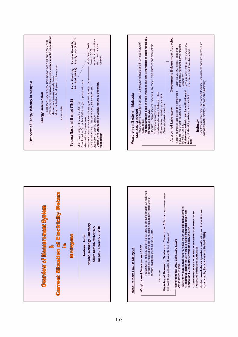
Nor
hisa
mIs
mai
lN
atio
nal M
etro
logy
Lab
orat
ory
SIR
IM B
erha
d, M
ALA
YSIA
Tues
day,
Feb
ruar
y 28
200
6
Ove
rvie
w o
f Ene
rgy
Indu
stry
in M
alay
sia
Ener
gy C
omm
issi
on-E
stab
lishe
d un
der E
nerg
y C
omm
issi
on A
ct 2
001
on 1
stM
ay 2
001
-Res
pons
ible
to re
gula
te th
e en
ergy
sup
ply
activ
ities
in M
alay
sia
-To
enfo
rce
ener
gy s
uppl
y la
ws
-Pro
mot
e fu
rther
dev
elop
men
t of t
he e
nerg
y
3 m
ain
utilit
ies
Tena
gaN
asio
nalB
erha
d (T
NB
)Sa
bah
Elec
tric
itySd
n. B
hd. (
SESB
)Sa
raw
ak E
lect
ricity
Supp
ly C
orp.
(SES
CO
)-M
ain
pow
er u
tility
in P
enin
sula
r Mal
aysi
a-E
stab
lishe
d in
Sep
tem
ber 1
990
thro
ugh
corp
orat
izat
ion
and
priv
atiz
atio
n by
gov
ernm
ent
-For
mer
ly k
now
n as
Nat
iona
l Ele
ctric
ity B
oard
(NEB
) in
1965
-Cor
e ac
tiviti
es a
re in
the
gene
ratio
n, tr
ansm
issi
on a
nd
dist
ribut
ion
of e
lect
ric e
nerg
y-U
nder
the
dist
ribut
ion,
ele
ctric
ity m
eter
s is
one
of t
he
mai
n ac
tivity
Inde
pend
ent P
ower
Prov
ider
(IPP
)-s
uppl
y to
mai
n ut
ilitie
s ab
out 4
0% in
200
2-1
9 IP
Ps
Mea
sure
men
t Law
in M
alay
sia
Wei
ghts
and
Mea
sure
Act
197
2 -P
resc
ribes
S.I
units
as
the
only
lega
l uni
ts to
be
used
thro
ugho
ut M
alay
sia
-Pro
vide
s fo
r the
est
ablis
hmen
t of n
atio
nal m
easu
rem
ent s
tand
ards
of
phys
ical
qua
ntiti
es b
ased
on
the
S.I u
nits
Enf
orce
men
t
Min
istr
y of
Dom
estic
Tra
de a
nd C
onsu
mer
Affa
ir -E
nfor
cem
ent D
ivis
ion
-Ele
ctric
ity m
eter
s, ta
xi m
eter
s, w
ater
met
er a
nd b
illin
g sy
stem
sin
te
leco
mm
unic
atio
n in
dust
ry a
re e
xem
pted
from
ver
ifica
tion
and
insp
ectio
n by
Insp
ecto
r of W
eigh
ts a
nd M
easu
res
-The
se in
stru
men
ts a
re in
stea
d to
be
verif
ied
and
test
ed b
y th
e re
spec
tive
desi
gnat
ed a
utho
ritie
s
-In th
e ca
se o
f ele
ctric
ity m
eter
s, v
erifi
catio
n an
d in
spec
tion
are
cond
ucte
d by
Ten
aga
Nas
iona
lBer
had
(TN
B)
-It i
s ga
zette
as
Insp
ecto
r of W
eigh
ts a
nd M
easu
res
4 am
endm
ents
: 198
1, 1
985,
199
0 &
199
2A
men
dmen
t in
1985
Mea
sure
men
t Sys
tem
in M
alay
sia
NM
L-SI
RIM
Ber
had
-Res
pons
ible
of e
stab
lishm
ent a
nd m
aint
enan
ce o
f nat
iona
l prim
ary
stan
dard
s of
m
easu
rem
ent
-All
mea
sure
men
t use
d in
trad
e tr
ansa
ctio
ns a
nd o
ther
fiel
ds o
f leg
al m
etro
logy
ar
e tr
acea
ble
to N
ML
-Ele
ctric
al –
smok
e m
eter
s, ra
dar g
un, l
uxm
eter
, sto
p w
atch
es a
nd a
lso
patte
rn
appr
oval
of p
arki
ng m
eter
-M
echa
nica
l –w
eigh
t, ba
lanc
e, ru
lers
-Flo
w-v
olum
e, c
apac
ity, p
rove
rtan
k-C
hem
istry
-bre
ath
anal
yzer
Gov
ernm
ent E
nfor
cem
ent A
genc
ies
Acc
redi
ted
Labo
rato
ry-A
bout
4 a
ccre
dite
d la
bora
torie
s in
ele
ctric
met
ers
incl
udin
g TN
B th
roug
h its
sub
sidi
ary,
TN
B M
eter
ing
Sdn.
Bhd
.-R
efer
ence
sta
ndar
ds u
sed
for v
erifi
catio
n an
d te
stin
g of
ele
ctric
ity m
eter
s ar
e tr
acea
ble
to
NM
L
-Suc
h as
MD
TC, p
olic
e, R
oad
and
Tran
spor
t Dep
artm
ent,
Envi
ronm
enta
l D
epar
tmen
t-M
easu
rem
ent i
nstru
men
ts u
sed
in la
w
enfo
rcem
ent a
re tr
acea
ble
to N
ML
Indu
stry
-Non
e tra
de m
easu
rem
ent u
sed
for m
anuf
actu
ring,
indu
stria
l and
sci
entif
ic p
urpo
ses
are
trace
able
to N
ML
dire
ctly
or t
o ac
cred
ited
labo
rato
ry
153
Lega
l uni
t
-The
lega
l uni
t use
d in
sal
e of
ele
ctric
ity is
kilo
wat
t hou
r (kW
h)
Patte
rn A
ppro
val
-Pat
tern
app
rova
l of e
lect
ricity
met
ers
is c
ompu
lsor
y an
d pe
rform
ed b
y TN
B.-A
dopt
ing
IEC
sta
ndar
d w
hich
is d
epen
ding
on
clas
s of
the
met
er.
-The
ele
ctric
ity m
eter
’s m
anuf
actu
rers
are
requ
ired
to a
ttach
the
resu
lts fr
om
certi
fied
inde
pend
ent l
abor
ator
y.
Elec
tric
ity M
eter
s Ve
rific
atio
n
-Ele
ctric
ity m
eter
s ve
rific
atio
n is
per
form
ed b
y TN
B.-F
or m
ediu
m a
nd h
igh
volta
ge c
onsu
mer
whi
ch e
lect
ricity
met
ers
used
of
tran
sfor
mer
, the
ver
ifica
tion
inte
rval
is o
nce
a ye
ar.
-For
low
vol
tage
con
sum
er, i
n si
ngle
pha
se o
r thr
ee p
hase
ele
ctric
ity
met
ers,
ther
e is
no
spec
ific
verif
icat
ion
inte
rval
.The
ver
ifica
tions
test
is d
one
whe
re th
ere
is s
ome
diffe
renc
es in
bill
stat
istic
or c
ompl
ain
byth
e co
nsum
ers.
Than
k Y
ou
154
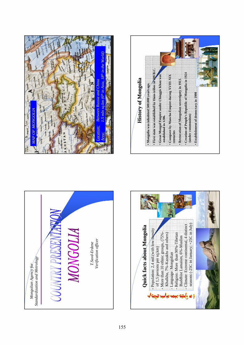
Mon
golia
n Ag
ency
for
Stan
dard
izat
ion
and
Met
rolo
gy
T.Su
vd-E
rden
eVe
rific
atio
n of
ficer
MAP
OF
MO
NG
OLI
AM
AP O
F M
ON
GO
LIA
Loca
tion:
Loca
tion:
Betw
een
Russ
ia a
nd C
hina
Betw
een
Russ
ia a
nd C
hina
Area
:Ar
ea:
1.5
1.5
mln
mln
sq.k
m (6
sq.k
m (6
ththin
Asi
a, 1
8in
Asi
a, 1
8thth
in th
e W
orld
)in
the
Wor
ld)
Qui
ck fa
cts a
bout
Mon
golia
Qui
ck fa
cts a
bout
Mon
golia
-Pop
ulat
ion:
2,4
mil.
(with
low
den
sity
of 1
,5 p
erso
ns p
er sq
.km
)-M
ore
than
10
ethn
ic g
roup
s, (7
5%-
Kha
lkha
, 7%
-Kaz
akhs
and
oth
ers)
-L
angu
age:
Mon
golia
n -R
elig
ion:
Mor
e th
an 9
0%-T
ibet
an
Bud
dhis
t Lam
aism
, 6%
-Mus
lim-C
limat
e: E
xtre
me
cont
inen
tal,
4 di
stin
ct
seas
ons (
-25C
in Ja
nuar
y; +
25C
in Ju
ly)
His
tory
of M
ongo
liaH
isto
ry o
f Mon
golia
•• Mon
golia
was
inha
bite
d 50
0.00
0 ye
ars a
go.
Mon
golia
was
inha
bite
d 50
0.00
0 ye
ars a
go.
•• Fir
st st
ate
was
est
ablis
hed
by H
uns t
ribe
s in
209
B.C
. Fi
rst s
tate
was
est
ablis
hed
by H
uns t
ribe
s in
209
B.C
.
•• Gre
at M
ongo
l Em
pire
und
er
Gre
at M
ongo
l Em
pire
und
er C
hing
gis
Chi
nggi
sK
han
was
K
han
was
es
tabl
ishe
d in
120
6.es
tabl
ishe
d in
120
6.
•• Con
ques
t by
Man
chu
Em
pire
dur
ing
XV
III
Con
ques
t by
Man
chu
Em
pire
dur
ing
XV
III --
XIX
X
IX
cent
urie
s ce
ntur
ies
•• Res
tora
tion
of M
ongo
lian
sove
reig
nty
in 1
911.
R
esto
ratio
n of
Mon
golia
n so
vere
ignt
y in
191
1.
•• Cre
atio
n of
Peo
ple'
s Rep
ublic
of M
ongo
lia in
192
4 C
reat
ion
of P
eopl
e's R
epub
lic o
f Mon
golia
in 1
924
(und
er c
omm
unis
m)
(und
er c
omm
unis
m)
•• Est
ablis
hmen
t of d
emoc
racy
in 1
990
Est
ablis
hmen
t of d
emoc
racy
in 1
990
155
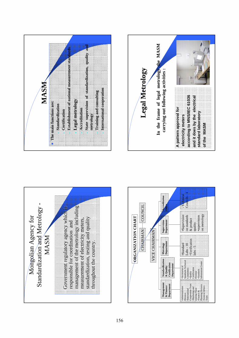
Mon
golia
n A
genc
y fo
r St
anda
rdiz
atio
n an
d M
etro
logy
-M
ASM
Gov
ernm
ent r
egul
ator
y ag
ency
whi
ch is
G
over
nmen
t reg
ulat
ory
agen
cy w
hich
is
resp
onsi
ble
for c
oord
inat
ion
and
re
spon
sibl
e fo
r coo
rdin
atio
n a
nd
man
agem
ent o
f the
met
rolo
gy in
clud
ing
man
agem
ent o
f the
met
rolo
gy in
clud
ing
mea
sure
men
t of e
lect
ricity
met
ers,
mea
sure
men
t of e
lect
ricity
met
ers,
stan
dard
izat
ion,
test
ing
and
qual
ity
stan
dard
izat
ion,
test
ing
and
qual
ity
thro
ugho
ut th
e co
untry
.th
roug
hout
the
coun
try.
MA
SMT
he m
ain
func
tions
are
:•
Stan
dard
izat
ion
•C
ertif
icat
ion
•E
stab
lishm
ent o
f nat
iona
l mea
sure
men
t sta
ndar
ds
•L
egal
met
rolo
gy•
Acc
redi
tatio
n•
Stat
e su
perv
isio
n of
sta
ndar
diza
tion,
qua
lity
and
met
rolo
gy•
Tra
inin
g an
d co
nsul
ting
•In
tern
atio
nal c
oope
ratio
n
OR
GA
NIZ
AT
ION
CH
AR
T
CH
AIR
MA
N
VIC
E C
HA
IRM
AN
CO
UN
CIL
Man
agem
ent
& F
inan
ce
Dep
artm
ent
Acc
redi
tatio
n O
ffic
eSu
perv
isio
n D
epar
tmen
tM
etro
logy
D
epar
tmen
tSt
anda
rdiz
atio
n &
Qua
lity
Cer
tific
atio
n D
epar
tmen
t
•Adm
inis
tratio
n D
ivis
ion
•Int
erna
tiona
l C
oope
ratio
n Te
am•M
arke
ting
and
train
ing
Team
•Fin
ance
&
Plan
ning
Div
isio
n•G
ener
al A
ffai
rs
Team
•Sec
reta
riat o
f St
anda
rds T
echn
ical
C
omm
ittee
s•Q
ualit
y C
ertif
icat
ion
Div
isio
n •S
tand
ards
In
form
atio
n C
ente
r
•Sta
ndar
d La
bs -
10•V
erifi
catio
n la
bs -
5
•Sup
ervi
sion
on
stan
dard
s &
pro
duct
qu
ality
•sup
ervi
sion
on
met
rolo
gy
•Tec
hnic
al
Cou
ncils
-4
Leg
al M
etro
logy
In t
he f
ram
e of
leg
al m
etro
logy
the
MA
SM
carr
ying
out
follo
win
g ac
tiviti
es :
A p
atte
rn a
ppro
val f
or
elec
tric
ity m
eter
s
acco
rdin
g to
MN
S/IE
C 6
1036
an
d it
does
by
the
ele
ctric
al
stan
dard
labo
rato
ry
of th
e M
ASM
156
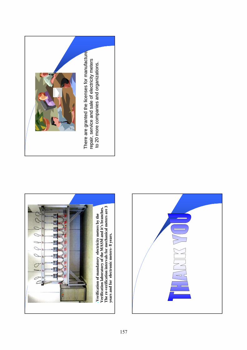
•Ver
ifica
tion
of m
anda
tory
ele
ctri
city
met
ers b
y th
e
Ver
ifica
tion
labo
rato
ry o
f the
MA
SM a
nd it
’s b
ranc
hes.
The
re-
veri
ficat
ion
inte
rval
s for
mec
hani
cal m
eter
s are
3
year
s and
for
ele
ctro
nic
met
ers-
8 ye
ars.
Ther
e ar
e gr
ante
d th
e lic
ense
s fo
r man
ufac
ture
, Th
ere
are
gran
ted
the
licen
ses
for m
anuf
actu
re,
repa
ir, s
ervi
ce a
nd s
ale
of e
lect
ricity
met
ers
repa
ir, s
ervi
ce a
nd s
ale
of e
lect
ricity
met
ers
to 2
0 m
ore
com
pani
es a
nd o
rgan
izat
ions
. to
20
mor
e co
mpa
nies
and
org
aniz
atio
ns.
157
AP
EC
/ A
PLM
F (C
TI 1
0/20
05T)
AP
EC
/ A
PLM
F (C
TI 1
0/20
05T)
Trai
ning
Cou
rse
on E
lect
ricity
Met
ers
Trai
ning
Cou
rse
on E
lect
ricity
Met
ers
Feb
28
Feb
28 ––
Mar
ch 3
, 200
6M
arch
3, 2
006
Intro
duct
ion
Intro
duct
ion
Nam
e: M
r. V
icto
r G
abi
Nam
e: M
r. V
icto
r G
abi
Posi
tion:
Sen
ior
Met
rolo
gist
(O
IC M
etro
logy
Po
sitio
n: S
enio
r M
etro
logi
st (
OIC
Met
rolo
gy
Dep
t)D
ept)
Org
aniz
atio
n: N
atio
nal I
nstit
ute
of S
tand
ards
O
rgan
izat
ion:
Nat
iona
l Ins
titut
e of
Sta
ndar
ds
and
Indu
stria
l Tec
hnol
ogy
an
d In
dust
rial T
echn
olog
y
Dep
artm
ent:
Met
rolo
gyD
epar
tmen
t: M
etro
logy
Res
pons
ibili
ty:
Nat
iona
l Bod
y in
cha
rge
of
Res
pons
ibili
ty:
Nat
iona
l Bod
y in
cha
rge
of
Phys
ical
and
Leg
al M
etro
logy
in t
he C
ount
ry.
Phys
ical
and
Leg
al M
etro
logy
in t
he C
ount
ry.
Wha
t Org
aniz
atio
n (s
) reg
ulat
e th
e m
easu
rem
ent
Wha
t Org
aniz
atio
n (s
) reg
ulat
e th
e m
easu
rem
ent
of e
lect
ricity
in y
our e
cono
my?
of e
lect
ricity
in y
our e
cono
my?
PN
G P
OW
ER L
TD (
serv
ice
deliv
ery
and
Reg
ula
tor
Fun
ctio
ns)
ve
rifi
cati
on/t
esti
ng/
insp
ecti
on
ICC
C (
Con
sum
er P
rote
ctio
n/c
onsu
mer
rig
ht)
NII
SIT
(cal
led
upo
n f
or S
tan
dard
s an
d C
onfo
rman
ce)
Kilo
Wat
thou
r
Wha
t are
the
Lega
l Uni
ts o
f Mea
sure
men
t for
the
Wha
t are
the
Lega
l Uni
ts o
f Mea
sure
men
t for
the
sale
of e
lect
ricity
?sa
le o
f ele
ctric
ity?
Do
elec
trici
ty M
eter
s re
quire
app
rova
l of t
ype?
Do
elec
trici
ty M
eter
s re
quire
app
rova
l of t
ype?
Yes
th
ey d
o re
quir
e ty
pe t
esti
ng
Yes
th
ey d
o re
quir
e ty
pe t
esti
ng
--A
S W
irin
g R
ule
s &
Ass
ocia
ted
STD
S A
S W
irin
g R
ule
s &
Ass
ocia
ted
STD
S P
NG
PO
WER
Tra
de C
ircu
lar
PN
GP
OW
ER T
rade
Cir
cula
r
Wha
t org
aniz
atio
n pe
rform
s ap
prov
al o
f typ
es
Wha
t org
aniz
atio
n pe
rform
s ap
prov
al o
f typ
es
test
ing?
test
ing?
PN
G P
ower
Ltd
PN
G P
ower
Ltd
158
Is m
eter
ver
ifica
tion
test
ing
requ
ired?
Is m
eter
ver
ifica
tion
test
ing
requ
ired?
PN
G P
ower
Ltd
PN
G P
ower
Ltd
Wha
t org
aniz
atio
n pe
rform
s th
e m
eter
ver
ifica
tion
Wha
t org
aniz
atio
n pe
rform
s th
e m
eter
ver
ifica
tion
test
?
test
?
Yes
Yes
Are
test
per
form
ed o
n m
eter
in s
ervi
ce?
Are
test
per
form
ed o
n m
eter
in s
ervi
ce?
PN
G P
ower
Ltd
PN
G P
ower
Ltd
Are
met
ers
give
n a
verif
icat
ion
inte
rval
?A
re m
eter
s gi
ven
a ve
rific
atio
n in
terv
al?
Yes
. 5 y
ears
inte
rval
Yes
. 5 y
ears
inte
rval
Is th
ere
a m
easu
rem
ent c
ompl
aint
/dis
pute
Is
ther
e a
mea
sure
men
t com
plai
nt/d
ispu
te
reso
lutio
n pr
oces
s?re
solu
tion
proc
ess?
Yes
. Y
es.
Trip
arti
te :
PN
GP
OW
ER, I
CC
C, N
ISIT
Trip
arti
te :
PN
GP
OW
ER, I
CC
C, N
ISIT
Trac
eabi
lity
of M
easu
rem
ent
Trac
eabi
lity
of M
easu
rem
ent
MS
L (N
ISIT
)
Reg
ulat
ors
(ICC
C)
Accr
edite
d la
bs
Use
rs
NM
I Aus
tralia
BIP
M
OIM
L
AP
LMF
Phy
sica
l Met
rolo
gy
Lega
l Met
rolo
gy
Prototype
Prim
ary
Seco
ndar
y
Terti
ary
Commercial/
Industrial
Nat
iona
l Reg
iona
l
Inte
rnat
iona
l
END
END
159
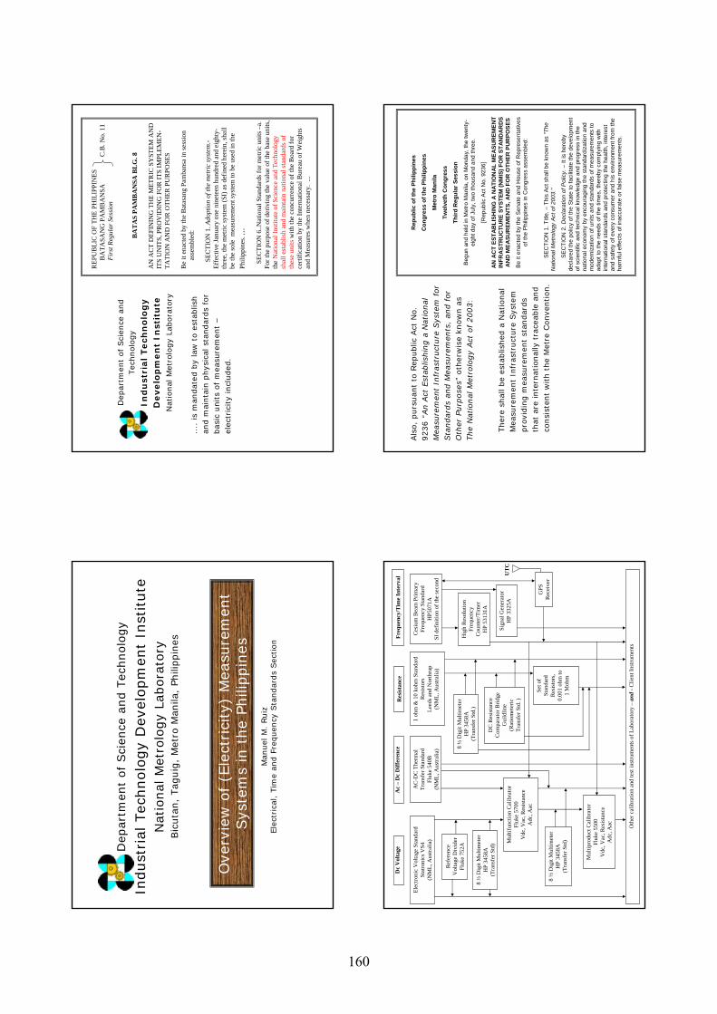
Ove
rvie
w o
f (E
lect
rici
ty)
Mea
sure
men
t Sys
tem
s in
the
Phili
ppin
es
Dep
artm
ent
of
Sci
ence
and T
echnolo
gy
Indust
rial
Tec
hnolo
gy
Dev
elopm
ent
Inst
itute
Nat
ional
Met
rolo
gy
Labora
tory
Bic
uta
n,
Tag
uig
, M
etro
Man
ila,
Phili
ppin
es
Man
uel
M.
Ruiz
Ele
ctri
cal, T
ime
and F
requen
cy S
tandar
ds
Sec
tion
....
is
man
dat
ed b
y la
w t
o e
stab
lish
and m
ainta
in p
hys
ical
sta
ndar
ds
for
bas
ic u
nits
of
mea
sure
men
t –
elec
tric
ity
incl
uded
.
REP
UB
LIC
OF
THE
PHIL
IPPI
NES
BA
TASA
NG
PA
MB
AN
SA
C.B
. No.
11
Firs
t Reg
ular
Ses
sion
BA
TA
S PA
MB
AN
SA B
LG
. 8
AN
AC
T D
EFIN
ING
TH
E M
ETR
IC S
YST
EM A
ND
IT
S U
NIT
S, P
RO
VID
ING
FO
R IT
S IM
PLEM
EN-
TATI
ON
AN
D F
OR
OTH
ER P
UR
POSE
S
Be
it en
acte
d by
the
Bat
asan
g Pa
mba
nsa
in se
ssio
nas
sem
bled
:
SEC
TIO
N 1
. Ado
ptio
n of
the
met
ric
syst
em.-
Effe
ctiv
e Ja
nuar
y on
e ni
nete
en h
undr
ed a
nd e
ight
y-th
ree,
the
met
ric sy
stem
(SI)
as d
efin
ed h
erei
n, sh
all
be th
e so
le m
easu
rem
ent s
yste
m to
be
used
in th
e Ph
ilipp
ines
. ...
SEC
TIO
N 6
..Nat
iona
l Sta
ndar
ds fo
r met
ric u
nits
–a.
Fo
r the
pur
pose
of d
eriv
ing
the
valu
e of
the
base
uni
ts,
the
Nat
iona
l Ins
titut
e of
Sci
ence
and
Tec
hnol
ogy
shal
l est
ablis
h an
d m
aint
ain
natio
nal s
tand
ards
of
thes
e un
itsw
ith th
e co
ncur
renc
e of
the
Boa
rd fo
r ce
rtific
atio
n by
the
Inte
rnat
iona
l Bur
eau
of W
eigh
ts
and
Mea
sure
s whe
n ne
cess
ary.
...
Dep
artm
ent
of
Sci
ence
and
Tec
hnolo
gy
Ind
ust
rial Tech
no
log
yD
evelo
pm
en
t In
stit
ute
Nat
ional
Met
rolo
gy
Labora
tory
Ref
eren
ce
Vol
tage
Div
ider
Fluk
e 75
2A
8 ½
Dig
it M
ultim
eter
HP
3458
A(T
rans
fer S
td)
8 ½
Dig
it M
ultim
eter
HP
3458
A(T
rans
fer S
td)
Mul
tipro
duct
Cal
ibra
tor
Fluk
e 55
00V
dc, V
ac, R
esis
tanc
eA
dc, A
ac
Hig
h R
esol
utio
n Fr
eque
ncy
Cou
nter
/Tim
erH
P 53
131A
Sign
al G
ener
ator
HP
3325
A
Oth
er c
alib
ratio
n an
d te
st in
stru
men
ts o
f Lab
orat
ory
–an
d -C
lient
Inst
rum
ents
Dc
Vol
tage
Ac
–D
c D
iffer
ence
Res
ista
nce
Freq
uenc
y/T
ime
Inte
rval
GPS
R
ecei
ver
UT
C
Elec
troni
c V
olta
ge S
tand
ard
Stat
roni
cs V
S4(N
ML,
Aus
tralia
) Mul
tifun
ctio
n C
alib
rato
rFl
uke
5700
Vdc
, Vac
, Res
ista
nce
Adc
, Aac
AC
-DC
The
rmal
Tr
ansf
er S
tand
ard
Fluk
e 54
0B(N
ML,
Aus
tralia
) 8 ½
Dig
it M
ultim
eter
HP
3458
A(T
rans
fer S
td.)
DC
Res
ista
nce
Com
para
tor B
ridge
Gui
ldlin
e(R
atio
met
eric
Tr
ansf
er S
td. )
Set o
f St
anda
rd
Res
isto
rs,
0.00
1 oh
m to
1
Moh
m
1 oh
m &
10
kohm
Sta
ndar
d R
esis
tors
Leed
s and
Nor
thru
p(N
ML,
Aus
tralia
)
Ces
ium
Bea
m P
rimar
y Fr
eque
ncy
Stan
dard
HP5
071A
SI d
efin
ition
of t
he se
cond
Als
o,
purs
uan
t to
Rep
ublic
Act
No.
9236 “
An A
ct E
stab
lishin
g a
Nat
ional
M
easu
rem
ent
Infr
astr
uct
ure
Sys
tem
for
Sta
ndar
ds
and M
eas
ure
men
ts,
and f
or
Oth
er P
urp
ose
s”oth
erw
ise
know
n a
s The
Nat
ional
Met
rolo
gy
Act
of
2003:
Ther
e sh
all be
esta
blis
hed
a N
atio
nal
M
easu
rem
ent
Infr
astr
uct
ure
Sys
tem
pro
vidin
g m
easu
rem
ent
stan
dar
ds
that
are
inte
rnat
ional
ly t
race
able
and
consi
sten
t w
ith t
he
Met
re C
onve
ntion.
Rep
ublic
of t
he P
hilip
pine
s
Con
gres
s of
the
Phili
ppin
es
Met
ro M
anila
Twel
veth
Con
gres
s
Third
Reg
ular
Ses
sion
Begu
n an
d he
ld in
Met
ro M
anila
, on
Mon
day,
the
twen
ty-
eigh
t day
of J
uly,
two
thou
sand
and
thre
e.
[Rep
ublic
Act
No.
923
6]
AN
AC
T ES
TAB
LISH
ING
A N
ATI
ON
AL
MEA
SUR
EMEN
T IN
FRA
STR
UC
TUR
E SY
STEM
(NM
IS) F
OR
STA
ND
AR
DS
AN
D M
EASU
REM
ENTS
, AN
D F
OR
OTH
ER P
UR
POSE
S
Be it
ena
cted
by
the
Sena
te a
nd H
ouse
of R
epre
sent
ativ
esof
the
Phili
ppin
es in
Con
gres
s as
sem
bled
:
SEC
TIO
N 1
. Titl
e. –
This
Act
sha
ll be
kno
wn
as "T
he
Nat
iona
l Met
rolo
gy A
ct o
f 200
3."
SEC
TIO
N 2
. Dec
lara
tion
of P
olic
y. –
It is
her
eby
de
clar
ed th
e po
licy
of th
e St
ate
to fa
cilit
ate
the
deve
lopm
ent
of s
cien
tific
and
tech
nica
l kno
wle
dge
and
prog
ress
in th
e na
tiona
l eco
nom
y by
enc
oura
ging
the
stan
dard
izat
ion
and
mod
erni
zatio
n of
uni
ts a
nd s
tand
ards
of m
easu
rem
ents
to
adap
t to
the
need
s of
the
times
, the
reby
com
plyi
ng w
ith
inte
rnat
iona
l sta
ndar
ds a
nd p
rote
ctin
g th
e he
alth
, int
eres
t an
d sa
fety
of e
very
con
sum
er a
nd h
is e
nviro
nmen
t fro
m th
e ha
rmfu
l effe
cts
of in
accu
rate
or f
alse
mea
sure
men
ts.
160
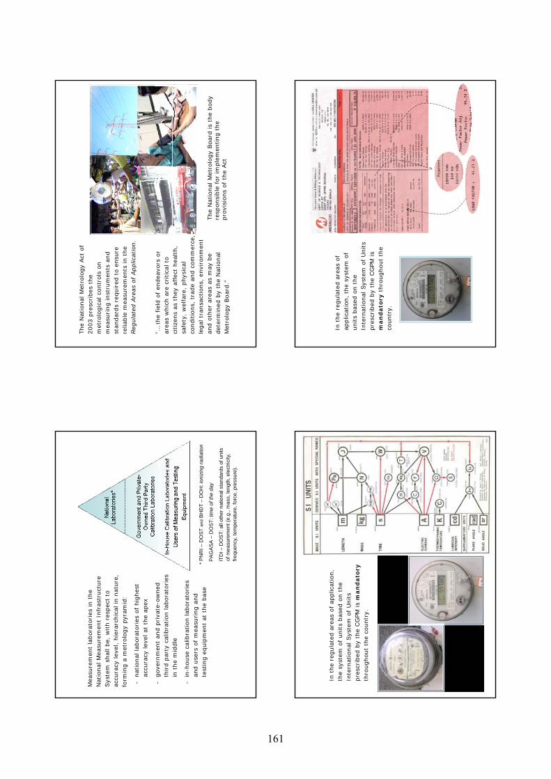
Mea
sure
men
t la
bora
tori
es in t
he
Nat
ional
Mea
sure
men
t In
fras
truct
ure
Sys
tem
shal
l be,
with r
espec
t to
ac
cura
cy lev
el,
hie
rarc
hic
al in n
ature
, fo
rmin
g a
met
rolo
gy
pyr
am
id:
-nat
ional
lab
ora
tori
es o
f hig
hes
t ac
cura
cy lev
el a
t th
e ap
ex
-gove
rnm
ent
and p
riva
te-o
wned
th
ird p
arty
cal
ibra
tion lab
ora
tori
es
in t
he
mid
dle
-in
-house
cal
ibra
tion lab
ora
tori
es
and u
sers
of
mea
suri
ng a
nd
test
ing e
quip
men
t at
the
bas
e*
PN
RI –
DO
ST
and
BH
DT
–D
OH
: ion
izin
g ra
diat
ion
PA
GA
SA
–D
OS
T: ti
me
of th
e da
y
ITD
I –D
OS
T: a
ll ot
her n
atio
nal s
tand
ards
of u
nits
of
mea
sure
men
t (e.
g., m
ass,
leng
th, e
lect
ricity
, fre
quen
cy, t
empe
ratu
re, f
orce
, pre
ssur
e).
The
Nat
ional
Met
rolo
gy
Act
of
2003 p
resc
ribes
the
met
rolo
gic
al c
ontr
ols
on
mea
suri
ng inst
rum
ents
and
stan
dar
ds
requir
ed t
o e
nsu
re
relia
ble
mea
sure
men
ts in t
he
Reg
ula
ted A
reas
of
Applic
atio
n.
“…th
e fiel
d o
f en
dea
vors
or
area
s w
hic
h a
re c
ritica
l to
ci
tize
ns
as t
hey
affec
t hea
lth,
safe
ty,
wel
fare
, phys
ical
co
nditio
ns,
tra
de
and c
om
mer
ce,
legal
tra
nsa
ctio
ns,
envi
ronm
ent
and o
ther
are
as a
s m
ay b
e det
erm
ined
by
the
Nat
ional
M
etro
logy
Boar
d.”
The
Nat
ional
Met
rolo
gy
Board
is
the
body
resp
onsi
ble
for
imple
men
ting t
he
pro
visi
ons
of
the
Act
In t
he
regula
ted a
reas
of
applic
atio
n,
the
syst
em o
f units
bas
ed o
n t
he
Inte
rnat
ional
Sys
tem
of
Units
pre
scri
bed
by
the
CG
PM
is
man
dato
ryth
roughout
the
countr
y.
In t
he
regula
ted a
reas
of
applic
atio
n,
the
syst
em o
f units
bas
ed o
n t
he
Inte
rnat
ional
Sys
tem
of
Units
pre
scri
bed
by
the
CG
PM
is
man
dato
ryth
roughout
the
countr
y.
161
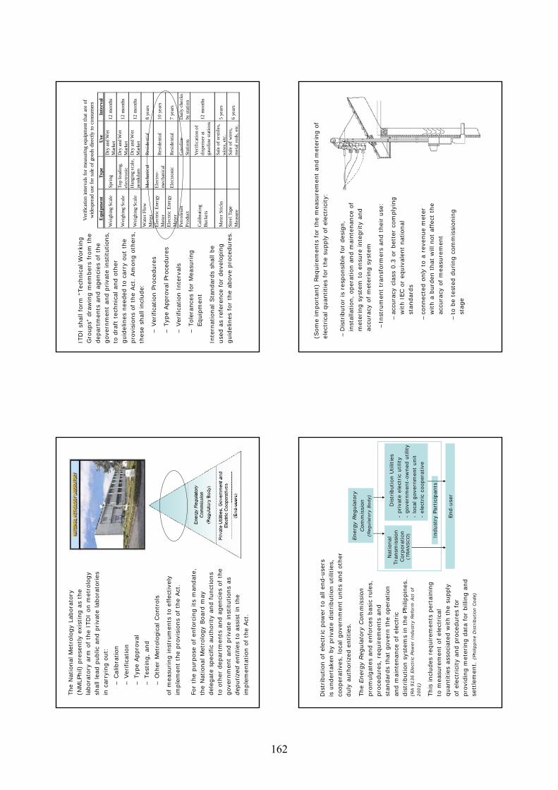
The
Nat
ional
Met
rolo
gy
Labora
tory
(N
MLP
hil)
pre
sently
exis
ting a
s th
e la
bora
tory
arm
of
the
ITD
I on m
etro
logy
shal
l le
ad p
ublic
and p
riva
te lab
ora
tori
es
in c
arry
ing o
ut:
–Cal
ibra
tion
–Ver
ific
atio
n
–Typ
e Appro
val
–Tes
ting,
and
–O
ther
Met
rolo
gic
al C
ontr
ols
of
mea
suri
ng inst
rum
ents
to e
ffec
tive
ly
imple
men
t th
e pro
visi
ons
of
the
Act
.
For
the
purp
ose
of
enfo
rcin
g its
man
dat
e,
the
Nat
ional
Met
rolo
gy
Boar
d m
ay
del
egat
e sp
ecific
auth
ori
ty a
nd f
unct
ions
to o
ther
dep
artm
ents
and a
gen
cies
of
the
gove
rnm
ent
and p
riva
te inst
itutions
as
dep
utize
d e
ntities
to a
ssis
t in
the
imple
men
tation o
f th
e Act
.
ITD
I sh
all fo
rm “
Tec
hnic
al W
ork
ing
Gro
ups”
dra
win
g m
ember
s fr
om
the
dep
artm
ents
and a
gen
cies
of
the
gove
rnm
ent
and p
riva
te inst
itutions,
to
dra
ft t
echnic
al a
nd o
ther
guid
elin
es n
eeded
to c
arry
out
the
pro
visi
ons
of
the
Act
. Am
ong o
ther
s,
thes
e sh
all in
clude:
–Ver
ific
ation P
roce
dure
s
–Typ
e Appro
val Pro
cedure
s
–Ver
ific
atio
n I
nte
rval
s
–Tole
rance
s fo
r M
easu
ring
Equip
men
t
Inte
rnat
ional
Sta
ndar
ds
shal
l be
use
d a
s re
fere
nce
for
dev
elopin
g
guid
elin
es f
or
the
above
pro
cedure
s.
Equ
ipm
ent
Type
Use
Inte
rval
Wei
ghin
g Sc
ale
Spri
ngD
ry an
d W
et
Mar
ket
12 m
onth
s
Wei
ghin
g Sc
ale
Top
load
ing,
el
ectro
nic
Dry
and
Wet
M
arke
t12
mon
ths
Wei
ghin
g Sc
ale
Han
ging
sca
le,
pend
ulum
Dry
and
Wet
M
arke
t12
mon
ths
Wat
er F
low
Met
erM
echa
nica
lRe
side
ntia
l8
year
s
Elec
tric
Ene
rgy
Met
erEl
ectr
o-m
echa
nica
lRe
side
ntia
l10
yea
rs
Elec
tric
Ene
rgy
Met
erEl
ectr
onic
Resi
dent
ial
7 ye
ars
Petr
oleu
m
Prod
uct
Gas
olin
e St
atio
nsD
aily
che
cks
by s
tatio
n
Calib
ratin
g Bu
cket
s
Veri
ficat
ion
of
disp
ense
r at
gaso
line
stat
ions
12 m
onth
s
Met
er S
ticks
Sale
of t
extil
es,
wire
s, et
c.5
year
s
Stee
l Tap
e M
easu
reSa
le o
f wir
es,
met
al ro
ds, e
tc.
6 ye
ars
Ver
ifica
tion
inte
rvals
for m
easu
ring
equi
pmen
t tha
t are
of
wid
espr
ead
use
for s
ale
of g
oods
dire
ctly
to c
onsu
mer
s
Dis
trib
ution o
f el
ectr
ic p
ow
er t
o a
ll en
d-u
sers
is
under
take
n b
y pri
vate
dis
trib
ution u
tilit
ies,
co
oper
ativ
es,
loca
l gove
rnm
ent
units
and o
ther
duly
auth
ori
zed e
ntities
.
The
Ener
gy
Reg
ula
tory
Com
mis
sion
pro
mulg
ates
and e
nfo
rces
bas
ic r
ule
s,
pro
cedure
s, r
equir
emen
ts a
nd
stan
dar
ds
that
gove
rn t
he
oper
atio
n
and m
ainte
nan
ce o
f el
ectr
ic
dis
trib
ution s
yste
ms
in t
he
Phili
ppin
es.
(RA 9
136 E
lect
ric
Pow
er I
ndust
ry R
eform
Act
of
2001)
This
incl
udes
req
uirem
ents
per
tain
ing
to m
easu
rem
ent
of
elec
tric
al
quan
tities
ass
oci
ated
with t
he
supply
of
elec
tric
ity
and p
roce
dure
s fo
r pro
vidin
g m
eter
ing d
ata
for
bill
ing a
nd
sett
lem
ent.
(Ph
ilippin
e D
istr
ibution C
ode)
Energ
y Regula
tory
Com
mis
sion
(Reg
ula
tory
Body)
Nat
ional
Tra
nsm
issi
on
Corp
ora
tion
(TRAN
SC
O)
Dis
trib
ution U
tilit
ies
-priva
te e
lect
ric
utilit
y-
gove
rnm
ent-
ow
ned
utilit
y-
loca
l gove
rnm
ent
unit
-el
ectr
ic c
ooper
ativ
e
End-u
ser
Indust
ry P
artici
pan
ts
–D
istr
ibuto
r is
res
ponsi
ble
for
des
ign,
inst
alla
tion,
oper
atio
n a
nd m
ainte
nan
ce o
f m
eter
ing s
yste
m t
o e
nsu
re inte
gri
ty a
nd
accu
racy
of
met
erin
g s
yste
m
–In
stru
men
t tr
ansf
orm
ers
and t
hei
r use
:
–ac
cura
cy c
lass
0.3
or
bet
ter
com
ply
ing
with I
EC o
r eq
uiv
alen
t nat
ional
st
andar
ds
–co
nnec
ted o
nly
to a
rev
enue
met
er
with a
burd
en t
hat
will
not
affe
ct t
he
accu
racy
of
mea
sure
men
t
–to
be
test
ed d
uring c
om
mis
sionin
g
stag
e
(Som
e im
port
ant)
Req
uir
emen
ts f
or
the
mea
sure
men
t an
d m
eter
ing o
f el
ectr
ical
quan
tities
for
the
supply
of el
ectr
icity:
162
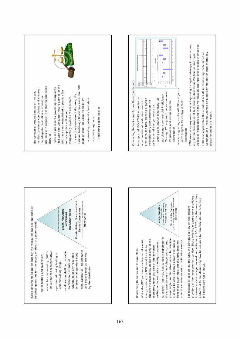
–m
eter
tes
ting a
nd c
alib
ration:
–sh
all be
conduct
ed b
y ERC
or
its
auth
ori
zed r
epre
senta
tive
–per
form
ed d
uri
ng t
esting o
r co
mm
issi
onin
g s
tage
–ca
libra
tion s
hal
l be
trace
able
to
Nat
ional
Inst
itute
of
Sta
ndar
ds
or
any
reputa
ble
in
tern
atio
nal
sta
ndar
d b
ody.
–te
st,
calib
ration,
mai
nte
nan
ce
and s
ealin
g r
ecord
s ar
e ke
pt
by
the
dis
trib
uto
r
(Som
e im
port
ant)
Req
uir
emen
ts f
or
the
mea
sure
men
t an
d m
eter
ing o
f el
ectr
ical
quan
tities
for
the
supply
of el
ectr
icity
(continued
):The
Consu
mer
Aff
airs
Ser
vice
of
the
ERC
han
dle
s co
nsu
mer
com
pla
ints
and e
nsu
res
the
adeq
uat
e pro
motion o
f co
nsu
mer
in
tere
sts
with r
espec
t to
met
erin
g a
nd b
illin
g
dis
pute
s.
Rule
s an
d p
roce
dure
s gove
rnin
g c
om
pla
ints
file
d w
ith t
he
Consu
mer
Aff
airs
Ser
vice
of
the
ERC h
ave
bee
n e
stab
lished
to p
rovi
de
fair
an
d a
ccep
table
act
ions
on
com
pla
ints
/gri
evan
ces
of
consu
mer
s.
In
case
of
mea
sure
men
t dis
pute
s, t
he
Nat
ional
Met
rolo
gy
Boar
d m
ay
assi
st t
he
ERC,
court
or
oth
er a
dju
dic
ativ
e body
by:
–pro
vidin
g t
echnic
al info
rmat
ion
–co
nduct
ing t
ests
–re
nder
ing e
xper
t op
inio
n
Concl
udin
g R
emar
ks a
nd F
utu
re P
lans:
While
the
ERC
per
form
s ca
libra
tion o
f el
ectr
ic
ener
gy
met
ers,
the
NM
L m
ust
be
able
to
support
the
trac
eabili
ty n
eeds
not
only
of
the
regula
tory
body
but
also
of
the
in-h
ouse
ca
libra
tion lab
ora
tori
es o
f utilit
y co
mpan
ies.
At
pre
sent,
the
NM
L has
suff
icie
nt
capab
ility
in
the
mea
sure
men
t of
ac v
oltag
e an
d c
urr
ent,
phas
e an
gle
, an
d t
ime/
freq
uen
cy.
In p
rinci
ple
, it s
hould
be
able
to d
eriv
e pow
er a
nd e
ner
gy
from
those
quan
tities
, but
the
NM
L does
not
off
er t
he
mea
sure
men
t or
calib
ration s
ervi
ce.
For
reas
ons
of
econom
ics,
the
NM
L w
ill c
ontinue
to r
ely
on t
he
pre
sent
pro
vider
s of
the
mea
sure
men
t se
rvic
e. T
hes
e ex
isting m
easu
rem
ent
pro
vider
s how
ever
are
enco
ura
ged
to s
eek
accr
editat
ion (
ISO
17025)
for
the
serv
ice
they
per
form
. A f
orm
al d
eputizi
ng m
ay b
e r
equir
ed t
o form
aliz
e st
ature
acc
ord
ing
the
Met
rolo
gy
Act
of
2003.
In s
upport
of
ISO
17025 a
ccre
ditat
ion
requir
emen
ts o
f ca
libra
tion s
ervi
ce
pro
vider
s, t
he
NM
L pla
ns
to o
rgan
ize
inte
rlab
ora
tory
com
pari
sons
on t
he
calib
ration o
f en
ergy
met
ers
by:
–ac
ting a
s re
fere
nce
lab
ora
tory
, or
–purc
has
ing a
com
mer
cial
Pro
fici
ency
Tes
ting,
PT p
rogra
m f
rom
an o
vers
eas
PT p
rovi
der
and a
ctin
g p
rogra
m
coord
inat
or
–al
so s
ugges
ting t
o t
he
APLM
F to
org
aniz
e a
PT p
rogra
m f
or
ener
gy
met
er
calib
ration
ITD
I w
elco
mes
any
assi
stan
ce in im
pro
ving its
leg
al m
etro
logy
infr
astr
uct
ure
, e.
g.
in t
he
pre
par
atio
n o
f te
chnic
al g
uid
elin
es f
or
Ver
ific
atio
nan
d T
ype
Appro
val Pro
cedure
s an
d in t
he
Ver
ific
atio
n a
nd A
ppro
val pro
cess
them
selv
es.
ITD
I al
so a
ppre
ciat
es t
he
effo
rts
of APLM
F in
conduct
ing t
hes
e se
ries
of
Sem
inar
s an
d T
rain
ing C
ours
es o
n E
lect
rici
ty M
eter
s fo
r le
gal
met
rolo
gy
pra
ctitio
ner
s in
the
regio
n.
Concl
udin
g R
emar
ks a
nd F
utu
re P
lans
(continued
):
163

APE
C/A
PLM
F Se
min
ar a
nd T
rain
ing
Cou
rses
in
Lega
l Met
rolo
gy
Tung
-Tua
n W
uTa
iwan
Ele
ctric
Res
earc
h &
Tes
ting
Cen
ter,
TER
TEC
Febr
uary
28
-Mar
ch 3
, 20
06
Ove
rvie
w o
f the
Mea
sure
men
t Sys
tem
ab
out E
lect
rici
ty M
eter
s In
Chi
nese
T
aipe
i O
rgan
izat
ions
reg
ulat
e th
e m
easu
rem
ent
of e
lect
rici
ty
MO
EA (M
inis
try o
f Eco
nom
ic A
ffai
r)
regu
late
s met
rolo
gica
l con
trol o
f Mea
surin
g in
stru
men
ts.
BSM
I (B
urea
u o
f Sta
ndar
ds, M
etro
logy
an
d In
spec
tion)
ver
ifies
mea
surin
g in
stru
men
ts b
efor
e its
sale
or u
sage
.B
SMI i
nspe
cts m
easu
ring
inst
rum
ents
.
The
lega
l uni
ts o
f mea
sure
for
the
sale
of e
lect
rici
ty
Res
iden
tial :
KW
att-h
our.
Com
mer
cial
and
indu
stria
l :
max
imum
dem
and
KV
A-h
our.
Req
uire
men
t app
rova
l for
diff
eren
t el
ectr
icity
met
ers
Subm
issi
on o
f a m
eter
and
its t
echn
ical
in
form
atio
n to
BSM
I for
type
app
rova
l.
Labo
rato
ry te
sts e
nsur
e th
at e
lect
ricity
m
eter
com
plie
s with
regu
latio
n.
164
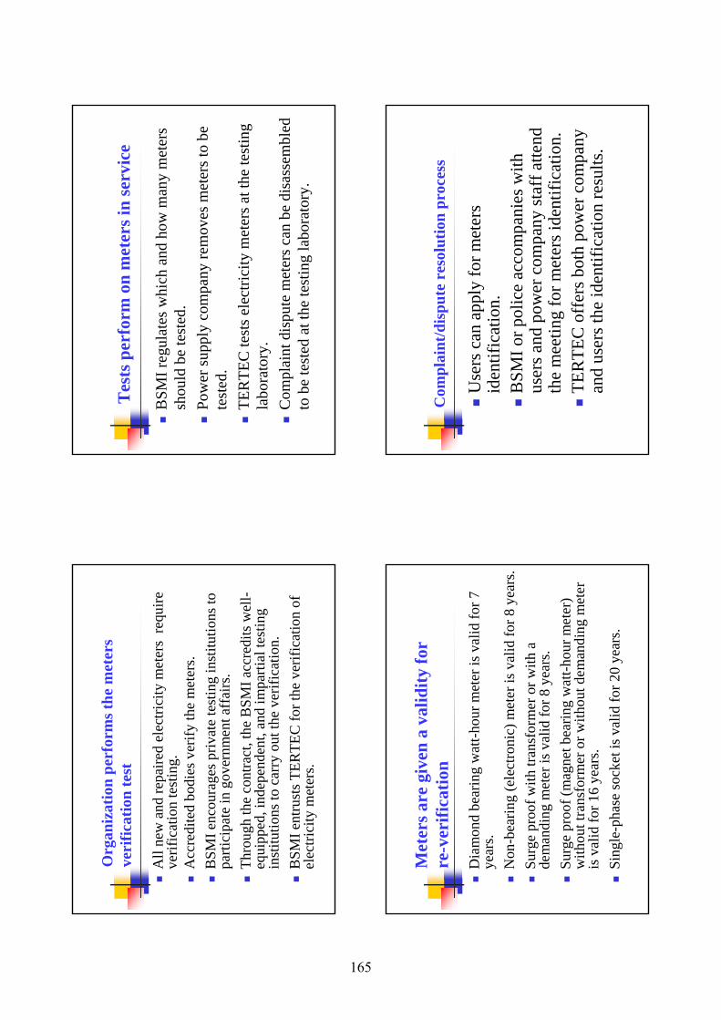
Org
aniz
atio
n pe
rfor
ms t
he m
eter
s ve
rific
atio
n te
st
All
new
and
repa
ired
elec
trici
ty m
eter
s re
quire
ve
rific
atio
n te
stin
g.A
ccre
dite
d bo
dies
ver
ify th
e m
eter
s.B
SMI e
ncou
rage
s priv
ate
test
ing
inst
itutio
ns to
pa
rtici
pate
in g
over
nmen
t aff
airs
.Th
roug
h th
e co
ntra
ct, t
he B
SMI a
ccre
dits
wel
l-eq
uipp
ed, i
ndep
ende
nt, a
nd im
parti
al te
stin
g in
stitu
tions
to c
arry
out
the
verif
icat
ion.
BSM
I ent
rust
s TER
TEC
for t
he v
erifi
catio
n of
el
ectri
city
met
ers.
BSM
I reg
ulat
es w
hich
and
how
man
y m
eter
s sh
ould
be
test
ed.
Po
wer
supp
ly c
ompa
ny re
mov
es m
eter
s to
be
test
ed.
TER
TEC
test
s ele
ctric
ity m
eter
s at t
he te
stin
g la
bora
tory
.C
ompl
aint
disp
ute
met
ers c
an b
edi
sass
embl
ed
to b
e te
sted
at t
he te
stin
g la
bora
tory
.
Tes
ts p
erfo
rm o
n m
eter
s in
serv
ice
Met
ers a
re g
iven
a v
alid
ity fo
r re
-ver
ifica
tion
Dia
mon
d be
arin
g w
att-h
our m
eter
is v
alid
for 7
ye
ars.
Non
-bea
ring
(ele
ctro
nic)
met
er is
val
id fo
r 8 y
ears
.Su
rge
proo
f with
tran
sfor
mer
or w
ith a
de
man
ding
met
er is
val
id fo
r 8 y
ears
.Su
rge
proo
f (m
agne
t bea
ring
wat
t-hou
r met
er)
with
out t
rans
form
er o
r with
out d
eman
ding
met
er
is v
alid
for 1
6 ye
ars.
Sing
le-p
hase
sock
et is
val
id fo
r 20
year
s.
Com
plai
nt/d
ispu
te r
esol
utio
n pr
oces
s
Use
rs c
an a
pply
for m
eter
s id
entif
icat
ion.
BSM
I or p
olic
e ac
com
pani
es w
ith
user
s and
pow
er c
ompa
ny st
aff a
ttend
th
e m
eetin
g fo
r met
ers i
dent
ifica
tion.
TER
TEC
off
ers b
oth
pow
er c
ompa
ny
and
user
s the
iden
tific
atio
n re
sults
.
165
BSM
I (B
urea
u of
Stan
dard
s, M
etro
logy
an
d In
spec
tion)
ht
tp://
ww
w.b
smi.g
ov.tw
TE
RT
EC
(Tai
wan
Ele
ctri
c R
esea
rch
&
Tes
ting
Cen
ter)
http
://w
ww
.tert
ec.o
rg.tw
Tha
nk y
ou fo
r yo
ur a
tten
tion!
166
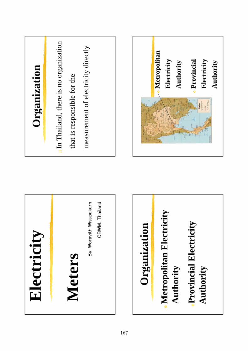
Ele
ctri
city
Met
ers B
y: W
ora
vith
Wis
upa
karn
CB
WM
. Thai
land
Org
aniz
atio
n
In T
haila
nd,t
here
is n
o or
gani
zatio
n
that
isre
spon
sibl
e fo
r the
mea
sure
men
t of e
lect
ricity
dire
ctly
Met
ropo
litan
Ele
ctri
city
A
utho
rity
Prov
inci
al E
lect
rici
ty
Aut
hori
ty
Org
aniz
atio
nM
etro
polit
an
Ele
ctri
city
A
utho
rity
Prov
inci
al
Ele
ctri
city
A
utho
rity
167
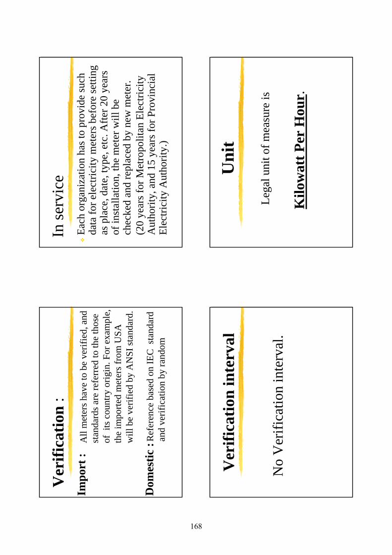
Ver
ifica
tion
:
Ref
eren
ce b
ased
on IE
C s
tand
ard
and
verif
icat
ion
by ra
ndom
All
met
ers h
ave
to b
e ve
rifie
d,an
d st
anda
rdsa
re re
ferr
edto
the
thos
eof
its
cou
ntry
orig
in. F
or e
xam
ple,
the
impo
rted
met
ers f
rom
USA
will
be
verif
ied
by A
NSI
stan
dard
.
Impo
rt :
Dom
estic
:
In se
rvic
eEa
ch o
rgan
izat
ion
hast
o pr
ovid
e su
ch
data
for e
lect
ricity
met
ers b
efor
e se
tting
as
pla
ce, d
ate,
type
, etc
. Afte
r 20
year
s of
inst
alla
tion,
the
met
er w
ill b
e ch
ecke
d an
d re
plac
ed b
y ne
w m
eter
. (2
0 ye
arsf
or M
etro
polit
an E
lect
ricity
A
utho
rity,
and
15 y
ears
for P
rovi
ncia
l El
ectri
city
Aut
horit
y.)
Ver
ifica
tion
inte
rval
No
Ver
ifica
tion
inte
rval
.
Uni
t
Lega
l uni
t of m
easu
re is
Kilo
wat
t Per
Hou
r.
168
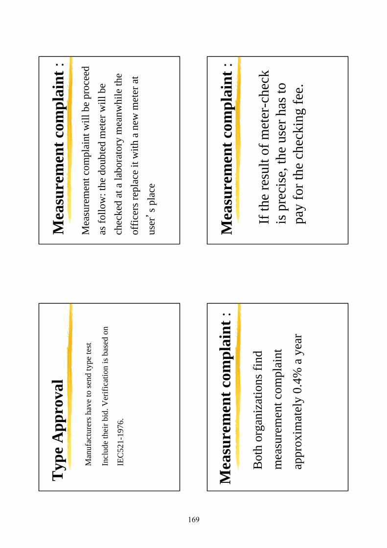
Typ
e A
ppro
val
Man
ufac
ture
rsha
ve to
send
type
test
Incl
ude
thei
rbid
. Ver
ifica
tion
is b
ased
on
IEC
521-
1976
.
Mea
sure
men
t com
plai
nt:
Mea
sure
men
t com
plai
nt w
ill b
e pr
ocee
d as
follo
w:t
hedo
ubte
d m
eter
will
be
chec
ked
at a
labo
rato
ry m
eanw
hile
the
offic
ersr
epla
ce it
with
ane
w m
eter
at
user
’s p
lace
Mea
sure
men
t com
plai
nt:
Bot
h or
gani
zatio
ns fi
ndm
easu
rem
ent c
ompl
aint
ap
prox
imat
ely
0.4%
a y
ear
Mea
sure
men
t com
plai
nt:
If th
e re
sult
of m
eter
-che
ck
is p
reci
se,t
he u
ser h
as to
pa
y fo
r the
che
ckin
g fe
e.
169
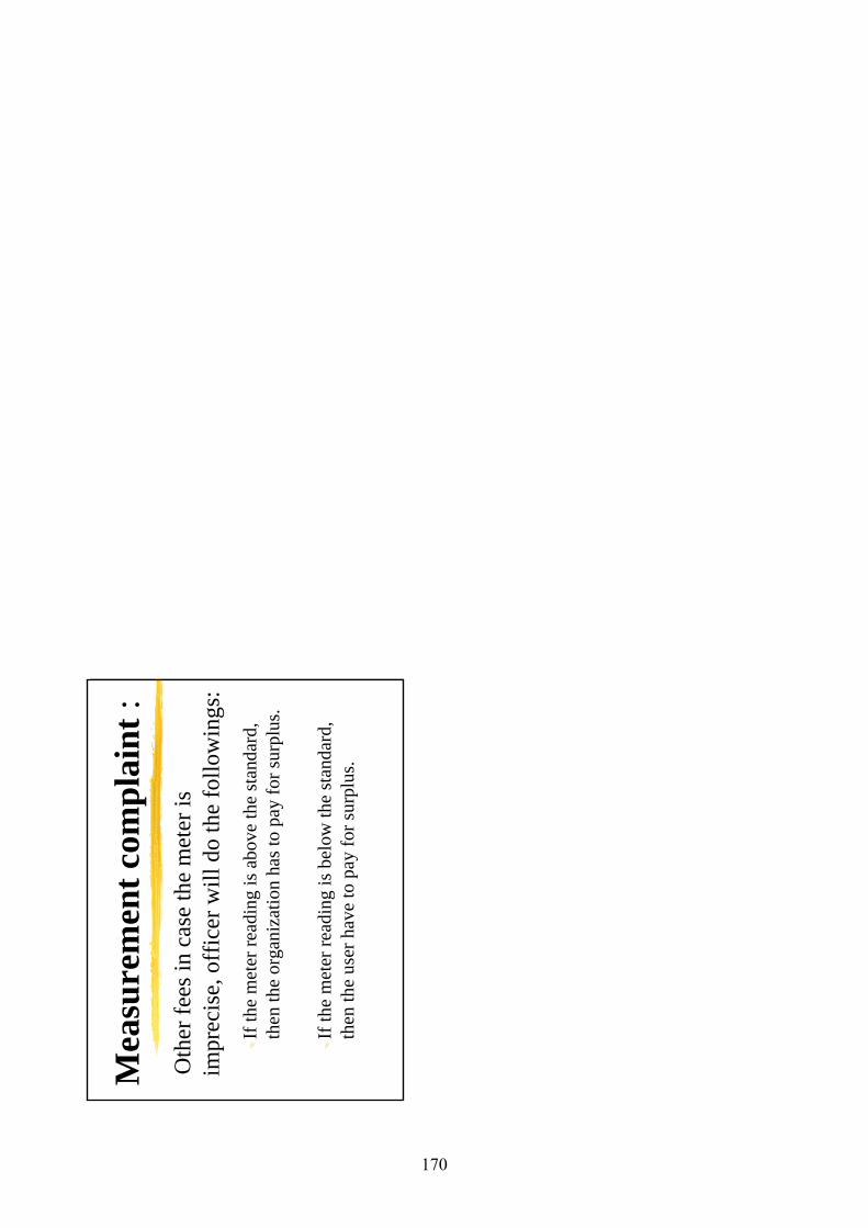
Mea
sure
men
t com
plai
nt:
Oth
er fe
es in
cas
e th
e m
eter
is
impr
ecis
e,of
ficer
will
do
the
follo
win
gs:
If th
e m
eter
read
ing
is a
bove
the
stan
dard
,th
en th
e or
gani
zatio
n ha
sto
pay
for s
urpl
us.
If th
e m
eter
read
ing
is b
elow
the
stan
dard
,th
en th
e us
er h
ave
to p
ay fo
r sur
plus
.
170
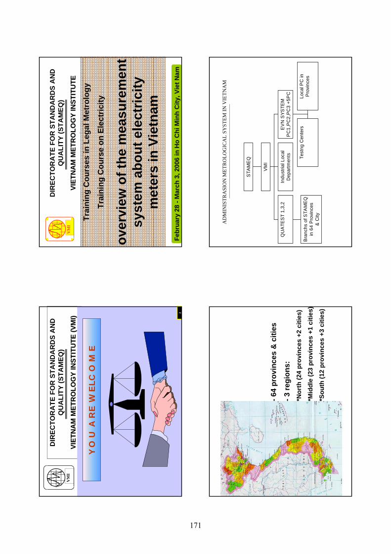
DIR
ECTO
RA
TE F
OR
STA
ND
AR
DS
AN
D
QU
ALI
TY (S
TAM
EQ)
VIET
NA
M M
ETR
OLO
GY
INST
ITU
TE (V
MI)
VIET
NA
M M
ETR
OLO
GY
INST
ITU
TE (V
MI)
,,
VM
I
2
YO
U A
RE
WE
LCO
ME
DIR
ECTO
RA
TE F
OR
STA
ND
AR
DS
AN
D
QU
ALI
TY (S
TAM
EQ)
VIET
NA
M M
ETR
OLO
GY
INST
ITU
TEVI
ETN
AM
MET
RO
LOG
Y IN
STIT
UTE
,,
Trai
ning
Cou
rses
in L
egal
Met
rolo
gy
Trai
ning
Cou
rse
on E
lect
ricity
over
view
of t
he m
easu
rem
ent
syst
em a
bout
ele
ctric
ity
met
ers
in V
ietn
am..
Febr
uary
28
-Mar
ch 3
, 200
6 in
Ho
Chi
Min
hC
ity, V
iet N
am
VM
I
-64
prov
ince
s &
citi
es
-3 re
gion
s:*N
orth
(24
prov
ince
s +2
citi
es)
*Mid
dle
(23
prov
ince
s +1
citi
es)
*Sou
th (1
2 pr
ovin
ces
+3 c
ities
)
AD
MIN
ISTR
ASI
ON
MET
RO
LOG
ICA
L SY
STEM
IN V
IETN
AM
Bra
nchs
of S
TAM
EQ
in 6
4 P
rovi
nces
& C
ity
QU
ATE
ST
1,3,
2In
dust
rial L
ocal
Dep
artm
ents Te
stng
Cen
ters
Loca
l PC
inP
rovi
nces
EV
N S
YSTE
MP
C1,
PC
2,P
C3
+5P
C
VM
I
STA
ME
Q
171
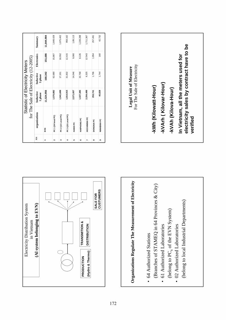
Elec
trici
ty D
istri
butio
n Sy
stem
in V
ietn
am(A
l sys
tem
bel
ongi
ng to
EV
N)
PRO
DU
CTI
ON
(Hyd
ro &
The
rmo)
TRA
NSM
ITIO
N &
DIS
TRIB
UTI
ON
SALE
FO
R
CU
STU
MER
S
Sta
tistic
of E
lect
ricity
Met
ers
for T
he S
ale
of E
lect
ricity
(12-
2005
)N
Nor
gani
zatio
nsIn
duct
ive
1 ph
ase
Indu
ctiv
e3
phas
eE
lect
roni
csSu
mm
ary
1EV
N11
,524
,956
16
8,34
2 15
1,68
6 11
,844
,984
2PC
1 (2
4 lo
cal P
C)
1,57
0,88
2 62
,680
15
,867
1,
649,
429
3PC
2 (1
2 Lo
cal P
C)
1,94
1,69
9 17
,151
16
,552
1,
975,
402
4PC
3 (2
3 Lo
cal P
C)
1,91
4,91
5 31
,832
12
,415
95
9,16
2
5H
ANO
I PC
2,57
1,00
7 14
,046
9,
060
1,89
,113
6H
AIPH
ON
G P
C1,
027,
385
32,7
68
8,13
5 1,
228,
288
7H
OC
HIM
INH
PC
2.20
4,49
9 6,
325
12.5
43
1,71
1,36
7
8D
ON
GN
AI P
C25
3,74
1 1,
796
1,95
4 25
7,49
1
9N
INH
BIN
H P
C40
,828
1,
744
160
42,7
32
•64
Aut
horiz
ed S
tatio
ns
(Bra
nche
s of S
TAM
EQ in
64
Prov
ince
s & C
ity)
•61
Aut
horiz
ed L
abor
ator
ies
(bel
ong
to P
Cs
of th
e EV
N S
yste
m)
•02
Aut
horiz
ed L
abor
ator
ies
(bel
ong
to lo
cal I
ndus
trial
Dep
artm
ents
)
Org
aniz
atio
ns R
egul
ate
The
Mea
sure
men
t of E
lect
rici
tyL
egal
Uni
t of M
easu
reFo
r The
Sal
e of
Ele
ctric
ity
-kW
h (K
ilow
att-H
our)
-kVA
rh (
Kilo
var-
Hou
r)
-kVA
h (K
ilova
-Hou
r)
In V
ietn
am, a
ll th
e m
eter
s us
ed fo
r el
ectr
icity
sal
es b
y co
ntra
ct h
ave
to b
e ve
rifie
d
172
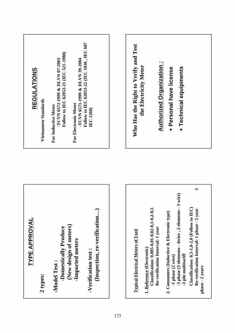
2 ty
pes:
-Mod
el T
est :
-Dom
estic
ally
Pro
duce
(N
ew d
esig
n of
met
ers)
-Im
port
ed m
eter
s
-Ver
ifica
tion
test
:(I
nspe
ctio
n, r
e-ve
rific
atio
n…)
TYPE
APP
RO
VAL
Vie
tnam
ese
Stan
dard
s
For
Indu
ctiv
e M
eter
-TC
VN
657
2-19
99 &
DL
VN
07-
2003
Follo
w to
IEC
620
53-2
1 (I
EC
521
-198
8)
For
Ele
ctro
nic
Met
er
-TC
VN
657
1-19
99 &
DL
VN
39-
2004
Fo
llow
to IE
C 6
2053
-22
(IE
C 1
036
, IE
C 6
87
IEC
126
8) REG
ULA
TIO
NS
Typ
ical
Ele
ctri
cal M
eter
s of U
sed
1. R
efer
ence
(Ele
ctro
nic)
Cla
ssifi
catio
n: 0
,005
-0,0
1-0,
02-0
,1-0
,2-0
,5R
e-ve
rific
atio
n In
terv
al: 1
yea
r
2. C
onsu
mer
s (In
duct
ive
& E
lect
roni
c ty
pe)
-1 p
hase
(2 w
ire)
-3 p
hase
(3 e
lem
ents
-4w
ire
, 2 e
lem
ents
-3
wir
e)-3
phi
mul
titar
iffC
lass
ifica
tion:
0,5
-1,0
-2,0
(Fol
low
to IE
C)
Re-
veri
ficat
ion
Inte
rval
: 1 p
hase
-5
year
3
phas
e -2
yea
rs
Who
Has
the
Rig
ht to
Ver
ify a
nd T
est
the
Ele
ctri
city
Met
er
Aut
horiz
ed O
rgan
izat
ion
:
+ Pe
rson
al h
ave
licen
se
+ Te
chni
cal e
quip
men
ts
173
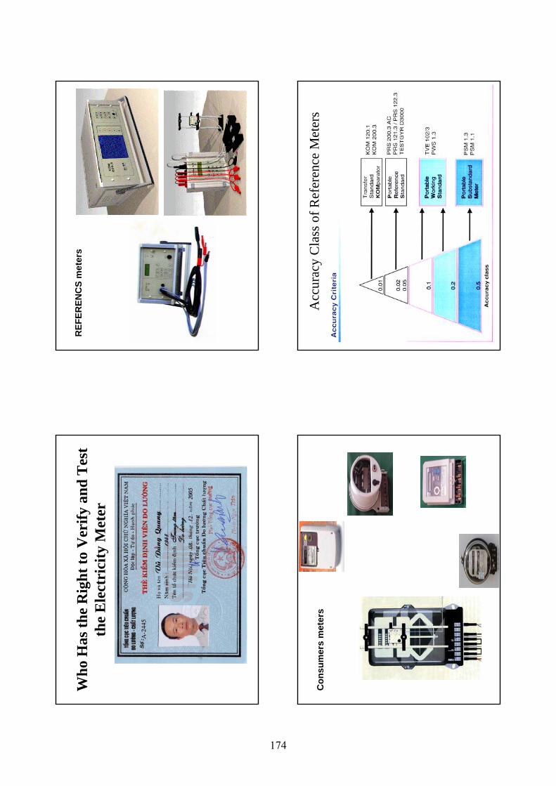
Who
Has
the
Rig
ht to
Ver
ify a
nd T
est
the
Ele
ctri
city
Met
erR
EFER
ENC
S m
eter
s
Con
sum
ers
met
ers
Acc
urac
y C
lass
of R
efer
ence
Met
ers
174
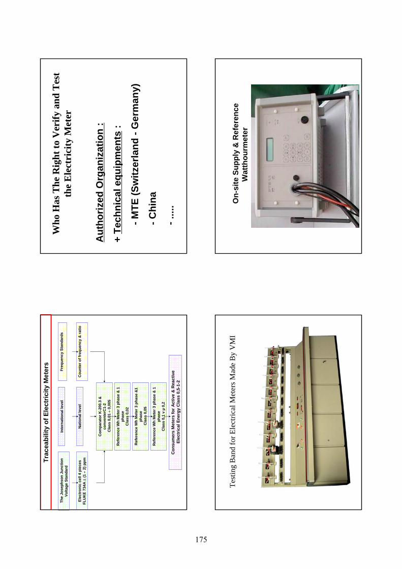
Trac
eabi
lity
of E
lect
ricity
Met
ers
Con
sum
ers
Met
ers
for A
ctiv
e &
Rea
ctiv
eEl
ectr
ical
Ene
rgy
Cla
ss 0
,5-1
-2
The
Jose
phso
nJu
nctio
nVo
ltage
Sta
ndar
d
Elec
tron
ic c
ell 4
pie
ces
FLU
KE
734A
±(1
÷2)
ppm
Inte
rnat
iona
l lev
el
Nat
iona
l lev
el
Com
para
tor K
-200
.3 &
co
nven
terC
1-2
Cla
ss 0
,01 ÷
0,00
5
Freq
uenc
y St
anda
rds
Cou
nter
of f
requ
ency
& ra
tio
Ref
eren
ce W
h M
eter
3 p
hase
& 1
ph
ase
Cla
ss 0
,02
Ref
eren
ce W
h M
eter
3 p
hase
&1
phas
eC
lass
0,0
5
Ref
eren
ce W
h M
eter
3 p
hase
& 1
ph
ase
Cla
ss 0
,1 v
µ0,
2
Who
Has
The
Rig
ht to
Ver
ify a
nd T
est
the
Ele
ctri
city
Met
er
Aut
horiz
ed O
rgan
izat
ion
:
+ Te
chni
cal e
quip
men
ts:
-MTE
(Sw
itzer
land
-G
erm
any)
-Chi
na
-....
.
Test
ing
Ban
d fo
r Ele
ctric
al M
eter
s Mad
e B
y V
MI
On-
site
Sup
ply
& R
efer
ence
W
atth
ourm
eter
.
175
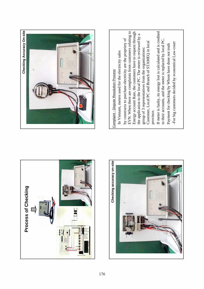
Proc
ess
of C
heck
ing
Che
ckin
g A
ccur
acy
On-
site
Che
ckin
g ac
cura
cy o
n-si
teC
ompl
aint
-D
ispu
te R
esol
utio
n P
roce
ssIn
Vie
tnam
, met
ers u
sed
for t
he e
lect
ricity
sale
sby
con
stra
cts t
o pu
rcha
se e
lect
ricity
are
the
prop
riety
of
EVN
. Whe
n th
ere
are
com
plai
nts f
rom
cus
tom
ers r
elat
ing
to
Ener
gy a
ccou
nt R
ate,
the
cust
omer
s hav
e to
requ
est t
hrou
gh
the
appl
icat
ion
to th
e lo
cal P
C. T
he m
eter
is re
view
ed b
y a
grou
p of
3 re
pres
enta
tives
from
the
orga
niza
tions
: C
usto
mer
, Loc
al P
C a
nd B
ranc
h of
STA
MEQ
in lo
cal
prov
ince
.If
met
er is
faul
ty, i
ts e
nerg
y lo
st is
cal
cula
ted
and
is c
redi
ted
to th
eir a
ccou
nts,
and
the
met
er is
repl
aced
by
loca
l PC
.Pa
ymen
t for
che
ckin
g by
Who
m h
ave
done
not
trut
h -F
or b
ig c
usto
mer
s dec
ided
by
econ
omic
al L
aw-c
ourt
176
Than
k Yo
u
for y
our a
ttent
ion
VM
I
DIR
ECTO
RA
TE F
OR
STA
ND
AR
DS
AN
D
QU
ALI
TY (S
TAM
EQ)
VIET
NA
M M
ETR
OLO
GY
INST
ITU
TE (V
MI)
VIET
NA
M M
ETR
OLO
GY
INST
ITU
TE (V
MI)
,,
177


