Division 1:
General Conditions
For
BRIDGE 269 REPLACEMENT CR1 OVER FISHER-GORDON DITCH
________________________________________________________________________ OWNERS: ELKHART COUNTY, INDIANA, ACTING THROUGH
ITS BOARD OF COUNTY COMMISSIONERS ELKHART COUNTY HIGHWAY DEPARTMENT ENGINEERING SECTION 610 STEURY AVENUE GOSHEN, IN 46528
________________________________________________________________________
Elkhart County Highway Department 610 Steury Avenue, Goshen, Indiana 46528 Phone: 574-534-9394 • Fax: 574-533-7103
TABLE OF CONTENTS
DEFINITIONS 6
ARTICLE 1 - PRELIMINARY MATTERS 10
1.1 Delivery of Bonds 10
1.2 Copies of Documents 10
1.3 Contract Documents 10
1.4 Commencement of Contract Time; Notice to Proceed 10
1.5 Starting the Project 10
1.6 Before Starting Construction 10
1.7 Submission for Review 11
1.8 Delivery of Certificates 11
1.9 Subcontracts 11
1.10 Preconstruction Conference 11
1.11 Non-Discrimination 11
1.12 Insurance 12
1.13 Proof of Carriage Insurance 14
ARTICLE 2 - CONTRACT DOCUMENTS: INTENT, AMENDING, REUSE 14
2.1 Intent 14
2.2 Amending and Supplementing Contract Documents: 15
ARTICLE 3 - AVAILABILITY OF LANDS; PHYSICAL CONDITIONS; REFERENCE POINTS 15
3.1 Availability of Lands 15
3.2 Physical Conditions - Underground Facilities 16
3.3 Not Shown or Indicated 16
3.4 Assignment of Contract 16
ARTICLE 4 - CONTRACTOR'S RESPONSIBILITIES 16
4.1 Supervision and Superintendence 16
4.2 Labor, Materials and Equipment 17
4.3 Substitutes or "Or-Equal" Items 17
4.4 Contractor Responsibility 19
4.5 Subcontractor Responsibility 19
4.6 Permits 19
4.7 Laws and Regulations 19
4.8 Taxes 19
4.9 Use of Premises 20

4.10 Record Documents 20
4.11 Safety and Protection 21
4.12 Emergencies 21
4.13 Shop Drawings and Samples 22
4.14 Continuing the Work 22
4.15 Indemnification: 23
4.16 Sanitation 23
4.17 Road Closing Requirements 24
ARTICLE 5 - OTHER WORK 25
5.1 Related Work at Site 25
ARTICLE 6 - OWNER'S RESPONSIBILITIES 25
6.1 Communication 25
6.2 Appointment of Engineer 25
6.3 Payment 25
6.4 Change Orders 25
6.5 Inspection 25
6.6 Service Termination 26
ARTICLE 7 - ENGINEER'S STATUS DURING CONSTRUCTION 26
7.1 Owner's Representative 26
7.2 Visits to Site 26
7.3 Project Representation 26
7.4 Clarifications and Interpretations 26
7.5 Authorized Variations in Work 26
7.6 Rejecting Defective Work 27
7.7 Decisions on Disputes 27
7.8 Limitations on Engineer’s Responsibilities 27
ARTICLE 8 - CHANGES IN THE WORK 28
8.1 Work Modifications 28
8.2 Disagreement 28
8.3 Contract Price and Time 28
8.4 Change orders 28
8.5 Notification of Change 28
ARTICLE 9 - CHANGE OF CONTRACT PRICE 29
9.1 Change Order 29
9.2 Determination of Contract Price 29
9.3 Cost of the Work 29
ARTICLE 10 - CHANGE OF CONTRACT TIME 30
ARTICLE 11 - WARRANTY AND GUARANTEE; TESTS AND INSPECTIONS; CORRECTION, REMOVAL OR ACCEPTANCE OF DEFECTIVE WORK 30
11.1 Warranty and Guarantee 30
11.2 Access to Work 30
11.3 Tests and Inspections 30
11.4 Uncovering Work 31
11.5 Owner May Stop the Work 31
11.6 Correction or Removal of Defective Work 32
11.7 Three Years Correction Period 32
11.8 Maintenance Bond 32
11.9 Acceptance of Defective Work: 32
11.10 OWNER May Correct Defective Work: 33
ARTICLE 12 - PAYMENTS TO CONTRACTOR AND COMPLETION 33
12.1 Schedule of Values 33
12.2 Application for Progress Payment 33
12.3 Contractor’s Warranty of Title 33
12.4 Review of Applications for Progress Payment 33
12.5 Substantial Completion 35
12.6 Partial Utilization 35
12.7 Final Inspection 36
12.8 Final Application for Payment 36
12.9 Final Payment and Acceptance 37
12.10 Contractor’s Continuing Obligation 37
12.11 Waiver of Claims 37
ARTICLE 13 - SUSPENSION OF WORK AND TERMINATION 38
13.1 OWNER May Suspend Work 38
13.2 Conditions of Termination by Owner 38
13.3 Termination by Owner 39
13.4 Conditions of Termination by Contractor 40
ARTICLE 14 - MISCELLANEOUS 40
14.1 Giving Notice 40
14.2 Computation of Time 40
14.3 Bid Submission 41
BID FORM 42
BID BOND 44
CERTIFICATE AS TO CORPORATE PRINCIPAL 47
PERFORMANCE BOND 48
AGREEMENT 53

6
DEFINITIONS The following terms, as used in these Contract Documents, are defined as follows: "ADDENDA" Written or graphic instruments issued prior to the
opening of Bids, which clarify, correct, or change the bidding documents or Contract Documents.
"APPROVED" The words "approved", "acceptable", "satisfactory", "in
the judgment of", and words of like import, shall mean approval by, acceptable to, satisfactory to, or in the judgment of, the Engineer or Owner.
“BONDS" Bid, Performance, or Maintenance Bonds, and other
instruments of security. "CHANGE ORDER" A document recommended by ENGINEER, which is
signed by CONTRACTOR and OWNER and authorizes an addition, deletion or revision in the Work, or an adjustment in the Contract Price or the Contract Time, issued on or after the Effective Date of the Agreement.
"CONTRACTOR' The person, firm, or corporation to whom the enclosed
contract is awarded by the Owner and who is subject to the terms hereof.
"COUNTY SPECIFICATIONS” The current Elkhart County roads guidelines and
standards for design and public improvements. "DIRECTED" The words "directed", "required", "permitted",
"ordered", "designated", and words of like import shall imply the direction, requirement, permission, order of designation of the Engineer or Owner.
"ENGINEER" The Elkhart County Highway Division, or, the Elkhart
Co. Manager of Engineering, or duly authorized representative designated by the Owner.
"FIELD ORDER" A written order issued by ENGINEER which orders
minor changes in the Work in accordance with paragraph 7.5 but which does not involve a change in the Contract Price or the Contract Time.
“FINAL ACCEPTANCE” The date when OWNER accepts ENGINEER’S
recommendation of final payment. "GENERAL REQUIREMENTS" Sections of Division A of the Specifications.
7
"LAWS AND REGULATIONS; Laws, rules, regulations, ordinances, codes and/or LAWS OR REGULATIONS" orders. "MUTCD"` Manual of uniform traffic control devices. "NOTICE TO PROCEED" A written notice given by OWNER to CONTRACTOR
(with a copy to ENGINEER) fixing the date on which the Contract Time will commence to run and on which CONTRACTOR shall start to perform CONTRACTOR'S obligations under the Contract Documents.
"OWNER" The public body or authority, corporation, association,
firm or person with whom CONTRACTOR has entered into the Agreement and for whom the Work is to be provided. This typically being Elkhart County, Indiana, acting through its Board of County Commissioners.
"PARTIAL UTILIZATION" Placing a portion of the Work in service for the purpose
for which it is intended (or a related purpose) before reaching Substantial Completion for all the Work.
"PROJECT" The total construction of which the Work to be provided
under the Contract Documents may be the whole or a part as indicated elsewhere in the Contract Documents.
"RESIDENT PROJECT The authorized representative of ENGINEER REPRESENTATIVE" who is assigned to the site or any part thereof "SHOP DRAWINGS" All drawings, diagrams, illustrations, schedules and
other data which are specifically prepared by or for CONTRACTOR to illustrate some portion of the Work and all illustrations, brochures, standard schedules, performance charts, instructions, diagrams and other information prepared by a Supplier and submitted by CONTRACTOR to illustrate material or equipment for some portion of the Work.
"SPECIFICATIONS" Those portions of the Contract Documents consisting
of written technical descriptions of materials, equipment, construction systems, standards and workmanship as applied to the Work and certain administrative details applicable thereto.
8
“STANDARD The current INDOT standard sheets with standard DETAILS” details. “STANDARD The latest edition of the Indiana Department of SPECIFICATIONS” Transportation Standard Specifications and current supplemental Technical Specifications. “STOP ORDER or STOP Written order from OWNER or ENGINEER to stop all WORK ORDER work covered by the Contract Documents. "SUBCONTRACTOR" An individual, firm or corporation having a direct
contract with CONTRACTOR or with any other Subcontractor for the performance of a part of the Work at the site.
"SUPPLEMENTARY The part of the Contract Documents which CONDITIONS" amends or supplements these General Conditions. “SUBSTANTIAL COMPLETION” See Paragraph 12.5 of these General Conditions. "SURETY" Financial guarantee that insures the CONTRACTOR’S
obligation. "UNDERGROUND FACILITIES" All pipelines, conduits, ducts, cables, wires, manholes,
vaults, tanks, tunnels or other such facilities or attachments. In addition, any encasement containing such facilities that have been installed underground to furnish any of the following services or materials; electricity, gases, steam, liquid petroleum products, telephone or other communication means, cable television, sewage and drainage removal, traffic or other control systems or water.
"UNIT PRICE WORK" Work to be paid for on the basis of unit prices. "WORK" Work to be done under this Contract at the site of the
improvement. "WORK DIRECTIVE CHANGE" A written directive to CONTRACTOR, issued on or
after the Effective Date of the Agreement and signed by OWNER and recommended by ENGINEER, ordering an addition, deletion or revision in the Work, or responding to differing or unforeseen physical conditions under which the Work is to be performed.

9
"WRITTEN AMENDMENT" A written amendment of the Contract Documents, signed by OWNER and CONTRACTOR on or after the Effective Date of the Agreement and normally dealing with the non-engineering or non-technical rather than strictly Work-related aspects of the Contract Documents

Bridge 269 Replacement CR1 over Fisher-Gordon Ditch GENERAL CONDITIONS _____________________________________________________________________
10
ARTICLE 1 - PRELIMINARY MATTERS
Delivery of Bonds When CONTRACTOR delivers the executed Agreements to OWNER, CONTRACTOR shall also deliver to OWNER such Bonds as called for in the Contract Documents.
Copies of Documents OWNER shall furnish to CONTRACTOR up to three (3) copies (unless otherwise specified in the Supplementary Conditions) of the Contract Documents as are reasonably necessary for the execution of the Work. Additional copies will be furnished, upon request, at the cost of reproduction.
Contract Documents These Contract Documents are complementary and what is called for in one shall be as binding as if called for in all. The intention of these Contract Documents is to include in the Contract Price the costs of all labor and materials, water, fuel, tools, plant, equipment, light, transportation, taxes, bonds, and all other expense and profit as may be necessary for the proper and complete execution of the work.
Commencement of Contract Time; Notice to Proceed The Contract Time will commence when the Contractor receives the Notice to Proceed from the Engineer. CONTRACTOR shall not be paid for any work performed prior to receiving the Notice to Proceed from the Engineer.
Starting the Project CONTRACTOR shall start to perform the Work on the date when the Contract Time commences to run, but no Work shall be done at the site prior to the date on which the Contract Time commences to run unless such work is specifically approved by the owner/engineer.
Before Starting Construction Before undertaking each part of the Work, CONTRACTOR shall carefully study and compare the Contract Documents and check and verify pertinent figures shown thereon and all applicable field measurements. CONTRACTOR shall promptly report in writing to ENGINEER any conflict, error or discrepancy which CONTRACTOR may discover and shall obtain a written interpretation or clarification from ENGINEER before proceeding with any Work affected thereby; however, CONTRACTOR shall not be liable to OWNER or ENGINEER for failure to report any conflict, error or discrepancy in the Contract Documents, unless CONTRACTOR had actual knowledge thereof or should reasonably have known thereof.
Bridge 269 Replacement CR1 over Fisher-Gordon Ditch GENERAL CONDITIONS _____________________________________________________________________
11
Submission for Review
Within ten (10) days after the Effective Date of the Agreement (unless otherwise specified in the General Requirements), CONTRACTOR shall submit to ENGINEER for review: 1.7.1 An estimated progress schedule indicating the starting and completion dates
of the various stages of the Work; and 1.7.2 A preliminary schedule of Shop Drawings and/or sample submissions. 1.7.3 CONTRACTOR shall provide an updated progress schedule at all scheduled
progress meetings.
Delivery of Certificates Before any Work at the site is started, CONTRACTOR shall deliver to OWNER, with a copy to ENGINEER, certificates (and other evidence of insurance requested by OWNER) which CONTRACTOR is required to purchase and maintain.
Subcontracts The Contractor shall not execute an Agreement with any Subcontractor or permit any Subcontractor to perform any work in this Contract until he has received written approval of such Subcontractor from the Owner or Owner’s appointed designee.
Preconstruction Conference Following the Effective Date of the Agreement, but before CONTRACTOR starts the Work at the site, a conference attended by CONTRACTOR, ENGINEER and others, as appropriate, will be held to discuss the schedules referred to in paragraph 1.7, as well as the Subcontractors proposed by Contractor for certain portions of the work, to discuss procedures for handling Shop Drawings and other submittals and for processing Applications for Payment, and to establish a working understanding among the parties as to the Work.
Non-Discrimination In compliance with the Acts of Indiana General Assembly, 1933, Chapter 270, the Contractor hereby agrees:
1.11.1 That in the hiring of employees for the performance of work under this Contract or any Subcontract hereunder, no Contractor, Subcontractor, nor any person acting on behalf of such Contractor or Subcontractor shall, by reason of race or color, discriminate against any citizen qualified to do work to which the employment relates;
Bridge 269 Replacement CR1 over Fisher-Gordon Ditch GENERAL CONDITIONS _____________________________________________________________________
12
1.11.2 That no Contractor, Subcontractor, nor any person on his behalf shall, in any manner, discriminate against or intimidate any employee hired for the performance of work under this Contract on account of race or color; 1.11.3 That there may be deducted from the amount payable to the Contractor by the Owner under this contract, a penalty of Five Dollars ($5.00) for each person for each calendar day during which such person was discriminated against or intimidated in violation of the provisions of this Contract; and 1.11.4 That this Contract may be canceled or terminated by the Owner, and all money due or to become due hereunder may be forfeited for a second or any subsequent violation of the terms or conditions of this section of the Contract.
Insurance
1.12.1 Contractor's Liability Insurance:
a) The Contractor shall maintain such insurance as well as protect himself from claims under Workmen's Compensation Acts and other employee benefit acts; from claims for damages because of bodily injury, including death, to his employees and all others; and from claims for damages to property, any or all of which may arise out of or result from the Contractor's operation under the Contract, whether such operations be by himself or by any subcontractor, or anyone directly or indirectly employed by either of them. This insurance shall be written for not less than any limits of liability specified herein and shall name Elkhart County as an additional insured.
1.12.2 Contractor's Insurance:
The types and minimum amount of insurance to be provided for by the Contractor shall be as follows:
a) Workmen's Compensation and Occupational Disease Insurance The Contractor shall provide Workmen's Compensation and Occupational Disease Insurance as required by law. Such policy shall specifically include coverage for the State of Indiana, and such adjoining states as required by the Contractor's operations.
b) Employer's Liability Insurance The Contractor shall provide Employer's Liability with a minimum coverage of $1,000,000.

Bridge 269 Replacement CR1 over Fisher-Gordon Ditch GENERAL CONDITIONS _____________________________________________________________________
13
c) Comprehensive General Liability Insurance The Contractor shall maintain a Comprehensive General Liability form of Insurance with bodily injury of not less than $1,000,000 for any one (1) occurrence, and $2,000,000 aggregate. The insurance policy shall include the following:
1. Premises Operations: The policy shall include coverage for the following special hazards when applicable to the project:
i) Property damage arising out of blasting or explosion. ii) Property damage arising out of collapse of or structural injury to any
building or structure due to grading of land, excavation, borrowing, filling, backfilling, tunneling, pile driving, cofferdam work or caisson work or to moving, shoring, underpinning, raising, or demolition of any building or structure or rebuilding of any structural support thereof.
iii) Injury to or destruction of wires, conduits, pipes, mains, sewers, and
other similar property of any apparatus in connection therewith below the surface of ground, if caused by use of mechanical equipment.
2. Contractual (Broad Form Indemnification): The Contractor agrees to indemnify and save harmless the Owner and the Engineer, their agents and employees, from and against all loss or expense (including costs and attorneys' fees) by reason of liability imposed by law upon the Owner or the Engineer for damages because of bodily injury, including death, at any time resulting there from, sustained by any person or persons or an account of damage to property is due or claimed to be due to negligence of the Contractor, his Subcontractors, employees or agents. 3. Contractor's Protective: The Contractor shall maintain this type of coverage on a "Blanket" basis to cover the operations of any subcontractors.
d) Automobile Liability Insurance The Contractor shall maintain Comprehensive Automobile Liability Insurance with bodily injury liability limits of not less than $1,000,000 for one (1) occurrence and $2,000,000 aggregate. This coverage may be provided either as a separate policy or as part of the Comprehensive General Liability Policy described previously. The automobile insurance must include coverage for all owned, non-owned and hired vehicles.
Bridge 269 Replacement CR1 over Fisher-Gordon Ditch GENERAL CONDITIONS _____________________________________________________________________
14
e) Furnish Indiana State Forms No. 19 (Workmen's Compensation) and No.105 (Occupational Disease Act).
f) Umbrella Policy Insurance The Contractor shall maintain a minimum $3,000,000 Umbrella Policy in addition to their primary insurance.
Proof of Carriage Insurance
1.13.1 Contractor shall not commence work until he has obtained all insurance specified herein, has filed with the Owner one (1) copy of Certificate of Insurance, and such insurance has been approved by the Owner. 1.13.2 Should any Coverage approach expiration during the Contract period, it shall be renewed prior to its expiration, and certificate again filed with the Owner. 1.13.3 If any of such policies are canceled or are changed so as to reduce the coverage evidenced by the Certificate, at least ten (10) days prior written notice by registered mail of such cancellation or change shall be sent to the Owner. 1.13.4 All insurance provided for under this Section shall be written by Insurance Companies licensed to do business in Indiana and Countersigned by resident Indiana agent. The insurance company shall file with the Owner, one (1) copy of Affirmation of Authority, on the form furnished by the Engineer, as verification of the resident agent. 1.13.5 All insurance shall be maintained in full force and effect until the Contract has been fully and completely performed.
ARTICLE 2 - CONTRACT DOCUMENTS: INTENT, AMENDING, REUSE
Intent The Contract Documents comprise the entire agreement between OWNER and CONTRACTOR concerning the Work. The Contract Documents are complimentary; what is called for by one is as binding as if called for by all. The Contract Documents will be construed in accordance with the law of the place of the Project.
2.1.1 It is the intent of the Contract Documents to describe a functionally complete Project (or part thereof) to be constructed in accordance with the Contract Documents. Any Work, materials or equipment that may reasonably be inferred from the Contract Documents as being required to produce the intended result will be supplied whether or not specifically called for.

Bridge 269 Replacement CR1 over Fisher-Gordon Ditch GENERAL CONDITIONS _____________________________________________________________________
15
2.1.2 If during the performance of the Work, CONTRACTOR finds a conflict, error or discrepancy in the Contract Documents, CONTRACTOR shall so report to ENGINEER in writing at once and before proceeding with the Work affected thereby shall obtain a written interpretation or clarification from ENGINEER; however, CONTRACTOR shall not be liable to OWNER or ENGINEER for failure to report any conflict, error or discrepancy in the Contract Documents unless CONTRACTOR had actual knowledge thereof or should reasonably have known thereof.
Amending and Supplementing Contract Documents:
The Contract Documents may be amended to provide for additions, deletions and revisions in the Work or to modify the terms and conditions thereof in one or more of the following ways:
2.2.1 A formal Written Amendment, 2.2.2 A Change Order, or 2.2.3 A Work Directive Change (pursuant to paragraph 8.1).
In addition, the requirements of the Contract Documents may be supplemented and minor variations and deviations in the Work may be authorized, in one or more of the following ways:
2.2.4 A Field Order, 2.2.5 ENGINEER's approval of a Shop Drawing or sample, or 2.2.6 ENGINEER's written interpretation or clarification.
ARTICLE 3 - AVAILABILITY OF LANDS; PHYSICAL CONDITIONS; REFERENCE POINTS
Availability of Lands OWNER shall indicate, as shown in the Contract Documents, the lands upon which the Work is to be performed, rights-of-way and easements for access thereto, and such other lands which are designated for the use of CONTRACTOR. Easements for permanent structures or permanent changes in existing facilities will be obtained and paid for by OWNER, unless otherwise provided in the Contract Documents. If CONTRACTOR believes that any delay in OWNER's furnishing these lands, rights-of-way or easements entitles CONTRACTOR to an extension of the Contract Time, CONTRACTOR may make a claim for an extension of Contract Time.
Bridge 269 Replacement CR1 over Fisher-Gordon Ditch GENERAL CONDITIONS _____________________________________________________________________
16
Physical Conditions - Underground Facilities The information and data shown or indicated in the Contract Documents with respect to existing Underground Facilities at or contiguous to the site is based on information and data furnished to OWNER or ENGINEER by the owners of such Underground Facilities or by others. Unless it is otherwise expressly provided in the Supplementary Conditions:
3.2.1 OWNER and ENGINEER shall not be responsible for the accuracy or completeness of any such information or data; and, 3.2.2 CONTRACTOR shall have full responsibility for reviewing and checking all such information and data, for locating all Underground Facilities shown or indicated in the Contract Documents, for coordination of the Work with the owners of such Underground Facilities during construction, for the safety and protection thereof, and repairing any damage thereto resulting from the Work, the cost of all of which will be considered as having been included in the Contract Price.
Not Shown or Indicated
If an Underground Facility is uncovered or revealed at or contiguous to the site which was not shown or indicated in the Contract Documents and which CONTRACTOR could not reasonably have been expected to be aware of, CONTRACTOR shall, promptly after becoming aware thereof and before performing any Work affected thereby (except in an emergency) as permitted by paragraph 4.2.1, identify the owner of such Underground Facility and give written notice thereof to that owner and to OWNER and ENGINEER. ENGINEER will promptly review the Underground Facility to determine the extent to which the Contract Documents should be modified to reflect and document the consequences of the existence of the Underground Facility, and the Contract Documents will be amended or supplemented to the extent necessary. During such time, CONTRACTOR shall be responsible for the safety and protection of such Underground Facility. CONTRACTOR shall be allowed an increase in the Contract Price or an extension of the Contract Time, or both, to the extent that they are attributable to the existence of any Underground Facility.
Assignment of Contract The Contractor shall not assign this Contract or any part hereof without prior consent of the Owner.
ARTICLE 4 - CONTRACTOR'S RESPONSIBILITIES
Supervision and Superintendence
4.1.1 CONTRACTOR shall supervise and direct the Work competently and efficiently, devoting such attention thereto and applying such skills and expertise as

Bridge 269 Replacement CR1 over Fisher-Gordon Ditch GENERAL CONDITIONS _____________________________________________________________________
17
may be necessary to perform the Work in accordance with the Contract Documents. CONTRACTOR shall be solely responsible for the means, methods, techniques, sequences and procedures of construction, but CONTRACTOR shall not be responsible for the negligence of others in the design or selection of a specific means, method, technique, sequence or procedure of construction which is indicated in and required by the Contract Documents. CONTRACTOR shall be responsible to see that the finished Work complies accurately with the Contract Documents. 4.1.2 CONTRACTOR shall keep on the Work at all times during its progress a competent resident superintendent, who shall not be replaced without written notice to OWNER and ENGINEER except under extraordinary circumstances. The superintendent will be CONTRACTOR's representative at the site and shall have authority to act on behalf of CONTRACTOR. All communications given to the superintendent shall be as binding as if given to CONTRACTOR.
Labor, Materials and Equipment
4.2.1 CONTRACTOR shall provide competent, suitably qualified personnel to survey and lay out the Work and perform construction as required by the Contract Documents. CONTRACTOR shall at all times maintain good discipline and order at the site, particularly in connection with the safety or protection of persons or the Work or property at the site or adjacent thereto, and except as otherwise indicated in the Contract Documents. 4.2.2 Unless otherwise specified in the General Conditions, CONTRACTOR shall furnish and assume full responsibility for all materials, equipment, labor, transportation, construction equipment and machinery, tools, appliances, fuel, power, light, heat, telephone, water, sanitary facilities, temporary facilities and all other facilities and incidentals necessary for the furnishing, performance, testing, start-up and completion of the Work. 4.2.3 All materials and equipment shall be of good quality and new, except as otherwise provided in the Contract Documents. If required by ENGINEER, CONTRACTOR shall furnish satisfactory evidence (including reports of required tests) as to the kind and quality of materials and equipment. All materials and equipment shall be applied, installed, connected, erected, used, cleaned and conditioned in accordance with the instructions of the applicable Supplier except as otherwise provided in the Contract Documents.
Substitutes or "Or-Equal" Items
4.3.1 Whenever materials or equipment are specified or described in the Contract Documents by using the name of a proprietary item or the name of a particular Supplier the naming of the item is intended to establish the type, function and quality required. Unless the name is followed by words indicating that no substitution is
Bridge 269 Replacement CR1 over Fisher-Gordon Ditch GENERAL CONDITIONS _____________________________________________________________________
18
permitted, materials or equipment of other Suppliers may be accepted by ENGINEER if sufficient information is submitted by CONTRACTOR to allow ENGINEER to determine that the material or equipment proposed is equivalent or equal to that named. The procedure for review by ENGINEER will include the following as supplemented in the General Conditions. Requests for review of substitute items of material and equipment will not be accepted by ENGINEER from anyone other than CONTRACTOR. If CONTRACTOR wishes to furnish or use a substitute item of material or equipment, CONTRACTOR shall make written application to ENGINEER for acceptance thereof, certifying that the proposed substitute will perform adequately the functions and achieve the results called for by the general design, be similar and of equal substance to that specified and be suited to the same use as that specified. The application will state that the evaluation and acceptance of the proposed substitute will not prejudice CONTRACTOR's achievement of Substantial Completion on time, whether or not acceptance of the substitute for use in the Work will require a change in any of the Contract Documents. All variations of the proposed substitute from that specified will be identified in the application and available maintenance, repair and replacement service will be indicated. The application will also contain an itemized estimate of all costs that will result directly or indirectly from acceptance of such substitute, including costs of redesign and claims of other contractors affected by the resulting change, all of which shall be considered by ENGINEER in evaluating the proposed substitute. ENGINEER may require CONTRACTOR to furnish at CONTRACTOR's expense additional data about the proposed substitute. 4.3.2 If a specific means, method, technique, sequence or procedure of construction is indicated in or required by the Contract Documents, CONTRACTOR may furnish or utilize a substitute means, method, sequence, technique or procedure of construction acceptable to ENGINEER, if CONTRACTOR submits sufficient information to allow ENGINEER to determine that the substitute proposed is equivalent to that indicated or required by the Contract Documents.
4.3.3 ENGINEER will be allowed a reasonable time within which to evaluate each proposed substitute. ENGINEER will be the sole judge of acceptability, and no substitute will be ordered, installed or utilized without ENGINEER's prior written acceptance which will be evidenced by either a Change Order or an approved Shop Drawing. OWNER may require CONTRACTOR to furnish at CONTRACTOR's expense a special performance guarantee or other surety with respect to any substitute. ENGINEER will record time required by ENGINEER and ENGINEER's consultants in evaluating substitutions proposed by CONTRACTOR and in making changes in the Contract Documents occasioned thereby. Whether or not ENGINEER accepts a proposed substitute, CONTRACTOR shall reimburse OWNER for the charges of ENGINEER and ENGINEER's consultants for evaluating each proposed substitute.
Bridge 269 Replacement CR1 over Fisher-Gordon Ditch GENERAL CONDITIONS _____________________________________________________________________
19
Contractor Responsibility CONTRACTOR shall be fully responsible to OWNER and ENGINEER for all acts and omissions of the Subcontractor, Suppliers and other persons and organizations performing or furnishing any of the Work under a direct or indirect contract with CONTRACTOR just as CONTRACTOR is responsible for CONTRACTOR's own acts and omissions. Nothing in the Contract Documents shall create any contractual relationship between OWNER or ENGINEER and any such Subcontractor, Supplier or other person or organization, nor shall it create any obligation on the part of OWNER or ENGINEER to pay or to see to the payment of any monies due any such Subcontractor, Supplier or other person or organization except as may otherwise be required by Laws and Regulations.
Subcontractor Responsibility All Work performed for CONTRACTOR by a Subcontractor will be pursuant to an appropriate agreement between CONTRACTOR and the Subcontractor which specifically binds the Subcontractor to the applicable terms and conditions of the Contract Documents for the benefit of OWNER and ENGINEER.
Permits Unless otherwise provided in the General Conditions, CONTRACTOR shall obtain and pay for all construction permits and licenses.
Laws and Regulations
4.7.1 CONTRACTOR shall give all notices and comply with all Laws and Regulations applicable to furnishing and performance of the Work. Except where otherwise expressly required by applicable Laws and Regulations, neither OWNER nor ENGINEER shall be responsible for monitoring CONTRACTOR's compliance with any Laws or Regulations. 4.7.2 If CONTRACTOR observes that the Specifications or Drawings are at variance with any Laws or Regulations, CONTRACTOR shall give ENGINEER prompt written notice thereof, and any necessary changes will be authorized by one of the methods indicated in paragraph 2.2. If CONTRACTOR performs any Work knowing or having reason to know that it is contrary to such Laws or Regulations, and without such notice to ENGINEER, CONTRACTOR shall bear all costs arising therefrom; however, it shall not be CONTRACTOR's primary responsibility to make certain that the Specifications and Drawings are in accordance with such Laws and Regulations.
Taxes
CONTRACTOR shall pay all sales, consumer, use and other similar taxes required to be paid by CONTRACTOR in accordance with the Laws and Regulations of the place of the
Bridge 269 Replacement CR1 over Fisher-Gordon Ditch GENERAL CONDITIONS _____________________________________________________________________
20
Project which are applicable during the performance of the Work.
Use of Premises
4.9.1 CONTRACTOR shall confine construction equipment, the storage of materials and equipment and the operations of workers to the Project site and land and areas identified in and permitted by the Contract Documents and other land and areas permitted by Laws and Regulations, rights-of-way, permits and easements, and shall not unreasonably encumber the premises with construction equipment or other materials or equipment. CONTRACTOR shall assume full responsibility for any damage to any such land or area, or to the owner or occupant thereof or of any land or areas contiguous thereto, resulting from the performance of the Work. Should any claim be made against OWNER or ENGINEER by any such owner or occupant because of the performance of the Work, CONTRACTOR shall promptly attempt to settle with such other party by agreement or otherwise resolve the claim by arbitration or at law. CONTRACTOR shall, to the fullest extent permitted by Laws and Regulations, indemnify and hold OWNER and ENGINEER harmless from and against all claims, damages, losses and expenses (including, but not limited to, fees of engineers, architects, attorneys and other professionals and court and arbitration costs) arising directly, indirectly or consequentially out of any action, legal or equitable, brought by any such other party against OWNER or ENGINEER to the extent based on a claim arising out of CONTRACTOR's performance of the Work. 4.9.2 During the progress of the Work, CONTRACTOR shall keep the premises free from accumulations of waste materials, rubbish and other debris resulting from the Work. At the completion of the Work CONTRACTOR shall remove all waste materials, rubbish and debris from and about the premises as well as all tools, appliances, construction equipment and machinery, and surplus materials, and shall leave the site clean and ready for occupancy by OWNER. CONTRACTOR shall restore to original condition all property not designated for alteration by the Contract Documents. 4.9.3 CONTRACTOR shall not load nor permit any part of any structure to be loaded in any manner that will endanger the structure, nor shall CONTRACTOR subject any part of the Work or adjacent property to stresses or pressures that will endanger it.
Record Documents
CONTRACTOR shall maintain in a safe place at the site one (1) record copy of all Drawings, Specifications, Addenda, Written Amendments, Change Orders, Work Directive Changes, Field Orders and written interpretations and clarifications issued in good order and annotated to show all changes made during construction. These record documents together with all approved samples and a counterpart of all approved Shop Drawings will be available to ENGINEER for reference. Upon completion of the Work,

Bridge 269 Replacement CR1 over Fisher-Gordon Ditch GENERAL CONDITIONS _____________________________________________________________________
21
these record documents, samples and Shop Drawings will be delivered to ENGINEER for OWNER.
Safety and Protection
4.11.1 CONTRACTOR shall be responsible for initiating, maintaining and supervising all safety precautions and programs in connection with the Work. CONTRACTOR shall take all necessary precautions for the safety of, and shall provide the necessary protection to prevent damage, injury or loss to:
a) All employees on the Work and other persons and organizations who may be affected thereby; b) All the Work and materials and equipment to be incorporated therein, whether in storage on or off the site; and c) Other property at the site or adjacent thereto, including trees, shrubs, lawns, walks, pavements, roadways, structures, utilities and Underground Facilities not designated for removal, relocation or replacement in the course of construction.
4.11.2 CONTRACTOR shall comply with all applicable Laws and Regulations of any public body having jurisdiction for the safety of persons or property or to protect them from damage, injury or loss; and shall erect and maintain all necessary safeguards for such safety and protection. CONTRACTOR shall notify owners of adjacent property and of Underground Facilities and utility owners when prosecution of the Work may affect them, and shall cooperate with them in the protection, removal, relocation and replacement of their property. All damage, injury or loss to any property referred to in paragraph 4.11.1(b) or 4.11.1(c) caused, directly or indirectly, in whole or in part, by CONTRACTOR, any Subcontractor, Supplier or any other person or organization directly or indirectly employed by any of them to perform or furnish any of the Work or anyone for whose acts any of them may be liable, shall be remedied by CONTRACTOR.
4.11.3 CONTRACTOR shall designate a responsible representative at the site whose duty shall be the prevention of accidents. This person shall be CONTRACTOR's superintendent unless otherwise designated in writing by CONTRACTOR to OWNER.
Emergencies
In emergencies affecting the safety or protection of persons or the Work or property at the site or adjacent thereto, CONTRACTOR, without special instruction or authorization from ENGINEER or OWNER, is obligated to act to prevent threatened damage, injury or loss. CONTRACTOR shall give ENGINEER prompt written notice if CONTRACTOR believes that any significant changes in the Work or variations from the Contract Documents have been caused thereby. If ENGINEER determines that a change in the
Bridge 269 Replacement CR1 over Fisher-Gordon Ditch GENERAL CONDITIONS _____________________________________________________________________
22
Contract Documents is required because of the action taken in response to an emergency, a Work Directive Change or Change Order will be issued to document the consequences of the changes or variations.
Shop Drawings and Samples
4.13.1 After checking and verifying all field measurements and after complying with applicable procedures specified in the General Conditions, CONTRACTOR shall submit to ENGINEER for review and approval three (3) copies of all Shop Drawings. All submissions will be identified as ENGINEER may require. The data shown on the Shop Drawings will be complete with respect to quantities, dimensions, specified performance and design criteria, materials and similar data to enable ENGINEER to review the information as required. 4.13.2 CONTRACTOR shall also submit to ENGINEER for review and approval with such promptness as to cause no delay in Work, all samples required by the Contract Documents.
4.13.3 At the time of each submission, CONTRACTOR shall give ENGINEER specific written notice of each variation that the Shop Drawings or samples may have from the requirements of the Contract Documents, and, in addition, shall cause a specific notation to be made on each Shop Drawing submitted to ENGINEER for review and approval of each such variation.
4.13.4 ENGINEER will review and approve with reasonable promptness Shop Drawings and samples, but ENGINEER's review and approval will be only for conformance with the design concept of the Project and for compliance with the information given in the Contract Documents and shall not extend to means, methods, techniques, sequences or procedures of construction. 4.13.5 ENGINEER's review and approval of Shop Drawings or samples shall not relieve CONTRACTOR from responsibility for any variation from the requirements of the Contract Documents unless CONTRACTOR has in writing called ENGINEER's attention to each such variation at the time of submission. 4.13.6 Where a Shop Drawing or sample is required by the Specifications, any related Work performed prior to ENGINEER's review and approval of the pertinent submission will be the sole expense and responsibility of CONTRACTOR.
Continuing the Work
CONTRACTOR shall carry on the Work and adhere to the progress schedule during all disputes or disagreements with OWNER. No Work shall be delayed or postponed pending resolution of any disputes or disagreements, except as permitted by paragraph 13.4 or as CONTRACTOR and OWNER may otherwise agree in writing.
Bridge 269 Replacement CR1 over Fisher-Gordon Ditch GENERAL CONDITIONS _____________________________________________________________________
23
Indemnification: To the fullest extent permitted by Laws and Regulations CONTRACTOR shall indemnify and hold harmless OWNER and ENGINEER and their consultants, agents and employees from and against all claims, damages, losses, and expenses, direct, indirect or consequential (including but not limited to fees and charges of engineer, architects, attorneys and other professionals and court and arbitration costs) arising out of or resulting from the performance of the Work, provided that any such claim, damage, loss or expense:
4.15.1 (a) is attributable to bodily injury, sickness, disease or death, or to injury to or destruction of tangible property (other than the Work itself) including the loss of use resulting there from and (b) is caused in whole or in part by any negligent act or omission of CONTRACTOR, any Subcontractor, any person or organization directly or indirectly employed by any of them to perform or furnish any of the Work or anyone for whose acts any of them may be liable, regardless of whether or not it is caused in part by a party indemnified hereunder or arises by or is imposed by Law and Regulations regardless of the negligence of any such party.
4.15.2 In any and all claims against OWNER or ENGINEER or any of their consultants, agents or employees by any employee of CONTRACTOR, any Subcontractor, any person or organization directly or indirectly employed by any of them to perform or furnish any of the Work or anyone for whose acts any of them may be liable, the indemnification obligation under paragraph 1.12.2 (c)2 shall not be limited in any way by any limitation on the amount or type of damages, compensation or benefits payable by or for CONTRACTOR or any such Subcontractor or other person or organization under workers' or workmen's compensation acts, disability benefit acts or other employee benefit acts.
Sanitation
4.16.1 The Contractor shall introduce and enforce among his employees, such regulations in regard to cleanliness and the disposal of garbage and wastes as shall comply with the Local ordinances. The Contractor shall take such means as the Owner may direct to effectually prevent the creation of a nuisance at the work site or any part of the property of the Owner. Under no circumstances shall the Contractor create or maintain a nuisance. The Contractor shall construct toilets and maintain them in a sanitary condition, properly secluded from public observation at such points as shall be approved. 4.16.2 All waste, rubbish and debris – whether personal or from construction related processes – shall be removed from the job site and adjacent properties by hauling away and shall not be buried or discarded.
Bridge 269 Replacement CR1 over Fisher-Gordon Ditch GENERAL CONDITIONS _____________________________________________________________________
24
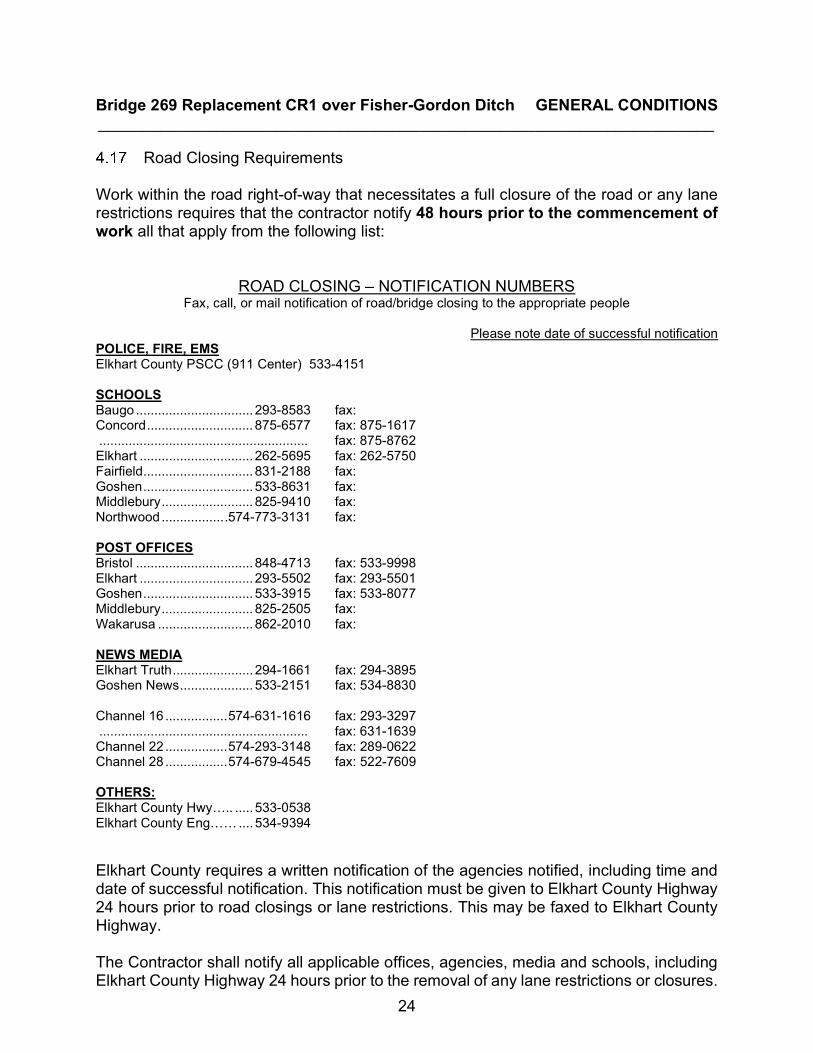
Road Closing Requirements Work within the road right-of-way that necessitates a full closure of the road or any lane restrictions requires that the contractor notify 48 hours prior to the commencement of work all that apply from the following list:
ROAD CLOSING – NOTIFICATION NUMBERS Fax, call, or mail notification of road/bridge closing to the appropriate people
Please note date of successful notification
POLICE, FIRE, EMS Elkhart County PSCC (911 Center) 533-4151 SCHOOLS Baugo ................................ 293-8583 fax: Concord ............................. 875-6577 fax: 875-1617 ......................................................... fax: 875-8762 Elkhart ............................... 262-5695 fax: 262-5750 Fairfield .............................. 831-2188 fax: Goshen .............................. 533-8631 fax: Middlebury ......................... 825-9410 fax: Northwood ................. .574-773-3131 fax: POST OFFICES Bristol ................................ 848-4713 fax: 533-9998 Elkhart ............................... 293-5502 fax: 293-5501 Goshen .............................. 533-3915 fax: 533-8077 Middlebury ......................... 825-2505 fax: Wakarusa .......................... 862-2010 fax: NEWS MEDIA Elkhart Truth ...................... 294-1661 fax: 294-3895 Goshen News .................... 533-2151 fax: 534-8830 Channel 16 ................. 574-631-1616 fax: 293-3297 ......................................................... fax: 631-1639 Channel 22 ................. 574-293-3148 fax: 289-0622 Channel 28 ................. 574-679-4545 fax: 522-7609 OTHERS: Elkhart County Hwy….. ..... 533-0538 Elkhart County Eng…… .... 534-9394 Elkhart County requires a written notification of the agencies notified, including time and date of successful notification. This notification must be given to Elkhart County Highway 24 hours prior to road closings or lane restrictions. This may be faxed to Elkhart County Highway. The Contractor shall notify all applicable offices, agencies, media and schools, including Elkhart County Highway 24 hours prior to the removal of any lane restrictions or closures.
Bridge 269 Replacement CR1 over Fisher-Gordon Ditch GENERAL CONDITIONS _____________________________________________________________________
25
The Contractor shall coordinate the specific timing of the activation of any new signalization system, reopening, etc. When practical, the Contractor shall provide access through the site for emergency vehicle traffic.
ARTICLE 5 - OTHER WORK
Related Work at Site OWNER may perform other work related to the Project at the site by OWNER's own forces, have work performed by utility owners, or let other direct contracts.
5.1.1 CONTRACTOR shall afford each utility owner and other contractor who is a party to such a direct contract (or OWNER, if OWNER is performing the additional work with OWNER's employees) proper and safe access to the site and a reasonable opportunity for the introduction and storage of materials and equipment and the execution of such work, and shall properly connect and coordinate the Work with theirs, CONTRACTOR shall do all cutting, fitting and patching of the Work that may be required to make its several parts come together properly and integrate with such other work.
ARTICLE 6 - OWNER'S RESPONSIBILITIES
Communication OWNER shall issue all communications to CONTRACTOR through ENGINEER.
Appointment of Engineer In case of termination of the employment of ENGINEER, OWNER shall appoint an engineer whom CONTRACTOR makes no reasonable objection to, whose status under the Contract Documents shall be that of the former ENGINEER. Any dispute in connection with such appointment shall be subject to arbitration.
Payment OWNER shall furnish the data required of OWNER under the Contract Documents promptly and shall make payments to CONTRACTOR promptly after they are due.
Change Orders OWNER is obligated to execute Change Orders as indicated in paragraph 8.4.
Inspection
Bridge 269 Replacement CR1 over Fisher-Gordon Ditch GENERAL CONDITIONS _____________________________________________________________________
26
OWNER's responsibility in respect of certain inspections, tests and approvals is set forth in paragraph 11.3.
Service Termination In connection with OWNER's right to stop Work or suspend Work, see paragraphs 11.5 and 13.1. Paragraph 13.2 deals with OWNER's right to terminate services of CONTRACTOR under certain circumstances.
ARTICLE 7 - ENGINEER'S STATUS DURING CONSTRUCTION
Owner's Representative ENGINEER will be OWNER's representative during the construction period. The duties and responsibilities and the limitations of authority of ENGINEER as OWNER's representative during construction are set forth in the Contract Documents and shall not be extended without written consent of OWNER and ENGINEER.
Visits to Site ENGINEER will make visits to the site at intervals appropriate to the various stages of construction to observe the progress and quality of the executed Work and to determine, in general, if the Work is proceeding in accordance with the Contract Documents. ENGINEER will not be required to make exhaustive or continuous on-site inspections to check the quality or quantity of the Work. ENGINEER's efforts will be directed toward providing for OWNER a greater degree of confidence that the completed Work will conform to the Contract Documents. On the basis of such visits and on-site observations as an experienced and qualified design professional, ENGINEER will keep OWNER informed of the progress of the Work and will endeavor to guard OWNER against defects and deficiencies in the Work.
Project Representation If OWNER and ENGINEER agree, ENGINEER will furnish a Resident Project Representative to assist ENGINEER in observing the performance of the Work.
Clarifications and Interpretations ENGINEER will issue with reasonable promptness such written clarifications or interpretations of the requirements of the Contract Documents (in the form of Drawings or otherwise) as ENGINEER may determine necessary, which shall be consistent with or reasonably inferable from the overall intent of the Contract Documents.
Authorized Variations in Work
Bridge 269 Replacement CR1 over Fisher-Gordon Ditch GENERAL CONDITIONS _____________________________________________________________________
27
ENGINEER may authorize minor variations in the Work from the requirements of the Contract Documents which do not involve an adjustment in the Contract Price or the Contract Time and are consistent with the overall intent of the Contract Documents. These may be accomplished by a Field Order and will be binding on OWNER, and also on CONTRACTOR who shall perform the Work involved promptly.
Rejecting Defective Work ENGINEER will have authority to disapprove or reject Work which ENGINEER believes to be defective, and will also have authority to require special inspection or testing of the Work at CONTRACTOR’S expense.
Decisions on Disputes
7.7.1 ENGINEER will be the initial interpreter of the requirements of the Contract Documents and judge of the acceptability of the Work thereunder. Claims, disputes and other matters relating to the acceptability of the Work or the interpretation of the requirements of the Contract Documents pertaining to the performance and furnishing of the Work and claims under Articles 9 and 10 in respect to changes in the Contract Price or Contract Time will be referred initially to ENGINEER in writing with a request for a formal decision in accordance with this paragraph, which ENGINEER will render in writing within a reasonable time. Written notice of each such claim, dispute and other matter will be delivered by the claimant to ENGINEER and the other party to the Agreement promptly (but in no event later than thirty (30) days) after the occurrence of the event giving rise thereto, and written supporting data will be submitted to ENGINEER and the other party within sixty (60) days after such occurrence unless ENGINEER allows an additional period of time to ascertain more accurate data in support of the claim. 7.7.2 When functioning as interpreter and judge under paragraphs 7.7.1 ENGINEER will not show partiality to OWNER or CONTRACTOR and will not be liable in connection with any interpretation or decision rendered in good faith in such capacity.
Limitations on Engineer’s Responsibilities
Neither ENGINEER's authority to act under this Article 7 or elsewhere in the Contract Documents nor any decision made by ENGINEER in good faith either to exercise or not exercise such authority shall give rise to any duty or responsibility of ENGINEER to CONTRACTOR, any Subcontractor, any Supplier, or any other person or organization performing any of the Work, or to any surety for any of them.
7.8.1 ENGINEER will not be responsible for CONTRACTOR's means, methods, techniques, sequences or procedures of construction, or the safety precautions and programs incident thereto, and ENGINEER will not be responsible for

Bridge 269 Replacement CR1 over Fisher-Gordon Ditch GENERAL CONDITIONS _____________________________________________________________________
28
CONTRACTOR's failure to perform or furnish the Work in accordance with the Contract Documents. 7.8.2 ENGINEER will not be responsible for the acts or omissions of CONTRACTOR or of any Subcontractor, any Supplier, or of any other person or organization performing or furnishing any of the Work.
ARTICLE 8 - CHANGES IN THE WORK
Work Modifications
Without invalidating the Agreement and without notice to any surety, OWNER may, at any time or from time to time, order additions, deletions or revisions in the Work; these will be authorized by a Written Amendment, a Change Order, or a Work Directive Change. Upon receipt of any such document, CONTRACTOR shall promptly proceed with the Work involved which will be performed under the applicable conditions of the Contract Documents (except as otherwise specifically provided).
Disagreement If OWNER and CONTRACTOR are unable to agree as to the extent, if any, of an increase or decrease in the Contract Price or an extension or shortening of the Contract Time that should be allowed as a result of a Work Directive Change, a claim may be made therefore as provided in Article 9 or Article 10.
Contract Price and Time CONTRACTOR shall not be entitled to an increase in the Contract Price or an extension of the Contract Time with respect to any Work performed that is not required by the Contract Documents.
Change orders OWNER and CONTRACTOR shall execute appropriate Change Orders covering:
8.4.1 Changes in the Work which is ordered by OWNER. 8.4.2 Changes in the Contract Price or Contract Time which are agreed to by the parties. 8.4.3 Changes in the Contract Price or Contract Time which embody the substance of any written decision rendered by ENGINEER.
Notification of Change
If notice of any change affecting the general scope of the Work or the provisions of the

Bridge 269 Replacement CR1 over Fisher-Gordon Ditch GENERAL CONDITIONS _____________________________________________________________________
29
Contract Documents is required by the provisions of any Bond to be given to a surety, the giving of any such notice will be CONTRACTOR's responsibility, and the amount of each applicable Bond will be adjusted accordingly.
ARTICLE 9 - CHANGE OF CONTRACT PRICE The Contract Price constitutes the total compensation (subject to authorized adjustments) payable to CONTRACTOR for performing the Work. All duties, responsibilities and obligations assigned to or undertaken by CONTRACTOR shall be at his expense without change in the Contract Price. 3
Change Order The Contract Price may only be changed by a Change Order or by a Written Amendment.
Determination of Contract Price The value of any Work covered by a Change Order (extra work order) for an increase or decrease in the Contract Price shall be determined in one of the following ways:
9.2.1 Where the Work involved is covered by unit prices contained in the Contract Documents, by application of unit prices to the quantities of the items involved. 9.2.2 On the basis of the actual Cost of the Work, plus the allowable Contractor's mark-up as per INDOT Specification 109.05 added thereon for overhead and profit.
Cost of the Work
The term Cost of the Work means the sum of all costs necessarily incurred and paid by CONTRACTOR in the proper performance of the Work. The term Cost of the Work shall not include any of the following:
9.3.1 Payroll costs and other compensation of CONTRACTOR's officers, executives, principals (of partnership and sole proprietorships), general managers, attorneys, auditors, accountants, purchasing and contracting agents, CONTRACTOR whether at the site or in CONTRACTOR's principal or a branch office for general administration of the Work. 9.3.2 Expenses of CONTRACTOR's principal and branch offices other than CONTRACTOR's office at the site. 9.3.3 Any part of CONTRACTOR's capital expenses, including interest on CONTRACTOR's capital employed for the Work and charges against CONTRACTOR for delinquent payments.
Bridge 269 Replacement CR1 over Fisher-Gordon Ditch GENERAL CONDITIONS _____________________________________________________________________
30
9.3.4 Cost of premiums for all Bonds and for all insurance whether or not CONTRACTOR is required by the Contract Documents to purchase and maintain the same. 9.3.5 Costs due to the negligence of CONTRACTOR, any Subcontractor, or anyone directly or indirectly employed by any of them or for whose acts any of them may be liable, including but not limited to, the correction of defective Work, disposal of materials or equipment wrongly supplied and making good any damage to property.
ARTICLE 10 - CHANGE OF CONTRACT TIME The Contract Time may only be changed by a Change Order or a Written Amendment. Any claim for an extension or shortening of the Contract Time shall be based on written notice delivered by the party making the claim to the other party and to ENGINEER promptly (but in no event later than fifteen (15) days) after the occurrence of the event giving rise to the claim and stating the general nature of the claim. Notice of the extent of the claim with supporting data shall be delivered within thirty (30) days after such occurrence (unless ENGINEER allows an additional period of time to ascertain more accurate data in support of the claim) and shall be accompanied by the claimant's written statement that the adjustment claimed is the entire adjustment to which the claimant has reason to believe it is entitled as a result of the occurrence of said event. All claims for adjustment in the Contract Time shall be determined by ENGINEER. No extension of Contract Time shall be allowed for weather, changes in quantities placed, or ENGINEER review times set forth in this contract.
ARTICLE 11 - WARRANTY AND GUARANTEE; TESTS AND INSPECTIONS; CORRECTION, REMOVAL OR ACCEPTANCE OF DEFECTIVE WORK
Warranty and Guarantee
CONTRACTOR warrants and guarantees to OWNER and ENGINEER that all Work will be in accordance with the Contract Documents and will not be defective. Prompt notice of all defects shall be given to CONTRACTOR. All defective Work, whether or not in place, may be rejected, corrected or accepted as provided in this Article 11.
Access to Work ENGINEER and ENGINEER's representatives, other representatives of OWNER, testing agencies and governmental agencies with jurisdictional interests will have access to the Work at reasonable times for their observation, inspecting and testing. CONTRACTOR shall provide proper and safe conditions for such access.
Tests and Inspections
Bridge 269 Replacement CR1 over Fisher-Gordon Ditch GENERAL CONDITIONS _____________________________________________________________________
31
CONTRACTOR shall give ENGINEER timely notice of readiness of the Work for all required inspections, tests or approvals.
11.3.1 If Laws or Regulations of any public body having jurisdiction require any Work (or part thereof) to specifically be inspected, tested or approved, CONTRACTOR shall assume full responsibility therefore, pay all costs in connection therewith and furnish ENGINEER the required certificates of inspection, testing or approval. 11.3.2 The Contractor shall assume full responsibility for paying all costs in connection with testing or certification of materials required under INDOT Standard Specifications. In the case of failed or rejected materials or product used in construction of the project either by CONTRACTOR or SUBCONTRACTORS, independent third-party testing may be used at CONTRACTOR’S expense. 11.3.3 If any Work (including the work of others) that is to be inspected, tested or approved is covered without written concurrence of ENGINEER, it must, if requested by ENGINEER, be uncovered for observation. Such uncovering shall be at CONTRACTOR's expense unless CONTRACTOR has given ENGINEER timely notice of CONTRACTOR's intention to cover the same and ENGINEER has not acted with reasonable promptness in response to such notice. 11.3.4 Neither observations by ENGINEER nor inspections, tests or approvals by others shall relieve CONTRACTOR from CONTRACTOR's obligations to perform the Work in accordance with the Contract Documents.
Uncovering Work
11.4.1 If any Work is covered contrary to the written request of ENGINEER, it must, if requested by ENGINEER, be uncovered for ENGINEER's observation and replaced at CONTRACTOR's expense. 11.4.2 If ENGINEER considers it necessary or advisable that covered Work be observed by ENGINEER or inspected or tested by others, CONTRACTOR, at ENGINEER's request, shall uncover, expose or otherwise make available for observation, inspection or testing as ENGINEER may require, that portion of the Work in question, furnishing all necessary labor, material and equipment.
Owner May Stop the Work
If the Work is defective, or CONTRACTOR fails to supply sufficient skilled workers or suitable materials or equipment, or fails to furnish or perform the Work in such a way that the completed Work will conform to the Contract Documents, OWNER may order CONTRACTOR to stop the Work, or any portion thereof, until the cause for such order has been eliminated.
Bridge 269 Replacement CR1 over Fisher-Gordon Ditch GENERAL CONDITIONS _____________________________________________________________________
32
Correction or Removal of Defective Work
If required by ENGINEER, CONTRACTOR shall promptly, as directed, either correct all defective Work, whether or not fabricated, installed or completed, or, if the Work has been rejected by ENGINEER, remove it from the site and replace it with non-defective Work. CONTRACTOR shall bear all direct, indirect and consequential costs of such correction or removal (including but not limited to fees and charges of engineers, attorneys and other professionals) made necessary thereby.
Three Years Correction Period If, within three (3) years after the date of Final Acceptance, any Work is found to be defective, CONTRACTOR shall promptly, without cost to OWNER and in accordance with OWNER's written instructions, either correct such defective Work, or, if it has been rejected by OWNER and/or Engineer remove it from the site and replace it with non-defective work. If CONTRACTOR does not promptly comply with the terms of such instructions, or in an emergency where delay would cause serious risk of loss or damage, OWNER may have the defective Work corrected or the rejected Work removed and replaced, and all direct, indirect and consequential costs of such removal and replacement (including but not limited to fees and charges of engineers, attorneys and other professionals) will be paid by CONTRACTOR.
Maintenance Bond Each Contractor shall furnish prior to Final Acceptance a Maintenance Bond (form attached) in an amount at least equal to ten percent (10%) of the Contract Price, guaranteeing for a period of three (3) years after the date of acceptance by the Owner, that all workmanship and materials entered into the Contract are in accordance with the Plans and Specifications. Each Contractor shall remove any defects due to faulty workmanship and/or materials and shall pay for any damage to other work resulting there from which shall appear within the guarantee period. Should such quality assurance tests, as are called for in the contract Plans and Specifications (e.g., roll test, density, concrete strength, etc.), not be performed or if the work is not performed within reasonable conformity to the Plans and Specifications, the maintenance bond period may be extended to six (6) years.
Acceptance of Defective Work: If instead of requiring correction or removal and replacement of defective Work, OWNER prefers to accept it, OWNER may do so. CONTRACTOR shall bear all direct, indirect and consequential costs attributable to OWNER's evaluation of and determination to accept such defective Work. If any such acceptance occurs prior to ENGINEER's recommendation of final payment, a Change Order will be issued incorporating the necessary revisions in the Contract Documents with respect to the Work; and OWNER shall be entitled to an appropriate decrease in the Contract Price.
Bridge 269 Replacement CR1 over Fisher-Gordon Ditch GENERAL CONDITIONS _____________________________________________________________________
33
OWNER May Correct Defective Work:
If CONTRACTOR fails within a reasonable time after written notice of ENGINEER to proceed to correct and to correct defective Work or to remove and replace rejected Work as required by ENGINEER in accordance with paragraph 11.6, or if CONTRACTOR fails to perform the Work in accordance with the Contract Documents, or if CONTRACTOR fails to comply with any other provision of the Contract Documents, OWNER may, after seven (7) days' written notice to CONTRACTOR, correct and remedy any such deficiency. All direct, indirect and consequential costs of OWNER in exercising such rights and remedies will be charged against CONTRACTOR in an amount approved as to reasonableness by ENGINEER, and a Change Order will be issued incorporating the necessary revisions in the Contract Documents with respect to the Work; and OWNER shall be entitled to an appropriate decrease in the Contract Price.
ARTICLE 12 - PAYMENTS TO CONTRACTOR AND COMPLETION
Schedule of Values The schedule of values (itemized proposal) established at contract unit prices will serve as the basis for progress payments and will be incorporated into a form of Application for Payment acceptable to ENGINEER. Progress payments on account of Unit Price Work will be based on the number of units completed.
Application for Progress Payment At least fifteen (15) days before each regularly scheduled County Commissioners Meeting, CONTRACTOR shall submit to ENGINEER for review an Application for Payment filled out and signed by CONTRACTOR covering the Work completed as of the date of the Application and accompanied by such supporting documentation as is required by the Contract Documents.
Contractor’s Warranty of Title CONTRACTOR warrants and guarantees that title to all Work, materials and equipment covered by any Application for Payment, whether incorporated in the Project or not, will pass to OWNER no later than the time of payment free and clear of all Liens.
Review of Applications for Progress Payment
12.4.1 ENGINEER will, within ten (10) days after receipt of each Application for Payment, either indicate in writing a recommendation of payment and present the Application to OWNER, or return the Application to CONTRACTOR indicating in writing ENGINEER's reasons for refusing to recommend payment. In the latter case, CONTRACTOR may make the necessary corrections and resubmit the Application. Ten (10) days after presentation of the Application for Payment with ENGINEER's

Bridge 269 Replacement CR1 over Fisher-Gordon Ditch GENERAL CONDITIONS _____________________________________________________________________
34
recommendation, the amount recommended will become due and when due will be paid by OWNER to CONTRACTOR. All progress payments will be subject to a ten Percent (10%) retainage that will not be released until Maintenance Bond is received. 12.4.2 ENGINEER's recommendation of any payment requested in an Application for Payment will constitute a representation by ENGINEER to OWNER, based on ENGINEER's on-site observations of the Work in progress as an experienced and qualified design professional and on ENGINEER's review of the Application for Payment and the accompanying data and schedules that the Work has progressed to the point indicated; that, to the best of ENGINEER's knowledge, information and belief, the quality of the Work is in accordance with the Contract Documents and that CONTRACTOR is entitled to payment of the amount recommended. However, by recommending any such payment ENGINEER will not thereby be deemed to have represented that exhaustive or continuous on-site inspections have been made to check the quality or the quantity of the Work beyond the responsibilities specifically assigned to ENGINEER in the Contract Documents or that there may not be other matters or issues between the parties that might entitle CONTRACTOR to be paid additionally by OWNER or OWNER to withhold payment to CONTRACTOR.
12.4.3 ENGINEER's recommendation of final payment will constitute an additional representation by ENGINEER to OWNER that the conditions precedent to CONTRACTOR's being entitled to final payment as set forth in paragraph 12.9 have been fulfilled. 12.4.4 ENGINEER may refuse to recommend the whole or any part of any payment if, in ENGINEER's opinion, it would be incorrect to make such representations to OWNER. ENGINEER may also refuse to recommend any such payment, or, because of subsequently discovered evidence or the results of subsequent inspections or tests, nullify any such payment previously recommended, to such extent as may be necessary in ENGINEER's opinion to protect OWNER from loss because:
a) The Work is defective, or completed Work has been damaged requiring correction or replacement.
b) The Contract Price has been reduced by Written Amendment or Change
Order. c) OWNER has been required to correct defective Work or complete Work in
accordance with paragraph 11.10, or d) Of ENGINEER's actual knowledge of the occurrence of any of the events
enumerated in paragraphs 13.2.1 through 13.2.9 inclusive. OWNER may refuse to make payment of the full amount recommended by
Bridge 269 Replacement CR1 over Fisher-Gordon Ditch GENERAL CONDITIONS _____________________________________________________________________
35
ENGINEER because claims have been made against OWNER on account of CONTRACTOR's performance or furnishing of the Work or Liens have been filed in connection with the Work or there are other items entitling OWNER to a set-off against the amount recommended, but OWNER must give CONTRACTOR immediate written notice (with a copy to ENGINEER) stating the reasons for such action.
Substantial Completion
When CONTRACTOR considers the entire Work ready for its intended use (that is, use by the public) and all work items are complete, CONTRACTOR shall notify OWNER and ENGINEER in writing that the entire Work is substantially complete and request that ENGINEER issue a certificate of Substantial Completion. Within seven (7) calendar days for a contract price under $1,000,000.00 and fourteen (14) calendar days otherwise, OWNER, CONTRACTOR and ENGINEER shall make an inspection of the Work to determine the status of completion. If ENGINEER does not consider the Work substantially complete, ENGINEER will notify CONTRACTOR in writing giving the reasons therefore. If ENGINEER considers the Work substantially complete, ENGINEER will prepare and deliver to OWNER a tentative certificate of Substantial Completion which shall fix the date of Substantial Completion. There shall be attached to the certificate a tentative list of items to be corrected before final payment. The ENGINEER may recommend to the OWNER that a Waiver of Time be provided to the CONTRACTOR for the seven (7) or fourteen (14) calendar days listed herein if the CONTRACTOR has demobilized from the site, and there are no remaining defective or incomplete Work items. A Waiver of Time is a document that waives the Liquidated Damages for the seven (7) or fourteen (14) day time-frame. A Waiver of Time may be given for part or the entirety of the seven (7) or fourteen (14) day period listed herein. The amount of time provided in the Waiver of Time is at the discretion of the OWNER.
Partial Utilization Use by OWNER of any finished part of the Work, which has specifically been identified in the Contract Documents, or which OWNER, ENGINEER and CONTRACTOR agree constitutes a separately functioning and useable part of the Work that can be used by OWNER without significant interference with CONTRACTOR's performance of the remainder of the Work, may be accomplished prior to Substantial Completion of all the Work subject to the following:
12.6.1 OWNER at any time may request CONTRACTOR in writing to permit OWNER to use any such part of the Work which OWNER believes to be ready for its intended use and substantially complete. If CONTRACTOR agrees, CONTRACTOR will certify to OWNER and ENGINEER that said part of the Work is substantially complete and request ENGINEER to issue a certificate of Substantial Completion for that part of the Work. CONTRACTOR at any time may notify OWNER and ENGINEER in writing that CONTRACTOR considers any such part of the Work
Bridge 269 Replacement CR1 over Fisher-Gordon Ditch GENERAL CONDITIONS _____________________________________________________________________
36
ready for its intended use and substantially complete and request ENGINEER to issue a certificate of Substantial Completion for that part of the Work. Within a reasonable time after either such request, OWNER, CONTRACTOR and ENGINEER shall make an inspection of that part of the Work to determine its status of completion. If ENGINEER does not consider that part of the Work to be substantially complete, ENGINEER will notify OWNER and CONTRACTOR in writing giving the reasons therefore. If ENGINEER considers that part of the Work to be substantially complete, the provisions of paragraph 12.5 will apply with respect to certification of Substantial Completion of that part of the Work and the division of responsibility in respect thereof and access thereto. 12.6.2 OWNER may at any time request CONTRACTOR in writing to permit OWNER to take over operation of any such part of the Work although it is not substantially complete. A copy of such request will be sent to ENGINEER and within a reasonable time thereafter OWNER, CONTRACTOR and ENGINEER shall make an inspection of that part of the Work to determine its status of completion and will prepare a list of the items remaining to be completed or corrected thereon before final payment. If CONTRACTOR does not object in writing to OWNER and ENGINEER that such part of the Work is not ready for separate operation by OWNER, ENGINEER will finalize the list of items to be completed or corrected and will deliver such list to OWNER and CONTRACTOR together with a written recommendation as to the division of responsibilities pending final payment between OWNER and CONTRACTOR with respect to security, operation, safety, maintenance, utilities, insurance, warranties and guarantees for that part of the Work which will become binding upon OWNER and CONTRACTOR at the time when OWNER takes over such operation (unless they shall have otherwise agreed in writing and so informed ENGINEER). During such operation and prior to Substantial Completion of such part of the Work, OWNER shall allow CONTRACTOR reasonable access to complete or correct items on said list and to complete other related Work.
Final Inspection
Upon written notice from CONTRACTOR that the entire Work or an agreed portion thereof is complete, ENGINEER will make a final inspection with OWNER and CONTRACTOR and will notify CONTRACTOR in writing of all particulars in which this inspection reveals that the Work is incomplete or defective. CONTRACTOR shall immediately take such measures as are necessary to remedy such deficiencies.
Final Application for Payment After CONTRACTOR has completed all such corrections to the satisfaction of ENGINEER and delivered all maintenance and operating instructions, schedules, guarantees, Bonds, certificates of inspection, marked-up record documents and other documents--all as required by the Contract Documents, and after ENGINEER has indicated that the Work is acceptable, CONTRACTOR may make application for final payment following the

Bridge 269 Replacement CR1 over Fisher-Gordon Ditch GENERAL CONDITIONS _____________________________________________________________________
37
procedure for progress payments.
Final Payment and Acceptance
12.9.1 If, on the basis of ENGINEER's observation of the Work during construction and final inspection, and ENGINEER's review of the final Application for Payment and accompanying documentation--all as required by the Contract Documents, ENGINEER is satisfied that the Work has been completed and CONTRACTOR's other obligations under the Contract Documents have been fulfilled, ENGINEER will, within ten (10) days after receipt of final Application for Payment, indicate in writing ENGINEER's recommendation of payment and present the Application to OWNER for payment. Thereupon ENGINEER will give written notice to OWNER and CONTRACTOR that the Work is acceptable subject to the provisions of paragraph 12.15. Otherwise, ENGINEER will return the Application to CONTRACTOR, indicating in writing the reasons for refusing to recommend final payment, in which case CONTRACTOR shall make the necessary corrections and resubmit the Application. Thirty (30) days after presentation to OWNER of the Application and accompanying documentation, in appropriate form and substance, and with ENGINEER's recommendation and notice of acceptability, the amount recommended by ENGINEER will become due and will be paid by OWNER to CONTRACTOR. 12.9.2 If, through no fault of CONTRACTOR, final completion of the Work is significantly delayed and if ENGINEER so confirms, OWNER shall, upon receipt of CONTRACTOR's final Application for Payment and recommendation of ENGINEER, and without terminating the Agreement, make payment of the balance due for that portion of the Work fully completed and accepted.
Contractor’s Continuing Obligation
CONTRACTOR's obligation to perform and complete the Work in accordance with the Contract Documents shall be absolute. Neither recommendation of any progress or final payment by ENGINEER, nor the issuance of a certificate of Substantial Completion, nor any payment by OWNER to CONTRACTOR under the Contract Documents, nor any use or occupancy of the Work or any part thereof by OWNER, nor any act of acceptance by OWNER nor any failure to do so, nor any review and approval of a Shop Drawing or sample submission, nor the issuance of a notice of acceptability by ENGINEER, nor any correction of defective Work by OWNER will constitute an acceptance of Work not in accordance with the Contract Documents or a release of CONTRACTOR's obligation to perform the Work in accordance with the Contract Documents (except as provided in paragraph 12.11).
Waiver of Claims The making and acceptance of final payment will constitute:
Bridge 269 Replacement CR1 over Fisher-Gordon Ditch GENERAL CONDITIONS _____________________________________________________________________
38
12.11.1 A waiver of all claims by OWNER against CONTRACTOR, except claims arising from unsettled Liens, from defective Work appearing after final inspection pursuant to paragraph 12.10 or from failure to comply with the Contract Documents or the terms of any special guarantees specified therein; however, it will not constitute a waiver by OWNER of any rights in respect of CONTRACTOR's continuing obligations under the Contract Documents; and 12.11.2 A waiver of all claims by CONTRACTOR against OWNER other than those previously made in writing and still unsettled.
ARTICLE 13 - SUSPENSION OF WORK AND TERMINATION
OWNER May Suspend Work OWNER may, at any time and without cause, suspend the Work or any portion thereof for a period of not more than one hundred eighty (180) days by notice in writing to CONTRACTOR and ENGINEER which will fix the date on which Work will be resumed. CONTRACTOR shall resume the Work on the date so fixed. CONTRACTOR shall be allowed an increase in the extension of the Contract Time directly attributable to any suspension.
Conditions of Termination by Owner Upon the occurrence of any one or more of the following events:
13.2.1 If CONTRACTOR commences a voluntary case under any chapter of the Bankruptcy Code (Title 11, United States Code), as now or hereafter in effect, or if CONTRACTOR takes any equivalent or similar action by filing a petition or otherwise under any other federal or state law in effect at such time relating to the bankruptcy or insolvency; 13.2.2 If a petition is filed against CONTRACTOR under any chapter of the Bankruptcy Code as now or hereafter in effect at the time of filing, or if a petition is filed seeking any such equivalent or similar relief against CONTRACTOR under any other federal or state law in effect at the time relating to bankruptcy or insolvency; 13.2.3 If CONTRACTOR makes a general assignment for the benefit of creditors; 13.2.4 If a trustee, receiver, custodian or agent of CONTRACTOR is appointed under applicable law or under contract, whose appointment or authority to take charge of property of CONTRACTOR is for the purpose of enforcing Lien against such property or for the purpose of general administration of such property for the benefit of CONTRACTOR's creditors; 13.2.5 If CONTRACTOR admits in writing an inability to pay its debts generally as
Bridge 269 Replacement CR1 over Fisher-Gordon Ditch GENERAL CONDITIONS _____________________________________________________________________
39
they become due; 13.2.6 If CONTRACTOR persistently fails to perform the Work in accordance with the Contract Documents (including, but not limited to, failure to supply sufficient skilled workers or suitable materials or equipment or failure to adhere to the progress schedule established under paragraph 1.7 as revised from time to time); 13.2.7 If CONTRACTOR disregards Laws or Regulations of any public body having jurisdiction; 13.2.8 If CONTRACTOR disregards the authority of ENGINEER; or 13.2.9 If CONTRACTOR otherwise violates in any substantial way any provisions of the Contract Documents;
Termination by Owner
13.3.1 OWNER may, after giving CONTRACTOR and the surety, if there be one, seven (7) days' written notice and to the extent permitted by Laws and Regulations, terminate the services of CONTRACTOR, exclude CONTRACTOR from the site and take possession of the Work and of all CONTRACTOR's tools, appliances, construction equipment and machinery at the site and use the same to the full extent they could be used by CONTRACTOR (without liability to CONTRACTOR for trespass or conversion), incorporate in the Work all materials and equipment stored at the site or for which OWNER has paid CONTRACTOR but which are stored elsewhere, and finish the Work as OWNER may deem expedient. In such case CONTRACTOR shall not be entitled to receive any further payment until the Work is finished. If the unpaid balance of the Contract Price exceeds the direct, indirect and consequential costs of completing the Work (including but not limited to fees and charges of engineers, attorneys and other professionals and court and arbitration costs) such excess will be paid to CONTRACTOR. If such costs exceed such unpaid balance, CONTRACTOR shall pay the difference to OWNER. Such costs incurred by OWNER will be approved as to reasonableness by ENGINEER and incorporated in a Change Order, but when exercising any rights or remedies under this paragraph OWNER shall not be required to obtain the lowest price for the Work performed. 13.3.2 Where CONTRACTOR's services have been so terminated by OWNER, the termination will not affect any rights or remedies of OWNER against CONTRACTOR then existing or which may thereafter accrue. Any retention or payment of monies due CONTRACTOR by OWNER will not release CONTRACTOR from liability. 13.3.3 Upon seven (7) days' written notice to CONTRACTOR and ENGINEER, OWNER may, without cause and without prejudice to any other right or remedy, elect to abandon the Work and terminate the Agreement. In such case, CONTRACTOR shall be paid for all Work executed and any expense sustained plus
Bridge 269 Replacement CR1 over Fisher-Gordon Ditch GENERAL CONDITIONS _____________________________________________________________________
40
reasonable termination expenses, which will include, but not be limited to, direct, indirect and consequential costs (including, but not limited to, fees and charges of engineers, architects, attorneys and other professionals and court and arbitration costs).
Conditions of Termination by Contractor
13.4.1 If, through no act or fault of CONTRACTOR, the Work is suspended for a period of more than one hundred eighty (180) days by OWNER or under an order of court or other public authority, or ENGINEER fails to act on any Application for Payment within thirty (30) days after it is submitted, or 13.4.2 If OWNER fails for thirty (30) days to pay CONTRACTOR any sum finally determined to be due, then CONTRACTOR may, upon seven (7) days' written notice to OWNER and ENGINEER, terminate the Agreement and recover from OWNER payment for all Work executed and any expense sustained plus reasonable termination expenses. In addition and in lieu of terminating the Agreement, if ENGINEER has failed to act on an Application for Payment or OWNER has failed to make any payment as aforesaid, CONTRACTOR may upon seven (7) days' written notice to OWNER and ENGINEER stop the Work until payment of all amounts then due. The provisions of this paragraph shall not relieve CONTRACTOR of the obligations under paragraph 4.14 to carry on the Work in accordance with the progress schedule and without delay during disputes and disagreements with the OWNER.
ARTICLE 14 - MISCELLANEOUS 14.1 Giving Notice Whenever any provision of the Contract Documents requires the giving of written notice, it will be deemed to have been validly given if delivered in person to the individual or to a member of the firm or to an officer of the corporation for whom it is intended, or if delivered at or sent by registered or certified mail, postage prepaid, to the last business address known to the giver of the notice. 14.2 Computation of Time When any period of time is referred to in the Contract Documents by days, it will be computed to exclude the first and include the last day of such period. If the last day of any period falls on a Saturday or Sunday or on a day made a legal holiday by the law of the applicable jurisdiction, such day will be omitted from the computation.
14.2.1 A calendar day of twenty-four hours measured from midnight to the next midnight shall constitute a day.

Bridge 269 Replacement CR1 over Fisher-Gordon Ditch GENERAL CONDITIONS _____________________________________________________________________
41
14.3 Bid Submission Each bidder who submits a proposal for any portion of the work included in the Project Manual must submit with its bid this form fully completed and signed by an authorized officer of the bidder and must provide the data requested by the form. Unless this form is fully completed and signed by the bidder, the proposal made by that bidder will be incomplete and will not be considered by the Board of County Commissioners.
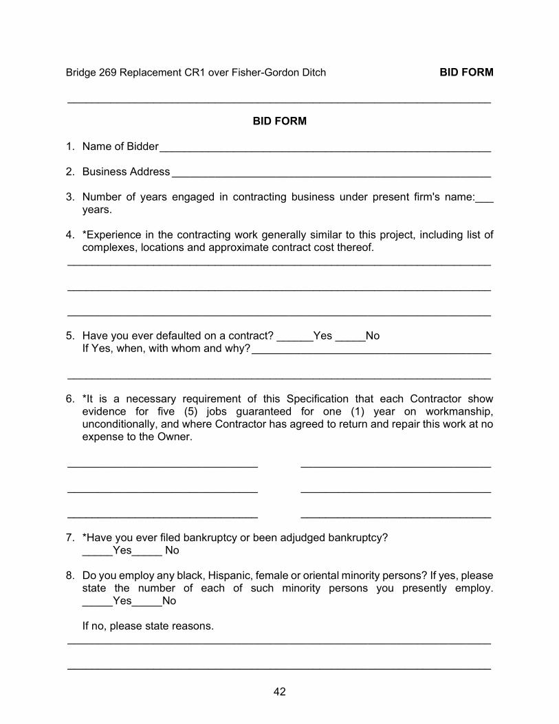
Bridge 269 Replacement CR1 over Fisher-Gordon Ditch BID FORM _____________________________________________________________________
42
BID FORM 1. Name of Bidder ______________________________________________________ 2. Business Address ____________________________________________________ 3. Number of years engaged in contracting business under present firm's name:___
years. 4. *Experience in the contracting work generally similar to this project, including list of
complexes, locations and approximate contract cost thereof. _____________________________________________________________________ _____________________________________________________________________ _____________________________________________________________________ 5. Have you ever defaulted on a contract? ______Yes _____No
If Yes, when, with whom and why? _______________________________________ _____________________________________________________________________ 6. *It is a necessary requirement of this Specification that each Contractor show
evidence for five (5) jobs guaranteed for one (1) year on workmanship, unconditionally, and where Contractor has agreed to return and repair this work at no expense to the Owner.
_______________________________ _______________________________ _______________________________ _______________________________ _______________________________ _______________________________ 7. *Have you ever filed bankruptcy or been adjudged bankruptcy?
_____Yes_____ No 8. Do you employ any black, Hispanic, female or oriental minority persons? If yes, please
state the number of each of such minority persons you presently employ. _____Yes_____No
If no, please state reasons.
_____________________________________________________________________ _____________________________________________________________________

Bridge 269 Replacement CR1 over Fisher-Gordon Ditch BID FORM _____________________________________________________________________
43
9. Have you encouraged minority building subcontractors to submit proposals in connection with your bid? _____Yes _____ No. If yes, state the name(s) of the minority subcontractors who have been contacted by you for the purpose of submitting a bid/proposal. If no, please state reasons.
_____________________________________________________________________ _____________________________________________________________________ _____________________________________________________________________ 10. Do you intend to use any minority subcontractors in performing the work or providing
the materials contained within your bid? _____Yes _____No. If yes, please state the name of the subcontractor. If no, please state reasons.
_____________________________________________________________________ _____________________________________________________________________ _____________________________________________________________________ 11 Have you been involved in any complaints or litigation relative to the use of minority
subcontractors? _____Yes _____No. If yes, what is the status of the complaints of the litigation?
_____________________________________________________________________ _____________________________________________________________________ _____________________________________________________________________ 12 Additional pertinent comments:
___________________________________________________________________ ___________________________________________________________________ ___________________________________________________________________
BY: __________________________________________
__________________________________________ (Signature of official completing this form)
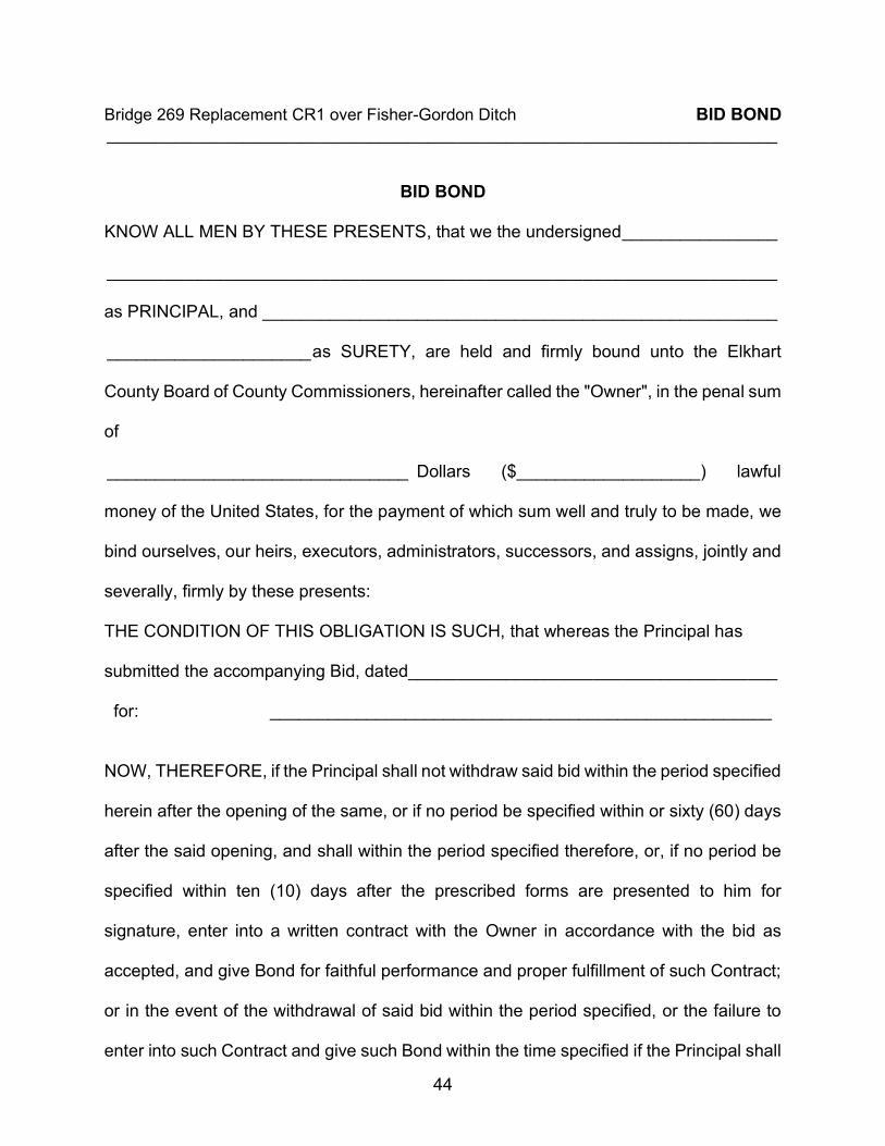
Bridge 269 Replacement CR1 over Fisher-Gordon Ditch BID BOND _____________________________________________________________________
44
BID BOND
KNOW ALL MEN BY THESE PRESENTS, that we the undersigned ________________
_____________________________________________________________________
as PRINCIPAL, and _____________________________________________________
_____________________ as SURETY, are held and firmly bound unto the Elkhart
County Board of County Commissioners, hereinafter called the "Owner", in the penal sum
of
_______________________________ Dollars ($___________________) lawful
money of the United States, for the payment of which sum well and truly to be made, we
bind ourselves, our heirs, executors, administrators, successors, and assigns, jointly and
severally, firmly by these presents:
THE CONDITION OF THIS OBLIGATION IS SUCH, that whereas the Principal has
submitted the accompanying Bid, dated ______________________________________
for: ____________________________________________________
NOW, THEREFORE, if the Principal shall not withdraw said bid within the period specified
herein after the opening of the same, or if no period be specified within or sixty (60) days
after the said opening, and shall within the period specified therefore, or, if no period be
specified within ten (10) days after the prescribed forms are presented to him for
signature, enter into a written contract with the Owner in accordance with the bid as
accepted, and give Bond for faithful performance and proper fulfillment of such Contract;
or in the event of the withdrawal of said bid within the period specified, or the failure to
enter into such Contract and give such Bond within the time specified if the Principal shall
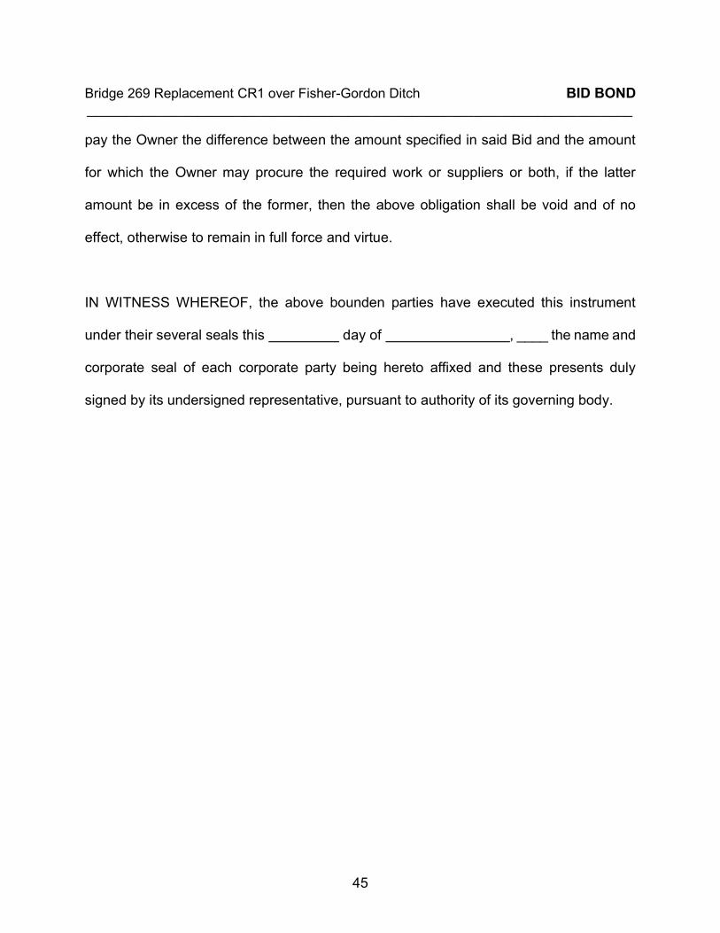
Bridge 269 Replacement CR1 over Fisher-Gordon Ditch BID BOND _____________________________________________________________________
45
pay the Owner the difference between the amount specified in said Bid and the amount
for which the Owner may procure the required work or suppliers or both, if the latter
amount be in excess of the former, then the above obligation shall be void and of no
effect, otherwise to remain in full force and virtue.
IN WITNESS WHEREOF, the above bounden parties have executed this instrument
under their several seals this day of , ____ the name and
corporate seal of each corporate party being hereto affixed and these presents duly
signed by its undersigned representative, pursuant to authority of its governing body.
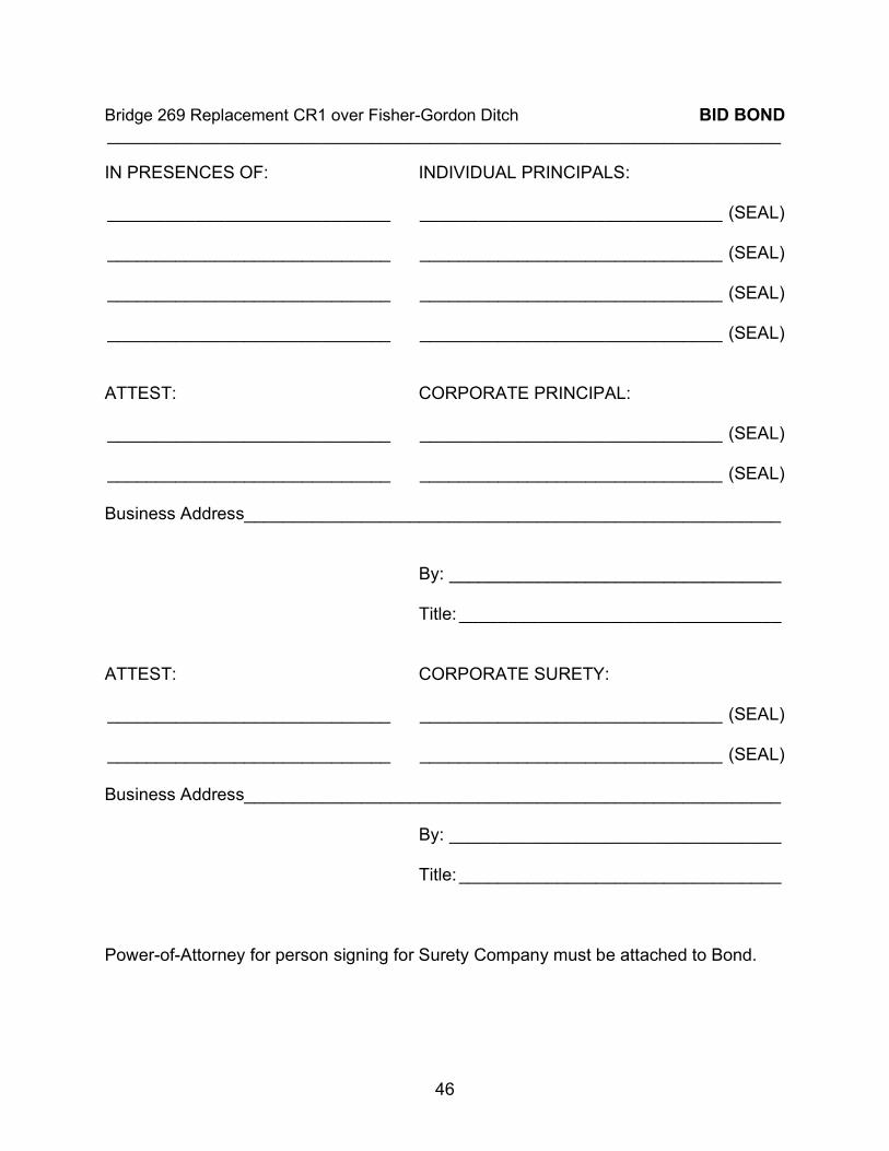
Bridge 269 Replacement CR1 over Fisher-Gordon Ditch BID BOND _____________________________________________________________________
46
IN PRESENCES OF: INDIVIDUAL PRINCIPALS: _____________________________ _______________________________ (SEAL) _____________________________ _______________________________ (SEAL) _____________________________ _______________________________ (SEAL) _____________________________ _______________________________ (SEAL) ATTEST: CORPORATE PRINCIPAL: _____________________________ _______________________________ (SEAL) _____________________________ _______________________________ (SEAL) Business Address_______________________________________________________
By: __________________________________
Title: _________________________________
ATTEST: CORPORATE SURETY: _____________________________ _______________________________ (SEAL) _____________________________ _______________________________ (SEAL) Business Address_______________________________________________________
By: __________________________________
Title: _________________________________ Power-of-Attorney for person signing for Surety Company must be attached to Bond.

Bridge 269 Replacement CR1 over Fisher-Gordon Ditch CERTIFICATE AS TO CORPORATE PRINCIPAL _____________________________________________________________________
47
CERTIFICATE AS TO CORPORATE PRINCIPAL I, ____________________________________________________________________
certify that I am the ______________________________________________________
Secretary of the Corporation named as Principal in the within Bond; that ____________
__________________________ who signed the said Bond on behalf of the Principal
was then ______________________________________of the corporation, that I know
his signature, and his signature thereto is genuine; and that said Bond was duly signed,
sealed, and attested to, for and in behalf of said corporation by authority of its governing
body.
_______________________________ (SEAL)

Bridge 269 Replacement CR1 over Fisher-Gordon Ditch PERFORMANCE BOND _____________________________________________________________________
48
PERFORMANCE BOND
KNOW ALL MEN BY THESE PRESENTS,
That__________________________________ ________________as principal and
_____________________________________ as surety, are firmly bound unto Elkhart
County, Indiana, acting through its Board of County Commissioners (OWNER) in the
penal sum of an amount equal to one hundred percent (100%) the amount of his bid or
the contract price, if the proposal is accepted, for the payment of which, well and truly to
be made, we bind ourselves, jointly and severally, and our joint and several heirs,
executors, administrators, and assigns, firmly by these presents, this _____day
of____________________, ____.
THE CONDITIONS OF THE ABOVE OBLIGATION ARE SUCH That, Whereas, the
principal is herewith submitting a bid and proposal for the erection, construction and
completion of Bridge 269 Replacement CR1 over Fisher-Gordon Ditch in accordance with
the plans and specifications approved and adopted by said OWNER, which are made a
part of this bond.
NOW, THEREFORE, if the said OWNER shall award said principal the contract for work
and said principal shall promptly enter into a contract with said OWNER for the said work
and shall well and faithfully do and perform the same in all respects according to the plans
and specifications provided by the said OWNER, and according to the time, terms, and
conditions specified in said contract to be entered into, and in accordance with all
Bridge 269 Replacement CR1 over Fisher-Gordon Ditch PERFORMANCE BOND _____________________________________________________________________
49
requirements of law, and shall promptly pay all debts incurred by him or any subcontractor
in the construction of said work, including labor, service, and materials furnished, then
this obligation shall be void; otherwise to remain in full force, virtue and effect.
IT IS AGREED that no modifications, omissions, or additions in or to the terms of such
contract or in or to the plans or specifications therefore shall in any wise affect the
obligation of such sureties on its bond.
IN WITNESS WHEREOF, we hereunto set our hands and seal this ______day of
____________________, ____.
NAME____________________________ NAME___________________________________
ADDRESS_________________________ ADDRESS________________________________
BY_______________________________ BY______________________________________ Signature Title Signature Title _________________________________ _________________________________________
(Printed or Typed) (Printed or Typed) Surety Principal
Bridge 269 Replacement CR1 over Fisher-Gordon Ditch PERFORMANCE BOND _____________________________________________________________________
50
State of Indiana, County of ________________________ss:
Personally appeared before me,______________________________________________
as principal and___________________________________________________________
as surety and each acknowledged the execution of the above bond this______ day
of ___________________, ____.
BY
Signature Notary Public
____________________________________________ (Printed or Typed) Witness my hand and notarial seal the said last named date. My Commission Expires _______, ____. _____________________________________
(County of Residence) Accepted and approved this _____day of____________________, _____.
_________________________________ Mike Yoder _________________________________ Suzanne Weirick _________________________________
Frank Lucchese ATTEST: _________________________
Patricia A. Pickens, Auditor
Bridge 269 Replacement CR1 over Fisher-Gordon Ditch MAINTENANCE BOND _____________________________________________________________________
51
MAINTENANCE BOND
KNOW ALL MEN BY THESE PRESENT: That we,________________________________
_________________________________________________________________________, as
Principal, and
____________________________________________________________________
as Surety, are held and firmly bound to the ________________________________________
__________________________________________________________________________ in
the sum of__________________________________________________________________
____________________________________________________________________________
______________________________Dollars ($______________________________________)
for the payment of which sum well and truly to be made, we jointly and severally bind ourselves,
our heirs, executors, administrators, and successors, firmly by these present.
THE CONDITIONS OF THE ABOVE OBLIGATION are that, whereas the Principal, entered into
a contract with the Owner on the ____________day of_____________________, _____, to
construct ______________________________according to the Plans and Specifications, and
also warranting the work and materials as provided in the aforesaid Contract and Specifications,
for a period of three (3) years from the date of final acceptance of work by the Owner.
Now, if the said Principal shall faithfully perform and fulfill all the requirements of said Warranty
and Guaranty, and make all repairs required under said Guaranty and, in the manner provided
for, then this Bond to be null and void, otherwise to be in full force and effect.
Bridge 269 Replacement CR1 over Fisher-Gordon Ditch MAINTENANCE BOND _____________________________________________________________________
52
IN WITNESS WHEREOF, this statement is executed in two (2) counterparts, each one of which
shall be deemed an original, this__________ day of_______________________, _____.
______________________________________ (SEAL) Principal
ATTEST:
____________________________ BY:__________________________________
____________________________ _____________________________________ Title Title (SEAL) ATTEST: ____________________________ BY:__________________________________ ____________________________ _____________________________________ Title Title APPROVED this _____________ day of____________________, _____. ELKHART COUNTY, INDIANA By and Through Its BOARD OF COUNTY COMMISSIONERS _________________________________ Mike Yoder _________________________________ Suzanne Weirick _________________________________
Frank Lucchese ATTEST: _________________________
Patricia A. Pickens, Auditor
53
AGREEMENT THIS AGREEMENT, made and entered into this _____ day of _______, ____, by and
between (a corporation organized and existing under the laws of
the State of Indiana), hereinafter referred to as the “CONTRACTOR,” and “ELKHART COUNTY,
INDIANA,” acting through the Board of Commissioners, hereinafter referred to as the “OWNER.”
WITHESSETH, that the Contractor and the Owner, for the considerations stated herein,
mutually agree as follows:
ARTICLE 1 -- STATEMENT OF WORK
The Contractor shall furnish all supervision, technical personnel, labor, materials,
machinery, tools, equipment and services, including utility and transportation services, and traffic
control, and perform and complete all work required for Bridge 269 Replacement CR1 over
Fisher-Gordon Ditch, in Elkhart County, Indiana, as more particularly described in the
Specifications, Special Provisions, General Requirements, Supplementary Conditions, Terms for
Bidding, plans and drawings, and other items contained therein prepared by Elkhart County
(“ENGINEER”) and referred to herein as the “Construction Documents.” All such Construction
Documents have been reviewed and approved by the parties hereto and all are incorporated
herein by reference as a part of this Agreement consistent with Article 4 below. All undertakings,
duties, obligations, and performance required of Contractor by the Construction Documents and
this Agreement are hereinafter referred to as the “Work.”
ARTICLE 2 -- CONTRACTOR REPRESENTATIONS
The Contractor represents to Owner that it is fully experienced and properly qualified as
an expert to render the performance required for the Work, and that it is properly equipped,
organized and financed for performance of this Agreement. Contractor further represents and
acknowledges that it is an independent contractor, and that Contractor IS NOT, in any manner or
form, an agent, employee, or representative of Owner.

54
CONTRACTOR INDEMNIFICATION
The Contractor agrees to indemnify and save harmless the Owner and Engineer, their
agents and employees, from and against all loss or expense (including court costs and attorneys’
fees of defense or enforcement) by reason of liability imposed by law or otherwise upon the Owner
or Engineer, for (1) damages because of bodily injury, including death at any time resulting
therefrom, sustained by any person or persons, or (2) on account of damage to property or
property rights or interests, including loss of use thereof, arising out of or in consequence of the
performance of the Work, provided such injury to persons or damage to property is due or claimed
to be due to negligence of the Contractor, its subcontractors, employees or agents, or in violation
of this Agreement.
REQUIREMENTS FOR CONTRACTORS ON PUBLIC WORKS PROJECTS 1) The provisions of Indiana Code Section 5-16-13 are hereby incorporated by reference
including, but not limited to, the following specific provisions:
a) Contractor must contribute in work performed by its employees, materials supplied directly
by Contractor, and services supplied directly by its employees of at least fifteen percent
(15%) of the total contract price.
b) Contractor must maintain general liability insurance in the amounts provided in the
Construction Documents but in no event less than One Million Dollars ($1,000,000.00) for
each occurrence limit and Two Million Dollars ($2,000,000.00) for the general aggregate
limit.
c) Contractor must implement and comply with the requirements of Indiana Code Section
22-5-1.7 concerning the E-Verify system with respect to its employee hiring. Contractor
must submit, before work begins on the Agreement, the E-Verify case verification number
for each individual who is required to be verified under Indiana Code Section 22-5-1.7. An
individual who is required to be verified under Indiana Code Section 22-5-1.7 whose final
55
case result is final non-confirmation may not be employed on this Work.
d) Contractor may not pay cash to any individual employed by the Contractor for work done
by the individual on this Work.
e) Contractor must be in compliance with the Federal Fair Labor Standards Act of 1938, as
amended (29 USC 201-209) and Indiana Code Section 22-2-2-1 through Indiana Code
Section 22-2-2-8.
f) Contractor must be in compliance with Indiana Code Section 22-3-5-1 and Indiana Code
Section 22-3-7-34.
g) Contractor must be in compliance with Indiana Code Section 22-4-1 through Indiana Code
Section 22-4-39.5.
h) Contractor must be in compliance with Indiana Code Section 4-13-18-1 through Indiana
Code Section 4-13-18-7.
2) Drug Testing of Employees. Indiana Code Section 4-13-18 regarding the drug testing of
employees of public works contractors applies to the Agreement as the estimated cost hereof
is at least One Hundred Fifty Thousand Dollars ($150,000.00) and has been awarded after
June 30, 2015.
3) Nondiscrimination. Pursuant to Indiana Code Section 22-9-1-10, Contractor and its
subcontractors, if any, shall not discriminate against any employee or applicant for
employment to be employed in the performance of the Agreement with respect to hire, tenure,
terms, conditions or privileges of employment or any matter directly or indirectly related to
employment, because of race, religion, color, sex, disability, national origin, ancestry, or
veteran status. Breach of this covenant may be regarded as a material breach of the
Agreement.
4) Anti-nepotism. Contractor is aware of the provisions of Indiana Code Section 36-1-21 et seq.
with respect to anti-nepotism in contractual relationships with governmental entities.
Contractor certifies that none of the owners of Contractor is a relative of any elected Council
56
Member or Commissioner of the County of Elkhart, Indiana.
5) Investment Activity. Pursuant to Indiana Code Section 5-22-16.5-13, Contractor certifies that
Contractor is not engaged in investment activities in Iran.
ARTICLE 3 -- THE CONTRACT PRICE
The Owner will pay the Contractor for the performance of the Work subject to additions
and deductions provided herein, in current funds, and per applicable Indiana law and the required
procedures for payments by Owner, the sum of $________________. The Contractor shall start
the Work on or after August 3, 2020, be substantially complete by November 27, 2020 and
receive final acceptance on or before December 28, 2020. Any Work remaining to be completed
after November 27, 2020 or Final Acceptance has not been received by December 28, 2020 is
subject to the following damages:
For each and every day Work contemplated in this Agreement fails to achieve substantial
completion, beyond the substantial completion date herein established (November 27, 2020) or
final acceptance has not been received by the final acceptance date herein established
(December 28, 2020), Contractor shall owe and pay to Owner the sum of $1,000 per day, as
liquidated damages and not as penalty. In establishing said $1,000 sum per day as and for
liquidated damages owed by the Contractor to Owner, the parties hereto stipulate and agree that
the actual damages that would be suffered by Owner because of the failure of Contractor to timely
complete the Work contemplated are indefinite and uncertain; however, the parties hereto
stipulate that the sum herein established is a reasonable estimate by the parties of the probably
damages to be suffered by the Owner upon the failure of the Contractor to timely complete the
Work contemplated. The liquidated damages herein established shall be deducted daily from the
Contract Price herein established, thereby reducing the same for the total amount of liquidated
damages as herein stipulated, and hence reducing payments of the Contract Price Owner would
otherwise make. If an intermediate date is specified for one or more of the items or phases of the
contract, liquidated damages will apply for that particular item or phase as if the intermediate date
57
specified for said item or phase is conclusion of said portion of project or contract.
ARTICLE 4 -- CONTRACT DOCUMENTS
The Contract Documents forming a part of this Agreement by reference shall consist of
the following:
a. This Agreement.
b. Memos:
c. Invitation for Bids.
d. Notice to Bidders.
e. Signed copy of Bid and Itemized Bid Form.
f. General Conditions and Supplementary Conditions.
g. Construction Specifications and Related Documents.
h. Plans.
i. Addendums
ARTICLE 5 -- PROJECT CONTROL
The Contractor will carry out this project and complete the Work under the direction of the
Owner and the Owner’s agents, the Engineer, or other consultant designated by the Owner. The
Owner’s designated representative during the construction period will make visits to the site at
intervals appropriate to the various states of construction to observe the progress and quality of
the executed Work and to determine, in general, if the Work is proceeding in accordance with the
Contract Documents.
This Agreement, to include the Contract Documents enumerated in Article 4 above,
constitutes the full agreement and understanding of the parties hereto, and save for change
orders and procedures therefore set forth within the Contract Documents, shall not be amended
by the parties, other than by instrument executed by each party hereto.
IN WITNESS WHEREOF, the parties hereto have caused this Agreement to be executed
in various counterparts effective as of the date and year first above written.

58
CONTRACTOR:
By_______________________________________ Signature _________________________________________ Printed Name _________________________________________ Title
OWNER: ELKHART COUNTY, INDIANA, by and through its Board of County Commissioners
_________________________________ Mike Yoder _________________________________ Suzanne Weirick _________________________________
Frank Lucchese ATTEST: _________________________
Patricia A. Pickens, Auditor

Division 2:
Supplemental Provisions
For
BRIDGE 269 REPLACEMENT CR1 OVER FISHER-GORDON DITCH
________________________________________________________________________ OWNERS: ELKHART COUNTY, INDIANA, ACTING THROUGH
ITS BOARD OF COUNTY COMMISSIONERS ELKHART COUNTY HIGHWAY DEPARTMENT ENGINEERING SECTION 610 STEURY AVENUE GOSHEN, IN 46528
____________________________________________________________________________________________
Elkhart County Highway Department 610 Steury Avenue, Goshen, Indiana 46528 Phone: 574-534-9394 • Fax: 574-533-7103
Bridge 269 Replacement CR1 over Fisher-Gordon Ditch SUPPLEMENTAL PROVISIONS ________________________________________________________________________
2
INDEX
SP1 – GENERAL INFORMATION ............................................................................................. 3
SP2 – TIME OF COMPLETION ................................................................................................. 4
SP3 – UTILITIES ....................................................................................................................... 6
SP4 – STORAGE OF CONTRACTOR'S EQUIPMENT, MATERIALS AND TEMPORARY OFFICES ................................................................................................................................... 7
SP5 – ENVIRONMENTAL RESTRICTIONS .............................................................................. 8
SP6 – CONTRACTOR'S RESPONSIBILITY FOR MATCHING OLD WORK .............................. 9
SP7 – DUST AND AIR POLLUTION CONTROL .......................................................................10
SP8 – CONTAMINATION PRECAUTION .................................................................................11
SP10 – PROOFROLLING .........................................................................................................12
SP11 – DISPOSAL OF UNSUITABLE MATERIAL ....................................................................13
SP12 – RECORD DRAWINGS .................................................................................................14
SP13 – COORDINATION CLAUSE ..........................................................................................15
SP14 – MATERIAL TESTING ...................................................................................................16
SP15 – VIDEO REQUIREMENTS FOR CONSTRUCTION CORRIDOR ...................................17
SP16 – RESIDENTIAL ACCESS ..............................................................................................18
Bridge 269 Replacement CR1 over Fisher-Gordon Ditch SUPPLEMENTAL PROVISIONS ________________________________________________________________________
3
SP1 – GENERAL INFORMATION 1. GENERAL
The following Technical Provisions are in addition to the latest edition of the Indiana Department of Transportation "STANDARD SPECIFICATIONS", which Standard Specifications shall apply to this contract. Where the words "Standard Specifications" and also where reference consisting of a number or numbers are used, they shall be construed as referring to the latest edition of the Indiana Department of Transportation Standard Specifications and current supplementary specifications and standard detail drawings. The term “State” as used in the Standard Specifications shall be deleted and replaced with the term “County”. The term “Engineer” as used in the Standard Specifications shall be the person, firm, or corporation named as such in the written Agreement between the OWNER and CONTRACTOR.
2. HIERARCHY The hierarchy of governing authority in the contract Documents is as follows.
A. Division 1 provisions as modified by the Supplementary Provisions B. Project Specifications C. Project Drawings D. County Specifications E. INDOT Standard Specifications F. INDOT Standard Drawings
Bridge 269 Replacement CR1 over Fisher-Gordon Ditch SUPPLEMENTAL PROVISIONS ________________________________________________________________________
4
SP2 – TIME OF COMPLETION 1. MOBILIZATION
Work on this Contract shall not begin prior to notice to proceed. The Contractor shall notify the Owner at least two (2) weeks in advance of his intention to perform any Work on the project. The Contractor shall give the owner/inspector updated schedules of work on a bi-weekly basis or as the schedule changes. The Contractor shall also notify the appropriate agencies of his intention to close any County Road in connection with the project. See ROAD CLOSING REQUIREMENTS. Note that “Road Construction Ahead” signage shall be installed prior to any other work, and shall be removed only upon final acceptance of the project or initial acceptance of the segment for paving packages. These signs shall be checked on a daily basis and promptly reset as needed.
2. SUBSTANTIAL COMPLETION Add the following new definition to the DEFINITIONS section of the General Provisions:
“SUBSTANTIALLY COMPLETE” The time at which the Work (or a specified portion thereof) is ready for its intended use and all work items (in the specified portion thereof) are complete.
Add the following at the beginning of Section 12.5 of the General Provisions:
A project is considered substantially complete when the entire Work is ready for its intended use and all work items are complete.
3. LIQUIDATED DAMAGES
The completion date as referred to in ARTICLE 3 of the agreement will be used interchangeably with the term Final Acceptance. Final Acceptance is the point in time where the Engineer provides recommendation of final payment to the Owner as outlined in Section 12.9 of the General Provisions. Liquidated damages will apply for the following dates and intermediate dates until conclusion of said portion of project or contract.
Description Date Substantial Completion November 27, 2020 Final Acceptance December 28, 2020
4. REVIEW TIMES
The Engineer is allowed to use to the following time to produce items owed to the Owner or Contractor per this agreement and the Owner is not obligated to provide the Contractor a change of contract time therefore.
Bridge 269 Replacement CR1 over Fisher-Gordon Ditch SUPPLEMENTAL PROVISIONS ________________________________________________________________________
5
In Section 12.5 of the General Provisions, ‘a reasonable time thereafter’ is seven (7) calendar days for a contract price under $1,000,000.00 and fourteen (14) calendar days otherwise. The Owner is not required to provide the Contractor a change in contract time therefore. In Section 12.9 of the General Provisions, the Engineer will indicate in writing Engineer's recommendation of payment and present the Application to Owner for payment within fourteen (14) calendar days after receipt of final Application for Payment. The Engineer may recommend to the Owner that a Waiver of Time be provided to the Contractor for the fourteen (14) calendar days listed herein if the Contractor has demobilized from the site, there are no remaining defective or incomplete Work items. A Waiver of Time is document that waives the Liquidated Damages for the time-frame indicated in the document. A Waiver of Time may be given for part or the entirety of the fourteen (14) day period listed herein. The amount of time provided in the Waiver of Time is at the discretion of the Owner.
5. CHANGE OF CONTRACT TIME Add the following new definition to the DEFINITIONS section of the General Provisions:
No extension of Contract Time shall be allowed for weather or changes in quantities placed. Changes in Contract Time will only be considered if requested in writing by the Contractor in accordance with Article 10 of the General Conditions.
Determination and Extension of Contract Time for Completion and Failure to Complete on Time shall be in accordance with the Agreement and all applicable requirements of 108.08, and modified as follows.
A. This completion date is a ‘fixed calendar date’ as defined by INDOT Standard Specifications section 108.
B. Changes in Contract Time will only be considered if requested in writing by the
Contractor in accordance with Article 10 of the General Conditions.
Bridge 269 Replacement CR1 over Fisher-Gordon Ditch SUPPLEMENTAL PROVISIONS ________________________________________________________________________
6
SP3 – UTILITIES 1. GENERAL
The Contractor shall determine the location of all underground and overhead utility lines within the project limits. If proper clearances cannot be obtained, affected planned structures shall be placed as otherwise directed and approved by the adjacent utility representatives (and as accepted by the Engineer).
2. COORDINATION WITH UTILITIES
The Contractor shall be responsible for utility property and services in accordance with 107.20 of INDOT’s Standard Specifications. All of the permanent and temporary utility appurtenances in their present or relocated positions shall have been considered in the bid. No additional compensation will be allowed for any delays, inconvenience, or damage sustained by the Contractor due to any interference from the said utility appurtenances or the operations of moving them. The plan drawings include a list of names for the known companies that may have utilities located within the limits of construction in this contract. If any of these utilities are affected, it shall be the Contractor's responsibility to identify and coordinate with that utility. The prime contractor shall be ultimately responsible for the completeness and promptness of utility location(s) for subcontractors. Multiple locations of the same facilities may be required throughout the project time.
Bridge 269 Replacement CR1 over Fisher-Gordon Ditch SUPPLEMENTAL PROVISIONS ________________________________________________________________________
7
SP4 – STORAGE OF CONTRACTOR'S EQUIPMENT, MATERIALS AND TEMPORARY OFFICES
1. GENERAL
The Contractor will be permitted to store non-operating construction equipment, workmen’s vehicles, materials and temporary offices within the limits of the Right-of-Way with approval from Owner. In the event that the Right-of-Way is not available for storage, the Contractor shall procure an adequately secure operations site as an incidental item to the contract. All areas within the limits of the Right-of-Way that are used by the Contractor for temporary storage, of any kind, shall be restored to their original condition by the Contractor at his own expense, when no longer required for that purpose. The Contractor shall not use property adjacent to the project Right-of-Way for storage, parking or any other use without prior approval from the property owner.
Bridge 269 Replacement CR1 over Fisher-Gordon Ditch SUPPLEMENTAL PROVISIONS ________________________________________________________________________
8
SP5 – ENVIRONMENTAL RESTRICTIONS 1. GENERAL
A. All trees or shrubs outside the construction limits shall not be disturbed. B. Construction limit is defined as the Right-of-Way line unless otherwise shown on the plans.
2. PERMITS
Regulatory permits for this project to be obtained by the OWNER are as follows:
Army Corps of Engineers Section 404 Indiana Department of Environmental Management Section 401 WQC
The CONTRACTOR is responsible for securing all other permits that may be required for this project in accordance with the Standard Specifications.
Bridge 269 Replacement CR1 over Fisher-Gordon Ditch SUPPLEMENTAL PROVISIONS ________________________________________________________________________
9
SP6 – CONTRACTOR'S RESPONSIBILITY FOR MATCHING OLD WORK 1. GENERAL
Where new work is to be fitted to old work, the Contractor shall check all leading dimensions and conditions in the field and report any errors or discrepancies to the Engineer and assume responsibility for their correctness and the fit of new parts to old. If such parts do not fit properly, the Contractor shall make and pay for such alterations or new parts as may be necessary to assure proper fits and connections meeting the approval of the Engineer.

Bridge 269 Replacement CR1 over Fisher-Gordon Ditch SUPPLEMENTAL PROVISIONS ________________________________________________________________________
10
SP7 – DUST AND AIR POLLUTION CONTROL 1. GENERAL
Provision shall be made for prompt removal from traveled roadways of all dirt and other materials that have been deposited thereon by operations concerned with the project whenever the accumulation is sufficient to cause the formation of dust or mud, interfere with drainage, damage pavements, or create a traffic hazard.
2. CONSTRUCTION Construction methods and means shall be employed to keep flying dust and air pollution to a minimum. Provisions shall be made for the control of dust on the project and on the roads, streets and other areas affected by the project wherever traffic or buildings or construction materials are affected by such dust. The materials and methods used for dust control shall be subject to approval by the Engineer. The cost of controlling dust and air pollution shall be included in the costs of other pay items and no additional payment will be made.

Bridge 269 Replacement CR1 over Fisher-Gordon Ditch SUPPLEMENTAL PROVISIONS ________________________________________________________________________
11
SP8 – CONTAMINATION PRECAUTION 1. GENERAL
Contractor shall take all precautions to avoid the spillage of construction-related liquids and fuels during the project. All portable stationary fuel tanks shall have secondary containment.
Bridge 269 Replacement CR1 over Fisher-Gordon Ditch SUPPLEMENTAL PROVISIONS ________________________________________________________________________
12
SP10 – PROOFROLLING 1. GENERAL
Proofrolling of the natural ground surface or subgrade treated surface shall be in accordance with 203.26. All areas where HMA will be placed shall be required to pass a proofroll prior to paving operations. Any soft soils encountered during the proofrolling operations, which will not readily compact, shall be removed and replaced with Structure Backfill to an elevation two (2) feet above the ground water level, if ground water is encountered. Otherwise backfilling shall be accomplished in accordance with 203.09. The Contractor shall schedule a proofroll with the Owner’s representative 24 hours in advance of all proofrolls. A load ticket will be required for the truck performing the proof roll, showing a minimum gross weight of 68,000 lbs. for a tri-axle or tandem axle truck. No quad axle trucks will be allowed unless the fourth axle is lifted from the surface for the test.
2. PAYMENT No direct payment will be made for proofrolling. The cost of this work shall be included in bid price of other items.
Bridge 269 Replacement CR1 over Fisher-Gordon Ditch SUPPLEMENTAL PROVISIONS ________________________________________________________________________
13
SP11 – DISPOSAL OF UNSUITABLE MATERIAL 1. GENERAL
A. No temporary Right-of-Way has been provided on this contract for disposal of unsuitable material. The disposal of any peat and/or any other unsuitable soil that might be encountered throughout the length of the project shall be in accordance with all applicable requirements of 203.12.
B. Excess peat material left over after placement as set out in 203.12 shall be disposed of
outside the Right-of-Way with no additional payment. C. Excess material may be utilized as “topsoil” where appropriate.
Bridge 269 Replacement CR1 over Fisher-Gordon Ditch SUPPLEMENTAL PROVISIONS ________________________________________________________________________
14
SP12 – RECORD DRAWINGS 1. GENERAL
Record Drawings shall be required for all major projects. Record Drawings shall be required for minor projects if they include, but not limited to, the following elements: change in road elevations, profile, alignment, small structure improvement, intersection improvement, drainage pipe and structures. The Contractor shall provide the Owner with two (2) neatly prepared and reproducible sets of record drawings and two (2) complete sets in PDF format on a CD or DVD.
2. MINIMUM RECORD DRAWING REQUIREMENTS
Record drawings shall include the following, but not be limited to:
a) Installed structure locations (including GPS coordinates) and elevations b) Elevations of installed improvements at regular intervals not to exceed 50 feet,
i.e., curb and gutter, pavement centerline, swales and ditches, etc. c) Detention/Retention basin elevations with constructed capacity d) Any other newly constructed or reconstructed features pertinent to the project
Record drawing preparation shall be incidental to the contract.
Bridge 269 Replacement CR1 over Fisher-Gordon Ditch SUPPLEMENTAL PROVISIONS ________________________________________________________________________
15
SP13 – COORDINATION CLAUSE 1. GENERAL
Contractor shall coordinate the work on this project with any other public works projects that may be taking place within the vicinity of the project site, or that are seen to, or are expected to, have an effect on this project or that this project has on another. This includes coordination with projects funded by Elkhart County, neighboring counties, municipalities, utilities or INDOT.
Bridge 269 Replacement CR1 over Fisher-Gordon Ditch SUPPLEMENTAL PROVISIONS ________________________________________________________________________
16
SP14 – MATERIAL TESTING 1. LABORATORY INSPECTION AND TESTING
A. All collection, laboratory inspection and testing of materials shall be performed as required
under Article 106.02 of the Standard Specifications except as modified herein. It is the responsibility of the Contractor to see that all work is performed as required herein. The collection, laboratory inspection and testing of materials shall be performed by an independent testing laboratory.
B. The minimum number of samples and/or tests will be in accordance with INDOT’s “Manual
for Frequency of Sampling and Testing and Basis for Use of Material” unless superseded by the Technical Provisions and Supplementary Specifications for this project. This manual is available for review at INDOT’s Office of the Division of Materials and Tests.
C. The cost of this work shall be included in the bid price of other items. D. The Engineer, or the Engineer’s Authorized Representative, may require that collection,
laboratory inspection and testing of materials be performed in addition to the minimum number of tests required as described above. A written order will be provided to the Contractor requesting the additional work. Payment for the additional collection, laboratory inspection and testing of materials will be made either by change order or under the item allowance for Inspection and Testing if included in the contract. All test results shall be given to the owner/inspector in a timely manner.
Bridge 269 Replacement CR1 over Fisher-Gordon Ditch SUPPLEMENTAL PROVISIONS ________________________________________________________________________
17
SP15 – VIDEO REQUIREMENTS FOR CONSTRUCTION CORRIDOR 1. GENERAL
The Contractor shall provide video footage, including sound, of the entire project, but not limited to any off-site areas used for material storage, hauling, dumping, and other areas that may be affected by the construction process. The video shall provide a complete record of the physical conditions of the entire project BEFORE mobilization and AFTER cleanup. The video shall be cataloged by automobile odometer readings taken in one-tenth (1/10) of a mile increments for those areas accessible by automobile, or by project Stationing, either via on-screen text or audible notes. Time and date stamp shall be recorded throughout and clearly legible on the video.
2. QUALITY The video shall be 720p quality or better. The videos shall be in mpeg-4 or H.264 format. Should multiple individual files be used, each should overlap 100 feet with the one previous to it. The center of the road, driveways, landscaping, and lawn areas adjacent to the project should be clearly visible.
3. COST AND TIMELINE The cost of video recording shall be incidental to the other project items. However, no application for payment will be approved until after the pre-construction videos have been reviewed and accepted by both the Engineer and Owner. The pre-construction videos shall be provided to the Engineer at least two (2) weeks prior to the application of initial progress payment. Prior to final payment application to release retainage, the Contractor shall submit to the Engineer the post-construction video.

Bridge 269 Replacement CR1 over Fisher-Gordon Ditch SUPPLEMENTAL PROVISIONS ________________________________________________________________________
18
SP16 – RESIDENTIAL ACCESS 1. GENERAL
Access shall be maintained to all residence within the project limits at all times. If there exists more than one driveway to a residence, only one driveway shall be removed at a time.
Division 3:
Project Technical Specifications
For
BRIDGE 269 REPLACEMENT CR1 OVER FISHER-GORDON DITCH
________________________________________________________________________ OWNERS: ELKHART COUNTY, INDIANA, ACTING THROUGH
ITS BOARD OF COUNTY COMMISSIONERS ELKHART COUNTY HIGHWAY DEPARTMENT ENGINEERING SECTION 610 STEURY AVENUE GOSHEN, IN 46528
________________________________________________________________________
Elkhart County Highway Department 610 Steury Avenue, Goshen, Indiana 46528 Phone: 574-534-9394 • Fax: 574-533-7103
Bridge 269 Replacement CR1 over Fisher-Gordon Ditch TECHNICAL SPECIFICATIONS ________________________________________________________________________
2
INDEX
TP1 – SPECIAL RIGHT-OF-WAY CONDITIONS ....................................................................... 3
TP2 – MOBILIZATION AND DEMOBILIZATION ........................................................................ 4
TP3 – MAINTENANCE OF TRAFFIC ......................................................................................... 5
TP4 – RIPRAP, REMOVE .......................................................................................................... 8
TP5 – MAILBOX RESET ............................................................................................................ 9
TP6 – FERNCO COUPLER ......................................................................................................10
TP7 – PIPE ...............................................................................................................................11
TP8 – GUARDRAIL TRANSITION, TYPE TGB, MODIFIED ......................................................12
TP9 - MULCHED SEEDING WITH TOPSOIL ...........................................................................13
TP10 – EROSION CONTROL BLANKET ..................................................................................14
Bridge 269 Replacement CR1 over Fisher-Gordon Ditch TECHNICAL SPECIFICATIONS ________________________________________________________________________
3
TP1 – SPECIAL RIGHT-OF-WAY CONDITIONS 1. GENERAL
This item shall include any work necessary to address an unforeseen condition found during construction. If an unforeseen condition is encountered, the Contractor shall advise the Engineer of the condition. A method of resolving the condition will be provided to the Contractor so that the cost of the additional work can be determined. The Contractor must receive written approval from Elkhart County before proceeding with any additional work. This approval will define the amount of this bid item to be applied to the cost of the additional work. The Contractor will only receive payment for this item if extra work approved by Elkhart County is performed and then only the approved amount. Any unused portion of this item will be deleted from the contract upon completion of the project.

Bridge 269 Replacement CR1 over Fisher-Gordon Ditch TECHNICAL SPECIFICATIONS ________________________________________________________________________
4
TP2 – MOBILIZATION AND DEMOBILIZATION 1. GENERAL All work shall be done in accordance with INDOT Standard Specifications Section 110, except as described herein. Mobilization and Demobilization for Seeding will be included in this item and will not be paid for directly. Pay Item Pay Unit Mobilization and Demobilization Lump Sum
Bridge 269 Replacement CR1 over Fisher-Gordon Ditch TECHNICAL SPECIFICATIONS ________________________________________________________________________
5
TP3 – MAINTENANCE OF TRAFFIC 1. GENERAL
All signs and traffic control devices shall be in accordance with the Indiana Department of Transportation Standard Specifications and the Indiana MUTCD. When necessary, or as directed by the Engineer, the Contractor shall provide standard reflective barrels with approved weighting systems, flagmen, caution tape, temporary pavement markings, etc. Reflective barrels shall be placed to warn motorists of hazards. Maximum spacing of barrels shall be 30 ft. The Contractor shall be responsible for safe driving of haul trucks, heavy equipment, etc. related to the project work, including subcontractors. Temporary pavement markings shall be required before two-way traffic is allowed on a newly paved road, if more than one lane is present in the same direction, turn lanes or if previous pavement markings existed. “Road Construction Ahead” signage shall be installed prior to any other work, and shall be removed only upon final acceptance of the project or initial acceptance of the segment for paving packages. These signs shall be checked on a daily basis and promptly reset as needed.
2. RESPONSIBILITY The Contractor shall be totally responsible for the maintenance of traffic. Maintaining of traffic shall be the non-delegable duty of the Contractor to fulfill each and every responsibility and to accept full liability. All applicable provisions of 107.12 shall apply to work being done under traffic. The Contractor shall give a 24 hr./day emergency phone number to the owner and to local law enforcement authorities, for the prompt response to project-related concerns during non-work hours.
3. RESIDENTIAL AND COMMERCIAL ACCESS Access to residential and business driveways within the project limits shall be maintained at all times. Temporary closure of driveway access may be allowed upon approval of the Engineer and adequate notification of the property owner. All driveways shall be accessible at the end of each work day. Stone, gravel or other temporary materials needed to make driveways and roadways accessible will not be paid for directly but will be included in the Maintenance of Traffic pay item.
4. LANE CLOSURES AND RESTRICTIONS
Bridge 269 Replacement CR1 over Fisher-Gordon Ditch TECHNICAL SPECIFICATIONS ________________________________________________________________________
6
The timing of any lane restrictions shall be subject to approval by the Engineer. Lane restrictions shall be during daylight hours only unless otherwise approved by the Engineer. The Contractor shall keep lane restrictions to an absolute minimum, as reasonable in order to complete the work. When lane restrictions are necessary, the Contractor shall perform continuous work operations so as to lift the lane restrictions as soon as possible. Lane restrictions shall not remain in place while the Contractor is not actively working. The Contractor shall coordinate the specific timing of the activation of any new signalization system, reopening, etc. When practical, the Contractor shall provide access through the site for emergency vehicle traffic. The practicality, as previously stated, shall be decided by the Engineer.
5. CONDITION OF TRAFFIC CONTROL DEVICES AND DAILY LOGS A. Construction signs and barricades shall be as per current INDOT standard specifications
and drawings, as well as the current Indiana MUTCD, and shall be in new condition for good functioning (i.e. visible, readable, reflective, etc.). Every temporary traffic control device not supported on posts driven into the ground shall be anchored with a minimum of four 30-pound sand bags. Sand bags shall be in new condition and tightly sealed. Torn or leaking sand bags shall be immediately replaced. The Contractor will be responsible for maintenance of traffic including all construction signs necessary or as directed by the Engineer for the duration of construction.
B. The Contractor shall furnish a sign person on a twenty-four (24) hour per day, seven
(7) day per week basis with a vehicle to patrol all areas of the Contract where signs and barricades are in place to affect a lane closure or a diversion of traffic from its normal flow. He (or She), shall make at least one (1) trip every day through the limits of the construction site and keep all traffic controls in proper position and operation. The patrol person shall be capable of making repairs to equipment, including light repairs, battery replacement, arrow board adjustment, barrier wall reflector replacement and arrowboard replacement. All corrections must be completed within 24 hours.
The Contractor shall submit to the Engineer a daily log of the sign patrol persons’ activities. The daily log shall be submitted in a timely fashion with no more than three (3) days lapsing between the date of the report and the date which the Engineer receives the report. The report shall include date, patrol hours, name of patrol person, contact number, and hourly activities or events.
C. In the event the Contractor fails to submit daily log to the Engineer as mentioned above,
there may be deducted from the amount payable to the Contractor by the Owner under this Contract, a penalty of two-hundred and fifty ($250.00) dollars for each day during which a daily log was not submitted in violation of provisions of this Contract. In the event the condition or placement of the traffic control devices are found to be in violation of the provisions of this contract, there may be deducted from the amount payable

Bridge 269 Replacement CR1 over Fisher-Gordon Ditch TECHNICAL SPECIFICATIONS ________________________________________________________________________
7
to the Contractor by the Owner under this Contract, a penalty of two-hundred and fifty ($250.00) dollars for each day the condition and/or placement of the traffic control devices are in violation of the provisions in this contract.
6. PAYMENT
Payment will be made at the unit price as indicated below:
Pay Item Pay Unit Maintenance of Traffic LS
Bridge 269 Replacement CR1 over Fisher-Gordon Ditch TECHNICAL SPECIFICATIONS ________________________________________________________________________
8
TP4 – RIPRAP, REMOVE 1. GENERAL
The work specified in this section includes removing the riprap identified in the drawings. Riprap may be large angular rock and also pieces of disposed concrete. Removed riprap must be removed from site and shall not be re-used on this project.
2. PAYMENT The accepted number of mailboxes reset, measured as noted above, shall be paid for at the unit price for each which shall be payment in full for furnishing all material, labor, equipment, tools and incidentals necessary to complete the work.
Pay Item Pay Unit Riprap, Remove L.S.
Bridge 269 Replacement CR1 over Fisher-Gordon Ditch TECHNICAL SPECIFICATIONS ________________________________________________________________________
9
TP5 – MAILBOX RESET 1. GENERAL
The work specified in this section includes removing existing mailboxes as shown in the contract or as designated by the Engineer, and resetting them at the locations and at the elevations designated. The term mailbox shall include the mailbox and support on which it is mounted.
2. MATERIALS Existing mailboxes shall be used unless damaged by Contractor.
3. CONSTRUCTION
(a) Access to existing mailboxes shall be maintained for mail delivery service during construction.
(b) As soon as the state of the work permits and the Engineer so directs, all
mailboxes shall be reset by the Contractor in permanent locations in compliance with postal regulations. The Domestic Mail Manual states that mailboxes "must be placed so that they may be safely and conveniently served by carriers without leaving their conveyances...” The Postal Service recommends that mailboxes be placed with the bottom of the box at a vertical height of between three and one-half (3½) feet to four (4) feet from the road surface.
(c) The Contractor shall replace, without additional compensation, any mailboxes,
supports, or any related parts that have been damaged as a result of the construction work.
4. PAYMENT
The actual number of mailboxes reset shall be the number of each reset, complete in place as directed or designated. The accepted number of mailboxes reset, measured as noted above, shall be paid for at the unit price for each which shall be payment in full for furnishing all material, labor, equipment, tools and incidentals necessary to complete the work.
Pay Item Pay Unit Mailbox Reset Each
Bridge 269 Replacement CR1 over Fisher-Gordon Ditch TECHNICAL SPECIFICATIONS ________________________________________________________________________
10
TP6 – FERNCO COUPLER 1. GENERAL
The work specified in this section includes installing a Fernco coupler to an existing pipe as shown on the drawings.
2. PAYMENT
The installation of the Fernco Coupler, measurement as noted above, shall be paid for at the unit price each, which shall be payment in full for furnishing all material, labor, equipment, tools and incidentals necessary to complete the work.
Pay Item Pay Unit Fernco Coupler, _______ EACH Diameter
Bridge 269 Replacement CR1 over Fisher-Gordon Ditch TECHNICAL SPECIFICATIONS ________________________________________________________________________
11
TP7 – PIPE 1. GENERAL
The work specified in this section includes installing pipe to the limits shown on the drawings in accordance with INDOT Specification Section 715.02 (a), except that the material and diameter of the pipe are specified in the bid item description, as indicated in the payment section.
2. PAYMENT The installation of the pipe, measurement as noted above, shall be paid for at the unit price per linear foot of pipe, which shall be payment in full for furnishing all material, labor, equipment, tools and incidentals necessary to complete the work.
Pay Item Pay Unit Pipe, _______, _______ L.F. Material Diameter
Bridge 269 Replacement CR1 over Fisher-Gordon Ditch TECHNICAL SPECIFICATIONS ________________________________________________________________________
12
TP8 – GUARDRAIL TRANSITION, TYPE TGB, MODIFIED
1. GENERAL
This item is the same as the INDOT item Guardrail Transition, Type TGB with the exception that it will be curved as shown on the plans.
Bridge 269 Replacement CR1 over Fisher-Gordon Ditch TECHNICAL SPECIFICATIONS ________________________________________________________________________
13
TP9 - MULCHED SEEDING WITH TOPSOIL 1. GENERAL
Mulched Seeding R shall be used and will be in accordance with Section 621, except as described herein. Turfgrass Species: Turf Type Tall Fescue, minimum four cultivars. Seeding rate: 8 lbs per 1000 square foot. Paper Mat shall not be allowed for mulching. The Contractor shall place topsoil to a depth of 4-inches in all disturbed areas not paved or riprapped. The cost of materials, labor, equipment, and all other incidental materials necessary for the completion of the seeding shall be included in the cost of the pay item. Any additional topsoil required to complete the work shall not be paid for separately, but shall be included in the cost of the pay item.

Bridge 269 Replacement CR1 over Fisher-Gordon Ditch TECHNICAL SPECIFICATIONS ________________________________________________________________________
14
TP10 – EROSION CONTROL BLANKET 1. GENERAL
This work shall consist of preparing the subgrade, furnishing and installing seed, fertilizer, and the erosion control blankets. This work shall include all necessary materials, labor, supervision, and equipment for installation of the erosion control blankets. The erosion control blanket shall be used to prevent surface erosion and establish revegetation.
2. MATERIALS
CLASS All erosion control blankets shall be excelsior type material, unless specified otherwise by the engineer or herein. The following classes may be specified in the line item:
(a) SM
Straw mat shall be in accordance with INDOT Standard Specifications 621.05 (f). (b) C1
Curlex I erosion control blankets by American Excelsior Company or engineer approved equivalent. Specifications for an alternate erosion control blanket shall be equivalent to the specifications of the Curlex I blankets by American Excelsior Company and be approved by the engineer.
(c) C2
Curlex II erosion control blankets by American Excelsior Company or engineer approved equivalent. Specifications for an alternate erosion control blanket shall be equivalent to the specifications of the Curlex II blankets by American Excelsior Company and be approved by the engineer.
(d) FW
SC150BN by North American Green company or engineer approved equal. Alternate erosion control blankets shall be:
(1) Excelsior type material (2) Heavy-duty, biodegradable, and net-free or with loose-woven/Leno-
woven netting (3) Have a permissible slope of 2H:1V or steeper (4) Equivalent permissible shear stress, and velocity to SC150BN
Bridge 269 Replacement CR1 over Fisher-Gordon Ditch TECHNICAL SPECIFICATIONS ________________________________________________________________________
15
(e) PM
Paper mat may not be used on the project unless approved by the engineer in writing prior to use on the project.
(f) OTHER
If the class of the erosion control blanket is not specifically listed within this technical specification section but there is a class listed within the bid item, then the class refers to a specific model number for a specific manufacturer of erosion control blanket that is designated on the plans.
SEED MIXTURE TYPE The type refers to the seeding mixture type, which shall be in accordance with INDOT standard specifications section 621.06.
(a) Seed Mixture R
Seed Mixture R shall be in accordance with INDOT Standard Specifications 621.06 (a).
(b) Seed Mixture U
Seed Mixture U shall be in accordance with INDOT Standard Specifications 621.06 (b).
(c) Seed Mixture P
Seed Mixture P shall be in accordance with INDOT Standard Specifications 621.06 (c).
(d) Seed Mixture D
Seed Mixture D shall be in accordance with INDOT Standard Specifications 621.06 (e).
(e) Seed Mixture MR
Seed may be applied as a total mix or in several passes if certain species are not compatible during mixing and/or application. Sand or other approved material may be used as filler to facilitate seeding. Fertilizer or amended fillers are not to be used. Seed may be drilled or sliced into the seedbed, or broadcast mechanically or by hand. Seeding areas that are broadcast seeded require light raking to insure
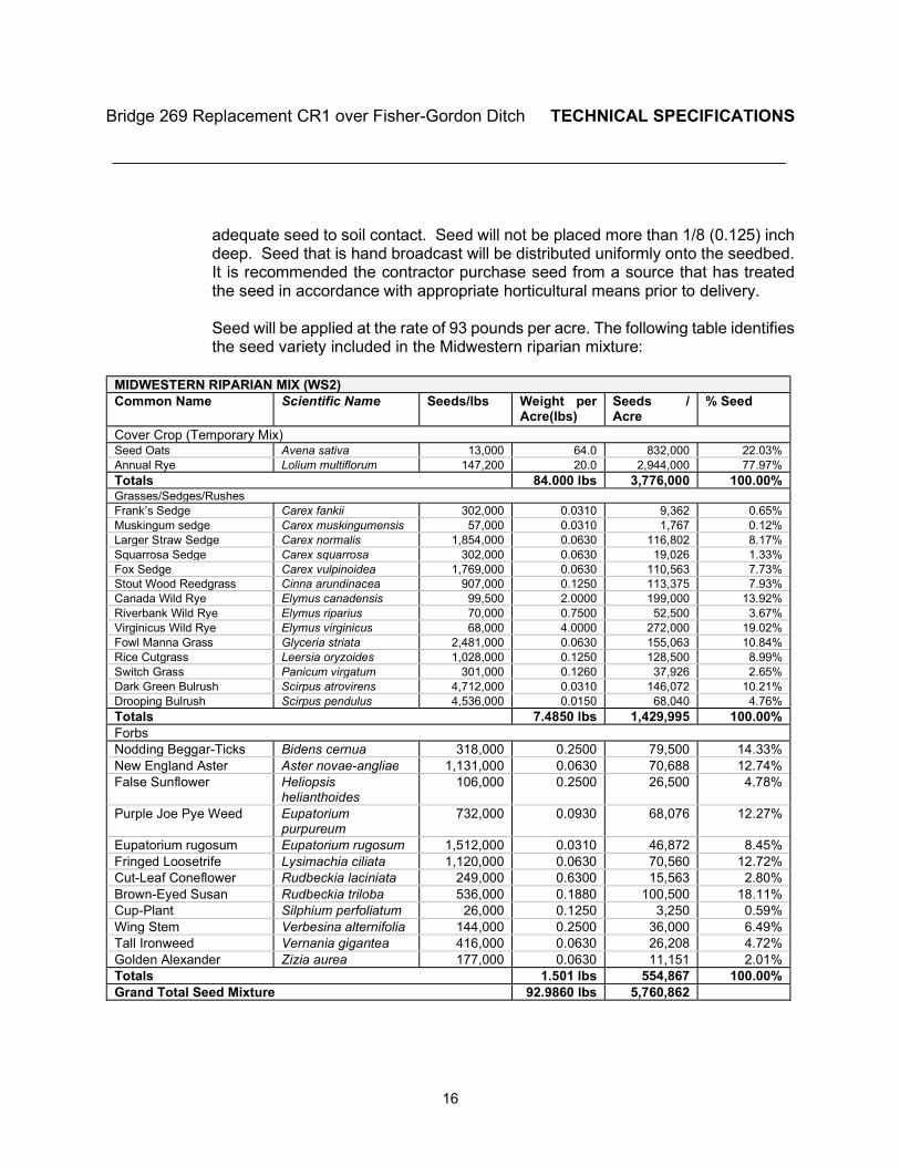
Bridge 269 Replacement CR1 over Fisher-Gordon Ditch TECHNICAL SPECIFICATIONS ________________________________________________________________________
16
adequate seed to soil contact. Seed will not be placed more than 1/8 (0.125) inch deep. Seed that is hand broadcast will be distributed uniformly onto the seedbed. It is recommended the contractor purchase seed from a source that has treated the seed in accordance with appropriate horticultural means prior to delivery. Seed will be applied at the rate of 93 pounds per acre. The following table identifies the seed variety included in the Midwestern riparian mixture:
MIDWESTERN RIPARIAN MIX (WS2) Common Name Scientific Name Seeds/lbs Weight per
Acre(lbs) Seeds / Acre
% Seed
Cover Crop (Temporary Mix) Seed Oats Avena sativa 13,000 64.0 832,000 22.03% Annual Rye Lolium multiflorum 147,200 20.0 2,944,000 77.97% Totals 84.000 lbs 3,776,000 100.00% Grasses/Sedges/Rushes Frank’s Sedge Carex fankii 302,000 0.0310 9,362 0.65% Muskingum sedge Carex muskingumensis 57,000 0.0310 1,767 0.12% Larger Straw Sedge Carex normalis 1,854,000 0.0630 116,802 8.17% Squarrosa Sedge Carex squarrosa 302,000 0.0630 19,026 1.33% Fox Sedge Carex vulpinoidea 1,769,000 0.0630 110,563 7.73% Stout Wood Reedgrass Cinna arundinacea 907,000 0.1250 113,375 7.93% Canada Wild Rye Elymus canadensis 99,500 2.0000 199,000 13.92% Riverbank Wild Rye Elymus riparius 70,000 0.7500 52,500 3.67% Virginicus Wild Rye Elymus virginicus 68,000 4.0000 272,000 19.02% Fowl Manna Grass Glyceria striata 2,481,000 0.0630 155,063 10.84% Rice Cutgrass Leersia oryzoides 1,028,000 0.1250 128,500 8.99% Switch Grass Panicum virgatum 301,000 0.1260 37,926 2.65% Dark Green Bulrush Scirpus atrovirens 4,712,000 0.0310 146,072 10.21% Drooping Bulrush Scirpus pendulus 4,536,000 0.0150 68,040 4.76% Totals 7.4850 lbs 1,429,995 100.00% Forbs Nodding Beggar-Ticks Bidens cernua 318,000 0.2500 79,500 14.33% New England Aster Aster novae-angliae 1,131,000 0.0630 70,688 12.74% False Sunflower Heliopsis
helianthoides 106,000 0.2500 26,500 4.78%
Purple Joe Pye Weed Eupatorium purpureum
732,000 0.0930 68,076 12.27%
Eupatorium rugosum Eupatorium rugosum 1,512,000 0.0310 46,872 8.45% Fringed Loosetrife Lysimachia ciliata 1,120,000 0.0630 70,560 12.72% Cut-Leaf Coneflower Rudbeckia laciniata 249,000 0.6300 15,563 2.80% Brown-Eyed Susan Rudbeckia triloba 536,000 0.1880 100,500 18.11% Cup-Plant Silphium perfoliatum 26,000 0.1250 3,250 0.59% Wing Stem Verbesina alternifolia 144,000 0.2500 36,000 6.49% Tall Ironweed Vernania gigantea 416,000 0.0630 26,208 4.72% Golden Alexander Zizia aurea 177,000 0.0630 11,151 2.01% Totals 1.501 lbs 554,867 100.00% Grand Total Seed Mixture 92.9860 lbs 5,760,862

Bridge 269 Replacement CR1 over Fisher-Gordon Ditch TECHNICAL SPECIFICATIONS ________________________________________________________________________
17
3. CONSTRUCTION
A. Prior to seeding, the ground shall be prepared in accordance with INDOT Standard Specifications section 621.03.
B. Prior to applying erosion control blankets, the ground shall be prepared in accordance with
INDOT Standard Specifications section 621.04. Excelsior blankets shall be placed within 24 hours after seeding operations have been completed.
C. Fertilizer shall be applied in accordance with INDOT Standard Specifications section
621.05 (a). D. Seed shall be applied in accordance with INDOT Standard Specifications section 621.05
(b).
E. If an erosion control blanket manufacturer and/or product is specified, the contractor is
responsible for installing the erosion control blanket per manufacturer’s installation procedures.
F. The appropriate seeding type shall be installed to match the adjacent property. Areas
specified with seeding type are approximate only. The seeding type to be used for each area shall be presented by the contractor and approved by the engineer prior to installation.
4. PAYMENT
The accepted erosion control blanket material, furnished and delivered complete in place, will be paid for at the contract unit price per square yard. The cost of material and installation of fertilizer, seeding, water, excavation of earth bed, disposal of surplus material, and all necessary incidentals shall be included in the cost of the erosion control blanket. Payment will be made at the unit price as indicated below:
Pay Item Pay Unit Erosion Control Blanket,_______, _______ SYS Class Type
The cost of leguminous inoculants, preparing seed beds, sowing, raking, and all other necessary incidentals shall be included in the cost of erosion control blankets. The cost of furnishing and placing fertilizer, seed mixtures, and erosion control blankets, in addition to the incidentals listed above for seed mixtures shall be included in the cost of erosion control blanket. The cost of furnishing, hauling, and placing the material, including material used as tie-down,
Bridge 269 Replacement CR1 over Fisher-Gordon Ditch TECHNICAL SPECIFICATIONS ________________________________________________________________________
18
repair of areas for which mulch fails to stay in place, all labor, equipment, and necessary incidentals shall be included in the cost of mulching material. Repair of areas outside the construction limits which must be disturbed to construct the work required by the contract will be paid for in accordance with INDOT Std. Spec. Section 201.07(e). A warranty bond for the seed shall be provided in accordance with 621.12 and 612.14(a).
Division 4:
Bid Documents
For
BRIDGE 269 REPLACEMENT CR1 OVER FISHER-GORDON DITCH
________________________________________________________________________ OWNERS: ELKHART COUNTY, INDIANA, ACTING THROUGH
ITS BOARD OF COUNTY COMMISSIONERS ELKHART COUNTY HIGHWAY DEPARTMENT ENGINEERING SECTION 610 STEURY AVENUE GOSHEN, IN 46528
________________________________________________________________________
Elkhart County Highway Department 610 Steury Avenue, Goshen, Indiana 46528 Phone: 574-534-9394 • Fax: 574-533-7103

Bridge 269 Replacement CR1 over Fisher-Gordon Ditch BID DOCUMENTS _____________________________________________________________________
NOTICE TO BIDDERS
Notice is hereby given that the Board of County Commissioners of Elkhart County, Indiana, will receive bids up to 9:00 AM on July 6, 2020 for the Bridge 269 Replacement CR1 over Fisher-Gordon Ditch. It is the responsibility of the bidder to ensure that its bid is delivered on time to the Office of the Elkhart County Commissioners, County Administration Building, 117 N. Second Street, Goshen, IN 46526. Plans, Specifications and bidding documents may be obtained from the Elkhart County Highway Department, website at www.elkcohwy.org starting at 9:00 AM on June 3, 2020. Plans, Specifications and Bidding Documents may not be obtained prior to this date. Plans, Specifications and Bidding Documents will be available for inspection at the Elkhart County Highway Department Office, 610 Steury Ave, Goshen, Indiana starting on June 3, 2020. Proposals shall be properly and completely executed on proposal forms furnished by the County in accordance with Revised Indiana Form 96 and shall be accompanied by the Contractor’s Financial Statement form taken from Form 96 for any proposal of $5,000 or more. The Contractor shall submit an itemized proposal of the approximate quantities and components of labor and materials to complete the contract. Said proposal shall be upon the standard bid sheets used by Elkhart County, and said sheet must contain an authorized signature of the Contractor, or the bid of the Contractor may, at the discretion of Elkhart County, be rejected and declared invalid. Each proposal shall be accompanied by a non-collusion affidavit as required by the Statutes of Indiana. Bids shall be enclosed in a sealed envelope, bearing the title of the project and name and address of bidder. Bids will be accepted only from bidders who are sufficiently and currently pre-qualified by the Indiana Department of Transportation. Proof of pre-qualifications must be submitted with the bid. A current Contractor’s Financial Statement taken from Form 96 and the Indiana Department of Transportation pre-qualification certificate may be placed on file with the Board of County Commissioners of Elkhart County at the Highway Division annually in lieu of executing these documents for each project. All work may begin on August 3, 2020 and shall be completed by December 28, 2020. Delays in completion beyond that date shall result in liquidated damages levied against the Contractor by Elkhart County. The damage charges shall be $1,000 per day per item beyond the above stated date and any intermediate completion dates noted in the specifications. A satisfactory bid bond (10% of bid), payable to the Board of County Commissioners of Elkhart County, Indiana executed by the bidder shall be submitted with each bid. No bids shall be withdrawn after the opening of the bids without the consent of the Board of Commissioners of Elkhart County for a period of thirty (30) days after the scheduled time of closing. Said work shall be subject to all the provisions of the plans and specifications therefore herein above referred to including the completion date thereof and penalty clause as therein set forth. The Board of County Commissioners reserves the right to reject any and all Bids or to waive any informalities in the bidding. Dated this 1st day of June, 2020 Board of County Commissioners of Elkhart County By Patricia A. Pickens, Auditor Advertise: June 3, 2020 and June 10, 2020 - Elkhart Truth and Goshen News

Bridge 269 Replacement CR1 over Fisher-Gordon Ditch BID DOCUMENTS _____________________________________________________________________
The approximate quantities for this contract are as shown on the itemized bid tabs included on the attached pages. If extra work is necessary due to shifting of any of the items of construction or if additional work is called for in accordance with these specifications, such work shall be paid for on the basis of the following itemized unit prices. In addition to the above, the said unit prices shall also be the basis of payment to the Contractor for actual quantities placed. The attached sheet (s) must be completely filled out and submitted with the sealed bid or Elkhart County may at its discretion, reject the bid and declare the same invalid. An authorized signature of the Contractor is mandatory upon the bid sheets. All other items necessary to properly complete this project or specifically outlined, shall be included within the line items provided and will be considered as incidental. The award of this contract will be based on the sum of the items listed below. NOTE: Any Item may be withdrawn by Elkhart County at any time prior to
performing the work.
ELKHART COUNTY
BID TOTAL ____________________________________________________________ dollars
($____________________________________________________________________)
Acknowledge Receipt of Addenda No.(s) ___________________________. Submitted by: _________________________________________ Company _________________________________________ Authorized Signature Date: _____________________ Phone: _____________________ ATTEST: ________________________________________
APPENDICES
For
BRIDGE 269 REPLACEMENT CR1 OVER FISHER-GORDON DITCH
APPENDIX A – Geotechnical Report APPENDIX B – USACE Permit
APPENDIX C – <<AppendixC>> APPENDIX D – <<AppendixD>> APPENDIX E – <<AppendixE>> APPENDIX F – <<AppendixF>>
________________________________________________________________________ OWNERS: ELKHART COUNTY, INDIANA, ACTING THROUGH
ITS BOARD OF COUNTY COMMISSIONERS ELKHART COUNTY HIGHWAY DEPARTMENT ENGINEERING SECTION 610 STEURY AVENUE GOSHEN, IN 46528
________________________________________________________________________
Elkhart County Highway Department 610 Steury Avenue, Goshen, Indiana 46528 Phone: 574-534-9394 • Fax: 574-533-7103
APPENDIX A
For
BRIDGE 269 REPLACEMENT CR1 OVER FISHER-GORDON DITCH
APPENDIX A – Geotechnical Report
________________________________________________________________________ OWNERS: ELKHART COUNTY, INDIANA, ACTING THROUGH
ITS BOARD OF COUNTY COMMISSIONERS ELKHART COUNTY HIGHWAY DEPARTMENT ENGINEERING SECTION 610 STEURY AVENUE GOSHEN, IN 46528
________________________________________________________________________
Elkhart County Highway Department 610 Steury Avenue, Goshen, Indiana 46528 Phone: 574-534-9394 • Fax: 574-533-7103
GEOTECHNICAL EVALUATION
CR 1 OVER FISHER-GORDON DITCHELKHART COUNTY, INDIANA
Prepared for
ELKHART COUNTY HIGHWAY DEPARTMENT
610 STEURY AVE.
GOSHEN, INDIANA 46528
By
EARTH EXPLORATION, INC.,
A TERRACON COMPANY
2204 YANKEE STREET
NILES, MICHIGAN 49120
APRIL 8, 2020
Appendix A - Geotechnical Report
April 8, 2020
Mr. Tom Rushlow, P.E.
Elkhart County Highway Department
Via electronic mail: [email protected]
Re: Geotechnical Evaluation
CR 1 over Fisher-Gordon Ditch
Structure No.: BR 269
Elkhart County, Indiana
EEI Project No. CK205002
Dear Mr. Rushlow:
We have completed our geotechnical evaluation for the referenced project. This report presents the
results of our subsurface exploratory program and provides geotechnical recommendations for the
bridge foundations. The opinions and recommendations submitted in this report are based, in part,
on our interpretation of the subsurface information revealed at the exploratory locations as indicated
on an attached Test Boring Location Plan. This report does not reflect variations in subsurface
conditions between or beyond these locations. Therefore, variations in these conditions can be
expected, and fluctuation of the groundwater levels will occur with time. Other important limitations of
a geotechnical report are discussed in Appendix A.
We understand that Elkhart County is planning to replace an existing bridge structure carrying CR 1
over Fisher-Gordon Ditch (Structure No. BR 269) using local funds only. Based on the preliminary
plans provided by Elkhart County, the new structure is anticipated to consist of a single span steel
beam bridge supported on 14-in. steel pipe piles with end cover plates. The bottom of the
semi-integral abutments is planned to be near El. 832 on the north side and El. 831 on the south side,
and the water level of the existing creek is near El. 830, according to the plans provided to us by
Elkhart County. Additionally, as a part of the bridge replacement, 14.5-ft long wingwalls are
planned at each end bent and parallel to the existing road. It should be noted that the scope of
this report is to provide foundation recommendations for the end bents only. At this time, other
information such as pile load and construction schedule are not known.
Subsurface Conditions
Subsurface conditions for the proposed improvements were explored by performing two structure
borings (designated B-1 and B-2) located near the end bents. The approximate exploratory locations
are shown on the Test Boring Location Plan included in Appendix C. Details of the drilling and
sampling procedures are provided in Appendix B.
The subsurface profile at the boring locations predominantly consisted of cohesive soils (i.e., clay
loam, sandy loam, silty clay loam, silt, and loam). Isolated granular soil layers (i.e., sand and sandy
loam) were observed to be interbedded within the predominate cohesive soil strata near depths of 31
to 34.5 ft and 67 to 77 ft at Boring B-1 and near depths of 32 to 36 ft and 67 to 75 ft at Boring B-2. The
cohesive soils observed within 67 ft (El. 784 to 785) of the existing ground surface (i.e. sandy loam,
Appendix A - Geotechnical Report
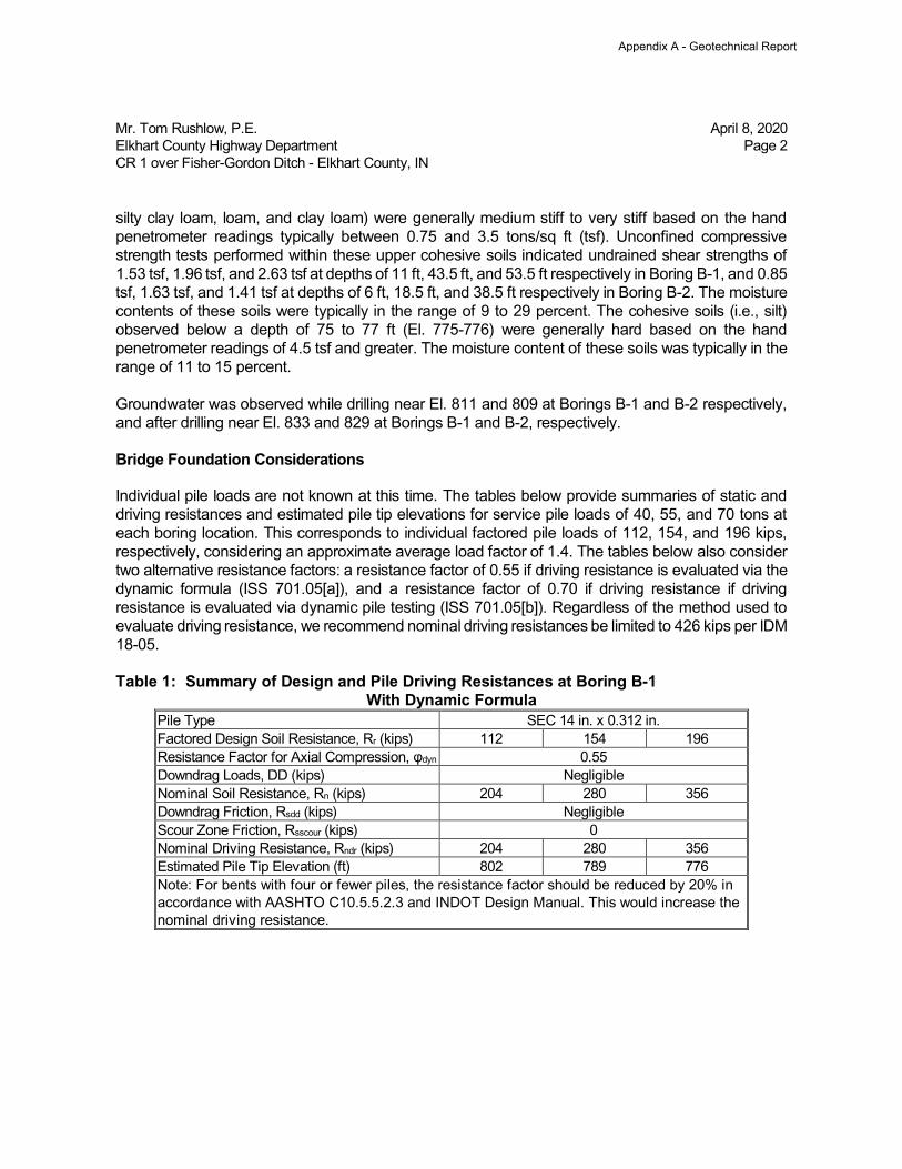
Mr. Tom Rushlow, P.E. April 8, 2020
Elkhart County Highway Department Page 2
CR 1 over Fisher-Gordon Ditch - Elkhart County, IN
silty clay loam, loam, and clay loam) were generally medium stiff to very stiff based on the hand
penetrometer readings typically between 0.75 and 3.5 tons/sq ft (tsf). Unconfined compressive
strength tests performed within these upper cohesive soils indicated undrained shear strengths of
1.53 tsf, 1.96 tsf, and 2.63 tsf at depths of 11 ft, 43.5 ft, and 53.5 ft respectively in Boring B-1, and 0.85
tsf, 1.63 tsf, and 1.41 tsf at depths of 6 ft, 18.5 ft, and 38.5 ft respectively in Boring B-2. The moisture
contents of these soils were typically in the range of 9 to 29 percent. The cohesive soils (i.e., silt)
observed below a depth of 75 to 77 ft (El. 775-776) were generally hard based on the hand
penetrometer readings of 4.5 tsf and greater. The moisture content of these soils was typically in the
range of 11 to 15 percent.
Groundwater was observed while drilling near El. 811 and 809 at Borings B-1 and B-2 respectively,
and after drilling near El. 833 and 829 at Borings B-1 and B-2, respectively.
Bridge Foundation Considerations
Individual pile loads are not known at this time. The tables below provide summaries of static and
driving resistances and estimated pile tip elevations for service pile loads of 40, 55, and 70 tons at
each boring location. This corresponds to individual factored pile loads of 112, 154, and 196 kips,
respectively, considering an approximate average load factor of 1.4. The tables below also consider
two alternative resistance factors: a resistance factor of 0.55 if driving resistance is evaluated via the
dynamic formula (ISS 701.05[a]), and a resistance factor of 0.70 if driving resistance if driving
resistance is evaluated via dynamic pile testing (ISS 701.05[b]). Regardless of the method used to
evaluate driving resistance, we recommend nominal driving resistances be limited to 426 kips per IDM
18-05.
Table 1: Summary of Design and Pile Driving Resistances at Boring B-1
With Dynamic Formula
Pile Type SEC 14 in. x 0.312 in.
Factored Design Soil Resistance, Rr (kips) 112 154 196
Resistance Factor for Axial Compression, φdyn 0.55
Downdrag Loads, DD (kips) Negligible
Nominal Soil Resistance, Rn (kips) 204 280 356
Downdrag Friction, Rsdd (kips) Negligible
Scour Zone Friction, Rsscour (kips) 0
Nominal Driving Resistance, Rndr (kips) 204 280 356
Estimated Pile Tip Elevation (ft) 802 789 776
Note: For bents with four or fewer piles, the resistance factor should be reduced by 20% in
accordance with AASHTO C10.5.5.2.3 and INDOT Design Manual. This would increase the
nominal driving resistance.
Appendix A - Geotechnical Report
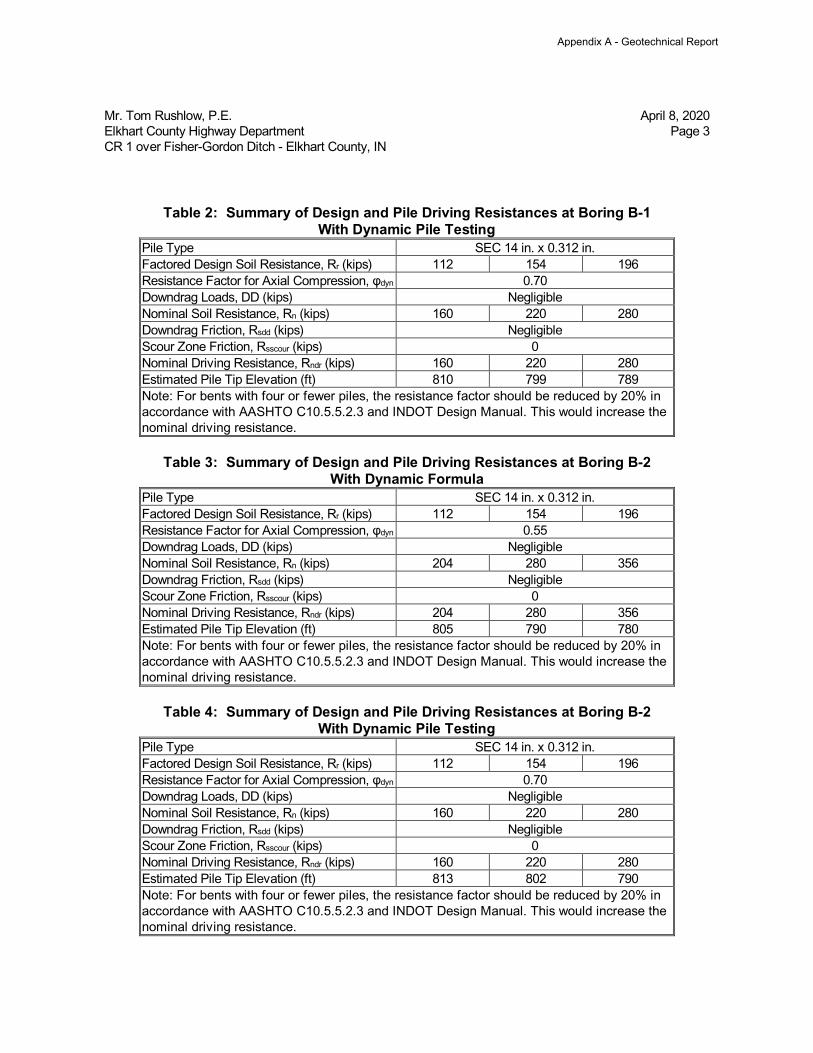
Mr. Tom Rushlow, P.E. April 8, 2020
Elkhart County Highway Department Page 3
CR 1 over Fisher-Gordon Ditch - Elkhart County, IN
Table 2: Summary of Design and Pile Driving Resistances at Boring B-1
With Dynamic Pile Testing
Pile Type SEC 14 in. x 0.312 in.
Factored Design Soil Resistance, Rr (kips) 112 154 196
Resistance Factor for Axial Compression, φdyn 0.70
Downdrag Loads, DD (kips) Negligible
Nominal Soil Resistance, Rn (kips) 160 220 280
Downdrag Friction, Rsdd (kips) Negligible
Scour Zone Friction, Rsscour (kips) 0
Nominal Driving Resistance, Rndr (kips) 160 220 280
Estimated Pile Tip Elevation (ft) 810 799 789
Note: For bents with four or fewer piles, the resistance factor should be reduced by 20% in
accordance with AASHTO C10.5.5.2.3 and INDOT Design Manual. This would increase the
nominal driving resistance.
Table 3: Summary of Design and Pile Driving Resistances at Boring B-2
With Dynamic Formula
Pile Type SEC 14 in. x 0.312 in.
Factored Design Soil Resistance, Rr (kips) 112 154 196
Resistance Factor for Axial Compression, φdyn 0.55
Downdrag Loads, DD (kips) Negligible
Nominal Soil Resistance, Rn (kips) 204 280 356
Downdrag Friction, Rsdd (kips) Negligible
Scour Zone Friction, Rsscour (kips) 0
Nominal Driving Resistance, Rndr (kips) 204 280 356
Estimated Pile Tip Elevation (ft) 805 790 780
Note: For bents with four or fewer piles, the resistance factor should be reduced by 20% in
accordance with AASHTO C10.5.5.2.3 and INDOT Design Manual. This would increase the
nominal driving resistance.
Table 4: Summary of Design and Pile Driving Resistances at Boring B-2
With Dynamic Pile Testing
Pile Type SEC 14 in. x 0.312 in.
Factored Design Soil Resistance, Rr (kips) 112 154 196
Resistance Factor for Axial Compression, φdyn 0.70
Downdrag Loads, DD (kips) Negligible
Nominal Soil Resistance, Rn (kips) 160 220 280
Downdrag Friction, Rsdd (kips) Negligible
Scour Zone Friction, Rsscour (kips) 0
Nominal Driving Resistance, Rndr (kips) 160 220 280
Estimated Pile Tip Elevation (ft) 813 802 790
Note: For bents with four or fewer piles, the resistance factor should be reduced by 20% in
accordance with AASHTO C10.5.5.2.3 and INDOT Design Manual. This would increase the
nominal driving resistance.
Appendix A - Geotechnical Report
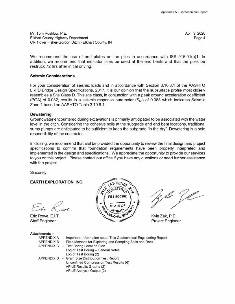
Mr. Tom Rushlow, P.E. April 9, 2020
Elkhart County Highway Department Page 4
CR 1 over Fisher-Gordon Ditch - Elkhart County, IN
We recommend the use of end plates on the piles in accordance with ISS 915.01(a)1. In
addition, we recommend that indicator piles be used at the end bents and that the piles be
restruck 72 hrs after initial driving.
Seismic Considerations
For your consideration of seismic loads and in accordance with Section 3.10.3.1 of the AASHTO
LRFD Bridge Design Specifications, 2017, it is our opinion that the subsurface profile most closely
resembles a Site Class D. This site class, in conjunction with a peak ground acceleration coefficient
(PGA) of 0.032, results in a seismic response parameter (SD1) of 0.083 which indicates Seismic
Zone 1 based on AASHTO Table 3.10.6-1.
Dewatering
Groundwater encountered during excavations is primarily anticipated to be associated with the water
level in the ditch. Considering the cohesive soils at the subgrade and end bent locations, traditional
sump pumps are anticipated to be sufficient to keep the subgrade “in the dry”. Dewatering is a sole
responsibility of the contractor.
In closing, we recommend that EEI be provided the opportunity to review the final design and project
specifications to confirm that foundation requirements have been properly interpreted and
implemented in the design and specifications. We appreciate the opportunity to provide our services
to you on this project. Please contact our office if you have any questions or need further assistance
with the project.
Sincerely,
EARTH EXPLORATION, INC.
Eric Rowe, E.I.T. Kyle Zak, P.E.
Staff Engineer Project Engineer
Attachments –
APPENDIX A - Important Information about This Geotechnical Engineering Report
APPENDIX B - Field Methods for Exploring and Sampling Soils and Rock
APPENDIX C - Test Boring Location Plan
Log of Test Boring – General Notes
Log of Test Boring (2)
APPENDIX D - Grain Size Distribution Test Report
Unconfined Compression Test Results (6)
APILE Results Graphs (2)
APILE Analysis Output (2)
Appendix A - Geotechnical Report
APPENDIX A
IMPORTANT INFORMATION ABOUT THISGEOTECHNICAL ENGINEERING REPORT
Appendix A - Geotechnical Report
Geotechnical-Engineering Report
Important Information about This
Subsurface problems are a principal cause of construction delays, cost overruns, claims, and disputes.
While you cannot eliminate all such risks, you can manage them. The following information is provided to help.
The Geoprofessional Business Association (GBA)
has prepared this advisory to help you – assumedly
a client representative – interpret and apply this
geotechnical-engineering report as effectively
as possible. In that way, clients can benefit from
a lowered exposure to the subsurface problems
that, for decades, have been a principal cause of
construction delays, cost overruns, claims, and
disputes. If you have questions or want more
information about any of the issues discussed below,
contact your GBA-member geotechnical engineer.
Active involvement in the Geoprofessional Business
Association exposes geotechnical engineers to a
wide array of risk-confrontation techniques that can
be of genuine benefit for everyone involved with a
construction project.
Geotechnical-Engineering Services Are Performed for
Specific Purposes, Persons, and Projects
Geotechnical engineers structure their services to meet the specific needs of their clients. A geotechnical-engineering study conducted for a given civil engineer will not likely meet the needs of a civil-works constructor or even a different civil engineer. Because each geotechnical-engineering study is unique, each geotechnical-engineering report is unique, prepared solely for the client. Those who rely on a geotechnical-engineering report prepared for a different client can be seriously misled. No one except authorized client representatives should rely on this geotechnical-engineering report without first conferring with the geotechnical engineer who prepared it. And no one – not even you – should apply this report for any purpose or project except the one originally contemplated.
Read this Report in Full
Costly problems have occurred because those relying on a geotechnical-engineering report did not read it in its entirety. Do not rely on an executive summary. Do not read selected elements only. Read this report in full.
You Need to Inform Your Geotechnical Engineer
about Change
Your geotechnical engineer considered unique, project-specific factors when designing the study behind this report and developing the confirmation-dependent recommendations the report conveys. A few typical factors include: • the client’s goals, objectives, budget, schedule, and risk-management preferences; • the general nature of the structure involved, its size, configuration, and performance criteria; • the structure’s location and orientation on the site; and • other planned or existing site improvements, such as retaining walls, access roads, parking lots, and underground utilities.
Typical changes that could erode the reliability of this report include those that affect:• the site’s size or shape;• the function of the proposed structure, as when it’s changed from a parking garage to an office building, or from a light-industrial plant to a refrigerated warehouse;• the elevation, configuration, location, orientation, or weight of the proposed structure;• the composition of the design team; or• project ownership.
As a general rule, always inform your geotechnical engineer of project changes – even minor ones – and request an assessment of their impact. The geotechnical engineer who prepared this report cannot accept responsibility or liability for problems that arise because the geotechnical engineer was not informed about developments the engineer otherwise would have considered.
This Report May Not Be Reliable
Do not rely on this report if your geotechnical engineer prepared it:• for a different client;• for a different project;• for a different site (that may or may not include all or a portion of the original site); or • before important events occurred at the site or adjacent to it; e.g., man-made events like construction or environmental remediation, or natural events like floods, droughts, earthquakes, or groundwater fluctuations.
Note, too, that it could be unwise to rely on a geotechnical-engineering report whose reliability may have been affected by the passage of time, because of factors like changed subsurface conditions; new or modified codes, standards, or regulations; or new techniques or tools. If your geotechnical engineer has not indicated an “apply-by” date on the report, ask what it should be, and, in general, if you are the least bit uncertain about the continued reliability of this report, contact your geotechnical engineer before applying it. A minor amount of additional testing or analysis – if any is required at all – could prevent major problems.
Most of the “Findings” Related in This Report Are
Professional Opinions
Before construction begins, geotechnical engineers explore a site’s subsurface through various sampling and testing procedures. Geotechnical engineers can observe actual subsurface conditions only at those specific locations where sampling and testing were performed. The data derived from that sampling and testing were reviewed by your geotechnical engineer, who then applied professional judgment to form opinions about subsurface conditions throughout the site. Actual sitewide-subsurface conditions may differ – maybe significantly – from those indicated in this report. Confront that risk by retaining your geotechnical engineer to serve on the design team from project start to project finish, so the individual can provide informed guidance quickly,
whenever needed.
Appendix A - Geotechnical Report

This Report’s Recommendations Are
Confirmation-Dependent
The recommendations included in this report – including any options or alternatives – are confirmation-dependent. In other words, they are not final, because the geotechnical engineer who developed them relied heavily on judgment and opinion to do so. Your geotechnical engineer can finalize the recommendations only after observing actual subsurface conditions revealed during construction. If through observation your geotechnical engineer confirms that the conditions assumed to exist actually do exist, the recommendations can be relied upon, assuming no other changes have occurred. The geotechnical engineer who prepared this report cannot assume responsibility or liability for confirmation-dependent recommendations if you fail to retain that engineer to perform construction observation.
This Report Could Be Misinterpreted
Other design professionals’ misinterpretation of geotechnical-engineering reports has resulted in costly problems. Confront that risk by having your geotechnical engineer serve as a full-time member of the design team, to: • confer with other design-team members, • help develop specifications, • review pertinent elements of other design professionals’ plans and specifications, and • be on hand quickly whenever geotechnical-engineering guidance is needed. You should also confront the risk of constructors misinterpreting this report. Do so by retaining your geotechnical engineer to participate in prebid and preconstruction conferences and to perform construction observation.
Give Constructors a Complete Report and Guidance
Some owners and design professionals mistakenly believe they can shift unanticipated-subsurface-conditions liability to constructors by limiting the information they provide for bid preparation. To help prevent the costly, contentious problems this practice has caused, include the complete geotechnical-engineering report, along with any attachments or appendices, with your contract documents, but be certain to note conspicuously that you’ve included the material for informational purposes only. To avoid misunderstanding, you may also want to note that “informational purposes” means constructors have no right to rely on the interpretations, opinions, conclusions, or recommendations in the report, but they may rely on the factual data relative to the specific times, locations, and depths/elevations referenced. Be certain that constructors know they may learn about specific project requirements, including options selected from the report, only from the design drawings and specifications. Remind constructors that they may
perform their own studies if they want to, and be sure to allow enough time to permit them to do so. Only then might you be in a position to give constructors the information available to you, while requiring them to at least share some of the financial responsibilities stemming from unanticipated conditions. Conducting prebid and preconstruction conferences can also be valuable in this respect.
Read Responsibility Provisions Closely
Some client representatives, design professionals, and constructors do not realize that geotechnical engineering is far less exact than other engineering disciplines. That lack of understanding has nurtured unrealistic expectations that have resulted in disappointments, delays, cost overruns, claims, and disputes. To confront that risk, geotechnical engineers commonly include explanatory provisions in their reports. Sometimes labeled “limitations,” many of these provisions indicate where geotechnical engineers’ responsibilities begin and end, to help others recognize their own responsibilities and risks. Read these provisions closely. Ask questions. Your geotechnical engineer should respond fully and frankly.
Geoenvironmental Concerns Are Not Covered
The personnel, equipment, and techniques used to perform an environmental study – e.g., a “phase-one” or “phase-two” environmental site assessment – differ significantly from those used to perform a geotechnical-engineering study. For that reason, a geotechnical-engineering report does not usually relate any environmental findings, conclusions, or recommendations; e.g., about the likelihood of encountering underground storage tanks or regulated contaminants. Unanticipated subsurface environmental problems have led to project failures. If you have not yet obtained your own environmental information, ask your geotechnical consultant for risk-management guidance. As a general rule, do not rely on an environmental report prepared for a different client, site, or project, or that is more than six months old.
Obtain Professional Assistance to Deal with Moisture
Infiltration and Mold
While your geotechnical engineer may have addressed groundwater, water infiltration, or similar issues in this report, none of the engineer’s services were designed, conducted, or intended to prevent uncontrolled migration of moisture – including water vapor – from the soil through building slabs and walls and into the building interior, where it can cause mold growth and material-performance deficiencies. Accordingly, proper implementation of the geotechnical engineer’s recommendations will not of itself be sufficient to prevent moisture infiltration. Confront the risk of moisture infiltration by including building-envelope or mold specialists on the design team. Geotechnical engineers are not building-envelope or mold specialists.
Copyright 2016 by Geoprofessional Business Association (GBA). Duplication, reproduction, or copying of this document, in whole or in part, by any means whatsoever, is strictly prohibited, except with GBA’s specific written permission. Excerpting, quoting, or otherwise extracting wording from this document is permitted only with the express written permission of GBA, and only for purposes of scholarly research or book review. Only members of GBA may use this document or its wording as a complement to or as an element of a report of any
kind. Any other firm, individual, or other entity that so uses this document without being a GBA member could be committing negligent
Telephone: 301/565-2733e-mail: [email protected] www.geoprofessional.org
Appendix A - Geotechnical Report

APPENDIX B
FIELD METHODS FOR EXPLORING AND SAMPLING SOILS AND ROCK
Appendix A - Geotechnical Report
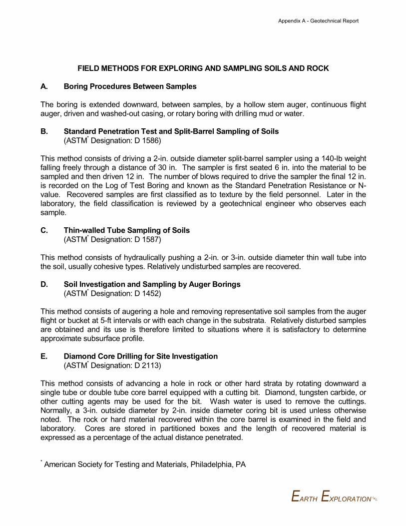
EARTH EXPLORATION INC.
FIELD METHODS FOR EXPLORING AND SAMPLING SOILS AND ROCK
A. Boring Procedures Between Samples
The boring is extended downward, between samples, by a hollow stem auger, continuous flightauger, driven and washed-out casing, or rotary boring with drilling mud or water.
B. Standard Penetration Test and Split-Barrel Sampling of Soils
(ASTM* Designation: D 1586)
This method consists of driving a 2-in. outside diameter split-barrel sampler using a 140-lb weightfalling freely through a distance of 30 in. The sampler is first seated 6 in. into the material to besampled and then driven 12 in. The number of blows required to drive the sampler the final 12 in.is recorded on the Log of Test Boring and known as the Standard Penetration Resistance or N-value. Recovered samples are first classified as to texture by the field personnel. Later in thelaboratory, the field classification is reviewed by a geotechnical engineer who observes eachsample.
C. Thin-walled Tube Sampling of Soils
(ASTM* Designation: D 1587)
This method consists of hydraulically pushing a 2-in. or 3-in. outside diameter thin wall tube intothe soil, usually cohesive types. Relatively undisturbed samples are recovered.
D. Soil Investigation and Sampling by Auger Borings
(ASTM* Designation: D 1452)
This method consists of augering a hole and removing representative soil samples from the augerflight or bucket at 5-ft intervals or with each change in the substrata. Relatively disturbed samplesare obtained and its use is therefore limited to situations where it is satisfactory to determineapproximate subsurface profile.
E. Diamond Core Drilling for Site Investigation
(ASTM* Designation: D 2113)
This method consists of advancing a hole in rock or other hard strata by rotating downward asingle tube or double tube core barrel equipped with a cutting bit. Diamond, tungsten carbide, orother cutting agents may be used for the bit. Wash water is used to remove the cuttings.Normally, a 3-in. outside diameter by 2-in. inside diameter coring bit is used unless otherwisenoted. The rock or hard material recovered within the core barrel is examined in the field andlaboratory. Cores are stored in partitioned boxes and the length of recovered material isexpressed as a percentage of the actual distance penetrated.
* American Society for Testing and Materials, Philadelphia, PA
Appendix A - Geotechnical Report
APPENDIX C
TEST BORING LOCATION PLAN
LOG OF TEST BORING - GENERAL NOTES
LOG OF TEST BORING (2)
Appendix A - Geotechnical Report
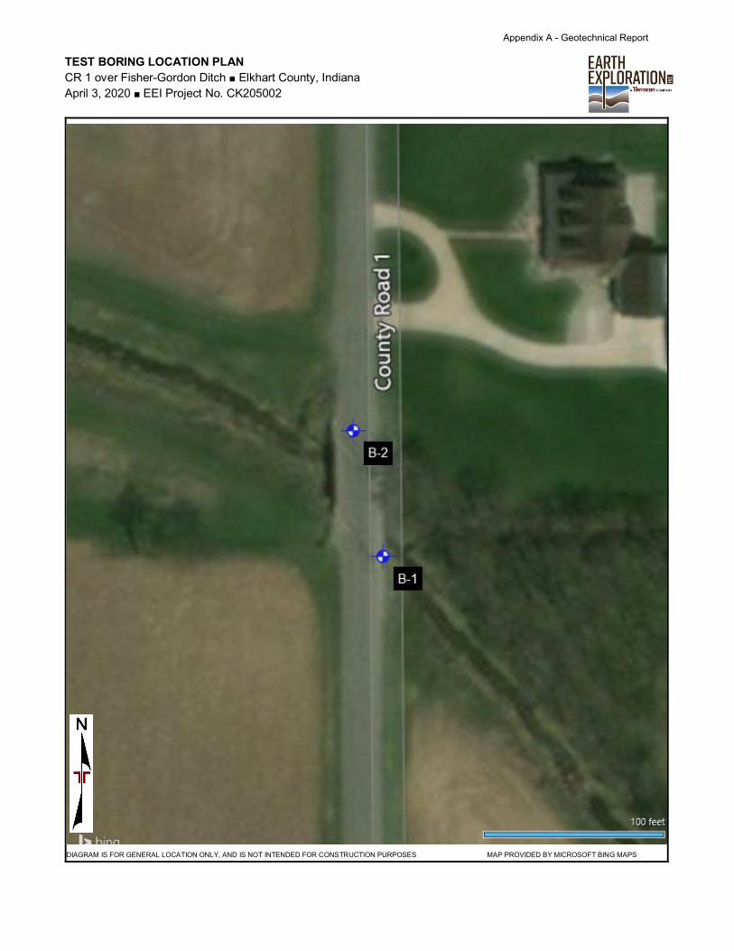
TEST BORING LOCATION PLAN
CR 1 over Fisher-Gordon Ditch ■ Elkhart County, Indiana
April 3, 2020 ■ EEI Project No. CK205002
Note to Preparer: This is a large table with outside borders. Just click inside the table
above this text box, then paste your GIS Toolbox image.
When paragraph markers are turned on you may notice a line of hidden text above and
outside the table – please leave that alone. Limit editing to inside the table.
The line at the bottom about the general location is a separate table line. You can edit
it as desired, but try to keep to a single line of text to avoid reformatting the page.
MAP 2 PORTRA IT
DIAGRAM IS FOR GENERAL LOCATION ONLY, AND IS NOT INTENDED FOR CONSTRUCTION PURPOSES MAP PROVIDED BY MICROSOFT BING MAPS
Appendix A - Geotechnical Report

LOG OF TEST BORING – GENERAL NOTES
DESCRIPTIVE CLASSIFICATION SYMBOLS
GRAIN SIZE TERMINOLOGY DRILLING AND SAMPLING
Soil Fraction Particle Size US Standard Sieve Size
Boulders ................ Larger than 75 mm ............... Larger than 3”Gravel .................... 4.76 mm to 75 mm ............... #10 to 75 mmSand: Coarse ..... 2.00 to 4.76 mm ................... #40 to #10
Fine ......... 0.075 to 0.42 mm ................. #200 to #40Silt ......................... 0.002 to 0.075 mm ............... Smaller than #200Clay ....................... Smaller than 0.002 mm …….. Smaller than #200
GENERAL TERMINOLOGY RELATIVE DENSITY
Physical Characteristics Term “N” Value- Color, moisture, grain shapefineness, etc. Very loose …………….............. 0 – 5
Major Constituents Loose …………………………… 6 – 10- Clay silt, sand, gravel Medium dense ………………… 11 – 30Structure Dense …………………………… 31 – 50- Laminated, varved, fibrous, Very Dense …………………….. 51+stratified, cemented, fissured,etc.
Geologic Origin CONSISTENCY- Glacial, alluvial, eolian,residual, etc. Term “qp”
Very soft ……………………… 0.0 – 0.25
RELATIVE PROPORTIONS Soft ……………………………. 0.25 – 0.5
OF COHESIONLESS SOILS Medium ………………………. 0.5 – 1.0
Stiff ……………………………. 1.0 – 2.0 LABORATORY TESTSDefining Range by Very Stiff ……………………… 2.0 – 4.0
Term % of Weight Hard …………………………… 4.0+
Trace ………………. 1 – 10%
Little ……………….. 11 – 20% PLASTICITYSome ……………… 21 – 35%And ……………….. 36 – 50% Term Plastic Index
None to slight ……………. 0 – 4
ORGANIC CONTENT BY Slight ……………………… 5 – 7
COMBUSTION METHOD Medium …………………… 8 – 22
High/Very High …………... Over 22Soil Description LOI
WATER LEVELw/ organic matter ……….…. 4 – 15 % MEASUREMENTOrganic Soil (A-8) …………. 16 – 30%Peat (A-8) ………………….. More than 30%
Note: Water level measurements shownThe penetration resistance, N, is the summation of the number of blows on the boring logs represent conditionsrequired to effect two successive 6-in. penetrations of the 2-in. split-barrel at the time indicated and may not reflectsampler. The sampler is driven with a 140-lb weight falling 30 in. and is static levels, especially in cohesive soils.seated to a depth of 6 in. before commencing the standard penetration test.
AS – Auger SampleBS – Bag SampleC – Casing Size 2½”, NW, 4”, HW
COA – Clean-Out AugerCS – Continuous SamplingCW – Clear WaterDC – Driven CasingDM – Drilling MudFA – Flight AugerFT – Fish TailHA – Hand Auger
HSA – Hollow Stem AugerNR – No Recovery
PMT – Borehole Pressuremeter TestPT – 3” O.D. Piston Tube Sample
PTS – Peat SampleRB – Rock BitRC – Rock Coring
REC – RecoveryRQD – Rock Quality DesignationRS – Rock SoundingS – Soil Sounding
SS – 2” O.D. Split-Barrel Sample2ST – 2” O.D. Thin-Walled Tube Sample3ST – 3” O.D. Thin-Walled Tube SampleVS – Vane Shear Test
WPT – Water Pressure Test
qp – Penetrometer Reading, tsf
qu – Unconfined Strength, tsf
W – Moisture Content, %LL – Liquid Limit, %PL – Plastic Limit, %PI – Plasticity IndexSL – Shrinkage Limit, %LOI – Loss on Ignition, %
ال d – Dry Unit Weight, pcf
pH – Measure of Soil Alkalinity/Acidity
BF – Backfilled upon CompletionNW – No Water Encountered
Appendix A - Geotechnical Report

6-6-5
2-2-2
1-2-2
2-3-6
3-3-4
2-4-5
2-5-6
3-4-5
3-4-5
100
44
0
100
100
100
100
100
67
Asphalt, (7")
Gravelly Sand, medium dense, dark brown
Sandy Loam, stiff, dark brown, with trace
of gravel
Silty Clay Loam, very stiff, dark brown,
with trace of gravel
0.6
2.0
8.0
14
12
6
5
SS
1
SS
2
SS
3
SS
4
SS
5
SS
6
SS
7
SS
8
SS
9
20
17
1.75
2.25
2
2
2.25
2.25
3
19.2
25.0
12.1
9.5
11.7
11.5
11.0
130.9 1.53
BORING METHOD
RIG TYPE
CASING DIA.
CORE SIZE
:
:
:
:
03-09-20
03-09-20
At completion 8.5 ft
DATE STARTED
DATE COMPLETED
Encountered at 31.0 ft
:
:
:
:
Caved in at 22.0 ft
PROJECT NO.: CK205002
CR 1 over Fisher-Gordon Ditch
Elkhart
LOCATION
COUNTY
HAMMER
DRILLER/INSP
TEMPERATURE
WEATHER
:
:
:
:
Hollow Stem Auger
CME 550X
3¼
ELEVATION
STATION
OFFSET
LINE
DEPTH
:
:
:
:
:
Auto
C.N.
50 °F
Cloudy
GROUNDWATER:
842.0
6+55
8.0 ft Right
'"PRK"'
90.0 ft
UN
CO
NF
.
CO
MP
., tsf ATTERBERG
LIMITS
2.5
5.0
7.5
10.0
12.5
15.0
17.5
20.0
22.5
25.0
27.5
30.0
BORING NO.:
SHEET 3
LL
:
840.0
835.0
830.0
825.0
820.0
815.0
225725: STRUCTURE #
B-1
---
REMARKS
Bridge Replacement
BR 269
NORTHING : 2276356
SP
T
per 6
"
NAD 83
ELE
VA
TIO
N
1
PIPO
CK
ET
PE
N., tsf
MO
IST
UR
E
CO
NT
EN
T
EASTING :
SOIL/MATERIAL DESCRIPTION
DES NO.
Elkhart County Highway Department
Continued on next page
SA
MP
LE
DE
PT
HPROJECT TYPE
:
DATUM :
OFLOG OF TEST BORING
CLIENT :
PLSA
MP
LE
NU
MB
ER
DR
Y
DE
NS
ITY
, pcf
% RE
CO
VE
RY
EE
I B
OR
ING
LO
G (
IND
OT
FO
RM
AT
) C
HE
CK
ED
OU
T C
K2
05
00
2 I
ND
OT
CR
-1 O
VE
R F
ISH
ER
GO
RD
ON
DIT
CH
.GP
J
IN_
DO
T1
.GD
T
4/7
/20
Appendix A - Geotechnical Report
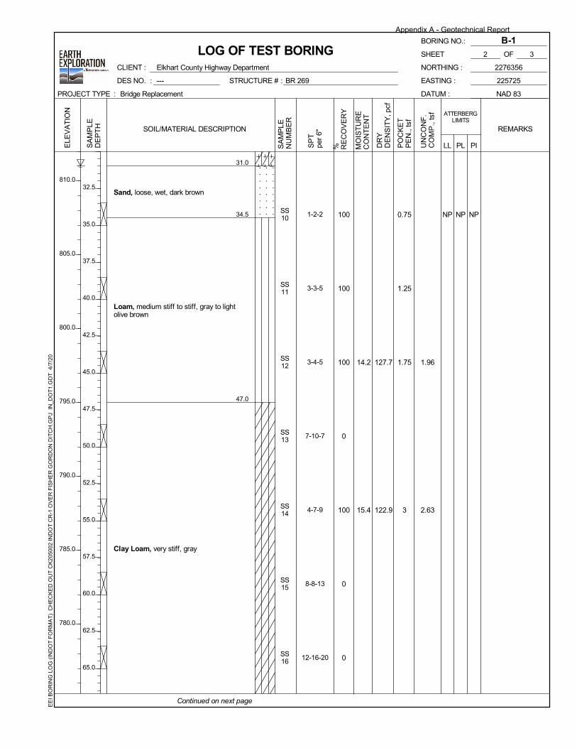
1-2-2
3-3-5
3-4-5
7-10-7
4-7-9
8-8-13
12-16-20
100
100
100
0
100
0
0
Sand, loose, wet, dark brown
Loam, medium stiff to stiff, gray to light
olive brown
Clay Loam, very stiff, gray
31.0
34.5
47.0
NP NPSS
10
SS
11
SS
12
SS
13
SS
14
SS
15
SS
16
NP0.75
1.25
1.75
3
14.2
15.4
127.7
122.9
1.96
2.63
UN
CO
NF
.
CO
MP
., tsf ATTERBERG
LIMITS
32.5
35.0
37.5
40.0
42.5
45.0
47.5
50.0
52.5
55.0
57.5
60.0
62.5
65.0
BORING NO.:
SHEET 3
LL
:
810.0
805.0
800.0
795.0
790.0
785.0
780.0
225725: STRUCTURE #
B-1
---
REMARKS
Bridge Replacement
BR 269
NORTHING : 2276356
SP
T
per 6
"
NAD 83
ELE
VA
TIO
N
2
PIPO
CK
ET
PE
N., tsf
MO
IST
UR
E
CO
NT
EN
T
EASTING :
SOIL/MATERIAL DESCRIPTION
DES NO.
Elkhart County Highway Department
Continued on next page
SA
MP
LE
DE
PT
HPROJECT TYPE
:
DATUM :
OFLOG OF TEST BORING
CLIENT :
PLSA
MP
LE
NU
MB
ER
DR
Y
DE
NS
ITY
, pcf
% RE
CO
VE
RY
EE
I B
OR
ING
LO
G (
IND
OT
FO
RM
AT
) C
HE
CK
ED
OU
T C
K2
05
00
2 I
ND
OT
CR
-1 O
VE
R F
ISH
ER
GO
RD
ON
DIT
CH
.GP
J
IN_
DO
T1
.GD
T
4/7
/20
Appendix A - Geotechnical Report

37-50
36-50
15-26-38
11-20-27
8-20-35
100
100
100
100
100
Sandy Loam, very dense, wet, gray, with
trace of gravel, (till)
Silt, hard, gray, (till)
Bottom of Boring at 90.0 ft
67.0
77.0
90.0
SS
17
SS
18
SS
19
SS
20
SS
21
4.5+
4.5+
11.4
12.8
14.9
UN
CO
NF
.
CO
MP
., tsf ATTERBERG
LIMITS
67.5
70.0
72.5
75.0
77.5
80.0
82.5
85.0
87.5
90.0
92.5
95.0
97.5
100.0
102.5
BORING NO.:
SHEET 3
LL
:
775.0
770.0
765.0
760.0
755.0
750.0
745.0
740.0
225725: STRUCTURE #
B-1
---
REMARKS
Bridge Replacement
BR 269
NORTHING : 2276356
SP
T
per 6
"
NAD 83
ELE
VA
TIO
N
3
PIPO
CK
ET
PE
N., tsf
MO
IST
UR
E
CO
NT
EN
T
EASTING :
SOIL/MATERIAL DESCRIPTION
DES NO.
Elkhart County Highway Department
SA
MP
LE
DE
PT
HPROJECT TYPE
:
DATUM :
OFLOG OF TEST BORING
CLIENT :
PLSA
MP
LE
NU
MB
ER
DR
Y
DE
NS
ITY
, pcf
% RE
CO
VE
RY
EE
I B
OR
ING
LO
G (
IND
OT
FO
RM
AT
) C
HE
CK
ED
OU
T C
K2
05
00
2 I
ND
OT
CR
-1 O
VE
R F
ISH
ER
GO
RD
ON
DIT
CH
.GP
J
IN_
DO
T1
.GD
T
4/7
/20
Appendix A - Geotechnical Report
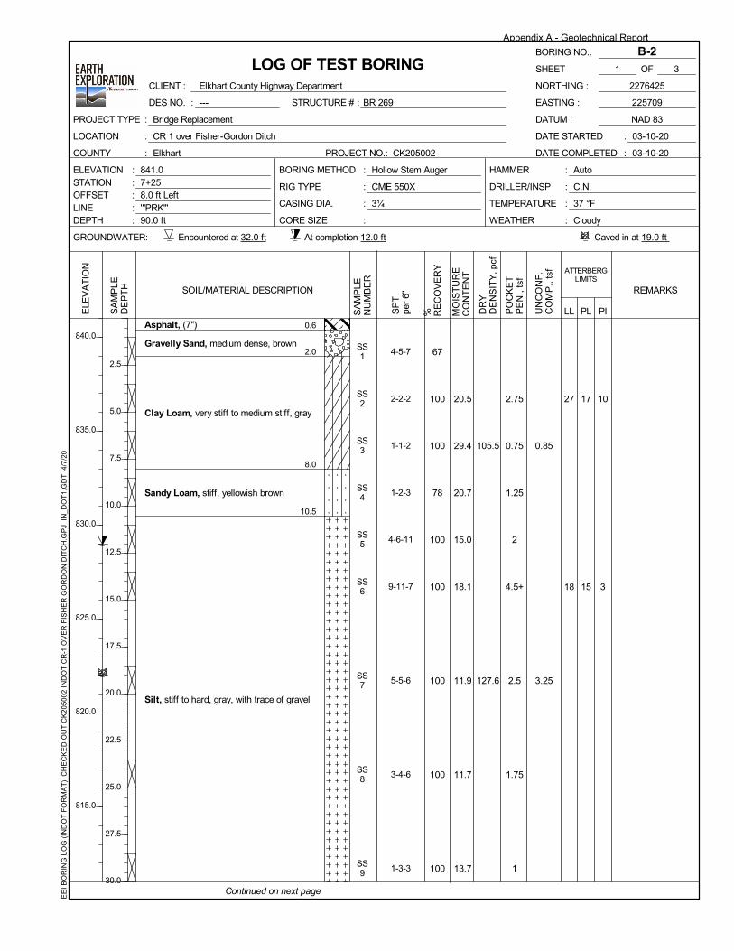
4-5-7
2-2-2
1-1-2
1-2-3
4-6-11
9-11-7
5-5-6
3-4-6
1-3-3
67
100
100
78
100
100
100
100
100
Asphalt, (7")
Gravelly Sand, medium dense, brown
Clay Loam, very stiff to medium stiff, gray
Sandy Loam, stiff, yellowish brown
Silt, stiff to hard, gray, with trace of gravel
0.6
2.0
8.0
10.5
17
15
10
3
SS
1
SS
2
SS
3
SS
4
SS
5
SS
6
SS
7
SS
8
SS
9
27
18
2.75
0.75
1.25
2
4.5+
2.5
1.75
1
20.5
29.4
20.7
15.0
18.1
11.9
11.7
13.7
105.5
127.6
0.85
3.25
BORING METHOD
RIG TYPE
CASING DIA.
CORE SIZE
:
:
:
:
03-10-20
03-10-20
At completion 12.0 ft
DATE STARTED
DATE COMPLETED
Encountered at 32.0 ft
:
:
:
:
Caved in at 19.0 ft
PROJECT NO.: CK205002
CR 1 over Fisher-Gordon Ditch
Elkhart
LOCATION
COUNTY
HAMMER
DRILLER/INSP
TEMPERATURE
WEATHER
:
:
:
:
Hollow Stem Auger
CME 550X
3¼
ELEVATION
STATION
OFFSET
LINE
DEPTH
:
:
:
:
:
Auto
C.N.
37 °F
Cloudy
GROUNDWATER:
841.0
7+25
8.0 ft Left
'"PRK"'
90.0 ft
UN
CO
NF
.
CO
MP
., tsf ATTERBERG
LIMITS
2.5
5.0
7.5
10.0
12.5
15.0
17.5
20.0
22.5
25.0
27.5
30.0
BORING NO.:
SHEET 3
LL
:
840.0
835.0
830.0
825.0
820.0
815.0
225709: STRUCTURE #
B-2
---
REMARKS
Bridge Replacement
BR 269
NORTHING : 2276425
SP
T
per 6
"
NAD 83
ELE
VA
TIO
N
1
PIPO
CK
ET
PE
N., tsf
MO
IST
UR
E
CO
NT
EN
T
EASTING :
SOIL/MATERIAL DESCRIPTION
DES NO.
Elkhart County Highway Department
Continued on next page
SA
MP
LE
DE
PT
HPROJECT TYPE
:
DATUM :
OFLOG OF TEST BORING
CLIENT :
PLSA
MP
LE
NU
MB
ER
DR
Y
DE
NS
ITY
, pcf
% RE
CO
VE
RY
EE
I B
OR
ING
LO
G (
IND
OT
FO
RM
AT
) C
HE
CK
ED
OU
T C
K2
05
00
2 I
ND
OT
CR
-1 O
VE
R F
ISH
ER
GO
RD
ON
DIT
CH
.GP
J
IN_
DO
T1
.GD
T
4/7
/20
Appendix A - Geotechnical Report
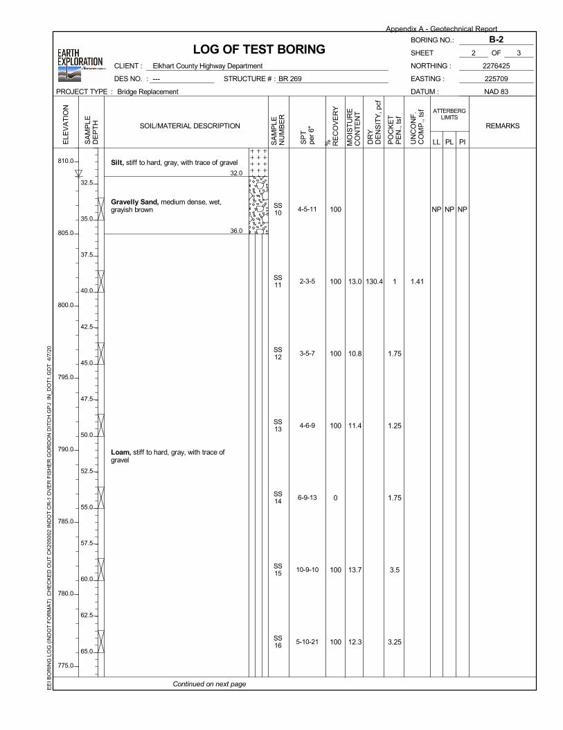
4-5-11
2-3-5
3-5-7
4-6-9
6-9-13
10-9-10
5-10-21
100
100
100
100
0
100
100
Silt, stiff to hard, gray, with trace of gravel
Gravelly Sand, medium dense, wet,
grayish brown
Loam, stiff to hard, gray, with trace of
gravel
32.0
36.0
NP NPSS
10
SS
11
SS
12
SS
13
SS
14
SS
15
SS
16
NP
1
1.75
1.25
1.75
3.5
3.25
13.0
10.8
11.4
13.7
12.3
130.4 1.41
UN
CO
NF
.
CO
MP
., tsf ATTERBERG
LIMITS
32.5
35.0
37.5
40.0
42.5
45.0
47.5
50.0
52.5
55.0
57.5
60.0
62.5
65.0
BORING NO.:
SHEET 3
LL
:
810.0
805.0
800.0
795.0
790.0
785.0
780.0
775.0
225709: STRUCTURE #
B-2
---
REMARKS
Bridge Replacement
BR 269
NORTHING : 2276425
SP
T
per 6
"
NAD 83
ELE
VA
TIO
N
2
PIPO
CK
ET
PE
N., tsf
MO
IST
UR
E
CO
NT
EN
T
EASTING :
SOIL/MATERIAL DESCRIPTION
DES NO.
Elkhart County Highway Department
Continued on next page
SA
MP
LE
DE
PT
HPROJECT TYPE
:
DATUM :
OFLOG OF TEST BORING
CLIENT :
PLSA
MP
LE
NU
MB
ER
DR
Y
DE
NS
ITY
, pcf
% RE
CO
VE
RY
EE
I B
OR
ING
LO
G (
IND
OT
FO
RM
AT
) C
HE
CK
ED
OU
T C
K2
05
00
2 I
ND
OT
CR
-1 O
VE
R F
ISH
ER
GO
RD
ON
DIT
CH
.GP
J
IN_
DO
T1
.GD
T
4/7
/20
Appendix A - Geotechnical Report

18-33-30
7-13-23
12-20-31
9-15-26
8-18-32
100
100
100
100
100
Sandy Loam, very dense, wet, gray, with
trace of gravel, (till)
Sand, dense, wet, gray
Silt, hard, gray, with trace of gravel
Bottom of Boring at 90.0 ft
67.0
74.0
75.0
90.0
SS
17
SS
18
SS
19
SS
20
SS
21
4.5+
4.5+
4.5+
7.2
16.0
11.7
14.0
13.3
UN
CO
NF
.
CO
MP
., tsf ATTERBERG
LIMITS
67.5
70.0
72.5
75.0
77.5
80.0
82.5
85.0
87.5
90.0
92.5
95.0
97.5
100.0
102.5
BORING NO.:
SHEET 3
LL
:
770.0
765.0
760.0
755.0
750.0
745.0
740.0
225709: STRUCTURE #
B-2
---
REMARKS
Bridge Replacement
BR 269
NORTHING : 2276425
SP
T
per 6
"
NAD 83
ELE
VA
TIO
N
3
PIPO
CK
ET
PE
N., tsf
MO
IST
UR
E
CO
NT
EN
T
EASTING :
SOIL/MATERIAL DESCRIPTION
DES NO.
Elkhart County Highway Department
SA
MP
LE
DE
PT
HPROJECT TYPE
:
DATUM :
OFLOG OF TEST BORING
CLIENT :
PLSA
MP
LE
NU
MB
ER
DR
Y
DE
NS
ITY
, pcf
% RE
CO
VE
RY
EE
I B
OR
ING
LO
G (
IND
OT
FO
RM
AT
) C
HE
CK
ED
OU
T C
K2
05
00
2 I
ND
OT
CR
-1 O
VE
R F
ISH
ER
GO
RD
ON
DIT
CH
.GP
J
IN_
DO
T1
.GD
T
4/7
/20
Appendix A - Geotechnical Report
APPENDIX D
GRAIN SIZE DISTRIBUTION TEST REPORT
UNCONFINED COMPRESSION TEST RESULTS (6)
APILE RESULTS GRAPHS (2)
APILE ANALYSIS OUTPUT (2)
Appendix A - Geotechnical Report
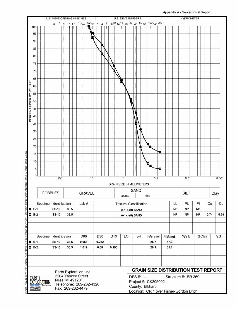
0
5
10
15
20
25
30
35
40
45
50
55
60
65
70
75
80
85
90
95
100
0.0010.010.1110100
40 14032
COBBLES
HYDROMETER
6
U.S. SIEVE NUMBERS
3/8
fine
B-1
B-2
B-1
B-2
NP
NP 0.74 5.28
SS-10
SS-10
33.5
33.5 0.193
26.7
29.9
SS-10
SS-10
LL
D30
Lab #
NP
NP
coarse
5060
16 10020
1/24
1
U.S. SIEVE OPENING IN INCHES
0.282
0.38
PL PI
%Sand %Silt
Specimen Identification
NP
NP
pH
683/4
PE
RC
EN
T F
INE
R B
Y W
EIG
HT
4
Textural Classification
A-1-b (0) SAND
A-1-b (0) SAND
3
GRAVELSAND
57.3
65.1
Cc Cu
D60
0.956
1.017
Specimen Identification
33.5
33.5
SILT Clay
GRAIN SIZE DISTRIBUTION TEST REPORT
14
GRAIN SIZE IN MILLIMETERS
2001.5
3010
D10 LOI %Gravel %Clay SG
DES #: --- Structure #: BR 269
Project #: CK205002
County: Elkhart
Location: CR 1 over Fisher-Gordon Ditch
Earth Exploration, Inc.
2204 Yankee Street
Niles, MI 49120
Telephone: 269-262-4320
Fax: 269-262-4479
IND
OT
_G
RA
IN_
SIZ
E (
EE
I L
OG
O)
CH
EC
KE
D O
UT
CK
20
50
02
IN
DO
T C
R-1
OV
ER
FIS
HE
R G
OR
DO
N D
ITC
H.G
PJ
IN_
DO
T1
.GD
T
4/7
/20
Appendix A - Geotechnical Report

0
0.2
0.4
0.6
0.8
1.0
1.2
1.4
1.6
1.8
0 4 8 12 16 20 24
12.1
Depth
Moisture
Content (%)
Saturation
(%)
Height/Diameter
Ratio
Specimen
Height (mm)
Void
Ratio
Specimen
Diameter (mm)
Dry
Density (pcf)
AXIAL STRAIN, %
ClassificationBoring
15.0
Sample
130.9
2.0
B-1
UNCONFINED COMPRESSION TEST
SS-5
146.8
Shear Strength
(tsf)
Strain Rate
(%)
1.0
35.4 71.2
Failure Strain
(%)
Unconfined
Strength (tsf)
CO
MP
RE
SS
IVE
ST
RE
SS
, ts
f
1.53
11 - 12.5 Silty Clay Loam
0.76
Moist
Density (pcf)
DES #: --- Structure #: BR 269
Project #: CK205002
County: Elkhart
Location: CR 1 over Fisher-Gordon Ditch
Earth Exploration, Inc.
2204 Yankee Street
Niles, MI 49120
Telephone: 269-262-4320
Fax: 269-262-4479
IND
OT
_U
NC
ON
FIN
ED
_T
ES
T (
EE
I L
OG
O)
CH
EC
KE
D O
UT
CK
20
50
02
IN
DO
T C
R-1
OV
ER
FIS
HE
R G
OR
DO
N D
ITC
H.G
PJ
IN_
DO
T1
.GD
T
4/7
/20
Appendix A - Geotechnical Report
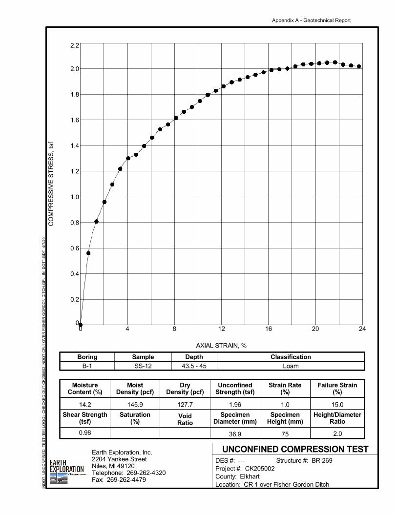
0
0.2
0.4
0.6
0.8
1.0
1.2
1.4
1.6
1.8
2.0
2.2
0 4 8 12 16 20 24
14.2
Depth
Moisture
Content (%)
Saturation
(%)
Height/Diameter
Ratio
Specimen
Height (mm)
Void
Ratio
Specimen
Diameter (mm)
Dry
Density (pcf)
AXIAL STRAIN, %
ClassificationBoring
15.0
Sample
127.7
2.0
B-1
UNCONFINED COMPRESSION TEST
SS-12
145.9
Shear Strength
(tsf)
Strain Rate
(%)
1.0
36.9 75
Failure Strain
(%)
Unconfined
Strength (tsf)
CO
MP
RE
SS
IVE
ST
RE
SS
, ts
f
1.96
43.5 - 45 Loam
0.98
Moist
Density (pcf)
DES #: --- Structure #: BR 269
Project #: CK205002
County: Elkhart
Location: CR 1 over Fisher-Gordon Ditch
Earth Exploration, Inc.
2204 Yankee Street
Niles, MI 49120
Telephone: 269-262-4320
Fax: 269-262-4479
IND
OT
_U
NC
ON
FIN
ED
_T
ES
T (
EE
I L
OG
O)
CH
EC
KE
D O
UT
CK
20
50
02
IN
DO
T C
R-1
OV
ER
FIS
HE
R G
OR
DO
N D
ITC
H.G
PJ
IN_
DO
T1
.GD
T
4/7
/20
Appendix A - Geotechnical Report
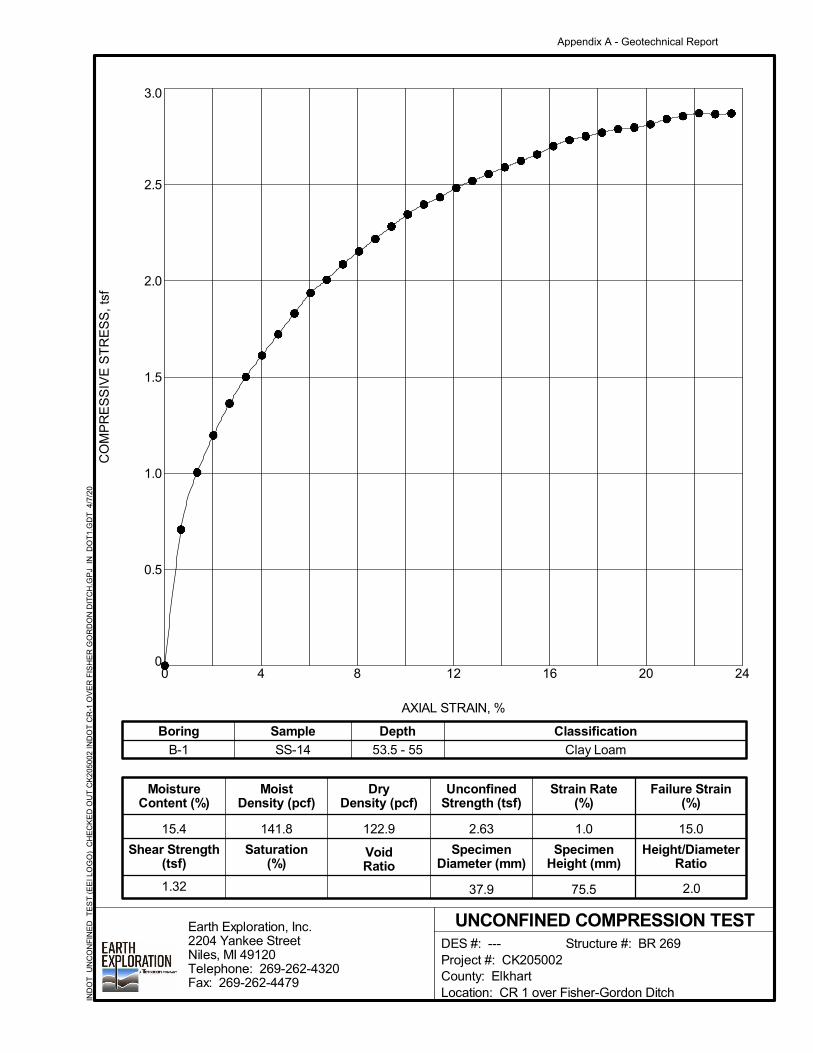
0
0.5
1.0
1.5
2.0
2.5
3.0
0 4 8 12 16 20 24
15.4
Depth
Moisture
Content (%)
Saturation
(%)
Height/Diameter
Ratio
Specimen
Height (mm)
Void
Ratio
Specimen
Diameter (mm)
Dry
Density (pcf)
AXIAL STRAIN, %
ClassificationBoring
15.0
Sample
122.9
2.0
B-1
UNCONFINED COMPRESSION TEST
SS-14
141.8
Shear Strength
(tsf)
Strain Rate
(%)
1.0
37.9 75.5
Failure Strain
(%)
Unconfined
Strength (tsf)
CO
MP
RE
SS
IVE
ST
RE
SS
, ts
f
2.63
53.5 - 55 Clay Loam
1.32
Moist
Density (pcf)
DES #: --- Structure #: BR 269
Project #: CK205002
County: Elkhart
Location: CR 1 over Fisher-Gordon Ditch
Earth Exploration, Inc.
2204 Yankee Street
Niles, MI 49120
Telephone: 269-262-4320
Fax: 269-262-4479
IND
OT
_U
NC
ON
FIN
ED
_T
ES
T (
EE
I L
OG
O)
CH
EC
KE
D O
UT
CK
20
50
02
IN
DO
T C
R-1
OV
ER
FIS
HE
R G
OR
DO
N D
ITC
H.G
PJ
IN_
DO
T1
.GD
T
4/7
/20
Appendix A - Geotechnical Report
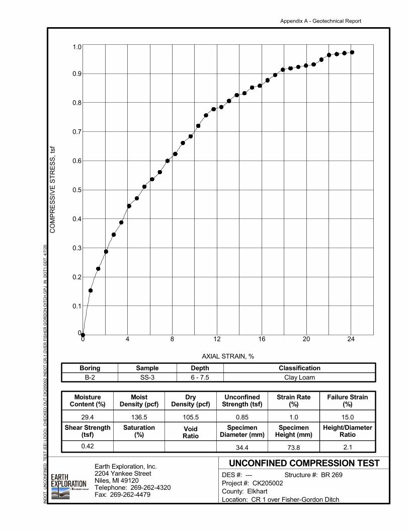
0
0.1
0.2
0.3
0.4
0.5
0.6
0.7
0.8
0.9
1.0
0 4 8 12 16 20 24
29.4
Depth
Moisture
Content (%)
Saturation
(%)
Height/Diameter
Ratio
Specimen
Height (mm)
Void
Ratio
Specimen
Diameter (mm)
Dry
Density (pcf)
AXIAL STRAIN, %
ClassificationBoring
15.0
Sample
105.5
2.1
B-2
UNCONFINED COMPRESSION TEST
SS-3
136.5
Shear Strength
(tsf)
Strain Rate
(%)
1.0
34.4 73.8
Failure Strain
(%)
Unconfined
Strength (tsf)
CO
MP
RE
SS
IVE
ST
RE
SS
, ts
f
0.85
6 - 7.5 Clay Loam
0.42
Moist
Density (pcf)
DES #: --- Structure #: BR 269
Project #: CK205002
County: Elkhart
Location: CR 1 over Fisher-Gordon Ditch
Earth Exploration, Inc.
2204 Yankee Street
Niles, MI 49120
Telephone: 269-262-4320
Fax: 269-262-4479
IND
OT
_U
NC
ON
FIN
ED
_T
ES
T (
EE
I L
OG
O)
CH
EC
KE
D O
UT
CK
20
50
02
IN
DO
T C
R-1
OV
ER
FIS
HE
R G
OR
DO
N D
ITC
H.G
PJ
IN_
DO
T1
.GD
T
4/7
/20
Appendix A - Geotechnical Report
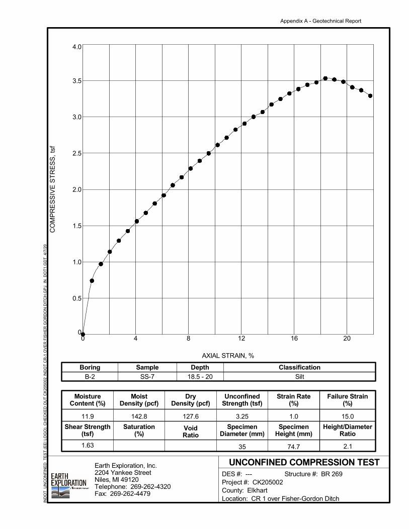
0
0.5
1.0
1.5
2.0
2.5
3.0
3.5
4.0
0 4 8 12 16 20
11.9
Depth
Moisture
Content (%)
Saturation
(%)
Height/Diameter
Ratio
Specimen
Height (mm)
Void
Ratio
Specimen
Diameter (mm)
Dry
Density (pcf)
AXIAL STRAIN, %
ClassificationBoring
15.0
Sample
127.6
2.1
B-2
UNCONFINED COMPRESSION TEST
SS-7
142.8
Shear Strength
(tsf)
Strain Rate
(%)
1.0
35 74.7
Failure Strain
(%)
Unconfined
Strength (tsf)
CO
MP
RE
SS
IVE
ST
RE
SS
, ts
f
3.25
18.5 - 20 Silt
1.63
Moist
Density (pcf)
DES #: --- Structure #: BR 269
Project #: CK205002
County: Elkhart
Location: CR 1 over Fisher-Gordon Ditch
Earth Exploration, Inc.
2204 Yankee Street
Niles, MI 49120
Telephone: 269-262-4320
Fax: 269-262-4479
IND
OT
_U
NC
ON
FIN
ED
_T
ES
T (
EE
I L
OG
O)
CH
EC
KE
D O
UT
CK
20
50
02
IN
DO
T C
R-1
OV
ER
FIS
HE
R G
OR
DO
N D
ITC
H.G
PJ
IN_
DO
T1
.GD
T
4/7
/20
Appendix A - Geotechnical Report

0
0.2
0.4
0.6
0.8
1.0
1.2
1.4
1.6
0 4 8 12 16 20 24
13.0
Depth
Moisture
Content (%)
Saturation
(%)
Height/Diameter
Ratio
Specimen
Height (mm)
Void
Ratio
Specimen
Diameter (mm)
Dry
Density (pcf)
AXIAL STRAIN, %
ClassificationBoring
15.0
Sample
130.4
1.9
B-2
UNCONFINED COMPRESSION TEST
SS-11
147.4
Shear Strength
(tsf)
Strain Rate
(%)
1.0
38 71.6
Failure Strain
(%)
Unconfined
Strength (tsf)
CO
MP
RE
SS
IVE
ST
RE
SS
, ts
f
1.41
38.5 - 40 Loam
0.71
Moist
Density (pcf)
DES #: --- Structure #: BR 269
Project #: CK205002
County: Elkhart
Location: CR 1 over Fisher-Gordon Ditch
Earth Exploration, Inc.
2204 Yankee Street
Niles, MI 49120
Telephone: 269-262-4320
Fax: 269-262-4479
IND
OT
_U
NC
ON
FIN
ED
_T
ES
T (
EE
I L
OG
O)
CH
EC
KE
D O
UT
CK
20
50
02
IN
DO
T C
R-1
OV
ER
FIS
HE
R G
OR
DO
N D
ITC
H.G
PJ
IN_
DO
T1
.GD
T
4/7
/20
Appendix A - Geotechnical Report
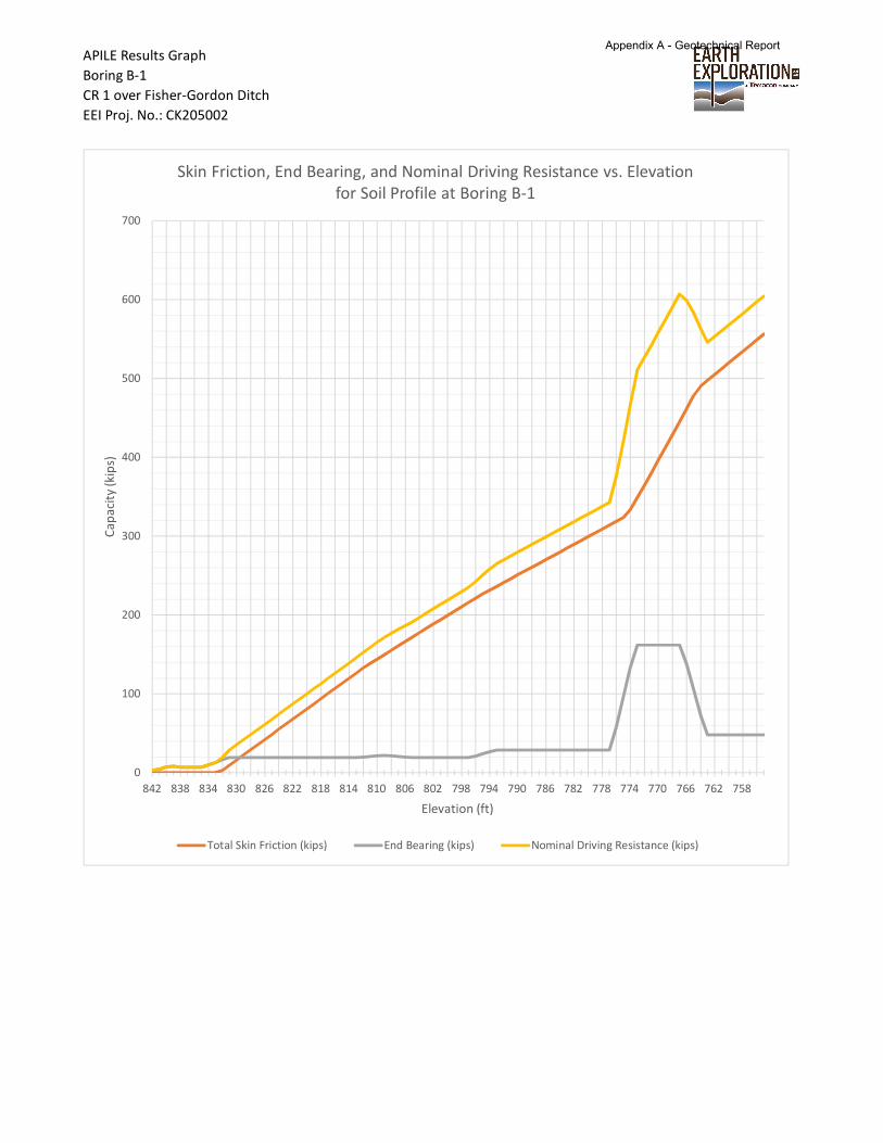
APILE Results Graph
Boring B-1
CR 1 over Fisher-Gordon Ditch
EEI Proj. No.: CK205002
0
100
200
300
400
500
600
700
842 838 834 830 826 822 818 814 810 806 802 798 794 790 786 782 778 774 770 766 762 758
Ca
pa
city
(kip
s)
Elevation (ft)
Skin Friction, End Bearing, and Nominal Driving Resistance vs. Elevation
for Soil Profile at Boring B-1
Total Skin Friction (kips) End Bearing (kips) Nominal Driving Resistance (kips)
Appendix A - Geotechnical Report
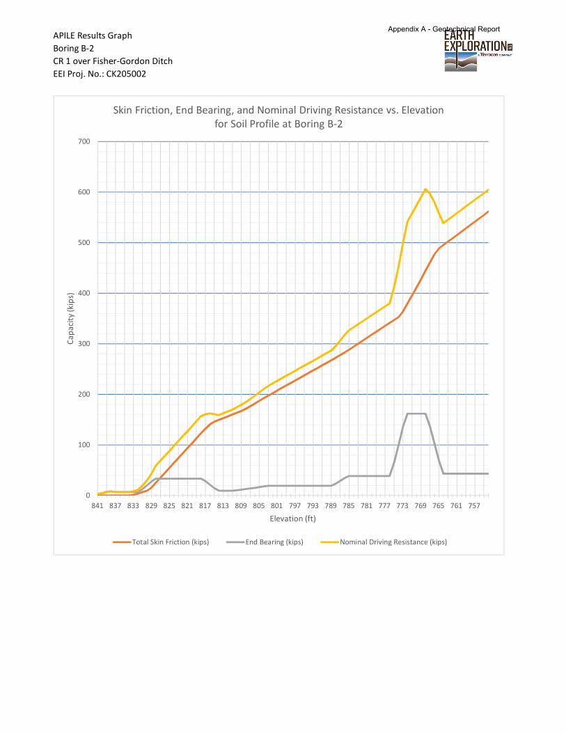
APILE Results Graph
Boring B-2
CR 1 over Fisher-Gordon Ditch
EEI Proj. No.: CK205002
0
100
200
300
400
500
600
700
841 837 833 829 825 821 817 813 809 805 801 797 793 789 785 781 777 773 769 765 761 757
Ca
pa
city
(kip
s)
Elevation (ft)
Skin Friction, End Bearing, and Nominal Driving Resistance vs. Elevation
for Soil Profile at Boring B-2
Total Skin Friction (kips) End Bearing (kips) Nominal Driving Resistance (kips)
Appendix A - Geotechnical Report

CK205002 B-1 APILE.ap9o =========================================================================
APILE for Windows, Version 2019.9.3
Serial Number : 228330792
A Program for Analyzing the Axial Capacity and Short-term Settlement of Driven Piles under Axial Loading. (c) Copyright ENSOFT, Inc., 1987-2015 All Rights Reserved
=========================================================================
This program is licensed to :
Earth Exploration Inc Niles, MI
Path to file locations : N:\Projects\2020\CK205002\WorkingFiles\Calculations-Analyses\ Name of input data file : CK205002 B-1 APILE.ap9d Name of output file : CK205002 B-1 APILE.ap9o Name of plot output file : CK205002 B-1 APILE.ap9p
------------------------------------------------------------------------- Time and Date of Analysis -------------------------------------------------------------------------
Date: April 07, 2020 Time: 16:51:54
1 ********************* * INPUT INFORMATION * *********************
Pile at Boring B-1
DESIGNER : Eric Rowe, E.I.T.
JOB NUMBER : CK205002
METHOD FOR UNIT LOAD TRANSFERS :
Page 1
Appendix A - Geotechnical Report
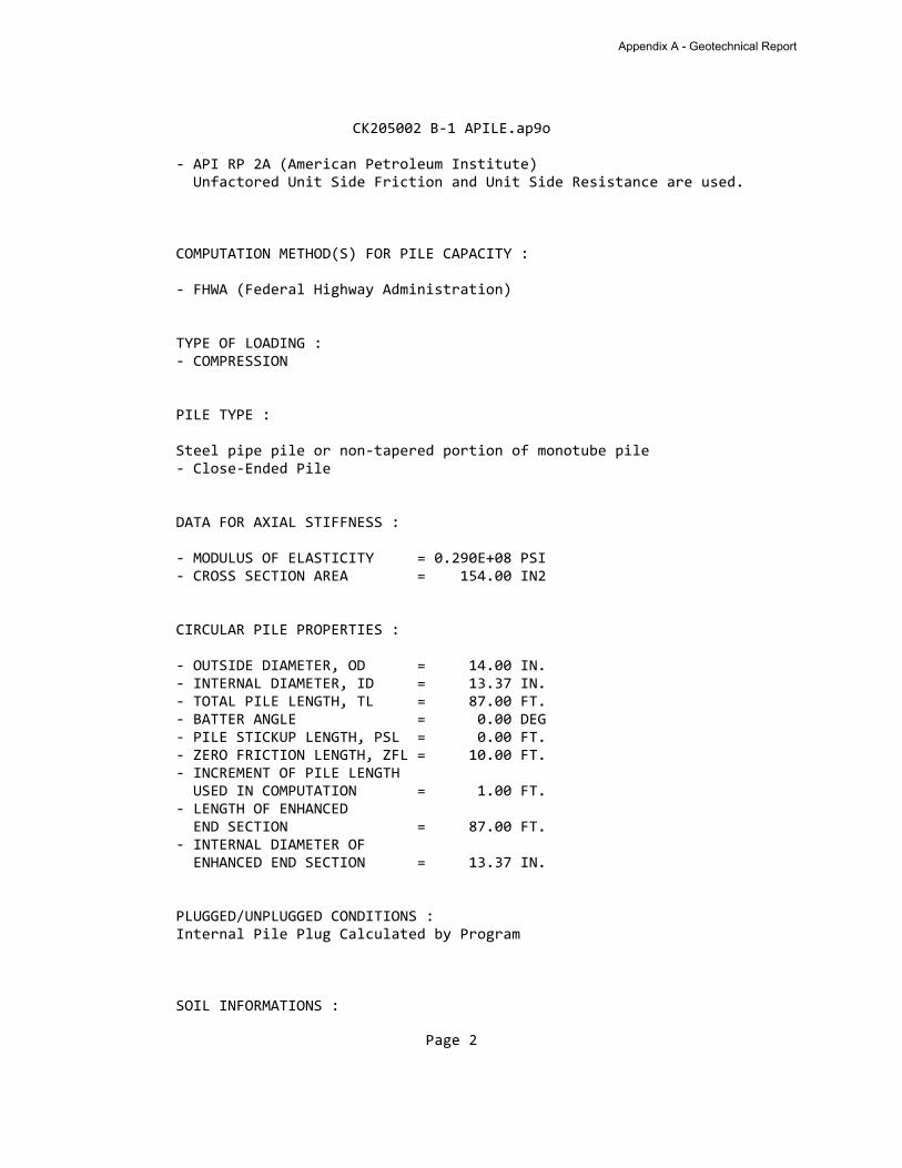
CK205002 B-1 APILE.ap9o
- API RP 2A (American Petroleum Institute) Unfactored Unit Side Friction and Unit Side Resistance are used.
COMPUTATION METHOD(S) FOR PILE CAPACITY :
- FHWA (Federal Highway Administration)
TYPE OF LOADING : - COMPRESSION
PILE TYPE :
Steel pipe pile or non-tapered portion of monotube pile - Close-Ended Pile
DATA FOR AXIAL STIFFNESS :
- MODULUS OF ELASTICITY = 0.290E+08 PSI - CROSS SECTION AREA = 154.00 IN2
CIRCULAR PILE PROPERTIES :
- OUTSIDE DIAMETER, OD = 14.00 IN. - INTERNAL DIAMETER, ID = 13.37 IN. - TOTAL PILE LENGTH, TL = 87.00 FT. - BATTER ANGLE = 0.00 DEG - PILE STICKUP LENGTH, PSL = 0.00 FT. - ZERO FRICTION LENGTH, ZFL = 10.00 FT. - INCREMENT OF PILE LENGTH USED IN COMPUTATION = 1.00 FT. - LENGTH OF ENHANCED END SECTION = 87.00 FT. - INTERNAL DIAMETER OF ENHANCED END SECTION = 13.37 IN.
PLUGGED/UNPLUGGED CONDITIONS : Internal Pile Plug Calculated by Program
SOIL INFORMATIONS :
Page 2
Appendix A - Geotechnical Report

CK205002 B-1 APILE.ap9o
LATERAL EFFECTIVE FRICTION BEARING SOIL EARTH UNIT ANGLE CAPACITY DEPTH TYPE PRESSURE WEIGHT DEGREES FACTOR FT. LB/FT^3 0.00 SAND 1.00 123.00 36.00 20.00 2.00 SAND 1.00 123.00 36.00 20.00 2.00 CLAY 0.80* 124.00 0.00 8.00** 8.50 CLAY 0.80* 124.00 0.00 8.00** 8.50 CLAY 0.80* 128.00 0.00 8.00** 31.00 CLAY 0.80* 128.00 0.00 8.00** 31.00 SAND 1.00 51.00 31.00 12.00 35.00 SAND 1.00 51.00 31.00 12.00 35.00 CLAY 0.80* 66.00 0.00 8.00** 47.00 CLAY 0.80* 66.00 0.00 8.00** 47.00 CLAY 0.80* 70.00 0.00 8.00** 67.00 CLAY 0.80* 70.00 0.00 8.00** 67.00 SAND 1.00 70.00 36.00 50.00 77.00 SAND 1.00 70.00 36.00 50.00 77.00 CLAY 0.80* 133.00 0.00 8.00** 90.00 CLAY 0.80* 133.00 0.00 8.00**
* VALUE ASSUMED BY THE PROGRAM ** VALUE ESTIMATED BY THE PROGRAM BASED ON FRICTION ANGLE
MAXIMUM MAXIMUM UNDISTURB REMOLDED UNIT UNIT SHEAR SHEAR BLOW UNIT SKIN UNIT END FRICTION BEARING STRENGTH STRENGTH COUNT FRICTION BEARING KSF KSF KSF KSF KSF KSF 0.10E+08* 0.10E+08* 0.00 0.00 0.00 0.00 0.00 0.10E+08* 0.10E+08* 0.00 0.00 0.00 0.00 0.00 0.10E+08* 0.10E+08* 0.75 0.00 0.00 0.00 0.00 0.10E+08* 0.10E+08* 0.75 0.00 0.00 0.00 0.00 0.10E+08* 0.10E+08* 2.00 0.00 0.00 0.00 0.00 0.10E+08* 0.10E+08* 2.00 0.00 0.00 0.00 0.00 0.10E+08* 0.10E+08* 0.00 0.00 0.00 0.00 0.00 0.10E+08* 0.10E+08* 0.00 0.00 0.00 0.00 0.00 0.10E+08* 0.10E+08* 2.00 0.00 0.00 0.00 0.00 0.10E+08* 0.10E+08* 2.00 0.00 0.00 0.00 0.00 0.10E+08* 0.10E+08* 3.00 0.00 0.00 0.00 0.00 0.10E+08* 0.10E+08* 3.00 0.00 0.00 0.00 0.00 0.10E+08* 0.10E+08* 0.00 0.00 0.00 0.00 0.00 0.10E+08* 0.10E+08* 0.00 0.00 0.00 0.00 0.00 0.10E+08* 0.10E+08* 5.00 0.00 0.00 0.00 0.00 0.10E+08* 0.10E+08* 5.00 0.00 0.00 0.00 0.00
Page 3
Appendix A - Geotechnical Report
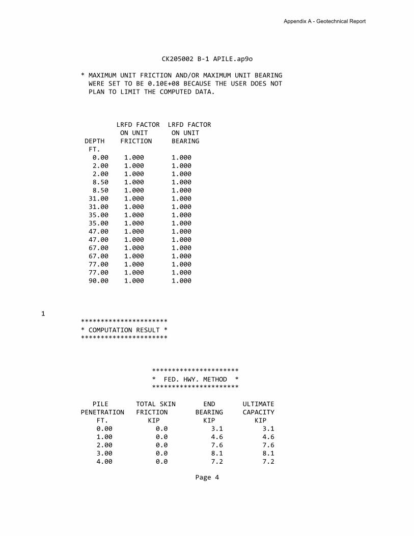
CK205002 B-1 APILE.ap9o
* MAXIMUM UNIT FRICTION AND/OR MAXIMUM UNIT BEARING
WERE SET TO BE 0.10E+08 BECAUSE THE USER DOES NOT
PLAN TO LIMIT THE COMPUTED DATA.
LRFD FACTOR LRFD FACTOR
ON UNIT ON UNIT
DEPTH FRICTION BEARING
FT.
0.00 1.000 1.000
2.00 1.000 1.000
2.00 1.000 1.000
8.50 1.000 1.000
8.50 1.000 1.000
31.00 1.000 1.000
31.00 1.000 1.000
35.00 1.000 1.000
35.00 1.000 1.000
47.00 1.000 1.000
47.00 1.000 1.000
67.00 1.000 1.000
67.00 1.000 1.000
77.00 1.000 1.000
77.00 1.000 1.000
90.00 1.000 1.000
1
**********************
* COMPUTATION RESULT *
**********************
**********************
* FED. HWY. METHOD *
**********************
PILE TOTAL SKIN END ULTIMATE
PENETRATION FRICTION BEARING CAPACITY
FT. KIP KIP KIP
0.00 0.0 3.1 3.1
1.00 0.0 4.6 4.6
2.00 0.0 7.6 7.6
3.00 0.0 8.1 8.1
4.00 0.0 7.2 7.2
Page 4
Appendix A - Geotechnical Report
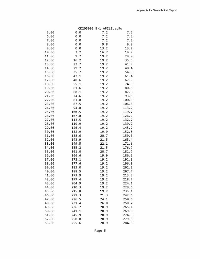
CK205002 B-1 APILE.ap9o
5.00 0.0 7.2 7.2
6.00 0.0 7.2 7.2
7.00 0.0 7.2 7.2
8.00 0.0 9.8 9.8
9.00 0.0 13.2 13.2
10.00 3.2 16.7 19.9
11.00 9.7 19.2 29.0
12.00 16.2 19.2 35.5
13.00 22.7 19.2 41.9
14.00 29.2 19.2 48.4
15.00 35.7 19.2 54.9
16.00 42.1 19.2 61.4
17.00 48.6 19.2 67.9
18.00 55.1 19.2 74.3
19.00 61.6 19.2 80.8
20.00 68.1 19.2 87.3
21.00 74.6 19.2 93.8
22.00 81.0 19.2 100.3
23.00 87.5 19.2 106.8
24.00 94.0 19.2 113.2
25.00 100.5 19.2 119.7
26.00 107.0 19.2 126.2
27.00 113.5 19.2 132.7
28.00 119.9 19.2 139.2
29.00 126.4 19.2 145.7
30.00 132.9 19.9 152.8
31.00 138.6 20.7 159.3
32.00 143.9 21.5 165.4
33.00 149.5 22.1 171.6
34.00 155.2 21.5 176.7
35.00 161.0 20.7 181.7
36.00 166.6 19.9 186.5
37.00 172.1 19.2 191.3
38.00 177.6 19.2 196.8
39.00 183.0 19.2 202.3
40.00 188.5 19.2 207.7
41.00 193.9 19.2 213.2
42.00 199.4 19.2 218.7
43.00 204.9 19.2 224.1
44.00 210.3 19.2 229.6
45.00 215.8 19.2 235.1
46.00 221.3 21.3 242.6
47.00 226.5 24.1 250.6
48.00 231.4 26.8 258.2
49.00 236.2 28.9 265.1
50.00 241.1 28.9 269.9
51.00 245.9 28.9 274.8
52.00 250.8 28.9 279.6
53.00 255.6 28.9 284.5
Page 5
Appendix A - Geotechnical Report
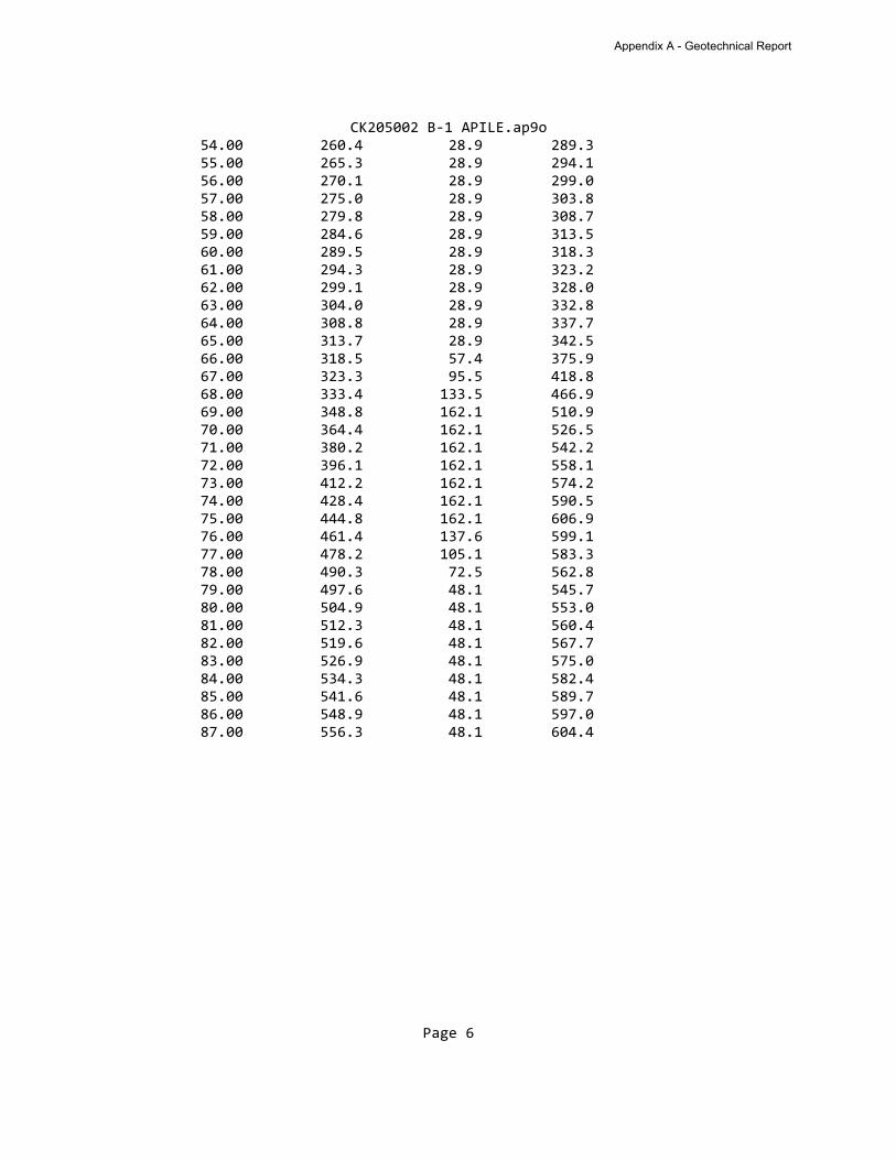
CK205002 B-1 APILE.ap9o
54.00 260.4 28.9 289.3
55.00 265.3 28.9 294.1
56.00 270.1 28.9 299.0
57.00 275.0 28.9 303.8
58.00 279.8 28.9 308.7
59.00 284.6 28.9 313.5
60.00 289.5 28.9 318.3
61.00 294.3 28.9 323.2
62.00 299.1 28.9 328.0
63.00 304.0 28.9 332.8
64.00 308.8 28.9 337.7
65.00 313.7 28.9 342.5
66.00 318.5 57.4 375.9
67.00 323.3 95.5 418.8
68.00 333.4 133.5 466.9
69.00 348.8 162.1 510.9
70.00 364.4 162.1 526.5
71.00 380.2 162.1 542.2
72.00 396.1 162.1 558.1
73.00 412.2 162.1 574.2
74.00 428.4 162.1 590.5
75.00 444.8 162.1 606.9
76.00 461.4 137.6 599.1
77.00 478.2 105.1 583.3
78.00 490.3 72.5 562.8
79.00 497.6 48.1 545.7
80.00 504.9 48.1 553.0
81.00 512.3 48.1 560.4
82.00 519.6 48.1 567.7
83.00 526.9 48.1 575.0
84.00 534.3 48.1 582.4
85.00 541.6 48.1 589.7
86.00 548.9 48.1 597.0
87.00 556.3 48.1 604.4
Page 6
Appendix A - Geotechnical Report
CK205002 B-2 APILE.ap9o =========================================================================
APILE for Windows, Version 2019.9.3
Serial Number : 228330792
A Program for Analyzing the Axial Capacity and Short-term Settlement of Driven Piles under Axial Loading. (c) Copyright ENSOFT, Inc., 1987-2015 All Rights Reserved
=========================================================================
This program is licensed to :
Earth Exploration Inc Niles, MI
Path to file locations : N:\Projects\2020\CK205002\WorkingFiles\Calculations-Analyses\ Name of input data file : CK205002 B-2 APILE.ap9d Name of output file : CK205002 B-2 APILE.ap9o Name of plot output file : CK205002 B-2 APILE.ap9p
------------------------------------------------------------------------- Time and Date of Analysis -------------------------------------------------------------------------
Date: April 07, 2020 Time: 16:59:35
1 ********************* * INPUT INFORMATION * *********************
Pile at Boring B-2
DESIGNER : Eric Rowe, E.I.T.
JOB NUMBER : CK205002
METHOD FOR UNIT LOAD TRANSFERS :
Page 1
Appendix A - Geotechnical Report

CK205002 B-2 APILE.ap9o
- API RP 2A (American Petroleum Institute) Unfactored Unit Side Friction and Unit Side Resistance are used.
COMPUTATION METHOD(S) FOR PILE CAPACITY :
- FHWA (Federal Highway Administration)
TYPE OF LOADING : - COMPRESSION
PILE TYPE :
Steel pipe pile or non-tapered portion of monotube pile - Close-Ended Pile
DATA FOR AXIAL STIFFNESS :
- MODULUS OF ELASTICITY = 0.290E+08 PSI - CROSS SECTION AREA = 154.00 IN2
CIRCULAR PILE PROPERTIES :
- OUTSIDE DIAMETER, OD = 14.00 IN. - INTERNAL DIAMETER, ID = 13.30 IN. - TOTAL PILE LENGTH, TL = 87.00 FT. - BATTER ANGLE = 0.00 DEG - PILE STICKUP LENGTH, PSL = 0.00 FT. - ZERO FRICTION LENGTH, ZFL = 8.00 FT. - INCREMENT OF PILE LENGTH USED IN COMPUTATION = 1.00 FT. - LENGTH OF ENHANCED END SECTION = 87.00 FT. - INTERNAL DIAMETER OF ENHANCED END SECTION = 13.30 IN.
PLUGGED/UNPLUGGED CONDITIONS : Internal Pile Plug Calculated by Program
SOIL INFORMATIONS :
Page 2
Appendix A - Geotechnical Report

CK205002 B-2 APILE.ap9o
LATERAL EFFECTIVE FRICTION BEARING SOIL EARTH UNIT ANGLE CAPACITY DEPTH TYPE PRESSURE WEIGHT DEGREES FACTOR FT. LB/FT^3 0.00 SAND 1.00 123.00 36.00 20.00 2.00 SAND 1.00 123.00 36.00 20.00 2.00 CLAY 0.80* 124.00 0.00 8.00** 11.00 CLAY 0.80* 124.00 0.00 8.00** 11.00 CLAY 0.80* 130.00 0.00 8.00** 25.00 CLAY 0.80* 130.00 0.00 8.00** 25.00 CLAY 0.80* 125.00 0.00 8.00** 32.00 CLAY 0.80* 125.00 0.00 8.00** 32.00 SAND 1.00 63.00 30.00 20.00 36.00 SAND 1.00 63.00 30.00 20.00 36.00 CLAY 0.80* 68.00 0.00 8.00** 53.50 CLAY 0.80* 68.00 0.00 8.00** 53.50 CLAY 0.80* 70.00 0.00 8.00** 67.00 CLAY 0.80* 70.00 0.00 8.00** 67.00 SAND 1.00 70.00 36.00 40.00 75.00 SAND 1.00 70.00 36.00 40.00 75.00 CLAY 0.80* 71.00 0.00 8.00** 90.00 CLAY 0.80* 71.00 0.00 8.00**
* VALUE ASSUMED BY THE PROGRAM ** VALUE ESTIMATED BY THE PROGRAM BASED ON FRICTION ANGLE
MAXIMUM MAXIMUM UNDISTURB REMOLDED UNIT UNIT SHEAR SHEAR BLOW UNIT SKIN UNIT END FRICTION BEARING STRENGTH STRENGTH COUNT FRICTION BEARING KSF KSF KSF KSF KSF KSF 0.10E+08* 0.10E+08* 0.00 0.00 0.00 0.00 0.00 0.10E+08* 0.10E+08* 0.00 0.00 0.00 0.00 0.00 0.10E+08* 0.10E+08* 0.75 0.00 0.00 0.00 0.00 0.10E+08* 0.10E+08* 0.75 0.00 0.00 0.00 0.00 0.10E+08* 0.10E+08* 3.50 0.00 0.00 0.00 0.00 0.10E+08* 0.10E+08* 3.50 0.00 0.00 0.00 0.00 0.10E+08* 0.10E+08* 1.00 0.00 0.00 0.00 0.00 0.10E+08* 0.10E+08* 1.00 0.00 0.00 0.00 0.00 0.10E+08* 0.10E+08* 0.00 0.00 0.00 0.00 0.00 0.10E+08* 0.10E+08* 0.00 0.00 0.00 0.00 0.00 0.10E+08* 0.10E+08* 2.00 0.00 0.00 0.00 0.00 0.10E+08* 0.10E+08* 2.00 0.00 0.00 0.00 0.00 0.10E+08* 0.10E+08* 4.00 0.00 0.00 0.00 0.00 0.10E+08* 0.10E+08* 4.00 0.00 0.00 0.00 0.00
Page 3
Appendix A - Geotechnical Report
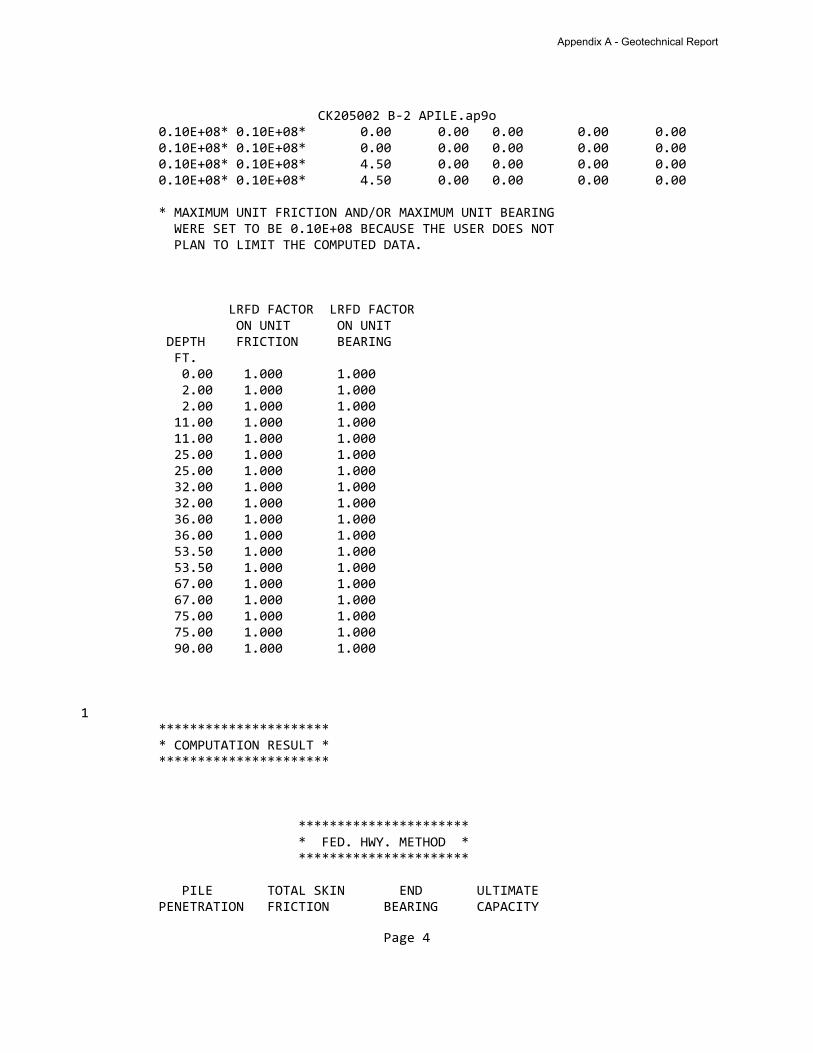
CK205002 B-2 APILE.ap9o 0.10E+08* 0.10E+08* 0.00 0.00 0.00 0.00 0.00 0.10E+08* 0.10E+08* 0.00 0.00 0.00 0.00 0.00 0.10E+08* 0.10E+08* 4.50 0.00 0.00 0.00 0.00 0.10E+08* 0.10E+08* 4.50 0.00 0.00 0.00 0.00
* MAXIMUM UNIT FRICTION AND/OR MAXIMUM UNIT BEARING WERE SET TO BE 0.10E+08 BECAUSE THE USER DOES NOT PLAN TO LIMIT THE COMPUTED DATA.
LRFD FACTOR LRFD FACTOR ON UNIT ON UNIT DEPTH FRICTION BEARING FT. 0.00 1.000 1.000 2.00 1.000 1.000 2.00 1.000 1.000 11.00 1.000 1.000 11.00 1.000 1.000 25.00 1.000 1.000 25.00 1.000 1.000 32.00 1.000 1.000 32.00 1.000 1.000 36.00 1.000 1.000 36.00 1.000 1.000 53.50 1.000 1.000 53.50 1.000 1.000 67.00 1.000 1.000 67.00 1.000 1.000 75.00 1.000 1.000 75.00 1.000 1.000 90.00 1.000 1.000
1 ********************** * COMPUTATION RESULT * **********************
********************** * FED. HWY. METHOD * **********************
PILE TOTAL SKIN END ULTIMATE PENETRATION FRICTION BEARING CAPACITY
Page 4
Appendix A - Geotechnical Report
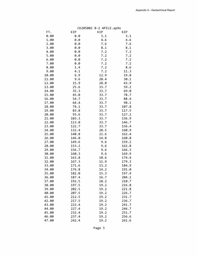
CK205002 B-2 APILE.ap9o FT. KIP KIP KIP 0.00 0.0 3.1 3.1 1.00 0.0 4.6 4.6 2.00 0.0 7.6 7.6 3.00 0.0 8.1 8.1 4.00 0.0 7.2 7.2 5.00 0.0 7.2 7.2 6.00 0.0 7.2 7.2 7.00 0.0 7.2 7.2 8.00 1.4 7.2 8.6 9.00 4.1 7.2 11.3 10.00 6.9 12.9 19.8 11.00 9.6 20.4 30.1 12.00 15.9 28.0 43.9 13.00 25.6 33.7 59.2 14.00 35.3 33.7 69.0 15.00 45.0 33.7 78.7 16.00 54.7 33.7 88.4 17.00 64.4 33.7 98.1 18.00 74.1 33.7 107.8 19.00 83.8 33.7 117.5 20.00 93.6 33.7 127.2 21.00 103.3 33.7 136.9 22.00 113.0 33.7 146.7 23.00 122.7 33.7 156.4 24.00 132.4 28.5 160.9 25.00 140.8 21.6 162.4 26.00 146.0 14.8 160.8 27.00 149.6 9.6 159.2 28.00 153.2 9.6 162.8 29.00 156.7 9.6 166.3 30.00 160.3 9.6 169.9 31.00 163.8 10.6 174.4 32.00 167.3 11.9 179.3 33.00 171.6 13.2 184.9 34.00 176.8 14.2 191.0 35.00 182.0 15.3 197.4 36.00 187.4 16.7 204.1 37.00 192.5 18.2 210.7 38.00 197.5 19.2 216.8 39.00 202.5 19.2 221.8 40.00 207.5 19.2 226.7 41.00 212.5 19.2 231.7 42.00 217.5 19.2 236.7 43.00 222.4 19.2 241.7 44.00 227.4 19.2 246.7 45.00 232.4 19.2 251.7 46.00 237.4 19.2 256.6 47.00 242.4 19.2 261.6
Page 5
Appendix A - Geotechnical Report
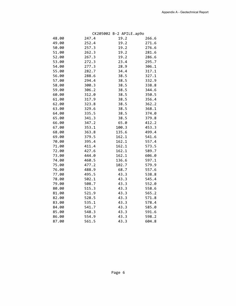
CK205002 B-2 APILE.ap9o 48.00 247.4 19.2 266.6 49.00 252.4 19.2 271.6 50.00 257.3 19.2 276.6 51.00 262.3 19.2 281.6 52.00 267.3 19.2 286.6 53.00 272.3 23.4 295.7 54.00 277.3 28.9 306.1 55.00 282.7 34.4 317.1 56.00 288.6 38.5 327.1 57.00 294.4 38.5 332.9 58.00 300.3 38.5 338.8 59.00 306.2 38.5 344.6 60.00 312.0 38.5 350.5 61.00 317.9 38.5 356.4 62.00 323.8 38.5 362.2 63.00 329.6 38.5 368.1 64.00 335.5 38.5 374.0 65.00 341.3 38.5 379.8 66.00 347.2 65.0 412.2 67.00 353.1 100.3 453.3 68.00 363.8 135.6 499.4 69.00 379.5 162.1 541.6 70.00 395.4 162.1 557.4 71.00 411.4 162.1 573.5 72.00 427.6 162.1 589.7 73.00 444.0 162.1 606.0 74.00 460.5 136.6 597.1 75.00 477.2 102.7 579.9 76.00 488.9 68.7 557.6 77.00 495.5 43.3 538.8 78.00 502.1 43.3 545.4 79.00 508.7 43.3 552.0 80.00 515.3 43.3 558.6 81.00 521.9 43.3 565.2 82.00 528.5 43.3 571.8 83.00 535.1 43.3 578.4 84.00 541.7 43.3 585.0 85.00 548.3 43.3 591.6 86.00 554.9 43.3 598.2 87.00 561.5 43.3 604.8
Page 6
Appendix A - Geotechnical Report
APPENDIX B
For
BRIDGE 269 REPLACEMENT CR1 OVER FISHER-GORDON DITCH
APPENDIX B – USACE Permit
________________________________________________________________________ OWNERS: ELKHART COUNTY, INDIANA, ACTING THROUGH
ITS BOARD OF COUNTY COMMISSIONERS ELKHART COUNTY HIGHWAY DEPARTMENT ENGINEERING SECTION 610 STEURY AVENUE GOSHEN, IN 46528
________________________________________________________________________
Elkhart County Highway Department 610 Steury Avenue, Goshen, Indiana 46528 Phone: 574-534-9394 • Fax: 574-533-7103
DEPARTMENT OF THE ARMY
CORPS OF ENGINEERS, DETROIT DISTRICT
U.S. ARMY CORPS OF ENGINEERS
MICHIANA BRANCH
2422 VIRIDIAN DRIVE SUITE # 200
SOUTH BEND, IN 46628-3489
February 28, 2020 REPLY TO
ATTENTION OF:
Engineering & Technical Services
Regulatory Office
File No. LRE-2020-00252-120-R20
Tom Rushlow
Elkhart County Highway Dept.
610 Steury Avenue
Goshen, Indiana 46528
Dear Mr. Rushlow:
Please refer to your application for a Department of the Army (DA) permit to
discharge fill into Fisher-Gordon Ditch to facilitate stabilization work associated with the
replacement of an existing bridge (Structure No. 269) on CR 1 between CR 46 and CR
144 near Wakarusa, Indiana (Latitude 41.497146 N., Longitude -86.040335, Elkhart
County).
Under Section 10 of the Rivers and Harbors Act of 1899 and Section 404 of the
Clean Water Act, Chicago, Louisville, and Detroit Districts reissued Regional Permit
LRE-2014-00571-100-S19 on December 15, 2019, for certain activities having minimal
impact in Indiana. We have verified that your proposed work shown on the enclosed
plans and described below is authorized under the Regional Permit. You may proceed
with the work subject to the enclosed general conditions, any noted special conditions,
and Indiana Department of Environmental Management (IDEM) Section 401 Water
Quality Certification.
The project appears to meet the terms for IDEM's blanket Section 401 Certification.
If you have questions concerning the Certification and its conditions, contact IDEM at
317-233-8488.
The following work is authorized, as shown on the attached plans:
Discharge approximately 7 cubic yards (cys) of riprap into a 94 square foot area of
the Fisher-Gordon Ditch (south bank) and discharge approximately 8 (cys) of riprap into
a 94 square foot area (north bank), to facilitate stabilization work associated with the
bridge replacement.
Appendix B - USACE Permit
-2-
Special Conditions:
1. Erosion controls, such as silt fencing, shall be placed to prevent unauthorized
material from entering the wetlands. These must be erected prior to starting
work, and their effectiveness must be maintained until all work at the site is
completed and the area has been stabilized.
2. All fill shall consist of clean, inert materials from an upland source. The fill
material must be free from toxic substances, fines, oil and grease, debris,
wood, general refuse, plaster, and other pollutants, and shall contain no
broken asphalt, oil-based material, or metal.
3. If you discover any unknown historic or archeological remains while
accomplishing the activity authorized by this permit, you must immediately stop
work in that area and notify this office of what you have found. We will initiate
the Federal and state coordination required to determine if the remains warrant
a recovery effort or if the site is eligible for listing in the National Register of
Historic Places.
Any construction activity other than that shown on the plans may not qualify for the
Regional Permit. If you plan changes or additional activities from those depicted on the
plans, please submit them to this office for review prior to construction.
Upon completion of the work authorized by this Regional Permit, the enclosed
Completion Report form must be completed and returned to this office. This verification
is valid until December 15, 2024, or 1 year from the date of this letter, whichever occurs
later, unless the Regional Permit is modified, suspended, or revoked.
We are obligated to provide recipients of permit verifications with a jurisdictional
determination (JD) when requested to do so. The Corps of Engineers has the following
options with respect to JDs: (1) Approved Jurisdictional Determinations (AJD), which
are considered “official” JDs and can be administratively appealed; (2) Preliminary
Jurisdictional Determinations (PJD), which are non-binding JDs and advise an affected
party that the Corps of Engineers believes there may be waters of the United States on
the property that fall under the Corps’ regulatory authority and enables the Corps and a
permit applicant or other affected party to resolve certain jurisdiction and permit issues
without expending time on making an official determination of the Corps’ jurisdiction;
and (3) No Jurisdiction Determination (NJD), which is used in situations where issuance
of a JD is deemed unnecessary by a permit applicant or other affected party because
Corps’ jurisdiction is undisputed (e.g., work is in a navigable water of the United States)
or not subject to question. The NJD option requires less documentation than a PJD and
likewise enables the Corps and a permit applicant or other affected party to resolve
jurisdiction and permit issues without expending time on an official determination of the
Corps’ jurisdiction.
Appendix B - USACE Permit
-3-
We have attached a completed PJD form which references the subject stream. Per
the information in your application, we believe the work described in this permit
verification will occur in Fisher-Gordon Ditch, which is subject to the Detroit District, U.S.
Army Corps of Engineers’ regulatory authority under Section 404 of the Clean Water
Act.
Our intended use of a PJD in this instance does not preclude an applicant/affected
party from requesting an AJD, which would provide an official determination of
jurisdictional waters on a site. As noted above, an AJD can be administratively
appealed. Information regarding the appeals process can be found in the enclosed
form entitled Notification of Administrative Appeals Options and Process and Request
for Appeal. If use of a PJD satisfies your needs with respect to the above-discussed
activity, please sign and return a copy of the PJD to our office within 30 days of the date
of this letter. As stated in paragraph 2 of the enclosed PJD, undertaking the work
subject to this permit verification, even if you do not return a signed copy of the PJD,
constitutes acceptance of the use of the PJD and agreement that all wetlands and
waterbodies on the site affected in any way by the work in question are jurisdictional
waters of the United States. Please contact us if you have questions on our appeals
process.
We are interested in your thoughts and opinions concerning your experience with the
Detroit District, Corps of Engineers Regulatory Program. If you are interested in letting
us know how we are doing, you can complete an electronic Customer Service Survey
from our web site at: http://corpsmapu.usace.army.mil/cm_apex/f?p=136:4:0.
Alternatively, you may contact us and request a paper copy of the survey that you may
complete and return to us by mail or fax. Thank you for taking the time to complete the
survey. We appreciate your feedback.
Should you have any questions, please contact me at the above address, by E-Mail
at [email protected], or by telephone at (574) 232-1952 ext. 21964. In
all communications, please refer to File Number LRE-2020-00252-120-R20.
Sincerely,
Ryan D. Cassidy
Regulatory Project Manager
CC: Michiana Branch
IDEM, Randolph, w/encl.
IDNR, Smithers, w/encl.
Hagel Engineering, Inc.
Digitally signed by CASSIDY.RYAN.DAVID.1139376133
Date: 2020.02.28 11:42:06 -05'00'
Appendix B - USACE Permit

Appendix B - USACE Permit
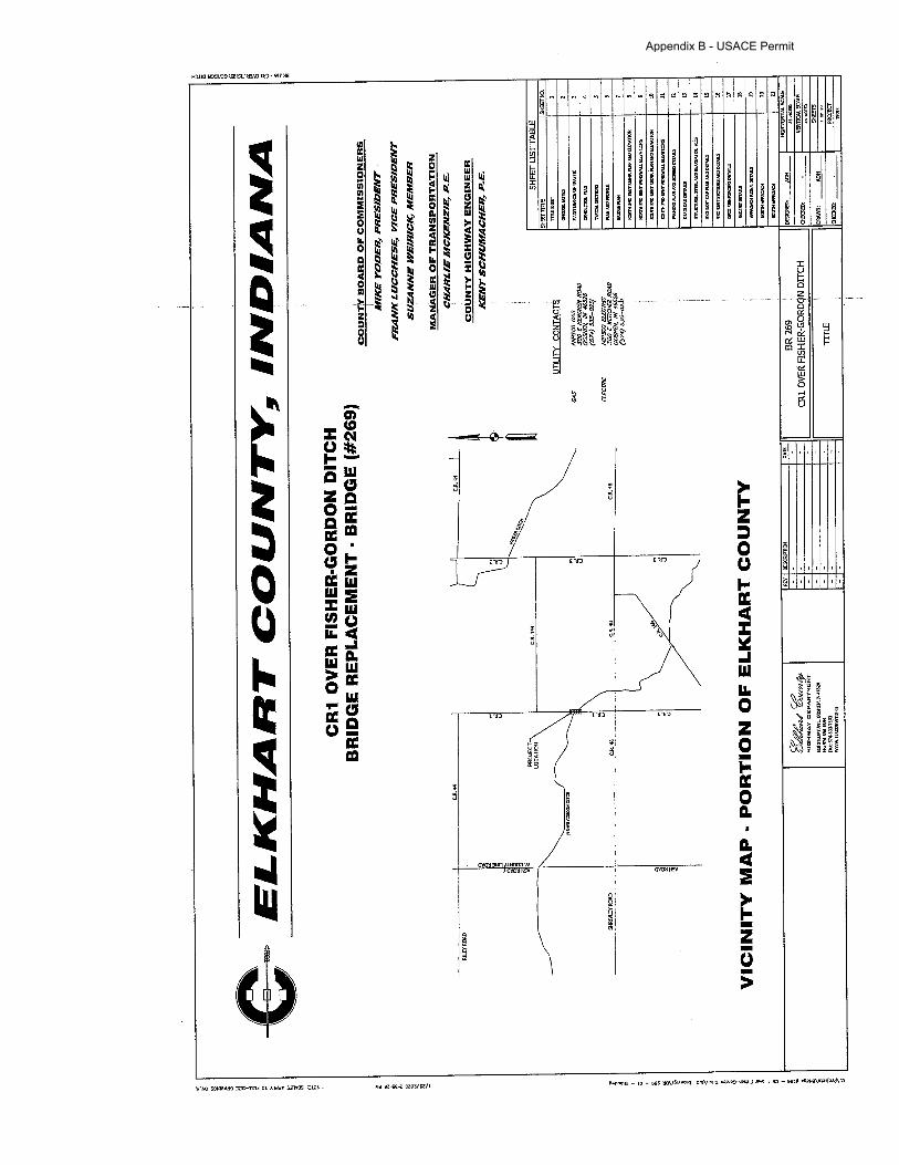
Appendix B - USACE Permit
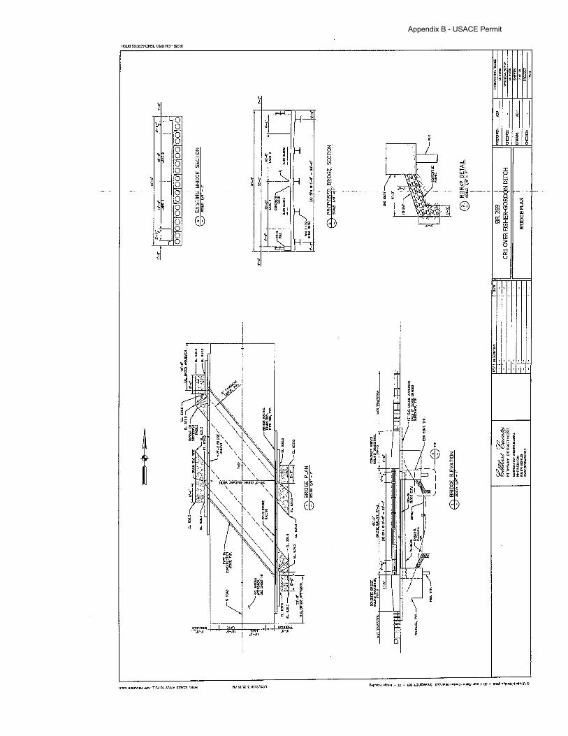
Appendix B - USACE Permit
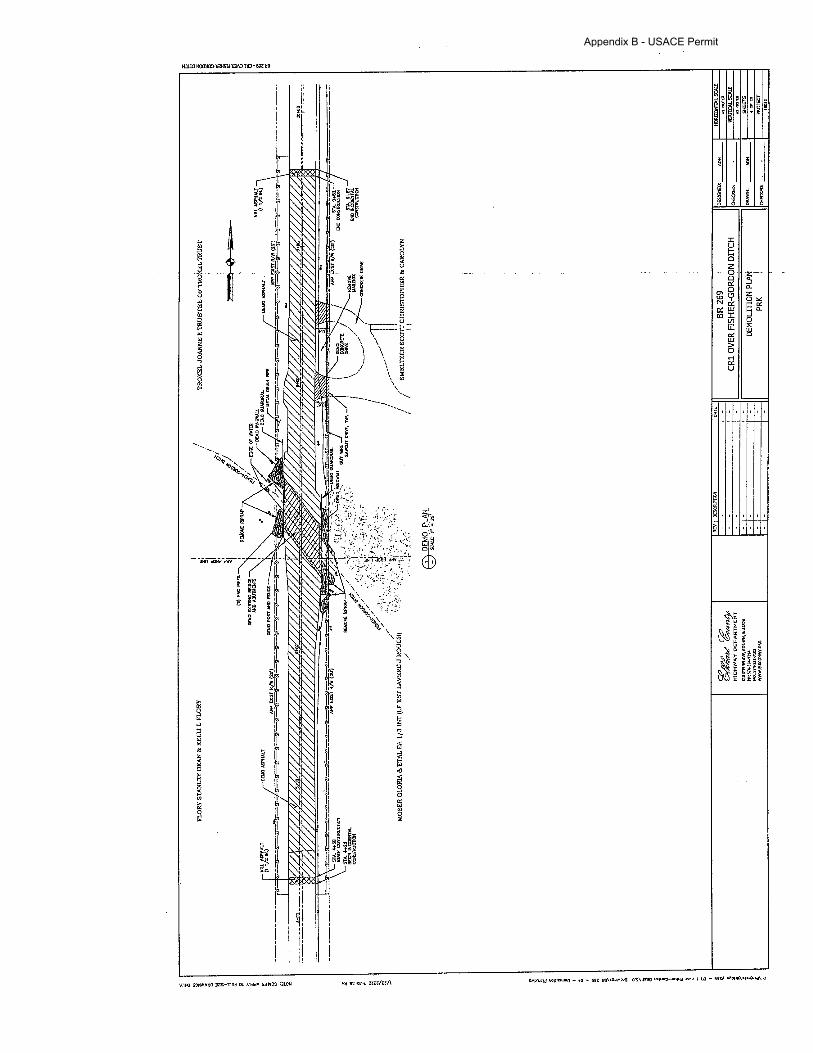
Appendix B - USACE Permit
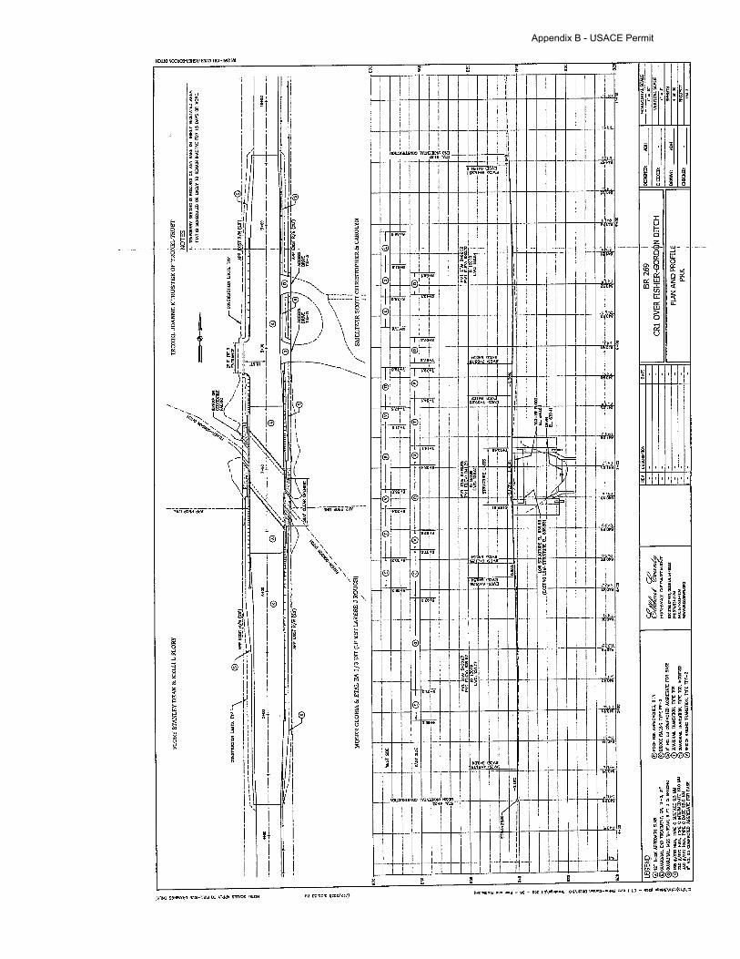
Appendix B - USACE Permit
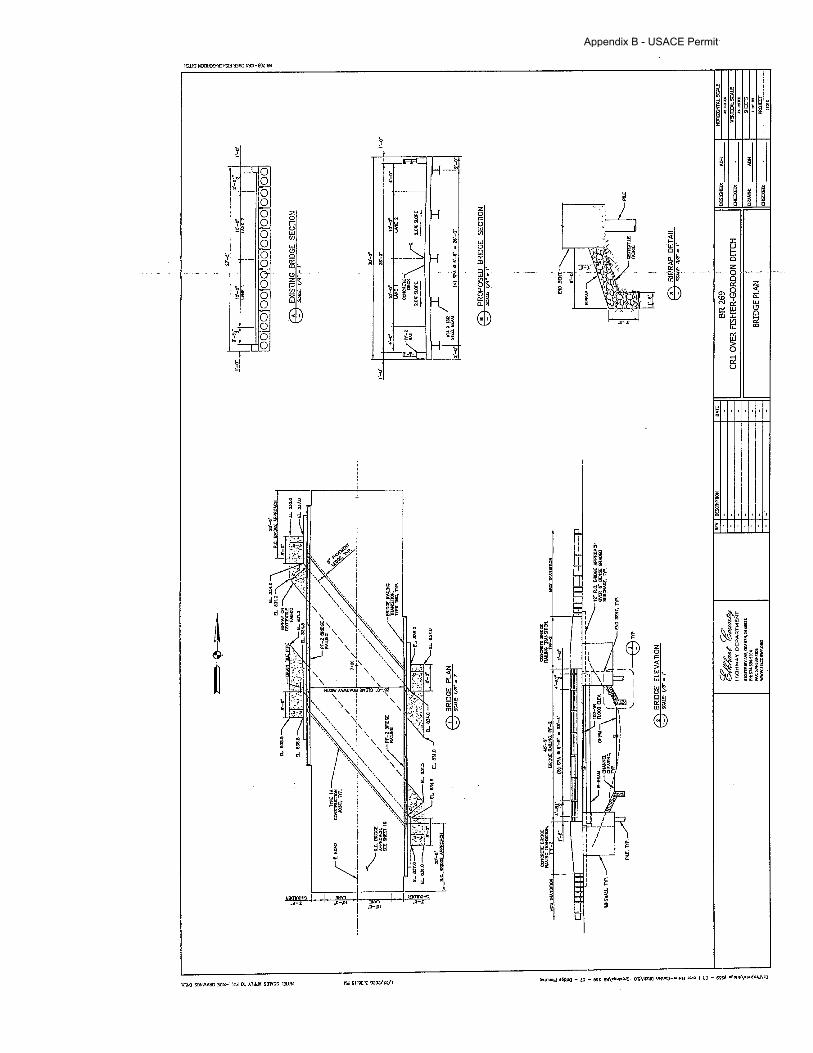
Appendix B - USACE Permit
-4-
GENERAL CONDITIONS:
1. Navigation: (a) No activity authorized by the RGP may
cause more than a minimal adverse effect on navigation.
(b) Any safety lights and signals prescribed by the U.S.
Coast Guard, through regulations or otherwise, must be
installed and maintained at the permittee’s expense on
authorized facilities in navigable waters of the United States.
(c) The permittee understands and agrees that, if future
operations by the United States require the removal,
relocation, or other alteration, of the structure or work herein
authorized, or if, in the opinion of the Secretary of the Army,
or his authorized representative, said structure or work shall
cause unreasonable obstruction to the free navigation of the
navigable waters, the permittee will be required, upon due
notice from the Corps of Engineers, to remove, relocate, or
alter the structural work or obstructions caused thereby,
without expense to the United States. No claim shall be
made against the United States on account of any such
removal or alteration.
2. Aquatic Life: No activity may substantially disrupt the
necessary life cycle movements of those species of aquatic
life indigenous to the waterbody, including those species that
normally migrate through the area, unless the activity’s
primary purpose is to impound water. All permanent and
temporary crossings of waterbodies shall be suitably
culverted, bridged, or otherwise designed and constructed to
maintain low flows to sustain the movement of those aquatic
species.
3. Spawning Areas: Activities in spawning areas during
spawning seasons must be avoided to the maximum extent
practicable. Activities that result in the physical destruction
(e.g., through excavation, fill, or downstream smothering by
substantial turbidity) of an important spawning area are not
authorized.
4. Shellfish Beds: No activity may occur in areas of
concentrated shellfish populations, unless the activity is
directly related to an authorized shellfish harvesting activity,
or is a shellfish seeding or habitat restoration activity.
5. Suitable Materials: No activity, including structures and
work in waters of the U.S. or discharges of dredged or fill
material, may use unsuitable material, including auto bodies,
tires, garbage or debris, scrap lumber, metal refuse, roofing
materials, asphalt or other bituminous material, broken
concrete containing asphalt, or any material which would
cause water pollution as defined by the Indiana Department
of Environmental Management.
6. Water Supply Intakes: The permittee shall not perform
any work under the RGP where the discharge of dredged
and/or fill material will occur in the proximity of a public water
supply intake except where the activity is for the repair or
improvement of the public water supply intake structures or
adjacent bank stabilization.
7. Safety of Impoundment Structures: To ensure that all
impoundment structures are safely designed, the District
Engineer may require non-federal applicants to demonstrate
that the structures comply with established state dam safety
criteria or have been designed by qualified persons, i.e., a
licensed engineer. The District Engineer may also require
documentation that the design has been independently
reviewed by similarly qualified persons, and appropriate
modifications made to ensure safety.
8. Adverse Effects from Impoundments: If the activity creates
an impoundment of water, adverse effects to the aquatic
system due to accelerating the passage of water, and/or
restricting its flow must be minimized to the maximum extent
practicable.
9. Management of Water Flows: To the maximum extent
practicable, the pre-construction course, condition, capacity,
and location of open waters must be maintained for each
activity, including stream channelization and storm water
management activities, except as provided below. The
activity must be constructed to withstand expected high
flows. The activity must not restrict or impede the passage
of normal or high flows, unless the primary purpose of the
activity is to impound water or manage high flows. The
activity may alter the pre-construction course, condition,
capacity, and location of open waters if it benefits the aquatic
environment (e.g., stream restoration or relocation activities).
10. Fills Within 100-Year Floodplains: The activity must
comply with applicable FEMA-approved state or local
floodplain management requirements.
11. Equipment: All construction equipment shall be refueled
and maintained on an upland site away from existing
streams, drainage ways and wetland areas. Heavy
equipment working in wetlands must be placed on mats, or
other measures taken to minimize soil disturbance.
12. Soil Erosion and Sedimentation Controls: Appropriate
soil erosion and sediment controls must be used and
maintained in effective operating condition during
construction, and all exposed soil and other fills, as well as
any work below the ordinary high water mark, must be
permanently stabilized at the earliest practicable date.
Appendix B - USACE Permit
-5-
Permittees are encouraged to perform work within waters of
the United States during periods of low-flow or no-flow.
13. Removal of Temporary Fills: Temporary fills must be
removed in their entirety and the affected areas returned to
pre-construction conditions (i.e., elevation, contours, re-
establishment of vegetation, etc.).
14. Proper Maintenance: Any authorized structure or fill shall
be properly maintained, including maintenance to ensure
public safety and compliance with applicable general
conditions, as well as any activity-specific conditions added
by the District Engineer to an RGP authorization.
15. Single and Complete Project: The activity must be a
single and complete project. The same RGP cannot be used
more than once for the same single and complete project.
16. Endangered Species: (a) No activity is authorized under
the RGP which is likely to directly or indirectly jeopardize the
continued existence of a threatened or endangered species
or a species proposed for such designation, as identified
under the Federal Endangered Species Act, or which will
directly or indirectly destroy or adversely modify the critical
habitat of such species. No activity is authorized under the
RGP which “may affect” a listed species or critical habitat,
unless Section 7 consultation addressing the effects of the
proposed activity has been completed.
(b) Federal agencies should follow their own procedures
for complying with the requirements of the ESA. Federal
permittees must provide the District Engineer with the
appropriate documentation to demonstrate compliance with
those requirements. The District Engineer will review the
documentation and determine whether it is sufficient to
address ESA compliance for the RGP activity, or whether
additional ESA consultation is necessary.
(c) Non-federal permittees must submit a pre-construction
notification to the District Engineer if any listed species or
designated critical habitat might be affected or is in the
vicinity of the project, and shall not begin work on the activity
until notified by the District Engineer that the requirements of
the ESA have been satisfied and that the activity is
authorized. For activities that might affect federally-listed
endangered or threatened species or designated critical
habitat, the pre-construction notification must include the
name(s) of the endangered or threatened species that might
be affected by the proposed work. The District Engineer will
determine whether the proposed activity “may affect” or will
have “no effect” to listed species and designated critical
habitat and will notify the non-federal applicant of the Corps
determination within 45-days of receipt of a complete pre-
construction notification. In cases where the non-federal
applicant has identified listed species or critical habitat that
might be affected or is in the vicinity of the project, and has
so notified the Corps, the applicant shall not begin work until
the Corps has provided notification the proposed activities
will have “no effect” on listed species or critical habitat, or
until Section 7 consultation has been completed. If the non-
federal applicant has not heard back from the Corps within
45 days, the applicant must still wait for notification from the
Corps.
(d) As a result of formal or informal consultation with the
USFWS the District Engineer may add species-specific
regional endangered species conditions to the RGP.
(e) Authorization of an activity under the RGP does not
authorize the "take" of a threatened or endangered species
as defined under the ESA. In the absence of separate
authorization (e.g., an ESA Section 10 Permit, a Biological
Opinion with "incidental take" provisions, etc.) from the
USFWS Service, the ESA prohibits any person subject to the
jurisdiction of the United States to take listed species, where
“take” means to harass, harm, pursue, hunt, shoot, wound,
kill, trap, capture, or collect, or to attempt to engage in any
such conduct. The word “harm” in the definition of “take”
means an act which actually kills or injures wildlife. Such an
act may include significant habitat modification or
degradation where it actually kills or injures wildlife by
significantly impairing essential behavioral patterns,
including breeding, feeding or sheltering.
(f) Information on the location of threatened and
endangered species and their critical habitat can be obtained
directly from the offices of the USFWS or their webpages on
the Internet.
17. Migratory Birds and Bald and Golden Eagles: The
permittee is responsible for obtaining any “take” permits
required under the USFWS’ regulations governing
compliance with the Migratory Bird Treaty Act or the Bald
and Golden Eagle Protection Act. The permittee should
contact the appropriate local office of the USFWS to
determine if such “take” permits are required for a particular
activity.
18. Migratory Bird Breeding Areas: Activities in waters of the
United States that serve as breeding areas for migratory
birds must be avoided to the maximum extent practicable.
19. Historic Properties: The permittee shall not perform any
activity under the RGP which may affect historic properties
listed, or eligible for listing, in the National Register of
Historic Places until the District Engineer has complied with
the provisions of 33 CFR Part 325, Appendix C. The
permittee must notify the District Engineer if the activity
authorized by the RGP may affect any historic properties
listed, determined to be eligible or which the permittee has
reason to believe may be eligible for listing on the National
Appendix B - USACE Permit
-6-
Register of Historic Places, and shall not begin construction
until notified by the District Engineer that the requirements of
the National Historic Preservation Act have been satisfied
and that the activity is authorized. Information on the
location and existence of historic resources can be obtained
from the IDNR, Division of Historic Preservation and
Archaeology.
If the permittee discovers any previously unknown historic or
archaeological remains while accomplishing the activity
authorized by the RGP, work must be immediately stopped
and the Corps immediately notified. The District will initiate
the Federal, tribal and State coordination required to
determine if the remains warrant a recovery effort or if the
site is eligible for listing in the National Register of Historic
Places.
20. Discovery of Previously Unknown Remains and Artifacts:
If you discover any previously unknown historic, cultural, or
archeological remains and artifacts while accomplishing the
activity authorized by this permit, you must immediately
notify the District Engineer of what you have found, and to
the maximum extent practicable, avoid construction activities
that may affect the remains and artifacts until the required
coordination has been completed. The District Engineer will
initiate the federal, Tribal, and state coordination required to
determine if the items or remains warrant a recovery effort or
if the site is eligible for listing in the National Register of
Historic Places.
21. Mitigation: The permittee shall provide a mitigation
proposal that meets the standards set forth in Title 33 CFR
Parts 325 and 332, Compensatory Mitigation for Losses of
Aquatic Resources, as published April 10, 2008 in the
Federal Register, Vol. 73, No. 70, and any District guidance
for any activity where the adverse impact (i.e., loss of
waters) on special aquatic sites (including wetlands) exceeds
0.10 acre (4,356 sq. ft.) or is determined to be more than
minimal impact. The permittee shall also provide a mitigation
proposal that meet s the standards set forth in Title 33 CFR
Parts 325 and 332, Compensatory Mitigation for Losses of
Aquatic Resources, as published April 10, 2008 in the
Federal Register, Vol. 73, No. 70, and any District guidance
for any channelization, encapsulation, or relocation of
greater than 300 linear feet of stream, unless there is no net
loss of function, in which case the District Engineer will
determine, on a case-by-case basis, if mitigation is required.
22. Water Quality: If an individual 401 WQC is required, the
permittee must provide a copy of it to the Corps. The
permittee must comply with any case specific special
conditions added by the Corps or by the Section 401 WQC.
The conditions imposed in the Section 401 WQC are also
conditions of this RGP.
23. Minimization/Avoidance: Discharges of dredged or fill
material into waters of the U.S. must be minimized or
avoided to the maximum extent practicable at the project site
(i.e. on-site). In determining the minimal impact threshold,
the Districts will consider the direct and secondary impacts of
the fill or work and any mitigation measures.
24. Access: Representatives from the Corps of Engineers
and/or IDEM may inspect any authorized activity or
mitigation site at any time deemed necessary to ensure
compliance with the terms and conditions of the RGP,
Section 401 WQC, and applicable laws.
25. Construction Period: If construction of the project has
commenced, or is under contract to commence prior to the
expiration date, the applicant must complete the project
within one (1) year of the RGP expiration date. If you find
you need more time to complete the authorized activity,
submit your request for a time extension to this office for
consideration at least 3 months prior to the expiration date.
26. Reporting: The permittee, after completion of work under
the RGP, shall submit a signed certification letter regarding
the completed work and required mitigation, if applicable.
The certification letter will include a statement that the work
was done in accordance with the RGP authorization
including compliance with all general and special conditions
and completion of mitigation work.
27. Activities Affecting Structures or Work Built by the United
States: An activity that is located on an existing locally or
federally maintained U.S. Army Corps of Engineers project
requires separate approval from the District under 33 USC
408.
Appendix B - USACE Permit
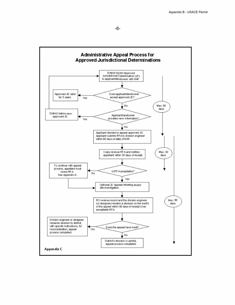
-6-
Appendix B - USACE Permit
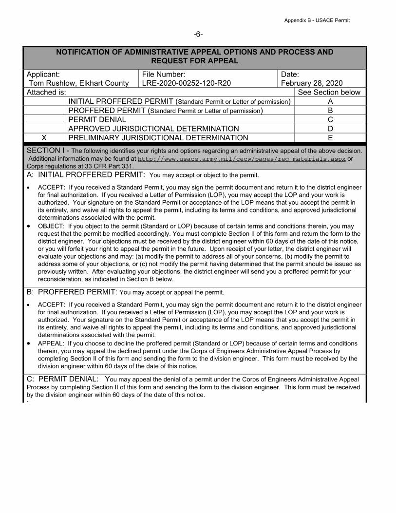
-6-
NOTIFICATION OF ADMINISTRATIVE APPEAL OPTIONS AND PROCESS AND
REQUEST FOR APPEAL
Applicant:
Tom Rushlow, Elkhart County
File Number:
LRE-2020-00252-120-R20
Date:
February 28, 2020
Attached is: See Section below
INITIAL PROFFERED PERMIT (Standard Permit or Letter of permission) A
PROFFERED PERMIT (Standard Permit or Letter of permission) B
PERMIT DENIAL C
APPROVED JURISDICTIONAL DETERMINATION D
X PRELIMINARY JURISDICTIONAL DETERMINATION E
SECTION I - The following identifies your rights and options regarding an administrative appeal of the above decision.
Additional information may be found at http://www.usace.army.mil/cecw/pages/reg_materials.aspx or
Corps regulations at 33 CFR Part 331.
A: INITIAL PROFFERED PERMIT: You may accept or object to the permit.
ACCEPT: If you received a Standard Permit, you may sign the permit document and return it to the district engineer
for final authorization. If you received a Letter of Permission (LOP), you may accept the LOP and your work is
authorized. Your signature on the Standard Permit or acceptance of the LOP means that you accept the permit in
its entirety, and waive all rights to appeal the permit, including its terms and conditions, and approved jurisdictional
determinations associated with the permit.
OBJECT: If you object to the permit (Standard or LOP) because of certain terms and conditions therein, you may
request that the permit be modified accordingly. You must complete Section II of this form and return the form to the
district engineer. Your objections must be received by the district engineer within 60 days of the date of this notice,
or you will forfeit your right to appeal the permit in the future. Upon receipt of your letter, the district engineer will
evaluate your objections and may: (a) modify the permit to address all of your concerns, (b) modify the permit to
address some of your objections, or (c) not modify the permit having determined that the permit should be issued as
previously written. After evaluating your objections, the district engineer will send you a proffered permit for your
reconsideration, as indicated in Section B below.
B: PROFFERED PERMIT: You may accept or appeal the permit.
ACCEPT: If you received a Standard Permit, you may sign the permit document and return it to the district engineer
for final authorization. If you received a Letter of Permission (LOP), you may accept the LOP and your work is
authorized. Your signature on the Standard Permit or acceptance of the LOP means that you accept the permit in
its entirety, and waive all rights to appeal the permit, including its terms and conditions, and approved jurisdictional
determinations associated with the permit.
APPEAL: If you choose to decline the proffered permit (Standard or LOP) because of certain terms and conditions
therein, you may appeal the declined permit under the Corps of Engineers Administrative Appeal Process by
completing Section II of this form and sending the form to the division engineer. This form must be received by the
division engineer within 60 days of the date of this notice.
C: PERMIT DENIAL: You may appeal the denial of a permit under the Corps of Engineers Administrative Appeal
Process by completing Section II of this form and sending the form to the division engineer. This form must be received
by the division engineer within 60 days of the date of this notice. .
Appendix B - USACE Permit

-6-
D: APPROVED JURISDICTIONAL DETERMINATION: You may accept or appeal the approved JD or
provide new information.
ACCEPT: You do not need to notify the Corps to accept an approved JD. Failure to notify the Corps within 60 days
of the date of this notice, means that you accept the approved JD in its entirety, and waive all rights to appeal the
approved JD.
APPEAL: If you disagree with the approved JD, you may appeal the approved JD under the Corps of Engineers
Administrative Appeal Process by completing Section II of this form and sending the form to the division engineer.
This form must be received by the division engineer within 60 days of the date of this notice.
E: PRELIMINARY JURISDICTIONAL DETERMINATION: You do not need to respond to the Corps
regarding the preliminary JD. The Preliminary JD is not appealable. If you wish, you may request an approved JD
(which may be appealed), by contacting the Corps district for further instruction. Also you may provide new information
for further consideration by the Corps to reevaluate the JD.
SECTION II - REQUEST FOR APPEAL or OBJECTIONS TO AN INITIAL PROFFERED PERMIT
REASONS FOR APPEAL OR OBJECTIONS: (Describe your reasons for appealing the decision or your
objections to an initial proffered permit in clear concise statements. You may attach additional information to this form to
clarify where your reasons or objections are addressed in the administrative record.)
ADDITIONAL INFORMATION: The appeal is limited to a review of the administrative record, the Corps memorandum for
the record of the appeal conference or meeting, and any supplemental information that the review officer has
determined is needed to clarify the administrative record. Neither the appellant nor the Corps may add new information
or analyses to the record. However, you may provide additional information to clarify the location of information that is
already in the administrative record.
POINT OF CONTACT FOR QUESTIONS OR INFORMATION:
If you have questions regarding this decision and/or the
appeal process you may contact:
Ryan Cassidy
U.S. Army Corps of Engineers
Michiana Branch
2422 Viridian Drive Suite # 200
South Bend, IN 46628-3489
(574) 232-1952 Ext. 21964
If you only have questions regarding the appeal process
you may also contact:
Jacob Siegrist
Regulatory Appeals Review Officer
US Army Corps of Engineers
Great Lakes & Ohio River Division
550 Main Street, Room 10-714
Cincinnati, Ohio 45202-3222
Tel. (513) 684-2699 Fax (513) 684-2460
RIGHT OF ENTRY: Your signature below grants the right of entry to Corps of Engineers personnel, and any
government consultants, to conduct investigations of the project site during the course of the appeal process. You will
be provided a 15 day notice of any site investigation, and will have the opportunity to participate in all site investigations.
______________________________________
Signature of appellant or agent.
Date: Telephone number:
Appendix B - USACE Permit
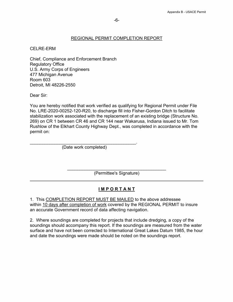
-6-
REGIONAL PERMIT COMPLETION REPORT
CELRE-ERM
Chief, Compliance and Enforcement Branch
Regulatory Office
U.S. Army Corps of Engineers
477 Michigan Avenue
Room 603
Detroit, MI 48226-2550
Dear Sir:
You are hereby notified that work verified as qualifying for Regional Permit under File
No. LRE-2020-00252-120-R20, to discharge fill into Fisher-Gordon Ditch to facilitate
stabilization work associated with the replacement of an existing bridge (Structure No.
269) on CR 1 between CR 46 and CR 144 near Wakarusa, Indiana issued to Mr. Tom
Rushlow of the Elkhart County Highway Dept., was completed in accordance with the
permit on:
___________________________________________.
(Date work completed)
________________________________________
(Permittee's Signature)
I M P O R T A N T
1. This COMPLETION REPORT MUST BE MAILED to the above addressee
within 10 days after completion of work covered by the REGIONAL PERMIT to insure
an accurate Government record of data affecting navigation.
2. Where soundings are completed for projects that include dredging, a copy of the
soundings should accompany this report. If the soundings are measured from the water
surface and have not been corrected to International Great Lakes Datum 1985, the hour
and date the soundings were made should be noted on the soundings report.
Appendix B - USACE Permit
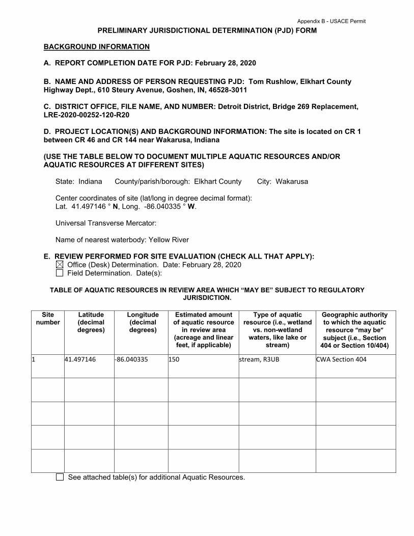
PRELIMINARY JURISDICTIONAL DETERMINATION (PJD) FORM
BACKGROUND INFORMATION
A. REPORT COMPLETION DATE FOR PJD: February 28, 2020
B. NAME AND ADDRESS OF PERSON REQUESTING PJD: Tom Rushlow, Elkhart County
Highway Dept., 610 Steury Avenue, Goshen, IN, 46528-3011
C. DISTRICT OFFICE, FILE NAME, AND NUMBER: Detroit District, Bridge 269 Replacement,
LRE-2020-00252-120-R20
D. PROJECT LOCATION(S) AND BACKGROUND INFORMATION: The site is located on CR 1
between CR 46 and CR 144 near Wakarusa, Indiana
(USE THE TABLE BELOW TO DOCUMENT MULTIPLE AQUATIC RESOURCES AND/OR
AQUATIC RESOURCES AT DIFFERENT SITES)
State: Indiana County/parish/borough: Elkhart County City: Wakarusa
Center coordinates of site (lat/long in degree decimal format):
Lat. 41.497146 ° N, Long. -86.040335 ° W.
Universal Transverse Mercator:
Name of nearest waterbody: Yellow River
E. REVIEW PERFORMED FOR SITE EVALUATION (CHECK ALL THAT APPLY):
Office (Desk) Determination. Date: February 28, 2020
Field Determination. Date(s):
TABLE OF AQUATIC RESOURCES IN REVIEW AREA WHICH “MAY BE” SUBJECT TO REGULATORY
JURISDICTION.
Site
number
Latitude
(decimal
degrees)
Longitude
(decimal
degrees)
Estimated amount
of aquatic resource
in review area
(acreage and linear
feet, if applicable)
Type of aquatic
resource (i.e., wetland
vs. non-wetland
waters, like lake or
stream)
Geographic authority
to which the aquatic
resource “may be”
subject (i.e., Section
404 or Section 10/404)
1 41.497146 ‐86.040335 150 stream, R3UB CWA Section 404
See attached table(s) for additional Aquatic Resources.
Appendix B - USACE Permit
1) The Corps of Engineers believes that there may be jurisdictional aquatic resources in the review
area, and the requestor of this PJD is hereby advised of his or her option to request and obtain
an approved JD (AJD) for that review area based on an informed decision after having
discussed the various types of JDs and their characteristics and circumstances when they may
be appropriate.
2) In any circumstance where a permit applicant obtains an individual permit, or a Nationwide
General Permit (NWP) or other general permit verification requiring “pre-construction notification”
(PCN), or requests verification for a non-reporting NWP or other general permit, and the permit
applicant has not requested an AJD for the activity, the permit applicant is hereby made aware
that: (1) the permit applicant has elected to seek a permit authorization based on a PJD, which
does not make an official determination of jurisdictional aquatic resources; (2) the applicant has
the option to request an AJD before accepting the terms and conditions of the permit
authorization, and that basing a permit authorization on an AJD could possibly result in less
compensatory mitigation being required or different special conditions; (3) the applicant has the
right to request an individual permit rather than accepting the terms and conditions of the NWP or
other general permit authorization; (4) the applicant can accept a permit authorization and
thereby agree to comply with all the terms and conditions of that permit, including whatever
mitigation requirements the Corps has determined to be necessary; (5) undertaking any activity
in reliance upon the subject permit authorization without requesting an AJD constitutes the
applicant’s acceptance of the use of the PJD; (6) accepting a permit authorization (e.g., signing a
proffered individual permit) or undertaking any activity in reliance on any form of Corps permit
authorization based on a PJD constitutes agreement that all aquatic resources in the review area
affected in any way by that activity will be treated as jurisdictional, and waives any challenge to
such jurisdiction in any administrative or judicial compliance or enforcement action, or in any
administrative appeal or in any Federal court; and (7) whether the applicant elects to use either
an AJD or a PJD, the JD will be processed as soon as practicable. Further, an AJD, a proffered
individual permit (and all terms and conditions contained therein), or individual permit denial can
be administratively appealed pursuant to 33 C.F.R. Part 331. If, during an administrative appeal,
it becomes appropriate to make an official determination whether geographic jurisdiction exists
over aquatic resources in the review area, or to provide an official delineation of jurisdictional
aquatic resources in the review area, the Corps will provide an AJD to accomplish that result, as
soon as is practicable. This PJD finds that there “may be” waters of the U.S. and/or that there
“may be” navigable waters of the U.S. on the subject review area, and identifies all aquatic
features in the review area that could be affected by the proposed activity, based on the following
information:
Appendix B - USACE Permit
SUPPORTING DATA. Data reviewed for PJD (check all that apply)
Checked items should be included in subject file. Appropriately reference sources below where
indicated for all checked items:
Maps, plans, plots or plat submitted by or on behalf of the PJD requestor:
Map: Provided by Hagel Engineering, Inc.
Data sheets prepared/submitted by or on behalf of the PJD requestor.
Office concurs with data sheets/delineation report.
Office does not concur with data sheets/delineation report. Rationale: .
Data sheets prepared by the Corps: .
Corps navigable waters’ study: .
U.S. Geological Survey Hydrologic Atlas: 07120001 , Upper Mississippi Region, Upper Illinois,
Kankakee.
USGS NHD data.
USGS 8 and 12 digit HUC maps.
U.S. Geological Survey map(s). Cite scale & quad name: 1:24,000, Nappanee West .
USDA Natural Resources Conservation Service Soil Survey. Citation: NRCS Web Soil Survey.
National wetlands inventory map(s). Cite name: USFWS online wetland mapper.
State/Local wetland inventory map(s): .
FEMA/FIRM maps: .
100-year Floodplain Elevation is: (National Geodetic Vertical Datum of 1929)
Photographs: Aerial (Name & Date): .
Or Other (Name & Date): .
Previous determination(s). File no. and date of response letter: .
Other information (please specify): .
IMPORTANT NOTE: The information recorded on this form has not necessarily been verified
by the Corps and should not be relied upon for later jurisdictional determinations.
___________________________ ________________________________
Signature and date of Signature and date of
Regulatory staff member person requesting PJD
completing PJD (REQUIRED, unless obtaining
the signature is impracticable)1
1 Districts may establish timeframes for requestor to return signed PJD forms. If the requestor does not respond within the
established time frame, the district may presume concurrence and no additional follow up is necessary prior to finalizing an
action.
Digitally signed by CASSIDY.RYAN.DAVID.1139376133
Date: 2020.02.28 11:42:49 -05'00'
Appendix B - USACE Permit
![B71full[2].pdf - LA County Department of Public Health](https://cdn.vdocuments.mx/doc/165x107/633bcfc3a7695ed95e02a16f/b71full2pdf-la-county-department-of-public-health.jpg)


