file no. 3900:440-2 merigauge model 3900 operating ... · file no. 3900:440-2 merigauge model 3900...
TRANSCRIPT
File No. 3900:440-2
MERIGAUGE MODEL 3900OPERATING INSTRUCTIONS
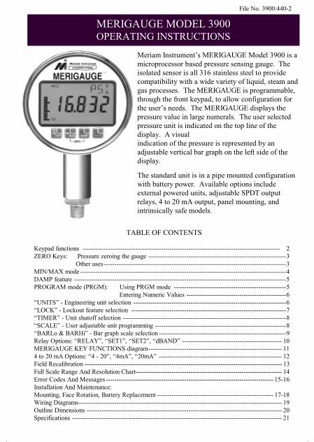
Meriam Instrument’s MERIGAUGE Model 3900 is amicroprocessor based pressure sensing gauge. Theisolated sensor is all 316 stainless steel to providecompatibility with a wide variety of liquid, steam andgas processes. The MERIGAUGE is programmable,through the front keypad, to allow configuration forthe user’s needs. The MERIGAUGE displays thepressure value in large numerals. The user selectedpressure unit is indicated on the top line of thedisplay. A visualindication of the pressure is represented by anadjustable vertical bar graph on the left side of thedisplay.
The standard unit is in a pipe mounted configurationwith battery power. Available options includeexternal powered units, adjustable SPDT outputrelays, 4 to 20 mA output, panel mounting, andintrinsically safe models.
TABLE OF CONTENTS
Keypad functions --------------------------------------------------------------------------------------------- 2ZERO Keys: Pressure zeroing the gauge -----------------------------------------------------------------3 Other uses--------------------------------------------------------------------------------------3MIN/MAX mode -------------------------------------------------------------------------------------------------4DAMP feature ----------------------------------------------------------------------------------------------------5PROGRAM mode (PRGM): Using PRGM mode -----------------------------------------------------5 Entering Numeric Values -----------------------------------------------6“UNITS” - Engineering unit selection ------------------------------------------------------------------------6“LOCK” - Lockout feature selection -------------------------------------------------------------------------7“TIMER” - Unit shutoff selection -----------------------------------------------------------------------------8“SCALE” - User adjustable unit programming --------------------------------------------------------------8“BARLo & BARHi” - Bar graph scale selection ------------------------------------------------------------9Relay Options: “RELAY”, “SET1”, “SET2”, “dBAND” ----------------------------------------------- 10MERIGAUGE KEY FUNCTIONS diagram--------------------------------------------------------------- 114 to 20 mA Options: “4 - 20”, “4mA”, “20mA” ---------------------------------------------------------- 12Field Recalibration --------------------------------------------------------------------------------------------- 13Full Scale Range And Resolution Chart--------------------------------------------------------------------- 14Error Codes And Messages ------------------------------------------------------------------------------- 15-16Installation And Maintenance:Mounting, Face Rotation, Battery Replacement ------------------------------------------------------- 17-18Wiring Diagrams------------------------------------------------------------------------------------------------ 19Outline Dimensions -------------------------------------------------------------------------------------------- 20Specifications --------------------------------------------------------------------------------------------------- 21
3900440plus.pub page 1
Friday, June 15, 2001 11:15

2
KEYPAD FUNCTIONS
ON/OFF & BACKSPACE KEYTurns the gauge on into the Measure Mode and then turns the unit offfrom the Measure Mode. Also serves as a backspace key whenediting in the Program Mode. The Backspace function takes the userout of a programmable register without changing the previous setting.
Pressing this key repeatedly will return the user to the Measure Mode and thenshut off the gauge. When editing a numeric value, each press of the key willbackup one digit, until finally exiting the register. Note, this key will notfunction as an OFF key if any of the optional outputs are enabled in the outputregisters. Instead it will reboot the gauge if pressed.
MIN/MAX & UP ARROW KEYIn the Measure Mode, activates the Min/Max function of the gauge.When either the Min or Max is activated, the corresponding value isdisplayed on the upper right of the display. Min/Max values on the
display are updated per the damp rate setting (see page 5). Pressing the Min/Maxkey once from measure mode will toggle between the MAX, MIN and MeasureMode. The Min/Max value is reset by using the zero keys (see page 3). When inProgram Mode, pressing the Up arrow key scrolls up through the availableprogram menu. Once a register is opened, this key allows editing by scrolling upthrough the options in the register. When editing numeric values, pressing theUp arrow key scrolls up from 0 - 9.
DAMP & DOWN ARROW KEYIn the Measure Mode, opens the DAMP feature for editing. Whenopened the current value flashes in the upper right of the display.Scrolling through the available damp rate choices is done by pressing the
Up arrow or the Down arrow keys. A new damp rate is entered by pressingthePRGM key, or the process can be aborted by pressing the backspace key.When in Program Mode, pressing the Down arrow key scrolls through theprogram menu. Once a register is opened, the key allows editing by scrollingdown through the options in the register. When editing numeric values, pressing
theDown arrow key scrolls down from 9- 0.
PRGM & ENTER KEYPuts the gauge into Program Mode from the Measure Mode. When in
the Program Mode, pressing this key opens the program menu selected forediting. After editing the available options or numeric value, pressing thePRGM key enters the new selection into the gauge’s non-volatile memory. Thiskey also acts as a Forward space key when editing user defined numeric values
M IN/M AX
ON/ OFF
DAM P
PRGM
3900440plus.pub page 2
Friday, June 15, 2001 11:15

3
Note: All Models and rangescan be zeroed only if the newZero is within ± 10% of the fullscale pressure. If outside thislimit an “E002” error code
ZERO KEYS: PRESSURE ZEROING THE GAUGE (OUTPUTS DISABLED)
Prior to putting into service, the MERIGAUGE should be zeroed for pressure.This will eliminate any zero drift that has occurred since manufacture. To zerothe gauge, turn the unit on and then, while in the measure mode, simultaneouslypress theUp arrow and the Down arrow keys. This should be done with no pressureapplied and with the MERIGAUGE in the position it will be installed. Periodicre-zeroing may be needed to maintain the MERIGAUGE in peak operating
ZERO
MIN/MAXOOFF
DAMPOOFF
ZERO KEYS: OTHER USES
The zero keys are also used for the following:
1.) Resetting the MIN and MAX to current pressure (page 4).2.) Resetting Damp rate to factory default setting (OFF, page 5)3.) Resetting any Program menu option to factory default setting.4.) Opening the calibration pressure registers (page 13)
ZERO KEYS: PRESSURE ZEROING THE GAUGE (OUTPUTS ENABLED)
The output options are calculated based on the displayed pressure. Since re-zeroing the gauge may change the displayed pressure, the outputs may changeaccordingly. For safety purposes, if the outputs are enabled, an extra step is re-quired to warn the operator and confirm the desired action. When zeroing withan output enabled, the display will begin countdown from “5” to “0”. This initialcountdown is a warning to the operator that an output is enabled and that zeroingthe gauge may change the output. If you do not procede, the gauge will countdown and return to measure mode. If you choose to go ahead and rezero, pressthe PRGM key before the countdown expires. Once this is done, the displaywill again count down from “5” to “0”. Zeroing the gauge (simultaneously pressthe Up arrow and theDown arrow keys) during this second countdown will cause the gauge to zero.
3900440plus.pub page 3
Friday, June 15, 2001 11:15
4
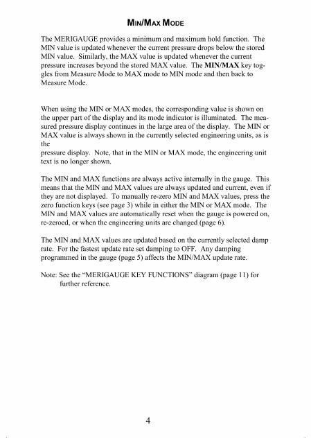
MIN/MAX MODE
The MERIGAUGE provides a minimum and maximum hold function. TheMIN value is updated whenever the current pressure drops below the storedMIN value. Similarly, the MAX value is updated whenever the currentpressure increases beyond the stored MAX value. The MIN/MAX key tog-gles from Measure Mode to MAX mode to MIN mode and then back toMeasure Mode.
When using the MIN or MAX modes, the corresponding value is shown onthe upper part of the display and its mode indicator is illuminated. The mea-sured pressure display continues in the large area of the display. The MIN orMAX value is always shown in the currently selected engineering units, as isthepressure display. Note, that in the MIN or MAX mode, the engineering unittext is no longer shown.
The MIN and MAX functions are always active internally in the gauge. Thismeans that the MIN and MAX values are always updated and current, even ifthey are not displayed. To manually re-zero MIN and MAX values, press thezero function keys (see page 3) while in either the MIN or MAX mode. TheMIN and MAX values are automatically reset when the gauge is powered on,re-zeroed, or when the engineering units are changed (page 6).
The MIN and MAX values are updated based on the currently selected damprate. For the fastest update rate set damping to OFF. Any dampingprogrammed in the gauge (page 5) affects the MIN/MAX update rate.
Note: See the “MERIGAUGE KEY FUNCTIONS” diagram (page 11) for further reference.
3900440plus.pub page 4
Friday, June 15, 2001 11:15
5
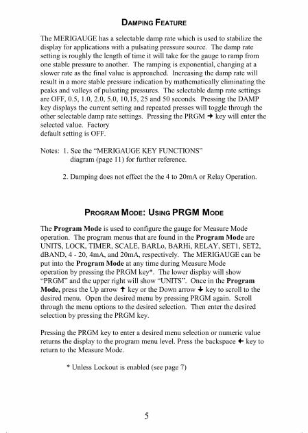
DAMPING FEATURE
The MERIGAUGE has a selectable damp rate which is used to stabilize thedisplay for applications with a pulsating pressure source. The damp ratesetting is roughly the length of time it will take for the gauge to ramp fromone stable pressure to another. The ramping is exponential, changing at aslower rate as the final value is approached. Increasing the damp rate willresult in a more stable pressure indication by mathematically eliminating thepeaks and valleys of pulsating pressures. The selectable damp rate settingsare OFF, 0.5, 1.0, 2.0, 5.0, 10,15, 25 and 50 seconds. Pressing the DAMPkey displays the current setting and repeated presses will toggle through theother selectable damp rate settings. Pressing the PRGM key will enter theselected value. Factorydefault setting is OFF.
Notes: 1. See the “MERIGAUGE KEY FUNCTIONS” diagram (page 11) for further reference.
2. Damping does not effect the the 4 to 20mA or Relay Operation.
PROGRAM MODE: USING PRGM MODE
The Program Mode is used to configure the gauge for Measure Modeoperation. The program menus that are found in the Program Mode areUNITS, LOCK, TIMER, SCALE, BARLo, BARHi, RELAY, SET1, SET2,dBAND, 4 - 20, 4mA, and 20mA, respectively. The MERIGAUGE can beput into the Program Mode at any time during Measure Modeoperation by pressing the PRGM key*. The lower display will show“PRGM” and the upper right will show “UNITS”. Once in the ProgramMode, press the Up arrow key or the Down arrow key to scroll to thedesired menu. Open the desired menu by pressing PRGM again. Scrollthrough the menu options to the desired selection. Then enter the desiredselection by pressing the PRGM key.
Pressing the PRGM key to enter a desired menu selection or numeric valuereturns the display to the program menu level. Press the backspace key toreturn to the Measure Mode.
* Unless Lockout is enabled (see page 7)
3900440plus.pub page 5
Friday, June 15, 2001 11:15

6
PROGRAM MODE: ENTERING NUMERIC VALUES
Program menus LOCK, SCALE, BARLo, BARHi, SET1, SET2, 4mA and20mA require the user to input numeric values. The input operation isaccomplished one digit at a time starting at the left (flashing). Use the Uparrow key or the Down arrow key to display the correct value, thenpress the Forward key to move over one place to the right. Repeat theprocedure until finished with all digits. For registers other than lock, thedecimal point will now be flashing. Move the decimal point to the desiredlocation using the Up arrow key or the Down arrow key. To correct apreviously entered position, use the Backspace key to backup one digit ata time. Repeated pressing of the Backspace key will return to theMeasure Mode without entering a value. Press PRGM key to accept thevalue and complete the input.Note: For registers that accept negative values, a prompt for the + or – signcomes before the numeric value entry. Change the sign, if necessary, bypressing the Up arrow key or the Down arrow key. Press the Forward
key to accept and move to numeric editing.
Note: See the “MERIGAUGE KEY FUNCTIONS” diagram (page 11) for further reference.
“UNITS” - ENGINEERING UNITS
The standard engineering units on the MERIGAUGE are:
1. PSI 5. InH2O (20º C) 9. BAR2. FTH2O (20º C) 6. InH2O (60º F) 10. mmHG3. FTH2O (60º F) 7. InH2O (4º C) 11. KPA4. FTH2O (4º C) 8. InHG 12. User
To select a unit, from measure mode press the PRGM key. Press PRGM again to open the UNITS options. Use the Up arrow or Down arrow
keys to scroll through the units to the desired selection. Press PRGM toenter the selection. Then press the backspace key to return to the measuremode.
Notes: See “Program Mode: Using PRGM Mode” (page 5) andMERIGAUGE Key Functions” diagram (page 11) for UNIT selection instructions.
“User” units can be configured for non-standard engineering units.See “SCALE” on page 8 to set up a custom unit.
3900440plus.pub page 6
Friday, June 15, 2001 11:15
7
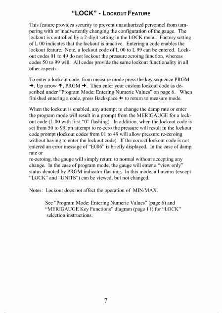
“LOCK” - LOCKOUT FEATURE
This feature provides security to prevent unauthorized personnel from tam-pering with or inadvertently changing the configuration of the gauge. Thelockout is controlled by a 2-digit setting in the LOCK menu. Factory settingof L 00 indicates that the lockout is inactive. Entering a code enables thelockout feature. Note, a lockout code of L 00 to L 99 can be entered. Lock-out codes 01 to 49 do not lockout the pressure zeroing function, whereascodes 50 to 99 will. All codes provide the same lockout functionality in allother aspects.
To enter a lockout code, from measure mode press the key sequence PRGM, Up arrow , PRGM . Then enter your custom lockout code as de-
scribed under “Program Mode: Entering Numeric Values” on page 6. Whenfinished entering a code, press Backspace to return to measure mode.
When the lockout is enabled, any attempt to change the damp rate or enterthe program mode will result in a prompt from the MERIGAUGE for a lock-out code (L 00 with first “0” flashing). In addition, when the lockout code isset from 50 to 99, an attempt to re-zero the pressure will result in the lockoutcode prompt (lockout codes from 01 to 49 will allow pressure re-zeroingwithout having to enter the lockout code). If the correct lockout code is notentered an error message of “E006” is briefly displayed. In the case of damprate orre-zeroing, the gauge will simply return to normal without accepting anychange. In the case of program mode, the gauge will enter a “view only”status denoted by PRGM indicator flashing. In this mode, all menus (except“LOCK” and “UNITS”) can be viewed, but not changed.
Notes: Lockout does not affect the operation of MIN/MAX.
See “Program Mode: Entering Numeric Values” (page 6) and “MERIGAUGE Key Functions” diagram (page 11) for “LOCK” selection instructions.
3900440plus.pub page 7
Friday, June 15, 2001 11:15

8
“TIMER” - TIMER SHUTOFF VALUE
This feature is available on battery powered units only. This feature sets thetime for automatic shutoff. The automatic shutoff can be set for “OFF”, or 1,2, 5, 10, 15, 25, or 50 minutes. If set to “OFF” the gauge will remain onuntil the ON/OFF key is pressed. Factory default timer setting is 10 minutes.
To change the timer settings, from measure mode press the key sequencePRGM , Up arrow twice, PRGM then scroll through the desiredtimer setting options. Press PRGM key to enter the the displayed selec-tion. Then press the backspace key to return to the measure mode.
Note: See “Program Mode: Using PRGM Mode” (page 5) and“MERIGAUGE Key Functions” diagram (page 11) for “TIMER” selection instruc-tions.
“SCALE” - USER ADJUSTABLE SCALING
Allows entering of engineering units not included in the standard selection ofthe MERIGAUGE. The value entered will be used to linearly re-scale thefull scale value (in PSI) of the MERIGAUGE. This is particularly useful fordisplaying non-standard pressure units or linear tank levels. The factorysetting is set for the full scale range in PSI.
To enter a value, from measure mode press the key sequence PRGM , Uparrow three times, PRGM then enter the numeric value (see page 6).A value of .0001 to 9999 can be entered. Press PRGM key to enter thethe displayed selection. After editing the “SCALE”, the gauge automaticallychanges engineering units to the “User” unit and returns to measure mode.
Note: See “Program Mode: Entering Numeric Values” (page 6) and “MERIGAUGE Key Functions” diagram (page 11) for “SCALE” selection instructions.
3900440plus.pub page 8
Friday, June 15, 2001 11:15

9
“BARLO” & “BARHI” - BAR GRAPH SCALE
The MERIGAUGE has a 21 segment bar graph display that is fully useradjustable for visual display of any part of the pressure range. The defaultscaling is from 0 to 100% of the full scale range. The “BARLo” is used toset the minimum desired pressure indication in PSI and the “BARHi” is usedto set the maximum desired pressure indication in PSI.
For “BARLo” the programmable range is -20% of full scale to 5% of fullscale less than the BARHi setting. For “BARHi” the programmable range is5% of full scale greater than the BARLo setting to 120% of full scale. Thisensures a minimum range for meaningful bargraph operation.
For the combination vacuum gauge, both the BARLo and BARHi settingscan be adjusted from -15 PSI to 120% of full scale. This provides flexibilityto program a “reverse-acting” bargraph (bargraph increases with increasingvacuum). Note that, in this case, the “minimum range” is not enforced, sothe user should take care to program a minimum range of 5% of full scale formeaningful bargraph operation.
To enter a value in “BARLo”, from measure mode press the key sequencePRGM , Up arrow four times, PRGM then enter the numeric value(see page 6). Press PRGM key to enter the value. Then press thebackspace key to return to the measure mode.
To enter a value in “BARHi”, from measure mode press the key sequencePRGM , Up arrow five times, PRGM then enter the numeric value(see page 6). Press PRGM key to enter the value. Then press thebackspace key to return to the measure mode.
Notes: See “Program Mode: Entering Numeric Values” (page 6) and “MERIGAUGE Key Functions” diagram (page 11) for “BARLo” and “BARHi” selection instructions.
3900440plus.pub page 9
Friday, June 15, 2001 11:15

10
RELAY OPTIONS
When installed, the Relay option provides two adjustable relay outputs, eachwith a normally opened and normally closed contact. Each of these relayscan be enabled or disabled. Each relay can also be adjusted in PSI from -20%to 120% of full scale pressure (except the combination pressure/vacuumgauge, which has a lower limit setting of -15 PSI). An adjustable deadbandfor the SPDT relays is provided. Deadband can be set to 0%, 0.1, 0.2, 0.5, 1,2, 5 and 10% of full scale. The relay will energize precisely at the pressurevalue set in the Relay feature on increasing pressure. The relay will de-energize at a value equal to the relay pressure setting, minus the deadbandvalue, on decreasing pressure.
“SET1” and “SET2”
To enter values in “SET1” or “SET2” from measure mode press the keyPRGM , and then Up arrow until “SET1” or “SET2” is in the upperdisplay. Then press PRGM to enter the numeric value in PSI (see page 6).Press PRGM key to enter the value. Then press the backspace key toreturn to the measure mode.
Note that factory defaults for the “SET1” and “SET2” registers are 0 and 100% of the instrument range, respectively.
“dBAND” (Deadband)
To select a value in “dBAND”, from measure mode press the key PRGM ,and then Up arrow until “dBAND” is in the upper display. Then pressPRGM to scroll through the desired deadband setting options. PressPRGM key to enter the displayed selection. Then press the Backspace key to return to the measure mode. Note: “SET1” and “SET2” will beequally effected by the deadband value if both are enabled.
“RELAY”
Once the “SET1”, “SET2” or “dBAND” values have been entered the“RELAY” option can be enabled. To enable the Relays, from measuremode, press the key PRGM , and then Up arrow until “RELAY” is inthe upper display. Press PRGM to enter the register, then scroll throughthe desired relay setting options. The choices are to have both relays turnedoff or to have one on and the other off or to have both relays turned on.Press PRGM key to enter the displayed selection. Then press theBackspace key to return to the measure mode.
Notes: See “Program Mode: Entering Numeric Values” (page 6) and “MERIGAUGE Key Functions” diagram (page 11) for
3900440plus.pub page 10
Friday, June 15, 2001 11:15

12
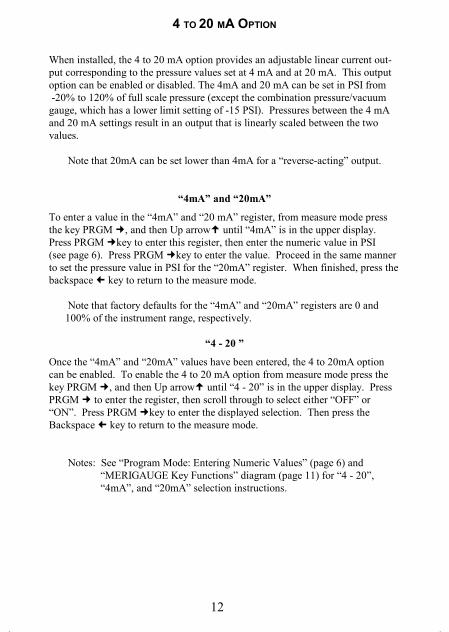
4 TO 20 MA OPTION
When installed, the 4 to 20 mA option provides an adjustable linear current out-put corresponding to the pressure values set at 4 mA and at 20 mA. This outputoption can be enabled or disabled. The 4mA and 20 mA can be set in PSI from -20% to 120% of full scale pressure (except the combination pressure/vacuumgauge, which has a lower limit setting of -15 PSI). Pressures between the 4 mAand 20 mA settings result in an output that is linearly scaled between the twovalues.
Note that 20mA can be set lower than 4mA for a “reverse-acting” output.
“4mA” and “20mA”
To enter a value in the “4mA” and “20 mA” register, from measure mode pressthe key PRGM , and then Up arrow until “4mA” is in the upper display.Press PRGM key to enter this register, then enter the numeric value in PSI(see page 6). Press PRGM key to enter the value. Proceed in the same mannerto set the pressure value in PSI for the “20mA” register. When finished, press thebackspace key to return to the measure mode.
Note that factory defaults for the “4mA” and “20mA” registers are 0 and 100% of the instrument range, respectively.
“4 - 20 ”
Once the “4mA” and “20mA” values have been entered, the 4 to 20mA optioncan be enabled. To enable the 4 to 20 mA option from measure mode press thekey PRGM , and then Up arrow until “4 - 20” is in the upper display. PressPRGM to enter the register, then scroll through to select either “OFF” or“ON”. Press PRGM key to enter the displayed selection. Then press theBackspace key to return to the measure mode.
Notes: See “Program Mode: Entering Numeric Values” (page 6) and “MERIGAUGE Key Functions” diagram (page 11) for “4 - 20”, “4mA”, and “20mA” selection instructions.
3900440plus.pub page 12
Friday, June 15, 2001 11:15

13
FIELD RECALIBRATION
The MERIGAUGE can be re-calibrated at any time against any standard pressurereference that has accuracy specifications exceeding the accuracy of theMERIGAUGE. Calibration is done at three points throughout the range of theMERIGAUGE. The factory calibration is set to values approximately equal to0%, 50% and 100% of full scale pressure in PSI. For example, a 10 PSI unit willtypically have the calibration points set at 0, 5, and 10 PSI, respectively, from thefactory.
The Calibration Mode is entered by pressing and holding the MIN/MAX keyduring power up sequence*. The PRGM, MIN, and MAX annunciators will flashto indicate that the calibration mode has been entered. The top display will indi-cate which point is ready to be calibrated (LOW, MID, or HIGH). The mainpressure display indicates the expected pressure in PSI for that point. The PRGM
key is used to accept the pressure applied for the calibration point. Once theLOW point is calibrated the display will automatically advance to the MID point,and similarly to the HIGH point. The Up arrow and Down arrow keys maybe used to toggle between LOW, MID and HIGH. The backspace key may beused to abort the process and to turn the gauge off.
*Note: If a lockout code has been set, it must be cleared before attempting toenter Calibration Mode, otherwise a “Lockd” message will appear. See page 7.
Defining Pressure Points For Field Calibration
The three points of calibration are user adjustable and can be set for -5% to 25%of full scale for the low value, > 25% to 75% of full scale for the mid value, and> 75% to 105% of full scale for the high value. The factory defined calibrationpressure points are roughly 0%, 50% and 100% of full scale pressure in PSI.This feature allows the user to define the exact value of the pressure referencethat will be used for calibration. To redefine the pressure value at any of thethree points (LOW, MID, or HIGH), simultaneously press the Up arrow andthe Down arrow keys while in any of the three calibration point menus. Thefirst digit in the upper display will flash indicating that editing can start. Enterthe desired numeric value (see page 6).
Important: Changing the pressure points will shift the calibration curve. Therefore, do not edit these registers except when calibrating.
3900440plus.pub page 13
Friday, June 15, 2001 11:15
14
10 P
SI
50 P
SI
100
PS
I50
0 P
SI
1000
PS
I15
00 P
SI
3000
PS
I50
00 P
SI
6000
PS
I
PS
I10
.000
50.0
010
0.00
500.
010
00.0
1500
.030
0050
0060
00
FTH
2O23
.108
115.
5423
1.08
1155
.423
10.8
3466
.269
3211
554
1386
5
InH
2O27
7.30
1386
.527
73.0
1386
527
730
141
595
183
189
113
8649
116
6379
1
InH
G20
.360
101.
8020
3.60
1018
.020
36.0
3054
.161
0810
180
1221
6
BA
R0.
6895
3.44
76.
895
34.4
768
.95
103.
4220
6.8
344.
741
3.7
mm
HG
517.
1525
85.8
5171
.525
857
151
715
177
573
115
5146
125
8577
131
0292
1
KP
A 6
8.94
8 3
44.7
468
9.48
3447
.468
94.8
1034
2.1
2068
434
474
4136
9
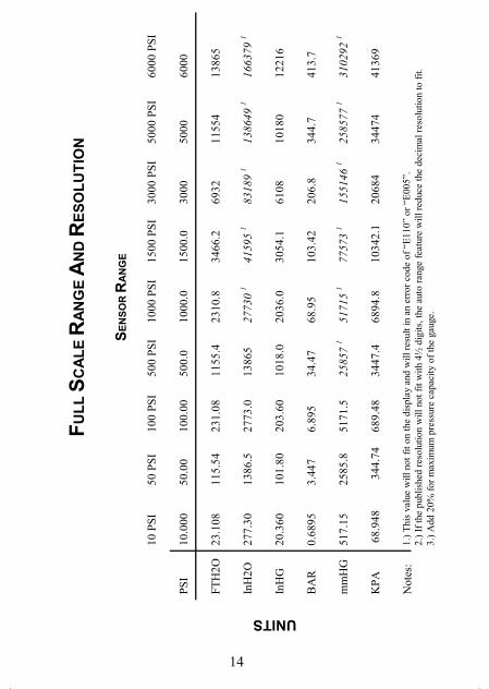
Not
es:
1.)
Thi
s va
lue
will
not
fit
on th
e di
spla
y an
d w
ill r
esul
t in
an e
rror
cod
e of
“E
110”
or
“E00
5”.
2.)
If th
e pu
blis
hed
reso
lutio
n w
ill n
ot f
it w
ith 4
½ d
igits
, the
aut
o ra
nge
feat
ure
will
red
uce
the
deci
mal
res
olut
ion
to f
it.3.
) A
dd 2
0% f
or m
axim
um p
ress
ure
capa
city
of
the
gaug
e.
FU
LL
SC
AL
E R
AN
GE
AN
D R
ES
OL
UT
ION
UNITS
SE
NS
OR
RA
NG
E
3900440plus.pub page 14
Friday, June 15, 2001 11:15

15
ERROR DESCRIPTION
LO BAT Low Battery Warning. The batteries should be replaced immedi-ately when this annunciator is visible.
“Sensr”“FAIL”
EXR=1
SGN=1
Problem with data collection. Possible cause is a loose sensorcable at the main board connector.
“T-Out” Automatic Shutoff timer has expired; gauge is shutting downnormally.
“WARN”“OP”
Overpressure warning. The measured pressure exceeds the fullscale pressure by 20% of full scale or more (high or low) .Sensor is at risk of permanent damage!
“RANGE”“BAD”
Memory error. Service required.
E002 Requested ZERO value is not within 10% of full scale pressure,and thus ignored.
E005 Full Scale Range for Engineering Units selected is beyond scale ofdisplay (>19,999). This message would be seen, for example,during power up of a 1000 PSI gauge with mmHg last selected,since the corresponding full scale display of 51,715.3 mmHg willnot fit on the 4½ digit display.
E006 User Entered incorrect Lockout Code. Gauge is locked. A view-only status will be entered if Program Mode was requested (seepage 7). To enter calibration mode, the lockout code must firstbe cleared (page 13), and then the key sequence to enter calibra-tion mode must be repeated (page 13)
E010 Requested User-Units Full Scale range is less than or equal to0.0. Value must be greater than 0.0.
E011 Requested Bar Graph Low Value is out of range. It must be setgreater than -20% of full scale sensor range, and 5% of full scalesensor range less than the BarGraph High setting. EXCEPTION:
ERROR CODES AND MESSAGES The MERIGAUGE has an error/message feature to inform the operator of problemswith the operation or programming of the gauge. These Error Codes andmessages are identified and described below:
3900440plus.pub page 15
Friday, June 15, 2001 11:15
16
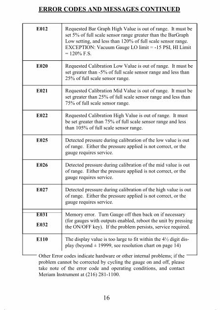
E012 Requested Bar Graph High Value is out of range. It must beset 5% of full scale sensor range greater than the BarGraphLow setting, and less than 120% of full scale sensor range.EXCEPTION: Vacuum Gauge LO limit = -15 PSI, HI Limit= 120% F.S.
E020 Requested Calibration Low Value is out of range. It must beset greater than -5% of full scale sensor range and less than25% of full scale sensor range.
E021 Requested Calibration Mid Value is out of range. It must beset greater than 25% of full scale sensor range and less than75% of full scale sensor range.
E022 Requested Calibration High Value is out of range. It mustbe set greater than 75% of full scale sensor range and lessthan 105% of full scale sensor range.
E025 Detected pressure during calibration of the low value is outof range. Either the pressure applied is not correct, or thegauge requires service.
E026 Detected pressure during calibration of the mid value is outof range. Either the pressure applied is not correct, or thegauge requires service.
E027 Detected pressure during calibration of the high value is outof range. Either the pressure applied is not correct, or thegauge requires service.
E031
E032
Memory error. Turn Gauge off then back on if necessary(for gauges with outputs enabled, reboot the unit by pressingthe ON/OFF key). If the problem persists, service required.
E110 The display value is too large to fit within the 4½ digit dis-play (beyond ± 19999, see resolution chart on page 14)
ERROR CODES AND MESSAGES CONTINUED
Other Error codes indicate hardware or other internal problems; if theproblem cannot be corrected by cycling the gauge on and off, pleasetake note of the error code and operating conditions, and contactMeriam Instrument at (216) 281-1100.
3900440plus.pub page 16
Friday, June 15, 2001 11:15

17
INSTALLATION AND MAINTENANCE
PIPE MOUNTINGThe MERIGAUGE has a 316 stainless steel ¼” male NPT connection fordirect mounting. The threads should be coated with a pipe sealantcompound before installation. Torque the fitting using a 7/8 inch wrench onthe hex fitting above the threads. NEVER USE THE BODY OF THEGAUGE TO TIGHTEN THE THREADS.
PANEL MOUNTING
1. Determine the desired gauge mounting location.2. Make a panel cutout and drill the mounting screw holes per the drawing.3. Insert the gauge through the front of the panel making sure the rubber sealing gasket is positioned between the gauge flange and the mounting surface.4. Secure the gauge to the panel with three mounting screws (not provided).5. Connect the pressure line. Hold the 7/8 inch hex nut on the stem with a wrench while tightening the pressure connection. DO NOT PUT EXCESSIVE PRESSURE ON THE GAUGE STEM AND BODY WHEN TIGHTENING. IN ADDITION, IT IS IMPORTANT TO ENSURE THAT EXCESSIVE TENSION IS NOT APPLIED TO THE GAUGE BY THE PIPING AND CONNECTION LINES.6. Make any required electrical connections. See the wiring connection
3900440plus.pub page 17
Friday, June 15, 2001 11:15
18
FACE OR INSTRUMENT BODY ROTATIONFor a pipe mounted unit the MERIGAUGE can be rotated ± 180º toaccommodate various mounting orientations. On a panel mounted unit thecase with pressure connection stem can be rotated ± 180º to meet the needsof the panel installation. Simply loosen the center screw at the rear of thehousing, rotate the face or instrument body and retighten the screw. To pro-tect theinternal cables, DO NOT ROTATE THE FACE OR PRESSURE CONNEC-TION FURTHER THAN 180 DEGREES IN EITHER DIRECTION.
BATTERY INSTALLATION / REPLACEMENTPIPE MOUNTED UNIT:The MERIGAUGE batteries need to be replaced when LO BAT is displayed.To replace the MERIGAUGE batteries, remove the center screw at the rearof the main housing, and carefully pull the face of the gauge from the body.USE CAUTION TO PROTECT THE CABLE FROM BEING CRIMPED,STRETCHED OR PINCHED. The best method to protect this cable is to laythe face of the gauge down on a table, with the housing laying on its backnext to the face. Then, change the batteries and carefully re-assemble thegauge.
BATTERY INSTALLATION / REPLACEMENTPANEL MOUNTED UNIT:The MERIGAUGE batteries need to be replaced when LO BAT is displayed.To replace the MERIGAUGE batteries, the unit should be removed from thepanel by disconnecting the pressure line, removing the three mountingscrews, and removing the entire unit through the front of the panel. Then,remove the center screw at the rear of the main housing, and carefully pullthe face of the gauge from the body. USE CAUTION TO PROTECT THECABLE FROM BEING CRIMPED, STRETCHED OR PINCHED. The bestmethod to protect this cable is to lay the face of the gauge down on a table,
INSTALLATION AND MAINTENANCE (CONTINUED)
3900440plus.pub page 18
Friday, June 15, 2001 11:15

19
INSTALLATION AND MAINTENANCE (CONTINUED)
WIRING CONNECTION DIAGRAMS
Note: Before making electrical connections, make sure the power sup-ply is disconnected and secured.
All external powered units and units ordered with output options are shippedwith a 6 foot wiring harness with male and female connectors included.There are two possible wiring harnesses depending on the chosen options.The wire number pin-out diagram and wire color coding diagrams are in-cluded below.
The wiring harnesses can also be removed so that the MERIGAUGE canaccept other wiring directly at the auxiliary circuit board. The circuit boardterminal diagram is included below. To access the circuit board, loosen thecable fitting where the harness enters the rear of the unit. Then, remove thecenter screw at the rear of the main housing, and carefully pull the face of thegauge from the body. Disconnect the wires from the circuit board terminals.Install the new wiring in reverse order.
Note: A hook up cable with an outside diameter of 0.114” to 0.250” is re-quired
3900440plus.pub page 19
Friday, June 15, 2001 11:15
20
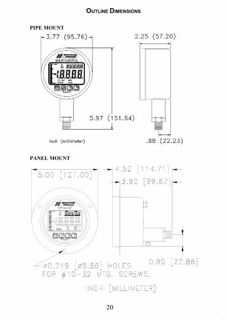
OUTLINE DIMENSIONS
PIPE MOUNT
PANEL MOUNT
3900440plus.pub page 20
Friday, June 15, 2001 11:15
