fieldshield strongfiber drop wheel - clearfield · fieldshield® strongfiber drop wheel...
TRANSCRIPT

FieldShield® StrongFiber Drop WheelInstallation Manual ______________________________________________________
Manual 019456 REV A - Dec 2017
Direct: 763.476.6866 • National: 800.422.2537 • www.SeeClearfield.com • [email protected] 2
FieldShield® StrongFiber Drop WheelInstallation Manual _________________________________________________________
Manual 019456 REV A - Dec 2017
Table of ContentsApplications 3Description 3Drop Wheel Dimensions 3Technical Specifications 3Mounting the Drop Wheel Cradle 4Deploying StrongFiber 5Assembling Pullable Connector 6Connector Cleaning Procedure 8Standard Warranty 11Proprietary Notice 12Technical Support 12

3
FieldShield® StrongFiber Drop Wheel__________________________________________________________ Installation Manual
Direct: 763.476.6866 • National: 800.422.2537 • www.SeeClearfield.com • [email protected] Manual 019456 REV A - Dec 2017
Applications• MDU• FTTH
DescriptionThe Drop Wheel Wall Box provides all the components to distribute drop cables in a compact, quick deploy platform. Each Drop Wheel is spooled with 200 feet of FieldShield Strong Fiber pre-terminated with a pullable SC/APC or SC/UPC and a matching standard connector. Once mount-ed, Drop Wheels can be easily deploy be extending the wheel from the cradle, pulling the fiber through the microduct, and then assembling the pulled connector. Drop Wheel assemblies can be ordered in 4, 8, 12 and 16 ports.
Drop Wheel Dimensions5.09”
5.30”
8.19”
Technical Specifications
Characteristic SpecificationMaterial Black Thermoplastic
Fiber 200 Feet of FieldShield Strong FiberConnectors Pullable SC/APC to Standard SC/APC (SC/UPC available)
Direct: 763.476.6866 • National: 800.422.2537 • www.SeeClearfield.com • [email protected] 4
FieldShield® StrongFiber Drop WheelInstallation Manual _________________________________________________________
Manual 019456 REV A - Dec 2017
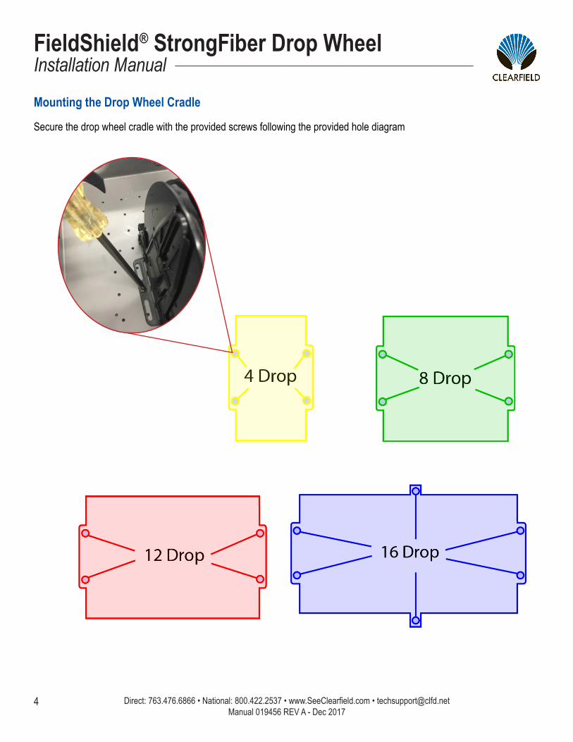
Mounting the Drop Wheel Cradle
Secure the drop wheel cradle with the provided screws following the provided hole diagram
5
FieldShield® StrongFiber Drop Wheel__________________________________________________________ Installation Manual
Direct: 763.476.6866 • National: 800.422.2537 • www.SeeClearfield.com • [email protected] Manual 019456 REV A - Dec 2017
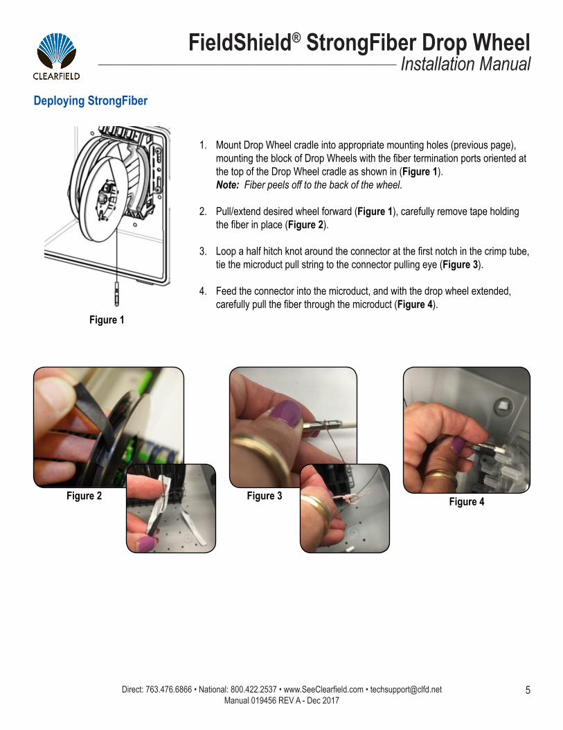
1. Mount Drop Wheel cradle into appropriate mounting holes (previous page), mounting the block of Drop Wheels with the fiber termination ports oriented at the top of the Drop Wheel cradle as shown in (Figure 1). Note: Fiber peels off to the back of the wheel.
2. Pull/extend desired wheel forward (Figure 1), carefully remove tape holding the fiber in place (Figure 2).
3. Loop a half hitch knot around the connector at the first notch in the crimp tube, tie the microduct pull string to the connector pulling eye (Figure 3).
4. Feed the connector into the microduct, and with the drop wheel extended, carefully pull the fiber through the microduct (Figure 4).
Figure 1
Figure 2 Figure 3 Figure 4
Deploying StrongFiber
Direct: 763.476.6866 • National: 800.422.2537 • www.SeeClearfield.com • [email protected] 6
FieldShield® StrongFiber Drop WheelInstallation Manual _________________________________________________________
Manual 019456 REV A - Dec 2017
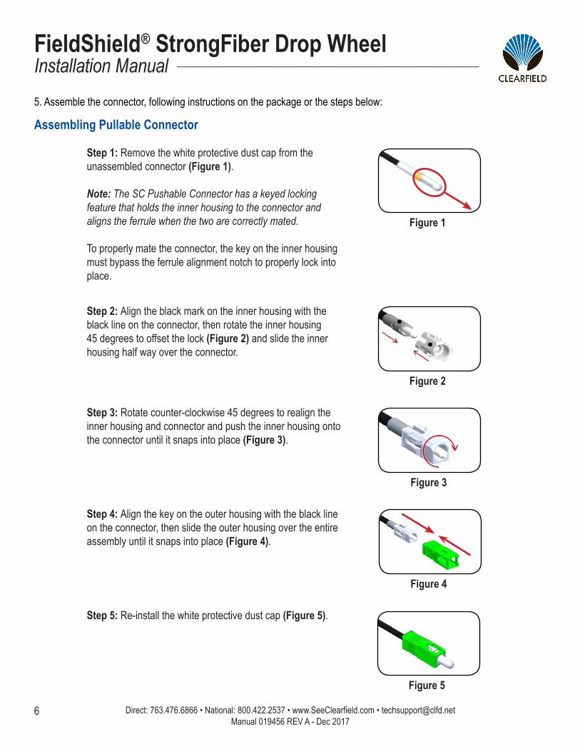
Step 1: Remove the white protective dust cap from the unassembled connector (Figure 1).
Note: The SC Pushable Connector has a keyed locking feature that holds the inner housing to the connector and aligns the ferrule when the two are correctly mated.
To properly mate the connector, the key on the inner housing must bypass the ferrule alignment notch to properly lock into place.
Figure 1
Step 3: Rotate counter-clockwise 45 degrees to realign the inner housing and connector and push the inner housing onto the connector until it snaps into place (Figure 3).
Step 2: Align the black mark on the inner housing with the black line on the connector, then rotate the inner housing 45 degrees to offset the lock (Figure 2) and slide the inner housing half way over the connector.
Figure 2
Figure 3
Figure 4
Figure 5
Step 5: Re-install the white protective dust cap (Figure 5).
Step 4: Align the key on the outer housing with the black line on the connector, then slide the outer housing over the entire assembly until it snaps into place (Figure 4).
5. Assemble the connector, following instructions on the package or the steps below:
Assembling Pullable Connector
7
FieldShield® StrongFiber Drop Wheel__________________________________________________________ Installation Manual
Direct: 763.476.6866 • National: 800.422.2537 • www.SeeClearfield.com • [email protected] Manual 019456 REV A - Dec 2017
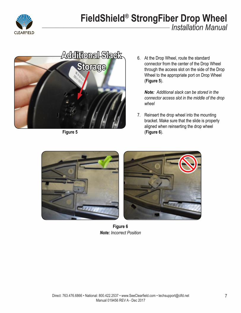
6. At the Drop Wheel, route the standard connector from the center of the Drop Wheel through the access slot on the side of the Drop Wheel to the appropriate port on Drop Wheel (Figure 5). Note: Additional slack can be stored in the connector access slot in the middle of the drop wheel
7. Reinsert the drop wheel into the mounting bracket. Make sure that the slide is properly aligned when reinserting the drop wheel (Figure 6).Figure 5
Additional Slack Storage
Figure 6Note: Incorrect Position

Direct: 763.476.6866 • National: 800.422.2537 • www.SeeClearfield.com • [email protected] 8
FieldShield® StrongFiber Drop WheelInstallation Manual _________________________________________________________
Manual 019456 REV A - Dec 2017
Whether factory terminated or field spliced, clean connectors are essential for proper system operation. Even the smallest dust particle can cause transmission problems, so for optimal network performance, inspect and if necessary, clean all connectors and adapters prior to mating.
I.T.C…Inspect Then Connect! ALWAYS inspect the connector first thing with a clean fiber scope inspect the pair. Three types of contamination require different cleaning techniques. The use of Chemtronics end face and bulkhead cleaning products and techniques ensures a clean end face, no matter the type of contamination.
These are Clearfield recommended products/application. Use the product you feel will complete your cleaning procedures. Create a “best practice” for your company and follow those procedures.
**Note: It is NOT recommended to use IPA to clean the end-face.
Cleaning the end-face…but not just the end-face
• Place one wiping paper on QbE-2 FiberSafe™ Cleaning Platen. Figure 1
• Apply small amount of precision cleaner (about 1” in diameter) with Elec-tro-Wash MX pen on to one end of the wipe. Figure 2
• Hold end face 90 degree. Adjust for APC connection by slightly tilting the container or end face. Angle is correct when no drag is left on the end face. Figure 3
• Draw end face from wet to dry part of the wipe 3 times. Use just enough pressure to ensure complete contact between end face and the wipe.
DO NOT retrace previous step.
Figure 1
Figure 2
Figure 3
Connector Cleaning Procedure

9
FieldShield® StrongFiber Drop Wheel__________________________________________________________ Installation Manual
Direct: 763.476.6866 • National: 800.422.2537 • www.SeeClearfield.com • [email protected] Manual 019456 REV A - Dec 2017
• CLEAN THE FERRULE…Lightly moisten the fiber optic swab (2.5mm/38542F or 1.25mm/38040) by spotting a small amount (about 1”) of Electro-Wash PX or Electro-Wash MX pen onto the QBE-2. Hold the swab, 1 side down to the wetted area and hold for a count of 1-2-3-4-5. Figure 4
• Insert swab into side of ferrule, wet side to the ceramic ferrule and circle around 2-3 times and remove. Turn swab to dry side and repeat. Figure 5
Cleaning the mate through a bulkhead adapter AND the adapter itself!
• Lightly moisten the fiber optic swab(2.5mm/38542F or 1.25mm/38040) by spotting a small amount (about 1”) of Electro-Wash PX or Elec-tro-Wash MX pen onto the QBE-2. Hold the tip of the swab onto the wetted area and hold for a count of 1-2-3-4-5.
• Insert the swab into the adapter to the connector, press lightly against the connector, twist 2-3 times, remove and discard.
• Dry with a second dry swab.
• Inspect (re-clean if necessary) and test for signal strength.
• Use additional swabs to clean inside the actual adapter. Moisten swab, like above, insert through hole and remove while twisting. Figure 6
Figure 4
Figure 5
Figure 6
Direct: 763.476.6866 • National: 800.422.2537 • www.SeeClearfield.com • [email protected] 10
FieldShield® StrongFiber Drop WheelInstallation Manual _________________________________________________________
Manual 019456 REV A - Dec 2017
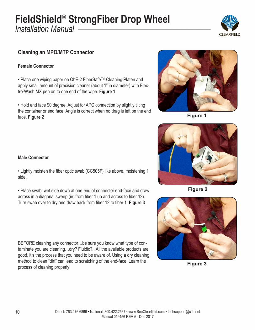
Cleaning an MPO/MTP Connector
Female Connector
• Place one wiping paper on QbE-2 FiberSafe™ Cleaning Platen and apply small amount of precision cleaner (about 1” in diameter) with Elec-tro-Wash MX pen on to one end of the wipe. Figure 1
• Hold end face 90 degree. Adjust for APC connection by slightly tilting the container or end face. Angle is correct when no drag is left on the end face. Figure 2
Male Connector
• Lightly moisten the fiber optic swab (CC505F) like above, moistening 1 side.
• Place swab, wet side down at one end of connector end-face and draw across in a diagonal sweep (ie: from fiber 1 up and across to fiber 12). Turn swab over to dry and draw back from fiber 12 to fiber 1. Figure 3
BEFORE cleaning any connector…be sure you know what type of con-taminate you are cleaning…dry? Fluidic?...All the available products are good, it’s the process that you need to be aware of. Using a dry cleaning method to clean “dirt” can lead to scratching of the end-face. Learn the process of cleaning properly!
Figure 1
Figure 2
Figure 3

11
FieldShield® StrongFiber Drop Wheel__________________________________________________________ Installation Manual
Direct: 763.476.6866 • National: 800.422.2537 • www.SeeClearfield.com • [email protected] Manual 019456 REV A - Dec 2017
Standard WarrantyClearfield warrants to the original purchaser of the Product sold hereunder is free from defects in material and workmanship under normal use and service, subject to exceptions stated herein. Product purchased is warranted as follows: Clearfield designed and branded Products are warranted for five (5) years: Products manufactured by Clearfield to customer prints and/or specifications are warranted for one (1) year; and any Product Clear-field acquires from or through a third-party manufacturer or distributor and resells to Customer as the original customer will carry the manufacturer’s pass-through warranty, if any. In all cases, the warranty period commences on the date of shipment to the original purchaser.
Warranty Claim Procedure
If any Product purchased from Clearfield is found defective under the above warranty, the following basic procedure must be followed:
1. Customer must contact Clearfield and obtain a Return Materials Authorization2. Following authorization, the Customer ships the product-freight collect-to Clearfield’s manufacturing facility3. Clearfield shall repair or replace the defective Product at its sole option and discretion, and return the repaired or replacement Product to Cus-
tomer’s site, freight prepaid
Note: If the Product is not found to be defective by Clearfield, the product will be returned to the Customer and the customer billed for freight in both directions.
Limitations of Warranty
Correction of defects by repair or replacement, at the option of Clearfield Inc, shall constitute the exclusive sole remedy for a breach of this limited warranty. Clearfield shall not be liable under any circumstances for any special, consequential, incidental, punitive, or exemplary damages arising out of or in any way connected with the product or with agreement to sell product to buyer, including, but not limited to damages for lost profits, loss of use, or for any damages or sums paid by buyer to third parties. The foregoing limitation of liability shall apply whether the claim is based upon principles of contract, warranty, negligence or other tort, breach of statutory duty, principles of indemnity or contribution, the failure of any limited or exclusive remedy to achieve its essential purpose, or otherwise.
Clearfield will not be responsible for any labor or materials costs associated with installation or incorporation of Clearfield products at customer sites, including any costs of alteration, replacement or defective product, or any field repairs.
Other Limitations
1. Clearfield assumes no warranty liability regarding defects caused by:2. Customer’s modification of Product, excepting installation activities described in Clearfield documentation3. Customer re-packaging of Product for shipment to third parties or destinations other than those originally shipped to by Clearfield, or any de-
fects suffered during shipping where the Product has been re-packaged4. Customer’s installation or maintenance, excepting activities described in and performed in accordance with Clearfield documentation5. Customer’s improper or negligent use or application of Product6. Other causes external to the Product, including but not limited to accidents, catastrophe, acts of God, government action, war, riot, strikes, civil
commotion, sovereign conduct, or the acts or conduct of any person or persons not party to or associated with Clearfield
Direct: 763.476.6866 • National: 800.422.2537 • www.SeeClearfield.com • [email protected] 12
FieldShield® StrongFiber Drop WheelInstallation Manual _________________________________________________________
Manual 019456 REV A - Dec 2017
Proprietary Notice
About FieldShield Product Line Application
Information contained in this document is copyrighted by Clearfield, Inc. and may not be duplicated in full or part by any person without prior written approval of Clearfield, Inc.
Its purpose is to provide the user with adequately detailed documentation to efficiently install the equipment supplied. Every effort has been made to keep the information contained in this document current and accurate as of the date of publication or revision.
However, no guarantee is given or implied that the document is error free or that it is accurate with regard to any specification.
Technical Support
Clearfield, Inc. can be contacted for any issues that arise with the supplied product.
If you need to return the supplied product, you must contact the Clearfield, Inc. Customer Service Department to request a Returned Materials Authorization (RMA) number.
Clearfield, Inc.7050 Winnetka Ave NMinneapolis, MN 55428
Toll Free: 800.422.2537Phone: 763.476.6866Fax: 763.475.8457
Customer Support: [email protected] Support: [email protected]