fieldbussystem new - allied electronics. (maximumnumber of solenoidsconnected:32)...
TRANSCRIPT

Daisy-chain wiringcommunication
IP67IP67 IP67 IP40
Applicable Fieldbus protocols
Space-saving InstallationSpace-saving InstallationCompact
28mm(Actual size)
¡IP67∗
∗ For units with D-sub connector, and when connected to S0700 manifolds, it is IP40.
¡Drives up to 32 solenoids
Top ported valve Bottom ported valve Side ported valve
Mixed valve sizes manifold
7 mm width valve
NewNew
CAT.NAS02-25BSeries EX260
Fieldbus System(Output device for driving 5 port solenoid valves)
®
NewNew
RoHS
EtherNet/IP™ added !

E3/5 E3/5
1 P
B
4 A
2 B
4 A
2 B
4 A
2 B
4 A
2 B
4 A
2
E3/5 E3/5B
4 A
2 B
4 A
2 B
4 A
2 B
4 A
2 B
4 A
2
Product SpecificationVariations
M12 communicationconnector(PROFIBUS DP)
D-sub communicationconnector(PROFIBUS DP)
16
32
PNP
NPN
M12
D-sub
16
32
PNP
NPN
M12
16
32
PNP
NPN
M12
16
32
PNP
NPN
M12
16
32
PNP
NPN
M12
28.2 mm
81 mm
!Communication connector examples
Fieldbus
EX260
16
32
PNP
NPN
M12
Manifold length is shortened by the smallfieldbus output module (SI unit).
Wiring and piping from the same direction is possible.(for side ported)
Effective for installation in locations where space is
limited above the valve.
Existing model EX250
External branch connector is not necessary. Daisy-chain wiring is possible. Reduced wiring space
Branch connectorExisting model (EX250)
External terminating resistor is not necessary.(Only available for M12 PROFIBUS DP,
CC-Link communication connectors)
ON/OFF switching is possible with an internal terminating
resistor. External terminating resistor is not necessary.
External terminating resistor
Internal terminating
resistor
SI unit
Number of
outputs
Output polarity
Communication
connector
Features 1

SY3000
SY5000
S0700
SV1000
SV2000
SV3000
VQC1000
VQC2000
VQC4000
0.35 (standard)
0.1 (with power-
saving circuit)32
32
32
24
0.6
0.4 (standard)
1.0 (standard)
0.35
IP67
IP40
IP67
IP67
0.19
0.17
0.39
0.35
0.18
0.21
0.30
0.30
0.38
1.6
3.6
0.37
1.1
2.4
4.3
1.0
3.2
7.3
page 7
page 24
page 29
page 38
Series
Power
consumption
(W)Enclosure Standards
Flow-rate characteristics (4/2→5/3)
C [dm3/(s·bar)] b
Maximum
number of
solenoids
!Applicable Valve Series
Page
Note) For units with D-sub communication connector, it is IP40.
Features 2
®
Sideported
Sideported
Bottomported
Topported
<Example of Use>
Valve piping direction variations
SeriesSY3000/5000 Pressure switch
"Piping is possible from 3 directions.
Mixed mounting of top ported and side ported is possible.
By mounting top ported valves on
side ported and bottom ported type
manifolds, it is possible to detect the
output of the A/B port with a pressure
switch.
Valves can be freely connected up to 24 stations. Mixed valve sizes manifold
"Valves of different sizes,
SY3000 and SY5000, can
be mounted on the same
manifold.
" It is possible to connect
only the number of valves
required, from 1 to 24
stations, to suit the
application.
(Maximum number of
solenoids connected: 32)
7 mmwidth valves can be
connected.
" It is possible to connect only the number of 7 mm
width valves required, from 1 to 24 stations.
(Maximum number of solenoids connected: 32)
SeriesS0700

32
16
16
32
PROFINET
EtherCAT
EtherNet/IP™
PROFIBUS DP
DeviceNet™
CC-Link
AS-Interface
CANopen
CompoNet™
!
!
!
!
!
!
!
!
!
!
!
!
!
!
!
!
!
!
!
!
!
!
!
!
!
16
None
EX260
32 16 (total 64)
16 (total 64)
EX500
!
!
!
!
!
!
!
!
!
!
!
!
!
!
32
144
EX600
!
!
!
!
!
!
!
!
!
!
!
!
!
!
!
32
32
EX250
3000
5000
0700
1000
2000
3000
4000
1000
2000
4000
1000
2000
4000
5000
SV
VQC
VQ
EX260
EX124EX126
EX124 EX260EX126
EX500
EX600 EX250
Fieldbus SystemVariations
!
!
!
!
!
!
!
!
!
!
!
!
!
!
!
!
!
!
!
!
!
!
!
!
!
!
!
!
!
!
!
!
!
IP67/65 specification models
I/O separated type I/O integrated type
Inputs only
Valve outputs only Gateway-typevalve outputs only
inputs only
Valve outputswith multiple I/O’s
Valve outputswith inputs
Numberofvalveoutputs
Numberofinputs
Number of valve outputs
Number of inputs
SI unit series
Opennetwork
Applicablevalveseries
SY(Plug-in connector
connecting base)
S0700(Stacking base)
Features 3

PROFINET
EtherCAT
EtherNet/IP™
PROFIBUS DP
DeviceNet™
CC-Link
AS-Interface
CANopen
CompoNet™
!
!
!
!
!
!
!
!
!
!
!
!
!
!
!
!
!
!
!
!
!
!
!
!
!
!
!
!
!
!
!
!
!
!
!
!
!
!
!
!
!
!
!
!
!
!
!
!
!
!
!
!
!
!
!
!
16
EX120
32 16 (total 64)
16 (total 64)
EX510
3000
5000
2000
3000
3000
5000
0700
3000
5000
7000
3000
5000
7000
1000
2000
3000
4000
1000
2000
4000
5000
1000
2000
3000
1000
2000
3000
3000
5000
7000
SJ
VQ
SV
SQ
SZ
VQZ
SYJ
EX120
EX122 EX140 EX180EX121
EX122 EX140
EX180
EX121
32
16
16
32
EX510
IP20 specification modelsFieldbus SystemVariations
I/O separated type I/O integrated type
Inputs only
Valve outputs only Gateway-typevalve outputs only
inputs only
Valve outputswith multiple I/O’s
Valve outputswith inputs
Num
berofvalveoutputs
Numberofinputs
Number of valve outputs
Number of inputs
SI unit series
None
SY(Bar stock)
SY(Plug-in connectorconnecting base)
S0700(Bar stock)
SY(Plug-in
metal base)
SY(Stacking base)
Applicablevalveseries
Opennetwork
Features 4

M12
DN1DN2DN3DN4PR1PR2PR3PR4PR5PR6PR7PR8MJ1MJ2MJ3MJ4EC1EC2EC3EC4PN1PN2PN3PN4EN1EN2EN3EN4
DeviceNet™
PROFIBUS DP
EtherCAT
PROFINET
Note) Enclosure is IP40 when the communication connector is D-sub.
SI unit output polarity
32
16
32
16
32
16
32
16
32
16
32
16
32
16
M12
M12
D-sub Note)
M12
M12
EtherNet/IP™ M12
Source/PNP (Negative common)
Sink/NPN (Positive common)
Source/PNP (Negative common)
Sink/NPN (Positive common)
Source/PNP (Negative common)
Sink/NPN (Positive common)
Source/PNP (Negative common)
Sink/NPN (Positive common)
Source/PNP (Negative common)
Sink/NPN (Positive common)
Source/PNP (Negative common)
Sink/NPN (Positive common)
Source/PNP (Negative common)
Sink/NPN (Positive common)
Source/PNP (Negative common)
Sink/NPN (Positive common)
Source/PNP (Negative common)
Sink/NPN (Positive common)
Source/PNP (Negative common)
Sink/NPN (Positive common)
Source/PNP (Negative common)
Sink/NPN (Positive common)
Source/PNP (Negative common)
Sink/NPN (Positive common)
Source/PNP (Negative common)
Sink/NPN (Positive common)
Source/PNP (Negative common)
Sink/NPN (Positive common)
QAN
QA
QBN
QB
NAN
NA
NBN
NB
NCN
NC
NDN
ND
VAN
VA
VBN
VB
DAN
DA
DBN
DB
FAN
FA
FBN
FB
EAN
EA
EBN
EB
Communication protocol
Compact design Compact design for space saving
Number of outputs Each 32/16 digital output type available in the series
Enclosure IP67 (For units with D-sub connector, and when connected with S0700 manifolds, it is IP40.)
Output polarity Each negative common (PNP) / positive common (NPN) type available in the series
Internal terminating resistorON/OFF switching is possible with an internal terminating resistor for communication.
(Only for units compatible with M12 PROFIBUS DP, CC-Link communication connectors)
SY3000/5000 VQC1000/2000/4000 S0700 SV1000/2000/3000
DD
DD
How to Order SI Units
PR1EX260 S
Note)
Note) The SY3000/5000, VQC1000/2000/4000, and S0700 are not yet UL-compatible.
CC-Link
®
RoHS
ProtocolSymbol Number of outputs Communication connector Manifold symbol
1
Series EX260
SI Unit Integrated-type/For Output

SI Unit Specifications
Model EX260-SPR1/3 EX260-SPR2/4 EX260-SPR5/7 EX260-SPR6/8 EX260-SDN1/3 EX260-SDN2/4 EX260-SMJ1/3 EX260-SMJ2/4
125 k/250 k/500 kbps156 k/625 k/
2.5 M/5 M/10 Mbps
M12
Built-in
—
—22.8 to 26.4 VDC
11 to 25 VDC
100 mA or less
Applicable
system
I/O occupation area(Inputs/Outputs)
Communication speed
Power supply
for control
Power supply for output
Communication connector specification
Terminating resistor switch
Power supply for
communication
Output
Environmental
resistance
Standards
Weight
Mounting screw
Accessories
IP67 IP40 IP67
14 to 122°F (–10 to 50°C)
35 to 85%RH (No condensation)
500 VAC for 1 minute between terminals and housing
10 MΩ or more (500 VDC measured via megohmmeter) between terminals and housing
CE marking, UL (CSA) compatible
0.44 lbs (200 g)
2 pcs.
24 VDC
Power supply voltage
Internal current consumption
Power supply voltage
Power supply voltage
Internal current consumption
Protocol
Version Note 1)
Configuration file Note 3)
Supplied current
Output type
Number of outputs
Load
Supplied voltage
Enclosure
Operating temperature range
Operating humidity range
Withstand voltage
Insulation resistance
Seal cap (for M12connector socket)
Source/PNP(Negative common)
Sink/NPN(Positive common)
Source/PNP(Negative common)
Sink/NPN(Positive common)
Source/PNP(Negative common)
Sink/NPN(Positive common)
SPR1: 32 pointsSPR3: 16 points
SPR2: 32 pointsSPR4: 16 points
SPR5: 32 pointsSPR7: 16 points
SPR6: 32 pointsSPR8: 16 points
SDN1: 32 pointsSDN3: 16 points
SDN2: 32 pointsSDN4: 16 points
SPR1: 0/32SPR3: 0/16
SPR2: 0/32SPR4: 0/16
SPR5: 0/32SPR7: 0/16
SPR6: 0/32SPR8: 0/16
SDN1: 0/32SDN3: 0/16
SDN2: 0/32SDN4: 0/16
SMJ1: 32/32SMJ3: 32/32(1 station, remote I/O stations)
SMJ2: 32/32SMJ4: 32/32(1 station,remote I/O stations)
SPR1: Max. 2.0 ASPR3: Max. 1.0 A
SPR2: Max. 2.0 ASPR4: Max. 1.0 A
SPR5: Max. 2.0 ASPR7: Max. 1.0 A
SPR6: Max. 2.0 ASPR8: Max. 1.0 A
SDN1: Max. 2.0 ASDN3: Max. 1.0 A
SDN2: Max. 2.0 ASDN4: Max. 1.0 A
EX9-AWTS (1 pc.) — EX9-AWTS (1 pc.)
D-sub M12
None Built-in
Volume 1(Edition 3.5)Volume 3(Edition 1.5)
9.6 k/19.2 k/45.45 k/93.75 k/187.5 k/500 k/1.5 M/3 M/6 M/12 Mbps
21.6 to 26.4 VDC
100 mA or less
—
— —
—
21.6 to 26.4 VDC
100 mA or less
PROFIBUS DP DeviceNet™ CC-Link
DP-V0 Ver.1.10
—GSD file EDS file
Source/PNP(Negative common)
Sink/NPN(Positive common)
SMJ1: 32 pointsSMJ3: 16 points
SMJ2: 32 pointsSMJ4: 16 points
SMJ1: Max. 2.0 ASMJ3: Max. 1.0 A
SMJ2: Max. 2.0 ASMJ4: Max. 1.0 A
Solenoid valve with protective circuit for surge voltage of 24 VDC/1.5 W or less (SMC)
Model EX260-SEC1/3 EX260-SEC2/4 EX260-SPN1/3 EX260-SPN2/4 EX260-SEN1/3 EX260-SEN2/4
Applicable
system
I/O occupation area (Inputs/Outputs)
Communication speed
Power supply
for controlPower supplyfor output
Communication connector specification
Terminating resistor switch
Power supply for
communication
Output
Environmental
resistance
Standards
Weight
Mounting screw
Accessories
IP67
14 to 12°F (–10 to 50°C)
35 to 85%RH (No condensation)
500VAC for 1 minute between terminals and housing
10 MΩ or more (500VDCmeasured via megohmmeter) between terminals and housing
CE marking, UL (CSA) compatible
0.44 lbs (200 g)
2 pcs.
24 VDC
Power supply voltage
Internal current consumption
Power supply voltage
Power supply voltage
Internal current consumption
Protocol
Version Note 1)
Configuration file Note 3)
Supplied voltage
Output type
Load
Supplied voltage
Enclosure
Operating temperature range
Operating humidity range
Withstand voltage
Insulation resistance
Seal cap (for M12connector socket)
Source/PNP(Negative common)
Sink/NPN(Positive common)
Source/PNP(Negative common)
Sink/NPN(Positive common)
Source/PNP(Negative common)
Sink/NPN(Positive common)
SEC1: 32 pointsSEC3: 16 points
SEC2: 32 pointsSEC4: 16 points
SPN1: 32 pointsSPN3: 16 points
SPN2: 32 pointsSPN4: 16 points
SEN1: 32 pointsSEN3: 16 points
SEN2: 32 pointsSEN4: 16 points
SEC1: 0/32SEC3: 0/16
SEC2: 0/32SEC4: 0/16
SPN1: 0/32SPN3: 0/16
SPN2: 0/32SPN4: 0/16
SEN1: 16/32SEN3: 16/16
SEN2: 16/32SEN4: 16/16
SEC1: Max. 2.0 ASEC3: Max. 1.0 A
SEC2: Max. 2.0 ASEC4: Max. 1.0 A
SPN1: Max. 2.0 ASPN3: Max. 1.0 A
SPN2: Max. 2.0 ASPN4: Max. 1.0 A
SEN1: Max. 2.0 ASEN3: Max. 1.0 A
SEN2: Max. 2.0 ASEN4: Max. 1.0 A
EX9-AWTS (1 pc.)
Volume 1(Edition 3.8)Volume 2(Edition 1.9)
21.6 to 26.4 VDC
100 mA or less
22.8 to 26.4 VDC
—
—
M12
None
10 M/100 Mbps Note 2)100 Mbps Note 2)
EtherCAT Note 2) EtherNet/IP™ Note 2)
Conformance Test Record V.1.1
XML file
PROFINET Note 2)
PROFINET SpecificationVersion 2.2
GSD file EDS file
Solenoid valve with protective circuit for surgevoltage of 24 VDC/1.5 W or less (SMC)
Solenoid valve with protective circuit for surgevoltage of 24 VDC/1.0 W or less (SMC)
Solenoid valve with protective circuit for surgevoltage of 24 VDC/1.5 W or less (SMC)
Note 1) Please note that the
version is subject to
change.
Note 2) Use a CAT5 or higher
transmission cable for
EtherCAT, PROFINET,
EtherNet/IP™.
Note 3) Each file can be
downloaded from the SMC
website,
http://www.smcworld.com
Number ofoutputs
EX260
SY
SV
VQC
S0700
2
Integrated-type/For Output Series EX260

D-sub communication connector typeM12 communication connector type
90.9
28.2
102.4 90.9
102.4
28.221 20.6 16.4 9
76.5
28.75 29.25 9
76.5
SI Unit Dimensions
Part no.
Communication protocol
EX260-SPR1/-SPR2-SPR3/-SPR4
PROFIBUS DP
5 pins, socket, B code
5 pins, plug, B code
5 pins, plug, A code
Note) The setting switch varies depending on the model.
Refer to the operation manual for details.
Please download it via the SMC website, http://www.smcworld.com
EX260-SDN!
DeviceNet™
5 pins, socket, A code
5 pins, plug, A code
4 pins, plug, A code
EX260-SMJ!
CC-Link
EX260-SEC!
EX260-SPN!
EX260-SEN!
EtherCAT
PROFINET
EtherNet/IP™
M3
Communication connector (M12) BUS OUT
Communication connector (M12) BUS IN
Ground terminal
Power connector (M12)
<Setting switch>
• Address switch
• Communication speed switch
•Terminating resistor switch
• Others
<LED indication>
• Communication state
• Unit power supply state
•Valve power supply state
Part no.
Communication protocol
EX260-SPR5/-SPR6/-SPR7/-SPR8
PROFIBUS DP
M3
9 pins, socket
5 pins, plug, A code
Ground terminal
Communication connector (D-sub) BUS IN/OUT
Power connector (M12)
D-sub communication connector type
Functions of SI Unit Parts
<Connector>M12 communication connector type
<LED indication and setting switch>
5 pins, socket, A code
4 pins, plug, A code
5 pins, plug, B code
4 pins, socket, D code
4 pins, socket, D code
5 pinsNote1), 4 pinsNote2),plug, A code
Note 1) For EtherCAT, PROFINET
Note 2) For EtherNet/IP™
(mm)
3
Series EX260
EX260
SY
SV
VQC
S0700
WhiteOrangeWhite
Green
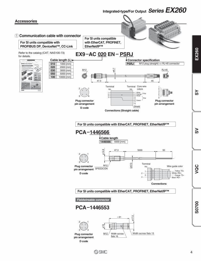
Accessories
q Communication cable with connector
For SI units compatible with
PROFIBUS DP, DeviceNet™, CC-Link
For SI units compatible
with EtherCAT, PROFINET,
EtherNet/IP™
Refer to the catalog (CAT. NAS100-73)
for details. 020EX9 AC ENCable length (L)
1000 [mm]
2000 [mm]
3000 [mm]
5000 [mm]
10000 [mm]
010020030050100
PSRJ
M12 plug (straight) ⇔ RJ-45 connectorPSRJ
1
3 4
2
Plug connector
pin arrangement
D codeConnections (Straight cable)
M12 RJ-45
ø6.7
47.3 45L
Plug connectorpin arrangement
12345678
Terminalno.
1234
12345678
Terminalno.
Shield
Pair
Pair
Core wire colors
Connector specification
For SI units compatible with EtherCAT, PROFINET, EtherNet/IP™
PCA 1446566
For SI units compatible with EtherCAT, PROFINET, EtherNet/IP™
PCA 1446553
5000 [mm]1446566
Cable length
Fieldwireable connector
(ø6.5)
50500047.3
ø14.8
Plug connectorpin arrangement
D code
12
3 4
M12
SPEEDCON
ø17.5
ø19
≈ 61
Width across flats 13Width acrossflats 16
M12
Integrated-type/For Output Series EX260
Plug connectorpin arrangement
D code
12
3 4
123
4
White: RD+
Blue: RD–
Yellow: TD+
Orange: TD–
Connections
Terminalno. Wire guide color
4

w Power cable with connector (for SI units)
Accessories
EX500 AP
2
4 3
Socket connectorpin arrangement
A code
Socket connectorpin arrangement
A code
1
12
34
5
Terminalno.
Core wirecolors
M12
ø14.9
48
34
18
L
ø6
30 5
50
Connections (PROFIBUS DP/EtherCAT)
Cable length (L)
1000 [mm]
5000 [mm]
010050
Connector specificationStraight
Angle
SA
S050
For SI units compatible with PROFIBUS DP, DeviceNet™, EtherCAT, PROFINET, EtherNet/IP™
e Seal cap: For M12 connector socket
EX9 AW
Use this on ports that are not being used for communication connector (M12
connector socket).
Use of this seal cap maintains the integrity of the IP67 enclosure.
Note) Tighten the seal cap with the prescribed tightening torque. (For M12: 0.07 lbf·ft (0.1 N·m)
TS
Connector type
For M12 connector socket (10 pcs.)For M12 connector socket
M12 x 1
14
10.2
14
Brown: 24 VDC +10%/–5% (Solenoid valve power supply)White: 0 V (Solenoid valve power supply)
Blue: 24 VDC ±10% (Control power supply)Black: 0 V (Control power supply)
Gray: Not connected
12
34
5
Terminalno.
Core wire colors
Connections (DeviceNet™, EtherNet/IP™)
Brown: Not connected Note 1), 24 VDC ±10% (Control power supply) Note 2)
White: 24 VDC +10%/–5% (Solenoid valve power supply) Blue: Not connected Note 1), 0 V (Control power supply) Note 2)
Black: 0 V (Solenoid valve power supply)Gray: Not connected
Straight connector type
For SI units compatible with CC-Link
Straight connector type
2
4 3
51
M12
31.3
28.3
30 5
50L
ø6
Angle connector type
TS
5
EX9 AC 1Cable length (L)
1000 [mm]
3000 [mm]
5000 [mm]
010030050
050
SPEEDCON
SPEEDCON
PCACable length (L)
1500 [mm]
3000 [mm]
5000 [mm]
140180414018051401806
1401804
PCACable length (L)
1500 [mm]
3000 [mm]
5000 [mm]
140180714018081401809
1401807
2
4 3
51
Socket connectorpin arrangement
B code
M1248.1
L
30
50
5
ø6.4
Connections
12
34
5
Terminalno.
Cable core
wire colors
4 3
21
4 3
21
ø14.8
M12
SPEEDCON
M12
SPEEDCON
ø14.8
44.5 L 50
50L44.5
ø5.0
±0.15
ø5.0
±0.15
5
5
Socket connectorpin arrangement
A code
Socket connectorpin arrangement
B code
Note 1) For DeviceNet™
Note 2) For EtherNet/IP™
Brown: 24 VDC +10%/–5% (Solenoid valve power supply)White: 0 V (Solenoid valve power supply)
Blue: 24 VDC ±10% (Control power supply)Black: 0 V (Control power supply)
Gray: Not connected
5
Series EX260