field testing program for power transformers jeffrey short, doble engineering
DESCRIPTION
Field Testing Program for Power Transformers Jeffrey Short, Doble Engineering. What are the benefits of starting a testing program for transformers? What is the motivation for having the program? What tests can be performed to assess the condition of transformers?. Introduction. - PowerPoint PPT PresentationTRANSCRIPT

Knowledge Is PowerSM
Apparatus Maintenance and Power Management for Energy Delivery
Field Testing Program for Power Transformers
Jeffrey Short, Doble Engineering

2005 APPA Conference
Introduction
What are the benefits of starting a testing program for transformers?
What is the motivation for having the program?
What tests can be performed to assess the condition of transformers?

2005 APPA Conference
Benefits of Testing Program
Enhance System Reliability Minimize Damage to Apparatus Enhances Safety to Personnel Minimize Loss of Revenue Extension of Apparatus Life
Degradation of Insulation, if detected before failure, can generally be restored to its original condition
Defer replacement costs
2005 APPA Conference
Benefits of Testing Program
Better Utilization of Resources Acceptance of New Apparatus
Verify that new apparatus meets purchased specification and agrees with factory test reports
Assures proper field Assembly
2005 APPA Conference
Benefits of Testing Program
Field Testing provides the maintenance engineer a group of tools to assess the condition of the transformer
Benefit for each test must be clear and results able to be interpreted Data may relate to different areas
Dielectric Thermal Mechanical
Engineer should choose the right tool for the right job

2005 APPA Conference
Motivation for Field Testing
Acceptance Testing Establish a Baseline Routinely to Establish a Condition Trend Determine Dryness of Insulation Assess Condition after Electrical Disturbance Isolate a Problem Area Assess Condition after a Relocation Asset Management - Ranking and Prioritizing Reduce Catastrophic Failures

2005 APPA Conference
Reduce Catastrophic Failure

2005 APPA Conference
Transformer Failures
Cause of Failure for Utility Transformers
29%
18%16%
13%
13%
7%
2%1%
0%1%
Elect Dist
Insulation
Lightning
Maintenance
Elect Connection
Moisture
Overload
Sabotage
Workmanship
Other
Hartford Steam Boiler Insurance Co. Statistics
2005 APPA Conference
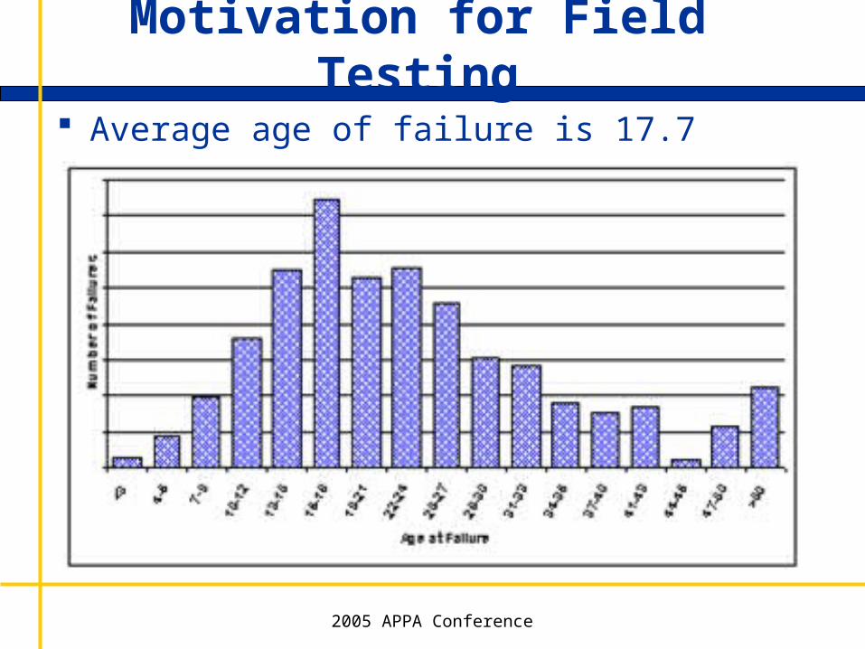
Motivation for Field Testing
Average age of failure is 17.7 years

2005 APPA Conference
Condition Assessment Tests
Dielectric tests - Power Factor and Capacitance Perform on
Overall Windings Bushings Liquid Insulation Surge Arresters -Field test on insulation portion of
arrester
Assess the condition of the insulation and physical properties of the transformer

2005 APPA Conference
Dielectric Power Factor Example

2005 APPA Conference
FPE, 3-, 2-winding , -Y transformer13.8/4.3 kV, 7 MVA
High CL % P.F. & disagreement between HV & LV CHL %P.F.s
Localized moisture/contamination in the L.V. winding
Problem Revealed in LV Winding

2005 APPA Conference
Dielectric CapacitanceExample

2005 APPA Conference
Significance of Measured Capacitance
Capacitance detects movement and deformation of transformer windings.
Interwinding (CHT) capacitance of anautotransformer.
Test Date 20C % PF Cap (pF)1965 0.20 2,6501968 0.29 2,7561974 0.29 3,7101982 0.32 5,100

2005 APPA Conference
Capacitance change detects movement and deformation of transformer windings.
Significance of Measured Capacitance
C =A
4d

2005 APPA Conference
Excitation Currents

2005 APPA Conference
Field Testing
Excitation Current and Loss Factory Tests at Rated Voltage. Field Tests at the Lesser of Rated Voltage or Highest
Capability of the Test Set. Simple measurement of single-phase current on one side
of the transformer, usually the HV side, with the other side left floating (with the exception of a grounded neutral).
Magnetic Circuit and Winding Tests

Types of Problems found with Excitation Current
Windings (includes high, low, tertiary, preventative auto and series windings) Turn-to-turn winding insulation failure causing a short or
high resistance connection. Winding to ground short for a grounded winding. Open windings (main, tap, reactor). High resistance conductor connections. Phase to phase electrical tracking.
• These conditions result in a change in the effective reluctance of the magnetic circuit, which affects the current required to force a given flux through the core.
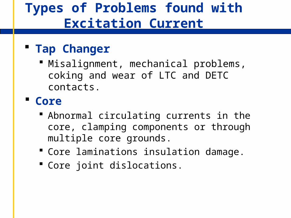
Types of Problems found with Excitation Current
Tap Changer Misalignment, mechanical problems, coking and wear
of LTC and DETC contacts.
Core Abnormal circulating currents in the core, clamping
components or through multiple core grounds. Core laminations insulation damage. Core joint dislocations.
2005 APPA Conference
Field Testing
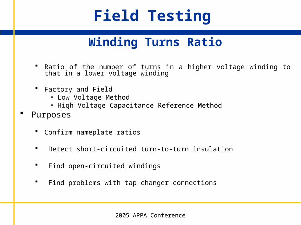
Winding Turns Ratio
Ratio of the number of turns in a higher voltage winding to that in a lower voltage winding
Factory and Field• Low Voltage Method• High Voltage Capacitance Reference Method
Purposes
Confirm nameplate ratios
Detect short-circuited turn-to-turn insulation
Find open-circuited windings
Find problems with tap changer connections
2005 APPA Conference
Mechanical Assessment
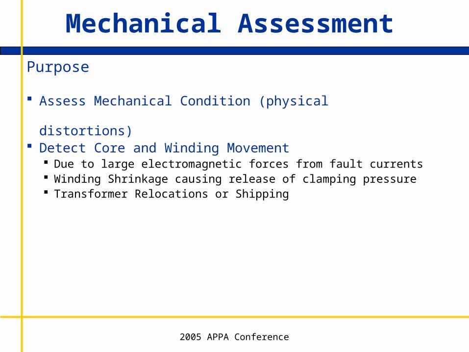
Purpose
Assess Mechanical Condition (physical distortions) Detect Core and Winding Movement
Due to large electromagnetic forces from fault currents Winding Shrinkage causing release of clamping pressure Transformer Relocations or Shipping

2005 APPA Conference
Mechanical Assessment
Current Techniques
Frequency Response Analysis (FRA) Leakage Reactance Capacitance Excitation Current These independent diagnostic methods have their place in
ascertaining transformer condition
2005 APPA Conference
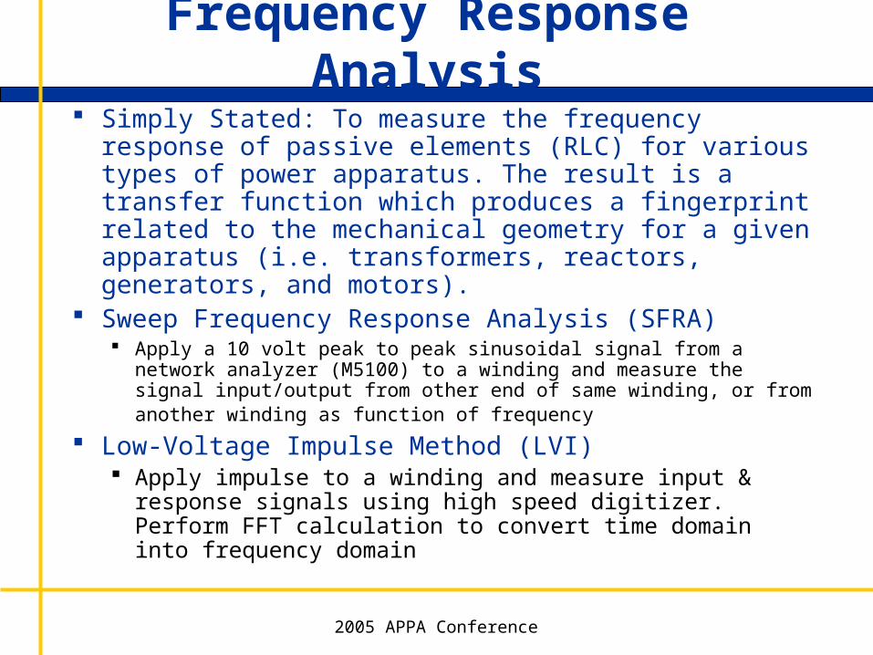
Frequency Response Analysis Simply Stated: To measure the frequency response of
passive elements (RLC) for various types of power apparatus. The result is a transfer function which produces a fingerprint related to the mechanical geometry for a given apparatus (i.e. transformers, reactors, generators, and motors).
Sweep Frequency Response Analysis (SFRA) Apply a 10 volt peak to peak sinusoidal signal from a network analyzer
(M5100) to a winding and measure the signal input/output from other end of same winding, or from another winding as function of frequency
Low-Voltage Impulse Method (LVI) Apply impulse to a winding and measure input & response
signals using high speed digitizer. Perform FFT calculation to convert time domain into frequency domain

2005 APPA Conference
Frequency Response Analysis
Experience to date shows that certain frequency bands indicate different problem conditions 2kHz scan sensitive to core deformation, open circuits,
shorted turns & residual magnetism 20kHz scan is sensitive mainly to bulk winding
movement relative to each other 200kHz and 2MHz scans are sensitive to deformation
within the windings 10MHz scan is sensitive to movement of winding leads
2005 APPA Conference
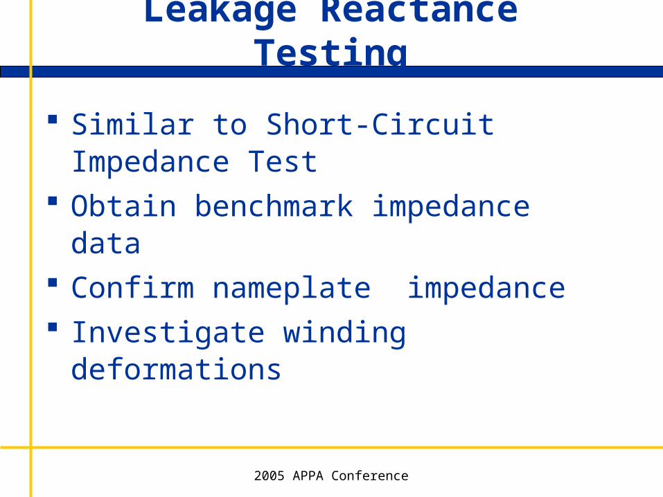
Leakage Reactance Testing
Similar to Short-Circuit Impedance Test Obtain benchmark impedance data Confirm nameplate impedance Investigate winding deformations

2005 APPA Conference
Transformer Test Summary
Each test is sensitive to a specific set of problems. Motivation for testing should always be
determined before arbitrarily performing a variety of tests
Routine testing should provide owner with a high level of comfort with transformer condition
Investigative testing needs to be more focused and thorough
Test results should always be scrutinized and taken seriously

2005 APPA Conference
Transformer Test Summary
Planning discussions for contingencies are important in making good decisions
There are cases where some tests will fail to identify a problem.

Knowledge Is PowerSM
Apparatus Maintenance and Power Management for Energy Delivery
Thank You!!!