field manual headquarters no. 23-91 department of …
TRANSCRIPT

★ FM 23-91
FIELD MANUALNo. 23-91
HEADQUARTERSDEPARTMENT OF THE ARMY
Washington, DC, 6 December 1991
i
Downloaded from http://www.everyspec.com

FM 23-91
ii
Downloaded from http://www.everyspec.com

FM 23-91
iii
Downloaded from http://www.everyspec.com

FM 23-91
iv
Downloaded from http://www.everyspec.com

FM 23-91
v
Downloaded from http://www.everyspec.com
FM 23-91
Preface
This manual provides guidance for MOS 11C soldiers and their trainers on theemployment of the 60-mm (M224 and M19) mortars, 81-mm (M252 and M29A1)mortars, 4.2-inch (M30) mortar, and 120-mm (M120) mortars. It discusses thepractical applications of ballistics and a system combining the principals, techniques, andprocedures essential to the delivery of timely and accurate mortar fire. (See FM 23-90for information on mechanical training, crew drills, and the characteristics,components, and technical data of each mortar.)
This manual is divided into four parts: Part One discusses the fundamentals of mortargunnery; Part Two summarizes the operational procedures of a fire direction center;Part Three describes the capabilities and use of the mortar ballistic computer; andPart Four describes the capabilities and use of the M16/M19 plotting board.
The proponent of this publication is US Army Infantry School. Send commentsand recommendations on DA Form 2028 (Recommended Changes toPublications and Blank Forms) directly to Commandant, US Army Infantry School,ATTN: ATSH-IN-1B-B, Fort Benning, GA 31905-5000
Unless this publication states otherwise, masculine nouns and pronouns do notrefer exclusively to men.
vi
Downloaded from http://www.everyspec.com

Part OneINTRODUCTION AND FUNDAMENTALS OF
MORTAR GUNNERY
CHAPTER 1
Introduction
The mission of the mortar platoon is to provide close and immediate indirect firesupport for the maneuver battalion and companies.
1-1. MORTAR TRAINING STRATEGYThe mortar training strategy is a concept that synchronizes the training documents,doctrine, institutional training programs, unit training programs, and trainingresources. It achieves and sustains the goal of training soldiers and leaders to win onthe battlefield. The mortar training strategy is implemented in TRADOC institutionaltraining (IET, NCOES, OES) and in units. It is supported by training devices, trainingammunition, and training support products.
a. In institutional courses, soldiers and leaders are provided initial training oncritical individual tasks. In the unit, the initial tasks are sustained, additional individualtasks are trained, and collective training is conducted.
b. Devices, simulations/simulators, training ammunition, and ranges provide soldiersand leaders the opportunity to conduct performance-oriented training under realisticconditions. The main devices that support mortar training are the sabot training round, theM880 SRTR, the M879 LRTR, and subcaliber inserts for the 4.2-inch and 120-mm mortars.
c. Training is also supported by TRADOC-developed publications that outlineconditions and performance standards for individual and collective tasks (FMs, TECs,ACCPs, ARTEPs, SMs, MQSs).
(1) This manual discusses the technical aspects of training mortar FDCs.(2) FM 23-90 discusses the technical aspects of training mortar squads.(3) FM 7-90 discusses the tactical employment of the mortar platoon and section.(4) ARTEP 7-90-MTP outlines the critical tasks, conditions, and standards for the
mortar platoon, section, and squad; and methods for conducting training andevaluations of these elements.
1-1
Downloaded from http://www.everyspec.com

FM 23-91
(5) ARTEP 7-90-DRILL outlines the standard battle, crew, and combat drills formortar platoons, sections, and squads.
(6) Artillery publications are the primary sources for FO, FIST and FSEprocedures. FO procedures are common tasks in soldier’s manuals.
(7) TMs contain the technical aspects of operating and maintaining mortar equipment.
1-2. ORGANIZATIONMortars are organized as part of a company and battalion. They are either sections orplatoons in airborne, ranger, air assault, light infantry companies, and cavalry troops.They are organized as platoons in all tank and infantry battalions. Regardless of theorganization to which they belong, mortars have the battlefield role of providing themaneuver commander with immediate indirect fires. They can fulfill that mission whenall of the elements responsible for placing effective mortar fire on the enemy areproperly trained.
1-3. INSTITUTIONAL TRAINING PROGRAM INTEGRATIONMost individual and all collective and tactical gunnery/FDC training takes place in the unit.However, institutional courses taught at USAIS are an important part of the total processof training soldiers and leaders. This training enables soldiers and leaders to reach theobjective of mortar platoons and sections prepared to perform in combat. Institutionalleader courses are taught at all the infantry, armor, and field artillery schools.
a. The training strategy (Appendix A) for mortars begins in 11C OSUT The soldieris taught critical common skill level 1 tasks and critical 11C MOS tasks. As with allMOS-specific IET training, the objective is to provide the unit with a soldier who canimmediately perform the most basic position in the unit. He must also be prepared tomove to positions requiring greater skill and task mastery. In OSUT, the 11C soldier isfully trained to be a gunner, assistant gunner, and ammunition bearer. When assignedto a permanent duty station, he should be assigned as an ammunition bearer until heis more experienced and has demonstrated the potential to function as an assistantgunner or gunner. His training includes the 60-mm, 81-mm, 4.2-inch, and 120-mmmortar systems in ground-mounted configurations as well as the 4.2-inch and 120-mmmortar vehicle-mounted configurations. The 11C soldier also receives 40 hours of FDCprocedures in which he learns the basic functions of the mortar fire team.
b. Soldier training up to squad leader level (skill level 2) and squad training (crew)takes place in the unit. Additional driver and gunner tasks are taught to allow soldiersto perform as a crew member. Gunners and each crew member must pass a gunner’sexamination (FM 23-90) semiannually (AC) or annually (RC). Also, mortar squads conductcrew drill training. This training develops the skills required for the mortar squads toeffectively engage targets.
c. FDC training also takes place in the unit. An FDC qualification examination is a keyelement in this training. FDC personnel must be trained to qualification standards.
d. Section training is critical. Most individual and squad training is conducted bythe section leader. Also, within the mortar platoon, the section is the basic mortarfighting organization. At BNCOC, NCOs who are or will be section leaders receive two
1-2
Downloaded from http://www.everyspec.com

FM 23-91
weeks of common core training. This is followed by four weeks of critical mortar combatand training tasks instruction. Most of this training consists of FDC procedures. Thisprepares the NCO to train individual, squad, crew, and FDC tasks required to performthe unit’s wartime mission.
e. Platoons, sections, squads, and crews practice battle and combat drills and trainMTP tasks. As part of the platoon training, the FDC and FO must train with gun crewsto ensure the entire mortar team can function as one. Platoon-level training consists oftactical STXs, FTXs, and LFXs that are designed using T&EOs extracted from theARTEP mission training plans and drill books.
f. For qualification, a mortar platoon/section must successfully conduct a live-fireexercise designed by the commander from the ARTEP. This should include the FIST aswell as the mortar platoon/section. The final outcome of the qualification should besuccessfully putting fires on the target within MTP standards. The platoon/section must beexternally evaluated, in conjunction with a higher-level FTX, to demonstrate proficiency atmaneuvering with and supporting the commander’s concept for defeating the enemy.
g. Mortar platoon training in units is supported by 11C ANCOC, which trains andcertifies platoon sergeants on battle competencies, and IMPC that trains officers andNCOs to set up and conduct mortar training in units. While the lieutenant at IOBC isnot trained to serve in mortar organizations, an orientation on mortars is provided. InIOBC, the officer is first trained to be a rifle platoon leader in an infantry organization.Any officer being assigned to a mortar element can attend the IMPC after IOBC. Also,exportable courses for the mortar section leader, platoon sergeant, and platoon leaderare available through the ACCP.
h. Training leaders to use mortars is another critical aspect of the mortar training strategy.Mortars must be used within their capabilities and limitations to best contribute to defeating theenemy. They must be effectively commanded controlled and supported. At officer basic,advanced, and precommand courses at the armor, infantry, and field artillery schools, leadersand commanders are trained to tactically employ mortars and their fires and to provide CSS.
1-4. GENERAL DOCTRINEDoctrine demands the timely and accurate delivery of indirect fire to meet the needs ofsupported units. All members of the indirect fire team must be thoroughly indoctrinatedwith a sense of urgency. They must strive to reduce, by all possible measures, the timerequired to execute an effective fire mission.
a. For mortar fire to be effective, it must be dense enough and must hit the targetat the right time with the right projectile and fuze. Good observation is required foreffective mortar fire. Limited observation results in a greater expenditure ofammunition and less effective fire. Some type of observation is desirable for everytarget to ensure that fire is placed on the target. Observation of close battle areas isusually visual. When targets are hidden by terrain features or when great distance orlimited visibility is involved, observation may be radar or by sound. When observationis possible, corrections can be made to place mortar fire on the target by adjustmentprocedures; however, lack of observation must not preclude firing on targets that canbe located by other means.
1-3
Downloaded from http://www.everyspec.com

FM 23-91
b. Mortar fire must be delivered by the most accurate means that time and the tacticalsituation permit. When possible, survey data will be used to accurately locate the mortarposition and target. Under some conditions, only a rapid estimate of the relative locationof weapons and targets may be possible.
c. To achieve the most effective massed fires, units should conduct a survey usingaccurate maps of each mortar position and registration points and targets. The immediateobjective is to deliver a large volume of accurate and timely fire to inflict as many casualtiesas possible on the enemy. The number of casualties inflicted in a target area can usually beincreased by surprise fire. If surprise massed fires cannot be achieved, the time required tobring effective fires on the target should be kept to a minimum.
d. The greatest demoralizing effect on the enemy can be achieved by the deliveryof a maximum number of rounds from all the mortars in a mortar section or platoon inthe shortest possible time.
e. Mortar units must be prepared to handle multiple fire missions. They can providean immediate, heavy volume of accurate fire for sustained periods. Mortars are area fireweapons; however, units can employ them to neutralize or destroy area or point targets, toscreen large areas with smoke for sustained periods, or to provide illumination.
f. In the armor and mechanized infantry battalions, units can normally fire mortars frommortar carriers. However, mortars maintain their ground-mounted capability. Firing froma carrier permits rapid displacement and quick reaction to the tactical situation.
1-5. INDIRECT FIRE TEAMIndirect fire procedures are a team effort (Figure l-l). They include locating the target,determining firing data, applying data to the mortar, and preparing the ammunition.Since the mortar is normally fired from the defilade (where the crew cannot see thetarget), the indirect fire team gathers and applies the required data. The team consistsof the FO, the FDC, and the mortar squad.
a. The team mission is to provide accurate, timely response to the unit it supports.Effective communication is vital to the successful coordination of the efforts of theindirect fire team.
b. ADS artillery battery provides the FO as part of the FIST. There are three FOs foreach FIST. Their job is to find and report the location of targets and to request and adjustfire. FOs should be habitually assigned to the same unit to know the commanders overallfire support. Also, units that train together understand how each other functions. This avoidsconfusion that results when FOs use FA adjusting techniques with mortars.
c. The FDC has two computer personnel in each section (except the 60-mm squad,which does not have assigned FDC personnel) who control the mortar firing. Theyconvert the data from the FO in a call for fire into firing data that can be applied to themortar and ammunition.
d. Mechanized infantry and armor mortar squads consist of one squad leader,one gunner, one assistant gunner, and one ammunition bearer. Airborne, airassault, and light infantry squads have the same number personnel of the heavysquads as well as one more ammunition bearer at the battalion level. At companylevel these light units have two 3-man sections consisting of one section sergeant,
1-4
Downloaded from http://www.everyspec.com

FM 23-91
one squad leader, two gunners, and two assistant gunners. The squad lays the mortarand prepares the ammunition, using the data from the FDC fire command. When thedata have been applied, the mortar squad fires the mortar. The squad must also be ableto fire without the FDC.
1-6. MORTAR POSITIONSUnits should employ mortars in defilade positions to protect mortars from the enemydirect fire and observation. These positions can also take the greatest advantage of theindirect fire role of mortars.
a. The use of defilade precludes sighting the weapons directly at the target (directlay). This is necessary for survivability.
b. Mortars are indirect fire weapons. Therefore, special procedures ensure that theweapon and ammunition settings used will cause the projectile to burst on or at the properheight above the target. A coordinated effort by the indirect fire team also ensures timelyand accurate engagement of targets.
1-5
Downloaded from http://www.everyspec.com

FM 23-91
c. The steps used in applying the essential information and engagement of a targetfrom a defilade position areas follows:
(1) Locate targets and mortar positions.(2) Determine chart data (direction, range, and vertical interval (VI) from
mortars to targets).(3) Convert chart data to firing data.(4) Apply firing data to the mortar and to the ammunition.
1-6
Downloaded from http://www.everyspec.com

CHAPTER 2
Fundamentals of Mortar Gunnery
This chapter discusses the elements of firing data, ballistics, firing tables, fire planning,target analysis, and methods of attack. This information will enable the FDC to engage theenemy even during adverse conditions.
Section IELEMENTS OF FIRING DATA AND BALLISTICS
Firing data are applied to the ammunition and the mortar so that the firedprojectile bursts at the desired location. Those data are based on the direction,horizontal range, and vertical interval from the mortar to the target, the patternof bursts desired at the target, and MET conditions.
2-1. DIRECTIONIn mortar gunnery, direction is a horizontal angle measured from a fixed reference. Theindirect fire team normally measures direction in mils clockwise from grid north, which is thedirection of the north-south grid lines on a tactical map. The team emplaces its mortars on amounting azimuth, then uses the direction to make angular shifts onto the target. Directionto the target may be computed, determined graphically, or estimated (Figure 2-1, page 2-2).
NOTE: The unit of angular measurement in mortar gunnery is the mil. A mil equalsabout 0.056 of a degree. There are 17.8 mils in a degree and 6400 mils in a360-degree circle.
2-2. RANGERange is the horizontal distance, expressed in meters, from the mortars to the target.It is computed, measured graphically, or estimated. The range of a projectile dependson its muzzle velocity (which depends on charge and other factors) and the elevationof the mortar.
2-3. VERTICAL INTERVALVI is the difference in altitude between the mortar section and the target or point ofburst. It is determined from maps, by survey, or by a shift from a known point.
2-4. DISTRIBUTION OF BURSTSDistribution of bursts is the pattern of bursts in the target area. Normally, all mortarsof the section or platoon in a standard formation fire with the same deflection, fuzesetting, charge, and elevation. Since targets may be of various shapes and sizes and
2-1
Downloaded from http://www.everyspec.com

FM 23-91
mortars may use terrain mortar positioning, it is best to adjust the pattern of bursts tothe shape and size of the target. Sometimes, individual mortar corrections fordeflections, fuze setting, charge, and elevation are computed and applied to achieve aspecific pattern of bursts.
2-5. INTERIOR BALLISTICSInterior ballistics deals with the factors affecting the motion of a mortar round beforeit leaves the muzzle of the barrel. The total effect of all interior ballistic factorsdetermines the velocity with which the projectile leaves the muzzle. That velocity iscalled muzzle velocity and is expressed in meters per second (MPS).
2-6. NATURE OF PROPELLENTS AND PROJECTILE MOVEMENTSPropellent is a low-order explosive that burns rather than detonates. The mortar firessemifixed ammunition. When the gases from the burning propellent develop enoughpressure to overcome projectile weight and initial bore resistance, the projectile beginsto move.
a. Gas pressure peaks quickly and subsides gradually after the projectile begins tomove. The peak pressure, together with the travel of the projectile in the bore,determines the speed at which the projectile leaves the barrel.
2-2
Downloaded from http://www.everyspec.com

FM 23-91
b. Factors that affect the velocity of a mortar-ammunition combination are as follows:(1) An increase or decrease in the rate of burning of the propellent increases or
decreases gas pressure.(2) An increase in the size of the chamber of the weapon without a corresponding
increase in the amount of propellent decreases gas pressure.(3) Gas escaping around the projectile in the barrel decreases pressure.(4) An increase in bore resistance to projectile movement, before peak pressure,
further increases pressure.(5) An increase in bore resistance at anytime has a dragging effect on the projectile
and decreases velocity. Temporary variations in bore resistance are caused by carbonbuildup in the barrel.
2-7. STANDARD MUZZLE VELOCITYFiring tables give the standard muzzle velocity for each charge. Values are based on astandard barrel and are guides, since they cannot be reproduced in a given instance. Aspecific mortar-ammunition combination cannot be selected with the assurance that it willresult in a standard muzzle velocity when fired. Charge velocities are established indirectlyby the military characteristics of a weapon. Since mortars are high-angle of fire weapons,they require greater variation in charges than do howitzers, which are capable of low-angleof fire. This variation helps achieve a range overlap between charge zones and desiredrange-trajectory. Other factors considered in establishing charge velocities are themaximum range specified for the weapon, and the maximum elevation and charge (withresulting maximum pressure) that the weapon can accommodate.
2-8. NONSTANDARD MUZZLE VELOCITYIn mortar gunnery techniques, nonstandard velocity is expressed as a variation (plus orminus MPS) from an accepted standard. Round-to-round corrections for dispersioncannot be made. Each factor causing nonstandard muzzle velocity is treated asindependent of related factors.
a. Velocity Trends. Not all rounds of a series fired from the same weapon usingthe same ammunition lot will develop the same muzzle velocity. Some muzzlevelocities are higher than average, and some are lower. This is called velocitydispersion. Under most conditions, the first few rounds follow a somewhat regularpattern rather than the random pattern associated with normal dispersion. This iscalled velocity trend. The magnitude and extent (number of rounds) of velocitytrends vary with the mortar, charge, barrel condition, and firings that precede theseries. Velocity trends cannot be predicted, so computer personnel should notattempt to correct for their effects.
b. Ammunition Lots. Each lot of ammunition has its own performance level whenrelated to the same mortar barrel. Although the round-to-round probable error (PE)within each lot is about the same, the mean velocity developed by one lot may be higheror lower than that of another lot. Variations in the projectile, such as, the diameter andhardness of the rotating disk, affect muzzle velocity. Projectile variations have a muchmore apparent effect on exterior ballistics than on interior ballistics.
2-3
Downloaded from http://www.everyspec.com

FM 23-91
c. Tolerances in New Weapons. All new mortars of a given size and model do notalways develop the same muzzle velocity. In a new barrel, the main factors arevariations in the powder chamber and in the interior dimensions of the bore. If abattalion armed with new mortars fired with a common lot of ammunition, a velocitydifference of 3 or 4 MPS between the mortars with the highest and lowest muzzlevelocity would be normal.
d. Wear of Barrel. Heated gases, chemical action, and friction from projectiles duringcontinued firing of a mortar wear away the bore. This wear is more pronounced whenhigher charges are being fired. Barrel wear decreases muzzle velocity by allowing moreroom for gases to expand. The gases escape past the rotating disk of the 4.2-inch mortar orthe obturator ring of the 60-mm/81-mm/120-mm mortars, decreasing resistance to initialprojectile movement and lessening pressure buildup. Wear can be reduced by carefulselection of the charge and by proper cleaning of the weapon and ammunition.
e. Rotating Disks. Rotating disks allow proper seating, keep gases from escapingbetween the bore and the projectile, and create proper resistance to the projectile’s initialmovement. Also, disks allow uniform pressure buildup but minimum drag on the movingprojectile, and they help give it a proper spin. Dirt or burrs on the rotating disk causeimproper seating, which increases barrel wear and reduces muzzle velocity. If the bore isexcessively worn, the rotating disk may not properly engage the lands and grooves to impartproper spin to the 4.2-inch mortar projectile. Not enough spin reduces projectile stabilityin flight, which can result in dangerously short, erratic rounds.
f. Temperature of the Propellant. Any combustible material burns rapidly when itis heated before ignition. When a propellent burns more rapidly, the resultant pressureon the projectile is greater, increasing muzzle velocity. Firing tables show themagnitude of that change. Appropriate corrections to firing data can be computed, butsuch corrections are valid only if they reflect the true propellent temperature, Thetemperature of propellants in sealed packing cases remains fairly uniform, though notalways standard (70 degrees F).
(1) Once the propellant is unpacked, its temperature tends to approach the prevailingair temperature, The time and type of exposure to weather result in propellent temperaturevariations between mortars. It is not practical to measure propellent temperature and toapply corrections for each round fired by each mortar. Propellent temperatures must bekept uniform; if they are not, firing is erratic. A sudden change in propellent temperaturecan invalidate even the most recent corrections.
(2) To let propellants reach air temperature uniformly, ready ammunition should bekept off the ground. Ammunition should be protected from dirt, moisture, and direct sunrays. An airspace should be between the ammunition and protective covering.
(3) Enough rounds should be unpacked so that they are not mixed with newlyunpacked ammunition. They should be fired in the order in which they are unpacked;hence, opened rounds are fired first.
g. Moisture Content of Propellant. Handling and storage can cause changes in themoisture content of the propellent, which affects the velocity. This moisture contentcannot be measured or corrected; also, ammunition must be protected from moisture.
2-4
Downloaded from http://www.everyspec.com

FM 23-91
h. Weights of Projectile. The weight of like projectiles varies within certain weightzones. For the lighter 60-mm and 81-mm projectiles, the difference is minimal and haslittle affect on muzzle velocity. For the 4.2-inch mortar projectile, however, thedifference must be considered. The appropriate weight zone is stenciled on theprojectile as squares ( ❑ ) of weight. A heavier-than-standard projectile is harder topush through the barrel and has less muzzle velocity. A lighter projectile is easier topush through the barrel and has a higher muzzle velocity. The weight of the projectileis also a factor in exterior ballistics.
i. Barrel Temperature. The temperature of the barrel affects the muzzle velocity,A cold barrel offers more resistance to projectile movement than a warm barrel.
j. Propellant Residues. Residues from the burned propellant and certain chemicalagents mixed with expanding gases are deposited on the bore surface in a mannersimilar to coppering. Unless the barrel is properly cleaned and cared for, such residuesincrease subsequent barrel wear by pitting, thus increasing abrasion by the projectiles.
k. Oil or Moisture. Oil or moisture in the barrel or on the rotating disk tends toincrease the velocity of a round by causing a better initial gas seal and reducingprojectile friction on the bore surface. Conversely, too much oil or moisture in thebarrel decreases velocity, causing a short round.
2-9. EXTERIOR BALLISTICSExterior ballistics – mainly gravity and air – affect the motion of a projectile after itleaves the muzzle of the barrel. Gravity causes the projectile to fall; air resistanceimpedes it, When projectiles are fired in the air, their paths differ since projectiles ofdifferent sizes or weights respond differently to the same atmospheric conditions.Also, a given elevation and muzzle velocity can result in a wide variety of trajectories,depending on the combined properties of the projectile and the atmosphere.
2-10. TRAJECTORYTrajectory (Figure 2-2, page 2-6) is the flight path followed by a projectile from themuzzle of the mortar to its point of impact. The ascending branch is the portion of thetrajectory traced while the projectile is rising from its origin, The descending branchis that portion of the trajectory traced while the projectile is falling. The summit is thehighest point of the trajectory, It is the end of the ascending branch and the beginningof the descending branch. The maximum ordinate is the altitude (in meters) at thesummit above the point of origin.
a. Trajectory in Atmosphere. The resistance of the air to a projectile depends onthe air movement, density, and temperature. An assumed air density and temperature,and a condition of no wind, are used as a point of departure for computing firing tables.The air structure so derived is called the standard atmosphere.
b. Characteristics of Trajectory in Standard Atmosphere. The velocity (Figure 2-2)at the level point is less than the velocity at origin. The projectile travels more slowlybeyond the summit than before the summit so it does not travel as far. Its descendingbranch is shorter than its ascending branch, and its angle of fall is greater than itsangle of elevation.
2-5
Downloaded from http://www.everyspec.com

FM 23-91
(1) The spin initially imparted to the 4.2-inch mortar projectile causes drift (Figure 2-3).This characteristic has an effect on trajectory that must be considered when aiming.
(2) A trajectory in standard atmosphere is effected by the following factors:Horizontal velocity decreases with continued time of flight.Vertical velocity is affected not only by gravity but also by air resistance.
c. Standard Conditions and Corrections. Certain atmospheric and materialconditions are accepted as standard. Those conditions are outlined in the introduction
to the firing tables given below.When conditions vary fromstandard, the trajectoryvaries. Variations in thefollowing conditions can bemeasured and corrected:
Difference in altitudebetween the mortarand the target.Propellant temperature.Drift.Ballistic wind.Air temperature.Air density.Weight of the projectile.
2-6
Downloaded from http://www.everyspec.com

FM 23-91
Section IIFIRING TABLES
Firing tables are based on firing the weapon and its ammunition under, or correlatedto, standard conditions (Figure 2-4). Those standards are the bases used tocompensate for variations in the weapoon, weather, and ammunition at a given timeand place. The atmospheric standards in United States firing tables reflect themean annual conditions in the north temperate zone. The main elements measuredin experimental firing are angle of elevation, angle of departure, muzzle velocity,attained range, drift, and concurrent atmospheric conditions.
2-11. PURPOSEThe main purpose of a firing table is to provide the data required to bring effective fireon a target under any condition. Data for firing tables are obtained by firing the weaponat various elevations and charges – for example, 4.2-inch mortar elevations 800, 900,and 1065, and various charges.
2-12. UNIT CORRECTIONSFiring tables describe unit corrections as range corrections for an increase or decrease in range,wind, air temperature, density, and projectile weight, followed by the unit value in meters.
a. Each correction is computed on the assumption that all other conditions arestandard. However, any correction will differ slightly from that computed if one or moreof the other conditions are nonstandard. The amount of difference depends on the effect
2-7
Downloaded from http://www.everyspec.com

FM 23-91
of the other nonstandard conditions. The effect of one nonstandard condition on the effectof another nonstandard condition is known as an interaction effect. The effect of anonstandard condition depends on how long the projectile is exposed to that condition.
b. The extent to which weather affects a projectile can be determined from ameteorological (MET) message if the maximum ordinate achieved is known.Corrections for those effects can be compensated for in the appropriate firing tables.
2-13. STANDARD RANGEThe standard range is the range opposite the charge in the firing table, which is thehorizontal distance from origin to level point. The attained range is that reached byfiring with a given elevation and charge. If actual firing conditions duplicate the ballisticproperties and MET conditions upon which the firing table is based, the attained rangeand the standard range will be equal. The command range corresponds to the givenelevation and charge that must be fired to reach the target.
a. Effect of Nonstandard Conditions. Deviations from standard conditions, if notcorrected in computing firing data, cause the projectile to impact or burst at other thanthe desired point. Nonstandard conditions that affect range also affect time of flight(TOF). Corrections are made for nonstandard conditions to improve accuracy. Theaccuracy of mortar fires depends on the accuracy and completeness of data available,computation procedures used, and care in laying the weapons. Accuracy should not beconfused with precision. Precision is related to tightness of the dispersion patternwithout regard to its nearness to a desired point. Accuracy is related to the location ofthe MPI with respect to a desired point.
b. Range Effects. Vertical jump is a small change in barrel elevation caused bythe shock of firing. It causes minor range dispersion. In modern weapons, verticaljump cannot be predicted and is usually small, so it is not considered separately ingunnery.
(1) The weight of the projectile affects muzzle velocity. Two opposing factors affectthe flight of a projectile of nonstandard weight. A heavier projectile is more efficient inovercoming air resistance; however, its muzzle velocity is normally lower because it is moredifficult to push through the barrel, An increase in projectile efficiency increases range, buta decrease in muzzle velocity decreases range. In firing tables, corrections for those twoopposing factors are combined into a single correction. The change in muzzle velocitypredominates at shorter times of flight; the change in projectile efficiency predominates atlonger times of flight. Hence, for a heavier-than-standard projectile, the correction is plusat shorter times of flight and minus at longer times of flight. The reverse is true for alighter-than-standard projectile.
(2) Air resistance affects the flight of the projectile in both range and deflection.The component of air resistance that is opposite to the direction of flight is called drag.Because of drag, both the horizontal and vertical components of velocity are less at anygiven time of flight than they would be if drag were zero, as in a vacuum. The greaterthe drag, the shorter the range; and the heavier the projectile, the longer the range, allother factors being equal. Some factors considered in the computation of drag are airdensity, air temperature, velocity, and diameter.
2-8
Downloaded from http://www.everyspec.com

FM 23-91
(a) The drag of a given projectile is proportional to the density of the air throughwhich it passes. For example, an increase in air density by a given percentage increasesthe drag by the same percentage. Since the air density at a particular place, time, andaltitude varies widely, the standard trajectories reflected in the firing tables arecomputed with a fixed relation between density and altitude. As the air temperatureincreases, the drag decreases, thereby increasing range.
(b) The faster a projectile moves, the more the air resists its motion. Examinationof a set of firing tables shows that, for a given elevation, the effect of 1 percent of airdensity (1 percent of drag) increases with an increase of charge (muzzle velocity).
(c) Two projectiles of identical shape but different size do not experience the samedrag. For example, a larger projectile offers a larger area for the air to act upon; hence,its drag will be increased.
(3) The finish of the shell surface affects muzzle velocity. A rough surface on theprojectile or fuze increases air resistance, thereby decreasing range.
(4) The ballistic coefficient of a projectile is its efficiency in overcoming air resistancecompared to an assumed standard projectile. Each projectile and projectile lot, however,has its own efficiency level. Therefore, to establish firing tables, one specific projectile lotmust be selected and fired. Based on the performance of that lot, standard ranges aredetermined. The ballistic coefficient of that lot becomes the firing table standard.However, other projectile lots of the same type may not have the same ballistic coefficientas the one reflected in the firing tables. If one of the other lots is more efficient – that is, hasa higher ballistic coefficient than the firing table standard—it will achieve a greater rangewhen fired. The reverse is true for a less efficient projectile lot.
NOTE: For ease in computations, all projectile types are classified into certainstandard groups.(5) Range wind is that component of the wind blowing parallel to the direction of
fire and in the plane of fire. Range wind changes the relationship between the velocityof the projectile and the velocity of the air near the projectile. If the air is moving withthe projectile (tail wind), it offers less resistance to the projectile and a longer rangeresults; a head wind has the opposite effect.
2-14. DEFLECTION EFFECTSThe crosswind is that component of the ballistic wind blowing across the direction of fire(DOF). Crosswind tends to carry the projectile with it and causes a deviation from theDOF. The lateral deviation of the projectile, however, is not as large as the velocity of thecrosswind acting on that projectile. Wind component tables simplify the reduction of theballistic wind into its two components —crosswind and range wind— with respect to the DOF.(A discussion of the wind component table appears in Chapter 4.)
a. Lateral jump is a small change in barrel deflection caused by the shock of firing.The effect is ignored since it is small and varies from round to round.
b. Drift is the departure of the projectile from standard direction due to airresistance, projectile spin, and gravity. To understand the forces that cause drift,mortarmen must understand the angle of yaw, which is the angle between the direction
2-9
Downloaded from http://www.everyspec.com
FM 23-91
of motion of the projectile and the axis of the projectile. The yaw of a spinningprojectile changes constantly: right, down, left, up.
c. Initial yaw is greatest near the muzzle and gradually subsides. The atmosphereoffers greater resistance to a yawing projectile; therefore, projectiles are designed tokeep yaw to a minimum and to retard it in flight.
d. Summital yaw occurs at the summit of the trajectory and directs the nose of theprojectile slightly toward the direction of the spin. Since 4.2-inch mortar projectileshave a clockwise spin, they drift to the right. The magnitude of drift (expressed aslateral distance on the ground) depends on the TOF and rotational speed of theprojectile and on the curvature of the trajectory.
2-15. DISPERSION AND PROBABILITYIf a number of rounds of the same caliber and same lot are fired from the samemortar with the same charge, elevation, and deflection, the rounds will not all fallat a single point. Instead, they will be scattered in a pattern of bursts called thedispersion pattern.
a. The points of impact of the projectiles are scattered both laterally (deflection)and in depth (range). This is due to minor variations of many elements from round toround. These variations must not be confused with variations in point of impact causedby mistakes or constant errors. Mistakes can be removed and constant errorscompensated for. Errors that cause dispersion may be due to conditions in the bore,conditions of the standard or biped, or conditions during flight.
b. Muzzle velocity is effected by conditions in the bore such as minor variations inthe weight, moisture content, temperature, and arrangement of the propelling charge.Also, it is affected by differences in the ignition of the charge, the weight of theprojectile, and the form of the rotating disk.
c. Direction and elevation are affected by conditions of the standard or biped suchas play (looseness) in the traversing mechanisms of the standard, physical limitationson precision in setting scales, and nonuniform reaction to firing stresses.
d. Air resistance is affected by conditions during flight such as differences in theweight, velocity, and form of the projectile; and by changes in air density, wind velocity,and temperature.
2-16. PROBABLE ERRORAt some point along the line of fire beyond the MPI, a second horizontal line can bedrawn at right angles to the line of fire, This line divides the number of rounds overinto two equal parts (line AA, Figure 2-5). All of the rounds beyond the MPI manifestan error in range— they are all over. Some of the rounds falling over are more in errorthan others. If the distance from the MPI to line AA is a measure of error, half of therounds over have a greater error and half of the rounds over have a lesser error. Thedistance from the MPI to line AA becomes a convenient unit of measure. That distanceis called one probable error (PE). The most concise definition of a PE is that it is theerror that is exceeded as often as not. PE applies to short rounds, as well as to roundsto the left and right of the MPI.
2-10
Downloaded from http://www.everyspec.com

FM 23-91
a. Range Probable Error. The approximate value of the probable error in range(PEr) is shown in the firing tables and can be taken as an index of the precision of themortar. Firing table values for PEs are based on the firing of specific ammunition undercontrolled conditions. The actual round-to-round PE experienced in the field isnormally larger.
b. Deflection Probable Error. The value of the probable error in deflection (PEd)is given in the firing tables. For mortars, the deflection PE is much smaller than therange PE. For example, for a 4.2-inch mortar firing charge 20 5/8 at a range of 3,600 metersand elevation 800, the PE is 6 meters (Figure 2-6). In other words, 50 percent of theprojectiles fired will hit within 6 meters, 82 percent will hit within 12 meters (two PEs),and 96 percent will hit within 18 meters (three PEs) of the mean deflection.
2-11
Downloaded from http://www.everyspec.com

FM 23-91
c. Application of Probable Errors. Normal distribution is expressed as PEs.Firing tables list PEs for range and deflection at each listed range. It is possible toexpress a given distance in terms of PEs and to solve problems by using the dispersionscale or probability tables. To compute the probability of a round’s landing within errorof a certain magnitude, the specified error is reduced to equivalent PEs in one directionalong the dispersion scale, and the sum is multiplied by 2.
EXAMPLEA 4.2-inch mortar has fired a number of rounds with charge 21, elevation 800,and the MPI has been determined to be at least 3,660 meters. What is theprobability that the next round fired will fall within 54 meters of the MPI?
SolutionRange PE at 3,660 meters (charge 21)= 27 meters.Equivalent of 54 meters in PEs (54/27) = 2.Percentage of rounds falling within 2 PEs = 2(25 percent plus 16 percent) = 82 percent.
2-17. MEAN POINT OF IMPACTFor any large number of rounds fired, a line can be drawn perpendicular to the line of firethat divides the points of impact equally in half. Half of the points will be beyond the lineor over; half will be inside the line or short. For the same group of rounds, another linedrawn parallel to the line of fire divides the points equally in half. Half of the points will beright of the line; half will be to the left of the line. The first line, at the right angles to theline of fire, represents the mean range; the second line, parallel to the line of fire, representsthe mean deflection. The intersection of the two lines is the MPI (Figure 2-7).
a. Dispersion Scale. In the distribution of rounds in a normal burst pattern, thenumber of rounds short of the MPI will be the same as the number of rounds over theMPI. The probable error (PE) will be the same in both cases.
(1) For any normal distribution (such as mortar fire), a distance of four PEs oneither side of the MPI will include almost all of the rounds in the pattern. A smallfraction of rounds (about 7 out of 1,000) will fall outside four PEs on either side of the MPI.
2-12
Downloaded from http://www.everyspec.com
FM 23-91
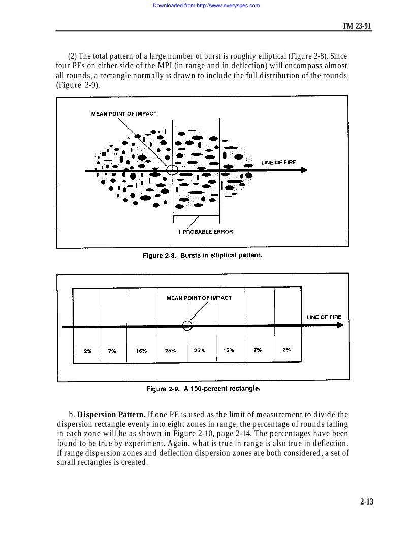
(2) The total pattern of a large number of burst is roughly elliptical (Figure 2-8). Sincefour PEs on either side of the MPI (in range and in deflection) will encompass almostall rounds, a rectangle normally is drawn to include the full distribution of the rounds(Figure 2-9).
b. Dispersion Pattern. If one PE is used as the limit of measurement to divide thedispersion rectangle evenly into eight zones in range, the percentage of rounds fallingin each zone will be as shown in Figure 2-10, page 2-14. The percentages have beenfound to be true by experiment. Again, what is true in range is also true in deflection.If range dispersion zones and deflection dispersion zones are both considered, a set ofsmall rectangles is created.
2-13
Downloaded from http://www.everyspec.com

FM 23-91
Section IIIFIRE PLANNING
The ability of mortar platoons to engage targets with accurate and sustainedfires depends on the precision and detail of fire planning. Fire planning isconcurrent and continuous at all levels of command. The principles of fireplanning used by field artillery also apply to mortars. These principles are closeand continuous support of the battalion, coordination with adjacent and higherunits, and continuous planning.
2-18. TERMINOLOGYSome of the common terms used in fire planning are defined as follows:
a. A target may be troops, weapons, equipment, vehicles, buildings, or terrain thatwarrant engagement by fire and that may be numbered for future reference. A solidcross designates a target on overlays, with the center of the cross representing the centerof the target. The target number consists of two letters and four numbers allocated byhigher headquarters. That numbering system identifies the headquarters that plannedthe target, distinguishes one target from another, and prevents duplication.
b. Targets of opportunity are targets for which fires have not been planned. Plannedtargets are scheduled or on call.
(1) Scheduled targets are fired at a specific time before or after H-hour, or uponcompletion of a predetermined movement or task.
(2) On-call targets are fired only upon request. They include targets for whichfiring data are kept current, and targets for which firing data are not prepared inadvance—for example, a prominent terrain feature, such as a road junction, that theFO may use as a reference point.
2-14
Downloaded from http://www.everyspec.com

FM 23-91
c. A group of targets consistsof two or more targets to be firedat the same time. Targets aregraphically portrayed by circlingand identifying them with agroup designation (Figure2-11). Mortars are normallyassigned groups of targets. Thegroup designation consists of theletters assigned to the maneuverbrigade by the division TOCwith a number inserted betweenthem. For example, if thebrigade is assigned the lettersA and B, the first group of targets planned by the DS battalion FDC is designated A1B,the second group A2B, and so on. Similarly, if the division TOC has designated theletters A and Y, the first group is A1Y and the second is A2Y. The designation of agroup of targets does not preclude firing at any individual target within the group.
d. A series of targets (Figure 2-12) is a number of targets or groups of targets plannedto support the operation. For example, a series of targets may be planned on a large objectiveso that fires are lifted or shifted as the support unit advances. Graphically, a series is shownas individual targets or groups of targets within a prescribed area. The series is given a codename. The fact that a series of targets has been formed does not preclude the attack ofindividual targets or groups of targets within a series.
2-15
Downloaded from http://www.everyspec.com
FM 23-91
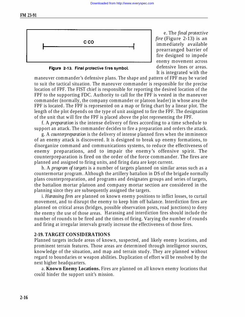
e. The final protectivefire (Figure 2-13) is animmediately availableprearranged barrier offire designed to impedeenemy movement acrossdefensive lines or areas.It is integrated with the
maneuver commander’s defensive plans. The shape and pattern of FPF may be variedto suit the tactical situation. The maneuver commander is responsible for the preciselocation of FPF. The FIST chief is responsible for reporting the desired location of theFPF to the supporting FDC. Authority to call for the FPF is vested in the maneuvercommander (normally, the company commander or platoon leader) in whose area theFPF is located. The FPF is represented on a map or firing chart by a linear plot. Thelength of the plot depends on the type of unit assigned to fire the FPF. The designationof the unit that will fire the FPF is placed above the plot representing the FPF.
f. A preparation is the intense delivery of fires according to a time schedule tosupport an attack. The commander decides to fire a preparation and orders the attack.
g. A counterpreparation is the delivery of intense planned fires when the imminenceof an enemy attack is discovered. It is designed to break up enemy formations, todisorganize command and communications systems, to reduce the effectiveness ofenemy preparations, and to impair the enemy’s offensive spirit. Thecounterpreparation is fired on the order of the force commander. The fires areplanned and assigned to firing units, and firing data are kept current.
h. A program of targets is a number of targets planned on similar areas such as acountermortar program. Although the artillery battalion in DS of the brigade normallyplans counterpreparation, and programs and designates groups and series of targets,the battalion mortar platoon and company mortar section are considered in theplanning since they are subsequently assigned the targets.
i. Harassing fires are planned on known enemy positions to inflict losses, to curtailmovement, and to disrupt the enemy to keep him off balance. Interdiction fires areplanned on critical areas (bridges, possible observation posts, road junctions) to denythe enemy the use of those areas. Harassing and interdiction fires should include thenumber of rounds to be fired and the times of firing. Varying the number of roundsand firing at irregular intervals greatly increase the effectiveness of those fires.
2-19. TARGET CONSIDERATIONSPlanned targets include areas of known, suspected, and likely enemy locations, andprominent terrain features. Those areas are determined through intelligence sources,knowledge of the situation, and map and terrain study. They are planned withoutregard to boundaries or weapon abilities. Duplication of effort will be resolved by thenext higher headquarters.
a. Known Enemy Locations. Fires are planned on all known enemy locations thatcould hinder the support unit’s mission.
2-16
Downloaded from http://www.everyspec.com
FM 23-91
b. Suspected Enemy Locations. These include areas such as probable OPs, trooppositions, assembly areas, avenues of approach, and routes of withdrawal. Fires areplanned on suspected locations so that fires are available if the target is confirmed.
c. Likely Enemy Locations. Targets in this category are determined from a carefulstudy of the terrain and maps, and from a knowledge of the enemy’s methods of placingtroops and weapons.
d. Prominent Terrain Features. Hilltops, road junctions, manufactured objects,and other easily identifiable locations on a map and on the ground are planned astargets to provide reference points from which to shift to targets of opportunity.
2-20. SUPPORT OF OFFENSIVE OPERATIONSFires planned to support an attack consist of a preparation, if ordered, and subsequentfires. The preparation may be delivered before the advance of the assault elementsfrom their LD and may continue for a short time thereafter. Fires planned for thepreparation are normally limited to known targets and suspected areas. The deliveryof fires on scheduled targets should be consistent with the threat imposed, timeavailable for coordination, and availability of ammunition.
a. Support Artillery. An artillery preparation is usually phased to permitsuccessive attacks of certain targets. The phasing should be planned to provide forearly domination of enemy fire support means, then the attack of local reserves andcommand and control installations, and later the attack of enemy forward elements.The detail and extent of preparation plans depend on the availability ofintelligence.
b. Battalion Mortar Platoon. The battalion fire plan table for a preparation mayinclude fires by the battalion mortar platoon. Those fires should be limited to theengagement of enemy forward elements. Once the preparation is fired, the mortarplatoon is available for fire support of the battalion maneuver elements. In somesituations, the battalion commander may exclude the mortars from the preparation andretain them for targets of opportunity throughout the attack.
c. Company Mortar Platoon. The company mortar platoon may be requiredto fire preparation fires. Those fires are limited to the engagement of enemyforward elements. Before committing the mortars to preparation fires, thecommander should consider ammunition resupply and availability of mortars toquickly attack targets of opportunity.
d. Fires Supporting the Attack. Fires planned in support of the attack are shiftedto conform to the movements of the supported unit. They are planned in the form oftargets, groups of targets, and series of targets. They may be fired on a time scheduleor on-call and may include targets from the LD to the objective, on the objective, andbeyond the objective.
e. Objectives. Supporting fires have several specific objectives. They assist theadvance of the supported unit by neutralizing enemy forces, weapons, and observationshort of the objective. They assist the supported unit in gaining fire superiority on theobjective so that the assaulting force can close to assault distance, and they protect thesupported unit during reorganization. (On-call targets are planned on likely assembly
2-17
Downloaded from http://www.everyspec.com

FM 23-91
areas and routes for enemy counterattacks.) Supporting fires prevent the enemy fromreinforcing, supplying, or disengaging his forces. Also, they quickly provide mutual firesupport to lower, adjacent, and higher headquarters.
2-21. SUPPORT OF DEFENSIVE OPERATIONSFires in support of defensive operations include long-range fires, close defensive fires,final protective fires, and fires within the battle area.
a. Long-Range Fires. Long-range fires are designed to engage the enemy as earlyas possible to inflict casualties, to delay his advance, to harass him, to interdict him, andto disrupt his organization. They consist of the fires of the supporting weapons withinthe battle area capable of long-range fires. The enemy is engaged by long-rangeweapons as soon as he comes within range. As a result, the volume of fire increases asthe enemy continues to advance and comes within range of additional weapons.A counterpreparation designed to disrupt the enemy’s attack preparations before theattack can be fired as part of long-range fires.
b. Close Defensive Fires. Close defensive fires are supporting fires employed todestroy the enemy attack formations before the assault.
c. Final Protective Fires. FPF are fires planned to prohibit or breakup the enemyassault on the forward defense area. They consist of prearranged fires of supportingweapons to include machine gun FPLs and mortar and artillery FPF. Only thoseweapons whose FPF are in front of the threatened unit fire their assigned fires; all otheravailable weapons use observed fire to supplement or reinforce the FPF in thethreatened area. Direct-fire weapons engage targets in front of the threatened area toreinforce FPF or to engage other targets.
(1) The artillery and mortar FPF are integrated with the FPL of machine guns.Each artillery battery normally fires one FPF. The mortar platoon of the battalionmay fire one or two FPF; however, the platoon’s fires are more effective in one FPFthan in two.
(2) The FPF of the DS artillery are available to the supported brigade and itsbattalions. The FPF of any artillery reinforcing DS battalion is normally available.The brigade commander designates the general areas for available FPF or allocatesthem to the maneuver battalions. The maneuver battalion commander, in turn,designates general locations or allocates them to maneuver companies.
d. Fires Within the Battle Area. The precise location of an FPF is the responsibilityof the company commander in whose sector it falls. The exact locations of FPF within eachforward company are included in the fire plan and reported to battalion. Fires within thebattle area are planned to limit penetrations and to support counterattacks.
2-22. FIRE SUPPORT COORDINATION MEASURESThe FIST and fire support planners use fire support coordination measures to ensurethat fires impacting in their zone will not jeopardize troop safety, interfere with otherfire support means, or disrupt adjacent unit operations.
a. Boundaries. Boundaries determined by maneuver commanders establish theoperational zone for a maneuver unit and the area in which the commander fires and
2-18
Downloaded from http://www.everyspec.com

FM 23-91
maneuvers freely. A unit may fire and maneuver against clearly identified enemy targetsnear or over its boundary, as along as such action does not interfere with adjacent units.
b. Coordination Measures. Coordination measures designate portions of thebattlefield where actions may or may not be taken. The fire FSCOORD/FIST chiefrecommends coordination measures; the commander establishes them. They facilitateoperations by establishing rules and guidelines for selected areas for a given time.There are two categories: permissive and restrictive.
(1) Permissive measures. Permissive measures are drawn in black on overlays andmaps. They are titled and indicate the establishing headquarters and the effectivedate-time group. Permissive measures allow fires into an area such as a free-fire areaor across a line — for example, a coordinated fire line or FSCL — that need not be furthercoordinated as long as they remain within the zone of the established headquarters.
(a) A coordinated fire line is a line beyond which conventional surface fire supportmeans (mortars, FA, NGF) may fire any time within the zone of the establishingheadquarters without further coordination.
(b) A fire support coordination line is a line beyond which all targets may be attacked byany weapon system without endangering troops or requiring further coordination with theestablishing headquarters. The effects of any weapon system may not fall short of this line.
(c) A free-fire area is a designated area into which any weapon system may firewithout further coordination with the establishing headquarters.
(2) Restrictive measures. Restrictive measures are drawn in red. They are titledand indicate the establishing headquarters and the effective date-time group.Restrictive measures mean that fires into an area or across a line must be coordinatedwith the establishing headquarters on a case-by-case basis. Examples of restrictivemeasures include a restrictive fire area, a no-fire area, a restrictive fire line, and anairspace coordination area.
(a) A restrictive fire area is an area in which specific restrictions are imposed andinto which fires that exceed those restrictions will not be delivered without coordinationwith the establishing headquarters.
(b) A no-fire area is an area in which no fires or effects of fires are allowed. Thereare two exceptions: when establishing headquarters approves fires temporarily withina no-fire area on a mission basis; and when an enemy force within the no-fire areaengages a friendly force, and the commander engages the enemy to defend his force.
(c) A restrictive fire line is a line established between converging friendly forces (oneor both may be moving) that prohibits fires or effects from fires across the line withoutcoordination with the affected force.
(d) An airspace coordination area is a block of airspace in the target area in whichfriendly aircraft are reasonably safe from friendly surface fires. It may be a formalmeasure but is usually informal.
2-23. COMPANY FIRE SUPPORT PLANThe company commander’s fire planning begins with receipt or assumption of a missionand continues throughout the execution of the mission. The company fire planningteam consists of the company commander, FIST chief, mortar platoon leader, and
2-19
Downloaded from http://www.everyspec.com

FM 23-91
platoon’s FIST FOs. During the process of evaluating, refining, revising, and decidinghow to accomplish the mission, the commander constantly seeks the most efficient andeffective application of all resources to produce maximum combat power.
a. The FIST chief, as the commander’s special staff officer for fire support,performs a critical role in this planning process. He ensures that the commander hasall required information on available fire support and recommends how best to applyit in concert with other resources. For best results, the commander should include theteam in every step of his decision-making process.
b. The company commander gives guidance to the fire planning team in the form of aconcept. This concept outlines the scheme of maneuver and the desire for fire support.Later, when the FIST chief submits the proposed consolidated target list and companyfire plan, the company commander approves or changes it.
c. The company commander supervises the preparation of the company fire planand coordinates the fire planning activities. The FIST chief develops the company fireplan and consolidates it with copies of the target lists prepared by the platoon FOs.This consolidated list is then submitted to the company commander for approval.
d. The company fire planners inform the company commander of the fire supportavailable. They also obtain the following information for or from the company commander:
Location of forward elements.Scheme of maneuver.Known enemy locations, avenues of approach,and assembly areas.Fires desired.Exact location of the company and battalionmortar and artillery FPF.Location of the command post.
Upon receipt of this information, the fire planners start planning fires to supporte.the company. Through map inspection and ‘terrain analysis, the-target lists- areprepared (Table 2-l). If time and facilities permit, an overlay, giving a graphicrepresentation, may also be prepared. The target list includes for each target the targetnumber, map coordinates, description, and amplifying remarks if required. It does notinclude target altitudes, which are determined by the respective FDCs.
f. When time is limited, target information may be submitted by telephone orradio directly to an FDC. The FIST chief assigns numbers to targets not includedin the list from the platoon FO or mortar platoon leader. Numbers from theseparate target lists are transferred to the corresponding targets on the approvedconsolidated target list/company fire plan. Targets on the list are arranged by targetnumber alphabetically and numerically.
g. Once the fire plan is approved, it is distributed to those who will need itto include FOs, rifle platoon leaders, FDC, company fire planners, and battalionS3. Also, the FIST chief sends a copy of the approved target list to the FSO atbattalion headquarters.
2-20
Downloaded from http://www.everyspec.com

FM 23-91
2-24. BATTALION FIRE SUPPORT PLANFire planning at battalion level is initiated the same as in the company. The battalionfire planning team consists of the battalion commander, S3, battalion mortar platoonleader, and FSO. The battalion mortar platoon must always be directly responsive tothe desires of the battalion commander. The platoon leader takes a position that bestassists the S3 in planning and obtaining fire support. The FSO is normally the battalionFSO; however, the battalion mortar platoon leader serves in the absence of the FSO.
a. The battalion commander and S3 present the commander’s concept of the operation,which, as in the case of the company, includes the scheme of maneuver and the plan for firesupport. After the FSO has consolidated the target lists prepared by the company fireplanners, the battalion commander approves the consolidated target list as part of thebattalion fire support plan. The written plan becomes an annex to the operation plan.
b. The FSO is usually the battalion FSCOORD and receives target lists from thecompany’s FIST chief and from the battalion mortar platoon leader. Once duplicationsare deleted, all fire plans are updated by assigning target numbers or by consolidatingtargets. Then, the FSO submits all fire plans and target lists to the battalion S3 as theproposed battalion fire support plan.
c. The S3 ensures that the proposed fire support plan supports the scheme ofmaneuver. After the battalion commander approves the fire plan, the plan becomesan annex to the battalion operation plan. It is disseminated to all subordinate elementsto include rifle companies and the battalion mortar platoon.
2-21
Downloaded from http://www.everyspec.com

FM 23-91
Section IV.TARGET ANALYSIS AND ATTACK
The FIST chief, when planning fires or when deciding to engage a target, ensuresthat the fire conforms to the scheme of maneuver of the support unit. He mustalso be informed of the present enemy situation.
2-25. TARGET DESCRIPTIONThe method of attacking a target depends largely on its description, which includes thetype, size, density, cover, mobility, and importance. Those factors are weighed againstthe guidelines established by the commander. The FDC then decides the type ofprojectile, fuze, fuze setting, and ammunition to be used.
a. Fortified targets must be destroyed by point-type fire using projectiles and fuzesappropriate for penetration. Mortar fire does not usually destroy armor, but it canharass and disrupt armor operations.
b. A target consisting of both men and materiel is normally attacked by area fire using airor impact bursts to neutralize the area. Flammable targets are engaged with HE projectilesto inflict fragmentation damage, and then with WP projectiles to ignite the material.
c. The method of attacking a target is governed by the results desired: suppression,neutralization, or destruction.
(1) Suppressive fires limit the ability of enemy troops in the target area to be aneffective force. HE/PROX creates apprehension or surprise and causes tanks to buttonup. Smoke is used to blind or confuse, but the effect lasts only as long as fires arecontinued.
(2) Neutralization knocks the target out of the battle temporarily. Ten percent ormore casualties usually neutralize most units. The unit becomes effective again whencasualties are replaced and equipment repaired.
(3) Destructive fires put the target out of action permanently. A unit with 30percent or more casualties is usually rendered permanently ineffective, depending onthe type and discipline of the force. Direct hits are required on hard materiel targets.
2-26. REGISTRATION AND SURVEY CONTROLFiring corrections within the transfer limits should be maintained through registration,survey data, and current MET message. When those data are unavailable orinadequate, targets should be attacked with observed fire since unobserved fires maybe ineffective. Surveillance should be obtained on all missions to determine the resultsof the FFE. If accurate, FFE without adjustments is highly effective against troops andmobile equipment because damage is inflicted before the target can take evasive action.All destruction missions and missions fired at moving targets must be observed, andFFE should be adjusted on the target.
2-27. SIZE OF ATTACK AREAThe size of the attack area is determined by the size of the target, or by the size of thearea in which the target is known or suspected to be located. That information is usuallyan estimate based on intelligence and experience in similar situations. The size of the
2-22
Downloaded from http://www.everyspec.com

FM 23-91
attack area is limited when considering units to fire. Mortars are the best weapons forengaging targets in depth. This is due to their versatility in making range changes andmaintaining high rates of fire. All mortars can fire traversing fires with only minormanipulations.
2-28. MAXIMUM RATE OF FIREThe greatest effect is achieved when surprise fire is delivered with maximum intensity.Intensity is best attained by massing the fires of several organic battalion units usingTOT procedures. The intensity of fires available is limited by each unit’s maximumrate of fire (Table 2-2) and ammunition supply. Maximum rates cannot be exceededwithout danger of damaging the tube. To maintain those rates (either to neutralize atarget or to attack a series of targets), mortars must be rested or cooled from previousfiring. If not, the heat can cause ignition of the increment or charges on a round beforeit reaches the bottom of the barrel. The lowest charge possible should be used duringprolonged firing, since heating is more pronounced with higher charges.
2-29. AMOUNT AND TYPE OF AMMUNITIONThe amount of ammunition available is an important consideration in the attack oftargets, The CSR should not be exceeded except by authority of higher headquarters.
2-23
Downloaded from http://www.everyspec.com

FM 23-91
When the CSR is low, missions should be limited to those that contribute the most tothe mission of the supported units. When the CSR is high, missions fired may includetargets that affect planning or future operations and targets that require massing of fireswithout adjustment.
a. The selection of a charge with which to engage a target depends on the elevationrequired. The range and terrain dictate the elevation to be used. Hence, targets at agreat distance require the lowest elevations and greatest charge, while targets in deepdefilade require the highest elevations. Targets in deep defilade and at great range arehard to engage. This is due to the low elevation required to reach those targets, whichprevents the round from having the high trajectory needed. The 4.2-inch mortar usesone of three constant elevations and makes range changes by varying the charge. The60-mm and 81-mm mortars vary both the elevation and charge but attempt to stay atthe lowest charge while varying the elevation.
b. The type of ammunition selected to engage a target depends on the nature ofthe target and characteristics of the ammunition available. The effect of HEammunition varies with the fuze used.
(1) Quick and superquick fuzes. Quick and SQ fuzes are used for impactdetonation. When the HE projectile with a quick or SQ fuze passes through trees,detonation may occur in the foliage. Therefore, its effectiveness may be eitherimproved or lost, depending on the density of the foliage and the nature of thetarget.
(2) Proximity fuzes. A proximity fuze is used with HE ammunition to get airbursts.A proximity or VT fuze detonates automatically upon approach to an object. It is usedto get airbursts without adjusting the HOB. If the proximity element fails to function,a fuze quick-action occurs upon impact. The HOB varies according to the caliber ofprojectile, the angle of fall, and the type of terrain in the target area. If the terrain iswet or marshy, the HOB is increased. Light foliage has little effect on a proximity fuze,but heavy foliage increases the HOB by about the height of the foliage. The greaterthe angle of fall, the closer the burst is to the ground.
(3) Fuze delay. Fuze delay produces a mine action caused by the round’spenetration before detonation. Fuze delay can be used to destroy earth and logemplacements. It is also effective against some masonry and concrete structures. Fuzedelay is NOT used against armor. The depth of penetration depends on the type of soiland terminal velocity of the round.
(4) Illumination. Illumination using time fuze gives an airburst depending on thetime set on it. The setting depends on the charge and elevation fired. When time fuzeis used, the HOB can be adjusted to give the best illumination on the desired location.
(5) Chemical ammunition. Chemical ammunition is used for producing casualties,incendiary effects, screening, marking, and harassing. Among the types of fillings inchemical projectiles are gas (CS) and WP.
(6) Projectiles. Projectiles filled with chemical agents are useful for causing casualtiesin fortified positions or installations. Chemical rounds may be used at low expenditure ratesto harass the enemy and to force them to wear protective masks for prolonged periods.
2-24
Downloaded from http://www.everyspec.com

FM 23-91
c. The influence of weather (wind direction, velocity, temperature, andhumidity) influences the effectiveness and tactical desirability of chemical agents.If the weather is favorable, chemical agents can be more effective than HE on around-for-round basis.
2-30. UNIT SELECTIONThe unit selected for a mission must have weapons of the proper caliber and range tocover the target area quickly, effectively, and economically. Many targets are of suchsize as to allow a wide choice for selecting the units to be employed. If the unit selectedto fire cannot mass its fires in an area as small as the target area, ammunition is wasted.Conversely, if a unit can cover only a small part of the target area at a time, surprise islost during the shifting of fire. Also, the rate of fire for the area may not be adequateto get the desired effect. The decision is often critical as to whether to have many unitsfiring a few rounds on a large target or a few units firing many rounds. Several factorsaffect the selection of units and the number of rounds to fire on a target. Some of thosefactors are discussed below.
a. Availability of Mortar Fire. When the number of available mortar units is small,more targets must be assigned to each mortar unit.
b. Size of the Area to be Covered. The size of the area to be covered must becompared to the effective depth and width of the sheaf to be used by the platoon orplatoons available.
c. Increased Area Coverage. Targets greater in depth or width than the standardsizes can be covered by—
(1) Increasing the number of units firing.(2) Dividing the target into several targets and assigning portions to different platoons.(3) Shifting fire laterally or using zone fire with a single unit or with a number of
units controlled as a single fire unit.(4) Traversing fire with each mortar that is covering a portion of the target.
d. Caliber and Type of Unit. The projectiles of larger calibers are more effectivefor destruction missions.
e. Surprise. To achieve surprise, a few rounds from many pieces are better thanmany rounds from a few pieces.
f. Accuracy of Target Location. Important targets that are not accurately locatedmay justify the fire of several units to ensure coverage.
g. Dispersion. At extreme ranges for a given mortar, fire is less densebecause of increasing PE. More ammunition is required to effectively cover thetarget. To compensate for that dispersion, the commander selects a unit, whenpossible, whose GT line coincides with the long axis of the target.
h. Maintenance of Neutralization and Interdiction Fires. These fires may bemaintained by the use of a few small units. A unit may fire other missions during thetime it also maintains neutralization or interdiction fires.
i. Vulnerability of Targets. Some targets should be attacked rapidly with massed fireswhile they are vulnerable. These targets could be truck parks and troops in the open.
2-25
Downloaded from http://www.everyspec.com

FM 23-91
2-31. TYPICAL TARGETS AND METHODS OF ATTACKMortar targets include enough enemy materiel, fortifications, and troops to justifyammunition expenditure (Table 2-3). Mortar fire is not effective against minefieldand barbed wire. Also, HE ammunition is not effective for clearing minefield sincemines are detonated only by direct hits. As a result, mortar fire fails to clear theminefield and compounds the problem of locating and removing the mines by hand andof moving equipment across the mined area. Mortars also require extravagant amountsof ammunition to breach barbed wire and should not be used.
2-26
Downloaded from http://www.everyspec.com

FM 23-91
2-27
Downloaded from http://www.everyspec.com
Part TwoFIRE DIRECTION CENTER
CHAPTER 3
INTRODUCTION
This chapter contains information on the principals of fire direction procedures,organization of FDCs, and duties and responsibilities of FDC personnel. Mortar leadersshould use this information as a guide to help prepare and conduct training for combat.
3-1. PRINCIPLES OF FIRE DIRECTIONFire direction is the tactical and technical employment of firepower, the exercise oftactical command of one or more units in the selection of targets, the massing ordistribution of fire, and the allocation of ammunition for each mission. Fire directionalso includes the methods and techniques used in FDCs to convert calls for fire intoproper fire commands.
a. Tactical fire direction is the control by the FDC over the mortars in the selectionof targets, the designation of the units to fire, and the allocation of ammunition for eachmission,
b. The FDC is the element of the mortar platoon headquarters that controls thefire of the mortar section and relays information and intelligence from the observersto higher headquarters, Fire direction methods must ensure—
(1) Close, continuous, accurate, and timely indirect fire support under allconditions of weather, visibility, and terrain.
(2) Flexibility to engage all types of targets within the company or battalion areaof responsibility.
(3) The ability to engage two or more targets at the same time.(4) The ability to implement independent gun operation.
3-2. ORGANIZATIONThe FDC is the element of the indirect fire team that receives the call for fire from theFO, FIST chief, or higher headquarters; determines firing data; and announces the firecommand to the firing section. The FDC also determines and applies corrections tochart data and to standard firing table values to achieve accuracy in firing. Firing data
3-1
Downloaded from http://www.everyspec.com

FM 23-91
normally are produced in the FDC. However, they may be produced by a squad leaderwhen the section is firing without an FDC. Accuracy, flexibility, and speed in theexecution of fire missions depend on—
a. Accurate and rapid computation of firing data from the MBC and plotting board.b. Clear transmission of commands to the mortar section.c. Accurate and rapid verification of firing data.d. Efficient division of duties.e. Adherence to standard techniques and procedures.f. Efficient use of FDC plotting equipment, MBC, and other data-determining devices.g. Teamwork and operating in a specified sequence.h. Efficient use of communications, including the FDC switchboard.
3-3. PERSONNEL DUTIESThe FDC of the 4.2-inch mortar section consists of: one SFC who is the sectionsergeant, one SSG who serves as the chief computer, one SGT who is the checkcomputer, and one PFC who is the driver/RATELO. The FDC of the 8 l-mm mortarplatoon consists of: one SSG who serves as the section sergeant; and two sergeantswho are the computers (one trained as a driver); and one PFC who is thedriver/RATELO.
a. Fire Direction Chief/Section Sergeant. The fire direction chief (chiefcomputer/section sergeant), as the senior enlisted member of the FDC, plans,coordinates, and supervises the activities of the FDC and is responsible for the trainingof all FDC members. The fire direction chief must operate all FDC equipment as wellas supervise their operation. The fire direction chief/section sergeant also performsbut is not limited to the following duties:
(1) Makes the decision to fire. When a target is reported, examines its locationrelative to friendly troops, boundary lines, no-fire lines, and fire coordination lines.Using that information, along with the nature of the target, the ammunition available,and the policy of the commander, decides whether to fire. If the decision is to engagethe target, uses that same information in deciding how to do so.
(2) Issues the FDC order. Once the decision has been made to engage a target,issues the FDC order to inform the other members of the FDC how the mission willbe conducted.
(3) Verifies corrections and commands. Verifies firing corrections obtained froma registration or a MET message before they are applied. Ensures that all firing dataand fire commands sent to the mortar section are cross-checked to eliminate errors.Resolves discrepancies.
(4) Determines the altitude of a target from the map and announces it immediatelyafter the FDC order so that the computers may compute and apply any altitude correction.
(5) Maintains records for all fire missions and all corrections to be applied.(6) Evaluates and relays target surveillance data and intelligence reports from
observers.(7) Coordinates with the FIST chief regarding sectors of responsibility and
up-to-date tactical information. If the FDC gets a call-for-fire for a target it cannot
3-2
Downloaded from http://www.everyspec.com

FM 23-91
engage immediately or effectively, it must inform the FIST chief so the mission can beassigned to another firing element.
b. Section Sergeant. The section sergeant is responsible for the same duties forthe 81-mm mortar FDC as the chief computer for the 4.2-inch/120-mm mortar platoon.The section sergeant also has the following duties:
(1) Supervises tactical deployment of the mortar squads.(2) Selects sites for tactical employment of mortar squads.(3) Supervises the laying of the mortar section.(4) Supervises the section during fire missions.c. Computers. Two fire direction computer personnel are in the FDC of each type
of mortar section, with the exception of the 60-mm mortar. Reasons for having twocomputers in the FDC are many. There is not only a vastly reduced possibility of errorbut also an increase in speed and efficiency of operation. Also, the platoon or sectionmay be split to fire multiple missions. Members of the FDC should be cross trained incomputing to allow rotation for round-the-clock operations. In the 81-mm/120-mmmortar section, one computer acts as RATELO for communications with the observers,while the other computer relays fire commands to the section.
(1) The MBC is the main means of fire control for all mortars. The FDC uses theMBC to convert observer data to fire commands to inform the firing section. It usesthe M16 plotting board as the alternate means of fire control for all mortars. The FDCalso uses the M19 plotting board as an alternate means of fire control for the 60-mmmortar section. The FDC should use two MBCs or two M16/M19 plotting boards atall times, one to cross-check the other, to prevent errors.
(2) The computer’s duties include preparing and maintaining an MBC or plottingboard for the plotting of targets and production of firing data. The computer plotstarget locations called in by an observer and updates them with observer corrections.He then determines and announces gun(s) to fire, number of rounds, deflection, charge,and elevation.
(3) The computer determines the size of angle T and announces it when required.This team member numbers and replots targets for future reference, and computes andapplies registration and MET corrections. He also plots information as to the locationof friendly elements, supported unit boundaries, observers, no-fire lines, and safetylimits in the MBC or on the M16/M19 plotting board, The computer maintains thedata sheet with current firing information on all targets.
d. Driver/Radiotelephone Operator. The RATELO in the FDC is also the driverfor the FDC vehicle. He must be trained in communications procedures as well as inthe duties of the computers. Specific duties are to operate the telephones and radioswithin the FDC, to repeat calls for fire received from an observer, and to issue themessage to the observer.
3-3
Downloaded from http://www.everyspec.com

CHAPTER 4
MAJOR CONCERNS OF THEFIRE DIRECTION CENTER
This chapter contains information on some of the "tools” the FDC uses to accomplishits mission. It also discusses the methods and techniques used in FDCs to convert calls forfire into proper fire commands.
4-1. TYPES OF SHEAVESWhen the mortar section or platoon engages a target, different sheaves can be used,which depend on the type of target being engaged.
a. Parallel Sheaf. A parallel sheaf (Figure 4-1) is usually used on area targets.With the parallel sheaf, the distance between impacts of rounds from two or moremortars is the same as the distance between the mortars. Also, mortars all fire the samedeflection, elevation, and charge.
b. Converged Sheaf. The converged sheaf (Figure 4-2) is normally used on a pointtarget such as a bunker or machine gun position. It causes rounds from two or moremortars, each firing a different deflection, to impact at the same point.
4-1
Downloaded from http://www.everyspec.com

FM 23-91
c. Open Sheaf. The open sheaf (Figure 4-3) is normally used to engage targets thatare wider than a standard sheaf can cover. With the open sheaf, the distance betweenimpacts of rounds from two or more mortars is half again the distance between thebursts of the rounds in a standard sheaf. Normally, 81-mm and 4.2-inch mortar roundsimpact 40 meters apart, and 120-mm rounds impact 60 meters apart. Thus, in an opensheaf with 60-mm mortars, which impact 30 meters apart in a standard sheaf, roundswould impact 45 meters apart. All mortars fire different deflections for an open sheaf.
d. Special Sheaf. The special sheaf (Figure 4-4) is normally used in an attitudemission and when needed for the FPF. With the special sheaf, each mortar has a certainpoint to engage. The mortars may have different deflections and elevations.
e. Standard Sheaf. With the standard sheaf (Figure 4-5), rounds impact within thetotal effective width of the bursts, regardless of the mortar formation.
4-2
Downloaded from http://www.everyspec.com

FM 23-91
4-2. COMPUTER’S RECORDThe DA Form 2399, Computer’s Record (Figure 4-6), is a worksheet used to record theFO’s call-for-fire and corrections, firing data, and commands to the mortars during afire mission. The FDC uses this form for each mission received and fired by the FDC.Instructions on how to complete DA Form 2399 are discussed below.
4-3
Downloaded from http://www.everyspec.com
FM 23-91
a. ORGANIZATION. Unit that is firing the mission.b. DATE. Date the mission is fired.c. TIME. Time the mission was received (the call-for-fire recorded).d. OBSERVER ID. Forward observer’s callsign.e. TARGET NUMBER. Number assigned to the mission.f. WARNING ORDER. Type of warning order used for the mission (adjust fire,
FFE, immediate suppression).g. TARGET LOCATION. Method used to locate target (grid, shift from, polar).h. TARGET DESCRIPTION. Details of target (type, size, number, protection).i. METHOD OF ENGAGEMENT. Types of adjustment and ammunition (when used).j. METHOD OF CONTROL. The adjustment gun (when named by the FO) and
time of delivery (when used).k. MESSAGE TO OBSERVER. Space used to record any message sent to the
forward observer (when used).l. FDC ORDER. This includes the following:(1) MORTAR TO FFE (mortar to fire for effect) — Mortar(s) that will be used
during the FFE phase of the mission.(2) MORTAR TO ADJ (mortar to adjust) — Mortar(s) that will be used during the
adjustment phase of the mission. Leave blank if the mortar to adjust is the same as themortar to fire for effect.
(3) METHOD OF ADJ (method of adjustment) — Number of rounds used by theadjusting mortar(s) for each correction during the adjustment phase of the mission.
(4) BASIS FOR CORRECTION — Point (usually the registration point) from whichthe correction factors to be applied are determined (surveyed chart only).
(5) SHEAF CORRECTION — Type of sheaf, other than parallel sheaf, that will beused during the FFE.
(6) SHELL AND FUZE — Shell and fuze combination that will be used for themission. The first line is used for the ammunition that will be fired in the adjustmentphase. The second line is used for the ammunition that will be fired in the FFE if itchanges from the adjustment round type. If different types of ammunition will be usedduring the mission, the different rounds are listed – for example:
SHELL AND FUZE: HEQ in Adj, HEQ/WP in FFE(7) METHOD OF FFE (method of fire for effect) — Number and type rounds for
each mortar in the FFE phase of the mission — for example:METHOD OF FFE: 2 Rds HEQ, 2 Rds WP.(8) RANGE LATERAL SPREAD — This is used with illumination with one of the
following:(a) Rg Spread: 60-mm mortar, 250 meters between rounds; 81-mm mortar, 500
meters between rounds; and 4.2-inch and 120-mm mortars, 1,000 meters between rounds.(b) Lateral Spread: 60-mm mortar, 250 meters between rounds; 81-mm mortar, 500
meters between rounds; and 4.2-inch and 12-mm mortars, 1,000 meters between rounds.(c) Rg/Lateral Spread: A combination of range spread and lateral spread.
4-4
Downloaded from http://www.everyspec.com

FM 23-91
(9) ZONE — This is used only with the 4.2-inch mortar. The zone will normallycover 100 or 200 meters. A platoon-size target would require a 100-meter zone, whilea company-size target would require a 200-meter zone. Should the target require it,the 4.2-inch mortar can fire a larger zone. Zone missions fired by 60-mm, 81-mm, and120-mm mortars are fired using searching fire.
(10) TIME OF OPENING FIRE — The fire control for the mission.W/R = When readyAMC = At my command (either the FO or FDC)
The chief computer/section sergeant usually completes the FDC order. This areadescribes how the FDC will engage the target.
m. INITIAL CHART DATA. This includes the following:(1) DEFLECTION — Initial deflection from the mortar position to the target
being engaged.(2)(3)(4)(5)(6)(7)(8)
DEFLECTION CORRECTION — Deflection correction used for the mission.RANGE — Initial range from the mortar position to the target being engaged.VI/ALT CORRECTION — Vertical interval/altitude difference used for the mission.RANGE CORRECHON — Range correction factor used for the mission.CHARGE/RANGE — Charge and corrected range used for the mission.AZIMUTH — The direction from the gun position to the target.ANGLE T — Mil difference between the GT line and the OT line. (Recorded
to the nearest 10 mils and transmitted to the nearest 100 mils.)n. INITIAL FIRE COMMAND. This is the first fire command that is sent to the
mortar section for a mission. To complete the initial fire command, the computermust use the initial chart data, plus any corrections, and the information in theFDC order.
(1) MORTAR TO FOLLOW (mortars to follow or FFE) — The mortar(s) to followall commands or the mortar(s) that will be used in the FFE.
(2) SHELL AND FUZE — The shell and fuze combination used during themission. If it is an adjustment mission, that is the round used during the adjustment.
(3) MORTAR TO FIRE — The number of mortar(s) being used during theadjustment phase.
(4) METHOD OF FIRE — The number of rounds being used for adjustmentand in the FFE, and the type, if mixed. Any control by the FDC would be placedhere — for example:
(a) One round HEQ in adjustment; two rounds HEQ/two rounds WP in FFE, AMC.Announcing the number of rounds in the FFE gives the ammunition bearer time to preparethose rounds, such as, in the event of an immediate-suppression mission.
(b) Three rounds HEQ.(5) DEFLECTION — The command deflection to fire the first round.(6) CHARGE — The command charge needed to fire the first round.(7) TIME SETTING — The time setting needed on mechanical-time fuzes
(normally, illumination) to obtain the desired effects over the target area.
4-5
Downloaded from http://www.everyspec.com

FM 23-91
(8) ELEVATION — The elevation used for engaging the target (800, 900, and 1065for 4.2-inch mortar; for 60-mm, 81-mm, and 120-mm mortars, it is the elevationobtained from the FTs for the range to be fired). The elevation is also the commandto fire in the absence of any type of fire control.
o. ROUNDS EXPENDED. A cumulative count of the number of rounds fired forthe initial fire command.
p. OBSERVER CORRECTION. This includes the following:(1) DEV (deviation) — The LEFT/RIGHT, in meters, sent in by the observer — for example:
DEV: L200 = The observer wants a "left 200 meters" correction.(2) RANGE — The ADD/DROP, in meters, sent in by the observer — for example:
RG: "Add 200" is recorded as + 200, while "Drop 200" isrecorded as -200.
(3) TIME (HEIGHT) — The height correction the observer wants, usually usedwith illumination. For corrections in height, the observer will send UP/DOWN: "UP200" or "DOWN 200" and record the same.
q. CHART DATA. Chart data are obtained from the M16/M19 plotting boards forthe observer’s requested corrections. This section is used only when firing correctionsare to be applied to the chart data to obtain firing data. (Disregard this portion of thecomputer’s record when using the MBC.)
(1) DEFL (deflection) — The deflection read from the plotting equipment beforeany corrections are applied.
(2) CHARGE (RANGE) — Chart charge (or range) is read from the plottingequipment before any corrections are applied. If a range is recorded, the chargecorresponding to it may be written either in the lower part of the CHG box or inparentheses in the adjoining unused MORT FIRE box.
r. SUBSEQUENT COMMANDS. The command data are sent to the mortar(s)to fire the next round(s). Those commands, DEFL/CHG/ELEV, contain chart dataand all firing corrections to apply. In the subsequent fire command, the onlycommands that are announced are any changes from the initial fire command orthe previous subsequent fire command. The elevation is always given regardlessof any changes.
(1) MORTAR TO FIRE — Self-explanatory.(2) METHOD OF FIRE — The number of rounds and type of fire.(3) DEFL (deflection) — The command deflection(s) to fire the round(s).(4) RANGE/CHARGE — The 4.2-inch mortar: the command charge to fire the
rounds; 60-mm/81-mm/120-mm mortars: the command range used for this round(s)and the charge, if different. The range is recorded and used to determine the chargethat is given to the 60-mm/81-mm/120-mm mortars (range is not given to mortars).
(5) TIME (SETTING) — The time setting needed for the mechanical-time fuze.(6) ELEV (elevation) — The elevation used for this round(s); also, the command
to fire in the absence of any fire control.
4-6
Downloaded from http://www.everyspec.com

FM 23-91
4-3. DATA SHEETDA From 2188-R, Data Sheet (Figure 4-7), is used by the computer to record data thatpertains to the mortar section or platoon and the firing data for each target engaged.(For a blank reproducible copy of DA Form 2188-R, see the back of this manual.)
4-7
Downloaded from http://www.everyspec.com

FM 23-91
a. SETUP. FDC uses this block to record the initialization data used by the firing element.(1)(2)(3)(4)(5)(6)(7)(8)(9)
TIME OUT — Amount of time selected between switch function.TGT PRFX — Target prefix used by the firing element.TGT NO. — Target numbering block.ALARM — Alarm on and off function for messages.MIN E/MIN N — Minimum casting and northing coordinates from the map sheet.GD — East or west grid declination.LAT — Latitude from the map sheet.LISTEN — Allows message transmission and reception.BIT RATE — Message transmission rates for DMD-supported missions.
(10) KEY TONE — Length of time required for a communications device.(11) BLK — Transmit block mode for DMD-supported missions.(12) OWNER ID — Owner identification.b. WEAPON DATA. FDC uses this block to record the weapon initialization data
used by the firing element.(1)(2)(3)(4)(5)(6)(7)(8)(9)
UNIT — Unit mortar element is assigned._mm CAR — Weapon type and indicates either mounted or dismounted.BP — Basepiece number.E — Basepiece casting map coordinate.N — Basepiece northing map coordinate.ALT — Altitude in meters of the basepiece.AZ — Mils of the basepiece direction of fire.DEF — Referred deflection used by the firing element.ELE — 107-mm requires a selected elevation.
(10) WPN/DIR/DIS — Weapon number, direction, and distance from thebasepiece. FDC continues completing information until all weapons have beenrecorded for firing section.
c. FO DATA. FDC uses this block to record the forward observers’ locations.(1) FO — Call sign of the forward observer.(2) ALT — Altitude at the forward observer’s location.(3) GRID — Grid coordinates of the forward observer’s location.d. AMMUNITION DATA. FDC uses this section to monitor the rounds. This
information should be updated after each mission.(1)(2)(3)
hand.(4)
TEMPERATURE — Current temperature.TYPE — Appropriate types of ammunition issued.LOT NUMBER — Listing of different lot numbers of the rounds and fuzes on
WEIGHT — Weight difference between types of projectiles.(5) ONHAND — The number, by lot number, the firing element has on the firing position.(6) RECEIVED — Number and type of rounds received.(7) TOTAL — The combination of rounds on hand and those received.(8) ROUNDS EXPENDED — The number of rounds expended for missions.
4-8
Downloaded from http://www.everyspec.com

FM 23-91
(9) ROUNDS REMAINING — The number of rounds remaining.e. TARGET DATA. FDC uses this section to record previously fired targets.(1) TARGET ID — This includes the following:(a) TGT NO (target number) — Alphanumeric identifier assigned to a target.(b) GRID — Six- or eight-digit coordinates of a target.(c) ALT — Altitude of the target.(2) CHART DATA — This includes the following:(a) DEFL (deflection) — Chart (M16/M19) or initial (MBC) deflection to the target.(b) RG/CHG (range/charge) — Chart (M16) or initial (MBC) range and charge for
the mortars needed for a target.(3) FIRING CORRECTIONS — For the 4.2-inch mortar, column (1) is used to
record the total deflection correction used during the mission. Columns (3) and (4)are used on the modified and surveyed charts only. This section includes:
(a) DEFL CORR (deflection correction) — Direction (left/right) and number ofmils to apply to the chart deflection to engage the target.
(b) RG CORR (range correction) — Number and type (+/-) of meters to apply tothe chart range to engage the target.
(c) ALT (altitude) VI (vertical interval) — Altitude of the target and VI difference,UP (+) or DOWN (-) in meters, between the target and the mortar altitudes.
(d) ALT CORR (altitude correction) — For all mortars, this is the number anddirection (UP/DOWN) of meters used for altitude corrections that are applied. For4.2-inch mortars, charge correction is listed that is needed for the VI. For the 60-mm,81-mm, and 120-mm only, corrections for deflection and range are used on the modifiedand surveyed charts.
(4) FIRING DATA — This is the base gun command data for the targets. Thisinformation contains all corrections (when used) plus chart data to get the firing data(command data) to the center mass of the target.
(a) DEFL (deflection) — Command deflection to hit the center mass of the target.(b) RG/CHG (range/charge) — The command range and charge to hit the target.(c) FUZE TIME SETT (fuze time setting) — Fuze/time setting on mechanical fuzes
recorded to the nearest 0.1 second.(d) ELEV (elevation) — Elevation used to fire the round: for 4.2-inch mortars,
800, 900, or 1065; for 60-mm/81-mm/120-mm mortars, the elevation from the firingtables for the command range.
(5) INTELLIGENCE — This includes the following:(a) TIME FIRED — The time the call for fire was received.(b) TARGET DESCR (target description) — What the target was (from the call for
fire on the computer’s record).(c) METH OF ENGMT (method of engagement) — How the target was engaged
(number of mortars, number and type of rounds fired in the FFE).(d) SURVEILLANCE — What happened to the target.(6) ROUNDS — Rounds expended for mission and amount remaining for future missions.
4-9
Downloaded from http://www.everyspec.com
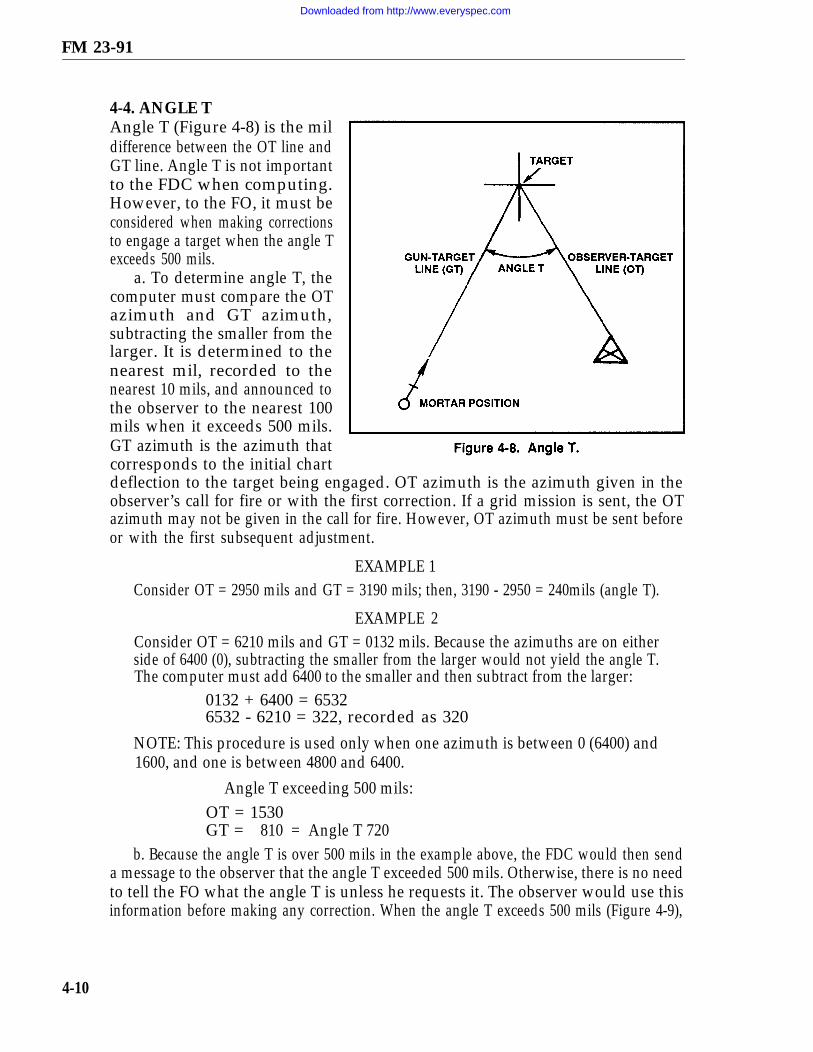
FM 23-91
4-4. ANGLE TAngle T (Figure 4-8) is the mildifference between the OT line andGT line. Angle T is not importantto the FDC when computing.However, to the FO, it must beconsidered when making correctionsto engage a target when the angle Texceeds 500 mils.
a. To determine angle T, thecomputer must compare the OTazimuth and GT azimuth,subtracting the smaller from thelarger. It is determined to thenearest mil, recorded to thenearest 10 mils, and announced tothe observer to the nearest 100mils when it exceeds 500 mils.GT azimuth is the azimuth thatcorresponds to the initial chartdeflection to the target being engaged. OT azimuth is the azimuth given in theobserver’s call for fire or with the first correction. If a grid mission is sent, the OTazimuth may not be given in the call for fire. However, OT azimuth must be sent beforeor with the first subsequent adjustment.
EXAMPLE 1Consider OT = 2950 mils and GT = 3190 mils; then, 3190 - 2950 = 240mils (angle T).
EXAMPLE 2Consider OT = 6210 mils and GT = 0132 mils. Because the azimuths are on eitherside of 6400 (0), subtracting the smaller from the larger would not yield the angle T.The computer must add 6400 to the smaller and then subtract from the larger:
0132 + 6400 = 65326532 - 6210 = 322, recorded as 320
NOTE: This procedure is used only when one azimuth is between 0 (6400) and1600, and one is between 4800 and 6400.
Angle T exceeding 500 mils:OT = 1530GT = 810 = Angle T 720
b. Because the angle T is over 500 mils in the example above, the FDC would then senda message to the observer that the angle T exceeded 500 mils. Otherwise, there is no needto tell the FO what the angle T is unless he requests it. The observer would use thisinformation before making any correction. When the angle T exceeds 500 mils (Figure 4-9),
4-10
Downloaded from http://www.everyspec.com

FM 23-91
the FO would continue to use the OT factor to make deviation corrections. However,if it is observed that the correction is more than asked for, the deviation correctionsshould be reduced proportionately during the mission. Information about the angle Tis automatically given to the FO only if it exceeds 500 mils. If the FO wants to knowwhat the angle-T-is, then the FDC would announce it to the nearest 100 mils.
EXAMPLEThe angle T is 630FDC to FO - "Angle T 600 mils"
ORThe angle T is 320:
FO to FDC - "Request angle T"FDC to FO - "Angle T is 300 mils"
4-5. FIRING TABLESThe firing tables contained in this manual include complete instructions for their use.
NOTE: Refer to appropriate firing tables for specific rounds that are not listed inthis manual.
a. The 60-mm Mortar Firing Tables (Figure 4-10, page 4-12).(1) Parts I, II, III, and IV of FT 60-P-1 contain firing data for various rounds that
use given propelling charges. Each part contains five tables: Table A provides thecomponents of a 1-knot wind; Table B provides air temperature and density corrections;Table C provides variations in muzzle velocity due to propellent temperature; Table Dprovides basic data and nonstandard correction factors; and Table E providessupplementary data.
4-11
Downloaded from http://www.everyspec.com

FM 23-91
(2) Part I includes the M720 HE round; Part II includes the M49A4 HE round; PartIII includes the M302A1 WP round; and Part IV includes the M83A3 illuminationround. The appendixes contain the trajectory charts for the M720 HE round.
(3) FT-6-Q-1 contains information for M49A4 HE, M50A3 training practice,M302A1 WP, and M83A3 illumination rounds for the M31 subcaliber assembly.
b. The 81-mm Mortar Firing Tables (Figure 4-11).(1) FT 81-AR-1 contains the following information:(a) Part I contains six parts. The first of which contains data for corrections for the
HE M889 cartridge. The other five parts contain firing data for a given propelling
4-12
Downloaded from http://www.everyspec.com

FM 23-91
charge using the HE M821 cartridge. Tables A, B, C, D, and E are included to providethe same data for all mortar firing tables.
(b) Part II contains four parts. It provides data for the M819 cartridge, redphosphorus. All four parts contain data for given propelling charges.
(c) The appendixes contain trajectory charts. The computer uses these charts todetermine the height of a round for a given charge and the nearest 100-mil elevationthe round will travel to a given range. These charts assist the computer in determiningwhat round to use in urban combat.
(2) FT 81-AI-3 contains similar data as for the FT 81-AR-1 for the M374A2 andM374 HE, and M375A2 and M375 WP, and M301A3 illumination rounds. Alsoincluded is the section containing information on range, elevation, and maximumordinate for the M68 training round.
(3) FT 81-AQ-1 contains similar data as for the FT 81-AR-1 for the M374A3 HE rounds.
4-13
Downloaded from http://www.everyspec.com

FM 23-91
c. The 4.2-Inch Mortar Firing Tables (Figure 4-12).(1) For the 4.2-inch mortar, FT 4.2-H-2 applies to the M329A1 HE, M328A1 WP,
XM630 chemical, and M335A1 and M335A2 illumination rounds. FT 4.2-K-2 appliesto the M329A2 HE rounds.
NOTE: The M329A1E1 has been type-classified as M329A2.
(2) Parts I, II, III, and IV of FT 4.2-H-2 give details on the different elevations that canbe used with the 4.2-inch mortar, with and without extension, for various rounds and charges.These parts also provide Tables A, B, C, D, and E, which provide the same information asin all firing tables. Part I includes the M329A1 HE round and the M328A1 WP round;
4-14
Downloaded from http://www.everyspec.com

FM 23-91
Part II includes the XM630 round; Part III includes the M335A1 round; and Part IV includesthe M335A2 illumination round. The appendixes contain the trajectory charts.
(3) Parts 1-1, 1-2, and 1-3 of FT 4.2-K-2 provide details of the different elevationsthat can be used with the 4.2-inch mortar for the M329A2 round. These parts alsoprovide Tables A, B, C, D, and E that reflect the same information as in all firing tables.The appendixes contain the trajectory charts.
4-6. BALLISTIC MET MESSAGEThe Ballistic MET Message (DA Form 3675) provides the means to determine the correctionsneeded to the firing data so that the section has better accuracy and target effect withoutreregistering every two to four hours. The MET message corrections are valid until a subsequentMET message is received. It provides the information to compensate for all nonstandardconditions, such as changes in powder temperatures, projectile weight, air temperature and density,and the speed and direction of the wind between the mortar platoon and the targets.
a. Use of MET Message. To be valid, the MET message must be received along withthe initial registration mission. The FDC should request a MET message as soon aspossible after setting up the surveyed firing chart to ensure that the first MET message willbe current. This message alone is not adequate to determine firing corrections. However,it can inform the FDC of how much of the registration corrections are due to weather. Afterthe first MET message is received and computed, a second MET message should bereceived within four hours. This message is computed, the two are compared, and the dataare determined for updating the firing equipment.
b. Source of MET Message. The MET message is received from the corps FAtarget acquisition battalion and is usually transmitted by FM radio to battalion.Battalion headquarters then sends the message down to the FDC. Prior coordinationwith the target acquisition battalion will ensure that the FDC receives the MET inballistic format instead of computerized format.
c. Receipt of MET Message. The MET message is broadcast in six-charactergroups. These groups of characters are shown in Figure 4-13, page 4-16, for ease ofexplanation. An example of a completed DA Form 3675 is given in Figure 4-14, page4-17, using the same six-character groups to show how they are entered into the form.The message has two parts: the introduction and the body.
(1) Introduction. The first four groups of six characters in the MET message arethe introduction, identifying the type of message and the MET station transmitting themessage. This is what the character groups mean:
(a) GROUP 1: MET B 31.MET - indicates that the transmission is a MET message.B - (type of fire) indicates that the message is a ballistic MET message.3 - indicates that the message is for surface-to-surface fire. Foruse with mortars, the number 3 must appear.1 - indicates the octant of the globe in which the MET messageapplies. When code 9 is sent for the octant, the area is in code andnot in numbers — for example, MIF MIF.
4-15
Downloaded from http://www.everyspec.com

FM 23-91
NOTE: Octants are further defined in the firing tables.(b) GROUP 2:344985.
344 - indicates the latitude of the center of the area, expressed tothe nearest tenth of a degree.985 - indicates the longitude of the center of the area, expressedto the nearest tenth of a degree.
(c) GROUP 3: 071010.07 - indicates the day of the month.101 - indicates, to the nearest tenth of an hour, Greenwich meantime (GMT), the hour the period of validity begins.
NOTE: To convert GMT to the standard time, see FM 6-15.0 - indicates the duration of the MET message. For US armedforces, the MET data are presumed valid until a later message isreceived.
(d) GROUP 4: 049982.049 - indicates, in tens of meters, the altitude of the MET stationabove sea level.
4-16
Downloaded from http://www.everyspec.com

FM 23-91
982 - indicates the atmospheric pressure at the MET datum plane(MDP). This value is rounded to the nearest one-tenth of apercent of standard atmospheric pressure at sea level. When thisvalue is 100 or greater, the initial digit 1 is omitted.
4-17
Downloaded from http://www.everyspec.com

FM 23-91
(2) Body. The next groupof six-character blocks is thebody, containing the METdata listed by line number.The relationship of the linenumbers and zone heights tothe meteorological datumplane is shown in Figure 4-15.The remaining 16 lines of thebody are the same form andcontain the same information.The use of all 16 lines is notapplicable for mortars,because of the height that themortars can fire. Only thefirst seven lines (00-006) needbe recorded (Figure 4-16,page 4-19). The charactergroups that compose the body(Figure 4-13, page 4-16) areinterpreted as follows:
(a) 002618: 00 - the line number indicating the standard height relative to the MDP.26 - the direction from which the ballistic wind is blowing (measuredclockwise from north). This is in hundreds of mils; that is, 2600 mils.
18 - the ballistic wind speed to the nearest knot, that is 18 knots.
(b) 009976: 009 - the ballistic air temperature to the nearest 0.1 percent of standard.The initial digit 1 is omitted when the value is 100 or greater.
976 - the ballistic air density to the nearest 0.1 percent of standard. Aswith temperature, the initial 1 is omitted when the value is 100 or greater.
d. Recording of the MET Message. As the MET message is sent, it is recorded onDA Form 3675 (Ballistic MET Message) (Figure 4-14). If, during the transmission,something is missed or recorded wrong, the format of the form allows the computer toask for that portion of the message to be repeated.
e. MET Message Computation. Using DA Form 2601-1 (MET Data CorrectionSheet for Mortars) (Figure 4-17, page 4-20) after the MET message has been recorded,the FDC computes the MET and determines the corrections to apply for updating thefiring equipment. Known data are recorded in the proper spaces on the form. Theseare data available at the mortar platoon or section (obtained from the data sheet orsection sergeant) and are interpreted as follows:
(1) CHARGE — the command charge used to hit the RP. This charge is used todetermine the line number to be used for computing the message.
4-18
Downloaded from http://www.everyspec.com

FM 23-91
(2) CHART RANGE — the command range from the mortar platoon orsection to the RP.
NOTE: The reason for using the command charge and range is that this putsthe round at its highest ordinate for that range, which is where the round isaffected most.
4-19
Downloaded from http://www.everyspec.com

FM 23-91
4-20
Downloaded from http://www.everyspec.com

FM 23-91
(3) ELEVATION OF MORTARS — the elevation used to hit the RP.(4) ALT OF MORTARS — the altitude of the mortar platoon or section to the
nearest 10 meters.(5) LINE NUMBER — used for the MET and can also be recorded before the MET
message is received. To do so, the computer enters the firing tables as follows:(6) DIRECTION OF FIRE — the azimuth to the RP to the nearest 100 mils.(7) POWDER TEMP — the temperature of the propellants. If the temperature of the
powder cannot be determined, air temperature at the platoon or section can be used.(8) WT (weight) OF PROJECTILE (4.2-inch mortar) — the weight of the
ammunition used during the registration mission. The weight is expressed insquares, and two squares (2 ) has been set as the standard. If the section hasdifferent types of ammunition, the same weight projectile must be used during theregistration.
(a) For the 4.2-inch mortar, at the elevation used during the registration: go tocolumn 2 and find the command charge, then go to column 6. The number at thatcharge in column 6 is the line number.
(b) For the 60-mm, 81-mm, or 120-mm mortars, at the command charge: go tocolumn 1 (range) and find the command range, then go to column 5. The number atthat range in column 5 is the line number.
(c) Once the MET message has been received and recorded, record theintroduction and information from the line number being used on DA Form 2601-1(Figure 4-17).
(d) Since the altitude of the MDP is in tens of meters and the wind direction is inhundreds of mils, change them to read their actual values. Once this is done, determinethe MET values (the corrections for this MET).
f. Air Temperature and Air Density Corrections. To determine the correctedvalues for air temperature and air density, the computer must first determine wherethe platoon or section is in relationship to the MDP (difference in DH correction). Todo so, the altitude of the section and the MDP are compared, and the smaller issubtracted from the larger. The remainder is the height of the platoon or section aboveor below the MDP.
NOTE: If the altitude of the section is above the MDP, the sign is plus (+); if below,the sign is minus (-).
(1) Once the distance above or below the MDP is known, the computer can enterTable B (Figure 4-18, page 4-22), which shows the correction that must be applied onthe MET data correction sheet (Figure 4-17) to the ballistic AIR TEMP AIRDENSITY. This compensates for the difference in altitude between the platoon orsection and the MDP, and determines the corrections for AIR TEMP (difference inDT) and AIR DENSITY (difference in DD). Those corrections modify the values ofAIR TEMP and AIR DENSITY determined at the MDP to what the would be at themortar platoon or section. Corrections for difference in DT and difference in DD arearranged in four double rows in the table.
4-21
Downloaded from http://www.everyspec.com

FM 23-91
EXAMPLE
(2) The numbers 0,+100–, +200–, and+300– in the left columnof the table representd i f f e r e n c e i n Hexpressed in hundreds ofmeters. The numbers 0and +10– through+90– across the toprepresent difference inDH in tens of meters.The corrections can befound where theproper hundreds rowcrosses the proper tenscolumn. The numericalsign of the correctionsis opposite of thedifference in DH sign.
Assume that the difference in DH is -30, the corrected value for the differencein DH is + 0.1, and the difference in DD is + 0.3 (enter a 0 in hundreds column,go across to +30-column). Those corrections entered on DA Form 2601-1 andthe corrected values can then be determined and recorded in the proper spaces(Figure 4-17).
g. Wind Component Corrections. To determine the corrections for windcomponents, the computer compares the DIRECTION OF WIND (MET) and theDOF (Figure 4-17). If the direction of wind is lessand then subtracts the DOF.
EXAMPLEDOF 4300, DIRECTION OF WIND (MET) 2900:
than the DOF, he adds 6400 mils
2900 + 6400 = 9300 – 4300 =5000 mils (chart directionof wind).
The remainder (CHART DIRECTION OF WIND) is then used to enter TableA (Figure 4-19, page 2-23) at the CHART DIRECTION OF WIND. Table Adivides a 1-knot wind into crosswind and range wind components to show theeffect on a round in flight. The chart direction of wind is the angle formed bythe DOF and direction of wind. The computer reads across that row to find thecrosswind and range wind components. Those are recorded in the proper spacesin DA Form 2601-1. Once the wind components have been determined, thecomputer determines crosswind and range wind corrections.
4-22
Downloaded from http://www.everyspec.com
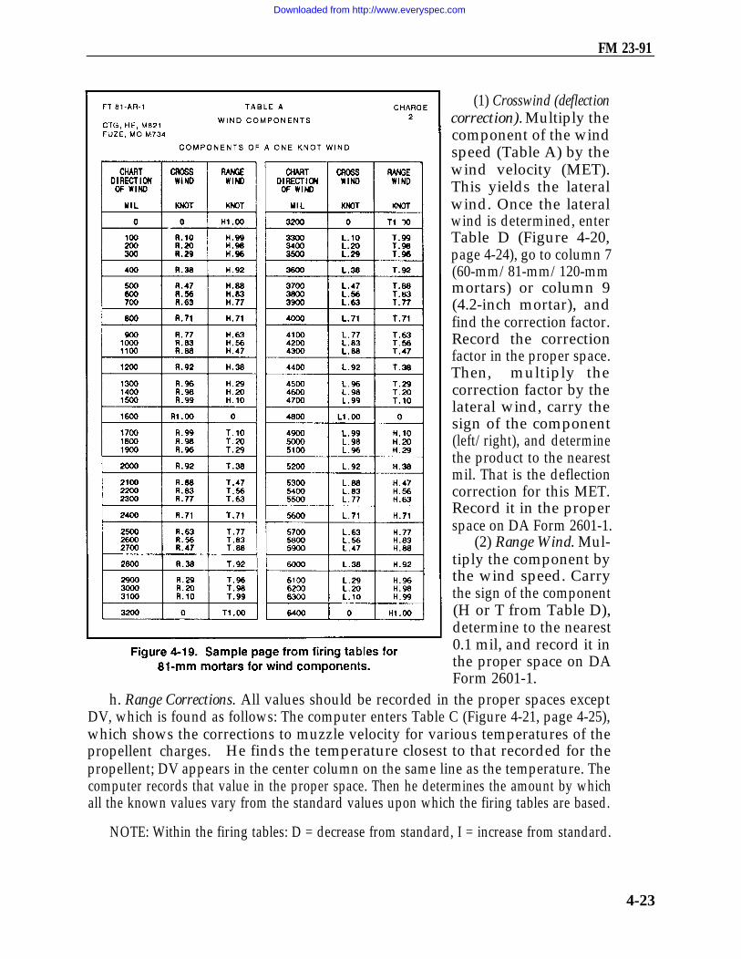
FM 23-91
(1) Crosswind (deflectioncorrection). Multiply thecomponent of the windspeed (Table A) by thewind velocity (MET).This yields the lateralwind. Once the lateralwind is determined, enterTable D (Figure 4-20,page 4-24), go to column 7(60-mm/81-mm/120-mmmortars) or column 9(4.2-inch mortar), andfind the correction factor.Record the correctionfactor in the proper space.Then, multiply thecorrection factor by thelateral wind, carry thesign of the component(left/right), and determinethe product to the nearestmil. That is the deflectioncorrection for this MET.Record it in the properspace on DA Form 2601-1.
(2) Range Wind. Mul-tiply the component bythe wind speed. Carrythe sign of the component(H or T from Table D),determine to the nearest0.1 mil, and record it inthe proper space on DAForm 2601-1.
h. Range Corrections. All values should be recorded in the proper spaces exceptDV, which is found as follows: The computer enters Table C (Figure 4-21, page 4-25),which shows the corrections to muzzle velocity for various temperatures of thepropellent charges. He finds the temperature closest to that recorded for thepropellent; DV appears in the center column on the same line as the temperature. Thecomputer records that value in the proper space. Then he determines the amount by whichall the known values vary from the standard values upon which the firing tables are based.
NOTE: Within the firing tables: D = decrease from standard, I = increase from standard.
4-23
Downloaded from http://www.everyspec.com

FM 23-91
(1) Once those variations are determined, enter the firing table at Table D (Figure 4-20)(command charge and elevation, 4.2-inch mortars; command charge and range,60-mm/81-mm/120-mm mortar), go to columns 8 to 15 (60-mm, 81-mm, and 120-mm)or 10 to 17 (4.2-inch mortar) and record the unit corrections for each variation.
NOTE: The sign of the unit correction must be recorded; numbers without a signare a plus (+). If the column ends, the last listed numbers are considered to continue.
(2) Once the variations have been recorded, multiply the variations fromstandard by the unit corrections and place the result (rounded to the nearest wholemeter) in the column with the same sign as the unit correction. Once all correctionshave been multiplied, compare the minus (–) and plus (+), subtract the smaller
4-24
Downloaded from http://www.everyspec.com

FM 23-91
from the larger, and use the sign of the larger. Determine the result to the nearestmeter for 60-mm/81-mm/120-mm mortars, or to the nearest 10 meters for 4.2-inchmortars, and record in the proper space.
4-7. THE 6400-MIL METMESSAGEThe target area is usuallylarger than the transfer limitsof the RP, and yet time,ammunition, and the tacticalsituation will permit firingonly one registration.
a. By assuming negligibleerror in surveyor maps, lay ofthe weapons, and preparationof the plotting boards orMBC computer, the FDC candivide the registrationcorrections for the RP intotwo parts. The first part is acorrection that is only afunction of the range fired,and it is constant for a givenrange, regardless of direction.The second part is a functionof the direction fired.
b. If the amount of theconcurrent MET computed forthe RP is subtracted from thetotal registration correction, theresult is an absolute registrationcorrection that does not changewith the direction fired or theweather. The FDC can thenplot an imaginary RP at thesame range as the original RP,but in other directions(usually 800 mils apart),compute a MET correction
for each of those directions, and, by adding the different MET corrections to theabsolute registration correction, determine different firing corrections for each of theimaginary RPs. The firing corrections determined for the imaginary RPs can then beapplied when engaging targets within their transfer limits.
4-25
Downloaded from http://www.everyspec.com

FM 23-91
4-8. COMPUTATION OF MET CORRECTIONS FORLARGE SECTOR CAPABILITYA special worksheet, such as DA Form 2601-2-R, MET Data Correction Sheet 6400Mils (Mortars) (Figures 4-22 and 4-23), is needed to compute multiple MET fromsingle registration. The supplemental (imaginary) RPs are spaced 800 mils apart,extending to the right and left of the RP as far as needed to cover the sector
of responsibility. DAForm 2601-2-R shows afull 6400-mil capacity.On the firing chart, allof the imaginary RPsare plotted at the samerange from the mortarposition as the real RP.Computation of theMET corrections aredescribed herein. (Fora blank reproduciblecopy of DA Form2601-2-R, see the backof this publication.)
a. Complete the topsection of the sheet.Compute the differencein DH corrections andthe corrected valuesfor AIR TEMP andAIR DENSITY in theusual way.
b. Determine theCHART DIRECTIONOF WIND as on anormal MET. Copy theresult into the boxmarked I (RP) and asmany others as thereare imaginary RPs (II is800 mils clockwisefrom the RP, and thenumbers increase in aclockwise direction toVIII, which is 800 milscounterclockwise fromthe RP).
4-26
Downloaded from http://www.everyspec.com

FM 23-91
c. Add the directional variations to the CHART DIRECTION OF WIND,
d. Copy the wind velocity into the first row of boxes under DEFLECTIONCORRECTIONS and RANGE CORRECTIONS. Do not use any column that does nothave the CHART DIRECTION OF WIND written on top.
e. From Table A(Figure 4-19), extract theappropriate crosswindcomponent (record it int h e DEFLECTIONCORRECTIONS section)and range wind component(record it in the RANGECORRECTIONS section)for each value of chart windto checkpoints.
f. Multiply the velocityby the components to getvalues for crosswind andrange wind.
g. Find the crosswindcorrection factor in Table D,(column 7, 60-mm/81-mm/120-mm mortars; column 9,4.2-inch mortar) cor-responding to the adjustedRP charge. Multiply it bythe crosswind to get theMET DEFLECTIONCORRECTION.
h. Find the properrange wind unit correctionin Table D, (columns 10and 11, 60-mm/81-mmmortars; columns 12 and13, 4.2-inch mortar).Multiply it by the rangewind to get the RANGEWIND CORRECTION.
i. Compute the METRANGE CORRECTIONSfor POWDER TEMP, AIR
4-27
Downloaded from http://www.everyspec.com

FM 23-91
TEMP, AIR DENSITY, and PROJECTILE WT in the usual manner. The net ofthe four is the ballistic range correction.
j. Combine the ballistic range correction with the various range windcorrections to obtain the total range corrections.
k. Obtain the total MET corrections by bringing together the MET RANGECORRECTION and the MET DEFLECTION CORRECTION for eachof the points.
l. Determine the absolute registration correction. First, calculate theregistration correction. The registration range correction is the differencebetween the chart range to the RP and the range corresponding to the initialrange at the RP; it is plus if the chart range is smaller. The DEFLECTIONCORRECTION is the LARS (left, add; right, subtract) correction, which mustbe applied to the initial deflection read at the RP to get the firing deflectionthat hit it. The RP MET correction, which has been recorded under I (RP), isthen subtracted from the registration correction; the result is the absoluteregistration correction.
m. Add the absolute registration correction to each point MET correction toobtain the corrections to apply at the points.
4-9. METEOROLOGICAL (MET) CORRECTIONSTo place fire on a target without adjustment, the FDC must know the exact locationof the target. He must be able to compensate for all nonstandard conditions.Registration and reregistration are the most accurate methods for determining andmaintaining firing corrections, but reregistration is not always practical. Theballistic MET message helps to determine corrections due to changes in conditionsthat affect the flight of rounds during the periods between registrations. Thoseconditions include changes in powder temperature, air temperature, air density,and the speed and direction of the wind. The FDC assumes that all other factorsremain relatively constant until the section displaces.
a. Corrections computed from the MET message are not adequate firingcorrections alone. To be of value to the FDC, a valid MET message must bereceived along with (or within four hours) the registration. The registrationcorrects for all nonstandard conditions. A MET message received andcomputed along with the registration tells the FDC how much of the totalregistration correction is due to weather. By comparing the corrections from alater MET message, the FDC can modify the registration corrections to accountfor changes in weather. Therefore, the use of MET corrections eliminates theneed for reregistration.
b. For MET corrections to be of use, the FDC must receive two METmessages. The corrections from the two are compared to determine the currentcorrections to update the firing corrections determined from the registration.Once the two messages are computed, the correcting areas (deflectioncorrection and range correction) are compared, and the product is used toupdate the registration corrections.
4-28
Downloaded from http://www.everyspec.com

FM 23-91
Assume that —MET 1:
MET 2:
Place the correction from the MET messages on a MET cross.
EXAMPLE(Figure 4-24)
Deflection correction L20Range correction -100Deflection correction R10Range correction +25
4-29
Downloaded from http://www.everyspec.com

FM 23-91
c. The MET cross helps answer three key questions:Where are you? L20 – 100 (MET 1)Where are you going? R10 + 25 (MET 2)What is required to get there?
(1) Deflection correction. To get from L20 to an R10, first go from L20 to 0, thenright to R10; in doing so, you went R20 then R10 for a total of R30.
(2) Range correction. To get from a –100 to a +25, first go from –100 to 0, thenup the scale to +25; in doing so, you went +100 then +25 for a total correction of +125.
EXAMPLE(Figure 4-25)
MET messages on the same side of the MET cross. Assume —
MET 1: Deflection correction L30Range correction +50
MET 2: Deflection correction L40Range correction +75
Deflection correction L30 + L40 = L10Range correction +50 + +75 = +25
Use the same procedure – "Where am I?" "Where am I going?" "What is requiredto get there?" each time to determine the corrections. Remember, MET 1 iscompared to MET 2, MET 2, to MET 3. This procedure continues as long as METmessages are received and as long as the unit remains in the same position.
d. Once the MET corrections have been determined, the FDC can then determine thecorrections to use for updating. MET is based on the RP, and therefore the correctionsfrom the MET messages are applied to corrections determined from the registration.
(1) Range correction. Compare the range correction from the RP and the MET rangecorrection. For difference signs, subtract the smaller from the larger and use the sign ofthe larger for the new range correction for the RP. If signs are the same, add the values.
EXAMPLERange correction from the registration + 150.Range correction from the MET +50.
+ 150 + 50 = +200 range correction
(2) Range correction factor. Once the range correction has been determined, todetermine the RCF, divide the initial chart range (rounded to the nearest hundred andexpressed in thousandths) into the range correction.
4-30
Downloaded from http://www.everyspec.com

FM 23-91
4-31
Downloaded from http://www.everyspec.com
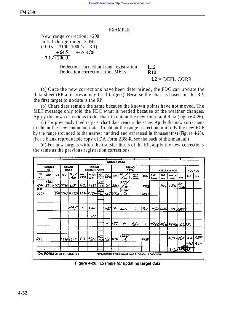
FM 23-91
EXAMPLENew range correction: +200Initial charge range: 3,050(100’s = 3100; 1000’s = 3.1)
Deflection correction from registrationDeflection correction from METs
= DEFL CORR
(a) Once the new corrections have been determined, the FDC can update thedata sheet (RP and previously fired targets). Because the chart is based on the RP,the first target to update is the RP.
(b) Chart data remain the same because the known points have not moved. TheMET message only told the FDC what is needed because of the weather changes.Apply the new corrections to the chart to obtain the new command data (Figure 4-26).
(c) For previously fired targets, chart data remain the same. Apply the new correctionsto obtain the new command data. To obtain the range correction, multiply the new RCFby the range (rounded to the nearest hundred and expressed in thousandths) (Figure 4-26).(For a blank reproducible copy of DA Form 2188-R, see the back of this manual.)
(d) For new targets within the transfer limits of the RP, apply the new correctionsthe same as the previous registration corrections.
4-32
Downloaded from http://www.everyspec.com

CHAPTER 5
CALL FOR FIRE
A call for fire is a concise message prepared by the observer. It contains all informationthe FDC needs to determine the method of target attack.
5-1. INTRODUCTIONThe call for fire is a request for fire — not an order. It must be sent quickly and be clearenough to be understood, recorded, and read back without error by the FDC. Theobserver should tell the RATELO that he has seen a target. This enables the RATELOto start the call for fire while the target location is determined. The RATELO sendsthe information as it is determined instead of waiting until a complete call for fire hasbeen prepared.
a. Regardless of the target location method used, the normal call for fire istransmitted in a maximum of three parts, consisting of six elements, with a break andreadback after each part. The three parts are as follows:
Observer identification and warning order.Target location.Description of target, method of engagement, and method of fire and control.
b. The six elements of the call for fire are listed below in the sequence in whichthey are transmitted.
Observer identification.Warning order.Target location.Target description.Method of engagement.Method of fire and control.
5-2. OBSERVER IDENTIFICATIONObserver identification tells the FDC who is calling for fire, and it clears the net for thefire mission. It consists of appropriate call signs or codes needed to establish contactbetween the observer and the unit FDC to which he is calling for fire.
5-3. WARNING ORDERThe warning order consists of the type of mission and the method of target location. Itis a request for fire unless authority has been given to order fire.
5-1
Downloaded from http://www.everyspec.com

FM 23-91
a. Type of Mission. The following describes the four types of missions for a warning order.(1) Adjust fire (A/F). When the observer decides that an adjustment is needed
because of questionable target location or lack of registration corrections, heannounces, "Adjust fire."
(2) Fire for effect (FFE). The observer should always strive for first-round fire foreffect. The accuracy required to FFE depends on the target and the ammunition beingused. When the observer is certain that the target location is accurate and that the firstvolley will have the desired effect on the target with little or no adjustment, heannounces, "Fire for effect." Accurate, immediate FFE has appreciable surprisevalue and is preferred. FFE without adjustment is warranted when the target hasbeen fired upon previously or when it is within transfer limits of a registration point(+/– 1,500 meters; right or left 400 mils) and its location is either surveyed oraccurately specified by the observer.
(3) Suppression. To rapidly bring fire on an on-call target that is not currentlyactive, the observer announces, "Suppress/suppression (target identification)."
(4) Immediate suppression or immediate smoke (IS). When engaging a plannedtarget or target of opportunity that has taken friendly maneuver or aerial elementsunder fire, the observer announces, "Immediate suppression (target location)." If a hastyscreen for obscuration is the desired effect, then the FO announces, "Immediate smoke."
b. Target Locations. This element enables the FDC to plot (M16/M19) or enter(MBC) the location of the target to determine firing data.
(1) Polar plot. If the target is located by use of the polar plot method, the observerannounces, "Polar." In a polar plot mission, the word polar in the warning order alertsthe FDC that the target will be located with respect to the observer’s position. Theobserver’s location must be known to the FDC. The observer sends the direction (tothe nearest 10 mils) and distance (to the nearest 100 meters). A vertical shift (to thenearest 5 meters) tells the FDC how far the target is located above (up) or below (down)the observer’s location. Vertical shift may also be described by a vertical angle (VA)in mils relative to the observer’s location.
(2) Shift from a known point. If the target is located by this method, the FOannounces, "Shift (known point)." In a shift from a known point mission, the pointfrom which the shift will be made is sent in the warning order. The point must be knownto both the observer and FDC. The observer then sends the OT direction. Normally,direction to the target will be sent to the nearest 10 mils; however, the FDC can usemils, degrees, or cardinal directions, whichever is specified by the observer. The lateralshift (how far left or right the target is from the known point, expressed to the nearest10 meters), the range shift (how much farther [add] or closer [drop] the target is inrelation to the known point, to the nearest 100 meters), and the vertical shift (how muchthe target is above [up] or below [down] the altitude of the known point, to the nearest5 meters) are sent next. The vertical shift is ignored unless it exceeds 30 meters.
(3) Grid. If the target is located by the grid method, the FO announces, "Grid."In a grid mission, six-place grids are normally sent. Eight-place grids should be sentfor registration points or other points for which greater accuracy is required. Since the
5-2
Downloaded from http://www.everyspec.com

FM 23-91
FDC does not need the OT direction to locate the target, it is sent at the end of the callfor fire or just before the initial correction. Direction is expressed to the nearest 10 mils.
5-4. TARGET DESCRIPTIONThe observer must describe the target in enough detail to allow the FDC to determinethe amount and type of ammunition to use. The FDC selects different ammunition fordifferent types of targets. The observer’s description should be brief but accurate andcontain the following:
a. What the target is (troops, equipment, supply dump, trucks, and so forth).b. What the target is doing (digging in, establishing an assembly area, and so forth).c. The number of elements in the target (squad, platoon, three trucks, six tanks,
and so forth).d. The degree of protection (in the open, in fighting positions, in bunkers with
overhead cover, and so forth).e. The target size and shape if significant. When the target is rectangular, the
length and width (in meters), and the attitude (azimuth of the long axis) to the nearest50 mils should be given — for example, 400 meters by 100 meters; attitude 2,650. Whenthe target is circular, the radius should be given. Linear targets may be described bylength, width, and attitude.
5-5. METHOD OF ENGAGEMENTThe observer must indicate how he wants to attack the target. This element consistsof the type of adjustment, type of ammunition, and distribution of fire.
a. Type of Adjustment. In an adjustment, two types of fire may be used — area orprecision.
(1) If no specific type of adjustment is designated, area fire will be used. (Split a100-meter bracket.)
(2) When precision fire is desired, the observer announces, "Registration" or"Destruction," depending on the reason for firing. (Split a 50-meter bracket.)
(3) The term danger close will be included in the method of engagement when thetarget is within 400 meters of friendly troops.
b. Type of Ammunition. If the observer does not request a specific projectile orfuze, he is given shell HE, fuze IMP (impact).
(1) The observer may initially request one type of projectile or fuze andsubsequently request another to complete the fire mission.
(2) When the observer requests smoke, the chief computer normally directs theuse of HE initially in the adjustment and WP for the completion of the adjustment and FFE.
(3) When the observer wants a combination of projectiles or fuzes in effect, hemust state so in this element of the call for fire — for example, "HE and WP in effect"or "IMP and PROX in effect."
(4) The observer may also request the volume of the fire he needs for FFE — for example,"Three rounds." If the observer does not specify the number of rounds to be fired in effect,the FDC should notify the observer of the number of rounds that will be fired in effect.
5-3
Downloaded from http://www.everyspec.com

FM 23-91
c. Distribution of Fire. A standard sheaf is fired on an area target in FFE. Whenanother type of sheaf is desired, the observer must announce "Converge" or "Open sheaf."
5-6. METHODS OF FIRE AND CONTROLThe methods of fire and control indicate the desired manner of attacking the target,whether the observer wants to control the time of delivery of fire or if he can observethe target. The observer announces the methods of fire and control using the termsdiscussed below:
a. Method of Fire. Adjustment normally is conducted with the number 2 mortar.The observer may request any weapon or combination of weapons to adjust. Forexample, if the observer wants to see where each of the mortars in the section hits, hemay request, "Section right (left)." The normal interval of time between rounds firedby a section right or left is 10 seconds. If the observer wants another interval, he mayso specify.
b. Method of Control. The control element indicates the control, which theobserver exercises over the time of delivery of fire, and if an adjustment is to be made.In the absence of observer methods of control, the firing section fires when ready(W/R). The observer announces the method of control by use of the terms below:
(1) At my command (AMC). This announcement indicates that the observerdesires to control the time of delivery of fire. The observer announces, "At mycommand," immediately preceding "Adjust fire or fire for effect." When the weaponsare ready to fire, the FDC personnel announces, "Section is ready," to the observer.The observer then announces, "Fire," when he wants the mortar section to fire. At mycommand remains in effect until the observer announces, "Cancel at my command" or"End of mission."
(2) Cannot observe. This announcement indicates that the observer can not adjustfire. However, the observer believes that a target exists at the given location, and thetarget is important enough to justify firing on it without adjustment.
(3) Time on target (TOT). The observer may tell the FDC when he wants therounds to impact by requesting, "Time on target (so many) minutes from now," or"Time on target zero six four five (0645) hours." The observer must conduct a timecheck to ensure that his timepiece is synchronized with the FDC’s.
(4) Continuous illumination. If no interval is given by the observer, the FDCdetermines the interval by the burn time of the illuminating ammunition in use. Ifanother interval is required, it is indicated in seconds.
(5) Coordinated illumination. The observer may order the interval betweenilluminating and HE rounds in seconds. This achieves a time of impact of the HEround that coincides with optimum illumination, or he may use normal at-my-commandprocedures. The preferred method is to have the FDC compute the intervals betweenthe HE and illuminating rounds.
(6) Cease loading. This command is used during firing of two or more rounds tostop the loading of rounds into the mortars. The gun sections may fire any rounds thathave already been loaded (hung).
(7) Check fire. This command is used to cause an immediate halt in firing.
5-4
Downloaded from http://www.everyspec.com
FM 23-91
(8) Continuous fire. In mortars, this command means loading and firing as rapidlyas possible, consistent with accuracy, within the prescribed rate of fire for the mortarbeing used. Firing continues until suspended by the commands CEASE LOADINGor CHECK FIRE.
(9) Repeat. This command can mean one of two things.(a) During adjustment, REPEAT means to fire another round(s) at the last data
and adjust for any change in ammunition.(b) During FFE, REPEAT means to fire the same number of rounds using the same
method of FFE. Changes to the number of guns, gun data, interval, or ammunitionmay be requested.
(10) Followed by. This is part of a term used to indicate a change in the rate of fire,the type of ammunition, or another order for FFE.
5-7. MESSAGE TO OBSERVERAfter receiving the call for fire, the FDC determines how the target will be attacked.That decision is announced to the observer in the form of a message to observer (MTO).
a. The MTO consists of the following four items:(1) Unit(s) to fire — the number of mortars available that will fire the mission.
EXAMPLEIn a six-gun 4.2-inch mortar platoon, two guns are already involved in a firemission. The other four are available, but the FDC only wants to use three mortarson the new target. The FDC would announce to the observer, "Three guns."
(2) Changes to the call for fire — any change to the observer’s request in thecall for fire.
EXAMPLEThe observer requested IMP in effect, and the FDC decides to fire PROXin effect.
(3) Number of rounds — the number of rounds for each tube in FFE.(4) Target number — assigned to each mission to help the processing of subsequent
corrections.b. The information below can also be transmitted in the MTO.(1) Angle T — sent to the observer when it is equal to or greater than 500 mils, or
when requested.(2) Time of flight — sent to an observer during a moving target mission, during an
aerial observer mission, or when requested.
NOTE: See FM 6-30 and TC 6-40 for more information on MTOs.
5-5
Downloaded from http://www.everyspec.com

FM 23-91
5-8. CALL-FOR-FIRE FORMATThe following is the format for a call for fire.
a. Observer Identification.b. Warning Order.(1) Adjust fire.(2) Fire for effect.(3) Suppression.(4) Immediate suppression/smoke.c. Location of Target.(1) Grid coordinates — direction.(2) Shift from a known point — direction, lateral shift, range shift, vertical shift.(3) Polar coordinates — direction, distance, vertical shift from the OP.d. Description of Target.e. Method of Engagement.(1) Type of adjustment — area, precision (registration, destruction), danger close.(2) Ammunition and fuze.(3) Distribution.
Standard sheaf.Parallel sheaf.Open sheaf.Converged sheaf.Special sheaf.Traversing fire.Range spread, lateral spread,or range lateral spread (illumination only).
f. Method of Fire and Control.(1) Method of fire.(2) Method of control.
At my command.Time on target.Continuous illumination.Coordinated illumination.When ready.
5-9. AUTHENTICATIONAuthentication is considered a normal element of the initial requests for indirect fire.
a. The FDC inserts the challenge in the last readback of the call for fire. The FOtransmits the correct authentication reply to the FDC immediately following thechallenge. Authentication replies exceeding 20 seconds are automatically suspect anda basis for rechallenge. Subsequent adjustments of fire or immediate engagement of
5-6
Downloaded from http://www.everyspec.com
FM 23-91
additional targets by the observer who originated the fire request normally would notrequire continued challenge by the FDC.
b. The two methods of authentication authorized for use areas follows:Challenge and reply.Transmission.
The operational distinction between the two is that challenge and reply require two-waycommunications, whereas transmission authentication does not. Challenge and replyauthentication is used when possible. Transmission authentication is used only ifauthentication is required and it is not possible or desirable for the receiving station toreply — for example, message instruction, imposed radio silence, final protective fire,and immediate suppression.
c. The observer is given a transmission authentication table IAW unit SOP. Thetable consists of 40 columns with authenticators in each column. After eachauthenticator is used, a line may be drawn through it to avoid revising the same one.
5-7
Downloaded from http://www.everyspec.com

PART THREEMORTAR BALLISTIC COMPUTER
CHAPTER 6
INTRODUCTION
This chapter describes the characteristics, capabilities, and memory storage of themortar ballistic computer.
6-1. DESCRIPTIONThe M23 MBC is handheld, lightweight, and battery-powered. It is used forautomated computations, digital communications, and displaying mortar-relatedinformation (Figure 6-1). The MBC weighs 7 pounds (including battery) or 8 pounds(including battery and case assembly). It is highly portable, can be used in all-weatheroperations, and has built-in self-test circuits. The MBC requires fire mission datainput to compute fire commands needed to effectively execute a mortar firemission. When theMBC is connected to anexternal communicationdevice (digital messagedevice), FO fire missioninput are automaticallyentered and may bereviewed and edited bythe MBC operator.When the MBC is notconnected to an externalcommunication device,all fire mission data areentered manually by theMBC operator. The firecommands are thenrelayed to the gun line bywire or voice.
6-1
Downloaded from http://www.everyspec.com

FM 23-91
a. Initialization Switches (Figure 6-2). These switches include the following:
SET UP (1). Starts the menu for entry of setup data: timeout, target prefix andblock number range, audio alarm, minimum casting and northing coordinates,location grid declination, latitude, listen only mode, message transmission rate,transmitter warm-up delay time, single or double message block mode, and owneridentification.
WPN DATA (2). Starts menus for entry of weapon data or review of weapon datafor each unit: selection of up to three firing sections; grid location of the basepieces(normally the registering gun) for each of these sections; up to six individual gunlocations for each section; and weapon type, carrier- or ground-mounted, altitude,azimuth of fire, and referred deflection being used.
FO LOC (3). Starts menus for entry of data: FO number (12 maximum), gridlocation, and altitude.
REG DATA (4). Starts menus for manually entering a registration data file forregistration points (RP) or review of RP data: RP number, location, altitude,weapon unit and number; elevation for 107-mm or charge for the 60-/81-/120-mm;and type of MET data used when the RP was fired to include the range anddeflection correction factors.
BRT (5). Selects the level of brightness for the display area. Controls thebackground lighting for the keyboard. The MBC can be operated in total darknessif the brightness is set at LOW. When set at LOW, the background (keyboard) is lit.
ON/OFF (6). Turns the MBC on or off. When turned on, the display temporarilyshows POWERUP TEST, then shows READY.
FIRE ZONES (7). Starts menus for entry of or review of fire zone/fire lineboundaries: location points for fire lines, zone numbers, number of points for firezone (no-fire area), and location points for fire zone boundaries.
MET (8). Starts menus for entry of nonstandard MET: MET station data andlocation; and entry of nine lines of MET data including wind direction, speed,temperature, and pressure for each line of MET data.
KNPT/TGT (9). Starts menus for data entry of known points or target referencepoints: known point or target number, grid location, and altitude.
AMMO DATA (10). Starts menus for entry of ammunition data for each caliberweapon in use: ammunition types, powder temperature change, and correctionfactors for projectile weight.
TEST (11). Manually starts self-test of microprocessor (ROM, RAM, andinstruction set) for all switches and keys, display (character generation), modem(communication device), software revision number, and communications (transmittest message).
6-2
Downloaded from http://www.everyspec.com

FM23-91
b. Action Switches (Figure 6-3, page 6-4). These switches include the following:
MSG(1). Displays first line of a message transmitted by a digital message device(DMD).
SEQ(2). Displays next line of menu to allow viewing or entry of data. Data enteredfrom keyboard is not stored in memory until the SEQ switch is pressed.
BACK (3). Displays previous menu line to allow reviewing or data changes(reverse-sequence through data).
XMIT (4). Starts message to observer (MTO)menus or command messageto observer (CMD) menus for entry and transmission of firing informationto the observer.
CLEAR ENTRY (5). Removes last (rightmost) character from a data field.Allows rekeying for an entry.
COMPUTE (6). Starts computation of fire mission data, survey data, registrationdata, and adjustments.
EOM (7). Starts menus for manual entry of end-of-mission instructions to deleteall mission data or end the active mission and to store the final target grid locationin the target file.
MSN (8). Starts menus to review current fire mission data and to assign a missionnumber (making the mission operational). This allows changing to mission buffersand applying corrections to a subsequent mission.
SURV (9). Starts menus for manual entry of survey data for computation. Surveytypes are resection, intersection, and traverse. Data entries are horizontal andvertical angles, and distances. Computed answer may be stored as a known point,target, FO location, or base mortar location.
REVIEW (10). Returns display to first line of a message or to main menu currently in use.
6-3
Downloaded from http://www.everyspec.com

FM 23-91
c. Alphanumeric Keys (Figure 6-4). Eleven keys are used to enter alphabetical(alpha) or numerical (numeric) characters and minus sign. Alpha or numeric selectionfor combination keys is either automatic or menu-selectable.
d. Fire Mission Switches (Figure 6-5). The operator starts a fire mission menu bypressing either the grid, shift, or polar switches.
GRID (1). For manual entry of grid fire mission data when target location isidentified by grid coordinates. Entries are: FO ID number, FO direction to target,target location, and altitude when known.
6-4
Downloaded from http://www.everyspec.com

FM23-91
ADJ(2). For manual entry of fire mission adjustment data (corrections) from theFO. By menu selection, use registration point data or MET data. Correctionentries are: left or right deviations, plus or minus range, and up or down height.
REG (3). For review of registration data, and computation and storage ofregistration point correction factors. Displayed output from computation includesrange correction factor and deflection correction amount. (To review registrationdata, use REG DATA switch.)TFC (4). For manual entry of technical firing data. Use to enter or changeinformation for sheaf, method of control, and weapons to fire. Use registrationpoint data or type of MET data.
FPF (5). For manual entry of FPF line data, safety fan, and minimum/maximumcharge. Entries are: FPF location, target altitude, target width, and attitude.
WPN/AMMO (6). For manual entry or to change the weapon or ammunition datafor a fire mission. Entries are: weapon unit and number (A section, No. 3 gun), shelland fuze combination, elevation (107-mm mortar) or charge (60-mm/81-mm mortar).
NOTE: When the 120-mm mortar data becomes available, the computermust be updated.
BURST (7). For manual entry of burst location data (corrections) supplied by alaser-equipped FO. Entries, from laser to burst are: direction, distance, andvertical angle.
POLAR (8). For manual entry of either a normal or laser-designated polar firemission using polar plot data. A normal polar mission target is identified bydirection, distance, and up/down height from an FO. A laser polar mission targetis identified by laser direction, laser distance, and laser vertical angle.
6-5
Downloaded from http://www.everyspec.com

FM 23-91
SHIFT (9). For manual entry of shift fire mission data when a target location isidentified by a shift from an existing known-point target. Entries are: FO ID,known/target number FO direction to target, direction, and amount of shift.
e. Output Switches (Figure 6-6). These switches include the following:
FIRE DATA (1). For reviewingexisting fire commands of active firemissions. Data are the same as theCOMPUTE switch output.
SFTY DATA (2). Data menus foractive fire missions to review safetyfactors. Enter boundaries for a safefiring area or a minimum andmaximum charge for the safety area.
REPLOT (3). To review target replotdata and to increase target locationaccuracy. Enter new target altitudethen press REPLOT switch tocompute a new grid location.
f. Display Switches(Figure 6-7). The displayarea displays up to 16alphanumeric characters.The flashing characterblocks signal a need foran operator action. Torespond, the operatorpresses the display switchbelow the flashing block orthe SEQ switch . Anycombination of blocks (ornone) may flash. If noblock is flashing, there is noaction required, and theoperator cannot changewhat is shown on thedisplay.
g. LED Indicators (Figure 6-8). LED indicators include the following:
Standby Indicator (1). Indicates (when flashing) that the display timeout periodhas expired. Flashes once every 6 seconds while the display is "time out." To bringthe last display back on, press any key once.
6 - 6
Downloaded from http://www.everyspec.com

FM23-91
NOTE: It is recommended not to use the FIRE MISSION keys. Some of thesekeys are highly sensitive and a fire mission can reinitiated. The safest key touse is the sequence key.
Sequence Indicator (2). Indicates (when flashing) that more data are available forthe current menu or display.
BATT LOW Indicator (3). Indicates (when flashing) that the internal 12-voltbattery is low. This indicator starts flashing when the battery output reaches 11volts. The MBC shuts off at 10 volts. If the BATT LOW indicator starts flashingin the middle of a fire mission, continue with the mission, and change the batteryas soon as possible.
Message Indicator (4). Indicates (when flashing) that the MBC has received up to threedigital messages. The flash rate increases with the number of messages received.
6-7
Downloaded from http://www.everyspec.com

FM 23-91
Flash Rates:
1.25 times per second = one message
2.5 times per second = two or more messages
5 times per second = one or more FO command (CMD) messages
6-2. AUDIO ALARMThe internal audio alarm beeps continuously when digital messages are received. Thebeep rate for an FO CMD message is noticeably faster than the rate for other messagetypes. To turn off the beeping alarm, the operator presses any switch or key. The alarmOFF/ON function is menu-selectable in the SETUP switch function.
6-3. CAPABILITIESThe MBC performs the following functions:
a. Communicates with the digital message device (DMD). Incoming messages areof two types: fire request messages and information only messages. When the messageindicator is lit or the audio alarm sounds and the MSG switch is pressed, the first lineof the first message received is displayed. When the message is a fire mission, the MBCautomatically assigns a mission and target number, unless three active fire missions arein progress. Therefore, the MBC displays NO AVAIL MSN and discards the message.
b. Handles a full range of mortar ammunition. The ammunition file in the MBCcontains the following ammunition for each mortar system. The first round listed bytype is the MBC "default" ammunition.
(1) M224, 60-mm mortar.High explosive: M720; M49A4; (X)M888White phosphorous: M302A1; M722Illumination: M83A3; M721
(2) M252 and M29, 81-mm mortars.High explosive: M374; M374A2; M374A3; M821; M889White phosphorous: M375;M375A2Illumination: M301A3; M853A1Training/Practice: M1; M68; M879
(TP ammunition must be ground-mounted mode only)Red phosphorous: M819
(3) M30, 107-mm mortar.High explosive: M329A1; M329A2White phosphorous: M328A1Illumination: M335A2Tactical CS: (X)M630
c. Computes and applies registration corrections.d. Computes and applies MET corrections.
6-8
Downloaded from http://www.everyspec.com

FM23-91
e. Computes firing data for all fire mission types.f. Allows mortar dispersion up to 999 meters from the basepiece.
6-4. MEMORY STORAGEThe memory storage specifications of the MBC are as follows:
Active fire missions (3).Messages in the message buffer (3).Weapon systems; three sections/platoonswith up to six mortars each (up to 18).FO locations with their call signs (12).Known points/targets (50).Registration points (16).Firing sections (3).No-fire zones; must have a minimum of 3 points,80 total points are available (10).Points for each no-fire zone (8).FPFs files; one for each section/platoon (3).Safety fans; one for each section/platoon (3).No-fire line (1).
6-9
Downloaded from http://www.everyspec.com

CHAPTER 7
PREPARATION OF FIRE CONTROL EQUIPMENT
This chapter discusses the different types of data entry for the mortar ballistic computerand how they are entered into the computer The different levels of initialization are alsoexplained. Figure 7-1 is an overview of the groupings of switches and indicators used insetting up the MBC for the tactical scene.
7-1
Downloaded from http://www.everyspec.com

FM 23-91
7-1. TYPES OF DATA ENTRYThe types of MBC data entries are default (computer-selected), alphabetical (alpha), numerical(numeric), correction direction, andmultiple choice. The following examples use only the SETUP menu to demonstrate each type of data entry. The data entry examples apply to all menus.
a. The operator presses the ON/OFF switch to activate the MBC. The displayshows: POWERUP TEST, then shows: READY.
NOTE: The self-test should be conducted when the MBC is first turned on. However,the operator must first know how to make menu selections to conduct the self-test.
(1) Default entry. Press the SET UP switch. The MBC displays the menu for setup data:timeout target prefix, target number block, grid declination message transmission rate, transmitterwarm-up delay time, transmission single or double block mode, and owner identification.
(a) The display window of the MBC shows: TIME OUT:1 5. Timeout means thatthe computer will automatically shut off the display if another switch is not selectedbefore the given time runs out. The computer is not off, just conserving energy. If thecomputer should shut off during these examples, press any key (except the fire missionkeys, which are grid, shift, or polar) to reactivate the display screen.
(b) The flashing cursor on the display screen (on the 15) indicates that a selectioncan be made to the timeout of the computer. The timeout of the computer can be setat 15, 30, 45, or 60 seconds. The timeout period of 15 seconds is computer-assigned(a default entry) to the lowest setting, thereby maintaining the highest energyconservation. During the time needed to "train up" on the MBC, the timeout periodshould be changed to 60 seconds.
(2) Correction entry. Select the blue display switch beneath the flashing cursor inthe display window. The display shows: 15 30 45 60. There are flashing cursors oneach number. The four blue display switches interact with the display directly abovethem – for example, if the switches were numbered from left to right 1, 2, 3, and 4, andthe timeout is to be changed (corrected) to 60 seconds, select the number 4 displayswitch. The computer now shows: TIME OUT: 60.
(3) Alphabetical entry. The target number block assigned to the mortar platoon isAH0001 - AH0099. Use the keyboard to enter the target prefix, which is entered inthe underlined blanks. The target prefix is AH.
(a) Press the sequence key. The display shows: TGT PRFX:_ _.(b) Press the 1/ABC key. The display shows: A B C. Since a numerical entry is not
required at this time, the MBC automatically deleted the number 1 from the display screen.(c) Press the number 1 blue display switch to select A. The display shows:
TGT PRFX:A _.(d) Press the 3/GHI key. The display shows: G H I. Since a numerical entry is not
required at this time the MBC automatically deleted the number 3 from the display screen.(e) Press the number 2 blue display switch to select H. The display shows:
TGT PRFX:AH.
Once the prefix has been entered, the sequence switch activates the memory storageof the computer. The target prefix selected will be used to identify all the targets that
7-2
Downloaded from http://www.everyspec.com

FM 23-91
are programmed through the MBC. The prefix will be used until changed by theoperator or the computer is cleared.
(4) Numerical entry. After the sequence switch is selected to store the target prefix,the display screen asks for the numerical half of the target block number: 0001-0099.The display shows: TN:____-____. To make the numeric entry –
(a) Press the 0 key three times. The display shows: TN:000 _ - _ _ _ _ .(b) Press the l/ABC key. The number 1 is automatically entered onto the display
because the MBC knows that a alphabetical entry is not called for in this situation. Thedisplay shows: TN:0001- - - - - .
(c) Press the 0 key twice and the 9/YZ key twice. Once again the MBC isprogrammed to know when an alphabetical or numerical entry is to be made.Therefore, when the 9/YZ key is selected and the number 9 is automatically enteredon the display, the display should show: TN:00 01-0099.
Once the sequence key is pressed, the target block numerical entries are stored in thememory of the MBC. If a mistake is made in entering the target block numbers, theoperator only has to make a correction entry.
(5) Correction entry. If the sequence key is pressed before making the correctionentry, simply press the BACK key to bring the last screen information "back" on.
(a) Clearing only the rightmost character:The last digit entered for the target block number is a 9, but itis supposed to be a 5 Press the CLEAR ENTRY switch onetime and the display shows: TN:0001-009 _.Now select the proper number. Press the 5/MNO key. Thedisplay shows: TN:0001-0095.
(b) Clearing the entire field. During firing, your section leader tells you that thetarget block numbers have been changed from AH-0095 to AH-8000. The flashingcursors above the display switches 1 and 3 indicate that both fields may be changed.To clear the entire field, in this case the 0095, follow these instructions:
Press the number 3 (blue) display key. The field is cleared andthe display shows: TN:0001- - - - - .Enter the new number by pressing the 8/VWX key once and the0 key three times. The display should show: TN:0001-8000.
For the computer to use the target numbers, the sequence switch must be pressed.Once the sequence switch is pressed, the numbers are stored in memory.
NOTE: The next display is for the ALARM OFF/ON function, which is discussedin Chapter 9. For now, sequence past this display. The computer defaults theselection to ALARM:OFF.
MIN E:_ _ _000 and MIN N:_ _ _000, are entered with numberical selections.(6) Minimum easting and minimum northing entries. The next two displays,
The minimum casting (MIN E) and the minimum northing (MIN N) are thecoordinates at the lower left corner of a map sheet. Each of these coordinates are
7-3
Downloaded from http://www.everyspec.com

FM 23-91
entered into the MBC preceded by a 0 – for example, the grid intersection of a map sheet(lower left corner) is 50/89. The MIN E is entered into the computer as 050, and the MINN is entered as 089. The three trailing zeros are computer-entered for each display.
(7) Direction entry (display-selectable). Select the sequence switch and the displayshows: E W GD:_ _ _. This display is one example of a direction entry with anamount. East (E) or west (W) must be selected from the display before filling in theunderlined blanks for grid declination.
(a) Locate the grid declination (GD) in the map sheet legend of the area ofoperations. Before entering the GD, round it off to the nearest 10 and express it intenths – for example, the GD of 132 is 130; expressed in tenths is 13 (Figure 7-2).
(b) Since the grid declination is easterly,make the selection of the blue displayswitch beneath the E on the display.The display should show: E W GD:E_ _. The declination diagram shows the declinationin both degrees and mils. Use the mils valuegiven. The difference between the grid northand magnetic north is 100 mils. The entrymade in the MBC is in tens of mils. Press the1/ABC key once and the zero (0) key once. Thedisplay shows: E W GD:E 1 0.
(c) Additional direction indicators foundin other menus are as follows:
H = Horizontal S = SlantL = Left R = RightU = Up D = Down+ = Add - = Drop+ = North - = South
When these symbols appear in later chapters,their meaning is discussed in depth. Selectthe sequence switch once and store the griddeclination in the computer.
(8) Multiple choice entry. The keytone is the length of time required for acommunications device (FM radio) to enable the transmitter before sending data. When aradio is hot from frequent use, it takes a lower keytone to send a message. Similarly, if theradio is cold from the outside temperature, it takes longer to send a message. The normal ordefault value is 1.4 seconds. For this example, change the keytone to 3.5 seconds as follows:
NOTE: The next three screens are not required at this time. They are explainedin later chapters. Press the sequence switch four times, advancing the display to thekeytone menu.
(a) Press the number 3 display switch under the flashing cursor. This rejects thedefault value and gives the first four available selections: 0.2 0.7 1.4 2.1. The
7-4
Downloaded from http://www.everyspec.com

FM 23-91
selection 3.5 is not yet available. The sequence indicator bulb should also be flashingat this time, indicating that there are more selections to be viewed.
(b) Press the sequence switch again, and the remaining selections appear in thedisplay: 2.8 3.5 4.2 4.8. Press the blue display switch under the flashing cursor and 3.5.The display should now show: KEYTONE: 3.5.
(c) Return to ready display. Press the sequence switch twice and advance to the lastfill-in-the-blank selection in the SETUP menu. The display shows: OWN ID:_. Theowner identification code must be entered here. This code is found in the SOI. Enter theOWN ID, A through Z or 0 through 9. For this example enter 1. Press the 1/ABC keyonce. Press the blue display key (4) under the 1 once. The display now shows: OWN ID:1.
7-2. INITIALIZATIONThis paragraph discusses the initialization switches and how different modes ofoperation affect these switches.
a. SELF-TEST. The MBC can perform its own internal tests. When the operatorturns on the MBC or suspects a malfunction, he should initiate the self-test.
(1) Press the ON/OFF switch. The MBC shows: POWERUP TEST while performinginternal circuit checks, and then it shows: READY. If any other display appears, turn theMBC in to the GS maintenance team. If the BATT (battery) LOW indicator flashes or thedisplay does not appear, replace the battery or check the power connections.
(2) The SELF-TEST switch provides testing of the microprocessor (MICR), allswitches and keys (SW), the display and indicators (DSP), and the modem (MOD).Perform these four tests in any sequence.
(3) Press the TEST switch. If the correct software revision number (REVISIONNO. 2) is not displayed after pressing the TEST switch, turn the MBC in to the GSmaintenance team.
(a) Microprocessor. Press the SEQ switch. Use the multiple choice entry to selectMICR. If after the microprocessor test (about 38 seconds) a display other than MICR: PASSappears, turn in the MBC to the GS maintenance team.
(b) Switches and Keys. Press the REVIEW switch. Use the multiple choice entryto select SW. Press the switch or key indicated in the display. When a switch fails oris pressed out of sequence, the display shows: ERROR. The display returns to the nameof the switch to be pressed. If the specified switch is pressed and ERROR reappearsin the display, the switch is inoperative. Failure of the MBC to respond to a normalkey pressed indicates a malfunctioning keyboard assembly and should be turned intothe GS maintenance team. After all the switches and keys have been tested, the MBCshows: END OF TEST, and then READY.
(c) Display. Press the REVIEW switch. Use the multiple choice entry to selectDSP? Press the SEQ switch three times to check for unlighted dot segments in eachcharacter space. During the first part of the display test, make sure all dot segmentsare lit in the 16-character display. In the second part of the test, check for charactergeneration and indicators. Even though one or more dot segments may be out, use theMBC if characters are readable. When characters are not readable or an indicator isnot flashing, turn the MBC in to the GS maintenance team.
7-5
Downloaded from http://www.everyspec.com

FM 23-91
CAUTIONDO NOT TEST MODEM WHILE CONNECTED TO A RADIO.THIS COULD CAUSE INTERNAL DAMAGE TO THE MBC.
(d) Modem. Press the REVIEW switch. Use the multiple choice entry toselect MOD. After modem test (about 20 seconds), the MBC shows: MODEMPASS or MODEM FAIL. If MODEM FAIL shows, message transmission andreception are inoperative. The MBC still accepts manual input data and computesfire missions.
b. Basic Data Input. Before computing a fire mission, operators must usecertain initialization switches to input basic data. Overall MBC initialization isdirectly related to the tactical scene. Operators must always initialize SET UP,WPN DATA, and AMMO DATA switches, and they initialize other switchesas needed.
(1) Manual mode. When the MBC is not connected to an external communicationdevice, all data are manually entered.
(2) Digital mode. When the MBC is connected to an external device(DMD-supported), data are digitally entered into the appropriate switch memory.Data entered digitally may be reviewed or supplemented manually.
c. Minimum Initialization. Minimum initialization is the least required data tocompute for a standard mission. For minimum initialization, operators use thefollowing sequence:
(1) TEST and BRT. These keys are used first to check the overall MBC operationand to set the display brightness. The LOW setting in the BRT menu also lights up thekeyboard for night or limited visibility usage.
(2) SET UP and WPN DATA. These two switches must be initialized. They arealways manually entered in the MBC. These data never change due to other switchaction; however, the operator may review and update data as needed. When theAMMO DATA switch default values are suitable, this switch is not needed forinitialization. The default values are as follows:
60-mm mortar: HE, M720; WP, M302A1;and ILLUM, M83A3.81-mm mortar: HE, M374; WP, M375; ILLUM,M301A3; TNG, M1; and RP, M819.4.2-inch mortar: HE, M329A1; WPM328A1; ILLUM, M335A2; and CS, XM630.
d. Minimal Initialization. Once the MBC is turned on and the self-test isconducted, the following minimal initialization information must be entered tocompute for a standard grid mission.
7-6
Downloaded from http://www.everyspec.com

FM 23-91
EXAMPLE
SET UP (menu):Timeout: 60 secondsTarget prefix: AHTarget numbering block: 0001 - 0200Easting (area of operation): 096000Northing (area of operation): 029000
(Digital communications data)Computer owner’s identification: A
WPN DATA (menu):Unit: A (section)Caliber: 107 mmElevation: 0800 mils (107 mm only)Carrier mounted: YESBase piece: A2Base piece location: E: 0400
N: 4700Altitude: 750 metersAzimuth of fire: 0800 milsReferred deflection: 2800 mils
NOTE: If firing a parallel sheaf with all mortars on line, the platoon needs only thebase piece. When the situation allows, enter the rest of the section.
Weapon No. 1: Direction - 1600 milsDistance - 35 meters
Weapon No. 3: Direction - 4800 milsDistance - 35 meters
AMMO DATA (menu): (ammunition data for 107-mm only)Powder temperature: +70 degrees FHE: M329A1 - 4 squaresWP: M328A1 - 0 squaresILL M335A2 - (noncorrectable)CS: XM630 - default
(1) Press the ON/OFF switch. The display shows: POWERUP TEST momentarily,and then shows: READY. Use the test switch to manually start the MBC self-test. Performthe self-test as the situation permits or as advised by the supervisor.
(2) Use the BRT switch to select the level of display character brightness (LOW,MED, HI, and MAX). Use the LOW level to turn on the keyboard backgroundlighting. Character brightness is always set at HI when the MBC is turned on or whenthe BRT switch is pressed.
7-7
Downloaded from http://www.everyspec.com

FM 23-91
(3) Press the SEQ switch. The display shows: READY. Press the SETUP switch.Use the multiple choice entry to change the time-out to the desired length. Usetime-out to set the number of seconds (15, 30, 45, or 60); the display stays on betweenswitch actions. The default value of 15 seconds provides for minimal battery drain. Atime-out of 60 is recommended for the novice FDC computer.
(4) Press the SEQ switch. Using alpha entry, enter the target prefix AH.(5) Press the SEQ switch. Using numeric entry, enter the target numbering block
0001 through 9999.(6) Press the SEQ switch. Use the default shown: ALARM:OFF. Use message
alarm for DMD-supported missions, if needed.(7) Press the SEQ switch. Using numeric entry, enter the minimum casting
coordinate 096.
NOTE: Precede each casting and northing coordinate with a 0 (zero).(8) Press the SEQ switch. Using numeric entry, enter the minimum northing
coordinate 029.(9) Press the SEQ switch until OWN ID: is displayed. The E W GD:, + - LAT:,
LISTEN ONLY:OFF, BIT RATE:1200, KEYTONE:1.4, and BLK:SNG informationmay be entered into the computer for expanded initialization.
(10) The final entry in the SET UP menu is the OWN ID. Enter the unitidentification code located in the SOI.
e. Weapon Data. Use the WPN DATA switch to enter the weapon data for sectionA, B, and or C. Assign weapons to one, two, or all three sections. A total of 18 weaponsmay be assigned (six for each section): A1 through A6, B1 through B6, and C1 throughC6. The first weapon entered in a section becomes the basepiece. The basepiece isthe reference point for the MBC to locate and add weapons to a section. It does nothave to be the No. 2 gun or adjusting piece.
(1) Press the WPN DATA switch. Use the multiple choice entry to select thedesired section (A). With the weapon types displayed, select the caliber (107 mm).
(2) After the caliber of weapon is selected, the choice of carrier or ground-mountis next (except for the 60-mm mortar). The MBC defaults to: CARRIER:NO. Ensureall weapons in the section are mounted the same. Using the multiple choice entry,select the CARRIER mode for the section. CARRIER:NO indicates the section is tobe ground-mounted. CARRIER:YES indicates the section is to be carrier-mounted.The muzzle velocity is figured differently for ground-mounted to carrier-mounted.After entering the selection of carrier-mounted, press the SEQ switch and the displayshows: CARRIER MV ENTERED. Carrier-mounted muzzle velocity correctionsare entered into the memory of the MBC for that section.
(3) Press the SEQ switch. Enter the basepiece (BP) number using multiple choice entry(A2). The basepiece is just a reference for the MBC to locate the other mortars in that section.Time and effort are usually saved if one of the flank mortars is used as the basepiece.
(4) Press the SEQ switch. Enter the BP casting and northing grid coordinates.Most mortar locations are known to within eight-digit grid coordinates. To enter thecoordinates, follow these instructions:
7-8
Downloaded from http://www.everyspec.com

FM 23-91
(a) Given the grid location for the basepiece as 04004700, enter the first foureasterly digits by pressing the alphanumeric key for that number followed with a zero.Press the 0 key. The display should look like this: E:O_ _ _ _ N:_ _ _ _. Enter therest of the coordinates. The numeric function of the key is the only entry that canbe made. The alpha characters are not part of the selection process for gridcoordinates. The final display should show: E:04000 N:47000. Do the same if only asix-digit coordinate is known – for example 123456 is entered as 12300 45600.
NOTE: All casting and northing grid coordinates require five-digit entries.(b) Press the SEQ switch. Use the multiple choice entry to enter the altitude (in
meters) of the BP (0750). The altitude is a mandatory entry. If the altitude is unknownto the FDC, then an entry of 0000 is used. This entry tells the MBC to compute fromsea level. Altitude entries may be made from 9999 meters to a minus (-) 999 meters.
(c) Press the SEQ switch. Use a multiple choice entry to enter (in mils) thedirection of fire (azimuth 0800) and referred deflection (2800).
(d) Press the SEQ switch and the display shows: CONT END. Select CONT(continue) if the rest of the section is to be entered at this time. If not, select END andthe computer shows: READY.
(e) To continue entering weapons, select CONT and the MBC shows: WPN:A_NXT CLR. Enter the weapon number (1) using the 1/ABC alphanumeric key.
(f) Press the SEQ switch. Use the multiple choice entry to enter weapon direction(1600 mils) and distance (035 meters) from the basepiece.
(g) Press the SEQ switch. Repeat the steps in paragraph (a) and (b) above until allguns in the section have been entered. Select END and the MBC display shows: READY.
f. Ammunition Data Default Values. If the AMMO DATA default values aresuitable, the minimum initialization is complete. The operator then uses the AMMODATA to select shell types for each ammunition type for the caliber in use. Powdertemperature default is 70 degrees and is correctable. Three 107-rnm ammunition types areweight correctable: the M329A1, M328A1, and XM630. When corrections are entered,the operator changes the word NO on the right side of the display to CR. He enters weightchanges in pounds or squares. Then a conversion is made to show both unit entries.
(1) Press the AMMO DATA switch. The display shows: 60 81 107 TEMP.Select the caliber of weapon being used (107 mm) by pressing the blue display switch(display switch No. 3) beneath the number 107.
(2) The display now shows: HE: M329A1 :NO. Flashing cursors are on the 2 andthe N. These cursors indicate that changes may be made to the display. HE: M329A1is the default value for the 107-mm mortar, so no changes are needed for the roundtype. However, the round also comes indifferent weights as explained earlier. Squareweight is usually given on the exterior of the boxes that the ammunition comes in. TheFT 4.2-H-2 has charts (pages X through XII) on the mean weights of all rounds andtheir fuze combinations, except for the M329A2. The weight of the M329A2 round isstandard and requires no changes to weight or squares. Once the entry has been madeeither by weight in pounds or in squares, press the SEQ switch and the display shows:HE: M329A1 :CR.
7-9
Downloaded from http://www.everyspec.com

FM 23-91
(3) Press the SEQ switch. Continue the above procedures until all the ammunitionrequirements are entered.
NOTE: The ammunition menus for all the mortars are similar in format.g. Expanded Initialization. Expanded initialization includes the switches MET,
FIRE ZONES, FO LOC (forward observer location), KNPT/TGT, and REG DATA.These data are initialized as they become available.
(1) Always manually initialize MET for entry of nonstandard MET data. If theMET switch is not used, use standard (STD) conditions for MET data. Then ensurethat the SET UP menu has the current data for the grid declination (GD) and latitude(LAT).
(2) Always manually initialize and update FIRE ZONES when needed.(3) Manually initialize and update FO LOC when in the manual mode. When the
MBC is DMD-supported, input is automatically entered when a valid observer locationmessage is received. Update the SET UP menu. The communication data areLISTEN ONLY: OFF, BIT RATE: 1200, KEYTONE: 1.4, and BLK:SNG.
NOTE: The bit rate and transmit block mode are located in the SOI.(4) Initialize and update KNPT/TGT at any time regardless of the mode of
operation. Update the KNPT7TGT switch automatically by using the EOM, REPLOT,and SURV switches, or by receiving digital messages related to the KNPT/TGT.
(5) Manually initialize REG DATA to maintain a registration file when enoughdata are known from conducting a fire mission. Normally registration data aregenerated automatically by using the REG switch during fire mission processing.However, data manually entered with the REG DATA switch are automaticallyupdated when the REG switch is used to compute registration.
7-10
Downloaded from http://www.everyspec.com

CHAPTER 8
TYPES OF MISSIONS
All fire missions, except final protective fires, begin with the GRID, SHIFT, or POLARswitches. The needed elements of the fire request are entered into the MBC. TheWPN/AMMO switch is used to identify the section and the adjusting piece. The firing dataare displayed after pressing the compute switch.
8-1. TECHNICAL FIRE CONTROLBased on information given in the call for fire, the FDC chief/section leader decideshow best to engage the target. Once the FO enters the FFE phase, the MBC operatorcan use the technical fire control (TFC) switch to engage the target (as directed by theFDC order).
a. The TFC control menu allows the FDC to enter or change information for thefollowing:
Default ValuesSheaf ParallelMethod of Control: Adjust FireWeapons to fire: Base piece selectedRegistration data: NOMET data: Standardb. When all of the defaults are acceptable, the TFC switch is not needed. A brief
description of the TFC menu abbreviations and their uses follows:(1) SHEAF:PRL — This is the type of sheaf needed to engage the target. Sheaves
selectable within the menu are PRL (parallel), CVG (converge), and SPECIAL.(2) CON:AF — CON stands for control of fires. The multiple choice selections
include AF (adjusting fire), FFE (fire for effect), DST (destruction), and REG(registration).
NOTE: In the adjust fire mode, the only weapon shown is the same weaponselected through the WPN AMMO switch. When the operator enters FFE, allassigned available weapons in that section are included in the computation of firedata. When control is FFE or DST (destruction), some weapons (not the adjustingweapon) may be deleted by using correction entry.(3) GUNS — This shows which mortars are available for the designated control of
fires. For example, if AF appears on the previous screen, the only mortar shown on thisdisplay is the piece designated by the MBC operator in the WPN/AMMO menu.
8-1
Downloaded from http://www.everyspec.com

FM 23-91
(4) REG/MET — If a MET has been entered and made current, this display wouldshow REG/MET: YES. This tells the operator that MET or registration correctionswill be applied to the target firing data. If the display shows REG/MET: NO, there areno corrections applied.
(5) MET:STD — This tells the operator what type of MET corrections are used forthe fire mission. There are two possible types: STD (standard) and CURR (current).
8-2. SHEAVESThe term sheaf denotes the lateral distribution of the bursts of two or more weaponsfiring at the same target at the same time. The distribution of bursts is the pattern ofbursts in the area of the target. Normally, all weapons of the platoon/section fire withthe same deflection, charge, and elevation. However, since targets may be of variousshapes and sizes and the weapons deployed irregularly, it may be best to adjust thepattern of bursts to the shape and size of the target.
a. Individual weapon corrections for deflection, charge, and elevation arecomputed and applied to obtain a specific pattern of bursts. These corrections arecalled special corrections. These corrections are computed and applied based on thetarget attitude, width, length, and adjusting point.
b. When the mortar section or platoon engages a target, different sheaves can beused. The types of sheaves include the parallel, converged, open, standard, and special(see Chapter 4).
(1) When mortars fire a parallel sheaf, the distance between impacts of rounds isthe same as the distance between mortars. The mortars all fire using the same firingdata. A parallel sheaf is normally used on area targets.
(2) When mortars fire a converged sheaf, the rounds, fired from two or moremortars impact on the same point in the target area. This sheaf is normally used on apoint target such as a bunker or a machine gun position.
(3) When mortars fire an open sheaf, the distance between impacts of roundsis half again the distance between mortars. Normally, 8 l-mm and 4.2-inch mortarsare 35 to 40 meters apart; thus, in an open sheaf, rounds should land about 60 metersapart. For the 60-mm mortars, which are normally 25 to 30 meters apart, roundsshould land about 45 meters apart. All mortars fire using different deflections.The open sheaf is used when the target is slightly wider than the area a standardsheaf would cover.
(4) When mortars fire a standard sheaf, rounds impact within the total effectivewidth of the bursts, regardless of the mortar locations.
(5) When mortars fire a special sheaf, each mortar has a certain point to engage.The mortars may have different deflections, charges, and elevations. This sheaf isnormally used in an attitude mission.
NOTE: When mortars fire an open sheaf or a standard sheaf, the operator mustuse the special sheaf function and enter the appropriate data to obtain thedesired results.
8-2
Downloaded from http://www.everyspec.com

FM 23-91
8-3. TRAVERSING FIREMortars use traversing fire when the target is wider than what can be completelyengaged by a standard or open sheaf. They engage wide targets using a distributedFFE. Each mortar of the section covers a portion of the total target area and traversingacross that area. The mortars are manipulated for deflection between rounds until thenumber of rounds given in the fire command has been fired.
NOTE: The target attitude should be within 100 mils of the attitude of the mortarsection (WPN DATA menu).a. Upon receiving the call for fire, the section leader/chief computer determines
from the size and description of the target that traversing fire will be used to cover thetarget. He then issues the FDC order (Figure 8-1),
NOTE: Distribution of mortar fire to cover area targets (depth or width) iscomputed at one round per 30 meters and four rounds per 100 meters.
8-3
Downloaded from http://www.everyspec.com

FM 23-91
b. When using the information in the call for fire, FDC order, and FO corrections,the FDC computes the data to adjust the base mortar (usually the No. 2 mortar) ontothe center mass of the target area. He computes the firing data to center mass. TheFDC selects the SAFETY DATA switch and records the range and burst point gridcoordinate on DA Form 2399 (Figure 8-2.).
8-4
Downloaded from http://www.everyspec.com

FM 23-91
c. After the adjustment is complete, the FDC must perform the followingprocedures:
(1) Divide the target into equal segments by dividing the width of the target by thenumber of mortars in the FFE.
EXAMPLEtarget width = 300 metersnumber of mortars in the FFE = 3300/3 = 100 meters each mortar has to cover.
(2) Determine and apply the modification (either +/- RNG correction orleft/right DEV correction). Divide the the segment width (100) by 2 to determine theamount of the modification – for example, 100/2 =50. Use one of the followingmethods to apply the modification.
(a) Use Table 8-1 to determine the direction (plus or minus) for the modification. Asan example, let the GT be 5300 mils, traverse right. Since the GT azimuth falls in the azimuthblock of 4901-1499, the modification will be a plus if traversing left and a minus (–) iftraversing right. Since the mortars will traverse right, their modification will be –50.
8-5
Downloaded from http://www.everyspec.com

FM 23-91
OR(b) When the FDC finds itself without the GT AZ chart an alternative method of
computing for the modification is needed. Therefore, draw the situation to help new FDCpersonnel develop an understanding of how and why the MBC computes for the traverse data.
EXAMPLE(Figures 8-3 through 8-5)
Target = 300 x 50 metersAttitude (TGT) = 0400 milsGT AZ (DOF) = 5300 milsThree-mortar section
Guns must be placed so they are using the direction of the target attitude (400 mils).The FDC determines if it needs a plus or minus correction to get to the starting point.
8-6
Downloaded from http://www.everyspec.com
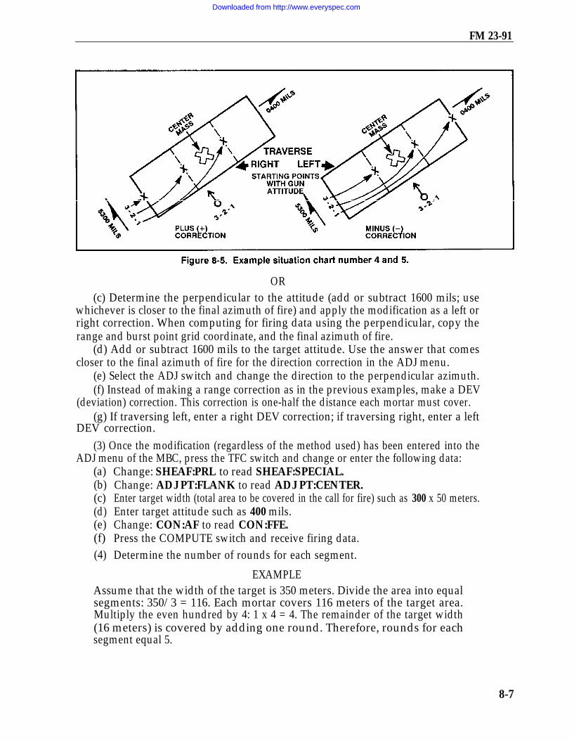
FM 23-91
OR(c) Determine the perpendicular to the attitude (add or subtract 1600 mils; use
whichever is closer to the final azimuth of fire) and apply the modification as a left orright correction. When computing for firing data using the perpendicular, copy therange and burst point grid coordinate, and the final azimuth of fire.
(d) Add or subtract 1600 mils to the target attitude. Use the answer that comescloser to the final azimuth of fire for the direction correction in the ADJ menu.
(e) Select the ADJ switch and change the direction to the perpendicular azimuth.(f) Instead of making a range correction as in the previous examples, make a DEV
(deviation) correction. This correction is one-half the distance each mortar must cover.(g) If traversing left, enter a right DEV correction; if traversing right, enter a left
DEV correction.(3) Once the modification (regardless of the method used) has been entered into the
ADJ menu of the MBC, press the TFC switch and change or enter the following data:(a)(b)(c)(d)(e)(f)(4)
Change: SHEAF:PRL to read SHEAF:SPECIAL.Change: ADJ PT:FLANK to read ADJ PT:CENTER.Enter target width (total area to be covered in the call for fire) such as 300 x 50 meters.Enter target attitude such as 400 mils.Change: CON:AF to read CON:FFE.Press the COMPUTE switch and receive firing data.Determine the number of rounds for each segment.
EXAMPLEAssume that the width of the target is 350 meters. Divide the area into equalsegments: 350/3 = 116. Each mortar covers 116 meters of the target area.Multiply the even hundred by 4: 1 x 4 = 4. The remainder of the target width(16 meters) is covered by adding one round. Therefore, rounds for eachsegment equal 5.
8-7
Downloaded from http://www.everyspec.com

FM 23-91
(5) Determine the mil width of one segment. If the mil width of one segment isdetermined, the other segments are the same. Use one of two methods to determinethe number of mils for one segment:
(a) In the first method, the start point deflections for all the mortars are given. Bycomparing the mil difference between either No. 1 mortar and No. 2 mortar or No. 2 mortarand No. 3 mortar (or No. 3 mortar and No. 4 mortar, if available). For example, No. 1mortar has a deflection of 2719 mils and No. 2 mortar has a deflection of 2773 mils. Themil difference is 54 mils (subtract the smaller from the larger: 2773-2719 = 54 mils).
(b) The second method uses the DCT (Figure 8-6) to determine the mil width ofone segment. Enter the DCT at the final range, rounded off to the nearest 100. Goacross the deflection-in-meters line to the closest meters to cover the segment. Thepoint at which the range line and the deflection line meet is the number of mils thatwill cover the segment.
(6) To determine the number of turns it will take to cover one segment, divide thenumber of mils for each turn on the traversing hand crank by the mil width of one
8-8
Downloaded from http://www.everyspec.com

FM 23-91
segment – for example, 10 (number of mils for each turn)/54 = 5.4 (rounded off to thenearest one-half turn) or 5 1/2 turns to cover 116 meters.
(7) To compute the number of turns between rounds, the number of rounds to be firedmust be known for each segment (FFE). This information is in the FDC order. Todetermine the turns between rounds, divide the total turns by the intervals (always one lessthan the number of rounds) between rounds – for example, 5 rounds = 4 intervals;5.5 (total turns)/4 (intervals):
5.5/4 = 1.3 (rounded to nearest 1/2 turn)= 1 1/2 turns between rounds
8-4. SEARCHING OR ZONE FIREArea targets that have more depth than a standard sheaf covers require that mortarsuse searching fires to effectively engage these targets. Any target having more depththan 50 meters can be covered by mortars. This is done by either elevating ordepressing the barrel during the FFE. In the call for fire, the FO sends the size of thetarget and the attitude. He gives the width and depth on the attitude of the target.(Attitude is the direction [azimuth] through the long axis of the target.)
a. All mortar systems use searching fire with the exception of the 4.2-inch mortar,which uses zone fire to cover the target area. Before determining the search data, theFDC must compute any correction that was sent with the FFE command from the FO.Also, the burst point grid coordinate must be recorded.
(1) Press the ADJ switch and enter the target attitude in place of the direction.
NOTE: Whether searching up or searching down, always determine the firing datafor the far edge of the target area first. This saves time if the charge designated atthe near edge is different than the one designated at the far edge.
(2) When using searching fire, enter an add correction that is half the total targetlength. This places the mortars on the far edge of the target.
(3) Compute the firing data for the far edge and record the information.(4) Enter a correction to place the mortars on the opposite edge of the target. The
correction to enter will be a drop and the distance will be the entire length of the target area.(5) Compare the charge needed to hit the near edge with the charge needed to hit
the far edge of the target. The charge must be the same. If they are not, select thecharge designated for the far edge by using the WPN/AMMO menu and recomputethe near edge firing data.
(6) Determine the number of turns between rounds by determining the mildistance to cover the target area and by dividing it by 10 (the number of mils in oneturn of the elevation hand crank). Round off the answer to the nearest one-half turn.Compute the distribution of mortar fire to cover area targets (depth or width) at oneround per 30 meters and four rounds per 100 meters.
(a) Compare the far edge elevation to the near edge elevation and subtract thesmaller from the larger.
(b) Divide the mil distance by 10 and round off to the nearest half a turn.
8-9
Downloaded from http://www.everyspec.com

FM 23-91
(7) Determine the turns between rounds by dividing the intervals into the turnsand by rounding off to the nearest half turn. The intervals are always one less than thenumber of rounds in the FFE.
b. The 4.2-inch mortar does not fire a search mission the same as the 60-mm,81-mm, or 120-mm mortars. It does not have the same elevating characteristics as thesemortars; therefore, the 4.2-inch mortar uses zone fire. The 4.2-inch mortarplatoon/section usually fires two standard zones: a 100-meter zone (three rounds foreach mortar) for a platoon-size target, and a 200-meter zone (five rounds for eachmortar) for a company-size target. A larger zone can be covered by firing more rounds.
(1) Establishing the 100-meter zone. Once the FO gives the FFE, the computerproceeds as follows:
(a) Firing without extension. Add and subtract 3/8 charge from the base commandcharge. (The base command charge is the command charge in the FFE center mass oftarget.) This gives each mortar three rounds with a different charge on each to coverthe 100-meter zone (Figure 8-7).
(b) Firing with extension. Add and subtract 4/8 charge from the base commandcharge and use three rounds for each mortar.
NOTE: A 3/8 charge correction to any charge without extension moves the roundabout 50 meters at any elevation used. A 4/8 charge correction to any charge withextension moves the round about 50 meters at any elevation used.
(c) Firing the 100-meter zone. Once the mortars are up (rounds set for propercharges) and the fire command is given, the rounds are fixed in any sequence — forexample, No. 1 fires long, short, center mass; No. 2 fires center mass, short, long.
8-10
Downloaded from http://www.everyspec.com

FM 23-91
(2) Establishing the 200-meter zone. Once the FFE has been given by the FO, thecomputer proceeds as follows:
(a) Firing without extension. Add and subtract 3/8 charge from the base commandcharge for the rounds on either side of the base round and 6/8 charge for the long andshort round (Figure 8-8).
(b) Firing with extension. Add and subtract 4/8 charge from the base commandcharge for the rounds on either side of the base round and a whole charge for the longand short rounds.
(c) Firing the 200-meter zone. The mortars can fire the rounds in any sequence.
NOTE: If a larger zone is needed, use the same procedures, only firing more roundsfor each mortar and cutting the charges.
8-5. ILLUMINATIONIllumination assists friendly forces with light for night operations.
a. The FDC routinely obtains firing data. However, the FDC uses one of the flankmortars to adjust the illumination, leaving the base mortar ready to adjust HE roundsif a target is detected.
NOTE: Normally, when a four-mortar section is firing, the No. 4 mortar is used toadjust the illumination, leaving the No. 2 mortar as the base mortar. When the No. 1mortar is used to adjust illumination, the No. 3 mortar becomes the base mortar.
8-11
Downloaded from http://www.everyspec.com

FM 23-91
b. The FO makes range and deviation corrections for illumination rounds in notless than 200-meter increments. He also makes corrections for height of burst (up ordown) of not less than 50-meter increments.
c. Multiple mortar illumination procedures are used when single mortarillumination does not light up the area enough. Two mortars are used to fireillumination only when visibility is poor. Two mortars, usually side by side ( No. 1 and2, No. 2 and 3, and so on), fire rounds at the same time at the same deflection, charge,and time setting to provide a large amount of light in a small area. If the FO suspectsa large target or if he is uncertain of target location and desires a larger area beilluminated, he may call for illumination: range, lateral, or range-lateral spread .
(1) Range spread. Two mortars fire one round each at the same deflection but withdifferent charges so that rounds burst at different ranges along the same line. Thespread between the rounds depends on the type of mortar firing the mission. The4.2-inch mortar rounds have 1,000 meters between bursts, and the 81-mm mortarrounds have 500 meters between bursts. When four mortars are present in the firingsection, the No. 2 and No. 3 mortars normally fire the range spread. When firing athree-mortar section, the range spread may be fired with just one mortar, which firesboth rounds.
(a) Enter the type of target location called in by the FO into the MBC to initiatethe mission. The weapon selected by the FDC in the WPN/AMMO menu (to activatethe section) should be one of the mortars that is going to fire the mission.
(b) The initial firing data determined for the mission are center of mass targetdata. These data are not fired but are used as the starting point for the adjustmentof the spread.
(c) Enter the ADJ menu. Use the GT for direction and enter a correction for thefirst round of the spread. Compute the firing data and record them.
(d) Select the ADJ menu and enter a correction to get the required distancebetween rounds, which depends on the mortar system being used.
(e) Compute for firing data, record it, and fire the two rounds for the range spread.
NOTE: The two rounds should burst at the same time. The far round must befired first, with the near round being fired after, at the difference between thetime settings.
EXAMPLEAssume the mortar selected to fire is the No. 2 mortar. Enter the initial targetlocation and determine the center mass data. Next, enter the ADJ menu andgive the No. 2 mortar a correction of +500 (for 4.2-inch) or +250 (for 81-mm).Compute these data and record them. Enter the ADJ menu again and make acorrection of – 1000 (for 4.2-inch) or –500 (for 81-mm). Compute and recordthese data.
Using both sets of data to fire the rounds, rounds will burst the desired length(1,000 or 500 meters) between rounds on the GT line.
8-12
Downloaded from http://www.everyspec.com

miFM 23-91
NOTE: A range spread may be fired using one mortar and firing both rounds – onelong and one short.(2) Lateral spread. Two mortars fire one round each at different deflections but with
the same charge. Therefore, the rounds burst at the same range along the same attitude.(a) Using the No. 2 mortar, process the call for fire and determine firing data for
center mass.(b) Using the ADJ menu to enter left and right corrections, use the GT as the
direction and enter the first correction.
NOTE: The No. 2 mortar is used for the initial round. The first correction can beeither a right or left correction. For example, the first correction for the 4.2-inchmortar is R 500 and the first correction for the 81-mm mortar round is L 250.(c) Compute for the firing data and copy it down.(d) Select the ADJ menu and enter the reverse of the first correction the entire
distance required between rounds: L/R 1,000 meters for the 4.2-inch or L/R 500 metersfor the 81-mm.
(3) Range-lateral spread. If the target area is extremely large or if visibility islimited, the FO may call for range-lateral spread. This procedure combines the twomethods (Figure 8-9). This results in a large diamond-shaped pattern of bursts. Ifmortars use the flank mortars for the lateral spread and the center mortar(s) for therange spread, the danger of rounds crossing in flight is removed.
8-13
Downloaded from http://www.everyspec.com

CHAPTER 9
SPECIAL PROCEDURES
Procedures for basic fire missions with the MBC are simple and require littlecoordination by the indirect fire team. The one element that is lacking in these proceduresis accuracy, which the indirect fire team strives to improve. In-depth planning and priorcoordination between elements of the indirect fire team help ensure the delivery of timelyand accurate fires. This chapter discusses the special procedures needed to conductregistration missions, final protective fires, and quick or immediate smoke.
9-1. REGISTRATION AND SHEAF ADJUSTMENTThe firing of the registration is the first mission completed if time and the tacticalsituation permit. Two types of registration missions are coordinated anduncoordinated.
a. A coordinated registration is a planned mission using an available RP, known(surveyed) to at least an eight-digit grid coordinate. Firing corrections may bedetermined and applied after the registration mission is fired. The FDC usuallyinitiates this mission.
b. An uncoordinated registration is not planned and may not have a surveyed RPto fire on. This registration is used mainly to adjust the sheaf and to establish a knownpoint within the area of responsibility. If the RP is not surveyed, firing data correctionscannot be determined or applied. The FO usually initiates this mission.
c. When using the MBC for registration, the computer uses the same procedures as agrid mission until the FO determines the registration is complete. He adjusts the basepieceonto the registration point as in any standard adjust mission. Once the FDC receives"registration complete" from the FO, any refinement corrections received with thecommand must be computed. After this data are given to the mortars, the section fireseither a section left or a section right. The basepiece does not fire. For example, the finalcorrection sent by the FO is "Drop 25, registration complete."
(1) The computer uses the ADJ menu to enter the correction of -25. He pressesthe COMPUTE switch to process the refinement data.
(2) The computer presses the REG fire mission switch (coordinated registrationonly) once the refinement firing data are available.
(3) The registration number and FO identification (if the FO was entered with thecall for fire) are displayed. The computer presses the —
(a) SEQ switch. The mission target numbers are displayed.(b) SEQ switch. The FO’s direction to the target is displayed.
9-1
Downloaded from http://www.everyspec.com

FM 23-91
(c) SEQ switch. The RP grid is displayed. This grid is the initial grid used fromthe call for fire, not the adjusting point grid.
(d) SEQ switch. The altitude to the RP is displayed.(e) SEQ switch. The weapon caliber and number of the adjusted piece are
displayed.(f) SEQ switch. The charge used to reach the RP is displayed.(g) SEQ switch. The MBC requests the operator to push COMPUTE to
determine the firing corrections.(h) COMPUTE switch. The assigned RP number is displayed.(i) SEQ switch. The type of MET used and the range correction factor (RCF) are
displayed.(j) SEQ switch. The type of MET used and the deflection correction are displayed.(k) SEQ switch. READY is displayed.d. The MBC has determined the firing corrections, but it will not apply them to any
subsequent data during this mission. However, it automatically applies the correctionfactors to all following missions that are within the transfer limits of this RP. This does notpreclude the FDC from copying this data to the appropriate spaces on the data sheet.
e. To prepare the MBC for sheaf adjustments, the computer uses the TFC menu tochange control CON:AF to CON:FFE. After the control has been changed, he pressesthe COMPUTE switch.
NOTE: Changing CON:AF to CON:FFE and pressing COMPUTE are mandatorysteps before adjusting individual guns.f. The FDC initiates the adjustment of the sheaf. He tells the FO, "Prepare to
adjust the sheaf." The FO responds with, "Section left/right." The section left/right isfired without the basepiece unless the FO specifies to fire the basepiece. The operatorprepares to receive corrections for each mortar not firing within the sheaf. Then, herecords the corrections and computes them separately.
NOTE: The MBC can only compute one correction at a time; therefore, if the computerrecords the corrections, he may compute for the corrections as he desires. The smallercorrections should be entered first since the mortars will not likely be fired again.(1) Use the adjust menu (press ADJ) and sequence to ADJ:AUF
(adjusting: adjusting unit of fire). Change the AUF to SHEAF.(2) Sequence to WPN: and enter the weapon number to adjust and the correction.(3) Compute the correction. The weapon number identified with the correction
is the only weapon affected by the correction. The other weapons will still be on thelast firing data.
(4) Use the adjust (ADJ) switch and sequence to WPN:NXT CONT. The WPN isfor "weapon." The abbreviation NXT is for the "next" mortar to adjust. The CONTmeans "continue with the same mortar" identified in (2) above for more corrections.
NOTE: If a correction is over 50 meters (L/R) then that mortar will be refired. Ifthe correction is less than 50 meters (L/R) the mortar is considered to be adjusted.
9-2
Downloaded from http://www.everyspec.com

FM 23-91
(5) Sequence to WPN: and enter the weapon to adjust and enter the correction.(6) Compute the correction.(7) Use the firing data menu to sequence through the data and record the
new fire commands.g. After the sheaf has been adjusted, the section/platoon must refer the sight and
realign the aiming post on the last (hit) deflection of the basepiece used for theregistration. The mission is ended using the EOM menu.
h. The computer uses the REG DATA (initialization switch) menu to storeinformation concerning the RP and to update the RP. Then the MBC applies the correctionfactors to all subsequent fire requests that are within the transfer limits of the RF?
NOTE: The RP must be updated for any MET or reregistration conducted.
9-2. MEAN POINT OF IMPACT REGISTRATIONSpecial procedures permit registration under unusual conditions. This paragraphdiscusses one of the special procedures available — the MPI registration. Visualadjustment of fire on an RP at night cannot be performed without illumination. Indesert, jungle, or arctic operations, clearly defined RPs in the target areas are notusually available.
a. In an MPI registration, two FOs are normally used. The computer must knowthe location and altitude of each FO to survey accuracy and then to enter them into theMBC in the FO LOC menu. The expected point of impact and mortar position mustalso be known to survey accuracy. To determine the initial firing data —
(1) Start the mission using the GRID menu and enter the expected burst point (asthe grid to the target) and altitude.
NOTE: An FO ID and direction should not be entered in this menu.(2) Use the WPN/AMMO menu to assign the mission to an adjusting piece.(3) Press COMPUTE to determine the firing data and record the needed
information to include the burst point to the target.
NOTE: The MBC does not allow access to the MPI menu under the ADJ (adjust)switch until a mission has been activated. This is done by using the GRID andWPN/AMMO menus.b. After the locations of the FOs and target point are known, the FDC can compute
and report the orienting data to the FOs. The FOs must be given their orienting databefore firing. To determine the orienting data of the observer –
(1) Press the ADJ switch. Select MPI:, and FILE CONT INIT is displayed.(2) Select INIT to initialize the MPI mission. INIT YES NO (for
verification) is displayed.(3)(4)(5)(6)(7)
Select YES. The MBC prompts the operator for one of the FO’s ID.Enter either one of the FO IDs.Press the SEQ switch. The orienting direction is displayed for the FO entered.Press the SEQ switch. The vertical angle is displayed for the FO entered.Press the SEQ switch. The target number is entered and displayed.
9-3
Downloaded from http://www.everyspec.com

FM 23-91
(8) Press the SEQ switch. The orienting data are ready to be transmitted to theFO. If the MBC is DMD-supported, select YES to transmit via digital. If the MBC isnot DMD-supported, select NO. The MBC prompts the operator for the other FO’s ID.
(9) Follow steps (4) through (8) for the other FO.(10) If the MBC is not DMD-supported, transmit the orienting data to the FOS in
the following format:FDC: "PREPARE TO OBSERVE MPI REGISTRATION.
HOTEL 42 DIRECTION 2580 VERTICAL ANGLE + 40;HOTEL 41 DIRECTION 2850 VERTICAL ANGLE + 10;REPORT WHEN READY TO OBSERVE."
c. The FOs should announce "Ready to observe" after they have received theorienting data from the FDC and have set up their instruments.
d. The section leader/chief computer directs the firing of the orienting round using thecomputed firing data. The FOs use the round to check the orientation of their instruments.The orienting round should be within 50 mils of the expected point of impact.
(1) If the round lands 50 mils or more from the expected point of impact, the FOreorients his instrument and announces the new direction to the FDC. If one FOreorients his instrument, the spotting of the other FO is disregarded. When either ofthe FOs must reorient, the operator must enter the new direction by using the ADJ menu.
Enter the ADJ menu. Press the ADJ switch.Select MPI.Select INIT.Reenter the FO’s ID, when prompted.
(2) If the burst impacts less than 50 mils from the expected point of impact, the FOsends the FDC a spotting. The spotting contains the number of mils left or right of theexpected point of impact.
(3) When both FOs report their instruments are ready, the adjusting mortar firesthe number of rounds needed to get six usable spottings. To enter the spottings intothe MBC –
(a) Press the ADJ switch and select MPI. The computer displays: FILE CONT INIT.(b) Select FILE to enter the spottings. The MBC requests the sighting number.(c) Enter the sighting (round) number.(d) Press the SEQ switch. Determine the azimuth from the FO to the target using
the RALS (right add, left subtract) rule. Add or subtract this correction from the FO’sreferred (orienting) direction. Enter the azimuth as the FO’s direction.
(e) Press the SEQ switch. The MBC prompts for the vertical angle from the FOto the round. Enter the vertical angle, if any.
(f) Press the SEQ switch. The second FO’s ID is displayed. Enter the sighting(round) number. Determine the azimuth from the FO to the target using the RALSrule. Add or subtract the correction from the FO’s referred (orienting) direction.Enter the azimuth as the FO’s direction.
9-4
Downloaded from http://www.everyspec.com

FM 23-91
NOTE: The MBC computes for only one vertical angle correction. This correctionapplies only to the first FO entry. When the vertical angle entry must be computed,the operator ensures the proper FO is entered.
(g) Press the SEQ switch. The MBC prompts the operator for the next sighting.(h) Press the COMPUTE switch and enter the FO’s sightings as described until all
sightings have been entered. After the last sighting has been entered, select END onthis display.
(i) Press the COMPUTE switch and sequence to view the RP corrections.(j) Press the EOM switch to end the mission.
9-3. RADAR REGISTRATIONThe radar registration requires only one OP, which is the radar. It requires less survey,fewer communications facilities, and less coordination. The radar registration can beconducted quickly and during poor visibility. This mission may be conducted as a gridor polar mission. The grid mission procedures are discussed below.
a. The radar registration mission is a coordinated mission and is conducted as anormal grid mission with the following exceptions:
(1) The FO will not send corrections. He will send grid coordinates to the impactof the rounds fired.
(2) The FDC, instead of the FOs, must convert spottings to corrections.b. The procedure for radar registration is as follows:(1) The FDC sends an MTO - for example, "Prepare to Register RP 1, Grid 03817158."(2) The radar operator orients his radar set, then tells the FDC, "Ready to Observe."(3) The first round is fired, and the radar operator sends a grid of the impact point
of the round to the FDC.(4) The FDC records the grid and compares it to the RP grid to deterrnine the spotting.(a) Comparing the grid to grid, the FO sends a grid to the first round fired; that
grid (in this example) is 03557120. By comparing the 2 eight-digit grids, the FDCdetermines the spotting.
NOTE: Use 10-digit grid coordinates; add a zero to the end of each casting ornorthing coordinate until there are 10 digits for each coordinate – for example, thegrid 123456 becomes 1230045600.
Easting Northing
RP Grid 0381(0) 7158(0)1st Round Grid -0355(0) -7120(0)
26(0) 38(0)
(b) By using a piece of blank scrap paper, the FDC can draw a large square torepresent a 1000-meter grid square.
(c) The FDC labels the bottom left-hand corner of the square with the gridintersection of the RP (03/71) (Figure 9-1, see page 9-6).
9-5
Downloaded from http://www.everyspec.com

FM 23-91
(d) He divides the large square into four smaller squares by drawing a line throughthe center of the box from top to bottom and from left to right.
—
(e) He estimates the location of both grid coordinates and plots them inside the box.(f) By looking at these plots, the FDC can tell whether the round is left or right and
whether it is over or short of the RP This is the spotting of the round. For this example,the spotting is left (260 meters) and short (380 meters).
(g) The spotting is then converted to a correction by converting the left spotting toa RIGHT (R)260 correction and the short spotting to an ADD (+)380 correction.Using the ADJ menu, the operator enters the corrections to apply.
Change the direction to 6400 (or 0000).Enter R 0260 for the deviation correction.Enter + 0380 for the range correction.Sequence to READY.
The operator then computes for the firing data and sends it to the guns.
(5) The second round is fired, and the FO sends the grid 04007180.process is repeated as for the first correction.
The same
(a) The grids are compared and the spotting is determined (RIGHT 190 andOVER 220).
(b) The corrections (LEFT [L] 190 and DROP [-] 220) are made in the ADJ menu,and the firing data are sent to the mortars.
9-6
Downloaded from http://www.everyspec.com

FM 23-91
(6) The computer repeats this procedure until the spotting is within 25 meters of theRP and until the FO has given "End of Mission, Registration Complete." The FDC –
(a) Enters the final correction through the ADJ menu and computes.(b) Presses the REG switch and sequences through the REG menu. He ensures
that the data pertaining to the RP are correct.(c) Presses COMPUTE when indicated at the end of the REG menu to determine
the RCF and deflection correction (DEFK).(7) After the registration is completed, the FDC informs the FO (radar operator),
"Prepare to Adjust the Sheaf." These procedures are continued until the sheaf isadjusted. To adjust the sheaf —
(a) The FDC converges the sheaf on the RP. Using the TFC switch, the operatorchanges sheaf parallel (PRL) to sheaf converge (CVG).
(b) The operator changes the method of control (CON) from adjust fire (AF) tofire for effect (FFE).
(c) The operator sequences through the rest of the menu, ensuring all data matchwith the FDC order. He presses the COMPUTE switch when the MBC reads PUSHCOMPUTE.
(d) All mortars are fired (except the BP) at 10-to 20-second intervals.(e) The radar operator sends the FDC the grid to the impact of each round fired.(f) The FDC compares the grids to the impact of each round with the grid of the
RP, and it determines the deviation corrections for each mortar. THE FDC DOESNOT USE RANGE CORRECTIONS. When adjusting for a parallel sheaf during aregistration mission, the FDC disregards range corrections.
NOTES:1. The operator compares the full grid for all rounds fired. Any extreme deviation
or range spotting means there is a problem in the setup of that mortarposition(s).
2. If the operator is using the MBC to apply these corrections, he must first enter andcompute all corrections under 50 meters.
(g) All corrections more than 50 meters are refired, the new grids are comparedto the RP grid, and new data are computed for those weapons.
(8) Once the sheaf is adjusted, the FDC must open the sheaf. Using the deflectionconversion table (DCT), the FDC opens the sheaf mathematically the distance requiredbased on the mortar system used.
(9) The FDC now has the mortars refer their sights to the HIT deflection of thebasepiece and realign the aiming posts.
9-4. FINAL PROTECTIVE FIRESFPF are the highest priority mission that the mortar section/platoon fires. They areprearranged barriers of fires designed to protect friendly troops and to stop the enemyadvance. They are integrated with the other weapons of the unit being supported and coverdead space and likely avenues of approach. FPF involve an entire mortar section/platoon
9-7
Downloaded from http://www.everyspec.com
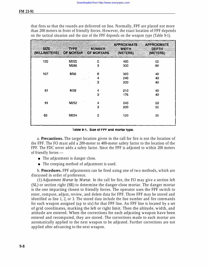
FM 23-91
that fires so that the rounds are delivered on line. Normally, FPF are placed not morethan 200 meters in front of friendly forces. However, the exact location of FPF dependson the tactical situation and the size of the FPF depends on the weapon type (Table 9-1).
a. Precautions. The target location given in the call for fire is not the location ofthe FPF. The FO must add a 200-meter to 400-meter safety factor to the location of theFPF. The FDC never adds a safety factor. Since the FPF is adjusted to within 200 metersof friendly forces —
The adjustment is danger close.The creeping method of adjustment is used.
b. Procedures. FPF adjustments can be fired using one of two methods, which arediscussed in order of preference.
(1) Adjustment Mortar by Mortar. In the call for fire, the FO may give a section left(SL) or section right (SR) to determine the danger-close mortar. The danger mortaris the one impacting closest to friendly forces. The operator uses the FPF switch toenter, compute, adjust, review, and delete data for FPF. Three FPF may be stored andidentified as line 1, 2, or 3. The stored data include the line number and fire commandsfor each weapon assigned (up to six) for that FPF line. An FPF line is located by a setof grid coordinates, marking the left or right limit. Then the altitude, width, andattitude are entered. When the corrections for each adjusting weapon have beenentered and recomputed, they are stored. The corrections made to each mortar areautomatically applied to the next weapon to be adjusted. Further corrections are notapplied after advancing to the next weapon.
9-8
Downloaded from http://www.everyspec.com

FM 23-91
NOTE: After entering the FPF line, a safety fan maybe entered. All adjustingrounds should be set for fuze delay to further reduce the danger to friendly forces.(a) Press the FPF switch and select INIT. Enter the line number (1, 2, or 3) andthe section/weapon number. The displays shows: LINE: 1 WPN:A1.
(b) Press the SEQ switch. (Shell/fuze combination [default entry by MBC is HEPD] is normally not changed.)
(c) Press the SEQ switch and select the GT or enter the FO direction to target.
(d) Press the SEQ switch and enter the FPF right or left limit.
NOTE: If the right limit grid is entered for the FPF, adjust the right flank mortarfirst. If the left limit grid is entered for the FPF, adjust the left flank mortar first.
(e) Press the SEQ switch and enter the FPF altitude (if known).
(f) Press the SEQ switch and enter the left or right limit and FPF line width in meters. Thedisplay shows: L R WID: L350. The coordinate point becomes the left or right limit.
NOTE The direction of the FPF should be left if the right flank mortar (No. 1)is adjusting, and right if the left flank mortar (No. 3 or No. 4) if the left flankmortar is adjusting.
(g) Press the SEQ switch and enter the attitude of the FPF. This is aMANDATORY ENTRY.
(h) Press the SEQ switch and follow the instruction by the MBC. Press theCOMPUTE switch to receive firing data.
(i) Sequence through the firing data (record needed data) until the ADJ * is displayed.
NOTE: If the ADJ * selection is passed, the display shows: READY. Tocontinue adjusting the FPF, press the FPF mission switch and select ADJ.Proceed to paragraph (k).
(j) Select the blue display key beneath the asterisk (*).
(k) Enter the weapon number to adjust. If another weapon is to be adjusted, select NXT.
NOTE: The MBC considers the previous weapon adjusted, and it saves thefiring commands in the FPF data file. When the last weapon is adjusted, selectNXT in this display to end the mission. The display shows: FPF ADJUSTED.
(l) Press the SEQ switch. The display shows the direction to the target.
(m) Press the SEQ switch and enter the deviation correction (if any) from the FO.
(n) Press the SEQ switch and enter the range correction, if any.
(o) Press the SEQ switch. (The operator may change the height corrections fromthe default given in meters to feet.)
(p) Press the SEQ switch and enter the vertical correction (if any) from the FO.
9-9
Downloaded from http://www.everyspec.com

FM 23-91
(q) Press the SEQ switch. The display shows: PRESS COMPUTE. Press theCOMPUTE switch to receive the firing data.
(r) Repeat procedures in paragraphs (i) through (q) until each weapon in thesection has been adjusted. Repeat procedures in paragraphs (i) through (k) to endthe mission.
(2) Adjustment of Danger-Close Mortar Only. In the call for fire, the FDC is giventhe attitude of the target area. From this attitude, the FDC can determine thedanger-close mortar.
(a) The operator uses the FPF menu to fire and adjust as with the mortar-by-mortarmethod.
(b) Once the danger-close mortar is adjusted, the other mortars involved in theFPF will have firing data already computed.
(c) The difference between this method and the mortar-by-mortar adjustment isthat each mortar will not actually fire on the FPF. Rather, the firing data for thenonfiring mortars are calculated based on the firing data for the danger-close mortarand the attitude of the target area.
c. Data Review. The FPF data for the section may be reviewed at any time usingthe FPF menu switch.
(1) Press the FPF switch and select DATA.(2) Press the SEQ switch and enter the line number of the FPF to be displayed.(3) Sequence through the display to review each mortar’s data.d. Safety Data. After an FPF has been initiated, the operator may review the safety
data at any time.(1) Press the FPF mission switch. The sequence indicator should blink, indicating
that another choice is available (for multiple entry).(2) Press the SEQ switch. The fifth choice, SFTY, is displayed. Select the blue
display key beneath the flashing cursor to select safety (SFTY).(3) Press the SEQ switch, and enter the line number of the FPF safety data to be viewed.(4) Press the SEQ switch. The display prompts the operator to press the SEQ
switch to view the burst-point grid coordinate.(5) Press the SEQ switch. The casting and northing are displayed.(6) Press the SEQ switch. The maximum ordinate of the last round to its
burst-point is displayed.(7) Press the SEQ switch. The time of flight is displayed.(8) Press the SEQ switch. READY is displayed.
9-5. IMMEDIATE SMOKE OR IMMEDIATE SUPPRESSIONWhen engaging a planned target or target of opportunity that has taken friendly forcesunder fire, the FO announces (in the call for fire) either immediate smoke or immediatesuppression. The delivery of fires is performed as quickly as possible — immediateresponse is more important than the accuracy of these fires.
a. The FO uses the immediate-smoke mission to obscure the enemy’s vision for
9-10
Downloaded from http://www.everyspec.com

FM 23-91
short periods. This aids maneuver elements in breaking contact or evading enemydirect fire; it is not intended as a screening mission. The total area that can be coveredis 150 meters or less.
b. The FO uses the immediate-suppression mission to indicate that his unit isreceiving enemy fire. His request should be processed at once. These fires, plannedand delivered to suppress the enemy, hamper enemy operation and limit his ability (inthe target area) to perform his mission.
c. The procedures for firing an immediate-suppression or immediate-smoke missionare the same except for the ammunition used. HEQ is used for the immediate-suppressionmission and WP or RP is used in the immediate-smoke mission.
(1) The FDC receives a call for fire from the FO. In the warning order, the wordIMMEDIATE will precede either suppression or smoke.
(2) The target location is normally by grid coordinate. The FDC processes his callfor fire as a normal grid mission using the GRID menu with one exception. After theWPN/AMMO menu, the FDC will immediately use the TFC switch and change themethod of control (CON) from AF to FFE.
NOTE: The TFC menu maybe deleted from this procedure if the mortars to fireare in a straight line with the rest of the section and if they are all the same distanceapart (a perfect parallel position).
(3) The entire section fires one or two rounds within 90 seconds of the FDC’sreceipt of the target location.
(4) If any adjustments are needed, the entire section conducts them, firing the samenumber of rounds each time as in the previous command.
9-6. QUICK SMOKEThe techniques used by the mortar unit in attacking targets with smoke are influencedby factors independent of the mission. These factors include weather, terrain,dispersion, adjustment, distribution of fire, and ammunition availability. Clearance tofire, ammunition requirements, and general considerations discussed in this chapterapply to all mortars.
a. The mortar unit establishes screening smoke between the enemy and friendlyunits or installations. It uses smoke to hamper observation, to reduce observed fire, tohamper and confuse hostile operations, and to deceive the enemy as to friendlyoperations.
b. The main consideration in planning for a smoke screen is that it must accomplishits purpose without interfering with the activities of friendly forces. This requires muchplanning. Authority to fire smoke missions rests with the highest commander whosetroops will be affected. The unit commander must ensure that flank unit commanderswho may be affected have been informed.
c. Normally, the section/platoon is given a smoke mission through commandchannels. The methods used to accomplish the mission are not usually prescribed butare developed by the section leader/chief computer and the FO who will conduct the
9-11
Downloaded from http://www.everyspec.com

FM 23-91
mission. The following factors help in deciding how to engage the target.(1) Ammunition. The number of rounds required to establish and maintain a
screen is based on the size of the target and the weather conditions affecting thedispersion of the smoke. The chief computer cannot accurately determine the weatherconditions that will exist at the time the mission is fired. However, he does determinethe amount of ammunition for the most unfavorable conditions that might be expectedat that time and place.
(a) A quick-smoke mission is usually conducted in three phases. The first phase isthe adjustment phase. The computer adjusts the upwind flank mortar to the upwindedge of the target area using HE ammunition. At the end of this phase, one round ofWP is fired to see if it hits the desired location. The second phase is the establishmentphase. The computer establishes the screen by firing twice the number of roundsrequired to maintain the screen for one minute, but not less than 12 rounds. Theserounds are fired as quickly as possible (FFE phase for any other mission). The thirdphase is the maintenance phase. The computer maintains the screen by firing thedetermined number of rounds per minute (RPM), times the length of time the screenis to be in place.
(b) The computer uses the smoke chart (Figure 9-2) to compute the number of roundsneeded to maintain a screen for one minute. This chart is prepared for various weatherconditions and a screen 500 meters wide. Other widths are computed by scaling the valuesproportionally. To extract the proper value from the chart, the FDC must know wind speed(confirmed by the FO before firing), wind direction (confirmed by the FO before firing),relative humidity (obtained from the battalion S3 or by estimation), and temperaturegradient (obtained from the battalion S3 or by estimation).
(c) The temperature gradient determines which line to use. It is a measure of howair temperature changes with altitude. Neutral is the most common condition. It occurswhen there is no appreciable temperature change with an increase in altitude (midday).Lapse conditions exist when the temperature changes with increase in altitude(evening). Inversion conditions exist when the temperature rises with an increase inaltitude (early morning).
(d) The wind speed in knots determines which column to use. The box where theproper row and column intersect contains the number of RPM needed to maintain ascreen 500 meters wide for one minute with a flank wind.
EXAMPLE
For conditions of 60 percent humidity, a neutral temperature gradient, and a 4-knotwind, it would take 6 RPM to maintain a 500-meter screen with a flank wind. If thescreen is to be only 400 meters wide, use the following procedure:
400 divided by 500 (or 400/500) = 4/5 = 0.8
0.8 x 12 (number of rounds x 2-minute duration for establishment phase)= 9.6The result (9.6 in this case) is always rounded up (no less than 12 rounds will be
9-12
Downloaded from http://www.everyspec.com

FM 23-91
fired in the establishment phase). Each mortar fires (4.2-inch mortar platoon) 2 roundseach, (4.2-inch mortar section) 4 rounds each, (81-mm mortar platoon) 3 rounds each,and (81-mm mortar section) 6 rounds each.
(e) The total number of smoke rounds needed for the mission is computed as follows:
Adjustment phase =Establishment phase =
Maintenance phase =
Total =NOTE: The time used during
1 round (all missions)2 x number of rounds to maintainfor 1 minute; at least 12
Number of rounds to maintain for1 minute x number of minutes
(a) + (b) + (c)the establishment phase is not to be considered as
9-13
Downloaded from http://www.everyspec.com

FM 23-91
any part of the maintenance phase time of the mission.(2) Mortars required. Under favorable conditions the 4.2-inch mortar platoon can
screen an area about 800 meters wide and the 8 l-mm mortar platoon about 500 meters.The 60-mm mortar section does not fire a screening mission. A limitation, however,is their maximum and sustained rates of fire. For the entire platoon, these rates of fireare multiplied by the number of mortars firing. If the required number of RPM exceedsthe rate of fire, the platoon must request supporting fire from flank units or artillery.
(3) Effects desired. If smoke is to be placed directly on the target for blinding orcasualty-producing effects, the FO adjusts the center of impact of the rounds onto thecenter of the target. The number of RPM to produce this effect is twice that for a normalquick-smoke mission.
(4) Ordering of ammunition. When ordering ammunition for a mission, the FDCestimates what weather could exist, remembering that it is better to have too muchammunition than too little.
(5) Briefing of the observer. Due to the many clearances required to fire themission, the FDC chief/section leader normally has ample time to brief the FO on thequick-smoke screen. This briefing should include a map reconnaissance of the area tobe screened so that the FO will be able to identify it on the ground and to select an OPfrom which the screen can be observed.
(6) Call for fire. At the appointed time,usually 10 to 20 minutes before the mission is tobe fired, the FO sends the call for fire. Thisallows the FDC to process the data in advanceand to prepare the needed ammunition. The FOshould have checked the wind so that the call forfire will specify the wind direction.
(7) Exact ammunition requirement. Aboutthe time the call for fire is received, the chiefcomputer/section leader makes a final check onthe weather and directs the computation of theexact ammunition requirements for the mission.The section/platoon has at least this amount ofammunition broken down and ready to fire.
(8) Mission computation. The chief com-puter/section leader issues the FDC order (Figure9-3). The method of FFE is the number of roundscomputed to establish the screen, divided by thenumber of mortars to FFE. The time of openingfire is at the chief computer/section leader’scommand. Once the first round of smoke is fired,all commands should be such that they can beapplied with a minimum of reaction time.
(a) The MBC operator, upon receipt of the
9-14
Downloaded from http://www.everyspec.com

FM 23-91
FDC order, processes the fire commands as he would a normal grid mission until thefinal correction.
(b) HE is adjusted to within 100 meters of the adjusting point. The FO splits the100-meter bracket and calls for one round of WP (in adjustment) to see if the WP willstrike the adjusting point.
The MBC operator uses the WPN/AMMO switch/menu to change theSHELL/FUZE combination.After the shell and fuze correction, the MBC operator computes the finaladjustment and relays this information to the adjusting mortar.
(c) The FO makes corrections for the WP. When the FO requests FFE, the FDCtells the mortars how many rounds to fire (employing volley fire). The maintenancephase begins almost immediately after the establishment phase. If the FO notices thescreen thinning in one place (usually the upwind end), the rate of fire maybe doubledfor one or more mortars.
(9) Four phases to screening mission. When a standard sheaf will not cover the area,a screening mission is conducted in four phases.
PHASE 1. Using HE ammunition, the FO adjusts the upwind flankmortar to the upwind edge of the area to be screened.PHASE 2. At the end of the adjustment phase, one round of smoke isfired to see if it hits the adjustment point.PHASE 3. The FO calls for the sheaf to be opened (not to be confusedwith a normal open sheaf).PHASE 4. The FDC presses the TFC switch and changes or selects thefollowing information:
Changes SHEAF:PRL to SPECIALSelects ADJ PT:FLANKEnters the direction and size of the screen based on the adjusting (upwind)mortar. If number 1 is adjusting, selects L (left) and size of the area to bescreened. If the number 3 (or 4) mortar is adjusting, selects R (right) and entersthe size of the area to be screened.Enters the attitude of the target area.Changes CON:AF to CON:FFEPushes compute and observes the firing data.
(10) End of mission. Control in ending the screening mission rests with thecommander who ordered it established. Normally, screens are fired according to atime schedule; however, the commander may order the screen to be maintained beyondthe scheduled termination time. In the absence of external control, the FDC controlsthe timing, ordering the section/platoon to cease fire. The squad leaders give the FDCa count of rounds expended (or remaining) at the end of the mission.
9-15
Downloaded from http://www.everyspec.com

FM 23-91
9-7. SPECIAL KEYS AND FUNCTIONSThis paragraph describes some of the functions of the following MBC special keys: MSG(message), REVIEW, SURV(survey), MSN(mission), XMIT(transmit), and SAFETY DATA.
a. MSG (message) Menu. A maximum of three incoming digital messages canbe stored. Incoming messages are of two types: fire request and information only.When the message indicator is lit or the audio alarm sounds and the MSG switchis pressed, the first line of the first message received is displayed. When themessage is a fire request, the MBC automatically assigns a mission and targetnumber, unless there are already three active missions. Therefore, the MBCdisplays: NO AVAIL MSN and discards the message. Some of the abbreviations andtheir meanings are given as follows:
FR GRID, (SHIFT), (POLAR), or (LASER). Fire request using gridcoordinates, shift from a known point, polar corrections, or laser data.
OBS LOC. FO location data.SUBQ ADJ. Subsequent adjustment to a fire request.SA COORDS. Subsequent adjustment using coordinates.PREC ADJ. Precision adjustment.SA LASER. Subsequent adjustment to a laser fire request.EOM & SURV. End of mission and surveillance data.FPF. Request for FPF.QF KNPT or QF TGT. Quick fire request on a known
point or known target.ASKNPT. FO request to assign a known point number.FO CMD. FO command message.HB/MPI. High burst/mean point of impact.FL TRACE. Front-line trace data.RDR REG. Radar registration data.FREE TEXT. Free text form messages.
b. REVIEW Switch. This switch returns the display to the first line of a messageor to the beginning of the last main menu selected.
c. SURV (Survey) Switch. This switch is used to solve one of three survey problems:Resection (RES).Intersection (INT).Traverse (TRV).
(1) These functions are used to determine the coordinates and altitude of anunknown point using measurements from known point(s).
(2) These known points must be entered in the MBC under the KNPT/TGT menu
9-16
Downloaded from http://www.everyspec.com

FM 23-91
before using any of the SURV functions.(3) Computed coordinates may be stored as a basepiece, FO, known point, or target.d. MSN (Mission) Switch. This switch is used to review current active fire mission
data and to specify which mission is operational. The MBC can store data for three activefire missions and compute fire commands for each of these missions one at a time.
(1) A mission and target number are computer-assigned to a mission each time theGRID, SHIFT, or POLAR switch is pressed. Use these switches only when starting afire mission to avoid misuse of the target numbers from the target numbering block.
(2) Access fire mission data (active missions only) through the MSN switch.
NOTE: Only an operational mission allows entry or change of data for that mission.A mission must be active before input can be applied from the WPN AMMO, REG,TFC, SFTY DATA, EOM, and REPLOT switches.
e. XMIT (Transmit) Switch. This switch, in either manual or digital mode, is usedto display or send message to observer and command messages. Some of theinformation in this menu is as follows:
(1) NR VOL. The number of volleys for the FFE.(2) NR UNITS. The number of units to be used in the FFE.(3) PR ERR:NOTGVN. The probable error entered by the computer (MBC); this
example reads NOT GIVEN.(4) ADJ SF. Adjusting shell/fuze entered by the computer.(5) 1ST SF:NOPR. Shell/fuze for the first round for FFE entered by the computer.
NOPR means no preference.(6) SUBS SF. Shell/fuze combination for subsequent rounds for FFE entered by
the computer.(7) MOE. Method of engagement. Use the default value.(8) CON: WR AF. Method of control (WR = when ready, and AF = adjust fire).
Use default shown.(9) TOF. Time of flight for the next (or last) round.(10) ANG T. Angle T entered by the computer.f. SFTY (Safety) DATA Switch. This switch is used to review safety factors in effect
for a current fire mission. Some of the data and information found in the safety menuare as follows:
(1) RN: AZ. Range and azimuth from the guns to the target (GT).(2) BURST POINT SEQF. The coordinate of impact for the round fired can be
found by sequencing forward (SEQF).(3) BP. Burst point casting and northing grid coordinates.(4) MAX ORD. The maximum ordinate (top of the trajectory) of the round fired,
measured in meters from sea level.
9-17
Downloaded from http://www.everyspec.com

FM 23-91
(5) SAFETY DIAGRAM. Entries can be made to store up to three safety fans (one foreach section/platoon in WPN DATA menu) identified as A, B, or C.
(a)(b)(c)(d)(e)
LLAZ: Left limit azimuth in mils.RLAZ: Right limit azimuth in mils.MAX RN: Maximum range in meters.MIN RN: Minimum range in meters.MIN: _ MAX: _ Minimum and maximum charges (except 4.2-inch mortar).
9-18
Downloaded from http://www.everyspec.com

PART FOUR
M16 AND M19 PLOTTING BOARDS
CHAPTER 11
INTRODUCTION
The M16 and M19 plotting boards are secondary means of fire control for all mortars.The computer can determine deflection, azimuth, and range. When plotting on the plottingboard, he should only use a soft lead pencil. Computers NEVER use map pins, needles,ink pens, or grease pencils since these can damage the board.
11-1. M16 PLOTTING BOARDThe M16 plotting board consists of a base, azimuth disk, and a range armor range
scale arm (Figure 11-1, page 11-2).a. Base. The base is a white plastic sheet, bonded to a magnesium alloy backing.
The grid system printed on the base is to a scale of 1:12,500, making each square 50 metersby 50 meters and each large square 500 meters by 500 meters. At the center of the baseis the pivot point to which the azimuth disk is attached. Extending up and down fromthe pivot point is the vertical centerline. The vertical centerline range scale is graduatedevery 50 meters, and numbered every 100 meters from 0 (pivot point) to 3,100 meters,with a total range from the pivot point of 3,200 meters. The vertical centerline endswith an arrowhead at the top of the board.
(1) The arrowhead, known as the index mark pointer, is used in determiningazimuths and deflections to the nearest 10 mils. It points to the index mark of the vernierscale (0 mark), which is used to determine azimuths and deflections to the nearest mil.The vernier scale is divided every mil and numbered every 5 mil, with a total of 10 milleft and right of the 0.
(2) The secondary range scale, to the left of the vertical centerline, is numberedevery 500 meters (from 0 to 6,000) with a total range of 6,400 meters. It is used todetermine range when the mortar position is plotted at points other than the pivot point.Two additional range scales, 1:50,000 and 1:25,000, are on the right-hand edge of thebase. They are used with maps in determining ranges.
11-1
Downloaded from http://www.everyspec.com

FM 23-91
b. Azimuth Disk. The azimuth disk, made of clear plastic, is roughened on oneside so that it can be written on with a soft lead pencil. The azimuth scale on the outeredge is numbered every 100 mils (from 0 to 6300) and divided every 10 mils with a longerline at every 50 mils, giving a complete circle of 6400 mils.
c. Range Arm. The range arm, made of plastic, is used when the mortars areplotted at the pivot point. The arm has a vertical centerline with a range scale and avernier scale, both of which are the same as on the base.
d. Range Scale Arm. The range scale arm, a transparent plastic device, has a knob withpivot pin, two range scales (one on each edge), a protractor on the right bottom, and a
11-2
Downloaded from http://www.everyspec.com

FM 23-91
vernier scale across the top. The range scales are numbered every 100 meters andgraduated every 50 meters. The protractor is graduated every 100 mils from 0 to 1600 mils.
11-2. M19 PLOTTING BOARDThe M19 plotting board consists of a rotating disk of transparent plastic and aremovable range arm, both attached to a flat grid base (Figure 11-2).
a. Base. The base is a white plastic sheet bonded to a magnesium alloy backing.A grid is printed on the base in green at a scale of 1:25,000. The vertical centerline isgraduated and numbered up and down from the center (pivot point) (from 0 through32) in hundreds of meters with a maximum range of 3,200 meters. Each small gridsquare is 100 meters by 100 meters.
11-3
Downloaded from http://www.everyspec.com

FM 23-91
(1) The index mark points to the center of the vernier scale at the top edge of theplotting board. It is the point at which deflections or azimuths may be read to thenearest 10 mils. When plotting at the pivot point, the pivot point represents thelocation of the No. 2 mortar.
(2) In addition to the grid pattern, a vernier scale is printed on the base. It is usedto obtain greater accuracy when reading the mil scale on the azimuth disk. The vernierscale permits the operator to read azimuths and deflections accurately to the nearestmil.
(3) On the bottom of the base, a double map scale in meters with representativefractions of 1:50,000 and 1:12,500 is used to transfer to and from a map that has one ofthose scales.
b. Azimuth Disk. The rotating azimuth disk is made of plastic. It is roughened onthe upper surface for marking and writing. A mil scale on the outer edge is used forplotting azimuths and angles. It reads clockwise to conform to the azimuth scale of acompass. The scale is divided into 10-mil increments (from 0 to 6400) and is numberedevery 100 mils. Also, the disk has two black lines called centerlines. These centerlinesare printed across the center of the disk from 0 to 3200 and from 1600 to 4800 mil.
c. Range Scale Arm. The range scale arm is used when the mortars are plotted atthe pivot point. It is made of plastic and can be plugged into the pivot point. Two rangescales are on the range scale arm. On the right edge is a range scale that correspondsto the range scale found on the vertical centerline. An alternative range scale rangingfrom 0 to 6,000 meters is on the left edge of the range scale arm and is used when plottingaway from the pivot point. The vernier scale at the upper end of the range scale armis used to read azimuths or deflection when plotting at the pivot point without rotatingthe disk back to the vertical centerline. The direction of the FO can be kept indexedat the index point. The vernier scale on the range scale arm is read in reverse of theone on the grid base. The left portion is read for azimuth, and the right portion is readfor deflection. The protractor lines below the range scale arm knob may be used toplace a sector of fire on the disk.
(1) To read azimuth to 1 mil, read the left portion, starting at 0, and read to the 10in the center.
(2) To read deflections, start at the right edge of the range scale arm and read to 10.
11-3. CAPABILITIESThe straightedge of the plotting board should always be on the user’s right. Each plotis circled and numbered for identification. To avoid distortion, the computer shouldplace his eye directly over the location of a plot and hold the pencil perpendicular tothe board. The plot should be so small that it is difficult to see. The computer mustbe careful when placing a plot on the disk since a small plotting error could cause thefinal data to be off by as much as 25 meters in range and more than 10 mils in deflection.
a. To determine azimuths, read the first three numbers from the azimuth disk, leftof the index mark. Read the fourth number, or the last mil, by using the azimuth diskand the right side of the vernier scale (Figure 11-3).
11-4
Downloaded from http://www.everyspec.com

FM 23-91
b. For example, consider the azimuth 3033 in Figure 11-3. The first and secondnumbers are the first 100-mil indicator to the left of the index mark (30). To obtain thethird number, count the 10-mil graduations between the 100-mil indicator and the indexmark (3). The fourth number, or last mil, is read by counting the 1-mil graduationsfrom 0 to the right on the vernier scale until one of the 1-mil graduations align with oneof the 10-mil graduations on the azimuth disk (3).
11-5
Downloaded from http://www.everyspec.com

CHAPTER 12
PREPARATION OF FIRE CONTROL EQUIPMENT
Three types of firing charts can be constructed on the M16/M19 plotting board: theobserved firing chart, the modified-observed firing chart, and the surveyed firing chart.This chapter discusses methods of constructing all three charts.
12-1. OBSERVED FIRING CHARTSThe mobile nature of modern combat often requires mortars to provide accurate andresponsive indirect fire support before survey information is available. The observedfiring chart provides this ability.
a. Pivot-Point Method Without Use of Range Arms. The observed firing chart(pivot point) is the simplest and fastest way to plot. The mortars are plotted at the pivotpoint. This allows the computer to use the vertical centerline to ensure that the mortarposition and plot are parallel and to measure range faster.
(1) Preparation of the plotting board. Two items are needed to set up the plottingboard for operation: a direction (azimuth) and a range from the mortar position to thetarget. The azimuth and range from the mortar position to the target are usuallyobtained from a map by plotting each position and then determining the grid azimuthand range. That information is then transferred to the plotting board (Figure 12-1,page 12-2). For example, the computer determines the initial direction (azimuth)between the mortar position and target is 3220, and the range is 2,600 meters.
(2) Determination of mounting azimuth. To determine the mounting azimuth(MAZ) from the DOF, the DOF is rounded to the nearest 50 mils. (Round-off rule forobtaining the mounting azimuth: 0 to 24, round to 00; 25 to 49, round to 50; 51 to 74,round to 50; 75 to 99, round to 100.) The aiming circle operator uses the mountingazimuth to lay the section, and the computer uses it to prepare the M16/M19 plottingboard. This gives the computer a starting point for superimposing the referreddeflection scale at a longer graduation.
EXAMPLESDOF 3200 = MAZ 3200DOF 1625 = MAZ 1650DOF 3150 = MAZ 3150
(DOF 3150 is already at the nearest 50 mils; there is no need to round off.)
(3) Referred deflection. The aiming circle operator gives the referred deflection tothe FDC after the section is laid. The referred deflection can be any 100-mil deflection
12-1
Downloaded from http://www.everyspec.com

FM 23-91
from 0 to 6300, as long as all of the mortars can place out their aiming posts on the samedeflection. Normally, the referred deflection used is 2800 to the front or 0700 to the rear.
(4) Superimposition of referred deflection. The referred deflection is superimposed(written) on the azimuth disk under the mounting azimuth using the LARS (left add,right subtract) rule. The disk is normally numbered 400 mils left and right of thereferred deflection (Figure 12-2), which is usually enough to cover the area ofoperation. However, if needed, the deflection scale can be superimposed all the wayaround the azimuth disk.
12-2
Downloaded from http://www.everyspec.com

FM 23-91
(5) Determination of firing data. After plotting the first round on the DOF at thedetermined range and superimposing the deflection scale, the computer rotates theazimuth disk until the first round is over the vertical centerline. He determines thedeflection to fire the first round by using the deflection scale and the left portion of thevernier scale (Figure 12-3).
(a) Read the first two digits from the deflection scale. Since deflections increaseto the left, read the first number (100-mil indicator) to the right of the index mark. Inthis example, it is 27.
(b) Read the third digit from the 10-mil graduations between deflection scalenumbers 27 and 28 ( 100-mil indicators). Count the 10-mil graduations on the azimuthdisk (from 27 to the index mark) to find that the index mark is between the eighth andninth 10-mil graduations, making the third digit 8.
(c) Read the fourth digit at the vernier scale. For deflections, use the left half ofthe vernier scale. Count the l-mil graduations, starting at the 0, to the left until one ofthe l-mil graduations of the vernier scale and one of the 10-mil graduations on theazimuth disk are aligned. In this example, the fourth l-mil graduation is aligned,making the fourth digit 4.
(d) Determine the range by rotating the plot over the vertical centerline andreading the range to the nearest 25 meters. Enter the firing table (such as FT 81-AI-3)and determine the charge as follows: Open the FT at TAB "PART ONE" and turn backone page (page XXXIX). This page is the charge-vs-range chart (Figure 12-4, page 12-4).
12-3
Downloaded from http://www.everyspec.com
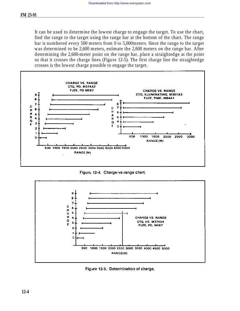
FM 23-91
It can be used to determine the lowest charge to engage the target. To use the chart,find the range to the target using the range bar at the bottom of the chart. The rangebar is numbered every 500 meters from 0 to 5,000meters. Since the range to the targetwas determined to be 2,600 meters, estimate the 2,600 meters on the range bar. Afterdetermining the 2,600-meter point on the range bar, place a straightedge at the pointso that it crosses the charge lines (Figure 12-5). The first charge line the straightedgecrosses is the lowest charge possible to engage the target.
12-4
Downloaded from http://www.everyspec.com

FM 23-91
(e) Another method that can be used is to turn to page II in the FT. There is alisting of charges for M374A2 (HE) and M375A2 (WP) from charge 0 through charge 9.Below that listing is the charge listing for M301A3 illumination (illum) from charge 0through charge 8. Write in after each charge the minimum and the maximum rangesthat each charge zone covers (Figure 12-6). By looking at the maximum range, thecorrect charge to use can easily be determined.
(6) Plotting of observer corrections. To plot the FO’s corrections, the computer firstindexes the FO’s direction to the target. That OT direction is given in the call-for-fire orwith the first correction. Going from the last round, he applies the FO’s corrections.
(a) For example, assume that the OT direction is 3050, and the FO sends thesecorrections: RIGHT 50, DROP 200. Ensuring that OT direction is indexed, makethese corrections from the first plot (Figure 12-7, page 12-6).
(b) To do this, move to the right one small square (50 meters), or the equivalent of onesmall square, then straight down the board four small squares (200 meters), or theequivalent of four small squares. Then, make a small plot, circle it, and label it "No. 2." Todetermine the firing data, rotate the disk until the No. 2 plot is over the vertical centerline.Then, read the deflection and range (Figure 12-8, page 12-7). Using the FT, determine thecharge and elevation to fire the round, and compute the subsequent fire command.
(c) Once the end of mission (EOM) has been given, update the M16/M19 plotting board(Figure 12-9, page 12-8). To do this, erase all the plots except the final plot. Then enclosethat plot with a hollow cross and number it with the target number (Figure 12-10, page 12-8).
(7) Engagement of other targets. To fire other targets on this chart, the computermust perform the following actions:
(a) Grid. Go back to the map, plot the target location, and determine the rangeand direction.
(b) Shift. Index the FO’s direction to the target and apply the correction from theknown point, which must be plotted on the chart.
12-5
Downloaded from http://www.everyspec.com

FM 23-91
b. Below Pivot-Point Method. The observed firing chart (with mortars plottedbelow pivot point) is used when the ranges to the targets being engaged are over3,200 meters. (When theinitial range to the target is 2,900 meters or more, mortarsare always plotted below the pivot point.)
(1) Two items are needed to setup the board for operation: a gun-target azimuthand a range from the mortar position to the target. To construct the chart –
(a) Index the gun-target azimuth.(b) Drop below the pivot point 1,000 meters for 60-mm mortars, 2,000 meters for
the 81-mm mortars, and 3,000 meters for the 4.2-inch and 120-mm mortars.
12-6
Downloaded from http://www.everyspec.com

FM 23-91
12-7
Downloaded from http://www.everyspec.com

FM 23-91
12-8
Downloaded from http://www.everyspec.com

FM 23-91
(c) Plot the mortar position 500 meters left or right of the vertical centerline(Figure 12-11).
(2) Once these actions have been taken, ensure that the azimuth disk is still indexedon the gun target azimuth. Then, from the mortar position, plot the first round at the
12-9
Downloaded from http://www.everyspec.com
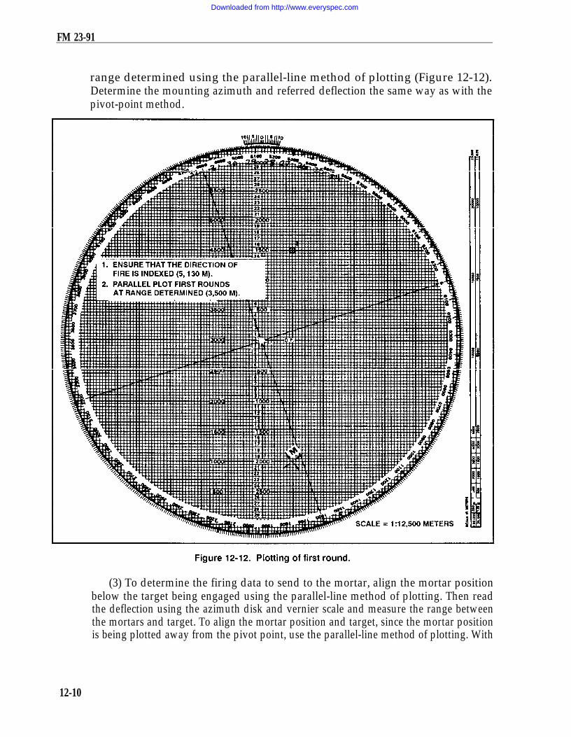
FM 23-91
range determined using the parallel-line method of plotting (Figure 12-12).Determine the mounting azimuth and referred deflection the same way as with thepivot-point method.
(3) To determine the firing data to send to the mortar, align the mortar positionbelow the target being engaged using the parallel-line method of plotting. Then readthe deflection using the azimuth disk and vernier scale and measure the range betweenthe mortars and target. To align the mortar position and target, since the mortar positionis being plotted away from the pivot point, use the parallel-line method of plotting. With
12-10
Downloaded from http://www.everyspec.com
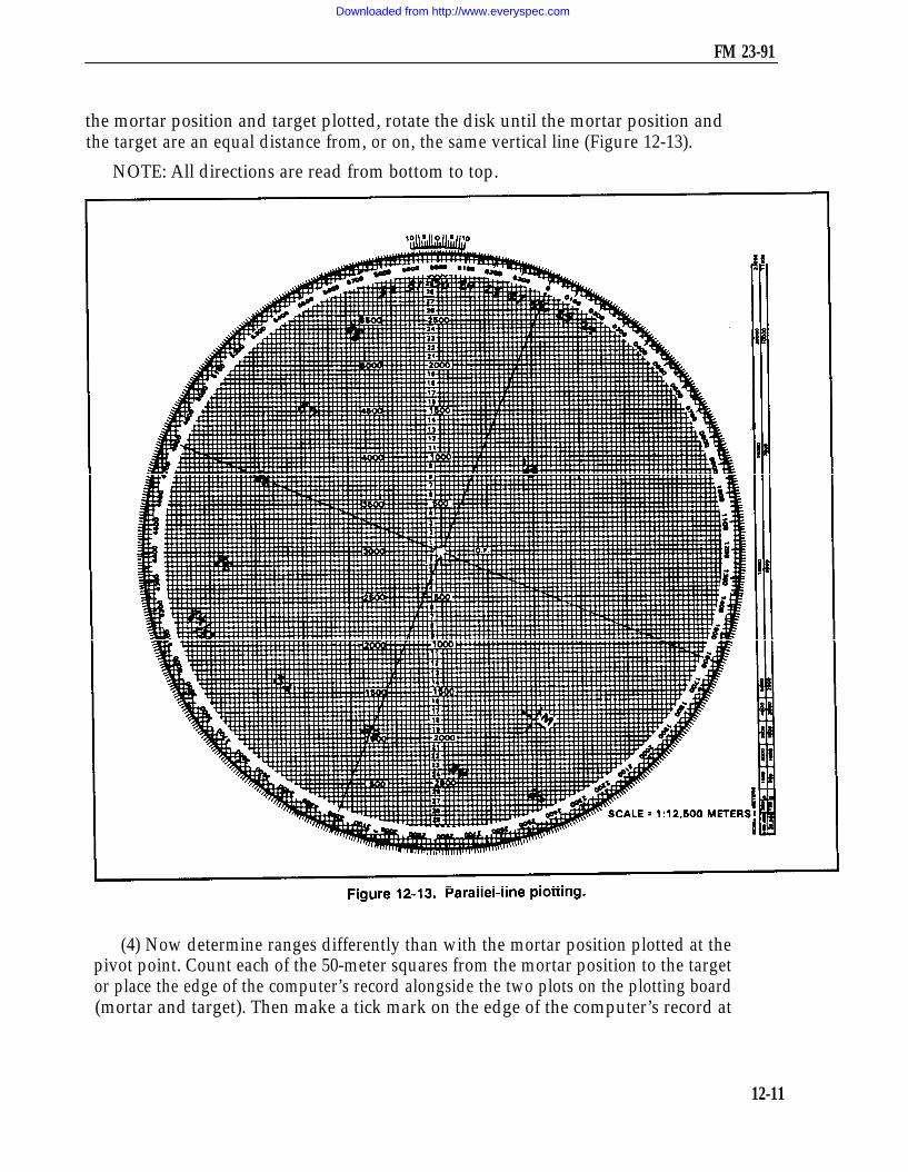
FM 23-91
the mortar position and target plotted, rotate the disk until the mortar position andthe target are an equal distance from, or on, the same vertical line (Figure 12-13).
NOTE: All directions are read from bottom to top.
(4) Now determine ranges differently than with the mortar position plotted at thepivot point. Count each of the 50-meter squares from the mortar position to the targetor place the edge of the computer’s record alongside the two plots on the plotting board(mortar and target). Then make a tick mark on the edge of the computer’s record at
12-11
Downloaded from http://www.everyspec.com

FM 23-91
each plot. Using the alternate range scale to the left of the pivot point, lay thecomputer’s record along this scale with the mortar tick mark at 0 and read the range(Figure 12-14).
12-12
Downloaded from http://www.everyspec.com

FM 23-91
(5) To update the board after the EOM is given or to engage other targets, use thesame method as with the pivot-point method.
NOTE: When operating the M16 plotting board as an observed firing chart (pivot-pointor below-pivot-point methods), no correction factors are applied to the data.
c. Mortars Plotted at Pivot Point. With the pivot pin inserted in the pivot point ofthe plotting board, the computer can use the range scale arm the same as with the rangearm to determine deflections and range to both the initial and subsequent rounds.
(1) Determine the range and direction to the center of the sector from a map orby visual observation. Round off the azimuth to the initial round or direction of fire(DOF) to the nearest 50 mils to determine a mounting azimuth, and superimpose adeflection scale on the azimuth disk.
(2) Make the initial plot by indexing the DOF (or initial azimuth) to the initialround at the index mark. This may be different from the mounting azimuth becauseof the round-off rule. Use the scale on the vertical centerline to make the initial plotat the correct range.
(3) When the FO calls in a target direction (the OT azimuth), index the azimuthdisk on the M16/M19 plotting board at the OT azimuth. It remains indexed on thatazimuth until the mission is completed. Plot corrections from the FO IAW procedures.Once a correction has been plotted, rotate the range arm until the right edge of therange arm is over the new plot. Determine the range to the nearest 25 meters, and readthe deflection to the nearest mil using the vernier scale.
(4) Plot additional corrections, and use the range scale arm to determine range anddeflection. Once the azimuth disk is indexed on the OT azimuth, the disk does nothave to be rotated to determine ranges or deflections.
d. Mortars Plotted Below Pivot Point. With the pivot pin inserted in the pivotpoint, the computer can use the left edge of the range scale arm to plot the initial round.The mounting azimuth and azimuth to the initial round are determined as for mortarsplotted at pivot point. The computer indexes the azimuth disk on the DOF and alignsthe right edge of the range scale arm on the vertical centerline. Next j he makes a smallplot at the zero range on the left edge of the range scale arm. Then, still using the leftedge, he makes a small plot at the range for the initial round. The mortar position plotmust be marked with a hollow cross to further identify its position. Once the initialround is fired, the range scale arm is removed, and the left edge is used as a range scale.
e. Care and Cleaning of Plotting Boards. Plotting boards must be handled withcare to prevent bending, scratching, or chipping. They must be kept away fromexcessive heat or prolonged exposure to the sun, which may cause them to warp.When storing a board, it is placed in its carrying case, base down, on a horizontalsurface. It is not placed on edge or have other equipment stored on it. The plottingboard can normally be cleaned with a nongritty (art gum) eraser. If the board isexcessively dirty, a damp cloth is used. The contact surface of the disk and base arecleaned often. The disk is removed by pushing a blunt instrument through the pivotpoint hole from the back of the base.
12-13
Downloaded from http://www.everyspec.com

FM 23-91
12-2. MODIFIED-OBSERVED FIRING CHARTThe modified-observed firing chart can be constructed on the M16 plotting board.It is constructed when the mortar position or target is known to survey accuracy. Threebasic items needed to construct the modified observed chart are: a DOF (usually tothe center of the platoon area of responsibility), one point (mortar position, target, orreference point) that must be known to surveyed accuracy (eight-digit gridcoordinates), and a grid intersection to represent the pivot point.
a. Determination of Direction of Fire. The section sergeant usually determinesDOF. In most cases, it is to the center of sector. The mortar location can be surveyedby map inspection, terrain inspection, or pacing from a known point on an azimuth, aslong as the position of the base gun is known to a valid eight digits,
(1) For the 60-mm and 81-mm mortars, the grid intersection representing the pivotpoint (Figure 12-15) is between 1,500 and 2,000 meters forward of the mortar location.This allows the full range of the mortar to be used.
NOTE: When using the M16 plotting board with the 4.2-inch and 120-mmmortars, the grid intersection selected should be 2,000 to 2,500 meters forwardof the mortar position.
(2) The grid intersection should be outside the area of responsibility. This ensuresthat the pivot point does not interfere with plotting targets or corrections. The grid
12-14
Downloaded from http://www.everyspec.com

FM 23-91
intersection is also as close as possible to the area of responsibility. This ensures thatas much of the area of responsibility as possible will be on the plotting board.
b. Superimposition of Grid System on Plotting Board. Once the grid intersectionhas been determined, the computer indexes “0” on the azimuth disk. He then drops down2,000 meters below the pivot point and writes in the north/south indicator on the verticalcenterline at the 2,000-meter mark. Next, he goes 2,000 meters to the left of the pivot pointon the heavy center horizontal line and writes the east/west indicator. To complete the gridsystem, the computer writes in the other north/south, east/west grid numbers as thoughlooking at a map. By numbering every other heavy dark line (two large squares) on theplotting board, he retains a scale of 1:12,500 on the board (Figure 12-16).
12-15
Downloaded from http://www.everyspec.com

FM 23-91
c. Plotting of Mortar Position. Now that a grid system is on the board, thecomputer can plot any grid coordinates. To do this, he must —
(1) Ensure that the azimuth disk is indexed at 0.(2) Read like a map: RIGHT and UP.(3) Remember that the scale is 1:12,500 (each small square is 50 meters by
50 meters) (Figure 12-17).
To superimpose the deflection scale, the computer writes the referred deflection on theboard the same way as with the observed chart. Firing data are determined by usingthe parallel-line method of plotting.
12-16
Downloaded from http://www.everyspec.com

FM 23-91
d. Field-Expedient Method for Construction. If the grid coordinates of the mortarposition are known but a map is not available for determining the grid intersection torepresent the pivot point, the computer can construct the modified-observed firingchart by using the following procedures:
(1) Index the DOF.(2) Drop below the pivot point on the vertical centerline 2,000 to 2,500 meters.(3) Go 500 to l,000 meters left or right of the vertical centerline and make a plot
(Figure 12-18).
12-17
Downloaded from http://www.everyspec.com

FM 23-91
(4) Rotate the azimuth disk and index "0."(5) Determine the l,000-meter grid that contaim the mortars (Figure l2-l9). The
first, second, fifth, and sixth numbers of the mortar grid give the 1,000-meter grid square.(6) Superimpose the grid system.(7) Replot the mortar location to the surveyed grid.
12-18
Downloaded from http://www.everyspec.com

FM 23-91
12-3. TRANSFER OF TARGETSTransfer is the process of transferring a target from the observed chart to themodified-observed chart, or from the modified-observed chart to the surveyed chart,as more information becomes available. This occurs since the targets transferred areknown points to the FO and FDC, and these points may be used in future missions.Transfer is always done using chart data (deflection and range to the final plot).
EXAMPLEAssume that the mortar section is at grid 939756 (six digits: observed chart) andtwo targets have been fired on (Figure 12-20). The platoon leader determinesthat the eight-digit grid to the mortar position is 93937563 (modified-observedchart) and designates the grid intersection to represent the pivot point. Thecomputer constructs the chart and transfers the targets from the observed chart(Figure 12-21, page 12-20).
12-19
Downloaded from http://www.everyspec.com

FM 23-91
NOTE: No firing corrections are used with the observed chart. Once transferredto the modified-observed chart, the altitude of the target is assumed to be the sameas that of the mortar position.
a. Target Plotting. After transfer, through coordination with the FO, an RP ortarget may be identified to valid eight-digit coordinates. The plotting board is thenreconstructed as a surveyed chart. When the situation permits, a registration missionshould be conducted on the point for which the valid eight-digit coordinates weredetermined. Then firing corrections are computed.
12-20
Downloaded from http://www.everyspec.com

FM 23-91
(1) When transferring targets from one type of chart to another, remember thatthe target plots on the observed chart are plotted at the data it takes to hit the target.This is not always the locations of the targets.
(2) The same holds true for the modified-observed chart, except that with sometargets, altitude correction (VI) may have been used. When replotting the target at theend of the mission, strip this altitude correction from the command range and plot thetarget using this range. Using this procedure gives a more accurate picture of the exactlocation of the target than the observed chart; however, it is not always the actuallocation of the target.
b. Plotting of Previously Fired Targets. At the completion of the surveyedregistration mission and the computation of the firing corrections, previously fired targetsplotted on the plotting board must be forward plotted. Since the surveyed chart is themost accurate chart to use, all information on it should be the most accurate possible.
EXAMPLEWhen targets AL0010 and AL0011 (Table 12-1) were fired before the surveyedregistration, the data and the plots included all firing corrections, even thoughthey may have been unknown at the time of firing. To forward plot these targets,the computer strips the firing correction from the range and deflection to plotthem at their actual location.NOTE: To strip out the corrections, the signs must be reversed.
12-4. DEFLECTION CONVERSION TABLEWhen an adjustment is made to a sheaf, such as after the completion of the registration,the sheaf is paralleled or converged if engaging a point-type target, or opened whenengaging a wider target. In these situations, the computer must determine the new dataand convert the deviation corrections required into mils. He can use the deflectionconversion table (Figure 12-22, page 12-22) or the mil-relation formula.
12-21
Downloaded from http://www.everyspec.com

FM 23-91
a. To use the DCT, first round off the range at which the section is firing to the nearest100 meters. This is required because the ranges on the table are divided into 100-meterincrements. Next, go down the range column to find the range. The deflection is in metersacross the top of the card.
b. Using the number of meters the FO requested to move the strike of the round,find that number of meters and go straight down that column until itintersects with therange. That number is the number of mils that would have to be applied to the mortarsight to move the strike of the round the required meters. If the range is greater than4,000 meters, divide the range and mil correction by two.
12-22
Downloaded from http://www.everyspec.com

FM 23-91
EXAMPLEThe mortar section has completed a registration mission and is prepared toadjust the sheaf. The final adjusted range for the RP is 2,750 meters. The No.1 and No. 3 mortars fire one round each. The FO sends the followingcorrections: NUMBER 3, R30; NUMBER 1, L20; END OF MISSION,SHEAF ADJUSTED. Any corrections of 50 meters or more must be refired.
For this example, the last deflection fired from No. 1 and No. 3 was 2931 mils.Using the DCT, round off the range to the nearest 100 meters (2,800). Find2,800 meters in the range column and, using the FO’s corrections, find 30 and20 in the deflection-in-meters column. Go across and down those columnsto where they intersect. The table shows that the requirements are 11 milsfor 30 meters and 7 mils for 20 meters.
Using this information, use the previous deflection fired, which was 2931 mils.Since the FO’s correction for the No. 3 mortar was R30, which equals R11 mils(using the LARS rule), subtract 11 mils from 2931 mils. This gives a newdeflection of 2920 mils. The correction for No. 1 mortar was L20, which equalsL7 mils. Using the LARS rule for deflection, add 7 mils to 2931, which gives anew deflection of 2938 mils.
If there is no deflection conversion table available, use the mil-relationformula (W/R x M) to convert the corrections from meters to mils. To usethe formula for the same FO’s corrections of R30 and L20 used in theexample cited, cover the item needed (in this case M [mils]). The remainderof the formula states: divide W (width in meters) by R (range in thousandths).
W/R = 20/2.8 = M
W/R = 30/2.8 = M
These are exactly the same figures determined by using the DCT.
12-5. GRID MISSIONFor an observed chart, the grid coordinates of the target must be plotted on the map,and a direction and distance determined from the mortar location to the target. Formodified and surveyed charts, index “0” and plot the target using the grid coordinates.
NOTE: Corrections for VI can be used on the modified and surveyed charts.
12-6. SHIFT MISSIONFor an observed chart, the known point must be plotted on the firing chart. This maybe a fired-in target or a mark-center-of-sector round. The OT azimuth is indexed, and
12-23
Downloaded from http://www.everyspec.com

FM 23-91
the correction applied is sent in the call for fire. For modified and surveyed charts, thesame procedure is used as for the observed chart.
12-7. POLAR MISSIONThe FO’s location must be plotted on the plotting board before a polar mission can befired. For an observed chart, the location can be plotted in three ways: by resection,by direction and distance, or by range and azimuth from a known point.
a. Resection (Figure 12-23). Plot two known points on the plotting board. Then indexthe azimuths the FO sends from these two points, and draw lines from the known pointstoward the bottom of the board. The intersection of these lines is the FO’s location.
12-24
Downloaded from http://www.everyspec.com

FM 23-91
b. Direction and Distance (Figure 12-24). The FO sends the computer the grid tothe FO position. The computer then plots the grid on the map, determines thedirection and distance from the mortar position to that grid, transfers the direction anddistance to the plotting board, and plots the FO’s location.
c. Range and azimuth from a known point. The FO must send the range from theknown point and the azimuth on which that point is seen. Once that is known, thecomputer can index the azimuth, drop below the known point the range given, and plotthe FO’s location (Figure 12-25, page 12-26). For modified and surveyed charts, the
12-25
Downloaded from http://www.everyspec.com

FM 23-91
FO’s location can be plotted if the grid of the FO is known, by indexing "0" and plottingthe FO grid. If the grid is not known, then the computer can use resection, directionand distance, or range and azimuth from a known point.
12-26
Downloaded from http://www.everyspec.com

CHAPTER 13
TYPES OF MISSIONS
Certain missions require that special procedures be applied to effectively engage targets;therefore, these missions should not be fired on the observed chart. Area tarets have widthor depth or both, requiring the mortar section to use either searching or traversing fire, ora combination of these.
13-1. TRAVERSING FIRETraversing fire is used when the target has more width than a section firing a parallel sheafcan engage. Each mortar of the section covers part of the total target area and traversesacross that area. The M16/M19 plotting board can be constructed as any one of the threefiring charts. Table 13-1 lists the data used to setup the plotting board for traversing fire.
a. Upon receiving the call for fire, thesection sergeant determines from the sizeand description of the target thattraversing fire must be used to cover thetarget. (To effectively engage a target usingtraversing fire, the section sergeantensures the attitude of the target is within100 mils of the attitude of the firing section.)The section sergeant then completes theFDC order (Figure 13-1, page 13-2).
b. The three or four mortars areplotted separately on the M16/M19 plotting board, using the attitude of the section.During the mission, the computer ensures that the correct plots are used to determinedata required — for example, during the adjustment, the impact point is aligned withthe No. 2 mortar plot. Using the information in the call for fire, the FDC order, andthe observer corrections, the computer computes the data to adjust the No. 2 mortaronto the center mass of the target. After the adjustment is complete (Figure 13-2, page 13-3),the computer must complete the following procedure:
(1) Plot the 250-meter length of the target on the plotting board using the attitude of the target.(2) Divide the target into segments.(3) Determine the number of rounds for each segment.(4) Determine the mil width of one segment.(5) Determine the number of turns required to cover one segment.(6) Determine the number of turns between rounds.
13-1
Downloaded from http://www.everyspec.com

FM 23-91
13-2
Downloaded from http://www.everyspec.com
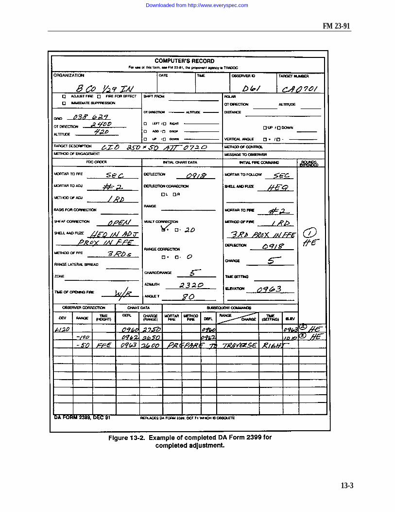
FM 23-91
.
13-3
Downloaded from http://www.everyspec.com

FM 23-91
c. To plot the target on the plotting board, the computer rotates the azimuth discuntil the target attitude (taken from the call for fire) is indexed. The computer erasesall the plots except the last plot. After ensuring that the attitude is indexed, thecomputer divides the total target area into segments. These plots represent the startingpoints for each mortar. The area between the plots is the area each mortar must coverwith fire (Figure 13-3).
d. The target is now divided into three segments. Once the remaining data for onesegment have been determined, the data will apply to all three mortars. Since eachsegment of the target is 75 meters, if the computer determines the mil width of onesegment, the other two will be the same. The computer can use one of two methodsto determine the number of mils for one segment.
13-4
Downloaded from http://www.everyspec.com

FM 23-91
(1) In the first method, the computer knows the deflection that was used to hit theNo. 3 point. By aligning the No. 2 plot and No. 3 mortar, the computer can determinethe deflection to fire to hit the start point for the No. 2 mortar (Figure 13-4).Subtracting these two numbers determines the mil width of the segment:
Number 3 plot deflection 2993 milsNumber 2 plot deflection 2942 mils
Mil width of segment 51 mils
(2) The second method uses the DCT to determine the mil width of onesegment. The computer enters the DCT at the final chart range that is rounded offto the nearest 100 meters. He goes across the deflection-in-meters line to theclosest meters (75) to cover the segment. The point at which the range line and the
13-5
Downloaded from http://www.everyspec.com

FM 23-91
deflection line meet is the number of mils that will cover the segment. Each turn ofthe traversing handwheel is about 10 mils. By dividing the mil width of each segment(29) by 10, the computer obtains the total number of turns to cover the segment (roundoff to the nearest whole turn):
e. To compute the number of turns to take between rounds, the computer mustknow how many rounds will be fired for each segment. This information is given in theFDC order (3 rounds). To determine the turns between rounds, the computer dividesthe total turns by the interval between rounds (there will always be one less intervalthan the number of rounds: 3 rounds = 2 intervals).
Turns between rounds are rounded to the nearest half turn. The number of rounds tofire is based on the rule: four rounds per 100 meters of target width, or one round per30 meters.
f. At this point, the computer must determine the deflection and range for eachmortar by aligning each mortar with its start point, completing the subsequentcommand, and issuing it to the mortar section. If there is a range change of 25 metersor more, the mortar will receive its own elevation.
g. Upon completion of the adjustment phase of the mission, the section is given thecommand PREPARE TO TRAVERSE RIGHT (LEFT). The gunners then traversethe mortars all the way in the direction opposite to that given, back off two turns, andawait further instructions (Figure 13-5).
13-2. SEARCHING AND ZONE FIREAn area target having more depth than 50 meters can be covered by mortars by eitherelevating or depressing the barrel during the FFE. An area up to 50 meters can becovered by a section — three mortars firing four rounds on the same elevation anddeflection — due to range and deflection dispersion. In the call for fire, the FO sendsthe size of the target and attitude since it is more area to cover than a section firing aparallel sheaf can engage. The FO gives the width and then depth of the attitude ofthe target. Attitude is the direction (azimuth) through the long axis of the target.
13-6
Downloaded from http://www.everyspec.com

FM 23-91
13-7
Downloaded from http://www.everyspec.com

FM 23-91
a. Searching Fire. For the mortar section to effectively engage a target using onlysearching fire, the attitude of the target cannot be more than 100 mils difference fromthe attitude of the gun section. If the difference is more than 100 mils, the target shouldbe engaged using a combination of searching and traversing fire, or traversing fire only.When the section is firing a searching mission, the adjustment phase of the mission isthe same as a regular mission using the base mortar (No. 2) as the adjusting mortar.The base mortar is adjusted to center mass of the target.
(1) Upon completion of the adjustment phase of the mission, the computer mustcompute the data to cover the target with fire. He must determine the number of roundsto cover the target, the turns required to cover the target, and the turns between rounds.
(2) With the target area given in the call for fire, the computer can determine thenumber of rounds needed to cover the target. When firing on a target using traversingor searching fire, the computer uses 4 rounds for every 100 meters of either target widthor depth, or 1 round for every 30 meters. The computer must always consider thenumber of rounds on hand and the resupply rate when determining the number ofrounds to fire.
EXAMPLEAssume that the depth of the target is 350 meters. Multiply the even 100’sby 4: 4 + 3 = 12. For the remainder of the target depth (50 meters), oneround covers 30 meters, which would add one more round: 12 + 1 = 13rounds. At this point, 20 meters of target is left. To cover the 20 meters, addone more round.
(3) When determining the number of turns needed to cover the target, thecomputer can use one of two methods. If the computer is using the unabridged firingtable (all escept for FT 4.2-K-2), the number of turns in elevation required for a100-meter change in range is given in column 4 of Table D (basic data).
EXAMPLEAssume that the target is 350 meters in depth, the range to the target center ofmass is 2,125 meters (always use chart range), and the firing charge is 4. Todetermine the turns, determine the range to the center of mass of the target(2,125), enter the firing table at charge 4, range 2,125, and go across to column 4.Four turns are needed to cover 100 meters. Multiply 4 by 3.5 (range inhundreds): 4 x 3.5 = 14 turns to cover the target. The mortars are adjustedto center of mass. To obtain the range to the far edge (search up), add half thetarget area to the range to the center of mass.
EXAMPLEThe range to the center is 2,125 meters; target area is 100 meters by 350 meters;half of target depth is 350 divided by 2 = 175 meters; and the range to the farend is 2,300 meters. To search down, start at the near edge and subtract half thetarget depth from target center.
13-8
Downloaded from http://www.everyspec.com

FM 23-91
(4) Applying the second method, the computer must determine the mil length ofthe target by using the firing tables. He uses the elevation for the far end of the target(adjusting point) and the elevation to hit the near end of the target:
Range to adjusting point 2,300 meters Elevation 974 milsRange to near end 1,950 meters Elevation 1128 mils
By subtracting the two elevations, the computer has the mil length of the target:
1128 mils974 mils
Length of target 154 mils
(5) Each turn of the elevating crank is 10 mils. Dividing the mil length of the target(154 mils) by 10 gives the computer the total turns to cover the target:
NOTE: Table D (basic data) in all FTs (except for FT 4.2-K-2), column 4, gives thenumber of turns per 100 meters difference in range. These data may be used todetermine the total turns to cover the target.
(6) To compute the number of turns to take between rounds, the computer mustknow how may rounds each mortar will fire. The computer computes this informationor finds it in the FDC order (14 rounds). To determine the turns between rounds, hedivides the total turns by the intervals between rounds (there will always be one lessinterval than the number of rounds: 14 rounds = 13 intervals).
(7) The computer rounds turns to the nearest half turn. The number of roundsto fire is based on the rule: five rounds per 100 meters of target depth, or one roundper 20 meters. At this point, the computer has all the information needed tocomplete the subsequent command. The command can then be issued to themortars (Figure 13-6, page 13-10).
13-9
Downloaded from http://www.everyspec.com
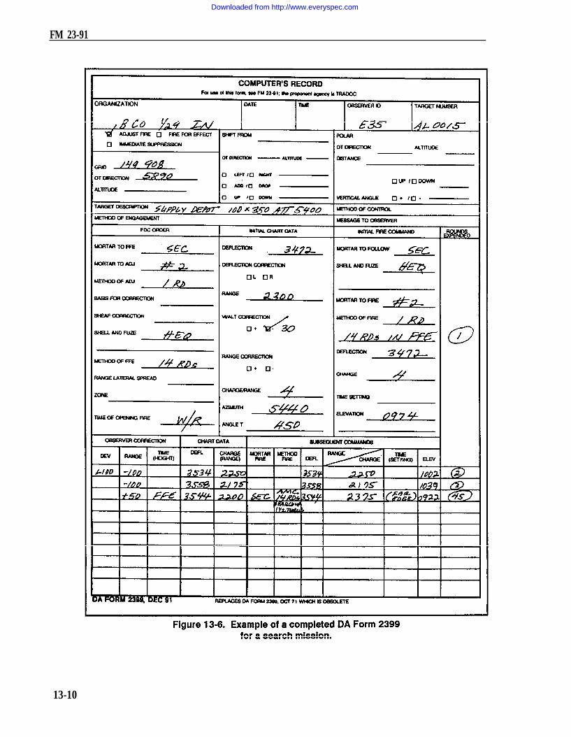
FM 23-91
13-10
Downloaded from http://www.everyspec.com

FM 23-91
(8) The only difference between a search UP mission and a search DOWN missionis the starting point. Normally, a search mission is fired by searching UP. This allowsthe FO to better observe the effect of the rounds on target as the rounds walk towardhim (Figure 13-7).
b. Zone Fire. The 4.2-inch mortar does not fire a search mission the same as the120-mm, 81-mm, 60-mm mortars. It does not have the same elevating characteristicsas the other mortars; therefore, the 4.2-inch mortar uses zone fire when targets havemore depth than a platoon/section can cover when firing a standard sheaf. The 4.2-inchmortar platoon/section usually fires two standard zones: a 100-meter zone (threerounds for each mortar) for a platoon-size target, and a 200-meter zone (five roundsfor each mortar) for a company-size target.
Note: A larger zone can be covered by firing one round for every 50-meter increasein the target area.
(1) Establishing the 100-meter zone. Once FO gives the FFE, the computerproceeds as follows:
(a) Firing without extension (M329A1). Add and subtract 3/8 charge from thebase command charge. (The base command charge is the command charge in the FFE
13-11
Downloaded from http://www.everyspec.com

FM 23-91
center mass of target.) This gives each mortar three rounds with a different charge oneach to cover the 100-meter zone (Figure 13-8).
(b) Firing with extension (M329A1). Add and subtract 4/8 charge from the basecommand charge and use three rounds for each mortar.
Note: A 3/8 charge correction to any charge without extension moves the roundabout 50 meters at any elevation used. A 4/8 charge correction to any charge withextension moves the round about 50 meters at any elevation used.
(c) Firing with M329A2. Add and subtract 2/8 charge from the base command charge.(d) Firing the 100-meter zone. Once the mortars are up (rounds set for proper
charges) and the fire command is given, fix the rounds in any sequence — for example,No. 1 fires long, short, center mass; No. 2 fires center mass, short, long.
(2) Establishing the 200-meter zone. Once the FFE has been given by the FO, thecomputer proceeds as follows:
(a) Firing without extension. Add and subtract 3/8 charge from the base commandcharge for the rounds on either side of the base round and 6/8 charge for the long andshort round (Figure 13-9).
(b) Firing with extension. Add and subtract 4/8 charge from the base commandcharge for the rounds on either side of the base round and a whole charge for the longand short rounds.
13-12
Downloaded from http://www.everyspec.com

FM 23-91
(c) Firing With M329A2. Add and subtract 2/8 charge from the base command charge.(d) Firing the 200-meter zone. Fire the rounds in any sequence.
13-3. ILLUMINATIONIllumination assists friendly forces with light for night operations. The M16/M19 canbe setup for illumination as any one of the three types of firing charts. Determiningfiring data is the same as with any type of mission, only now the FDC uses one ofthe flank mortars to adjust the illumination, leaving the base mortar (No. 2) readyto adjust HE. The FO enters corrections for the illumination rounds inrange — deviation not less than 200-meter corrections, and corrections for height(up/down) not less than 50-meter corrections.
a. Observers. Observers who are to adjust illumination should be informed whenthe 81-mm mortars are firing M301A3 illumination rounds. The M301A3 has an HOBof 600 meters, while the M301A1 and M310A2 rounds have 400-meter HOBs. Thereis a difference in adjustment procedure. The M301A1 and M301A2 rounds areadjusted to a ground-level burnout; the M301A3 round should have a burnout 150 to200 meters above ground. This procedure is based on the fact that all three of therounds fall at a rate of 6 mps (Table 13-2, page 13-14).
b. Corrections. The ranges in the firing tables are in 50-meter increments.(Rule: Always round up, such as range 2,525 meters = 2,550 meters, to enter Part II of thefiring tables.) Corrections to the HOB are obtained in columns 4 and 5. These correctionsare used to move the roundup or down in relation to the HOB line (Fig 13-10, page 13-14).
13-13
Downloaded from http://www.everyspec.com

FM 23-91
13-14
Downloaded from http://www.everyspec.com

FM 23-91
EXAMPLEChart range to the first round fired: 2,525 meters = 2,550 meters to enter the
firing table (FT 81-A1-3).Optimum charge to use: charge 8Basic data, columns 1 (Range to Burst), 2 (Elevation) and 3 (Fuze Setting) to
give the basic HOB for 600 meters above the mortar position:Range to Burst = 2,550 metersElevation = 1107 milsFuze setting = 31.0
c. Adjustments. The round is fired and the FO sends: ADD TWO ZERO ZERO(200), UP ONE ZERO ZERO (100). The computed range is now 2,725 = 2,750(Figure 13-11, page 13-17). The basic data only give an HOB of 600 meters, but theFO requested an UP 100, meaning that the round needs more height. To compute thischange, the computer must determine where this round will be in relation to the HOB line:HOB = 600 meters; UP 100 is two increments above the HOB line. Once the numberof increments has been determined, the computer goes to column 4 (change inelevation for 50-meter increase in HOB) and column 5 (changes in fuze setting for50-meter increase in HOB), and multiplies the increments times the correction factorsgiven in these columns.
EXAMPLERange to burst 2,750 meters, + 2 incrementsColumn 4 = –14 X 2 increments
(100 mils above HOB) = -28 milsColumn 5 = –0.7 13 X 2 increments
(100 mils above HOB) = -1.4 seconds
(1) Once the corrections have been determined, apply those to the basic data(columns 2 and 3) to obtain the firing data for the next round.
EXAMPLEBasic data: column 2 = 1034 (600 meters HOB)
-28 mils (correction)1006 (elevation needed to fire)
column 3 = 29.5 (600 meters HOB)-1.4 (correction)
(time set needed to fire)28.1
(2) Assume that the second round is fired and the FO sends: DOWN FIFTY (50).Note that a range change was not sent, but an HOB correction was sent. Again,determine the relation to the HOB line and apply the correction factors to the basicdata to obtain the firing data.
13-15
Downloaded from http://www.everyspec.com

FM 23-91
EXAMPLE
Range to burst 2,750 meters, charge 8, down 50.
The computer is now working with one increment above the HOB line.Increments (relationship to HOB, 600 meters)
1 X -14 (column 4) = -141 X -0.7 (column 5) = -0.7
New data:1034 mils (basic data) -14 = 1020 mils elevation29.5 (basic data) –0.7 = 28.8 fuze setting.
(3) When the correction is below the HOB line, use the opposite sign of the signfound in columns 4 and 5 to obtain the same HOB. To compute the correction, assumethat the chart range to burst is 1,550 meters and the optimum charge is 6. The firstround is fired at an elevation of 1260 mils with a fuze setting of 29.0.
(4) The FO sends: DROP TWO ZERO ZERO (200), DOWN ONE FIVE ZERO(150). Assume that the new range is 1,325 meters ( = 1,350), and the optimum charge is 5.The procedure for determining the increments is the same as with the last example:600-meter basic HOB, down 150 = 3 increments below the HOB line.
(5) Determining the correcting factors is the same as before, except that whencomputing below the HOB line, reverse the signs since columns 4 and 5 are setup forincreases in HOB.
3 X –8 (column 4) = –24 mils = +24 mils3 X -0.6 (column 5) = –1.8 sec = + 1.8 sec
Determining new firing data is the same as before.
Basic data:1245 mils (column 2) +24 mils = 1269 mils elevation25.9 (column 3) + 1.8 sec = 27.7 fuze setting
(6) Assume that the second round is fired and the FO sends: DROP TWO ZEROZERO (-200), and the new range is 1,150 meters. Note that a range change is givenbut not an HOB correction. When only a range change is sent, only the incrementsbelow the HOB line for the old range must be applied to the new range to keep theHOB correct. To determine the data, apply the steps as before:
Increments below HOB = 3Correcting factors: 3 X -5 = -15 = +15 (sign reversed)
3 x -0.5 = -1.5 = +1.5 (sign reversed)New data: 1309 mils + 15 mils = 1,324 mils elevation
26.6 + 1.5 = 28.1 fuze setting
13-16
Downloaded from http://www.everyspec.com

FM 23-91
,
13-17
Downloaded from http://www.everyspec.com

CHAPTER 14
SPECIAL CONSIDERATIONS
This chapter discusses the special procedures applied to some missions to effectivelyengage targets.
14-1. REGISTRATION AND SHEAF ADJUSTMENTFiring the registration is the first mission that will be completed if time and the tacticalsituation permit.
a. Firing Coordinated and Noncoordinated Missions. Two types of registrationmissions are fired on the surveyed chart: coordinated and noncoordinated.
(1) Firing coordinated missions. The FDC and FO coordinate the location of theRP before the FO joins the unit to support it. Once the FO is in position, the FDCsends a message telling the FO to prepare to register RP 1. The FO sends the OTdirection to the RP.
(2) Firing noncoordinated missions. The FO, upon joining the unit to support it,checks the area of responsibility and selects a point to be used as the RP. This pointmust be identifiable both on the ground and on the map to allow a valid eight-digit gridto be determined. The FO then sends the call for fire to register the RP.
b. Constructing Surveyed Firing Chart. The surveyed firing chart is the mostaccurate chart that can be constructed. It can be used to determine all the correctingfactors that are needed to fire more first-round FFE missions than the other firingcharts. Three items must be known to construct the surveyed chart: a grid intersectionto represent the pivot point, a surveyed mortar position, and a surveyed registrationpoint. (The construction of the surveyed chart is similar to the modified-observed chart.)
(1) To obtain the DOF after constructing the chart, align the mortar position withthe Rp. Determine the DOF to the nearest mil.
(2) To determine the mounting azimuth, round off the DOF to the nearest 50 mils.(3) To superimpose the deflection scale, the referred deflection is received from
the section sergeant. Then, construct the deflection scale in the same manner as forthe modified-observed chart.
NOTE: The procedure to obtain the firing data is the same as with all firing charts.(4) Determine correction factors after the registration has been completed. Apply
these factors to all other targets within the transfer limits of the RP.c. Obtaining Firing Data. Obtaining the firing data is the same as with any
mission, except that the FO continues to adjust until a 50-meter bracket is split and
14-1
Downloaded from http://www.everyspec.com

FM 23-91
the last fired round is within 25 meters of the target (Figure 14-1). Refinementcorrections are sent to the FDC and the mission is ended. Table 14-1 provides informationto be used insetting up the plotting boards to fire a surveyed registration.
d. Adjusting the Sheaf. The purpose of adjusting the sheaf is to get all mortarsfiring parallel. The mortars are positioned with gun No. 1 through 4 for the 81-mm andthe 120-mm platoons, No. 1 through 6 for the 4.2-inch (when employed as a platoon),or No. 1 through 3 for the 4.2-inch (when employed as a section) from right to left asseen from behind the guns. There is normally a 10-second interval between rounds.The FO needs that time to observe the impact of the rounds and to determinecorrections. If the corrections are 50 meters or more (deviation left/right only), themortar must be refired. The corrections can be plotted on the board, or the DCT(Figure 14-2) can be used to determine the number of mils to add or subtract from thebase mortar deflection.
EXAMPLEThe sheaf of a 81-mm platoon is being adjusted, No. 2 mortar conducted theregistration. The FDC has requested to prepare to adjust the sheaf. The FOrequests section right. The entire platoon then fires, in order, starting at theleft (No. 4, 3, 1) with 10-second intervals between rounds. The mortar thatwas used to register (No. 2) will not fire. The sheaf is adjusted perpendicularto the gun-target line. The observer notes where each round lands and sendsback deviation corrections in meters; range corrections are ignored if less than50 meters. If a deviation correction is 50 meters or more, it must be refired.Corrections to be refired should always be transmitted first by the FO.
14-2
Downloaded from http://www.everyspec.com

FM 23-91
If angle T is greater than 500 mils, each piece is adjusted onto the registration point,and the FDC computes the data for the sheaf. In adjusting the sheaf, all roundsmust be adjusted on line at about the same range (within 50 meters) and with thelateral spread between rounds equal to the bursting diameter of the ammunition used.
14-3
Downloaded from http://www.everyspec.com

FM 23-91
The spottings from the FO are No. 4, right20, No. 3, left 60, and No. 1, left 30 (Figure14-3). The FO sends the corrections tothe FDC; No. 3, right 60 (since it needsto be refired), No. 4, left 20 No. 4 isadjusted, and No. 1, right 30 No. 1 isadjusted. The No. 3 mortar is now fired,and the round impacts 10 meters right ofthe desired burst point. The FO thensends: No. 3, left 10, No. 3 is adjusted,sheaf is adjusted, end of mission.e. Obtaining Firing Corrections Using the Deflection Conversion Table. The computer
enters the DCT at the initial chart range rounded to the nearest 100 meters: 3050 = 3100.(Remember, the RP is at a surveyed grid, and it has not moved.) Using the deflectionin meters line at the top of the table, the computer finds the meters needed to correctthe sheaf. Where the range line and the correction line meet is the number of milsneeded to apply. He applies the mils to the base deflection. (When working withdeflections, use the LARS rule.) Once the FO has given EOM, “Sheaf adjusted,” thesection is given, “Section, refer deflection two eight zero one (2801), realign aiming posts,”(2801 was the base mortar’s hit deflection). This procedure allows all mortars tobefired with the same data, and the resulting sheaf will be parallel.
f. Determining Firing Corrections. Once registration is completed, the firingcorrections (range correction factor and deflection correction) are determined for usewithin the transfer limits of the RP (Figure 14-4). The computer applies correctionfactors to correct for nonstandard conditions (weather and equipment wear) affecting
the round. Range correction isthe number of meters to beadded to or subtracted from thechart range to hit the targetbecause of the nonstandardconditions. As the registrationmission is fired and completed,the rounds on the plotting boardmay not be plotted at the pointwhere the RP was plotted,Because of wind and weather,the rounds may have to be firedat a greater or lesser range andto the right or left of the target tohit it. As shown in Figure 14-5,the initial chart range to the RPwas 3,050 meters; the finaladjusted chart range (range usedto hit the RP) was 3,200.
14-4
Downloaded from http://www.everyspec.com

FM 23-91
g. Determining Range Difference. The computer compares the initial chart rangeand the final adjusted chart range and subtracts the smaller from the larger. This givesthe range difference. If the initial chart range is larger than the final adjusted chartrange, then the range correction is a minus (–). If it is smaller, then the range correctionis a plus (+).
EXAMPLEInitial chart range smaller: 3,050; final adjusted chart range: 3,200
Then, 3,200-3,050 = + 150 meters.Initial chart range larger: 3,200; final adjusted chart range: 3,050
Then 3,200-3,050 = –150 meters.
(1) Range correction factor. The RCF is the number of meters per thousand to beadded to or subtracted from the chart range to hit a target within the transfer limits.Continuing the preceding example, since the ranges to other targets will not be 3,050(range to RP), the RCF (+150) will not be correct. Therefore, other range correctionsmust be determined and used for other targets. Once the range difference has beendetermined, round the initial chart range to the nearest 100 and then express that inthousandths.
EXAMPLEInitial chart range: 3,050.Round to nearest 100 = 3,100
expressed in thousandths = 3.1.Divide the range in thousandths into
the range difference: +150.
Determine to the nearest whole meterand use the sign of the range correction.
14-5
Downloaded from http://www.everyspec.com
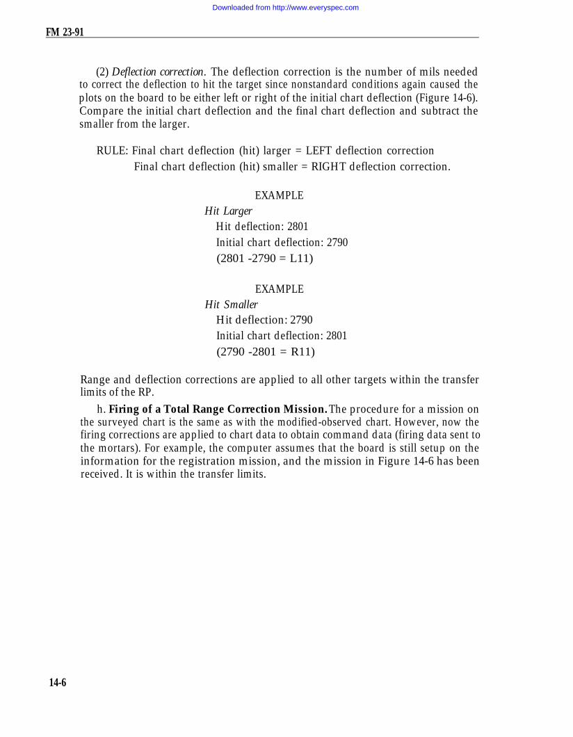
FM 23-91
(2) Deflection correction. The deflection correction is the number of mils neededto correct the deflection to hit the target since nonstandard conditions again caused theplots on the board to be either left or right of the initial chart deflection (Figure 14-6).Compare the initial chart deflection and the final chart deflection and subtract thesmaller from the larger.
RULE: Final chart deflection (hit) larger = LEFT deflection correctionFinal chart deflection (hit) smaller = RIGHT deflection correction.
EXAMPLEHit Larger
Hit deflection: 2801Initial chart deflection: 2790(2801 -2790 = L11)
EXAMPLEHit Smaller
Hit deflection: 2790Initial chart deflection: 2801(2790 -2801 = R11)
Range and deflection corrections are applied to all other targets within the transferlimits of the RP.
h. Firing of a Total Range Correction Mission. The procedure for a mission onthe surveyed chart is the same as with the modified-observed chart. However, now thefiring corrections are applied to chart data to obtain command data (firing data sent tothe mortars). For example, the computer assumes that the board is still setup on theinformation for the registration mission, and the mission in Figure 14-6 has beenreceived. It is within the transfer limits.
14-6
Downloaded from http://www.everyspec.com

FM 23-91
14-7
Downloaded from http://www.everyspec.com

FM 23-91
i. Applying Firing Corrections. Once the chart data have been determined, thecomputer applies the deflection correction by either adding or subtracting thedeflection correction to the chart data determined. When working with deflectioncorrections, the computer uses the LARS rule. The deflection correction must beapplied to each chart deflection throughout the mission.
EXAMPLE
2715 + L11 = 2726
(1) Range correction factor. Determine the initial chart range, then round to thenearest hundred and express it in thousandths; for example, 2975 = 3000 =3.0.Multiply the range in thousandths times the RCF and use the sign of the RCF:3.0 X +48 = + 144. This gives the range correction for this target.(2) Total range correction. The total range correction (TRC) is the totalcorrection that must be applied to get the command range to fire the target.TRC is the range correction (RCF x range in thousandths) plus or minus thealtitude correction.
EXAMPLERange correction = + 144 – 25 (altitude correction) = + 119 TRC
The two factors (RCF and altitude correction) are compared. If one of these factors isa negative, subtract the smaller from the larger. The sign of the larger is used for theTRC. If both factors are negative or positive, then add the two factors to get the TRC.This must be applied to every chart range to obtain command range. To enter the firingtables, the command range is rounded to the nearest 25 meters.
j. Firing Reregistration. The FDC must consider weather changes to ensure theaccuracy of the firing data (firing corrections) from the surveyed chart. Two methodscan be used to do this: reregistration on the RP or MET message. Of those twomethods, reregistration is the better because all the unknown (nonstandard) factors arefired out. However, due to countermortar-radar, determining and applying the METmessages may be safer. Choice would be dictated by the tactical situation and theavailability of the MET messages.
(1) Fire the reregistration at the established RP using only the mortar thatoriginally fired the registration (Figure 14-7). (The FDC assumes that the sheaf is stillparallel; therefore, the sheaf should not need adjusting again.) The chart data are thesame as with the initial registration. Apply the firing corrections to obtain the commanddata (Figure 14-8, page 14-10). (A blank reproducible copy of DA Form 2188-R,Data Sheet, is located at the back of this manual.)
14-8
Downloaded from http://www.everyspec.com

FM 23-91
14-9
Downloaded from http://www.everyspec.com

FM 23-91
14-10
Downloaded from http://www.everyspec.com

FM 23-91
(2) The chart deflection plus or minus deflection correction equals commanddeflection. The chart range plus or minus the range correction plus or minus thealtitude correction equals the command range.
(3) Carry out the mission the same as with the initial registration. Once theEOM, “Registration complete,” has been given, determine firing corrections again.
(4) In the initial registration, the FDC compared the initial chart range and thefinal chart range difference. Determining the range difference after thereregistration is the same; however, now determine the final adjusted range.During the reregistration, firing corrections were applied for each round. Now applythose same corrections.
(5) Adjusted range is the final range with the correction for altitude correctiondeleted.
Final command range: 3,EXAMPLE
100 meters; altitude correction: -25.Final adjusted range: 3,100 + 25 = 3,125.
The altitude correction is added since it was initially subtracted. If the altitude correctionhad been a plus (+), then it would have been subtracted to obtain the final adjusted range.
(6) Once the final adjusted range has been determined, compare the initial chartand the final adjusted range. Subtract the smaller from the larger to determine theRCF. The sign (+/–) would be determined as with the initial registration. Again,divide the range (initial chart range rounded to the nearest 100 expressed inthousandths) into the new range correction to determine the new RCF.
(7) To determine the deflection correction, compare the initial chart deflection andthe final command deflection. Subtract the smaller from the larger and determine thesign (L or R) to apply.
(8) Apply the new firing corrections to all targets that have been and are firedwithin the transfer limits. For those targets that are already plotted on the board, applythe new firing corrections and update the target data. (The chart data do not change.The target has not moved; only the weather has changed.)
14-2. MEAN POINT OF IMPACT REGISTRATIONThe FDC uses MPI registration during darkness and on featureless terrain to determinefiring corrections. Two M2 aiming circles or radar must be used to conduct an MPIregistration. (MPI registration can also be used for reregistration.)
a. Conduct of an MPI Registration. To fire the MPI registration, the FDC mustproceed as follows:
(1) Set up the M16/M19 plotting board as a surveyed firing chart (eight-digit gridsto the mortar position and RP).
(2) Plot the location and altitudes of the two FO points to be used.
14-11
Downloaded from http://www.everyspec.com
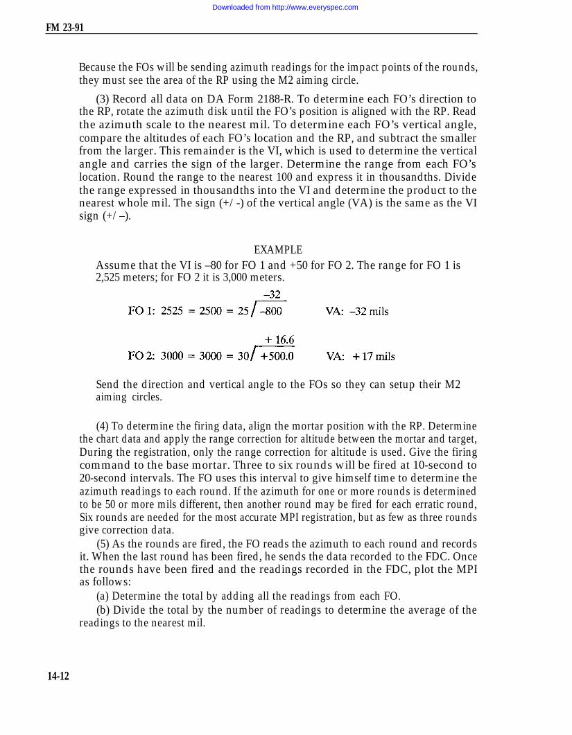
FM 23-91
Because the FOs will be sending azimuth readings for the impact points of the rounds,they must see the area of the RP using the M2 aiming circle.
(3) Record all data on DA Form 2188-R. To determine each FO’s direction tothe RP, rotate the azimuth disk until the FO’s position is aligned with the RP. Readthe azimuth scale to the nearest mil. To determine each FO’s vertical angle,compare the altitudes of each FO’s location and the RP, and subtract the smallerfrom the larger. This remainder is the VI, which is used to determine the verticalangle and carries the sign of the larger. Determine the range from each FO’slocation. Round the range to the nearest 100 and express it in thousandths. Dividethe range expressed in thousandths into the VI and determine the product to thenearest whole mil. The sign (+/-) of the vertical angle (VA) is the same as the VIsign (+/–).
EXAMPLEAssume that the VI is –80 for FO 1 and +50 for FO 2. The range for FO 1 is2,525 meters; for FO 2 it is 3,000 meters.
Send the direction and vertical angle to the FOs so they can setup their M2aiming circles.
(4) To determine the firing data, align the mortar position with the RP. Determinethe chart data and apply the range correction for altitude between the mortar and target,During the registration, only the range correction for altitude is used. Give the firingcommand to the base mortar. Three to six rounds will be fired at 10-second to20-second intervals. The FO uses this interval to give himself time to determine theazimuth readings to each round. If the azimuth for one or more rounds is determinedto be 50 or more mils different, then another round may be fired for each erratic round,Six rounds are needed for the most accurate MPI registration, but as few as three roundsgive correction data.
(5) As the rounds are fired, the FO reads the azimuth to each round and recordsit. When the last round has been fired, he sends the data recorded to the FDC. Oncethe rounds have been fired and the readings recorded in the FDC, plot the MPIas follows:
(a) Determine the total by adding all the readings from each FO.(b) Divide the total by the number of readings to determine the average of the
readings to the nearest mil.
14-12
Downloaded from http://www.everyspec.com

FM 23-91
EXAMPLE
FO 1 FO 2
1 6104 04002 6110 04023 6105 04044 6106 04055 6107 04016 6109 0400
TOTAL 36641 mils 2412 mils
NOTE: FO may send the average azimuth.
(c) Once the average azimuth for each FO has been determined, index the averageazimuth and draw a line from each FO position toward the top of the board; where thelines intersect is the MPI. Determine and record the eight-digit grid coordinates andaltitude of the MPI.
b. Determination of Range Correction Factors. With the MPI and RP on theboard and the altitude determined, correction factors to be applied to other targetswithin the transfer limits of the RP must be determined. Again, because of the effectsof interior and exterior ballistics on the round, the MPI may not be plotted in the samelocation on the plotting board as the surveyed point. Therefore, the corrections to hitthat surveyed point must be determined. These corrections are noted on DA Form5472-R, Computer’s Record (MPI) (Figure 14-9, page 14-14). (A blank reproduciblecopy of DA Form 5472-R is located at the back of this manual.)
(1) Range difference. Compare the command range to the MPI point (minus thealtitude correction) and the initial chart range to the RP.
EXAMPLECommand range MPI = M Alt 500 mils, MPI Alt 450 mils, VI = -50, Alt Corr-25.Adjusted chart range to the MPI = command range 2,650 M + 25 (to deletealtitude correction, reverse the sign) = 2,675 adjusted chart range to the MPI.The sign of the range difference is determined by how the move from the MPIto the RP must be made. If the RP range is larger, the difference is a plus (+);if smaller, it is a minus (–).
14-13
Downloaded from http://www.everyspec.com

FM 23-91
14-14
Downloaded from http://www.everyspec.com

FM 23-91
EXAMPLEInitial chart range to the RP is 2,600 meters; adjusted chart range to the MPI is2,675 meters.
2,675 – 2,600 = –75 range difference
(2) Range correction factor. Once the range difference has been determined,divide it by the chart range to the MPI rounded to the nearest 100 expressed inthousandths and round it to the nearest whole meter. The sign is the same as therange difference.
EXAMPLERange difference – 75; chart range to
MPI 2,675 meters.Rounded to the nearest 100 = 2,700 metersExpressed in thousandths = 2.7
(3) Deflection correction. Compare the chart deflection of the MPI and the chartdeflection of the RP (Figure 14-9, page 14-14) to determine the deflection correction.The sign of the deflection correction will be determined by how the move from the MPIto the RP must be made.
RULE: RP deflection is greater than MPI deflection = LEFT deflectioncorrection
RP deflection is less than MPI deflection = RIGHT deflectioncorrection
EXAMPLEMPI chart deflection = 2810;RP chart deflection = 2790.2810-2790 = L20 (correction to apply R20)
The application of the correction factors to other targets, within the transfer limit ofthe RP, is the same as with the other registration corrections, except that the sign of thecorrections must be reversed. The only time the corrections will be applied with thesigns as determined is when the corrections are being applied to move the strike of theround from the MPI to the RP.
14-15
Downloaded from http://www.everyspec.com

FM 23-91
14-3. VERTICAL INTERVAL CORRECTION FACTORSWhen the mortar position is known to surveyed accuracy and a map is being used, thecomputer can work with altitude differences and the correction factor for those altitudedifferences. As noted earlier, the term used for altitude difference is vertical interval (VI).
a. Determination of Vertical Interval. The computer compares the altitude of themortar position and the altitude of the target being engaged. If the altitude of the targetis higher than that of the mortar position, then the VI will be a plus (+); if lower. it willbe a minus (-) (Figure 14-10).
b. Correction for Vertical Interval. Because of the VI, a range correction must beapplied to the chart range to obtain the range to be fired (command). The rangecorrection to apply is half of the VI; it is determined to the nearest whole meter.
EXAMPLEVI = 75 meters1/2 = 38 meters (altitude [range] correction)
The altitude (range) correction must be 25 meters or more to be applied. The rangecorrection is then added to or subtracted from the chart range. If the target is higherthan the mortar, the computer adds the range correction; if lower, the computersubtracts to get the altitude to be fired (command). The altitude correction is appliedto every chart range throughout the mission.
14-16
Downloaded from http://www.everyspec.com
FM 23-91
NOTE: A VI of less than 50 meters is not used when working with themodified-observed chart.
c. Determination of Vertical Interval for Different Missions. When there is adifference in altitude between the mortar position and the target, a range correction ismade. Since the mortar round has a steep angle of fall, corrections are made only whendifferences of 50 meters or more in altitude exist. The chart range is corrected byone-half the difference in altitude expressed in meters. The correction is added whenthe target is above the mortar, and subtracted when the target is below the mortar.Difference in altitude can be determined from contour maps, by estimating, or bymeasuring the angle of sight, and by using the mil-relation formula.
(1) Grid missions. The target is plotted on the map and the altitude determined.If the altitude of the target cannot be determined, then the computer assumes that it isthe same as that of the mortars.
(2) Shift missions. The target is assumed to be the same altitude as the point beingshifted from unless, in the call for fire, the FO sends a vertical shift (up or down).Therefore, that shift is applied to the point being shifted from, and that is the altitudeof the new target.
(3) Polar missions. The altitude of the target is assumed to be the same as that ofthe FO’s position if no vertical shift is given. If one is given, then the computer appliesthe shift to the FO’s altitude, and that is the altitude of the new target. Once thecomputer has determined the altitude of the target, then it is possible to determine theVI for the mission and, finally, the altitude correction to apply. Remember, VI is thedifference in altitude between the mortars and the target.
14-4. RADAR REGISTRATIONRadar registration is another method used by the FDC to obtain firing corrections toapply to the firing data to obtain better accuracy.
a. Two types of radar units can be used: AN/PPS-5, which gives direction anddistance to impact; and AN/PPS-4, which gives grid of impact. The one used willdetermine which method the FDC will use during the registration. At the unit level,the AN/PPS-5 will probably be used for the 60-mm and 81-mm mortars; the AN/PPS-4for the 4.2-inch and 120-mm mortars.
NOTE: Registration of the AN/PPS-5 is explained here for the 60-mm and 81-mm mortars.
b. The M16/M19 plotting board must be set up as a surveyed firing chart. That is,the mortar position, RP, and radar site must be plotted to surveyed accuracy. Theprocedure for obtaining firing data is the same as with a regular registration mission.The altitude correction is the only firing correction used. Because this is a polar-typemission, the VI is now obtained as with a polar mission. The firing corrections areobtained in the same manner as with the regular registration mission.
c. After the board is set up and the direction and distance from the radar to thetarget have been determined, the FDC informs the radar operator of this information.The radar operator then orients the radar set using the information and calls the FDC
14-17
Downloaded from http://www.everyspec.com

FM 23-91
when the set is ready. Once the radar is ready, the FDC then gives the initial data tothe mortar section. The base mortar will adjust and then the sheaf will be established.
(1) When the first round impacts, the radar operator sends the FDC the directionand distance to that round.
(2) The FDC then indexes that direction and plots the round at the distance sent(the plot is made from the radar
(3) The FDC indexes themortar RP azimuth anddetermines the spotting bycomparing the round’s impactplot with the RP plot. The FDC,acting as the FO, determines allspottings (Figure 14-11).
(4) Once the spotting hasbeen determined, the FDCconverts the spotting into acorrection to fire the secondround. He does this byreversing the signs of thespotting. He then applies that tothe registration point on theazimuth of the radar position(Figure 14-12).
(5) The firing data are thenobtained by aligning the newplot with the mortar position.
(6) The spottings foradditional rounds are spottedfrom the initial RP, but thecorrections (spotting reversed)are applied to the last firedplot. This procedure isrepeated for all adjustmentrounds until a range correctionof 50 meters is split.
position plot, using the distance sent).
14-5. FINAL PROTECTIVE FIRESThe highest priority mission for the mortar section is FPF. The FPF is a barrier of steeldesigned to stop the enemy. It is integrated with the other weapons of the unit beingsupported to cover dead space or likely avenues of approach. The FPF is a last-ditcheffort to stop the enemy force from overrunning the unit. Normally, it is placed notmore than 200 meters in front of friendly forces; however, the exact position of the FPFis based on the tactical situation.
14-18
Downloaded from http://www.everyspec.com

FM 23-91
a. The M16/M19 plotting board can be set up as any one of the three firing chartsfor FPF. With regard to the area of an FPF, the 60-mm and 81-mm mortar platoonscan fire up to three FPF (one for each mortar).
b. The target location given in the call for fire is not the location of the FPF.A 200-to-400-meter safety factor is added to the location of the FPF by the FO. Thisis the location given in the call for fire.
NOTE: The computer never adds a safety factor.c. An FPF adjustment can be fired in three ways:(1) Adjust each mortar onto the FPF (most desirable method).(2) Adjust only the danger-close mortar, using the attitude of the target and mortar
position to compute data for the other mortars.(3) Using the attitude of both the mortar section and the FPF, compute only the
data for the FPF, with no rounds being fired (least desirable method).d. Obtaining the firing data is still performed by aligning the mortar location with
the plot being engaged and using the azimuth disk and vernier scale.NOTE: If the FPF is within 200 meters of friendly troops, the FO should call for HEdelay in adjustment (preferred method) and use the creeping method of adjustment.e. When adjusting each mortar, the FO may (in the call for fire) give a section left
(SL) or section right (SR) to determine the danger-close mortar. The danger-closemortar is the one impacting closest to friendly troops.
(1) Once the danger mortar is known (Figure 14-13), it is adjusted onto the FPF line.(2) Once the danger mortar has been adjusted, the next mortar (No. 2) is given the
danger mortar data and fired. The firing of the same data should put the impact of thenext mortar 40 meters left or right of the adjusted mortar.
14-19
Downloaded from http://www.everyspec.com

FM 23-91
(3) This procedure is used for the remaining mortars until each is on the FPF line.As each mortar is adjusted to the FPF line, the data are then given to each mortar andplaced on the mortar after each mission. Also, the predetermined number (unit SOP)of rounds are set aside ready to fire (Figure 14-14).
14-20
Downloaded from http://www.everyspec.com

FM 23-91
f. When adjusting only the danger-close mortar, the computer is given the attitudeof the target in the call for fire.
(1) The FDC can determine the danger-close mortar by indexing the target attitudeand drawing a line from the initial FPF plot (given in the call for fire) 50 meters aboveand below (Figure 14-15).
(2) After drawing the FPF line, the computer rotates the azimuth disk and alignsthe mortar plot with the FPF plot to see which side of the line is closest to the friendlytroops (Figure 14-16, page 14-22).
(a) To use this method, the frontline trace of the supported unit must be plottedon the board.
(b) Once the danger mortar has been determined, that danger mortar is fired andadjusted to the FPF line.
(3) After the danger mortar is adjusted to the FPF line, the computer then indexesthe FPF attitude and erases all but the last plot.
(4) Using the last plot, the computer draws the FPF symbol by extending a line 90 meterslong toward the top of the board and 10 meters long from the plot towards the bottomof the board. This shows the full 100-meter width of the FPF.
14-21
Downloaded from http://www.everyspec.com

FM 23-91
(5) The remaining plots for the No. 1, No. 2, and No. 3 mortars are then plotted40 meters apart (Figure 14-17).
(6) Once the plots are on the plotting board, the computer determines the firing datafor each mortar by aligning each mortar plot with its intended impact plot (Figure 14-18).
(7) Again, these data are placed on the mortar after each mission, and the roundsare readied to fire.
g. To compute data for FPF without adjustment, the computer indexes the attitudeof the FPF line and makes a plot 40 meters above and below the FPF starting plot.
14-22
Downloaded from http://www.everyspec.com

FM 23-91
(1) The computer then indexesthe attitude of the mortar sectionand plots the No. 1, No. 3, and No. 4mortars 40 meters above and belowthe No. 2 mortar plot.
(2) Once the FPF and mortarshave been plotted, each mortar isaligned with its impact plot, and thedata determined.
(3) These data are given to themortars and, again, are set on themortars between missions.
(4) This method is used whenammunition is low and time or thetactical situation does not permitthe adjustment of the FPF.
14-23
Downloaded from http://www.everyspec.com