ferg tappen
DESCRIPTION
ÂTRANSCRIPT
FERG, S.L.Avda.Mas Galí, 8Pol. Ind. Mas Galí
E-08503 GURB (Barcelona)España (Spain)
Tel.: +34 93 883 32 52Fax: +34 93 885 65 56
E-mail: [email protected]: www.ferg.es
Auf der Rückseite der Aufklappseite finden Sie die WERKSTOFFGRUPPEN
On the back of this fold-out page you will find the MATERIAL GROUPS
Par derrière de la page-dépliant vous trouverez les GROUP’S MATÉRIAUX
2 0 0 9DE - EN - FR
GEW
IND
E / S
eite
THRE
AD /
Page
FILE
TAG
E / P
age
M (MJ)MFMF EN 60423UNC (UNJC)UNF (UNJF)NPS / NPT / NPTFW / BSFPGEG M / EG UN
BildPhotoPhoto
Beschichted / Coated / Revêtu
Bestell-Nr.Order Nr.
Référence
Anschnitt / Lead chamfer / Entrée
Tiefe / Deep / Profond
StahlSteelAcier
2. Rostfreier StahlStainless steelAcier inoxydable
3. GußeisenCast ironFonte
4. TitanTitaniumTitane
5. NickelNickelNickel
6. KupferCopperCuivre
7. AluminiumMagnesium
8. KunststoffSynthetic materialMat. plastique
9. Sonder-WerkstoffSpecial materialMat. spéciale
1.11.21.31.41.51.6.11.6.21.7.11.7.21.8.11.8.2
60÷120100÷200100÷250150÷250250÷360350÷410410÷470450÷570450÷570570÷705
25÷3838÷4545÷4949÷5549÷5555÷6060÷65
200÷400350÷700350÷850500÷850
850÷12001200÷14001400÷16001600÷20001600÷2000
MagnetweicheisenBaustahl allgemein, EinsatzstahlKohlenstoffstahlLegierter StahlLegierter/vergüteter StahlLegierter/vergüteter StahlLegierter/vergüteter StahlGehärteter Stahl / kurzspanendGehärteter Stahl / langspanendGehärteter StahlGehärteter Stahl
Magnetic soft steelStructural steel, carburizing steelPlain carbon steelAlloyed steelAlloyed steel/hardened and tempered steelAlloyed steel/hardened and tempered steelAlloyed steel/hardened and tempered steelHardened steel / short chippingHardened steel / long chippingHardened steelHardened steel
Acier doux magnétiqueAcier de construction et de cémentationAcier carbone non alliéAcier alliéAcier allié/traitéAcier allié/traitéAcier allié/traitéAcier traité / copeaux courtAcier traité / copeaux longAcier traitéAcier traité
2.12.22.32.4
120÷250130÷250130÷320320÷410
400÷850450÷850
450÷11001100÷1400
Rostfreier Stahl, geschwefeltAustenitischFerritisch, Ferritisch+Austenitisch, MartensitichHochfeste Chrom-Nickel-Legierungen
Free machining stainless steelAusteniticFerritic, Ferritic+Austenitic, MartensiticHigh alloy chrome nickel
Acier inoxydable, soufréAcier austénitiqueFerritique, Ferrit.+Austénitique, MartensitiqueAlliage Nickel/Chrome fortement allié
3.13.23.33.43.5
50÷150150÷300150÷200200÷300200÷300
14÷3214÷32
150÷500500÷1000500÷700
700÷1000700÷1000
Grauguß lamellarGrauguß vergütetKugelgraphitguß, TempergußKugelgraphitguß, TempergußGußeisen vermikular
Lamellar graphiteLamellar graphiteNodullar graphite, malleable cast ironNodullar graphite, malleable cast ironCompacted graphite iron
Fonte grise graphit lamellaireFonte griseF. g. à graphite sphéroïdal, fonte malléableF. g. à graphite sphéroïdal, fonte malléableFonte au graphite vermiculaire
4.14.24.3
120÷200200÷270270÷410
14÷2828÷44
400÷700700÷900
900÷1400
Reintitan, unlegiertTitan-LegierungTitan-Legierung
Titanium, unalloyedTitanium, alloyedTitanium, alloyed
Titane pur Alliage de titaneAlliage de titaneAlliage de titane
5.15.25.3
120÷150150÷270270÷470 28÷49
400÷500500÷900
900÷1600
ReinnickelNickel-LegierungNickel-Legierung
Nickel, unalloyedNickel alloyed, heat resistantNickel alloyed, heat resistant
Nickel purAlliage de nickelAlliage de nickel
6.16.26.36.46.56.6
80÷100100÷200120÷200200÷400120÷250120÷250
14÷27
250÷350350÷700400÷700
700÷1500400÷850400÷850
Kupfer, unlegiertKupfer-Legierung, kurzspanendKupfer-Legierung, langspanendCu-Al-Fe-LegierungCu-Al-Ni-Legierung, kurzspanendCu-Al-Ni-Legierung, langspanend
Copper, unalloyedShort chip brass, bronze, copperLong chip brassAmpcoCu-Al-Ni-alloy, short chipCu-Al-Ni-alloy, long chip
Cuivre pur, non alliéAlliage de cuivre, à coupeau courtAlliage de cuivre, à coupeau longAlliage de Cu-Al-FeAlliage de Cu-Al-Ni à coupeau courtAlliage de Cu-Al-Ni à coupeau long
7.17.27.3.17.3.27.47.5.17.5.27.5.3
60÷12090÷18090÷18090÷18090÷180
70÷120
200÷350300÷600300÷600300÷600300÷600120÷300240÷400120÷300
Aluminium, unlegiertAluminium, legiert, Si<0,5%Aluminium, legiert, ≥0,5%Si<4%Aluminium, legiert, ≥4%Si<10%Aluminium, legiert, >10%SiMagnesium-Standard-GußlegierungMagnesium-hochherfeste LegierungMagnesium-warmfeste Legierung
Aluminium, Magnesium, unalloyedAluminium, alloyed, Si<0,5%Aluminium, alloyed, ≥0,5%Si<4%Aluminium, alloyed, ≥4%Si<10%Aluminium, alloyed, Si>10%Magnesium, standard alloyMagnesium, alloyed, of higher tensile strengthHeat resistant Magnesium alloy
Aluminium, Magnésium, non alliéAluminium allié, Si<0,5%Aluminium allié, ≥0,5%Si<4%Aluminium allié, ≥4%Si<10%Aluminium allié, Si>10%Magnésium, Alliage de fonderie standardMagnésium, fortement alliéMagnésium, alliage réfractair
8.18.28.3 240÷440
<50<80
800÷1500
ThermoplastDuroplaste un PreßstoffFaserverstärkte Kunststoff
ThermoplasticThermosetting plasticReinforced plastic material
ThermoplastiqueMatière thermodurcissableMatiè synthétique avec fibres
9.19.29.39.4
450÷500435÷550150÷350150÷350
48÷5144÷52
1500÷17001400÷1800500÷1200500÷1200
TIC-HartstoffWolfram-LegierungCobalt-BasislegierungMolybdän-Legierung
Cermets (metal ceramic)Tungsten alloyAlloy of cobalt baseMolybdenum alloy
Matière du TICAlliage de TungstèneAlliage à base de CobaltAlliage de Molydène
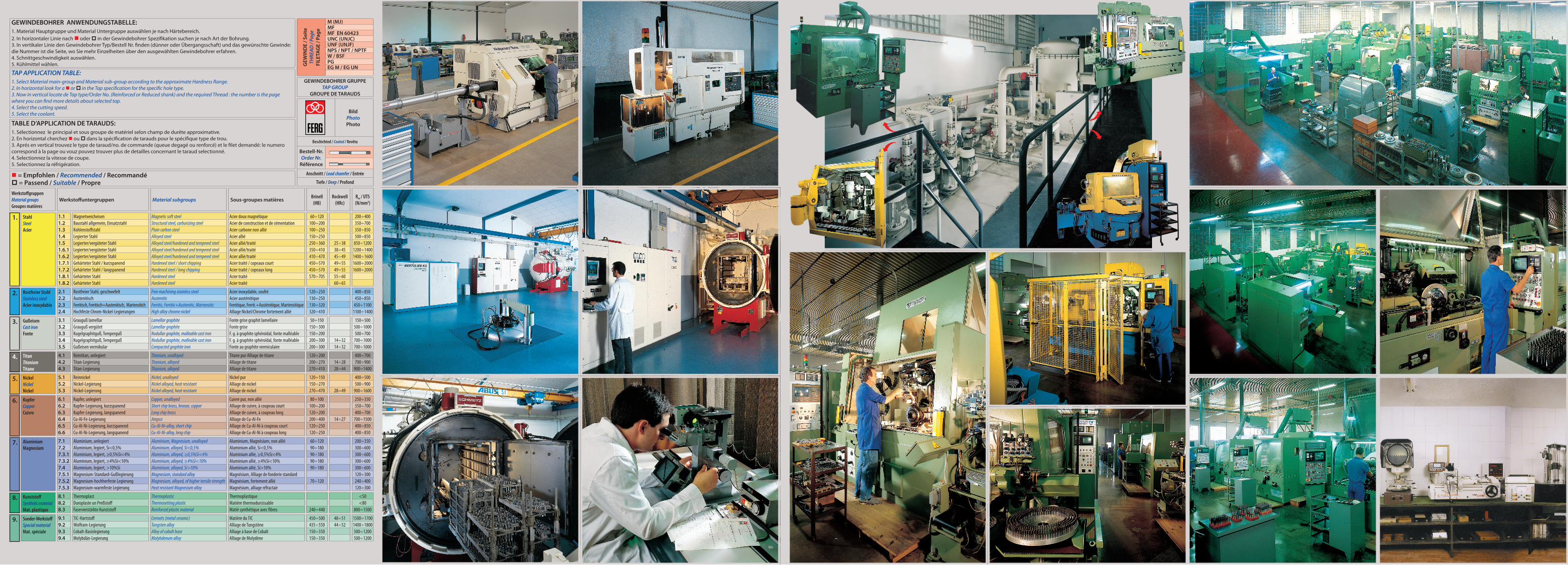
WerkstoffgruppenMaterial groupsGroupes matières
Werkstoffuntergruppen Material subgroups Sous-groupes matières Brinell(HB)
Rockwell(HRc)
Rm / UTS(N/mm2)
GEWINDEBOHRER GRUPPETAP GROUP
GROUPE DE TARAUDS
GEWINDEBOHRER ANWENDUNGSTABELLE:1. Material Hauptgruppe und Material Untergruppe auswählen je nach Härtebereich. 2. In horizontaler Linie nach oder in der Gewindebohrer Spezifikation suchen je nach Art der Bohrung.3. In vertikaler Linie den Gewindebohrer Typ/Bestell Nr. finden (dünner oder Übergangsschaft) und das gewünschte Gewinde: die Nummer ist die Seite, wo Sie mehr Einzelheiten über den ausgewählten Gewindebohrer erfahren.4. Schnittgeschwindigkeit auswählen.5. Kühlmittel wählen.
= Empfohlen / Recommended / Recommandé = Passend / Suitable / Propre
TABLE D’APPLICATION DE TARAUDS:1. Sélectionnez le principal et sous groupe de matériel selon champ de durête approximative.2. En horizontal cherchez ou dans la spécification de tarauds pour le spécifique type de trou.3. Aprés en vertical trouvez le type de taraud/no. de commande (queue degagé ou renforcé) et le filet demandé: le numero correspond à la page ou vouz pouvez trouver plus de detailles concernant le taraud selectionné.4. Selectionnez la vitesse de coupe.5. Selectionnez la réfrigération.
TAP APPLICATION TABLE:1. Select Material main-group and Material sub-group according to the approximate Hardness Range.2. In horizontal look for a or in the Tap specification for the specific hole type.3. Now in vertical locate de Tap type/Order No. (Reinforced or Reduced shank) and the required Thread : the number is the page where you can find more details about selected tap.4. Select the cutting speed.5. Select the coolant.
1.

1
Prosp ekt 2009
Le a f l e t 2 0 0 9
Prosp ec tus 2009

2
GS
vap TiN vap TiN vap TiN nit nit TiN
105A 104A V104A T104A L104A VL104A TL104A 150A 151A 109A 110A T110A135 V135 T135 104 V104 T104 L104 VL104 TL104 109 110 T110
2 ½ (C) 4-5 (B) 4-5 (B) 4-5 (D) 3 ½ (D)≤ 1 ½ x d1 ≤ 3 x d1 ≤ 0,5 x d1 ≤ 2 x d1
1.11.21.31.41.51.6.11.6.21.7.11.7.21.8.11.8.2
2.12.22.32.4
3.13.23.33.43.5
4.14.24.3
5.15.25.3
6.16.26.36.46.56.6
7.17.27.3.17.3.27.47.5.17.5.27.5.3
8.18.28.3
9.19.29.39.4
20 ÷ 35 40 ÷ 50 E15 ÷ 20 30 ÷ 40 E12 ÷ 18 24 ÷ 36 E10 ÷ 15 20 ÷ 30 E - A6 ÷ 10 10 ÷ 20 A4 ÷ 6 6 ÷ 10 A2 ÷ 3 3 ÷ 5 A
10 ÷ 15 A7 ÷ 10 A5 ÷ 7 A
A
4 ÷ 6 8 ÷ 12 A - E2 ÷ 4 6 ÷ 8 A - E2 ÷ 4 3 ÷ 5 A - E2 ÷ 3 3 ÷ 5 A - E
10 ÷ 15 20 ÷ 30 E - S6 ÷ 8 15 ÷ 20 E - S
8 ÷ 12 20 ÷ 30 E - A4 ÷ 6 10 ÷ 15 A - E4 ÷ 6 10 ÷ 15 E - S
10 ÷ 15 20 ÷ 30 S - E8 ÷ 12 15 ÷ 20 A4 ÷ 6 6 ÷ 10 A
8 ÷ 12 20 ÷ 30 A - E3 ÷ 5 5 ÷ 8 A2 ÷ 3 3 ÷ 5 A
8 ÷ 12 15 ÷ 20 E25 ÷ 35 40 ÷ 60 E15 ÷ 20 30 ÷ 40 E
2 ÷ 4 3 ÷ 5 A15 ÷ 25 30 ÷ 40 A - E10 ÷ 15 15 ÷ 25 A - E
10 ÷ 15 40 ÷ 50 E25 ÷ 35 50 ÷ 60 E25 ÷ 30 35 ÷ 40 E20 ÷ 25 30 ÷ 35 E15 ÷ 20 20 ÷ 30 E20 ÷ 30 30 ÷ 40 E20 ÷ 30 30 ÷ 40 E20 ÷ 30 30 ÷ 40 E
20 ÷ 30 20 ÷ 30 E10 ÷ 15 10 ÷ 15 E - S
3 ÷ 5 6 ÷ 10 E - S
2 ÷ 4 3 ÷ 5 S2 ÷ 3 3 ÷ 5 A1 ÷ 2 2 ÷ 3 A
MASCHINEN-GEWINDEBOHRERMACHINE TAPS
TARAUDS MACHINE
SCHNITTGESCHWINDIGKEIT
CUTTING SPEED
VITESSE DE COUPEVc
m/min
HSSEZylindrisches Gewinde
Cylindrical thread
Filetage cylindrique
Kühl
ung
- Coo
lant
- Ré
frig
eran
t
Unbe-schichtet /
oberf-láchenbe-handelt
Uncoated /Surface
treatmentNon
revêtus /Traite-
ment de surface
Beschi-chtet
Coated
Revêtus
E = Emulsion / Emulsion / Emulsion A = Schneidöl / Cutting oil / Huile de coupe S = Trocken / Dry / Sec
= Empfohlen / Recommended / Recommandé = Passend / Suitable / Propre

3
GS
vap TiN vap TiN
112A V112A T112A L112A V112A T112A112 V112 T112 L112 VL112 TL112
2 ½ (C)≤ 3 x d1
VG
TiN TiAlN TiN TiAlN TiN TiAlN TiN TiAlN
184A T184A A184A 684A T684A A684A 182A T182A A182A 183A T183A A183A184 T184 A184 684 T684 A684 182 T182 A182 183 T183 A183
4-5 (B) 2 ½ (C) 1 ½ (E)≤ 3 x d1 ≤ 3 x d1 ≤ 3 x d1
1.11.21.31.41.51.6.11.6.21.7.11.7.21.8.11.8.2
2.12.22.32.4
3.13.23.33.43.5
4.14.24.3
5.15.25.3
6.16.26.36.46.56.6
7.17.27.3.17.3.27.47.5.17.5.27.5.3
8.18.28.3
9.19.29.39.4
E = Emulsion / Emulsion / Emulsion A = Schneidöl / Cutting oil / Huile de coupe S = Trocken / Dry / Sec
= Empfohlen / Recommended / Recommandé = Passend / Suitable / Propre
4
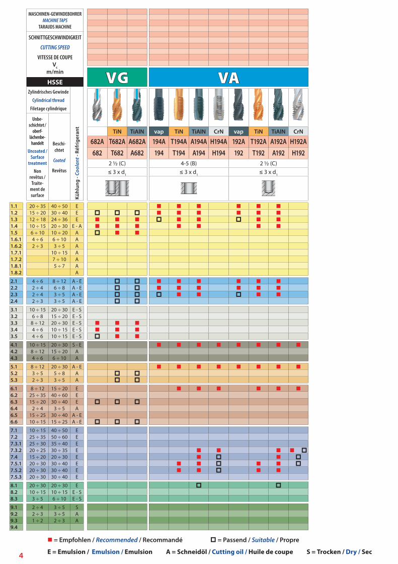
VA
vap TiN TiAlN CrN vap TiN TiAlN CrN
194A T194A A194A H194A 192A T192A A192A H192A194 T194 A194 H194 192 T192 A192 H192
4-5 (B) 2 ½ (C)≤ 3 x d1 ≤ 3 x d1
1.11.21.31.41.51.6.11.6.21.7.11.7.21.8.11.8.2
2.12.22.32.4
3.13.23.33.43.5
4.14.24.3
5.15.25.3
6.16.26.36.46.56.6
7.17.27.3.17.3.27.47.5.17.5.27.5.3
8.18.28.3
9.19.29.39.4
20 ÷ 35 40 ÷ 50 E15 ÷ 20 30 ÷ 40 E12 ÷ 18 24 ÷ 36 E10 ÷ 15 20 ÷ 30 E - A6 ÷ 10 10 ÷ 20 A4 ÷ 6 6 ÷ 10 A2 ÷ 3 3 ÷ 5 A
10 ÷ 15 A7 ÷ 10 A5 ÷ 7 A
A
4 ÷ 6 8 ÷ 12 A - E2 ÷ 4 6 ÷ 8 A - E2 ÷ 4 3 ÷ 5 A - E2 ÷ 3 3 ÷ 5 A - E
10 ÷ 15 20 ÷ 30 E - S6 ÷ 8 15 ÷ 20 E - S
8 ÷ 12 20 ÷ 30 E - S4 ÷ 6 10 ÷ 15 E - S4 ÷ 6 10 ÷ 15 E - S
10 ÷ 15 20 ÷ 30 S - E8 ÷ 12 15 ÷ 20 A4 ÷ 6 6 ÷ 10 A
8 ÷ 12 20 ÷ 30 A - E3 ÷ 5 5 ÷ 8 A2 ÷ 3 3 ÷ 5 A
8 ÷ 12 15 ÷ 20 E25 ÷ 35 40 ÷ 60 E15 ÷ 20 30 ÷ 40 E
2 ÷ 4 3 ÷ 5 A15 ÷ 25 30 ÷ 40 A - E10 ÷ 15 15 ÷ 25 A - E
10 ÷ 15 40 ÷ 50 E25 ÷ 35 50 ÷ 60 E25 ÷ 30 35 ÷ 40 E20 ÷ 25 30 ÷ 35 E15 ÷ 20 20 ÷ 30 E20 ÷ 30 30 ÷ 40 E20 ÷ 30 30 ÷ 40 E20 ÷ 30 30 ÷ 40 E
20 ÷ 30 20 ÷ 30 E10 ÷ 15 10 ÷ 15 E - S
3 ÷ 5 6 ÷ 10 E - S
2 ÷ 4 3 ÷ 5 S2 ÷ 3 3 ÷ 5 A1 ÷ 2 2 ÷ 3 A
VG
TiN TiAlN
682A T682A A682A682 T682 A682
2 ½ (C)≤ 3 x d1
MASCHINEN-GEWINDEBOHRERMACHINE TAPS
TARAUDS MACHINE
SCHNITTGESCHWINDIGKEIT
CUTTING SPEED
VITESSE DE COUPEVc
m/min
HSSEZylindrisches Gewinde
Cylindrical thread
Filetage cylindrique
Kühl
ung
- Coo
lant
- Ré
frig
eran
t
Unbe-schichtet /
oberf-láchenbe-handelt
Uncoated /Surface
treatmentNon
revêtus /Traite-
ment de surface
Beschi-chtet
Coated
Revêtus
E = Emulsion / Emulsion / Emulsion A = Schneidöl / Cutting oil / Huile de coupe S = Trocken / Dry / Sec
= Empfohlen / Recommended / Recommandé = Passend / Suitable / Propre
5
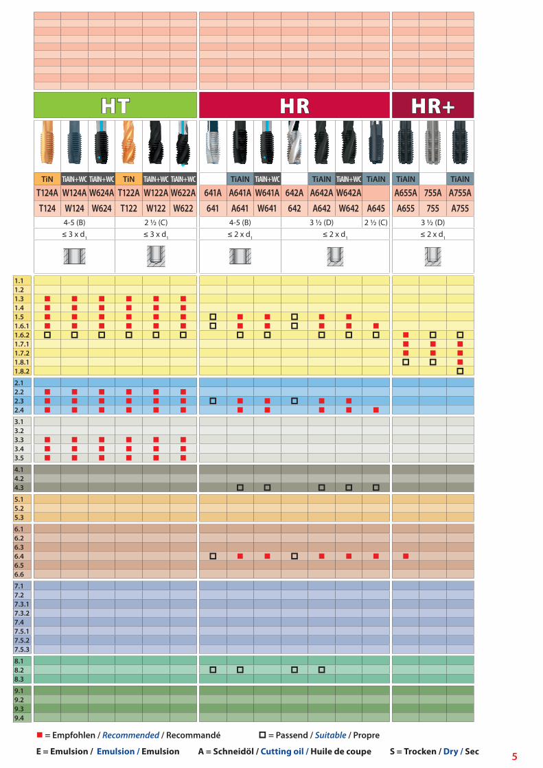
HT
TiN TiAlN+WC TiAlN+WC TiN TiAlN+WC TiAlN+WC
T124A W124A W624A T122A W122A W622AT124 W124 W624 T122 W122 W622
4-5 (B) 2 ½ (C)≤ 3 x d1 ≤ 3 x d1
1.11.21.31.41.51.6.11.6.21.7.11.7.21.8.11.8.2
2.12.22.32.4
3.13.23.33.43.5
4.14.24.3
5.15.25.3
6.16.26.36.46.56.6
7.17.27.3.17.3.27.47.5.17.5.27.5.3
8.18.28.3
9.19.29.39.4
HR
TiAlN TiAlN+WC TiAlN TiAlN+WC TiAlN
641A A641A W641A 642A A642A W642A641 A641 W641 642 A642 W642 A645
4-5 (B) 3 ½ (D) 2 ½ (C)≤ 2 x d1 ≤ 2 x d1
HR+
TiAlN TiAlN
A655A 755A A755AA655 755 A755
3 ½ (D)≤ 2 x d1
E = Emulsion / Emulsion / Emulsion A = Schneidöl / Cutting oil / Huile de coupe S = Trocken / Dry / Sec
= Empfohlen / Recommended / Recommandé = Passend / Suitable / Propre

6
1.11.21.31.41.51.6.11.6.21.7.11.7.21.8.11.8.2
2.12.22.32.4
3.13.23.33.43.5
4.14.24.3
5.15.25.3
6.16.26.36.46.56.6
7.17.27.3.17.3.27.47.5.17.5.27.5.3
8.18.28.3
9.19.29.39.4
Ni Ti
TiAlN TiAlN+WC TiAlN TiAlN+WC
664A A664A W664A 662A A662A W662A664 A664 W664 662 A662 W662
4-5 (B) 3½ (D)≤ 2 x d1 ≤ 2 x d1
TiN TiAlN CrN TiN TiAlN CrN
630A T630A A630A H630A 632A T632A A632A H632A630 T630 A630 H630 632 T632 A632 H632
4-5 (B) + AZ 2 ½ (C)≤ 2 x d1 ≤ 2 x d1
20 ÷ 35 40 ÷ 50 E15 ÷ 20 30 ÷ 40 E12 ÷ 18 24 ÷ 36 E10 ÷ 15 20 ÷ 30 E - A6 ÷ 10 10 ÷ 20 A4 ÷ 6 6 ÷ 10 A2 ÷ 3 3 ÷ 5 A
10 ÷ 15 A7 ÷ 10 A5 ÷ 7 A
A
4 ÷ 6 8 ÷ 12 A - E2 ÷ 4 6 ÷ 8 A - E2 ÷ 4 3 ÷ 5 A - E2 ÷ 3 3 ÷ 5 A - E
10 ÷ 15 20 ÷ 30 E - S6 ÷ 8 15 ÷ 20 E - S
8 ÷ 12 20 ÷ 30 E - S4 ÷ 6 10 ÷ 15 E - S4 ÷ 6 10 ÷ 15 E - S
10 ÷ 15 20 ÷ 30 S - E8 ÷ 12 15 ÷ 20 A4 ÷ 6 6 ÷ 10 A
8 ÷ 12 20 ÷ 30 A - E3 ÷ 5 5 ÷ 8 A2 ÷ 3 3 ÷ 5 A
8 ÷ 12 15 ÷ 20 E25 ÷ 35 40 ÷ 60 E15 ÷ 20 30 ÷ 40 E
2 ÷ 4 3 ÷ 5 A15 ÷ 25 30 ÷ 40 A - E10 ÷ 15 15 ÷ 25 A - E
10 ÷ 15 40 ÷ 50 E25 ÷ 35 50 ÷ 60 E25 ÷ 30 35 ÷ 40 E20 ÷ 25 30 ÷ 35 E15 ÷ 20 20 ÷ 30 E20 ÷ 30 30 ÷ 40 E20 ÷ 30 30 ÷ 40 E20 ÷ 30 30 ÷ 40 E
20 ÷ 30 20 ÷ 30 E10 ÷ 15 10 ÷ 15 E - S
3 ÷ 5 6 ÷ 10 E - S
2 ÷ 4 3 ÷ 5 S2 ÷ 3 3 ÷ 5 A1 ÷ 2 2 ÷ 3 A
MASCHINEN-GEWINDEBOHRERMACHINE TAPS
TARAUDS MACHINE
SCHNITTGESCHWINDIGKEIT
CUTTING SPEED
VITESSE DE COUPEVc
m/min
HSSEZylindrisches Gewinde
Cylindrical thread
Filetage cylindrique
Kühl
ung
- Coo
lant
- Ré
frig
eran
t
Unbe-schichtet /
oberf-láchenbe-handelt
Uncoated /Surface
treatmentNon
revêtus /Traite-
ment de surface
Beschi-chtet
Coated
Revêtus
E = Emulsion / Emulsion / Emulsion A = Schneidöl / Cutting oil / Huile de coupe S = Trocken / Dry / Sec
= Empfohlen / Recommended / Recommandé = Passend / Suitable / Propre

7
1.11.21.31.41.51.6.11.6.21.7.11.7.21.8.11.8.2
2.12.22.32.4
3.13.23.33.43.5
4.14.24.3
5.15.25.3
6.16.26.36.46.56.6
7.17.27.3.17.3.27.47.5.17.5.27.5.3
8.18.28.3
9.19.29.39.4
GG
TiAlN TiAlN
A160A A660AA160 A660
2 ½ (C)≤ 3 x d1
Al
TiN CrN TiN CrN
130A T130A H130A 140A T140A H140A130 T130 H130 140 T140 H140
4-5 (B) + AZ 2 ½ (C)≤ 2 x d1 ≤ 2 x d1
GAl
TiAl CrN
A142A H142AA142 H142
2 ½ (C)≤ 3 x d1
15 ÷ 20 20 ÷ 30 A7 ÷ 10 15 ÷ 20 A5 ÷ 7 10 ÷ 15 A2 ÷ 3 4 ÷ 6 A2 ÷ 3 3 ÷ 5 A
30 ÷ 40 40 ÷ 60 E - S15 ÷ 20 25 ÷ 35 E - S25 ÷ 35 30 ÷ 40 E - S15 ÷ 20 20 ÷ 30 E - S12 ÷ 15 15 ÷ 20 E - S
20 ÷ 30 S - E
30 ÷ 40 30 ÷ 40 E50 ÷ 70 50 ÷ 70 E30 ÷ 40 30 ÷ 40 E10 ÷ 15 10 ÷ 15 A40 ÷ 50 40 ÷ 50 A - E20 ÷ 30 20 ÷ 30 A - E
30 ÷ 40 50 ÷ 70 E40 ÷ 60 60 ÷ 80 E50 ÷ 60 70 ÷ 80 E40 ÷ 50 60 ÷ 70 E30 ÷ 40 40 ÷ 60 E40 ÷ 60 60 ÷ 80 E40 ÷ 60 60 ÷ 80 E40 ÷ 60 60 ÷ 80 E
40 ÷ 60 50 ÷ 70 E25 ÷ 35 25 ÷ 35 E - S15 ÷ 20 15 ÷ 20 E - S
5 ÷ 7 8 ÷ 12 S4 ÷ 6 5 ÷ 7 A3 ÷ 5 4 ÷ 6 A
10 ÷ 15 15 ÷ 20
GAl
TiAl
740A A740A740 A740
2 ½ (C)≤ 3 x d1
MASCHINEN-GEWINDEBOHRERMACHINE TAPS
TARAUDS MACHINE
SCHNITTGESCHWINDIGKEIT
CUTTING SPEED
VITESSE DE COUPEVc
m/min
HMZylindrisches Gewinde
Cylindrical thread
Filetage cylindrique
Kühl
ung
- Coo
lant
- Ré
frig
eran
t
Unbe-schichtet /
oberf-láchenbe-handelt
Uncoated /Surface
treatmentNon
revêtus /Traite-
ment de surface
Beschi-chtet
Coated
Revêtus
E = Emulsion / Emulsion / Emulsion A = Schneidöl / Cutting oil / Huile de coupe S = Trocken / Dry / Sec
= Empfohlen / Recommended / Recommandé = Passend / Suitable / Propre
8
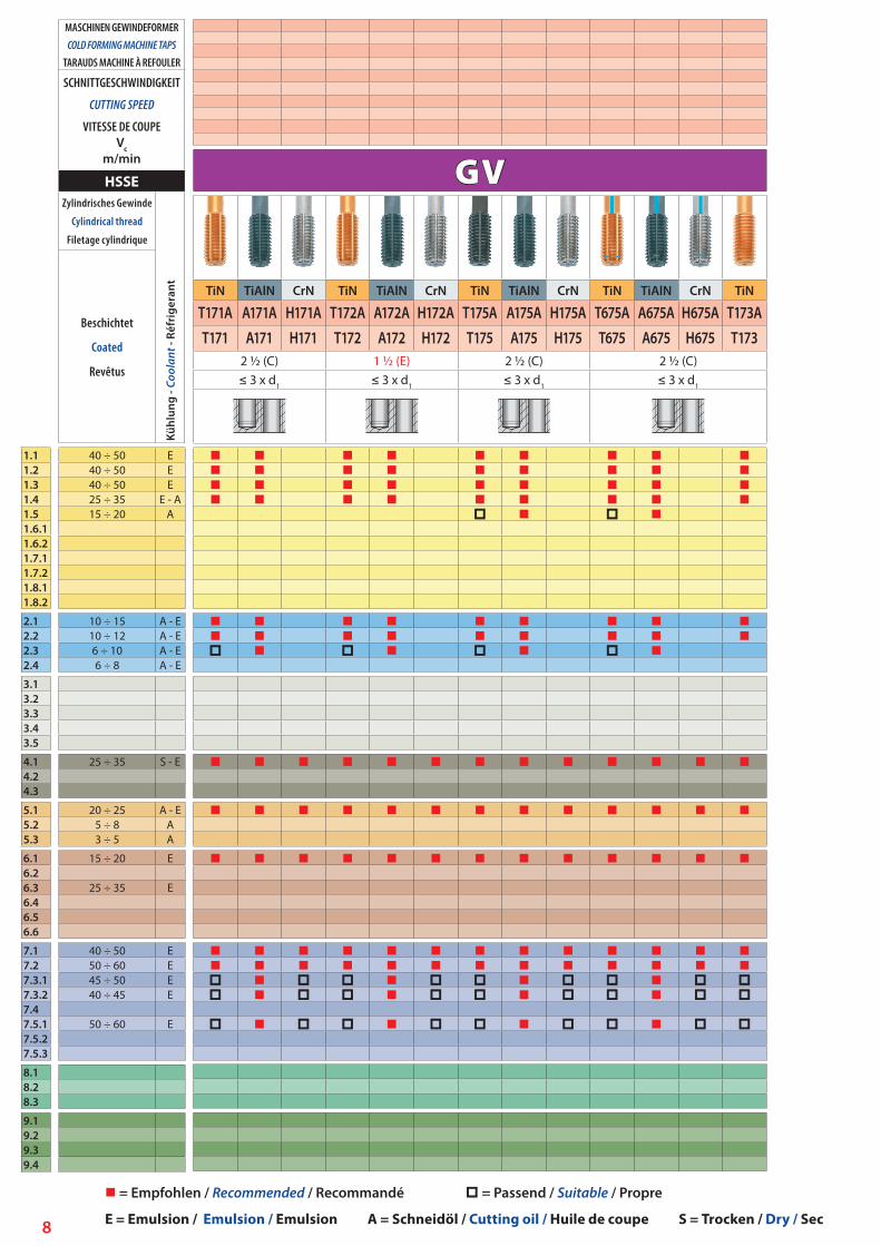
GV
TiN TiAlN CrN TiN TiAlN CrN TiN TiAlN CrN TiN TiAlN CrN TiN
T171A A171A H171A T172A A172A H172A T175A A175A H175A T675A A675A H675A T173AT171 A171 H171 T172 A172 H172 T175 A175 H175 T675 A675 H675 T173
2 ½ (C) 1 ½ (E) 2 ½ (C) 2 ½ (C)≤ 3 x d1 ≤ 3 x d1 ≤ 3 x d1 ≤ 3 x d1
1.11.21.31.41.51.6.11.6.21.7.11.7.21.8.11.8.2
2.12.22.32.4
3.13.23.33.43.5
4.14.24.3
5.15.25.3
6.16.26.36.46.56.6
7.17.27.3.17.3.27.47.5.17.5.27.5.3
8.18.28.3
9.19.29.39.4
40 ÷ 50 E40 ÷ 50 E40 ÷ 50 E25 ÷ 35 E - A15 ÷ 20 A
10 ÷ 15 A - E10 ÷ 12 A - E6 ÷ 10 A - E6 ÷ 8 A - E
25 ÷ 35 S - E
20 ÷ 25 A - E5 ÷ 8 A3 ÷ 5 A
15 ÷ 20 E
25 ÷ 35 E
40 ÷ 50 E50 ÷ 60 E45 ÷ 50 E40 ÷ 45 E
50 ÷ 60 E
MASCHINEN GEWINDEFORMERCOLD FORMING MACHINE TAPS
TARAUDS MACHINE À REFOULER
SCHNITTGESCHWINDIGKEIT
CUTTING SPEED
VITESSE DE COUPEVc
m/min
HSSEZylindrisches Gewinde
Cylindrical thread
Filetage cylindrique
Kühl
ung
- Coo
lant
- Ré
frig
eran
t
Beschichtet
Coated
Revêtus
E = Emulsion / Emulsion / Emulsion A = Schneidöl / Cutting oil / Huile de coupe S = Trocken / Dry / Sec
= Empfohlen / Recommended / Recommandé = Passend / Suitable / Propre

9
Ms
TiN TiN
106A T106A106 T106 206 T206
1 ½ (E) 1 ½ (E)≤ 2 x d1 ≤ 2 x d1
1.11.21.31.41.51.6.11.6.21.7.11.7.21.8.11.8.2
2.12.22.32.4
3.13.23.33.43.5
4.14.24.3
5.15.25.3
6.16.26.36.46.56.6
7.17.27.3.17.3.27.47.5.17.5.27.5.3
8.18.28.3
9.19.29.39.4
20 ÷ 35 40 ÷ 50 E15 ÷ 20 30 ÷ 40 E12 ÷ 18 24 ÷ 36 E10 ÷ 15 20 ÷ 30 E - A6 ÷ 10 10 ÷ 20 A4 ÷ 6 6 ÷ 10 A2 ÷ 3 3 ÷ 5 A
10 ÷ 15 A7 ÷ 10 A5 ÷ 7 A
4 ÷ 6 8 ÷ 12 A - E2 ÷ 4 6 ÷ 8 A - E2 ÷ 4 3 ÷ 5 A - E2 ÷ 3 3 ÷ 5 A - E
10 ÷ 15 20 ÷ 30 E - S6 ÷ 8 15 ÷ 20 E - S
8 ÷ 12 20 ÷ 30 E - A4 ÷ 6 10 ÷ 15 A - E4 ÷ 6 10 ÷ 15 E - S
10 ÷ 15 20 ÷ 30 S - E8 ÷ 12 15 ÷ 20 A4 ÷ 6 6 ÷ 10 A
8 ÷ 12 20 ÷ 30 A - E3 ÷ 5 5 ÷ 8 A2 ÷ 3 3 ÷ 5 A
8 ÷ 12 15 ÷ 20 E25 ÷ 35 40 ÷ 60 E15 ÷ 20 30 ÷ 40 E
2 ÷ 4 3 ÷ 5 A15 ÷ 25 30 ÷ 40 A - E10 ÷ 15 15 ÷ 25 A - E
10 ÷ 15 40 ÷ 50 E25 ÷ 35 50 ÷ 60 E25 ÷ 30 35 ÷ 40 E20 ÷ 25 30 ÷ 35 E15 ÷ 20 20 ÷ 30 E20 ÷ 30 30 ÷ 40 E20 ÷ 30 30 ÷ 40 E20 ÷ 30 30 ÷ 40 E
20 ÷ 30 20 ÷ 30 E10 ÷ 15 10 ÷ 15 E - S
3 ÷ 5 6 ÷ 10 E - S
2 ÷ 4 3 ÷ 5 S2 ÷ 3 3 ÷ 5 A1 ÷ 2 2 ÷ 3 A
MASCHINEN-GEWINDEBOHRERMACHINE TAPS
TARAUDS MACHINE
SCHNITTGESCHWINDIGKEIT
CUTTING SPEED
VITESSE DE COUPEVc
m/min
HSSEZylindrisches Gewinde
Cylindrical thread
Filetage cylindrique
Kühl
ung
- Coo
lant
- Ré
frig
eran
t
Unbe-schichtet /
oberf-láchenbe-handelt
Uncoated /Surface
treatmentNon
revêtus /Traite-
ment de surface
Beschi-chtet
Coated
Revêtus
E = Emulsion / Emulsion / Emulsion A = Schneidöl / Cutting oil / Huile de coupe S = Trocken / Dry / Sec
= Empfohlen / Recommended / Recommandé = Passend / Suitable / Propre

10
GewindewerkzeugeThreading toolsOutils à fileter
11
GewindebohrerThreading tapsTarauds à fileter
GewindefräserThread millsFraises à fileter
Gewinde-SchneideisenCircular thread diesFilières à fileter

12
GewindebohrergruppeTap groupGroupe de tarauds
Gutspanbare Stähle Rm < 750 N/mm², Kugelgraphitguß, Temperguß vergütet Steels with good machinability Rm < 750 N/mm² (101,500 PSI), Nodular graphite, Malleable cast iron Aciers de bonne usinabilité Rm < 750 N/mm², Fonte à graphite sphéroïdal, Fonte malléable
Vergütete und hitzebeständige Stähle Rm < 1.0000 N/mm2
Heat treated and heat-resistant steels Rm < 1.000 N/mm2
Aciers traités et aciers réfractaires Rm < 1.000 N/mm²
Rostfreie Stähle und Baustähle Rm < 600 N/mm²Stainless steels and structural steels Rm < 600 N/mm²Aciers inoxydable, aciers au carbone et peu alliés Rm < 600 N/mm²
Werkzeugstähle, hochfeste Stähle Rm = 1.000÷1.300 N/mm²Very high resistant steels Rm = 1.000÷1.300 N/mm²Aciers à très haute résistance Rm = 1.000÷1.300 N/mm²
Gehärtete Stähle 40÷63 HRCHardened steels 40÷63 HRCAciers traités 40÷63 HRC
Baustahl und hochfester Stahl mit bis zu 1.300 N/mm², Rostfreier Stahl, Temper- und Kugelgraphitguß, Langspanende Aluminium- und KupferlegierungenPlain carbon steel, Alloyed / tempered steel up to tensile strength 1.300 N/mm², Stainless steel, Spheroidal graphite, Malleable cast iron, Long-chiping aluminium and copper alloysAcier de construction, Acier haute résistance jusqu’à 1.300 N/mm², Acier inoxydable, Fonte a graphite sphéroidal, Fonte malléable, Alliages d’aluminium et cuivre à copeau long
Gut verformbare Werkstoffe (kaltformen)Any material with at least 12% elongationAciers de bonne déformabilité (impression)
Nickel-LegierungenNickel alloysAlliages de nickel
Titan-LegierungenTitanium alloysAlliages de titane
GraugußGrey cast ironFonte grise
Aluminium-Knetlegierungen (langspanend)Wrought aluminium alloys (long-chipping)Aluminium durcissable (à copeaux longs)
Gußaluminium (kurzspanend)Cast aluminium (short-chipping)Fontes d’aluminium (à copeaux courts)
Kurzspanendes Messing, BronzeShort chip Brass, BronzeLaiton à copeau court et Bronze
AbkürzungenExplanation of symbolsExplication des symboles utilisés
13
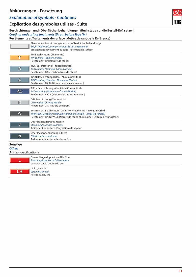
Beschichtungen und -Oberflächenbehandlungen (Buchstabe vor die Bestell-Ref. setzen)Coatings and surface treatments (To put before Type Nr.)Revêtements et Traitements de surface (Mettre devant de la Référence)
Blank (ohne Beschichtung oder ohne Oberflächenbehandlung)Bright (without Coating or without Surface treatment)Brillant (sans Revêtement ou sans Traitement de surface)
TiN Beschichtung (Titannitrid)TiN coating (Titanium nitride)Revêtement TiN (Nitrure de titane)
TiCN Beschichtung (Titancarbonitrid)TiCN coating (Titanium Carbon Nitride)Revêtement TiCN (Carbonitrure de titane)
TiAlN Beschichtung (Titan, -Aluminiumnitrid)TiAlN coating (Titanium Aluminium Nitride)Revêtement TiAlN (Nitrure de titane aluminium)
AlCrN Beschichtung (Aluminium Chromnitrid)AlCrN coating (Aluminium Chrome Nitride)Revêtement AlCrN (Nitrure de chrom aluminium)
CrN Beschichtung (Chromnitrid)CrN coating (Chrome Nitride)Revêtement CrN (Nitrure de chrom)
TiAlN+WC/C Beschichtung (Titanaluminiumnitrid + Wolframkarbid)TiAlN+WC/C coating (Titanium Aluminium Nitride + Tungsten carbide)Revêtement TiAlN+WC/C (Nitrure de titane aluminium + Carbure de tungstene)
Oberflächen dampfbehandeltSteam oxide surface treatmentTraitement de surface d’oxydation à la vapeur
Oberflächenbehandlung nitriertNitride surface treatmentTraitement de surface de nitruration
SonstigeOthersAutres specifications
Gesamtlänge doppelt wie DIN NormTotal length double as DIN standardLonguer totale double du DIN
LinksgewindeLeft hand threadFiletage à gauche
Abkürzungen - ForsetzungExplanation of symbols - ContinuesExplication des symboles utilisés - Suite
14
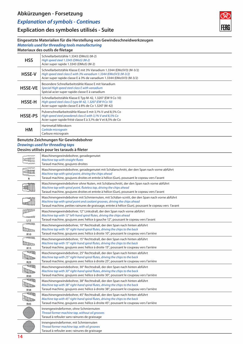
Eingesetzte Materialien für die Herstellung von GewindeschneidwerkzeugenMaterials used for threading tools manufacturingMateriaux des outils de filetage
HSSSchnellarbeitstähle 1.3343 (DMo5) (M-2)High speed steel 1.3343 (DMo5) (M-2)Acier super rapide 1.3343 (DMo5) (M-2)
HSSE-VSchnellarbeitstähle Klasse E mit 3% Vanadium 1.3344 (EMo5V3) (M-3/2)High speed steel class E with 3% vanadium 1.3344 (EMo5V3) (M-3/2)Acier super rapide classe E à 3% de vanadium 1.3344 (EMo5V3) (M-3/2)
HSSE-VEBesondere Schnellarbeitstähle Klasse E mit VanadiumSpecial High speed steel class E with vanadiumSpécial acier super rapide classe E à vanadium
HSSE-HSchnellarbeitstähle Klasse E Typ M-42, 1.3207 (EW 9 Co 10)High speed steel class E type M-42, 1.3207 (EW 9 Co 10)Acier super rapide classe E à 8% de Co 1.3247 (M-42)
HSSE-PSPulverschnellarbeitstähle Klasse E mit 3,1% V und 8,5% CoHigh speed steel powdered class E with 3,1% V and 8,5% CoAcier super rapide fritté classe E à 3,1% de V et 8,5% de Co
HMHartmetall MikrokornCarbide micrograinCarbure micrograin
Benutzte Zeichnungen für GewindebohrerDrawings used for threading tapsDessins utilisés pour les tarauds à fileter
Maschinengewindebohrer, geradegenutetMachine tap with straight flutesTaraud machine, goujures droites
Maschinengewindebohrer, geradegenutet mit Schälanschnitt, der den Span nach vorne abführtMachine tap with spiral point, driving the chips aheadTaraud machine, goujures droites et entrée à hélice (Gun), poussant le copeau vers l’avant
Maschinengewindebohrer ohne Nuten, mit Schälanschnitt, der den Span nach vorne abführtMachine tap with spiral point, fluteless tap, driving the chips aheadTaraud machine, goujures droites et entrée à hélice (Gun), poussant le copeau vers l’avant
Maschinengewindebohrer mit Schmiernuten, mit Schälan-scnitt, der den Span nach vorne abführtMachine tap with spiral point and coolant grooves, driving the chips aheadTaraud machine, petites rainures de graissage, entrée à hélice (Gun), poussant le copeau vers l’avant
Maschinengewindebohrer, 12° Linksdrall, der den Span nach vorne abführtMachine tap with 12° left-hand spiral flutes, driving the chips aheadTaraud machine, goujures avec hélice à gauche 12°, poussant le copeau vers l’avant
Maschinengewindebohrer, 10° Rechtsdrall, der den Span nach hinten abführtMachine tap with 10° right-hand spiral flutes, driving the chips to the backTaraud machine, goujures avec hélice à droite 10°, poussant le coupeau vers l’arrière
Maschinengewindebohrer, 15° Rechtsdrall, der den Span nach hinten abführtMachine tap with 15° right-hand spiral flutes, driving the chips to the backTaraud machine, goujures avec hélice à droite 15°, poussant le coupeau vers l’arrière
Maschinengewindebohrer, 25° Rechtsdrall, der den Span nach hinten abführtMachine tap with 25° right-hand spiral flutes, driving the chips to the backTaraud machine, goujures avec hélice à droite 25°, poussant le coupeau vers l’arrière
Maschinengewindebohrer, 30° Rechtsdrall, der den Span nach hinten abführtMachine tap with 30° right-hand spiral flutes, driving the chips to the backTaraud machine, goujures avec hélice à droite 30°, poussant le coupeau vers l’arrière
Maschinengewindebohrer, 38° Rechtsdrall, der den Span nach hinten abführtMachine tap with 38° right-hand spiral flutes, driving the chips to the backTaraud machine, goujures avec hélice à droite 38°, poussant le coupeau vers l’arrière
Maschinengewindebohrer, 45° Rechtsdrall, der den Span nach hinten abführtMachine tap with 45° right-hand spiral flutes, driving the chips to the backTaraud machine, goujures avec hélice à droite 45°, poussant le coupeau vers l’arrière
Innengewindeformer, ohne SchmiernutenThread former machine tap, without oil groovesTaraud à refouler sans rainures de graissage
Innengewindeformer, mit SchmiernutenThread former machine tap, with oil groovesTaraud à refouler avec rainures de graissage
Abkürzungen - ForsetzungExplanation of symbols - ContinuesExplication des symboles utilisés - Suite
15
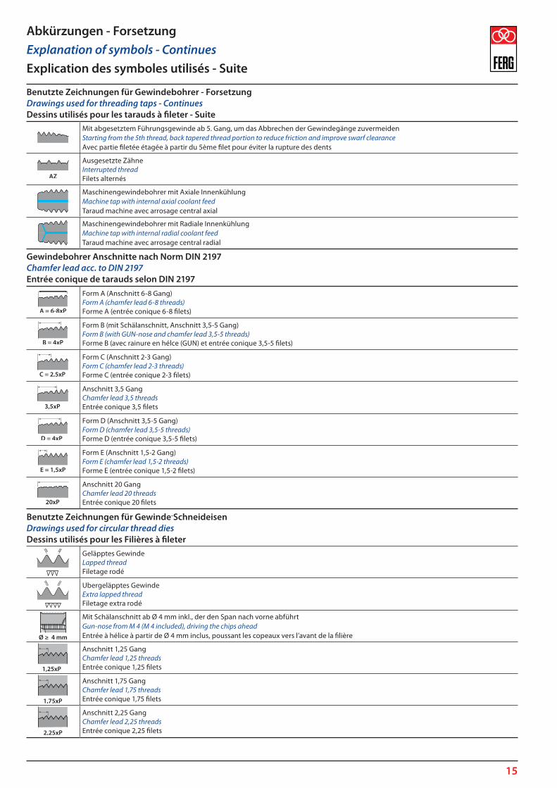
Benutzte Zeichnungen für Gewindebohrer - ForsetzungDrawings used for threading taps - ContinuesDessins utilisés pour les tarauds à fileter - Suite
Mit abgesetztem Führungsgewinde ab 5. Gang, um das Abbrechen der Gewindegänge zuvermeidenStarting from the 5th thread, back tapered thread portion to reduce friction and improve swarf clearanceAvec partie filetée étagée à partir du 5ème filet pour éviter la rupture des dents
Ausgesetzte ZähneInterrupted threadFilets alternés
Maschinengewindebohrer mit Axiale InnenkühlungMachine tap with internal axial coolant feedTaraud machine avec arrosage central axial
Maschinengewindebohrer mit Radiale InnenkühlungMachine tap with internal radial coolant feedTaraud machine avec arrosage central radial
Gewindebohrer Anschnitte nach Norm DIN 2197Chamfer lead acc. to DIN 2197Entrée conique de tarauds selon DIN 2197
Form A (Anschnitt 6-8 Gang)Form A (chamfer lead 6-8 threads)Forme A (entrée conique 6-8 filets)
Form B (mit Schälanschnitt, Anschnitt 3,5-5 Gang)Form B (with GUN-nose and chamfer lead 3,5-5 threads)Forme B (avec rainure en hélce (GUN) et entrée conique 3,5-5 filets)
Form C (Anschnitt 2-3 Gang)Form C (chamfer lead 2-3 threads)Forme C (entrée conique 2-3 filets)
Anschnitt 3,5 GangChamfer lead 3,5 threadsEntrée conique 3,5 filets
Form D (Anschnitt 3,5-5 Gang)Form D (chamfer lead 3,5-5 threads)Forme D (entrée conique 3,5-5 filets)
Form E (Anschnitt 1,5-2 Gang)Form E (chamfer lead 1,5-2 threads)Forme E (entrée conique 1,5-2 filets)
Anschnitt 20 GangChamfer lead 20 threadsEntrée conique 20 filets
Benutzte Zeichnungen für Gewinde-SchneideisenDrawings used for circular thread diesDessins utilisés pour les Filières à fileter
Geläpptes GewindeLapped threadFiletage rodé
Ubergeläpptes GewindeExtra lapped threadFiletage extra rodé
Mit Schälanschnitt ab Ø 4 mm inkl., der den Span nach vorne abführtGun-nose from M 4 (M 4 included), driving the chips aheadEntrée à hélice à partir de Ø 4 mm inclus, poussant les copeaux vers l’avant de la filière
Anschnitt 1,25 GangChamfer lead 1,25 threadsEntrée conique 1,25 filets
Anschnitt 1,75 GangChamfer lead 1,75 threadsEntrée conique 1,75 filets
Anschnitt 2,25 GangChamfer lead 2,25 threadsEntrée conique 2,25 filets
Abkürzungen - ForsetzungExplanation of symbols - ContinuesExplication des symboles utilisés - Suite
16
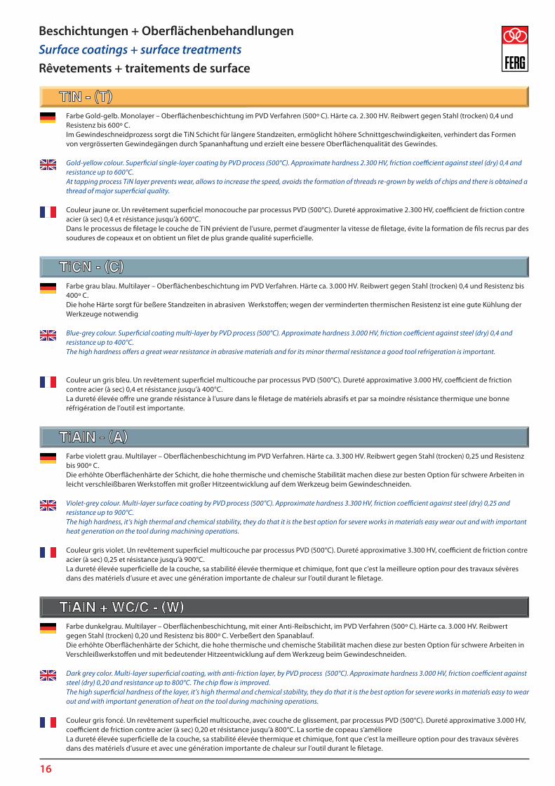
Farbe Gold-gelb. Monolayer – Oberflächenbeschichtung im PVD Verfahren (500º C). Härte ca. 2.300 HV. Reibwert gegen Stahl (trocken) 0,4 und Resistenz bis 600º C. Im Gewindeschneidprozess sorgt die TiN Schicht für längere Standzeiten, ermöglicht höhere Schnittgeschwindigkeiten, verhindert das Formen von vergrösserten Gewindegängen durch Spananhaftung und erzielt eine bessere Oberflächenqualität des Gewindes.
Gold-yellow colour. Superficial single-layer coating by PVD process (500°C). Approximate hardness 2.300 HV, friction coefficient against steel (dry) 0,4 and resistance up to 600°C. At tapping process TiN layer prevents wear, allows to increase the speed, avoids the formation of threads re-grown by welds of chips and there is obtained a thread of major superficial quality.
Couleur jaune or. Un revêtement superficiel monocouche par processus PVD (500°C). Dureté approximative 2.300 HV, coefficient de friction contre acier (à sec) 0,4 et résistance jusqu’à 600°C. Dans le processus de filetage le couche de TiN prévient de l’usure, permet d’augmenter la vitesse de filetage, évite la formation de fils recrus par des soudures de copeaux et on obtient un filet de plus grande qualité superficielle.
Farbe grau blau. Multilayer – Oberflächenbeschichtung im PVD Verfahren. Härte ca. 3.000 HV. Reibwert gegen Stahl (trocken) 0,4 und Resistenz bis 400º C. Die hohe Härte sorgt für beßere Standzeiten in abrasiven Werkstoffen; wegen der verminderten thermischen Resistenz ist eine gute Kühlung der Werkzeuge notwendig
Blue-grey colour. Superficial coating multi-layer by PVD process (500°C). Approximate hardness 3.000 HV, friction coefficient against steel (dry) 0,4 and resistance up to 400°C. The high hardness offers a great wear resistance in abrasive materials and for its minor thermal resistance a good tool refrigeration is important.
Couleur un gris bleu. Un revêtement superficiel multicouche par processus PVD (500°C). Dureté approximative 3.000 HV, coefficient de friction contre acier (à sec) 0,4 et résistance jusqu’à 400°C.La dureté élevée offre une grande résistance à l’usure dans le filetage de matériels abrasifs et par sa moindre résistance thermique une bonne réfrigération de l’outil est importante.
Farbe violett grau. Multilayer – Oberflächenbeschichtung im PVD Verfahren. Härte ca. 3.300 HV. Reibwert gegen Stahl (trocken) 0,25 und Resistenz bis 900º C. Die erhöhte Oberflächenhärte der Schicht, die hohe thermische und chemische Stabilität machen diese zur besten Option für schwere Arbeiten in leicht verschleißbaren Werkstoffen mit großer Hitzeentwicklung auf dem Werkzeug beim Gewindeschneiden.
Violet-grey colour. Multi-layer surface coating by PVD process (500°C). Approximate hardness 3.300 HV, friction coefficient against steel (dry) 0,25 and resistance up to 900°C. The high hardness, it’s high thermal and chemical stability, they do that it is the best option for severe works in materials easy wear out and with important heat generation on the tool during machining operations.
Couleur gris violet. Un revêtement superficiel multicouche par processus PVD (500°C). Dureté approximative 3.300 HV, coefficient de friction contre acier (à sec) 0,25 et résistance jusqu’à 900°C.La dureté élevée superficielle de la couche, sa stabilité élevée thermique et chimique, font que c’est la meilleure option pour des travaux sévères dans des matériels d’usure et avec une génération importante de chaleur sur l’outil durant le filetage.
Farbe dunkelgrau. Multilayer – Oberflächenbeschichtung, mit einer Anti-Reibschicht, im PVD Verfahren (500º C). Härte ca. 3.000 HV. Reibwert gegen Stahl (trocken) 0,20 und Resistenz bis 800º C. Verbeßert den Spanablauf. Die erhöhte Oberflächenhärte der Schicht, die hohe thermische und chemische Stabilität machen diese zur besten Option für schwere Arbeiten in Verschleißwerkstoffen und mit bedeutender Hitzeentwicklung auf dem Werkzeug beim Gewindeschneiden.
Dark grey color. Multi-layer superficial coating, with anti-friction layer, by PVD process (500°C). Approximate hardness 3.000 HV, friction coefficient against steel (dry) 0,20 and resistance up to 800°C. The chip flow is improved. The high superficial hardness of the layer, it’s high thermal and chemical stability, they do that it is the best option for severe works in materials easy to wear out and with important generation of heat on the tool during machining operations.
Couleur gris foncé. Un revêtement superficiel multicouche, avec couche de glissement, par processus PVD (500°C). Dureté approximative 3.000 HV, coefficient de friction contre acier (à sec) 0,20 et résistance jusqu’à 800°C. La sortie de copeau s’amélioreLa dureté élevée superficielle de la couche, sa stabilité élevée thermique et chimique, font que c’est la meilleure option pour des travaux sévères dans des matériels d’usure et avec une génération importante de chaleur sur l’outil durant le filetage.
Beschichtungen + OberflächenbehandlungenSurface coatings + surface treatmentsRêvetements + traitements de surface

17
Farbe silbergrau. Monolayer – Oberflächenbeschichtung im PVD Verfahren (500º C). Härte ca. 1.750 HV, Reibwert gegen Stahl (trocken) 0,5 und Resistenz bis 700º C. Die erhöhte Korrosionsfestigkeit und eine bedeutende Hitzebeständigkeit, zusammen mit einer geringen chemischen Affinität mit den nicht Eisenwerkstoffen, macht sie besonders intereßant für den Einsatz in Fällen, wo Titanium Beschichtungen nicht angebracht sind (Luftfahrt und Chirurgie).
Gray silver colour. Single-layer superficial coating by PVD process (500°C). Approximate hardness 1.750 HV, friction coefficient against steel (dry) 0,5 and resistance up to 700°C. The high resistance to corrosion and an important refractority, that together with its scanty chemical affinity with the non ferreous metals, makes it very interesting for machining materials where the use of Titanium layer is counter indicated (Aeronautical and Surgical).
Couleur gris argent. Un revêtement superficiel monocouche par processus PVD (500°C). Dureté approximative 1.750 HV, coefficient de friction contre acier (à sec) 0,5 et résistance jusqu’à 700°C.La résistance élevée à la corrosion et un important réfractairité, qui avec son affinité peu abondante chimique avec les métaux non de fer, la fait très intéressante pour ces types de filetages et dans lequel l’usage de couches de Titane est contre-indiqué (Aéronautique et Chirurgicale).
Farbe blaugrau. Monolayer – Oberflächenbeschichtung im PVD Verfahren (500º C). Härte ca. 3.200 HV, Reibwert gegen Stahl (trocken) 0,35 und Resistenz bis 1.100º C. Sehr hohe Resistenzfestigkeit gegen Schleifverschleiß, hitzebeständig und äußerst rostbeständig.
Blue-grey colour. Single-layer surface coating by PVD process (500°C). Approximate hardness 3.200 HV, friction coefficient against steel (dry) 0,35 and resistance up to 1.100°C. Very high wear resistance for abrasion, resistance to high temperatures and resistance without equal to the oxidation.
Couleur gris bleu. Un revêtement superficiel monocouche par processus PVD (500°C). Une dureté approximative 3.200 HV, coefficient de friction contre acier (à sec) 0,35 et résistance jusqu’à 1.100°C.Une très haute résistance à l’usure par abrasion, résistance à de hautes températures et résistance sans égal à l’oxydation.
Farbe dunkelblau. Die Werkzeuge aus Schnellstahl werden einer Behandlung in einer Atmosphäre aus Waßerdampf unterzogen und es entsteht eine Oxidschicht. Diese Oxidschicht ist zäh und hält das Kühlmittel, was Kaltschweißen vermeidet, das beim Gewindeschneiden bei Stählen mit niedrigen Karbidgehalt entsteht.
Blue-dark colour. The tools of high speed steel are submitted to a treatment in an atmosphere of water steam and a layer of oxide is formed. This layer of oxide is tenacious and retains the coolant, which helps to avoid the weld in cold that takes place by threading low-carbon steels
Couleur bleu foncé. Les outils en acier rapide sont soumis à un traitement dans une atmosphère de vapeur d’eau et se forme une couche d’oxyde.Cette couche d’oxyde est tenace et retient le réfrigérant, ce qui aide à éviter la soudure à froid que se produit au fileter des aciers bas de carbone ou des sucreries.
Farbe dunkelgrau. Thermo-chemische Behandlung mit Nitraten und Sulfiden, die sich mit dem Schnellstahl der Werkzeuge kombinieren. Die Oberfläche hat eine Härte von ungefähr 900 HV 0,1, einen niedrigen Reibwert und hohe Verschleißfestigkeit, eine hohe Dauerfestigkeit und ist rostbeständig. Wichtig im Einsatz von Schleifmaterialien.
Gray-dark colour. Treatment thermos-chemist with Nitrides and Sulphurs that are combined with the high speed steel of the tools. The surface possesses a hardness of ≈ 900 HV 0,1, a low friction coefficient and a major resistance to wear, to fatigue and to corrosion. Important for use in abrasive materials.
Couleur grise foncé. Un traitement thermos - chimiste avec les Nitrures et les Sulfures qui se combinent avec l’acier rapide des outils.La surface possède une dureté de ≈ 900 HV 0,1, un moindre coefficient de frottement et une plus grande résistance à l’usure, à la fatigue et à la corrosion. Important son usage pour des matériels abrasifs.
Beschichtungen + Oberflächenbehandlungen - ForsetzungSurface coatings + surface treatments - ContinuesRêvetements + traitements de surface - Suiete
18
Katalog-Nr. - Catalogue N. - N0 CatalogueBESCHICHTUNG
COATINGSREVÊTEMENTS
HSSE-VØ ≤ 30 mm
HSSØ > 30 mm
DIN 371 DIN 376 - 374 - 5156
≤ 3 x d1
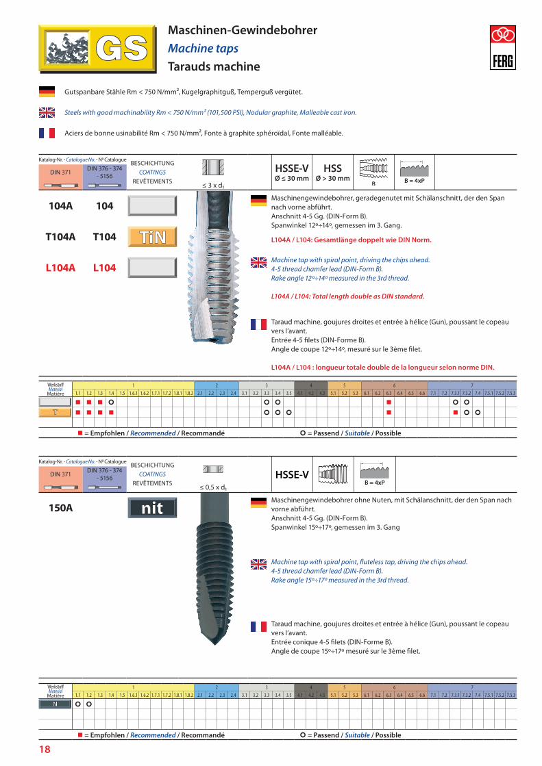
104A 104Maschinengewindebohrer, geradegenutet mit Schälanschnitt, der den Span nach vorne abführt. Anschnitt 4-5 Gg. (DIN-Form B). Spanwinkel 12º÷14º, gemessen im 3. Gang.
L104A / L104: Gesamtlänge doppelt wie DIN Norm.T104A T104
L104A L104Machine tap with spiral point, driving the chips ahead. 4-5 thread chamfer lead (DIN-Form B). Rake angle 12º÷14º measured in the 3rd thread. L104A / L104: Total length double as DIN standard.
Taraud machine, goujures droites et entrée à hélice (Gun), poussant le copeau vers l’avant. Entrée 4-5 filets (DIN-Forme B). Angle de coupe 12º÷14º, mesuré sur le 3ème filet. L104A / L104 : longueur totale double de la longueur selon norme DIN.
Gutspanbare Stähle Rm < 750 N/mm², Kugelgraphitguß, Temperguß vergütet.
Steels with good machinability Rm < 750 N/mm² (101,500 PSI), Nodular graphite, Malleable cast iron.
Aciers de bonne usinabilité Rm < 750 N/mm², Fonte à graphite sphéroïdal, Fonte malléable.
Maschinen-GewindebohrerMachine tapsTarauds machine
Katalog-Nr. - Catalogue N. - N0 CatalogueBESCHICHTUNG
COATINGSREVÊTEMENTS
HSSE-VDIN 371 DIN 376 - 374 - 5156
≤ 0,5 x d1
150AMaschinengewindebohrer ohne Nuten, mit Schälanschnitt, der den Span nach vorne abführt. Anschnitt 4-5 Gg. (DIN-Form B). Spanwinkel 15º÷17º, gemessen im 3. Gang
Machine tap with spiral point, fluteless tap, driving the chips ahead. 4-5 thread chamfer lead (DIN-Form B). Rake angle 15º÷17º measured in the 3rd thread.
Taraud machine, goujures droites et entrée à hélice (Gun), poussant le copeau vers l’avant. Entrée conique 4-5 filets (DIN-Forme B). Angle de coupe 15º÷17º mesuré sur le 3ème filet.
WerkstoffMaterial
Matière
1 2 3 4 5 6 71.1 1.2 1.3 1.4 1.5 1.6.1 1.6.2 1.7.1 1.7.2 1.8.1 1.8.2 2.1 2.2 2.3 2.4 3.1 3.2 3.3 3.4 3.5 4.1 4.2 4.3 5.1 5.2 5.3 6.1 6.2 6.3 6.4 6.5 6.6 7.1 7.2 7.3.1 7.3.2 7.4 7.5.1 7.5.2 7.5.3
= Empfohlen / Recommended / Recommandé = Passend / Suitable / Possible
WerkstoffMaterial
Matière
1 2 3 4 5 6 71.1 1.2 1.3 1.4 1.5 1.6.1 1.6.2 1.7.1 1.7.2 1.8.1 1.8.2 2.1 2.2 2.3 2.4 3.1 3.2 3.3 3.4 3.5 4.1 4.2 4.3 5.1 5.2 5.3 6.1 6.2 6.3 6.4 6.5 6.6 7.1 7.2 7.3.1 7.3.2 7.4 7.5.1 7.5.2 7.5.3
= Empfohlen / Recommended / Recommandé = Passend / Suitable / Possible
19
Katalog-Nr. - Catalogue N. - N0 CatalogueBESCHICHTUNG
COATINGSREVÊTEMENTS
HSSE-VDIN 371 DIN 376 - 374 - 5156
≤ 0,5 x d1
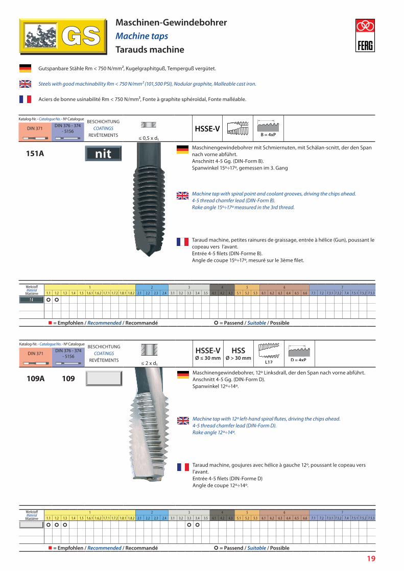
151AMaschinengewindebohrer mit Schmiernuten, mit Schälan-scnitt, der den Span nach vorne abführt. Anschnitt 4-5 Gg. (DIN-Form B). Spanwinkel 15º÷17º, gemessen im 3. Gang
Machine tap with spiral point and coolant grooves, driving the chips ahead. 4-5 thread chamfer lead (DIN-Form B). Rake angle 15º÷17º measured in the 3rd thread.
Taraud machine, petites rainures de graissage, entrée à hélice (Gun), poussant le copeau vers l’avant. Entrée 4-5 filets (DIN-Forme B). Angle de coupe 15º÷17º, mesuré sur le 3ème filet.
Maschinen-GewindebohrerMachine tapsTarauds machine
Katalog-Nr. - Catalogue N. - N0 CatalogueBESCHICHTUNG
COATINGSREVÊTEMENTS
HSSE-VØ ≤ 30 mm
HSSØ > 30 mm
DIN 371 DIN 376 - 374 - 5156
≤ 2 x d1
109A 109Maschinengewindebohrer, 12º Linksdrall, der den Span nach vorne abführt. Anschnitt 4-5 Gg. (DIN-Form D). Spanwinkel 12º÷14º.
Machine tap with 12º left-hand spiral flutes, driving the chips ahead. 4-5 thread chamfer lead (DIN-Form D). Rake angle 12º÷14º.
Taraud machine, goujures avec hélice à gauche 12º, poussant le copeau vers l’avant. Entrée 4-5 filets (DIN-Forme D) Angle de coupe 12º÷14º.
Gutspanbare Stähle Rm < 750 N/mm², Kugelgraphitguß, Temperguß vergütet.
Steels with good machinability Rm < 750 N/mm² (101,500 PSI), Nodular graphite, Malleable cast iron.
Aciers de bonne usinabilité Rm < 750 N/mm², Fonte à graphite sphéroïdal, Fonte malléable.
WerkstoffMaterial
Matière
1 2 3 4 5 6 71.1 1.2 1.3 1.4 1.5 1.6.1 1.6.2 1.7.1 1.7.2 1.8.1 1.8.2 2.1 2.2 2.3 2.4 3.1 3.2 3.3 3.4 3.5 4.1 4.2 4.3 5.1 5.2 5.3 6.1 6.2 6.3 6.4 6.5 6.6 7.1 7.2 7.3.1 7.3.2 7.4 7.5.1 7.5.2 7.5.3
= Empfohlen / Recommended / Recommandé = Passend / Suitable / Possible
WerkstoffMaterial
Matière
1 2 3 4 5 6 71.1 1.2 1.3 1.4 1.5 1.6.1 1.6.2 1.7.1 1.7.2 1.8.1 1.8.2 2.1 2.2 2.3 2.4 3.1 3.2 3.3 3.4 3.5 4.1 4.2 4.3 5.1 5.2 5.3 6.1 6.2 6.3 6.4 6.5 6.6 7.1 7.2 7.3.1 7.3.2 7.4 7.5.1 7.5.2 7.5.3
= Empfohlen / Recommended / Recommandé = Passend / Suitable / Possible

20
Katalog-Nr. - Catalogue N. - N0 CatalogueBESCHICHTUNG
COATINGSREVÊTEMENTS
HSSE-VØ ≤ 30 mm
HSSØ > 30 mm
DIN 371 DIN 376 - 374 - 5156
≤ 1½ x d1
105A 105Maschinengewindebohrer, geradegenutet. Anschnitt 2,5 Gg. (DIN-Form C). Spanwinkel 12º÷14º.
Machine tap with straight flutes. 2,5 thread chamfer lead (DIN-Form C). Rake angle 12º÷14º.
Taraud machine, goujures droites. Entrée 2,5 filets (DIN-Forme C). Angle de coupe 12º÷14º.
Maschinen-GewindebohrerMachine tapsTarauds machine
Katalog-Nr. - Catalogue N. - N0 CatalogueBESCHICHTUNG
COATINGSREVÊTEMENTS
HSSE-VØ ≤ 30 mm
HSSØ > 30 mm
DIN 371 DIN 376 - 374 - 5156
≤ 1½ x d1
135Maschinengewindebohrer, geradegenutet. Ausgesetzte Zähne. Anschnitt 2,5 Gg. (DIN-Form C). Spanwinkel 12º÷14º.
V135
T135Machine tap with straight flutes. Interrupted thread. 2,5 thread chamfer lead (DIN-Form C). Rake angle 12º÷14º.
Taraud machine, goujures droites. Filets alternés. Entrée 2,5 filets (DIN-Forme C). Angle de coupe 12º÷14º.
Gutspanbare Stähle Rm < 750 N/mm², Kugelgraphitguß, Temperguß vergütet.
Steels with good machinability Rm < 750 N/mm² (101,500 PSI), Nodular graphite, Malleable cast iron.
Aciers de bonne usinabilité Rm < 750 N/mm², Fonte à graphite sphéroïdal, Fonte malléable.
WerkstoffMaterial
Matière
1 2 3 4 5 6 71.1 1.2 1.3 1.4 1.5 1.6.1 1.6.2 1.7.1 1.7.2 1.8.1 1.8.2 2.1 2.2 2.3 2.4 3.1 3.2 3.3 3.4 3.5 4.1 4.2 4.3 5.1 5.2 5.3 6.1 6.2 6.3 6.4 6.5 6.6 7.1 7.2 7.3.1 7.3.2 7.4 7.5.1 7.5.2 7.5.3
= Empfohlen / Recommended / Recommandé = Passend / Suitable / Possible
WerkstoffMaterial
Matière
1 2 3 4 5 6 71.1 1.2 1.3 1.4 1.5 1.6.1 1.6.2 1.7.1 1.7.2 1.8.1 1.8.2 2.1 2.2 2.3 2.4 3.1 3.2 3.3 3.4 3.5 4.1 4.2 4.3 5.1 5.2 5.3 6.1 6.2 6.3 6.4 6.5 6.6 7.1 7.2 7.3.1 7.3.2 7.4 7.5.1 7.5.2 7.5.3
= Empfohlen / Recommended / Recommandé = Passend / Suitable / Possible

21
Katalog-Nr. - Catalogue N. - N0 CatalogueBESCHICHTUNG
COATINGSREVÊTEMENTS
HSSE-VØ ≤ 30 mm
HSSØ > 30 mm
DIN 371 DIN 376 - 374 - 5156
≤ 2 x d1
110A 110Maschinengewindebohrer, 15º Rechtsdrall, der den Span nach hinten abführt. Anschnitt 3,5 Gg. (DIN-Form D). Spanwinkel 12º÷14º. Vorwiegend auf Drehautomaten und Mehrspindelmachinen einzusetze.
T110A T110
Machine tap with 15º right-hand spiral flutes, driving the chips to the back. 3,5 thread chamfer lead (DIN-Form D). Rake angle 12º÷14º.
Taraud machine, goujures avec hélice à droite 15º, poussant le coupeau vers l’arrière. Entrée 3,5 filets (DIN-Forme D). Angle de coupe 12º÷14º.
Maschinen-GewindebohrerMachine tapsTarauds machine
Katalog-Nr. - Catalogue N. - N0 CatalogueBESCHICHTUNG
COATINGSREVÊTEMENTS
HSSE-VØ ≤ 30 mm
HSSØ > 30 mm
DIN 371 DIN 376 - 374 - 5156
≤ 3 x d1
112A 112Maschinengewindebohrer, 38º Rechtsdrall, der den Span nach hinten abführt. Gewindelänge 10 Gg. Mit abgsetztem Führungsgewinde ab 5. Gang, um das Abbrechen der Gewindegänge zu vermeiden. Anschnitt 2,5 Gg. (DIN-Form C). Spanwinkel 12º÷14º. L112A / L112: Gesamtlänge doppelt wie DIN Norm.
T112A T112
L112A L112Machine tap with 38º right-hand spiral flutes, driving the chips to the back. Threaded length: 10 threads. Starting from the 5th thread, back tapered thread portion to reduce friction and improve swarf clearance. 2,5 thread chamfer lead (DIN-Form C). Rake angle 12º÷14º. L112A / L112: Total length double as DIN standard.
Taraud machine, goujures avec hélice à droite 38º, poussant le coupeau vers l’arrière. Longueur de la partie filetée : 10 filets. Avec partie filetée étagée à partir du 5ème filet pour éviter la rupture des dents. Entrée 2,5 filets (DIN-Forme C). Angle de coupe 12º÷14º. L112A / L112 : longueur totale double de la longueur selon norme DIN.
Gutspanbare Stähle Rm < 750 N/mm², Kugelgraphitguß, Temperguß vergütet.
Steels with good machinability Rm < 750 N/mm² (101,500 PSI), Nodular graphite, Malleable cast iron.
Aciers de bonne usinabilité Rm < 750 N/mm², Fonte à graphite sphéroïdal, Fonte malléable.
WerkstoffMaterial
Matière
1 2 3 4 5 6 71.1 1.2 1.3 1.4 1.5 1.6.1 1.6.2 1.7.1 1.7.2 1.8.1 1.8.2 2.1 2.2 2.3 2.4 3.1 3.2 3.3 3.4 3.5 4.1 4.2 4.3 5.1 5.2 5.3 6.1 6.2 6.3 6.4 6.5 6.6 7.1 7.2 7.3.1 7.3.2 7.4 7.5.1 7.5.2 7.5.3
= Empfohlen / Recommended / Recommandé = Passend / Suitable / Possible
WerkstoffMaterial
Matière
1 2 3 4 5 6 71.1 1.2 1.3 1.4 1.5 1.6.1 1.6.2 1.7.1 1.7.2 1.8.1 1.8.2 2.1 2.2 2.3 2.4 3.1 3.2 3.3 3.4 3.5 4.1 4.2 4.3 5.1 5.2 5.3 6.1 6.2 6.3 6.4 6.5 6.6 7.1 7.2 7.3.1 7.3.2 7.4 7.5.1 7.5.2 7.5.3
= Empfohlen / Recommended / Recommandé = Passend / Suitable / Possible
22
Katalog-Nr. - Catalogue N. - N0 CatalogueBESCHICHTUNG
COATINGSREVÊTEMENTS
HSSE-VDIN 371 DIN 376 - 374 - 5156
≤ 3 x d1
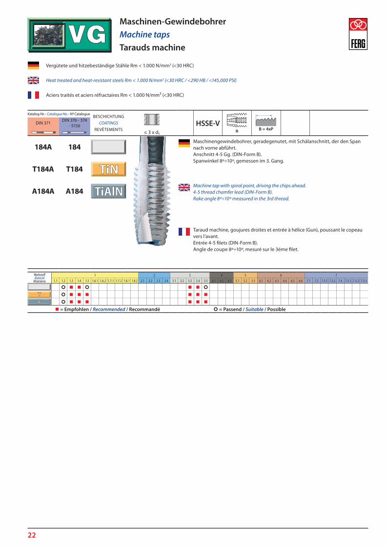
184A 184Maschinengewindebohrer, geradegenutet, mit Schälanschnitt, der den Span nach vorne abführt. Anschnitt 4-5 Gg. (DIN-Form B). Spanwinkel 8º÷10º, gemessen im 3. Gang.
T184A T184
A184A A184Machine tap with spiral point, driving the chips ahead. 4-5 thread chamfer lead (DIN-Form B). Rake angle 8º÷10º measured in the 3rd thread.
Taraud machine, goujures droites et entrée à hélice (Gun), poussant le copeau vers l’avant. Entrée 4-5 filets (DIN-Form B). Angle de coupe 8º÷10º, mesuré sur le 3éme filet.
Vergütete und hitzebeständige Stähle Rm < 1.000 N/mm2 (<30 HRC)
Heat treated and heat-resistant steels Rm < 1.000 N/mm2 (<30 HRC / <290 HB / <145,000 PSI)
Aciers traités et aciers réfractaires Rm < 1.000 N/mm² (<30 HRC)
Maschinen-GewindebohrerMachine tapsTarauds machine
WerkstoffMaterial
Matière
1 2 3 4 5 6 71.1 1.2 1.3 1.4 1.5 1.6.1 1.6.2 1.7.1 1.7.2 1.8.1 1.8.2 2.1 2.2 2.3 2.4 3.1 3.2 3.3 3.4 3.5 4.1 4.2 4.3 5.1 5.2 5.3 6.1 6.2 6.3 6.4 6.5 6.6 7.1 7.2 7.3.1 7.3.2 7.4 7.5.1 7.5.2 7.5.3
= Empfohlen / Recommended / Recommandé = Passend / Suitable / Possible
23
Katalog-Nr. - Catalogue N. - N0 CatalogueBESCHICHTUNG
COATINGSREVÊTEMENTS
HSSE-VDIN 371 DIN 376 - 374 - 5156
≤ 3 x d1
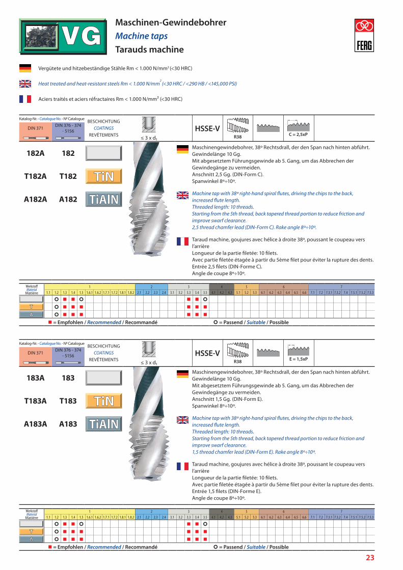
182A 182Maschinengewindebohrer, 38º Rechtsdrall, der den Span nach hinten abführt. Gewindelänge 10 Gg. Mit abgesetztem Führungsgewinde ab 5. Gang, um das Abbrechen der Gewindegänge zu vermeiden. Anschnitt 2,5 Gg. (DIN-Form C). Spanwinkel 8º÷10º.
T182A T182
A182A A182Machine tap with 38º right-hand spiral flutes, driving the chips to the back, increased flute length. Threaded length: 10 threads. Starting from the 5th thread, back tapered thread portion to reduce friction and improve swarf clearance. 2,5 thread chamfer lead (DIN-Form C). Rake angle 8º÷10º.
Taraud machine, goujures avec hélice à droite 38º, poussant le coupeau vers l’arrière Longueur de la partie filetée: 10 filets. Avec partie filetée étagée à partir du 5ème filet pour éviter la rupture des dents. Entrée 2,5 filets (DIN-Forme C). Angle de coupe 8º÷10º.
Vergütete und hitzebeständige Stähle Rm < 1.000 N/mm2 (<30 HRC)
Heat treated and heat-resistant steels Rm < 1.000 N/mm2
(<30 HRC / <290 HB / <145,000 PSI)
Aciers traités et aciers réfractaires Rm < 1.000 N/mm² (<30 HRC)
Maschinen-GewindebohrerMachine tapsTarauds machine
Katalog-Nr. - Catalogue N. - N0 CatalogueBESCHICHTUNG
COATINGSREVÊTEMENTS
HSSE-VDIN 371 DIN 376 - 374 - 5156
≤ 3 x d1
183A 183Maschinengewindebohrer, 38º Rechtsdrall, der den Span nach hinten abführt. Gewindelänge 10 Gg. Mit abgesetztem Führungsgewinde ab 5. Gang, um das Abbrechen der Gewindegänge zu vermeiden. Anschnitt 1,5 Gg. (DIN-Form E). Spanwinkel 8º÷10º.
T183A T183
A183A A183Machine tap with 38º right-hand spiral flutes, driving the chips to the back, increased flute length. Threaded length: 10 threads. Starting from the 5th thread, back tapered thread portion to reduce friction and improve swarf clearance. 1,5 thread chamfer lead (DIN-Form E). Rake angle 8º÷10º.
Taraud machine, goujures avec hélice à droite 38º, poussant le coupeau vers l’arrière Longueur de la partie filetée: 10 filets. Avec partie filetée étagée à partir du 5ème filet pour éviter la rupture des dents. Entrée 1,5 filets (DIN-Forme E). Angle de coupe 8º÷10º.
WerkstoffMaterial
Matière
1 2 3 4 5 6 71.1 1.2 1.3 1.4 1.5 1.6.1 1.6.2 1.7.1 1.7.2 1.8.1 1.8.2 2.1 2.2 2.3 2.4 3.1 3.2 3.3 3.4 3.5 4.1 4.2 4.3 5.1 5.2 5.3 6.1 6.2 6.3 6.4 6.5 6.6 7.1 7.2 7.3.1 7.3.2 7.4 7.5.1 7.5.2 7.5.3
= Empfohlen / Recommended / Recommandé = Passend / Suitable / Possible
WerkstoffMaterial
Matière
1 2 3 4 5 6 71.1 1.2 1.3 1.4 1.5 1.6.1 1.6.2 1.7.1 1.7.2 1.8.1 1.8.2 2.1 2.2 2.3 2.4 3.1 3.2 3.3 3.4 3.5 4.1 4.2 4.3 5.1 5.2 5.3 6.1 6.2 6.3 6.4 6.5 6.6 7.1 7.2 7.3.1 7.3.2 7.4 7.5.1 7.5.2 7.5.3
= Empfohlen / Recommended / Recommandé = Passend / Suitable / Possible

24
Vergütete und hitzebeständige Stähle Rm < 1.000 N/mm2 (<30 HRC)
Heat treated and heat-resistant steels Rm < 1.000 N/mm2 (<30 HRC / <290 HB / <145,000 PSI)
Aciers traités et aciers réfractaires Rm < 1.000 N/mm² (<30 HRC)
Maschinen-GewindebohrerMachine tapsTarauds machine
Katalog-Nr. - Catalogue N. - N0 CatalogueBESCHICHTUNG
COATINGSREVÊTEMENTS
HSSE-VDIN 371 DIN 376 - 374 - 5156
≤ 3 x d1
684A 684MASCHINENGEWINDEBOHRER MIT INNENKÜHLUNG. Erleichtert den Spanabfluss und eine bessere Kühlung. Geradegenutet, mit Schälanschnitt, der den Span nach vorne abführt. Anschnitt 4-5 Gg. (DIN-Form B). Spanwinkel 8º÷10º, gemessen im 3. Gang.
T684A T684
A684A A684MACHINE TAP WITH INTERNAL COOLANT FEED. Facilitates chip evacuation and improves cooling in cutting area. With spiral point, driving the chips ahead. 4-5 thread chamfer lead (DIN-Form B). Rake angle 8º÷10º measured int the 3rd thread.
TARAUD MACHINE AVEC ARROSAGE CENTRAL Facilite l’évacuation du copeau et une meilleure réfrigération. Goujures droites et entrée à hélice (Gun), poussant le copeau vers l’avant. Entrée 4-5 filets (DIN-Forme B). Angle de coupe 8º÷10º, mesuré sur le 3ème filet.
Katalog-Nr. - Catalogue N. - N0 CatalogueBESCHICHTUNG
COATINGSREVÊTEMENTS
HSSE-VDIN 371 DIN 376 - 374 - 5156
≤ 3 x d1
682A 682MASCHINENGEWINDEBOHRER MIT INNENKÜHLUNG. Erleichtert den Spanabfluss und eine bessere Kühlung. 38° Rechtsdrall, der den Span nach hinten abführt. Gewindelänge 10 Gg. Mit abgesetztem Führungsgewinde ab 5. Gang, um das Abbrechen der Gewindegänge zu vermeiden. Anschnitt 2,5 Gg. (DIN-Form C). Spanwinkel 8º÷10º.
T682A T682
A682A A682MACHINE TAP WITH INTERNAL COOLANT FEED. Facilitates chip evacuation and improves cooling in cutting area. With 38º right-hand spiral flutes, driving the chips to the back, increased flute length. Threaded length: 10 threads. Starting from the 5th thread, back tapered thread portion to reduce friction and improve swarf clearance. 2,5 thread chamfer lead (DIN-Form C). Rake angle 8º÷10º.
TARAUD MACHINE AVEC ARROSAGE CENTRAL Facilite l’évacuation du copeau et une meilleure réfrigération. Goujures avec hélice à droite 38º, poussant le coupeau vers l’arrière. Longueur de la partie filetée: 10 filets. Avec partie filetée étagée à partir du 5ème filet pour éviter la rupture des dents. Entrée 2,5 filets (DIN-Forme C). Angle de coupe 8º÷10º.
WerkstoffMaterial
Matière
1 2 3 4 5 6 71.1 1.2 1.3 1.4 1.5 1.6.1 1.6.2 1.7.1 1.7.2 1.8.1 1.8.2 2.1 2.2 2.3 2.4 3.1 3.2 3.3 3.4 3.5 4.1 4.2 4.3 5.1 5.2 5.3 6.1 6.2 6.3 6.4 6.5 6.6 7.1 7.2 7.3.1 7.3.2 7.4 7.5.1 7.5.2 7.5.3
= Empfohlen / Recommended / Recommandé = Passend / Suitable / Possible
WerkstoffMaterial
Matière
1 2 3 4 5 6 71.1 1.2 1.3 1.4 1.5 1.6.1 1.6.2 1.7.1 1.7.2 1.8.1 1.8.2 2.1 2.2 2.3 2.4 3.1 3.2 3.3 3.4 3.5 4.1 4.2 4.3 5.1 5.2 5.3 6.1 6.2 6.3 6.4 6.5 6.6 7.1 7.2 7.3.1 7.3.2 7.4 7.5.1 7.5.2 7.5.3
= Empfohlen / Recommended / Recommandé = Passend / Suitable / Possible
25
Katalog-Nr. - Catalogue N. - N0 CatalogueBESCHICHTUNG
COATINGSREVÊTEMENTS
HSSE-VDIN 371 DIN 376 - 374 - 5156
≤ 3 x d1
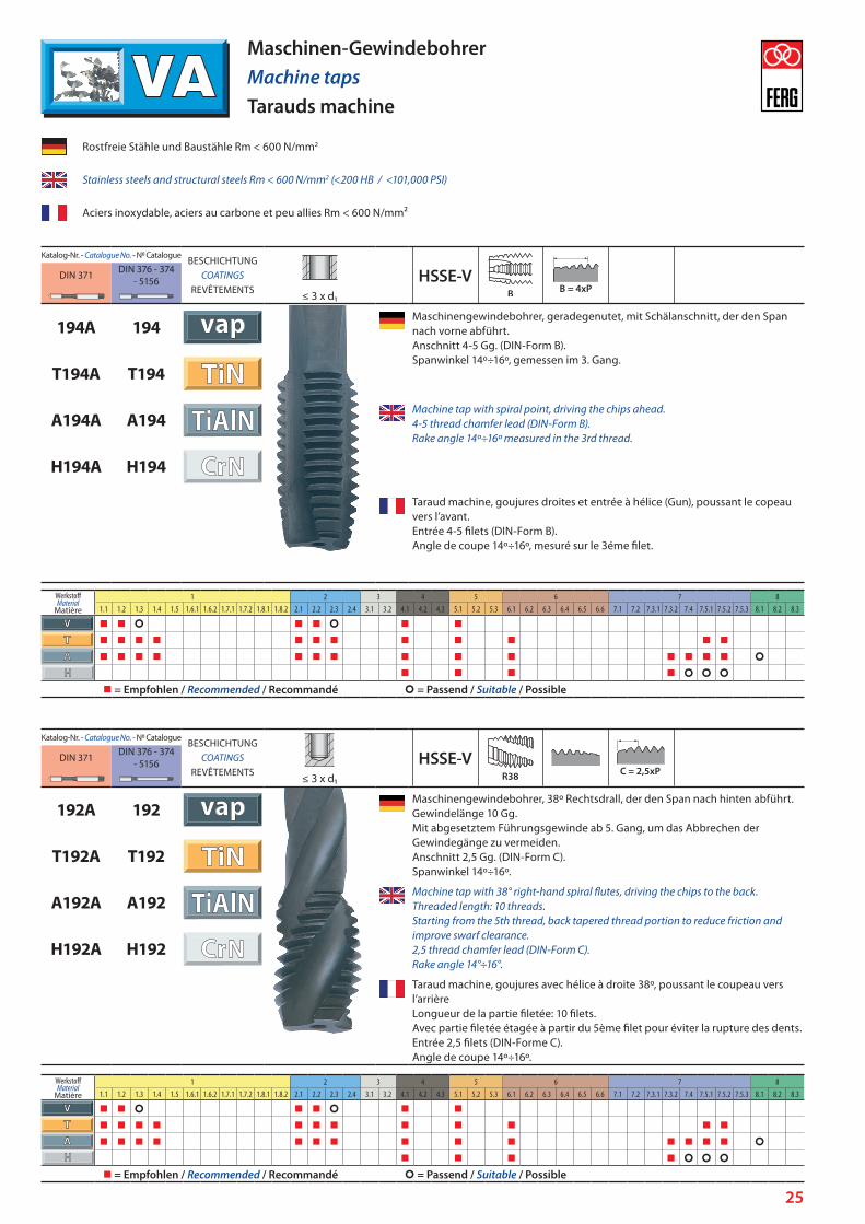
194A 194Maschinengewindebohrer, geradegenutet, mit Schälanschnitt, der den Span nach vorne abführt. Anschnitt 4-5 Gg. (DIN-Form B). Spanwinkel 14º÷16º, gemessen im 3. Gang.
T194A T194
A194A A194Machine tap with spiral point, driving the chips ahead. 4-5 thread chamfer lead (DIN-Form B). Rake angle 14º÷16º measured in the 3rd thread.
H194A H194
Taraud machine, goujures droites et entrée à hélice (Gun), poussant le copeau vers l’avant. Entrée 4-5 filets (DIN-Form B). Angle de coupe 14º÷16º, mesuré sur le 3éme filet.
Rostfreie Stähle und Baustähle Rm < 600 N/mm2
Stainless steels and structural steels Rm < 600 N/mm2 (<200 HB / <101,000 PSI)
Aciers inoxydable, aciers au carbone et peu allies Rm < 600 N/mm²
Maschinen-GewindebohrerMachine tapsTarauds machine
Katalog-Nr. - Catalogue N. - N0 CatalogueBESCHICHTUNG
COATINGSREVÊTEMENTS
HSSE-VDIN 371 DIN 376 - 374 - 5156
≤ 3 x d1
192A 192Maschinengewindebohrer, 38º Rechtsdrall, der den Span nach hinten abführt. Gewindelänge 10 Gg. Mit abgesetztem Führungsgewinde ab 5. Gang, um das Abbrechen der Gewindegänge zu vermeiden. Anschnitt 2,5 Gg. (DIN-Form C). Spanwinkel 14º÷16º.
T192A T192
A192A A192Machine tap with 38° right-hand spiral flutes, driving the chips to the back. Threaded length: 10 threads. Starting from the 5th thread, back tapered thread portion to reduce friction and improve swarf clearance.2,5 thread chamfer lead (DIN-Form C).Rake angle 14°÷16°.
H192A H192
Taraud machine, goujures avec hélice à droite 38º, poussant le coupeau vers l’arrière Longueur de la partie filetée: 10 filets. Avec partie filetée étagée à partir du 5ème filet pour éviter la rupture des dents. Entrée 2,5 filets (DIN-Forme C). Angle de coupe 14º÷16º.
WerkstoffMaterial
Matière
1 2 3 4 5 6 7 81.1 1.2 1.3 1.4 1.5 1.6.1 1.6.2 1.7.1 1.7.2 1.8.1 1.8.2 2.1 2.2 2.3 2.4 3.1 3.2 4.1 4.2 4.3 5.1 5.2 5.3 6.1 6.2 6.3 6.4 6.5 6.6 7.1 7.2 7.3.1 7.3.2 7.4 7.5.1 7.5.2 7.5.3 8.1 8.2 8.3
= Empfohlen / Recommended / Recommandé = Passend / Suitable / Possible
WerkstoffMaterial
Matière
1 2 3 4 5 6 7 81.1 1.2 1.3 1.4 1.5 1.6.1 1.6.2 1.7.1 1.7.2 1.8.1 1.8.2 2.1 2.2 2.3 2.4 3.1 3.2 4.1 4.2 4.3 5.1 5.2 5.3 6.1 6.2 6.3 6.4 6.5 6.6 7.1 7.2 7.3.1 7.3.2 7.4 7.5.1 7.5.2 7.5.3 8.1 8.2 8.3
= Empfohlen / Recommended / Recommandé = Passend / Suitable / Possible
26
Katalog-Nr. - Catalogue N. - N0 CatalogueBESCHICHTUNG
COATINGSREVÊTEMENTS
HSSE-HDIN 371 DIN 376 - 374 - 5156
≤ 2 x d1
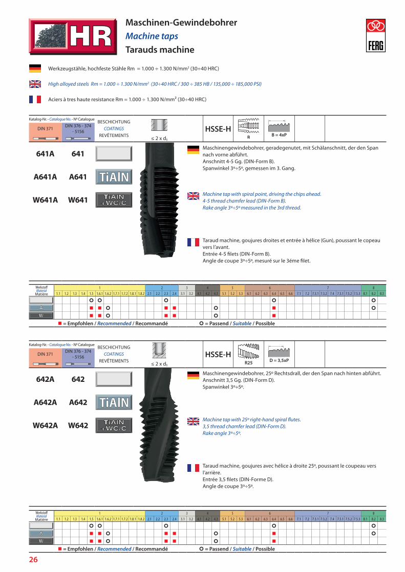
641A 641Maschinengewindebohrer, geradegenutet, mit Schälanschnitt, der den Span nach vorne abführt. Anschnitt 4-5 Gg. (DIN-Form B). Spanwinkel 3º÷5º, gemessen im 3. Gang.
A641A A641
W641A W641Machine tap with spiral point, driving the chips ahead. 4-5 thread chamfer lead (DIN-Form B). Rake angle 3º÷5º measured in the 3rd thread.
Taraud machine, goujures droites et entrée à hélice (Gun), poussant le copeau vers l’avant. Entrée 4-5 filets (DIN-Form B). Angle de coupe 3º÷5º, mesuré sur le 3éme filet.
Werkzeugstähle, hochfeste Stähle Rm = 1.000 ÷ 1.300 N/mm2 (30÷40 HRC)
High alloyed steels Rm = 1.000 ÷ 1.300 N/mm2 (30÷40 HRC / 300 ÷ 385 HB / 135,000 ÷ 185,000 PSI)
Aciers à tres haute resistance Rm = 1.000 ÷ 1.300 N/mm² (30÷40 HRC)
Maschinen-GewindebohrerMachine tapsTarauds machine
Katalog-Nr. - Catalogue N. - N0 CatalogueBESCHICHTUNG
COATINGSREVÊTEMENTS
HSSE-HDIN 371 DIN 376 - 374 - 5156
≤ 2 x d1
642A 642Maschinengewindebohrer, 25º Rechtsdrall, der den Span nach hinten abführt. Anschnitt 3,5 Gg. (DIN-Form D). Spanwinkel 3º÷5º.
A642A A642
W642A W642Machine tap with 25º right-hand spiral flutes. 3,5 thread chamfer lead (DIN-Form D). Rake angle 3º÷5º.
Taraud machine, goujures avec hélice à droite 25º, poussant le coupeau vers l’arrière. Entrée 3,5 filets (DIN-Forme D). Angle de coupe 3º÷5º.
WerkstoffMaterial
Matière
1 2 3 4 5 6 7 81.1 1.2 1.3 1.4 1.5 1.6.1 1.6.2 1.7.1 1.7.2 1.8.1 1.8.2 2.1 2.2 2.3 2.4 3.1 3.2 4.1 4.2 4.3 5.1 5.2 5.3 6.1 6.2 6.3 6.4 6.5 6.6 7.1 7.2 7.3.1 7.3.2 7.4 7.5.1 7.5.2 7.5.3 8.1 8.2 8.3
= Empfohlen / Recommended / Recommandé = Passend / Suitable / Possible
WerkstoffMaterial
Matière
1 2 3 4 5 6 7 81.1 1.2 1.3 1.4 1.5 1.6.1 1.6.2 1.7.1 1.7.2 1.8.1 1.8.2 2.1 2.2 2.3 2.4 3.1 3.2 4.1 4.2 4.3 5.1 5.2 5.3 6.1 6.2 6.3 6.4 6.5 6.6 7.1 7.2 7.3.1 7.3.2 7.4 7.5.1 7.5.2 7.5.3 8.1 8.2 8.3
= Empfohlen / Recommended / Recommandé = Passend / Suitable / Possible
27
Katalog-Nr. - Catalogue N. - N0 CatalogueBESCHICHTUNG
COATINGSREVÊTEMENTS
HSSE-VDIN 371 DIN 376 - 374 - 5156
≤ 1,5 x d1
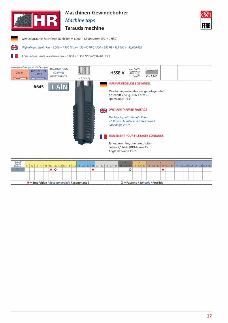
A645NUR FÜR KEGELIGES GEWINDE. Maschinengewindebohrer, geradegenutet. Anschnitt 2,5 Gg. (DIN-Form C). Spanwinkel 1°÷3°.
ONLY FOR TAPERED THREADS Machine tap with straight flutes. 2,5 thread chamfer lead (DIN-Form C). Rake angle 1º÷3º.
SEULEMENT POUR FILETAGES CONIQUES. Taraud machine, goujures droites. Entrée 2,5 filets (DIN-Forme C). Angle de coupe 1°÷3°.
Werkzeugstähle, hochfeste Stähle Rm = 1.000 ÷ 1.300 N/mm2 (30÷40 HRC)
High alloyed steels Rm = 1.000 ÷ 1.300 N/mm2 (30÷40 HRC / 300 ÷ 385 HB / 135,000 ÷ 185,000 PSI)
Aciers à tres haute resistance Rm = 1.000 ÷ 1.300 N/mm2(30÷40 HRC)
Maschinen-GewindebohrerMachine tapsTarauds machine
WerkstoffMaterial
Matière
1 2 3 4 5 6 71.1 1.2 1.3 1.4 1.5 1.6.1 1.6.2 1.7.1 1.7.2 1.8.1 1.8.2 2.1 2.2 2.3 2.4 3.1 3.2 3.3 3.4 3.5 4.1 4.2 4.3 5.1 5.2 5.3 6.1 6.2 6.3 6.4 6.5 6.6 7.1 7.2 7.3.1 7.3.2 7.4 7.5.1 7.5.2 7.5.3
= Empfohlen / Recommended / Recommandé = Passend / Suitable / Possible
28
Katalog-Nr. - Catalogue N. - N0 CatalogueBESCHICHTUNG
COATINGSREVÊTEMENTS
40÷55HRC
HSSE-VE
DIN 371 DIN 376 - 374 - 5156
≤ 2 x d1
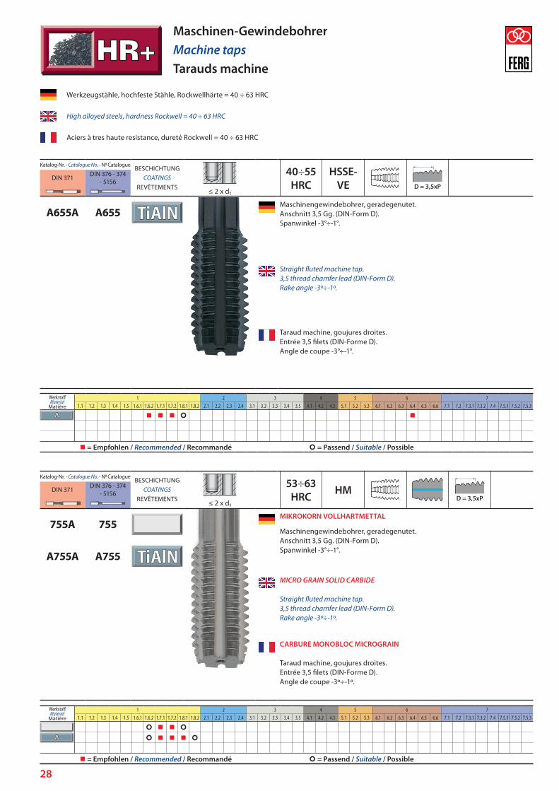
A655A A655Maschinengewindebohrer, geradegenutet. Anschnitt 3,5 Gg. (DIN-Form D). Spanwinkel -3°÷-1°.
Straight fluted machine tap. 3,5 thread chamfer lead (DIN-Form D). Rake angle -3º÷-1º.
Taraud machine, goujures droites. Entrée 3,5 filets (DIN-Forme D). Angle de coupe -3°÷-1°.
Werkzeugstähle, hochfeste Stähle, Rockwellhärte = 40 ÷ 63 HRC
High alloyed steels, hardness Rockwell = 40 ÷ 63 HRC
Aciers à tres haute resistance, dureté Rockwell = 40 ÷ 63 HRC
Maschinen-GewindebohrerMachine tapsTarauds machine
Katalog-Nr. - Catalogue N. - N0 CatalogueBESCHICHTUNG
COATINGSREVÊTEMENTS
53÷63HRC HMDIN 371 DIN 376 - 374
- 5156≤ 2 x d1
755A 755MIKROKORN VOLLHARTMETTAL
Maschinengewindebohrer, geradegenutet. Anschnitt 3,5 Gg. (DIN-Form D). Spanwinkel -3°÷-1°.
A755A A755
MICRO GRAIN SOLID CARBIDE Straight fluted machine tap. 3,5 thread chamfer lead (DIN-Form D). Rake angle -3º÷-1º.
CARBURE MONOBLOC MICROGRAIN Taraud machine, goujures droites. Entrée 3,5 filets (DIN-Forme D). Angle de coupe -3º÷-1º.
WerkstoffMaterial
Matière
1 2 3 4 5 6 71.1 1.2 1.3 1.4 1.5 1.6.1 1.6.2 1.7.1 1.7.2 1.8.1 1.8.2 2.1 2.2 2.3 2.4 3.1 3.2 3.3 3.4 3.5 4.1 4.2 4.3 5.1 5.2 5.3 6.1 6.2 6.3 6.4 6.5 6.6 7.1 7.2 7.3.1 7.3.2 7.4 7.5.1 7.5.2 7.5.3
= Empfohlen / Recommended / Recommandé = Passend / Suitable / Possible
WerkstoffMaterial
Matière
1 2 3 4 5 6 71.1 1.2 1.3 1.4 1.5 1.6.1 1.6.2 1.7.1 1.7.2 1.8.1 1.8.2 2.1 2.2 2.3 2.4 3.1 3.2 3.3 3.4 3.5 4.1 4.2 4.3 5.1 5.2 5.3 6.1 6.2 6.3 6.4 6.5 6.6 7.1 7.2 7.3.1 7.3.2 7.4 7.5.1 7.5.2 7.5.3
= Empfohlen / Recommended / Recommandé = Passend / Suitable / Possible
29
Katalog-Nr. - Catalogue N. - N0 CatalogueBESCHICHTUNG
COATINGSREVÊTEMENTS
HSSE-VDIN 2174 - 2184 DIN 2174 - 2184 - 2189
≤ 3 x d1
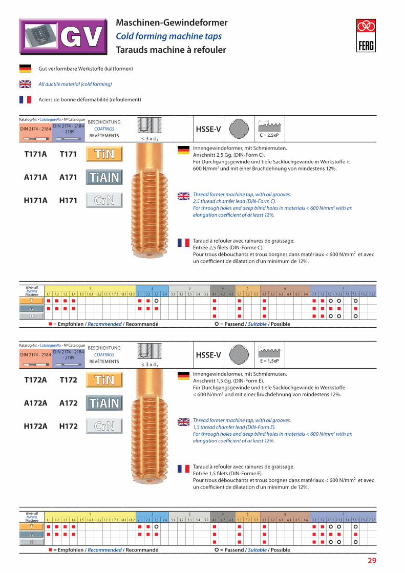
T171A T171Innengewindeformer, mit Schmiernuten. Anschnitt 2,5 Gg. (DIN-Form C). Für Durchgangsgewinde und tiefe Sacklochgewinde in Werkstoffe < 600 N/mm2 und mit einer Bruchdehnung von mindestens 12%.
A171A A171
H171A H171Thread former machine tap, with oil grooves. 2,5 thread chamfer lead (DIN-Form C). For through holes and deep blind holes in materials < 600 N/mm2 with an elongation coefficient of at least 12%.
Taraud à refouler avec rainures de graissage. Entrée 2,5 filets (DIN-Forme C). Pour trous débouchants et trous borgnes dans matériaux < 600 N/mm² et avec un coefficient de dilatation d’un minimum de 12%.
Gut verformbare Werkstoffe (kaltformen)
All ductile material (cold forming)
Aciers de bonne déformabilité (refoulement)
Maschinen-GewindeformerCold forming machine tapsTarauds machine à refouler
Katalog-Nr. - Catalogue N. - N0 CatalogueBESCHICHTUNG
COATINGSREVÊTEMENTS
HSSE-VDIN 2174 - 2184 DIN 2174 - 2184 - 2189
≤ 3 x d1
T172A T172Innengewindeformer, mit Schmiernuten. Anschnitt 1,5 Gg. (DIN-Form E). Für Durchgangsgewinde und tiefe Sacklochgewinde in Werkstoffe < 600 N/mm2 und mit einer Bruchdehnung von mindestens 12%.
A172A A172
H172A H172Thread former machine tap, with oil grooves. 1,5 thread chamfer lead (DIN-Form E). For through holes and deep blind holes in materials < 600 N/mm2 with an elongation coefficient of at least 12%.
Taraud à refouler avec rainures de graissage. Entrée 1,5 filets (DIN-Forme E). Pour trous débouchants et trous borgnes dans matériaux < 600 N/mm² et avec un coefficient de dilatation d’un minimum de 12%.
WerkstoffMaterial
Matière
1 2 3 4 5 6 71.1 1.2 1.3 1.4 1.5 1.6.1 1.6.2 1.7.1 1.7.2 1.8.1 1.8.2 2.1 2.2 2.3 2.4 3.1 3.2 3.3 3.4 3.5 4.1 4.2 4.3 5.1 5.2 5.3 6.1 6.2 6.3 6.4 6.5 6.6 7.1 7.2 7.3.1 7.3.2 7.4 7.5.1 7.5.2 7.5.3
= Empfohlen / Recommended / Recommandé = Passend / Suitable / Possible
WerkstoffMaterial
Matière
1 2 3 4 5 6 71.1 1.2 1.3 1.4 1.5 1.6.1 1.6.2 1.7.1 1.7.2 1.8.1 1.8.2 2.1 2.2 2.3 2.4 3.1 3.2 3.3 3.4 3.5 4.1 4.2 4.3 5.1 5.2 5.3 6.1 6.2 6.3 6.4 6.5 6.6 7.1 7.2 7.3.1 7.3.2 7.4 7.5.1 7.5.2 7.5.3
= Empfohlen / Recommended / Recommandé = Passend / Suitable / Possible

30
Gut verformbare Werkstoffe (kaltformen)
All ductile material (cold forming)
Aciers de bonne déformabilité (refoulement)
Maschinen-GewindeformerCold forming machine tapsTarauds machine à refouler
Katalog-Nr. - Catalogue N. - N0 CatalogueBESCHICHTUNG
COATINGSREVÊTEMENTS
HSSE-VDIN 2174 - 2184 DIN 2174 - 2184 - 2189
≤ 1 ½ x d1
T173A T173Innengewindeformer. Anschnitt 2,5 Gg. (DIN-Form C). Für Durchgangsgewinde und tiefe Sacklochgewinde in Werkstoffe < 600 N/mm2 und mit eine Bruchdehnung von mindestens 12%.
Thread former machine tap. 2,5 thread chamfer lead (DIN-Form C). For through and blind holes in materials < 600 N/mm2 and with an elongation coefficient of at least 12%.
Taraud à refouler. Entrée 2,5 filets (DIN-Forme C). Pour trous débouchants et trous borgnes dans matériaux < 600 N/mm² et avec un coefficient de dilatation d’un minimum de 12%.
WerkstoffMaterial
Matière
1 2 3 4 5 6 71.1 1.2 1.3 1.4 1.5 1.6.1 1.6.2 1.7.1 1.7.2 1.8.1 1.8.2 2.1 2.2 2.3 2.4 3.1 3.2 3.3 3.4 3.5 4.1 4.2 4.3 5.1 5.2 5.3 6.1 6.2 6.3 6.4 6.5 6.6 7.1 7.2 7.3.1 7.3.2 7.4 7.5.1 7.5.2 7.5.3
= Empfohlen / Recommended / Recommandé = Passend / Suitable / Possible

31
Katalog-Nr. - Catalogue N. - N0 CatalogueBESCHICHTUNG
COATINGSREVÊTEMENTS
HSSE-VE
DIN 2174 - 2184 DIN 2174 - 2184 - 2189
≤ 3 x d1
T175A T175Innengewindeformer, mit Schmiernuten. Anschnitt 2,5 Gg. (DIN-Form C). Für Durchgangsgewinde und tiefe Sacklochgewinde in Werkstoffe < 850 N/mm2 und mit einer Bruchdehnung von mindestens 12%.
A175A A175
H175A H175Thread former machine tap, with oil grooves. 2,5 thread chamfer lead (DIN-Form C). For through holes and deep blind holes in materials < 850 N/mm2 with an elongation coefficient of at least 12%..
Taraud à refouler, avec rainures de graissage. Entrée 2,5 filets (DIN-Forme C). Pour trous débouchants et trous borgnes dans matériaux < 850 N/mm² et avec un coefficient de dilatation d’un minimum de 12%.
Gut verformbare Werkstoffe (kaltformen)
All ductile material (cold forming)
Aciers de bonne déformabilité (refoulement)
Maschinen-GewindeformerCold forming machine tapsTarauds machine à refouler
Katalog-Nr. - Catalogue N. - N0 CatalogueBESCHICHTUNG
COATINGSREVÊTEMENTS
HSSE-VE
DIN 2174 - 2184 DIN 2174 - 2184 - 2189
≤ 3 x d1
T675A T675INNENGEWINDEFORMER MIT INNENKÜHLUNG. Erleichtert den eine bessere Kühlung. Mit Schmiernuten. Anschnitt 2,5 Gg. (DIN-Form C). Für Durchgangsgewinde und tiefe Sacklochgewinde in Werkstoffe < 850 N/mm2 und mit einer Bruchdehnung von mindestens 12%.
A675A A675
H675A H675THREAD FORMER MACHINE TAP, WITH INTERNAL COOLANT FEED. Facilitates chip evacuation and improves cooling in cutting area. With oil grooves. 2,5 thread chamfer lead (DIN-Form C). For through holes and deep blind holes in materials < 850 N/mm2 with an elongation coefficient of at least 12%.
TARAUD À REFOULER AVEC ARROSAGE CENTRAL Facilite une meilleure réfrigération. Avec rainures de graissage. Entrée 2,5 filets (DIN-Forme C). Pour trous débouchants et trous borgnes dans matériaux < 850 N/mm² et avec un coefficient de dilatation d’un minimum de 12%.
WerkstoffMaterial
Matière
1 2 3 4 5 6 71.1 1.2 1.3 1.4 1.5 1.6.1 1.6.2 1.7.1 1.7.2 1.8.1 1.8.2 2.1 2.2 2.3 2.4 3.1 3.2 3.3 3.4 3.5 4.1 4.2 4.3 5.1 5.2 5.3 6.1 6.2 6.3 6.4 6.5 6.6 7.1 7.2 7.3.1 7.3.2 7.4 7.5.1 7.5.2 7.5.3
= Empfohlen / Recommended / Recommandé = Passend / Suitable / Possible
WerkstoffMaterial
Matière
1 2 3 4 5 6 71.1 1.2 1.3 1.4 1.5 1.6.1 1.6.2 1.7.1 1.7.2 1.8.1 1.8.2 2.1 2.2 2.3 2.4 3.1 3.2 3.3 3.4 3.5 4.1 4.2 4.3 5.1 5.2 5.3 6.1 6.2 6.3 6.4 6.5 6.6 7.1 7.2 7.3.1 7.3.2 7.4 7.5.1 7.5.2 7.5.3
= Empfohlen / Recommended / Recommandé = Passend / Suitable / Possible

32
Katalog-Nr. - Catalogue N. - N0 CatalogueBESCHICHTUNG
COATINGSREVÊTEMENTS
HSSE-VE
DIN 371 DIN 376 - 374 - 5156
≤ 3 x d1
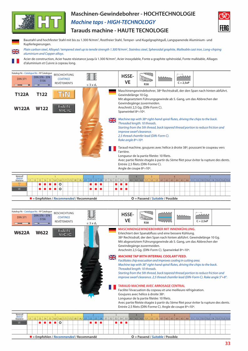
T124A T124Maschinengewindebohrer , geradegenut mit Schälanschnitt, der den Span nach vorne abführt. Anschnitt 4-5 Gg. (DIN-Form B). Spanwinkel 8º÷10º, gemessen im 3. Gang.
W124A W124
Machine tap, with spiral point, driving the chips ahead. 4-5 thread chamfer lead (DIN-Form B). Rake angle 8º÷10º measured in the 3rd thread.
Taraud machine, goujures droites et entrée à hélice (Gun), poussant le copeau vers l’avant. Entrée 4-5 filets (DIN-Form B). Angle de coupe 5º÷8º, mesuré sur le 3éme filet.
Baustahl und hochfester Stahl mit bis zu 1.300 N/mm2, Rostfreier Stahl, Temper- und Kugelgraphitguß, Langspanende Aluminium- und Kupferlegierungen.
Plain carbon steel, Alloyed / tempered steel up to tensile strength 1.300 N/mm2, Stainless steel, Spheroidal graphite, Malleable cast iron, Long-chiping aluminium and Copper alloys.
Acier de construction, Acier haute résistance jusqu’à 1.300 N/mm2, Acier inoxydable, Fonte a graphite sphéroidal, Fonte malléable, Alliages d’aluminium et Cuivre à copeau long.
Maschinen-Gewindebohrer - HOCHTECHNOLOGIEMachine taps - HIGH-TECHNOLOGYTarauds machine - HAUTE TECNOLOGIE
Katalog-Nr. - Catalogue N. - N0 CatalogueBESCHICHTUNG
COATINGSREVÊTEMENTS
HSSE-VE
DIN 371 DIN 376 - 374 - 5156
≤ 3 x d1
W624A W624MASCHINENGEWINDEBOHRER MIT INNENKÜHLUNG. Erleichtert den Spanabfluss und eine bessere Kühlung. Geradegenutet, mit Schälanschnitt, der den Span nach vorne abführt. Anschnitt 4-5 Gg. (DIN-Form B). Spanwinkel 8º÷10º, gemessen im 3. Gang.
MACHINE TAP, WITH INTERNAL COOLANT FEED. Facilitates chip evacuation and improves cooling in cutting area. With spiral point, driving the chips ahead. 4-5 thread chamfer lead (DIN-Form B). Rake angle 8º÷10ºmeasured in the 3rd thread.
TARAUD MACHINE, AVEC ARROSAGE CENTRAL Facilite l’évacuation du copeau et une meilleure réfrigération. Goujures droites et entrée à hélice (Gun), poussant le copeau vers l’avant. Entrée 4-5 filets (DIN-Forme B). Angle de coupe 8º÷10º, mesuré sur le 3ème filet.
WerkstoffMaterial
Matière
1 2 3 4 5 6 71.1 1.2 1.3 1.4 1.5 1.6.1 1.6.2 1.7.1 1.7.2 1.8.1 1.8.2 2.1 2.2 2.3 2.4 3.1 3.2 3.3 3.4 3.5 4.1 4.2 4.3 5.1 5.2 5.3 6.1 6.2 6.3 6.4 6.5 6.6 7.1 7.2 7.3.1 7.3.2 7.4 7.5.1 7.5.2 7.5.3
= Empfohlen / Recommended / Recommandé = Passend / Suitable / Possible
WerkstoffMaterial
Matière
1 2 3 4 5 6 71.1 1.2 1.3 1.4 1.5 1.6.1 1.6.2 1.7.1 1.7.2 1.8.1 1.8.2 2.1 2.2 2.3 2.4 3.1 3.2 3.3 3.4 3.5 4.1 4.2 4.3 5.1 5.2 5.3 6.1 6.2 6.3 6.4 6.5 6.6 7.1 7.2 7.3.1 7.3.2 7.4 7.5.1 7.5.2 7.5.3
= Empfohlen / Recommended / Recommandé = Passend / Suitable / Possible
33
Katalog-Nr. - Catalogue N. - N0 CatalogueBESCHICHTUNG
COATINGSREVÊTEMENTS
HSSE-VE
DIN 371 DIN 376 - 374 - 5156
≤ 3 x d1
T122A T122Maschinengewindebohrer, 38º Rechtsdrall, der den Span nach hinten abführt. Gewindelänge 10 Gg. Mit abgesetztem Führungsgewinde ab 5. Gang, um das Abbrechen der Gewindegänge zuvermeiden. Anschnitt 2,5 Gg. (DIN-Form C). Spanwinkel 8º÷10º.
W122A W122
Machine tap with 38º right-hand spiral flutes, driving the chips to the back.Threaded length: 10 threads. Starting from the 5th thread, back tapered thread portion to reduce friction and improve swarf clearance. 2,5 thread chamfer lead (DIN-Form C). Rake angle 8º÷10º.
Taraud machine, goujures avec hélice à droite 38º, poussant le coupeau vers l’arrière. Longueur de la partie filetée: 10 filets. Avec partie filetée étagée à partir du 5ème filet pour éviter la rupture des dents. Entrée 2,5 filets (DIN-Forme C). Angle de coupe 8º÷10º.
Katalog-Nr. - Catalogue N. - N0 CatalogueBESCHICHTUNG
COATINGSREVÊTEMENTS
HSSE-VE
DIN 371 DIN 376 - 374 - 5156
≤ 3 x d1
W622A W622MASCHINENGEWINDEBOHRER MIT INNENKÜHLUNG. Erleichtert den Spanabfluss und eine bessere Kühlung. 38º Rechtsdrall, der den Span nach hinten abführt. Gewindelänge 10 Gg. Mit abgesetztem Führungsgewinde ab 5. Gang, um das Abbrechen der Gewindegänge zuvermeiden. Anschnitt 2,5 Gg. (DIN-Form C). Spanwinkel 8º÷10º.
MACHINE TAP WITH INTERNAL COOLANT FEED. Facilitates chip evacuation and improves cooling in cutting area. Machine tap with 38° right-hand spiral flutes, driving the chips to the back. Threaded length: 10 threads. Starting from the 5th thread, back tapered thread portion to reduce friction and improve swarf clearance. 2,5 thread chamfer lead (DIN-Form C). Rake angle 5°÷8°.
TARAUD MACHINE AVEC ARROSAGE CENTRAL Facilite l’évacuation du copeau et une meilleure réfrigération. Goujures avec hélice à droite 38º. Longueur de la partie filetée: 10 filets. Avec partie filetée étagée à partir du 5ème filet pour éviter la rupture des dents. Entrée 2,5 filets (DIN-Forme C). Angle de coupe 8º÷10º.
Baustahl und hochfester Stahl mit bis zu 1.300 N/mm2, Rostfreier Stahl, Temper- und Kugelgraphitguß, Langspanende Aluminium- und Kupferlegierungen.
Plain carbon steel, Alloyed / tempered steel up to tensile strength 1.300 N/mm2, Stainless steel, Spheroidal graphite, Malleable cast iron, Long-chiping aluminium and Copper alloys.
Acier de construction, Acier haute résistance jusqu’à 1.300 N/mm2, Acier inoxydable, Fonte a graphite sphéroidal, Fonte malléable, Alliages d’aluminium et Cuivre à copeau long.
Maschinen-Gewindebohrer - HOCHTECHNOLOGIEMachine taps - HIGH-TECHNOLOGYTarauds machine - HAUTE TECNOLOGIE
WerkstoffMaterial
Matière
1 2 3 4 5 6 71.1 1.2 1.3 1.4 1.5 1.6.1 1.6.2 1.7.1 1.7.2 1.8.1 1.8.2 2.1 2.2 2.3 2.4 3.1 3.2 3.3 3.4 3.5 4.1 4.2 4.3 5.1 5.2 5.3 6.1 6.2 6.3 6.4 6.5 6.6 7.1 7.2 7.3.1 7.3.2 7.4 7.5.1 7.5.2 7.5.3
= Empfohlen / Recommended / Recommandé = Passend / Suitable / Possible
WerkstoffMaterial
Matière
1 2 3 4 5 6 71.1 1.2 1.3 1.4 1.5 1.6.1 1.6.2 1.7.1 1.7.2 1.8.1 1.8.2 2.1 2.2 2.3 2.4 3.1 3.2 3.3 3.4 3.5 4.1 4.2 4.3 5.1 5.2 5.3 6.1 6.2 6.3 6.4 6.5 6.6 7.1 7.2 7.3.1 7.3.2 7.4 7.5.1 7.5.2 7.5.3
= Empfohlen / Recommended / Recommandé = Passend / Suitable / Possible
34
Katalog-Nr. - Catalogue N. - N0 CatalogueBESCHICHTUNG
COATINGSREVÊTEMENTS
HSSE-PS
DIN 371 DIN 376 - 374 - 5156
≤ 2 x d1
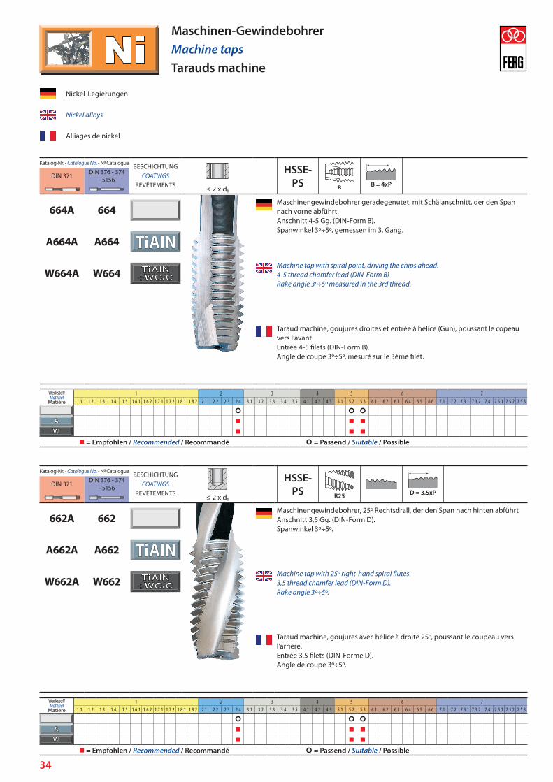
664A 664Maschinengewindebohrer geradegenutet, mit Schälanschnitt, der den Span nach vorne abführt. Anschnitt 4-5 Gg. (DIN-Form B). Spanwinkel 3º÷5º, gemessen im 3. Gang.
A664A A664
W664A W664Machine tap with spiral point, driving the chips ahead. 4-5 thread chamfer lead (DIN-Form B) Rake angle 3º÷5º measured in the 3rd thread.
Taraud machine, goujures droites et entrée à hélice (Gun), poussant le copeau vers l’avant. Entrée 4-5 filets (DIN-Form B). Angle de coupe 3º÷5º, mesuré sur le 3éme filet.
Nickel-Legierungen
Nickel alloys
Alliages de nickel
Katalog-Nr. - Catalogue N. - N0 CatalogueBESCHICHTUNG
COATINGSREVÊTEMENTS
HSSE-PS
DIN 371 DIN 376 - 374 - 5156
≤ 2 x d1
662A 662Maschinengewindebohrer, 25º Rechtsdrall, der den Span nach hinten abführt Anschnitt 3,5 Gg. (DIN-Form D). Spanwinkel 3º÷5º.
A662A A662
W662A W662Machine tap with 25º right-hand spiral flutes. 3,5 thread chamfer lead (DIN-Form D). Rake angle 3º÷5º.
Taraud machine, goujures avec hélice à droite 25º, poussant le coupeau vers l’arrière. Entrée 3,5 filets (DIN-Forme D). Angle de coupe 3º÷5º.
Maschinen-GewindebohrerMachine tapsTarauds machine
WerkstoffMaterial
Matière
1 2 3 4 5 6 71.1 1.2 1.3 1.4 1.5 1.6.1 1.6.2 1.7.1 1.7.2 1.8.1 1.8.2 2.1 2.2 2.3 2.4 3.1 3.2 3.3 3.4 3.5 4.1 4.2 4.3 5.1 5.2 5.3 6.1 6.2 6.3 6.4 6.5 6.6 7.1 7.2 7.3.1 7.3.2 7.4 7.5.1 7.5.2 7.5.3
= Empfohlen / Recommended / Recommandé = Passend / Suitable / Possible
WerkstoffMaterial
Matière
1 2 3 4 5 6 71.1 1.2 1.3 1.4 1.5 1.6.1 1.6.2 1.7.1 1.7.2 1.8.1 1.8.2 2.1 2.2 2.3 2.4 3.1 3.2 3.3 3.4 3.5 4.1 4.2 4.3 5.1 5.2 5.3 6.1 6.2 6.3 6.4 6.5 6.6 7.1 7.2 7.3.1 7.3.2 7.4 7.5.1 7.5.2 7.5.3
= Empfohlen / Recommended / Recommandé = Passend / Suitable / Possible
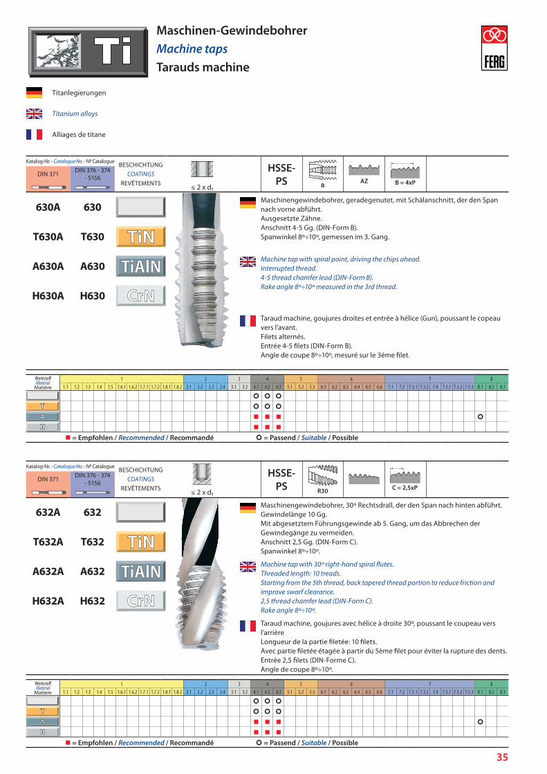
35
Katalog-Nr. - Catalogue N. - N0 CatalogueBESCHICHTUNG
COATINGSREVÊTEMENTS
HSSE-PS
DIN 371 DIN 376 - 374 - 5156
≤ 2 x d1
630A 630Maschinengewindebohrer, geradegenutet, mit Schälanschnitt, der den Span nach vorne abführt. Ausgesetzte Zähne. Anschnitt 4-5 Gg. (DIN-Form B). Spanwinkel 8º÷10º, gemessen im 3. Gang.T630A T630
A630A A630Machine tap with spiral point, driving the chips ahead. Interrupted thread. 4-5 thread chamfer lead (DIN-Form B). Rake angle 8º÷10º measured in the 3rd thread.
H630A H630
Taraud machine, goujures droites et entrée à hélice (Gun), poussant le copeau vers l’avant. Filets alternés. Entrée 4-5 filets (DIN-Form B). Angle de coupe 8º÷10º, mesuré sur le 3éme filet.
Maschinen-GewindebohrerMachine tapsTarauds machine
Katalog-Nr. - Catalogue N. - N0 CatalogueBESCHICHTUNG
COATINGSREVÊTEMENTS
HSSE-PS
DIN 371 DIN 376 - 374 - 5156
≤ 2 x d1
632A 632Maschinengewindebohrer, 30º Rechtsdrall, der den Span nach hinten abführt. Gewindelänge 10 Gg. Mit abgesetztem Führungsgewinde ab 5. Gang, um das Abbrechen der Gewindegänge zu vermeiden. Anschnitt 2,5 Gg. (DIN-Form C). Spanwinkel 8º÷10º.
T632A T632
A632A A632Machine tap with 30º right-hand spiral flutes. Threaded length: 10 treads. Starting from the 5th thread, back tapered thread portion to reduce friction and improve swarf clearance. 2,5 thread chamfer lead (DIN-Form C). Rake angle 8º÷10º.
H632A H632
Taraud machine, goujures avec hélice à droite 30º, poussant le coupeau vers l’arrière Longueur de la partie filetée: 10 filets. Avec partie filetée étagée à partir du 5ème filet pour éviter la rupture des dents. Entrée 2,5 filets (DIN-Forme C). Angle de coupe 8º÷10º.
Titanlegierungen
Titanium alloys
Alliages de titane
WerkstoffMaterial
Matière
1 2 3 4 5 6 7 81.1 1.2 1.3 1.4 1.5 1.6.1 1.6.2 1.7.1 1.7.2 1.8.1 1.8.2 2.1 2.2 2.3 2.4 3.1 3.2 4.1 4.2 4.3 5.1 5.2 5.3 6.1 6.2 6.3 6.4 6.5 6.6 7.1 7.2 7.3.1 7.3.2 7.4 7.5.1 7.5.2 7.5.3 8.1 8.2 8.3
= Empfohlen / Recommended / Recommandé = Passend / Suitable / Possible
WerkstoffMaterial
Matière
1 2 3 4 5 6 7 81.1 1.2 1.3 1.4 1.5 1.6.1 1.6.2 1.7.1 1.7.2 1.8.1 1.8.2 2.1 2.2 2.3 2.4 3.1 3.2 4.1 4.2 4.3 5.1 5.2 5.3 6.1 6.2 6.3 6.4 6.5 6.6 7.1 7.2 7.3.1 7.3.2 7.4 7.5.1 7.5.2 7.5.3 8.1 8.2 8.3
= Empfohlen / Recommended / Recommandé = Passend / Suitable / Possible
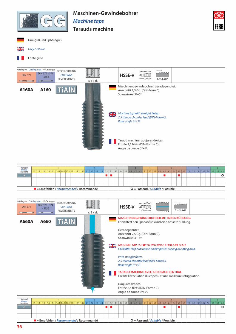
36
Katalog-Nr. - Catalogue N. - N0 CatalogueBESCHICHTUNG
COATINGSREVÊTEMENTS
HSSE-VDIN 371 DIN 376 - 374 - 5156
≤ 3 x d1
A160A A160Maschinengewindebohrer, geradegenutet. Anschnitt 2,5 Gg. (DIN-Form C). Spanwinkel 3º÷5º.
Machine tap with straight flutes. 2,5 thread chamfer lead (DIN-Form C). Rake angle 3º÷5º.
Taraud machine, goujures droites. Entrée 2,5 filets (DIN-Forme C). Angle de coupe 3º÷5º.
Grauguß und Sphäroguß
Grey cast iron
Fonte grise
Maschinen-GewindebohrerMachine tapsTarauds machine
Katalog-Nr. - Catalogue N. - N0 CatalogueBESCHICHTUNG
COATINGSREVÊTEMENTS
HSSE-VDIN 371 DIN 376 - 374 - 5156
≤ 3 x d1
A660A A660MASCHINENGEWINDEBOHRER MIT INNENKÜHLUNG Erleichtert den Spanabfluss und eine bessere Kühlung. Geradegenutet. Anschnitt 2,5 Gg. (DIN-Form C). Spanwinkel 3º÷5º.
MACHINE TAP TAP WITH INTERNAL COOLANT FEED Facilitates chip evacuation and improves cooling in cutting area. With straight flutes. 2,5 thread chamfer lead (DIN-Form C). Rake angle 3º÷5º.
TARAUD MACHINE AVEC ARROSAGE CENTRAL Facilite l’évacuation du copeau et une meilleure réfrigération. Goujures droites. Entrée 2,5 filets (DIN-Forme C). Angle de coupe 3º÷5º.
WerkstoffMaterial
Matière
1 2 3 4 5 6 7 81.1 1.2 1.3 1.4 1.5 1.6.1 1.6.2 1.7.1 1.7.2 1.8.1 1.8.2 2.1 2.2 2.3 2.4 3.1 3.2 3.3 3.4 3.5 4.1 4.2 4.3 5.1 5.2 5.3 6.1 6.2 6.3 6.4 6.5 6.6 7.1 7.2 7.3.1 7.3.2 7.4 8.1 8.2 8.3
= Empfohlen / Recommended / Recommandé = Passend / Suitable / Possible
WerkstoffMaterial
Matière
1 2 3 4 5 6 7 81.1 1.2 1.3 1.4 1.5 1.6.1 1.6.2 1.7.1 1.7.2 1.8.1 1.8.2 2.1 2.2 2.3 2.4 3.1 3.2 3.3 3.4 3.5 4.1 4.2 4.3 5.1 5.2 5.3 6.1 6.2 6.3 6.4 6.5 6.6 7.1 7.2 7.3.1 7.3.2 7.4 8.1 8.2 8.3
= Empfohlen / Recommended / Recommandé = Passend / Suitable / Possible
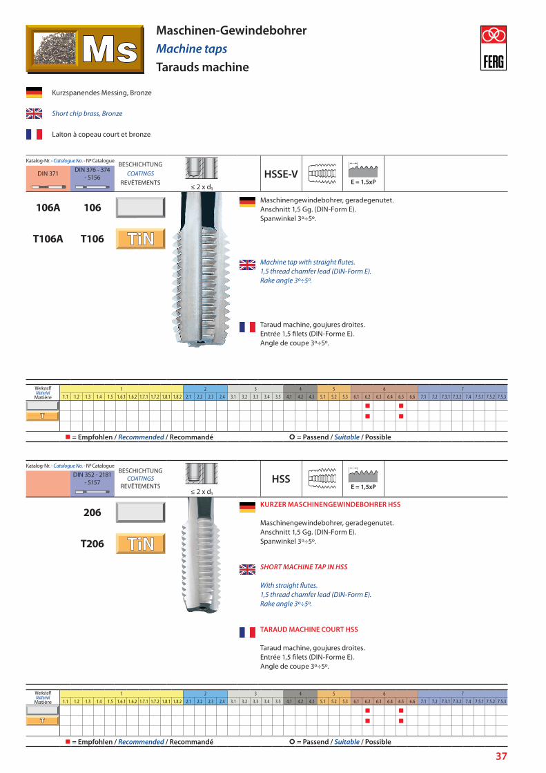
37
Katalog-Nr. - Catalogue N. - N0 CatalogueBESCHICHTUNG
COATINGSREVÊTEMENTS
HSSE-VDIN 371 DIN 376 - 374 - 5156
≤ 2 x d1
106A 106Maschinengewindebohrer, geradegenutet. Anschnitt 1,5 Gg. (DIN-Form E). Spanwinkel 3º÷5º.
T106A T106
Machine tap with straight flutes. 1,5 thread chamfer lead (DIN-Form E). Rake angle 3º÷5º.
Taraud machine, goujures droites. Entrée 1,5 filets (DIN-Forme E). Angle de coupe 3º÷5º.
Kurzspanendes Messing, Bronze
Short chip brass, Bronze
Laiton à copeau court et bronze
Maschinen-GewindebohrerMachine tapsTarauds machine
Katalog-Nr. - Catalogue N. - N0 CatalogueBESCHICHTUNG
COATINGSREVÊTEMENTS
HSSDIN 352 - 2181 - 5157
≤ 2 x d1
206KURZER MASCHINENGEWINDEBOHRER HSS Maschinengewindebohrer, geradegenutet. Anschnitt 1,5 Gg. (DIN-Form E). Spanwinkel 3º÷5º.T206
SHORT MACHINE TAP IN HSS With straight flutes. 1,5 thread chamfer lead (DIN-Form E). Rake angle 3º÷5º.
TARAUD MACHINE COURT HSS Taraud machine, goujures droites. Entrée 1,5 filets (DIN-Forme E). Angle de coupe 3º÷5º.
WerkstoffMaterial
Matière
1 2 3 4 5 6 71.1 1.2 1.3 1.4 1.5 1.6.1 1.6.2 1.7.1 1.7.2 1.8.1 1.8.2 2.1 2.2 2.3 2.4 3.1 3.2 3.3 3.4 3.5 4.1 4.2 4.3 5.1 5.2 5.3 6.1 6.2 6.3 6.4 6.5 6.6 7.1 7.2 7.3.1 7.3.2 7.4 7.5.1 7.5.2 7.5.3
= Empfohlen / Recommended / Recommandé = Passend / Suitable / Possible
WerkstoffMaterial
Matière
1 2 3 4 5 6 71.1 1.2 1.3 1.4 1.5 1.6.1 1.6.2 1.7.1 1.7.2 1.8.1 1.8.2 2.1 2.2 2.3 2.4 3.1 3.2 3.3 3.4 3.5 4.1 4.2 4.3 5.1 5.2 5.3 6.1 6.2 6.3 6.4 6.5 6.6 7.1 7.2 7.3.1 7.3.2 7.4 7.5.1 7.5.2 7.5.3
= Empfohlen / Recommended / Recommandé = Passend / Suitable / Possible
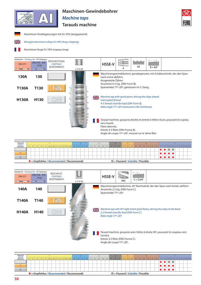
38
Katalog-Nr. - Catalogue N. - N0 CatalogueBESCHICHTUNG
COATINGSREVÊTEMENTS
HSSE-VDIN 371 DIN 376 - 374 - 5156
≤ 2 x d1
130A 130Maschinengewindebohrer, geradegenutet, mit Schälanschnitt, der den Span nach vorne abführt. Ausgesetzte Zähne. Anschnitt 4-5 Gg. (DIN-Form B). Spanwinkel 17º÷20º, gemessen im 3. Gang.T130A T130
H130A H130Machine tap with spiral point, driving the chips ahead. Interrupted thread. 4-5 thread chamfer lead (DIN-Form B). Rake angle 17º÷20º measured in the 3rd thread.
Taraud machine, goujures droites et entrée à hélice (Gun), poussant le copeau vers l’avant. Filets alternés. Entrée 4-5 filets (DIN-Forme B). Angle de coupe 17º÷20º, mesuré sur le 3ème filet.
Katalog-Nr. - Catalogue N. - N0 CatalogueBESCHICHT.
COATINGSREVÊTEMENTS
HSSE-VDIN 371 DIN 376 - 374 - 5156
≤ 2 x d1
140A 140Maschinengewindebohrer, 45º Rechtsdrall, der den Span nach hinten abführt. Anschnitt 2,5 Gg. (DIN-Form C). Spanwinkel 17º÷20º.
T140A T140
H140A H140Machine tap with 45º right-hand spiral flutes, driving the chips to the back. 2,5 thread chamfer lead (DIN-Form C). Rake angle 17º÷20º.
Taraud machine, goujures avec hélice à droite 45º, poussant le coupeau vers l’arrière Entrée 2,5 filets (DIN-Forme C). Angle de coupe 17º÷20º.
Maschinen-GewindebohrerMachine tapsTarauds machine
Aluminium-Knetlegierungen mit Si<10% (langspanend)
Wrought aluminium alloys Si<10% (long-chipping)
Aluminium forgé Si<10% (copeau long)
WerkstoffMaterial
Matière
1 2 3 4 5 6 71.1 1.2 1.3 1.4 1.5 1.6.1 1.6.2 1.7.1 1.7.2 1.8.1 1.8.2 2.1 2.2 2.3 2.4 3.1 3.2 3.3 3.4 3.5 4.1 4.2 4.3 5.1 5.2 5.3 6.1 6.2 6.3 6.4 6.5 6.6 7.1 7.2 7.3.1 7.3.2 7.4 7.5.1 7.5.2 7.5.3
= Empfohlen / Recommended / Recommandé = Passend / Suitable / Possible
WerkstoffMaterial
Matière
1 2 3 4 5 6 71.1 1.2 1.3 1.4 1.5 1.6.1 1.6.2 1.7.1 1.7.2 1.8.1 1.8.2 2.1 2.2 2.3 2.4 3.1 3.2 3.3 3.4 3.5 4.1 4.2 4.3 5.1 5.2 5.3 6.1 6.2 6.3 6.4 6.5 6.6 7.1 7.2 7.3.1 7.3.2 7.4 7.5.1 7.5.2 7.5.3
= Empfohlen / Recommended / Recommandé = Passend / Suitable / Possible
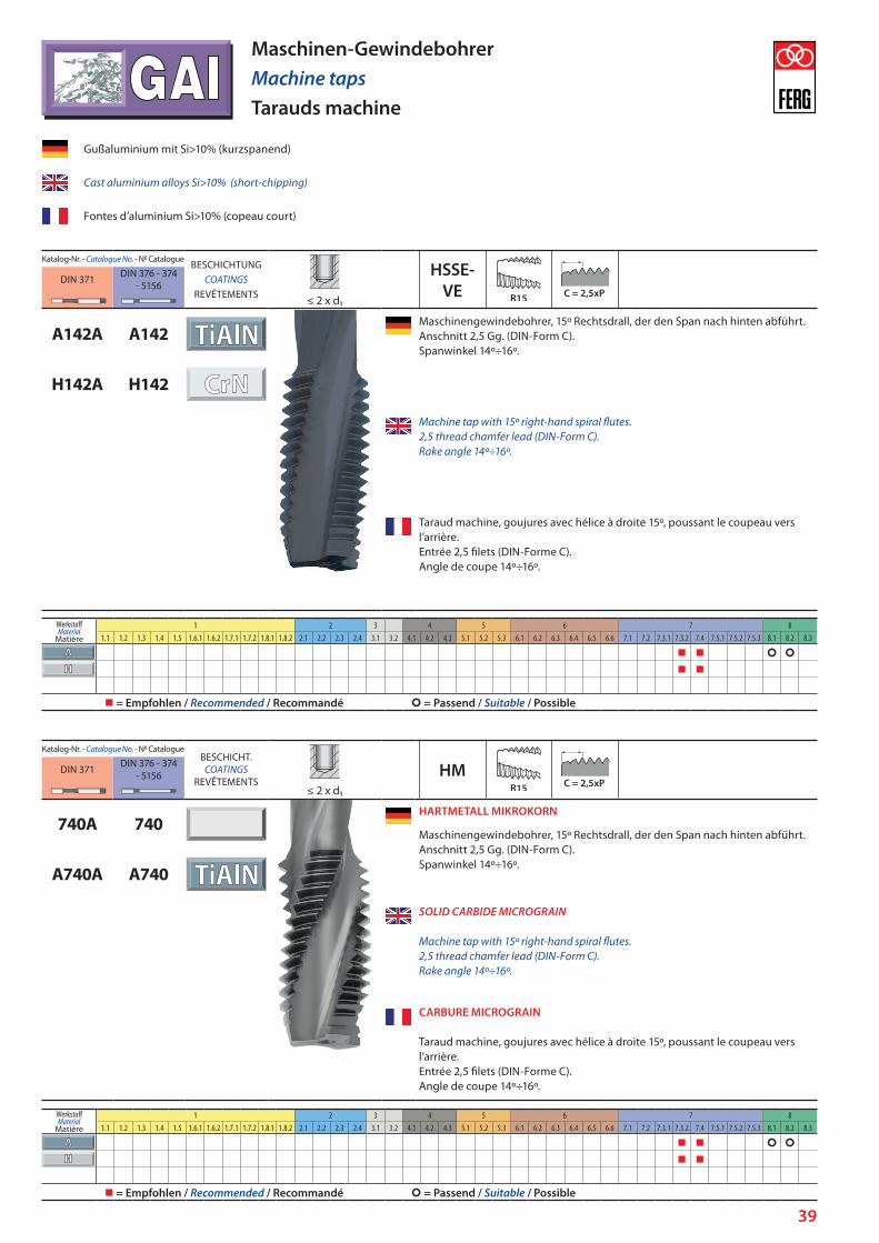
39
Katalog-Nr. - Catalogue N. - N0 CatalogueBESCHICHTUNG
COATINGSREVÊTEMENTS
HSSE-VE
DIN 371 DIN 376 - 374 - 5156
≤ 2 x d1
A142A A142Maschinengewindebohrer, 15º Rechtsdrall, der den Span nach hinten abführt. Anschnitt 2,5 Gg. (DIN-Form C). Spanwinkel 14º÷16º.
H142A H142
Machine tap with 15º right-hand spiral flutes. 2,5 thread chamfer lead (DIN-Form C). Rake angle 14º÷16º.
Taraud machine, goujures avec hélice à droite 15º, poussant le coupeau vers l’arrière. Entrée 2,5 filets (DIN-Forme C). Angle de coupe 14º÷16º.
Katalog-Nr. - Catalogue N. - N0 CatalogueBESCHICHT.
COATINGSREVÊTEMENTS
HMDIN 371 DIN 376 - 374 - 5156
≤ 2 x d1
740A 740HARTMETALL MIKROKORN
Maschinengewindebohrer, 15º Rechtsdrall, der den Span nach hinten abführt. Anschnitt 2,5 Gg. (DIN-Form C). Spanwinkel 14º÷16º.
A740A A740
SOLID CARBIDE MICROGRAIN Machine tap with 15º right-hand spiral flutes. 2,5 thread chamfer lead (DIN-Form C). Rake angle 14º÷16º.
CARBURE MICROGRAIN Taraud machine, goujures avec hélice à droite 15º, poussant le coupeau vers l’arrière. Entrée 2,5 filets (DIN-Forme C). Angle de coupe 14º÷16º.
Maschinen-GewindebohrerMachine tapsTarauds machine
Gußaluminium mit Si>10% (kurzspanend)
Cast aluminium alloys Si>10% (short-chipping)
Fontes d’aluminium Si>10% (copeau court)
WerkstoffMaterial
Matière
1 2 3 4 5 6 7 81.1 1.2 1.3 1.4 1.5 1.6.1 1.6.2 1.7.1 1.7.2 1.8.1 1.8.2 2.1 2.2 2.3 2.4 3.1 3.2 4.1 4.2 4.3 5.1 5.2 5.3 6.1 6.2 6.3 6.4 6.5 6.6 7.1 7.2 7.3.1 7.3.2 7.4 7.5.1 7.5.2 7.5.3 8.1 8.2 8.3
= Empfohlen / Recommended / Recommandé = Passend / Suitable / Possible
WerkstoffMaterial
Matière
1 2 3 4 5 6 7 81.1 1.2 1.3 1.4 1.5 1.6.1 1.6.2 1.7.1 1.7.2 1.8.1 1.8.2 2.1 2.2 2.3 2.4 3.1 3.2 4.1 4.2 4.3 5.1 5.2 5.3 6.1 6.2 6.3 6.4 6.5 6.6 7.1 7.2 7.3.1 7.3.2 7.4 7.5.1 7.5.2 7.5.3 8.1 8.2 8.3
= Empfohlen / Recommended / Recommandé = Passend / Suitable / Possible
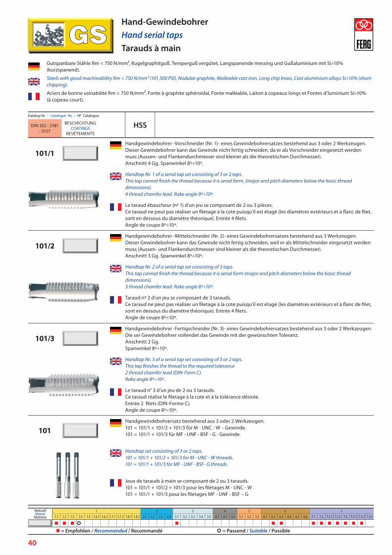
40
Katalog-Nr. - Catalogue N. - N0 Catalogue
HSSDIN 352 - 2181 - 5157
BESCHICHTUNGCOATINGS
REVÊTEMENTS
101/1Handgewindebohrer -Vorschneider (Nr. 1)- eines Gewindebohrersatzes bestehend aus 3 oder 2 Werkzeugen. Dieser Gewindebohrer kann das Gewinde nicht fertig schneiden, da er als Vorschneider eingesetzt werden muss (Aussen- und Flankendurchmesser sind kleiner als die theoretischen Durchmesser). Anschnitt 4 Gg. Spanwinkel 8º÷10º.
Handtap Nr. 1 of a serial tap set consisting of 3 or 2 taps. This tap cannot finish the thread because it is serial form, (major and pitch diameters below the basic thread dimensions). 4 thread chamfer lead. Rake angle 8º÷10º.
Le taraud ébaucheur (nº 1) d’un jeu se composant de 2 ou 3 pièces. Ce taraud ne peut pas réaliser un filetage à la cote puisqu’il est étagé (les diamètres extérieurs et à flanc de filet, sont en dessous du diamètre théorique). Entrée 4 filets. Angle de coupe 8º÷10º.
101/2Handgewindebohrer -Mittelschneider (Nr. 2)- eines Gewindebohrersatzes bestehend aus 3 Werkzeugen. Dieser Gewindebohrer kann das Gewinde nicht fertig schneiden, weil er als Mittelschneider eingesetzt werden muss (Aussen- und Flankendurchmesser sind kleiner als die theoretischen Durchmesser). Anschnitt 3 Gg. Spanwinkel 8º÷10º.
Handtap Nr. 2 of a serial tap set consisting of 3 taps. This tap cannot finish the thread because it is serial form (major and pitch diameters below the basic thread dimensions). 3 thread chamfer lead. Rake angle 8º÷10º.
Taraud nº 2 d’un jeu se composant de 3 tarauds. Ce taraud ne peut pas réaliser un filetage à la cote puisqu’il est étagé (les diamètres extérieurs et à flanc de filet, sont en dessous du diamètre théorique). Entrée 4 filets. Angle de coupe 8º÷10º.
101/3Handgewindebohrer -Fertigschneider (Nr. 3)- eines Gewindebohrersatzes bestehend aus 3 oder 2 Werkzeugen. Die ser Gewindebohrer vollendet das Gewinde mit der gewünschten Toleranz. Anschnitt 2 Gg. Spanwinkel 8º÷10º.
Handtap Nr. 3 of a serial tap set consisting of 3 or 2 taps. This tap finishes the thread to the required tolerance 2 thread chamfer lead (DIN-Form C). Rake angle 8º÷10º.
Le taraud n° 3 d’un jeu de 2 ou 3 tarauds. Ce taraud réalise le filetage à la cote et à la tolérance désirée. Entrée 2 filets (DIN-Forme C). Angle de coupe 8º÷10º.
101Handgewindebohrersatz bestehend aus 3 oder 2 Werkzeugen. 101 = 101/1 + 101/2 + 101/3 für M - UNC - W – Gewinde. 101 = 101/1 + 101/3 für MF - UNF - BSF - G - Gewinde.
Handtap set consisting of 3 or 2 taps. 101 = 101/1 + 101/2 + 101/3 for M - UNC - W threads. 101 = 101/1 + 101/3 for MF - UNF - BSF- G threads.
Jeux de tarauds à main se composant de 2 ou 3 tarauds.101 = 101/1 + 101/2 + 101/3 pour les filetages M - UNC - W101 = 101/1 + 101/3 pour les filetages MF - UNF - BSF – G
Hand-GewindebohrerHand serial tapsTarauds à main
Gutspanbare Stähle Rm < 750 N/mm², Kugelgraphitguß, Temperguß vergütet, Langspanende messing und Gußaluminium mit Si>10% (kurzspanend).
Steels with good machinability Rm < 750 N/mm² (101,500 PSI), Nodular graphite, Malleable cast iron, Long chip brass, Cast aluminium alloys Si>10% (short-chipping).
Aciers de bonne usinabilité Rm < 750 N/mm², Fonte à graphite sphéroïdal, Fonte malléable, Laiton à copeaux longs et Fontes d’luminium Si>10% (à copeau court).
WerkstoffMaterial
Matière
1 2 3 4 5 6 71.1 1.2 1.3 1.4 1.5 1.6.1 1.6.2 1.7.1 1.7.2 1.8.1 1.8.2 2.1 2.2 2.3 2.4 3.1 3.2 3.3 3.4 3.5 4.1 4.2 4.3 5.1 5.2 5.3 6.1 6.2 6.3 6.4 6.5 6.6 7.1 7.2 7.3.1 7.3.2 7.4 7.5.1 7.5.2 7.5.3
= Empfohlen / Recommended / Recommandé = Passend / Suitable / Possible

41
Katalog-Nr. - Catalogue N. - N0 Catalogue
HSSE-VDIN 352 - 2181 - 5157
BESCHICHTUNGCOATINGS
REVÊTEMENTS
108/1Der Gewindebohrer Nr. 1 hat eine zylindrische Führung, die eine perfekte Ausrichtung des Gewindes beim manuellen Gewinde-schneiden ermöglicht. Das Anschneiden von nur 3-4 Gängen ist ausreichend. Anschnitt 3 Gg. Spanwinkel 6º÷8º.
Handtap Nr. 1 with pilot guide, to assure the concentric start at manual threading. Tapping only 3-4 threads is enough. 3 thread chamfer lead. Rake angle 6º÷8º.
Le taraud n° 1 dispose d’un guide cylindrique qui permet un alignement parfait du filet pendant le filetage manuel. Il est suffisant de tarauder seulement 3-4 filets. Entrée 3 filets. Angle de coupe 6º÷8º.
108/2Gewindebohrer Nr. 2 hat die gleichen Dimensionen wie der 108/1. Anschnitt 3 Gg. Spanwinkel 6º÷8º.
Handtap Nr. 2 with the same thread sizes as 108/1. 3 thread chamfer lead. Rake angle 6°÷8°.
Taraud n° 2 avec les mêmes dimensions que le 108/1. Entrée 3 filets. Angle de coupe 6º÷8º.
108/3Der Gewindebohrer Nr. 3 vollendet das Gewinde mit der gewünschten Toleranz. Nicht als Einzelschneider einsetzen. Anschnitt 3 Gg. Spanwinkel 6º÷8º.
Handtap Nr. 3 that finishes the thread to the required tolerance. Not suitable to use as single pass tap. 3 thread chamfer lead. Rake angle 6º÷8º.
Le taraud n° 3 réalise le filetage avec la tolérance voulue. Ne pas utiliser ce taraud seul. Entrée 3 filets. Angle de coupe 6º÷8º.
108Der Satz besteht aus 3 Gewindebohrern: 108 = 108/1 + 108/2 + 108/3. Es wird empfohlen, ohne Unterbrechung zu schneiden und ohne zurückzudrehen, um den Span zu entfernen.
Handtap set consisting of 3 taps: 108 = 108/1 + 108/2 + 108/3. You must tap continuously, it means without stop and reversing the tap to break the chip.
Le jeu se compose de 3 tarauds : 108 = 108/1 + 108/2 + 108/3.
On recommande de tarauder de façon continue, c’est-à-dire, sans arrêter ni reculer le taraud pour casser le copeau.
Hand-GewindebohrerHand serial tapsTarauds à main
Vergütete und hitzebeständige Stähle Rm < 1.000 N/mm2 (<30 HRC)
Heat treated and heat-resistant steels Rm < 1.000 N/mm2
(<30 HRC / <290 HB / <145,000 PSI)
Aciers traités et aciers réfractaires Rm < 1.000 N/mm² (<30 HRC)
WerkstoffMaterial
Matière
1 2 3 4 5 6 71.1 1.2 1.3 1.4 1.5 1.6.1 1.6.2 1.7.1 1.7.2 1.8.1 1.8.2 2.1 2.2 2.3 2.4 3.1 3.2 3.3 3.4 3.5 4.1 4.2 4.3 5.1 5.2 5.3 6.1 6.2 6.3 6.4 6.5 6.6 7.1 7.2 7.3.1 7.3.2 7.4 7.5.1 7.5.2 7.5.3
= Empfohlen / Recommended / Recommandé = Passend / Suitable / Possible

42
Katalog-Nr. - Catalogue N. - N0 Catalogue
HSSE-VDIN 352 - 2181 - 5157
BESCHICHTUNGCOATINGS
REVÊTEMENTS
V108/1Der Gewindebohrer Nr. 1 hat eine zylindrische Führung, die eine perfekte Ausrichtung des Gewindes beim manuellen Gewindeschneiden ermöglicht. Das Anschneiden von nur 3-4 Gängen ist ausreichend. Anschnitt 3 Gg. Spanwinkel 6°÷8°.
Handtap Nr. 1 with pilot guide, to assure the concentric start at manual threading. Tapping only 3-4 threads is enough. 3 thread chamfer lead. Rake angle 6º÷8º.
Le taraud n° 1 dispose d’un guide cylindrique qui permet un alignement parfait du filet pendant le filetage manuel. Il est suffisant de tarauder seulement 3-4 filets. Entrée 3 filets. Angle de coupe 6º÷8º.
V108/2Gewindebohrer Nr. 2 hat die gleichen Dimensionen wie der V108/1. Anschnitt 3 Gg. Spanwinkel 6°÷8°.
Handtap Nr. 2 with the same thread sizes as V108/1. 3 thread chamfer lead. Rake angle 6º÷8º.
Taraud n° 2 avec les mêmes dimensions que le 108/1. Entrée 3 filets. Angle de coupe 6º÷8º.
V108/3Der Gewindebohrer Nr. 3 vollendet das Gewinde mit der gewünschten Toleranz. Nicht als Einzelschneider einsetzen. Anschnitt 3 Gg. Spanwinkel 6°-8°.
Handtap Nr. 3 that finishes the thread to the required tolerance. Not suitable to use as single pass tap. 3 thread chamfer lead. Rake angle 6º÷8º.
Le taraud n° 3 réalise le filetage avec la tolérance voulue. Ne pas utiliser ce taraud seul. Entrée 3 filets. Angle de coupe 6º÷8º.
V108Der Satz besteht aus 3 Gewindebohrern: V108 = V108/1 + V108/2 + V108/3. Es wird empfohlen, ohne Unterbrechung zu schneiden und ohne zurückzudrehen, um den Span zu entfernen.
Handtap set consisting of 3 taps: V108 = V108/1 + V108/2 + V108/3. You must tap continuously, it means without stop and reversing the tap to break the chip.
Le jeu se compose de 3 tarauds : V108 = V108/1 + V108/2 + V108/3.
On recommande de tarauder de façon continue, c’est-à-dire, sans arrêter ni reculer le taraud pour casser le copeau.
Hand-GewindebohrerHand serial tapsTarauds à main
Rostfreie Stähle und Baustähle Rm < 1.000 N/mm2
Stainless steels and structural steels Rm < 1.000 N/mm2
(<30 HRC / <290 HB / <145,000 PSI)
Aciers inoxydable, aciers au carbone et peu allies Rm < 1.000 N/mm²
WerkstoffMaterial
Matière
1 2 3 4 5 6 71.1 1.2 1.3 1.4 1.5 1.6.1 1.6.2 1.7.1 1.7.2 1.8.1 1.8.2 2.1 2.2 2.3 2.4 3.1 3.2 3.3 3.4 3.5 4.1 4.2 4.3 5.1 5.2 5.3 6.1 6.2 6.3 6.4 6.5 6.6 7.1 7.2 7.3.1 7.3.2 7.4 7.5.1 7.5.2 7.5.3
= Empfohlen / Recommended / Recommandé = Passend / Suitable / Possible

43
Katalog-Nr. - Catalogue N. - N0 Catalogue
HSSE-VDIN 352 - 2181 - 5157
BESCHICHTUNGCOATINGS
REVÊTEMENTS
A648/1Der Gewindebohrer Nr. 1 hat eine zylindrische Führung, die eine perfekte Ausrichtung des Gewindes beim manuellen Gewindeschneiden ermöglicht. Das Anschneiden von nur 3-4 Gängen ist ausreichend. Anschnitt 3 Gg. Spanwinkel 1º÷3º.
Handtap Nr. 1 with pilot guide, to assure the concentric start at manual threading. Tapping only 3-4 threads is enough. 3 thread chamfer lead. Rake angle 1º÷3º.
Le taraud n° 1 dispose d’un guide cylindrique qui permet un alignement parfait du filet pendant le filetage manuel. Il est suffisant de tarauder seulement 3-4 filets. Entrée 3 filets. Angle de coupe 1º÷3º.
A648/2Gewindebohrer Nr. 2 hat die gleichen Dimensionen wie der A648/1. Anschnitt 3 Gg. Spanwinkel 1º÷3º.
Handtap Nr. 2 with the same thread sizes as A648/1. 3 thread chamfer lead. Rake angle 1º÷3º.
Taraud n° 2 avec les mêmes dimensions que le 648/1. Entrée 3 filets. Angle de coupe 1º÷3º.
A648/3Der Gewindebohrer Nr. 3 vollendet das Gewinde mit der gewünschten Toleranz. Nicht als Einzelschneider einsetzen. Anschnitt 3 Gg. Spanwinkel 1º÷3º.
Handtap Nr. 3 that finishes the thread to the required tolerance. Not suitable to use as single pass tap. 3 thread chamfer lead. Rake angle 1º÷3º.
Le taraud n° 3 réalise le filetage avec la tolérance voulue. Ne pas utiliser ce taraud seul. Entrée 3 filets. Angle de coupe 1º÷3º.
A648Der Satz besteht aus 3 Gewindebohrern: A108 = A108/1 + A108/2 + A108/3. Es wird empfohlen, ohne Unterbrechung zu schneiden und ohne zurück zudrehen, um den Span zu entfernen.
Handtap set consisting of 3 taps: A648 = A648/1 + A648/2 + A648/3. You must tap continuously, it means without stop and reversing the tap to break the chip.
Le jeu se compose de 3 tarauds : A648 = A648/1 + A648/2 + A648/3.
On recommande de tarauder de façon continue, c'est-à-dire, sans arrêter ni reculer le taraud pour casser le copeau.
Hand-GewindebohrerHand serial tapsTarauds à main
Werkzeugstähle, hochfeste Stähle Rm = = 1.000 ÷ 1.300 N/mm2 (30÷40 HRC)
High alloyed steels Rm = 1.000 ÷ 1.300 N/mm2 (30÷40 HRC / 300 ÷ 385 HB / 135,000 ÷ 185,000 PSI)
Aciers à tres haute resistance Rm = 1.000 ÷ 1.300 N/mm2(30÷40 HRC)
WerkstoffMaterial
Matière
1 2 3 4 5 6 71.1 1.2 1.3 1.4 1.5 1.6.1 1.6.2 1.7.1 1.7.2 1.8.1 1.8.2 2.1 2.2 2.3 2.4 3.1 3.2 3.3 3.4 3.5 4.1 4.2 4.3 5.1 5.2 5.3 6.1 6.2 6.3 6.4 6.5 6.6 7.1 7.2 7.3.1 7.3.2 7.4 7.5.1 7.5.2 7.5.3
= Empfohlen / Recommended / Recommandé = Passend / Suitable / Possible
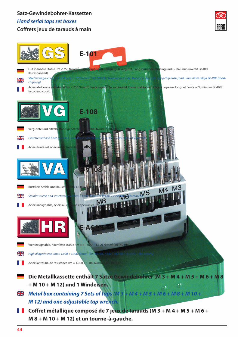
44
Die Metallkassette enthält 7 Sätze Gewindebohrer (M 3 + M 4 + M 5 + M 6 + M 8 + M 10 + M 12) und 1 Windeisen.
Metal box containing 7 Sets of taps (M 3 + M 4 + M 5 + M 6 + M 8 + M 10 + M 12) and one adjustable tap wrench.
Coffret métallique composé de 7 jeux de tarauds (M 3 + M 4 + M 5 + M 6 + M 8 + M 10 + M 12) et un tourne-à-gauche.
Satz-Gewindebohrer-KassettenHand serial taps set boxesCoffrets jeux de tarauds à main
Gutspanbare Stähle Rm < 750 N/mm², Kugelgraphitguß, Temperguß vergütet, Langspanende messing und Gußaluminium mit Si>10% (kurzspanend).
Steels with good machinability Rm < 750 N/mm² (101,500 PSI), Nodular graphite, Malleable cast iron, Long chip brass, Cast aluminium alloys Si>10% (short-chipping).
Aciers de bonne usinabilité Rm < 750 N/mm², Fonte à graphite sphéroïdal, Fonte malléable, Laiton à copeaux longs et Fontes d’luminium Si>10% (à copeau court).
Vergütete und hitzebeständige Stähle Rm < 1.000 N/mm2 (<30 HRC)
Heat treated and heat-resistant steels Rm < 1.000 N/mm2
(<30 HRC / <290 HB / <145,000 PSI)
Aciers traités et aciers réfractaires Rm < 1.000 N/mm² (<30 HRC)
Rostfreie Stähle und Baustähle Rm < 1.000 N/mm2 (<30 HRC)
Stainless steels and structural steels Rm < 1.000 N/mm2
(<30 HRC / <290 HB / <145,000 PSI)
Aciers inoxydable, aciers au carbone et peu allies Rm < 1.000 N/mm² (<30 HRC)
Werkzeugstähle, hochfeste Stähle Rm = = 1.000 ÷ 1.300 N/mm2 (30÷40 HRC)
High alloyed steels Rm = 1.000 ÷ 1.300 N/mm2 (30÷40 HRC / 300 ÷ 385 HB / 135,000 ÷ 185,000 PSI)
Aciers à tres haute resistance Rm = 1.000 ÷ 1.300 N/mm2 (30÷40 HRC)
E-101
E-108
E-V108
E-A648
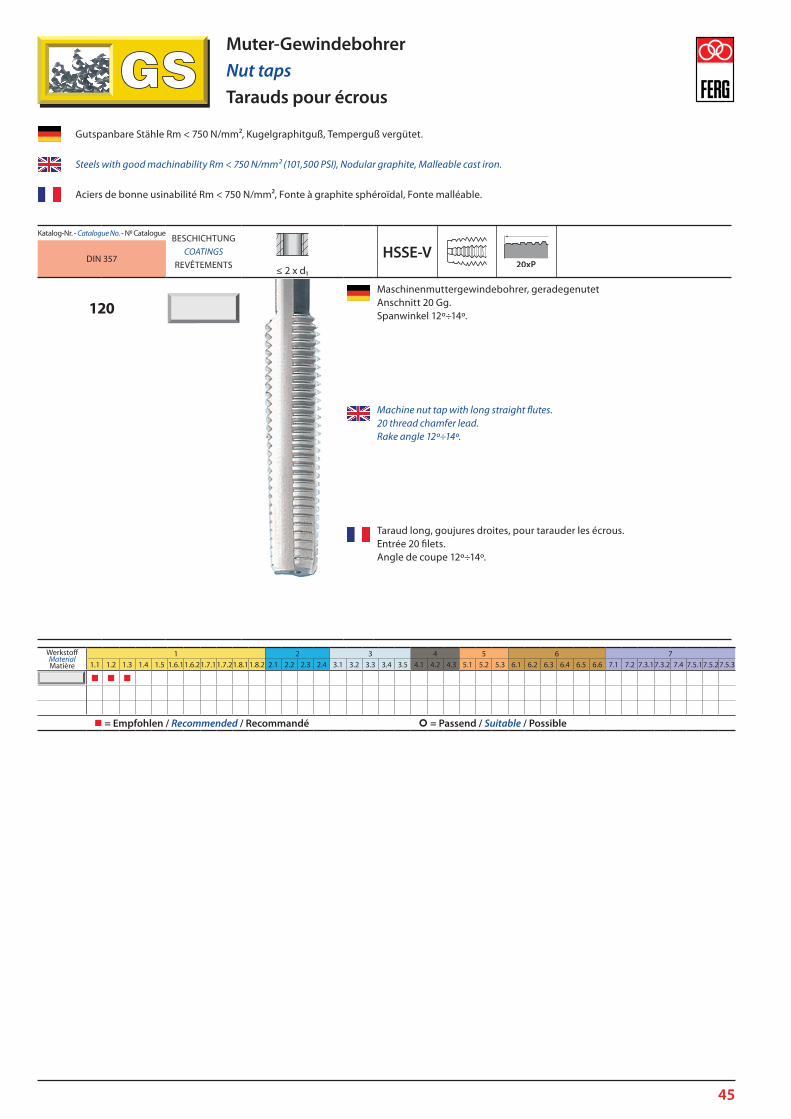
45
Katalog-Nr. - Catalogue N. - N0 CatalogueBESCHICHTUNG
COATINGSREVÊTEMENTS
HSSE-VDIN 357≤ 2 x d1
120Maschinenmuttergewindebohrer, geradegenutet Anschnitt 20 Gg. Spanwinkel 12º÷14º.
Machine nut tap with long straight flutes. 20 thread chamfer lead. Rake angle 12º÷14º.
Taraud long, goujures droites, pour tarauder les écrous. Entrée 20 filets. Angle de coupe 12º÷14º.
Muter-GewindebohrerNut tapsTarauds pour écrous
WerkstoffMaterialMatière
1 2 3 4 5 6 71.1 1.2 1.3 1.4 1.5 1.6.11.6.21.7.11.7.21.8.11.8.2 2.1 2.2 2.3 2.4 3.1 3.2 3.3 3.4 3.5 4.1 4.2 4.3 5.1 5.2 5.3 6.1 6.2 6.3 6.4 6.5 6.6 7.1 7.2 7.3.17.3.2 7.4 7.5.17.5.27.5.3
= Empfohlen / Recommended / Recommandé = Passend / Suitable / Possible
Gutspanbare Stähle Rm < 750 N/mm², Kugelgraphitguß, Temperguß vergütet.
Steels with good machinability Rm < 750 N/mm² (101,500 PSI), Nodular graphite, Malleable cast iron.
Aciers de bonne usinabilité Rm < 750 N/mm², Fonte à graphite sphéroïdal, Fonte malléable.

46
BohrgewindefräserThread drill millsFraises à percer-fileter
Katalog-Nr. - Catalogue No. - Nº CatalogueBESCHICHTUNG
COATINGSREVÊTEMENTS
HM DIN 6535-HA DIN 6535-HB DIN 6535-HEFERG STANDARD
BGF1BGF2BGF3
Bohrgewindefräser mit 45º-Fase, 27º Rechtsdrall, mit/ohne Kühlmittelzuführung, zum Kernlochbohren, Anfasen und Gewindefräsen in einem Werkzeug.
BGF1-ABGF2-ABGF3-A
Thread drill mill with phase 45º, 27º right-hand spiral flutes, with / without coolant supply, to the core hole drilling, chamfering and thread milling in a single tool.
Fraise à percer fileter, avec chamfreineur à 45º, des rainures hélicoïdales 27º à droite, avec ou sans arrosage central, pour percer le avant trou, chamfreineur et fraiser le filet avec une seule outil.
Einsatzgebiete in kurzspanenden Materialien: Grauguss, legierter Grauguss, Messing und kurzspanende Bronze, Aluminium, Aluminium Legierungen.
The application range is in short chipping materials: Grey cast iron, Alloyed grey cast iron, Brass and short chipping Bronze, Aluminium, Aluminium alloys.
Application à retenir dans les matières à copeaux courts : fonte grise, alliages de fonte grise, laiton et bronze à copeaux courts, aluminium et alliages d’aluminium, magnésium.
GewindefräserThread milling cuttersFraises à fileter
Katalog-Nr. - Catalogue No. - Nº CatalogueBESCHICHTUNG
COATINGSREVÊTEMENTS
HM DIN 6535-HA DIN 6535-HB DIN 6535-HEFERG STANDARD
GSF
Gewindefräser, 15º Rechtsdrall, mit Kühlmittelzuführung.
GSF-A
Thread milling cutter, 15º right-hand spiral flutes, with coolant supply.
Fraise à fileter, des rainures hélicoïdales 15º à droite, avec arrosage central.
Einsetzbar in den meisten Materialien: Grauguss, legierter Grauguss, Messing und kurzspanende Bronze, Aluminium und Aluminiumlegierungen, niedrig legierte Stähle, legierte Stähle bis 1.400 N/mm2, rostfreier Stähle, Titanlegierungen.
Usable in the majority of materials: Grey cast iron, Alloyed grey cast iron, Brass and short chipping Bronze, Aluminium and Aluminium alloys, Low alloyed steels, Alloyed steels up to 1.400 N/mm², Stainless steels, Titanium alloys.
Utilisable dans la majorité des matériaux: fonte grise, fonte grise alliée, laiton et bronze à copeaux courts, aluminium et alliages, aciers faiblement alliés jusqu’à 1.400 N/mm2.

47
Gewindefräser mit SenkfaseThread milling cutters with countersinkFraises à fileter avec chamfrein
Katalog-Nr. - Catalogue No. - Nº CatalogueBESCHICHTUNG
COATINGSREVÊTEMENTS
HM DIN 6535-HA DIN 6535-HB DIN 6535-HEFERG STANDARD
GSFM1GSFM2GSFM3
Gewindefräser mit 45º-Fase, 27º Rechtsdrall, mit Kühlmittelzuführung.
GSFM1-AGSFM2-AGSFM3-A
Thread milling cutter with 45º countersink, 27º right-hand spiral flutes, with coolant supply.
Fraise à fileter, avec chamfreineur à 45º, des rainures hélicoïdales 27º à droite, avec arrosage central.
Einsetzbar in den meisten Materialien: Grauguss, legierter Grauguss, Messing und kurzspanende Bronze, Aluminium und Aluminiumlegierungen, niedrig legierte Stähle, legierte Stähle bis 1.400 N/mm2, rostfreier Stähle, Titanlegierungen.
Usable in the majority of materials: Grey cast iron, Alloyed grey cast iron, Brass and short chipping Bronze, Aluminium and Aluminium alloys, Low alloyed steels, Alloyed steels up to 1.400 N/mm², Stainless steels, Titanium alloys.
Utilisable dans la majorité des matériaux: fonte grise, fonte grise alliée, laiton et bronze à copeaux courts, aluminium et alliages, aciers faiblement alliés jusqu’à 1.400 N/mm2.
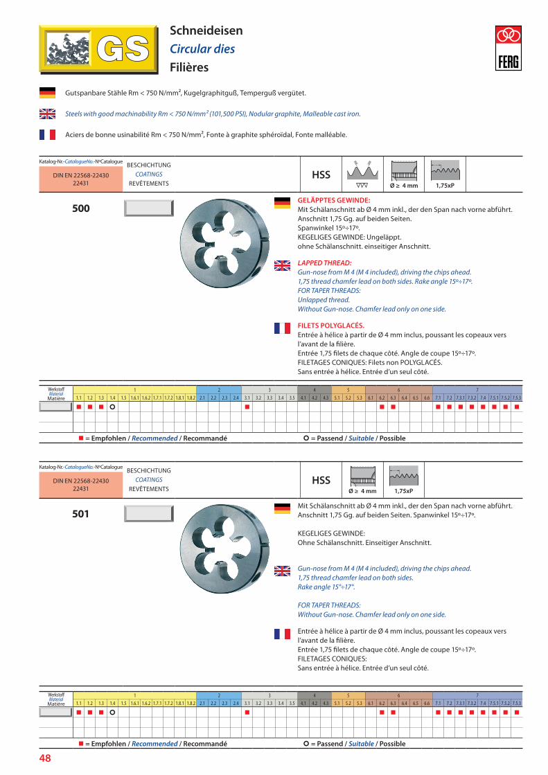
48
SchneideisenCircular diesFilières
Katalog-Nr. - Catalogue No. - Nº CatalogueBESCHICHTUNG
COATINGSREVÊTEMENTS
HSSDIN EN 22568-2243022431
500GELÄPPTES GEWINDE: Mit Schälanschnitt ab Ø 4 mm inkl., der den Span nach vorne abführt. Anschnitt 1,75 Gg. auf beiden Seiten. Spanwinkel 15º÷17º. KEGELIGES GEWINDE: Ungeläppt. ohne Schälanschnitt. einseitiger Anschnitt.
LAPPED THREAD: Gun-nose from M 4 (M 4 included), driving the chips ahead. 1,75 thread chamfer lead on both sides. Rake angle 15º÷17º. FOR TAPER THREADS: Unlapped thread. Without Gun-nose. Chamfer lead only on one side.
FILETS POLYGLACÉS. Entrée à hélice à partir de Ø 4 mm inclus, poussant les copeaux vers l’avant de la filière. Entrée 1,75 filets de chaque côté. Angle de coupe 15º÷17º. FILETAGES CONIQUES: Filets non POLYGLACÉS. Sans entrée à hélice. Entrée d’un seul côté.
Katalog-Nr. - Catalogue No. - Nº CatalogueBESCHICHTUNG
COATINGSREVÊTEMENTS
HSSDIN EN 22568-2243022431
501Mit Schälanschnitt ab Ø 4 mm inkl., der den Span nach vorne abführt. Anschnitt 1,75 Gg. auf beiden Seiten. Spanwinkel 15º÷17º. KEGELIGES GEWINDE: Ohne Schälanschnitt. Einseitiger Anschnitt.
Gun-nose from M 4 (M 4 included), driving the chips ahead. 1,75 thread chamfer lead on both sides. Rake angle 15°÷17°. FOR TAPER THREADS: Without Gun-nose. Chamfer lead only on one side.
Entrée à hélice à partir de Ø 4 mm inclus, poussant les copeaux vers l’avant de la filière.Entrée 1,75 filets de chaque côté. Angle de coupe 15º÷17º.FILETAGES CONIQUES:Sans entrée à hélice. Entrée d’un seul côté.
Gutspanbare Stähle Rm < 750 N/mm², Kugelgraphitguß, Temperguß vergütet.
Steels with good machinability Rm < 750 N/mm² (101,500 PSI), Nodular graphite, Malleable cast iron.
Aciers de bonne usinabilité Rm < 750 N/mm², Fonte à graphite sphéroïdal, Fonte malléable.
WerkstoffMaterial
Matière
1 2 3 4 5 6 71.1 1.2 1.3 1.4 1.5 1.6.1 1.6.2 1.7.1 1.7.2 1.8.1 1.8.2 2.1 2.2 2.3 2.4 3.1 3.2 3.3 3.4 3.5 4.1 4.2 4.3 5.1 5.2 5.3 6.1 6.2 6.3 6.4 6.5 6.6 7.1 7.2 7.3.1 7.3.2 7.4 7.5.1 7.5.2 7.5.3
= Empfohlen / Recommended / Recommandé = Passend / Suitable / Possible
WerkstoffMaterial
Matière
1 2 3 4 5 6 71.1 1.2 1.3 1.4 1.5 1.6.1 1.6.2 1.7.1 1.7.2 1.8.1 1.8.2 2.1 2.2 2.3 2.4 3.1 3.2 3.3 3.4 3.5 4.1 4.2 4.3 5.1 5.2 5.3 6.1 6.2 6.3 6.4 6.5 6.6 7.1 7.2 7.3.1 7.3.2 7.4 7.5.1 7.5.2 7.5.3
= Empfohlen / Recommended / Recommandé = Passend / Suitable / Possible

49
Katalog-Nr. - Catalogue No. - Nº CatalogueBESCHICHTUNG
COATINGSREVÊTEMENTS
HSSE-VDIN EN 22568-2243022431
520GELÄPPTES GEWINDE: Mit Schälanschnitt ab Ø 4 mm inkl., der den Span nach vorne abführt. Anschnitt 1,75 Gg. auf beiden Seiten. Spanwinkel 10º÷12º. KEGELIGES GEWINDE: ungeläppt. ohne Schälanschnitt. Einseitiger Anschnitt.
LAPPED THREAD. Gun-nose from M 4 (M 4 included), driving the chips ahead. 2,25 thread chamfer lead on both sides. Rake angle 10º÷12º. FOR TAPER THREADS: Unlapped thread. Without Gun-nose. Chamfer lead only on one side.
FILETS POLYGLACÉS. Entrée à hélice à partir de Ø 4 mm inclus, poussant les copeaux vers l’avant de la filière. Entrée 1,75 filets de chaque côté. Angle de coupe 10º÷12º. FILETAGES CONIQUES: Filets non polyglacés. Sans entrée à hélice. Entrée d’un seul côté.
SchneideisenCircular diesFilières
Vergütete und hitzebeständige Stähle Rm < 1.000 N/mm2 (<30 HRC)
Heat treated and heat-resistant steels Rm < 1.000 N/mm2
(<30 HRC / <290 HB / <145,000 PSI
Aciers traités et aciers réfractaires Rm < 1.000 N/mm² (<30 HRC)
WerkstoffMaterial
Matière
1 2 3 4 5 6 71.1 1.2 1.3 1.4 1.5 1.6.1 1.6.2 1.7.1 1.7.2 1.8.1 1.8.2 2.1 2.2 2.3 2.4 3.1 3.2 3.3 3.4 3.5 4.1 4.2 4.3 5.1 5.2 5.3 6.1 6.2 6.3 6.4 6.5 6.6 7.1 7.2 7.3.1 7.3.2 7.4 7.5.1 7.5.2 7.5.3
= Empfohlen / Recommended / Recommandé = Passend / Suitable / Possible

50
SchneideisenCircular diesFilières
Katalog-Nr. - Catalogue No. - Nº CatalogueBESCHICHTUNG
COATINGSREVÊTEMENTS
HSSDIN EN 22568-2243022431
V500GELÄPPTES GEWINDE: Mit Schälanschnitt ab Ø 4 mm inkl., der den Span nach vorne abführt. Anschnitt 1,75 Gg. auf beiden Seiten. Spanwinkel 15º÷17º. KEGELIGES GEWINDE: ungeläppt. ohne Schälanschnitt. einseitiger Anschnitt.
LAPPED THREAD: Gun-nose from M 4 (M 4 included), driving the chips ahead. 1,75 thread chamfer lead on both sides. Rake angle 15º÷17º. TAPER THREADS: Unlapped thread. Without Gun-nose. Chamfer lead only on one side
FILETS POLYGLACÉS: Entrée à hélice à partir de Ø 4 mm inclus, poussant les copeaux vers l’avant de la filière. Entrée 1,75 filets de chaque côté. Angle de coupe 15º÷17º. FILETAGES CONIQUES: Filets non polyglacés. Sans entrée à hélice. Entrée d’un seul côté.
Rostfreie Stähle und Baustähle Rm < 600 N/mm2
Stainless steels and structural steels Rm < 600 N/mm2 (<200 HB / <101,000 PSI)
Aciers inoxydable, aciers au carbone et peu allies Rm < 600 N/mm²
WerkstoffMaterial
Matière
1 2 3 4 5 6 71.1 1.2 1.3 1.4 1.5 1.6.1 1.6.2 1.7.1 1.7.2 1.8.1 1.8.2 2.1 2.2 2.3 2.4 3.1 3.2 3.3 3.4 3.5 4.1 4.2 4.3 5.1 5.2 5.3 6.1 6.2 6.3 6.4 6.5 6.6 7.1 7.2 7.3.1 7.3.2 7.4 7.5.1 7.5.2 7.5.3
= Empfohlen / Recommended / Recommandé = Passend / Suitable / Possible
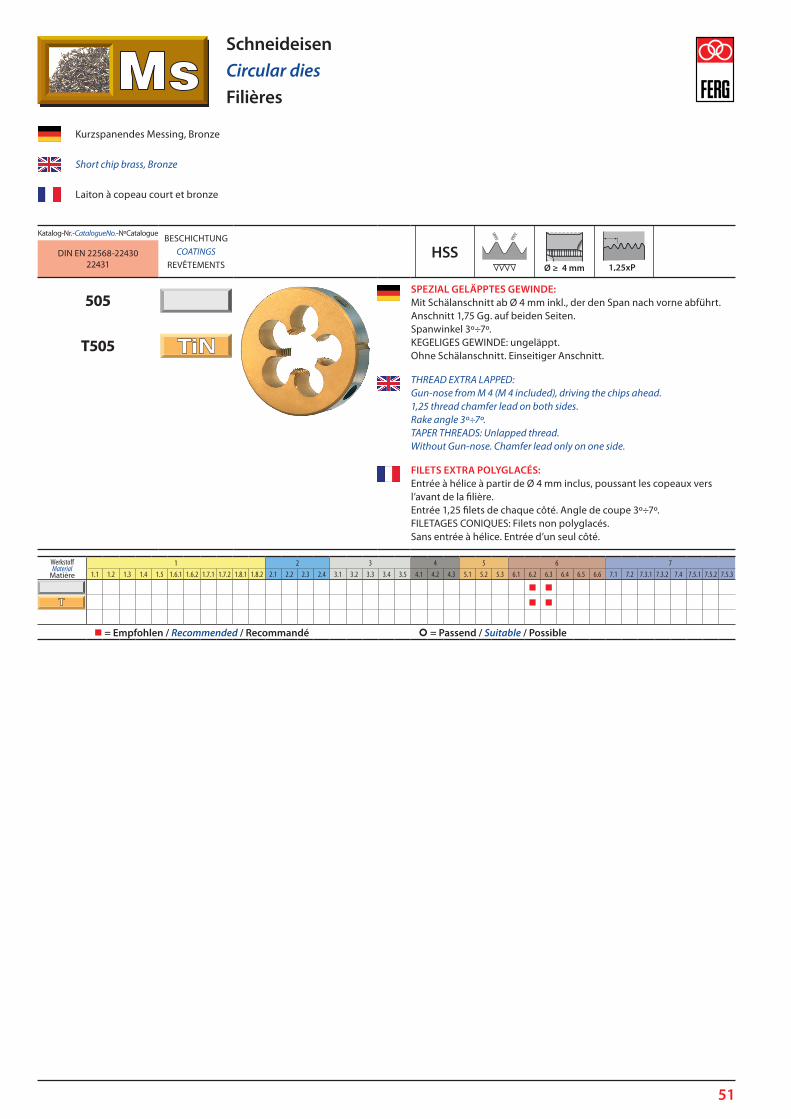
51
SchneideisenCircular diesFilières
Katalog-Nr. - Catalogue No. - Nº CatalogueBESCHICHTUNG
COATINGSREVÊTEMENTS
HSSDIN EN 22568-2243022431
505SPEZIAL GELÄPPTES GEWINDE: Mit Schälanschnitt ab Ø 4 mm inkl., der den Span nach vorne abführt. Anschnitt 1,75 Gg. auf beiden Seiten. Spanwinkel 3º÷7º. KEGELIGES GEWINDE: ungeläppt. Ohne Schälanschnitt. Einseitiger Anschnitt.
T505
THREAD EXTRA LAPPED: Gun-nose from M 4 (M 4 included), driving the chips ahead. 1,25 thread chamfer lead on both sides. Rake angle 3º÷7º. TAPER THREADS: Unlapped thread. Without Gun-nose. Chamfer lead only on one side.
FILETS EXTRA POLYGLACÉS:Entrée à hélice à partir de Ø 4 mm inclus, poussant les copeaux vers l’avant de la filière. Entrée 1,25 filets de chaque côté. Angle de coupe 3º÷7º. FILETAGES CONIQUES: Filets non polyglacés. Sans entrée à hélice. Entrée d’un seul côté.
Kurzspanendes Messing, Bronze
Short chip brass, Bronze
Laiton à copeau court et bronze
WerkstoffMaterial
Matière
1 2 3 4 5 6 71.1 1.2 1.3 1.4 1.5 1.6.1 1.6.2 1.7.1 1.7.2 1.8.1 1.8.2 2.1 2.2 2.3 2.4 3.1 3.2 3.3 3.4 3.5 4.1 4.2 4.3 5.1 5.2 5.3 6.1 6.2 6.3 6.4 6.5 6.6 7.1 7.2 7.3.1 7.3.2 7.4 7.5.1 7.5.2 7.5.3
= Empfohlen / Recommended / Recommandé = Passend / Suitable / Possible
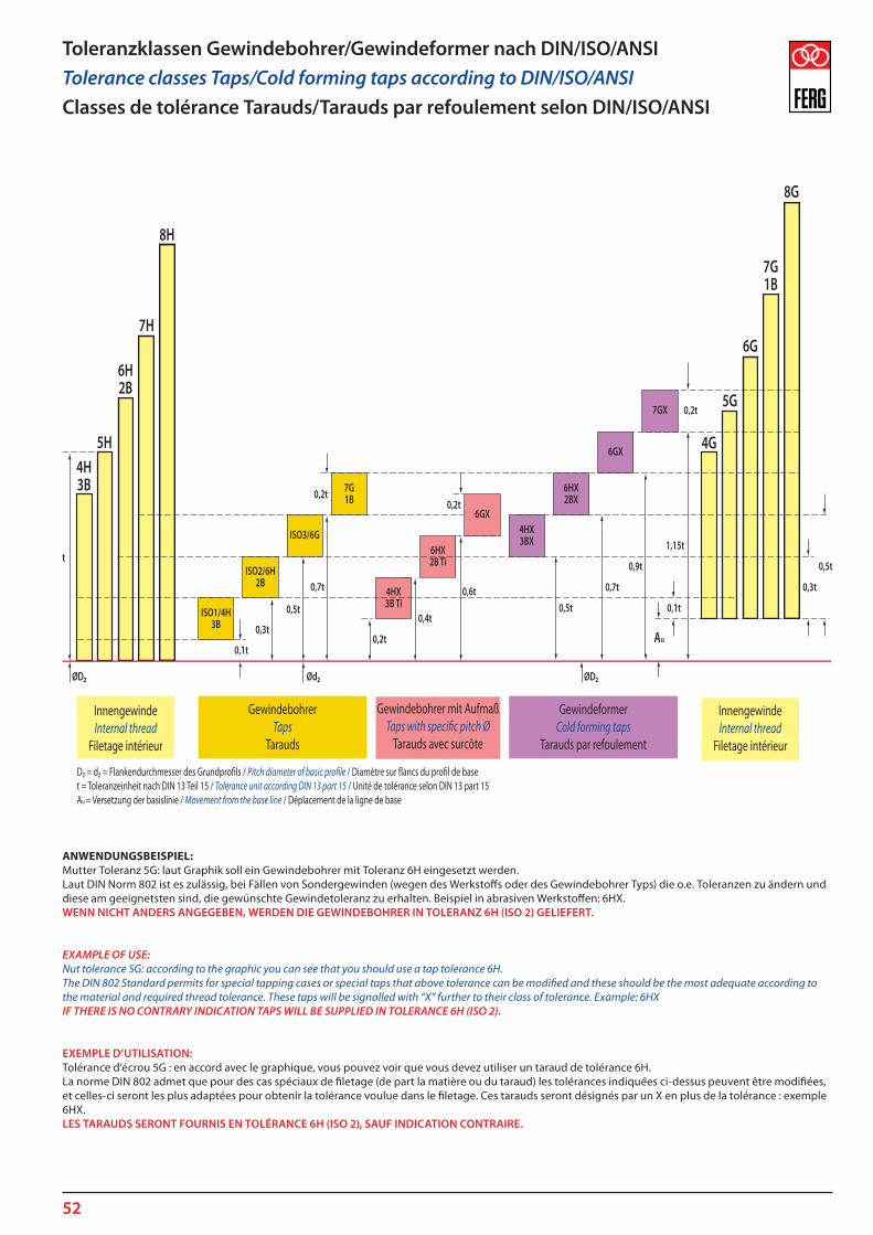
52
Toleranzklassen Gewindebohrer/Gewindeformer nach DIN/ISO/ANSITolerance classes Taps/Cold forming taps according to DIN/ISO/ANSIClasses de tolérance Tarauds/Tarauds par refoulement selon DIN/ISO/ANSI
ANWENDUNGSBEISPIEL: Mutter Toleranz 5G: laut Graphik soll ein Gewindebohrer mit Toleranz 6H eingesetzt werden.Laut DIN Norm 802 ist es zulässig, bei Fällen von Sondergewinden (wegen des Werkstoffs oder des Gewindebohrer Typs) die o.e. Toleranzen zu ändern und diese am geeignetsten sind, die gewünschte Gewindetoleranz zu erhalten. Beispiel in abrasiven Werkstoffen: 6HX.WENN NICHT ANDERS ANGEGEBEN, WERDEN DIE GEWINDEBOHRER IN TOLERANZ 6H (ISO 2) GELIEFERT.
EXAMPLE OF USE: Nut tolerance 5G: according to the graphic you can see that you should use a tap tolerance 6H.The DIN 802 Standard permits for special tapping cases or special taps that above tolerance can be modified and these should be the most adequate according to the material and required thread tolerance. These taps will be signalled with “X” further to their class of tolerance. Example: 6HXIF THERE IS NO CONTRARY INDICATION TAPS WILL BE SUPPLIED IN TOLERANCE 6H (ISO 2).
EXEMPLE D’UTILISATION: Tolérance d’écrou 5G : en accord avec le graphique, vous pouvez voir que vous devez utiliser un taraud de tolérance 6H.La norme DIN 802 admet que pour des cas spéciaux de filetage (de part la matière ou du taraud) les tolérances indiquées ci-dessus peuvent être modifiées, et celles-ci seront les plus adaptées pour obtenir la tolérance voulue dans le filetage. Ces tarauds seront désignés par un X en plus de la tolérance : exemple 6HX.LES TARAUDS SERONT FOURNIS EN TOLÉRANCE 6H (ISO 2), SAUF INDICATION CONTRAIRE.
ISO1/4H3B
ISO2/6H2B
ISO3/6G
7G1B
4HX3BX
6HX2BX
6GX
4HX3B Ti
6HX2B Ti
6GX
7GX
InnengewindeInternal thread
Filetage intérieur
InnengewindeInternal thread
Filetage intérieur
GewindebohrerTaps
Tarauds
Gewindebohrer mit AufmaßTaps with speci�c pitch Ø
Tarauds avec surcôte
GewindeformerCold forming taps
Tarauds par refoulement
D2 = d2 = Flankendurchmesser des Grundpro�ls / Pitch diameter of basic pro�le / Diamètre sur �ancs du pro�l de baset = Toleranzeinheit nach DIN 13 Teil 15 / Tolerance unit according DIN 13 part 15 / Unité de tolérance selon DIN 13 part 15Au = Versetzung der basislinie / Movement from the base line / Déplacement de la ligne de base

53
Technische InformationTechnical InformationInformation technique

54
M 3 x 0,35 2,65 M 3,5 x 0,35 3,15 M 4 x 0,35 3,65 M 4 x 0,5 3,5 M 5 x 0,5 4,5 M 6 x 0,5 5,5 M 6 x 0,75 5,2 M 7 x 0,75 6,2 M 8 x 0,5 7,5 M 8 x 0,75 7,2 M 8 x 1 7 M 9 x 1 8 M 10 x 0,5 9,5 M 10 x 0,75 9,2 M 10 x 1 9 M 10 x 1,25 8,8 M 11 x 1 10 M 12 x 0,75 11,2 M 12 x 1 11 M 12 x 1,25 10,8 M 12 x 1,5 10,5 M 13 x 1 12 M 13 x 1,5 11,5 M 14 x 1 13 M 14 x 1,25 12,8 M 14 x 1,5 12,5 M 15 x 1 14 M 15 x 1,5 13,5 M 16 x 1 15 M 16 x 1,5 14,5 M 18 x 1 17 M 18 x 1,5 16,5 M 18 x 2 16 M 20 x 1 19 M 20 x 1,5 18,5 M 20 x 2 18 M 22 x 1 21 M 22 x 1,5 20,5 M 22 x 2 20 M 24 x 1 23 M 24 x 1,5 22,5 M 24 x 2 22 M 25 x 1 24 M 25 x 1,5 23,5 M 26 x 1 25 M 26 x 1,5 24,5 M 27 x 1 26 M 27 x 1,5 25,5 M 27 x 2 25 M 28 x 1,5 26,5 M 28 x 2 26 M 30 x 1 29 M 30 x 1,5 28,5 M 30 x 2 28 M 32 x 1,5 30,5 M 33 x 1,5 31,5 M 33 x 2 31 M 34 x 1,5 32,5 M 35 x 1,5 33,5 M 36 x 1,5 34,5 M 36 x 2 34 M 36 x 3 33 M 38 x 1,5 36,5 M 39 x 1,5 37,5 M 39 x 2 37 M 39 x 3 36
M 40 x 1,5 38,5 M 40 x 2 38 M 40 x 3 37 M 42 x 1,5 40,5 M 42 x 2 40 M 42 x 3 39 M 45 x 1,5 43,5 M 45 x 2 43 M 45 x 3 42 M 48 x 1,5 46,5 M 48 x 2 46 M 48 x 3 45 M 50 x 1,5 48,5 M 50 x 2 48 M 50 x 3 47 M 52 x 1,5 50,5 M 52 x 2 50 M 52 x 3 49
No. 1 - 64 1,5 No. 2 - 56 1,8 No. 3 - 48 2,1 No. 4 - 40 2,25 No. 5 - 40 2,6 No. 6 - 32 2,75 No. 8 - 32 3,5 No. 10 - 24 3,9 No. 12 - 24 4,5 1/4 - 20 5,1 5/16 - 18 6,6 3/8 - 16 8 7/16 - 14 9,4 1/2 - 13 10,75 9/16 - 12 12,2 5/8 - 11 13,5 3/4 - 10 16,5 7/8 - 9 19,5 1 - 8 22,25 1 1/8 - 7 25 1 1/4 - 7 28 1 3/8 - 6 30,75 1 1/2 - 6 34 1 3/4 - 5 39,5 2 - 4,5 45
No. 0 - 80 1,25 No. 1 - 72 1,55 No. 2 - 64 1,85 No. 3 - 56 2,15 No. 4 - 48 2,35 No. 5 - 44 2,7 No. 6 - 40 2,95 No. 8 - 36 3,5 No. 10 - 32 4,1 No. 12 - 28 4,6 1/4 - 28 5,5 5/16 - 24 6,9 3/8 - 24 8,5 7/16 - 20 9,9 1/2 - 20 11,5 9/16 - 18 12,9 5/8 - 18 14,5 3/4 - 16 17,5 7/8 - 14 20,4 1 - 12 23,25 1 1/8 - 12 26,5 1 1/4 - 12 29,5 1 3/8 - 12 32,75 1 1/2 - 12 36
1/4 - 32 5,55 5/16 - 32 7,15 3/8 - 32 8,7 7/16 - 28 10,2 1/2 - 28 11,8 9/16 - 24 13,2 5/8 - 24 14,8 11/16 - 24 16,4 3/4 - 20 17,8 7/8 - 20 20,95 1 - 20 24,2
1 1/8 - 8 25,4 1 1/4 - 8 28,5 1 3/8 - 8 31,8 1 1/2 - 8 35 1 5/8 - 8 38,1 1 3/4 - 8 41,3 1 7/8 - 8 44,5 2 - 8 47,7 2 1/4 - 8 54
M 1 (0,25) 0,75 M 1,1 (0,25) 0,85 M 1,2 (0,25) 0,95 M 1,4 (0,3) 1,1 M 1,6 (0,35) 1,25 M (1,7) (0,35) 1,3 M 1,8 (0,35) 1,45 M 2 (0,4) 1,6 M 2,2 (0,45) 1,75 M (2,3) (0,4) 1,9 M 2,5 (0,45) 2,05 M (2,6) (0,45) 2,1 M 3 (0,5) 2,5 M 3,5 (0,6) 2,9 M 4 (0,7) 3,3 M 4,5 (0,75) 3,7 M 5 (0,8) 4,2 M 6 (1) 5 M 7 (1) 6 M 8 (1,25) 6,8 M 9 (1,25) 7,8 M 10 (1,5) 8,5 M 11 (1,5) 9,5 M 12 (1,75) 10,2 M 14 (2) 12 M 16 (2) 14 M 18 (2,5) 15,5 M 20 (2,5) 17,5 M 22 (2,5) 19,5 M 24 (3) 21 M 27 (3) 24 M 30 (3,5) 26,5 M 33 (3,5) 29,5 M 36 (4) 32 M 39 (4) 35 M 42 (4,5) 37,5 M 45 (4,5) 40,5 M 48 (5) 43 M 52 (5) 47 M 56 (5,5) 50,5 M 60 (5,5) 54,5 M 64 (6) 58 M 68 (6) 62
No. 1 - 64 1,5 No. 2 - 56 1,8 No. 3 - 48 2,05 No. 4 - 40 2,3 No. 5 - 40 2,65 No. 6 - 32 2,8 No. 8 - 32 3,5 No. 10 - 24 3,9 No. 12 - 24 4,6 1/4 - 20 5,2 5/16 - 18 6,7 3/8 - 16 8,1 7/16 - 14 9,5 1/2 - 13 10,9 9/16 - 12 12,3 5/8 - 11 13,7 3/4 - 10 16,75
No. 0 - 80 1,25 No. 1 - 72 1,55 No. 2 - 64 1,85 No. 3 - 56 2,1 No. 4 - 48 2,4 No. 5 - 44 2,7 No. 6 - 40 2,95 No. 8 - 36 3,6 No. 10 - 32 4,15 No. 12 - 28 4,7 1/4 - 28 5,6 5/16 - 24 7 3/8 - 24 8,6 7/16 - 20 10 1/2 - 20 11,5 5/8 - 18 14,5
MJ 2 x 0,4 1,65 MJ 2,5 x 0,45 2,1 MJ 3 x 0,5 2,6 MJ 3,5 x 0,6 3 MJ 4 x 0,7 3,4 MJ 5 x 0,8 4,3 MJ 6 x 1 5,1 MJ 7 x 1 6,1 MJ 8 x 1 7,1 MJ 10 x 1,25 8,9 MJ 12 x 1,25 10,9 MJ 14 x 1,5 12,6 MJ 16 x 1,5 14,6 MJ 18 x 1,5 16,6 MJ 20 x 1,5 18,6
Empfohlene Kernlochdurhmesser für das GewindeachneidenRecommended core hole diameter for cutting threadsDiamètre de perçage des avant-trous recommendé pour des filets coupés
MNennmaß
Nominal sizesDimension nominale
Ø MF
NennmaßNominal sizes
Dimension nominale
Ø MF
NennmaßNominal sizes
Dimension nominale
Ø UNC
NennmaßNominal sizes
Dimension nominale
Ø UNF
NennmaßNominal sizes
Dimension nominale
Ø
UNEFNennmaß
Nominal sizesDimension nominale
Ø UN-8
NennmaßNominal sizes
Dimension nominale
Ø
MJNennmaß
Nominal sizesDimension nominale
Ø UNJC
NennmaßNominal sizes
Dimension nominale
Ø UNJF
NennmaßNominal sizes
Dimension nominale
Ø

55
EG M 8 x 1 8,3 EG M 10 x 1 10,25 EG M 10 x 1,25 10,4 EG M 12 x 1,25 12,25 EG M 12 x 1,5 12,5 EG M 14 x 1,5 14,5 EG M 16 x 1,5 16,5 EG M 18 x 1,5 18,5 EG M 18 x 2 18,5 EG M 20 x 1,5 20,5
EG M 2,5 (0,45) 2,6 EG M 3 (0,5) 3,2 EG M 3,5 (0,6) 3,7 EG M 4 (0,7) 4,2 EG M 5 (0,8) 5,2 EG M 6 (1) 6,3 EG M 8 (1,25) 8,4 EG M 10 (1,5) 10,5 EG M 12 (1,75) 12,5 EG M 14 (2) 14,5 EG M 16 (2) 16,5 EG M 18 (2,5) 18,75 EG M 20 (2,5) 20,75 EG M 22 (2,5) 22,75 EG M 24 (3) 24,75
EG No. 2 - 56 2,3 EG No. 3 - 48 2,7 EG No. 4 - 40 3 EG No. 5 - 40 3,4 EG No. 6 - 32 3,7 EG No. 8 - 32 4,4 EG No. 10 - 24 5,1 EG No. 12 - 24 5,8 EG 1/4 - 20 6,7 EG 5/16 - 18 8,4 EG 3/8 - 16 10 EG 7/16 - 14 11,7 EG 1/2 - 13 13,3
EG No. 2 - 64 2,3 EG No. 3 - 56 2,7 EG No. 4 - 48 3 EG No. 5 - 44 3,4 EG No. 6 - 40 3,7 EG No. 8 - 36 4,4 EG No. 10 - 32 5,1 EG 1/4 - 28 6,6 EG 5/16 - 24 8,2 EG 3/8 - 24 9,8 EG 7/16 - 20 11,5 EG 1/2 - 20 13,1
W 3/32 1,8 W 1/8 2,55 W 5/32 3,1 W 3/16 3,6 W 7/32 4,4 W 1/4 5,1 W 5/16 6,5 W 3/8 7,9 W 7/16 9,25 W 1/2 10,5 W 9/16 12 W 5/8 13,5 W 3/4 16,5 W 7/8 19,25 W 1 21,75 W 1 1/8 24,75 W 1 1/4 27,75 W 1 3/8 30,5 W 1 1/2 33,5 W 1 3/4 39 W 2 44,5 W 2 1/4 50 W 2 1/2 56,5 W 2 3/4 62 W 3 68
BSF 3/16 4 BSF 7/32 4,5 BSF 1/4 5,2 BSF 9/32 6 BSF 5/16 6,6 BSF 3/8 8,1 BSF 7/16 9,5 BSF 1/2 11 BSF 9/16 12,5 BSF 5/8 14 BSF 11/16 15,5 BSF 3/4 16,5 BSF 13/16 18,25 BSF 7/8 19,5 BSF 1 22,5 BSF 1 1/8 25,5 BSF 1 1/4 28,5 BSF 1 3/8 31,5 BSF 1 1/2 34,5
G 1/16 6,8 G 1/8 8,8 G 1/4 11,8 G 3/8 15,25 G 1/2 19 G 5/8 21 G 3/4 24,5 G 7/8 28,25 G 1 30,75 G 1 1/8 35,3 G 1 1/4 39,25 G 1 3/8 41,9 G 1 1/2 45,25 G 1 3/4 51,3 G 2 57 G 2 1/4 63,1 G 2 1/2 72,6 G 2 3/4 79,1 G 3 85,5 G 3 1/4 91,5 G 3 1/2 97,7
Rp 1/16 6,55 Rp 1/8 8,6 Rp 1/4 11,5 Rp 3/8 15 Rp 1/2 18,5 Rp 3/4 24 Rp 1 30,25 Rp 1 1/4 39 Rp 1 1/2 44,85 Rp 2 56,5 Rp 2 1/2 72,25 Rp 3 85
1/8 NPSM 9,1 1/4 NPSM 12 3/8 NPSM 15,5 1/2 NPSM 19 3/4 NPSM 24,5 1 NPSM 30,5 1 1/4 NPSM 39,25 1 1/2 NPSM 45,5 2 NPSM 57,5 2 1/2 NPSM 69 3 NPSM 85
1/16 NPSF 6,35 1/8 NPSF 8,75 1/4 NPSF 11,3 3/8 NPSF 14,7 1/2 NPSF 18,2 3/4 NPSF 23,5 1 NPSF 29,5
W 21,80 - 14 19,8 W 24,32 - 14 22,3
Pg 7 11,4 Pg 9 14 Pg 11 17,25 Pg 13,5 19 Pg 16 21,25 Pg 21 26,9 Pg 29 35,5 Pg 36 45,5 Pg 42 52,5 Pg 48 58
BA 0 5,1 BA 1 4,5 BA 2 4 BA 3 3,4 BA 4 3 BA 5 2,6 BA 6 2,3 BA 7 2 BA 8 1,8 BA 9 1,5 BA 10 1,3 BA 11 1,2 BA 12 1 BA 13 0,95 BA 14 0,75
EG MNennmaß
Nominal sizesDimension nominale
Ø EG UNC
NennmaßNominal sizes
Dimension nominale
Ø EG UNF
NennmaßNominal sizes
Dimension nominale
Ø EG MF
NennmaßNominal sizes
Dimension nominale
Ø
W (BSW)Nennmaß
Nominal sizesDimension nominale
Ø BSF
NennmaßNominal sizes
Dimension nominale
Ø G (BSP)
NennmaßNominal sizes
Dimension nominale
Ø Rp (BSPP)Nennmaß
Nominal sizesDimension nominale
Ø BA
NennmaßNominal sizes
Dimension nominale
Ø
NPSMNennmaß
Nominal sizesDimension nominale
Ø NPSF
NennmaßNominal sizes
Dimension nominale
Ø W DIN 477
NennmaßNominal sizes
Dimension nominale
Ø Pg
NennmaßNominal sizes
Dimension nominale
Ø
Empfohlene Kernlochdurhmesser für das GewindeachneidenRecommended core hole diameter for cutting threadsDiamètre de perçage des avant-trous recommendé pour des filets coupés

56
Rc 1/16 - 28 10,1 6,3 Rc 1/8 - 28 10,1 8,3 Rc 1/4 - 14 15 11 Rc 3/8 - 14 15,4 14,5 Rc 1/2 - 14 20,5 18,1 Rc 3/4 - 14 21,8 23,5 Rc 1 - 11 26 29,6 Rc 1 1/4 - 11 28,3 38,1 Rc 1 1/2 - 11 28,3 44 Rc 2 - 11 32,7 55,6
Rc 1/16 - 28 10,1 6,5 6 Rc 1/8 - 28 10,1 8,5 8 Rc 1/4 - 14 15 11,35 10,7 Rc 3/8 - 14 15,4 14,85 14,15 Rc 1/2 - 14 20,5 18,5 17,6 Rc 3/4 - 14 21,8 24 23 Rc 1 - 11 26 30,2 29 Rc 1 1/4 - 11 28,3 38,8 37,5 Rc 1 1/2 - 11 28,3 44,7 43,35 Rc 2 - 11 32,7 56,5 54,9
1/16 - 27 12 6,2 1/8 - 27 12 8,5 1/4 - 18 17,5 11 3/8 - 18 17,6 14,5 1/2 - 14 22,8 17,8 3/4 - 14 23 23 1 - 11½ 27,4 29 1 1/4 - 11½ 28,1 37,5 1 1/2 - 11½ 28,4 44 2 - 11½ 28 56
1/16 - 27 12 6,38 6 1/8 - 27 12 8,73 8,3 1/4 - 18 17,5 11,35 10,7 3/8 - 18 17,6 14,8 14,2 1/2 - 14 22,8 18,32 17,4 3/4 - 14 23 23,66 22,8 1 - 11½ 27,4 29,69 28,6 1 1/4 - 11½ 28,1 38,45 37,4 1 1/2 - 11½ 28,4 44,52 43,4 2 - 11½ 28 56,56 55,5
1/16 - 27 12 6,2 1/8 - 27 12 8,5 1/4 - 18 17,5 11 3/8 - 18 17,6 14,5 1/2 - 14 22,8 17,8 3/4 - 14 23 23 1 - 11½ 27,4 29 1 1/4 - 11½ 28,1 37,5 1 1/2 - 11½ 28,4 44 2 - 11½ 28 56
1/16 - 27 12 6,41 6 1/8 - 27 12 8,76 8,3 1/4 - 18 17,5 11,4 10,7 3/8 - 18 17,6 14,84 14,2 1/2 - 14 22,8 18,33 17,4 3/4 - 14 23 23,68 22,8 1 - 11½ 27,4 29,72 28,6 1 1/4 - 11½ 28,1 38,48 37,4 1 1/2 - 11½ 28,4 44,55 43,4 2 - 11½ 28 56,59 55,5
Rc (BSPT)NennmaßNominal sizesDimension nominale
Ø
L1 min. D1
Zylindrisch vorbohrenDrill cylindrically
Perçage cylindrique
Rc (BSPT)NennmaßNominal sizesDimension nominale
Ø
L1 min. D3 D2
Zylindrisch vorbohren un kegelig aufreibenDrill cylindrically and prepare tapered hole
with reamerPerçage cylindrique et alésage conique
NPTNennmaßNominal sizesDimension nominale
Ø
L1 min. D1
NPTNennmaßNominal sizesDimension nominale
Ø
L1 min. D3 D2
NPTFNennmaßNominal sizesDimension nominale
Ø
L1 min. D1
NPTFNennmaßNominal sizesDimension nominale
Ø
L1 min. D3 D2
Unsere Gewindebohrer sind geeignet für Bohrungen laut Zeichnungen und Abmessungen wie oben. Möglichst mit konischer Vorbohrung arbeiten.Für Sacklöcher mit einer Mindesttiefe die anders als die genannten Werte sind, müssen.Sondergewindebohrer eingesetzt werden und hierfür benötigen wir von Ihnen eine Zeichnung mit Massen.Our taps are adequate to tap holes according to drawings and sizes as above indicated.Intent to work with tapered pre-hole.For blind holes with a minimum depth L1 different to indicated values, it is necessary to use special taps, for which you have to send us a drawing with sizes.Nos tarauds sont adéquats pour la réalisation de filetages selon dessins et dimensions indiqués ci-dessus. Faire en sorte préalablement de réaliser des trous coniques. Pour les trous borgnes avec une profondeur minima L1 différente des valeurs indiquées, il est nécessaire d’utiliser des tarauds spéciaux et de fournir un plan avec des cotes précises.
Empfohlene Kernlochdurhmesser für das GewindeachneidenRecommended core hole diameter for cutting threadsDiamètre de perçage des avant-trous recommendé pour des filets coupés

57
M 1,8 (0,35) 1,67 - 1,63 M 2 (0,4) 1,82 - 1,78 M 2,2 (0,45) 2,02 - 1,98 M (2,3) (0,4) 2,12 - 2,08 M 2,5 (0,45) 2,32 - 2,28 M (2,6) (0,45) 2,42 - 2,38 M 3 (0,5) 2,83 - 2,77 M 3,5 (0,6) 3,28 - 3,22 M 4 (0,7) 3,73 - 3,67 M 4,5 (0,75) 4,18 - 4,12 M 5 (0,8) 4,68 - 4,62 M 6 (1) 5,6 - 5,5 M 7 (1) 6,6 - 6,5 M 8 (1,25) 7,45 - 7,35 M 9 (1,25) 8,45 - 8,35 M 10 (1,5) 9,35 - 9,25 M 11 (1,5) 10,35 - 10,25 M 12 (1,75) 11,25 - 11,15 M 14 (2) 13,15 - 13,05 M 16 (2) 15,15 - 15,05 M 18 (2,5) 16,95 - 16,85 M 20 (2,5) 18,95 - 18,85 M 22 (2,5) 20,95 - 20,85 M 24 (3) 22,7 - 22,6
M 3 x 0,35 2,87 - 2,83 M 4 x 0,5 3,78 - 3,72 M 5 x 0,5 4,78 - 4,72 M 6 x 0,5 5,78 - 5,72 M 6 x 0,75 5,68 - 5,62 M 7 x 0,75 6,68 - 6,62 M 8 x 0,5 7,78 - 7,72 M 8 x 0,75 7,68 - 7,62 M 8 x 1 7,6 - 7,5 M 9 x 1 8,6 - 8,5 M 10 x 0,75 9,68 - 9,62 M 10 x 1 9,6 - 9,5 M 10 x 1,25 9,45 - 9,35 M 11 x 1 10,6 - 10,5 M 12 x 0,75 11,68 - 11,62 M 12 x 1 11,6 - 11,5 M 12 x 1,25 11,45 - 11,35 M 12 x 1,5 11,35 - 11,25 M 14 x 1 13,6 - 13,5 M 14 x 1,5 13,35 - 13,25 M 16 x 1 15,6 - 15,5 M 16 x 1,5 15,35 - 15,25
No. 1 - 64 1,69 - 1,65 No. 2 - 56 1,97 - 1,93 No. 3 - 48 2,28 - 2,22 No. 4 - 40 2,58 - 2,52 No. 5 - 40 2,93 - 2,87 No. 6 - 32 3,18 - 3,12 No. 8 - 32 3,83 - 3,77 No. 10 - 24 4,35 - 4,25 No. 12 - 24 5,05 - 4,95 1/4 - 20 5,8 - 5,7 5/16 - 18 7,35 - 7,25 3/8 - 16 8,85 - 8,75 7/16 - 14 10,35 - 10,25 1/2 - 13 11,85 - 11,75 9/16 - 12 13,35 - 13,25 5/8 - 11 14,85 - 14,75 3/4 - 10 17,95 - 17,85
No. 1 - 72 1,71 - 1,67 No. 2 - 64 2,02 - 1,98 No. 3 - 56 2,32 - 2,28 No. 4 - 48 2,63 - 2,57 No. 5 - 44 2,93 - 2,87 No. 6 - 40 3,23 - 3,17 No. 8 - 36 3,88 - 3,82 No. 10 - 32 4,48 - 4,42 No. 12 - 28 5,15 - 5,05 1/4 - 28 6 - 5,9 5/16 - 24 7,5 - 7,4 3/8 - 24 9,05 - 8,95 7/16 - 20 10,55 - 10,45 1/2 - 20 12,15 - 12,05 9/16 - 18 13,7 - 13,6 5/8 - 18 15,3 - 15,2 3/4 - 16 18,35 - 18,25
G 1/16 7,3 - 7,20 G 1/8 9,3 - 9,20 G 1/4 12,55 - 12,45 G 3/8 16,05 - 15,95 G 1/2 20,05 - 19,95 G 5/8 22,05 - 21,95 G 3/4 25,55 - 25,45 G 7/8 29,3 - 29,20 G 1 32,05 - 31,95
Empfohlene Kernlochdurhmesser für das GewindeformenRecommended core hole diameter for forming threadsDiamètre de perçage des avant-trous recommendé pour des filets refoulés
MNennmaß
Nominal sizesDimension nominale
Ø MF
NennmaßNominal sizes
Dimension nominale
Ø UNF
NennmaßNominal sizes
Dimension nominale
Ø
G (BSP)Nennmaß
Nominal sizesDimension nominale
Ø
UNCNennmaß
Nominal sizesDimension nominale
Ø

58
2 318 478 637 796 955 1274 1592 1911 2388 2864 3185 3981 4777 5570 6369 7165 7961 9549 11141
3 212 318 425 531 637 849 1062 1274 1592 1909 2123 2654 3185 3713 4246 4777 5308 6366 7427
4 159 239 318 398 478 637 796 955 1194 1432 1592 1990 2389 2785 3185 3582 3981 4775 5570
5 127 191 255 318 382 510 637 764 955 1145 1274 1592 1911 2228 2548 2866 3185 3820 4456
6 106 159 212 265 318 425 531 637 796 954 1062 1327 1592 1856 2123 2388 2654 3183 3714
8 80 119 159 199 239 318 398 478 597 716 796 995 1194 1392 1592 1791 1991 2387 2785
10 64 96 127 159 191 255 318 382 478 572 637 796 955 1114 1274 1433 1593 1910 2228
12 53 80 106 133 159 212 265 318 398 477 531 663 796 928 1062 1194 1327 1592 1857
14 45 68 91 114 136 182 227 273 341 409 455 569 682 795 910 1023 1138 1364 1592
16 40 60 80 100 119 159 199 239 299 358 398 498 597 696 796 895 996 1194 1399
18 35 53 71 88 106 142 170 212 265 318 354 442 531 618 708 796 885 1061 1238
20 32 48 64 80 96 127 159 191 239 286 318 398 478 557 637 716 797 955 1114
22 28 43 57 72 86 115 144 173 216 260 289 361 433 506 578 651 724 868 1013
24 26 39 52 66 79 106 132 159 198 238 265 331 397 464 530 597 664 796 928
27 23 35 47 58 70 94 117 141 176 211 235 294 353 412 471 531 590 707 825
30 21 32 42 53 64 85 106 127 159 190 212 265 318 371 425 478 531 637 743
33 19 28 38 48 57 77 96 115 144 173 192 240 289 337 385 434 483 579 675
36 17 26 35 43 52 70 88 105 132 159 176 220 265 309 353 398 443 531 619
39 16 24 32 40 48 65 81 97 122 146 162 204 244 285 326 367 409 490 571
42 15 22 30 37 45 60 75 90 113 136 151 189 227 265 303 341 380 455 531
45 14 21 28 35 42 57 71 85 106 127 142 177 212 247 283 318 354 424 495
48 13 19 26 33 39 52 66 79 99 119 132 165 198 232 265 299 332 398 464
52 12 18 24 30 36 48 61 73 91 110 122 152 183 214 244 276 307 367 428
Ømm.
Vc = m/min
2 3 4 5 6 8 10 12 15 18 20 25 30 35 40 45 50 60 70
Vc = 12 m/min, Ø 8 mm. 478 r.p.m. (min-1)
Übertragung der schnittgeschwindigkeit VC von m/min. auf u.p.m. (min-1)Transformation Vc from m/min. to r.p.m. (min-1)Tableau de vitesse de coupe VC de m/min. a r.p.m. (min-1)

59
255 80 76 270 85 81 41,0 285 90 86 48,0 305 95 90 52,0 320 100 95 56,2 335 105 100 350 110 105 62,3 370 115 109 385 120 114 66,7 400 125 119 415 130 124 71,2 430 135 128 450 140 133 75,0 465 145 138 480 150 143 78,7 495 155 147 510 160 152 81,7 530 165 156 545 170 162 85,0 560 175 166 575 180 171 87,1 595 185 176 610 190 181 89,5 625 195 185 640 200 190 91,5 660 205 195 92,5 675 210 199 93,5 690 215 204 94,0 705 220 209 95,0 720 225 214 96,0 740 230 219 96,7 755 235 223 770 240 228 98,1 20,3 785 245 233 21,3 800 250 238 99,5 22,2 820 255 242 23,1 830 260 247 24,0 850 265 252 24,8 865 270 257 25,6 880 275 261 26,4 900 280 266 27,1 915 285 271 27,8 930 290 276 28,5 950 295 280 29,2 965 300 285 29,8 995 310 295 31,0 1030 320 304 32,2 1060 330 314 33,3 1095 340 323 34,4 1125 350 333 35,5 1155 360 342 36,6 1190 370 352 37,7 1220 380 361 38,8 1255 390 371 39,8 1290 400 380 40,8 1320 410 390 41,8 1350 420 399 42,7 1385 430 409 43,6 1420 440 418 44,5 1455 450 428 45,3 1485 460 437 46,1 1520 470 447 46,9 1555 480 456 47,7 1595 490 466 48,4 1630 500 475 49,1
1665 510 485 49,8 1700 520 494 50,5 1740 530 504 51,1 1775 540 513 51,7 1810 550 523 52,3 1845 560 532 53,0 1880 570 542 53,6 1920 580 551 54,1 1955 590 561 54,7 1995 600 570 55,2 2030 610 580 55,7 2070 620 589 56,3 2105 630 599 56,8 2145 640 608 57,3 2180 650 618 57,8 660 58,3 670 58,8 680 59,2 690 59,7 700 60,1 720 61,0 740 61,8 760 62,5 780 63,3 800 64,0 820 64,7 840 65,3 860 65,9 880 66,4 900 67,0 920 67,5 940 68,0
Härtevergleichstabelle (≈ DIN 50150)Hardness conversion table (≈ DIN 50150)Table de conversion de dureté (≈ DIN 50150)
ZugfestigkeitTensile strength
Resistance a la tractionVICKERS BRINELL ROCKWELL
Rm (=N/mm2) HV 10 HB 30 HRB HRC
ZugfestigkeitTensile strength
Resistance a la tractionVICKERS BRINELL ROCKWELL
Rm (=N/mm2) HV 10 HB 30 HRB HRC

60
0 0,000000 0,0000 25,4000 50,8000 76,2000 101,6000 127,0000 152,4000 177,8000 203,2000 228,6000 1/64 0,015625 0,3969 25,7969 51,1969 76,5969 101,9969 127,3969 152,7969 178,1969 203,5969 228,9969 1/32 0,031250 0,7938 26,1938 51,5938 76,9938 102,3938 127,7938 153,1938 178,5938 203,9938 229,3938 3/64 0,046875 1,1906 26,5906 51,9906 77,3906 102,7906 128,1906 153,5906 178,9906 204,3906 229,7906 1/16 0,062500 1,5875 26,9875 52,3875 77,7875 103,1875 128,5875 153,9875 179,3875 204,7875 230,1875 5/64 0,078125 1,9844 27,3844 52,7844 78,1844 103,5844 128,9844 154,3844 179,7844 205,1844 230,5844 3/32 0,093750 2,3813 27,7813 53,1813 78,5813 103,9813 129,3813 154,7813 180,1813 205,5813 230,9813 7/64 0,109375 2,7781 28,1781 53,5781 78,9781 104,3781 129,7781 155,1781 180,5781 205,9781 231,3781 1/8 0,125000 3,1750 28,5750 53,9750 79,3750 104,7750 130,1750 155,5750 180,9750 206,3750 231,7750 9/64 0,140625 3,5719 28,9719 54,3719 79,7719 105,1719 130,5719 155,9719 181,3719 206,7719 232,1719 5/32 0,156250 3,9688 29,3688 54,7688 80,1688 105,5688 130,9688 156,3688 181,7688 207,1688 232,5688 11/64 0,171875 4,3656 29,7656 55,1656 80,5656 105,9656 131,5656 156,7656 182,1656 207,5656 232,9656 3/16 0,187500 4,7625 30,1625 55,5625 80,9625 106,3625 131,7625 157,1625 182,5625 207,9625 233,3625 13/64 0,203125 5,1594 30,5594 55,9594 81,3594 106,7594 132,1594 157,5594 182,9594 208,3594 233,7594 7/32 0,218750 5,5563 30,9563 56,3563 81,7563 107,1563 132,5563 157,9563 183,3563 208,5763 234,1563 15/64 0,234375 5,9531 31,3531 56,7531 82,1531 107,5531 132,9531 158,3531 183,7531 209,1531 234,5531 1/4 0,250000 6,3500 31,7500 57,1500 82,5500 107,9500 133,3500 158,7500 184,1500 209,5500 234,9500 17/64 0,265625 6,7469 32,1469 57,5469 82,9469 108,3469 133,7469 159,1469 184,5469 209,9469 235,3469 9/32 0,281250 7,1438 32,5438 57,9438 83,3438 108,7438 134,1438 159,5438 184,9438 210,3438 235,7438 19/64 0,296875 7,5406 32,9406 58,3406 83,7406 109,1406 134,5406 159,9406 185,3406 210,7406 236,1406 5/16 0,312500 7,9375 33,3375 58,7375 84,1375 109,5375 134,9375 160,3375 185,7375 211,1375 236,5375 21/64 0,328125 8,3344 33,7344 59,1344 84,5344 109,9344 135,3344 160,7344 186,1344 211,5344 236,9344 11/32 0,343750 8,7313 34,1313 59,5313 84,9313 110,3313 135,7313 161,1313 186,5313 211,9313 237,3313 23/64 0,359375 9,1281 34,5281 59,9281 85,3281 110,7281 136,1281 161,5281 186,9281 212,3281 237,7281 3/8 0,375000 9,5250 34,9250 60,3250 85,7250 111,1250 136,5250 161,9250 187,3250 212,7250 238,1250 25/64 0,390625 9,9219 35,3219 60,7219 86,1219 111,5219 136,9219 162,3219 187,7219 213,1219 238,5219 13/32 0,406250 10,3188 35,7188 61,1188 86,5188 111,9188 137,3188 162,7188 188,1188 213,5188 238,9188 27/64 0,421875 10,7156 36,1156 61,5156 86,9156 112,3156 137,7156 163,1156 188,5156 213,9156 239,3156 7/16 0,437500 11,1125 36,5125 61,9125 87,3125 112,7125 138,1125 163,5125 188,9125 214,3125 239,7125 29/64 0,453125 11,5094 36,9094 62,3094 87,7094 113,1094 138,5094 163,9094 189,3094 214,7094 240,1094 15/32 0,468750 11,9063 37,3063 62,7063 88,1063 113,5063 138,9063 164,3063 189,7063 215,1063 240,5063 31/64 0,484375 12,3031 37,7031 63,1031 88,5031 113,9031 139,3031 164,7031 190,1031 215,5031 240,9031 1/2 0,500000 12,7000 38,1000 63,5000 88,9000 114,3000 139,7000 165,1000 190,5000 215,9000 241,3000 33/64 0,515625 13,0969 38,4969 63,8969 89,2969 114,6969 140,0969 165,4969 190,8969 216,2969 241,6969 17/32 0,531250 13,4938 38,8938 64,2938 89,6938 115,0938 140,4938 165,8938 191,2938 216,6938 242,0938 35/64 0,546875 13,8906 39,2906 64,6906 90,0906 115,4906 140,8906 166,2906 191,6906 217,0906 242,4906 9/16 0,562500 14,2875 39,6875 65,0875 90,4875 115,8875 141,2875 166,6875 192,0875 217,4875 242,8875 37/64 0,578125 14,6844 40,0844 65,4844 90,8844 116,2844 141,6844 167,0844 192,4844 217,8844 243,2844 19/32 0,593750 15,0813 40,4813 65,8813 91,2813 116,6813 142,0813 167,4813 192,8813 218,2813 243,6813 39/64 0,609375 15,4781 40,8781 66,2781 91,6781 117,0781 142,4781 167,8781 193,2781 218,6781 244,0781 5/8 0,625000 15,8750 41,2750 66,6750 92,0750 117,4750 142,8750 168,2750 193,6750 219,0750 244,4750 41/64 0,640625 16,2719 41,6719 67,0719 92,4719 117,8719 143,2719 168,6719 194,0719 219,4719 244,8719 21/32 0,656250 16,6688 42,0688 67,4688 92,8688 118,2688 143,6688 169,0688 194,4688 219,8688 245,2688 43/64 0,671875 17,0656 42,4656 67,8656 93,2656 118,6656 144,0656 169,4656 194,8656 220,2656 245,6656 11/16 0,687500 17,4625 42,8625 68,2625 93,6625 119,0625 144,4625 169,8625 195,2655 220,6625 246,0625 45/64 0,703125 17,8594 43,2594 68,6594 94,0594 119,4594 144,8594 170,2594 195,6594 221,0594 246,4594 23/32 0,718750 18,2563 43,6563 69,0563 94,4563 119,8563 145,2563 170,6563 196,0563 221,4563 246,8563 47/64 0,734375 18,6531 44,0531 69,4531 94,8531 120,2531 145,6531 171,0531 196,4531 221,8531 247,2531 3/4 0,750000 19,0500 44,4500 69,8500 95,2500 120,6500 146,0500 171,4500 196,8500 222,2500 247,6500 49/64 0,765625 19,4469 44,8469 70,2469 95,6469 121,0469 146,4469 171,8469 197,2469 222,6469 248,0469 25/32 0,781250 19,8438 45,2438 70,6438 96,0438 121,4438 146,8438 172,2438 197,6438 223,0438 248,4438 51/64 0,796875 20,2406 45,6406 71,0406 96,4406 121,8406 147,2406 172,6406 198,0406 223,4406 248,8406 13/16 0,812500 20,6375 46,0375 71,4375 96,8375 122,2375 147,6375 173,0375 198,4375 223,8375 249,2375 53/64 0,828125 21,0344 46,4344 71,8344 97,2344 122,6344 148,0344 173,4344 198,8344 224,2344 249,6344 27/32 0,843750 21,4313 46,8313 72,2313 97,6313 123,0313 148,4313 173,8313 199,2313 224,6313 250,0313 55/64 0,859375 21,8281 47,2281 72,6281 98,0281 123,4281 148,8281 174,2281 199,6281 225,0281 250,4281 7/8 0,875000 22,2250 47,6250 73,0250 98,4250 123,8250 149,2250 174,6250 200,0250 225,4250 250,8250 57/64 0,890625 22,6219 48,0219 73,4219 98,8219 124,2219 149,6219 175,0219 200,4219 225,8219 251,2219 29/32 0,906250 23,0188 48,4188 73,8188 99,2188 124,6188 150,0188 175,4188 200,8188 226,2188 251,6188 59/64 0,921875 23,4156 48,8156 74,2156 99,6156 125,0156 150,4156 175,8156 201,2156 226,6156 252,0156 15/16 0,937500 23,8125 49,2125 74,6125 100,0125 125,4125 150,8125 176,2125 201,6125 227,0125 252,4125 61/64 0,953125 24,2094 49,6094 75,0094 100,4094 125,8094 151,2094 176,6094 202,0094 227,4094 252,8094 31/32 0,968750 24,6063 50,0063 75,4063 100,8063 126,2063 151,6063 177,0063 202,4063 227,8063 253,2063 63/64 0,984375 25,0031 50,4031 75,8031 101,2031 126,6031 152,0031 177,4031 202,8031 228,2031 253,6031
Umrechnungstabelle - zoll-millimeter - DIN 4890 - Teil 2Conversion inches - millimetres - DIN 4890 - Section 2Convertion pouces - millimetres - DIN 4890 - Part 2
ZollbrücheInch fraction
Fraction de pouce
Ganze zoll / Inch units / Unités de pouces0” 1” 2” 3” 4” 5” 6” 7” 8” 9”
Milimeter / Milimeters / Milimetres
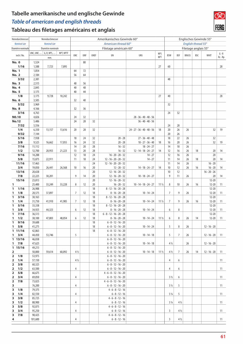
61
No. 0 1,524 80 1/16 1,588 7,723 7,895 27 60 28 No. 1 1,854 64 72 No. 2 2,184 56 64 3/32 2,381 48 No. 3 2,515 48 56 No. 4 2,845 40 48 No. 5 3,175 40 44 1/8 3,175 9,728 10,242 27 40 28 No. 6 3,505 32 40 5/32 3,969 32 No. 8 4,166 32 36 3/16 4,763 24 32 N0.10 4,826 24 32 28 - 36 - 40 - 48 - 56 No.12 5,486 24 28 32 36 - 40 - 48 - 56 7/32 5,556 24 28 1/4 6,350 13,157 13,616 20 28 32 24 - 27 - 36 - 40 - 48 - 56 18 20 26 26 32 19 9/32 7,144 20 26 5/16 7,938 18 24 32 20 - 28 27 - 36 - 40 - 48 18 22 26 32 3/8 9,525 16,662 17,055 16 24 32 20 - 28 18 - 27 - 36 - 40 18 16 20 26 32 19 7/16 11,112 14 20 28 16 - 32 18 - 24 - 27 14 18 26 1/2 12,700 20,955 21,223 13 20 28 16 - 32 12 - 14 - 18 - 24 - 27 14 12 16 26 18 20 14 9/16 14,288 12 18 24 16 - 20 - 28 - 32 14 - 27 12 16 26 20 5/8 15,875 22,911 11 18 24 12 - 16 - 20 - 28 - 32 14 - 27 11 14 26 18 20 14 11/16 17,463 24 12 - 16 - 20 - 28 - 32 11 14 26 16 - 20 3/4 19,050 26,441 26,568 10 16 20 12 - 28 - 32 14 - 18 - 24 - 27 14 10 12 26 16 16 - 20 14 13/16 20,638 20 12 - 16 - 28 - 32 10 12 16 - 20 - 26 7/8 22,225 30,201 9 14 20 12 - 16 - 28 - 32 10 - 18 - 24 - 27 9 11 26 20 14 15/16 23,813 20 12 - 16 - 28 - 32 12-20 1 25,400 33,249 33,228 8 12 20 16 - 28 - 32 10 - 14 - 18 - 24 - 27 11 ½ 8 10 26 16 12-20 11 1 1/16 26,988 18 8 - 12 - 16 - 20 - 28 12-20 1 1/8 28,575 37,897 7 12 18 8 - 16 - 20 - 28 10 - 14 - 24 7 9 26 12-20 11 1 3/16 30,163 18 8 - 12 - 16 - 20 - 28 12-20 1 1/4 31,750 41,910 41,985 7 12 18 8 - 16 - 20 - 28 10 - 14 - 24 11 ½ 7 9 26 16 12-20 11 1 5/16 33,338 18 8 - 12 - 16 - 20 - 28 12-20 1 3/8 34,925 44,323 6 12 18 8 - 16 - 20 - 28 10 - 14 - 24 6 8 12-20 11 1 7/16 36,513 18 6 - 8 - 12 - 16 - 20 - 28 12-20 1 1/2 38,100 47,803 48,054 6 12 18 8 - 16 - 20 - 28 10 - 14 - 24 11 ½ 6 8 26 14 12-20 11 1 9/16 39,688 18 6 - 8 - 12 - 16 - 20 1 5/8 41,275 18 6 - 8 - 12 - 16 - 20 10 - 14 - 24 5 8 26 12 - 16 - 20 1 11/16 42,863 18 6 - 8 - 12 - 16 - 20 1 3/4 44,450 53,746 5 6 - 8 - 12 - 16 - 20 10 - 14 - 18 5 7 26 12 - 16 - 20 11 1 13/16 46,038 6 - 8 - 12 - 16 - 20 1 7/8 47,625 6 - 8 - 12 - 16 - 20 10 - 14 - 18 4 ½ 26 12 - 16 - 20 1 15/16 49,213 6 - 8 - 12 - 16 - 20 2 50,800 59,614 60,092 4 ½ 6 - 8 - 12 - 16 - 20 10 - 14 - 18 11 ½ 4 ½ 7 26 14 12 - 16 - 20 11 2 1/8 53,975 6 - 8 - 12 - 16 - 20 2 1/4 57,150 4 ½ 6 - 8 - 12 - 16 - 20 4 6 11 2 3/8 60,325 6 - 8 - 12 - 16 - 20 2 1/2 63,500 4 6 - 8 - 12 - 16 - 20 4 6 11 2 5/8 66,675 4 - 6 - 8 - 12 - 16 - 20 2 3/4 69,850 4 6 - 8 - 12 - 16 - 20 3 ½ 6 11 2 7/8 73,025 4 - 6 - 8 - 12 - 16 - 20 3 76,200 4 6 - 8 - 12 - 16 - 20 3 ½ 5 11 3 1/8 79,375 4 - 6 - 8 - 12 - 16 3 1/4 82,550 4 6 - 8 - 12 - 16 3 ¼ 5 11 3 3/8 85,725 4 - 6 - 8 - 12 - 16 3 1/2 88,900 4 6 - 8 - 12 - 16 3 ¼ 4 ½ 11 3 5/8 92,075 4 - 6 - 8 - 12 - 16 3 3/4 95,250 4 6 - 8 - 12 - 16 3 4 ½ 11 3 7/8 98,425 4 - 6 - 8 - 12 - 16 4 101,600 4 6 - 8 - 12 - 16 3 4 ½ 11
Nenndurchmesser Nenndurchmesser Amerikanisches Gewinde 60° Englisches Gewinde 55°Nominal size Nominal size American thread 60° English thread 55°
Diamètre nominale Diamètre nominale Filetage américain 60° Filetage anglais 55°
inch / No.UNC, UNF, .... G, R, NPS, .... NPT, NPTF
UNC UNF UNEF UN UNSNPS NPT
BSW BSF BRASS BSC WHITG - R
Rc - Rpmm.
Tabelle amerikanische und englische GewindeTable of american and english threadsTableau des filetages américains et anglais
62
63
64