feedforward and ratio control - control global · feedforward and ratio control isa mentor program...
TRANSCRIPT
Standards
Certification
Education & Training
Publishing
Conferences & Exhibits
Feedforward and Ratio Control ISA Mentor Program Presentation by:
Gregory K. McMillan
Presenter
• Gregory K. McMillan is a retired Senior Fellow from Solutia/Monsanto and an ISA Fellow. Greg was an adjunct professor in the Washington University Saint Louis Chemical Engineering Department 2001-2004. Greg received the ISA “Kermit Fischer Environmental” Award for pH control in 1991, the Control Magazine “Engineer of the Year” Award for the Process Industry in 1994, was inducted into the Control “Process Automation Hall of Fame” in 2001, was honored by InTech Magazine in 2003 as one of the most influential innovators in automation, and received the ISA Life Achievement Award in 2010. Greg is the author of numerous ISA books on process control, his most recent being Advances in Reactor Measurement and Control and Good Tuning: A Pocket Guide - 4th Edition. Greg has been the monthly “Control Talk” columnist for Control magazine since 2002. Greg is the founder and co-leader with Hunter Vegas of the ISA Mentor Program for users. Greg’s expertise is available on the web sites: http://www.controlglobal.com/blogs/controltalkblog/ http://automation.isa.org/author/gregmcmillan/
2
When there is no secondary flow or speed controller, the feedforward summer in the primary controller is used to directly manipulate a valve position or power input signal. A secondary controller is too slow for pressure control.
When there is a flow or speed controller, Ratio control is predominantly used where a secondary flow or speed controller setpoint is manipulated to follow a leader flow or speed that is multiplied by a desired ratio. Ratio control is used to assist primary PIDs for composition, level, pH, temperature, & quality control.
In Ratio control the leader and follower flow first go to a Ratio block whose output is the input to a Bias/Gain block whose output is the cascade setpoint for a flow or speed controller. The setpoint (SP) of each block (ratio or bias) can be set by operator (auto mode) or automatically corrected by a primary PID (cascade mode). The manipulation of the primary PID of the Bias SP and Ratio SP is effectively a feedforward summer and feedforward multiplier, respectively. The use of the ratio and bias/gain blocks provide the operator visibility and accessibility in ratio control particularly important for understanding and procedural automation during startup, changes in products and abnormal operations.
The Bias SP is manipulated for volumes with back mixing due to agitation, turbulence or boiling (e.g., vessels and columns).
The actual and desired Ratio SP are displayed. During startup until the process is at its normal operating point, the primary controller is often in manual. In this case the operator runs with a manually set bias and ratio without correction.
Feedforward Multiplier vs Summer

Blend composition control - additive/feed (flow/flow) ratio Column temperature control - distillate/feed, reflux/distillate, reflux/feed,
steam/feed, and bottoms/feed (flow/flow) ratio Combustion temperature control - air/fuel (flow/flow) ratio Drum level control - feedwater/steam (flow/flow) ratio Extruder quality control - extruder/mixer (power/power) ratio Heat exchanger temperature control - coolant/feed (flow/flow) ratio Neutralizer pH control - reagent/feed (flow/flow) ratio Reactor reaction rate control - catalyst/reactant (speed/flow) ratio Reactor composition control - reactant/reactant (flow/flow) ratio Sheet, web, and film line machine direction (MD) gage control -
roller/pump (speed/speed) ratio Slaker conductivity control - lime/liquor (speed/flow) ratio Spin line fiber diameter gage control - winder/pump (speed/speed) ratio Header pressure control – letdown/user (flow/flow) ratio
For level and pressure, the mass flow theoretical ratio is simply 1
Ratios Here, There and Everywhere

Cascade Ratio or Cascade Bias Correction by Primary PID output
Follower Flow or Speed
Leader Flow or Speed
Cascade Ratio Correction
Cascade Bias Correction
Original Relationship per Process Flow Diagram (PFD)
Automatic correction of cascade Ratio Setpoint (feedforward multiplier) creates a gain factor in the open loop gain that is proportional to flow. For plug flow processes this multiplier gain factor cancels out a process gain that is inversely proportional to flow.
For back mixed processes, the process time constant being inversely proportional to flow cancels out process gain nonlinearity in the PID tuning where the PID gain is proportional to the process time constant divided by the process gain.
In this case the correction of the cascade ratio creates a residual nonlinearity that adversely affects PID tuning The primary PID output scaling is more critical and prone to error when correcting a ratio
The PID output scaling can be as simple as -50% to +50% of secondary PID scale when correcting a Bias Finally, many corrections in Ratio Control are simply associated with offsets from bias errors in the flow measurements or unmeasured loads
When in doubt which is best, automatically correct the Bias Setpoint You can slowly adapt the uncorrected Ratio or Bias by use of a generic integral only controller to reduce the correction by primary PID
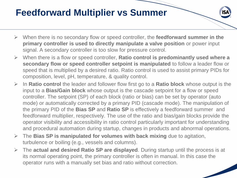
Loop and Load Disturbance Dynamics Block Diagram
Y fraction of small lag that is equivalent dead time is a logarithmic function of the ratio of the small to largest lag (Y = 0.28, 0.88 for ratios = 1.0 and 0.01, respectively)
Feedforward correction should arrive at this point at same time as the Load Upset
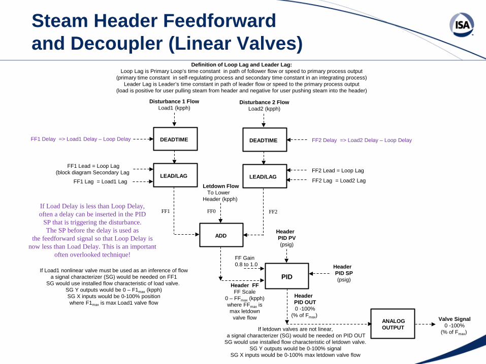
Steam Header Feedforward and Decoupler (Linear Valves)
Definition of Loop Lag and Leader Lag: Loop Lag is Primary Loop’s time constant in path of follower flow or speed to primary process output
(primary time constant in self-regulating process and secondary time constant in an integrating process) Leader Lag is Leader’s time constant in path of leader flow or speed to the primary process output
(load is positive for user pulling steam from header and negative for user pushing steam into the header)
ADD
DEADTIME
FF1 Lead = Loop Lag (block diagram Secondary Lag
Letdown Flow To Lower Header (kpph)
LEAD/LAG
Disturbance 1 Flow Load1 (kpph)
FF2 Delay => Load2 Delay – Loop Delay
FF1 Lag = Load1 Lag
DEADTIME
LEAD/LAG
Disturbance 2 Flow Load2 (kpph)
FF2 Lead = Loop Lag
FF2 Lag = Load2 Lag
FF1 FF0 FF2
FF1 Delay => Load1 Delay – Loop Delay
If letdown valves are not linear, a signal characterizer (SG) would be needed on PID OUT
SG would use installed flow characteristic of letdown valve. SG Y outputs would be 0-100% signal
SG X inputs would be 0-100% max letdown valve flow
If Load1 nonlinear valve must be used as an inference of flow a signal characterizer (SG) would be needed on FF1
SG would use installed flow characteristic of load valve. SG Y outputs would be 0 – F1max (kpph) SG X inputs would be 0-100% position where F1max is max Load1 valve flow
PID
Header PID PV (psig)
Header PID SP (psig)
Header FF FF Scale
0 – FFmax (kpph) where FFmax is max letdown
valve flow
FF Gain 0.8 to 1.0
ANALOG OUTPUT
Header PID OUT 0 -100%
(% of Fmax) Valve Signal 0 -100%
(% of Fmax)
If Load Delay is less than Loop Delay, often a delay can be inserted in the PID
SP that is triggering the disturbance. The SP before the delay is used as
the feedforward signal so that Loop Delay is now less than Load Delay. This is an important
often overlooked technique!
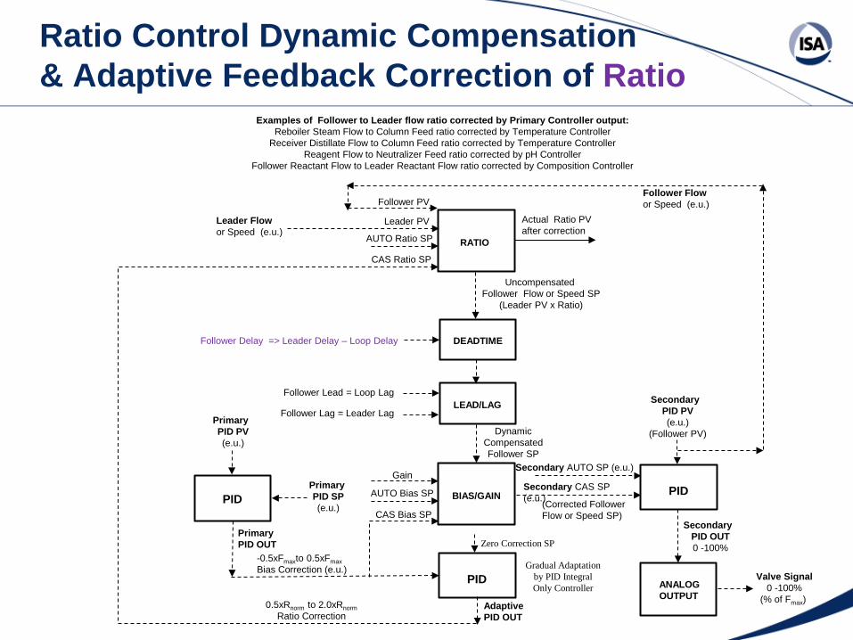
Ratio Control Dynamic Compensation & Adaptive Feedback Correction of Ratio
Examples of Follower to Leader flow ratio corrected by Primary Controller output: Reboiler Steam Flow to Column Feed ratio corrected by Temperature Controller
Receiver Distillate Flow to Column Feed ratio corrected by Temperature Controller Reagent Flow to Neutralizer Feed ratio corrected by pH Controller
Follower Reactant Flow to Leader Reactant Flow ratio corrected by Composition Controller
Leader Flow or Speed (e.u.)
DEADTIME
Follower Lag = Leader Lag
LEAD/LAG
Follower PV
Follower Delay => Leader Delay – Loop Delay
RATIO
Follower Lead = Loop Lag
Leader PV
AUTO Ratio SP
CAS Ratio SP
Actual Ratio PV after correction
Uncompensated Follower Flow or Speed SP
(Leader PV x Ratio)
Follower Flow or Speed (e.u.)
PID
Primary PID PV (e.u.)
Primary PID SP (e.u.)
ANALOG OUTPUT
BIAS/GAIN
CAS Bias SP
Dynamic Compensated Follower SP
AUTO Bias SP
Gain PID
Secondary PID PV (e.u.)
(Follower PV)
Secondary CAS SP (e.u.)
Secondary AUTO SP (e.u.)
(Corrected Follower Flow or Speed SP)
Secondary PID OUT 0 -100%
-0.5xFmaxto 0.5xFmax Bias Correction (e.u.)
Primary PID OUT
Valve Signal 0 -100%
(% of Fmax)
PID
Zero Correction SP
0.5xRnorm to 2.0xRnorm Ratio Correction
Adaptive PID OUT
Gradual Adaptation by PID Integral Only Controller
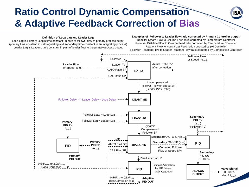
Ratio Control Dynamic Compensation & Adaptive Feedback Correction of Bias
Definition of Loop Lag and Leader Lag: Loop Lag is Primary Loop’s time constant in path of follower flow to primary process output
(primary time constant in self-regulating and secondary time constant in an integrating process) Leader Lag is Leader’s time constant in path of leader flow to the primary process output
Examples of Follower to Leader flow ratio corrected by Primary Controller output: Reboiler Steam Flow to Column Feed ratio corrected by Temperature Controller
Receiver Distillate Flow to Column Feed ratio corrected by Temperature Controller Reagent Flow to Neutralizer Feed ratio corrected by pH Controller
Follower Reactant Flow to Leader Reactant Flow ratio corrected by Composition Controller
Leader Flow or Speed (e.u.)
DEADTIME
Follower Lag = Leader Lag
LEAD/LAG
Follower PV
Follower Delay => Leader Delay – Loop Delay
PID
Primary PID PV (e.u.)
Primary PID SP (e.u.)
ANALOG OUTPUT
RATIO
Follower Lead = Loop Lag
Leader PV
AUTO Ratio SP
CAS Ratio SP
Actual Ratio PV after correction
BIAS/GAIN
CAS Bias SP
Dynamic Compensated Follower SP
AUTO Bias SP
Gain
Uncompensated Follower Flow or Speed SP
(Leader PV x Ratio)
PID
Secondary PID PV (e.u.)
(Follower PV)
Secondary CAS SP (e.u.)
Secondary AUTO SP (e.u.)
(Corrected Follower Flow or Speed SP) Secondary
PID OUT 0 -100%
Primary PID OUT
Follower Flow or Speed (e.u.)
Valve Signal 0 -100%
(% of Fmax)
PID
Zero Correction SP
0.5xRnorm to 2.0xRnorm Ratio Correction
Adaptive PID OUT
-0.5xFmaxto 0.5xFmax Bias Correction (e.u.)
Gradual Adaptation by PID Integral Only Controller
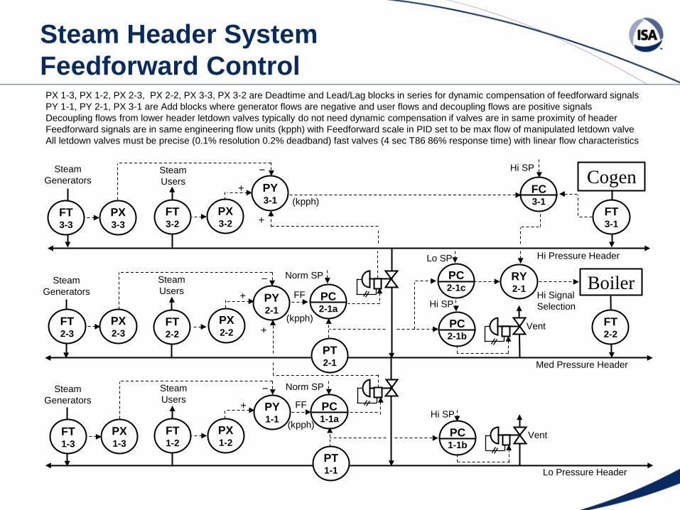
Steam Header System Feedforward Control
FT 3-3
FT 3-2
PT 2-1
PC 2-1c
PY 2-1
Cogen
FT 3-1
Boiler
FT 2-2
PC 2-1a
PC 2-1b
PX 3-2
PX 3-3
PX 2-3
FT 2-3
FT 2-2
PX 2-2
RY 2-1
FC 3-1
PY 3-1
PT 1-1
PY 1-1
PC 1-1a
PC 1-1b
PX 1-3
FT 1-3
FT 1-2
PX 1-2
Hi Pressure Header
Med Pressure Header
Lo Pressure Header
Hi SP
Hi SP
Lo SP
Hi SP
Norm SP
Norm SP
Hi Signal Selection
Vent
Vent
FF
Steam Generators
Steam Generators
Steam Generators
Steam Users
Steam Users
Steam Users
+
−
+
−
+
−
FF
(kpph)
(kpph)
(kpph)
PX 1-3, PX 1-2, PX 2-3, PX 2-2, PX 3-3, PX 3-2 are Deadtime and Lead/Lag blocks in series for dynamic compensation of feedforward signals PY 1-1, PY 2-1, PX 3-1 are Add blocks where generator flows are negative and user flows and decoupling flows are positive signals Decoupling flows from lower header letdown valves typically do not need dynamic compensation if valves are in same proximity of header Feedforward signals are in same engineering flow units (kpph) with Feedforward scale in PID set to be max flow of manipulated letdown valve All letdown valves must be precise (0.1% resolution 0.2% deadband) fast valves (4 sec T86 86% response time) with linear flow characteristics
+
+
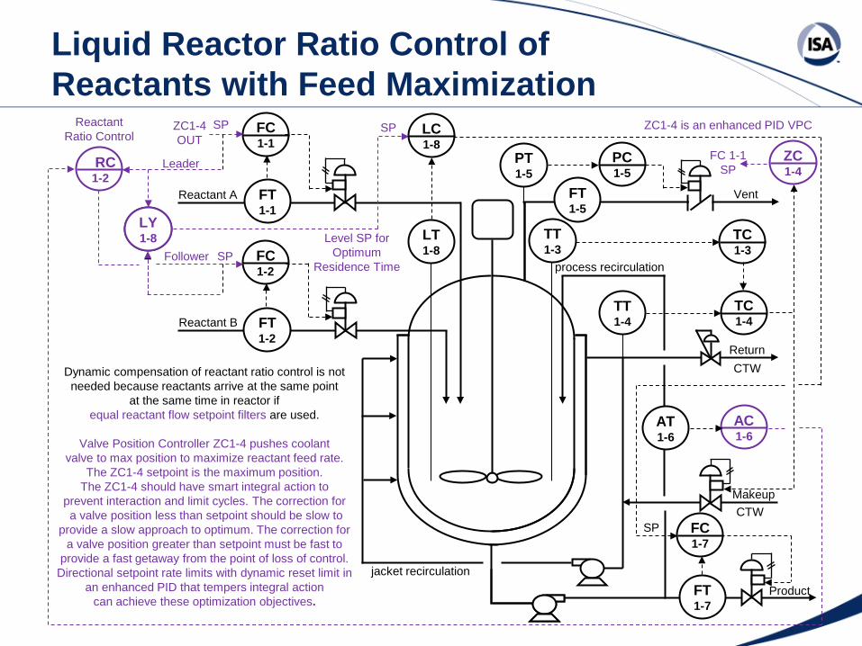
Liquid Reactor Ratio Control of Reactants with Feed Maximization
TT 1-4
TC 1-3
TC 1-4
AT 1-6
LY 1-8
FT 1-2
FC 1-2
Reactant A
Reactant B
SP
Level SP for Optimum
Residence Time SP
AC 1-6
Makeup
Return
LY 1-8 LT
1-8 TT 1-3
LC 1-8
Reactant Ratio Control
Product
Vent FT 1-1
FC 1-1
FC 1-7
FT 1-7
SP
PT 1-5
PC 1-5
FT 1-5
CTW
CTW
FC 1-1 SP
ZC1-4 OUT
ZC 1-4
ZC1-4 is an enhanced PID VPC
RC 1-2
Leader
Follower
SP
jacket recirculation
process recirculation
Dynamic compensation of reactant ratio control is not needed because reactants arrive at the same point
at the same time in reactor if equal reactant flow setpoint filters are used.
Valve Position Controller ZC1-4 pushes coolant
valve to max position to maximize reactant feed rate. The ZC1-4 setpoint is the maximum position.
The ZC1-4 should have smart integral action to prevent interaction and limit cycles. The correction for a valve position less than setpoint should be slow to
provide a slow approach to optimum. The correction for a valve position greater than setpoint must be fast to
provide a fast getaway from the point of loss of control. Directional setpoint rate limits with dynamic reset limit in
an enhanced PID that tempers integral action can achieve these optimization objectives.
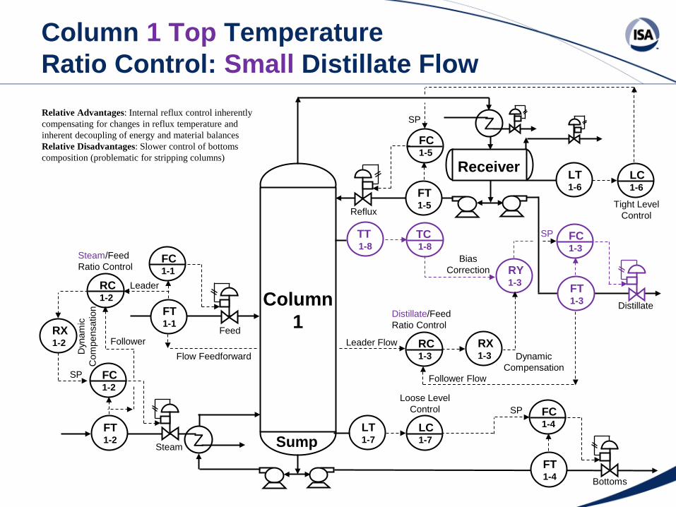
Column 1 Top Temperature Ratio Control: Small Distillate Flow
Column 1
Z
Z FT 1-2
FC 1-2
FT 1-4
FC 1-4
FT 1-5
FC 1-5
LT 1-6
LC 1-6
FT 1-3
FC 1-3
FT 1-1
FC 1-1
TT 1-8
TC 1-8
RC 1-3
RY 1-3 RC
1-2
Feed
Steam
Distillate
Bottoms
Reflux
Distillate/Feed Ratio Control
Steam/Feed Ratio Control
Bias Correction
Flow Feedforward
Receiver
Sump LT 1-7
LC 1-7
Tight Level Control
Loose Level Control
Leader Flow
Follower Flow
SP
SP
SP
SP
Leader
Follower RX 1-2 RX
1-3 Dynamic Compensation
Dyn
amic
C
ompe
nsat
ion
Relative Advantages: Internal reflux control inherently compensating for changes in reflux temperature and inherent decoupling of energy and material balances Relative Disadvantages: Slower control of bottoms composition (problematic for stripping columns)
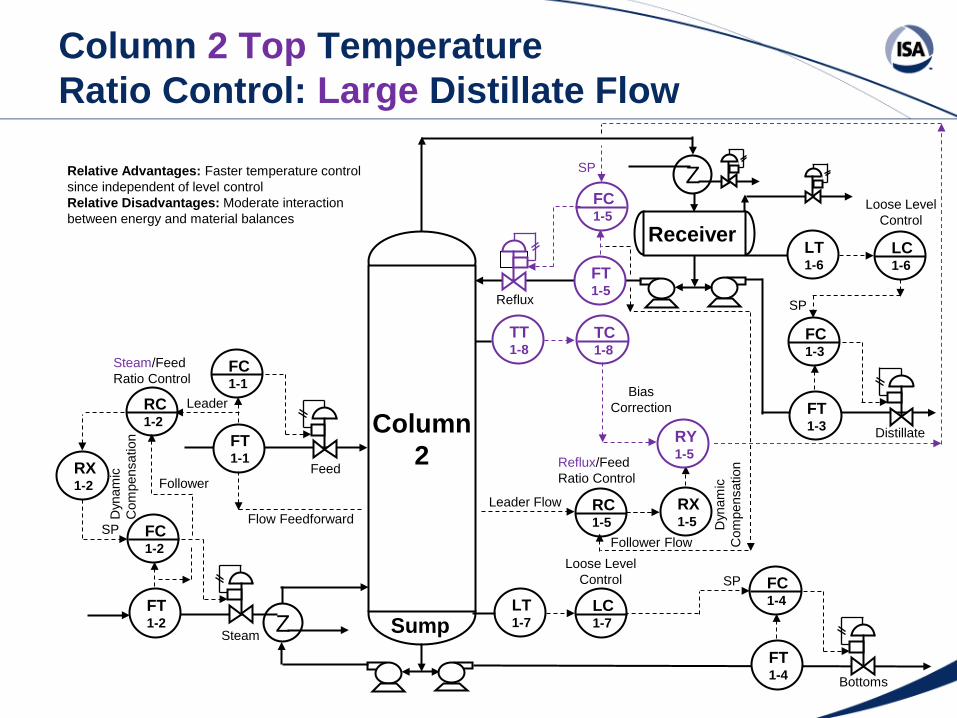
Column 2 Top Temperature Ratio Control: Large Distillate Flow
Column 2
Z
Z FT 1-4
FC 1-4
FT 1-5
FC 1-5
LT 1-6
LC 1-6
FT 1-3
FC 1-3
FT 1-1
FC 1-1
TT 1-8
TC 1-8
RC 1-5
Feed
Distillate
Bottoms
Reflux
Reflux/Feed Ratio Control
Bias Correction
Flow Feedforward
Receiver
Sump LT 1-7
LC 1-7
Loose Level Control
Loose Level Control
FT 1-2
FC 1-2
RC 1-2
Steam
Steam/Feed Ratio Control
SP
Leader
Follower
RY 1-5
Dyn
amic
C
ompe
nsat
ion
RX 1-2
RX 1-5 D
ynam
ic
Com
pens
atio
n
SP
SP
Leader Flow
Follower Flow
SP
Relative Advantages: Faster temperature control since independent of level control Relative Disadvantages: Moderate interaction between energy and material balances
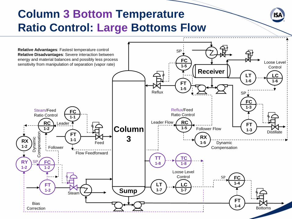
Column 3 Bottom Temperature Ratio Control: Large Bottoms Flow
Column 3
Z
Z FT 1-4
FC 1-4
FT 1-5
FC 1-5
LT 1-6
LC 1-6
FT 1-3
FC 1-3
FT 1-1
FC 1-1
TT 1-8
TC 1-8
RC 1-5
LT 1-7
LC 1-7
Feed
Distillate
Bottoms
Reflux
Reflux/Feed Ratio Control
Bias Correction
Flow Feedforward
Receiver
Sump
RY 1-2
Loose Level Control
Loose Level Control
FT 1-2
FC 1-2
RC 1-2
Steam
Steam/Feed Ratio Control
SP
Leader
Follower
Dyn
amic
C
ompe
nsat
ion
RX 1-2
RX 1-5 Dynamic
Compensation
Leader Flow Follower Flow
SP
SP
SP
Relative Advantages: Fastest temperature control Relative Disadvantages: Severe interaction between energy and material balances and possibly less process sensitivity from manipulation of separation (vapor rate)
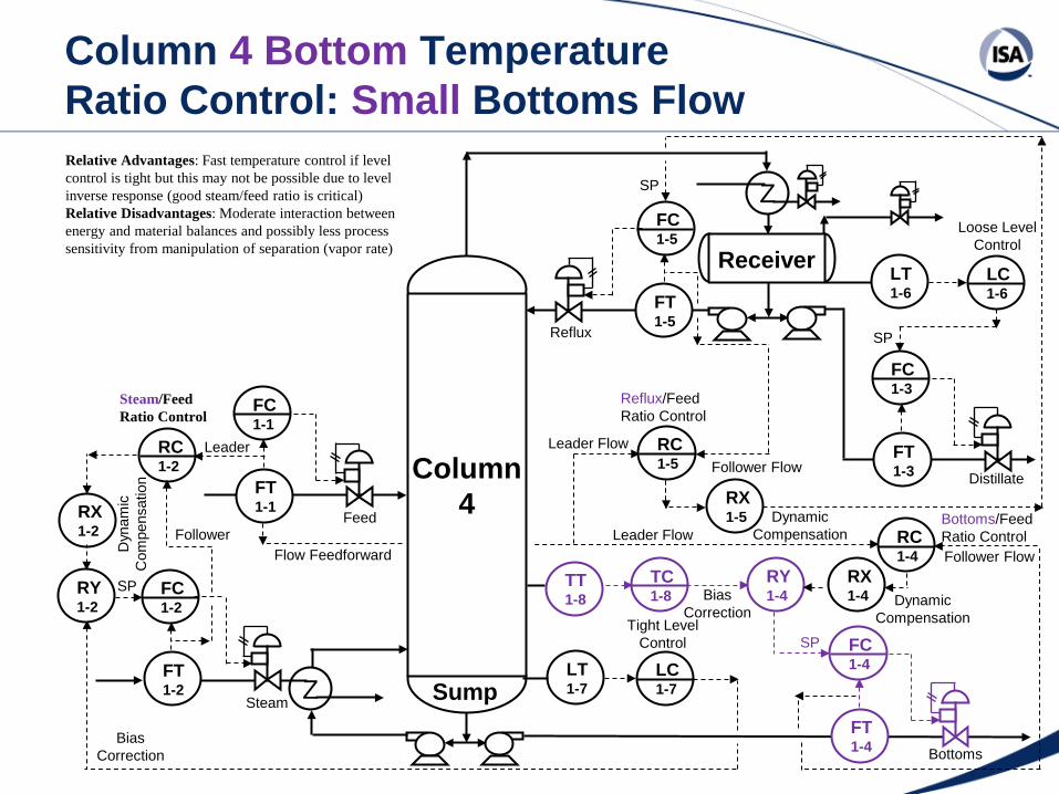
Column 4 Bottom Temperature Ratio Control: Small Bottoms Flow
Column 4
Z
FT 1-4
FC 1-4
FT 1-5
FC 1-5
LT 1-6
LC 1-6
FT 1-3
FC 1-3
TT 1-8
TC 1-8
RC 1-5
LT 1-7
LC 1-7
Distillate
Bottoms
Reflux
Reflux/Feed Ratio Control
Bias Correction
Receiver
Sump
RC 1-4
RY 1-4
Tight Level Control
Loose Level Control
Z
FT 1-1
FC 1-1
Feed
Bias Correction
Flow Feedforward
RY 1-2
FT 1-2
FC 1-2
RC 1-2
Steam
SP
Leader
Follower
Steam/Feed Ratio Control
Dyn
amic
C
ompe
nsat
ion
RX 1-2
RX 1-4
RX 1-5 Dynamic
Compensation
Dynamic Compensation
Bottoms/Feed Ratio Control
Leader Flow Follower Flow
Leader Flow Follower Flow
SP
SP
SP
Relative Advantages: Fast temperature control if level control is tight but this may not be possible due to level inverse response (good steam/feed ratio is critical) Relative Disadvantages: Moderate interaction between energy and material balances and possibly less process sensitivity from manipulation of separation (vapor rate)
Standards
Certification
Education & Training
Publishing
Conferences & Exhibits
Questions?