fbx - schneider electricmt.schneider-electric.be/op_main/fbx/instructions/am… · ·...
TRANSCRIPT

FBXSF6 Gas-insulated switchboards
InstructionsOperation - Maintenance
Secondary Distribution Switchgear

FBX Contents
iAMTNoT132-02 revision: 04
1 Schneider Electric at your service 1. . . . . . . . . . . . . . . . . . . 1.1 Our Service Unit: our specialists, and suitably adapted services... 1. . . . . . . . .
1.2 Schneider Electric Training: Together, let us develop our skills... 1. . . . . . . . . . .
2 With regards to this User Manual 2. . . . . . . . . . . . . . . . . . . . 2.1 Responsibilities 2. . . . . . . . . . . . . . . . . . . . . . . . . . . . . . . . . . . . . . . . . . . . . . . . . . .
2.2 Particular instructions for operations and interventions on energized equipment 2. . . . . . . . . . . . . . . . . . . . . . . . . . . . . . . . . . . . . . . . . . . . . . . . . . . . . . . .
2.3 Other technical notices to be consulted 2. . . . . . . . . . . . . . . . . . . . . . . . . . . . . . . .
2.4 Tools (not supplied) required for the operations described in this user manual 2
2.5 Symbols & conventions 2. . . . . . . . . . . . . . . . . . . . . . . . . . . . . . . . . . . . . . . . . . . . .
3 Functional interlocks 3. . . . . . . . . . . . . . . . . . . . . . . . . . . . . . . 3.1 Functional mechanical interlocks 3. . . . . . . . . . . . . . . . . . . . . . . . . . . . . . . . . . . . .
3.2 Interlocks for functions C and T1 3. . . . . . . . . . . . . . . . . . . . . . . . . . . . . . . . . . . . .
3.3 Interlocks for function T2 3. . . . . . . . . . . . . . . . . . . . . . . . . . . . . . . . . . . . . . . . . . . .
3.4 Interlocks for function Sb 3. . . . . . . . . . . . . . . . . . . . . . . . . . . . . . . . . . . . . . . . . . .
4 Operating accessories 4. . . . . . . . . . . . . . . . . . . . . . . . . . . . . . 4.1 Reminder for Manual Operations 4. . . . . . . . . . . . . . . . . . . . . . . . . . . . . . . . . . . . .
4.2 Operating accessories 4. . . . . . . . . . . . . . . . . . . . . . . . . . . . . . . . . . . . . . . . . . . . .
4.3 Lockouts using padlocks (Optional) 4. . . . . . . . . . . . . . . . . . . . . . . . . . . . . . . . . . .
5 Use of the RE function 5. . . . . . . . . . . . . . . . . . . . . . . . . . . . . . 5.1 Opening the earthing switch 5. . . . . . . . . . . . . . . . . . . . . . . . . . . . . . . . . . . . . . . . .
5.2 Closing the earthing switch 5. . . . . . . . . . . . . . . . . . . . . . . . . . . . . . . . . . . . . . . . . .
6 Use of the C function 6. . . . . . . . . . . . . . . . . . . . . . . . . . . . . . . 6.1 Opening the earthing switch 6. . . . . . . . . . . . . . . . . . . . . . . . . . . . . . . . . . . . . . . . .
6.2 Closing the earthing switch 6. . . . . . . . . . . . . . . . . . . . . . . . . . . . . . . . . . . . . . . . . .
6.3 Closing the load break switch 7. . . . . . . . . . . . . . . . . . . . . . . . . . . . . . . . . . . . . . . .
6.4 Opening the load break switch 7. . . . . . . . . . . . . . . . . . . . . . . . . . . . . . . . . . . . . . .
6.5 Movements of motorised control mechanisms 7. . . . . . . . . . . . . . . . . . . . . . . . . .
7 Use of the T1 function 8. . . . . . . . . . . . . . . . . . . . . . . . . . . . . . 7.1 Opening the earthing switch 8. . . . . . . . . . . . . . . . . . . . . . . . . . . . . . . . . . . . . . . . .
7.2 Closing the earthing switch 8. . . . . . . . . . . . . . . . . . . . . . . . . . . . . . . . . . . . . . . . . .
7.3 Closing the load break switch 8. . . . . . . . . . . . . . . . . . . . . . . . . . . . . . . . . . . . . . . .
7.4 Manually opening the load break switch 8. . . . . . . . . . . . . . . . . . . . . . . . . . . . . . .
7.5 Movements of motorised control mechanisms 8. . . . . . . . . . . . . . . . . . . . . . . . . .
8 Use of the T2 function 9. . . . . . . . . . . . . . . . . . . . . . . . . . . . . . 8.1 Opening the earthing switch 9. . . . . . . . . . . . . . . . . . . . . . . . . . . . . . . . . . . . . . . . .
8.2 Closing the earthing switch 9. . . . . . . . . . . . . . . . . . . . . . . . . . . . . . . . . . . . . . . . . .
8.3 Closing the line isolating switch [circuit breaker open] 9. . . . . . . . . . . . . . . . . . . .
8.4 Opening the line isolating switch [circuit breaker open] 9. . . . . . . . . . . . . . . . . . .
8.5 Closing the circuit breaker [Line Isolator closed] 10. . . . . . . . . . . . . . . . . . . . . . . .
8.6 Opening the circuit breaker [Line Isolator closed] 10. . . . . . . . . . . . . . . . . . . . . . .
8.7 Closing the circuit breaker [Line Isolator open] 10. . . . . . . . . . . . . . . . . . . . . . . . . .
8.8 Movements of motorised control mechanisms 10. . . . . . . . . . . . . . . . . . . . . . . . . .
9 Use of Function Sb 11. . . . . . . . . . . . . . . . . . . . . . . . . . . . . . . . . 9.1 Opening the earthing switch 11. . . . . . . . . . . . . . . . . . . . . . . . . . . . . . . . . . . . . . . . .
9.2 Closing the earthing switch 11. . . . . . . . . . . . . . . . . . . . . . . . . . . . . . . . . . . . . . . . . .
9.3 Closing the load break switch 11. . . . . . . . . . . . . . . . . . . . . . . . . . . . . . . . . . . . . . . .
9.4 Opening the load break switch 11. . . . . . . . . . . . . . . . . . . . . . . . . . . . . . . . . . . . . . .
9.5 Movements of motorised control mechanisms 11. . . . . . . . . . . . . . . . . . . . . . . . . .
10 Using motorised functions 12. . . . . . . . . . . . . . . . . . . . . . . . . . 10.1 Movements of motorised control mechanisms [Optional] 12. . . . . . . . . . . . . . . . .
10.2 Manual emergency movements of motorised controls 12. . . . . . . . . . . . . . . . . . . .
10.3 Approximate number of turns for backup manual control levers 12. . . . . . . . . . . .
10.4 Manual interventions involving Functions C and Sb [Earthing switch open] 12. .
10.5 Manual interventions involving Function T1 [Earthing switch open] 13. . . . . . . . .
10.6 Manual interventions involving Function T2 [Earthing switch open] 13. . . . . . . . .
11 Maintenance 14. . . . . . . . . . . . . . . . . . . . . . . . . . . . . . . . . . . . . . . 11.1 Levels of maintenance 14. . . . . . . . . . . . . . . . . . . . . . . . . . . . . . . . . . . . . . . . . . . . .
11.2 Preventive maintenance 14. . . . . . . . . . . . . . . . . . . . . . . . . . . . . . . . . . . . . . . . . . . .

FBX
ii AMTNoT132-02 revision: 04
11.3 Corrective maintenance 14. . . . . . . . . . . . . . . . . . . . . . . . . . . . . . . . . . . . . . . . . . . .
11.4 Replacement of the three fuses 14. . . . . . . . . . . . . . . . . . . . . . . . . . . . . . . . . . . . . .
Replacement of a fuse 14. . . . . . . . . . . . . . . . . . . . . . . . . . . . . . . . . . . . . . . . . . . . .
When using under 12 kV 16. . . . . . . . . . . . . . . . . . . . . . . . . . . . . . . . . . . . . . . . . . . .
11.5 Replacement of a voltage indicator unit [E.g.: Type VPIS] 16. . . . . . . . . . . . . . . .
11.6 Periodic frequency for maintenance operations of the VDS boxes 17. . . . . . . . .
12 Spare parts 18. . . . . . . . . . . . . . . . . . . . . . . . . . . . . . . . . . . . . . . . 12.1 The spare part 18. . . . . . . . . . . . . . . . . . . . . . . . . . . . . . . . . . . . . . . . . . . . . . . . . . . .
12.2 Identification of materials 18. . . . . . . . . . . . . . . . . . . . . . . . . . . . . . . . . . . . . . . . . . . .
12.3 Storage conditions 18. . . . . . . . . . . . . . . . . . . . . . . . . . . . . . . . . . . . . . . . . . . . . . . . .
13 Cable testing 19. . . . . . . . . . . . . . . . . . . . . . . . . . . . . . . . . . . . . . . 13.1 Preparation of the function 19. . . . . . . . . . . . . . . . . . . . . . . . . . . . . . . . . . . . . . . . . .
13.2 Cable testing with plug-in `T' piece connectors (busbar energised) 19. . . . . . . . .
13.3 Cable tests: EON specification with plug-in 'T' piece connectors [busbar energised] 20. . . . . . . . . . . . . . . . . . . . . . . . . . . . . . . . . . . . . . . . . . . . . . . . .
13.4 Testing the casing of plug-in connectors 20. . . . . . . . . . . . . . . . . . . . . . . . . . . . . . .
14 Characteristics and Volumes of SF6 gas 21. . . . . . . . . . . . . 14.1 General characteristics 21. . . . . . . . . . . . . . . . . . . . . . . . . . . . . . . . . . . . . . . . . . . . .
14.2 Filling pressure 21. . . . . . . . . . . . . . . . . . . . . . . . . . . . . . . . . . . . . . . . . . . . . . . . . . . .
14.3 Operating thresholds of the pressure gauge contacts 21. . . . . . . . . . . . . . . . . . . .
14.4 FBX functions 21. . . . . . . . . . . . . . . . . . . . . . . . . . . . . . . . . . . . . . . . . . . . . . . . . . . . .
15 At the end of the equipment's operational life 22. . . . . . . . 15.1 Valorization of the equipment 22. . . . . . . . . . . . . . . . . . . . . . . . . . . . . . . . . . . . . . . .
15.2 Safety instructions 22. . . . . . . . . . . . . . . . . . . . . . . . . . . . . . . . . . . . . . . . . . . . . . . . .
15.3 Dismantling of the equipment service 22. . . . . . . . . . . . . . . . . . . . . . . . . . . . . . . . .
15.4 Distribution and valorization of the materials used for FBX (See § 15.1) 23. . . . .
16 Notes 24. . . . . . . . . . . . . . . . . . . . . . . . . . . . . . . . . . . . . . . . . . . . . .

FBX
AMTNoT132-02 revision: 04 1
Operations and maintenance may only becarried out by personnel who have receivedsuitable authorisation for the operations andmanœuvres they are responsible forperforming.
If this is not the case, please refer to ourService Unit or Training Centre.
All locking-out operations must be performedaccording to the ”General Safety Instructionsbooklet for Electrical Applications” UTE C 18 510 (or its equivalent outsideFRANCE).
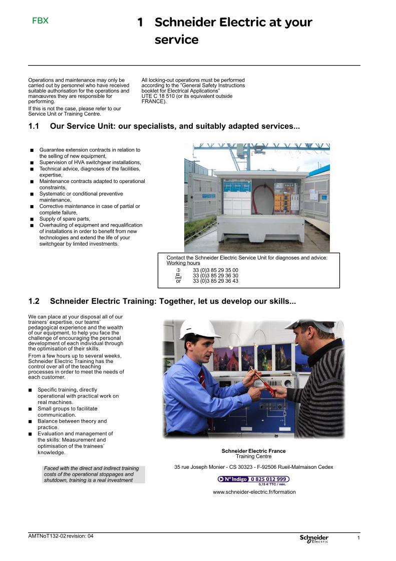
1.1 Our Service Unit: our specialists, and suitably adapted services...
Contact the Schneider Electric Service Unit for diagnoses and advice:Working hours
� 33 (0)3 85 29 35 00 33 (0)3 85 29 36 30or 33 (0)3 85 29 36 43
� Guarantee extension contracts in relation tothe selling of new equipment,
� Supervision of HVA switchgear installations,
� Technical advice, diagnoses of the facilities,expertise,
� Maintenance contracts adapted to operationalconstraints,
� Systematic or conditional preventivemaintenance,
� Corrective maintenance in case of partial or
complete failure,� Supply of spare parts,� Overhauling of equipment and requalification
of installations in order to benefit from newtechnologies and extend the life of yourswitchgear by limited investments.
1.2 Schneider Electric Training: Together, let us develop our skills...
Schneider Electric FranceTraining Centre
35 rue Joseph Monier - CS 30323 - F-92506 Rueil-Malmaison Cedex
www.schneider-electric.fr/formation
We can place at your disposal all of ourtrainers' expertise, our teams'pedagogical experience and the wealthof our equipment, to help you face thechallenge of encouraging the personaldevelopment of each individual throughthe optimisation of their skills.
From a few hours up to several weeks,Schneider Electric Training has thecontrol over all of the teachingprocesses in order to meet the needs ofeach customer.
� Specific training, directlyoperational with practical work onreal machines.
� Small groups to facilitatecommunication.
� Balance between theory andpractice.
� Evaluation and management ofthe skills: Measurement andoptimisation of the trainees'
knowledge.
Faced with the direct and indirect trainingcosts of the operational stoppages andshutdown, training is a real investment
1 Schneider Electric at your
service
FBX
2 AMTNoT132-02 revision: 04
© - Schneider Electric - 2010. SchneiderElectric, the Schneider Electric logo and theirfigurative forms are Schneider Electricregistered trademarks. The other brandnames mentioned within this document,whether they be copyright or not, belong totheir respective holders.
2.1 Responsibilities
Our devices are quality controlled and testedat the factory in accordance with thestandards and the regulations currently inforce.
Apparatus efficiency and apparatus lifedepend on the compliance with theinstallation, commissioning and operationinstructions described in this user manual.Non respect of these instructions is likely toinvalidate any guarantee.
Local requirements especially about safetyand which are in accordance with theindications given in this document, must beobserved.
Schneider Electric declines any responsibilityfor the consequences:- due to the non respect of therecommendations in this manual which makereference to the international regulations inforce.- due to the non respect of the instructions bythe suppliers of cables and connectionaccessories during installation and fittingoperations,- of any possible aggressive climaticconditions (humidity, pollution, etc.) acting inthe immediate environment of the materialsthat are neither suitably adapted norprotected for these effects.
This user manual does not list the locking-outprocedures that must be applied. Theinterventions described are carried out onde-energized equipment (in the course ofbeing installed) or locked out (nonoperational).
2.2 Particular instructions for operations and interventions on energized equipment
When commissioning and operating theequipment under normal conditions, theGeneral safety instructions for electricalapplications must be respected, (protectivegloves, insulating stool, etc.), in addition tostandard operating instructions.
All manipulations must be completed oncestarted.
The durations (for completing the operationsmentioned) given in the maintenance tablesare purely an indication and depend onon-site conditions.
2.3 Other technical notices to be consulted
� AMTNoT131-02 FBX SF6 Gas-insulated switchboards Installation - Commissioning
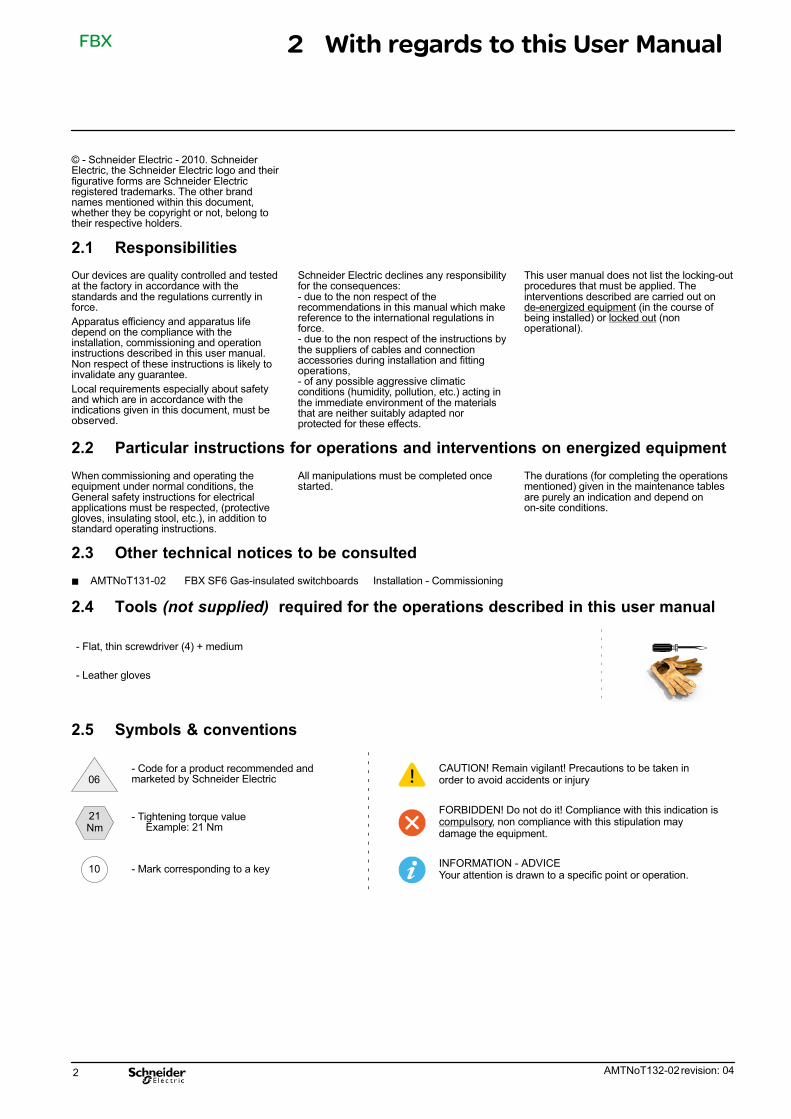
2.4 Tools (not supplied) required for the operations described in this user manual
- Flat, thin screwdriver (4) + medium
- Leather gloves
2.5 Symbols & conventions
- Code for a product recommended andmarketed by Schneider Electric 06 ATTENTION
CAUTION! Remain vigilant! Precautions to be taken inorder to avoid accidents or injury
FORBIDDEN! Do not do it! Compliance with this indication iscompulsory, non compliance with this stipulation maydamage the equipment.
INFORMATION - ADVICEYour attention is drawn to a specific point or operation.
10
- Tightening torque value Example: 21 Nm
- Mark corresponding to a key
21Nm
2 With regards to this User Manual
FBX
AMTNoT132-02 revision: 04 3
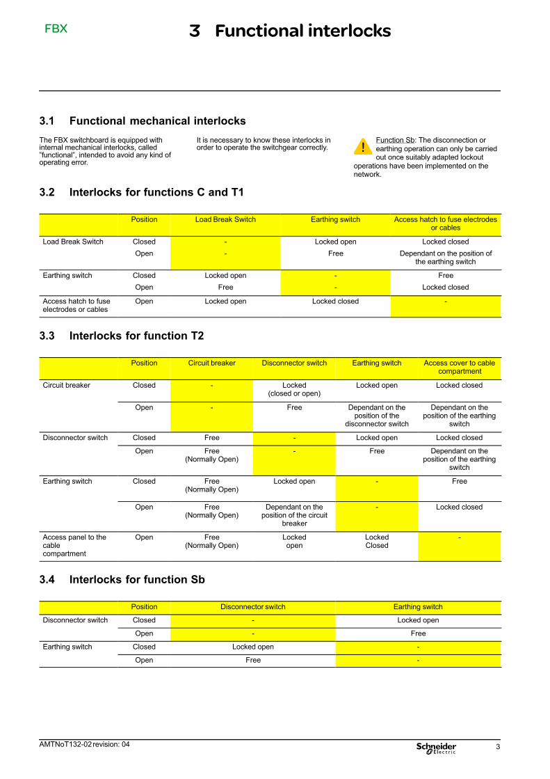
3.1 Functional mechanical interlocks
The FBX switchboard is equipped withinternal mechanical interlocks, called”functional”, intended to avoid any kind ofoperating error.
It is necessary to know these interlocks inorder to operate the switchgear correctly.
Function Sb: The disconnection orearthing operation can only be carriedout once suitably adapted lockout
operations have been implemented on thenetwork.
3.2 Interlocks for functions C and T1
Position Load Break Switch Earthing switch Access hatch to fuse electrodesor cables
Load Break Switch Closed
Open
-
-
Locked open
Free
Locked closed
Dependant on the position ofthe earthing switch
Earthing switch Closed
Open
Locked open
Free
-
-
Free
Locked closed
Access hatch to fuseelectrodes or cables
Open Locked open Locked closed -
3.3 Interlocks for function T2
Position Circuit breaker Disconnector switch Earthing switch Access cover to cablecompartment
Circuit breaker Closed - Locked(closed or open)
Locked open Locked closed
Open - Free Dependant on theposition of the
disconnector switch
Dependant on theposition of the earthing
switch
Disconnector switch Closed Free - Locked open Locked closed
Open Free(Normally Open)
- Free Dependant on theposition of the earthing
switch
Earthing switch Closed Free(Normally Open)
Locked open - Free
Open Free(Normally Open)
Dependant on theposition of the circuit
breaker
- Locked closed
Access panel to thecable compartment
Open Free(Normally Open)
Lockedopen
LockedClosed
-
3.4 Interlocks for function Sb
Position Disconnector switch Earthing switch
Disconnector switch Closed - Locked open
Open - Free
Earthing switch Closed Locked open -
Open Free -
3 Functional interlocks

FBX
4 AMTNoT132-02 revision: 04
4.1 Reminder for Manual Operations
The operating manoeuvres are made withoutany special effort. Nevertheless, the forcerequired is greater for latching controls (T1,T2) than for tumbler switches (C).
All movements of the lever must be frank andcomplete.
The lever moves through approximately 95°.
4.2 Operating accessories
� Standard operating lever for the earthingswitch (red end).
� Standard operating lever for theload-break switch (black end).
� Fuse electrode compartment key.
� Emergency manual control lever formotorised mechanisms.
4.3 Lockouts using padlocks (Optional)
Optional: Each mechanical control hubcan be fitted so as to allow it to belocked out using a padlock (notsupplied).
4 Operating accessories

FBX
AMTNoT132-02 revision: 04 5
5.1 Opening the earthing switch
� Check that the tag is fully lowered.� Insert the appropriate lever (red end) into
the earthing switch socket.
� Grasp the lever with both hands. � Lift the lever: the earthing switch is nowin the open position.
� Remove the lever.
5.2 Closing the earthing switch
Before closing the earthing switch,ensure there is no voltage across theindicator units (see corresponding
manual - § 2.3).
� Check that the tag is fully lowered.� Insert the appropriate lever (red end) into
the earthing switch socket.
� Grasp the lever with both hands. � Pull the lever down: the earthing switchis closed.
� Remove the lever.
5 Use of the RE function
FBX
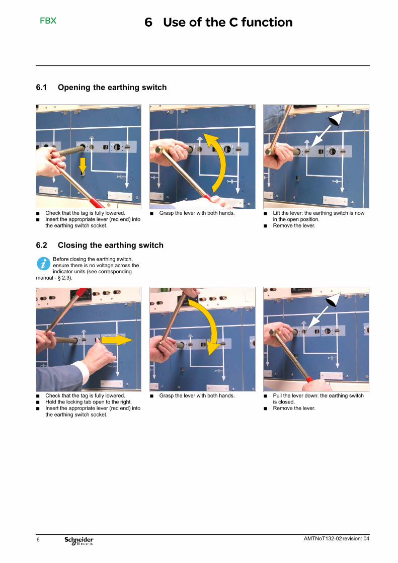
6 AMTNoT132-02 revision: 04
6.1 Opening the earthing switch
� Check that the tag is fully lowered.� Insert the appropriate lever (red end) into
the earthing switch socket.
� Grasp the lever with both hands. � Lift the lever: the earthing switch is nowin the open position.
� Remove the lever.
6.2 Closing the earthing switch
Before closing the earthing switch,ensure there is no voltage across theindicator units (see corresponding
manual - § 2.3).
� Check that the tag is fully lowered.� Hold the locking tab open to the right.� Insert the appropriate lever (red end) into
the earthing switch socket.
� Grasp the lever with both hands. � Pull the lever down: the earthing switchis closed.
� Remove the lever.
6 Use of the C function
FBX
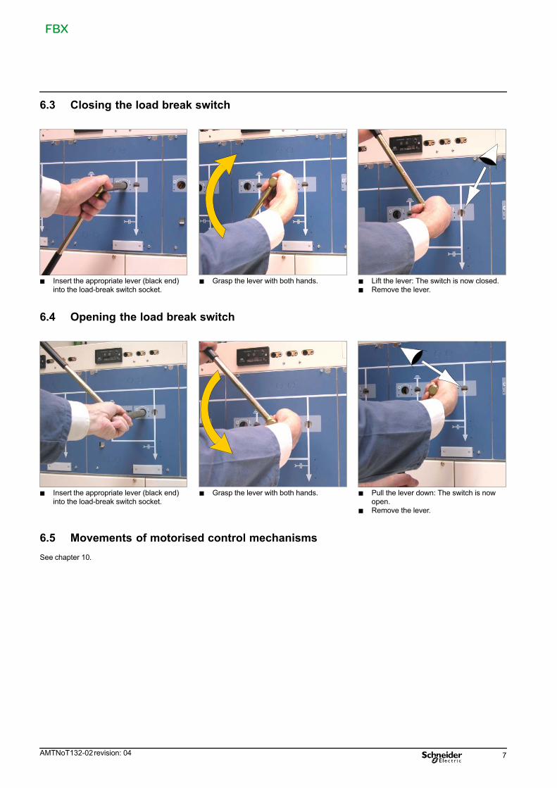
AMTNoT132-02 revision: 04 7
6.3 Closing the load break switch
� Insert the appropriate lever (black end)into the load-break switch socket.
� Grasp the lever with both hands. � Lift the lever: The switch is now closed.� Remove the lever.
6.4 Opening the load break switch
� Insert the appropriate lever (black end)into the load-break switch socket.
� Grasp the lever with both hands. � Pull the lever down: The switch is nowopen.
� Remove the lever.
6.5 Movements of motorised control mechanisms
See chapter 10.
FBX
8 AMTNoT132-02 revision: 04
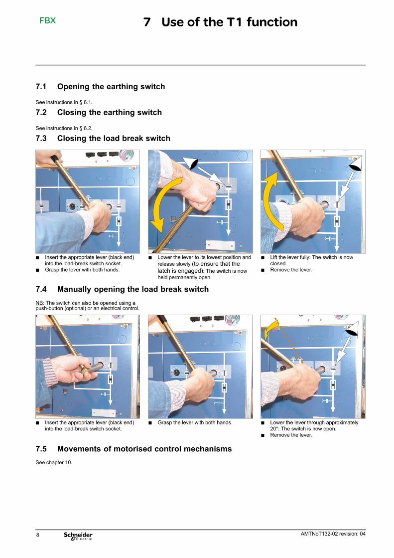
7.1 Opening the earthing switch
See instructions in § 6.1.
7.2 Closing the earthing switch
See instructions in § 6.2.
7.3 Closing the load break switch
� Insert the appropriate lever (black end)into the load-break switch socket.
� Grasp the lever with both hands.
� Lower the lever to its lowest position and
release slowly (to ensure that the
latch is engaged): The switch is now
held permanently open.
� Lift the lever fully: The switch is nowclosed.
� Remove the lever.
7.4 Manually opening the load break switch
NB: The switch can also be opened using apush-button (optional) or an electrical control.
� Insert the appropriate lever (black end)into the load-break switch socket.
� Grasp the lever with both hands. � Lower the lever through approximately20°: The switch is now open.
� Remove the lever.
7.5 Movements of motorised control mechanisms
See chapter 10.
7 Use of the T1 function

FBX
AMTNoT132-02 revision: 04 9
8.1 Opening the earthing switch
See instructions in § 6.1.
8.2 Closing the earthing switch
See instructions in § 6.2.
8.3 Closing the line isolating switch [circuit breaker open]
� Lift the locking tab.� Insert the appropriate lever (black end)
into the disconnector switch socket.
� Grasp the lever with both hands. � Lift the lever: The line isolator is nowclosed.
� Remove the lever.
8.4 Opening the line isolating switch [circuit breaker open]
� Lift the locking tab.� Insert the appropriate lever (black end)
into the disconnector switch socket.
� Grasp the lever with both hands. � Pull the lever down: The line isolator isnow open.
� Remove the lever.
8 Use of the T2 function
FBX
10 AMTNoT132-02 revision: 04
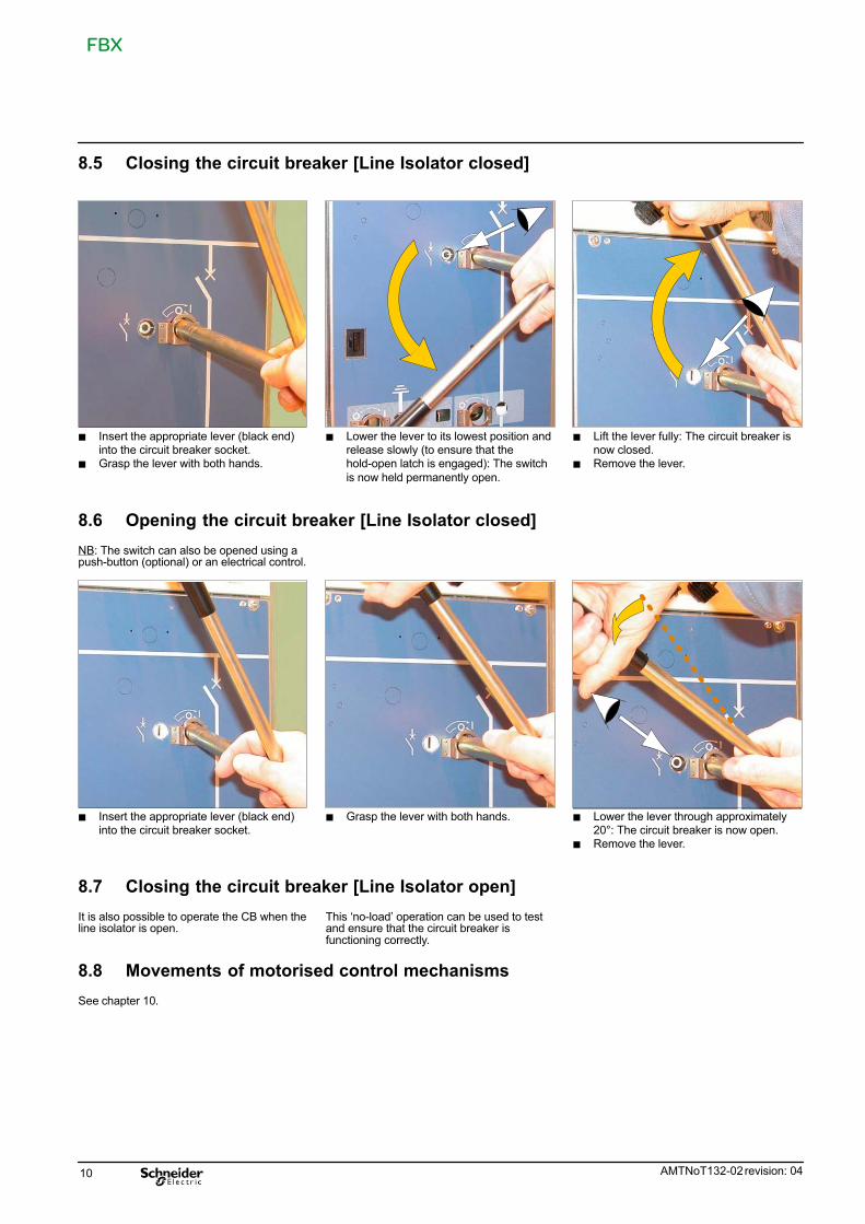
8.5 Closing the circuit breaker [Line Isolator closed]
� Insert the appropriate lever (black end)into the circuit breaker socket.
� Grasp the lever with both hands.
� Lower the lever to its lowest position andrelease slowly (to ensure that thehold-open latch is engaged): The switch
is now held permanently open.
� Lift the lever fully: The circuit breaker isnow closed.
� Remove the lever.
8.6 Opening the circuit breaker [Line Isolator closed]
NB: The switch can also be opened using apush-button (optional) or an electrical control.
� Insert the appropriate lever (black end)into the circuit breaker socket.
� Grasp the lever with both hands. � Lower the lever through approximately20°: The circuit breaker is now open.
� Remove the lever.
8.7 Closing the circuit breaker [Line Isolator open]
It is also possible to operate the CB when theline isolator is open.
This `no-load' operation can be used to testand ensure that the circuit breaker isfunctioning correctly.
8.8 Movements of motorised control mechanisms
See chapter 10.
FBX
AMTNoT132-02 revision: 04 11
9.1 Opening the earthing switch
Follow the instructions given in § 6.1.
9.2 Closing the earthing switch
The disconnection or earthing opera‐tion can only be carried out once suit‐ably adapted lockout operations have
been implemented on the network.
Before closing the earthing switch,ensure there is no voltage (or current)across the circuit in question
(see corresponding manual - § 2.3).
Follow the instructions given in § 6.2.
9.3 Closing the load break switch
Follow the instructions given in § 6.3.
9.4 Opening the load break switch
Follow the instructions given in § 6.4.
9.5 Movements of motorised control mechanisms
Se reporter au chapitre 10.
9 Use of Function Sb
FBX
12 AMTNoT132-02 revision: 04
10.1 Movements of motorised control mechanisms [Optional]
If the FBX switchboard is fitted with motorisedcontrols (optional), the various functions canbe energised/de-energised remotely inaccordance with the circuit diagram suppliedas part of the contract.
For functions T1 and T2, opening operationscan also be triggered by a push-button(optional) or electrical controls.
Function Sb: The disconnection orearthing operation can only be carriedout once suitably adapted lockout
operations have been implemented on thenetwork.
10.2 Manual emergency movements of motorised controls
In the event of an outage of the motor supplysource, a back-up control can be used tocomplete a manoeuvre underway or to carryout manual manoeuvres.
The position of the indicators should beverified after each operation.
If the supply is re-established whilst thehandle is inserted, it will be pushed out of thesocket.
When the earthing switch is closedthe backup manual control lever can‐not be fitted (Except for CB T2).
10.3 Approximate number of turns for backup manual control levers
Switch Disconnector Circuit breaker
To Open To Close To Open To Close
Functions Cand Sb
31 turns 31 turns
Function T1 7 turns 50 turns
Function T2 31 turns 31 turns 7 turns 50 turns
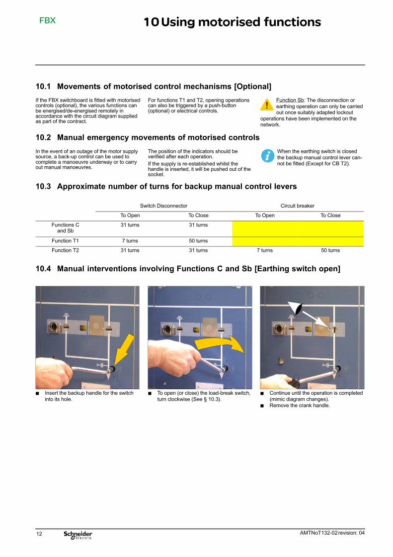
10.4 Manual interventions involving Functions C and Sb [Earthing switch open]
� Insert the backup handle for the switchinto its hole.
� To open (or close) the load-break switch,turn clockwise (See § 10.3).
� Continue until the operation is completed(mimic diagram changes).
� Remove the crank handle.
10 Using motorised functions
FBX
AMTNoT132-02 revision: 04 13
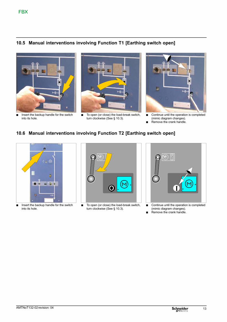
10.5 Manual interventions involving Function T1 [Earthing switch open]
� Insert the backup handle for the switchinto its hole.
� To open (or close) the load-break switch,turn clockwise (See § 10.3).
� Continue until the operation is completed(mimic diagram changes).
� Remove the crank handle.
10.6 Manual interventions involving Function T2 [Earthing switch open]
� Insert the backup handle for the switchinto its hole.
� To open (or close) the load-break switch,turn clockwise (See § 10.3).
o
� Continue until the operation is completed(mimic diagram changes).
� Remove the crank handle.
I
FBX
14 AMTNoT132-02 revision: 04
11.1 Levels of maintenance
D e s c r i p t i o n Levels
Operations recommended in the instructions manual ”installation - operation - maintenance”, carried out by suitably qualifiedpersonnel having received training allowing them to intervene whilst respecting the safety rules.
1
Complex operations, requiring specific expertise and the implementation of support equipment in accordance with SchneiderElectric's procedures. These must be carried out by Schneider Electric or by a specialised technician trained by SchneiderElectric (See § 1.2) when starting the procedures, with the appropriate specific equipment.
2
All preventive and corrective maintenance, all renovation and reconstruction work is carried out by Schneider Electric. 3
11.2 Preventive maintenance
P R E V E N T I V E M A I N T E N A N C E Frequency Levels
Recommended operations 6 years 1 2 3
Verification of the presence and condition of accessories (levers, etc.) X X X X
Visual inspection of the exterior (cleanliness, absence of oxidation, etc.) X X X X
Cleaning of external elements, with a clean, dry cloth. X X X X
Verification of the positioning of the status indicators (open and closed) X X X X
Verification of the functioning of the mechanical control mechanism by making several manoeuvres X X X X
Visual surveillance of the general appearance of connections X X X X
11.3 Corrective maintenance
C O R R E C T I V E M A I N T E N A N C E Levels
Replacements or modifications See § 1 2 3
Replacement of the three fuses 11.4 X X X
Replacement of a voltage indicator unit [E.g.: Type VPIS] 11.5 X X X
11.4 Replacement of the three fuses
Intervention Busbar Cables Load Break Switch Earthing switch
Normal de-energized de-energized open closed
Possible energized de-energized open closed
Locking out the Functional UnitAll locking-out operations must be performedaccording to the particular rules for the net‐work concerned.
Tools required:- Leather gloves- Compartment key- Small, flat-headed screwdriver
Parts required:- 3 fuses with the same reference(verify values in accordance with the transfor‐mer power)
See the corresponding chapter in theInstallation Manual for the character‐istics of the fuses (See § 2.3).
Replacement of a fuse
For an apparently single phase fault, itis imperative that all 3 fuses bereplaced.
The body of a fuse can become veryhot following a short circuit. Takestandard precautions (leather gloves)
before starting work.
Whenever changing or fitting a fuse,close the compartment immediatelyafterwards to avoid letting dust and
humidity enter.
11 Maintenance

FBX
AMTNoT132-02 revision: 04 15
� Ensure that the function's earthing switchis closed.
� Open the compartment using the
corresponding key.
� Lift the latch and open the panel. � The end plugs on the fuse holders arenow accessible.
� Pull the fuse holder out without turning it. � Slowly remove the fuse cartridge – whichmay be hot.
� Place the assembly on a clean surface.� Unscrew the small fixing screw
(flat-headed screwdriver).
� Extract the fuse.
� Insert the new fuse into the housing andlightly tighten the small screw.
� Insert the fuse cartridge into its housing. � Insert the fuse support lug into the slot inthe insulated tube and press firmly.

FBX
16 AMTNoT132-02 revision: 04
� Re-position the fuse access cover.� Push the panel fully in.� Lock the panel with the key.
When using under 12 kV
For 12 kV networks, add the adapter(optional), which fits on to the end of the fuse.
Adapter
End plug
Striker
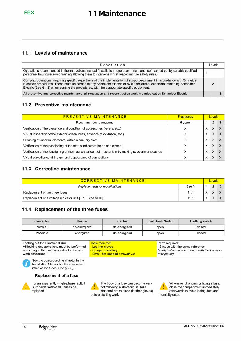
11.5 Replacement of a voltage indicator unit [E.g.: Type VPIS]
Intervention Busbar Cables Load Break Switch Earthing switch
Normal de-energized de-energized open closed
Possible energized energized closed open
Locking out the Functional UnitAll locking-out operations must be performedaccording to the particular rules for the net‐work concerned.
Tools required:- Flat headed screwdriver
Parts required:- VPIS Indicator Unit
FBX
AMTNoT132-02 revision: 04 17
� VPIS Unit � Unscrew the two side screws � Extract the unit by the front.
� Disconnect the box. � To fit a new VPIS unit, repeat theoperations in reverse order.
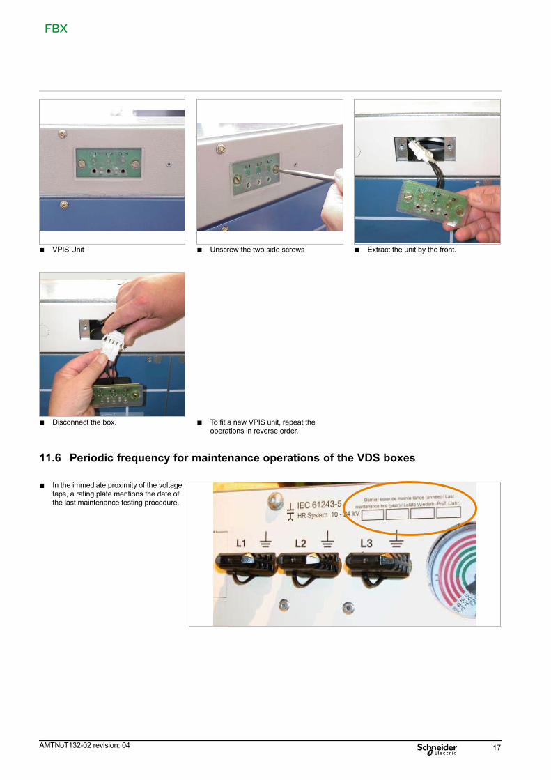
11.6 Periodic frequency for maintenance operations of the VDS boxes
� In the immediate proximity of the voltagetaps, a rating plate mentions the date ofthe last maintenance testing procedure.
FBX
18 AMTNoT132-02 revision: 04
12.1 The spare part
Describes a part that is designed to replace acorresponding one with a view tore-establishing the original function.
The replacement of these parts canonly be carried out by a person who issuitably qualified and trained for this
operation.
For an explanation of the levels ofmaintenance, please refer to § 11.1.
Programmed replacement DenominationReplacement Levels
every 1 2 3
This concerns wearing parts, designed to be replacedafter a predetermined number of uses.
Use: Maintenance stock, necessary for optimum main‐tenance procedures every 6 years.
HV fuses (by 3) 20 years X X X
Non-Programmed replacement DenominationLevels
1 2 3
Describes spare parts whose replacement intervenesin the course of corrective maintenance.
Illuminated Indicators X X X
Exceptional replacement DenominationLevels
1 2 3
Describes the spare parts or assemblies whose fore‐seeable service life is at least equal to that of theequipment.
Use: Spare parts or sub-assemblies conserved in asafety stock.
Cable strapping X X X
Manometer X X X
Motor X X X
Auxiliary contacts X X X
Operating lever for the earthing switch X X X
Load break switch operating lever X X X
Emergency manual control lever for motorised mechanisms X X X
Fuse electrode compartment key X X X
Mechanical control X X X
12.2 Identification of materials
For all orders for spare parts, it isnecessary to enclose the equipmentcharacteristics form.
12.3 Storage conditions
The components should be stored away fromdust, humidity or the sun. In order to facilitatethe search, they must be marked by theSchneider Electric reference number.
Certain components are fragile, they shouldpreferably be stored in their originalpackaging.
12 Spare parts
FBX
AMTNoT132-02 revision: 04 19
13.1 Preparation of the function
Implement lockout rules in accord‐ance with the regulations specific toeach network.
De-energise the loadbreak switch and closethe earthing switch (See correspondingchapter).
Remove the cable compartment accesspanel.
13.2 Cable testing with plug-in `T' piece connectors (busbar energised)
� 1. Remove the end panel cover.� 2. Fit the test adapter.
1
2
Simulate the presence of the door.
� 3. Push the lock downwards: Theearthing switch is now unlocked.
In this position, the switch can bemoved, unless the switchboard is
fitted with an additional interlock betweenthe cable panel and the load break
switch (optional).
3
� 4. Lower the locking tab.� Open the earthing switch (See § 6.1).� Procede with the tests.
4
� Close the earthing switch (See § 6.2).
5. Pull the lock upwards.
5
6. Raise the unlocking latch by hand.
6
� Remove the adapters.� Screw the covers onto each extremity.� Re-fit the cable compartment panel.
13 Cable testing
FBX
20 AMTNoT132-02 revision: 04
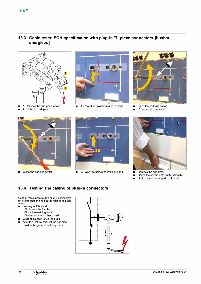
13.3 Cable tests: EON specification with plug-in 'T' piece connectors [busbarenergised]
� 1. Remove the end panel cover.� 2. Fit the test adapter.
1
2
� 3. Lower the unlocking latch by hand.
4
� Open the earthing switch.� Procede with the tests.
� Close the earthing switch. � 6. Raise the unlocking latch by hand.
6
� Remove the adapters.� Screw the covers onto each extremity.� Re-fit the cable compartment panel.
13.4 Testing the casing of plug-in connectors
Consult the supplier of the plug-in connectorsfor all information and figures relating to sucha test.� To carry out this test:
. Shut down the function.
. Close the earthing switch.
. Disconnect the earthing braid.� Current injection is via the braid.� After the test, re-connect the earthing
braid to the general earthing circuit.
FBX
AMTNoT132-02 revision: 04 21
14.1 General characteristics
Type of Insulating Gas:Sulphur Hexafluoride (SF6) – iaw IEC60376.
Each switchboard comprises a tank, filledwith SF6 gas, designed as a pressurised,sealed-unit system in accordance with therequirements of IEC60694.
During the expected operating life and undernormal operating conditions the gas shouldnot need topping up.
Never pierce the pressurised tank!
Never attempt to open the tank.
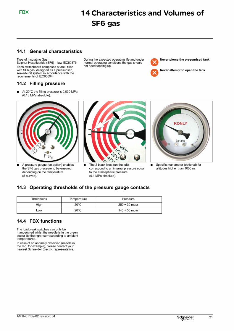
14.2 Filling pressure
� At 20°C the filling pressure is 0.030 MPa(0.13 MPa absolute).
� A pressure gauge (on option) enablesthe SF6 gas pressure to be ensured,depending on the temperature
(5 curves).
� The 2 black lines (on the left),correspond to an internal pressure equalto the atmospheric pressure
(0.1 MPa absolute).
� Specific manometer (optional) foraltitudes higher than 1000 m.
14.3 Operating thresholds of the pressure gauge contacts
Thresholds Temperature Pressure
High 20°C 250 + 30 mbar
Low 20°C 140 + 50 mbar
14.4 FBX functions
The loadbreak switches can only bemanoeuvred whilst the needle is in the greensector (to the right) corresponding to ambienttemperatures.
In case of an anomaly observed (needle inthe red, for example), please contact yournearest Schneider Electric representative.
14 Characteristics and Volumes of
SF6 gas

FBX
22 AMTNoT132-02 revision: 04
15.1 Valorization of the equipment
Our Functional Units are composed ofrecyclable elements.
The tables (§ 15.4) give information andfigures for the types of materials, their qualityand their methods of valorization.
They enable the following:- Calculation to be made of the capacities forvalorization,- Optimising the valorization process,- Evaluating the cost of valorization.
The indications given in tables (§ 15.4)facilitate co-operation between users andSchneider Electric to valorize the product atthe end of the product's service life.
*
*
FBX-C (IS) C-C-T1 (24 kV - 400 A)
*1
2
3
15.2 Safety instructions
Do not dismantle the mechanicalcontrol mechanism springs withoutthe releasing device.
Never attempt to open thesealed-tank of a Functional Unit.
Don't try to recuperate the SF6,without specific tools and out of alocal dedicated to that operation.
15.3 Dismantling of the equipment service
Consult Schneider Electric for alldecommissioning services.
Recovery the SF6, and opening thetank can be realized only in a specificroom, equiped for this type of service.
15 At the end of the equipment's
operational life
1 2 3

FBX
AMTNoT132-02 revision: 04 23
15.4 Distribution and valorization of the materials used for FBX (See § 15.1)
Total weight: FBX-C (IS) C-C-T1 + 3 fuses = 310.416 kg.
Metals – incl. inserts Weight (kg) % of Materials Valorization
Steel 155.810 Yes
Stainless steel 83.854
Copper and copper-based alloys
Aluminium and aluminium alloys
Silver
26.5
9.8
0.051
Yes
Total 276.015 88.92
Thermosetting parts Weight (kg) % of Materials Valorization
Epoxy Resin* 12.141 Cannot be valorized
(sent toTechnical Burial Centres)Total 12.141 3.91
* mainly silica
Thermo-plastics Weight (kg) % of Materials Valorization
Polyesters 7.330
Yes
Aromatic polyamides 2.964
Polyamides 1.198
Others 0.152
Total 11.645 3.75
Elastomers Weight (kg) % of Materials Valorization
EPDM 0.095 0.03 Cannot be valorized
Gas Weight (kg) % of Materials Valorization
SF6 2.450 0.79 Yes (regeneration)
Others Weight (kg) % of Materials Valorization
Silica 3.000
Yes
Porcelain 2.993
Cordierite 1.097
Sodium Aluminosilicate 0.500
Phenolic paper 0.430
Grease 0.050
Total 8.070 2.60
FBX
24 AMTNoT132-02 revision: 04
16 Notes
If you have any comments on the use of this document or on the use of the equipment and services that are described in it, please sendus your remarks, suggestions and wishes to:
Schneider Electric Technical Department BP 84019 F-71040 Mâcon Cedex 9 - FRANCE
Fax: 33 (0)3 85 29 36 36


Schneider Electric
35, rue Joseph Monier
CS 30323
F - 92506 Rueil-Malmaison Cedex
RCS Nanterre 954 503 439
Capital social 896 313 776 €
www.schneider-electric.com
AMTNoT132-02 revision: 04
As standards, specifications and designs change from time to time, please ask for confirmationof the information given in this publication.
Design: Schneider Electric
Photos: Schneider Electric
12-2010
� 2
010
Schneid
er
Ele
ctr
ic -
All
rights
reserv
ed