fault linkage and graben tansfer in canyonlands and the north sea
TRANSCRIPT
AUTHORS
Haakon Fossen � Center for IntegratedPetroleum Research, Department of Earth Sci-ence, University of Bergen, P.O. Box 7800, Bergen5020, Norway; [email protected]
Haakon Fossen received his Candidatus Scien-tiarum degree (M.S. degree equivalent) fromthe University of Bergen (1986) and his Ph.D. instructural geology from the University of Min-nesota (1992). He joined Statoil in 1986 andthe University of Bergen in 1996. His scientificinterests cover the evolution and collapse ofmountain ranges, the structure and evolutionof the North Sea rift basins, and petroleum-related deformation structures at various scales.
Richard A. Schultz � Geomechanics-RockFracture Group, Department of Geological
GEOLOGIC NOTE
Fault linkage and grabenstepovers in the Canyonlands(Utah) and the NorthSea Viking Graben, withimplications for hydrocarbonmigration and accumulationHaakon Fossen, Richard A. Schultz, Egil Rundhovde,Atle Rotevatn, and Simon J. Buckley
Sciences and Engineering/172, University ofNevada, Reno, Nevada 89557;[email protected]
Richard Schultz received his B.A. degree in ge-ology from Rutgers University (1979), his M.S.degree in geology from Arizona State University(1982), and his Ph.D. in geomechanics fromPurdue University (1987). He worked at the Lunarand Planetary Institute, NASA centers, and inprecious metals exploration before joining theUniversity of Nevada, Reno, in 1990. His interestsinclude rock fracture mechanics, growth andstatistics of fracture and band populations, andplanetary structural geology.
Egil Rundhovde � StatoilHydro, Box 7200,Bergen 5020, Norway; [email protected]
Egil Rundhovde received his Candidatus Scien-tiarum degree (M.S. degree equivalent) fromthe University of Bergen in 1987, studying duc-tilely deformed rocks of the Norwegian Cale-donides. In 1992, he received his Ph.D. in struc-tural geology from the University of Trondheim,focusing on precious ore genesis in deformedophiolite complexes. He joined Statoil’s researchcenter in 1991 and since 1998 has been involvedin the production of the North Sea Gullfaksfield and other assets in the Tampen region ofthe North Sea. He is currently the subsurface
ABSTRACT
Segmented graben systems develop stepovers that have im-portant implications in the exploration of oil and gas in exten-sional tectonic basins. We have compared and modeled a rep-resentative stepover between grabens in Canyonlands, Utah,and the North Sea Viking Graben and, despite their differentstructural settings, found striking similarities that pertain toother graben systems. In both cases, the stepovers represent rela-tively high parts within the graben systems that are likely to beamong the first to be filled with hydrocarbons generated indeeper parts of the grabens. Furthermore, the relay ramps andsmaller fault offsets in stepovers ease hydrocarbon migrationand allow stepovers to act as preferred migration routes fromdeep graben kitchens to structurally higher traps in the basin.Graben stepovers and their related structures should be paidspecial attention during exploration because they may repre-sent hydrocarbon accumulations complementary to larger trapsalong the graben flanks. These observations explain the locationof the Kvitebjørn, Valemon, and Huldra fields in a stepoverstructure of the Viking Graben and encourage increased focuson similar graben stepovers in the Viking Graben and othergraben systems.
manager of the Volve and Glitne fields forStatoilHydro.
Copyright ©2010. The American Association of Petroleum Geologists. All rights reserved.
Manuscript received May 8, 2009; provisional acceptance June 28, 2009; revised manuscript receivedSeptember 11, 2009; final acceptance October 13, 2009.DOI:10.1306/10130909088
AAPG Bulletin, v. 94, no. 5 (May 2010), pp. 597–613 597
Atle Rotevatn � Center for Integrated Pe-troleum Research, University of Bergen,Allegaten 41, 5007 Bergen, Norway; presentaddress: Rocksource ASA, P.O. Box 994 Sentrum,Bergen 5808, Norway;[email protected]
Atle Rotevatn received his Candidatus Scien-tiarum degree (M.S. degree equivalent) from theUniversity of Oslo in 2004, studying ductilelydeformed rocks of the East Greenland Caledonides.In 2007, he received his Ph.D. in structural ge-ology from the University of Bergen, focusing onreservoir-scale deformation structures and theirinfluence on fluid flow in oil and gas reservoirs.In 2006, he joined the Norwegian explorationand production company Rocksource, where hecurrently works in international exploration.
Simon J. Buckley � Center for IntegratedPetroleum Research, University of Bergen,Allegaten 41, Bergen 5007, Norway;[email protected]
Norway Simon Buckley received his B.S. degree(1999) and Ph.D. (2003) in geomatics fromNewcastle University, United Kingdom. He hassince been a research fellow at the Universityof Newcastle, Australia, and is currently a re-searcher at the University of Bergen. His researchinterests include the application and advance-ment of geomatics techniques, particularly LIDARand photogrammetry, within the Earth sciences.
ACKNOWLEDGEMENTS
This manuscript benefited from helpful reviewsby Martin J. Evans, Christopher K. Morley, andSandro Serra. The basis for this work developedduring the preparation of Statoil field coursesin Utah and later fieldwork, modeling, andanalyses.The AAPG Editor thanks the following reviewersfor their work on this article: Martin J. Evans,Christopher K. Morley, and Sandro Serra.
598 Geologic Note
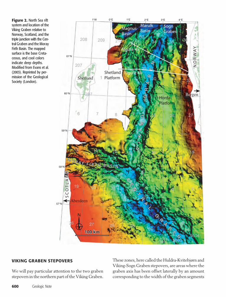
INTRODUCTION
Large-scale lateral shifts or steps in graben axes (Figure 1) arewell known frommany continental rift systems, such as the EastAfrican rift system (Rosendahl et al., 1986;Morley et al., 1990;Nelson et al., 1992), the Oslo rift (Sundvoll and Larsen, 1994),the Rheine rift (Ziegler, 1992), the Suez rift (Bosworth, 1995),and the RioGrande rift (Mack and Seager, 1995), as well as frommid-ocean rift systems (e.g., Sempéré et al., 1993). In the well-explored Late Jurassic North Sea passive rift system, the VikingGraben defines the central rift graben between latitudes 60and 62° (Figure 2). The Viking Graben is segmented in a con-sistent right-stepping sense (Figures 3, 4). Some of the largestNorth Sea offshore oil fields (e.g., the Statfjord, Gullfaks, Snorre,andOseberg fields) are located on the flanks of the Viking Gra-ben, and several smaller hydrocarbon-filled structures have re-cently been discovered in the same area. Although the giant oiland gas fields are located on the elevated rift margins, severalsmaller fields and plays are found in areas of overlapping gra-ben segments. The coincidence between graben transfer zonesor stepovers and hydrocarbon accumulations is intriguing andfar from coincidental: we suggest that these accumulations arerelated to specific structural characteristics of graben step-overs. Although various structural characteristics of grabenstepover structures and rift accommodation zones have beendiscussed in several previous works (e.g., Rosendahl, 1987;Morley et al., 1990), we will focus here on structural parallelsbetween graben stepovers in the Viking Graben and a geomet-rically similar graben system in the Canyonlands, Utah. Basedon the comparison between the exceptionally well-exposedCanyonlands example and the larger-scale VikingGraben, alongwith calculations of graben-related topography and boundary-fault propagation, we discuss the implications of graben seg-mentation to petroleum exploration.
RELAY STRUCTURES AND GRABEN SEGMENTATION
Faults grow from smaller-scale structures by accumulation ofslip through seismic activity and aseismic creep (e.g., Cowieet al., 2007). During the evolution of fault populations, indi-vidual faults interact and overlap, forming relay structures (e.g.,Larsen, 1988;Childs et al., 1995).A relay structure, also referredto as a stepover, is the site of displacement transfer between twofaults. Where displacement is transferred by means of ductilefolding of the stratigraphy between the overlapping normal
fault tips (e.g.,Willemse, 1997), the area is definedas a relay ramp (e.g., Peacock andSanderson, 1994).Relay ramps may accumulate strain until the rocksin the ramp fail in shear (Crider andPollard, 1998).At this point, the two fault segments become phys-ically connected by the formation of one or morethrough-going faults (Soliva and Benedicto, 2004).The resulting structure is referred to as a breachedrelay ramp (Childs et al., 1995).
Relay rampsare formedanddestroyed(breached)continually throughout the growth history of a faultpopulation. Furthermore, they format awide rangeof scales, from centimeter-scale structures observ-able in hand sample to map-scale structures up to100 km wide (Peacock et al., 2000; Soliva andBenedicto, 2004). Relay structures in the form ofrelay ramps may negatively influence the sealingcapacity of faults andhave a positive effect on com-munication across faults duringmigration aswell asproduction of water and hydrocarbons (Bense andBalen, 2004; Rotevatn et al., 2007, 2009a, b).
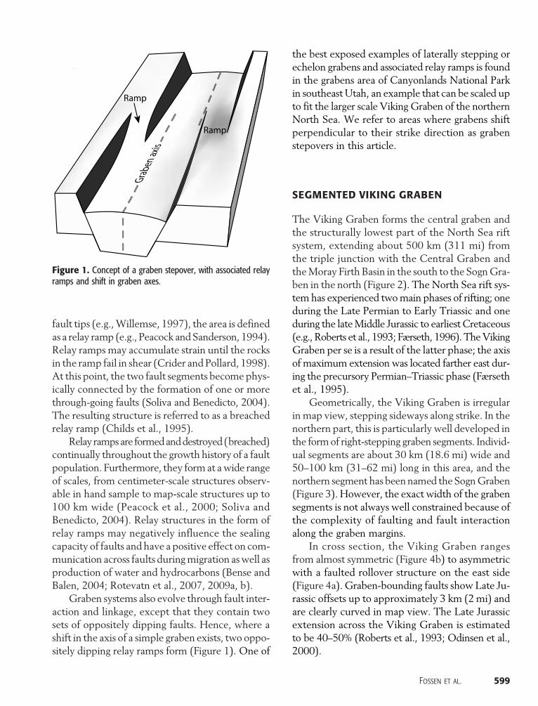
Graben systems also evolve through fault inter-action and linkage, except that they contain twosets of oppositely dipping faults. Hence, where ashift in the axis of a simple graben exists, two oppo-sitely dipping relay ramps form (Figure 1). One of
the best exposed examples of laterally stepping orechelon grabens and associated relay ramps is foundin the grabens area of Canyonlands National Parkin southeast Utah, an example that can be scaled upto fit the larger scale Viking Graben of the northernNorth Sea. We refer to areas where grabens shiftperpendicular to their strike direction as grabenstepovers in this article.
SEGMENTED VIKING GRABEN
The Viking Graben forms the central graben andthe structurally lowest part of the North Sea riftsystem, extending about 500 km (311 mi) fromthe triple junction with the Central Graben andtheMoray Firth Basin in the south to the SognGra-ben in the north (Figure 2). The North Sea rift sys-tem has experienced twomain phases of rifting; oneduring the Late Permian to Early Triassic and oneduring the lateMiddle Jurassic to earliest Cretaceous(e.g., Roberts et al., 1993; Færseth, 1996). TheVikingGraben per se is a result of the latter phase; the axisof maximum extension was located farther east dur-ing the precursory Permian–Triassic phase (Færsethet al., 1995).
Geometrically, the Viking Graben is irregularin map view, stepping sideways along strike. In thenorthern part, this is particularly well developed inthe formof right-stepping graben segments. Individ-ual segments are about 30 km (18.6 mi) wide and50–100 km (31–62 mi) long in this area, and thenorthern segment has beennamed the SognGraben(Figure 3). However, the exact width of the grabensegments is not always well constrained because ofthe complexity of faulting and fault interactionalong the graben margins.
In cross section, the Viking Graben rangesfrom almost symmetric (Figure 4b) to asymmetricwith a faulted rollover structure on the east side(Figure 4a). Graben-bounding faults show Late Ju-rassic offsets up to approximately 3 km (2mi) andare clearly curved in map view. The Late Jurassicextension across the Viking Graben is estimatedto be 40–50% (Roberts et al., 1993; Odinsen et al.,2000).
Figure 1. Concept of a graben stepover, with associated relayramps and shift in graben axes.
Fossen et al. 599
VIKING GRABEN STEPOVERS
Wewill pay particular attention to the two grabenstepovers in the northern part of theVikingGraben.
600 Geologic Note
These zones, here called theHuldra-Kvitebjørn andViking-SognGraben stepovers, are areaswhere thegraben axis has been offset laterally by an amountcorresponding to the width of the graben segments
Figure 2. North Sea riftsystem and location of theViking Graben relative toNorway, Scotland, and thetriple junction with the Cen-tral Graben and the MorayFirth Basin. The mappedsurface is the base Creta-ceous, and cool colorsindicate deep depths.Modified from Evans et al.(2003). Reprinted by per-mission of the GeologicalSociety (London).
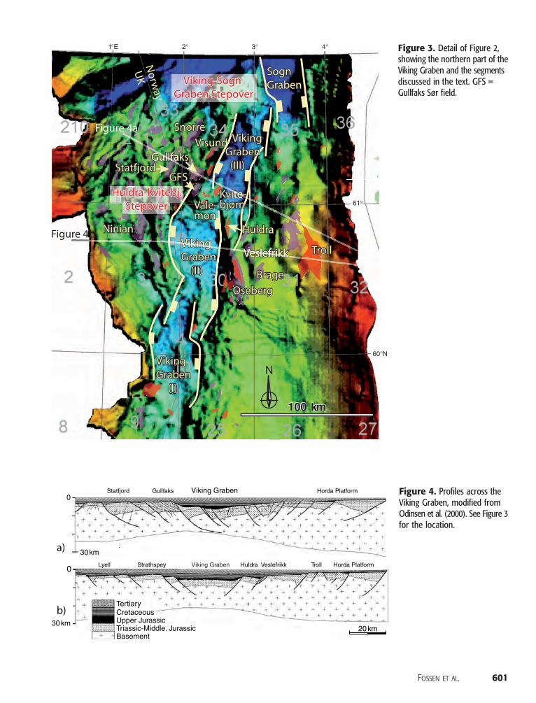
Figure 3. Detail of Figure 2,showing the northern part of theViking Graben and the segmentsdiscussed in the text. GFS =Gullfaks Sør field.
Figure 4. Profiles across theViking Graben, modified fromOdinsen et al. (2000). See Figure 3for the location.
Fossen et al. 601
(∼35 km [22 mi]) (Figures 3, 4). Although themap shown in Figure 3 presents a simplified pic-ture of the complex pattern of faulting in this re-gion, it illustrates some striking features that areimportant. One is that the depth of the grabensvaries systematically within each graben segment,from deep in the central parts of the segments toremarkably shallow within the stepovers (Figure 5).Another is that hydrocarbon fields (Huldra andKvitebjørn fields) are located in the highest partswithin the Huldra-Kvitebjørn stepover, and sev-eral major oil fields (Gullfaks area and Oseberg-Veslefrikk area) are located immediately next tothem. Furthermore, several relay structures are lo-cated in the graben stepovers, connecting the gra-ben area with the hydrocarbon-filled highs in thevicinity of the stepovers. We find that these fea-tures are characteristic of many graben stepover
602 Geologic Note
zones, and we will explore them more closely bymeans of a well-exposed Canyonlands example.
CANYONLANDS GRABENS
The grabens area is located in the Needles districtof Canyonlands National Park, Utah. In this area,several grabens have formed, and are still develop-ing, in a 12-km (7-mi)-wide and 25-km (15-mi)-long area on the east side of the Colorado River(McGill and Stromquist 1979;Moore and Schultz,1999; Trudgill, 2002; Furuya et al., 2007). The gra-ben system, which on a large scale shows an arcuateshape, is developed in an approximately 460-m(1509-ft)-thick sequence of Carboniferous to Perm-ian sandstones and subordinate limestones belong-ing to the Cutler, Rico, and Hermosa formations.
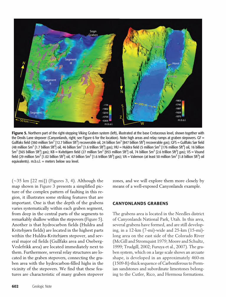
Figure 5. Northern part of the right-stepping Viking Graben system (left), illustrated at the base Cretaceous level, shown together withthe Devils Lane stepover (Canyonlands, right; see Figure 6 for the location). Note high areas and relay ramps at graben stepovers. GF =Gullfaks field (360 million Sm3 [12.7 billion Sft3] recoverable oil, 24 billion Sm3 [847 billion Sft3] recoverable gas); GFS = Gullfaks Sør field(48 million Sm3 [1.7 billion Sft3] oil, 46 billion Sm3 [1.6 trillion Sft3] gas); HU = Huldra field (5 million Sm3 [176 million Sft3] oil, 16 billionSm3 [565 billion Sft3] gas); KB = Kvitebjørn field (27 million Sm3 [953 million Sft3] oil, 74 billion Sm3 [2.6 trillion Sft3] gas); VS = Visundfield (29 million Sm3 [1.02 billion Sft3] oil, 47 billion Sm3 [1.6 trillion Sft3] gas); VA = Valemon (at least 50 million Sm3 [1.8 billion Sft3] oilequivalents). m.b.s.l. = meters below sea level.
The sandstones rest on Pennsylvanian evaporitedeposits (Paradox Formation) that outcrop alongthe base of this particular section of the ColoradoRiver canyon.
The sedimentary strata in the grabens area dipvery gently (∼4°) toward the Colorado River can-yon, and the graben system forms in response to aslow, gravity-driven translation of the sandstonesand limestones toward the canyon incised by theColorado River (McGill and Stromquist, 1979;Schultz-Ela and Walsh, 2002). Hence, the grabenformation initiated after the Colorado River haderoded through the Carboniferous–Permian sand-stones and into the underlying salt, a process thatinitiated during the late Cenozoic uplift of theColorado Plateau.
Mechanically, the grabens form by faulting ofpreexisting joint sets that are extensively devel-oped in this part of the Colorado Plateau. Thejoints, which are thought to have formed duringthe uplift and cooling history of the sedimentaryrocks, are steeply dipping and in this area have ac-cumulated shear displacements up to several hun-dred meters (up to 600–700 ft). During normalfaulting, the grabens descended into the underly-ing salt, and these vertical movements are tied todissolution and lateral flow of the underlying salt.In map view, the graben-bounding normal faultsinteract, and several outstanding exposures of gra-ben stepovers and associated relay structures arefound in the grabens area (Trudgill and Cartwright,1994; Moore and Schultz, 1999).
The petrophysical properties of the Canyon-lands faults are somewhat different from thosefound in the North Sea and most other reservoirsbecause of their near-surface formation by faultingof preexisting joints in well-lithified sandstones.This resulted in faults and joints that not onlytransmit but also vertically conduct fluid flow. Inreservoirs such as those of theNorth Sea, where up-lift is scarce or absent and where faulting occurredin unfractured sediments and sedimentary rocks,faults tend to represent tabular zones of reducedpermeability that are more likely to influence fluidflow. In this article, we will focus on geometricalinstead of petrophysical attributes between theViking Graben and Canyonlands grabens, focusing
on a particularly well-exposed stepover zone lo-cated in theDevils Lane graben of theCanyonlandsarea, given that the differences in fault propertiesare secondary to their geometric similarities andstructural behavior.
DEVILS LANE
Devils Lane represents one of several asymmetricnorth-south–trendingCanyonlands grabenswith themain fault located on the west side of the graben.The east side is a gentle rollover structure affected
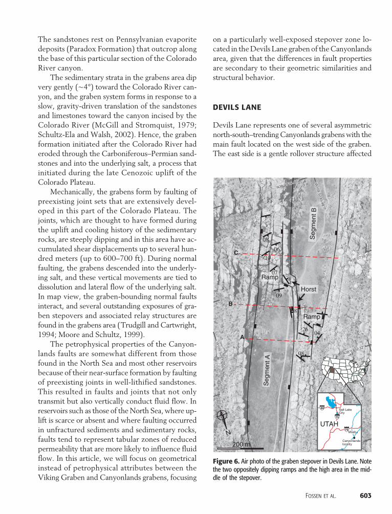
Figure 6. Air photo of the graben stepover in Devils Lane. Notethe two oppositely dipping ramps and the high area in the mid-dle of the stepover.
Fossen et al. 603
by the opening of a regional set of preexisting north-south–trending joints and subsequent faulting onthe same fractures. Geometrically, the similari-ties to theVikingGraben are striking (Figure 5), al-though the Canyonlands faults are steeper andcontrolled by preexisting joint sets (Figures 6, 7).Furthermore, bedding within the intervening faultblocks is less rotated, and the extension is consider-ably less than in the North Sea example.
The air photo and the corresponding map in-terpretation shown in Figure 6 reveal several char-acteristic attributes of the grabens area. First, theshift in graben axis across the stepover is about thewidth of the graben, i.e., about 200m (656 ft). Thiscorresponds to the shifts described from theVikingGraben (above). Second, two oppositely dippingramps in the Devils Lane area are still mostly un-breached but are dissected by joints and minorfaults. The ramps are located in the overlap zonesbetween the graben bounding faults: as displace-
604 Geologic Note
ment decreases along one fault into the ramp area,the other picks it up as displacement is transferredacross the ramp. The Devils Lane ramps show sim-ple geometries, with subordinate faults and jointscontrolled by the trends of the preexisting regionaljoint pattern, but the overall geometry is very simi-lar to that of the Viking Graben.
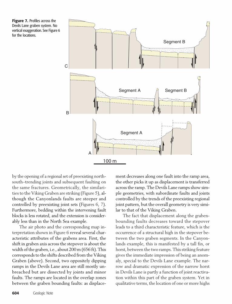
The fact that displacement along the graben-bounding faults decreases toward the stepoverleads to a third characteristic feature, which is theoccurrence of a structural high in the stepover be-tween the two graben segments. In the Canyon-lands example, this is manifested by a tall fin, orhorst, between the two ramps. This striking featuregives the immediate impression of being an anom-aly, special to the Devils Lane example. The nar-row and dramatic expression of the narrow horstin Devils Lane is partly a function of joint reactiva-tion within this part of the graben system. Yet inqualitative terms, the location of one ormore highs
Figure 7. Profiles across theDevils Lane graben system. Novertical exaggeration. See Figure 6for the locations.
in a graben stepover is expected to occur also inother examples and settings. In the Viking Grabenexample, such highs are indeed found and repre-sented by gas and condensate accumulations suchas the Kvitebjørn field, the Huldra field, and theValemon accumulation (Figure 5).
MODELING OF FAULT INTERACTIONDURING GRABEN LINKAGE
The narrow horst (fin) in the Devils Lane grabenstepover represents an interesting feature in partcontrolled by the preexisting joint system in thearea and in part created during the growth historyof the two approaching graben-bounding fault seg-ments (cf. Serra and Nelson, 1988). Similar struc-tural highs are also observed in the linked VikingGraben system. Is there any generality expressedby this structure, predicting qualitatively similarbehavior of nonjointed and softer rocks?
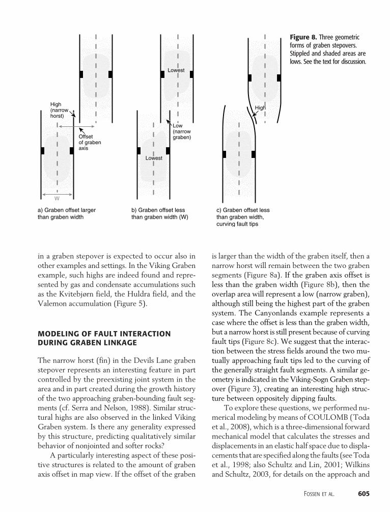
A particularly interesting aspect of these posi-tive structures is related to the amount of grabenaxis offset in map view. If the offset of the graben
is larger than the width of the graben itself, then anarrow horst will remain between the two grabensegments (Figure 8a). If the graben axis offset isless than the graben width (Figure 8b), then theoverlap area will represent a low (narrow graben),although still being the highest part of the grabensystem. The Canyonlands example represents acase where the offset is less than the graben width,but a narrow horst is still present because of curvingfault tips (Figure 8c). We suggest that the interac-tion between the stress fields around the two mu-tually approaching fault tips led to the curving ofthe generally straight fault segments. A similar ge-ometry is indicated in the Viking-SognGraben step-over (Figure 3), creating an interesting high struc-ture between oppositely dipping faults.
To explore these questions, we performed nu-merical modeling by means of COULOMB (Todaet al., 2008), which is a three-dimensional forwardmechanical model that calculates the stresses anddisplacements in an elastic half space due to displa-cements that are specified along the faults (seeTodaet al., 1998; also Schultz and Lin, 2001; Wilkinsand Schultz, 2003, for details on the approach and
Figure 8. Three geometricforms of graben stepovers.Stippled and shaded areas arelows. See the text for discussion.
Fossen et al. 605
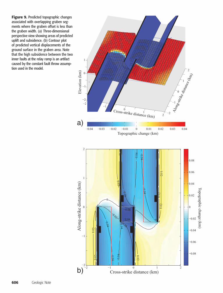
Figure 9. Predicted topographic changesassociated with overlapping graben seg-ments where the graben offset is less thanthe graben width. (a) Three-dimensionalperspective view showing areas of predicteduplift and subsidence. (b) Contour plotof predicted vertical displacements of theground surface in the graben area. Notethat the high subsidence between the twoinner faults at the relay ramp is an artifactcaused by the constant fault throw assump-tion used in the model.
606 Geologic Note
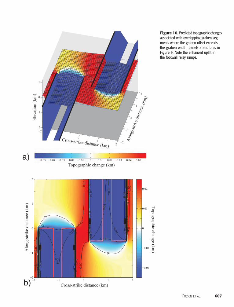
Figure 10. Predicted topographic changesassociated with overlapping graben seg-ments where the graben offset exceedsthe graben width; panels a and b as inFigure 9. Note the enhanced uplift inthe footwall relay ramps.
Fossen et al. 607
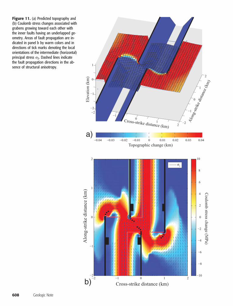
Figure 11. (a) Predicted topography and(b) Coulomb stress changes associated withgrabens growing toward each other withthe inner faults having an underlapped ge-ometry. Areas of fault propagation are in-dicated in panel b by warm colors and indirections of tick marks denoting the localorientations of the intermediate (horizontal)principal stress s2. Dashed lines indicatethe fault propagation directions in the ab-sence of structural anisotropy.
608 Geologic Note
applications to normal fault and graben systems).Using amechanicalmodel for fault growth, as donehere, provides insight into the development of faultpatterns and associated topography beyond thatavailable from analog models (e.g., Hus et al.,2005; Bose andMitra, 2009). The fault geometrieswe investigated are shown in Figure 8a and b. Eachgraben is defined by a pair of inwardly dipping nor-mal faults that are, for this analysis, 4 km (2.5) inlength and dipping at 60° down to a depth of 1 km(0.6mi). A constant displacement of 100m (328 ft)is applied along each fault, for a ratio of displace-ment to length of 0.025, in accord with values ofother normal faults (e.g., Schultz et al., 2008). Thehost rock is represented by a Young’s modulus of80 GPa (145,038 psi), a Poisson’s ratio of 0.25,and a friction coefficient of 0.6, values that are con-sistent with those of sedimentary rocks. An obser-vation grid measuring 2 � 2 km (1.24 � 1.24 mi)is placed at the ground surface centered on the gra-ben stepover area with calculations performed at aregular spacing of 100 m (328 ft). Although thespecific values of fault dimensions, offsets, dip an-gles, and host-rock properties affect the resultspresented below in detail, the conclusions of theanalysis are not changed substantially by variationsin these values. As a result, our conclusions applyto other graben systems having similar fault geom-etries and stepover topographies.
Grabens that have grown into an overlapped ge-ometry can form either the case in Figure 8a, wherethe graben offset is larger than the graben width,or the case portrayed in Figure 8b, where the off-set is less than the graben width. In the last case(Figure 8b), faulting results in subsidence in thecentral overlap area, and the model predicts a basinin this area (see Figure 9). However, faulting in thefirst case (Figure 8a) leads to enhanced uplift in theintervening horst (Figure 10). These results suggestthat propagation of grabens into overlapped geom-etries leads to enhanced subsidence or uplift in therelays depending on the initial spacing between thegrabens, although the simplifying assumption ofconstant fault throw exaggerates these effects inthe stepovers to some degree.
The cases shown in Figures 9 and 10 assumethat the two inner faults outlining the narrow gra-
ben in Figure 8b propagate along strike withoutchanging trend. This can occur, for example, whena preexisting fabric or joint set controls the faultpropagation direction, as in the case of Canyon-lands. Our modeling shows that this behavior canbe explained by the stress state in an underlappedstepover (Figure 11a). The orientation of themini-mum horizontal stress predicted by the model fa-vors propagation of the inner faults in a counter-clockwise sense, producing a graben or horst thatis rotated relative to the overall trend of the grabens(Figure 11b). The eye-catching horst segment inthe Canyonlands example is not significantly ro-tated because the faults propagate along preexistingjoints and make abrupt steps along them insteadof a gradual rotation predicted by the model andshown in Figure 8c. The central fin or horst at Dev-ils Lane graben in Canyonlands can thus be inter-preted as the result of propagation of faults withwide spacing and an along-strike anisotropy (i.e.,the joint set), whereas the rotated horsts and gra-bens along the segmentedNorth Sea Viking Grabenresulted from fault propagation in strata that lacksignificant anisotropy, as illustrated in Figure 11b.
DISCUSSION
Some of the characteristics shared between theCanyonlands example and the Viking Graben areof particular importance when it comes to explo-ration. In principle, three key aspects of linkedgraben systems exist. One aspect is that the deepparts of the graben segmentsmay be locatedwithinthe oil window although its flanks are not. Thus,graben systems serve as kitchen areas in many pe-troleumand gas provinces, including theNorth Sea.During continued subsidence, the deep parts of agraben system will eventually escape the oil win-dow, in which case, the shallower stepovers maystill reside within the oil window. Hence, grabensegmentation gives a longer graben source rock re-sidual time within the oil window.
A second aspect concerns the role of relay struc-tures in the graben stepovers with respect to hy-drocarbon migration and trapping. In structuralsettings such as the North Sea, where many large
Fossen et al. 609
faults are sealing because of the juxtaposition ofpermeable against nonpermeable units or, in rarercases, because of shale smear, relay structures pro-vide important migration paths for hydrocarbonsfrom the deep graben parts to structural highs onthe flanks. The sealing capacity of faults dependson several factors, of which displacement, togetherwith lithological properties and stratigraphy, is re-garded as the most important one (e.g., Yieldinget al., 1997). At some critical point, typically nearthe fault tip, displacement is small enough thatthe fault changes from sealing to nonsealing. Be-cause faults lose displacement toward graben step-overs and their relay structures, stepovers are likelylocations of communication across otherwise seal-ing faults, even where subseismic structures occurwithin relay ramps (Rotevatn et al., 2009a). In thecontext of large-scale graben stepovers such as theViking Graben, this means that stepovers are loca-tions where hydrocarbons generated in deep partsof the graben system can escape into the surround-ing fault blocks andmigrate to high structures alongthe flanks of the graben system. In the northern partof the Viking Graben, migration of hydrocarbonsseems to have occurred laterally around or throughlow-displacement parts of faults (Johannesen et al.,2002), using the pathways generated by grabenstepover structures.
Vertical migration of fluids along faults alsooccurs in basins, and even laterally sealing faultsmay, intermittently or constantly, conduct fluidsin the vertical direction. Because the number offaults and related fractures in graben stepovers isanomalously high, wewould expect enhanced ver-tical migration of hydrocarbons in such settings.This expectation is supported by a study of a seg-mented rift system inNewZealand byRowland andSibson (2004). These authors found a concentra-tion of geothermal fields in stepovers and linked thisto enhanced vertical permeability caused by highstructural complexity in these zones. Note that thestructural complexities found in graben stepoversmay cause problems during production, althoughthis depends on a large number of local factors.Combined with deep locations and hence poorerseismic imaging, such complexities may representa challenge and a call for careful structuralmapping.
610 Geologic Note
A third attribute common to the Canyonlandsand Viking Graben systems is the location of localstructural highs in graben stepovers. These struc-tures, located in the migration route of hydrocar-bons from the deep grabens, may accumulate sig-nificant amounts of hydrocarbons if the grabensystem is large, although they will tend to be vol-umetrically smaller than the shallower, flankingstructures. In the Viking Graben example, theKvitebjørn field is the largestwell-explored accumu-lation located within a graben stepover so far, con-taining some 27 million Sm3 (953 million Sft3) re-coverable oil and 74 billion Sm3 (2.6 trillion Sft3)recoverable gas.
In general, the observations and mechanicalanalysis indicate that graben stepovers should begiven special attention during regional mappingof rift systems. The likelihood of finding hydrocar-bon accumulations in these areas depends, amongother things, on the depth of the stepovers. If theyare deeply buried, theymay represent gas accumu-lations only, and high temperature and pressurecausing compaction and cementationmay have re-duced the permeability in these areas. Mapping ofdeep structures such as the Huldra-Kvitebjørn step-over can also be hampered by poor seismic dataquality. Nevertheless, the hydrocarbon fields inthe Huldra-Kvitebjørn stepover are of significantcommercial interest and are also the only locationswithin the Viking Graben area that are in produc-tion. In less mature rift systems, however, stepoversmay host the most attractive plays in the region. Ingeneral, knowledge of graben stepovers as locallyhigh regions and thus potential sites of hydrocar-bon accumulations can help focus exploration ontothese areas.
Major grabens in rifts are by nature segmented,but the nature of graben stepovers varies (Nelsonet al., 1992). The resulting stepover geometries de-pend on a large number of variables, such as base-ment anisotropy, the angle between the stress fieldand preexisting structures, amount of extension,fault dip, rift asymmetry, and magmatic influence.Although a discussion of different stepover typesand their origins is beyond the scope of this work,we note that characteristics found in Canyonlandsand the well-studied Viking Graben also pertain to
other graben systems, notably those that showsome degree of along-strike symmetry. Even someasymmetric rift systems, consisting of linked halfgrabens, show several of the same characteristics(e.g., Ebinger, 1989). This was explored in detailby Rosendahl (1987), who studied the East Afri-can rift system and found local highs in what hereferred to as accommodation zones. Althoughevery graben system is unique and deserves specialattention, we consider the main concluding pointsof this work to have general implications for themapping and exploration of graben systems in riftsettings.
CONCLUSIONS
The comparative study ofVikingGraben andCan-yonlands graben stepover geometries has revealedvery similar geometric characteristics that we be-lieve have both local (Viking Graben) and gener-al relevance and implications for hydrocarbonexploration:
1. Graben stepovers can represent positive-reliefparts along linked graben systems. This allowsfor hydrocarbon accumulations in stepoverswhile the source rock is maturing in the deepercentral parts of graben segments. Thus, recog-nizing the presence of graben stepovers may bean important factor during migration evalua-tion and basin modeling.
2. Stepovers are places where otherwise sealingfaults terminate or lose enough displacementthat they lose their sealing properties. Hydro-carbons canmore easily escape the graben systemhere than elsewhere along the system, feedingshallower flanking structures capable of trappingsmall or large amounts of oil and gas.
3. Local structural traps may occur in graben step-overs, as exemplified by both the grabens areain the Canyonlands National Park and in theViking Graben. In a large graben system suchas the Viking Graben, such positive structuresmay trap enough hydrocarbons to be of com-mercial interest.
4. Positive structures within stepovers are mosteasily formed where the graben axis offset islarger than the graben width, but modelingand observations discussed here show that theycan also form where the offset is less than thegraben width.
REFERENCES CITED
Bense, V. F., and R. V. Balen, 2004, The effect of fault relayand clay smearing on groundwater flow patterns in thelower Rhine embayment: Basin Research, v. 16, p. 397–411, doi:10.1111/j.1365-2117.2004.00238.x.
Bose, S., and S. Mitra, 2009, Deformation along oblique andlateral ramps in listric normal faults: Insights from ex-perimental models: AAPG Bulletin, v. 93, p. 431–451,doi:10.1306/12080808117.
Bosworth, W., 1995, A high-strain rift model for the south-ern Gulf of Suez (Egypt), in J. J. Lambiase, ed., Hydro-carbon habitat in rift basins: Geological Society (London)Special Publication 80, p. 75–102.
Childs, C., J. Watterson, and J. J. Walsh, 1995, Fault overlapzones within developing normal fault systems: Journal ofGeological Society (London), v. 152, p. 535–549.
Cowie, P. A., G. P. Roberts, and E. Mortimer, 2007, Strainlocalization within fault arrays over time scales of 100–107 years, in M. R. Handy, G. Hirth, and N. Hovius,eds., Tectonic faults: Agents of change on a dynamicEarth: Dahlem Workshop Report 95: Cambridge, MITPress, p. 47–77.
Crider, J. G., and D. D. Pollard, 1998, Fault linkage: Three-dimensional mechanical interaction between echelonnormal faults: Journal of Geophysical Research, v. 103,p. 24,373–24,391.
Ebinger, C. J., 1989, Geometric and kinematic developmentof border faults and accommodation zones, Kivu-Rusizirift, Africa: Tectonics, v. 8, p. 117–133, doi:10.1029/TC008i001p00117.
Evans, D., C. Graham, A. Armour, and P. Bathurst, 2003,The millennium atlas: Petroleum geology of the centraland northern North Sea: Geological Society (London),390 p.
Færseth, R. B., 1996, Interaction of Permo-Triassic and Ju-rassic extensional fault-blocks during the developmentof the northern North Sea: Journal of the Geological So-ciety (London), v. 153, p. 931–944.
Færseth, R. B., T. S. Sjøblom, R. J. Steel, T. Liljedahl, B. E.Sauar, and T. Tjelland, 1995, Tectonic controls onBathonian-Volgian syn-rift successions on the Visundfault block, northern North Sea, in R. J. Steel, ed., Se-quence stratigraphy on the northwest European margin:Norwegian Petroleum Society Special Publication 5,p. 325–346.
Furuya, M., K. Mueller, and J. Wahr, 2007, Active salt tec-tonics in the Needles District, Canyonlands (Utah) as de-tected by interferometric synthetic aperture radar and
Fossen et al. 611
point target analysis: 1992–2002: Journal of GeophysicalResearch, v. 112, p. B06418, doi:10.1029/JB004302.
Hus, R., V. Acocella, R. Funiciello, and M. De Batist, 2005,Sandbox models of relay ramp structure and evolution:Journal of Structural Geology, v. 27, p. 459–473, doi:10.1016/j.jsg.2004.09.004.
Johannesen, J., S. J.Hay, J. K.Milne, C. Jebsen, S. C.Gunnesdal,and A. Vayssaire, 2002, 3D oil migration modeling ofthe Jurassic petroleum system of the Statfjord area,Norwegian North Sea: Petroleum Geoscience, v. 8,p. 37–50.
Larsen, P.-H., 1988, Relay structures in a Lower Permianbasement-involved extension system, east Greenland:Journal of Structural Geology, v. 10, p. 3–8.
Mack, G. H., and W. R. Seager, 1995, Transfer zones in thesouthern Rio Grande rift: Journal of the Geological So-ciety (London), v. 152, p. 551–560.
McGill, G. E., and A. W. Stromquist, 1979, The grabens ofCanyonlands National Park, Utah:Geometry,mechanics,and kinematics: Journal of Geophysical Research, v. 84,p. 4547–4563, doi:10.1029/JB084iB09p04547.
Moore, J. M., and R. A. Schultz, 1999, Processes of faultingin jointed rocks of Canyonlands National Park, Utah:Geological Society of America Bulletin, v. 111, p. 808–822, doi:10.1130/0016-7606(1999)111<0808:POFIJR>2.3.CO;2.
Morley, C. K., R. A. Nelson, T. L. Patton, and S. G. Munn,1990, Transfer zones in the East African rift system andtheir relevance to hydrocarbon exploration in rifts: AAPGBulletin, v. 74, p. 1234–1253.
Nelson, R. A., T. L. Patton, and C. K. Morley, 1992, Rift-segment interaction and its relationship to exploration incontinental rift systems: AAPG Bulletin v. 76, p. 1153–1169.
Odinsen, T., P. Christiansson, R. H. Gabrielsen, J. I. Faleide,and A. Berge, 2000, The geometries and deep structureof the northern North Sea, in A. Nøttvedt, ed., Dy-namics of the Norwegian margin: Geological Society(London) Special Publication 167, p. 41–57.
Peacock, D. C. P., and D. J. Sanderson, 1994, Geometry anddevelopment of relay ramps in normal fault systems:AAPG Bulletin, v. 78, p. 147–165.
Peacock, D. C. P., S. P. Price, and C. S. Pickles, 2000, Theworld’s biggest relay ramp: HoldWith Hope, NEGreen-land: Journal of Structural Geology v. 22, p. 843–850,doi:10.1016/S0191-8141(00)00012-2.
Roberts, A. M., G. Yielding, N. J. Kusznir, I. M. Walker, andD. Dorn-Lopez, 1993, Mesozoic extension in the NorthSea: Constraints from flexural backstripping, forwardmodeling and fault populations, in J. R. Parker, ed., Pe-troleum geology of northwest Europe: Proceedings ofthe 4th conference: Journal of the Geological Society(London), v. 2, p. 1123–1136.
Rosendahl, B. R., 1987, Architecture of continental rifts withrespect to East Africa: Annual Review of Earth and Plan-etary Sciences, v. 15, p. 445–503, doi:10.1146/annurev.ea.15.050187.002305.
Rosendahl, B. R., D. J. Reynolds, P. M. Lorber, C. F. Burgess,J. McGill, D. Scott, J. J. Lambiase, and S. J. Derksen,1986, Structural expressions of rifting: Lessons from
612 Geologic Note
Lake Tanganykia, Africa, in L. E. Frostick, R. W. Renaut,I. Reid, and J. J. Tiercelin, eds., Sedimentation in theAfrican rifts: Geological Society (London) Special Publi-cation 25, p. 29–43.
Rotevatn, A., H. Fossen, J. Hesthammer, T. E. Aas, and J. A.Howell, 2007, Are relay ramps conduits for fluid flow?Structural analysis of a relay ramp in Arches NationalPark, Utah, in L. Lonergan, R. J. H. Jolly, K. Rawnsley,and D. J. Sanderson, eds., Fractured reservoirs: Geolo-gical Society (London) Special Publication 270, p. 55–71.
Rotevatn,A., J. Tveranger, J. A.Howell, andH. Fossen, 2009a,Dynamic investigation of the effect of a relay ramp onsimulated fluid flow: Geocellular modeling of the Deli-cate Arch Ramp, Utah: Petroleum Geoscience, v. 15,p. 45–58, doi:10.1144/1354-079309-779.
Rotevatn, A., S. J. Buckley, J. A. Howell, and H. Fossen,2009b, Overlapping faults and their effect on fluid flowin different reservoir types: A LIDAR-based outcropmodeling and flow simulation study: AAPG Bulletin,v. 93, p. 407–427, doi:10.1306/09300807092.
Rowland, J. V., and R. H. Sibson, 2004, Structural controlson hydrothermal flow in a segmented rift system, Taupovolcanic zone, New Zealand: Geofluids, v. 4, p. 259–283, doi:10.1111/j.1468-8123.2004.00091.x.
Schultz, R. A., and J. Lin, 2001, Three-dimensional normalfaulting models of Valles Marineris, Mars, and geody-namic implications: Journal of Geophysical Research,v. 106, p. 16,549–16,566.
Schultz, R. A., R. Soliva, H. Fossen, C. H. Okubo, and D. M.Reeves, 2008, Dependence of displacement-length scal-ing relations for fractures and deformation bands on thevolumetric changes across them: Journal of StructuralGeology, v. 30, p. 1405–1411, doi:10.1016/j.jsg.2008.08.001.
Schultz-Ela, D. D., and P. Walsh, 2002, Modeling of grabensextending above evaporites in Canyonlands NationalPark, Utah: Journal of Structural Geology, v. 24, p. 247–275, doi:10.1016/S0191-8141(01)00066-9.
Sempéré, J.-C., J. Lin,H. S. Brown,H. S. Schouten, andG.M.Purdy, 1993, Segmentation and morphotectonic varia-tions along a slow-spreading center: The Mid-Atlanticridge (24°00′N–30°40′N): Marine and Geophysical Re-search, v. 15, p. 153–200, doi:10.1007/BF01204232.
Serra, S., and R. A. Nelson, 1988, Clay modeling of rift asym-metry and associated structures: Tectonophysics, v. 153,p. 307–312, doi:10.1016/0040-1951(88)90023-6.
Soliva, R., and A. Benedicto, 2004, A linkage criterion forsegmented normal faults: Journal of Structural Geology,v. 26, p. 2251–2267.
Sundvoll, B., and B. T. Larsen, 1994, Architecture and earlyevolution of the Oslo rift: Tectonophysics, v. 240,p. 173–189, doi:10.1016/0040-1951(94)90271-2.
Toda, S., R. S. Stein, P. A. Reasenberg, J. H. Dieterich, and A.Yoshida, 1998, Stress transferred by the 1995 Mw = 6.9Kobe, Japan, shock: Effect on aftershocks and futureearthquake probabilities. Journal of Geophysical Re-search, v. 103, p. 24,543–24,565.
Toda, S., J. Lin, R. Stein, and V. Sevilgen, 2008, Coulomb 3.Graphic-rich deformation and stress-change software for
earthquake, tectonic, and volcano research and teaching,http://quake.usgs.gov/research/deformation/modeling/coulomb/overview.html (accessed April 9, 2009).
Trudgill, B., and J. Cartwright, 1994, Relay-ramp formsand normal-fault linkages, Canyonlands National Park,Utah: Geological Society of America Bulletin, v. 106,p. 1143–1157, doi:10.1130/0016-7606(1994)106<1143:RRFANF>2.3.CO;2.
Trudgill, B. D., 2002, Structural controls on drainage devel-opment in the Canyonlands grabens of southeast Utah:AAPG Bulletin, v. 86, p. 1095–1112.
Wilkins, S. J., and R. A. Schultz, 2003, Cross faults in exten-sional settings: Stress triggering, displacement localiza-
tion, and implications for the origin of blunt troughs inValles Marineris, Mars: Journal of Geophysical Re-search, v. 108, 24 p., doi:10.1029/2002JE001968.
Willemse, E. J. M., 1997, Segmented normal faults: Corre-spondence between three-dimensional mechanical mod-els and field data: Journal of Geophysical Research,v. 102, p. 675–692, doi:10.1029/96JB01651.
Yielding, G., B. Freeman, and D. T. Needham, 1997, Quanti-tative fault seal prediction: AAPGBulletin, v. 81, p. 897–917.
Ziegler, P. A., 1992, European Cenozoic rift system: Tectono-physics, v. 208, p. 91–111, doi:10.1016/0040-1951(92)90338-7.
Fossen et al. 613