fatigue crack growth mechanisms in fully lamellar oc
TRANSCRIPT

FATIGUE CRACK GROWTH MECHANISMS IN FULLY LAMELLAR Ti6242 ALLOY AT 520 OC
F. Sansoz and H. Ghonem Mechanics of Materials Laboratory, Department of Mechanical Engineering University of Rhode Island, Kingston, RI 02881 (USA)
ABSTRACT
Fatigue crack growth experiments were performed on three different lamellar microstructures of Ti 6242 at 520oC. Two loading frequencies were utilized in this study; 10 and 0.05 Hz. The lower frequency was explored with and without imposing a 5 minutes hold-time at the peak stress level. Results show that variations in lamella and colony size have no effects on the fatigue crack growth rate except for the early stage of crack propagation. It is also shown that the addition of a hold-time did not alter the fatigue crack growth rate. The crack growth behavior is found to be sensitive to the loading rate. For the same microstructure, the crack growth rate is lower at 10 Hz than at 0.05 Hz. The mechanism responsible for these differences is explained in terms of the slip process along two prism directions in the hexagonal α phase as well as the slip transmission at the α/β interfaces within the crack tip plastic zone. At 0.05 Hz, the low slip density along the prism slip directions results in a1-type crack path being a predominant fracture mechanism. At 10 Hz, both a1-type and a2-type crack paths are possible fracture mechanisms. Analysis of these mechanisms is made through fracture surface examinations and measurements of the crack path orientation with respect to the long axis colony direction.
KEYWORDS
titanium alloys, lamellar microstructure, fatigue crack growth, α/β interfaces, planar slip
INTRODUCTION
In the α/β titanium alloys, lamellar microstructures represent an advantage at elevated temperatures due to their good creep resistance and enhanced long fatigue crack growth behavior [1-3]. Conflicting views, however, exist regarding the influence of lamellar microstructure parameters on the fatigue crack growth rates [4]. For example, it is assumed that the Burger orientation between α phase and β phase allows easy slip transmission between the two phases which points out to the significance of a specific microstructure feature, in particular the α/β colony size [3-5]. In this view, the effective length of a slip band in an activated system would govern the evolution rate of the corresponding damage process. This view is supported by

observations indicating that the strength of a microstructure tends to increase as the colony size decreases [5]. Ravichandran [6], however, concluded that α platelets are dominant in fully lamellar microstructures, while colonies are important in basket weave structures. Choi et al. [7] showed also that fatigue crack growth rates could be reduced by interface cracking. Therefore, it appears no consensus on the relative importance of different microstructure features in the failure process. Other studies have focused on the micro-mechanical aspects of the damage processes within the colony, with particular emphasis on the slip behavior at α/β interfaces. Chan et al [8] studied the deformation of individual aligned colonies in compression and demonstrated that the yield stress of the colony was controlled by the angle between the slip direction and the α/β interface. The yield stress was at its lowest when the slip direction was parallel to the interface. Suri et al. [9,10], in their work on single-colony crystals of Ti6242 and Ti-5-2.5-0.5 alloys, have shown that an anisotropy in mechanical properties exists between the different slip systems transmitted at α/β interfaces. No attempts however were made to correlate the crack growth mechanisms and slip response in α/β titanium alloys.
The primary objective of this paper is the understanding of the crack tip interaction with basic microstructure parameters, particularly the lamella size and the colony size, under different loading frequencies. The model material is the α/β alloy Ti-6Al-2Sn-4Zr-2Mo-0.1Si (Ti6242). In the present work, all test were carried out at a typical service- temperature, 520oC. The first part of this paper briefly reviews the relationships between heat treatment procedure and microstructure, and presents three typical fully lamellar microstructures, which are used in this work. The results of the fatigue crack growth experiments performed on each of these microstructures at 520oC are also presented. The second part focuses on the examinations of the controlling crack growth mechanisms with particular emphasis on the crack path orientation with respect to the colony direction. This part presents an attempt to define a generalized fatigue crack growth mechanisms in a/b titanium lamellar microstructures at elevated temperature.
EXPERIMENTAL PROCEDURE AND RESULTS
The material used in this investigation was obtained from a manufactured compressor disk forged at 30oC above the β transus (995oC). Its chemical composition is: Ti-balance, Al-6.000, Sn-1.940, Zr-4.095, Mo-2.045, Si-0.115, Fe-0.031, C-0.009, O-0.011 (in weight %). The as-received microstructure presents an arrangement of α/β lamellar colonies within large β grains. A series of heat treatments was carried out on this microstructure in order to change the size of the microstructure features. The typical route is a solutioning of 1 hr at 1025oC followed by quenching at room temperature. The material is, then, aged for 8 hr at 595oC and air-cooled. Three different cooling rates were, therefore, imposed: air-cooling (134oC/min), furnace cooling (10oC/min), and very slow furnace cooling (1oC/min). The resulting microstructures are shown in Fig. 1. Microscopic examinations were carried out using a JEOL Scanning Electron Microscope (SEM) and a NIKON optical microscope. Quantitative measurements were conducted on each microstructure in order to determine the average size of the prior β grain, the α/β colony, and the α and β platelets. The size of the prior-β grains is kept very large (0.8 mm) and approximately constant in all microstructure. The most significant effect of the cooling rates occurs in the dimension of the colony and the α platelets. In this paper the three microstructures discussed above will be referred as fine lamellar, coarse lamellar, and extra-coarse lamellar microstructures.

The average dimension of α platelets, in these microstructures is 0.7, 2.0 and 5.9 µm, respectively.
Fatigue crack growth (FCG) experiments were carried out using Compact Tension specimens, A room-temperature precracking was performed at a loading frequency of 20 Hz to obtain a crack length of 0.3 W. The crack growth was monitored using optical measurements made on both sides of the test specimen. The crack growth was, additionally, monitored using the Potential Drop method. The potential drop curve used in these experiments was calibrated on the basis of optical measurements. All FCG tests were conducted on servo-hydraulic material testing systems controlled by Test Star IIS computer environment. Heating of the specimens was achieved using a clamshell furnace in which the specimen temperature is controlled by two spot-welded thermocouples. Temperature variations in all tests were maintained less than 5oC along the specimen height. The crack mouth opening displacements (CMOD) was measured using a high temperature clip gauge. These data were used to determine the crack opening level during the test by means of the compliance method. All tests were performed with a constant load ratio, R= 0.1. Post test examinations were carried out on the fracture surface of each specimen by Scanning Electron Microscopy.
The effect of loading frequency on the fatigue crack growth rates (FCGR) was investigated, first, on the as-received microstructure. A test was performed on this microstructure at a constant ∆K test (20 MPa√m) with a loading frequency varying from 0.01 to 10 Hz. Results of this test showed that fatigue crack growth rate increases as the loading frequency decreases and a significant crack growth rate occurs at frequencies lower than 0.1 Hz. A selection was then made to examine the three microstructures mentioned above using two different loading frequencies; 10Hz and 0.05 Hz. The latter frequency was applied with and without 5 minutes hold-time being imposed at the maximum load level to explore the effect of creep process.
Figures 2a and 2b show the FCGR versus the applied ∆K for the three microstructures at the loading frequencies of 10 Hz and 0.05 Hz. The addition of a 5 minutes hold-time seems not to alter the crack growth rate at 0.05Hz as shown in Fig. 2b. This result is similar to data reported in literature by studies attempting to investigate the creep response of different titanium alloys. Vesier and Antholovich [11] observed no effects of 30 seconds hold time in Ti6242 alloy at 538oC. Also, Evans and Gostelow [12] found no effects of 5 minutes hold time in aligned α microstructure of IMI 685 at 124oC.
Similarly, the work of Sommer and Eylon [13] did not detect any FCGR acceleration in Ti-6Al-4V tested at room temperature with 5 minutes hold time. These results show that the creep strain corresponding to 5 minutes, which, using the strain-rate sensitive Hollomon flow law at a stress equal to the yield level [14], is estimated to be less than 0.002, is not sufficient to produce crack tip fatigue/creep interaction effects in the lamellar Ti6242. Furthermore, Fig. 2a shows that the FGCR at 10 Hz is not significantly influenced by changes in the microstructure. This behavior of microstructure independency also exists for the 0.05 Hz at ∆K values higher than 30 MPa√m. Below this level, the FCGR of the fine lamellar microstructure shows a relative independence of ∆K. This “plateau” effect, which is less pronounced in the coarse microstructure and almost absent in the extra-coarse microstructure, could be interpreted in terms of microstructure or, as suggested by other authors, related to combined microstructure/environment effects. This will be discussed in more details in the later part of this section.

(a)
(b)
(c)
Fig.1. Microstructure variations as a result of different cooling rates from β solutioning in Ti6242 alloy. (a) 134 oC/min. (b) 10 oC/min. (c) 1 oC/min.
2 µm250 µm
250 µm
250 µm
2 µm

The effect of the loading frequency on the cracking process is shown in Fig. 2 where the FCGR corresponding to 10 Hz loading is lower than that obtained at 0.05 Hz. Several authors have reconciled this type of differences by accounting for the crack tip closure effects; see, for example, the work of Ghonem and Foerch [15] on Ti-1100. The crack tip closure is generally determined by measurements of the crack mouth opening displacements during the loading cycle. Results of all test performed in this study show that the crack closure does not change significantly within the range of ∆K explored in the current study; 17-40 MPa√m. Therefore, the differences in the FCGR as observed in the above mentioned figure, were further explored by examining their corresponding fracture mechanisms.
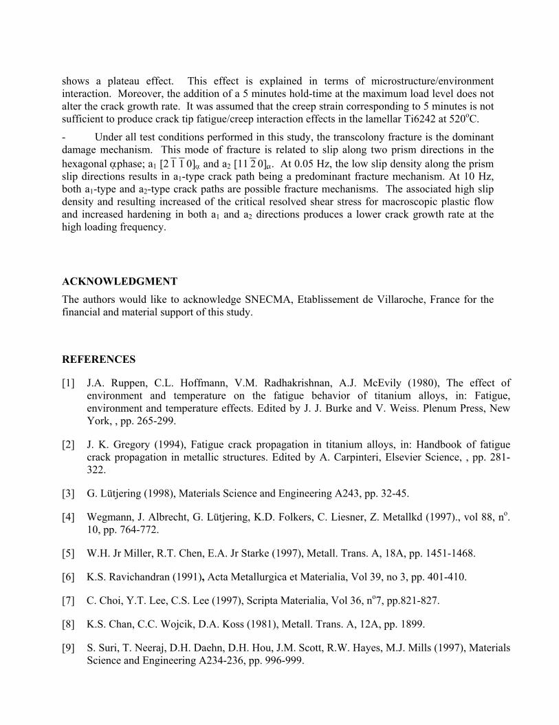
The damage mechanisms associated with the cracking process described above have been investigated by examining the fracture path on the faces of test specimens and, also, their respective fracture surface. Two fracture patterns have been identified; transcolony and interboundary. The transcolony fracture corresponds to crack propagation through the α/β colony along a path either traversing the lamella or parallel to the lamellae direction. The parallel-to-colony fracture occurs, in general, within the α phase with no apparent α/β interface sliding. The second pattern, interboundary fracture, is related to decohesion of intercolony boundaries or prior β grain boundaries. The relative occurrence of transcolony and interboundary fractures has been calculated by determining the crack path within each fractured colony along the faces of each test specimen and results are given in Fig. 3 as a function of the loading frequency. This figure shows that, under all test conditions performed in this study, the transcolony fracture is the dominant damage mechanism. In focusing on this mechanism, one observes that the associated fracture surfaces display typical planar features; see Fig. 4a, which tend to follow slip bands directions The accumulation of theses bands, which are generated as a result of dislocations emission at the crack tip, tend to reduce the transverse strength of the materials within. each band [16] and thus allow fracture to proceed along a planar direction. Transverse cracking is also observed along these slip bands, which indicates the possibility of cross-slip within the colony and giving rise to the step-wise planar fracture patterns as shown in Fig. 4b. The nature of the planar fracture process and its correlation with the microstructure and loading frequency is discussed below.
In the two-phase α/β Ti alloys, the highly anisotropic, hexagonal α phase, which is significantly less ductile than the bcc β phase [8] and, governs the slip process within the deformed colonies. The orientation of α platelets of a particular colony is related to the prior β grain orientation by one of the twelve variants of the Burgers relation [17]: (101)β || (0001)α and <111>β || <11 2 0>α . The relative orientation of the three <11 2 0> slip directions at the intersection of basal plane (0001)α and prism planes {10 1 0}α of the α phase are represented in Fig. 5a. In this figure, the basal plane (0001)α coincides with the plane (101)� of the β phase. While the basal plane is often considered to be the most likely fracture plane [18], slip is also reported to occur along prism planes in the �phase[19]. In the current study, however, it was observed that the large number of well-defined planar slip traces is accompanied with shear offsets at the α/β interfaces, as illustrated in Fig. 10d. As the basal slip is generally more fine and homogenous with no possible shearing appearing at the β lamellae due to the easy transmission along the α/β interface, the result of the previous figure suggests that prisms slips are preferentially activated in Ti6242 alloy. This result is supported by the recent study of Savage et al. [20], who have also demonstrated that for this alloy, the Critical Resolved Shear Stress (CRSS) along prism plane directions is lower than along basal plane directions.

R=0.1520oC
Ti6242 alloy
∆K (MPa.m1/2)
20 30 40 50 60 7010
da/d
N (µ
m/c
ycle
)0.01
0.1
1
1010s-300s-10s, Coarse 10s-10s, Coarse 10s-300s-10s, Fine 10s-10s, Fine
R=0.1520oC
Ti6242 alloy
∆K (MPa.m1/2)20 30 40 50 60 7010
da/d
N (µ
m/c
ycle
)
0.01
0.1
1
1010s-10s, Coarse 10 Hz, Coarse 10s-10s, Extracoarse 10 Hz, Extracoarse 10s-10s, Fine
Freq.= 10 Hz
Freq.= 0.05 Hz
(a) (b)
Fig. 2. Fatigue crack growth rate in Ti6242 alloy at 520oC with different lamellar microstructures. (a) Effect of loading frequency. (b). Effect of 5 minutes hold time at peak stress (0.05Hz frequency).

Fig. 3. Probability of cracking mode as a function of the loading frequency at 520oC.
The prism slip process occurring within α/β colonies is illustrated in Fig. 5a. The interface between α and β platelets is semi-coherent [21]. The edge dislocations along a1 [2 11 0]�will always impinge on the interface with a shallow angle, while the a2 [11 2 0]�and a3 directions edge dislocations will glide at a large angle to the interface [10]. Typical prism slip bands can be seen in the micrograph presented in Fig. 5b. Both a1 and a2 prism slips were indicated on this micrograph. Shear offsets are clearly observed along the a2 direction. Full examination of the planar crack paths has been carried out in the three different microstructures and for the two loading frequencies, 10 Hz and 0.05 Hz. In order to detect a preferential slip orientation for quasi-cleavage, the angle between the planar crack path and the long axis direction of fractured colonies has been measured. Figure 6 presents the results of this examination. It shows that the crack path occurs along three preferential angles formed in relation to the long axis of the colonies. Those angles are respectively close to 0o, 60o and 90o. In considering the prism slip direction as discussed above, a crack path at near 0o angle is related to a prism slip along the a1 direction (a1-type crack path). On the other hand, crack paths at near 90o and near 60o are related to a2 and, to a less extent, a3 prism directions and will be referred to as a2-type and a3-type crack paths, respectively. At 0.05 Hz, it is observed that a1-type crack path is a predominant fracture mechanism. This is in line with earlier work on single-colony crystals of α/β Ti alloys performed by Suri et al. [9,10] who studied the anisotropy of creep and strain deformation along the directions a1 and a2. In their work, it is shown that the strain hardening and the yield stress are significantly lower in the a1 direction than in the a2 direction. This is due to the relative mismatch existing between
0%
10%
20%
30%
40%
50%
60%
70%
80%
90%
100%
Perc
enta
ge o
f col
onie
s on
crac
k pa
th 520 C, 0.05 Hz520 C, 10 Hz
TranscolonyInterboundaryfracture
oC, oC,

a)
b)
Fig. 4. (a) a typical fracture surface with quasi-cleavage facets (b) Shear offset at α/β interface indicated by an arrow showing prism planar slip.
the prism direction a2 [11 2 0]α of the α phase and the direction b2 [ 11 1]β of the β phase [21]. It should be mentioned that their results are different from approaches followed by several authors who assumed easy slip transmission at the α/β interface. Therefore, due to the fact that a1-type crack path has a shallow angle of incidence with the α/β interface; the crack path becomes
40 µm
5 µm
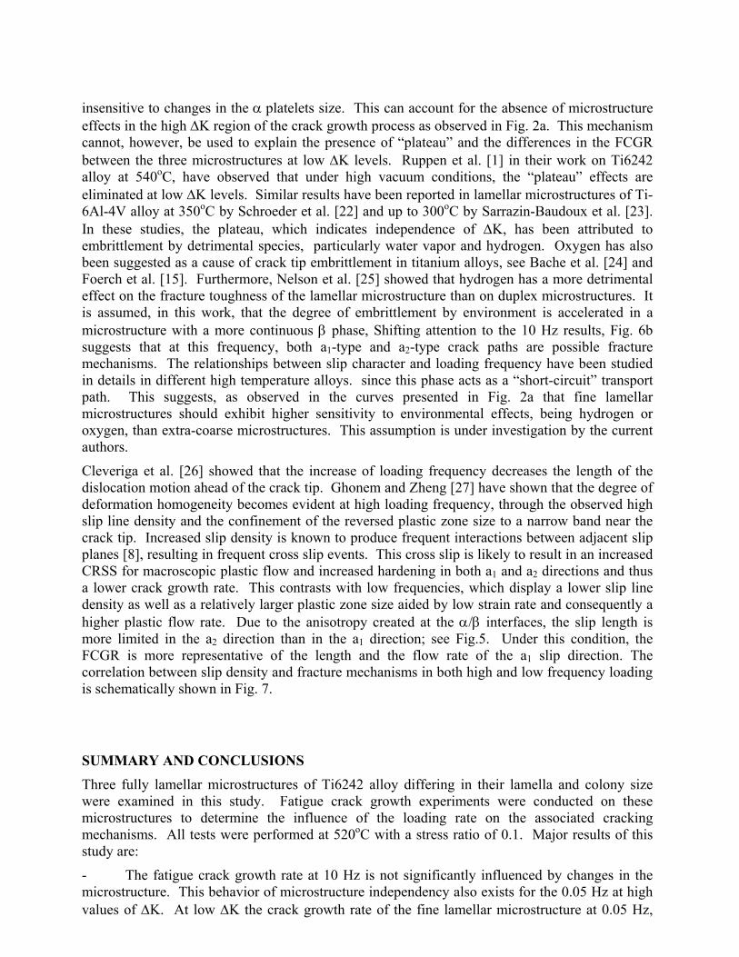
insensitive to changes in the α platelets size. This can account for the absence of microstructure effects in the high ∆K region of the crack growth process as observed in Fig. 2a. This mechanism cannot, however, be used to explain the presence of “plateau” and the differences in the FCGR between the three microstructures at low ∆K levels. Ruppen et al. [1] in their work on Ti6242 alloy at 540oC, have observed that under high vacuum conditions, the “plateau” effects are eliminated at low ∆K levels. Similar results have been reported in lamellar microstructures of Ti-6Al-4V alloy at 350oC by Schroeder et al. [22] and up to 300oC by Sarrazin-Baudoux et al. [23]. In these studies, the plateau, which indicates independence of ∆K, has been attributed to embrittlement by detrimental species, particularly water vapor and hydrogen. Oxygen has also been suggested as a cause of crack tip embrittlement in titanium alloys, see Bache et al. [24] and Foerch et al. [15]. Furthermore, Nelson et al. [25] showed that hydrogen has a more detrimental effect on the fracture toughness of the lamellar microstructure than on duplex microstructures. It is assumed, in this work, that the degree of embrittlement by environment is accelerated in a microstructure with a more continuous β phase, Shifting attention to the 10 Hz results, Fig. 6b suggests that at this frequency, both a1-type and a2-type crack paths are possible fracture mechanisms. The relationships between slip character and loading frequency have been studied in details in different high temperature alloys. since this phase acts as a “short-circuit” transport path. This suggests, as observed in the curves presented in Fig. 2a that fine lamellar microstructures should exhibit higher sensitivity to environmental effects, being hydrogen or oxygen, than extra-coarse microstructures. This assumption is under investigation by the current authors.
Cleveriga et al. [26] showed that the increase of loading frequency decreases the length of the dislocation motion ahead of the crack tip. Ghonem and Zheng [27] have shown that the degree of deformation homogeneity becomes evident at high loading frequency, through the observed high slip line density and the confinement of the reversed plastic zone size to a narrow band near the crack tip. Increased slip density is known to produce frequent interactions between adjacent slip planes [8], resulting in frequent cross slip events. This cross slip is likely to result in an increased CRSS for macroscopic plastic flow and increased hardening in both a1 and a2 directions and thus a lower crack growth rate. This contrasts with low frequencies, which display a lower slip line density as well as a relatively larger plastic zone size aided by low strain rate and consequently a higher plastic flow rate. Due to the anisotropy created at the α/β interfaces, the slip length is more limited in the a2 direction than in the a1 direction; see Fig.5. Under this condition, the FCGR is more representative of the length and the flow rate of the a1 slip direction. The correlation between slip density and fracture mechanisms in both high and low frequency loading is schematically shown in Fig. 7.
SUMMARY AND CONCLUSIONS Three fully lamellar microstructures of Ti6242 alloy differing in their lamella and colony size were examined in this study. Fatigue crack growth experiments were conducted on these microstructures to determine the influence of the loading rate on the associated cracking mechanisms. All tests were performed at 520oC with a stress ratio of 0.1. Major results of this study are:
- The fatigue crack growth rate at 10 Hz is not significantly influenced by changes in the microstructure. This behavior of microstructure independency also exists for the 0.05 Hz at high values of ∆K. At low ∆K the crack growth rate of the fine lamellar microstructure at 0.05 Hz,
shows a plateau effect. This effect is explained in terms of microstructure/environment interaction. Moreover, the addition of a 5 minutes hold-time at the maximum load level does not alter the crack growth rate. It was assumed that the creep strain corresponding to 5 minutes is not sufficient to produce crack tip fatigue/creep interaction effects in the lamellar Ti6242 at 520oC.
- Under all test conditions performed in this study, the transcolony fracture is the dominant damage mechanism. This mode of fracture is related to slip along two prism directions in the hexagonal αphase; a1 [2 11 0]α and a2 [11 2 0]α . At 0.05 Hz, the low slip density along the prism slip directions results in a1-type crack path being a predominant fracture mechanism. At 10 Hz, both a1-type and a2-type crack paths are possible fracture mechanisms. The associated high slip density and resulting increased of the critical resolved shear stress for macroscopic plastic flow and increased hardening in both a1 and a2 directions produces a lower crack growth rate at the high loading frequency.
ACKNOWLEDGMENT The authors would like to acknowledge SNECMA, Etablissement de Villaroche, France for the financial and material support of this study.
REFERENCES
[1] J.A. Ruppen, C.L. Hoffmann, V.M. Radhakrishnan, A.J. McEvily (1980), The effect of environment and temperature on the fatigue behavior of titanium alloys, in: Fatigue, environment and temperature effects. Edited by J. J. Burke and V. Weiss. Plenum Press, New York, , pp. 265-299.
[2] J. K. Gregory (1994), Fatigue crack propagation in titanium alloys, in: Handbook of fatigue crack propagation in metallic structures. Edited by A. Carpinteri, Elsevier Science, , pp. 281-322.
[3] G. Lütjering (1998), Materials Science and Engineering A243, pp. 32-45.
[4] Wegmann, J. Albrecht, G. Lütjering, K.D. Folkers, C. Liesner, Z. Metallkd (1997)., vol 88, no. 10, pp. 764-772.
[5] W.H. Jr Miller, R.T. Chen, E.A. Jr Starke (1997), Metall. Trans. A, 18A, pp. 1451-1468.
[6] K.S. Ravichandran (1991), Acta Metallurgica et Materialia, Vol 39, no 3, pp. 401-410.
[7] C. Choi, Y.T. Lee, C.S. Lee (1997), Scripta Materialia, Vol 36, no7, pp.821-827.
[8] K.S. Chan, C.C. Wojcik, D.A. Koss (1981), Metall. Trans. A, 12A, pp. 1899.
[9] S. Suri, T. Neeraj, D.H. Daehn, D.H. Hou, J.M. Scott, R.W. Hayes, M.J. Mills (1997), Materials Science and Engineering A234-236, pp. 996-999.

[10] S. Suri, G.B. Viswanathan, T. Neeraj, D.H. Hou, M.J. Mills (1999), Acta Materialia, Vol 47, no3, pp. 1019-1034.
[11] L.S. Vesier, S.D. Antolovich (1990), Engng Frac. Mech., vol 37, no4, pp 753-775.
[12] W.J. Evans, C. Gostelow (1979), Metall. Transaction A, 10A, pp 1837-1846.
[13] A.W. Sommer, D. Eylon (1983), Metall. Transaction A, 14A, pp. 2178-2181.
[14] T. Neeraj, D.H. Hou, G.S. Daehn and M.J. Mills (2000), Acta Mater. 48, pp. 1225-1238.
[15] R. Foerch, A. Madsen, H. Ghonem (1993), Metall. Trans. A, 24A, , pp. 1321-1332.
[16] J.A. Hall, (1997) Int. J. Fatigue, Vol. 19, supp. No. 1, pp. S23-S37.
[17] J.A. Ruppen, C.L. Hoffmann, V.M. Radhakrishnan, A.J. McEvily (1980), The effect of environment and temperature on the fatigue behavior of titanium alloys, in: Fatigue, environment and temperature effects. Edited by J. J. Burke and V. Weiss. Plenum Press, New York, , pp. 265-299.
[18] M.R. Bach, M. Copet, H.M. Davies, W.J. Evans, G. Harrison (1997), Int. J. Fatigue, Vol. 19, supp. No. 1, pp. S83-S88.
[19] J. Ruppen, P. Bhowal, D. Eylon, A.J. McEvily (1979), On the process of subsurface fatigue crack initiation in Ti-6Al-4V, in: Fatigue Mechanisms, Proceedings of an ASTM-NBS-NSF symposium, Kansas City, MO, J.T. Fong (Ed.), ASTM STP 675, ASTM, pp 47-68.
[20] M.F. Savage, J. Tatalovich, M. Zupan, K.J. Hemker, M.J. Mills (2001), Materials Science and Engineering A319-321, pp. 398-403.
[21] U. Dahmen (1982), Acta Metallurgica, Vol 30, pp. 63-73.
[22] G. Schroeder, J. Albrecht, G. Luetjering (2001), Materials Science and Engineering, Vol. A319-321, pp. 602-606. .
[23] C. Sarrazin-Baudoux, S. Lesterlin, J. Petit (1997), Atmospheric influence on fatigue crack propagation in titanium alloys at elevated temperature, in: Elevated temperature effects on fatigue and fracture, ASTM STP 1297, R.S. Piascik, R.P. Gangloff, and A. Saxena, Eds., ASTM, pp. 117-139.
[24] M.R. Bache, W.J. Evans, M. McElhone (1997), Materials Science and Engineering, Vol. A234-236, pp. 918-922.
[25] H.G. Nelson, D.P. Williams, J.E. Stein (1972), Metall. Transactions, Vol. 3, pp. 469-475.
[26] H.H.M. Cleveringa, E. Van Der Giessen, A. Needleman (2001), Materials Science and Engineering, Vol. A317, pp. 37-43.
[27] H. Ghonem, D. Zheng, (1992), Metall. Trans. A, 23A, pp. 3067-3072.

a)
b)
Fig. 5. Illustration and micrograph showing (a) direction of slip transmission in α phase at α/β interface and (b) slip traces along a and b platelets with the appearance of shear offsets at α/β interface.
(0001)α
(101)β
b1]111[ b2
]111[β
a1]0112[
a2]0211[
a3
α platelet
β platelet
a1
a2
5 µm

a)
b)
Fig. 6. Probability of transcolony crack path orientation with respect to the colony long axis direction at two different loading frequencies: (a) 0.05 Hz. (b) 10 Hz.
0%
5%
10%
15%
20%
25%
30%
0 20 25 30 35 40 45 50 55 60 65 70 75 80 85 90
Crack direction with colony orientation, θ (in degree)
Perc
enta
ge o
f col
onie
s on
crac
k pa
th
loading freq. = 0.05 Hz
θ Crack
0%
5%
10%
15%
20%
25%
30%
0 10 20 25 30 35 40 45 50 55 60 65 70 75 80 85 90
Crack direction with colony orientation, θ (in degree)
Perc
enta
ge o
f col
onie
s on
crac
k pa
th
loading freq. = 10 Hz

αβ
a) b)
αβ
a1
a2
Fig. 7. Schematic illustrating strain rate effects on the slip process at α/β interfaces: a) at low frequency, slip length is limited in a2 direction due to difficulties in slip transmission at interface, b) at high frequency the two slip systems along a1 and a2 directions while are active cracking mechanisms, are limited in length.
Low loading frequency High loading frequency
a1