falcon-avr arduino compatible motion controller...
TRANSCRIPT
Vx TechTM
VXD-1703001A1 © 2017 Vx Technology. All rights reserved. Page 1 of 26
FALCON-AVR™ ARDUINO COMPATIBLE
MOTION CONTROLLER USER’S GUIDE
1. DESCRIPTION
The Falcon-AVR™ is a general-purpose Arduino compatible motion controller, using the Microchip/Atmel
ATMega328P microprocessor. Originally developed for aircraft applications, it provides three H-bridge or six
unipolar motor drivers, general purpose inputs and outputs, relay and lamp drivers, and a long-haul serial interface
in a robust, environmentally hardened design. Operating at input voltages from 8 to 17 volts, the device is ideally
suited to automotive, marine and aeronautical applications.

Vx TechTM
VXD-1703001A1 © 2017 Vx Technology. All rights reserved. Page 2 of 26
Arduino (www.arduino.cc) is an open-source hardware/software integrated development environment (IDE),
originally created as an educational tool. It has been widely adopted by hobbyists, students, and small to medium
sized engineering companies as the platform of choice for quick-turn development of custom microcontroller
applications. Developers worldwide support the millions of Arduino users, providing readily available, low cost
hardware and open-source software.
Unfortunately, the basic Arduino Uno processor does not actually do anything other than blink a light! To make it
more useful, you must purchase or design custom ‘shields’ that plug into the Arduino platform, design or purchase
a proper power supply and find an enclosure for the project. Even so, despite a working prototype, the robustness
and reliability of the project is questionable. Vehicle electrical systems, static discharge, strong radio frequency
fields, and accidental short circuits or even residual lightning strikes make for a hostile environment. What works
in the lab, may not work in the field! In the end, the low-cost Arduino platform, shields and power supplies that
have been put together end up costing many times the original purchase cost of the Arduino processor board and
the result is not production-worthy.
The Falcon-AVR, however, was developed to be a production-ready prototyping system. Fully compatible with the
Arduino or Atmel Studio development environments, it provides robust power conditioning and four levels of
protection from electrostatic discharge, over voltages and short circuits. It uses reliable industry standard D-
subminiature connector for low-current connections and robust fast-on tabs for high-current connections. Best of
all, it saves time and money by fitting into a standard Hammond enclosure.
The Falcon-AVR intentionally uses through-hole components to facilitate hardware customization, field
modifications and long-term serviceability. Five external connectors are provided: The primary connector is a 25-
pin D-subminiature receptacle that provides pins for the low-current (1 Amp) motor driver channels and
miscellaneous I/O. The secondary connector uses fast-on tabs to support the high current (10 Amp intermittent)
relay-based motor drivers.
Provided on board is a six-pin rectangular in-circuit serial programming (ICSP) and a six-pin linear bootloader
connector for Arduino programming of the resident ATMega328P processor. An optional audio jack is provided for
alarm generation tone output.

Vx TechTM
VXD-1703001A1 © 2017 Vx Technology. All rights reserved. Page 3 of 26
FEATURES:
Microchip/Atmel ATMega328P based three channel full-bridge or six channel single-ended motor and lighting controller.
Compatible with the Arduino, Atmel Studio, and other commercial development tools for ease of software development.
Designed entirely with through-hole components to facilitate customization, field modification and maintenance.
Operates from 8 to 17 Volts DC with -40 °C to +85 °C ambient temperatures and provides extensive power and I/O conditioning to increase reliability in harsh environments.
I/O capability
o Nine general-purpose protected I/O pins, including three with 5 Volt analog input capabilities. One input has 30 Volt withstanding capability.
o Four 12 Volt, 1 Amp PWM outputs plus two 12 Volt, 10 Amp relay outputs for driving motors or other heavy loads. Configurable in bridge mode for forward/reverse motor control.
o Two 30 Volt open-collector I/O channels for driving external lamps or relays, paired with digital or analog input capabilities for read-back.
o One general purpose 30 Volt open collector output for driving external lamps or relays.
o One on board adjustable potentiometer or audio output jack (assembly option).
o Provides a full duplex RS-422 communications interface for reliable long-haul communications. Compatible with RS-232 for short-haul applications. Pins also usable for general purpose I/O.
o Provides on-board header pins for both in-circuit serial programming (ICSP), and USB to serial bootloading (U2S).
Uses a standard Hammond enclosure to reduce packaging costs in end-use applications.
APPLICATIONS:
Automotive, Marine or Aeronautical actuator control systems
Lighting controller
General purpose laboratory controller
Data acquisition system

Vx TechTM
VXD-1703001A1 © 2017 Vx Technology. All rights reserved. Page 4 of 26
2. APPLICATION EXAMPLES
AIRCRAFT TWO AXIS AUTO-TRIM PLUS FLAPS CONTROLLER
The application example shown in Figure 1 demonstrates an aircraft two-axis auto-trim plus flaps controller. It
controls the pitch and roll trim servos using the PWM H-bridge motor drive channels and the flaps motor using the
on-board H-bridge relay deck.
The EFIS/EMS System (compatible with Dynon SkyView or Garmin G3X) provides important airspeed/attitude data,
sensor data and control data via a serial RS-232 link at 115,200 kilobits per second. This information is extracted to
provide control of the trims and flaps depending on airspeed, sensor values and autopilot control information.
Advanced features such as speed-sensitive flaps control, trim/flaps preset, trim speed scheduling and auto-trim are
all possible by interpreting the serial data link information. A switch input and lamp is used for field programming
of settings and operational mode configuration, such as flaps preset.
Ray Allen
Servo
All wires 22 AWG
unless otherwise
noted
orangegreenblue
GP
Input 1
AX1
AX2
AM1
AM2
BX1
BX2
PWR GNDPitch Servo
Roll Servo
Falcon-AVR™
Pitch (Elevator)
Roll (Aileron)
white
white
PILOT
Copilot
Enable
IDEC AL6Q-M13P-Y or
equivalent
+12 V or
Dimmer Bus Motor Speed
Control
Nose Down
Nose Up
Right Wing Down
Left Wing Down
AM1AM2Mode
Nose Down
Nose Up Ground
Ground
+12V
+12V
TM
GP
Input 6
5V Aux
Power
Signal
Ground
GP
Input 2
Ray Allen POS-12
Position Sensor
orangegreen
blue
Fast-On
Tabs
Flaps
PSNA
PSNB
PSNC
BIAS
EMS
BM1BM2Mode
Left Wing
Down
Left Wing
UpGround
Ground
+12V
+12V
RES
Flaps
Motor
COPILOT
(Option)
12 V Bus18 AWG
5A
10A
white
white
BM1
BM2 Ray Allen
Servoorangegreenblue
8
21
9
22
10
20
19
11
23
2
15
1 14
7
11
24
12
23
13
SWX
LMP
OC1
OC2
Any Serial
TXD
EFIS
RX-
RX+
GNDS
TX-
TX+
18
5
6
17
4
GNDA25
CM1
CM2
CX2
CX1
F2
F3
F4
F1
Figure 1. Aircraft Two Axis Trim and Flaps Controller, EFIS/EMS Mode.
Vx TechTM
VXD-1703001A1 © 2017 Vx Technology. All rights reserved. Page 5 of 26
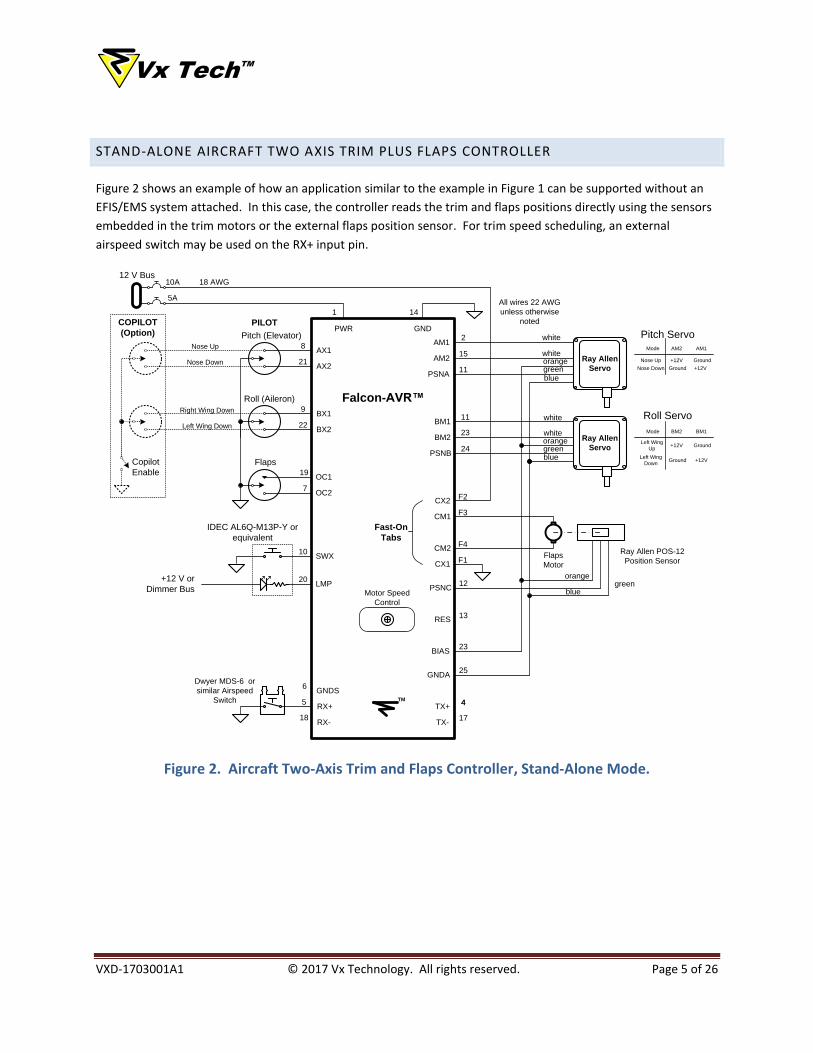
STAND-ALONE AIRCRAFT TWO AXIS TRIM PLUS FLAPS CONTROLLER
Figure 2 shows an example of how an application similar to the example in Figure 1 can be supported without an
EFIS/EMS system attached. In this case, the controller reads the trim and flaps positions directly using the sensors
embedded in the trim motors or the external flaps position sensor. For trim speed scheduling, an external
airspeed switch may be used on the RX+ input pin.
Ray Allen
Servo
12 V Bus
All wires 22 AWG
unless otherwise
noted
orangegreenblue
AX1
AX2
AM1
AM2
BX1
BX2
PWR GNDPitch Servo
Roll Servo
Falcon-AVR™
Pitch (Elevator)
Roll (Aileron)
white
white
PILOT
Copilot
Enable
Motor Speed
Control
Nose Down
Nose Up
Right Wing Down
Left Wing Down
AM1AM2Mode
Nose Down
Nose Up Ground
Ground
+12V
+12V
18 AWG
TM
Ray Allen POS-12
Position Sensor
orangegreen
blue
Fast-On
Tabs
Flaps
5A
10A
PSNA
PSNB
PSNC
BIAS
GNDA
BM1BM2Mode
Left Wing
Down
Left Wing
UpGround
Ground
+12V
+12V
RES
Flaps
Motor
COPILOT
(Option)
white
white
BM1
BM2 Ray Allen
Servoorangegreenblue
8
21
9
22
10
20
19
11
23
2
15
1 14
7
11
24
12
23
25
4
13
SWX
LMP
OC1
OC2
RX-
RX+
GNDS
TX-
TX+
18
5
6
17
4
Dwyer MDS-6 or
similar Airspeed
Switch
IDEC AL6Q-M13P-Y or
equivalent
+12 V or
Dimmer Bus
CM1
CM2
CX2
CX1
F2
F3
F4
F1
Figure 2. Aircraft Two-Axis Trim and Flaps Controller, Stand-Alone Mode.
Vx TechTM
VXD-1703001A1 © 2017 Vx Technology. All rights reserved. Page 6 of 26
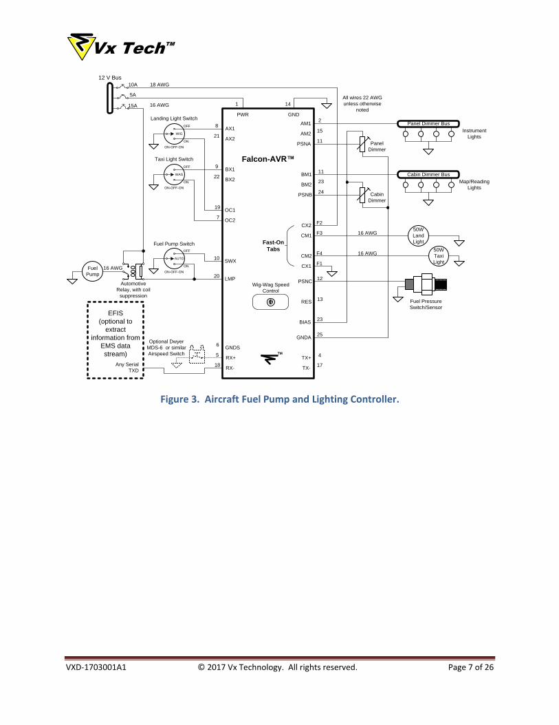
AUTOMATIC FUEL PUMP & LIGHTING CONTROLLER
Figure 3 shows an example of how the Falcon-AVR may be configured as a general purpose automatic fuel pump
and lighting controller.
The fuel pump switch has Off, Auto and On positions. Fuel pressure is derived from the fuel pressure
switch/sensor. Alternatively, if a compatible EFIS/EMS is installed, fuel pressure may be extracted from the
incoming serial data stream. In the On position, the fuel pump switch directly controls the fuel pump relay without
software intervention. In the Off or Auto positions, the fuel pump is controlled in software. The software detects
when fuel pressure is too low, as indicated by the fuel pressure switch/sensor. Then, the fuel pump is turned on
by using the LMP pin as a relay driver.
The landing and taxi light switches select Off, Flash (Wig-Wag) or On. In the On position, the switches control the
OC1 and OC2 pins, which directly drive the onboard relays without software intervention. In the Off or Auto
positions, the lights are controlled in software. Lamp power is provided with the onboard relays, up to 5 Amps
each. The software can generate custom flashing or wig-wag patterns as an anti-collision warning. If an external
pressure sensor switch is added, patterns can be changed depending on airspeed. Instead, if a compatible
EFIS/EMS system is installed, flashing patterns can be changed according to airspeed, altitude or other conditions
extracted from the incoming serial data stream.
Two dimmer busses are provided for instrument and map lights, controlled by the corresponding adjustable
controls. Up to 1 Amp loads on AM1 or AM2 are supported using pulse-width-modulation (PWM) to control the
lamp intensity.
Appendix A shows an example Arduino sketch that implements the Application as described, in stand-alone mode
without an EFIS/EMS or Airspeed Switch.
Vx TechTM
VXD-1703001A1 © 2017 Vx Technology. All rights reserved. Page 7 of 26
All wires 22 AWG
unless otherwise
noted
AX1
AX2
AM1
AM2
BX1
BX2
PWR GND
Falcon-AVR™
Wig-Wag Speed
Control
TM
Fast-On
Tabs
PSNA
PSNB
PSNC
BIAS
RES
12 V Bus
18 AWG
5A
10A
BM1
BM2
8
21
9
22
10
20
19
11
23
2
15
1 14
7
11
24
12
23
13
SWX
LMP
OC1
OC2
Any Serial
TXD
EFIS
(optional to
extract
information from
EMS data
stream)
RX-
RX+
GNDS
TX-
TX+
18
5
6
17
4
GNDA25
50W
Land
Light
50W
Taxi
Light
Panel Dimmer Bus
Cabin Dimmer Bus
OFF
WIG
ON
OFF
WAG
ON
Panel
Dimmer
Cabin
Dimmer
15A 16 AWG
Fuel
Pump
OFF
AUTO
ON
Automotive
Relay, with coil
suppression
ON-OFF-ON
ON-OFF-ON
ON-OFF-ON
Landing Light Switch
Taxi Light Switch
Fuel Pump Switch
Instrument
Lights
Map/Reading
Lights
16 AWG
16 AWG
16 AWG
Fuel Pressure
Switch/Sensor
Optional Dwyer
MDS-6 or similar
Airspeed Switch
CM1
CM2
CX2
CX1
F2
F3
F4
F1
Figure 3. Aircraft Fuel Pump and Lighting Controller.

Vx TechTM
VXD-1703001A1 © 2017 Vx Technology. All rights reserved. Page 8 of 26
3. HARDWARE
J1
J2
J3
J4
X1
X4
X3
X2
Figure 4. Falcon AVR Connector Placement
The Falcon-AVR device has four main connectors, with one more optional. As shown in Figure 4, connector J1 is a
standard female 25-pin D-subminiature for connecting the main board power, special and general purpose inputs
and outputs, RS-422 communication and the 1 Amp motor drivers.
J2 supports a standard USB to Serial adapter cards, available from a number of sources. It is a standard 6-pin
female socket that is easy to convert to a male plug by using standard pin headers strips inserted into the socket.
J3 is a 6-pin rectangular in-circuit serial programmer (ICSP) port for directly programming the ATMega328P
processor chip using an Atmel Studio IDE, or an Arduino Uno configured as an ICSP.
The optional J4 is a stereo/mono audio jack for connecting to a compatible audio system. It is useful in generating
audio alarm tones. The J4 position is shared with the trimmer potentiometer, R4. Installing R4 instead of J4 allows
a variable voltage control, readable in software.
The four fast-on tabs, X1-X4 are for the connection of high power loads, controlled by the onboard relays.

Vx TechTM
VXD-1703001A1 © 2017 Vx Technology. All rights reserved. Page 9 of 26
PIN DESCRIPTION
J1 25 Pin DSub Pinout
Pin
Number
Pin
Name
AVR
Function
Arduino
Function
Pin
Description
1 PWR PWR -- 12 Volt power Input
2 AM1 PD3 3 Motor driver channel A1
3 BM1 PD6 6 Motor driver channel B1
4 TX+ TX+ TX/1 *Serial Port TX+ output, logically paired with TX-
5 RX+ RX+ RX/0 *Serial Port RX+ input, logically paired with RX-
6 GNDS GND GND Shield Ground for serial communications
7 OC2 PC5, PB2 A5/19, 10 Input with analog, open collector output (K2 relay).
8 AX1 PD2 2 General purpose I/O
9 BX1 PD7 7 General purpose I/O
10 SWX PB4 12 General Purpose I/O, 30 Volt tolerant
11 PSNA PC0 A0/14 General purpose I/O, with analog input capability
12 PSNC PC2 A2/16 General purpose I/O, with analog input capability
13 RES PC6/RESET RESET Reset or general purpose I/O. 100 kohm pullup to 5V.
14 GND GND GND Main power ground
15 AM2 PD5 5 Motor driver channel A2
16 BM2 PB1 9 Motor driver channel B2
17 TXD- TXD- TX/1 *Serial Port TX- output, logically paired with TX+
18 RXD- RXD- RX/0 *Serial Port RX- input, logically paired with RX+
19 OC1 PC4, PB3 A4/18, 17 Input with analog, open collector output (K1 relay)
20 LMP PB5 13 Open Collector Out for driving relays or lamps
21 AX2 PD4 4 General purpose I/O
22 BX2 PB0 8 General purpose I/O
23 BIAS -- -- 5 Volt sensor power
24 PSNB PC1 A1/15 General purpose I/O, with analog input capability
25 GNDA GND GND Analog sensor Ground
Vx TechTM
VXD-1703001A1 © 2017 Vx Technology. All rights reserved. Page 10 of 26
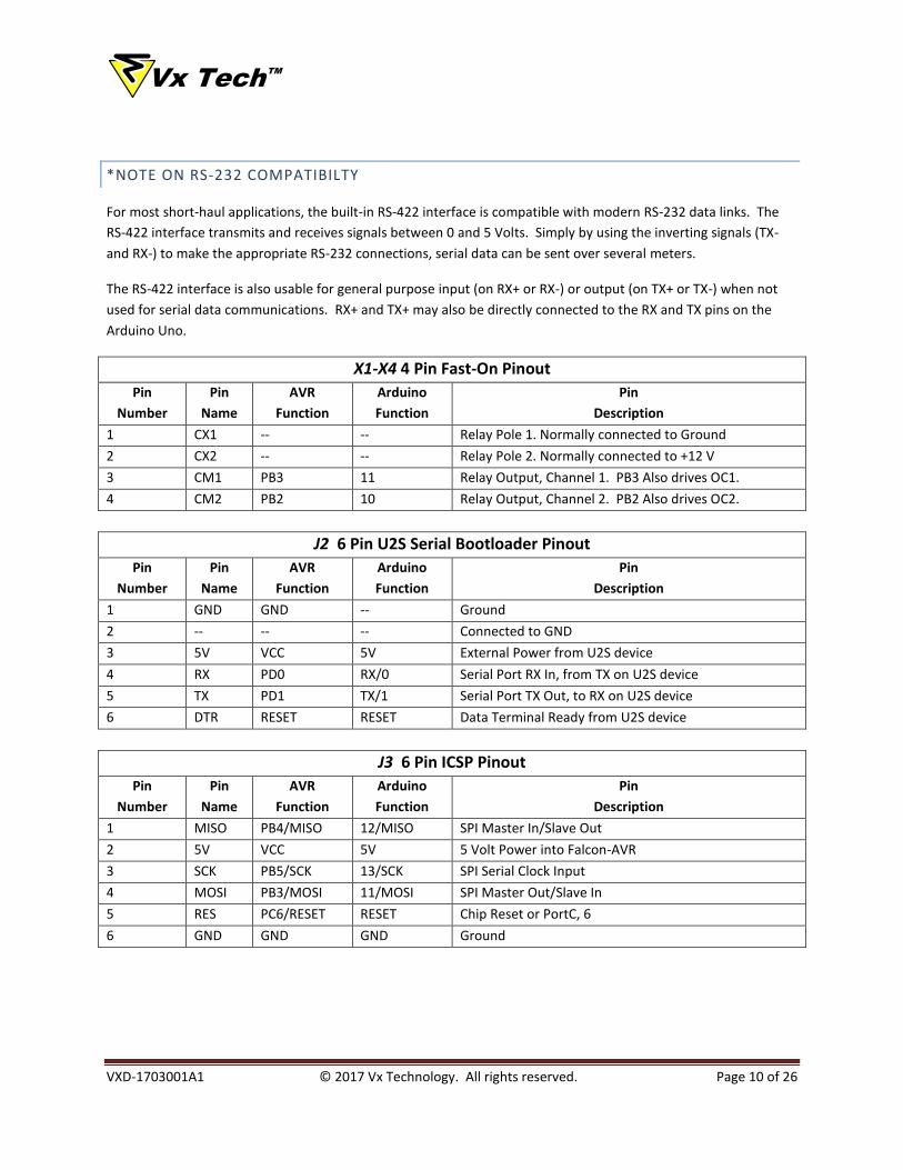
*NOTE ON RS-232 COMPATIBILTY
For most short-haul applications, the built-in RS-422 interface is compatible with modern RS-232 data links. The
RS-422 interface transmits and receives signals between 0 and 5 Volts. Simply by using the inverting signals (TX-
and RX-) to make the appropriate RS-232 connections, serial data can be sent over several meters.
The RS-422 interface is also usable for general purpose input (on RX+ or RX-) or output (on TX+ or TX-) when not
used for serial data communications. RX+ and TX+ may also be directly connected to the RX and TX pins on the
Arduino Uno.
X1-X4 4 Pin Fast-On Pinout
Pin
Number
Pin
Name
AVR
Function
Arduino
Function
Pin
Description
1 CX1 -- -- Relay Pole 1. Normally connected to Ground
2 CX2 -- -- Relay Pole 2. Normally connected to +12 V
3 CM1 PB3 11 Relay Output, Channel 1. PB3 Also drives OC1.
4 CM2 PB2 10 Relay Output, Channel 2. PB2 Also drives OC2.
J2 6 Pin U2S Serial Bootloader Pinout
Pin
Number
Pin
Name
AVR
Function
Arduino
Function
Pin
Description
1 GND GND -- Ground
2 -- -- -- Connected to GND
3 5V VCC 5V External Power from U2S device
4 RX PD0 RX/0 Serial Port RX In, from TX on U2S device
5 TX PD1 TX/1 Serial Port TX Out, to RX on U2S device
6 DTR RESET RESET Data Terminal Ready from U2S device
J3 6 Pin ICSP Pinout
Pin
Number
Pin
Name
AVR
Function
Arduino
Function
Pin
Description
1 MISO PB4/MISO 12/MISO SPI Master In/Slave Out
2 5V VCC 5V 5 Volt Power into Falcon-AVR
3 SCK PB5/SCK 13/SCK SPI Serial Clock Input
4 MOSI PB3/MOSI 11/MOSI SPI Master Out/Slave In
5 RES PC6/RESET RESET Chip Reset or PortC, 6
6 GND GND GND Ground

Vx TechTM
VXD-1703001A1 © 2017 Vx Technology. All rights reserved. Page 11 of 26
J4 Optional Audio Output Jack Pinout
Pin
Number
Pin
Name
AVR
Function
Arduino
Function
Pin
Description
1 TIP PC1 A3/17 Audio output, line level. Tip and Ring
2 RING PC1 A3/17 shorted together.
3 SLEEVE GND GND Analog Audio ground
J4 is an assembly option, to replace R4 (see schematic diagram). J4 is a stereo audio jack, wired to work with mono
or stereo inputs on a compatible audio system. The ATMega328P processor is able to generate tones by
manipulating port PC1 (Arduino A3/17).
When the R4 potentiometer is installed this pin is used as a general purpose variable analog input.

Vx TechTM
VXD-1703001A1 © 2017 Vx Technology. All rights reserved. Page 12 of 26
ABSOLUTE MAXIMUM RATINGS
Symbol Parameter Min Max Units Conditions
PWR Power Supply Voltage -1 17 Volts With respect to GND. Clamped internally.
Exceeding limits may blow internal fuse.
VIN Input Voltage,
standard I/O
-12 17 Volts 10 seconds maximum. Limited by heating of
internal input protection resistor.
VIN Input Voltage,
SWX input
-12 30 Volts Negative voltage, 10 seconds maximum.
Limited by heating of internal input protection
resistor.
VIN Input Voltage,
RX+, RX-
-7 +7 Volts Internally clamped.
VOUT Output Voltage,
standard I/O
-12 17 Volts 10 seconds maximum. Limited by heating of
internal input protection resistor.
VOUT Output Voltage,
open collector I/O
-0.5 30 Volts Negative voltage, 10 seconds maximum
VOUT Output Voltage,
TX+, TX-
-7 +7 Volts
VOUT Output Voltage,
BIAS pin
-0.5 +5.5 Volts
IS AM1, AM2 or
BM1, BM2
2.8 Amps
RMS
Total load on each pair of outputs
ISPK AM1, AM2 or
BM1, BM2
7.1 Amps
peak
Instantaneous load on each pair of outputs
IS CX1, CX2, CM1, CM2 10 Amps Total steady-state current load through either
or both of the onboard relays.
ISPK CX1, CX2, CM1, CM2 15 Amps
peak
Total peak current load through either or both
of the onboard relays.
TA Ambient Operating
Temperature
-40 +55 °C Non-condensing

Vx TechTM
VXD-1703001A1 © 2017 Vx Technology. All rights reserved. Page 13 of 26
RECOMMENDED OPERATING CONDITIONS
Symbol Parameter Min Max Units Conditions
PWR Power Supply Voltage 8 15 Volts With respect to GND.
VIN Input Voltage,
standard I/O
-0.3 5.5 Volts
VIN Input Voltage,
SWX input
-0.3 30 Volts
VIN Input Voltage,
RX+, RX-
-0.3 5.5 Volts
VOUT Output Voltage,
standard I/O
-0.3 5.5 Volts
VOUT Output Voltage,
open collector I/O
-0.3 30 Volts
VOUT Output Voltage,
TX+, TX-
-0.3 5.5 Volts
IS AM1, AM2, or
BM1, BM2
1.4 Amps
RMS
Total load for each pair of pins.
IS AM1, AM2,
BM1, BM2
2.8 Amps
RMS
Total load on all pins,
IS CX1, CX2, CM1, CM2 10 Amps Total peak or sustained current load through
either or both of the onboard relays.
FSW PWM operating
frequency
100 KHz
DATA RATE RS-422 operating rate 250 Kbit/s

Vx TechTM
VXD-1703001A1 © 2017 Vx Technology. All rights reserved. Page 14 of 26
4. CONFIGURING THE ARDUINO ENVIRONMENT
HARDWARE SETUP
The Falcon-AVR is not an Arduino Shield. Instead, it provides a convenient way of using the Arduino IDE to
download sketches to the board and use all of the Arduino tools and libraries. The following description provides
the options for working with the Falcon-AVR to load Arduino sketches.
OPTION 1: USING THE ARDUINO USB 2 SERIAL MICRO
Purchase an Arduino USB 2 Serial Micro device. This device will plug directly into the U2S connector on the Falcon-
AVR and connect to the host computer with a USB cable. You are now ready to program with the Arduino IDE.
OPTION 2: RELOCATING THE PROCESSOR CHIP
This option assumes that you have a working Arduino Uno.
The ATMega328P processor chip from the Arduino Uno must be carefully removed from the Uno. If there is not a
processor with a bootloader already installed on the Falcon-AVR , insert the one removed from the Uno into the
available socket. The Uno processor contains the bootloader that allows the Arduino IDE to talk to the Falcon-AVR.
For more information on how to load a bootloader on the ATMega328P device, refer to the Burning the
Bootloader section.
Note: The ATMega328P is a static sensitive device. You should only handle it if you are at a properly grounded
ESD (electrostatic discharge) workstation and you are properly grounded yourself. Use proper tools to extract or
insert the processor, the pins are easily damaged.
CONNECT THE WIRES
Connect jumper wires between the Arduino Uno to the Falcon AVR using one of the following options:
Arduino Uno Falcon-AVR (option 1)
J1 25-pin Connector
Falcon-AVR (option 2)
J2 6-pin U2S Connector
5V 23 (BIAS) 3 (5V)
GND 6 (GND) 1 (GND)
RX 5 (RX+) 4 (RX)
TX 4 (TX+) 5 (TX)
RESET 13 (RES) 6 (DTR)

Vx TechTM
VXD-1703001A1 © 2017 Vx Technology. All rights reserved. Page 15 of 26
TESTING
Using the Arduino USB 2 Serial Micro (Option 1) or the Arduino Uno (Option 2, with the processor chip removed),
configure the serial port (Tools:Port:<choose>) and select Arduino Uno from the target list (Tools:Board:
Arduino/Genduino Uno). Load the example program ‘Blink’ (File:Examples:01.Basics:Blink) and modify the
program as follows:
TEST SKETCH
void setup() {
// initialize the TX+ pin as an output.
pinMode(1, OUTPUT);
}
void loop() {
digitalWrite(1, HIGH); // turn the LED on (HIGH is the voltage level)
delay(1000); // wait for a second
digitalWrite(1, LOW); // turn the LED off by making the voltage LOW
delay(1000); // wait for a second
}
LED1 should now be blinking on the Falcon-AVR. If it is not, or you get an error message from the Arduino IDE,
check the configuration and wiring (Option 2).
Assuming that the ‘Blink’ sketch worked on the Falcon-AVR, you are now ready to develop your own sketches.
Congratulations!
Vx TechTM
VXD-1703001A1 © 2017 Vx Technology. All rights reserved. Page 16 of 26
BURNING THE BOOTLOADER
Sometimes it is necessary to burn a bootloader onto the ATMega328P chip. Normally, this is required when:
Installing newly purchased ATMega328P chips,
After using the Atmel Studio IDE (which erases the bootloader) then you wish to use the Arduino IDE, or
You have accidentally erased or overwritten the bootloader on the ATMega328P chip.
The procedure for burning a bootloader requires that you have a functional Arduino Uno to serve as a
programmer. The procedure is as follows:
1. Connect pins 1, 2, 3, 4, and 6 of the Falcon-AVR board’s ICSP connector to the same pins on the Arduino
Uno board’s ICSP connector (the one nearest the ATMega328P chip). Ensure that you have correctly
identified the proper pins on each board. Pin 1 is usually marked with a dot or a square surrounding the
pin. See Appendix C. Falcon-AVR Schematic Diagram for more information on the ICSP connector.
2. Connect pin 5 of the Falcon-AVR board ICSP connector to the Uno board’s pin 10 (marked as ~10 on the
board).
3. Plug in the Uno and properly configure the Arduino environment, then load the sketch “ArdunioISP” from
(File:Examples:01.Basics:11.ArduionoISP:ArduinoISP) and click the Upload arrow to program the Uno.
4. When it’s done Uploading, select Tools:Burn Bootloader. After a few seconds, the operation will be
completed and the message “Done burning bootloader” will be displayed.
5. Unplug the Uno and remove the connections to the Falcon-AVR ICSP connector before proceeding.
The ATMega328P chip on the Falcon-AVR will now be able to accept Arduino sketches when configured according
to the instructions in the Hardware Setup section.

Vx TechTM
VXD-1703001A1 © 2017 Vx Technology. All rights reserved. Page 17 of 26
APPENDIX A. EXAMPLE ARDUINO SKETCH FOR FUEL PUMP AND LIGHTING CONTROL
//
// Falcon-AVR Demonstration Program
// "Fuel Pump and Lights"
// Written by Vernon Little for the Falcon-AVR(tm) Motion Controller.
// Version 1.0, April, 2017
//
// Fuel Pump Operation:
// Assumes a fuel pressure sensor connected to the PSNC input
// and an ON-OFF-ON FP switch.
// One pole of the FP switch is connected to the SWX pin.
// The center pole of the FP switch is grounded,
// and the third pole connected to the LMP pin.
// The coil of a 12 volt relay is connected to the LMP pin.
// When the FP switch is set to 'Auto', the device automatically
// switches on the fuel pump relay when
// the Pressure sensor connected to the PSNC input is high,
// which indicates low pressure.
// If the PSNC input is low, indicating a normal pressure,
// the fuel pump relay is switched off.
// When the FP switch is 'On', the fuel pump is always on.
// When FP switch is 'Off', the fuel pump is always off.
//
// Landing and Taxi Light Operation:
// Assumes an ON-OFF-ON switch for each of the Landing or Taxi lights.
// One pole of the Landing light switch is connected to AX1,
// the center pole is grounded and the third pole is connected to OC1.
// Similarly, one pole of the Taxi light switch is connected to BX1,
// the center pole is grounded, and the third pole is connected to OC2.
// The switches can turn the lights Off, Flash, or On,
// with the center position being the Flash position.
// When flashing, each lamp follows an 8-tick binary pattern
// as defined in the flash1 and flash2 variables.
//
// Lamp Dimmer Operation:
// Assumes a dimmer control for each of the two dimming channels,
// Panel Dimmer and Cabin Dimmer.
// The analog dimmer values control the pulse-width-modulation of the
// AM1 and BM2 outputs, respectively.
// Each output can drive up to 1 Amp in total load.
// The program can easily be modified to also drive AM2 and BM2
// if more loads are required.
//
//
// Falcon-AVR pin cross reference to Arduino pin definitions
//

Vx TechTM
VXD-1703001A1 © 2017 Vx Technology. All rights reserved. Page 18 of 26
const byte AM1 = 3, AM2 = 5, BM1 = 6, BM2 = 9;
const byte TX = 1, RX = 0;
const byte PSNA = 14, PSNB = 15, PSNC = 16, SPD = 17; //A0, A1, A2, A3
const byte OC1IN = 18, OC2IN = 19; //A4, A5
const byte OC1OUT = 11, OC2OUT = 10;
const byte AX1 = 2, AX2 = 4, BX1 = 7, BX2 = 8;
const byte SWX = 12, LMP = 5, RES = 1;
const byte PressureThreshold = 20; // PSI. Only if analog pressure sender used.
const byte shift = 1;
byte flash1 = 0b10101100;
byte flash2 = 0b01010011;
int sensorValue;
byte outputValue;
byte FuelPressure;
byte FPump;
//
// Byte rotate function for flashing patterns
//
byte rotateRight (byte value, byte amount)
{
amount &= 0b00000111;
return (value>>amount|value<<(8-amount));
}
void setup() {
pinMode(AM1, OUTPUT);
pinMode(AM2, OUTPUT);
pinMode(BM1, OUTPUT);
pinMode(BM2, OUTPUT);
pinMode(TX, OUTPUT);
pinMode(OC1OUT, OUTPUT);
pinMode(OC1IN, INPUT_PULLUP);
pinMode(OC2OUT, OUTPUT);
pinMode(OC2IN, INPUT_PULLUP);
pinMode(AX1, INPUT_PULLUP);
pinMode(AX2, INPUT_PULLUP);
pinMode(BX1, INPUT_PULLUP);
pinMode(BX2, INPUT_PULLUP);
pinMode(SWX, INPUT_PULLUP);
pinMode(PSNA, INPUT);
pinMode(PSNB, INPUT);
pinMode(PSNC, INPUT_PULLUP);
Serial.begin(9600);
}
//
// Main program loop, repeats at a rate set by the SPD control.
//

Vx TechTM
VXD-1703001A1 © 2017 Vx Technology. All rights reserved. Page 19 of 26
void loop() {
delay(analogRead(SPD)*2); // Sets the flash rate and program scanning rate
//
// Landing and Taxi light flashing (wig-wag)
// Adjust variables flash1 and flash2 to set individual flash pattern sequences.
// Flash pattern repeats every eight cycles.
//
flash1 = rotateRight (flash1, shift);
flash2 = rotateRight (flash2, shift);
if ((flash1 & bit(0)) && (byte) digitalRead(AX1)) digitalWrite (OC1OUT, HIGH);
else digitalWrite (OC1OUT, LOW);
if ((flash2 & bit(0)) && (byte) digitalRead(BX1)) digitalWrite (OC2OUT, HIGH);
else digitalWrite (OC2OUT, LOW);
Serial.println ("tick");
//
// Panel Dimmer
// External Panel Dimmer control changes the pulse width on AM1.
// Up to 1 Amp of lighting loads may be supported.
// Program may be modified to also drive AM2 for more loads.
//
sensorValue = analogRead(PSNA);
outputValue = map(sensorValue, 0, 1023, 0, 255);
analogWrite(AM1, outputValue);
//
// Map/Reading Light Dimmer
// External Map/Reading light Dimmer control changes the pulse width on BM1.
// Up to 1 Amp of lighting loads may be supported.
// Program may be modified to also drive BM2 for more loads.
//
sensorValue = analogRead(PSNB);
outputValue = map(sensorValue, 0, 1023, 0, 255);
analogWrite(BM1, outputValue);
//
// Fuel Pump Switch
// External ON-OFF-ON FP switch:
// If the FP switch is in the AUTO position,
// the fuel pump is turned on automatically if the external
// Pressure Switch on the POSNC input is off (high), indicating low fuel pressure.
// If the FP switch is in the OFF position, the fuel pump is turned off.
// If the FP switch is in the ON position, the switch will overide
// the internal logic and force the fuel pump on.
//

Vx TechTM
VXD-1703001A1 © 2017 Vx Technology. All rights reserved. Page 20 of 26
// Analog pressure senders are easily accomodated by changing to an
// analogRead of the input, followed by a
// threshold comparison as indicated in the notes below.
//
FuelPressure = digitalRead(PSNC);
FPump = digitalRead(SWX);
if (FuelPressure & FPump) digitalWrite(LMP, LOW);
else digitalWrite(LMP, HIGH);
// FuelPressure = analogRead(PSNC);
// FPump = digitalRead(SWX);
// if ((FuelPressure > PressureThreshold) & FPump) digitalWrite(LMP, LOW);
// else digitalWrite(LMP, HIGH);
}

Vx TechTM
VXD-1703001A1 © 2017 Vx Technology. All rights reserved. Page 21 of 26
5. APPENDIX B. PIN CONFIGURATION CROSS-REFERENCE
1
2
3
4
5
6
7
8
9
10
11
12
13
PWR
PD3
GND
PC5**
PD2
PD7
PB4
PC0
PC2**
PC6
5
16
4
13
18
23
25
1
A0
A2
3
10
2
7
12
14
16
PCINT14
PD6126
PCINT8
PCINT10
PCINT18
PCINT23
PCINT4
RES
PSNC
PSNA
SW
BX1
AX1
OC2
RX+
TX+
BM1
AM114
15
16
17
18
19
20
21
22
23
24
25
PD5 11
GND
PB1 15
PD1 3
PD0 2
PB5 19
PD4 6
PB0 14
PC1 24
BIAS
GNDA
PCINT17
PCINT20
PCINT0
PCINT16
PCINT9
5
9
1
0
5
4
8
15A1
GNDA
PSNB
BIAS
BX2
AX2
LMP
OC1
TX-
BM2
AM2
GNDPWR
RX-GNDS
PWMPWM
PWM
PWM
PWM
AVR Port Pin
AVR Physical Pin
Arduino Reference
Analog Related Pin
Digital Pin
Falcon-AVR Pin
Power or Voltage
Ground
1
2
3
4
GND
CM2
PB2** 16
PB3** 17
10
11
CM1
CX1
CX2
X1-X4, Fast-On
Tabs
J1, 25 Pin
**Refer to Schematic for details
Logically Paired with TX- and RX-
(pins 17 & 18, respectively
PD1 3
PD0 2
PCINT17
PCINT16
1
0
RX
TX
PC6 1 PCINT14
5V 5V
GND
GNDGND
RESET
12vGND
IOREF
12V PWR
IOREF
J2, U2S
Bootloader
PC4** 27 A4 PCINT1218PB3** 17 11 PWM
PB2**28A519PCINT13
PCINT21
PCINT1
PCINT5
PCINT19
PCINT22
PCINT2PCINT3
Digital Output Only, Interrupt not Available
1
2
3
4
5
6 DTRRES
A3Internal Trimmer
PotentiometerPC3 26 17 PCINT11
OUTIN
OUTIN
Inverted Logic**
Pull-up/down resistors on board**
AVRPinArduinoFalcon-AVR AVR Pin Arduino Falcon-AVR
Pin ArduinoAVR Falcon-AVR
-Or- Audio Jack
(J4)
MISO 5V
SCK MOSI
GNDRESET
1 2
3 4
5 6
J3, ICSP Port
Figure 5. Falcon-AVR Pin Configuration Cross-Reference

Vx TechTM
VXD-1703001A1 © 2017 Vx Technology. All rights reserved. Page 22 of 26
6. APPENDIX C. FALCON-AVR SCHEMATIC DIAGRAM
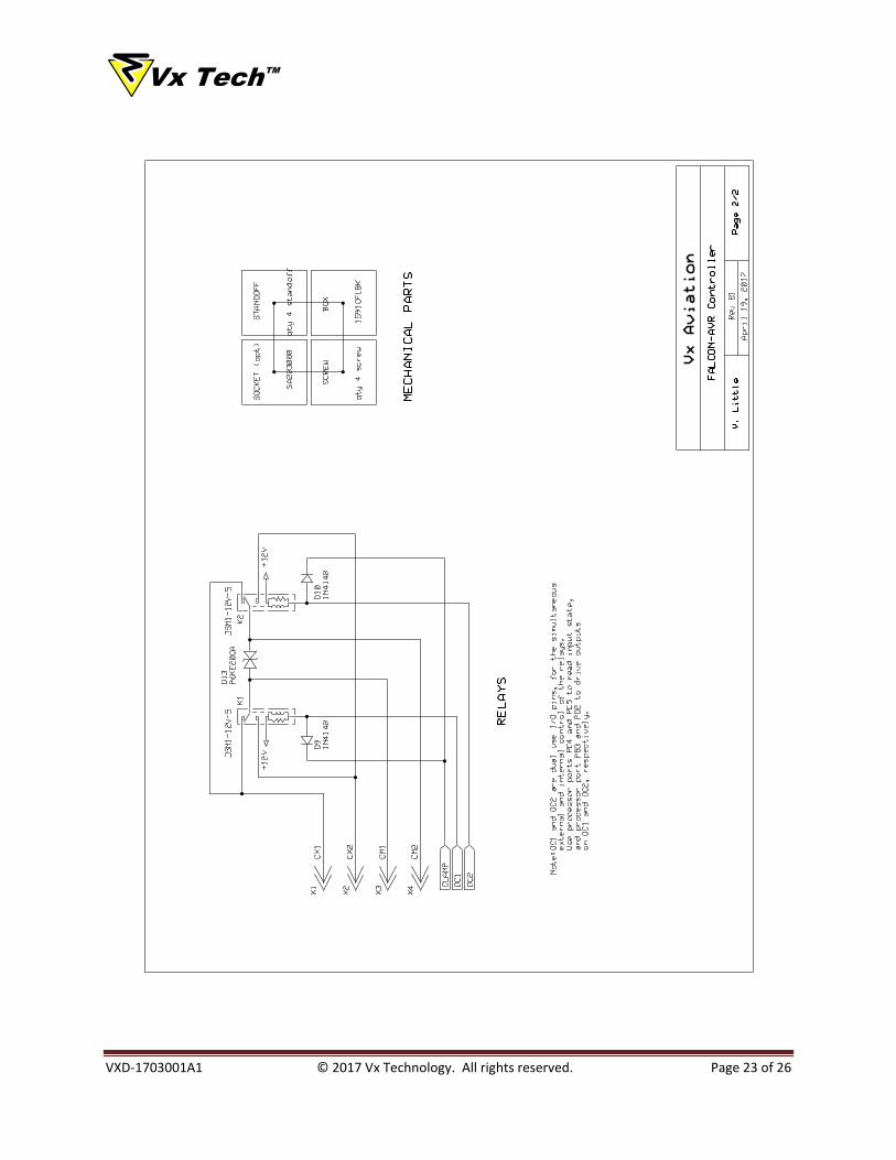
Vx TechTM
VXD-1703001A1 © 2017 Vx Technology. All rights reserved. Page 23 of 26

Vx TechTM
VXD-1703001A1 © 2017 Vx Technology. All rights reserved. Page 24 of 26
7. APPENDIX D. ENCLOSURE
The Falcon-AVR mounts directly into a standard Hammond 1591CFLBK case. The end plates of the case need to be
machined to allow access to the device connectors, as shown in Figure 7.
2.56
0.75
1.630.47 Typ
TOP
END (Typical)
HAMMOND 1591CFLBK
1.42
4.72
Figure 7. Case Machining Guide
Vx TechTM
VXD-1703001A1 © 2017 Vx Technology. All rights reserved. Page 25 of 26
8. DOCUMENT REVISION HISTORY
Issue Number Date Purpose
VXD-1703001A1 April 19, 2017 Initial Product Release

Vx TechTM
VXD-1703001A1 © 2017 Vx Technology. All rights reserved. Page 26 of 26