faiez sayahi print iii - diva portal
TRANSCRIPT

LICENTIATE T H E S I S
Department of Civil, Environmental and Natural Resources EngineeringDivision of Structural and Fire Engineering
Plastic Shrinkage Cracking
in ConcreteISSN 1402-1757
ISBN 978-91-7583-678-2 (print)ISBN 978-91-7583-679-9 (pdf)
Luleå University of Technology 2016
Faez Sayahi Plastic Shrinkage Cracking in C
oncrete Faez Sayahi
Structural Engineering


PLASTIC SHRINKAGE CRACKING IN CONCRETE
Faez Sayahi
Luleå 2016
Division of Structural and Fire Engineering Department of Civil, Environmental and Natural Resources Engineering
Luleå University of Technology SE-97187 Luleå, Sweden
Printed by Luleå University of Technology, Graphic Production 2016
ISSN 1402-1757 ISBN 978-91-7583-678-2 (print)ISBN 978-91-7583-679-9 (pdf)
Luleå 2016
www.ltu.se
Cover photo from Slowik, et al. (2008), shows Scanning Electron Microscope images of the process of plastic shrinkage cracking in drying suspension of fly ash and water (magnification factor 300).The photo is published here with permission from Professor Volker Slowik, Leipzig University of Applied Science (HTWK Leipzig).

Academic thesis
For the Degree of Licentiate (Tech. Lic) in structural engineering, which by due of the Technical Faculty Board at Luleå University of Technology will be publicly defended in:
Room F1031, Luleå University of Technology
Thursday, October 27th, 2016, 10:00 am
Discussion leader: Dr. Magnus Åhs, Lund University
Principal supervisor: Prof. Mats Emborg, Luleå University of Technology
Assistant supervisors: Prof. Andrzej Cwirzen, Luleå University of Technology Adj. Prof. Hans Hedlund, Luleå University of Technology

I
PREFACE This PhD project, started on September 2013 at the Division of Structural and Fire Engineering of Luleå University of Technology (LTU), aims at investigating the plastic shrinkage cracking phenomenon of fresh concrete. The project was financially supported by the Development Fund of the Swedish Construction Industry (SBUF), to whom I am sincerely grateful. This licentiate thesis was not to be written without the support and motivations I have received from so many people. In particular, it is a genuine pleasure to acknowledge the efforts of my main supervisor Prof. Mats Emborg, who guided me through this journey by his fruitful advices. His dedication, commitment and overwhelming attitude to help me was the main driving force in this work. Also, special thanks are due to my assistant supervisors Prof. Jan-Erik Jonasson, Adj. Prof. Hans Hedlund and Prof. Andrzej Cwirzen for their support and valuable comments. I would like to express my deep sense of gratitude to Adj. Prof. Ingemar Löfgren from Chalmers University, for his concern, support and remarkable comments on my work by which my path was enlightened. Furthermore, I should express my thankfulness to Prof. Volker Slowik from Leipzig University of Applied Sciences, for his technical support and productive discussions. I thank profusely all the technicians of CompLab at Luleå University of Technology for their technical help. Also, I would like to thank all my friends and colleagues at the Division of Structural and Fire Engineering for the fantastic working environment and all the enjoyable moments. Moreover, no matter how hard I try, I cannot thank my parents enough for all the love, joy, happiness and protection, I received from them during my lifetime. Their sacrifices, dedication and suffering are the main reasons behind any task I accomplish in my life, and for that I am always in their debt. Last but not least, I would like to express my deep indebtedness and appreciation to my beloved wife, Sally, and my precious little princess, Nicole, who provided all I needed to carry out this task. Without their love, support and motivations, the completion of this project could not have been possible.
Faez Sayahi Luleå, September 2016

III
ABSTRACT Early-age (up to 24 hours after casting) cracking may become problematic in any concrete structure. It can damage the aesthetics of the concrete member and decrease the durability and serviceability by facilitating the ingress of harmful material. Moreover, these cracks may expand gradually during the member’s service-life due to long-term shrinkage and/or loading. Early-age cracking is caused by two driving forces: 1) plastic shrinkage cracking which is a physical phenomenon and occurs due to rapid and excessive loss of moisture, mainly in form of evaporation, 2) chemical reactions between cement and water which causes autogenous shrinkage. In this PhD project only the former is investigated. Rapid evaporation from the surface of fresh concrete causes negative pressure in the pore system. This pressure, known as capillary pressure, pulls the solid particles together and decreases the inter-particle distances, causing the whole concrete element to shrink. If this shrinkage is hindered in any way, cracking may commence. The phenomenon occurs shortly after casting the concrete, while it is still in the plastic stage (up to around 8 hours after placement), and is mainly observed in concrete elements with high surface to volume ratio such as slabs and pavements. Many parameters may affect the probability of plastic shrinkage cracking. Among others, effect of water/cement ratio, fines, admixtures, geometry of the element, ambient conditions (i.e. temperature, relative humidity, wind velocity and solar radiation), etc. has been investigated in previous studies. In this PhD project at Luleå University of Technology (LTU), in addition to studying the influence of various parameters, effort is made to reach a better and more comprehensive understanding about the cracking governing mechanism. Evaporation, capillary pressure development and hydration rate are particularly investigated in order to define their relationship. This project started with intensive literature study which is summarized in Papers I and II. Then, the main objective was set upon which series of experiments were defined. The utilized methods, material, investigated parameters and results are presented in Papers III and IV. It has been so far observed that evaporation is not the only driving force behind the plastic shrinkage cracking. Instead a correlation between evaporation, rate of capillary pressure development and the duration of dormant period governs the phenomenon. According to the results, if rapid evaporation is accompanied by faster capillary pressure development in the pore system and slower hydration, risk of plastic shrinkage cracking increases significantly. Key words: Plastic shrinkage cracking, Evaporation, Capillary pressure, Hydration rate.


V
SAMMANFATTNING Tidig sprickbildning (upp till 24 timmar efter gjutning) kan bli problematiskt i betongelement. Den kan skada de estetiska egenskaperna hos betongelementet och minska hållbarheten och servicevänlighet genom att underlätta inträngning av skadliga material. Dessutom kan dessa sprickor expandera successivt under betongens livslängd på grund av långsiktig krympning och/eller lastning. Tidig sprickbildning orsakas av två drivkrafter: 1) plastisk krympsprickbildning som är ett fysikaliskt fenomen och uppstår på grund av en snabb och stor förlust av fukt, främst i form av avdunstning, 2) kemiska reaktioner mellan cement och vatten som orsakar autogen krympning. I detta doktorandprojekt undersöks endast den förstnämnda. Snabb avdunstning från ytan av färsk betong förorsakar undertryck i porsystemet. Detta tryck, känt som kapillära undertrycket, drar de fasta partiklarna tillsammans och minskar avståndet mellan dem, vilket gör att hela betongelementet krymper. Om denna krympning hindras på något sätt, påbörjar sprickbildning. Detta fenomen som inträffar kort efter gjutning av betongen, medan den fortfarande är i plastiskt skede (upp till ca 8 timmar efter gjutning), är i huvudsak observerat i betongkonstruktioner med hög yta till volymförhållande såsom plattor, industrigolv, beläggningar och brobanor. Många parametrar kan påverka sannolikheten för plastisk krympsprickbildning. Bland annat har effekten av vatten/cement-tal (vct), finmaterial, tillsatsmedel, geometri av elementet, omgivningsförhållanden (dvs. temperatur, relativ fuktighet, vindhastighet och solinstrålning), etc. undersökts i tidigare studier. Under detta doktorandprojekt vid LTU, förutom att studera inverkan av olika parametrar, har ansträngningar gjorts för att nå en bättre och mer omfattande förståelse om sprickbildning styrande mekanism. Avdunstning, utveckling kapillära undertryck och hydratiseringshastigheten har särskilt undersökts för att definiera deras inbördes förhållande att påverka sprickbildningen. Projektet började med en intensiv litteraturstudie som sammanfattas i artiklar I och II. Därefter definierades det huvudsakliga målet och experimentupplägg. De använda metoderna, material, undersökta parametrar och resultaten presenteras i artiklar III och IV. Det har observerats i studien att avdunstningen inte är den enda drivkraften bakom plastisk krympsprickbildning. Istället styrs fenomenet genom en korrelation mellan avdunstning, hastigheten för kapillära undertryck utveckling och hydratiseringshastigheten. Enligt resultaten ökar risken för plastisk krympsprickbildning betydligt.om snabb avdunstning sker samtidigt som en snabb kapillär tryckutveckling i porsystemet samt långsam hydratation, Nyckelord: plastisk krympsprickbildning, avdunstning, kapillära undertryck, hydratationshastigheten.


VII
TABLE OF CONTENTS
PREFACE ................................................................................................................................... I
ABSTRACT ............................................................................................................................. III
SAMMANFATTNING ............................................................................................................. V
NOTATIONS ............................................................................................................................ X
1. INTRODUCTION .............................................................................................................. 1
1.1 Background .................................................................................................................. 1
1.2 Hypothesis, aim and research questions ...................................................................... 3
1.3 Limitations ................................................................................................................... 4
1.4 Scientific approach ...................................................................................................... 4
1.5 Disposition of the thesis .............................................................................................. 5
1.6 Appended papers ......................................................................................................... 5
2. PLASTIC SHRINKAGE IN CEMENTITIOUS MATERIAL ........................................... 7
2.1 Introduction ................................................................................................................. 7
2.2 Mechanism of plastic shrinkage .................................................................................. 9
2.3 Evaporation ................................................................................................................ 12
2.4 Capillary pressure ...................................................................................................... 15
2.5 Main factors affecting plastic shrinkage cracking .......................................................... 20
2.5.1 Water/cement ratio ............................................................................................. 20
2.5.2 Additives ............................................................................................................ 21
2.5.3 Fibres .................................................................................................................. 22
2.5.4 Fines content ...................................................................................................... 22
2.5.5 Depth of the concrete section ............................................................................. 22
2.5.6 Curing measures ................................................................................................. 23
2.6 Concluding remarks ........................................................................................................ 23
3. TEST METHODS AND MEASURING TECHNIQUES ................................................ 25
3.1 General ....................................................................................................................... 25
3.2 Test methods .............................................................................................................. 25
3.2.1 Rectangular mould test setup ............................................................................. 25
3.2.2 ASTM C 1579 .................................................................................................... 26

VIII
3.2.3 Ring test method (NT BUILD 433) ................................................................... 28
3.2.4 Capillary pressure ............................................................................................... 30
4. EXPERIMENTAL RESULTS .......................................................................................... 31
4.1 General ....................................................................................................................... 31
4.2 Evaporation rate ......................................................................................................... 31
4.3 Capillary pressure development rate ......................................................................... 32
4.4 Effect of w/c ratio on cracking ....................................................................................... 33
4.5 Effect of cement type on cracking .................................................................................. 34
4.6 Effect of coarse aggregate content on cracking .............................................................. 34
4.7 Effect of superplasticizer on cracking ............................................................................ 34
5. DISCUSSION AND GENERAL CONCLUSIONS ......................................................... 37
5.1 Discussion .................................................................................................................. 37
5.2 Conclusions ............................................................................................................... 38
5.3 Future research .......................................................................................................... 39
REFERENCES ......................................................................................................................... 41
APPENDIX A
APPENDIX B
PAPER I
PAPER II
PAPER III
PAPER IV

IX
NOTATIONS Symbol Description Unit E water evaporation rate [lb/ft2/hr], [kg/m2/h] e0 pressure of saturated vapour [psi] ea vapour pressure of the ambient air [psi] Mw molar mass of water [kg/mol] P pressure [Pa] Pc capillary pressure [Pa] R radius of meniscus when wetting angle is zero [m] R ideal gas constant [J/mol K] R´ radius of meniscus for an arbitrary wetting angle [m] RH relative humidity [%] r relative humidity [%] S specific surface area [m2/kg] T absolute temperature [K] Ta air temperature [°F], [°C] Tc concrete temperature [°F], [°C] V wind speed [mph] W water evaporation rate [lb/ft2/hr] w/c water/cement ratio [weight%] w/b water/binder ratio [weight%] γ surface tension of the pure liquid [N/m][ J/m2] γw surface tension of the pure liquid [N/m] ρw density of water [kg/m3]
Abbreviation Description ACC accelerator C cement CPSS capillary pressure sensors system CRR cracking reduction ratio FRC fibre-reinforced concrete HPC high-performance concrete SCC self-compacting concrete SP superplasticizer SRA shrinkage-reducing admixture UHPC ultra high-performance concrete W water

Part I


1 Introduction
1. INTRODUCTION 1.1 Background Early-age shrinkage in concrete may lead to deleterious cracking which in some occasions can dramatically impair the aesthetics, durability and serviceability of a structure (Boshoff & Combrinck 2013, Sivakumar & Santhanam 2006). Plastic- and autogenous shrinkage are the two main phenomena by which early-age shrinkage is caused. The former occurs due to excessive loss of water e.g. by evaporation, whereas the latter is a result of hydration and chemical reactions (Sivakumar & Santhanam 2006). Plastic shrinkage and its probable cracking, the main topic of this research, occurs shortly after casting, while the concrete still is in its plastic phase, Figure 1.1. The phenomenon is defined as the shrinkage of young concrete which occurs due to rapid and excessive drying. The cracking occurs when the concrete surface dries and shrinks so fast, that the induced tensile strains exceed the strain capacity of the very young concrete. It may clearly affect the aesthetics, durability and serviceability of the structure by accelerating the ingress of harmful materials that might cause damage in future, e.g. corrosion of the reinforcement. According to ACI 305R (1999): “Plastic shrinkage cracking is frequently associated with hot weather concreting in arid climates. It occurs in exposed concrete, primarily in flat work but also in beams and footings and may develop in other climates whenever the evaporation rate is greater than the rate at which the water rises to the surface of recently placed concrete by bleeding”. The main driving force behind the phenomenon is thus believed to be rapid and excessive loss of water, which mainly takes place in form of surface water evaporation.
Figure 1.1 - Plastic shrinkage cracking at concrete surface from Slowik, et al. (2008).

2 Introduction
However, this description is more suitable for conventional concretes where a thin layer of water covers the surface due to bleeding (Schmidt & Slowik 2013). In concretes of lower water/cement ratios (w/c) and those including considerably high volumes of fines, like self-compacting concrete (SCC), where the bleeding rate is very low and other types of water loss (e.g. suction of water by the fine material) take place in addition to evaporation. In other words, water does not accumulate on the SCC surface (Esping 2007). Plastic shrinkage cracking mainly occurs in horizontal concrete elements with large surface to volume ratio (e.g. slabs, pavements, industrial floors). As a result of water evaporation, hydraulic pressure (capillary pressure) builds-up in the pore system which in turn causes the concrete to shrink (Lerch 1957, Ravina & Shalon 1968, Van Dijk & Boardman 1971, Kasai, et al. 1972, Cohen, et al. 1990, Radocea 1992, Almusallam, et al. 1999, ACI 1999, Qi, et al. 2003, Josserand, et al. 2006, Dao, et al. 2010, Schmidt & Slowik 2013, Uno 1998). If the concrete is restrained (e.g. by the formwork, reinforcement, change of sectional depth, difference in shrinkage in different parts of the concrete, etc.) and it has not gained enough tensile strength, the shrinkage will lead to cracking. Unlike autougenous shrinkage induced cracks which usually propagate uniformly through the concrete member, plastic shrinkage cracks initiate at the concrete surface and develop inward. These cracks often are formed in meshed or parallel patterns. They usually are between 50 mm to 1000 mm long and up to 2 mm wide with 50 mm to 700 mm crack spacing (Kosmatka, et al. 2002). However, sometimes these cracks can be such fine that may not be detected by unaided eye. They can propagate deep into the concrete element and even through the entire cross-section (Slowik, et al. 2008). Many parameters may influence the cracking tendency of concrete at its early age. Among others, w/c ratio, type of cement, fibres, admixture, member size, fines content, temperature of the concrete surface and ambient conditions (i.e. relative humidity, air temperature and wind velocity) may increase or decrease the risk of cracking (Uno 1998, Boshoff & Combrinck 2013, Lura, et al. 2007). The risk of plastic shrinkage cracking has increased during the past few decades. Nowadays, in commonly used concretes, such as high performance concrete (HPC), ultra-high performance concrete (UHPC) and self-compacting concrete (SCC), early-age cracking can be highly problematic, as they possess large shrinkage after casting. The reason lies into the fact that these concretes have relatively low water/binder (w/b) ratio and contain high dosage of water-reducing admixture (superplasticizer). This phenomenon, thus, is not limited only to hot and arid countries and has become a challenge even in the cold Scandinavia. How serious plastic shrinkage cracking in these kind of concretes is, can be comprehended in Kompen’s (1994) final remarks in his internal report about a bridge construction project in Norway (Hammer 2007):
“The plastic cracking phenomenon is regarded the most serious problem met in using low w/b-ratio concrete. There are serious worries that this phenomenon will jeopardise the quality improvements intended by the use of low w/b concretes. By observation in the field and full-scale trials a lot of experience has been gained on how to reduce cracking to a more acceptable level. Understanding of the mechanisms involved has, however, not reached such a level that this cracking can be completely avoided in every construction work. Consequently, it is strongly recommended that research should continue on

3 Introduction
early age cracking problem, to develop both basic understanding and practical measures.”
The research performed in Scandinavia on plastic shrinkage cracking can be traced back to mid-1980s. Researchers such as Hedin (1985), Radocea (1992), Johansen and Dahl (1993), Hammer (1999), Esping and Löfgren (2005) and engineering students as Lund et al. (1997) studied different aspects of plastic shrinkage cracking and prepared a strong launch platform for further investigations (Sayahi, et al. 2014, Paper I). Despite of the lack of consensus about a generally accepted theory, what seems to be important based on these studies, is to distinguish between the cracking mechanisms which are driven by the loss of moisture (i.e. plastic shrinkage) and those which are caused by hydration and chemical reactions (i.e. autogenous shrinkage). Once the cracking mechanism is identified at the planning stage or during casting, proper measures can be applied in order to reduce the cracking risk at the very initial phase. For instance if the concrete is considered susceptible to plastic shrinkage cracking, reducing the amount of the transferred moisture to the environment by using appropriate curing measures can be effective. Furthermore, a proper mix design (e.g. adding shrinkage-reducing admixture) may reduce the plastic and autogenous shrinkage of the concrete (Lura, et al. 2007). In general, early-age cracking in concrete is a result of complex relationship between interconnected parameters such as evaporation, capillary pressure, hydration rate, settlement, etc. Gaining a comprehensive understanding about the phenomenon requires a high level of persistence and intense theoretical and experimental investigation. Having such knowledge may facilitate the identification of the early-age shrinkage components (i.e. plastic- and autogenous shrinkage) and accordingly the proper crack preventative measure. 1.2 Hypothesis, aim and research questions Based on above the following hypothesis, aim and research questions can be formulated: Hypothesis: Evaporation is not the only driving force behind plastic shrinkage cracking. Instead a complex correlation between several parameters (e.g. evaporation, capillary pressure, hydration rate, etc.) governs the phenomenon. Aim: The project aims at gaining more knowledge about the early-age behaviour of concrete in general. Comprehending the governing mechanism behind the early-age cracking, especially in the plastic stage, is particularly of interest. The final outcome is intended to be a collection of pre- and post-casting measures which form a general guideline to prevent or reduce the risk of plastic shrinkage cracking in young concrete. Research questions: The research is adapted and formulated in order to find answers of the following questions: RQ1 – Is water evaporation really the main reason behind plastic shrinkage cracking of young concrete? RQ2 – What is the role of capillary pressure in the cracking process?

4 Introduction
RQ3 – In which way are vertical and horizontal deformation related to other influencing factors (i.e. evaporation, capillary pressure and hydration rate)? RQ4 – Can the effects of parameters related to mix design as well as to ambient conditions at casting be graded and quantified individually. 1.3 Limitations The presented research is confined due to several limitations. First, the vast domain of various parameters that may affect the early-age cracking of concrete makes it really hard to examine and identify the effect of each. Therefore, a limited number of factors, which were considered the most important, were chosen to be tested. The second limitation lies in the interconnected nature of the concrete mixture’s constituents. It is almost impossible to modify the amount of one constituent, without substituting, adding and/or adjusting others, which makes it difficult to study the pure effect of a particular constituent. The third limitation is the dissimilar moisture loosing mechanisms of different concrete types. While in conventional concrete, the moisture is mostly lost due to evaporation of the surface water, in other types of concrete such as SCC, HPC and UHPC, the water is partially absorbed by the fine material. However, in order to have a standard procedure for all the experiments, it is assumed that the loss of water occurs only due to evaporation. 1.4 Scientific approach This study commenced by an intensive literature review which included books, papers and technical reports about various topics that are related to the early-age behaviour of concrete in one way or another. This vast set of references included papers from 1941 and onwards. The information collected at this stage revealed the gaps and the neglected aspects of the topic, which needed to be covered. Furthermore, the research questions were raised based on the identified knowledge gaps. The information collected are summarized and presented in a state of the art journal paper. According to the literature, early-age cracking, as already mentioned, is caused by two different mechanisms:
Loss of moisture, mainly due to evaporation (plastic shrinkage) Chemical reactions which lead to autogenous shrinkage.
Furthermore, it was observed in literature that the influence of capillary pressure in the pore system, somehow, was underestimated, if not neglected. Even if the role of capillary pressure was investigated, the results did not look logical in the studied papers and technical reports, due to inaccurate measurements and/or inappropriate measuring techniques. Consequently, the relationship between evaporation and capillary pressure, if there is any, has not clearly been determined. The fundamental scientific approach of this project, thus, is based on separating the early-age cracks based on their governing mechanisms and identifying the relationship between

5 Introduction
evaporation and capillary pressure. This relationship can be further expanded to include the internal temperature evolution (i.e. hydration rate) by which the different structural phases of concrete can be determined (see Section 2.1). Qualitative and quantitative studies were conducted in form of series of laboratory tests, in which the hypothesis was tested and the research questions were addressed. Three experimental setups (i.e. rectangular mould, ASTM C 1579 and NORDTEST method) were utilized during the tests. Each setup was modified to some extent in order to include more measurements and/or increase the accuracy. During the tests, water evaporation, capillary pressure, hydration, settlement and horizontal deformation (i.e. shrinkage) were recorded. The outcomes of the laboratory tests are then intended to be compared with the results of half- and full-scale field tests. The experimental results, alongside with the information collected at the literature review stage, has led to conclusions and crack preventative measures, which are reported in this thesis and the appended papers. 1.5 Disposition of the thesis This licentiate thesis summarizes the outcomes of the first three years of a PhD project at Luleå University of Technology which investigates the plastic shrinkage cracking in young concrete. The thesis consists of 5 chapters which are briefly described below: Chapter 1 generally describes the conducted research trough presenting background, aim and the scientific approach followed in the project. Chapter 2 explains the mechanism of the early-age concrete deformation and the main factors affecting plastic shrinkage cracking. Chapter 3 describes the experimental methods and measuring techniques utilized in the study, by which plastic shrinkage cracking in fresh concrete is investigated. Chapter 4 presents the results and the findings of the experimental work performed by methods explained in Chapter 3. Chapter 5 concludes the thesis based on the findings and addresses the research questions raised initially. 1.6 Appended papers Paper I
”Plastic Shrinkage Cracking in Concrete: Research in Scandinavia”, Sayahi, F., Emborg, M. and Hedlund, H. (2014), published in proceeding of the XXII Nordic Concrete Research symposium, Reykjavik, Iceland, August 13 – 15, 2014, pp. 351 – 354.
The paper briefly describes the research that has been carried out on plastic shrinkage cracking in concrete in Scandinavia. Besides, the first laboratory test plan and future work are presented.

6 Introduction
Paper II ”Plastic Shrinkage Cracking in Concrete: State of the Art”, Sayahi, F., Emborg, M. and Hedlund, H. (2014), published in Nordic Concrete Research, Vol. 51, No. 3, December 2014, pp. 95 – 110.
Paper II presents a state of the art in which research from all around the world are summarized. Mechanism of plastic shrinkage cracking is explained and the roles of various parameters (evaporation, bleeding and capillary pressure) are defined. In addition, effect of various factors (e.g. w/c ratio, depth of the element, additives, fibres, fines content and post-casting curing measures) is briefly discussed. Paper III
”Plastic Shrinkage Cracking in Self-Compacting Concrete: a Parametric Study”, Sayahi, F., Emborg, M. and Hedlund, H. Löfgren, I. (2016), published in proceeding of the international RILEM conference on Materials, Systems and Structures in Civil Engineering, MSSCE 2016, Lyngby, Denmark, August 22 – 24, 2016, pp. 609 – 619.
The conference paper reports the results of laboratory experiments performed using ring test method. Influence of w/c ratio, cement type, coarse aggregate content and SP on the early-age cracking of SCC is investigated in this paper. The results are presented in form of evaporation, capillary pressure, internal temperature and average crack area measurements. The findings of these experiments form the basis of the theory presented in Paper IV. Paper IV
”The Relationship between Evaporation, Capillary Pressure and Dormant Period during Plastic Shrinkage Cracking of Self-Compacting Concrete”, Sayahi, F., Emborg, M. and Hedlund, H. (2016), ready for submission.
In Paper IV, the experimental results presented in Paper III, are utilized in order to explain a theory about the relationship between evaporation, rate of capillary pressure development and rate of hydration (i.e. duration of dormant period) of SCC. Effort is made to distinguish between the plastic- and the autogenous shrinkage induced cracking.

7 Plastic shrinkage in cementitious material
2. PLASTIC SHRINKAGE IN CEMENTITIOUS MATERIAL 2.1 Introduction The total shrinkage that any concrete element experiences during its lifespan is, as known, caused by various contracting mechanisms. Among others, phenomena such as evaporation, hydration and/or carbonation can participate in the total shrinkage of the cementitious materials (Esping 2007). However, the effect of these phenomena on the concrete’s total shrinkage is strongly time-dependent and hence, the total shrinkage of concrete can be divided into: (a) early-age shrinkage which represents the shrinkage in the first 24 hours after mixing, and (b) long-term shrinkage for the time beyond (Esping 2007). Figure 2.1 illustrates the governing mechanisms of the total shrinkage in cementitious materials and the way they influence the early-age and long-term shrinkage. It ought to be noted that long-term shrinkage is not the topic of this research. Instead, early-age shrinkage and its driving mechanisms (especially plastic shrinkage) are particularly investigated. As mentioned, early-age shrinkage consists of plastic and autogenous shrinkage. Distinguishing these two shrinkage mechanisms is the key in choosing the appropriate crack preventative measure in concrete’s initial phase.
Figure 2.1. Illustration of the governing mechanisms of the total shrinkage in cementitious materials, based on Esping (2007).

Plastic shrinkage in cementitious material
8
In literature (Holt 2001, Esping 2007), it is concluded that the fresh concrete experiences three different structural phases (states) in the first 24 hours after mixing:
1- Plastic: the concrete at this stage is still liquid, plastic, viscoelastic and workable.
2- Semi-plastic: commences after the initial setting, where a stiff skeleton starts to form and the concrete gradually becomes rigid.
3- Rigid: begins after the point of final setting. At this stage the maximum hydration heat is probably reached and the strength of the concrete increases due to the ongoing hydration.
Due to the chemical reaction between the cement and water, a self-load bearing skeleton forms inside the concrete which leads to solidification of the mixture. Initial setting of the concrete is defined as the border between the plastic and semi-plastic phases, where the solidification begins. Up to this point, the concrete is still workable and fluid. On the other hand, final setting of the concrete is reached when the mixture passes from the semi-plastic state to the rigid phase. By then, the concrete is stiff enough to carry its own weight and support stresses. However, determining the exact time of the initial and final set is not possible since neither is a distinct and well-defined physical state (Esping 2007). There are several methods for determining the time of initial and final setting such as Vicat needle (EN 196-3), the penetration resistance method (ASTM C403) and the ultrasonic technique (De Haas, et al. 1975, Reinhardt, et al. 2000, Esping 2007). However, the settings time is usually defined arbitrarily according to the deformation and/or the hydration heat development rate, see Figure 2.2. The period of plastic shrinkage is defined from mixing until the final setting i.e. sum of the plastic and the semi-plastic phase of the concrete (Tattersall & Banfill 1983, Mindess, et al. 2003, Neville 1995). However, since no significant chemical reaction takes place in the plastic stage (i.e. before the initial set), it is assumed that the governing mechanism at this phase is predominantly physical (i.e. evaporation). In this study, the term “plastic shrinkage” is used only for describing this physical process that leads to early-age cracking. Meanwhile, the shrinkage originating from chemical reactions and mainly occurring after the initial setting is referred as autogenous shrinkage. Figure 2.2 illustrates the relationship between the rate of hydration heat development, early-age deformation and the setting times (initial and final) of the concrete mixture in the first 24 hours after mixing in experiments performed by Esping and Löfgren (2005). What is ought to be noted here is the period between mixing and the initial set, which is known as dormant period. During this period the hydration rate is very low. Accordingly, the cracking mechanism at this stage is totally physical and induced by loss of water, mainly due to evaporation. The duration of dormant period, thus, may facilitate the separation between the plastic shrinkage cracks and those caused by autogenous shrinkage.

9 Plastic shrinkage in cementitious material
Figure 2.2 - Illustration of the three structural phases of concrete vs. autogenous shrinkage and hydration heat evolution in experiments performed by Esping and Löfgren, based on Esping & Löfgren (2005). 2.2 Mechanism of plastic shrinkage Rapid loss of moisture, mainly due to evaporation dries the concrete surface and makes it shrink easily, as it has poorly developed stiffness. Another crucial parameter influencing the phenomenon is the strain capacity of the concrete. Several experiments (Kasai, et al. 1972, Hannant, et al. 1999, Branch, et al. 2002, Swaddiwudhipong, et al. 2003, Holt & Leivo 2004, Dao, et al. 2009, Morris & Dux 2010) have shown that the strain capacity reaches its lowest value around the initial setting time, Figure 2.3. If the concrete is restrained in anyway (e.g. by the mould, reinforcement, change of sectional depth, difference in shrinkage in different parts of the concrete, etc.), tensile stresses arise at the concrete surface, which eventually may exceed the low strain capacity and cause cracking. Figure 2.4, in details, illustrates the process of plastic shrinkage cracking in fresh concrete. For conventional concrete, once it is placed in the mould, its solid particles settle under the influence of the gravitational forces, forcing the water in the pore system up to the surface (i.e. bleeding). Consequently, the entire concrete surface is covered with a thin layer of water, as stated by Slowik and Schmidt (2008). However, for self-compacting concrete (SCC) and concrete with low w/b ratio, more or less no free water will accumulate at the surface. At this stage an inter-connected pore system forms inside the mixture, which is almost completely water-filled. Meanwhile loss of water takes place mainly due to evaporation or in some cases also due to external absorption (i.e. by the mould) and/or self-desiccation. As soon as the rate of evaporation exceeds the rate at which water is transported to the surface (i.e. bleeding), the water layer disappears. Consequently, due to adhesive forces and surface tension, water menisci are formed in the pores (Esping 2007). This is the onset point of negative pressure (capillary pressure) build-up in the concrete pore system, see Paper II and Section 2.4 where the capillary pressure and its development process are further discussed.

Plastic shrinkage in cementitious material
10
Figure 2.3 - Tensile strain capacity of fresh concrete, based on Boshoff & Combrinck (2013). The negative pressure then pulls the solid particles together, resulting in shrinkage of the still plastic concrete. Accordingly, the inter-particle spaces become smaller and the pores get narrower which leads to more water drainage to the concrete surface (Slowik, et al. 2008). The progressive evaporation gradually decreases the radius of the menisci resulting in further negative capillary pressure build-up (see Paper II). The capillary pressure in turn causes more settlement by pulling the solid particles down and forcing the pore water to the surface (Lura, et al. 2007). The consolidation together with continues water loss due to the progressive capillary pressure reduces the concrete fluidity before the cement hydration starts (Leemann, et al. 2014). Finally, the solid skeleton is stiff enough to resist the gravitational forces, which means that the vertical deformation (settlement) of the concrete either stops completely or continues with a much lower rate (see Paper II). Eventually, the menisci can no longer bridge the pore which means that its radius has reached the “break-through” value (minimum possible radius) (Slowik & Schmidt 2010). The capillary pressure suddenly breaks down and the pores are no longer completely filled with water (Slowik & Schmidt 2010). This facilitates air penetration in the pore system starting from the largest pores. Therefore, this moment is also denoted as air-entry time. The empty pores form weak points at the concrete surface which are the origin of strain localization. If the shrinkage is hindered, it can lead to cracking, initiating from these empty pores. The cracks form initially at the surface and propagate downwards. This phenomenon can be clearly seen in Figure 2.5 (from left to right), where a suspension made of fly ash and water is subjected to drying. In the first image on the left, the solid particles at the surface are completely covered by a thin layer of water. However, it can be seen in the second image that this layer starts to disappear, due to evaporation. At this point the evaporation is taking place inside the pore system, causing capillary pressure development. The dark dots in the third image are the pores which are penetrated by air after the capillary pressure break-through point. Finally, in the fourth image, these empty pores are connected and have formed a crack (Slowik, et al. 2008).

11 Plastic shrinkage in cementitious material
Figure 2.4- Mechanism of capillary pressure build-up and the consequent plastic shrinkage in concrete, from Schmidt & Slowik (2013)
Figure 2.5 – Scanning Electron Microscope images of drying suspension of fly ash and water, magnification factor 300, from Slowik, et al. (2008). Despite of the fact that plastic shrinkage cracking is mainly related to the evaporation rate of the concrete, the role of capillary pressure in the governing mechanism of plastic shrinkage cracking is also pronounced by several researchers ((Uno 1998, Schmidt &Slowik 2013, Boshoff & Combrinck 2013, Radocea 1994). Evaporation and capillary pressure are further discussed in the following sections.
Plastic shrinkage in cementitious material
12
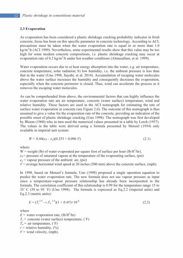
2.3 Evaporation As evaporation has been considered a plastic shrinkage cracking probability indicator in fresh concrete, focus has been on this specific parameter in concrete technology. According to ACI, precautions must be taken when the water evaporation rate is equal to or more than 1.0 kg/m2/h (ACI 1999). Nevertheless, some experimental results show that this value may be too high for some modern concrete compositions, i.e. plastic shrinkage cracking may occur at evaporation rate of 0.2 kg/m2/h under hot weather conditions (Almusallam, et al. 1999). Water evaporation occurs due to a) heat energy absorption into the water, e.g. air temperature, concrete temperature, solar radiation; b) low humidity, i.e. the ambient pressure is less than that in the water (Uno 1998, Sayahi, et al. 2014). Accumulation of escaping water molecules above the water surface increases the humidity and consequently decreases the evaporation, especially when the concrete perimeter is closed. Thus, wind can accelerate the process as it removes the escaping water molecules. As can be comprehended from above, the environmental factors that can highly influence the water evaporation rate are air temperature, concrete (water surface) temperature, wind and relative humidity. These factors are used in the ACI nomograph for estimating the rate of surface water evaporation in concrete (see Figure 2.6). The outcome of this nomograph is thus assumed to give a value for the evaporation rate of the concrete, providing an indication of the possible onset of plastic shrinkage cracking (Uno 1998). The nomograph was first developed by Bloem (1960) who in turn used the numerical values presented in a table by Lerch (1957). The values in the table were derived using a formula presented by Menzel (1954) only available in imperial unit system:
W = 0.44(e0 – ea)(0.253 + 0.096 V) (2.1) where: W = weight (lb) of water evaporated per square foot of surface per hour (lb/ft2/hr), e0 = pressure of saturated vapour at the temperature of the evaporating surface, (psi) ea = vapour pressure of the ambient air, (psi) V = average horizontal wind speed at 20 inches (500 mm) above the concrete surface, (mph). In 1998, based on Menzel’s formula, Uno (1998) proposed a single operation equation to predict the water evaporation rate. The new formula does not use vapour pressure as input since a temperature-vapour pressure relationship has already been incorporated in the formula. The correlation coefficient of this relationship is 0.99 for the temperature range 15 to 35 ̊ C (59 to 95 ˚F) (Uno 1998). The formula is expressed as Eq.2.2 (imperial units) and Eq.2.3 (metric units):
E = (Tc2.5 - r.Ta 2.5)(1 + 0.4V)×10-6 (2.2)
where E = water evaporation rate, (lb/ft2/hr) Tc = concrete (water surface) temperature, (˚F) Ta = air temperature, (˚F) r = relative humidity, (%) V = wind velocity, (mph).

13 Plastic shrinkage in cementitious material
E = 5([Tc + 18]2.5 – r . [Ta + 18]2.5)(V + 4) ×10-6 (2.3) where E = water evaporation rate, (kg/m2/h) Tc = concrete (water surface) temperature, (˚C) Ta = air temperature, (˚C) r = relative humidity, (%) V = wind velocity, (km/h).
Figure 2.6 – ACI nomograph for estimating surface water evaporation rate of concrete i e. the “ACI Hot Weather Concreting Evaporation Nomograph”, from ACI (1999). Uno’s formula and ACI nomograph are widely used since the establishment, due to their simplicity. Comparison between Menzel and Uno’s formula shows almost complete accordance in the results. Table 2.1, shows the evaporation rate calculated by Menzel and
Plastic shrinkage in cementitious material
14
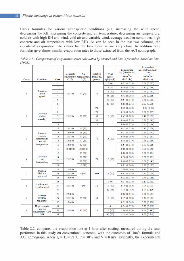
Uno’s formulas for various atmospheric conditions (e.g. increasing the wind speed, decreasing the RH, increasing the concrete and air temperature, decreasing air temperature, cold air with high RH and wind, cold air and variable wind, average weather conditions, high concrete and air temperature with low RH). As can be seen in the last two columns, the calculated evaporation rate values by the two formulas are very close. In addition both formulas give almost similar evaporation rates to those extracted from the ACI nomograph. Table 2.1 - Comparison of evaporation rates calculated by Menzel and Uno’s formulas, based on Uno (1998).
Table 2.2, compares the evaporation rate at 1 hour after casting, measured during the tests performed in this study on conventional concrete, with the outcomes of Uno’s formula and ACI nomograph, when Ta = Tc = 21˚C, r = 30% and V = 8 m/s. Evidently, the experimental

15 Plastic shrinkage in cementitious material
result is in good agreement with the evaporation rate calculated by the formula and the one extracted from the nomograph. Table 2.2 - Comparison of evaporation rates measured during the experiments performed in this research on conventional concrete with 0.38 w/c ratio, with the evaporation rates calculated by Uno’s formulas and ACI nomograph.
Method Uno’s formula ACI nomograph Experiment Evaporation rate (kg/m2/h) 1.09 1 1.13
However, even if the water evaporation rate is accurately determined based on the above methods, still there is no guarantee that it can be applicable and reliable indicator of the cracking onset. That is due to the fact that, as mentioned earlier, the evaporation rate has to exceed the concrete bleed rate in order to cause plastic shrinkage (Powers 1969). Besides, these formulas and nomograph seem to be only practical for predicting the evaporation rate of free water and not a water layer over concrete surface. According to the experimental results of this particular project at LTU, evaporation rate of a free water surface is almost constant, while the rate by which bleed water evaporates from a concrete surface decreases gradually, due to the reduction in the amount of the water being drained to the surface,see Figure 2.7. Menzel and Uno’s formulas and the ACI nomograph, thus, give an overestimated value for evaporation. They should be further developed by including the time effect in the evaporation prediction process.
Figure 2.7 - Evaporation rate of free water and water accumulated on surface of conventional concrete with 0.38 w/c ratio. The figure plots results of experiments performed in this particular PhD project.
2.4 Capillary pressure Due to the irregularity of particle arrangement in the concrete paste, the air-entry (Figure 2.8, Level D) does not occur simultaneously in all pores (Slowik & Schmidt 2010) (see also Figure 2.4). In other words, air-entry is rather a local event than a universal one. Therefore,
Plastic shrinkage in cementitious material
16
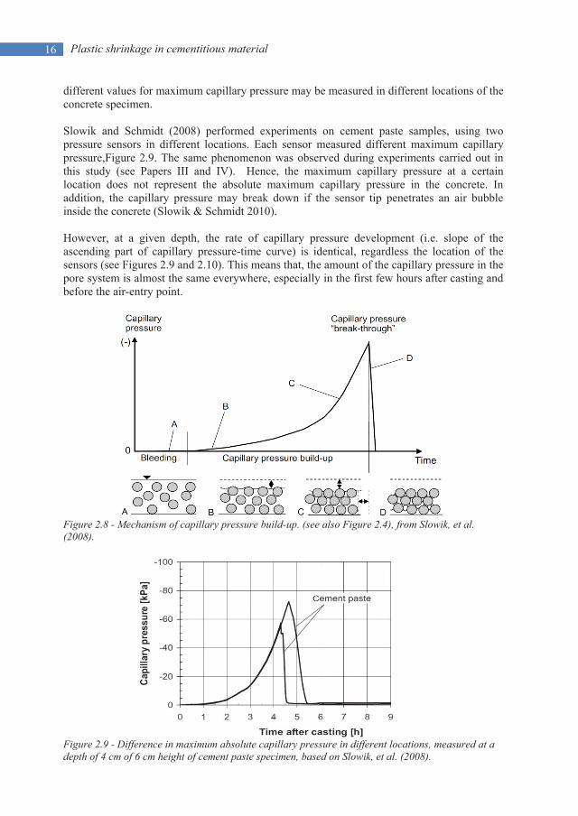
different values for maximum capillary pressure may be measured in different locations of the concrete specimen. Slowik and Schmidt (2008) performed experiments on cement paste samples, using two pressure sensors in different locations. Each sensor measured different maximum capillary pressure,Figure 2.9. The same phenomenon was observed during experiments carried out in this study (see Papers III and IV). Hence, the maximum capillary pressure at a certain location does not represent the absolute maximum capillary pressure in the concrete. In addition, the capillary pressure may break down if the sensor tip penetrates an air bubble inside the concrete (Slowik & Schmidt 2010). However, at a given depth, the rate of capillary pressure development (i.e. slope of the ascending part of capillary pressure-time curve) is identical, regardless the location of the sensors (see Figures 2.9 and 2.10). This means that, the amount of the capillary pressure in the pore system is almost the same everywhere, especially in the first few hours after casting and before the air-entry point.
Figure 2.8 - Mechanism of capillary pressure build-up. (see also Figure 2.4), from Slowik, et al. (2008).
Figure 2.9 - Difference in maximum absolute capillary pressure in different locations, measured at a depth of 4 cm of 6 cm height of cement paste specimen, based on Slowik, et al. (2008).
17 Plastic shrinkage in cementitious material
.
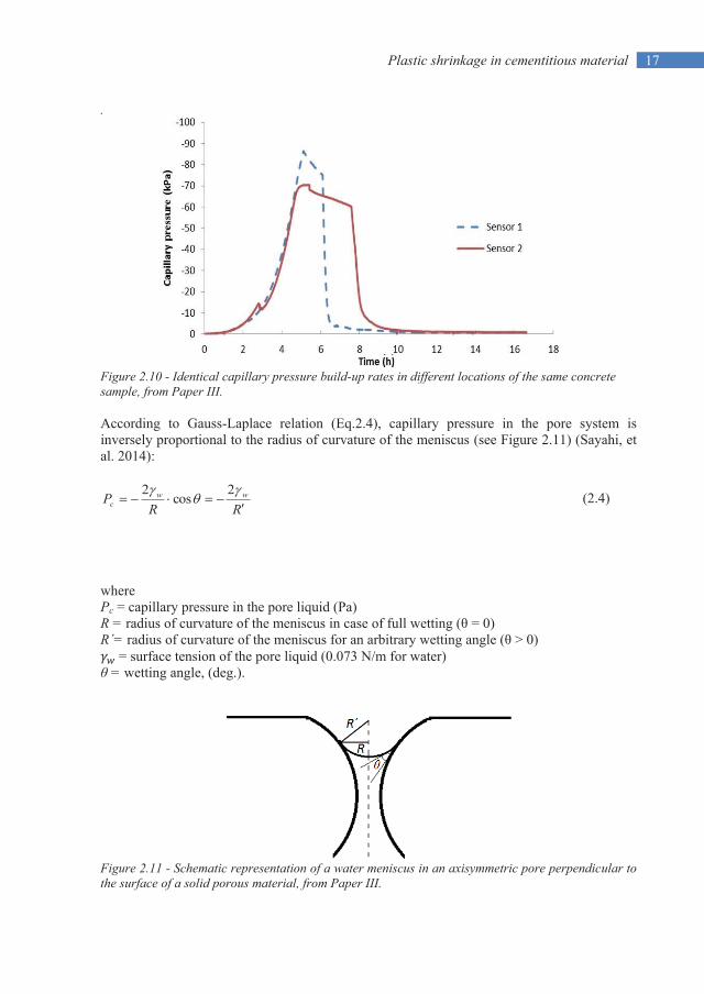
Figure 2.10 - Identical capillary pressure build-up rates in different locations of the same concrete sample, from Paper III. According to Gauss-Laplace relation (Eq.2.4), capillary pressure in the pore system is inversely proportional to the radius of curvature of the meniscus (see Figure 2.11) (Sayahi, et al. 2014):
RRP ww
c2
cos2 (2.4)
where Pc = capillary pressure in the pore liquid (Pa) R = radius of curvature of the meniscus in case of full wetting (θ = 0) R´= radius of curvature of the meniscus for an arbitrary wetting angle (θ > 0)
= surface tension of the pore liquid (0.073 N/m for water) θ = wetting angle, (deg.).
Figure 2.11 - Schematic representation of a water meniscus in an axisymmetric pore perpendicular to the surface of a solid porous material, from Paper III.

Plastic shrinkage in cementitious material
18
On the other hand, Kelvin’s equation, relates the capillary pore pressure to the relative humidity (RH):
TRMP
RTRMRHLn
w
wc
w
ww2 (2.5)
where RH = ambient relative humidity just above the pore,
= surface tension of the pore liquid (0.073 J/m2 for water) Mw = molar mass of water (~0.018 kg/mol) ρw = density of water, (kg/m3) R = ideal gas constant, (8.314 J/mol K) T = absolute temperature in Kelvin, (20 ˚C ≈ 293 K) R´= radius of curvature of the meniscus for an arbitrary wetting angle (θ > 0) Pc = capillary tensile pressure, (Pa) Eq.2.5 gives the maximum RH that allows the pore liquid (in this case water) to evaporate. Accordingly, capillary pore pressure can be obtained by combining Eq.2.4 and 2.5:
RHM
TRP
w
wc ln (2.6)
where Pc = capillary tensile pressure, (Pa) ρw = density of water, (kg/m3) R = ideal gas constant, (8.314 J/mol K) T = absolute temperature in Kelvin, (20 ˚C ≈ 293 K) Mw = molar mass of water (~0.018 kg/mol) RH = ambient relative humidity, (%). As might be seen, capillary pressure is strongly dependent on the relative humidity, due to its logarithmic expression. Hence, even small reduction of RH significantly increases the capillary pressure,see Figure 2.12.
Figure 2.12 - Relation between relative humidity and capillary pressure at 20°C. The pressure is negative and logarithmic, from Esping (2007). Based on Carman (1941), a relation was proposed by Powers (1996) for determining maximum capillary pressure in concrete, which was modified by Cohen (1990):

19 Plastic shrinkage in cementitious material
cw
SP 3101 (2.7)
where P= capillary tensile pressure, (MPa)
= surface tension of the pore liquid (0.073 N/m for water) S = mass specific surface area of cement, (m2/kg)
cw = water/cement ratio by mass, (-)
The constant 10-3 has the dimension mass density (kg/m3).
It can be seen in Eq.2.7, that the maximum capillary pressure (P) is directly proportional to and S, and inversely proportional to w/c ratio. It means that keeping other variables constant, concrete with higher w/c ratio and lower and S is less suspected to experience plastic shrinkage cracking, if the maximum pressure is considered as the main influencing parameter (Dao, et al. 2010). This needs to be further investigated, since according to some Swedish tests (Sayahi, et al. 2016, Löfgren, et al. 2006) SCC with high w/c ratio is significantly prone to plastic shrinkage cracking.
Moreover, assuming constant and w/c ratio in Eq.2.7, capillary pressure (P) is directly proportional to mass specific surface area of cement (S). In other word, maintaining all conditions similar, any difference in plastic shrinkage characteristics (i.e. strain and cracking) would be due to the difference in surface area or particle size of the solid material ((Cohen, et al. 1990). This was also observed by Pihlajavaara (1974) who suggested that the maximum capillary pressure in concrete with spherical non-porous solid aggregates can be determined as:
SP 7106.2 (2.8)
where P = capillary tensile pressure, (MPa)
= surface tension of the pore liquid (0.073 N/m for water) S = mass specific surface area of cement, (m2/kg) ρ = solid density of cement, (kg/m3)
Comparison between the experimental results of this project and the outcomes of Eq.2.7 and 2.8 shows that while the former seems to overestimate the maximum capillary pressure; the latter can fairly predict the real pressure value. Assuming = 0.073 N/m, S = 2000 m2/kg, ρ = 3080 and w/c = 0.67 the maximum capillary pressure based on Eq. 2.7 and 2.8 are 0.218 MPa and 0.117 MPa, respectively. The maximum pressure value in the tests performed in this work, with the mentioned assumptions, is 0.088 MPa which is far from the outcome of Eq.2.7, but in fair agreement with the pressure value calculated based on Eq.2.8.
Cohen and Pihlajavaara´s equations can, thus, interpret the influence of fine material on the plastic shrinkage cracking tendency of the concrete. Experiments ((Löfgren, et al. 2006, Sayahi, et al. 2016) have shown that the risk of plastic shrinkage cracking increases with increasing the amount of the fine materials in the concrete mixture. The finer the binder is, the

Plastic shrinkage in cementitious material 20
narrower the pores would be in the concrete pore system, which according to Eq.2.4 will increase the negative capillary pressure in the pore liquid.
As already indicated, it should be noted that Eqs.2.5 to 2.8 only calculate the maximum capillary pressure in the pore system. It is not possible to determine the pressure in different ages after casting and therefore the rate of capillary pressure development cannot be specified. The only equation that may offer this possibility is Eq.2.4. However, it is really complicated, if not impossible, to measure the radius of the water meniscus versus time after placement. Hence, the capillary pressure build-up rate cannot be determined theoretically based on the current knowledge.
2.5 Main factors affecting plastic shrinkage cracking
Figure 2.13 summarizes the process of plastic shrinkage cracking and the factors which can affect the phenomenon. A deep comprehension on how these factors influence the whole cracking process can lead to invention of new crack preventative methods. Some of the factors are briefly described in the following.
2.5.1 Water/cement ratio
Water/cement ratio significantly affects the plastic shrinkage cracking tendency. Assuming constant mixture constituents, higher w/c ratio causes more bleeding water and vice versa. In case of high w/c ratio, thus, it takes longer time for the surface water layer to disappear due to evaporation and consequently delays the capillary pressure build-up in the pore system.
Figure 2.13 – Plastic shrinkage cracking flowchart, based on Paper II.

21 Plastic shrinkage in cementitious material
However, this is highly dependent on the concrete mix. A lower amount of cement in SCC with low w/c ratio often is compensated with more fines (e.g. filler) in order to avoid segregation and reduction of durability and serviceability. This leads to formation of finer pore system inside the concrete with shorter inter-particle distances. According to Eq.2.4, capillary pressure is higher in narrower pores, which means that the solid particles on the pore’s perimeter wall experience higher tensile stresses and consequently, the total plastic shrinkage of the concrete member increases.
Moreover, it is known that a lower w/c ratio causes less bleeding (in conventional concrete) and thus increases the risk of cracking (Lund, et al. 1997). On the other hand w/c ratio has an inverse relation with the concrete strength. Research (Samman, et al. 1996) has shown that high-strength concrete mixtures (containing more cement) have low bleeding rate and subsequently higher risk of plastic shrinkage cracking. An optimized w/c ratio can, thus, reduce the risk of plastic shrinkage cracking, while the strength of the concrete is not diminished so much. Löfgren and Esping (2006) concluded that if the w/c ratio is in region of 0.55, the cracking tendency of the concrete decreases significantly. This optimum region of w/c ratio, in this particular work, is determined to be between 0.45 and 0.55 (see Section 4.4). Löfgren and Esping (2006) also observed that concretes with w/c ratio lower than 0.55 are more prone to autougenous shrinkage cracking, while those with w/c ratio higher than 0.55 predominantly crack due to evaporation (see Figure 2.14).
Figure 2.14 - Separation of autougenous and evaporation induced shrinkage. w/c ratio less than 0.55 causes autogenous shrinkage cracking, while w/c ratio more than 0.55 increases the risk of plastic shrinkage cracking. from Esping & Löfgren (2005).
2.5.2 Additives
Several studies have been carried out to find new admixtures in order to reduce the plastic shrinkage of concrete. These admixtures show high practicality in reducing evaporation rate, settlement, negative capillary pressure and plastic shrinkage formation. For instance, it has been concluded that cellulose-based viscosity modifying agent (stabilizer) causes reduction of the evaporation rate in cementitious material (Lin & Huang 2010).

Plastic shrinkage in cementitious material 22
Aaccelerators (ACC) and retarders have a strong influence on the plastic shrinkage cracking tendency. Some experiments (Kronlöf, et al. 1995, Combrinck & Boshoff 2013) showed that accelerator admixtures cause higher plastic shrinkage and total crack area, while retarders act contrary. However, other experiments (Soroka 2003, Esping & Löfgren 2005) showed that excessive usage of retarder admixtures may increase the risk of plastic shrinkage cracking due to the slower strength gain of the concrete.
On the other hand, superplasticizer (SP) reduces the need for water in the concrete mixtures i.e. less bleed water. This reduction of surface water may however not increase the risk ofcracking, as the SP modifies the surface tension and prevents or delays the onset of plasticshrinkage crack formation (Cabrera, et al. 1992). Nevertheless, SP acts as a retarder anddelays the hydration which means longer dormant period and slower strength gaining rate.Experiments on SCC have shown that a higher SP dosage increases the cracking tendency ofthe fresh concrete (Esping & Löfgren 2005).
Furthermore, experiments proved that a shrinkage-reducing admixture (SRA) reduces the plastic shrinkage cracking tendency by decreasing the evaporation, settlement and the surface tension (Lura, et al. 2007).
2.5.3 Fibres
Fibres (steel and/or polypropylene) often have been used in concrete mixtures in order to reduce the width of the plastic shrinkage cracks, through stitching the concrete surface particles together. Experiments performed by Sivakumar and Santhanam (2006) show that a combination of steel and polypropylene fibres (hybrid fibres), can reduce the width of the plastic shrinkage cracks up to 55%. However, despite of the lower crack width, parallel cracks may form around the main crack. This phenomenon can be due to the transfer of the shrinkage stresses, through the fibres, to the surrounding areas.
2.5.4 Fines content
Fines such as fly ash, silica fume, slag, etc. lead to a larger total specific surface area of the binder, and narrower pores. Consequently, the water that is supposed to be transported to the concrete surface will be trapped inside and adsorbed by the fine particles, resulting in lower bleeding rate compared to a concrete with lower volume of fines. Cohen et al. (1990) concluded that higher surface area of the particles leads to higher tensile capillary pressure and eventually higher probability of plastic shrinkage crack formation. Moreover, experiments performed by Esping and Löfgren (2005) showed that silica fume increases the crack tendency in the concrete, despite of the evaporation reduction. Accordingly, using high proportion of fine material in the concrete mixture is not favourable as regards to plastic shrinkage cracking.
2.5.5 Depth of the concrete section
A deeper concrete member typically experiences more settlement. As a result, more water is being transported to the concrete surface trough the pore system leading to a larger water accumulation on the surface. This means that the surface water layer evaporation takes longer time, causing delay in capillary pressure build-up. Consequently, a deeper concrete section is less prone to plastic shrinkage cracking (Van Dijk & Boardman 1971, Schiessl & Schmidt

23 Plastic shrinkage in cementitious material
1990). However, due to the high degree of settlement, the concrete may instead be vulnerable to settlement cracking, typically formed above the reinforcement bars, which may facilitate the ingress of chlorides and other harmful substances.
2.5.6 Curing measures
Plastic shrinkage cracks can be avoided through several post-casting curing measures. These measures in general aim at reduction of the surface water evaporation. For instance, sealing the concrete surface (e.g. covering the concrete with plastic sheet) decreases the evaporation rate and consequently can lead to a crack-free concrete. In another case, experiments have shown that evaporation of the surface water can be suppressed through spraying aliphatic alcohols over the fresh concrete surface (Cordon & Thorpe 1965, Hedin 1985).
Compensating the evaporated water (rewetting) is another way to protect the fresh concrete against plastic shrinkage cracking. Fogging the concrete surface, on one hand, reduces the evaporation rate through increasing the ambient relative humidity, and on the other hand, replaces some lost surface water due to evaporation (Slowik & Schmidt 2010). In addition, using a wind breaker to prevent or reduce the air flow over the concrete surface can be another efficient way to reduce the evaporation (Uno 1998).
2.6 Concluding remarks
Based on what has been mentioned so far, the following remarks can be made:
Although, concrete in the plastic stage is still fluid and workable, after a while it will have enough rigidity, so an initial form of Hooke’s stress-strength law can be applicable. Hence, the ultimate goal in preventing plastic shrinkage cracking is to keep the induced tensile stresses below the very low tensile strength of the concrete.
The main driving force behind plastic shrinkage cracking is not the evaporation alone, but also the way that evaporation affects the development of capillary pressure development in the pore system, while the concrete is still plastic.
Commonly used evaporation rate prediction techniques may not be applicable for determining the probable rate of evaporation from a concrete surface, since the time effect is not considered.
The main parameter affecting the capillary pressure development is the radius of the capillary pore, which is a function of the concrete mix design.
The rate of capillary pressure development cannot be determined theoretically based on the current knowledge.
A higher w/c ratio increases the risk of plastic shrinkage cracking. On the other hand, reducing the w/c ratio converts to crack inducing mechanism to autogenous shrinkage.
Plastic shrinkage cracking can be encountered by several pre- and post-casting measures. While post-casting measures are focused on compensating the evaporated water and/or reducing it, pre-casting measures should aim at avoiding and/or controlling the parameters that may influence the shrinkage of the concrete e.g. SP, fines, etc.


25 Test methods and measuring techniques
3. TEST METHODS AND MEASURING TECHNIQUES
3.1 General
As mentioned, plastic shrinkage of the fresh concrete is the physical component of the early-age shrinkage, which depends on several geometrical and environmental conditions. During the plastic stage, concrete deforms both vertically (i.e. settlement) and horizontally. By measuring these two deformations, the volumetric shrinkage can be calculated. Displacement transducers (e.g. LVDT, laser displacement sensor, strain gauge, etc.) are thus, often utilized. Since concrete elements with high surface to volume ratio are of high interest, specimens in form of small slabs are mainly used in experiments. The concrete surface should be exposed to the surrounding in order to facilitate the evaporation. The test should take place in controlled and constant ambient conditions (i.e. RH, temperature, wind velocity). It is, thus, recommended to perform the experiments in a climate chamber.
As the amount of the evaporated water is considered equal to sample’s weight loss, the specimen can be placed on load-cells in order to achieve a continues measurement. The capillary pressure is another parameter that should be measured, using sophisticated pressure sensors. These sensors are filled with degased water and can be installed either vertically and/or horizontally. Furthermore, the internal temperature can be measured by thermo threads or any other type of standard temperature sensors. The experiments last for few hours after casting but no more than 24 hours. All the measurements are to be started shortly after the concrete placement and stopped prior to the demoulding.
In the following, experimental method and the measuring techniques used in Papers III and IV are briefly described. More information can be found in the appendices.
3.2 Test methods
3.2.1 Rectangular mould test setup
For part of the experiments performed in this work, a rectangular mould (1200x400x90 mm) has been designed based on the experimental setups used by Hedin (1985) and Lund et al. (1997), Figure 3.1. The frame is made of UPE80-beams placed on a 1 mm thick stainless steel baseplate. The gaps between the mould and the baseplate are sealed by Latex. Three rebars (8 mm in diameter) are installed on each side of the mould to restrain the concrete element. The rebars are fixed against 18 rods in total around the mould (6 rods along the long- and 3 rods along the short-side). Each rod penetrates the concrete by 60 mm.

Test methods and measuring techniques 26
A 50 cm wide fan is used to produce wind with constant velocity on the slab surface, varying from 0 to 7 m/s in different trials. To ensure fairly constant and laminar wind velocity, a wind tunnel is placed on the slab to conduct the wind over the surface. The wind tunnel is manufactured with Plexiglas to facilitate the visual inspection of the concrete surface.
The mould is placed on four load-cells and the weight loss (i.e. the evaporation), is documented per second. Besides, the internal temperature and capillary pressure are measured by thermo threads and CPSS sensors (see Section3.2.4) respectively. The experiment continues for 24 hours after casting. Then, the cracking tendency is calculated based on the crack area, which is defined as the crack length multiplied by the crack width. This test setup in this particular work was used only for studying conventional concretes.
Figure 3.1 – Two rectangular mould test setups with fans and Plexiglas wind tunnels, placed on four load-cells.
3.2.2 ASTM C 1579
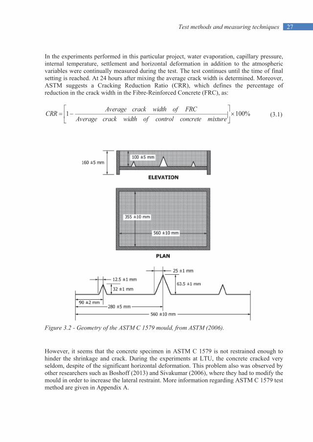
ASTM C 1579, Figure 3.2, is a test method developed mainly in order to compare the plastic shrinkage cracking behaviour of different concrete mixtures containing fibre reinforcement under prescribed conditions of restraint and moisture loss that are severe enough to produce cracking before final setting of the concrete (ASTM 2006). However, its application is not limited to only fibre reinforced concrete and can be used in studying other parameters as well.
The big metal notch insert in the middle, is the stress riser which acts as a crack initiation point. The other two smaller metal inserts on the sides serve as internal restraints. The surface of the metal inserts and the mould sides was coated with a thin layer of oil, in order to reduce bond between the concrete and mould. The mould should be placed in a climate chamber in order to control the ambient conditions. Since many other variables such as cement fineness, aggregate gradation, aggregate volume, mixing procedures, slump, air content, concrete temperature and surface finish can also influence potential cracking, attention shall be paid to keep these as consistent as possible from mixture to mixture (ASTM 2006).
27 Test methods and measuring techniques
In the experiments performed in this particular project, water evaporation, capillary pressure, internal temperature, settlement and horizontal deformation in addition to the atmospheric variables were continually measured during the test. The test continues until the time of final setting is reached. At 24 hours after mixing the average crack width is determined. Moreover, ASTM suggests a Cracking Reduction Ratio (CRR), which defines the percentage of reduction in the crack width in the Fibre-Reinforced Concrete (FRC), as:
%1001mixtureconcretecontrolofwidthcrackAverage
FRCofwidthcrackAverageCRR (3.1)
Figure 3.2 - Geometry of the ASTM C 1579 mould, from ASTM (2006).
However, it seems that the concrete specimen in ASTM C 1579 is not restrained enough to hinder the shrinkage and crack. During the experiments at LTU, the concrete cracked very seldom, despite of the significant horizontal deformation. This problem also was observed by other researchers such as Boshoff (2013) and Sivakumar (2006), where they had to modify the mould in order to increase the lateral restraint. More information regarding ASTM C 1579 test method are given in Appendix A.

Test methods and measuring techniques 28
3.2.3 Ring test method (NT BUILD 433)
The results presented in Papers III and IV are based on experiments performed using a ring test method (NORDTEST-method NT BUILD 433). It was first developed by Johansen and Dahl at NTNU (1993). The method is intended to determine the influence of mixture constituents on the cracking potential of fresh concrete at a “macro” level. Esping and Löfgren (Esping & Löfgren 2005) used a modified ring test method in their experiments which had different sample thickness, environmental conditions and cracking tendency evaluating method. The utilized ring test method in this study is deviated from Esping and Löfgren’s method by the ambient temperature and the capillary pressure measurement technique (see next section).
In this method, the mould consists of two concentric steel rings which are fixed to a stiff stainless steel baseplate. The surface of the baseplate is smooth and coated with a thin layer of oil. A set of three identical moulds is used. The depth of each mould is 80 mm and the diameters of the inner and outer rings are 300 and 600 mm respectively. To provide crack initiation points, steel ribs (stress raisers) are attached to the rings (see Figures 3.3 and 3.4). More information are presented in Appendix B.
After placing the concrete between the two rings, the mould is covered with a transparent air funnel attached to a suction fan, giving 4.5 m/s wind velocity across the concrete surface. During this particular investigation, the ambient temperature and relative humidity were 20±1˚C and 35±3% respectively. The weight loss (i.e. the evaporation), capillary pressure and internal temperature are recorded continually.
One of the three specimens is placed on three load-cells (scales) in order to record the evaporation per second. During these experiments, the capillary pressure is measured in 15 s intervals by means of two wireless capillary pressure sensors filled with degassed water (see Section3.2.4), which were inserted vertically down to 4 cm distance from the concrete surface right after casting. The internal temperature is recorded in 1 s intervals with a thermo thread located at 2 cm distance from the bottom of the mould. All the measurements start 60 minutes after the concrete placement and are finished 18 hours later.
The concrete surface in all three specimens is visually inspected every 30 minutes in order to determine the time of the probable crack initiation. At the end of the experiment, the crack width and the crack length were measured by a digital microscope (to an accuracy of 0.05 mm) and a digital measuring wheel (to an accuracy of ±1 mm) respectively. The averagecrack area of the three moulds is then calculated, as suggested by Esping and Löfgren (2005),as:
3)( widthcracklengthcrack
areacrackAverage (3.2)

29 Test methods and measuring techniques
Figure 3.3 - Ring test method setup for plastic shrinkage cracking tendency determination, based on Löfgren, et al. (2006) (dimensions in mm).
Figure 3.4 - Arrangement of the three moulds in the ring test method.
Test methods and measuring techniques 30
3.2.4 Capillary pressure
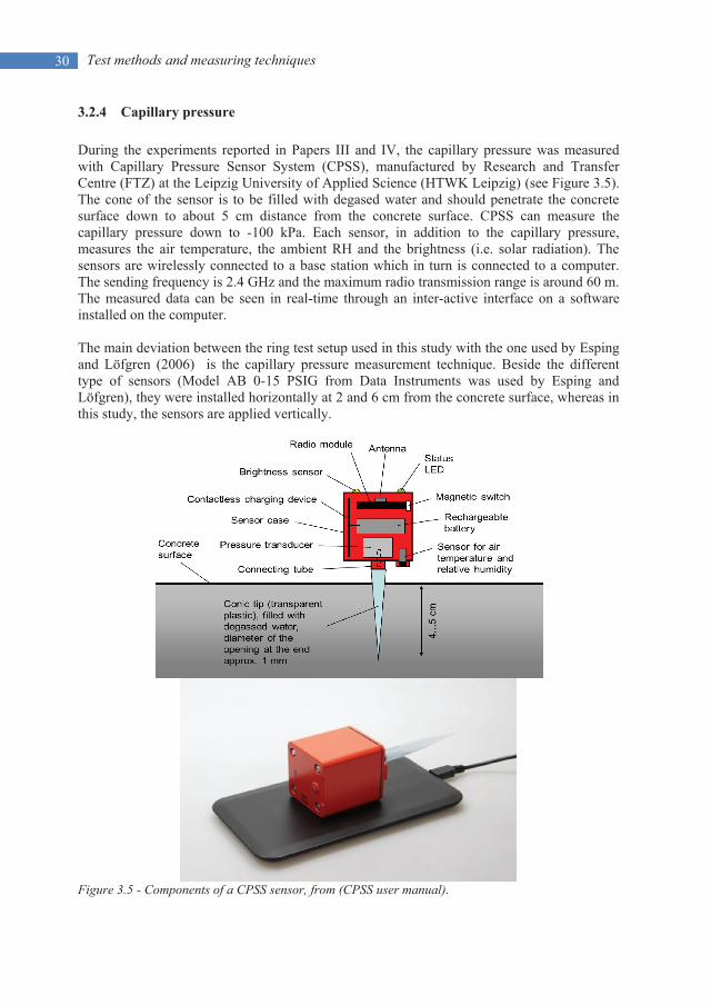
During the experiments reported in Papers III and IV, the capillary pressure was measured with Capillary Pressure Sensor System (CPSS), manufactured by Research and Transfer Centre (FTZ) at the Leipzig University of Applied Science (HTWK Leipzig) (see Figure 3.5). The cone of the sensor is to be filled with degased water and should penetrate the concrete surface down to about 5 cm distance from the concrete surface. CPSS can measure the capillary pressure down to -100 kPa. Each sensor, in addition to the capillary pressure, measures the air temperature, the ambient RH and the brightness (i.e. solar radiation). The sensors are wirelessly connected to a base station which in turn is connected to a computer. The sending frequency is 2.4 GHz and the maximum radio transmission range is around 60 m. The measured data can be seen in real-time through an inter-active interface on a software installed on the computer.
The main deviation between the ring test setup used in this study with the one used by Esping and Löfgren (2006) is the capillary pressure measurement technique. Beside the different type of sensors (Model AB 0-15 PSIG from Data Instruments was used by Esping and Löfgren), they were installed horizontally at 2 and 6 cm from the concrete surface, whereas in this study, the sensors are applied vertically.
Figure 3.5 - Components of a CPSS sensor, from (CPSS user manual).
31 Experimental results
4. EXPERIMENTAL RESULTS
4.1 General
In this chapter, results of the experiments performed in this project so far, are generally presented. More details and discussions are presented in the appended papers. It ought to be mentioned that some of these results are not necessarily novel and may have been observed by other researchers as well. What is different in this work is the way that the results are analysed and utilized in order to tackle the plastic shrinkage cracking phenomenon. This will be explained more in the following.
4.2 Evaporation rate
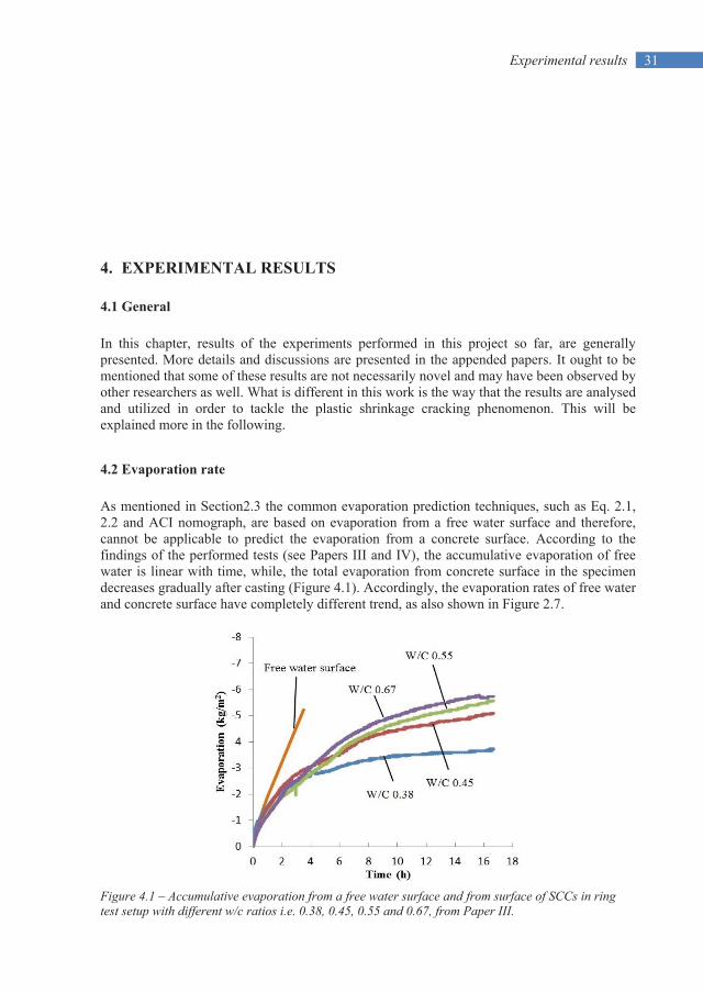
As mentioned in Section2.3 the common evaporation prediction techniques, such as Eq. 2.1, 2.2 and ACI nomograph, are based on evaporation from a free water surface and therefore, cannot be applicable to predict the evaporation from a concrete surface. According to the findings of the performed tests (see Papers III and IV), the accumulative evaporation of free water is linear with time, while, the total evaporation from concrete surface in the specimen decreases gradually after casting (Figure 4.1). Accordingly, the evaporation rates of free water and concrete surface have completely different trend, as also shown in Figure 2.7.
Figure 4.1 – Accumulative evaporation from a free water surface and from surface of SCCs in ring test setup with different w/c ratios i.e. 0.38, 0.45, 0.55 and 0.67, from Paper III.

Experimental results 32
4.3 Capillary pressure development rate
Capillary pressure in concrete has been known to researchers for a long time. It has been the topic of numerous studies and was discussed in many papers and books. However, it seems that, in the previous research, the role of the maximum value of the capillary pressure in plastic shrinkage cracking has been highlighted more than its rate of development.
According to the results of the experiments performed here (see Papers III and IV), despite of the local nature of the maximum capillary pressure, at any given depth, the pressure develops with the same rate, regardless of the sensor’s location (see Section 2.4 and Figures 2.9 and 2.10).
Since the deformation is related to the capillary pressure is, the rate of the pressure build-up, can be an indication of the amount of the shrinkage the concrete element undergoes. For example, in Figure 4.2, the value of capillary pressure for SCC with different w/c ratios, at 4 hours after finishing the surface, can be compared. As it can be seen, the capillary pressure at this time is -38 kPa for W/C 0.67, while it is around -24 kPa for the others i.e. W/C 0.67 experiences higher shrinkage. This can also be comprehended from photos taken at the end of the experiments, where the cracks in W/C 0.67 is about 10 times wider than those in W/C 0.45 (Figure 4.3).
Figure 4.2 – Rete of capillary pressure build-up in SCCs with different w/c ratios i.e. 0.38, 0.45, 0.55 and 0.67, from Paper IV.

33 Experimental results
Figure 4.3 - Plastic shrinkage crack width in (a) SCC with 0.45 w/c ratio and (b) SCC with 0.67 w/c ratio at 24 hours after casting, from Paper IV.
4.4 Effect of w/c ratio on cracking By studying the influence of w/c ratio on the cracking tendency of SCC, an optimum w/c ratio range for the lowest early-age cracking risk can be identified between 0.45 to 0.55. Any SCC with w/c ratio out of this range has a high tendency of early-age cracking, see Figure 4.4. However, it was also observed that SCC with w/c ratio less than 0.45 cracks mainly due to autogenous shrinkage, while plastic shrinkage is the main driving force behind the cracking of SCC with w/c ratio higher than 0.55 (see also Figure 2.14 and discussion in Papers III and IV). This finding is also manifested in the time of crack initiation measured during the tests (Figure 4.4), as decreasing the w/c ratio delays the cracking.
Figure 4.4 – Average crack area (calculated based on Eq.3.2) and time of crack initiation of SCCs in ring test setup with 0.38, 0.45, 0.55 and 0.67 w/c ratios, from Paper IV.
(a) (b)

Experimental results 34
4.5 Effect of cement type on cracking
According to the tests, normal hardening Swedish Portland cements seem to increase the plastic shrinkage cracking tendency comparing to rapid hardening cements, see Figure 4.5. The reason lies in the fact that rapid hydration of the concrete leads to faster build-up of the rigid skeleton and consequently higher tensile strength.
Figure 4.5 – Average crack area (calculated based on Eq.3.2) and time of crack initiation of SCCs in ring test setup produced with CEM I 52.5R, CEM II/A-LL 42.5R and CEM I 42.5N cements, from Paper IV.
4.6 Effect of coarse aggregate content on cracking
It was observed in the tests that a reduction of coarse aggregate content in the concrete mixture results in significant increase in the plastic shrinkage cracking risk, Figure 4.6. The reduced amount of coarse aggregates will be compensated by fine material, which in turn, leads to finer and narrower pores. Capillary pressure, according to Eq. 2.4, is higher in pores with smaller radius and hence, larger tensile stresses are applied on the solid particles which increase the plastic shrinkage.
4.7 Effect of superplasticizer on cracking
The retarding effect of SP increases the risk of plastic shrinkage cracking as shown in Papers III and IV, Figure 4.7. By increasing the SP dosage, the hydration rate decreases, which means that the concrete remains plastic for a longer time. This facilitates the cracking since the tensile strength gaining process is slower.

35 Experimental results
Figure 4.6 – Average crack area (calculated based on Eq.3.2) and time of crack initiation of SCCs in ring test setup with 35% and 40% of total aggregate volume coarse aggregate content, from Paper IV.
Figure 4.7 – Average crack area (calculated based on Eq.3.2) and time of crack initiation of SCCs in ring test setup with 0.6%, 0.8% and 1.0% SP dosage, from Paper IV.


37 Discussion and general conclusions
5. DISCUSSION AND GENERAL CONCLUSIONS
5.1 Discussion
Early-age cracking in concrete is a result of a complex correlation of physical and chemical processes on which the cracking governing mechanisms are based. While the rapid and excessive loss of moisture, mainly due to evaporation, is the driving force behind the physically induced shrinkage (i.e. plastic shrinkage), chemical reactions between the cement constituents and water cause autougenous shrinkage. Logically different crack preventative methods should be applied based on the early-age cracks origin. Here lies the importance of separation of the governing mechanisms behind the cracking. Doing that it would be easier to find the proper crack preventative measure and the best application time (i.e. pre- and/or post-casting).
In this thesis, plastic shrinkage of concrete in general and SCC in particular has been discussed. Although autogenous shrinkage may notably influence the early-age cracking tendency of the concrete, it has been disregarded in this study and the plastic shrinkage induced cracks have been intensively investigated. Influence of several parameters (e.g. w/c ratio, additives, coarse aggregate content, ambient conditions, etc.) is studied and effort is made in order to deepen the comprehension of the crack governing mechanisms. Therefore, the probable relationship between water evaporation, capillary pressure and hydration rate is investigated.
The main characteristic of SCC is its high flowability, despite of its lower water possession. The lower amount of water is compensated by water-reducing admixtures (superplasticizer), which act as retarders and may lower the hydration rate of the concrete which leads to longer dormant period. Moreover, to avoid any potential segregation, higher amount of fines are often added to the mixture. Consequently the arrangement of the solid particles differs causing finer pore structure and shorter inter-particle distances in comparison to conventional concrete. Accordingly, the capillary pressure develops faster in the pores, which means that the concrete experience higher tensile stresses at earlier stages. Longer dormant period (i.e. delayed initial set) accompanied by higher surface tension facilitates the plastic shrinkage whereupon may significantly increase the cracking tendency. Therefore, SCC is considered to be highly prone to plastic shrinkage cracking.
During this work, it has been observed from the test results, that if the w/c ratio is between 0.45 and 0.55, the plastic shrinkage cracking risk would be low. Any concrete with w/c ratio which does not fit in this range may be endangered by plastic shrinkage cracking. It also has been observed that increasing the w/c ratio changes the crack inducing mechanism from autogenous shrinkage in concretes with low w/c ratio to pure plastic shrinkage in those with

Discussion and general conclusions 38
high w/c ratio. Furthermore, clear impact was detected on the evaporation, capillary pressure build-up rate, hydration rate and the crack initiation time. According to the results, evaporation is not the only driving force behind the cracking. Instead a correlation between the evaporation, the capillary pressure and the hydration rate governs the cracking tendency of the fresh concrete.
Despite of the fact that the maximum value of capillary pressure i.e. break-through point, is local and differs in different locations, but it was found that rate of capillary pressure build-up (i.e. the slope of the ascending part of the capillary pressure vs. time curve) at a certain depth is almost identical, regardless of the sensors’ position. This happened in every experiment without exception. Hence, the capillary pressure development rate may give us a clue about the amount of shrinkage that the concrete element undergoes. The higher the capillary pressure development rate is, the concrete shrinks more and vice versa. However, it ought to be mentioned that this is true only if the duration of the dormant period is assumed constant.
The rate of the capillary pressure development depends on the arrangement of the solid particles and the pore system structure. As mentioned, capillary pressure is inversely proportional to the radius of the pore (water menisci). Accordingly, it is possible that in wide pores, even with higher evaporation, the capillary pressure increases with lower rate (as in case of increasing SP dosage). This means that the concrete shrinks slower. However, if the hydration rate is low, which means that the initial set is delayed, the concrete will have more time to shrink without resistance. Hence, eventually the total shrinkage is higher and accordingly is the cracking tendency.
5.2 Conclusions
Plastic shrinkage cracking is a complex interaction of several variables that may change under different circumstances and conditions at the very early ages. These variables have a direct influence on the evaporation, capillary pressure build-up rate and the duration of dormant period. The explanations offered in this thesis and the appended papers for the plastic shrinkage cracking mechanism and the role of each mixture constituent in the process facilitates gaining a comprehensive and clear vision of the phenomenon. However, considerably more information is needed to gain a clear view on the influence of each constituent, which hopefully can lead to innovation of new crack preventive measures.
Based on the findings of this study, the following remarks can be listed:
Although, concrete in the plastic stage is still fluid and workable, after a while it will have enough rigidity to apply the Hooke’s stress-strength law. The ultimate goal in preventing plastic shrinkage cracking is to keep the induced tensile stresses below the tensile strength of the young concrete.
The main driving force behind plastic shrinkage cracking is not the evaporation alone, but the way that evaporation affects the development of capillary pressure development in the pore system, while the concrete is still plastic.
Commonly used evaporation prediction techniques are not applicable for determining the probable evaporation of the bleed water accumulating on concrete surface, since the time effect i.e. the variation by time is not considered.
The main parameter affecting the capillary pressure development is the radius of the pore, which is a function of the concrete mix design.

39 Discussion and general conclusions
The rate of capillary pressure development cannot be theoretically determined based on the current knowledge and physical data on the concrete.
High capillary pressure build-up rate accompanied with high or moderate evaporation and long, moderate or short dormant period is the worst combination significantly increasing the plastic shrinkage cracking risk.
Low capillary pressure build-up rate together with low or moderate evaporation, regardless of the duration of the dormant period, is the best case scenario preventing plastic shrinkage cracking.
Increasing the w/c ratio in SCC, converts the early age cracking from being autogenous to pure plastic shrinkage cracking.
Protecting concretes with high w/c ratios against evaporation reduces the risk of plastic shrinkage cracking significantly.
Cracks in SCC produced by rapid hydrating cements are mainly autogenous, while those produced by slow hydrating cements are mainly subjected to plastic shrinkage cracking.
Reducing the amount of the coarse aggregate in SCC accelerates the crack initiation.
SP decreases the capillary pressure build-up rate, delays the hydration and increases the evaporation. Concretes with higher SP dosage are thus, more prone to plastic shrinkage cracking, despite of the slower capillary pressure development.
Protecting the concrete with high SP dosage against evaporation is an effective way to prevent plastic shrinkage cracking.
5.3 Future research
In general, fully understanding the governing mechanism behind the phenomenon of plastic shrinkage cracking is not an easy task. Based on the findings, the following measures are suggested for future:
Vertical and horizontal deformation measurement should be included in the coming experiments, in order to determine the volumetric shrinkage of the concrete and its potential relationship with the evaporation and capillary pressure.
More tests under controlled atmospheric conditions are needed in order to develop new equations which can predict the evaporation rate of water from concrete surface. In other words, the time effect should be included in predicting evaporation rate in concrete.
By performing more tests, a database of capillary pressure measurements under various circumstances will be provided, by which the rate of the pressure development can be modelled and theoretically calculated.
It is highly important to confirm the general conclusions of this project by performing half- and/or full-scale tests.


41 References
REFERENCES
ACI 305R, "Hot Weather Concreting", ACI Manual of Construction Practice, Part 2, Farmington Hills: American Concrete Institute International, 1999.
Almusallam, A., Abdul-Waris, M., MASLEHUDDIN, M. and AL-GAHTANI, A., "Placing and shrinkage at extreme temperatures". Concrete International, Vol.21(1), 1999, pp. 75-79.
ASTM C 1579, “Standard test method for evaluating plastic shrinkage cracking of restrained fiber reinforced concrete (using a steel form insert)". American Society for Testing and Materials, USA, 2006.
Bloem, D., 1960. "Plastic cracking of concrete". Engineering Information, National Ready Mixed Concrete Association/National Sand and Gravel Association, July 1960, 2 p.
Boshoff, W.P. and Combrinck, R., "Modelling the severity of plastic shrinkage cracking in concrete". Journal of Cement and Concrete Researchl, Vol. 48, 2013, pp. 34-39.
Branch, J., Rawling, A., Hannant, D. and Mulheron, M., "The effects of fibres on the plastic shrinkage cracking of high strength concrete". Journal of Materials and Structures, Vol. 35(3), 2002, pp. 189-194.
Cabrera, J., Cusens, A. and Brookes-Wang, Y., "Effect of superplasticizers on the plastic shrinkage of concrete". Magazine of Concrete Research, Vol. 44(160), 1992, pp. 149-155.
Carman, P., "Capillary rise and capillary movement of moisture in fine sands". Journal of Soil Science, Vol. 52(1), 1941, pp. 1-14.
Cohen, M.D., Olek, J. and Dolch, W.L., "Mechanism of plastic shrinkage cracking in portland cement and portland cement-silica fume paste and mortar". Journal of Cement and Concrete Research, Vol. 20(1), 1990, pp. 103-119.
Combrinck, R. and Boshoff, W.P., "Typical plastic shrinkage cracking behaviour of concrete". Magazine of Concrete Research, Vol. 65(8), 2013, pp. 486-493.
Cordon, W.A. and THORPE, J.D., "Control of Rapid Drying of Fresh Concrete by Evaporation Control", ACI Journal, Proceedings, Aug. 1965, pp. 977-984.
Dao, V.T., Dux, P.F. and Morris, P.H., 2009. "Tensile Properties of Early-Age Concrete". ACI Materials Journal, Vol. 106(6), 2009, pp. 483-489

References 42
Dao, V., Dux, P., Morris, P. and O'MOORE, L., "Plastic shrinkage cracking of concrete". Australian Journal of Structural Engineering. Vol.10, No.3, 2010, pp.207-214.
De Haas, G., Kreijger, P., Niël, E., Slagter, J., Stein, H., Theissing, E. and Van Wallendael, M., "The shrinkage of hardening cement paste and mortar". Journal of Cement and Concrete Research,Vol. 5(4), 1975, pp. 295-319.
Esping, O., "Early age properties of self-compacting concrete. Effects of fine aggregate and limestone filler" Ph.D. Thesis, Chalmers University of Technology, Sweden, 2007.
Esping, O. and Löfgren, I., "Cracking due to plastic and autogenous shrinkage-Investigation of early age deformation of self-compacting concrete-Experimental study", Technical report, Chalmers University of Technology, Sweden, 2005.
Esping, O., Löfgren, I., Marchand, J., Bissonnette, B., Gagné, R. and Jolin, M., "Investigation of early age deformation in self-compacting concrete", Proceedings of the 2nd International Symposium on Advances in Concrete Science, Quebec. 2006.
Hammer, T., "Test methods for linear measurement of autogenous shrinkage before setting". Autogenous Shrinkage of Concrete, (Ed. Tazawa) E & FN Spon, London, 1999, pp. 143-154.
Hammer, T.A., 2007. "Deformations, strain capacity and cracking of concrete in plastic and early hardening phases". Ph.D. Thesis, Norwegian University of Science and Technology Faculty of Engineering Science and Technology Department of Structural Engineering, Trondheim, Norway, November 2007 .
Hannant, D., Branch, J. and Mulheron, M., 1999. "Equipment for tensile testing of fresh concrete". Magazine of Concrete Research, Vol. 51(4), 1999, pp. 263-267.
Hedin, C., 1985. "Plastiska Krympsprickor–Motåtgärder". Internal technical report, Central Laboratory of Betongindustri , pp. 85-83.
Holt, E. and Leivo, M., "Cracking risks associated with early age shrinkage". Journal of Cement and Concrete Composites, Vol. 26(5), 2004, pp. 521-530.
Holt, E.E., 2001. "Early age autogenous shrinkage of concrete". Technical Research Centre of Finland.
Johansen, R. and Dahl, P., "Control of plastic shrinkage of cement", Proceedings of the 18th Conference on Our World in Concrete and Structures, Singapore 1993.
Josserand, L., Coussy, O. and De Larrard, F., "Bleeding of concrete as an ageing consolidation process". Journal of Cement and Concrete Research, Vol. 36(9), 2006, pp. 1603-1608.
Kasai, Y., Vokoyama, K. and Matsui, I., "Tensile properties of early-age concrete", Proceedings of Conference on Mechanical Behaviour of Materials. Japan, Vol. 4, 1972, pp. 288-299.

43 References
Kompen, R., "High performance concrete: Field observations of cracking tendency at early ages", Proceedings of the International Rilem Symposium: Thermal Cracking in Concrete at Early Ages, Munich, Rilem Proceedings 25, Oct. 1995, pp. 449-456.
Kosmatka, S.H., Panarese, W.C. and Kerkhoff, B., "Design and control of concrete mixtures", Engineering Bulletin 001, 14th edition, 2002.
Kronlöf, A., Leivo, M. and Sipari, P., "Experimental study on the basic phenomena of shrinkage and cracking of fresh mortar". Journal of Cement and Concrete Research, Vol. 25(8), 1995, pp. 1747-1754.
Leemann, A., Nygaard, P. and Lura, P., "Impact of admixtures on the plastic shrinkage cracking of self-compacting concrete". Journal of Cement and Concrete Composites, Vol. 46, 2014, pp. 1-7.
Lerch, W., "Plastic Shrinkage" ACI Journal, Vol. 53(8), Feb. 1957, pp. 797-802.
Lin, S. and Huang, R., "Effect of viscosity modifying agent on plastic shrinkage cracking of cementitious composites". Journal of Materials and Structures, Vol. 43(5), 2010, pp. 651-664.
Löfgren, I., Esping, O., Jensen, O., Lura, P. and Kovler, K., "Early age cracking of self-compacting concrete", International RILEM Conference on Volume Changes of Hardening Concrete: Testing and Mitigation, Lyngby 2006, pp. 251-260.
Lund, A., Skoog, M. and Thorstensson, R., "Plastiska Krympsprickor i Betong", Department of Structural Mechanics and Engineering, Royal Institute of Technology, Stockholm, Sweden, 1997
Lura, P., Pease, B., Mazzotta, G.B., Rajabipour, F. and Weiss, J., "Influence of shrinkage-reducing admixtures on development of plastic shrinkage cracks". ACI Materials Journal, Vol. 104(2), 2007.
Menzel, C.A., "Causes and prevention of crack development in plastic concrete". Proceedings of the Portland Cement Association, Vol. 130, 1954, pp. 136.
Mindess, S., Young, J.F. and Darwin, D., "Concrete", 2nd Edition, Prentice Hall, New Jersey, 2003.
Morris, P. and Dux, P., "Analytical solutions for bleeding of concrete due to consolidation". Journal of Cement and Concrete Research, Vol 40(10), 2010, pp. 1531-1540.
Neville, A.M., "Properties of concrete", 4th Edition, Prentice Hall, London, 2000.
Pihlajavaara, S., "A review of some of the main results of a research on the ageing phenomena of concrete: Effect of moisture conditions on strength, shrinkage and creep of mature concrete". Journal of Cement and Concrete Research, Vol. 4(5), 1974, pp. 761-771.
Powers, T.C., "The properties of fresh concrete", New York, 1969.
References 44
Qi, C., Weiss, J. and Olek, J., "Characterization of plastic shrinkage cracking in fiber reinforced concrete using image analysis and a modified Weibull function". Journal of Materials and Structures, Vol. 36(6), 2003, pp. 386-395.
Radocea, A., "A model of plastic shrinkage". Magazine of Concrete Research, Vol. 46(167), 1994, pp. 125-132.
Radocea, A., "A study on the mechanism of plastic shrinkage of cement-based materials". Chalmers University of Technology, Sweden, 1992.
Ravina, D. and Shalon, R., "Plastic shrinkage cracking", ACI Journal, Proceeding April 1968, pp. 282-291.
Reinhardt, H., Grosse, C. and Herb, A., "Ultrasonic monitoring of setting and hardening of cement mortar—a new device". Journal of Materials and Structures, Vol. 33(9), 2000, pp. 581-583.
Samman, T.A., Mirza, W.H. and Wafa, F.F., "Plastic shrinkage cracking of normal and high-strength concrete: a comparative study". ACI Materials Journal, Vol. 93(1), 1996.
Sayahi, F., Emborg, M. and Hedlund, H., "Plastic Shrinkage Cracking in Concrete: State of the Art". Journal of Nordic Concrete Research, Vol. 51(3), 2014, pp. 95-16, (Note: attached paper II in this thesis).
Sayahi, F., Emborg, M., Hedlund, H. and Löfgren, L., 2016. Plastic Shrinkage Cracking in Self-Compacting Concrete: A Parametric Study, International RILEM conference on Materials, Systems and Structures in Civil Engineering, MSSCE 2016 2016, pp. 609-619, (Note: attached paper III in this thesis).
Sayahi, F., Emborg, M. and Hedlund, H., "Plastic Shrinkage Cracking in Concrete: Research in Scandinavia", Proceedings of Nordic Concrete Research Conference, Reykjavik, Iceland, Vol. 50, 2014, pp. 351-354, (Note: attached paper I in this thesis).
Schiessl, P. and SchmidT, R., "Bleeding of concrete", RILEM Proceedings of the Colloquium 1990, pp. 24-32.
SchmidT, M. and Slowik, V., "Instrumentation for Optimizing Concrete Curing". Concrete International, Vol. 35(8), 2013.
Sivakumar, A. and Santhanam, M., "Experimental methodology to study plastic shrinkage cracks in high strength concrete". Proceedings of the conference Measuring, Monitoring and Modeling Concrete Properties. Springer, 2006, pp. 291-296.
Slowik, V. and Schmidt, M., 2010. "Early age cracking and capillary pressure controlled concrete curing". Advance in Cement-Based Material. 2010.
Slowik, V., Schmidt, M. and Fritzsch, R., "Capillary pressure in fresh cement-based materials and identification of the air entry value". Journal of Cement and Concrete composites, Vol. 30(7), 2008, pp. 557-565.
Soroka, I., "Concrete in hot environments" CRC Press, 2003, pp. 251.

45 References
Swaddiwudhipong, S., Lu, H. and Wee, T., "Direct tension test and tensile strain capacity of concrete at early age". Journal of Cement and Concrete Research, Vol. 33(12), 2003, pp. 2077-2084.
Tattersall, G.H. and Banfill, P., "The rheology of fresh concrete". Pitman London, 1983.
Uno, P.J., "Plastic shrinkage cracking and evaporation formulas". ACI Materials Journal, Vol. 95, 1998, pp. 365-375.
CPSS - User Manual , manufactured by Research and Transfer Centre (FTZ) at the Leipzig University of Applied Science (HTWK Leipzig).
Van Dijk, J. and Boardman, V., "Plastic shrinkage cracking of concrete", Proceeding of RILEM International Symposium of Concrete and Reinforced Concrete in Hot Countries 1971, pp. 225-239.


47 Doctoral and licentiate theses
DOCTORAL AND LICENTIATE THESES
Division of Structural Engineering
Luleå University of Technology
Doctoral theses
1980 Ulf Arne Girhammar: Dynamic fail-safe behaviour of steel structures. Doctoral Thesis 1980:060D. 309 pp.
1983 Kent Gylltoft: Fracture mechanics models for fatigue in concrete structures. Doctoral Thesis 1983:25D. 210 pp.
1985 Thomas Olofsson: Mathematical modelling of jointed rock masses. Doctoral Thesis 1985:42D. 143 pp. (In collaboration with the Division of Rock Mechanics).
1988 Lennart Fransson: Thermal ice pressure on structures in ice covers. Doctoral Thesis 1988:67D. 161 pp.
1989 Mats Emborg: Thermal stresses in concrete structures at early ages. Doctoral Thesis 1989:73D. 285 pp.
1993 Lars Stehn: Tensile fracture of ice. Test methods and fracture mechanics analysis. Doctoral Thesis 1993:129D, September 1993. 136 pp.
1994 Björn Täljsten: Plate bonding. Strengthening of existing concrete structures with epoxy bonded plates of steel or fibre reinforced plastics. Doctoral Thesis 1994:152D, August 1994. 283 pp.
1994 Jan-Erik Jonasson: Modelling of temperature, moisture and stresses in young concrete. Doctoral Thesis 1994:153D, August 1994. 227 pp.
1995 Ulf Ohlsson: Fracture mechanics analysis of concrete structures. Doctoral Thesis 1995:179D, December 1995. 98 pp.
1998 Keivan Noghabai: Effect of tension softening on the performance of concrete structures. Doctoral Thesis 1998:21, August 1998. 150 pp.

Doctoral and licentiate theses 48
1999 Gustaf Westman: Concrete creep and thermal stresses. New creep models and their effects on stress development. Doctoral Thesis 1999:10, May 1999. 301 pp.
1999 Henrik Gabrielsson: Ductility in high performance concrete structures. An experimental investigation and a theoretical study of prestressed hollow core slabs and prestressed cylindrical pole elements. Doctoral Thesis 1999:15, May 1999. 283 pp.
2000 Patrik Groth: Fibre reinforced concrete – Fracture mechanics methods applied on self-compacting concrete and energetically modified binders. Doctoral Thesis 2000:04, January 2000. 214 pp. ISBN 978-91-85685-00-4.
2000 Hans Hedlund: Hardening concrete. Measurements and evaluation of non-elastic deformation and associated restraint stresses. Doctoral Thesis 2000:25, December 2000. 394 pp. ISBN 91-89580-00-1.
2003 Anders Carolin: Carbon fibre reinforced polymers for strengthening of structural members. Doctoral Thesis 2003:18, June 2003. 190 pp. ISBN 91-89580-04-4.
2003 Martin Nilsson: Restraint factors and partial coefficients for crack risk analyses of early age concrete structures. Doctoral Thesis 2003:19, June 2003. 170 pp. ISBN: 91-89580-05-2.
2003 Mårten Larson: Thermal crack estimation in early age concrete – Models and methods for practical application. Doctoral Thesis 2003:20, June 2003. 190 pp. ISBN 91-86580-06-0.
2005 Erik Nordström: Durability of sprayed concrete. Steel fibre corrosion in cracks. Doctoral Thesis 2005:02, January 2005. 151 pp. ISBN 978-91-85685-01-1.
2006 Rogier Jongeling: A process model for work-flow management in construction. Combined use of location-based scheduling and 4D CAD. Doctoral Thesis 2006:47, October 2006. 191 pp. ISBN 978-91-85685-02-8.
2006 Jonas Carlswärd: Shrinkage cracking of steel fibre reinforced self compacting concrete overlays – Test methods and theoretical modelling. Doctoral Thesis 2006:55, December 2006. 250 pp. ISBN 978-91-85685-04-2.
2006 Håkan Thun: Assessment of fatigue resistance and strength in existing concrete structures. Doctoral Thesis 2006:65, December 2006. 169 pp. ISBN 978-91-85685-03-5.
2007 Lundqvist Joakim: Numerical analysis of concrete elements strengthened with carbon fiber reinforced polymers. Doctoral Thesis 2007:07, March 2007. 50 pp. ISBN 978-91-85685-06-6.

49 Doctoral and licentiate theses
2007 Arvid Hejll: Civil structural health monitoring – Strategies, methods and applications. Doctoral Thesis 2007:10, March 2007. 189 pp. ISBN 978-91-85685-08-0.
2007 Stefan Woksepp: Virtual reality in construction: Tools, methods and processes. Doctoral Thesis 2007:49, November 2007. 191 pp. ISBN 978-91-85685-09-7.
2007 Romuald Rwamamara: Planning the healthy construction workplace through risk assessment and design methods. Doctoral Thesis 2007:74, November 2007. 179 pp. ISBN 978-91-85685-11-0.
2008 Björnar Sand: Nonlinear finite element simulations of ice forces on offshore structures. Doctoral Thesis 2008:39, September 2008. 241 pp.
2008 Bengt Toolanen: Lean contracting: relational contracting influenced by lean thinking. Doctoral Thesis 2008:41, October 2008. 190 pp.
2008 Sofia Utsi: Performance based concrete mix-design: Aggregate and micro mortar optimization applied on self-compacting concrete containing fly ash. Doctoral Thesis 2008:49, November 2008. 190 pp.
2009 Markus Bergström: Assessment of existing concrete bridges: Bending stiffness as a performance indicator. Doctoral Thesis, March 2009. 241 pp. ISBN 978-91-86233-11-2.
2009 Tobias Larsson: Fatigue assessment of riveted bridges. Doctoral Thesis, March 2009. 165 pp. ISBN 978-91-86233-13-6.
2009 Thomas Blanksvärd: Strengthening of concrete structures by the use of mineral based composites: System and design models for flexure and shear. Doctoral Thesis, April 2009. 156 pp. ISBN 978-91-86233-23-5.
2011 Anders Bennitz: Externally unbonded post-tensioned CFRP tendons – A system solution. Doctoral Thesis, February 2011. 68 pp. ISBN 978-91-7439-206-7.
2011 Gabriel Sas: FRP shear strengthening of reinforced concrete beams. Doctoral Thesis, April 2011. 97 pp. ISBN 978-91-7439-239-5.
2011 Peter Simonsson: Buildability of concrete structures: processes, methods and material. Doctoral Thesis, April 2011. 64 pp. ISBN 978-91-7439-243-2.
2011 Stig Bernander: Progressive landslides in long natural slopes. Formation, potential extension and configuration of finished slides in strain-softening soils. Doctoral Thesis, May 2011, rev. August 2011 and April 2012. 250 pp. ISBN 978-91-7439-238-8. (In collaboration with the Division of Soil Mechanics and FoundationEngineering).
2012 Arto Puurula: Load carrying capacity of a strengthened reinforced concrete bridge: non-linear finite element modeling of a test to failure. Assessment of train load

Doctoral and licentiate theses 50
capacity of a two span railway trough bridge in Örnsköldsvik strengthened with bars of carbon fibre reinforced polymers (CFRP). Doctoral Thesis, May 2012. 100 pp. ISBN 978-91-7439-433-7.
2015 Mohammed Salih Mohammed Mahal: Fatigue behaviour of RC beams strengthened with CFRP, Analytical and experimental investigations. Doctoral Thesis, March 2015. 138 pp. ISBN 978-91-7583-234-0.
2015 Jonny Nilimaa: Concrete bridges: Improved load capacity. Doctoral Thesis, June 2015. 180 pp. ISBN 978-91-7583-344-6.
2015 Tarek Edrees Saaed: Structural control and identification of civil engineering structures. Doctoral Thesis, June 2015. 314 pp. ISBN 978-91-7583-241-8.
2015 Majid Al-Gburi: Restraint effect in early age concrete structures. Doctoral Thesis, September 2015. 190 pp. ISBN 978-91-7583-374-3.
Licentiate theses
1984 Lennart Fransson: Bärförmåga hos ett flytande istäcke. Beräkningsmodeller och experimentella studier av naturlig is och av is förstärkt med armering. Licentiate Thesis 1984:012L. 137 pp. (In Swedish).
1985 Mats Emborg: Temperature stresses in massive concrete structures. Viscoelastic models and laboratory tests. Licentiate Thesis 1985:011L, May 1985. rev. November 1985. 163 pp.
1987 Christer Hjalmarsson: Effektbehov i bostadshus. Experimentell bestämning av effektbehov i små- och flerbostadshus. Licentiate Thesis 1987:009L, October 1987. 72 pp. (In Swedish).
1990 Björn Täljsten: Förstärkning av betongkonstruktioner genom pålimning av stålplåtar. Licentiate Thesis 1990:06L, May 1990. 205 pp. (In Swedish).
1990 Ulf Ohlsson: Fracture mechanics studies of concrete structures. Licentiate Thesis 1990:07L, May 1990. 66 pp.
1990 Lars Stehn: Fracture toughness of sea ice. Development of a test system based on chevron notched specimens. Licentiate Thesis 1990:11L, September 1990. 88 pp.
1992 Per Anders Daerga: Some experimental fracture mechanics studies in mode I of concrete and wood. Licentiate Thesis 1992:12L, April 1992, rev. June 1992. 81 pp.
1993 Henrik Gabrielsson: Shear capacity of beams of reinforced high performance concrete. Licentiate Thesis 1993:21L, May 1993. 109 pp.
51 Doctoral and licentiate theses
1995 Keivan Noghabai: Splitting of concrete in the anchoring zone of deformed bars. A fracture mechanics approach to bond. Licentiate Thesis 1995:26L, May 1995. 123 pp.
1995 Gustaf Westman: Thermal cracking in high performance concrete. Viscoelastic models and laboratory tests. Licentiate Thesis 1995:27L, May 1995. 125 pp.
1995 Katarina Ekerfors: Mognadsutveckling i ung betong. Temperaturkänslighet, hållfasthet och värmeutveckling. Licentiate Thesis 1995:34L, October 1995. 137 pp. (In Swedish).
1996 Patrik Groth: Cracking in concrete. Crack prevention with air-cooling and crack distribution with steel fibre reinforcement. Licentiate Thesis 1996:37L, October 1996. 128 pp.
1996 Hans Hedlund: Stresses in high performance concrete due to temperature and moisture variations at early ages. Licentiate Thesis 1996:38L, October 1996. 240 pp.
2000 Mårten Larson: Estimation of crack risk in early age concrete. Simplified methods for practical use. Licentiate Thesis 2000:10, April 2000. 170 pp.
2000 Stig Bernander: Progressive landslides in long natural slopes. Formation, potential extension and configuration of finished slides in strain-softening soils.. Licentiate Thesis 2000:16, May 2000. 137 pp. (In collaboration with the Division of Soil Mechanics and Foundation Engineering).
2000 Martin Nilsson: Thermal cracking of young concrete. Partial coefficients, restraint effects and influences of casting joints. Licentiate Thesis 2000:27, October 2000. 267 pp.
2000 Erik Nordström: Steel fibre corrosion in cracks. Durability of sprayed concrete. Licentiate Thesis 2000:49, December 2000. 103 pp.
2001 Anders Carolin: Strengthening of concrete structures with CFRP – Shear strengthening and full-scale applications. Licentiate thesis 2001:01, June 2001. 120 pp. ISBN 91-89580-01-X.
2001 Håkan Thun: Evaluation of concrete structures. Strength development and fatigue capacity. Licentiate Thesis 2001:25, June 2001. 164 pp. ISBN 91-89580-08-2.
2002 Patrice Godonue: Preliminary design and analysis of pedestrian FRP bridge deck. Licentiate Thesis 2002:18. 203 pp.
2002 Jonas Carlswärd: Steel fibre reinforced concrete toppings exposed to shrinkage and temperature deformations. Licentiate Thesis 2002:33, August 2002. 112 pp.
2003 Sofia Utsi: Self-compacting concrete – Properties of fresh and hardening concrete for civil engineering applications. Licentiate Thesis 2003:19, June 2003. 185 pp.

Doctoral and licentiate theses 52
2003 Anders Rönneblad: Product models for concrete structures – Standards, applications and implementations. Licentiate Thesis 2003:22, June 2003. 104 pp.
2003 Håkan Nordin: Strengthening of concrete structures with pre-stressed CFRP. Licentiate Thesis 2003:25, June 2003. 125 pp.
2004 Arto Puurula: Assessment of prestressed concrete bridges loaded in combined shear, torsion and bending. Licentiate Thesis 2004:43, November 2004. 212 pp.
2004 Arvid Hejll: Structural health monitoring of bridges. Monitor, assess and retrofit. Licentiate Thesis 2004:46, November 2004. 128 pp.
2005 Ola Enochsson: CFRP strengthening of concrete slabs, with and without openings. Experiment, analysis, design and field application. Licentiate Thesis 2005:87, November 2005. 154 pp.
2006 Markus Bergström: Life cycle behaviour of concrete structures – Laboratory test and probabilistic evaluation. Licentiate Thesis 2006:59, December 2006. 173 pp. ISBN 978-91-85685-05-9.
2007 Thomas Blanksvärd: Strengthening of concrete structures by mineral based composites. Licentiate Thesis 2007:15, March 2007. 300 pp. ISBN 978-91-85685-07-3.
2008 Peter Simonsson: Industrial bridge construction with cast in place concrete: New production methods and lean construction philosophies. Licentiate Thesis 2008:17, May 2008. 164 pp. ISBN 978-91-85685-12-7.
2008 Anders Stenlund: Load carrying capacity of bridges: Three case studies of bridges in northern Sweden where probabilistic methods have been used to study effects of monitoring and strengthening. Licentiate Thesis 2008:18, May 2008. 306 pp. ISBN 978-91-85685-13-4.
2008 Anders Bennitz: Mechanical anchorage of prestressed CFRP tendons – Theory and tests. Licentiate Thesis 2008:32, November 2008. 319 pp.
2008 Gabriel Sas: FRP shear strengthening of RC beams and walls. Licentiate Thesis 2008:39, December 2008. 107 pp.
2010 Tomas Sandström: Durability of concrete hydropower structures when repaired with concrete overlays. Licentiate Thesis, February 2010. 179 pp. ISBN 978-91-7439-074-2.
2013 Johan Larsson: Mapping the concept of industrialized bridge construction: Potentials and obstacles. Licentiate Thesis, January 2013. 66 pp. ISBN 978-91-7439-543-3.
2013 Jonny Nilimaa: Upgrading concrete bridges: Post-tensioning for higher loads. Licentiate Thesis, January 2013. 300 pp. ISBN 978-91-7439-546-4.

53 Doctoral and licentiate theses
2013 Katalin Orosz: Tensile behaviour of mineral-based composites. Licentiate Thesis, May 2013. 92 pp. ISBN 978-91-7439-663-8.
2013 Peter Fjellström: Measurement and modelling of young concrete properties. Licentiate Thesis, May 2013. 121 pp. ISBN 978-91-7439-644-7.
2014 Majid Al-Gburi: Restraint in structures with young concrete: Tools and estimations for practical use. Licentiate Thesis, September 2014. 106 pp. ISBN 978-91-7439-977-6.
2014 Niklas Bagge: Assessment of Concrete Bridges Models and Tests for Refined Capacity Estimates. Licentiate Thesis, November 2014. 132 pp. ISBN 978-91-7583-163-3.
2014 Tarek Edrees Saaed: Structural identification of civil engineering structures. Licentiate Thesis, November 2014. 135 pp. ISBN 978-91-7583-053-7.
2015 Cosmin Popescu: FRP strengthening of concrete walls with openings. Licentiate Thesis, December 2015. 134 pp. ISBN 978-91-7583-453-5.


Part II

APPENDIX A: ASTM C 1579
Standard Test Method for Evaluating Plastic Shrinkage Cracking of Restrained Fibre Reinforced Concrete (Using a Steel Form Insert).

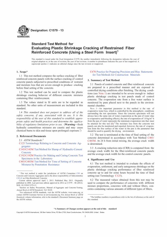
1
Designation: C1579 −13
Standard Test Method forEvaluating Plastic Shrinkage Cracking of Restrained FiberReinforced Concrete (Using a Steel Form Insert)1
This standard is issued under the fixed designation C1579; the number immediately following the designation indicates the year oforiginal adoption or, in the case of revision, the year of last revision. A number in parentheses indicates the year of last reapproval. Asuperscript epsilon ( ) indicates an editorial change since the last revision or reapproval.
1. Scope*1.1 This test method compares the surface cracking of fiber
reinforced concrete panels with the surface cracking of controlconcrete panels subjected to prescribed conditions of restraintand moisture loss that are severe enough to produce crackingbefore final setting of the concrete.
1.2 This test method can be used to compare the plasticshrinkage cracking behavior of different concrete mixturescontaining fiber reinforcement.
1.3 The values stated in SI units are to be regarded asstandard. No other units of measurement are included in thisstandard.
1.4 This standard does not purport to address all of thesafety concerns, if any, associated with its use. It is theresponsibility of the user of this standard to establish appro-priate safety and health practices and determine the applica-bility of regulatory limitations prior to use. (Warning—freshhydraulic cementitious mixtures are caustic and may causechemical burns to skin and tissue upon prolonged exposure.2)
2. Referenced Documents2.1 ASTM Standards:3
C125 Terminology Relating to Concrete and Concrete Ag-gregates
C143/C143M Test Method for Slump of Hydraulic-CementConcrete
C192/C192M Practice for Making and Curing Concrete TestSpecimens in the Laboratory
C403/C403M Test Method for Time of Setting of ConcreteMixtures by Penetration Resistance
1 This test method is under the jurisdiction of ASTM Committee C09 onConcrete and Concrete Aggregates and is the direct responsibility of SubcommitteeC09.42 on Fiber-Reinforced Concrete.
Current edition approved April 1, 2013. Published May 2013. Originallypublished in 2006. Last previous edition approved in 2012 as C1579 – 06 (2012).DOI: 10.1520/C1579-13.
2 Section on Safety Precautions, Manual of Aggregate and Concrete Testing,Annual Book of ASTM Standards, Vol 04.02.
3 For referenced ASTM standards, visit the ASTM website, www.astm.org, orcontact ASTM Customer Service at [email protected]. For Annual Book of ASTMStandards volume information, refer to the standard’s Document Summary page onthe ASTM website.
C670 Practice for Preparing Precision and Bias Statementsfor Test Methods for Construction Materials
3. Summary of Test Method3.1 Panels of control concrete and fiber reinforced concrete
are prepared in a prescribed manner and are exposed tocontrolled drying conditions after finishing. The drying condi-tions (see Note 1) are intended to be severe enough to induceplastic shrinkage cracking in test panels made of controlconcrete. The evaporation rate from a free water surface ismonitored by pans placed next to the panels in the environ-mental chamber.
NOTE 1—An important parameter in this method is the rate ofevaporative water loss, which is controlled by the atmospheric conditionssurrounding the test specimens. Since the concrete specimens will notalways have the same rate of water evaporation as the pan of water (dueto evaporative and bleeding effects), the rate of evaporation of 1.0 kg/m2·hfrom the pan of water represents the minimum evaporation rate that mustbe attained for this test (1).4 The moisture loss from the concrete testpanels can also be monitored and reported, however, the rate of evapora-tion from the free surface of the water in the pan is the parameter thatshould be used to quantify the drying environment.
3.2 The test is terminated at the time of final setting of theconcrete determined in accordance with Test Method C403/C403M. At 24 h from initial mixing, the average crack widthis determined.
3.3 A cracking reduction ratio (CRR) is computed from theaverage crack width for the fiber-reinforced concrete panelsand the average crack width for the control concrete panels.
4. Significance and Use4.1 The test method is intended to evaluate the effects of
evaporation, settlement, and early autogenous shrinkage on theplastic shrinkage cracking performance of fiber reinforcedconcrete up to and for some hours beyond the time of finalsetting (see Terminology C125).
4.2 The measured values obtained from this test may beused to compare the performance of concretes with differentmixture proportions, concretes with and without fibers, con-cretes containing various amounts of different types of fibers,
4 The boldface numbers in parentheses refer to the list of references at the end ofthis standard.
*A Summary of Changes section appears at the end of this standardCopyright © ASTM International, 100 Barr Harbor Drive, PO Box C700, West Conshohocken, PA 19428-2959. United States

C1579 − 13
2
and concretes containing various amounts and types of admix-tures. For meaningful comparisons, the evaporative conditionsduring test shall be sufficient to produce an average crack widthof at least 0.5 mm in the control specimens (2, 3) (see Note 2).In addition, the evaporation rate from a free surface of watershall be within 5 % for each test.
NOTE 2—To achieve evaporation rates that result in a crack of at least0.5 mm in the control specimens, it may be necessary to use anevaporation rate higher than that discussed in Note 1.
4.3 This method attempts to control atmospheric variablesto quantify the relative performance of a given fresh concretemixture. Since many other variables such as cement fineness,aggregate gradation, aggregate volume, mixing procedures,slump, air content, concrete temperature and surface finish canalso influence potential cracking, attention shall be paid to keepthese as consistent as possible from mixture to mixture.
5. Apparatus
5.1 Molds:5.1.1 For maximum coarse aggregate size equal to or less
than 19 mm, use a mold with a depth of 100 5 mm andrectangular dimensions of 355 10 mm by 560 15 mm (seeFig. 1). The mold can be fabricated from metal, plastic, orplywood.
NOTE 3—If plywood is used for molds, the plywood should have lowmoisture absorption. The mold should be constructed to be lightweightand stiff. The molds, when properly constructed, should last for approxi-mately 50 uses.
5.1.2 This test method is designed for aggregate less than orequal to 19 mm. For coarse aggregate greater than 19 mm, thedepth of the mold shall be at least 65 mm plus at least 2 timesthe maximum coarse aggregate size.
FIG. 1 Specimen and Stress Riser Geometry (4, 3)

C1579 − 13
3
5.2 Stress Riser and Internal Restraints—The internal re-straints and stress riser shall be bent from one piece of sheetmetal, as illustrated in Fig. 1, or made from a solid piece ofsteel. The sheet metal shall have a thickness of 1.2 0.05 mm(18 gauge) (see Fig. 1 and Ref 2). Two 32 1 mm highrestraints are placed 90 2 mm inward from each end of themold. The central stress riser is 64 2 mm high and serves asan initiation point for cracking. This sheet metal stress riserwith internal restraints shall fit at the bottom of the mold.
5.2.1 Use form release oil to coat the metal insert and moldsides to reduce bond with concrete. The insert and mold areconsidered to be properly oiled when the entire surface iscoated and excess oil has been removed with a clean, dry rag.
5.3 Variable Speed Fan(s)—The fan(s) used shall be capableof achieving a wind speed of more than 4.7 m/s over the entiretest panel surface area.
5.4 Environmental Chamber—The use of a fan box in anenvironmental chamber is a method for producing a uniformairflow over the panel surface (see Fig. 2). A clear cover overthe panels will aid in obtaining uniform airflow and allow forobservation of cracking. Another method of producing uniformairflow is to use a specifically designed environmental chamberas shown in Fig. 3. A commercially available heater,humidifier, and dehumidifier can be used to maintain thespecified environmental condition. This test is conducted usingeither apparatus shown in Fig. 2 or Fig. 3 by exposing thepanels to an evaporation rate of at least 1.0 kg/m2·h (see Note1). For the standard test, the temperature must be maintained at36 3°C, the relative humidity must be 30 10 %, and thewind velocity must be sufficient to maintain the minimumevaporation rate during the test.
NOTE 4—Before casting the concrete panels, atmospheric variables inthe environmental facility should be checked to determine that thenecessary evaporative conditions can be achieved. A wind velocity of 4.7m/s should be sufficient to achieve the minimum specified evaporationrate, but a higher wind velocity may be needed to obtain sufficient averagecrack width in some control panels.
5.5 Sensors—Use temperature, humidity, and wind velocitysensors to measure ambient air and concrete surface tempera-ture to the nearest 0.5°C, relative humidity to the nearest 1 %,and air speed to the nearest 0.1 m/s.
5.6 Vibrating Platform—Any device that can fully consoli-date the test panel that meets minimum frequency requirementsas stated in Practice C192/C192M for an external vibrator issuitable.
5.7 Surface Finishing Equipment—An angle iron screedshall be used for the concrete after vibration. A magnesium,steel, or wood trowel shall be used for finishing the surface ofthe specimen after screeding.
5.8 Monitoring Pan—A pan suitable for exposing water tothe air stream for each concrete test panel is required. The sidesof the pan shall be vertical. The pan shall be of sufficient sizeto expose at least 0.1 0.01 m2 of water to the air stream. Theexposed lip of the pan shall not extend more than 5 mm abovethe water level at the start of the test.
NOTE 5—The test panels and monitoring pans can be placed in anenvironmental chamber designed for this test method (see Fig. 3) or thepans can be placed downstream from panels in a fan box (see Fig. 2).
5.9 Scale—If the rate of moisture loss from test panels isrequired by the specifier of tests, weigh test panels with a scalehaving a capacity of at least 100 kg and accurate to within0.1 % of the test load. Weigh the evaporation rate monitoringpans with a balance or scale having a capacity of at least 3 kgand accurate to within 5 g.
5.10 Crack Measurement Tool—Optical hand-heldmicroscope, crack comparator, or image analysis system can beused. The measurement tool should be capable of measuringcrack width to at least the nearest 0.05 mm. If an automatedimage analysis system is used, it should be demonstrated toprovide an accurate measurement. To demonstrate the accuracyof the measurement, the system shall be used to measure a 0.5mm notch that is machined into a piece of steel and thereported notch width shall be within 0.05 mm of themachined width.
6. Sampling, Test Specimens, and Test Units6.1 Test Panels—Cast test panels in accordance with the
applicable provisions of Practice C192/C192M, using the samesource of materials, preparation, mixing and finishing proce-dures.
6.2 Test Unit—A test unit is comprised of at least twocontrol specimens and at least two fiber reinforced concretespecimens with the same mixture proportions. A group of twocontrol specimens has to be tested each time in order todetermine the plastic shrinkage crack reduction of fiber rein-forced concrete.
7. Procedure7.1 Determine the slump of each mixture in accordance with
Test Method C143/C143M.7.2 Fabricate specimens for setting time determination in
accordance with Test Method C403/C403M. If fiber reinforcedconcrete cannot be wet sieved readily, use the control concretespecimen to measure time of final setting of both the controland the fiber-reinforced mixtures. Place the time of settingspecimens in the air stream so that they are exposed to the sameenvironmental conditions as the plastic shrinkage panels.
7.3 Fill the panel molds using one layer. Consolidate theconcrete with external vibration until the concrete is approxi-mately level with the top of the mold. Screed each specimenperpendicular to the stress riser three times.
7.4 After screeding, trowel specimens using a predeter-mined number of passes. If moisture loss from the panel is tobe determined, remove any waste concrete adhering to theoutside of the mold and weigh each panel while in the mold.
7.5 Place a fiber reinforced concrete mixture panel andcontrol mixture panel in the environmental chamber down-stream from the fan(s) (see arrangements in Figs. 2 and 3).
7.6 Turn on the fan(s), which have been preset to achievethe air speed to obtain the required evaporative conditions (seeNote 4). The evaluation of cracking commences at this time.
7.7 At the start of the test and at 30-min intervals, record airtemperature, relative humidity, and air flow speed at a location100 5 mm above each panel surface. If required by the
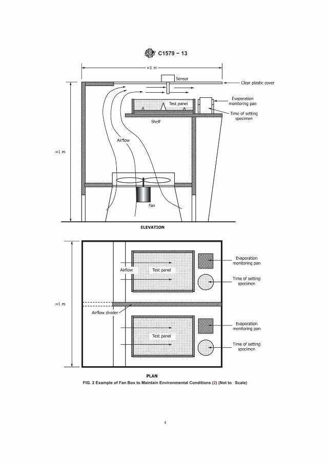
C1579 − 13
4
FIG. 2 Example of Fan Box to Maintain Environmental Conditions (2) (Not to Scale)

C1579 − 13
5
FIG. 3 Example of Chamber to Maintain Environmental Conditions (4)
specifier of tests, record the time at which cracking is firstobserved for each panel surface. Perform penetration tests atregular time intervals according to Test Method C403/C403M.Continue recording the environmental variables until the timeof final setting.
7.8 The evaporation rate is determined by initially weighingthe full monitoring pans at the start of the test and at 30-minintervals thereafter (5). Record the mass loss to the nearest 5 gat each weighing. To determine the evaporation rate duringeach time interval, divide the mass loss between successiveweighings by the surface area of the water in the weighing pan
and the time interval between successive weighings (see Note6). The test is not valid if the average evaporation rate is lessthan 1.0 kg/m2·h.
NOTE 6—Adjustments to wind velocity should be made if necessary tomaintain the evaporation rate at the required level. It is suggested that themonitoring pans be placed on scales in the air stream for continuousmonitoring without periodic removal during testing. If this is not possible,the monitoring pan should be removed from the air stream, weighed, andreturned to the air stream within 15 seconds.
7.9 After final setting occurs (use the later of the measuredtime of setting in the two specimens), record the atmosphericvariables, stop the fans, record the time, and determine the total
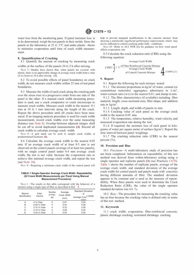
C1579 − 13
6
water loss from the monitoring pans. If panel moisture loss isto be determined, weigh the test panels in their molds. Store thepanels in the laboratory at 23 2°C and under plastic sheetsto minimize evaporation until time of crack width measure-ment.
8. Quantification of Cracking8.1 Quantify the amount of cracking by measuring crack
help to prevent marginal modifications to the concrete mixture fromshowing a statistically significant performance improvement, which maynot be sufficient to control cracking under field conditions.
NOTE 10—Refer to ACI 305R (1) for guidance on how wind speedaffects evaporation rate.
8.5 Calculate the crack reduction ratio (CRR) using thefollowing equation:
Average Crack Width
widths at the surface of the panels 24 2 h after mixing.NOTE 7—Studies have shown that, when panels are covered with
plastic, there is no appreciable change in average crack width from a timeof six hours to 24 h after mixing (3).
CRR of Fiber Reinforced Concrete Mixture1 Average Crack Widthof Control Concrete Mixture 4 100 % (1)
8.2 To avoid possible effects of panel boundaries on crackwidth, do not measure crack widths within 25 mm of test panelboundaries.
8.3 Measure the width of each crack along the cracking pathover the stress riser in a progressive order from one side of thepanel to the other. If a manual crack width measuring proce-dure is used, use a crack comparator or crack microscope tomeasure crack widths. Measure crack width to the nearest 0.1mm at 10 1 mm intervals along the length of the crack.Repeat the above procedure until all cracks have been mea-sured. If an imaging analysis procedure is used for crack widthmeasurement, record crack widths over the same measuringdistance (see Note 8). Overlap between adjacent images shallbe cut off to avoid duplicated measurements (4). Record allcrack widths to calculate average crack width.
NOTE 8—A grid mask can be used to sample crack widths atpredetermined locations (4).
8.4 Calculate the average crack width to the nearest 0.05mm. If an average crack width of at least 0.5 mm is notobserved on the control panels (average of at least two panels),with no single control panel under 0.4 mm average crackwidth, the test is not valid. Increase the evaporation rate toachieve this minimal average crack width, and repeat the test(see Note 10).
NOTE 9—Requiring a minimum crack width of the control panel will
TABLE 1 Single-Operator Average Crack Width Repeatability(22 Crack Width Measurements per Panel Using Manual
Measurement Procedure)
NOTE 1—The results in this table correspond with the behavior of amixture using a single type of fiber as described in Ref 3.
9. Report9.1 Report the following for each mixture tested:9.1.1 The mixture proportions in kg/m3 of water, cement (or
cementitious materials): aggregates; admixtures in L/m3;water-cement ratio (w/c) to the nearest 0.01; and slump in mm.
9.1.2 The fiber characteristics (if available) including fibermaterial, length, cross-sectional area, fiber shape, and additionrate in kg/m3.
9.1.3 Length, depth, and width of panels in mm.9.1.4 Cracking value of each panel as the average crack
width to the nearest 0.05 mm.9.1.5 The temperature, relative humidity, wind velocity, and
measured evaporation rate during the test.9.1.6 If required, the moisture loss of each panel in kilo-
grams of water per square meter of surface (kg/m2). Report thetime interval between panel weighings.
9.1.7 The cracking reduction ratio (CRR) to the nearestpercent (%).
10. Precision and Bias10.1 Precision—A multi-laboratory study of precision has
not been completed. Information on repeatability of this testmethod was derived from within-laboratory testing using asingle operator and replicate panels (3) (see Practices C670).Table 1 shows the number of replicate panels, average of theaverage crack width, and standard deviation of the averagecrack width for control panels and panels made with concreteshaving different amounts of fiber. The standard deviationappears to be constant and is used as the measure of repeat-ability. When three panels were used to determine the CrackReduction Ratio (CRR), the value of the single operatorstandard deviation was 4.6 %.
Number Average Standard Deviation
k Width10.2 Bias—The procedure for measuring the cracking value
has no bias because the cracking value is defined only in termsof this test method.
11. Keywords11.1 crack width; evaporation; fiber-reinforced concrete;
plastic shrinkage cracking; restrained shrinkage cracking
3
MixtureIdentification
FiberVolume of Pan-
elsCrack Width of
(mm) Average Crac(mm)
A 0 % Fiber 6 0.67 0.04B 0.05 % Fiber 4 0.44 0.05C 0.10 % Fiber 4 0.33 0.05D 0.15 % Fiber 4 0.08 0.04E 0.20 % Fiber 2 0.03 0.02
C1579 − 13
7
REFERENCES
(1) “Hot Weather Concreting,” ACI 305.R-99, ACI Manual of ConcretePractice, American Concrete Institute, Farmington Hills, MI, 2004.
(2) Berke, N. S., and Dalliare, M. P., “The Effect of Low Addition Rateof Polypropylene Fibers on Plastic Shrinkage Cracking and Mechani-cal Properties of Concrete,” Fiber Reinforced Concrete: Developmentand Innovations, ACI SP-142, American Concrete Institute, Farming-ton Hills, MI, 1994 , pp.19–41.
(3) Qi, C., Weiss, J., and Olek, J., “Statistical Significance of theRestrained Slab with a Stress Riser for Quantifying Plastic Crackingin Fiber Reinforced Concrete,” ASTM Journal of Testing andEvaluation, July 2005.
(4) Qi, C., Weiss, J., and Olek, J., “Characterization of Plastic ShrinkageCracking in Fiber-Reinforced Concrete Using Semi-Automated ImageAnalysis,” RILEM Materials and Structures, Vol 36, No. 260, July2003, pp. 386–395.
(5) Nanni, A., Ludwig, D. A., and Mcgillis, M. T., “Plastic ShrinkageCracking of Restrained Fiber-Reinforced Concrete,” TransportationResearch Record, 1382, 1993, pp. 69–72.
SUMMARY OF CHANGES
Committee C09 has identified the location of selected changes to this specification since the last issue, C1579– 06 (2012), that may impact the use of this specification. (Approved April 1, 2013.)
(1) Removed reference to ASTM C995 from Sections 2.1, 7.1,and 9.1.1.
ASTM International takes no position respecting the validity of any patent rights asserted in connection with any item mentionedin this standard. Users of this standard are expressly advised that determination of the validity of any such patent rights, and the riskof infringement of such rights, are entirely their own responsibility.
This standard is subject to revision at any time by the responsible technical committee and must be reviewed every five years andif not revised, either reapproved or withdrawn. Your comments are invited either for revision of this standard or for additional standardsand should be addressed to ASTM International Headquarters. Your comments will receive careful consideration at a meeting of theresponsible technical committee, which you may attend. If you feel that your comments have not received a fair hearing you shouldmake your views known to the ASTM Committee on Standards, at the address shown below.
This standard is copyrighted by ASTM International, 100 Barr Harbor Drive, PO Box C700, West Conshohocken, PA 19428-2959,United States. Individual reprints (single or multiple copies) of this standard may be obtained by contacting ASTM at the aboveaddress or at 610-832-9585 (phone), 610-832-9555 (fax), or [email protected] (e-mail); or through the ASTM website(www.astm.org). Permission rights to photocopy the standard may also be secured from the Copyright Clearance Center, 222Rosewood Drive, Danvers, MA 01923, Tel: (978) 646-2600; http://www.copyright.com/


APPENDIX B: CONCRETE CRACKING RING TEST
Cracking Tendency Measurement due to Drying Deformation the First 24 Hours


1 (4)
CONCRETE CRACKING RING TEST:CRACKING TENDENCY MEASUREMENT DUE TO DRYING DEFORMATION THE FIRST 24 HOURS Key words: Concrete, cracking, shrinkage, drying
1 SCOPE This test method covers determination ofconcrete cracking tendency at early ages. Thetest is performed on 3 restrained ring shapedspecimen, exposed to an air stream of defined velocity, temperature and relative humidity, thefirst 24 hours after casting.
The principle of the test is that the concretesample is cast around a restraining inner steelring, causing a development of tangentialstresses, that if sufficiently high may lead to cracking. The evaluation is based oncharacterization of the cracks in terms of averagetotal area by the three samples.
The method is a modification of the Nordtestmethod “NT BUILD433”.
Problems with early-age shrinkage and crackinghave become problematic. Conditions as reducedmaximum aggregate size, increased amount of fines, presence of retarding admixtures,increased binder content and deficient coveringand curing all contribute to this problem.
Most likely the cracking caused by dryingshrinkage also are consisting autogenousshrinkage. Compared with autogenous shrinkagethat generally develops uniformly through theconcrete member, drying shrinkage occurs fromthe outside surface of the concrete inward, bothcausing cracks that develops rapidly and occurswhen the cement paste is young and has poorlydeveloped mechanical properties.
2 FIELD OF APPLICATIONWith the “Concrete cracking ring test”, the plasticand hardening concrete cracking tendency canbe used for an evaluated of different type of concrete exposed to early drying.
The test is only to be applied for laboratory usewhere the method information is relative and cannot predict the extent of cracking which mightoccur under prevailing conditions.
Maximum coarse aggregate size is 16 mm.
Concrete cracking ring test is preferable to be combined with:
Volume or linear measurement of autogenousdeformation, e.g. Concrete Digital Dilatometer(CDD) test for concrete.
3 REFERENCESSampling procedure: EN 12350-1, ASTM C172or NT BUILD 191.
Cracking tendency test: NT BUILD 433
4 NOTATIONS4.1 Definitions Shrinkage; when the deformation is a contraction,it may be referred to as shrinkage, e.g. autogenous or drying shrinkage.
Autogenous shrinkage; the unrestrained, time-depending, bulk deformation of fresh andhardening sealed concrete at a constanttemperature.
Chemical shrinkage; under sealed conditions, the cement paste hydration products occupy lessspace than the original reactants. Chemical is themajor of factors causing the autogenousshrinkage.
Drying shrinkage; when water evaporates fromthe fresh and hardening concrete, tensile stressbuild up in the capillaries causing the concrete to contract. In early stages, drying shrinkage can bedefined as plastic shrinkage.
4.1 Symbols
n number of cracks of each specimen.
l length of each crack, in millimeter [mm].
w each crack average width, in millimeter [mm].
A average total crack area calculated from twoore more samples, in sqr millimeter [mm2].
t time after mixing, in hours [h].
m sample weight loss due to drying, in kilogram [kg].
E sample evaporation, in kilogram per sqrmeter [kg/m2].
v air velocity, in meter per second [m/s].
RH air relative humidity, in percentage [%].
Ta air temperature, in degree Celsius [ºC]
Tc concrete temperature, in degree Celsius [ºC]
Concrete cracking ring test: cracking tendency measurement due to drying deformation the first 24 hours

2 (4)
5 METHOD OF TEST5.1 Principle When water evaporates from the fresh concretethe concrete tends to contract, and as contractionis restrained, tangential tension develops crosssection of the ring specimen. The extent of cracking depends on both the magnitude of thetensile forces and on the strain capacity of the concrete.
The concrete is cast between two concentricsteel rings with diameter 300 and 600 mm with adepth of 80 mm, see Figure 1. The steel ringshave ribs attached to provide crack initiation andare fixed to a stiff base plate with a smoothsurface. After casting, the ring specimens arepositioned under air funnels with a 10 mmopening between the concrete surface and thefunnel along the circumference of the outer ring.The funnel is shaped to provide equal windvelocity across the concrete surface of 4.5 m/s. The test is to be performed at stabile andconstant environmental conditions, where one of the samples is to be placed on a balance.
The cracking tendency is evaluated from cracklength and average width measurements on theconcrete top surface.
5.2 Apparatus Required equipment and apparatus for a typical test is:
Thermal and humidity controlled room or chamber with a constant air temperature of T=20±1ºC and relative humidity of RH=40±3%. The conditions magnitude is not absolute, but they are preferable.
3 complete mould setup for ring specimen,as shown in Figure 1.
3 set of air funnels, including fan andducting, as shown in Figure 1.
Balance (load cell) with manual reading or automatic recording of weight changes.
Devices and instrumentation for manualreading or automatic recording of: - air velocity- temperature and relative humidity of air - concrete temperature.
Ruler or measuring wheel graded in 1/1 mm.
Water level.
Stopwatch, measuring 1/1 sec.
5.3 Preparation of test specimen 5.3.1 Mould The inner and outer steel rings are fixed on a stiff base steel plate with a smooth surface. The steelrings are to be covered with a thin layer of form oil and the base plate is not be oiled.
5.3.2 Mix Concrete constituents by dry weight shall berecorded. Max coarse aggregate size is 16 mm.
5.3.3 Mixing Suitable concrete mixing method, mixer and volume is to be selected and documented. Nostandards are available.
5.3.4 Sample The sample size is 17 liter (x3) and is to be collected in accordance with EN 12350-1, ASTM C172 or NT BUILD 191.
5.3.5 Casting The concrete shall be sampled from the mixer immediately after the end of mixing period. Thecasting of 3 ring specimens shall beaccomplished within 30-45 minutes after wateraddition.
The specimen must completely fill the mould (to the top of the inner and outer steel ring). If needed, compaction by vibration. Top surface areto be smoothed in equal manner.
5.4 Procedure 5.4.1 Starting the test
a) One of the specimens is to be placed on the balance.
b) Each specimens horizontal position are to be ensured (if unsure, use a water level).
c) One concrete temperature sensors is to beplaced in the center of the mould crosssection.
d) The air funnels are to be placed in such away that the opening between the concretesurface and the funnel edge is uniform (10mm) along the whole circumference of the outer steel ring.
Concrete cracking ring test: cracking tendency measurement due to drying deformation the first 24 hours

3 (4)
e) The fans are to be started 55 minutes after water addition. Velocity over the concretesurface are to be ensured (4.5 m/s)
f) The recording phase (time t, concretetemperature Tc, specimen weight loss m,air temperature and humidity Ta and RH) tobe started, 60 minutes after water addition.
The test is be performed in a thermal humiditystable and controlled room or chamber with an air temperature of 20±1ºC. and relative humidity of 40±3%
The starting procedure (a-d) is to be performedwithin 60 minutes from water addition, if not this time is to be noted.
5.4.2 During the test If manual reading, continuously record the time t,concrete temperature Tc, specimen weight loss
m, air temperature and humidity Ta and RH.Enough sampling frequency is to be selected for smooth curve of temperature and weight lossdevelopment (less then 1/2 hours interval).
Visual observation of specimens throughout the24 hours can be made in order to describe the crack development. The type, orientation and time of occurrence of cracks can then be noted.
5.4.3 Finishing the test Recording phase (t, Tc, m, Ta and RH) stops.Values are to be transferred to computer for calculation and evaluation.
5.4.3 Crack measurementsThe ring specimens shall normally be examinedafter 24 hours exposure, and surface cracks withan approximate radial orientation shall beidentified and marked in an adequate way. The average widths (w) and length (l) of each crackare to be measured and recorded. The widthmeasurements shall be performed by the use of the magnifying glass and readings by interpolation to the nearest 0.02 mm. It is recommended that a lower crack limit is 0.05mm. The main crack pattern of each ring can be recorded by photo or sketched by drawing.
The standard procedure also includes recordingof weight loss and temperature development.These parameters give useful information aboutthe evaporation of water, and serve as a controlfor identical tests as well.
5.5 Expression of results The total crack area for each ring shall be calculated as accumulated sum of each averagecrack width multiplied by its length. The averagetotal crack area (A) is expressed by the averageareas for 3 rings, rounded to the nearest 0.1 mm,as:
3
))wl((A
3
1j
n
1iii
[mm2]
The water evaporation (E) is calculated by the quote of weight loss ( m) and ring surface area,as:
212.0mE [kg/m2]
The development of concrete temperature (Tc)and evaporation (E) with time (t) is to bepresented graphically.
6 TEST REPORTThe report is shall include necessary informationfrom among the following:
a) Document id (name, nr, test method, etc).
b) Date and time.
c) Performer id (name and address).
d) Test object id.
e) Purpose of test.
f) Concrete id (producer, recipe, etc).
g) Identification of the test equipment andinstruments used.
h) Method of sampling.
i) Time from water addition to start/stop sampling and crack measuring.
j) Air velocity (v), temperature (ta) and humidity(RH) during the test.
k) Test results: number of cracks (n), total crack area (A) and graphical presentation of concrete temperature and evaporation (t, Tcand E).
l) Relevant visually observations and personaljudgments and interpretations.
m) Any deviation from the test method.
n) Inaccuracy and/or uncertainty of test results.
o) Date and signature.
Concrete cracking ring test: cracking tendency measurement due to drying deformation the first 24 hours
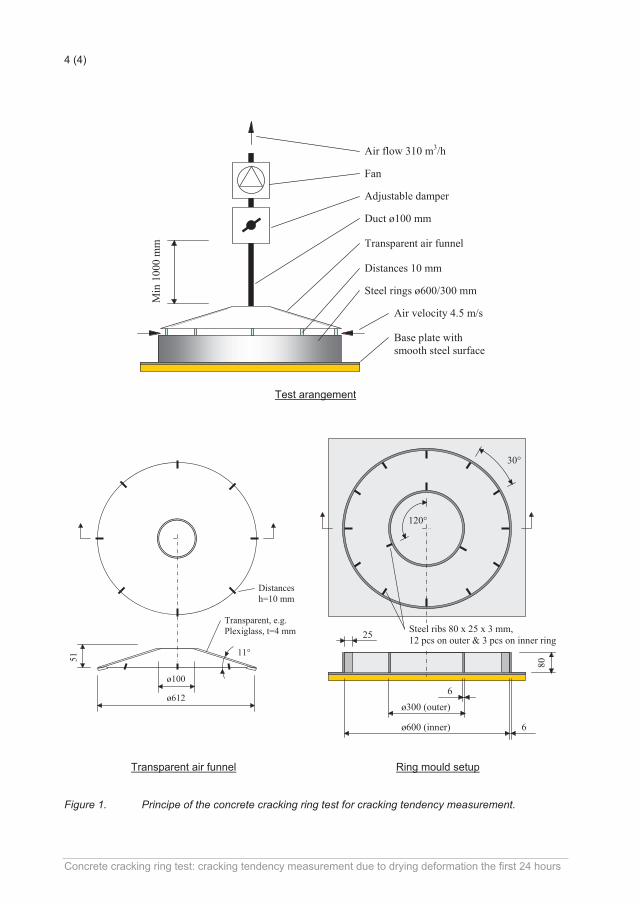
4 (4)
Duct ø100 mm
Min
100
0 m
m
Adjustable damper
Fan
Base plate withsmooth steel surface
Transparent air funnel
Distances 10 mm
Steel rings ø600/300 mm
Air flow 310 m3/h
Air velocity 4.5 m/s
Test arangement
51
Transparent, e.g.Plexiglass, t=4 mm
ø100
ø612
11°
Distancesh=10 mm
80
ø600 (inner)
120°
30°
ø300 (outer)
6
6
25 Steel ribs 80 x 25 x 3 mm,12 pcs on outer & 3 pcs on inner ring
Transparent air funnel Ring mould setup
Figure 1. Principe of the concrete cracking ring test for cracking tendency measurement.
Concrete cracking ring test: cracking tendency measurement due to drying deformation the first 24 hours
APPENDED PAPERS

PAPER I: Plastic Shrinkage Cracking in Concrete: Research in Scandinavia Sayahi, F., Emborg, M. and Hedlund, H. (2014), published in proceeding of the XXII Nordic Concrete Research symposium, Reykjavik, Iceland, August 13 – 15, 2014, pp. 351 – 354.


351
Plastic Shrinkage Cracking in Concrete: Research in Scandinavia
Faez Sayahi Ph.D. Student Div. of Structural Engineering Luleå University of Technology, LTU 971 87 Luleå, Sweden. [email protected] Mats Emborg
Professor LTU/Head R&D Betongindustri AB 971 87 Luleå, Sweden. / Betongindustri AB, 100 74 Stockholm, Sweden mats.emborg@ betongindustri .se [email protected] Hans Hedlund Professor LTU/Skanska Teknik AB 971 87 Luleå, Sweden/Skanska AB, 405 18 Göteborg, Sweden [email protected] [email protected]
ABSTRACT As plastic shrinkage cracking still causes considerable repair costs annually, an understanding of the phenomenon is essential to prevent these damages in the future. In the paper, the status of present technology to avoid cracking is briefly reported through referring to research conducted in Scandinavia. In addition, on-going activities at LTU are described and future plan is demonstrated. Thus, experiments are performed on concrete slabs cast in rectangular moulds and cured at some variations of environmental conditions. The results will be used to find critical evaporation rate at very early age. KEYWORDS: Plastic Shrinkage, Cracking, Concrete, Evaporation. 1. INTRODUCTION Crack-free concrete structures are needed, in order to ensure high level of durability and functionality, since cracks accelerate the ingress of harmful materials that might cause damage in future (i.e. corrosion of the reinforcement). Plastic shrinkage cracking is the first type of cracks occurring directly after placing the concrete, sometimes even before the final setting /Schmidt & Slowlk 2013/. This type of cracking mainly occurs on horizontal concrete surfaces such as slabs, pavements, beams, etc. exposed to hot and/or windy conditions. Many factors affect the likelihood of plastic shrinkage cracking such as water-cement ratio, admixture, member size, fines content , concrete surface temperature and ambient conditions (i.e. relative humidity, air temperature and wind velocity) /Uno 1998/. All these factors influence the water
352
evaporation rate from the freshly placed concrete surface which is considered as an indication of the possible beginning of the plastic shrinkage cracking /Uno 1998/. 2. PREVIOUS RESEARCH IN SCANDINAVIA In order to obtain a better comprehension of the plastic shrinkage cracking phenomenon, various research have been performed world-wide and Scandinavia is not an exception. Researchers such as Hedin /1985/, Johansen and Dahl /1993/, Lund et al. /1997/, Hammer /1999/ and Esping and Löfgren /2006/ studied different aspects of plastic shrinkage cracking and prepared a strong launch platform for further investigations. For example, ten laboratory experiments and two field trials conducted by Hedin in 1985 to investigate what type of curing best prevents plastic shrinkage in the newly cast concrete. It was stated that covering the concrete with plastic wrap and membrane, decreases the evaporation rate and consequently leads to a crack-free concrete. Using the same setup, Lund et al. argued that lower water-cement ratio causes less bleeding water and thus, logically, increases the risk of cracking /Lund et al. 1997/. Also the evaporation rate was documented in the study. In 1993, Johansen and Dahl preformed series of experiments in order to develop a method for determination of the cracking tendency of concrete at early ages. During the tests, fresh concrete was cast between two concentric steel rings. The specimen was then placed under an air funnel, to create an air stream with the required velocity over the fresh concrete surface /Johansen and Dahl 1993/. The crack tendency was then judged quantitatively at the end of the test (20 to 24 hours after casting) /NORDTEST NT BUILD 433, 1995/. Hammer performed a set of experiments to study the relations between autogenous volumetric and linear shrinkage before and during the setting of paste-mortar-concrete, chemical shrinkage bleeding and concrete settlement. The objective was to obtain a reliable and meaningful method to measure the linear autogenous shrinkage of concrete /Hammer 1999/. Among other things it was observed that reabsorption of bleeding water which occurs around the setting is helpful from crack risk point of view /Hammer 1999/. Esping and Löfgren studied the early age (less than 24 hours) autogenous deformation and pore-pressure development of Self-Compacting Concrete (SCC) and evaluated its crack tendency due to plastic shrinkage. This was done by exposing concrete specimens to early drying conditions (a modified NT BUILD 433). The experiments consisted of different SCC constituents and mix compositions e.g. water-cement ratio from 0.38 to 0.67, silica fume, and different admixtures /Esping & Löfgren 2006/. In addition, the experiments were repeated with standard concrete for comparison. According to the results, Esping and Löfgren argued that a high crack tendency occurs when there is a) a large amount of autogenous shrinkage (low w/c, silica addition, high fineness) b) retardation (retarder or high super plasticizer dosage) c) high water evaporation (low fineness or high w/c) d) low content of coarse aggregate /Esping & Löfgren 2006/. 3. EXPERIMENTS AT LTU In order to practically study the phenomenon of plastic shrinkage cracking, laboratory tests have been conducted in the laboratory of Complab, Luleå University of Technology (LTU). The experiments were designed in order to monitor and understand the water evaporation rate in

353
concrete slab under varying environmental conditions. Furthermore, how capillary pressure in the concrete develops and its relationship with plastic shrinkage cracking is a part of the project. Various concrete mixtures at different conditions will be tested to understand how the water evaporation rate and capillary pressure develops and influences the plastic shrinkage cracking. For these experiments, a test rig (1200x400x90 mm) has been designed based on the experimental setups used by Hedin /1985/ and Lund /1997/, (see Figure 1). The frame is made of UPE80-beams placed on a 1 mm thick steel plate. It is possible to disassemble and reuse the frame after each test. Latex is used to seal the beam-plate and beam-beam interfaces. Rebars, 8 mm diameter, are installed inside the mould to create external constraint in the concrete. The rebars are fixed against 18 rods in total around the mould (6 rods along the long- and 3 rods along the short-side). Each rod penetrates the concrete by 60 mm. The rig is placed on four load cells for continuous weight measurement. A 50 cm wide fan is used to produce wind with constant velocity on the slab surface varying from 0 to 7 m/s in different trials. A wind tunnel is place on the slab to conduct the wind over the surface. At the moment, two parallel rigs are used to be able to vary curing conditions etc. on exactly the same concrete mix.
Figure 1 – Test setup for plastic shrinkage crack experiments at LTU. So far tests have been performed with CEM II Portland-limestone cement (Byggcement, Cementa) which is vastly used in standard concrete work such as house building nowadays. Water-cement ratio is 0.38 to reach a 28 days strength of 60 MPa alongside with a S4 slump (160-210 mm) / Lundström 2013/. It should be noted that the mentioned values represent the first tested mixture which may differ by the experiments progress in future. The aggregates and cement are mixed together for 1 minute in a mixer with 50 litre capacity. Then, water and the super plasticizer are added to the mixture simultaneously. The concrete should be left to mix for 5 minutes. The final fresh concrete would be cast in the above described mould and compacted using a vibrator. At this stage the concrete slab surface should be treated and finished carefully in order to have a smooth surface. Having prepared the surface, the wind tunnel is placed on the slab and the fan is set on the required speed. Documentation is performed on water evaporation, air temperature, concrete temperature (at 7 points), wind speed and relative humidity. Each specimen is exposed to the wind for at least 4 hours while the surface of the slab is carefully monitored to record the occurrence of possible plastic shrinkage crack initiation.

354
4. FINAL COMMENTS In these experiments the total weight lost is considered to be the total water evaporation. By plotting the evaporation rate against time, effect of different factors on the evaporation rate can be understood. The plan is to perform this test for different concretes to achieve a clear picture regarding the critical water evaporation rate for cracking at different conditions. Furthermore, it is planned to include the capillary pressure measurement in future. Results of the above mentioned tests, can prepare a useful database for further investigations regarding plastic shrinkage cracking in concrete. Outcomes of these experiments, will be compared with full scale tests and the currently used method such as nomograph presented by Uno /1998/. Based on such a comparison, further investigation opportunities may emerge. ACKNOWLEDGMENT The authors would like to appreciate the support they received from the Development Fund of the Swedish Construction Industry, SBUF, as well as the personnel of Complab at LTU. REFERENCES Esping, O., & Löfgren, I., 2006
”Investigation of Early Age Deformation in Self-Compacting Concrete”, Proceeding, 2nd International Symposium on Advances in Concrete through Science and Engineering, Quebec City, Canada, 11-13 September 2006.
Hammer, T. A., 1999 ”Test Methods for Linear Measurement of Autogenous Shrinkage before Setting”, Autogenous Shrinkage of Concrete, Edited by Ei-ichi Tazawa, E & FN Spon, London, United Kingdom, pp. 143-154.
Hedin, C., 1985 ”Plastiska Krympsprickor – Motåtgärder”, (in Swedish), Internal technical report 85-3. Central laboratory of Betongindustri AB.
Johansen, R. & Dahl, P.A., 1993 ”Control of plastic shrinkage of cement”, Paper presented at the 18th Conference on Our World in Concrete and Structures, Singapore, 1993.
Lund, A., Skoog, M., Thorstensson, R., 1997 ”Plastiska Krympsprickor i Betong”, (in Swedish), Dept. of Structural Mechanics and Engineering, Royal Institute of Technology, Stockholm, Sweden, 1997.
Lundström, J., 2013 ”Uppkomst av plastiska krympsprickor: Ny försöksuppställning och inverkan av cementtyp och vindhastighet”, Master thesis (in Swedish), Luleå University of Technology, Luleå, Sweden, 2013,98 pp.
NORDTEST NT BUILD 433, 1995 ”Concrete: Cracking Tendency – Exposure to Drying During the First 24 Hours”, NORDTEST, Espoo, Finland, 1995.
Schmidt, M., & Slowlk, V., 2013 ”Instrumentation for Optimizing Concrete Curing”, Concrete International, Vol. 35 , No. 8, August 2013, pp 60-64.
Uno, P.J., 1998 “Plastic Shrinkage Cracking and Evaporation Formulas”, ACI Material Journal, Vol. 95, No. 4, July-August 1998, pp. 365-375.

PAPER II: Plastic Shrinkage Cracking in Concrete: State of the Art
Sayahi, F., Emborg, M. and Hedlund, H. (2014), published in Nordic Concrete Research, Vol. 51, No. 3, December 2014, pp. 95 – 110.


95
Plastic Shrinkage Cracking in Concrete: State of the Art
Faez Sayahi Ph.D. Student Div. of Structural Engineering Luleå University of Technology, LTU 971 87 Luleå, Sweden. [email protected] Mats Emborg Professor LTU/Head R&D Betongindustri AB 971 87 Luleå, Sweden. /Betongindustri AB, 100 74 Stockholm. mats.emborg@betongindustri .se [email protected] Hans Hedlund Professor LTU/Skanska Teknik AB 971 87 Luleå, Sweden/Skanska AB, 405 18 Göteborg, Sweden [email protected] [email protected] ABSTRACT As plastic shrinkage cracking can dramatically reduce the durability of a concrete member and causes considerable repair costs annually, a comprehensive understanding of the mechanism of the phenomenon is essential to prevent these damages in future. In this paper, an overview is given on the mechanism of plastic shrinkage crack formation and the status of present technologies avoiding the cracking are reported through referring to previously conducted research and observations. Keywords: Plastic Shrinkage, Cracking, Concrete, Evaporation, Capillary pressure.

96
1. INTRODUCTION Crack-free concrete structures are needed in order to ensure high level of durability and functionality, since cracks accelerate the ingress of harmful materials that might cause damage in future, e.g. corrosion of the reinforcement [1]. Plastic shrinkage cracking of concrete is often the first type of cracks occurring shortly (within the first few hours) after placing the concrete, even before initial setting [1-4]. As known also settlement cracks can occur very early. According to ACI 305R [5]: “Plastic shrinkage cracking is frequently associated with hot weather concreting in arid climates. It occurs in exposed concrete, primarily in flat work but also in beams and footings and may develop in other climates whenever the evaporation rate is greater than the rate at which the water rises to the surface of recently placed concrete by bleeding”. It is thus understood that this type of cracking, mainly occurring on horizontal concrete elements with large surface to volume ratio (such as slabs, pavements, beams, etc.), can dramatically affect the aesthetics, durability and serviceability of the structure [6, 7]. The main reason behind plastic shrinkage cracking is considered to be rapid and excessive surface water evaporation of the concrete element in the plastic stage (freshly cast concrete) which in turn leads to the so-called plastic or capillary shrinkage [2-5, 8-17]. Consequently, many factors affect the likelihood of plastic shrinkage crack formation such as water-cement ratio, admixture, member size, fines content, concrete surface temperature and ambient conditions (i.e. relative humidity, air temperature and wind velocity). All these factors influence the water evaporation rate of the concrete which is considered, among others, as an indication of the possible beginning of the plastic shrinkage cracking [18]. As long as the evaporation rate is less than the bleeding rate, a thin water film covers the surface of the concrete. Soon after the disappearance of this thin water layer, capillary pressure inside the concrete increases, which results in the so called plastic shrinkage. It should be mentioned here that the bleeding can be very small or not existing at all for concretes of low water/cement ratio, e. g. those designed for fast drying through self-desiccation.. If the concrete member is restrained in any way (e.g. due to reinforcement, change of sectional depth, difference in shrinkage in different parts of the concrete, friction of the mould, etc.) , the developed shrinkage can cause tensile strain accumulation, starting from the concrete surface. When the tensile strain exceeds the tensile strain capacity of the concrete, which at early ages is very low, cracks start to form [19]. In many cases, plastic shrinkage cracks are so thin (sometimes invisible to an unaided eye) which can be overlooked or covered by the surface finishing [2]. However, later on phenomena such as external loading, thermal strain, or drying shrinkage can widen the crack which as mentioned earlier negatively influences the serviceability of the concrete structure. Plastic shrinkage cracking, in general, is a complex combination of interdependent variables which can facilitate or prevent the phenomenon under different circumstances. Thus, studying plastic shrinkage cracking requires a high level of persistence and intense theoretical and experimental investigation. In this paper, the phenomenon of plastic shrinkage cracking in concrete is investigated and an attempt is made to reach a comprehensive perspective of the formation process and mechanism. In addition several variables such as water/cement ratio, thickness of the concrete section, fines content, additives, and fibres are briefly described. This research is based on the achievements reported by several researchers around the world and aims to present a state of the art in order to

97
make plastic shrinkage cracking in concrete clearer and more understandable. The work intends to constitute a base of future research at Luleå University of Technology. 2. MECHANISM OF PLASTIC SHRINKAGE CRACKING In order to gain a general comprehension of the plastic shrinkage cracking phenomenon, initially, it is important to have a picture, as clear as possible, regarding the mechanism of plastic shrinkage crack formation. In Fig.Figure 1 (quoted from [6]), the process of plastic shrinkage crack formation is schematically explained. Based on the interaction between the plotted lines (factors), various milestones (i.e. drying time, air entry time, crack onset time, etc.) can be defined. After placing the concrete in its mould, if not a high performance concrete or similar is used, a thin film of water covers the surface and an interconnected pore system, completely filled with water is formed [2]. Shortly later the drying time (TD) is reached when the water evaporation rate exceeds the bleeding rate of the concrete (see Fig.1). In this case the thin water film is disappeared due to evaporation and the water in the pore system starts to evaporate [20]. This moment is the onset of capillary pressure rise which converts it from a compressive pressure to a tensile pressure. The reason that capillary pressure is compressive before drying time is the existence of the internal water pressure in the concrete [20]. The capillary pressure keeps increasing until air breaks through the pore system, starting from the largest pores. This time is defined as the air entry time [17]. Consequently, the capillary pressure drops down suddenly and dramatically since the paste can no longer resist the tensile capillary pressure. Value of the capillary pressure at the air entry time is critical since the empty pores form weak points at the concrete surface which can be the origin of strain localization and cracking [2]. Based on the above, plastic shrinkage cracking is mainly related to the evaporation rate and bleeding rate of the concrete. These factors in addition to capillary pressure and tensile strain play the key role in the mechanism of plastic shrinkage cracking [2, 6, 18, 21]. These parameters are discussed briefly in the following sections.
Figure 1 - Typical behaviour of plastic shrinkage crack [6]
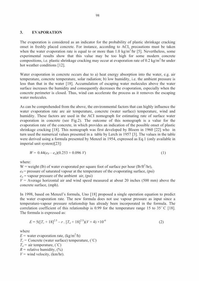
98
3. EVAPORATION The evaporation is considered as an indicator for the probability of plastic shrinkage cracking onset in freshly placed concrete. For instance, according to ACI, precautions must be taken when the water evaporation rate is equal to or more than 1.0 kg/m2/hr [5]. Nevertheless, some experimental results show that this value may be too high for some modern concrete compositions, i.e. plastic shrinkage cracking may occur at evaporation rate of 0.2 kg/m2/hr under hot weather conditions [12]. Water evaporation in concrete occurs due to a) heat energy absorption into the water, e.g. air temperature, concrete temperature, solar radiation; b) low humidity, i.e. the ambient pressure is less than that in the water [18]. Accumulation of escaping water molecules above the water surface increases the humidity and consequently decreases the evaporation, especially when the concrete perimeter is closed. Thus, wind can accelerate the process as it removes the escaping water molecules. As can be comprehended from the above, the environmental factors that can highly influence the water evaporation rate are air temperature, concrete (water surface) temperature, wind and humidity. These factors are used in the ACI nomograph for estimating rate of surface water evaporation in concrete (see Fig.2). The outcome of this nomograph is a value for the evaporation rate of the concrete, in which provides an indication of the possible onset of plastic shrinkage cracking [18]. This nomograph was first developed by Bloem in 1960 [22] who in turn used the numerical values presented in a table by Lerch in 1957 [3]. The values in the table were derived using a formula presented by Menzel in 1954, expressed as Eq.1 (only available in imperial unit system)[23]:
W = 0.44(e0 – ea)(0.253 + 0.096 V) (1) where: W = weight (lb) of water evaporated per square foot of surface per hour (lb/ft2/hr), e0 = pressure of saturated vapour at the temperature of the evaporating surface, (psi) ea = vapour pressure of the ambient air, (psi) V = Average horizontal air and wind speed measured at about 20 inches (500 mm) above the concrete surface, (mph). In 1998, based on Menzel’s formula, Uno [18] proposed a single operation equation to predict the water evaporation rate. The new formula does not use vapour pressure as input since a temperature-vapour pressure relationship has already been incorporated in the formula. The correlation coefficient of this relationship is 0.99 for the temperature range 15 to 35 ̊ C [18]. The formula is expressed as:
E = 5([Tc + 18]2.5 – r . [Ta + 18]2.5)(V + 4) ×10-6 (2) where E = water evaporation rate, (kg/m2/h) Tc = Concrete (water surface) temperature, (˚C) Ta = air temperature, (˚C) R = relative humidity, (%) V = wind velocity, (km/hr).

99
This formula is widely used since the establishment. Comparison between Menzel and Uno’s formula shows almost complete accordance in the results. In addition both formulas give almost similar evaporation rates to those extracted from the ACI nomograph. However, even if the water evaporation rate is accurately determined based on the above mentioned methods, still there is no guarantee that it can be applicable and reliable indicator of the cracking onset. That is due to the fact that, as mentioned earlier, the evaporation rate has to exceed the concrete bleed rate in order to cause plastic shrinkage [25].
Figure 2 – ACI nomograph for estimating surface water evaporation rate of concrete i e. the “ACI Hot Weather Concreting Evaporation Nomograph” [5]. 4. BLEEDING Bleeding is defined as the ascending of the mixing water to the concrete surface. Typically, it occurs as the result of settlement and consolidation of freshly placed concrete under the gravitational force [26]. It occurs due to the inability of the solid particles to retain the water during the settlement. There are two independent driving forces which cause bleeding in concrete: the gravity which settles the solid particles of the concrete mixture, and the capillary pressure (suction) which occurs after the thin water layer on the surface has disappeared [16]. Bleeding rate can be measured experimentally using some standard methods such as the Australian standard [27] or according to ASTM C232/C232M [28].

100
In general, bleeding depends on the water/cement ratio, particle size distribution, viscosity of the concrete and the rate of hydration [6]. In addition, the depth of the concrete member can influence the bleeding rate [2]. Bleeding typically stops when the hydration products are abundant enough to prevent any further concrete settlement, which is the description of the state at the initial setting time of the concrete [29]. The assumed range of bleeding rate for concrete has decreased during the past century. Until 1960, it ranged from 0.5 to 1.5 kg/m2/h [16, 18]. However, in modern concretes, bleeding rate is considerably decreased to less than 1 kg/m2/h [16]. The reason lies in the general desire of gaining less bleed rate in order to achieve higher mechanical properties and less permeability in the modern concretes through lowering w/c ratio and increasing fine cement, fly ash and silica fume content in the mixture. The final product then, is a concrete with extremely low or even zero bleeding rate [30]. Although a certain level of bleeding might be desirable in order to replace evaporated water and keep the surface wet, it should be noted that excessive bleeding in turn, may cause various damages as well. These damages include plastic settlement cracking, surface laitance formation, longer finishing time, strength decrease and lower bonding between the solid particles [12, 16]. 5. CAPILLARY PRESSURE Capillary pressure (also referred to as matric suction, capillary tension or capillary suction) is as discussed earlier the origin of plastic shrinkage cracking. It is highly influenced by the water evaporation rate of the concrete. Therefore, capillary pressure can be considered as another indicator for the risk of shrinkage cracking onset. 5.1 Capillary pressure build-up mechanism Plastic or capillary shrinkage is a result of a physical process which builds up negative pore pressure in the liquid phase of the cementitious material [2, 11]. As mentioned before, after casting the concrete, a thin plane film of water covers the surface of the concrete member and an interconnected pore system, completely filled with water is formed (Fig.3, Level A). As long as the evaporation rate is less than the bleeding rate, the surface remains covered by this thin water layer. However, the thickness of this layer decreases gradually, as a result of evaporation. Once the water layer disappears, the adhesive force and surface tension of water form menisci between the solid particles of the paste (Fig.3, Level B and Fig.4). These menisci cause negative pressure (tensile capillary pressure) in the concrete pore system. The description of this phenomenon lies in the Young-Laplace equation when the pores are assumed perpendicular to the concrete surface:
cos2R
P (3)
where P= pressure in the pore liquid, (Pa) R = radius of the meniscus, (m), see Fig.4
= surface tension of the pore liquid (0.073 N/m for water)θ = wetting angle, (deg.).

101
Cementitious materials are considered as siliceous materials i.e. full wetting material. In such material the wetting angle is 0. The negative capillary pressure, applies inward force on the solid particles at the concrete surface. As the evaporation continues, the radius of the menisci in the pore system gradually decreases (Fig.3, Level C). Consequently, the capillary pressure keeps rising, causing contraction of the material. So far the contraction induced volume change approximately equals the volume of the evaporated water [17].
Figure 3 – Mechanism of capillary pressure build-up. The upper part of the figure shows evaporation and bleeding vs. time after placement (see also Fig. 1) [2].
Figure 4 – Water meniscus in a pore.

102
As the capillary pressure increases, the radius of the meniscus decreases until it becomes equal to the minimum radius of the associated pore (Fig.3, Level D). The rise of the capillary pressure continues until at a certain value, the menisci break and let air penetrates the pore system (Fig.3, Level E). Once this happens, the capillary pressure dramatically drops down to almost zero i.e. it breaks down. The moment when capillary pressure breaks down and air penetrates into the pore system is called air-entry time. It should be noted that due to the irregularity of particle arrangement in the concrete paste, air entry does not occur simultaneously in all pores [17]. In other words, air entry is rather a local event than a universal one. Therefore, different values for maximum capillary pressure may be measured in different parts of the concrete member. For example, Slowik [29] in 2008 performed an experiment on cement paste samples, using two pressure sensors in different locations. Each sensor measured different maximum capillary pressure (Fig.5). Thus, the maximum capillary pressure at a certain location does not represent the absolute maximum capillary pressure in the concrete. In addition, the capillary pressure may break down if the sensor tip penetrates an air bubble inside the concrete [17].
Figure 5 – Difference in maximum absolute capillary pressure in different locations [29]. Based on Carman [31], an equation was proposed by Powers [25] for determining maximum capillary tensile pressure in concrete, which was modified by Cohen [10]:
cw
SP 3101 (4)
where P= capillary tensile pressure, (MPa)
= surface tension of the pore liquid (0.073 N/m for water)S = mass specific surface area of cement, (m2/kg)
cw = water/cement ratio by mass, (-)
The constant 10-3 has the dimension mass density (kg/m3).

103
According to Eq.4, capillary pressure (P) is directly proportional to and S, and inversely proportional to w/c ratio. It means that keeping other variables constant, concrete with higher w/c ratio and lower and S is less suspected to experience plastic shrinkage cracking [16]. Furthermore, based on Eq.4, assuming constant and w/c ratio, capillary pressure (P) is directly proportional to mass specific surface area of cement (S). In other word, maintaining all conditions similar, any difference in plastic shrinkage characteristics (i.e. strain and cracking) would be due to the difference in surface area or particle size of the solid material [10]. This was also observed in Eq.5 proposed by Pihlajavaara [32] to determine the capillary pressure in concrete with spherical non-porous solid aggregates:
SP 7106.2 (5) where P= capillary tensile pressure, (MPa)
= surface tension of the pore liquid (0.073 N/m for water)S = mass specific surface area of cement, (m2/kg) ρ = solid density of cement, (kg/m3)The constant 2.6×10⁻⁷ is dimensionless. The maximum absolute capillary pressure, P, is considered critical since - after breaking down - creates weak points at the surface of the concrete. If the concrete is restrained, these weak spots, eventually, may be origins of strain localization and crack initiation along a line which connects them. Based on the above mentioned facts, the capillary pressure in the concrete must kept less than the air entry value to prevent any strain localization and cracking onset. This typically takes place through preventing the surface water evaporation 5.2 Capillary pressure measurement Capillary pressure in concrete is typically measured using pressure sensors such as those showed in Fig. 6. The tip of the sensor is filled with water which allows in-situ negative fluid pressure measurement. The tip of the sensor should penetrate the concrete by about 50 mm. In this case, the weight of the sensor is supported by the sensor tip. A recording device, then, collects all the data from the pressure sensors, which makes it possible to plot them versus time in a diagram. Both wired and wireless sensors are now available on the market.
6. TENSILE STRAIN As previously mentioned, increasing capillary pressure leads to plastic shrinkage in the concrete. If the concrete is restrained (e.g. due to reinforcement, change of sectional depth, difference in shrinkage in different parts of the concrete, friction of the mould, etc.), this plastic shrinkage causes mechanical tensile strain (i.e. if the plastic shrinkage can develop freely, it will not induce any cracking). On the other hand, experiments have shown that strain capacity reaches its lowest value around the initial setting time of the concrete (see Fig.7) [6]. Once the strain capacity is less than the mechanical tensile strain, the concrete starts to crack.

104
Figure 6 – Wired and wireless pressure sensors [2]
Figure 7 – Tensile strain capacity of fresh concrete [6]. As it was mentioned in section 2, plastic shrinkage cracks, typically, are visible after the initial setting time of the concrete (see Fig.1), which confirms the above mentioned fact. Hence, plastic shrinkage induced tensile strain can be another indicator of the cracking risk. Several researchers have taken this fact into account and developed models to estimate the plastic shrinkage cracking risk based on the tensile strain in the concrete. Boshoff [6] in 2013, proposed a so-called “PShC severity model” to predict the plastic shrinkage cracking degree: PShC = ER × tset ̶ Wbl (6) where ER = evaporation rate, (kg/m2/h) tset = the time between casting and the initial setting time, (hr) Wbl = the total bleed water, (kg/m2).

105
According to this model, the severity of plastic shrinkage cracking is dependent on the plastic shrinkage strain which is directly related to the rate of water evaporation, hardening time of the concrete (initial setting time) and bleeding characteristics [6]. In other word, it relates the severity of plastic shrinkage cracking to the amount of the evaporated water (total amount of evaporated water, minus the bleed water) from within the concrete, between the casting and initial setting time [6]. 7. MAIN FACTORS AFFECTING PLASTIC SHRINKAGE CRACKING So far, the main parameters in the mechanism of plastic shrinkage formation, (i.e. evaporation rate, bleeding rate, capillary pressure and tensile strain) and the relation between them have been briefly described. Fig. 8 is an attempt so summarize the parameters mentioned and the way they are linked together. Nevertheless, there are many factors which can affect plastic shrinkage cracking. A deep comprehension of the way these factors influence the whole cracking process can lead to invention of new crack prevention methods. Some of these factors are briefly described in the following , including water/cement ratio, depth of the concrete section, additives, fines content, fibres and curing measures. 7.1 Water/cement Ratio Water/cement ratio plays a key role in plastic shrinkage cracks formation. Higher w/c ratio means more bleeding water and vice versa. Thus, in case of high w/c ratio, it takes longer time for the surface water layer to disappear due to evaporation and consequently delays the capillary pressure build-up in the pore system. It is known that a lower w/c ratio causes less bleeding water and thus increases the risk of cracking [33]. On the other hand w/c ratio has an inverse relation with the concrete strength as higher w/c ratio causes lower concrete strength and vice versa. Research has shown that high-strength concrete mixtures (containing more cement) have low bleeding rate and subsequently higher risk of plastic shrinkage cracking [34]. Thus, optimizing the w/c ratio can be a method to avoid plastic shrinkage crack formation. If high-strength concrete is not necessary, it may be a good idea to use higher w/c ratio. However, it should be noted that very high w/c ratio can dramatically reduce the durability and serviceability of the concrete member. 7.2 Depth of the concrete section A deeper concrete member typically experiences more settlement, since it contains more settling solid particles. Correspondingly, for higher w/c ratios, the bleeding capacity of the member is higher resulting in more bleed water accumulation on the surface. This means that the surface water layer evaporation takes longer time in comparison, causing delay in capillary pressure build-up. Consequently, it can be concluded that a deeper concrete section is less prone to plastic shrinkage cracking [8, 35]. However, due to the high degree of settlement, the concrete may be vulnerable to settlement cracking typically formed above the reinforcement bars, which may facilitate the ingress of chlorides and other harmful materials.

106
Figure 8 – Plastic shrinkage cracking flowchart. 7.3 Additives Several research studies have been carried out to find new admixtures in order to reduce the plastic shrinkage of concrete. These admixtures show high practicality in reducing evaporation rate, settlement, negative capillary pressure and plastic shrinkage formation. For instance, it has been concluded that cellulose-based viscosity modifying agent (stabilizer) causes reduction of the evaporation rate [36]. Moreover, accelerators and retarders have a strong influence on plastic shrinkage cracking. Some experiments [20, 37] showed that accelerator admixtures cause higher plastic shrinkage and total crack area, while retarders act contrary. However, other experiments [15, 38] showed that excessive usage of retarder admixtures may increase the risk of plastic shrinkage cracking due to the slower strength gain of the concrete.

107
On the other hand, superplasticizers reduce the need for water in the concrete mixtures (less bleed water at the surface). This reduction of surface water may however not increase the risk of cracking, as the superplasticizer modifies the surface tension and prevent or delays the onset of plastic shrinkage crack formation [39]. 7.4 Fibres Fibres (steel and/or polypropylene) have often been recently used in concrete mixtures aiming at lowering the risk of plastic shrinkage cracking, through stitching the concrete surface particles together. For instance experimental results presented by Sivakumar and Santhanam [7] show that a combination of steel and polypropylene fibres (hybrid fibres), can reduce the width of the plastic shrinkage crack up to 55% in comparison to concrete mixture without fibres usage. However, the only problem is that although the crack width was lower, parallel cracks were formed in the main crack’s surroundings. This phenomenon can be due to the transfer of the shrinkage stresses, through the fibres, to the surrounding areas. The number of these parallel cracks could be reduced in case of steel fibre usage. The reason lies in more fibre availability in case of hybrid usage compared to the steel fibre system (due to the lower density of polypropylene fibre in comparison to steel fibres), which facilitates the shrinkage stress transfer. Nevertheless, hybrid fibres show a great enhancement in relation to reducing plastic shrinkage cracks [7]. 7.5 Fines content Fines (such as fly ash, silica fume, slag, etc.) induce greater surface area to adsorb water. Consequently, the water that is supposed to be transported to the concrete surface will be adsorbed on the fine particles, resulting in lower bleeding rate. Cohen et al. [10] concluded that higher surface area of the particles leads to higher tensile capillary pressure and eventually higher probability of plastic shrinkage crack formation. Moreover, experiments performed by Esping et al. [15] showed that silica fume increases the crack tendency in the concrete. Thus, using high proportion of fine material in the concrete mixture is not favourable in relation to plastic shrinkage cracking. 7.6 Curing measures Plastic shrinkage cracks can be avoided through several curing measures applied on the concrete after casting. Since the main reason behind this phenomenon is water evaporation, curing measures in general aim to eliminate or reduce the evaporation of the surface water. For example covering the concrete with plastic sheet, decreases the evaporation rate and consequently leads to a crack-free concrete [40]. In another case, experiments have shown that evaporation of the surface water can be suppressed through spraying aliphatic alcohols over the fresh concrete surface [41]. Moreover, in some cases curing the concrete takes place through replacing the evaporated surface water (rewetting). For example, fogging the freshly cast concrete surface, on one hand, reduces the evaporation rate through increasing the ambient relative humidity, and on the other hand, replaces some lost surface water due to evaporation [17].
108
In addition to the above, using a wind breaker to prevent or reduce the air flow over the concrete surface can be another way to reduce the evaporation of the surface water [18]. 8. CONCLUSION Plastic shrinkage cracking is a complex interaction of several variables that may change in different circumstances. These variables have direct influence on the evaporation and bleed rate of the concrete which subsequently affect the capillary pressure and tensile strain at the early age. The explanations offered in this paper for the plastic shrinkage cracking mechanism and the role of each variable in the process may facilitate gaining a comprehensive understanding of the phenomenon. Moreover, knowing the influence of each variable can lead to innovation of new crack preventive measures. Despite of the general consensus on the major role of water evaporation in the plastic shrinkage crack formation, not all the cracking incidents are explainable based on that. This illustrates the incompletely understood aspects of the whole process. The inter-connection and complexity of the different variables need to be explored. Thus, in the future, emphasis should be on documenting the various factors through laboratory tests under controlled conditions. ACKNOWLEDGMENT The authors would like to gratefully appreciate the financial support they received from the Development Fund of the Swedish Construction Industry, SBUF. REFERENCES 1. Leemann A, Nygaard P, Lura P. "Impact of admixtures on the plastic shrinkage cracking of
self-compacting concrete". Cement and Concrete Composites. Vol.46, 2014, pp.1-7. 2. Schmidt M, Slowik V. "Instrumentation for optimizing concrete curing". Concrete
International. 2013;35(8). 3. Lerch W. "Plastic shrinkage". ACI journal proceedings; ACI; 1957. 4. Ravina D, Shalon R. "Plastic shrinkage cracking". ACI journal proceedings; ACI; 1968. 5. "ACI D. 305R-hot weather concreting". American Concrete Institute International, 1999. 6. Boshoff WP, Combrinck R. "Modelling the severity of plastic shrinkage cracking in
concrete". Cement and Concrete Research. Vol.48, 2013 JUN, pp.34-39. 7. Sivakumar A, Santhanam M. "Experimental methodology to study plastic shrinkage cracks in
high strength concrete. In: Measuring, Monitoring and Modelling Concrete Properties. Springer, 2006. pp. 291-296.
8. Van Dijk J, Boardman V. "Plastic shrinkage cracking of concrete". RILEM international symposium of concrete and reinforced concrete in hot countries, Technion, Israel institute of technology, Haifa, 1971, pp. 225-239.
9. Kasai Y, Vokoyama K, Matsui I. "Tensile properties of early-age concrete. Proceedings of conference on mechanical behaviour of materials". 1972, pp.288-299.
10. Cohen MD, Olek J, Dolch WL. "Mechanism of plastic shrinkage cracking in Portland cement and Portland cement-silica fume paste and mortar". Cement and Concrete Research, Vol.20, No.1, 1990, pp.103-119.

109
11. Radocea A. "A study on the mechanism of plastic shrinkage of cement-based materials". Chalmers University of Technology,; 1992.
12. Almusallam A, Abdul-Waris M, Maslehuddin M, Al-Gahtani A. "Placing and shrinkage at extreme temperatures". Concrete International, Vol.21, 1999, pp.75-79.
13. Qi C, Weiss J, Olek J. "Characterization of plastic shrinkage cracking in fiber reinforced concrete using image analysis and a modified weibull function". Materials and Structures. Vol.36, No.6, 2003, pp.386-395.
14. Josserand L, Coussy O, de Larrard F. "Bleeding of concrete as an ageing consolidation process". Cement and Concrete Research,Vol.36, No.9, 2006, pp.1603-1608.
15. Esping O, Löfgren I, Marchand J, Bissonnette B, Gagné R, Jolin M, et al. "Investigation of early age deformation in self-compacting concrete". 2nd International Symposium on Advances in Concrete through Science and Engineering, 11-13 September 2006, Quebec City, Canada,
16. Dao V, Dux P, Morris P, O'Moore L. "Plastic shrinkage cracking of concrete". Australian Journal of Structural Engineering. Vol.10, No.3, 2010, pp.207-214.
17. Slowik V, Schmidt M. "Early age cracking and capillary pressure controlled concrete curing". Advance in Cement-Based Material. 2010.
18. Uno PJ. "Plastic shrinkage cracking and evaporation formulas". ACI Mater Journal. Vol.95, 1998, pp.365-375.
19. Ghoddousi P, Javid AAS. "Effect of reinforcement on plastic shrinkage and settlement of self-consolidating concrete as repair material". Materials and Structures, Vol.45, No.1-2, 2012, pp.41-52.
20. Combrinck R, Boshoff WP. "Typical plastic shrinkage cracking behaviour of concrete". Magazine of Concrete Research, Vol.65, No.8, 2013, pp.486-493.
21. Radocea A. "A model of plastic shrinkage". Magazine of Concrete Research,Vol.46, No.167, 1994, pp.125-132.
22. Bloem D. "Plastic cracking of concrete". Engineering Information. 1960. 23. Menzel CA. "Causes and prevention of crack development in plastic concrete". Proceedings
of the Portland Cement Association. 1954, pp.130-136. 24. Goff JA, Gratch S. "Low-pressure properties of water from-160 to 212 F". Transaction of
the American Society Heating and Ventilating Engineers, Vol.51, 1946, pp.125-164. 25. Powers TC. "The properties of fresh concrete". John Wiley and sons, 1969. 26. Kwak H, Ha S, Weiss WJ. "Experimental and numerical quantification of plastic settlement
in fresh cementitious systems". Journal of Material of Civil Engineering, Vol.22, No.10, 2010, pp.951-966.
27. Standards Australia 1999. "Method for the determination of bleeding of concrete". 1999. Report No.: AS1012.6-1999.
28. ASTM C232/C232M. "Standard test method for bleeding of concrete". American Society of Testing and Material, 2013.
29. Slowik V, Schmidt M, Fritzsch R. "Capillary pressure in fresh cement-based materials and identification of the air entry value," Cement and Concrete composites, Vol.30, No.7, 2008, pp.557-565.
30. Khayat KH. "Workability, testing, and performance of self-consolidating concrete". ACI Material Journal, Vol.96, No.3, 1999.
31. Carman P. "Capillary rise and capillary movement of moisture in fine sands," Soil Science, Vol.52, No.1, 1941, pp.1-14.
32. Pihlajavaara S. "A review of some of the main results of a research on the ageing phenomena of concrete: Effect of moisture conditions on strength, shrinkage and creep of mature concrete," Cement and Concrete Research,Vol.4, No.5, 1974, pp.761-771.
110
33. Lund A, Skoog M, Thorstensson R. ”Plastiska krympsprickor i betong”,. Dept. of Structural Mechanics and Engineering, Royal Institute of Technology, Stockholm, Sweden, 1997. (in swedish)
34. Samman TA, Mirza WH, Wafa FF. "Plastic shrinkage cracking of normal and high-strength concrete: A comparative study," ACI Material Journal, Vol.93, No.1, 1996, pp.36-40.
35. Schiessl P, Schmidt R. "Bleeding of concrete," RILEM proceedings of the colloquium, Hanover, 1990, pp.24-32.
36. Lin S, Huang R. "Effect of viscosity modifying agent on plastic shrinkage cracking of cementitious composites," Material and Structure. Vol.43, No.5, 2010, pp.651-664.
37. Kronlöf A, Leivo M, Sipari P. "Experimental study on the basic phenomena of shrinkage and cracking of fresh mortar," Cement and Concrete Research,Vol.25, No.8, 1995, pp.1747-1754.
38. Soroka I. "Concrete in hot environments," CRC Press, 2003, 251 pp. 39. Cabrera J, Cusens A, Brookes-Wang Y. "Effect of superplasticizers on the plastic shrinkage
of concrete," Magazine of Concrete Research, Vol.44, No.160, 1992, pp.149-155. 40. Hedin, C., "Plastiska Krympsprickor – Motåtgärder", Internal technical report 85-3. Central
laboratory of Betongindustri AB, 1985, (in Swedish). 41. Cordon, W. A., Thorpe, J. D., "Control of Rapid Drying of Fresh Concrete by Evaporation
Control", ACI Journal, Proceedings Aug. 1965, pp. 977-984.

PAPER III: Plastic Shrinkage Cracking in Self-Compacting Concrete: a Parametric Study Sayahi, F., Emborg, M. and Hedlund, H. Löfgren, I. (2016), published in proceeding of the Materials, Systems and Structures in Civil Engineering Conference, MSSCE 2016, Lyngby, Denmark, August 22 – 24, 2016, pp. 609 – 619.

International RILEM Conference on Materials, Systems and Structures in Civil Engineering Conference segment on Service Life of Cement-based Materials and Structures
22-24 August 2016, Technical University of Denmark, Lyngby, Denmark
609
PLASTIC SHRINKAGE CRACKING IN SELF-COMPACTING CONCRETE: A PARAMETRIC STUDY Faez Sayahi(1), Mats Emborg(1),(2), Hans Hedlund(1),(3), Ingemar Löfgren(4),(5) (1) Luleå University of Technology, Luleå, Sweden (2) Betongindustri AB, Stockholm, Sweden (3) Skanska Sverige AB, Gothenburg, Sweden (4) Chalmers University of Technology, Gothenburg, Sweden (5) Thomas Concrete Group, Gothenburg, Sweden Abstract Plastic shrinkage cracking, often the first type of cracks occurring even before initial setting, causes enormous expenses for the building industry annually. The main reason behind the phenomenon is believed to be rapid and excessive surface water evaporation of the concrete element in the plastic stage which in turn leads to the so-called plastic or capillary shrinkage. These cracks mainly occur in horizontal concrete elements with large surface to volume ratio (such as slabs, pavements, etc.). This paper reports results from experiments performed, using ring test method (NORDTEST-method NT Build 433). During the experiments, influence of water-cement (w/c) ratio, cement type, coarse aggregate content and super plasticizer dosage was investigated. Moreover, effort was made to explain the difference in cracking tendency of different concretes based on water evaporation rate and capillary pressure. It seems that various parameters have different influences on the cracking tendency, the evaporation rate, as well as the hydration rate and capillary pressure. Although, capillary pressure is local and its maximum value differs in different locations, it seems that its development rate, especially in the first few hours, is almost identical everywhere in the specimen. This may be used as a plastic shrinkage indicator. Keywords: Plastic Shrinkage, Cracking, Evaporation, Capillary pressure, Dormant period, NORDTEST-method NT Build 433. 1. Introduction Plastic shrinkage cracking in concrete is the first type of cracks occurring within the first few hours after casting, even before the initial setting. Horizontal concrete elements with large surface to volume ratio (e.g. slabs and pavements) are prone to this type of cracking. It accelerates the ingress of harmful materials that might cause damage in future, e.g. corrosion

International RILEM Conference on Materials, Systems and Structures in Civil Engineering Conference segment on Service Life of Cement-based Materials and Structures
22-24 August 2016, Technical University of Denmark, Lyngby, Denmark
610
of the reinforcement. Accordingly, cracks can dramatically impair the aesthetics, durability and serviceability of the structure [1, 2]. The main reason behind plastic shrinkage cracking is considered to be rapid and excessive surface water evaporation in the plastic stage [3-5]. Also, the phenomenon is closely related to settlement, capillary pressure and the duration of dormant period [6]. For conventional concrete, once it is placed in the mould, its solid particles settle under the influence of the gravitational forces, forcing the water in the pore system up to the surface (i.e. bleeding). Consequently, the entire concrete surface is covered with a thin layer of water [7]. However, for self-compacting concrete (SCC) and concrete with low w/c ratio, no free water will accumulate at the surface. As soon as the evaporation rate exceeds the rate at which water is transported to the surface, the water layer disappears, and water menisci are formed in the pores. This is the onset point of negative pressure (capillary pressure) build-up in the concrete pore system [8]. The progressive evaporation gradually decreases the radius of the menisci resulting in more negative capillary pressure build-up [8]. The capillary pressure in turn causes more settlement by pulling the solid particles down and forcing the pore water to the surface [9]. Gradually due to the consolidation and continues water loss, the solid skeleton of the concrete becomes stiffer and eventually, the settlement stops [6]. At this point, the capillary pressure, applies inward horizontal forces on the solid particles causing the concrete to shrink (i.e. plastic shrinkage). If the concrete is restrained, the plastic shrinkage can lead to tensile strain accumulation at the surface. Eventually, once the tensile strain exceeds the very low early age tensile strain capacity of the concrete, cracks start to form [10]. Many factors can influence the risk of plastic shrinkage cracking such as water-cement ratio (w/c), cement type, member size, admixtures, coarse aggregate content and ambient conditions (i.e. relative humidity, air temperature and wind velocity) [1, 11]. However, despite that many papers are dedicated to study the influence of concrete mixture constituents on plastic shrinkage cracking of SCC, it is still not possible to explain all the cracking incidents based on the current knowledge. It is also not clear why sometimes cracking tendency increases despite of reduction in the evaporation. This is where other parameters such as capillary pressure, internal temperature and/or autogenous shrinkage may offer better explanations. Although most of the experiments in this study were already performed by other researchers [12, 13], the role of capillary pressure in particular and its relation with evaporation and duration of dormant period have not been discussed. Filling this gap is the objective of this paper. Moreover, the trend of capillary pressure development in the first few hours is especially discussed. The presented research is part of an on-going PhD project at Luleå University of Technology in Sweden which aims at gaining a comprehensive understanding about the mechanism of plastic shrinkage cracking in concrete. 2. Materials and methods 2.1 Materials and mixing process Tables 1 and 2 show the mix design of the tested SCCs and the composition of the cements. Two reference concert mixtures (Ref.1 with 0.45 w/c ratio and Ref.2 with 0.67 w/c ratio)

International RILEM Conference on Materials, Systems and Structures in Civil Engineering Conference segment on Service Life of Cement-based Materials and Structures
22-24 August 2016, Technical University of Denmark, Lyngby, Denmark
611
were produced by Portland limestone cement (CEM II/A-LL 42.5R according to EN 197-1). Fine (0-4 mm and 0-8 mm) and coarse (8-16 mm) aggregates, respectively, constitute 60 and 40% of the total aggregates volume in both Ref.1 and Ref.2. During the experiments, superplasticizer (Sikament 56) with density of 1100 kg/m3 and 37% by weight of dry content was used. In addition, mineral filler (Limus 40) with density of 2700 kg/m3 was utilized to stabilize the concrete. The dry material (aggregates, cement and filler) was premixed in a pan type concrete mixer for one minute before the water and superplasticizer (SP) were added. Then the mixing process continued for another 5 minutes. To ensure reproducibility, all the concrete mixtures were produced and tested twice. Table 1: Mix design of the different tested concretes (W/C = Water-cement ratio, Ref = Reference concrete, CC = Coarse aggregate content, SP = Superplasticizer) in kg/m3.
Name W/C 0.45
(Ref.1)
W/C 0.67
(Ref.2)
W/C 0.38
W/C 0.55
Based on Ref.1 Based on Ref.2
CC35% CC45% SP0.6% SP1.0%
Cement 380 300 420 340 380 380 300 300 Water 171 200 160 187 171 171 200 200 Agg. 0-4 0 155 0 81 0 0 155 155 Agg. 0-8 998 771 1021 879 1089.4 921.8 771 771 Agg. 8-16 678 628 694 651 586.6 754.2 628 628 Filler 100 220 40 160 100 100 220 220 SP 5.7 2.4 4.6 4.1 5.7 5.7 1.8 3 W/C 0.45 0.67 0.38 0.55 0.45 0.45 0.67 0.67 Table 2: Composition of the utilized cements (produced by Cementa).
Name MgO (%)
SO3 (%)
CI-
(%) C3A (%)
Na2Oeqv (%)
Density (kg/m3)
Blaine (m2/kg)
CEM II/A-LL 42.5R (Bygg) 1.1-1.3 3.3-4.0 0.02-0.04 - - 3080 430
CEM I 52.5R (SH) 1.1-1.3 3.3-4.0 0.02-0.04 - - 3125 550
CEM I 42.5N (Anläggning) 1.2-1.5 2.3-2.5 0.01-0.03 1.3-2.7 0.48-0.58 3200 310 2.2 Testing sequence Four concrete mixtures with different w/c ratios (W/C0.38, W/C0.45, W/C0.55 and W/C0.67) were produced and tested (Table 1). W/C0.45 (Ref.1) was used as a reference for investigating the effect of coarse aggregate content; whereas the effect of SP dosage and cement type was studied by W/C0.67 (Ref.2). The cement used in Ref.2 (CEM II/A-LL 42.5R) was substituted by two different cements, mentioned in Table 2 in order to study the influence of cement type. To investigate the impact of coarse aggregate content, the ratio in Ref.1 was changed once from 40% to 35% (CC35%)
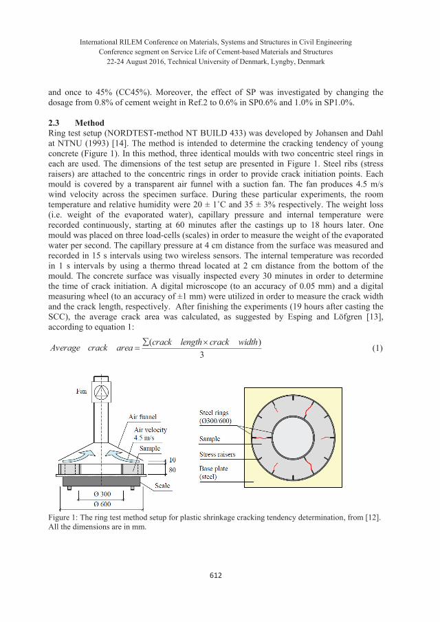
International RILEM Conference on Materials, Systems and Structures in Civil Engineering Conference segment on Service Life of Cement-based Materials and Structures
22-24 August 2016, Technical University of Denmark, Lyngby, Denmark
612
and once to 45% (CC45%). Moreover, the effect of SP was investigated by changing the dosage from 0.8% of cement weight in Ref.2 to 0.6% in SP0.6% and 1.0% in SP1.0%. 2.3 Method Ring test setup (NORDTEST-method NT BUILD 433) was developed by Johansen and Dahl at NTNU (1993) [14]. The method is intended to determine the cracking tendency of young concrete (Figure 1). In this method, three identical moulds with two concentric steel rings in each are used. The dimensions of the test setup are presented in Figure 1. Steel ribs (stress raisers) are attached to the concentric rings in order to provide crack initiation points. Each mould is covered by a transparent air funnel with a suction fan. The fan produces 4.5 m/s wind velocity across the specimen surface. During these particular experiments, the room temperature and relative humidity were 20 ± 1˚C and 35 ± 3% respectively. The weight loss (i.e. weight of the evaporated water), capillary pressure and internal temperature were recorded continuously, starting at 60 minutes after the castings up to 18 hours later. One mould was placed on three load-cells (scales) in order to measure the weight of the evaporated water per second. The capillary pressure at 4 cm distance from the surface was measured and recorded in 15 s intervals using two wireless sensors. The internal temperature was recorded in 1 s intervals by using a thermo thread located at 2 cm distance from the bottom of the mould. The concrete surface was visually inspected every 30 minutes in order to determine the time of crack initiation. A digital microscope (to an accuracy of 0.05 mm) and a digital measuring wheel (to an accuracy of ±1 mm) were utilized in order to measure the crack width and the crack length, respectively. After finishing the experiments (19 hours after casting the SCC), the average crack area was calculated, as suggested by Esping and Löfgren [13], according to equation 1:
3)( widthcracklengthcrackareacrackAverage (1)
Figure 1: The ring test method setup for plastic shrinkage cracking tendency determination, from [12]. All the dimensions are in mm.
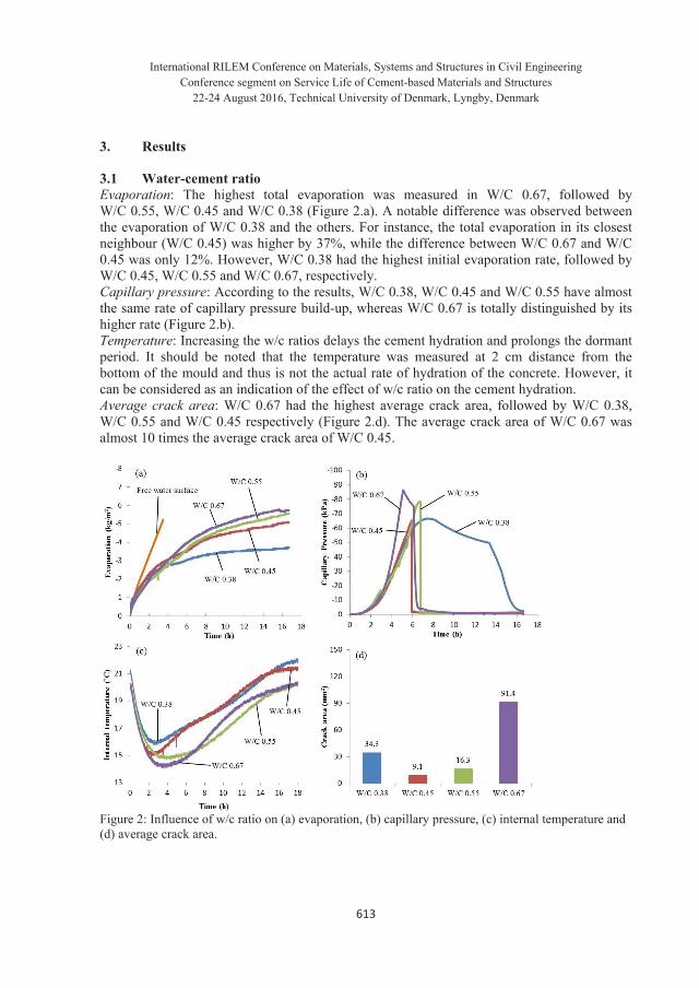
International RILEM Conference on Materials, Systems and Structures in Civil Engineering Conference segment on Service Life of Cement-based Materials and Structures
22-24 August 2016, Technical University of Denmark, Lyngby, Denmark
613
3. Results 3.1 Water-cement ratio Evaporation: The highest total evaporation was measured in W/C 0.67, followed by W/C 0.55, W/C 0.45 and W/C 0.38 (Figure 2.a). A notable difference was observed between the evaporation of W/C 0.38 and the others. For instance, the total evaporation in its closest neighbour (W/C 0.45) was higher by 37%, while the difference between W/C 0.67 and W/C 0.45 was only 12%. However, W/C 0.38 had the highest initial evaporation rate, followed by W/C 0.45, W/C 0.55 and W/C 0.67, respectively. Capillary pressure: According to the results, W/C 0.38, W/C 0.45 and W/C 0.55 have almost the same rate of capillary pressure build-up, whereas W/C 0.67 is totally distinguished by its higher rate (Figure 2.b). Temperature: Increasing the w/c ratios delays the cement hydration and prolongs the dormant period. It should be noted that the temperature was measured at 2 cm distance from the bottom of the mould and thus is not the actual rate of hydration of the concrete. However, it can be considered as an indication of the effect of w/c ratio on the cement hydration. Average crack area: W/C 0.67 had the highest average crack area, followed by W/C 0.38, W/C 0.55 and W/C 0.45 respectively (Figure 2.d). The average crack area of W/C 0.67 was almost 10 times the average crack area of W/C 0.45.
Figure 2: Influence of w/c ratio on (a) evaporation, (b) capillary pressure, (c) internal temperature and (d) average crack area.

International RILEM Conference on Materials, Systems and Structures in Civil Engineering Conference segment on Service Life of Cement-based Materials and Structures
22-24 August 2016, Technical University of Denmark, Lyngby, Denmark
614
3.2 Cement type Evaporation: Substituting the cement used in “Ref.2” mixture (CEM II/A-LL 42.5R) with CEM I 42.5N led to 31% increase in the total evaporation, while CEM I 52.5R had an opposite impact and reduced it by 14.7% (Figure 3.a). Capillary pressure: Cement type does not have noticeable influence on the capillary pressure build-up rate, as the slopes of the ascending part of the plotted curves in Figure 3.b are almost identical. Temperature: The slow hydrating cement of CEM I 42.5N delayed the cement hydration to a large extent and consequently prolonged the dormant period (Figure 3.c). On the other hand CEM I 52.5R accelerated the hydration and shortened the dormant period. This cement was even the only one that reached its heat flow peak before the end of the experiment (after 15 hours). Average crack area: While CEM I 52.5R and CEM II 42.5R show almost the same cracking tendency (although the former cracked slightly more in comparison), but a notable jump was observed in the cracking tendency of CEM I 42.5N (Figure 3.d).
Figure 3: Influence of cement type on (a) evaporation, (b) capillary pressure, (c) internal temperature and (d) average crack area. 3.3 Coarse aggregate content Evaporation: decreasing the coarse aggregate content from 40% to 35% decreased the total evaporation by 10%. However, the evaporation of CC35% was more than the evaporation of CC40% in the first 5 hours. The concrete was segregated to some extend when the coarse aggregate content was increased to 45%, which in turn led to even more evaporation reduction (Figure 4.a).

International RILEM Conference on Materials, Systems and Structures in Civil Engineering Conference segment on Service Life of Cement-based Materials and Structures
22-24 August 2016, Technical University of Denmark, Lyngby, Denmark
615
Capillary pressure: CC35% had a higher capillary pressure build-up rate, followed by the segregated CC45% and the reference concrete of CC40% respectively (Figure 4.b). Temperature: Both CC35% and CC45% accelerated the cement hydration in comparison to CC40% (Figure 4.c). Average crack area: Only 5% reduction in the coarse aggregate content of CC 40% caused an increase in the average crack area of CC 35% by 1036%. Meanwhile, increasing the coarse aggregate content by 5% resulted in 250% increase in the average crack area, which is much lower than the cracking tendency of CC 35% (Figure 4.d).
Figure 4: Influence of coarse aggregate content on (a) evaporation, (b) capillary pressure, (c) internal temperature and (d) average crack area.
3.4 Superplasticizer dosage (SP) Evaporation: Reducing the SP dosage from 0.8% to 0.6% of the cement weight decreased the amount of the evaporated water by 18%. On the other hand the total evaporation was higher by 14% when the SP dosage was increased to 1.0% (Figure 5.a). Capillary pressure: SP 0.6% led to a faster capillary pressure build-up, while SP1.0% delayed it in comparison to SP0.8% (Figure 5.b). Temperature: SP0.6% accelerated the cement hydration and shortened the dormant period, while SP1.0% slightly delayed the hydration in comparison to SP0.8% (Figure 5.c). Average crack area: SP0.6% decreased the average crack area from 91.4 mm2 in SP0.8% to 56.8 mm2, whereas this value was increased to 112.4 mm2 in SP1.0% (Figure 5.d).

International RILEM Conference on Materials, Systems and Structures in Civil Engineering Conference segment on Service Life of Cement-based Materials and Structures
22-24 August 2016, Technical University of Denmark, Lyngby, Denmark
616
Figure 5: Influence of SP dosage on (a) evaporation, (b) capillary pressure, (c) internal temperature and (d) average crack area. 4. Discussion Although the maximum capillary pressure value is totally local, the results show that the rate of the negative pressure build-up is almost identical everywhere in the specimen (Figure 6.a and 6.b). During the experiments, both pressure sensors showed equal capillary pressure build-up rate, despite of their different locations. This means that, regardless of the location, the amount of the negative pressure in the pore system is almost identical, especially in the first few hours and before the air-entry point. This phenomenon was also observed in other studies [7, 15].
Figure 6: Capillary pressure measured at 4 cm distance from the surface in two different positions, (a) 0.45 w/c ratio and (b) 0.67 w/c ratio.

International RILEM Conference on Materials, Systems and Structures in Civil Engineering Conference segment on Service Life of Cement-based Materials and Structures
22-24 August 2016, Technical University of Denmark, Lyngby, Denmark
617
Since capillary pressure pulls the solid particles together and forces the concrete to shrink, its build-up rate can be considered as an indicator of the amount of horizontal (plastic) shrinkage. Thus, the rate of capillary pressure build-up can also be a governing mechanism of plastic shrinkage cracking alongside evaporation. For example, the concrete with 0.67 w/c ratio has the highest evaporation and crack area (Figure 2.a). It seems that the cracking in this concrete is governed by the evaporation. However, its slightly higher evaporation (not mentioning its lowest evaporation in the first two hours) cannot justify the huge average crack area difference (Figure 2.d). In this case the higher capillary pressure build-up rate indicates that, at any particular time after capillary pressure build-up onset, W/C 0.67 experiences higher horizontal shrinkage and consequently higher tensile stresses, in comparison to the other tested concretes. Accordingly, in addition to the evaporation, the cracking tendency of concretes with high w/c ratios is amplified by the rate of capillary pressure build-up. However, the above mentioned cannot explain the cracking behaviour of W/C 0.38. In this case, one reason can be that the concrete experiences higher autogenous shrinkage, since its dormant period is relatively short (Figure 2.c). This hypothesis is backed up with experiments performed by Esping and Löfgren [13]. Meanwhile, the temperature of concretes with high w/c ratios drops faster than those with low ratios. This is probably caused by the higher cooling effect due to the higher evaporation. Moreover, delayed hydration heat development onset (longer dormant period) facilitates more temperature drop. The main reason behind plastic shrinkage cracking differs based on the early strength gaining class of concrete (rapid or normal). As cement type seems not to affect the capillary pressure build-up rate (Figure 3.b), evaporation, may be the main cause of the cracking (Figure 3.a). It should be noted that the evaporations of the two rapid strength gaining concretes are almost identical, especially in the first 4 hours. The segregation during CC45% production makes it hard to analyse the results. Thus, the results are not reliable enough for any conclusion to be based on. On the other hand, CC35% had lower evaporation comparing to CC40%. This can be attributed to the higher amount of fines which reduces the pores diameter and consequently decreases the bleeding. The above mentioned can also justify the higher capillary pressure build-up rate. Furthermore, the higher amount of trapped water in the concrete chemically reacts with the cement which means earlier hydration onset and shorter dormant period (Figure 4.c). In case of the effect of SP dosage, the evaporation seems to be the main crack tendency governing mechanism. However, the relation between the evaporation and capillary pressure build-up rate cannot be fully understood without measuring the settlement and bleeding. On the other hand, SP acts like a retarder as it delays the hydration onset. Hence, at higher SP dosage the retardation will lead to a longer dormant period where water can be lost by evaporation as it’s not prevented by the initial structural build-up (Figure 5.c). 5. Conclusion Based on the results of this study the following remarks can be concluded: High capillary pressure build-up rate, only when accompanied with high evaporation,
significantly increases the cracking tendency. This can be amplified further by a long dormant period.
International RILEM Conference on Materials, Systems and Structures in Civil Engineering Conference segment on Service Life of Cement-based Materials and Structures
22-24 August 2016, Technical University of Denmark, Lyngby, Denmark
618
The main driving force behind plastic shrinkage cracking in concretes with high w/c ratio is evaporation alongside high capillary pressure build-up rate and long dormant period. On the other hand, autogenous shrinkage, probably, is the main reason behind crack formation in concretes with low w/c ratio.
The optimum w/c ratio is between 0.45 and 0.55. Any concrete with w/c ratio out of this range is more prone to early age cracking.
Reducing the evaporation or compensating the evaporated water in concretes with both low and high w/c ratios (e.g. fogging, curing membrane, wind breaker, etc.) reduces the risk of plastic shrinkage cracking.
Concretes with normal early strength gaining cements and/or high SP dosage need to be protected against evaporation.
Acknowledgment The authors would like to gratefully appreciate the financial support they received from the Development Fund of the Swedish Construction Industry, SBUF. Special thanks are due to the MSc students of CET 2016 and staff of Complab at Luleå University of Technology. References [1]. Boshoff WP, Combrinck R. Modelling the severity of plastic shrinkage cracking in concrete. Cem Concr
Res. 48 (2013),34-39. [2]. Sivakumar A, Santhanam M. Experimental methodology to study plastic shrinkage cracks in high strength
concrete. In: Measuring, Monitoring and Modeling Concrete Properties. Springer; (2006), 291-296. [3]. Cohen MD, Olek J, Dolch WL. Mechanism of plastic shrinkage cracking in portland cement and portland
cement-silica fume paste and mortar. Cem Concr Res. 20 (1990), 103-119. [4]. Radocea A. A study on the mechanism of plastic shrinkage of cement-based materials. Chalmers University
of Technology (1992). [5]. ACI D. 305R-Hot Weather Concreting. American Concrete Institute International, USA (1999). [6]. Leemann A, Nygaard P, Lura P. Impact of admixtures on the plastic shrinkage cracking of self-compacting
concrete. Cement and Concrete Composites, 46 (2014), 1-7. [7]. Slowik V, Schmidt M, Fritzsch R. Capillary pressure in fresh cement-based materials and identification of
the air entry value. Cement and Concrete composites, 30 (2008), 557-565. [8]. Sayahi F, Emborg M, Hedlund H. Plastic Shrinkage Cracking in Concrete: State of the Art. Nordic Concrete
Research. 51 (2014), 95-116. [9]. Lura P, Pease B, Mazzotta GB, Rajabipour F, Weiss J. Influence of shrinkage-reducing admixtures on
development of plastic shrinkage cracks. ACI Mater J. 104 (2007), 187. [10]. Ghoddousi P, Javid AAS. Effect of reinforcement on plastic shrinkage and settlement of self-consolidating
concrete as repair material. Mater Struct. 45 (2012), 41-52. [11]. Uno PJ. Plastic shrinkage cracking and evaporation formulas. ACI Mater J. 95 (1998), 365-375. [12]. Löfgren I, Esping O, Jensen O, Lura P, Kovler K. Early age cracking of self-compacting concrete.
International RILEM Conference on Volume Changes of Hardening Concrete: Testing and Mitigation, Denmark (2006), 251-260.
[13]. Esping O, Löfgren I, Marchand J, Bissonnette B, Gagné R, Jolin M. Investigation of early age deformation in self-compacting concrete. Proceedings of the 2nd International Symposium on Advances in Concrete Science, Quebec (2006).
[14]. Johansen R, Dahl P. Control of plastic shrinkage of cement. 18th Conference on Our World in Concrete and Structures, Singapore (1993).
[15]. Schmidt M, Slowik V. Capillary pressure controlled concrete curing in pavement construction. Airfield and Highway Pavement Conference, USA (2013), 295-306.

PAPER IV: The Relationship between Evaporation, Capillary pressure and Dormant Period during Plastic Shrinkage Cracking of Self-compacting Concrete Sayahi, F., Emborg, M. and Hedlund, H. (2016), manuscript prepared for submission.


1
The Relationship between Evaporation, Capillary pressure and Dormant Period during Plastic Shrinkage Cracking of Self-compacting Concrete Faez Sayahia,*, Mats Emborga,b, Hans Hedlunda,c, Andrzej Cwirzena
a Luleå University of Technology (LTU), Luleå, Sweden.
b Betongindustri AB, Stockholm, Sweden. c Skanska AB, Gothenburg, Sweden.
ABSTRACT Plastic shrinkage cracking, occurring shortly after casting, is believed to happen due to rapid and excessive water evaporation which leads to capillary pressure build-up in the pore system. The negative capillary pressure pulls the solid particles together and forces the concrete to contract, causing the plastic shrinkage. If the shrinkage induced tensile strains exceed the low strain capacity of the young concrete, cracks initially form at the surface and propagate downwards. This paper reports results from experiments performed on self-compacting concrete (SCC) using ring test setups. Influence of concrete mix composition (i.e. water-cement ratio, cement type, coarse aggregate content and superplasticizer dosage) on water evaporation, capillary pressure, rate of hydration heat evolution, time of crack initiation and average crack area has been investigated. It is observed that, a complex correlation between evaporation, capillary pressure build-up rate and duration of dormant period formulates the governing mechanism of the cracking. Moreover, in some cases, the cracking appeared to be also caused by the autogenous shrinkage. Keywords: Plastic Shrinkage, Cracking, Evaporation, Capillary pressure, Dormant period, Ring test, 1. INTRODUCTION
Early-age shrinkage in concrete may lead to cracking which can dramatically impair the aesthetics, durability and serviceability of a structure 1, 2. The early-age shrinkage can be divided into: (1) plastic shrinkage due to rapid and excessive evaporation, and (2) autogenous shrinkage due to hydration and chemical reactions 3. High performance concrete (HPC), ultra-high performance concrete (UHPC) and self-compacting concrete (SCC), are characterised by higher risk of early-age cracking due to their significant shrinkage, rapidly developing after casting.
As the concrete is still in its plastic stage, rapid and excessive water evaporation leads to capillary pressure build-up in the pore system which in turn causes the shrinkage 4-16. Accordingly, the induced cracks are called plastic shrinkage cracks. This type of cracking, mainly occurring in horizontal concrete elements with large surface to volume ratio (e.g. slabs pavements, industrial floors), accelerates the ingress of aggressive media that might cause damage and durability problem in future, e.g. corrosion of the reinforcement.
Many parameters may affect the risk of plastic shrinkage cracking such as water-cement ratio (w/c), admixture, member size, coarse aggregate content, concrete surface temperature and ambient conditions (i.e. relative humidity, air temperature and wind velocity) 1, 17 . It seems that the phenomenon is also closely related to the duration of the dormant period 23.
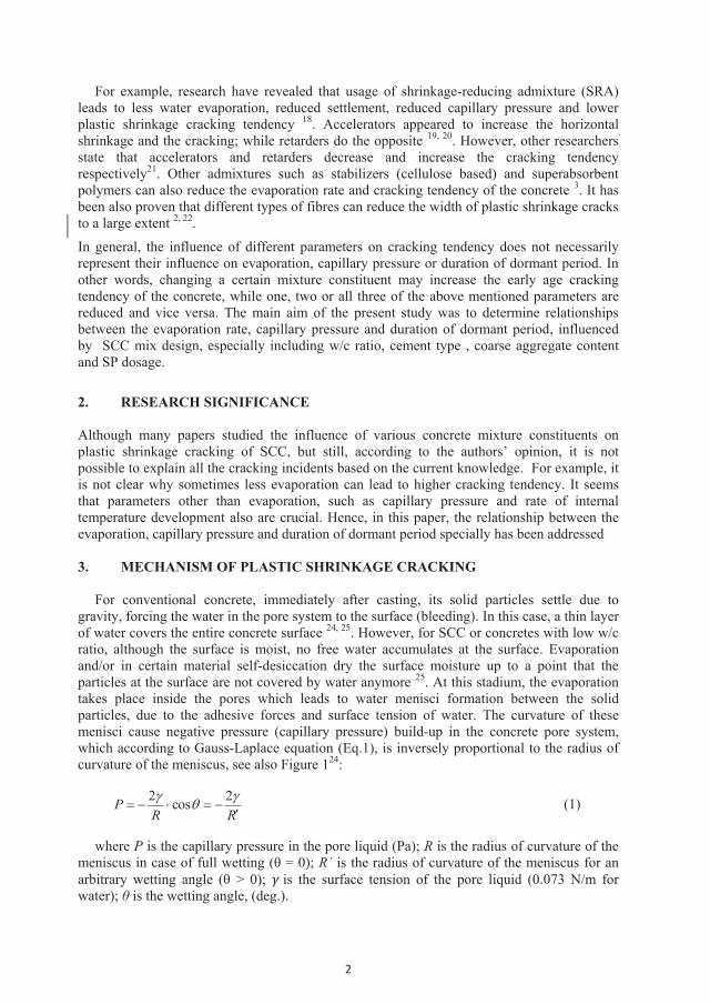
2
For example, research have revealed that usage of shrinkage-reducing admixture (SRA) leads to less water evaporation, reduced settlement, reduced capillary pressure and lower plastic shrinkage cracking tendency 18. Accelerators appeared to increase the horizontal shrinkage and the cracking; while retarders do the opposite 19, 20. However, other researchers state that accelerators and retarders decrease and increase the cracking tendency respectively21. Other admixtures such as stabilizers (cellulose based) and superabsorbent polymers can also reduce the evaporation rate and cracking tendency of the concrete 3. It has been also proven that different types of fibres can reduce the width of plastic shrinkage cracks to a large extent 2, 22.
In general, the influence of different parameters on cracking tendency does not necessarily represent their influence on evaporation, capillary pressure or duration of dormant period. In other words, changing a certain mixture constituent may increase the early age cracking tendency of the concrete, while one, two or all three of the above mentioned parameters are reduced and vice versa. The main aim of the present study was to determine relationships between the evaporation rate, capillary pressure and duration of dormant period, influenced by SCC mix design, especially including w/c ratio, cement type , coarse aggregate content and SP dosage.
2. RESEARCH SIGNIFICANCE Although many papers studied the influence of various concrete mixture constituents on plastic shrinkage cracking of SCC, but still, according to the authors’ opinion, it is not possible to explain all the cracking incidents based on the current knowledge. For example, it is not clear why sometimes less evaporation can lead to higher cracking tendency. It seems that parameters other than evaporation, such as capillary pressure and rate of internal temperature development also are crucial. Hence, in this paper, the relationship between the evaporation, capillary pressure and duration of dormant period specially has been addressed 3. MECHANISM OF PLASTIC SHRINKAGE CRACKING
For conventional concrete, immediately after casting, its solid particles settle due to gravity, forcing the water in the pore system to the surface (bleeding). In this case, a thin layer of water covers the entire concrete surface 24, 25. However, for SCC or concretes with low w/c ratio, although the surface is moist, no free water accumulates at the surface. Evaporation and/or in certain material self-desiccation dry the surface moisture up to a point that the particles at the surface are not covered by water anymore 25. At this stadium, the evaporation takes place inside the pores which leads to water menisci formation between the solid particles, due to the adhesive forces and surface tension of water. The curvature of these menisci cause negative pressure (capillary pressure) build-up in the concrete pore system, which according to Gauss-Laplace equation (Eq.1), is inversely proportional to the radius of curvature of the meniscus, see also Figure 124:
RRP 2cos2
(1)
where P is the capillary pressure in the pore liquid (Pa); R is the radius of curvature of the meniscus in case of full wetting (θ = 0); R´ is the radius of curvature of the meniscus for an arbitrary wetting angle (θ > 0); is the surface tension of the pore liquid (0.073 N/m for water); θ is the wetting angle, (deg.).
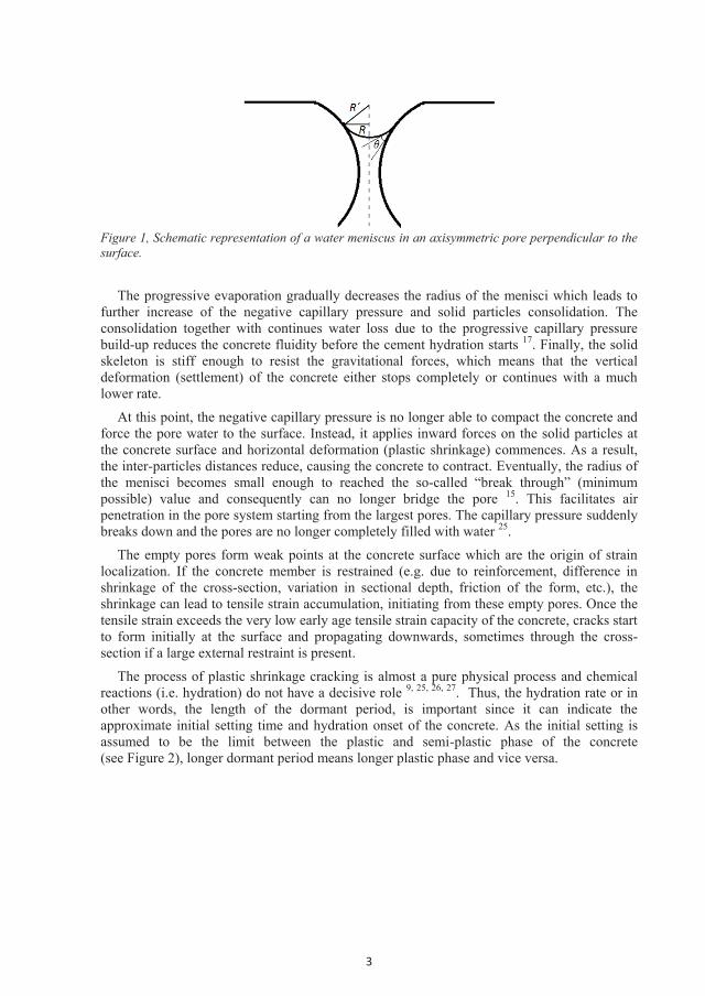
3
Figure 1, Schematic representation of a water meniscus in an axisymmetric pore perpendicular to the surface.
The progressive evaporation gradually decreases the radius of the menisci which leads to further increase of the negative capillary pressure and solid particles consolidation. The consolidation together with continues water loss due to the progressive capillary pressure build-up reduces the concrete fluidity before the cement hydration starts 17. Finally, the solid skeleton is stiff enough to resist the gravitational forces, which means that the vertical deformation (settlement) of the concrete either stops completely or continues with a much lower rate.
At this point, the negative capillary pressure is no longer able to compact the concrete and force the pore water to the surface. Instead, it applies inward forces on the solid particles at the concrete surface and horizontal deformation (plastic shrinkage) commences. As a result, the inter-particles distances reduce, causing the concrete to contract. Eventually, the radius of the menisci becomes small enough to reached the so-called “break through” (minimum possible) value and consequently can no longer bridge the pore 15. This facilitates air penetration in the pore system starting from the largest pores. The capillary pressure suddenly breaks down and the pores are no longer completely filled with water 25.
The empty pores form weak points at the concrete surface which are the origin of strain localization. If the concrete member is restrained (e.g. due to reinforcement, difference in shrinkage of the cross-section, variation in sectional depth, friction of the form, etc.), the shrinkage can lead to tensile strain accumulation, initiating from these empty pores. Once the tensile strain exceeds the very low early age tensile strain capacity of the concrete, cracks start to form initially at the surface and propagating downwards, sometimes through the cross-section if a large external restraint is present.
The process of plastic shrinkage cracking is almost a pure physical process and chemical reactions (i.e. hydration) do not have a decisive role 9, 25, 26, 27. Thus, the hydration rate or in other words, the length of the dormant period, is important since it can indicate the approximate initial setting time and hydration onset of the concrete. As the initial setting is assumed to be the limit between the plastic and semi-plastic phase of the concrete (see Figure 2), longer dormant period means longer plastic phase and vice versa.

4
Figure 2, Schematic representation of different phases of concrete based on the early-age deformation and the corresponding heat evolution, based on 21. 4. MATERIALS AND METHODS 4.1 Materials and mixing process
The mix design of the tested concretes and composition of the cements are shown in Tables 1 and 2 respectively. Two reference concretes (Ref.1 with 0.45 w/c ratio and Ref.2 with 0.67 w/c ratio) were produced. Portland cement type CEM II/A-LL 42.5R (Byggcement) containing 6-20 wt% of limestone was used. In both reference concretes 60 wt% of crushed fine aggregates (0-4 mm and 0-8 mm) and 40 wt% of mixed natural/crushed coarse (8-16 mm) aggregates were used. Also, a polycarboxylate ether based SP (Sikament 56) with density of 1100 kg/m3 and 37 wt% of dry content and mineral filler (Limus 40) with density of 2700 kg/m3 were used. The slump flow of Ref.1 and Ref.2 were 600 mm and 670 mm, respectively.
All the components were stored at the same temperature at which concrete mixing took place (20±1 ˚C). The aggregates, filler and cement were premixed in a pan type mixer for one minute before the water and SP were added. Then, mixing continued for five more minutes. All the concrete mixtures were produced and tested twice to ensure reproducibility.
Four concrete mixtures with four w/c ratios (W/C 0.38, W/C 0.45, W/C 0.55 and W/C0.67) were tested (according to Table 1). Concrete mix Ref.1 having the w/c ratio of 0.45 was used to study the influence of coarse aggregate content; whereas the effect of cement type and SP dosage was studied on concrete mix Ref.2 having w/c ratio of 0.67. The 40% coarse aggregate content of Ref.1 was reduced to 35% in mix CC35%, in order to study its influence. The effect of SP dosage was investigated by changing its portion from 0.8% of cement weight in Ref.2 to 0.6% and 1.0% of cement weight in SP0.6% and SP1.0% respectively. Moreover, the cement type used in Ref.2 (CEM II/A-L 42.5R) was substituted by two other cements (CEM I 42.5N and CEM I 52.5R), according to Table 2, without changing the mix design.

5
Table 1, mix design of tested SCCs (W/C = Water-cement ratio, Ref = Reference concrete, CC = Coarse aggregate content, SP = Superplasticizer) in kg/m3. Name W/C 0.38 W/C 0.45
(Ref.1) W/C 0.55 W/C 0.67 (Ref.2)
SP0.6% (Ref 2)
SP1.0% (Ref 2)
CC35% (Ref 1)
Cement (Table 2) 420 380 340 300 300 300 380 Water 160 171 187 200 200 200 171 Agg. 0-4 0 0 81 155 155 155 0 Agg. 0-8 1021 998 879 771 771 771 1089.4 Agg. 8-16 694 678 651 628 628 628 586.6 Filler (Limus 40) 40 100 160 220 220 220 100 SP (Sikament 56) 4.6 5.7 4.1 2.4 1.8 3 5.7 W/C 0.38 0.45 0.55 0.67 0.67 0.67 0.45 Table 2, composition of the utilized cements (manufactured by Cementa AB, Sweden). Name MgO
(%) SO3 (%)
CI-
(%) C3A (%)
NA2O (%)
Density (kg/m3)
Blaine (m2/kg)
CEM II/A-LL 42.5R (Byggcement) 1.1-1.3 3.3-4.0 0.02-0.04 - - 3080 430 CEM I 42.5N (Anläggningscement) 1.2-1.5 2.3-2.5 0.01-0.03 1.3-2.7 0.48-0.58 3200 310 CEM I 52.5R (SH-cement) 1.1-1.3 3.3-4.0 0.02-0.04 - - 3125 550 4.2 Method
The ring test (NORDTEST-method NT BUILD 433) used in this research was developed earlier by Johansen and Dahl at NTNU (1993) 28. The method is intended to determine the influence of mixture constituents on the cracking potential of fresh concrete at a “macro” level. It consists of three identical moulds with two concentric steel rings in each. The depth of each mould is 80 mm and the diameters of the inner and outer rings are 300 and 600 mm respectively. To provide crack initiation points, steel ribs (stress raisers) are attached to the rings, see Figure 3.
After casting of the concrete between the rings, the mould was covered with a transparent air funnel attached to a suction fan, giving 4.5 m/s wind velocity across the concrete surface. During this particular investigation, the ambient temperature and relative humidity were 20 ± 1˚C and 35 ± 3% respectively. The weight loss (i.e. the evaporation), capillary pressure and internal temperature were recorded continually.
One of the three specimens was placed on three load-cells (scales) in order to measure the water evaporation per second. During these experiments, the capillary pressure was measured at 15 s intervals by means of two wireless capillary pressure sensors filled with degassed water, which were inserted vertically, down to 4 cm distance from the concrete surface right after casting. The internal temperature was recorded in 1 s intervals with a thermo thread located at 2 cm distance from the bottom of the mould. All the measurements start 60 minutes after the castings and were finished 18 hours later.
The concrete surface in all three specimens was visually inspected every 30 minutes in order to determine possible time of crack initiation. The crack width and the crack length were measured by a digital microscope (to an accuracy of 0.05 mm) and a digital measuring wheel (to an accuracy of ±1 mm) respectively. The average crack area is then calculated, as suggested by Esping and Löfgren 21using equation (2):
3)( widthcracklengthcrackareacrackAverage (2)
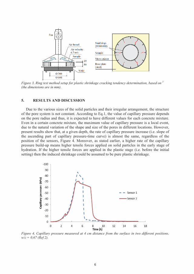
6
Figure 3, Ring test method setup for plastic shrinkage cracking tendency determination, based on 3 (the dimensions are in mm). 5. RESULTS AND DISCUSSION
Due to the various sizes of the solid particles and their irregular arrangement, the structure of the pore system is not constant. According to Eq.1, the value of capillary pressure depends on the pore radius and thus, it is expected to have different values for each concrete mixture. Even in a certain concrete mixture, the maximum value of capillary pressure is a local event, due to the natural variation of the shape and size of the pores in different locations. However, present results show that, at a given depth, the rate of capillary pressure increase (i.e. slope of the ascending part of capillary pressure-time curve) is almost the same, regardless of the position of the sensors, Figure 4. Moreover, as stated earlier, a higher rate of the capillary pressure build-up means higher tensile forces applied on solid particles in the early stage of hydration. If the higher tensile forces are applied in the plastic stage (i.e. before the initial setting) then the induced shrinkage could be assumed to be pure plastic shrinkage.
Figure 4, Capillary pressure measured at 4 cm distance from the surface in two different positions, w/c = 0,67 (Ref 2).

7
5.1 Influence of w/c ratio
The results show that, the total evaporation increases with a higher w/c ratio, Figure 5a. However, the largest average crack area was measured in W/C 0.67, followed by W/C 0.38, W/C 0.55 and W/C 0.45, Figure 5b. Evidently, this obviously does not represent the evaporation trend. Also, the significant difference between the average crack area of W/C 0.67 and the other mixes cannot be explained based on the evaporation solely. Instead, it can possibly be related to the rate of capillary pressure build-up (Figure 5c) and the length of dormant period of each mixture (Figure 5d).
In the concrete with low w/c ratio (W/C 0.38), a lower evaporation means that the radius of the curvature of the menisci in the pores decreases slower, which seems to lead to a somewhat lower rate of capillary pressure build-up (Figure 5c). However, the shorter dormant period (i.e. rapid hydration) (Figure 5d) is an indication of faster stiffening of the concrete skeleton. This implies that the reduction of the menisci radius is no longer compensated by the inward movement of the particles at the pore wall. Instead the reduction of the menisci radius is accelerated which in turn, increases the capillary pressure build-up rate to be almost the same as the other concretes. Moreover, taking the late crack initiation time of W/C 0.38 into account (Figure 5b); it seems that the shrinkage and cracking of SCCs with low w/c ratios is mainly related to the autogenous deformation. This agrees to a large extent with the results of experiments performed by Esping and Löfgren 21.
Furthermore, by increasing the w/c ratio, the cooling effect of the higher evaporation slows down the hydration, i.e. longer dormant period (Figure 5d). The reduction of the capillary pressure build-up rate is then compensated with a higher rate of pore water evaporation (see W/C 0.45 and W/C 0.55 in Figure 5a).
Figure 5, influence of w/c ratio on (a) evaporation, (b) average crack area and time of crack initiation, (c) capillary pressure and (d) internal temperature.
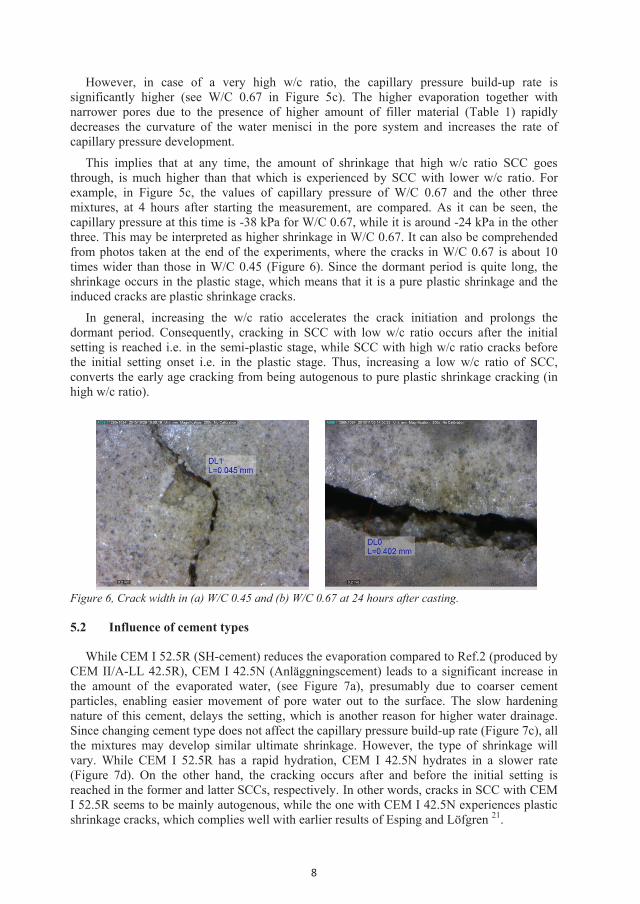
8
However, in case of a very high w/c ratio, the capillary pressure build-up rate is significantly higher (see W/C 0.67 in Figure 5c). The higher evaporation together with narrower pores due to the presence of higher amount of filler material (Table 1) rapidly decreases the curvature of the water menisci in the pore system and increases the rate of capillary pressure development.
This implies that at any time, the amount of shrinkage that high w/c ratio SCC goes through, is much higher than that which is experienced by SCC with lower w/c ratio. For example, in Figure 5c, the values of capillary pressure of W/C 0.67 and the other three mixtures, at 4 hours after starting the measurement, are compared. As it can be seen, the capillary pressure at this time is -38 kPa for W/C 0.67, while it is around -24 kPa in the other three. This may be interpreted as higher shrinkage in W/C 0.67. It can also be comprehended from photos taken at the end of the experiments, where the cracks in W/C 0.67 is about 10 times wider than those in W/C 0.45 (Figure 6). Since the dormant period is quite long, the shrinkage occurs in the plastic stage, which means that it is a pure plastic shrinkage and the induced cracks are plastic shrinkage cracks.
In general, increasing the w/c ratio accelerates the crack initiation and prolongs the dormant period. Consequently, cracking in SCC with low w/c ratio occurs after the initial setting is reached i.e. in the semi-plastic stage, while SCC with high w/c ratio cracks before the initial setting onset i.e. in the plastic stage. Thus, increasing a low w/c ratio of SCC, converts the early age cracking from being autogenous to pure plastic shrinkage cracking (in high w/c ratio).
Figure 6, Crack width in (a) W/C 0.45 and (b) W/C 0.67 at 24 hours after casting. 5.2 Influence of cement types
While CEM I 52.5R (SH-cement) reduces the evaporation compared to Ref.2 (produced by CEM II/A-LL 42.5R), CEM I 42.5N (Anläggningscement) leads to a significant increase in the amount of the evaporated water, (see Figure 7a), presumably due to coarser cement particles, enabling easier movement of pore water out to the surface. The slow hardening nature of this cement, delays the setting, which is another reason for higher water drainage. Since changing cement type does not affect the capillary pressure build-up rate (Figure 7c), all the mixtures may develop similar ultimate shrinkage. However, the type of shrinkage will vary. While CEM I 52.5R has a rapid hydration, CEM I 42.5N hydrates in a slower rate (Figure 7d). On the other hand, the cracking occurs after and before the initial setting is reached in the former and latter SCCs, respectively. In other words, cracks in SCC with CEM I 52.5R seems to be mainly autogenous, while the one with CEM I 42.5N experiences plastic shrinkage cracks, which complies well with earlier results of Esping and Löfgren 21.

9
Hence, it can be comprehended that when the capillary pressure build-up rate is equal, the SCC with the higher evaporation and longer dormant period is the most prone to plastic shrinkage cracking.
Figure 7, influence of cement type on (a) evaporation, (b) average crack area and time of crack initiation, (c) capillary pressure and (d) internal temperature.
5.3 Influence of coarse aggregate contents
Although decreasing the coarse aggregate content from 40% to 35% decreases the total evaporation, the initial evaporation is increased up to around 5 hours after casting, Figure 8a. The average crack area, on the other hand, increases significantly in comparison to the concrete with higher coarse aggregate content, see Figure 8b. Finer pore structure due to the higher packing, accompanied with higher initial evaporation increases the rate of capillary pressure build-up (Figure 8c).
Since the duration of dormant period is not affected by the coarse aggregate content (Figure 8d), and the crack initiation is accelerated (Figure 8b), reducing the amount of the coarse aggregate in SCC leads to more plastic shrinkage and higher cracking risk. Here, high initial evaporation (in the first 5 hours) is combined with high capillary pressure build-up rate and relatively short dormant period.

10
Figure 8, influence of coarse aggregate content on (a) evaporation, (b) average crack area and time of crack initiation, (c) capillary pressure and (d) internal temperature. 5.4 Influence of SP amount
Increasing the SP dosage in Ref.2, increased the evaporation rate, due to the prolonged setting time (Figures 9a and 9d), while reducing it has the opposite effect. The average crack area is increased and decreased for higher and lower the SP dosage, respectively (Figure 9b). The prolonged dormant period in the case of a high SP dosage, facilitates the water transportation to the surface, causing a slower capillary pressure build-up (Figure 9c). Exactly the opposite occurs when the amount of the SP is reduced.
The cracking appeared to be initiated before the initial setting time was reached (see Figures 9b and 9d). The results showed that SP does not affect the type of the early-age crack inducing phenomenon i.e. plastic or autogenous shrinkage. By adjusting the amount of SP in SCC, the concrete will still start to crack in the plastic stage.
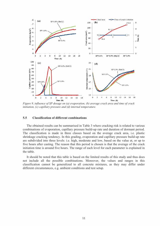
11
Figure 9, influence of SP dosage on (a) evaporation, (b) average crack area and time of crack initiation, (c) capillary pressure and (d) internal temperature. 5.5 Classification of different combinations
The obtained results can be summarised in Table 3 where cracking risk is related to various combinations of evaporation, capillary pressure build-up rate and duration of dormant period. The classification is made in three classes based on the average crack area, i.e. plastic shrinkage cracking tendency. In this grading, evaporation and capillary pressure build-up rate are subdivided into three levels: i.e. high, moderate and low, based on the value at, or up to five hours after casting. The reason that this period is chosen is that the average of the crack initiation time is around five hours. The range of each level for each parameter is explained in the table.
It should be noted that this table is based on the limited results of this study and thus does not include all the possible combinations. Moreover, the values and ranges in this classification cannot be generalized to all concrete mixtures, as they may differ under different circumstances, e.g. ambient conditions and test setup.

12
Table 3, cracking tendency classification based on combinations of evaporation, capillary pressure build-up rate and duration of dormant period, in this test series.
LDP MDP SDP HE ME LE HE ME LE HE ME LE
HCPR 3 - - - 2 / 3 - 3 - - MCPR 3 - - - - - - 1 / A - LCPR - 1 - - - - - 1 A
SDP: Short Dormant Period (< 4 hours) MDP: Moderate Dormant Period (4-6 hours) LDP: Long Dormant Period (6 hours <) LE: Low Evaporation (< 3 kg/m2) ME: Moderate Evaporation (3-3.5 kg/m2) HE: High Evaporation (3.5 kg/m2 <) LCPR: Low Capillary Pressure build-up rate
between 3 to 5 hours (< 27 kPa) MCPR: Moderate Capillary Pressure build-up
rate between 3 to 5 hours (27-30 kPa) HCPR: High Capillary Pressure build-up rate
between 3 to 5 hours (30 kPa <)
1: Low cracking tendency (< 30 mm2) 2: Moderate cracking tendency (30-60 mm2) 3: High cracking tendency (60 mm2 <) A: Autogenous shrinkage cracking - : No data is available.
6. CONCLUSIONS
Plastic shrinkage cracking is a complex interaction of several variables that may change under different circumstances and conditions at the very early ages. These variables have a direct influence on the evaporation, capillary pressure build-up rate and the duration of dormant period. Based on the results of this study, the following concluding remarks can be listed:
High capillary pressure build-up rate accompanied by high or moderate evaporation and
long, moderate or short dormant period appeared to be the most influential combinations that significantly increase the risk of plastic shrinkage cracking.
Low capillary pressure build-up rate together with moderate evaporation, regardless of the duration of the dormant period, significantly decreases the plastic shrinkage.
Increasing the w/c ratio in SCC, converts the early age cracking from autogenous to pure plastic shrinkage cracking.
Protecting concretes with high w/c ratios against evaporation reduces the risk of plastic shrinkage cracking significantly.
Cracks in SCC produced using fine rapid hydrating cements are mainly related to autogenous shrinkage, while those containing coarse slow hydrating cements to plastic shrinkage.
Reducing the amount of the coarse aggregates in SCC accelerates the crack initiation which means that it is more plastic shrinkage governed cracking.
SP decreases the capillary pressure build-up rate, delays the hydration and increases the evaporation. Concretes with higher SP (Sikament 56) dosage are more prone to plastic shrinkage cracking, despite of the slower capillary pressure development.
Protecting the concrete with high SP (Sikament 56) dosage against evaporation is an effective way to prevent plastic shrinkage cracking.

13
7. FUTURE RESEARCH
Based on the results, it is suggested to include both vertical and horizontal deformation measurement in any future research. Investigating the influence of the tested constituents on bleeding can also be an interesting and essential addition as well as changing the ambient conditions. More experiments are needed in order to fill the blank cells in Table 3. Moreover, it is of highly focus to examine the feature of the mixtures in half- and/or full-scale conditions. ACKNOWLEDGMENT
The authors would like to gratefully appreciate the financial support they received from the Development Fund of the Swedish Construction Industry, SBUF. Special thanks are also due to the student members of Civil Engineers on Tour (CET 2016) and staff of Complab at Luleå University of Technology. REFERENCES 1. Boshoff WP, Combrinck R. Modelling the severity of plastic shrinkage cracking in concrete. Cem Concr Res
2013 JUN;48:34-9. 2. Sivakumar A, Santhanam M. Experimental methodology to study plastic shrinkage cracks in high strength
concrete. In: Measuring, monitoring and modeling concrete properties. Springer; 2006. . 3. Löfgren I., Esping O., Early age cracking of self-compacting concrete. International RILEM conference on
volume changes of hardening concrete: Testing and mitigation”, lyngby; 2006. . 4. Plastic shrinkage. ACI journal proceedingsACI; 1957. . 5. Plastic shrinkage cracking. ACI journal proceedingsACI; 1968. . 6. Plastic shrinkage cracking of concrete. Proceeding: RILEM international symposium of concrete and
reinforced concrete in hot countries; 1971. . 7. Tensile properties of early-age concrete. Proceedings of conference on mechanical behaviour of materials.;
1972. . 8. Cohen MD, Olek J, Dolch WL. Mechanism of plastic shrinkage cracking in portland cement and portland
cement-silica fume paste and mortar. Cem Concr Res 1990 1;20(1):103-19. 9. Radocea A. A study on the mechanism of plastic shrinkage of cement-based materials. Chalmers University of
Technology,; 1992. . 10. Almusallam A, Abdul-Waris M, Maslehuddin M, Al-Gahtani A. Placing and shrinkage at extreme
temperatures. Concr Int 1999;21(1). 11. ACI D. 305R-hot weather concreting. American Concrete Institute International 1999. 12. Qi C, Weiss J, Olek J. Characterization of plastic shrinkage cracking in fiber reinforced concrete using image
analysis and a modified weibull function. Mater Struct 2003;36(6):386-95. 13. Josserand L, Coussy O, de Larrard F. Bleeding of concrete as an ageing consolidation process. Cem Concr
Res 2006;36(9):1603-8. 14. Dao V, Dux P, Morris P, O'Moore L. Plastic shrinkage cracking of concrete. Australian Journal of Structural
Engineering 2010;10(3):207. 15. Slowik V, Schmidt M. Early age cracking and capillary pressure controlled concrete curing. 2010. 16. Schmidt M, Slowik V. Instrumentation for optimizing concrete curing. Concr Int 2013;35(8). 17. Uno PJ. Plastic shrinkage cracking and evaporation formulas. ACI Mater J 1998;95:365-75. 18. Lura P, Pease B, Mazzotta GB, Rajabipour F, Weiss J. Influence of shrinkage-reducing admixtures on
development of plastic shrinkage cracks. ACI Mater J 2007;104(2):187. 19. Combrinck R, Boshoff WP. Typical plastic shrinkage cracking behaviour of concrete. Magazine of Concrete
Research 2013;65(8):486-93. 20. Kronlöf A, Leivo M, Sipari P. Experimental study on the basic phenomena of shrinkage and cracking of
fresh mortar. Cem Concr Res 1995;25(8):1747-54. 21. Investigation of early age deformation in self-compacting concrete. Proceedings of the 2nd international
symposium on advances in concrete science, quebec.(note, attached paper V in this thesis); 2006. . 22. P Fontana, S Pirskawetz, P Lura, Plastic shrinkage cracking risk of Concrete–Evaluation of test methods. 7th
RILEM international conference on cracking in pavementsSpringer; 2012.
14
23. Leemann A, Nygaard P, Lura P. Impact of admixtures on the plastic shrinkage cracking of self-compacting concrete. Cement and Concrete Composites 2014;46:1-7.
24. Sayahi F, Emborg M, Hedlund H. Plastic shrinkage cracking in concrete: State of the art. 2014;51(3):95-16. 25. Slowik V, Schmidt M, Fritzsch R. Capillary pressure in fresh cement-based materials and identification of
the air entry value. Cement and Concrete Composites 2008;30(7):557-65. 26. Evaporation, settlement, temperature evolution, and development of plastic shrinkage cracks in mortars with
shrinkage-reducing admixtures. Int. RILEM-JCI seminar on concrete durability and service life planning (ConcreteLife'06); 2006. .
27. Wittmann F. On the action of capillary pressure in fresh concrete. Cem Concr Res 1976;6(1):49-56. 28. Control of plastic shrinkage of cement. 18th conference on our world in concrete and structures, singapore;
1993. .

