faculty of engineering - near east universitydocs.neu.edu.tr/library/6071573860.pdf · design an...
TRANSCRIPT

111111m1111111111111rn111111111111111111111111111111,1111111u1m11•··
Faculty of Engineering
Department of Electric and Electronic Engineering
Electrical Installation
Graduation Project
EE400
Students: Ali Say (20033689) & Cihat Direk (20032292)
Supervisor: Ozgur Ozerdem
Nicosia - 2008

·------ 15 15 15 15 15 16 16 16 16 16 16 16 17 17 18 19 21 21 22 22
1 Introduction
CHAPTER-I LIGHTNING 2-15
1.1- Filaments Lamp 1.1.1-Coiled-Coil Lamp 1.1.2-Effect of Voltage Variation
. 1.1.3-Bulb-Fimsh 1.1.4-Reflector Lamps 1.1.5-Tungsten Halogen Lamps 1.2-Discharge Lamp 1.2.1-Cold Cathode Lamp 1.2.2-Hot Cathode Lamp 1.3-Ultra Violet Lamp 1.4-Flourescent Lamp 1.4.1-Electrical Aspects of Operations 1.4.2-Advantages 1.4.3-Disadvantages 1.4.3.1-Ballast 1.4.3.2-Power Factor 1.4.3.3-Power Harmonics 1.4.3.4-0ptimum Operatmg Temoerature 1.4.3.5-Dimming
2 3 3 3 4 4 5 5 6 10 12 12 13 13 14 14 14 14 14
CHAPTER-2 TYPES OF CiRCuiT BREAKER 15-45
2.1-MCCB 2.1.1-Applications 2.1.2-Mechanism 2.1.3-Material 2.1.4-Accessories 2.1.5-The Technology of Tripping Devices 2.1.5.1-MCCB Arc Chamber 2.1.5.2-Fixed Contact 2.1.5.3-Materials 2.1.5.4-Repulsive Force 2.1.5.5-Time Delay Operation 2.1.5.6-Proper MCCB for Protection 2.1.5.7-Nominal Current 2.1.5.8-Fault Current Icu,Ics 2.2-MCB 2.3-RCD 2.3.1-Main Characteristics 2.3.2-Number of Poles[2p,3p or 4p] 2.3.3-Rated Rurrent 2.3.4-Sensitivity

2.3.5-Type [AC or A or B] 22
2.3.6-Break Time [in ms] 23
2.3.7-Surge Current Resistance 24
2.4-Contactor 24
2.4.1-Construction 24
2.4.2-0perating Principle 25
2.4.3-Ratings 26
2.5-MDRC 27
2.5.1-Technical Properties 27
2.5.2-Wiring Diagram 28
2.5.3-12 Channel 10 Amp Adaptive 29
2.5.3.1-Source Controller 30
2.5.3.1.1-Features 30
2.5.3.1.2-0verview 30
2.5.3.1.3-Electrical 31
2.5.3.1.4-Load Types 31
2.5.3.1.5-Dimmed Outputs 31
2.5.3.1.6-Terminal Size 31
2.5.3.1.7-Memory 32
2.5.3.1.8-Mechanical 32
2.5.3.1.9-Climate Range 32
2.5.3.1.10-Control Inputs 32
2.5.4- 4 Channel 10 Amp Adaptive 33
2.5.4.1-Source Controller 33
2.5.4.1.1-Features 33
2.5.4.1.2-0verview ----- 34
2.5.4.1.3-Mechanical 34
2.5.4.1.4-Control Inputs 34
2.5.4.1.5-Electrical 34
2.5.4.1.6-0ptions 34
2.5.4.1.7-Load types 35
2.5.4.1.8-Dimmed Outputs 35
2.5.4.1.9-Switched Outputs 35
2.5.4.1.10-Terminal Size 35
2.5.4.1.11-Memory 35
2.5.5-Classic Series Control Panels 36
2.5.5.1-Features 36
2.5.5.2-0verview 37
2.5.5.3-Technival Specification 37
2.5.5.3.1-Mechanical 37
2.5.5.3.2-Electrical Data 38
2.5.5.3.3-Memory 38
2.6-Mini Touch Screen 39
2.6.1-0verview 39
2.6.2-Features 40
2.6.3-Technical Specification 40

2.6.3.1-Mechanical 2.6.3.2-Control Inputs 2.6.3.3-Memory 2.6.3.4-Electrical Data
40 40 40 41
CHAPTER-3 SWiTCHES,SOCKETS AND BUTTONS 42-45
3.1-Switches 3.1.1-single key 3.1.2-commutator 3.1.3-vaevien 3.1.4-Well hole switches 3.2-Sockets 3.3-Buttons
42 42 42 42 43 43 44
CHAPTER-4 CONDUCTORS AND CABLES 45-56
4.1-Conductors 4.2-Insulators 4.2.1-Rubber 4.2.2-85°C Rubber 4.2.3-Silicone rubber 4.2.4-PVC 4.2.5-Paper 4.2.6-Mmeral Insulation 4.2.6.1-Gas insulation 4.3-Cables 4.3.1-Smgle Core 4.3.2-Two core 4.3.3-Three Core 4.3.4-Composite Cables 4.3.5-Wiring Cables 4.3.6-Power Cables 4.3.7-Mining Cables 4.3.8-Ship-Wiring Cables 4.3.9-0ver Head Cables 4.3.11-Communication Cables 4.3.12-Welding Cables 4.3.13-Electric Sign Cables 4.3.14-Equipment Wires 4.3.15-Appliance-Wiring Cables 4.3.16-Heating Cables 4.3.17-Flexible Cords 4.3.18-Twin-Twisted 4.3.19-Three-Core (Twisted) 4.3.20-Twin-Circular
46 48 48 49 49 49 50 50 50 50 51 51 51 52 52 52 52 52 53 53 53 53 53 53 54 54 54 54 54

4.3.21-Three Core (Circular) 55 4.3.22-Four Core (Circular 55 4.3.23-Parallel Twin 55 4.3.24-Twin Core (Flat) 55 4.3.25-Flexible Cables 55
CHAPTER-5 EARTHiNG 56-60
CHAPTER-6 VOLTAGE DROP 60-63
6.1-Voltage Drop in Direct Current Circuits 60 6.2-Voltage Drop in Alternating Current Circuits 61 6.3-Voltage Drop in Household Wiring 61
CHAPTER-7 POWER FACTOR CORRECTiON 63-70
CHAPTER-8 DiMMER BANK 70-80
CHAPTER-9 CALCULA TiONS OF iLLUMiNATiON,POWER,CURRENT,VOLTAGE DROP AND TOTAL 81-144 iNVETMENT

'"'!!!1111111111111111"1111111111111111111111111111111!!,IIII L!!""'"'
ACKNOWLEGMENT
Firstly we are glad to express our thanks to those who have role in our education
during four year Undergraduate program in Near East University.
Secondly we would like to thank Mr.Ozgur Cemal OZERDEM for giving his time
and encouragement for the entire graduation project.He has given his support which is the
main effect in our succes.
Finally, I would like to express our thanks to Mr. Cemal KA VALCIOGLU for his
able guidance and useful suggestions, and also our friends/classmates for their help and
wishes for the successful completion of this project.

ABSTRACT
In the present day we have a branch for engineering as illumination enginnering.
So we can understant the importance of the illumination.For satisfying the consumer
requirements, electrical installation should be well designed and applied with a
Professional knowledge, because in the present day when we are choosing an armature
we are not looking only to its watt value.We are considering the lumen of the lamp the
type and design of the armature if its suitable or not for the Project, and sometimes the
working temperature.
Our Project is about the electrical installation of an international bank, and this
Project needs well knowledge about electrical installation and also researching the
present systems.This Project consist the installation of lighting circuits,the installation of
sockets,the aircondition,telephone and data sockets and a local compensation system

LIST OF ABBREVIATIONS
MCB Miniature Circuit Breaker
MDRC Modular DIN Rail mounted Devices
RCD Residual-current Devices
RCBO Residual-current Breakers with Overcurrent Protection
cu Consumer Unit
MCCB Moulded Case Circuit Breakers Ii,""':
BMC Bold Moulded Compound
AUX Auxiliary
UVT Undervoltage Release
ST Shunt Trip
AS Alarm Switch
PIK Plug in Kit
RH Rotary Handle
MOD Motor Operating Mechanism
PFC Power factor Correction

INTRODUCTION
Design an electrical installation project, in most efficient way,is one of the
essential subject in ~lectrical Engineering.This is taken into consideration in our project.
In this project all the related,electrical installation and some rules designing will
be shown according priority.
Chapter one gives information abotut types of lamps and advantages of
flourescent lamp and dis advantages of it
Chapter two gives information about type of circuit breaker
(mcb,mccb,rscd,mdrc,contactor,and aparatus) and technical details of them
Chapter three gives information about types of switches,sockets and buttons
Chapter four gives informatin about conductors and cables
1
Cahapter five based on earting and techniques
Chapter six and seven are devoted to two essential subjects.In these chapters
'Voltage Drop and Power Factor Correction' one cowered in daily applications.
Cahapter eight based on dimmer bank and gives information abotut operating
principle and technical aparatus
Chapter nine is composed of the entire calculations in the project.The calculations
are illumination, power,current,voltage drop, calculations and also 'Total Investment' is
reff ered in this chapter.
The conclusion presents useful pointsand important results obtained from the
theory and also comment belong to the students who preparedthe Project.

1-LIGHTING
Lighting plays a most important role in many buildings, not only for functional
purposes (simply supplying light) but to enhance the environment and surroundings.
Modem offices, shops, factories, shopping malls, department stores, main roads, football
stadium, swimming pools - all these show not only the imagination of architects and
lighting engineers but the skills of the practising electrician in the installation of
luminaries.
Many sources of light are available today with continual improvements in lighting
efficiency and colour of light.
Lm: This is a unit of luminous flux or (amount of light) emitted from a source.
Luminous efficacy: This denotes the amount of light produced by a source for
the energy used; therefore the luminous efficacy is stated in 'lumens per watt' (lm I W).
A number of types of lamps are used today: filament, fluorescent, mercury
vapour, sodium vapour, metal Halide, neon. All these have specific advantages and
applications
I.I-FILAMENT LAMPS
Almost all filament lamps for general lighting service are made to last an average
of at least 1000 hours. This does not imply that every individual lamp will do so, but that
the short-life ones will be balanced by the long-life ones; with British lamps the precision
and uniformity of manufacture now ensures that the spread of life is small, most
individual lamps in service lasting more or just less than 1000 hours when used as they
are intended to be used.
In general, vacuum lamps, which are mainly of the tubular and fancy shapes, can
be used in any position without affecting their performance. The ordinary pear-shaped
2

gas filled lamps are designed to be used in the cap-up position in which little or no
blackening of the bulb becomes apparent in late life. The smaller sizes, up to 150 W, may
be mounted horizontally or upside-down, but as the lamp ages in these positions the bulb
becomes blackened immediately above the filament and absorbs some of the light. Also
vibration may have a more serious effect on lamp life in these positions Over the 150 W
size, burning in the wrong position leads to serious shortening of life.
1.1.1-Coiled - Coil lamps:
By double coiling of the filament in a lamp of given wattage a longer and thicker
filament can be employed, and additional light output is obtained from the greater surface
area of the coil, which is maintained at the same temperature thus avoiding sacrificing
life. The extra light obtained varies from 20 % in the 40 W size to 10 % in the 100 W
size.
1.1.2-Effect of voltage variation:
Filament lamps are very sensitive to voltage variation. A 5 % over-voltage halves
lamp life due to over-running of the filament. A 5% under-voltage prolongs lamp life but
leads to the lamp giving much less than its proper light output while still consuming
nearly its rated wattage. The rated lamp voltage should correspond with the supply
voltage. Complaints of short lamp life very often arise directly from the fact that mains
voltage is on the high side of the declared value, possibly because the complainant
happens to live near a substation
1.1.3-Bulb finish:
In general, the most appropriate use for clear bulbs is in wattages of 200 and
above in fittings where accurate control of light is required. Clear lamps afford a view of
the intensely bright filament and are very glaring, besides giving rise to hard and sharp
shadows. In domestic sizes, from 150 W downwards, the pearl lamp - which gives equal
light output - is greatly to be preferred on account of the softness of the light produced.
Even better in this respect are silica lamps; these are pearl lamps with an interior coating
of silica powder which completely diffuses the light so that the whole bulb surface
3

appears equally bright, with a loss of 5% of light compared with pearl or clear lamps.
Silica lamps are available in sizes from 40 - 200 W. Double life lamps compromise
slightly in lumen output to provide a rated life of 2,000 hours.
1.1.4-Reflector lamps:
For display purposes reflector lamps are available in sizes of 25W to 150W. They
have an internally mirrored bulb of parabolic section with the filament at its focus, and a
lightly or strongly diffusing front glass, so that the beam of light emitted is either wide or
fairly narrow according to type. The pressed-glass (PAR) type of reflector lamp gives
a good light output with longer life than a blown glass lamp. Since it is made of
borosilicate glass, it can be used out-of-doors without protection
1.1.5- Tungsten halogen lamps:
The life of an incandescent lamp depends on the rate of evaporation of the
filament, which is partly a function of its temperature and partly of the pressure exerted
on it by the gas filling. Increasing the pressure slows the rate of evaporation and allows
the filament to be run at a higher temperature thus producing more light for the same life.
If a smaller bulb is used, the gas pressure can be increased, but blackening of the
bulb by tungsten atoms carried from the filament to it by the gas rapidly reduces light
output. The addition of a very small quantity of a haline, iodine or bromine, to the gas
filling overcomes this difficulty, as near the bulb wall at a temperature of about 300°C
this combines with the free tungsten atoms to form a gas. The tungsten and the haline
separate again when the gas is carried back to the filament by convection currents, so that
the haline is freed the cycle.
Tungsten halogen lamps have a longer life, give more light and are much smaller
than their conventional equivalents, and since there is no bulb blackening, maintain their
colour throughout their lives. Mains-voltage lamps of the tubular type should be operated
within 5 degrees of the horizontal. A lOOOW tungsten halogen lamp gives 21 000 lm and
has a life of 2000 hours. These lamps have all but replaced the largest sizes of g.I.s.
lamps for floodlighting, etc. They are used extensively in the automotive industry. They
4

are also making inroads into shop display and similar areas in the form of 1 v. (12 V.)
Single-ended dichroic lamps.
1.2-DISCHARGE LAMPS
Under normal circumstances, an electric current cannot flow through a gas.
However, if electrodes are fused into the ends of a glass tube, and the tube is slowly
pumped free of air, current does pass through at a certain low pressure. A faint red
luminous column can be seen in the tube, proceeding from the positive electrode; at the
negative electrode a weak glow is also just visible. Very little visible radiation is
obtainable. But when the tube is filled with certains gases, definite luminous effects can
be obtained. One important aspect of the gas discharge is the 'negative resistance
characteristic '. This means that when the temperature of the material (in this case the
gas) rises, its resistance decreases - which is the opposite of what occurs with an 'ohmic'
resistance material such as copper. When a current passes through the gas, the
temperature increases and its resistance decreases. This decrease in resistance causes a
rise in the current strength which, if not limited or controlled in some way, will
eventually cause a short circuit to take place. Thus, for all gas discharge lamps there is
always a resistor, choke coil (or inductor) or leak transformer for limiting the circuit
current. Though the gas-discharge lamp was known in the early days of electrical
engineering, it was not until the 1930s that this type of lamb came onto the market in
commercial quantities. There are two main types of electric discharge lamp:
( a) Cold cathode.
( b) Hot cathode.
1.2.1-Cold Cathode Lamp:
The cold-cathode lamp uses a high voltage (about 3.5 kV) for its operation. For
general lighting purposes they are familiar as fluorescent tubes about 25mm in diameter,
either straight, curved or bent to take a certain form. The power consumption is generally
5

about 8 W per 30 cm; the current taken is in milliamps. The electrodes of these lamps are
not preheated. A more familiar type of cold-cathode lamp is the neon lamp used for sign
and display lighting. Here the gas is neon which gives a reddish light when the electric
discharge takes place in the tubes. Neon lamps are also available in very small sizes in
the form of 'pygmy' lamps and as indicating lights on wiring accessories (switches and
socket-outlets). This type of lamp operates on mains voltage. Neon signs operate on the
high voltage produced by transformers.
1.2.2-Hot-Cathode Lamp:
The hot-cathode lamp is more common. In it, the electrodes are heated and it
operates generally on a low or medium voltage. Some types of lamp have an auxiliary
electrode for starting.
The most familiar type of discharge lamp is the fluorescent lamp. It consists of a
glass tube filled with mercury vapour at a low pressure. The electrodes are located at the
ends of the tube. When the lamp is switched on, an arc- discharge excites a barely visible
radiation, the greater part of which consists of ultra-violet radiation. The interior wall of
the tube is coated with a fluorescent powder which consists of ultra-violet rays into
visible radiation or light. The type of light (that is the colour range) is determined by the
composition of the fluorescent powder. To assist starting. The mercury vapour is mixed
with a small quantity of argon gas. The light produced by the fluorescent lamp varies
from 45 to 55 lm/W. The colours available from the fluorescent lamp include a near
daylight and a colour-corrected light for use where colours (of wool, paints, etc.) must be
seen correctly. The practical application of this type of lamp includes the lighting of
shops, domestic premises, factories, streets, ships, transport (buses), tunnels and coal-
mines.
The auxiliary equipment associated with the fluorescent circuit includes:
(a) The choke, which supplies a high initial voltage on starting (caused by the
interruption of the inductive circuit), and also limits the current in the lamp when the
lamp is operating.
6

(b) The starter;
(c) The capacitor, which is fitted to correct or improve the power factor by
neutralizing the inductive effect of the choke.
The so-called 'switch less' start fluorescent lamp does not require to be preheated.
The lamp lights almost at once when the circuit switch is closed. An auto-transformer is
used instead of a starting switch.
Mercury and Metal Halide Lamps:
The mercury spectrum has four well-defined lines in the visible area and two in
the invisible ultra violet region. This u.v. radiation is used to excite fluorescence in
certain phosphors, by which means some of the missing colours can be restored to the
spectrum. The proportion of visible light to u.v. increases as the vapour pressure in the
discharge tube so that colour correction is less effective in a high-pressure mercury lamp
than in a low-pressure (fluorescent) tube.
High pressure mercury lamps are designed MBF and the outer bulb is coated with
a fluorescent powder. MBF lamps are now commonly used in offices, shops and in door
situations where previously they were considered unsuitable. Better colour rendering
lamps have recently been introduced MBF de-luxe or MBF-DL lamps and are at presents
lightly more expensive than ordinary MBF lamps.
A more fundamental solution to the problem of colour rendering is to add the
halides of various metals to mercury in the discharge tube. In metal halide lamps
( designed MBI ) the number of spectral lines is so much increased that a virtually
continuous emission of light is achieved, and colour rendering is thus much improved.
The addition of fluorescent powders to the outer jacket (MBIF) still further improves the
colour rendering properties of the lamp, which is similar. to that of a de luxe natural
fluorescent tube.
7

Metal halide lamps are also made in a compact linear from for floodlighting
(MBIL) in which case the enclosed floodlighting projector takes the place of the outer
jacket and in a very compact form (CSI) with a short arc length which is used for
projectors, and encapsulated in a pressed glass reflector, for long range floodlighting of
sports arenas, etc. In addition, single-ended low wattage (typically 150 W) metal halide
lamps (MBI-T) have been developed offering excellent colour rendering for display
lighting, floodlighting and up lighting of commercial interiors.
No attempt should ever be made to keep an MB and MBF lamp in operation if the
outer bulb becomes accidentally broken, for in these types the inner discharge tube of
quartz does not absorb potentially dangerous radiations which are normally blocked by
the outer glass bulb.
Sodium Lamps:
Low pressure sodium lamps give light which is virtually monochromatic; that is,
they emit yellow light at one wavelength only, all other colours of light being absent.
Thus white and yellow objects look yellow, and other colours appear in varying shades of c grey and black.
However, they have a very efficacy and are widely used for streets where the
primary aim is to provide light for visibility at minimum cost; also for floodlighting
where a yellow light is acceptable or preferred.
The discharge U-tube is contained within a vacuum glass jacket which conserves
the heat and enables the metallic sodium in the tube to become sufficiently vaporized.
The arc is initially struck in neon, giving a characteristic red glow; the sodium then
becomes vaporised and takes over the discharge.
Sometimes leakage transformers are used to provide the relatively high voltage
required for starting, and the lower voltage required as the lamp runs up to full brightness
a process taking up to about 15 minutes. Modern practice is to use electronic ignitors to
8

start the lamp which then continues to operate on conventional choke ballast. A power
factor correction capacitor should be used on the mains side of the transformer primary.
A linear sodium lamp (SLI/H) with an efficacy of 150 lm/W is available and in
the past was used for motorway lighting. The outer tube is similar to that of a fluorescent
lamp and has an internal coating of indium to conserve heat in the arc. Mainly because of
its size the SLI/H lamp has been replaced with the bigger versions of SOX lamps as
described above.
Metallic sodium may burn if brought into contact with moisture, therefore care is
necessary when disposing of discarded sodium lamps; a sound plan is to break the lamps
in a bucket in the open and pour water on them, then after a short while the residue can be
disposed of in the ordinary way. The normal life of all sodium lamps has recently been
increased to 4 000 hours with an objective average of 6 000 hours.
SON High-Pressure Sodium Lamps:
In this type of lamp, the vapour pressure in the discharge tube is raised resulting
in a widening of the spectral distribution of the light, with consequent improvement in its
colour-rendering qualities. Although still biassed towards the yellow, the light is quite
acceptable for most general lighting purposes and allows colours to be readily
distinguished. The luminous efficacy of these lamps is high, in the region of 1001 m per
watt, and they consequently find a considerable application in industrial situations, for
street lighting in city centres and for floodlighting.
Three types of lamp are available; elliptical type (SON) in which the outer bulb is
coated with a fine diffusing powder, intended for general lighting; a single-ended
cylindrical type with a clear glass outer bulb, used for flood-lighting, (SON.T); and a
double-ended tubular lamp (SON.TD) also designed for floodlighting and dimensioned
so that it can be used in linear parabolic reflectors designed for tungsten halogen lamps.
This type must always be used in an enclosed fitting.
9

The critical feature of the SON lamp is the discharge tube. This is made of
sintered aluminium oxide to withstand the chemical action of hot ionized sodium vapour,
a material that is very difficult to work. Recent research in this country has resulted in
improved methods of sealing the electrodes into the tubes, leading to the production of
lower lamp ratings, down to 50W, much extending the usefulness of the lamps.
Most types of lamps require some from of starting device which can take the form
of an external electric pulse ignitor or an internal starter. At least one manufacturer offers
a range of EPS lamps with internal starters and another range that can be used as direct
replacements for MBF lamps of similar rating. They may require small changes in respect
of ballast tapping, values of p.f. correction capacitor and upgrading of the wiring
insulation to withstand the starting pulse voltage. Lamps with internal starters may take
up to 20 minutes to restart where lamps with electronic ignition allow hot restart in about
1 minute.
Considerable research is being made into the efficacy and colour rendering
properties of these lamps and improvements continue to be introduced.
Recent developments have led to the introduction of SON deluxe or DL lamps. At
the expense of some efficacy and a small reduction in life far better colour rendering has
been obtained. They are increasingly being used in offices and shops as well as for
industrial applications
1.3-UL TRA - VIOLET LAMPS
The invisible ultra-violet portion of the spectrum extends for an appreciable
distance beyond the limit of the visible spectrum. The part of the u.v. spectrum which is
near the visible spectrum is referred to as the near u.v. region. The next portion is known
as the middle u.v. region and the third portion as the far u.v. region. 'Near' u.v. rays are
used for exciting fluorescence on the stage, in discos, etc.
'Middle' u.v. rays are those which are most effective in therapeutics. 'Far' u.v.
rays are applied chiefly in the destruction of germs, though they also have other
applications in biology and medicine, and to excite the phosphors in fluorescent tubes.
10

Apart from their use in the lamps themselves fluorescent phosphors are used in
paints and dyes to produce brighter colours than can be obtained by normal reflection of
light from a coloured surface. These paints and dyes can be excited by the use of
fluorescent tubes coated with phosphors that emit near ultra violet to reinforce that from
the discharge. They may be made of clear glass in which case some of the visible
radiation from the arc is also visible, or of black 'Woods' glass which absorbs almost all
of it. When more powerful and concentrated sources of u. v. are required, as for example,
on stage, 125W and 175W MB lamps with 'Woods' glass outer envelopes are used.
Since the 'black light' excites fluorescence in the vitreous humour of the human
eye, it becomes a little difficult to see clearly, and objects are seen through a slight haze.
The effect is quite harmless and disappears as soon as the observer's eyes are no longer
irradiated.
Although long wave u.v. is harmless, that which occurs at about 3000nm is not,
and it can cause severe burning of the skin and 'snow blindness'. Wavelengths in this
region, which are present in all mercury discharge, are completely absorbed by the
ordinary soda lime glass of which the outer bulbs of high pressure lamps and fluorescent
tubes are made, but they can penetrate quartz glass. A germicidal tube is made in the
30W size and various types of high pressure mercury discharge lamps are made for
scientific purposes. It cannot to be too strongly emphasised that these short-wave sources
of light should not be looked at with the naked eye. Ordinary glass spectacles (although
not always those with plastics lenses) afford sufficient protection.
Note that if the outer jacket of an MBF or MBI lamp is accidentally broken, the
discharge tube may continue to function for a considerable time. Since short-wave u.v. as
well as the other characteristic radiation will be produced these lamps can be injurious to
health and should not be left in circuit.
11

1.4FLOURESCENT LAMP
A fluorescent lamp or fluorescent tube is a gas-discharge lamp that uses electricity to
excite mercury vapor in argon or neon gas, resulting in a plasma that produces short
wave ultraviolet light. This light then causes a phosphor to fluoresce, producing visible
light.
Unlike incandescent lamps, fluorescent lamps always require a ballast to regulate the
flow of power through the lamp. In common tube fixtures (typically 4 ft (122 cm) or 8 ft
(244 cm) in length), the ballast is enclosed in the fixture. Compact fluorescent light bulbs
may have a conventional ballast located in the fixture or they may have ballasts
integrated in the bulbs, allowing them to be used in lampholders normally used for
incandescent lamps.
1.4.1-Electrical aspects of operation
Fluorescent lamps are negative differential resistance devices, so as more current
flows through them, the electrical resistance of the fluorescent lamp drops, allowing even
more current to flow. Connected directly to a constant-voltage mains power line, a
fluorescent lamp would rapidly self-destruct due to the uncontrolled current flow. To
prevent this, fluorescent lamps must use an auxiliary device, a ballast, to regulate the
current flow through the tube; and to provide a higher voltage for starting the lamp.
While the ballast could be (and occasionally is) as simple as a resistor, substantial
power is wasted in a resistive ballast so ballasts usually use an inductor instead. For
operation from AC mains voltage, the use of simple magnetic ballast is common. In
countries that use 120 V AC mains, the mains voltage is insufficient to light large
fluorescent lamps so the ballast for these larger fluorescent lamps is often a step-up
12

autotransformer with substantial leakage inductance (so as to limit the current flow).
Either form of inductive ballast may also include a capacitor for power factor correction.
In the past, fluorescent lamps were occasionally run directly from a DC supply of
sufficient voltage to strike an arc. The ballast must have been resistive rather than
reactive, leading to power losses in the ballast resistor (a resistive ballast would dissipate
about as much power as the lamp). Also, when operated directly from DC, the polarity of
the supply to the lamp must be reversed every time the lamp is started; otherwise, the
mercury accumulates at one end of the tube. Fluorescent lamps are essentially never
operated directly from DC; instead, an inverter converts the DC into AC and provides the
current-limiting function .
1.4.2-Advantages
Fluorescent lamps are more efficient than incandescent light bulbs of an equivalent
brightness. This is because a greater proportion of the power used is converted to usable
light and a smaller proportion is converted to heat, allowing fluorescent lamps to run
cooler. A typical 100 Watt tungsten filament incandescent lamp may convert only 10% of
its power input to visible white light, whereas typical fluorescent lamps convert about
22% of the power input to visible white light - see the table in the luminous efficacy
article. Typically a fluorescent lamp will last between 10 to 20 times as long as an
equivalent incandescent lamp when operated several hours at a time. Consumer
experience suggests that the lifetime is much lower when operated for very short frequent
intervals.
1.4.3-Disadvantages
Health issues
If a fluorescent lamp is broken, mercury can contaminate the surrounding
environment. A 1987 report described a 23-month-old toddler hospitalized due to
mercury poisoning traced to a carton of 8-foot fluorescent lamps that had broken. The
glass was cleaned up and discarded, but the child often used the area for play.
13

Elimination of fluorescent lighting is appropriate for several conditions. In addition to
causing headache and fatigue, 8 and problems with light sensitivity, they are listed as
problematic for individuals with epilepsy, lupus, chronic fatigue syndrome, and vertigo
1.4.3.1-Ballasts:
Fluorescent lamps require a ballast to stabilize the lamp and to provide the initial
striking voltage required to start the arc discharge. This increases the cost of fluorescent
light fixtures, though often one ballast is shared between two or more lamps.
Electromagnetic ballasts with a minor fault can produce an audible humming or buzzing
noise.
1.4.3.2-Power factor
Simple inductive fluorescent lamp ballasts have a power factor of less than unity.
Inductive ballasts include power factor correction capacitors.
1.4.3.3-Power harmonics
Fluorescent lamps are a non-linear load and generate harmonics on the electrical
power supply. This can generate radio frequency noise in some cases. Suppression of
harmonic generation is standard practice, but imperfect. Very good suppression is
possible, but adds to the cost of the fluorescent fixtures.
1.4.3.4-0ptimum operating temperature
Fluorescent lamps operate best around room temperature (say, 20 °C or 68 °F). At
much lower or higher temperatures, efficiency decreases and at low temperatures (below
freezing) standard lamps may not start. Special lamps may be needed for reliable service
outdoors in cold weather. A "cold start" electrical circuit was also developed in the mid-
1970s.
1.4.3.5-Dimming
14

Fluorescent light fixtures cannot be connected to a standard dimmer switch used for
incandescent lamps. Two effects are responsible for this: the waveshape of the voltage
emitted by a standard phase-control dimmer interacts badly with many ballasts and it
becomes difficult to sustain an arc in the fluorescent tube at low power levels. Many
installations require 4-pin fluorescent lamps and compatible dimming ballasts for
successful fluorescent dimming.
2-TYPE OF CiRCUiT BREAKER
2.1-MCCB
2.1.1-Application The current limiting MCCB Superior series is suitable for circuit protection in
individual enclosures, switchboards, lighting and power panels as well as motor-control
centers. The MCCB is designed to protect systems against overload and short circuits up
to 65kA with the full range of accessories.
2.1.2-Mechanisrn The MCCB Superior series is designed to be trip-free. This applies when the breaker
contacts open under overload and short circuit conditions and even if the breaker handle is
held at the ON position. To eliminate single phasing, should an overload or short circuit
occur on any one phase, a common trip mechanism will disconnect all phase contacts of a
multipole breaker.
2.1.3-Material
The Superior series circuit breakers' housing is made of BMC material, which is
unbreakable and has a very high dielectric strength, to ensure the highest level of
insulation. The same material is also used to segregate the live parts in between the
phases.
2.1.4-Accessories To enhance the Superior series MCCB, internal and external modules can be fitted
onto the breaker. They are as follows:
• shunt trip coil • undervoltage release
• auxiliary switch • alarm switch
• motorized switch • rotary handle
15

• plug-in kit (draw-out unit)
• auxiliary & alarm switch
2.1.5-THE TECHNOLOGY of TRIPPING DEVICES
2.1.5.1-MCCB Arc Chamber
The MCCB arc chamber is specially designed with an arc channel as a flow guide to
improve the capability of extinguishing the arc and reducing the arc distance.
Mounting screws are used to insert thread nuts in the MCCB base. The cover can
withstand high electromagnetic force during a short-circuit; this prevents the MCCB cover
from tearing off. This is an improvement over self-taping screw of other models.
2.1.5.2-Fixed Contact
The MCCB fixed contact does not have any mounting screws near the contact points.
A steel screw can generate heat and the magnetic flux surrounding the conductor carrying
the current can create a very high temperature. If a short-circuit occurs, it will cause the
contact points to be welded or melted.
2.1.5.3-Materials
The base and cover of the MCCB are made of a specially formulated material, i.e.
bold moulded compound (BMC). It has a high-impact thermal strength, fire resistant and
capable of withstanding high electromagnetic forces that occur during a short-circuit.
Majority MCCB manufacturers in the market use pheonolic compounds with less
electrical and mechanical strength.
2.1.5.4-Repulsive Force
An electromagnetic repulsive force is where the force works between acurrent of the
movable conductor and a current (I) in the reversed direction of the fixed conductor. This
is an improvement of the electromagnetic force during breaking over other models.
2.1.5.5-Time-Delay Operation
16

Time-delay operation occurs when an overcurrent heats and warps the bimetal to
actuate the trip bar.
2.1.5.6-Proper MCCB for Protection
It is very important to select and apply the right MCCB for a long lasting and rouble
free operation in a power system. The right selection requires a detailed understanding of
the complete system and other influencing factors. The factors for selecting a MCCB are
as follows:
1) nominal current rating of the MCCB
2 ) fault current Icu, Ics
3 ) other accessories required
4 ) number of poles
2.1.5.7-Nominal Current
To determine the nominal current of a MCCB, it is dependent on the full load current
rating of the load and the scope of load enhancement in future.
2.1.5.8-Fault Current Icu, ks
It is essential to calculate precisely the fault current that the MCCB will have to clear
for a healthy and trouble-free life of the system down stream. The level of fault current at
a specific point in a power system depends on following factors:
a ) transformer size in KV A and the impedance
b ) type of supply system
c ) the distance between the transformer and the fault location
d ) size and material of conductors and devices in between the transformer and the fault
location
17

2.2-MCB
MCBs are miniature circuit breakers with optimum protection facilities of overcurrent only.These are manufactured for fault level of up to lOKA only with operating current range of 0.5 to 63 Amps (the ranges are fixed), single,double and three pole verson.These are used for smaller loads -electronic circuits,house wiring etc. MCCBs are Moulded case Circuit breakers,with protection facilities of overcurrent, earth fault.it has a variable range of 50% to 100% operating current.They can be wired for remote as well as local operation both.They are manufactured for fault levels of 16KA to 50KA and operating current range of 25A to 630Amps.They are used for aplication related with larger power flow requirement.
18

2.3-RCD
A residual current device (RCD), or residual current circuit breaker (RCCB), is an electrical wiring device that disconnects a circuit whenever it detects that the electric current is not balanced between the phase ("hot") conductor and the neutral conductor. Such an imbalance is sometimes caused by current leakage through the body of a person who is grounded and accidentally touching the energized part of the circuit. A lethal shock can result from these conditions; RCDs are designed to disconnect quickly enough to mitigate the harm caused by such shocks
Purpose and operation
RCDs operate by measuring the current balance between two conductors using a differential current transformer, and opening the device's contacts if there is a balance fault (i.e. sufficient difference in current between the line conductor and the neutral conductor). More generally (single phase, three phase, etc.) RCDs operate by detecting a nonzero sum of currents, i.e. the current in the "live" (line) conductor plus that in the "neutral" conductor must equal zero (within some small tolerance), otherwise there is a leakage of current to somewhere else (to earth/ground, or to another circuit, etc.). In the United States, the National Electrical Code, requires GFCI devices intended to protect people to interrupt the circuit if the leakage current exceeds a range of 4-6 mA of current (the exact trip setting can be chosen by the manufacturer of the device and is typically 5 mA) within 25 milliseconds. GFCI devices which protect equipment (not people) are allowed to trip as high as 30 mA of current. In Europe, the commonly used RCDs have
trip currents of 10-300 mA.
RCDs are designed to prevent electrocution by detecting the leakage current, which can be far smaller (typically 5-30 mA milliamperes) than the trigger currents needed to operate conventional circuit breakers, which are typically measured in amperes. RCDs are intended to operate within 25-40 milliseconds, before electric shock can drive the heart into ventricular fibrillation, the most common cause of death through electric shock.
Residual current detection is complementary to, rather than a replacement for, conventional over-current detection, as residual current detection cannot provide protection for faults which do not involve an external leakage current, for example faults that pass the current directly from one side of the circuit through the victim to the other. Notably, RCDs do not provide protection against overloads or short circuits between
phase (live, hot, line) and neutral or phase to phase.
19

RCDs with trip currents as high as 500 mA are sometimes deployed in environments (such as computing centers) where a lower threshold would carry an unacceptable risk of accidental trips. These high-current RCDs serve more as an additional fire-safety protection than as an effective protection against the risks of electrical shocks.
In some countries, two-wire (ungrounded) outlets may be replaced with three-wire GFCis to protect against electrocution, and a grounding wire does not need to be supplied to that GFCI, but it must be tagged as such (the GFCI manufacturers provide tags for the appropriate installation description).
Types
A Residual Current Breaker with Overload (RCBO) is a combination of an RCD and a miniature circuit breaker (MCB).
In Europe RCDs can fit on the same DIN rail as the MCBs, however the busbar arrangements in consumer units and distribution boards can make it awkward to use them in this way. If it is desired to protect an individual circuit an RCBO (Residual-current Circuit Breaker with Overcurrent protection) can be used. This incorporates an RCD and a miniature circuit breaker in one device.
It is common to install an RCD in a consumer unit in what is known as a split load configuration where one group of circuits is just on the main switch (or time delay RCD in the case of a TT earth) and another group is on the RCD.
Electrical plugs which incorporate an RCD are sometimes installed on appliances which might be considered to pose a particular safety hazard, for example long extension leads which might be used outdoors or garden equipment or hair dryers which may be used near a tub orsink. Occasionally an in-line RCD may be used to serve a similar function to one in a plug. By putting the RCD in the extension lead you provide protection at whatever outlet is used even if the building has old wiring.
Electrical sockets with included RCDs are becoming common. In the U.S. these are required by law in wet areas (See National Electrical Code (US) for details.)
In North America, RCD ("GFCI") sockets are usually of the decora size (a size that harmonizes outlets and switches, so that there is no difference in size between an outlet
cover and a switch cover). For example, using the decora size outlets, RCD outlets can be mixed with regular outlets or with switches in a multigang box with a standard cover
plate. Active/passive latching/non-latching
20

RCDs may be obtained that have different behaviours if the circuit they are protecting is
de-energised.
One type will trip on power failure and not re-make the circuit when the circuit is re energised. This type is know as non-latching or active
Another type will re-make the circuit when the circuit is re-energised. This type is know as latching or passive
The first type are used when the power-drawing equipment is regarded as a safety hazard if it is unexpectedly re-energised after a power failure e.g. lawn-mowers and hedge
trimmers.
The second type may be used on equipment where unexpected re-energisation after a power failure is not a hazard. An example may be the use of an RCD on a circuit providing power to a food freezer, where having to reset an RCD after a power failure may be inconvenient.
2.3.1-Main characteristics
The following key parameters determine the RCD:
Number of poles [2P or 3P or 4P]
Rated current [in A]
Sensitivity [in mA]
Type [AC or A or BJ
Break time [in ms]
Surge current resistance [in A]
2.3.2- Number of poles (2P, 3P or 4P]
RCDs may comprise one or two poles for use on single phase supplies (two current paths), three poles for use on three phase supplies (three current paths) or four poles for use on three phase & neutral supplies (four current paths).
21

n RCD is chosen according to the maximum sustained load current :Dis connected in series with, and downstream of a circuit-breaker, th items shall be the same).
11A]
xessed as the rated residual operating current, noted Lin. Preferred ied by the IEC, thus making it possible to divide RCDs into three ieir I~n value.
6 - 10 - 30 mA (for direct-contact I life injury protection),
IS): 100 - 300 - 500 - 1000 mA (for fire protection),
3 - 10 - 30 A (typically for protection of machines).
mind that nameplate rating and real trip current are not necessarily e UK 30mA RCDs must trip at an imbalance current lower than
(General requirements for residual current operated protective types of RCD depending on the characteristics of the fault current.
rich tripping is ensured for residual sinusoidal alternating currents.
.h tripping is ensured: alternating currents,
lirect currents,
lirect currents superimposed by a smooth direct current of 0.006 A, angle control, independent of the polarity.
h tripping is ensured:
t\,
currents up to 1000 Hz,
22

for residual sinusoidal currents superposed by a pure direct current,
for pulsating direct currents superposed by apure direct current,
for residual currents which may result from rectifying circuits, i.e.:
three pulse star connection or six pulse bridge connection,
two pulse bridge connection line-to-line with or without phase-angle monitoring,
independently of the polarity.
2.3.6-Break time [in ms]
There are two groups of devices:
G (general use) for instantaneous RCDs (i.e. without a time delay)
Minimum break time: immediate.
Maximum break time: 200 ms for lx I&l, 150 ms for 2x Izxn, and 40 ms for 5x Mn;
S (selective) or T (time delayed) for RCDs with a short time delay (typically used in
circuits containing surge suppressors).
Minimum break time: 130 ms for lx IL1n, 60 ms for 2x IL1n, and 50 ms for 5x IL1n.
Maximum break time: 500 ms for lx IL'.1n, 200 ms for 2x Mn, and 150 ms for 5x IL1n;
2.3.7-Surge current resistance (in Al Peak current an RCD is designed to withstand (8/20 µs impulse). The IEC 61008 and IEC 61009 standards impose the use of a 0.5 µs/ 100 kHz damped oscillator wave (ring wave) to test the ability of residual current protection devices to withstand operational discharges with a peak current equal to 200 A. With regard to atmospheric discharges, IEC 61008 and 61009 standards establish the 8/20 µs surge current test with 3000 A peak current but limit the requirement to RCDs classified as Selective.
23

2.4-CONT ACTOR
A contactor is an electrically controlled switch (relay) used for switching a power circuit. A contactor is activated by a control input which is a lower voltage I current than that which the contactor is switching. Contactors come in many forms with varying capacities and features. Unlike a circuit breaker a contactor is not intended to interrupt a short circuit current.
Contactors range from having a breaking current of several amps and 110 volts to thousands of amps and many kilovolts. The physical size of contactors ranges from a few inches to the size of a small car.
Contactors are used to control electric motors, lighting, heating, capacitor banks, and other electrical loads
Contactors are used to control electric motors, lighting, heating, capacitor banks, and other electrical loads
2.4.1-Construction
A contactor is composed of three different systems. The contact system is the current carrying part of the contactor. This includes Power Contacts, Auxiliary Contacts, and Contact Springs. The electromagnet system provides the driving force to close the contacts. The enclosure system is a frame housing the contact and the electromagnet. Enclosures are made of insulating materials like Bakelite, Nylon 6, and thermosetting plastics to protect and insulate the contacts and to provide some measure of protection against personnel touching the contacts. Open-frame contactors may have a further enclosure to protect against dust, oil, explosion hazards and weather.
Contactors used for starting electric motors are commonly fitted with overload protection to prevent damage to their loads. When an overload is detected the contactor is tripped, removing power downstream from the contactor.
Some contactors are motor driven rather than relay driven and high voltage contactors (greater than 1000 volts) often have arc suppression systems fitted (such as a vacuum or an inert gas surrounding the contacts).
Magnetic blowouts are sometimes used to increase the amount of current a contactor can successfully break. The magnetic field produced by the blowout coils force the electric arc to lengthen and move away from the contacts. The magnetic blowouts in the pictured Albright contactor more than double the current it can break from 600 Amps to 1500 Amps.
24

Sometimes an Economizer circuit is also installed to reduce the power required to keep a contactor closed. A somewhat greater amount of power is required to initially close a contactor than is required to keep it closed thereafter. Such a circuit can save a substantial amount of power and allow the energized coil to stay cooler. Economizer circuits are nearly always applied on direct-current contactor coils and on large alternating current contactor coils.
Contactors are often used to provide central control of large lighting installations, such as an office building or retail building. To reduce power consumption in the contactor coils, two coil latching contactors are used. One coil, momentarily energized, closes the power circuit contacts; the second opens the contacts.
A basic contactor will have a coil input (which may be driven by either an AC or DC supply depending on the contactor design) and generally a minimum of two poles which are controlled.
2.4.2-0perating Principle
Unlike general-purpose relays, contactors are designed to be directly connected to high current load devices, not other control devices. Relays tend to be of much lower capacity and are usually designed for both Normally Closed and Normally Open applications. Devices switching more than 15 amperes or in circuits rated more than a few kilowatts are usually called contactors. Apart from optional auxiliary low current contacts, contactors are almost exclusively fitted with Normally Open contacts.
When current passes through the electromagnet, a magnetic field is produced which attracts ferrous objects, in this case the moving core of the contactor is attracted to the stationary core. Since there is an air gap initially, the electromagnet coil draws more current initially until the cores meet and reduct the gap, increasing the inductive impedance of the circuit.
For contactors energized with alternating current, a small part of the core is surrounded with a shading coil, which slightly delays the magnetic flux in the core. The effect is to average out the alternating pull of the magnetic field and so prevent the core from buzzing at twice line frequency.
Most motor control contactors at low voltages (600 volts and less) are "air break" contactors, since ordinary air surrounds the contacts and extinguishes the arc when interrupting the circuit. Modem medium-voltage motor controllers use vacuum contactors.
25

Motor control contactors can be fitted with short-circuit protection (fuses or circuit breakers), disconnecting means, overload relays and an enclosure to make a combination starter. In large industrial plants many contactors may be assembled in motor control centers.
2.4.3-Ratings
Contactors are rated by designed load current per contact (pole), maximum fault withstand current, duty cycle, voltage, and coil voltage. A general purpose motor control contactor may be suitable for heavy starting duty on large motors; so-called "definite purpose" contactors are carefully adapted to such applications as air-conditioning compressor motor starting. North American and European ratings for contactors follow different philosophies, with North American contactors generally emphasizing simplicity of application while European rating philosophy emphasizes design for the intended life cycle of the application. A contactor basically consists of two parts; signaling and actual.
A motor rated contactor (AC3) would be better than a relay (ACl) because of arc suppression design for inductive loads. Relays generally don't have arc suppression (arcing plates). That is what pitting on the contact surface is caused by. For arduous starting conditions, use AC4 ratings.
26

2.5-MDRC
2.5.1-Technical properties: The 16 A Switch Actuators are modular installation devices in proM design for installation in the distribution board on 35 mm mounting rails. The connection to the ABB i-bus® EIB I KNX is implemented via a Bus Connection Terminal. The 2-, 4- and 8-fold switch actuators feature a load current detection on every output. A separate external voltage supply for the actuator is not required. The actuators switch up to 12 independent electrical loads via potential free contacts. The outputs are connected using screw terminals with combination drive head screws. Each output is controlled and monitored separately via the EIB I KNX. The switch actuators can be manually operated via an operating element which simultaneously indicates the switch status. The actuators are particularly suitable for switching loads with high peak inrush currents such as fluorescent lighting with compensation capacitors or fluorescent lamp loads
The programming requires the EIB Software Tool ETS2 VI .3 or higher. If the ETS3 is used a ". VD3" type file must be imported. The application program is located within the ETS2 I ETS3 in the category ABB/output/Binary
27

output, x-fold/switch, xf16S/1 (x = 2, 4, 8 or 12, number of outputs, S = current detection)
2.5.2Wiring diagram SAIS x.16.SS
~ I.r. ~ f.i.I.I. I.I.I.I. I.f.r.r,
I' . Iii ... ·.·~.· .. ·.···.·' .. I llillifi
1 Label carrier S Contact position indicatior 2 Programming button and manual operation 3 Programming LED 6 Load current circuits, 4 Bus Connection Terminal per circuit 2 connection terminals
' 1) For multiple element lamps or other types the number of electronic ballasts must be determined using the peak inrush current of the electronic ballasts. 2) Limited by protection with a B16 miniature circuit breaker
28

2.5.3-12 Channel 10 Amp Adaptive SCH1210
29

2.5.3.1-Source Controller
2.5.3.1.1-Features 12 x 10 Amp fully rated iCAN™ programmable and adaptive source controller module 128 scene memory Auto Senses for load type, and suitable for resistive, inductive and capacitive loads Complete with iProtect TM lamp protection and auto short circuit protection Multiple choice of circuit protection and security door to MCBs Fail to full safety feature iCAN™ network inputs Audio Visual Port (RS485) Optional: DMX512 input Panic/fire alarm input CE compliant to all relevant standards Future proof with FLASH memory Designed and manufactured to IS09001 :2000 standards
2.5.3.1.2-0verview
This 12 x 10 amp source controller is designed to provide scene set dimming of lighting loads that require either leading or trailing edge dimming. This FET based adaptive dimmer automatically detects the type of load connected to it and adopts the appropriate dimming method. It is suitable for resistive, inductive and capacitive loads. In the event of reactive loads being detected, it uses patented circuitry to protect both itself and the connected load. With a 128 scene integral memory this device offers multiple control options to meet the most demanding specifications. The device is complete with dynamic voltage and current monitoring. This facility provides short circuit protection, and protects the lamps from thermal shock and so extends the lamp life. It is completely silent in operating mode when using trailing edge dimming. In addition to the iCANnet™ connectivity, it also has anaudio visual port and auxiliary, as well as a DMX512 optional input. The versatility and adaptability of this product makes it the perfect device for hotel ballrooms, museums, visitor centres, entertainment venues, and as part of large integrated systems. This compact HF Ballast controller is a 12 channel device that provides 12 switched power circuits with 12 channels of scene set dimming for 1-10 volt, Tridonic DSI or DALI digital HF Fluorescent ballasts. Its 10 Amp power relays make it suitable for independent non-dimmable loads as well. In addition to the iCANnet™ connectivity, it also has an audio visual port. It is suitable for controlling other 0-10 volt devices, such as a motorised Iris in a projector and 0-10 and DSI I DALI controlled transformers, and cold cathode. It is typically used on its own in medium to larger spaces that need manageable and controlled light, such as open plan offices, auditoria circulation lobbies, or as part of a comprehensive network in large building complexes.
30

2.5.3.1.3-Electrical
Maximum Load: 40 Amp three phase @ 40°C Maximum Channel Current: 10 Amp Supply: 415/230 volts-/+ 10% 50/60 Hz (optionally, 220/127 volt 60 Hz) Protection: 10 Amp MCBs Type C, 6KA rated plus internal electronic short circuit protection Options SCA1210S - Single pole SCA1210N - Neutral disconnect SCA1210D - Double pole
2.5.3.1.4-Load Types:
Incandescent 230 volt lamps, low voltage inductive lamps (wire wound or electronic) Low voltage electronic (capacitive), cold cathode 1-10 volts HF Fluorescent, 100 per channel, 1200 per unit. Tridonic DSI HF Fluorescent Ballast, 64 per channel, 128 per unit. Broadcast DALI HF Fluorescent Ballast, 64 per channel, 128 per unit. 0-10 volt Iris control (20K Ohm input) 1-10 volt Multi-Load transformers 1000 (Control only)
2.5.3.1.5-Dimmed Outputs:
12 x 1-10 volts at 0.1 Amp sink current per channel 12 x Tridonic DSI outputs (uses electronic power switching in ballasts) 12 x DALI outputs (uses electronic power switching in ballasts) The output types above are selectable within iCANedit for each circuit Minimum Load: 20 watts per channel Dimmed Outputs: 2 x 45 Amp FET's per circuit Switched Outputs: 12 x 230v 10 Amp (inductive or resistive) The Dimmed outputs may be configured as switches for non-dimmed loads. They require a minimum load of 30mA for them to latch. Before connecting discharge lamps, consult the iLight™ help desk
2.5.3.1.6-Terminal Sizes:
Incoming supply, max' cable size: 10mm2 Ballast output, max' cable size: 12 pairs x 2.5mm2 Loads, max' cable size: 1 x 4mm2 or 2 x 2.5mm2 per circuit iCANnet™ cable size: 5 x 1 mm2 Audio Visual Port: RS485 2 x lmm2 Panic/fire alarm input: 2 x 1 mm2
31

2.5.3.1. 7-Memory:
RASH memory to be able to upgrade firmware EEPROM for 128 scene memory Fade Times: 0.1 seconds to 60 minutes Mains Stabilisation: 50: 1 Other Adaptive Source Controllers: SCA0410 and SCMA0402 Notes: Where control of HF ballasts for fluorescent lighting is required. Refer to the SCH0410S, SCH1210S, or SCH1200T. For further information on load compatibility, please refer to the iLight ™ technical binder.
2.5.3.1.8-Mechanical
Weight: 18kg UK Version - Mains Cable Access: 12 x 25mm and 1 x PG29 knockouts Control Cable Access: 1 x 25mm knockout EURO Version - Mains Cable Access: 12 x PG16 and 1 x PG29 knockouts Control Cable Access: 1 x PG 16 knockout 2.5.3.1.9-Climate Range: Temperature: +2°C to +40°C Humidity: +5 to 95% non condensing Temperature Monitor: This unit is complete with thermal monitoring. Should it over-heat the unit will automatically switch off
2.5.3.1.10-Control Inputs:
Two sets of terminals for the iCANnet™ network Suitable for CA T5 FTP One RJ12 socket for the programming iCANnet™ network One set of terminals for the Audio Visual Port, RS485 One set of terminals for the panic/fire alarm input Optional: DMX512 input card (add X to the end of the part number) Optional: DMX512 input card (add X to the end of the part number)
Typical Schematic: SOURCE
CONTROLLER
SOURCE CONTROLLER
CONTROL PANEL
iCANnet"'' (CAT5-fTP)
32

2.5.4-4 Channel 10 Amp HF Ballast 2.5.4.lSource Controller SCH0410
2.5.4.1.1-Features
40 Amp total box load on 4 circuits 1-10 volt, DSI and DALI ballasts 128 Scene Memory Multiple choice of circuit protection Security door for MCBs Fail to full safety feature iCAN™ network inputs Audio Visual Port (RS485) Panic/Fire alarm input Emergency Lighting Terminals CE compliant to all relevant standards Future proof with FLASH memory
33

Designed and manufactured to IS09001 :2000 standards
2.5.4.1.2-0verview
This compact HF Ballast controller is a 4 channel device that provides 4 switched power circuits with 4 channels of scene set dimming for 1-10 volt, Tridonic DSI or DALI digital HF Fluorescent ballasts. Its 10 Amp power relays make it suitable for independent non dimmable loads as well. In addition to the iCANnet™ connectivity, it also has an audio visual port. It is suitable for controlling other 0-10 volt devices, such as a motorised Iris in a projector and 0-10 and DSI I DALI controlled transformers and cold cathode. It is typically used on its own in small areas that need manageable and controlled light, such as meeting rooms, cinema and entrance lobbies, or as part of a comprehensive network in large building complexes.
2.5.4.1.3-Mechanical
Weight: 4kg Mains Cable Access: 4 x 25mm, 4 x P16 and 1 x PG21 knockouts Control Cable Access: 1 x 25mm and 1 x PG 16 knockouts Climate Range: Temperature: +2°C to +40°C Humidity: +5 to 95% non condensing
2.5.4.1.4-Control Inputs:
Two sets of terminals for the iCANnet™ network. Suitable for CA TS Ff P One RJ12 socket for programming iCANnet™ network One set of terminals for the Audio Visual Port, RS485 One set of terminals for the panic/fire alarm input
2.5.4.1.5-Electrical
Maximum Load: 40 Amp single phase @ 40°c Maximum Channel Current: 10 Amp Supply: 230 volts -/+ 10% 50/60 Hz (optionally, 127 volt 60 Hz) Protection: 10 amp MCBs Type C, 6KA rated
2.5.4.1.6-0ptions:
SCH0410S - Single pole SCH0410N - Neutral disconnect SCH0410D - Double pole*
34

2.5.4.1.7-Load Types:
1-10 volts HF Fluorescent, 100 per channel. Tridonic DSI HF Fluorescent Ballast, 32 per channel. DALI HF Fluorescent Ballast (Broadcast mode only), 32 per channel, max 28 per unit. 0-10 volt Iris control (20K Ohm input). 1-10 volt Multi-Load transformers 1000 (Control only)
2.5.4.1.8-Dimmed Outputs:
4 x 1-10 volts at 0.1 Amp sink current per channel 4 x Tridonic DSI outputs (uses electronic power switching in ballasts) 4 x DALI outputs (uses electronic power switching in ballasts) The output types above are selectable within iCANedit for each circuit
2.5.4.1.9-Switched Outputs:
4 x 230v 10 Amp (inductive or resistive)
2.5.4.1.10-Terminal Sizes:
Incoming supply, max' cable size: 10mm2 Ballast output, max' cable size: 4 pairs x 2.5mm2 Loads, max' cable size: 1 x 4mm2 or 2 x 2.5mm2 per circuit iCANnet™ cable size: 5 x lmm2 Audio Visual Port: RS485 2 x lmm2 Panic/fire alarm input: 2 x 1 mm2
2.5.4.1.11-Memory:
FLASH memory to be able to upgrade firmware EEPROM for 128 scene memory Fade Times: 0.1 seconds to 60 minutes Other HF Ballast controllers: SCH1210, SCH1220, SCMH0410 and the SCH 1200T *When double pole MCBs are specified the box size increases to 400x220x 155mm.
35

2.5.5-Classic Series Control Panels
2.5.5.1-Features
Designed to match Wandsworth Series 2 or Series 3 metal Panels with 15 finishes available Other special finishes to order Up to 10 buttons per panel (single gang) or 20 buttons (double gang) Buttons have integral indication of active button Choice of red (standard) or blue ( optional) button illumination All button functions are programmable Engraving options on buttons or plate Hidden RJl 2 programming socket or IR receiver option Keyswitch option Eeprom program and sequence memory CE compliant to all relevant standards Future proof with FLASH memory Designed and manufactured to IS09001 :2000 standards
36

2.5.5.2-0verview
These control panels provide the interface between the user and the remote dimmer. Installed in a standard single gang UK style electrical wallbox connected to the dimmer by L V cable, these versatile units can be installed in any chosen position to suit the layout. These single gang control panels dim the lighting intensity as the user slides them. Control Panels perform a number of tasks. Their buttons allow users to select lighting scenes, raise or lower levels, or select any other programmed system function. If the Program function is set, they allow lighting scenes to be programmed locally, and their RJ12 socket, when connected to a suitable iCANsoft™ computer, allows full remote access to the whole iCANnet™ network. It is possible to have more than one control panel in an area. When used in this way the indicators in the buttons will show which function is selected in the area irrespective of which control panel activated it.
2.5.5.3-Technical Specification
2.5.5.3.1-Mechanical
UK Version Control Cable Access: as standard 35mm deep wallbox - not provided Climate Range: Temperature: +2°C to +40°C Humidity: +5 to 95% non condensing Control Inputs: One set of terminals for the iCANnet™ network Suitable for CA TS FfP
Button Functions Scene selection Scene raise/lower Channel raise/lower Toggle on/off Toggle raise/lower True off
37

Open/close (for curtains or blinds) Raise/lower (for motorized screens) Task (start/stop a sequence) Program (to record a scene locally)
2.5.5.3.2-Electrical Data
Supply: +12V (via iCANnet™ cable) Terminal Sizes: iCANnet™ cable size: 5 x lmm2
2.5.5.3.3-Memory: FLASH memory to be able to upgrade firmware EEPROM for program and sequence memory
38

2.6-MINI TOUCHSCREEN
2.6.1-0verview The LCD touch screen is a flexible device which provides an intuitive "user friendly" method of interfacing to the iCAN control system. The LCD touch screen provides virtually a limitless flexibility of system configuration and control. It is completely software based, and programs can be tailored to suit the precise needs of the user. The touch screen can also be used to provide control of other integrated systems such as audio, curtains, blinds and heating. The TSC30 incorporates fully customisable graphics which allows the user to create the exact look and feel of their screen. From a welcome page in a hotel suite that includes a background image of the hotel, to a minimalist theme for a home cinema room, the LCD touch screen can be tailored for you. A full choice of fascia colours and metal finishes
39

coupled with a comprehensive range of graphic 'themes' within the software library allow the touch screen to blend into it's environment.
2.6.2-Features
3.5 inch (89mm) diagonal backlit LCD screen with analogue touch overlay 1-4 VGA 320 x 240 pixel resolution. 65000 Colours available Fits standard double gang backbox (35mm Depth) Selection of Bezel finishes with screw less fixing Allows the user to easily reprogram their own scenes (engineer site vist not required) Supplied with basic configuration installed Standard buttons and backgrounds supplied with configuration software All graphics and buttons can be customised Programmable backlight level to automatically reduce screen brightness to a non intrusive level after time out period Password feature to allow different access levels Large memory allows for up to 250 pages depending of graphics used Designed and manufactured to IS09001 :2000 standards
2.6.3-Technical Specification
2.6.3.1-Mechanical Climate Range: Temperature: +2°C to +40°C Humidity: +5 to 95% non condensing
2.6.3.2Control Inputs:
One set of terminals for iCANnet network suitable for CA T5FTP
2.6.3.3-Memory:
FLASH memory to be able to upgrade firmware 250 Page Memory - Depending on graphics used Includes RJl 2 Programming Point
40

2.6.4-Electrical Data: Supply 9VDC 1 Amp via included power supply Termination Rising clamp screw terminals within two part connectors, able to accept l .5mm2 stranded and solid wire. iCANnet CATS: Screw terminals within two part connectors, able to accept l .5mm2 stranded and solid wire. Programming and configuration Programming via iCANsoft, via USB. Functionality Scene Selection Scene programming Channel level indicated with bar graphs and percentage. Scene and channel naming Task I sequence programming Default screen programming Photocell I motion sensor interaction Ability to import room layout drawings, customer logos & graphics Ability to insert soft buttons for activating scenes and I or channels.
41

3-SWITCHES, SOCKETS AND BUTTONS
3.1- SWITCHES:
Different type. of switches can use on the electrical equipment of apartment.
Switches have to be made suitable to TS - 41
Switch is equipment that it can on and off the electrical energy of an electrical
circuit. The current can not be lower from 10 Ampere for using by 250 V. Electric circuit.
Switches are in three (4) groups
1 - Single key
2 - Commutator
3 vaevien
4- Button
3.1.1-Single Key:
This switch can on and off a lamp or lamps only from one place. These switches
are use usually in kitchen, toilets, room etc ...
3.1.2-Commutator:
This switch can on and off two different lamp or lamps from one place at the same
time or different time.
These switches are used usually for a wall lamp, drawing room.
3.1.3-Vaevien:
This switch can on and off a lamp or lamps of the same time from different place.
These switches are used usually in the balcony which has two doors or in the kitchen
which have two doors.
42

3.1.4-Well hole switches:
These switches can on and off the lamp or lamps more than two (2) different place
at the same time.
These switches are used at the stair.
3.2-SOCKET:
Sockets are very important in our life because we need sockets in our home or in
our work. To operate electrical devices sockets that we use have to be made to TS _ 40
Sockets are in two groups for a safety.
1 - Normal sockets
2 - Ground sockets
43

3.3.-BUTTONS:
Buttons are used for a door bell. When we push to the buttons then it is operate
when we stop to the push button then it stops.
At the electrical Project we have to fit to the rules of
BAKANLIGI ELEKTRiK TESiSA TI SARTNAMESi "
BA YINDIRLIK
At the practice:
The switches from ground 150 cm ,
The sockets from ground 40cm
The wall lamp from ground 190cm
The conduit box from ground 220cm
The fuse box from the ground 200cm
44

4-CONDUCTORS AND CABLES
A 'conductor' in electrical work means a material which will allow the free
passage of an electric current along it and which presents very little resistance to the
current. If the conducting material has an extremely low resistance (for instance a copper
conductor) there will be only a slight warming effect when the conductor carries a
current. If the conductor material has a significant resistance (for instance, iron wire) then
the conductor will slow the effects of the electric current passing through it, usually in the
form of an appreciable rise in temperature to produce a heating effect.
A 'cable' is defined as a length of insulated conductor (solid or stranded), or of
two or more such conductors, each provided with its own insulation, which are laid up
together. The conductor, so far as a cable is concerned, is the conducting portion,
consisting of a single wire or of a group of wires in contact with each other.
The practical electrician will meet two common conductor materials
Extensively in his work: copper and aluminium.
As a conductor of electricity, copper has been used since the early days of the
electrical industry because it has so many good properties. It can cope with onerous
conditions. It has a high resistance to atmospheric corrosion. It can be jointed without any
special provision to prevent electrolytic action. It is tough, slow to tarnish, and is easily
worked. For purposes of electrical conductivity, copper is made with a very high degree
of purity (at least 99.9 per cent). In this condition it is only slightly inferior to silver.
Aluminium is now being used in cables at an increasing rate. Although reduced
cost is the main incentive to use aluminium in most applications, certain other advantages
are claimed for this metal. For instance, because aluminium is pliable, it has been used in
solid-core cables. Aluminium was under as a conductor material for overhead lines about
seventy years ago, and in an insulated form for buried cables at the tum of the century.
The popularity of aluminium increased rapidly just after the Second World War, and has
now a definite place in electrical work of all kinds.
45

4.1-CONDUCTORS:
Conductors as found in electrical work are most commonly in the form of wire or
bars and roods. There are other variations, of course, such as machined sections for
particular electrical devices (e.g. contactor contacts). Generally, wire has a flexible
property and is used in cables. Bars and rods, being more rigid, are used as busbars and
earth electrodes. In special form, aluminium is used for solid-core cables.
Wire for electrical cables is made from wire-bars. Each bar is heated and passed
through a series of grooved rollers until it finally emerges in the form of a round rod. The
rod is then passed through a series of lubricated dies until the final diameter of wire is
obtained. Wires of the sizes generally used for cables are hard in temper when drawn and
so are annealed at various stages during the transition from wire-bar to small-diameter
wire. Annealing involves placing coils of the wire in furnaces for a period until the metal
becomes soft or ductile again.
Copper wires are often tinned. This process was first used in order to prevent the
deterioration of the rubber insulation used on the early cables. Tin is normally applied by
passing the copper wire through a bath containing molten tin. With the increasing use of
plastic materials for cable insulation there was a tendency to use untinned wires. But now
many manufacturers tin the wires as an aid in soldering operations.
Untinned copper wires are, however, quite common. Aluminium wires need no further
process after the final drawing and annealing.
All copper cables and some aluminium cables have conductors which are made up
from a number of wires.
46
These conductors are two basic types:
stranded
Bunched.
The latter type is used mainly for the smaller sizes of flexible cable and cord.
The solid-core conductor (in the small sizes) is merely one single wire.
Most stranded conductors are built up on a single central conductor. Surrounding
this conductor are layers of wires in a numerical progression of 6 in the first layer, 12 in
the second layer, 18 in the third layer and so on. The number of wires contained in most
common conductors is to be found in the progression 7, 19, 37, 61, 127.
Stranded conductors containing more than one layer of wires are made in such a
way that the direction of lay of the wires in each layer is of the reverse hand to those of
adjacent layers. The flexibility of these layered conductors is good in the smaller sizes
(E.g. 61/2.25 mm).
When the maximum amount of flexibility is required the 'bunching' method is
used. The essential difference of this method from 'stranding' is that all the wires
forming the conductor are given the same direction of lay. A further improvement in
flexibility is obtained by the use of small-diameter wires, instead of the heavier gauges as
used in stranded cables.
When more than one core is to be enclosed within a single sheath, oval and sector
shaped conductors are of ten used.
It is of interest to note that when working out the de resistance of stranded
conductors, allowance must be made for the fact that, apart from the central wire, the
individual strands in a stranded conductor follow a helical path - and so are slightly
longer than the cable itself. The average figure is 2 per cent. This means that if a stranded
conductor is 100 m long, only the centre strand is this length. The other wires
surrounding it will be anything up to 106 m in length.
47

Because aluminium is very malleable, many of the heavier cables using this
material as the conductor have solid cores, rather than stranded. A saving in cost is
claimed for the solid-core aluminium conductor cable.
Conductors for overhead lines are often strengthened by a central steel core which
takes the weight of the copper conductors between the poles or pylons. Copper and
aluminium are used for overhead lines.
Conductor sizes are indicated by their cross sectional area (csa). Smaller sizes
tend to be single strand conductors; larger sizes are stranded. Cable sizes are
standardized, starting at 1 mrrr', and then increasing to 1.5, 2.5, 4, 6, 10, 16, 25 and 35
mm". As cable sizes increases in csa the gaps between them also increase. The large sizes
of armoured mains cable from 25 mm" tend to have shaped stranded conductors.
4.2-INSULATORS:
Many materials are used for the insulation of cable conductors. The basic function
of any cable insulation is to confine the electric current to a definite path; that is, to the
conductor only. Thus, insulating materials chosen for this duty must be efficient and able
to withstand the stress of the working voltage of the supply system to which the cable is
connected. The following are some of the more common materials used for cable
insulation:
4.2.1-Rubber:
This was one of the most common insulating materials until it was largely
replaced by PVC. In old wiring systems it is found in its 'vulcanised form', which is
rubber with about 5 per cent sulphur. It is flexible, impervious to water but suffers (it
hardens and become brittle) when exposed to a temperature above 55°C. Because the
sulphur content in the rubber attacks copper, the wires are always tinned. About the only
application for rubber as insulation material for conductors nowadays is in domestic
flexibles used for hand appliances such as electric irons. The working temperature is
60°C.
48

4.2.2-85°C rubber:
This material is a synthetic rubber designed for working temperatures up to 85°C.
It is in its flexible cord format used for hot situations such as immersion heaters and night
storage heaters where the heat from elements can travel into the flexible conductors. As a
sheathing material it is susceptible to oil and grease and thus such flexibles are sheathed
with chloro-sulphonated polyethylene (C.S.P.). This type of sheath is known as HOFR.
Often used for heavy-duty applications, it is found in its larger csa sizes feeding exterior
equipment such as mobile cranes and conveyors.
4.2.3-Silicone rubber:
This material is sometimes designated 150°C. Insulation and can operate in a
continuous temperature up to that level. Applications of this fire-resistant cable include
the wiring fire alarm, security and emergency lighting circuits where there is a need for
these circuit to function in fire conditions. It is also useful when connections have to be
made to terminals in enclosures in which heat might be considerable, such as in enclosed
lamp fittings and heaters.
4.2.4-PVC:
This material is polyvinyl chloride and is now the most common insulating
material used for cables and flexibles at low voltages. Its insulating properties are
actually less than those for rubber. However it is impervious to water and oil and can be
self-coloured without impairing it insulation resistance qualities. The maximum working
temperature is 70°C. , above which the PVC will tend to become plastic and melt. If PVC
exposed to a continuous temperature of around l 15°C. It will produce a corrosive
substance which will attack copper and brass terminals. At low temperatures, around
0°C., the PVC tends to become brittle and it is not recommended for PVC cables to be
installed in freezing conditions. Apart from its use as conductor insulation, it is used as a
sheathing material. Its most common form is in the cables used for domestic wiring and
for domestic flexibles.
49

4.2.5-Paper:
Paper has been used as an insulating material from the very early days of the
electrical industry. The paper, however, is impregnated to increase its insulating qualities
and to prevent its being impaired by moisture. Paper-insulated cables, usually of the large
csa sizes, are terminated in cable boxes sealed with resin, or compound, to prevent
ingress of moisture. The cables are sheathed with lead and armoured with steel or
aluminium wire or tape. Such cables are mainly used for large loads at high voltages.
4.2.6-Mineral Insulation:
This is composed of magnesium oxide powder and is used in the type of cable
known as MIMS with the sheath usually made from copper. It was originally developed
to withstand both fire and explosion, but is now used for more general applications. The
cable is non-ageing and can be operated with sheath temperatures of up to 250°C.
Because the magnesium oxide is hygroscopic (it absorbs moisture) the cable ends must
always be sealed. The temperature limits of the seals depend on the cable's application.
4.2.6.1-Glass Insulation:
This material is very heat-resistant and is used for temperatures as high as 180°C.
As glass-fibre, the insulation takes the form of impregnated glass-fibre lappings, with
impregnated glass-fibre braiding. This insulation is found commonly in the internal
wiring of electric cookers or other appliances where the cable must be impervious to
moisture, resistant to heat and be tough and flexible.
4.3-CABLES:
The range of types of cables used in electrical work is very wide: from heavy
lead-sheathed and armoured paper-insulated cables to the domestic flexible cable used to
connect a hair-drier to the supply. Lead, tough-rubber, PVC and other types of sheathed
cables used for domestic and industrial wiring are generally placed under the heading of
power cables. There are, however, other insulated copper conductors (they are sometimes
aluminium) which, though by definition are termed cables, are sometimes not regarded as
such. Into this category fall those rubber and PVC insulated conductors drawn into some
so

:o.----·,-..:::.-, /?(Q)\:l.3., ~ 1/"J \:) I • f> .'-'_ I/ ~ Ge?.\ form of conduit or trunking. for domestic and factory wiring, and ~ilar conductcfrs\
l d f h . . f l . l . I ddi · h ~i. "~~~,1., 0 \ emp oye ror t e wmng o e ectnca equipment. n a 1t10n, t ere · uu1e vanous' Vyp~§: of insulated flexible conductors including those used for portable app~~~~s and pendk;t . . ~/'ffJ s·<(-;;·;,,- fittings. ~~,
The main group of cables is ' flexible cables ' , so termed to indicate that they consist
of one or more cores, each containing a group of wires, the diameters of the wires and the
construction of the cables being such that they afford flexibility.
4.3.1-Single-core:
These are natural or tinned copper wires. The insulating materials include butyl
rubber (known also as 85 °C rubber insulated cables), silicone-rubber
(150 °C, EP-rubber) (Ethylene propylene), and the more familiar PVC. The synthetic
rubbers are provided with braiding and are self-coloured. The IEE Regulations recognize
these insulating materials for twin-and multi-core flexible cables rather than for use as
single conductors in conduit or trunking wiring systems. But they are available from
cable manufacturers for specific installation requirements. Sizes vary from 1.00 to 36
mm2 (PVC) and 50 mm2 (synthetic rubbers).
4.3.2-Two-core:
Two -core or 'twin' cables are flat or circular. The insulation and sheathing
materials are those used for single-core cables. The circular cables require cotton filler
threads to gain the circular shape. Flat cables have their two cores laid side by side.
4.3.3-Three-core:
These cables are the same in all respects to single and two-core cables except, of course, they carry three cores.
51

4.3.4-Composite Cables:
Composite cables are those which, in addition to carrying the current-carrying
circuit conductors, also contain a circuit-protective conductor.
To summarize, the following groups of cable types and applications are to be
found in electrical work, and the electrician, at one time or another during his career, may
be asked top install them.
4.3.5-Wiring Cables:
Switchboard wiring; domestic and workshop flexible cables and cords. Mainly
copper conductors.
4.3.6-Power Cables:
Heavy cables, generally lead-sheathed and armoured; control cables for electrical
equipment. Both copper and aluminium conductors.
4.3.7-Mining Cables:
in this field cables are used for trailing cables to supply equipment; shot-firing
cables; roadway lighting; lift-shaft wiring; signalling, telephone and control cables.
Adequate protection and fireproofing are features of cables for this application field.
4.3.8-Ship-wiring Cables:
These cables are generally lead-sheathed and armoured, and mineral-insulated,
metal-sheathed. Cable must comply with Lloyd's Rules and Regulations, and with
Admiralty requirements.
52

4.3.9-0verhead Cables:
Bare, lightly-insulated and insulated conductors of copper, copper-cadmium and
aluminium generally, sometimes with steel core for added strength. For overhead
distribution cables are PVC and in most cases comply with British Telecom requirements
4.3.lOCommunications Cables:
This group includes television down-leads and radio-relay cables; radio
frequency cables; telephone cables.
4.3.11-Welding Cables:
These are flexible cables and heavy cords with either copper or aluminium
conductors.
4.3.12-Electric-sign Cables:
PVC and rubber insulated cables for high-voltage discharge lamps (neon, etc.).
4.3.14-Eguipment Wires:
Special wires for use with instruments often insulated with special materials such
as silicone, rubber and irradiated polythene.
4.3.15-Appliance-wiring Cables:
This group includes high-temperature cables for electric radiators, cookers and so
on. Insulation used includes nylon, asbestos and varnished cambric.
53

4.3.16Heating Cables:
Cables for floor-warming, road-heating, soil-warming, ceiling-heating and similar
applications.
4.3.17-Flexible Cords:
A flexible cord is defined as a flexible cable in which the csa of each conductor
does not exceed 4 mrrr'. The most common types of flexible cords are used in domestic
and light industrial work. The diameter of each strand or wire varies from 0.21 to 0.31
mm. Flexible cords come in many sizes and types; for convenience they are grouped as
follows:
4.3.18Twin-twisted:
These consist of two single insulated stranded conductors twisted together to
form a two-core cable. Insulation used is vulcanised rubber and PVC.· Colour
identification in red and black is often provided. The rubber is protected by a braiding of
cotton, glazed-cotton, rayon-braiding and artificial silk. The PVC insulated conductors
are not provided with additional protection.
4.3.19-Three-core (twisted):
Generally as twin-twisted cords but with a third conductor coloured green, for
earthing lighting fittings.
4.3.20-Twin-circular:
This flexible cord consist of two conductors twisted together with cotton filler
threads, coloured brown and blue, and enclosed within a protective braiding of cotton or
nylon. For industrial applications, the protection is though rubber or PVC.
54
55
4.3.21-Three-core (circular):
Generally as twin-core circular expect that the third conductor is coloured green
and yellow for earthing purposes.
4.3.22-Four-core (circular):
Generally as twin-core circular. Colours are brown and blue.
4.3.23-Parallel-twin:
These are two stranded conductors laid together in parallel and insulated to form a
uniform cable with rubber or PVC
4.3.24-Twin-core (flat):
This consists of two stranded conductors insulated with rubber, coloured red and
black, laid side and braided with artificial silk.
4.3.25-Flexible Cables:
These cables are made with stranded conductors, the diameters being 0.3, 0.4, 0.5
and 0.6 mm. They are generally used for trailing cables and similar applications where
heavy currents up to 630 an are to be carried, for instance, to welding plant.

5-EARTIDNG
The purpose of earthing is to ensure that no person operating an electrical
installation can receive an electric shock which could cause injury or a fatality. In simple
terms, ' earthing ' involves the connection of all metalwork associated with the electrical
installation with protective conductors ( CPCs) which are terminated at a common point,
the main earth terminal. This terminal is further connected to a proven earth connection
which can be the supply authority's wire-armoured supply cable, an over head line
conductor or an earth electrode driven directly into the soil. The availability of one or
other of these connections depends on the type of electrical system used to supply
electricity.
Apart from the ' exposed conductive parts ' found in an installation, there is other
metalwork which has nothing to do with the electrical installation but which could
become live in the event of a fault to earth. This metalwork is known as 'extraneous
conductive parts' and includes hot and cold water pipes, radiators, structural steelwork,
metal-topped sink units and metallic ducting used for ventilation. These parts are
connected by means of,
(a) Main bonding conductors and (b) supplementary bonding conductors. The
former are used to bond together metallic services at their point of entry into a building.
The latter are used to bond together metallic pipes and the like within the installation.
These bonding conductors are also taken to the installation's main earth terminal. Thus
all metalwork in a building is at earth potential.
Once all CPCs and bounding conductors are taken to the main earth terminal, the
building is known as an 'equipotential zone' and acts as a kind of safety cage in which
persons can be reasonably assured of being safe from serious electric shock. Any
electrical equipment taken outside the equipotential zone, such as an electric lawnmower,
56
must be fed from a socket-outlet which incorporates a residual current device (RCD). The
word 'equipotential' simply means that every single piece of metal in the building is at
earth potential.
The earthing of all metalwork does not complete the protection against electric
shock offered to the consumer. Overcurrent devices are required to operate within either
0.5 second or 4 second if a fault to earth occurs. And the use of RCDs also offers further
protection in situations when an earth fault may not produce sufficient current to operate
overcurrent protective devices.
Even before the days of electricity supply on a commercial scale, the soil has been
used as a conductor for electrical currents. In early telegraphy systems the earth was used
as a return conductor. The early scientists discovered that charges of electricity could be
dissipated by connecting a charged body to general mass of earth by using suitable
electrodes, of which the earliest form was a metal plate (the earth plate). But the earth has
many failings as a conductor. This is because the resistance of soils varies with their
composition. When completely dry, most soils and rocks are non-conductors of
electricity. The exceptions to this are, of course, where metallic minerals are present to
form conducting paths. Sands, loams and rocks can therefore be regarded as non
conductors; but when water or moisture is present; their resistivity drops to such a low
value that they become conductors though very poor ones. This means that the resistivity
drops to such a low poor ones. This means that the resistivity of a soil is determined by
the quantity of water present in it and on the resistivity of the water itself. It also means
that conduction through the soil is in effect conduction through the water, and so is of an
electrolytic nature.
For all that the earth is an inefficient conductor; it is widely used in electrical
work. There are three main functions of earthing:
57

- To maintain the potential of any part of a system at a definite value respect to
earth.
- To allow current to flow to earth in the event of fault, so that the protective gear
will operate to isolate the faulty circuit.
- To make sure that, in the event of a fault, apparatus normally 'dead' cannot
reach a dangerous potential with respect to earth.
IEE Regulation 130 - 04 states that where metalwork, other than current-carrying
conductors, is liable to become charged with electricity in such a manner as to create a
danger if the insulation of a conductor should become defective, or if a defect should
occur in any apparatus (I) the metalwork shall be earthed in such a manner as will ensure
immediate electrical discharge without danger.
The basic reason for earthing is to prevent or to minimize the risk of shock to
human beings. If an earth fault occurs in an installation it means that a live conductor has
come into contact with metal-work to cause the metalwork to become live that is, to reach
the same potential or voltage as the live conductor. Any person touching the metalwork,
and who is standing on a non insulating floor, will receive an electric shock as the result
of the current flowing through the body to earth. If however, the metalwork is connected
to the general mass of earth through a low resistance path, the circuit now becomes a
parallel branch circuit with:
A. the human body as one branch with a resistance of, say, 10 000 ohms; and
58

B. the CPC fault path as the other branch with a resistance of 1 ohm or less.
The result of properly earthed metalwork is that by far the greater proportion of
fault-current will flow through the low-resistance path, so limiting the amount of current
is really heavy ( as in a direct short circuit ) then a fuse will blow or a protective device
will operate. However an earth fault current may flow with a value not sufficient to blow
a fuse yet more than enough to cause over heating at say, a loose connection to start a
fire.
59

6-VOLT AGE DROP Voltage drop is the reduction in voltage in an electrical circuit between the source
and load. In electrical wiring national and local electrical codes may set guidelines for
maximum voltage drop allowed in a circuit, to ensure reasonable efficiency of
distribution and proper operation of electrical equipment (the maximum permitted
voltage drop varies from one country to another)
Voltage drop may be neglected when the impedance of the interconnecting
conductors is small relative to the other components of the circuit.
For example, an electric space heater may very well have a resistance of ten ohms, and
the wires which supply it may have a resistance of 0.2 ohms, about 2% of the total circuit
resistance. This means that 2% of the supplied voltage is actually being lost by the wire
itself.
Excessive voltage drop will result in unsatisfactory operation of electrical equipment, and
represents energy wasted in the wiring system. Voltage drop can also cause damage to
electrical motors.
In electronic design and power transmission, various techniques are used to
compensate for the effect of voltage drop on long circuits or where voltage levels must be
accurately maintained. The simplest way to reduce voltage drop is to increase the
diameter of the cable between the source and the load which lowers the overall
resistance.
6.1-Voltage drop in direct current circuits
A current flowing through the non-zero resistance of a practical conductor
necessarily produces a voltage across that conductor. The de resistance of the conductor
depends upon the conductor's length, cross-sectional area, type of material, and
temperature.The local voltages along the long line decrease gradually from the source to
the load
If the voltage between the conductor and a fixed reference point is measured at many
points along the conductor, the measured voltage will decrease gradually toward the load.
As the current passes through a longer and longer conductor, more and more of the
voltage is "Jost" (unavailable to the load), due to the voltage drop developed across the
60

resistance of the conductor. In this diagram the voltage drop along the conductor is
represented by the shaded area.
6.2-Voltage drop in alternating current circuits
In alternating current circuits, additional opposition to current flow occurs due to the
interaction between electric and magnetic fields and the current within the conductor; this
opposition is called "impedance". The impedance in an alternating current circuit depends
on the spacing and dimensions of the conductors, the frequency of the current, and the
magnetic permeability of the conductor and its surroundings. The voltage drop in an AC
circuit is the product of the current and the impedance (Z) of the circuit. Electrical
impedance, like resistance, is expressed in ohms. Electrical impedance is the vector sum
of electrical resistance, capacitive reactance, and inductive reactance. The voltage drop
occurring in an alternating current circuit is the product of the current and impedance of
the circuit. It is expressed by the formula E = IZ, analogous to Ohm's law for direct
current circuits.
6.3- Voltage drop in household wiring
The majority of circuits wired within a residential building usually are not long
enough or high current enough to make voltage drop a factor in selection of wiring.
However this is a necessary factor in cable choice in a percentage of cases. In the case of
very long circuits, for example, connecting a home to a separate building on the same
property, it is often necessary to increase the size of conductors over the minimum
requirement for the circuit current rating. It is also normal for a percentage of UK
domestic circuits to require cable size increase to meet voltage drop specs in the UK
wiring regulations.
Some wiring codes or regulations set an upper limit to the allowable voltage drop in
a branch circuit. In the United States, the 2005 National Electrical Code (NEC)
recommends no more than a 5% voltage drop for residential applications at the outlet.
UK regulations limit voltage drop to 4% of supply voltage.
Voltage drop of a branch circuit is readily calculated, or less accurately it can be
measured by observing the voltage before and after applying a load to the circuit.
Excessive voltage drop on a residential branch circuit may be a sign of insufficientlysized
wiring or of other faults within the wiring system, such as high resistance connections.
61

7-POWER FACTOR CORRECTION Power factor correction (PFC) is the process of adjusting the characteristics of electric
loads that create a power factor that is less than 1. Power factor correction may be applied
either by an electrical power transmission utility to improve the stability and efficiency of
the transmission network; or, correction may be installed by individual electrical
customers to reduce the costs charged to them by their electricity supplier. A high power
factor is generally desirable in a transmission system to reduce transmission losses and
improve voltage regulation at the load.
7.1-Linear Loads
Electrical loads consuming alternating current power consume both real power,
which does useful work, and reactive power, which dissipates no energy in the load and
which returns to the source on each alternating current cycle. The vector sum of real and
reactive power is the apparent power. The ratio of real power to apparent power is the
power factor, a number between O and 1 inclusive. The presence of reactive power causes
the real power to be less than the apparent power, and so, the electric load has a power
factor of less than 1.
The reactive power increases the current flowing between the power source and the
load, which increases the power losses through transmission and distribution lines. This
results in additional costs for power companies. Therefore, power companies require their
customers, especially those with large loads, to maintain their power factors above a
specified amount (usually 0.90 or higher) or be subject to additional charges. Electricity
utilities measure reactive power used by high demand customers and charge higher rates
accordingly. Some consumers install power factor correction schemes at their factories to
cut down on these higher costs.
Electrical engineers involved with the generation, transmission, distribution and
consumption of electrical power have an interest in the power factor of loads because
power factors affect efficiencies and costs for both the electrical power industry and the
consumers. In addition to the increased operating costs, reactive power can require the
use of wiring, switches, circuit breakers, transformers and transmission lines with higher
current capacities.
62

Power factor correction brings the power factor of an AC power circuit closer to 1 by
supplying reactive power of opposite sign, adding capacitors or inductors which act to
cancel the inductive or capacitive effects of the load, respectively. For example, the
inductive effect of motor loads may be offset by locally connected capacitors.
Sometimes, when the power factor is leading due to capacitive loading, inductors (also
known as reactors in this context) are used to correct the power factor. In the electricity
industry, inductors are said to consume reactive power and capacitors are said to supply
it, even though the reactive power is actually just moving back and forth between each
AC cycle.
7.2-Non-linear Loads
Non-linear loads create harmonic currents in· addition to the original AC current.
Addition of linear components such as capacitors and inductors cannot cancel these
harmonic currents, so other methods such as filters or active power factor correction are
required to smooth out their current demand over each cycle of alternating current and so
reduce the generated harmonic currents.
7.3-Switched-mode power supplies
A typical switched-mode power supply first makes a DC bus, using a bridge rectifier
or similar circuit. The output voltage is then derived from this DC bus. The problem with
this is that the rectifier is a non-linear device, so the input current is highly non-linear.
That means that the input current has energy at harmonics of the frequency of the voltage.
This presents a particular problem for the power companies, because they cannot
compensate for the harmonic current by adding simple capacitors or inductors, as they
could for the reactive power drawn by a linear load. Many jurisdictions are beginning to
legally require power factor correction for all power supplies above a certain power level.
The simplest way to control the harmonic current is to use a filter: it is possible to
design a filter that passes current only at line frequency (e.g. 50 or 60 Hz). This filter
reduces the harmonic current, which means that the non-linear device now looks like a
linear load. At this point the power factor can be brought to near unity, using capacitors
63

or inductors as required. This filter requires large-value high-current inductors, however,
which are bulky and expensive.
It is also possible to perform active PFC. In this case, a boost converter is inserted
between the bridge rectifier and the main input capacitors. The boost converter attempts
to maintain a constant DC bus voltage on its output while drawing a current that is always
in phase with and at the same frequency as the line voltage. Another switchmode
converter inside the power supply produces the desired output voltage from the DC bus.
This approach requires additional semiconductor switches and control electronics, but
permits cheaper and smaller passive components. It is frequently used in practice. Due to
their very wide input voltage range, many power supplies with active PFC can
automatically adjust to operate on A'.C power from about 100 V (Japan) to 240 V (UK).
That feature is particularly welcome in power supplies for laptops and cell phones.
7.4-Passive PFC
This is a simple way of correcting the nonlinearity of a load by using capacitor banks. It
is not as effective as active PFC. Switching the capacitors into or out of the circuit causes
harmonics, which is why active PFC or a synchronous motor is preferred.
7.5-Active PFC
An Active Power Factor Corrector (active PFC) is a power electronic system that controls
the amount of power drawn by a load in order to obtain a Power factor as close as
possible to unity. In most applications, the active PFC controls the input current of the
load so that the current waveform is proportional to the mains voltage waveform (a
sinew ave).
Some types of active PFC are
1. Boost
2. Buck
3. Buck-boost
Active power factor correctors can be single-stage or multi-stage.
Active PFC is the most effective and can produce a PFC of 0.99 (99% ).
64

Figure -Internal View of a Figure 2-as Autocad View
Compensation Board (in real life)
65

Figure 3-Different View of a Compensation Board
66

Usage class A 8 15 M 29 i 43 72 101 i'.J
Saturetion current Qth) 25 32 40 50 80 125 200
Crossectional connection area 6 10 10 25 50 95 (mmA2) 4
Saturated I I .o -;, I 220/240 V 3- 6 7 10 15 140 conductor I
power ( kV Ar) 1 !lM/J,I!cll I i:: I 10 15 20 30 50 70
Satureated isolator voltage V I ego I ego 690 690 690 1 sgo [ 690 I ' '
Is lo ! io 1 Saturated resist current kV 8 !8 8 0 I" u i I.; I
' Electrical life time ( open · close) I 200. OC{: i 200 000 200 000 200000 200 000 I zo en I 200.000 ••. .1. 'v
No. of assistant conductors I 1 MA. + 1 \JK I 1 N/1, + 1 NK 1MA. + 1NK I 1N.t, + 1NK 2NA + 1NV, i 2NA + 1NK 11 NA veya r~·< I
Weight I o.39 Io 4n I G.58 I 0.60 1.36 i ,,. I 2.65 kg I . - 1 iss
Figure 4-Table of Contuctors

0.8
D.B 0.8 D.8 '1.25. i;fl. 21,0 t83[) DJJSg 0.8 0 •. 8 t.25 1.6 24.0 t150 o:oa,o to 1:'6 t7 2:G.O sm D,Q7g to 0.8 tt l;S 27,5 [);5'24 • '[) v 0:n tO IU t6 !SQ ao.5 0.337 0.076
0.,8 2.0 2,:0 3'5.0 0.268· '0:075 IJ.B :1:-0 2] B:S.5 0.193 o.s 2.0 42.0 as 2.5'
0.8. I lJ.'9 .. 1 · t4 113.0 ,,t:
1;.4 \ 14.5 ·1.5 1,5.
0,8 - 1,25·: u 0,'8 u 1.'6 t.O 0:.8 J;B, to 0?.8 u t9 30.5 to M 2A} .2;0 35.-5 0.3S7 0.0Ji6
1.4 I 1,2 O.B 2,0 2.'t &9.0 0.268 0.015 'l:ifl. t2 es 2.0 2? 44.5 0.193 0.073 -~
as 2.0 2.4 49.5 OJ53 0.073. 0.8 2.5 2~5- 53.5 0.124 O.Ot3
68

Explain the different Lighting Communication Terminologies
Answer: Within the lighting industry there are many names, codes and acronyms that are used to describe the communication between lighting control devices. Some are industry standards others are manufacturer specific. Below is a means of removing the mystery and defining how different market segments use different communication means.
Fluorescent ballast control There are 3 means of controlling fluorescent ballasts. Two of which are industry standards, the other from a single manufacturer. ·1 - 10V This still remains the standard means of controlling the light level of fluorescent ballasts. Ballasts with this control incorporate a dimming circuit controlled by an analogue 1 - lOVDC control voltage (EN60929 standard). Mains power to the ballast is switched separately and externally to the ballast. ·DSI This is digital ballast control from Tridonic. The primary advantage that DSI ballasts have over the 1 - lOV control is that they have an internal electronic power switch. By using the digital control pair, the power can be switched on/off as part of a control message. This removes the requirement to separately switch the power supply to the ballasts. ·DALI DALI is short for Digital Addressable Lighting Interface. The major European ballast manufacturers have devised this standard and it offers similar benefits to DSI. These ballasts offer integral controls and scene setting functions. However a DALI system requires addressing of each ballast or device and each network is limited to a maximum of 64 DALI ballasts or devices such as control panels and sensors.
Audio Visual Integration The Recommended Standards (RS) below are purely the means of communication not the message/ protocol. DMX, for example, uses RS485 as the bus with the DMX being the protocol. Many manufacturers use the RS buses and have there own protocols written in either hex code or ASCII characters. ·RS232 RS232 offers simple point-to-point communication between two devices at relatively slow data rates (up to 20K bits/second) and short distances up to 15m.
69

·RS422 RS422 (differential) was designed for greater distances and higher Baud rates than RS232. Data rates of up to lOOK bits/ second (Baud) with distances up to 1200m can be accommodated with RS422. RS422 is also specified for multi-drop applications where one driver is connected to, and transmits on, a "bus" of receivers. ·RS485 RS485 is similar to RS422 in terms of data rates and distance but allows multiple devices to talk to each other rather. RS485 has generally replaced RS422. Entertainment lighting control •DMXS12 DMX512 is the internationally accepted standard of communication for entertainment lighting products, such as control desks, dimmer packs, moving lights and colour scrollers. As the standard DMX512 implies, there are 512 control channels available on a single network and the protocol runs on a RS485 bus at 250K bits/ second (Baud) at 750m. ·ACN Advanced Control Network (ACN) is a new control protocol that will run on a standard Ethernet bus. It is currently in the design process in the United States.
Integrated bus and protocol systems There are a number of integrated bus and protocol systems that are used across the building industry. Below are the systems that are also used by the lighting industry. All of them offer distributed control; i.e. there is no central control system, each device on the network is part of the intelligence collective. They are all open standards, i.e. the protocol is easily available and open to a manufacturer to produce compliant product. •CAN CAN is an acronym for Controller Area Network. This is a bus system developed by Robert Bosch GMBH, for use in the automotive industry. Because it was developed to work in highly hostile environments, it is intrinsically stable and reliable. It is now used by a number of lighting control manufacturers due to its reliability and cost effectiveness. ·Lon Works Echelon's LonWorks platform is an open standard for control networks. LonWorks can be made up of a variety of LonWorks compliant products linked together on the same LonWorks network. LonWorks is used in factory and building automation. ·EIB European Installation Bus (EIB) is widely in continental Europe for building automation, both commercial and domestic. Insta is a collective of German electrical accessory manufacturers who make a variety of EIB control
70
Question:
Answer:
Question:
Answer:
Question:
components.
What are the features found on a touch screen?
Full graphical "tell back" control of each and every circuit within an area. Integral Astronomical time clock. Virtual fader control for manual operation of circuit levels. Hidden page and function capability. This will provide (for example) a hidden programming page for the lighting designer to program pre-set scenes. An automatic screen fade down function which reduces the screen brightness automatically to a non-intrusive level after a programmed time out period.A programmable "return to welcome page" function. Help pages. The LCD touch screen communicates directly with the iCANnet™ network. Messages are both transmitted and received, allowing remote monitoring of control panels and sensors.
What is a touch screen?
In this method of control all manual, scene set, time clock and graphical control can all be integrated into one simple control panel. The LCD touch screen is a flexible device which provides an intuitive "user friendly" method of interfacing to the lighting control system. The LCD touch screen provides virtually a limitless flexibility of system configuration and control. This method of control is ideal for areas where complex and flexible control is required. It is completely software based, and programs can be tailored to suit the precise needs of the user. It also offers many advantages over conventional control panels not least of which are multiple control functions. For example in a hotel suite, these units can be programmed to control the lighting, the motorised curtains, the air conditioning, the TV, and any other device that is fitted with the appropriate control interface. The screens can be programmed in a highly graphical way to guide the user through what they should do to achieve the desired result. This is particularly useful where users have a variety of languages or levels of skill.
What other methods could you use for scene setting?
71

Answer:
Question:
Answer:
Question:
Answer:
Question:
Answer:
Other methods of accessing the preset scenes are from LCD touch screen controllers, time clock, PE/PIR units, wireless remote hand held controls, central PC controllers with remote access and Audio Visual and Home control systems, as well as Building Management Computer systems. Time Clocks and PE/PIR Photo Electric/Passive InfraRed units enable the scene selection process to be automated. This method ensures that the correct scenes are set at the appropriate time of day and day of the week. PE/PIR units allow scenes to be triggered or selected automatically, depending on ranges of natural light intensities or by persons entering a room or area in a building.
How would you use a user interface?
The user interface to the scene setting is usually by means of a push button control panel, mounted at a logical position within a room. In many applications there will be several controls operating in parallel. Each button cap is back illuminated when active, and will invariably have a legend with the name of the scene.
What products would you use to program lighting scenes?
The programming of the lighting scenes is done using either the control panels themselves, a hand held programmer which is removed once the programming is completed or a laptop computer with dedicated programming software (iCANsoft™). The secure memory facility in the iCAN™ source controllers provides a capacity for over 128 scenes, which is more than adequate for even the most demanding of installations. There are very many different applications for the scene setting approach
What is scenesetting?
In the theatrical sense a scene takes place in a dramatic context, hence the expression setting the scene ( or in an architectural sense, setting a mood). As the story unfolds, so the look and feel and structure of the scenes within a play will change. The lighting is a fundamental part of this mood setting. Indeed the Set in a play may remain
72

Question:
Answer:
unchanged through a complete act, but as part of the illusion process in theatre, the lighting directs our attention to where the action is. Clever and creative use of lighting in theatre enables very basic Sets to be dramatically manipulated to spectacular effect by the director. The same principles of lighting apply in an architectural application
How do you dim fluorescents?
The method of dimming of fluorescent lamps is dependant on the type of dimmable ballast being used. This is dealt with in greater detail in the technical information Section entitled "Load Compatibility". Note however that there is a vast array of different fluorescent lamps available. As a general rule, only those with 4 pins are dimmable. Furthermore, they must be supplied with ballasts that are electronically dimmable. Whilst there are still some mains voltage dimmable ballasts available, in general terms these are either themselves prohibitively expensive or do not comply with CE directives on EMC, Safety or the Low Voltage Directive. Use of the latter devices within the EU is illegal. ilight™ has a range of HF Ballast controllers that are compatible with all commercially available dimmable ballasts available in the EU. As a rule these fall into three types:- The most common units require the mains supply to be switched on or off, and the intensity of the lamp is determined by a control voltage in the range 1-> 10 volts. The second popular ballast is the digital ballast available from Tridonic. These are referred to as DSI ballasts. The primary advantage that these ballasts have over the 1- > 10-volt units is that they have an internal electronic switch. By using the digital control pair, the power can be switched on/off as part of a control message. This removes the requirement to separately switch the power supply to the ballasts. Finally, there are DALI ballasts. These will become commercially available in early 2001. In theory these ballasts offer integral controls and scene setting functions. In practice the concept requires a random addressing of each ballast. This would mean that commissioning or maintaining installed systems would be difficult and expensive. Each network is also limited to a maximum of 64 ballasts. It is understood that most ballast manufacturers will be offering units with both 1->10 volt control as well as DALI.
73 -

Question:
Answer:
What the advantages of adaptive dimmers
ilight™ has developed an FET (field effect transistor) source controller that solves all the load compatibility problems inherent in loads controlled by both triac and transistor dimmers. In the ilight™ Adaptive Dimmer, both the voltage and the current are monitored, and this is linked into the CPU which controls the dimmers operating parameters. This control is dynamic and offers several major benefits over conventional dimmers. These adaptive source controllers will work with resistive, capacitive and inductive loads. They will also detect reactive loads. If a reactive load is connected to the dimmer, it will immediately switch to full on, thus avoiding any possible damage to the gear associated with that circuit. Alternatively, the unit can be configured to switch off, if that is the user preference. When the adaptive source controller "sees" an inductive load, it adopts a leading edge dimming mode. Furthermore the patented iProtect™ circuitry within the source controller can determine if the load is too great for it to cope with. In this case the unit will immediately switch off. However, in the case where the lamp inrush current is the reason for the overload* the dimmer will attempt to turn on every half cycle. Each time it tries a small amount of energy is transmitted to the lamps. This energy has the effect of warming up the lamp filament. As the temperature rises, so does the resistance of the lamp, thus reducing the current passing through the filament. After several cycles, the filaments will have heated up sufficiently to offer sufficient resistance and so the monitoring circuitry within the source controller will allow full control or illumination of the lamps. Should the adaptive source controller identify a resistive or capacitive load, then it will adopt a trailing edge dimming methodology. This has the added benefit that the unit will be then totally silent in operation - because trailing edge dimming techniques result in there being no magneto striction in the suppression chokes (used for RFI (EMC) suppression). The other major advantage of this technology over conventional dimmers is that the speed of "turn on" can be precisely and dynamically controlled. In entertainment lighting, there is a requirement to be able to flash lights on very quickly. However, when theatrical lamps are turned full on instantly, the filaments suffer thermal shock. This shock reduces the life of the lamp. By optimising the turn on time in a dynamic way, the fastest possible turn on times may be achieved whilst minimising the thermal shock to the lamps and thus dramatically extending lamp life.
74

Question:
Answer:
Question:
What is a transistor dimmer?
A number of dimmer manufacturers produce transistor based dimmers which operate in a different fashion to triac dimmers making it compatible with electronic (capacitive) transformers even if they are not designed for dimming applications.A transistor dimmer switches the supply off and is commonly known as a trailing edge dimmer. By switching the current off the possibility for voltage peaks is eliminated.
What are the concerns with electronic transformers?
75

Answer:
Question:
Answer:
Question:
Answer:
Unlike wire wound transformers, which by their very nature are dimmable, electronic transformers may induce problems and care must be taken when selecting electronic transformers to ensure compatibility with dimmers in a control system. Almost all dimmers in the UK employ triac or thyristor pair circuitry to control the mains voltage sinusoidal waveform which reduces the energy flow and hence the light output in a lamp.A triac dimmer switches the supply on and may be known as a leading edge dimmer. When used with an electronic transformer that has a capacitive nature, an amount of overshoot can occur resulting in higher than normal peak-to-peak voltages. A transformer that has been designed for use with triac dimmers should not produce these peaks. A transformer that is not designed for triac dimming may work but is likely to emit audible noise when dimmed. This noise is usually a symptom of internal stress, which in turn can cause failure of the transformer. This problem will become worse with more fittings on a circuit.
What is an inductive load?
The above examples hold true for mains voltage tungsten loads but low voltage fittings introduce a transformer into the circuit that makes the load more complex. With a mains voltage incandescent lamp, which has a resistive characteristic, the voltage and current waveforms are almost identical. On the other hand, a wire wound transformer is an inductive load and the current tends to lag behind the voltage. Once triggered a triac or thyristor relies on the current flowing through the device to keep it conducting. Should the current fall below the device's threshold level it will turn off and stop conducting. However with an inductive load the current 'lags' behind the voltage so it is possible that the current through the triac will not reach the triacs threshold level before the trigger pulse ends. This results in unacceptable dimming performance. To avoid this, dimmers designed for use with wire wound transformer fed loads use what is known as a hard firing technique. This ensures that the trigger pulse is maintained for a long enough period of time to ensure that the current reaches the device's threshold level.
What is the difference between triac and thyristor dimmers?
Triacs and thyristors are similar components; a triac is essentially two thyristors combined in one package.
76

Question:
Answer:
Thyristors tend to be more expensive but more robust. Triacs have the advantage that they are less likely to "half wave" on failure and so the opportunity for headache induced (SOHz) flickering and subsequent damage to transformers is greatly reduced. Furthermore, when triacs are over-rated, they offer a technically more elegant solution than thyristors.
How does a dimmer work?
There are several types of dimmers generally available. Those employing triac or thyristor devices operate in a very similar fashion. These are used for resistive, and inductive loads, such as incandescent, cold cathode and low voltage (inductive) lamp sources.Both act as high-speed switches and in a dimmer are used to control the amount of electrical energy passing to a lamp. They do this by 'chopping' the sinusoidal mains voltage waveform. A trigger or firing pulse dictates at what point the device starts to conduct. The later the device is fired the later it starts to conduct and hence less power is transmitted to the lamp.
77

CONCLUSiON
In this Project we obey the 16th regulation rule which are ging to use at Northern Cyprus.Our symbols and calculations are according to British standad.At our Project the best installation techniques was considered and we increase the security level at every section of Project and we do not consider about economy .Electrical installation Project carry big responsibilities.We have to be very carefull while choosing the MCCBs,RCDs,Contactors,MCBs,Sockets and Cables for protection requirement of human,circuits and devices.
How we protected both of them?
At Illumination:We connected each armature's line output of the contactor and we control the armatures by using the switch of contactor.The contactor Works 24V de so we put the 240/24V transformer in distribution box.So we protected the human by using this system. We connected the outputs of MCB 's to inputs of Contactor to protect the devices for over load and short circuit.We used C/0 0/1 300 mA sensitvity for any phase to ground and neutral to grund short circuits.
At power:We used the ring circuits which are most preferable circuit type for sockets.We connected the RCD 32A C/0 lOOmA sensitvity socket and cooker circuits.Our distributions box 3 Miniature Circuit Breaker (MCB) connect to output of the current operated earth leakage with over load 300mA sensitivity Circuit Breaker for overcome the short circuit faults.So we protected both of them
At fire alarm: We used smoke detector some area where are the the possibility of fire are the highest
78

REFERENCES
http://www.ilight.co. uk/ application-network.shtml
http://www.ilight.co. uk/products-control-panels.shtml
http://www.coopercontrols.co.uk/index-uk.htm
http://www.indelec.com/catalogue/52-227-S-6.60
http://www.ilight.co.uk/products-source-controllers.shtml
http://www.ilight.co. uk/products-source-controllers-inducti ve.shtml
http://www.productsonline.info/POL/itemDetails.jsp#
http:l/217.56.53.217 /POL/itemDetails.jsp#
http://en.wikipedia.org/wiki/Residual-current device
http://en.wikipedia.org/wiki/Residual-current device#Purpose and operation
http://welsun.manufacturer.globalsources.com/si/6008811990285/pdtl/Circui t breaker/1006030167 /Circuit-Breaker.htm
79

http://anhuitech.manufacturer.globalsources.com/si/6008823879I04/pdtl/Circuit breaker/l 007 I 48498/L 7-Type-Mini-Circuit-Breaker.htm
http://webI.automationdirect.com/adc/Overview/Catalog/Circuit Protection -z- Fuses - z- Disconnects/Molded Case Circuit Breakers (MCCB)
http://library.abb.com/GLOBAL/SCOT /SCOT209 .nsf/VerityDisplay/11 COA 1A68765 84 7EC I 25708400525E5 I /$File/2CDC505052D020 I .PDF
http://www.abb.com/ gsa/ 1 abb v I I .asp ?abbpage=&abbcontext=&g=switch+actuator+ac3 +4+fold+4. I 6.5s
80

POWER CALCULATION OF PROJECT
- 8 1 -

DISTRIBUTION BOX 1 R y B L1 480 L2 240 L3 160 L4 160 LS 240 L6 480 L7 500 L8 700 L9 80 L10 80 L11 140 S1 4000 S2 2000 S3 2500 S4 1000 S5 4000 S6 2000 S7 2000 S8 2000 P18 6000 P10 6000 P14 6000 P19 6000 P11 6000 P15 6000 P20 6000 P12 6000 P16 6000 P21 6000 P13 6000 P17 6000
TOT AL WATTS/PHASE 33220 29820 31720
TOTAL WATTS 94760
-82-

DISTRIBUTION BOX 2 R y B L1 480 L2 480 L3 480 L4 480 LS 480 L6 480 L7 200 L8 400 L9 600
EXT/L 1 1500 S1 6000 S2 6000 S3 6000 S4 6000 S5 6000 S6 6000
TOT AL WATTS/PHASE 14660 13360 13560 DISTRIBUTION BOX 1.1
L1 480 L2 480 L3 480 L4 480 LS 480 L6 480 L7 220 L8 400 L9 600 L10 1200 S1 6000 S2 6000 S3 6000 S4 6000 S5 6000 S6 6000
TOT AL WATTS/PHASE 14380 13360 13560 TOTAL WATTS DB 1.1 41300 TOTAL WATTS 082 82880
-83-

DISTRIBUTION BOX 3 R y B RYB STORAGE HEATER 2500
L1 140 S1 2000
TOTAL WATTS/PHASE 2140 TOTAL WATTS 6640
DISTRIBUTION BOX 4 4500 L1 100 S1 1000
TOT AL WATTS/PHASE 100 1000 TOTAL WATTS 5600
-84-

DISTRIBUTION BOX 5 R y B L1 240 L2 240 L3 240 L4 480 LS 180 L6 160 L7 420 LS 500 L9 500
EXT/L 1 1500 S1 3000 S2 3000 S3 3000 S4 3000 ss 4000 S6 2000
TOT AL WATTS/PHASE 8640 7920 5900 DISTRIBUTION BOX 1.2
L1 480 L2 240 L3 160 L4 220 LS 300 L6 500 L7 1200 S1 3000 S2 5000 S3 2000
TOT AL WATTS/PHASE 4900 5540 2660 TOT AL WATTS/PHASE 13540 13460 8560
TOTAL WATTS 35560
-85-

DISTRIBUTION BOX 6 R y B L1 180 L2 160 L3 240 L4 120 L5 160 L6 160 L7 80 LS 20 L9 180 L10 360 S1 4000 S2 4000 S3 4000 S4 5000 S5 7000 S6 3000 S7 2000 S8 1500 S9 500 P1 5500 P2 5500 P3 5500 pg 5500 P6 5500 P4 5500 P7 500 P10 5500 P5 4000 PS 500 P11 5500 P12 1000
TOT AL WATTS/PHASE 26740 25840 30080 TOTAL WATTS 82660
-86-

DISTRIBUTION BOX 7 R y B L1 240 L2 240 L3 80 L4 120 LS 180 L6 150 L7 120 LS 800 L9 190 S1 6000 S5 2500 S4 1500 S2 3000 S3 3000 P2 5500 P1 5500 P4 300
TOTAL WATTS/PHASE 17980 9520 1920 TOTAL WATTS 29420
- 8 7 -

:::>ISTRIBUTION BOX 8 R y B L1 160 L2 160 L3 40 L4 80 LS 120 L6 220 L7 280 LS 600 S1 4000 S2 4000 S4 1500 S3 1000
TOTAL WATTS/PHASE 5520 4880 1760 TOTAL WATTS 12160
-88-

DISTRIBUTION BOX 9 R y B DIMMER BANK 3300 3080 1440
L1 160 L2 120 L3 120 L4 120 L5 180 L6 160 L7 180 LS 900 S1 5000 S2 4000 S3 2000 S4 8000 S5 2000 S6 1500 S7 5000 2500 P1 600 P2 600 P3 1000 P4 1000
TOT AL WATTS/PHASE 23360 14380 5220 TOTAL WATTS 42960 DIMMER BANK A R y B
L1 100 L2 360 L3 360 L4 360 L5 360 L6 360 L7 360 LS 180 L9 180 L10 180 L11 600 L12 120
DIMMER BANK B L13 240 L14 60 L16 2000
DIMMER BANK C L15 2000
TOTAL WATTS/DIMMER BANK 3300 3080 1440
-89-

DISTRIBUTION BOX 10 R y B RYB Storage Heater 2500
L1 60 S1 1000
TOTAL WATTS/PHASE 2060 TOTAL WATTS 3560
-90-

DISTRIBUTION BOX 11 R y B L1 120 L2 80 S1 3000 S2 3000 P4 5500 P2 6000 P1 200 P3 250 PS 300 P6 300
TOTAL WATTS/PHASE 9420 3580 5750 TOTAL WATTS 18750
- 9 1 -

DISTRIBUTION BOX A R y B L1 480 L2 480 L3 320 L4 60 LS 160 L6 190 L7 300 LB 40 L9 80 L10 80 L11 700
EXT/L 1 1000 EXT/L2 140
S1 1000 S2 6000 S6 4000 S3 1000 S4 1000 S7 3000 S5 2500 P1 5500 P2 5500 P3 5500 P4 6000 PS 1000 P6 500
TOTAL WATTS/PHASE 12060 14380 20090 TOTAL WATTS 46530
-92-

DISTRIBUTION BOX A-1 R y B RYB Storage Heater 2500
L1 60 S1 1000
TOT AL WATTS/PHASE 1060 TOTAL WATTS 4620
DISTRIBUTION BOX HD L1 140 S1 500
TOTAL WATTS/PHASE 640 TOTAL WATTS 640
-93-

DISTRIBUTION BOX 1.3 R y B L1 240 L2 480 S1 6000 S2 6000 S3 4000 S4 4000 S5 8000 S6 2000
TOT AL WATTS/PHASE 10240 14480 6000 TOTAL WATTS 30720
-94-

VOLT AGE DROP CALCULATIONS OF PROJECT
-95-

DISTRIBUTION BOX 1
>- Conductor type :4*70mm+50mm earth XLPE/SW A/PVC
>- Total watt=977110W*80%=77368W
>, l=77368W/(1.73*415*0.85)=126.6A takmg 160A MCB
>- Voltage drop (V d)=G*L *I=0.57* 160*66.5m=6.1 V
>- 6.1V<l0.375V satisfied
-96-

DISTRIBUTION BOX 2
> Conductor type :4*70mm+50mm earth XLPE/SW A/PVC
> Total watt=82880W*60%=49728W
> 1=49728W/(1.73*415*0.85)=81.39A takmg lOOA MCB
> Voltage drop (V d)=G*L *1=0.57* 100*3m=4.6V
> 4.6V<10.375V satisfied
-97-

DISTRIBUTION BOX 3
> Conductor type :4*16mm +10mm earth XLPE/SWA/PVC
> Total watt=2140W*60%+2500W=3784W
> l=3784W/(1.73*415*0.85)=6.19A takmg 30A MCB
> Voltage drop (Vd)=G*L*l=2.2*30*33.5m=2.21V
> 2.21V<l0.375V satisfied
-98-

DISTRIBUTION BOX 4
> Conductor type :4*16mm +IOmm earth XLPE/SWAJPVC
> Total watt= 11OOW*60%+4500W=5160W
> l=5160W/(l.73*415*0.85)=8.44A taking 30A MCB
> Voltage drop (Vd)=G*L *1=2.2*30*39m=2.6V
> 2.6V<10.375V satisfied
-99-

DISTRIBUTION BOX 5
~ Conductor type :4*25mm
~ Total watt=33560W*60%=20136W+16mm earth XLPE/SWAJPVC
~ l=20136W/(l.73*415*0.85)=33A takmg 63A MCB
~ Voltage drop (Vd)=G*L*l=l.5*63*37.5m=3.55V
~ 3.55V<10.375V satisfied
-100-
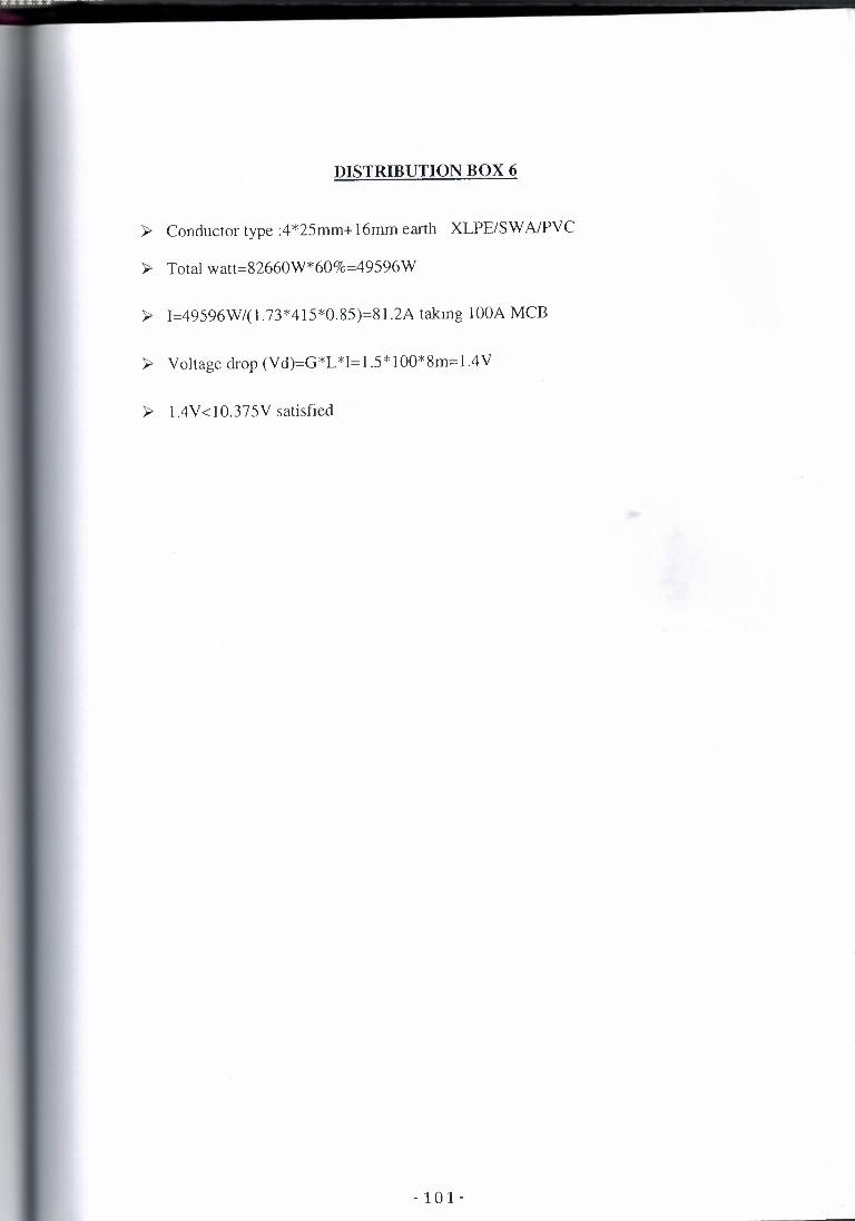
DISTRIBUTION BOX 6
>- Conductor type :4*25mm+16rnrn earth XLPE/SWA/PVC
>- Total watt=82660W*60%=49596W
>- l=49596W/(l .73*415*0.85)=81.2A takmg IOOA MCB
>- Voltage drop (Vd)=G*L *I= 1.5*100*8m=l .4V
>- 1.4V<10.375V satisfied
- 101-

DISTRIBUTION BOX 7
>- Conductor type :4*16mm+10mrn earth XLPE/SWA/PVC
>- Total watt=29420W*60%=17652W
>- 1=17652/(l.73*415*0.85)=28.9A takmg 40A MCB
>- Voltage drop (Vd)=G*L*I=2.2*40*107m=9.416V
>- 9.416V<10.375V satisfied
-102-

DISTRIBUTION BOX 8
~ Conductor type :4*16mm+10mm earth XLPE/SWA/PVC
~ Total watt=12160*60%=7296V
~ l=7296/(1.73*415*0.85)=11.94A takmg 40A MCB
~ Voltage drop (Vd)=G*L *I=2.2*40*40m=3.520V
~ 3.520V<10.375V satisfied
-103-
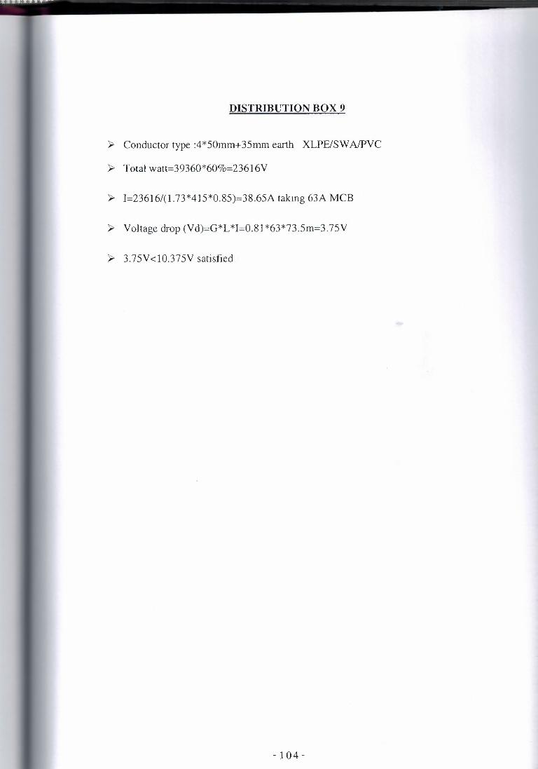
DISTRIBUTION BOX 9
>- Conductor type :4*50mm+35mm earth XLPE/SWA/PVC
>- Total watt=39360*60%=23616V
>- l=23616/(l.73*415*0.85)=38.65A takmg 63A MCB
>- Voltage drop (Vd)=G*L *I=0.81 *63*73.5m=3.75V
>- 3.75V<10.375V satisfied
-104-

DISTRIBUTION BOX 10
> Conductor type :4*16mm+10mm earth XLPE/SWA!PVC
> Total watt=3560* 100%=3560V
> l=3560/(1.73*415*0.85)=5.83A taking 40A MCB
> Voltage drop (Vd)=G*L *l=2.2*40*57m=5.016V
> 5.016V <10.375V satisfied
-105-

DISTRIBUTION BOX 11
~ Conductor type :4*16mm+10mm earth XLPE/SWA/PVC
~ Total watt=l 8750W*100%=18750W
~ l=l 8750/(l .73*415*0.85)=30.68A takmg 40A MCB
~ Voltage drop (Vd)=G*L *1=2.2*40*40m=3.52V
~ 3.52V<10.375V satisfied
-106-

DISTRIBUTION BOX A
};> Conductor type :4*50mm+35mm earth XLPE/SWA/PVC
};> Total watt= 16500* 100%= l 6500W+(30430*0.6)=34 758W
};> 1=34758/(l.73*415*0.85)=56.88A takmg 63A MCB
};> Voltage drop (Vd)=G*L *1=0.81*63*106m=5.41 V
};> 5.41 V<l0.375V satisfied
-107-

DISTRIBUTION BOX Al
> Conductor type :4*16mm+10mm earth XLPE/SWA/PVC
> Total watt=2500* 100%=2500+( 1060*0.6)=3136W
> l=3136W/(1.73*415*0.85)=5.l 3A takmg 40A MCB
> Voltage drop (Vd)=G*L *l=2.2*40*80.2m=7.06V
> 7.06V<l0.375V satisfied
-108-

DISTRIBUTION BOX HD
~ Conductor type :2*10mm+6mm earth XLPE/SWA!PVC
~ Total watt=640W* 100%=640W
~ I=640W/(240*0.85)=3.13A takmg 30A MCB
~ Voltage drop (Vd)=G*L*I=4.1 *30*3m=0.369V
~ 0.369V <6V satisfied

DISTRIBUTION BOX 1.1
» Conductor type :4*16mm +IOmm earth XLPE/SWA/PVC
» Total watt=41300W*60%=24 780W
» l=24780W/( 1.73*415*0.85)=40.6A takmg 63A MCB
» Voltage drop (Vd)=G*L *1=2.2*63*6m=0.832Y
» 0.832V < 10.375V satisfied
- 1 1 0 -

DISTRIBUTION BOX 1.2
> Conductor type :4*16mm+10mm earth XLPE/SWA/PVC
> Total watt=12100W*60%=7260W
> 1=7260W/(1.73*415*0.85)=11.88A takmg 40A MCB
> Voltage drop (Vd)=G*L *1=2.2*40*8m=0.71 V
> 0.71 V<10.375V satisfied
- 1 1 1 -

DISTRIBUTION BOX 1.3
> Conductor type :4*16mm+l0mm earth XLPE/SWA/PVC
> Total watt=30720W*60%=18432W
> l=l8432W/(l.73*415*0.85)=30.16A takmg 40A MCB
> Voltage drop (Vd)=G*L*l=2.2*40*24m=3.3V
> 3.3V <10.375V satisfied
- 112 -

ILLUMINATION CALCULATIONS OF PROJECT
- 1 1 3 -

l) ~~~~~~~~~~~~~~~~~~~~ 3 ro
~
-143-