facies analysis and depositoinal environment of d-3
TRANSCRIPT

_____________________________________________________________________________________________________
*Corresponding author: E-mail: [email protected], [email protected];
Journal of Geography, Environment and Earth ScienceInternational
19(2): 1-19, 2019; Article no.JGEESI.40885ISSN: 2454-7352
Facies Analysis and Depositoinal Environment ofD-3 Reservoir Sands Vin Field, Eastern Niger Delta
Onyewuchi, Chinedu Vin1* and Minapuye, I. Odigi2
1Department of Geology, University of Port Harcourt, Port Harcourt, Nigeria.2Centre for Petroleum Geosciences, Institute of Petroleum Studies, University of Port Harcourt,
Nigeria.
Authors’ contributions
This work was carried out in collaboration between both authors. Both authors read and approved thefinal manuscript.
Article Information
DOI: 10.9734/JGEESI/2019/v19i230080Editor(s):
(1) Dr. Wen-Cheng Liu, Department of Civil and Disaster Prevention Engineering, National United University, Taiwan andTaiwan Typhoon and Flood Research Institute, National United University, Taipei, Taiwan.
Reviewers:(1) Moses Oghenenyoreme Eyankware, Ebonyi State University, Nigeria.
(2) Adewumi Adeniyi JohnPaul, Achievers University, Nigeria.(3) A. K. Soni, CSIR- Central Institute of Mining and Fuel Research (CSIR-CIMFR), India.
Complete Peer review History: http://www.sdiarticle3.com/review-history/40885
Received 02 February 2018Accepted 19 April 2018
Published 23 February 2019
ABSTRACT
Facies analysis and depositional environment identification of the Vin field was evaluated throughthe integration and comparison of results from wireline logs, core analysis, seismic data, ditchcutting samples and petrophysical parameters. Well log suites from 22 wells comprising gamma ray,resistivity, neutron, density, seismic data, and ditch cutting samples were obtained and analyzed.Prediction of depositional environment was made through the usage of wireline log shapes of faciescombined with result from cores and ditch cuttings sample description. The aims of this study wereto identify the facies and depositional environments of the D-3 reservoir sand in the Vin field. Twosets of correlations were made on the E-W trend to validate the reservoir top and base while theisopach map was used to establish the reservoir continuity. Facies analysis was carried out toidentify the various depositional environments. The result showed that the reservoir is an elongate ,four way dip closed roll over anticline associated with an E-W trending growth fault and contains twostructural high separated by a saddle. The offshore bar unit is an elongate sand body with length:width ratio of >3:1 and is aligned parallel to the coast-line. Analysis of the gamma ray logs indicatedthat four log facies were recognized in all the wells used for the study. These include: Funnel-
Original Research Article

Vin and Minapuye; JGEESI, 19(2): 1-19, 2019; Article no.JGEESI.40885
2
shaped (coarsening upward sequences), bell-shaped or fining upward sequences, the bow shapeand irregular shape. Based on these categories of facies, the depositional environments wereinterpreted as deltaic distributaries, regressive barrier bars, reworked offshore bars and shallowmarine. Analysis of the wireline logs and their core/ditch cuttings description has led to theconclusion that the reservoir sandstones of the Agbada Formation in the Vin field of the easternNiger Delta is predominantly marine deltaic sequence, strongly influenced by clastic output from theNiger Delta. Deposition occurred in a variety of littoral and neritic environment ranging from barriersand complex to fully marine outer shelf mudstones.
Keywords: Facies; environment; littoral; ditch cuttings.
1. INTRODUCTION
A sub-surface study of the Agbada Formation inthe Vin oilfield of the eastern Niger Delta wasundertaken in order to determine the faciesand depositional environment of the reservoirsand- bodies. Facies analysis provides usefulinformation on paleoenvironmentalreconstruction. Depositional environment andtheir component facies form the primary buildingblock of reservoirs and exert a fundamentalcontrol on the Vin field reservoir quality,behaviour and recovery efficiency. In this study,prediction of the depositional environment was
made by the usage of wireline log shapes offacies combined with the result from cores andditch cuttings sample description. The Vin fieldsequence comprises cyclically alternatingsuccessions of sandstones and shale. More than10 discrete sand-bodies, varying in thicknessfrom 16m to 230 m, some of which constitute oiland gas reservoirs, were developed in places inthe formation. Among these sand bodies, onlythe D-3 reservoir sand produces petroleum from14 wells in Vin field. The D-2 reservoir sand alsocontains hydrocarbon that is not of economicsignificance, although it was useful in interpretingthe environment of deposition.
Fig. 1. Location of Vin field

Vin and Minapuye; JGEESI, 19(2): 1-19, 2019; Article no.JGEESI.40885
3
Extensive descriptions of depositional facies andenvironments in Niger Delta Basin are presentedin many publications. Some of these includeAmajor and Agbaire [1], Nton and Adesina [2],Onyekuru et al. [3], Reijers [4] among others.This study, therefore, utilizes these previousresearch as well as that of Selly [5] and Amajorand Agbaire [1] who defined the depositionalhistory of the reservoir sandstones of the Agbadaformation in the Akpor and Apara oilfields,eastern Niger Delta using integration of well logswith ditch cutting samples.
Using the proposed integrated methodology willlead to a significantly more accurate reservoirdescription and 3-D reservoir model, which canbe used to forecast reservoir behaviour andenhance recovery. The Vin field is located 30kmoffshore in the shallow waters of the EasternNiger Delta with an average water depth of 76ft(Fig. 1). A total of 49 wells have been drilled inthe field, out of these, 21 have been pilot holes, 2have been water injectors and 18 have beenhorizontal production wells. Two of the wellsdrilled (A2 and A9) penetrates the Akata
Formation in the Niger Delta at 8930ft and 8500ftrespectively.
2. GEOLOGY OF STUDY AREA
The geology of the Niger delta has beenextensively discussed by several authors. Thepresent study builds on work of Short & Stauble[6], Weber [7], Weber & Daukoru [8], Evamy etal. [9], Ejedawe [10], Doust & Omatsola [11], and[4]. The evolution of the delta is controlled bypre- and synsedimentary tectonics as desc ribedby Evamy et al. [9], Knox & Omatsola [12],Reijers et al. [13] and Reijers [4]. The basinevolved following the separation of African andSouth American plates during the EarlyCretaceous times. This was followed by theopening of the South Atlantic Ocean and severalepisodes of transgressions and regressionsaccounted for the sedimentary fills in both theCretaceous and Tertiary.
The stratigraphy of the study area falls within theextensional Miocene to Pleistocene age (Fig. 2).The structural pattern is characterised by South
Fig. 2. Regional structural element and schematic section through eastern Niger Delta(Modified from Corredor et al. [14])
Extensional Belt

Vin and Minapuye; JGEESI, 19(2): 1-19, 2019; Article no.JGEESI.40885
4
dipping NE-SW trending growth faults andcounter regional faults, which defined andcontrolled sedimentation especially theprospective Biafra Member and the AgbadaFormation.
The stratigraphic sequence in the south-easternflank of the Niger delta shows a marked facieschange in comparison with the sequence in thecentral part of the delta. The Agbada formation inSE Niger delta is divided into four local members:D-1, Qua Iboe, Rubble and Biafra member Orifeand Avbovbo [15].
From bottom to top, the eastern offshorestratigraphy (Fig. 3) is divided into:
AKATA SHALE of Middle Miocene age is Pro-deltaic and under-compacted dark shaledeposited in deep marine environment.
AGBADA FORMATION: Consist of alternatingUpper Miocene to Pliocene marine shales and
fluvio-marine sands ranging from lower coastalplain to delta front environment which can besub-divided into:
BIAFRA Member: A pro-grading oldMiocene sandy deltaic system.
RUBBLE BEDS Member: Depositedduring the transition Miocene- Pliocene.
KWA IBOE SHALE Member: Thick Pro-deltaic shales of early Plio-cene age.
D1 Member which represents the uppersand bearing series of the progradingyoung Pliocene deltaic system.
SANDY BENIN FORMATION of Pleistocene topresent age. The Benin Formation is theunconsolidated fresh water sand proceedingAgbada Formation. Oil and gas accumulationshave only been encountered in the KwaIboe, Rubble Beds, and mainly in the BiafraMember which contains the best reservoirs(Fig. 4).
Fig. 3. Lithostratigraphy of the southeastern Niger Delta (Joseph et al. [17])

Vin and Minapuye; JGEESI, 19(2): 1-19, 2019; Article no.JGEESI.40885
5
Fig. 4. Stratigraphic model of S-E Niger Delta (Joseph et al. [17])
3. MATERIALS AND METHODS
The data used for this research was collectedfrom Moni Pulo Limited under the auspicesof Lulu Briggs chair, Institute of PetroleumStudies University of Port Harcourt. The dataset include the following: Well data for 22wells (exploratory, pilot, horizontal and injectionwells), Surface location map of the wells, LWDlogs (22 wells), Survey data (22 wells), 3DSeismic data, Core data for A2P2 (1 well) andwireline data.
The seismic dataset include 3D-Pre-stack data inSEG-Y format and well data (logs) in variousdigital formats. The seismic and well data wasloaded into Petrel database. Well log correlationand formation evaluation analysis were carriedout with Gamma ray, resistivity, sonic, neutronand density logs. A combination of log suits (GR,neutron, density and resistivity), and petro-physical evaluation results (volume of shale,
porosity and water saturation) were used invalidating the top and base of the reservoir. Thesands in both the eastern and western flank ofVin field were correlated. The fluid contact andfluid in the reservoir were characterized usingNeutron – density, bulk density and resistivitylogs. The Gamma ray index was used todetermine the percentage of shale and thedominant lithology. The prediction andconstruction of the depositional environment wasbased on the use of wireline logs and ditchcuttings Weber [7], Amajor and Agbaire [1] andSelly [5], (Fig. 5). This was due to the lack ofcore samples and core photos for this study.
Gamma ray log was used to measure theshaliness of a formation. Such gradual changesare indicative of the litho-facies and thedepositional environment of the rock, and areassociated with changes in grain size and sorting(Fig. 6).

Vin and Minapuye; JGEESI, 19(2): 1-19, 2019; Article no.JGEESI.40885
6
Fig. 5. Paleoenvironmental interpretation of SP/gamma ray log motifs and borehole ditchcuttings data (After Selley [5])
Fig. 6. Sedimentologic facies indications from gamma ray log. (Modified from Serra)
Vin and Minapuye; JGEESI, 19(2): 1-19, 2019; Article no.JGEESI.40885
6
Fig. 5. Paleoenvironmental interpretation of SP/gamma ray log motifs and borehole ditchcuttings data (After Selley [5])
Fig. 6. Sedimentologic facies indications from gamma ray log. (Modified from Serra)
Vin and Minapuye; JGEESI, 19(2): 1-19, 2019; Article no.JGEESI.40885
6
Fig. 5. Paleoenvironmental interpretation of SP/gamma ray log motifs and borehole ditchcuttings data (After Selley [5])
Fig. 6. Sedimentologic facies indications from gamma ray log. (Modified from Serra)

Vin and Minapuye; JGEESI, 19(2): 1-19, 2019; Article no.JGEESI.40885
7
4. RESULTS AND DISCUSSIONS
4.1 Structure
The 3D seismic data quality is good, showinggood events continuity and reflection terminationagainst faults (Fig. 7). The structural style of thefield is entirely composed of normal growth faultseparating the region of interest from the north(Fig. 8)
The study shows that the Vin field ischaracterized by rollover anticline associated
with an E-W trending growth fault to the North(Fig. 9A). It exhibits 4-way dip closure (Fig. 9B)and two structural highs, Vin West and Vin East,separated by a saddle (Fig. 10). The structure ismost apparent within the Agbada formation,suggesting synsedimentary development. Thesynsedimentary growth faults activated at thedelta front retards the advancement of the sandyBenin Formation. The down thrown partbecomes the new focus of Agbada paralic faciesdeposition until subsidence stabilizes; by then amaximum thickness of Agbada Formation hasbeen deposited [16].
Fig. 7. Fault interpretation on an Inline 10488
Fig. 8. Variance cube Time slice at 1300ms, showing fault lineaments and the ROI

Vin and Minapuye; JGEESI, 19(2): 1-19, 2019; Article no.JGEESI.40885
8
Fig. 9 (A and B) Schematic diagram showing the roll over anticline and four way dip closure
Fig. 10. Structure of the D-3 reservoir showing the E – W trending growth fault and twostructural highs
4.2 Stratigraphic Correlation
Stratigraphic correlation was carried out toestablish the stratigraphic framework of the D-3reservoir. The stratigraphic correlation of theWestern part of the field consisting of wells(A13P1 – E1 – A9P3) as shown in (Fig. 11),while that of the Eastern part of the fieldconsisting of wells (AP61 - AI – A2P1) as shownin (Fig. 12). Petrophysical attributes suggest thatopen hole gamma ray, deep resistivity well- logdata and porosity logs, can be used to predictfacies distribution in wells that lack core control[17]. A combination of log suites (GR, density,neutron, and resistivity) and petrophysicalevaluation results (volume of clay, porosity andwater saturation) were used in validating the topsand bases of the reservoir. Three facies weredefined based on log signatures and cut-off. TheD-3 reservoir consists of sand, silt and shale
sequences. It is characterized by clean sandswith some silt and shale intercalations. It isbounded at the top and base by distinctive shaleunits.
Field-wide correlation from the Western to theEastern part of the field was also carried out. Asshown in (Fig.13), a transect passes through theselected wells. The transect line W – E connectswells (A9P2 – A16 – A15 – A2PA – A8). Alldepths for the stratigraphical correlations are truevertical depth subsea (SSTVD). An appropriatedatum of 2000ft was chosen. This was the baseof the Qua Iboe shale which is the first majorregional shale marker typical of the base ofBenin sands. The D-3 reservoir has fairlyconstant thickness from one well to another,laterally extensive and cuts across all the wells inthe field.

Vin and Minapuye; JGEESI, 19(2): 1-19, 2019; Article no.JGEESI.40885
9
Fig. 11. Stratigraphic framework of D-5 reservoir in Vin West
Fig. 12. Stratigraphic framework of D-5 reservoir in Vin East

Vin and Minapuye; JGEESI, 19(2): 1-19, 2019; Article no.JGEESI.40885
10
Fig. 13. A. stratigraphic correlation of Vin field from west to east. B. the transect line W–E connectimg wells (A9P2 – A16 – A15 – A2PA – A8)
Vin and Minapuye; JGEESI, 19(2): 1-19, 2019; Article no.JGEESI.40885
10
Fig. 13. A. stratigraphic correlation of Vin field from west to east. B. the transect line W–E connectimg wells (A9P2 – A16 – A15 – A2PA – A8)
Vin and Minapuye; JGEESI, 19(2): 1-19, 2019; Article no.JGEESI.40885
10
Fig. 13. A. stratigraphic correlation of Vin field from west to east. B. the transect line W–E connectimg wells (A9P2 – A16 – A15 – A2PA – A8)

Vin and Minapuye; JGEESI, 19(2): 1-19, 2019; Article no.JGEESI.40885
11
4.3 ISOPACH Map
In this study, isopach map is useful indetermining the shape of the field, position of theshoreline, areas of uplift, sand studies andgrowth history analysis of the sands.
Sand accumulation is better developed in thewestern than eastern part of the field. The D-3reservoir has fairly constant thickness from onewell to another. The gross thickness of thereservoir ranges from 111ft to 305ft, as shown bythe isopach map (Fig. 15). The overall trend inthickness reflects general thinning towards theflank of Vin East and Vin West of the field. Themap also confirms two structural highs Vinwest and Vin east with a saddle in between. Itcan be inferred that the sand was suppliedby a distributary channel which was latterreworked by wave action to form longbars almost parallel to the coast line. Thedifference in thickness of the two structuralhighs can be due to difference in the rate ofsediment supply to each structural high or dueto higher rate of erosion and sedimentreworking in the eastern high than the westernhigh. In addition, we can infer that the shorelinecould have been very close at the time offormation of the reservoir sand. The elongatenature of the sand body also suggests a sandbar.
4.4 Reservoir Continuity and Geometry
Knowledge of reservoir continuity is aprerequisite to establish the reserve and
identifying the method for recovering it. Potter[18], proposed a scheme to classify and quantifythe lateral continuity of sands. Two major groupsof sand (sheet and elongate bodies) wererecognized. Sheet bodies are continuous withlength: width ratios of 1:1 and occur inenvironment ranging from turbidite fans andcrevasse- splays [5]. The elongate bodies have alength: width ratio of 3:1, are generally depositedin barrier bar environments (Fig. 16).
Vin field is an elongate sand body with length:Width ratio of >3:1. According to Selly [5], thebest known of the elongate sand are the ribbonor shoestrings which are generally deposited inbarrier environment (Fig. 17).
4.5 Facies Analysis and DepositionalEnvironment
Facies analysis provides useful information inpaleoenvironmental reconstruction.
Selley [5] considered the shapes of well-logcurves as basic tool to interpret depositionalfacies because shape of log is directly related tothe grain size of rock successions. Cant [19]defined five different log curve shapes used tointerpret the depositional environment and alsoconsidered the study of core with relation to logsas important tool of facies interpretation in thesubsurface.
Analysis of the gamma ray logs indicated thatfour log facies were recognized in all the wellsused for the study. They include: Funnel-shaped
Fig. 15. Model of D-3 Reservoir Isopach map

Vin and Minapuye; JGEESI, 19(2): 1-19, 2019; Article no.JGEESI.40885
12
Fig. 16. Nomenclature of sand body geometry (After Potter, 1962 [18])
Fig. 17. D-3 Reservoir Thickness map showing length to width ratio
(coarsening upward sequences), bell-shaped orfining upward sequences, the bow shape andirregular shape. Based on these categories offacies, the depositional environments wereinterpreted.
4.5.1 Facies A (Bell Shaped succession)
The gamma ray log trend of the bell shapedsuccession is characterized by consistentupward decreases from maximum value of logreading in trend. The bell shape succession isseen in well A2P1, A2P2.
4.5.1.1 Description
The bell shaped gamma ray log trend in the D-3reservoir sand, occurs between depths of 4600ftand 4950ft SSTVD in well A2P1.It is serrated,with sharp basal contact and with a thickness ofabout 350ft (Fig 18). At sand A2P2, (Fig 19) itoccurred between depths 4520ft to 4720ftSSTVD. Ditch cutting and core sampledescription indicates that the unit comprises afining upward textural gradient (fine to mediumgrained sand at the base and shale to silt at thetop).The sand is well sorted subangular to

Vin and Minapuye; JGEESI, 19(2): 1-19, 2019; Article no.JGEESI.40885
13
subrounded, Carbonaceous detritus and micaare common. Vertically the percentage, thicknessand grain size of the sandstone strata decreasesand the upper part of the unit is dominated bythin bedded heterolithics. The mudstone strataare commonly dark grey, organic rich withcarbonaceous plant material.
4.5.1.2 Interpretation
These attributes favours deposition of the top ofthe sand in a marine environment, possibly inshallow marine due to the fining upward log
signature. This represents a decrease indepositional energy. This presence of glauconiteindicates deposition in a shallow marineenvironment [5]. Bell shaped successions withcarbonaceous detritus are deposited inenvironments of deltaic distributary channel [5,1]. The overall fining upward log trend and grainsize, reflects decrease in flow velocities relatedto either lateral accretion of channel point bars orchannel abandonment. These intervals areinterpreted as the product of deltaic distributarychannel (point bar).
Fig. 18. East – West stratigraphic correlation of the D3 sand showing the Bell shape logsignature of well A2P1
Fig. 19. Bell shaped log trend showing sharp base and fining upward trend

Vin and Minapuye; JGEESI, 19(2): 1-19, 2019; Article no.JGEESI.40885
14
4.5.2 Facies B (Funnel Shaped succession)
The gamma ray log trend of the funnel shapedsuccession is characterized by consistentupward increases of log reading in trend. Thefunnel shape succession is seen in almost all thewells that penetrate the D3 sand in the field (Fig20). It consists of stacked series of successionsvarying up to 20 to 25m in total thickness (Fig21).
4.5.2.1 Description
Ditch cutting description indicates that the unitcomprises a coarsening upward textural gradient(shale to silt at the base, and fine to very finegrained sand at the top). The sand is very fine tofine grained, well sorted with interbed of shaleand carbonaceous detritus. There is presence offossil (shell fragment) and it is micaceous,glauconite is absent.
4.5.2.2 Interpretation
According to Selley [5], the environments ofshallowing-upward and coarsening successionsare divided into three categories namely;Regressive barrier bars, prograding marine shelffans and prograding delta or crevasse splays.Facies B is not likely to be a crevasse splaybecause one of the main differences between acrevasse splay and a prograding delta is thedepositional scale. The funnel shaped logmotifs in the entire D-2 reservoir across the wellsin this study are not less than 59 ft.Both regressive barrier bars and progradingsubmarine fan are usually depositedwith glauconite and shell debris [5,20].The characteristics suggest that the environmentof deposition is a prograding delta since noglauconite is recorded in this succession. It isoverlain by marine shale.
Fig. 20. Section of the D3 sand showing the top and base of the reservoir
Fig. 21. Section of the D3 sand showing the top and base of the reservoir

Vin and Minapuye; JGEESI, 19(2): 1-19, 2019; Article no.JGEESI.40885
15
4.5.3 Facies C (Bow Shaped succession)
The bow trend (also known as the barrel trends)consists of a cleaning upward trend, overlain bya dirtying-up trend of similar thickness and nosharp break between the two. It is identified inalmost all the wells in the D3-sand Vin field. Thisis the hydrocarbon producing reservoir in thefield (Fig. 22)
4.5.3.1 Description
The bow shaped gamma ray log trend in the D-3sand ranges in thickness from 111ft to 310ft. It ischaracterized by a gradational contact above andbelow the gamma ray trend (Fig. 23). Ditch
cutting description indicates that the sand is finedto very fine grained, well sorted, subangular tosubrounded, carbonaceous detritus and mica iscommon. Glauconite is present.
4.5.3.2 Interpretation
It is the result of a waxing and waning of clasticsedimentation rate in a basinal setting, where thesediment is constrained by base level. Shallowmarine bow motif occur where growth faultingmay have constrained regression and allowed athick transgressive body to develop [21].Marinetransgression and coastal subsidence by growthfault forces facies belt to migrate landward.
Fig. 22. Section of the D3 sand showing the top and base of the reservoir
Fig. 23. Gamma ray trend of the bow shape in the D3 reservoir showing coarsening upward(CU) and a fining upward shape, gradational top and base, and top and base of the reservoir

Vin and Minapuye; JGEESI, 19(2): 1-19, 2019; Article no.JGEESI.40885
16
According to Cant, 1992 [19], the environment ofdeposition is reworked offshore bar or aregressive to transgressive shore face delta. Thebarrier shoreface unit is an elongate sand bodywith length: width ratio of >3:1. According to Selly[5], the best known of the elongate sand are theribbon or shoestrings which are generallydeposited in barrier environment.
4.5.4 Facies D (Irregular log trend)
The irregular trend abounds in the analysis of allthe wells in Vin field (Figs. 24). According toEmery and Myers [21], Irregular trends have nosystematic change in either base line, or lack theclean character of the boxcar trend. Theyrepresent aggradations of a shaley or siltylithology.
4.5.4.1 Description
The ditch cuttings samples descriptions showgrey to dark grey, firm to hard, sub blocky toblocky, carbonaceous. Non-calcareousclaystones and siltstones were recoveredfrom this unit. Similar log signature havebeen identified in well A9P2 with ditchcutting sample description showing grey/greenand greybrown, carbonaceous, micromicaceous and non calcareous claystone andsiltstone. The occasional abundance of plantremains indicate that the clays were deposited in
the inner to middle neritic zones in the shelfalsetting.
4.5.4.2 Interpretation
The environment is characteristically, a blanketof clays and fine silts deposited from suspension,with high lateral continuity and low lithologicvariation.
On regional evidence, this unit is thought to havebeen deposited during the marine transgressionassociated with depositional subsidence whichled to marine transgression. The occurrence ofcarbonaceous and micaceous materialssuggests deposition in shallow marine setting inthe inner to middle neritic zone. These units formlaterally extensive reservoir seals.
4.6 Conceptual Depositional Model
Analysis of the wireline logs and their core/ditchcuttings description has led to the conclusion thatthe reservoir sandstones of the AgbadaFormation in the Vin field of the eastern NigerDelta is predominantly marine deltaic sequence,strongly influenced by clastic output from theNiger Delta. Deposition occurred in a variety oflittoral and neritic environment ranging frombarrier sand complex to fully marine outer shelfmudstones. The conceptual depositional modelis shown in (Fig. 25)
Fig. 24. Irregular log trend of well 8, Vin field
Vin and Minapuye; JGEESI, 19(2): 1-19, 2019; Article no.JGEESI.40885
17
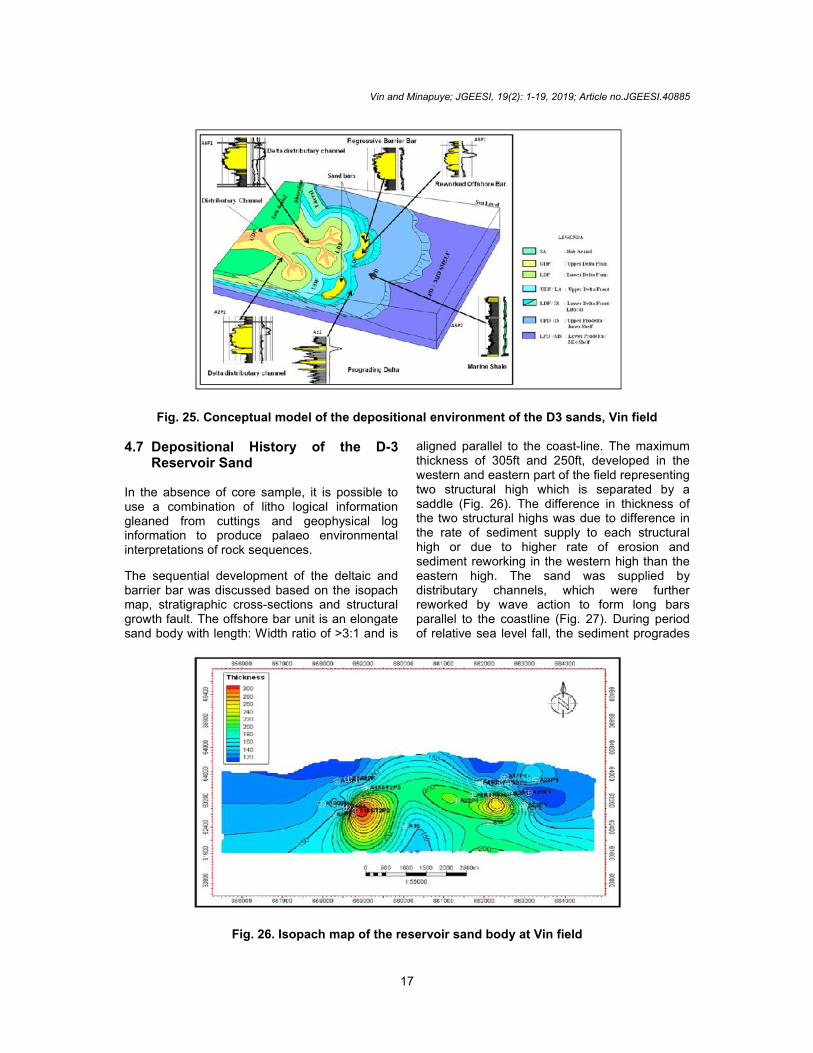
Fig. 25. Conceptual model of the depositional environment of the D3 sands, Vin field
4.7 Depositional History of the D-3Reservoir Sand
In the absence of core sample, it is possible touse a combination of litho logical informationgleaned from cuttings and geophysical loginformation to produce palaeo environmentalinterpretations of rock sequences.
The sequential development of the deltaic andbarrier bar was discussed based on the isopachmap, stratigraphic cross-sections and structuralgrowth fault. The offshore bar unit is an elongatesand body with length: Width ratio of >3:1 and is
aligned parallel to the coast-line. The maximumthickness of 305ft and 250ft, developed in thewestern and eastern part of the field representingtwo structural high which is separated by asaddle (Fig. 26). The difference in thickness ofthe two structural highs was due to difference inthe rate of sediment supply to each structuralhigh or due to higher rate of erosion andsediment reworking in the western high than theeastern high. The sand was supplied bydistributary channels, which were furtherreworked by wave action to form long barsparallel to the coastline (Fig. 27). During periodof relative sea level fall, the sediment progrades
Fig. 26. Isopach map of the reservoir sand body at Vin field
Vin and Minapuye; JGEESI, 19(2): 1-19, 2019; Article no.JGEESI.40885
18
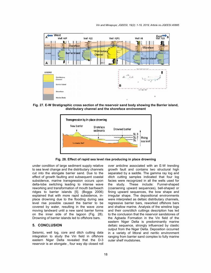
Fig. 27. E-W Stratigraphic cross section of the reservoir sand body showing the Barrier island,distributary channel and the shoreface environment
Fig. 28. Effect of rapid sea level rise producing in place drowning
under condition of large sediment supply relativeto sea level change and the distributary channelscut into the elongate barrier sand. Due to theeffect of growth faulting and subsequent coastalsubsidence, marine transgression occurs upondelta-lobe switching leading to intense wavereworking and transformation of mouth bar/beachridges to barrier islands [5]. (Boggs 2006)explained that with more rapid subsidence, in-place drowning due to the flooding during sealevel rise possible caused the barrier to becovered by water, resulting in the wave zonemoving landward until a new sand barrier formson the inner side of the lagoon (Fig. 28).Drowning of barrier islands led to offshore bars.
5. CONCLUSION
Seismic, well log, core and ditch cutting dataintegration to study the Vin field in offshoreeastern Niger Delta revealed that the D-3reservoir is an elongate , four way dip closed roll
over anticline associated with an E-W trendinggrowth fault and contains two structural highseparated by a saddle. The gamma ray log andditch cutting samples indicated that four logfacies were recognized in all the wells used forthe study. These include: Funnel-shaped(coarsening upward sequences), bell-shaped orfining upward sequences, the bow shape andirregular shape. The depositional environmentswere interpreted as deltaic distributary channels,regressive barrier bars, reworked offshore barsand shallow marine. Analysis of the wireline logsand their core/ditch cuttings description has ledto the conclusion that the reservoir sandstones ofthe Agbada Formation in the Vin field of theeastern Niger Delta is predominantly marinedeltaic sequence, strongly influenced by clasticoutput from the Niger Delta. Deposition occurredin a variety of littoral and neritic environmentranging from barrier sand complex to fully marineouter shelf mudstones.
Vin and Minapuye; JGEESI, 19(2): 1-19, 2019; Article no.JGEESI.40885
18
Fig. 27. E-W Stratigraphic cross section of the reservoir sand body showing the Barrier island,distributary channel and the shoreface environment
Fig. 28. Effect of rapid sea level rise producing in place drowning
under condition of large sediment supply relativeto sea level change and the distributary channelscut into the elongate barrier sand. Due to theeffect of growth faulting and subsequent coastalsubsidence, marine transgression occurs upondelta-lobe switching leading to intense wavereworking and transformation of mouth bar/beachridges to barrier islands [5]. (Boggs 2006)explained that with more rapid subsidence, in-place drowning due to the flooding during sealevel rise possible caused the barrier to becovered by water, resulting in the wave zonemoving landward until a new sand barrier formson the inner side of the lagoon (Fig. 28).Drowning of barrier islands led to offshore bars.
5. CONCLUSION
Seismic, well log, core and ditch cutting dataintegration to study the Vin field in offshoreeastern Niger Delta revealed that the D-3reservoir is an elongate , four way dip closed roll
over anticline associated with an E-W trendinggrowth fault and contains two structural highseparated by a saddle. The gamma ray log andditch cutting samples indicated that four logfacies were recognized in all the wells used forthe study. These include: Funnel-shaped(coarsening upward sequences), bell-shaped orfining upward sequences, the bow shape andirregular shape. The depositional environmentswere interpreted as deltaic distributary channels,regressive barrier bars, reworked offshore barsand shallow marine. Analysis of the wireline logsand their core/ditch cuttings description has ledto the conclusion that the reservoir sandstones ofthe Agbada Formation in the Vin field of theeastern Niger Delta is predominantly marinedeltaic sequence, strongly influenced by clasticoutput from the Niger Delta. Deposition occurredin a variety of littoral and neritic environmentranging from barrier sand complex to fully marineouter shelf mudstones.

Vin and Minapuye; JGEESI, 19(2): 1-19, 2019; Article no.JGEESI.40885
19
COMPETING INTERESTS
Authors have declared that no competinginterests exist.
REFERENCES
1. Amajor LC, Agbaire DW. Depositionalhistory of the reservoir sandstone, Akporand Apara oilfields, eastern Niger delta,Nigeria, Journal of Petroleum Geology.1989;12(4):453-464.
2. Nton ME, Adesina AD. Aspects ofstructures and depositional environment ofsand bodies within tomboy field, offshorewestern Niger Delta. The Materials andGeo Environment. 2009;56(3):284–303.
3. Onyekuru SO, Ibelegbu EC, Iwuagwu CJ,Essien AG, Akaolisa CJ. Sequencestratigraphic analysis of “XB field”. CentralSwamp Depobelt, Niger Delta Basin,Southern Nigeria. International Journal ofGeosciences. 2012;3:237-257.
4. Reijers TJ. Stratigrahpy and Sedimento-logy of the Niger Delta. Geologos. 2011;17(3):133-162.
5. Selley RC. Element of petroleum geology.Elsevier, London. 1998;460.
6. Short KC, Stauble AJ. Outline of geologyof Niger Delta. American Association ofPetroleum Geologists Bulletin. 1995;51:761-779.
7. Weber KJ. Sedimentological aspect of theoil fields in the Niger Delta: Geologie enMijnbouw. 1971;50(3):559-576.
8. Weber KJ, Daukoru EM. Petroleumgeology of the Niger delta: Proceedings ofthe ninth world petroleum congress. Geo-logy: London. Applied Science PublishersLtd. 1975;2:210-221.
9. Evamy BD, Haremboure J, Kamerling P,Knaap WA, Molloy FA, Rowlands PH.Hydrocarbon habitat of Tertiary NigerDelta: AAPG Bulletin. 1978;62:277-298.
10. Ejedawe JE. Patterns of incidence of oilreserves in Niger Delta Basin Amer.Assoc. Petroleum Geologists. 1981;65:1571–1585.
11. Doust H, Omatsola E. Niger Delta, inEdwards JD, Santogrossi PA, eds.,Divergent/Passive Margin Basins, AAPGMemoir 48: Tulsa, American Association ofPetroleum Geologists. 1990;239-248.
12. Knox GJ, Omatsola ME. Development ofthe Cenozoic Niger Delta in terms of theescalator regression model, in CoastalLowlands, Geology and geotechnology.Proc. Kon. Nederl. Geol. Mijnb. Genoots.1989;181-202.
13. Reijers TJA, Petters SW, Nwajide CS. TheNiger Delta Basin, in Selley RC, ed.,African Basins-Sedimentary Basin of theWorld 3, Amsterdam, Elsevier Science.1997;151-172.
14. Corredor F, Shaw JH, Bilohi. Structuralstyles in the deepwater fold and thrustbelts of the Niger Delta. AAPG Bulletin.2005;89(6):753-780.
15. Orife JM, Avbovbo AA. Stratigraphy andthe unconformity traps in Niger Delta.American Association of PetroleumGeologist Memoire. 1982;32:265.
16. Ekweozor CM, Daukoru EM. Petroleumsource bed evaluation of Tertiary NigerDelta – reply. American Association ofPetroleum Geologists Bulletin. 1984;68:390–394.
17. Joseph MB, Steven LG, Ronald LW. Gulfof guinea geology. Oil and Gas Journal.Penny Well. 2004;8.
18. Potter PE. Sand body shape and mappatterns of Pennsylvanian sandstones in Illinois. Illinois Geol. Surv., Circular. 1962;339.
19. Cant DJ. Subsurface facies analysis. In:Facies models response to sea-levelchanges. eds. Walkker RG, James NP.Geol Soc Canada. 1992;27–45.
20. Chow JJ, Ming-Ching Li, Fuh S.Geophysical well log study on the paleoenvironment of hydrocarbon producingzones in the erchungchi formation. Hsinyin,SW Taiwan. TAO. 2005;16(3):531-543.
21. Emery D, Myers KJ. Sequencestratigraphy. Blackwell Science Ltd. 1996;264.
_________________________________________________________________________________© 2019 Vin and Minapuye; This is an Open Access article distributed under the terms of the Creative Commons AttributionLicense (http://creativecommons.org/licenses/by/4.0), which permits unrestricted use, distribution, and reproduction in anymedium, provided the original work is properly cited.
Peer-review history:The peer review history for this paper can be accessed here:
http://www.sdiarticle3.com/review-history/40885