fabrication of photomasks consisting microlenses for the ... michelle.pdf · fabrication of...
TRANSCRIPT

RESEARCH ARTICLE
Fabrication of photomasks consisting microlensesfor the production of polymeric microneedle array
Himanshu Kathuria1 & Michelle H. M. Fong1 & Lifeng Kang1
Published online: 25 July 2015# Controlled Release Society 2015
Abstract A photomask consisting plano-convex microlensesfor the production of polymeric microneedles was fabricatedfrom a microinjection array. The microinjection array was firstfabricated using photolithographical approach and subse-quently assembled onto a polydimethylsiloxane (PDMS)stamp. Poly (ethylene glycol) diacrylate (PEGDA) solutionwas loaded into the microinjection stamp. The microinjectionstamp was then applied onto a coverslip to dispense the poly-mer solution, producing liquid microdroplets. They were thenirradiated to form plano-convex microlenses. Thesemicrolenses were evaluated for their geometric properties andwere fabricated into photomasks. The photomask consistingmicrolenses was used to fabricate polymeric microneedles thatwere evaluated and tested for skin penetration efficiency.
Keywords Microneedle .Microinjection .Microlens .
Hydrogel . Photolithography
Introduction
Transdermal drug delivery offers an appealing alternative foradministration of both oral and hypodermic dosage forms ofbiotechnology-based drugs [1]. It has many advantages in-cluding improved patient compliance, avoidance of first
pass effect, and non-invasiveness [2, 3]. However, drug per-meation through the skin has been shown to be limited by thestratum corneum (SC) acting as a physical barrier to exoge-nous substances [4]. Various chemical, physical, and mechan-ical strategies, such as chemical penetration enhancers, pres-sure waves, and iontophoresis, were used to overcome thisbarrier [5].
One of the promising approaches to overcome the barrier isthe use of microneedles, which penetrate the SC, creatingmicron-sized channels into the underlying tissues for directdelivery of the therapeutics [6]. These needles are smallenough to avoid fear and pain, and allow self-administration[7]. Recently, there has been extensive interest in microneedlesand its fabrication [8]. Conventional microfabrication tech-niques involve the use of etching, laser cutting, metalelectroplating, and micromolding, alone or in combination,to generate microstructures using varying materials such aspolymers and metals [9–11].
Photolithography in combination with photomaskconsisting microlenses has also been used to fabricate themicroneedle arrays. Microlenses are widely seen inbiodetection systems [12, 13], biomedical imaging [14], andoptical communications [15], to collect light, change the focallength, and steer light beams [16]. Thus, many sophisticatedmicrolens fabrication methods have been reported, such asreflowing [17, 18], etching [19], molding [20], and stamping[21]. With its ability to alter the pathway of UV light, a meth-od has been developed to fabricate microneedles by usingphotolithography in combination with photomask consistingconcave microlenses [22].
Recently, a new method was developed in our lab to sim-plify sharp microneedle fabrication by using photomasks in-tegrated with isotropically etched convex microlenses [23].However, the lens surfaces were found to be flat and not con-vex, due largely to manner in which the chemicals etched into
Himanshu Kathuria and Michelle H. M. Fong contributed equally to thiswork.
* Lifeng [email protected]
1 Department of Pharmacy, National University of Singapore, 18Science Drive 4, Singapore 117543, Singapore
Drug Deliv. and Transl. Res. (2015) 5:438–450DOI 10.1007/s13346-015-0245-z
the wafer. These lenses had unpredictable effects leading toformation of irregular microneedle tips in some cases. Thishas motivated us to find an alternative method to fabricatethe photomask consisting microlenses with convex surfaces.
In this study, a microinjection array was used to dispensemicrodroplets of prepolymer solution containing poly (ethyl-ene glycol) diacrylate (PEGDA), a photocurable macromer[24]. The microdroplet array was then cured by UV light toform plano-convex microlenses. These microlenses werefound to possess appropriate geometric properties, key to op-tically modifying UV light path to fabricate microneedles thatare shorter and sharper.
Materials and methods
Materials
PEGDA (Mn=250), PEGDA (Mn=575), PEGDA (Mn=700), 2-hydroxy-2-methyl-propiophenone (HMP) and3-(trimethoxysilyl) propyl methacrylate (TMSPMA) werepurchased from Sigma-Aldrich (St. Louis,MO). Silicone elas-tomer base solution and curing agent Sylgard 184 were pur-chased from Dow Corning Corporation (Midland, USA). Allmaterials were reagent grade and were used as received.
Fabrication of microinjection array
Coating of glass slides and coverslips
Glass slides (Corning, USA, 1.06 mm thickness, 75×50 mm)and glass coverslips (Menzel Glaser, Germany, 190 μm thick-ness, 22×22mm)were rinsedwith 70% ethanol and air-dried.They were immersed in 0.4 % TMSPMA solution for coatingovernight. The glass slides and coverslips were then washedwith water and baked for 2 h at 70 °C. Silanol groups on theglass will attach onto the TMSPMA molecules [25].
Fabrication of backing layer
A setup was made on a TMSPMA-coated glass slide asseen in Fig. 1. A cavity was created using coverslips asshown in Fig. 1b. The number of coverslips used deter-mines the height of the cavity (spacer thickness). A pho-tomask is a plastic film inked specifically to a pattern. Thebacking layer photomask had inked circles with a center-to-center spacing of 1500 μm. The microinjection arrayphotomask had inked circles, with a center-to-center spac-ing of 1500 μm, that were surrounded by a circle of largerdiameter. Figure 1 and Table 2 show dimensions of thetwo photomasks, for the backing layer and microinjectionarray. These were designed separately using AutoCAD2014 and printed using high-resolution (8000 dpi) printer
on the plastic film of 7 mil (Infinite Graphics, Singapore).During all steps of fabrication, ink/emulsion side of thephotomask was facing the UV light source. Assembly oftwo photomask (for backing and microinjection array)was done manually utilizing the Nikon SMZ25 stereomi-croscope (Nikon, Japan) to confirm that alignment wasdone appropriately. The inked regions blocked UV accesswhile surrounding transparent regions allowed UV light topass through to photopolymerize the polymer solution.Both photomasks had to be aligned such that all inkedcircles of both the backing layer photomask and the mi-croinjection photomask overlapped (see Fig. 1), for mi-croinjections to form onto the backing layer directly. Tofacilitate the alignment of the photomasks in later steps,prealignment of both photomask was necessary as shownin Fig. 1c, d. The aligned photomasks were laid opened,flat down, and the backing layer photomask was securedonto the front side of the setup with tape on all threesides. The microinjection photomask was folded downand secured with tape on one side.
On the back side of the setup, an uncoated coverslipwas placed over the cavity and filled with PEGDA (Mn=250) containing 0.5 % w/w HMP (referred to asprepolymer solution). The setup was then flipped overand irradiated with UV of desired intensity and time ofexposure, at a distance of 10 cm using a UV curing sta-tion with a UV filter range of 320–500 nm (OmniCure®S2000, EXFO Photonics Solutions Inc., Canada). The UVintensity was measured with OmniCure® R2000 radiom-eter. A collimating adaptor (EXFO 810–00043) was usedwith the UV light probe. Following polymerization, thecoverslip was removed and the backing layer formed onthe setup was rinsed with running water and dried usingcompressed air (Fig. 2a). This prevented undesired poly-merization of the backing layer, as a result of any residueunpolymerized prepolymer solution present, during thefabrication of the microinjection array.
Fabrication of microinjections
The microinjection photomask was folded over the back-ing layer photomask with proper alignment, assisted bythe prealignment step (Fig. 1d). Later on the back sideof the setup now containing the backing layer, an uncoat-ed coverslip was placed over the cavity, 5-coverlips inthickness, and filled with the prepolymer solution. Thesetup was flipped over and irradiated at a UV intensityof 3.82 W/cm2 for a desired time of exposure, at a dis-tance of 10 cm from the UV source. Following polymer-ization, the microinjection array formed was carefully re-moved, rinsed with running water, and dried using com-pressed air (Fig. 2b). The array was then irradiated with7.95 W/cm2 UV intensity for 2 s at a distance of 10 cm,
Drug Deliv. and Transl. Res. (2015) 5:438–450 439

for rigidization of the microinjections. The microinjec-tions were imaged using Nikon SMZ25 stereomicroscope(Nikon, Japan). With the microinjections being colorless,it was difficult to view it under the stereomicroscope.Thus, for the purpose of imaging, 200 μL of rhodamineB 0.09 % w/w (Alfa Aesar, Lancaster, UK) solution wasadded into the prepolymer solution for the fabricationprocess.
Fabrication of plano-convex microlenses
Selection of polymer
Polymers’ physical properties like viscosity, transparency,density, etc. may directly affect the fabrication of microlens.Three different molecular weight of PEGDA, i.e., PEGDA(Mn=250), PEGDA (Mn=575), and PEGDA (Mn=700),
d Setup-Microinjections array
a Front view b Back view
c Setup-Backing layer
Pre-
polymer
solutionCoverslip
TMSPMA coated
glass slide
UV exposure Area
Place
photomask(s)
For Backing
For Microinjection
Aligned
photomaskFor Microinjection For Backing
Ta
pe
2 × 2 cm
1 × 1 cm
Fig. 1 Schematic of setup withUVexposure area defined. a Frontview of setup. b Back view ofsetup. A cavity, measuring 1.5×1.5 cm, was created usingcoverslips fitted down on eitherside. The height of the cavity isequivalent to the thickness of 1coverslip. c Prealigning andassembling of photomasks onsetup during fabrication of thebacking layer. d Microinjectionphotomask folded over backinglayer photomask formicroinjection fabrication
a Backing Layer
Perforated
PEGDA backing
Photomask
Prepolymer
Solution
Ultraviolet
Irradiation
2.2 cm
TMSPMA Coated
Glass slide
Coverslip
Coverslip
Coverslip
b Microinjection Array
2.2 cm
Aligned Photomask
Coverslips
Microinjection
array on glass
Invert
Invert
Invert
Invert
Fig. 2 a Schematicrepresentation of the backinglayer fabrication process. Thesetup was irradiated with UVthrough the backing layerphotomask that was positionedprior to filling the cavity withprepolymer solution. b Schematicrepresentation of themicroinjection array fabricationprocess. The setup was irradiatedagain, this time through themicroinjection photomaskaligned over the backing layerphotomask. Microinjections werecreated using cavity height of 5coverslips thickness
440 Drug Deliv. and Transl. Res. (2015) 5:438–450

were chosen for the preliminary assessment. All three poly-mers were similar in density, refractive index but different inthe viscosity, where the PEGDA 700 had comparativelyhigher viscosity than the PEGDA 575 and PEGDA 250.These were further evaluated for selection based on dynamiccontact angle measurements (see Dynamic contact angle).
Dynamic contact angle
PEGDA (Mn=250), PEGDA (Mn=575), and PEGDA (Mn=700) were individually mixed with 0.5 % w/w of HMP. Fromeach solution, 1 μL using the pipette were placed onto glasscoverslips to form droplets that were labeled according to timeintervals 0, 5, 10, and 15 min. At the specified time points, theappropriately labeled coverslip with droplets from all threesolutions was irradiated with high-intensity UV light(7.95 W/cm2) for 3 s, at a distance of 10 cm from the UVsource. The microlenses formed on each coverslip were im-aged using Nikon SMZ25 stereomicroscope (Nikon, Japan).Dynamic contact angle and dimensions of each droplet weremeasured using the measurement tools (height, diameter, andfree angle) from Nikon imaging software (NIS-Element Anal-ysis D 4.20.00).
Fabrication of microlens array
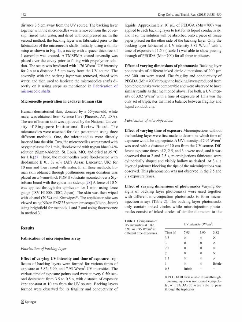
A polydimethylsiloxane (PDMS) microinjection array stampwas used to fabricate plano-convex microlenses. A PDMSstamp (Fig. 5a) was first fabricated by curing a 10:1 mixtureof silicone elastomer base solution and curing agent Sylgard184 in a petri dish with a Combifix® Adapter (B. BraunMelsungen AG, Germany) placed in the center. The PDMSelastomer solution was degassed for 20 min in a vacuumchamber and cured at 70 °C for 2 h before the PDMS stampwas peeled from the petri dish [26]. A thin layer of elastomersolution was then applied onto the stamp, on the area sur-rounding the opening of the syringe adapter. The microinjec-tion array was carefully placed over the opening of the adap-tor, and the stamp was cured again at 70 °C for 1 h. Thiscemented the microinjection array onto the PDMS stamp witha complete seal around the opening of the syringe adapter.Onlymicroinjections that were in direct contact with the open-ing of the syringe adaptor will have polymer solution flowingthrough them to form liquid microdroplets. Following the fab-rication of the microinjection array stamp, 100 μL of PEGDA(Mn=700) containing 0.5 % w/w HMP was pipetted into theCombifix® Adapter (B. Braun Melsungen AG, Germany).The solution was allowed to pass through the microinjectionsand drain onto a piece of tissue. Another 100 μL of the solu-tion was added at the same time, and after dabbing the stampgently onto the tissue, the stamp was stamped onto an appro-priate backing to produce liquid microdroplets. Before eachstamping was carried out, the stamp has to be dabbed onto a
piece of tissue to clean off any excess polymer solution sur-rounding the microinjections. Once the liquid microdropletswere produced, they were irradiated with high-intensity UVlight (7.95 W/cm2) for 5 s at a distance of 10 cm from the UVsource (Fig. 5b), to form polymerized plano-convexmicrolenses.
Only 4 out of 49 microinjections in the 1×1 cm array werein direct contact with the opening of the syringe adapter, andthus, each produced a complete droplet of microlens capableof each microinjection. The four microlenses were then im-aged using Nikon SMZ25 stereomicroscope (Nikon, Japan)prior to their fabrication into photomasks.
Fabrication of photomasks
The areas on the backing not covered by the microlenses werepainted with Marabu 073 black glass paint (Marabu, Germa-ny) using the Expression Series E81 size 15/0 detail spotter(Daler-Rowney, England). Five layers were applied with a 10-min drying interval between each layer (Fig. 5c).
Fabrication of microneedle shafts
Microneedles were fabricated using the photomask consistingof plano-convex microlenses that were fabricated previously.Firstly, to fabricate the microneedle shafts, a setup similar toFig. 2b was used but having a coated coverslip placed over thecavity of desired spacer thickness. Also, backing layer andmicroinjection array photomasks were not used in this setup;instead, the photomask containing plano-convex microlenseswas directly placed over the coated coverslip. The setup wasirradiated with UV light at desired intensity and time of expo-sure, at a distance of 3.5 cm from the UV source. After poly-merization, the photomask was removed for future use, andthe coated coverslip now containing microneedles was re-moved from the setup, rinsed with water and dried with com-pressed air. Rigidization of the microneedles was carried outby exposing them to UV light (1.76 W/cm2) for 3 s, at adistance of 3.5 cm from the UV source. The microneedleswere imaged using Nikon SMZ25 stereomicroscope (Nikon,Japan). Since the microneedles were also colorless, for thepurpose of imaging, 200 μL of rhodamine B 0.09%w/w (AlfaAesar, Lancaster, UK) solution was added into the prepolymersolution for the fabrication process.
Fabrication of microneedle backing
A backing layer had to be fabricated for the microneedle shaftsprior to evaluating skin penetration efficiency. Two methodsof creating the backing were being developed. First one, a thinlayer of prepolymer solution was applied onto the TMSPMA-coated coverslip containing the microneedles. The coverslipwas then irradiated with UV light (1.76 W/cm2) for 4 s at a
Drug Deliv. and Transl. Res. (2015) 5:438–450 441
distance 3.5 cm away from the UV source. The backing layertogether with the microneedles were removed from the cover-slip, rinsed with water, and dried with compressed air. In thesecond method, the backing layer was fabricated prior to thefabrication of the microneedle shafts. Initially, using a similarsetup as shown in Fig. 1b, a cavity with a spacer thickness of1-coverslip was created. A TMSPMA-coated coverslip wasplaced over the cavity prior to filling with prepolymer solu-tion. The setup was irradiated with 1.76 W/cm2 UV intensityfor 2 s at a distance 3.5 cm away from the UV source. Thecoverslip with the backing layer was removed, rinsed withwater, and then used to fabricate the microneedles shafts di-rectly on it using steps as mentioned in Fabrication ofmicroneedle shafts.
Microneedle penetration in cadaver human skin
Human dermatomed skin, donated by a 55-year-old, whitemale, was obtained from Science Care (Phoenix, AZ, USA).The use of human skin was approved by the National Univer-sity of Singapore Institutional Review Board. Themicroneedles were assessed for skin penetration using threedifferent methods. One, the microneedles were directlyinserted into the skin. Two, the microneedles were treated withoxygen plasma for 1 min, flood-coated with trypan blue 0.4 %solution (Sigma-Aldrich, St. Louis, MO) and dried at 35 °Cfor 1 h.[27] Three, the microneedles were flood-coated withrhodamine B 0.1 % w/w (Alfa Aesar, Lancaster, UK) for10 min and then rinsed with water. In all three methods, hu-man skin obtained through posthumous organ donation wasplaced on a 6-mm-thick PDMS substrate mounted over a Sty-rofoam board with the epidermis side up.[28] A force of 10 Nwas applied through the applicator for 1 min, using forcegauge (JSV H1000, JISC, Japan). The skin was then wipedwith ethanol (70 %) and Kimwipes®. The application site wasviewed using Nikon SMZ25 stereomicroscope (Nikon, Japan)using brightfield for methods 1 and 2 and using fluorescencein method 3.
Results
Fabrication of microinjection array
Fabrication of backing layer
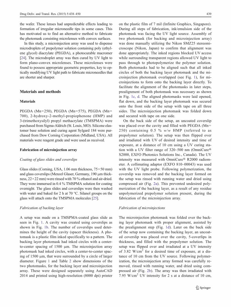
Effect of varying UV intensity and time of exposure Trip-licates of backing layers were formed for various times ofexposure at 3.82, 5.90, and 7.95 W/cm2 UV intensities. Thevarious time of exposure points used were at every 0.5th sec-ond decrement from 3.5 to 0.5 s, with distance of exposurekept constant at 10 cm from the UV source. Backing layersformed were observed for its fragility and conductivity of
liquids. Approximately 10 μL of PEDGA (Mn=700) wasapplied to each backing layer to test for its liquid conductivity,and if so, the solution will be absorbed onto a piece of tissuepaper placed on the other side of the backing layer. Only thebacking layer fabricated at UV intensity 3.82 W/cm2 with atime of exposure of 1.5 s (Table 1) was able to show passingthrough of PEGDA (Mn=700) for all three triplicates.
Effect of varying dimensions of photomasks Backing layerphotomasks of different inked circle dimensions of 200 μmand 300 μm were tested. The fragility and conductivity ofPEGDA (Mn=700) through the backing layers produced fromboth photomasks were comparable and were observed to havesimilar results as that mentioned above. For both, a UV inten-sity of 3.82 W/cm2 with a time of exposure of 1.5 s was theonly set of triplicates that had a balance between fragility andliquid conductivity.
Fabrication of microinjections
Effect of varying time of exposure Microinjections withoutthe backing layer were first made to determine which time ofexposurewould be appropriate. AUVintensity of 7.95W/cm2
was used with a distance of 10 cm from the UV source. Dif-ferent exposure times of 2, 2.5, and 3 s were used, and it wasobserved that at 2 and 2.5 s, microinjections fabricated werecylindrically shaped and visibly hollow as desired. At 3 s, alayer of polymer blocking the tips of the microinjections wasobserved. This phenomenon was not observed in the 2.5 and2 s exposure times.
Effect of varying dimensions of photomasks Varying de-signs of backing layer photomasks were used togetherwith different microinjection photomasks to form micro-injection arrays (Table 2). The backing layer photomasksonly contain inked circles while microinjection photo-masks consist of inked circles of similar diameters to the
Table 1 Comparison ofUV intensities at 3.82,5.90, or 7.95 W/cm2 atdifferent time exposures
UV intensity (W/cm2)
Time (s) 7.95 5.90 3.82
3.5 ✕ ✕ ✕
3 ✕ ✕ ✕
2.5 ✕ ✕ ✕
2 ✕ ✕ ✕
1.5 ✕ ✕ ✓
1 ✕ ✕ Brittle
0.5 Brittle − −
✕ PEGDA700 was unable to pass through,−backing layer was not formed complete-ly, ✓ PEGDA700 were able to passthrough the triplicates
442 Drug Deliv. and Transl. Res. (2015) 5:438–450

backing layer photomask it was paired with and surround-ing outer circles of larger dimensions. Each outer circlesurrounds the inked circle in the microinjection photo-mask such that there was a transparent ring of a certainthickness, as seen in Fig. 1c. When both photomasks wereoverlapped to form microinjection array, this thicknesswas equivalent to the thickness of the resultant microin-jection walls. Microinjections fabricated from pair A wereobserved to have blockage. The base of the microinjec-tions also had reduced inner diameters of approximately80 μm. Subsequently, pair B was used, and the microin-jections were observed to be incompletely formed. Man-ual alignment of both photomasks was also difficult dueto the small dimensions of the circles. In consideration ofboth pairs of photomasks initially experimented on, an-other pair of photomasks was used, pair C. The microin-jections formed were observed to be hollow throughoutwith an inner base diameter approximating 200 μm, anouter tip diameter approximating 500 μm, and an innertip diameter approximating 400 μm (Fig. 3). This sug-gested that the thickness of the transparent ring on thephotomasks could indeed fabricate microinjection wallsof equivalent thickness. Alignment in pair C was alsoeasier which led to less instances of misalignment. Mis-alignment of the photomasks could lead to incompletelyformed microinjections or microinjections with thickenedwalls, leading to reduced inner diameters. This could af-fect the volume of liquid expelled from each microinjec-tion to form the microlenses.
Following the fabrication of the microinjections, allmicroinjections of an array were proved to be fully func-tional by simply pipetting PEGDA solution onto the back-ing layer of the microinjection array and determine if thesolution was able to pass through the microinjection tipsand be absorbed onto a piece of Kimwipes. Also, themicroinjections were also seen to be hollow using thestereomicroscope.
Fabrication of microlenses
Dynamic contact angle
Characterization of droplets formed from PEGDA of varyingmolecular weights which also varied in viscosity was done todetermine the effect on the droplet size over a period of dif-ferent intervals. The higher the molecular weight PEGDAused, the larger the contact angle of the droplet was observedas shown in Fig. 4. PEGDA (Mn=250) microlens was ob-served to be comparably flat at time 0 min, while PEGDA(Mn=700) microlens was observed to retain its shape evenafter 10 min.
Stamping
Triplicates of microlens array were produced from the fabri-cated microinjection array stamp. A stereomicroscopic imageof the microlenses has been shown in Fig. 5e. The averageheight and diameter of the four microlenses from each cover-slip were measured. The pooled average height of 12microlenses was 135.5±24.4 μm while the pooled averagediameter was 734.5±90.0 μm. The radius of curvature of themicrolenses was calculated using the following equation withthe pooled averages:
R ¼ K þ 1ð Þh2 þ ∅� 2ð Þ22h
ð1Þ
where R is the radius of curvature, ∅ is the diameter of themicrolens, K is the aspheric constant, and h is the height. Theaspheric constant (K) of a spherical plano-convex lens is 0[29]. The radius of curvature calculated using the pooled av-erages was 565.4 μm.
The contact angle (α) of a plano-convex lens is also givenby
sinα ¼ r.R ð2Þ
where r is the radius of the microlens. For the microlensesfabricated, the contact angle was 40.6±6.0.
Fabrication of photomask
Water-based glass paint was colored onto areas using the spotterand carefully controlled not to spread over the microlenses(Fig. 5f). Physical properties of themicrolenses remained approx-imately the same after painting. As for optical properties, thefocal length ( f ) produced from these microlenses were estimatedto be 1203.0 μm via the lens maker’s equation as stated below:
1
f¼ nl
nm−1
� �� 1
r1−1
r2
� �ð3Þ
Table 2 Summary of circle dimensions patterned on different pairs (A,B, or C) of backing layer and microinjection photomasks
Diameter (μm)
Pair Inked circle Outer circle Thickness
A 200 600 200
B 300 400 50
C 300 500 100
Backing layer photomasks only contain inked circles while microinjec-tion photomasks consist of inked circles of similar diameters to the back-ing layer photomask it is paired with and surrounding outer circles oflarger dimensions. Each outer circle surrounds the inked circle such thatthere is a clear transparent ring of a certain thickness, which will beequivalent to the thickness of the resultant microinjection walls. Pair Cwas the chosen pair of photomasks used
Drug Deliv. and Transl. Res. (2015) 5:438–450 443

where nl is the refractive index of the lens material PEGDA(Mn=700) (1.47), nm is the refractive index of ambient medium,air (1.00) at a wavelength of 365 nm, r1 is the radius of curvature
of the first surface, r2 is the radius of curvature of the secondsurface, which is ∞ (1/r2=0) for a plano-convex lens. The pho-tomask was then tested for its use in microneedle fabrication.
500 µm 500 µm
a b
c
Bottom view Top viewFig. 3 a Back view of the base oftwo microinjections. b Top viewof two microinjection tips. cImage of microinjection array
0
10
20
30
40
50
60
70
0 5 10 15
Co
nta
ct
An
gle
Time (min)
PEGDA 250 PEGDA 575 PEGDA 700
61.62
53.68
51.28
42.52
53.41
50.41
49.23
40.91
30.72
22.34
18.65
18.53
PEGDA 700 PEGDA 575 PEGDA 250
0 m
in5
min
10
min
15
min
a b
Fig. 4 Contact angle of PEGDAs at 1 μL each on the glass coverslip. a Images of polymerized droplets with contact angle. bContact angle of PEGDAsof varied molecular weight with respect to time
444 Drug Deliv. and Transl. Res. (2015) 5:438–450
Fabrication of microneedle shafts
Photomask consisting plano-convex microlenses enabled theUV light to focus at a focal point to form tapered microneedles.In combination with the use of the photomask containingplano-convex microlenses, microneedle fabrication was alsofurther enhancedwith the optimization of other parameters suchas UV intensity, spacer thickness, and time of exposure.
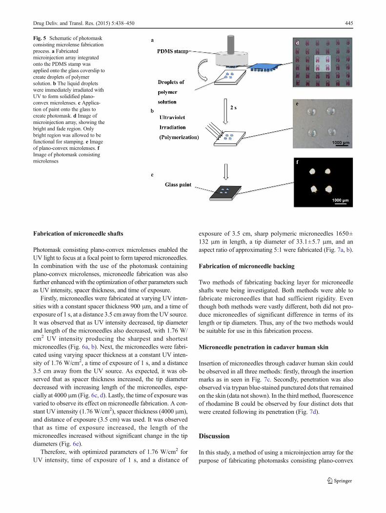
Firstly, microneedles were fabricated at varying UV inten-sities with a constant spacer thickness 900 μm, and a time ofexposure of 1 s, at a distance 3.5 cm away from the UV source.It was observed that as UV intensity decreased, tip diameterand length of the microneedles also decreased, with 1.76 W/cm2 UV intensity producing the sharpest and shortestmicroneedles (Fig. 6a, b). Next, the microneedles were fabri-cated using varying spacer thickness at a constant UV inten-sity of 1.76 W/cm2, a time of exposure of 1 s, and a distance3.5 cm away from the UV source. As expected, it was ob-served that as spacer thickness increased, the tip diameterdecreased with increasing length of the microneedles, espe-cially at 4000μm (Fig. 6c, d). Lastly, the time of exposure wasvaried to observe its effect on microneedle fabrication. A con-stant UV intensity (1.76 W/cm2), spacer thickness (4000 μm),and distance of exposure (3.5 cm) was used. It was observedthat as time of exposure increased, the length of themicroneedles increased without significant change in the tipdiameters (Fig. 6e).
Therefore, with optimized parameters of 1.76 W/cm2 forUV intensity, time of exposure of 1 s, and a distance of
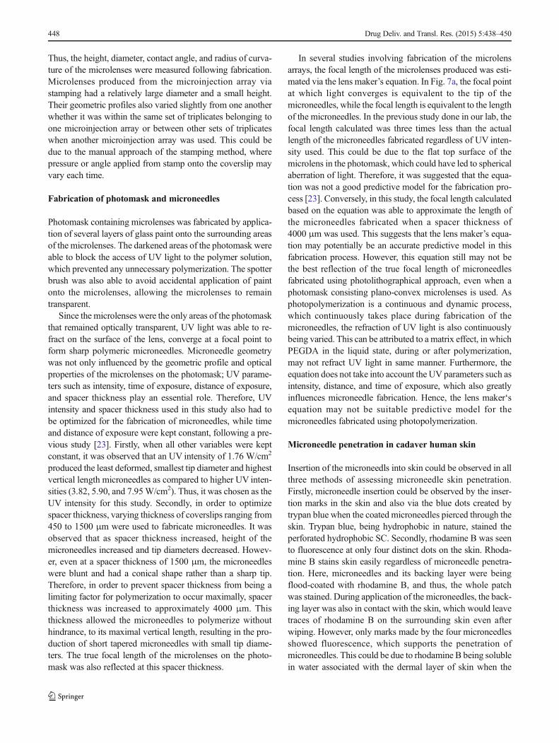
exposure of 3.5 cm, sharp polymeric microneedles 1650±132 μm in length, a tip diameter of 33.1±5.7 μm, and anaspect ratio of approximating 5:1 were fabricated (Fig. 7a, b).
Fabrication of microneedle backing
Two methods of fabricating backing layer for microneedleshafts were being investigated. Both methods were able tofabricate microneedles that had sufficient rigidity. Eventhough both methods were vastly different, both did not pro-duce microneedles of significant difference in terms of itslength or tip diameters. Thus, any of the two methods wouldbe suitable for use in this fabrication process.
Microneedle penetration in cadaver human skin
Insertion of microneedles through cadaver human skin couldbe observed in all three methods: firstly, through the insertionmarks as in seen in Fig. 7c. Secondly, penetration was alsoobserved via trypan blue-stained punctured dots that remainedon the skin (data not shown). In the third method, fluorescenceof rhodamine B could be observed by four distinct dots thatwere created following its penetration (Fig. 7d).
Discussion
In this study, a method of using a microinjection array for thepurpose of fabricating photomasks consisting plano-convex
Fig. 5 Schematic of photomaskconsisting microlense fabricationprocess. a Fabricatedmicroinjection array integratedonto the PDMS stamp wasapplied onto the glass coverslip tocreate droplets of polymersolution. b The liquid dropletswere immediately irradiated withUV to form solidified plano-convex microlenses. c Applica-tion of paint onto the glass tocreate photomask. d Image ofmicroinjection array, showing thebright and fade region. Onlybright region was allowed to befunctional for stamping. e Imageof plano-convex microlenses. fImage of photomask consistingmicrolenses
Drug Deliv. and Transl. Res. (2015) 5:438–450 445

microlenses has been presented. Microinjection array was firstfabricated using a two-step photolithographic approach andthen incorporated into a stamp to produce liquidmicrodroplets. These liquid microdroplets were polymerizedand made into a photomask, which was used to converge theUV light path to fabricate sharp polymeric needles. Therefore,in order to produce microlenses of desired geometric profiles,the physical properties of the microinjection array such as theheight, diameter, and rigidity had to be optimized.
Fabrication of microinjection array
The backing layer and microinjection tips were two es-sential components to the microinjection array. The back-ing layer had to possess microwell-like structures in orderto act as a hollow base for the microinjections. Whenthe backing layer was initially fabricated without the
microinjections, varying the dimensions of the backinglayer photomask did not significantly affect the abilityof PEGDA (Mn=700) to pass through. However, whenthe microinjection tips were fabricated onto the backinglayer, the microwell structures in the backing layer greatlyreduced in diameter. This could be due to increased poly-merization of the backing layer during microinjection fab-rication where it was exposed to another round of UVlight. When microinjection array was fabricated using pairA, the microinjections were observed to be closed off dueto the great thickness of the walls. This suggested that areduction in wall thickness was necessary and thereforeimplied that the microinjection photomask used shouldpossess transparent rings of reduced thickness. However,when wall thickness was reduced to approximately50 μm, as in pair B, the microinjections were incomplete-ly formed and were fragile. Thus, a balance between
Fig. 6 a Tip diameters ofmicroneedles when UV intensitywas varied. b Length of themicroneedles when UV intensitywas varied. c Using a constantUV intensity of 1.76 W/cm2, tipdiameters of microneedles variedwith different spacer thickness. dUsing a constant UV intensity of1.76 W/cm2, length ofmicroneedles varied withdifferent spacer thickness. eUsing a constant UV intensity of1.76 W/cm2 and spacer thicknessof 4000 μm, microneedle lengthdid not vary much with differenttimes of exposure
446 Drug Deliv. and Transl. Res. (2015) 5:438–450

preserving the microwell structures of the backing layerand the fragility of the microinjections had to be opti-mized. Therefore, a 300-μm backing layer photomaskand a microinjection photomask having transparent ringsof 100 μm thickness, as in pair C, was used in the finalfabrication method of the microinjections as it was theonly pair which presented with such a balance (Table 2).
The microinjections fabricated from pair C were cylin-drical in shape and were hollow. However, when innerdiameters of different parts of the microinjection weremeasured, it gradually increased from the base to the tipof the microinjection. This could be due to the change indiffraction of UV light as it passes through the photomaskand as the microinjection forms. This could have in-creased the volume of polymer solution individual micro-injections could hold.
Using two methods, i.e., PEGDA pass through andstereomicroscopy, it was confirmed that all the microin-jections within the array were fully functional and any ofthe microinjections can be used further. Therefore, in or-der to prove the concept of fabrication of the microlensusing this method, only 4 out of the 49 microinjectionswithin the array were used. For upscaling the fabricationof microlens array, the assembly of the PDMS microin-jection stamp (see Dynamic contact angle and Fig. 5) canbe modified to allow PEGDA to pass through more num-ber of microinjections (>2×2 array). This allows the for-mation of bigger array of microdroplet and hence the big-ger array of microlens after photolithography. The authorrecommends the use of controlled system or machinery to
control the passage of PEGDA to form the microdropletsfor further improvements and upscaling of microlensarray.
Fabrication of microlenses
The fabrication of microlenses starts off with the selection ofpolymer and backing, as both were essential in the resultantcharacterization of the plano-convex microlenses. Firstly, thechoice of the polymer solution used was greatly influenced byits molecular weight and viscosity. The higher the molecularweight of PEGDA used, the greater the viscosity [30], andthus, droplets of more desirable geometric profiles were pro-duced. Furthermore, as shown in Fig. 4, PEGDA 700 wasfound to have higher contact angle on glass coverslip thanother low molecular weight PEGDA. Contact angle werefound to be dependent on time for all three types of PEGDA.However, the decrease in the contact angle for PEGDA 700and PEGDA 575 was still much higher than PEGDA 250 after15 min. Therefore, PEGDA 700 as the polymer solution onglass coverslips was amenable for the fabrication of plano-convex microlenses. The change in contact angle can be at-tributed to the inertial and viscous effects of contact anglewhich might be a cause of dynamic interfacial interaction ofliquid droplets with solid glass surface and its dependency ontime [32–34].
To construct a photomask that was able to fabricate sharppolymeric needles, the geometry of the microlenses had to beoptimized. Characteristics of the microlenses determine thedegree of refraction of UV light rays on the convex surface.
1000 µm
a
dc
bFig. 7 a UV light refracts on thesurface of the lens to focus UVlight into a conical light path,producing tapered microneedles.b Side view of the microneedles(inverted). c Image of skinfollowing microneedle insertion.d Skin penetration assessed usingfluorescence following skinpenetration of rhodamine B
Drug Deliv. and Transl. Res. (2015) 5:438–450 447
Thus, the height, diameter, contact angle, and radius of curva-ture of the microlenses were measured following fabrication.Microlenses produced from the microinjection array viastamping had a relatively large diameter and a small height.Their geometric profiles also varied slightly from one anotherwhether it was within the same set of triplicates belonging toone microinjection array or between other sets of triplicateswhen another microinjection array was used. This could bedue to the manual approach of the stamping method, wherepressure or angle applied from stamp onto the coverslip mayvary each time.
Fabrication of photomask and microneedles
Photomask containing microlenses was fabricated by applica-tion of several layers of glass paint onto the surrounding areasof the microlenses. The darkened areas of the photomask wereable to block the access of UV light to the polymer solution,which prevented any unnecessary polymerization. The spotterbrush was also able to avoid accidental application of paintonto the microlenses, allowing the microlenses to remaintransparent.
Since the microlenses were the only areas of the photomaskthat remained optically transparent, UV light was able to re-fract on the surface of the lens, converge at a focal point toform sharp polymeric microneedles. Microneedle geometrywas not only influenced by the geometric profile and opticalproperties of the microlenses on the photomask; UV parame-ters such as intensity, time of exposure, distance of exposure,and spacer thickness play an essential role. Therefore, UVintensity and spacer thickness used in this study also had tobe optimized for the fabrication of microneedles, while timeand distance of exposure were kept constant, following a pre-vious study [23]. Firstly, when all other variables were keptconstant, it was observed that an UV intensity of 1.76 W/cm2
produced the least deformed, smallest tip diameter and highestvertical length microneedles as compared to higher UV inten-sities (3.82, 5.90, and 7.95W/cm2). Thus, it was chosen as theUV intensity for this study. Secondly, in order to optimizespacer thickness, varying thickness of coverslips ranging from450 to 1500 μm were used to fabricate microneedles. It wasobserved that as spacer thickness increased, height of themicroneedles increased and tip diameters decreased. Howev-er, even at a spacer thickness of 1500 μm, the microneedleswere blunt and had a conical shape rather than a sharp tip.Therefore, in order to prevent spacer thickness from being alimiting factor for polymerization to occur maximally, spacerthickness was increased to approximately 4000 μm. Thisthickness allowed the microneedles to polymerize withouthindrance, to its maximal vertical length, resulting in the pro-duction of short tapered microneedles with small tip diame-ters. The true focal length of the microlenses on the photo-mask was also reflected at this spacer thickness.
In several studies involving fabrication of the microlensarrays, the focal length of the microlenses produced was esti-mated via the lens maker’s equation. In Fig. 7a, the focal pointat which light converges is equivalent to the tip of themicroneedles, while the focal length is equivalent to the lengthof the microneedles. In the previous study done in our lab, thefocal length calculated was three times less than the actuallength of the microneedles fabricated regardless of UV inten-sity used. This could be due to the flat top surface of themicrolens in the photomask, which could have led to sphericalaberration of light. Therefore, it was suggested that the equa-tion was not a good predictive model for the fabrication pro-cess [23]. Conversely, in this study, the focal length calculatedbased on the equation was able to approximate the length ofthe microneedles fabricated when a spacer thickness of4000 μm was used. This suggests that the lens maker’s equa-tion may potentially be an accurate predictive model in thisfabrication process. However, this equation still may not bethe best reflection of the true focal length of microneedlesfabricated using photolithographical approach, even when aphotomask consisting plano-convex microlenses is used. Asphotopolymerization is a continuous and dynamic process,which continuously takes place during fabrication of themicroneedles, the refraction of UV light is also continuouslybeing varied. This can be attributed to a matrix effect, in whichPEGDA in the liquid state, during or after polymerization,may not refract UV light in same manner. Furthermore, theequation does not take into account the UV parameters such asintensity, distance, and time of exposure, which also greatlyinfluences microneedle fabrication. Hence, the lens maker‘sequation may not be suitable predictive model for themicroneedles fabricated using photopolymerization.
Microneedle penetration in cadaver human skin
Insertion of the microneedls into skin could be observed in allthree methods of assessing microneedle skin penetration.Firstly, microneedle insertion could be observed by the inser-tion marks in the skin and also via the blue dots created bytrypan blue when the coated microneedles pierced through theskin. Trypan blue, being hydrophobic in nature, stained theperforated hydrophobic SC. Secondly, rhodamine B was seento fluorescence at only four distinct dots on the skin. Rhoda-mine B stains skin easily regardless of microneedle penetra-tion. Here, microneedles and its backing layer were beingflood-coated with rhodamine B, and thus, the whole patchwas stained. During application of the microneedles, the back-ing layer was also in contact with the skin, which would leavetraces of rhodamine B on the surrounding skin even afterwiping. However, only marks made by the four microneedlesshowed fluorescence, which supports the penetration ofmicroneedles. This could be due to rhodamine B being solublein water associated with the dermal layer of skin when the
448 Drug Deliv. and Transl. Res. (2015) 5:438–450
microneedles penetrated, leading to fluorescence only in pen-etrated region on skin.
Further optimization of this microlense fabrication methodusingmicroinjection arrays is still required to produce a biggerarray of microlenses. This would, in turn, also lead to photo-masks consisting of moremicrolenses that are able to fabricatelarger microneedle arrays. Nevertheless, through the success-ful fabrication of short tapered microneedles in this study,apart from the UV parameters being optimized, it suggeststhat the photomask consisting plano-convex microlenses fab-ricated using this method can perform its function efficiently.
Conclusion
In this study, the microinjection array was shown to be capableof producing plano-convex microlenses that possessed appro-priate geometric properties. Photomask consisting microlensarray was successfully fabricated using a microinjection array.Photomask fabrication was simple and was able to producepolymeric microneedles, which were shorter and sharper. Itcan also potentially enhance skin penetration efficiency asdemonstrated in cadaver human skin. This approach can beof potential use to fabricate sharp microneedle arrays of vari-ous dimensions using the photomask consisting microlensesby varying the dimensions of microlens. It can also be ofpotential use to fabricate the hollow polymeric microneedlearray.
Acknowledgments The authors thank Dr. Jaspreet Singh Kochharfrom P&G Singapore, Dr. Pan Jing, and Ms. Li Hairui from the NationalUniversity of Singapore for their helpful discussions.
Conflict of interest The authors declare no conflict of interest.
References
1. Daugimont L, Baron N, Vandermeulen G, Pavselj N, Miklavcic D,Jullien MC, et al. Hollow microneedle arrays for intradermal drugdelivery and DNA electroporation. J Membr Biol. 2010;236(1):117–25.
2. Paudel KS, Milewski M, Swadley CL, Brogden NK, Ghosh P,Stinchcomb AL. Challenges and opportunities in dermal/transdermal delivery. Ther Deliv. 2010;1(1):109–31.
3. Lhernould MS. Optimizing hollow microneedles arrays aimed attransdermal drug delivery. Microsyst Technol. 2013;19(1):1–8.
4. Kaestli LZ,Wasilewski-Rasca AF, Bonnabry P, Vogt-Ferrier N. Useof transdermal drug formulations in the elderly. Drugs Aging.2008;25(4):269–80.
5. Kenneth A. Walters MSR. Dermatologic, cosmeceutic and cosmet-ic development. 1st ed. Informa Healthcare; 2007.
6. Escobar-Chávez JJ, Bonilla-Martínez D, Angélica M, Villegas G,Molina-Trinidad E, Casas-Alancaster N, et al. Microneedles: avaluable physical enhancer to increase transdermal drug delivery.J Clin Pharmacol. 2011;51(7):964–77.
7. Kim YC, Park JH, Prausnitz MR. Microneedles for drug and vac-cine delivery. Adv Drug Deliv Rev. 2012;64(14):1547–68.
8. Indermun S, Luttge R, Choonara YE, Kumar P, du Toit LC, ModiG, et al. Current advances in the fabrication of microneedles fortransdermal delivery. J Control Release. 2014;185(0):130–8.
9. Bariya SH, Gohel MC, Mehta TA, Sharma OP. Microneedles: anemerging transdermal drug delivery system. J Pharm Pharmacol.2012;64(1):11–29.
10. Park JH, Allen MG, Prausnitz MR. Biodegradable polymermicroneedles: fabrication, mechanics and transdermal drug deliv-ery. J Control Release. 2005;104(1):51–66.
11. Wilke N, Mulcahy A, Ye SR, Morrissey A. Process optimizationand characterization of silicon microneedles fabricated by wet etchtechnology. Microelectron J. 2005;36(7):650–6.
12. Schlingloff G, Kiel HJ, Schober A.Microlenses as amplification forCCD-based detection devices for screening applications in biology,biochemistry, and chemistry. Appl Opt. 1998;37(10):1930–4.
13. Roulet JC, Volkel R, Herzig HP, Verpoorte E, de Rooij NF,Dandliker R. Fabrication of multilayer systems combiningmicrofluidic and microoptical elements for fluorescence detection.J Microelectromech Syst. 2001;10(4):482–91.
14. Stevens R, Harvey T. Lens arrays for a three-dimensional imagingsystem. J Opt A Pure Appl Opt. 2002;4(4):S17.
15. HeM, Yuan XC, Ngo NQ, Bu J, Tao SH. Single-step fabrication ofa microlens array in sol–gel material by direct laser writing and itsapplication in optical coupling. J Opt A Pure Appl Opt. 2004;6(1):94.
16. Sunghyun Y, Joon-Geun H, Joo-Young J, Chang-Hyeon J, Yong-Kweon K. Monolithically integrated glass microlens scanner usinga thermal reflow process. J Micromech Microeng. 2013;23(6):065012.
17. Lian ZJ, Hung SY, Shen MH, Yang H. Rapid fabrication ofsemiellipsoid microlens using thermal reflow with two differentphotoresists. Microelectron Eng. 2014;115(0):46–50.
18. He M, Yuan XC, Ngo N, Bu J, Kudryashov V. Simple reflowtechnique for fabrication of a microlens array in solgel glass. OptLett. 2003;28(9):731–3.
19. Xiangwei M, Feng C, Qing Y, Hao B, Hewei L, Pubo Q, et al. Asimple way to fabricate close-packed high numerical aperturemicrolens arrays. IEEE Photon Technol Lett. 2013;25(14):1336–9.
20. Kuo JN, Hsieh CC, Yang SY, Lee GB. An SU-8 microlens arrayfabricated by soft replica molding for cell counting applications. JMicromech Microeng. 2007;17(4):693.
21. Kuo SM, Lin CH. Fabrication of aspherical SU-8 microlens arrayutilizing novel stamping process and electro-static pulling method.Opt Express. 2010;18(18):19114–9.
22. Park JH, Yoon YK, Choi SO, Prausnitz MR, Allen MG. Taperedconical polymer microneedles fabricated using an integrated lenstechnique for transdermal drug delivery. IEEE Trans Biomed Eng.2007;54(5):903–13.
23. Kochhar J, Anbalagan P, Shelar S, Neo J, Iliescu C, Kang L. Directmicroneedle array fabrication off a photomask to deliver collagenthrough skin. Pharm Res. 2014;31(7):1724–34.
24. de Groot JH, van Beijma FJ, Haitjema HJ, Dillingham KA, HoddKA, Koopmans SA, et al. Injectable intraocular lensmaterials basedupon hydrogels. Biomacromolecules. 2001;2(3):628–34.
25. Kochhar JS, Goh WJ, Chan SY, Kang L. A simple method ofmicroneedle array fabrication for transdermal drug delivery. DrugDev Ind Pharm. 2013;39(2):299–309.
26. Pan J, Yung Chan S, Common JE, Amini S, Miserez A, BirgitteLane E, et al. Fabrication of a 3D hair follicle-like hydrogel by softlithography. J Biomed Mater Res A. 2013;101(11):3159–69.
27. Li H, Low Y, Chong H, Zin M, Lee CY, Li B et al. Microneedle-mediated delivery of copper peptide through skin. Pharm Res.2015;32(8):2678–89.
Drug Deliv. and Transl. Res. (2015) 5:438–450 449

28. Kochhar JS, Quek TC, Soon WJ, Choi J, Zou S, Kang L.Effect of microneedle geometry and supporting substrate onmicroneedle array penetration into skin. J Pharm Sci. 2013;102(11):4100–8.
29. Nussbaum P, Voelkel R, Herzig HP, Eisner M, Haselbeck S.Design, fabrication and testing of microlens arrays for sensorsand microsystems. Pure Appl Opt: J Eur Opt Soc Part A.1997;6(6):617.
30. Moon BU, Tsai SH, Hwang D. Rotary polymer micromachines:in situ fabrication of microgear components in microchannels.Microfluid Nanofluid. 2015;19(1):1–8.
31. Cox RG. Inertial and viscous effects on dynamic contact angles. JFluid Mech. 1998;357(1):249–78.
32. Welygan DG, Burns CM. Dynamic contact angles of viscous liq-uids. J Adhes. 1980;11(1):41–55.
33. Tan G, Wang Y, Li J, Zhang S. Synthesis and characterization ofinjectable photocrosslinking poly (ethylene glycol) diacrylate basedhydrogels. Polym Bull. 2008;61(1):91–8.
34. Rupp F, Axmann D, Ziegler C, Geis-Gerstorfer J. Adsorption/desorption phenomena on pure and teflon AF-coated titania sur-faces studied by dynamic contact angle analysis. J Biomed MaterRes. 2002;62(4):567–78.
450 Drug Deliv. and Transl. Res. (2015) 5:438–450