fabrication of a cell culture plate with a three
TRANSCRIPT

Myo Min ZawDepartment of Mechanical Engineering,
University of Maryland Baltimore,
County 1000 Hilltop Circle,
Baltimore, MD 21250
e-mail: [email protected]
William D. HedrichDepartment of Pharmaceutical Sciences,
University of Maryland School of Pharmacy,
Baltimore, MD 21201
e-mail: [email protected]
Timothy MunuheMem. ASME
Department of Mechanical Engineering,
University of Maryland Baltimore,
County 1000 Hilltop Circle,
Baltimore, MD 21250
e-mail: [email protected]
Mohamad HosseinBanazadeh
Department of Mechanical Engineering,
University of Maryland Baltimore,
County 1000 Hilltop Circle,
Baltimore, MD 21250
e-mail: [email protected]
Hongbing WangDepartment of Pharmaceutical Sciences,
University of Maryland School of Pharmacy,
Baltimore, MD 21201
e-mail: [email protected]
S. Andrew GadsdenMem. ASME
College of Engineering and Physical Sciences,
University of Guelph,
Guelph, ON N1G 2W1, Canada
e-mail: [email protected]
Liang ZhuMem. ASME
Department of Mechanical Engineering,
University of Maryland Baltimore,
County 1000 Hilltop Circle,
Baltimore, MD 21250
e-mail: [email protected]
Ronghui MaMem. ASME
Department of Mechanical Engineering,
University of Maryland Baltimore,
County 1000 Hilltop Circle,
Baltimore, MD 21250
e-mail: [email protected]
Fabrication of a Cell CulturePlate With a Three-DimensionalPrinted Mold and ThermalAnalysis of PDMS-BasedCasting ProcessPolydimethylsiloxane (PDMS)-based casting method was used to fabricate PDMS cellculture platforms with molds printed by a fused deposition modeling (FDM) printer. Cellviability study indicated that the produced plates have the suitable biocompatibility, sur-face properties, and transparency for cell culture purposes. The molds printed fromacrylonitrile-butadiene-syrene (ABS) were reusable after curing at 65 �C, but were dam-aged at 75 �C. To understand thermal damage to the mold at elevated temperatures, thetemperature distribution in an ABS mold during the curing process was predicted using amodel that considers conduction, convection, and radiation in the oven. The simulatedtemperature distribution was consistent with the observed mold deformation. As the maxi-mum temperature difference in the mold did not change appreciably with the curing tem-perature, we consider that the thermal damage is due to the porous structure thatincreases the thermal expansion coefficient of the printed material. Our study demon-strated that FDM, an affordable and accessible three-dimensional (3D) printer, has greatpotential for rapid prototyping of custom-designed cell culture devices for biomedicalresearch. [DOI: 10.1115/1.4040134]
Keywords: heat transfer, simulation, 3D printing, PDMS-based casting
1 Introduction
Commercially available in vitro cell culture models are widelyused in drug screening to assess therapeutic efficacy and unwantedside effects [1,2]. To improve the efficiency and throughput of thescreening process, it is highly desirable to formulate a cell co-culture model that enables the drug efficacy and toxicity on multi-ple organs to be evaluated simultaneously. Ideally, a cell
Contributed by the Heat Transfer Division of ASME for publication in theJOURNAL OF THERMAL SCIENCE AND ENGINEERING APPLICATIONS. Manuscript receivedOctober 17, 2017; final manuscript received April 4, 2018; published online July 13,2018. Assoc. Editor: Samuel Sami.
Journal of Thermal Science and Engineering Applications DECEMBER 2018, Vol. 10 / 061002-1Copyright VC 2018 by ASME
Downloaded From: http://thermalscienceapplication.asmedigitalcollection.asme.org/ on 08/30/2018 Terms of Use: http://www.asme.org/about-asme/terms-of-use

co-culture model should allow cells derived from selected organsto share medium to include inter-organ interactions in the toxico-logical study [2]. Unfortunately, most commercially available cellculture plates do not accommodate user-specific medium sharing.Researchers have to design and prototype cell co-culture devicestailored to the specific research interests in their labs. Currently,polydimethylsiloxane (PDMS)-based casting is a widely adoptedmethod in research labs to prototype biomedical fluidic devicesthat are designed to carry out disease diagnostics, to culture cellswith a controllable microenvironment, and to examine chemicaland biological processes with a high level of precision [3]. Theproduction of such devices involves fabrication of a master moldwith a negative design, curing PDMS liquid in the mold at ele-vated temperatures, and assembly of the device. Among thesesteps, fabrication of the master mold is the most time-consumingand costly process.
A number of traditional processes have been used to createmaster molds, which include, but are not limited to hot embossing,injection molding, laser photoablation, and photolithography[4–6]. Using a dedicated pressure equipment, hot embossingmethod creates a designed pattern by pressing an established moldagainst heated thermoplastic materials under a high pressure.Injection molding involves forcing melted thermoplastic materialsinto a heated mold cavity, followed by cooling down inside of thecavity. The requirement of a high-quality mold and dedicatedequipment before production makes both methods time-consuming and expensive for prototyping. Laser photoablationmethod applies a high-powered pulsed laser to remove the mate-rial from a plate of thermoplastic material [4]. This process isinexpensive but it takes extended time to create a pattern. In addi-tion, the mold material has to be compatible with the laser. Photo-lithography is a comparably complicated process involvingmultiple operation steps, such as mask preparing, spin coating ofphotoresist, baking, and UV light exposure. This method is expen-sive, time-consuming, and dependent on sophisticated facilities ina clean room [5]. More details about other fabrication methodsand the associated advantages and disadvantages can be found inRefs. [4] and [6].
Recent development of three-dimensional (3D) printing tech-nology has offered a simplified fabrication process to make com-plex structures directly from a computer aided design [7–14].Unlike the above-mentioned conventional methods, the 3D print-ing technology allows for rapid prototyping of a master moldwithout necessitating access to expensive facilities and/or estab-lished molds. The rapid prototyping nature of this technology alsooffers an affordable means to enabling agile iterative design andoptimization. Components of microfluidic devices and integratedfunctional platforms have been fabricated using various commer-cialized 3D printing techniques, i.e., stereolithography, digitalmicromirror device-based projection printing, two-photon poly-merization, fused deposition modeling (FDM), inkjet, and bio-printing [7–17]. A variety of biomedical fluidic devices have beendeveloped using 3D printing technologies [7,8,17].
Besides creation of master molds, curing of liquid PDMS poly-mer is another important step in soft lithography. A high curingtemperature reduces the required curing time while increasing thehardness of the final product [18]. Curing temperature of thePDMS also affects the mechanical properties of the cured PDMSparts [18]. The manufacturer of the elastomer (SYLGARD 184SILICONE ELASTOMER, Ellsworth Adhesives, WI) suggeststemperature-dependent curing time, for example, 35 min at100 �C, 20 min at 125 �C, and 10 min at 150 �C, etc [19]. Thesesuggested curing temperatures might not be suitable for some 3Dprinted polymer-based molds because of their low threshold ofglass transition temperature. To the authors’ best knowledge, thereis no existing thermal analysis of PDMS curing process.
In this study, we demonstrated a custom-designed PDMS cellco-culture plate made with an acrylonitrile-butadiene-syrene(ABS) mold. ABS was used because of its demonstrated biocom-patibility and acceptable glass transition temperature for the
curing process. The master molds were generated using an FDMprinter due to its affordable cost and easy access to users [7,8].Designed with multiple inter-connected chambers, the multi-chamber cell culture plate is intended to serve as an efficient cellco-culture model that allows for user-specific medium sharingbetween cells housed in different compartments. The fabricatedPDMS cell co-culture plates were tested for cell culture compati-bility and cell viability. PDMS were cured with two different cur-ing temperatures, and we observed that the ABS molds retainedtheir structural integrity after curing in the oven at 65 �C for anhour, but were damaged over the same duration when the oventemperature was 10 �C higher. To understand the cause of molddamage, we also performed numerical simulation to predict andanalyze the transient and steady-state temperature distribution inPDMS and the mold during the curing process.
2 Material and Method
The custom-designed cell co-culture plate with a diameter of85 mm is shown in Fig. 1(a). It has a large chamber with a diame-ter of 27 mm located at its center and six smaller wells (18 mm indiameter) evenly distributed around the central chamber. All ofthe chambers are six millimeters in depth. Human primary hepato-cytes are seeded in the center chamber while the cells derivedfrom other organs including kidney, heart, and lung, are culturedin the surrounding chambers. Channels with a width of four milli-meters are designed to connect a chamber with adjacent ones ena-bling medium sharing with the assistance of an orbital shaker. Thecorresponding master mold for this plate is shown in Fig. 1(b).The plate was designed using the commercial software,SOLIDWORKS.
The fabrication process involves three major steps: (1) proto-typing of the mold using an FDM printer, (2) surface treatment ofthe mold, and (3) fabrication of PDMS platform. Each step isdescribed in detail below.
3D printing of the mold: A 3D printer (TAZ 5, LULZBOT, CO)was used to print the mold using ABS filament (3 mm, LulzBot,CO). It typically took 3–4 h to print the designed mold. Aftermolds with base thicknesses of 2 mm, 3 mm, and 4 mm weretested, we found that a minimum thickness of 3 mm is necessaryto prevent the mold from warping at the chosen curingtemperatures.
Surface treatment: The surface roughness of the printed partswith an FDM printer mainly depends on the deposited layer thick-ness. The FDM printer (TAZ 5, LULZBOT) allows depositionlayer thickness to be adjusted in the range from 350 microns to750 microns. Even when we used a layer thickness of 350 lm, theprinted molds still had a poor surface finishing. The uneven sur-face, if untreated, would be transferred to the cast PDMS part.The surface roughness of the plate would not only hinder cell
Fig. 1 (a) PDMS culture plate design and (b) mold with nega-tive pattern
061002-2 / Vol. 10, DECEMBER 2018 Transactions of the ASME
Downloaded From: http://thermalscienceapplication.asmedigitalcollection.asme.org/ on 08/30/2018 Terms of Use: http://www.asme.org/about-asme/terms-of-use

growth but also yield poor optical transparency, making it difficultto monitor cell growth under a microscope. In this study, the 3Dprinted mold was treated in a closed environment with severalpaper towels saturated with 50 ml pure Acetone (Pure AcetoneRemover, MI). Usually, it took 1.5–2 h to obtain a smooth surface.The porosity of the 3D printed parts was also measured. The moldwas weighted first. Then the mold was fully submerged into abeaker initially containing 300 ml of water and the total volumewas read. The volume of the mold, Vmold, was determined as thedifference between the total volume and the initial water volume.The volume of the solid ABS in the mold, Vabs was determined asmmold/qabs, where mmold is the measured mass of the mold andqabs is the density of the ABS material [20]. The porosity of themold, which is defined as volumetric fraction of the pores, wascalculated as uf ¼ 1-Vabs/Vmold.
Casting and curing of a PDMS platform: The prepared moldwas first fixed to the bottom of a Petri dish (100 mm dia.) using adouble-sided adhesive. 36 g of PDMS base was homogenouslymixed with 3.6 g of the curing agent at a weight ratio of 10:1(SYLGARD 184 SILICONE ELASTOMER, Ellsworth Adhe-sives, WI). Then, 39.6 g (40 ml) of the mixture was poured ontothe mold fixed in the Petri dish. After degassing in a vacuumchamber (RS – 1, Best Value Vacs, Napaville, IL) for an hour, thePetri dish was placed on a piece of fire brick in an oven (10GC,Quincy Lab, Inc., Chicago, IL) preheated to a setup temperature.After curing in the oven for an hour, the PDMS part was peeled.The mold, if undamaged, could be reused. At the end of the curingprocess, the steady-state temperature at the top surface of curedPDMS was measured using an infrared meter (Ti100, FlukeImager, NC) and the interior temperature on the ceiling and foursides of the oven surfaces were measured using thermal couples(copper and constantan wires, 100 micro dia. each, CaliforniaFine Wire Company, Grover Beach, CA). A thermometer at thetop of the oven measured the air temperature in the oven through-out the curing process.
Culture of human primary hepatocytes: Human primary hepato-cytes (HPH) were provided by Bioreclamation, IVT (Baltimore,MD). HPH with an initial viability greater than 90% were seededin the PDMS plates after collagen coating at 7.5� 105 cells perwell. Following attachment to the plates, the HPH were overlaidwith matrigel (0.25 mg/mL) in serum-free Williams Medium E,forming the typical sandwich culture for hepatocyte cultures.HPH were kept in supplemented Williams Medium E and incu-bated at 5% CO2 and 37 �C. Cells were visualized with a NikonEclipse Ti Microscope.
Cell viability assay: HPHs were seeded at 7.5� 105 cells/wellin collagen-coated 12-well plates or the PDMS plates followingcollagen coating. Cells were incubated for 72 h at 37 �C and 5%CO2. A typical 3-[4,5-dimethylthiazol-2-yl]-2,5 diphenyl tetrazo-lium bromide (MTT) assay was performed. Cell viability wasexpressed as the percentage of the cells grown in the typicalcollagen-coated 12-well plates.
3 Numerical Modeling of Curing Process
As shown in Fig. 2, a Petri dish containing PDMS polymer andan ABS mold was placed on a piece of fire brick in the pre-heatedoven for 60 min. The glass transition temperature of the ABS,which is 104 �C, sets up the upper limit of the curing temperature.Moreover, temperature difference in the mold during heating maycause warpage. To acquire information on the thermal conditionsduring the curing process, a heat transfer model considering con-duction, convection, and radiation was developed to predict thetransient and final temperature distributions in the PDMS and theABS mold. Heat conduction in the PDMS material, the mold, andthe fire brick is expressed by the traditional heat conduction equa-tion as
qicqi@T
@t¼ r � kirTð Þ; i ¼ 1; 2; 3 (1)
where q is the density, Cp is the specific heat, T is the temperature,and k is the thermal conductivity. Subscript i designates differentmaterials, which are the PDMS, the ABS mold, and the fire brickbase. Previous study shows that the volume shrinkage of PDMSafter polymerization is less than 0.6% [19,21]. Therefore, the den-sity of the PDMS is assumed constant throughout the curing pro-cess. Determining the thermal conductivity of the PDMS beforecomplete polymerization is difficult because the rate of polymer-ization is unknown. Considering the temperature in the mold atthe later stage of curing is more relevant to the mold deformation,we used temperature-dependent thermal conductivities of thecured PDMS in the thermal analysis of heat-induced mold defor-mation. The thin-walled Petri dish is not considered in the modelas it has similar properties as the ABS. Perfect contact is assumedat the interfaces between the PDMS and the mold because airpockets trapped at the interface have been eliminated by thedegassing process. The contact resistance between the Petri dishand firebrick is estimated to be 2.75 m2K/W based on a smoothsurface of Petri dish [22] and has been included in the heat trans-fer model. Thermal properties of the PDMS, the ABS mold, theair, and the fire brick are given in Table 1 [19, 23–30].
For curing temperatures in the range from 60 �C to 90 �C, peakradiation in the oven falls in the infrared spectrum with a wave-length range between 8 and 8.7 lm. The transmittance of PDMSfilms over this range of spectrum was studied by Chen et al. [31].They measured the transmittance of PDMS film in the mid-infrared spectrum for three different mixing ratios of the PDMSbase and the curing agent: 8:1, 10:1, and 12:1. This study showsthat when PDMS base and curing agent mixing ratio is 10:1, thePDMS layer has a significantly low transmittance for wavelengtharound 8 lm. Therefore, we assume the 3 mm-thick PDMS layeron top of ABS as an opaque medium for radiation heat transfer.
The 3D printed products by the FDM method have porousstructures and their thermal conductivities are porosity-dependent.The porosity of the 3D printed parts used in this study has beenmeasured to be 0.25 6 0.03. Numerous empirical models havebeen developed to evaluate the effective thermal conductivity ofcomposite materials [32,33]. The Maxwell model was first intro-duced to evaluate effective thermal conductivity in a heterogene-ous medium, but it is only validated when the porosity is less than0.25. Many researchers modified Maxwell’s model and considereddifferent effects such as filler loading, particle size, particle shape,and homogeneity of the dispersed phase in the matrix [32,33]. Forevaluating the effective thermal conductivity of 3D printed parts,
Fig. 2 Schematic of curing process in the oven
Journal of Thermal Science and Engineering Applications DECEMBER 2018, Vol. 10 / 061002-3
Downloaded From: http://thermalscienceapplication.asmedigitalcollection.asme.org/ on 08/30/2018 Terms of Use: http://www.asme.org/about-asme/terms-of-use

we used the Maxwell, Effective Medium Theory, Brueggemann,and Russell methods. The expressions of the models and eval-uated effective thermal conductivity are given in Table 2. Theresult from Russell method was used in the simulation as itemphasizes the connectivity of the solid structure, which is perti-nent for 3D printed parts by an FDM printer.
The thermal conditions of the simulation are shown in Fig. 2.Before curing, the PDMS liquid and the ABS mold are at theroom temperature of 20 �C. The assembly of the mold, the PDMSliquid, and the fire brick exchange heat with the surrounding envi-ronment by radiation and natural convection. As the surface areaof the assembly is much smaller than the interior surface area ofthe oven, radiation heat transfer is approximated as radiationbetween a small object enclosed by a large isothermal surface.The boundary condition is thus expressed as
�ki@T
@n¼ h T � Tairð Þ þ eir T4 � T4
w
� �(2)
where Tair is the air temperature, Tw is the temperature of the inte-rior oven surface, n is the unit vector pointing outward of the part,r is the Stefan-Boltzmann constant, e is the emissivity of thePDMS or the ABS mold, and h is the heat transfer coefficient. Theemissivity of the PDMS and ABS mold is 0.86 [13]. Tair wasmeasured by a built-in thermometer during the curing process.The air temperature was observed to be nearly constant during thecuring process. According to the manufacturer of the oven, themaximum temperature variation over the interior wall surface ofthe oven is less than 3 �C after a steady-state is established. Ourmeasurements confirmed that the maximum interior surface tem-perature variation at the curing temperatures of 65 �C and 75 �Cwere 61.75 �C and 62.25 �C, respectively. Thereby, the tempera-ture variation over the interior surface of the oven was minor andtherefore, neglected. Also, the air temperature measured by thethermometer at the ceiling of the oven remained nearly constantduring the curing process. Therefore, the change in the surfacetemperature due to the placement of the PDMS was not consid-ered either. Instead, the temperatures measured at the center of thetop and the side surfaces of oven were averaged to obtain Tw to
assume a uniform oven environment. The fire brick base was pre-heated in the oven and was assumed to be at the same temperatureas the air before curing.
The natural convection heat transfer coefficient, h, is dependenton the temperature difference between the cured parts and the sur-rounding environment. The heat transfer coefficient for naturalconvection on a horizontal surface is expressed as [22]
h ¼ 0:54ðGrLPrÞ14k
Lc(3)
where GrL is the Grashof number, Pr is the Prandtl number, whichis ðv=aÞ, Lc is the characteristics length of the PDMS layer, and vand a are kinematics viscosity and thermal diffusivity ofthe air, respectively [22]. Grashof number is defined as GrL
¼ ðgb Ts � Tairð ÞL3c=v2Þ, where g is the gravitational force, b is air
thermal expansion coefficient, which is 1/T for ideal gas, and Ts isthe top surface temperature of the PDMS. In the numerical solu-tion, the temperature at the center of the PDMS surface was usedas Ts.
In this study, heat generation due to polymerization of PDMS isneglected after an order-of-magnitude analysis. Previous studyshowed that heat generation is 2.79 kJ/mol at 25 �C and 23.4 kJ/mol at 77 �C for D3 based PDMS [34]. Using the higher amountof heat generation at 77 �C, and assuming the polymerization rateis constant and is completed within 30 min, the rate of heat gener-ation is estimated to be 0.122 W. The radiation heat transfer rateqradi from the oven to the top surface of the PDMS is estimatedusing below equation:
qradi ¼ eAr T4s�T4
w
� �(4)
For a curing temperature of 65 �C, the radiation heat transfer rateis 2.8 W at the beginning of the heating and 1.2 W when thePDMS surface temperature reaches 50 �C. Since the calculatedpolymerization heat generation rate is one order of magnitudelower than the radiation heat transfer rate, it is neglected in thisstudy.
Table 1 Thermal and physical properties of PDMS, ABS mold, air and fire brick
Properties PDMS Bulk ABS ABS mold Air Fire Brick
Density, q (kg/m3) 1030 [19] 1020 [25] 764.1a 1.177 [26] 2300 [27]Thermal conductivity, k (W/m K) 0.25 at 230 K, and 0.20 at 290 K–340 K [23] 0.17 [25] 0.122a 0.0257 [26] 0.47 [28]Specific heat, Cp (J/kgK) 1450 [24] 1386 [29] 1038.2a 1005 [26] 1000 [30]
aProperties of ABS mold are calculated based on porosity of 3D printed part.
Table 2 Correlations for effective thermal conductivity
Model Expression Effective thermal conductivity (W/mK)
Maxwell model [32] keff
km¼ 1þ 3u
kf þ km
kf � km
� �� uf
0.124
Effective medium theory [32]um �
km � keff
km � 2keff
þ uf �kf � keff
kf � 2keff
¼ 00.121
Brueggeman [32]ð1� uf Þ ¼
ðkf � keffÞ � ðkm=keffÞ1=3
ðkf � kmÞ0.123
Russell [32]
keff ¼ km �u2=3
f þ km
kf� ð1� u2=3
f Þ� �
u2=3f � uf þ
km
kfð1þ uf � u2=3
f Þ� �
0.122
Note: keff, km, and kf are the thermal conductivity of ABS mold, ABS polymer, and the air, respectively, and um and uf are volume fraction of ABS poly-mer and the air, respectively.
061002-4 / Vol. 10, DECEMBER 2018 Transactions of the ASME
Downloaded From: http://thermalscienceapplication.asmedigitalcollection.asme.org/ on 08/30/2018 Terms of Use: http://www.asme.org/about-asme/terms-of-use

The geometries of PDMS, the mold, and the fire brick basewere generated and assembled in SOLIDWORKS. Then the geometrywas imported into ANSYS FLUENT 18.2. A nonstructured grid sys-tem was employed to solve the heat conduction equation with thesupplemented boundary conditions. A mesh with 328901 tetrahe-dral elements was used in the simulation. In the study of meshdependency, a refined mesh with a doubled amount of elementsyielded less than 2% difference in the maximum temperature. Thesecond-order central scheme was used for the spatial discretiza-tion in the implicit form. A time increment of one second wasused for this simulation. For each time–step, the residual of theenergy equation was less than the 10�6. Increasing time-step to10 s will cause a difference less than 3% in maximum temperaturein the mold. Due to the limited measurement available duringthe curing process, the simulation was validated by comparing themeasured and simulated temperature at the center of the top of thePDMS layer at the end of the curing process.
4 Results and Discussion
4.1 Experimental Results. The ABS mold after surface treat-ment is shown in Fig. 3(a) and the fabricated PDMS cell cultureplate is displayed in Fig. 3(b). With the oven temperature set at65 �C, the air temperature measured 60 �C and the average innersurface temperature of the oven measured 70 �C. At the end ofcuring, the surface temperature of PDMS was measured as64.5 �C using an infrared thermometer. The ABS mold retainedstructural integrity and can be reused for curing at thistemperature.
For the curing temperature of 75 �C, the air temperature meas-ured 70 �C, and the average wall temperature of the oven was80 �C. As shown in Fig. 4, despite its glass transition temperatureof 104 �C, mold deformation occurred at the outer edge of thecylindrical column. To understand the cause of mold deformation,numerical simulation was performed to obtain the highest temper-ature and temperature difference in the mold during the curingprocess for the two curing temperatures.
The temperature distributions on the ABS mold surface and ona central vertical plane after curing at 65 �C for 60 min are dis-played in Figs. 5(a) and 5(b), respectively. The same results forcuring at 75 �C are displayed in Figs. 6(a) and 6(b). For curing at65 �C, the simulated temperature at the geometrical center of topPDMS surface is 63.75 �C, which is close to the measured valueof 64.5 �C. We observed that the pattern of the temperature distri-bution is similar for these two curing temperatures. The highesttemperatures and temperature gradients were observed at the outeredge of the cylindrical column. It is not surprising that deforma-tion occurred at the same location. The largest temperature differ-ence in the ABS mold after 60 min of curing was about 2.85 �Cfor curing at 65 �C and 3.23 �C for curing at 75 �C.
The simulated temperature distributions on the top PDMS sur-face at the end of curing are shown in Figs. 7(a) and 7(b), respec-tively. For both curing temperatures, the highest temperature inthe mold was below the glass transition temperature of ABS, andelevated curing temperature did not significantly increase the tem-perature difference in the mold. If we assume that the thermalexpansion coefficient of ABS is constant over the range of65–75 �C, then temperature difference alone cannot explain theobserved deformation at the edge of the cylindrical column at thehigher curing temperature.
One possible explanation for this observation is the increasedthermal expansion coefficient of the printed part due to the hightemperature and the presence of pores in the ABS material[35–38]. Both elevated temperatures and the presence of porousstructure reduce the Young’s modulus of polymer-based materialsdecreases. The effect of porosity on the effective Young’s modu-lus of ABS material is described by the power–law empirical rela-tionship of Phani and Niyogi [35–38], which is expressed as
E ¼ E0 1� p
pc
� �f
(5)
In Eq. (4), E0 is Young modulus of the bulk material, pc is poros-ity of the bulk material, which is 100%, p is the porosity of theporous material, and f is a positive parameter, which depends onthe grain morphology and pore geometry of porous material [36].With a reduced Young’s modulus, it is not surprising that theporous ABS structure expands more and is subject to visibledeformation under a higher curing temperature. Nevertheless,quantitative characterization of the relationship between thermalexpansion behavior and porosity of the printed part is needed toconfirm the role of porous structure in the mold deformation.Fig. 4 A damaged ABS mold after curing for an hour at 75 �C
Fig. 5 (a) Surface temperature of the ABS mold and (b) temper-ature distribution on the cross-sectional plane N–N after curingat 65 �C for 60 min
Fig. 3 (a) A Petri dish filled with PDMS liquid after degasifica-tion and (b) a final PDMS platform after curing
Journal of Thermal Science and Engineering Applications DECEMBER 2018, Vol. 10 / 061002-5
Downloaded From: http://thermalscienceapplication.asmedigitalcollection.asme.org/ on 08/30/2018 Terms of Use: http://www.asme.org/about-asme/terms-of-use

Fig. 6 (a) Surface temperature of the ABS mold and (b) temperature dis-tribution on the cross-sectional plane N–N after curing at 75 �C for 60 min
Fig. 7 Simulated surface temperature of the PDMS after curing at (a) 65 �C and (b) 75 �C for 60 min
Fig. 8 The temporal evolution of the highest and the lowest temperature in the ABS mold dur-ing the curing process
061002-6 / Vol. 10, DECEMBER 2018 Transactions of the ASME
Downloaded From: http://thermalscienceapplication.asmedigitalcollection.asme.org/ on 08/30/2018 Terms of Use: http://www.asme.org/about-asme/terms-of-use
We also studied the transient behavior of temperature changesduring the curing process. Figure 8 presents the simulated highestand lowest temperature in ABS molds throughout the curing pro-cess with different setup temperatures. The temperature in themold increased rapidly in the first 20 min and did not changeappreciably afterwards. Also, the maximum temperature differ-ence in the first 20 min was more sensitive to curing temperature.One limitation of this study is the lack of information on the poly-merization rate, which directly affects the thermal properties ofthe PDMS before complete polymerization. As the mold deforma-tion occurs when the mold reaches and stays at the highest tem-perature during the later stage of the curing process, using thethermal properties of the cured PDMS has minor impact on thesimulation of steady-state temperature distributions, but it mayaffect the transient behavior at the beginning the curing process.
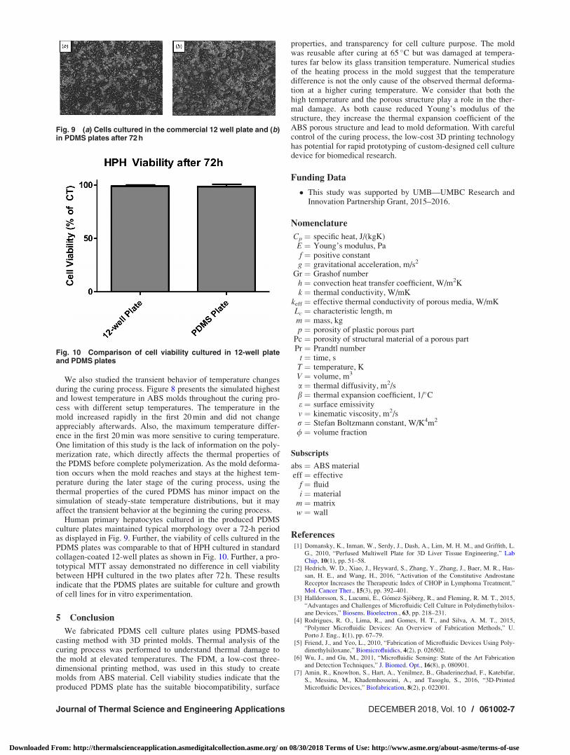
Human primary hepatocytes cultured in the produced PDMSculture plates maintained typical morphology over a 72-h periodas displayed in Fig. 9. Further, the viability of cells cultured in thePDMS plates was comparable to that of HPH cultured in standardcollagen-coated 12-well plates as shown in Fig. 10. Further, a pro-totypical MTT assay demonstrated no difference in cell viabilitybetween HPH cultured in the two plates after 72 h. These resultsindicate that the PDMS plates are suitable for culture and growthof cell lines for in vitro experimentation.
5 Conclusion
We fabricated PDMS cell culture plates using PDMS-basedcasting method with 3D printed molds. Thermal analysis of thecuring process was performed to understand thermal damage tothe mold at elevated temperatures. The FDM, a low-cost three-dimensional printing method, was used in this study to createmolds from ABS material. Cell viability studies indicate that theproduced PDMS plate has the suitable biocompatibility, surface
properties, and transparency for cell culture purpose. The moldwas reusable after curing at 65 �C but was damaged at tempera-tures far below its glass transition temperature. Numerical studiesof the heating process in the mold suggest that the temperaturedifference is not the only cause of the observed thermal deforma-tion at a higher curing temperature. We consider that both thehigh temperature and the porous structure play a role in the ther-mal damage. As both cause reduced Young’s modulus of thestructure, they increase the thermal expansion coefficient of theABS porous structure and lead to mold deformation. With carefulcontrol of the curing process, the low-cost 3D printing technologyhas potential for rapid prototyping of custom-designed cell culturedevice for biomedical research.
Funding Data
� This study was supported by UMB—UMBC Research andInnovation Partnership Grant, 2015–2016.
Nomenclature
Cp ¼ specific heat, J/(kgK)E ¼ Young’s modulus, Paf ¼ positive constantg ¼ gravitational acceleration, m/s2
Gr ¼ Grashof numberh ¼ convection heat transfer coefficient, W/m2Kk ¼ thermal conductivity, W/mK
keff ¼ effective thermal conductivity of porous media, W/mKLc ¼ characteristic length, mm ¼ mass, kgp ¼ porosity of plastic porous part
Pc ¼ porosity of structural material of a porous partPr ¼ Prandtl number
t ¼ time, sT ¼ temperature, KV ¼ volume, m3
a ¼ thermal diffusivity, m2/sb ¼ thermal expansion coefficient, 1/�Ce ¼ surface emissivityv ¼ kinematic viscosity, m2/sr ¼ Stefan Boltzmann constant, W/K4m2
/ ¼ volume fraction
Subscripts
abs ¼ ABS materialeff ¼ effective
f ¼ fluidi ¼ material
m ¼ matrixw ¼ wall
References[1] Domansky, K., Inman, W., Serdy, J., Dash, A., Lim, M. H. M., and Griffith, L.
G., 2010, “Perfused Multiwell Plate for 3D Liver Tissue Engineering,” LabChip, 10(1), pp. 51–58.
[2] Hedrich, W. D., Xiao, J., Heyward, S., Zhang, Y., Zhang, J., Baer, M. R., Has-san, H. E., and Wang, H., 2016, “Activation of the Constitutive AndrostaneReceptor Increases the Therapeutic Index of CHOP in Lymphoma Treatment,”Mol. Cancer Ther., 15(3), pp. 392–401.
[3] Halldorsson, S., Lucumi, E., G�omez-Sj€oberg, R., and Fleming, R. M. T., 2015,“Advantages and Challenges of Microfluidic Cell Culture in Polydimethylsilox-ane Devices,” Biosens. Bioelectron., 63, pp. 218–231.
[4] Rodrigues, R. O., Lima, R., and Gomes, H. T., and Silva, A. M. T., 2015,“Polymer Microfluidic Devices: An Overview of Fabrication Methods,” U.Porto J. Eng., 1(1), pp. 67–79.
[5] Friend, J., and Yeo, L., 2010, “Fabrication of Microfluidic Devices Using Poly-dimethylsiloxane,” Biomicrofluidics, 4(2), p. 026502.
[6] Wu, J., and Gu, M., 2011, “Microfluidic Sensing: State of the Art Fabricationand Detection Techniques,” J. Biomed. Opt., 16(8), p. 080901.
[7] Amin, R., Knowlton, S., Hart, A., Yenilmez, B., Ghaderinezhad, F., Katebifar,S., Messina, M., Khademhosseini, A., and Tasoglu, S., 2016, “3D-PrintedMicrofluidic Devices,” Biofabrication, 8(2), p. 022001.
Fig. 9 (a) Cells cultured in the commercial 12 well plate and (b)in PDMS plates after 72 h
Fig. 10 Comparison of cell viability cultured in 12-well plateand PDMS plates
Journal of Thermal Science and Engineering Applications DECEMBER 2018, Vol. 10 / 061002-7
Downloaded From: http://thermalscienceapplication.asmedigitalcollection.asme.org/ on 08/30/2018 Terms of Use: http://www.asme.org/about-asme/terms-of-use

[8] Ho, B., Ng, S. H., Li, H., and Yoon, Y., 2015, “3D Printed Microfluidics forBiological Applications,” Lab Chip., 15(18), pp. 3627–3637.
[9] Anderson, K. B., Lockwood, S. Y., Martin, R. S., and Spence, D. M., 2013, “A3D Printed Fluidic Device That Enables Integrated Features,” Anal. Chem.,85(12), pp. 5622–5626.
[10] Chen, C., Wang, Y., Lockwood, S. Y., and Spence, D. M., 2014, “3D-PrintedFluidic Devices Enable Quantitative Evaluation of Blood Components in Modi-fied Storage Solutions for Use in Transfusion Medicine,” Analyst, 139(13), pp.3219–3226.
[11] Dragone, V., Sans, V., Rosnes, M. H., Kitson, P. J., and Cronin, L., 2013, “3D-Printed Devices for Continuous-Flow Organic Chemistry,” Beilstein J. Org.Chem., 9, pp. 951–959.
[12] Byun, I., Ueno, R., and Kim, B., 2014, “Micro-Heaters Embedded inPDMS Fabricated Using Dry Peel-Off Process,” Microelectron. Eng., 121,pp. 1–4.
[13] Warkiani, M. E., Khoo, B. L., Wu, L., Tay, A. K. P., Bhagat, A. A. S., Han, J.,and Lim, C. T., 2016, “Ultra-Fast, Label-Free Isolation of Circulating TumorCells From Blood Using Spiral Microfluidics,” Nat. Protocols, 11(1), pp.134–148.
[14] Kitson, P. J., Rosnes, M. H., Sans, V., Dragone, V., and Cronin, L., 2012,“Configurable 3D-Printed Millifluidic and Microfluidic ‘Lab on a Chip’ Reac-tionware Devices,” Lab Chip, 12(18), pp. 3267–3271.
[15] Bony�ar, A., S�antha, H., Varga, M., Ring, B., Vit�ez, A., and Hars�anyi, G., 2014,“Characterization of Rapid PDMS Casting Technique Utilizing Molding FormsFabricated by 3D Rapid Prototyping Technology (RPT),” Int. J. Mater., 7(2),pp. 189–196.
[16] Thomas, M. S., Millare, B., Clift, J. M., Bao, D., Hong, C., and Vullev, V. I.,2010, “Print-and-Peel Fabrication for Microfluidics: What’s in It for Biomedi-cal Applications?,” Ann. Biomed. Eng., 38(1), pp. 21–32.
[17] Au, A. K., Huynh, W., Horowitz, L. F., and Folch, A., 2016, “3-D PrintedMicrofluidics,” Angew. Chem., Int. Ed., 55(12), pp. 3862–3881.
[18] Johnston, D., McCluskey, D. K., Tan, C. K. L., and Tracey, M. C., 2014,“Mechanical Characterization of Bulk Sylgard 184 for Microfluidics and Micro-engineering,” J. Micromech. Microeng., 24(3), p. 035017.
[19] Corning, D., 2013, “SylgardTM 184 Silicone Elastomer,” Technical Data Sheet,accessed Dec. 10, 2017, https://consumer.dow.com/content/dam/dcc/documents/en-us/productdatasheet/11/11-31/11-3184-sylgard-184-elastomer.pdf?iframe=true
[20] Bag, S. D., Nandan, B., Alam, S., Kandpal, L. C., and Mathur, G. N., 2003,“Density Measurements of Plastics—A Simple Standard Test Method,” IndianJ. Chem. Technol., 10, pp. 561–563.
[21] Abhishek, K., 2017, “PDMS Shrinkage,” University of Pennsylvania, Philadelphia,PA, accessed Dec. 10, 2017, https://repository.upenn.edu/scn_protocols/42/?utm_source=repository.upenn.edu%2Fscn_protocols%2F42&utm_medium=PDF&utm_campaign=PDFCoverPages
[22] Incropera, F. P., Dewitt, D. P., Bergman, T. L., and Lavine, A., 2009, Introduc-tion to Heat Transfer, 5th ed., Wiley, Hoboken, NJ.
[23] Ngo, I. L., and Byon, C., 2016, “Thermal Conductivity of Particle-FilledPolymers,” Polymer Science: Research Advances, Practical Applications, andEducational Aspects, Formatex Research Center, Badajoz, Spain.
[24] Livermore, C., and Voldman, J., 2004, “Design and Fabrication of Microelec-tromechanical Devices Material Properties Database,” Massachusetts Instituteof Technology, Cambridge, MA, accessed Dec. 10, 2017, http://web.mit.edu/6.777/www/
[25] Styrolution, 2015, “Acrylonitrile Butadiene Styrene (ABS),” Technical DataSheet, Styrolution, accessed Dec. 10, 2017, http://www.activas.com.br/down-loads/especialidades/abs/terluran-hh-106.pdf
[26] Engineering Toolbox, 2001, “Dry Air Properties Dry,” The Engineering Tool-Box, accessed Dec. 10, 2017, https://www.engineeringtoolbox.com/dry-air-properties-d_973.html
[27] Engineering Toolbox, “Densities of Solids,” The Engineering ToolBox,accessed Dec. 10, 2017, https://www. engineeringtoolbox.com/density-solids-d_1265.html
[28] Engineering Toolbox, 2001, “Thermal Conductivity of Common Materials andGases,” The Engineering ToolBox, accessed Dec. 10, 2017, https://www.engineeringtoolbox.com/thermal-conductivity-d_429.html
[29] Granta Design, 2017, “Acrylonitrile Butadiene Styrene (ABS),” Granta Design,Cambridge, UK, accessed Dec. 10, 2017, http://www.grantadesign.com/education/datasheets/ABS.htm
[30] Engineering Toolbox, 2001, “Specific Heat of Solids,” The Engineering ToolBox,accessed Dec. 10, 2017, https://www.engineeringtoolbox.com/specific-heat-solids-d_154.html
[31] Chen, K.-C., Wo, A. M., and Chen, Y.-F., 2006, “Transmission Spectrum ofPDMS in 4-7 lm Mid-IR Range for Characterization of Protein Structure,”NSTI-Nanotech., 2, pp. 732–735.
[32] Iwan, S., Ando, Y., and Shimamura, S., 2006, “Theoretical Consideration of theEffect of Porosity on Thermal Conductivity of Porous Materials,” J. PorousMater., 13(3–4), pp. 439–443.
[33] Pietrak, K., and Wi�sniewski, T. S., 2015, “A Review of Models for Effective Ther-mal Conductivity of Composite Materials,” J. Power Technol., 95(1), pp. 14–24.
[34] Kuo, A. C. M., 1999, Polymer Data Handbook, Oxford University Press, New York.[35] Shui, Z., Zhang, R., Chen, W., and Xuan, D., 2010, “Effects of Mineral Admix-
tures on the Thermal Expansion Properties of Hardened Cement Paste,” Constr.Build. Mater., 24(9), pp. 1761–1767.
[36] Ghabezloo, S., 2010, “Effect of Porosity on the Thermal Expansion Coefficient:A Discussion of the Paper ‘Effects of Mineral Admixtures on the ThermalExpansion Properties of Hardened Cement Paste’ by Z.H. Shui, R. Zhang, W.Chen, D. Xuan,” Constr. Build. Mater., 24(9), pp. 1796–1798.
[37] Kov�acik, J., 1999, “Correlation Between Young’s Modulus and Porosity inPorous Materials,” J. Mater. Sci. Lett., 18(13), pp. 1007–1010.
[38] Ashby, M., 2010, “Material and ProcessSelection Charts,” Granta Design, Cam-bridge, UK, accessed Dec. 10, 2017, http://www.grantadesign.com/download/pdf/teaching_resource_books/2-Materials-Charts-2010.pdf
061002-8 / Vol. 10, DECEMBER 2018 Transactions of the ASME
Downloaded From: http://thermalscienceapplication.asmedigitalcollection.asme.org/ on 08/30/2018 Terms of Use: http://www.asme.org/about-asme/terms-of-use