fabrication and analysis of vortex tube refrigeration system · fabrication and analysis of vortex...
TRANSCRIPT
300 | P a g e
FABRICATION AND ANALYSIS OF VORTEX TUBE
REFRIGERATION SYSTEM
Krishna Kumar Karothiya1, Siddharth Chauhan
2
1,2 Department of Mechanical Engineering, IIMT College of Engineering, Greater Noida UP (INDIA)
ABSTRACT
In this paper, we have constructed a vortex tube refrigeration system. Effects of inlet tangential nozzles, the tube
diameter, and the diameter of the inlet nozzle on the temperature reduction in the tube were experimentally
investigated. The general motivation of this thesis is to clarify the numerous assumptions and taking optimal
data from various research papers in order to analyze the temperature difference obtained. Compared to previous
studies, standard measurements and the fabrication techniques are improved to achieve accurate results. New
measurements are obtained with the help of two novel techniques:
i) Nozzle is fitted to let the compressed air flow tangentially.
ii) Insulation is provided to remove the chances of heat loss.
The temperature drops of the cold air obtained and compare at a similar scale of separating conditions. The
experimental results showed that the vortex tube with tangential inlet nozzles and cold tube diameter 12.7 mm
yielded the highest temperature reduction which was found to be 6⁰C.
I. INTRODUCTION
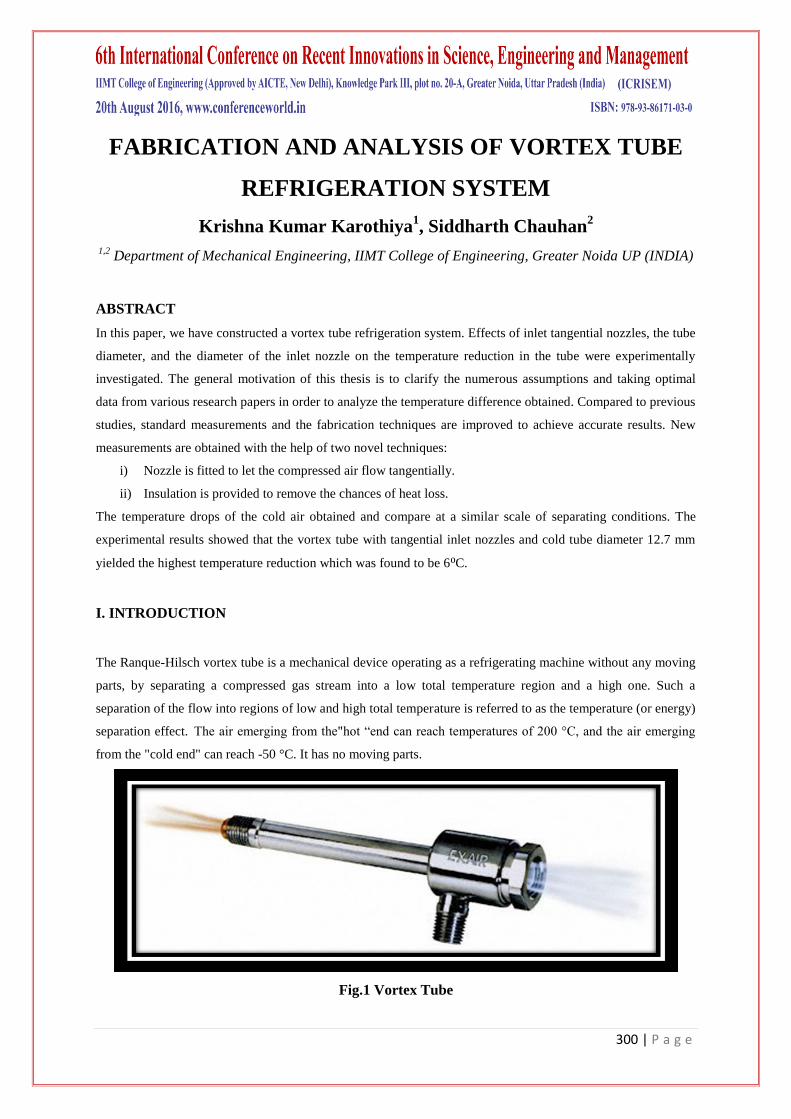
The Ranque-Hilsch vortex tube is a mechanical device operating as a refrigerating machine without any moving
parts, by separating a compressed gas stream into a low total temperature region and a high one. Such a
separation of the flow into regions of low and high total temperature is referred to as the temperature (or energy)
separation effect. The air emerging from the"hot ―end can reach temperatures of 200 °C, and the air emerging
from the "cold end" can reach -50 °C. It has no moving parts.
Fig.1 Vortex Tube
301 | P a g e
II. TYPES OF VORTEX TUBES
Generally, the vortex tube can be classified into two types. One is the counterflow type (often referred to as the
standard type) and the other is the parallel or uni-flow type.
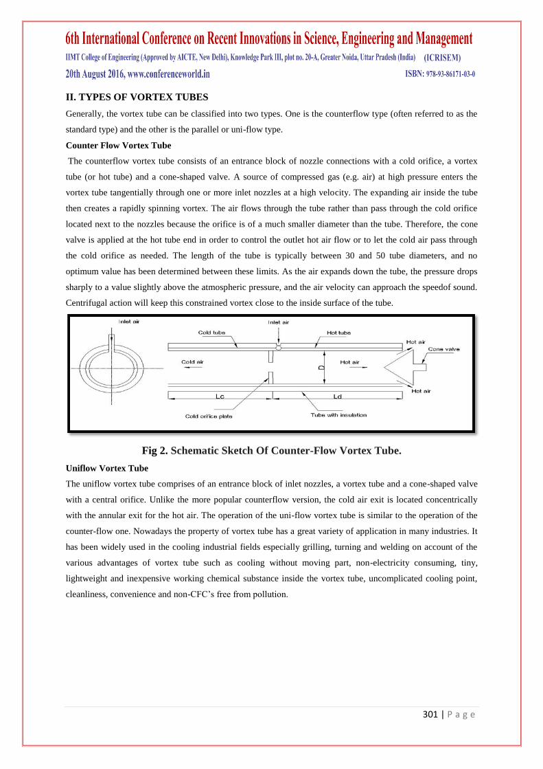
Counter Flow Vortex Tube
The counterflow vortex tube consists of an entrance block of nozzle connections with a cold orifice, a vortex
tube (or hot tube) and a cone-shaped valve. A source of compressed gas (e.g. air) at high pressure enters the
vortex tube tangentially through one or more inlet nozzles at a high velocity. The expanding air inside the tube
then creates a rapidly spinning vortex. The air flows through the tube rather than pass through the cold orifice
located next to the nozzles because the orifice is of a much smaller diameter than the tube. Therefore, the cone
valve is applied at the hot tube end in order to control the outlet hot air flow or to let the cold air pass through
the cold orifice as needed. The length of the tube is typically between 30 and 50 tube diameters, and no
optimum value has been determined between these limits. As the air expands down the tube, the pressure drops
sharply to a value slightly above the atmospheric pressure, and the air velocity can approach the speedof sound.
Centrifugal action will keep this constrained vortex close to the inside surface of the tube.
Fig 2. Schematic Sketch Of Counter-Flow Vortex Tube.
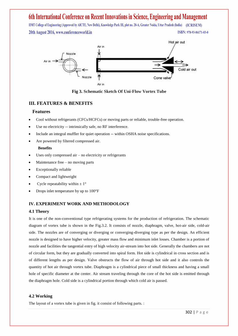
Uniflow Vortex Tube
The uniflow vortex tube comprises of an entrance block of inlet nozzles, a vortex tube and a cone-shaped valve
with a central orifice. Unlike the more popular counterflow version, the cold air exit is located concentrically
with the annular exit for the hot air. The operation of the uni-flow vortex tube is similar to the operation of the
counter-flow one. Nowadays the property of vortex tube has a great variety of application in many industries. It
has been widely used in the cooling industrial fields especially grilling, turning and welding on account of the
various advantages of vortex tube such as cooling without moving part, non-electricity consuming, tiny,
lightweight and inexpensive working chemical substance inside the vortex tube, uncomplicated cooling point,
cleanliness, convenience and non-CFC’s free from pollution.
302 | P a g e
Fig 3. Schematic Sketch Of Uni-Flow Vortex Tube
III. FEATURES & BENEFITS
Features
Cool without refrigerants (CFCs/HCFCs) or moving parts or reliable, trouble-free operation.
Use no electricity -- intrinsically safe, no RF interference.
Include an integral muffler for quiet operation -- within OSHA noise specifications.
Are powered by filtered compressed air.
Benefits
Uses only compressed air – no electricity or refrigerants
Maintenance free – no moving parts
Exceptionally reliable
Compact and lightweight
Cycle repeatability within ± 1°
Drops inlet temperature by up to 100°F
IV. EXPERIMENT WORK AND METHODOLOGY
4.1 Theory
It is one of the non-conventional type refrigerating systems for the production of refrigeration. The schematic
diagram of vortex tube is shown in the Fig.3.2. It consists of nozzle, diaphragm, valve, hot-air side, cold-air
side. The nozzles are of converging or diverging or converging-diverging type as per the design. An efficient
nozzle is designed to have higher velocity, greater mass flow and minimum inlet losses. Chamber is a portion of
nozzle and facilities the tangential entry of high velocity air-stream into hot side. Generally the chambers are not
of circular form, but they are gradually converted into spiral form. Hot side is cylindrical in cross section and is
of different lengths as per design. Valve obstructs the flow of air through hot side and it also controls the
quantity of hot air through vortex tube. Diaphragm is a cylindrical piece of small thickness and having a small
hole of specific diameter at the center. Air stream traveling through the core of the hot side is emitted through
the diaphragm hole. Cold side is a cylindrical portion through which cold air is passed.
4.2 Working
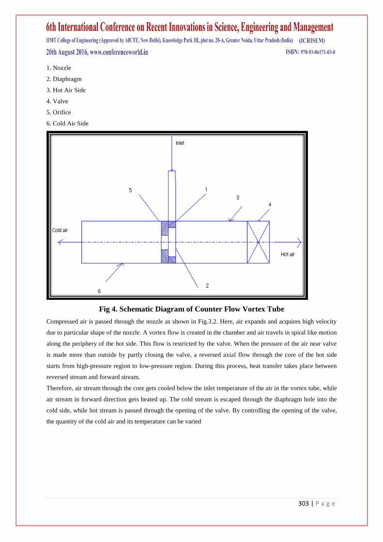
The layout of a vortex tube is given in fig. it consist of following parts. :
303 | P a g e
1. Nozzle
2. Diaphragm
3. Hot Air Side
4. Valve
5. Orifice
6. Cold Air Side
Fig 4. Schematic Diagram of Counter Flow Vortex Tube
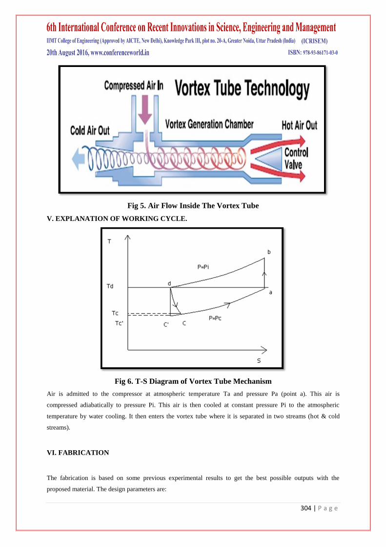
Compressed air is passed through the nozzle as shown in Fig.3.2. Here, air expands and acquires high velocity
due to particular shape of the nozzle. A vortex flow is created in the chamber and air travels in spiral like motion
along the periphery of the hot side. This flow is restricted by the valve. When the pressure of the air near valve
is made more than outside by partly closing the valve, a reversed axial flow through the core of the hot side
starts from high-pressure region to low-pressure region. During this process, heat transfer takes place between
reversed stream and forward stream.
Therefore, air stream through the core gets cooled below the inlet temperature of the air in the vortex tube, while
air stream in forward direction gets heated up. The cold stream is escaped through the diaphragm hole into the
cold side, while hot stream is passed through the opening of the valve. By controlling the opening of the valve,
the quantity of the cold air and its temperature can be varied
304 | P a g e
Fig 5. Air Flow Inside The Vortex Tube
V. EXPLANATION OF WORKING CYCLE.
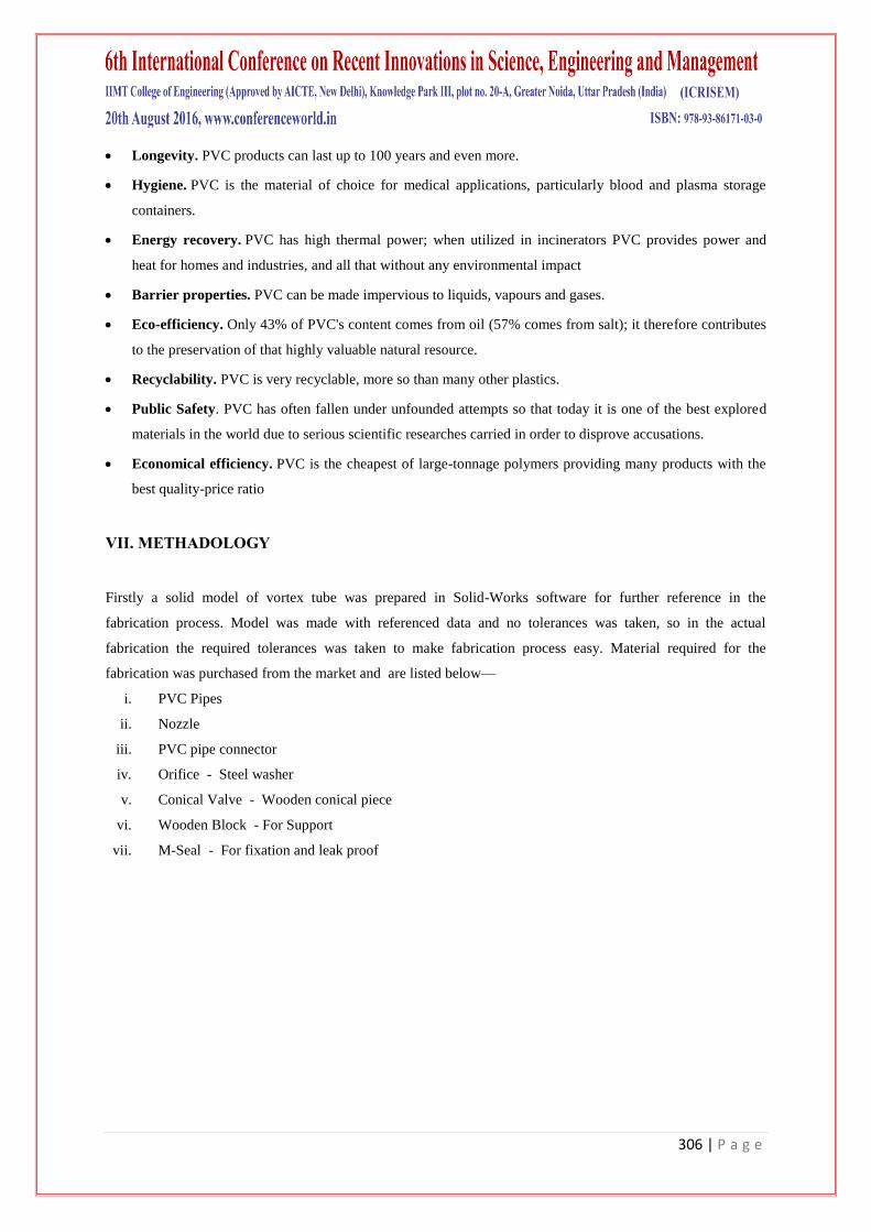
Fig 6. T-S Diagram of Vortex Tube Mechanism
Air is admitted to the compressor at atmospheric temperature Ta and pressure Pa (point a). This air is
compressed adiabatically to pressure Pi. This air is then cooled at constant pressure Pi to the atmospheric
temperature by water cooling. It then enters the vortex tube where it is separated in two streams (hot & cold
streams).
VI. FABRICATION
The fabrication is based on some previous experimental results to get the best possible outputs with the
proposed material. The design parameters are:

305 | P a g e
a. Cold tube length, diameter.
b. Hot tube length, diameter.
c. Vortex chamber specification.
All the data is taken from the paper published by Mohammad Mahmudur Rahman On “Design, Construction
And Performance Test Of A Vortex Tube Cooling System Constructed By Locally Availablematerials”
and the limitations under that paper were tried to be removed.
The diameter of the cold tube was taken as D = 12.70 mm (0.50 inch) according to Rudolf Hilsch. The length of
the cold tube was taken as 10D, hot tube is 45D and the diameter of cold orifice or diaphragm hole is taken as
0.5D in accordance with Hilsch, Pongjet Promvonge and Smith Eiamsaard. The diameter of the nozzle is taken
as D/3 according to Guillaume and Jully. The inlet pressure is varied to visualize the variations of temperature
drop with pressure drop and a constant mass fraction of approximately maintained by a cone shape. The material
for the tube was chosen as PVC which is locally very much available in the market and also cheaper than any
other such material.
After fabrication the setup was set on a wooden frame and prepared for experiment. An insulating chamber was
made to measure the temperature of the cold air at the cold end of the tube.
Design Parameters Table
Sr. No Design Parameters In Inches In MM
1 Tube Diameter 0.5 12.7
2 Cold Tube Length 5 127
3 Hot Tube Length 22.5 571
4 Orifice Diameter 0.25 6.4
5 Nozzle Diameter 0.1667 4.2
Table 1. Design Parameters
VI. MATERIAL SELECTION
Vortex tube cab be formed from either steel and pvc.In previous papers mostly pvc material due to its
availability and economically aspects.Further working with pvc is easy and do not require heavy tools.
PVC
PVC (polyvinyl chloride) is a versatile thermoplastic material obtained from ethylene (petrochemistry product)
and salt by vinyl chloride polymerization.
Properties
Weathering stability. PVC is resistant to aggressive environmental factors is therefore the material of
choice for roofing.
Versatility. PVC can be flexible or rigid.
Fire protection. PVC is a material resistant to ignition due to its chlorine content.
306 | P a g e
Longevity. PVC products can last up to 100 years and even more.
Hygiene. PVC is the material of choice for medical applications, particularly blood and plasma storage
containers.
Energy recovery. PVC has high thermal power; when utilized in incinerators PVC provides power and
heat for homes and industries, and all that without any environmental impact
Barrier properties. PVC can be made impervious to liquids, vapours and gases.
Eco-efficiency. Only 43% of PVC's content comes from oil (57% comes from salt); it therefore contributes
to the preservation of that highly valuable natural resource.
Recyclability. PVC is very recyclable, more so than many other plastics.
Public Safety. PVC has often fallen under unfounded attempts so that today it is one of the best explored
materials in the world due to serious scientific researches carried in order to disprove accusations.
Economical efficiency. PVC is the cheapest of large-tonnage polymers providing many products with the
best quality-price ratio
VII. METHADOLOGY
Firstly a solid model of vortex tube was prepared in Solid-Works software for further reference in the
fabrication process. Model was made with referenced data and no tolerances was taken, so in the actual
fabrication the required tolerances was taken to make fabrication process easy. Material required for the
fabrication was purchased from the market and are listed below—
i. PVC Pipes
ii. Nozzle
iii. PVC pipe connector
iv. Orifice - Steel washer
v. Conical Valve - Wooden conical piece
vi. Wooden Block - For Support
vii. M-Seal - For fixation and leak proof
307 | P a g e
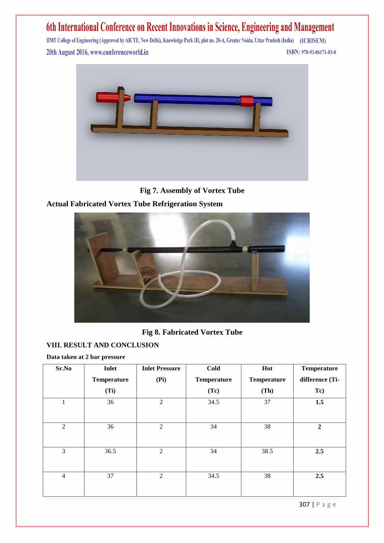
Fig 7. Assembly of Vortex Tube
Actual Fabricated Vortex Tube Refrigeration System
Fig 8. Fabricated Vortex Tube
VIII. RESULT AND CONCLUSION
Data taken at 2 bar pressure
Sr.No Inlet
Temperature
(Ti)
Inlet Pressure
(Pi)
Cold
Temperature
(Tc)
Hot
Temperature
(Th)
Temperature
difference (Ti-
Tc)
1 36 2 34.5 37 1.5
2 36 2 34 38 2
3 36.5 2 34 38.5 2.5
4 37 2 34.5 38 2.5
308 | P a g e
5 36 2 33.5 38.5 2.5
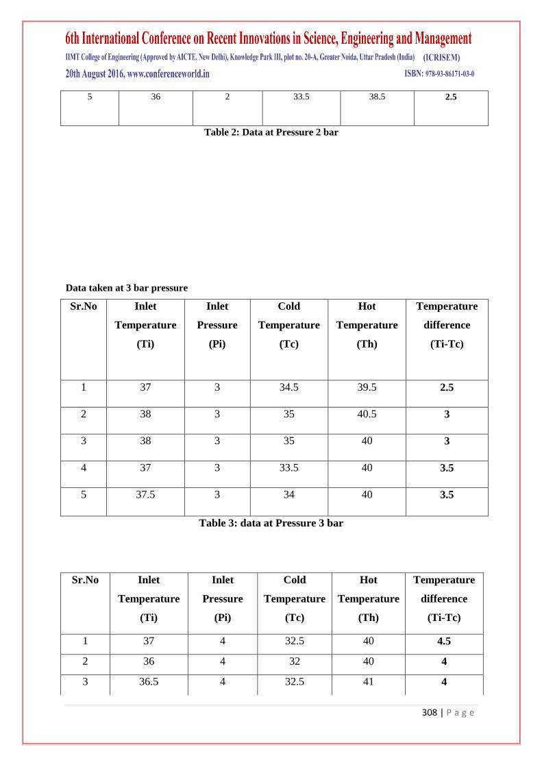
Table 2: Data at Pressure 2 bar
Data taken at 3 bar pressure
Sr.No Inlet
Temperature
(Ti)
Inlet
Pressure
(Pi)
Cold
Temperature
(Tc)
Hot
Temperature
(Th)
Temperature
difference
(Ti-Tc)
1 37 3 34.5 39.5 2.5
2 38 3 35 40.5 3
3 38 3 35 40 3
4 37 3 33.5 40 3.5
5 37.5 3 34 40 3.5
Table 3: data at Pressure 3 bar
Sr.No Inlet
Temperature
(Ti)
Inlet
Pressure
(Pi)
Cold
Temperature
(Tc)
Hot
Temperature
(Th)
Temperature
difference
(Ti-Tc)
1 37 4 32.5 40 4.5
2 36 4 32 40 4
3 36.5 4 32.5 41 4
309 | P a g e
Data taken at 4 bar pressure
Table 4: Data at Pressure 4 bar
Data taken at 5 bar pressure
Table 5: Data at Pressure 5 bar
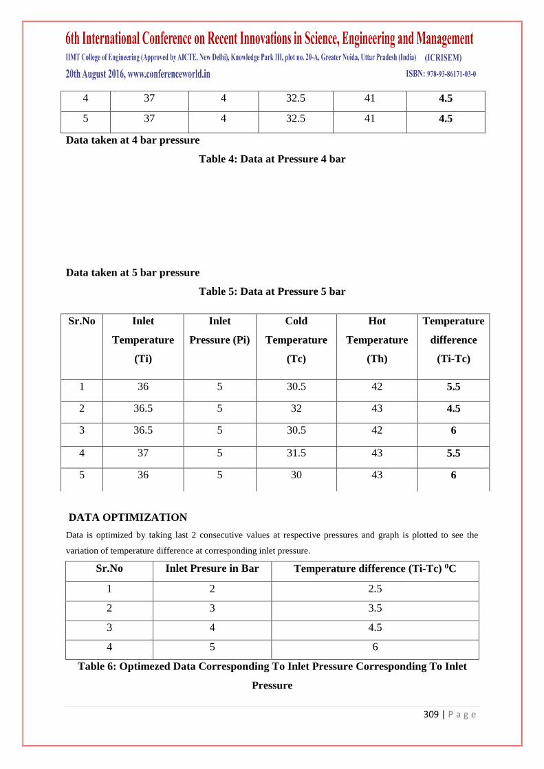
DATA OPTIMIZATION
Data is optimized by taking last 2 consecutive values at respective pressures and graph is plotted to see the
variation of temperature difference at corresponding inlet pressure.
Sr.No Inlet Presure in Bar Temperature difference (Ti-Tc) ⁰C
1 2 2.5
2 3 3.5
3 4 4.5
4 5 6
Table 6: Optimezed Data Corresponding To Inlet Pressure Corresponding To Inlet
Pressure
4 37 4 32.5 41 4.5
5 37 4 32.5 41 4.5
Sr.No Inlet
Temperature
(Ti)
Inlet
Pressure (Pi)
Cold
Temperature
(Tc)
Hot
Temperature
(Th)
Temperature
difference
(Ti-Tc)
1 36 5 30.5 42 5.5
2 36.5 5 32 43 4.5
3 36.5 5 30.5 42 6
4 37 5 31.5 43 5.5
5 36 5 30 43 6
310 | P a g e
0
1
2
3
4
5
6
7
2 bar 3 bar 4 bar 5 bar
x- axis( pressure)
y- axis ( temp. diff. Ti-Tc)
Graph 1 Temperature Difference(Ti-Tc) V/S Inlet Pressure
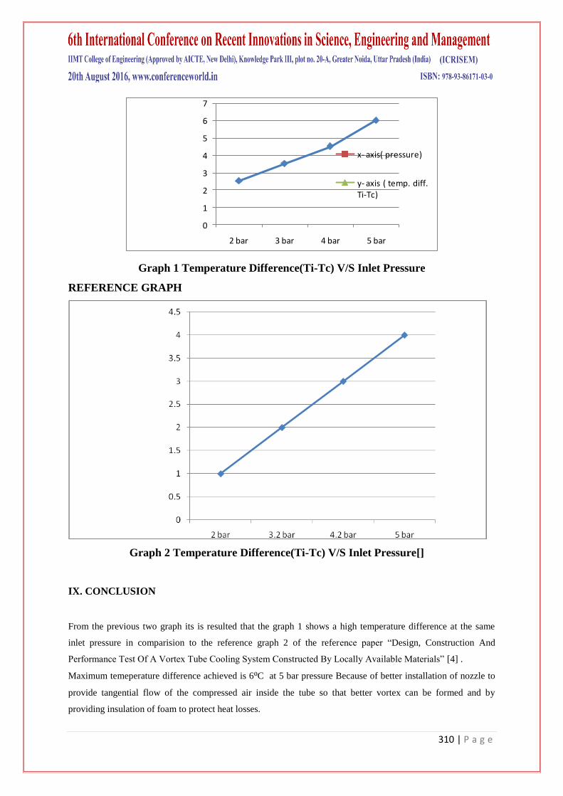
REFERENCE GRAPH
Graph 2 Temperature Difference(Ti-Tc) V/S Inlet Pressure[]
IX. CONCLUSION
From the previous two graph its is resulted that the graph 1 shows a high temperature difference at the same
inlet pressure in comparision to the reference graph 2 of the reference paper ―Design, Construction And
Performance Test Of A Vortex Tube Cooling System Constructed By Locally Available Materials‖ [4] .
Maximum temeperature difference achieved is 6⁰C at 5 bar pressure Because of better installation of nozzle to
provide tangential flow of the compressed air inside the tube so that better vortex can be formed and by
providing insulation of foam to protect heat losses.
311 | P a g e
REFERENCES
[1] Nozzle parameters affecting vortex tube energy separation Performance Mohammad O. Hamdan • Basel
Alsayyed • Emad Elnajjar DOI 10.1007/s00231-012-1099-2
[2] 6 Effects of gas properties and geometrical parameters on performance of a vortex tube H. Khazaeia,∗ ,
A.R. Teymourtasha, M. Malek-Jafarian b a Ferdowsi University of Mashhad, Mashhad, P.O. Box 91735-
134, Iran b Birjand University, Birjand, P.O. Box 97175-615, Iran
[3] Experimentally investigated the effects of Orifice diameter and tube length on a vortex tube performance
Mahyar Kargaran*1 and Mahmood Farzaneh -Gord2
1Department of mechanical Engineering, University of Tehcnology, Sydeny Australia
2Deparmentent of mechanical Engineering, Shahrood of Tehcnology, Shahrood ,Iran
[4] DESIGN, CONSTRUCTION AND PERFORMANCE TEST OF A VORTEX TUBE COOLING
SYSTEM CONSTRUCTED BY LOCALLY AVAILABLE MATERIALS
Mohammad Mahmudur Rahman 1,*, Mohammad Rezwan Sheikh 2, Mohammad Monir Hossain 2, Mihir
Ranjan Halder 2 - 1 Department of Industrial Engineering & Management, Khulna University of
Engineering & Technology, Khulna-9203, BANGLADESH Department ofmechanical Engineering,
Khulna University of Engineering & Technology, Khulna-9203, BANGLADESH
[5] Thermodynamic Analysis Of Counter Flow Vortex Tube Upendra S. Gupta (Asst. Prof. SVITS Indore)
Manoj K. Joshi (SGSITS Indore) Saurabh Rai
[6] Iinternational journal of research in Aeronautical and mechanical engineering Comparative study of
conventional vortex tube and modified vortex Tube Rahul s.pise1 , prof avinash m. Patil2 1student
m.e.(hpe)mech engg department, p.v.p.it.budhgaon 9096845909 [email protected] 2
assistant professor, mech engg department, p.v.p.it.budhgaon, 9422613035
[7] http://en.wikipedia.org/wiki/Helikon_vortex_separation_process
[8]http://www.exair.com/enUS/Primary%20Navigation/Products/Vortex%20Tubes%20and%20Spot%20Coolin
g/Vortex%20Tubes/Pages/A%20Phenomenon%20of%20Physics.aspx