fab2seriesplc usermanual - array.sh manual e.pdf · 3 1 introduction fab2 series plc is an upgraded...
TRANSCRIPT
1
VER:1.0
FAB2 series PLCUser Manual
FAB2 series PLC is an upgraded version of FABseries PLC. Before you use the product, pleasekindly read the manual carefully so as toensure proper use of the product.
ARRAY ELECTRONIC CO., LTD.

2
Contents1 Introduction.............................................................................................................3
1.1 Structure of FAB2......................................................................................... 31.2 Specifications and models...........................................................................41.3 FAB2 Features.............................................................................................. 5
2 Installation and wiring..............................................................................................72.1 Installation......................................................................................................7
2.1.1 Methods.............................................................................................. 72.1.2 Dimensions(unit:mm)........................................................................8
2.2 Wiring of FAB2.............................................................................................. 82.2.1 Connection of power supply............................................................ 92.2.2 FAB2 Input Connection.....................................................................92.2.3 FAB2 output connection................................................................. 11
3 Programming on FAB2 panel...............................................................................133.1 FAB2 status display interface................................................................... 133.2 Password confirming..................................................................................133.3 Function Interface.......................................................................................14
3.3.1 FAB/Rom Interface..........................................................................153.3.2 Setting interface...............................................................................19
4 Communication connection..................................................................................204.1 FAB2 download port...................................................................................204.2 FAB2 485 interface.....................................................................................20
4.2.1 FAB2 A1B1 interface.......................................................................204.2.2 FAB2 A2B2 interface....................................................................21
5 Functional comparison..........................................................................................23
6 Technical Parameters............................................................................................246.1 General technical parameters.................................................................. 246.2 AF-10MR-A2/AF-20MR-A2....................................................................... 256.3 AF-10MT-D2/AF-20MT-D2........................................................................ 266.4 AF-10MR-D2/AF-20MR-D2.......................................................................276.5 AF-10MT-E2/AF-20MT-E2.........................................................................286.6 AF-10MR-E2/AF-20MR-E2....................................................................... 296.7 AF-10MT-GD2/AF-20MT-GD2..................................................................30
3
1 Introduction
FAB2 series PLC is an upgraded version of old FAB PLC, which isprogrammed by the use of a Function Block Diagram. The programming ofFAB is simpler and easier to learn than that of a conventional PLC, which usesladder diagrams and associated instructions. In the design concept of FAB2series products, it adds power indicator, comes with 2-way 485 communicationinterface, supports standard MODBUS RTU protocol and can modifyparameters and other functions through the LCD panel, which greatly reducesthe user's cost investment, and for the operation It brings greatconvenience.The volume of FAB2 series products follows the old FAB2's smallsize, light weight and other characteristics, and is especially suitable forinternal installation and use.Now FAB2 are being widely used in many fieldssuch as industry,commerce,mining, agriculture, home automation etc.
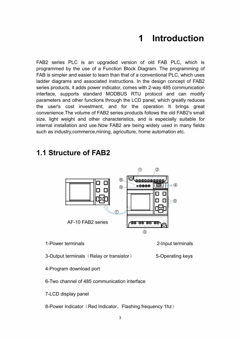
1.1 Structure of FAB2
○2
○6
○7
○5
○4
○3
○1
○8
1-Power terminals 2-Input terminals
3-Output terminals(Relay or transistor) 5-Operating keys
4-Program download port
6-Two channel of 485 communication interface
7-LCD display panel
8-Power Indicator(Red Indicator,Flashing frequency 1hz)
AF-10 FAB2 series
FAB2 series PLC INSTRODUCTION
4
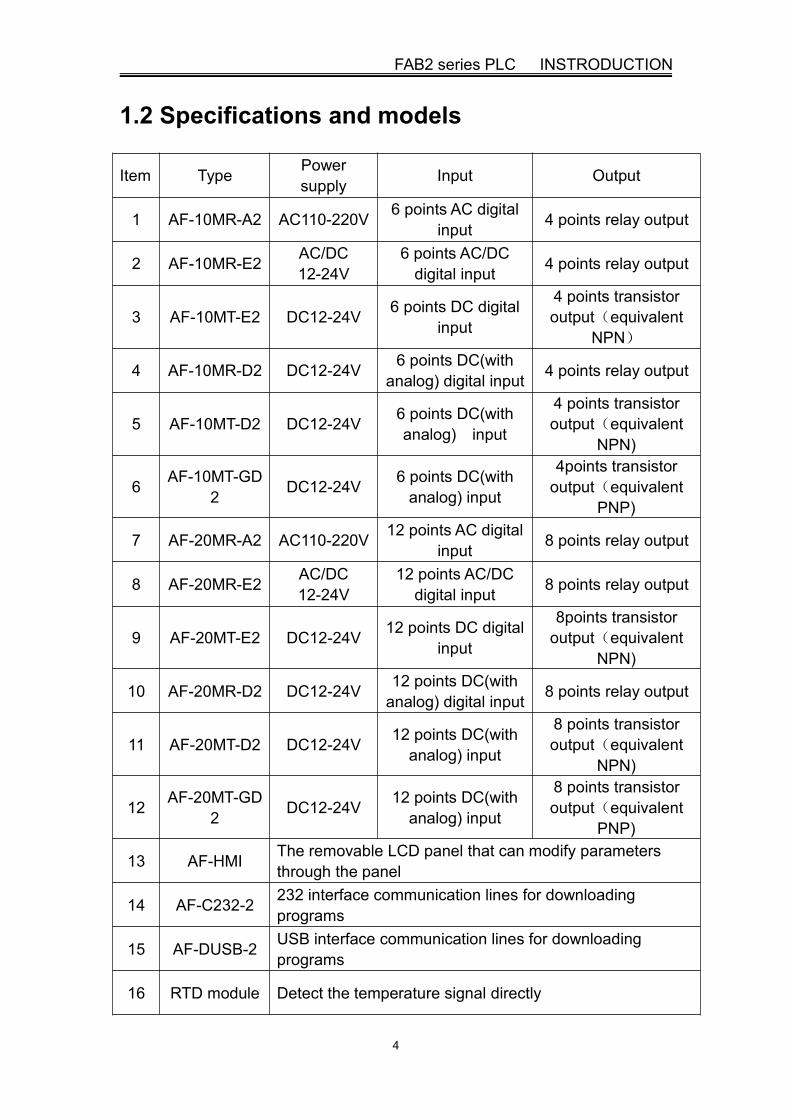
1.2 Specifications and models
Item Type Powersupply Input Output
1 AF-10MR-A2 AC110-220V 6 points AC digitalinput 4 points relay output
2 AF-10MR-E2 AC/DC12-24V
6 points AC/DCdigital input 4 points relay output
3 AF-10MT-E2 DC12-24V 6 points DC digitalinput
4 points transistoroutput(equivalent
NPN)
4 AF-10MR-D2 DC12-24V 6 points DC(withanalog) digital input 4 points relay output
5 AF-10MT-D2 DC12-24V 6 points DC(withanalog) input
4 points transistoroutput(equivalent
NPN)
6 AF-10MT-GD2 DC12-24V 6 points DC(with
analog) input
4points transistoroutput(equivalent
PNP)
7 AF-20MR-A2 AC110-220V 12 points AC digitalinput 8 points relay output
8 AF-20MR-E2 AC/DC12-24V
12 points AC/DCdigital input 8 points relay output
9 AF-20MT-E2 DC12-24V 12 points DC digitalinput
8points transistoroutput(equivalent
NPN)
10 AF-20MR-D2 DC12-24V 12 points DC(withanalog) digital input 8 points relay output
11 AF-20MT-D2 DC12-24V 12 points DC(withanalog) input
8 points transistoroutput(equivalent
NPN)
12 AF-20MT-GD2 DC12-24V 12 points DC(with
analog) input
8 points transistoroutput(equivalent
PNP)
13 AF-HMI The removable LCD panel that can modify parametersthrough the panel
14 AF-C232-2 232 interface communication lines for downloadingprograms
15 AF-DUSB-2 USB interface communication lines for downloadingprograms
16 RTD module Detect the temperature signal directly

FAB2 series PLC user manual
5
1.3 FAB2 Features
1.Removable LCD display(AF-HMI)
AF-HMI(Removable LCD display) can be used flexibly according to yourneeds.When you need it, you can install and use the keys on the panel toquery/set the FAB2 address, FAB2 system time, modify the function blockparameters and manually calibrate the analog quantity, etc.When you don'tneed it, you can disassemble it and replace it with an ordinary panel, which willgreatly reduce your cost of use.However, compared with AF-LCD, the AF-HMIoperator panel cannot be programmed manually.
2.FB programming and big program storage capacity
FAB2 uses a function block to realize the control function that the previousPLC needed a large section of the program to realize, and several functionalblocks are connected in a certain way to complete more complicated controlfunctions.The FAB2 can accommodate up to 127 function block programs.There are enough resources for you to implement complicated controlrequirements. Once the program is written, it will never be lost. FAB2 uses alarger memory capacity chip than FAB.
3.Exquisite and compact designIf you are looking to make your device delicate, FAB2 will be your bestpartner.It only needs to occupy youAF-10 Series:71.6mm*90.4*57.6mmAF-20 Series:126.4mm*90.4*57.6mm
3.Free programming softwareThe free QUICKII programming software is an extremely friendlyhuman-machine programming interface.It not only can edit function charts, butalso can provide functions such as off-line simulation of your programs andon-line monitoring of I/O status. It solves many inconveniences such ascustomer online testing.
4.Real-time clock functionThe FAB2 has a clock-recording function that can run at any time you need,and you can set up to 127 different time periods, especially for systems thatrequire time control.The timing is accurate to the second, and FAB2's RTCprecision error is greatly improved to 20s/month compared with FAB, makingyour time control more accurate.

FAB2 series PLC INSTRODUCTION
6
3.Analog inputsFAB2 can receive analog input except for switch input so as to complete thecontrol of temperature, humidity, pressure, flow, liquid level, etc., and canmonitor the analog value status of the PC through short distance or longdistance.And FAB2 simulation accuracy and FAB greatly improved to 10 (0.1v)
4.Security password lock functionFAB2 has absolute confidentiality for the program you write. You can set yourown password before burning the program. You can modify the applicationonly after entering the correct password.When the AF-HMI panel enters thefunction interface, it must enter the correct password and protect it with the *symbol.
5.Power indicatorFAB2 adds red power indicator to facilitate the customer to visually checkwhether the machine is properly connected to the power supply.Whencustomers use FAB before, it is necessary to use a multimeter to test thevoltage across the power supply to determine whether the power supply isproperly connected to the customer, causing inconvenience to the customer.
6.Communication interfaceIn addition to downloading the communication port, FAB2 also adds two 485ports to save the cost and space for customers directly. FAB2's A1B1 interfacesupports the standard MODBUS RTU protocol and can communicate withother manufacturers' branded touch screens and other devices.FAB2's A2B2interface is used to communicate with our SH300 text display. A detaileddescription of the communication interface is given chapter 4.
7.Communication protocolIn addition to the custom protocol for the download port, FAB2 adds thestandard MODBUS RTU protocol. The old FAB only supports custom protocols.

7
2 Installation and wiring
2.1 Installation
2.1.1 Methods
FAB2 is small so it is suitable to be fit inside panels or machinery.The installation of FAB2 is extremely easy.1.Use standard 35mm DIN rail mounting FAB2,as shown in Fig 2.1,2.Use the screw mounting holes on FAB2 for direct mounting
Fig 2.1 Use stand and DIN rail for installation of FAB
Screw mounting hole
Screw mounting hole
Buckle at the bottom
35mm DIN rail
Do not remove the AF-HMI while it is powered on. Otherwise it may causemechanical damage and even endanger the safety of the operator. Werecommend powering off and plugging the AF-HMI panel.
FAB2 series PLC Installation and Wiring
8
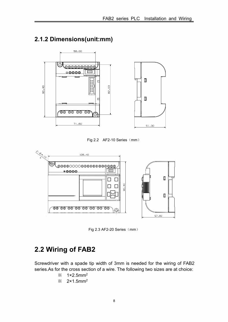
2.1.2 Dimensions(unit:mm)
Fig 2.2 AF2-10 Series(mm)
Fig 2.3 AF2-20 Series(mm)
2.2 Wiring of FAB2
Screwdriver with a spade tip width of 3mm is needed for the wiring of FAB2series.As for the cross section of a wire. The following two sizes are at choice:
※ 1×2.5mm2
※ 2×1.5mm2

FAB2 series PLC user manual
9
2.2.1 Connection of power supply
1. For FAB2s like AF-10MR-A2 and AF-20MR-A2, its applicable power supplyis 100~240VAC,50/60Hz.The grid voltage fluctuation range is about 10%.
2. For FAB2s likeAF-10MR-D2,AF-20MR-D2,AF-10MT-D2,AF-20MT-D2,AF-10MT-GD2,AF-20MT-GD2,AF-10MT-E2,AF-20MT-E2,Its applicable power supplyvoltage is DC12V-24V.
3. For FAB2s like AF-10MR-E2 and AF-20MR-E2,its applicable power supplyvoltage is AC/DC12V-24V.
FAB2 series power wiring diagram is as shown in Fig 2.4 and Fig 2.5,
Fig 2.4 AC type Fig 2.5 DC Type
2.2.2 FAB2 Input Connection
FAB2 input can be either switch,such as on/off switches and photoelectric baffle and sunshine switch etc.,or analog, such as pressure,temperature,humidity,flow and so on.The specific requirements are as follows,
DemandType
AF-10MR-A2AF-20MR-A2
AF-10/20MR-D2AF-10/20MT-D2AF-10/20MT-GD2
AF-10MR-E2AF-20MR-E2
AF-10MT-E2AF-20MT-E2
switchstatus 0
<AC40V <DC3.5V <AC/DC4.5V <DC3.5V
Inputcurrent
<0.1mA <0.4mA <0.2mA <0.5mA
switchstatus1
AC85-240V DC10-24V AC/DC10-24V
DC10-24V
Inputcurrent
<0.2mA <2.5mA <2mA <2.5mA
L N I1 I2 I3 I4 I5 I6
NL
L+ M I1 I2 I3 I4 I5 I6
ML+

FAB2 series PLC Installation and Wiring
10
Proximity switch type with direct input 2-wire system/3-wire system/4-wireNote:1. Analog can be input into analog-receivable FAB2s likeAF-10/20MR-D2,AF-10/20MT-D2,AF-10/20MT-GD2 through all the inputports(I1-I6/I1-IC).As long as the analog-related function blocks are used inthe program,Its port is automatically set to analog input. If in the program donot use the analog-related function blocks, its port is automatically set to digitinput.
2. The analog inputs require DC 0V~10V voltage signals, which are dividedequally in 0.1V increments. When you edit the program, all the blockparameters related to the analog inputs are based on the minimum incrementof 0.1V.
3.When the input voltage is higher than DC10.0V, it can only be used as switch,not be used as analog.
4.For digit input,when the switch state changes from 0 to 1, the time of the 1state must be greater than 50ms .When the switch state changes from 1 to 0,the 0 state must also exist for more than 50 ms.
FAB2 input connection is shown as shown in Fig 2.6 and Fig 2.7 and Fig 2.8,
Fig 2.6 AC Type Fig 2.7 DC Type
Fig 2.8 DC Type(D/GD)

FAB2 series PLC user manual
11
2.2.3 FAB2 output connection
AF-10MR-A2/AF-20MR-A2/AF-10MR-E2/AF-20MR-E2/AF-10MR-D2/AF-20MR-D2 type FAB2 is the relay output, the relay's contact to the power and inputis isolated.AF-10MT-D2/AF-20MT-D2/AF-10MT-GD2/AF-20MT-GD2/AF-10MT-E2/AF-20MT-E2 type FAB2 is the transistor output.
1. Requirements for the relay outputsVarious loads can be connected to the output of FAB2, such as: incandescentlamps, fluorescent lamps, motors, contactors, etc.The maximum output currentthat FAB2 can provide is: non-inductive load 10A, inductive load 2A.The connection is shown as shown in Fig 2.9,
Fig 2.9 Relay output
2.Requirements for the transistors outputsThe transistor is divided into D type and GD typeThe load connected to FAB2 must have the following characteristics:When theswitch is ON(Q=1), the maximum current is 2A.1)Type D connection is shown in Fig 2.10

FAB2 series PLC Installation and Wiring
12
Fig 2.10 Transistor Output(D type)
2)Type GD connection is shown in Fig2.11,
Fig 2.11 Transistor Output(GD type)
13
3 Programming on FAB2 panel
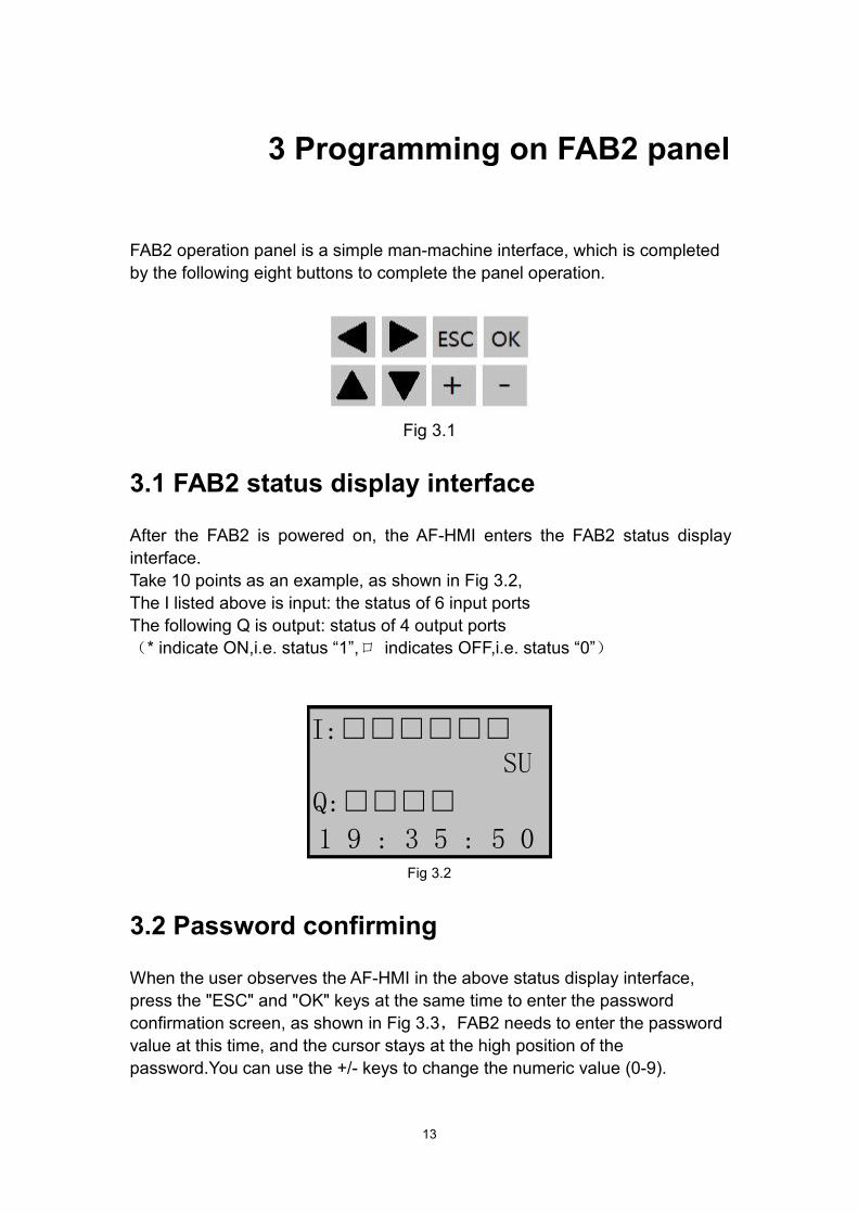
FAB2 operation panel is a simple man-machine interface, which is completedby the following eight buttons to complete the panel operation.
Fig 3.1
3.1 FAB2 status display interface
After the FAB2 is powered on, the AF-HMI enters the FAB2 status displayinterface.Take 10 points as an example, as shown in Fig 3.2,The I listed above is input: the status of 6 input portsThe following Q is output: status of 4 output ports(* indicate ON,i.e. status “1”,口 indicates OFF,i.e. status “0”)
Fig 3.2
3.2 Password confirming
When the user observes the AF-HMI in the above status display interface,press the "ESC" and "OK" keys at the same time to enter the passwordconfirmation screen, as shown in Fig 3.3,FAB2 needs to enter the passwordvalue at this time, and the cursor stays at the high position of thepassword.You can use the +/- keys to change the numeric value (0-9).
I:□□□□□□SU
Q:□□□□1 9 : 3 5 : 5 0

FAB2 series PLC user manual
14
When you press the +/- key for the first time, the password value is 0. You canuse the left/right keys to move the password input position and enter theremaining number of password values.If the user password is entered correctly,it will enter the panel function interface;If the user password is not enteredcorrectly, it will stay on the input password interface.
Four-digit password, every time you enter a digit to enter the next digit, theprevious digit is hidden with the * symbol, and you must enter the four-digitnumber to enter the FAB2 function interface.
Fig 3.3 Password Interface
3.3 Function Interface
When the user enters the following function interface, please kindly useand keys to move the left ">" key and press OK key to select the function,including four options.
Editor.. Program Edit (System Reserved, FAB2 Not Enabled)FAB/Rom Read FAB2 program, simulate calibration, modify FAB2
address, etc.Set.. Real time clock setting and password settingRun Run FAB2 program, click RUN to return to FAB2 status display
interface
Fig 3.4 Function Interface
Run
FAB/RomSet..
Password
VerifyUsers
xxxx
> Editor..

FAB2 series PLC Panel Operation
15
3.3.1 FAB/Rom Interface
When the user enter into the FAB/Rom interface as shown above, thenwhen the user enters the Calibrate interface, Rom → FAB interface andFAB_Addr interface under the FAB2 function interface, the FAB2 machine willstop running.
Fig 3.5
Calibrate Analog calibrationRom→FAB Read FAB2 programFAB_Addr View or set the FAB2 address (default address 000)MODEM System Reserved (FAB2 is not enabled for this feature)
3.3.1.1 Analog Calibration Interface
The analog channel calibration method is as follows,1.When the user enters the Calibrate interface as above, please kindly pressand hold the ok and > keys on the LCD panel to enter the calibration page.Separate each analog channel by analog (AI1 corresponds to I1), and inputthe channel number to be calibrated, and press OK to confirm.
Fig 3.6
MODEMFAB_AddrRom→FAB
> Calibrate
AI:00Value:0000
C A L I B

FAB2 series PLC user manual
16
2. When the minimum value is prompted, an external power supply is requiredto input the minimum voltage value for this channel, then press OK toconfirm and mark as Vmin. When the maximum value is prompted,an externalpower supply is required to input the maximum voltage value for this channel.Then Press OK to confirm it and mark as Vmax. After calibrate successful,the screen will prompt succeed.
The Vmin and Vmax inputs must be between 0V and 10V. (The maximumcalibration value of the value must be greater than the minimum calibrationvalue)
Fig 3.7
3. After successful analog calibration, FAB2 needs to be powered on again.4. Other channel calibrations is similar as above. After the analog calibratesuccessful,when using an analog-related module, the value of the analog inputpin input (0V–10V) is not the actual input voltage value, but follows themathematical calculation formula (V input –Vmin)/(Vmax-Vmin) * 10.
3.3.1.2 Rom→FAB Program Interface
The user can view the function block number of the FAB2 program on thisinterface, and can modify the parameters of the function block number.Such asDPR,DDR and UCN and so on.When the user enters the Rom → FAB program interface through FAB/Rominterface , select the function block number to be viewed or modified by the +/-keys.The function block number in the AF-HMI panel starts from 0, and the B0block number corresponds to the B1 block number in the QUICKII software.
SucceedAI:01
Value:3520
C A L I B

FAB2 series PLC Panel Operation
17
1) Timing function blockTime unit:Unit Unit(1-hour,2-minute,4-second)Int. Integer bitM Decimal places
As shown in Fig 3.8, B002 function block is MPLR single pulse functionblock,The parameter is 30.3 seconds.If you want to modify the parameter, plskindly remove the cursor to the modified bit you need, then set up theparameter via+/- keys.
Fig 3.8
2) Counting function clockCounting unit:Consisting of six digits, the highest position is the leftmost, the lowest positionis the rightmost, and his range is 1-999999For example. As shown in Fig 3.9B018 function block is COUNTU ,the parameter of Upward counting functionblock is 100 .If you want to modify the parameter, pls kindly remove the cursorto the modified bit you need, then set up the parameter via +/- keys.
Fig 3.9
3) Clock switching functionThe parameter setting of the clock switch function block is divided into datetype and week type.
4 30 30Unit Int.M
MPLR
T
B002
000100Counter
COUNTU
PreC
B018

FAB2 series PLC user manual
18
For example, as shown in Fig 3.10B000 function block for SCHD clock switch week type, open Monday toSaturday 8:30. If you want to modify the parameter, you could remove thecursor to the modified bit you need, then set up the parameter via +/- key.
Fig 3.10 Week type
For example, as shown in Fig 3.11B008 function block is SCHD clock switch date type,July 2nd, 2017 Closed at21:00.If you want to modify the parameter, you could remove the cursor to themodified bit you need, then set up the parameter via +/- key.
Fig 3.11 Date Type
3.3.1.3 FAB_Addr address interface
The User can view the address of FAB2 machine in Fig 3..12, and can modifyhis address.
When the user enters the FAB_Address interface through the FAB/Rominterface, the FAB2 address can be viewed or modified through the +/- keys.
B008 SCHD
21-00-0017-07-02Day OFF
B000 SCHD
08-30-0000-00-00W 1-6 ON

FAB2 series PLC Panel Operation
19
Fig 3.12
3.3.2 Setting interface
When the user enters the Set.. setting interface on the FAB2 function interface,as shown in Fig 3.13When the user enters the Set.. setting interface under the FAB2 functioninterface, the FAB2 system time and FAB2 password can be viewed ormodified.
Fig 3.13
Real clock time:24HRDate:Y/M/DWeek:0 for Sunday and 1-6 for Monday to SaturdayPassword:FAB2 machine password
FAB_Addr
2 0 1 7-0 7-0 72 3 : 5 0 : 3 0
D A Y 0 SU0 0 0 1
001

20
4 Communication connection
FAB2 series PLC not only has a download port custom protocol, but alsosupports Modbus RTU protocol, and can communicate with other devices thatsupport modbus RTU protocol.The upper right side of the FAB2 is the program download port,as shownFig 4.1The upper left side of FAB2 front view is 485 interface, as shown in Fig 4.1
Fig 4.1
4.1 FAB2 download port
The user could communicate with FAB2 PLC and QUICKII directly throughAF-C232-2 and AF-DUSB2 so as to realize read and write programs, read andwrite FAB2 address and online monitoring functions.
4.2 FAB2 485 interface
FAB2 supports 2-way 485 interface,One way is A1B1 standard MODBUS RTUprotocol, another way is A2B2 and sh300 communication.
4.2.1 FAB2 A1B1 interface
A1B1 supports MODBYS RTU protocol.the address of MODBUS RTU is asbelow,
485interface
Programdownload port

FAB2 series PLC Communication
21
AddressType
Read-writeProperty
FunctionCode
Comment
0X Only Read 01 Read the status of system(00-FF)0X Only Read 01 Read status of digit input(100-1FF)4X Only Read 03 Read status of AI(300-3FF)0X Only Read 01 Read status of Output Q(200-2FF)
1:Fab-2 is act as Modbus slave device, which responds according to therequested data by Modbus master device.2: Communication parameters:19200bps,8 data bits,1 stop bit and no parity.
4.2.2 FAB2 A2B2 interface
The A2B2 interface is used for communication between our SH300 text display.His related parameters are as follows:
Item contentSH300 Communication port 9-pin communication portPLC Communication port 485 interface(A2B2)Communication parameters 9600bps、8bits、1stop、none
Bureau number The range of Bureau number 0-254communication mode 485
Using Address Type Description in SH300 SoftwareComponent
typeAddress type
Address range Read/Write Description
Indicatorlamp
I 1-12 Read Reading input status
Q 1-8 Read Reading output status
M
Correspondingintermediate relaynumber in FAB2program(0-127)
ReadReading function blockoutput status in FAB2
program
Functionkeys Q 1-8 Write
Write empty output portstatus (unoccupied outputport in FAB2 program)
Dynamictext
I 1-12 Read Reading input analogvalue (DC PLC)
B Correspondingblock number in Read Reading parameter values
of function blocks in FAB2

FAB2 series PLC user manual
22
FAB2 program(1-128)
programs
Register
I 1-12 Read Reading input analogvalue
B
Correspondingblock number inthe FAB2 program
(1-128)
ReadReading parameter valuesof function blocks in FAB2
programs
WriteWrite parameter values offunction blocks in FAB2
programs
Stick/TrendChart
I 1-12 Read Reading input analogvalues
B
Correspondingblock number inthe FAB2 program
(1-128)
ReadReading parameter valuesof function blocks in FAB2
programs

23
5 Functional comparison
The FAB2 series PLC is an upgraded version of the FAB series PLC. Thefunction comparison diagrams of the two are as follows:
Item FAB FAB2
Basic features
25℃RTC buffer 100h 160h
RTC accuracy 150s/month 20s/month
Password Protection Yes Yes(*protection)
Expanded module Yes(voice module) None(without voice module)
Panel parameters queried/modified queried/modified
Panel programming Yes None
The function ofAutomatic Startup None Yes(0.5 second after Power on
or download the program)
Quick II Not shared Not shared
Integration Communication
RS485 None Two Groups(One groupsh300+One modbus only read)
Communication Rate 9600 9600/19200
CommunicationProtocol Self-defined protocol Self-defined/Standard Modbus
(Note 1)
AI Characteristics
AD Resolution 8 bits(0.2v) 10 bits(0.1v)
Signal Type 0-10VDC 0-10VDC

24
6 Technical Parameters
6.1 General technical parameters
Item Basis Condition
Climate environment
Humidity Cold:EC68-2-1Heat:IEC68-2-2
HorizontalinstallationVertical
installation
-20℃~70℃-20℃~70℃
Storage/Transportation -40℃~70℃
Relativehumidity IEC68-2-30 5%~95% without condensation
Atmosphericpressure 795-1080Kpa
Pollutants IEC68-2-42IEC68-2-43
SO2 10cm3/m3,4daysH2S 1cm3/m3,4days
Mechanical environment
Protection type IP20
Vibration 2 IEC68-2-6
10~57Hz(constant amplitude0.15mm)
57~150Hz(constantacceleration 2g)
Impact IEC68-2-27 18 impacts(semi sine15g/11ms)
Fall IEC68-2-31 Falling height 50mmFreely fallingobjects(withpackage)
IEC68-2-32 1m
Electromagnetic compatibility(EMC)
Static discharge Severe grade 3 8kv air discharge,6kv contactdischarge
Electromagneticfield IEC801-3 Field strength 10V/m
Interference EN55011 Limitation grade B group 1

FAB2 series PLC user manual
25
suppression
Shock pulse IEC801-4Severe grade 3
2kv for power line
2kv for power lineIEC/VDE safety information
InsulationIntensity IEC1131 Meet the requirements
25℃ clock buffermenory Typical 100h
RTC accuracy ±Max 20S/Month
6.2 AF-10MR-A2/AF-20MR-A2
Power SupplyThe rated voltage of power supply AC100-240VAllowable range of the rated input
voltagesVDE0631:IEC1131:
Allowable main frequency
AC85-260VAC85-260V47~63Hz
Power consumption(AC220V) AF-10MR-A(6W)
AF-20MR-A(10W)
Digit inputInput voltage L1
Signal 0Signal 1
AC0-40VAC80-240V
Input Current of signal 1 Typical 0.2mA(AC230V)
Delay TimeChanged From 1 to 0Changed From to 1
Typical 50msTypical 50ms
Length of Power Line(without shield) 100mDigital output
Output Type Relay OutputElectrical Isolation Yes
Group 1Continuous Current Ith Max 10AIncandescent Lamp Load(25,000 switch cycles)
1000W(AC230/240V)500W(AC115/120V)
Fluorescent Light Tube With ElectricalController(25,000 Switch cycles) 10×58W(AC230/240V)

FAB2 series PLC Technical Parameters
26
Fluorescent Light Tube With RegularCompensation(25,000Switch cycles) 1×58W(AC230/240V)
Fluorescent Light Tube withoutCompensation
(25,000 Switch Cycles)10×58W(AC230/240V)
Short Circuit Protectioncos1 Power Supply ProtectionB16600A
Short Circuit Protectioncos0.5-0.7
Power Supply ProtectionB16900A
Output Relay Protection Max.20AFeatureB16
Switch FrequencyMachine 10Hz
Resistor Load/Lamp Load 2HzInduced Load 0.5Hz
6.3 AF-10MT-D2/AF-20MT-D2
Power SupplyThe rated voltage of power supply DC12/24VAllowable range of the rated input
voltage PowerConsumption(DC24V)(Output full load)
DC10-28VTypical 80mATypical 2W
Input section(digital input)Signal 0Signal 1
<DC3.5VDC10-24V
Input current of signal 1 <2.5mAInput section(analog input)
Signal 1 DC0-10VInput current of signal 1 <0.8mA
Delay TimeChanged From 1 to 0Changed From to 1
Typical 50msTypical 50ms
Length of Power Line(without shield) 100mDigital output
Output typeOutput voltageOutput Current
Transistor output( equivalentNPN)
≤DC80VMax 2A
Short Circuit and Overload Protection No

FAB2 series PLC user manual
27
Current limit of short circuit about 2A
Reduction of the rated value No( even in the wholetemperature range)
6.4 AF-10MR-D2/AF-20MR-D2
Power SupplyThe rated Voltage of power supply DC12/24VAllowable range of the rated input
voltage DC10-28V
Power Consumption (DC24V)(Output full load)
AF-10MR-D (4W)AF-20MR-D(5W)
Input section(digital input)Signal 0Signal 1
<DC3.5VDC10-24V
Input current of Signal 1 <2.5mAInput section(analog input)
Signal 1 DC0-10VInput current of Signal 1 <0.8mA
Delay TimeChanged From 1 to 0Changed From to 1
Typical 50msTypical 50ms
Length of Power Line(without shield) 100mDigital output
Output Type Relay outputElectrical Isolation Yes
Group 1Continuous Current Ith Max. 10A
Incandescent Lamp Load(25,000 switch cycles) 1000W
Fluorescent Light Tube With ElectricalController(25,000 Switch cycles) 10×58W
Fluorescent Light Tube With RegularCompensation(25,000Switch cycles) 1×58W
Fluorescent Light Tube withoutCompensation
(25,000 Switch Cycles)10×58W
Short Circuit Protection cos1 Power Supply Protection B16600A
Short Circuit Protectioncos0.5-0.7
Power Supply ProtectionB16 900A
Output Relay Protection Not allowed
FAB2 series PLC Technical Parameters
28
Switch Frequency Max. 20A FeatureB16Machine
Resistor Load/Lamp Load 10HzInduced Load 2HzOutput Type 0.5Hz
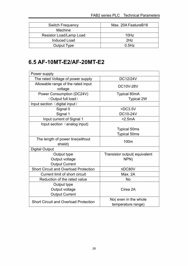
6.5 AF-10MT-E2/AF-20MT-E2
Power supplyThe rated Voltage of power supply DC12/24VAllowable range of the rated input
voltage DC10V-28V
Power Consumption (DC24V)(Output full load)
Typical 80mATypical 2W
Input section(digital input)Signal 0Signal 1
<DC3.5VDC10-24V
Input current of Signal 1 <2.5mAInput section(analog input)
Typical 50msTypical 50ms
The length of power line(withoutshield) 100m
Digital OutputOutput type
Output voltageOutput Current
Transistor output( equivalentNPN)
Short Circuit and Overload Protection ≤DC80VCurrent limit of short circuit Max. 2AReduction of the rated value No
Output typeOutput voltageOutput Current
Cirea 2A
Short Circuit and Overload Protection No( even in the wholetemperature range)
FAB2 series PLC user manual
29
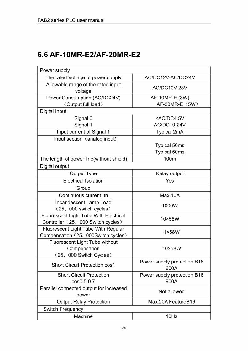
6.6 AF-10MR-E2/AF-20MR-E2
Power supplyThe rated Voltage of power supply AC/DC12V-AC/DC24VAllowable range of the rated input
voltage AC/DC10V-28V
Power Consumption (AC/DC24V)(Output full load)
AF-10MR-E (3W)AF-20MR-E(5W)
Digital InputSignal 0Signal 1
<AC/DC4.5VAC/DC10-24V
Input current of Signal 1 Typical 2mAInput section(analog input)
Typical 50msTypical 50ms
The length of power line(without shield) 100mDigital output
Output Type Relay outputElectrical Isolation Yes
Group 1Continuous current Ith Max.10A
Incandescent Lamp Load(25,000 switch cycles) 1000W
Fluorescent Light Tube With ElectricalController(25,000 Switch cycles) 10×58W
Fluorescent Light Tube With RegularCompensation(25,000Switch cycles) 1×58W
Fluorescent Light Tube withoutCompensation
(25,000 Switch Cycles)10×58W
Short Circuit Protection cos1 Power supply protection B16600A
Short Circuit Protectioncos0.5-0.7
Power supply protection B16900A
Parallel connected output for increasedpower Not allowed
Output Relay Protection Max.20A FeatureB16Switch Frequency
Machine 10Hz

FAB2 series PLC Technical Parameters
30
Resistor Load/Lamp Load 2HzInduced Load 0.5Hz
6.7 AF-10MT-GD2/AF-20MT-GD2
Power supplySupply voltage rating DC12/24V
Fluctuation voltage allowable rangeConsumption(DC24V)(Output full load)
DC10V-28VTypical 80mATypical 2W
Input section(digit input)Signal 0Signal 1
<DC3.5VDC10-24V
Input current of signal 1 <2.5mAInput section(analog input)
Signal 0Signal 1 DC0-10V
Input current of Signal 1 <0.8mAInput section(analog input)
Typical 50msTypical 50ms
The length of power line(without shield) 100mDigital Output
Output typeOutput VoltageOutput Current
Transistor output(equivalentPNP)≤DC80V
Max.2AShort circuit and Overload Protection No
Current limit of short circuit Circa2A
Reduction of the related value The entire temperature rangedoes not degrade the rating