f5g 01a01 gb - kebdvd.keb.de/fileadmin/media/manuals/f5/control/f5g/00f5geak320.pdf · issue...
TRANSCRIPT

Issue 06/2005
KEB COMBIVERT F5-BASIC / COMPACT / GENERAL 3.2
Part.No.: 00.F5.GEA-K320
APPLICATION MANUAL
Charge 40,- Euro

1 1Name:Basis
KEB COMBIVERT F5-G / C / B2 27.06.05© KEB Antriebstechnik, 2003
All Rights reserved
Introduction General
Chapter Section Page Date

31 1 327.06.05KEB COMBIVERT F5-G / C / B
Name:Basis
1
Chapter Section PageDate© KEB Antriebstechnik, 2003All Rights reserved
GeneralIntroduction
This chapter shall allow a fast access to the wanted information. It consists of contents,index and search criterion.
Here the inverter and its features as well as the operating conditions and applicationpurpose are described.
Description of hardware, technical data of the inverter as well as connection of powerand control terminals.
The basic operation of the KEB COMBIVERT like password input, parameter and setselection.
A list of all parameters classified according to parameter groups. The parameterdescription comprises addresses, value ranges and references with regard to thefunctions for which they are used.
To make the programming easier all inverter functions and the parameters belongingto it are comprised in this chapter.
Gives support with regard to the initial start-up and shows possibilities and techniquesfor the optimization of the drive.
Describes special operating modes, like e.g. DC-coupling.
Avoidance of errors, evaluation of error messages and elimination of the causes.
Serves as aid for the lay out design during the planning stage.
Survey of the possible interconnection of the KEB COMBIVERT in existing networks.
Everything that didn’t fit anywhere else or what we didn’t think of earlier.
1. Introduction
2. Summary
3. Hardware
4. Operation
5. Parameter
6. Functions
7. Start-up
8. Special Operation
9. Error Assistance
10. Project Planning
11. Networks
12. Annex

1 1Name: Basis
KEB COMBIVERT F5-G / C / B4 29.06.05
Chapter Section © KEB Antriebstechnik, 2002All Rights reserved
Page Date
Einführung

51 1 529.06.05KEB COMBIVERT F5-G / C / B
Name: Basis Chapter Section PageDate© KEB Antriebstechnik, 2003All Rights reserved
Einführung
1.1 General1. Introduction
2. Summary
3. Hardware
4. Operation
5. Parameter
6. Functions
7. Start-up
8. Special Operation
9. Error Assistance
10. Project Planning
11. Networks
12. Annex
1.1.1 Table of Contents .................... 71.1.2 Preface ................................. 13

1 1Name:Basis
KEB COMBIVERT F5-G / C / B6 27.06.05© KEB Antriebstechnik, 2003
All Rights reserved
Introduction General
Chapter Section Page Date
71 1 727.06.05KEB COMBIVERT F5-G / C / B
Name:Basis
1
Chapter Section PageDate© KEB Antriebstechnik, 2003All Rights reserved
GeneralIntroduction
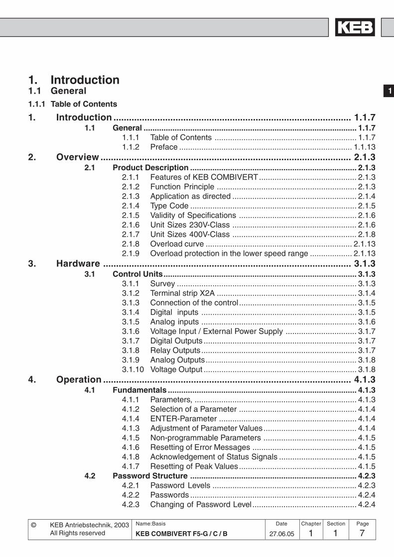
1. Introduction1.1 General1.1.1 Table of Contents
1. Introduction ............................................................................................ 1.1.71.1 General ................................................................................................ 1.1.7
1.1.1 Table of Contents ................................................................ 1.1.71.1.2 Preface .............................................................................. 1.1.13
2. Overview ................................................................................................. 2.1.32.1 Product Description ........................................................................... 2.1.3
2.1.1 Features of KEB COMBIVERT............................................ 2.1.32.1.2 Function Principle ............................................................... 2.1.32.1.3 Application as directed ........................................................ 2.1.42.1.4 Type Code ........................................................................... 2.1.52.1.5 Validity of Specifications ..................................................... 2.1.62.1.6 Unit Sizes 230V-Class ........................................................ 2.1.62.1.7 Unit Sizes 400V-Class ........................................................ 2.1.82.1.8 Overload curve .................................................................. 2.1.132.1.9 Overload protection in the lower speed range ................... 2.1.13
3. Hardware ................................................................................................ 3.1.33.1 Control Units....................................................................................... 3.1.3
3.1.1 Survey ................................................................................. 3.1.33.1.2 Terminal strip X2A ............................................................... 3.1.43.1.3 Connection of the control ..................................................... 3.1.53.1.4 Digital inputs ...................................................................... 3.1.53.1.5 Analog inputs ...................................................................... 3.1.63.1.6 Voltage Input / External Power Supply ................................ 3.1.73.1.7 Digital Outputs ..................................................................... 3.1.73.1.8 Relay Outputs ...................................................................... 3.1.73.1.9 Analog Outputs.................................................................... 3.1.83.1.10 Voltage Output ..................................................................... 3.1.8
4. Operation ................................................................................................ 4.1.34.1 Fundamentals ..................................................................................... 4.1.3
4.1.1 Parameters, ......................................................................... 4.1.34.1.2 Selection of a Parameter ..................................................... 4.1.44.1.4 ENTER-Parameter .............................................................. 4.1.44.1.3 Adjustment of Parameter Values.......................................... 4.1.44.1.5 Non-programmable Parameters .......................................... 4.1.54.1.6 Resetting of Error Messages ............................................... 4.1.54.1.8 Acknowledgement of Status Signals ................................... 4.1.54.1.7 Resetting of Peak Values..................................................... 4.1.5
4.2 Password Structure ........................................................................... 4.2.34.2.1 Password Levels ................................................................. 4.2.34.2.2 Passwords ........................................................................... 4.2.44.2.3 Changing of Password Level ............................................... 4.2.4

1 1Name:Basis
KEB COMBIVERT F5-G / C / B8 27.06.05© KEB Antriebstechnik, 2003
All Rights reserved
Introduction General
Chapter Section Page Date
4.3 CP-Parameter ..................................................................................... 4.3.34.3.1 Operation in CP-Mode......................................................... 4.3.34.3.2 Factory Setting .................................................................... 4.3.44.3.3 Password Input .................................................................... 4.3.54.3.4 Operating Display................................................................ 4.3.54.3.5 Basic Adjustment of the Drive............................................. 4.3.74.3.6 Special Adjustments.......................................................... 4.3.10
4.4 Drive-Mode .......................................................................................... 4.4.34.4.1 Adjustment Possibilities ...................................................... 4.4.34.4.2 Display and Keyboard ......................................................... 4.4.34.4.3 Setpoint Display /Setpoint Input .......................................... 4.4.34.4.4 Rotation Setting ................................................................... 4.4.44.4.5 Start / Stop / Run ................................................................. 4.4.44.4.7 Further Settings ................................................................... 4.4.54.4.6 Leaving the Drive-Mode ...................................................... 4.4.5
5. Parameter ............................................................................................... 5.1.35.1 Parameter ............................................................................................ 5.1.3
5.1.1 Parameter Groups ............................................................... 5.1.35.1.2 F5-BASIC Control ............................................................... 5.1.45.1.3 F5-GENERAL Control B-housing........................................ 5.1.45.1.4 F5-GENERAL Control >= D-housing .................................. 5.1.55.1.5 Parameter Listing ................................................................ 5.1.7
6. Functional Description ......................................................................... 6.1.36.1 Operating and Appliance Data .......................................................... 6.1.3
6.1.1 Overview of the ru-Parameters ........................................... 6.1.36.1.2 Overview of the In-Parameters............................................. 6.1.46.1.3 Overview of the Sy-Parameters ........................................... 6.1.46.1.4 Explanation to Parameter Description ................................. 6.1.56.1.5 Description of the ru-Parameters ......................................... 6.1.66.1.6 Description of the In-Parameters ....................................... 6.1.196.1.7 Description of the Sy-Parameters ...................................... 6.1.23
6.2 Analog In- and Outputs ...................................................................... 6.2.36.2.1 Summary Description Analog Inputs ................................... 6.2.36.2.2 Interface Selection (An.0; An.10) ......................................... 6.2.46.2.3 Interference Suppression Filter (An.1; An.11; An.21) ........... 6.2.56.2.4 Save Mode (An.2; An.12; An.22) .......................................... 6.2.56.2.5 Input Selection (An.3; An.13; An.23) .................................... 6.2.56.2.6 Zero Point Hysteresis (An.4; An.14; An.24) .......................... 6.2.66.2.7 Amplifier of the Input Characterstic (An.5...7; An.15...17;
An.25...27) ........................................................................... 6.2.76.2.8 Lower and Upper Limit (An.8; An.9; An.18; An.19; An.28; An.29)
6.2.86.2.9 Selection Set Point-/Auxiliary Input (An.30) ......................... 6.2.96.2.10 Brief Description Analog Outputs ...................................... 6.2.106.2.11 Output signals ................................................................... 6.2.11

91 1 927.06.05KEB COMBIVERT F5-G / C / B
Name:Basis
1
Chapter Section PageDate© KEB Antriebstechnik, 2003All Rights reserved
GeneralIntroduction
6.2.12 Analog Output / Functions (An.31/An.36/An.41) ............... 6.2.126.2.13 Analog Output / Display..................................................... 6.2.126.2.14 Gain of Output Characteristic (An.33...35 /An.38...40 /
An.43...45) ......................................................................... 6.2.136.2.15 Period ANOUT3 (An.46) .................................................... 6.2.146.2.17 Used Parameters .............................................................. 6.2.146.2.16 ANOUT 1...4 Digital Settings (An.32/37/42/48) ................. 6.2.14
6.3 Digital In- and Outputs ....................................................................... 6.3.36.3.1 Summary Description Digital Inputs .................................... 6.3.36.3.2 Input Signals PNP / NPN (di.0) ........................................... 6.3.36.3.3 Setting of Digital Inputs by Software (di.1, di.2) ................... 6.3.46.3.4 Terminal Status (ru.21) ........................................................ 6.3.56.3.5 Digital Filter (di.3) ................................................................ 6.3.56.3.6 Inversion of Inputs (di.4) ...................................................... 6.3.56.3.7 Edge-triggering (di.5) ........................................................... 6.3.56.3.8 Strobe-dependent Inputs (di.6, di.7, di.8) ............................. 6.3.66.3.9 Input Status (ru.22) .............................................................. 6.3.86.3.10 Reset/Input Selection and Edge Evaluation
(di.9 / di.10) .......................................................................... 6.3.86.3.11 Assignment of the Inputs ..................................................... 6.3.86.3.12 Summary Description - Digital Outputs.............................. 6.3.136.3.13 Output Signals ................................................................... 6.3.146.3.14 Output filter (do.43, do.44) .................................................. 6.3.146.3.15 Switching Conditions (do.0...do.7) ..................................... 6.3.156.3.16 Inverting of Switching Conditions for Flags (do.8...do.15) .. 6.3.186.3.17 Selection of Switching Conditions for Flags (do.16...do.23)6.3.186.3.18 Linking the Switching Conditions for Flags (do.24) ........... 6.3.186.3.20 Selection of Flags (do.33...do.40) ...................................... 6.3.196.3.21 Linking the Flags (do.41) ................................................... 6.3.196.3.19 Inverting of Flags (do.25...do.32) ....................................... 6.3.196.3.22 Inversion of Outputs (do.42) ............................................... 6.3.206.3.23 Output Terminal Status (ru.25) ........................................... 6.3.206.3.24 Hardware output allocation (do.51) .................................... 6.3.206.3.25 Programming Example ...................................................... 6.3.216.3.26 Used Parameters ............................................................... 6.3.22
6.4 Setpoint-, Rotation- and Ramp Adjustment ..................................... 6.4.36.4.1 Summary Description .......................................................... 6.4.36.4.3 Rotation Selection oP.1 ....................................................... 6.4.76.4.4 Fixed Frequencies (oP.18...23) .......................................... 6.4.106.4.5 Setpoint Limits ................................................................... 6.4.126.4.6 Setpoint Computation ........................................................ 6.4.136.4.7 Ramp Generator ................................................................ 6.4.146.4.8 Limiter (oP.36...41) ............................................................. 6.4.166.4.9 Ramp with constant time ................................................... 6.4.166.4.10 Used Parameters ............................................................... 6.4.19

1 1Name:Basis
KEB COMBIVERT F5-G / C / B10 27.06.05© KEB Antriebstechnik, 2003
All Rights reserved
Introduction General
Chapter Section Page Date
6.5 Voltage-/Frequency Characteristic Adjustment ............................... 6.5.36.5.1 Control Type (ud.2) and
Max Frequency Mode (only F5-B) ....................................... 6.5.36.5.2 Rated frequency (uF.0) and Boost (uF.1) ............................. 6.5.46.5.3 Additional Rated Point (uF.2/uF.3) ....................................... 6.5.46.5.4 Delta Boost (uF.4/uF.5) ........................................................ 6.5.46.5.5 Voltage Stabilization (uF.9) .................................................. 6.5.56.5.6 Maximal voltage mode (uF.10)............................................. 6.5.66.5.7 Switching Frequency (uF.11) ............................................... 6.5.66.5.8 Used Parameters ................................................................. 6.5.7
6.6 Motor Data Adjustment ...................................................................... 6.6.36.6.1 Motor Name Plate................................................................ 6.6.36.6.2 Motor Data from the Name Plate (dr.0...dr.5) ........................ 6.6.36.6.3 Motor Data from Data Sheets (dr. 9) ..................................... 6.6.46.6.4 Motor Stator Resistance (dr.6) ............................................. 6.6.46.6.5 Used Parameters ................................................................. 6.6.6
6.7 Protective Functions .......................................................................... 6.7.36.7.1 Ramp Stop and Hardware Current Limit.............................. 6.7.36.7.2 Current Limit Constant Run (Stall-Function) ........................ 6.7.56.7.3 Automatic Restart and Speed Search ................................. 6.7.76.7.4 Dead Time Compensation (uF.18) ....................................... 6.7.96.7.5 Base-Block Time (uF.12) and Voltage Level (uF.13) ............ 6.7.96.7.6 Response to Errors or Warning Signals ............................... 6.7.96.7.7 Quick Stop ......................................................................... 6.7.136.7.8 Motor Protection Mode ...................................................... 6.7.156.7.9 GTR7-Control .................................................................... 6.7.196.7.10 Special Functions.............................................................. 6.7.20
6.8 Parameter Sets ................................................................................... 6.8.36.8.1 Non-programmable Parameters .......................................... 6.8.36.8.2 Security Parameters ............................................................ 6.8.36.8.3 System Parameters ............................................................. 6.8.36.8.4 Indirect and Direct Set-Addressing ...................................... 6.8.36.8.5 Copying of Parameter Sets via Keyboard (Fr.1) ................... 6.8.46.8.6 Copying of Parameter Sets via Bus (Fr.1, Fr.9) .................... 6.8.46.8.7 Parameter Set Selection ...................................................... 6.8.76.8.8 Locking of Parameter Sets................................................. 6.8.106.8.9 Parameter Set ON/OFF Delay (Fr.5, Fr.6) .......................... 6.8.106.8.10 Used Parameters ............................................................... 6.8.11
6.9 Special Functions .............................................................................. 6.9.36.9.1 DC-Braking ......................................................................... 6.9.36.9.2 Energy Saving Function ...................................................... 6.9.56.9.3 Motorpoti Function ............................................................... 6.9.76.9.4 Timer and Counter ............................................................ 6.9.116.9.5 Brake Control .................................................................... 6.9.156.9.6 Power-Off Function ............................................................ 6.9.196.9.7 Wobbel Function ............................................................... 6.9.27

111 1 1127.06.05KEB COMBIVERT F5-G / C / B
Name:Basis
1
Chapter Section PageDate© KEB Antriebstechnik, 2003All Rights reserved
GeneralIntroduction
6.9.8 Diameter Correction .......................................................... 6.9.296.9.9 Positioning Function .......................................................... 6.9.316.9.10 Analog Setting of Parameter Values .................................. 6.9.34
6.10 Encoder Interface ............................................................................. 6.10.36.10.1 Designs ............................................................................. 6.10.36.10.2 Encoder Interface Channel 1 (X3A) ................................... 6.10.46.10.3 Encoder Inteface Channel 2 (X3B) .................................... 6.10.56.10.4 Power Supply of Encoder .................................................. 6.10.76.10.5 Selection of Encoder ......................................................... 6.10.86.10.6 Basic Setting ................................................................... 6.10.106.10.7 Additional
Parameters ...................................................................... 6.10.136.10.8 Used Parameters ............................................................. 6.10.16
6.11 SSM ................................................................................................... 6.11.36.11.1 Torque Compensation ....................................................... 6.11.36.11.2 Speed Control ................................................................... 6.11.46.11.3 Used Parameters ............................................................... 6.11.6
6.12 Technology Control ......................................................................... 6.12.36.12.1 The PID Controller ............................................................ 6.12.36.12.2 PID Setpoint Value ............................................................ 6.12.56.12.3 PID Actual Value ............................................................... 6.12.66.12.4 Sample Applications ......................................................... 6.12.76.12.5 Used Parameters ............................................................ 6.12.10
6.13 CP-Parameter Definition .................................................................. 6.13.36.13.1 Survey ............................................................................... 6.13.36.13.2 Assignment of CP-Parameters .......................................... 6.13.46.13.3 Example ............................................................................ 6.13.56.13.4 Display standardization ..................................................... 6.13.66.13.5 Variable Standardization .................................................. 6.13.86.13.6 Used Parameters ............................................................. 6.13.10
7. Start-up .......................................................................................................... 7.1.37.1 Preparatory Measures........................................................................ 7.1.3
7.1.1 After unpacking the Goods .................................................. 7.1.37.1.2 Installation and connection .................................................. 7.1.37.1.3 Checklist prior to Start-up .................................................... 7.1.4
7.2 Initial Start-up...................................................................................... 7.2.37.2.1 Switching on of KEB COMBIVERT ..................................... 7.2.37.2.3 Set value selection .............................................................. 7.2.47.2.2 Basic Settings in the CP-Mode............................................ 7.2.4
8. Special Operations ................................................................................ 8.1.38.1 Temperature Control .......................................................................... 8.1.3
8.1.1 Parameter Description ......................................................... 8.1.38.1.2 Possibilities for a Temperature Control ................................ 8.1.48.1.3 Connection to the Cooling System ...................................... 8.1.58.1.4 Inverter Protection Function „Overheat“ ............................... 8.1.68.1.5 Information about Water Cooling ......................................... 8.1.7

1 1Name:Basis
KEB COMBIVERT F5-G / C / B12 27.06.05© KEB Antriebstechnik, 2003
All Rights reserved
Introduction General
Chapter Section Page Date
8.1.6 Operation Example.............................................................. 8.1.89. Error Assistance .................................................................................... 9.1.3
9.1 Troubleshooting ................................................................................. 9.1.39.1.1 General ............................................................................... 9.1.39.1.2 Error Messages and their Cause ......................................... 9.1.3
10. Project design ...................................................................................... 10.1.310.1 General Designs ............................................................................... 10.1.3
10.1.1 Control Cabinet Design Calculation .................................. 10.1.310.1.2 Design of Braking Resistors .............................................. 10.1.410.1.3 Cables and fuses .............................................................. 10.1.6
11. Networks............................................................................................... 11.1.311.1 Network Components ...................................................................... 11.1.3
11.1.1 Available Hardware ........................................................... 11.1.311.1.2 RS232-Cable PC / Operator 00.58.025-001D ................... 11.1.311.1.3 HSP5-Cable / Control Board 00.F5.0C0-0001 .................. 11.1.311.1.4 Interface Operator F5 00.F5.060-2000.............................. 11.1.411.1.5 Profibus-DP Operator F5 00.F5.060-3000......................... 11.1.511.1.6 InterBus Operator F5 00.F5.060-4000 ............................... 11.1.611.1.7 CanOpen Operator F5 00.F5.060-5000............................. 11.1.711.1.8 Sercos Operator 00.F5.060-6000 ...................................... 11.1.8
11.2. Bus Parameters ................................................................................ 11.2.311.2.1 Adjustment of Inverter Address (Sy.6)................................ 11.2.311.2.2 Baud Rate ext. Bus (Sy.7) .................................................. 11.2.311.2.3 Baud Rate int. Bus (Sy.11) ................................................. 11.2.311.2.4 Watchdog-Time (Pn.6) ....................................................... 11.2.311.2.5 Response to E.bus (Pn.5) ................................................. 11.2.311.2.6 HSP5 Watchdog Time (Sy.9) ............................................. 11.2.311.2.7 Automatic Storing (ud.5) .................................................... 11.2.311.2.8 Control and Status Word ................................................... 11.2.411.2.9 Speed Setting via Bus ....................................................... 11.2.511.2.10 Used Parameters ............................................................... 11.2.6

131 1 1327.06.05KEB COMBIVERT F5-G / C / B
Name:Basis
1
Chapter Section PageDate© KEB Antriebstechnik, 2003All Rights reserved
GeneralIntroduction
Who shall read all this?Everybody who is entrusted with the development and construction of applications.He who knows the extensive programming possibilities of the KEB COMBIVERT,can save external controls and expensive cabling already in the planning stage ofa machine simply by using the unit as active control element. This manual is nota replacement of the documentation accompanying the unit, it serves only ascompletion.
1000 and one application...and if possible with one unit. Who does not know this demand from purchasingdepartments, production or service. We have taken this request very seriouslyand developed a series with open programming, which can be adapted to thedifferent applications with PC or operator.
Nobody can handle this...some sceptics may say. But we have found a solution to this too. Once thedevelopment stage of a machine is completed only a few adjustment possibilitiesare needed on the inverter and in some cases even none at all. So why should allparameters still be visible? Said and done, by defining an own menu only selectedparameters are visible. This makes the handling much easier, simplifies the userdocumentation and improves the safety of operation against unauthorized access(see picture 1.1.2).
1.1.2 Preface
Picture 1.1.2
Entire parameter pool
User menu(CP-Parameters)

1 1Name: Basis
KEB COMBIVERT F5-G / C / B14 29.06.05
Chapter Section © KEB Antriebstechnik, 2002All Rights reserved
Page Date
Einführung

2.1 Product Description
Summary
1. Introduction
2. Summary
3. Hardware
4. Operation
5. Parameter
6. Functions
7. Start-up
8. Special Operation
9. Error Assistance
10. Project Planning
11. Networks
12. Annex
12 1 1KEB COMBIVERT F5
Name: Basis
04.05.04© KEB Antriebstechnik, 2002
All Rights reserved
Section PageDate Chapter
2.1.1 Features ofKEB COMBIVERT.................. 3
2.1.2 Function Principle .................. 32.1.3 Application as directed ........... 42.1.4 Type Code .............................. 52.1.5 Validity of Specifications ........ 62.1.6 Unit Sizes 230V-Class ........... 62.1.7 Unit Sizes 400V-Class ........... 82.1.8 Overload curve .................... 132.1.9 Overload protection in the lower
speed range ......................... 13

2 1 KEB COMBIVERT F52Name: Basis
04.05.04© KEB Antriebstechnik, 2002
All Rights reserved
Product DescriptionSummary
Chapter Section Page Date

32 1 3KEB COMBIVERT F5
Name: Basis
04.05.04
2
© KEB Antriebstechnik, 2002All Rights reserved
Product Description Summary
Section PageDate Chapter
L1
L2
(L3)
2.1.1 Features of KEBCOMBIVERT
2.1 Product Description
KEBCOMBIVERT
8 parameter sets
14 parameter groups
Prog. Operator menu
2 prog. relay outputs
8 prog. digital inputs
2 prog. digital output
2 prog. analog output
2 prog. analog inputs
Hardware current limit
Autoboost
Slip compensation
DC-braking
Jogging-function (prog.)
Speed search
Power-Off function
HSP5 interface
Energy saving function
PID-controller
Protective equipment
Electr. motor protection
Prog. filter for analog and digital inputs
Software In-/Outputs
Adjustable balancing of the ramps
Hour meter
2.1.2 FunctionPrinciple
The power circuit of a frequency inverter consists basically of a mains rectifier, theDC-link and an inverter at the output. The mains rectifier consists of an uncontrolledsingle or three-phase bridge connection, the single-phase design is restricted tosmall powers. It converts the AC-voltage of the mains into a DC-voltage, which issmoothed by the DC-link capacitor, thus in the ideal case (inverter unloaded) theDC-link is charged with a voltage of U
ZK = Ö2 . U
N.
Since during the charging of the DC-link capacitor very high currents flow for a shorttime which would lead to the tripping of the input fuses or even to the destruction ofthe mains rectifier, the charging current must be limited to a permissible level. This isachieved by using an inrush current limiting resistor in series to the capacitor. Afterthe charging of the capacitor is completed the limiting resistor is bridged, for example,by a relay and is therefore only active at the switch-on of the inverter.As the smoothing of the DC-link voltage requires a large capacity, the capacitor stillhas a high voltage for some time after the disconnection of the inverter from themains.The actual task of the frequency inverter, to produce an output voltage variable infrequency and amplitude for the control of the three-phase AC motor, is taken overby the converter at the output. It makes available a 3-phase output voltage accordingto the principle of the pulse-width modulation, which generates a sinusoidal currentat the three-phase asynchronous motor
Picture 2.1.2 Block diagram of an inverter power circuit
2. Overview
Encoder interface
�
� �
�
UN R
CW
U
VUZK
Mains rectifier MotorConverterDC-link

2 1 KEB COMBIVERT F54Name: Basis
04.05.04© KEB Antriebstechnik, 2002
All Rights reserved
Product DescriptionSummary
Chapter Section Page Date
2.1.3 Application as directed
The KEB COMBIVERT is a frequency inverter with DC-voltage link. It works according to the principle of the pulse-width modulation and serves exclusively for the steplessspeed control of three-phase AC motors.The unit has been developed subject to the relevant safetystandards and is manufactured with the highest demands onquality. Condition for an unobjectionable operation is thefunction-conform configuring of the drive and correct transportand storage as well as careful installation and connection.
The operation of other electric consumers is prohibited andcan lead to the destruction of the units as well asconsequential damages as a result from it.

52 1 5KEB COMBIVERT F5
Name: Basis
04.05.04
2
© KEB Antriebstechnik, 2002All Rights reserved
Product Description Summary
Section PageDate Chapter
2.1.4 Type Code
10.F5.G1B–3200
at FI: Cooling at Servos: motor cooling0: Standard 0: Self-cooling1: Flat rear 1: External cooling2: Water-cooled3: Convection
Encoder interface type see control part0: no interface 5: Resolver a. SSI A: Ink.-Input a. Initiator F: Hiperface a. Ink.-Outp.1: Ink.-Input a. Ink.-I/O 6: Hiperface a. SSI B: Resolver a. Initiator G: Ink.-Input a. Ink.-Inp.2: Resolver a. Ink.-I/O 7: Ink.-Input a. Tacho C: Hiperface a. Initiator H: Resolver a. Ink.-Inp.3: Hiperface a. Ink.-I/O 8: Resolver a. Tacho D: Ink.-Input a. Ink.-Outp. I: Hiperface a. Ink.-Inp.4: Ink.-Input a. SSI 9: Hiperface a. Tacho E: Resolver a. Ink.-Outp.
at FI: Switching frequency / max. short time current / OC-tripping current0: 2 kHz/125%/150% 5: 4 kHz/150%/180% A: 8 kHz/180%/216% F: 16 kHz/200%/240%1: 4 kHz/125%/150% 6: 8 kHz/150%/180% B: 16 kHz/180%/216% G: 2 kHz/400%/480%2: 8 kHz/125%/150% 7: 16 kHz/150%/180% C: 2 kHz/200%/240% H: 4 kHz/400%/480%3: 16 kHz/125%/150% 8: 2 kHz/180%/216% D: 4 kHz/200%/240% I: 8 kHz/400%/480%4: 2 kHz/150%/180% 9: 4 kHz/180%/216% E: 8 kHz/200%/240% K: 16 kHz/400%/480%
at Servos: motor speed1: 1500 rpm 2: 2000 rpm 3: 3000 rpm 4: 4000 rpm 6: 6000 rpm
Input identification0: 1ph 230V AC/DC 5: 400V DC A: 6ph 400V AC1: 3ph 230V AC/DC 6: 1ph 230V AC Z: 230V AC or AC/DC2: 1/3ph 230V AC/DC 7: 3ph 230V AC Y: 400V AC or AC/DC3: 3ph 400V AC/DC 8: 1/3ph 230V AC W: 230V DC4: 230V DC 9: 3ph 400V AC V: 400V DC
Housing type A, B, D, E, G, H, R, U, W
Accessory0: without 4: integrated PFC 2)
1: GTR 7 1) 5: GTR 7 1), integrated PFC 2)
2: integrated filter 6: integrated filter , integrated PFC 2)
3: GTR 7 1), integrated filter 7: GTR 7 1), integrated filter, integrated PFC 2)
Control typeB: BASIC (controlled frequency inverter with standard function)G: GENERAL (controlled frequency inverter with enhanced function)C: COMPACT (controlled frequency inverter with enhanced function)M: MULTI (regulated, field-oriented frequency inverter for three-phase asynchronous motors)S: SERVO (regulated frequency inverter for synchronous motors)
Series F5
at FI in the 1. and 2. place: unit size
at Servos: motor identification / motor dimension wide
1) GTR 7: brake transistor2) PFC: Power Factor Control

2 1 KEB COMBIVERT F56Name: Basis
04.05.04© KEB Antriebstechnik, 2002
All Rights reserved
Product DescriptionSummary
Chapter Section Page Date
2.1.6 Unit Sizes 230V-Class
The following technical specifications refer to 2-/4-pole standard motors. In case ofdifferent pole numbers the frequency inverter must be dimensioned for the ratedmotor current. With regard to special or medium frequency motors, please contactKEB.Site altitude max. 2000 m. For altitudes of 1000 m or more above N.N. a powerreduction of 1 % per 100m must be taken into account.
2.1.5 Validity ofSpecifications
05 07 09 10 12 13A A B B D B D D E1 1 3 1 1 3 1 3 1 3 1 3 1 3 3 3
[kVA] 0,9 1,6 2,8 4,0 6,6 9,5[kW] 0,37 0,75 1,5 2,2 4,0 5,5
[A] 2,3 4 7 10 16,5 24[A] 4,1 7,2 12,6 18 29,7 36[A] 5,0 8,6 15,1 21,6 35,6 43[A] 4,6 4,6 3,2 8,0 8,0 5,6 14 9,8 14 9,8 20 14 20 14 23 31[A] – 3,7 – – 6,4 – – – – –
[kW] – 0,85 – – 1,5 – – – – –[A] 10 16 10 20 16 20 16 20 16 25 20 25 20 25 35
[kHz] 4 16 8 16 16 8 16 8 8[kHz] 4 16 8 16 16 16 16 16
[W] 30 55 65 90 130 105 170 210 290[W] – 85 – – 130 – – – – –
[A] 2,3 4 7 10 16,5 24
[A] 2,3 4 7 10 16,5 24
[A] – 2,3 – 4 7 8,5 10 10 16,8
[°C] 90
[mm²] 1,5 1,5 2,5 1,5 2,5 1,5 2,5 1,5 4 2,5 4 2,5 4 6
[Ohm] 100 56 100 56 47 33 27 16
[Ohm] 180 180 100 68 33 27[A] 4,5 7,5 4,5 7,5 9,5 12 15 25
1[Nm] 0,5 1,2
50
BInverter SizeHousing sizePhasesOutput nominal powerMax. rated motor powerOutput nominal current
Max. short time current 1)
OC-tripping currentNominal input current
Nominal input current 2)
Real input rated power 2)
Max. permissible mains fuse (inert)Rated switching frequencyMax. switching frequencyPower loss at nominal operating
Power loss at rated operation 2)
Stall current at 4kHz 3)
Stall current at 8kHz 3)
Stall current at 16kHz 3)
Max. heat sink temperature TOH
Motor line cross section 4)
Min. braking resistor 5)
Typ. braking resistor 5)
Max. braking currentOverload curve (page appendex)Tightening torque for terminalsMains voltageMains frequencyOutput voltageOutput frequency
Max.shielded motor line length at 4 kHz 6)
Max.shielded motor line length at 8 kHz 6)
Max.shielded motor line length at 16 kHz 6)
Storage temperatureOperating temperatureModel / protective systemRelative humidityEMC tested according toClimatic category
[V] 180...260 –0 (230 V Nominal voltage)[Hz] 50 / 60 +/- 2[V] 3 x 0...U Mains (3 x 0...255V 2))[Hz] see Control board[m] 10 30 10 100 100
[m] 10 20 10 50 100
[m] - 10 - 20 40 100[ C] -25...70 C[ C] -10...45 C
IP20max. 95% without condensation
EN 61800-33K3 in accordance with EN 50178
1) With the regulated systems F5-M as well as F5-S 5% are to be subtracted as control reserve.2) Fuses of type Ferraz Shawmut 6,6 UD Type 313) Max. current before the responding of the OL2-function (only F5-M; F5-S; F5-A)4) Recommended minimum cross section for rated power and a cable length of upto 100m (copper)5) This data is only valid for units with internal brake transistor (see "unit identification")6) Rated voltage 400V; at mains voltage ³ 460V multiply the rated current with factor 0.86.7) The temperature range is only valid for the control circuit. For the power circuit the temperature range is depending on the control cabinet
installation and the cooling system.8) 31.F5 only watercooled.
72 1 7KEB COMBIVERT F5
Name: Basis
04.05.04
2
© KEB Antriebstechnik, 2002All Rights reserved
Product Description Summary
Section PageDate Chapter
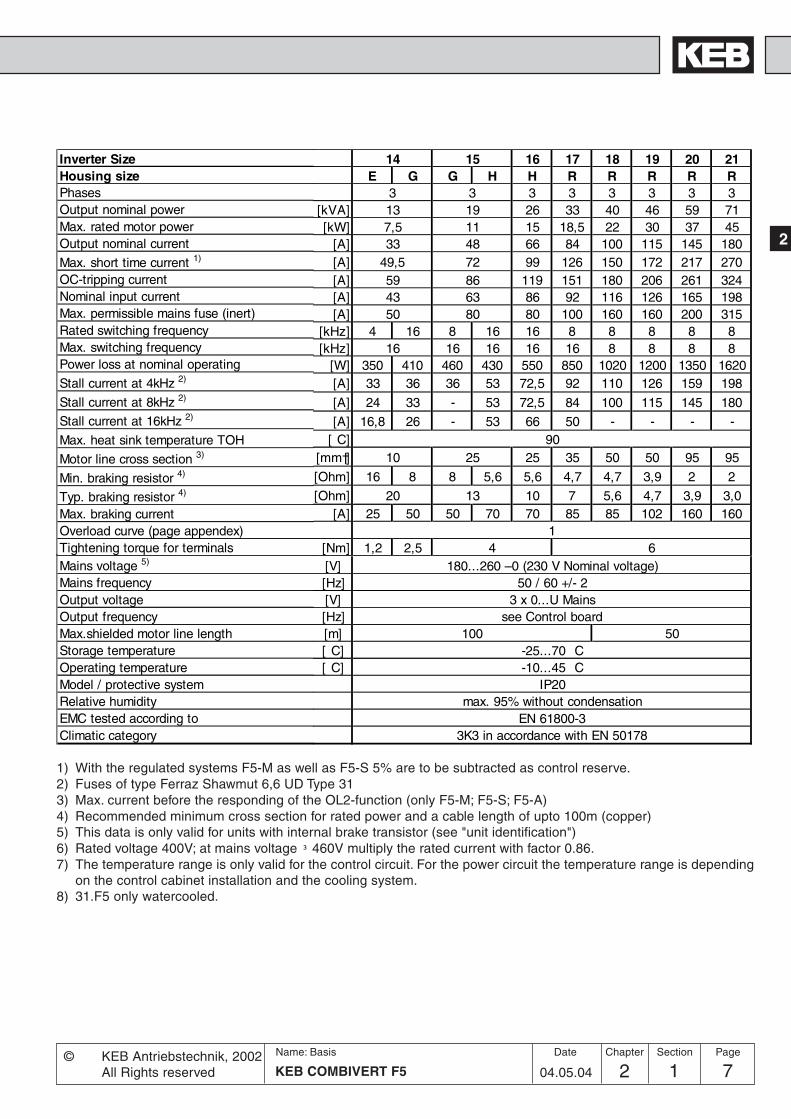
14 15 16 17 18 19 20 21E G G H H R R R R R
3 3 3 3 3 3 3 3[kVA] 13 19 26 33 40 46 59 71[kW] 7,5 11 15 18,5 22 30 37 45
[A] 33 48 66 84 100 115 145 180[A] 49,5 72 99 126 150 172 217 270[A] 59 86 119 151 180 206 261 324[A] 43 63 86 92 116 126 165 198[A] 50 80 80 100 160 160 200 315
[kHz] 4 16 8 16 16 8 8 8 8 8[kHz] 16 16 16 16 16 8 8 8 8
[W] 350 410 460 430 550 850 1020 1200 1350 1620[A] 33 36 36 53 72,5 92 110 126 159 198
[A] 24 33 - 53 72,5 84 100 115 145 180
[A] 16,8 26 - 53 66 50 - - - -[ C] 90
[mm†] 10 25 25 35 50 50 95 95
[Ohm] 16 8 8 5,6 5,6 4,7 4,7 3,9 2 2
[Ohm] 20 13 10 7 5,6 4,7 3,9 3,0[A] 25 50 50 70 70 85 85 102 160 160
1[Nm] 1,2 2,5 4 6
Inverter SizeHousing sizePhasesOutput nominal powerMax. rated motor powerOutput nominal current
Max. short time current 1)
OC-tripping currentNominal input currentMax. permissible mains fuse (inert)Rated switching frequencyMax. switching frequencyPower loss at nominal operating
Stall current at 4kHz 2)
Stall current at 8kHz 2)
Stall current at 16kHz 2)
Max. heat sink temperature TOH
Motor line cross section 3)
Min. braking resistor 4)
Typ. braking resistor 4)
Max. braking currentOverload curve (page appendex)Tightening torque for terminalsMains voltage 5)
Mains frequencyOutput voltageOutput frequencyMax.shielded motor line lengthStorage temperatureOperating temperatureModel / protective systemRelative humidityEMC tested according toClimatic category
[V] 180...260 –0 (230 V Nominal voltage)[Hz] 50 / 60 +/- 2[V] 3 x 0...U Mains[Hz] see Control board[m] 100 50[ C] -25...70 C[ C] -10...45 C
IP20max. 95% without condensation
EN 61800-33K3 in accordance with EN 50178
1) With the regulated systems F5-M as well as F5-S 5% are to be subtracted as control reserve.2) Fuses of type Ferraz Shawmut 6,6 UD Type 313) Max. current before the responding of the OL2-function (only F5-M; F5-S; F5-A)4) Recommended minimum cross section for rated power and a cable length of upto 100m (copper)5) This data is only valid for units with internal brake transistor (see "unit identification")6) Rated voltage 400V; at mains voltage ³ 460V multiply the rated current with factor 0.86.7) The temperature range is only valid for the control circuit. For the power circuit the temperature range is depending
on the control cabinet installation and the cooling system.8) 31.F5 only watercooled.

2 1 KEB COMBIVERT F58Name: Basis
04.05.04© KEB Antriebstechnik, 2002
All Rights reserved
Product DescriptionSummary
Chapter Section Page Date
2.1.7 Unit Sizes 400V-Class
05 07 09 10 12 13 14B B B D B D D B D E D E G D E G3 3 3 3 3 3 3
[kVA] 0,9 1,8 2,8 4,0 6,6 8,3 11[kW] 0,37 0,75 1,5 2,2 4,0 5,5 7,5
[A] 1,3 2,6 4,1 5,8 9,5 12 16,5[A] 2,3 4,7 7,4 10,4 17 21,6 18 29,7 24,8[A] 2,8 5,6 8,9 12,5 21 25,9 21,6 35,6 29,7[A] 1,8 3,6 6 8 13 17 23[A] 16 16 16 16 20 25 25
[kHz] 16 16 8 8 4 16 4 8 16 4 16 2 8 16[kHz] 16 16 16 16 4 16 16 16 6) 16
[W] 60 90 80 105 120 140 170 150 185 300 185 250 200 185 320 380[A] 1,3 2,6 4,1 5,8 9,5 12 14,5 16,5
[A] 1,3 2,6 4,1 5,8 5,2 5,8 - 9,5 9,5 12 7,4 16,5
[A] 1,3 2,6 3,5 4,9 3,5 5,8 - 5,8 9,5 5,8 12 5,7 10 12
[ C] 90
[mm†] 1,5 1,5 1,5 1,5 2,5 4 4
[Ohm] 390 120 120 82 82 39 56 39 50 56 39
[Ohm] 620 620 390 270 150 110 85[A] 2,2 7,5 7,5 10 10 21 15 21 15 15 21
1[Nm] 0,5 1,2 0,5 1,2
Inverter SizeHousing sizePhasesOutput nominal powerMax. rated motor powerOutput nominal current
Max. short time current 1)
OC-tripping currentNominal input currentMax. permissible mains fuse (inert)Rated switching frequency
Max. switching frequencyPower loss at nominal operating
Stall current at 4kHz 2)
Stall current at 8kHz 2)
Stall current at 16kHz 2)
Max. heat sink temperature TOH
Motor line cross section 3)
Min. braking resistor 4)
Typ. braking resistor 4)
Max. braking currentOverload curve (page appendex)Tightening torque for terminals
Mains voltage 5)
Mains frequencyOutput voltageOutput frequencyMax.shielded motor line length at 4 kHzMax.shielded motor line length at 8 kHzMax.shielded motor line length at 16 kHzStorage temperatureOperating temperatureModel / protective systemRelative humidityEMC tested according toVibration/Jolt according toClimatic category
[V] 305...500 –0 (400 V Nominal voltage)[Hz] 50 / 60 +/- 2[V] 3 x 0...U Mains
[Hz] see Control board[m] 10 10 100 100 50 100 100 100[m] 8 8 30 50 100 - 100 100 - 100[m] 4 5 10 10 20 - 100 100 - 100[ C] -25...70 C[ C] -10...45 C
IP20max. 95% without condensation
EN 61800-3Germanischer Lloyd; EN 50155
3K3 in accordance with EN 50178
1) With the regulated systems F5-M as well as F5-S 5% are to be subtracted as control reserve.2) Fuses of type Ferraz Shawmut 6,6 UD Type 313) Max. current before the responding of the OL2-function (only F5-M; F5-S; F5-A)4) Recommended minimum cross section for rated power and a cable length of upto 100m (copper)5) This data is only valid for units with internal brake transistor (see "unit identification")6) Rated voltage 400V; at mains voltage ³ 460V multiply the rated current with factor 0.86.7) The temperature range is only valid for the control circuit. For the power circuit the temperature range is depending
on the control cabinet installation and the cooling system.8) 31.F5 only watercooled.

92 1 9KEB COMBIVERT F5
Name: Basis
04.05.04
2
© KEB Antriebstechnik, 2002All Rights reserved
Product Description Summary
Section PageDate Chapter
[V] 305...500 –0 (400 V Nominal voltage)[Hz] 50 / 60 +/- 2[V] 3 x 0...U Mains
[Hz] see Control board[m] 100
[ C] -25...70 C[ C] -10...45 C
IP20max. 95% without condensation
EN 61800-33K3 in accordance with EN 50178
15 16 17 18 19E G H E G H G H H R H R
3 3 3 3 3[kVA] 17 23 29 35 42[kW] 11 15 18,5 22 30
[A] 24 33 42 50 60[A] 36 49,5 63 75 90[A] 43 59 75 90 108[A] 31 43 55 65 66[A] 35 50 50 63 80 80
[kHz] 4 8 16 2 8 16 4 8 8 16 4 8[kHz] 16 4 16 16 16 16
[W] 350 290 360 330 310 490 360 470 610 850 540 750[A] 24 27 33 42 50 60
[A] 16 19 24 - 21,5 33 21,4 30 45 50 39 60
[A] 10 8,4 15 - 9,5 20 - 13,5 20 40 18 27
[ C] 90
[mm†] 6 10 10 16 25 25
[Ohm] 39 22 25 22 25 22 13 9 13 9
[Ohm] 56 42 30 20 15[A] 21 37 32 30 37 30 37 63 88 63 88
1[Nm] 2,5 1,2 2,5 1,2 2,5 2,5 6 2,5 61,2
Inverter SizeHousing sizePhasesOutput nominal powerMax. rated motor powerOutput nominal current
Max. short time current 1)
OC-tripping currentNominal input currentMax. permissible mains fuse (inert)Rated switching frequencyMax. switching frequencyPower loss at nominal operating
Stall current at 4kHz 2)
Stall current at 8kHz 2)
Stall current at 16kHz 2)
Max. heat sink temperature TOH
Motor line cross section 3)
Min. braking resistor 4)
Typ. braking resistor 4)
Max. braking currentOverload curve (page appendex)Tightening torque for terminalsMains voltage 5)
Mains frequencyOutput voltageOutput frequencyMax. shielded motor line lengthStorage temperatureOperating temperatureModel / protective systemRelative humidityEMC tested according toClimatic category
1) With the regulated systems F5-M as well as F5-S 5% are to be subtracted as control reserve.2) Fuses of type Ferraz Shawmut 6,6 UD Type 313) Max. current before the responding of the OL2-function (only F5-M; F5-S; F5-A)4) Recommended minimum cross section for rated power and a cable length of upto 100m (copper)5) This data is only valid for units with internal brake transistor (see "unit identification")6) Rated voltage 400V; at mains voltage ³ 460V multiply the rated current with factor 0.86.7) The temperature range is only valid for the control circuit. For the power circuit the temperature range is depending
on the control cabinet installation and the cooling system.8) 31.F5 only watercooled.

2 1 KEB COMBIVERT F510Name: Basis
04.05.04© KEB Antriebstechnik, 2002
All Rights reserved
Product DescriptionSummary
Chapter Section Page Date
20 21 22 23 24R R R R U R U3 3 3 3 3
[kVA] 52 62 80 104 125[kW] 37 45 55 75 90
[A] 75 90 115 150 180[A] 112 135 172 225 270[A] 135 162 207 270 324[A] 83 100 127 165 198[A] 100 160 160 200 315
[kHz] 8 4 8 4 8 2 8 2 4 8[kHz] 16 16 16 12 8 8
[W] 900 1000 1100 1200 1500 1300 1900 1700 2000 2400[A] 75 90 115 115 127,5 150 144 180
[A] 75 63 90 80 115 90 150 108 180
[A] 34 45 54 46 51 - - - -
[ C] 90
[mm†] 35 50 50 95 95
[Ohm] 9 6 5 4
[Ohm] 12 10 8,6 6,7 5[A] 88 133 160 200
1[Nm] 6 15
Inverter SizeHousing sizePhasesOutput nominal powerMax. rated motor powerOutput nominal current
Max. short time current 1)
OC-tripping currentNominal input currentMax. permissible mains fuse (inert)Rated switching frequencyMax. switching frequencyPower loss at nominal operating
Stall current at 4kHz 2)
Stall current at 8kHz 2)
Stall current at 16kHz 2)
Max. heat sink temperature TOH
Motor line cross section 3)
Min. braking resistor 4)
Typ. braking resistor 4)
Max. braking currentOverload curve (page appendex)Tightening torque for terminals
Mains voltage 5)
Mains frequencyOutput voltageOutput frequencyMax. shielded motor line lengthStorage temperatureOperating temperatureModel / protective systemRelative humidityEMC tested according toClimatic category
[V] 305...500 –0 (400 V Nominal voltage)[Hz] 50 / 60 +/- 2[V] 3 x 0...U Mains
[Hz] see Control board[m] 50
[ C] -25...70 C[ C] -10...45 C -10...40 C
IP20max. 95% without condensation
EN 61800-33K3 in accordance with EN 50178
1) With the regulated systems F5-M as well as F5-S 5% are to be subtracted as control reserve.2) Fuses of type Ferraz Shawmut 6,6 UD Type 313) Max. current before the responding of the OL2-function (only F5-M; F5-S; F5-A)4) Recommended minimum cross section for rated power and a cable length of upto 100m (copper)5) This data is only valid for units with internal brake transistor (see "unit identification")6) Rated voltage 400V; at mains voltage ³ 460V multiply the rated current with factor 0.86.7) The temperature range is only valid for the control circuit. For the power circuit the temperature range is depending
on the control cabinet installation and the cooling system.8) 31.F5 only watercooled.

112 1 11KEB COMBIVERT F5
Name: Basis
04.05.04
2
© KEB Antriebstechnik, 2002All Rights reserved
Product Description Summary
Section PageDate Chapter
25 26 27U U U3 3 3
[kVA] 145 173 208[kW] 110 132 160
[A] 210 250 300[A] 263 313 375[A] 315 375 450[A] 231 275 330[A] 315 400 450
[kHz] 4 4 2[kHz] 8 8 8
[W] 2300 2800 3100[A] 210 250 240
-
[ C] 90
[mm†] 95 120 150[Ohm] 4 4 4[Ohm] 4,3 4,3 4,3
[A] 200 200 2002
[Nm] 25
Inverter SizeHousing sizePhasesOutput nominal powerMax. rated motor powerOutput nominal current
Max. short time current 1)
OC-tripping currentNominal input currentMax. permissible mains fuse (inert)Rated switching frequencyMax. switching frequencyPower loss at nominal operating
Stall current at 4kHz 2)
Stall current at 8kHz 2)
Stall current at 16kHz 2)
Max. heat sink temperature TOH
Motor line cross section 3)
Min. braking resistor 4)
Typ. braking resistor 4)
Max. braking currentOverload curve (page appendex)Tightening torque for terminals
Mains voltage 5)
Mains frequencyOutput voltageOutput frequencyMax. shielded motor line lengthStorage temperatureOperating temperatureModel / protective systemRelative humidityEMC tested according toClimatic category
[V] 305...500 –0 (400 V Nominal voltage)[Hz] 50 / 60 +/- 2[V] 3 x 0...U Mains
[Hz] see Control board[m] 50
[ C] -25...70 C[ C] -10...40 C
IP20max. 95% without condensation
EN 61800-33K3 in accordance with EN 50178
1) With the regulated systems F5-M as well as F5-S 5% are to be subtracted as control reserve.2) Fuses of type Ferraz Shawmut 6,6 UD Type 313) Max. current before the responding of the OL2-function (only F5-M; F5-S; F5-A)4) Recommended minimum cross section for rated power and a cable length of upto 100m (copper)5) This data is only valid for units with internal brake transistor (see "unit identification")6) Rated voltage 400V; at mains voltage ³ 460V multiply the rated current with factor 0.86.7) The temperature range is only valid for the control circuit. For the power circuit the temperature range is depending
on the control cabinet installation and the cooling system.8) 31.F5 only watercooled.

2 1 KEB COMBIVERT F512Name: Basis
04.05.04© KEB Antriebstechnik, 2002
All Rights reserved
Product DescriptionSummary
Chapter Section Page Date
Inverter Size 28 29 30 31Housing Size WPhases 3 2 x 3 3 2 x 3 2 x 3 2 x 3Output nominal power [kVA] 256 319 395 436
Max. rated motor power8) [kW] 200 250 315 355Output nominal current [A] 370 460 570 630
Max. short time current 1) [A] 463 575 713 787OC-tripping current [A] 555 690 855 945Nominal input current [A] 410 2x205 510 2x255 2x315 2x350
Max. permissible mains fuse (inert) [A] 550 315 700 400 450 550Rated operating frequency [kHz] 2 2 2 2Max. operating frequency [kHz] 4 2 2 2Power loss at nominal operating [W] 3500 4200 5100 5600
Stall current at 4kHz 3) [A] 370 – –Max. heat sink temperature TOH [°C] 90 90 90 60
Motor line cross section 4) [mm²] 2x95 2x150 2x185 2x185
Min. braking resistor 5) [Ohm] 1,2 1,2 1,2 1,2
Typ. braking resistor 5) [Ohm] 2,2 1,7 1,3 –Max. braking current [A] 660 660 660 660Overload curve 2Tightening torque for terminals [Nm] 25...30
Mains voltage 6) [V] 305...500 ±0Mains frequency [Hz] 50 / 60 +/- 2Output voltage [V] 3 x 0...U mainsOutput frequency [Hz] see control cardMax. shielded motor line length [m] 50Storage temperature [°C] -25...70 °COperating temperature [°C] -10...45 °C -10...45 °C 7)
Model / protective system IP20Relative humidity max. 95% without condensationEMC tested in accordance with ... EN 61800-3Climatic category 3K3 according EN 50178
1) With the regulated systems F5-M as well as F5-S 5% are to be subtracted as control reserve.2) Fuses of type Ferraz Shawmut 6,6 UD Type 313) Max. current before the responding of the OL2-function (only F5-M; F5-S; F5-A)4) Recommended minimum cross section for rated power and a cable length of upto 100m (copper)5) This data is only valid for units with internal brake transistor (see "unit identification")6) Rated voltage 400V; at mains voltage ³ 460V multiply the rated current with factor 0.86.7) The temperature range is only valid for the control circuit. For the power circuit the temperature range is depending
on the control cabinet installation and the cooling system.8) 31.F5 only watercooled.

132 1 13KEB COMBIVERT F5
Name: Basis
04.05.04
2
© KEB Antriebstechnik, 2002All Rights reserved
Product Description Summary
Section PageDate Chapter
2.1.8 Overload curve
Time [s]
Load [%]30
60
90
120
150
180
210
240
270
300
0 105 110 115 120 125 130 135 140 145 150 160 170 180 190 200 210 220
The characteristic declines device-dependently in this range (see technical data)
On exceeding a load of 105 % the counter starts. When falling below the counter counts backwards. If the counterachieves the overload characteristic that corresponds to the inverter the error E.OL is triggered.
Curve 1
30
60
90
120
150
180
210
240
270
300
0 105 110 115 120 125 130 135 140 145 150
Time [s]
Load [%]
Curve 2
2.1.9 Overload protection in the lower speed range(only valid for F5-M and F5-S, stall current see technical data)
Load [%]
E.OL2 E.OL
Stall current
Short-time limit current
Min. frequency atcontinuous full load
OC-tripping current
If the permissible current is exceeded a PT1-element (t=280ms) starts, after its sequence of operation the error E.OL2is triggered.
Start of overloadintegrator at 105%
f [Hz]

2 1 KEB COMBIVERT F514Name: Basis
04.05.04© KEB Antriebstechnik, 2002
All Rights reserved
Product DescriptionSummary
Chapter Section Page Date

Hardware
3.1 Control Units
1. Introduction
2. Summary
3. Hardware
4. Operation
5. Parameter
6. Functions
7. Start-up
8. Special Operation
9. Error Assistance
10. Project Planning
11. Networks
12. Annex
3 1 1KEB COMBIVERT F5-G / C / B
Name: Basis
04.05.04
Section PageDate© KEB Antriebstechnik, 2001All Rights reserved
Chapter
3.1.1 Survey .................................... 33.1.2 Terminal strip X2A.................. 43.1.3 Connection of the control ....... 53.1.4 Digital inputs .......................... 53.1.5 Analog inputs ......................... 63.1.6 Voltage input / external power
supply..................................... 73.1.7 Digital outputs ........................ 73.1.8 Relay outputs ......................... 73.1.9 Analog outputs ....................... 83.1.10 Voltage output ........................ 8

3 1 KEB COMBIVERT F5-G / C / B2Name: Basis
04.05.04
Chapter Section Page Date © KEB Antriebsteclnik, 2001All Rights reserved
Hardware Control Cards

3 1 3KEB COMBIVERT F5-G / C / B
Name: Basis
04.05.04
3
Section PageDate© KEB Antriebstechnik, 2001All Rights reserved
Chapter
HardwareControl Cards
3.1.1 Survey
3.1 Control Units
In this application manual the control cards F5-BASIC, F5-COMPACT andF5-GENERAL are described. The control card F5-GENERAL is available in twoversion, one version for housing size B and another version for larger housings. Thecontrol cards F5-BASIC and F5-GENERAK in the B-housing have a restricedfunctional range compared to the large F5-GENERAl control card. These restrictionsgenerally refer to the missing hardware components and the appropriate parameters.
3. Hardware
The following section is to get an overview of the F5 control cards.
Contol card BASIC COMPACT GENERAL B GENERAL >=DInputsSet value input 1 2 2 2 (optional +1)Digital inputs (programmable) 5 8 8 8Înternal inputs 4 4 4 4External supply of the control card - X X XEncoder interface - - - X (optional)Scan time of the in- and outputs 2 ms 2 ms 1 ms 1 msOutputsAnalog outputs ±10 V 1 2 1 2Digital outputs - 2 2 2Relay outputs 2 2 2 2Internal outputs 4 4 4 4Potential-free operator output X X X XFunctionsParameter sets 8 8 8 8Aux function X X X XBrake control X X X XDC braking X X X XEnergy saving function X X X XSpeed search X X X XAutoboost X X X XSlip compensation X X X XFixed frequencies X X X XElectronic motor protection X X X XPower on counter X X X XPower off function X X X XPID controller X X X XJerk lever starting by s-curves X X X XBus response time 2 ms 2 ms 1 ms 1 msSuitable forHousing size A X - - -Housing size B X X X -Housing size D X X - XHousing size E X X - XHousing size >= G X X - X

3 1 KEB COMBIVERT F5-G / C / B4Name: Basis
04.05.04
Chapter Section Page Date © KEB Antriebsteclnik, 2001All Rights reserved
Hardware Control Cards
3.1.2 Terminal strip X2A
1 2 3 4 5 6 7 8 9 10 11 12 13 14 15 16 17 18 19 20 21 22 23 24 25 26 27 28 29
1 5 7 8 10 11 14 15 16 20 22 24 25 26 27 28 29
GENERAL/ COMPACT
BASIC
PIN Function Name Description
1 + Set Value input 1 AN1+ The input signal (0...±10 V; 0...±20 mA and 4...20 mA) is determined
2 - Set Value input 1 AN1- with An.0/10. Specification and control see chap. 6.2.2.
3 + Set Value input 2 AN2+ Resolution: 12 Bit (BASIC and GENERAL B-housing: 11 Bit)
4 - Set Value input 2 AN2- Scan time: 1 ms (BASIC: 2 ms)
at directly setpoint input: 250 µs (see chapter 6.4.2)
5 Analog Output 1 ANOUT1 The variable for outputting at analog output 2 is determined with
An.31 / 36. Specification and control see chap. 6.2.11.
6 Analog Output 2 ANOUT2 Voltage range: 0...±10V, Ri = 100 W, Resolution: ±10 Bit
7 +10 V Output CRF Reference voltage output +10 VDC +5% / max. 4 mA for set value
potentiometer.
8 Analog Mass COM Mass for analog in- and outputs
9 Analog Mass COM Mass for analog in- and outputs
10 Progr. Input 1 I1 Specifications, control and programming of the digital
11 Progr. Input 2 I2 inputs see chap. 6.3.1...6.3.11
12 Progr. Input 3 I3 All digital inputs are free programmable.
13 Progr. Input 4 I4 The control release is firmly linked with the input ST, but can be
14 Progr. Input Forward F additional occupied with other functions.
15 Progr. Input Reverse R Ri = 2,1 kW
16 Progr. Input Control Rel. ST Scan time: 1 ms (BASIC: 2 ms)
17 Progr. Input Reset RST
18 Transistor Output 1 O1 Specifications, control and programming of the digital
19 Transistor Output 2 O2 transistor outputs see chap. 6.3.12...6.3.22,
a total of max. 50 mADC for both outputs
20 +24 V Output Uout
approx. 24V DC output (max.100 mA)
21 20...30 V Input Uin
Ext. supply voltage for digital in-/outputs, potential 0V (X2A.22/23)
22 Digital Mass 0V Potential for digital in-/outputs
23 Digital Mass 0V Potential for digital in-/outputs
24 Relay 1 /NO contact RLA Programmable relay output 1 (Terminal X2A.24...26);
25 Relay 1 /NC contact RLB Programmable relay output 2 ( Terminal X2A.27...29)
26 Relay 1 /switching contact RLC Specifications, control and programming of the relay outputs
27 Relay 2 /NO contact FLA see chapter 6.3.11...6.3.17
28 Relay 2 /NC contact FLB max. 30 V DC, 1 A
29 Relay 2 /switching contact FLC
3 1 5KEB COMBIVERT F5-G / C / B
Name: Basis
04.05.04
3
Section PageDate© KEB Antriebstechnik, 2001All Rights reserved
Chapter
HardwareControl Cards
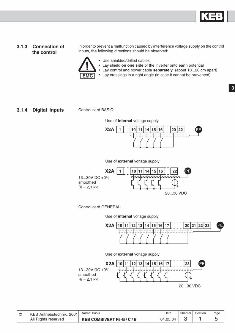
3.1.3 Connection ofthe control
3.1.4 Digital inputs
In order to prevent a malfunction caused by interference voltage supply on the controlinputs, the following directions should be observed:
• Use shielded/drilled cables• Lay shield on one side of the inverter onto earth potential• Lay control and power cable separately (about 10...20 cm apart)• Lay crossings in a right angle (in case it cannot be prevented)EMC
Use of external voltage supply
Use of internal voltage supply
Control card BASIC:
Use of external voltage supply
Use of internal voltage supply
Control card GENERAL:
10 11 12 13 14 15 PEX2A 16 17 20 21 22 23
10 11 12 13 14 15 PEX2A 16 17 23
+
1 10 11 14 15 PE16 20 22X2A
1 10 11 14 PE15 16 22
+
X2A
20...30 VDC
20...30 VDC
13...30V DC ±0%smoothedRi = 2,1 kW
13...30V DC ±0%smoothedRi = 2,1 kW
3 1 KEB COMBIVERT F5-G / C / B6Name: Basis
04.05.04
Chapter Section Page Date © KEB Antriebsteclnik, 2001All Rights reserved
Hardware Control Cards
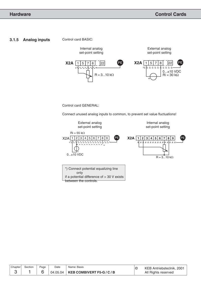
3.1.5 Analog inputs
Connect unused analog inputs to common, to prevent set value fluctuations!
*) Connect potential equalizing lineonly
if a potential difference of > 30 V existsbetween the controls.
Control card GENERAL:
Control card BASIC:
Internal analogset-point setting
External analogset-point setting
Internal analogset-point setting
External analogset-point setting
X2A 1 2 3 4 5 6 7 8 9
R = 3...10 k�
PEX2A 1 2 3 4 5 6 7 8 9 PE
0...±10 VDC
Ri = 55 k�
+
*
1 7 8
R = 3...10 k�
PE5 22X2A 1 5 8 22 PE7X2A
+
0...±10 VDCRi = 30 kΩ
3 1 7KEB COMBIVERT F5-G / C / B
Name: Basis
04.05.04
3
Section PageDate© KEB Antriebstechnik, 2001All Rights reserved
Chapter
HardwareControl Cards
10 18 19 20 PEX2A 21 22 23
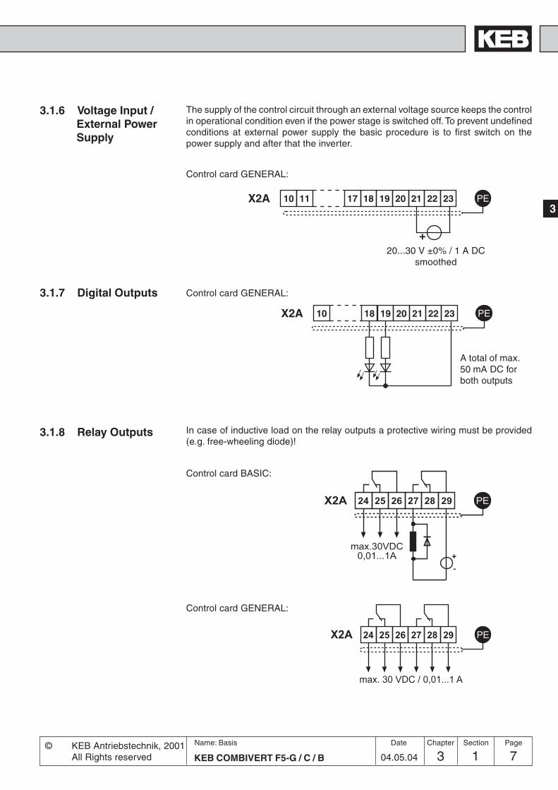
3.1.8 Relay Outputs
3.1.7 Digital Outputs
A total of max.50 mA DC forboth outputs
3.1.6 Voltage Input /External PowerSupply
In case of inductive load on the relay outputs a protective wiring must be provided(e.g. free-wheeling diode)!
The supply of the control circuit through an external voltage source keeps the controlin operational condition even if the power stage is switched off. To prevent undefinedconditions at external power supply the basic procedure is to first switch on thepower supply and after that the inverter.
Control card GENERAL:
Control card BASIC:
�� �� �� ����� �� � �
�������� �����������
10 11 17 18 19 20 PEX2A 21 22 23
+
�� �� �� ���� � �
������ ������� �
�
���
Control card GENERAL:
20...30 V ±0% / 1 A DCsmoothed
Control card GENERAL:

3 1 KEB COMBIVERT F5-G / C / B8Name: Basis
04.05.04
Chapter Section Page Date © KEB Antriebsteclnik, 2001All Rights reserved
Hardware Control Cards
3.1.9 Analog Outputs
3.1.10 Voltage Output The voltage output serves for the setting of the digital inputs as well as for the supplyof external control elements. Do no exceed the maximum output current of 100 mA.
Control card GENERAL:
Control card BASIC:
X2A 1 2 3 4 5 6 7 8 9 PE
U0: 0...±11,5 VDCRi: 100 Ω
Uout: 0...±10 VDCImax: 10 mA
10 18 19 20 PEX2A 21 22 23
+ -ca. 24VDC / max. 100 mA
1 225 7 8 PE
-10...10 VDC5 mA
X2A
approx
Control card GENERAL:

4.1 Fundamentals
4.2 Password Structure
4.3 CP-Parameter
4.4 Drive-Mode
Fundamentals
1. Introduction
2. Summary
3. Hardware
4. Operation
5. Parameter
6. Functions
7. Start-up
8. Special Operation
9. Error Assistance
10. Project Planning
11. Networks
12. Annex
KEB COMBIVERT F5
Name: Basis
4 1 104.05.04© KEB Antriebstechnik, 2002
All Rights reserved
Section PageDate Chapter
4.1.1 Parameters, Parameter Groups,Parameter Sets ...................... 3
4.1.2 Selection of a Parameter ....... 44.1.3 Adjustment of Parameter
Values .................................... 44.1.4 ENTER-Parameter ................. 44.1.5 Non-programmable
Parameters ............................ 54.1.6 Resetting of Error Messages . 54.1.7 Resetting of Peak Values ....... 54.1.8 Acknowledgement of Status
Signals ................................... 5

4 1 KEB COMBIVERT F52Name: Basis
04.05.04
Operation Fundamentals
© KEB Antriebstechnik, 2002All Rights reserved
Chapter Section Page Date
KEB COMBIVERT F5
Name: Basis
4 1 304.05.04
4
OperationFundamentals
© KEB Antriebstechnik, 2002All Rights reserved
Section PageDate Chapter
4.1.1 Parameters,Parameter Groups,Parameter Sets
4.1 Fundamentals
The following chapter describes the fundumentals of the software structure as wellas the operation of the unit.
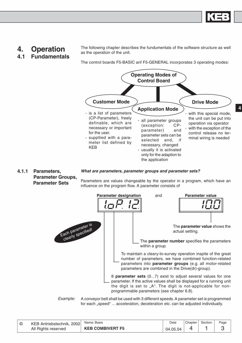
The control boards F5-BASIC anf F5-GENERAL incorporates 3 operating modes:
Operating Modes ofControl Board
Customer Mode
- is a list of parameters(CP-Parameter), freelydefinable, which arenecessary or importantfor the user.
- suppllied with a para-meter list defined byKEB
Application Mode
- all parameter groups(exception: CP-parameter) andparameter sets can beselected and, ifnecessary, changed
- usually it is activatedonly for the adaption tothe application
Drive Mode
- with this special mode,the unit can be put intooperation via operator
- with the exception of thecontrol release no ter-minal wiring is needed
What are parameters, parameter groups and parameter sets?
Parameters are values changeable by the operator in a program, which have aninfluence on the program flow. A parameter consists of
Parameter designation and Parameter value
Example:
Each parameter is
clearly specified!The parameter value shows theactual setting.
The parameter number specifies the parameterswithin a group.
To maintain a cleary-to-survey operation inspite of the greatnumber of parameters, we have combined function-relatedparameters into parameter groups (e.g. all motor-relatedparameters are combined in the Drive(dr)-group).
8 parameter sets (0...7) exist to adjust several values for oneparameter. If the active values shall be displayed for a running unitthe digit is set to „A“. The digit is not-applicable for non-programmable parameters (see chapter 6.8).
A conveyor belt shall be used with 3 different speeds. A parameter set is programmedfor each „speed“ ... acceleration, deceleration etc. can be adjusted individually.
4. Operation

4 1 KEB COMBIVERT F54Name: Basis
04.05.04
Operation Fundamentals
© KEB Antriebstechnik, 2002All Rights reserved
Chapter Section Page Date
4.1.2 Selection of aParameter
The blinking point indicates the changeable area. By pressing the ENTER-key theblinking point is shifted.
✻
ENTERF/R
ENTERF/R
✻✻
✻✻✻
▲START ▼
STOP ▲START ▼
STOP ▲START ▼
STOP
Select Select Selectparameter number parameter group parameter set
A parameter set number is not displayedfor non-programmable parameters (see 4.1.5)!
Changes between parameter valueFUNCTSPEED and parameter designation
Changing of
Standard-Parameters ENTER-Parameters
▲START ▼
STOP
▲START ▼
STOP
▲START ▼
STOP
▲START ▼
STOP
ENTERF/R
Parameter values can be changed only, when the parameter setis not adjusted to „Active parameter set“ (A) ! (see 4.1.6)
For some parameters it is not sensible that the selected values become activeimmediately. For that reason they are called ENTER-parameters, they do not becomeactive until the ENTER-key is pressed.Example: At digital setting of rotation direction the rotation reverse (r) shall be selected
from standstill (LS). As shown above, the actuation must be done via rotationforward (F). However, the drive must not start yet, first the rotation directionreverse has to be selected and confirmed with ENTER (point disappears).
4.1.3 Adjustment ofParameter Values
4.1.4 ENTER-Parameter
- Values areimmediatelyaccepted andstored non-volatile!
- During changing a point isindicated behind the lastdigit
- The value is accepted withENTER and stored non-volatile (point disappears)

KEB COMBIVERT F5
Name: Basis
4 1 504.05.04
4
OperationFundamentals
© KEB Antriebstechnik, 2002All Rights reserved
Section PageDate Chapter
4.1.5 Non-programmableParameters
Certain parameters are not programmable, as their value must be the same in allsets (e.g. bus address or baud rate). For an easy identification of these parametersthe parameter set number is missing in the parameter identification. For all non-programmable parameters the same value is valid independent of the selectedparameter set!
If a malfunction occurs during operation, the actual display is overwritten by a blinkingerror message. The error message can be cancelled by pressing the ENTER-key,so that the original value is again shown in the display.ATTENTION! The resetting of the error message with ENTER is no error reset, i.e.the error status in the inverter is not reset. Thus it is possible to correct adjustmentsbefore the error reset. An error reset is only possible through the reset terminal orcontrol release.
To permit conclusions on the operational performance of the drive, parameters areprovided that indicate the peak values. Peak value means that the highest measuredvalue is stored for the ON-time of the inverter (slave pointer principle). The peakvalue is cancelled by s or t and the actual measured value is shown in the display.
To monitor the correct execution of an action some parameters send a status signal.For example, after copying a set the display shows „PASS“ to indicate that the actionwas carried out without error. These status signals must be acknowledged withENTER.
4.1.6 Resetting of ErrorMessages
4.1.7 Resetting of PeakValues
4.1.8 Acknowledgementof Status Signals

4 1 KEB COMBIVERT F56Name: Basis
04.05.04
Operation Fundamentals
© KEB Antriebstechnik, 2002All Rights reserved
Chapter Section Page Date

Operation
4.1 Fundamentals
4.2 Password Structure
4.3 CP-Parameter
4.4 Drive-Mode
1. Introduction
2. Summary
3. Hardware
4. Operation
5. Parameter
6. Functions
7. Start-up
8. Special Operation
9. Error Assistance
10. Project Planning
11. Networks
12. Annex
14 2 1KEB COMBIVERT F5
Name: Basis
04.05.04© KEB Antriebstechnik, 2002
All Rights reserved
Section PageDate Chapter
4.2.1 Password Levels .................... 34.2.2 Passwords.............................. 44.2.3 Changing of Password Level . 4

4 2 KEB COMBIVERT F52Name: Basis
04.05.04© KEB Antriebstechnik, 2002
All Rights reserved
Operation Password Structure
Chapter Section Page Date

34 2 3KEB COMBIVERT F5
Name: Basis
04.05.04
4
Password Structure
© KEB Antriebstechnik, 2002All Rights reserved
Operation
Section PageDate Chapter
4.2 PasswordStructure
The KEB COMBIVERT is provided with extensive password protection. The diffe-rent passwords are used to
- change the operating mode- set a write protection- activate the Service-Mode- switch to the Drive-Mode
Depending on the actual operating mode the password can be entered in followingparameters
when the CP-Mode is active
when the applicatioan mode is active
The parameter value of the above parameters shows the actual password level.Following indications are possible:
CP - read only
CP - on
CP - Service
Application
Drive-Mode
4.2.1 Password Levels
Only the Customer-parametergroup is visible, exept for CP.0 allparameters are in the read-onlystatus (see chapter 4.3).
Only the Customer-parametergroup is visible. All parameters canbe changed.
Like CP-on, but the parameteridentification is indicated accordingto the original parameter (seechapter 4.3).
All application parameters are vi-sible and can be changed. The CP-parameters are not visible.
The Drive-Mode is a specialoperating mode, here the unit canbe put into operation via theoperator (see chapter 4.4).
4 2 KEB COMBIVERT F54Name: Basis
04.05.04© KEB Antriebstechnik, 2002
All Rights reserved
Operation Password Structure
Chapter Section Page Date
4.2.2 Passwords
4.2.3 Changing ofPassword Level
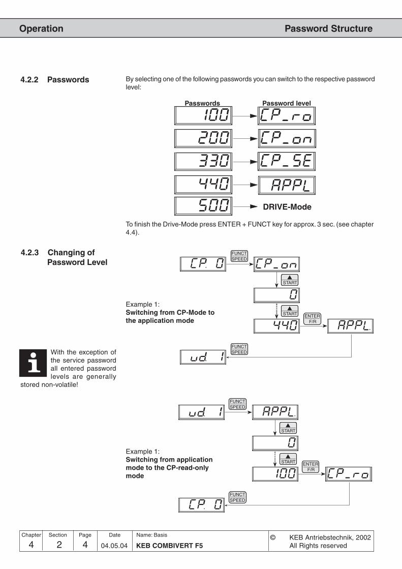
By selecting one of the following passwords you can switch to the respective passwordlevel:
Passwords Password level
DRIVE-Mode
▲START
ENTERF/R
FUNCTSPEED
▲START
▲START
FUNCTSPEED
To finish the Drive-Mode press ENTER + FUNCT key for approx. 3 sec. (see chapter4.4).
Example 1:Switching from CP-Mode tothe application mode
Example 1:Switching from applicationmode to the CP-read-onlymode
▲START
ENTERF/R
FUNCTSPEED
▲START
▲START
FUNCTSPEED
With the exception ofthe service passwordall entered passwordlevels are generally
stored non-volatile!

4.1 Fundamentals
4.2 Password Structure
4.3 CP-Parameter
4.4 Drive-Mode
Operation
1. Introduction
2. Summary
3. Hardware
4. Operation
5. Parameter
6. Functions
7. Start-up
8. Special Operation
9. Error Assistance
10. Project Planning
11. Networks
12. Annex
14 3 1KEB COMBIVERT F5-G / C / B
Name: Basis
04.05.04© KEB Antriebstechnik, 2002
All Rights reserved
Chapter Section PageDate
4.3.1 Operation in CP-Mode ........... 34.3.2 Factory Setting ....................... 44.3.3 Password input ....................... 54.3.4 Status Display ........................ 54.3.5 Basic Adjustment of the Drive 74.3.6 Special Settings ................... 10

4 3 KEB COMBIVERT F5-G / C / B2Name: Basis
04.05.04
CP - Parameter
© KEB Antriebstechnik, 2002All Rights reserved
Operation
Chapter Section Page Date

34 3 3KEB COMBIVERT F5-G / C / B
Name: Basis
04.05.04
4
CP - Parameter
© KEB Antriebstechnik, 2002All Rights reserved
Operation
Chapter Section PageDate
4.3.1 Operation inCP-Mode
4.3 CP-Parameter The Customer-Parameters (CP) are a special group of parameter. With theexception of CP.0 (Password input), they can be defined by the user (see Chapter6.13). The following Parameters are preset at delivery.
Advantages from it: - operator-friendly for the customer- critical parameters are protected against maloperation- low documentation cost for the machine builder
FUNCTSPEED
▲START ▼
STOP ▲START ▼
STOP
Adjustment ofparameter number
Adjustment ofparameter value
Compared to the Application-Mode the operation in the CP-Mode is easier becauseparameter set selection and parameter group selection are unnecessary.

4 3 KEB COMBIVERT F5-G / C / B4Name: Basis
04.05.04
CP - Parameter
© KEB Antriebstechnik, 2002All Rights reserved
Operation
Chapter Section Page Date
The following list shows the CP-parameter group predefined by us. The definitionof the CP-parameters is done in the User-Definition-Parameters (ud). How youcan define your own parameters is described in Chapter 6.13.
4.3.2 Factory Setting
1) Enter-Parameter2) depending on power circuit
Display Parameter Setting range Resolution Factory setting Appl. Parameter
CP. 0 Password input 0…9999 1 – ud.1 / 0801h
CP. 1 Actual frequency display – 0,0125 Hz – ru.3 / 0203h
CP. 2 Set frequency display – 0,0125 Hz – ru.1 / 0201h
CP. 3 Inverter status display – – – ru.0 / 0200h
CP. 4 Apparent current – 0,1 A – ru.15 / 020Fh
CP. 5 Apparent current / Peak value – 0,1 A – ru.16 / 0210h
CP. 6 Utilization – 1 % – ru.13 / 020Dh
CP. 7 Intermediate circuit voltage – 1 V – ru.18 / 0212h
CP. 8 Intermediate circuit voltage/
Peak value – 1 V – ru.19 / 0213h
CP. 9 Output voltage – 1 V – ru.20 / 0214h
CP.10 Minimal frequency 0…400 Hz 0,0125 Hz 0 Hz op.6 / 0306h
CP.11 Maximal frequency 0…400 Hz 0,0125 Hz 70 Hz op.10 / 030Ah
CP.12 Acceleration time 0,00…300,00 s 0,01 s 5,00 s op.28 / 031Ch
CP.13 Deceleration time (-1 = CP.12) -0,01; 0,00…300,00s 0,01 s 5,00 sop.30 /
031Eh
CP.14 S-curve time 0,00 (off)…5,00 s 0,01 s 0,00 s (off) op.32 / 0320h
CP.15 Boost 0,0…25,5 % 0,1 % 2,0 % uf.1 / 0501h
CP.16 Rated frequency 0…400 Hz 0,0125 Hz 50 Hz uf.0 / 0500h
CP.17 1) Voltage stabilization 1…650 V (off) 1 V 650 (off) uf.9 / 0509h
CP.18 1) Carrier frequency 2/4/8/12/16 kHz 2) 1 – 2) uf.11 / 050Bh
CP.19 Fixed frequency 1 -400...400 Hz 0,0125 Hz 5 Hz op.21 / 0315h
CP.20 Fixed frequency 2 -400...400 Hz 0,0125 Hz 50 Hz op.22 / 0316h
CP.21 Fixed frequency 3 -400...400 Hz 0,0125 Hz 70 Hz op.23 / 0317h
CP.22 1) DC-braking / Mode 0…9 1 7 pn.28 / 041Ch
CP.23 DC-braking / Time 0,00…100,00 s 0,01 s 10,00 s pn.30 / 041Eh
CP.24 Max. ramp current 0…200 % 1 % 140 % pn.24 / 0418h
CP.25 Max. constant current 0…200 % (off) 1 % 200 % (off) pn.20 / 0414h
CP.26 1) Speed search condition 0…15 1 8 pn.26 / 041Ah
CP.27 Quick stop time 0,00…300,00 s 0,01 s 2,00 s pn.60 / 043Ch
CP.28 Reaction of ext. overtemperature 0…7 1 7 pn.12 / 040Ch
CP.29 1) Analog output 1 / Function 0…20 1 2 an.31 / 0A1Fh
CP.30 Analog output 1 / Amplification -20,00…20,00 0,01 1,00 an.33 / 0A21h
CP.31 1) Relay output 1 / function 0…75 1 4 do.2 / 0C02h
CP.32 1) Relay output 2 / function 0…75 1 27 do.3 / 0C03h
CP.33 Relay output 2 / switching level -30000,00…30000,00 0,01 4,00 le.3 /
0D03h
CP.34 1) Source of rotation direction 0…9 1 2 op.1 / 0301h
CP.35 1) AN1 interface selection 0…2 1 0 an.0 / 0A00h
CP.36 AN1 zero point hysteresis -10,0…10,0 % 0,1 % 0,2 % an.4 / 0A04h

54 3 5KEB COMBIVERT F5-G / C / B
Name: Basis
04.05.04
4
CP - Parameter
© KEB Antriebstechnik, 2002All Rights reserved
Operation
Chapter Section PageDate
Password
FUNC
ENTER
UP
Enabling the CP-Parameter
FUNC
ENTER
UP
PasswordBarring theCP-Parameter
4.3.3 Password Input Ex works the frequency inverter is supplied without password protection, this meansthat all changeable parameters can be adjusted. After parameterizing the unit canbe barred against unauthorized access (Passwords: see chapter 4.2). The adjustedmode is stored.
The parameters below serve for thecontrolling of the frequency inverter duringoperation.
Display of the actual output frequency with a resolution of 0.0125 Hz. The operatordisplays additionally „noP“ and „LS“ if the control release or the direction of rotationare not switched (see CP.3). The rotation of the inverter is indicated by the sign.
Output frequency 18.3 Hz, rotation forwardExamples:
Output frequency 18.3 Hz, rotation reverse
4.3.4 Operating Display
Actual frequency display
Inverter status display The status display shows the actual working conditions of the inverter. Possibledisplays and their meanings are:
"no Operation" control release not bridged, modulation switchedoff, output voltage = 0 V, drive is not controlled.
"Low Speed" no rotation preset, modulation switched off, outputvoltage = 0 V, drive is not controlled.
Display of actually set frequency. The indication is done in the same manner as atCP.1. For control reasons the set frequency is displayed even if control release ordirection of rotation are not switched. If no direction of rotation is set, the set frequencyfor clockwise rotation (forward) is displayed.
Set frequency

4 3 KEB COMBIVERT F5-G / C / B6Name: Basis
04.05.04
CP - Parameter
© KEB Antriebstechnik, 2002All Rights reserved
Operation
Chapter Section Page Date
"Forward Acceleration" drive accelerates with direction of rotationforward .
"Forward Deceleration" drive decelerates with direction of rotationforward.
"Reverse Acceleration" drive accelerates with direction of rotationreverse.
"Reverse Deceleration" drive decelerates with direction of rotationreverse.
"Forward Constant" drive runs with a constant speed and directionof rotation forward.
"Reverse Constant" drive runs with constant speed and directionof rotation reverse.
Other status messages are described at the parameters, where they occur.
Apparent current Display of the actual apparent current in ampere.
Intermediate circuit voltage Display of actual DC voltage in volt.Typical calues:
CP.5 makes it possible to recognize the max. apparent current. For that the highestvalue of CP.4 is stored in CP.5. The peak value memory can be cleared by pressingthe UP, DOWN or ENTER key or over bus by writing any value you like to the addressof CP.5. The switch off of the inverter also clears the memory.
Apparent current /Peak value
Utilization Display of the actual inverter rate of utilization in percent. 100% rate of utilization isequal to the inverter rated current. Only positive values are displayed, meaning thereis no differentiation between motor and regenerative operation.
V-class Normal operation Over volt. (E.OP) Under volt. (E.UP)230 V 300…330 V DC approx. 400 V DC approx. 216 V DC400 V 530…620 V DC approx. 800 V DC approx. 240 V DC

74 3 7KEB COMBIVERT F5-G / C / B
Name: Basis
04.05.04
4
CP - Parameter
© KEB Antriebstechnik, 2002All Rights reserved
Operation
Chapter Section PageDate
4.3.5 Basic Adjustmentof the Drive
Intermediate circuit voltage/Peak value
Output voltage
Minimum frequency
Maximum frequency
f
UREF
�����
�����
� ��
CP.8 makes it possible to recognize short-time voltage rises within an operatingcycle. For that the highest value of CP.7 is stored in CP.8. The peak value memorycan be cleared by pressing the UP, DOWN or ENTER key or over bus by writing anyvalue you like to the address of CP.8. The switch off of the inverter also clears thememory.
Display of the actual output voltage in volt.
The following parameters determine the fundamental operating data of the drive. Theyshould be checked and/or adapted to the application.
With this frequency the inverter operates without presetting an analog set value.Internal limiting of the fixed frequencies CP.19…CP.21.
Adjustment range: 0...400 HzResolution: 0,0125 HzFactory setting: 0,0 Hz
With this frequency the inverter operates with maximum analog set value.Internal limiting of the fixed frequencies CP.19…CP.21.
Adjustment range: 0...400 HzResolution: 0,0125 HzFactory setting: 70 Hz

4 3 KEB COMBIVERT F5-G / C / B8Name: Basis
04.05.04
CP - Parameter
© KEB Antriebstechnik, 2002All Rights reserved
Operation
Chapter Section Page Date
Acceleration time
f
t
100 Hz
The parameter determines the time needed to accelerate from 0 Hz to 100 Hz. Theactual acceleration time is proportional to the frequency change.
100 Hz–––––– x actual acceleration time = CP.12delta f
Adjustment range: 0,00...300,00 sResolution: 0,01 sFactory setting: 5,00 s
Example: actual acceleration time = 5s; the drive should accelerate from 10 Hz to60 Hz. delta f = 60 Hz - 10 Hz = 50 Hz
CP.12 = (100 Hz / 50 Hz) x 5 s = 10 s
The parameter determines the time needed to decelerate from 100 Hz to 0 Hz. Theactual deceleration time is proportional to the frequency change.
100 Hz–––––– x actual deceleration time = CP.13delta f
Adjustment range: -0,01; 0,00...300,00 sResolution: 0,01 sFactory setting: 5,00 s
At deceleration time = -0,01 see CP.12 (Display: "=Acc")!
Example: actual deceleration time = 5s; the drive should decelerate from 60 Hz to10 Hz. delta f = 60 Hz - 10 Hz = 50 Hz
CP.12 = (100 Hz / 50 Hz) x 5 s = 10 s
For some applications it is of advantage when the drive starts and stops jerk-free.This is achieved through a straightening of the acceleration and deceleration ramps.The straightening time, also called S-curve time, can be adjusted with CP.14.
Adjustment range: 0,00 (off)...5,00 sResolution: 0,01 sFactory setting: 0,00 s (off)
Deceleration time
f
t
100 Hz
CP. 13
S-curve time
In order to drive defined ramps with activated S-curve time, theacceleration and deceleration times (CP.12 and CP.13) must beadjusted higher than the S-curve time (CP.14).
CP. 12

94 3 9KEB COMBIVERT F5-G / C / B
Name: Basis
04.05.04
4
CP - Parameter
© KEB Antriebstechnik, 2002All Rights reserved
Operation
Chapter Section PageDate
t1 t1 t1 t1
t2 t3
+f [Hz]
-f [Hz]
t [s]
t1 = S-curve time (CP.14)t2 = Acceleration time (CP.12)t3 = Deceleration time (CP.13)
t1 t1 t1 t1
t2 t3
Ramp adjustment with S-curves
Boost
UA
f
In the lower speed range a large part of the motor voltage decreases on the statorresistance. To keep the breakdown torque nearly constant over the entire speedrange, the voltage decrease can be compensated with the boost.
Adjustment range: 0,0...25,5 %Resolution: 0,1 %Factory setting: 2,0 %
Adjustment: • Determine the rate of utilzation in no-load operationwith rated frequency
• Preset about 10 Hz and adjust the boost, so that about the samerate of utilization is reached as with the rated frequency.
When the motor, during continuous operation, drives with low speed and toohigh voltage it can lead to an overheating of the motor.
UA
f
With the adjusted frequency the inverter reaches a maximal output voltage. Theadjustment of the rated motor frequency is typical in this case. Note: Motors canoverheat when the rated frequency is incorrectly adjusted!
Adjustment range: 0...400 HzResolution: 0,0125 HzFactory setting: 50 Hz 100%
CP. 16
Rated frequency
CP. 15
CP. 16

4 3 KEB COMBIVERT F5-G / C / B10Name: Basis
04.05.04
CP - Parameter
© KEB Antriebstechnik, 2002All Rights reserved
Operation
Chapter Section Page Date
250 V
190 V
CP.17=230 V
CP.16=50 Hz
UN/UA
f
4.3.6 SpecialAdjustments
The following parameters serve for the optimization of the drive and the adaption to certainapplications. These adjustments can be ignored at the initial startup.
With this parameter a regulated output voltage in relation to the rated frequency canbe adjusted. For that reason voltage variations at the input as well as in theintermediate circuit only have a small influence on the output voltage (U/f-characteristic).The function allows, among other things, an adaption of the output voltage to specialmotors.
Adjustment range: 1...650 V (off)Resolution: 1 VFactory setting: 650 V (off)Note: Enter-Parameter
In the example below the output voltage is stabilized to 230 V (0% boost).
UN = mains voltage
UA bei U
N = 190V stabilized
UA bei U
N = 190V unstabilized
UA bei U
N = 250V unstabilized
UA bei U
N = 250V stabilized
UA= output voltage
Voltage stabilization

114 3 11KEB COMBIVERT F5-G / C / B
Name: Basis
04.05.04
4
CP - Parameter
© KEB Antriebstechnik, 2002All Rights reserved
Operation
Chapter Section PageDate
Step frequency 1...3Input I1
Input I2
Input I1 and I2
Three fixed frequencies can be adjusted. The fixed frequencies are selected with theinputs I1 and I2.
Adjustment range: -400...400 HzResolution: 0,0125 HzFactory settingCP.19: 5 HzFactory settingCP.20: 50 HzFactory settingCP.21: 70 Hz
If adjustments are made that are outside the fixed limits of CP.10 and CP.11, thenthe frequency is internally limited. The negative values are released in applicationmode.The rotation source of the fixed frequencies is not changed by CP.34, it alwayscorresponds to CP.34 = 2.
Adjustment range (depending on power circuit): 2 / 4 / 8 / 12 / 16 kHzFactory setting: depending on power circuitNote: Enter-Parameter
low switching frequency• less inverter heating• less discharge current• less switching losses• less radio interferences• improved concentricity with low speed
high switching frequency• less noise development• improved sine-wave simulation• less motor losses
Carrier frequency The switching frequency with which the power modules are clocked can be changeddepending on the application. The employed power stage determines the maximumswitching frequency as well as the factory setting (see manual: part2). Refer to followinglist to learn about influences and effects of the switching frequency.
At switching frequencies above 4 kHz pay absolute attention to the max.motor line length in the technical data of the chapter 2.1.

4 3 KEB COMBIVERT F5-G / C / B12Name: Basis
04.05.04
CP - Parameter
© KEB Antriebstechnik, 2002All Rights reserved
Operation
Chapter Section Page Date
DC-braking / Mode
If the braking time depends on the actual frequency (CP.22 = 2...7), it is calculatedas follows:
CP.23 x frealt
Breal = –––––––––
100 Hz
Otherwise the braking time corresponds to CP.23.
Adjustment range: 0,00...100,00 sResolution: 0,01 sFactory setting: 10,00 s
DC-braking / Time
f
t
100 Hz
freal
tBreal CP.23
With DC-braking the motor is not decelerated by the ramp. Quick braking is causedby D.C. voltage, which is applied onto the motor winding. This parameter determineshow the dc-braking is triggered.
Value Activation0 DC-braking deactivated1 DC-braking at switch off of the direction of rotation and upon reaching
0Hz. The braking time is CP.23 or until the next direction of rotation.2* DC-braking as soon as setting for the direction of rotation is absent.3* DC-braking as soon as the direction of rotation changes or is absent.4* DC-braking on disabling the direction of rotation and if the real
frequency falls below 4 Hz.5* DC-braking when the real frequency falls below 4 Hz.6* DC-braking as soon as the set value falls below 4 Hz.7* DC-braking when input I4 is switched. Braking time depends on the real
frequency. At control circuit B = value "0"8 DC-braking as long as input I4 is switched. At control circuit B = value
"0"9 DC-braking after switching on the modulation on.
* Braking time depends on the actual frequency.
Adjustment range: 0...9Resolution: 1Factory setting: 7Note: Enter-Parameter

134 3 13KEB COMBIVERT F5-G / C / B
Name: Basis
04.05.04
4
CP - Parameter
© KEB Antriebstechnik, 2002All Rights reserved
Operation
Chapter Section PageDate
This function protects the frequency inverter against switch off through overcurrentduring constant output frequency. When exceeding the adjusted value, the outputfrequency is reduced until the value drops below the adjusted value. CP. 3 displays"SSL" at active function.
Adjustment range: 0...200 % (off)Resolution: 1 %Factory Setting: 200 % (off)
t
fset
freal
on
off
on
off
CP.25
CP.24
LAD-stop
Current limit
t
t
t
Max. constant current
Utilization
This function protects the frequency inverter against switching off through overcurrentduring the acceleration ramp. When the ramp reaches the adjusted value,it is stoppedso long until the current decreases again. CP.3 displays "LAS" at active function.
Adjustment range: 0...200 %Resolution: 1 %Factory setting: 140 %
Max. ramp current

4 3 KEB COMBIVERT F5-G / C / B14Name: Basis
04.05.04
CP - Parameter
© KEB Antriebstechnik, 2002All Rights reserved
Operation
Chapter Section Page Date
When connecting the frequency inverter onto a decelerating motor, an error can betriggered by the differing rotating field frequencies. With activated speed search theinverter searches for the actual motor speed, adapts its output frequency andaccelerates with the adjusted ramp to the given set value. During speed search CP.3displays "SSF". The parameter determines, under what conditions the functionsoperate. In case of several conditions the sum of the value must be entered.
Example: CP.26 = 12 means after reset and after auto-reset UP.
Speed search condition
Adjustment range: 0...15Resolution: 1Factory setting: 8Note: Enter-Parameter
Value Condtion0 function off1 at control release2 at switch on4 after reset8 after Auto-Reset UP
100 Hz
f
t
Quick stop time The fast-stop function is activated depending on CP.28. The parameter determinesthe time needed to decelerate from 100 Hz to 0 Hz. The actual deceleration time isproportional to the frequency change. The response to overtemperature (CP.28) isdisabled in the factory setting. If it is activated then the modulation switches offautomatically after 10 s if the motor is still too hot.
100 Hz–––––– x actual deceleration time = CP.27delta f
Adjustment range: 0,00...300,00 sResolution: 0,01 sFactory setting: 2,00 s
Example: actual deceleration time = 5s; the drive should decelerate from 50 Hz to0 Hz. delta f = 50 Hz - 0 Hz = 50 Hz
CP.27 = (100 Hz / 50 Hz) x 5 s = 10 s
CP. 27

154 3 15KEB COMBIVERT F5-G / C / B
Name: Basis
04.05.04
4
CP - Parameter
© KEB Antriebstechnik, 2002All Rights reserved
Operation
Chapter Section PageDate
Reaction ofexternal overtemperature
Adjustment range: 0...7Resolution: 1Setting range: 7
This parameter determines the response of the drive on the external temperaturemonitoring (factory setting = off). In order to activate this function the power circuitterminals T1/T2 must be connected in accordance with the instruction manual Part2. After that the response can be adusted according to following table.If overheat no longer exists, the message E.ndOH (or A.ndOH) is output. Only thenthe error can be reset or the automatic restart can be carried out.
CP.28 Display Reaction Restart0 E.dOH Immediate disabling of modulation
1 * A.dOH Quick stopping / disabling ofmodulation after reaching speed 0
2 * A.dOH Quick stopping/holding toruqe at speed 03 A.dOH Immediate disabling of modulation
4 * A.dOH Quick stopping / disabling ofmodulation after reaching speed 0
5 * A.dOH Quick stopping/holding toruqe at speed 06 * no No effect on the drive;
With CP.31/32 = 9 an external modulecan be controlled (e.g. fan)
7 no No effect on the drive;!Störung existiert nicht! ExternalTemperature monitoring is not activated
Remove fault;Actuate reset
Automatic reset,if the fault is nolongerpresent
- inapplicable -
*) If the motor is still too hot after 10 seconds, the error E.dOH is triggered and themodulation is switched off!

4 3 KEB COMBIVERT F5-G / C / B16Name: Basis
04.05.04
CP - Parameter
© KEB Antriebstechnik, 2002All Rights reserved
Operation
Chapter Section Page Date
Analog ouput 1 / Function CP.32 defines the function of analog output 1.
Value Function0 absolute actual value 100 Hz1 absolute set value 100 Hz2 actual value ru.7 ±100 Hz3 set value ru.1 ±100 Hz4 output voltage ru.20 500 V5 DC voltage ru.18 1000 V6 apparent current ru.15 2 • I
rated
7 active current ru.17 2 • ±Irated
8 digital An.32/An.37/An.42 100 %9 external PID output ru.52 ±100 %
10 absolute ext. PID output ru.52 100 %11 absolute active current ru.17 2 • I
rated
12 power mod. temperature ru.38 100°C13 motor temperature 0...100 °C
14-18 application mode only19 ramp output frequency 0...±100 Hz20 absolute ramp output frequency 0...100 Hz
Analog output 1 /Amplification
10V
CP.30
100%
-100% 100%
-100%
in
out Setting aid:The analog output shall giveout +10 V at 70 Hz insteadat 100 Hz:
100 HzCP.30 = –––––– = 1,43
70 Hz
With the amplification the output voltage of the analog output can be tuned thesignal to be given out. An amplification of 1 corresponds to ±100 % = +10 V.
Adjustment range: 0...20Resolution: 1Factory setting: 2Note: Enter-Parameter
Adjustment range: -20,00...20,00Resolution: 0,01Factory setting: 1,00

174 3 17KEB COMBIVERT F5-G / C / B
Name: Basis
04.05.04
4
CP - Parameter
© KEB Antriebstechnik, 2002All Rights reserved
Operation
Chapter Section PageDate
Relay output 1 / Function
Relay output 2 / Function
CP.31 and CP.32 determine the function of the two outputs.CP.31 for relay output 1 (terminal X2A.24...X2A.26)CP.32 for relay output 2 (terminal X2A.27...X2A.29)
The switching level of CP.32 is CP.33!
Value Function0 No function (generelly off)1 Generelly on2 Run signal; also by DC-braking3 Ready signal (no error)4 Fault relay5 Fault relay (not at under voltage error)6 Warning or error message at abnormal stopping7 Overload alert signal8 Overtemperature alert signal power modules9 External Overload alert signal motor
10 Only application-mode11 Excess-temperature alert signal interior OHI12 Cable breakage 4...20 mA on analog input 113 Only application-mode14 Max. constant current (stall, CP.25) exceeded15 Max. ramp current (LA-Stop CP.24) exceeded16 DC-braking active
17-19 Only application-mode20 Actual value=set value (CP.3=Fcon, rcon; not at noP, LS error,SSF)21 Accelerate (CP.3 = FAcc, rAcc, LAS)22 Decelerate (CP.3 = FdEc, rdEc, LdS)23 Real direction of rotation = set direction of rotation24 Utilization (CP.6) > 100% (only CP.31)25 Active current > switching level (only CP.32)26 Intermediate circuit voltage (CP.7)>switching level (only CP.32)27 Real value (CP.1) > switching level (only CP.32)28 Set value (CP.2) > switching level (only CP.32)
29/30 Only application-mode31 Absolut set value on AN1 > switching level (only CP.32)32 Absolut set value on AN2 > switching level (only CP.32)33 Only application-mode34 Set value on AN1 > switching level (only CP.32)35 Set value on AN2 > switching level (only CP.32)
36-39 Only application-mode40 Hardware current limit activated41 Modulation on-signal
42-43 Only application-mode44 Inverter status (CP.3) = switching level45 Power module temperatur > Level46 Motor temperatur > Level47 Ramp output frequency > Level48 Apparent current (CP.4) > Level49 Clockwise rotation (not at noP, LS, abnormal stopping, Fehler)50 Counter clockwise (not at noP, LS, abnormal stopping, Fehler)
51-62 Only application-mode63 Absolut ANOUT1 > switching level64 Absolut ANOUT2 > switching level65 ANOUT1 > switching level66 ANOUT2 > switching level
67-69 Only application-mode70 Driver voltage activ (Safety relay)
71-72 Only application-mode73 Absolut active power74 Active power75 Only application-mode
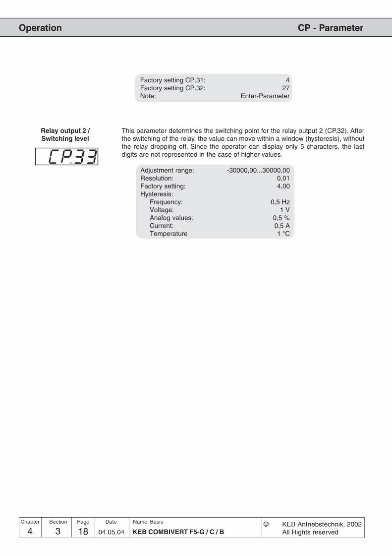
4 3 KEB COMBIVERT F5-G / C / B18Name: Basis
04.05.04
CP - Parameter
© KEB Antriebstechnik, 2002All Rights reserved
Operation
Chapter Section Page Date
Relay output 2 /Switching level
This parameter determines the switching point for the relay output 2 (CP.32). Afterthe switching of the relay, the value can move within a window (hysteresis), withoutthe relay dropping off. Since the operator can display only 5 characters, the lastdigits are not represented in the case of higher values.
Adjustment range: -30000,00...30000,00Resolution: 0,01Factory setting: 4,00Hysteresis:
Frequency: 0,5 HzVoltage: 1 VAnalog values: 0,5 %Current: 0,5 ATemperature 1 °C
Factory setting CP.31: 4Factory setting CP.32: 27Note: Enter-Parameter

194 3 19KEB COMBIVERT F5-G / C / B
Name: Basis
04.05.04
4
CP - Parameter
© KEB Antriebstechnik, 2002All Rights reserved
Operation
Chapter Section PageDate
The source rotation setting and the mode of evaluating the rotation setting is definedwith this parameter (Enter-Parameter). With CP.34 one does not modify the rotationsource of the fixed frequencies (CP.19... 21).
Value Function0/1 Only application mode2 Setting by way of terminal strip forward/reverse; negative set values are
set to zero (factory setting)3 Setting by way of terminal strip forward/reverse; the signs of the setpoint
values have no effect on the direction of rotation4 Setting by way of terminal strip run/stop (X2A.14) and forward/reverse
(X2A.15); negative values are set to zero5 Setting by way of terminal strip run/stop (X2A.14) and forward/reverse;
the signs of the setpoint values have no effect on the direction ofrotation
6 Set value dependent, positive value - clockwise rotation; negative value-counterclockwise rotation; with set value "0" it is switched into status"Low speed" (LS)
7 Set value dependent, positive value - clockwise rotation; clockwiserotation is indicated
8/9 Only application mode
Source of rotation direction
Set value0-limited(Value 2 and 4)
Set valueabsolute(Value 3 and 5)
Adjustment range: 0...9Resolution: 1Factory setting: 2Note: Enter-Parameter
10V100%
-100% 100%
-100%
extern
-10V
interninternal
external
10V100%
-100% 100%
-100%
extern
-10V
interninternal
external

4 3 KEB COMBIVERT F5-G / C / B20Name: Basis
04.05.04
CP - Parameter
© KEB Antriebstechnik, 2002All Rights reserved
Operation
Chapter Section Page Date
Adjustment range: -10,0...10,0 %Resolution: 0,1 %Factory setting: 0,2 %
AN1 Zero point hysteresis Through capacitive as well as inductive coupling on the input lines or voltagefluctuations of the signal source, the motor connected to the inverter may start todrift inspite of the analog input filters. It is the function of the zero point hysteresis tosuppress this drifting.With parameter CP.36 the analog signal for the input REF can be faded out in therange of 0...±10%. The adjusted value is valid for both directions of rotation.If a negative percentage value is adjusted then the hysteresis is not only effective onthe zero point but also around the actual set value. Set value changes are acceptedonly when they are larger than the adjusted hysteresis.
AN1 Interface selection
f
UREF
�����
�����
���� ��
����������
The set value input 1 (AN1) at the F5-GENERAL control can be triggered by varioussignal levels. In order to correctly evaluate the signal, this parameter must be adaptedto the signal source. At F5-BASIC in A- or B-housing the signal source may not be re-adjusted.
Value Reference signal0 0...±10 V DC / Ri = 56 kOhm1 0...+20 mA DC / Ri = 250 Ohm2 4...20 mA DC / Ri = 250 Ohm
Adjustment range: 0...2Resolution: 1Factory setting: 0Note: Enter-Parameter

4.1 Fundamentals
4.2 Password Structure
4.3 CP-Parameter
4.4 Drive-Mode
Operation
1. Introduction
2. Summary
3. Hardware
4. Operation
5. Parameter
6. Functions
7. Start-up
8. Special Operation
9. Error Assistance
10. Project Planning
11. Networks
12. Annex
14 4 1KEB COMBIVERT F5-G / C / B
Name: Basis
04.05.04© KEB Antriebstechnik, 2001
All Rights reserved
Section PageDate Chapter
4.4.1 Adjustment Possibilities ......... 34.4.2 Display and Keyboard ............ 34.4.3 Setpoint Display /
Setpoint Input ......................... 34.4.4 Rotation Setting ..................... 44.4.5 Start / Stop / Run ................... 44.4.6 Leaving the Drive-Mode ......... 54.4.7 Further Settings ..................... 5

4 4 KEB COMBIVERT F5-G / C / B2Name: Basis
04.05.04
Operation Drive-Mode
© KEB Antriebstechnik, 2002All Rights reserved
Chapter Section Page Date

34 4 3KEB COMBIVERT F5-G / C / B
Name: Basis
04.05.04
4
OperationDrive-Mode
© KEB Antriebstechnik, 2002All Rights reserved
Section PageDate Chapter
START
FUNC.
SPEED
ENTER
F/RSTOP
START
FUNC.
SPEED
ENTER
F/RSTOP
START
FUNC.
SPEED
ENTER
F/RSTOP
START
FUNC.
SPEED
ENTER
F/RSTOP
The Drive-Mode is a special operating mode of the KEB COMBIVERT. It allowsan easy manual start-up. To activate the Drive-Mode enter the password „500“ in‘CP.0’ or ‘ud.1’. Following settings are possible:
– Stop / Start / Run– Setpoint value– Direction of rotation
All other settings like setpoint limitation, acceleration time, deceleration time etc.correspond to the preselection in the parameter sets.
Hardware condition: The control release must be bridged!
4.4 Drive-Mode
4.4.3 Setpoint Display /Setpoint Input
Rotation display
Interface checkTransmission "LED on"
Display operating status /actual speed / setpointspeed
Status-/ Error displayNormal "LED on"Error "LED blinking"
Operator panel
4.4.1 AdjustmentPossibilities
Press the SPEED-key andreduce the displayed setpointvalue with the DOWN-key.
Press the SPEED-key andincrease the displayed setpointvalue with the UP-key.
The adjusted setpoint value isdisplayed for as long as theSPEED-key is pressed.
4.4.2 Display and Key-board
The setpoint entry via keyboard is possible only for parameter ud.9 = 0 (see4.4.7).
reduceset value
increaseset value
The actual set value couldbe read by bus at Sy.45.

4 4 KEB COMBIVERT F5-G / C / B4Name: Basis
04.05.04
Operation Drive-Mode
© KEB Antriebstechnik, 2002All Rights reserved
Chapter Section Page Date
FUNC.
SPEED
START
FUNC.
SPEED
ENTER
F/RSTOP
START
STOP
ENTER
F/R
ENTER
F/R
4.4.4 Rotation Setting Setting possibilities: F = forward (clockwise rotation)r = reverse (counter-clockwise rotation)
Each actuatin of the keyF/R causes a change inrotational direction
4.4.5 Start / Stop / Run
Status „Run“The drive runs with
preselected frequency
(e.g. „F 50.0“)
Status „Stop“Power module
disconnected, driveis freewheeling(e.g. „F LS“)
FUNC.
SPEED
ENTER
F/R
START
FUNC.
SPEED
ENTER
F/RSTOP
START
STOP
START
STOP
3 operating states exist in the Drive-Mode:
Status „Start“Power module is controlledwith 0 Hz, drive stands withholding torque
(e.g. „F 0.0“)
Bit 2 and 3 of the parameter ud.9 determines in what way the keys START andSTOP approach the individual operating states:
Stop Run
ud. 9 Bit 2, 3 = 0(default)
FUNC.
SPEED
ENTER
F/R
START
FUNC.
SPEED
ENTER
F/RSTOP
START
STOP
START
STOP
Start Run
ud. 9 Bit 2, 3 = 1
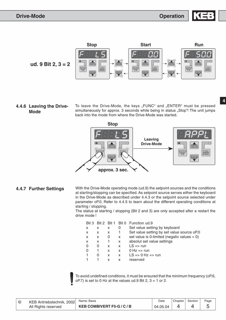
54 4 5KEB COMBIVERT F5-G / C / B
Name: Basis
04.05.04
4
OperationDrive-Mode
© KEB Antriebstechnik, 2002All Rights reserved
Section PageDate Chapter
To leave the Drive-Mode, the keys „FUNC“ and „ENTER“ must be pressedsimultaneously for approx. 3 seconds while being in status „Stop“! The unit jumpsback into the mode from where the Drive-Mode was started.
START
FUNC.
SPEED
ENTER
F/RSTOP
START
STOP
FUNC.
SPEED
ENTER
F/R
START
STOP
START
STOP
FUNC.
SPEED
ENTER
F/R
START
STOP
Stop Run
ud. 9 Bit 2, 3 = 2
Start
4.4.6 Leaving the Drive-Mode
FUNC.
SPEED
ENTER
F/R
START
FUNC.
SPEED
ENTER
F/RSTOP
START
STOP
approx. 3 sec.
Stop
LeavingDrive-Mode
4.4.7 Further Settings
To avoid undefined conditions, it must be ensured that the minimum frequency (oP.6,oP.7) is set to 0 Hz at the values ud.9 Bit 2, 3 = 1 or 2.
Bit 3 Bit 2 Bit 1 Bit 0 Function ud.9x x x 0 Set value setting by keyboardx x x 1 Set value setting by set value source oP.0x x 0 x set value is 0-limited (negativ values = 0)x x 1 x absolut set value settings0 0 x x LS => run0 1 x x 0 Hz => run1 0 x x LS => 0 Hz => run1 1 x x reserved
With the Drive-Mode operating mode (ud.9) the setpoint sources and the conditionsat starting/stopping can be specified. As setpoint source serves either the keyboardin the Drive-Mode as described under 4.4.3 or the setpoint source selected underparameter oP.0. Refer to 4.4.5 to learn about the different operating conditions atstarting / stopping.The status at starting / stopping (Bit 2 and 3) are only accepted after a restart thedrive mode !

4 4 KEB COMBIVERT F5-G / C / B6Name: Basis
04.05.04
Operation Drive-Mode
© KEB Antriebstechnik, 2002All Rights reserved
Chapter Section Page Date

Parameter
5.1 Parameter
1. Introduction
2. Summary
3. Hardware
4. Operation
5. Parameter
6. Functions
7. Start-up
8. Special Operation
9. Error Assistance
10. Project Planning
11. Networks
12. Annex
5 1 1KEB COMBIVERT F5-G / C / B
Name: Basis
30.09.05
Section PageDate© KEB Antriebstechnik, 2002All Rights reserved
Chapter
55.1.1 Parameter Groups ................... 35.1.2 F5-BASIC Control ................... 45.1.3 F5-GENERAL Control
B-housing ............................... 45.1.4 F5-GENERAL Control
>= D-housing .......................... 55.1.5 Parameter Listing F5-G ........... 7

5 1 KEB COMBIVERT F5-G / C / B2Name: Basis
14.06.02
Parameter
Chapter Section Page Date © KEB Antriebstechnik, 2002All Rights reserved

5 1 3KEB COMBIVERT F5-G / C / B
Name: Basis
14.06.02
Parameter
Section PageDate© KEB Antriebstechnik, 2002All Rights reserved
Chapter
5
5.1.1 Parameter Groups
5.1 Parameter
5. Parameter
Picture 5.1.1
The frequency inverters KEB COMBIVERT F5-GENERAL and F5-BASIC contains 16(>= D=housing 17) fixed, one free-to-define parameter group. We have already learnedabout the free-to-define group (CP). In the fixed parameter groups the parameters arecombined function-related.
ru-Parameter
StatusDisplay
In-Parameter
InverterInformation
Fr-Parameter
ProgrammingParameter
Sets
ud-Parameter
Bus Interfaceand KeyboardConfiguration
CP-Parameter
User-definedParameters
Control Terminal Strip
An-Parameter
Analog In- and Outputs
di-Parameter
Digital Inputs
do-Parameter
Digital Outputs
LE-Parameter
Switching Level
oP-Parameter
Setpoint Calculation
Pn-Parameter
Protective andSpecial Functions
oP-Parameter
Ramp Generatorand S-curves
cS/cn-Parameter
Technologie andSpeed Control
uF-Parameter
U/f-CharacteristicModulator
MasterDrive
M3~
PG
PG
Sy-Parameter
SystemParameter
XY at BasicAA-only G>=D
AdjustmentAssistantParameter
EncoderParameter
Ec-Parameter
dr-Para.

5 1 KEB COMBIVERT F5-G / C / B4Name: Basis
14.06.02
Parameter
Chapter Section Page Date © KEB Antriebstechnik, 2002All Rights reserved
5.1.3 F5-GENERALControlB-housing
This control card is used for housing size B. The parameters In.8 and In.9 are onlyavailable at this control card.The following parameters are not available, so they donot need to be considered in the parameter description:
5.1.2 F5-BASICControl
This control card is used for all housing sizes. Following parameters are not availablewith the control F5-BASIC, so they do not need to be considered in the parameterdescription:
ru 4 encoder 1 frequencyru 5 encoder 2 frequencyru 6 calculated act. freq.ru 7 actual value displayru 9 encoder 1 speedru 10 encoder 2 speedru 31 AN3 pre amplifier disp.ru 32 AN3 post amplifier disp.op44 ext. funct. mode/srcop45 ext. funct. dig. sourceop46 ext. funct. acc/dec timeop47 sweep-gen. acc. timeop48 sweep-gen. dec. timeop49 diam. corr. dmin/dmaxop51 motorpoti destinationan20 AN3 interface selectionan21 AN3 noise filteran22 AN3 save modean23 AN3 save trig. inp. sel.an24 AN3 zero clampan25 AN3 gainan26 AN3 offset Xan27 AN3 offset Yan28 AN3 lower limitan29 AN3 upper limitin 5 interface typein 17 temp.- modecs 1 act. sourcedr 3 DASM rated powerec 0 encoder 1 interfaceec 1 encoder 1 (inc/r)
ru 4 encoder 1 frequencyru 5 encoder 2 frequencyru 6 calculated act. freq.ru 7 actual value displayru 9 encoder 1 speedru 10 encoder 2 speedru 29 AN2 pre amplifier disp.ru 30 AN2 post amplifier disp.ru 31 AN3 pre amplifier disp.ru 32 AN3 post amplifier disp.ru 35 ANOUT2 pre ampl. disp.ru 36 ANOUT2 post ampl. disp.an10 AN2 interface selectionan11 AN2 noise filteran12 AN2 save modean13 AN2 save trig. inp. sel.an14 AN2 zero clampan15 AN2 gainan16 AN2 offset Xan17 AN2 offset Yan18 AN2 lower limitan19 AN2 upper limitan20 AN3 interface selectionan21 AN3 noise filteran22 AN3 save modean23 AN3 save trig. inp. sel.an24 AN3 zero clampan25 AN3 gainan26 AN3 offset Xan27 AN3 offset Yan28 AN3 lower limit
an29 AN3 upper limitan36 ANOUT2 functionan37 ANOUT2 valuean38 ANOUT2 gainan39 ANOUT2 offset Xan40 ANOUT2 offset Ydi 0 PNP / NPN selectiondo25 inv. flags for O1do26 inv. flags for O2do33 flag select. for O1do34 flag select. forO2in 8 software version p. unitin 9 software date p. unit
ec 3 time 1 for speed calc.ec 4 gear 1 numeratorec 5 gear 1 determinatorec 6 enc.1 rotationec 7 enc.1 triggerec10 encoder 2 interfaceec11 encoder 2 (inc/r)ec13 time 2 for speed calc.ec14 gear 2 numeratorec15 gear 2 determinatorec16 enc.2 rotationec17 enc.2 triggerec20 enc.2 operating modeec21 SSI multiturn res.ec22 SSI clock frq. sel.ec23 SSI data codeec25 nominal tacho speedec27 operation mode outputaa14 evaluation para 1aa15 evaluation para 2aa16 evaluation para 3aa17 evaluation para 4aa18 evaluation para 5aa19 evaluation para 6aa20 evaluation para 7aa21 evaluation para 8aa22 evaluation para 9aa23 evaluation para 10aa24 evaluation para 11aa25 evaluation para 12

5 1 5KEB COMBIVERT F5-G / C / B
Name: Basis
14.06.02
Parameter
Section PageDate© KEB Antriebstechnik, 2002All Rights reserved
Chapter
5
5.1.4 F5-GENERALControl >= D-housing
This control card is used for housing size D and upwards. The control comprises theentire parameters (except In.8 / In.9 and ud.5) and functions, that are described in thisinstruction manual.

5 1 KEB COMBIVERT F5-G / C / B6Name: Basis
14.06.02
Parameter
Chapter Section Page Date © KEB Antriebstechnik, 2002All Rights reserved

5 1 7KEB COMBIVERT F5-G / C / B
Name: Basis
14.06.02
Parameter
Section PageDate© KEB Antriebstechnik, 2002All Rights reserved
Chapter
5
5.1.5 Parameter Listing
Parameter Adr. Control Properties min. max. Step default [?] See on page
LegendParameter: Parameter group, number and nameAdr.: Parameter addressControl: shows on in which control the appropriate parameter is present
B => F5-Basic; C => F5-COMPACT; g => F5-General ; G => F5-General >= D-housing;M => F5-Multi, S => F5-Servo; A => F5-Servo at A-housing
Properties: R => read only; P => programmable; E => Enter parameter; V => variable resolution (dep. on ud.2)min.: Min. value (normalized); the non-normalized value results on division by the step rangemax.: Max. value (normalized); the non-normalized value results on division by the step rangeStep: Step rangedefault: Default value (normalized); the non-normalized value results on division by the step range[?]: Unit of measureSee on page: Additional informations for this parameter on page ... (not chapter)
an 0 AN1 interface selection 0A00 B C g G M S A - - E - 0 2 1 0 - 6.2.4an 1 AN1 noise filter 0A01 B C g G M S A - - E - 0 4 1 0 - 6.2.5an 2 AN1 save mode 0A02 B C g G M S A - - E - 0 3 1 0 - 6.2.5an 3 AN1 save trig. inp. sel. 0A03 B C g G M S A - - E - 0 4095 1 0 - 6.2.5an 4 AN1 zero clamp 0A04 B C g G M S A - - - - -10,0 10,0 0,1 0,2 % 6.2.6an 5 AN1 gain 0A05 B C g G M S A - P - - -20,00 20,00 0,01 1,00 - 6.2.7an 6 AN1 offset X 0A06 B C g G M S A - P - - -100,0 100,0 0,1 0,0 % 6.2.7an 7 AN1 offset Y 0A07 B C g G M S A - P - - -100,0 100,0 0,1 0,0 % 6.2.7an 8 AN1 lower limit 0A08 B C g G M S A - P - - -400,0 400,0 0,1 -400,0 % 6.2.8an 9 AN1 upper limit 0A09 B C g G M S A - P - - -400,0 400,0 0,1 400,0 % 6.2.8an10 AN2 interface selection 0A0A - C g G M S - - - E - 0 2 1 0 - 6.2.4an11 AN2 noise filter 0A0B - C g G M S - - - E - 0 4 1 0 - 6.2.5an12 AN2 save mode 0A0C - C g G M S - - - E - 0 3 1 0 - 6.2.5an13 AN2 save trig. inp. sel. 0A0D - C g G M S - - - E - 0 4095 1 0 - 6.2.5an14 AN2 zero clamp 0A0E - C g G M S - - - - - -10,0 10,0 0,1 0,2 % 6.2.6an15 AN2 zero clamp 0A0F - C g G M S - - P - - -20,00 20,00 0,01 1,00 - 6.2.7an16 AN2 offset X 0A10 - C g G M S - - P - - -100,0 100,0 0,1 0,0 % 6.2.7an17 AN2 offset Y 0A11 - C g G M S - - P - - -100,0 100,0 0,1 0,0 % 6.2.7an18 AN2 lower limit 0A12 - C g G - - - - P - - -400,0 400,0 0,1 -400,0 % 6.2.8an19 AN2 upper limit 0A13 - C g G M S - - P - - -400,0 400,0 0,1 400,0 % 6.2.8an20 AN3 interface selection 0A14 - - - G M S - - - E - 0 1 1 0 - 6.2.4an21 AN3 noise filter 0A15 - - - G M S - - - E - 0 4 1 0 - 6.2.5an22 AN3 save mode 0A16 - - - G M S - - - E - 0 3 1 0 - 6.2.5an23 AN3 save trig. inp. sel. 0A17 - - - G M S - - - E - 0 4095 1 0 - 6.2.5an24 AN3 zero clamp 0A18 - - - G M S - - - - - -10,0 10,0 0,1 0,0 % 6.2.6an25 AN3 gain 0A19 - - - G M S - - P - - -20,00 20,00 0,01 1,00 - 6.2.7an26 AN3 offset X 0A1A - - - G M S - - P - - -100,0 100,0 0,1 0,0 % 6.2.7an27 AN3 offset Y 0A1B - - - G M S - - P - - -100,0 100,0 0,1 0,0 % 6.2.7an28 AN3 lower limit 0A1C - - - G M S - - P - - -400,0 400,0 0,1 -400,0 % 6.2.8an29 AN3 upper limit 0A1D - - - G M S - - P - - -400,0 400,0 0,1 400,0 % 6.2.8an30 sel.REF inp./AUX-funct. 0A1E - C - G M S A - P E - 0 65535 1 2112 - 6.2.9an30 sel.REF inp./AUX-funct. 0A1E B - g - - - - - P E - 0 1 1 1 - 6.2.9an31 ANOUT1 function 0A1F B C g G M S A - P E - 0 20 1 2 - 6.2.11an32 ANOUT1 value 0A20 B C g G M S A - P - - -100,0 100,0 0,1 0,0 % 6.2.13an33 ANOUT1 gain 0A21 B C g G M S A - P - - -20,00 20,00 0,01 1,00 - 6.2.12an34 ANOUT1 offset X 0A22 B C g G M S A - P - - -100,0 100,0 0,1 0,0 % 6.2.12an35 ANOUT1 offset Y 0A23 B C g G M S A - P - - -100,0 100,0 0,1 0,0 % 6.2.12an36 ANOUT2 function 0A24 - C g G M S - - P E - 0 20 1 6 - 6.2.11an37 ANOUT2 value 0A25 - C g G M S - - P - - -100,0 100,0 0,1 0,0 % 6.2.13an38 ANOUT2 gain 0A26 - C g G M S - - P - - -20,00 20,00 0,01 1,00 - 6.2.12an39 ANOUT2 offset X 0A27 - C g G M S - - P - - -100,0 100,0 0,1 0,0 % 6.2.12an40 ANOUT2 offset Y 0A28 - C g G M S - - P - - -100,0 100,0 0,1 0,0 % 6.2.12an41 ANOUT3 function 0A29 B C g G M S - - - E - 0 20 1 12 - 6.2.11an42 ANOUT3 value 0A2A B C g G M S - - - - - -100,0 100,0 0,1 0,0 % 6.2.13an43 ANOUT3 gain 0A2B B C g G M S - - - - - -20,00 20,00 0,01 1,00 - 6.2.12an44 ANOUT3 offset X 0A2C B C g G M S - - - - - -100,0 100,0 0,1 0,0 % 6.2.12an45 ANOUT3 offset Y 0A2D B C g G M S - - - - - -100,0 100,0 0,1 0,0 % 6.2.12an46 ANOUT3 period 0A2E B C g G M S - - - E - 0 240 1 0 s 6.2.13an47 ANOUT4 function 0A2F - C - G M S - - - E - 0 20 1 12 - 6.2.11an48 ANOUT4 value 0A30 - C - G M S - - - - - -100,0 100,0 0,1 0,0 % 6.2.13an49 ANOUT4 gain 0A31 - C - G M S - - - - - -20,00 20,00 0,01 1,00 - 6.2.12an50 ANOUT4 offset X 0A32 - C - G M S - - - - - -100,0 100,0 0,1 0,0 % 6.2.12an51 ANOUT4 offset Y 0A33 - C - G M S - - - - - -100,0 100,0 0,1 0,0 % 6.2.12
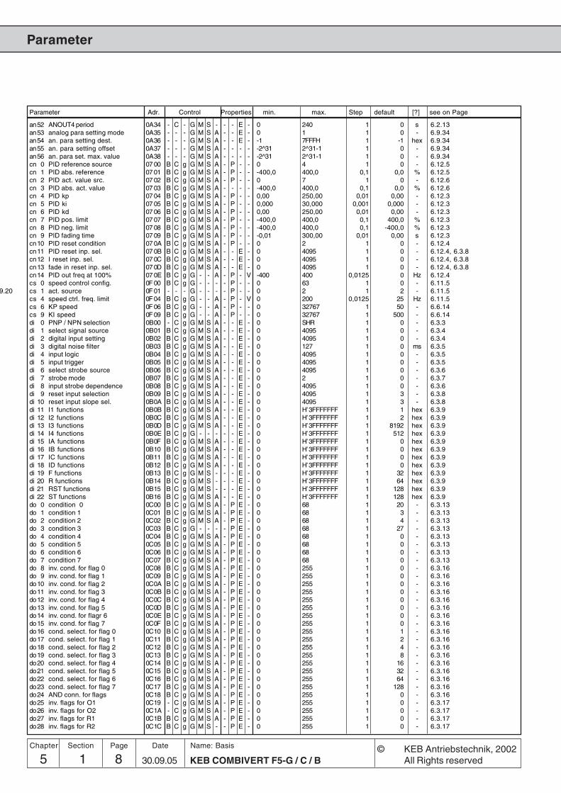
Parameter
5 1 KEB COMBIVERT F5-G / C / B8Name: Basis
30.09.05
Chapter Section Page Date © KEB Antriebstechnik, 2002All Rights reserved
Parameter Adr. Control Properties min. max. Step default [?] see on Page
9.20
an52 ANOUT4 period 0A34 - C - G M S - - - E - 0 240 1 0 s 6.2.13an53 analog para setting mode 0A35 - - - G M S A - - E - 0 1 1 0 - 6.9.34an54 an. para setting dest. 0A36 - - - G M S A - - E - -1 7FFFH 1 -1 hex 6.9.34an55 an. para setting offset 0A37 - - - G M S A - - - - -2^31 2^31-1 1 0 - 6.9.34an56 an. para set. max. value 0A38 - - - G M S A - - - - -2^31 2^31-1 1 0 - 6.9.34cn 0 PID reference source 07 00 B C g G M S A - P - - 0 4 1 0 - 6.12.5cn 1 PID abs. reference 07 01 B C g G M S A - P - - -400,0 400,0 0,1 0,0 % 6.12.5cn 2 PID act. value src. 07 02 B C g G M S A - P - - 0 7 1 0 - 6.12.6cn 3 PID abs. act. value 07 03 B C g G M S A - - - - -400,0 400,0 0,1 0,0 % 6.12.6cn 4 PID kp 07 04 B C g G M S A - P - - 0,00 250,00 0,01 0,00 - 6.12.3cn 5 PID ki 07 05 B C g G M S A - P - - 0,000 30,000 0,001 0,000 - 6.12.3cn 6 PID kd 07 06 B C g G M S A - P - - 0,00 250,00 0,01 0,00 - 6.12.3cn 7 PID pos. limit 07 07 B C g G M S A - P - - -400,0 400,0 0,1 400,0 % 6.12.3cn 8 PID neg. limit 07 08 B C g G M S A - P - - -400,0 400,0 0,1 -400,0 % 6.12.3cn 9 PID fading time 07 09 B C g G M S A - P - - -0,01 300,00 0,01 0,00 s 6.12.3cn10 PID reset condition 07 0A B C g G M S A - P - - 0 2 1 0 - 6.12.4cn11 PID reset inp. sel. 07 0B B C g G M S A - - E - 0 4095 1 0 - 6.12.4, 6.3.8cn12 I reset inp. sel. 07 0C B C g G M S A - - E - 0 4095 1 0 - 6.12.4, 6.3.8cn13 fade in reset inp. sel. 07 0D B C g G M S A - - E - 0 4095 1 0 - 6.12.4, 6.3.8cn14 PID out freq at 100% 07 0E B C g G - - A - P - V -400 400 0,0125 0 Hz 6.12.4cs 0 speed control config. 0F 00 B C g G - - - - P - - 0 63 1 0 - 6.11.5cs 1 act. source 0F 01 - - - G - - - - P - - 0 2 1 2 - 6.11.5cs 4 speed ctrl. freq. limit 0F 04 B C g G - - A - P - V 0 200 0,0125 25 Hz 6.11.5cs 6 KP speed 0F 06 B C g G - - A - P - - 0 32767 1 50 - 6.6.14cs 9 KI speed 0F 09 B C g G - - A - P - - 0 32767 1 500 - 6.6.14di 0 PNP / NPN selection 0B00 - C g G M S A - - E - 0 SHR 1 0 - 6.3.3di 1 select signal source 0B01 B C g G M S A - - E - 0 4095 1 0 - 6.3.4di 2 digital input setting 0B02 B C g G M S A - - E - 0 4095 1 0 - 6.3.4di 3 digital noise filter 0B03 B C g G M S A - - E - 0 127 1 0 ms 6.3.5di 4 input logic 0B04 B C g G M S A - - E - 0 4095 1 0 - 6.3.5di 5 input trigger 0B05 B C g G M S A - - E - 0 4095 1 0 - 6.3.5di 6 select strobe source 0B06 B C g G M S A - - E - 0 4095 1 0 - 6.3.6di 7 strobe mode 0B07 B C g G M S A - - E - 0 2 1 0 - 6.3.7di 8 input strobe dependence 0B08 B C g G M S A - - E - 0 4095 1 0 - 6.3.6di 9 reset input selection 0B09 B C g G M S A - - E - 0 4095 1 3 - 6.3.8di 10 reset input slope sel. 0B0A B C g G M S A - - E - 0 4095 1 3 - 6.3.8di 11 I1 functions 0B0B B C g G M S A - - E - 0 H’ 3FFFFFFF 1 1 hex 6.3.9di 12 I2 functions 0B0C B C g G M S A - - E - 0 H’ 3FFFFFFF 1 2 hex 6.3.9di 13 I3 functions 0B0D B C g G M S A - - E - 0 H’ 3FFFFFFF 1 8192 hex 6.3.9di 14 I4 functions 0B0E B C g G - - - - - E - 0 H’ 3FFFFFFF 1 512 hex 6.3.9di 15 IA functions 0B0F B C g G M S A - - E - 0 H’ 3FFFFFFF 1 0 hex 6.3.9di 16 IB functions 0B10 B C g G M S A - - E - 0 H’ 3FFFFFFF 1 0 hex 6.3.9di 17 IC functions 0B11 B C g G M S A - - E - 0 H’ 3FFFFFFF 1 0 hex 6.3.9di 18 ID functions 0B12 B C g G M S A - - E - 0 H’ 3FFFFFFF 1 0 hex 6.3.9di 19 F functions 0B13 B C g G M S - - - E - 0 H’ 3FFFFFFF 1 32 hex 6.3.9di 20 R functions 0B14 B C g G M S - - - E - 0 H’ 3FFFFFFF 1 64 hex 6.3.9di 21 RST functions 0B15 B C g G M S - - - E - 0 H’ 3FFFFFFF 1 128 hex 6.3.9di 22 ST functions 0B16 B C g G M S A - - E - 0 H’ 3FFFFFFF 1 128 hex 6.3.9do 0 condition 0 0C00 B C g G M S A - P E - 0 68 1 20 - 6.3.13do 1 condition 1 0C01 B C g G M S A - P E - 0 68 1 3 - 6.3.13do 2 condition 2 0C02 B C g G M S A - P E - 0 68 1 4 - 6.3.13do 3 condition 3 0C03 B C g G - - - - P E - 0 68 1 27 - 6.3.13do 4 condition 4 0C04 B C g G M S A - P E - 0 68 1 0 - 6.3.13do 5 condition 5 0C05 B C g G M S A - P E - 0 68 1 0 - 6.3.13do 6 condition 6 0C06 B C g G M S A - P E - 0 68 1 0 - 6.3.13do 7 condition 7 0C07 B C g G M S A - P E - 0 68 1 0 - 6.3.13do 8 inv. cond. for flag 0 0C08 B C g G M S A - P E - 0 255 1 0 - 6.3.16do 9 inv. cond. for flag 1 0C09 B C g G M S A - P E - 0 255 1 0 - 6.3.16do10 inv. cond. for flag 2 0C0A B C g G M S A - P E - 0 255 1 0 - 6.3.16do11 inv. cond. for flag 3 0C0B B C g G M S A - P E - 0 255 1 0 - 6.3.16do12 inv. cond. for flag 4 0C0C B C g G M S A - P E - 0 255 1 0 - 6.3.16do13 inv. cond. for flag 5 0C0D B C g G M S A - P E - 0 255 1 0 - 6.3.16do14 inv. cond. for flagr 6 0C0E B C g G M S A - P E - 0 255 1 0 - 6.3.16do15 inv. cond. for flag 7 0C0F B C g G M S A - P E - 0 255 1 0 - 6.3.16do16 cond. select. for flag 0 0C10 B C g G M S A - P E - 0 255 1 1 - 6.3.16do17 cond. select. for flag 1 0C11 B C g G M S A - P E - 0 255 1 2 - 6.3.16do18 cond. select. for flag 2 0C12 B C g G M S A - P E - 0 255 1 4 - 6.3.16do19 cond. select. for flag 3 0C13 B C g G M S A - P E - 0 255 1 8 - 6.3.16do20 cond. select. for flag 4 0C14 B C g G M S A - P E - 0 255 1 16 - 6.3.16do21 cond. select. for flag 5 0C15 B C g G M S A - P E - 0 255 1 32 - 6.3.16do22 cond. select. for flag 6 0C16 B C g G M S A - P E - 0 255 1 64 - 6.3.16do23 cond. select. for flag 7 0C17 B C g G M S A - P E - 0 255 1 128 - 6.3.16do24 AND conn. for flags 0C18 B C g G M S A - P E - 0 255 1 0 - 6.3.16do25 inv. flags for O1 0C19 - C g G M S A - P E - 0 255 1 0 - 6.3.17do26 inv. flags for O2 0C1A - C g G M S A - P E - 0 255 1 0 - 6.3.17do27 inv. flags for R1 0C1B B C g G M S A - P E - 0 255 1 0 - 6.3.17do28 inv. flags for R2 0C1C B C g G M S - - P E - 0 255 1 0 - 6.3.17

Parameter
5 1 9KEB COMBIVERT F5-G / C / B
Name: Basis
30.09.05
Section PageDate© KEB Antriebstechnik, 2002All Rights reserved
Chapter
Parameter Adr. Control Properties min. max. Step default [?] see on Page
5
do29 inv. flags for OA 0C1D B C g G M S A - P E - 0 255 1 0 - 6.3.17do30 inv. flags for OB 0C1E B C g G M S A - P E - 0 255 1 0 - 6.3.17do31 inv. flags for OC 0C1F B C g G M S A - P E - 0 255 1 0 - 6.3.17do32 inv. flags for OD 0C20 B C g G M S A - P E - 0 255 1 0 - 6.3.17do33 flag select. for O1 0C21 - C g G M S A - P E - 0 255 1 1 - 6.3.17do34 flag select. for O2 0C22 - C g G M S A - P E - 0 255 1 2 - 6.3.17do35 flag select. for R1 0C23 B C g G M S A - P E - 0 255 1 4 - 6.3.17do36 flag select. for R2 0C24 B C g G M S - - P E - 0 255 1 8 - 6.3.17do37 flag select. for OA 0C25 B C g G M S A - P E - 0 255 1 16 - 6.3.17do38 flag select. for OB 0C26 B C g G M S A - P E - 0 255 1 32 - 6.3.17do39 flag select. for OC 0C27 B C g G M S A - P E - 0 255 1 64 - 6.3.17do40 flag select. for OD 0C28 B C g G M S A - P E - 0 255 1 128 - 6.3.17do41 AND conn. for outputs 0C29 B C g G M S A - P E - 0 255 1 0 - 6.3.17do42 inverted outputs 0C2A B C g G M S A - P E - 0 255 1 0 - 6.3.18do43 cond. 0 filter time 0C2B - C - G M S A - P - - 0 1000 1 0 ms 6.3.12do44 cond. 1 filter time 0C2C - C - G M S A - P - - 0 1000 1 0 ms 6.3.12do51 hardw. outp. allocation 0C33 - C - G M S A - P - - 0 255 1 228 -dr 0 DASM rated current 06 00 B C g G M - A - P - - 0,0 710 0,1 LTK A 6.6.3dr 1 DASM rated speed 06 01 B C g G M - A - P - - 0 64000 1 LTK rpm 6.6.3dr 2 DASM rated voltage 06 02 B - g G M - A - P - - 120 500 1 LTK V 6.6.3dr 3 DASM rated power 06 03 - C - G M - A - P - - 0,35 400,00 0,01 LTK kW 6.6.3dr 4 DASM rated cos(phi) 06 04 B C g G M - A - P - - 0,50 1,00 0,01 LTK - 6.6.3dr 5 DASM rated frequency 06 05 B C g G M - A - P - - 0,0 1600,0 0,1 LTK Hz 6.6.3dr 6 DASM stator resistance 06 06 B C g G M - A - P - - 0,000 50,000 0,001 LTK Ohm 6.6.4dr 9 breakdown factor 06 09 B C g G - - A - P - - 0,5 4,0 0,1 2,5 -dr 11 motorprotection mode 06 0B B C g G M - A - P - - 0 1 1 1 - 6.7.16dr 12 motorprot. rated current 06 0C B C g G M - A - P - - 0,0 710,0 0,1 LTK A 6.7.16ec 0 encoder 1 interface 10 00 - - - G M S A - - X - -127 127 1 GBK - 6.10.10ec 1 encoder 1 (inc/r) 10 01 - - - G M S A - - - - GBK GBK 1 GBK inc 6.10.10ec 3 time 1 for speed calc. 10 03 - - - G M S A - - - - 0 9 1 3 - 6.10.10ec 4 gear 1 numerator 10 04 - - - G M S A - - - - -10000 10000 1 1000 - 6.10.11ec 5 gear 1 determinator 10 05 - - - G M S A - - - - 1 10000 1 1000 - 6.10.11ec 6 enc.1 rotation 10 06 - - - G M S A - - - - 0 19 1 0 - 6.10.11ec 7 enc.1 trigger 10 07 - - - G M S - - - - - GBK GBK 1 GBK - 6.10.11ec10 encoder 2 interface 10 0A - - - G M S A - - X - -127 127 1 GBK - 6.10.6, 6.10.10ec11 encoder 2 (inc/r) 10 0B - - - G M S A - - - - GBK GBK 1 GBK inc 6.10.10ec13 time 2 for speed calc. 10 0D - - - G M S A - - - - 0 9 1 3 - 6.10.10ec14 gear 2 numerator 10 0E - - - G M S A - - - - -10000 10000 1 1000 - 6.10.11ec15 gear 2 determinator 10 0F - - - G M S A - - - - 1 10000 1 1000 - 6.10.11ec16 enc.2 rotation 10 10 - - - G M S A - - - - 0 19 1 0 - 6.10.11ec17 enc.2 trigger 10 11 - - - G M S - - - - - GBK GBK 1 GBK - 6.10.11ec20 enc.2 operating mode 10 14 - - - G M S A - - - - 0 1 1 0 - 6.10.7ec21 SSI multiturn res. 10 15 - - - G M S - - - - - 0 13 1 12 - 6.10.13ec22 SSI clock frq. sel. 10 16 - - - G M S - - - - - 0 1 1 0 - 6.10.13ec23 SSI data code 10 17 - - - G M S - - - - - 0 1 1 1 - 6.10.13ec25 nominal tacho speed 10 19 - - - G M S - - - - - 1 16000 1 1500 rpm 6.10.13ec27 operation mode output 10 1A - - - G M S - - - E - 0 47 1 0 - 6.10.12ec31 abs. position ch1 10 1F - - - G M S A - - - - -2^31 2^31-1 1 0 inc 6.10.13ec32 abs. position ch2 10 20 - - - G M S - - - - - -2^31 2^31-1 1 0 inc 6.10.13ec36 enc.1 encoder type 10 24 - - - G M S - - - - - 0 255 1 0 - 6.10.13ec37 enc.1 encoder status 10 25 - - - G M S - - - - - 0 255 1 0 - 6.10.13ec38 enc.1 encoder r/w 10 26 - - - G M S - - - E - 0 2 1 0 - 6.10.13fr 1 copy parameter set 09 01 B C g G M S A - P E - -4 7 1 0 - 6.8.4fr 2 parameter set source 09 02 B C g G M S A - - E - 0 5 1 0 - 6.8.5fr 3 parameter set lock 09 03 B C g G M S A - - E - 0 255 1 0 - 6.8.8fr 4 parameter set setting 09 04 B C g G M S A - - E - 0 7 1 0 - 6.8.5fr 5 set activation delay 09 05 B C g G M S A - P - - 0,00 2,55 0,01 0,00 s 6.8.8, 6.9.31fr 6 set deactivation delay 09 06 B C g G M S A - P - - 0,00 2,55 0,01 0,00 s 6.8.8, 6.9.31fr 7 paraset input sel. 09 07 B C g G M S A - - E - 0 4095 1 0 - 6.8.6, 6.3.8fr 8 motor set classification 09 08 B C g G M - A - P - - 0 7 1 0 - 6.7.14fr 9 bus parameter set 09 09 B C g G M S A - - - - -1 7 1 0 - 6.8.4fr 10 load mot.dependent para. 09 0A - C - G - - - - P E - 3 3 1 3 - 6.6.6fr 11 reset set input sel. 09 0B B C g G M S A - - E - 0 4095 1 0 - 6.8.7, 6.3.8in 0 inverter type 0E00 B C g G M S A R - - - LTK LTK 1 LTK hex 6.1.19in 1 rated inverter current 0E01 B C g G M S A R - - - LTK LTK 0,1 LTK A 6.1.19in 3 max. carrier frequency 0E03 B C g G M S A R - - - LTK LTK 1 LTK - 6.1.20in 4 rated carrier frequency 0E04 B C g G M S A R - - - LTK LTK 1 LTK - 6.1.20in 6 software version 0E06 B C g G M S A R - - - SW SW 0,01 SW - 6.1.20in 7 software date 0E07 B C g G M S A R - - - SW SW 0,1 SW - 6.1.20in 8 software version p. unit 0E08 - - g - - - - R - - - LTK LTK 1 LTK -in 9 software date p. unit 0E09 - - g - - - - R - - - LTK LTK 1 LTK -in 10 serial no. (date) 0E0A B C g G M S A R - - - 0 65535 1 0 - 6.1.21in 11 serial no. (count) 0E0B B C g G M S A R - - - 0 65535 1 0 - 6.1.21in 12 serial no. (AB-no. high) 0E0C B C g G M S A R - - - 0 65535 1 0 - 6.1.21in 13 serial no. (AB-no. low) 0E0D B C g G M S A R - - - 0 65535 1 0 - 6.1.21in 14 customer no. high 0E0E B C g G M S A R - - - 0 65535 1 0 - 6.1.21in.15 customer no. low 0E0F B C g G M S A R - - - 0 65535 1 0 - 6.1.21

Parameter
5 1 KEB COMBIVERT F5-G / C / B10Name: Basis
30.09.05
Chapter Section Page Date © KEB Antriebstechnik, 2002All Rights reserved
Parameter Adr. Control Properties min. max. Step default [?] see on Page
in 16 QS no. 0E10 B C g G M S A R - - - 0 65535 1 0 - 6.1.21in 17 temp.- mode 0E11 - - - G M S A R - - - LTK LTK 1 LTK - 6.1.21in 22 user parameter 1 0E16 B C g G M S A - - - - 0 65535 1 0 - 6.1.21in 23 user parameter 2 0E17 B C g G M S A - - - - 0 65535 1 0 - 6.1.21in 24 last error 0E18 B C g G M S A R - E - 0 255 - 0 - 6.1.21in 25 error diagnosis 0E19 B C g G M S A R P - - 0 65535 1 0 hex 6.1.22in 26 E.OC error counter 0E1A B C g G M S A R - - - 0 65535 1 0 - 6.1.22in 27 E.OL error counter 0E1B B C g G M S A R - - - 0 65535 1 0 - 6.1.22in 28 E.OP error counter 0E1C B C g G M S A R - - - 0 65535 1 0 - 6.1.22in 29 E.OH error counter 0E1D B C g G M S A R - - - 0 65535 1 0 - 6.1.22in 30 E.OHI error counter 0E1E B C g G M S A R - - - 0 65535 1 0 - 6.1.22le 0 comparison level 0 0D00 B C g G - - - - P - - -30000,00 30000,00 0,01 0,00 - 6.3.15, 6.9.13le 1 comparison level 1 0D01 B C g G - - - - P - - -30000,00 30000,00 0,01 0,00 - 6.3.15, 6.9.13le 2 comparison level 2 0D02 B C g G - - - - P - - -30000,00 30000,00 0,01 100,00 - 6.3.15, 6.9.13le 3 comparison level 3 0D03 B C g G - - - - P - - -30000,00 30000,00 0,01 4,00 - 6.3.15, 6.9.13le 4 comparison level 4 0D04 B C g G - - - - P - - -30000,00 30000,00 0,01 0,00 - 6.3.15, 6.9.13le 5 comparison level 5 0D05 B C g G - - - - P - - -30000,00 30000,00 0,01 0,00 - 6.3.15, 6.9.13le 6 comparison level 6 0D06 B C g G - - - - P - - -30000,00 30000,00 0,01 0,00 - 6.3.15, 6.9.13le 7 comparison level 7 0D07 B C g G - - - - P - - -30000,00 30000,00 0,01 0,00 - 6.3.15, 6.9.13le 8 hysteresis 0 0D08 B C g G M S A - P - - 0,00 300,00 0,01 0,00 - 6.3.15le 9 hysteresis 1 0D09 B C g G M S A - P - - 0,00 300,00 0,01 0,00 - 6.3.15le 10 hysteresis 2 0D0A B C g G M S A - P - - 0,00 300,00 0,01 5,00 - 6.3.15le 11 hysteresis 3 0D0B B C g G M S A - P - - 0,00 300,00 0,01 0,50 - 6.3.15le 12 hysteresis 4 0D0C B C g G M S A - P - - 0,00 300,00 0,01 0,00 - 6.3.15le 13 hysteresis 5 0D0D B C g G M S A - P - - 0,00 300,00 0,01 0,00 - 6.3.15le 14 hysteresis 6 0D0E B C g G M S A - P - - 0,00 300,00 0,01 0,00 - 6.3.15le 15 hysteresis 7 0D0F B C g G M S A - P - - 0,00 300,00 0,01 0,00 - 6.3.15le 16 freq/speed hysteresis 0D10 B C g G - - - - - - V 0 20 0,0125 0,8 Hz 6.3.15le 17 timer 1 start inp. sel. 0D11 B C g G M S A - - E - 0 4095 1 0 - 6.3.8, 6.9.12le 18 timer 1 start condition 0D12 B C g G M S A - - E - 0 7 1 0 - 6.3.8, 6.9.12le 19 timer 1 reset inp. sel. 0D13 B C g G M S A - - E - 0 4095 1 0 - 6.3.8, 6.9.12le 20 timer 1 reset condition 0D14 B C g G M S A - - E - 0 31 1 16 - 6.9.13le 21 timer 1 mode 0D15 B C g G M S A - - - - 0 31 1 0 - 6.9.11le 22 timer 2 start inp. sel. 0D16 B C g G M S A - - E - 0 4095 1 0 - 6.3.8, 6.9.12le 23 timer 2 start condition 0D17 B C g G M S A - - E - 0 7 1 0 - 6.3.8, 6.9.12le 24 timer 2 reset inp. sel. 0D18 B C g G M S A - - E - 0 4095 1 0 - 6.3.8, 6.9.12le 25 timer 2 reset condition 0D19 B C g G M S A - - E - 0 31 1 16 - 6.9.13le 26 timer 2 mode 0D1A B C g G M S A - - - - 0 31 1 0 - 6.9.11op 0 reference source 03 00 B C g - - - - - P E - 0 6 1 0 - 6.4.4, 6.9.9op 0 reference source 03 00 - - - G M S A - P E - 0 9 1 0 - 6.4.4, 6.9.9op 1 rotation source 03 01 B C g G - - - - P E - 0 9 1 2 - 6.4.6, 6.9.9op 2 rotation setting 03 02 B C g G M S A - P E - 0 2 1 0 - 6.4.6op 3 reference setting 03 03 B C g G - - - - P - V -400 400 0,0125 0 Hz 6.4.4op 5 reference setting % 03 05 B C g G M S A - P - - -100,0 100,0 0,1 0,0 % 6.4.4op 6 min. reference forward 03 06 B C g G - - - - P - V 0 400 0,0125 0 Hz 6.4.11op 7 min. reference reverse 03 07 B C g G - - - - P - V -0,0125 400 0,0125 -0,0125 Hz 6.4.11op10 max. reference forward 03 0A B C g G - - - - P - V 0 400 0,0125 0 Hz 6.4.11op11 max. reference reverse 03 0B B C g G - - - - P - V -0,0125 400 0,0125 -0,0125 Hz 6.4.11op14 abs. max. reference for 03 0E B C g G - - - - P - V 0 400 0,0125 400 Hz 6.4.11op15 abs. max. reference rev 03 0F B C g G - - - - P - V -0,0125 400 0,0125 -0,0125 Hz 6.4.11op18 step value rot. source 03 12 B C g G - - - - P E - 0 9 1 2 - 6.4.9op19 step value input sel. 1 03 13 B C g G M S A - - E - 0 4095 1 16 - 6.4.9, 6.3.8op20 step value input sel. 2 03 14 B C g G M S A - - E - 0 4095 1 32 - 6.4.9, 6.3.8op21 step value 1 03 15 B C g G - - - - P - V -400 400 0,0125 5 Hz 6.4.9op22 step value 2 03 16 B C g G - - - - P - V -400 400 0,0125 50 Hz 6.4.9op23 step value 3 03 17 B C g G - - - - P - V -400 400 0,0125 70 Hz 6.4.9op27 acc dec mode 03 1B B C g G M S A - P E - 0 255 1 0 - 6.4.16op28 acc. time forward 03 1C B C g G M S A - P - - 0,00 300,00 0,01 5,00 s 6.4.13op29 acc. time reverse 03 1D B C g G M S A - P - - -0,01 300,00 0,01 -0,01 s 6.4.13op30 dec. time forward 03 1E B C g G M S A - P - - -0,01 300,00 0,01 5,00 s 6.4.13op31 dec. time reverse 03 1F B C g G M S A - P - - -0,01 300,00 0,01 -0,01 s 6.4.13op32 s-curve time acc. for. 03 20 B C g G M S A - P - - 0,00 5,00 0,01 0,00 s 6.4.14op33 s-curve time acc. rev. 03 21 B C g G M S A - P - - -0,01 5,00 0,01 -0,01 s 6.4.14op34 s-curve time dec. for. 03 22 B C g G M S A - P - - -0,01 5,00 0,01 -0,01 s 6.4.14op35 s-curve time dec. rev. 03 23 B C g G M S A - P - - -0,01 5,00 0,01 -0,01 s 6.4.14op36 min. output freq. for 03 24 B C g G - - A - P - V 0 400 0,0125 0 Hzop37 min. output freq. rev 03 25 B C g G - - A - P - V -0,0125 400 0,0125 -0,0125 Hzop40 max. output val. for. 03 28 B C g G - - - - P - V 0 400 0,0125 400 Hz 6.4.15, 6.7.5op41 max. output val. rev. 03 29 B C g G - - - - P - V -0,0125 400 0,0125 -0,0125 Hz 6.4.15, 6.7.5op44 ext. funct. mode/src 03 2C - C - G M S A - P E - 0 63 1 0 - 6.9.27, 6.9.29op45 ext. funct. dig. source 03 2D - C - G M S A - P - - 0,00 100,00 0,01 0,00 % 6.9.27, 6.9.29op46 ext. funct. acc/dec time 03 2E - C - G M S A - P - - 0,00 20,00 0,01 10,00 s 6.9.27, 6.9.30op47 sweep-gen. acc. time 03 2F - C - G M S A - P - - 0,00 20,00 0,01 10,00 s 6.9.27op48 sweep-gen. dec. time 03 30 - C - G M S A - P - - 0,00 20,00 0,01 10,00 s 6.9.27op49 diam. corr. dmin/dmax 03 31 - C - G M S A - P - - 0,010 0,990 0,001 0,500 - 6.9.30op50 motorpoti function 03 32 B C g G M S A - - E - 0 3 1 0 - 6.9.8op52 motorpoti value 03 34 B C g G M S A - P - - -100,00 100,00 0,01 0,00 % 6.9.9

Parameter
5 1 11KEB COMBIVERT F5-G / C / B
Name: Basis
30.09.05
Section PageDate© KEB Antriebstechnik, 2002All Rights reserved
Chapter
Parameter Adr. Control Properties min. max. Step default [?] see on Page
5
op53 motorpoti min. value 03 35 B C g G M S A - - - - -100,00 100,00 0,01 0,00 % 6.9.8op54 motorpoti max. value 03 36 B C g G M S A - - - - -100,00 100,00 0,01 100,00 % 6.9.8op55 motorpoti reset value 03 37 B C g G M S A - - - - -100,00 100,00 0,01 0,00 % 6.9.7op56 Eing.wahl MPoti erhöhen 03 38 B C g G M S A - - E - 0 4095 1 0 - 6.3.8, 6.9.8op57 mot.poti dec. input sel. 03 39 B C g G M S A - - E - 0 4095 1 0 - 6.9.8, 6.3.8op58 mot.poti reset inp. sel. 03 3A B C g G M S A - - E - 0 4095 1 0 - 6.9.8, 6.3.8op59 motorpoti inc/dec time 03 3B B C g G M S A - - - - 0,00 50000,00 0,01 66,00 s 6.9.8op60 dir. forward input sel. 03 3C B C g G M S A - - E - 0 4095 1 4 - 6.3.8, 6.4.7op61 dir. reverse input sel. 03 3D B C g G M S A - - E - 0 4095 1 8 - 6.3.8, 6.4.7op62 acc/dec time factor 03 3E B C g G M S A - - E - 0 4 1 0 - 6.4.13op63 ref. value high-res 033F - - - - M S A - - - - -2^31-1 2^31-1 1 0 6.4.5op64 rel. value high-res 0340 - - - - M S A - - - - 0 n * 400 n * 0,0125 1 Hz 6.4.5op65 min. proh. reference 1 0341 - - - - M S A - - - - -4000 4000 0,125 0 rpm 6.4.6op66 max. proh. reference 1 0342 - - - - M S A - - - - -4000 4000 0,125 0 rpm 6.4.6op67 min. proh. reference 2 0343 - - - - M S A - - - - -4000 4000 0,125 0 rpm 6.4.6op68 max. proh. reference 2 0344 - - - - M S A - - - - -4000 4000 0,125 0 rpm 6.4.6pn 0 auto retry UP 04 00 B C g G M S A - - - - 0 1 1 1 - 6.7.7pn 1 auto retry OP 04 01 B C g G M S A - - - - 0 1 1 0 - 6.7.7pn 2 auto retry OC 04 02 B C g G M S A - - - - 0 1 1 0 - 6.7.7pn 3 E. EF stopping mode 04 03 B C g G M S A - - - - 0 6 1 0 - 6.7.10pn 4 ext. fault input select 04 04 B C g G M S A - - E - 0 4095 1 64 - 6.7.9, 6.3.8pn 5 E.buS stopping mode 04 05 B C g G M S A - - - - 0 6 1 6 - 6.7.10, 11.2.3pn 6 watchdog time 04 06 B C g G M S A - - E - 0,00:off 10,00 0,01 0,00:off s 6.7.10, 11.2.3pn 8 warning OL stop. mode 04 08 B C g G M S A - - - - 0 6 1 6 - 6.7.11, 6.3.15pn 9 OL warning level 04 09 B C g G M S A - - - - 0 100 1 80 % 6.7.10pn10 warning OH stop. mode 04 0A B C g G M S A - - - - 0 6 1 6 - 6.7.11, 6.3.15pn11 OH warning level 04 0B B C g G M S A - - - - 0 90 1 70 °C 6.7.11pn12 warning dOH stop. mode 04 0C B C g G - - - - - - - 0 7 1 7 - 6.7.11, 6.3.15, 6.7.18pn13 E.dOH delay time 04 0D B C g G - - - - - - - 0 120 1 10 s 6.7.11, 6.7.18pn14 warning OH2 stop. mode 04 0E B C g G M S A - - - - 0 6 1 6 - 6.7.12, 6.7.17, 6.3.15pn16 warning OHI stop. mode 04 10 B C g G M S A - - - - 0 7 1 7 - 6.7.12, 6.3.16pn17 E.OHI delay time 04 11 B C g G M S A - - - - 0 120 1 0 s 6.7.12pn18 E.Set stopping mode 04 12 B C g G M S A - - - - 0 6 1 0 - 6.7.12pn19 stall mode 04 13 - C - G M - - - P E - 0 255 1 0 - 6.7.5pn19 stall mode 04 13 B - g - - - A - P E - 0 127 1 0 - 6.7.5pn20 stall level 04 14 B C g G M - A - P - - 0 200 1 200:off % 6.7.6pn21 stall acc/dec time 04 15 B C g G M - A - P - - 0 300,00 0,01 2,00 s 6.7.6pn22 LAD stop function 04 16 B C g G M S A - P E - 0 7 1 1 / 0 - 6.7.3pn23 LAD stop input selection 04 17 B C g G M S A - - E - 0 4095 1 0 - 6.7.3, 6.3.8pn24 LAD load level 04 18 B C g G M S A - P - - 0 200 1 140 % 6.7.3pn25 LD voltage 04 19 B C g G M S A - P - - 200 800 1 375 / 720 V 6.7.3pn26 speed search condition 04 1A B C g G M - - - P E - 0 15 1 8 - 6.7.7pn27 speed search mode 04 1B B C g G M - - - - E - 0 127 1 0/88 - 6.7.7pn28 DC braking mode 04 1C B C g G M - - - P E - 0 9 1 7 - 6.9.4pn29 DC brake input selection 04 1D B C g G M - - - - E - 0 4095 1 128 - 6.9.4, 6.3.8pn30 DC braking time 04 1E B C g G M - - - P - - 0,00 100,00 0,01 10,00 s 6.9.3pn31 DC braking max. voltage 04 1F B C g G M - - - P - - 0,0 25,5 0,1 25,5 % 6.9.3pn32 DC braking start freq. 04 20 B C g G - - - - P - V 0 400 0,0125 4 Hz 6.9.3pn34 brake control mode 04 22 B C g G M S A - P E - 0 4 1 0 - 6.9.16pn35 premagnetizing time 04 23 B C g G M S A - P - - 0,00 100,00 0,01 0,25 s 6.9.15pn36 brake release time 04 24 B C g G M S A - P - - 0,00 100,00 0,01 0,25 s 6.9.15pn37 Bremsenstrg. Startwert 04 25 B C g G - - - - P - V -20 20 0,0125 0 Hz 6.9.17pn39 brake delay time 04 27 B C g G M S A - P - - 0,00 100,00 0,01 0,25 s 6.9.15pn40 brake closing time 04 28 B C g G M S A - P - - 0,00 100,00 0,01 0,25 s 6.9.15pn41 brake ctrl. stop ref. 04 29 B C g G - - - - P - V -20 20 0,0125 0 Hz 6.9.17pn41 brake ctrl. stop ref. 04 29 - - - - M S A - P - V -600 600 0,125 0 rpm 6.9.17pn43 min. load brake ctrl. 04 2B B C g G M S A - P - - 0 100 1 0 % 6.9.16pn44 power off mode 04 2C B C g G M S A - - E - 0 511 1 0 - 6.9.19, 6.9.20, 6.9.23pn45 power off start voltage 04 2D B C g G M S A - - - - 200 800 1 290 / 500 V 6.9.20, 6.9.21pn46 power off auto st. level 04 2E B C g G M S A - - - - 50 90 1 80 % 6.9.20, 6.9.21pn47 power off brake torque 04 2F B C g G - - - - - - - 0,0 100,0 0,1 0,0 % 6.9.21pn48 power off restart level 04 30 B C g G - - - - - - V 0 400 0,0125 0 Hz 6.9.22pn50 power off ref. DC volt. 04 32 B C g G - - - - - - - 200 800 1 290 / 500 V 6.9.21pn51 power off KP DC volt. 04 33 B C g G M - - - - - - 0 32767 1 128 - 6.9.22pn52 power off restart delay 04 34 B C g G M S A - - - - 0,00 100,00 0,01 0,00 s 6.9.23pn53 power off KP act.curr. 04 35 B C g G - - - - - - - 0 32767 1 50 - 6.9.22pn54 power off KI act.curr. 04 36 B C g G - - - - - - - 0 32767 1 50 - 6.9.22pn55 power off KD act.curr. 04 37 B C g G - - - - - - - 0 32767 1 0 - 6.9.22pn56 power off jump factor 04 38 B C g G - - - - - - - 0 800 1 100 % 6.9.20pn57 power off KI DC volt. 04 39 - C - G M - - - - - - 0 32767 1 5 - 6.9.22pn58 quick stop mode 04 3A B C g G - - A - - E - 0 3 1 0 - 6.7.13pn59 quick stop level 04 3B B C g G - - - - - - - 0 200 1 200 % 6.7.13pn60 quick stop acc/dec time 04 3C B C g G M S A - - - - 0 300,00 0,01 2,00 s 6.7.13pn62 dOH warning level 04 3E - - - G M S A - - - - 0 200 1 100 °C 6.7.11pn63 positioning delay 04 3F B C g G - - A - P - - -0,02 327,67 0,01 -0,01 s 6.9.31pn64 set GTR7 input selection 04 40 - C - G M S A - - E - 0 4095 1 0 - 6.7.19, 6.3.8pn65 special functions 04 41 - C - G M S A - - - - 0 7 1 0 - 6.7.20, 6.7.19, 6.7.9

Parameter
5 1 KEB COMBIVERT F5-G / C / B12Name: Basis
30.09.05
Chapter Section Page Date © KEB Antriebstechnik, 2002All Rights reserved
Parameter Adr. Control Properties min. max. Step default [?] see on Page
ru 5 encoder 2 frequency 02 05 - - - G - - A R - - V -400 400 0,0125 0 Hzru 6 calculated act. freq. 02 06 - - - G - - A R - - V -400 400 0,0125 0 Hzru 7 actual value display 02 07 - - - G - - - R - - V -400 400 0,0125 0 Hz 6.1.7ru 9 encoder 1 speed 02 09 - - - G - - - R - - V -32000 32000 1 0 rpm 6.1.7ru 10 encoder 2 speed 02 0A - - - G - - - R - - V -32000 32000 1 0 rpm 6.1.7ru 13 actual utilization 02 0D B C g G M S A R - - - 0 65535 1 0 % 6.11.6, 6.1.8ru 14 peak utilization 02 0E B C g G M S A - - - - 0 65535 1 0 % 6.1.8ru 15 apparent current 02 0F B C g G M S A R - - - 0 6553,5 0,1 0 A 6.1.8ru 16 peak apparent current 02 10 B C g G M S A - - - - 0 6553,5 0,1 0 A 6.1.8ru 17 active current 02 11 B C g G M S A R - - - -3276,7 3276,7 0,1 0 A 6.12.6, 6.1.9ru 18 actual DC voltage 02 12 B C g G M S A R - - - 0 1000 1 0 V 6.12.6, 6.1.9ru 19 peak DC voltage 02 13 B C g G M S A - - - - 0 1000 1 0 V 6.1.9ru 20 output voltage 02 14 B C g G M S A R - - - 0 778 1 0 V 6.1.9ru 21 input terminal state 02 15 B C g G M S A R - - - 0 4095 1 0 - 6.1.10, 6.3.5ru 22 internal input state 02 16 B C g G M S A R - - - 0 4095 1 0 - 6.1.10, 6.3.8ru 23 output condition state 02 17 B C g G M S A R - - - 0 255 1 0 - 6.1.11ru 24 state of output flags 02 18 B C g G M S A R - - - 0 255 1 0 - 6.1.11ru 25 output terminal state 02 19 B C g G M S A R - - - 0 255 1 0 - 6.1.12, 6.3.18ru 26 active parameter set 02 1A B C g G M S A R - - - 0 7 1 0 - 6.1.12ru 27 AN1 pre amplifier disp. 02 1B B C g G M S A R - - - -100,0 100,0 0,1 0 % 6.1.12, 6.2.3, 6.4.4ru 28 AN1 post amplifier disp. 02 1C B C g G M S A R - - - -400,0 400,0 0,1 0 % 6.1.12, 6.2.3, 6.4.4ru 29 AN2 pre amplifier disp. 02 1D - C g G M S - R - - - -100,0 100,0 0,1 0 % 6.1.13, 6.2.3, 6.4.4ru 30 AN2 post amplifier disp. 02 1E - C g G M S - R - - - -400,0 400,0 0,1 0 % 6.1.13, 6.2.3, 6.4.4ru 31 AN3 pre amplifier disp. 02 1F - - - G M S - R - - - -100,0 100,0 0,1 0 % 6.1.13, 6.2.3, 6.4.4ru 32 AN3 post amplifier disp. 02 20 - - - G M S - R - - - -400,0 400,0 0,1 0 % 6.1.13, 6.2.3, 6.4.4ru 33 ANOUT1 pre ampl. disp. 02 21 B C g G M S A R - - - -400,0 400,0 0,1 0 % 6.1.14, 6.2.12ru 34 ANOUT1 post ampl. disp. 02 22 B C g G M S A R - - - -115,0 115,0 0,1 0 % 6.1.14, 6.2.12ru 35 ANOUT2 pre ampl. disp. 02 23 - C g G M S - R - - - -400,0 400,0 0,1 0 % 6.1.14, 6.2.12ru 36 ANOUT2 post ampl. disp. 02 24 - C g G M S - R - - - -115,0 115,0 0,1 0 % 6.1.14, 6.2.12ru 37 motorpoti actual value 02 25 B C g G M S A R - - - -100,00 100,00 0,01 0 % 6.1.14, 6.9.8ru 38 power module temperature 02 26 B C g G M S A R - - - 0 150 1 0 °C 6.1.15ru 39 OL counter display 02 27 B C g G M S A R - - - 0 100 1 0 % 6.1.15ru 40 power on counter 02 28 B C g G M S A R - - - 0 65535 1 0 h 6.1.15ru 41 modulation on counter 02 29 B C g G M S A R - - - 0 65535 1 0 h 6.1.15ru 42 modulation grade 02 2A B C g G M S A R - - - 0 110 1 0 % 6.1.15ru 43 timer 1 display 02 2B B C g G M S A - - - - 0 655,35 0,01 0 - 6.1.15, 6.9.12ru 44 timer 2 display 02 2C B C g G M S A - - - - 0 655,35 0,01 0 - 6.1.16, 6.9.12ru 45 act. carrier frequency 02 2D B C g G M S A R - - - 0 4 1 0 - 6.1.16ru 46 motor temperature 02 2E B C g G M S - R - - - 0 255 1 0 °C 6.1.16ru 52 ext. PID out disp. 02 34 B C g G M S A R - - - -100,0 100,0 0,1 0 % 6.1.17, 6.4.4ru 53 AUX display 02 35 B C g G M S A R - - - -400,0 400,0 0,1 0 % 6.1.17, 6.12.6ru 68 rated DC voltage 02 44 B C - G M S A R - - - 0 1000 1 0 V 6.1.17ru 69 distance ref.-zeropoint 02 45 B - - G M S A R - - - -2^31 2^31 – 1 0 1 inc. 6.1.17ru 71 teach/scan position 02 47 B - - G M S A R - - - -2^31 2^31 – 1 0 1 inc. 6.1.17ru 73 set torque in percent 02 49 B - - G M S A R - - - -100,0 100,0 0,1 0 % 6.1.17ru 74 act torque in percent 02 4A B - - G M S A R - - - -100,0 100,0 0,1 0 % 6.1.17ru 78 act. val. display in percent 02 4E B - - G M S A R - - - -100,0 100,0 0,1 0 % 6.1.17ru 79 abs. speed value 02 4F B - - G M S A R - - - n*-4000 n*4000 n*0,125 0 rpm 6.1.17ru 80 digital output state 02 50 B C - G M S A R - - - 0 255 1 0 - 6.1.18ru 81 active power 02 51 B C - G M S A R - - - -400 400 0,00 0,00 kW 6.1.18sy 2 inverter identifier 00 02 B C g G M S A - - - - identifier identifier 1 identifier hex 6.1.23sy 3 power unit code 00 03 B C g G M S A - - E - 1 255 1 LTK - 6.1.23sy 6 inverter address 00 06 B C g G M S A - - E - 0 239 1 1 - 6.1.23, 11.2.3sy 7 baud rate ext. bus 00 07 B C g G M S A - - E - 0 6 1 5 - 6.1.23, 11.2.3sy 9 HSP5 watchdog time 00 09 B C g G M S A - - E - 0,00:off 10,00 0,01 0,00:off s 6.1.24, 11.2.3sy11 baud rate int. bus 00 0B B C g G M S A - - E - 3 11 1 5 - 6.1.24, 11.2.3sy32 scope timer 00 20 B C g G M S A R - - - 0 65535 1 0 - 6.1.24sy41 control word (high) 00 29 - C - G M S A - - E - 0 65535 1 0 hex 6.1.24, 11.2.4sy42 status word (high) 00 2A - C - G M S A R - - - 0 65535 1 0 hex 6.1.25, 11.2.5sy43 control word (long) 00 2B - C - G M S A R - - - -2^31 2^31 - 1 1 0 hex 6.1.25, 11.2.5sy50 control word (low) 00 32 B C g G M S A - - E - 0 65535 1 0 hex 6.1.25, 6.4.8, 11.2.4sy51 status word (low) 00 33 B C g G M S A R - - - 0 65535 1 0 hex 6.1.25, 11.2.4sy52 set speed value 00 34 B C g G M S A - - - - -16000 16000 1 0 rpm 6.1.26, 11.2.4sy53 actual speed value 00 35 B C g G M S A R - - - -16000 16000 1 0 rpm 6.1.25, 11.2.4sy56 start display address 00 38 B C g G - - A - - E - 0 7FFFH 1 0203H hex 6.1.25ud 1 password 08 01 B C g G M S A - - - - 0 9999 1 - - 4.2.3, 4.4.3, 6.13.3ud 2 maximum frequency mode 08 02 B C g - - - - - - - - 0 2 1 0 - 6.5.3ud 2 control type 08 02 - - - G M S A - - E - 0 10 1 0 - 6.5.3ud 5 auto store 08 05 B C g - - - - - - - - 0 1 1 1 - 11.2.3ud 9 drive-mode-control 08 09 B C g G M S A - - - - 0 11 1 0 - 4.4.4ud15 cp selector 08 0F B C g G M S A - - E - 1 36 1 1 - 6.13.4
pn69 GTR7 voltage 04 19 - C g G M S A 300 1000 1 380;740 Vru 0 inverter state 02 00 B C g G M S A R - - - 0 255 1 0 - 6.1.6ru 1 set value display 02 01 B C g G - - - R - - V -400 400 0,0125 0 Hz 6.1.6, 6.9.3ru 2 ramp output display 02 02 B C g G - - - R - - V -400 400 0,0125 0 Hz 6.1.6ru 3 actual frequency display 02 03 B C g G M S A R - - V -400 400 0,0125 0 Hz 6.1.6ru 4 encoder 1 frequency 02 04 - - - G - - A R - - V -400 400 0,0125 0 Hz

Parameter
5 1 13KEB COMBIVERT F5-G / C / B
Name: Basis
30.09.05
Section PageDate© KEB Antriebstechnik, 2002All Rights reserved
Chapter
Parameter Adr. Control Properties min. max. Step default [?] see on Page
5
uf 0 rated frequency 05 00 B C g G M - A - P - V 0 400 0,0125 50 Hz 6.5.4uf 1 boost 05 01 B C g G M - A - P - - 0,0 25,5 0,1 2,0 % 6.5.4uf 2 add. frequency 05 02 B C g G M - A - P - V -1 400 0,0125 0:off Hz 6.5.4uf 3 add. voltage 05 03 B C g G M - A - P - - 0,0 100,0 0,1 0,0 % 6.5.4uf 4 delta boost 05 04 B C g G M - A - P - - 0,0 25,5 0,1 0,0 % 6.5.4uf 5 delta boost time 05 05 B C g G M - A - P - - 0,00 10,00 0,01 0,00 s 6.5.4uf 6 energy saving mode 05 06 B C g G M - A - P - - 0 7 1 0 - 6.9.5uf 7 energy saving factor 05 07 B C g G M - A - P - - 0,0 130,0 0,1 70,0 % 6.9.5uf 8 energy saving input sel. 05 08 B C g G M - A - - E - 0 4095 1 0 - 6.9.5, 6.3.8uf 9 voltage stabilisation 05 09 B C g G M - - - P E - 1 650:off 1 650:off V 6.5.5uf 10 max. voltage mode 05 0A - C - G M - A - P - - 0 3 1 0 - 6.5.6uf 10 max. voltage mode 05 0A B - g - - - - - P - - 0 2 1 0 - 6.5.6uf 11 carrier frequency 05 0B B - g G M S A - P E - 0 LTK 1 LTK - 6.5.6uf 12 base block time 05 0C B - g G M S A R - - - LTK LTK 0,01 LTK s 6.7.9uf 13 base block voltage level 05 0D B - g G M S A R - - - LTK LTK 1 LTK % 6.7.9uf 15 hardw. curr. lim. mode 05 0F - - - G M S A - - - - 0 2 1 1 - 6.7.3uf 15 hardw. curr. lim. mode 05 0F B - g - - - - - - - - 0 1 1 1 - 6.7.3uf 16 autoboost configuation 05 10 B - g G - - A - P - - 0 3 1 0 - 6.11.4uf 17 autoboost gain 05 11 B C g G - - A - P - - 0,00 2,50 0,01 1,20 - 6.11.4uf 18 deadtime comp. mode 05 12 B C g G M - - - - - - 0 1 1 1 - 6.7.9uf 19 volt.stab.PT1-timeconst. 05 13 - - - G - - A - - - - 0 10 1 0 - 6.5.5uf 20 KI Offset-Control 0514 - - - - - - - - - - - 0 32767 1 50 -
ud16 cp address 08 10 B C g G M S A - - E - -1 32767 1 Tabelle hex 6.13.4ud17 cp set norm 08 11 B C g G M S A - - E - 1 32767 1 1 - 6.13.4ud18 divisor display norm 08 12 B C g G M S A - P E - -32767 32767 1 1 - 6.13.6ud19 multiplier display norm 08 13 B C g G M S A - P E - -32767 32767 1 1 - 6.13.6ud20 offset display norm 08 14 B C g G M S A - P E - -32767 32767 1 0 - 6.13.6ud21 ctrl. display norm 08 15 B C g G M S A - P E - 0 1791 1 0 - 6.13.6

5 1 KEB COMBIVERT F5-G / C / B14Name: Basis
14.06.02
Parameter
Chapter Section Page Date © KEB Antriebstechnik, 2002All Rights reserved

6 1 104.05.04
Name: Basis
KEB COMBIVERT F5-G / C / B
Chapter Section PageDate© KEB Antriebstechnik, 2002All rights reserved
Functional DescriptionOperating and Appliance Data
1. Introduction
2. Summary
3. Hardware
4. Operation
5. Parameter
6. Functions
7. Start-up
8. Special Operation
9. Error Assistance
10. Project Planning
11. Networks
12. Annex
6.1 Operating and ApplicanceDate
6.2 Analog In- and Outputs
6.3 Digital In- and Outputs
6.4 Set Value and RampAdjustment
6.5 Voltage-/FrequencyCharacteristic (U/f)Adjustment
6.6 Motor Data Adjustment
6.7 Protective Functions
6.8 Parameter Sets
6.9 Special Functions
6.10 Encoder Interface
6.11 SMM
6.12 Technology Control
6.13 CP-Parameter Definition
6.1.1 Overview of theru-Parameters ........................ 3
6.1.2 Overview of theIn-Parameters ........................ 4
6.1.3 Overview of theSy-Parameters ....................... 4
6.1.4 Explanation to ParameterDescription ............................. 5
6.1.5 Description of theru-Parameters ........................ 6
6.1.6 Description of theIn-Parameters ...................... 17
6.1.7 Description of theSy-Parameters ..................... 21

6 1Name: Basis
KEB COMBIVERT F5-G / C / B2 04.05.04
Functional Description
© KEB Antriebstechnik, 2002All rights reserved
Chapter Section Page Date
Operating and Appliance Data

6 1 304.05.04KEB COMBIVERT F5-G / C / B
Name: Basis
6
Functional Description
© KEB Antriebstechnik, 2002All rights reserved
Chapter Section PageDate
Operating and Appliance Data
ru. 0 Inverter statusru. 1 Set value displayru. 2 Ramp output displayru. 3 Actual frequency displayru. 4 Encoder 1 frequencyru. 5 Encoder 2 frequencyru. 6 Calculated actual frequencyru. 7 Actual value displayru. 9 Encoder 1 speedru. 10 Encoder 2 speedru. 13 Actual utilizationru. 14 Peak utilizationru. 15 Apparent currentru. 16 Apparent current/peak valueru. 17 Active currentru. 18 DC-link voltageru. 19 DC-link voltage/peak valueru. 20 Output voltageru. 21 Input terminal stateru. 22 Internal input stateru. 23 Output condition stateru. 24 State of output flagsru. 25 Output terminal stateru. 26 Active parameter setru. 27 AN1 display before amplificationru. 28 AN1 display after amplificationru. 29 AN2 display before amplificationru. 30 AN2 display after amplificationru. 31 AN3 display before amplificationru. 32 AN3 display before amplificationru. 33 Analog output 1 display before amplificationru. 34 Analog output 1 display after amplificationru. 35 Analog output 2 display before amplificationru. 36 Analog output 2 display after amplificaitonru. 37 Motorpoti - actual valueru. 38 Power module temperatureru. 39 OL-counter displayru. 40 power on counterru. 41 Modulation on counterru. 42 Modulation graderu. 43 Timer 1 displayru. 44 Timer 2 displayru. 45 Actual carrier frequencyru. 46 Motor temperatureru. 52 External PID out displayru. 53 AUX displayru. 68 Rated DC voltage
6.1.1 Overview of theru-Parameters
6.1 Operating andAppliance Data
The parameter groups „ru“ , „Sy“ and „In“ are described in this chapter. Theyserve for the operational monitoring, error analysis and evaluation as well as forthe unit identification.
6. Functional Description
The ru- (run) parameter group represents the multimeter of the inverter. Herespeeds, currents, voltages etc. are displayed, with those a statement about theoperating condition of the inverter can be made. Especially during startup or troubleshooting on a plant, this can turn out to be a great aid. Following parameters areavailable:

6 1Name: Basis
KEB COMBIVERT F5-G / C / B4 04.05.04
Functional Description
© KEB Antriebstechnik, 2002All rights reserved
Chapter Section Page Date
Operating and Appliance Data
6.1.2 Overview of theIn-Parameters
In. 0 Inverter typeIn. 1 Rated inverter currentIn. 3 Max. switching frequencyIn. 4 Rated switching frequencyIn. 5 Interface typeIn. 6 Software versionIn. 7 Software dateIn. 8 Software version power circuitIn. 9 Software date power circuitIn. 10 Serial number (date)In. 11 Serial number (counter)In. 12 Serial number (Ackn.-No. High)In. 13 Serial number (Ackn.-No. Low)In. 14 Customer number (High)In. 15 Customer number (Low)In. 16 QS-NumberIn. 17 Temperature modeIn. 22 User parameter 1In. 23 User parameter 2In. 24 Last errorIn. 25 Error diagnosisIn. 26 Error counter OCIn. 27 Error counter OLIn. 28 Error counter OPIn. 29 Error counter OHIn. 30 Error counter OHI
The In- (Information) parameter group contains data and information on theidentification of the hardware and software as well as on the type and number of theerrors that occurred. Following parameters are available:
6.1.3 Overview of theSy-Parameters
As the name already says the Sy- (system) parameter group contains system-specificparameters. Following parameters are available:
Sy. 2 Inverter identifierSy. 3 Power unit codeSy. 6 Inverter addressSy. 7 Baud rate ext. busSy. 9 HSP5 Watchdog timeSy. 11 Baud rate int. busSy. 32 Scope timerSy. 41 Control word highSy. 42 Status word highSy. 43 Control word longSy. 44 Status word longSy. 50 Control word lowSy. 51 Status word lowSy. 52 Set speed valueSy. 53 Actual speed valueSy. 56 Start display address

6 1 504.05.04KEB COMBIVERT F5-G / C / B
Name: Basis
6
Functional Description
© KEB Antriebstechnik, 2002All rights reserved
Chapter Section PageDate
Operating and Appliance Data
Adr. min max default
6.1.4 Explanation to Parameter Description
The parameters described in the following receive a symbol line with following detailsfor a better overview:
ru. 1 Set value display
0201h
Parameter group, parameter number and parameter name
Parameter address
-400 400 0,0125 Hz -
Parameter� writable� read-only
Parameter� set-programmable� not programmable
Enter parameter� after„Enter“ active� immediately active
Value rangeLower limit Upper limit Resolution,
increments
UnitDefault value
Information lineContains special features, tips and crossreferences
Free for user adjustments
ud.2!ud.2!
Resolution and valuerange depend on ud.2
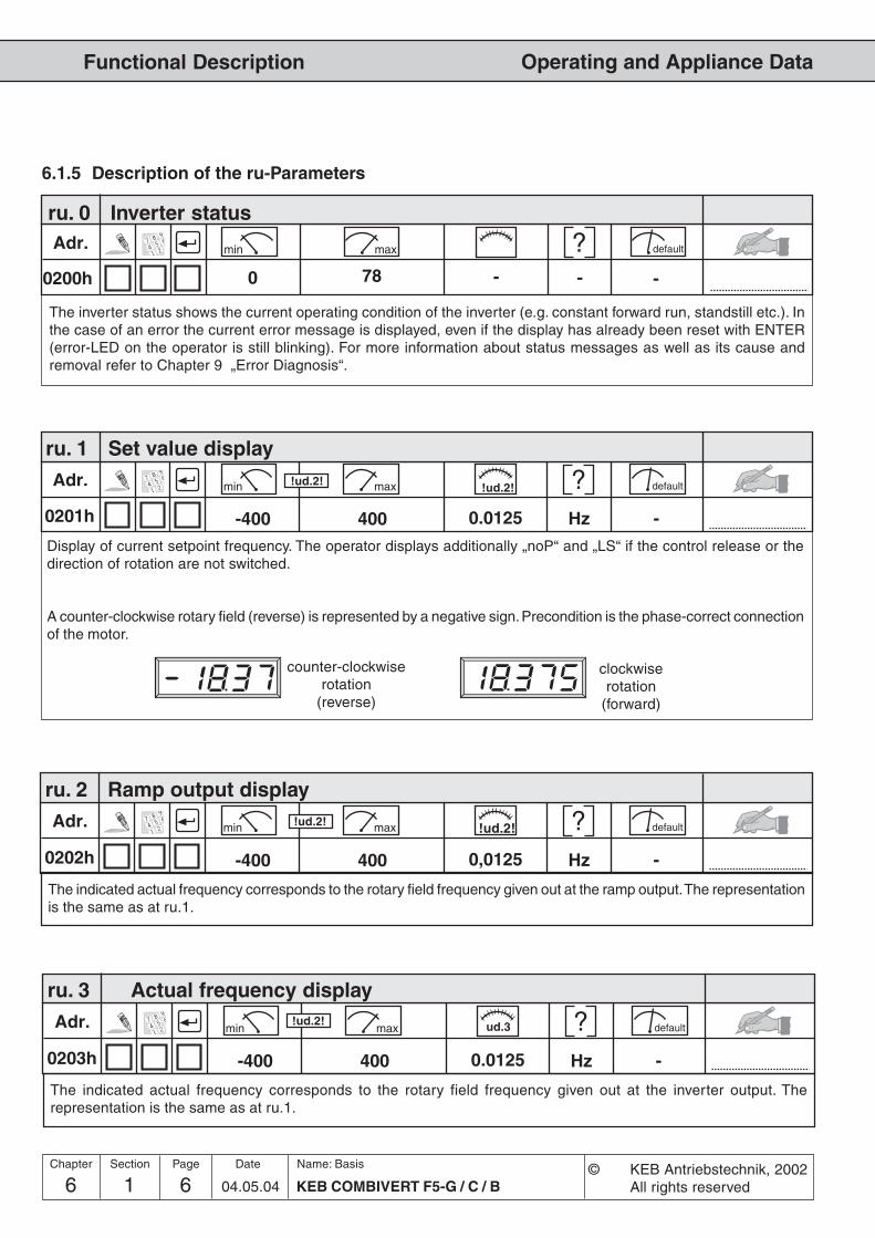
6 1Name: Basis
KEB COMBIVERT F5-G / C / B6 04.05.04
Functional Description
© KEB Antriebstechnik, 2002All rights reserved
Chapter Section Page Date
Operating and Appliance Data
Adr. min max default
Adr. min max default
ud.3!ud.2!
0201h
ru. 1 Set value display
0.0125 Hz -400-400Display of current setpoint frequency. The operator displays additionally „noP“ and „LS“ if the control release or thedirection of rotation are not switched.
A counter-clockwise rotary field (reverse) is represented by a negative sign. Precondition is the phase-correct connectionof the motor.
0203h
ru. 3 Actual frequency display
0.0125 Hz -400-400
The indicated actual frequency corresponds to the rotary field frequency given out at the inverter output. Therepresentation is the same as at ru.1.
clockwiserotation
(forward)
counter-clockwiserotation
(reverse)
!ud.2! !ud.2!
Adr. min max default
6.1.5 Description of the ru-Parameters
ru. 0 Inverter status
0200h 0 78 - - -
The inverter status shows the current operating condition of the inverter (e.g. constant forward run, standstill etc.). Inthe case of an error the current error message is displayed, even if the display has already been reset with ENTER(error-LED on the operator is still blinking). For more information about status messages as well as its cause andremoval refer to Chapter 9 „Error Diagnosis“.
Adr. min max default
0202h
ru. 2 Ramp output display
0,0125 Hz -400-400
The indicated actual frequency corresponds to the rotary field frequency given out at the ramp output. The representationis the same as at ru.1.
!ud.2!!ud.2!

6 1 704.05.04KEB COMBIVERT F5-G / C / B
Name: Basis
6
Functional Description
© KEB Antriebstechnik, 2002All rights reserved
Chapter Section PageDate
Operating and Appliance Data
Adr. min max default
0204h
ru. 4 Encoder 1 frequency
0,0125 Hz -400-400
!ud.2!!ud.2!
Adr. min max default
0205h
ru. 5 Encoder 2 frequency
0,0125 Hz -400-400
!ud.2!!ud.2!
Adr. min max default
0206h
ru. 6 Calculated actual frequency
0,0125 Hz -400-400
!ud.2!!ud.2!
Adr. min max default
0209h
ru. 9 Encoder 1 speed
0,125 rpm -4000-4000
!ud.2!!ud.2!
Adr. min max default
020Ah
ru.10Encoder 2 speed
0,125 rpm -4000-4000
!ud.2!!ud.2!
The displayed value corresponds to the actual frequency measured at the encoder input 1. The value „0“ is indicated,even if no encoder interface is available.
The displayed value corresponds to the actual frequency measured at the encoder input 2. The value „0“ is indicated,even if no encoder interface is available.
The displayed speed corresponds to the actual speed measured at the encoder input 1. The value „0“ is indicated,even if no encoder interface is available.
The displayed speed corresponds to the actual speed measured at the encoder input 2. The value „0“ is indicated,even if no encoder interface is available.
The displayed value corresponds to the actual frequency calculated from the inverter.
Adr. min max default
0207h
ru. 7 Actual value display
0,0125 Hz -400-400
The displayed value corresponds to the rotary field frequency given out at the inverter output (cS.0 Bit 0...2 = 0 or 1).At cS.0 Bit 0...2 = 2 the frequency of the channel selected in cS.1 is displayed (ru.4/5/6).
!ud.2!!ud.2!
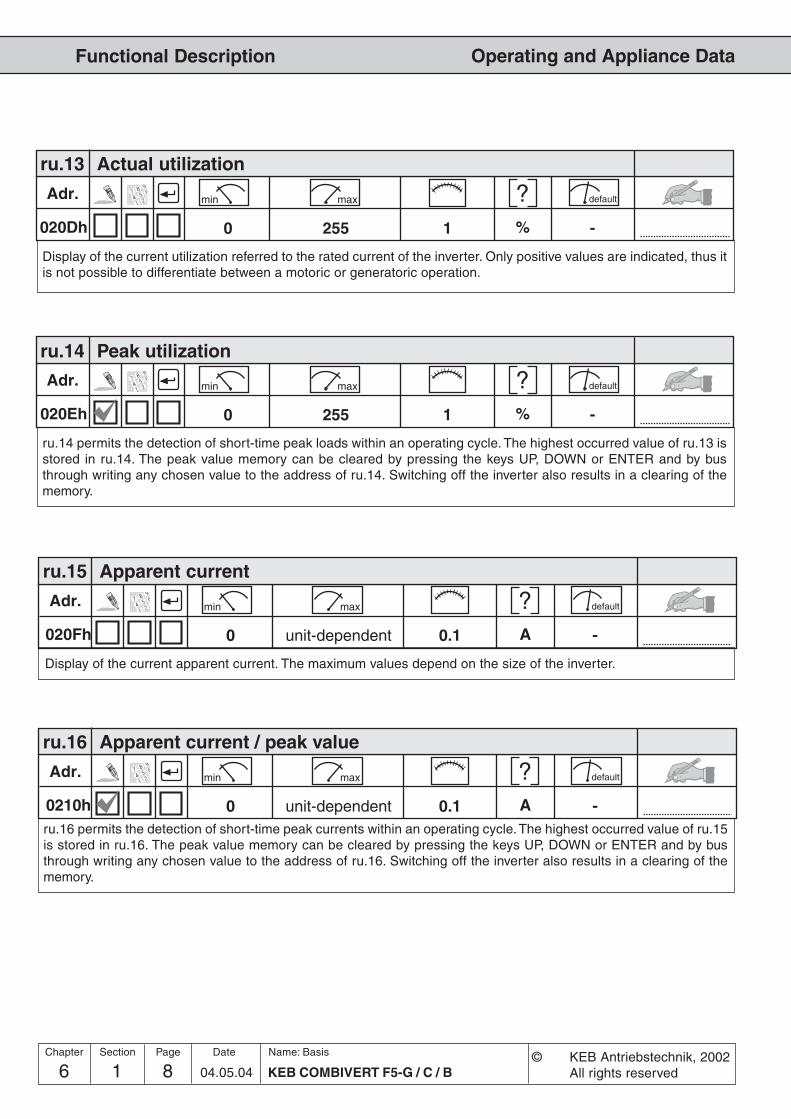
6 1Name: Basis
KEB COMBIVERT F5-G / C / B8 04.05.04
Functional Description
© KEB Antriebstechnik, 2002All rights reserved
Chapter Section Page Date
Operating and Appliance Data
Adr. min max default
0210h
ru.16 Apparent current / peak value
0.1 A -unit-dependent0ru.16 permits the detection of short-time peak currents within an operating cycle. The highest occurred value of ru.15is stored in ru.16. The peak value memory can be cleared by pressing the keys UP, DOWN or ENTER and by busthrough writing any chosen value to the address of ru.16. Switching off the inverter also results in a clearing of thememory.
Adr. min max default
Adr. min max default
020Dh
ru.13 Actual utilization
1 % -2550
Display of the current utilization referred to the rated current of the inverter. Only positive values are indicated, thus itis not possible to differentiate between a motoric or generatoric operation.
020Eh
ru.14 Peak utilization
1 % -2550
ru.14 permits the detection of short-time peak loads within an operating cycle. The highest occurred value of ru.13 isstored in ru.14. The peak value memory can be cleared by pressing the keys UP, DOWN or ENTER and by busthrough writing any chosen value to the address of ru.14. Switching off the inverter also results in a clearing of thememory.
Adr. min max default
020Fh
ru.15 Apparent current
0.1 A -unit-dependent0
Display of the current apparent current. The maximum values depend on the size of the inverter.

6 1 904.05.04KEB COMBIVERT F5-G / C / B
Name: Basis
6
Functional Description
© KEB Antriebstechnik, 2002All rights reserved
Chapter Section PageDate
Operating and Appliance Data
Adr. min max default
0211h
ru.17 Active current
0.1 A -+unit-dependent-unit-depend.
Display of the torque-forming active current (stator losses already deducted). Negative current corresponds togeneratoric operation, positive current corresponds to motoric operation. The more precise the motor data are ente-red, the more precise is the indication of the active current. The maximum values depend on the size of the inverter.
Adr. min max default
Adr. min max default
0212h
ru.18 DC-link voltage
1 V -10000
Display of current DC-link voltage. Typical values areNormal operation: 230V-class 300-330V over volt. (E.OP): approx. 400V under volt. (E.UP): approx. 216V
400V-class 530-620V approx. 800V approx. 240V
0213h
ru.19 DC-link voltage / peak value
1 V -10000
ru.19 permits the detection of short-time voltage rises within an operating cycle. The higest occurred value of ru.18 isstored in ru.19. The peak value memory can be cleared by pressing the keys UP, DOWN or ENTER and by busthrough writing any chosen value to the address of ru.19. Switching off the inverter also results in a clearing of thememory.
Adr. min max default
0214h
ru.20 Output voltage
1 V -7780
Display of the current output voltage.

6 1Name: Basis
KEB COMBIVERT F5-G / C / B10 04.05.04
Functional Description
© KEB Antriebstechnik, 2002All rights reserved
Chapter Section Page Date
Operating and Appliance Data
Adr. min max default
0216h
ru.22 Internal input state
1 - -40950
Display of the digital external and internal inputs set currently. The input is only regarded as set if it is available aseffective signal to the further processing (i.e. accepted through Strobe, edge-triggering or logic operation). Accordingto following table a specific decimal value is given out for each digital input. If several inputs are controlled, the sum ofthe decimal values (see ru.21) is indicated (also see Chapt. 6.3 „Digital inputs“)
Adr. min max default
0215h
ru.21 Input terminal state
1 - -40950
Display of the digital inputs controlled currently. The logic levels are indicated at the input terminals or at the internalinputs regardless of the following logic operations (also see Chapt. 6.3 „Digital inputs“). According to following table aspecific decimal value is given out for each digital input. If several inputs are controlled, the sum of the decimal valuesis indicated.
Bit -No. Decimal Value Input Terminal
0 1 ST (prog. input „control release/Reset“) X2A.16
1 2 RST (prog. input „Reset“) X2A.17
2 4 F (prog. input „forward“) X2A.14
3 8 R (prog. input „reverse“) X2A.15
4 16 I1 (prog. input 1) X2A.10
5 32 I2 (prog. input 2) X2A.11
6 64 I3 (prog. input 3) X2A.12
7 128 I4 (prog. input 4) X2A.13
8 256 IA (internal input A) none
9 512 IB (internal input B) none
10 1024 IC (internal input C) none
11 2048 ID (internal input D) none

6 1 1104.05.04KEB COMBIVERT F5-G / C / B
Name: Basis
6
Functional Description
© KEB Antriebstechnik, 2002All rights reserved
Chapter Section PageDate
Operating and Appliance Data
Adr. min max default
0217h
ru.23 Output condition state
1 - -2550
With parameters do.0...do.7 switching conditions can be selected, that serve as a base for setting the outputs. Thisparameter indicates which of the selected switching conditions are met before they are linked or inverted byprogrammable logic (also see Chapt. 6.3 „Digital outputs“). According to following table a specific decimal value isgiven out for the switching conditions. If several of the selected switching conditions are met, the sum of the decimalvalues is indicated.
Bit -No. Decimal value Output
0 1 switching condition 0 (do.0)
1 2 switching condition 1 (do.1)
2 4 switching condition 2 (do.2)
3 8 switching condition 3 (do.3)
4 16 switching condition 4 (do.4)
5 32 switching condition 5 (do.5)
6 64 switching condition 6 (do.6)
7 128 switching condition 7 (do.7)
Adr. min max default
0217h
ru.24 State of output flags
1 - -2550
Display of the links after logic step 1. The selected switching conditions are linked in logic step 1 (do.8...24) andindicated here (see Chapt. 6.3 „Digital outputs“). According to following table a specific decimal value is given out foreach linkage. If several links are set, the sum of the decimal values is indicated.
Bit -No. Decimal value Output
0 1 flag 0
1 2 flag 1
2 4 flag 2
3 8 flag 3
4 16 flag 4
5 32 flag 5
6 64 flag 6
7 128 flag 7

6 1Name: Basis
KEB COMBIVERT F5-G / C / B12 04.05.04
Functional Description
© KEB Antriebstechnik, 2002All rights reserved
Chapter Section Page Date
Operating and Appliance Data
Adr. min max default
021Ah
ru.26 Active parameter set
1 - -70
The frequency inverter F5-GENERALand F5-BASIC can fall back on 8 internal parameter sets (0-7). Throughprogramming the inverter can change parameter sets autonomously and can thus start different modes of operation.This parameter shows the parameter set, with which the inverter is operating currently. Independent of it anotherparameter set can be edited by bus (also see chapter 6.8 „Parameter sets“).
Adr. min max default
021Bh
ru.27 Analog input 1 / display before amplification
0.1 % -100-100
This parameter indicates the value of the analog signal AN1 on the differential voltage input (terminal X2A.1 / X2A.2)before signal amplification in percent. In dependence on An.0 the indicated value 0...±100 % corresponds to: 0...±10 V;0...±20 mA or 4...20 mA (also see Chapt. 6.2 „Analog inputs“).
Adr. min max default
021Ch
ru.28 Analog input 1 / display after amplification
0.1 % -400-400
This parameter shows the value of the analog signal AN1 in percent after passing the characteristic amplifier. Therange of indication is limited to ±400 % (also see Chapt. 6.2 „Analog inputs“).
Adr. min max default
0218h
ru.25 Output terminal state
1 - -2550
Display of the external and internal digital output set currently. According to following table a specific decimal value isgiven out for each digital output. If several outputs are set, the sum of the decimal values is indicated.
Bit -No. Decimal value Output Terminal
0 1 O1 (transistor output 1) X2A.18
1 2 O2 (transistor output 2) X2A.19
2 4 R1 (relay RLA,RLB,RLC) X2A.24...26
3 8 R2 (relay FLA,FLB,FLC) X2A.27...29
4 16 OA (internal output A) none
5 32 OB (internal output B) none
6 64 OC (internal output C) none
7 128 OD (internal output D) none
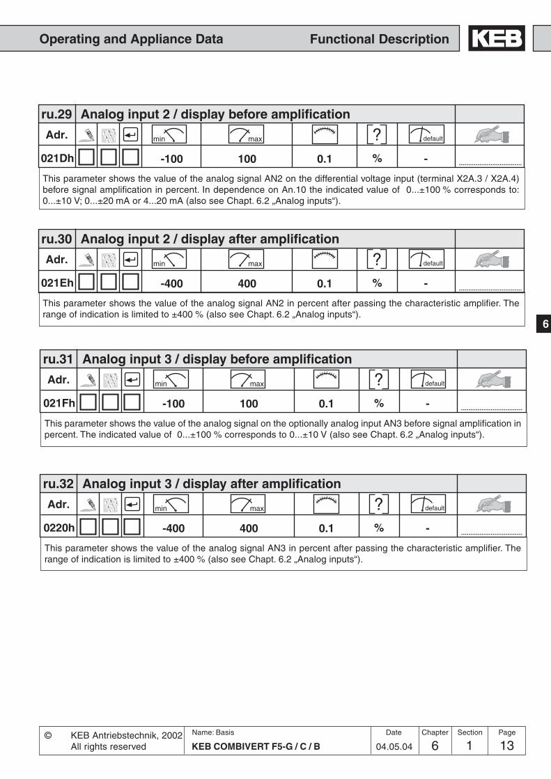
6 1 1304.05.04KEB COMBIVERT F5-G / C / B
Name: Basis
6
Functional Description
© KEB Antriebstechnik, 2002All rights reserved
Chapter Section PageDate
Operating and Appliance Data
Adr. min max default
021Dh
ru.29 Analog input 2 / display before amplification
0.1 % -100-100
This parameter shows the value of the analog signal AN2 on the differential voltage input (terminal X2A.3 / X2A.4)before signal amplification in percent. In dependence on An.10 the indicated value of 0...±100 % corresponds to:0...±10 V; 0...±20 mA or 4...20 mA (also see Chapt. 6.2 „Analog inputs“).
Adr. min max default
021Eh
ru.30 Analog input 2 / display after amplification
0.1 % -400-400
This parameter shows the value of the analog signal AN2 in percent after passing the characteristic amplifier. Therange of indication is limited to ±400 % (also see Chapt. 6.2 „Analog inputs“).
Adr. min max default
021Fh
ru.31 Analog input 3 / display before amplification
0.1 % -100-100
This parameter shows the value of the analog signal on the optionally analog input AN3 before signal amplification inpercent. The indicated value of 0...±100 % corresponds to 0...±10 V (also see Chapt. 6.2 „Analog inputs“).
Adr. min max default
0220h
ru.32 Analog input 3 / display after amplification
0.1 % -400-400
This parameter shows the value of the analog signal AN3 in percent after passing the characteristic amplifier. Therange of indication is limited to ±400 % (also see Chapt. 6.2 „Analog inputs“).
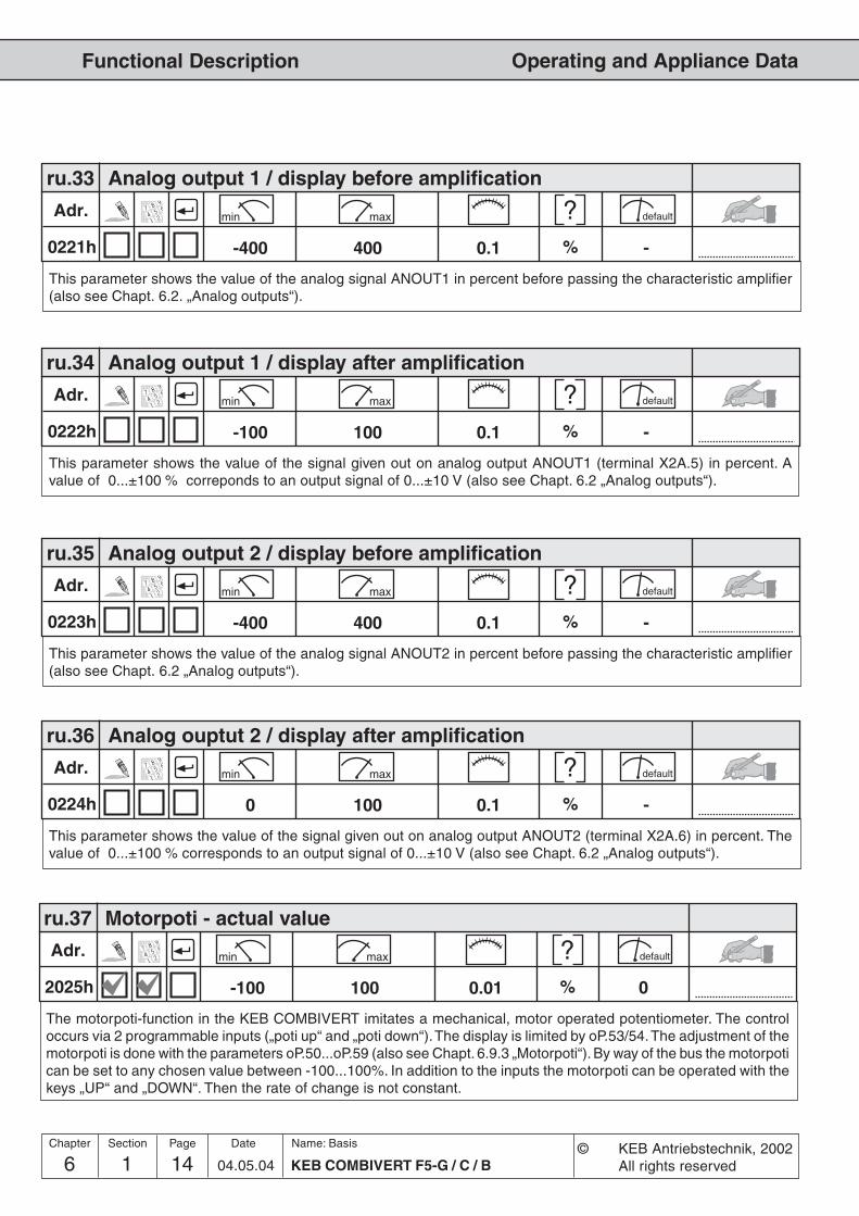
6 1Name: Basis
KEB COMBIVERT F5-G / C / B14 04.05.04
Functional Description
© KEB Antriebstechnik, 2002All rights reserved
Chapter Section Page Date
Operating and Appliance Data
Adr. min max default
0223h
ru.35 Analog output 2 / display before amplification
0.1 % -400-400
This parameter shows the value of the analog signal ANOUT2 in percent before passing the characteristic amplifier(also see Chapt. 6.2 „Analog outputs“).
Adr. min max default
0224h
ru.36 Analog ouptut 2 / display after amplification
0.1 % -1000
This parameter shows the value of the signal given out on analog output ANOUT2 (terminal X2A.6) in percent. Thevalue of 0...±100 % corresponds to an output signal of 0...±10 V (also see Chapt. 6.2 „Analog outputs“).
Adr. min max default
2025h
ru.37 Motorpoti - actual value
0.01 % 0100-100
The motorpoti-function in the KEB COMBIVERT imitates a mechanical, motor operated potentiometer. The controloccurs via 2 programmable inputs („poti up“ and „poti down“). The display is limited by oP.53/54. The adjustment of themotorpoti is done with the parameters oP.50...oP.59 (also see Chapt. 6.9.3 „Motorpoti“). By way of the bus the motorpotican be set to any chosen value between -100...100%. In addition to the inputs the motorpoti can be operated with thekeys „UP“ and „DOWN“. Then the rate of change is not constant.
Adr. min max default
0221h
ru.33 Analog output 1 / display before amplification
0.1 % -400-400
This parameter shows the value of the analog signal ANOUT1 in percent before passing the characteristic amplifier(also see Chapt. 6.2. „Analog outputs“).
Adr. min max default
0222h
ru.34 Analog output 1 / display after amplification
0.1 % -100-100
This parameter shows the value of the signal given out on analog output ANOUT1 (terminal X2A.5) in percent. Avalue of 0...±100 % correponds to an output signal of 0...±10 V (also see Chapt. 6.2 „Analog outputs“).

6 1 1504.05.04KEB COMBIVERT F5-G / C / B
Name: Basis
6
Functional Description
© KEB Antriebstechnik, 2002All rights reserved
Chapter Section PageDate
Operating and Appliance Data
Adr. min max default
022Ah
ru.42 Modulation factor
1 % -1100
The modulation factor shows the output voltage in percent. 100 % correspond to the input voltage (no-load). At avalue of > 100 % the inverter works with overmodulation.
Adr. min max default
Adr. min max default
Adr. min max default
Adr. min max default
0227h
ru.39 OL - counter display
1 % -1000
In order to preclude „E.OL“ - errors by too high load (load reduction in due time), the internal count of the OL-countercan be made visible with this indication. At 100 % the inverter switches off with error „E.OL“. The error can be resetonly after a cooling time (blinking display „E.nOL“).
0226h
ru.38 Power module temperature
1 °C -1500
ru.38 shows the current power moduls temperature of the inverter.
0228h
ru.40 Operating hours meter
1 h -655350
The operating hours meter shows the time the inverter was switched on. The indicated value comprises all operatingphases. On reaching the maximum value (approx. 7.5 years) the indication remains on the maximum value.
0229h
ru.41 Modulation hours meter
1 h -655350
The modulation hours meter shows the time the inverter was active (power modules controlled). On reaching themaximum value (approx. 7.5 years) the indication remains on the maximum value.
Adr. min max default
022Bh
ru.43 Timer 1 / display
0.01 s / h -655.350
The count of the free-programmable timer 1 is indicated. The display is done either in seconds, in hours or in slopes/100 (see LE.21). The counter can a adjusted to any chosen value by keyboard or bus. The programming of thecounter is done with the parameters LE.17...LE.21 (also see Chapt. 6.9.4 „Timer“).

6 1Name: Basis
KEB COMBIVERT F5-G / C / B16 04.05.04
Functional Description
© KEB Antriebstechnik, 2002All rights reserved
Chapter Section Page Date
Operating and Appliance Data
Adr. min max default
022Dh
ru.45 Actual switching frequency
1 - -40
Shows the current switching frequency of the inverter. The displayed value corresponds to following switchingfrequencies:
0 = 2 kHz 3 = 12 kHz1 = 4 kHz 4 = 16 kHz2 = 8 kHz
Adr. min max default
022Ch
ru.44 Timer 2 / display
0.01 s / h -655.350
The count of the free-programmable timer 2 is indicated. The display is done either in seconds, in hours or in slopes/100 (see LE.26). The counter can be adjusted to any chosen value by keyboard or bus. The programming of thecounter is done with the parameters LE.22...LE.26 (also see Chapt. 6.9.4 „Timer“).
Adr. min max default
0234h
ru.52 External PID out display
0,1 % -100,0-100,0A universal PI-controller is integrated into the inverter. It can be used externally as well as internally. The indicatedmanipulated variable is given out in a range of ±100 %.
Adr. min max default
0235h
ru.53 AUX display
0,1 % -400,0-400,0
The AUX input is setting with An.30. This parameter shows the value of the analog signal AUX in percent. The rangeof indication is limited to ±400 % (also see Chapt. 6.2 „Analog inputs“).
Adr. min max default
022Eh
ru.46 Motor temperature (optionally)
1 °C -2550
Indicates the current motor temperature. Precondition for this function is aspecial power circuit. The temperaturedetection is connected to the terminals T1/T2.0: T1/T2 closed 253, 254: broken cable; short circuit; detection error255: T1/T2 open
This parameter shows the rated DC-link voltage automatically determined by the inverter. The value is measured atswitch-on.
Adr. min max default
0244h
ru.68 Rated DC voltage
1 V -10000

6 1 1704.05.04KEB COMBIVERT F5-G / C / B
Name: Basis
6
Functional Description
© KEB Antriebstechnik, 2002All rights reserved
Chapter Section PageDate
Operating and Appliance Data
Adr. min max default
0247h
ru.71 Teach/ scan position
1 inc. 02^31-1-2^31
This parameter displays the current teach position. This position remains until a new position is teached.
Adr. min max default
0245h
ru.69 Distance ref.- zeropoint
1 inc. 02^31-1-2^31
Adr. min max default
024Ah
ru.74 Act. torque in percent
0,1 % 0100,0-100,0
This parameter displays the actual torque display (ru.12) in percent at the input referring to the absolute torquereference (cs.19).
Adr. min max default
024Eh
ru.78 Act. val. display in perc.
0,1 % 0100,0-100,0
Adr. min max default
0249h
ru.73 Set torque in percent
0,1 % 0100,0-100,0
This parameter displays the set torque (ru.11) in percent at the input referring to the absolute torque reference(cs.19).
In order to protect the inverter against overvoltage in the field weakening range, an EMK dependent speed should notbe exceeded. This calculated value has priority to all other limits. It is is displayed in ru.79.
Adr. min max default
024Fh
ru.79 Abs. speed value (EMK)
n*-125 rpm 0n*4000n*-4000
This parameter displays the distance to the zeropoint after relieve the reference switch.
This parameter displays the actual value display (ru.7) in percent referring to the max. reference forward (oP.10).

6 1Name: Basis
KEB COMBIVERT F5-G / C / B18 04.05.04
Functional Description
© KEB Antriebstechnik, 2002All rights reserved
Chapter Section Page Date
Operating and Appliance Data
Adr. min max default
0250h
ru.80 Digital output state
1 - 02550
The active power of the inverter is displayed with parameter ru.81. Negative values are displayed during generatoricoperation
Adr. min max default
0251h
ru.81 Active power
0,00 kW 0,00400,00-400,00
With do.51 the digital output signals can be assigned to the hardware outputs (see chapter 6.3.). This parametershows the digital output state of the output signals in accordance with the following table. If several outputs are set,the sum of the decimal values is indicated.
Bit -No. Decimal value Output Terminal
0 1 O1 (Transistor output 1) X2A.18
1 2 O2 (Transistor output 2) X2A.19
2 4 R1 (Relay RLA,RLB,RLC) X2A.24...26
3 8 R2 (Relay FLA,FLB,FLC) X2A.27...29
4 16 OA (Internal output A) no
5 32 OB (Internal output B) no
6 64 OC (Internal output C) no
7 128 OD (Internal output D) no

6 1 1904.05.04KEB COMBIVERT F5-G / C / B
Name: Basis
6
Functional Description
© KEB Antriebstechnik, 2002All rights reserved
Chapter Section PageDate
Operating and Appliance Data
Adr. min max default
Adr. min max default
0E01h 0.1 A -7100
6.1.6 Description of the In-Parameters
0E00h
In. 0 Inverter type
1 hex -FFFFh0h
The inverter type is displayed in hexadecimal numbers. The bits have following meaning:
Bit 0-4 Unit size 05, 07, 09 etc.
Bit 5 Voltage class 0 = 230 V1 = 400 V
Bit 6 Phase number 0 = 1-phase1 = 3-phase
Bit 7 free
Bit 8-12 Housing 0 = A 10 = K 20 = U1 = B 11 = L 21 = V2 = C 12 = M 22 = W3 = D 13 = N 23 = X4 = E 14 = O 24 = Y5 = F 15 = P 25 = Z6 = G 16 = Q7 = H 17 = R8 = I 18 = S9 = J 19 = T
Bit 13-15 Control 0 = G1 = M2 = B3 = S4 = A5 = C6 = R
Example:hex 0 4 0 Abinary 0 0 0 0 0 1 0 0 0 0 0 0 1 0 1 0decimal 0 4 0 0 10
=> 10.F5 G-Control / E-housing / 230V / 1ph.
In. 1 Rated inverter current
Display of the rated inverter current in A. The value is determined from the power circuit identification (P-ID) andcannot be changed.

6 1Name: Basis
KEB COMBIVERT F5-G / C / B20 04.05.04
Functional Description
© KEB Antriebstechnik, 2002All rights reserved
Chapter Section Page Date
Operating and Appliance Data
Adr. min max default
0E03h
Adr. min max default
0E06h
Adr. min max default
0E07h
0.01 - -9.990.00
0.1 - ---
1 - P-ID40Display of the maximum possible switching frequency in kHz for this inverter. The displayed value corresponds tofollowing switching frequencies:
0: 2 kHz / 1: 4 kHz / 2: 8 kHz / 3: 12 kHz / 4: 16 kHz
In. 3 Max. switching frequency
Display of the software version number..1. and 2. digit: Software version (z.B. 2.1)3. digit: Special version (0 = standard)
In. 6 Software version
Display of the software date. The value contains day, month and year, from the year only the last digit is indicated.Example: Display = 2102.0
Date = 21.02.2000
In. 7 Software date
Adr. min max default
0E04h 1 - P-ID40Display of the rated switching frequency. The displayed value corresponds to the following switching frequencies:
0: 2 kHz / 1: 4 kHz / 2: 8 kHz / 3: 12 kHz / 4: 16 kHz
In. 4 Rated switching frequency

6 1 2104.05.04KEB COMBIVERT F5-G / C / B
Name: Basis
6
Functional Description
© KEB Antriebstechnik, 2002All rights reserved
Chapter Section PageDate
Operating and Appliance Data
Adr. min max default
0E09h 0.1 - ---Display of the software date of the power section. Display and value range like at In.7.
In. 9 Software date LT
Adr. min max default
1 - 0655350s.a.
In.10 Serial number / date 0E0AhIn.11 Serial number / counter 0E0BhIn.12 Serial number / Ackn.-No. high 0E0ChIn.13 Serial number / Ackn.-No. low 0E0DhIn.14 Customer number / high 0E0EhIn.15 Customer numer / low 0E0FhIn.16 QS-number 0E10h
The serial number and the customer number identify the inverter. The QS-number contains production internalinformation.
Adr. min max default
0E08h 0.01 - -9.990.00
In. 8 Software version LT
This parameter shows the software version of the power section. Definition like at In.6.
Adr. min max default
0E11h 1 - P-IDP-ID0
In.17 Temperature mode
This parameter is for service personell only.

6 1Name: Basis
KEB COMBIVERT F5-G / C / B22 04.05.04
Functional Description
© KEB Antriebstechnik, 2002All rights reserved
Chapter Section Page Date
Operating and Appliance Data
Adr. min max default
0E19h 1 - 4095655350Shows the last 8 errors that occurred (in the sets 0...7). The oldest error is in set 7. Between errors of the same typea difference time is determined and stored too.
Bit 0...11 Value 0...4094 difference time minutesValue 4095 difference time > 4094 minutes
Bit 12...15 Value Error type Value Error type Value Error type0 no error 3 E.OP 6...15 free1 E.OC 4 E.OH2 E.OL 5 E.OHI
In.25 Error diagnosis
Adr. min max default
1 - 0655350
In.26 Error counter OC 0E1AhIn.27 Error counter OL 0E1BhIn.28 Error counter OP 0E1ChIn.29 Error counter OH 0E1DhIn.30 Error counter OHI 0E1Eh
The error counters (for E.OC, E.OL, E.OP, E.OH, E.OHI) specify the total number of errors of each error type.
s.o.
Adr. min max default
0E17h 1 - 0655350
In.23 User parameter 2
This parameter is not assigned to any function and is available to the user for input.
Adr. min max default
0E18h 1 - -2550In.24 shows the last error that occurred.E. UP is not stored. The error messages are described at chapter 9.
In.24 Last error
Adr. min max default
0E16h 1 - 0655350
In.22 User parameter 1
This parameter is not assigned to any function and is available to the user for input.

6 1 2304.05.04KEB COMBIVERT F5-G / C / B
Name: Basis
6
Functional Description
© KEB Antriebstechnik, 2002All rights reserved
Chapter Section PageDate
Operating and Appliance Data
6.1.7 Description of the Sy-Parameters
Adr. min max default
0002h 1 hex -99990000
Sy. 2 Inverter identifier
A unique number is assigned to each type of frequency inverter which identifies the hard- and software. This value isused for example by COMBIVIS to load the correct configuration files. Sy.2 kann mit dem angezeigten Wert beschrie-ben werden (z.B. zur Identifikation von Downloadlisten).
Adr. min max default
0003h 1 P-ID -255-255
Sy. 3 Power unit code
On the basis of the power circuit identification the control recognizes the used power circuit respectively a change ofthe power circuit and adjusts certain parameters accordingly. To accept a new P-Id enter positive values (see chap. 9„E.Puch“).
Adr. min max default
0006h 1 - 12390
Sy. 6 Inverter address
With Sy.6 the address is adjusted under which the inverter is addressed by „COMBIVIS“ or another control. Thepossible values are between 0 and 239, the default value is 1. If several inverters are operated simulaneously on thebus, it is absolutely necessary to assign different addresses, since otherwise communication problems arise becauseseveral inverters may responded at the same time. The development info DIN 66019II protocol (C0.F5.01I-K001)contains further information.
Adr. min max default
0007h 1 - 560
Sy. 7 Baud rate ext. bus
Following values are possible for the baudrate of the serial interface:
Parameter value Baudrate0 1200 baud1 2400 baud2 4800 baud
3 (default) 9600 baud4 19200 baud5 38400 baud6 55500 baud
If the value for the baudrate is changed over the serial interface, it can only be changed again by way of the keyboardor after adapting the baudrate of the master, since no communication is possible in the case of different baudratesbetween master and slave.If problems occur during the data transmission, select a baudrate up to max. 38400 baud.

6 1Name: Basis
KEB COMBIVERT F5-G / C / B24 04.05.04
Functional Description
© KEB Antriebstechnik, 2002All rights reserved
Chapter Section Page Date
Operating and Appliance Data
Adr. min max default
000Bh 1 - 5113
Sy. 11 Baud rate int. bus
With the internal baudrate the transmission rate between operator and inverter is determined. Following values arepossible:
Value Baudrate Value Baudrate Value Baudrate3 9,6 kBaud 6 55,5 kBaud 9 115,2 kBaud4 19,2 kBaud 7 57,6 kBaud 10 125 kBaud5 38,4 kBaud 8 100 kBaud 11 250 kBaud
Adr. min max default
0020h 1 - 0655350
Sy. 32 Scope Timer
The scope timer generates a time period of 1 ms. This can be used by external programs, e.g. Scope, to representtime patterns. The timer counts from 0...65535 and starts again with 0 after an overflow.
Adr. min max default
0009h 0,01 s 0 (off)10,000 (off)
Sy. 9 HSP5 Watchdaog time
The HSP5 Watchdog-function monitores the communication of the HSP5-interface (control card - operator; or controlcard - PC). After expiration of an adjustable time (0,01...10 s) without incoming telegrams, the response adjusted inPn.5 is triggered. The value „off“ deactivates the function.
Adr. min max default
0029h 1 - 0655350
Sy. 41 Control word high
The control word is used for the status control of the inverter via bus. The control word long (Sy.43) consists of the two16 bit parameters control word high (Sy.41) and Control word low (Sy.50). The status word is bit-coded. The descriptionof the individual bits is found in Chapter 11.2.7.
Adr. min max default
002Ah 1 - 0655350
Sy. 42 Status word high
With the status word the current condition of the inverter can be readout. The status word long (Sy.44) consists of thetwo 16 bit parameters status word high (Sy.42) and status word low (Sy.51). The status word is bit-coded. Thedescription of the individual bits is found in Chapter 11.2.7.

6 1 2504.05.04KEB COMBIVERT F5-G / C / B
Name: Basis
6
Functional Description
© KEB Antriebstechnik, 2002All rights reserved
Chapter Section PageDate
Operating and Appliance Data
Adr. min max default
0032h 1 - 0655350
Sy. 50 Control word
The control word is used for the status control of the inverter via bus. The control word long (Sy.43) consists of the two16 bit parameters control word high (Sy.41) and Control word low (Sy.50). Das Steuerwort ist bitcodiert. The statusword is bit-coded. The description of the individual bits is found in Chapter 11.2.7.
Adr. min max default
0033h 1 - 0655350
Sy. 51 Status word
With the status word the current condition of the inverter can be readout. The status word long (Sy.44) consists of thetwo 16 bit parameters status word high (Sy.42) and status word low (Sy.51). Das Steuerwort ist bitcodiert. The statusword is bit-coded. The description of the individual bits is found in Chapter 11.2.7.
Adr. min max default
0034h 1 rpm 016000-16000
Sy. 52 Set speed value
Presetting of the setpoint speed in the range of ±16000 rpm. The source of direction of rotation is determined as withthe other absolute setpoint sources over oP.1. The setpoint source oP.0 must be adjusted to „5“ for setpoint setting bySy.52.
Adr. min max default
002Bh 1 - 02147483647-2147483648
Sy. 43 Control word long
The control word is used for the status control of the inverter via bus. The control word long (Sy.43) consists of the two16 bit parameters control word high (Sy.41) and Control word low (Sy.50). The status word is bit-coded. The descriptionof the individual bits is found in Chapter 11.2.7.
Adr. min max default
002Ch 1 - 0
Sy. 44 Status word long
With the status word the current condition of the inverter can be readout. The status word long (Sy.44) consists of thetwo 16 bit parameters status word high (Sy.42) and status word low (Sy.51). The status word is bit-coded. The descriptionof the individual bits is found in Chapter 11.2.7.
2147483647-2147483648

6 1Name: Basis
KEB COMBIVERT F5-G / C / B26 04.05.04
Functional Description
© KEB Antriebstechnik, 2002All rights reserved
Chapter Section Page Date
Operating and Appliance Data
Adr. min max default
0035h 1 rpm 016000-16000
Sy. 53 Actual speed value
With this parameter the current actual speed can be readout in rpm. The direction of rotation is signaled by the sign.
Adr. min max default
0038h 1 hex 02037FFF0
Sy. 56 Start display address
Sy.56 adjusts the parameter address which shall be represented on switching on the operator. Only valid addressesare accepted.If this parameters is available in the CP-Mode, the setting becomes effective there. Otherwise CP.0 is indicated asstart parameter.

Functional Description
1. Introduction
2. Summary
3. Hardware
4. Operation
5. Parameter
6. Functions
7. Start-up
8. Special Operation
9. Error Assistance
10. Project Planning
11. Networks
12. Annex
6.1 Operating and Applicance
Date
6.2 Analog In- and Outputs
6.3 Digital In- and Outputs
6.4 Set Value and Ramp
Adjustment
6.5 Voltage-/Frequency
Characteristic (U/f)
Adjustment
6.6 Motor Data Adjustment
6.7 Protective Functions
6.8 Parameter Sets
6.9 Special Functions
6.10 Encoder Interface
6.11 SMM, Posi, Synchron
6.12 Technology Control
6.13 CP-Parameter Definition
6 2 1KEB COMBIVERT F5
Name: Basis Chapter Section PageDate© KEB Antriebstechnik, 2002All rights reserved 26.08.04
6.2.1 Summary DescriptionAnalog Inputs ......................... 3
6.2.2 Interface Selection ................. 46.2.3 Interference Suppression Filter
56.2.4 Save mode ............................. 56.2.5 Input selection ........................ 56.2.6 Zero point hysteresis ............. 66.2.7 Amplifier of the Input
Characteristic ......................... 76.2.8 Lower and Upper Limit ........... 86.2.9 Selection Set Point-/
Auxiliary Input ........................ 96.2.10 Summary Description
Analog Outputs .................... 106.2.11 Output Signals ..................... 116.2.12 Analog Output / Functions ... 116.2.13 Analog Output / Display ....... 116.2.14 Amplifier of the Output
Characteristic ....................... 116.2.15 Period ANOUT3 ................... 136.2.16 Digital Settings ..................... 136.2.17 Used Parameters ................. 14

Functional Description Analog In- and Outputs
2 26Name: Basis
KEB COMBIVERT F5
Chapter Section Page Date
26.08.04© KEB Antriebstechnik, 2002
All rights reserved
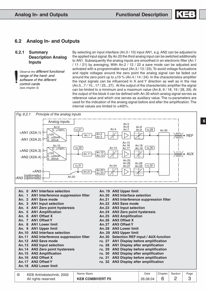
6
Functional DescriptionAnalog In- and Outputs
6 2 3KEB COMBIVERT F5
Name: Basis Chapter Section PageDate© KEB Antriebstechnik, 2002All rights reserved 26.08.04
6.2.1 SummaryDescription AnalogInputs
6.2 Analog In- and Outputs
By selecting an input interface (An.0 / 10) input AN1, e.g. AN2 can be adjusted tothe applied input signal. By An.20 the third analog input can be switched additionallyto AN1. Subsequently the analog inputs are smoothed in an electronic filter (An.1/ 11 / 21) by averaging. With An.2 / 12 / 22 a save mode can be adjusted andactivated with a programmable input (An.3 / 13 / 23). To avoid voltage fluctuationsand ripple voltages around the zero point the analog signal can be faded outaround the zero point up to ±10 % (An.4 / 14 / 24). In the characteristics amplifierthe input signals can be influenced in X and Y direction as well as in the rise(An.5...7 / 15...17 / 25...27). At the output of the characteristic amplifier the signalcan be limited to a minimum and a maximum value (An.8, 9 / 18, 19 / 28, 29). Atthe output of the block it can be defined with An.30 which analog signal serves asreference value and which one serves as auxiliary value. The ru-parameters areused for the indication of the analog signal before and after the amplification. Theinternal values are limited to ±400%.
Fig. 6.2.1 Principle of the analog inputs
Analog inputs
An. 0 AN1 Interface selectionAn. 1 AN1 Interference suppression filterAn. 2 AN1 Save modeAn. 3 AN1 Input selectionAn. 4 AN1 Zero point hysteresisAn. 5 AN1 AmplificationAn. 6 AN1 Offset XAn. 7 AN1 Offset YAn. 8 AN1 Lower limitAn. 9 AN1 Upper limitAn.10 AN2 Interface selectionAn.11 AN2 Interference suppression filterAn.12 AN2 Save modeAn.13 AN2 Input selectionAn.14 AN2 Zero point hysteresisAn.15 AN2 AmplificationAn.16 AN2 Offset XAn.17 AN2 Offset YAn.18 AN2 Lower limit
An. 19 AN2 Upper limitAn.20 AN3 Interface selectionAn.21 AN3 Interference suppression filterAn.22 AN3 Save modeAn.23 AN3 Input selectionAn.24 AN3 Zero point hysteresisAn.25 AN3 AmplificationAn.26 AN3 Offset XAn.27 AN3 Offset YAn.28 AN3 Lower limitAn. 29 AN3 Upper limitAn.30 Selection REF-input / AUX-functionru. 27 AN1 Display before amplificationru. 28 AN1 Display after amplificationru. 29 AN2 Display before amplificationru. 30 AN2 Display after amplificationru. 31 AN3 Display before amplificationru. 32 AN3 Display after amplification
400%
-400%
400%
-400%
An.18An.19
An.1
An.11
An.4
An.14ru.29An.10
An.5An.6An.7
An.15An.16An.17
An.8An.9
ru.30
An.30ru.27 ru.28
0...±100%
An.00...±100%
±10V0...±20mA4...20mA
±10V0...±20mA4...20mA
An.28An.29
An.21
An.24ru.31
An.25An.26An.27 ru.32
An.20
An.12An.13
An.2An.3
An.22An.23
+AN1 (X2A.1)REF
AUX
-AN1 (X2A.2)
+AN2 (X2A.3)
-AN2 (X2A.4)
+AN3(optionally)
-AN3 (optionally)
Observe the different functionalrange of the hard- andsoftware of the differentcontrol cards(see chapter 3).

Functional Description Analog In- and Outputs
2 46Name: Basis
KEB COMBIVERT F5
Chapter Section Page Date
26.08.04© KEB Antriebstechnik, 2002
All rights reserved
X2A. 1 2 3 4 5 6 7 8 9
R = 3...10 k�
PE
0...10V DCRi=30kW(An.0 / An.10 = 0)
6.2.2 Interface Selection(An.0; An.10)
Fig. 6.2.2.a Connection as differential voltage inputs 0...±10V DC
The output CRF Kl. X2A.7 maybe loaded with maximal 6mA!
Depending on the selected interface (An.0/An.10) the analog inputs AN1 and AN2can process following input signals:
An.0 / An.10= 0 0...±10 V (default)= 1 0...±20 mA= 2 4...20 mA
Fig. 6.2.2.b Control with potentiometer and internal reference voltage
X2A. 1 2 3 4 5 6 7 8 9 PE
0...±10 VDC
+ -SPS
+ -SPS
1)
1) Connect equipotential bonding conductor only, if a potential difference of> 30V exists between the controls. The internal resistance is reduced to 30kOhm.
X2A. 1 2 3 4 5 6 7 8 9
+0...±20 mADC4...20 mADCRi = 250 Ω
PE
+An.0 / An.10 = 1 or 2
Fig. 6.2.2.c Control with current signal
Interface Selection(An.20)
With An.20 it is determined from where the 3. analog setpoint signal is received.Following values can be defined:
Value Function0 Analog value from the optional analog input (default)1 Analog value via the terminals of AN1
Ri = 55 kOhm

6
Functional DescriptionAnalog In- and Outputs
6 2 5KEB COMBIVERT F5
Name: Basis Chapter Section PageDate© KEB Antriebstechnik, 2002All rights reserved 26.08.04
6.2.3 InterferenceSuppressionFilter (An.1;An.11; An.21)
The interference suppression filters shall suppress disturbances and ripples of theinput signals. If the interference suppression filter is switched off the analog inputsare queried every 1 ms (control card BASIC 2 ms) and the recorded value is thentransferred. With the interference suppression filters the inputs can now be queried2-, 4-, 8- or 16-times. From these values an average value is determined which isthen transferred.
An.1 / 11 / 21 Function0 no averaging (default)1 averaging over 2 values2 averaging over 4 values3 averaging over 8 values4 averaging over 16 values
6.2.4 Save Mode (An.2;An.12; An.22)
6.2.5 Input Selection(An.3; An.13;An.23)
Coming from the input filter the save mode can be switched on with An.2 / An.12 /An.22. If now the programmable digital input (value 1) is set the analog signal isprocessed directly and written parallel into the nonvolatile memory. As soon as thedigital input is disconnected (value 0), the inverter continous to run with value storedin the memory. Moreover, with An.2 / An.12 / An.22 it can be determined whether thememory contents are saved or deleted upon switch off. The parameter is bit-coded,the sum of the decimal values must be entered.
Bild 6.2.4 Save mode
With An.3 / 13 / 23 the digital inputs for storing are selected according to the table onthe next page (also see Chapter 6.3.11 „Assignment of inputs“). In order to save ananalog value, the save mode (An.2 / 12 / 22 = 1) must be switched on under An2 / 12/ 22 and the selected input must be activated.
0
1
0
1
1
0
An.2/12/22 Bit 00: Direct mode1: Save mode
Bit Dez. Meaning0 0 Direct mode (default)
1 Save mode
1 0 Do not delete memory contents at switch off (default)2 Delete memory contents at switch off
frominput filter
nonvolatilememory
to thecharacteristicamplifier
Input selectiion An.3/13/23Input inactive: Value is not savedInput active: Value is saved
An2/12/22 Bit 11: delete0: do not delete

Functional Description Analog In- and Outputs
2 66Name: Basis
KEB COMBIVERT F5
Chapter Section Page Date
26.08.04© KEB Antriebstechnik, 2002
All rights reserved
-10%10%
10%
-10%
6.2.6 Zero Point Hyste-resis (An.4;An.14; An.24)
Through capacitive as well as inductive coupling on the input lines or voltagefluctuations of the signal source, the motor connected to the inverter can still drift(tremble) during standstill in spite of the analog input filter. It is the task of the zeropoint hysteresis to suppress this.With the parameters An.4 / 14 / 24 the respective analog signals can be faded outwithin a range of 0...10% . The adjusted value is applicable for both directions ofrotation.If a negative percent value is adjusted the hysteresis acts in addition to the zeropoint around the current setpoint. Setpoint changes are accepted only if they arelarger than the adjusted hysteresis.
from interferencesuppression filter
for the further signal processing
fade-out range
Input Parameter Value range Resolution Default valueAN1 An.4 0...±10% 0,1% 0,2%AN2 An.14 0...±10% 0,1% 0,2%AN3 An.24 0...±10% 0,1% 0,2%
Fig. 6.2.6 Zero point hysteresis
Value range
Bit -No. Decimal value Input Terminal0 1 ST (prog. input „control release/Reset“) X2A.161 2 RST (prog. input „Reset“) X2A.172 4 F (prog. input „forward“) X2A.143 8 R (prog. input „reverse“) X2A.154 16 I1 (prog. input 1) X2A.105 32 I2 (prog. input 2) X2A.116 64 I3 (prog. input 3) X2A.127 128 I4 (prog. input 4) X2A.138 256 IA (internal input A) none9 512 IB (internal input B) none
10 1024 IC (internal input C) none11 2048 ID (internal input D) none
Input selection table

6
Functional DescriptionAnalog In- and Outputs
6 2 7KEB COMBIVERT F5
Name: Basis Chapter Section PageDate© KEB Antriebstechnik, 2002All rights reserved 26.08.04
100%
100%
-100%
-100%
100%
100%
-100%
-100%
An.6
50%
100%
100%
-100%
-100%
An.5
1. 2.
6.2.7 Amplifier of theInput Characterstic(An.5...7;An.15...17;An.25...27)
With these parameters the input signals can be adapted in X and Y direction as wellas in the rise to the requirements. In the case of factory setting no zero point offset isadjusted, the rise (gain) is 1, i.e. the input value corresponds to the output value ofthis step (see Fig. 6.2.7.a) The output value is calculated according to followingformula:
Out = Amplification • ( In - Offset X) + Offset Y
Input value (In)
Output value (Out)
Fig. 6.2.7.a Factory setting: no Offset, Gain 1
By means of some examples, we want to show the possibilities of this function.According to Fig. 6.2.7.b
1. adjustment of the X-Offset for input AN1 to 50 (%)2. adjustment of the amplificaiton to 2
Fig. 6.2.7.b X-Offset (An.6)=50%; amplification (An.5)=2.00
With these settings the entirespeed range can be driven with0...10 V via input AN1.(rotation direction = ±analog)0% In corresponds to- 1 0 0 %Out50% In corresponds to 0% Out100% In corresponds to 100%Out
Input AN1 AN2 AN3 Value range Resolution Default valueAmplification An.5 An.15 An.25 -20,00...20,00 0,01 1,00Offset X An.6 An.16 An.26 -100,0%...100,0% 0,1% 0,0%Offset Y An.7 An.17 An.27 -100,0%...100,0% 0,1% 0,0%

Functional Description Analog In- and Outputs
2 86Name: Basis
KEB COMBIVERT F5
Chapter Section Page Date
26.08.04© KEB Antriebstechnik, 2002
All rights reserved
6.2.8 Lower and UpperLimit (An.8; An.9;An.18; An.19;An.28; An.29)
These parameters serve for the limiting of the analog signals after the amplifierstage. All parameters are adjustable in the range of -400...400 %. Since no mutuallocking exists, it is to be ensured, that the lower limit is adjusted smaller than theupper limit (exception F5-M: if lower limit > upper limit then the output value is thelower limit).
An.8 AN1 lower limitAn.9 AN1 upper limitAn.18 AN2 lower limitAn.19 AN2 upper limitAn.28 AN3 lower limitAn.29 AN3 upper limit
400%
400%
-400%
-400%
An.9 / An.19 / An.29
An.8 / An.18 / An.28
Fig. 6.2.8 Limiting of the analog signal
According to Fig. 6.2.7.c1. adjustment of the X-Offset for input AN1 to 75 (%)2. adjustment of the Y-Offset for input AN1 to 100 (%)3. adjustment of the amplificaiton to -1
Fig. 6.2.7.c X-Offset (An.6)=75%; Y-Offset (An.7)= 100%; amplification.(An.5)= -1.00
100%
100%
-100%
-100%
An.5
An.7=100%
100%
-100%
-100%
An.6=75%
An.7=100%
100%
-100%
-100%

6
Functional DescriptionAnalog In- and Outputs
6 2 9KEB COMBIVERT F5
Name: Basis Chapter Section PageDate© KEB Antriebstechnik, 2002All rights reserved 26.08.04
6.2.9 Selection SetPoint-/AuxiliaryInput (An.30)
Following functions are combined in An.30:
- Bit 0..2 Selection of the analog input (AN1, AN2, AN3) as REF analog- Bit 3..5 Mode of the AUX-Function- Bit 6..10 Selection source 1 for the AUX-Function- Bit 11..15 Selection source 2 for the AUX-Function
For possible expansions not all values are defined in the bit groups. Not definedvalues have the same function as value 0. The sum of the respective values is to beentered.
Assignment of the analog inputs:
Bit 0..2 FunctionValue REF analog
0 AN1 (ru.28) (default)1 AN2 (ru.30) x2 AN3 (ru.32) x
Bit 3..5 FunctionValue Mode of the AUX-Function
0 Source 1 (default)8 Source 1 + Source 2
16 Source 1 * (100% + Source 2)24 Source1 * Source 232 Source1 absolute
Bit 6..10 FunctionValue Aux-input source 1
0 AN1 (ru.28)64 AN2 (ru.30) (default) x
128 Percental setpoint value (op.5)192 Motorpoti (ru.37)256 Process controller output (ru.52)320 AN3 (ru.32) x
Bit 11..15 FunctionValue Aux-input source 2
0 AN1 (ru.28)2048 AN2 (ru.30) (default) x4096 Percental setpoint value (op.5)6144 Motorpoti (ru.37)8192 Process controller output (ru.52)
11240 AN3 (ru.32) x
x: not for control card BASIC

Functional Description Analog In- and Outputs
2 106Name: Basis
KEB COMBIVERT F5
Chapter Section Page Date
26.08.04© KEB Antriebstechnik, 2002
All rights reserved
6.2.10 Brief DescriptionAnalog Outputs
The KEB COMBIVERT has three programmable analog outputs (ANOUT1...4). Pa-rameters An.31 and An.36 allow the selection of one size each which is given out atthe outputs X2A.5 / 6. The third and fourth analog output (An.41/47) is not led to theterminal strip, it can be output as switching condition 42, e.g. 43 with the digitaloutputs as PMW-signal. By means of the characteristic amplifier (An.33...35 / 38...40/ 43...45/ 49...51) the analog signals can be adapted to the requirements. The ru-parameters show the current size before and after the amplification. The period timefor the PWM-signal can be adjusted with An.46/52.
Fig. 6.2.10 Principle of analog output
An.31
An.33An.34An.35
X2A.5ANOUT1
X2A.8AGND
0...±100%
0...±10V
ru.34ru.33
An.36
An.38An.39An.40
X2A.6ANOUT2
X2A.9AGND
0...±100%
0...±10V
ru.36ru.35
An.41
An.43An.44An.45
PWM
100%
An.46
An.47
An.49An.50An.51
PWM
100%
An.52
01234567891011121314151617181920
ru.7ru.1
±ru.7±ru.1ru.20ru.18ru.15ru.17An.xx
±ru.52ru.52ru.17ru.38ru.46
±ru.12ru.12
±ru.11ru.11-
±ru.2ru.2
Observe the different functional range ofthe hard- and software of the differentcontrol cards !The reference values of real and set valuesdepends on ud.2.
100% correspond to An.31/36/41/47 =
absolute actual value (100 Hz/1000 min-1)
absolute set value (100 Hz/±1000 min-1)
actual value (±100 Hz/±1000 min-1)
set value (±100 Hz/±1000 min-1)
output voltage (500 V)
DC voltage (1000 V)
apparent current (2 * Irated)
active current (2 * ±Irated)
digital An.32/37/42/48
external PID output (±100 %)
absolute ext. PID output (100 %)
absolute active current (2 • Irated)
Power mod. temperature (100 °C)
Motor temperature (100 °C)
actual torque (F5-M/S)
absolute actual torque (F5-M/S)
set torque (F5-M/S)
absolute set torque (F5-M/S)
system deviation/speed controller (±100Hz/±1000min-1)
speed reference variable (±100 Hz/±1000 min-1)
absolute speed reference variable (100 Hz/1000 min-1)
do.0...do.7value „42“
do.0...do.7value „43“

6
Functional DescriptionAnalog In- and Outputs
6 2 11KEB COMBIVERT F5
Name: Basis Chapter Section PageDate© KEB Antriebstechnik, 2002All rights reserved 26.08.04
6.2.11 Output signals A voltage of 0...±11,5 VDC represents the selected size in the range of 0...±115 %with a resolution of ±10 Bit at the output. 100% correspond to the bracket valuesspecified in Fig. 6.2.10. In order to be able to balance load-dependent voltage drops,the limitation at the output of the characteristic amplifiers is ±115 %.
AGND(X2A.8 / X2A.9)
+ -
ANOUT1 (X2A.5) /ANOUT2 (X2A.6)
Uout = 0...±10V
RB
Imax = 5mARi < 100�
Process variables, that change only slowly, as for example the power moduletemperature, can be output over two virtual analog outputs (ANOUT3 and 4). This isrealised through generation of a PWM-signal (pulse-width-modulation) on a digitaloutput. At that the period T is adjustable from 1...240 s.
T= An.46/52
t
Bild 6.2.11.a PWM - output signal
ANOUT 3/4
Input value 50 %
Input value 25 %
Fig. 6.2.11 Analog output

Functional Description Analog In- and Outputs
2 126Name: Basis
KEB COMBIVERT F5
Chapter Section Page Date
26.08.04© KEB Antriebstechnik, 2002
All rights reserved
6.2.13 Analog Output /Display
Following parameters are used for the indication of the analog outputs, before andafter the characteristic amplification:
ru.33 ANOUT1 pre ampl. display 0...±400 %ru.34 ANOUT1 post ampl. display 0...±115 %
ru.35 ANOUT2 pre ampl. display 0...±400 %ru.36 ANOUT2 post ampl. display 0...±115 %
At the outputs ANOUT 3 and 4 there is no display provided.
6.2.12 Analog Output /Functions(An.31/An.36/An.41)
These parameters define the function which controls the respective output. Followingadjustments are possible:
An.xx Function Scaling factor 0...100 %
0 absolute actual value 0...100 Hz/3000 min-1 2)
1 absolute set value 0...100 Hz/3000 min-1 2)
2 actual value ru.7 0...±100 Hz/±3000 min-1 2)
3 set value ru.1 0...±100 Hz/±3000 min-1 2)
4 output voltage ru.20 0...500 V5 DC voltage ru.18 0...1000 V6 apparent current ru.15 0...2 • I
rated 1)
7 active current ru.17 0...2 • ±Irated
1)
8 digital An.32/An.37/An.42 0...100 %9 external PID output ru.52 0...±100 %
10 absolute ext. PID output ru.52 0...100 %11 absolute active current ru.17 0...2 • I
rated 1)
12 power mod. temperature ru.38 0...100°C13 Motor temperature ru.46 0...100°C14 actual torque (F5-M/S) 0...± 3 • rated torque15 absolute actual torque (F5-M/S) 0...3 • rated torque16 set torque (F5-M/S) 0...± 3 • rated torque17 absolute set torque (F5-M/S) 0...3 • rated torque18 system deviation/speed controller 0...±100 Hz/±3000 min-1 2)
19 speed reference variable ru.2 0...±100 Hz/±3000 min-1 2)
20 absolute speed reference variable ru.2 0...100 Hz/1000 min-1 2)
22 analog input 1 before gain (ru.27) +/- 100 % 0> +/- 100 %23 analog input 1 after gain (ru.28) +/- 100 % 0> +/- 100 %24 analog input 2 before gain (ru.29) +/- 100 % 0> +/- 100 %25 analog input 2 after gain (ru.30) +/- 100 % 0> +/- 100 %26 active power (ru.81) +/- 2* Pnenn => +/- 100 %
1) dependent of inverter rated current (In.1) 2) dependent of ud.2

6
Functional DescriptionAnalog In- and Outputs
6 2 13KEB COMBIVERT F5
Name: Basis Chapter Section PageDate© KEB Antriebstechnik, 2002All rights reserved 26.08.04
10V
100%-100%
-100%
An.34
An.35
100%
An.33
10V
100%-100%
-100%
An.34
100%
An.33
An example for using the characteristic amplifier is shown in Fig. 6.2.14.b:1. adjustment of the X-Offset (An.34) to 100 (%)2. adjustment of the amplification (An.33) to -1.00
Fig. 6.2.14.b Inverting the analog output
Because of the high amplification theanalog output switches in a relativesmall switching window.
Analog output as switch An example for using the analog output as 0/10V-switch is shown in Fig. 6.2.14.c:1. adjustment of the amplification (An.33) to 20.002. adjustment of the X-Offset (An.34) to the desired switching level
Fig. 6.2.14.c Analog output as switch
Inverting the analog output
These settings result in an inverting ofthe analog signal.
0% correspond to 10V at the output100% correspond to 0V at the output
10V
100%
-100%
-100%
An.33An.34
An.35
100%
variable to be indicated
output voltage
Fig. 6.2.14.a Factory setting: no Offset, Gain 1
displayable range
6.2.14 Gain of OutputCharacteristic(An.33...35 /An.38...40 /An.43...45)
After selecting the signal to be given out it can be adapted to the requirements bymeans of characteristic amplifier in X/Y-direction or gain. With factory setting no zeropoint offset is adjusted, the gain is 1, i.e. 100% of the variable to be given outcorrespond to 10V at the analog output (see Fig. 6.2.14.a).
Function ANOUT1 -2 -3 -4 Value range Resolution DefaultGain An.33 An.38 An.43 An.49 ±20,00 0,01 1,00X-Offset An.34 An.39 An.44 An.50 ±100,0% 0,1% 0,0%Y-Offset An.35 An.40 An.45 An.51 ±100,0% 0,1% 0,0%

Functional Description Analog In- and Outputs
2 146Name: Basis
KEB COMBIVERT F5
Chapter Section Page Date
26.08.04© KEB Antriebstechnik, 2002
All rights reserved
Param. Adr. min max default
ENTERPROG.R/W
Step
6.2.17 Used Parameters
ru.1 0201h - - - -400 Hz 400 Hz 0,0125 Hz - resolution and value range see ud.2
ru.2 0202h - - - -400 Hz 400 Hz 0,0125 Hz - resolution and value range see ud.2
ru.7 0207h - - - -400 Hz 400 Hz 0,0125 Hz - resolution and value range see ud.2
ru.15 020Fh - - - 0 A 6553,5 A 0,1 A - -
ru.17 0211h - - - -3276,7 A 3276,7 A 0,1 A - -
ru.18 0212h - - - 0 V 1000 V 1 V - -
ru.20 0214h - - - 0 V 778 V 1 V - -
ru.27 021Bh - - - -100,0 % 100,0 % 0,1 % - -
ru.28 021Ch - - - -400,0 % 400,0 % 0,1 % - -
ru.29 021Dh - - - -100,0 % 100,0 % 0,1 % - -
ru.30 021Eh - - - -400,0 % 400,0 % 0,1 % - -
ru.31 021Fh - - - -100,0 % 100,0 % 0,1 % - -
ru.32 0220h - - - -400,0 % 400,0 % 0,1 % - -
ru.33 0221h - - - -400,0 % 400,0 % 0,1 % - -
ru.34 0222h - - - -100,0 % 100,0 % 0,1 % - -
ru.35 0223h - - - -400,0 % 400,0 % 0,1 % - -
Since the analog output always works firmly onto the values defined under 6.2.10,one can adjust the characteristic with the aid of the amplification so that the completerange of 0...±10V is utilized.
defined value––––––––––– = Amplification (An.33 / 38 / 43 / 49)desired value
Example output frequency
100Hz––––– = 1,4768Hz
Computation of theamplification
6.2.15 Period ANOUT3(An.46)
The amount of the selected process variable (An.41/47) is converted into apercentage. The output of the characteristic amplifier (An.43...45 / An.49...51) islimited to values from 0...100 %. The multiplication of the base value with the cycleduration (An.46 / 52) results in the ON period of the digital output (selection in do.0..7value „42/43“). The period can be adjusted in a range from 1...240 s.
6.2.16 ANOUT 1...4Digital Settings(An.32/37/42/48)
With these parameters analog values can be adjusted in percent for the respectiveinput. For that purpose the value „8 digital setting“ must be adjusted as processvariable. The setting is done within the range ±100 %.

6
Functional DescriptionAnalog In- and Outputs
6 2 15KEB COMBIVERT F5
Name: Basis Chapter Section PageDate© KEB Antriebstechnik, 2002All rights reserved 26.08.04
ru.36 0224h - - - -100,0 % 100,0 % 0,1 % - -
ru.38 0226h - - - 0 °C 150 °C 1 °C - -
ru.46 022Fh - - - 0 °C 255 °C 1 °C - 0; 253...255 see desciption
ru.52 0234h - - - -100,0 % 100,0 % 0,1 % - -
An.0 0A00h 4 - 4 0 2 1 0 -
An.1 0A01h 4 - 4 0 4 1 0 -
An.2 0A02h 4 - 4 0 3 1 0 -
An.3 0A03h 4 - 4 0 4095 1 0 -
An.4 0A04h 4 - - -10,0 % 10,0 % 0,1 % 0,2 % -
An.5 0A05h 4 4 - -20,00 20,00 0,01 1,00 -
An.6 0A06h 4 4 - -100,0 % 100,0 % 0,1 % 0,0 % -
An.7 0A07h 4 4 - -100,0 % 100,0 % 0,1 % 0,0 % -
An.8 0A08h 4 4 - -400,0 % 400,0 % 0,1 % -400,0 % -
An.9 0A09h 4 4 - -400,0 % 400,0 % 0,1 % 400,0 % -
An.10 0A0Ah 4 - 4 0 2 1 0 -
An.11 0A0Bh 4 - 4 0 4 1 0 -
An.12 0A12h 4 - 4 0 3 1 0 -
An.13 0A13h 4 - 4 0 4095 1 0 -
An.14 0A0Eh 4 - - 0,0 % 10,0 % 0,1 % 0,2 % -
An.15 0A0Fh 4 4 - -20,00 20,00 0,01 1,00 -
An.16 0A10h 4 4 - -100,0 % 100,0 % 0,1 % 0,0 % -
An.17 0A11h 4 4 - -100,0 % 100,0 % 0,1 % 0,0 % -
An.18 0A12h 4 4 - -400,0 % 400,0 % 0,1 % -400,0 % -
An.19 0A13h 4 4 - -400,0 % 400,0 % 0,1 % 400,0 % -
An.20 0A14h 4 - 4 0 1 1 0 -
An.21 0A15h 4 - 4 0 4 1 0 -
An.22 0A16h 4 - 4 0 3 1 0 -
An.23 0A17h 4 - 4 0 4095 1 0 -
An.24 0A18h 4 - - -10,0 % 10,0 % 0,1 % 0,2 % -
An.25 0A19h 4 4 - -20,00 20,00 0,01 1,00 -
An.26 0A1Ah 4 4 - -100,0 % 100,0 % 0,1 % 0,0 % -
An.27 0A1Bh 4 4 - -100,0 % 100,0 % 0,1 % 0,0 % -
An.28 0A1Ch 4 4 - -400,0 % 400,0 % 0,1 % -400,0 % -
An.29 0A1Dh 4 4 - -400,0 % 400,0 % 0,1 % 400,0 % -
An.30 0A1Eh 4 4 4 0 12287 1 2112 -
Param. Adr. min max default
ENTERPROG.R/W
Step
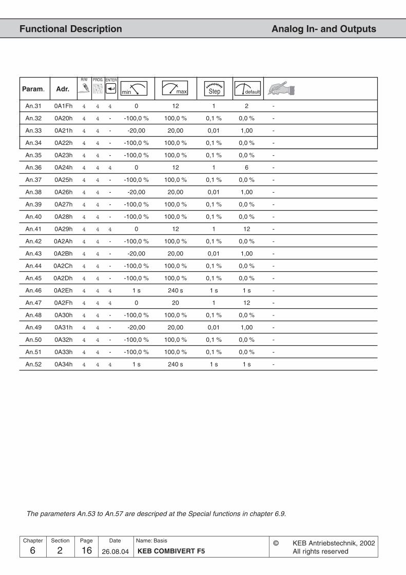
Functional Description Analog In- and Outputs
2 166Name: Basis
KEB COMBIVERT F5
Chapter Section Page Date
26.08.04© KEB Antriebstechnik, 2002
All rights reserved
Param. Adr. min max default
ENTERPROG.R/W
Step
An.31 0A1Fh 4 4 4 0 12 1 2 -
An.32 0A20h 4 4 - -100,0 % 100,0 % 0,1 % 0,0 % -
An.33 0A21h 4 4 - -20,00 20,00 0,01 1,00 -
An.34 0A22h 4 4 - -100,0 % 100,0 % 0,1 % 0,0 % -
An.35 0A23h 4 4 - -100,0 % 100,0 % 0,1 % 0,0 % -
An.36 0A24h 4 4 4 0 12 1 6 -
An.37 0A25h 4 4 - -100,0 % 100,0 % 0,1 % 0,0 % -
An.38 0A26h 4 4 - -20,00 20,00 0,01 1,00 -
An.39 0A27h 4 4 - -100,0 % 100,0 % 0,1 % 0,0 % -
An.40 0A28h 4 4 - -100,0 % 100,0 % 0,1 % 0,0 % -
An.41 0A29h 4 4 4 0 12 1 12 -
An.42 0A2Ah 4 4 - -100,0 % 100,0 % 0,1 % 0,0 % -
An.43 0A2Bh 4 4 - -20,00 20,00 0,01 1,00 -
An.44 0A2Ch 4 4 - -100,0 % 100,0 % 0,1 % 0,0 % -
An.45 0A2Dh 4 4 - -100,0 % 100,0 % 0,1 % 0,0 % -
An.46 0A2Eh 4 4 4 1 s 240 s 1 s 1 s -
An.47 0A2Fh 4 4 4 0 20 1 12 -
An.48 0A30h 4 4 - -100,0 % 100,0 % 0,1 % 0,0 % -
An.49 0A31h 4 4 - -20,00 20,00 0,01 1,00 -
An.50 0A32h 4 4 - -100,0 % 100,0 % 0,1 % 0,0 % -
An.51 0A33h 4 4 - -100,0 % 100,0 % 0,1 % 0,0 % -
An.52 0A34h 4 4 4 1 s 240 s 1 s 1 s -
The parameters An.53 to An.57 are descriped at the Special functions in chapter 6.9.

Functional Description
1. Introduction
2. Summary
3. Hardware
4. Operation
5. Parameter
6. Functions
7. Start-up
8. Special Operation
9. Error Assistance
10. Project Planning
11. Networks
12. Annex
6.1 Operating and ApplicanceDate
6.2 Analog In- and Outputs
6.3 Digital In- and Outputs
6.4 Set Value and RampAdjustment
6.5 Voltage-/FrequencyCharacteristic (U/f)Adjustment
6.6 Motor Data Adjustment
6.7 Protective Functions
6.8 Parameter Sets
6.9 Special Functions
6.10 Encoder Interface
6.11 SMM, Posi, Synchron, CTM
6.12 Technology Control
6.13 CP-Parameter Definition
16 3 1KEB COMBIVERT F5
Name: Basis
22.09.05
Section PageDate© KEB Antriebstechnik, 2002All rights reserved
Chapter
6.3.1 Summary DescriptionDigital Inputs .......................... 3
6.3.2 Input Signals .......................... 36.3.3 Setting of Digital Inputs by
Software ................................. 46.3.4 Terminal Status ...................... 56.3.5 Digital Filter ............................ 56.3.6 Inversion of Inputs .................. 56.3.7 Edge-triggering ...................... 56.3.8 Strobe-dependent Inputs ....... 66.3.9 Inputs Status .......................... 86.3.10 Reset/Input Selection and
Edge Evaluation ..................... 86.3.11 Assignment of the Inputs ....... 86.3.12 Summary Description
Digital Outputs ..................... 136.3.13 Output Signals ..................... 146.3.14 Output filter .......................... 146.3.15 Switching Conditions ........... 156.3.16 Inverting of Switching
Conditions for Flags ............. 186.3.17 Selection of Switching
Conditions for Flags ............. 186.3.18 Linking the Switching
Conditions for Flags ............. 186.3.19 Inverting of Flags ................. 196.3.20 Selection of Flags ................ 196.3.21 Linking the Flags .................. 176.3.22 Inversion of Outputs ............. 206.3.23 Output Terminal Status ........ 206.3.24 Hardware output allocation .. 206.3.25 Example ............................... 216.3.26 Used Parameters ................. 22

6 3 KEB COMBIVERT F52Name: Basis
22.09.05
Chapter Section Page Date © KEB Antriebstechnik, 2002All rights reserved
Functional Description Digital In- and Outputs

36 3 3KEB COMBIVERT F5
Name: Basis
22.09.05
6
Section PageDate© KEB Antriebstechnik, 2002All rights reserved
Chapter
Functional DescriptionDigital In- and Outputs
6.3.1 SummaryDescription DigitalInputs
6.3 Digital In- and OutputsThe KEB COMBIVERT has 8 external digital inputs and 4 internal inputs (IA...ID).All inputs can be assigned to one or several functions.Coming from the terminal strip it can be defined with parameter di.0 (not at F5-B),whether external inputs shall be controlled in PNP or NPN (not at safety relais)wiring. Parameter ru.21 shows the currently controlled input. Each input canoptionally (di.1) be set via terminal strip or by means of software with di.2. A digitalfilter (di.3) reduces the interference susceptibility of the inputs. The inputs can beinverted with di.4 and with di.5 one can switch to edge-triggering. With theparameters di. 6...di. 8 a Strobe-mode can be activated. The input status (ru.22)shows the inputs that are actually set for processing. The function(s), that aprogrammed input carries out, is defined by means of the input selection of thecorresponding function or by di.11...22.For safety reasons the control release (ST) must generally be switched by meansof hardware. Edge-triggering, inversion and strobe signal can be adjusted buthave no influence.Fig. 6.3.1 Principle of digital inputs
6.3.2 Input Signals PNP /NPN (di.0)
Fig. 6.3.2.a Digital inputs with PNP control (di.0 = 0)
Uin= 18...26V DC ±0%
smoothed
Ri = 2,1 kW
8di.0
di.2
di.1 di.3 di.41
di.5
12
12
di.8
di.7di.6
12
1
ru.21 ru.22
12
4
PNP/NPN
Terminalstatus
Selectinputsdigital
Digital-filter
DefineStrobeinput
Strobemode
Input status
Assignmentof the inputs
Terminal stripX2A.10...17
Internal inputsIA...ID
10 11 12 13 14 15 2016 17
I1 I2 I3 I4 F R GNDSTRST
PEX2A 22 23
24Vout
21
24Vin
Internal supply
10 11 12 13 14 15 2016 17
I1 I2 I3 I4 F R GNDST RST
PEX2A 22 23
24Vout
21
24Vin
+External supply24...30 VDC
Observe the different functionalrange of the hard- andsoftware of the differentcontrol cards(see chapter 3).
Not valid for BASIC!

6 3 KEB COMBIVERT F54Name: Basis
22.09.05
Chapter Section Page Date © KEB Antriebstechnik, 2002All rights reserved
Functional Description Digital In- and Outputs
� � � � � �� � �
�� �� �� �� � � ��������
����� �� ��
������
�
�����
10 11 12 13 14 15 2016 17
I1 I2 I3 I4 F R GND24VoutST RST
PEX2A 22 2321
24Vin
1 128 256 512 1024 2048
ST
I4
IA
IB
IC
ID
ST
I4
IA
IB
IC
ID
di.2
1
128
256
512
1024
2048
di.1
& &
Sy.50 Bit0 = 1
Fig. 6.3.2.b Digital inputs with NPN control (di.0 = 1)
Uin= 18...26V DC ±0%
smoothed
Ri = 2,1kW
Terminal strip
As shown in Fig. 6.3.3, it can be selected with di.1, whether the inputs shall beswitched from the terminal strip (default) or by way of parameter di.2. Bothparameters are bit-coded, i.e. according to following table, the appropriate valuefor the input is to be entered. In the case of several inputs the sum is to be formed.(Exception: Control release must always be bridged at the terminal strip).
Internal voltage supply
External voltage supply
18...26 VDC
6.3.3 Setting of DigitalInputs by Software(di.1, di.2)
With the aid of parameter di.1 and di.2 the digital input can be set without externalwiring.
Fig. 6.3.3 Digital inputs controlled by Software (di.1/di.2)
The control release mustgenerally be switched by meansof hardware even if one switchesby software (see Fig. 6.3.3 AND-operation wtih di.2 and Sy.50)!
Bit -No. Decimal value Input Terminal0 1 ST (Prog. input „Control release/Reset“) X2A.161 2 RST (Prog. input „Reset“) X2A.172 4 F (Prog. input „Forward“) X2A.143 8 R (Prog. input „Reverse“) X2A.154 16 I1 (Prog. input 1) X2A.105 32 I2 (Prog. input 2) X2A.116 64 I3 (Prog. input 3) X2A.127 128 I4 (Prog. input 4) X2A.138 256 IA (Internal input A) none9 512 IB (Internal input B) none10 1024 IC (Internal input C) none11 2048 ID (Internal input D) none
Internal Inputs
Not valid for BASIC andA-Servo!
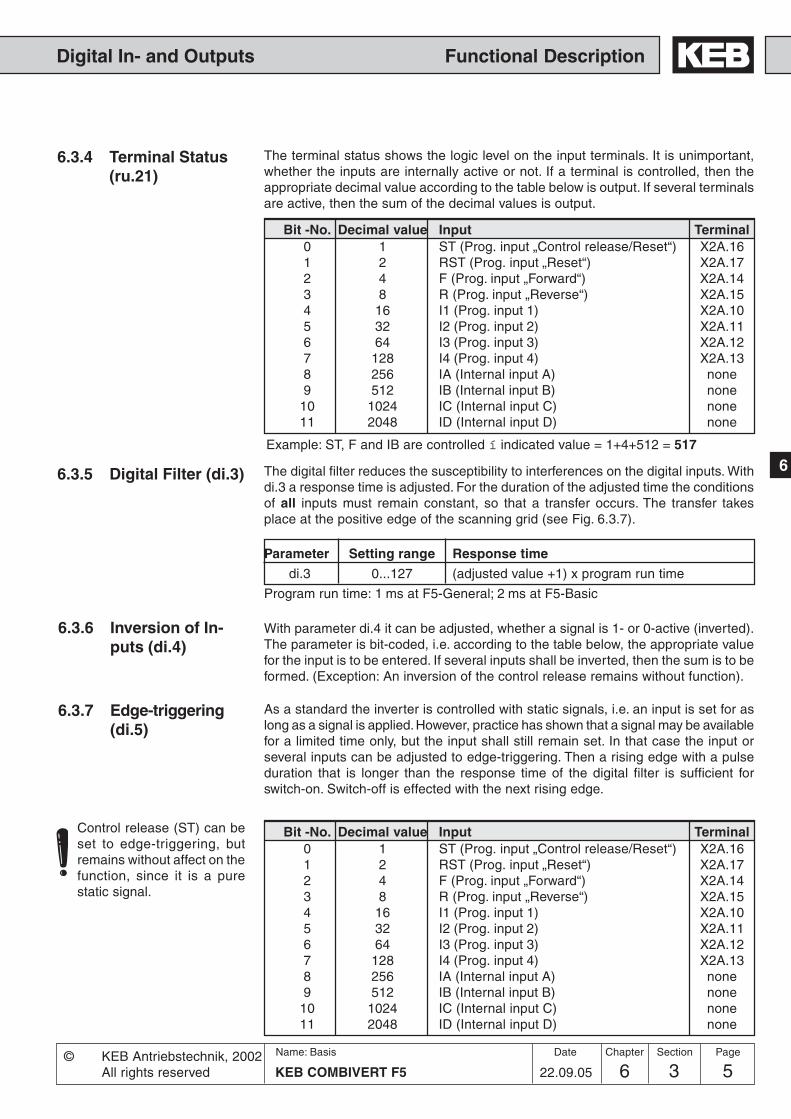
56 3 5KEB COMBIVERT F5
Name: Basis
22.09.05
6
Section PageDate© KEB Antriebstechnik, 2002All rights reserved
Chapter
Functional DescriptionDigital In- and Outputs
6.3.5 Digital Filter (di.3) The digital filter reduces the susceptibility to interferences on the digital inputs. Withdi.3 a response time is adjusted. For the duration of the adjusted time the conditionsof all inputs must remain constant, so that a transfer occurs. The transfer takesplace at the positive edge of the scanning grid (see Fig. 6.3.7).
Parameter Setting range Response time
di.3 0...127 (adjusted value +1) x program run time
Program run time: 1 ms at F5-General; 2 ms at F5-Basic
6.3.6 Inversion of In-puts (di.4)
With parameter di.4 it can be adjusted, whether a signal is 1- or 0-active (inverted).The parameter is bit-coded, i.e. according to the table below, the appropriate valuefor the input is to be entered. If several inputs shall be inverted, then the sum is to beformed. (Exception: An inversion of the control release remains without function).
6.3.7 Edge-triggering(di.5)
As a standard the inverter is controlled with static signals, i.e. an input is set for aslong as a signal is applied. However, practice has shown that a signal may be availablefor a limited time only, but the input shall still remain set. In that case the input orseveral inputs can be adjusted to edge-triggering. Then a rising edge with a pulseduration that is longer than the response time of the digital filter is sufficient forswitch-on. Switch-off is effected with the next rising edge.
Control release (ST) can beset to edge-triggering, butremains without affect on thefunction, since it is a purestatic signal.
6.3.4 Terminal Status(ru.21)
The terminal status shows the logic level on the input terminals. It is unimportant,whether the inputs are internally active or not. If a terminal is controlled, then theappropriate decimal value according to the table below is output. If several terminalsare active, then the sum of the decimal values is output.
Example: ST, F and IB are controlled í indicated value = 1+4+512 = 517
Bit -No. Decimal value Input Terminal0 1 ST (Prog. input „Control release/Reset“) X2A.161 2 RST (Prog. input „Reset“) X2A.172 4 F (Prog. input „Forward“) X2A.143 8 R (Prog. input „Reverse“) X2A.154 16 I1 (Prog. input 1) X2A.105 32 I2 (Prog. input 2) X2A.116 64 I3 (Prog. input 3) X2A.127 128 I4 (Prog. input 4) X2A.138 256 IA (Internal input A) none9 512 IB (Internal input B) none
10 1024 IC (Internal input C) none11 2048 ID (Internal input D) none

6 3 KEB COMBIVERT F56Name: Basis
22.09.05
Chapter Section Page Date © KEB Antriebstechnik, 2002All rights reserved
Functional Description Digital In- and Outputs
t1
t
t
t
t
1. 2. 1. 2. 1. 2. 1. 2.
Signal atterminals
Scanning grid(acceptance
at rising edge)
Inverted signal
Input status at edge-triggering
6.3.8 Strobe-dependent Inputs(di.6, di.7, di.8)
A Strobe signal is used mainly for triggering the input signals. For example, twoinputs shall be used for the parameter set selection. But the signals for the controldo not arrive exactly even, so for a short time it would be switched into an unintendedset. With active Strobe (scanning signal) the current input signals of the Strobe-dependent inputs are accepted and kept until the next scanning.
With di.8 any input can be selected as Strobe-dependent input. With the controlrelease di.8 has no function since this is a static input.
With parameter di.6 the Strobe input is set. If several inputs are adjusted as Strobethey are linked in OR-operation. At the next rising edge of the clock signal, theStrobe signal is triggered.
di.8 Strobe-dependent inputsdi.6 Selection strobe signal
From where comes the Strobesignal?
Which inputs are switched byStrobe?
Fig. 6.3.7 Example of a signal flow diagram for input I1 (di.3=1; di.4=16; di.5=16)
Bit -No. Decimal value Function di.6 / di.8 / ru.22 / di.9 / di.10 Terminal0 1 * ST (Prog. input „Control release/Reset“) X2A.161 2 RST (Prog. input „Reset“) X2A.172 4 F (Prog. input „Forward“) X2A.143 8 R (Prog. input „reverse“) X2A.154 16 I1 (Prog. input 1) X2A.105 32 I2 (Prog. input 2) X2A.116 64 I3 (Prog. input 3) X2A.127 128 I4 (Prog. input 4) X2A.138 256 IA (Internal input A) none9 512 IB (Internal input B) none10 1024 IC (Internal input C) none11 2048 ID (Internal input D) none
* No function at di.8, as the control release works static.
t1: 1 ms at F5-General; 2 ms at F5-Basic
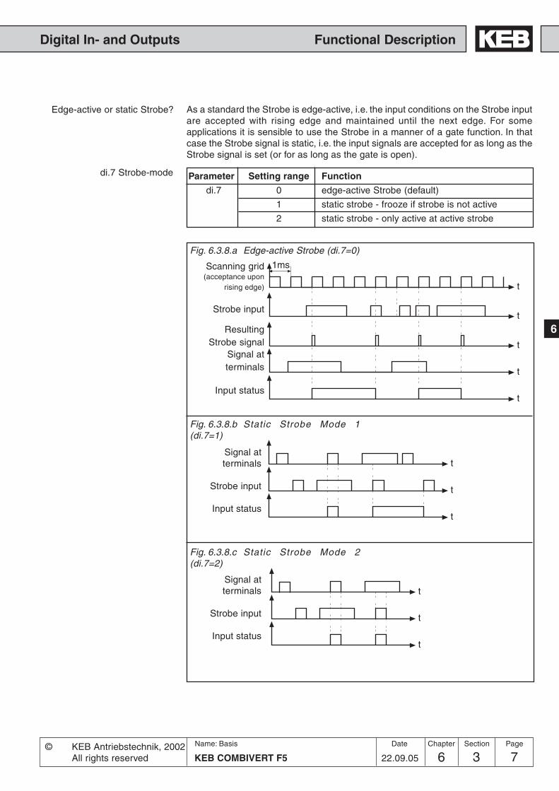
76 3 7KEB COMBIVERT F5
Name: Basis
22.09.05
6
Section PageDate© KEB Antriebstechnik, 2002All rights reserved
Chapter
Functional DescriptionDigital In- and Outputs
t
t
t
t
t
1ms
t
t
t
Edge-active or static Strobe? As a standard the Strobe is edge-active, i.e. the input conditions on the Strobe inputare accepted with rising edge and maintained until the next edge. For someapplications it is sensible to use the Strobe in a manner of a gate function. In thatcase the Strobe signal is static, i.e. the input signals are accepted for as long as theStrobe signal is set (or for as long as the gate is open).
di.7 Strobe-mode
Fig. 6.3.8.a Edge-active Strobe (di.7=0)
Fig. 6.3.8.b Static Strobe Mode 1(di.7=1)
Signal atterminals
Strobe input
Input status
Scanning grid(acceptance upon
rising edge)
Strobe input
ResultingStrobe signal
Signal atterminals
Input status
Parameter Setting range Function
di.7 0 edge-active Strobe (default)
1 static strobe - frooze if strobe is not active
2 static strobe - only active at active strobe
t
t
t
Signal atterminals
Strobe input
Input status
Fig. 6.3.8.c Static Strobe Mode 2(di.7=2)

6 3 KEB COMBIVERT F58Name: Basis
22.09.05
Chapter Section Page Date © KEB Antriebstechnik, 2002All rights reserved
Functional Description Digital In- and Outputs
6.3.11 Assignment ofthe Inputs
An. 3 AN1 save trigger / input selectionAn.13 AN2 save trigger / input selectionAn.23 AN3 save trigger / input selectioncn.11 PID reset / input selectioncn.12 I reset / input selectioncn.13 Fade in reset / input selectiondi. 9 Reset / input selectionFr. 7 Parameter set / input selectionFr.11 Reset set / input selectionLE.17 Timer 1 Start / input selectionLE.19 Timer 1 Reset / input selectionLE.22 Timer 2 Start / input selectionLE.24 Timer 2 Reset / input selectionoP.19 Fixed value / input selection 1oP.20 Fixed value / input selection 2oP.56 Motorpoti increase / input selection
There are two different procedures for the assignment of inputs. Both variants arelocked against each other to give the user maximum flexibility.List of parameters, that can be assigned with inputs:
The internal input status shows the logic condition of the digital inputs which areinternally set for processing. It is unimportant, whether the external terminals areactive or not. If an input is set, the appropriate decimal value according to the tableunder 6.3.8 is output. If several inputs are set, then the sum of the decimal values isoutput.
With di.9 the reset input is defined according to the table under 6.3.8. If the resetinput shall react to an edge, one or several of the reset inputs defined with di.9 canbe switched to edge evaluation with di.10.
6.3.9 Input Status(ru.22)
6.3.10 Reset/InputSelection andEdge Evaluation(di.9 / di.10)
1) By selecting the source of rotation (oP.1) the adjustment can be changed from forward/reverse to Run/Stop.
oP.57 Motorpoti decrease / input selectionoP.58 Motorpoti Reset / input selectionoP.60 1) Rotation forward (Run) / input selectionoP.61 1) Rotation reverse (Stop) / input selectionPn. 4 External fault / input selectionPn.23 Ramp stop / input selectionPn.29 DC-braking / input selectionPn.64 set GTR7 input selectionPS.2 pos/sync input selectPS.3 shift. slave input selectionPS.10 shift slave invers input selectionPS.18 reference switch input selectionPS.19 start reference input selectionPS.29 start posi input selectionuF. 8 Energy-saving function / input selection
di.24 I1 prog. functiondi.25 I2 prog. functiondi.26 I3 prog.functiondi.27 I4 prog.functiondi.28 IA prog.functiondi.29 IB prog.function
Additional functions Parameters can be allocated with one additional function each. The parameters arefirmly assigned to the prefixed inputs and are activated by setting bit 31.
di.30 IC prog.functiondi.31 ID prog.functiondi.32 FOR prog.functiondi.33 REV prog.functiondi.34 RST prog.functiondi.35 ST prog.function
Value Function0 PS.11 Reset Master/Slave Difference / input selection1 PS.13 Set reference point / input selection2 PS.36 Teach position / input selection

96 3 9KEB COMBIVERT F5
Name: Basis
22.09.05
6
Section PageDate© KEB Antriebstechnik, 2002All rights reserved
Chapter
Functional DescriptionDigital In- and Outputs
20 oP.19 1
21 oP.20 2
22 oP.56 4
23 oP.57 8
24 oP.58 16
25 oP.60 32
26 oP.61 64
27 di. 9 128
28 Pn.23 256
29 Pn.29 512
210 uF. 8 1.024
211 Fr. 7 2.048
212 Fr.11 4.096
213 Pn. 4 8.192
214 An. 3 16.384
215 An.13 32.768
216 An.23 65.536
217 LE.17 131.072
218 LE.19 262.144
219 LE.22 524.288
220 LE.24 1.048.576
221 cn.11 2.097.152
222 cn.12 4.194.304
223 cn.13 8.388.608
I1 di.1131
I2 di.1231
I3 di.1331
I4 di.1431
IA di.1531
IB di.1631
IC di.1731
ID di.1831
F di.1931
R di.2031
RST di.2131
ST di.2231
224 PS.2 16.777.216
225 PS.3 32.554.432
226 PS.18 67.108.864
227 PS.19 134.217.728
228 Pn.64 268.435.456
229 PS.29 536.870.912
230 PS.10 1.073.741.824
Fig. 6.3.11a Input-related assignment
• Input-related assignmentA parameter is assigned to each input (di.11...22) which adjusts the desiredfunction(s).The appropriate function is determined by the input of the decimal value. If severalfunctions should be selected, then the sum of the decimal values must be ente-red.
The input ST is assigned by hardware means with the function „control release“.Further functions can be adjusted only „additionally“.
Input Parameter Function
*
*
*
*
*
** no function at F5-G/B

6 3 KEB COMBIVERT F510Name: Basis
22.09.05
Chapter Section Page Date © KEB Antriebstechnik, 2002All rights reserved
Functional Description Digital In- and Outputs
Fig. 6.3.11b Function-related assignment
12
cn.13
cn.12
cn.11
LE.24
LE.22
LE.19
LE.17
An.13
An. 3
Pn. 4
Fr.11
Fr. 7
uF. 8
Pn.29
Pn.23
oP.61
oP.60
oP.58
oP.57
oP.56
oP.20
oP.19
di. 9
12
12
12
12
12
12
12
12
12
12
12
12
12
12
12
12
12
12
12
12
12
12
20
I1
I2
I3
I4
IA
IB
IC
ID
F
R
RST
ST
1
21 2
22 4
23 8
24 16
25 32
26 64
27 128
28 256
29 512
210 1024
211 2048
PS.18
PS.3
PS.2
12
12
12PS.10
12
PS.19
12
PS.29
12
Pn.64
12
An.2312
di. 24...3512
• Function-related assignmentA parameter is assigned to each function which adjusts the desired input(s).The appropriate input is determined by the input of the decimal value. If severalinputs should be selected, then the sum of the decimal values must be entered.
InputFunction
*
*
*
*
*
** no function at F5-G/C/B
*
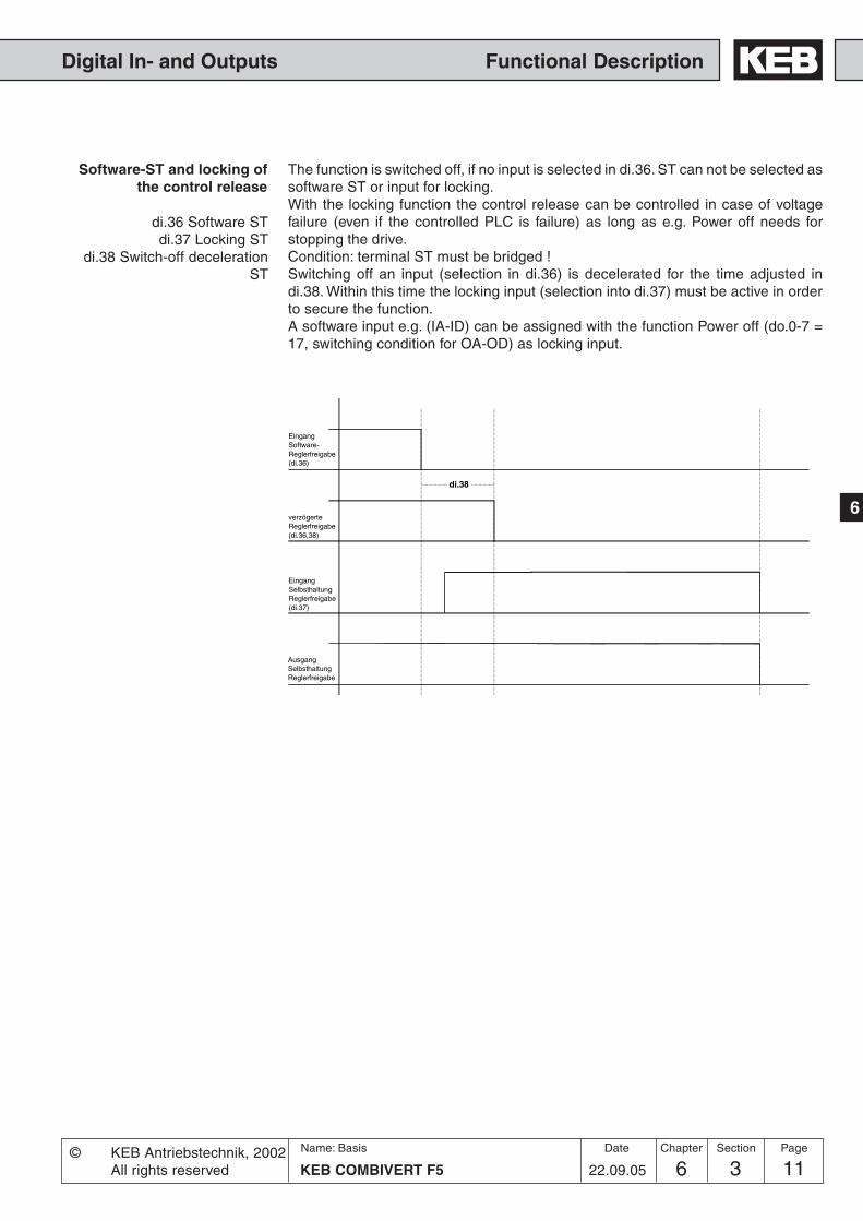
116 3 11KEB COMBIVERT F5
Name: Basis
22.09.05
6
Section PageDate© KEB Antriebstechnik, 2002All rights reserved
Chapter
Functional DescriptionDigital In- and Outputs
The function is switched off, if no input is selected in di.36. ST can not be selected assoftware ST or input for locking.With the locking function the control release can be controlled in case of voltagefailure (even if the controlled PLC is failure) as long as e.g. Power off needs forstopping the drive.Condition: terminal ST must be bridged !Switching off an input (selection in di.36) is decelerated for the time adjusted indi.38. Within this time the locking input (selection into di.37) must be active in orderto secure the function.A software input e.g. (IA-ID) can be assigned with the function Power off (do.0-7 =17, switching condition for OA-OD) as locking input.
Software-ST and locking ofthe control release
di.36 Software STdi.37 Locking ST
di.38 Switch-off decelerationST
EingangSoftware-Reglerfreigabe(di.36)
EingangSelbsthaltungReglerfreigabe(di.37)
verzögerteReglerfreigabe(di.36,38)
AusgangSelbsthaltungReglerfreigabe
di.38

6 3 KEB COMBIVERT F512Name: Basis
22.09.05
Chapter Section Page Date © KEB Antriebstechnik, 2002All rights reserved
Functional Description Digital In- and Outputs

136 3 13KEB COMBIVERT F5
Name: Basis
22.09.05
6
Section PageDate© KEB Antriebstechnik, 2002All rights reserved
Chapter
Functional DescriptionDigital In- and Outputs
do.2
do.4
do.6
do.0
do.1
do.3
do.5
do.7
do.8
12...
128
do.16
do.9 do.17
do.10do.18
do.11do.19
do.12do.20
do.13do.21
12...
128
8
8
8
8
8
8
12...
128
12...
128
12...
128
12...
128
do.14do.22
8
12...
128
do.15do.23
8
12...
128
do.25
12...
128
do.33
do.26do.34
do.27do.35
do.28do.36
do.29do.37
do.30do.38
12...
128
8
8
8
8
8
8
12...
128
12...
128
12...
128
12...
128
do.31do.39
8
12...
128
do.32do.40
8
12...
128
do.42
1
2
4
8
16
32
64
128
&
>1
20=1
8
8
&
>18
8
&
>18
8
&
>18
8
&
>18
8
&
>18
8
do.24
8
8
8
8
&
>1
&
>1
21=2
22=4
23=8
24=16
25=32
26=64
27=128
&
>1
20=1
8
8
&
>18
8
&
>18
8
&
>18
8
&
>18
8
&
>18
8
do.41
8
8
8
8
&
>1
&
>1
21=2
22=4
23=8
24=16
25=32
26=64
27=128
8
8
0
1
2
3
4
5
6
7
8
9
10
11
12
13
14
15
16
17
18
19
20
21
22
23
z-1
z-1
do.43
do.44
1
1
1
1
1
1
1
1
1
1
1
1
1
1
1
1
1
1
1
1
1
1
1
1
1
1
1
1
1
1
1
1
1
1
1
1
1
1
1
1
1
1
1
1
1
1
1
1
1
1
1
1
1
1
1
1
8
do.51
0123
O1=O1O1=O2O1=R1O1=R2
04812
O2=O1O2=O2O2=R1O2=R2
0163248
R1=O1R1=O2R1=R1R1=R2
064128192
R2=O1R2=O2R2=R1R2=R2
Bit 0-1
Bit 2-3
Bit 4-5
Bit 6-7
4
4
4
6.3.12 Summary Description - Digital Outputs
Fig. 6.3.12 Principle of digital outputs
Internal output OD
Internal output OC
Internal output OB
Internal output OA
Relay output (R2)X2A.27...29
Transistor output(O2)X2A.19
Transistor output (O1)X2A.18
Relay output (R1)X2A.24...26
Flag 0...7 Outputs
ru.23 Outputcondition status
ru.24 Statusof output flags
ru.25 Outputterminal Status
Condition 0...7
1 von75
75
1 von 75
1 von 75
1 von 75
1 von 75
1 von 75
1 von 75
1 von 75
75
75
75
75
75
75
75
75
ru.80 digitaloutput state

6 3 KEB COMBIVERT F514Name: Basis
22.09.05
Chapter Section Page Date © KEB Antriebstechnik, 2002All rights reserved
Functional Description Digital In- and Outputs
For the switching of the digital outputs one can choose up to 8 conditions from the69 different conditions. These are entered in do.0...do.7. Switching condition 0 and 1can be filtered by do.43 and do.44. Parameter ru.23 shows, if one or several of theseconditions are met. For each channel it can now be selected which of the 8 conditionsshall apply to it (do.16...do.23). Each condition can still be inverted before selection(do.8...do.15). As a standard all conditions (if several are selected) are OR-operated,i.e. if one of the selected conditions is fulfilled, the channel is set. With do.24 this canbe changed to AND-operation, i.e. all conditions selected for this channel must befulfilled before it is set. Parameter ru.24 shows the channels which are set in thisstage. do.33...40 form a second logic step with which a selection of the channelsfrom logic step 1 can be made. Every individual condition can be inverted withdo..25...32. do.41 adjusts the manner of the linkage (AND/OR). Parameter do.42 isused for inverting one or several outputs.With do.51 the output signals are assignedto the terminals. ru.80 serves for the display of the status prior to allocation, thereafterru.25. The internal outputs OA...OD are directly connected with the internal inputsIA...ID.
6.3.13 Output Signals Fig. 6.3.12 Connection of digital outputs
The total current ofX2A.18...20 is limited to50mA. In case of inductiveload at the relay outputs or atthe transistor output aprotective wiring is to beprovided (free-wheelingdiode)!
24 25 26RLA RLB RLC
X2Amax. 30V / 1A DC
R1
19 2320O2 0VUout
X2A
+24V / 50mA
R2
27 28 29FLA FLB FLC
max. 30V / 1A DC
18O1
X2A
6.3.14 Output filter(do.43, do.44)
With do.43 a filter can be set for switching condition 0, with do.44 for switchingcondition 1. The change of a switching condition must be applied for the filter time,then it becomes active at the output of the filter. If the change of a switching conditionis cancelled during the filter time, the filter time is reset and restarted at the nextchange. The filter time is adjustable within the range of 0 (off)...1000 ms.
Description

156 3 15KEB COMBIVERT F5
Name: Basis
22.09.05
6
Section PageDate© KEB Antriebstechnik, 2002All rights reserved
Chapter
Functional DescriptionDigital In- and Outputs
6.3.15 Switching Conditions (do.0...do.7)From the following switching conditions one can select up to 8 for further processing.The values are then entered in the parameters do.0...do.7.
Value Function0 Off1 Always active2 Run signal; also at DC-braking3 Ready for operation; if no fault exists (ru.0 <> error)4 Fault relay trips, when the inverter is switched off with an error5 Fault relay, as at 2, but not for errors which are reset automatically with activated „Auto-restart-function“6 Warning or error signal is given, when the inverter fulfills an abnormal-stopping condition (ru.0).
7 Overload-prewarning! ru.39 is an overload counter, counting in steps of 1%. On reaching 100 % the inverterswitches off. Upon exceeding the level of Pn.9 (default 80%) the overload warning is given. The performance incase of a warning can be adjusted with Pn.8 (response to OL-warning)
8 Overheating-prewarning (OH)! Depending on the power circuit the inverter switches off between 60...95°Cpower module temperature. The prewarning is output, when the level OH-warning (Pn.11) is reached (default70°C). The behaviour in case of an warning can be adjusted with Pn.10 (response to OH-warning).
9 PTC-prewarning (dOH), on tripping of the motor-PTC connected to the terminals T1/T2. After expiration of anadjustable switch-off time Pn.13 (0...120s) the inverter switches off. the behaviour in case of an error can beadjusted with Pn.12 (response to dOH-warning).
10 Motor protection prewarning (OH2), if the motor protection triggering time defined according to VDE hasexpired. The response to the warning can be adjusted with Pn.14 (response to motor protective function)(seeChapter 6.7 „Motor protective function“).
11 Interior temperature-prewarning (OHI) is output, when the interior temperature of the inverter exceeds thelevel OHI-warning (Pn.17). The behaviour in case of an error can be adjusted with Pn.16 (response to OHI-warning). Not at Pn.16 = 7
12 Cable breakage at 4...20mA setpoint adjustment at AN1; Trips, if the setpoint current drops below 2mA (An.0 =2).
13 Cable breakage at 4...20mA setpoint adjustment at AN2; Trips, if the setpoint current drops below 2mA (An.10= 2).
14 Max. constant current (Stall) exceeded (Pn.17). See chapter 6.7 „Constant current limit“.15 Ramp stop function active (LA-/LD-Stop), current (Pn.22) or voltage (Pn.23) exceeded during acceleration/
deceleration. See chapter 6.7 „Ramp stop“.16 DC-braking active; see chapter 6.9 „DC-brake“17 Power-Off function active (see chapter 6.9 „Power-Off“), in case of an error or SSF the condition is not fulfilled18 Brake control is set, when the brake shall be released (see chapter 6.9 „Brake control“)19 Speed control difference > level20 Actual value = setpoint at constant run; not at ru.0 = noP, LS, Error or SSF.21 Inverter is in the acceleration phase, at ru.0 = FAcc, rAcc and LAS (acceleration stop)22 Inverter is in the deceleration phase, at ru.0 = Fdec, rdec and LDS (deceleration stop)23 Actual direction of rotation = set direction of rotation24 Utilization (ru.13) > level25 Active current (ru.17) > level26 DC-link voltage > level27 Actual value (ru.7) > level28 Setpoint value (ru.1) > level29 Ref. point run completed (only F5-M/S)30 Actual torque > level (only F5-M/S)31 AN1 on output of characteristic amplifier > level; without sign evaluation32 AN2 on output of characteristic amplifier > level; without sign evaluation

6 3 KEB COMBIVERT F516Name: Basis
22.09.05
Chapter Section Page Date © KEB Antriebstechnik, 2002All rights reserved
Functional Description Digital In- and Outputs
33 AN3 on output of characteristic amplifier > level; without sign evaluation34 AN1 on output of characteristic amplifier > level; with sign evaluation35 AN2 on output of characteristic amplifier > level; with sign evaluation36 AN3 on output of characteristic amplifier > level; with sign evaluation37 Timer 1 > level38 Timer 2 > level39 Angle difference > level (only F5-M/S)40 Hardware current limit active41 Modulation on-signal42 Output of analog signal ANOUT3 as PWM-signal. The period is adjusted with An.46.43 Output of analog signal ANOUT4 as PWM-signal. The period is adjusted with An.52.44 Inverter state (ru.0) = Level45 Power module temperatur (ru.38) > Level46 Motor temperatur (ru.46) > Level47 Ramp output value (ru.2) > Level48 Apparent current (ru.15) > Level49 Clockwise rotation (not at noP, LS, abnormal stopping, error)50 Counter clockwise (not at noP, LS, abnormal stopping, error)51 Warning E.OL252 Current control at the limit (only F5-M/S)53 Speed control at the limit54 Target window reached (Posi module at F5-M/S)55 Current position > Level (Posi module at F5-M/S)56 Positioning active (Posi module at F5-M/S)57 Position inaccessible (Posi module at F5-M/S)58 Profile processing active (Posi module at F5-M/S)59 AND-operation of the selected inputs. The condition is active, if all selected inputs are active. The selection is
done with the switching levels (LE.0...7) according to following table:Input ST RST F R I1 I2 I3 I4 IA IB IC IDValue 1 2 4 8 16 32 64 128 256 512 1024 2048
The sum of the inputs to be queried is entered in the switching levels.Example:If the inputs I3 and I4 are active, the condition do.4 shall be set.Adjust switching condition 4 (do.4) to „59“. Adjust switching level 4 (LE.4) to „192“ („64“ for I3 + „128“ for I4).
60 OR-operation of the selected inputs. The condition is active, if at least one of the selected inputs is active.Adjustment as at value „59“.
61 NAND-operation of the selected inputs. The condition is active, if at least one of the selected inputs is inactive.Adjustment as at value „59“.
62 NOR-operation of the selected inputs. The condition is active, if all of the selected inputs are inactive.Adjustment as at value „59
63 Absolute value ANOUT1 > Level64 Absolute value ANOUT2 > Level65 ANOUT1 > Level66 ANOUT2 > Level67 Active relative position > Level. The output is set, if the distance covered after the starting position is larger
than the adjusted level. That means, the function works relative to the starting position. If the positioning iscompleted, the output is reset (Posi module at F5-M/S).
68 Active position to the target > Level. The output is set, if the distance to be covered to the target is larger thanthe adjusted level. If the positioning is completed, the output is reset (Posi module at F5-M/S).
69 Absolute control difference of the external PI controller > Level70 Driver voltage activ (driver relay)

176 3 17KEB COMBIVERT F5
Name: Basis
22.09.05
6
Section PageDate© KEB Antriebstechnik, 2002All rights reserved
Chapter
Functional DescriptionDigital In- and Outputs
The hysteresis, in reference to the adjusted values, defines the parametersLE. 8...LE.15. Hysteresis 0 (LE.8) applies for comparison level 0; LE.9 for comparisonlevel 1 ... and so forth.
Default:Frequency: 0,5 HzVoltage: 1 VAnalog values: 0,5 %Current: 0,5 ATemperature: 1 °C
LE.16 defines the hysteresis for the status constant-run and tripping frequencies forthe DC-brake.
Hysteresis 0...7LE. 8...LE.15
Frequency hysteresis LE.16
Response to warning signalsPn.8, Pn.10, Pn.12, Pn.14,
Pn.16
These parameters determine the behaviour of the inverter in case of warning signals.To learn more about the adjustment possibilities as well as the performance of theappropriate drive please refer to Chapter 6.7 „Protective functions“.
Level 0...7LE.0...LE.7
These parameters defines the level of the switching conditions. Level 0 (LE.0) appliesfor switching condition 0; LE.1 for switching condition 1 ... and so forth.
Setting range: -30000,00...30000,00Step: 0,01Default: see parameter table
At pretending in increments one increment is 0,01.
71 Drive runs synchronously; is set, if after the activation of the synchronous run the drive is synchronized (F5-M/S).
72 Actual position index = Level (Posi modul at F5-M/S)73 Absolute active power > Level74 Active power > Level75 Absolute (actuel position – scan position) > Level (Posi modul at F5-M/S)76 Actual position = position of index ps.2878 reservated79 reservated80 Actual current > level

6 3 KEB COMBIVERT F518Name: Basis
22.09.05
Chapter Section Page Date © KEB Antriebstechnik, 2002All rights reserved
Functional Description Digital In- and Outputs
&>1 0
1 Bit 08do.16
&>1 0
1 Bit 18do.17
&>1 0
1 Bit 78do.23
do.24
Fig. 6.3.15 Inversion and selection of switching conditions6.3.16 Inverting ofSwitching Conditionsfor Flags(do.8...do.15)
With the parameters do.8...do.15 each of the 8 switching conditions (do.0...do.7)can be inverted for each flag separately. Through this function it is possible to setany chosen switching condition as Non-condition. The parameter is bit-coded.According to Fig. 6.3.15 the weighting of the switching conditions to be invertedmust be entered in do.8...do.15. If several conditions shall be inverted, the sum isto be formed.Output X2A.19 shall be set when the inverter is not accelerating. In this case weassign the switching condition 21 (inverter accelerates) for example to do.1 (entervalue 21). We invert the switching condition with do.9, so enter value 2.
6.3.17 Selection ofSwitchingConditions for Flags(do.16...do.23)
Example:
The parameters do.16...do.23 serve for the selection of the 8 defined switchingconditions. The selection is done for each chanel separately, where one can choosebetween no one and up to all 8 switching conditions. According to Fig. 6.3.15 theweighting of the selected switching conditions is to be entered into do.16...do.23 .If several conditons are selected, the sum is to be formed.
After the switching conditons are selected for each output, it can now be determined,how these are linked. As a default all conditions are OR-operated, i.e. if one of theselected conditions is met, the output switches. Another possibility is the AND-operation which can be adjusted with do.24. AND-operation means that all selectedconditions must be fulfilled before the output switches.Parameter do.24 is bit-coded. The table under 6.3.17 shows the assignment.
6.3.18 Linking theSwitchingConditions for Flags(do.24)
Fig. 6.3.17 Linking the switching conditions in logic step 1
8do.24
1111
do.8...do.15
do.0do.1do.2do.3do.4do.5do.6do.7
1248
163264
128
do.16...do.231248
163264
128
1111
Flag 0
Flag 1
Flag 7

196 3 19KEB COMBIVERT F5
Name: Basis
22.09.05
6
Section PageDate© KEB Antriebstechnik, 2002All rights reserved
Chapter
Functional DescriptionDigital In- and Outputs
Fig. 6.3.18 Inversion and selection of switching conditions from step 1
8do.41do.24
1111
do.25...do.32
Bit 0Bit 1Bit 2Bit 3Bit 4Bit 5Bit 6Bit 7
1248
163264
128
do.33...do.401248
163264
128
1111
6.3.19 Inverting of Flags(do.25...do.32)
In the second logic step a selection of the flags of the first logic step can be made.The selection is done for each output separately, where one can choose betweenno one and up to all 8 flags. According to Fig. 6.3.18 the weighting of the selectedflags is to be entered into do.33...do.40. If several flags shall be selected, the sumis to be formed.
With the parameters do.25...do.32 each of the 8 flags (bit 0...7) from logic step 1can be inverted separately. Through this function it is possible to set any chosenflag as Non-flag. The parameter is bit-coded. According to Fig. 6.3.18 the weightingof the switching conditions to be inverted must be entered in do.25...do.32. Ifseveral flags shall be inverted, the sum is to be formed.
6.3.20 Selection of Flags(do.33...do.40)
&>1 0
1 Bit 08
&>1 0
1 Bit 18do.34
&>1 0
1 Bit 78do.40
do.41
do.33O1
O2
OD
Fig. 6.3.19 Linking the switching conditions in logic step 2
6.3.21 Linking the Flags(do.41)
Terminal Name Function Decimal values do.41X2A.18 O1 Transistor output 1X2A.19 O2 Transistor output 2X2A.24...26 R1 Relay output 4X2A.27...29 R2 Relay output 8- OA Internal output 16- OB Internal output 32- OC Internal output 64- OD Internal output 128
After the switching conditions are selected for each output, it can now bedetermined, how these are linked. As a default all conditions are OR-operated,i.e. if one of the selected conditions is met, the output switches. Another possibilityis the AND-operation, which is adjusted with do.41. AND-operation means, thatall selected condtions must be fulfilled before the output switches.Parameter do.41 is bit-coded. The table under 6.3.20 shows the assignment.

6 3 KEB COMBIVERT F520Name: Basis
22.09.05
Chapter Section Page Date © KEB Antriebstechnik, 2002All rights reserved
Functional Description Digital In- and Outputs
6.3.22 Inversion of Out-puts (do.42)
As shown in Fig. 6.3.21, with parameter do.42 the outputs can be once again invertedafter the linking. The parameter is bit-coded, i.e. according to following table thevalue belonging to this output must be entered. If several outputs shall be invertedthe sum is to be formed
6.3.23 Output TerminalStatus (ru.25)
Parameter ru.25 indicates the logic condition of the digital outputs after the allocationby do.51. Parameter ru.80 indicates the logic condition before the allocation. It isirrelevant whether the output is set due to conditions or by inverting. If an output isset the appropriate decimal value, according to the table below, is output. If severaloutputs are set, then the sum of the decimal values is output.
1111
do.42
Bit 0Bit 1Bit 2Bit 3Bit 4Bit 5Bit 6Bit 7
1248
163264
128
1111
do.41
Terminal Name FunctionX2A.18 O1 Transistor outputX2A.19 O2 Transistor outputX2A.24...26 R1 Relay outputX2A.27...29 R2 Relay output- OA Internal output- OB Internal output- OC Internal output- OD Internal output
Fig. 6.3.21 Inverting the outputs
Terminal Name Function Decimal values ru.25X2A.18 O1 Transistor output 1X2A.19 O2 Transistor output 2X2A.24...26 R1 Relay output 4X2A.27...29 R2 Relay output 8- OA Internal output 16- OB Internal output 32- OC Internal output 64- OD Internal output 128
6.3.24 Hardware outputallocation (do.51)
With do.51 the output signals are assigned to the output terminals O1, O2, R1 andR2. The assignment is done according to following table:
Bit Value Signal Output Default0 + 1 0 O1 x
1 O2 O1 (terminal X2A.18)2 R13 R2
2+3 0 O14 O2 O2 (terminal X2A.19) x8 R116 R2
4+5 0 O116 O2 R1 (terminal X2A.24...26)32 R1 x48 R2
6+7 0 O116 O2 R2 (terminal X2A.27...29)32 R148 R2 x

216 3 21KEB COMBIVERT F5
Name: Basis
22.09.05
6
Section PageDate© KEB Antriebstechnik, 2002All rights reserved
Chapter
Functional DescriptionDigital In- and Outputs
6.3.25 ProgrammingExample
For a better understanding, the correlations are explained on the basis of a littlemore complex example. Following conditions are required:
• Condition 1: Output X2A.19 switches, if the inverter accelerates• Condition 2: Relais X2A.24...26 switches, if the inverter load is > 100 %• Condition 3: Relais X2A.27...29 switches, if the actual frequency is > 4 Hz• Output X2A.18 switches, if the conditions 2 and 3 are realized, but the inverter
does not accelerate.
Solution proposal:
First set the switching conditions and levels.Set do.0 to „21“ (inverter accelerates)Set do.1 to „24“ (inverter utilization > level); set LE.1 to „100“ (load level for do.1100 %); set LE.9 to „5“ (5 % hysteresis for level 1; not required but reasonable foroptimal switching performance)Set do.2 to „27“ (actual frequency > level); set LE.2 to „4“ (frequency level fordo.2=4 Hz); set LE.10 to „0.5“ (0.5 Hz hysteresis for level 3; not required butreasonable for optimal switching performance)
Set do.16 to „1“ (evaluate switching condition of do.0)Set do.17 to „2“ (evaluate switching condition of do.1)Set do.18 to „4“ (evaluate switching condition of do.2)Set do.8, do.9 and do.10 to „0“ (no inverting)The setting of do.24 is independent for this example, as only one condition each isset at do.16...18.
Output O1 (terminal X2A.18)Set do.33 to „7“ (evaluate flags 1...3)Set do.25 to „1“ (flag 1 is inverted, it means that the condition is fulfilled if the inverterdoes not accelerate.Set do.41 to „1“ (the conditions selected with do.33 become AND-operated)
Output O2 (terminal X2A.19)Set do.34 to „1“ (evaluate flag 1)Set do.26 to „0“ (no inverting)The setting of do.41 is independent for this example, as only one condition is set atdo.34.
Relay output R1 (terminal X2A.24...26)Set do.35 to „2“ (evaluate flag 2)Set do.27 to „0“ (no inverting)The setting of do.41 is independent for this example, as only one condition is set atdo.35.
Relay output R2 (terminal X2A.27...29)Set do.36 to „4“ (evaluate flag 3)Set do.28 to „0“ (no inverting)The setting of do.41 is independent for this example, as only one condition is set atdo.36.
Set switching conditions,levels and hysteresis
Set switching conditionsof stage 1
Set flags

6 3 KEB COMBIVERT F522Name: Basis
22.09.05
Chapter Section Page Date © KEB Antriebstechnik, 2002All rights reserved
Functional Description Digital In- and Outputs
Param. Adr. min max default
ENTERPROG.R/W
Step
6.3.26 Used Parameters
di.0 0B00h 4 - 4 0 1 1 0 0: PNP 1:NPN (without safety relay)
di.1 0B01h 4 - 4 0 4095 1 0 -
di.2 0B02h 4 - 4 0 4095 1 0 -
di.3 0B03h 4 - 4 0 127 1 0 -
di.4 0B04h 4 - 4 0 4095 1 0 -
di.5 0B05h 4 - 4 0 4095 1 0 -
di.6 0B06h 4 - 4 0 4095 1 0 -
di.7 0B07h 4 - 4 0 2 1 0 -
di.8 0B08h 4 - 4 0 4095 1 0 -
di.9 0B09h 4 - 4 0 4095 1 3 ST+RST
di.10 0B0Ah 4 - 4 0 4095 1 3 ST+RST
di.11 0B0Bh 4 - 4 0 231 - 1 1 1 -
di.12 0B0Ch 4 - 4 0 231 - 1 1 2 -
di.13 0B0Dh 4 - 4 0 231 - 1 1 8192 -
di.14 0B0Eh 4 - 4 0 231 - 1 1 512 -
di.15 0B0Fh 4 - 4 0 231 - 1 1 0 -
di.16 0B10h 4 - 4 0 231 - 1 1 0 -
di.17 0B11h 4 - 4 0 231 - 1 1 0 -
di.18 0B12h 4 - 4 0 231 - 1 1 0 -
di.19 0B13h 4 - 4 0 231 - 1 1 32 -
di.20 0B14h 4 - 4 0 231 - 1 1 64 -
di.21 0B15h 4 - 4 0 231 - 1 1 128 -
di.22 0B16h 4 - 4 0 231 - 1 1 128 -
di.24 0B18h 4 - 4 0 2 1 0 -
di.25 0B19h 4 - 4 0 2 1 0 -
di.26 0B1Ah 4 - 4 0 2 1 0 -
di.27 0B1Bh 4 - 4 0 2 1 0 -
di.28 0B1Ch 4 - 4 0 2 1 0 -
di.29 0B1Dh 4 - 4 0 2 1 0 -
di.30 0B1Eh 4 - 4 0 2 1 0 -
di.31 0B1Fh 4 - 4 0 2 1 0 -
di.32 0B20h 4 - 4 0 2 1 0 -
di.33 0B21h 4 - 4 0 2 1 0 -
di.34 0B22h 4 - 4 0 2 1 0 -

236 3 23KEB COMBIVERT F5
Name: Basis
22.09.05
6
Section PageDate© KEB Antriebstechnik, 2002All rights reserved
Chapter
Functional DescriptionDigital In- and Outputs
Param. Adr. min max default
ENTERPROG.R/W
Step
di.35 0B23h 4 - 4 0 2 1 0 -
do.0 0C00h 4 4 4 0 80 1 27 -
do.1 0C01h 4 4 4 0 80 1 3 -
do.2 0C02h 4 4 4 0 80 1 4 -
do.3 0C03h 4 4 4 0 80 1 27 -
do.4 0C04h 4 4 4 0 80 1 0 -
do.5 0C05h 4 4 4 0 80 1 0 -
do.6 0C06h 4 4 4 0 80 1 0 -
do.7 0C07h 4 4 4 0 80 1 0 -
do.8 0C08h 4 4 4 0 255 1 0 -
do.9 0C09h 4 4 4 0 255 1 0 -
do.10 0C0Ah 4 4 4 0 255 1 0 -
do.11 0C0Bh 4 4 4 0 255 1 0 -
do.12 0C0Ch 4 4 4 0 255 1 0 -
do.13 0C0Dh 4 4 4 0 255 1 0 -
do.14 0C0Eh 4 4 4 0 255 1 0 -
do.15 0C0Fh 4 4 4 0 255 1 0 -
do.16 0C10h 4 4 4 0 255 1 1 -
do.17 0C11h 4 4 4 0 255 1 2 -
do.18 0C12h 4 4 4 0 255 1 4 -
do.19 0C13h 4 4 4 0 255 1 8 -
do.20 0C14h 4 4 4 0 255 1 16 -
do.21 0C15h 4 4 4 0 255 1 32 -
do.22 0C16h 4 4 4 0 255 1 64 -
do.23 0C17h 4 4 4 0 255 1 128 -
do.24 0C18h 4 4 4 0 255 1 0 -
do.25 0C19h 4 4 4 0 255 1 0 -
do.26 0C1Ah 4 4 4 0 255 1 0 -
do.27 0C1Bh 4 4 4 0 255 1 0 -
do.28 0C1Ch 4 4 4 0 255 1 0 -
do.29 0C1Dh 4 4 4 0 255 1 0 -
do.30 0C1Eh 4 4 4 0 255 1 0 -
do.31 0C1Fh 4 4 4 0 255 1 0 -
do.32 0C20h 4 4 4 0 255 1 0 -
do.33 0C21h 4 4 4 0 255 1 1 -
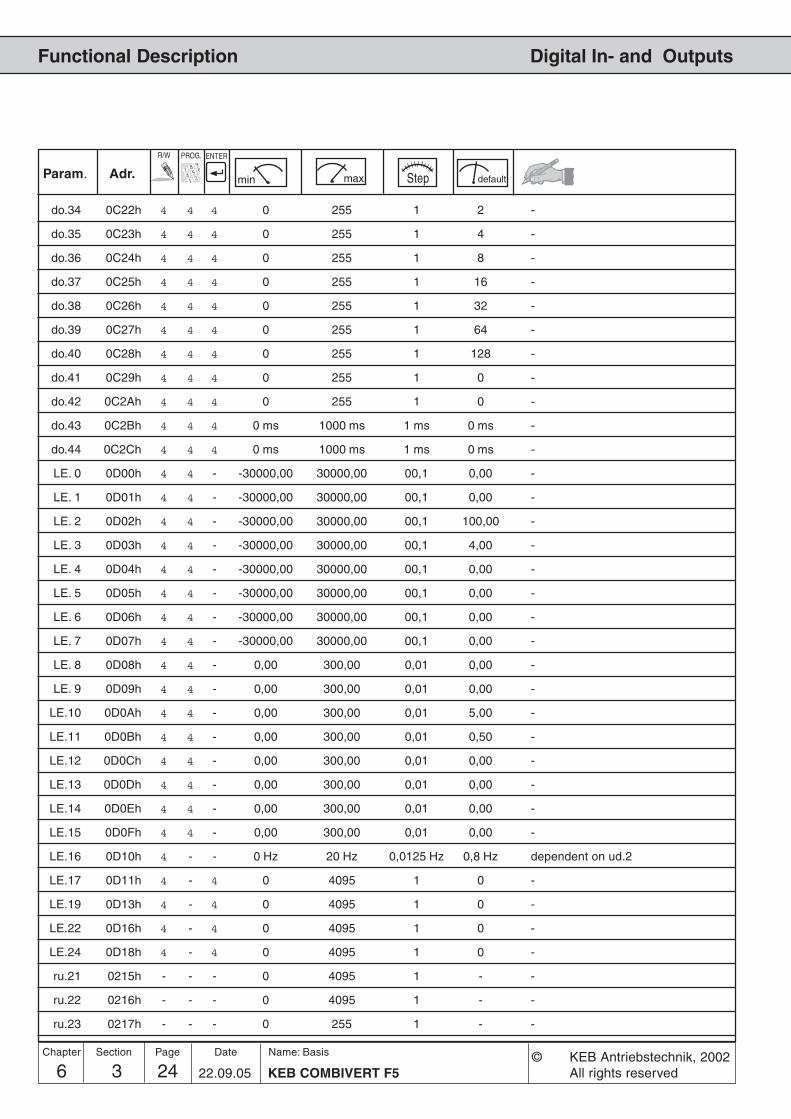
6 3 KEB COMBIVERT F524Name: Basis
22.09.05
Chapter Section Page Date © KEB Antriebstechnik, 2002All rights reserved
Functional Description Digital In- and Outputs
Param. Adr. min max default
ENTERPROG.R/W
Step
do.34 0C22h 4 4 4 0 255 1 2 -
do.35 0C23h 4 4 4 0 255 1 4 -
do.36 0C24h 4 4 4 0 255 1 8 -
do.37 0C25h 4 4 4 0 255 1 16 -
do.38 0C26h 4 4 4 0 255 1 32 -
do.39 0C27h 4 4 4 0 255 1 64 -
do.40 0C28h 4 4 4 0 255 1 128 -
do.41 0C29h 4 4 4 0 255 1 0 -
do.42 0C2Ah 4 4 4 0 255 1 0 -
do.43 0C2Bh 4 4 4 0 ms 1000 ms 1 ms 0 ms -
do.44 0C2Ch 4 4 4 0 ms 1000 ms 1 ms 0 ms -
LE. 0 0D00h 4 4 - -30000,00 30000,00 00,1 0,00 -
LE. 1 0D01h 4 4 - -30000,00 30000,00 00,1 0,00 -
LE. 2 0D02h 4 4 - -30000,00 30000,00 00,1 100,00 -
LE. 3 0D03h 4 4 - -30000,00 30000,00 00,1 4,00 -
LE. 4 0D04h 4 4 - -30000,00 30000,00 00,1 0,00 -
LE. 5 0D05h 4 4 - -30000,00 30000,00 00,1 0,00 -
LE. 6 0D06h 4 4 - -30000,00 30000,00 00,1 0,00 -
LE. 7 0D07h 4 4 - -30000,00 30000,00 00,1 0,00 -
LE. 8 0D08h 4 4 - 0,00 300,00 0,01 0,00 -
LE. 9 0D09h 4 4 - 0,00 300,00 0,01 0,00 -
LE.10 0D0Ah 4 4 - 0,00 300,00 0,01 5,00 -
LE.11 0D0Bh 4 4 - 0,00 300,00 0,01 0,50 -
LE.12 0D0Ch 4 4 - 0,00 300,00 0,01 0,00 -
LE.13 0D0Dh 4 4 - 0,00 300,00 0,01 0,00 -
LE.14 0D0Eh 4 4 - 0,00 300,00 0,01 0,00 -
LE.15 0D0Fh 4 4 - 0,00 300,00 0,01 0,00 -
LE.16 0D10h 4 - - 0 Hz 20 Hz 0,0125 Hz 0,8 Hz dependent on ud.2
LE.17 0D11h 4 - 4 0 4095 1 0 -
LE.19 0D13h 4 - 4 0 4095 1 0 -
LE.22 0D16h 4 - 4 0 4095 1 0 -
LE.24 0D18h 4 - 4 0 4095 1 0 -
ru.21 0215h - - - 0 4095 1 - -
ru.22 0216h - - - 0 4095 1 - -
ru.23 0217h - - - 0 255 1 - -

256 3 25KEB COMBIVERT F5
Name: Basis
22.09.05
6
Section PageDate© KEB Antriebstechnik, 2002All rights reserved
Chapter
Functional DescriptionDigital In- and Outputs
Param. Adr. min max default
ENTERPROG.R/W
Step
ru.24 0218h - - - 0 255 1 - -
ru.25 0219h - - - 0 255 1 - -
oP.19 0313h 4 - 4 0 4095 1 16 I1
oP.20 0314h 4 - 4 0 4095 1 32 I2
oP.56 0337h 4 - 4 0 4095 1 0 -
oP.57 0338h 4 - 4 0 4095 1 0 -
oP.58 0339h 4 - 4 0 4095 1 0 -
oP.60 033Bh 4 - 4 0 4095 1 4 F
oP.61 033Ch 4 - 4 0 4095 1 8 R
Pn. 4 0404h 4 - 4 0 4095 1 64 I3
Pn.23 0417h 4 - 4 0 4095 1 0 -
Pn.29 041Dh 4 - 4 0 4095 1 128 Default 0 at F5-M/S
Pn.64 0440h 4 - 4 0 4095 1 0 -
uF. 8 0508h 4 - 4 0 4095 1 0 -
Fr. 7 0907h 4 - 4 0 4095 1 0 -
Fr.11 090Bh 4 - 4 0 4095 1 0 -
An. 3 0A03h 4 - 4 0 4095 1 0 -
An.13 0A0Dh 4 - 4 0 4095 1 0 -
An.23 0A17h 4 - 4 0 4095 1 0 -
cn.11 070Bh 4 - 4 0 4095 1 0 -
cn.12 070Ch 4 - 4 0 4095 1 0 -
cn.13 070Dh 4 - 4 0 4095 1 0 -

6 3 KEB COMBIVERT F526Name: Basis
22.09.05
Chapter Section Page Date © KEB Antriebstechnik, 2002All rights reserved
Functional Description Digital In- and Outputs
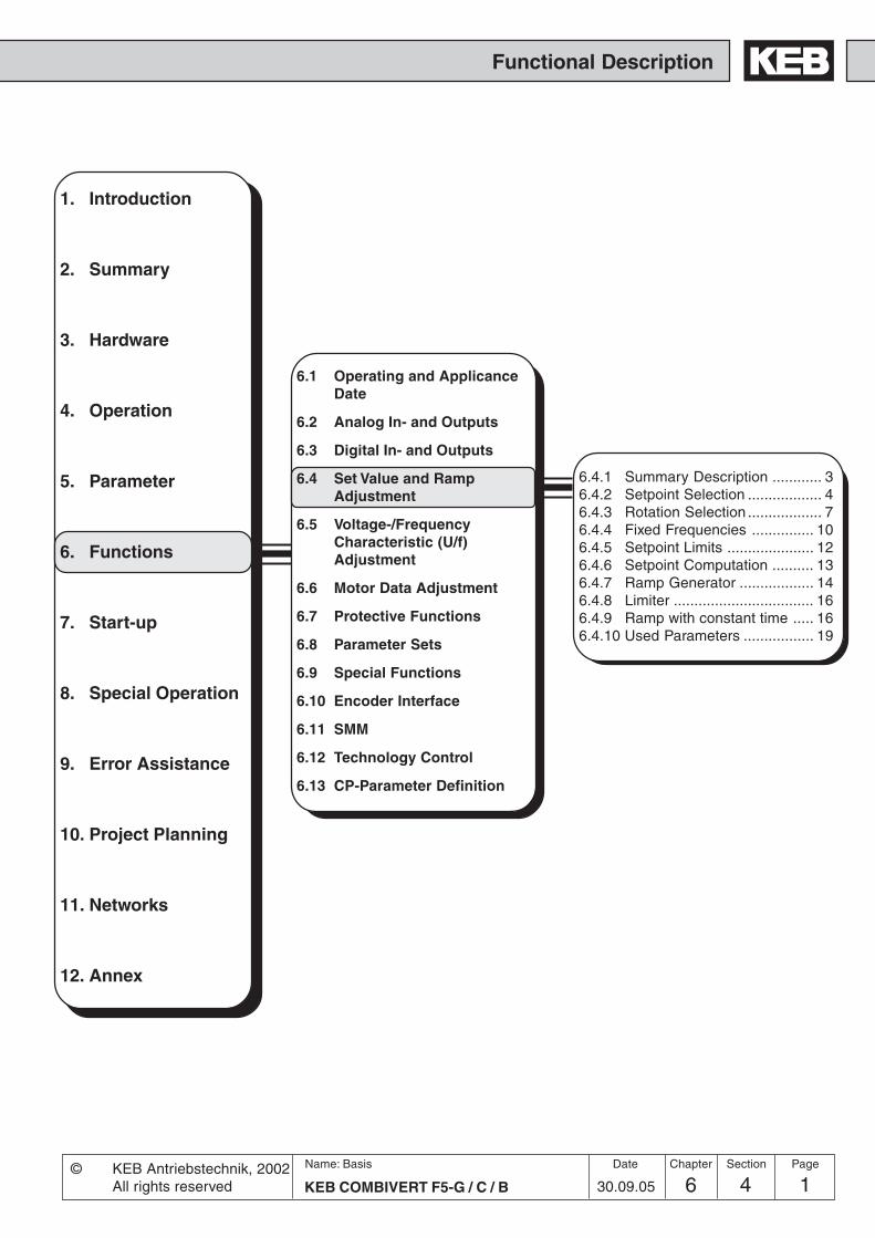
Functional Description
1. Introduction
2. Summary
3. Hardware
4. Operation
5. Parameter
6. Functions
7. Start-up
8. Special Operation
9. Error Assistance
10. Project Planning
11. Networks
12. Annex
6.1 Operating and ApplicanceDate
6.2 Analog In- and Outputs
6.3 Digital In- and Outputs
6.4 Set Value and RampAdjustment
6.5 Voltage-/FrequencyCharacteristic (U/f)Adjustment
6.6 Motor Data Adjustment
6.7 Protective Functions
6.8 Parameter Sets
6.9 Special Functions
6.10 Encoder Interface
6.11 SMM
6.12 Technology Control
6.13 CP-Parameter Definition
6 4 1KEB COMBIVERT F5-G / C / B
Name: Basis
30.09.05© KEB Antriebstechnik, 2002
All rights reserved
Section PageDate Chapter
6.4.1 Summary Description ............ 36.4.2 Setpoint Selection .................. 46.4.3 Rotation Selection .................. 76.4.4 Fixed Frequencies ............... 106.4.5 Setpoint Limits ..................... 126.4.6 Setpoint Computation .......... 136.4.7 Ramp Generator .................. 146.4.8 Limiter .................................. 166.4.9 Ramp with constant time ..... 166.4.10 Used Parameters ................. 19

6 4 KEB COMBIVERT F5-G / C / B2Name: Basis
30.09.05© KEB Antriebstechnik, 2002
All rights reserved
Functional Description Set Value and Ramp Adjustment
Chapter Section Page Date
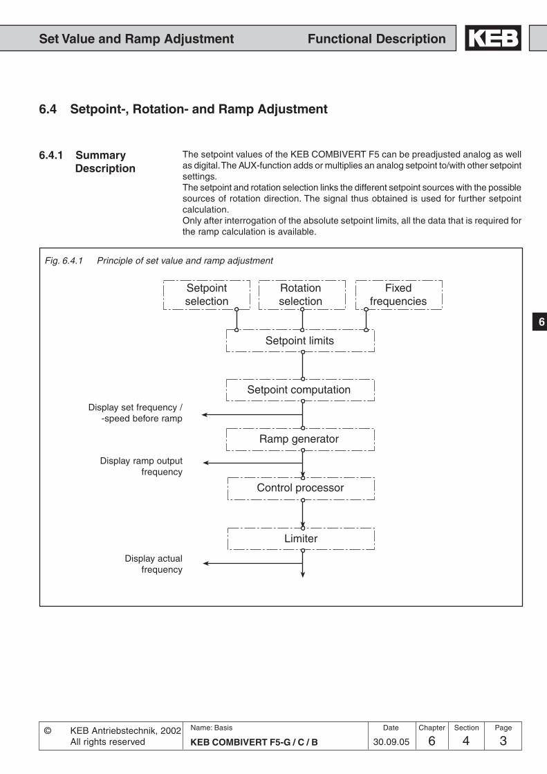
6 4 3KEB COMBIVERT F5-G / C / B
Name: Basis
30.09.05
6
© KEB Antriebstechnik, 2002All rights reserved
Functional DescriptionSet Value and Ramp Adjustment
Section PageDate Chapter
6.4.1 SummaryDescription
6.4 Setpoint-, Rotation- and Ramp Adjustment
Fig. 6.4.1 Principle of set value and ramp adjustment
The setpoint values of the KEB COMBIVERT F5 can be preadjusted analog as wellas digital. The AUX-function adds or multiplies an analog setpoint to/with other setpointsettings.The setpoint and rotation selection links the different setpoint sources with the possiblesources of rotation direction. The signal thus obtained is used for further setpointcalculation.Only after interrogation of the absolute setpoint limits, all the data that is required forthe ramp calculation is available.
Rotationselection
Setpoint limits
Setpoint computation
Ramp generator
Control processor
Display set frequency /-speed before ramp
Display actualfrequency
Fixedfrequencies
Setpointselection
Limiter
Display ramp outputfrequency

6 4 KEB COMBIVERT F5-G / C / B4Name: Basis
30.09.05© KEB Antriebstechnik, 2002
All rights reserved
Functional Description Set Value and Ramp Adjustment
Chapter Section Page Date
With oP.0 it is determined how the setpoint is adjusted.
The analog setpoints are adjusted via AN1, AN2 or AN3 (option). Chapter 6.2„Analog In- and Outputs“ describes the analog signal processing. The indicationof the setpoints can occur either before or after the signal processing(ru.27...32, ru.53).
With parameter oP.3 „Absolute digital setpoint adjustment“ a setpoint frequencyof -400... 400 Hz can be adjusted.With parameter oP.5 „Digital setpoint adjustment in percent“ a setpoint of-100% ... +100% of the maximal frequency (oP.10 / oP.11) can be adjusted.
With the motorpoti function a setpoint of -100%...0...100% between the limitsadjusted in the parameters oP.6 / oP.7 and oP.10 / oP.11 can be adjusted viadigital inputs (see 6.9.3 „Motorpoti function“).
Adjustment of absolute setpoint speed in rpm (SY.52) via the systemparameters.
Motorpoti function
Analog setpoint
Digital setpoint
System parameters
���! ���"
��#�
����� �$�#�����#
����
��
� � # %!&"
��#�
����
���& ��� ���� ���! ��� ��" ��# ���
�
���%�
Fig. 6.4.2 Setpoint selection
Analog setpoint Digital setpoint
see Chap. 6.7Motorpoti
see Chap. 6.2Analog input
Motorpoti
AUXREF
Setpoint limits
absolute in %
Systemparameter
Keyboard / Bus
Other setpoints
Terminal strip
Setpointselection
AN2Kl. X2A.3 /
X2A.4
AN1Kl. X2A.1 /
X2A.2
Output ext.PID-controller
AN1direct
Speedmeasurement
1
Speedmeasurement
2
ref. valuehigh res.
AN3(opt.)

6 4 5KEB COMBIVERT F5-G / C / B
Name: Basis
30.09.05
6
© KEB Antriebstechnik, 2002All rights reserved
Functional DescriptionSet Value and Ramp Adjustment
Section PageDate Chapter
Adjustment of the setpoint value from the output of the technology controller (see6.12).
Adjustment of the setpoint value via one of the two speed measurements (see6.10).
The cycle time of the software is 1 ms (BASIC: 2). During this time the analoginput/output status is updated once. Additionally the inverter requires a processingtime of 1...3 ms before the new setpoint value is calculated. If the inverter is usedas secondary final control element of a superior control, this time can impair thedynamics of the entire closed-loop control system.In such cases the analog setpoint value can be processed directly to the controlprocessor (direct setpoint adjustment). Thus a sampling time of 250 ms is possible.To enable this fast response to an analog setpoint value, some restrictions mustbe accepted:
• The setpoint limitations oP. 6 / oP. 7 / oP. 11 do not have any function; thefrequency setpoint is only limited by oP. 14 (for both directions).
• The calculation formula of the analog setpoint value changes. The parametersoP.6 / oP. 7 are without influence on the setpoint calculation.
nset
= (analog value/10V * 100% - An. 6) * An. 5 * oP.10
• The acceleration / deceleration and S-curve time have no effect; it is operatedinternally without ramps.
• The parameters An.1...4 and An. 7...9 are without any function.• The maximal filter time for the analog inputs is 2 ms.
Direct analog setpoint adjustment(AN1 direct)
(not at B-control)
Output external PID-controller
Speed measurement(not at B-control)
High-resolution reference setting(oP.63, oP64)
The reference value is determined as follows from oP.63 and oP.64 at oP.0 = 10(internal resolution):
Ref. value (high-resolution) = 0P.64 * resolution factor * oP.63/ 2^14
A 32-bit-value results from this modulation. The upper 16 bits are processeddirectly (modulator or speed controller reference value). The lower 16 bits areintegrated. In case of an overflow the value of the upper 16 bits is increased by 1,so a fine value results in the midrange.
oP.0 = 10oP.64 = 100 HzResolution factor = 80 HzoP.63 = 150994
Example
• The stop position controller cannot be activated.
6 4 KEB COMBIVERT F5-G / C / B6Name: Basis
30.09.05© KEB Antriebstechnik, 2002
All rights reserved
Functional Description Set Value and Ramp Adjustment
Chapter Section Page Date
Ref. value (high-resolution) = 100 * 80 * 150994/ 2^14 = 73727/ 2^16 = 1,124985
This corresponds to 0,0140625 Hz.
In case of a resolution of 0.0125 Hz, 0.0250 Hz must be given out in each eightcycle, in order to reach the reference value
Dec. place of the reference value = Remain of the reference value/ 2^16 =8191
The overflow when integrating the decimal place can be determined as follows,in order to reach the mean value.
Number of cycles up to the overflow = 2^16/ decimal places = 8,00098
The following displayed values results of:
ru.82 (ramp output) = 150992
converted in Hz:
Ramp output (Hz) = ru.82 * oP.64./ 2^30 = 0,0140622 Hz
ru.83 (actual value) = 134217 and in each eight cycle 268434
converted in Hz:
Actual value = ru.83 * oP.64/ 2^30 = 0,0125 Hzin each eight cycle 0,025 Hz
Setting ranges are faded out with this function, in order to avoid resonances. Thetarget is pass through with the ramp. The setpoint value is always adjusted to theupper or lower limit of the target.
Parameter:oP.65 min. proh. reference 1oP.66 max. proh. reference 1oP.67 min proh. reference 2oP.68 max. proh. reference 2
The parameters are not programmable.
Fade out target for setpoint value
The adjusted values are accepted still as setpoint value, so that the function isnot active in case that lower and upper limit have the same value. If a highervalue is selected for the lower limit than for the upper limit, the function is also notactive.

6 4 7KEB COMBIVERT F5-G / C / B
Name: Basis
30.09.05
6
© KEB Antriebstechnik, 2002All rights reserved
Functional DescriptionSet Value and Ramp Adjustment
Section PageDate Chapter
6.4.3 RotationSelection oP.1
oP. 10
2
1
354
6
7
8
9
Fig. 6.4.3 Rotation selection with oP.1
DigitaloP.2
Terminal stripforward/reverse
Terminal stripRun/Stop
Setpoint-dependent
Control wordSY.50
0-lim. 0-lim. 0-lim. LS 0-lim.abs. abs. abs. no LS abs.
Setpoint limits
Rotationselection
The selection of rotation direction determines the manner in which the rotationdirection is adjusted. One can choose between following possibilities:
Digital rotation adjustment(oP.2)
oP.2 Display Setpoint rotation0 LS Standstill (Low Speed)1 F Forward (Forward)2 r Reverse (Reverse)
0-limited or absolute
Setpoint Setpoint
0-limited absolute
Setpointadjustment
Concerning the adjustment of direction of rotation it is differentiated between twoevaluations:0-limited - negative setpoints are set to zero, i.e. only positive setpoints are driven
in accordance with the selected rotation directionabsolute - no sign of the setpoint is evaluated and it is always driven with the
amount in accordance with the selected rotation direction
6.4.3.a Absolute and 0-limited
Setpointadjustment

6 4 KEB COMBIVERT F5-G / C / B8Name: Basis
30.09.05© KEB Antriebstechnik, 2002
All rights reserved
Functional Description Set Value and Ramp Adjustment
Chapter Section Page Date
Rotation adjustment via terminalstrip
oP.1 = „2“ or „3“
� �
�����������
Input selectionRotation direction F (Run/Stop) oP.60
Rotation direction R (forward/reverse) oP.61
The rotation selection via terminal strip allows the adjustment of the direction ofrotation via switch or from a primary control.
With parameter oP.60 one input is determined for rotation direction forward (orrun/stop) and with oP.61 one input for rotation direction reverse (or forward/reverse).
Bit -No. Decimal value Input Terminal0 1 ST (Prog. input „Control release/Reset“) X2A.161 2 RST (Prog. input „Reset“) X2A.172 4 F (Prog. input „Forward“) 1) X2A.143 8 R (Prog. input „Reverse“) 2) X2A.154 16 I1 (Prog. input 1) X2A.105 32 I2 (Prog. input 2) X2A.116 64 I3 (Prog. input 3) X2A.127 128 I4 (Prog. input 4) X2A.138 256 IA (Internal input A) none9 512 IB (Internal input B) none
10 1024 IC (Internal input C) none11 2048 ID (Internal input D) none
1) default at oP.60 2) default at oP.61
In the case of rotation selection forward/reverse (oP.1= „2“ or „3“) the inputsdetermined with oP.60 and oP.61 work as follows:
Forward Revers InputF R Function0 0 LS0 1 Reverse1 0 Forward1 1 Forward
In the case of rotation selection run/stop and forward/reverse (oP.1= „4“ or „5“)the inputs determined with oP.60 and oP.61 work as follows:
Revers Forward InputF/R Run/Stop Function0 0 LS0 1 Forward1 0 LS1 1 Reverse
oP.1 = „4“ or „5“
X2A.14 X2A.15
X2A.14 X2A.15

6 4 9KEB COMBIVERT F5-G / C / B
Name: Basis
30.09.05
6
© KEB Antriebstechnik, 2002All rights reserved
Functional DescriptionSet Value and Ramp Adjustment
Section PageDate Chapter
Rotation direction is dependenton the sign of the setpoint
The direction of rotation can be defined with the preadjusted setpoint signal. Inthe case of analog signals through adjustment of positive or negative voltages. Inthe case of digital signals through adjustment of positive frequencies (withoutsign) or negative frequencies (negative sign in the display). Following settingsare possible:
In this case a direction of rotation must be adjusted via a digital input, digitally viaoP.2 or via control word SY.50 in order for the inverter to modulate. It is unimportantwhich direction of rotation is adjusted, as the direction of rotation is dependenton the setpoint.
no rotation direction set -> LS (Modulation disabled)oP.1 = 6 set direction of rot.;pos. value (also 0) -> rotation direction forward
set direction of rot.;negative value -> rotation direction revers
In this case the inverter always modulates. No direction of rotation needs to beadjusted.
oP.1 = 7 positive value (also 0) -> rotation direction forwardnegative value -> rotation direction reverse
Rotation direction is dependenton the control word SY.50
The control word is used for the state control of the inverter via bus. In order forthe inverter to react to the control word, the respective control process must beenabled (oP.1=8 or 9). When adjusting the direction of rotation via the controlword, the setpoint can be evaluated 0-limited (oP.1 = 8) or absolute (oP.1 = 9).
Evaluation with LS (switch-off of modulation)
Evaluation without LS
Bit Function Description0 Control release 0 = control release not enabled; 1= control release
enabled This bit takes effect only if di.1 Bit 0 is set.Then the AND-operation with di.2 Bit 0 and the terminalST is effective); control release ST (hardware) must beset additionally.
1 Reset Triggers reset when changing from 0 => 12 Run / Stop 0 = setpoint rotation Stop; 1 = setpoint rotation Run
(source of setpoint direction op.1 = 8 or 9)3 For / Rev 0 = setpoint rotation forward; 1 = setpoint rotation
reverse(source of setpoint rotation op.1 = 8 or 9)
4-6 Current set Source of set selection fr.2 = 57 Free8 Fast stop 0 = fast stop not activated; 1 = fast stop activated
( OR-operation with further sources for fast stop)9-15 Free
If Run/Stop is to be adjusted over the control word, oP.2 must be setto „0“. The terminals F/R may not be wired (OR-operation of terminal,oP.2 and Sy.50).
Control word (low) Sy.50

6 4 KEB COMBIVERT F5-G / C / B10Name: Basis
30.09.05© KEB Antriebstechnik, 2002
All rights reserved
Functional Description Set Value and Ramp Adjustment
Chapter Section Page Date
Fig. 6.4.4 Fixed frequencies
6.4.4 Fixed Frequencies(oP.18...23)
The KEB COMBIVERT supports up to 3 fixed frequencies for each parameterset, which can be selected via two digital inputs. With oP.19 and oP.20 the inputsrequired for the selection are defined (also see „Digital inputs“ Chapt. 6.3.11).The rotation direction source for fixed frequency mode is defined with oP.18. Theadjustment is independent of oP.1 and is valid exclusively for the fixed frequencies.The adjustment of a fixed frequency has priority over the „normal“ setpointadjustment.
Input fixed frequency 1
Input fixed frequency 2
Fixed frequenciesf1...f3
oP. 180
2
1
354
6
7
8
9
oP.19 Input selectionFixed frequency 1
0...4095(according to table)
oP.20 Input selectionFixed frequency2
0...4095(according to table)
Fixed frequency 1oP.21: -400...400 Hz
Fixed frequency 2oP.22: -400...400 Hz
Fixed frequency 3oP.23: -400...400 Hz
Setpoint limits
DigitaloP.2
0-lim. abs. 0-lim. abs. 0-lim. abs. 0-lim. abs.LS no LS
Terminalstrip
For / Rev
Terminalstrip
Run / Stop
Setpoint-dependent
DRIVECOMSY.50
Fixed valuerotation direction source
f1f2f3
t
Setpoint
Fig. 6.4.4.a Selection of fixed frequencies
InputFixed frequency 1
InputFixed frequency 2
Selection of fixed frequencies

6 4 11KEB COMBIVERT F5-G / C / B
Name: Basis
30.09.05
6
© KEB Antriebstechnik, 2002All rights reserved
Functional DescriptionSet Value and Ramp Adjustment
Section PageDate Chapter
Fixed-value rotation directionsource (oP.18)
With oP.18 it is defined how the direction of rotation is determined in case ofactive fixed frequency. The function and the value range correspond to oP.1.
oP.18 Rotation direction source for fixed frequencies0 digital via oP.2; setpoint 0-limited1 digital via oP.2; setpoint absolute2 terminal strip F/R; setpoint 0-limited3 terminal strip F/R; setpoint absolute4 terminal strip Run/Stop; setpoint 0-limited5 terminal strip Run/Stop; setpoint absolute6 setpoint-dependent with LS-recognition7 setpoint-dependent without LS-recognition8 control word SY.50; 0-limited9 control word SY.50; 0-absolute
Fixed-value input selection 1 and 2(oP.19; oP.20)
Fixed frequency 1...3(oP.21, oP.22, oP.23)
The three fixed frequencies oP.21...23 are set-programmable and can be adjustedin the range of -400...400 Hz.
Bit -No. Decimal value Input Terminal0 1 ST (Prog. input „Control release/Reset“) X2A.161 2 RST (Prog. input „Reset“) X2A.172 4 F (Prog. input „Forward“) X2A.143 8 R (Prog. input „Reverse“) X2A.154 16 I1 (Prog. input 1) X2A.105 32 I2 (Prog. input 2) X2A.116 64 I3 (Prog. input 3) X2A.127 128 I4 (Prog. input 4) X2A.138 256 IA (Internal input A) none9 512 IB (Internal input B) none10 1024 IC (Internal input C) none11 2048 ID (Internal input D) none

6 4 KEB COMBIVERT F5-G / C / B12Name: Basis
30.09.05© KEB Antriebstechnik, 2002
All rights reserved
Functional Description Set Value and Ramp Adjustment
Chapter Section Page Date
+f [Hz]
-f [Hz]
400
oP.7*1 (oP.6)
oP.6
oP.14
oP.10
oP.15*1 (oP.14)
oP.11*1 (oP.10)
+100
-100
-400
Absolute maximalfrequency reverse
6.4.5 Setpoint Limits Following limit values can be preadjusted:
Setpoint[%]Setpoint[%]
Minimal frequencyforward
Maximal frequencyforward
Absolute maximalfrequency forward
Maximal frequencyreverse
Minimal frequencyreverse
*1 If the value „=For“ is adjusted in these parameters (limit values rotationdirection reverse), then the adjusted values for rotation direction forward (oP.6,oP.10 and oP.14) are valid.
In case of setpoint adjustment in percent the minimal and maximal frequenciesform the characteristic for the frequency calculation (0% = minimal frequency;100% = maximal frequency). In case of absolute setpoint adjustment the minimaland maximal frequencies limit the setpoint. Separate limits can be adjusted forboth rotation directions. If the value „For“ is adjusted for rotation direction „Re-verse“, then the values for „Forward“ are valid.
Setting range: oP.6: 0...400 Hz Default: 0 HzoP.10: 0...400 Hz Default: 70 HzoP.7: =For, 0...400 Hz Default: =ForoP.11: =For, 0...400 Hz Default: =For
Minimal- / Maximal frequency(oP.6, oP.7, oP.10, oP.11)
After the minimal and maximal frequencies the setpoint is limited through theabsolute maximal frequency and subsequently transferred to the ramp generator.Since the analog setpoint is always calculated onto the maximal frequencies(oP.10, oP.11), it is possible, to adjust the characteristic of the analog setpointwith the same gain for both rotation directions (see Fig. 6.4.5.a) in spite of diffe-rent maximal output frequencies. If the value „=For“ is adjusted in oP.15, then theabsolute maximal frequency of oP.14 is valid for both rotation directions.
Absolute maximal frequency(oP.14, oP.15)
Fig. 6.4.5 Setpoint limits

6 4 13KEB COMBIVERT F5-G / C / B
Name: Basis
30.09.05
6
© KEB Antriebstechnik, 2002All rights reserved
Functional DescriptionSet Value and Ramp Adjustment
Section PageDate Chapter
(oP. 10)
-100% +100%
(oP.14)
+f [Hz]
-f [Hz]
(oP.11/oP.15)
The unit differentiates between two setpoint adjustments:- the setpoint adjustment
With the adjusted setpoint limits the frequency range 0%...100% is defined.in this case the adjustment 0% corresponds to the minimal frequency and100% to the maximal frequency. The frequency is calculated according tofollowing formula:
positive setpoint [Hz] = oP.6 + (setpoint adjustment [%] x oP.10-oP.6
) 100%
negative setpoint [Hz] = oP.7 + (setpoint adjustment [%] x oP.11-oP.7
) 100%
The frequency is limited through the corresponding maximal frequencies.
- the absolute setpoint adjustment, i.e. the setpoint is directly adjusted asfrequency and limited through the corresponding minimal and maximalfrequencies as well as through the absolute maximal frequency.
The setpoint sources are assigned as follows:
Setpoint adjustment in percent Absolute setpoint adjustmentTerminal strip (analog setpoint) Keyboard/Bus absoluteKeyboard/Bus in % Set speed value SY.52Motorpoti Speed detectionPID-controller
6.4.6 SetpointComputation
Fig. 6.4.5.a Setpoint limits
Setpoint[%]Setpoint [%]
Maximal frequencyforward
Absolute maximal frequencyforward
Maximal frequencyreverse = abs.max. frequencyreverse

6 4 KEB COMBIVERT F5-G / C / B14Name: Basis
30.09.05© KEB Antriebstechnik, 2002
All rights reserved
Functional Description Set Value and Ramp Adjustment
Chapter Section Page Date
100
80
0
D f
100
50
D t
oP.28
Df
D t
oP.29
D t
D f Df
oP.30
D t
oP.31
+f [Hz]
-f [Hz]
Rot
atio
n di
rect
ion
cloc
kwis
eR
otat
ion
dire
ctio
nco
unte
r-cl
ockw
ise
oP.28 Acceleration time forwardoP.29 *1 Acceleration time reverseoP.30 *2 Deceleration time forwardoP.31 *1 Deceleration reverse
D f Frequency changeD t Acceleration time for Df
Fig. 6.4.7 Acceleration and deceleration times
*1 If the value „=For“ is adjusted in these parameters (acceleration and deceleration times for rotation directionreverse), then the values for rotation direction forward (oP.28 and oP.30) are valid.
*2 If the value „=Acc“ is adjusted, then the value for acceleration forward (oP.28) is valid.
6.4.7 Ramp Generator The ramp generator assigns an adjustable time to a frequency change, during thistime the change stall take place. The acceleration time (for pos. frequency changes)and deceleration time (for neg. frequency changes) can be adjusted separately forboth directions of rotation. To enable jerk-free acceleration and deceleration, so-called S-curves can be adjusted in addition to it.The adjusted ramp times refer to 100Hz (at ud.2=0). The ramp times changes inproportion to the frequency change. The times to be adjusted are calculated asfollows:
desired ramp time frequency change (Df)––––––––––––––––––––––––––––––––– = –––––––––––––––––––ramp time to be adjusted (oP.28...oP.31) 100 Hz (dep. on ud.2)
Calculation of theacceleration anddeceleration times:
5s x 100Hz oP.28 = ———————— = 8,33s
(70Hz-10Hz)
100Hz x real ramp timeoP.28...oP.31 = ––––––––––––––––––––
Df
A drive shall accelerate from 10Hz to 70Hz in 5s.Example
ACC/DEC time factor (oP.62) The time factor extends the standard ramp time (oP.28...31) by the adjusted value.The S-curve time do not change.
Value Ramp time0 adjusted value x 11 adjusted value x 22 adjusted value x 43 adjusted value x 84 adjusted value x 16

6 4 15KEB COMBIVERT F5-G / C / B
Name: Basis
30.09.05
6
© KEB Antriebstechnik, 2002All rights reserved
Functional DescriptionSet Value and Ramp Adjustment
Section PageDate Chapter
oP.28
t [s]
oP.32 oP.32
oP.30
oP.34 oP.34
oP.33
oP.29
oP.33 oP.35
oP.31
oP.35
70
70
0
For some applications it is of advantage if the drive starts and stops nearly jerk-free. This function is achieved by straightening the acceleration and decelerationramps. The straightening time, also called S-curve time, can be preadjusted withthe parameters oP.32...oP.35. But S-curves are excecuted only with the adjustment„Ramp with constant rise“.
S-curve time
+f [Hz]
-f [Hz]
Rot
atio
n di
rect
ion
forw
ard
Rot
atio
n di
rect
ion
reve
rse
Fig. 6.4.6.a S-curve timeoP.28 Acceleration time forwardoP.29 *1 Acceleration time reverseoP.30 Deceleration time forwardoP.31 *1 Deceleration time reverseoP.32 *2 S-curve time acceleration forwardoP.33 *1 S-curve time acceleration reverseoP.34 *3 S-curve time deceleration forwardoP.35 *1 S-curve time deceleration reverse
In order to drive defined ramps with activated S-curve time, the preadjustedacceleration and deceleration times (oP.28...oP.31) must be larger than theS-curve time (oP.32...oP.34) belonging to it.
At the beginning and the end of the acceleration ramp a parabolic curve is drivenfor the time adjusted in parameter oP.32. As a result the adjusted ramp time isextended by oP.32.
*1 If the value „For“ is adjusted in these parameters (for rotation direction reverse), then the values adjusted in the parametersfor rotation direction forward are valid.
*2 If the value „=Acc“ is adjusted, then the value for acceleration forward (oP.28) is valid.*3 If the value „=Acc“ is adjusted in parameter oP.34, then the value adjusted in parameter oP.32 is valid for all S-curve times.
Value „0“ switches the corresponding S-curve off.
Total acceleration time = oP.28 + oP.32
Example for acceleration withrotation direction forward

6 4 KEB COMBIVERT F5-G / C / B16Name: Basis
30.09.05© KEB Antriebstechnik, 2002
All rights reserved
Functional Description Set Value and Ramp Adjustment
Chapter Section Page Date
6.4.8 Limiter (oP.36...41) The setpoint after the ramp generator can be changed for example through slipcompensation. Before the setpoint triggers the modulator, it is once again limited.So the limiter determines the minimal and maximal output frequency and can beprogrammed differently in all sets.
If the frequency drops below the adjusted minimal output frequency, the modulationis switched off. For oP.37 = „=For“, the value for clockwise-rotation oP.36 is valid.
Setting range oP.36 0...400 Hz Default: 0 HzSetting range oP.37 =For; 0...400 Hz Default: =For
If the frequency rises above the adjusted maximal output frequency, it is limitedonto the adjusted value. For oP.41 = „=For“, the value for clockwise-rotation oP.40is valid.
Setting range oP.40 0...400 Hz Default: 200 HzSetting range oP.41 =For; 0...400 Hz Default: =For
Minimal output frequencyclockwise rotation (oP.36)
Minimal output frequency counter-clockwise rotation (oP.37)
Maximal output frequencyclockwise rotation (oP.40)
Maximal output frequency counter-clockwise rotation (oP.41)
6.4.9 Ramp with constanttime
At the ramp with constant time the acceleration and deceleration times adjustedwith oP.28...oP.31 always equal the real ramp times, independent of the set value.In this operating mode S-curves are not possible.
Here a little example for the use of ramps with constant time:
Two conveyor belts run with different speeds. Both of them receive the Stop-command at the same time. The belts reduce the speed in proportion to theadjusted time and come to a standstill simultaneously.
f_sollf_ist
tt_rampet_rampet_rampet_rampet_rampe
Fig. 6.4.9.a Forward acceleration with constant ramp time
f_sollf_ist

6 4 17KEB COMBIVERT F5-G / C / B
Name: Basis
30.09.05
6
© KEB Antriebstechnik, 2002All rights reserved
Functional DescriptionSet Value and Ramp Adjustment
Section PageDate Chapter
f_sollf_ist
tt_rampet_rampet_rampet_rampet_rampe
Fig. 6.4.9.b Forward deceleration with constant ramp time
f_sollf_ist
The different ramp functions can be adjusted separately for every frequencychange (acceleration forward, deceleration forward and so on). The selection ismade with oP.27 and is adjustable separately in each set.The function is activatedafter pressing „ENTER“.
Ramp Bit-No Value Mode Reference frequency0 const. ascent 100 Hz (dep. of ud.2)
Acc. 0 + 1 1 const. time actual set valueforward 2 *const. time last set value at constant run
3 reserved0 const. ascent 100 Hz (dep. of ud.2)
Dec. 2 + 3 4 *const. time actual set valueforward 8 const. time last set value at constant run
12 reserved0 const. ascent 100 Hz (dep. of ud.2)
Acc. 4 + 5 16 const. time actual set valuereverse 32 *const. time last set value at constant run
48 reserved0 const. ascent 100 Hz (dep. of ud.2)
Dec. 6 + 7 64 *const. time actual set valuereverse 128 const. time last set value at constant run
192 reserved
* Do not adjust these values - they are only sensible, if acceleration does nottake place from standstill or deceleration is not made to standstill.
If the mode constant time is activated for a ramp, then the s-curve function isdeactivated for this ramp. The ascent is limited to minimum 100 Hz / 4800 s.
Ramp mode (oP.27)

6 4 KEB COMBIVERT F5-G / C / B18Name: Basis
30.09.05© KEB Antriebstechnik, 2002
All rights reserved
Functional Description Set Value and Ramp Adjustment
Chapter Section Page Date
The frequency change per raster scan delta_t (step size delta_f) for the modeconstant ascent is calculated from the ramp time t_ramp and the referencefrequency (100 Hz dependend on ud.2) as follows:
100 Hzdelta_f = —————————
t_rampe / delta_t
For different set values the real ramp time is calculated according to followingformula:
f_sett = t_ramp * ————
100 Hz
The actual step size for the mode constant time is calculated from the step sizedelta_f and the actual set value f_set as follows:
f_setdelta_f(variabel) = delta_f * ———
100 Hz
For the simplification of the internal calculation as frequency reference 102.4 Hz(e.g. 204.8 Hz or 409.6 Hz dependend on ud.2) is used :
f_setdelta_f(variabel) = delta_f * —————
102.4 Hz
As a result an error of -2,4 % for the real ramp time occurs. If a certain real ramptime has to be adjusted, the desired value must be divided by 1.024.
Example:
desired ramp time = 10 sadjusted ramp time = 10 s / 1.024 = 9.77 s
Fig. 6.4.9.c Graph with ramp modes
delta_fkonstant
delta_t
delta_fkonstant
delta_t
delta_fkonstant
delta_t
delta_f_2variabel
delta_t
delta_f_1variabel delta_t
t_rampet_1
f_1
t
t_2
f_2
f_soll
100 Hz
f_soll
f_2
100 Hz
f_1
delta_fkonstant
delta_fkonstant
delta_f_2variabel
delta_f_1variabel
delta_fkonstant
Calculations

6 4 19KEB COMBIVERT F5-G / C / B
Name: Basis
30.09.05
6
© KEB Antriebstechnik, 2002All rights reserved
Functional DescriptionSet Value and Ramp Adjustment
Section PageDate Chapter
StepParam. Adr.ENTERPROG.R/W
min max default
6.4.10 Used Parameters
oP.0 0300h 4 4 4 0 9 1 0 -
oP.1 0301h 4 4 4 0 9 1 7 -
oP.2 0302h 4 4 4 0 2 1 0 -
oP.3 0303h 4 4 - -4000 rpm 4000 rpm 0,125 rpm 0 rpm dep. on ud.2
oP.5 0305h 4 4 - -100 % 100 % 0,1 % 0,0 % -
oP.6 0306h 4 4 - 0 rpm 4000 rpm 0,125 rpm 0 rpm dep. on ud.2
oP.7 0307h 4 4 - -0,125 rpm 4000 rpm 0,125 rpm -0,125 rpm -0,125 rpm: =For (dep. on ud.2)
oP.10 030Ah 4 4 - 0 rpm 4000 rpm 0,125 rpm 2100 rpm dep. on ud.2
oP.11 030Bh 4 4 - -0,125 rpm 4000 rpm 0,125rpm -0,125 rpm -0,125 rpm: =For (dep. on ud.2)
oP.14 030Eh 4 4 - 0 rpm 4000 rpm 0,125 rpm 4000 rpm dep. on ud.2
oP.15 030Fh 4 4 - -0,125 rpm 4000 rpm 0,125rpm -0,125 rpm -0,125 rpm: =For (dep. on ud.2)
oP.18 0312h 4 4 4 0 9 1 7 -
oP.19 0313h 4 - 4 0 4095 1 16 -
oP.20 0314h 4 - 4 0 4095 1 32 -
oP.21 0315h 4 4 - -4000 rpm 4000 rpm 0,125 rpm 100 rpm dep. on ud.2
oP.22 0316h 4 4 - -4000 rpm 4000 rpm 0,125 rpm -100 rpm dep. on ud.2
oP.23 0317h 4 4 - -4000 rpm 4000 rpm 0,125 rpm 0 rpm dep. on ud.2
oP.27 031Bh 4 4 4 0 255 1 0 -
oP.28 031Ch 4 4 - 0,00 s 300,00 s 0,01 s 5,00 s -
oP.29 031Dh 4 4 - -0,01 s 300,00 s 0,01 s -0,01 s -0,01 s: =For
oP.30 031Eh 4 4 - -0,01 s 300,00 s 0,01 s 5,00 s -0,01 s: =Acc
oP.31 031Fh 4 4 - -0,01 s 300,00 s 0,01 s -0,01 s -0,01 s: =For
oP.32 0320h 4 4 - 0,00 s 5,00 s 0,01 s 0,00 s 0,00 s: off
oP.33 0321h 4 4 - -0,01 s 5,00 s 0,01 s -0,01 s -0,01 s: =For; 0,00 s: off
oP.34 0322h 4 4 - -0,01 s 5,00 s 0,01 s -0,01 s -0,01 s: =Acc; 0,00 s: off
oP.35 0323h 4 4 - -0,01 s 5,00 s 0,01 s -0,01 s -0,01 s: =For; 0,00 s: off
oP.40 0328h 4 4 - 0 rpm 4000 rpm 0,125 rpm 4000 rpm dep. on ud.2
oP.41 0329h 4 4 - -0,125 rpm 4000 rpm 0,125rpm 0,01 rpm -0,125 s: =For; dep. on ud.2
oP.60 033Ch 4 - 4 0 4095 1 4 -
oP.61 033Dh 4 - 4 0 4095 1 8 -
SY.52 0034h 4 - - -16000 rpm 16000 rpm 1 rpm 0 rpm -
oP.62 033Eh - - 4 0 4 1 0 -
oP.63 033Fh - - - -2^31-1 2^31-1 1 0 -
oP.64 0340h - - - 0 n * 400 n * 0,0125 0 Hz

6 4 KEB COMBIVERT F5-G / C / B20Name: Basis
30.09.05© KEB Antriebstechnik, 2002
All rights reserved
Functional Description Set Value and Ramp Adjustment
Chapter Section Page Date
StepParam. Adr.ENTERPROG.R/W
min max default
oP.65 0341h - - - -4000 min-1 4000 min-1 0,125 min-1 0 min-1 -
oP.66 0342h - - - -4000 min-1 4000 min-1 0,125 min-1 0 min-1 -
oP.67 0,43h - - - -4000 min-1 4000 min-1 0,125 min-1 0 min-1 -
oP.68 0344h - - - -4000 min-1 4000 min-1 0,125 min-1 0 min-1 -
SY.52 0034h 4 - - -16000 min-1 16000 min-1 1 min-1 0 min-1 -

6 5 1KEB COMBIVERT F5
Name: Basis
03.03.04
Functional Description
Chapter Section PageDate© KEB Antriebstechnik, 2002All Rights reserved
1. Introduction
2. Summary
3. Hardware
4. Operation
5. Parameter
6. Functions
7. Start-up
8. Special Operation
9. Error Assistance
10. Project Design
11. Networks
12. Annex
6.1 Operating and Appliance
Date
6.2 Analog In- and Outputs I
6.3 Digital In- and Outputs
6.4 Set Value and Ramp
Adjustment
6.5 Voltage-/Frequency
Characteristic (U/f)
Adjustment
6.6 Motor Data Adjustment
6.7 Protective Functions
6.8 Parameter Sets
6.9 Special Functions
6.10 Speed Measurement
6.11 SMM, Posi, Syncron, CTM
6.12 Technology Control
6.13 CP-Parameter Definition
6.5.1 Control Type andMax. Frequency Mode ........... 3
6.5.2 Rated Frequency and Boost .. 46.5.3 Additional Rated Point ........... 46.5.4 Delta Boost ............................ 46.5.5 Voltage Stabilization............... 56.5.6 Max. Voltage Mode................. 66.5.7 Switching Frequency .............. 66.5.8 Used Parameters ................... 7

6 5 KEB COMBIVERT F52Name: Basis
03.03.04
Chapter Section Page Date © KEB Antriebstechnik, 2002All Rights reserved
Functional Description U/f-Characteristic Adjustment

36 5 3KEB COMBIVERT F5
Name: Basis
03.03.04
6
Section PageDate© KEB Antriebstechnik, 2002All Rights reserved
Chapter
Functional DescriptionU/f-Characteristic Adjustment
6.5 Voltage-/FrequencyCharacteristicAdjustment
In the following chapter all parameters for the adjustment of the voltage/frequencycharacteristic as well as the appropriate adjustments like modulation, voltage rise(Boost) and switching frequency are described. Except for the switching frequencythese adjustments apply only to F5-C, F5-B, F5-G and F5-M in controlled operation(CS.0=off).
6.5.1 Control Type (ud.2)and Max FrequencyMode (only F5-B)
This parameter depends in the value range on the used control. The values 0...3apply to open loop systems (F5-B/ -C and -G), the values 4...7 to closed loop systems(F5-M) and the values 8...11 to servos (F5-S).
This parameter defines the maximal possible output frequency/speed, the resolutionand the reference values for the ramp times, the analog outputs and the dcbrake.Changes effect all frequency/speed dependent parameters. The parametercan only be written with opened control release. After a change the initialization ispassed through, so that no Power-On-Reset is necessary.
ud. 2 Control type Maximal frequency Resolution0 F5-C/B/G 400 Hz 0,0125 Hz1 F5-C/B/G 800 Hz 0,025 Hz2 F5-C/B/G 1600 Hz 0,05 Hz3 F5-G 50 Hz 1,56 mHz4 F5-M 4000 rpm 0,125 rpm5 F5-M 8000 rpm 0,25 rpm6 F5-M 16000 rpm 0,5 rpm7 F5-M 500 rpm 0,0156 rpm8 F5-S 4000 rpm 0,125 rpm9 F5-S 8000 rpm 0,25 rpm
10 F5-S 16000 rpm 0,5 rpm11 F5-S 500 rpm 0,0156 rpm
For every frequency mode COMBIVIS uses an own Config-File. In the case of amode changeover all parameter information are read from the inverter and a newConfig-File is generated should it not already exist.
The switching frequency(uF.11) must be adjusted atleast 10-times higher than themaximal possible outputfrequency!
For applications with maximum torque with small output frequency a new mode wasintroduced.Special characteristics at High-Torque-Modus:• default of the set torque; the display is in 0,01 Nm• default of the rated speed /-frequency in 0,125 rpm / 0,0125 Hz.• the EMC constant for synchronous motors can be default up to 32 kV / 1000 rpm,that means rated speeds of the motors up to 12,5 rpm.
High-Torque-Modus

6 5 KEB COMBIVERT F54Name: Basis
03.03.04
Chapter Section Page Date © KEB Antriebstechnik, 2002All Rights reserved
Functional Description U/f-Characteristic Adjustment
UA
tuF.1
100%
uF.5
uF.4
uF.4 = 0,0...25,5 %; Default = 0 %uF.5 = 0,00...10,00 s; Default = 0 s
6.5.4 Delta Boost (uF.4/uF.5)
The Delta-Boost is a time-limited Boost used to overcome large breakaway torques.The Delta-Boost acts adding to the Boost; but the sum is limited to 25.5 %.
Fig. 6.5.4 Delta Boost
uF.1
100%
uF.0
110%
200%
uF.10=0
uF.10=1
uF.10=2 / 3
Fig. 6.5.2 Rated Frequency and Boost
6.5.2 Rated frequency(uF.0) and Boost(uF.1)
The voltage/frequency characteristic (U/f) is adjusted with the rated frequency (uF.0)and the Boost (uF.1).The rated frequency adjusts the frequency at which 100 %modulation depth (~input voltage) are achieved. The boost adjusts the output voltageto 0 Hz. Depending on uF.10 the modulation limit can be further increased in thisstage up to 200 % (see Fig. 6.5.2).
uF.0 = 0,00...400 Hz; Default = 50 HzuF.1 = 0,0...25,5 %; Default = PU-Id
uF.2 =-1: parabolic characteristic0,0...400 Hz; Default = 0,0 Hz
uF.3 = 0,0...100,0 %; Default = 0,0 %
6.5.3 Additional RatedPoint (uF.2/uF.3)
To adapt the U/f-characteristic to special conditions an additional point of supportcan be specified with uF.2 and uF.3. uF.2 defines the frequency and uF.3 the voltage.At uF.2 = 0 Hz the adjustment is ignored.
UA
fout
uF.1
100%
uF.0
uF.3
uF.2
Fig. 6.5.3 Additional Rated Point

56 5 5KEB COMBIVERT F5
Name: Basis
03.03.04
6
Section PageDate© KEB Antriebstechnik, 2002All Rights reserved
Chapter
Functional DescriptionU/f-Characteristic Adjustment
250 V
190 V
CP.17=230 V
CP.16=50 Hz
UN/UA
f
uF.9 = 230V
uF.0 = 50 Hz
6.5.5 VoltageStabilization(uF.9)
Due to fluctuations of the mains voltage or the load the DC-link voltage and with itthe directly dependent output voltage can change. In the case of enabled voltagestabilization the fluctuations of the output voltage are compensated. That means100% output voltage correspond to the value adjusted in uF.9, but maximally 110 %· (DC-link voltage / Ö 2 ). ÖFurthermore, this function makes it possible to adaptmotors with a smaller rated current to the inverter. The function can be smoothedwith uF.19. In closed loop operation the voltage stabilization works as limitation,which is not desired, especially in generatoric operation.
uF.9 = 1...649 V650 = off (default)
Fig. 6.5.5.a Voltage stabilization
with voltage stabilization without voltage stabilization
Fig. 6.5.5.b Example: Acceleration with load
LoadLoad
Motor voltage
Motor speed
Motor voltage
Motor speed
UA at UN = 250V unstabilized
UA at UN = 190V unstabilized
UA ar UN = 190V stabilized
UA at UN = 250V stabilized
Example:uF.9 = 230Vno Boost is adjusted
UN = Mains voltageUA = Output voltage
Voltage stabilizationPT1-time constant
(uF.19)(only for F5-G upto D-housing)
With uF.19 the time constant of a PT1-element is defined. The PT1-element servesfor the smoothing of the DC-link voltage. The initial value of the PT1-element is usedas actual value for the voltage stabilization.
uF.19 PT1-time constant
0 function off
1 2 ms2 4 ms3 8 ms4 16 ms5 32 ms6 64 ms7 128 ms8 256 ms9 512 ms10 1024 ms

6 5 KEB COMBIVERT F56Name: Basis
03.03.04
Chapter Section Page Date © KEB Antriebstechnik, 2002All Rights reserved
Functional Description U/f-Characteristic Adjustment
Fig. 6.5.5.c Example: Deceleration of a high-inertia drive from 80Hz
with voltage stabilization without voltage stabilization
Utilization
Motor voltage
Actual frequency
DC-link voltage
Utilization
Motor voltage
Actual frequency
DC-link voltage
6.5.6 Maximal voltagemode (uF.10)
By changing the maximal voltage mode more torque can be released free above therated frequency through overmodulation (110% voltage). Raising the U/f-characteristichas an influence at activated energy saving function or at voltage stabilization.
uF.10 Modulation Description
0 100 % U/f / 100% voltage without overmodulation; all limitations 100% ofmodulation factor
1 110 % U/f / 110% voltage with overmodulation; all limitations 110% ofmodulation factor
2 200 % U/f / 100% voltage limitations between voltage-forming functions200%; limitation before modulator 100% ofmodulation factor
3 200 % U/f / 110% voltage limitations between voltage-forming functions200%; limitation before modulator 110% ofmodulation factor
6.5.7 SwitchingFrequency (uF.11)
The switching frequency with which the power modules are clocked, can be changeddepending on the application. The maximal possible switching frequency as well asthe factory setting are determined by the employed power circuit. The display occursin kHz.
uf.11 Switching frequencyCOMBIVISDisplay/Plaintext Frequency
0 2 2 kHz1 4 4 kHz2 8 8 kHz3 12 12 kHz4 16 16 kHz
The current switching frequency is indicated in the parameter ru.45, the max. switchingfrequency in In.3 and the rated switching frequency in In.4.
At switching frequenciesabove 4 kHz absolutely
consider the max. motor linelength specified in chapter 2.1.6and 2.1.7.

76 5 7KEB COMBIVERT F5
Name: Basis
03.03.04
6
Section PageDate© KEB Antriebstechnik, 2002All Rights reserved
Chapter
Functional DescriptionU/f-Characteristic Adjustment
Param. Addr. min max default
ENTERPROG.R/W
Step
6.5.8 Used Parameters
ud. 2 0802h yes - - 0 11 1 0/4/8 default value dep. on the control
uf.0 0500h yes yes - 0 Hz 400 Hz 0,0125 Hz 50,0 Hz dependent on ud.2
uf.1 0501h yes yes - 0,0 % 25,5 % 0,1 % 2,0 % -
uF.2 0502h yes yes - -1 Hz 400 Hz 0,0125 Hz 0,0 Hz dep. on ud.2; -0,0125=parabolic
uF.3 0503h yes yes - 0,0 % 100,0 % 0,1 % 0,0 % -
uF.4 0504h yes yes - 0,0 % 25,5 % 0,1 % 0,0 % -
uF.5 0505h yes yes - 0,00 s 10,00 s 0,01 s 0,00 s -
uf.9 0509h yes yes - 1 V 649 V; 650: off 1 V 650:off -
uF.10 050Ah yes yes - 0 3 1 0 -
uf.11 050Bh yes yes - 0 PU-Id 1 PU-Id PU-Id = Power unit Identification
uF.19 0513h - - - 0 10 1 0 -
small switching frequency
- less inverter heating
- less discharge current- less switching losses- less radio interferences- improved concentricity at smallspeeds
high switching frequency
- less noise development
- improved sine-wave simulation- lessmotor losses
Influences and effects of the switching frequency are listed below:

6 5 KEB COMBIVERT F58Name: Basis
03.03.04
Chapter Section Page Date © KEB Antriebstechnik, 2002All Rights reserved
Functional Description U/f-Characteristic Adjustment

Functional Description
1. Introduction
2. Summary
3. Hardware
4. Operation
5. Parameter
6. Functions
7. Start-up
8. Special Operation
9. Error Assistance
10. Project Planning
11. Networks
12. Annex
6.1 Operating and ApplicanceDate
6.2 Analog In- and Outputs
6.3 Digital In- and Outputs
6.4 Set Value and RampAdjustment
6.5 Voltage-/FrequencyCharacteristic (U/f)Adjustment
6.6 Motor Data Adjustment
6.7 Protective Functions
6.8 Parameter Sets
6.9 Special Functions
6.10 Encoder Interface
6.11 SMM
6.12 Technology Control
6.13 CP-Parameter Definition
6 6 1KEB COMBIVERT F5-G / C / B
Name: Basis
04.05.04
Chapter Section PageDate© KEB Antriebstechnik, 2002All rights reserved
6.6.1 Motor Name Plate .................. 36.6.2 Motor Data from Name Plate . 36.6.3 Motor Data from Data Sheets 46.6.4 Motor Stator Resistance ........ 46.6.5 Used Parameters ................... 6

Functional Description Motor Data Adjustment
6 26Name: Basis
KEB COMBIVERT F5-G / C / B04.05.04
Chapter Section Page Date © KEB Antriebstechnik, 2002All rights reserved

6
Funtional DescriptionMotor Data Adjustment
6 6 3KEB COMBIVERT F5-G / C / B
Name: Basis
04.05.04
Chapter Section PageDate© KEB Antriebstechnik, 2002All rights reserved
ANTRIEBSTECHNIK
KEB AntriebstechnikGmbH & Co. KGSchneeberg
Made inGermany
-Mot IP IM W.KI. °C kg
Hz Vcos
/Y
1/min
U V~Mot Hz Nm mm
FL
MBr ISp max
DK 160 L 4 F I /TW15096/1632804/ 001
3 55 B 3 F 40 127VDE 053 0
15,0 KW
j50 230/400
0,861455
230/4003 50
49,5/28,5 AIGR 05B 2500 Imp5V D0/RS 6xTTLdr.1
dr.0
dr.5
dr.4
dr.2
6.6 Motor DataAdjustment
Fig. 6.6.1 Example of a motor name plate
6.6.1 Motor Name Plate
The adjustment of the correct motor data is important for many inverter functions,since calculations are derived from it, which the inverter requires to achieve the bestpossible results in the control of Boost and slip compensation.
6.6.2 Motor Data fromthe Name Plate(dr.0...dr.5)
Following parameters can be taken directly from the name plate (see above) andentered:
- dr.0 Rated motor current 0.0...710.0 A (Star-/Delta-connection)- dr.1 Rated motor speed 0...64000 rpm- dr.2 Rated motor voltage 120...500 V (Star-/Delta-connection)- dr.3 Rated motor power 0.35...400.00 kW- dr.4 Rated motor power factor cos(phi) 0.00...1.00- dr.5 Rated motor frequency 0...1600.0 Hz
dr.3
Parameter dr.0 and dr.2 are always to be adjusted according to the usedwiring (star/delta). For above stated motor name plate that is 230 V / 49.5 Aat delta-connection and 400 V / 28.5 at star-connection

Functional Description Motor Data Adjustment
6 46Name: Basis
KEB COMBIVERT F5-G / C / B04.05.04
Chapter Section Page Date © KEB Antriebstechnik, 2002All rights reserved
Ohm
U
V
W
PE
6.6.4 Motor StatorResistance (dr.6)
The motor stator resistance is measured independent of the motor wiring (D / Y) witha warm motor between 2 phases of the motor incoming line. To obtain a more exactresult all 3 values (U/V, U/W and V/W) can be measured and the average value beformed.In this way the ohmic line resistance is registered simultaneously (important in thecase of long incoming lines).
Fig. 6.6.3 Measuring the motor stator resistanceIf the measured resistanceshould be larger than the ma-ximal value, the maximalvalue is to be adjusted.
6.6.3 Motor Data fromData Sheets (dr. 9)
Usually the breakdown torque factor (MK/M
N) is not included in the motor rating plate.
This data is found in the corresponding data sheet or the motor catalog. For KEBstandard motors (4-pole) the information is listed in the following table:
kW 0,37 0,75 1,1 1,5 2,2 3,0 4,0 5,5 7,5M
K/M
N2,2 2,3 2,5 2,6 3,1 2,8 3,2 3,0 2,9
kW 11,0 15,0 18,5 22,0 30,0 37,0 45,0 55,0 75,0M
K/M
N3,3 3,0 2,9 2,6 2,4 2,5 2,5 2,3 2,2
kW 90,0 110,0 132,0 160,0 200,0 250,0 315,0M
k/M
N2,2 2,2 2,2 2,0 2,4 2,3 2,5
If the motor stator resistance is taken from a data sheet, then there is usually R120
-equivalent resistance (phase value) specified. Depending on the used connectionthe following value must be adjusted in dr.6:
Star connection: dr.6 = 2 • R120
to 2,24 • R120
Delta connection: dr.6 = 0,666 • R120
to 0,75 • R120
If only the warm resistance RW is specified:
Star connection: dr.6 = 1,4 • R1W to 1,6 • R1
W
Delta connection: dr.6 = 0,46 • R1W to 0,53 • R1W
Use suitablemeasuringdevices

6
Funtional DescriptionMotor Data Adjustment
6 6 5KEB COMBIVERT F5-G / C / B
Name: Basis
04.05.04
Chapter Section PageDate© KEB Antriebstechnik, 2002All rights reserved
230V / 400V-motors in 230V / 400V-motors in Y-connectionDDDDD-connection Y-connection 400V / 690V-motors in DDDDD-connection
P/kW R/WWWWW (dr.6) R/WWWWW (dr.6) P/kW R/WWWWW (dr.6)
0.37 14.0 42.0 5.5 2.20.55 12.0 36.0 7.5 1.50.75 9.0 27.0 11.0 0.9
1.1 5.5 16.5 15.0 0.61.5 3.5 10.5 18.5 0.452.2 2.5 7.5 22.0 0.363.0 1.5 4.5 30.0 0.244.0 1.1 3.3 45.0 0.15
55.0 0.1275.0 0.09
Standard values, if no suitablemeasuring equipment isavailable!
Automatic determinationof the motor stator
resistance
The KEB COMBIVERT supports an automatic determination of the motor statorresistance. For that proceed as follows:• input motor data of the identification plate into the parameter set which is to
programm.• select and activate the parameter set which is to programm.• Execute the measurement dependent on the operational case in cold status
respectively let the motor warm up to operating temperature.• Switch control release• Preset no direction of rotation (inverter must be in status „LS“)• Write maximal value „50.000“ to parameter dr.6
During the determination the status display (ru.0) indicates „Cdd“. Upon successfuldetermination the motor stator resistance is entered in dr.6. If an error occurs duringthe determination then the error signal „E.Cdd“ is output. The detection can be carriedout for each parameter set separately. Thus a parameter set can be programmed forexample as „Warm-up set“ for particularly critical applications.
Load motor dependentparameters (Fr.10)
After input of the name plate data of a new motor or after the automatic measurementof the stator resistance, an automatic optimization of autoboost and slip compensationcan be executed with Fr.10.The optimization is started by writing value „3“ on Fr.10. At that the inverter mustbe in the status „noP“ (no control release. Provided that only one motor is used,the measurement can occur with direct set programming for all parameters atonce.Following parameters are changed by the activation of Fr.10:
uF.0 Rated frequency = Rated motor frequency (dr.5)uf.1 Boost = calculated valueuF.2 Additional Frequency = -0,0125 Hz (parabolic characteristic)uF.3 Additional Voltage = 0uF.9 Voltage stabilization = Rated motor voltage (dr.2)uF.16 Autoboost configuration = 1 (with sign)uF.17 Autoboost gain = 1,2cS.0 Speed control configuration = 34 (speed controller + slip limitation)cS.1 Actual Source = 2 (calculated)cS.4 speed controller frequency limitation= 4 • rated motor slip
The adaption should cover approx. 90 % of the applications. For an application-specific adjustment a manual fine adjustment can now still be carried out for anindividual case.

Functional Description Motor Data Adjustment
6 66Name: Basis
KEB COMBIVERT F5-G / C / B04.05.04
Chapter Section Page Date © KEB Antriebstechnik, 2002All rights reserved
dr.0 0600h 4 4 - 0,0 A 710,0 A 0,1 A P-ID*) max. 25,5 A at B-housing
dr.1 0601h 4 4 - 0 rpm 64000 rpm 1 rpm P-ID*) -
dr.2 0602h 4 4 - 120 V 500 V 1 V P-ID*) -
dr.3 0603h 4 4 - 0,35 kW 400,00 kW 0,01 kW P-ID*) -
dr.4 0604h 4 4 - 0,50 1,00 0,01 P-ID*) -
dr.5 0605h 4 4 - 0,0 Hz 1600,0 Hz 0,1 Hz P-ID*) -
dr.6 0606h 4 4 - 0,000 Ohm 50,000 Ohm 0,001 Ohm P-ID*) 50 Ohm start automatic determitation
dr.9 0609h 4 4 - 0,5 4,0 0,1 2,5 -
Fr.10 090Ah 4 4 4 3 3 1 3 -
*) dependent on the power circuit identification
Param. Adr. min max default
ENTERPROG.R/W
Step
6.6.5 Used Parameters

6 7 1KEB COMBIVERT F5
Name: Basis
24.06.05
Functional Description
Chapter Section PageDate© KEB Antriebstechnik, 2003
All Rights reserved
1. Introduction
2. Summary
3. Hardware
4. Operation
5. Parameter
6. Functions
7. Start-up
8. Special Operation
9. Error Assistance
10. Project Design
11. Networks
12. Annex
6.1 Operating and Appliance
Date
6.2 Analog In- and Outputs I
6.3 Digital In- and Outputs
6.4 Set Value and Ramp
Adjustment
6.5 Voltage-/Frequency
Characteristic (U/f)
Adjustment
6.6 Motor Data and Controller
6.7 Protective Functions
6.8 Parameter Sets
6.9 Special Functions
6.10 Speed Measurement
6.11 SMM, Posi, Synchron
6.12 Technology Control
6.13 CP-Parameter Definition
6.7.1 Ramp Stop and HardwareCurrent Limit ........................... 3
6.7.2 Maximal Constant Current ...... 56.7.3 Automatic Restart
and Speed Search .................. 76.7.4 Dead Time Compensation /
Mode ...................................... 96.7.5 Base-Block Time and
Voltage Level ............................9
6.7.6 Response to Errors or WarningSignals ................................... 9
6.7.7 Fast Stop .............................. 136.7.8 Motor Protection Mode ......... 156.7.9 GTR7-Control ........................ 196.7.10 Special Functions ................. 20

6 7 KEB COMBIVERT F52Name: Basis
24.06.05
Chapter Section Page Date © KEB Antriebstechnik, 2003All Rights reserved
Functional Description Protective Functions

36 7 3KEB COMBIVERT F5
Name: Basis
24.06.05
6
Section PageDate© KEB Antriebstechnik, 2003All Rights reserved
Chapter
Functional DescriptionProtective Functions
6.7 ProtectiveFunctions
Fig. 6.7.1.a Survey ramp stop function
6.7.1 Ramp Stop andHardware CurrentLimit
The protective functions protect the inverter against switch off caused by overcurrent,overvoltage as well as thermal overheating.Furthermore, you can restart the driveafter an error automatically (Keep-On-Running).
Pn.25 Deceleration stop / DC-voltage200…800 V
Pn.24 Max. Ramp current0…200 %
Ramp stop
Pn.22 Ramp stop/ActivationLD-Stop (I) LD-Stop (U) LA-Stop
0 off off off1 off off on2 off on off3 off on on4 on off off5 on off on6 on on off7 on on on
LA-Stop The function protects the frequency inverter against switch off caused by overcurrentduring the acceleration phase. The current level is adjustable with Pn.24 in the rangeof 0…200 %. The protective function can be deactivated with Pn.22.
During deceleration energy is refeed into the frequency inverter, which causes a riseof the DC-link voltage.If too much energy is refeed the inverter can trip to error OP or OC. If the LD-Stopfunction is activated with Pn.22, the DEC-ramp is regulated according to the adjustedDC-link voltage (Pn.25) or the DC-link current (Pn.24), so that errors are avoided to alarge extent.An activation of LD-Stop(I) - functionality leads to the deceleration stop, if the setpointis reduced or if the protective function maximum constant current (stall-function) shouldcause a reduction of the frequency. Consequently inverters „get stuck“ at high speedsconcerning applications like e.g. pumps / fans and overload errors can occur.Since the error E.OP occurs far more often during deceleration and the avoidance ofsuch errors is covered by the function LD(U), LD(I) should be activated only if it isabsolutely necessary (overcurrent error during deceleration).
LD-Stop
The ramp stop function essentially fulfills two tasks. It prevents- overcurrent errors (E.OC) during the acceleration phase,- overvoltage and overcurrent errors (E.OC/E.OP) during the deceleration phase,
by stopping the ramp on exceeding adjustable levels. Moreover, the ramp stop functioncan be activated by a digital input.Beyond that a hardware current limit is integrated which intervenes independent ofthe software and is thus much faster. Although these functions can be activated incontrolled operation, this is to be avoided, since the KEB COMBIVERT regulateshere at the torque limits.
see „Digital outputs“ do.0...do.7 value„15“
Pn.23 Ramp stopInput selection
0...4095 (Default 0)also see 6.3
„Digital inputs“

6 7 KEB COMBIVERT F54Name: Basis
24.06.05
Chapter Section Page Date © KEB Antriebstechnik, 2003All Rights reserved
Functional Description Protective Functions
Param. Addr. min max default
ENTERPROG.R/W
Step
A
B
C
Used Parameters
Pn.22 0416h yes yes yes 0 7 1 1 bit-coded
Pn.23 0417h yes - yes 0 4095 1 0 -
Pn.24 0418h yes yes - 0 % 200 % 1 % 140 % % referring to inverter rated current
Pn.25 0419h yes yes - 200 V 800V 1 V 375/720V depending on voltage class
uF.15 050Fh yes - - 0 2 1 1 -
Fig. 6.7.1.b Example for ramp stop function
Actual frequency (ru.3)
Inverter status (ru.0)
Actual utilization (ru.13)
max. ramp current Pn.24
LA-Stop
Actual frequency (ru.3)
Inverter status (ru.0)
DC-link voltage (ru.18)
Deceleration stop (U)
max. DC-voltage Pn.25
The hardware current limit is an additional, fast protection to prevent faults caused byovercurrent. Upon exceeding the max. short-time current limit (see Chapt. 2.1.6 and2.1.7) the hardware current limit becomes active. The following settings are possiblewith uF.15:
0 off; Hardware current limit disabled1 Single phase mode; Hardware current limit enabled; works both in motoric
and generatoric operation2 Zero vector mode; Hardware current limit enabled; works only motoric, but at
activated function it makes available more torque. Generatoric operationswitches to Mode 1.
Hardware current limit (uF.15)
The hardware current limit limits the current at the limit and triggers no error. This can lead to torquebreakdowns at the motor shaft, which is especially important during the operation „lifting and lowering“since the drive can sag because of missing torque without the brake engaging.
Not valid for BASIC andCOMPACT!
higher torque limit duringinterruption of the HCL
possible!

56 7 5KEB COMBIVERT F5
Name: Basis
24.06.05
6
Section PageDate© KEB Antriebstechnik, 2003All Rights reserved
Chapter
Functional DescriptionProtective Functions
6.7.2 Current LimitConstant Run(Stall-Function)
The Stall-function protects the frequency inverter against overload. Upon reachingthe maximal constant current the utilization is reduced by increasing/decreasing theoutput frequency. When falling below the maximal constant current the inverteraccelerates/decelerates again with the normal ramp time. These adjustments applyonly to F5-B, F5-G and F5-M in controlled operation (CS.0=off).The basic mode of operation is determined with Pn.19:
Pn.19 Stall mode BinaryBit 0/1
xxxxxx00xxxxxx01xxxxxx10xxxxxx11Bit 2
xxxxx0xxxxxxx1xx
Bit 3xxxx0xxx
xxxx1xxx
Bit 4xxx0xxxx
xxx1xxxx
Bit 5xx0xxxxxxx1xxxxx
Bit 6
x0xxxxxx
x1xxxxxx
Bit 70xxxxxxx1xxxxxxx
Dec.
0123
04
0
8
0
16
032
0
64
0128
DescriptionFinal value to which deceleration/acceleration takes place. Bothlimits are always adjusted as the control direction may be invertedduring generatoric operation.decelerates to accelerates tooP.6/oP.7 oP.10/oP.11oP.36/oP.37 oP.10/oP.11oP.6/oP.7 oP.40/oP.41oP.36/oP.37 oP.40/oP.41With this bit one adjusts whether the control direction inverts itselfduring generatoric operation.Control direction independent on active currentControl direction is inverted in the case of negative active current(generatoric operation)This bit determines the control mode.The frequency is increased/decreased by way of the rampgenerator. The ramp time is preset by Pn.21.The frequency is increased/decreased by a setpoint/actual-valuedifferential controller. The time constant of the controller is presetby Pn.21, the setpoint is preset by Pn.20.Determines when the stall controller should intervene,Stall-controller only active during constant running factual=fset(status ru.0: fcon or rconStall-controller generally on
Determines which actual value serves for the controlApparent current (default)Active current; this setting in combination with Bit3 = „1“ isnecessary for generatoric operation (at F5-B = value 0)
Determines the torque/speed characteristic of the Stall-function.Positive characteristic, e.g. for fans, the frequency must be reducedso that the utilization decreases.Negative characteristic, e.g. for drilling machines, the frequencymust be increased so that the utilization decreases.
Current limitation calculation above the rated pointNo current limitation calculationCurrent limitation calculation above the rated point. Above therated point (uf.0) the Stall-level (Pn.20) is lowered according tofollowing formula:
Rated point (uf.0) ²Current limit = Pn.20 ( ——————— )Actual frequency (ru.3)

6 7 KEB COMBIVERT F56Name: Basis
24.06.05
Chapter Section Page Date © KEB Antriebstechnik, 2003All Rights reserved
Functional Description Protective Functions
Param. Addr. min max default
ENTERPROG.R/W
Step
Pn.19 0413h yes yes yes 0 255 1 0 bit-coded
Pn.20 0414h yes yes - 0 % 199 % (200 = oFF) 1 % oFF % referring to inverter rated current
Pn.21 0415h yes yes - 0,00 s 300,00 s 0,01 s 2,00 s -
Used Parameters
Fig. 6.7.2 Functioning of Stall-function with standard setting
Actual frequency (ru.3)
Inverter status (ru.0)
Actual utilization (ru.13)
adjustedconstant current limit
Pn.20 Stall level The max. constant current represents the setpoint for the control. The adjusted valuerefers to the inverter rated current (In.1).Setting range: 0...199 %; 200 = off (default)
Depending on the setting of Pn.19 (bit 3) the ramp time or the time constant of thedifferential controller is adjusted here. The adjusted ramp times refer to 100 Hz / 1000rpm (depending on ud.2).Setting range 0...300,00 s (2,00 s default)
Pn.21 Stall Acc/Dec time

76 7 7KEB COMBIVERT F5
Name: Basis
24.06.05
6
Section PageDate© KEB Antriebstechnik, 2003All Rights reserved
Chapter
Functional DescriptionProtective Functions
X X
6.7.3 Automatic Restartand Speed Search
Fig. 6.7.3.a Principle of speed search
Conditions at the start of speed search Function
³ old setpoint secureactual setpoint ³ act. motor speed secure
< act. motor speed critical
actual rotation direction= old rotation direct. secure¹ old rotation direct. critical
Speed Search / Mode Pn.27 The speed search mode determines the frequency and voltage jumps as well as themaximum utilization with which the function works. Higher values let the functionwork faster, lower values make the function „softer“.
With automatic restart the inverter can reset errors automatically. The function can beactivated in a separate manner according to error with the Pn-parameters.
Because of the independent starting of the machine safety measures must beprovided for operating personnel and machine.
The function speed search permits the connection of the frequency inverter onto arunning out motor. After the function has been activated by the selected startingconditions (Pn.26), it searches for the actual motor speed and adapts the outputfrequency and voltage accordingly. If the synchronization point is found the inverteraccelerates the drive with the adjusted ACC-ramp to the setpoint.In regulated operationthe ramp output value is set to the measured actual value.
Pn.0 Automatic restart UP0 = off 1 = on
Pn.1 Automatic restart OP0 = off 1 = on
Pn.2 Automatic restart OC0 = off 1 = on
Terminal strip X2A
Power on
Terminal strip X2A
Pn.26 Starting condition
1 Control release
2 Power on
4 Reset
8 Auto-Reset
Pn.27 Speed search modeValue Frequency lowering by (dep. on
ud.2)0 50 Hz/s / 375 rpm1 70 Hz/s / 525 rpm2 100 Hz/s / 750 rpm3 150 Hz/s / 1125 rpm4 200 Hz/s / 1500 rpm5 280 Hz/s / 2100 rpm6 400 Hz/s / 3000 rpm7 560 Hz/s / 4200 rpm
Value Voltage rise by0 0,025 % / ms8 0,12 % / ms
16 0,24 % / ms24 0,48 % / ms
Value Utilization level up to0 80%
32 130%Value Search
0 Set value64 Measured actual value
Speed search
Add up the decimal values of the 3 blocksand enter it into Pn.27. (e.g. 100Hz/s = 2;0,12 % = 8, 130 % = 32, setpoint = 0Pn.27 = 2 + 8 + 32 + 0 = 42)
Pn.3, 5, 7, 8, 10, 12, 14, 16, 18, 66at value „3“

6 7 KEB COMBIVERT F58Name: Basis
24.06.05
Chapter Section Page Date © KEB Antriebstechnik, 2003All Rights reserved
Functional Description Protective Functions
Param. Addr. min max default
ENTERPROG.R/W
Step
Fig. 6.7.3.b Speed search with „soft“ adjusted function
Set speed
Motor speed
Utilization
Output voltage
Speed search Ramp
Error Reset
Set speed
Motor speed
Utilization
Output voltage
Fig. 6.7.3.c Speed search with „fast“ adjusted function
Pn.0 0400h yes - - 0 1 1 1 -
Pn.1 0401h yes - - 0 1 1 0 -
Pn.2 0402h yes - - 0 1 1 0 -
Pn.26 041Ah yes yes yes 0 15 1 8 bit-coded
Pn.27 041Bh yes - yes 0 127 1 0 bit-coded
Used Parameters

96 7 9KEB COMBIVERT F5
Name: Basis
24.06.05
6
Section PageDate© KEB Antriebstechnik, 2003All Rights reserved
Chapter
Functional DescriptionProtective Functions
6.7.4 Dead TimeCompensation(uF.18)
The dead time compensation optimizes the switch-off times of the power modulesemiconductors. The parameter is intended for service purposes only and should notbe changed.
uF.18 Dead Time Compensation / Mode0 off1 on (default)
On switching off the modulation (e.g. on opening the control release or triggering theDC-brake) the motor induces a voltage which acts contrary to its cause. The Base-Block time (uF.12 in s) protects the power modules against destruction by blockingthe power modules in this stage. The duration of the Base-Block time depends on thepower stage. During the Base-Block time the display indicates „bbl“. Below the indicatedBase-Block voltage level uF.13 no Base-Block time occurs. The current modulationgrade is indicated in ru.42.
6.7.5 Base-Block Time(uF.12) andVoltage Level(uF.13)
6.7.6 Response toErrors or WarningSignals
The following errors or warning signals must not lead automatically to the disconnectionof the inverter. The behaviour can be adjusted by parameters:
Pn.4 Input selection external error => Pn.3 Response to external faultPn.6 Watchdog time => Pn.5 Response to error watchdog
=> Pn.7 Response to limit switch=> Pn.18 Response to set-warning=> Pn.66 Response to soft limit switch
At the following signals one can react to the interference additionally by setting aswitching condition:
Pn.9 Level OL-warning => Pn.8 Response to OL-warningPn.11 Level OH-warning => Pn.10 Response to OH-warningPn.13 Clearing time E.dOH => Pn.12 Response to dOH-warning
Motor protective circuit-breaker Chap. 6.7.8 => Pn.14 Response to OH2-warningPn.17 Level OHI-warning => Pn.16 Response to OHI-warning
Input selectionexternal fault (Pn.4)
In order to trigger an error in the inverter with an external signal, one or several inputscan be selected for it with Pn.4.
In case of several inputs the sum of their decimal values must be entered.
Bit -No. Decimal value Input Terminal0 1 ST (prog. input „control release/reset“) X2A.161 2 RST (prog. input „reset“) X2A.172 4 F (prog. input „forward“) X2A.143 8 R (prog. input „reverse“) X2A.154 16 I1 (prog. input 1) X2A.105 32 I2 prog. input 2) X2A.116 64 I3 (prog. input 3) X2A.127 128 I4 (prog. input 4) X2A.138 256 IA (internal input A) none9 512 IB (internal input B) none10 1024 IC (internal input C) none11 2048 ID (internal input D) none
With Pn.65 Bit 1 it can bedefined, whether with the
inputs selected here E.EF (withresponse from Pn.3) or E.UP(response from 6.7.3) is triggered.

6 7 KEB COMBIVERT F510Name: Basis
24.06.05
Chapter Section Page Date © KEB Antriebstechnik, 2003All Rights reserved
Functional Description Protective Functions
Response to E.EF (Pn.3) With Pn.3 it is defined how the inverter reacts when an external error (E.EF; A.EF) istriggered. Following reactions can be selected:
Pn.3 Response0 Error; restart after Reset
1 Fast stop; modulation off;restart after Reset
2 Fast stop; holding torque;restart after Reset
3 modulation off; automaticrestart
4 Fast stop; modulation off;automatic restart
5 Fast stop; holding torque;automatic restart
6 Protective function off; noreaction
DescriptionError message E.xxImmediate switch off of modulation. Correct the errorfor the restart and activate reset.The prewarning changes to an error. The drive remainsin the error state until a reset signal is recognized.Status message A.xxFast stop - switch off of modulation after reaching 0Hz.Correct the error for the restart and activate reset. Thedrive remains in condition fast stop until a reset signalis recognized.Status message A.xxFast stop - holding torque on reaching 0 Hz. Correctthe error for the restart and activate reset. The driveremains in condition fast stop until a reset signal isrecognized.Status message A.xxImmediate switch off of modulation; the drive returnsautomatically to normal operation, as soon as thefault no longer exists.Status message A.xxFast stop - switch off of modulation after reaching0Hz. The drive returns automatically to normaloperation, as soon as the fault no longer exists.Status message A.xxFast stop - Holding torque on reaching 0 Hz. Thedrive returns automatically to normal operation, assoon as the fault no longer exists.no status messageNo effect on the drive. Fault is being ignored.
Watchdog-time (Pn.6) The Watchdog-time monitores communication on the external bus between operatorand e.g. PC. The response upon exceeding the adjusted time is defined with Pn.5. Thetime is adjustable in the range of 0 (no reaction); 0.01...10.00 s.
The possible reactions correspond to the reactions of Pn.3 (see above). Depending onthe selected setting a status message E.buS or A.buS is output or fault is beingignored.
If the 100%-utilization of the inverter is exceeded by 5 %, the internal overload counterstarts to count forward. If the utilization falls below 100 %, the counter counts back-ward. The current counter content can be read in parameter ru.39. Upon reaching 100% the inverter switches off with error message „E.OL“ and the counter counts back-ward. When it has reached 0 % the status changes to E.nOL. The error can now bereset.With Pn.9 a level between 0...100 % can be adjusted, at which the condition OL-warning is fulfilled. The response to the warning signal is defined with Pn.8.
Response to E.buS (Pn.5)
Level OL-warning (Pn.9)

116 7 11KEB COMBIVERT F5
Name: Basis
24.06.05
6
Section PageDate© KEB Antriebstechnik, 2003All Rights reserved
Chapter
Functional DescriptionProtective Functions
Response to OL-warning(Pn.8)
Level OH-warning (Pn.11) The overtemperature detection protects the power module against thermal overload.The temperature, at which the frequency inverter switches off with error message"E.OH" depends on the power circuit (usually 90°C). After a cooling phase the statuschanges from E.OH to E.nOH and can then be reset.With Pn.11 a level between 0° C up to 90 °C is adjustable, at which the condition OH-warning is fulfilled. The response to the warning signal is defined with Pn.10.
The motor temperature detection protects the motor against thermal overload. Atemperature sensor integrated into the motor winding is connected to the terminalsT1/T2 of the inverter. Upon exceeding a resistance of 1650 Ohm (e.g. a motortemperature > Level Pn.62) the disconnecting time adjusted with Pn.13 is started, theswitching condition "9" (dOH-warning) is set and the adjusted response to the warningsignal is carried out. After the expiration of the disconnecting time (Pn.13) the errorE.dOH is triggered.
Depending on the selected setting an error / status message E.dOH or A.dOH isoutput and the selected response is activated. If overheat no longer exists, the messageE.ndOH (or A.ndOH) is output. Only then the error can be reset or the automaticrestart can be carried out.
A special power circuit is necessary for this function. The motor overtemperaturelevel defines a temperature in the range of 0...200 °C. On exceeding the adjustedtemperature the turn-off time (Pn.13) starts, the switching condition „46“ is set andthe response according to Pn.12 is executed. After expiration of the turn-off time theinverter switches off with the error message E.dOH. The current temperature is indicatedin ru.46.With a standard power circuit Pn.62 has no function. In the motor temperature displayru.46 only T1-T2 closed or T1-T2 open is displayed.An electronic motor protective circuit-breaker is integrated in servo F5-S (see Chapt.
Response to OH-warning(Pn.10)
Disconnecting time E.dOH (Pn.13)
Response to dOH-warning (Pn.12)
Pn.12 Response0...5 see Pn.3
6 warning signal onlyat dig. output
7 warning signal
disabled(default)
Descriptionsee Pn.3Switching condition Value „9“ is set. No effect on thedrive until the disconnecting time (Pn.13). Switch off witherror message E.dOH.Function disabled; terminals are not queried. Switchingcondition Value „9“ dOH warning is not set.
Level dOH-warning (Pn.62)
Depending on the selected setting a status message E.OL or A.OL is output or thefault is being ignored.
Pn.8 Response0...5 see Pn.3
6 warning signal onlyat dig. output
Descriptionsee Pn.3No effect on the drive upon reaching 100 %. Switchingcondition do.0...7 value „7“ is set.
Pn.10 Response0...5 see Pn.3
6 warning signal onlyat dig. output
Descriptionsee Pn.3No effect on the drive upon reaching the switching offlevel. Switching condition do.0...7 Value „8“ is set.
Limit switch error response(Pn.7)
(only F5-M/S)
This parameter adjusts the response if one of inputs programmed as limit switch istriggered. The possible reactions correspond to the reactions of Pn.3 (see leftpage).Depending on the selected setting and the rotation direction an error/statusmessage E.Prr/A.Prr or E.PrF/A.PrF is output.

6 7 KEB COMBIVERT F512Name: Basis
24.06.05
Chapter Section Page Date © KEB Antriebstechnik, 2003All Rights reserved
Functional Description Protective Functions
This parameter determines the response to a set selection error. The possible reactionscorrespond to the reactions of Pn.3 (see left page). Depending on the selected settingan error/status message E.Set or A.Set is output.
OHI stopping mode (Pn.16)
Pn.16 Response0...5 see Pn.3
6 warning signal onlyat dig. output
7 warning signal
disabled
Descriptionsee Pn.3The prewarning changes to an error. The drive remainsin the error status until a reset signal is detected.No effect on the drive until the disconnecting time(Pn.17). Switching condition Value „11“ is set.Function disabled; interior temperature is not evaluated.
E.Set stopping mode (Pn.18)
E.OHI delay time (Pn.17)
6.7.8). A level of 0...100 % of the tripping time is adjustable with Pn.15. On reachingthe adjusted level, the switching condition „OH2-warning“ is set (also see „Digitaloutputs“). The response to the warning signal is defined with Pn.14.
An electronic motor protective circuit-breaker is integrated in KEB COMBIVERT (seeChapt. 6.7.8). When the tripping times, defined according to VDE 0660, are exceededthe switching condition "OH2-warning" is set (also see 6.3 „Digital outputs“).Response to OH2-warning
(Pn.14)
Pn.14 Response0...5 see Pn.3
6 warning signal onlyat dig. output
Descriptionsee Pn.3No effect on the drive. Fault is being ignored. Switchingcondition do.0...7 value „10“ is set.
The interior temperature monitoring protects the inverter against malfunctions causedby too high temperature in the interior of the inverter. Upon exceeding a unit-specifictemperature the interior fan is activated. If after approx. 10 minutes the temperature isstill too high, the switch off time adjusted with Pn.17 is started, the switching condition„11“ OHI-warning is set and the adjusted response to the warning message is executed.After expiration of the switch-off time (0...120 s) the error E.OHI is triggered (also see6.3 „Digital Outputs“).
The response to the warning signal is defined with Pn.16. Depending on the selectedsetting an error/status message E.OHI or A.OHI is output. After a cooling phase theinverter status changes from E.OHI to E.nOHI or in case of warning from A.OHI toA.nOHI and can then be reset (see also 6.3 "Digital Outputs").
Level OH2-warning (Pn.15)
(only for F5-S)
This parameter determines the response to a software limit switch error. The possiblereactions correspond to the reactions of Pn.3 (see left page). Depending on the selectedsetting and the rotation direction an error/status message E.SLF/A.SLF or E.SLr/A.SLr is output.The software limit switches are only active if:• after a reference point approach or setting the reference point active• the position is stored (PS.14 Bit 0-1 = 3)• the position is valid (PS.14 Bit 7 = 1) (absolute value encoder)
Software limit switch errorresponse (Pn.66)

136 7 13KEB COMBIVERT F5
Name: Basis
24.06.05
6
Section PageDate© KEB Antriebstechnik, 2003All Rights reserved
Chapter
Functional DescriptionProtective Functions
6.7.7 Quick Stop The function quick stop is triggered through malfunctions (abnormal stopping) or bythe control word (sy.50 Bit 8).It is defined by the following parameters.
The quick stop mode determines the basic operating mode of the function.
Pn.58 Description
Bit 0 Control mode
0 Control via ramp generator (default)
1 Control via differential controller
Bit 1 Actual value for differential controller
0 Apparent current (default)
2 Active current
Bit 2 Behaviour at standstill after activation by control word (sy.50)
0 Modulation off
4 Holding torque
Bit 3 Status word Bit 8 at standstill
0 = 1, until quick stop function is left
8 = 0, if standstill is reachedThe fast stop level determines the setpoint value for the differential control. The adjustablevalue of 10...200% refers to a rated inverter current (In.1).
Depending on the adjustment of the control mode in Pn.58 the ramp time or the timeconstant of the differential controller is adjusted here within the range of 0...300.00 s(default 2.00 s). The ramp time refers to 100 Hz / 1000 rpm (depending on ud.2).
Adjustment of the torque limit during fast stop in the range of 0...10000 Nm. Pn.61 islimited to dr.15 (max. torque FI) and dr.33 (three-phase motor) (dr.15 > dr.33 > cS.19).
Setting of the max. torque at field weakening speed (dr.18) during quick stop in therange 0...10000,00 Nm (also see chap. 6.6.4).
An active quick stop is interrupted with the adjusted time here. The frequency inverterswitches the modulation off and changes into the corresponding error status (A.xx =>E.xx). Value 0 switches the function off
Quick Stop / Level (Pn.59)(F5-G)
Quick Stop /Ramp time (Pn.60)
Quick Stop / Mode (Pn.58)(F5-G)
Function description F5-G Regulation by ramp generator:Quick stop with time delay stop (LD(U)-Stop) onto the minimum output value (op.36 /op.37). At abnormal stopping with holding torque the modulation remains switched on,otherwise it is switched off (also at quick stop by control word sy.50 Bit 8).
Regulation by differential controllerQuick stop with time delay stop (LD(U)-Stop) onto the minimum output value (op.36 /op.37) with variable step size (see below). At abnormal stopping with holding torquethe modulation remains switched on, otherwise it is switched off.The differential controller changes the adjusted step size (from pn.60), if the actualvalue is larger than the setpoint value:
100HzAdjusted step size = ––––––––––
Ramp time
Setpoint value - Actual valueStep size = adjusted step size * ( 1 + —––––––—————)
Inverter rated current
Quick StopTorque limit (Pn.61) (F5-M/S)
Quick Stopmax. torque at corner speed
(Pn.67) (F5-M/S)Max. abn. stopping time
(Pn.68) (not at F5-B/C)

6 7 KEB COMBIVERT F514Name: Basis
24.06.05
Chapter Section Page Date © KEB Antriebstechnik, 2003All Rights reserved
Functional Description Protective Functions
Used Parameters
Parameter Addr. ro prog min max default [?] Notes
Pn.3 E.EF stopping mode 0403 - - 0 6 1 0 - -Pn.4 ext. fault input select 0404 - - yes 0 4095 1 64 - 64 => I3Pn.5 E.buS stopping mode 0405 - - - 0 6 1 6 -Pn.6 watchdog time 0406 - - - 0: off 10,00 s 0,01 s 0: off -Pn.7 proh. rot. stopping mode 0407 - - - 0 6 1 6 - not at F5-B/C/GPn.8 warning OL stop. mode 0408 - - - 0 6 1 6 -Pn.9 OL warning level 0409 - - - 0 % 100 % 1 % 80 % -Pn.10warning OH stop. mode 040 A - - - 0 6 1 6 -Pn.11OH warning level 040B - - - 0 °C 90 °C 1 °C 70 °C -Pn.12warning dOH stop. mode 040C - - - 0 7 1 6 - not at F5-B/C/GPn.13E.dOH delay time 040D - - - 0 120 s 1 s 10 s - not at F5-B/C/GPn.14warning OH2 stop. mode 040E - - - 0 6 1 6 -Pn.15OH2 warning level 040F - - - 0 % 100 % 1 % 100 % - only for F5-SPn.16warning OHI stop. mode 0410 - - - 0 7 1 7 -Pn.17E.OHI delay time 0411 - - - 0 s 120 s 1 s 0 s -Pn.18E.Set stopping mode 0412 - - - 0 6 1 0 -Pn.58quick stop mode 043 A - - yes 0 3 1 0 - not at F5-M/SPn.59quick stop level 043B - - - 0 % 200 % 1 % 200 % - not at F5-M/SPn.60quick stop acc/dec time 043C - - - 0,00 s 300,00 s 0,01 s 2,00 s -Pn.61quick stop torque limit 043D - - - 0,00 Nm10000,00 Nm 0,01 NmAdaption - not at F5-B/C/GPn.62dOH warning level 043E - - - 0 °C 200 °C 1 °C 100 °C - not at F5-B/CPn.66soft. limit stopping mode 0442 - - - 0 6 1 6 - not at F5-B/C/GPn.67q. stop max. torq. corn. sp. 0443 - yes - 0 10000,00 0,01 Adap. Nm not at F5-B/C/GPn.68max. abn. stopping time 0444 - - - 0,00 100,00 0,01 0,00 s not at F5-B/C
At quick stop the motor is decelerated with the adjusted ramp time (pn.60) with LD(U)-Stop or at the torque limit (pn.61) to 0 rpm.At abnormal stopping with holding torque the modulation remains switched on, otherwiseit is switched off (also at quick stop by control word sy.50 Bit 8).
Description for F5-M and F5-S

156 7 15KEB COMBIVERT F5
Name: Basis
24.06.05
6
Section PageDate© KEB Antriebstechnik, 2003All Rights reserved
Chapter
Functional DescriptionProtective Functions
ß ßßßß ß
6.7.8 Motor ProtectionMode
The motor protective function protects the connected motor against thermaldesctruction caused by high currents.The function corresponds largely to mechanicalmotor protective components, additionally the influence of the motor speed on thecooling of the motor is taken into consideration. The load of the motor is calculatedfrom the measured apparent current (ru.15) and the adjusted rated motor current(dr.12).For motors with separately driven fan or at rated frequency of a self-ventilated motorfollowing tripping times (VDE 0660, Part 104) apply:
1,2 • In
Þ 2 hours1,5 • I
nÞ 2 minutes
2 • In
Þ 1 minute8 • I
nÞ 5 seconds
dr.11 Electronic motor protection0 Separate cooling1 Self-cooling
ru.15 Apparent current
dr.12 Motor protect. rated current0.1…460.0 A
Fr.8 Motor setassignment
0 Counter 01 Counter 12 Counter 23 Counter 34 Counter 45 Counter 56 Counter 67 Counter 7
Parameter setselection
see Chapt. 6.8
Fig. 6.7.8.a Motor protection mode
If several motors are operated on one inverter, each motor can be individually protectedby selecting different counters (0...7).
Example: - a different counter is assigned to each motor
1. Motor 2. Motor 3. Motorß ß ß
Counter 0 Counter 1 Counter 2
- this counter is now adjusted in all parameter sets of the correspondingmotor
Counter 0 = Value „0“ Counter 1 = Value „1“ Counter 2 = Value „2“
Set 1 Set 5 Set 0 Set 2 Set 6 Set 3
Motor set assignment fr.8
following ß ß ßvalues 0.fr.8 = 0 2.fr.8 = 1 3.fr.8 = 2adjust: 1.fr.8 = 0 6.fr.8 = 2
5.fr.8 = 0
The counter works only in the active set with the measured value. In all inactive setsit is counted down. If one counter exceeds the limit, the response adjusted in Pn.14 istriggered.
Pn.14 Motor protect. function response0...6 (see Chapt. 6.7.6)
Description forF5-B, F5-G and F5-M
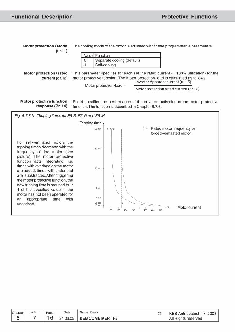
6 7 KEB COMBIVERT F516Name: Basis
24.06.05
Chapter Section Page Date © KEB Antriebstechnik, 2003All Rights reserved
Functional Description Protective Functions
50 100 150 200 400 600 800%
5 sec30 sec
1 min
2 min
30 min
60 min
120 min
120
f = 0 Hz
Tripping time
Motor current
f ³ Rated motor frequency orforced-ventilated motor
Fig. 6.7.8.b Tripping times for F5-B, F5-G and F5-M
For self-ventilated motors thetripping times decrease with thefrequency of the motor (seepicture). The motor protectivefunction acts integrating, i.e.times with overload on the motorare added, times with underloadare substracted.After triggeringthe motor protective function, thenew tripping time is reduced to 1/4 of the specified value, if themotor has not been operated foran appropriate time withunderload.
Motor protection / ratedcurrent (dr.12)
This parameter specifies for each set the rated current (= 100% utilization) for themotor protective function. The motor protection-load is calculated as follows:
Inverter Apparent current (ru.15)Motor protection-load =
Motor protection rated current (dr.12)
The cooling mode of the motor is adjusted with these programmable parameters.
Value Function0 Separate cooling (default)1 Self-cooling
Motor protection / Mode(dr.11)
Motor protective functionresponse (Pn.14)
Pn.14 specifies the performance of the drive on activation of the motor protectivefunction. The function is described in Chapter 6.7.6.

176 7 17KEB COMBIVERT F5
Name: Basis
24.06.05
6
Section PageDate© KEB Antriebstechnik, 2003All Rights reserved
Chapter
Functional DescriptionProtective Functions
Functional Description forF5-S
Fig. 6.7.8.c Tripping time for F5-S
With Pn.15 a level of 0...100 % of the final counter value can be adjusted. On reachingthe adjusted level, the switching condition „OH2-warning“ is set (also see „Digitaloutputs“). The response to the warning signal is defined with Pn.14.
Pn.14 specifies the performance of the drive on activation of the motor protectivefunction. The function is described in Chapter 6.7.6.
This parameter displays the tripping time at a ratio of apparent current to continuouscurrent (Is/Id) of 300 % (adjustable with V2.5 and upwards).
This parameter displays the tripping time at apparent current = maximum current (Is =Imax).
The time, that must expire after triggering an OH2-error, before the error can be reset,is adjusted in dr.36.
Level OH2-warning (Pn.15)
Motor protective functionresponse (Pn.14)
The motor protection function becomes active, if the ratio apparent current to continuouscurrent (Is/Id) reaches 300%. The tripping time for this point is adjusted in dr.34. Thetripping time at Is = Imax (max. current) is adjusted in dr.35. If dr.35 > dr.34, dr.34 isvalid within the entire range. The tripping time is the time, which the internal counterneeds, in order to count from 0 to 100%. A warning level can be adjusted in Pn.15. Ifthe counter reaches this level, the adjusted response in Pn.14 is executed.The counter is reduced if the relation apparent current to continuous current is <300%. The recovery time is the time which the counter needs in order to count from100% to 0 (after an error is triggered). This time is adjusted in dr.36.
NId = (In - Id0) * — + Id0
nN
MmaxImax = In * ———
MN
Id: continuous currentId0: continuous standstill current (dr.28)In: rated motor current (dr.23)n: actual speednn: rated motor speed (dr.24)
Imax: maximum currentIn: rated motor current (dr.23)Mmax: maximum torque (dr.33, limited to
dr.15)Mn: rated motor torque (dr.27)
Calculation ofcontinuous current
Calculation ofmaximum current
0,1
0,2
0,3
0,4
0,5
3,0 4,0 5,0 6,0 7,0 8,0
t [s]
Is/Id
Imax/In = 5dr.34 = 0,5 sdr.35 = 0,2 s
Imax/In = 8dr.34 = 0,5 sdr.35 = 0,2 s
Imax/In = 8dr.34 = 0,5 sdr.35 = 0,4 s
Imax/In = 8dr.34 = 0,5 sdr.35 = 0,4 s
Motor protective time at 300 %Id (dr.34)
Motor protective time at Imax(dr.35)
Motor protection recovery(dr.36)

6 7 KEB COMBIVERT F518Name: Basis
24.06.05
Chapter Section Page Date © KEB Antriebstechnik, 2003All Rights reserved
Functional Description Protective Functions
Used Parameters
The KEB COMBIVERT provides another possibility to protect the motor by connectingan external temperature monitoring. Following components can be connected toterminals T1/T2:
External error controlprocedure
With these two parameters the behaviour of the terminals T1/T2 is determined. Thefunction is described in Chapter 6.7.6.
dOH stopping mode (Pn.12)
dOH delay time (Pn.13)
Thermo contact(NC contact)
Temperature sensor (PTC)1650W ...4kW tripping resistance750W ...1650W reset resistance
T1T2
T1T2
Parameter Addr. ro prog min max default [?] Notes
Fr.8 motor set classification 0908 - yes - 0 7 1 0 - not at F5-SPn.12warning dOH stop. mode Response040C - - - 0 7 1 6 - -Pn.13E.dOH delay time 040D - - - 0 120 1 0 s -Pn.14warning OH2 stop. mode 040E - - - 0 6 1 6 - -Pn.15OH2 warning level 040F - - - 0 100 1 100 % only F5-Sdr.11 motor protection mode 060B - yes - 0 1 1 1 - not at F5-Sdr.12 motor prot. rated current 060C - yes - 0,0 710,0 A 0,1 A PU-Id A not at F5-Sdr.34 mot.prot. time 300% Id 0622 - - - 0,1 10,0 0,1 0,5 s only F5-Sdr.35 mot.prot. time Imax 0623 - - - 0,1 10,0 0,1 0,2 s only F5-Sdr.36 mot.prot. recovery time 0624 - - - 0,1 10,0 0,1 5,0 s only F5-Sru.15 apparent current 020Fyes - - 0,0 6553,5 A 0,1 A - A -

196 7 19KEB COMBIVERT F5
Name: Basis
24.06.05
6
Section PageDate© KEB Antriebstechnik, 2003All Rights reserved
Chapter
Functional DescriptionProtective Functions
6.7.9 GTR7-Control The GTR7 (brake transistor) serves for the control of the brake resistor. As a standardthe GTR7 is switched in dependence on the DC-link voltage, in order to discharge fed-back energy. The switching behaviour of the GTR7 can be altered with the parametersPn.64 and Pn.65. In the following some applications are specified, at which the factorysetting should be modified.Output filters, with the contained capacities and inductivities, form an oscillatory circuitwith the motor, thus the drive also operates as generator.
Synchronous motors operate as generator even if the modulation is switched off.
Especially at low-load systems voltages can be induced, which can lead to thedestruction of the inverter if no attention is paid to it.
The energy fed into the intermediate circuit is transferred over the GTR7 to the brakeresistor. However, as a standard the GTR7 only operates if the inver termodulates.Generally drives should always be decelerated in a controlled manner. Incase of voltage failure this can be guaranteed with the Power-Off function. Withparameter Pn.65 the switching behaviour of the GTR7 can be adjusted as follows:
Pn.65 Switching behaviour GTR7 (Bit 0)0 not in status „LS“ (default)1...3 also switches level-dependent at „LS“4 output is not set (do.0...7 = 4/5/6)
With Pn.64 an input can be defined for the activation of the GTR7. In this case theGTR7 switches independent of the inverter status and the DC-link voltage as soon asthe input is active.Exception: On opening the control release (noP) the inverter must switch off the GTR7for safety reasons.
Output filter
Parallel connection ofinverters (DC-interconnection)
Input selection GTR7 (Pn.64)
Special functions (Pn.65) Bit 0
In a DC-interconnection of inverters the occurring braking energy can be distributedonto different inverters with brake resistor. With Pn.64 an input at the correspondinginverter can be defined over which the activation of the GTRs is synchronized.
Bit -No. Decimal value Input Terminal0 1 ST (prog. input „control release/reset“) X2A.161 2 RST (prog. input „reset“) X2A.172 4 F (prog. input „forward“) X2A.143 8 R (prog. input „reverse“) X2A.154 16 I1 (prog. input 1) X2A.105 32 I2 prog. input 2) X2A.116 64 I3 (prog. input 3) X2A.127 128 I4 (prog. input 4) X2A.138 256 IA (internal input A) none9 512 IB (internal input B) none10 1024 IC (internal input C) none11 2048 ID (internal input D) none
Synchronous motors
(not at F5-B/C)
Used Parameters
Parameter Addr. ro prog min max default [?] Notes
Pn.64GTR7 input selection 0440 - - E 0 4095 1 0 - not at F5-B/CPn.65Special Functions 0441 - - - 0 8 1 0 - not at F5-B/C

6 7 KEB COMBIVERT F520Name: Basis
24.06.05
Chapter Section Page Date © KEB Antriebstechnik, 2003All Rights reserved
Functional Description Protective Functions
6.7.10 SpecialFunctions
Functions which influence thebehaviour of the frequencyinverter in certain operatingmodes are summarized here.
Special functions (Pn.65)
Bit Value Meaning
0 Switching behaviour GTR7 (see Chapter 6.7.9 „GTR-control“)
0 not in status „LS“ (default)
1 also switches level-dependent at „LS“
1 This bit determines the error-/warning message, that is triggered at theswitching of an external error input (Pn.4).
0 Pn.4 is selection for external error-/warning message. The response tothis message (A.EF/E.EF) is defined with Pn.3.
1 Pn.4 is selection for error undervoltage (E.UP). Pn.3 has no function inthis case.
2 Status, if the power circuit is not ready (no_PU). This setting applies tothe output switching conditions do.0...7 = 4...6 and the ERROR-bit inthe status word (sy.44/sy.51 Bit 1).
0 State „no_PU“ is an Error
1 State „no_PU“ is no Error
3 Like LS the GTR7 can be activated level dependent also in the case oferror. Exception: When opening the control release and with notsupplied power circuit (no_PU) the GTR7 is switched off.
0 GTR7 not active in case of error
1 GTR7 level-dependent in case of error
4 temperature-dependent OL2
0 not temperature-dependent
1 temperature-dependent
5 Release GTR7 at software noP, with some applications it is reasonablethat the GTR7 is not immediately switched off when control release isopened. The software control release must be activated for this via di.36.
0 not released
1 dependent on the voltage level
6 Limiting of the derating characteristics. A limiting can be switched onwith the OL2-characteristics in order that the OL2-function releases onlywhen the rated frequency is reached.
0 no
1 yes
7 status word Bit 1 = 0 at E.UP
0 no
1 yes
8 suppression status display BBL in ru.00
0 Status BBL is displayed
1 Status BBL is not displayed
(not at F5-B)

6 8 1KEB COMBIVERT F5
Name: Basis
05.02.03
Functional Description
Chapter Section PageDate© KEB Antriebstechnik, 2002All rights reserved
1. Introduction
2. Summary
3. Hardware
4. Operation
5. Parameter
6. Functions
7. Start-up
8. Special Operation
9. Error Assistance
10. Project Design
11. Networks
12. Annex
6.1 Operating and Appliance
Date
6.2 Analog In- and Outputs I
6.3 Digital In- and Outputs
6.4 Set Value and Ramp
Adjustment
6.5 Voltage-/Frequency
Characteristic (U/f)
Adjustment
6.6 Motor Data Adjustment
6.7 Protective Functions
6.8 Parameter Sets
6.9 Special Functions
6.10 Speed Measurement
6.11 SMM, Posi, Synchron
6.12 Technology Control
6.13 CP-Parameter Definition
6.8.1 Non-programmable Parameters3
6.8.2 Security Parameters .............. 36.8.3 System Parameters ............... 36.8.4 Indirect and Direct
Set-Addressing ...................... 36.8.5 Copying of Parameter
Sets via Keyboard .................. 46.8.6 Copying of
Parameter Sets via Bus ......... 46.8.7 Parameter Set Selection ........ 56.8.8 Locking of Parameter Sets ..... 86.8.9 Parameter Set ON and
OFF Delay .............................. 86.8.10 Used Parameters ................... 9

6 8 KEB COMBIVERT F52Name: Basis
05.02.03
Chapter Section Page Date © KEB Antriebstechnik, 2002All rights reserved
Functional Description Parameter Sets

36 8 3KEB COMBIVERT F5
Name: Basis
05.02.03
6
Section PageDate© KEB Antriebstechnik, 2002All rights reserved
Chapter
Functional DescriptionParameter Sets
6.8 Parameter Sets The KEB COMBIVERT contains 8 parameter sets (0...7), i.e. all programmableparameters are available 8 times in the inverter and independent of each other theycan be assigned with different values. As a lot of parameters in the parameter setscontain the same value, it would be relatively complicated to change every parameterin each set individually. In this section it is described, how one copies whole parametersets, locks them, selects them and reinitializes the inverter.
6.8.1 Non-programmableParameters
Certain parameters are not programmable, as their value must be the same in allsets (e.g. bus address or baud rate). For an easy identification of these parametersthe parameter set number is missing in the parameter identification. For all non-programmable parameters the same value is valid independent of the selectedparameter set!
Sy-Parameterru-ParameterEc-ParameterAA-Parameterdi-ParameterIn-Parameter (exception: In.25)dr-Parameter (not at F5-S)oP.19/20/50/53-62
Pn.0-18/23/27/29/44-60/62-66uF.8/12-15/18 (uF.9 at F5-S)ud.1-17 (all at F5-S)Fr.2-4/7/9/11 (Fr.10 at F5-S)An.0-4/10-14/20-24/41-56LE.16-26cn.3/11-13dS.0-1 (only F5-S)PS.2-4/10-27/29-31
6.8.1 Non-programmable Parameters
6.8.2 Security Parame-ters
The security parameters contain the Baud rate, inverter address, hours/meter, controltype, serial-/customer number, trimming values and error diagnosis. They are notoverwritten while copying parameter sets from the default set.
Sy.2/3/6/7/11ru.40/41ud. 1/2Fr.1In.10-16/24-31
6.8.2 Security Parameters
6.8.3 System Parame-ters
The system parameters contain the motor and encoder data.
dr-ParametercS.0-19-22Ec.1-7/11-27/36-38
6.8.3 System Parameters
6.8.4 Indirect andDirect Set-Addressing
During indirect set addressing the parameter values are indicated and edited to theadjustment of the set indicator (Fr.9). The direct set addressing enables the displayor writing of a parameter value independent of the set indicator directly into one orseveral parameter sets. The direct set programming is only possible with busoperation.
Pn.61/67dS.0-1/13Fr.10

6 8 KEB COMBIVERT F54Name: Basis
05.02.03
Chapter Section Page Date © KEB Antriebstechnik, 2002All rights reserved
Functional Description Parameter Sets
6.8.5 Copying of Para-meter Sets viaKeyboard (Fr.1) 0. Fr. 1
1. Fr. 1
2. Fr. 1
3. Fr. 1
4. Fr. 1
5. Fr. 1
6. Fr. 1
7. Fr. 1
�DOWN
UP�
Adjust target set
With the keys UP/Down and at flas-hing point the target set 0...7 is ad-justed in addition to the parameterset number. The active (A) parame-ter set must not be adjusted as tar-get set while copying. If the target setis > 0, only the programmable para-meters are overwritten!
AS Fr
· 1
1
2
3
4
5
6
7
�DOWN
UP�
Adjust source set
The source set is adjusted with the keys UP/Down. The copying process is started with„Enter“. Copying is only possible withopened control release or error, otherwise„I_oPE“ appears in the display (invalidoperation).After copying „PASS“ appears in the displayand could be erase by „ENTER“.
0
dEF_S ñ
Changeover to sourceñ
with Funct.
By loading the factory settingall definitions defined by themechanical engineer arereset! This can comprise the
terminal assignment, setchangeover or operating states.Before loading the default set itis to be ensured that nounintended operating statesoccur.
ini_A
ini_S
dEF_A
Target set Source set Action0...7 0...7 All programmable parameters (System parameters too)
of the source set are copied into the target set.0 -1: dEF_S Default values are copied into all parameters of set 0
(with exception of System and Security parameters).1...7 -1: dEF_S Default values are copied into all programmable
parameters of the target set (with the exception ofSystem and Security parameters).
All -2: dEF_A Default values are copied into all parameters of all sets(with the exception of System and Security parameters).
0 -3: ini_S Default values are copied into all parameters of set 0(with the exception of Security parameters).
1...7 -3: ini_S Default values are copied into all programmableparameters of the target set (with the exception ofSecurity parameters).
All -4: ini_A Default values are copied into all parameters of all sets(with the exception of Security parameters).
6.8.6 Copying of Para-meter Sets viaBus (Fr.1, Fr.9)
In case of indirect set addressing at Bus operation two parameters are responsiblefor the copying of parameter sets. Fr.9 defines the target set. Fr.1 defines the sourceparameter set and starts the copying process. In the case of direct set programmingthe source set (Fr. 1) is copied into the selected parameter sets. The following copyingactions can be practised:

56 8 5KEB COMBIVERT F5
Name: Basis
05.02.03
6
Section PageDate© KEB Antriebstechnik, 2002All rights reserved
Chapter
Functional DescriptionParameter Sets
Custom-specific defaultvalues
Value Source Default values copied parameters Target sets-1 KEB Customer parameters
selected-2 KEB Customer parameters all-3 KEB Customer/ system parameters
selected-4 KEB Customer/ system parameters all-5 custom-specific Customer parameters
selected-6 custom-specific Customer parameters all-7 custom-specific Customer/ system parameters
selected-8 custom-specific Customer/ system parameters all-9 Current parameter setting Customer/ system parameters all
store as custom-specificdefault values
The values -5 to -8 are corresponding to the previous values -1 to -4 referring to thecopied parameters and target sets. They differ only in the default value source.Value -9 enables storing of the current parameter setting as custom-specific defaultvalues. The values of all customer and system parameters are stored in all setsthereby.
Bit 27 is set in characteristics 2 for parameters, which contains only the KEB defaultvalue. These are among others all security parameters and all write protectedparameters. During loading the specific default values (fr.01 = -5..-8) these parameters are loa-ded with KEB default values if necessary.
The indicator parameter (first parameter of an indirect addressed group) has not acustomer default value, because the parameter was set to 0 with Power-On-Reset.The parameters belonging to the group have a default value for each value of theindicator.
A source table is generated. For this one byte is reserved for each parameter in thesequence of the bus addresses. This byte contains the information for each set,whether the default value is determined from the parameter definition (= 0, KEBdefault value) or if the value is stored in the custom-specific storage area (= 1).This information is determined by comparison to the KEB default value.For indirect addressed parameters the number of reserved bytes for each groupmember is equal to the number of valid values of the indicator.36 byte are reserved for ud.16 and ud.17, ud.15 = 1..3616 byte are reserved for ps.24..27, ps.23 = 0..15The custom-specific default values are stored in the sequence of the bus addresses(ascending) set depending (set 7..0).The custom-specific default values for indirect addressed parameters are storedfirst to bus address (ascending), then to indicator value (max. .. min.), then setdependent (set 7..0).
Example: Default value ud.09, default values ud.16 for ud.15 = 36..1, default valuesud.17 for ud.15 = 36..1, default values ud.18 for set 7..0, etc.
Parameters only with KEB-Default value
Indirect addressed Parame-ters
Storing the custom-specificdefault values

6 8 KEB COMBIVERT F56Name: Basis
05.02.03
Chapter Section Page Date © KEB Antriebstechnik, 2002All rights reserved
Functional Description Parameter Sets
Copy custom-specific defaultvalues in the sets
With the bits in the source table the default value for each set is determined eitherfrom the parameter definition for each parameter in the sequence of the bus addressor read-out from the custom-specific memory area and written into the parameter.Parameters only with KEB default value are loaded with the KEB default value in thiscase.
The default values are reset for all parameters to KEB default values in the followingcases:
- All parameters are set to default values (initial loading)- The version identification of the software changes (new version, or new date
code)- The control type is changed (ud.02 Bit 2+3)
The custom-specific default values can be reset manually as follows:
- Loading KEB default values in all sets (fr.01 = -4)- Storing defaul values (fr.01 = -9)
Reset of the custom-specificdefault values
Changed power unit orencoder identifier,
changeover standard/USsetting
The power unit identification was changed:
- The power unit identifiction dependent KEB default values are adapted.- if necessary uf.11 is limited in all sets to the maximal switching frequency
(in.03).- If a custom-specific default value of uf.11 is not within the valuer a n g e
(0..in.03), uf.11 is loaded during default value loading in the correspondingset with the KEB-default value.
- If the write value of sy.03 is unequal to the reading power unit identification, allcustomer and system parameters are loaded with KEB default values(according to fr.01 = -4)
The encoder identifier was changed:
- The encoder identifier dependent KEB default values are adapted.- EC-Parameters are loaded with KEB default values.- Changeover standard/US setting (change in.21 bit 0 at in.20 = 32):- The KEB default values depending on this setting are adapted.- Customer and system parameters are loaded with KEB default values(corresponding to fr.01 = -4)
The length of the source table (in byte) and the length of the memory area of thecustomer default values (in byte) are stored in one word at the end of the externalRAM.The source table for the custom-specific default value range is in front of these twocells. The length is dependent on the number of permitted parameters of the adjustedcontrol type (ud.02 bit 2+3)The memory area for the custom-specific default values starts next to the sourcetable. The length is dependent on the number of values stored here. Only the valueswhich are different to the KEB default values are stored. The default values arestored in descending order of memory addresses.The off-line memory includes the period between the temporary variables and thememory area for the custom-specific default values. The size of the off-line memoryis depending on the number of custom-specific default values.
Memory management

76 8 7KEB COMBIVERT F5
Name: Basis
05.02.03
6
Section PageDate© KEB Antriebstechnik, 2002All rights reserved
Chapter
Functional DescriptionParameter Sets
Fig. 6.8.7 Principle of parameter set selection
6.8.7 Parameter SetSelection
Fr.20
12 3
202122 1234567 1234567
45
digital
As shown in Fig. 6.8.7, with Fr.2 it is defined whether the parameter set selection isenabled or disabled via keyboard/Bus (Fr.4), the terminal strip or via control word(SY.50). The selection is activated with „Enter".
Fr.2 Function
0 Set selection deactivated; set 0 always active1 Set selection via keyboard/bus with Fr.42 Set selection binary-coded via terminal strip3 Set selection input-coded via terminal strip
Priority: ST>RST>R>F>I1>I2>I3>I4>IA>IB>IC>ID4 Set selection input-coded via terminal strip
Priority: ID>IC>IB>IA>I4>I3>I2>I1>R>F>RST>ST5 Set selection via control word SY.50
Fr.2 Source parameter set
Fr.4 Adjustment parameterset
This parameter can be written by bus as well as by keyboard. The desired parameterset (0...7) is preadjusted directly as value and activated with „Enter“.
set selectiondeactivated
always set 0 active
Fr.4 viakeyboard/bus terminal strip
binary coded
terminal stripbinary coded
ST>RST>...>ID
terminal stripbinary codedID>IC>...>ST
SY.50 withcontrol word
(only bus)
Parameter set 0...7
Fr.3 Parameter set lockSet 0...7 (Value 0...255)
Isselected set
locked ?yes
no
Actual Parameter set
Error messageE.SEt
ATTENTION! The valency atFr.2 = 2...4 is generally ID >IC > ...>ST. The successiondescribes at the inputs refersto the priority.
Complete use of the availablememory
fr.01 = -10 (customer default memory is full) is set if the memory area is completelyfilled with custom-specific default values, all values could not be stored.That means only one part of the parameter settings (with low bus addresses) containcustom-specific default values, further settings only contain KEB default values.This restriction should not occur since enough memory capacity is available.
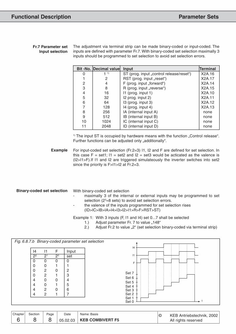
6 8 KEB COMBIVERT F58Name: Basis
05.02.03
Chapter Section Page Date © KEB Antriebstechnik, 2002All rights reserved
Functional Description Parameter Sets
The adjustment via terminal strip can be made binary-coded or input-coded. Theinputs are defined with parameter Fr.7. With binary-coded set selection maximally 3inputs should be programmed to set selection to avoid set selection errors.
Binary-coded set selection
F
I1
I4
t
I4 I1 F Input2² 21 20 set0 0 0 00 0 1 10 2 0 20 2 1 34 0 0 44 0 1 54 2 0 64 2 1 7
Fig. 6.8.7.b Binary-coded parameter set selection
Fr.7 Parameter setInput selection
With binary-coded set selection- maximally 3 of the internal or external inputs may be programmed to set
selection (23=8 sets) to avoid set selection errors.- the valence of the inputs programmed for set selection rises
(ID>IC>IB>IA>I4>I3>I2>I1>R>F>RST>ST)
Example 1: With 3 inputs (F, I1 and I4) set 0...7 shall be selected1.) Adjust parameter Fr. 7 to value „148“2.) Adjust Fr.2 to value „2“ (set selection binary-coded via terminal strip)
1) The input ST is occupied by hardware means with the function „Control release“.Further functions can be adjusted only „additionally“.
For input-coded set selection (Fr.2=3) I1, I2 and F are defined for set selection. Inthis case F = set1; I1 = set2 and I2 = set3 would be acticated as the valence is(I2>I1>F).If I1 and I2 are triggered simulateously the inverter switches into set2since the priority is F>I1>I2 at Fr.2=3.
Bit -No. Decimal value Input Terminal0 1 1) ST (prog. input „control release/reset“) X2A.161 2 RST (prog. input „reset“) X2A.172 4 F (prog. input „forward“) X2A.143 8 R (prog. input „reverse“) X2A.154 16 I1 (prog. input 1) X2A.105 32 I2 prog. input 2) X2A.116 64 I3 (prog. input 3) X2A.127 128 I4 (prog. input 4) X2A.138 256 IA (internal input A) none9 512 IB (internal input B) none10 1024 IC (internal input C) none11 2048 ID (internal input D) none
Set 0Set 1Set 2Set 3Set 4Set 5Set 6Set 7
Example

96 8 9KEB COMBIVERT F5
Name: Basis
05.02.03
6
Section PageDate© KEB Antriebstechnik, 2002All rights reserved
Chapter
Functional DescriptionParameter Sets
Input-codedset selection
Fig. 6.8.7.c Input-coded parameter set selection (Fr.2=3)
With input-coded set selection- maximally 7 of the internal or external inputs may be programmed to set
selection (0...7 sets) to avoid set selection errors.- the lowest of the selected inputs has priority at Fr.2 = „3“
(ST>RST>R>F>I1>I2>I3>I4>IA>IB>IC>ID)- the highest of the selected inputs has priority at Fr.2 = „4“
(ID>IC>IB>IA>I4>I3>I2>I1>R>F>RST>ST)
Example 1: With 5 inputs (I1, I2, I4, IB and ID) set 0...5 shall be selected.
1.) Adjust parameter Fr. 7 to value „2736“2.) Adjust Fr.2 to value „3“ (set selection input-coded via terminal strip)
����#
��
��
��
�'
��
set
setsetsetsetset
Reset setinput selection (fr.11)
This parameter defines an input, with which one can switch independently of thecurrent parameter set in to parameter set 0 (see table at Fr.7). This function is onlyactive at Fr.2 = 0...4.– with static input assignment the inverter remains in set 0 as long as the input
is set.– with edge-triggered inputs set 0 is always activated with the 1st edge. With
the 2 nd edge the set activated by the other inputs is selected again.
ID IB I4 I2 I1 set setFr.2 = 3 4
0 0 0 0 0 0 00 0 0 0 1 1 10 0 0 2 0 2 20 0 3 0 0 3 30 4 0 0 0 4 45 0 0 0 0 5 55 0 3 0 0 3 55 0 3 0 1 1 5

6 8 KEB COMBIVERT F510Name: Basis
05.02.03
Chapter Section Page Date © KEB Antriebstechnik, 2002All rights reserved
Functional Description Parameter Sets
1
2
3
4
5 6
With these parameters the time is adjusted,
- with which the activation of a new set is delayed (Fr.5)- with which the deactivation of an old set is delayed (Fr.6)
In the case of set changeover the OFF time of the old set and ON time of the new setare added up.
Set 1
Set 3
Set 2
Set 1
Set 3
Set 2
Set 0
Set 0
Adjusted set
Current set
Fig. 6.8.9 ON and OFF-delay
Example
on off
set Fr.5 Fr.6
0 0 s 0 s
1 2 s 0 s
2 0 s 1 s
3 2 s 2 s
1: ON delay for set 3 of 2s2: OFF delay for set 3 of 2s3: OFF delay for set 2 of 1s +
ON delay for set 1 of 2 s4: immediate changeover as no delay is adjusted5: OFF delay for set 2 of 1s +
ON delay for set 3 of 2s6: OFF delay for set 3 of 2s
6.8.9 Parameter SetON/OFF Delay(Fr.5, Fr.6)
6.8.8 Locking of Para-meter Sets
Parameter sets, that shall not and must not be selected, can be locked with Fr.3. Ifone of the locked sets is selected, the inverter switches off with set selection error(E.SEt).
Value Locked set Example1 0 -2 1 -4 2 48 3 -
16 4 -32 5 3264 6 -128 7 -
Set 2 and Set 5 locked Sum 36
Fr.3 Parameter set lock

116 8 11KEB COMBIVERT F5
Name: Basis
05.02.03
6
Section PageDate© KEB Antriebstechnik, 2002All rights reserved
Chapter
Functional DescriptionParameter Sets
6.8.10 Used Parameters
Parameter Addr. ro prog min max default [?] Notes
Fr. 1 Copy parameter set 0901 - yes yes -4 7 1 0 -Fr.2 Parameter set source 0902 - - yes 0 5 1 0 -Fr.3 Parameter set lock 0903 - - yes 0 255 1 0 -Fr.4 Parameter set setting 0904 - - yes 0 7 1 0 -Fr.5 Set activation delay 0905 - yes - 0 32,00 0,01 0 sFr.6 Set deactivation delay 0906 - yes - 0 32,00 0,01 0 sFr.7 Paraset input sel. 0907 - - yes 0 4095 1 0 -Fr.9 Bus parameter set 0909 - - - -1 7 1 0 - -1:active set (only viabus)Fr.11 Reset>set 0 input sel. 090B - yes yes 0 4095 1 0 -

6 8 KEB COMBIVERT F512Name: Basis
05.02.03
Chapter Section Page Date © KEB Antriebstechnik, 2002All rights reserved
Functional Description Parameter Sets

6 9 1KEB COMBIVERT F5
Name: Basis
16.02.05
Functional Description
Chapter Section PageDate© KEB Antriebstechnik, 2002All Rights reserved
1. Introduction
2. Summary
3. Hardware
4. Operation
5. Parameter
6. Functions
7. Start-up
8. Special Operation
9. Error Assistance
10. Project Design
11. Networks
12. Annex
6.1 Operating and Appliance
Date
6.2 Analog In- and Outputs I
6.3 Digital In- and Outputs
6.4 Set Value and Ramp
Adjustment
6.5 Voltage-/Frequency
Characteristic (U/f)
Adjustment
6.6 Motor Data Adjustment
6.7 Protective Functions
6.8 Parameter Sets
6.9 Special Functions
6.10 Speed Measurement
6.11 SMM, Posi, Synchron
6.12 Technology Control
6.13 CP-Parameter Definition
6.9.1 DC-Braking ............................ 36.9.2 Energy Saving Function ......... 56.9.3 Motorpoti Function ................. 76.9.4 Timer and Counter ............... 116.9.5 Brake Control ....................... 156.9.6 Power-Off Function .............. 196.9.7 Wobbel Function .................. 276.9.8 Diameter Correction ............. 296.9.9 Positioning Function ............. 316.9.10 Analog Setting of Parameter
Values .................................. 34

6 9 KEB COMBIVERT F52Name: Basis
16.02.05
Chapter Section Page Date © KEB Antriebstechnik, 2002All Rights reserved
Functional Description Special Functions

6 9 3KEB COMBIVERT F5
Name: Basis
16.02.05
6
Section PageDate© KEB Antriebstechnik, 2002All Rights reserved
Chapter
Functional DescriptionSpecial Functions
6.9 SpecialFunctions
Fig. 6.9.1 Principle of DC-brake
6.9.1 DC-Braking During the DC-braking the motor is not decelerated over the ramp. The fastdeceleration is done with DC-voltage, that is given onto the motor winding.Between the activation and the triggering of DC-braking a time constant called Base-Block time (bbl) of 150…5000 ms (depending on the power circuit) is necessary.Itserves as protection of the power modules during the motor de-excitation time. With Pn.28 one adjusts through what the DC-brake is triggered. According to theadjusted mode one can preset with Pn.32 the frequency/speed from which the DC-brake is triggered. Pn.30 defines the braking time. The maximum braking voltage isadjusted with Pn.31.The brake controllers are dimensioned 1:1 of inverter to motor,thus the maximum braking voltage must be reduced in the case of deviatingdimensioning to prevent the overheating of the motor. At large ratings the maximumbraking voltage can lead to overcurrent errors (OC). In that case reduce it with Pn31.Pn.29 is bit-coded and defines the inputs which trigger DC-braking.
The following section should facilitate the adjustment and programming of specialfunctions.
Pn.30 DC-brake/ time
Pn.32 DC-brake Start value
Set brake time= Pn.30
actual brake time= Pn.30 · factual
reference value 1)
actual brake time= Pn.30 · Pn.32
reference value 1)
Pn.28 DC Braking Mode
0 DC-braking not activated1 DC-braking after reaching 0Hz/rpm and missing
rotation setting; max. for the adjusted DC-brakingtime Pn.30 (independent of actual frequency/speed) or until the next setting of rotationdirection.
2 DC-braking as soon as rotation direction ismissing; braking time is dependent on actualfrequency /speed
3 DC-braking as soon as rotation directionchanges; braking time is dependent on actualfrequency/speed
4 DC-braking as soon as rotation setting is missingand the actual frequency/speed falls below theadjusted level in Pn.32; braking time isdependent on Pn.32
5 DC-braking as soon as the actual frequency/speedfalls below the adjusted level in Pn.32; braking timeis dependent on Pn.32
6 DC-braking as soon as setpoint value ru.1 fallsbelow the adjusted level in Pn.32; braking time isdependent on actual frequency/speed
7 DC-braking as soon as an input programmed toDC-braking is active; braking time is dependenton actual frequency/speed; restart only after theinput is deactivated.
8 DC-braking as long as an input programmed toDC-braking is active.
9 DC-braking after enabling the modulation(direction of rotation + control release) for thetime adjusted in Pn.30.
Pn.31 DC-brake/max. voltage
0...25,5% (default 25,5 %)
ru.3 Actual frequency / speed
Pn.29 DC-brake
Input selection
0...4095 also see 6.3 „Digital inputs“
Pn.32 DC-brake/start value
0...400 Hz (default 4 Hz)
0...4000 rpm (default 120rpm)
ru.1 Setpoint display
1) Reference value:100/200/400 Hz1000/2000/4000 rpmdependent on ud.2
(only F5-B, F5-G and F5-M if cS.0=0)

6 9 KEB COMBIVERT F54Name: Basis
16.02.05
Chapter Section Page Date © KEB Antriebstechnik, 2002All Rights reserved
Functional Description Special Functions
f, n, U
t
Pn.31
Pn.28 = 1
t
Pn.31
Pn.28 = 2
bbl
t
Pn.31
Pn.28 = 3
t
Pn.31
Pn.28 = 4
bbl
Pn.30
F
R
Pn.32
t
Pn.31
Pn.28 = 5
t
Pn.31
Pn.28 = 6
Pn.32
Pn.32
bbl dLS
bbl
Pn.28 = 7 Pn.28 = 8
t
Pn.31
bbl dLSt
Pn.31
bblt
Pn.31
Pn.28 = 9
Pn.30
ru.0= fdec; rdec
bbl
Pn.30 • f / 100Pn.30 • n /1000
Pn.30•Pn.32/1000
f, n, U
Pn.30 • f / 100Pn.30 • n /1000
f, n, U
Pn.30 • f / 100Pn.30 • n /1000
f, n, U
Pn.30•Pn.32/100Pn.30•Pn.32/1000
f, n, U
Pn.30•Pn.32/100Pn.30•Pn.32/1000
f, n, U
Pn.30 • f / 100Pn.30 • n /1000
f, n, U f, n, U f, n, U
DC Braking / Mode (Pn.28)
Used Parameters
Parameter Addr. ro prog min max default [?] Notes
Pn.28DC braking mode 041C - yes yes 0 9 1 7 -Pn.29DC brake input selection 041D - - yes 0 4095 1 0 - default at F5-M: 128Pn.30DC braking time 041E - yes - 0,00 100,00 s 0,01 s 10,00 s -Pn.31DC braking max. voltage 041F - yes - 0 25,5 % 0,1 % 25,5 % -Pn.32DC braking start freq. 0420 - yes - 0 400 Hz 0,0125 Hz 4 Hz - F5-G/B dep. on ud.2Pn.32DC braking start freq. 0420 - yes - 0 4000 rpm 0,125 rpm120 rpm - F5-M dep. on ud.2
Rotation direction
Digital input Digital input
ST
F or R
Rotation direction Rotation direction
fset
DC braking Input selection(Pn.29)
Bit Decimal value Input Terminal0 1 ST (prog. input „control release/reset“) X2A.161 2 RST (prog. input „reset“) X2A.172 4 F (prog. input „forward“) X2A.143 8 R (prog. input „reverse“) X2A.154 16 I1 (prog. input 1) X2A.105 32 I2 prog. input 2) X2A.116 64 I3 (prog. input 3) X2A.127 128 I4 (prog. input 4) X2A.138 256 IA (internal input A) none9 512 IB (internal input B) none
10 1024 IC (internal input C) none11 2048 ID (internal input D) none

6 9 5KEB COMBIVERT F5
Name: Basis
16.02.05
6
Section PageDate© KEB Antriebstechnik, 2002All Rights reserved
Chapter
Functional DescriptionSpecial Functions
uF.7
t
6.9.2 Energy SavingFunction
The energy saving function allows the lowering or raising of the current output voltage.In accordance with the activation conditions defined in uF.6, the voltage valid accordingto the V/Hz-characteristic is changed in percent onto the energy saving level (uF.7).
However, the maximal output voltage cannot be higher than the input voltage even ifthe value is > 100 %. The function is used for example in cyclic executed load/no-load applications. During the no-load phase the speed is maintained, but energy issaved as a result of the voltage reduction.
uF.7 Energy saving factor0,0…130,0 % (default 70 %)
uF.6 Energy saving function / ModeBit 0...3 Activation0 Function off1 Generally on2 When actual = setpoint frequency/speed3 Activation through programmable inputs4 Generally at rotation direction forward5 Generally at rotation direction reverse6 Rotation direction forward and actual = set freq./speed7 Rotation direction reverse and actual = set freq./
speed8...15 reservedBit 4...6 Adjustment of the voltage ramp
Voltage ramp at B/C-control approx. 1 sVoltage ramp at G/M/S-control approx. 1,6 s
0 Voltage ramp16 Voltage ramp / 232 Voltage ramp / 448 Voltage ramp / 864 Voltage ramp / 16
factual ; nactual;UA Hysteresis
Example: uF.6 = 2, uF.7 = 50 %
Used Parameters
Parameter Addr. ro prog min max default [?] Notes
uF.6 Energy saving function / Mode0506 - yes - 0 79 1 0 -uF.7 Energy saving factor 0507 - yes - 0,0 % 130,0 % 1 % 70 % -uF.8 Energy saving input sel. 0508 - - yes 0 4095 1 0 -
uF.8 Energy saving functionInput selection
0...4095 (Default 0)also see 6.3
„Digital inputs“
(only F5-B, F5-G andF5-M if cS.0=0)
fset ; nset

6 9 KEB COMBIVERT F56Name: Basis
16.02.05
Chapter Section Page Date © KEB Antriebstechnik, 2002All Rights reserved
Functional Description Special Functions

6 9 7KEB COMBIVERT F5
Name: Basis
16.02.05
6
Section PageDate© KEB Antriebstechnik, 2002All Rights reserved
Chapter
Functional DescriptionSpecial Functions
-100%
100%
oP.54
oP.55
0%
oP.53
toP.59
oP.59 oP.59
oP.59
� �
�����
An.55
An.56
6.9.3 Motorpoti Function This function simulates a mechanic motor potentiometer. Over two inputs the motorpotentiometer value can be increased or decreased.
Fig. 6.9.3 Motorpoti Function
Bit Value Input Terminal0 1 ST (prog. input „control release/reset“) X2A.161 2 RST (prog. input „reset“) X2A.172 4 F (prog. input „forward“) X2A.143 8 R (prog. input „reverse“) X2A.154 16 I1 (prog. input 1) X2A.105 32 I2 prog. input 2) X2A.116 64 I3 (prog. input 3) X2A.127 128 I4 (prog. input 4) X2A.138 256 IA (internal input A) none9 512 IB (internal input B) none10 1024 IC (internal input C) none11 2048 ID (internal input D) none
oP.50 Motor potentiometer / FunctionBit 1 Bit 0 Meaning
x 0 Value is changed in the current setx 1 Value is changed only in set 00 x No motor poti reset after Power-on1 x Reset on oP.55 after Power-on
oP.56 Increase motor potivalue input selection
oP.57 Decrease motor potivalue input selection
oP.58 Reset on oP.55Input selection
oP.52 Motor poti / ValuePresetting via parameter±100%(oP.59 is being ignored)
ru.37 Motor poti act. value-100...0...100 %
Rotationdirection
+ = forward- = reverse
Setpointvalue
to oP.0Value „4“
to oP.1 value „6 and 7“
AUX
An.54 Targetanalog Parameter
settings
Parameter setting by themotor poti / aux function
see chapter 6.9.10

6 9 KEB COMBIVERT F58Name: Basis
16.02.05
Chapter Section Page Date © KEB Antriebstechnik, 2002All Rights reserved
Functional Description Special Functions
Determine inputs(oP.56...oP.58)
In the first step 2 inputs must be defined with which the motor potentiometer can beincreased or decreased. For that purpose one input each according to the inputtable is assigned to the parameters oP.56 and oP.57. If both inputs are triggeredsimultaneously, the potentiometer value is decreased.
Increase motorpoti value Decrease motorpoti valueß ß
oP.56 oP.57
Another input (oP.58) can be used to reset the motor potentiometer to the adjustedreset value oP.55.
Motor poti inc/dec time(oP.59)
Motorpoti function(oP.50)
The correcting range(oP.53, oP.54)
Display of motorpotentiometer value (ru.37)
With this parameter a time is defined, which the motor potentiometer needs in orderto run from 0...100%. The time is adjustable between 0...50000 s.
The correcting range is limited by the parameters oP.53 „Motor poti min. value“ andoP.54 „Motor poti max. value“ (see Fig. 6.9.3).
This parameter shows the current value of the motor potentiometer in percent.
The basic working method of the motor potentiometer is defined with oP.50. Theparameter is bit-coded.
Bit oP.50 Motor potentiometer / Function1 0x 0 Motor poti is changed in the current set (default)x 1 Motor poti is changed only in set 00 x Motor poti value is maintained after Power-on (default)1 x Motor poti value is reset to reset value oP.55
Input table Bit -No. Decimal value Input Terminal0 1 ST (prog. input „control release/reset“) X2A.161 2 RST (prog. input „reset“) X2A.172 4 F (prog. input „forward“) X2A.143 8 R (prog. input „reverse“) X2A.154 16 I1 (prog. input 1) X2A.105 32 I2 prog. input 2) X2A.116 64 I3 (prog. input 3) X2A.127 128 I4 (prog. input 4) X2A.138 256 IA (internal input A) none9 512 IB (internal input B) none
10 1024 IC (internal input C) none11 2048 ID (internal input D) none

6 9 9KEB COMBIVERT F5
Name: Basis
16.02.05
6
Section PageDate© KEB Antriebstechnik, 2002All Rights reserved
Chapter
Functional DescriptionSpecial Functions
Source of Setpoint (oP.0) andDirection of rotation (oP.1)
In order to preset the setpoint by way of the motor potentiometer oP.0 (setpointsource) must be set to value „4“. The source of rotation direction (oP.1) must beadjusted in dependence on the setpoint (value „6“ or „7“).If the motor potentiometer is used as setpoint source, the setpoint is calculated fromthis with the respective limits just as with other percental setpoint sources (see Chapter6.4. „Set Value Adjustment“).
Motor potentiometer value(oP.52)
With this parameter a value in percent can be adjusted within the preset limits directlyby operator or bus. The ramp time remains unconsidered at this setting.
Param. Addr. min max default
ENTERPROG.
ro Step
Used Parameters
ru.37 0225h - - - -100,00 % 100,00 % 0,01 % - -
oP.0 0300h - 4 4 0 9 1 0 „4“ for motor potentiometer
oP.1 0301h - 4 4 0 9 1 2 „6 a. 7“ rotation direct. over setpoint
oP.50 0332h - - 4 0 3 1 0 -
oP.52 0334h - 4 - -100,00 % 100,00 % 0,01 % 0,00 % -
oP.53 0335h - - - -100,00 % 100,00 % 0,01 % 0,00 % -
oP.54 0336h - - - -100,00 % 100,00 % 0,01 % 100,00 % -
oP.55 0337h - - - -100,00 % 100,00 % 0,01 % 0,00 % -
oP.56 0338h - - 4 0 4095 1 0 -
oP.57 0339h - - 4 0 4095 1 0 -
oP.58 033Ah - - 4 0 4095 1 0 -
oP.59 033Bh - - - 0,00 s 50000,00 s 0,01 s 66,00 s -

6 9 KEB COMBIVERT F510Name: Basis
16.02.05
Chapter Section Page Date © KEB Antriebstechnik, 2002All Rights reserved
Functional Description Special Functions

6 9 11KEB COMBIVERT F5
Name: Basis
16.02.05
6
Section PageDate© KEB Antriebstechnik, 2002All Rights reserved
Chapter
Functional DescriptionSpecial Functions
6.9.4 Timer and Coun-ter
Two timers are incorporated in the COMBIVERT. As long as one of the adjustablestarting conditions (LE.18/23) or a programmable input (LE.17/22) is set, the timercounts until reaching the final range value. If one of the reset conditions (LE.20/25)is fulfilled or one programmable input (LE.19/24) is set, the timer jumps back to zero.The clock source and the counting direction is adjusted with LE.21/26. It can becounted in seconds, hours or by a special programmed input for that. The currenttimer content is displayed in ru.43/44. On reaching an adjustable comparison level(LE.0...7), the switching condition 37/38 is set. It can be used to set an output.
Fig. 6.9.4 Timer programming
Timer / Mode (LE.21/26) LE.21 and LE.26 determine the clock source and the counting direction of timer 1and 2. Clock source can be the time counter in 0,01 s or h-grid or impulses from aninput. The timer runs generally as long as a starting condition is active. After a resetthe timer starts again at zero. The timer stops at the maximal value of 655,35. Followingclock sources can be selected:
Bit Value Function0...2 Clock source
0 Time counter 0,01 s (default)1 Time counter 0,01 hour2 Edge counter, each edge increases/decreases the counter by 0,013 Edge counter, only positive edges increases/decreases the counter
by 0,014...7 reserved
3...4 Counting direction0 Upward8 The counting direction is dependent on direction of rotation
(FOR=upward; REV=downward)16 The counting direction is dependent on direction of rotation
(REV=upward; FOR=downward)5 Overflow behaviour
0 Stop at limit32 Reset and further
The values from Bit 0...2 and 3...5 are to be added up.
Switching condition37 „Timer 1 > Level
A“is being set!
Timer value >Level LE.0...LE.7 ?
Is areset condition of
LE.20 or LE.19fulfilled ?
Timer counts up to maximumvalue; down to 0, if a conditionof LE.18 is fulfilled or an input
of LE.17 is set
ru.43 Timer 1 Display
no
LE.21 Timer 1 /Mode
no yes
yes
Resetting to zero
continues to count
Switching condition38 „Timer 2 > Level
A“is being set!
Timer value >Level LE.0...LE.7 ?
Is aIs a reset
condition of LE.25or LE.24 fulfilled ?
Timer counts up to maximumvalue; downwards to 0, if a
condition of LE.23 is fulfilled oran input of LE.22 is set
ru.44 Display timer 2
no
LE.26 Timer 2 /Mode
no yes
yes
Resetting to zero
continues to count
I3
I4
Input I3 => Timer 1
Input I4 => Timer 2
at BASIC:
Input I1 => Timer 1
Input I2 => Timer 2

6 9 KEB COMBIVERT F512Name: Basis
16.02.05
Chapter Section Page Date © KEB Antriebstechnik, 2002All Rights reserved
Functional Description Special Functions
According to the following table the inputs with which the timer is reset can bespecified. The individual inputs are OR-operated, i.e. if one of the specified inputs istriggered, the timer jumps back to zero. If a starting and reset condition are activesimultaneously, reset has priority.
Timer Reset Input selection(LE.19/24)
Timer start Input selection(LE.17/22)
Additionally the timer can be activated by one or several inputs. The sum of thevalences is to be entered, if the timer shall be started by different inputs The indivi-dual inputs are OR-operated. The start input selection is OR-operated with the timer/ starting condition (LE.18/LE.22).
ru.43 / ru.44 displays the actual counter reading dependent of the adjusted clocksource (LE.21/26). By writing on ru.43/44 the counter can be set to a value. If theclock source is changed during the running time the counter content is maintainedbut is interpreted according to the new clock source.
Timer Display (ru.43/44)
Bit -No. Decimal value Input Terminal0 1 ST (prog. input „control release/reset“) X2A.161 2 RST (prog. input „reset“) X2A.172 4 F (prog. input „forward“) X2A.143 8 R (prog. input „reverse“) X2A.154 16 I1 (prog. input 1) X2A.105 32 I2 prog. input 2) X2A.116 64 I3 (prog. input 3) X2A.127 128 I4 (prog. input 4) X2A.138 256 IA (internal input A) none9 512 IB (internal input B) none
10 1024 IC (internal input C) none11 2048 ID (internal input D) none
From the following table the conditions can be selected at which the timer is started.The individual conditions are OR-operated with the Timer start input selection (LE.17/LE.22).
Bit Value Timer / Starting condition0 1 Modulation on1 2 Modulation off2 4 Actual freq. =setpoint freq.
In case of several starting conditions the values are to be added up.
Timer / Starting condition(LE.18/23)

6 9 13KEB COMBIVERT F5
Name: Basis
16.02.05
6
Section PageDate© KEB Antriebstechnik, 2002All Rights reserved
Chapter
Functional DescriptionSpecial Functions
Param. Addr. min max default
ENTERPROG.
ro Step
Level 0...7(LE.0...LE.7)
LE.0...LE.7 define the level for the switching conditions 37/38 („Timer > Level“). Ifthe timer exceeds the adjusted value the switching condition is set. A level in therange of -10.737.418,24 to 10.737.418,23 can be adjusted. But only values of0...655,35 are sensible for the counter.
Used Parameters
ru.43 022Bh - - - 0,00 655,35 0,01 0,00 -
ru.44 022Ch - - - 0,00 655,35 0,01 0,00 -
LE. 0 0D00h - 4 - -10737418,24 10737418,23 0,01 0 -
LE. 1 0D01h - 4 - -10737418,24 10737418,23 0,01 0 -
LE.2 0D02h - 4 - -10737418,24 10737418,23 0,01 0 -
LE.3 0D03h - 4 - -10737418,24 10737418,23 0,01 0 -
LE. 4 0D04h - 4 - -10737418,24 10737418,23 0,01 0 -
LE. 5 0D05h - 4 - -10737418,24 10737418,23 0,01 0 -
LE. 6 0D06h - 4 - -10737418,24 10737418,23 0,01 0 -
LE. 7 0D07h - 4 - -10737418,24 10737418,23 0,01 0 -
LE.17 0D11h - - 4 0 4095 1 0 bit-coded
LE.18 0D12h - - 4 0 7 1 0 -
LE.19 0D13h - - 4 0 4095 1 0 bit-coded
LE.20 0D14h - - 4 0 31 1 16 -
LE.21 0D15h - - - 0 31 1 0 -
LE.22 0D16h - - 4 0 4095 1 0 bit-coded
LE.23 0D17h - - 4 0 7 1 0 -
LE.24 0D18h - - 4 0 4095 1 0 bit-coded
LE.25 0D19h - - 4 0 31 1 16 -
LE.26 0D1Ah - - - 0 31 1 0 -
Timer Reset condition(LE.20/25)
According to the following table the conditions can be defined under which the timeris reset in addition to the inputs. The individual conditions are OR-operated.
Bit -No. Decimal value Condition0 1 Modulation on1 2 Modulation off2 4 Actual value = Setpoint value3 8 Change of parameter set4 16 Power-On-Reset

6 9 KEB COMBIVERT F514Name: Basis
16.02.05
Chapter Section Page Date © KEB Antriebstechnik, 2002All Rights reserved
Functional Description Special Functions

6 9 15KEB COMBIVERT F5
Name: Basis
16.02.05
6
Section PageDate© KEB Antriebstechnik, 2002All Rights reserved
Chapter
Functional DescriptionSpecial Functions
F1>F2
MH = F1-F2
F1F2
MH = 0
F1F2
MH MH
F=F1-F2 F=0
6.9.5 Brake Control For applications in the field of lifting and lowering the control of the holding brakecan be taken over by this function. A digital output can be programmed as controlsignal. The function is set-programmable.
As shown in the opposite graphic atorque in the amount of the powerdifference F1-F2 must be built up, sothat F1 does not slump after releasingthe brake. We call that holding torque.In the case of the slip-affected three-phase asynchronous machine afrequency in the direction of theholding torque must be preset.
Mode of functioning
6.9.5.b Principle of brake control
During the start, triggered by switching on the direction of rotation, a holding torqueis built up first. For it a premagnetizing time (Pn.35) and a starting value (Pn.37) arepreset. As a safety function the monitoring of the acceptance of the inverter can nowbe adjusted. Before releasing the brake the utilization is compared with the minimumutilization level (Pn.43). If the utilization is less than this level or the hardware currentlimit is reached, the error E. br is triggered and the brake remains engaged. If theutilization acceptance is ensured, the signal for releasing the brake is given after thetime has elapsed. For an additional time (Pn.36: brake release time), in which thebrake is mechanically released, the holding frequency is maintained. Then itaccelerates to the adjusted setpoint.
During stopping, triggered by taking away the direction of rotation, the inverter runsfirst to the holding frequency (Pn.41). After expiration of the brake delay time (Pn.39)the signal for engaging the brake is given. After expiration of the brake closing time(Pn.40), in which the brake takes over the utilization, it is decelerated until standstilland the inverter changes into status LS.
Brake control
Brake release
Pn.34 Brake control ModeoffOn; Display boff/bonOn; Display acc; dec; conOn; Display boff/bon/phase checkOn; Display acc/dec/con/phase check
R o t a t i o nenableddisabled
Pn.41 Stop valueHz or rpm
Pn.39 Brake delay time0...100 s (default 0,25 s)
Pn.35 Premagnetizing time0...100 s (default 0,25 s)
Pn.37 Starting valueHz or rpm
Switching condition 18„brake opened“see „digital outputs“
Pn.43 Minimum utilizationlevel0...100% (default 0%)
Pn.36 Brake release time0...100 s (default 0,25 s)
Pn.40 Brake closing time0...100 s (default 0,25 s)
setting
reset

6 9 KEB COMBIVERT F516Name: Basis
16.02.05
Chapter Section Page Date © KEB Antriebstechnik, 2002All Rights reserved
Functional Description Special Functions
LSfacc fcon fconboff boff boff facc fcon rdec
fcon fconLSbon bon
6.9.5.c Example: Setpoint direction forward; positive holding frequency
The function is activated and the status display can be changed over with thisparameter. Furthermore a motor phase monitoring can be activated, which checksbefore acceleration to the starting value, if all motor phases are connected. If onephase is missing E.br is triggered. Pn.34 is set-programmable.
Value Function0 Function deactivated (default)1 Brake control active, display boff/bon2 Brake control active, display acc/dec/con3 Brake control active, display boff/bon with phase monitoring4 Brake control active, display acc/dec/con with phase monitoring
The status display during the holding phases depends on the setting of the mode forthe brake control (see Fig. 6.9.5.c).At - Pn.34 =1+3 the status boff (release brake) or bon (engage brake)
is displayed.- Pn.34 =2+4 the normal ramp status is displayed.
In addition to it a digital output (switching condition 18) is to be programmed for thecontrol (see Chapter 6.3).
For the monitoring of the utilization acceptance through the inverter a minimalutilization level can be adjusted in this parameter. When the brake shall be releasedduring the start, the utilization may not be less than the adjusted level. Otherwise theerror E. br is triggered. Reaching the hardware current limit the error E.br is triggeredtoo.The monitoring is deactivated when Pn.43 is set to 0.
Mode brake control(Pn.34)
Minimal utilization level(Pn.43)
Error message E. br
Setpointvalue
Inverter state
closed
Stop value Pn.41Starting value
Pn.37
Rotation settingFor
brakeopened Premagnetizing
timePn.35 Brake release
timePn.36
Brake releasetime
Pn.40Brake delaytime
Pn.39
Set frequency/speedbrake control
actual frequency/speed

6 9 17KEB COMBIVERT F5
Name: Basis
16.02.05
6
Section PageDate© KEB Antriebstechnik, 2002All Rights reserved
Chapter
Functional DescriptionSpecial Functions
Param. Addr. min max default
ENTERPROG.
ro Step
At using the brake control the direction of rotation ( oP.1) may not be set to „7“,because then no Low-Speed-Signal (LS) is output.
Used Parameters
Pn.34 0422h - 4 4 0 4 1 0 -
Pn.35 0423h - 4 - 0,00 s 100,00 s 0,01 s 0,25 s -
Pn.36 0424h - 4 - 0,00 s 100,00 s 0,01 s 0,25 s -
Pn.37 0425h - 4 - -20 Hz 20 Hz 0,0125 Hz 0 Hz F5-G/C/B depending on ud.2
0425h - 4 - -600 rpm 600 rpm 0,125 rpm 0 Hz F5-M/S depending on ud.2
Pn.39 0427h - 4 - 0,00 s 100,00 s 0,01 s 0,25 s -
Pn.40 0428h - 4 - 0,00 s 100,00 s 0,01 s 0,25 s -
Pn.41 0429h - 4 - -20 Hz 20 Hz 0,0125 Hz 0 Hz F5-G/C/B depending on ud.2
0429h - 4 - -600 rpm 600 rpm 0,125 rpm 0 Hz F5-M/S depending on ud.2
Pn.43 042Bh - 4 - 0 100 % 1 % 0 % -
Start value (Pn.37)Stop value (Pn.41)
The adjustable start/stop value stands in direct connection with the necessary holdingtorque. The preadjustment, according to following formula, is valid for rated motortorques:
(no-load motor speed - rated motor speed) x rated motor frequencyStart-/Stop value=
no-load motor speed
(1500rpm - 1420rpm ) x 50HzExample: = 2,67 Hz
1500 rpm
The direction into which the holding torque shall take effect is determined by thesign. The parameters are set-programmable.

6 9 KEB COMBIVERT F518Name: Basis
16.02.05
Chapter Section Page Date © KEB Antriebstechnik, 2002All Rights reserved
Functional Description Special Functions

6 9 19KEB COMBIVERT F5
Name: Basis
16.02.05
6
Section PageDate© KEB Antriebstechnik, 2002All Rights reserved
Chapter
Functional DescriptionSpecial Functions
6.9.6 Power-OffFunction
It is the task of the Power-Off function to ensure a controlled deceleration of thedrive until standstill in case of undervoltage (e.g. due to power failure). The kineticenergy of the rotating drive is used to support the inverter DC-link voltage. As aresult the inverter remains in operation and can decelerate the drive in a controlledmanner.Especially in the case of parallel running drives (e.g.textile machines) the uncontrolledrunning down of the motors and the consequences resulting from it (thread breakage)can be avoided.The parameter Power-Off-Mode (Pn.44) switches on the function and determinesthe basic behaviour:
Power-Off Mode (Pn.44)
Switch on Power-Off(Pn.44 Bit 0)
The Power-Off function is switched on/off with Bit 0 of Pn.44. Parameter Pn.44 is anEnter-parameter.
The Power-Off function starts when the DC-link voltage drops below a certain value,the start voltage. The start voltage can be set automatically or manually dependingon Pn.44 Bit 1.
Tripping of Power-Off
+
-
Fig. 6.9.6.a Starting the Power-Off function
Auto-DC-link voltage setvalue
measured at Power-On
Pn.44 Bit 1 starting voltage0 auto detect s tar t ingvoltage
2 setting starting voltageby Pn.45
Pn.46 Auto-startvoltage 50...90%
(80%)Pn.45 starting voltage
200...800 V
DC-link voltage real value
Starting power off if realvalue < set value
ru.68 Rated DC voltage display
8 7 6 5 4 3 2 1 0 BitWert FunktionEin-/Aus-Schalten von Netz-Aus
x x x x x x x x 0 0 ausx x x x x x x x 1 1 ein
Netz-Aus / Startspannungx x x x x x x 0 x 0 Automatische Ermittlung der Startspannungx x x x x x x 1 x 2 Vorgabe der Startspanunng mit Pn.45
Ermittlung des Anfangssprungx x x x x x 0 x x 0 aus dem Schlupfx x x x x x 1 x x 4 aus der Auslastung
Verhalten des Antriebes bei Ausgangswert <= min. Ausgangswertx x x x 0 0 x x x 0 Status Poff, Modulation an, Reset erforderlichx x x x 0 1 x x x 8 Poff, Mod. An, Wiederanlauf bei Netzrückkehr nach Pn.52x x x x 0 0 x x x 16 Status PLS, Modulation aus, Reset erforderlichx x x x 1 1 x x x 24 reserviert
reserviertx x x 0 x x x x x 0 reserviertx x x 1 x x x x x 32 reserviert
Auswahl des Sollwertes (bei F5-S immer Bremsmoment)x 0 0 x x x x x x 0 Startspannungx 0 1 x x x x x x 64 Spannungssollwert (Pn.50)x 1 0 x x x x x x 128 Startspannung, wenn Istfrq. > Pn.48 sonst Spannungssollwertx 1 1 x x x x x x 192 bremsmoment (Pn.47)
Spannungsstabilisierung0 x x x x x x x x 0 eingeschaltet1 x x x x x x x x 256 ausgeschaltet

6 9 KEB COMBIVERT F520Name: Basis
16.02.05
Chapter Section Page Date © KEB Antriebstechnik, 2002All Rights reserved
Functional Description Special Functions
Fig. 6.9.6.b Frequency jump for generatoric operation at the 1. cycle
Starting voltage (Pn.45)
Frequency jump forgeneratoric operation
First of all the drive must be brought into generatoric operation to enable the feedback of energy into the intermediate circuit. This is achieved by making a frequencyjump, so that the speed of the drive is larger than the output rotating field speed ofthe inver ter.
With the actual value source it is defined whether the Power-Off works as slip control(with speed detection on channel 1 or 2 value „0“ or „1“) or as active current control(without speed detection value „2“). Normally this parameter is adjusted at the setupof the speed control (see Chapter 6.11) and should not be changed here.
The parameter Pn.44 Bit 2 determines, whether the starting jump is calculated fromthe active current or from the utilization. This setting has no effect on slip regulation.Default value is the calculation of the active current, but in the case of high harmoniccontent of the output current it can lead to false values. In that case the starting jumpmust be determined from the utilization. To get proper values enter motor data intodr-parameters first.
By means of the jump factor the automatically determined starting jump can beadapted to the respective application.In case the jump factor is too small, the inverter trips to UP!In case the jump factor is too high, the inverter runs into the hardware current limitation.The control cannot work correctly, thus causing a wrong calculation of the activecurrent!
Enter motor data intodr-parameters!
With manual adjustment the starting voltage can be preset with Pn.45 in the rangeof 200...800 volt. For a secure range the adjusted starting voltage must be at least50V over the UP-threshold (UP: 400V-class=240V; 200V-class=216V DC).
With automatic starting voltage the DC-link voltage is measured at "Power-On" anddisplayed in ru.68. The auto-start voltage is determined by Pn.46, which adjusts thestarting voltage in percent in the range of 50...90 % (Default 80 %) of the measuredvalue.If the DC-link voltage drops below the starting voltage, adjusted automatically ormanually, the Power-Off function is started.
Auto starting voltage (Pn.46)
Starting jump (Pn.44 Bit 2)
Utilization
Pn.44 Bit 2Starting jump
0: Active current Iw
1: Load IsSlip calculation
Pn.56 Jump factor0...800 %
Jump factor (Pn.56)
Motor data
Slip calculation by the active current
Channel 2
channel 1
CS.1 Act. valuesource
0: EncoderChannel 1
1: EncoderChannel 2
2: calculatedactual value
Frequency jump
Actual source (cS.1)
Rated DC-voltage (ru.68) The rated DC-voltage is always measured during switch on of the power circuit orafter E.UP and displayed in ru.68.
F5-B/C
(at F5-B/C alwaysactive current control)

6 9 21KEB COMBIVERT F5
Name: Basis
16.02.05
6
Section PageDate© KEB Antriebstechnik, 2002All Rights reserved
Chapter
Functional DescriptionSpecial Functions
0
1
Pn.44 Bit 1
fout>
Pn.48
+- +
-Pn.53: KPPn.54: KIPn.55: KD
Pn.51: KPPn.57: KI
Fig. 6.9.6.c Power off controller
Auto startvoltage
Pn.50 Volt. set value
Pn.44 Bit 6,7Interface selection
2: dep. on fout
1: Volt. set value
0: starting voltage
DC-linkvoltage real
value
Pn.45 Startvoltage
yes
no Voltage setvalue ramp
Pn.47 Braking torque
Slip limit
Active currentset value ramp
DC linkcontroller
CS.1 Act. valuesource2: Active current
control(calculatedactual value)
0,1: Slip controller(Encoderinterface)
Pn.44 Bit 6,7Interfaceselection
3: Braking torque(Act. current/ slipcontrolling)
< 3: DC linkcontroller
active current/slip act. value
act. current/Slipcontroller
HSR
Power off controller In Fig. 6.9.3.c the different controls (DC-link voltage, active current and slip control)as well as the setpoint and actual value sources are represented. The parameterCS.1 is normally defined by the encoder (see Chapter 6.11) and should not bechanged here.
Starting voltage (Pn.45) The starting voltage is used as setpoint value source, if the adjustment is Pn.44 Bit1 = „1“ and Bit 6-7 = „0“. The starting voltage can be preset within the range of200...800 Volt.
The auto starting voltage is used as setpoint value source, if the adjustment is Pn.44Bit 1 = „0“ and Bit 6-7 = „0“. With automatic starting voltage the DC-link voltage ismeasured at "Power-On" and displayed in ru.68. The auto starting voltage isdetermined by Pn.46, which adjusts the voltage in percent in the range of 50...90 %(Default 80 %) of the measured value.
The braking torque is used as setpoint value source, if the drive must be stopped asquickly as possible in case of power failure. For this setting to become effective,Pn.44 Bit 6-7 must be set to „3“. In this case the DC-link control is disabled, i.e. it isa pure active current/slip control. The braking torque can be preset within the rangeof 0,1...100,0 %. Depending on CS.1 the active current control or the slip controlworks.
The voltage setpoint value is used as setpoint value source, if the adjustment isPn.44 Bit 6-7 = „1“. If Bit 6-7 are adjusted to „2“, the voltage setpoint value takeseffect only below the restart value (Pn.48), so that the drive still has enough energyfor braking when reaching the minimum output value. On reaching the restart valuethe starting voltage is increased over a ramp to the voltage setpoint value.The setpoint DC-link voltage can be preset in the range of 200...800 V. To ensure asafe operation the internal value is limited down. The value of the DC-link voltage innormal operation plus approx. 50V adjusts itself as minimum value. If a brakingresistor is connected, the adjusted value may not lie above the threshold of thebraking resistor, else the controller cannot work (threshold 200V-class: 380V; 400V-class: 740V).
Auto starting voltage (Pn.46)
Braking torque (Pn.47)
Setpoint DC-link voltage(Pn.50)
F5-B/C
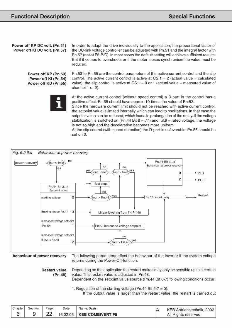
6 9 KEB COMBIVERT F522Name: Basis
16.02.05
Chapter Section Page Date © KEB Antriebstechnik, 2002All Rights reserved
Functional Description Special Functions
0
2 1
0
1
2
3
Fig. 6.9.6.d Behaviour at power recovery
Restart value(Pn.48)
yes
PLS
Pn.44 Bit 3...4Behaviour at power recovery
POFF
Power off KP DC volt. (Pn.51)Power off KI DC volt. (Pn.57)
In order to adapt the drive individually to the application, the proportional factor ofthe DC-link voltage controller can be adjusted with Pn.51 and the integral factor withPn.57 (not at F5-B/C). In most cases the default setting will achieve sufficient results.But if it comes to overshoots or if the motor looses synchronism the value must bereduced.
Pn.53 to Pn.55 are the control parameters of the active current control and the slipcontrol. The active current control is active at CS.1 = 2 (actual value = calculatedvalue), the slip control is active at CS.1 = 0 or 1 (actual value = measured value ofchannel 1 or 2).
At the active current control (without speed control) a D-part in the control has apositive effect. Pn.55 should have approx. 10-times the value of Pn.53.Since the hardware current limit should not be reached with active current control,the setpoint value is limited internally which can lead to oscillations. In that case thesetpoint value can be reduced, which leads to prolongation of the delay. If the voltagestabilization is switched on (Pn.44 Bit 8 = „1“) and uf.9 = rated voltage, the voltageis not so high and the deceleration becomes more uniform.At the slip control (with speed detection) the D-part is unfavorable. Pn.55 should beset on 0.
Power off KP (Pn.53)Power off KI (Pn.54)
Power off KD (Pn.55)
power recovery fout > fmin
fast stop
no
Pn.52 restart delayRestart
fout > Pn.48
fout > Pn.48
Pn.50 increased voltage setpoint
Linear lowering from f < Pn.48
Pn.44 Bit 3...4Setpoint value
starting voltage
Braking torque Pn.47
increased voltage setpoint
(Pn.50)
increased voltage setpoint
if fout < Pn.48
yesno
yesno
behaviour at power recovery The following parameters effect the behaviour of the inverter if the system voltagereturns during the Power-Off-function.
Depending on the application the restart makes may only be sensible up to a certainvalue. This restart value is adjusted in Pn.48.Dependent on the setpoint value source (Pn.44 Bit 6-7) following conditions occur:
1. Regulation of the starting voltage (Pn.44 Bit 6-7 = 0):If the output value is larger than the restart value, the restart is carried out
yesfout > fmin
noyes
fout > fmin
no

6 9 23KEB COMBIVERT F5
Name: Basis
16.02.05
6
Section PageDate© KEB Antriebstechnik, 2002All Rights reserved
Chapter
Functional DescriptionSpecial Functions
Restart at minimum outputvalue
(Pn.44 Bit 3, 4)
upon power recovery. The output value is kept constant during the restartdelay (Pn.52). Afterwards it is accelerated to the current setpoint value. Belowthe restart value it is delayed in case of power recovery with the fast-stop-function ( DEC-ramp at F5-B/C).
2. Regulation onto the voltage setpoint, if the output value is smaller than the restartvalue (Pn.44 Bit 6+7 = 2):As long as the output frequency and/or the actual speed is larger than therestart value, the inverter behaves as described under Point 1. Below therestart value the voltage setpoint value of Pn.50 is increased and with activecurrent control (without speed detection) the control parameters of the activecurrent control are reduced linearly with the output value.
3. 3. Regulation onto the voltage setpoint Pn.50 or braking torque Pn.47 (Pn.44 Bit6+7 = 1 or 3):The control parameters of the active current control (without speed detection)are reduced below the restart value linearly with the output value.
Bit 3 and 4 of Pn.44 determine the behaviour of the drive upon attaining the minimumoutput value.• Bit 3 = „0“ and Bit 4 = „0“; the inverter modulates independent of a set direction
of rotation with the adjusted boost and is in status „POFF“ (Caution: Motorheating). A reset is necessary for the restart.
• Bit 3 = „1“ and Bit 4 = „0“; the inverter modulates independent of a set directionor rotation with the adjusted boost and is in status „POFF“. After expiration ofthe restart delay Pn.52 (if adjusted) the inverter restarts automatically.
• Bit 3 = „0“ and Bit 4 = „1“; the inverter switches off the modulation and is instatus „PLS“. A reset is necessary for the restart.
The restart delay is the time during which the output value is kept constant afterpower recovery, if a restart is allowed. It is adjustable within the range of 0...100 s(Default 0 s). After expiration of the time it is accelerated again onto the currentsetpoint value.
Restart delay(Pn.52)
Examples To better understand the correlation, the operating modes are explained accordingto the control types in the following section.
If the Power-Off-function is switched on (pn.44 Bit 0 = 1), it becomes active if the DC-link voltage drops below the starting voltage value. In the first cycle the frequencyjump is given which shall put the drive into no-load running. Afterwards it is regulatedonto the DC-link voltage or only onto the active current respectively slip dependingon the setpoint value source. The changeover between active current control (withoutspeed detection) and slip control (with speed detection) takes place over cs.1. Atcs.1 = 2 (actual value = calculated value) the active current control is active, at cs.1= 0 or 1 the slip control is active.
Set value sourceStarting voltage (Pn.44 Bit 6-7 = Mode 0) or setpoint DC-link voltage Pn.50, if outputvalue < restart value Pn.48 (Pn.44 Bit 6-7 = Mode 2)
In this mode the motor shall be operated almost in no-load operation and only recover
ride-through ofshort-time supply failure
functional sequence F5-G
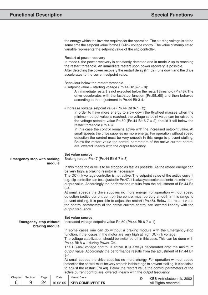
6 9 KEB COMBIVERT F524Name: Basis
16.02.05
Chapter Section Page Date © KEB Antriebstechnik, 2002All Rights reserved
Functional Description Special Functions
Emergency stop with brakingmodule
the energy which the inverter requires for the operation. The starting voltage is at thesame time the setpoint value for the DC-link voltage control. The value of manipulatedvariable represents the setpoint value of the slip controller.
Restart at power recoveryIn mode 0 the power recovery is constantly detected and in mode 2 up to reachingthe restart threshold. An immediate restart upon power recovery is possible.After detecting the power recovery the restart delay (Pn.52) runs down and the driveaccelerates to the current setpoint value.
Behaviour below the restart threshold• Setpoint value = starting voltage (Pn.44 Bit 6-7 = 0):
An immediate restart is not executed below the restart threshold (Pn.48). Thedrive decelerates with the fast-stop function (Pn.58..60) and then behavesaccording to the adjustment in Pn.44 Bit 3-4.
• Increase voltage setpoint value (Pn.44 Bit 6-7 = 2):In order to have more energy to slow down the flywheel masses when theminimum output value is reached, the voltage setpoint value can be raised tothe voltage setpoint value Pn.50 (Pn.44 Bit 6-7 = 2) should it fall below therestart threshold (Pn.48).In this case the control remains active with the increased setpoint value. Atsmall speeds the drive supplies no more energy. For operation without speeddetection the control must be very smooth in this range to prevent stalling.Below the restart value the control parameters of the active current controlare lowered linearly with the output frequency.
Set value sourceBraking torque Pn.47 (Pn.44 Bit 6-7 = 3)
In this mode the drive is to be stopped as fast as possible. As the refeed energy canbe very high, a braking resistor is necessary.The DC-link voltage controller is not active. The setpoint value of the active currente.g. slip controller can be adjusted in Pn.47. It is always decelerated onto the minimumoutput value. Accordingly the performance results from the adjustment of Pn.44 Bit3-4.At small speeds the drive supplies no more energy. For operation without speeddetection (active current control) the control must be very smooth in this range toprevent stalling. It is possible to adjust the restart (Pn.48). Below the restart valuethe control parameters of the active current control are lowered linearly with theoutput frequency.
Set value sourceIncreased voltage setpoint value Pn.50 (Pn.44 Bit 6-7 = 1)
In some cases one can do without a braking module with the Emergency-stopfunction, if the losses in the motor are very high at high DC-link voltage.The voltage stabilization should be switched off in this case. This can be done withPn.44 Bit 8 = 1 during Power-Off.The DC-link voltage control is active. It is always decelerated onto the minimumoutput value. Accordingly the performance results from the adjustment of Pn.44 Bit3-4.At small speeds the drive supplies no more energy. For operation without speeddetection the control must be very smooth in this range to prevent stalling. It is possibleto adjust the restart (Pn.48). Below the restart value the control parameters of theactive current control are lowered linearly with the output frequency.
Emergency stop withoutbraking module

6 9 25KEB COMBIVERT F5
Name: Basis
16.02.05
6
Section PageDate© KEB Antriebstechnik, 2002All Rights reserved
Chapter
Functional DescriptionSpecial Functions
If the Power-Off-function is switched on (pn.44 Bit 0 = 1), it becomes active if the DC-link voltage drops below the starting voltage value. The behaviour depends on theadjustment of the setpoint source (Pn.44 Bit 6-7). The behaviour setpoint source =voltage setpoint value (Pn.44 Bit 6-7 = 1 or 2) is the same as with voltage setpointvalue = starting voltage (Pn.44 Bit 6-7 = 0).
For F5-M only the parameters Pn.44..46, Pn.48, Pn.51, Pn.52 and Pn.57 are visible.In Pn.44 the Bits 2 and 8 are ineffective.The Power-Off function is switched off in controlled operation (cs.0 Bit 0..2 = 0..3).
Setpoint value source:Starting voltage (Pn.44 Bit 6-7 = 0)
In this mode the motor shall be operated almost in no-load operation and only recoverthe energy which the inverter requires for the operation. The starting voltage is at thesame time the setpoint value for the DC-link voltage control. The value of manipulatedvariable represents the torque limit of the speed controller.In case of weak supply systems it is recommended to choose the automatic startingvoltage, as in this case the starting voltage value is adapted to slow voltagefluctuations.In the first cycle the limit of the speed control is adjusted to the measured slip, sothat the drive is put into no-load operation.
Restart at power recoveryOnly in this mode the system recovery can be constantly detected. An immediaterestart upon power recovery is possible.After detecting the power recovery the restart delay (Pn.52) runs down and the driveaccelerates to the current setpoint value.An immediate restart is not executed below the restart value (Pn.48). The drivedecelerates with the fast-stop function (Pn.60..61) and then behaves according tothe adjustment in Pn.44 Bit 3-4.
Setpoint value source:Braking torque Pn.47 (Pn.44 Bit 6-7 = 3)
In this mode the drive is to be stopped as fast as possible. As the refeed energy canbe very high, a braking resistor is necessary.The DC-link voltage controller is not active. The drive decelerates with the fast-stopfunction (Pn.60..61) and then behaves according to the adjustment in Pn.44 Bit 3-4.
If the Power-Off-function is switched on (pn.44 Bit 0 = 1), it becomes active if the DC-link voltage drops below the starting voltage value. The drive decelerates with thefast-stop function (Pn.60..61) and then behaves according to the adjustment in Pn.44Bit 3-4.
Depending on the adjustment of bit 0 and in the quick stop mode (Pn.58) the ramptime (bit 0 = 0) or the time constant of the differential controller (bit 0 = 1, F5-G) is
Functional sequence F5-M
Bridging of mains gaps
Emergency stop with brakingmodule

6 9 KEB COMBIVERT F526Name: Basis
16.02.05
Chapter Section Page Date © KEB Antriebstechnik, 2002All Rights reserved
Functional Description Special Functions
Param. Addr. min max default
ENTERPROG.R/W
Step
Used Parameters
Pn.44 042Ch 4 - 4 0 511 1 0 -
Pn.45 042Dh 4 - - 200 V 800V 1 V 290/500 V dep. of the voltage class
Pn.46 042Eh 4 - - 50 % 90 % 1 % 80 % -
Pn.47 042Fh 4 - - 0,0 % 100,0 % 0,1 % 0 % only F5-G/B
Pn.48 0430h 4 - - 0 Hz 400 Hz 0,0125 Hz 0 Hz only F5-G/B
0430h 4 - - 0 rpm 4000 rpm 0,125 rpm 0 rpm only F5-M ; dep. on ud.2
Pn.50 0432h 4 - - 200 V 800 V 1 V 290/500 V dep. of the voltage class
Pn.51 0433h 4 - - 0 32767 1 128 (512) only F5-G; F5-M; (F5-B)
Pn.52 0434h 4 - - 0,00 s 100,00 s 0,01 s 0,00 s -
Pn.53 0435h 4 - - 0 32767 1 800 (50) only F5-G; (F5-B)
Pn.54 0436h 4 - - 0 32767 1 800 (50) only F5-G; (F5-B)
Pn.55 0437h 4 - - 0 32767 1 0 only F5-G/B
Pn.56 0438h 4 - - 0 % 800 % 1 % 100 % only F5-G/B
Pn.57 0439h 4 - - 0 32767 1 5 only F5-G; F5-M
Pn.60 043Ch - - - 0,00 s 300 s 0,01 s 2,00 s -
Pn.61 043Dh - - - 0 Nm 32000 Nm 0 Adapt. 0,01 Nm only F5-M ; F5-S
Pn.69 0445h 4 - 4 300V 1000 V 1 V 380V; 740V -
adjusted here.
The ramp time refers dependent on ud.2 bit 0+1 to 100/200/400/12.5 and/or 1000/2000/4000/125 rpm in the standard software. In the high speed software the ramptime refers at ud.2 bit 0+1 = 3 to 800 Hz and/or 8000 rpm.
The internally effective value is limited downward:
min. GTR7-Level = ru.68 (rated DC link voltage) * 1,0625
Input voltage = 400 V: min. GTR7-Level = 601 VInput voltage = 230 V: min. GTR7-Level = 346 V
For F5-S only the parameters Pn.44..46 and Pn.52 are visible. At Pn.44 only the Bits0, 1 and 3..-4 are active.
The torque limit for the quick stop function can be adjusted here.Functional sequence F5-
S
Quick stop dec time (Pn.60)
Quick stop torque limit (F5-M, F5-S) (Pn.61)
GTR7 voltage (Pn.69)

6 9 27KEB COMBIVERT F5
Name: Basis
16.02.05
6
Section PageDate© KEB Antriebstechnik, 2002All Rights reserved
Chapter
Functional DescriptionSpecial Functions
6.9.7 Wobbel Function(not at B-housing)
0
1
2
3
oP.44Bit 4...7
AN1 (ru.28)
AN2 (ru.30)
AN3 (ru.32)
digital (oP.45)
oP.46
oP.47, 48
oP.49
0
1
2
oP.44Bit 0...3
ru.2
Ramp output value
S e t p o i n tvalue
Wobbel generator
Diameter correction
Amplitude
Diameter signal
6.9.7 Additional function: Wobbel generator
The wobbel generator enables in period and amplitude changeable sawtooth processof the setpoint value. It is activated with the parameter oP.44 Bit 0...3 = „1“.
Additional function / Mode(oP.44 Bit 0...3)
Two different functions can be activated with oP.44 Bit 0...3. The value is to be addedto Bit 4...7.
oP.44 Bit 0...3 Function0 no function activated1 Wobbel generator activated2 Diameter correction (see chapter 6.9.8)
3...15 reserved
The input source for the functions is determined with oP.44 Bit 4...7. The value is tobe added to Bit 0...3.
oP.44 Bit 4...7 Function0 Analog input AN1
16 Analog input AN232 Analog input AN348 Digital presetting with oP.45
Additional function / Source(oP.44 Bit 4...7)
Additional functiondigital setting (oP.45)
If the value „49“ (sweep function with digital specification) is adjusted in oP.44, thesweep amplitude is preset with oP.45 within the range of 0...100 %.
Additional functionacceleration/deceleration
(oP.46)
With oP.46 a time can be preset between 0...20 s, with which the sweep amplituderises/falls. The entered value refers to a sweep amplitude of 100 %.

6 9 KEB COMBIVERT F528Name: Basis
16.02.05
Chapter Section Page Date © KEB Antriebstechnik, 2002All Rights reserved
Functional Description Special Functions
Wobbel generatorAcceleration time (oP.47)Deceleration time (oP.48)
With oP.47 the acceleration time and with oP.48 the deceleration is adjusted in eachcase within the range of 0...20,00 s. Together the two parameters result in the periodduration of the wobbel period.
6.9.7.b Acceleration and deceleration times of the wobbel generator
F
t
fset
oP.47 oP.48
Ampl. f
set+ ---------
- ----------2
Param. Addr. min max default
ENTERPROG.R/W
Step
Used Parameters
oP.44 032Ch 4 - 4 0 63 1 0 -
oP.45 032Dh 4 - - 0,00 % 100,00 % 0,01 % 0,00 % -
oP.46 032Eh 4 - - 0,00 s 20,00 s 0,01 s 10,00 s -
oP.47 032Fh 4 - - 0,00 s 20,00 s 0,01 s 10,00 s -
oP.48 0330h 4 - - 0,00 s 20,00 s 0,01 s 10,00 s -
Ampl.fset
----------2

6 9 29KEB COMBIVERT F5
Name: Basis
16.02.05
6
Section PageDate© KEB Antriebstechnik, 2002All Rights reserved
Chapter
Functional DescriptionSpecial Functions
6.9.8 DiameterCorrection
0
1
2
3
oP.44Bit 4...7
AN1 (ru.28)
AN2 (ru.30)
AN3 (ru.32)
digital (oP.45)
oP.46
oP.47, 48
oP.49
0
1
2
oP.44Bit 0...3
ru.2
Ramp output value
S e t p o i n tvalue
Wobbel generator
Diameter correction
Amplitude
Diameter signal
6.9.8 Additional function: Diameter correction
Through the use of the diameter correction the tool path feedrate of a winding productcan be kept constant at changing diameter of the reel bale.
Additional function / Mode(oP.44 Bit 0...3)
Two different functions can be activated with oP.44 Bit 0...3. The value is to be addedto Bit 4...7.
oP.44 Bit 0...3 Function0 no external function activated1 Wobbel generator (see chapter 6.9.7)2 Diameter correction activated
3...15 reserved
The input source for the functions is determined with oP.44 Bit 4...7. The value is tobe added to Bit 0...3.
oP.44 Bit 4...7 Function0 Analog input AN1
16 Analog input AN232 Analog input AN348 Digital presetting with oP.45
Additional function / Source(oP.44 Bit 4...7)
Additional functiondigital presetting (oP.45)
If the value "50“ (sweep function with digital specification) is adjusted in oP.44, thediameter signal can be preset with oP.45 within the range of 0...100 %.
(not at F5-B)

6 9 KEB COMBIVERT F530Name: Basis
16.02.05
Chapter Section Page Date © KEB Antriebstechnik, 2002All Rights reserved
Functional Description Special Functions
The diameter signal is evaluated within the range of 0 % to 100%. Values < 0% areset to 0%, values > 100% are limited to 100%.The diameter signal of 0% corresponds to the minimum diameter of the reel bale(d
min). The output frequency/speed of the ramp generator is not changed in this case.
A diameter signal of 100% corresponds to the maximum diameter of the reel bale(d
max). In order to be able to calculate the frequency/speed change the program
requires the ratio of minimum to maximum diameter (dmin
/dmax
).The ratio of minimum to maximum diameter (d
min/d
max) is preset by way of oP.49 and
can be adjusted within the range of 0,010...0,990 with a resolution of 0,001.
The corrected output frequency of the ramp generator is determined as follows:
fn_Ramp: Output frequency/speed of ramp generatorfn_presetting: Corrected output frequency/speedDS: Diameter signal 0 - 100% (0 to 1)oP.49: (d
min/d
max)
Diameter correction dmin/dmax (oP.49)
Additional functionacceleration/deceleration
(oP.46)
The rate of change of the diameter signal can be limited by a ramp generator. Byway of oP.46 the time can be preset within the range of 0,0...20 s, which is requiredfor a signal difference of 0...100%.
Param. Addr. min max default
ENTERPROG.R/W
Step
Used Parameters
oP.44 032Ch 4 - 4 0 63 1 0 -
oP.45 032Dh 4 - - 0,00 % 100,00 % 0,01 % 0,00 % -
oP.46 032Eh 4 - - 0,00 s 20,00 s 0,01 s 10,00 s -
oP.49 0331h 4 4 - 0,010 0,990 0,001 0,500 -
fn_Rampfn_presetting = –––––––––––––––––
1+DS·(1/oP.49-1)

6 9 31KEB COMBIVERT F5
Name: Basis
16.02.05
6
Section PageDate© KEB Antriebstechnik, 2002All Rights reserved
Chapter
Functional DescriptionSpecial Functions
6.9.9 PositioningFunction
The positioning function enables the approach of a position with a signal from diffe-rent frequencies. The positioning procedure is triggered by disabling the direction ofrotation through an external signal (e.g. through set changeover). The positioning isexecuted correctly only if at triggering the positioning the maximum frequency of thepositioning set is not exceeded and no s-curves are used. During the positioningprocedure the status ‘Positioning’ is displayed (value 83, display ‘POSI’).
In order to always travel the same distance in the case of different frequencies, thedrive continues to run with constant frequency after starting the positioning until theposition is reached with the adjusted deceleration. The frequency-dependent constantrunning time is calculated as follows:
t_dec2 f_max²
t_const = ———————— • (——— - f_actual)Reference frequency f_actual
t_const: frequency-dependent constant running time [sec.]t_dec: adjusted deceleration time [sec.]Reference frequency: 100Hz / 200Hz / 400Hz (dependent on ud.2)f_max: maximum frequency [Hz]f_actual: actual frequency [Hz] on triggering the positioning
With parameter Pn.63 a shifting of the stop position can be adjusted, which entailsan additional running time. Thus the shifting of the initiator can be omitted. The addi-tional constant running time is also frequency-dependent and is calculated as follows:
Pn.63 • f_maxt_delay = ——————
f_actual
Pn.63 Function-0,02 Positioning switched off-0,01 Positioning function switched off (standard)0,00...327,67 s Positioning function switched on; positioning delay by the adjusted
value; set change over during the positioning not possible, unlessit shall be changed in a set which is adjusted with Pn.63 = -0,02.
With the set switch-on delay (fr.5) and the set switch-off delay (fr.6) a delay time afterreaching the position e.g at set changeover can be adjusted.
Calculation of the frequency-dependent constant running
time
Positioning delay (Pn.63)
Setactivation delay (Fr.5)
Set deactivation delay (Fr.6)
Param. Addr. min max default
ENTERPROG.
ro Step
Used Parameters
Pn.63 043Fh - 4 4 -0,02 s 326,76 s 0,01 s -0,01 s -0,01 = posi off; -0,02=abort
Fr.5 0905h - 4 - 0,00 s 32,00 s 0,01 s 0,00 s -
Fr.6 0906h - 4 - 0,00 s 32,00 s 0,01 s 0,00 s -
t_delay: additional constant running time [sec.]Pn.63: Positioning / delay [sec.]f_max: maximum frequency [Hz]f_actual: actual frequency [Hz] on triggering the positioning
(only for F5-G/B)

6 9 KEB COMBIVERT F532Name: Basis
16.02.05
Chapter Section Page Date © KEB Antriebstechnik, 2002All Rights reserved
Functional Description Special Functions
Example 1 The drive runs a distance, positions and remains at the stop position for a time.The new cycle starts.
Download list:
set Parameter Value Notes
0 Ud01 Password 440
0 Fr01 Copy parameter set -2: def.cust.para all sets
0-1 oP00 Reference source 0: Analog REF
0 oP01 Rotation source 2: F/R, 0-lim. Set 0: running
1 oP01 Rotation source 0: dig., 0-lim. Set 1: positioning
1 oP02 Rotation setting 0: low speed
0-1 oP10 Max. reference forward 70,0000 Hz The max. setpoint value must be the
same in all sets.
0-1 oP28 Acc. time forward 0,01 s
0-1 oP30 Dec. time forward 0,20 s
0 Pn63 Positioning delay -1: off
1 Pn63 Positioning delay 5,00 s Shifting of the stop position
0 Fr02 Parameter set source 3: term. inp. coded ST-I1-ID
0 Fr05 Set activation delay 1,00 s Additional break at the stop position
1 Fr05 Set activation delay 0,00 s This time must be = 0
0 Fr06 Set deactivation delay 0,00 s This time must be = 0
1 Fr06 Set deactivation delay 2,55 s Break at the stop position
0 Fr07 Para. set input selection 16: I1
0 di11 I1 Function 2048: P. set selection initiator signal

6 9 33KEB COMBIVERT F5
Name: Basis
16.02.05
6
Section PageDate© KEB Antriebstechnik, 2002All Rights reserved
Chapter
Functional DescriptionSpecial Functions
The drive runs with different speed back and forth and always reverses at thesame points.
Download list:
set Parameter Value Notes
0 Ud01 Password 440
0 Fr01 Copy parameter set -2: def. cust.para all sets
0-3 oP00 Reference source 0: Analog REF
0-3 oP01 Rotation source 0: dig.(op.2), 0-lim.
0 oP02 Rotation setting 1: forward Set 0: clockwise rotation
1 oP02 Rotation setting 0: low speed Set 1: clockwise rotation positioning
2 oP02 Rotation setting 2: reverse Set 2: counterclockwise rotation
3 oP02 Rotation setting 0: low speed Set 3: counterclockwise positioning
0-3 oP10 Max. reference forward 70,0000 Hz The max. setpoint value must be the
same in all sets.
0-3 oP11 Max. reference reverse -1: = see oP.10 The max. setpoint value can be
different for the direction of rotation.
0-3 oP28 Acc. time forward 0,10 s
0-3 oP30 Dec. time forward 0,10 s
0 Pn63 Positioning delay -1: off
1 Pn63 Positioning delay 0,8 s Shifting of the position at clockwise
rotation
2 Pn63 Positioning delay -1: off
3 Pn63 Positioning delay 3,1 s Shifting the position at
counterclockwise rotation
0 Fr02 Parameter set source 2: terminal binary coded
0 Fr05 Set activation delay 0,00 s Additional break between counter-
clockwise and clockwise rotation
1 Fr05 Set activation delay 0,00 s This time must be = 0
2 Fr05 Set activation delay 0,00 s Additional break between clockwise
and counterclockwise rotation
3 Fr05 Set activation delay 0,00 s This time must be = 0
0 Fr06 Set deactivation delay 0,00 s This time must be = 0
1 Fr06 Set deactivation delay 1,00 s Break between clockwise and
counterclockwise rotation
2 Fr06 Set deactivation delay 0,00 s This time must be = 0
3 Fr06 Set deactivation delay 1,00 s Break between counterclockwise and
clockwise rotation
0 Fr07 Paraset input sel. 272: I1+IA
0 Fr11 Reset set input selection 0: no input
0 di11 I1 Function 2048: Set sel. initiator signal
0 di15 IA Function 2048: Set sel. Changeover between clockwise and
counterclockwise rotation
0 do04 Condition SB4 0: off Initiator active: -> set 1
1 do04 Condition SB4 1: on Positioning completed: -> set 2
2 do04 Condition SB4 1: on Initiator active: -> set 3
3 do04 Condition SB4 0: off Positioning completed: -> set 0
Example 2

6 9 KEB COMBIVERT F534Name: Basis
16.02.05
Chapter Section Page Date © KEB Antriebstechnik, 2002All Rights reserved
Functional Description Special Functions
6.9.10 Analog Setting ofParameter Values
With this function it is possible to preset parameter values analog. The AUX-functionor the motor-poti function can be adjusted as source.
Source analogparameter setting (An.53)
This parameter determines whether the analog parameter setting occurs via themotor-poti or the aux-function.
An.53 Function
0 AUX1 Motorpoti function
The Bus-address of the parameter, that is to be adjusted in analog mode, is adjustedhere (see chapter 5). Following parameters can be adjusted.
uF.1 / 7cn. 4 / 5 / 6An.32 / 37 / 42 / 48LE.0 / 1 / 2 / 3 / 4 / 5 / 6 / 7cS.6 / 9Ec.4 / 14PS.31 / 33
In case an invalid parameter address is selected, the message „IdAtA“ (or „datainvalid“ at COMBIVIS) is output and the setting is ignored.
Defines the parameter value, that adjusts itself at 0 % analog parameter setting. Theparameter value must be entered with the internal standardization of the targetparameter.
Desired value of target parameterValue to be adjusted = --------------------------------------------------------
Resolution of target parameter
Defines the parameter value, that adjusts itself at 100 % analog parameter setting.The parameter value must be entered with the internal standardization of the targetparameter.
An.57 determines the parameter set which edited the selected parameter. If aprogrammable parameter is adjusted as target parameter, the adjusted set in An.57is edited.
An.57 Function
-1 active set is edited
0...7 adjusted set is edited
If a non-programmable parameter is adjusted as target parameter, it is always editedin set 0 independent on An.57.
Target analogparameter setting (An.54)
Offset analogparameter setting (An.55)
Maximal value analogparameter setting (An.56)
Used Parameters
Parameter Addr. ro prog min max default [?] Notes
An.53Source anal. Para.setting 0A35 - - yes 0 1 1 0 -An.54Target anal. Para.setting 0A36 - - yes -1: off 7FFFH 0001h -1: off -An.55Offset anal. Para.setting 0A37 - - yes -231 231-1 1 0 -An.56Maximal value anal. Para.setting.0A38 - - yes -231 231-1 1 0 -An.57Set indicator anal. Para.setting0A39 - - yes -1 7 1 0 -
Set indicator analogparameter setting (An.57)

Functional Description
1. Introduction
2. Summary
3. Hardware
4. Operation
5. Parameter
6. Functions
7. Start-up
8. Special Operation
9. Error Assistance
10. Project Planning
11. Networks
12. Annex
6.1 Operating and ApplicanceDate
6.2 Analog In- and Outputs
6.3 Digital In- and Outputs
6.4 Set Value and RampAdjustment
6.5 Voltage-/FrequencyCharacteristic (U/f)Adjustment
6.6 Motor Data Adjustment
6.7 Protective Functions
6.8 Parameter Sets
6.9 Special Functions
6.10 Encoder Interface
6.11 SMM, Posi, Sync, CTM
6.12 Technology Control
6.13 CP-Parameter Definition
6 10 1KEB COMBIVERT F5
Name: Basis
17.02.03
Section PageDate© KEB Antriebstechnik, 2002All rights reserved
Chapter
6.10.1 Designs .................................. 36.10.2 Encoder Interface Channel 1 . 46.10.3 Encoder Interface Channel 2 . 56.10.4 Power Supply of Encoder ...... 76.10.5 Selection of Encoder .............. 86.10.6 Basic Settings ...................... 106.10.7 Additional Parameters .......... 136.10.8 Used Parameters ................. 16

6 10 KEB COMBIVERT F52Name: Basis
17.02.03
Chapter Section Page Date © KEB Antriebstechnik, 2002All rights reserved
Functional Description Encoder Interface

6 10 3KEB COMBIVERT F5
Name: Basis
17.02.03
6
Section PageDate© KEB Antriebstechnik, 2002All rights reserved
Chapter
Functional DescriptionEncoder Interface
��������
6.10 Encoder Interface
6.10.1 Designs
6.10.1 Encoder interfaces
X3AX3B
The KEB COMBIVERT F5 supports two from each other separated encoder channels.Each encoder channel can support following interface dependent on the availablehardware:
Encoder channel 1 (X3A)• is a 15-pole incremental encoder input for rectangular signals
Encoder channel 2 (X3B) can support following interfaces• 9-pole incremental encoder input for rectangular singal• Incremental encoder output• Incremental encoder In-/Output
Further Interfaces (describes in separate manuals)• Synchronous serial interface (SSI)• Tachometer input• Initiator input• Hiperface• Endat• SinCos
��� ��!��"#������$
%���&���'(������)
*����+$��"����",+�
",+#$����"�#$"#$$��
�,+��%�#-�#+����
%�$'""�()
.#����(/
X3AX3B
(not for B-housing)
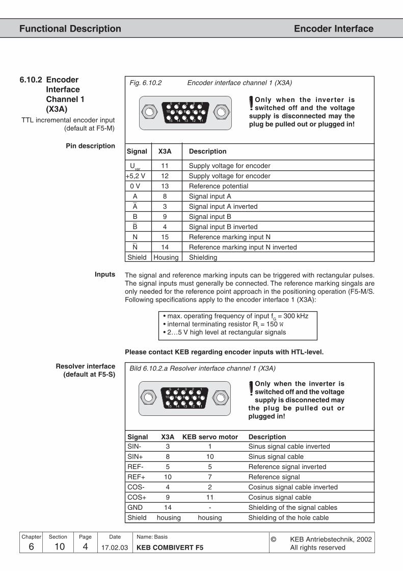
6 10 KEB COMBIVERT F54Name: Basis
17.02.03
Chapter Section Page Date © KEB Antriebstechnik, 2002All rights reserved
Functional Description Encoder Interface
Fig. 6.10.2 Encoder interface channel 1 (X3A)
Signal X3A Description
Uvar
11 Supply voltage for encoder
+5,2 V 12 Supply voltage for encoder
0 V 13 Reference potential
A 8 Signal input A_A 3 Signal input A inverted
B 9 Signal input B_B 4 Signal input B inverted
N 15 Reference marking input N_N 14 Reference marking input N inverted
Shield Housing Shielding
Pin description
Only when the inverter isswitched off and the voltage
supply is disconnected may theplug be pulled out or plugged in!
5 4 3 2 1
10 9 8 7 6
15 14 13 12 11
6.10.2 EncoderInterfaceChannel 1(X3A)
The signal and reference marking inputs can be triggered with rectangular pulses.The signal inputs must generally be connected. The reference marking singals areonly needed for the reference point approach in the positioning operation (F5-M/S.Following specifications apply to the encoder interface 1 (X3A):
• max. operating frequency of input fG
= 300 kHz• internal terminating resistor R
t= 150 W
• 2…5 V high level at rectangular signals
Inputs
Please contact KEB regarding encoder inputs with HTL-level.
Resolver interface(default at F5-S)
Bild 6.10.2.a Resolver interface channel 1 (X3A)
Signal X3A KEB servo motor DescriptionSIN- 3 1 Sinus signal cable inverted
SIN+ 8 10 Sinus signal cable
REF- 5 5 Reference signal inverted
REF+ 10 7 Reference signal
COS- 4 2 Cosinus signal cable inverted
COS+ 9 11 Cosinus signal cable
GND 14 - Shielding of the signal cables
Shield housing housing Shielding of the hole cable
Only when the inverter isswitched off and the voltagesupply is disconnected may
the plug be pulled out orplugged in!
5 4 3 2 1
10 9 8 7 6
15 14 13 12 11
TTL incremental encoder input(default at F5-M)

6 10 5KEB COMBIVERT F5
Name: Basis
17.02.03
6
Section PageDate© KEB Antriebstechnik, 2002All rights reserved
Chapter
Functional DescriptionEncoder Interface
12 3
4
5
678
9
10
11
12
SIN - 1SIN + 10
REF - 5REF + 7
COS - 2COS +11
Bild 6.10.2.b Resolver connector at the KEB servo motor
3 SIN - red8 SIN + blue
5 REF - yellow10 REF + green
4 COS - pink9 COS + grey
housing housing Aderfarbe
14 GND
Bild 6.10.2.c Resolver cable
6.10.3 Encoder IntefaceChannel 2 (X3B)
Fig. 6.10.3 Encoder interface channel 2 (X3B)
5 4 3 2 1
9 8 7 6
Only when the inverter isswitched off and the voltage
supply is disconnected may theplug be pulled out or plugged in!
ec.10 Definition of theinterface
Channel 2 can be equipped with different interfaces. To avoid the connection of awrong encoder, the installed interface is indicated in ec.10.
Incremental encoder input In synchronous operation the second incremental encoder serves as input of themaster drive. A second position encoder can be connected for positioning operation.

6 10 KEB COMBIVERT F56Name: Basis
17.02.03
Chapter Section Page Date © KEB Antriebstechnik, 2002All rights reserved
Functional Description Encoder Interface
Incremental encoder output
Signal X3B Description
Uvar
5 Supply voltage for encoder (see 6.10.2)
+5,2 V 4 Supply voltage for encoder (see 6.10.2)
0 V 9 Reference potential
A 1 Signal output A_A 6 Signal output A inverted
B 2 Signal output B_B 7 Signal output B inverted
N 3 Reference marking output N_N 8 Reference marking output N inverted
Shield Housing Shielding
The incremental encoder output gives out the signals recorded at the encoderinterface 1:1 in RS422-specification over the second channel (e.g. master drive insynchronous operation).
Operating modeencoder 2 (ec.20)
With parameter ec.20 it is defined whether the encoder channel 2 shall work asinput or output. Precondition for that is a built-in switch-selectable encoder interface(In.5 = 7).
ec.20 Function0 Incremental encoder input1 Incremental encoder output
Signal X3B Description
Uvar
5 Supply voltage for encoder (see 6.10.2)
+5,2 V 4 Supply voltage for encoder (see 6.10.2)
0 V 9 Reference potential
A 1 Signal input A_A 6 Signal input A inverted
B 2 Signal input B_B 7 Signal input B inverted
N 3 Reference marking input N_N 8 Reference marking input N inverted
Shield Housing Shielding
The signal inputs of the second encoder interface support only rectangular signals.
Following specifications apply to the endocer interface 2 (X3B):
• max. operating frequency of input fG
= 300 kHz• internal terminating resistor R
t= 150 W
• 2…5 V high level at rectangular signals

6 10 7KEB COMBIVERT F5
Name: Basis
17.02.03
6
Section PageDate© KEB Antriebstechnik, 2002All rights reserved
Chapter
Functional DescriptionEncoder Interface
6.10.4 Power Supply ofEncoder
Fig. 6.10.4 Power supply
X2A
X3A
X3B
+24VDC 0V
5,2V
Uvar+5,2V
0V
Uvar+5,2V
0V
21
220V
+20...30VDC
Uvar
+5,2 V
Uvar
is an unstabilized voltage that is provided by the power stage of the KEBCOMBIVERT. Dependent on the size of unit and the load, the voltage amounted to15... 30 V DC. Uvar is loadable at X3A and X3B with altogether 170 mA. If highervoltages / currents to supply the encoders are needed then the control must besupplied with an external voltage.
The +5 V voltage is a stabilized voltage and loadable at X3A and X3B with altogether500 mA. Since +5.2 V are generated from Uvar, the current from Uvar is reducedaccording to following formula:
5,2 V x I+5VIvar
= 170 mA - –————Uvar
Geberbetriebsart (Ec.20) Ec.20 defines the function of the encoder interfaces.
Ec.20 FunctionBit 0 channel 2 function0 Incremental encoder input1 Incremental encoder outputBit 1 terminating resistor at channel 20 input with terminating resistor2 input without terminating resistorBit 2 channel 1 Incremental encoder alert (encoder cable breakage)0 alert off4 alert on (the encoder must support alert function)Bit 3 channel 2 Incremental encoder alert (encoder cable breakage)0 alert off8 alert on (the encoder must support alert function)

6 10 KEB COMBIVERT F58Name: Basis
17.02.03
Chapter Section Page Date © KEB Antriebstechnik, 2002All rights reserved
Functional Description Encoder Interface
1000
10000
1000 10000
200 kHz
300 kHz
6.10.5 Selection ofEncoder
Precondition for a good control behaviour of the drive is not least a question of theselection and the correct connection of the encoder. This also includes the mechanicalas well as the electrical connection.
Max. operating frequency(max.sampling frequency)
Depending on the max. operating frequency of the encoder input, the encoder andthe maximum speed of the drive the line number of the encoder can be selected.
6.9.4 Speed and line number in dependence on the max. operatingfrequency of the encoder inputs
Sp
eed
n [
rpm
]
Line number z
The max. signal frequency, which is given out by the encoder, is calculated as follows:
nmax
[rpm] x z
60000fmax
[kHz] =fmax
: max. signal frequencyn
max: max. speed
z: encoder line number
The following condition must be met:
fmax
< max. operating frequency of encoder < max. operating frequency of interface
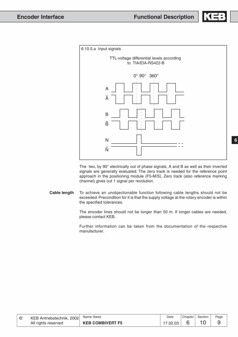
6 10 9KEB COMBIVERT F5
Name: Basis
17.02.03
6
Section PageDate© KEB Antriebstechnik, 2002All rights reserved
Chapter
Functional DescriptionEncoder Interface
0° 90° 360°
A
A
B
B
N
N
TTL-voltage differential levels according to TIA/EIA-RS422-B
6.10.5.a Input signals
The two, by 90° electrically out of phase signals, A and B as well as their invertedsignals are generally evaluated. The zero track is needed for the reference pointapproach in the positioning module (F5-M/S). Zero track (also reference markingchannel) gives out 1 signal per revolution.
Cable length To achieve an unobjectionable function following cable lengths should not beexceeded. Precondition for it is that the supply voltage at the rotary encoder is withinthe specified tolerances.
The encoder lines should not be longer than 50 m. If longer cables are needed,please contact KEB.
Further information can be taken from the documentation of the respectivemanufacturer.

6 10 KEB COMBIVERT F510Name: Basis
17.02.03
Chapter Section Page Date © KEB Antriebstechnik, 2002All rights reserved
Functional Description Encoder Interface
6.10.6 Basic Setting Prior to start-up the inverter must be adapted to the encoder(s) which is/are used.
Ec.0 displays the installed encoder interface 1; Ec.10 displays the installed encoderinterface 2. The values correspond to following interfaces:
Value Encoder interface0 no Interface1 Incremental encoder input TTL2 Incremental encoder output 5 V3 Incremental encoder input and output direct (not divisible by Ec.27;
switchable with Ec.20)4 Incremental encoder input and output TTL (switchable with Ec.20)5 Initiator6 SSI Interface7 Resolver Interface8 Tacho9 Incremental encoder output TTL (from resolver over channel 2)
10 Incremental encoder output TTL11 Hiperface12 Incremental encoder input 24 V HTL13 Incremental encoder input TTL with error detection14 Sin/cos encoder input15 Incremental encoder input 24 V HTL with error detection (push-pull)16 ENDAT17 Incremental encoder input 24 V HTL with error detection18 Analog option ±10 V
In case of an invalid encoder indentification the error „E.Hyb“ is indicated and themeasured value in is displayed inverted in ec.0/ec.10.On changing the encoder interface the error „E.HybC“ is indicated. By writing onparameter ec.0 or ec.10 the change is confirmed and the default values for the newinterface are loaded.
This parameter defines the time over which the speed average is determined. Atthat the resolution of the speed detection is defined simultaneously.
ec.3 Sampling Speed resolution with the use of anec.13 time incremental encoder with 2500 pulses
0 0,5 ms 12 rpm1 1 ms 6 rpm2 2 ms 3 rpm3 4 ms 1,5 rpm (Factory setting)4 8 ms 0,75 rpm5 16 ms 0,375 rpm6 32 ms 0,1875 rpm7 64 ms 0,09375 rpm8 128 ms 0,046875 rpm9 256 ms 0,0234375 rpm
Speed sampling time(Ec.3, Ec.13)
Encoder interface 1 / 2(Ec.0, Ec.10)
Adjustment of encoder linenumber (Ec.1, Ec.11)
With this parameter the encoder line number is adjusted to the connected encoderwithin a range of 1…16383.• ec.1 for encoder interface 1• ec.11 for encoder interface 2

6 10 11KEB COMBIVERT F5
Name: Basis
17.02.03
6
Section PageDate© KEB Antriebstechnik, 2002All rights reserved
Chapter
Functional DescriptionEncoder Interface
Multiple evaluation(Ec.7, Ec.17)
Through the gear factors it is possible to evaluate incremental encoders, which arenot directly mounted onto the motor shaft. The parameters Ec.4 and Ec.5 adjust thegear factor for encoder channel 1, Ec.14 and Ec.15 for encoder channel 2. The gearfactors are defined as follows:
Motor speedGear factor = –––––––––––––––
Gear speed
Ec.4 gear factor numerator 1 -10000...10000Gear factor 1 = –––––––––––––––––––––––– = –––––––––––––
Ec.5 gear factor denominator 1 1...10000
Ec.14 gear factor numerator 2 -10000...10000Gear factor 2 = –––––––––––––––––––––––– = –––––––––––––
Ec.15 gear factor denominator 2 1...10000
As additional function it is possible to trigger one of the two numerators with thefunction „Analog parameter setting“ (see Chapter 6.9.10).
Gear factor(Ec.4; Ec.5, Ec.14, Ec.15)
Value Evaluation of the encoder signals0 Single (for initiator: evaluation of positive edges only) (20)1 2-fold (for initiator: evaluation of positive and negative edge) (21)2 4-fold (for incremental encoder) (22) default3 8-fold (23)4 16-fold (24)5 32-fold (25)6 64-fold (26)...13 8192-fold (213)
Encoder track change(Ec.6, Ec.16)
With Ec.6 bit 0...1 a rotation change for encoder input 1 and with Ec.16 a rotationchange for encoder input 2 can be executed.With Bit 4 (value 16) a system inverting can be activated. With the system invertingit is possible to run the motor with positive setting counter-clockwise at the shaft,without changing the hardware.Following adjustments are possible:
Value FunctionDirection of rotation
0 no change (default)1 inverted2 depends on the sign of the actual frequency (initiator)3 depends on track B (initiator terminal 4)
4-16 reservedEncoder system
0 no change (default)16 inverted
When using other line numbers:
Speed resolution =Specified speed resolution x 2500
Line number

6 10 KEB COMBIVERT F512Name: Basis
17.02.03
Chapter Section Page Date © KEB Antriebstechnik, 2002All rights reserved
Functional Description Encoder Interface
Pretend parameter ec.14 set dependently in the range from -2000...2000
Formula:
Ec.14 -2000...2000–––––––– = ––––––––––––– Ec.15 1000
An.53 = motor poti = 1An.54 = 100Eh = ec.14An.55 = 2000 = 100%
oP.53 100% = motor poti min. value
oP.52 set 0 100% = motor poti value1 50%2 50%3 100%
Example
Adjustments of the analogparameter defaults
Simulation mode (Ec.27) With this parameter an encoder simulation can be adjusted.
Bit Value Function 0..1 Acceptance of the values
0 from channel 11 from channel 22 from current actual value
2..3 Number of increments to be output (at Bit 0..1 = 2)0 2564 5128 102412 2048
4...5 Divisor0 1 (direct)16 232 4
Ec.27 adjusts the mode of the simulation channel. If channel 2 is adjusted withEc.20 to incremental encoder output, then the mode in CH2 becomes effective withEc.27 (Ec.27 source => CH2 useless). Otherwise the adjustments refer to a thirdpure simulation channel (e.g. channel 2 15-poles).
When adjusting Ec.27 Bit 0...1 = actual value, then channel 2 may not be occupied,since the internal encoder counter is used for the generation of the zero signal.

6 10 13KEB COMBIVERT F5
Name: Basis
17.02.03
6
Section PageDate© KEB Antriebstechnik, 2002All rights reserved
Chapter
Functional DescriptionEncoder Interface
This parameter exists only at F5-S. The system position of the attached resolversystem is adjusted (factory setting).With this parameter it is possible to adjust the controller to a not aligned motor. If thesystem position of the motor is unknown an automatic trimming can carried out.Before starting with the adjustment, the direction of rotation must be checked. Thespeed display (ru.9) must be positive in the case of clockwise rotation by hand. Ifthat is not the case, the direction of rotation can be exchanged with Ec.6 as described.
• enter motor data• the connected motor must be able to rotate freely• open control release• enter Ec.2/12 = 2206• close control release
The motor is excited now with its rated current.If the direction of rotation of the connected motor is not correct or two motor phasesare exchanged, E.EnC is triggered.For resolver sytems the signal SIN+ and SIN- must be exchanged.If the system postion displayed in Ec.2/12 no longer changes the alignment iscompleted.
• open control release
If motors with aligned encoder systems are used, the value determined by theautomatic alignment can be entered directly in Ec.2/12.
Absolute position channel 1/2
(Ec.2 / Ec.12)(only F5-S)
In order to replace S4-systems by F5-S the following calculation must be carriedout:
ec.7 ( S4) * Pole pair number- Furthermore pay attention to the encoder cable -
- The lower 16 Bit of the result must be entered in Ec.2/12 -6.10.7 Additional
Parameters
The following parameters are needed only for specific encoder interfaces and areexplained more closely in the appropriate documentation.
If an SSI-multiturn-absolute value encoder is connected, the number of the bits forthe multiturn-resolution can be adjusted here (12 Bit).
The clock frequency of the SSI-encoder is adjusted in Ec.22. Two clock frequenciesare available 0 : 312,5 kHz or 1 : 156,25 kHz. The smaller clock frequency shouldonly be adjusted for long cables or in case interferences occur.
The unit supports two data formats for the SSI-encoders:0 : binary coded 1 : Gray code
As reference speed the max. tachometer speed is adjusted in Ec.25.
Position value directly from encoder channel 1 / 2 (with complete revolutions).
Ec.31 and Ec.32 show the position values of channel 1 and 2 after the gearbox.
SSI Multiturn resolution(Ec.21)
SSI Clock frequency select(Ec.22)
SSI Data code (Ec.23)
Nominal tacho speed (Ec.25)
Position channel 1 direct(Ec.29)
Position channel 2 direct(Ec.30)
Position Channel 1 (Ec.31)Position Channel 2 (Ec.32)

6 10 KEB COMBIVERT F514Name: Basis
17.02.03
Chapter Section Page Date © KEB Antriebstechnik, 2002All rights reserved
Functional Description Encoder Interface
Formula: actual position (ru.54) = position value - system offset (ec.33/34)
Which channel is taken for the actual value display is dependent on the adjustedmode
PS.0 = OFF /SYNCHRON -> CS.1PS.0 = POSI ->PS.1
In case of posi at the output (cs.1 < > ps.1) it shall be driven speed controlled between.In order to receive the actual position further on by ps.1, the posi mode can be leftonly by disconnecting from input ps.2!
Start-up procedure of a multiturn encoder:
If a multiturn encoder is mounted in the unit, it displays any position after Power-On (ec.29/30). By approaching to reference point and/or manual setting of thereference point, the actual position in ru.54 can be defined now. For this thesystem offset in parameters ec.33/34 is used. If the encoder leaves its value range(final value), then its position value starts with ZERO
1.An overflow of the encoder may not lead to a jump in the actual position (ru.r4)
2.After power off >on the position value (ru.54) must be available.
Conclusion: the overflow of the encoder must be noticed.
For this the position in ec.31/ 32 is internally stored and compared with theposition of the encoder of ec.29/30 after power on. A recognized overflow isconsidered in the system offset ec.33/34, i.e. the system offset is changed by theoverflow.After power off, the encoder may not change more than the half value range (finalvalue/2)!
Ec.36 indicates the type of the first supported encoder interface.
0 no encoder detected64 undefined type
The following hiperface types are supported:
2 SCS 60/707 SCM 60/70
34 SRS 50/6039 SRM 50/60
Ec.37 indicates the status of intelligent encoder interfaces (Hiperface, ENDAT, etc.).
„96“ is displayed if another encoder is used. With the F5-M/ S the change leads tothe display "E.Enc" and can be reset by a hardware reset. If "system position trimmingmust take place" is displayed, either the motor data of the encoder must be read outor a system position trimming must be done.
System offset Channel 1(Ec.33)
System offset Channel 2(Ec.34)
Encoder 1 Typ (Ec.36)
Encoder 1 state (Ec.37)

6 10 15KEB COMBIVERT F5
Name: Basis
17.02.03
6
Section PageDate© KEB Antriebstechnik, 2002All rights reserved
Chapter
Functional DescriptionEncoder Interface
Enc.1 encoder r/w
read data bit0 0 not active1 active (reset after reading)
store data bit1 0 not active (1)
1 active (reset after reading)
Motor data bit2 0 not automated (2)
1 automated
Data group bit3 0 System and application data (3)
1 System data
(1) Storing is supervisor-password protected(2) Servo power controller with Endat/Hiperface encoder do not have a factory
default download list of the motor data.(3) cs.19 and ec.3 belong to the application data
Dependent on bit 2 the once-only reading-out of the motor data from a Hiperface ora Endat encoder can be automated through:
- the factory configuration of the F5-S inverter (In.24 via supervisior password to199), so the motor data are read out with the first power on with encoder.
-Acknowledgement of the encoder interface change (E.HYPC) via ec.0.
-Loading the system default value fr.1 = -3 or -4, the motor data are read out only atF5-M/ S
If reading out is not possible error message „E.ENCC“ is displayed, and can only bereset by writing on ec.0 or via Bit 0 or 1 of ec.38. The inverter must be parameterizedthen, afterwards a system trimming at free rotating motor must take place.
This parameter must be activated for synchronous motors with indirect mountedencoder (e.g. via toothed belt). The gear ratio amounts to a multiple of the pole-pairnumber.
Displays the actual absolute el. position (2^16 = 360°).This parameter is used forthe system position trimming on a preset system position
mode channel 1 bit 0 0 full 32 bit range
1 only multiturn range
mode channel 2 bit 1 0 full 32 bit range
1 only multiturn range
Description also see ec.33/34
Encoder 1 read/write (Ec.38)
Encoder 1 over transmission(Ec.39)
Mode disp. multiturn (Ec.41)
Act. abs. pos el. (Ec.40)

6 10 KEB COMBIVERT F516Name: Basis
17.02.03
Chapter Section Page Date © KEB Antriebstechnik, 2002All rights reserved
Functional Description Encoder Interface
Parameter Addr. min max default [?] Notes
Ec.0 encoder 1 interface 1000 x – x -127 127 1 GBK - GBK=encoder IdEc.1 encoder 1 (inc/r) 1001 x – – 1 16383 1 GBK - GBK=encoder IdEc.2 Absolute position 1 1002 yes – – 0 65535 1 0 - only F5-SEc.3 time 1 for speed calc. 1003 x – – 0 9 1 3 - -Ec.4 gear 1 numerator 1004 x – – -10000 10000 1 1000 - -Ec.5 gear 1 determinator 1005 x – – 1 10000 1 1000 - -Ec.6 enc.1 rotation 1006 x – – 0 23 1 0 - -Ec.7 enc.1 trigger 1007 x – – 0 13 1 GBK - GBK=encoder IdEc.10 encoder 2 interface 100A x – x -127 127 1 GBK - GBK=encoder IdEc.11 encoder 2 (inc/r) 100B x – – 1 16383 1 GBK - GBK=encoder IdEc.12 Absolute position 2 100C yes – – 0 65535 1 0 - only F5-SEc.13 time 2 for speed calc. 100D x – – 0 9 1 3 - -Ec.14 gear 2 numerator 100E x – – -10000 10000 1 1000 - -Ec.15 gear 2 determinator 100F x – – 1 10000 1 1000 - -Ec.16 enc.2 rotation 1010 x – – 0 23 1 0 - -Ec.17 enc.2 trigger 1011 x – – 0 13 1 2 - GBK=encoder IdEc.20 enc.2 operating mode 1014 x – – 0 1 1 GBK - -Ec.21 SSI multiturn resolution 1015 x – – 0 13 12 1 - -Ec.22 SSI clock frq. sel. 1016 x – – 0 1 0 1 - -Ec.23 SSI data code 1017 x – – 0 1 1 1 - -Ec.25 nominal tacho speed 1019 x – – 1 16000 1500 1 rpm -Ec.27 operation mode output 101B x – x 0 47 1 0 - -Ec.29 Position Encoder 1 direct 101D – – – -231 231-1 1 0 Inc -Ec.30 Position Encoder 2 direct 101E – – – -231 231-1 1 0 Inc -Ec.31 Absolute position channel 1 101F – – – 0 255 1 0 - -Ec.32 Absolute position channel 2 1020 – – – 0 255 1 0 - -Ec.33 System offset channel 1 1021 yes – yes -231 231-1 1 0 Inc only F5-M/SEc.34 System offset channel 2 1022 yes – yes -231 231-1 1 0 Inc only F5-M/SEc.36 encoder 1 typ 1024 – – – 0 255 1 0 - -Ec.37 encoder 1 state 1025 – – – 0 255 1 0 - -Ec.38 encoder 1 r/w 1026 – – – 0 2 1 0 - -Ec.39 encoder 1 over transmission 1027 – – – 0 1 1 0 - -Ec.40 Absolute actual position 1028 – – – 0 65535 1 0 - only F5-M/SEc.41 Mode disp. multiturn 1029 – – yes 0 3 1 0 - only F5-M/S
6.10.8 Used Parameters
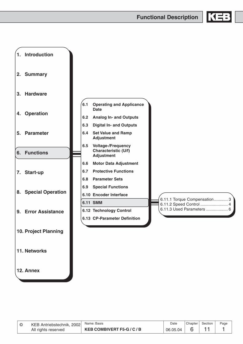
Functional Description
1. Introduction
2. Summary
3. Hardware
4. Operation
5. Parameter
6. Functions
7. Start-up
8. Special Operation
9. Error Assistance
10. Project Planning
11. Networks
12. Annex
6.1 Operating and ApplicanceDate
6.2 Analog In- and Outputs
6.3 Digital In- and Outputs
6.4 Set Value and RampAdjustment
6.5 Voltage-/FrequencyCharacteristic (U/f)Adjustment
6.6 Motor Data Adjustment
6.7 Protective Functions
6.8 Parameter Sets
6.9 Special Functions
6.10 Encoder Interface
6.11 SMM
6.12 Technology Control
6.13 CP-Parameter Definition
6 11 1KEB COMBIVERT F5-G / C / B
Name: Basis
06.05.04
Section PageDate© KEB Antriebstechnik, 2002All rights reserved
Chapter
6.11.1 Torque Compensation ............ 36.11.2 Speed Control ........................ 46.11.3 Used Parameters ................... 6

6 11 KEB COMBIVERT F5-G / C / B2Name: Basis
06.05.04
Chapter Section Page Date © KEB Antriebstechnik, 2002All rights reserved
Functional Description Regulated Operation

6 11 3KEB COMBIVERT F5-G / C / B
Name: Basis
6
06.05.04
Section PageDate© KEB Antriebstechnik, 2002All rights reserved
Chapter
Functional DescriptionRegulated Operation
6.11 SSM The SMM-function (sensorless motor management) includes the torque and slipcompensation. Precondition for a good control characteristic is the input of the motordata in the dr-parameters (see Chapter 6.6).
Torque compensation adapts the voltage at variable load torques in such a way thatthe magnetizing current setpoint is kept constant. With it a higher maximum torqueis achieved at small output frequencies compared to uncompensated operation.With uF.16 and uF.17 the torque compensation is activated and configured. Themagnetizing current setpoint and actual value are calculated in the motor model.With uF.7 the magnetizing current setpoint can be adjusted to the application.
Attention! Through overcompensation increased motor currents can occurparticularly with small frequencies.
6.11.1 TorqueCompensation
uF.17+
uF.161, 2, 30
PIuF.7
IUIV
phi (U)
U
-
0 25%ru.17
0123
M->f
f->U
+PWM
+
+
realfrequency
magnetizingcurrent set value
6.11.1Torque compensation
Motordata The motor data is entered in the parameters dr.0...dr.6 as described in Chapter 6.6.
Energy saving factor (uF.7) In the case of activated torque compensation this parameter is used for theoptimization of the magnetizing current setpoint to the application. If a drive operatesfor a long time in the partial-load range the motor heating and the energy consumptioncan be reduced by decreasing this factor.The energy saving function is switched off at activated torque compensation.
magnetizingcurrent real value
Motor model
Motor data
(off)
off

6 11 KEB COMBIVERT F5-G / C / B4Name: Basis
06.05.04
Chapter Section Page Date © KEB Antriebstechnik, 2002All rights reserved
Functional Description Regulated Operation
CS.4
012
CS.0 Bit 0, 1 = 2
KP=CS.6 KI=CS.9
+
-
oP.40 / 41
oP.36 / 37
CS.1
ru.7
ru.4/9
ru.5/10ru.6
6.11.2 Speed Control The integrated speed controller is used at cS.0 = „2“ for the slip compensation. Slipcompensation compensates the speed changes caused through load changes byincreasing/decreasing the output frequency (ru.3). With that a higher speed stabilityis achieved.If one determines during operation that the drive constantly overcompensates, itcan be balanced by a slight increase of the rated speed.
frequencycalculation
Technologie control(Capter 6.12)
f_ramp realfrequency
6.11.2 Drehzahlregler
Parameter uF.16 defines the basic controller structure.
Dec. Meaning0 Torque compensation off1 Torque compensation acts motoric and generatoric2 Torque compensation works only in the motoric operation; resulting in a
smoother run in the generatoric operation.3 Torque compensation in motoric operation; overcompensation in the
generatoric operation; resulting in a higher maximum torque and increasedcurrent in the generatoric operation compared to 1 and 2; because of thehigher motor-own losses a braking resistor is only necessary at higher energyrecovery compared to 0, 1 and 2.
Torque compensation/configuration (uF.16)
Torque compensation /amplification (uF.17)
With uF.17 the amplification is adjusted within the range of 0.00...2.50.
Ramp generator
Channel 2
Channel 1
(only at F5-Generalupon housing size D)

6 11 5KEB COMBIVERT F5-G / C / B
Name: Basis
6
06.05.04
Section PageDate© KEB Antriebstechnik, 2002All rights reserved
Chapter
Functional DescriptionRegulated Operation
Configuration speedcontroller (cS.0)
Bit Value Description
0,1 0 Speed controller off1 Process control via technologie controller2 Slip compensation3 reserved
2 0 No function
3 0 Change of direction of rotation via the controller not possible8 Change of direction of rotation via the controller possible
4 0 No controller intervention at f_setting = 0Hz16 Controller intervention at f_setting = 0Hz
5 0 No slip limiting32 Slip is limited to max. rated slip x dr.9
Frequency limitSpeed controller (cS.4)
The frequency limit defines the maximum controller intervention within the range of0...200 Hz (dep. on ud.2).
KP-Drehzahl (cS.6) KP-speed defines the proportional component of the speed controller within the rangeof 0...32767.
KI-Drehzahl (cS.9) KI-speed defines the integral component of the speed controller within the range of0...32767.
Actual value source (cS.1)- not at B-Control -
The parameter cS.1 determines the actual value source for the speed controller.Following selections are available:
Value Actual value source0 Actual value from encoder interface channel 11 Actual value from encoder interface channel 22 Actual value is calculated internally

6 11 KEB COMBIVERT F5-G / C / B6Name: Basis
06.05.04
Chapter Section Page Date © KEB Antriebstechnik, 2002All rights reserved
Functional Description Regulated Operation
6.11.3 Used Parameters
Parameter Addr. min max default [?] Notes
uF 7 Energy saving factor 0507 X X – 0,0 130,0 0,1 70,0 % –uF16 Autoboost configuration 0510 X X – 0 3 1 0 – –uF17 Autoboost gain 0511 X X – 0,00 2,50 0,01 1,25 – –cS 0 Speed control configuration 0F00 X X – 0 63 1 0 – –cS 1 Actual source 0F01 X X – 0 2 1 2 – not at B housingcS 4 Speed control frequncy limit 0F04 X X – 0 200 0,0125 25 Hz dep. on ud.2cS 6 KP-speed 0F06 X X – 0 32767 1 50 – –cS.9 KI-speed 0F09 X X – 0 32767 1 500 – –

6 12 1KEB COMBIVERT F5
Name: Basis
17.02.03
Functional Description
Chapter Section PageDate© KEB Antriebstechnik, 2002All Rights reserved
1. Introduction
2. Summary
3. Hardware
4. Operation
5. Parameter
6. Functions
7. Start-up
8. Special Operation
9. Error Assistance
10. Project design
11. Networks
12. Annex
6.1 Operating and Appliance
Date
6.2 Analog In- and Outputs I
6.3 Digital In- and Outputs
6.4 Set Value and Ramp
Adjustment
6.5 Voltage-/Frequency
Characteristic (U/f)
Adjustment
6.6 Motor Data Adjustment
6.7 Protective Functions
6.8 Parameter Sets
6.9 Special Functions
6.10 Speed measurement
6.11 SMM, Posi, Synchron
6.12 Technology Control
6.13 CP-Parameter Definition
6.12.1 The PID Controller ................. 36.12.2 PID Setpoint Value ................. 56.12.3 PID Actual Value .................... 66.12.4 Sample Applications .............. 76.12.5 Used Parameters ................. 10

6 12 KEB COMBIVERT F52Name: Basis
17.02.03
Chapter Section Page Date © KEB Antriebstechnik, 2002All Rights reserved
Functional Description Closed-loop Operation

6 12 3KEB COMBIVERT F5
Name: Basis
6
17.02.03
Section PageDate© KEB Antriebstechnik, 2002All Rights reserved
Chapter
Functional DescriptionClosed-loop Operation
%Hz
cn.14
0
+
ru.52
cn.7
cn.8
v
t
cS.0
oP.0
6.12.1 The PID Control-ler
Fig. 6.12.1 PID controller
The KEB COMBIVERT is equipped with an universally programmable technologycontroller, with it pressure, temperature or dancing position controls can be set up.
The technology controller consists of a set / actual value comparator, that puts thesystem deviation on a PID controller. With cn.4, 5 and 6 the P-, I- and D-componentis adjusted. The parameter cn.7 and cn.8 limit the maximum manipulated variable ofthe controller. With the PID-controller fade-in time (cn.9) the controller amplificationcan be driven up gently from 0...100%. Parameter cn.14 adjusts the frequency reachthrough in Hz/% (only F5-G/B). With parameters cn.11, 12 and 13 the PID controller,the I controller and/or the controller fade-in can be reset. With cn.10 a PID resetcondition can be adjusted.
PID controller KP (cn.4) Defines the proportional amplification factor in the range of 0,00...250,00.
Defines the integral amplification factor in the range of 0,000...30,000.
Defines the differential amplification factor in the range of 0,000...250,00.
PID controller KI (cn.5)
PID controller KD (cn.6)
PID positive limit (cn.7) PID negative limit (cn.8)
The max. positive manipulated variable is determined with cn.7 in the range of -400,0...400,0 %, the max. negative manipulated variable is determined with cn.8 inthe range of -400,0...400,0 %.
With it the control action during the start can be increased linear or decreased linearat the reset of the fade-in. The time refers of 100% of the controller output value. Ifone input is programmed for „Reset fade-in (cn.13)“ the fade-in is counted down atactive input and counted up at inactive input.
Value range: -0,01; 0,00...300 s Resolution: 0,01 s
With the setting „-0,01“ the fade-in is calculated according to following formula:
Fade-in factor = fsetting
(ru.2) / max. setpoint value (oP.10/11)
The function is only active, if the technology controller is used as process controller(cs.0 Bit 0...2 = 1). With the adjustment as setpoint controller the fade-in time is = 0.
Setpoint calculation
Actual valuecalculation
PID controller
cn.13 Reset Fadein / input selection
cn.11 Reset PID /input selection
cn.12 Reset I /inputselection
cn.10 PID Resetcondition
cn.4 PID kpcn.5 PID kicn.6 PID kd
cn.9 PIDfading time
Digital Inputs
PID fade-in time (cn.9)
6.12 TechnologyControl
see
see

6 12 KEB COMBIVERT F54Name: Basis
17.02.03
Chapter Section Page Date © KEB Antriebstechnik, 2002All Rights reserved
Functional Description Closed-loop Operation
PID Output frequency at 100%(cn.14)
This block converts the percental controller output value into a frequency. Theadjustment of cn.14 determines which frequency is output at 100 % controller outputvalue. A frequency from -400,0...400,0 Hz (dep.on ud.2) can be adjusted. At cS.0 Bit0...1 = 1 the output value added with the ramp output frequency (ru.2) forms theoutput frequency (ru.3).
The whole controller, the I-component as well as the controller fade-in can be resetvia a digital input. When resetting the masking the fade-in time is valid. In accordancewith the table below the decimal value of the appropriate inputs must be entered inthe following parameters:
cn.11 PID reset / input selectioncn.12 I reset / input selectioncn.13 Fade in reset / input selection
Reset by way of digital inputs(cn.11...13)
With cn.10 it is possible to preset the reset conditions for the PID-Controller. Thussimple speed regulations can be realized for both directions of rotation.
cn.10 Function0 PID controller is not reset1 PID controller = 0 (is continuously reset)2 PID controller is reset in case of modulation off
For speed regulations adjust value „2“, with that the I-component of the controller isreset at LS or nOP. The value „1“ serves mainly for the start-up, to reset the controllermanually.
PID Reset condition (cn.10)
Bit -No. Decimal value Input Terminal0 1 ST (prog. input „control release/reset“) X2A.161 2 RST (prog. input „reset“) X2A.172 4 F (prog. input „forward“) X2A.143 8 R (prog. input „reverse“) X2A.154 16 I1 (prog. input 1) X2A.105 32 I2 prog. input 2) X2A.116 64 I3 (prog. input 3) X2A.127 128 I4 (prog. input 4) X2A.138 256 IA (internal input A) no
9 512 IB (internal input B) no101024 IC (internal input C) no112048 ID (internal input D) no
(only F5-G/B)

6 12 5KEB COMBIVERT F5
Name: Basis
6
17.02.03
Section PageDate© KEB Antriebstechnik, 2002All Rights reserved
Chapter
Functional DescriptionClosed-loop Operation
6.12.2 PID SetpointValue
This section describes the PID-controller setpoint value. PID setpoint value iscomposed of the absolute reference value (cn.1) and an additional setpoint sourcewhich is adjustable with cn.0. The two values are added and transferred to the PIDcontroller setpoint input.
Fig. 6.12.2 PID controller set value
PID controllerabsolute reference
(cn.1)
With cn.1 the set value of the PID controller is preset percentually in the range of -400,0...400,0%. The parameter is set-programmable.
PID reference source(cn.0)
Parameter cn.0 specifies the input which supplies the additional setpoint value. Onecan choose between following possibilities:
cn. 0 PID reference source
0 off (default)
1 Analog input AN1 (ru.28)
2 Analog input AN2 (ru.30)
3 Analog input AN3 (ru.32)
4 Aux input (ru.53)
If one of the analog channels is adjusted, the signals can be individually adapted tothe requirements with the analog amplifier, as described in chapter 6.2.
+
+
0
1
2
3
4
cn.1 PID absolute reference-400,0...400,0 %
cn.0 PID reference source
off
Analog input AN1 (ru.28)
Analog input AN2 (ru.30)
Analog input AN3 (ru.32)
Aux input (ru.53)
PID controller

6 12 KEB COMBIVERT F56Name: Basis
17.02.03
Chapter Section Page Date © KEB Antriebstechnik, 2002All Rights reserved
Functional Description Closed-loop Operation
Fig. 6.12.3 PID Actual Value
6.12.3 PID Actual Value This section describes the PID controller actual value. The actual value input isadjusted with the PID reference source (cn.2).
PID actual value source(cn.2) The PID actual value source (cn.2) determines from where the PID controller receivesthe actual value signal. Following signals are available:
cn.2 Signal Function0 AN1 Signal of the analog input 1 (see chapter 6.2)1 AN2 Signal of the analog input 2 (see chapter 6.2)
- reserved at B-control -2 AN3 Signal of the analog input 3 (see chapter 6.2)
- reserved at B-control -3 AUX Signal of the Aux input (see chapter 6.2)4 cn.3 PID absolute actual value is preset with cn.3 in the range
o f-400,0...400,0 %
5 Active current The active current -200...200 % displayed in parameterru.17 is used as actual value signal (100 % = I
rated)
6 Utilization The utilization 0...255 % displayed in parameter ru.13is used as actual value signal (100 % = 100 %)
7 DC link voltage The DC-voltage 0...1000 V displayed in parameter ru.18is used as actual value signal (1000 V = 100 %).
0
1
2
3
4
5
6
7
cn.2 PID actual value source
Analog input AN1 (ru.28)
Analog input AN2 (ru.30)
Analog input AN3 (ru.32)
Aux input (ru.53) PID controller
Active current (ru.17)
Utilization (ru.13)
DC voltage (ru.18)
PID absolute actual value(cn.3)

6 12 7KEB COMBIVERT F5
Name: Basis
6
17.02.03
Section PageDate© KEB Antriebstechnik, 2002All Rights reserved
Chapter
Functional DescriptionClosed-loop Operation
AN1
AN2
cn.0 = 1
cn.2 = 1
ru.27
ru.29
ru.28
ru.30
cn.4...6cn.10
cn.7/8
ru.52
oP.0=1
+
-
ru.2
cn.1
%
V
%
V
ru.1 ru.53
An.30=8200
+
+
cn.1
AN1
AN2
cn.0 = 1
cn.2 = 1
ru.27
ru.29
ru.28
ru.30
cn.4...6cn.10
cn.7/8
ru.1
ru.52
%
%
V
V
oP.0=6
+
-ru.2
6.12.4 SampleApplications
The following part describes some sample applications of the PID controller.
PID controller without precontrol (e.g. for pressure, temperature, level control)
PID controller with precontrol (Variant 1)
PIDcontroller
Ramp generatorCharacteristic
amplifier
Characteristic amplifier
An-Parameter
Digital set value
Ramp outputvalue
Analog set value
actual value
oP-Parameter
Analogprecontrol
Digital set value
actual value
Characteristicamplifier
Characteristic amplifier
An-Parameter
An-ParameterPID
controller
Ramp generator
Ramp output value
oP-Parameter

6 12 KEB COMBIVERT F58Name: Basis
17.02.03
Chapter Section Page Date © KEB Antriebstechnik, 2002All Rights reserved
Functional Description Closed-loop Operation
AN1
AN2
cn.0 = 0
cn.2 = 1
ru.27
ru.29
ru.28
ru.30cn.4...6cn.10
ru.52
oP.0=0
+
-
ru.2
cn.1
%
V
%
V
ru.1
++
cS.0 = 1
cn.7/8 cS.4
%
Hz
cn.14
ru.2
PID controller with precontrol (Variant 2; dancing position control with precontrol - only for F5-G/B)
PID controller with precontrol (Variant 3; e.g. for speed regulation with tacho generator - only for F5-G/B)
AN1
AN2
cn.0 = 1
cn.2 = 1
ru.27
ru.29
ru.28
ru.30
cn.4...6cn.10
cn.7/8
ru.52
oP.0=1
+
-
ru.2
%
V
%
V
ru.1 ru.53
An.30=8200
+
+cn.1 = 0
Analogprecontrol
Digital set value
actual value
Characteristicamplifier
Characteristic amplifier
An-Parameter
An-ParameterPID
controller
Ramp generator
Ramp outputvalue
oP-Parameter
Analog setvalue andprecontrol
actual value
Characteristicamplifier
Characteristic amplifier
An-Parameter
An-ParameterPID
controller
Ramp generator
Ramp outputvalue
oP-Parameter
cS.0 = 0

6 12 9KEB COMBIVERT F5
Name: Basis
6
17.02.03
Section PageDate© KEB Antriebstechnik, 2002All Rights reserved
Chapter
Functional DescriptionClosed-loop Operation
AN1
AN2
cn.0 = 0
cn.0 = 2
ru.27
ru.29
ru.28
ru.30
cn.4...6cn.10
ru.52
oP.0=0
+
-
ru.2
cn.1
%
V
%
V
ru.1
++
cS.0 = 1
cn.7/8 cS.4
%
Hz
cn.14
ru.2ru.17cn.2 = 5
cn.1
AN1
ru.17
cn.0 = 1
cn.2 = 5
ru.27 ru.28
cn.4...6cn.10
cn.7/8
ru.1
ru.52
oP.0=6
+
-ru.2
%
V
cn.1
AN1
AN2
cn.0 = 1
cn.2 = 1
ru.27
ru.29
ru.28
ru.30
cn.4...6cn.10
cn.7/8 ru.52
+
-
ru.34
%
V
%
V
%
V
%
V
ru.36
ANOUT1
ANOUT2
An.31=9/10
An.31=9/10
ru.33
ru.35
PID controller on the analog output
PID controller as active current- (torque-) regulation without precontrol
PID controller as active current- (torque-) regulation with precontrol
oP.0 = 6 (external PID output ru.52)
PIDcontroller
Characteristicamplifier
Characteristic amplifier
An-Parameter
Digital set value
Analog set value
actual value
Characteristicamplifier
Characteristic amplifier
PIDcontroller
Characteristicamplifier
Characteristic amplifier
An-Parameter
Digital current set
value
Analog current set value
Active current-realvalue
Speed pre-control
An-Parameter
Ramp outputvalue
Ramp generator
Analog current set value
Active current-realvalue
Speed pre-control
Characteristicamplifier
An-Parameter
PIDcontroller
Ramp generator

6 12 KEB COMBIVERT F510Name: Basis
17.02.03
Chapter Section Page Date © KEB Antriebstechnik, 2002All Rights reserved
Functional Description Closed-loop Operation
Parameter Parameter Addr. min max default [?] Notes
cn 0 PID reference source 0700 x x – 0 4 1 0 – –cn 1 PID abs. reference 0701 x x – -400,0 400,0 0,1 0,0 % –cn 2 PID act. value src. 0702 x x – 0 7 1 0 – –cn 3 PID abs. act. value 0703 x – – -400,0 400,0 0,1 0,0 % –cn 4 PID kp 0704 x x – 0,00 250,00 0,01 0,00 – –cn 5 PID ki 0705 x x – 0,000 30,000 0,001 0,000 – –cn 6 PID kd 0706 x x – 0,00 250,00 0,01 0,00 – –cn 7 PID pos. limit 0707 x x – -400,0 400,0 0,1 400,0 % –cn 8 PID neg. limit 0708 x x – -400,0 400,0 0,1 -400,0 % –cn 9 PID fading time 0709 x x – -0,01 300,00 0,01 0,00 s -0,01 freq. dependentcn10 PID reset condition 070 A x x – 0 2 1 0 – –cn11 PID reset inp. sel. 070B x – x 0 4095 1 0 – –cn12 I reset inp. sel. 070C x – x 0 4095 1 0 – –cn13 fade in reset inp. sel. 070D x – x 0 4095 1 0 – –cn14 PID out freq at 100% 070E x x – -400,0 400,0 0,0125 0 Hz dependent on ud.2
ru13 actual utilization 020D – – – 0 255 1 0 % –ru17 active current 0211 – – – -3276,7 3276,7 0,1 0 A –ru18 actual DC voltage 0212 – – – 0 1000 1 0 V –ru28 AN1 post amplifier disp. 021C – – – -400,0 400,0 0,1 0 % –ru30 AN2 post amplifier disp. 021E – – – -400,0 400,0 0,1 0 % –ru53 AUX display 0235 – – – -400,0 400,0 0,1 0 % –
6.12.5 Used Parameters

6 13 1KEB COMBIVERT F5
Name: Basis
11.04.02
Functional Description
Chapter Section PageDate© KEB Antriebstechnik, 2002All Rights reserved
1. Introduction
2. Summary
3. Hardware
4. Operation
5. Parameter
6. Functions
7. Start-up
8. Special Operation
9. Error Assistance
10. Project Design
11. Networks
12. Annex
6.1 Operating and ApplianceDate
6.2 Analog In- and Outputs I
6.3 Digital In- and Outputs
6.4 Set Value and RampAdjustment
6.5 Voltage-/FrequencyCharacteristic (U/f)Adjustment
6.6 Motor Data Adjustment
6.7 Protective Functions
6.8 Parameter Sets
6.9 Special Functions
6.10 Speed Measurement
6.11 SMM, Posi, Synchron
6.12 Technology Control
6.13 CP-Parameter Definition
6.13.1 Survey ................................... 36.13.2 Assignment of CP-Parameters46.13.3 Example ................................ 56.13.4 Display Standardization......... 66.13.5 Variable Standardization ....... 86.13.6 Used Parameters ................ 10

6 13 KEB COMBIVERT F52Name: Basis
11.04.02
Chapter Section Page Date © KEB Antriebstechnik, 2002All Rights reserved
Functional Description CP-Parameter Definition

6 13 3KEB COMBIVERT F5Name: Basis
11.04.02
6
Section PageDate© KEB Antriebstechnik, 2002All Rights reserved
Chapter
Functional DescriptionCP-Parameter Definition
6.13 CP-ParameterDefinition
6.13.1 Survey Fig. 6.13.1 Definition structure
Once the development stage of a machine is completed, usually only a few parametersare required for the adjustment or the control of the inverter. To make the handlingeasier and the user documentation more understandable as well as to increase thesafety of operation against unauthorized access, the possibility exists to create theone user surface with the CP-parameters. For that purpose 37 parameters(CP.0...CP.36) are available, 36 of them (CP.1...CP.36) are free for assignment.
CP.0 / ud.1
ud.15
ud.17ru.3
ud.16
ud.17ru. 1
ud.16
ud.17An.4
CP.1
CP.2
CP.36
440 330 200 100 500
ud.161
2
36
With ud.15 the CP-parameter that is to be edited is determined. With ud.16 andud.17 the CP-parameter is defined through its address and the respective set.Depending on the adjusted password (CP.0 or ud.1)
- the adjusted parameter is directly displayed in the Service Mode- the adjusted parameter is displayed as CP-parameter in the CP-Mode
Parameter CP.0 is not programmable and always contains the password input. If theinverter is in the Application Mode or Service Mode ud.1 is used for the passwordinput.The parameters ud.15...17 as well as Fr.1 are not permitted as CP-parameter andare acknowledged as invalid parameter address. When entering an invalid parameteraddress the parameter is set to „oFF“ (-1). The appropriate CP-parameter is notdisplayed at this setting.
Application Mode Service Mode Read /Write
Readonly Drive Mode
Password
CP-ModeAddress
Set / Norm
Address
Address
Set / Norm
Set / Norm
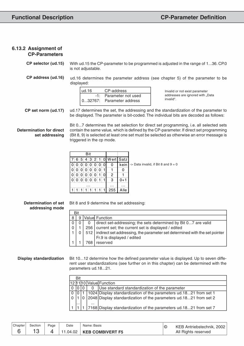
6 13 KEB COMBIVERT F54Name: Basis
11.04.02
Chapter Section Page Date © KEB Antriebstechnik, 2002All Rights reserved
Functional Description CP-Parameter Definition
6.13.2 Assignment ofCP-Parameters
ud.16 determines the parameter address (see chapter 5) of the parameter to bedisplayed:
ud.16 CP-address-1: Parameter not used
0...32767: Parameter address
ud.17 determines the set, the addressing and the standardization of the parameter tobe displayed. The parameter is bit-coded. The individual bits are decoded as follows:
Bit 0...7 determines the set selection for direct set programming, i.e. all selected setscontain the same value, which is defined by the CP-parameter. If direct set programming(Bit 8, 9) is selected at least one set must be selected as otherwise an error message istriggered in the cp mode.
CP address (ud.16)
Determination for directset addressing
Bit7 6 5 4 3 2 1 0 W ert Satz0 0 0 0 0 0 0 0 0 kein0 0 0 0 0 0 0 1 1 00 0 0 0 0 0 1 0 2 10 0 0 0 0 0 1 1 3 0+1
... ... ...1 1 1 1 1 1 1 1 255 Alle
Determination of setaddressing mode
Bit 8 and 9 determine the set addressing:
Bit8 9 Value Function0 0 0 direct set-addressing; the sets determined by Bit 0...7 are valid0 1 256 current set; the current set is displayed / edited1 0 512 indirect set addressing, the parameter set determined with the set pointer
Fr.9 is displayed / edited1 1 768 reserved
Display standardization Bit 10...12 determine how the defined parameter value is displayed. Up to seven diffe-rent user standardizations (see further on in this chapter) can be determined with theparameters ud.18...21.
Bit12 11 10 Value Function0 0 0 0 Use standard standardization of the parameter0 0 1 1024 Display standardization of the parameters ud.18...21 from set 10 1 0 2048 Display standardization of the parameters ud.18...21 from set 2
... ...1 1 1 7168 Display standardization of the parameters ud.18...21 from set 7
CP set norm (ud.17)
CP selector (ud.15) With ud.15 the CP-parameter to be programmed is adjusted in the range of 1...36. CP.0is not adjustable.
Invalid or not exist parameteraddresses are ignored with „Datainvalid“.
-> Data invalid, if Bit 8 and 9 = 0

6 13 5KEB COMBIVERT F5Name: Basis
11.04.02
6
Section PageDate© KEB Antriebstechnik, 2002All Rights reserved
Chapter
Functional DescriptionCP-Parameter Definition
6.13.3 Example As an example a user menu with the following features shall be programmed:
1. Display of current actual frequency (ru.3) in the respective set2. Adjustment of a fixed frequency / fixed value (oP.21) in set 23. Adjustment of a fixed frequency / fixed value (oP.21) in set 34. Acceleration and deceleration time (oP.28/oP.30) for set 2 and 35. Energy saving factor (uF.7) shall be displayed in set 0 with display
standardization 4
1.) ud.15 = 1 ; CP.1ud.16 = 0203h ; Parameter address for ru.3ud.17 = 256 ; Display in the active set
2.) ud.15 = 2 ; CP.2ud.16 = 0315h ; Parameter address for oP.21ud.17 = 4 ; Setting in set 2
3.) ud.15 = 3 ; CP.3ud.16 = 0315h ; Parameter address for oP.21ud.17 = 8 ; Setting in set 3
4.) ud.15 = 4 ; CP.4ud.16 = 031Ch ; Parameter address for oP.28ud.17 = 12 ; Setting in set 2 and 3ud.15 = 5 ; CP.5ud.16 = 031Eh ; Parameter address for oP.30ud.17 = 12 ; Setting in set 2 and 3
5.) ud.15 = 6 ; CP.6ud.16 = 0507h ; Parameter address for uF.7ud.17 = 4097 ; Setting in set 0 and display standardization 4
6.) ud.15 = 7 ; CP.7ud.16 = -1: off ; CP.7 not displayedud.17 = xxx ; ud.17 no function
Adjust all other parameter sets to „off“, so that no indication occurs.
The acceptance of the values takes place only after Power-On-Reset of the operator.

6 13 KEB COMBIVERT F56Name: Basis
11.04.02
Chapter Section Page Date © KEB Antriebstechnik, 2002All Rights reserved
Functional Description CP-Parameter Definition
6.13.4 Displaystandardization
The KEB COMBIVERT gives the user the possibility to define his own standardizations(e.g. km/h or bottles/min) in the CP-Mode. The parameters ud.18...20 are used forconversion, ud.21 for specifying the method of calculation, the decimal places aswell as the units indicated in KEB COMBIVIS.
6.13.4 Definition of own standardization
ud.19 Multiplier± 32767
ud.20 Offset± 32767
ud.18 Divisor± 32767
ud.21 Display flags0...1791
CP.xx = (selected parameter + ud.20) x ud.19
xunitud.18
ud.19 Multiplier± 32767
ud.20 Offset± 32767
ud.18 Divisor± 32767
CP.xx =ud.19
x unit(selected parameter + ud.20) x ud.18
ud.18 Displaystandardization Divisor
Adjusts the divisor in the range of ±32767 (default 1). The parameter is set-programmable (not at B-control).
ud.19 Displaystandardization Multiplier
Adjusts the multiplier in the range of ±32767 (default 1). The parameter is set-programmable (not at B-control).
ud.20 Displaystandardization Offset
Adjusts the offset in the range of ±32767 (default 0). The parameter is set-programmable (not at B-control).
ud.21 Displaystandardization Mode
With ud.21 the calculation mode, the decimal places as well as the units indicated inKEB COMBIVIS are adjusted. The parameter is bit-coded and set-programmable(not at B-control). It is adjustable in the range of 0...1791.
Bit 12...15 Bit 11...8 Bit 7...6 Bit 5...0 ud.21- - - see table 1 unit- - see table 2 - Calculation mode- see table 3 - - Representation
free - - - -
Standard
Inverted
The unstandardized value or the standardized value/resolution is always used forthe „selected parameter“ !

6 13 7KEB COMBIVERT F5Name: Basis
11.04.02
6
Section PageDate© KEB Antriebstechnik, 2002All Rights reserved
Chapter
Functional DescriptionCP-Parameter Definition
Table 1 Unit(Bit 0...5)
Value Unit Value Unit Value Unit Value Unit0 none 16 km/h 32 K 48 lbin1 mm 17 rpm 33 mW 49 in/s2 cm 18 Hz 34 W 50 ft/s3 M 19 kHz 35 kW 51 ft/min4 km 20 mV 36 inc 52 ft/s²5 g 21 V 37 % 53 ft/s³6 kg 22 kV 38 KWh 54 MPH7 us 23 mW 39 mH 55 KP8 ms 24 W 40 - 56 psi9 s 25 kW 41 - 57 °F
10 h 26 VA 42 in 58 -11 Nm 27 kVA 43 ft 59 -12 kNm 28 mA 44 yd 60 -13 m/s 29 A 45 oz 61 -14 m/s2 30 kA 46 lb 62 -15 m/s3 31 °C 47 lbft 63 -
Table 2Calculation mode
(Bit 6...7) (selected parameter + ud.20) xud.19
= CP.xxud.18
ud.19= CP.xx
(selected parameter + ud.20) x ud.18
Value
0
64
- free
Function
Value Representation0 0 decimal places
256 1 decimal place512 2 decimal places768 3 decimal places
1024 4 decimal places1280 variable decimal places1536 Hexadecimal
- free
Table 3Representation
(Bit 8...11)
Example The actual frequency shall be displayed in CP.1 in rpm. Display standardization fromset 4.
ud.15 = 1 ; CP.1ud.16 = 0203h ; Actual frequency ru.3ud.17 = 4352 ; Display in current set, display standardization from set 4
Set 4 ud.18 = 80 ; Conversion from 1/80 Hz into rpm without pole pair numberSet 4 ud.19 = 60Set 4 ud.20 = 0 ; no OffsetSet 4 ud.21 = 17 ; Unit rpm; direct calculation mode; no
decimal places
The unstandardized value is always used for the „selected parameter“!unstandardized value = standardized value / resolution

6 13 KEB COMBIVERT F58Name: Basis
11.04.02
Chapter Section Page Date © KEB Antriebstechnik, 2002All Rights reserved
Functional Description CP-Parameter Definition
A solution of this is to create a parameter group with fixed display characteristics,resolution 1, no decimal places, multiplicator = 1, divisor = 1. Then these parameterscan be used for the setting of values in custom-specific standardization. Theseparameters can be registered in the Configfile and they are also available viaCOMBIVIS. If you need an additional custom-specific visualization in COMBIVIS,these parameters can be defined as CP parameter, like all the others too. Howeverit is impossible with this procedure to design the start address of the parameterblock variable since the parameter addresses are already indicated in the Configfile.The name of the parameter group is programmable parameters.
The following configuration parameters must be available for one programmableparameter.The variable display standardization cannot be supported by means of memoryrequirements in this version. The version like F5-C is valid:
· Target address· Characteristics
The following settings can be made in the characteristics:
bit 0-7: Target/source set with direct addressingbit 8-9: Mode of set-addressing:
0: Target/source set of bit 0-71: Target/source set = current set2: Target/source set = fr.93: Accept target/source setting from PP-Para telegram
The configuration parameters are inserted in the Ud.group and indirect addressedlike the configuration parameters of the CP parameters over a selector.
UD.22: PP selector Value range: 0..47UD.23: PP target address Value range: -1(off)..7FFFH, only available and
permitted addresses are acceptedUD.24: PP properties Value range: 1 ... 1023
Target of these parameters is to allocate a set of parameter addresses to the control.By this way arbitrary inverter parameters with self-specified standardizations areaddressed.
6.13.5 VariableStandardization
Configuration
Required Parameters

6 13 9KEB COMBIVERT F5Name: Basis
11.04.02
6
Section PageDate© KEB Antriebstechnik, 2002All Rights reserved
Chapter
Functional DescriptionCP-Parameter Definition
· The values of the source parameter in the selected sets are compared.If all values are equal then this value is displayed, otherwise ´data invalid` isdisplayed.· If no source parameter is defined, ´data invalid´ is displayed.
· The write value is written into all selected sets of the target parameter.· The following characteristics of the target parameter are checked:Exceeding the limits: ‘Data invalid‘generally write protection: ‘Parameter write protected‘write protection when modulation is switched on: ‘Operation not possible‘write protection in active set: ‘Set invalid‘Password: ‘Password invalid‘ is only displayed at parameters with supervisor-password· ‘Data invalid‘ is always displayed if no source parameter is defined.
Some parameters cannot be adjusted as target/source parameter in ud.23. Thereare all parameters, which are not permissible as CP parameter (characteristics 2bits 15 = 1) or process date (characteristics 1 bit 28 = 1), as well as the prog.parameters itself. Explanation:- all sy parameters exception sy.02, 06, 07, 32, 41-44, 50-53- uf.12-14- all ud parameters exception ud.01, 09- fr.01- in.20,21,31-33- ec.00,10,36-38- aa.00-13, 26-29, 34-41- pp.00-47
The prog. parameters can be used as process data. Restrictions occur only if a prog.parameter is assigned with a process date invalid parameter. In this case the processdate is switched off and the adjusted address in the corresponding sy parameter isnegated, in order to mark this process date as switched off. This applies also if theprog. parameter is switched off (ud.23 = -1).A prog. parameter is additionally invalid as process write date, in case the targetparameter is write protected (generally, when the modulation is switched on, in activeset).The set definition of the process date is always valid as set source for process data(e.g. sy.17 for process read date 1). The adjustment in ud.24 is without meaning.
The prog. parameters can be used as scope data. If the selected prog. parameter isswitched off (ud.23 = -1) the scope date is switched off and the adjusted address inthe corresponding sy-parameter is negated, in order to mark this scope date switchedoff.Since the prog. parameters have the type LONG they cannot be assigned on Scopechannel 3 and 4, without Combivis leaves the fast scope mode.The set definition of the process date is always valid as set source for process data(e.g. sy.34 for scope date 1). The adjustment in ud.24 is without meaning.
Reading of the prog.parameters
Writing of the prog.parameters
Prog. parameters as processdata
Invalid target/sourceparameters
Prog. parameters as scopedata

6 13 KEB COMBIVERT F510Name: Basis
11.04.02
Chapter Section Page Date © KEB Antriebstechnik, 2002All Rights reserved
Functional Description CP-Parameter Definition
Param. Addr. min max default
ENTERPROG.R/W
Step
6.13.6 Used Parameters
ud.1 0801h 4 - 4 0 9999 1 440 Application
ud.15 080Fh 4 - 4 1 36 1 1 -
ud.16 0810h 4 - 4 -1 (off) 32767 (7FFFh) 515 (0203h) div. dep. on ud.15
ud.17 0811h 4 - 4 0 8191 1 1 -
ud.18 0812h 4 4 4 -32767 32767 1 1 not at B-control
ud.19 0813h 4 4 4 -32767 32767 1 1 not at B-control
ud.20 0814h 4 4 4 -32767 32767 1 0 not at B-control
ud.21 0815h 4 4 4 0 1791 1 0 not at B-control

7 1 1KEB COMBIVERT F5
Name: Basis
10.04.02
Start-up
Chapter Section PageDate© KEB Antriebstechnik, 2002All Rights reserved
1. Introduction
2. Summary
3. Hardware
4. Operation
5. Parameter
6. Functions
7. Start-up
8. Special Operation
9. Error Assistance
10. Project design
11. Networks
12. Annex
7.1 Preparatory Measures
7.2 Initial Start-up
7.1.1 After unpacking the Goods .... 37.1.2 Installation and connection .... 37.1.3 Checklist prior to Start-up ...... 4

7 1 KEB COMBIVERT F52Name: Basis
10.04.02
Chapter Section Page Date © KEB Antriebstechnik, 2002All Rights reserved
Start-up

37 1 3KEB COMBIVERT F5
Name: Basis
10.04.02
7
Section PageDate© KEB Antriebstechnik, 2002All Rights reserved
Chapter
Start-up
7.1.1 After unpackingthe Goods
7.1 PreparatoryMeasures
7.1.2 Installation andconnection
7. Start-up The following chapter is intended for everybody who has no experience with theKEB frequency inverters. It shall allow a correct entering into this field. But becauseof the complex application possibilities we must restrict ourselves to explaining thestart-up of standard applications.
After unpacking the goods and checking them for complete delivery followingmeasures are to be carried out:
� Visual control for transport damageShould any external damages to the KEB COMBIVERT be visible get in toughwith your forwarding agent and return the unit with a corresponding report toKEB.
� Check the voltage classAbsolute check before assembly whether the supply voltage of the KEBCOMBIVERT matches the application.
Fig. 7.1.2 Installation and connection
The EMC-conform installation of the inverter is described in the Instruction ManualPart 1. Installation and connection instructions are found in the Instruction ManualPart 2.
� The mounting surface of the inverter must be bright.
� If necessary, use contact lacquer as protection against corrosion.
� Connect the earthing strip to central point in the control cabinet
Preparatory Measures
.
1�-
02
3�3�
3�
�4������
�0����5��
6� ��
�78-9*�
�78-9*�::
*�:*�*�:*�
�:�:����::
������
�1����1���
��**���**�
�:�:7�7�

7 1 KEB COMBIVERT F54Name: Basis
10.04.02
Chapter Section Page Date © KEB Antriebstechnik, 2002All Rights reserved
Start-up
7.1.3 Checklist prior toStart-up
Before switching on the inverter go through the following checklist.
� Is the inverter firmly bolted in the control cabinet?
� Is there enough space to ensure sufficient air circulation?
� Are mains and motor cables as well as the control cables installedseparately from each other?
� Are the inverters connected to the correct supply voltage?
� Are all mass and earthing cables attached and well contacted?
� Ensure that mains and motor cables are not interchanged as thatwill lead to the destruction of the inverter!
� Is the motor connected in-phase?
� Check tacho, initiator and encoder for firm attachment and correctconnection!
� Check, whether all power and control cables are firmly in place!
� Remove any tools from the control cabinet!
� Attach all covers and protective caps to ensure that all live partsare secured against direct contact.
� When using measuring instruments or computers an isolatingtransformer should be used, if not, make sure that the equipotentialbonding between the supply lines is guaranteed!
�Open the control release of the inverter to avoid the unintended startingof the machine.
Preparatory Measures

Start-up
7.1 Preparatory Measures
7.2 Initial Start-up
1. Introduction
2. Summary
3. Hardware
4. Operation
5. Parameter
6. Functions
7. Start-up
8. Special Operation
9. Error Assistance
10. Project Planning
11. Networks
12. Annex
7 2 1KEB COMBIVERT F5-G / C / B
Name: Basis
06.05.04© KEB Antriebstechnik, 2002
All Rights reserved
Section PageDate Chapter
7.2.1 Switching on ofKEB COMBIVERT.................. 3
7.2.2 Basic Settings in theCP-Mode ................................ 4
7.2.3 Set value selection ................. 47.2.4 Testing of Drive ...................... 5

7 2 KEB COMBIVERT F5-G / C / B2Name: Basis
06.05.04© KEB Antriebstechnik, 2002
All Rights reserved
Initial Start-upStart-up
Chapter Section Page Date

7 2 3KEB COMBIVERT F5-G / C / B
Name: Basis
06.05.04
7
© KEB Antriebstechnik, 2002All Rights reserved
Initial Start-up Start-up
Section PageDate Chapter
7.2.1 Switching on ofKEB COMBIVERT
7.2 Initial Start-up After all preparatory measures have been carried out the KEB COMBIVERT F5 canbe switched on.
The sequence of the switch-on procedure as shown below refers to supplied unitswith factory setting. Because of the multitude of programs we cannot take intoconsideration customer-specific adjustments.
Picture 7.2.1 Swtich on of KEB COMBIVERT
Yes
Yes
Yes
1. Check mains voltage2. Operator inserted
correctly?3. Check connection of
control card for shortcircuit
Switch on inverter
Display dark ?
Is anerror message
displayed ?(E.xx)
Look up cause and remedy inchapter 9 „Error Assistance“
Display „noP“ ?
Switch control release
Press „FUNCT“-key
Display „CP.1“
check the defaultconfiguration

7 2 KEB COMBIVERT F5-G / C / B4Name: Basis
06.05.04© KEB Antriebstechnik, 2002
All Rights reserved
Initial Start-upStart-up
Chapter Section Page Date
7.2.2 Basic Settings inthe CP-Mode
After switch-on with factory setting the inverter is in the CP-Mode. The preadjustedvalues can be used for 90 % of all applications at the initial start-up. However, thefollowing parameters should be checked and, if necessary, adjusted.
� Corner frequency CP.16
� Minimum and maximum frequency CP.10/CP.11
� Acceleration and decelerationtimes CP.12/CP.13
� Boost CP.15
� Activation of the Motor PTC detection, if a PTC is attached
7.2.3 Set valueselection
After the basic settings have been made, it must now be determined how the setvalue input is done.
Set value input
In CP-or
Application Mode?
Viaterminal strip
oroperator?
Viavoltage signal
orcurrent signal?
0...20mAor
4...20mA?
CP.35 to value „0“;terminal X2A.1/2or/and X2A.3/4
CP.35 to value „1“;current signal
at terminal X2A.1/2
CP.35 to value „2“;current signal
at terminal X2A.1/2
Switch terminalX2A.10 and adjust
frequency withCP.19
see Chap. 6.4CP-Mode
OperatorTerminal strip
0...10V Current signal
0...20mA 4...20mA
Picture 7.2.3 Setvalue input

7 2 5KEB COMBIVERT F5-G / C / B
Name: Basis
06.05.04
7
© KEB Antriebstechnik, 2002All Rights reserved
Initial Start-up Start-up
Section PageDate Chapter
7.2.4 Testing of Drive For the drive to always allow a save controlling through the inverter, carry out thefollowing test under the most adverse operating conditions.
Picture 7.2.4 Testing of drive
No
Yes
Does the drive run with theselected direction of rotation?
Testing of drive
Switch release and adjustdirection of rotation
Adjust low set value
check phase sequence ofmotor cable, if necessary,
change
Put the drive in all possible operatingconditions of the application
Was an error triggered?see Error Assistance
Chapter 9
Test OK!
no
yes

7 2 KEB COMBIVERT F5-G / C / B6Name: Basis
06.05.04© KEB Antriebstechnik, 2002
All Rights reserved
Initial Start-upStart-up
Chapter Section Page Date

Special Operation
1. Introduction
2. Summary
3. Hardware
4. Operation
5. Parameter
6. Functions
7. Start-up
8. Special Operation
9. Error Assistance
10. Project Planning
11. Networks
12. Annex
8 1 1KEB COMBIVERT F5
Name: Basis
10.04.02
Section PageDate© KEB Antriebstechnik, 2002All rights reserved
Chapter
8.1 Temperature Control8.1.1 Parameter Description ........... 38.1.2 Possibilities for a Temperature
Control ................................... 48.1.3 Connection to the Cooling
System ................................... 58.1.4 Inverter Protection Function
„Overheat“ .............................. 68.1.5 Information about
Water Cooling ........................ 78.1.6 Operation Example ................ 8

8 1 KEB COMBIVERT F52Name: Basis
10.04.02
Special Operation
Chapter Section Page Date © KEB Antriebstechnik, 2002All Rights reserved

8 1 3KEB COMBIVERT F5
Name: Basis
10.04.02
Special Operation
Section PageDate© KEB Antriebstechnik, 2002All rights reserved
Chapter
8. Special Operations
8.1 TemperatureControl
This function serves only as temperature control for watercooled inverters. Thewater cooling system can be switched on with a pneumatic or solenoid valve.Toavoid pressure surges, the valves for a temperature control must be insertedbefore the cooling circuit. All usual valves can be used. Depending on the usedvalve the switching electronics must be provided by the customer. The controloccurs via the analog outputs 3 and 4 and the flags, which are assigned to thedigital outputs. Two functions must be programmed, because the temperatureranges of the inverter and the motor are different. Attention! Do not use relayoutputl
Period (An.46, An.52)
The respective functions are adjusted with these parameters (temperature controlof the power controller or the motor).
The period determines the cycle time in which the output is switched. The periodcan be adjusted in a range from 1,0...240,0 s.
The heat sink temperature which shall be controlled is entered with Offset. Thetemperature is in a range from 30 °C...50°C for inverters (heat sink temperature/see power unit data) and in a range from 40°C ...80°C for motors. The adjustmentoccurs in percentual values (1% = 1°C).
The gain determines the max.temperature. The adjustment occurs via a factorand is calculated as follows.
Max. temperature [°C] = An.44 + (100% / An.43)
Adjustments for the Controller
An.41 = 12 : Power stage temperatureAn.44 = 30 % Beginning of the temperature controlAn.43 = 5,00 Gain for the max. temperature, see formula aboveAn.46 = 20 s Period (cycle time)do.06 = 42 : ANOUT3 PWM, switching condition 6do.22 = 64 : Selection for flag 6do.33 = 64 : Selection and assignment of the output terminal
The switching period Tan
of the output is calculated by the following formula if theheat sink temperature is within the adjusted temperature range.
Tan =(Max. temp.-setpoint temp.)+(heat sink temp.-setpoint temp.) · Period
max. temp.-min.temp.
Offset X (An.44, An.50)
Gain (An.43, An.49)
Function (An.41, An.47)
Example
8.1.1 ParameterDescription

8 1 KEB COMBIVERT F54Name: Basis
10.04.02
Special Operation
Chapter Section Page Date © KEB Antriebstechnik, 2002All Rights reserved
(�)
KEBCOMBIVERT
Inflow
Inflow
Outflow
Outflow
Valve
Valve
EncoderFeedback
In this case inverter and motor possess independent cooling circuits. Twoprogrammable outputs of the control card are required for a control of the valve.(see the following fig.).
do.xxdo.xy
a.) Temperature Control withTemperature Monitoring in the
Motor
In this case the motor is without temperature monitoring. The motor can bepermanently supplied with coolant or the motor can be integrated in the coolingcircuit of the inverter.
b.) Temperature Control withoutTemperature Monitoring in the
Motor
There are two possibilities for a temperature control:a.) with temperature monitoring in the motorb.) without temperature monitoring in the motor
8.1.2 Possibilities for aTemperatureControl

8 1 5KEB COMBIVERT F5
Name: Basis
10.04.02
Special Operation
Section PageDate© KEB Antriebstechnik, 2002All rights reserved
Chapter
Inflow Outflow
Valve
Pump Heat exchanger,Re-cooling
system
KEBCOMBIVERT
Coolant
closed cooling circuit
The connection to the coolant must be done with flexible pressure-proof tubesand it must be secured with clips. (note flow direction and check tightness!) Theconnection to the cooling system is done via 1/2 inch secrewed glands .(Whitworth-pipe thread of DIN ISO 228-1).
The connection to the cooling system can occur as closed or opened coolingcircuit. It is dependent on the local circumstances and it is preset by the mechanicalengineer.
8.1.3 Connection to theCooling System
In case of a closed cooling circuit the outflow coolant is cooled down by a heatexchanger or by a re-cooling system and refeed back into the cooling cicuit.
do.xx

8 1 KEB COMBIVERT F56Name: Basis
10.04.02
Special Operation
Chapter Section Page Date © KEB Antriebstechnik, 2002All Rights reserved
open cooling circuit
Inflow
Outflow
Valve
KEBCOMBIVERT
Dependent on the power unit and overload capacity the inverter Off-temperaturesare 60 ° C, 73 ° C or 90 ° C. To ensure a safe operation the coolant outputtemperature must be 10 K under "Overheat"- function.
8.1.4 Inverter ProtectionFunction„Overheat“
In this case new coolant is constant given in and directly given out.
do.xx
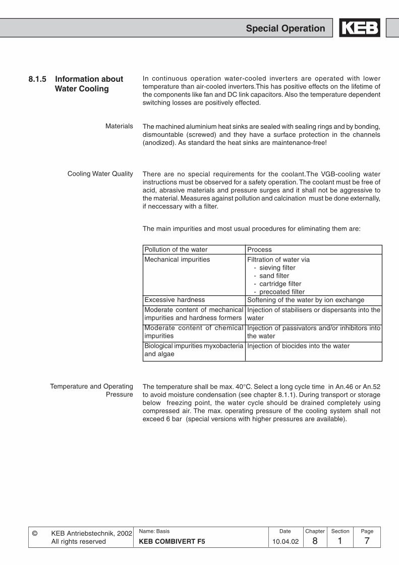
8 1 7KEB COMBIVERT F5
Name: Basis
10.04.02
Special Operation
Section PageDate© KEB Antriebstechnik, 2002All rights reserved
Chapter
8.1.5 Information aboutWater Cooling
In continuous operation water-cooled inverters are operated with lowertemperature than air-cooled inverters.This has positive effects on the lifetime ofthe components like fan and DC link capacitors. Also the temperature dependentswitching losses are positively effected.
The temperature shall be max. 40°C. Select a long cycle time in An.46 or An.52to avoid moisture condensation (see chapter 8.1.1). During transport or storagebelow freezing point, the water cycle should be drained completely usingcompressed air. The max. operating pressure of the cooling system shall notexceed 6 bar (special versions with higher pressures are available).
Temperature and OperatingPressure
Cooling Water Quality
The machined aluminium heat sinks are sealed with sealing rings and by bonding,dismountable (screwed) and they have a surface protection in the channels(anodized). As standard the heat sinks are maintenance-free!
There are no special requirements for the coolant.The VGB-cooling waterinstructions must be observed for a safety operation. The coolant must be free ofacid, abrasive materials and pressure surges and it shall not be aggressive tothe material. Measures against pollution and calcination must be done externally,if neccessary with a filter.
Materials
Pollution of the water
Mechanical impurities
Excessive hardness
Moderate content of mechanicalimpurities and hardness formers
Moderate content of chemicalimpurities
Biological impurities myxobacteriaand algae
Process
Filtration of water via- sieving filter- sand filter- cartridge filter- precoated filter
Softening of the water by ion exchange
Injection of stabilisers or dispersants into thewater
Injection of passivators and/or inhibitors intothe water
Injection of biocides into the water
The main impurities and most usual procedures for eliminating them are:

8 1 KEB COMBIVERT F58Name: Basis
10.04.02
Special Operation
Chapter Section Page Date © KEB Antriebstechnik, 2002All Rights reserved
8.1.6 Operation Example Selection of a COMBIVIS parameter list:
An.41 ANOUT 3 Function 12 : Power stage temperature (ru.38)An.44 ANOUT 3 Offset 30 %An.43 ANOUT 3 Gain 5,00An.46 ANOUT 3 Period 20 sdo.06 Switching Condition SB 6 42 : ANOUT3 PWMdo.22 Selection of SB for Flag 6 64 : SB6do.33 Selection of Flag for O1 64 : M6
An.47 ANOUT 4 Function 13 : Motor Temperature (ru.46)An.50 ANOUT 4 Offset 40 %An.49 ANOUT 4 Gain 2,50An.52 ANOUT 4 Period 20 sdo.07 Switching Condition SB 7 43 : ANOUT4 PWMdo.23 Selection SB for Flag 7 128 : SB7do.34 Selection of Flag for O2 128 : M7
do.00 Switching Condition SB 0 3: Ready for Operationdo.16 Selection of SB for Flag 0 1: SB0do.35 Selection of Flag for O2 1: M0
do.01 Selection of SB 1 7: Pre-Warning Overloaddo.02 Selection of SB 2 8: Pre-Warning Power Stage Overheatdo.03 Selection of SB 3 9: Pre-Warning Motor Overheatdo.04 Selection of SB 4 11: Warning internal Overheatdo.05 Selection of SB 5 0: alway switched-offdo.17 Selcetion of SB for Flag 1 62: SB1+SB2+SB3+SB4+SB5do.28 Inverted Flag for R2 2: M1do.36 Selection of Flag for R2 2: M1
Adjustments of the TemperatureClosed-Loop Control
Adjustments of the Motor-Temperature Closed-Loop Control
Pre-Warning Adjustments
For future informations please contact KEB.

9.1 Troubleshooting
Error Assistance
1. Introduction
2. Summary
3. Hardware
4. Operation
5. Parameter
6. Functions
7. Start-up
8. Special Operation
9. Error Assistance
10. Project Planning
11. Networks
12. Annex
19 1 1KEB COMBIVERT F5
Name: Basis
04.05.04
Section PageDate© KEB Antriebstechnik, 2002All Rights reserved
Chapter
9.1.1 General .................................. 39.1.2 Error Messages and their
Cause .................................... 3

9 1 KEB COMBIVERT F52Name: Basis
04.05.04
Error Assistance
Chapter Section Page Date © KEB Antriebstechnik, 2002All Rights reserved

39 1 3KEB COMBIVERT F5
Name: Basis
04.05.04
9
Error Assistance
Section PageDate© KEB Antriebstechnik, 2002All Rights reserved
Chapter
9.1 Troubleshooting
9.1.1 General
9. ErrorAssistance
The following chapter shall help you to avoid errors as well as help you to determineand remove the cause of errors on your own.
If error messages or malfunctions occur repeatedly during operation, the first thingto do is to pinpoint the exact error. To do that go through the following checklist:
- Is the error reproducable ?For that reset the error and try to repeat it under the same conditions. If the error canbe reproduced, the next step is to find out during which operating phase the erroroccurs.
- Does the error occur during a certain operating phase (e.g. always duringacceleration)?If so, consult the error messages and remove the causes listed there.
- Does the error occur or disappear after a certain time?That may be an indication for thermal causes. Check, whether the inverter is used inaccordance to the ambient conditions and that no moisture condensation takes place.
9.1.2 Error Messagesand their Cause
At KEB COMBIVERT error messages are always represented with an „E.“ and theappropriate error in the display. Error messages cause the immediate deactivationof the modulation. Restart possible only after reset.Malfunction are represented with an „A.“ and the appropriate message. Reactionsto malfunctions can vary.Status messages have no addition. The status message shows the current operatingstatus of the inverter (e.g. forward constant run, standstill etc.).In the following the display and their cause are described.
Status MessagesbbL base block 76 Power modules for motor de-excitation locked
bon close brake 85 Brake control, brake engaged (see chapter 6.9)
boFF open brake 86 Brake control, brake released (see chapter 6.9)
Cdd calculate drive 82 Measurement of the motor stator resistance
dcb DC brake 75 Motor is decelerated by a DC-voltage at the output.
dLS low speed / DC brake 77 Modulation is switched off after DC-braking (see chapter 6.9„DC-Braking“).
FAcc forward acceleration 64 Acceleration with the adjusted ramps in clockwise directionof rotation.
Fcon forward constant 66 Acceleration / deceleration phase is completed and it isdriven with constant speed / frequency in clockwisedirection of rotation.
FdEc forward deceleration 65 It is stopped with the adjusted ramp times in clockwisedirection of rotation.
HCL hardware current limit 80 The message is output if the output current reaches thehardware current limit.
Display COMBIVIS Value Meaning

9 1 KEB COMBIVERT F54Name: Basis
04.05.04
Error Assistance
Chapter Section Page Date © KEB Antriebstechnik, 2002All Rights reserved
IdAtA invalid Data - The parameter address adjusted for this parameter value isinvalid.
LAS LA stop 72 This message is displayed if during acceleration the load islimited to the adjusted load level.
LdS Ld stop 73 This message is displayed if during deceleration the load islimited to the adjusted load level or the DC-link current tothe adjusted voltage level.
LS low speed 70 No direction of rotation pre-set, modulation is off.
nO_PU power unit not ready 13 Power circuit not ready or not identified by the control.
noP no operation 0 Control release (terminal ST) is not switched.
PA positioning active 122 This message is displayed during a positioning process.
PLS low speed / power off 84 No modulation after Power-Off
PnA position not reachable 123 The specified position cannot be reached within the pre-setramps. The abort of the positioning can be programmed.
POFF power off function 78 Depending on the programming of the function (see chapter6.9 „Power-off Function“) the inverter restarts automaticallyupon system recovery or after a reset.
POSI positioning 83 Positioning function active (F5-G).
rAcc reverse acceleration 67 Acceleration with the adjusted ramp times in anti-clockwisedirection of rotation.
rcon reverse constant 69 The acceleration / deceleration phase is completed and it isdriven with constant speed / frequency in anti-clockwisedirection of rotation.
rdEc reverse deceleration 68 It is stopped with the adjusted ramp times in anti-clockwisedirection of rotation.
rFP ready for positioning 121 The drive signals that it is ready to start the positioningprocess.
SLL stall 71 This message is displayed if during constant operation theload is limited to the adjusted current limit.
SrA search for ref. active 81 Search for reference point approach active.
SSF speed search 74 Speed search function active, that means that the inverterattempts to synchronize onto a running down motor.
StOP quick stop 79 The message is output if as response to a warning signalthe quick-stop function becomes active.
Error MessagesE. br ERROR brake 56 Error: This error can occur in the case of switched on brake
control (see Chapter 6.9.5), if• the load is below the minimum load level (Pn.43) at startup or the absence of an engine phase was detected.• the load is too high and the hardware current limit isreached
E.buS ERROR bus 18 Error: Adjusted monitoring time (Watchdog) ofcommunication between operator and PC / operator andinverter has been exceeded.
E.Cdd ERROR calc. drive data 60 Error: During the automatic motor stator resistancemeasurement.
E.co1 ERROR counter overrun 1 54 Counter overflow encoder channel 1
Display COMBIVIS Value Meaning

59 1 5KEB COMBIVERT F5
Name: Basis
04.05.04
9
Error Assistance
Section PageDate© KEB Antriebstechnik, 2002All Rights reserved
Chapter
E.co2 ERROR counter overrun 2 55 Counter overflow encoder channel 2
E.dOH ERROR drive overheat 9 Error: Overtemperature of motor PTC. Error can only bereset at E.ndOH, if PTC is again low-resistance. Causes:• resistance at the terminals T1/T2 >1650 Ohm• motor overloaded• line breakage to the temperature sensor
E.dri ERROR driver relay 51 Error: Driver relay. Relay for driver voltage on power circuithas not picked up even though control release was given.
E.EEP ERROR EEPROM defective t 21 After reset the operation is again possible (without storagein the EEPROM)
E. EF ERROR external fault 31 Error: External error. Is triggered, if a digital input is beingprogrammed as external error input and trips.
E.EnC1 Error! Encoder 1 32 Cable breakage of encoder at encoder interface 1Encoder temperature is too highSpeed is too highEncoder signals are out of specificationEncoder has an internal error
E.EnC2 Error! Encoder 2 34 Cable breakage of encoder at encoder interface 2Encoder temperature is too highSpeed is too highEncoder signals are out of specificationEncoder has an internal error
E.EnCC Error! Encoder change 35 Operation of a synchronous motor with intelligent interface:• Encoder is not connected during the start• Encoder was changedThe error can be reset by writing on ec.0.
E.Hyb ERROR hybrid 52 Invalid encoder interface identifier
E.HybC ERROR hybrid changed 59 Error: Encoder interface identifier has changed, it must beconfirmed over ec.0 or ec.10.
E.iEd ERROR input error detect 53 Error at PNP/NPN switching or input failure.
E.InI ERROR initialisation MFC 57 MFC not booted.
E.LSF ERROR load shunt fault 15 Error: Load-shunt relay has not picked up, occurs for a shorttime during the switch-on phase, but must automatically bereset immediately. If the error message remains thefollowing causes may be applicable:• load-shunt defective• input voltage wrong or too low• high losses in the supply cable• braking resistor wrongly connected or damaged• braking module defective
E.ndOH no ERROR drive overheat 11 Motor temperature switch or PTC at the terminals T1/T2 isagain in the normal operating range. The error can be resetnow.
E.nOH no E. over heat pow.mod. 36 Temperature of the heat sink is again in the permissibleoperating range. The error can be reset now.
E.nOHI no ERROR overheat int. 7 No longer overheating in the interior E.OHI, interiortemperature has fallen by at least 3°C
Display COMBIVIS Value Meaning

9 1 KEB COMBIVERT F56Name: Basis
04.05.04
Error Assistance
Chapter Section Page Date © KEB Antriebstechnik, 2002All Rights reserved
E.nOL no ERROR overload 17 No more overload, OL-counter has reached 0%; after theerror E. OL a cooling phase must elapse. This messageappears upon completion of the cooling phase. The errorcan be reset. The inverter must remain switched on duringthe cooling phase.
E.nOL2 no ERROR overload 2 20 The cooling time has elapsed. The error can be reset.
E. OC ERROR overcurrent 4 Error: OvercurrentOccurs, if the specified peak current is exceeded. Causes:• acceleration ramps too short• the load is too big at turned off acceleration stop andturned off constant current limit• short-circuit at the output• ground fault• deceleration ramp too short• motor cable too long• EMC• DC brake at high ratings active (see 6.9.3)
E. OH ERROR overheat pow.mod. 8 Error: Overtemperature of power module. Error can only bereset at E.nOH. Causes:• insufficient air flow at the heat sink (soiled)• ambient temperature too high• ventilator clogged
E.OH2 ERROR motor protection 30 Electronic motor protective relay has tripped.
E.OHI ERROR overheat internal 6 Error: Overheating in the interior: error can only be reset atE.nOHI, if the interior temperature has dropped by at least3°C
E. OL ERROR overload (Ixt) 16 Error: Overload error can only be reset at E.nOL, if OL-counter reaches 0% again.Occurs, if an excessive load is applied longer than for thepermissible time (see technical data). Causes:• poor control adjustment (overshooting)• mechanical fault or overload in the application• inverter not correctly dimensioned• motor wrongly wired• encoder damaged
E.OL2 ERROR overload 2 19 Occurs if the standstill constant current is exceeded (seetechnical data and overload characteristics). The error canonly be reset if the cooling time has elapsed and E.nOL2 isdisplayed.
E. OP Error! Overvoltage 1 Voltage in the DC-link circuit too high.Occurs if the DC-link circuit voltage exceeds the permissiblevalue. Causes:• poor controller adjustment (overshooting)• input voltage too high• interference voltages at the input• deceleration ramp too short• braking resistor defective or too small
E.OS ERROR over speed 58 Real speed is bigger than the max. Output speed.
E.PFC ERROR Power factor control 33 Error in the power factor control
Display COMBIVIS Value Meaning

79 1 7KEB COMBIVERT F5
Name: Basis
04.05.04
9
Error Assistance
Section PageDate© KEB Antriebstechnik, 2002All Rights reserved
Chapter
E.PrF ERROR prot. rot. for. 46 The drive has driven onto the right limit switch. Programmedresponse “Error, restart after reset” (see chapter 6.7“Response to errors or warning messages”).
E.Prr ERROR prot. rot. rev. 47 The drive has driven onto the left limit switch. Programmedresponse “Error, restart after reset” (see chapter 6.7“Response to errors or warning messages”).
E. Pu ERROR power unit 12 Error: General power circuit fault
E.Puci ERROR pow. unit code inv. 49 Error: During the initialization the power circuit could not berecognized or was identified as invalid.
E.Puch ERROR power unit changed 50 Error: Power circuit identification was changed; with a validpower circuit this error can be reset by writing to SY.3. If thevalue displayed in SY.3 is written, only the power-circuitdependent parameters are reinitialized. If any other value iswritten, then the default set is loaded. On some systemsafter writing Sy.3 a Power-On-Reset is necessary.
E.PUCO ERROR power unit commun. 22 Error: Parameter value could not be written to the powercircuit. Acknowledgement from PC <> OK
E.PUIN ERROR power unit invalid 14 Error: Software version for power circuit and control cardare different. Error cannot be reset (only at F5-G B-housing)
E.SbuS ERROR bus synchron 23 Sychronization over sercos-bus not possible. Programmedresponse “Error, restart after reset” (see chapter 6.7“Response to errors or warning messages”).
E.SEt ERROR set 39 It has been attempted to select a locked parameter set.Programmed response “Error, restart after reset” (seechapter 6.7 “Response to errors or warning messages”).
E.SLF ERROR! Software limit switch forward 44 The target position lies outside of the limit defined with theright software limit switch.Programmed response “Error,restart after reset” (see chapter 6.7 “Response to errors orwarning messages”).
E.SLr ERROR software limit switch reverse 45 The target position lies outside of the limit defined with theleft software limit switch. Programmed response “Error,restart after reset” (see chapter 6.7 “Response to errors orwarning messages”).
E. UP ERROR underpotential 2 Error: Undervoltage (DC-link circuit). Occurs, if DC-linkvoltage falls below the permissible value. Causes:• input voltage too low or instable• inverter rating too small• voltage losses through wrong cabling• the supply voltage through generator / transformer breaksdown at very short ramps• At F5-G housing B E.UP is also displayed if nocommunication takes place between power circuit andcontrol card.• Jump factor (Pn.56) too small (see 6.9.20)• if a digital input was programmed as external error inputwith error message E.UP (Pn.65).
E.UPh ERROR Phase failure 3 One phase of the input voltage is missing (ripple-detection)
Warning Messages
Display COMBIVIS Value Meaning

9 1 KEB COMBIVERT F58Name: Basis
04.05.04
Error Assistance
Chapter Section Page Date © KEB Antriebstechnik, 2002All Rights reserved
A.buS ABN.STOP bus 93 Warning: Watchdog for communication between operator/control card or operator/PC has responded. The responseto this warning can be programmed (see chapter 6.7“Response to errors and warning messages”).
A.dOH ABN.STOP drive over heat 96 The motor temperature has exceeded an adjustablewarning level. The switch off time is started. The responseto this warning can be programmed (see chapter 6.7“Response to errors or warning messages”). This warningcan be generated only with a special power circuit.
A. EF ABN.STOP external fault 90 This warning is triggered via an external input. Theresponse to this warning can be programmed (see chapter6.7 “Response to errors or warning messages”).
A.ndOH no A. drive overheat 91 The motor temperature is again below the adjusted warninglevel. The switch off time is stopped.
A.nOH no A. overheat pow.mod. 88 The heat sink temperature is again below the adjustedwarning level.
A.nOHI no A.STOP overheat int. 92 The temperature in the interior of the inverter is again belowthe warning threshold.
A.nOL no ABN.STOP overload 98 Warning: no more overload, OL counter has reached 0 %.
A.nOL2 no ABN.STOP overload 2 101 The cooling time after “Warning! Overload during standstill”has elapsed. The warning message can be reset.
A. OH A.STOP overheat pow.mod 89 A level can be defined, when it is exceeded this warning isoutput. A response to this warning can be programmed (seechapter 6.7 “Response to errors or warning messages”).
A.OH2 ABN.STOP motor protect. 97 Warning: electronic motor protective relay has tripped. Theresponse to this warning can be programmed (see chapter6.7 “Response to error or warning messages”).
A.OHI ABN.STOP overheat int. 87 The temperature in the interior of the inverter lies above thepermissible level. The switch off time was started. Theprogrammed response to this warning message is executed(see chapter 6.7 “Response to errors or warningmessages”).
A. OL ABN.STOP overload 99 A level between 0 and 100 % of the load counter can beadjusted, when it is exceeded this warning is output. Theresponse to this warning can be programmed (see chapter6.7 “Response to errors or warning messages”).
A.OL2 ABN.STOP overload 2 100 The warning is output when the standstill continuous currentis exceeded (see technical data and overloadcharacteristics). The response to this warning can beprogrammed (see chapter 6.7 “Response to errors andwarning messages”). The warning message can only bereset after the cooling time has elapsed and A.nOL2 isdisplayed.
A.PrF ABN.STOP prot. rot. for. 94 The drive is driven onto the right limit switch. The responseto this warning can be programmed (see chapter 6.7“Response to errors and warning messages”).
A.Prr ABN.STOP prot. rot. rev. 95 The drive is driven onto the left limit switch. The response tothis warning can be programmed (see chapter 6.7“Response to errors and warning messages”).
Display COMBIVIS Value Meaning
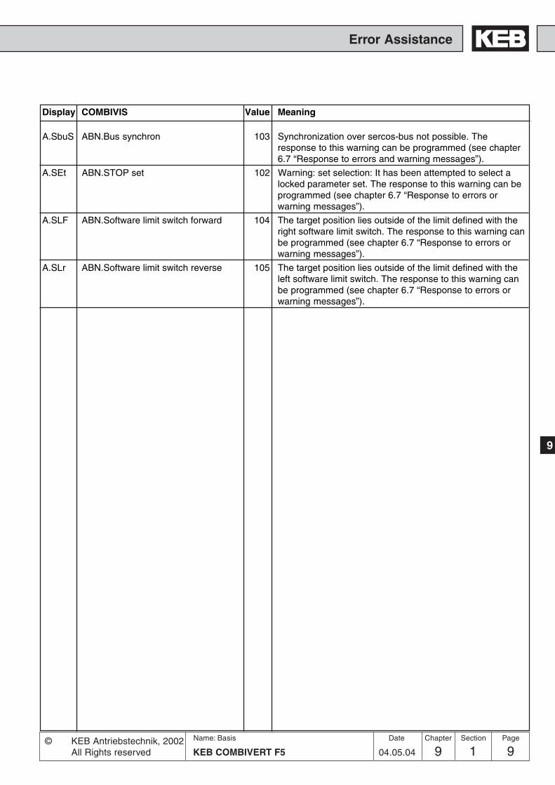
99 1 9KEB COMBIVERT F5
Name: Basis
04.05.04
9
Error Assistance
Section PageDate© KEB Antriebstechnik, 2002All Rights reserved
Chapter
A.SbuS ABN.Bus synchron 103 Synchronization over sercos-bus not possible. Theresponse to this warning can be programmed (see chapter6.7 “Response to errors and warning messages”).
A.SEt ABN.STOP set 102 Warning: set selection: It has been attempted to select alocked parameter set. The response to this warning can beprogrammed (see chapter 6.7 “Response to errors orwarning messages”).
A.SLF ABN.Software limit switch forward 104 The target position lies outside of the limit defined with theright software limit switch. The response to this warning canbe programmed (see chapter 6.7 “Response to errors orwarning messages”).
A.SLr ABN.Software limit switch reverse 105 The target position lies outside of the limit defined with theleft software limit switch. The response to this warning canbe programmed (see chapter 6.7 “Response to errors orwarning messages”).
Display COMBIVIS Value Meaning

9 1 KEB COMBIVERT F510Name: Basis
04.05.04
Error Assistance
Chapter Section Page Date © KEB Antriebstechnik, 2002All Rights reserved

10 1 1KEB COMBIVERT F5
Name: Basis
10.04.02
Project design
Chapter Section PageDate© KEB Antriebstechnik, 2002All Rights reserved
1. Introduction
2. Summary
3. Hardware
4. Operation
5. Parameter
6. Functions
7. Start-up
8. Special Operation
9. Error Assistance
10. Project design
11. Networks
12. Annex
10.1 General Designs 10.1.1 Control Cabinet DesignCalculation ........................... 3
10.1.2 Design of Braking Resistors .. 410.1.3 Cables and fuses ................... 6

10 1 KEB COMBIVERT F52Name: Basis
10.04.02
Chapter Section Page Date © KEB Antriebstechnik, 2002All Rights reserved
Project design

10 1 3KEB COMBIVERT F5
Name: Basis
10.04.02
10
Section PageDate© KEB Antriebstechnik, 2002All Rights reserved
Chapter
Project design
30
150
100
F4 F4
KEBCOMBIVERT
10.1 General De-signs
10. Projectdesign
The following chapter shall assist you in the planning stage of applications.
10.1.1 Control CabinetDesignCalculation
Control cabinet surface Calculation of control cabinet surface:
PVA = [m2]DT • K
Air flow rate with fan cooling:
3,1 • PVV = [m3/h]DT
A = Control cabinet surface [m2]DT = temperature differential [K]
(standard value = 20 K)K = coefficient of heat transmission
(standard value = 5 )
PV = power loss (see technical data)V = air flow rate of fan
For more details please refer to the catalogs of the control cabinet manufacturers.
W[ ]
m2 • K
Direction of cooling fins Minimumdistances
Warm airoutlet
Cool air inlet
Wm2 • K
F5 F5

10 1 KEB COMBIVERT F54Name: Basis
10.04.02
Chapter Section Page Date © KEB Antriebstechnik, 2002All Rights reserved
Project design
10.1.2 Design ofBraking Resistors
The KEB COMBIVERT fitted with an external braking resistor or an external brakingoption is suitable for a limited 4-quadrant operation. The braking energy, refeed intothe DC-bus at generatoric operation, is dissipated over the braking transistor to thebraking resistor.The braking resistor heats up during the braking process. If it is installed in a controlcabinet sufficient cooling of the control cabinet interior and sufficient distance to theKEB COMBIVERT must be observed.
Different braking resistors are available for the KEB COMBIVERT. Please refer tothe next page for the corresponding formula and restrictions (valid range).
1. Preset desired braking time.
2. Calculate braking time without braking resistor (tBmin
).
3. If the desired braking time shall be smaller than the calculated time, it isnecessary to use a braking resistor. (t
B < t
Bmin)
4. Calculate braking torque (MB). Take the load torque into account at the
calculation.
5. Calculate peak braking power (PB). The peak braking power must always be
calculated for the worst case (nmax
to standstill).
6. Selection of braking resistor:a) P
R > P
B
b) PN is to be selected according to the cycle time(ED).
The braking resistors may be used only for the listed unit sizes. The maximumcyclic duration of a braking resistor shall not be exceeded.
6 % ED = maximum braking time 8 s25 % ED = maximum braking time 30 s40 % ED = maximum braking time 48 s
For a longer cyclic duration time special designed braking resistors arenecessary. The continuous output of the braking transistor must be taken intoconsideration.
7. Check, whether the desired braking time is attained with the braking resistor(t
Bmin).
Restriction: Under consideration of the rating of the braking resistor and thebrake power of the motor, the braking torque may not exceed 1,5times of therating torque of the motor (see formula).When utilizing the maximum possible braking torque the frequency invertermust be dimensioned for the higher current.

10 1 5KEB COMBIVERT F5
Name: Basis
10.04.02
10
Section PageDate© KEB Antriebstechnik, 2002All Rights reserved
Chapter
Project design
( )
(JM + J
L) • (n
1 - n
2)
tBmin
=9,55 • (K • M
N + M
L)
1. Braking time without braking resistor 2. Braking torque (necessary)
4. Braking time with braking resistor
Formula
Valid range: n1 > n
N
(Field weakening range)
Condition: MB < 1.5 • M
N
f < 70 Hz
Condition: PB < PR Valid range: n1 > nN
PR • 9,55Condition: < MN • (1,5 -K)
(n1 - n2)
f < 70 HzPB < PR
JM
= mass moment of inertia motor [kgm2]J
L= mass moment of inertia load [kgm2]
n1
= motor speed prior to deceleration [rpm]n
2= motor speed after deceleration [rpm]
(standstill = 0 rpm)n
N= rated motor speed [rpm]
MN
= rated motor torque [Nm]M
B= braking torque (necessary) [Nm]
ML
= load torque [Nm]tB
= braking torque (necessary) [s]tBmin
= minimum braking time [s]tZ
= cycle time [s]P
B= peak braking power [W]
PR
= peak power of braking resistor [W]
K = 0,25 for motors upto 1,5 kW0,20 for motors2,2 upto 4 kW0,15 for motors5,5 upto 11 kW0,08 for motors 15 upto 45 kW0,05 for motors > 45 kW
(JM + J
L) • (n
1 - n
2)
MB = - M
L9,55 • tB
MB • n1PB =
9,55
3. Peak braking power
(JM + J
L) • (n
1 - n
2)
tBmin
* =P
R • 9,55
9,55 • K• MN+ M
L+
(n1 - n
2)
Cyclic duration factor (cdf)tBED = • 100 %
120 s
Cyclic duration factor for cycle time tZ > 120s
tBED = • 100 %tZ
Cyclic duration factor for cycle time tZ < 120s
t
f
tB
tZ
Braking time DEC The braking time DEC is adjusted at the frequency inverter. If it is chosen toosmall the KEB COMBIVERT switches off automatically and the error messageOP or OC appears. The approximate braking time can be determined accordingto following formula.

10 1 KEB COMBIVERT F56Name: Basis
10.04.02
Chapter Section Page Date © KEB Antriebstechnik, 2002All Rights reserved
Project design
10.1.3 Cables and fuses By means of this section you can check whether you can still optimize your machinewith regard to the material usage. The specifications are derived for the DIN VDE0298 Part 4. The values apply approximately and only for the intended operation. Inmarginal cases it must be always proceed according to the standard described obove.The following table shows the current capability of 3 and/or 5 core PVC cables (i.e. 2and/or 3 loaded cores) in dependence with the ambient temperature. The current isto be laid out to the input current of the frequency inverter.
Standard Alternativ 30°C 40°C 45°C 50°C0,5 mm² - 7 6 6 5
0,75 mm² - 12 10 10 91 mm² - 15 13 13 11
1,5 mm² - 18 16 15 132,5 mm² - 26 23 22 18
4 mm² 2 x 1,5 mm² 34 30 29 246 mm² 2 x 2,5 mm² 44 38 37 31
10 mm² 2 x 4 mm² 61 53 51 4316 mm² 2 x 6 mm² 82 71 69 5825 mm² 2 x 10 mm² 108 94 91 7735 mm² 2 x 16 mm² 135 117 113 9650 mm² 2 x 16 mm² 168 146 141 11970 mm² 2 x 25 mm² 207 180 174 14795 mm² 2 x 35 mm² 250 218 210 178
120 mm² 2 x 50 mm² 292 254 245 207150 mm² 2 x 50 mm² 330 287 277 234185 mm² 2 x 70 mm² 394 343 331 280240 mm² 2 x 95 mm² 450 392 378 320300 mm² 2 x 95 mm² 507 441 426 360400 mm² 2 x 150 mm² 661 575 555 469500 mm² 2 x 185 mm² 774 673 650 550
Strom in [A] beiQuerschnitt der Zuleitung
The use of special cables or the way of laying the cables allows even higher currents(see DIN VDE 0298 Part 4). The motor cable must correspond to the cross-sectionof the mains cable.If in case of long lines (>30m) still maximum torque is required at the motor shaft,the cable should be dimensioned for the next larger cross-section in order to reduceline resistances.
Mains fuses are to be designed for the rated input current of the inverter. The current/time-characteristic of the fuse must be slow-acting in order to avoid premature trippingwhen utilizing the power reserves of the inverter.

Networks
1. Introduction
2. Summary
3. Hardware
4. Operation
5. Parameter
6. Functions
7. Start-up
8. Special Operation
9. Error Assistance
10. Project Design
11. Networks
12. Annex
11.1 Network Components
11.2 Bus Parameters
Networks
11 1 1KEB COMBIVERT F5
Name: Basis
10.04.02
Section PageDate© KEB Antriebstechnik, 2002All rights reserved
Chapter
11.1.1 Available Hardware ............... 311.1.2 RS232-Cable PC/Inverter ..... 311.1.3 HSP5-Cable .......................... 311.1.4 Interface Operator ................. 411.1.5 Profibus Operator .................. 511.1.6 InterBus Operator ................. 611.1.7 CanOpen Operator ............... 711.1.8 Sercos Operator ................... 8

Network Hardware Networks
11 1 KEB COMBIVERT F52Name: Basis
10.04.02
Chapter Section Page Date © KEB Antriebstechnik, 2002All rights reserved

11
Network HardwareNetworks
11 1 3KEB COMBIVERT F5
Name: Basis
10.04.02
Section PageDate© KEB Antriebstechnik, 2002All rights reserved
Chapter
23
5
23
7
11.1.1 Available Hardware
11.1 NetworkComponents
The KEB COMBIVERT F5 can be easily integrated into different networks. Forthat purpose the inverter is fitted with an operator that is appropriate for therespective bus system. Following hardware components are available:
– RS232-Cable PC/Operator Part No.: 00.58.025-001Dfor operation with interface operator
– HSP5-Adaptor PC/Control board Part No.:00.F5.0C0-0001for operation without operator; RS232 => TTL
– F5 Interface-Operator Part No.: 00.F5.060-2000serial networks in RS232 or RS485-standard
– F5 Profibus-DP-Operator Part No.: 00.F5.060-3000
– F5 InterBus-Operator Part No.: 00.F5.060-4000
– InterBus-Remote bus interface connection Part No.:00.B0.0BK-K001(in connection with Interface-Operator)
– F5 CanOpen-Operator Part No.: 00.F5.060-5000
- F5 Sercos-Operator Part No.: 00.F5.060-6000
11. Networks
11.1.2 RS232-Cable PC /Operator00.58.025-001D
The cable of 3m length is used for the direct RS232-connection between PC (9-pole SUB-D-connector) and operator.
9-pole SUB-D coupling 9-pole SUB-Dconnector
Housing (PE)
PC F5-Operator
The RS232-cable is suitable exclusively for the communication between PCand Operator. If the cable is plugged in directly onto the control board, it canlead to the desctruction of the interface of the PC.
11.1.3 HSP5-Cable /Control Board00.F5.0C0-0001
The HSP5-cable is used for the direct connection between PC and control board.The necessary conversion to TTL-level occurs in the cable.
9-pole SUB-D coupling 9-pole SUB-Dconnector
PC F5-Control board
PC
HS
P5
TT
L

Network Hardware Networks
11 1 KEB COMBIVERT F54Name: Basis
10.04.02
Chapter Section Page Date © KEB Antriebstechnik, 2002All rights reserved
PIN Signal Meaning1 – Reserved2 TxD Transmission signal/RS2323 RxD Receive signal/RS2324 RxD-A (+) Receive signal A/RS4855 RxD-B (-) Receive signal B/RS4856 VP Supply voltage -Plus +5V (Imax=10mA)7 GND Data reference potential; earth for VP8 TxD-A (+) Transmission signal A/RS4859 TxD-B (-) Transmission signal B/RS485
11.1.4 Interface OperatorF500.F5.060-2000
A potential-separated RS232/RS484 interface is integrated in the interface operator(00.F5.060-2000).The telegram structure is compatible to protocol DIN 66019 andANSI X3.28 as well as to protocol expansion DIN 66019 II.
RS232/RS4855 4 3 2 1
9 8 7 6

11
Network HardwareNetworks
11 1 5KEB COMBIVERT F5
Name: Basis
10.04.02
Section PageDate© KEB Antriebstechnik, 2002All rights reserved
Chapter
PAR (green): Parameterizing channelactive
PDOUT (green):PDOUT-data are writtento the FI control.
PDIN (green): PDIN-data are read bythe FI control.
E (red): on ==> Inverter ready foroperation
blinking ==> Inverter failure off ==> No supply voltage
Diag: Diagnostic interface tothe PC
PBS1: PROFIBUS-DP interface(socket connector)
PBS2: PROFIBUS-DP interface(pin-connector)
ANTRIEBSTECHNIK
START
STOP
FUNC.
SPEED
ENTER
F/R
PBS1 PBS2
ANTRIEBSTECHNIK
Diag
EPAR
PDOUTPDIN
The PROFIBUS-DP-interface module realizes a passive user (Slave). This meansthat the PROFIBUS-DP-interface module only transmits, if it receives an enquiry forthat from the master.
The PROFIBUS-DP-protocol defines different operating conditions, that must beexecuted first, before the actual user data can be exchanged. The responsible DP-master must first parameterize and then configure his slaves. If these two functionsare successfully completed, the cyclic exchange of user data begins.
11.1.5 Profibus-DPOperator F500.F5.060-3000
Fig. 11.1.5 Profibus-DP Operator

Network Hardware Networks
11 1 KEB COMBIVERT F56Name: Basis
10.04.02
Chapter Section Page Date © KEB Antriebstechnik, 2002All rights reserved
11.1.6 InterBus Opera-tor F500.F5.060-4000
The InterBus operator F5 is a slip-on operator with interbus 2-wire remote busconnection for KEB COMBIVERT F5. The voltage supply occurs via the inverter, foran independent supply it can also be fed in externally over the control terminal stripof the inverter. Over the PCP channel 0, 1, 2 or 3 interbus register words can beconfigured for the process data channel. Parallel to the field bus operation theoperation via the integrated display/keyboard as well as a further serial interface fordiagnosis/parameterization (COMBIVIS) is possible.
Fig. 11.1.6 InterBus Operator
ANTRIEBSTECHNIK
ANTRIEBSTECHNIK
START
FUNC.
SPEED
ENTER
F/RSTOP
5 4 3 2 1
9 8 7 6
54321
9876
IB_in IB_out
BA (green)On:Interbus runsBlinking: Interbus was stopped by thehostOff: Remote bus cable not available ordefective/host not in operation ordefective
E (red)On: Ready for operationBlinking: Inverter failureOff: No supply voltage
RC (green)On: Remote bus ready for operationOff: Remote bus cable not available ordefective/host not in operation ordefective
COM (green)It lights in the case of communication via
InterBus PCP or diagnostic interface
RD (red)On: the remote bus interface (IB_out) was
turned off by the host
DiagDiagnostic interface to the PC
The diagnostic interface is connected to thePC via an adaptor and a HS5P cable. By wayof the PC-software COMBIVIS one has nownormal access to all inverter parameters. Theinternal operator parameters like Interbusprocess data length and occupation can beread and adjusted or parameterized throughdownload. Alternatively a monitoring of theInterBus PCP as well as the process datachannels can be carried out with the PC-software HSP5-monitor.
Separately available accessory:HSP5 cable between PC and adaptor(Part No: 00.F5.0C0-0001)Adaptor D-Sub9/Western(Part No: 00.F5.0C0-0002)
IB_outRemote bus output(D-Sub 9 socket)
IB_inRemote bus input
(D-Sub 9-connector)

11
Network HardwareNetworks
11 1 7KEB COMBIVERT F5
Name: Basis
10.04.02
Section PageDate© KEB Antriebstechnik, 2002All rights reserved
Chapter
CAN is a Multi-Master-System. This means every node has access to the BUS andcan send telegrams. In order to prevent problems when two nodes simultaneouslyaccess the BUS, the CAN-BUS has an arbitration phase which determines who maycontinue to send his telegram. When there is a conflict in accessing BUS the userwith the lowest telegram number (identifier) has priority. This user then can completelysend his telegram without repeating the first part. All other nodes go into receivingstatus and stop sending their telegram. Thus it is determined that lower telegramnumbers have automatically priority. The available telegram numbers in the CANversion 2.0A are limited to 2032 identifiers (0...2031).
SDO (green): SDO Communicationactive
PDOUT (green): PDOUT data arewritten to the FI control.
PDIN (green): PDIN data are read bythe FI control.
E (red):on => Inverter ready foroperation
blinking => Inverter in erroroff => No supply voltage
Diag: Diagnostic interface tothe PC
CAN f: CAN interface (socket-connector)
CAN m: CAN interface (pin-connector)
ANTRIEBSTECHNIK
START
STOP
FUNC.
SPEED
ENTER
F/R
CAN f CAN m
ANTRIEBSTECHNIK
Diag
ESDO
PDOUTPDIN
11.1.7 CanOpen Ope-rator F500.F5.060-5000
Fig. 11.1.7 CanOpen Operator

Network Hardware Networks
11 1 KEB COMBIVERT F58Name: Basis
10.04.02
Chapter Section Page Date © KEB Antriebstechnik, 2002All rights reserved
11.1.8 Sercos Operator00.F5.060-6000
START
FUNC.
SPEED
ENTER
F/RSTOP
S-IN S-OUT
ECOMLWL
Diag
ANTRIEBSTECHNIK
COM (green)Lights up when access via theSERCOS service channel
LWL (red)Full brightness: no SERCOS inputsignal (LWL disconnected, previousdevice switched off)Low brightness: receive distortionof the SERCOS input signal(transmitting power of the previousdevice too high or too low, incorrectbaud rate)
E (red)on: Inverter/Servo ready foroperationblinking: Inverter/Servo in erroroff: No supply voltage
DiagDiagnostic interface to the PC
S-INSERCOS input interface
S-OUTSERCOS output interface
The herein described unit is a plugable operator with SERCOS-interface for thefrequency inverter or servo KEB COMBIVERT F5. As far as possible the hard andsoftware were developed taking the DIN/EN 61491 into consideration. The voltagesupply occurs via the inverter, for an independent supply it can also be fed in externallyover the control terminal strip of the inverter. The SERCOS interface is designed asoptical fibre ring for plastic (POF) or fibre glas cable (HCS) with F-SMA plugs. TheSERCOS-service channel as well as cyclic data transfer are available. Parallel toSERCOS operation the operation via integrated display/keyboard and also an addi-tional serial interface for diagnosis / parameterization (KEB COMBIVIS) is possible(depending on the operation modeit may be disabled). SERCOS operation parameters like slave address, transmittingpower etc. can be adjusted via the keyboard.
Fig. 11.1.8 Sercos Operator

111 2 1KEB COMBIVERT F5
Name: Basis
Networks
1. Introduction
2. Summary
3. Hardware
4. Operation
5. Parameter
6. Functions
7. Start-up
8. Special Operation
9. Error Assistance
10. Project design
11. Networks
12. Annex
11.1 Network Components
11.2 Bus Parameters
Chapter Section Page
08.03.04
Date© KEB Antriebstechnik, 2003All rights reserved
Networks
11.2.1 Adjustment of Inverter Address3
11.2.2 Baud Rate ext. Bus ............. 311.2.3 Baud Rate int. Bus ............. 311.2.4 Watchdog-Time ................... 311.2.5 Response to E.bus ............. 311.2.6 HSP5-Watchdog-Time ........ 311.2.7 Automatic Storing ............... 311.2.8 Status and Control Word ..... 411.2.9 Speed Setting via Bus ........ 5

11 2 2Chapter Section Name:Basis © KEB Antriebstechnik, 2003
All rights reserved
Page Date
08.03.04 KEB COMBIVERT F5
Networks Bus Parameters

311 2 3
Operation
11
KEB COMBIVERT F5
Chapter Section Page
08.03.04
DateName:Basis© KEB Antriebstechnik, 2003All rights reserved
NetworksBus Parameters
11.2.1 Adjustment ofInverter Address(Sy.6)
11.2.2 Baud Rate ext.Bus (Sy.7)
The address under which the inverter is addressed by „COMBIVIS“ or another controlis adjusted via Sy.6. Values between 0 and 239 are possible, the default value is 1. Ifseveral inverters are operated on the bus simultaneously, it is absolutely necessaryto assign different addresses to them, since otherwise it leads to communicationfailures because several inverters may answer at the same time. The description ofthe DIN 66019II protocol (C0.F5.01I-K001) contains further information to this. Whileloading the default parameters there is no reset of Sy.6.
Following values for the baud rate of the serial interface are possible:
Parameter value Baud rate0 1200 Baud1 2400 Baud2 4800 Baud
3 (default) 9600 Baud4 19200 Baud5 38400 Baud6 55500 Baud
If the value for the baud rate is changed via the serial interface, it can be changedagain only by the keyboard or after adapting the baud rate of the master, as nocommunication is possible with different baud rates of master and slave.Should problems occur at the data transmission choose a transfer rate of maximal38400 baud.
With the internal baud rate the transmission rate is defined between operator andinverter. Following values are possible (dependent of the inverter):
Value Baud rate Value Baud rate Value Baud rate3 9,6 kBaud 6 55,5 kBaud 9 115,2 kBaud4 19,2 kBaud 7 57,6 kBaud 10 125 kBaud5 38,4 kBaud 8 100 kBaud 11 250 kBaud
11.2.4 Watchdog-Time(Pn.6)
For a continual check it is possible to trigger an error message of the inverter aftercompletion of an adjustable time (0,01...10 s) during which no telegram is received.The function can be deactivated by adjusting the value „off“.
This parameter determines the response to a Watchdog error. Depending on theselected setting a message E.buS or A.buS is output (further information in chapter6.7.6).
The HSP5 Watchdog function monitores the communication of the HSP5 interface(control card - operator; or control card - PC). After expiration of an adjustable time(0,01...10 s) without incoming telegrams, the response adjusted in Pn.5 is triggered.The value „off“ deactivates the function.
In case of factory setting the KEB COMBIVERT stores all parameter changesimmediately non-volatile. Most of the bus operations when new values are cyclicallypreset still not require this function. To avoid a premature tire of the internal memory,the automatic storing should be switched off with ud.5 = “off“. After each switchingon, ud.5 is adjusted to „on“ and must be switched off via bus.
11.2. Bus Parameters
11.2.5 Response toE.bus (Pn.5)
11.2.3 Baud Rate int.Bus (Sy.11)
11.2.6 HSP5 WatchdogTime (Sy.9)
11.2.7 AutomaticStoring (ud.5)
(only for F5-B/C)

11 2 4Chapter Section Name:Basis © KEB Antriebstechnik, 2003
All rights reserved
Page Date
08.03.04 KEB COMBIVERT F5
Networks Bus Parameters
The control word is used for the status control of the inverter via bus. With thestatus word the current state of the inverter is read out.
The status word low is bit-coded and structured as follows.
11.2.8 Control and StatusWord
Control word low Sy.50
The control word high is bit-coded and structured as follows.
Bit Function Description16 I1 Or-operation with di.2 Bit 417 I2 Or-operation with di.2 Bit 518 I3 Or-operation with di.2 Bit 619 I4 Or-operation with di.2 Bit 720 IA Or-operation with di.2 Bit 821 IB Or-operation with di.2 Bit 922 IC Or-operation with di.2 Bit 1023 ID Or-operation with di.2 Bit 1124 O1 Or-operation with ru.25 Bit 025 O2 Or-operation with ru.25 Bit 126 R1 Or-operation with ru.25 Bit 227 R2 Or-operation with ru.25 Bit 328... free
31
Control word high Sy.41
Control word long Sy.43
Bit Function Description0 Control release 0 = control release not enabled; 1= control release
given (this bit is only effective, if di.1 Bit 0 is set. Thenthe AND-connection with di.2 Bit 0 and the terminalstrip ST) is valid; in addition control release must set atterminal ST (hardware)
1 Reset Triggers reset when changing from 0 => 12 Run / Stop 0 = setpoint rotation Stop; 1 = setpoint rotation Run
(source of setpoint direction op.1 = 8 or 9)3 For / Rev 0 = setpoint rotation forward; 1 = setpoint rotation
reverse(source of rotation op.1 = 8 or 9)
4-6 Current set Source of set selection fr.2 = 57 free8 fast stop 0 = fast stop inactive; 1 = fast stop activated
( OR-operation with further sources for fast stop)9 Ref. Start 1 = starts the reference point drive
10 Posi Start 1 = starts the positioning11 reserved
12-13 Mode 1 = synchronous control; 2 = positioning; 3 = contourcontrol
14-15 reserved
The control word long (32 Bit) consists of Sy.50 and Sy.41.
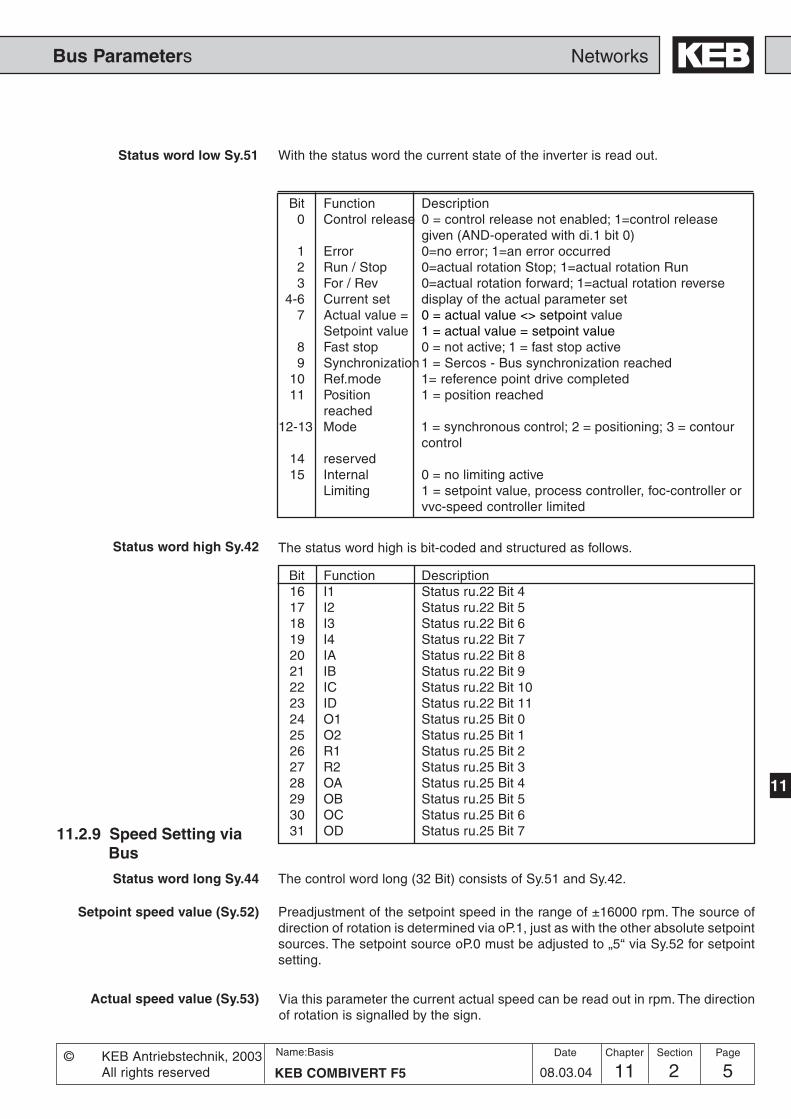
511 2 5
Operation
11
KEB COMBIVERT F5
Chapter Section Page
08.03.04
DateName:Basis© KEB Antriebstechnik, 2003All rights reserved
NetworksBus Parameters
Preadjustment of the setpoint speed in the range of ±16000 rpm. The source ofdirection of rotation is determined via oP.1, just as with the other absolute setpointsources. The setpoint source oP.0 must be adjusted to „5“ via Sy.52 for setpointsetting.
Bit Function Description0 Control release 0 = control release not enabled; 1=control release
given (AND-operated with di.1 bit 0)1 Error 0=no error; 1=an error occurred2 Run / Stop 0=actual rotation Stop; 1=actual rotation Run3 For / Rev 0=actual rotation forward; 1=actual rotation reverse
4-6 Current set display of the actual parameter set7 Actual value = 0 = actual value <> setpoint value
Setpoint value 1 = actual value = setpoint value8 Fast stop 0 = not active; 1 = fast stop active9 Synchronization 1 = Sercos - Bus synchronization reached
10 Ref.mode 1= reference point drive completed11 Position 1 = position reached
reached12-13 Mode 1 = synchronous control; 2 = positioning; 3 = contour
control14 reserved15 Internal 0 = no limiting active
Limiting 1 = setpoint value, process controller, foc-controller orvvc-speed controller limited
Status word low Sy.51 With the status word the current state of the inverter is read out.
11.2.9 Speed Setting viaBus
Setpoint speed value (Sy.52)
Actual speed value (Sy.53) Via this parameter the current actual speed can be read out in rpm. The directionof rotation is signalled by the sign.
The status word high is bit-coded and structured as follows.
Bit Function Description16 I1 Status ru.22 Bit 417 I2 Status ru.22 Bit 518 I3 Status ru.22 Bit 619 I4 Status ru.22 Bit 720 IA Status ru.22 Bit 821 IB Status ru.22 Bit 922 IC Status ru.22 Bit 1023 ID Status ru.22 Bit 1124 O1 Status ru.25 Bit 025 O2 Status ru.25 Bit 126 R1 Status ru.25 Bit 227 R2 Status ru.25 Bit 328 OA Status ru.25 Bit 429 OB Status ru.25 Bit 530 OC Status ru.25 Bit 631 OD Status ru.25 Bit 7
The control word long (32 Bit) consists of Sy.51 and Sy.42.
Status word high Sy.42
Status word long Sy.44

11 2 6Chapter Section Name:Basis © KEB Antriebstechnik, 2003
All rights reserved
Page Date
08.03.04 KEB COMBIVERT F5
Networks Bus Parameters
StepParam. Addr.ENTERPROG.R/W
min max default
Pn.5 0405h 4 - - 0 6 1 6 -
Pn.6 0406h 4 - - 0,00 s 10,00 s 0,01 s 0,00 s 0,00 = off
SY.6 0006h 4 - 4 0 239 1 1 -
SY.7 0007h 4 - 4 0 6 1 3 -
SY.9 0009h 4 - - 0.00 s 10.00 s 0.01 s 0.00 s 0.00 = off
Sy.11 000Bh 4 - 4 3 11 1 5 -
SY.41 0029h 4 - 4 0 65536 1 0 -
SY.42 002Ah - - - 0 65536 1 0 -
SY.43 002Bh 4 - 4 -231 231-1 1 0 -
SY.44 002Ch - - - -231 231-1 1 0 -
SY.50 0032h 4 - 4 0 65536 1 0 -
SY.51 0033h - - - 0 65536 1 0 -
SY.52 0034h 4 - - -16000 rpm 16000 rpm 1 rpm 0 rpm -
SY.53 0035h 4 - - -16000 rpm 16000 rpm 1 rpm 0 rpm -
ud. 5 0805h - - - 0 1 1 1 -
11.2.10 Used Parameters

13.1 Search and Find
Annex
1. Introduction
2. Summary
3. Hardware
4. Operation
5. Parameter
6. Functions
7. Start-up
8. Special Operation
9. Error Assistance
10. Project Planning
11. Networks
12. Annex
12 1 1KEB COMBIVERT F5-G / C / B
Name: Basis
13.03.06
Section PageDate© KEB Antriebstechnik, 2002All Rights reserved
Chapter
13.1.1 Index ...................................... 313.1.2 KEB - Worldwide ................. 1113.1.3 Domestic Representations .. 13

12 1 KEB COMBIVERT F5-G / C / B2Name: Basis
13.03.06
Annex Search and Find
Chapter Section Page Date © KEB Antriebstechnik, 2002All Rights reserved

12 1 3KEB COMBIVERT F5-G / C / B
Name: Basis
13.03.06
12
AnnexSearch and Find
Section PageDate© KEB Antriebstechnik, 2002All Rights reserved
Chapter
12.1 Search and Find
12.1.1 Index
12. Annex
A
Ablauf 8.1.4Abschaltverzögerung 6.7.18Actual frequency display 4.3.5actual value
-source 6.12.6calculation 6.12.6
Additional function 6.9.27acceleration/deceleration 6.9.27Digital Settings 6.9.27Mode 6.9.27source 6.9.27
additional rated point 6.5.4Address 11.2.3An. 0 6.2.4An. 1 6.2.5An. 2 6.2.5An. 3 6.2.5, 6.3.8An. 4 6.2.6An. 5...7 6.2.7An. 8 6.2.8An. 9 6.2.8An.10 6.2.4An.11 6.2.5An.12 6.2.5An.13 6.2.5, 6.3.8An.14 6.2.6An.15...17 6.2.7An.18 6.2.8An.20 6.2.4An.21 6.2.5An.22 6.2.5An.23 6.2.5, 6.3.8An.24 6.2.6An.25 6.2.7An.26 6.2.7An.27 6.2.7An.28 6.2.8An.29 6.2.8An.30 6.2.9An.31...45 6.2.12An.32 6.2.10An.41 8.1.3An.43 8.1.3An.44 8.1.3An.46 6.2.14, 8.1.3An.47 8.1.3An.49 8.1.3An.50 8.1.3An.52 8.1.3An.57 6.9.34Analog
inputs 6.2.5save mode 6.2.5
Application Mode 4.1.3Auslösezeiten 6.7.15Automatischer Wiederanlauf 6.7.7
B
Barring 4.3.5Base-block
Time 6.9.3Basic setting 7.2.4Baud rate 11.2.3Behaviour at power recovery 6.9.22Binary-coded set selection 6.8.8Boost 4.3.9, 6.5.4brake
control 6.9.15release 6.9.15
Brakingoption 10.1.4resistance 10.1.4time 10.1.4torque 10.1.4voltage 6.9.3
C
CAN-Bus 11.1.3cdf 10.1.4cn. 0 6.12.5cn. 1 6.12.5cn. 4...9 6.12.3cn.10...14 6.12.4cn.11...13 6.3.8cn.2 6.12.6cn.3 6.12.6COMBIVIS 11.2.3communication 11.2.3Communication faults 11.2.3Concentricity 6.5.7Control
at 100% 6.12.3deviation 6.12.3fade-in 6.12.3fading time 6.12.3units 3.1.3
Copyingof parameter sets 6.8.4
CounterReset condition 6.9.12, 6.9.13
CP-Parameterassignment 6.13.4define 6.13.3
CP-parameter 4.3.3CP. 0 6.13.3cS. 0 6.11.5cS. 1 6.11.5
cS. 4 6.11.5cS. 6 6.11.5cS. 9 6.11.5Current limit 4.3.13Customer Mode 4.1.3Cycle time 10.1.4Cyclic duration factor 10.1.5
D
Dancing position control 6.12.3Data transfer 11.2.3Dauerstrom 6.7.17DC
brake 6.9.3DC-link voltage
PT1-time constant 6.5.5Default set 6.8.4Delta Boost 6.5.4di. 0 6.3.3di. 1 6.3.4di. 2 6.3.4di. 3...5 6.3.5di. 6...8 6.3.6di. 9 6.3.8di.11...22 6.3.9Diameter
correction 6.9.29ratio 6.9.30signal 6.9.30
DIN 66019 11.2.3Discharge current 6.5.7dmin/dmax 6.9.30do. 0...7 6.3.15do. 8...24 6.3.18do.25...41 6.3.19do.42 6.3.20dr. 0... 5 6.6.3dr. 6 6.6.4dr. 9 6.6.4dr.11 6.7.16dr.12 6.7.16Drehmoment
-einbrüchen 6.7.4Drehzahl
-suche 6.7.7Drive-Mode 4.1.3, 4.2.4, 4.4.3
E
Ec. 0 6.10.10Ec. 1 6.10.10Ec. 2 6.10.13Ec. 3 6.10.10Ec. 4 6.10.11Ec. 5 6.10.11

12 1 KEB COMBIVERT F5-G / C / B4Name: Basis
13.03.06
Annex Search and Find
Chapter Section Page Date © KEB Antriebstechnik, 2002All Rights reserved
Ec. 6 6.10.11Ec. 7 6.10.11Ec.10 6.10.10Ec.11 6.10.10Ec.12 6.10.13Ec.13 6.10.10Ec.14 6.10.11Ec.15 6.10.11Ec.16 6.10.11Ec.17 6.10.11Ec.20...23 6.10.16Ec.25 6.10.16Ec.27 6.10.12Eingangs
-wahlexterner Fehler 6.7.9
Elektronischer Motorschutz 6.7.15EMV
conform installation 7.1.3Encoder
power supply 6.10.7track change 6.10.11
Endschalterfehler 6.7.11Energy saving
function 6.9.5level 6.9.5
ENTER-parameter 4.1.4Externe
Fehlerüberwachung 6.7.18
F
Factory setting 4.3.4, 6.8.4Fading time 6.12.3Fan cooling 10.1.3Filterung 8.1.7Fr. 1 6.8.4Fr. 2...4 6.8.7Fr. 7 6.3.8Fr. 8 6.7.15Fr.11 6.3.8Fr.3 6.8.10Fr.5 6.8.10Fr.6 6.8.10Fr.7 6.8.8Fr.9 6.8.4Function principle 2.1.3Fundamentals 4.1.3
G
GTR7 6.7.19Eingangswahl 6.7.19
H
Hardware 3.1.3
Strombegrenzung 6.7.3High-Torque-Modus 6.5.3Holding
frequency 6.9.16torque 6.9.17
HWSG 6.7.4
I
In-Parameter 6.1.4In. 0 6.1.19In. 1 6.1.19In. 7...17 6.1.20In.22...30 6.1.22In.5 6.10.5Incremental encoder
input 6.10.5output 6.10.6
Initial Start-up 7.2.3input
coded set selection 6.8.9Installation and connection 7.1.3InterBus
Loop 11.1.6Operator 11.1.3
Interface 11.2.3definition 6.10.5Operator 11.1.3
Interference voltage supply 3.1.5inverter
address 11.2.3Inverter status display 4.3.5
J
Jump factor 6.9.20
K
Keep-On-Running 6.7.3Kühlkörpertemperatur 6.1.17, 6.1.18Kühlwasserqualität 8.1.7
L
LA-/LD-Stop 6.3.17LAD-stop 4.3.13LE. 0...7 6.3.24LE. 8...15 6.3.17LE.16 6.3.17LE.17 6.3.8, 6.9.12LE.18 6.9.12LE.19 6.3.8, 6.9.12LE.20 6.9.13LE.21 6.9.11LE.22 6.3.8, 6.9.12LE.23 6.9.12
LE.24 6.3.8, 6.9.12LE.25 6.9.13LE.26 6.9.11LED 4.4.3
M
manipulated variable 6.12.3Mass moment of inertia 10.1.5Master 11.2.3Max.
frequency 6.5.3Max. operating frequency 6.10.8minimal
current level 6.9.16MK/MN 6.6.4Mode 6.9.27Modulation 4.3.5, 6.5.6Motor
-satzzuordnung 6.7.15-schutz
-funktion 6.7.15de-excitation 6.9.3losses 6.5.7poti
function 6.9.7rise time 6.9.8
ratedtorque 10.1.5
Motorpoti 6.4.4Maximum value 6.9.8Minimum value 6.9.8Ramp time 6.9.8
N
Netreverse 6.9.22work components 11.1.3
Noise development 6.5.7Non-programmable Parameters 6.8.3NPN 6.3.4
O
oP. 1 6.4.7oP. 2 6.4.7oP. 3 6.4.4oP. 5 6.4.4oP. 6 6.4.12oP. 7 6.4.12oP.0 6.9.9oP.1 6.9.9oP.10 6.4.12oP.11 6.4.12oP.14 6.4.12oP.15 6.4.12

12 1 5KEB COMBIVERT F5-G / C / B
Name: Basis
13.03.06
12
AnnexSearch and Find
Section PageDate© KEB Antriebstechnik, 2002All Rights reserved
Chapter
oP.18...23 6.4.10oP.27 6.4.17oP.28...35 6.4.15oP.36...41 6.4.16oP.40 6.4.19oP.41 6.4.19oP.44 6.9.27oP.45 6.9.27oP.46 6.9.27, 6.9.30oP.47 6.9.28oP.48 6.9.28oP.49 6.9.30oP.50 6.9.8oP.52 6.9.9oP.53 6.9.8oP.54 6.9.8oP.56...59 6.9.8oP.60 6.4.8oP.61 6.4.8oP.62 6.4.14Operating surface 6.13.3Output frequency
at 100% 6.12.3
P
Parameter 4.1.3, 5.1.3designation 4.1.3groups 4.1.3non-programmable 4.1.5set 4.1.3
lock 6.8.10selection 6.8.7
sets 6.8.3value 4.1.3
Password 4.2.4levels 4.2.3structure 4.2.3
Peakbraking power 10.1.4
PFC. Siehe Power Factor ControlPI
Control 6.12.3Reset conditions 6.12.4
Pn. 0...2 6.7.7Pn. 3 6.7.10Pn. 4 6.3.8, 6.7.9Pn. 5 6.7.10Pn. 6 6.7.10Pn. 7 6.7.11Pn. 8 6.7.11Pn. 9 6.7.10Pn.10 6.7.11Pn.10...17 6.3.17Pn.11 6.7.11
Pn.12...14 6.7.18Pn.14 6.7.12Pn.16...18 6.7.12Pn.19...21 6.7.5Pn.22...25 6.7.3Pn.23 6.3.8Pn.26 6.7.7Pn.27 6.7.7Pn.28...32 6.9.4, 6.9.5Pn.34...43 6.9.15Pn.44 6.9.19Pn.45 6.9.20, 6.9.21Pn.46 6.9.20, 6.9.21Pn.47...56 6.9.21Pn.5 11.2.3Pn.58...60 6.7.13Pn.6 11.2.3Pn.61 6.7.13Pn.62 6.7.11Pn.63 6.9.31Pn.64 6.7.19Pn.65 6.7.19Pn.7 6.7.11PNP / NPN 6.3.3point of support 6.5.4Positioning delay 6.9.31Power Factor Control 2.1.5Power-off
Control 6.9.21Function 6.9.19Mode 6.9.19
Profibus-DP 11.1.3PT1-time constant 6.5.5
R
Radio interference 6.5.7Rampen
-stop 6.7.3-funktion 6.7.3
Rated DC voltage 6.1.16rated DC voltage 6.9.20re
start 6.9.23delay 6.9.23frequency 6.9.22
Reset 3.1.4Resetting of
error messages 4.1.5peak values 4.1.5
Resolution 6.5.3Rotation
setting 4.4.4RS232/485 11.1.3RS485 interface 11.1.4
ru-Parameter 6.1.6ru. 0...3 6.1.6ru. 4...7 6.1.7ru. 9 6.1.7ru.10 6.1.7ru.13...16 6.1.8ru.14 6.3.5ru.15 6.3.20, 6.7.15ru.17...20 6.1.9ru.21 6.1.10, 6.3.5ru.22 6.1.10ru.23 6.1.11ru.24 6.1.11ru.25...28 6.1.12ru.29...32 6.1.13ru.33...36 6.2.12ru.33...37 6.1.14ru.38...43 6.1.15ru.43 6.9.12ru.44 6.9.12ru.44...46 6.1.16, 6.1.17ru.52 6.1.16, 6.1.17ru.53 6.1.16, 6.1.17, 6.1.18ru.59 6.1.16, 6.1.17, 6.1.18ru.68 6.1.16, 6.1.17, 6.1.18, 6.9.20
S
Schnellhalt 6.7.13Level 6.7.13Modus 6.7.13Rampenzeit 6.7.13Steuerwort 6.7.13
Schutzfunktionen 6.7.3Selection
of a parameter 4.1.4Serial interface 11.2.3Service 4.2.3Set speed 11.2.5Set-point
selection 7.2.4Setpoint value
calculationin % 6.12.5
source 6.12.5Setting parameter set 6.8.7sine-wave simulation 6.5.7Slave 11.2.3Sollwert 6.4.4source
Parameter set 6.8.7Source set 6.8.4Special
functions 6.9.3Specifications 2.1.6

12 1 KEB COMBIVERT F5-G / C / B6Name: Basis
13.03.06
Annex Search and Find
Chapter Section Page Date © KEB Antriebstechnik, 2002All Rights reserved
Speedkey 4.4.3search 4.3.14
Stall 6.3.17-funktion 6.7.5
Startkey 4.4.3
Start-up 7.1.3, 7.1.4Starting frequency 6.9.17Stop
frequency 6.9.17Stop-key 4.4.3Strom
-grenzeModus 6.7.5
StromgrenzePegel 6.7.6
Switchon 7.2.3
Switchingcabinet design 10.1.3frequency 6.5.3, 6.5.6losses6.5.7
Sy-Parameter 6.1.23Sy. 2 6.1.23Sy. 3 6.1.23Sy. 6 6.1.23Sy. 7 6.1.23Sy.11 6.1.24, 11.2.3Sy.32 6.1.24Sy.50 6.4.9Sy.50...52 6.1.25Sy.50...53 11.2.4, 11.2.5Sy.53 6.1.26Sy.56 6.1.24, 6.1.26SY.6 11.2.3SY.7 11.2.3Synchronisationspunkt 6.7.7Synchronmotore 6.7.19
T
Target set 6.8.4telegrams 11.2.3Temperature
deviation 10.1.3Temperaturregelung 8.1.3Testing of Drive 7.2.5Thermischer Überhitzung 6.7.3Timer 6.9.11
programming 6.9.11tool path feedrate 6.9.29Totzeit
-kompensation 6.7.9Type code 2.1.5
U
Über-lastung 6.7.16-strom 6.7.3
ud. 1 4.2.3, 4.4.3, 6.13.3ud. 2 6.5.3ud. 9 4.4.3ud.15...17 6.13.3ud.18...21 6.13.6uF. 0...5 6.5.4uF. 6...9 6.9.5uf.11 6.5.6uF.12 6.7.9uF.13 6.7.9uF.15 6.7.4uF.16 6.11.4uF.17 6.11.4uF.18 6.7.9uF.19 6.5.5Unterlast 6.7.16
V
V/Hz-characteristic 6.9.5Voltage
and frequency characteristic 6.5.4reduction 6.9.5
Voltage Stabilization 6.5.5
W
Watchdog 11.2.3winding product 6.9.29Wobbel
amplitude 6.9.27generator 6.9.27, 6.9.28
Z
Zulauf 8.1.4
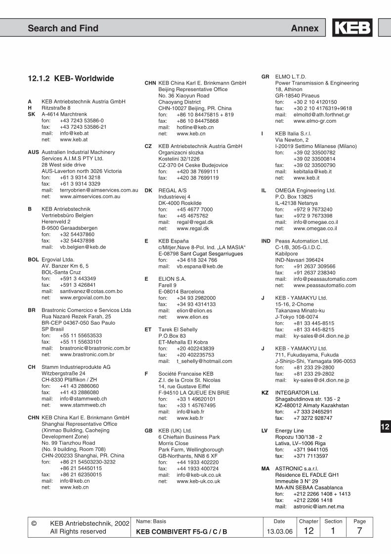
12 1 7KEB COMBIVERT F5-G / C / B
Name: Basis
13.03.06
12
AnnexSearch and Find
Section PageDate© KEB Antriebstechnik, 2002All Rights reserved
Chapter
A KEB Antriebstechnik Austria GmbHH Ritzstraße 8SK A-4614 Marchtrenk
fon: +43 7243 53586-0fax: +43 7243 53586-21mail: [email protected]: www.keb.at
AUS Australien Industrial MachineryServices A.I.M.S PTY Ltd.28 West side driveAUS-Laverton north 3026 Victoriafon: +61 3 9314 3218fax: +61 3 9314 3329mail: [email protected]: www.aimservices.com.au
B KEB AntriebstechnikVertriebsbüro BelgienHerenveld 2B-9500 Geraadsbergenfon: +32 54437860fax: +32 54437898mail: [email protected]
BOL Ergovial Ltda.AV. Banzer Km 6, 5BOL-Santa Cruzfon: +591 3 443349fax: +591 3 426841mail: [email protected]: www.ergovial.com.bo
BR Brastronic Comercico e Servicos LtdaRua Nazaré Rezek Farah, 25BR-CEP 04367-050 Sao PauloSP Brasilfon: +55 11 55653533fax: +55 11 55633101mail: [email protected]: www.brastronic.com.br
CH Stamm Industrieprodukte AGWitzbergstraße 24CH-8330 Pfäffikon / ZHfon: +41 43 2886060fax: +41 43 2886080mail: [email protected]: www.stammweb.ch
CHN KEB China Karl E. Brinkmann GmbHShanghai Representative Office(Xinmao Building, CaohejingDevelopment Zone)No. 99 Tianzhou Road(No. 9 building, Room 708)CHN-200233 Shanghai, PR. Chinafon: +86 21 54503230-3232
+86 21 54450115fax: +86 21 62350015mail: [email protected]: www.keb.cn
CHN KEB China Karl E. Brinkmann GmbHBeijing Representative OfficeNo. 36 Xiaoyun RoadChaoyang DistrictCHN-10027 Beijing, PR. Chinafon: +86 10 84475815 + 819fax: +86 10 84475868mail: [email protected]: www.keb.cn
CZ KEB Antriebstechnik Austria GmbHOrganizacni slozkaKostelini 32/1226CZ-370 04 Ceske Budejovicefon: +420 38 7699111fax: +420 38 7699119
DK REGAL A/SIndustrievej 4DK-4000 Roskildefon: +45 4677 7000fax: +45 4675762mail: [email protected]: www.regal.dk
E KEB Españac/Mitjer,Nave 8-Pol. Ind. „LA MASIA“E-08798 Sant Cugat Sesgarriuguesfon: +34 618 324 766mail: [email protected]
E ELION S.A.Farell 9E-08014 Barcelonafon: +34 93 2982000fax: +34 93 4314133mail: [email protected]: www.elion.es
ET Tarek El SehellyP.O.Box 83ET-Mehalla El Kobrafon: +20 402243839fax: +20 402235753mail: [email protected]
F Société Francaise KEBZ.I. de la Croix St. Nicolas14, rue Gustave EiffelF-94510 LA QUEUE EN BRIEfon: +33 1 49620101fax: +33 1 45767495mail: [email protected]: www.keb.fr
GB KEB (UK) Ltd.6 Chieftain Business ParkMorris ClosePark Farm, WellingboroughGB-Northants, NN8 6 XFfon: +44 1933 402220fax: +44 1933 400724mail: [email protected]: www.keb-uk.co.uk
GR ELMO L.T.D.Power Transmission & Engineering18, AthinonGR-18540 Piraeusfon: +30 2 10 4120150fax: +30 2 10 4176319+9618mail: [email protected]: www.elmo-gr.com
I KEB Italia S.r.l.Via Newton, 2I-20019 Settimo Milanese (Milano)fon: +39 02 33500782
+39 02 33500814fax: +39 02 33500790mail: [email protected]: www.keb.it
IL OMEGA Engineering Ltd.P.O. Box 13825IL-42138 Netanyafon: +972 9 7673240fax: +972 9 7673398mail: [email protected]: www.omegae.co.il
IND Peass Automation Ltd.C-1/B, 305-G.I.D.C.KabilporeIND-Navsari 396424fon: +91 2637 309566fax: +91 2637 238340mail: [email protected]: www.peassautomatio.com
J KEB - YAMAKYU Ltd.15-16, 2-ChomeTakanawa Minato-kuJ-Tokyo 108-0074fon: +81 33 445-8515fax: +81 33 445-8215mail: [email protected]
J KEB - YAMAKYU Ltd.711, Fukudayama, FukudaJ-Shinjo-Shi, Yamagata 996-0053fon: +81 233 29-2800fax: +81 233 29-2802mail: [email protected]
KZ INTEGRATOR Ltd.Shagabutdinova str. 135 - 2KZ-480012 Almaty Kazakhstanfon: +7 333 2465291fax: +7 3272 928747
LV Energy LineRopozu 130/138 - 2Lativa, LV–1006 Rigafon: +371 9441105fax: +371 7113597
MA ASTRONIC s.a.r.l.Résidence EL FADLE GH1Immeuble 3 N° 29MA-AIN SEBAA Casablancafon: +212 2266 1408 + 1413fax: +212 2266 1418mail: [email protected]
12.1.2 KEB- Worldwide

12 1 KEB COMBIVERT F5-G / C / B8Name: Basis
13.03.06
Annex Search and Find
Chapter Section Page Date © KEB Antriebstechnik, 2002All Rights reserved
MAL BSC Automation(M) Sdn Bhd12A, Jalan 7, 108 CTaman Sungai BesiMY-57100 Kuala Lumpurfon: +60 379809591fax: +60 379817442mail: [email protected]
NL KEB NederlandLeidsevaart 126NL–2013 HD Haarlemfon: +31 23 5320049fax: +31 23 5322260mobil: +31 653964667mail: [email protected]
NL Marsman ElektronicaEn Aandrijvingen BVZeearend 16NL-7609 PT Almelofon: +31 546 812121fax: +31 546 810655mail: [email protected]: www.marsman-almelo.nl
NZ Renold New Zealand LimitedP.O. Box 19460NZ-Avondale Aucklandfon: +64 9 8285018fax: +64 9 8285019mail: [email protected]: www.renold.co.nz
NZ Vectek Electronics Ltd.21 Carnegie Road, OnekawaNZ-Napierfon: +64 6 8431400fax: +64 6 8430398mail: [email protected]: www.vectek.co.nz
P KEB PortugalAvenida da Igreja -PavilãoA n.º 261 MouquimP-4770 - 360 MOUQUIM V.N.F.fon: +351 252 371 318 + 19fax: +351 252 371 320mail: [email protected]
PA Associated Textile Consultants (ATC)Private LTD219, The Forum, G-20, Block-9Khayaban-e-Jami, CliftonPK-75600, Parkistanfon: +92 21 582124-1...-6fax: +92 21 5821559 5821247mail: [email protected]
PL KEB Polskaul. BudapesztaD ´ska 3/16PL-80-288 GdaD ´skfon: +48 58 524 0518fax: +48 58 524 0519mail: [email protected]
RCH EMET LTDA.Madrid #1386RCH-Santiago, Chilefon: +56 2 5510630fax: +56 2 5510627mail: [email protected]: www.emet.cl
RI siehe Malaysia
ROC KEB Taiwan Ltd.No. 8, Lane 89, Sec. 3Taichung Kang Rd.R.O.C.-Taichung City, Taiwanfon: +886 4 23506488fax: +886 4 23501403mail: [email protected]
ROM ADF Industries srlBucarest Sec. 3, Str. Baraj BicazNr.2–4, M25 Ap 110PO 74661ROM-Bucarestfon: +40 21 3411200fax: +40 21 3403224mail: [email protected]: www.adf.ro
RSA P E C S Pneumatic ElectricControl Systems (PTY) Ltd.P.O. Box 473968, Balance Road, Stamford Hill 4001RSA-Durban / Greyville 4023fon: +27 31 3033701fax: +27 31 3127421mail: [email protected]:www.pecspowertransmission.co.za
RUS ServotechnicsVyborgskaya 22 of 52RUS-125130 Moskow / Russiafon: +7 095 797-8856fax: +7 095 450-0043mail: [email protected]
S REVA - drivteknik ABSlussgatan 13S-21130 Malmöfon: +46 4077110fax: +46 4079994mail: [email protected]: www.revadrivteknik.se
S KEB SverigeBox 265 (Bergavägen 19)S-4393 Hälsöfon: +46 31 96 1520fax: +46 31 96 1124mobil: +46 733856400mail: [email protected]
SGP THE ONE TRANSMISSION Pte Ltd.64 Sungei Kadut Loop729493 SingaporeSGP-Singaporefon: +65 6561 1215fax: +65 6561 1071mail: [email protected]
THA INNOTECH Solution Co. Ltd.25/120 Soi. Nawamin 165(Amornwiwat)Nawamin Rd., Bungkum,KlongkumTHA- Bangkok 10230 Bangkokfon: +66 2 9664927fax: +66 2 9664928mail: [email protected]: www.anet.net.th
TN H 2 M13, Rue El MoutanabiTN-2037, El Menzah 7fon: +216 71 427677fax: +216 71 427688mail: [email protected]
TR TEPEKS Elektronik Sanayi VeTicaret Ltd. SirketjHarman Cad. Ali Kaya Sok. No. 4POLAT Plaza B. Blok Kat 5TR-80640 Levent, Istanbulfon: +90 212 3252530fax.: +90 212 3252535mail: [email protected]: www.tepeks.com
UA MARKET-Kof. 2, 62 B, Vishnevetskogo Str.UA–257002 Cherkassyfon: +380 472 540617fax: +380 472 540614mail: [email protected]
USA KEBCO Inc.1335 Mendota Heights RoadUSA-Mendota Heights, MN 55120fon: +1 651 4546162fax: +1 651 4546198mail: [email protected]: www.kebco.com
UZ Mechatronika-TESStr. Mukana berk, 17UZ-700070 Tashkentfon: +998 712 556617fax: +998 712 555726mail: [email protected]
2/2004
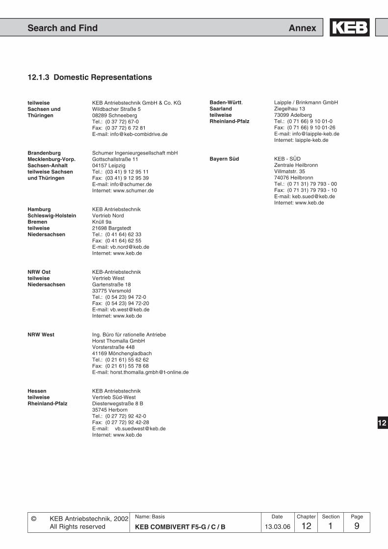
12 1 9KEB COMBIVERT F5-G / C / B
Name: Basis
13.03.06
12
AnnexSearch and Find
Section PageDate© KEB Antriebstechnik, 2002All Rights reserved
Chapter
12.1.3 Domestic Representations
teilweise KEB Antriebstechnik GmbH & Co. KGSachsen und Wildbacher Straße 5Thüringen 08289 Schneeberg
Tel.: (0 37 72) 67-0Fax: (0 37 72) 6 72 81E-mail: [email protected]
Brandenburg Schumer Ingenieurgesellschaft mbHMecklenburg-Vorp. Gottschallstraße 11Sachsen-Anhalt 04157 Leipzigteilweise Sachsen Tel.: (03 41) 9 12 95 11und Thüringen Fax: (03 41) 9 12 95 39
E-mail: [email protected]: www.schumer.de
Hamburg KEB AntriebstechnikSchleswig-Holstein Vertrieb NordBremen Knüll 9ateilweise 21698 BargstedtNiedersachsen Tel.: (0 41 64) 62 33
Fax: (0 41 64) 62 55E-mail: [email protected]: www.keb.de
NRW Ost KEB-Antriebstechnikteilweise Vertrieb WestNiedersachsen Gartenstraße 18
33775 VersmoldTel.: (0 54 23) 94 72-0Fax: (0 54 23) 94 72-20E-mail: [email protected]: www.keb.de
NRW West Ing. Büro für rationelle AntriebeHorst Thomalla GmbHVorsterstraße 44841169 MönchengladbachTel.: (0 21 61) 55 62 62Fax: (0 21 61) 55 78 68E-mail: [email protected]
Hessen KEB Antriebstechnikteilweise Vertrieb Süd-WestRheinland-Pfalz Diesterwegstraße 8 B
35745 HerbornTel.: (0 27 72) 92 42-0Fax: (0 27 72) 92 42-28E-mail: [email protected]: www.keb.de
Baden-Württ. Laipple / Brinkmann GmbHSaarland Ziegelhau 13teilweise 73099 AdelbergRheinland-Pfalz Tel.: (0 71 66) 9 10 01-0
Fax: (0 71 66) 9 10 01-26E-mail: [email protected]: laipple-keb.de
Bayern Süd KEB - SÜDZentrale HeilbronnVillmatstr. 3574076 HeilbronnTel.: (0 71 31) 79 793 - 00Fax: (0 71 31) 79 793 - 10E-mail: [email protected]: www.keb.de

© K
EB
00
.F5.
GE
A-K
320
10/2
016
KEB Automation KGSüdstraße 38 • D-32683 Barntrup
fon: +49 5263 401-0 • fax: +49 5263 401-116net: www.keb.de • mail: [email protected]
KEB Antriebstechnik GmbH & Co. KGWildbacher Str. 5 • D–08289 Schneebergfon: +49 3772 67-0 • fax: +49 3772 67-281
mail: [email protected]
KEB Antriebstechnik Austria GmbHRitzstraße 8 • A-4614 Marchtrenk
fon: +43 7243 53586-0 • fax: +43 7243 53586-21 Kostelni 32/1226 • CZ-370 04 Ceské Budejovicefon: +420 38 7319223 • fax: +420 38 7330697
net: www. keb.at • mail: [email protected]
KEB AntriebstechnikHerenveld 2 • B-9500 Geraadsbergen
fon: +32 5443 7860 • fax: +32 5443 7898mail: [email protected]
KEB CHINA Karl E. Brinkmann GmHShanghai Representative Office
(Xinmao Building, Caohejing Development Zone)No. 99 Tianzhou Road (No.9 building, Room 708)
CHN-200233 Shanghai, PR. Chinafon: +86 21 54503230-3232 • fax: +86 21 54450115
net: www.keb.cn • mail: [email protected]
KEB CHINA Karl E. Brinkmann GmHBeijing Representative Office
No. 36 Xiaoyun Road • Chaoyang DistrictCHN-10027 Beijing, PR. China
fon: +86 10 84475815 + 819 • fax: +86 10 84475868 net: www.keb.cn • mail: [email protected]
Société Française KEBZ.I. de la Croix St. Nicolas • 14, rue Gustave Eiffel
F-94510 LA QUEUE EN BRIEfon: +33 1 49620101 • fax: +33 1 45767495
net: www.keb.fr • mail: [email protected]
KEB (UK) Ltd.6 Chieftain Buisiness Park, Morris Close
Park Farm, Wellingborough GB-Northants, NN8 6 XF fon: +44 1933 402220 • fax: +44 1933 400724
net: www.keb-uk.co.uk • mail: [email protected]
KEB Italia S.r.l.Via Newton, 2 • I-20019 Settimo Milanese (Milano)
fon: +39 02 33500782 • fax: +39 02 33500790net: www.keb.it • mail: [email protected]
KEB - YAMAKYU Ltd.15–16, 2–Chome, Takanawa Minato-ku
J–Tokyo 108-0074fon: +81 33 445-8515 • fax: +81 33 445-8215
mail: [email protected]
KEB - YAMAKYU Ltd.711, Fukudayama, Fukuda
J–Shinjo-Shi, Yamagata 996 - 0053fon: +81 233 29-2800 • fax: +81 233 29-2802
mail: [email protected]
KEB NederlandLeidsevaart 126 • NL–2013 HD Haarlem
fon: +31 23 5320049 • fax: +31 23 5322260mail: [email protected]
KEB Portugal Avenida da Igreja – Pavilão A n. º 261 Mouquim
P-4770 - 360 MOUQUIM V.N.F.fon: +351 252 371318 + 19 • fax: +351 252 371320
mail: [email protected]
KEB Taiwan Ltd.No.8, Lane 89, Sec.3; Taichung Kang Rd.
R.O.C.-Taichung City / Taiwanfon: +886 4 23506488 • fax: +886 4 23501403
mail: [email protected]
KEB SverigeBox 265 (Bergavägen 19)
S-4393 Hälsöfon: +46 31 961520 • fax: +46 31 961124
mail: [email protected]
KEBCO Inc.1335 Mendota Heights Road
USA-Mendota Heights, MN 55120fon: +1 651 4546162 • fax: +1 651 4546198net: www.kebco.com • mail: [email protected]