experiments with solar cell (from solar kit) - cdn.ymaws.com · 4 observation and measurement: all...
TRANSCRIPT

1
Published by the MUSE group (More Understanding with Simple Experiments) in the Physics Education Division (PED) of the European Physical Society (EPS) http://www.eps.org/, education, MUSE
June 2015
Experiments with Solar Cell (from Solar Kit) Zdeňka Koupilová1
Solar energy is more and more used in everyday life. In addition to everyday objects such as solar
calculators or solar garden lamps, photovoltaic power plants are becoming more and more common.
It would be a natural assumption that for solar cell performance visible light is necessary. Using solar
kit toy containing a solar cell and a simple electromotor it can be easily shown that this is not true.
Moreover we can show to pupils that the range of visible region is defined by the sensitivity of our
eyes, and that even though the electromagnetic radiation with slightly lower frequencies than the
lower limit is undetectable by our eyes, a silicon solar cell can detect it.
Goals of the activity: By examining the performance of a solar cell using various filters and types of artificial light sources
we will find out that:
- there must be more components of light besides the visible one in the spectrum of a classic
light bulb, and the solar cell detects some of them
- for cell performance, visible and (near) infrared (NIR) part of electromagnetic spectrum are
important
- various artificial light sources radiate different amount of energy in (N)IR region
Equipment: – Solar cell – from the educational kit (toy) with simple electromotor
(solar cells from other device or bought separately should work as well)
- various light sources – in the paper following light sources for 240 V AC were used:
incandescent light bulb (60 W), fluorescent lamp (20 W), LED (13 W), halogen lamp (52 W)
- filters – standard glass, photographic IR filter (it blocks visible light and lets near infrared
radiation through), photographic filter called standard hot mirror (near infrared radiation
1 The MUSE group, Zdenka Koupilova, Andreas Mueller, Gorazd Planinsic, and Laurence Viennot, takes
responsibility for the content of this paper (June 2015).

2
does not go through, but visible light passes through it, the filter is further called “VL filter”),
thick glass which blocks near infrared radiation (it looks little greenish, e.g. from overhead
projector), IR filter made from black permanent marker dye [1] (further called DIY black dye
filter), colour filters – red, blue, green, magenta, cyan, yellow
- voltmeter, ammeter, wires
First step – there is invisible light
What to do
1) Assemble the kit – connect electromotor to the solar cell and prepare lamp with
incandescent light bulb. Find the distance between the lamp and the solar cell that ensures really
good operation of the electromotor (really high electromotor speed). The distance between the solar
cell and light sources should remain the same for all following experiments, so fix all parts firmly in
their places.
2) Observe the frequency of the electromotor when the solar cell is illuminated by the
incandescent light bulb.
3) Place various “filters” in front of a cell. Observe the changes in electromotor frequency and
compare to the frequency when solar cell is illuminated by the incandescent light bulb.
4) Try to explain your observations with respect to “which light is important for solar cell
performance”.
Observations
If the solar cell is near to the bulb, the electromotor rotates fast. The electromotor frequency
decreases as we move the solar cell away from the bulb.
Common glass does not influence the electromotor frequency, or its effect is hardly
noticeable.
Both photographic filters – the IR filter as well as the VL filter – and colour filters slightly slow
down the electromotor.
Thick glass influences the frequency of the electromotor very much. The frequency drops,
but the propeller is still moving.
The DIY black dye filter does not cause the electromotor to stop. It is still turning at
reasonably high frequency, comparable with its frequency in the case when thick glass was
used.

3
Explanation/conclusion
Because the electromotor was working very well with the IR filter that blocked VISIBLE light, the bulb
has to emit some other “light” besides the visible one. The solar cell detects at least part of this
invisible radiation/light.
The VL filter possibly blocks some invisible part of the spectrum, because all visible light goes through
it, but the frequency of electromotor slightly decreased when the filter was placed in front of the
solar cell. This means that the VL filter has to affect something else that the solar cell detects.
Common glass must be transparent not only for visible light, but for the invisible radiation that is
detected by solar cell as well.
Colour filters block some part(s) of the visible light, that’s why we observe a slight decrease in
frequency. Based on these experiments it is not possible to say if the colour filters affect the invisible
part of light or not.
Second step – solar cell colour sensitivity
What to do
The lamp with an incandescent light bulb is still used in the following experiment. Let us design the
experiment to measure the electric power produced by the solar cell. We need to measure voltage
across the electromotor and current through it. The power will be calculated as a product of both.
We will use all the filters from previous task.
Observe any changes in electromotor frequency when each filter is placed in front of the
solar cell. Measure the voltage and current and calculate the power.
Once you completed the measurements examine the emission spectrum of the light bulb and
transmission spectra of various filters (see spectra in the appendix). Combining
measurements and data from the spectra try to formulate the conclusions about sensitivity
of solar cell to light of different colours.

4
Observation and measurement:
All filters affect the solar cell performance. The electromotor frequency decreases in all cases.
The effect is quantified by measured values in the following table and graph.
Table 1: Measurements of the current through and terminal voltage across the solar cell when
incandescent bulb with various filters was used as a light source
filter
U I P U/Umax P/Pmax
V mA mW
no filter 1.02 57 58 100 % 100 %
common glass 1.02 56 57 100 % 98 %
IR filter 0.30 27 8 29 % 14 %
VL filter 0.89 51 45 87 % 78 %
thick glass 0.20 18 4 20 % 6 %
DIY black dye filter 0.23 19 4 23 % 8 %
blue 0.94 53 50 92 % 86 %
green 0.95 53 50 93 % 87 %
red 1.01 56 57 99 % 97 %
cyan 0.90 51 46 88 % 79 %
magenta 0.97 54 52 95 % 90 %
yellow 1.00 55 55 98 % 95 % a) If the bulb was switched off the measured voltage was 0.01 V and current 1 mA. It means that an effect of daylight is
negligible so no shielding was necessary.
Graph 1: Proportion of electromotor input power for various filters.

5
From measured data we may conclude that except for the common glass, all filters affect the
electromotor power. We can rank colours according to influence on electromotor performance:
cyan – blue – green – magenta – yellow – red. The data suggests: the power of electromotor is
greater when colours with “red” component are used in comparison with blue-green colours.
If we look at transmission spectra of filters, we can see that common glass does not change the
spectrum (note that this light has already passed through the thin glass of the bulb), that’s why it
does not influence the solar cell voltage.
Despite the VL filter transmits all visible light, when we use it, the electromotor power decreases by
about one fifth. It means that the solar cell detects also part of electromagnetic spectrum that is
invisible to our eyes, with wavelength longer than red light. In addition IR filter blocks all visible light
and its usage does not cause electromotor to stop.
Conclusion: Solar cell detects visible light as well as near infrared radiation.
Note: If we use the thick glass and DIY black dye filter only (cheaper substitutes of photographic
filters) it would not be so easy to make the conclusion above. Thick glass blocks approximately half of
the red light and all infrared radiation, that’s why the solar cell power decreases. The DIY black dye
filter works nearly reversely, it blocks all visible light from blue to yellow; only small part of red light
and only about one third of infrared radiation goes through. That’s why we almost cannot see
through it. A possible explanation would be: Detector is not affected by the infrared radiation and
smaller power of electromotor may be due to smaller amount of red light in both cases.
We can see that all colour filters are transparent for infrared radiation; cyan, blue and green absorb
part of it as well as IR filter.
Question: To which part of electromagnetic spectrum emitted by the incandescent light
bulb is the solar cell sensitive?
The previous measurement leads us to the question if radiation of all wavelengths (the bulb emits) is
detected by the solar cell or if the solar cell is sensitive only to a part of the spectrum, especially in
the visible region.
A comparison among red, yellow and magenta filters is interesting. All filters are transparent for
infrared radiation and red light. Red filter blocks yellow, green and blue part of the visible spectrum.
But yellow (magenta) filter lets yellow and green (red and blue) light through; however, solar cell
voltage is nearly the same for all three filters.
Does it mean that solar cell does not detect the green and blue light? This can be tested by using
several filters at the same time.

6
Table 2: Voltage and current through electromotor when incandescent bulb and more than one filter
were used.
filters transmitted
radiation U I P
U/Umax P/Pmax V mA mW
red + blue IR 0.91 40 36 89 % 74 %
blue + thick glass blue 0.02 3 0 2 % 0 %
green + thick glass green 0.03 4 0 3 % 0 %
red + thick glass part of red 0.15 10 2 15 % 3 %
Conclusion: (Near) infrared radiation and red light are important for solar cell behaviour. The solar
cell is almost insensitive to green and blue light.
Step three – different artificial light sources In the next experiment we will use different light sources – fluorescent lamp, halogen bulb,
LED bulb.
Observe the electromotor frequency for each of the light sources alone and with thick glass
or black dye filter. Measure the voltage and current.
Compare observations with the spectra of light sources in appendix.
Note: Individual light sources may have different luminosities. It is necessary to compare the measured data for
the certain source (with or without filter), not among various sources.
Observation and measurement: In our case the brightness of the light sources was not the same.
The halogen lamp was the brightest, brightness of incandescent bulb and fluorescent lamp was the
same, LED was slightly less bright than incandescent bulb.
Table 3: Measurement of current and terminal voltage for various light sources and various filters
U I P
U/Umax*) P/Pmax
*)
V mA mW
Inca
n-
des
cen
t b
ulb
without filter 1.02 48 49 100 % 100 %
green glass 0.35 14 5 34 % 10 %
black dye 0.40 15 6 39 % 12 %
Hal
oge
n
bu
lb without filter 1.06 50 53 100 % 100 %
green glass 0.30 12 4 28 % 7 %
black dye 0.43 17 7 41 % 14 %
LED
without filter 0.30 11 3 100 % 100 %
green glass 0.06 7 0 20 % 13 %
black dye 0.01 1 0 3 % 0 %
Flu
ore
s-ce
nt
lam
p without filter 0.57 24 14 100 % 100 %
green glass 0.23 12 3 40 % 20 %
black dye 0.01 2 0 2 % 0 % *) Umax and Pmax is voltage/power of the particular source without filter.

7
We can see that incandescent bulb and halogen bulb behave in very similarly. Further, we can
conclude that fluorescent lamp and LED do not emit in the (near) IR region, because there is no
voltage on solar cell when the black dye filter was used. Both observations are supported by spectra
(see Appendix).
Conclusion: Fluorescent lamps and LEDs are good sources of visible light; no energy is wasted to
produce infrared radiation. Incandescent bulb and halogen lamp are better for solar cell operation
because the solar cell detects the red part of visible light as well as the near infrared part which both
light sources emit.
Conclusion Described simple experiments with the solar cell from the toy kit and other cheap equipment are
appropriate to demonstrate the existence of (near) infrared radiation as a part of the
electromagnetic spectrum to which the solar cell is also sensitive. A maybe little surprising finding is
that the solar cell produces electricity even when we (people) sense complete darkness (see the IR
filter data in table 1).
The artificial light sources that we normally use at home emit visible as well as other radiation. We
specially examine near infrared part of the radiation. Amount of the energy in this part of the
spectrum influences the energy demand of the light source.
References [1] Polák Z.: Experiments with infrared radiation – suggestions, Physics Teachers’ Inventions Fair
proceedings, [online] http://vnuf.cz/proceedings/papers/15-24-Polak.html
8
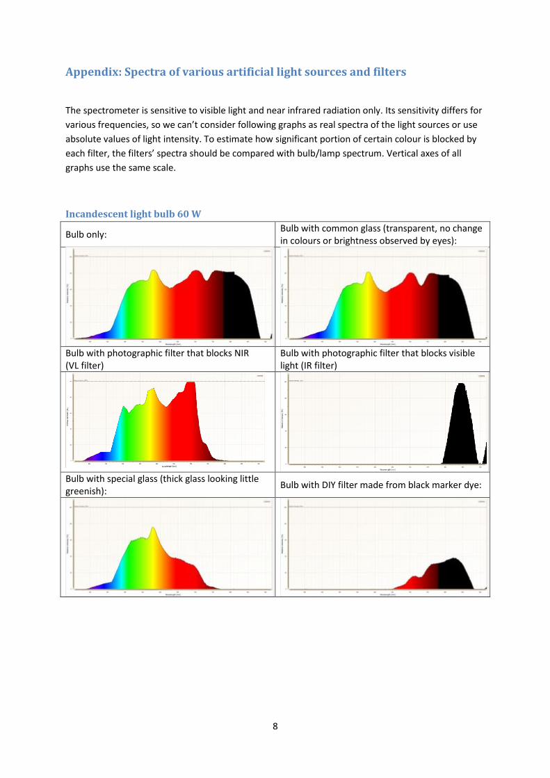
Appendix: Spectra of various artificial light sources and filters
The spectrometer is sensitive to visible light and near infrared radiation only. Its sensitivity differs for
various frequencies, so we can’t consider following graphs as real spectra of the light sources or use
absolute values of light intensity. To estimate how significant portion of certain colour is blocked by
each filter, the filters’ spectra should be compared with bulb/lamp spectrum. Vertical axes of all
graphs use the same scale.
Incandescent light bulb 60 W
Bulb only: Bulb with common glass (transparent, no change in colours or brightness observed by eyes):
Bulb with photographic filter that blocks NIR (VL filter)
Bulb with photographic filter that blocks visible light (IR filter)
Bulb with special glass (thick glass looking little greenish):
Bulb with DIY filter made from black marker dye:
9
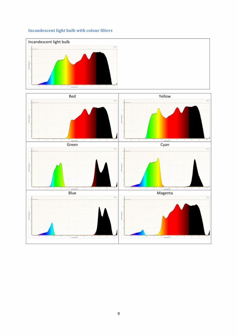
Incandescent light bulb with colour filters
Incandescent light bulb
Red
Yellow
Green
Cyan
Blue
Magenta

10
Incandescent bulb with combination of filters
Bulb only
Red + blue
Red + cyan
Red + blue + cyan
Various light sources
Incandescent bulb
Fluorescent lamp
Halogen bulb
LED