experimental study on hydraulic signal compensation for the application … · a joystick is used...
TRANSCRIPT
EXPERIMENTAL STUDY ON HYDRAULIC SIGNAL COMPENSATION FOR THE APPLICATION OF A HAPTIC INTERFACE TO A TELE-OPERATED
EXCAVATOR
Hyung-Jun Park1, Seunghoon Lee1, Sung-Kyun Kang2, Min-Sung Kang3, Min-Su Song3, and Changsoo Han1*
1 Department of Mechanical Engineering, Hanyang University, Korea
2 Department of Intelligent Robot Engineering, Hanyang University, Korea 3 Department of Mechatronics Engineering, Hanyang University, Seoul, Korea
* Corresponding author ([email protected])
ABSTRACT: Excavators are widely used in public works and construction sites. Semi-automated or automated excavators
are also being developed. They are used for very dangerous tasks such as building dismantlement and disaster restoration.
Under difficult circumstances, it is more efficient to use an excavator operated with a remote control system. Many
researches are underway to develop this kind of system. Conventional remote control systems have been mostly dependent
on two-dimensional images. In this study, this system was used, which made it difficult to measure the depth of the
excavation location and it took a long time to complete the work. That is why there have not been many practical cases of
utilization of tele-operated excavators. Because of these limitations, the haptic technology is proposed that enables
recognition of bucket-reflected force and its passing on to the operator. The research was conducted to overcome these
difficulties of using two-dimensional images, by developing a force-feedback joystick that efficiently detects the
underground condition and applies it to a tele-operated excavator.
Keywords: Tele-Operated Excavator, Haptic Interface, Force-feedback Joystick, Hydraulic Signal, Regression Matrix
1. INTRODUCTION
With customer needs diversifying in the domestic
construction industry, infrastructure is becoming advanced,
complicated, and high-quality. Thus, it is very important to
have improved technology amidst the competition. Also,
because of the opening of the construction industry, the
goal of construction companies to increase their
competitiveness is to become high-value-added businesses
through technology. Since the construction industry is
regarded as a 3D (Dirty, Difficult, and Dangerous) industry,
however, and as such, young people avoid working in it, it
is becoming more difficult to secure skilled workers for it.
The domestic construction industry should solve
problems such as lack of skilled workers, saturation of
aging workers, safety matters, and weakened
competitiveness of construction technology. These
problems can be addressed by “Construction Automation”.
Construction automation means software engineering such
as informatization using technologies for computer
utilization, management systems, and hardware
engineering, which refers to automatic and semi-automatic
robot development for mechanization [1]. There are limits
not only to operating construction equipment in dangerous
places such as slopes, soft ground, building dismantling
sites, distressed areas, and construction waste landfills, but
also to working in these places, because operators can be
exposed there to dangerous environments. Therefore,
construction automation is definitely needed for the safe
use of construction equipment.
Excavators are widely used in public works and
construction sites. They are particularly used for very
dangerous tasks such as building dismantling and disaster
restoration. Under difficult circumstances, it is more
efficient to use an excavator operated with a remote control
system. The conventional tele-operated excavator system,
however, has been mostly dependent on two-dimensional
S8-7
298

images. If it is used, it would be difficult to measure the
depth of the excavation location, and it will take a long
time to complete the work. To solve these problems, the
haptic technology is proposed, which allows recognition of
bucket-reflected force and its pass it to the operator.
Haptics is a generic term for the study of the use of
remote controls and robots to deliver sense-of-touch
information to operators in remote places. To send various
and accurate information on virtual objects to operators,
the precise implementation of touch is needed [2]. Haptic
interface, one of the fields of study in haptics, makes
operators feel as if they are in an actual or virtual
environment through a haptic device [3]. A joystick is used
with a thumb and an index finger, and is most sensitive to
humans, so it is a very appropriate haptic device [4].
Therefore, this research was conducted to develop a
force-feedback joystick that can efficiently detect the
underground condition and realize the reflected forces
using hydraulic signal compensation to allow the
application of a force-feedback joystick to a tele-operated
excavator so as to overcome the difficulties of using two-
dimensional images in tele-operated excavators.
2. IMPLEMENTATION OF THE MASTER SYSTEM
A. Configuration of the Force-Feedback Joystick
Although the excavator has a control lever with greater
than 6DOF, usually less than 2-3 actuators move at the
same time in a movement of the unit, so the force-feedback
joystick can have 2DOF. A force-feedback joystick consists
of three major components: the transmission mechanism,
the actuator, and the sensor. Among these components, the
transmission mechanism determines the workspace of the
joystick. In general, the transmission mechanism can be
classified into the coupled type and the decoupled type.
The single-yoke type under the coupled type has the
advantage of a simple structure, as shown in Fig. 1 (a).
When the central yoke moves, however, it has the
disadvantage of its two semi-circular connectors interfering
with each other [5]. To remove a contact, cancel and
mitigate the interference, and reduce the friction between
the semi-circular connectors, the multi-yoke type trans-
mission mechanism was adopted, as shown in Fig. 1 (b).
(a) Single-yoke Type (b) Multi-yoke Type
Fig. 1 Type of transmission mechanism.
Fig. 2 Configuration of the developed force-feedback
joystick.
In this study, two DC motors were used, as shown in Fig.
2, to derive the reflected forces. A gear structure using
compound gearing was adopted for torque amplification.
An encoder was used to produce a servo motor, and each
axis had one potentiometer for initial position control.
B. Kinematic Analysis of the Force-Feedback Joystick
The reference and rotated coordinates of the force-
feedback joystick are shown in Fig. 3, and the constraints
of the lever are defined as follows:
1 2
3 4
95 [ ], 45.24 [ ]
146 [ ], 137.34 [ ]
l mm l mm
l mm l mm
(1)
If the length from the reference coordinate to the end-
point of the joystick is r, the end-point of the joystick is
represented by α, β, and r of the spherical coordinate. From
Eq. (1), r is derived as follows:
2 2
3 4 3 42 cos156 277.15 [ ]r l l l l mm (2)
The spherical coordinate can be mapped on the Cartesian
coordinate system represented by x, y, and z, as follows:
S8-7
299

Fig. 3 Schematic of the joystick’s lever.
Fig. 4 Workspace of the force-feedback joystick.
( 25 ) ( 25 )
( 25 )
( 25 ) ( 25 )
x rc s
y rs
z rc c
(3)
The workspace of the force-feedback joystick can be
obtained using Eq. (3), and is shown in Fig. 4 with the
constraints -25° ≤ α, β ≤ 25°, and r [6].
To verify singularity in the workspace of the joystick,
the 3×3 Jacobian matrix can be calculated using partial
derivatives with independent variables (α, β, and r). The
determinant of the Jacobian is derived as follows:
2det cos( 25 )J r (4)
The singularity angles of the joystick can be derived
from Eq. (4). Singularities occur at α = -65° or 115°, which
are out of the constraints. Therefore, in this study, there
was no need to consider singularity problems of the force-
feedback joystick.
Fig. 5 Comparison of the typical joystick and the force-
feedback joystick.
C. Control Algorithm of the Force-Feedback Joystick
The joystick has to go back to its initial position to
minimize the load of the motor and to prevent the motor’s
malfunction if its operator does not use a joystick. Also, to
make operators feel the same tension that they would feel
if they were using a real joystick, a control algorithm was
applied, as follows.
The force-feedback joystick that was applied in this
study assumes the role of the spring in a general joystick
using a DC motor, as shown in Fig. 5 (a). As mentioned
that the joystick has to return to its initial position, if the
angle of the joystick is defined as β, Eq. (5) is derived as
follows:
0 , ref
e
(5)
Through the gain of the PD control, the spring and
damping term of the joystick can be derived as follows:
S P D P DF K e K e K K (6)
The operator can change the tension of the joystick as he
or she desires by changing each gain in Eq. (6). Also, when
the slave system contacts an environment, the virtual
position error of the end-effector is defined as ev and the
total force that operators receive is defined as F; and the
following equations are derived from Fig. 5 (b):
v
S f
e
F F F
(7)
In Eq. (7), Ff means the reflected force when the end-
effector contacts an environment. Therefore, Ff can be
written as Kfev. If Kf has the same value as the P gain, F in
Eq. (7) is derived as follows:
S8-7
300

( )
P D f
P D
F K K K
K K
(8)
Therefore, the operator can get information on the
environment through the proper gain tuning of the PD
control.
3. COMPENSATION FOR HYDRAULIC SIGNALS
Before the force-feedback joystick was applied to an
electronic excavator, it was necessary to find a solution for
transmitting the reflected forces to the force-feedback
joystick. Since an F/T sensor cannot be attached to the
bucket of the excavator, it is expected to realize reflected
forces by obtaining hydraulic signals of the boom, arm, and
bucket cylinder from an electronic excavator. Hydraulic
signals are obtained when the excavator arms move freely.
As the reflected force must be transmitted to the joystick
only when it makes contact with the environment, a
dynamic analysis of the excavator arms is needed to
compensate for the hydraulic signals with free motion.
Because the dynamic parameters of the excavator arms are
unknown, however, the reflected force is realized in a way
that estimates the dynamic parameters using a regression
matrix, calculates the torque of each joint using the
estimated dynamic parameters, and compares it with real
hydraulic signals.
A. Dynamic Equation of the Excavator Arms
When the dynamic model of a rigid-link manipulator is
expressed symbolically, the dynamic equation can be
written as follows:
( ) ( , ) ( )H q q C q q G q (9)
wherein H(q) is the n×n inertia matrix of the manipulator,
C( ) is an n×1 vector of the centrifugal and Coriolis
terms, and G(q) is an n×1 vector of the gravity terms. Also,
q is a joint-variable vector and τ is a joint-torque vector.
Fig. 6 shows a schematic of the excavator arms with the
assigned variables q1, q2, and q3 for the boom, arm, and
bucket joint angles, respectively. The swing angle is not
considered in this study. In Fig. 6, Gi is the center of
gravity for link, which is expressed in the polar coordinates
(ri, αi) relative to link i [7].
Fig. 6 Schematic drawing of the excavator arms.
If the system is conservative and the excavator’s cabin
does not move, the dynamic equation using the Lagrange
method is derived as follows:
2 2
3 3 3 3 123 3 1 3 1 23 3 1 23 3
2
3 2 3 12 3 3 12 3 3
3 3 123 3
( ) ( ) ( )
( ) ( )
( )
I m r q m l r q c q q s q
m l r q c q q s q
m gr c q
2 2 2
2 3 2 2 2 3 2 12 3 1 2 1 2 1 2
2
3 2 3 123 3 3 123 3 3
2
2 1 2 1 2 2 1 2 2
3 2 12 2 2 12 2
( ) ( )
( ) ( )
( ) ( )
( )
I m r m l q m l l q c q s
m l r q c q q s q
m l r q c q q s q
m gl c m gr c q
(10)
2 2
1 2 1 1 1 2 3 1 1
2
2 1 2 12 2 2 12 2 2
2
3 1 2 12 2 12 2
2
3 1 3 123 23 3 123 23 3
2 3 1 1 1 1 1 1
( )
( ) ( )
( )
( ) ( )
( ) ( )
I m r m m l q
m l r q c q q s q
m l l q c q s
m l r q c q q s q
m m gl c m grc q
wherein Ii is the moment of inertia of each link (boom, arm,
and bucket), q12 = q1 + q2, q23 = q2 + q3, and so on.
B. Identification of the Dynamic Parameters Using a
Regression Matrix
As mentioned, the dynamic parameter of the excavator
arms is unknown. To identify the dynamic parameters of
the excavator arms, Eq. (9) can be converted into the linear
representation of the dynamic model in the reference [8],
as follows:
( , , )u Y q q q (11)
wherein u is the joint-torque vector, ρ is the unknown
constant parameters vector, and Y is the regression matrix.
S8-7
301
If the joint torques, angles, velocities, and accelerations
have been obtained at the given time instances ti (i = 1, ···,
n), Eq. (11) can be rewritten as follows:
1 1
2 2
( ) ( )
( ) ( )
( ) ( )n n
t Y t
t Y tu
t Y t
(12)
The left pseudo-inverse matrix of Y can be applied to the
previous equation. Then a least squares estimate can be
found as follows:
1( )T TY Y Y u (13)
When the excavator works in a real field, the velocities
and accelerations of the excavator arms are slow. Therefore,
the velocities and accelerations were not considered in this
study, and Eq. (11) can be rewritten as follows:
1 1 1 2
12 12 2 3
123 123 3
0 0 0 0
0 0 0 0
0 0 0 0
G
gc gs
gc gc
gc gs
(14)
wherein the unknown dynamic parameters vector (ρG) is
derived as follows:
2 3 1 1 1 1
1 1 1
3 2 2 2 2
2 2 2
3 3 3
3 3 3
( )
G
m m l m rc
m r s
m l m r c
m r s
m r c
m r s
(15)
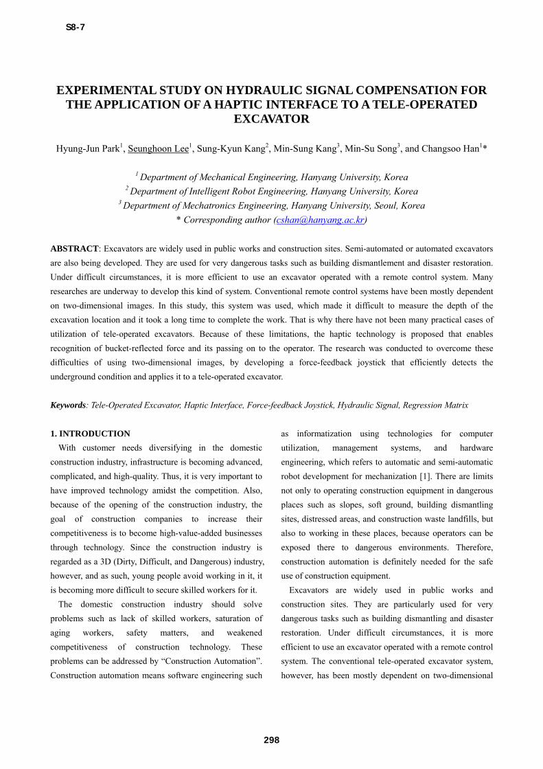
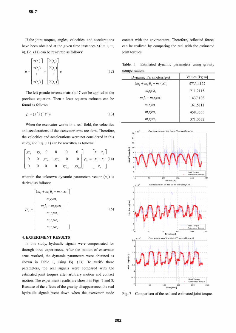
4. EXPERIMENT RESULTS
In this study, hydraulic signals were compensated for
through three experiences. After the motion of excavator
arms worked, the dynamic parameters were obtained as
shown in Table 1, using Eq. (13). To verify these
parameters, the real signals were compared with the
estimated joint torques after arbitrary motion and contact
motion. The experiment results are shown in Figs. 7 and 8.
Because of the effects of the gravity disappearance, the real
hydraulic signals went down when the excavator made
contact with the environment. Therefore, reflected forces
can be realized by comparing the real with the estimated
joint torques.
Table. 1 Estimated dynamic parameters using gravity
compensation.
Dynamic Parameters(ρG) Values [kg∙m]
2 3 1 1 1 1( )m m l m rc 5733.4127
1 1 1m rs 211.2115
3 2 2 2 2m l m r c 1437.103
2 2 2m r s 161.5111
3 3 3m r c 458.3555
3 3 3m r s 371.0572
0 50 100 150 200 250-2
0
2
4
6
8
10
12
14
16x 10
4 Comparison of the Joint Torque(Boom)
Time[sec]
Join
t Torq
ue[N
m]
Real Torque
Estimated Torque
0 50 100 150 200 250-2
-1
0
1
2
3
4
5x 10
4 Comparison of the Joint Torque(Arm)
Time[sec]
Join
t Torq
ue[N
m]
Real Torque
Estimated Torque
0 50 100 150 200 250-2
-1.5
-1
-0.5
0
0.5
1
1.5x 10
4 Comparison of the Joint Torque(Bucket)
Time[sec]
Join
t Torq
ue[N
m]
Real Torque
Estimated Torque
Fig. 7 Comparison of the real and estimated joint torque.
S8-7
302

0 10 20 30 40 50 60 70 800
2
4
6
8
10
12x 10
4 Comparison of the Joint Torque(Boom)
Time[sec]
Join
t Torq
ue[N
m]
Real Torque
Estimated Torque
0 10 20 30 40 50 60 70 80-3
-2
-1
0
1
2
3
4x 10
4 Comparison of the Joint Torque(Arm)
Time[sec]
Join
t Torq
ue[N
m]
Real Torque
Estimated Torque
Fig. 8 Comparison of the real and estimated joint torque
in the contact environment.
5. CONCLUSION
To overcome the problems with existing tele-operated
excavators, a force-feedback joystick that can detect
environmental information was developed, and hydraulic
signals were compensated for using a regression matrix to
realize the reflected forces in this study. The developed
joystick and reflected forces will be applied to an excavator,
and a performance evaluation will be conducted in the
future.
6. ACKNOWLEDGMENT
This research was supported by the MKE (The Ministry
of Knowledge Economy), Korea, under the ‘Advanced
Robot Manipulation Research Center’ support program
supervised by the NIPA (NIPA-2010-C7000-1001-0 002),
and a grant from the CTIP (Construction Technology
Innovation Program) funded by the MLTM (Ministry of
Land, Transportation, and Maritime Affairs of Korea).
REFERENCES
[1] Junbok Lee, Young-Suk Kim, “A Study on Technology
Roadmap for Construction Automation and Robotics”,
Journal of the Architectural Institute of Korea, Vol. 19, No.
5, pp. 95-104, 2003.
[2] Ae-Kyoung Ko, Joon-Young Choi et al., “A Haptic
Interface Using a Force-Feedback Joystick”, Journal of
Control, Automation, and Systems Engineering, Vol. 13,
No. 12, pp. 1207-1212, 2007.
[3] K. U. Kyung et al., “The State of the Art and R&D
Perceptives on Haptics”, Electron Communication Trend
Analysis, Vol. 21, No. 5, pp. 93-108, 2006.
[4] S. Weinstein, “Intensive and Extensive Aspect of
Tactile Sensitivity as a Function of Body Part, Sex, and
Laterality”, The Skin Sense(Editor : D. R. Kenshalo), pp.
195-218, Springfield.
[5] W. C. Lin and K. Y. Young, “Design of Force-
Reflection Joystick System for VR-Based Simulation”,
Journal of Information Science and Engineering, Vol. 23,
pp. 1421-1436, 2007.
[6] Byunghoon Bae, Kyihwan Park et al., “Design and
Control of a Two Degree of Freedom Haptic Device for the
Application of PC Video Games”, International
Conference on Intelligent Robots and Systems, pp. 1738-
1743, 2001.
[7] S. Tafazoli, P. D. Lawrence, and S. E. Salcudean,
“Identification of Inertial and Friction Parameters for
Excavator Arms”, IEEE Transactions on Robotics and
Automation, Vol. 15, No. 5, pp. 966-971, 2001.
[8] P. K. Khosla, “Categorization of Parameters in the
Dynamic Robot Model”, IEEE Transactions on Robotics
and Automation, Vol. 5, No. 3, pp. 261-268, 1989.
S8-7
303