a can system using multiple mcp25050 i/o expanders · dc drive battery pic16f874 ... in table 2....
TRANSCRIPT

M AN816A CAN System Using Multiple MCP25050 I/O Expanders
INTRODUCTIONThe MCP25050 I/O Expander is an effective deviceused in a Controller Area Network (CAN), which oper-ates without the use of a microcontroller. It supportsCAN V2.0B with bit rates up to 1 Mb/s. Since the I/OExpander is a stand-alone device, it can be configuredto user defaults using a software template. Thesedefaults are stored in non-volatile EPROM. A networkprotocol must be chosen that supports a Master Node.The Master Node is required for peer-to-peer commu-nications between I/O Expander Nodes and, therefore,handles communication to and from all I/O ExpanderNodes. For this design, we have chosen the CAN-NETprotocol, which provides a generic framework for com-munication that natively supports I/O Expander Nodes.The CAN-NET framework allows users to develop aproprietary protocol for use by their own products.This application note describes a control system for ascissor-lift, which is essentially a mobile work platformenabling the user to reach relatively high places. Theconcept behind this vehicle is to have versatile maneu-verability along with the ability to control the height. Allof the operations and movements for the scissor-liftuses one Master Node and three I/O Expander Nodes.The nodes are distributed throughout the vehicle andare connected together utilizing the 2-wire CAN inter-face. The master Node consists of a PIC16F874working with an MCP2510 CAN controller.
With the substantial I/O capability of the expanders, allof the scissor-lift control signals are able to seamlesslycommunicate with each other. The MCP25050 hasmany peripherals, such as digital I/O, four 10-bit A/Dchannels and two PWM outputs with up to 10-bits ofresolution. Utilizing the I/O Expanders reduces the sizeof each node, along with having the ability to control alarge system with a few wires, rather than usingcomplex wiring harnesses.
SYSTEM OVERVIEWThe basic block diagram is shown in Figure 1. All of theactuators in the system, including the traction motors,are hydraulically-based. A single DC motor drives ahydraulic pump and electro-hydraulic valves route thefluid to the appropriate actuator. The operator has com-plete control of the system from an operator panellocated on the work platform. A single axis joystick con-trols forward and reverse motion, while left and rightsteering is activated by a thumb-controlled rockerswitch on the top of the joystick. Raising and loweringof the platform is accomplished with UP and DOWNpush buttons. A battery indicator and horn button arealso located on the panel.
Author: Diversified Engineering Inc.Microchip Technology Inc.
2002 Microchip Technology Inc. Preliminary DS00816B-page 1

AN816
FIGURE 1: BASIC BLOCK DIAGRAMThe system uses CAN to bring all of the controlstogether utilizing the CAN bus, shown in Figure 2. TheCAN bus replaces large wiring harnesses and the con-trols are combined into a node. Each node handles theinputs and outputs along with transmitting and receiv-ing information utilizing the bus. The bus consists offour wires: two power wires and two CAN wires. Themaster controller supplies the main power and thenodes accept this power from the bus. Each node isregulated at 5V.
Key
Horn
Down
Up
L R
Forward
Reverse
BatteryDC Drive
Battery
PIC16F874
MCP25050 MCP25050
MCP25050
Steer LeftReverse
Forward
HornDown
Up
Steer Right
+ -
Power ControlOperator Controls on Work Platform
Master Hydraulic Valve Control Near Manifold
MCP2510
DS00816B-page 2 Preliminary 2002 Microchip Technology Inc.

AN816
FIGURE 2: SYSTEM DIAGRAMPIC16F874
LCD DISPLAY
MCP2510
Master Controller Node 0
Power Node #10
Operator Node #11
Valve Node #12
MCP25050
MCP25050
MCP25050
DC Drive, AOKey, DIBattery, AI
Up, DIDown, DI
Battery, AOSteer Left, DISteer Right, DIForward, AIReverse, AI
Steer Left, DOSteer Right, DOUp, DODown, DOHorn, DOForward, DOReverse, DO
LEGEND
AI = Analog InputAO = Analog Output (PWM)DI = Digital InputDO = Digital Output
NODE NAMESNode 0, Master ControllerNode 10, Power Node at BatteryNode 11, Operator NodeNode 12, Valve At Manifold
FUNCTIONS
Up DO Follows Up DIDown DO Follows Down DISteer L DO Follows Steer L DISteer R DO Follows Steer R DIHorn DO Follows Horn DIBattery AO Follows Battery AIKey DO Follows Key DIDC Drive AO Follows Fwd/Rev AIor Runs at 50% with Up or Down
CAN Bus
Horn, DI
2002 Microchip Technology Inc. Preliminary DS00816B-page 3

AN816
POWER NODEThe operation of the Power Node is shown in Table 1.The battery input is reduced from 12V and applied toone of the analog inputs on the MCP25050. The DCDrive is controlled by one of the PWM outputs of theMCP25050. The output signal is a PWM signal, whichis a filtered DC voltage and adjusts the speed input ofthe DC Drive. The forward and reverse movement ofthe joystick determines the duty cycle while the lift ismoving. When one of the up or down buttons aredepressed, the duty cycle will operate at 50%. A key-switch in the base unit is connected to a digital input onthe MCP25050 CAN I/O Expander.TABLE 1: OPERATION OF THE POWER NODE
OPERATOR NODEThe operation of the Operator Control Node is shownin Table 2. The Operator Control Node controls alloperations of the system from the work platform. Theup and down momentary buttons are digital inputs thatcontrol their corresponding hydraulic valves and oper-ate the DC Drive at 50% speed. The joystick has athumb-operated momentary rocker switch for left andright steering. Forward and reverse motion of the lift iscontrolled by two potentiometers in the joystick, whichare connected to two of the analog inputs on theMCP25050. These operations also control their corre-sponding hydraulic valves. The horn is a momentarybutton connected to a digital input and controls the hornrelay. The battery voltage is displayed on an analogpanel meter that is driven from one of the PWM outputson the MCP25050 CAN I/O Expander.
TABLE 2: OPERATION OF THE OPERATOR CONTROL NODE
VALVE NODEThe operation of the Valve Control Node is shown inTable 3. The Valve Control Node controls the hydraulicvalves located at the manifold. All signals come fromdigital outputs on the MCP25050 CAN I/O Expander.
TABLE 3: OPERATION OF THE VALVE CONTROL NODE
HARDWARE OVERVIEWThis reference design was implemented using CAN-NET development boards from Diversified EngineeringInc. The CAN-NET Education board was used for theMaster Control Node and the CAN-NET I/O ExpanderNode was used for all satellite nodes. The CAN-NETI/O Expander Node is a versatile development platformfor the MCP25050. Any combination of inputs and out-puts can be realized by selecting the proper connec-tions on the I/O header. Schematics for these boardsare included in Appendix A.The CAN data rate selected for this system is125 kbps.
CAN-NET GENERAL PURPOSE PROTOCOLGeneral StructureThis application note uses a flexible, general-purposeprotocol structure that is designed to provide a basicframework for development of specialized proprietaryprotocols. The goal is simplicity rather than sophistica-tion. We first present the general structure and thencustomize it to the reference design problem.
The general structure of the 29-bit Extended MessageIdentifier is divided into two types of messages: Broad-cast and Directed. Broadcast messages have no spe-cific destination. Directed messages are sent with oneor more specific destinations. Most of the fields of themessage identifier are the same for both messagetypes.The general structure is designed for systems with amaximum of 128 nodes, with each node having aunique address. This restriction can be made flexibleby rearranging the number of bits allocated to eachfield or by adjusting the meaning of the Source andDest/Subclass fields.
Operation Type Direction Pin Description
Battery Analog Input AN0Key Digital Input GP1DC Drive PWM Output PWM1
Operation Type Direction Pin Description
Forward Analog Input AN0Reverse Analog Input AN1Battery PWM Output PWM1Horn Digital Input GP3Steer Left Digital Input GP4Steer Right Digital Input GP5Up Digital Input GP6Down Digital Input GP7
Operation Type Direction Pin Description
Up Digital Output GP0Down Digital Output GP1Horn Digital Output GP2Steer Left Digital Output GP3Steer Right Digital Output GP4Forward Digital Output GP5Reverse Digital Output GP6
DS00816B-page 4 Preliminary 2002 Microchip Technology Inc.

AN816
FIGURE 3: I/O PROTOCOLThe message identifier is structured into six fields, asshown in the following table. These fields are mappedonto the 29-Bit message ID in the Microchip parts
through the use of four one-byte registers. This map-ping is common for the MCP2510 parts and the I/OExpander parts.
TABLE 4: MESSAGE IDENTIFIERS
Priority - The Priority bits are the upper three bits in theidentifier and are used to resolve priority conflicts if twonodes want to transmit at the same time. A ‘0’ has pri-ority over a ‘1’.
Class - The Class categorizes the type of informationcarried by the message. Eight bits support 256 classes,or types, of information. As will be discussed further,Broadcast type messages have a Subclass field thatfurther expands the number of categories supported.Broadcast - The Broadcast bit is a flag that identifiesthe message as a Directed message (0) or as aBroadcast message (1).
Dest/Subclass - The Dest/Subclass field is a seven-bitfield. Its definition depends on the preceding Broadcastflag.
If the message is a Directed message, then this is aDestination field and contains the address of the nodeor nodes to which the message is directed. A maximumof 128 node addresses is allowed.
If the message is a Broadcast message, then this is aSubclass field that further categorizes the Class ofinformation carried by the message. The meaning ofthe Subclass field depends on the specific Class.
Source - The Source field identifies the node that pro-duced the message. A maximum of 128 nodeaddresses are allowed.
CMD - This three-bit field is set aside as an additionalextension to the Class field to further identify the con-tents of the message. It is suggested that it be used todistinguish between multiple message types containedwithin the same node. This is how the I/O Expanderdevices use it and it is the only part of the message IDthat is hardware determined (in the case of I/OExpander devices) and not adjustable by the user.
SOF
Identifier11 Bits
SRR
IDE
Identifier Extension18 Bits
RTRPriority Class B Dest/Subclass Source Address CMD
3 2 1 8 7 6 5 4 3 2 1 7 6 5 4 3 2 1 7 6 5 4 3 2 1 3 2 1
CAN-NET Frame Format
1 2 3 4 5 6 7 8 9 10 11 12 13 14 15 16 17 18 19 20 21 22 23 24 25 26 27 28 29 30 31 32 33
Frame Bit Position
28 27 26 25 24 23 22 21 20 19 18 17 16 15 14 13 12 11 10 9 8 7 6 5 4 3 2 1 0
29-Bit ID Position
SIDH SIDL EID8 EID0
7 6 5 4 3 2 1 0 7 6 5 3 1 0 7 6 5 4 3 2 1 0 7 6 5 4 3 2 1 0
Field Name # ofBits Description
Priority 3 Priority: a 0 has priority over a 1.Class 8 Type of information.Broadcast 1 0=Directed, 1=Broadcast.Destination/Subclass 7 Destination or Class dependent modifier. Source Address 7 Source addressCMD 3 Reserved for hardware restrictions of node
2002 Microchip Technology Inc. Preliminary DS00816B-page 5

AN816
CAN-NET PROTOCOL IMPLEMENTATION FOR REFERENCE DESIGNClass DefinitionThe CAN communication for the reference design con-sists only of messages being exchanged between theController Board and I/O Expander nodes (i.e., I/OExpanders cannot generate messages that can bedecoded by other I/O Expanders).TABLE 5: CLASS DEFINITIONS
All of the classes have associated data that is format-ted in a specific manner that is fixed for an I/OExpander. Detailed information is available in theMCP2502X/5X CANI/O Expander (DS21664) DataSheet.
Class 1These messages are generated by the I/O Expanderfor consumption by the Controller board.The associated data is an eight-byte data group thatcontains all the measured data values measured by theMCP25050:
• The eight bits of IOINTFL indicate which inputs have changed since the last message.
• The eight bits of GPIO give the state of each of the inputs.
• The four bytes, AN0H, AN1H, AN2H, AN3H, give the upper eight bits of the 10-bit A/D measurement from each activated A/D input.
• The two bytes, AN10L and AN32L, give the lower two bits of the 10-bit A/D measurement from each activated A/D input. The bits are left-justified in the four nibbles that make up the two bytes as follows:- AN10L = (AN1:1,AN1:0,0,0 AN0:1,AN0:0,0,0)- AN32L = (AN3:1, AN3:0,0,0, AN2:1,AN2:0,0,0)
Class 2 and 3These messages are generated by the Controllerboard for use by the MCP25050 devices.The data group used by these classes is the "WriteRegister" command of the MCP25050 devices, whichallows the writing of a data value directly into a registerof the MCP2505X. In Class 2, the PWM registers areaddressed and, in Class 3, the GPLAT register sets thedigital output levels.
Node AddressesEach node in the system is assigned a unique nodeaddress for use in the Source and Dest/Subclass fields.
TABLE 6: NODE ADDRESSES
TABLE 7: MASTER CONTROLLER NODE
TABLE 8: POWER NODE
Class Description
1 CAN I/O Expander data packet contain-ing GPIO digital inputs and A/D values
2 CAN I/O Expander PWM output values3 CAN I/O Expander Digital outputs4 All other CAN I/O Expander messages
(ignored by Master Controller)
Number of Bits Bit Name
8 bits IOINTFL8 bits GPIO
4 bytes AN0H4 bytes AN1H2 bytes AN10L4 bytes AN2H4 bytes AN3H2 bytes AN23L
Address Node
0 Master Controller Node10 Power Node11 Operator Control Node12 Valve Control Node
Address ‘0’Direction
Send Receive
Priority 0 0
Class 2 or 3 1
Broadcast No YesDest/Subclass 10,11,12 0
Source 0 10,11,12
CMD 0 0
Address ‘10’Direction
Send Receive
Priority 0 0
Class 1,4 2,3
Broadcast Yes NoDest/Subclass 0 10
Source 10 0
CMD 0 0
DS00816B-page 6 Preliminary 2002 Microchip Technology Inc.

AN816
TABLE 9: OPERATOR CONTROL NODETABLE 10: VALVE CONTROL NODE
SOFTWARE OVERVIEWConfiguring the MCP25050 devices consists of provid-ing arguments to a set of macros that generate a datatable for MASM. In this sense, I/O Expander devicesare configured rather than programmed.
The Controller board is programmed in the normalfashion, but the specific details of the programming arenot particularly important for the reference design sincethe primary purpose of the Controller board is toreceive messages from the I/O Expanders andrepackage the data to be sent to the other I/OExpanders.
I/O EXPANDER CONFIGURATIONFor I/O Expander configurations that are static (i.e., theconfiguration is not changed dynamically over the net-work) the important configuration parameters fall intotwo categories: network related items and I/Ofunctions.Choosing network values other than the message ID'sconsist primarily in calculating the networking parame-ters determined by clock frequency and other physicalcharacteristics of the network. The message ID's fortransmitting and receiving messages are determinedby the network protocol selected. For the referencedesign, the message ID selection is described in detailabove.
The MCP25050 can be configured to perform up toeight I/O functions. There are eight digital inputs, sevendigital outputs, four 10-bit A/D channels and two PWMoutputs with up to 10-bits of resolution. Available with
each of the I/O types are associated support functions,such as message transmission triggered by a changein input. Scheduled message transmission can be usedin addition to on-change messaging to insure the net-work is routinely informed of the current state of theinputs, even if none of them have changed. A combina-tion of scheduled and on-change messages is often thebest solution to routine updates with rapid response tochange.The data selections for this application note are in thefollowing files:
TABLE 11: DATA SELECTIONS
CONTROLLER BOARD SOFTWAREThe Controller board software is written to operate onthe Diversified Engineering CAN-NET EducationBoard. The code for the CAN-NET board is written inthe PIC® instruction set to be assembled usingMicrochip's MPLAB® environment. There is significantuse of macros to make the code more readable andless error prone. In addition to the macros defined atthe top of the individual files, a large number of macroscan be found in the MACROS16.INC file. If you comeacross an unfamiliar instruction when reading the code,it probably is a macro. Macros are in MACROS16.INCand used extensively in writing code for PICmicro®
microcontrollers and have increased readability andgreatly reduce programming errors.To simplify the source code, the code that handles theLCD display and keypad input was removed. Whatremains is the initialization code that sets up the portsand initializes the MCP2510 CAN controller, in additionto a main loop that checks for CAN messages from theI/O Expander nodes and sends messages to thenodes.
The technique used by the program is to maintain alocal set of variables that fully represent the state of thesystem. The variables are updated by messagesreceived from the I/O Expander nodes, with the newvalues being sent to the appropriate I/O Expanders.
Address ‘11’Direction
Send Receive
Priority 0 0Class 1,4 2,3Broadcast Yes NoDest/Subclass 0 11Source 11 0CMD 0 0
Address ‘12’Direction
Send Receive
Priority 0 0
Class 1,4 2,3
Broadcast Yes NoDest/Subclass 0 12
Source 12 0
CMD 0 0
File Description
OPERNODE.ASM Operator BoardMAINNODE.ASM Main BoardVALVNODE.ASM Hydraulic Valve Board
2002 Microchip Technology Inc. Preliminary DS00816B-page 7
AN816
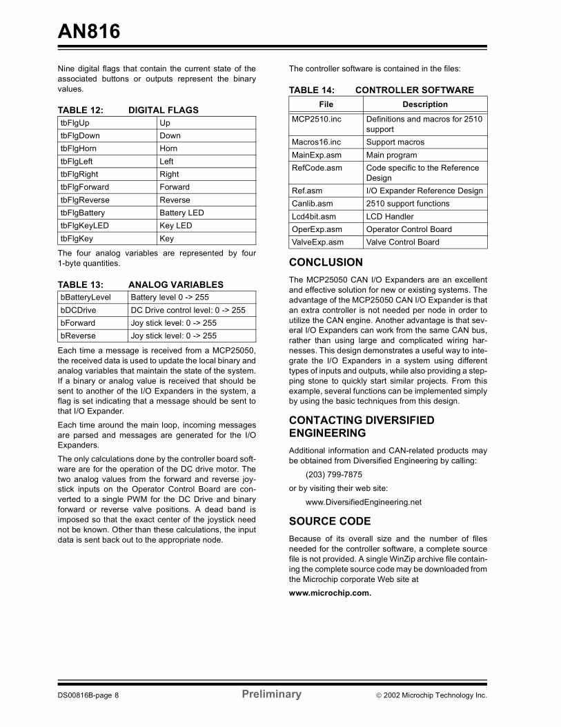
Nine digital flags that contain the current state of theassociated buttons or outputs represent the binaryvalues.TABLE 12: DIGITAL FLAGS
The four analog variables are represented by four1-byte quantities.
TABLE 13: ANALOG VARIABLES
Each time a message is received from a MCP25050,the received data is used to update the local binary andanalog variables that maintain the state of the system.If a binary or analog value is received that should besent to another of the I/O Expanders in the system, aflag is set indicating that a message should be sent tothat I/O Expander.
Each time around the main loop, incoming messagesare parsed and messages are generated for the I/OExpanders.
The only calculations done by the controller board soft-ware are for the operation of the DC drive motor. Thetwo analog values from the forward and reverse joy-stick inputs on the Operator Control Board are con-verted to a single PWM for the DC Drive and binaryforward or reverse valve positions. A dead band isimposed so that the exact center of the joystick neednot be known. Other than these calculations, the inputdata is sent back out to the appropriate node.
The controller software is contained in the files:
TABLE 14: CONTROLLER SOFTWARE
CONCLUSIONThe MCP25050 CAN I/O Expanders are an excellentand effective solution for new or existing systems. Theadvantage of the MCP25050 CAN I/O Expander is thatan extra controller is not needed per node in order toutilize the CAN engine. Another advantage is that sev-eral I/O Expanders can work from the same CAN bus,rather than using large and complicated wiring har-nesses. This design demonstrates a useful way to inte-grate the I/O Expanders in a system using differenttypes of inputs and outputs, while also providing a step-ping stone to quickly start similar projects. From thisexample, several functions can be implemented simplyby using the basic techniques from this design.
CONTACTING DIVERSIFIED ENGINEERINGAdditional information and CAN-related products maybe obtained from Diversified Engineering by calling:
(203) 799-7875or by visiting their web site:
www.DiversifiedEngineering.net
SOURCE CODEBecause of its overall size and the number of filesneeded for the controller software, a complete sourcefile is not provided. A single WinZip archive file contain-ing the complete source code may be downloaded fromthe Microchip corporate Web site atwww.microchip.com.
tbFlgUp UptbFlgDown DowntbFlgHorn HorntbFlgLeft LefttbFlgRight RighttbFlgForward ForwardtbFlgReverse ReversetbFlgBattery Battery LEDtbFlgKeyLED Key LEDtbFlgKey Key
bBatteryLevel Battery level 0 -> 255bDCDrive DC Drive control level: 0 -> 255bForward Joy stick level: 0 -> 255bReverse Joy stick level: 0 -> 255
File Description
MCP2510.inc Definitions and macros for 2510 support
Macros16.inc Support macrosMainExp.asm Main programRefCode.asm Code specific to the Reference
DesignRef.asm I/O Expander Reference DesignCanlib.asm 2510 support functionsLcd4bit.asm LCD HandlerOperExp.asm Operator Control BoardValveExp.asm Valve Control Board
DS00816B-page 8 Preliminary 2002 Microchip Technology Inc.

AN816
APPENDIX A: CAN-NET BOARD SCHEMATICSFIGURE A-1: MAIN CAN-NET BOARD SCHEMATIC
MCP2551
2002 Microchip Technology Inc. Preliminary DS00816B-page 9

AN816
FIGURE A-2: CAN I/O EXPANDER SCHEMATIC (1 OF 2)MCP2551
DS00816B-page 10 Preliminary 2002 Microchip Technology Inc.

AN816
FIGURE A-3: CAN I/O EXPANDER SCHEMATIC (2 OF 2)2002 Microchip Technology Inc. Preliminary DS00816B-page 11

AN816
NOTES:DS00816B-page 12 Preliminary 2002 Microchip Technology Inc.

Information contained in this publication regarding deviceapplications and the like is intended through suggestion onlyand may be superseded by updates. It is your responsibility toensure that your application meets with your specifications.No representation or warranty is given and no liability isassumed by Microchip Technology Incorporated with respectto the accuracy or use of such information, or infringement ofpatents or other intellectual property rights arising from suchuse or otherwise. Use of Microchip’s products as critical com-ponents in life support systems is not authorized except withexpress written approval by Microchip. No licenses are con-veyed, implicitly or otherwise, under any intellectual propertyrights.
2002 Microchip Technology Inc.
Trademarks
The Microchip name and logo, the Microchip logo, KEELOQ,MPLAB, PIC, PICmicro, PICSTART and PRO MATE areregistered trademarks of Microchip Technology Incorporatedin the U.S.A. and other countries.
FilterLab, microID, MXDEV, MXLAB, PICMASTER, SEEVALand The Embedded Control Solutions Company areregistered trademarks of Microchip Technology Incorporatedin the U.S.A.
dsPIC, dsPICDEM.net, ECONOMONITOR, FanSense,FlexROM, fuzzyLAB, In-Circuit Serial Programming, ICSP,ICEPIC, microPort, Migratable Memory, MPASM, MPLIB,MPLINK, MPSIM, PICC, PICDEM, PICDEM.net, rfPIC, SelectMode and Total Endurance are trademarks of MicrochipTechnology Incorporated in the U.S.A. and other countries.
Serialized Quick Turn Programming (SQTP) is a service markof Microchip Technology Incorporated in the U.S.A.
All other trademarks mentioned herein are property of theirrespective companies.
© 2002, Microchip Technology Incorporated, Printed in theU.S.A., All Rights Reserved.
Printed on recycled paper.
DS00816B - page 13
Microchip received QS-9000 quality system certification for its worldwide headquarters, design and wafer fabrication facilities in Chandler and Tempe, Arizona in July 1999 and Mountain View, California in March 2002. The Company’s quality system processes and procedures are QS-9000 compliant for its PICmicro® 8-bit MCUs, KEELOQ® code hopping devices, Serial EEPROMs, microperipherals, non-volatile memory and analog products. In addition, Microchip’s quality system for the design and manufacture of development systems is ISO 9001 certified.

DS00816B-page 14 2002 Microchip Technology Inc.
MAMERICASCorporate Office2355 West Chandler Blvd.Chandler, AZ 85224-6199Tel: 480-792-7200 Fax: 480-792-7277Technical Support: 480-792-7627Web Address: http://www.microchip.comRocky Mountain2355 West Chandler Blvd.Chandler, AZ 85224-6199Tel: 480-792-7966 Fax: 480-792-4338Atlanta500 Sugar Mill Road, Suite 200BAtlanta, GA 30350Tel: 770-640-0034 Fax: 770-640-0307Boston2 Lan Drive, Suite 120Westford, MA 01886Tel: 978-692-3848 Fax: 978-692-3821Chicago333 Pierce Road, Suite 180Itasca, IL 60143Tel: 630-285-0071 Fax: 630-285-0075Dallas4570 Westgrove Drive, Suite 160Addison, TX 75001Tel: 972-818-7423 Fax: 972-818-2924DetroitTri-Atria Office Building 32255 Northwestern Highway, Suite 190Farmington Hills, MI 48334Tel: 248-538-2250 Fax: 248-538-2260Kokomo2767 S. Albright Road Kokomo, Indiana 46902Tel: 765-864-8360 Fax: 765-864-8387Los Angeles18201 Von Karman, Suite 1090Irvine, CA 92612Tel: 949-263-1888 Fax: 949-263-1338San JoseMicrochip Technology Inc.2107 North First Street, Suite 590San Jose, CA 95131Tel: 408-436-7950 Fax: 408-436-7955Toronto6285 Northam Drive, Suite 108Mississauga, Ontario L4V 1X5, CanadaTel: 905-673-0699 Fax: 905-673-6509
ASIA/PACIFICAustraliaMicrochip Technology Australia Pty LtdSuite 22, 41 Rawson StreetEpping 2121, NSWAustraliaTel: 61-2-9868-6733 Fax: 61-2-9868-6755China - BeijingMicrochip Technology Consulting (Shanghai)Co., Ltd., Beijing Liaison OfficeUnit 915Bei Hai Wan Tai Bldg.No. 6 Chaoyangmen Beidajie Beijing, 100027, No. ChinaTel: 86-10-85282100 Fax: 86-10-85282104China - ChengduMicrochip Technology Consulting (Shanghai)Co., Ltd., Chengdu Liaison OfficeRm. 2401, 24th Floor, Ming Xing Financial TowerNo. 88 TIDU StreetChengdu 610016, ChinaTel: 86-28-86766200 Fax: 86-28-86766599China - FuzhouMicrochip Technology Consulting (Shanghai)Co., Ltd., Fuzhou Liaison OfficeUnit 28F, World Trade PlazaNo. 71 Wusi RoadFuzhou 350001, ChinaTel: 86-591-7503506 Fax: 86-591-7503521China - ShanghaiMicrochip Technology Consulting (Shanghai)Co., Ltd.Room 701, Bldg. BFar East International PlazaNo. 317 Xian Xia RoadShanghai, 200051Tel: 86-21-6275-5700 Fax: 86-21-6275-5060China - ShenzhenMicrochip Technology Consulting (Shanghai)Co., Ltd., Shenzhen Liaison OfficeRm. 1315, 13/F, Shenzhen Kerry Centre,Renminnan LuShenzhen 518001, ChinaTel: 86-755-82350361 Fax: 86-755-82366086China - Hong Kong SARMicrochip Technology Hongkong Ltd.Unit 901-6, Tower 2, Metroplaza223 Hing Fong RoadKwai Fong, N.T., Hong KongTel: 852-2401-1200 Fax: 852-2401-3431IndiaMicrochip Technology Inc.India Liaison OfficeDivyasree Chambers1 Floor, Wing A (A3/A4)No. 11, O’Shaugnessey RoadBangalore, 560 025, IndiaTel: 91-80-2290061 Fax: 91-80-2290062
JapanMicrochip Technology Japan K.K.Benex S-1 6F3-18-20, ShinyokohamaKohoku-Ku, Yokohama-shiKanagawa, 222-0033, JapanTel: 81-45-471- 6166 Fax: 81-45-471-6122KoreaMicrochip Technology Korea168-1, Youngbo Bldg. 3 FloorSamsung-Dong, Kangnam-KuSeoul, Korea 135-882Tel: 82-2-554-7200 Fax: 82-2-558-5934SingaporeMicrochip Technology Singapore Pte Ltd.200 Middle Road#07-02 Prime CentreSingapore, 188980Tel: 65-6334-8870 Fax: 65-6334-8850TaiwanMicrochip Technology (Barbados) Inc., Taiwan Branch11F-3, No. 207Tung Hua North RoadTaipei, 105, TaiwanTel: 886-2-2717-7175 Fax: 886-2-2545-0139
EUROPEAustriaMicrochip Technology Austria GmbHDurisolstrasse 2A-4600 WelsAustriaTel: 43-7242-2244-399Fax: 43-7242-2244-393DenmarkMicrochip Technology Nordic ApSRegus Business CentreLautrup hoj 1-3Ballerup DK-2750 DenmarkTel: 45 4420 9895 Fax: 45 4420 9910FranceMicrochip Technology SARLParc d’Activite du Moulin de Massy43 Rue du Saule TrapuBatiment A - ler Etage91300 Massy, FranceTel: 33-1-69-53-63-20 Fax: 33-1-69-30-90-79GermanyMicrochip Technology GmbHSteinheilstrasse 10D-85737 Ismaning, GermanyTel: 49-89-627-144 0 Fax: 49-89-627-144-44ItalyMicrochip Technology SRLCentro Direzionale Colleoni Palazzo Taurus 1 V. Le Colleoni 120041 Agrate BrianzaMilan, Italy Tel: 39-039-65791-1 Fax: 39-039-6899883United KingdomMicrochip Ltd.505 Eskdale RoadWinnersh TriangleWokingham Berkshire, England RG41 5TUTel: 44 118 921 5869 Fax: 44-118 921-5820
10/18/02
WORLDWIDE SALES AND SERVICE