experimental study of temperature rise of concrete and ... · pdf filerespect of thermal...
TRANSCRIPT

INTERNATIONAL JOURNAL OF CIVIL AND STRUCTURAL ENGINEERING
Volume 4, No 3, 2014
© Copyright by the authors - Licensee IPA- Under Creative Commons license 3.0
Research article ISSN 0976 – 4399
Received on September, 2013 Published on February 2014 353
Experimental study of temperature rise of concrete and assessment of
cracking due to internal restraint Tayade. K.C1, Deshpande. N.V2, Pofale. A.D3
1- Doctoral research Student, Rastrasant Tukadoji Maharaj Nagpur University, Nagpur.
2- Guide, Principal Gurunanak Institute of Engineering and Technology, Nagpur.
3- Co-Guide, Professor, Civil engineering department, Visvesvaraya National Institute of
Technology, Nagpur
doi: 10.6088/ijcser.201304010034
ABSTRACT
Experimental study was carried out on a prototype structure to investigate the temperature
rise characteristics of the concrete used. Two thermocouples each in 2 layers at four similar
locations, totaling 16 numbers were embedded during the concreting of said structure to
assess the characteristics of the temperature rise and temperature difference at peak in the
concrete. The cement used was OPC in first layer and was replaced by PPC in other layer to
find out the effect on the temperature rise and the temperature difference at peak. The study
revealed that the temperature rise in concrete with PPC was much less than where OPC was
used. The derived temperature rise equations with strong R2 values could be used to predict
the early age temperature rise in structures with similar geometry, weather conditions, curing
and form removal.
Another purpose of this study is to know the probability of cracking based on the existing
cracking assessment based on Korean methods as Indian specifications are non-existent and
also to find the crack index for internally restraint cases both the elastic; hypoelastic models.
The study indicated that the existing provisions based on crack index appear to be very
conservative which tend to overestimate the probability of crack occurrence compared with
construction observations on prototype structures.
Keywords: Heat of hydration, temperature gradient, crack, delayed ettringite formation,
crack index, internal restraint.
1. Introduction
In the massive concrete structures, like concrete Dams temperature gradients are produced
when the heat generated in the concrete is dissipated to the surrounding environment causing
temperature at the surface of the concrete to be lower from the temperature at the interior of
the concrete. With the interior of the concrete being more mature than the surface, it acts as
restraint against the contraction creating tensile stresses in concrete. Since the concrete is still
in its early age, its full tensile strength is not developed and if the tensile stresses are larger
than the early age tensile strength, cracking will occur, which would ultimately affect the
integrity of concrete and undermine durability.
To avoid concrete surface cracking caused by heat generated in the concrete, European
standard ENV 206, 1992 suggests that the limit on the maximum temperature difference
between the centre and the surface is 200 C (360 F).The exact magnitude of temperature
gradient depends on a number of factors, including the initial concrete temperatures, the

Experimental study of temperature rise of concrete and assessment of cracking due to internal restraint
Tayade. K.C, Deshpande. N.V, Pofale. A.D
International Journal of Civil and Structural Engineering
Volume 4 Issue 3 2014 354
ambient temperature around the structure and the thermal properties of concrete itself. A
number of early-age concrete properties affect the thermal attributes of concrete, including
heat development, specific heat, thermal conductivity, thermal diffusivity, coefficient of
thermal expansion, emissivity, resultant strain gradients, temperature gradients, and the
chemistry of cement paste. The temperature profile of concrete element is further affected by
external factors such as environmental temperatures, wind speed, humidity etc. Use of
supplementary cementitious materials can dramatically reduce the amount of heat generated.
ACI 116.R, 2005 Manual of Concrete Practice defines Mass Concrete as “any volume of
concrete with dimensions large enough to require that measures be taken to cope with the
generation of heat from the hydration of cement and attendant volume change to minimize
cracking. Common thought is that mass concrete principles only apply to large dams, but they
apply to any large pour such as massive foundation, bridge piers, thick slabs, thick columns,
retaining walls etc. As per ACI 301.R, 2005, “Specifications for Structural Concrete” in
general, heat generation should be considered when minimum cross sectional dimensions
approaches or exceeds 760 mm or when cement contents above 356 Kg/m3 are used.
Like thermal induced cracking another effect of high temperatures in concrete is delayed
ettringite formation (DEF).Under high temperatures, the ettringite is destroyed and its
component sulfate and aluminate absorbed by the calcium-silicate-hydrate (C-S-H) in the
hydrated cement paste. After cooling, the sulfate is released and again becomes available to
form ettringite. Ettringite is an especially crystalline compound with a high aspect ratio that
can form long needle like crystals. Once nucleation has occurred ettringite crystals tend to
grow lengthwise and even when the tips of the crystal encounter solid material the growth
continues, resulting in high localized stresses that lead to expansion and cracking of hydrated
cement paste matrix. To avoid DEF in mass concrete, it is necessary to prevent the
temperature rise in the concrete from exceeding the threshold value at which ettringite
nucleation occurs. The exact temperature required for the formation of DEF is extensively
debated; but the majority of available research reports 700C (1580F) as the minimum
temperature necessary for the formation of DEF (Lawrence, 1998; Taylor, 1997; Gajda,
2007; Drimalas, 2004). However, there are specific conditions necessary for the initiation of
DEF. Even in the presence of high temperatures it only occurs within cements with large
amounts of sulfur trioxide (SO3), alkalies or magnesium oxide (Mgo) and in the presence of
moisture.
DEF is a form of internal sulfate attack which is a result of high heat of hydration coupled
with sulfates in the cement paste and a relatively high C3A content of the cement (Ghorab,
2002).
However, the literature shows that the factors most relevant to cracking in massive structures
are thermal stresses induced by thermal gradients. The components which are most likely to
contribute to large thermal gradients in mass concrete structures are
1. High internal heats of hydration caused by the concrete mix design
2. Mix designs which utilize too much cementitious material
3. The use of cement with high heats of hydration.
1.1 Research significance

Experimental study of temperature rise of concrete and assessment of cracking due to internal restraint
Tayade. K.C, Deshpande. N.V, Pofale. A.D
International Journal of Civil and Structural Engineering
Volume 4 Issue 3 2014 355
A large amount of research has been carried out aimed at controlling and minimizing early
age cracks in concrete. The heat of hydration of concrete has been one of the most important
issues investigated. There are many criteria for assessment of the hydration heat induced
cracks. Some provisions adopt temperature based assessment as well as stress based
assessment. Temperatures can be readily assessed by field measurements as well as analysis
and the reliability of temperature measurement is significantly higher than that of stress
measurements. Consequently, temperature based assessment has been frequently employed in
practice to approximately decide the probability of occurrence of cracks based on the
temperature difference. The purpose of this study is to know the probability of cracking based
on the existing cracking assessment based on Korean methods and also on the crack index for
internally restraint cases both the elastic; hypoelastic models and practical consideration
developed by Jeon, 2008 and reported in ACI materials journal .
The temperatures recorded are the temperatures wherein the effects of exothermic reaction of
hydration of cement and all the atmospheric effects such as radiation; convection, conduction
so also the thermal properties of concrete have played their role and resultant is the
temperatures actually measured. Hence, this study can be used to compare and validate the
results of thermal analysis and modeling that can predict the temperature distribution and the
thermal stresses resulting from thermal gradients within the structure.
1.2 Literature review
ACI Committee 207.1R, 2005 and RILEM Tech. Committee 219 give useful guidance in
respect of thermal control plan and cracking in mass concrete.
ACI Committee 224.R, 2001contains recommendations regarding crack control in mass
concrete.
As per Mehta and Monterio, 1999, temperature differential induced tensile stresses cause
concrete cracks when they exceed the inherent tensile strength of concrete.
Panarese, 2003 postulated that when dimensions of concrete structures are more than 1 m,
temperature rise shall be considered.
Kelly has stated that cement hydration is a very exothermic process, leading to rise in
temperatures at the core of very large pours.
Gajda, 2003 has mentioned that most codes state a temperature differential of less than 200 C
(360 F) from surface to the core of the section.
European standard ENV 206, 1992 specify a temperature gradient less than 200 C.
Neville, 1996 states that cracking will occur when the temperature differential exceeds 200 C
between interior and exterior portion of concrete i.e. surface to the core of the section.
Use of cements high in tri calcium silicate (C3S) and/or tri calcium aluminates (C3A) will
lead to large temperature differentials as these compounds are responsible for the majority of
early heat development. It can also be intensified by cements with higher fineness, resulting
in faster reaction due to increased surface area (Price, 1974; Poole, 2004; Neville, 1996;
Larsen, 1991; Higginson, 1970).
1.3 Review of provisions regarding cracking assessment

Experimental study of temperature rise of concrete and assessment of cracking due to internal restraint
Tayade. K.C, Deshpande. N.V, Pofale. A.D
International Journal of Civil and Structural Engineering
Volume 4 Issue 3 2014 356
In the US the ACI guides ACI 207.2R, 2007 and ACI 305.R do not provide any specific
criteria for cracking induced by the heat of hydration.
In Europe CEB–FIB Model Code, 1993 and Lykke S. et al, 2000 gave crack risk criteria and
various temperature difference criteria have been employed together in some large projects
such as Oresund tunnel.
Standard specification as per Korea Concrete Institute, 2003 and Japan Concrete Institute,
1986 adopt the crack index based on the splitting tensile strength of concrete and the tensile
strength all of which are time dependant and can be obtained by thermal stress analysis. The
Korean specifications as per Korea Concrete Institute, 2003 however present simplified form
of crack index as a function of temperature and for internally restrained case given by the
equation,
Icr = 15 -- equation (1)
∆Ti
Where ∆Ti = maximum temperature difference across the section o C
Based on crack index, the crack probability relationship is as shown in Figure 1; which can
be used to assess the cracking index and cracking criteria as shown in Figure 2.
Probability of cracking as function of crack index
0
10
20
30
40
50
60
70
80
90
100
0 0.5 1 1.5 2Crack Index Icr
Pro
ba
bil
ity
of
cra
ck o
ccu
ran
ce %
Figure 1: Crack probability relationship Figure 2: Cracking Criteria
The temperature difference across the section is the primary information required for the
evaluation of the tendency of crack to form induced by the internal restraint. equation (1)
As derived and reported by Jeon,S.J. in ACI materials Journal, 2008 the crack index for
internally restraint cases for elastic model is given by the equation,
Icr(e) = 15.4 / ∆Ti - - equation (2)
and this equation is valid near the peak temperatures when the maximum temperature
difference occurs within 3 days after placing. Since elastic crack index depends only on the
maximum temperature difference only and does not take into account the development of
heat hydration, the member size, curing conditions, the form removal, the hardening
properties of concrete etc. a hypoelastic model is also developed by Jeon, 2008 and is given
by the equation,
The following criteria could be specified:
Criteria Icr Value
to prevent cracks Icr > 1.5
to limit cracks 1.2 > Icr < 1.5
to limit harmful cracks 0.7 > Icr < 1.2

Experimental study of temperature rise of concrete and assessment of cracking due to internal restraint
Tayade. K.C, Deshpande. N.V, Pofale. A.D
International Journal of Civil and Structural Engineering
Volume 4 Issue 3 2014 357
Icr(h) = 25 / ∆Ti -- equation (3)
2. The experimental program and scheme of study
The experimental program in the study was to measure and monitor the temperature rise in
concrete prototype structure. The temperature measurements was done by inserting an array
of thermo couples at different locations and levels.. The thermo couples used were PT100.
The positions of thermo couples is as shown in Figure 3.
The structure geometry and the four locations of thermo couples are as per Figure 3 & 4
respectively.
Figure 3: C/s of Retaining wall Figure 4: Location Plan
The Figure 5 shows the actual photo of structure with the projected locations of thermo
couples and also the photograph of the thermo couples being embedded in concrete.
Figure 5: Actual photo of structure with the projected locations
The scheme of study is to insert the thermo couples at four locations in structure namely
location 1 to location 4. All the locations the structure is having same geometry and cross-
section. At a particular location, in cross section total four thermo couples are embedded two
in each layer. In the first layer (Bottom layer) OPC was used and two thermo couples in the
middle of layer at positions namely (B) and (C) were inserted. In the second layer which was
laid above the first layer, PPC was used and again two thermo couples in the middle of layer
at positions namely (D) & (E) were inserted. The thickness of each layer was 1.00 m. All the
thermo couples were inserted 0.80m from face of concrete inside the concrete structure, so
that the effect of surface cooling is minimized. The thermo couple designated as (A) was used
to measure the ambient temperature and was kept outside the structure. There was a gap of
about 8 days between the first and second layer concreting. The scheme of study was as per
Table 1 below

Experimental study of temperature rise of concrete and assessment of cracking due to internal restraint
Tayade. K.C, Deshpande. N.V, Pofale. A.D
International Journal of Civil and Structural Engineering
Volume 4 Issue 3 2014 358
Table 1: Table showing the scheme of study
Total locations – I, II, III, IV
At each of the locations
Layer Thickness Cement Thermocouples( Tc) inserted
First 1.00m OPC (B) & (C) in middle of layer
Second 1.00m PPC (D) & (E) in middle of layer
The formwork used was of steel shuttering and it was removed after 3 days.
The test results for cements are as per Table 2.
Table 2: Table showing the test results for cements
Property OPC PPC
Type OPC 43 Grade PPC PPC
W-M-Y 38-09-10 41-10-10 42-10-10
Fineness(cm2/gm) 2790 -- 3405
Normal consistency(%) 30.0 31.0 31.5
Soundness(Autoclave) 0.025 0.018 0.038
Setting time
Initial
Final
175
285
200
315
120
395
Strength
3days
7days
28days
247
345
439
208
254
358
168
232
390
The mix proportion for the concrete Grade M-15(40MSA) adopted was as per Table 3.
Table 3: Table showing the mix proportion for the concrete Grade M-15(40MSA)
Cement ( Kg.) Water ( Kg.) Sand ( Kg.) Coarse aggregate( Kg.) Plasticiser (ml)
40mm 20mm 10mm
298 168 655 545 408 408 1200
The F.M. of sand was 2.72, which is categorized as Zone-II sand as per IS 383. The
monitoring of temperature recorded by thermocouples was done by digital recorder manually
on hourly basis up to 7 days and then once in 2 hrs up to 14 days and then increased to 3 hrs
up to 28 days. The graphs (Figure 8 to Figure 11) below represents the plots of time vs.
temperatures actually recorded for some thermo couples.
Figure 8: Graph-1 Figure 9: Graph -2

Experimental study of temperature rise of concrete and assessment of cracking due to internal restraint
Tayade. K.C, Deshpande. N.V, Pofale. A.D
International Journal of Civil and Structural Engineering
Volume 4 Issue 3 2014 359
Figure 10: Graph -3 Figure 11: Graph -4
The derived equations for the time–temperature record as shown in graphs above, are as
tabulated in Tables 4 and 5.
Table 4: Table showing the derived equations for different locations of Thermo couples for
28 Days (672 hrs) and 0 to 36 hrs. in Concrete layer with OPC.
Sr.
No
Locati
on
Thermocou
ple
Period(h
rs) Derived equation
R2
Value
1 I
Tc (B) 0 to 672
y = 4E-09x5 - 2E-06x4 + 0.000x3 - 0.038x2
+1.535x + 30.17 0.981
0 to 36 y = 0.000x3 - 0.045x2 + 1.820x + 28.65 0.992
Tc (C ) 0 to 672 Malfunctioned
0 to 36 Malfunctioned
2 II
Tc (B) 0 to 672
y = 1E-11x5 - 2E-08x4 + 9E-06x3 - 0.001x2 +
0.059x + 44.82 0.723
0 to 36 y = -0.001x3 + 1E-05x2 + 1.460x + 28.56 0.979
Tc (C ) 0 to 672
y = 1E-11x5 - 2E-08x4 + 1E-05x3 - 0.002x2 +
0.144x + 43.03 0.804
0 to 36 y = -0.000x3 - 0.016x2 + 1.492x + 29.54 0.982
3 III
Tc (B) 0 to 672
y = 2E-13x5 + 2E-10x4 - 3E-07x3 + 0.000x2 -
0.075x + 46.90 0.849
0 to 36 y = -0.000x3 - 0.016x2 + 1.704x + 28.90 0.977
Tc (C ) 0 to 672
y = 3E-12x5 - 5E-09x4 + 4E-06x3 - 0.001x2 +
0.072x + 42.91 0.904
0 to 36 y = -0.001x3 + 0.010x2 + 1.172x + 29.36 0.98
4 IV
Tc (B) 0 to 672
y = -1E-11x5 + 2E-08x4 - 7E-06x3 + 0.001x2 +
0.002x + 48.67 0.716
0 to 36 y = -0.005x3 + 0.203x2 - 0.587x + 36.24 0.927
Tc (C ) 0 to 672 Malfunctioned
0 to 36 Malfunctioned
Experimental study of temperature rise of concrete and assessment of cracking due to internal restraint
Tayade. K.C, Deshpande. N.V, Pofale. A.D
International Journal of Civil and Structural Engineering
Volume 4 Issue 3 2014 360
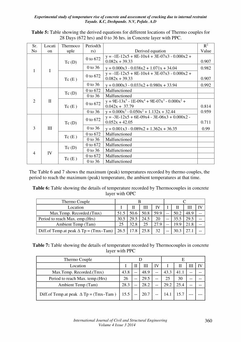
Table 5: Table showing the derived equations for different locations of Thermo couples for
28 Days (672 hrs) and 0 to 36 hrs. in Concrete layer with PPC.
Sr.
No
Locati
on
Thermoco
uple
Period(h
rs) Derived equation
R2
Value
1 I
Tc (D) 0 to 672
y = -1E-12x5 + 8E-10x4 + 3E-07x3 - 0.000x2 +
0.082x + 39.33 0.907
0 to 36 y = 0.000x3 - 0.038x2 + 1.071x + 34.04 0.982
Tc (E ) 0 to 672
y = -1E-12x5 + 8E-10x4 + 3E-07x3 - 0.000x2 +
0.082x + 39.33 0.907
0 to 36 y = 0.000x3 - 0.033x2 + 0.980x + 33.94 0.992
2 II
Tc (D) 0 to 672 Malfunctioned
0 to 36 Malfunctioned
Tc (E ) 0 to 672
y = 9E-13x5 - 1E-09x4 + 9E-07x3 - 0.000x2 +
0.042x + 37.79 0.814
0 to 36 y = 0.000x3 - 0.050x2 + 1.132x + 32.44 0.959
3 III
Tc (D) 0 to 672
y = -3E-12x5 + 6E-09x4 - 3E-06x3 + 0.000x2 -
0.052x + 42.05 0.711
0 to 36 y = 0.001x3 - 0.089x2 + 1.362x + 36.35 0.99
Tc (E ) 0 to 672 Malfunctioned
0 to 36 Malfunctioned
4 IV
Tc (D) 0 to 672 Malfunctioned
0 to 36 Malfunctioned
Tc (E ) 0 to 672 Malfunctioned
0 to 36 Malfunctioned
The Table 6 and 7 shows the maximum (peak) temperatures recorded by thermo couples, the
period to reach the maximum (peak) temperature, the ambient temperatures at that time.
Table 6: Table showing the details of temperature recorded by Thermocouples in concrete
layer with OPC
Thermo Couple B C
Location I II III IV I II III IV
Max.Temp. Recorded.(Tmx) 51.5 50.6 50.8 59.9 -- 50.2 48.9 --
Period to reach Max. emp.(Hrs) 30.5 29.5 24.5 20 -- 35.5 29.5 --
Ambient Temp (Tam) 25 32.8 25 27.9 -- 19.9 21.8 --
Diff.of Temp.at peak ∆ Tp = (Tmx–Tam) 26.5 17.8 25.8 32 -- 30.3 27.1 --
Table 7: Table showing the details of temperature recorded by Thermocouples in concrete
layer with PPC
Thermo Couple D E
Location I II III IV I II III IV
Max.Temp. Recorded.(Tmx) 43.8 -- 48.9 -- 43.3 41.1 -- --
Period to reach Max. temp.(Hrs) 26 -- 29.5 -- 25 30 -- --
Ambient Temp (Tam) 28.3 -- 28.2 -- 29.2 25.4 -- --
Diff.of Temp.at peak ∆ Tp = (Tmx–Tam ) 15.5 -- 20.7 -- 14.1 15.7 --- ---

Experimental study of temperature rise of concrete and assessment of cracking due to internal restraint
Tayade. K.C, Deshpande. N.V, Pofale. A.D
International Journal of Civil and Structural Engineering
Volume 4 Issue 3 2014 361
Having known the peak temperatures, the difference between peak temperatures and the
ambient temperatures at that time, designated as (∆Tp) was calculated. Applying this
temperature difference (∆Tp) the crack index as per equation (1) (2) and (3) were computed
as tabulated in table 8 and 9. The probability of crack occurrence was worked out from graph
given in Figure 1.
Table 8: Table showing the Crack index for ∆Tp in concrete layer with OPC
Thermo Couple B C
Location I II III IV I II III IV
Diff.of Temp.at peak ∆ Tp = (Tmx–Tam) 26.5 17.8 25.8 32 -- 30.3 27.1 --
Crack Index - - korean spcs. ICR(K) /15/∆ Tp 0.57 0.84 0.58 0.47 -- 0.49 0.55 --
Probability of crack occurance.% 92 75 90 96 -- 95 93 --
Crack Index - - elastic analysis ICR(e)=
15.4/∆ Tp 0.58 0.87 0.60 0.48 -- 0.51 0.57 --
Probability of crack occurance.% 90 72 87 96 -- 94 92 --
Crack Index - - Hypoelstic analysis.ICR(h)=
25/∆ Tp 0.94 1.40 0.97 0.78 -- 0.83 0.92 --
Probability of crack occurance.% 55 8 51 79 -- 73 56 --
Table 9: Table showing the Crack index for ∆Tp in concrete layer with PPC
Thermo Couple D E
Location I II III IV I II III IV
Diff.of Temp.at peak ∆ Tp = (Tmx–Tam) 15.5 -- 20.7 -- 14.1 15.7 -- --
Crack Index as per korean spcs. ICR(k)= 15/∆ Tp 0.97 -- 0.72 -- 1.06 0.96 -- --
Probability of crack occurance.% 53 -- 80 -- 49 54 -- --
Crack Index as per elastic analysis ICR(e)=
15.4/∆ Tp 0.99 -- 0.74 -- 1.09 0.98 -- --
Probability of crack occurance.% 51 -- 79 38 52 -- --
Crack Index as per Hypoelstic analysis.ICR(h)=
25/∆ Tp 1.61 -- 1.21 -- 1.77 1.59 -- --
Probability of crack occurance.% 4 -- 22 -- 2 5 -- --
3. Experimental observations and discussions
The equations tabulated in Tables 4 and 5, could be used to predict the temperature rise for
structures with similar geometry, cement contents, mix proportions, ambient temperature
conditions, curing conditions etc. The temperature rise in concrete where PPC is used is much
less than where OPC is used.
The temperature rise could be used to assess the thermal gradients and the effects such as
cracking index and the tensile stresses when the internal restraint is dominant specially in the
early ages say up to 3 days. As can be seen the peak temperatures are reached well within 3
days, and the temperatures were getting stabilized in 28 days with the rate of cooling being
very low.

Experimental study of temperature rise of concrete and assessment of cracking due to internal restraint
Tayade. K.C, Deshpande. N.V, Pofale. A.D
International Journal of Civil and Structural Engineering
Volume 4 Issue 3 2014 362
From the derived equations for the actual temperature rise it could be seen that for the first 36
hrs. the coefficient of correlation ( R2) is in the range of 0.927- 0.992 which is a strong
correlation which will give a good level of accuracy in predicting the temperatures albeit for
the same structure geometry and other parameters. For 28 days the (R2) values are in the
range of 0.711 – 0.981 but the use and significance of these equations diminishes as the
concrete is cooling with slow rates, and peak temperatures being achieved within 3 days.
The maximum temperatures recorded in concrete with OPC were in the range of 500C -600C
and that in concrete with PPC were in the range 400C -500C, hence, even if it is assumed that
all favorable conditions i.e. moisture, SO3 and Mgo exists for DEF to form, the lack of
threshold temperatures necessary for ettringite nucleation not being reached, it can be very
well said that DEF is absent in concrete of the structure studied.
Based on the temperature difference (∆T) the crack index as per the Korean formula gives a
high crack probability and hence this equation is too conservative and gives high risk of
cracking occurrence. The elastic model crack index is also very much similar to the crack
index as per Korean formula. The practical formula of crack index based on hypoelastic
model gives better assessment of the probability of crack occurrence. For example for a
temperature difference of 200C the elastic and hypoelastic model gives a crack index as 0.77
& 1.25 and accordingly this falls into the category of limiting harmful cracks under elastic
model whereas the hypoelastic model indicates that it falls into category of limiting the
cracks. The effect of these different results on the overall construction scheme and its
economics could be significant.
4. Conclusion
The derived temperature rise equations with strong R2 values could be used to predict the
early age temperature rise in structures with similar geometry, weather conditions, curing and
form removal. Significant reduction in temperature rise and maximum temperature rise of
PPC concrete is demonstrated in the experimental study. This indicates that the use of PPC or
fly ash in concrete pours can be beneficial in minimizing the mass overheating and
subsequent concrete cracking. The actual measured maximum temperatures are well below
the threshold temperatures of 70oC necessary for nucleation of DEF and hence it can be
concluded that the chances of DEF in concrete of the structure studied are remote. The
temperature based assessment of cracking which is based on crack index is a good and handy
tool to assess the probability of cracking. However, it should be used with caution and
restraint since it is too conservative. In the present study even though the probability of crack
occurrence in OPC layer is more than 50%, actually no cracks were observed, this could be
due to the use of temperature(skin) reinforcement in the structure. The more realistic
equation of crack index based on hypoelastic model can be used which nearly matches with
the existing limiting temperature difference namely 150C - 200C for the elimination of
cracking that has been adopted the world over.
List of symbols and abbreviations
Icr - Crack Index;
Icr(e) - Crack index as per elastic analysis.
Icr(h) - Crack index as per hypoelastic analysis.
Tc( n) - Thermocouple at position n;

Experimental study of temperature rise of concrete and assessment of cracking due to internal restraint
Tayade. K.C, Deshpande. N.V, Pofale. A.D
International Journal of Civil and Structural Engineering
Volume 4 Issue 3 2014 363
Tam - Ambient Temperature.
∆Tp - Difference of temperature at peak;
∆T – Max. temperature difference across a section.
Tmx – Max. temperature recorded (Peak Temperature)
OPC - Ordinary Portland cement conforming to IS 8112.
PPC - Portland pozzolona cement conforming to IS 1489, Part(I)
w-m-y - week-month-year of production of cement.
5 References
1. ACI Committee, ACI 116.R, (2005), Cement and concrete terminology, Farmington
Hills, M I.
2. ACI Committee, ACI 207.1R, (2005), Guide to Mass Concrete, Farmington Hills, M I.
3. ACI committee, ACI 207.2R, (2007), Effect of restraint, volume change, and
reinforcement on cracking of mass concrete, Farmington Hills, M I.
4. ACI Committee, ACI 224.R, (2001), Control of cracking in concrete structures
Farmington Hills, M I.
5. ACI Committee 301, Specifications for Structural Concrete, Farmington Hills, M I.
6. ACI committee ACI 301.R., (2005), Hot weather concreting, Farmington Hills, M I.
7. CEB–FIB Model Code, (1993) London, UK, ,437 pp.
8. Drimalas,T., (2004), laboratory testing and investigations of delayed Ettringite
formation, Masters Thesis, University of Texas, Austin,TX.
9. European Standard ENV206 (1992), Concrete: performance, production, placing and
compliance criteria, BSI Standards.
10. Gajda,J., (2003), Save time & money on mass concrete construction, Concrete
technology Today, Sept-Dec 03, pp 34-37.
11. Gajda,J., (2007), Mass concrete for buildings and bridges, Portland cement
Association, Skokie, IL.
12. Ghorab, H.Y., (2002), On the chemistry of delayed Ettringite formation, Proceedings
International RILEM TC 186- ISA workshop, RILEM. Villars, Switzerland, pp 65-81.
13. Higginson, E.C., (1970), The effect of cement fineness on concrete, ASTM,
Philadelphia PA, pp 71-81
14. Japan Concrete Institute, (1986), A guide for controlling the cracks of concrete, Japan
concrete institute, Tokyo, Japan, pp 305.

Experimental study of temperature rise of concrete and assessment of cracking due to internal restraint
Tayade. K.C, Deshpande. N.V, Pofale. A.D
International Journal of Civil and Structural Engineering
Volume 4 Issue 3 2014 364
15. Jeon,S.J., (2008), Advanced assessment of cracking due to heat of hydration and
Internal Restraint, ACI materials journal, Title 105-M37, July-August 2008, pp.325-
333
16. Kelly- Mass concrete lecture by Robert Moser, Document CEE8813A-Material
Science of Concrete.
17. Korea concrete institute, (2003), Standard specification for concrete, Korea concrete
institute, Seoul, Korea, p 79.
18. Larsen,T.J., (1991), The effects of variation of C3S of Portland cement on concrete
properties, August 1989, Revised 1991,Florida Deptt. Of Transportation, Tallahasee
19. Lawrence C.D., (1998), Physiochemical and mechanical properties of portland
cements; Lea’s chemistry of Portland cements, 4th edition, pp 343-349.
20. Lykke S. et al (2000), Prediction and control of early age cracking : Experiences from
the Oresund Tunnel, Concrete International, 22(9), pp 61-65
21. Mehta, P.K and Monterio, P.J.M., (1999), Concrete: Microstructure, properties and
materials, Indian edition, Indian Concrete Institute Reprint, p 101.
22. Neville, A. M., (1996), Properties of concrete, Fourth edition, John Wiley & sons,
Incorporated, New York.
23. Panarese,W.C., (2003), Design and control of concrete mixes, Fourteenth edition,
Portland Cement Association Skokie, IL.
24. Poole,T., (2004), Predicting heat of hydration in hydraulic cement, U.S. Army
Research and development centre, Vicksburg, M.S.
25. Price,W.h, (1974), Practical qualities of cement, Journal of ACI, 71(9), pp 436-444
26. RILEM, Technical Committee 219, RILEM Report 15.
27. Tanabe, Y. et al., (1986), Thermal stress analysis of massive concrete, Seminar
proceedings for finite element analysis of reinforced concrete structures, Tokyo, Japan,
May 21-24,1985, ASCE, New York, N.Y.
28. Taylor H.F.W., (1997), Cement Chemistry, Heron Quay, London, Thomas Telford
Publishing.