experimental investigation of thermal hydraulics in the ipr-r1 triga...
TRANSCRIPT

1
Experimental Investigation of Thermal Hydraulics in the IPR-R1 TRIGA
Nuclear Reactor
Amir Zacarias Mesquita1, Daniel Artur P. Palma2,
Antonella Lombardi Costa3, Cláubia Pereira3, Maria Auxiliadora F. Veloso3 and Patrícia Amélia L. Reis3
1Centro de Desenvolvimento da Tecnologia Nuclear/Comissão Nacional de Energia Nuclear 2Comissão Nacional de Energia Nuclear
3Departamento de Engenharia Nuclear –Universidade Federal de Minas Gerais Brazil
1. Introduction
Rising concerns about global warming and energy security have spurred a revival of interest in nuclear energy, leading to a “nuclear power renaissance” in countries the world over. In Brazil, the nuclear renaissance can be seen in the completion of construction of its third nuclear power plant and in the government's decision to design and build the Brazilian Multipurpose research Reactor (RMB). The role of nuclear energy in Brazil is complementary to others sources. Presently two Nuclear Power Plants are in operation (Angra 1 and 2) with a total of 2000 MWe that accounts for the generation of approximately 3% of electric power consumed in Brazil. A third unity (Angra 3) is under construction. Even though with such relatively small nuclear park, Brazil has one of the biggest world nuclear resources, being the sixth natural uranium resource in the world and has a fuel cycle industry capable to provide fuel elements. Brazil has four research reactors in operation: the MB-01, a 0.1 kW critical facility; the IEA-R1, a 5 MW pool type reactor; the Argonauta, a 500 W Argonaut type reactor and the IPR-R1, a 100 kW TRIGA Mark I type reactor. They were constructed mainly for using in education, radioisotope production and nuclear research.
Understanding the behavior of the operational parameters of nuclear reactors allow the development of improved analytical models to predict the fuel temperature, and contributing to their safety. The recent natural disaster that caused damage in four reactors at the Fukushima nuclear power plant shows the importance of studies and experiments on natural convection to remove heat from the residual remaining after the shutdown. Experiments, developments and innovations used for research reactors can be later applied to larger power reactors. Their relatively low cost allows research reactors to provide an excellent testing ground for the reactors of tomorrow.
The IPR-R1 TRIGA Mark-I research reactor is located at the Nuclear Technology Development Centre - CDTN (Belo Horizonte/Brazil), a research institute of the Brazilian Nuclear Energy Commission - CNEN. The IPR-R1 reached its first criticality on November
www.intechopen.com

Nuclear Reactors
2
1960 with a core configuration containing 56 aluminum clad standard TRIGA fuel elements, and a maximum thermal power of 30 kW. In order to upgrade the IPR-R1 reactor power, nine stainless steel clad fuel elements were purchased in 1971. One of these fuel elements was instrumented in the centreline with three type K thermocouples. On December 2000, four of these stainless steel clad fuel elements were placed into the core allowing to upgrading the nominal power to 250 kW. In 2004 the instrumented fuel element (IF) was inserted into all core rings and monitored the fuel temperature, allowing heat transfer investigations at several operating powers, including the maximum power of 250 kW (Mesquita, 2005). The basic safety limit for the TRIGA reactor system is the fuel temperature, both in steady-state and pulse mode operation. The time-dependence of temperature was not considered here, hence only the steady-state temperature profile was studied.
This chapter presents the experiments performed in the IPR-R1 reactor for monitoring some thermal hydraulic parameters in the fuel, pool and core coolant channels. The fuel temperature as a function of reactor power was monitored in all core rings. The radial and axial temperature profile, coolant velocity, mass flow rate and Reynolds’s number in coolant channels were monitored in all core channels. It also presents a prediction for the critical heat flux (CHF) in the fuel surface at hot channel. Data from the instrumented fuel element, pool, and bulk coolant temperature distribution were compared with the theoretical model and results from other TRIGA reactors. A data acquisition system was developed to provide a friendly interface for monitoring all operational parameters. The system performs the temperature compensation for the thermocouples. Information displayed in real-time was recorded on hard disk in a historical database (Mesquita & Souza, 2008). The data obtained during the experiments provide an excellent picture of the IPR-R1 reactor’s thermal performance. The experiments confirm the efficiency of natural circulation in removing the heat produced in the reactor core by nuclear fission (Mesquita & Rezende, 2010).
2. The IPR-R1 reactor
The IPR-R1 TRIGA (Instituto de Pesquisas Radiativas - Reactor 1, Training Research Isotope production, General Atomic) is a typical TRIGA Mark I light-water and open pool type reactor. The fuel elements in the reactor core are cooled by water natural circulation. The basic parameter which allows TRIGA reactors to operate safely during either steady-state or transient conditions is the prompt negative temperature coefficient associated with the TRIGA fuel and core design. This temperature coefficient allows great freedom in steady state and transient operations. TRIGA reactors are the most widely used research reactor in the world. There is an installed base of over sixty-five facilities in twenty-four countries on five continents. General Atomics (GA), the supplier of TRIGA research reactors, since late 50’s continues to design and install TRIGA reactors around the world, and has built TRIGA reactors in a variety of configurations and capabilities, with steady state thermal power levels ranging from 100 kW to 16 MW. TRIGA reactors are used in many diverse applications, including production of radioisotopes for medicine and industry, treatment of tumors, nondestructive testing, basic research on the properties of matter, and for education and training. The TRIGA reactor is the only nuclear reactor in this category that offers true "inherent safety", rather than relying on "engineered safety". It is possible due to the unique properties of GA's uranium-zirconium hydride fuel, which provides incomparable safety characteristics, which also permit flexibility in sitting, with minimal environmental effects
www.intechopen.com
Experimental Investigation of Thermal Hydraulics in the IPR-R1 TRIGA Nuclear Reactor
3
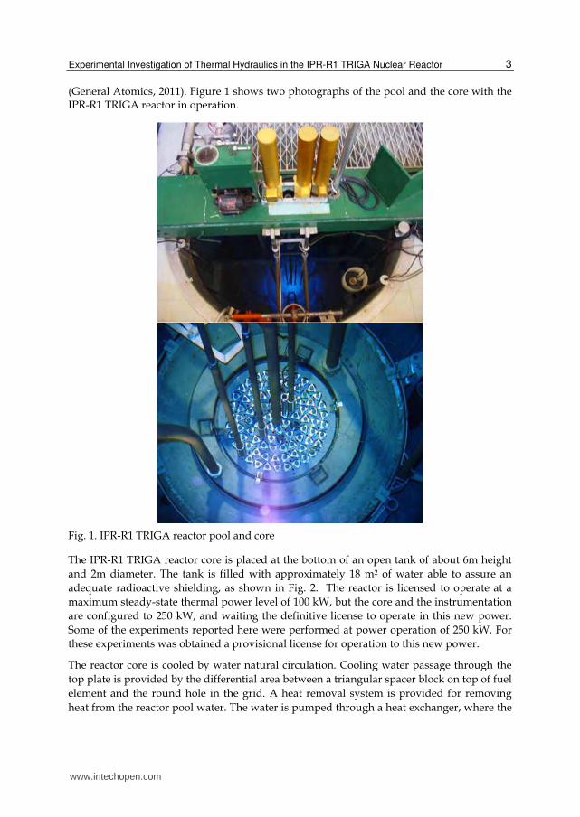
(General Atomics, 2011). Figure 1 shows two photographs of the pool and the core with the IPR-R1 TRIGA reactor in operation.
Fig. 1. IPR-R1 TRIGA reactor pool and core
The IPR-R1 TRIGA reactor core is placed at the bottom of an open tank of about 6m height and 2m diameter. The tank is filled with approximately 18 m2 of water able to assure an adequate radioactive shielding, as shown in Fig. 2. The reactor is licensed to operate at a maximum steady-state thermal power level of 100 kW, but the core and the instrumentation are configured to 250 kW, and waiting the definitive license to operate in this new power. Some of the experiments reported here were performed at power operation of 250 kW. For these experiments was obtained a provisional license for operation to this new power.
The reactor core is cooled by water natural circulation. Cooling water passage through the top plate is provided by the differential area between a triangular spacer block on top of fuel element and the round hole in the grid. A heat removal system is provided for removing heat from the reactor pool water. The water is pumped through a heat exchanger, where the
www.intechopen.com

Nuclear Reactors
4
heat is transferred from the primary to the secondary loop. The secondary loop water is cooled in an external cooling tower. Figure 3 shows the forced cooling system, which transfers the heat generated in the reactor core to a water-to-water heat exchanger. The secondary cooling system transfers the reactor core heat from the heat exchanger to a cooling tower. In the diagram is shown also the instrumentation distribution and the forced and natural circulation paths in the pool.
Fig. 2. IPR-R1 TRIGA reactor pool and core
A simplified view of the IPR R1 TRIGA core configuration is shown in the Fig. 4. As shown in the diagram there are small holes in the core upper grid plate. These holes were used to insert thermocouples to monitor the coolant channel temperatures. The core has a cylindrical configuration of six rings (A, B, C, D, E and F) having 1, 6, 12, 18, 24 and 30 locations respectively. These 91 positions are able to host either fuel rods or other components like control rods, a neutron source, graphite dummies (mobile reflector), irradiating and measurement channels (e.g. central thimble or A ring). Each location corresponds to a role in the aluminum upper grid plate of the reactor core. The core is surrounded by an annular graphite reflector and water. Inside the reflector there is a rotary specimen rack with 40 positions for placement of samples to be activated by neutron flux. The top view of the reactor core and the rotary specimen rack are presented in Fig. 5. There is a very high number of reactor loading configurations, so that it is possible to obtain the sub-critical level required simply loading/unloading fuel rods from the core.
www.intechopen.com

Experimental Investigation of Thermal Hydraulics in the IPR-R1 TRIGA Nuclear Reactor
5
Fig. 3. IPR-R1 TRIGA reactor cooling system and instrumentation distribution
Fig. 4. Simplified core diagram
The prototypical cylindrical fuel elements are a homogeneous alloy of zirconium hydride (neutron moderator) and uranium enriched at 20% in 235U. The reactor core has 58
www.intechopen.com

Nuclear Reactors
6
aluminum-clad fuel elements and 5 stainless steel-clad fuel elements. One of these steel-clad fuel elements is instrumented with three thermocouples along its centreline, and was inserted in the reactor core in order to evaluate the thermal hydraulic performance of the IPR-R1 reactor (Mesquita, 2005). The fuel rod has about 3.5 cm diameter, the active length is about 37 cm closed by graphite slugs at the top and bottom ends which act as axial reflector. The moderating effects are carried out mainly by the zirconium hydride in the mixture, and on a smaller scale by light water coolant. The characteristic of the fuel elements gives a very high negative prompt temperature coefficient, is the main reason of the high inherent safety behavior of the TRIGA reactors. The power level of the reactor is controlled with three independent control rods: a Regulating rod, a Shim rod, and a Safety rod.
Fig. 5. Core configuration with the rotary specimen rack
www.intechopen.com

Experimental Investigation of Thermal Hydraulics in the IPR-R1 TRIGA Nuclear Reactor
7
3. Methodology
3.1 Fuel and core coolant channel temperatures
Before starting the experiments the thermal power released by the core was calibrated, according with the methodology developed by Mesquita et al. (2007). The calibration method used consisted of the steady-state energy balance of the primary cooling loop. For this balance, the inlet and outlet temperatures and the water flow in this primary cooling loop were measured. The heat transferred through the primary loop was added to the heat leakage from the reactor pool. The temperature measurements lines were calibrated as a whole, including sensors, cables, data acquisition cards and computer. The uncertainties for the temperature measurement circuit were ±0.4 oC for resistance temperature detectors, and ±1.0 oC for thermocouples circuits. The adjusted equations were added to the program of the data acquisition system (DAS). The sensor signs were sent to an amplifier and multiplexing board of the DAS, which also makes the temperature compensation for the thermocouples. The temperatures were monitored in real time on the DAS computer screen. All data were obtained as the average of 120 readings and were recorded together with their standard deviations. The system was developed to monitor and to register the operational parameters once a second in a historical database (Mesquita & Souza, 2010).
The original fuel element at the reactor core position B1 was removed and replaced by an instrumented fuel element. Position B1 is the hottest location in the core (largest thermal power production), according to the neutronic calculation (Dalle et al., 2002). The instrumented fuel element is in all aspects identical to standard fuel elements, except that it is equipped with three chromel-alumel thermocouples (K type), embedded in the fuel meat. The sensitive tips of the thermocouples are located along the fuel centreline. Their axial position is one at the half-height of the fuel meat and the other two 2.54 mm above and 2.54 mm below. Figure 6 shows the diagram of the instrumented fuel element and the Table I presents its main characteristics (Gulf General Atomic, 1972). Figure 7 shows the instrumented fuel element and one thermocouple inside a core channel.
Fig. 6. Diagram of the instrumented fuel element
www.intechopen.com

Nuclear Reactors
8
Parameter Value
Heated length 38.1 cm
Outside diameter 3.76 cm
Active outside area 450.05 cm2
Fuel outside area (U-ZrH1.6) 434.49 cm2
Fuel element active volume 423.05 cm3
Fuel volume (U-ZrH1.6) 394.30 cm3
Power (total of the core = 265 kW) 4.518 kW
Table 1. Instrumented fuel element features
Fig. 7. IPR-R1 core top view with the instrumented fuel element in ring B and one probe with thermocouple inside the core.
The instrumented fuel element was replaced to new positions and measures the fuel temperature in each one of the core fuel rings (from B to F). At the same way, two thermocouples were replaced to channels close to the instrumented fuel element to measure the coolant channel temperature. Experiments were carried out with the power changing from about 50 kW to 250 kW in 50 kW steps for each position of the instrumented fuel element. The fuel and coolant temperatures were monitored as function of the thermal power and position in the core.
In the TRIGA type reactors the buoyancy force induced by the density differential across the core maintains the water circulation through the core. Countering this buoyancy force are the pressure losses due to the contraction and expansion at the entrance and exit of the core as well as the acceleration and friction pressure losses in the flow channels. Direct measurement of the flow rate in a coolant channel is difficult because of the bulky size and low accuracy of flow meters. The flow rate through the channel may be determined indirectly from the heat balance across the channel using measurements of the water inlet
www.intechopen.com

Experimental Investigation of Thermal Hydraulics in the IPR-R1 TRIGA Nuclear Reactor
9
and outlet temperatures. Two type K (chromel–alumel) thermocouples fixed in two rigid aluminum probes (7.9 mm of diameter), were inserted into the core in two channels close to position B1 (Channel 1 and 1’ in Fig. 4 and Fig. 5) and measured the inlet and outlet coolant channel temperatures. The probes penetrated axially the channels through small holes in the core upper grid plate. The probes were positioned in diametrically opposite channels, so that when a probe measured the channel entrance temperature, the other one registered the channel exit temperature. In a subsequent run, the probe positions were inverted. This procedure was used also for the Channels 1’, 2’, 3’, 4’ and 5’ (Fig. 5). There is no hole in the top grid plate in the direction of the Channel 0; so it was not possible to measure its temperature. The inlet and outlet temperatures in Channel 0 were considered as being the same of Channel 1. For the other channels there are holes in the top grid plate where it was possible to insert the temperature probes. To found the bulk coolant temperature axial profile at hot channel, with the reactor operating at 250 kW, the probe that measures the channel inlet temperature was raised in steps of 10 cm and the temperature was monitored. The same procedure was done with the reactor operating at 100 kW, but the probe was raised in steps of 5 cm.
3.2 Hydraulic parameters of the coolant
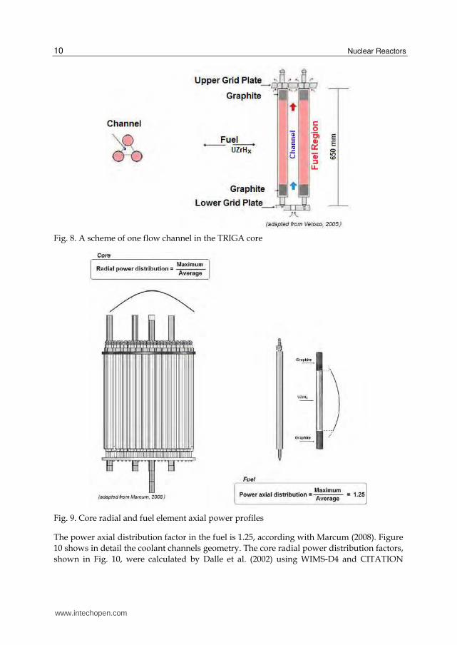
The mass flow rate through the core coolant channels was determined indirectly from the heat balance across each channel using measurements of the water entrance and exit temperatures. Although the channels are laterally open, in this work cross flow or mass transfer between adjacent channels was ignored. Inlet and outlet coolant temperatures in channels were measured with two rigid aluminum probes with thermocouples. They were inserted in the upper grid plate holes (Fig. 5). Figure 8 illustrates schematically the general natural convection process established by the fuel elements bounding one flow channel in the core. The core coolant channels extend from the bottom grid plate to the top grid plate. The cooling water flows through the holes in the bottom grid plate, passes through the lower unheated region of the element, flows upwards through the active region, passes through the upper unheated region, and finally leaving the channel through the differential area between a triangular spacer block on the top of the fuel element and a round hole in the grid. As mentioned, in natural convection the driving force is supplied by the buoyancy of the heated water in the core channels.
In a typical TRIGA flow channel entire fuel element is cooled by single phase convection as long as the maximum wall temperature is kept below that required to initiate boiling. However, at higher power levels the inlet and outlet regions of the core, where the heat fluxes are the lowest, the channels are cooled by single phase convection. In the central region, where the axial heat flux is highest, the mode of heat transfer is predominantly subcooled boiling (Rao et al., 1988 and Mesquita et al. 2011).
The channel heating process is the result of the thermal fraction contributions of the perimeter of each fuel around the channel. So there was an average power of 4.518 kW dissipated in each stainless steel cladding fuel element and 4.176 kW dissipated in each aluminum cladding fuel element at 265 kW core total power. The values are multiplied by the fuel element axial power distribution and core radial power distribution factors as shown in profiles of Fig. 9.
www.intechopen.com
Nuclear Reactors
10
Fig. 8. A scheme of one flow channel in the TRIGA core
Fig. 9. Core radial and fuel element axial power profiles
The power axial distribution factor in the fuel is 1.25, according with Marcum (2008). Figure 10 shows in detail the coolant channels geometry. The core radial power distribution factors, shown in Fig. 10, were calculated by Dalle et al. (2002) using WIMS-D4 and CITATION
www.intechopen.com

Experimental Investigation of Thermal Hydraulics in the IPR-R1 TRIGA Nuclear Reactor
11
codes. The products are multiplied by the fractions of the perimeters of each fuel in contact with the coolant in each channel. The two hottest channels in the core are Channel 0 and Channel 1’. Channel 0 is located closer to the core centre, where density of neutron flux is larger, but there is no hole in the top grid plate in the direction of this channel. Table 1 gives the geometric data of the coolant channels and the percentage of contribution relative to each fuel element to the channels power (Veloso, 2005 and Mesquita, 2005).
Fig. 10. Core coolant channels geometry and radial power distribution
Channel Number
Area [cm2]
Wetted Perimeter
[cm]
Heated Perimeter
[cm]
Hydraulic Diameter
[cm]
Channel Power
[%]
0 1.5740 5.9010 3.9060 1.0669 1.00
1’ 8.2139 17.6427 15.1556 1.8623 3.70
2’ 5.7786 11.7456 11.7456 1.9679 2.15
3’ 5.7354 11.7181 11.7181 1.9578 1.83
4’ 5.6938 11.7181 8.6005 1.9436 1.13
5’ 3.9693 10.8678 3.1248 1.4609 0.35
Table 2. Channel geometry and hydraulic parameters (Veloso, 2005; Mesquita, 2005)
www.intechopen.com
Nuclear Reactors
12
The mass flow rate in the hydraulic channel ( m ) in [kg/s] is given indirectly from the thermal balance along the channel using measurements of the water inlet and outlet temperatures:
c
p
qm
c T (1)
Where qc is the power supplied to the channel [kW], cp is the isobaric specific heat of the water [J/kgK] and ΔT is the temperature difference along the channel [oC]. The mass flux G is given by: G = m / channel area. The velocity u is given by u = G / ρ, where ρ is the water density (995 kg/m3). The values of the water thermodynamic properties were obtained as function of the bulk water temperature at the channel for the pressure 1.5 bar (Wagner & Kruse, 1988) Reynolds number (Re), used to characterize the flow regime, is given by:
Re wGD
(2)
Where G is the mass flux in [kg/m2s], Dw is the hydraulic diameter in [m] and μ is the dynamic viscosity [kg/ms].
3.3 Pool temperatures
Nine thermocouples and one platinum resistance thermometer (PT-100) were used to monitoring the reactor pool temperature. The thermocouples were positioned in a vertical aluminum probe and the first thermocouple was 143 mm above the core top grid plate. The reactor operated during a period of about eight hours at a thermal power of 265 kW before the steady state was obtained. The forced cooling system was turned on during the operation. This experiment is important to understand the behavior of the water temperature in the pool and evaluate the height of the chimney effect.
3.4 Temperatures with the forced cooling system turned off
The power of the IPR-R1 TRIGA was raised in steps of about 25 kW until to reach 265 kW. The forced cooling system of the reactor pool was turned off during the tests. The increase of the power was allowed only when all the desired quantities had been measured and the given limits were not exceeded. After the reactor power level was reached, the reactor was maintained at that power for about 15 min, so the entire steady-state conditions were not reached in the core and coolant. The fuel temperature data was obtained by using the instrumented fuel element. The fuel temperature measurements were taken at location B1 of the core (hottest position). The outlet temperature in the channel was measured with thermocouple inserted near the B1 position. One platinum resistance thermometer measured the water temperature in the upper part of the reactor tank. Two thermocouples measured the ambient temperatures around the reactor pool. The IPR-R1 reactor has a rotary specimen rack outside the reactor core for sample irradiation. It is composed by forty irradiation channels in a cylindrical geometry. One type K thermocouple was put during the experiment in Position 40 of the rotary specimen rack (Fig. 5).
www.intechopen.com
Experimental Investigation of Thermal Hydraulics in the IPR-R1 TRIGA Nuclear Reactor
13
3.5 Critical heat flux and DNBR
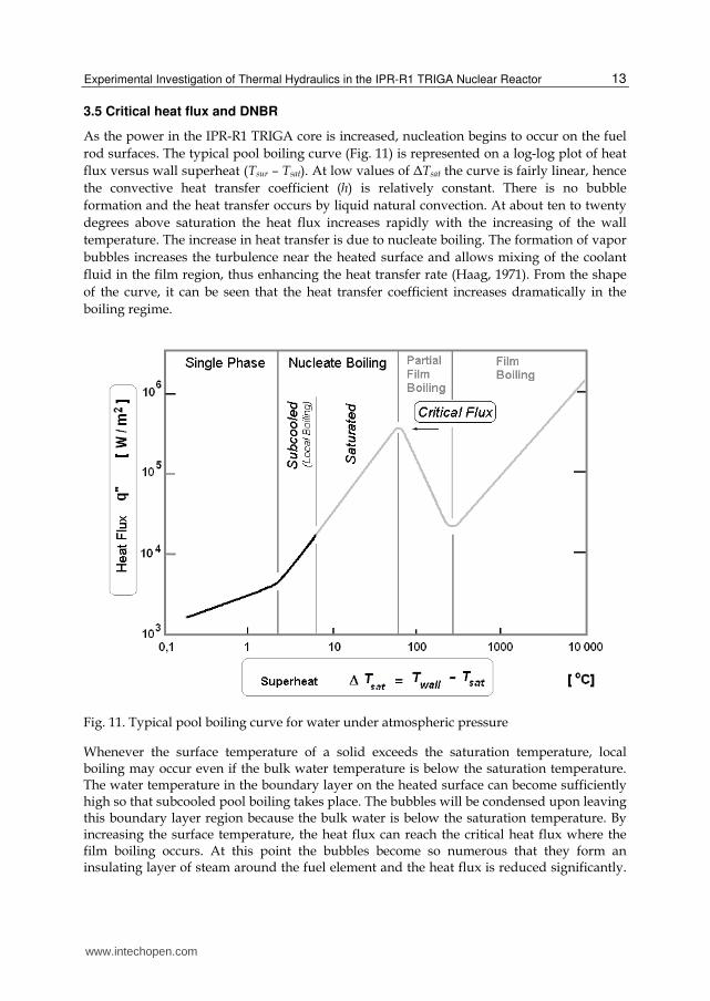
As the power in the IPR-R1 TRIGA core is increased, nucleation begins to occur on the fuel rod surfaces. The typical pool boiling curve (Fig. 11) is represented on a log-log plot of heat flux versus wall superheat (Tsur – Tsat). At low values of ΔTsat the curve is fairly linear, hence the convective heat transfer coefficient (h) is relatively constant. There is no bubble formation and the heat transfer occurs by liquid natural convection. At about ten to twenty degrees above saturation the heat flux increases rapidly with the increasing of the wall temperature. The increase in heat transfer is due to nucleate boiling. The formation of vapor bubbles increases the turbulence near the heated surface and allows mixing of the coolant fluid in the film region, thus enhancing the heat transfer rate (Haag, 1971). From the shape of the curve, it can be seen that the heat transfer coefficient increases dramatically in the boiling regime.
Fig. 11. Typical pool boiling curve for water under atmospheric pressure
Whenever the surface temperature of a solid exceeds the saturation temperature, local boiling may occur even if the bulk water temperature is below the saturation temperature. The water temperature in the boundary layer on the heated surface can become sufficiently high so that subcooled pool boiling takes place. The bubbles will be condensed upon leaving this boundary layer region because the bulk water is below the saturation temperature. By increasing the surface temperature, the heat flux can reach the critical heat flux where the film boiling occurs. At this point the bubbles become so numerous that they form an insulating layer of steam around the fuel element and the heat flux is reduced significantly.
www.intechopen.com

Nuclear Reactors
14
The critical heat flux is the maximum heat flux that a saturated fluid can absorb before acquiring more enthalpy than can be dissipated into its surroundings.
In the fully developed nucleate boiling regime, it is possible to increase the heat flux without an appreciable change in the surface temperature until the point of Departure from Nucleate Boiling (DNB). At this point, the bubble motion on the surface becomes so violent that a hydrodynamic crisis occurs with the formation of a continuous vapor film in the surface and the Critical Heat Flux (CHF) is reached. In subcooled boiling the CHF is a function of the coolant velocity, the degree of subcooling, and the pressure. There are a lot of correlations to predict the CHF. The correlation done by Bernath found in Lamarsh and Baratta (2001) was used to predicts CHF in the subcooled boiling region and is based on the critical wall superheat condition at burnout and turbulent mixing convective heat transfer. Bernath’s equation gives the minimum results so it is the most conservative. It is given by:
'' ( )crit crit crit fq h T T , (3)
where,
0.6
23.53 61.84 0.01863w
critw i w
Dh u
D D D (4)
and,
57 ln( 54) 283.70.1034 1.219crit
p uT p
p (5)
''critq is the critical heat flux [W/m2], hcrit is the critical coefficient of heat transfer [W/m2K],
Tcrit is the critical surface temperature [oC], Tf is the bulk fluid temperature [oC], p is the pressure [MPa], u is the fluid velocity [m/s] (u = m /channel area/water density), Dw is the wet hydraulic diameter [m], Di is the diameter of heat source [m]. This correlation is valid for circular, rectangular and annular channels, pressure of 0.1 to 20.6 MPa, velocity between 1 to 16 m/s and hydraulic diameter of 0.36 to 1.7 cm.
4. Results
4.1 Fuel temperature
Before beginning the experiments, the calibration of the thermal power released by the core were performed, and a power of 265 kW was found when the neutronic linear channel was indicating the power of 250 kW.
Figure 12 shows the radial power profile (neutron flux) calculated by Dalle et al. (2002) using the TRIGPOW code, the experimental fuel radial temperature profile, and the inlet/outlet coolant temperatures in the channel closest to the instrumented element. The theoretical results, for the IPR-R1 TRIGA, calculated by Veloso (2005) using the PANTERA code and the experimental results found in the ITU TRIGA Mark II reactor at the Istanbul University were also plotted (Özkul & Durmayaz, 2000).. All data are for the power of 265 kW.
www.intechopen.com

Experimental Investigation of Thermal Hydraulics in the IPR-R1 TRIGA Nuclear Reactor
15
Fig. 12. Core temperature radial profile at 265 kW thermal power
Figure 13 shows the results of fuel temperature versus reactor thermal power. In the experiment the instrumented fuel element was positioned in each core ring.
Fig. 13. Fuel temperature as function of the reactor power in all core rings
4.2 Core temperature
4.2.1 Outlet coolant temperature as function of the thermal power
The experimental coolant exit temperature for each core ring is shown in Fig 14 as a function of the reactor power. The aluminum probe with thermocouple was inserted in each hole at top grid plate, and the coolant inlet temperature was about 38 oC in all measurements.
www.intechopen.com

Nuclear Reactors
16
Fig. 14. Outlet coolant temperature as function of the thermal power
4.2.2 Radial temperature profile along the core coolant channels
Figure 15 shows the radial core coolant temperature profiles (inlet/outlet channel temperatures) at 265 kW. Theoretical results using the PANTERA code are also shown in the figure (Veloso, 2005).
Fig. 15. Radial temperature profile in the core coolant channels at 265 kW thermal power
www.intechopen.com

Experimental Investigation of Thermal Hydraulics in the IPR-R1 TRIGA Nuclear Reactor
17
4.2.3 Axial temperature profile in the hot channel
The experimental bulk coolant temperatures profile in Channel 1 is shown in Fig.16 as a function of the axial position, for the powers of 265 kW and 106 kW. Figure 16 shows also the curve predicted from the theoretical model using the PANTERA code at 265 kW (Veloso, 2005). The figure shows also the experimental results for other TRIGA reactors Bärs & Vaurio, 1966; Haag, 1971) and (Büke & Yavuz, 2000).
The experimental temperature profile along the coolant is different from that predicted from the theoretical model. Ideally, the coolant temperature would increase along the entire length of the channel, because heat is being added to the water by all fuel regions in the channel. Experimentally, the water temperature reaches a maximum near the middle length and then decreases along the remaining channel. The shape of the experimental curves is similar to the axial power distribution within the fuel rod as shown in Fig. 9. Although Channel 1 is located beside the control rod, the axial temperature profile was not influenced by a possible deformation of the neutron flux caused by this rod, because it was in its upper position, i.e. outside the core. The actual coolant flow is quite different probably, because of the inflow of water from the core sides (colder than its centre).
Fig. 16. Axial bulk coolant temperature profile along the Channel 1
4.2.4 Thermal hydraulic parameters of coolant channels
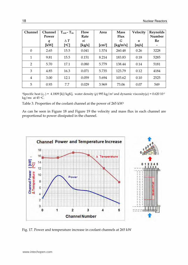
The pertinent parameters required for the analysis of coolant channels are tabulated in Table 3. Figure 17 shows the power dissipate and the temperature increase in each channel at 265 kW reactor total power. This power was the results of the thermal power calibration (Mesquita et al. 2007). The profile of the mass flow rate and velocity in the core is shown in the graphs of Figure 18. Figure 19 compares experimental and theoretical profile of mass flux G in the core coolant channels. The theoretical values were calculated using PANTERA code (Veloso, 2005). As it can see by the Reynolds number the flow regime is turbulent in channels near the core centre.
www.intechopen.com
Nuclear Reactors
18
Channel Channel Tout - Tin Flow Area Mass Velocity Reynolds Power Rate Flux Number q ∆ T m G u Re [kW] [oC] [kg/s] [cm2] [kg/m2s] [m/s] -
0 2.65 15.5 0.041 1.574 260.48 0.26 3228
1 9.81 15.5 0.151 8.214 183.83 0.18 5285
2 5.70 17.1 0.080 5.779 138.44 0.14 5181
3 4.85 16.3 0.071 5.735 123.79 0.12 4184
4 3.00 12.1 0.059 5.694 103.62 0.10 2525
5 0.93 7.7 0.029 3.969 73.06 0.07 549
1Specific heat (cp ) = 4.1809 [kJ/kgK], water density (ρ) 995 kg/m3 and dynamic viscosity(µ) = 0.620 10-3 kg/ms at 45 oC.
Table 3. Properties of the coolant channel at the power of 265 kW1
As can be seen in Figure 18 and Figure 19 the velocity and mass flux in each channel are proportional to power dissipated in the channel.
Fig. 17. Power and temperature increase in coolant channels at 265 kW
www.intechopen.com

Experimental Investigation of Thermal Hydraulics in the IPR-R1 TRIGA Nuclear Reactor
19
Fig. 18. Mass flow rate and velocity in coolant channels at 265 kW
Fig. 19. Mass flux in coolant channels at 265 kW
4.3 Pool temperature
Figure 20 shows the water temperatures evolution at the reactor pool, and the inlet and outlet coolant temperature in the core’s hottest channel until the beginning of steady state. The results showed that the thermocouples positioned 143 mm over the top grid plate (Inf 7) measure a temperature level higher than all the other thermocouples positioned over the reactor core. The temperature measurements above the core showed that thorough mixing of water occurs within the first centimeters above core top resulting in a uniform water temperature. It means that the chimney effect is not much high, less than 400 mm above the reactor core, in agreement with similar experiments reported by Rao et al. (1988). The chimney effect is considered as an unheated extension of the core. The chimney height is the
www.intechopen.com

Nuclear Reactors
20
distance between the channel exit and the fluid isotherm plan above the core and it depends of the reactor power.
Fig. 20. Temperatures patterns in the reactor pool at 265 kW thermal power
4.4 Temperatures with the forced cooling system tuned off
Figure 21 shows the behavior of fuel element, channel outlet, reactor pool, and specimen rack temperatures at various operation powers, with the forced cooling system turned off.
Fig. 21. Temperature evolution as a function of power with the forced cooling system off
www.intechopen.com
Experimental Investigation of Thermal Hydraulics in the IPR-R1 TRIGA Nuclear Reactor
21
4.5 Critical Heat Flux and DNBR
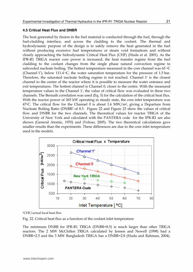
The heat generated by fission in the fuel material is conducted through the fuel, through the fuel-cladding interface, and across the cladding to the coolant. The thermal and hydrodynamic purpose of the design is to safely remove the heat generated in the fuel without producing excessive fuel temperatures or steam void formations and without closely approaching the hidrodynamic Critical Heat Flux (CHF) (Huda et al. 2001). As the IPR-R1 TRIGA reactor core power is increased, the heat transfer regime from the fuel cladding to the coolant changes from the single phase natural convection regime to subcooled nucleate boiling. The hottest temperature measured in the core channel was 65 oC (Channel1’), below 111.4oC, the water saturation temperature for the pressure of 1.5bar. Therefore, the saturated nucleate boiling regime is not reached. Channel 1' is the closest channel to the centre of the reactor where it is possible to measure the water entrance and exit temperatures. The hottest channel is Channel 0, closer to the centre. With the measured temperature values in the Channel 1', the value of critical flow was evaluated in these two channels. The Bernath correlation was used (Eq. 5) for the calculation of the critical heat flux. With the reactor power of 265 kW operating in steady state, the core inlet temperature was 47oC. The critical flow for the Channel 0 is about 1.6 MW/m2, giving a Departure from Nucleate Boiling Ratio (DNBR2 of 8.5. Figure 22 and Figure 23 show the values of critical flow and DNBR for the two channels. The theoretical values for reactor TRIGA of the University of New York and calculated with the PANTERA code for the IPR-R1 are also shown (General Atomic, 1970) and (Veloso, 2005). The two theoretical calculations gave smaller results than the experiments. These differences are due to the core inlet temperature used in the models.
2CHF/actual local heat flux
Fig. 22. Critical heat flux as a function of the coolant inlet temperature
The minimum DNBR for IPR-R1 TRIGA (DNBR=8.5) is much larger than other TRIGA reactors. The 2 MW McClellen TRIGA calculated by Jensen and Newell (1998) had a DNBR=2.5 and the 3 MW Bangladesh TRIGA has a DNBR=2.8 (Huda and Rahman, 2004).
www.intechopen.com

Nuclear Reactors
22
The power reactors are projected for a minimum DNBR of 1.3. In routine operation they operated with a DNBR close to 2. The IPR-R1 reactor operates with a great margin of safety at its present power of 250 kW, the maximum heat flux in the hottest fuel is about 8 times lesser than the critical heat flux that would take the hydrodynamic crisis in the fuel cladding. This investigation indicates that the reactor would have an appropriate heat transfer if the reactor operated at a power of about 1MW.
Fig. 23. DNBR as a function of the coolant inlet temperature
5. Conclusion
Experiments to understand the behavior of the nuclear reactors operational parameters allow improve model predictions, contributing to their safety. Developments and innovations used for research reactors can be later applied to larger power reactors. Their relatively low cost allows research reactors to provide an excellent testing ground for the reactors of tomorrow.
The experiments described here confirm the efficiency of natural convection in removing the heat produced in the reactor core by nuclear fission. The data taken during the experiments provides an excellent picture of the thermal performance of the IPR-R1 reactor core. The IPR-R1 TRIGA core design accommodates sufficient natural convective flow to maintain continuous flow of water throughout the core, which thereby avoids significant bubbles formation and restricts possible steam bubbles to the vicinity of the fuel element surface. The spacing between adjoining fuel elements was selected not only from neutronic considerations but also from thermohydrodynamic considerations. The experimental data also provides information, which allows the computation of other parameters, such as the fuel cladding heat transfer coefficient (Mesquita & Rezende, 2007). The theoretical temperatures and mass flux were determined under ideal conditions. There is a considerable coolant crossflow throughout the channels. Note that the natural convection
www.intechopen.com
Experimental Investigation of Thermal Hydraulics in the IPR-R1 TRIGA Nuclear Reactor
23
flow is turbulent in all channels near the centre. The temperature measurements above the IPR-R1 core showed that water mixing occurs within the first few centimeters above the top of the core, resulting in an almost uniform water temperature. The temperature at the primary loop suction point at the pool bottom, as shown in Fig. 3, has been found as the lowest temperature in the reactor pool. Pool temperature depends on reactor power, as well as on the external temperature because it affects the heat dissipation rate in the cooling tower. The results can be considered as typical of pool-type research reactor. Further research could be done in the area of boiling heat transfer by using a simulated fuel element heated by electrical current (mock-up). The mock fuel element would eliminate the radiation hazard and allow further thermocouple instrumentation. By using a thermocouple near the fuel element surface, the surface temperature could be measured as a function of the heat flux.
It is suggested to repeat the experiments reported here, by placing a hollow cylinder over the core, with the same diameter of it, to verify the improvement of the mass flow rate by the chimney effect. These experiments can help the designers of the Brazilian research Multipurpose Reactor (RBM), which will be a pool reactor equipped with a chimney to improve the heat removal from the core (CDTN/CNEN, 2009).
6. Acknowledgment
This research project is supported by the following Brazilian institutions: Nuclear Technology Development Centre (CDTN), Brazilian Nuclear Energy Commission (CNEN), Research Support Foundation of the State of Minas Gerais (FAPEMIG), Brazilian Council for Scientific and Technological Development (CNPq) and Coordination for the Improvement of Higher Education Personnel (CAPES).
7. References
Bärs, B. & Vaurio, J. (1966). Power Increasing Experiments on a TRIGA Reactor. Technical University of Helsinki, Department of Technical Physics. Report No. 445. Otaniemi Filand.
Büke, T & Yavuz, H. (2000). Thermal-Hydraulic Analysis of the ITU TRIGA Mark-II Reactor. Proceeding of 1st Eurasia Conference on Nuclear Science and its Application. Izmir, Turquia, October 23-27, 2000.
CDTN/CNEN - Nuclear Technology Development Centre/Brazilian Nuclear Energy Commission. (2009). Brazilian Multipurpose Reactor (RMB), Preliminary Report of Reactor Engineering Group, General Characteristics and Reactors Reference”. (in Portuguese).
Dalle, H.M., Pereira, C., Souza, R.M.G.P. (2002). Neutronic Calculation to the TRIGA IPR-R1 reactor using the WIMSD4 and CITATION codes. Annals of Nuclear Energy, Vol. 29, No. 8, ( May 2002) , pp. 901–912, ISSN 0306-4549.
General Atomic. (1970). Safeguards Summary Report for the New York University TRIGA Mark I Reactor. (GA-9864). San Diego.
General Atomics. (June 2011). TRIGA. In: TRIGA® Nuclear Reactors, 07.06.2011. Available from: http://www.ga-esi.com/triga/.
Gulf General Atomic. (1972). 15” SST Fuel Element Assembly Instrumented Core. Drawing Number TOS210J220. San Diego, CA.
www.intechopen.com
Nuclear Reactors
24
Haag, J.A. (1971). Thermal Analysis of the Pennsylvania State TRIGA Reactor. MSc Dissertation, Pennsylvania State University, Pennsylvania.
Huda, M.Q. & Rahman, M. (2004). Thermo-Hydrodynamic Design and Safety Parameter Studies of the TRIGA Mark II Research Reactor. Annals of Nuclear Energy, Vol. 31, (July 2004), pp.1102–1118, ISSN 0306-4549.
Huda, M.Q. et al. (2001). Thermal-hydraulic analysis of the 3 MW TRIGA Mark-II research reactor under steady-state and transient conditions. Nuclear Tecnology, Vol. 135, No. 1, (July 2001), pp. 51-66, ISSN 0029-5450.
Jensen, R.T. & Newell, D.L. (1998). Thermal Hydraulic Calculations to Support Increase in Operating Power in Mcclellen Nuclear Radiation Centre (MNRC) TRIGA Reactor. Proceedings of RELAP5 International User´s Seminar. College Station, Texas.
Lamarsh, J.R. & Baratta, A.J. (2001). Introduction to Nuclear Engineering. (3 ed.), Prendice Hall Inc., Upper Saddle River, ISBN 0-201-82498-1, New Jersey.
Marcum, W.R. (2008). Thermal Hydraulic Analysis of the Oregon State TRIGA® Reactor Using RELAP5-3D. MSc Dissertation. Oregon State University. Oregon.
Mesquita, A.Z., Costa, A.L., Pereira, C., Veloso, M.A.F. & Reis, P.A.L. (2011). Experimental Investigation of the Onset of Subcooled Nucleate Boiling in an Open-Pool Nuclear Research Reactor. Journal of ASTM International, Vol. 8, No. 6, (June 2011), pp. 12-20, 2011, ISSN 1546-962X.
Mesquita, A.Z. & Rezende, H. C. (2007). Experimental Determination of Heat Transfer Coefficients in Uranium Zirconium Hydride Fuel Rod. International Journal of Nuclear Energy, Science and Technology, Vol. 3, No. 2, (April 2007), pp. 170-179, ISSN 1741-6361.
Mesquita, A.Z. & Rezende, H.C. (2010). Thermal Methods for On-line Power Monitoring of the IPR-R1 TRIGA Reactor. Progress in Nuclear Energy, Vol. 52, (Abril 2010), pp. 268-272, ISSN: 0149-1970.
Mesquita, A.Z. & Souza, R.M.G.P. (2008). The Operational Parameter Electronic Database of the IPR-R1 TRIGA Research Reactor. Proceedings of 4th World TRIGA Users Conference, Lyon, September 8-9, 2008.
Mesquita, A.Z. & Souza, R.M.G.P. (2010). On-line Monitoring of the IPR-R1 TRIGA Reactor Neutronic Parameters. Progress in Nuclear Energy, Vol. 52, (Abril 2010), pp. 292-297, ISSN: 0149-1970.
Mesquita, A.Z. (2005). Experimental Investigation on Temperatures Distribuitions in the IPR-R1 TRIGA Nuclear Research Reactor, ScD Thesis, Universidade Estadual de Campinas, São Paulo. (in Portuguese).
Mesquita, A.Z., Rezende, H.C. & Tambourgi, E.B. (2007). Power Calibration of the TRIGA Mark I Nuclear Research Reactor, Journal of the Brazilian Society of Mechanical Sciences, Vol. 29, No 3, (July 2007), pp. 240-245, ISSN 1678-5878.
Özkul, E.H. & Durmayaz, A. (2000). A Parametric Thermal-Hydraulic Analysis of ITU TRIGA Mark II Reactor. Proceedings of 16th European TRIGA Conference, pp. 3.23-3.42, Institute for Nuclear Research, Pitesti, Romania.
Veloso, M.A. (2005). Thermal–Hydraulic Analysis of the IPR-R1 TRIGA Reactor in 250 kW, CDTN/CNEN, NI-EC3-05/05, Belo Horizonte, (in Portuguese).
Wagner, W & Kruse, A. (1998). Properties of Water and Steam – The Industrial Standard IAPWS-IF97 For The Thermodynamics Properties. Springer, Berlin
Rao, D.V., El-Genk, M.S., Rubio, R.A., Bryson, J.W., & Foushee, F.C. (1988). Thermal Hydraulics Model for Sandia's Annular Core Research Reactor, Proceeding of Eleventh Biennial U.S. TRIGA Users’s Conference, pp. 4.89-4.113, Washington, USA, April 9-13, 1988.
www.intechopen.com
Nuclear ReactorsEdited by Prof. Amir Mesquita
ISBN 978-953-51-0018-8Hard cover, 338 pagesPublisher InTechPublished online 10, February, 2012Published in print edition February, 2012
InTech EuropeUniversity Campus STeP Ri Slavka Krautzeka 83/A 51000 Rijeka, Croatia Phone: +385 (51) 770 447 Fax: +385 (51) 686 166www.intechopen.com
InTech ChinaUnit 405, Office Block, Hotel Equatorial Shanghai No.65, Yan An Road (West), Shanghai, 200040, China
Phone: +86-21-62489820 Fax: +86-21-62489821
This book presents a comprehensive review of studies in nuclear reactors technology from authors across theglobe. Topics discussed in this compilation include: thermal hydraulic investigation of TRIGA type researchreactor, materials testing reactor and high temperature gas-cooled reactor; the use of radiogenic leadrecovered from ores as a coolant for fast reactors; decay heat in reactors and spent-fuel pools; present statusof two-phase flow studies in reactor components; thermal aspects of conventional and alternative fuels insupercritical water?cooled reactor; two-phase flow coolant behavior in boiling water reactors under earthquakecondition; simulation of nuclear reactors core; fuel life control in light-water reactors; methods for monitoringand controlling power in nuclear reactors; structural materials modeling for the next generation of nuclearreactors; application of the results of finite group theory in reactor physics; and the usability of vermiculite as ashield for nuclear reactor.
How to referenceIn order to correctly reference this scholarly work, feel free to copy and paste the following:
Amir Zacarias Mesquita, Daniel Artur P. Palma, Antonella Lombardi Costa, Cláubia Pereira, Maria AuxiliadoraF. Veloso and Patrícia Amélia L. Reis (2012). Experimental Investigation of Thermal Hydraulics in the IPR-R1TRIGA Nuclear Reactor, Nuclear Reactors, Prof. Amir Mesquita (Ed.), ISBN: 978-953-51-0018-8, InTech,Available from: http://www.intechopen.com/books/nuclear-reactors/experimental-investigation-of-thermal-hydraulics-in-the-ipr-r1-triga-nuclear-reactor

© 2012 The Author(s). Licensee IntechOpen. This is an open access articledistributed under the terms of the Creative Commons Attribution 3.0License, which permits unrestricted use, distribution, and reproduction inany medium, provided the original work is properly cited.