experimental characterization of a manifold …...experimental characterization of a...
TRANSCRIPT

Experimental Characterization of a Manifold-Microchannel Heat Exchanger Fabricated Based onAdditive Manufacturing
William C. Yameen1, Nathan A. Piascik1, Riccardo C. Clemente1, Andrew K. Miller1
Seyed A. Niknam2, Jingru Benner1, Anthony D. Santamaria1, Mehdi Mortazavi1,∗
1 Department of Mechanical Engineering, Western New England University, Springfield, MA 011192 Department of Industrial Engineering, Western New England University, Springfield, MA 01119
∗Corresponding Author: [email protected]
ABSTRACTAir-cooled heat exchangers have gained much attention as
an alternative for cooling systems in power plants. How-ever, due to lower specific heat of air compared to waterlarger cooling facilities with excess compressing powers arerequired in air-cooled systems. Improving heat transfer per-formance of air-cooled systems can make them more appeal-ing to the market. This requires design and fabrication ofcomplex heat exchanger geometries which can be done byadditive manufacturing technology. In this study, a metal-lic manifold-microchannel heat exchanger was designed andfabricated based on direct metal laser sintering technology.The heat exchanger was fabricated from stainless steel withan overall dimension of 64.2 × 46.0 × 27.1 mm. Air-sideheat flow rate, air-side base convection heat transfer coeffi-cient, and air-side pressure drop were evaluated for differentair flow rates. The highest air-side heat flow rate achievedwas around 300 W at 14.1 `/s air flow rate. This heat flowrate resulted in an air-side base convection heat transfer co-efficient around 1,600 W/m2K. The highest air-side pressuredrop was measured around 3,450 Pa which occurred at 14.1`/s air flow rate. This study is the basis of further studieson the heat transfer characteristics of additively manufacturedheat exchangers. Modified manifold-microchannels heat ex-changers will be tested and compared with the original heatexchanger in future studies.INTRODUCTION
Currently, over 98% of the thermoelectric power plants inthe U.S. are cooled based on water-cooling systems. Suchpower plants consume 41% of fresh water in the U.S [1]. Thiscauses negative impact on environment. In addition, with-drawing this amount of fresh water is costly and adds to theoperational cost of the power plant. Furthermore, designingpower plants based on water-cooled systems dictates specificlocations with easy access to fresh water sources. In con-trast to water-cooled power plants, air-cooled power plantsrequire little or no water in their cooling systems. However,due to lower specific heat of air compared to water, a largercooling facility will be required in air-cooled power plants.The air-cooled systems can be more appealing to the marketif their heat transfer characteristics are enhanced. Moreover,the novel heat exchanger should still result in relatively lowair-side pressure drop in order to avoid excess blower power.These two requirements can be addressed in an innovativeheat exchanger design. Because the conventional fabricationtechniques are limited in capabilities additive manufacturingcan be utilized for fabricating more complex heat exchangerdesigns. Additive manufacturing is a powerful fabricationmethod that has enabled fabrication of complex geometriesthat are either challenging or impossible to fabricate based onconventional techniques. Over the last decade, additive man-ufacturing has developed significantly mainly because of theirpotential to revolutionize fabrication techniques. Recently,
additive manufacturing has been adopted in a wide range ofapplications such as medical, automotive, aerospace, and con-struction [2–4].
Additive manufacturing has been also utilized in fabricat-ing heat exchangers [5–8] as well as pin fins [9–12]. Kirschand Thole [12] used laser powder bed fusion (LPBF) methodsto fabricate pin fins that can endure in gas turbine engines.They examined the performance of pin fin arrays producedby direct metal laser sintering (DMLS) and observed that thefriction factor was extremely high in pin fins fabricated byLPBF compared to other additive manufacturing techniquesreported in literature with a marginal benefit in heat transfer.In a similar study, Frester et al. [10] evaluated the heat trans-fer performance of pin fins fabricated by additive manufactur-ing and for the application of gas turbine blade cooling. Theymanufactured triangular, star, and spherical shaped pins basedon DMLS and experimentally investigated pressure drop andheat transfer over a range of Reynolds numbers. Parametersthey studied included pin fin spacing, number of pin fins, andpin fin geometry. They reported that the additively manufac-tured triangle and cylinder pin fins outperform conventionalpin fin arrays.
In this study, heat transfer characteristics of a metallic air-water heat exchanger fabricated via additive manufacturingis investigated. The heat exchanger was fabricated based onDMLS technology and from stainless steel in EOS M 290.The overall size of heat exchanger is 64.2 × 46.0 × 27.1 mmwhich was designed based on manifold-microchannel heat ex-changer concept that had been introduced by Harpole andEninger in 1991 [13]. In this type of heat exchangers, air issupplied into inlet manifolds from one side and exists the heatexchanger from outlet manifolds on the other side. Each airinlet manifold is blocked at the end while adjacent manifoldsare open. Air passes from microchannels, fabricated on thetop and bottom surfaces of the manifolds, to enter into adja-cent manifolds. Water is supplied into water channels locatedunderneath air microchannels. This concept of heat exchangeris schematically shown in Figure 1.
cold air in
hot air out
hot water in
cold water out
air inlet manifold
water channelsmicrochannels
air outlet manifold
current direction of microchannels
air
air inlet manifold
air outlet manifold
Figure 1: CAD model of a manifold-microchannel HX
1

The fabricated heat exchangers are shown in Figure 2.Three heat exchangers with slightly different interior designswere fabricated by DMLS. In this study, the heat transfer char-acteristics of the heat exchanger with an original design isinvestigated. The original design has microchannels in per-pendicular orientation with respect to air manifolds. In futurestudies, the heat transfer performance of this original designwill be compared with modified heat exchangers with differ-ent orientation of air manifolds as well as added pins on theair manifolds.
Figure 2: Additively manufactured manifold-microchannelheat exchangers from stainless steel
Table 1 lists key dimensions of the heat exchanger investi-gated in this study.
Table 1: Heat exchanger dimensions. Some propertiesare shown in Figure. 3d.
water channel width 2.60 mmwater channel height 1.10 mmair manifold width 6.42 mmair manifold height 11.24 mmmicrochannel fin height (Hmc) 1.0 mmmicrochannel width (Wmc) 0.48 mmthickness of microchannel fins 0.48mmbase thickness (L) 0.48 mmnumber of water channel rows 4number of water channel in each row 8HX overall height (HHX) 64.20 mmHX overall width (WHX) 46.02 mmHX overall depth (DHX) 27.16 mmThickness of the heat- 1.5 mmexchanger body (THX)
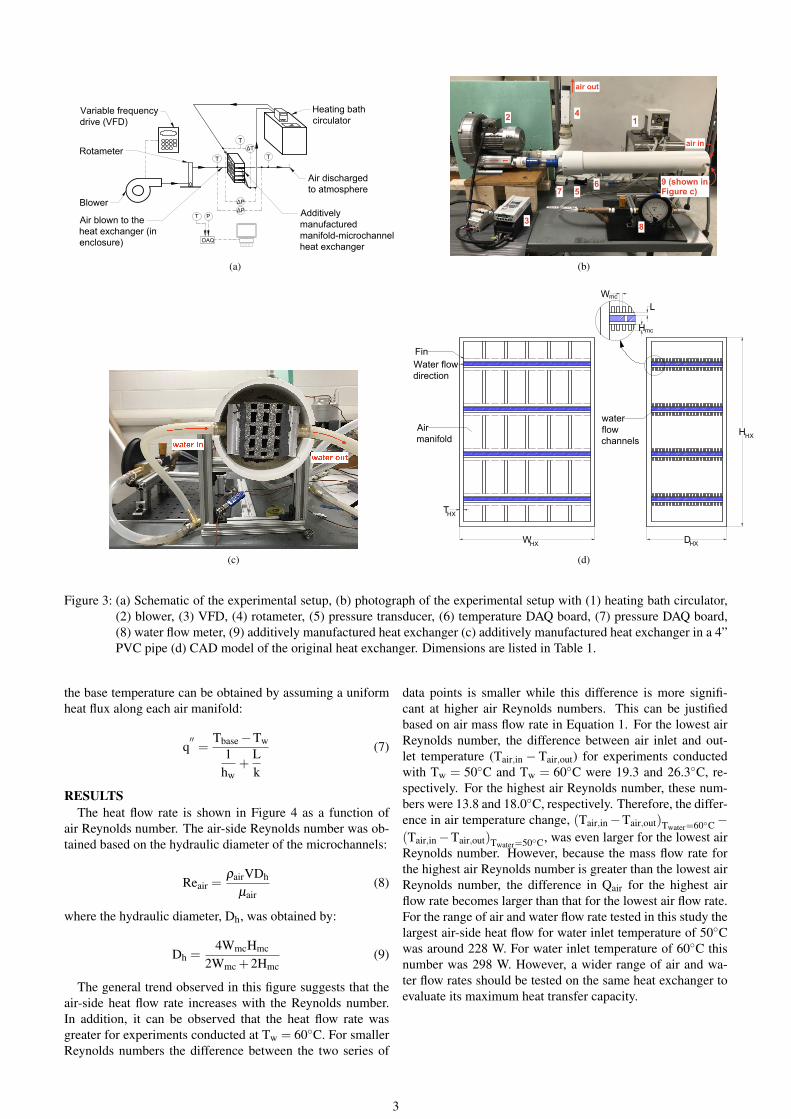
EXPERIMENTAL SETUPThe experimental setup is schematically shown in Figure 3.
The setup includes a variable speed blower (Republic, HRC200), a variable frequency drive (VFD), heating bath circu-lator (Thermo Scientific, S13), rotameter (King Instrument,7510), and data acquisition system (DAQ). Air, at differentflow rates, was supplied into the heat exchanger through a 4”PVC pipe and in an open loop. The rotameter had a measure-ment range between 6 and 60 scfm, equivalent to 2.83 and28.3 `/s, respectively. The air pressure drop through the heatexchanger was measured with a pressure transducer with 0 to6,350 Pa pressure measurement range (Dwyer 668D-08-1). A
combination of thermocouples and RTDs were used to mea-sure the temperature of air and water in inlet and outlet portof the heat exchanger. The additively manufactured heat ex-changer was inserted in a 4” PVC pipe in the suction side ofthe blower. This was done to ensure a uniform air inlet tem-perature into the heat exchanger. This is because regenerativeblowers can increase air temperature as the air passes throughthem. The rotameter was installed in the discharge side of theblower and was open to atmosphere. Aluminum manifoldswere attached to either sides of the heat exchanger to pumpwater into the water channels. Experiments were conductedat constant water flow rate and at two different water inlettemperature of 50 and 60◦C. All experiments were conductedat room temperature.DATA REDUCTION
The experiments were conducted at different air flow rateswhile the water flow rate was kept constant at 0.047 `/s. Theperformance of the heat exchanger was evaluated based onair-side heat flow rate, Qair, air-side base convection heattransfer coefficient hb,air, and air-side pressure drop, ∆Pair.The air-side heat flow rate was obtained by:
Qair = maircp,air(Tair,out−Tair,in) (1)
where mair, cp,air, Tair,in, and Tair,out are air mass flow rate, airspecific heat, air temperature in the inlet, and air temperaturein the outlet of the heat exchanger, respectively. The air-sidebase convection heat transfer coefficient (hb,air) was obtainedby:
hb,air =Qair
Abase|Tbase−Tair,in|(2)
where Abase and Tbase are base surface area and base averagetemperature, respectively. The base surface area was obtainedby:
Abase = (WHX−2THX)× (DHX−2THX) (3)
The base temperature can be calculated by applying onedimensional heat transfer from water to air.
Assuming water is equally distributed between 32 waterchannels in the heat exchanger, the water flow rate in eachchannel is 0.0014 `/s with an average velocity of 0.514 m/s.This yields a water Reynolds number of 1,503. The Nusseltnumber can be obtained based on the correlation proposed byGnielinski [14]:
NuD =(f/8)(ReD−1000)Pr
1+12.7(f/8)1/2(Pr2/3−1)(4)
where the friction factor, f, can be obtained by [15]:
f = (0.790lnReD−1.64)−2 (5)
Equation 5 is developed for smooth surface condition. Inthis study, it is assumed that the water channel surface issmooth. However, the water channel surface condition shouldbe properly explored in future studies. The average Nusseltnumber for the entire water channel is obtained by [16]:
NuD
NuD,fd= 1+
C(x/D)m (6)
where C = 23.99Re−0.23 and m =−2.08×10⁻⁶Re+0.815.The obtained Nusselt number can be used to calculate water
convection heat transfer coefficient, Nu = hwDh/k. Finally,
2
Heating bath
circulator
Blower
Variable frequency
drive (VFD)
Rotameter
Additively
manufactured
manifold-microchannel
heat exchanger
Air blown to the
heat exchanger (in
enclosure)
T T
ΔT
T
ΔP
ΔP
T P
DAQ
Air discharged
to atmosphere
(a) (b)
(c)
Water Side (version V3) ITherm
water
flow
channels
Water flow
direction
Fin
W
Air Side (version V3) ITherm
Air
manifold
T
HHX
HXD
HX
HX
Wmc
Hmc
L
(d)
Figure 3: (a) Schematic of the experimental setup, (b) photograph of the experimental setup with (1) heating bath circulator,(2) blower, (3) VFD, (4) rotameter, (5) pressure transducer, (6) temperature DAQ board, (7) pressure DAQ board,(8) water flow meter, (9) additively manufactured heat exchanger (c) additively manufactured heat exchanger in a 4”PVC pipe (d) CAD model of the original heat exchanger. Dimensions are listed in Table 1.
the base temperature can be obtained by assuming a uniformheat flux along each air manifold:
q′′=
Tbase−Tw1
hw+
Lk
(7)
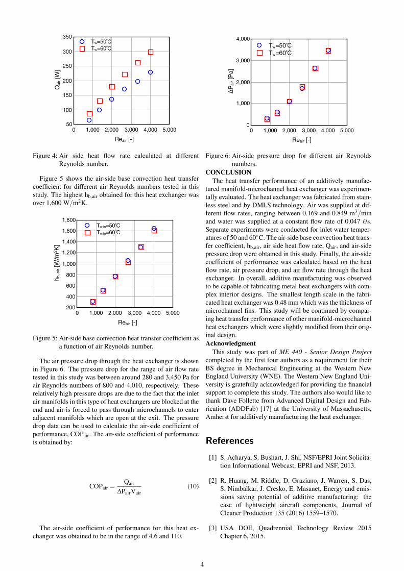
RESULTSThe heat flow rate is shown in Figure 4 as a function of
air Reynolds number. The air-side Reynolds number was ob-tained based on the hydraulic diameter of the microchannels:
Reair =ρairVDh
µair(8)
where the hydraulic diameter, Dh, was obtained by:
Dh =4WmcHmc
2Wmc +2Hmc(9)
The general trend observed in this figure suggests that theair-side heat flow rate increases with the Reynolds number.In addition, it can be observed that the heat flow rate wasgreater for experiments conducted at Tw = 60◦C. For smallerReynolds numbers the difference between the two series of
data points is smaller while this difference is more signifi-cant at higher air Reynolds numbers. This can be justifiedbased on air mass flow rate in Equation 1. For the lowest airReynolds number, the difference between air inlet and out-let temperature (Tair,in − Tair,out) for experiments conductedwith Tw = 50◦C and Tw = 60◦C were 19.3 and 26.3◦C, re-spectively. For the highest air Reynolds number, these num-bers were 13.8 and 18.0◦C, respectively. Therefore, the differ-ence in air temperature change, (Tair,in−Tair,out)Twater=60◦C−(Tair,in−Tair,out)Twater=50◦C, was even larger for the lowest airReynolds number. However, because the mass flow rate forthe highest air Reynolds number is greater than the lowest airReynolds number, the difference in Qair for the highest airflow rate becomes larger than that for the lowest air flow rate.For the range of air and water flow rate tested in this study thelargest air-side heat flow for water inlet temperature of 50◦Cwas around 228 W. For water inlet temperature of 60◦C thisnumber was 298 W. However, a wider range of air and wa-ter flow rates should be tested on the same heat exchanger toevaluate its maximum heat transfer capacity.
3
Qai
r [W
]
50
100
150
200
250
300
350
Reair [-]0 1,000 2,000 3,000 4,000 5,000
Tw=50˚CTw=60˚C
Figure 4: Air side heat flow rate calculated at differentReynolds number.
Figure 5 shows the air-side base convection heat transfercoefficient for different air Reynolds numbers tested in thisstudy. The highest hb,air obtained for this heat exchanger wasover 1,600 W/m2K.
h b, a
ir [W
/m2 K
]
200
400
600
800
1,000
1,200
1,400
1,600
1,800
Reair [-]0 1,000 2,000 3,000 4,000 5,000
Tw,in=50˚CTw,in=60˚C
Figure 5: Air-side base convection heat transfer coefficient asa function of air Reynolds number.
The air pressure drop through the heat exchanger is shownin Figure 6. The pressure drop for the range of air flow ratetested in this study was between around 280 and 3,450 Pa forair Reynolds numbers of 800 and 4,010, respectively. Theserelatively high pressure drops are due to the fact that the inletair manifolds in this type of heat exchangers are blocked at theend and air is forced to pass through microchannels to enteradjacent manifolds which are open at the exit. The pressuredrop data can be used to calculate the air-side coefficient ofperformance, COPair. The air-side coefficient of performanceis obtained by:
COPair =Qair
∆PairVair(10)
The air-side coefficient of performance for this heat ex-changer was obtained to be in the range of 4.6 and 110.
ΔPai
r [Pa
]
0
1,000
2,000
3,000
4,000
Reair [-]0 1,000 2,000 3,000 4,000 5,000
Tw=50˚CTw=60˚C
Figure 6: Air-side pressure drop for different air Reynoldsnumbers.
CONCLUSIONThe heat transfer performance of an additively manufac-
tured manifold-microchannel heat exchanger was experimen-tally evaluated. The heat exchanger was fabricated from stain-less steel and by DMLS technology. Air was supplied at dif-ferent flow rates, ranging between 0.169 and 0.849 m3/minand water was supplied at a constant flow rate of 0.047 `/s.Separate experiments were conducted for inlet water temper-atures of 50 and 60◦C. The air-side base convection heat trans-fer coefficient, hb,air, air side heat flow rate, Qair, and air-sidepressure drop were obtained in this study. Finally, the air-sidecoefficient of performance was calculated based on the heatflow rate, air pressure drop, and air flow rate through the heatexchanger. In overall, additive manufacturing was observedto be capable of fabricating metal heat exchangers with com-plex interior designs. The smallest length scale in the fabri-cated heat exchanger was 0.48 mm which was the thickness ofmicrochannel fins. This study will be continued by compar-ing heat transfer performance of other manifold-microchannelheat exchangers which were slightly modified from their orig-inal design.Acknowledgment
This study was part of ME 440 - Senior Design Projectcompleted by the first four authors as a requirement for theirBS degree in Mechanical Engineering at the Western NewEngland University (WNE). The Western New England Uni-versity is gratefully acknowledged for providing the financialsupport to complete this study. The authors also would like tothank Dave Follette from Advanced Digital Design and Fab-rication (ADDFab) [17] at the University of Massachusetts,Amherst for additively manufacturing the heat exchanger.
References
[1] S. Acharya, S. Bushart, J. Shi, NSF/EPRI Joint Solicita-tion Informational Webcast, EPRI and NSF, 2013.
[2] R. Huang, M. Riddle, D. Graziano, J. Warren, S. Das,S. Nimbalkar, J. Cresko, E. Masanet, Energy and emis-sions saving potential of additive manufacturing: thecase of lightweight aircraft components, Journal ofCleaner Production 135 (2016) 1559–1570.
[3] USA DOE, Quadrennial Technology Review 2015Chapter 6, 2015.
4
[4] H.S. Glenn, C. Mark, and K. Ben, “3D Opportunity inMedical Technology”, April 28, 2014.
[5] M. Arie, A. Shooshtari, S. Dessiatoun, M. Ohadi, Per-formance characterization of an additively manufacturedtitanium (ti64) heat exchanger for an air-water cool-ing application, in: ASME 2016 Heat Transfer Sum-mer Conference collocated with the ASME 2016 FluidsEngineering Division Summer Meeting and the ASME2016 14th International Conference on Nanochannels,Microchannels, and Minichannels, American Societyof Mechanical Engineers, 2016, pp. V002T22A002–V002T22A002.
[6] M. A. Arie, A. H. Shooshtari, R. Tiwari, S. V. Dessia-toun, M. M. Ohadi, J. M. Pearce, Experimental charac-terization of heat transfer in an additively manufacturedpolymer heat exchanger, Applied Thermal Engineering113 (2017) 575–584.
[7] M. A. Arie, A. H. Shooshtari, M. M. Ohadi, Experi-mental characterization of an additively manufacturedheat exchanger for dry cooling of power plants, AppliedThermal Engineering 129 (2018) 187–198.
[8] M. A. Arie, A. H. Shooshtari, V. V. Rao, S. V. Dessi-atoun, M. M. Ohadi, Air-side heat transfer enhance-ment utilizing design optimization and an additive man-ufacturing technique, Journal of Heat Transfer 139 (3)(2017) 031901.
[9] Y. Cormier, P. Dupuis, A. Farjam, A. Corbeil, B. Jodoin,Additive manufacturing of pyramidal pin fins: Heightand fin density effects under forced convection, Inter-national Journal of Heat and Mass Transfer 75 (2014)235–244.
[10] K. K. Ferster, K. L. Kirsch, K. A. Thole, Effects of ge-ometry, spacing, and number of pin fins in additivelymanufactured microchannel pin fin arrays, Journal ofTurbomachinery 140 (1) (2018) 011007.
[11] M. Wong, I. Owen, C. Sutcliffe, A. Puri, Convective heattransfer and pressure losses across novel heat sinks fab-ricated by selective laser melting, International Journalof Heat and Mass Transfer 52 (1-2) (2009) 281–288.
[12] K. L. Kirsch, K. A. Thole, Pressure loss and heat trans-fer performance for additively and conventionally manu-factured pin fin arrays, International Journal of Heat andMass Transfer 108 (2017) 2502–2513.
[13] G. M. Harpole, J. E. Eninger, Micro-channel heat ex-changer optimization, in: Semiconductor Thermal Mea-surement and Management Symposium, 1991. SEMI-THERM VII. Proceedings., Seventh Annual IEEE,IEEE, 1991, pp. 59–63.
[14] V. Gnielinski, New equations for heat and mass trans-fer in turbulent pipe and channel flow, Int. Chem. Eng.16 (2) (1976) 359–368.
[15] B. Petukhov, T. F. Irvine, J. P. Hartnett, Advances in heattransfer, eds 6.
[16] M. Molki, E. Sparrow, An empirical correlation for theaverage heat transfer coefficient in circular tubes, Jour-nal of heat transfer 108 (2) (1986) 482–484.
[17] AddFab, UMass Amherst.URL https://www.umass.edu/ials/addfab
5