experimental behaviour of end-plate …luisss/eccs/ficheiros/paper.pdfproject on endplate...
TRANSCRIPT

DEPARTMENT OF CIVIL ENGINEERING
UNIVERSITY OF COIMBRA
ECCS TECHNICAL COMMITTEE 10 “CONNECTIONS”
TWG 10.2
EXPERIMENTAL BEHAVIOUR OF END-PLATE
BEAM-TO-COLUMN JOINTS UNDER BENDING AND
AXIAL FORCE
Database reporting and discussion of results
by
L. SIMÕES DA SILVA, L. LIMA, P. VELLASCO and S. ANDRADE
Meeting in Ljubljana
April 11-12, 2001
UC/DEC/GCOM/2002-008/RR/JOINT and ECCS TC10-02-WG2/004 (Version 1 – 09/04/2002)

Experimental behaviour of endplate beam-to-column joints under bending and axial force
UC/DEC/GCOM/2002-008/RR/JOINT,and ECCS TC10-02-WG2/004 16-04-2002
2
EXPERIMENTAL BEHAVIOUR OF ENDPLATE BEAM-TO-COLUMN JOINTS UNDER BENDING AND AXIAL FORCE
Luís Simões da Silva1, Luciano R. O. de Lima2, Pedro C. G. da S. Vellasco3 e Sebastião A. L. de Andrade4
ABSTRACT
The objective of the present paper is to present the results of an experimental research project on endplate beam-to-column bolted steel joints subjected to ending and axial force currently being currently carried out at the University of Coimbra.
Because of the ongoing nature of this work, this paper is an updated version of a previous Document presented in Timisoara (Document TC10-01-WG2/011), 15 tests being now reported from flush and extended end-plate configurations. In addition, special emphasis is given to database reporting, to allow other research centres to use this experimental data for calibration of theoretical models.
1. INTRODUCTION
A great part of the beam-to-column connections and beams-splices are subject to axial forces, bending and shear. The interaction of these efforts modifies the behaviour of the joint with respect to its initial stiffness, bending resistance and rotation capacity.
In the Eurocode 3, [1], it is possible to evaluate the resistant capacity of a joint subject to bending moment and axial force whenever the latter is less than a maximum limit, given by the equation (1),
1.0≤plN
N (1)
where N is the beam axial force and Npl is the beam plastic resistance subjected to compression. Under these conditions, the axial force may be disregarded in the design of the joint. It is important to point out that there is no background to justify this empirical limit of 10%. For connections that exceed the limit range of this equation, Eurocode 3 does not make any specific recommendation. However, the general principles of the component method contemplate this case, since any component is characterized independently of the type of applied loading to the connection. It is up to the designer to define a coherent component 1 Department of Civil Engineering, University of Coimbra, Portugal 2 Department of Civil Engineering, PUC-Rio – Rio de Janeiro – Brazil (PhD Student - PDEE – CAPES – Brazil) 3 Department of Structures and Foundations, UERJ – Rio de Janeiro – Brazil 4 Department of Civil Engineering, PUC-Rio – Rio de Janeiro – Brazil and Department of Structures and
Foundations, UERJ – Rio de Janeiro – Brazil

Experimental behaviour of endplate beam-to-column joints under bending and axial force
UC/DEC/GCOM/2002-008/RR/JOINT,and ECCS TC10-02-WG2/004 16-04-2002
3
model that identifies the relevant interactions between the various components. Recent attempts to establish specific procedures for these types of connections were performed for Jaspart et al, [2], Cerfontaine, [3], Silva and Coelho, [4] and Silva et al, [5]. To provide as sound basis for further theoretical developments, a set of 15 tests was carried out at the University of Coimbra and are briefly described in the next section [6, 7]
2. DESCRIPTION OF THE EXPERIMENTAL TESTS
A series of 8 (eight) experimental tests of beam-to-column steel connections with flush endplate, typically illustrated in Figure 1, were already carried out at the University of Coimbra, within a research program on behaviour of beam-to-column joints under bending and axial force. In the first test, FE1, only bending moment was applied through a hydraulic actuator, located a meter away from the face of the column flange, Figure 1(a). For the following tests - FE3, FE4, FE5, FE6, FE7, FE8 and FE9 - constants axial forces of, respectively, -4%, -8%, -20%, -27%, -20%, +10% and 20% of the beam plastic resistance were applied to the beam.
A further series of 7 (seven) tests with extended endplate joints were also performed, Figure 1(b). As in the first test series, only bending moment was applied for test EE1. For the subsequent tests – EE2, EE3, EE4, EE5, EE6 and EE7 - constant axial forces of, respectively, -10%, -20%, -27%, -15%, +10% and +20% of the beam plastic resistance were applied to the beam.
In all tests, the columns were simply-supported at both ends and consist of a HEB240, the beams consist of an IPE240 and the endplate is 15 mm thick, all manufactured from a steel S275. The bolts are M20, class 10.9.
The compressive force application system, Figure 2(a), was composed of a hydraulic jack that applies a tension force to four cables of prestressing with diameter φ = 15,2 mm. The transfer of this force for the connection was performed through a central load cell with capacity of 500kN (NOVATECH), Figure 2 (c). These cables pass by a deviator constituted by a profile HEM100 to guarantee that the axial force is always parallel to the beam axis. A load cell TML with capacity of 200 kN in each cable was also used, with the purpose of to obtain the force in each cable. The transmission of the applied axial force in the connection to the reaction wall was made through a reinforced concrete footing that was connected to the reaction wall by means of a profile HEB 200, and prestressed to the reaction slab through bars DYWIDAG.
The tensile axial force application system is shown in Figure 3. Four hydraulic jacks placed in one of the extremities of a circular profile transmit the tension axial force. These circular profiles are simply supported in the other extremity for allow the rotation of these profiles and to guarantee that the axial force is applied always parallel to the beam axis.

Experimental behaviour of endplate beam-to-column joints under bending and axial force
UC/DEC/GCOM/2002-008/RR/JOINT,and ECCS TC10-02-WG2/004 16-04-2002
4
(a) (b)
Figure 1 –Endplate joints layout
(a)
(b)
(c)
Figure 2 – (a) Frame of application loading, (b) hydraulic jack and (c) central load cell
Figure 3 – Experimental test layout for tests subjected to bending and tension axial force
desviator

Experimental behaviour of endplate beam-to-column joints under bending and axial force
UC/DEC/GCOM/2002-008/RR/JOINT,and ECCS TC10-02-WG2/004 16-04-2002
5
All tests were instrumented as shown in Figure 4 and Figure 5, with single strain gauges (FLK 6-11-TML), rosettes to 45º (FRA 5-11-TML), bolts axial strain gauges (BTM 6-C-TML), and displacements transducers (LVDT's), in order to evaluate the main characteristics of the connection, such as, bending moment resistance, initial stiffness and rotation capacity. The registration of measurements was done with a data acquisition system TDS602-TMlL.
IPE240
HEB240
34
56
11
18/19
20/21
2223
/24
2829/30
31/32
78
9
1213
14
252627
10
18 19
20 21
2223 24
25, 26 & 27
28
29 30
31 32
B35 B36
B37 B38
28 32 32 28
25
3778
7837
267
20
IPE240
HEB
240
CH39 CH40
CH41 CH42
CH44
CH43CH45
CH47
CH46
CH48
CH49
1000500
16080
6060
230.
2
Figure 4 – Layout of Single strain gauges, rosettes to 45º, bolts axial strain gauges layout and
displacements transducers
(a)
(b)
Figure 5 – (a) Displacements transducers and (b) data acquisition system
For all tests, a constant axial force was applied first, maintained constant throughout
the test, with subsequent application of a bending moment incremented to failure. Two unloadings were performed, the first for a bending moment of 25 kNm (down to 5 KNm, to eliminate possible slack in the joint) and the second for a rotation of 20 mrad. Force control was used in the first part of each test, subsequently changed to displacement control.
Tensile tests on coupons extracted from the beams were carried out, aiming at characterizing the actual properties of the material. Then, it was possible to calculate the beam plastic resistance and to determine which the true level of applied axial force to the beam for the other tests. These tensile tests were accomplished according to the following specifications, EN10002 [6], EN10020 [7] and EN10025 [8], yielding the results of Table 1.

Experimental behaviour of endplate beam-to-column joints under bending and axial force
UC/DEC/GCOM/2002-008/RR/JOINT,and ECCS TC10-02-WG2/004 16-04-2002
6
Table 1 – Steel mechanical properties (beam of the first test - FE1)
Specimen fy (MPa) fu (MPa) Flange3A 312.1 439.2 Flange3B 319.7 459.2
Flange average 315.9 449.2 Web2B 345.1 451.4 Web3B 332.3 443.4 Wen3A 350.0 457.9
Web average 342.5 450.9
3. ANALYSIS OF THE EXPERIMENTAL RESULTS FOR THE FLUSH ENDPLATE JOINTS
3.1. Moment vs. Rotation Curves and Application of the Axial Force
The moment vs. rotation curves of the seven tests are presented below where it may be observed that even for a level of equivalent axial force of 20% of the beam plastic resistance, the bending moment is still higher than the Eurocode 3. This is due to the fact that the components in tension for two bolt row are alleviated by the compression axial force and the components in compression, even increased, don't reach the strength, even in presence of the axial force, Figure 6. The results of test FE9 (applied axial force of + 20% of the beam plastic resistance) will be added to the results shortly.
0
20
40
60
80
100
120
0 10 20 30 40 50 60 70 80 90 100Rotation (mrad)
Ben
ding
Mom
ent (
kN.m
)
FE1 (only M)FE3 (N = - 4% Npl)FE4 (N = - 8% Npl)FE5 (N = - 20% Npl)FE6 (N = - 27% Npl)FE7 (N = - 20% Npl)FE8 (N = + 10% Npl)FE9 (N = + 20% Npl)
Figure 6 – Moment vs. rotation curves
With the purpose of calibrating the axial force application system, a initial test was
performed (FE2) in elastic regime. It was verified that the applied axial load with the cables

Experimental behaviour of endplate beam-to-column joints under bending and axial force
UC/DEC/GCOM/2002-008/RR/JOIN
7
was transmitted by the central load cell to the connection as shown in Figure 7. In this graph, it was verified that the axial force applied to the connection, measured through the strain gages located in the web and flange beam and the measured by the central load cell is similar.
-300
-250
-200
-150
-100
-50
0-25 -20
Axia
l For
ce (k
N)
adds of the individual cells (1, 2, 3 e 4)strain gagesscentral load cell (5)
18 19
20 21
29 30
31 32
Fig
For higher levels of b
provoked a reduction of the fcables. Consequently, hydrauliof the axial force as the test isexemplified in the four individdetail of the hydraulic jacks. Th
The Table 2 presents tthe initial stiffness of the testsfrom slope of the unloading pcalculated according to Eurocodisregarded the presence of the
Table 2 - Experimental values of b
Test N (kN)
FE1 (only M) - FE3 (- 4% Npl) 52.7 FE4 (- 8% Npl) 105.6 FE5 (- 20% Npl) 265.0 FE6 (- 27% Npl) 345.0 FE7 (- 20% Npl) 265.0 FE8 (+ 10% Npl) 130.6 FE9 (+ 20% Npl) 264.9
1111T,and EC
ure 7 –– A
ending morce in c jacks w being peual cable correc
he value connecart of thde 3 we axial fo
ending mo
2222 3333C
t
t
r
4444
5555S TC10-02-WG2/004 16-04-2002
-15 -10 -5 0Displacement (mm)
pplied axial force verification
oment, it was verified that the rotation of the beam he lower cables and an increment of load of the top ere placed in the lower cables to make the correction
rformed. In Figure 8, the variation of the axial force is es with the moment applied for each test, as well as a tion can be observed in item (c). s obtained for the bending moment resistance and for ions. The values of the initial stiffness were obtained e moment vs. rotation curves. The theoretical values
re respectively, 68.9 kN.m and 5915.7 kN.m/rad being ce.
ment resistance and initial stiffness
MRd (kN.m) Si (kN.m/rad) 67.8 5785 72.0 5947 74.0 6250 75.5 6163 72.4 7869 76.4 5914 58.9 6095 49.9 5488

Experimental behaviour of endplate beam-to-column joints under bending and axial force
UC/DEC/GCOM/2002-008/RR/JOINT,and ECCS TC10-02-WG2/004 16-04-2002
8
y = 0.0005x - 52.679-60
-50
-40
-30
-20
-10
00 20 40 60 80 100
Bending Moment (kN.m)Ax
ial F
orce
(kN
)
(3) e (4)
(5)
(1) e (2)
(a) Test FE3
y = 0.0077x - 105.62
-140
-120
-100
-80
-60
-40
-20
00 20 40 60 80 100
Bending Moment (kN.m)
Axia
l For
ce (k
N)
(3) e (4)
(5)
(1) e (2)
(b) Test FE4
y = 0.0079x - 344.58
-400
-350
-300
-250
-200
-150
-100
-50
00 10 20 30 40 50 60 70 80 90 100
Bending Moment (kN)
Axi
al F
orce
(kN
)
(1), (2), (3) and (4)
(5)
(c) Test FE6
(d) Hydraulic jacks Figure 8 – Bending moment vs. axial force curves
3.2. Analysis of Individual Components
The Table 3 presents the theoretical values of the bending moment resistance and initial stiffness for all components of the connection in study, calculated in agreement with Eurocode 3.
Table 3 - Theoretical values of the resistance and stiffness of the components
Component Resistance (kN) Stiffness (mm) Column web in tension (3) 458,7 7,03 Column flange in bending (4) 397,2 38,22 Endplate in bending(5) 321,7 13,35 Beam web in tension (8) 455,2 ∞
Tension
Bolts in tension (10) 441,0 7,76 Column web in shear (1) 552,7 7,52 Column web in compression (2) 598,2 10,40 Compression Beam flange in compression (7) 503,6 ∞∞∞∞
In Figure 9, the moment vs. rotation curves of the four tests can be observed with the
experimental identification of the yielding sequence of the several components. It is clearly noticed that application of the compression axial force benefits the critical component of the tension zone (endplate in bending) and it decreases the capacity of the critical component of the compression zone (beam flange in compression).

Experimental behaviour of endplate beam-to-column joints under bending and axial force
UC/DE
9
0
10
20
30
40
50
60
70
80
90
100
0
Bend
ing
Mom
ent (
kN.m
)
80
90
100
0
10
20
30
40
50
60
70
80
90
100
0
Bend
ing
Mom
ent (
kN.m
)
columyieldinFigureindepe
Ben
ding
Mom
ent (
kN.m
)1 3
FEC/GCOM/2002-008/RR/JOINT,and ECCS TC10-02-WG2
10 20 30 40 50 60 70 80 90 100Rotation (mrad)
Experimental - FE1Endplate in bending (5)Beam flange in compression (7)Bolts in tension (10)Column flange in bending (4)Beam web in tension (8)Column web in shear (1)
0
10
20
30
40
50
60
70
0
Bend
ing
Mom
ent (
kN.m
)
10 20 30 40 50 60 70 80 90 100Rotation (mrad)
Experimental - FE4Beam flange in compression (7)Endplate in bending (5)Bolts in tension (10)Column flange in bending (4)Beam web in tension (8)Column web in shear (1)
0
10
20
30
40
50
60
70
80
90
100
0
Bend
ing
Mom
ent (
kN.m
)
Figure 9 – Moment vs. rotation curves with yield
In the graph presented in the Figure 10 it cann flange in bending presented deformations ag of the flange. The measured displacements 11 where it is noticed that the behaviour of thndently of the applied axial force.
0
20
40
60
80
100
120
-1000 0 1000 2000
Strain (µεµεµεµε)
Figure 10 – Moment vs. strain curves for colum
4
FE
10 20 30 40 50 60 70 80 90 100Rotation (mrad)
Experimental - FE3Endplate in bending (5)Beam flange in compression (7)Bolts in tension (10)Column flange in bending (4)Beam web in tension (8)Column web in shear (1)
FE/
c
e
n
FE5
004 16-04-2002
10 20 30 40 50 60 70 80 90 100Rotation (mrad)
Experimental - FE5Beam flange in compression (7)Endplate in bending (5)Column flange in bending (4)Beam web in tension (8)Bolts in tension (10)Column web in shear (1)
ing sequence of the components
be observed that, for all the tests, the cording to mode 1, that is, complete for this component are presented in component is similar for all the tests,
3000 4000 5000
FE1 (only M)
FE3 (N = - 4% Npl)
FE4 (N = - 8% Npl)
FE5 (N = - 20% Npl)
FE6 (N = - 27% Npl)
FE7 (N = - 20% Npl)
FE8 (N = + 10% Npl)
FE9 (N = + 20% Npl)
flange in bending component

Experimental behaviour of endplate beam-to-column joints under bending and axial force
UC/DEC/GCOM/2002-008/RR/JOINT,and ECCS TC10-02-WG2/004 16-04-2002
10
0
20
40
60
80
100
120
-6 -4 -2 0 2 4 6 8 10 12 14Displacement (mm)
Ben
ding
Mom
ent (
kN.m
)
FE1 (only M)
FE3 (N = - 4% Npl)
FE4 (N = - 8% Npl)
FE5 (N = - 20% Npl)
FE6 (N = - 27% Npl)
FE7 (N = - 20% Npl)
FE8 (N = + 10% Npl)
FE9 (N = + 20% Npl)
Figure 11 – Moment vs. displacements curves for column flange in bending component
In agreement with the design rules of Eurocode 3, the resistance of the endplate in
bending is equal to 321,7 kN. In the graph of the Figure 12, this component, in test FE1 reaches the yielding strain for a bending moment of, approximately, 45 kN.m. For this bending moment level, the tension load in the first bolt row, evaluated in agreement with the strain gages located in the beam flange, it is equal to 333,4 kN. However, for the test FE5, due to the contribution of the applied axial force, the endplate reached the yield strain for a higher level of applied moment. In Figure 13 the moment vs. displacements curves for this component are presented.
0
20
40
60
80
100
120
-80000 -70000 -60000 -50000 -40000 -30000 -20000 -10000 0 10000
Strain (µεµεµεµε)
Ben
ding
Mom
ent (
kN.m
)
FE1 (only M)
FE3 (N = - 4% Npl)
FE4 (N = - 8% Npl)
FE5 (N = - 20% Npl)
FE6 (N = - 27% Npl)
FE7 (N = - 20% Npl)
FE8 (N = + 10% Npl)
FE9 (N = + 20% Npl)
Figure 12 - Moment vs. strain curves for endplate in bending component

Experimental behaviour of endplate beam-to-column joints under bending and axial force
UC/DEC/GCOM/2002-008/RR/JOINT,and ECCS TC10-02-WG2/004 16-04-2002
11
0
20
40
60
80
100
120
-25 -20 -15 -10 -5 0 5Displacement (mm)
Ben
ding
Mom
ent (
kN.m
)
FE1 (only M)
FE3 (N = - 4% Npl)
FE4 (N = - 8% Npl)
FE5 (N = - 20% Npl)
FE6 (N = - 27% Npl)
FE7 (N = - 20% Npl)
FE8 (N = + 10% Npl)
FE9 (N = + 20% Npl)
Figure 13 - Moment vs. displacements curves for endplate in bending component
Analysing the curves presented in Figure 14, it is clearly noticed that the beam flange
also reaches yielding. According to Eurocode 3, the beam flange in compression resistance is 529,3 kN. For this bending moment level, the average of the measured strains in the inferior beam flange was 2300µε, that it, is equal to a force of 570,0 kN, higher than the 529,3 kN presented above, fact that can be explained through the hardening of the steel. However, it is worthwhile to point out that for the first test, where the compression axial force was not applied to the beam, beam flange yielding occurred for a larger value of bending moment than in the other tests.
0
20
40
60
80
100
120
-70000 -60000 -50000 -40000 -30000 -20000 -10000 0
Strain (µεµεµεµε)
Ben
ding
Mom
ent (
kN.m
)
FE1 (only M)
FE3 (N = - 4% Npl)
FE4 (N = - 8% Npl)
FE5 (N = - 20% Npl)
FE6 (N = - 27% Npl)
FE7 (N = - 20% Npl)
FE8 (N = + 10% Npl)
FE9 (N = + 20% Npl)
Figure 14 - Moment vs. strain curves for beam flange in compression component

Experimental behaviour of endplate beam-to-column joints under bending and axial force
UC/DEC/GCOM/2002-008/RR/JOINT,and ECCS TC10-02-WG2/004 16-04-2002
12
As it can be seen in Figure 15, the column web in compression component did not reach yielding for any of the tests.
0
20
40
60
80
100
120
-1400 -1200 -1000 -800 -600 -400 -200 0 200 400
Strain (µεµεµεµε)
Ben
ding
Mom
ent (
kN.m
)
FE1 (only M)
FE3 (N = - 4% Npl)
FE4 (N = - 8% Npl)
FE5 (N = - 20% Npl)
FE6 (N = - 27% Npl)
FE7 (N = - 20% Npl)
FE8 (N = + 10% Npl)
FE9 (N = + 20% Npl)
Figure 15 - Moment vs. displacements curves for column web in compression component
The column web in shear component reached yielding for all tests, Figure 16. This
graph was obtained through a rosette positioned in the centre of the column web panel where the used component was the ε45º.
0
20
40
60
80
100
120
0 2000 4000 6000 8000 10000 12000 14000 16000 18000
Strain (µεµεµεµε)
Ben
ding
Mom
ent (
kN.m
)
FE1 (only M)
FE3 (N = - 4% Npl)
FE4 (N = - 8% Npl)
FE5 (N = - 20% Npl)
FE6 (N = - 27% Npl)
FE7 (N = - 20% Npl)
FE8 (N = + 10% Npl)
FE9 (N = + 20% Npl)
Figure 16 - Moment vs. strain curves for column web in shear component
ε45º
Experimental behaviour of endplate beam-to-column joints under bending and axial force
UC/DEC/GCOM/2002-008/RR/JOINT,and ECCS TC10-02-WG2/004 16-04-2002
13
4. ANALYSIS OF EXPERIMENTAL RESULTS FOR EXTENDED ENDPLATE JOINTS
4.1. Moment vs. Rotation Curves and Application of the Axial Force
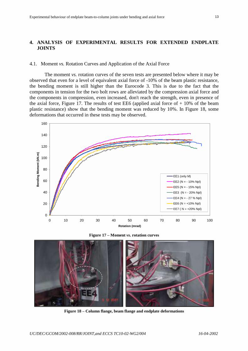
The moment vs. rotation curves of the seven tests are presented below where it may be observed that even for a level of equivalent axial force of -10% of the beam plastic resistance, the bending moment is still higher than the Eurocode 3. This is due to the fact that the components in tension for the two bolt rows are alleviated by the compression axial force and the components in compression, even increased, don't reach the strength, even in presence of the axial force, Figure 17. The results of test EE6 (applied axial force of + 10% of the beam plastic resistance) show that the bending moment was reduced by 10%. In Figure 18, some deformations that occurred in these tests may be observed.
0
20
40
60
80
100
120
140
160
0 10 20 30 40 50 60 70 80 90 100Rotation (mrad)
Ben
ding
Mom
ent (
kN.m
)
EE1 (only M)
EE2 (N = - 10% Npl)
EE5 (N = - 15% Npl)
EE3 (N = - 20% Npl)
EE4 (N = - 27 % Npl)
EE6 (N = +10% Npl)
EE7 ( N = +20% Npl)
Figure 17 – Moment vs. rotation curves
Figure 18 – Column flange, beam flange and endplate deformations

Experimental behaviour of endplate beam-to-column joints under bending and axial force
UC/DEC/GCOM/2002-008/RR/JOINT,and ECCS TC10-02-WG2/004 16-04-2002
14
5. DATABASE REPORTING
Currently, all tests performed at the University of Coimbra are organised in EXCEL sheets with the general organisation of Figure 19.
y = 0.167x + 72.307y = 4.763x + 5.7203
0
10
20
30
40
50
60
70
80
90
100
0.00 10.00 20.00 30.00 40.00 50.00 60.00 70.00 80.00 90.00 100.00Rotation (mrad)
Bend
ing
Mom
ent (
kN.m
)FE1 (only M)
Figure 19 – DATABASE information
Database on website: http://www.dec.uc.pt/~luisss/eccs/eccspreview.htm

Experimental behaviour of endplate beam-to-column joints under bending and axial force
UC/DEC/GCOM/2002-008/RR/JOINT,and ECCS TC10-02-WG2/004 16-04-2002
15
The detailed organisation of the information is as follows:
(i) Geometrical and Mechanical Properties.xls - This file described data for the complete experimental program (15 tests) in the following way:
(i.1) FLUSH ENDPLATE TESTS - These worksheets include nominal
values and all measured quantities
(i.1.a) Geometrical Properties • End-plate and beam (Figure 20) • Column
(i.1.b) Mechanical Properties* (i.1.c) Joint details (i.1.d) Test arrangement (i.1.e) Instrumentation - This worksheet identifies the relevant
positions within the test arrangement
(i.2) EXTENDED ENDPLATE TESTS *- These worksheets include nominal values and all measured quantities
(i.2.a) Geometrical Properties
• End-plate and beam (Figure 20) • Column
(i.2.b) Mechanical Properties * (i.2.c) Joint details (i.2.d) Test arrangement (i.2.e) Instrumentation - This worksheet identifies the relevant
positions within the test arrangement
(ii) FE1.xls to FE9.xls and EE1.xls to EE7.xls** - These files, all sharing the same structure, contain all the results for each individual test, organised in the following way:
(ii.1) DATALOGGER READINGS - This worksheet contains all readings
from datalogger, for the various channels already identified in file (i)Geometrical and Mechanical Properties.xls
(ii.2) INDIVIDUAL GRAPHS (CE… to CE…) - These worksheets contain graphical information for each channel, plotted agains load increments
* Incomplete ** Not all available at this stage

Experimental behaviour of endplate beam-to-column joints under bending and axial force
UC/DEC/GCOM/2002-008/RR/JOINT,and ECCS TC10-02-WG2/004 16-04-2002
16
Test d e f g h i lnominal 22.00 76.00 22.00 22.00 76.00 22.00 44.00
FE3 19.03 73.87 20.54 18.97 74.25 19.74 41.29FE4 21.57 72.47 18.61 21.78 73.43 18.65 43.05FE5 20.50 73.69 20.87 22.70 73.15 20.96 42.89FE1 21.05 73.60 16.00 22.05 73.60 15.95 44.50FE6 14.86 74.16 23.15 15.55 74.58 22.67 40.87FE7 17.80 74.17 20.86 17.84 73.98 20.95 44.13FE8 23.70 73.84 17.48 22.52 73.85 18.36 43.46FE9 18.77 73.32 19.85 18.03 73.10 20.34 51.06Test m n o p q d1 d2
nominal 44.00 136.00 136.00 44.00 44.00 22.00 22.00FE3 40.52 133.72 134.06 42.95 43.74 21.95 22.03FE4 42.67 133.81 133.08 43.94 43.45 22.14 22.17FE5 43.85 133.64 133.72 41.64 42.12 21.81 22.05FE1 43.70 133.71 133.76 40.70 40.20 22.10 22.15FE6 40.55 133.74 134.16 43.78 44.85 21.75 21.71FE7 44.38 133.73 133.80 41.04 40.88 21.87 21.88FE8 43.61 133.45 134.10 37.14 38.15 21.80 22.01FE9 51.01 132.71 132.58 40.00 40.12 22.94 22.89Test d3 d4 bp hp tp tfb1 tfb2
nominal 22.00 22.00 160.00 264.00 15.00 9.80 9.80FE3 22.03 22.11 158.01 263.86 15.52 10.18 9.56FE4 21.65 21.87 157.14 264.22 15.18 9.46 9.75FE5 21.94 22.25 156.58 262.46 15.24 9.33 9.84FE1 22.15 22.15 154.90 261.96 15.35 8.91 9.42FE6 21.72 21.83 155.63 263.46 15.52 9.50 9.49FE7 21.91 21.94 157.52 263.73 15.55 9.36 9.69FE8 21.86 21.84 159.49 258.27 15.16 9.65 8.93FE9 23.06 23.01 158.40 262.57 15.55 10.14 9.31Test tw wbf dh
nominal 6.20 120.00 240.00FE3 6.90 121.54 241.06FE4 6.90 122.08 241.05FE5 6.90 120.87 241.23FE1 6.90 121.05 242.36FE6 6.70 121.56 242.10FE7 7.00 121.45 242.77FE8 6.90 121.83 242.53FE9 7.50 120.83 243.22
wbftfb1
tw
dh
tfb2
d e f
g h i
ln
p
mo
q
hp
bp
tpd1 d2
d3 d4
Figure 20 – Column flange, beam flange and endplate measured quantities
This information is available for download from the following website:
http://www.dec.uc.pt/~luisss/eccs/eccspreview.htm
upon request (restricted use until the end of 2002, being part of the doctoral thesis of Luciano Lima – [email protected]).
6. CONCLUDING REMARKS
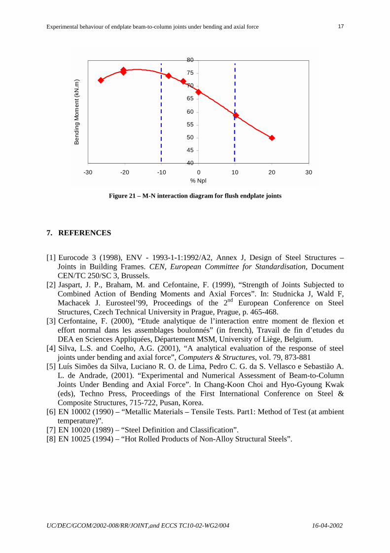
The experimental results obtained to the moment for beam-to-column connections with flush endplate allow the elaboration of a moment vs. axial force interaction curve corresponding to the elastic resistance of the connection, just as it illustrates the Figure 21.
From the analysis of the Table 3 that illustrates the resistance and elastic stiffness of the all components of the connection in study, calculated in agreement with Eurocode 3, it is possible to conclude that, for this connection, the tension zone presents a resistance of the critical component that is equal at 63% of the component of the compression zone. Thus, the compression axial force results in an increase of the bending moment resistance of the connection, as it is verified. The results evidence the need to prepare specific clauses for the design of connections subjected to axial forces and bending moment.
Experimental behaviour of endplate beam-to-column joints under bending and axial force
UC/DEC/GCOM/2002-008/RR/JOINT,and ECCS TC10-02-WG2/004 16-04-2002
17
40
45
50
55
60
65
70
75
80
-30 -20 -10 0 10 20 30% Npl
Bend
ing
Mom
ent (
kN.m
)
Figure 21 – M-N interaction diagram for flush endplate joints
7. REFERENCES
[1] Eurocode 3 (1998), ENV - 1993-1-1:1992/A2, Annex J, Design of Steel Structures – Joints in Building Frames. CEN, European Committee for Standardisation, Document CEN/TC 250/SC 3, Brussels.
[2] Jaspart, J. P., Braham, M. and Cefontaine, F. (1999), “Strength of Joints Subjected to Combined Action of Bending Moments and Axial Forces”. In: Studnicka J, Wald F, Machacek J. Eurosteel’99, Proceedings of the 2nd European Conference on Steel Structures, Czech Technical University in Prague, Prague, p. 465-468.
[3] Cerfontaine, F. (2000), “Etude analytique de l’interaction entre moment de flexion et effort normal dans les assemblages boulonnés” (in french), Travail de fin d’etudes du DEA en Sciences Appliquées, Département MSM, University of Liège, Belgium.
[4] Silva, L.S. and Coelho, A.G. (2001), “A analytical evaluation of the response of steel joints under bending and axial force”, Computers & Structures, vol. 79, 873-881
[5] Luís Simões da Silva, Luciano R. O. de Lima, Pedro C. G. da S. Vellasco e Sebastião A. L. de Andrade, (2001). “Experimental and Numerical Assessment of Beam-to-Column Joints Under Bending and Axial Force”. In Chang-Koon Choi and Hyo-Gyoung Kwak (eds), Techno Press, Proceedings of the First International Conference on Steel & Composite Structures, 715-722, Pusan, Korea.
[6] EN 10002 (1990) – “Metallic Materials – Tensile Tests. Part1: Method of Test (at ambient temperature)”.
[7] EN 10020 (1989) – “Steel Definition and Classification”. [8] EN 10025 (1994) – “Hot Rolled Products of Non-Alloy Structural Steels”.