experimental and numerical investigation of reduced gravity fluid
TRANSCRIPT
Experimental and Numerical Investigation of Reduced GravityFluid Slosh Dynamics for the Characterization of CryogenicLaunch and Space Vehicle Propellants
Laurie K. Walls\ Daniel Kirk2, Javier de Luis3
, Mark S. Haberbusch4
1 NASA, Kennedy Space CenterKennedy Space Center, FL 32899, USA
2 Florida Institute of TechnologyMelbourne, FL, 32901, USA
3 Aurora Flight SciencesCambridge, MA 02140, USA
4 Sierra Lobo, Inc.Milan, OH, 44846, USA
ABSTRACT
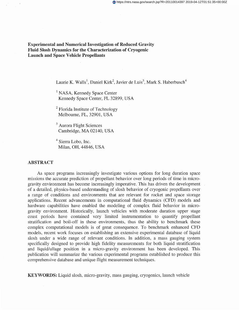
As space programs increasingly investigate various options for long duration spacemissions the accurate prediction of propellant behavior over long periods of time in microgravity environment has become increasingly imperative. This has driven the developmentof a detailed, physics-based understanding of slosh behavior of cryogenic propellants overa range of conditions and environments that are relevant for rocket and space storageapplications. Recent advancements in computational fluid dynamics (CFD) models andhardware capabilities have enabled the modeling of complex fluid behavior in microgravity environment. Historically, launch vehicles with moderate duration upper stagecoast periods have contained very limited instrumentation to quantify propellantstratification and boil-off in these environments, thus the ability to benchmark thesecomplex computational models is of great consequence. To benchmark enhanced CFDmodels, recent work focuses on establishing an extensive experimental database of liquidslosh under a wide range of relevant conditions. In addition, a mass gauging systemspecifically designed to provide high fidelity measurements for both liquid stratificationand liquid/ullage position in a micro-gravity environment has been developed. ThispUblication will summarize the various experimental programs established to produce thiscomprehensive database and unique flight measurement techniques.
KEYWORDS: Liquid slosh, micro-gravity, mass gauging, cryogenics, launch vehicle
https://ntrs.nasa.gov/search.jsp?R=20110014397 2019-04-12T01:51:35+00:00Z
INTRODUCTION
Upper-stages of rockets may undergo maneuvers, which may lead to sloshing of theliquid propellants and may adversely affect vehicle performance. For example, liquidmotion may generate reaction forces that alter the motion of the vehicle from its intendedtrajectory or cold cryogenic propellants may splash on warm tank surfaces leading tochanges in the thermodynamic state of the propellant. An additional consideration in launchvehicle design is the potential overlap of slosh resonant frequencies with the trajectorycontrol system and structural dynamics frequencies. Each of these potentially detrimentalsituations underscores the need for experimentally benchmarked CFD model, which wouldbe crucial to plan future space missions.
EXPERIMENTAL SLOSH CHARACTERIZATION AND NUMERICALMETHODS
Experimental data that allows full characterization of a slosh event is achieved viasynchronous capture by an array of cameras, accelerometers, and gyroscopic sensors. Thetime history of the tank relative to an inertial frame is sufficient to characterize a sloshevent, provided that the initial liquid distribution is known [1,2]. This approach is based onthe simultaneous measurement of the acceleration of the tank, the angular velocity, and thethree components of the heading vector. In this paper, two categories define any givenliquid slosh motion over a range of environments:
1. Forced motion of a rigid container: This category is applicable when fluid forcespushing back on the tank walls do not affect the prescribed motion of the tank. Themotion of the tank is independent of the sloshing forces acting on the container.2. Coupled motion of the tank and the sloshing liquid: If the container's motion is notconstrained, the sloshing liquid generates forces that push back on the container andmay alter its trajectory. This is especially important in suborbital applications such asupper-stage launch vehicles.
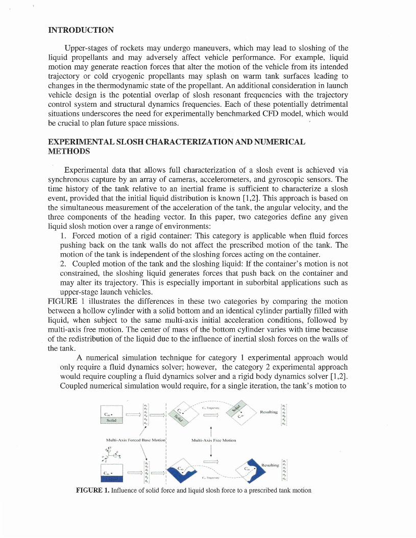
FIGURE 1 illustrates the differences in these two categories by comparing the motionbetween a hollow cylinder with a solid bottom and an identical cylinder partially filled withliquid, when subject to the same multi-axis initial acceleration conditions, followed bymulti-axis free motion. The center of mass of the bottom cylinder varies with time becauseof the redistribution of the liquid due to the influence of inertial slosh forces on the walls ofthe tank.
A numerical simulation technique for category 1 experimental approach wouldonly require a fluid dynamics solver; however, the category 2 experimental approachwould require coupling a fluid dynamics solver and a rigid body dynamics solver [1,2].Coupled numerical simulation would require, for a single iteration, the tank's motion to
/'
"<1("
n,/ Rc~uhing 0"
....v/ ~:::~
FIGURE 1. Influence of solid force and liquid slosh force to a prescribed tank motion
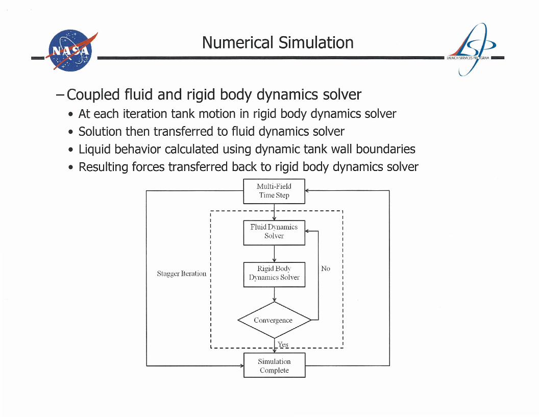
be solved in the rigid body dynamics solver and the solution to be transferred to the fluiddynamics solver. The liquid behavior is then calculated using the dynamic tank wallboundaries and the resulted liquid forces acting on the tank walls would transfer back to therigid body dynamics solver for the next iteration. The rigid body dynamics solver assumesthat any motion of a rigid body can be split into translational and rotational motions.Appropriate grid resolution is critical to achieving good results using any CFD method. Inparticular, the mesh near the tank walls must be sufficiently refined to capture capillaryaction and wall wetting.
EXPERIMENTAL AND COMPUTATIONAL RESULTS
This section presents examples from successful experiments performed over variedconditions, which offer diverse sloshing events. The different variety of sloshing eventsdue to different conditions challenges the CFD tool with a unique opportunity to validateeach set of sloshing events. This paper details three major experiments from three differentcategories: 1. Ground- based experiments, 2. Simulated micro-gravity experiments and 3.Long duration micro-gravity experiments. Liquid sloshing events due to each experimentare recorded and compared to CFD model predictions.
Ground- Based Experiments
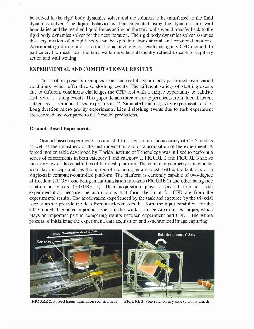
Ground-based experiments are a useful first step to test the accuracy of CFD modelsas well as the robustness of the instrumentation and data acquisition of the experiment. Aforced motion table developed by Florida Institute of Tehcnology was utilized to perform aseries of experiments in both category 1 and category 2. FIGURE 2 and FIGURE 3 showsthe overview of the capabilities of the slosh platform. The container geometry is a cylinderwith flat end caps and has the option of including an anti-slosh baffle; the tank sits on asingle-axis computer-controlled platform. The platform is currently capable of two-degreeof freedom (2DOF), one being linear translation in x-axis (FIGURE 2) and other being freerotation in y-axis (FIGURE 3). Data acquisition plays a pivotal role in sloshexperimentation because the assumptions that form the input for CFD are from theexperimental results. The acceleration experienced by the tank and captured by the tri-axialaccelerometer provide the data from accelerometers that form the input conditions for theCFD model. The other important aspect of this work is image-capturing technique, whichplays an important part in comparing results between experiment and CFD. The wholeprocess of initializing the experiment, data acquisition and synchronized image capturing,
FIGURE 2. Forced linear translation (constrained) FIGURE 3. Free rotation at y-axis (unconstrained)
0.1 H III
Time=- 1.6sTank with slosh baffle
mTime=- 1.65
Tank with no baffleTime =- 1.4 5
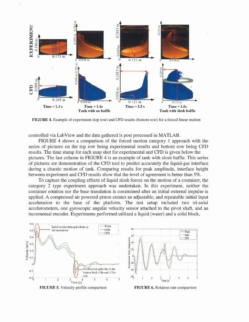
FIGURE 4. Example of experiment (top row) and CFD results (bottom row) for a forced linear motion
controlled via LabView and the data gathered is post processed in MATLAB.FIGURE 4 shows a comparison of the forced motion category 1 approach with the
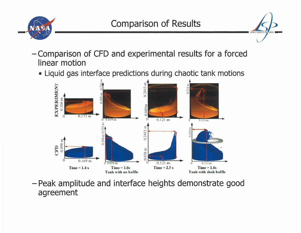
series of pictures on the top row being experimental results and bottom row being CFDresults. The time stamp for each snap shot for experimental and CFD is given below thepictures. The last column in FIGURE 4 is an example of tank: with slosh baffle. This seriesof pictures are demonstration of the CFD tool to predict accurately the liquid-gas interfaceduring a chaotic motion of tank. Comparing results for peak amplitude, interface heightbetween experiment and CFD results show that the level of agreement is better than 5%.
To capture the coupling effects of liquid slosh forces on the motion of a container, thecategory 2 type experiment approach was undertaken. In this experiment, neither thecontainer rotation nor the base translation is constrained after an initial external impulse isapplied. A compressed air powered piston creates an adjustable, and repeatable initial inputacceleration to the base of the platform. The test setup included two tri-axialaccelerometers, one gyroscopic angular velocity sensor attached to the pivot shaft, and anincremental encoder. Experiments performed utilized a liquid (water) and a solid block,
.O·~;:----:--~2--
, ,3 4Time (s)
FIGURE 6. Rotation rate comparison
KOI----,.------,----r--;::~====;l------Waler-Solid---CFD
:----·Walcr-Solid·····eFD
Dec'ei-;"'tion spill dll .. 10 tllebounce-bad: mU,e end cf U,eri1il~
Initial accelH~tion~pike from airdri;-en actuator
3 --"4--,-'--"6-_. -7
Time (5)
FIGURE 5. Velocity profile comparison
0.5
0.6
-0.1-
which was then replicated using the CFD tool. The solid block was preferred in simulationbecause of its predictive and simplified inertial motion it would impart to the tank. Theresults for the liquid tests, solid block tests and the corresponding liquid CFD simulationswere benchmarked using the linear velocity plot (FIGURE 5) and the rotation rate plot(FIGURE 6) from the gyroscopic sensor data.The velocity plot of the water test deviated amaximum of 43.04% compared to the solid test at 0.002 m3 fill level, and the deviationreduced to a maximum 28.95% at the 0.004 m3 fill level. Observation of rotation ratecomparison shows a similar trend, with the same initial acceleration, the system gained lessmomentum at low fill level. The less momentum gained by the entire system, the more theliquid motion affected system's motion due to the liquid to solid mass ratios, as seen on theprevious tests group. A general good agreement between water tests and CFD simulationswas found: the average difference in results (CFD compared to measured data) varied from8.74% to 10.53%.
Simulated Micro-gravity Experiments
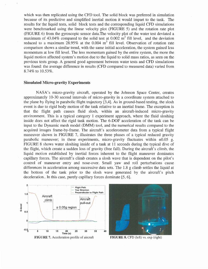
NASA's micro-gravity aircraft, operated by the Johnson Space Center, createsapproximately 10-30 second intervals of micro-gravity in a coordinate system attached tothe plane by flying in parabolic flight trajectory [3,4]. As in ground-based testing, the sloshevent is due to rigid body motion of the tank relative to an inertial frame. The exception isthat the flight path causes fluid slosh, within an aircraft-induced micro-gravityenvironment. This is a typical category 1 experiment approach, where the fluid sloshinginside does not affect the rigid tank motion. The 6-DOF acceleration of the tank can beinput to the Dynamic mesh model (DMM) tool, and the numerical results compared to theacquired images frame-by-frame. The aircraft's accelerometer data from a typical flightmaneuver shown in FIGURE 7, illustrates the three phases of a typical reduced gravityparabolic maneuver; in these experiments, micro-gravity fluctuates within ±0.05 g.FIGURE 8 shows water sloshing inside of a tank at 11 seconds during the typical dive ofthe flight, which create a sudden loss of gravity (free fall). During the aircraft's climb, theliquiq motion established by inertial forces inherent to the flight maneuver dominatescapillary forces. The aircraft's climb creates a slosh wave that is dependent on the pilot'scontrol of maneuver entry and nose-over. Small yaw and roll perturbations causedifferences in acceleration among successive data sets. The 1.8 g climb settles the liquid atthe bottom of the tank prior to the slosh wave generated by the aircraft's pitchdeceleration.. In this case, purely capillary forces dominate [5, 6].
5 10 15 20 25 30 35Time (5)
FIGURE 7. Acceleration profile of aircraft
2 -- -,--- --'.-
FIGURE 8. CFD (left) vs. exp (right)
40
!Aircraft:pull-outIIIIIIIIII
, ,-- Flight Path- Yaw Direction- Perpendicular to Flight Path
± 0.05g region
Aircraftclimbl----.
IIIIIIIIIII
1.5
11'ii>~
6 0.5
0
~.50

•
FIGURE 9. MIT SPHERES
Long Duration Micro-gravity Experiments
FIGURE 10. Future twin SPHERES concept
Simulated micro-gravity has shortcomings, one being it is a category 1experimentation approach and the other being a shorter time interval of simulated microgravity. These shortcomings are not relevant if the experiments performed would be in anactual micro-gravity environment. Synchronized Position Hold Engage and ReorientExperimental Satellites (SPHERES) an experimental platform developed initially atMassachusetts Institute of Technology (MIT), consists of small free-flying satellites, eachwith C02 cold gas thrusters and a thruster fuel tank.FIGURE 9 shows the schematic ofexperimental platform, which is highly beneficial due to its small size and the location ofthe experiment, the International Space Station (ISS). An example test would be a partiallyfilled SPHERES's thruster tank fired for a short duration from a specific face with the tank,settling after mitigation of sloshing events inside. The duration of experiment is not critical,but the magnitude and duration of single or multiple thrust events must be controlled so asnot to collide with space station walls. Information and data provided by SPHERESprogram, as the tank and satellite responded to the thrust event, was crucial inunderstanding fluid behavior in micro-gravity environment, and validation with CFDreinforced the reliability of CFD models to quantify accurately the sloshing events.
The success of SPHERES project dictated the need to push the envelope ofcomplexity involved in modeling slosh in micro-gravity. It was desired to determine if theCFD model could accurately predict a combined twin tank with different fluid or fill levelsundergoing different slosh modes due to the motion of launch or spacecraft vehicles. Itbecame important to establish scenarios common with docking procedures for launchvehicles, fuel depots in space, and satellites; hence, a concept has been created based on theinitial SPHERES project, utilizing two SPHERES and two liquid propellant tanksrepresenting a launch or space vehicle. The 6DOF motion would be created via an array ofcold-flow C02 thrusters supplied from the built-in liquid C02 tank. The DMM modelwould predict the effect of the liquid C02 slosh within the simulated tanks based on the 6DOF trajectory of the SPHERES satellite. This would be accomplished by applying aprescribed thruster impulse to the two satellites, one with a full C02 tank and a second onewith a near-empty C02 tank. In both cases, the resulting 6DOF motion would be captured,the differences being attributable to the different C02 slosh motion inside of the tank. The6DOF force and torque thrust vectors would form inputs to the DMM simulation, and theslosh responses and predictions would then be compared to the recorded trajectories.
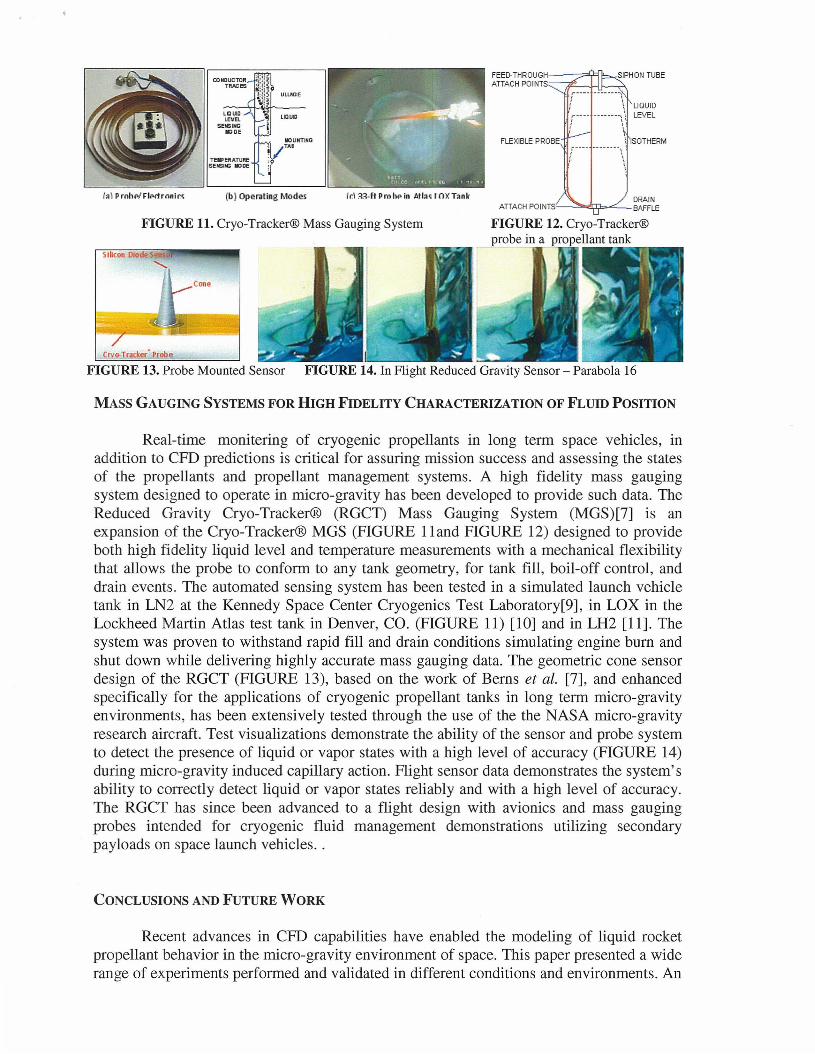
FIGURE 11. Cryo-Tracker® Mass Gauging System
~ SOTHERII1FLEXIBLE PROBE
DRAINATTACH POINTS'---.:~;I;b--~BAFFLE
FEED-THROUGH--=Y=lATIACH POINTS,iF--+Lf----.A
FIGURE 12. Cryo-Tracker®probe in a propellant tank
Id:n·ftPmhpin Atlo<lOXT.nk(b) Operating Modes
Cone
Crvo-T~cker' Probe
Silicon orode S ,
1.1 PrnhP! Flpctrnni«
FIGURE 13. Probe Mounted Sensor FIGURE 14. In Flight Reduced Gravity Sensor - Parabola 16
MASS GAUGING SYSTEMS FOR HIGH FIDELITY CHARACTERIZATION OF FLUID POSITION
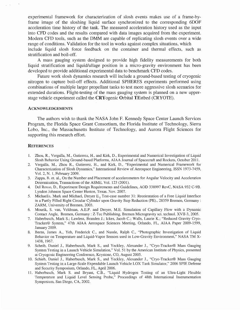
Real-time monitering of cryogenic propellants in long term space vehicles, inaddition to CFD predictions is critical for assuring mission success and assessing the statesof the propellants and propellant management systems. A high fidelity mass gaugingsystem designed to operate in micro-gravity has been developed to provide such data. TheReduced Gravity Cryo-Tracker® (RGCT) Mass Gauging System (MGS)[7] is anexpansion of the Cryo-Tracker® MGS (FIGURE lland FIGURE 12) designed to provideboth high fidelity liquid level and temperature measurements with a mechanical flexibilitythat allows the probe to conform to any tank geometry, for tank fill, boil-off control, anddrain events. The automated sensing system has been tested in a simulated launch vehicletank in LN2 at the Kennedy Space Center Cryogenics Test Laboratory[9], in LOX in theLockheed Martin Atlas test tank in Denver, CO. (FIGURE 11) [10] and in LH2 [11]. Thesystem was proven to withstand rapid fill and drain conditions simulating engine bum andshut down while delivering highly accurate mass gauging data. The geometric cone sensordesign of the RGCT (FIGURE 13), based on the work of Berns et al. [7], and enhancedspecifically for the applications of cryogenic propellant tanks in long term micro-gravityenvironments, has been extensively tested through the use of the the NASA micro-gravityresearch aircraft. Test visualizations demonstrate the ability of the sensor and probe systemto detect the presence of liquid or vapor states with a high level of accuracy (FIGURE 14)during micro-gravity induced capillary action. Flight sensor data demonstrates the system'sability to correctly detect liquid or vapor states reliably and with a high level of accuracy.The RGCT has since been advanced to a flight design with avionics and mass gaugingprobes intended for cryogenic fluid management demonstrations utilizing secondarypayloads on space launch vehicles..
CONCLUSIONS AND FUTURE WORK
Recent advances in CFD capabilities have enabled the modeling of liquid rocketpropellant behavior in the micro-gravity environment of space. This paper presented a widerange of experiments performed and validated in different conditions and environments. An
· '
experimental framework for characterization of slosh events makes use of a frame-byframe image of the sloshing liquid surface synchronized to the corresponding 6DOFacceleration time history of the tank. The measured acceleration history used as the inputinto CFD codes and the results compared with data images acquired from the experiment.Modem CFD tools, such as the DMM are capable of replicating slosh events over a widerange of conditions. Validation for the tool in works against complex situations, whichinclude liquid slosh force feedback on the container and thermal effects, such asstratification and boil-off.
A mass gauging system designed to provide high fidelity measurements for bothliquid stratification and liquid/ullage position in a micro-gravity environment has beendeveloped to provide additional experimental data to benchmark CFD codes.
Future work slosh dynamics research will include a ground-based testing of cryogenicnitrogen to capture boil-off effects. Additional SPHERES experiments performed usingcombinations of multiple larger propellant tanks to test more aggressive slosh scenarios forextended durations. Flight-testing of the mass gauging system is planned on a new upperstage vehicle experiment called the CRYogenic Orbital TEstbed (CRYOTE).
ACKNOWLEDGEMENTS
The authors wish to thank the NASA John F. Kennedy Space Center Launch ServicesProgram, the Florida Space Grant Consortium, the Florida Institute of Technology, SierraLobo, Inc., the Massachusetts Institute of Technology, and Aurora Flight Sciences forsupporting this research effort.
REFERENCES
1. Zhou, R., Vergalla, M., Gutierrez, H., and Kirk, D., Experimental and Numerical Investigation of LiquidSlosh Behavior Using Ground-based Platforms, AIAA Journal of Spacecraft and Rockets, October 2011.
2. Vergalla, M., Zhou R., Gutierrez, H., and Kirk, D., "Experimental and Numerical Framework forCharacterization of Slosh Dynamics," International Review of Aerospace Engineering, ISSN 1973-7459,Vol. 2, N. 1, February 2009.
3. Zappa, B. et. al., On the Number and Placement of accelerometers for Angular Velocity and AccelerationDetermination, Transactions of the ASME, Vol. 123 (2001).
4. Del Rosso, D., Experiment Design Requirements and Guidelines, AOD 338997 RevC, NASA 932 C-9B.Lyndon Johnson Space Center Huston, Texas. Nov. 2007.
5. Michaelis, Mark and Michael, Dreyer E't Test-case number 31: Reorientation of a Free Liquid Interfacein a Partly Filled Right Circular Cylinder upon Gravity Step Reduction (PE)., 28359 Bremen, Germany:ZARM, University of Bremen, 2003.
6. Mourik, S. van, Veldman, A.E.P. and Dreyer, M.E. Simulation of Capillary Flow with a DynamicContact Angle, Bremen, Germany: Z-Tec Publishing, Bremen Microgravity sci. technol. XVII-3, 2005.
7. Haberbusch, Mark S.; Lawless, Branden J.; Ickes, Jacob C.; Walls, Laurie K.; "Reduced Gravity CryoTracker® System," 47th AIAA Aerospace Sciences Meeting, Orlando, FL, AIAA Paper 2009-1599,January 2009.
8. Berns, James A., Yeh, Frederick c., and Nussle, Ralph c., "Photographic Investigation of LiquidBehavior on Temperature and Liquid-Vapor Sensors used in Low-Gravity Environment," NASA TM X1438, 1967.
9. Scheib, Daniel J., Haberbusch, Mark S., and Yeckley, Alexander J., "Cryo-Tracker® Mass GaugingSystem Testing in a Launch Vehicle Simulation," Vol. 51 by the American Institute of Physics, presentedat Cryogenic Engineering Conference, Keystone, CO, August 2005.
10. Schieb, Daniel J., Haberbusch, Mark S., and Yeckley, Alexander J., "Cryo-Tracker® Mass GaugingSystem Testing in a Large-Scale Expendable Launch Vehicle LOX Tank Simulator," 2006 SPIE Defenseand Security Symposium, Orlando, FL, April 2006.
11. Haberbusch, Mark S. and Bryant, C.B., "Liquid Hydrogen Testing of an Ultra-Light FlexibleTemperature and Liquid Level Sensing Probe," Proceedings of 48th International InstrumentationSymposium, San Diego, CA, 2002.
- N~~'".~~~"," +.': .
•
~~[fO[[fi)@[ft)trIIDO (ID[ft)@] ~(ill[[fi)@[fO~O Ir[ft)W~O~(ID~O@[ft) @1j~@@](ill~ @][f(IDWO~ [PO(ill O@] ~O@@[fi) [Q)J'1[ft)(ID[[fi)om {f@[f ~[fi)@
~[fi)(ID[f(ID~[fO~~O@[ft) @1j ~D}j~@[ft) o© ~ (ill [ft)©[fi) (ID [ft)@]~~(ID~ W@[}uo©O@ ~[F@~@OO(ID[ft)~
- Introduction
- The investigation of slosh dynamics in cryogenic propellant tanks oflaunch and space vehicles has become increasi 'g;u;)Gr:tam~:--l
• Planetary launches often require extended upper sta• Proposed long duration space missions may involve i• Planetary spacecraft and landers frequently utilize c
- Stringent mass requirements drive precision control and managementof propellant reserves• In space vehicle maneuvers drive slosh events that can cause severe
. iquid boil-off and asymmetric mass flow
mputational Fluid Dynamic (CFD) modelsexperimental data has become imperative fortion of complex space induced environments fors
- N~:.,~~~.,. +,': ..
Experimental Characterization
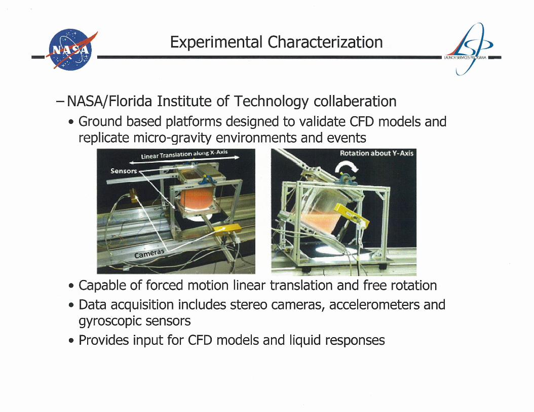
- NASA/Florida Institute of Technology collaberation• Ground based platforms designed to validate CFD models and
replicate micro-gravity environments and events
• Capable of forced motion linear translation and free rotation• Data acquisition includes stereo cameras, accelerometers and
gyroscopiC sensors• Provides input for CFD models and liquid responses
- Experimental Characterization
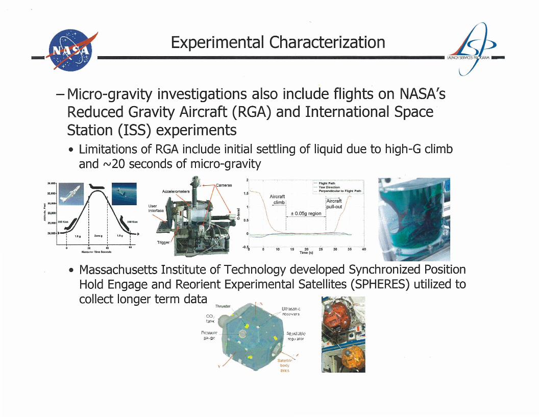
- Micro-gravity investigations also include flights on NASA'sReduced Gravity Aircraft (RGA) and International Space·Station (ISS) experiments• Limitations of RGA include initial settling of liquid due to high-G climb
and rv20 seconds of micro-gravity2 1 - ~
- Flight Path- Yaw Direction
1.5 ,---- - Perpendiculano Flighc Path
. Aircraft ~ /
\climb: :AirCraftj
0; 1 ----: :pull-out~ \ : ± O.05g region: ..
-.-.-e" 0.5 \: : /\ I I ,
0.=>: :./ >. I
I
I40.. ..
M.nevvtf Tlmt s.concta
JO.
;\e.ll~I<lIlJt'
!('>.jll i1IQr
r-(t~.I({
~~,.~(.
• Massachusetts Institute of Technology developed Synchronized PositionHold Engage and Reorient Experimental Satellites (SPHERES) utilized tocollect longer term data
ThrtJ!ltef
- Reduced Gravity Mass Gauging System
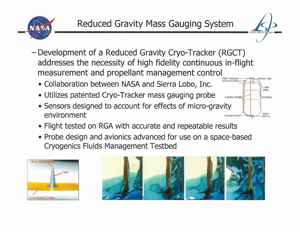
- Development of a Reduced Gravity Cryo-Tracker (RGCT)addresses the necessity of high fidelity continuous in-flightmeasurement and propellant management control
FEED-THROUGH~"Y4 6-..S
• Collaboration between NASA and Sierra Lobo, Inc. ATTACH POINTS
r---. \ 1\ LEVEL
• Utilizes patented Cryo-Tracker mass gauging probe FLEXIBLE PROBE :: :\ ISOTHERM
• Sensors designed to account for effects of micro-gravity : \environment ATTACHPOINTS~~~~~E
• Flight tested on RGA with accurate and repeatable results• Probe design and avionics advanced for use on a space-based
Cryogenics Fluids Management Testbed
Silicon Diode S -,
Crvo-Tracker' Probe
Cone

- Two methods of numerical simulation• Forced motion of a rigid container• Fluid forces on tank wall do not affect prescribed tank
motion
• Coupled motion of tank and sloshing liquid• Reactive liquid forces on tank alter trajectory
- N~;+t' •• " • ':.t.
0••••
+'" .
Computational Representations
~~~.~. . I
I ' .':;....~~, II
-='It:.!. r
i'~. --;~~~"
- N~.. ~:t-'..~~~... +.....
Numerical Simulation
- Coupled fluid and rigid body dynamics solver• At each iteration tank motion in rigid body dynamics solver• Solution then transferred to fluid dynamics solver• liquid behavior calculated using dynamic tank wall boundaries• Resulting forces transferred back to rigid body dynamics solver
Multi-FieldTime Step
Fluid DynamicsSolver
Stagger IterationRigid Body
Dynamics SolverNo
SimulationComplete
- N~.:...+,".~~~".. +.': .
Comparison of Results
- Comparison of CFD and experimental results for a forcedlinear motion• Liquid gas interface predictions during chaotic tank motions
Time: 1.4so . m
Tim =1.6sTank with no baffle
O.1I3m
Tim =1.6sTank with slosh baffle
- Peak amplitude and interface heights demonstrate goodagreement

- N~;'..~~~... +......
Comparison of Results
- Non constrained base translation and container• Liquid and solid block tests and CFD comparison
76
I·..n*water-SolidI···.. CFD
53 4Time (s)
26
-.-." Water
- olia·····CFD -----J
5
- "T'
"'1
De"C~iemt.ion:;:pike due to thebunce-back;lt tlle end nherail~,.._---'---,- ~ - - .......1 _
3 4Time (8)
a
.0.1,
-O.2~----'---
0.61 -'-'I I1l.itial accelewtlOllspike from <'IiI'
0.5~ :;, ~-.. dnyen achmtQl'I ,"
OAI' ....1 •.. .
.....-... I I \ ~ t'
~ 03 .. ",/E' \~.......'......... .a 0.2 :."'" .() I
a~ 0.1 I
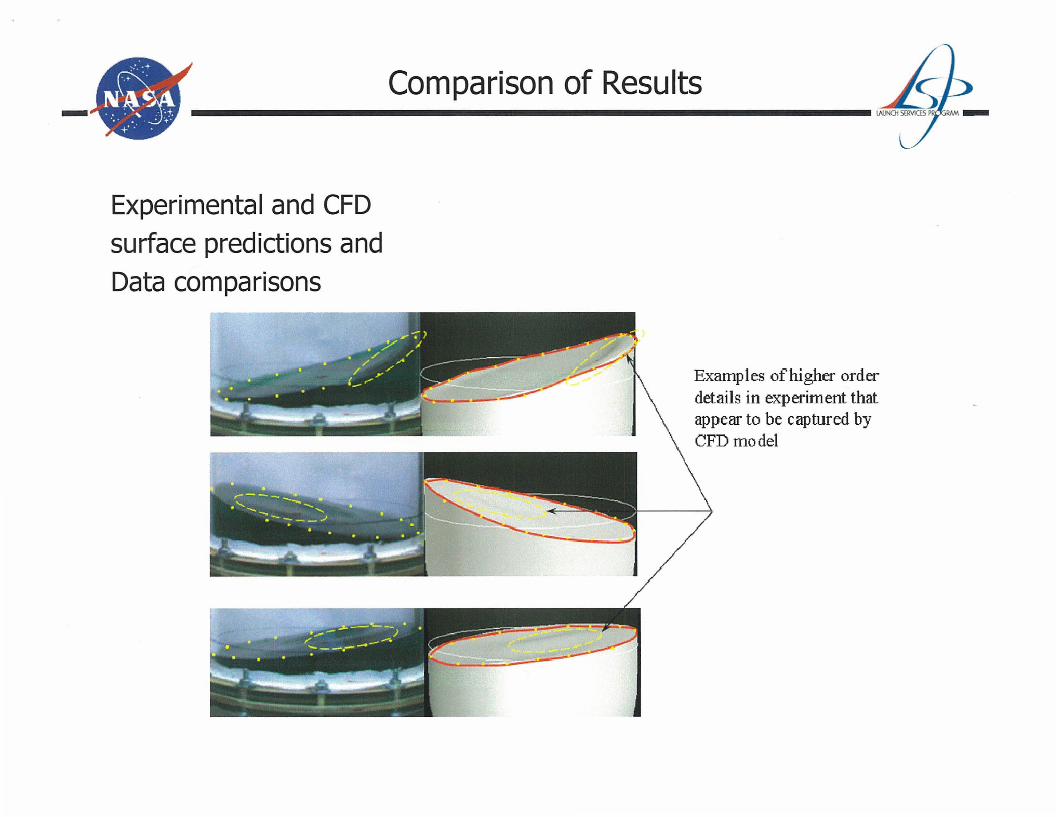
-Experimental and CFDsurface predictions andData comparisons
Comparison of Results
Examples of higher orderdetails in experiment thatappear to be captured byCFD model
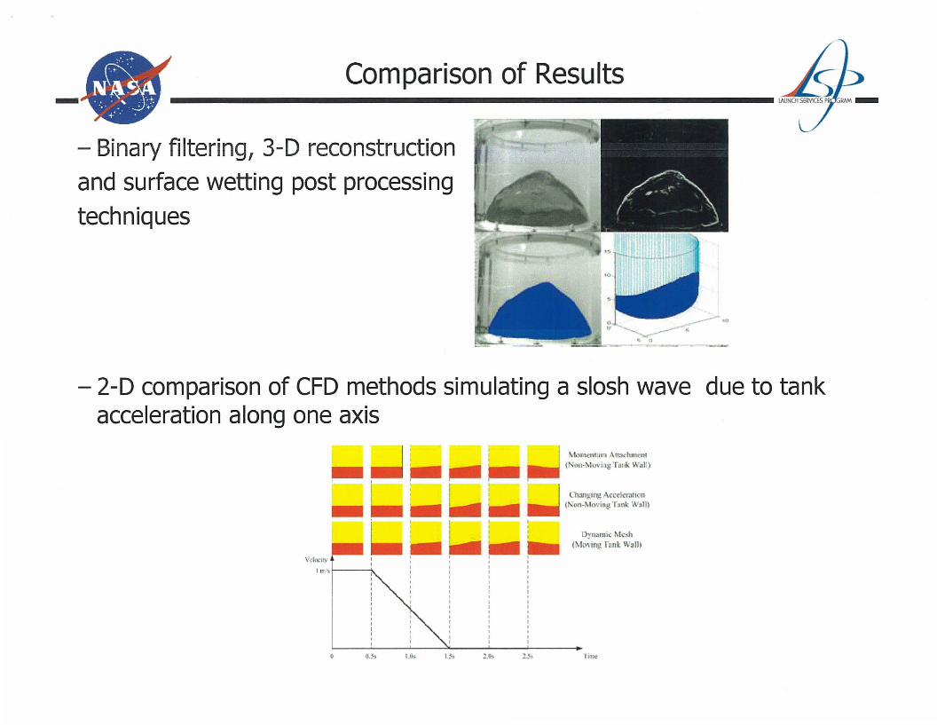
- Binary filtering, 3-D reconstructionand surface wetting post processingtechniques
- N~:'..~~~... + .
Comparison of Results
- 2-D comparison of CFD methods simulating a slosh wave due to tankacceleration along one axis
VdocllYIlr~f--_
Momcntlllll Atr:.lchment( 'on.1\IO"; 'f; Tank Wal')
Changlllg Accelcrarum( on.Mo\·;nll T.nk \ .11)
Dyn.mic M h(Mo\'mg r'nk \VallI
- ~.~:.. :+
N~·:~o'. • l''.0 +0': ..
Conclusions and Future Work
U1re boil-off effectsch vehicle propellant
eling of cryogenic LNrv:or_r,,"'I'S on ISS with simulate
- Ground base- Additiona SP
~
tanks - /- Flight testing of the micro-gravity mass gauging system on-board the upper stage
of a launch vehicle
• FUTURE WORK
• Recent advances in CFD capabilities have enabled modeling of cryogenic propellantbehavior in space environments
• A wide variety of experimental and computational techniques have been developedand validated for various conditions and environments
• Ability to model complex space vehicle events in micro-gravity and advanced dataacquisition techniques have been developed
• A mass gauging system designed to provide high fidelity measurements for liquidstratification and liquid/ullage positions in micro- gravity has been tested andvalidated