experiment ix - eskisehir.edu.treem.eskisehir.edu.tr/userfiles/heerol/files/exp9.pdf · eem471...
TRANSCRIPT

EEM471 ELECTRICAL MACHINERY LABORATORY / EXPERIMENT IX 1
Instructor : Assist. Prof. Dr. Sener AGALAR
TA : Res. Asst. H. Ersin EROL
ANADOLU UNIVERSITY
DEPT. OF ELECTRICAL AND ELECTRONICS
ENGINEERING
EEM 471 ELECTRICAL MACHINERY
LABORATORY
EXPERIMENT IX
Polyexcitation Direct Current (DC) Machine
• Effective Efficiency test of the DC Motor with Braking DC
Generator
EEM471 ELECTRICAL MACHINERY LABORATORY / EXPERIMENT IX 2
CONVENTIONAL EFFICIENCY
The conventional efficiency of DC motor can be calculated using the data measured in the
previous tests.
3.1 Friction and ventilation losses, at rated speed, measured through the method of no-load
motor operation (test 2) Pm = ....
3.2 No-load iron losses, at rated voltage and speed, measured through the method of no-load
motor operation (point 2) Pir = ...
3.3 Joule effect losses in inductor windings and in rheostats, at rated voltage and power.From
the no - load test the excitation current is calculated corresponding to the rated voltage,
then the excitation losses are calculated.Pe = Vr . lexc
3.4 Joule effect losses in armature windings. The ohmic resistance of the armature, measured
at room temperature (test 1), has to be referred to the conventional temperature of 75°C.
Ra75 = Rart[l + 0.004 (75 - rt)] When the rated absorbed current of the dc motor is indicated with la-, the total
armature current is given by la = I2r - lexc The armature losses can be therefore calculated
Pa = Ra75 . la2
3.5 Electric losses due to brush contacts. As the contact resistance between brush and
commutator follows an anomalous behaviour, the brush losses are conventionally
evaluated.
Pb = 2 la (carbon or graphite brushes)
Pb = 0.6 la (metal brushes) . Where la is the total armature current.
3.6 Additional losses. As the switching from no-load to load condition implies an alteration of
the pole flux distribution due to the armature reaction, this is kept into account through
additional losses that are conventionally evaluated
Padd = 0.5% Vr la
3.7 Conventional efficiency. The total losses of the DC motor operating at rated voltage and
load are given by P1 = Pm + Pir + Pe + Pa + Pb + Padd the conventional efficiency can be
therefore calculated:
where Pabs = Vr • lar
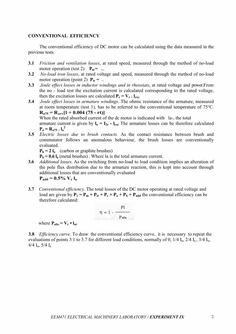
3.8 Efficiency curve. To draw the conventional efficiency curve, it is necessary to repeat the
evaluations of points 3.1 to 3.7 for different load conditions, normally of 0, 1/4 Ia, 2/4 Ia , 3/4 Ia,
4/4 Ia, 5/4 Ia
EEM471 ELECTRICAL MACHINERY LABORATORY / EXPERIMENT IX 3
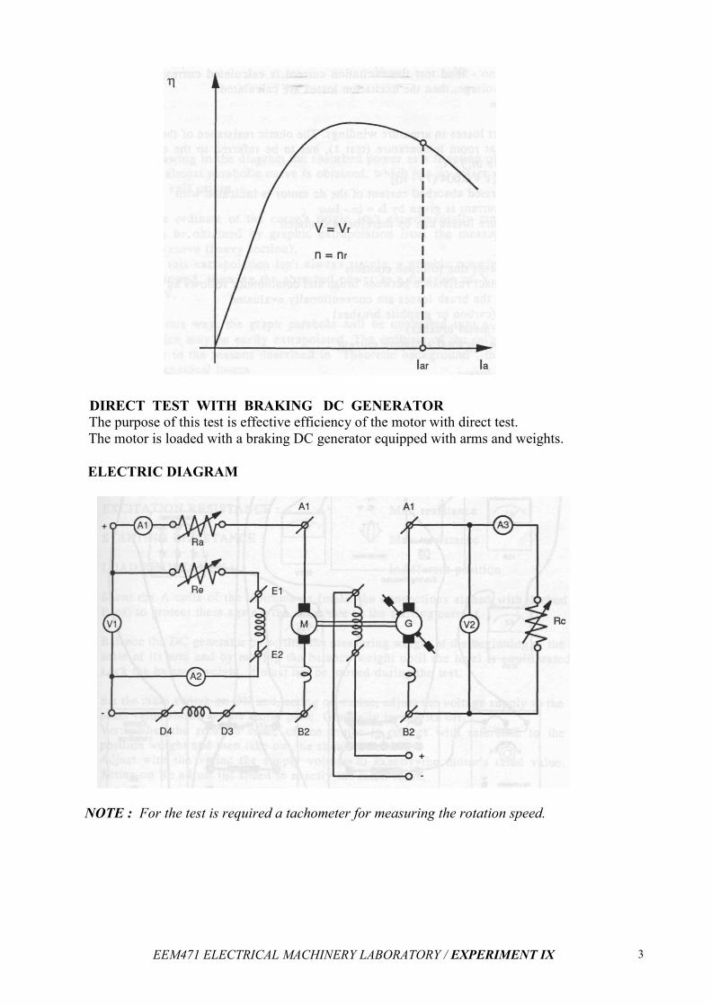
DIRECT TEST WITH BRAKING DC GENERATOR
The purpose of this test is effective efficiency of the motor with direct test.
The motor is loaded with a braking DC generator equipped with arms and weights.
ELECTRIC DIAGRAM
NOTE : For the test is required a tachometer for measuring the rotation speed.
EEM471 ELECTRICAL MACHINERY LABORATORY / EXPERIMENT IX 4
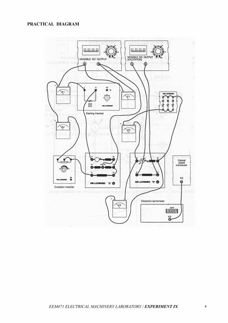
PRACTICAL DIAGRAM
EEM471 ELECTRICAL MACHINERY LABORATORY / EXPERIMENT IX 5
TEST PROCEDURE
After the set up of the motor under test and of the DC braking generator make all the connections in accordance with the attached diagrams and set the commands as follows:
1 Preset the module:
VARIABLE DC OUTPUT :
VARIABLE DC OUTPUT : (excitation)
EXCITATION RESISTANCE:
STARTING RESISTANCE :
LOAD RESISTANCE :
Switch open
Output with about 230V
Switch open
Variac fully turned in CCW direction
Min. resistance
Max. resistance
Indifferent position
2 Set the main switch on ON and, acting on variac, adjust the voltage supply to the exact value
shown on the motor plate. Gradually switch Ra off. Verify that the rotation sense of the motor
is correct with reference to the position weight and then take out the shunt current. Adjust with
the variac the supply voltage to exactly the motor's rated value. Acting on Re adjust the speed
to exactly the rated value.
3 Take up the instruments readouts and the motor rpm. through a tachometer.
4 Switch off the main switch which causes the stop the motor.
NOTE: Instead of DC braking generators, we will use magnetic brakes
for this test !!!

EEM471 ELECTRICAL MACHINERY LABORATORY / EXPERIMENT IX 6
Table of Measuring Results
Magnetic
Brake
Voltage
Levels
C (Nm) n (rpm) Pr (W) U (V) Iind Iexc Pabs η
0
25
50
75
100
125
150
175
200
Pabs = V.(Iind + Iexc) Iabs = Iind + Iexc η = Pr / Pabs
*** In report Plot Pr versus Iabs, n, η