experiment # 9 clock generator circuits...
TRANSCRIPT
Experiment # 9
Clock generator circuits
& Counters
Eng. Waleed Y. Mousa
1
1. Objectives: 1. Understanding the principles and construction of Clock generator.
2. To be familiar with clock pulse generation using 555 timer.
3. Introduction to counters. Design and applications.
2. Theory:
Clock Generator:
Timing or synchronization is very crucial to most electronic devices and systems. This
is because timing is essential in maintaining the proper sequencing of events. There
are many ICs designed and manufactured specifically to accomplish this task. One of
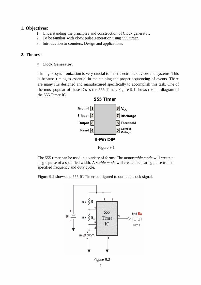
the most popular of these ICs is the 555 Timer. Figure 9.1 shows the pin diagram of
the 555 Timer IC.
The 555 timer can be used in a variety of forms. The monostable mode will create a
single pulse of a specified width. A stable mode will create a repeating pulse train of
specified frequency and duty cycle.
Figure 9.2 shows the 555 IC Timer configured to output a clock signal.
Figure 9.1
Figure 9.2
2
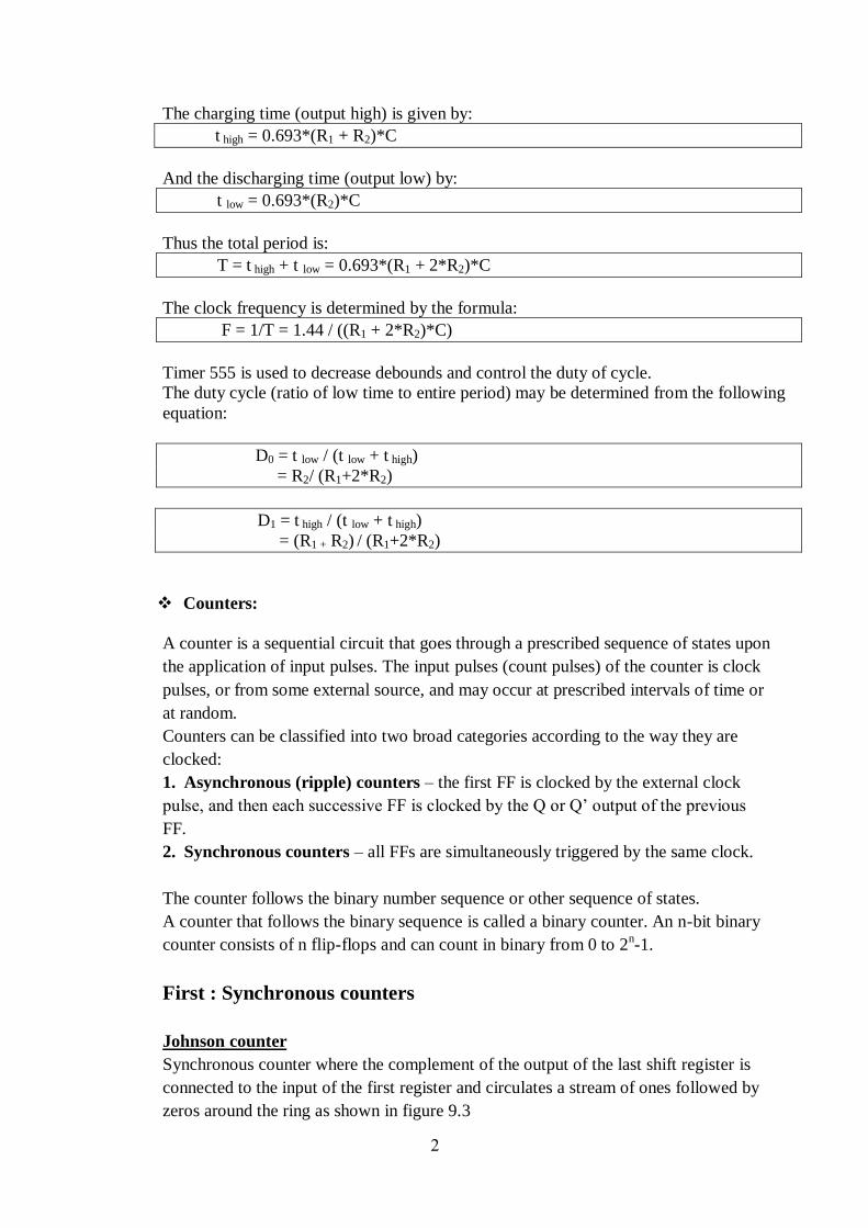
The charging time (output high) is given by:
t high = 0.693*(R1 + R2)*C
And the discharging time (output low) by:
t low = 0.693*(R2)*C
Thus the total period is:
T = t high + t low = 0.693*(R1 + 2*R2)*C
The clock frequency is determined by the formula:
F = 1/T = 1.44 / ((R1 + 2*R2)*C)
Timer 555 is used to decrease debounds and control the duty of cycle.
The duty cycle (ratio of low time to entire period) may be determined from the following
equation:
D0 = t low / (t low + t high)
= R2/ (R1+2*R2)
D1 = t high / (t low + t high)
= (R1 + R2) / (R1+2*R2)
Counters:
A counter is a sequential circuit that goes through a prescribed sequence of states upon
the application of input pulses. The input pulses (count pulses) of the counter is clock
pulses, or from some external source, and may occur at prescribed intervals of time or
at random.
Counters can be classified into two broad categories according to the way they are
clocked:
1. Asynchronous (ripple) counters – the first FF is clocked by the external clock
pulse, and then each successive FF is clocked by the Q or Q’ output of the previous
FF.
2. Synchronous counters – all FFs are simultaneously triggered by the same clock.
The counter follows the binary number sequence or other sequence of states.
A counter that follows the binary sequence is called a binary counter. An n-bit binary
counter consists of n flip-flops and can count in binary from 0 to 2n-1.
First : Synchronous counters
Johnson counter
Synchronous counter where the complement of the output of the last shift register is
connected to the input of the first register and circulates a stream of ones followed by
zeros around the ring as shown in figure 9.3

3
Ring counter
A ring counter is a type of counter composed of a circular shift register. The output of
the last shift register is fed to the input of the first register.
Second : Asynchronous (ripple) counters
Binary Ripple Counter
A binary ripple counter consists of a series connection of complementing flip
flops, with the output of each flip flop connected to the Clk input of the next higher-
order flip-flop. The flip flop holding the least significant bit receives the incoming
count pulses.
Figure 9.3: Johnson counter
Table 1: 4-bit Johnson counter sequences
4
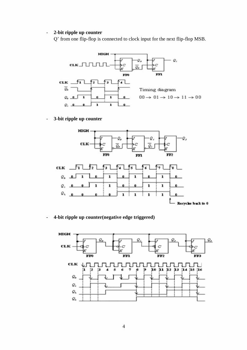
- 2-bit ripple up counter
Q’ from one flip-flop is connected to clock input for the next flip-flop MSB.
- 3-bit ripple up counter
- 4-bit ripple up counter(negative edge triggered)

5
- 3-bit ripple down counter
- BCD Ripple Counter
A decimal counter follows a sequence of ten states and returns to 0 after
the count of 9. Such counter must have at least four flip-flops to represent each
decimal digit, since a decimal digit is represented by a binary code with at
least four bits. The sequence of states in a decimal counter is indicated by the
binary code used to represent a decimal digit. If BCD is used, the sequence of
states is as shown in the state diagram of figure 9.4. This is similar to a binary
counter, except that the state after 1001 (code for decimal 9) is 0000 (code for
decimal 0).

6
The logic diagram of a BCD ripple counter is shown in figure 9.5. The four outputs
are designed by the letter symbol Q with a numeric subscript equal to the binary
weight of the corresponding bit in the BCD code. The flip-flops trigger on the
negative edge. Note that the output Q1 is applied to the Clk inputs of both Q2 and Q8
and the output of Q2 is applied to the Clk input of Q4. The J and K inputs are
connected either to a permanent 1 signal or to outputs of flip-flops, as shown in the
diagram.
The following are the conditions for each flip-flop state transition:-
1. Q1 is complemented on the negative edge of every count pulse.
2. Q2 is complemented if Q8 = 0 and Q1 goes from 1 to 0.
Q2 is cleared if Q8 = 1 and Q1 goes from 1 to 0.
3. Q4 is complemented when Q2 goes from 1 to 0.
4. Q8 is complemented when Q4Q2 = 11 and Q1 goes from 1 to 0.
Q8 is cleared if either Q4 or Q2 is 0 and Q1 goes from 1 to 0.
Figure 9.4: State diagram of a decimal BCD counter
Figure 9.5: BCD ripple counter

7
Other presentation of BCD ripple counter will be as follows:
1. We need four flip-flops, for example JK flip flops where J and K are high.
2. Count from 0-9, so when counter reaches 9 it will make the 10 to be 0.
3. Decimal 10 = (1010)2 , clear = D C' B A'
4. Take ones as inputs of NAND and take output of NAND to CLR.
3. Lab Work:
Clock generation with 555 IC Oscillator circuit:
a) Module KL-33007 block d will be used in this part.
b) Insert connection clips according to figure 9.6(a) to get equivalent circuit
shown in figure 9.6(b)
c) Connect F1 to LED and observe the output.
d) Adjust R9 an R12 and state how the output is affected by them.
figure 9.6(a) figure 9.6(b)

8
4. Exercises:
1) Using 555 timer equations, if R1 = R2 = 10kΩ, C = 1µF then find:
a) t low
b) t high
c) T
d) F
2) Draw 4-bit ring counter using D flip flops and then find its sequence
like Table 1 where QA=1, QB=0, QC=0, QD=0 at Clock Pulse No = 0.
3) Draw ripple down counter from 15 to 0 using JK flip flops with
negative edge triggered.
4) Draw BCD ripple counter using D flip-flops with negative edge
triggered and NAND gate.