exercise 11a - auto beam property - altair engineering · 2018-09-13 · exercise 11a - auto beam...
TRANSCRIPT

HyperWorks 13.0 Proprietary Information of Altair Engineering, Inc.
Exercise 11a - Auto Beam Property The purpose of the Beam Auto Property tool is to quickly generate cross section beam elements properties from a solid. Typically this would be used to help generate global loads models. This tool compliments http://www.altairhyperworks.com/hwhelp/Altair/hw13.0/help/engsol/engsol.htm?beam_auto_property_aero.htm
Step 1: Switch to the Aerospace profile and open the model 1. Start HyperMesh
2. Select the Aerospace profile with the OptiStruct option.
3. Open the HyperMesh model file, 11a_GFEM_beam.hm
Step 2: Interrogate the model 1. Use the model browser to toggle on and off the geometry and mesh in each component.
Note the following: 20737:Part3.1 – contain geometry for a rib Skin-FEM – contains elements representing the airframe skin Plotels – contains 1D plotel elements

HyperWorks 13.0 Proprietary Information of Altair Engineering, Inc.
Step 3: Use the Beam Auto Property tool to assign 1D cross section properties to the plotel elems 1. From the Aerospace dropdown, select Beam Auto Property.
2. With the dialog now open, select the elements in the Plotel component for the Plotel field. Then select 20737:Part3.1 component for the Comp field, which is the collector that holds the 3D rib geometry. Make you check the Equal offsets on both ends option as well.
3. Once selected, click Create. You will notice that the tool will then make 2D cross section properties for each element. It will slide the CAD normal to the nodes of each plotel element to define the cross section boundaries. Additionally, the 3D beam visualization was turned on to graphically visualize the beam sections it defined.
Notice that 35 beam properties were created, one for each plotel element.

HyperWorks 13.0 Proprietary Information of Altair Engineering, Inc.
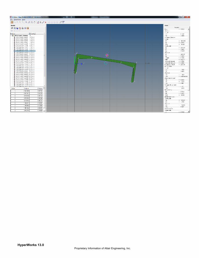
Step 4: Review the section definitions in HyperBeam Now that the section information was generated, review it both in the graphics area and in HyperBeam.
1. From the model browser, select the HyperBeam view icon to visualize the section information.
2. Click through the definitions to review different cross sections.
HyperWorks 13.0 Proprietary Information of Altair Engineering, Inc.

HyperWorks 13.0 Proprietary Information of Altair Engineering, Inc.
Exercise 11b - FE Absorb Plies - Shells to solids The purpose of the FE absorb Plies tool is to convert a traditional zone based composite model into a ply based model. http://www.altairhyperworks.com/hwhelp/Altair/hw13.0/help/engsol/engsol.htm?fe_absorb_plies_aero.htm
Step 1: Switch to the Aerospace profile and import the file 3. Start HyperMesh
4. Select the Aerospace profile with the OptiStruct option.
5. Import the file Absorb_plies-zones.fem.
Step 2: Interrogate the model 6. Color the elements by their property color. Note the different zones in the model.
7. Card edit a few of the PCOMP properties in the model browser to view the composite data. You can also view this same data vertically via the entity editor browser.

HyperWorks 13.0 Proprietary Information of Altair Engineering, Inc.
Step 3: Use the FE Absorb Plies tool to generate plie entities from the composite zone data 8. From the Aerospace dropdown, select the FE Absorb Plies tool.

HyperWorks 13.0 Proprietary Information of Altair Engineering, Inc.
9. With the dialog now open, select all of the properties in the model, and activate each option by checking it’s respective box.
10. Once finished, click OK. 190 separate Plies and Sets should be created, and a Laminate entity which contains the stacking sequence of the 190 plies. To visualize the plies, turn on both the 3D element representation for shells, and the Composite Layers option. To view the plies colored with respect to their color shown in the model browser, color elements By Prop.
HyperWorks 13.0 Proprietary Information of Altair Engineering, Inc.
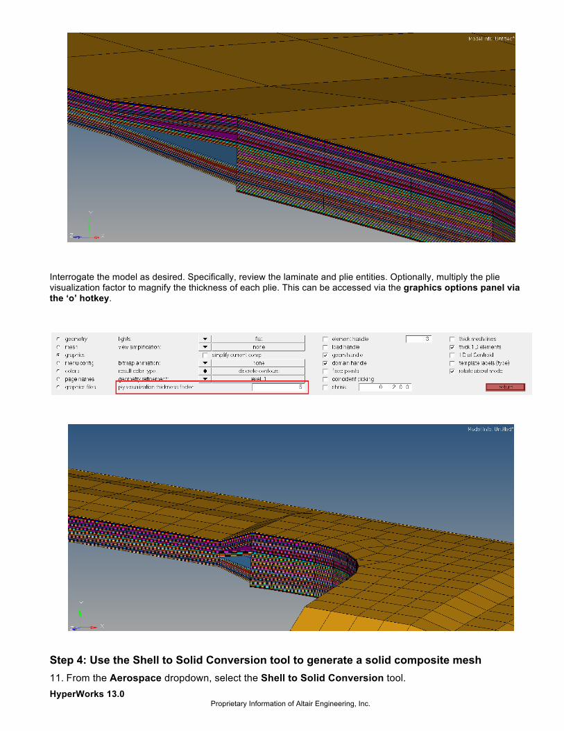
Interrogate the model as desired. Specifically, review the laminate and plie entities. Optionally, multiply the plie visualization factor to magnify the thickness of each plie. This can be accessed via the graphics options panel via the ‘o’ hotkey.
Step 4: Use the Shell to Solid Conversion tool to generate a solid composite mesh 11. From the Aerospace dropdown, select the Shell to Solid Conversion tool.

HyperWorks 13.0 Proprietary Information of Altair Engineering, Inc.
http://www.altairhyperworks.com/hwhelp/Altair/hw13.0/help/engsol/engsol.htm?shell_to_solid_conversion_aerospace.htm
12. With the dialog now open, select the laminate named lam in the model, and activate the desired options.
Once finished, click Convert. All of your plies represented by shells should now have been converted to hexa and penta elements.

HyperWorks 13.0 Proprietary Information of Altair Engineering, Inc.