example – endfire antenna array - eefocusdata.eefocus.com/myspace/33/165109/bbs/2010-01-04/... ·...
TRANSCRIPT
Ansoft High Frequency Structure Simulator v11 User’s Guide
Example – Endfire Antenna Array
5.7
5.7-1
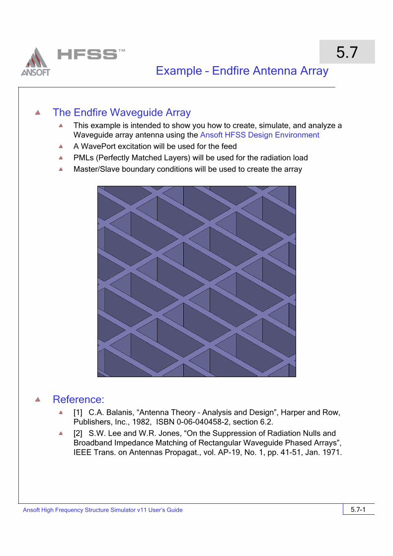
The Endfire Waveguide ArrayThis example is intended to show you how to create, simulate, and analyze a Waveguide array antenna using the Ansoft HFSS Design Environment
A WavePort excitation will be used for the feed
PMLs (Perfectly Matched Layers) will be used for the radiation load
Master/Slave boundary conditions will be used to create the array
Reference: [1] C.A. Balanis, “Antenna Theory – Analysis and Design”, Harper and Row, Publishers, Inc., 1982, ISBN 0-06-040458-2, section 6.2.
[2] S.W. Lee and W.R. Jones, “On the Suppression of Radiation Nulls and Broadband Impedance Matching of Rectangular Waveguide Phased Arrays”, IEEE Trans. on Antennas Propagat., vol. AP-19, No. 1, pp. 41-51, Jan. 1971.
Ansoft High Frequency Structure Simulator v11 User’s Guide
Example – Endfire Antenna Array
5.7
5.7-2
Design Review1. Instead of modeling the entire array, we will make use of the master/slave boundary
conditions and only model a unit cell.
2. Since the Master/Slave boundary conditions also allow us to change the scan angle, we will need a better radiation load on the top of the antenna than a simple radiation boundary condition. We will need to use a PML.
Ansoft HFSS Design EnvironmentThe following features of the Ansoft HFSS Design Environment are used to create this passive device model
3D Solid Modeling
Primitives: Box
Other: Perfectly Matched Layer (PML)
Boundaries/Excitations
Ports: Wave Ports
Boundaries: Master/Slave, Impedance
Analysis
Sweep: None
Results
Cartesian plotting
Field Overlays:
Radiation Patterns
Optimetrics
Parametric sweep
Getting Started
Launching Ansoft HFSS1. To access Ansoft HFSS, click the Microsoft Start button, select Programs, and select
the Ansoft > HFSS 10 program group. Click HFSS 10

Ansoft High Frequency Structure Simulator v11 User’s Guide
Example – Endfire Antenna Array
5.7
5.7-3
Setting Tool OptionsTo set the tool options:
Note: In order to follow the steps outlined in this example, verify that the following tool options are set :
1. Select the menu item Tools > Options > HFSS Options2. HFSS Options Window:
1. Click the General tab
Use Wizards for data entry when creating new boundaries: Checked
Duplicate boundaries with geometry: Checked
2. Click the OK button
3. Select the menu item Tools > Options > 3D Modeler Options.4. 3D Modeler Options Window:
1. Click the Operation tab
Automatically cover closed polylines: Checked
2. Click the Drawing tab
Edit property of new primitives: Checked
3. Click the OK button
Opening a New ProjectTo open a new project:
1. In an Ansoft HFSS window, click the On the Standard toolbar, or select the menu item File > New.
2. From the Project menu, select Insert HFSS Design.
Ansoft High Frequency Structure Simulator v11 User’s Guide
Example – Endfire Antenna Array
5.7
5.7-4
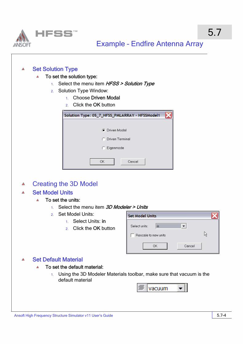
Set Solution TypeTo set the solution type:
1. Select the menu item HFSS > Solution Type2. Solution Type Window:
1. Choose Driven Modal
2. Click the OK button
Creating the 3D ModelSet Model Units
To set the units:
1. Select the menu item 3D Modeler > Units2. Set Model Units:
1. Select Units: in
2. Click the OK button
Set Default MaterialTo set the default material:
1. Using the 3D Modeler Materials toolbar, make sure that vacuum is the default material
Ansoft High Frequency Structure Simulator v11 User’s Guide
Example – Endfire Antenna Array
5.7
5.7-5
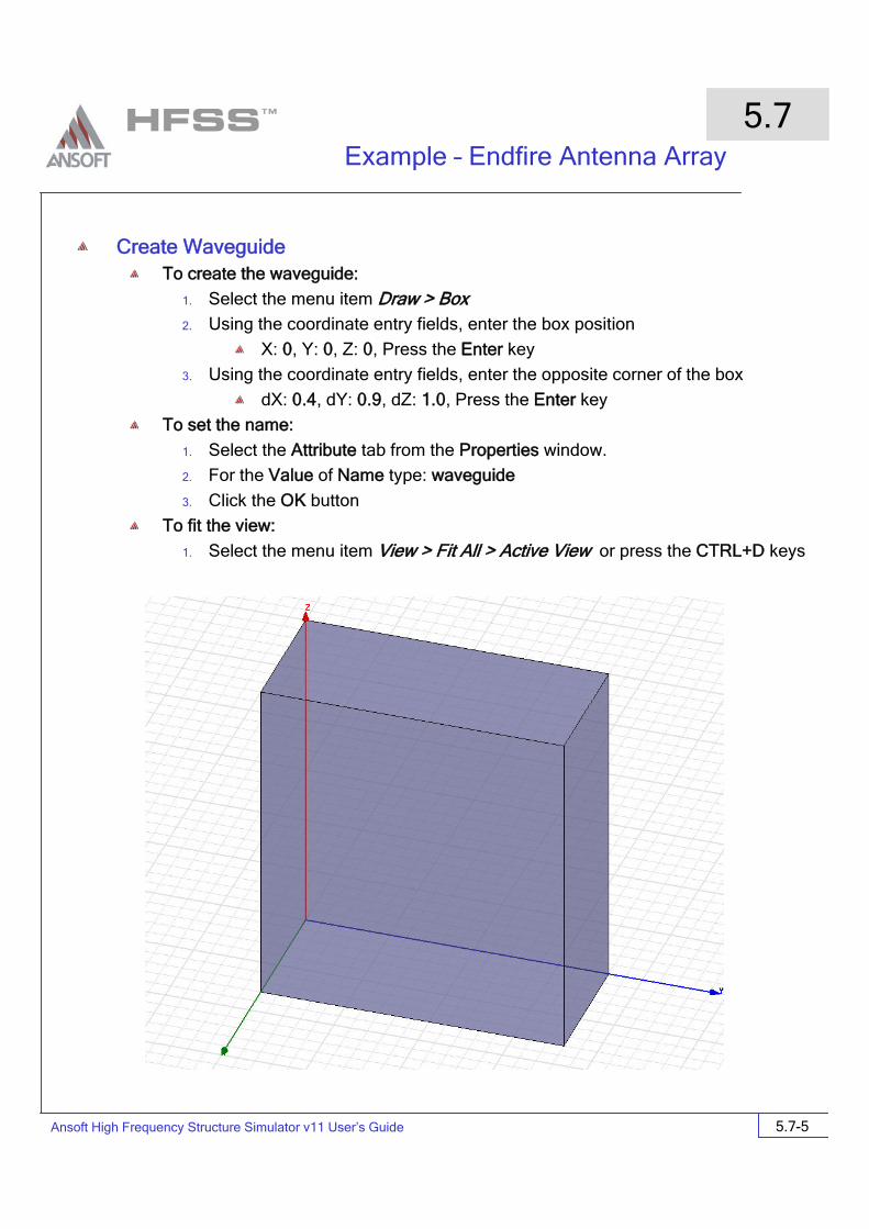
Create WaveguideTo create the waveguide:
1. Select the menu item Draw > Box2. Using the coordinate entry fields, enter the box position
X: 0, Y: 0, Z: 0, Press the Enter key
3. Using the coordinate entry fields, enter the opposite corner of the box
dX: 0.4, dY: 0.9, dZ: 1.0, Press the Enter key
To set the name:
1. Select the Attribute tab from the Properties window.
2. For the Value of Name type: waveguide
3. Click the OK button
To fit the view:
1. Select the menu item View > Fit All > Active View or press the CTRL+D keys
Ansoft High Frequency Structure Simulator v11 User’s Guide
Example – Endfire Antenna Array
5.7
5.7-6
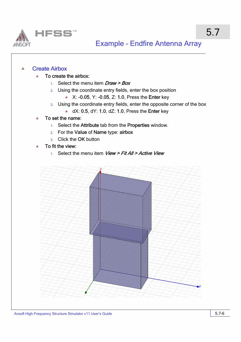
Create AirboxTo create the airbox:
1. Select the menu item Draw > Box2. Using the coordinate entry fields, enter the box position
X: -0.05, Y: -0.05, Z: 1.0, Press the Enter key
3. Using the coordinate entry fields, enter the opposite corner of the box
dX: 0.5, dY: 1.0, dZ: 1.0, Press the Enter key
To set the name:
1. Select the Attribute tab from the Properties window.
2. For the Value of Name type: airbox
3. Click the OK button
To fit the view:
1. Select the menu item View > Fit All > Active View

Ansoft High Frequency Structure Simulator v11 User’s Guide
Example – Endfire Antenna Array
5.7
5.7-7
Create PML loadTo select the proper face of the airbox:
1. Select the menu item Edit > Select > Faces2. Graphically pick the top face of the airbox that was just created.
To assign the PML boundary
1. Select the menu item HFSS > Boundaries > PML Setup Wizard2. PML Setup Wizard: Cover Objects
1. Select: Create PML Cover Objects on Selected Faces
2. Uniform Layer Thickness: 0.2in
3. Click the Next button
3. PML Setup Wizard: Material Parameters
1. Select: PML Objects accept Free Radiation
1. Min Frequency: 9 GHz
2. Minimum Radiating Distance: 1in
3. Click the Next button
2. Review settings on the PML Setup Wizard: Summary page
3. Click the Finish button
Top face selected PML added
Ansoft High Frequency Structure Simulator v11 User’s Guide
Example – Endfire Antenna Array
5.7
5.7-8
Make the PML object visibleBy default, the PML wizard will turn off visibility of the PML object once it is created. We want to turn it back on again.
1. Select the menu item View > Active View Visiblility2. Check the box next to PML_airbox1
3. Click Done
Create the Master/Slave boundary objects
Set Grid PlaneTo set the grid plane:
1. Select the menu item 3D Modeler > Grid Plane > YZ
Draw the Master / Slave objectsTo draw the first Master/Slave rectangle:
1. Select the menu item Draw > Rectangle2. Using the coordinate entry fields, enter the box position
X: 0.45, Y: -0.05, Z: 1.0, Press the Enter key
3. Using the coordinate entry fields, enter the opposite corner of the rectangle
dX: 0, dY: 1.0, dZ: 1.2, Press the Enter key
To set the name:
1. Select the Attribute tab from the Properties window.
2. For the Value of Name type: master1
3. Click the OK button
To set the grid plane:
1. Select the menu item 3D Modeler > Grid Plane > XZTo draw the second Master/Slave rectangle:
1. Select the menu item Draw > Rectangle2. Using the coordinate entry fields, enter the box position
X: -0.05, Y: -0.05, Z: 1.0, Press the Enter key
2. Using the coordinate entry fields, enter the opposite corner of the rectangle
dX: 0.5, dY: 0, dZ: 1.2, Press the Enter key

Ansoft High Frequency Structure Simulator v11 User’s Guide
Example – Endfire Antenna Array
5.7
5.7-9
Create the Master/Slave boundary objects (continued)
To set the name:
1. Select the Attribute tab from the Properties window.
2. For the Value of Name type: master2
3. Click the OK button
To duplicate the objects to create the slaves
1. Select the menu item Edit > Select > Objects2. Select the menu item Edit > Select > By Name3. Select the object, master1
4. Select the menu item Edit > Duplicate > Along Line5. Using the coordinate entry fields, enter the start position of the duplicate
vector
X: 0, Y: 0, Z: 0, Press the Enter key
6. Using the coordinate entry fields, enter the end point of the duplicate vector
dX: -0.5, dY: 0, dZ: 0, Press the Enter key
7. When the dialog box pops up requesting the total number of copies, change the value to 2, Press the OK button.
8. Repeat this process for the object master2 using a duplicate vector of <0,1,0>
Change Slave boundary namesTo change the duplicated master boundary to slave boundary
1. Select the menu item Edit > Select > By Name2. Select Object Dialog,
1. Select the objects named: master1_1
2. Click the OK button
3. Select the menu Item: Edit > Properties4. Change the name to: slave1
5. Repeat the process for master2_1 slave2
Ansoft High Frequency Structure Simulator v11 User’s Guide
Example – Endfire Antenna Array
5.7
5.7-10
Assign Master/Slave BoundariesTo create a Master boundary
1. Select the menu item Edit > Select > By Name2. Select Object Dialog,
1. Select the objects named: master1
2. Click the OK button
3. Select the menu item HFSS > Boundaries > Assign > Master4. Master Boundary window
1. Name: master1
2. Coordinate System: U Vector: click Undefined pulldown
3. Using the coordinate entry fields, enter the start position
X:0.45, Y: -0.05, Z:1.0, Press the Enter key
4. Using the coordinate entry fields, enter the stop position of the vector
dX: 0, dY: 1, dZ: 0, Press the Enter key
5. For the V vector, check the Reverse Direction box
Repeat the process for master2 using the following points:
1. Using the coordinate entry fields, enter the start position
X:0.45, Y: -0.05, Z:1.0, Press the Enter key
2. Using the coordinate entry fields, enter the stop position of the vector
dX:-0.5, dY: 0, dZ: 0, Press the Enter key
To create a Slave boundary
1. Select the menu item Edit > Select > By Name2. Select Object Dialog,
1. Select the objects named: slave1
2. Click the OK button
3. Select the menu item HFSS > Boundaries > Assign > Slave4. Slave Boundary window
1. Name: slave1
2. Master Boundary: click on Undefined pulldown and select Master1
3. Coordinate System: U Vector: click Undefined pulldown
4. Using the coordinate entry fields, enter the start position
X:-0.05, Y: -0.05, Z:1.0, Press the Enter key

Ansoft High Frequency Structure Simulator v11 User’s Guide
Example – Endfire Antenna Array
5.7
5.7-11
Assign Master / Slave Boundaries (continued)To create a Slave boundary (continued)
1. Using the coordinate entry fields, enter the stop position of the vector
dX: 0, dY: 1, dZ: 0, Press the Enter key
2. Click the Next button
3. Make sure that Use Scan Angles To Calculate Phase Delay is checked
1. For Phi, enter 0 deg
2. For Theta, enter a variable name theta_scan, and hit Enter
3. For the Add Variable dialog, enter 30deg for theta_scan
Repeat the process for slave2:
1. Select the menu item Edit > Select > By Name2. Select Object Dialog,
1. Select the objects named: slave2
2. Click the OK button
3. Select the menu item HFSS > Boundaries > Assign > Slave4. Slave Boundary window
1. Name: slave2
2. Master Boundary: click on Undefined pulldown and select Master2
3. Coordinate System: U Vector: click Undefined pulldown
4. Using the coordinate entry fields, enter the start position
X:0.45, Y: 0.95, Z:1.0, Press the Enter key
5. Using the coordinate entry fields, enter the stop position of the vector
dX:-0.5, dY: 0, dZ: 0, Press the Enter key
Ansoft High Frequency Structure Simulator v11 User’s Guide
Example – Endfire Antenna Array
5.7
5.7-12
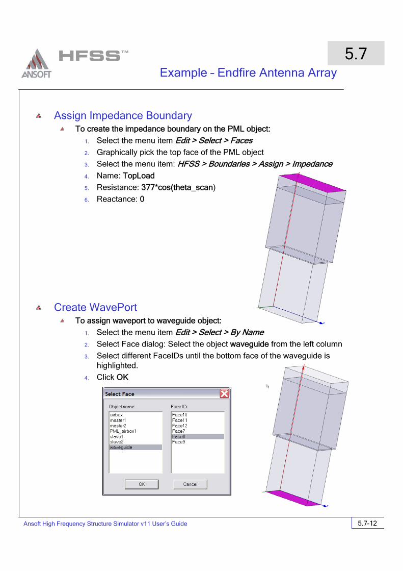
Assign Impedance BoundaryTo create the impedance boundary on the PML object:
1. Select the menu item Edit > Select > Faces2. Graphically pick the top face of the PML object
3. Select the menu item: HFSS > Boundaries > Assign > Impedance4. Name: TopLoad
5. Resistance: 377*cos(theta_scan)
6. Reactance: 0
Create WavePortTo assign waveport to waveguide object:
1. Select the menu item Edit > Select > By Name2. Select Face dialog: Select the object waveguide from the left column
3. Select different FaceIDs until the bottom face of the waveguide is highlighted.
4. Click OK

Ansoft High Frequency Structure Simulator v11 User’s Guide
Example – Endfire Antenna Array
5.7
5.7-13
Create WavePort (continued)To assign waveport to waveguide object (continued):
1. Select the menu item HFSS > Excitation > Assign > WavePort2. Name: p1
3. Click Next
4. Wave Port: Modes
1. Click Next
5. Wave Port: Post-Processing
1. Click Finish
Ansoft High Frequency Structure Simulator v11 User’s Guide
Example – Endfire Antenna Array
5.7
5.7-14
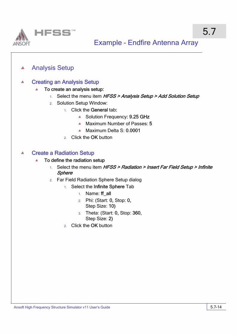
Analysis Setup
Creating an Analysis SetupTo create an analysis setup:
1. Select the menu item HFSS > Analysis Setup > Add Solution Setup2. Solution Setup Window:
1. Click the General tab:
Solution Frequency: 9.25 GHz
Maximum Number of Passes: 5
Maximum Delta S: 0.0001
2. Click the OK button
Create a Radiation SetupTo define the radiation setup
1. Select the menu item HFSS > Radiation > Insert Far Field Setup > Infinite Sphere
2. Far Field Radiation Sphere Setup dialog
1. Select the Infinite Sphere Tab
1. Name: ff_all
2. Phi: (Start: 0, Stop: 0, Step Size: 10)
3. Theta: (Start: 0, Stop: 360, Step Size: 2)
2. Click the OK button

Ansoft High Frequency Structure Simulator v11 User’s Guide
Example – Endfire Antenna Array
5.7
5.7-15
Save ProjectTo save the project:
1. In an Ansoft HFSS window, select the menu item File > Save As.
2. From the Save As window, type the Filename: hfss_pmlarray
3. Click the Save button
Analyze
Model ValidationTo validate the model:
1. Select the menu item HFSS > Validation Check2. Click the Close button
Note: To view any errors or warning messages, use the Message Manager.
AnalyzeTo start the solution process:
1. Select the menu item HFSS > Analyze All
Ansoft High Frequency Structure Simulator v11 User’s Guide
Example – Endfire Antenna Array
5.7
5.7-16
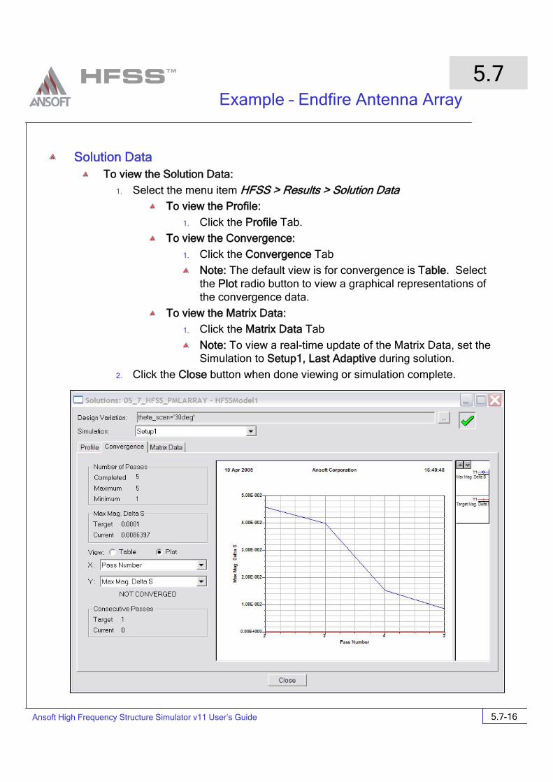
Solution DataTo view the Solution Data:
1. Select the menu item HFSS > Results > Solution DataTo view the Profile:
1. Click the Profile Tab.
To view the Convergence:
1. Click the Convergence Tab
Note: The default view is for convergence is Table. Select the Plot radio button to view a graphical representations of the convergence data.
To view the Matrix Data:
1. Click the Matrix Data Tab
Note: To view a real-time update of the Matrix Data, set the Simulation to Setup1, Last Adaptive during solution.
2. Click the Close button when done viewing or simulation complete.

Ansoft High Frequency Structure Simulator v11 User’s Guide
Example – Endfire Antenna Array
5.7
5.7-17
Far Field Plots
Create Far Field PlotTo create a 2D polar far field plot :
1. Select the menu item HFSS > Results > Create Report2. Create Report Window:
1. Report Type: Far Fields
2. Display Type: Radiation Pattern
3. Click the OK button
3. Traces Window:
1. Solution: Setup1: LastAdaptive
2. Geometry: ff_all
3. In the Sweeps tab:
1. Select Phi under the Name column, and on the drop list, select Theta. This changes the primary sweep to Theta.
4. In the Mag tab
1. Category: Directivity
2. Quantity: DirTotal
3. Function: dB
4. Click the Add Trace button
5. Click the Done button

Ansoft High Frequency Structure Simulator v11 User’s Guide
Example – Endfire Antenna Array
5.7
5.7-18
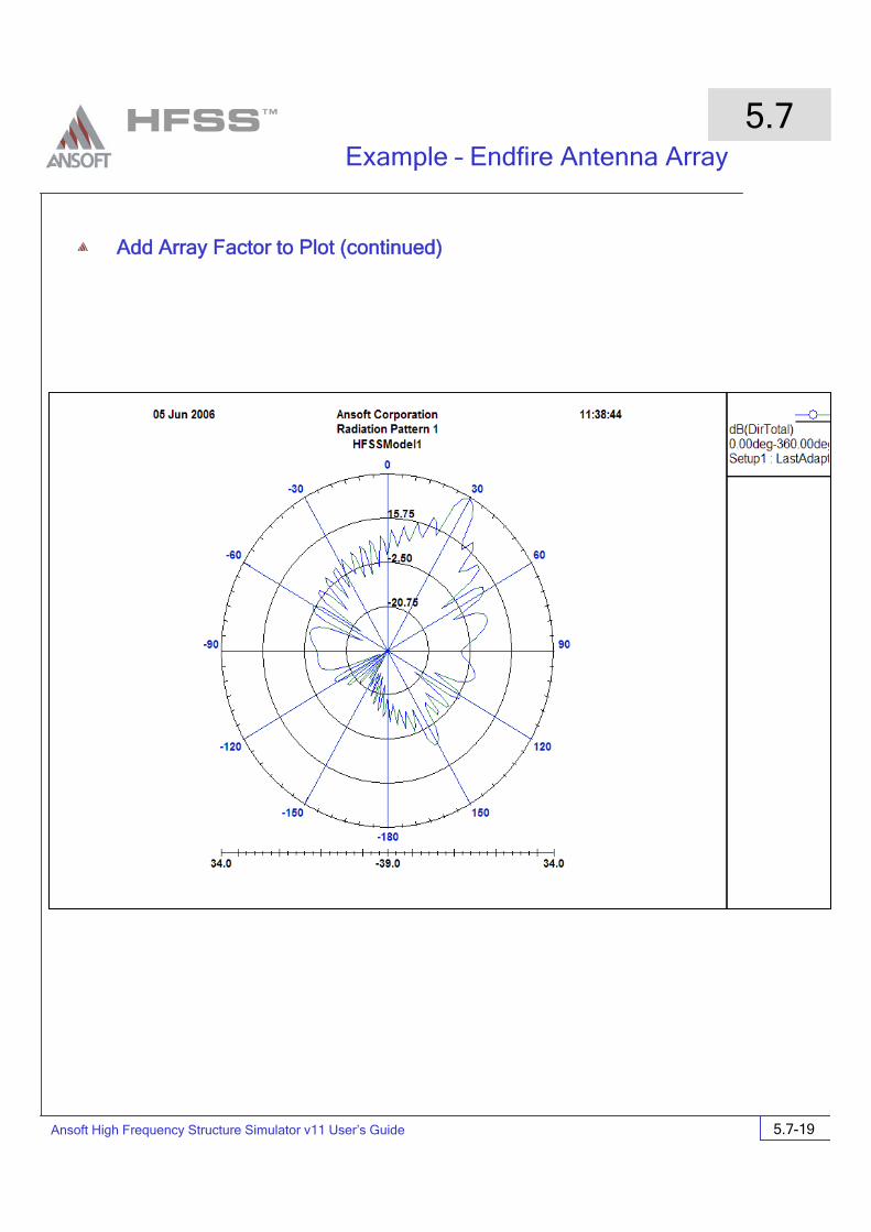
Add Array Factor to PlotTo setup array factor:
1. Select the menu item HFSS > Radiation > Antenna Array Setup2. Select the radio button for Regular Array Setup
3. Switch to the Regular Array tab
4. First Cell Position:
X:0in, Y: 0 in, Z:0 in
5. Directions: U vector
X:1, Y: 0, Z:0
6. Directions: V Vector
X:0, Y: 1, Z:0
7. Distance Between Cells
U Direction: 0.5 in
V Direction 1 in
8. Number of Cells
U Direction: 25
V Direction 25
9. Scan Definition: Use Scan Angles
Theta: theta_scan
Phi: 0 deg
Ansoft High Frequency Structure Simulator v11 User’s Guide
Example – Endfire Antenna Array
5.7
5.7-19
Add Array Factor to Plot (continued)

Ansoft High Frequency Structure Simulator v11 User’s Guide
Example – Endfire Antenna Array
5.7
5.7-20
Optimetrics Setup – Parametric SweepFor this array design, we want to see the effect of scan angle on the input match of the antenna. To do this, we must sweep the scan angle with a parametric sweep.
Add a Parametric Sweep1. Select the menu item HFSS > Optimetrics Analysis > Add Parametric2. Setup Sweep Analysis Window:
1. Click the Sweep Definitions tab:
1. Click the Add button
2. Add/Edit Sweep Dialog
1. Select Variable: theta_scan (this is the only variable defined, so it is greyed out)
2. Select Linear Step
3. Start: 0deg
4. Stop: 60deg
5. Step: 10deg
6. Click the Add button
7. Click the OK button
Analyze Parametric SweepTo start the solution process:
1. Expand the Project Tree to display the items listed under Optimetrics
2. Right-click the mouse on ParametricSetup1 and choose Analyze
Optimetrics ResultsTo view the Optimetrics Results:
1. Select the menu item HFSS > Optimetrics Analysis > Optimetrics Results2. Select the Profile Tab to view the solution progress for each setup.
3. Click the Close button when you are finished viewing the results

Ansoft High Frequency Structure Simulator v11 User’s Guide
Example – Endfire Antenna Array
5.7
5.7-21
Create S-Parameter Plot – S11 at each θTo create a report:
1. Select the menu item HFSS > Results > Create Report2. Create Report Window:
1. Report Type: Modal Solution Data
2. Display Type: Rectangular Plot
3. Click the OK button
3. Traces Window:
1. Solution: Setup1: LastAdaptive
2. Click the Sweeps tab
1. Select Sweep Design and Project variable values
3. In the Sweeps tab:
1. Select Freq under the Name column, and on the drop list, select theta_scan. This changes the primary sweep to theta_scan.
4. Click the Y tab
1. Category: S Parameter
2. Quantity: S(p1,p1)
3. Function: dB
4. Click the Add Trace button
5. Click the Done button